
You also want an ePaper? Increase the reach of your titles
YUMPU automatically turns print PDFs into web optimized ePapers that Google loves.
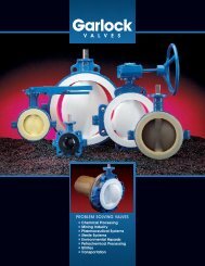
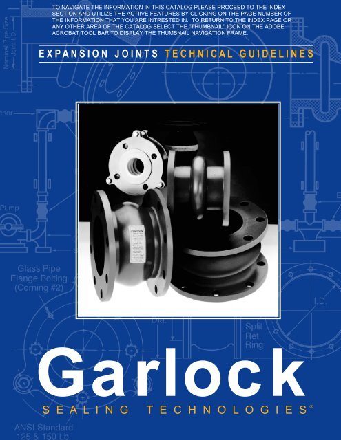
E X P A N S I O N J O I N T S T E C H N I C A L G U I D E L I N E S<br />
<strong>Garlock</strong><br />
S E A L I N G T E C H N O L O G I E S ®
<strong>Garlock</strong>…<br />
in service to world industries since the 1880’s, and for<br />
over fifty years a leader in producing and implementing<br />
the latest in Expansion Joint Technology.<br />
Just a few of the “firsts” developed by <strong>Garlock</strong><br />
Engineering and Manufacturing:<br />
■ Development of high temperature elastomers to the<br />
levels now considered the industry standard<br />
■ Developing the patented construction with bonded<br />
rectangular body rings<br />
■ Creation of fused FEP liners designed specifically<br />
for chemical use<br />
■ Abilities to combine fabric, FEP and elastomers<br />
effectively<br />
■ Design of spool type joints to over 10 foot (120" or<br />
3m) I.D.’s<br />
■ Development of the flowing arch design<br />
Contents<br />
Expansion Joint Styles<br />
Recommended Styles ......................................... 1<br />
GUARDIAN ® 200 and 200HP .............................. 2<br />
Styles 204 and 204HP ......................................... 3<br />
Style 206 EZ-FLO ® .............................................. 4<br />
Styles 207 and 208 .............................................. 5<br />
Styles 214 and 215 Flexible Couplings ............... 6<br />
GUARDIAN ® 306 EZ-FLO ® .................................. 8<br />
GARFLEX ® 8100 ............................................... 12<br />
Style 9394 .......................................................... 13<br />
Style 8400 Flue Ducts ....................................... 14<br />
Style 7250 FLEXO-MATIC ® ............................... 15<br />
Navy & Coast Guard Approved Styles ............... 15<br />
Engineering Data<br />
Size Chart .......................................................... 10<br />
Movement Capabilities ...................................... 10<br />
Drilling Specifications ........................................ 11<br />
Pressure Ratings and Conversion Chart ........... 11<br />
Types of Expansion Joints ................................. 16<br />
Expansion Joint Components ............................ 17<br />
Types of Pipe Movements ................................. 18<br />
Properties of Elastomers ................................... 19<br />
Temperature Ratings ......................................... 19<br />
Expansion Joint Installation ............................... 20<br />
Troubleshooting ................................................. 21<br />
Weights .............................................................. 21<br />
Application Data Form ...................................... BC<br />
Introduction<br />
An expansion joint is a specially engineered<br />
product inserted in a rigid piping system to achieve one<br />
or more of the following:<br />
■ Absorb movement<br />
■ Relieve system strain due to thermal change, load<br />
stress, pumping surges, wear or settling<br />
■ Reduce mechanical noise<br />
■ Compensate for misalignment<br />
■ Eliminate electrolysis between dissimilar metals<br />
At <strong>Garlock</strong>, the range of our engineering emphasis<br />
extends from the selection of the fabric used for<br />
reinforcement to the choice of materials used in actual<br />
expansion joint construction.<br />
Rigid laboratory and field tests of <strong>Garlock</strong> expansion<br />
joints are what back up our assurances of long life<br />
and reliable service. An important word on safety: all<br />
<strong>Garlock</strong> expansion joints carry safety ratings exceeding<br />
product specifications in all areas, including those<br />
of temperature, pressure and vacuum.<br />
<strong>Garlock</strong> nonmetallic expansion joints and flexible<br />
couplings are ideally suited for hundreds of applications<br />
in a wide range of industries, including:<br />
■ Power generating stations<br />
■ Pulp and paper<br />
■ Chemical and industrial process piping<br />
■ Waste water and sewage disposal<br />
■ Marine applications<br />
■ Heating, ventilating and air conditioning<br />
WARNING:<br />
Properties/applications shown throughout this brochure are typical. Your specific<br />
application should not be undertaken without independent study and evaluation for<br />
suitability. For specific application recommendations consult <strong>Garlock</strong>. Failure to<br />
select the proper sealing products could result in property damage and/or serious<br />
personal injury.<br />
Performance data published in this brochure has been developed from field testing,<br />
customer field reports and/or in-house testing.<br />
While the utmost care has been used in compiling this brochure, we assume no<br />
responsibility for errors. Specifications subject to change without notice. This edition<br />
cancels all previous issues. Subject to change without notice.<br />
GARLOCK is a registered trademark for packings, seals, gaskets, and other products<br />
of <strong>Garlock</strong>.
Expansion Joint Selection<br />
To select the proper type of<br />
expansion joint, consider:<br />
■ Pipe size<br />
■ Pumped medium: type of liquid,<br />
gas, or vapor in system<br />
■ Temperature range<br />
■ Pressure/vacuum range<br />
■ Movements needed<br />
■ Environment: degree of exposure<br />
to:<br />
• Weathering<br />
• Sunlight<br />
• Liquids<br />
• Gases<br />
• Vapors<br />
• Oil<br />
• Open flame<br />
• Chemicals<br />
• Other<br />
■ Installed face-to-face dimensions<br />
<strong>Garlock</strong> Recommendations<br />
Standard Piping—<br />
High Pressure<br />
Standard Piping—<br />
Low Pressure<br />
204, 207, 214,<br />
200 200HP 204HP 206 208 215 306 7706-S 7250 8100 9394<br />
★ ★ ★ ★ ★<br />
Chemical Piping ★ ★ ★<br />
★ ★<br />
Standard Ducts ★<br />
Nuclear ★ ★ ★ ★ ★<br />
Naval and<br />
Coast Guard<br />
■ Degree of pipe misalignment<br />
• If greater than 0.125"<br />
(3.2 mm), correct or<br />
use a special joint<br />
■ Drilling: if other than<br />
standard 125 Ib. ANSI,<br />
determine:<br />
• Flange O.D.<br />
• Bolt circle<br />
• Number of bolt holes<br />
• Diameter of hole<br />
■ Need for retaining rings<br />
■ Need for control units<br />
• Recommended for<br />
use with most expansion<br />
joints<br />
• Must be used in cases of<br />
insufficient pipe support<br />
■ Need for special construction<br />
★ ★<br />
1
GUARDIAN ®<br />
2<br />
200 and 200HP<br />
<strong>Garlock</strong> GUARDIAN ® 200 expansion joints consist<br />
of a chemically-resistant FEP* liner mechanically<br />
bonded to an abrupt arch. A chlorobutyl cover and blue<br />
protectant coating add resistance to environmental<br />
effects. (Alternate cover materials available.)<br />
Benefits<br />
■ High-density FEP liner reduces permeation and<br />
offers optimal chemical resistance<br />
■ Mechanically bound liner reduces delamination; no<br />
glue to be vulnerable to chemical attack<br />
■ High pressure and vacuum resistance ensures<br />
suitability for broad range of applications<br />
■ Available with GYLON ®<br />
3545 gasket face for raised<br />
face flange connections<br />
Design<br />
■ Tube<br />
• Seamless FEP lining extends to the outer edge<br />
of the flange; completely fused to the joint body<br />
• Abrupt arch design used for maximum movement<br />
capabilities<br />
■ Body<br />
• Chlorobutyl/polyester construction with welded,<br />
treated metal body rings for dimensional stability<br />
■ Cover<br />
• Homogeneous layer of chlorobutyl elastomer is<br />
standard<br />
• Elastomer extends to the outside diameter of the<br />
flange<br />
Fully Tested and Field Engineered<br />
All <strong>Garlock</strong> expansion joint styles have been<br />
rigorously lab- and field-tested, and engineered to<br />
ensure long life and reliable service.<br />
Temperature<br />
Max. Temp.<br />
Standard chlorobutyl/polyester.............. +250°F (+120°C)<br />
Chlorobutyl/fiberglass/Kevlar**<br />
with EPDM cover ............................ +300°F (+150°C)<br />
Fluoroelastomer w/ fiberglass/Kevlar .... +400°F (+205°C)<br />
* Fluorinated Ethylene Propylene<br />
** Kevlar is a registered trademark of DuPont.<br />
FPO<br />
Pressure and Vacuum Rating<br />
Pipe I.D. Pressure Vacuum<br />
Inch mm psi bar in. Hg mm Hg<br />
GUARDIAN ® 2-4 50-100 165 11 Full 750<br />
200 †<br />
5-12 125-300 140 10 Full 750<br />
14 350 85 6 Full 750<br />
16-24 400-600 65 5 Full 750<br />
26-30 650-750 55 4 Full 750<br />
GUARDIAN ® 2-6 50-150 200 14 Full 750<br />
200HP †<br />
8-12 200-300 190 13 Full 750<br />
14 350 130 9 Full 750<br />
16-20 400-500 110 8 Full 750<br />
22-24 550-600 100 7 Full 750<br />
26-30 650-750 90 6 Full 750<br />
† Higher pressure designs are available. Call <strong>Garlock</strong> with application<br />
details.<br />
Consult <strong>Garlock</strong> for sizes over 30" (750 mm). Metric sizes available<br />
on request.<br />
Made in the U.S.A.<br />
WARNING:<br />
Properties/applications shown throughout this brochure are typical. Your specific<br />
application should not be undertaken without independent study and evaluation for<br />
suitability. For specific application recommendations consult <strong>Garlock</strong>. Failure to<br />
select the proper sealing products could result in property damage and/or serious<br />
personal injury.<br />
Performance data published in this brochure has been developed from field testing,<br />
customer field reports and/or in-house testing.<br />
While the utmost care has been used in compiling this brochure, we assume no<br />
responsibility for errors. Specifications subject to change without notice. This edition<br />
cancels all previous issues. Subject to change without notice.<br />
GARLOCK is a registered trademark for packings, seals, gaskets, and other products<br />
of <strong>Garlock</strong>.
Styles 204 and 204HP<br />
Styles 204 and 204HP spool-type expansion joints<br />
can be constructed as single- or multiple-arch types.<br />
They connect pipe flanges in concentric or eccentric<br />
tapers, to join piping of unequal diameters.<br />
Benefits<br />
■ Fully lab- and field-tested for long life and exceptional<br />
reliability<br />
■ Seamless flange face eliminates need for gaskets<br />
■ High pressure- and vacuum-resistance increases<br />
safety and ensures suitability for wide range of<br />
applications<br />
■ Can be custom-designed for greater movement<br />
capability and easier installation<br />
■ Variety of elastomer and fabric combinations meet<br />
the demands of temperature, pressure and media<br />
Design<br />
■ Tube<br />
• Chlorobutyl resists cracking due to high temperatures,<br />
weathering, oxidation and chemicals<br />
• Abrupt arch configuration provides maximum<br />
movement, and pressure and vacuum resistance<br />
• Seamless tube creates a positive flange seal<br />
without gaskets<br />
■ Body<br />
• Chlorobutyl/polyester construction with welded,<br />
treated metal body rings for dimensional stability<br />
■ Cover<br />
• Chlorobutyl extends to outside flange diameter<br />
• Durable coating resists weathering and oxidation<br />
Special Liner and<br />
Cover Materials<br />
■ Hypalon**<br />
■ EPDM<br />
■ Nitrile<br />
■ Neoprene<br />
■ Natural (tube only)<br />
■ FDA tubes of EPDM, neoprene<br />
and natural<br />
* Not available on tapers<br />
** Kevlar is a registered trademark of DuPont; Hypalon<br />
is a registered trademark of DuPont Dow Elastomers.<br />
Temperature<br />
Optional Configurations<br />
Max. Temp.<br />
Standard chlorobutyl/polyester.............. +250°F (+120°C)<br />
Chlorobutyl/fiberglass/Kevlar**<br />
with EPDM tube and cover ............. +300°F (+150°C)<br />
Fluoroelastomer w/ fiberglass/Kevlar .... +400°F (+205°C)<br />
Pressure and Vacuum Rating<br />
Pipe I.D. Pressure Vacuum<br />
Inch mm psi bar in. Hg mm Hg<br />
Style 204 † 1/2-4 13-100 165 11 Full 750<br />
5-12 125-300 140 10 Full 750<br />
14 350 85 6 Full 750<br />
16-24 400-600 65 4.5 Full 750<br />
26-66 650-1650 55 4 Full 750<br />
72-84 1800-2100 45 3 Full 750<br />
Style 204HP † 1/2-6 13-150 200 14 Full 750<br />
8-12 200-300 190 13 Full 750<br />
14 350 130 9 Full 750<br />
16-20 400-500 110 8 Full 750<br />
22-24 550-600 100 7 Full 750<br />
26-40 650-1000 90 6 Full 750<br />
42-66 1050-1650 80 5.5 Full 750<br />
68-84 1700-2100 70 5 Full 750<br />
† Higher pressure designs are available. Call <strong>Garlock</strong> with application<br />
details.<br />
Consult <strong>Garlock</strong> for pressure ratings of larger sizes up to 144" (3660<br />
mm). Metric sizes available on request.<br />
Concentric Tapered Eccentric Tapered<br />
3
Style 206 EZ-FLO ®<br />
EZ-FLO ® expansion joints contain a single wide<br />
flowing arch, eliminating the need for filled arches on<br />
slurry services. <strong>Garlock</strong> EZ-FLO ® expansion joints have<br />
successfully served all major industries, including pulp<br />
and paper, steel, waste and water, HVAC, power<br />
generation, chemical, petrochemical and marine.<br />
Benefits<br />
■ Self-flushing design eliminates media buildup and<br />
reduces fluid turbulence<br />
■ High pressure- and vacuum-resistance ensures<br />
longer life and reduces inventory requirements<br />
■ Lightweight design installs easily, costs less to ship<br />
Design<br />
■ Tube<br />
• Standard chlorobutyl liner extends to outer edge<br />
of the flange for excellent chemical resistance<br />
• Flowing arch design adds pressure resistance<br />
and reduces product buildup<br />
■ Body<br />
• Rubber impregnated tire cord and polyester<br />
cross-wrapped in bias-ply construction<br />
■ Cover<br />
• Homogeneous layer of chlorobutyl elastomer<br />
extends to the outside edge of the flange<br />
• Coated with a weather-resistant protectant<br />
Fully Tested and Field Engineered<br />
All <strong>Garlock</strong> expansion joint styles have been<br />
rigorously lab- and field-tested, and engineered to<br />
ensure long life and reliable service.<br />
Special Liner * and Cover Materials<br />
■ Neoprene ■ Nitrile<br />
■ EPDM ■ Natural (tube only)<br />
■ Hypalon**<br />
■ FDA tubes in EPDM, neoprene and natural<br />
Temperature<br />
Max. Temp.<br />
Chlorobutyl/nylon tire cord .................... +250°F (+120°C)<br />
Chlorobutyl/Kevlar tire cord ................... +300°F (+150°C)<br />
* When EZ-FLO ® expansion joints are furnished with special liners,<br />
temperature and pressure ratings may change.<br />
** Kevlar is a registered trademark of DuPont;<br />
Hypalon is a registered trademark of DuPont Dow Elastomers.<br />
4<br />
Pressure and Vacuum Rating<br />
Pipe I.D. Pressure Vacuum<br />
Inch mm psi bar in. Hg mm Hg<br />
Style 206 2-10 50-250 250 17 26 650<br />
EZ-FLO ®† 12 300 250 17 12 300<br />
14 350 130 9 12 300<br />
16-20 400-500 110 8 12 300<br />
22-24 550-600 100 7 12 300<br />
26-40 650-1000 90 6 12 300<br />
42-66 1050-1650 80 5.5 12 300<br />
68-84 1700-2100 70 5 12 300<br />
† Pressure and vacuum ratings are for standard FF dimensions only.<br />
Consult <strong>Garlock</strong> for alternate sizes and corresponding pressure/<br />
vacuum ratings. Consult <strong>Garlock</strong> for larger sizes. Metric sizes available<br />
on request.<br />
Movement Capabilities<br />
Pipe I.D. Movement<br />
Type Movement Inch mm Inch mm<br />
Compression 2-5 50-125 3/4 19<br />
6-18 150-450 1 25<br />
20-24 500-600 1-1/8 30<br />
26-40 650-1000 1-1/4 32<br />
42 & Up 1050 & Up 1-3/8 35<br />
Elongation 2-5 50-125 3/8 10<br />
6-18 150-450 1/2 12<br />
20-24 500-600 1/2 12<br />
26 & Up 650 & Up 1/2 12<br />
Transverse 2-8 50-200 1/2 12<br />
(Lateral) 10 & Up 250 & Up 1/2 12<br />
Control Units<br />
Control units must be used to protect expansion<br />
joints from excessive movement if piping is not properly<br />
anchored. See page 17 for information.
Styles 207 and 208<br />
Styles 207 and 208 are U-type expansion joints<br />
constructed of specialty rubber and fabric. Available in<br />
round or rectangualr configurations, they are used as<br />
flexible connectors between a turbine and condenser,<br />
or other similar applications.<br />
Style 207<br />
■ Internally flanged for full vacuum and low pressure<br />
applications<br />
■ Temperature: To +250°F (+120°C)*<br />
Pressure: Full vacuum to 15 psig (1.0 bar)<br />
Style 208<br />
■ Externally flanged, primarily for vacuum service<br />
■ Temperature: To +250°F (+120°C)*<br />
Pressure: Full vacuum to 25 psig (1.7 bar)<br />
■ Available in very narrow face-to-face dimensions;<br />
staggered drilling facilitates installation<br />
■ Also recommended to reduce vibration and noise on<br />
lightweight piping, i.e. those carrying coal-laden air<br />
to pulverized coal burners<br />
Fully Tested and Field Engineered<br />
All <strong>Garlock</strong> expansion joint styles have been<br />
rigorously lab- and field-tested, and engineered to<br />
ensure long life and reliable service.<br />
NOTE: For recommendations for specific applications, including range of<br />
available elastomers, consult <strong>Garlock</strong>.<br />
Movement Capabilities<br />
Pipe I.D. Movement<br />
Type Movement Inch mm Inch mm<br />
Compression 2-20 50-500 1/2 12<br />
22 & Up 550 & Up 3/4 19<br />
Elongation 2-20 50-500 1/4 6<br />
22 & Up 550 & Up 1/4 6<br />
Lateral 2-20 50-500 1/2 12<br />
22 & Up 550 & Up 1/2 12<br />
* For higher temperature capabilities, consult <strong>Garlock</strong>.<br />
FPO<br />
WARNING:<br />
Properties/applications shown throughout this brochure are typical. Your specific application<br />
should not be undertaken without independent study and evaluation for suitability.<br />
For specific application recommendations consult <strong>Garlock</strong>. Failure to select<br />
the proper sealing products could result in property damage and/or serious personal<br />
injury.<br />
Performance data published in this brochure has been developed from field testing,<br />
customer field reports and/or in-house testing.<br />
While the utmost care has been used in compiling this brochure, we assume no responsibility<br />
for errors. Specifications subject to change without notice. This edition<br />
cancels all previous issues. Subject to change without notice.<br />
GARLOCK is a registered trademark for packings, seals, gaskets, and other products<br />
of <strong>Garlock</strong>.<br />
5
Styles 214 and 215<br />
These PTFE concentric spool-type flexible couplings<br />
are designed to reduce noise and compensate<br />
for expansion, contraction and minor piping misalignment<br />
in chemical processing, air conditioning and<br />
heating systems.<br />
Style 214<br />
■ Two convolutions<br />
■ Temperature: -100°F (-70°C) to +450°F (+230°C)<br />
Pressure: To 178 psig (12 bar),<br />
Full vacuum to +350°F (+180°C)<br />
Style 215<br />
■ Three convolutions<br />
■ Temperature: -100°F (-70°C) to +450°F (+230°C)<br />
Pressure: To 132 psig (9 bar),<br />
Full vacuum to +180°F (+80°C)<br />
Benefits<br />
■ Convolution shape provides extra-long flex life at<br />
high temperatures<br />
■ Proprietary contour molding process ensures<br />
consistent wall thickness for blowout resistance<br />
■ PTFE body withstands corrosion, water, steam, and<br />
most chemicals and gases<br />
■ Higher pressure and temperature ratings mean<br />
extended service life in most piping systems<br />
■ Preset restriction bolts prevent over-extension<br />
Design<br />
■ Complete assembly includes fluorocarbon resin<br />
PTFE body, plated ductile iron flanges, polyethylene-covered<br />
restriction bolts and corrosion-resistant<br />
reinforcing rings<br />
■ Standard sizes from 1" (25 mm) through 8" (200<br />
mm) pipe l.D.<br />
6<br />
Pressure and Vacuum Rating<br />
<strong>Garlock</strong> PTFE expansion joints and couplings have<br />
pressure ratings high enough to handle most applications.<br />
As the pipe size gets larger, <strong>Garlock</strong> increases<br />
the bellows thickness and the strength of the reinforcing<br />
rings to compensate for the change in internal<br />
forces. This permits the same high pressure rating for<br />
all sizes.<br />
Temperature 214 Pressure 215 Pressure<br />
psi bar psi bar<br />
50°F 10°C 178 12 132 9<br />
100°F 50°C 165 11 120 8<br />
150°F 65°C 150 10 103 7<br />
200°F 90°C 130 9 90 6<br />
250°F 120°C 110 8 75 5<br />
300°F 150°C 92 6 60 4<br />
350°F 180°C 78 5 50 3.5<br />
400°F 205°C 65 4.5 42 3<br />
450°F 230°C 60 4 35 2<br />
WARNING:<br />
Properties/applications shown throughout this brochure are typical. Your specific application<br />
should not be undertaken without independent study and evaluation for suitability.<br />
For specific application recommendations consult <strong>Garlock</strong>. Failure to select the proper<br />
sealing products could result in property damage and/or serious personal injury.<br />
Performance data published in this brochure has been developed from field testing,<br />
customer field reports and/or in-house testing.<br />
While the utmost care has been used in compiling this brochure, we assume no responsibility<br />
for errors. Specifications subject to change without notice. This edition cancels<br />
all previous issues. Subject to change without notice.<br />
GARLOCK is a registered trademark for packings, seals, gaskets, and other products<br />
of <strong>Garlock</strong>.
Movement<br />
Style 214 PTFE Flexible Couplings<br />
Pipe Size (Inches) 1 1-1/2 2 2-1/2 3 4 5 6 8<br />
Nominal Installed<br />
Face to-Face<br />
1-3/8 1-3/8 1-9/16 2-1/4 2-1/4 2-5/8 3-1/4 2-3/4 4<br />
Max. Restriction Bolt<br />
Setting<br />
1-1/4 1-5/16 1-15/32 2-7/32 2-1/4 2-23/32 3-5/16 2-3/4 4<br />
Max. Axial Movement<br />
+ or -<br />
1/4 1/4 1/4 5/16 3/8 1/2 1/2 1/2 1/2<br />
Max. Transverse<br />
Deflection, + or -*<br />
1/8 1/8 1/8 1/8 3/16 1/4 1/4 1/4 1/4<br />
Maximum angular movement aproximately 7°.<br />
* Based on unit being in normal installed position with no axial movement or angular deflection.<br />
Style 215 PTFE Flexible Couplings<br />
Pipe Size (Inches) 1 1-1/2 2 2-1/2 3 4 5 6 8<br />
Nominal Installed<br />
Face to-Face<br />
1-3/4 2 2-3/4 3-3/16 3-5/8 3-5/8 4 4 6<br />
Max. Restriction Bolt<br />
Setting<br />
1-7/8 2-5/32 3-5/32 3-9/16 4-1/4 4-1/4 4-9/16 4-5/8 6-5/8<br />
Max. Axial Movement<br />
+ or -<br />
1/2 1/2 3/4 3/4 1 1 1 1-1/8 1-1/8<br />
Max. Transverse<br />
Deflection, + or -*<br />
1/4 1/4 3/8 3/8 1/2 1/2 1/2 9/16 9/16<br />
Maximum angular movement aproximately 14°.<br />
* Based on unit being in normal installed position with no axial movement or angular deflection.<br />
PTFE Control Units and Flanges<br />
All PTFE joints and couplings are furnished with<br />
ductile iron flanges and control units ready for immediate<br />
installation on the job site. Flanges in other alloys<br />
are available by special order.<br />
Flanges are protected to resist atmosphere corrosion<br />
and are tapped to 150 Ibs. ANSI Standard drilling.<br />
Control units are assembled with flanges to prevent<br />
joints from excessive axial elongation. They are<br />
Flange Dimensions and Drilling<br />
designed to accept the<br />
static pressure thrust in the piping system.<br />
Tie rods are set at the factory at the maximum face-toface<br />
working limits, with lock nuts as insurance<br />
against overextension of the expansion joint. The<br />
tie rods are covered with polyethylene to eliminate<br />
metal-to-metal contact between the rods and<br />
flanges—the most frequent cause of noise transmission<br />
and electrolysis.<br />
Pipe Size (Inches)<br />
Flange<br />
1 1-1/2 2 2-1/2 3 4 5 6 8<br />
Dimension 5-11/16 6-7/16 7-7/8 9-1/8 10 11-1/8 12-7/8 13-7/8 15-1/2<br />
Thickness<br />
ANSI Std. Drilling<br />
3/8 3/8 1/2 5/6 5/8 11/16 11/16 11/16 11/16<br />
Bolt Circle Dia. 3-1/8 3-7/8 4-3/4 5-1/2 6 7-1/2 8-1/2 9-1/2 11-3/4<br />
No. Bolt Holes 4 4 4 4 4 8 8 8 8<br />
Bolt Hole Thread<br />
Corning Style*<br />
#2 Glass Pipe<br />
1/2-13 1/2-13 5/8-11 5/8-11 5/8-11 5/8-11 3/4-10 3/4-10 3/4-10<br />
Bolt Circle 3-1/8 3-7/8 4-3/4 — 6 7-1/2 — 9-1/2 —<br />
No. Bolt Holes 4 4 4 — 4 8 — 8 —<br />
Bolt Hole Thread 5/16-18 5/16-18 5/16-18 — 5/16-18 5/16-18 — 3/8-16 —<br />
* Special order only<br />
7
GUARDIAN ®<br />
8<br />
306 EZ-FLO ®<br />
<strong>Garlock</strong> GUARDIAN ® 306 EZ-FLO ® spool-type<br />
expansion joints feature an FEP lining that is fused to<br />
the body of the expansion joint.<br />
The GUARDIAN ® 306 EZ-FLO ® is designed for<br />
the chemical processing and pulp & paper industries,<br />
where its ability to resist corrosive attack at normal or<br />
elevated temperatures and pressures is unequaled.<br />
Benefits<br />
■ FEP liner is non-contaminating and suits a wide<br />
range of applications<br />
■ Flowing arch design prevents media buildup and<br />
reduces turbulence and vibration<br />
■ 250 psig (17 bar) pressure rating ensures longer<br />
service life and consolidates inventory<br />
■ Liner extends to outer diameter of flange to prevent<br />
chemical attack on expansion joint flanges<br />
■ Mechanically bonded liner resists delamination<br />
Design<br />
■ Tube<br />
• Seamless FEP lining extends to the outer edge<br />
of the flange; completely fused to the expansion<br />
joint body<br />
• Incorporates a flowing arch design to resist<br />
product build-up<br />
■ Body<br />
• Impregnated nylon tire cord fabric cross-wrapped<br />
in bias-ply construction<br />
■ Cover<br />
• Homogeneous layer of chlorobutyl elastomer<br />
extends to the outside edge of the flange<br />
• Coated with a weather-resistant protectant<br />
■ Special Designs<br />
• Non-standard face-to-face dimensions<br />
(pressure / vacuum ratings may be affected)<br />
• Non-standard drill patterns<br />
• Blind flanges (no drilling)<br />
• Lightweight designs available for low pressure<br />
and non-metallic pipe applications<br />
• Available with GYLON ®<br />
3545 gasket face for<br />
raised face flange connections<br />
Pressure and Vacuum Rating*<br />
Pipe I.D. Pressure Vacuum<br />
Inch mm psi bar in. Hg mm Hg<br />
Style 306 3-10 75-250 250 17 26 650<br />
EZ-FLO ® 12 300 250 17 17 425<br />
14 350 130 9 17 425<br />
16-20 400-500 110 8 15 375<br />
* Pressure and vacuum ratings are for neutral FF dimensions only.<br />
Consult <strong>Garlock</strong> for alternate sizes and corresponding pressure/vacuum<br />
ratings. Consult <strong>Garlock</strong> for larger sizes. Metric sizes available on request.<br />
Temperature<br />
Max. Temp.<br />
Chlorobutyl/nylon tire cord .................... +250°F (+120°C)<br />
Chlorobutyl/Kevlar** tire cord<br />
with EPDM cover ..................... +300°F (+150°C)<br />
** Kevlar is a registered trademark of DuPont.<br />
WARNING:<br />
Properties/applications shown throughout this brochure are typical. Your specific application<br />
should not be undertaken without independent study and evaluation for suitability.<br />
For specific application recommendations consult <strong>Garlock</strong>. Failure to select the proper<br />
sealing products could result in property damage and/or serious personal injury.<br />
Performance data published in this brochure has been developed from field testing,<br />
customer field reports and/or in-house testing.<br />
While the utmost care has been used in compiling this brochure, we assume no responsibility<br />
for errors. Specifications subject to change without notice. This edition cancels<br />
all previous issues. Subject to change without notice.<br />
GARLOCK is a registered trademark for packings, seals, gaskets, and other products<br />
of <strong>Garlock</strong>.
Movement Capabilities<br />
Force (lbs.)<br />
Pipe I.D. Movement<br />
Type Movement Inch mm Inch mm<br />
Compression 3-4 75-100 3/4 19<br />
6-20 150-500 1 25<br />
Elongation 3-4 75-100 3/8 10<br />
6-20 150-500 1/2 12<br />
Lateral 3-4 75-100 1/2 12<br />
6-20 150-500 1/2 12<br />
Compression Elongation<br />
8,000<br />
7,000<br />
6,000<br />
5,000<br />
4,000<br />
3,000<br />
2,000<br />
1,000<br />
4<br />
3<br />
Pipe Sizes<br />
20<br />
18<br />
16<br />
0<br />
0 1/8 1/4 3/8 1/2 5/8 3/4 7/8 1<br />
Joint Movement (inches)<br />
Fully Tested and Field Engineered<br />
All <strong>Garlock</strong> expansion joint styles have been<br />
rigorously lab- and field-tested, and engineered to<br />
ensure long life and reliable service.<br />
Control Units<br />
Control units must be used to protect expansion<br />
joints from excessive movement if piping is not properly<br />
anchored. See page 17 for information.<br />
14<br />
12<br />
10<br />
8<br />
6<br />
Force (lbs.)<br />
Pipe I.D. Movement<br />
Type Movement Inch mm Degrees<br />
Angular 3-4 75-100 8<br />
6-8 150-200 5<br />
10-12 250-300 4<br />
14-16 350-400 2.5<br />
18-20 450-500 2<br />
Torsional 3-12 75-300 3<br />
14-16 350-400 2<br />
18-20 450-500 1<br />
8,000<br />
7,000<br />
6,000<br />
5,000<br />
4,000<br />
3,000<br />
2,000<br />
1,000<br />
4<br />
3<br />
Pipe Sizes<br />
20<br />
18<br />
16<br />
14<br />
12<br />
10<br />
8<br />
6<br />
0<br />
0 1/16 1/8 3/16 1/4 5/16 3/8 7/16 1/2<br />
Joint Movement (inches)<br />
NOTES:<br />
1. Sizes 3"-20" indicate nominal ANSI pipe sizes.<br />
2. 3" and 4" I.D. have 3/4" maximum compression and 3/8" maximum<br />
elongation.<br />
3. Forces to compress and elongate are based on zero pressure<br />
conditions and ambient temperatures in the pipeline.<br />
4. To convert force in pounds to kilograms, divide by 2.205.<br />
5. Metric sizes avilable by special request.<br />
9
Technical Data<br />
Sizes • Dimensions • Movements • Forces to Compress, Deflect, Elongate<br />
Joint Size (Inside Dia.) 1 1 1 1 ⁄ 4 1 1 ⁄ 2 2 2 1 ⁄ 2 3 4 5 6 8 10 12 14 16 18 20 22 24 26 28 30 34 36<br />
Flange Outside Dia. 4 1 ⁄ 4 4 5 ⁄ 8 5 6 7 7 1 ⁄ 2 9 10 11 13 1 ⁄ 2 16 19 21 23 1 ⁄ 2 25 27 1 ⁄ 2 29 1 ⁄ 2 32 34 1 ⁄ 4 36 1 ⁄ 2 38 3 ⁄ 4 43 3 ⁄ 4 46<br />
Bolt Circle Dia. 3 1 ⁄ 8 3 1 ⁄ 2 3 7 ⁄ 8 4 3 ⁄ 4 5 1 ⁄ 2 6 7 1 ⁄ 2 8 1 ⁄ 2 9 1 ⁄ 2 11 3 ⁄ 4 14 1 ⁄ 4 17 18 3 ⁄ 4 21 1 ⁄ 4 22 3 ⁄ 4 25 27 1 ⁄ 4 29 1 ⁄ 2 31 3 ⁄ 4 34 36 40 1 ⁄ 2 42 3 ⁄ 4<br />
Number Bolt Holes 4 4 4 4 4 4 8 8 8 8 12 12 12 16 16 20 20 20 24 28 28 32 32<br />
Diameter Bolt Holes<br />
5 ⁄ 8<br />
A 9 ⁄ 16<br />
5 ⁄ 8<br />
9 ⁄ 16<br />
5 ⁄ 8<br />
9 ⁄ 16<br />
3 ⁄ 4<br />
9 ⁄ 16<br />
3 ⁄ 4<br />
9 ⁄ 16<br />
3 ⁄ 4<br />
9 ⁄ 16<br />
3 ⁄ 4<br />
9 ⁄ 16<br />
7 ⁄ 8<br />
9 ⁄ 16<br />
7 ⁄ 8<br />
5 ⁄ 8<br />
7 ⁄ 8 1 1 1 1 ⁄ 8 1 1 ⁄ 8 1 1 ⁄ 4 1 1 ⁄ 4 1 3 ⁄ 8 1 3 ⁄ 8 1 3 ⁄ 8 1 3 ⁄ 8 1 3 ⁄ 8 1 5 ⁄ 8 1 5 ⁄ 8<br />
3 ⁄ 4<br />
3 ⁄ 4<br />
3 ⁄ 4<br />
7 ⁄ 8<br />
7 ⁄ 8<br />
7 ⁄ 8 1 1 1 1 1 1 1 1<br />
⁄ ⁄ ⁄ ⁄ ⁄ ⁄ ⁄ ⁄ ⁄ ⁄ ⁄ ⁄ ⁄ ⁄ ⁄ ⁄ ⁄ ⁄ ⁄ ⁄ ⁄ ⁄ Dimensions B 1<br />
2<br />
1<br />
2<br />
5<br />
8<br />
3<br />
4<br />
3<br />
4<br />
3<br />
4<br />
7<br />
8<br />
7<br />
8<br />
7<br />
8<br />
7<br />
8 1 13 16 13 16 13 16 13 16 11 4 11 4 11 4 13 8 13 8 13 8 13 8 13 8<br />
204, 204HP C 1 1 11 ⁄ 4 11 ⁄ 4 11 ⁄ 4 11 ⁄ 4 11 ⁄ 4 11 ⁄ 4 11 ⁄ 4 11 ⁄ 2 11 ⁄ 2 11 ⁄ 2 2 2 2 2 2 2 21 ⁄ 4 21 ⁄ 4 21 ⁄ 4 21 ⁄ 4 21 ⁄ 4<br />
D<br />
1 ⁄ 2<br />
1 ⁄ 2<br />
1 ⁄ 2<br />
1 ⁄ 2<br />
1 ⁄ 2<br />
1 ⁄ 2<br />
1 ⁄ 2<br />
1 ⁄ 2<br />
1 ⁄ 2<br />
3 ⁄ 4<br />
3 ⁄ 4<br />
3 ⁄ 4<br />
3 ⁄ 4<br />
3 ⁄ 4<br />
3 ⁄ 4<br />
7 ⁄ 8<br />
7 ⁄ 8<br />
7 ⁄ 8 1 1 1 1 1<br />
Single Arch Min. F 3 5 1 ⁄ 2 5 1 ⁄ 2 5 1 ⁄ 2 5 1 ⁄ 2 5 1 ⁄ 2 5 1 ⁄ 2 5 1 ⁄ 2 5 1 ⁄ 2 5 1 ⁄ 2 5 1 ⁄ 2 7 7 7 7 7 7 9 9 9 9 9 9 9<br />
Double Arch Min. F 3 9 9 9 9 9 9 9 9 9 10 10 10 11 3 ⁄ 4 11 3 ⁄ 4 11 3 ⁄ 4 12 3 ⁄ 4 12 3 ⁄ 4 12 3 ⁄ 4 12 3 ⁄ 4 12 3 ⁄ 4 12 3 ⁄ 4 12 3 ⁄ 4 12 3 ⁄ 4<br />
Triple Arch Min. F 3 12 12 12 12 12 12 12 12 12 14 14 14 15 1 ⁄ 2 15 1 ⁄ 2 15 1 ⁄ 2 16 3 ⁄ 4 16 3 ⁄ 4 16 3 ⁄ 4 16 3 ⁄ 4 16 3 ⁄ 4 16 3 ⁄ 4 16 3 ⁄ 4 16 3 ⁄ 4<br />
G 3 ⁄ 8<br />
204, 204HP, 200, 200HP<br />
Max. Axial Compression 1 ⁄ 2<br />
Max. Lateral Deflection 1 ⁄ 2<br />
Max. Axial Elongation 1 ⁄ 4<br />
Dimensions A<br />
206 EZ-FLO ® B<br />
1 ⁄ 2<br />
3 ⁄ 8<br />
3 ⁄ 8<br />
1 ⁄ 2<br />
1 ⁄ 2<br />
1 ⁄ 4<br />
1 ⁄ 2<br />
3 ⁄ 8<br />
3 ⁄ 8<br />
1 ⁄ 2<br />
1 ⁄ 2<br />
1 ⁄ 4<br />
1 ⁄ 2<br />
3 ⁄ 8<br />
3 ⁄ 8<br />
1 ⁄ 2<br />
1 ⁄ 2<br />
1 ⁄ 4<br />
1 ⁄ 2<br />
3 ⁄ 8<br />
3 ⁄ 8<br />
1 ⁄ 2<br />
1 ⁄ 2<br />
1 ⁄ 4<br />
1 ⁄ 2<br />
3 ⁄ 8<br />
3 ⁄ 8<br />
1 ⁄ 2<br />
1 ⁄ 2<br />
1 ⁄ 4<br />
1 ⁄ 2<br />
3 ⁄ 8<br />
3 ⁄ 8<br />
1 ⁄ 2<br />
1 ⁄ 2<br />
1 ⁄ 4<br />
1 ⁄ 2<br />
3 ⁄ 8<br />
3 ⁄ 8<br />
1 ⁄ 2<br />
1 ⁄ 2<br />
1 ⁄ 4<br />
1 ⁄ 2<br />
3 ⁄ 8<br />
3 ⁄ 8<br />
1 ⁄ 2<br />
1 ⁄ 2<br />
1 ⁄ 4<br />
1 ⁄ 2<br />
9 ⁄ 16<br />
3 ⁄ 8<br />
3 ⁄ 4<br />
1 ⁄ 2<br />
3 ⁄ 8<br />
1 ⁄ 2<br />
9 ⁄ 16<br />
3 ⁄ 8<br />
3 ⁄ 4<br />
1 ⁄ 2<br />
3 ⁄ 8<br />
1 ⁄ 2<br />
9 ⁄ 16<br />
3 ⁄ 8<br />
3 ⁄ 4<br />
1 ⁄ 2<br />
3 ⁄ 8<br />
1 ⁄ 2<br />
5 ⁄ 8<br />
3 ⁄ 8<br />
3 ⁄ 4<br />
1 ⁄ 2<br />
3 ⁄ 8<br />
1 ⁄ 2<br />
5 ⁄ 8<br />
3 ⁄ 8<br />
3 ⁄ 4<br />
1 ⁄ 2<br />
3 ⁄ 8<br />
1 ⁄ 2<br />
5 ⁄ 8<br />
3 ⁄ 8<br />
3 ⁄ 4<br />
1 ⁄ 2<br />
3 ⁄ 8<br />
1 ⁄ 2<br />
5 ⁄ 8<br />
3 ⁄ 8<br />
7 ⁄ 8<br />
1 ⁄ 2<br />
7 ⁄ 16<br />
1 ⁄ 2<br />
5 ⁄ 8<br />
3 ⁄ 8<br />
7 ⁄ 8<br />
1 ⁄ 2<br />
7 ⁄ 16<br />
1 ⁄ 2<br />
5 ⁄ 8<br />
3 ⁄ 8<br />
3 ⁄ 8<br />
3 ⁄ 8<br />
3 ⁄ 8<br />
3 ⁄ 8<br />
3 ⁄ 8<br />
7 ⁄ 8 1 1 1 1 1<br />
1 ⁄ 2<br />
7 ⁄ 16<br />
5 ⁄ 8<br />
1 ⁄ 2<br />
1 ⁄ 2<br />
5 ⁄ 8<br />
1 ⁄ 2<br />
1 ⁄ 2<br />
5 ⁄ 8<br />
1 ⁄ 2<br />
1 ⁄ 2<br />
5 ⁄ 8<br />
1 ⁄ 2<br />
1 ⁄ 2<br />
5 ⁄ 8<br />
1 ⁄ 2<br />
1 ⁄ 2<br />
5 ⁄ 8<br />
13 ⁄ 16 13 ⁄ 16 13 ⁄ 16 13 ⁄ 16 13 ⁄ 16 13 ⁄ 16<br />
Single Arch Recom. F<br />
206 EZ-FLO<br />
6 6 6 6 6 6 6 6 6 6 8 8 8 8 8 8 10 10 10 10 10 10 10<br />
® , G-306 EZ-FLO ®<br />
⁄ ⁄ ⁄ ⁄ ⁄ ⁄ ⁄ ⁄ ⁄ ⁄ ⁄ ⁄ ⁄ ⁄ ⁄ ⁄ Max. Axial Compression 3<br />
4<br />
3<br />
4<br />
3<br />
4<br />
3<br />
4<br />
3<br />
4<br />
3<br />
4<br />
3<br />
4<br />
3<br />
4 1 1 1 1 1 1 1 11 8 11 8 11 8 11 4 11 4 11 4 11 4 11 4<br />
Max. Lateral Deflection 1 ⁄ 2<br />
Max. Axial Elongation 3 ⁄ 8<br />
1 ⁄ 2<br />
3 ⁄ 8<br />
1 ⁄ 2<br />
3 ⁄ 8<br />
1 ⁄ 2<br />
3 ⁄ 8<br />
1 ⁄ 2<br />
3 ⁄ 8<br />
1 ⁄ 2<br />
3 ⁄ 8<br />
1 ⁄ 2<br />
3 ⁄ 8<br />
1 ⁄ 2<br />
3 ⁄ 8<br />
1 ⁄ 2<br />
1 ⁄ 2<br />
Total Force Lbs 4 : Compress Jt 170 230 350 430 460 520 550 640 680 780 900 1450 1650 1800 2000 2200 2800 3000 3300 3400 3700 4150 4350<br />
1 ⁄ 2<br />
1 ⁄ 2<br />
Deflect Joint 95 255 410 500 530 560 620 700 780 850 1000 1150 1200 1400 1500 1600 1750 1850 2000 2100 2250 2450 2600<br />
1 ⁄ 2<br />
1 ⁄ 2<br />
Elongate Jt 85 115 175 215 230 260 275 320 340 390 450 725 825 900 1000 1100 1400 1500 1650 1700 1850 2075 2175<br />
All specifications in inches unless otherwise noted.<br />
Styles 200, 200HP, 204, 204HP<br />
Styles 206, 306 EZ-FLO ®<br />
10<br />
1 ⁄ 2<br />
1 ⁄ 2<br />
1 ⁄ 2<br />
1 ⁄ 2<br />
1 ⁄ 2<br />
1 ⁄ 2<br />
1 ⁄ 2<br />
1 ⁄ 2<br />
Single Abrupt Arch Movement<br />
1 ⁄ 2<br />
1 ⁄ 2<br />
1 ⁄ 2<br />
1 ⁄ 2<br />
Size Angular Movement Torsional Movement<br />
(Inches) (Degrees) (Degrees)<br />
2 14.5 3<br />
3 10 3<br />
4 7.5 3<br />
5 6 3<br />
6-8 5 3<br />
10-12 4 3<br />
14-16 2.5 2<br />
18-30 2 1<br />
34-54 1.5 1<br />
56-96 1 1<br />
Note: The degree of angular movement is based on the max. extension shown.<br />
NOTES:<br />
1. Pipe sizes through 1 1 ⁄2 " are supplied with a filled arch (Style 204, 204HP),<br />
and movements should be reduced accordingly. Open-arch construction is<br />
available on special order.<br />
2. Pressure/vacuum ratings are for standard FF dimensions only. Consult<br />
<strong>Garlock</strong> for non-standards.<br />
3. For shorter “F” dimensions, consult <strong>Garlock</strong>.<br />
4. Styles 204 and 204HP only: Forces to compress, deflect and elongate<br />
elastomeric expansion joints are based on zero pressure conditions in the<br />
1 ⁄ 2<br />
1 ⁄ 2<br />
1 ⁄ 2<br />
1 ⁄ 2<br />
1 ⁄ 2<br />
1 ⁄ 2<br />
1 ⁄ 2<br />
1 ⁄ 2<br />
1 ⁄ 2<br />
1 ⁄ 2<br />
1 ⁄ 2<br />
1 ⁄ 2
40 42 48 50 54 60 66 72 78 84 90 96 108 120<br />
50 3 ⁄ 4 53 59 1 ⁄ 2 61 3 ⁄ 4 66 1 ⁄ 4 73 80 86 1 ⁄ 2 93 99 3 ⁄ 4 106 1 ⁄ 2 113 1 ⁄ 4 126 3 ⁄ 4 140 1 ⁄ 4<br />
47 1 ⁄ 4 49 1 ⁄ 2 56 58 1 ⁄ 4 62 3 ⁄ 4 69 1 ⁄ 4 76 82 1 ⁄ 2 88 3 ⁄ 4 95 1 ⁄ 2 102 108 1 ⁄ 2 120 3 ⁄ 4 132 3 ⁄ 4<br />
36 36 44 44 44 52 52 60 60 64 68 68 72 76<br />
1 3 ⁄ 4 1 5 ⁄ 8 1 5 ⁄ 8 1 7 ⁄ 8 2 2 2 2 2 1 ⁄ 8 2 1 ⁄ 4 2 3 ⁄ 8 2 1 ⁄ 2 2 1 ⁄ 2 2 1 ⁄ 2<br />
1 1 3 ⁄ 16 1 3 ⁄ 16 1 3 ⁄ 16 1 3 ⁄ 16 1 3 ⁄ 16 1 3 ⁄ 16 1 3 ⁄ 16 1 1 ⁄ 4 1 1 ⁄ 4 1 1 ⁄ 4 1 1 ⁄ 4 1 1 ⁄ 4 1 3 ⁄ 8<br />
1 3 ⁄ 8 1 1 ⁄ 2 1 1 ⁄ 2 1 1 ⁄ 2 1 1 ⁄ 2 1 1 ⁄ 2 1 1 ⁄ 2 1 1 ⁄ 2 1 13 ⁄ 16 1 13 ⁄ 16 1 13 ⁄ 16 1 13 ⁄ 16 1 13 ⁄ 16 2<br />
2 1 ⁄ 4 2 1 ⁄ 2 2 1 ⁄ 2 2 1 ⁄ 2 2 1 ⁄ 2 2 1 ⁄ 2 2 1 ⁄ 2 2 1 ⁄ 2 2 1 ⁄ 2 2 1 ⁄ 2 2 1 ⁄ 2 2 1 ⁄ 2 2 1 ⁄ 2 2 1 ⁄ 2<br />
1 1 1 ⁄ 8 1 1 ⁄ 8 1 1 ⁄ 8 1 1 ⁄ 8 1 1 ⁄ 8 1 1 ⁄ 8 1 1 ⁄ 8 1 1 ⁄ 8 1 1 ⁄ 8 1 1 ⁄ 8 1 1 ⁄ 8 1 1 ⁄ 8 1 1 ⁄ 8<br />
9 10 10 10 10 10 10 10 10 10 10 10 10 10<br />
14 14 14 14 14 14 14 15 1 ⁄ 2 15 1 ⁄ 2 15 1 ⁄ 2 15 1 ⁄ 2 15 1 ⁄ 2 15 1 ⁄ 2 15 1 ⁄ 2<br />
17 1 ⁄ 2 17 1 ⁄ 2 17 1 ⁄ 2 17 1 ⁄ 2 17 1 ⁄ 2 17 1 ⁄ 2 17 1 ⁄ 2 17 1 ⁄ 2 17 1 ⁄ 2 17 1 ⁄ 2 17 1 ⁄ 2 17 1 ⁄ 2 17 1 ⁄ 2 17 1 ⁄ 2<br />
3 ⁄ 8<br />
3 ⁄ 8<br />
3 ⁄ 8<br />
3 ⁄ 8<br />
3 ⁄ 8<br />
3 ⁄ 8<br />
3 ⁄ 8<br />
3 ⁄ 8<br />
1 1 1 ⁄ 8 1 1 ⁄ 8 1 1 ⁄ 8 1 1 ⁄ 8 1 1 ⁄ 8 1 1 ⁄ 8 1 1 ⁄ 8 1 1 ⁄ 8 1 1 ⁄ 8 1 1 ⁄ 8 1 1 ⁄ 8 1 1 ⁄ 8 1 1 ⁄ 8<br />
1 ⁄ 2<br />
1 ⁄ 2<br />
5 ⁄ 8<br />
1 ⁄ 2<br />
1 ⁄ 2<br />
7 ⁄ 8<br />
1 ⁄ 2<br />
1 ⁄ 2<br />
7 ⁄ 8<br />
1 ⁄ 2<br />
1 ⁄ 2<br />
7 ⁄ 8<br />
1 ⁄ 2<br />
1 ⁄ 2<br />
7 ⁄ 8<br />
1 ⁄ 2<br />
1 ⁄ 2<br />
7 ⁄ 8<br />
1 ⁄ 2<br />
1 ⁄ 2<br />
1 ⁄ 2<br />
1 ⁄ 2<br />
3 ⁄ 8<br />
1 ⁄ 2<br />
1 ⁄ 2<br />
3 ⁄ 8<br />
1 ⁄ 2<br />
1 ⁄ 2<br />
7 ⁄ 8 1 1 ⁄ 4 1 1 ⁄ 4 1 1 ⁄ 4 1 1 ⁄ 4 1 1 ⁄ 4 1 1 ⁄ 4 1 3 ⁄ 8<br />
13 ⁄ 16 1 1 1 1 1 1 3 ⁄ 8 1 3 ⁄ 8 1 3 ⁄ 8 1 3 ⁄ 8 1 3 ⁄ 8 1 3 ⁄ 8 1 3 ⁄ 8 1 1 ⁄ 2<br />
10 12 12 12 12 12 12 12 12 12 12 12 12 12<br />
1 1 ⁄ 4 1 3 ⁄ 8 1 3 ⁄ 8 1 3 ⁄ 8 1 3 ⁄ 8 1 3 ⁄ 8 1 3 ⁄ 8 1 3 ⁄ 8 1 3 ⁄ 8 1 3 ⁄ 8 1 3 ⁄ 8 1 3 ⁄ 8 1 3 ⁄ 8 1 3 ⁄ 8<br />
1 ⁄ 2<br />
1 ⁄ 2<br />
1 ⁄ 2<br />
1 ⁄ 2<br />
1 ⁄ 2<br />
1 ⁄ 2<br />
1 ⁄ 2<br />
1 ⁄ 2<br />
1 ⁄ 2<br />
1 ⁄ 2<br />
1 ⁄ 2<br />
1 ⁄ 2<br />
1 ⁄ 2<br />
1 ⁄ 2<br />
1 ⁄ 2<br />
1 ⁄ 2<br />
4800 5000 5600 6000 6400 7200 7800 8500 9450 10,500 11,200 11,800 12,850 13,950<br />
2850 2950 3300 3450 3700 4050 4400 4800 5240 6600 6820 7120 9400 10,250<br />
2400 2500 2800 3000 3200 3600 3900 4250 4765 5170 5400 5870 8700 9470<br />
Pressure Conversion Chart<br />
1 ⁄ 2<br />
1 ⁄ 2<br />
1 ⁄ 2<br />
1 ⁄ 2<br />
To Convert To Atmos- Lbs. per Kgs per Inches Meters Meters Feet of Inches<br />
pheres Sq. Inch Sq. Cm* Mercury † Mercury † Water †† Water †† Water †† Bar<br />
From Multiply by<br />
Atmospheres 1.000 14.700 1.033 29.921 0.760 10.340 33.910 406.900 1 013<br />
Lbs per Sq. In. 0.068 1.000 0.070 2.036 0.052 0.704 2.307 27.680 0.069<br />
Kg per Sq. Cm 0.968 14.220 1.000 28.960 0.736 10.010 32.840 394.100 0.981<br />
Inches Mercury 0.033 0.491 0.035 1.000 0.025 0.346 1.1 32 1 3.590 0.034<br />
Meters Mercury 1.316 19.340 1.360 39.370 1.000 13.610 44.640 535.700 1.333<br />
Meters of Water 0.097 1.421 0.010 2.893 0.073 1.000 3.281 39.370 0.098<br />
Feet of Water 0.029 0.433 0.030 0.882 0.022 0.305 1.000 1 2.000 0.030<br />
Inches of Water 0.002 0.036 0.003 0.074 0.002 0.025 0.083 1.000 0.002<br />
Bar 0.987 14.500 1.020 29.530 0.750 10.21 0 33.490 401.800 1.000<br />
3 ⁄ 8<br />
1 ⁄ 2<br />
1 ⁄ 2<br />
1 ⁄ 2<br />
1 ⁄ 2<br />
3 ⁄ 8<br />
1 ⁄ 2<br />
1 ⁄ 2<br />
1 ⁄ 2<br />
1 ⁄ 2<br />
3 ⁄ 8<br />
1 ⁄ 2<br />
1 ⁄ 2<br />
1 ⁄ 2<br />
1 ⁄ 2<br />
3 ⁄ 8<br />
1 ⁄ 2<br />
1 ⁄ 2<br />
1 ⁄ 2<br />
1 ⁄ 2<br />
Pressure Ratings<br />
Style 204 / GUARDIAN ®<br />
200<br />
Pressure and vacuum service<br />
Pipe Size I.D. Pressure Vacuum<br />
Inches mm psi bar In. Hg mm Hg<br />
1/2-4 13-100 165 11 Full 750<br />
5-12 125-300 140 10 Full 750<br />
14 350 85 6 Full 750<br />
16-24 400-600 65 4.5 Full 750<br />
26-66 650-1650 55 4 Full 750<br />
72 & up 1800 & up 45 3 Full 750<br />
Style 204HP / GUARDIAN ®<br />
200HP<br />
High pressure and vacuum service<br />
Pipe Size I.D. Pressure Vacuum<br />
Inches mm psi bar In. Hg mm Hg<br />
1/2-6 13-150 200 14 Full 750<br />
8-12 200-300 190 13 Full 750<br />
14 350 130 9 Full 750<br />
16-20 400-500 110 8 Full 750<br />
22-24 550-600 100 7 Full 750<br />
26-40 650-1000 90 6 Full 750<br />
42-66 1050-1650 80 5.5 Full 750<br />
68-84 1700 -2100 70 5 Full 750<br />
Style 206 EZ-FLO ®<br />
High pressure service<br />
Pipe Size I.D. Pressure Vacuum<br />
Inches mm psi bar In. Hg mm Hg<br />
2-6 50-150 250 17 26 650<br />
8-10 200-250 250 27 26 650<br />
12 300 250 17 12 300<br />
14 350 130 9 12 300<br />
16-20 400-500 110 8 12 300<br />
22-24 550-600 100 7 12 300<br />
26-40 650-1000 90 6 12 300<br />
42-66 1050-1650 80 5.5 12 300<br />
68-84 1700 -2100 70 5 12 300<br />
1. See pages 8 and 9 for temperature and<br />
pressure ratings of GUARDIAN ® 306 EZ-FLO ®<br />
expansion joint.<br />
2. Pressure and vacuum ratings at neutral FF<br />
dimension.<br />
Drilling Specifications<br />
ANSI B16.1 .................. 1975 Class 125<br />
ANSI B16.24 ................ 1971 Class 150<br />
ANSI B16.5 .................. 1973 Class 150<br />
MSS SP-51 .............. 1965 MSS 150 lb.<br />
AWWA C201 ............................. Class B<br />
Example: Convert 10 psi to feet of water<br />
Note: psig = psia minus atmospheric pressure (14.7)<br />
1 psi = 2.307 ft. of water (from table) * Metric atmosphere<br />
† at +32°F (0°C) Note: Special drillings available.<br />
10 x 2.307 = 23.07 feet of water<br />
†† at +60°F (+16°C)<br />
pipeline. These forces should be considered only as approximate and may<br />
vary with the elastomers and fabric used in construction.<br />
WARNING:<br />
Properties/applications shown throughout this brochure are typical. Your specific application should<br />
not be undertaken without independent study and evaluation for suitability. For specific applica-<br />
5.<br />
To convert force in pounds to kilograms, divide by 2.205.<br />
Movement of multiple-arch joints can be determined by multiplying the<br />
tion recommendations consult <strong>Garlock</strong>. Failure to select the proper sealing products could result<br />
in property damage and/or serious personal injury.<br />
Performance data published in this brochure has been developed from field testing, customer<br />
number of arches by the single-arch values in the table above.<br />
field reports and/or in-house testing.<br />
6. For filled-arch joints, reduce the axial compression, elongation and<br />
transverse deflection value by 50%. Rated movements are non-current.<br />
While the utmost care has been used in compiling this brochure, we assume no responsibility for<br />
errors. Specifications subject to change without notice. This edition cancels all previous issues.<br />
Subject to change without notice.<br />
7. Control units are recommended for most applications.<br />
GARLOCK is a registered trademark for packings, seals, gaskets, and other products of <strong>Garlock</strong>.<br />
11
GARFLEX ®<br />
12<br />
8100<br />
GARFLEX ® expansion joints feature rugged yet<br />
flexible nylon cord reinforcement in a molded, spherical<br />
bellows design that ensures an exceptional burst<br />
pressure rating. The streamlined flowing arch design<br />
reduces turbulence and allows smooth, quiet flow—no<br />
need to fill the arch and restrict its movement.<br />
Benefits<br />
■ Flowing arch design prevents sediment buildup and<br />
reduces turbulence<br />
■ Floating flanges can be rotated to accommodate<br />
torsional misalignment<br />
■ Molded spherical bellows accommodate up to one<br />
inch of axial movement and transverse deflection<br />
■ Nylon-reinforced nitrile tube earns high pressure<br />
rating without sacrificing flexibility; resists most<br />
hydrocarbons, oils and gasoline<br />
Design<br />
■ Tube<br />
• Nitrile bellows with rugged nylon tire cord reinforcement<br />
ensure strength yet flexibility<br />
• Incorporates a flowing arch design to eliminate<br />
product buildup<br />
■ Cover<br />
• Homogeneous layer of neoprene coated with a<br />
protectant withstands weathering and ozone<br />
■ Flanges<br />
• Zinc-coated ductile iron flanges are corrosionresistant<br />
NOTE:<br />
Style 8100 expansion joints are supplied with rotating flanges drilled to<br />
ANSI Class 150# specifications. Can be installed against raised face pipe<br />
flanges.<br />
Bellow Sizes<br />
Nominal Nominal Bellow I.D. (inch)<br />
F-F (in.) 2 2.5 3 4 5 6 8 10 12<br />
Series 50 5 ■ ■ ■ ■ ■ ■ ■ ■ ■<br />
Series 60 6 ■ ■ ■ ■ ■ ■ ■ NA NA<br />
Series 80 8 NA NA NA NA NA NA NA ■ ■<br />
NA = Not available<br />
Temperature / Pressure<br />
Nylon-Reinforced Nitrile<br />
Operating Temperature<br />
°F °C<br />
Pressure<br />
psi bar<br />
To 120°F To 50°C 232 16<br />
120°F to 160°F 50°C to 70°C 174 12<br />
160°F to 195°F 70°C to 90°C 139 9.5<br />
195°F to 210°F 90°C to 100°C 70 5<br />
210°F to 230°F 100°C to 110°C 25 1.7<br />
Vacuum Rating* – Nitrile<br />
Pipe I.D. Vacuum<br />
Inch mm in. Hg mm Hg<br />
2 to 2-1/2 50 to 63 23 575<br />
3 75 20 500<br />
4 100 17 425<br />
5 to 6 125 to 150 11 275<br />
8 200 8 200<br />
10 to 12 250 to 300 5 125<br />
* At nominal FF dimensions only.<br />
Movement – Nylon-Reinforced Nitrile<br />
Movement<br />
Type Movement Inch mm<br />
Compression 1 25<br />
Elongation 1 25<br />
Transverse Deflection (at recom- ± 1 ± 25<br />
mended installed position)<br />
Pipe I.D. Max.<br />
Type Movement Inch mm Allowed<br />
Angular Deflection 2 50 35°<br />
(at recommended 2-1/2 to 3 63 to 75 30°<br />
installed position) 4 100 25°<br />
5 to 6 125 to 150 20°<br />
8 200 15°<br />
10 to 12 250 to 300 10°
Style 9394<br />
This multi-convoluted, lightweight expansion joint is<br />
designed for low pressure applications that require<br />
significant amounts of movement, axially and/or<br />
laterally. Its low spring rates make it ideal for load cell<br />
applications.<br />
Benefits<br />
■ Lightweight design installs easily, costs less to ship<br />
■ Can be custom-designed for even greater movement<br />
capability<br />
■ Choice of construction materials suitable for wide<br />
range of temperatures<br />
■ Available in flanged or sleeve type design, up to 48"<br />
(1219 mm) I.D.<br />
NOTE: Flanged designs require retaining rings for an effective seal.<br />
Sleeve type requires clamps; the overall length of the expansion joint<br />
should include an additional 4" (101.6 mm) for clamping space.<br />
Pressure<br />
■ Without external reinforcing rings: up to 3 psi<br />
(0.2 bar)<br />
■ With external reinforcing rings: up to 15 psi (1.0 bar)<br />
Vacuum<br />
■ Without internal reinforcing rings: up to 3 inches<br />
(75 mm) Hg<br />
■ With internal reinforcing rings: up to 15 inches<br />
(381 mm) Hg<br />
Contact <strong>Garlock</strong> if higher vacuum or pressure ratings are required.<br />
Movement Capabilities<br />
■ 3/4" (19 mm) axial compression per convolution<br />
■ 5/8" (16 mm) axial elongation per convolution<br />
■ 5/8" (16 mm) lateral deflection per convolution<br />
Larger convolutions are available to provide more movement. Contact<br />
<strong>Garlock</strong> if above listed movements need to be exceeded.<br />
Temperature<br />
Standard Materials Max. Temp.<br />
Chlorobutyl/polyester ...........................+250°F (+120°C)<br />
Chlorobutyl/fiberglass/Kevlar* .............. +300°F (+150°C)<br />
Fluoroelastomer/fiberglass/Kevlar ........+400°F (+205°C)<br />
* Kevlar is a registered trademark of DuPont;<br />
Viton and Hypalon are registered trademarks of DuPont Dow Elastomers.<br />
Cross Section of Style 9394 with Reinforcing Rings<br />
Alternate Tube and Cover<br />
Materials<br />
■ Neoprene ■ EPDM<br />
■ Nitrile ■ FDA Neoprene<br />
■ Hypalon* ■ FDA EPDM<br />
■ Natural/gum rubber ■ Viton*<br />
WARNING:<br />
Properties/applications shown throughout this brochure are typical. Your specific application<br />
should not be undertaken without independent study and evaluation for suitability.<br />
For specific application recommendations consult <strong>Garlock</strong>. Failure to select the proper<br />
sealing products could result in property damage and/or serious personal injury.<br />
Performance data published in this brochure has been developed from field testing,<br />
customer field reports and/or in-house testing.<br />
While the utmost care has been used in compiling this brochure, we assume no responsibility<br />
for errors. Specifications subject to change without notice. This edition cancels<br />
all previous issues. Subject to change without notice.<br />
GARLOCK is a registered trademark for packings, seals, gaskets, and other products<br />
of <strong>Garlock</strong>.<br />
13
Style 8400 Flue Ducts<br />
<strong>Garlock</strong> offers a wide range of flue duct type<br />
expansion joints for lightweight applications, especially<br />
for scrubbers, precipitators, baghouses, and fans in air<br />
handling systems. Style 8400 flue ducts are available in<br />
round, rectangular or square configurations, as belt<br />
type (without flanges) or U-type (flanged), with virtually<br />
no size restrictions.<br />
<strong>Garlock</strong> also provides on-site vulcanization for flue<br />
ducts that require splicing into position due to obstructions<br />
or interferences that prevent continuous construction<br />
installations.<br />
Rectangular / Square<br />
■ Face-to-face dimensions: typically 6" (152 mm), 9"<br />
(229 mm), 12" (305 mm) or 16" (406 mm)<br />
■ If any leg is smaller than 30" (762 mm), joint will be<br />
built on a metal form with column corners<br />
■ Movement capabilities: 1/4" (6.4 mm) in all directions<br />
Note: Other sizes also available.<br />
If more movement is required, please contact <strong>Garlock</strong>.<br />
Round<br />
■ Supplied in any size, with or without flanges or arch<br />
■ Variety of materials available: neoprene chlorobutyl,<br />
fluoroelastomer, nitrile, EPDM, Hypalon*, white<br />
neoprene, white EPDM or natural/gum rubber.<br />
■ Movement capabilities depend on expansion joint<br />
size and arch configuration<br />
Belt Type<br />
■ Supplied in any size, without flanges, with or without<br />
an arch<br />
■ Available in the same materials as round flue ducts<br />
■ Movement capabilities depend on installation width<br />
and arch configuration<br />
■ Supplied open-ended (wraparound), or continuous<br />
to fit over ducting<br />
Temperature<br />
Style No. Standard Materials Max. Temp.<br />
8400-250 Neoprene/fiberglass/Kevlar** ....... +250°F (+120°C)<br />
8400-300 Chlorobutyl/fiberglass/Kevlar ........ +300°F (+150°C)<br />
8400-400 Fluoroelastomer/fiberglass/Kevlar +400°F (+205°C)<br />
14<br />
Pressure<br />
■ Standard flue duct designs are rated for ±3 psi<br />
(0.2 bar) pressure<br />
Movement Capabilities<br />
■ Consult factory for movement capabilities<br />
Made in the U.S.A.<br />
* Hypalon is a registered trademark of DuPont Dow Elastomers.<br />
** Kevlar is a registered trademark of DuPont.<br />
WARNING:<br />
Properties/applications shown throughout this brochure are typical. Your specific<br />
application should not be undertaken without independent study and evaluation<br />
for suitability. For specific application recommendations consult <strong>Garlock</strong>.<br />
Failure to select the proper sealing products could result in property damage<br />
and/or serious personal injury.<br />
Performance data published in this brochure has been developed from field<br />
testing, customer field reports and/or in-house testing.<br />
While the utmost care has been used in compiling this brochure, we assume<br />
no responsibility for errors. Specifications subject to change without notice.<br />
This edition cancels all previous issues. Subject to change without notice.<br />
GARLOCK is a registered trademark for packings, seals, gaskets, and other<br />
products of <strong>Garlock</strong>.
Style 7250 FLEXO-MATIC ®<br />
Style 7250 is a flexible rubber pipe connector with<br />
integral flanges. Designed to absorb noise and vibration<br />
in a piping system, rubber pipe connectors are<br />
frequently used in air conditioning and heating installations<br />
because of their ability to limit or interrupt the<br />
transmission of sound from operating equipment to the<br />
pipes.<br />
Sizes and Dimensions*<br />
For 125/150 lb USA Drilling<br />
Navy<br />
<strong>Garlock</strong> manufactures numerous expansion joints in<br />
accordance with U.S. Navy specifications.<br />
Style 9278 EZ-FLO ®<br />
is designed to meet the requirements<br />
of ASTM F1123, and is constructed of neoprene and<br />
polyamide. Retaining rings must be galvanized in accordance<br />
with the specification. Hydrostatic testing may be<br />
required and is performed in-house at our Palmyra, New<br />
York, facility.<br />
Style 7706 S-type (as pictured) has been developed<br />
specifically for submarine service.<br />
Other styles are available per application. Consult the<br />
factory for specific designs.<br />
■ Material: chlorobutyl/polyester with steel<br />
reinforcement<br />
■ Temperature: Up to +250°F (+120°C)<br />
■ Pressure: Up to 150 psig (10 bar)<br />
■ Flanges: 125/150 lb. standard<br />
■ Vacuum: Up to 8" I.D 26" Hg<br />
Over 10" I.D 12" Hg<br />
Connector Size - Inside Diameter<br />
2 2-1/2 3 4 5 6 8 10 12<br />
Flange Outside Dia. 6 7 7-1/2 9 10 11 13-1/2 16 19<br />
Bolt Circle 4-3/4 5-1/2 6 7-1/2 8-1/2 9-1/2 11-3/4 14-1/4 17<br />
Number Bolt Holes 4 4 4 8 8 8 8 12 12<br />
Diameter Bolt Holes 3/4 3/4 3/4 3/4 7/8 7/8 7/8 1 1<br />
Retaining Ring I.D. 3-5/8 4-1/8 4-5/8 5-7/8 6-7/8 7-7/8 9-7/8 12-1/8 14-1/2<br />
Recommended FF Dim. 18 18 18 18 24 24 24 24 24<br />
Minimum FF Dimension 5 5 5 5 5 5 6 6 6<br />
Maximum FF Dimension 24 24 36 36 36 48 48 48 48<br />
Elongation 1/4 1/4 1/4 1/4 1/4 5/16 5/16 3/8 3/8<br />
Compression 3/16 1/4 1/4 1/4 1/4 5/16 5/16 3/8 3/8<br />
Lateral 1/4 1/4 1/4 1/4 1/4 3/16 3/16 3/16 3/16<br />
Consult <strong>Garlock</strong> for larger sizes or higher pressure capabilities.<br />
Metric sizes available on request.<br />
Navy and Coast Guard<br />
* All dimensions in inches.<br />
Coast Guard<br />
<strong>Garlock</strong> expansion joints certified to Coast Guard<br />
Specification 46CFR56.60-25(E) are:<br />
■ Style 206 EZ-FLO ®<br />
■ Style 204 CL 11<br />
■ GARFLEX ®<br />
8100<br />
All of these styles must have a neoprene cover<br />
(with no paint). Coast Guard certification should be<br />
requested at the time of quotation or order.<br />
15
Types of Expansion Joints<br />
Single Arch<br />
■ Fabric and rubber construction<br />
■ Reinforced with metal/wire rings<br />
■ Full-face flanges integral with joint body<br />
■ Flanges drilled to companion bolt pattern<br />
■ Gaskets not required<br />
Multiple Arch<br />
■ Accommodates greater movement than single arch<br />
■ Minimum joint length depends on number of arches<br />
■ Maximum of four arches recommended to maintain<br />
lateral stability<br />
Taper or Reducer<br />
■ Connects piping of different diameters<br />
■ Concentric tapered joints: same axis for both ends<br />
■ Eccentric: axis of one end offset from other end<br />
16<br />
Offset<br />
■ Compensates for initial misalignment and nonparallelism<br />
of piping axis<br />
■ Custom-built to your specifications<br />
■ Complete drawings and specifications recommended<br />
with inquiries/orders<br />
Sleeve<br />
■ Same as single arch type, except sleeve end I.D.<br />
equals pipe O.D.<br />
■ Slips over straight ends of open pipe<br />
■ Ends secured by suitable clamps<br />
■ Recommended for low pressure service only<br />
■ Tapers in excess of 15° are not recommended<br />
■ Pressure ratings are based on larger I.D.<br />
■ Available with or without arches
Expansion Joint Components<br />
Tube<br />
■ Synthetic or natural rubber forms seamless, leakproof<br />
lining<br />
■ Extends fully through bore to outer flange edge<br />
■ Common materials include chlorobutyl, neoprene,<br />
natural rubber, EPDM, Viton* and Hypalon*<br />
Body or Carcass<br />
■ When wrapped or plied, reinforcements provide<br />
support and flexibility between tube and cover<br />
■ Fabric reinforcement: polyester or other suitable<br />
fabrics impregnated with specified elastomers<br />
■ Metal reinforcement: bonded rectangular steel rings<br />
exclusive to <strong>Garlock</strong>, or continuous strands of wire<br />
and round steel body rings<br />
■ Metal reinforcement rings provide longer service life,<br />
extra safety protection, and extra rigidity, allowing<br />
higher pressure ratings<br />
Cover<br />
■ Homogeneous layer of synthetic or natural rubber<br />
■ Chlorobutyl is standard; other elastomers available<br />
to meet your specific applications<br />
■ Rubber or other weather-resistant coating protects<br />
carcass from corrosion or damage<br />
Metal Retaining Rings<br />
■ Must be used in all applications; provides metal<br />
surface to distribute bolting pressure equally,<br />
preventing flange damage during bolt tightening<br />
■ Install behind and against inner face of each flange<br />
Control Unit Installation<br />
■ Standard material: mild steel with corrosion-resistant<br />
coating; galvanized or stainless steel also available<br />
Metal Flow Liners<br />
■ Extends service life by providing protection from<br />
abrasive materials or solids, especially in high<br />
velocity applications<br />
■ Flanged at one end, installed at the head of the flow,<br />
tapered to a 5° angle, allows lateral deflection<br />
■ Liner flange thickness: 10 gauge<br />
Liner body thickness:12 gauge<br />
■ Available in 304/316 stainless steel; also: titanium,<br />
Hastelloy C**<br />
■ Special metal liner configurations also available for<br />
reducing or multiple arch design. Contact <strong>Garlock</strong>.<br />
Metal Flow Liner Installation<br />
Control Units<br />
■ Recommended on most applications to prevent<br />
damage due to excessive pipe movement<br />
■ Consists of two or more tie rods connected<br />
between flanges<br />
■ Triangular end plate has two holes for bolting<br />
plate securely to flange, and one hole to<br />
accommodate plate connecting tie rod<br />
■ Rubber washer between plate and rod substantially<br />
reduces both noise and vibration<br />
■ Installing pipe sleeves over tie rods provides<br />
additional protection against overcompression<br />
damage<br />
■ NOT designed to replace pipeline anchoring<br />
* Viton and Hypalon are registered trademarks of DuPont<br />
Dow Elastomers<br />
** Hastelloy is a registered trademark of Haynes International.<br />
17
Types of Pipe Movements<br />
Axial Compression<br />
■ Longitudinal movement shortens face-to-face<br />
dimension along axis of expansion joint or<br />
flexible coupling<br />
■ Pipe flanges remain perpendicular to axis<br />
Axial Elongation<br />
■ Longitudinal movement lengthens face-to-face<br />
dimension along axis of expansion joint or<br />
flexible coupling<br />
■ Pipe flanges remain perpendicular to axis<br />
Torsional Movement<br />
■ Rotation of one flange with stationary counterpart<br />
■ Simultaneous rotation of both flanges in opposing<br />
motion<br />
WARNING:<br />
Properties/applications shown throughout this brochure are typical. Your specific application<br />
should not be undertaken without independent study and evaluation for suitability. For specific<br />
application recommendations consult <strong>Garlock</strong>. Failure to select the proper sealing products<br />
could result in property damage and/or serious personal injury.<br />
Performance data published in this brochure has been developed from field testing, customer<br />
18<br />
Lateral/Transverse Movement<br />
■ Offset movement of one or both pipe flanges<br />
■ Both flanges remain parallel to each other while<br />
forming angle to axis of joint<br />
Angular Movement<br />
■ Deflection or rotation of one or both flanges<br />
■ Forms angle with axis of expansion joint or<br />
flexible coupling<br />
Vibration<br />
■ Oscillating movement around axis of expansion<br />
joint or flexible coupling<br />
■ Pipe flanges remain parallel with each other<br />
■ Flanges remain perpendicular to axis<br />
■ Mechanical vibration in<br />
steel piping system<br />
reduced with installation<br />
of pipe connectors or<br />
expansion joints<br />
field reports and/or in-house testing.<br />
While the utmost care has been used in compiling this brochure, we assume no responsibility for<br />
errors. Specifications subject to change without notice. This edition cancels all previous issues.<br />
Subject to change without notice.<br />
GARLOCK is a registered trademark for packings, seals, gaskets, and other products of <strong>Garlock</strong>.
Properties of Elastomers<br />
Material<br />
Designation Rating Scale Code Elastomer Physical and Chemical Properties Comparison<br />
ANSI / ASTM<br />
D1418-77<br />
ASTM D-2000<br />
D1418-77<br />
7 - Outstanding 3 - Fair to Good<br />
6 - Excellent 2 - Fair<br />
5 - Very Good 1 - Poor to Fair<br />
4 - Good 0 - Poor<br />
X - Contact Manufacturer<br />
COMMON NAME<br />
Chemical Group Name<br />
BC NEOPRENE<br />
Water<br />
Chemical<br />
Animal & Vegetable Oil<br />
Alkali, Condensed<br />
Alkali, Dilute<br />
Oil & Gasoline<br />
Lacquers<br />
Oxygenated Hydrocarbons<br />
Aromatic Hydrocarbons<br />
Aliphatic Hydrocarbons<br />
Acid, Concentrated<br />
Acid, Dilute<br />
Swelling in Oil<br />
Radiation<br />
Water Absorption<br />
Electrical Insulation<br />
Dielectric Strength<br />
Tensile Strength<br />
Compression Set<br />
Rebound, Cold<br />
Rebound, Hot<br />
Dynamic<br />
Impermeability<br />
Abrasion<br />
Tear<br />
Flame<br />
Cold<br />
Heat<br />
Oxidation<br />
Sunlight<br />
Weather<br />
Ozone<br />
CR BE chloroprene 4 3 4 0 4 4 0 1 2 3 4 6 4 5 4 3 5 4 2 4 5 2 4 5 4 4 4 4 5 5 6 5<br />
NR AA<br />
GUM RUBBER<br />
polyisoprene, synthetic<br />
NATURAL RUBBER<br />
5 3 X X X 0 0 4 0 0 3 3 0 6 5 5 6 6 4 6 6 6 2 7 5 0 5 2 4 0 2 0<br />
IR AA polyisoprene, synthetic<br />
BUTYL<br />
5 3 X X X 0 0 4 0 0 3 3 0 6 5 5 6 6 4 6 6 2 2 6 5 0 5 2 4 0 2 0<br />
IIR AA isobutene-isoprene 5 6 5 4 4 0 3 4 0 0 4 6 0 4 5 5 5 4 3 0 5 2 6 4 4 0 4 5 6 5 5 6<br />
AA CHLOROBUTYL<br />
CIIR BA<br />
BE<br />
chloro-isobutene-isoprene 5 6 5 4 4 0 3 4 0 0 4 6 0 4 5 5 5 4 3 0 5 2 6 4 4 0 4 5 6 5 5 6<br />
NBR BK BUNA-N / NITRILE 4 3 5 0 4 5 2 0 4 6 4 4 5 5 4 1 0 5 5 4 4 5 4 4 3 0 3 4 4 0 2 2<br />
CH nitrile-butadiene<br />
SBR / GRS / BUNA-S<br />
SBR AA styrene-butadiene<br />
HYPALON*<br />
5 3 X 2 4 0 0 4 0 0 3 3 0 6 5 5 4 5 4 4 4 4 2 5 3 0 5 3 2 0 2 0<br />
CSM CE chloro-sulfonyl-polyethylene<br />
VlTON* / FLUOREL**<br />
5 6 4 4 4 4 3 1 2 3 4 6 4 5 4 3 5 2 2 2 4 2 4 4 3 4 4 4 6 7 6 7<br />
FKM HK fluorocarbon elastomer 5 6 6 0 4 6 1 0 6 6 6 5 6 5 5 3 5 5 6 2 4 5 5 5 2 6 2 7 7 7 7 7<br />
EPR BA EPDM<br />
CA ethylene-propylene- 5 6 5 6 6 0 3 6 0 0 4 6 0 7 6 6 7 5 4 6 6 5 4 5 4 0 5 6 6 7 6 7<br />
DA diene-terpolymer<br />
TEFLON † / TFE / FEP<br />
AFMU fluoro-ethylene-polymers 7 7 7 7 7 7 7 7 7 7 7 7 7 3 7 X X X X X X X X 4 X X X 7 7 7 7 7<br />
S GE SILICONE 5 5 5 0 2 X 0 2 0 0 2 6 2 5 6 6 4 0 3 6 6 0 2 0 2 3 6 7 6 6 6 6<br />
Temperature Ratings<br />
Body Material Max. Temp.<br />
Chlorobutyl/polyester .............................. +250°F (+120°C)<br />
Chlorobutyl/nylon tire cord ...................... +250°F (+120°C)<br />
Chlorobutyl/fiberglass/Kevlar †<br />
with EPDM tube and cover ............. +300°F (+150°C)<br />
Fluoroelastomer/fiberglass/Kevlar .......... +400°F (+205°C)<br />
Liner and/or Cover Material Max. Temp.<br />
EPDM ...................................................... +300°F (+150°C)<br />
FEP fluorocarbon .................................... +400°F (+205°C)<br />
Fluoroelastomer ...................................... +400°F (+205°C)<br />
HNBR (hydrogenated nitrile) ................... +300°F (+150°C)<br />
Hypalon ................................................... +250°F (+120°C)<br />
Natural/gum ............................................ +180°F (+80°C)<br />
Neoprene ................................................ +250°F (+120°C)<br />
Nitrile ....................................................... +250°F (+120°C)<br />
PTFE ....................................................... +450°F (+230°C)<br />
* Hypalon and Viton are registered trademarks of DuPont Dow<br />
Elastomers.<br />
** Fluorel is a registered trademark of 3M Companies.<br />
† Teflon and Kevlar are registered trademarks of DuPont.<br />
WARNING:<br />
Properties/applications shown throughout this brochure are typical. Your specific application<br />
should not be undertaken without independent study and evaluation for suitability. For specific<br />
application recommendations consult <strong>Garlock</strong>. Failure to select the proper sealing products<br />
could result in property damage and/or serious personal injury.<br />
Performance data published in this brochure has been developed from field testing, customer<br />
field reports and/or in-house testing.<br />
While the utmost care has been used in compiling this brochure, we assume no responsibility<br />
for errors. Specifications subject to change without notice. This edition cancels all previous<br />
issues. Subject to change without notice.<br />
GARLOCK is a registered trademark for packings, seals, gaskets, and other products of <strong>Garlock</strong>.<br />
19
Expansion Joint Installation<br />
Preparation<br />
Check service range<br />
■ Double check performance limits against anticipated<br />
operating conditions<br />
■ Check temperature, pressure, vacuum recommendations<br />
■ Check total joint deflection—alter as needed to reduce<br />
deflection to correct range<br />
■ Anchor lines<br />
Check location<br />
■ Proper location is usually close to main anchoring point<br />
■ Install pipe guide(s) for proper alignment<br />
■ Joint should absorb pipeline expansion / contraction<br />
between fixed anchor points<br />
Check cover<br />
■ Check outside joint cover for damage<br />
■ Cover will keep harmful materials from penetrating joint<br />
carcass<br />
Check alignment<br />
■ Alignment should be 0.125" (3.2 mm) or less<br />
■ If 0.125" (3.2mm) must be exceeded, use a special<br />
offset joint<br />
Check support<br />
■ Weight must not be carried by joint<br />
■ Support with hangers or anchors<br />
Check flanges<br />
■ Clean all mating flanges<br />
■ Do not gouge or mutilate surfaces during cleaning<br />
■ Carefully examine used parts for smoothness<br />
20<br />
Installation<br />
Apply lubricant<br />
■ On elastomeric joints only, not required with all PTFEor<br />
FEP-lined joints<br />
■ Coat rubber faces with graphite in water, or glycerine,<br />
to prevent joint adherence to pipe flanges<br />
Insert bolts from arch side<br />
■ On elastomeric joints only, not necessary with PTFE<br />
joints/couplings with threaded holes<br />
■ Set bolt heads adjacent to arch<br />
Tighten bolts<br />
■ Elastomeric joints only, tighten gradually and equally,<br />
alternating around flange<br />
■ Edges of joint must bulge slightly at flange O.D.<br />
Check tightness<br />
■ Within one week after application, then periodically<br />
■ In hot or cold water systems during cyclical changes<br />
General Precautions<br />
Elastomeric Joints Only<br />
■ Use proper care breaking seal<br />
■ Drive flanges apart gently with wooden wedges<br />
■ Bring insulation only to pipe flange—do not insulate over<br />
or around joint<br />
• Covering joints may make leak detection difficult<br />
• Insulation could restrict joint movement or cause<br />
overheating<br />
■ Store in cool, dry, dark area<br />
■ Do not rest on flange edges<br />
■ Carefully protect joints near welding operations<br />
■ Never install spool-type joints next to flangeless check<br />
valves or butterfly valves<br />
■ Install only against full-face metal flanges or damage /<br />
leakage could result; restrictions also apply to raised face<br />
or any non-full face flange<br />
Typical Piping Layout Proper Use of Anchors in Branch Connections
Troubleshooting<br />
Flange leakage<br />
■ Check bolt tightness<br />
■ Check mating flange surface area for:<br />
• Grooves<br />
• Scratches<br />
• Distorted areas<br />
■ Over-extension may indicate need for control units<br />
Liquid weeping from bolt holes<br />
■ Check tube portion of joint for leaks; replace if<br />
necessary<br />
Expansion Joint Weights*<br />
For Rubber Spool-Type Joints, and Styles 200 and 204<br />
Joint Approx Lbs per Joint Approx. Lbs / Set<br />
Size Face to-Face Dimension Retaining Control<br />
(Inches) 6 Inches 8 Inches 10 Inches 12 Inches Rings Units<br />
2 3.5 4.0 — — 3.5 6.5<br />
2-1 /2 4.0 5.0 — — 5.0 7.5<br />
3 4.5 5.5 — — 5.5 8.0<br />
3-1/2 5.5 6.6 — — 6.5 8.0<br />
4 6.5 7.8 — — 6.8 8.0<br />
5 7.5 9.5 — — 7.5 8.0<br />
6 8.8 11.5 13.8 15.5 8.8 10.0<br />
8 12.5 15.0 20.0 22.0 12.5 13.0<br />
10 16.0 23.5 25.0 28.0 15.8 19.0<br />
12 — 28.8 35.0 41.5 23.5 20.0<br />
14 — 38.0 45.0 53.0 25.5 27.0<br />
16 — 48.0 52.0 60.0 31.0 27.0<br />
18 — 50.0 55.0 68.0 29.5 29.5<br />
20 — 55.0 67.0 78.0 36.0 38.5<br />
* For total approximate weights add the weight of the expansion joint in the<br />
required face-to-face dimension to the weight of retaining rings and/or<br />
control units.<br />
To convert pounds to kilograms, divide by 2.205.<br />
NOTE: For calculating weight of Style 206 EZ-FLO ® expansion joint = Style<br />
204 x 0.66.<br />
For PTFE Couplings, with Flanges and Restricting Bolts<br />
Pipe Size (Inches)<br />
1 1-1/2 2 2-1/2 3 4 5 6 8<br />
Style 214 2 Ibs. 4 Ibs. 7 Ibs. 10 Ibs. 12 Ibs. 18 Ibs. 24 Ibs. 29 Ibs. 47 Ibs.<br />
Style 215 2 Ibs. 4 Ibs. 8 Ibs. 11 Ibs. 13 Ibs. 19 Ibs. 25 Ibs. 30 Ibs. 47 Ibs.<br />
Cracking at base of arch or flange<br />
■ Check installed face-to-face dimensions for overextension<br />
or over-compression<br />
■ Check for proper pipe alignment: must not exceed<br />
0.125" (3.2mm)<br />
Excessive ballooning of arch<br />
■ Indicates distortion/deterioration of joint strengthening<br />
members, or excessive system pressure<br />
■ Re-evaluate service conditions<br />
■ Install new joint<br />
Joint Approx Lbs per Joint Approx. Lbs / Set<br />
Size Face to-Face Dimension Retaining Control<br />
(Inches) 6 Inches 8 Inches 10 Inches 12 Inches Rings Units<br />
24 — — 77.0 91.0 46.0 45.0<br />
26 — — 92.0 110.0 50.0 45.0<br />
28 — — 110.0 120.0 60.0 56.0<br />
30 — — 118.0 130.0 63.0 58.0<br />
34 — — 128.0 140.0 82.0 103.0<br />
36 — — 140.0 152.0 85.0 130.0<br />
42 — — — 222.0 113.0 163.0<br />
48 — — — 252.0 138.0 150.0<br />
54 — — — 275.0 157.0 226.0<br />
60 — — — 337.0 180.0 262.0<br />
72 — — — 365.0 250.0 321.0<br />
78 — — — 405.0 295.0 368.0<br />
84 — — — 430.0 350.0 438.0<br />
Example (Metrics):<br />
A 100 mm joint (200 mm face-to-face) with retaining rings equals 3.5 Kg. +<br />
3.1 Kg., or 6.6 Kg. A 350 joint (250 mm face-to-face) with retaining rings and<br />
control units equals 20.4 Kg. + 11.6 Kg. + 12.2 Kg., or 44.2 Kg.<br />
WARNING:<br />
Properties/applications shown throughout this brochure<br />
are typical. Your specific application should<br />
not be undertaken without independent study and<br />
evaluation for suitability. For specific application recommendations<br />
consult <strong>Garlock</strong>. Failure to select the<br />
proper sealing products could result in property damage<br />
and/or serious personal injury.<br />
Performance data published in this brochure has<br />
been developed from field testing, customer field reports<br />
and/or in-house testing.<br />
While the utmost care has been used in compiling<br />
this brochure, we assume no responsibility for errors.<br />
Specifications subject to change without notice.<br />
This edition cancels all previous issues. Subject<br />
to change without notice.<br />
GARLOCK is a registered trademark for packings,<br />
seals, gaskets, and other products of <strong>Garlock</strong>.<br />
21
Application Data Form<br />
For quotation or application recommendations, simply copy this page, fill it out entirely and mail or fax it to <strong>Garlock</strong><br />
or to your local authorized distributor.<br />
Name: ______________________________________<br />
Date: ____________________________________<br />
Company: ________________________________<br />
Phone No.: __________________________________ Fax No.: __________________________________<br />
Pipe Size: ___________________________________ Control Units?: _____________________________<br />
Temperature: _________________________________ Hydrostatic Testing?: ________________________<br />
Pressure/Vacuum: _____________________________ Replacement?: For What Style?: ______________<br />
Media: ______________________________________ Comments: _______________________________<br />
Movements - Compression: _____________________ ________________________________________<br />
Elongation: _______________________ ________________________________________<br />
Lateral: __________________________ ________________________________________<br />
Face-to-Face Dimension: _______________________ ________________________________________<br />
Drilling (if other than 125/150 Ib.): _________________ ________________________________________<br />
Retaining Rings: ______________________________ ________________________________________<br />
AUTHORIZED DISTRIBUTOR<br />
<strong>Garlock</strong> Sealing Technologies<br />
1666 Division Street<br />
Palmyra, New York 14522 USA<br />
1-315-597-4811<br />
1-800-448-6688<br />
Fax: 1-315-597-3216<br />
Visit the <strong>Garlock</strong> network:<br />
www.garlock.net<br />
WARNING:<br />
Properties/applications shown throughout this brochure are typical. Your specific<br />
application should not be undertaken without independent study and evaluation<br />
for suitability. For specific application recommendations consult <strong>Garlock</strong>.<br />
Failure to select the proper sealing products could result in property damage<br />
and/or serious personal injury.<br />
Performance data published in this brochure has been developed from field<br />
testing, customer field reports and/or in-house testing.<br />
While the utmost care has been used in compiling this brochure, we assume no<br />
responsibility for errors. Specifications subject to change without notice. This<br />
edition cancels all previous issues. Subject to change without notice.<br />
GARLOCK is a registered trademark for packings, seals, gaskets, and other<br />
products of <strong>Garlock</strong>.<br />
<strong>Garlock</strong><br />
Sealing Technologies ®<br />
© <strong>Garlock</strong> Inc 2000. All rights reserved worldwide.<br />
Other <strong>Garlock</strong> facilities are located in:<br />
Paragould, AR, USA 1-870-239-4051 Fax: 1-870-239-4054<br />
Columbia, SC, USA 1-803-783-1880 Fax: 1-803-783-4279<br />
Houston, TX, USA 1-281-459-7200 Fax: 1-281-458-0502<br />
Sydney, Australia 61-2-9793-2511 Fax: 61-2-9793-2544<br />
São Paulo, Brazil 55-11-884-9680 Fax: 55-11-884-9680<br />
Oakville, Canada 1-905-829-3200 Fax: 1-905-829-3333<br />
Berkshire, England 44-1635-38509 Fax: 44-1635-569573<br />
Saint-Étienne, France 33-4-7743-5100 Fax: 33-4-7743-5151<br />
Neuss, Germany 49-2131-3490 Fax: 49-2131-349-222<br />
Seoul, Korea 822-554-6341 Fax: 822-554-6343<br />
Mexico City, Mexico 52-5-567-7011 Fax: 52-5-368-0418<br />
Singapore 65-254-7372 Fax: 65-254-6708<br />
PRINTED IN U.S.A. EJ 9:15 DPI-4/00-5M-J