

Installation and maintenance instructions for liquid-filled ... - Unitrafo
Installation and maintenance instructions for liquid-filled ... - Unitrafo
Installation and maintenance instructions for liquid-filled ... - Unitrafo

Create successful ePaper yourself
Turn your PDF publications into a flip-book with our unique Google optimized e-Paper software.
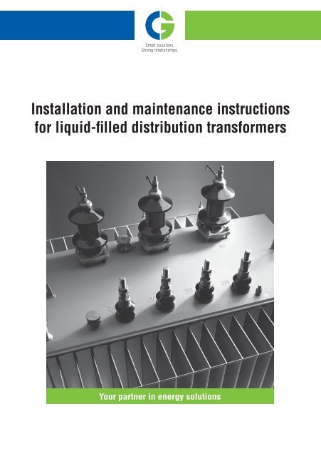
<strong>Installation</strong> <strong>and</strong> <strong>maintenance</strong> <strong>instructions</strong><br />
<strong>for</strong> <strong>liquid</strong>-<strong>filled</strong> distribution trans<strong>for</strong>mers<br />
Your partner in energy solutions<br />
DT_<strong>Installation</strong>_<strong>instructions</strong>_ENG_druk.indd 1 29/10/10 07:40
<strong>Installation</strong> <strong>and</strong> <strong>maintenance</strong> <strong>instructions</strong> <strong>for</strong> <strong>liquid</strong>-<strong>filled</strong> distribution trans<strong>for</strong>mers 2<br />
Version 4 - 01-08-2010.<br />
DT_<strong>Installation</strong>_<strong>instructions</strong>_ENG_druk.indd 2 29/10/10 07:40
Contents<br />
Caution 4<br />
1. Generally applicable conditions 5<br />
1.1. Warranty conditions 5<br />
1.2. Transportation 6<br />
1.2.1. Transportation by truck 6<br />
1.2.2. Transportation by rail or sea 6<br />
1.2.3. Moving distribution trans<strong>for</strong>mers 6<br />
1.2.4. Acceptance procedure 7<br />
1.3. Storage 8<br />
1.3.1. Preparation <strong>and</strong> checking of trans<strong>for</strong>mers be<strong>for</strong>e storage 8<br />
1.3.2. Monitoring <strong>and</strong> checking of trans<strong>for</strong>mers during storage 8<br />
1.3.3. Storage after taken out of operation 9<br />
2. Installing <strong>and</strong> connecting <strong>liquid</strong>-<strong>filled</strong> distribution trans<strong>for</strong>mers 9<br />
2.1. <strong>Installation</strong> 9<br />
2.2. Connections 9<br />
2.3. Earthing 10<br />
3. Putting into operation 11<br />
3.1. External check 11<br />
3.2. Electrical measurements be<strong>for</strong>e putting into operation 12<br />
3.3. Energizing 12<br />
3.4. Parallel operation 14<br />
4. Maintenance 15<br />
4.1. Annual external check 15<br />
4.2. Two-yearly <strong>maintenance</strong> 15<br />
5. Liquid sampling <strong>and</strong> analyses 16<br />
6. CG Power Systems Belgium NV After Sales Service 16<br />
7. Accessories 17<br />
8. St<strong>and</strong>ards 18<br />
9. End of life 19<br />
Annex 1: Insulation resistance measurement (Megger test) 20<br />
Annex 2: Recommended torque values in Nm <strong>for</strong> various connections 21<br />
<strong>Installation</strong> <strong>and</strong> <strong>maintenance</strong> <strong>instructions</strong> <strong>for</strong> <strong>liquid</strong>-<strong>filled</strong> distribution trans<strong>for</strong>mers 3<br />
Version 4 - 01-08-2010.<br />
DT_<strong>Installation</strong>_<strong>instructions</strong>_ENG_druk.indd 3 29/10/10 07:40
CAUTION<br />
When lifting or moving the trans<strong>for</strong>mer, care should be taken to ensure that the bushings, the cooling fins<br />
<strong>and</strong> the other accessories are not damaged by the lifting apparatus, pulling tools or adjacent obstacles.<br />
Be<strong>for</strong>e energizing the trans<strong>for</strong>mer, a basic visual electrical & mechanical component check up should be<br />
completed. Check that:<br />
> The trans<strong>for</strong>mer is not damaged;<br />
> The fins are not damaged;<br />
> There are no oil leaks;<br />
> The paint is not damaged;<br />
> The bushings & accessories are not damaged.<br />
Never open a hermetically sealed trans<strong>for</strong>mer. Please contact our After Sales Service department <strong>for</strong><br />
<strong>instructions</strong>. Never open such a trans<strong>for</strong>mer at oil temperatures higher than 20°C (thermometer pocket<br />
reading) since hot oil may be ejected.<br />
The tap-changer h<strong>and</strong>le must not be operated when the trans<strong>for</strong>mer is energized (must be OFF-CIRCUIT)!<br />
In case of presence of an expansion tank: remove the gasket from the fitted breather or replace the blind<br />
flange <strong>and</strong> install the breather.<br />
Refer to the Technical Data Sheet (TDS) <strong>and</strong> Material Safety Data Sheets (MSDS) <strong>for</strong> all safety measures <strong>and</strong><br />
precautions with regard to fire hazard, exposure to skin or contamination of materials such as the cooling<br />
<strong>liquid</strong> <strong>and</strong> paints.<br />
<strong>Installation</strong> <strong>and</strong> <strong>maintenance</strong> <strong>instructions</strong> <strong>for</strong> <strong>liquid</strong>-<strong>filled</strong> distribution trans<strong>for</strong>mers 4<br />
Version 4 - 01-08-2010.<br />
DT_<strong>Installation</strong>_<strong>instructions</strong>_ENG_druk.indd 4 29/10/10 07:40
1. Generally applicable conditions<br />
We are delighted that you have purchased a CG Power Systems trans<strong>for</strong>mer. It was manufactured using the<br />
latest techniques, tested in full <strong>and</strong> subjected to a thorough final inspection be<strong>for</strong>e delivery. In spite of these<br />
precautions difficulties may still arise during transportation, installation or operation. That is why we advise<br />
you to read the following <strong>instructions</strong> carefully.<br />
A trans<strong>for</strong>mer is an electrical appliance <strong>and</strong> should there<strong>for</strong>e be h<strong>and</strong>led according to the applicable national<br />
safety <strong>instructions</strong>.<br />
Remarks:<br />
This manual applies to <strong>liquid</strong>-<strong>filled</strong> “Distribution Trans<strong>for</strong>mers” which covers the range of trans<strong>for</strong>mers up to<br />
some 5MVA/36kV, not only used <strong>for</strong> distribution of electricity but also <strong>for</strong> energy supply to light industry <strong>and</strong><br />
generator step-up applications.<br />
This range typically uses trans<strong>for</strong>mers with finned tanks. If you have opted <strong>for</strong> a trans<strong>for</strong>mer tank with<br />
radiators, other <strong>instructions</strong> are partly applicable. Consult us about these.<br />
This manual applies to <strong>liquid</strong>-<strong>filled</strong> trans<strong>for</strong>mers in which the <strong>liquid</strong> can either be:<br />
> Mineral oil as per IEC 60296;<br />
> Silicone fluid as per IEC 60836;<br />
> Synthetic ester as per IEC 61099;<br />
> Natural (vegetal) ester as per supplier’s TDS.<br />
1.1. Warranty conditions<br />
The trans<strong>for</strong>mer typically comes with a factory warranty against construction defects that applies <strong>for</strong> 12<br />
months after being put into operation, with a maximum of 18 months after leaving the factory. Any deviations<br />
from this must be established contractually. The warranty is limited to the repair or possible replacement<br />
of the trans<strong>for</strong>mer <strong>and</strong> this repair or replacement does not extend the original warranty. If difficulties arise<br />
during the warranty period <strong>and</strong> afterwards, the service department of CG Power Systems Belgium NV can be<br />
contacted. They will give you the necessary assistance.<br />
In case of any interpretation disputes, the ‘General terms <strong>and</strong> conditions of sale’ of CG Power Systems<br />
Belgium NV shall take precedence over these <strong>instructions</strong> <strong>and</strong> the ‘Special agreements’ shall take precedence<br />
over the ‘General terms <strong>and</strong> conditions of sale’.<br />
<strong>Installation</strong> <strong>and</strong> <strong>maintenance</strong> <strong>instructions</strong> <strong>for</strong> <strong>liquid</strong>-<strong>filled</strong> distribution trans<strong>for</strong>mers 5<br />
Version 4 - 01-08-2010.<br />
DT_<strong>Installation</strong>_<strong>instructions</strong>_ENG_druk.indd 5 29/10/10 07:40
1.2. Transportation<br />
Distribution trans<strong>for</strong>mers are shipped ‘ready <strong>for</strong> installation’, which means <strong>filled</strong> with the insulating <strong>liquid</strong><br />
<strong>and</strong> with accessories fitted (or occasionally supplied separately).<br />
1.2.1. Transportation by truck<br />
The trans<strong>for</strong>mers must be tightly secured at the top <strong>and</strong> bottom on the truck. At the bottom by nailing down<br />
the skid, by using rubber mats or other means; fixed rollers should be clamped. The trans<strong>for</strong>mer must<br />
be tightly secured at the top via the lifting lugs or via special transport securing lugs. If securing straps<br />
are used, make sure they do not pull on the fins or fin rein<strong>for</strong>cements. If the trans<strong>for</strong>mer is fitted with an<br />
expansion tank <strong>and</strong> a silica gel breather, see paragraph 1.2.2. about hermetic sealing.<br />
1.2.2. Transportation by rail or sea<br />
Trans<strong>for</strong>mers are usually packed in sturdy crates, boxes or containers. When packed in crates, the<br />
trans<strong>for</strong>mer’s lifting lugs can be used to lift the entire equipment. Under no circumstances may moisture be<br />
allowed to penetrate into the trans<strong>for</strong>mer. For hermetically sealed trans<strong>for</strong>mers – those with gas cushions<br />
as well as those with integral filling – this is not a problem. The <strong>liquid</strong> cannot come into contact with the<br />
surrounding air. For trans<strong>for</strong>mers with an expansion tank the infiltration of air during transportation <strong>and</strong><br />
storage is prevented by:<br />
> Either placing a gasket in the de-aerator (breather) cap (which must be removed be<strong>for</strong>e the trans<strong>for</strong>mer<br />
is energized);<br />
> Or replacing the silica gel air breather by a blind flange that prevents the infiltration of air. In that case<br />
the air breather is supplied separately. Assembly <strong>instructions</strong> are included with the air breather.<br />
1.2.3. Moving distribution trans<strong>for</strong>mers<br />
In order to move a trans<strong>for</strong>mer the following accessories are required, depending on the trans<strong>for</strong>mer’s size<br />
<strong>and</strong> the directions:<br />
> A set of rollers, the wheels of which can be changed very simply in a longitudinal or diagonal direction;<br />
> Lifting lugs on the main cover;<br />
> Rein<strong>for</strong>cement of the bottom of the trans<strong>for</strong>mer tank allowing transportation by <strong>for</strong>klift, <strong>and</strong>;<br />
> If necessary, upon special request, jacking bosses <strong>and</strong>/or (fixed or detachable) lugs on the roller base or<br />
carriage.<br />
Attention: Never lift a trans<strong>for</strong>mer under the cooler fins. Never use the bushings (high voltage (HV) or<br />
low voltage (LV) insulators) to guide the trans<strong>for</strong>mer when moving it. Nor should the fins or fin<br />
rein<strong>for</strong>cements (round bar on top <strong>and</strong> bottom of the fins) be pulled on.<br />
The securing lugs are not to be used to manipulate the trans<strong>for</strong>mer; they must be used<br />
exclusively to secure the trans<strong>for</strong>mer during transport.<br />
<strong>Installation</strong> <strong>and</strong> <strong>maintenance</strong> <strong>instructions</strong> <strong>for</strong> <strong>liquid</strong>-<strong>filled</strong> distribution trans<strong>for</strong>mers 6<br />
Version 4 - 01-08-2010.<br />
DT_<strong>Installation</strong>_<strong>instructions</strong>_ENG_druk.indd 6 29/10/10 07:40
1.2.4. Acceptance procedure<br />
Upon arrival of a trans<strong>for</strong>mer <strong>and</strong> its accessories everything should be closely inspected.<br />
The following points should be checked:<br />
> Is the crate or box damaged?<br />
> Is there rust or is the paint on the trans<strong>for</strong>mer or its accessories damaged?<br />
> Are the trans<strong>for</strong>mer tank or accessories damaged?<br />
> Are there leaks?<br />
> If the <strong>liquid</strong> level is visible, is it high enough?<br />
> Is the delivery complete? Check the number of trans<strong>for</strong>mers, the number of boxes of accessories <strong>and</strong><br />
check that all accessories are fitted or present;<br />
> Check the in<strong>for</strong>mation on the rating plate.<br />
All deviations should immediately be marked on the delivery note (CMR) <strong>and</strong> should immediately be<br />
reported to CG Power Systems Belgium NV. If no report has been received within 24 hours of arrival at the<br />
customer’s, it shall be assumed that the delivery arrived complete <strong>and</strong> in good condition.<br />
In connection with transportation insurance, the following procedure is to be applied in the event of damage:<br />
> If no transportation by sea preceded transportation by l<strong>and</strong> <strong>and</strong> you did not receive an insurance<br />
certificate:<br />
- Declare the transport company liable by means of a comment on the delivery note <strong>and</strong> a registered<br />
letter;<br />
- Do what is necessary to limit the damage <strong>and</strong> to avoid additional damage;<br />
- In<strong>for</strong>m CG Power Systems Belgium NV.<br />
> If transportation by sea preceded transportation by l<strong>and</strong> <strong>and</strong>/or you received an insurance certificate:<br />
- Follow the <strong>instructions</strong> on the back of the insurance certificate carefully. Do not sign a ‘clean’ proof<br />
of receipt, but record your reservations on these documents;<br />
- In<strong>for</strong>m CG Power Systems Belgium NV.<br />
> In case of transportation by rail: have the authorities at the station the delivery was collected from draw<br />
up a report. This acceptance procedure must be repeated after each transportation stage, so that the<br />
origin of the damage can be established.<br />
<strong>Installation</strong> <strong>and</strong> <strong>maintenance</strong> <strong>instructions</strong> <strong>for</strong> <strong>liquid</strong>-<strong>filled</strong> distribution trans<strong>for</strong>mers 7<br />
Version 4 - 01-08-2010.<br />
DT_<strong>Installation</strong>_<strong>instructions</strong>_ENG_druk.indd 7 29/10/10 07:40
1.3. Storage of trans<strong>for</strong>mers<br />
1.3.1. Preparation <strong>and</strong> checking of trans<strong>for</strong>mers be<strong>for</strong>e storage<br />
> If an air breather is provided, it must be fitted <strong>and</strong> <strong>filled</strong> with dry silica gel. Fill the oil lock <strong>and</strong> fit<br />
it under the air breather. The <strong>liquid</strong> level is checked <strong>and</strong>, if necessary, <strong>liquid</strong> is added. For more<br />
in<strong>for</strong>mation about this, see chapter 4 ‘Maintenance’.<br />
> Any damage to the paint is touched up. Contact CG Power Systems Belgium NV <strong>for</strong> the correct<br />
procedure.<br />
> If a Buchholz relay is provided, the transport protection (test button lock) is removed.<br />
> If an explosion vent is fitted, replace the blank plate by the foil membrane.<br />
Storage is limited to 1 to 2 weeks. If it lasts longer than this, the expansion tank <strong>and</strong>, if provided, the air<br />
breather must be installed <strong>and</strong> the trans<strong>for</strong>mer must be <strong>filled</strong> or topped up with the <strong>liquid</strong> provided. Storage<br />
should preferably occur in a dry, ventilated area, unless the trans<strong>for</strong>mer is protected by a condensation-free<br />
cover.<br />
1.3.2. Monitoring <strong>and</strong> checking of trans<strong>for</strong>mers during storage<br />
Preferably only fully assembled, <strong>liquid</strong>-<strong>filled</strong> trans<strong>for</strong>mers are stored <strong>for</strong> a long period of time. The following<br />
checks must be carried out during storage:<br />
> Check the air breather, if fitted. Check the status of the silica gel (its colour indicates whether it is dry or<br />
wet; see chapter 7 <strong>for</strong> technical data on accessories). Check the level of the oil lock;<br />
> Check the trans<strong>for</strong>mer <strong>for</strong> leaks;<br />
> Check that there is no damage to the paint <strong>and</strong> that there is no rust.<br />
If any defects are established, they should either be remedied immediately or CG Power Systems Belgium<br />
NV should be in<strong>for</strong>med as quickly as possible.<br />
1.3.3. Storage after being taken out of operation<br />
Be<strong>for</strong>e the trans<strong>for</strong>mer is stored, a full check as described in the ‘Acceptance procedure’ paragraph should<br />
take place. Responsibility <strong>for</strong> correct storage lies with the customer. Attention should be paid to the<br />
following:<br />
> The possibility <strong>for</strong> the <strong>liquid</strong> to exp<strong>and</strong> must be guaranteed;<br />
> Contact of the <strong>liquid</strong> with the air must be avoided;<br />
> The trans<strong>for</strong>mer must always be stored <strong>filled</strong> with <strong>liquid</strong>.<br />
<strong>Installation</strong> <strong>and</strong> <strong>maintenance</strong> <strong>instructions</strong> <strong>for</strong> <strong>liquid</strong>-<strong>filled</strong> distribution trans<strong>for</strong>mers 8<br />
Version 4 - 01-08-2010.<br />
DT_<strong>Installation</strong>_<strong>instructions</strong>_ENG_druk.indd 8 29/10/10 07:40
2. Installing <strong>and</strong> connecting <strong>liquid</strong>-<strong>filled</strong> distribution trans<strong>for</strong>mers<br />
During installation the following rules must be followed in order to ensure that the trans<strong>for</strong>mer operates<br />
correctly:<br />
2.1. <strong>Installation</strong><br />
The local regulations <strong>for</strong> installing <strong>liquid</strong>-<strong>filled</strong> trans<strong>for</strong>mers in buildings, on a pole, in a cabinet or in the<br />
open air must be followed to the letter in relation to, among others, fire safety, protection against leaking<br />
(sump or oil-retaining tank), accessibility, electrical regulations,...<br />
The place where the trans<strong>for</strong>mer is set up must be adequately ventilated in order to enable dissipation of<br />
the heat given off by the trans<strong>for</strong>mer. We are at your disposal to do relevant calculations <strong>and</strong> to explain the<br />
precautions that need to be taken. For distribution trans<strong>for</strong>mers set up in buildings or steel sheet substations<br />
this implies a regular supply of fresh air from outside, adequate ventilation <strong>and</strong> enough free space in all<br />
directions around the trans<strong>for</strong>mer.<br />
Liquid sample plug, tap changer <strong>and</strong> any other operating <strong>and</strong> protection equipment must be easily<br />
accessible. Monitoring apparatus such as thermometers must be clearly visible <strong>and</strong>/or readable.<br />
Setting up the trans<strong>for</strong>mer completely parallel with a wall is not advisable as this may increase the noise.<br />
Anti-vibration pads under the wheels may reduce the transfer of noise vibrations to the ground.<br />
The area in which the trans<strong>for</strong>mer is placed must be inaccessible to pets, birds, rodents, ...<br />
We once again remind you that lifting the trans<strong>for</strong>mer under the cooling fins is absolutely <strong>for</strong>bidden. This<br />
will create leaks.<br />
2.2. Connections<br />
Electrical <strong>and</strong> other connections. Always ensure that connection of the cables <strong>and</strong> busbars to the bushings is<br />
done without any tensile <strong>for</strong>ce being exerted on the bushings that can lead to leakage by the gasket or cracks<br />
in the bushings. A flexible connection is highly recommended in all cases. In this way, expansion of the<br />
conductors due to temperature differences cannot lead to leaks or cracks.<br />
<strong>Installation</strong> <strong>and</strong> <strong>maintenance</strong> <strong>instructions</strong> <strong>for</strong> <strong>liquid</strong>-<strong>filled</strong> distribution trans<strong>for</strong>mers 9<br />
Version 4 - 01-08-2010.<br />
DT_<strong>Installation</strong>_<strong>instructions</strong>_ENG_druk.indd 9 29/10/10 07:40
Torque values to be used: see table in Annex 2.<br />
When using plug connections on the HV, the <strong>instructions</strong> of the manufacturer of the connectors are to be<br />
observed.<br />
To avoid any stress on the plug connection, the HV cables should be supported within 50 cm from the plug<br />
connection. The first 50 cm of the cable should not be bended, after this distance the bending radius as per<br />
<strong>instructions</strong> of the cable manufacturer should be respected.<br />
Ensure that all connections have large, solid <strong>and</strong> clean contact surfaces. When connecting different<br />
materials, precautions should be taken to avoid electrolytic couples. These connections can be made using<br />
cable lugs, flat busbars or adapted clamps. Each feeder conductor must have a sufficiently large section.<br />
Whenever the trans<strong>for</strong>mer’s HV <strong>and</strong> LV porcelain bushings are worked on, it must be ensured that the lower<br />
nut on the bushing remains in position. This ensures that the trans<strong>for</strong>mer remains sealed. Use 2 spanners<br />
when tightening the other nuts on the bushing to prevent the bushing from twisting.<br />
2.3. Earthing<br />
The trans<strong>for</strong>mer tank must be connected to the HV earthing system. There<strong>for</strong>e earthing bolts or bosses are<br />
fixed onto the cover, the roller carriage or the base of the trans<strong>for</strong>mer tank. The electrical resistance of the<br />
earthing terminal is usually specified by the power supply company. Ensure that the connection point is kept<br />
clean.<br />
<strong>Installation</strong> <strong>and</strong> <strong>maintenance</strong> <strong>instructions</strong> <strong>for</strong> <strong>liquid</strong>-<strong>filled</strong> distribution trans<strong>for</strong>mers 10<br />
Version 4 - 01-08-2010.<br />
DT_<strong>Installation</strong>_<strong>instructions</strong>_ENG_druk.indd 10 29/10/10 07:40
3. Putting into operation<br />
After setting up <strong>and</strong> connecting the trans<strong>for</strong>mer, the following steps must be carried out sequentially to put it<br />
into operation:<br />
3.1. External check<br />
> Check that the various transport protection measures have been removed: Buchholz test button lock,<br />
air-breather plugs, seal in filler cap of expansion tank, polystyrene blocks in cooling fins, …<br />
> Check the ambient temperature <strong>and</strong> ventilation of the premises.<br />
> Check <strong>for</strong> leaks, rust <strong>and</strong> damage; (check that the drain plug does not leak, that the sampling plug <strong>and</strong><br />
any filter press valves are completely closed).<br />
> Check the setting up <strong>and</strong> operation of the various accessories; dial plates of measuring apparatus <strong>and</strong><br />
the colour of the silica gel in the air-breather, if present, must be visible <strong>and</strong> readable at a safe distance<br />
from the live parts.<br />
> Check the colour of the silica gel (if applicable) since this indicates its dryness. If needed, the silica gel<br />
must be dried or replaced. See the PK-documents listed in chapter 7.<br />
> Check the <strong>liquid</strong> level via the oil level indicator (if applicable).<br />
Attention: Never top up a hermetically sealed trans<strong>for</strong>mer yourself as there may be overpressure or<br />
underpressure in the trans<strong>for</strong>mer tank.<br />
> Check whether bushings, apparatus <strong>and</strong> control units are dirty. They must be clean at all times.<br />
> Open HV <strong>and</strong> LV air-<strong>filled</strong> cable boxes: check <strong>for</strong> condensation, water penetration <strong>and</strong> leaks.<br />
> Check the compound level in the HV cable junction box (if applicable).<br />
> Tighten all bushings <strong>and</strong> electrical connections, including those in the boxes, using a torque spanner;<br />
see chapter 2.2. ‘Connections’.<br />
> Check that the trans<strong>for</strong>mer is properly earthed.<br />
> Remove all <strong>for</strong>eign objects from the conductors, from the cover <strong>and</strong> from the cable boxes. If the<br />
trans<strong>for</strong>mer is located in a distribution station or substation, all <strong>for</strong>eign objects must be removed from<br />
this area.<br />
> In case of dual voltage on the LV <strong>and</strong>/or HV side, check that the connecting strips or change-over<br />
switches are in the correct position to <strong>for</strong>m the required connection group <strong>and</strong> voltage.<br />
<strong>Installation</strong> <strong>and</strong> <strong>maintenance</strong> <strong>instructions</strong> <strong>for</strong> <strong>liquid</strong>-<strong>filled</strong> distribution trans<strong>for</strong>mers 11<br />
Version 4 - 01-08-2010.<br />
DT_<strong>Installation</strong>_<strong>instructions</strong>_ENG_druk.indd 11 29/10/10 07:40
3.2. Electrical measurements be<strong>for</strong>e putting into operation<br />
All trans<strong>for</strong>mers that leave the factory have been submitted to the routine tests <strong>and</strong> measurements in<br />
accordance with IEC 60076, <strong>and</strong> a test certificate is issued.<br />
To electrically test the trans<strong>for</strong>mer again after transportation, setting up or installation, CG Power Systems<br />
Belgium NV specifies the following tests:<br />
> An insulation test using a 2500 or 5000 Volt ‘Megger’ (see Annex 1);<br />
> A continuity test of the connections <strong>and</strong> windings, <strong>and</strong>;<br />
> A check of the auxiliary devices <strong>and</strong> accessories (correct operation, setting <strong>and</strong> checking of the contacts,<br />
cabling, checking of test equipment).<br />
Attention: Never pressurise trans<strong>for</strong>mers to check the pressure valve <strong>and</strong>/or pressure relay.<br />
3.3. Energizing<br />
Energizing should be carried out by an authorized person <strong>and</strong> the locally applicable safety <strong>instructions</strong><br />
should be observed.<br />
Conditions <strong>for</strong> Energizing<br />
The trans<strong>for</strong>mer should be initially energized without load <strong>and</strong> with the tap changer in the position equivalent<br />
to the rated no-load voltage. Measure the voltages between the LV phases themselves <strong>and</strong> to the earth.<br />
For safety reasons we strongly advise against measuring directly on the LV trans<strong>for</strong>mer terminals. If these<br />
voltages deviate from the rated no-load voltage, it can be adjusted (see procedure below). The trans<strong>for</strong>mer is<br />
left with no load <strong>for</strong> a few hours. During this period the sound, temperature <strong>and</strong> <strong>liquid</strong> levels – if visible – are<br />
checked regularly.<br />
> The trans<strong>for</strong>mer may now run under load. A gradually increasing load with intermediate checks is<br />
recommended.<br />
> Adjusting the low voltage. If the voltage on the LV side both at no load <strong>and</strong> under load deviates from the<br />
rated value <strong>and</strong> this must be adjusted, the procedure is as follows:<br />
- De-energize the trans<strong>for</strong>mer at the HV <strong>and</strong> LV side <strong>and</strong> earth it properly;<br />
- Unlock the tap changer by lifting the knob;<br />
- Change the tap changer to the desired position;<br />
- Release the knob until the spring presses it down again <strong>and</strong> thus re-locks the tap changer.<br />
<strong>Installation</strong> <strong>and</strong> <strong>maintenance</strong> <strong>instructions</strong> <strong>for</strong> <strong>liquid</strong>-<strong>filled</strong> distribution trans<strong>for</strong>mers 12<br />
Version 4 - 01-08-2010.<br />
DT_<strong>Installation</strong>_<strong>instructions</strong>_ENG_druk.indd 12 29/10/10 07:40
Low voltage too high (must be decreased)<br />
If the applied high voltage is higher than the rated trans<strong>for</strong>mer high voltage, this results in the low voltage<br />
being too high.<br />
In this case the HV tap changer knob should be put in a position that corresponds to a high voltage that is<br />
higher than the rated high voltage (see rating plate). The tap changer must be set at a lower position number.<br />
Low voltage too low (must be increased)<br />
If the applied high voltage is lower than the rated trans<strong>for</strong>mer high voltage this results in the low voltage<br />
being too low.<br />
In this case the HV tap changer knob should be put in a position that corresponds to a high voltage that is<br />
lower than the rated high voltage (see rating plate). The tap changer must be set at a higher position number.<br />
Increasing low voltage (higher tap changer knob position number compared with reference value)<br />
Decreasing low voltage (lower tap changer knob position number compared with reference value)<br />
Example (see rating plate)<br />
Position no. tap<br />
changer<br />
HV Volt LV Volt<br />
1 15,500<br />
2 15,250<br />
Rated. pos. 3 15,000 400 Rated voltage<br />
4 14,750<br />
5 14,500<br />
<strong>Installation</strong> <strong>and</strong> <strong>maintenance</strong> <strong>instructions</strong> <strong>for</strong> <strong>liquid</strong>-<strong>filled</strong> distribution trans<strong>for</strong>mers 13<br />
Version 4 - 01-08-2010.<br />
DT_<strong>Installation</strong>_<strong>instructions</strong>_ENG_druk.indd 13 29/10/10 07:40
3.4. Parallel operation<br />
When running in parallel, the trans<strong>for</strong>mers must satisfy the relevant regulations <strong>and</strong> conditions (including<br />
IEC 60076-1 <strong>and</strong> IEC 60076-8, see Chapter 4). These are the following:<br />
> Trans<strong>for</strong>mers must have the same clock-hour number. The winding connections may be different;<br />
> Impedance voltages must be the same (a tolerance of maximum 10% is allowed);<br />
> Rated voltages must be equal (both HV <strong>and</strong> LV);<br />
> When continuously running in parallel, the power rating ratio must not exceed 3:1.<br />
The in<strong>for</strong>mation <strong>for</strong> the above conditions can be found on the rating plate.<br />
Be<strong>for</strong>e switching to parallel operation, the following procedure must be followed:<br />
> Connect the corresponding HV terminals;<br />
> Connect the corresponding LV terminals;<br />
> Provide a (preferably common) earthing on both trans<strong>for</strong>mer tanks;<br />
> Connect the LV neutrals;<br />
> Connect the trans<strong>for</strong>mers to the supply system at the HV side. The LV main switches must remain open;<br />
> Check <strong>for</strong> any difference in voltage between the corresponding LV phases. The voltmeter should show<br />
no readings. If, however, there is a difference in voltage, the cause should be traced <strong>and</strong> remedied;<br />
> If there is no difference in voltage between the corresponding LV terminals, the main lower voltage<br />
busbars may be energized at the LV side;<br />
> Parallel operation of/with dual LV trans<strong>for</strong>mers (so-called “seven bushing” trans<strong>for</strong>mers) is not advised;<br />
> If the tap changers are put out of their rated positions, make sure that both set HV values correspond<br />
(see rating plate).<br />
If the above conditions are not satisfied, circulation currents can occur which can lead to damage to the<br />
trans<strong>for</strong>mer. For brief parallel operation (e.g. when switching over) this may be permitted. Consult IEC<br />
60076-8 <strong>for</strong> more details.<br />
We cannot be held liable <strong>for</strong> damage to trans<strong>for</strong>mers or electrical installations caused by faulty connections.<br />
<strong>Installation</strong> <strong>and</strong> <strong>maintenance</strong> <strong>instructions</strong> <strong>for</strong> <strong>liquid</strong>-<strong>filled</strong> distribution trans<strong>for</strong>mers 14<br />
Version 4 - 01-08-2010.<br />
DT_<strong>Installation</strong>_<strong>instructions</strong>_ENG_druk.indd 14 29/10/10 07:40
4. Maintenance<br />
Hermetically sealed distribution trans<strong>for</strong>mers are basically <strong>maintenance</strong> free.<br />
Trans<strong>for</strong>mers with an expansion tank require little <strong>maintenance</strong>.<br />
4.1. Annual external check<br />
This <strong>maintenance</strong> check can be carried out while the trans<strong>for</strong>mer remains energized.<br />
Attention: keep a safe distance from energized (live) parts.<br />
This type of <strong>maintenance</strong> comprises the following:<br />
> Assessing the various noises coming from the trans<strong>for</strong>mer;<br />
> Checking the ambient temperature <strong>and</strong> ventilation of the premises;<br />
> Checking <strong>for</strong> leaks, rust <strong>and</strong> damage;<br />
> Checking <strong>for</strong> dirt on the bushings, apparatus <strong>and</strong> control units;<br />
> Checking the colour of the silica gel (if applicable);<br />
> Checking the <strong>liquid</strong> level via the oil level gauge (if present);<br />
> Checking the <strong>liquid</strong> temperature (if thermometer present);<br />
> Checking local temperature rises due to contact resistances on HV <strong>and</strong> LV connections (infrared<br />
temperature measurement, discolorations, …), <strong>and</strong>;<br />
> Checking if the overpressure relief device has been activated (if present).<br />
4.2. Two-yearly <strong>maintenance</strong><br />
This type of <strong>maintenance</strong> should be carried out while the trans<strong>for</strong>mer is de-energized <strong>and</strong> earthed at the HV<br />
<strong>and</strong> LV sides. Also don’t <strong>for</strong>get to switch off the auxiliary voltage <strong>for</strong> the accessories!<br />
Two-yearly <strong>maintenance</strong> comprises the following:<br />
> Per<strong>for</strong>ming the annual external check (see 4.1.);<br />
> Remedying the comments from the yearly external inspection;<br />
> Checking the compound level in the HV cable junction box (if applicable);<br />
> Opening the HV <strong>and</strong> LV air cable boxes (if applicable), checking <strong>for</strong> condensation <strong>and</strong> water penetration;<br />
> Checking the auxiliary devices <strong>and</strong> accessories (correct operation, setting <strong>and</strong> checking of the contacts,<br />
cabling, checking of test equipment), <strong>and</strong>;<br />
> Checking the correct operation of the tap changer. The tap changer is tested whilst the trans<strong>for</strong>mer is<br />
de-energized by switching the tap changer into various positions <strong>and</strong> by measuring whether there is<br />
continuity in the internal connections.<br />
We advise trans<strong>for</strong>mer users to adjust the above <strong>maintenance</strong> frequency if the trans<strong>for</strong>mers are located in<br />
severe weather conditions <strong>and</strong> if the operating conditions allow or require a different frequency.<br />
<strong>Installation</strong> <strong>and</strong> <strong>maintenance</strong> <strong>instructions</strong> <strong>for</strong> <strong>liquid</strong>-<strong>filled</strong> distribution trans<strong>for</strong>mers 15<br />
Version 4 - 01-08-2010.<br />
DT_<strong>Installation</strong>_<strong>instructions</strong>_ENG_druk.indd 15 29/10/10 07:40
5. Liquid sampling <strong>and</strong> analysis<br />
Analysis of the sample of cooling <strong>liquid</strong> helps determine the condition of the trans<strong>for</strong>mer <strong>liquid</strong> <strong>and</strong> can also<br />
give an indication of the condition of the windings, (tap changer) switch <strong>and</strong> internal connections.<br />
Various <strong>liquid</strong> tests <strong>and</strong> analyses can be per<strong>for</strong>med upon request.<br />
Sampling should best be left up to qualified personnel.<br />
The sampling procedure, described in st<strong>and</strong>ards IEC 60475 <strong>and</strong> IEC 60567, must be followed strictly.<br />
Sampling of hermetically sealed trans<strong>for</strong>mers in service (= energized) is not recommended!<br />
After a sample of the <strong>liquid</strong> has been taken, the level must be checked without opening the trans<strong>for</strong>mer<br />
if possible, <strong>and</strong> if necessary or in case of doubt it must be adjusted by authorised CG Power Systems<br />
personnel.<br />
CG Power Systems advises a 5-yearly <strong>liquid</strong> analysis <strong>for</strong> hermetically sealed trans<strong>for</strong>mers <strong>and</strong> a 2-yearly<br />
<strong>liquid</strong> analysis <strong>for</strong> trans<strong>for</strong>mers with an expansion tank. This can be adjusted if the results obtained indicate<br />
the necessity of this or if operating conditions allow or require it.<br />
Attention: Never top up with another type of <strong>liquid</strong> than the original type of <strong>liquid</strong> in the trans<strong>for</strong>mer!<br />
6. CG Power Systems Belgium NV After Sales Service<br />
For specialized work we recommend you to use the CG Power Systems After Sales Service department. CG<br />
Power Systems offers qualified personnel <strong>and</strong> the necessary equipment to carry out specialized jobs adequately.<br />
Included in specialized work are:<br />
> Replacement of bushings, appliances <strong>and</strong> monitoring equipment;<br />
> Opening the trans<strong>for</strong>mers (trans<strong>for</strong>mer can be under overpressure or underpressure!);<br />
> H<strong>and</strong>ling <strong>and</strong> replacing the cooling <strong>liquid</strong>;<br />
> Sealing off trans<strong>for</strong>mer tank leaks;<br />
> Carrying out electrical measurements <strong>and</strong> their interpretation, <strong>and</strong>;<br />
> Interpretation of analysis of <strong>liquid</strong> samples.<br />
During office hours the After Sales Service can be reached on the following telephone <strong>and</strong> fax numbers:<br />
> Phone +32 15 283 333<br />
> Fax +32 15 283 300<br />
> E-mail: belgium@cgglobal.com <strong>and</strong> services.be@cgglobal.com<br />
Outside office hours, in the event of emergencies, this service is also available via the operator of<br />
CG Power Systems Belgium NV: + 32 15 283 333 <strong>and</strong> +32 15 283 222.<br />
<strong>Installation</strong> <strong>and</strong> <strong>maintenance</strong> <strong>instructions</strong> <strong>for</strong> <strong>liquid</strong>-<strong>filled</strong> distribution trans<strong>for</strong>mers 16<br />
Version 4 - 01-08-2010.<br />
DT_<strong>Installation</strong>_<strong>instructions</strong>_ENG_druk.indd 16 29/10/10 07:40
7. Accessories<br />
At the customer’s request the trans<strong>for</strong>mers can be fitted with a large variety of apparatus <strong>and</strong> control<br />
equipment.<br />
More in<strong>for</strong>mation on this (description, operation, ...) can be found on the PK sheets which are available upon<br />
request.<br />
Documentation: (list not complete)<br />
Valves/taps Oil drain/sampling tap PK 3835<br />
Sampling valve NW 15 PK 3812<br />
Temperature Dial thermometer 2 contacts PK 3544<br />
Dial thermometer without contacts PK 3849<br />
Distance thermometer 2 contacts PK 3546<br />
Thermostat 2 contacts PK 3611<br />
Thermostat 1 contact PK 3612<br />
Liquid level gauges Magnetic oil level 1 1/2” PK 3519<br />
Level gauge expansion tank DIN 42555 PK 3511<br />
Oil level gauge PK 3514<br />
Oil level indicator 1” (float type) PK 3527<br />
Pressure Pressure relief valve 1” PK 3735<br />
Pressure relief relay 2 contacts PK 3733<br />
Expansion tank Buchholz relay BG 25, 2 contacts PK 3710<br />
Air dryer PK 3750<br />
PK 3751<br />
Vent/filling opening of expansion tank DIN 42553<br />
Other DGPT 2 PK 3760<br />
Oil level switch PK 3520<br />
Bushings LV bushings 1 kV EN 50386<br />
LV busbar bushings 1 kV EN 50387<br />
LV bushings 3 kV DIN 42539<br />
HV bushings 12-24-36 kV EN 50180<br />
LV Connectors <strong>for</strong> terminal studs DIN 43675<br />
Current carrying connections up to 1600 A DIN 46200<br />
Plug-in bushings EN 50180<br />
<strong>Installation</strong> <strong>and</strong> <strong>maintenance</strong> <strong>instructions</strong> <strong>for</strong> <strong>liquid</strong>-<strong>filled</strong> distribution trans<strong>for</strong>mers 17<br />
Version 4 - 01-08-2010.<br />
DT_<strong>Installation</strong>_<strong>instructions</strong>_ENG_druk.indd 17 29/10/10 07:40
8. St<strong>and</strong>ards<br />
For more in<strong>for</strong>mation on trans<strong>for</strong>mers in general you can have a look at the following IEC <strong>and</strong> CENELEC<br />
st<strong>and</strong>ards:<br />
IEC 60076 Power Trans<strong>for</strong>mers<br />
> IEC 60076-1 : General<br />
> IEC 60076-2 : Temperature rise<br />
> IEC 60076-3 : Insulation levels, dielectric tests <strong>and</strong> external clearances in air<br />
> IEC 60076-5 : Ability to withst<strong>and</strong> short-circuit<br />
> IEC 60076-7 : Loading guide <strong>for</strong> oil-immersed power trans<strong>for</strong>mers<br />
> IEC 60076-8 : Application guide<br />
> IEC 60076-10 : Determination of sound levels<br />
IEC 60616 Terminal & tapping markings <strong>for</strong> power trans<strong>for</strong>mers<br />
IEC 60296 Specification <strong>for</strong> unused mineral insulating oils <strong>for</strong> trans<strong>for</strong>mers <strong>and</strong> switchgear<br />
IEC 60422 Supervision <strong>and</strong> <strong>maintenance</strong> guide <strong>for</strong> mineral insulating oils in electrical equipment<br />
IEC 60475 Method of sampling <strong>liquid</strong> dielectrics<br />
IEC 60567 Guide <strong>for</strong> the sampling of gases <strong>and</strong> of oil from oil-<strong>filled</strong> electrical equipment <strong>and</strong> <strong>for</strong><br />
the analysis of free <strong>and</strong> dissolved gases<br />
IEC 60599 Mineral oil-impregnated electrical equipment in service - Guide to the interpretation<br />
of dissolved <strong>and</strong> free gases analysis<br />
IEC 60836 Specifications <strong>for</strong> silicone <strong>liquid</strong>s <strong>for</strong> electrical purposes<br />
IEC 60944 Guide <strong>for</strong> the <strong>maintenance</strong> of silicone trans<strong>for</strong>mer <strong>liquid</strong>s<br />
IEC 61099 Specification <strong>for</strong> unused synthetic organic esters <strong>for</strong> electrical purposes<br />
IEC 61203 Synthetic organic esters <strong>for</strong> electrical purposes - Guide <strong>for</strong> <strong>maintenance</strong> of<br />
trans<strong>for</strong>mer esters in equipment<br />
EN 60076 Identical to IEC 60076<br />
EN 50180 Bushings above 1kV up to 36kV <strong>and</strong> from 250A to 3150A <strong>for</strong> <strong>liquid</strong>-<strong>filled</strong> trans<strong>for</strong>mers<br />
EN 50216 Power trans<strong>for</strong>mer <strong>and</strong> reactor fittings<br />
EN 50464 Three-phase oil-immersed distribution trans<strong>for</strong>mers 50Hz, from 50 to 2500kVA with<br />
highest voltage <strong>for</strong> equipment not exceeding 36kV<br />
EN 50386 Bushings up to 1kV <strong>and</strong> from 250A to 5kA <strong>for</strong> <strong>liquid</strong>-<strong>filled</strong> trans<strong>for</strong>mers<br />
<strong>Installation</strong> <strong>and</strong> <strong>maintenance</strong> <strong>instructions</strong> <strong>for</strong> <strong>liquid</strong>-<strong>filled</strong> distribution trans<strong>for</strong>mers 18<br />
Version 4 - 01-08-2010.<br />
DT_<strong>Installation</strong>_<strong>instructions</strong>_ENG_druk.indd 18 29/10/10 07:40
9. ENd Of LIfE<br />
The trans<strong>for</strong>mer is constructed in such a way that the different components can easily be recycled at the end<br />
of its life span.<br />
However, the components can only be recycled after the cooling <strong>liquid</strong> has been drained. The latter should be<br />
done with great care.<br />
The indicative relation between the different trans<strong>for</strong>mer materials is the following:<br />
> Cooling <strong>liquid</strong> 25%<br />
> Core material 35%<br />
> Winding material (copper <strong>and</strong>/or aluminium) 15%<br />
> Steel 20%<br />
> Insulation material 5%<br />
The insulation material is to be regarded as non-toxic waste. The trans<strong>for</strong>mer does not contain any PCBs, or<br />
PCTs, PCBTs or asbestos.<br />
<strong>Installation</strong> <strong>and</strong> <strong>maintenance</strong> <strong>instructions</strong> <strong>for</strong> <strong>liquid</strong>-<strong>filled</strong> distribution trans<strong>for</strong>mers 19<br />
Version 4 - 01-08-2010.<br />
DT_<strong>Installation</strong>_<strong>instructions</strong>_ENG_druk.indd 19 29/10/10 07:40
Annex 1: Insulation resistance measurement (Megger test)<br />
The Megger test measures the insulation resistance between the HV <strong>and</strong> LV windings <strong>and</strong> between the<br />
windings <strong>and</strong> the earth. Any short-circuit to the earth or low insulation resistance due to the presence of<br />
water in oil <strong>and</strong> windings or because of a high dissipation factor of the <strong>liquid</strong> can be detected in this way.<br />
The following <strong>instructions</strong> shall be observed when carrying out this measurement:<br />
> Remove HV <strong>and</strong> LV connections from the bushings;<br />
> Clean the bushings;<br />
> Carry out the measurement in dry conditions (no rain, fog, snow,…);<br />
> Carry out the measurement by measuring directly on the trans<strong>for</strong>mer terminals;<br />
> After each measurement the trans<strong>for</strong>mer should be discharged (extremely dangerous capacitive<br />
voltage!);<br />
> The trans<strong>for</strong>mer tank must be correctly connected to the earth.<br />
Measuring procedure:<br />
3 measurements are carried out, preferably with an electronic megger.<br />
For use <strong>and</strong> settings of the measuring device <strong>and</strong> to read (*) the scale values: check the appropriate manual.<br />
> HV to earth with 5000 or 2500 Volt (**)<br />
> LV to earth with 2500 Volt (**), <strong>and</strong><br />
> HV to LV with 5000 or 2500 Volt (**)<br />
(*) Value should be read when the meter needle is stable (generally after 1 minute).<br />
(**) The voltage applied during megger testing must never exceed the test voltage of the trans<strong>for</strong>mer.<br />
Measurement may be carried out on any HV <strong>and</strong> LV phase as the three phases are interconnected internally.<br />
If the values measured are less than 10 MOhm / kV, the cause must be established.<br />
For example:<br />
For a trans<strong>for</strong>mer with a rated high voltage of 15 kV the values must be minimum 10 x 15 = 150 MOhm (also<br />
<strong>for</strong> the low voltage).<br />
<strong>Installation</strong> <strong>and</strong> <strong>maintenance</strong> <strong>instructions</strong> <strong>for</strong> <strong>liquid</strong>-<strong>filled</strong> distribution trans<strong>for</strong>mers 20<br />
Version 4 - 01-08-2010.<br />
DT_<strong>Installation</strong>_<strong>instructions</strong>_ENG_druk.indd 20 29/10/10 07:40<br />
Ann<br />
Thread<br />
Spann<br />
Torque<br />
A/ Bu<br />
Low v<br />
1. Fixi<br />
2. Con<br />
3. Fixi<br />
in<br />
-<br />
4. Con<br />
(Bo<br />
5. Con<br />
Wit<br />
High<br />
1. Fixi<br />
(ter<br />
2. Con<br />
(ter<br />
3. Fixi<br />
(stu<br />
Wit<br />
B/ LV<br />
Inter<br />
C/ Lid<br />
Bol<br />
d/ Bu<br />
Fixi<br />
Top<br />
E/ Va<br />
Gas<br />
(bo<br />
f/ fla<br />
Gas<br />
(bo<br />
G/ Co<br />
Thr<br />
was
Annex 2: Recommended torque values <strong>for</strong> various connections<br />
Thread size M6 M8 M10 M12 M16 M20 M30 M42 M48 > M55<br />
Spanner size 10 13 17 19 24 30 46 65 75 75/85<br />
Torque Nm Nm Nm Nm Nm Nm Nm Nm Nm Nm<br />
A/ Bushings<br />
Low voltage (LV) 250A 630A<br />
1000A/<br />
1250A<br />
1800A/<br />
2000A<br />
<strong>Installation</strong> <strong>and</strong> <strong>maintenance</strong> <strong>instructions</strong> <strong>for</strong> <strong>liquid</strong>-<strong>filled</strong> distribution trans<strong>for</strong>mers 21<br />
Version 4 - 01-08-2010.<br />
3150A<br />
4000 A/<br />
4500 A<br />
1. Fixing of bushing stem (13a) :<br />
dIN 42530 7-12 25-40 65-100 100-150 100-150 100-150<br />
EN 50386 with buna <strong>and</strong> cork 12 20 55-60 70-75 100-120 125-145<br />
2. Connection between nuts (13b/c) 15-20 70-100 250-350<br />
3. Fixing of flag connector to terminal stem (bolt<br />
in stainless steel) (6a)<br />
25-35 40-60 90-120<br />
- with cup washer 50-70<br />
4. Connection to flag surface (6b)<br />
(Bolts 8.8 steel)<br />
40-50 65-85 100-180<br />
5. Connection monobloc on frame<br />
With buna <strong>and</strong> cork 20-30<br />
High Voltage (HV)<br />
1. Fixing of top terminal stem (9a) 10-15 22-55<br />
(terminal <strong>and</strong> nut in brass)<br />
2. Connection to terminal stem (9 b/c) 15-20<br />
(terminal stud <strong>and</strong> 2 nuts in brass)<br />
3. Fixing of base (12)<br />
(stud <strong>and</strong> nut in stainless steel)<br />
With buna <strong>and</strong> cork 10-20 20-35<br />
B/ LV connecting busbar<br />
Interconnection (bolt in 8.8 steel) 40-50 65-85 100-180<br />
C/ Lid / frame<br />
Bolt <strong>and</strong> nut in stainless steel 20-25 40-60<br />
d/ Busbar bushings<br />
Fixing on the lid 8-15 25-40<br />
Top piece onto bottom piece (M6) 3.5 10 20<br />
E/ Valves<br />
Gasket IT<br />
(bolt <strong>and</strong> nut A2 with cup washer) 100-130<br />
f/ flanges<br />
Gasket IT<br />
(bolt <strong>and</strong> nut A2 with cup washer) 100-130<br />
G/ Connection box on cover<br />
Threaded stud <strong>and</strong> nut A2 with cup<br />
washer<br />
12-15<br />
DT_<strong>Installation</strong>_<strong>instructions</strong>_ENG_druk.indd 21 29/10/10 07:40
Remark:<br />
Min Value : Checking torque - Max Value : max applied torque<br />
(If the torque that you measure is lower than Min Value -> re-apply Max torque Value)<br />
Checking recommended torque values is required:<br />
> When installing the trans<strong>for</strong>mer;<br />
> When connecting the cables <strong>and</strong>/or bars to the HV/LV connectors of the trans<strong>for</strong>mer;<br />
> When carrying out <strong>maintenance</strong> work.<br />
We recommend re-applying Max. Torque Value 4 weeks after replacement of the gaskets.<br />
LV<br />
<strong>Installation</strong> <strong>and</strong> <strong>maintenance</strong> <strong>instructions</strong> <strong>for</strong> <strong>liquid</strong>-<strong>filled</strong> distribution trans<strong>for</strong>mers 22<br />
Version 4 - 01-08-2010.<br />
DT_<strong>Installation</strong>_<strong>instructions</strong>_ENG_druk.indd 22 29/10/10 07:40<br />
LV<br />
HV
<strong>Installation</strong> <strong>and</strong> <strong>maintenance</strong> <strong>instructions</strong> <strong>for</strong> <strong>liquid</strong>-<strong>filled</strong> distribution trans<strong>for</strong>mers 23<br />
Version 4 - 01-08-2010.<br />
DT_<strong>Installation</strong>_<strong>instructions</strong>_ENG_druk.indd 23 29/10/10 07:40
Contact After Sales Service during office hours:<br />
> Phone +32 15 283 333<br />
> Fax +32 15 283 300<br />
> E-mail: belgium@cgglobal.com <strong>and</strong> services.be@cgglobal.com<br />
Outside office hours, in the event of emergencies, this service is also available<br />
via the operator of CG Power Systems Belgium NV: + 32 15 283 333 <strong>and</strong> +32 15 283 222.<br />
DT_<strong>Installation</strong>_<strong>instructions</strong>_ENG_druk.indd 24 29/10/10 07:40


