Computer Vision: Mosaics
Computer Vision: Mosaics
Computer Vision: Mosaics

Create successful ePaper yourself
Turn your PDF publications into a flip-book with our unique Google optimized e-Paper software.
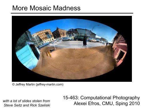
More Mosaic Madness<br />
© Jeffrey Martin (jeffrey-martin.com)<br />
with a lot of slides stolen from<br />
Steve Seitz and Rick Szeliski<br />
15-463: Computational Photography<br />
Alexei Efros, CMU, Sping 2010
Homography<br />
A: Projective – mapping between any two PPs with the<br />
same center of projection<br />
• rectangle should map to arbitrary quadrilateral<br />
• parallel lines aren’t<br />
• but must preserve straight lines<br />
• same as: project, rotate, reproject<br />
called Homography<br />
wx'<br />
wy'<br />
w<br />
p’<br />
*<br />
*<br />
*<br />
*<br />
*<br />
*<br />
*<br />
*<br />
*<br />
x<br />
y<br />
1<br />
H p<br />
To apply a homography H<br />
• Compute p’ = Hp (regular matrix multiply)<br />
• Convert p’ from homogeneous to image<br />
coordinates<br />
PP1<br />
PP2
Rotational <strong>Mosaics</strong><br />
Can we say something more about rotational mosaics?<br />
i.e. can we further constrain our H?
3D → 2D Perspective Projection<br />
K<br />
f<br />
u c<br />
u<br />
(X c,Y c,Z c)
3D Rotation Model<br />
Projection equations<br />
1. Project from image to 3D ray<br />
(x 0,y 0,z 0) = (u 0-u c,v 0-v c,f)<br />
2. Rotate the ray by camera motion<br />
(x 1,y 1,z 1) = R 01 (x 0,y 0,z 0)<br />
3. Project back into new (source) image<br />
(u 1,v 1) = (fx 1/z 1+u c,fy 1/z 1+v c)<br />
Therefore:<br />
H<br />
K<br />
0<br />
R<br />
01<br />
K<br />
1<br />
1<br />
(x,y,z)<br />
R<br />
(x,y,z)<br />
Our homography has only 3,4 or 5 DOF, depending if<br />
focal length is known, same, or different.<br />
• This makes image registration much better behaved<br />
f<br />
(u,v,f)<br />
(u,v,f)
Pairwise alignment<br />
Procrustes Algorithm [Golub & VanLoan]<br />
Given two sets of matching points, compute R<br />
pi’ = R pi with 3D rays<br />
pi = N(xi,yi,zi) = N(ui-uc,vi-vc,f) A = Σ i p i p i’ T = Σ i p i p i T R T = U S V T = (U S U T ) R T<br />
V T = U T R T<br />
R = V U T
Rotation about vertical axis<br />
What if our camera rotates on a tripod?<br />
What’s the structure of H?
Do we have to project onto a plane?<br />
mosaic PP
Full Panoramas<br />
What if you want a 360 field of view?<br />
mosaic Projection Cylinder
Cylindrical projection<br />
Y<br />
Z<br />
X<br />
unit cylinder<br />
unwrapped cylinder<br />
• Map 3D point (X,Y,Z) onto cylinder<br />
• Convert to cylindrical coordinates<br />
• Convert to cylindrical image coordinates<br />
cylindrical image
Y<br />
Cylindrical Projection<br />
X
Inverse Cylindrical projection<br />
Y<br />
Z<br />
X<br />
(X,Y,Z)<br />
(sin ,h,cos )
Cylindrical panoramas<br />
Steps<br />
• Reproject each image onto a cylinder<br />
• Blend<br />
• Output the resulting mosaic
Cylindrical image stitching<br />
What if you don’t know the camera rotation?<br />
• Solve for the camera rotations<br />
– Note that a rotation of the camera is a translation of the cylinder!
Assembling the panorama<br />
Stitch pairs together, blend, then crop
Problem: Drift<br />
Vertical Error accumulation<br />
• small (vertical) errors accumulate over time<br />
• apply correction so that sum = 0 (for 360 pan.)<br />
Horizontal Error accumulation<br />
• can reuse first/last image to find the right panorama radius
Full-view (360 ) panoramas
Spherical projection<br />
Y<br />
Z<br />
X<br />
unwrapped sphere<br />
• Map 3D point (X,Y,Z) onto sphere<br />
( xˆ<br />
, yˆ<br />
, zˆ<br />
)<br />
• Convert to spherical coordinates<br />
X<br />
• Convert to spherical image coordinates<br />
1<br />
spherical image<br />
2<br />
Y<br />
2<br />
Z<br />
2<br />
( X , Y , Z)<br />
(sin cos sin cos cos xˆ<br />
, yˆ<br />
, zˆ<br />
)
Y<br />
Spherical Projection<br />
X
Inverse Spherical projection<br />
Y<br />
Z<br />
X<br />
(x,y,z)<br />
(sinθcosφ,cosθcosφ,sinφ)<br />
φ<br />
sin φ<br />
cos φ<br />
cos θ cos φ
3D rotation<br />
Rotate image before placing on<br />
unrolled sphere<br />
(x,y,z)<br />
(sinθcosφ,cosθcosφ,sinφ)<br />
p = R p<br />
φ<br />
sin φ<br />
cos φ<br />
cos θ cos φ<br />
_ _<br />
_ _
Full-view Panorama<br />
+<br />
+<br />
+<br />
+
Other projections are possible<br />
You can stitch on the plane and then warp the resulting panorama<br />
• What’s the limitation here?<br />
Or, you can use these as stitching surfaces<br />
• But there is a catch…
Cylindrical reprojection<br />
top-down view Focal length – the dirty secret…<br />
Image 384x300<br />
f = 180 (pixels)<br />
f = 280<br />
f = 380
What’s your focal length, buddy?<br />
Focal length is (highly!) camera dependant<br />
• Can get a rough estimate by measuring FOV:<br />
• Can use the EXIF data tag (might not give the right thing)<br />
• Can use several images together and try to find f that would<br />
make them match<br />
• Can use a known 3D object and its projection to solve for f<br />
• Etc.<br />
There are other camera parameters too:<br />
• Optical center, non-square pixels, lens distortion, etc.
Distortion<br />
Radial distortion of the image<br />
• Caused by imperfect lenses<br />
No distortion Pin cushion Barrel<br />
• Deviations are most noticeable for rays that pass through the<br />
edge of the lens
Radial distortion<br />
Correct for “bending” in wide field of view lenses<br />
Use this instead of normal projection
Polar Projection<br />
Extreme “bending” in ultra-wide fields of view
Camera calibration<br />
Determine camera parameters from known 3D points or<br />
calibration object(s)<br />
1. internal or intrinsic parameters such as focal length,<br />
optical center, aspect ratio:<br />
what kind of camera?<br />
2. external or extrinsic (pose) parameters:<br />
where is the camera in the world coordinates?<br />
• World coordinates make sense for multiple cameras /<br />
multiple images<br />
How can we do this?
Approach 1: solve for projection matrix<br />
Place a known object in the scene<br />
• identify correspondence between image and scene<br />
• compute mapping from scene to image
Direct linear calibration<br />
Solve for Projection Matrix using least-squares (just<br />
like in homework)<br />
Advantages:<br />
• All specifics of the camera summarized in one matrix<br />
• Can predict where any world point will map to in the image<br />
Disadvantages:<br />
• Doesn’t tell us about particular parameters<br />
• Mixes up internal and external parameters<br />
– pose specific: move the camera and everything breaks
Approach 2: solve for parameters<br />
A camera is described by several parameters<br />
• Translation T of the optical center from the origin of world coords<br />
• Rotation R of the image plane<br />
• focal length f, principle point (x’ c, y’ c), pixel size (s x, s y)<br />
• blue parameters are called “extrinsics,” red are “intrinsics”<br />
Projection equation<br />
x<br />
sx<br />
sy<br />
s<br />
*<br />
*<br />
*<br />
*<br />
*<br />
*<br />
ΠX<br />
• The projection matrix models the cumulative effect of all parameters<br />
• Useful to decompose into a series of operations<br />
Π<br />
fs<br />
0<br />
0<br />
x<br />
0<br />
fs<br />
0<br />
y<br />
x'<br />
y'<br />
1<br />
c<br />
c<br />
1<br />
0<br />
0<br />
*<br />
*<br />
*<br />
0<br />
1<br />
0<br />
*<br />
*<br />
*<br />
0<br />
0<br />
1<br />
X<br />
Y<br />
Z<br />
1<br />
0<br />
0<br />
0<br />
R<br />
0<br />
3x3<br />
1x3<br />
03x1 I3<br />
x3<br />
T3<br />
1 0 1<br />
1x3<br />
intrinsics projection rotation translation<br />
• Solve using non-linear optimization<br />
x1<br />
identity matrix
Multi-plane calibration<br />
Advantage<br />
Images courtesy Jean-Yves Bouguet, Intel Corp.<br />
• Only requires a plane<br />
• Don’t have to know positions/orientations<br />
• Good code available online!<br />
– Intel’s OpenCV library: http://www.intel.com/research/mrl/research/opencv/<br />
– Matlab version by Jean-Yves Bouget:<br />
http://www.vision.caltech.edu/bouguetj/calib_doc/index.html<br />
– Zhengyou Zhang’s web site: http://research.microsoft.com/~zhang/Calib/