Heat Transfer in Gas-Solid Packed Bed Systems. 2. The Conduction ...
Heat Transfer in Gas-Solid Packed Bed Systems. 2. The Conduction ...
Heat Transfer in Gas-Solid Packed Bed Systems. 2. The Conduction ...

Create successful ePaper yourself
Turn your PDF publications into a flip-book with our unique Google optimized e-Paper software.
40 Ind. Eng. Chem. Process Des. Dev., Vol. 18, No. 1, 1979<br />
Gupta, A. S., Thodos, G., Ind. Eng. Chem. Fundam., 3, 218 (1964).<br />
Hallmann, V. W., Paas. G., Wolpert, H. D., Vai. Tech., 6, 169 (1973).<br />
Houghen. J. O., Piret, E. L., Chem. Eng. Prog., 47, 295 (1951).<br />
Kunii, D., Sujuki, M., Int. J. <strong>Heat</strong> Mass <strong>Transfer</strong>, IO, 884 (1967).<br />
Leva, M., Ind. Eng. Chem.. 39, 857 (1947).<br />
Leva, M., Grummer, M., Ind. fng. Chem., 40, 415 (1948).<br />
Leva, M., We<strong>in</strong>traub, M., Grummer, M.. Clark, E. L., Ind. Eng. Chem.. 40, 747<br />
(1948).<br />
L<strong>in</strong>dauer, G. C., AIChE J., 13, 1181 (1967).<br />
Nelson, P. A., Galloway, T. R.. Chem. fng. Sci., 30, 1 (1975).<br />
Plautz, D. A,, Johnstone, H. F., AIChE J., 1, 193 (1955).<br />
Ranz, W. E., Chem. Eng. Prog., 48, 247 (1952).<br />
Rowe, P. N., Chem. fng. Sci., 30, 7 (1975).<br />
Schumann, T. E. W., Voss, V., J. Fuel, 13, 249 (1934).<br />
S<strong>in</strong>ger. E., Wilhelm, R. H., Cbem. Eng. Prog., 46, 343 (1950).<br />
Sorenson, J. P., Stewart, W. E., Chem. Eng. Sci., 29, 827 (1974).<br />
Verschoor, H., Schuit, G. C. A., Appl. Sci. Res., 42, (Part A2, No. 2), 97 (1950).<br />
Votruba. J., S<strong>in</strong>kule, J., Hlavacek, V.. Skrivarek, J., Chem. Eng. Sci., 30, 117<br />
(1975a).<br />
Votruba, J.. Mikus, O., Nguen, K., Hhvacek, V., Skrivanek. J., Chem. fng. Sci.,<br />
30, 201 (1975b).<br />
Wakao, N., Kato, K., J. Chem. Eng. Jpn., 2, 24 (1969).<br />
Wakao, N., Vortmeyer, D., Chem. Eng. Sci., 26, 1753 (1971).<br />
Wakao, N., Takano. Y.. Pei, D. C. T., J. Chem. Eng. Jpn., 6, 269 (1973).<br />
Wilhelm, R. H., Johnson, W. C., Wynkoop, R., Coll<strong>in</strong>, D. W., Chem. Eng. Prog.,<br />
44, 105 (1948).<br />
Yagi, S., Kunii, D., AIChEJ., 3, 373 (1957).<br />
Yagi, S., Kunii, D., Wakao, N., AICh€ J., 6, 543 (1960).<br />
Yovanovich, M. M., ASME Paper 73-HT-43, ASME-AIChE <strong>Heat</strong> <strong>Transfer</strong><br />
Conference, Atlanta, Ga., 1973.<br />
<strong>Heat</strong> <strong>Transfer</strong> <strong>in</strong> <strong>Gas</strong>-<strong>Solid</strong> <strong>Packed</strong> <strong>Bed</strong> <strong>Systems</strong>. <strong>2.</strong><br />
<strong>The</strong> <strong>Conduction</strong> Mode<br />
Arcot R. Balakrishnan and David C. T. Pei'<br />
Department of Chemical Eng<strong>in</strong>eer<strong>in</strong>g, University of Waterloo, Waterloo, Ontario, Canada N2L 3G I<br />
Received for review February 3, 1977<br />
Accepted July 6, 1978<br />
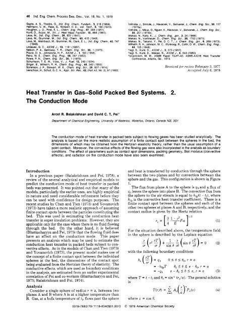
<strong>The</strong> conduction mode of heat transfer <strong>in</strong> packed beds subject to flow<strong>in</strong>g gases has been studied analytically. <strong>The</strong><br />
analysis is based on the more realistic assumption of a f<strong>in</strong>ite contact spot between the spheres <strong>in</strong> the bed, the<br />
dimensions of which may be obta<strong>in</strong>ed from the Hertzian elasticity theory, rather than the usual assumption of a<br />
po<strong>in</strong>t contact. Moreover, the convective effects of the flow<strong>in</strong>g gas were also <strong>in</strong>corporated <strong>in</strong> the analysis as boundary<br />
conditions. <strong>The</strong> effect of parameters such as contact spot dimensions, pack<strong>in</strong>g geometry, Biot modulus (convective<br />
effects), and radiation on the conduction mode have also been exam<strong>in</strong>ed.<br />
Introduction<br />
In a previous paper (Balakrishnan and Pei, 1978), a<br />
review of the several analytical and empirical models to<br />
predict the conduction mode of heat transfer <strong>in</strong> packed<br />
beds was presented. It was po<strong>in</strong>ted out that many of the<br />
models, particularly the earlier ones, are highly empirical<br />
<strong>in</strong> nature and need considerable ref<strong>in</strong>ement before they<br />
can be used with confidence for design purposes. <strong>The</strong><br />
recent studies by Chan and Tien (1973) and Yovanovich<br />
(1973) have taken a more realistic approach of assum<strong>in</strong>g<br />
f<strong>in</strong>ite contact spots between the particles constitut<strong>in</strong>g the<br />
bed. This was used <strong>in</strong> estimat<strong>in</strong>g the conduction heat<br />
transfer <strong>in</strong> super <strong>in</strong>sulation problems. However, they are<br />
applicable only for the case where there is no fluid flow<strong>in</strong>g<br />
through the bed. On the other hand, it is believed<br />
(Bhattacharyya and Pei, 1975) that the flow<strong>in</strong>g fluid does<br />
have an effect on the conduction mode. This paper<br />
presents an analysis which may he used to estimate the<br />
conduction heat transfer <strong>in</strong> packed beds subject to con-<br />
vective effects. As <strong>in</strong> the models of Chan and Tien (1973)<br />
and Yovanovich (1973), the present model makes use of<br />
the concept of a f<strong>in</strong>ite contact spot between the <strong>in</strong>dividual<br />
spheres <strong>in</strong> the bed, the dimensions of the contact spot<br />
be<strong>in</strong>g evaluated from the Hertzian theory of elasticity. <strong>The</strong><br />
conductive effects, which are used as boundary conditions<br />
<strong>in</strong> the analysis, are estimated from an earlier experimental<br />
correlation of Pei and co-workers (Bhattacharyya and Pei,<br />
1975; Balakrishnan and Pei, 1974).<br />
Analysis<br />
Consider a s<strong>in</strong>gle sphere of radius r = a, between two<br />
planes A and B where A is at a higher temperature than<br />
B. <strong>Gas</strong>, at a bulk temperature of tf, flows past the sphere<br />
and heat is transferred by conduction through the sphere<br />
between the two planes and by convection between the<br />
sphere and the gas. This configuration is shown <strong>in</strong> Figure<br />
1.<br />
<strong>The</strong> flux from plane A to the sphere is qo and a flux of<br />
q1 leaves the sphere <strong>in</strong>to plane B. <strong>The</strong> convective flux from<br />
the sphere to the air stream is equal to hfp(t - tf), where<br />
hfp is the convective heat transfer coefficient. <strong>The</strong>re is a<br />
f<strong>in</strong>ite contact spot between the spheres and each of the<br />
other two spheres at planes A and B, respectively, and the<br />
contact radius is given by the Hertz relation<br />
For the situation described above, the temperature field<br />
<strong>in</strong> the sphere is described by the Laplace equation<br />
with the follow<strong>in</strong>g boundary conditions<br />
= -hfpT<br />
= -ql<br />
0, 5 0 5 R - Bo, r = a<br />
A- 0, 5 0 I R, r = a (3)<br />
where T = t - tf and 6'" = s<strong>in</strong>-' (rJa). <strong>The</strong> general solution<br />
is<br />
where x = cos 0.<br />
0019-7882/79/1118-0040$01.00/0 @ 1978 American Chemical Society<br />
(4)
-.-E c<br />
Figure 1. Coord<strong>in</strong>ates for the analysis.<br />
A, is determ<strong>in</strong>ed us<strong>in</strong>g all the boundary conditions <strong>in</strong><br />
eq 3 and utiliz<strong>in</strong>g the orthogonality properties of Legendre<br />
polynomials; i.e.<br />
From the orthogonality properties of Legendre polynomials<br />
it follows that<br />
-2<br />
.lPn2(x) dx = -.I__<br />
2n + 1<br />
Moreover, s<strong>in</strong>ce xo is very close to unity (as Bo is small),<br />
the follow<strong>in</strong>g approximation may be made (Balakrishnan,<br />
1976)<br />
-2<br />
L?;(X) dx = ~<br />
2n + 1<br />
and furthermore, by def<strong>in</strong>ition<br />
L:P,(x) dx = -~<br />
Equation 5 then reduces to<br />
1 Cn<br />
2n + 1 [Pn-,(X,) - Pn+1(~0)1 =<br />
(8)<br />
2 40 cn 41 (-cn) hfP<br />
A, -*<br />
2n + 1 k, 2n + 1 k, 271 + 1 ks<br />
2<br />
2n + 1<br />
and, therefore, the solution to eq 12 with boundary<br />
conditions is<br />
where Bi = hfp-a/k,, which is the Biot modulus.<br />
By def<strong>in</strong>ition, the thermal resistance of the sphere is<br />
given by<br />
T(a,O) - T(a,n)<br />
R-A1 =<br />
cu 40 + 41<br />
rrc2<br />
2a .f<br />
Rcdl = --<br />
k, rrc2 n=l<br />
d<br />
Pzn-Axo) - PZn(X0)<br />
(2n - 1) + Bi<br />
(10)<br />
<strong>The</strong> resistance of a cubical volume of side 2a, just enclos<strong>in</strong>g<br />
one of the spheres <strong>in</strong> the bed, is also Rcdl. (This is because<br />
the only solid phase <strong>in</strong> this cube through which conduction<br />
can take place is the sphere.) <strong>The</strong> effective thermal<br />
Ind. Eng. Chem. Process Des. Dev., Vol. 18, No. 1, 1979 41<br />
conductivity of the bed, k,, can hence be def<strong>in</strong>ed by a heat<br />
balance on the cube (the cube be<strong>in</strong>g a part of the bed has<br />
the same k,)<br />
<strong>The</strong> conduction heat transfer coefficient, hcd, may be<br />
obta<strong>in</strong>ed from the def<strong>in</strong>ition<br />
<strong>The</strong>refore, the conduction heat transfer per layer of<br />
spheres <strong>in</strong> the bed is<br />
<strong>The</strong> correspond<strong>in</strong>g Nusselt number is def<strong>in</strong>ed as<br />
<strong>The</strong> conduction heat transfer coefficient obta<strong>in</strong>ed by eq<br />
12 can now be used <strong>in</strong> obta<strong>in</strong><strong>in</strong>g the total heat transfer <strong>in</strong><br />
packed beds subject to gas flow. <strong>The</strong>refore, the validity<br />
of this analysis can be substantiated by compar<strong>in</strong>g the total<br />
heat transfer so obta<strong>in</strong>ed with experimental data on total<br />
heat transfer of packed beds subject to flow<strong>in</strong>g gas. This<br />
will be dealt with <strong>in</strong> part 3 of this series.<br />
Parameter Studies<br />
It is apparent that the conduction coefficient, hcd, as<br />
derived <strong>in</strong> the analysis will depend on a variety of pa-<br />
rameters. This section exam<strong>in</strong>es this dependence of hcd<br />
on parameters such as pack<strong>in</strong>g arrangements (contact<br />
patterns), contact size (bed heights), Biot modulus<br />
(convective effects), and thermal radiation at elevated<br />
temperatures.<br />
1. Effect of Contact Size. Equation 11 for Rcdl, has<br />
for an <strong>in</strong>dependent parameter the contact size xo (= cos<br />
0,) where 0,, called the contact angle, is the ratio of rc/a.<br />
It is strongly dependent on the pressure applied on the<br />
contact spot. In fact, Chan and Tien (1973) have shown<br />
that for a material with a Young's modulus of 5.51 X 1O'O<br />
N/m2 and a Poisson's ratio of 0.22, an order of magnitude<br />
<strong>in</strong>crease <strong>in</strong> the applied pressure <strong>in</strong>creases r,/a by about<br />
half an order of magnitude.<br />
Figure 2 shows plots of Nud (hcd <strong>in</strong> dimensionless form)<br />
aga<strong>in</strong>st the contact angle do for two different bed materials.<br />
<strong>The</strong> follow<strong>in</strong>g observations may be made. (1) <strong>The</strong> NUcd<br />
varies l<strong>in</strong>early with Bo for a particular bed material with<br />
a constant Biot modulus. (2) Increas<strong>in</strong>g the Biot modulus,<br />
for a particular bed material, <strong>in</strong>creases the slope of the<br />
l<strong>in</strong>ear plot. (3) Different bed materials produce different<br />
slopes. Iron oxide (which has a lower thermal conduc-<br />
tivity) has a much lower slope than steel although the Biot<br />
modulus used with the iron oxide spheres is much larger<br />
than that used with steel (0.2 and 0.4 vs. 0.003 and 0.008).<br />
It may also be noted from Figure 2 that at the limit<strong>in</strong>g<br />
case Bo - 0, Nud approaches zero. This is to be expected<br />
as the resistance to conduction through the sphere will<br />
<strong>in</strong>crease with decreas<strong>in</strong>g contact angle. As Bo becomes<br />
smaller, the bend<strong>in</strong>g of the heat flow l<strong>in</strong>es <strong>in</strong> the sphere<br />
will be greater, thereby <strong>in</strong>creas<strong>in</strong>g the resistance to con-<br />
duction, and at the limit<strong>in</strong>g case of Bo - 0 the resistance<br />
will tend toward <strong>in</strong>f<strong>in</strong>ity. Moreover, the limit<strong>in</strong>g case Bo<br />
- 0 corresponds to the case where the spheres are <strong>in</strong> po<strong>in</strong>t<br />
contact.
42 Ind. Eng. Chem. Process Des. Dev., Vol. 18, No. 1, 1979<br />
d<br />
20<br />
Figure <strong>2.</strong> Effect of contact size.<br />
1 IRON OXIDE SPHERES<br />
D : 2 a I 0 635 cm<br />
K : 0.61 JlmsK<br />
5<br />
0 004 008<br />
CONTACT SIZE<br />
<strong>The</strong>re are several models (Agro and Smith, 1953; S<strong>in</strong>ger<br />
and Wilhelm, 1950; Wakao and Kato, 1969) <strong>in</strong> the liter-<br />
ature on the effective conductivity of packed beds (con-<br />
vective effects are neglected <strong>in</strong> these studies) which<br />
consider the spheres to be <strong>in</strong> po<strong>in</strong>t contact. However, this<br />
assumption which overlooks the size and shape of the<br />
contact spots between the spheres is compensated <strong>in</strong> the<br />
models through empirical constants.<br />
<strong>2.</strong> Effect of Pack<strong>in</strong>g Geometry. Three basic regular<br />
pack<strong>in</strong>g patterns-the simple cubic, face-centered cubic,<br />
and body-centered cubic-are used as convenient physical<br />
models to analyze the conduction heat transfer <strong>in</strong> a bed<br />
of uniform spheres. <strong>The</strong> three regular pack<strong>in</strong>g patterns<br />
are shown <strong>in</strong> Figure 3. It may be noted that <strong>in</strong> actual beds<br />
the porosity or void fraction is generally less than the<br />
simple cubic pattern but greater than the other two<br />
pack<strong>in</strong>g patterns (Chan and Tien, 1973).<br />
For a regular pack<strong>in</strong>g, each layer of the arrangement is<br />
isothermal normal to the direction of heat flow. Strictly<br />
speak<strong>in</strong>g, this is true only when the heat flow is <strong>in</strong> one<br />
direction. In other words, this is a good assumption only<br />
when axial conduction predom<strong>in</strong>ates over the heat transfer<br />
<strong>in</strong> the radial direction (which is the case when the bed walls<br />
are adiabatic). Furthermore, each particle has an identical<br />
contact pattern with the particles immediately above and<br />
below itself as shown <strong>in</strong> Figure 3. So the resistance to heat<br />
flow of any one sphere is the same as the other spheres <strong>in</strong><br />
the bed.<br />
For a given bed only those po<strong>in</strong>ts <strong>in</strong> physical contact<br />
with a layer above or below are of <strong>in</strong>terest to the analysis.<br />
This is because, as stated earlier, each layer of a regular<br />
pack<strong>in</strong>g is isothermal. <strong>The</strong>se thermal contact po<strong>in</strong>ts can<br />
be grouped <strong>in</strong>to pairs. Each pair is composed of a heat<br />
supply region <strong>in</strong> the upper hemisphere and a heat removal<br />
region <strong>in</strong> the lower hemisphere. <strong>The</strong>se two regions are<br />
diametrically opposite to each other. In the case of the<br />
simple cubic there is only one such pair of contact po<strong>in</strong>t<br />
pairs. In this case Rdl can be determ<strong>in</strong>ed us<strong>in</strong>g eq 10. In<br />
the case of the face-centered cubic there are three pairs<br />
of contact po<strong>in</strong>ts, symmetrical about an axis of the sphere<br />
that is parallel to the axis of the bed, namely a-a', b-b',<br />
and c-c' as shown <strong>in</strong> Figure 3. <strong>The</strong> temperature difference<br />
and heat flux will be the same for each pair. <strong>The</strong> tem-<br />
perature difference at each pair due to the heat flux of all<br />
the pairs can be obta<strong>in</strong>ed from the result of a s<strong>in</strong>gle pair<br />
0<br />
2 STEEL SPHERES<br />
D = 2a-0635 cm<br />
K : 4327 JlrnsK<br />
,012 016 .02<br />
<strong>Bed</strong> wall <strong>Bed</strong> wail <strong>Bed</strong> wll<br />
I t D + I I<br />
I - i D +<br />
I igr<br />
Simple Cubic Body-Centered tUbic Face -Centered Cubic<br />
Figure 3. <strong>The</strong>rmal contact patterns of different regular pack<strong>in</strong>g<br />
arrangements.<br />
by the method of superposition. For example, the tem-<br />
perature difference at b-b' and c-c' due to the heat flux<br />
at a-a' alone is the same and can be obta<strong>in</strong>ed from eq 4<br />
and is equal to<br />
(AT)b-bt = (A7'),-, = 2 E AnPn(1/2) (14)<br />
<strong>The</strong> temperature difference at each pair due to the heat<br />
flux at all the pairs is<br />
= 2eAn[Pn(1) + 2Pn(1/2)1 (15)<br />
n=l<br />
Hence the resistance of the sphere is<br />
Similarly, for the body-centered cubic arrangement, the<br />
expression for the resistance (Balakrishnan, 1976) is<br />
m<br />
n=l
N'cd<br />
20<br />
Figure 4. Effect of pack<strong>in</strong>g geometry.<br />
-<br />
81 1 0 008<br />
1.02<br />
E: 5 5 x 10" N/m2<br />
1 SIMRE CUEK<br />
2 SCW CENTRED CUSK<br />
3 FACE CENTRED CUBIC<br />
(<strong>The</strong> superscript of RcdL, refers to the pack<strong>in</strong>g pattern; i<br />
= 1 for simple cubic, i = 2 for body-centered cubic, and<br />
i = 3 for face-centered cubic.)<br />
Equations 16 and 17 may be compared with equation<br />
10, which is the expression for the simple cubic arrangement.<br />
Numerical evaluation of eq 16 and 17 suggests<br />
that the resistances of face-centered and body-centered<br />
arrangements can be directly determ<strong>in</strong>ed from the resistance<br />
of the simple cubic arrangement for the same<br />
contact spot dimensions by<br />
1<br />
Rcd2 = - R ' 4 cd<br />
1<br />
R,d3 = - R<br />
3 cd<br />
(18)<br />
(19)<br />
and Red' determ<strong>in</strong>ed by eq 10.<br />
From the above it appears that the resistance <strong>in</strong> the<br />
simple cubic arrangement is three times the resistance of<br />
the face-centered and four times the body-centered cubic<br />
arrangements. This is true only if the dimensions of the<br />
contact spot <strong>in</strong> each of the three arrangements are<br />
identical. However, for a given sphere the contact size, xo,<br />
varies from arrangement to arrangement.<br />
If the pressure P is def<strong>in</strong>ed as half the weight of the bed<br />
divided by the cross-sectional area of the bed, xo for each<br />
pack<strong>in</strong>g pattern may be def<strong>in</strong>ed (Chan and Tien, 1973) by<br />
where K' is a numerical factor (Table I) which expresses<br />
the vertical force P-A: <strong>in</strong> the direction normal to the<br />
contact spot and A: is the cross-sectional area of the bed<br />
per sphere (Table I).<br />
To obta<strong>in</strong> the effective conductivity of the bed consider<br />
an elemental volume <strong>in</strong> the bed of cross-sectional area A,'<br />
and height N,'. N,' is the height per layer of spheres and<br />
its values for i = 1, 2, and 3 are also listed <strong>in</strong> Table I.<br />
Hence, as <strong>in</strong> eq 11<br />
1 Nti<br />
ke=--<br />
Red' AsL<br />
It may be noted that for i = 1, eq 21 corresponds iden-<br />
tically with eq 11. This is because the simple cubic pattern<br />
was assumed (implicitly) <strong>in</strong> the derivation of eq 11.<br />
Furthermore, as before<br />
1 1<br />
hcd = -.-<br />
Rcdi A,'<br />
Ind. Eng. Chem. Process Des. Dev., Vol. 18, No. 1, 1979 43<br />
Table I. Parameter Values of Pack<strong>in</strong>g Arrangements<br />
(Chan and Tien, 1973)<br />
simple body- face-<br />
cubic, centered centered<br />
parameter i = 1 cubic, i = 2 cubic, i = 3<br />
A si 4a ' 2a2/3 16a2/3<br />
K' 1 116 314<br />
Nt' 2a 22a/3 2a/3<br />
Here, aga<strong>in</strong>, when i = 1, eq 22 and 12 are identical ow<strong>in</strong>g<br />
to the implicit assumption of simple cubic pack<strong>in</strong>g ge-<br />
ometry <strong>in</strong> deriv<strong>in</strong>g eq 1<strong>2.</strong><br />
Figure 4 shows the effect of these three pack<strong>in</strong>g ar-<br />
rangements on hcd <strong>in</strong> nondimensional terms (Nusselt<br />
number) for various values of pressure P on the contact<br />
spots. In other words, for a particular bed material whose<br />
properties are listed <strong>in</strong> Figure 4, P is varied <strong>in</strong> eq 20 and<br />
three different values of Bo (= rc/a) are obta<strong>in</strong>ed-one for<br />
each pack<strong>in</strong>g arrangement for each value of P. From this<br />
Rc; is evaluated and hence hcd values are obta<strong>in</strong>ed us<strong>in</strong>g<br />
(22). <strong>The</strong> significance of <strong>in</strong>creas<strong>in</strong>g P is that it is<br />
equivalent to us<strong>in</strong>g a bed with a larger heightldiameter<br />
ratio.<br />
From the figure it can be seen that the face- and<br />
body-centered configurations yield larger Nud values than<br />
the simple cubic case. Actual beds with randomly packed<br />
spheres have a porosity between that of the simple cubic<br />
and face-centered cubic arrangements (Chan and Tien,<br />
1973). <strong>The</strong>refore, it can be expected that the actual NUcd<br />
will be <strong>in</strong> between that of the simple and face-centered<br />
cubic patterns.<br />
3. Effect of Biot Modulus. <strong>The</strong> purpose of this<br />
section is to study the effect of the convective mode on the<br />
conduction. For simplicity, the simple cubic arrangement<br />
alone is considered. Equation 12 for comput<strong>in</strong>g hcd may<br />
be rewritten as<br />
3<br />
2<br />
z<br />
n=l (2n - 1) + Bi<br />
It is clearly seen that Bi (E h,,a/k,) is an <strong>in</strong>dependent<br />
variable that affects hcd. To visually see the effect of Bi<br />
on hcd, Figure 5 was made, show<strong>in</strong>g a plot of hcd vs. Bi.<br />
Property values used were those of 0.635-cm iron oxide<br />
spheres. As can be seen from the figure, Nucd <strong>in</strong>creases<br />
steadily with Bi. At Bi = 0, the Nucd value corresponds<br />
to the conductance of the bed when convective effects are<br />
absent.
44 Ind. Eng. Chem. Process Des. Dev., Vol. 18, No. 1, 1979<br />
N”cd<br />
5<br />
4 -<br />
3 -<br />
Figure 5. Effect of Biot modulus on Nucd.<br />
NUc d<br />
6<br />
1<br />
0<br />
0635 crn IRON OXIDE SPHERES<br />
01 02 0 3 0 4 0 5 0 6 07<br />
0 635 crn IRON OXIDE SPHERES<br />
0 100 200 300<br />
Figure 6. Effect of Reynolds number on hTu,d.<br />
<strong>The</strong> <strong>in</strong>crease of NUcd with Bi can be qualitatively ex-<br />
pla<strong>in</strong>ed as follows. Consider the sphere <strong>in</strong> Figure 1 (along<br />
with the coord<strong>in</strong>ates of the analysis described there<strong>in</strong>).<br />
<strong>The</strong> sphere has a total amount of heat Qo = q0ar,2 enter<strong>in</strong>g<br />
the contact spot at (a,O) and a quantity Q1 = q1rr,2 leav<strong>in</strong>g<br />
the contact spot at (a,s). Let the rest of the heat<br />
Qo - Q1 = Qf = hfP.(4~a2)*T<br />
be the fraction that leaves the sphere by convection. By<br />
def<strong>in</strong>ition<br />
T= 1<br />
area of sphere<br />
T(a,O) d A/S dA<br />
area of sphere<br />
If hfp is <strong>in</strong>creased, for the same specified heat fluxes, Twill<br />
decrease. It is reasonable then to expect AT = [T(a,O) -<br />
T(a,a)] also to decrease s<strong>in</strong>ce, qualitatively, if the average<br />
temperature of the sphere decreases, the temperature of<br />
the “hot” contact spot T(a,O) can be expected to decrease<br />
more than the “cold” contact spot T(a,r). Now s<strong>in</strong>ce<br />
hcd =<br />
(Qo + QJ/2<br />
(4~’) (AT)<br />
it is obvious that hcd will <strong>in</strong>crease with decreas<strong>in</strong>g AT<br />
(caused by <strong>in</strong>creas<strong>in</strong>g hf, as <strong>in</strong>dicated above). <strong>The</strong>refore<br />
Nucd <strong>in</strong>creases with <strong>in</strong>creas<strong>in</strong>g Bi.<br />
BI<br />
400 500 600 700<br />
h, is the convective heat transfer coefficient, which<br />
obviously must be a function of Reynolds number.<br />
<strong>The</strong>refore, it might be <strong>in</strong>formative to plot both NU,d and<br />
Bi as a function of Reynolds number. For the case of a<br />
packed bed subject to gas flow alone, the Biot modulus<br />
might be obta<strong>in</strong>ed as a function of gas Reynolds number<br />
us<strong>in</strong>g a literature correlation by (Balakrishnan and Pei,<br />
1974)<br />
kf<br />
Bi = 0.016~--.[Ar,1°~25[Re,10~5<br />
ksa<br />
Us<strong>in</strong>g this for 0.635-cm diameter iron oxide spheres, both<br />
Nucd and Bi have been plotted aga<strong>in</strong>st Re, <strong>in</strong> Figure 6. It<br />
can be seen from the figure that the conductance <strong>in</strong>creases<br />
with Reynolds number, rapidly at first and then levell<strong>in</strong>g<br />
off. This shows a greater dependence of NUcd on Re, at<br />
lower values of Re . In fact, Nud ultimately seems to reach<br />
an asymptotic varue, when further <strong>in</strong>creases <strong>in</strong> Re, have<br />
no appreciable effect on NUc,+ This is to be expected, for<br />
the follow<strong>in</strong>g reason. From Figure 5 it is apparent that<br />
NU,d varies almost l<strong>in</strong>early with Bi and therefore NU,d =<br />
mBi + c (where m and c are constants). Furthermore, from<br />
eq 24, Bi = nRe,o.5 (where n is a constant) and hence NUcd<br />
= (man) Re:.5 + c, and this is the type of behavior ex-<br />
hibited by Nucd with Re, <strong>in</strong> Figure 6. In compar<strong>in</strong>g the
SPHERE 1<br />
2<br />
SPHERE 2<br />
DlFTUSlMLY<br />
REF LECTlVE<br />
CYLINDRICAL WALL<br />
Figure 7. Coord<strong>in</strong>ates for radiant exchange between two spheres.<br />
behavior of Nucd and Bi with Re, <strong>in</strong> Figure 6, it must be<br />
borne <strong>in</strong> m<strong>in</strong>d that the ord<strong>in</strong>ates for the two parameters<br />
are different.<br />
One other aspect to be mentioned here is that while the<br />
conductive and convective modes are <strong>in</strong>teractive, hf, is<br />
<strong>in</strong>dependent of hcd. Consider the convective flux Qf =<br />
hb(4sa2). (tsdae - tfl& for hcd changes, tsurfae will change,<br />
and hence change Qf, but hfp will rema<strong>in</strong> unchanged.<br />
Hence, while the conductive and convective fluxes are<br />
<strong>in</strong>teractive, hfp itself is <strong>in</strong>dependent of hcd.<br />
One more po<strong>in</strong>t to be noted here is that an average<br />
convective heat transfer coefficient hfp is used <strong>in</strong> the model.<br />
However, at the contact po<strong>in</strong>t the local heat transfer<br />
coefficient will vary ow<strong>in</strong>g to rarefied gas effect. But <strong>in</strong><br />
view of the fact that the hfp used was obta<strong>in</strong>ed from experimental<br />
studies, it represents an average value which<br />
<strong>in</strong>corporates this variation. Moreover, this rarefied gas<br />
effect is limited to a very small region near the contact<br />
spot. <strong>The</strong>refore the assumption of constant hfp is a good<br />
approximation of the situation.<br />
4. Effect of Radiation. At high temperatures, heat<br />
transfer between the particles can also take place by radiation.<br />
<strong>The</strong> radiant heat transfer between the particles<br />
can be analyzed as a parallel path to the conduction mode.<br />
It is assumed that the radiation takes place between the<br />
bottom hemisphere of one sphere to the upper hemisphere<br />
of a sphere immediately above it. It is further assumed<br />
that the spheres are circumscribed with a diffusively reflective<br />
cyl<strong>in</strong>drical wall. This geometry is shown <strong>in</strong> Figure<br />
7.<br />
<strong>The</strong> radiant heat exchange Q, between hemisphere 1<br />
(average surface temperature T,) and hemisphere 2 (av-<br />
Figure 8. Effect of high temperature on Nurcd.<br />
Ind. Eng. Chem. Process Des. Dev., Vol. 18, No. 1, 1979 45<br />
erage surface temperature T,) circumscribed with the<br />
diffusively reflective wall is expressed as (Hottel, 1954)<br />
Q, = A1F12dT14 - T241<br />
(25)<br />
where the overall exchange factor F12 is<br />
2- = 2 (; - 1) + F,, 1<br />
F12<br />
where e is the emissivity of the surface of the spheres. In<br />
terms of the radiation heat transfer coefficient h,, eq 25<br />
is approximately rewritten as<br />
Qr = A1 hr (TI - 7'2) (27)<br />
If (T, - T,) is small, (T14 - T24)/(T1 - T,) can be approximated<br />
by 4T, where T is the average temperature for<br />
radiation, T = (T, + T2)/<strong>2.</strong> <strong>The</strong> average angle factor FI2<br />
<strong>in</strong> (26) has been shown by Wakao and Kat0 (1969) to be<br />
0.576. <strong>The</strong>refore, by substitut<strong>in</strong>g the Stefan-Boltzmann<br />
constant u = 4.88 X (kcal/m2 h K4) and (26), the<br />
expression for h, becomes<br />
(&y h, = 2<br />
kcal/m2 h K<br />
- - 0.264<br />
e<br />
or <strong>in</strong> SI units<br />
h, = 2 0'227<br />
- - 0.264<br />
e<br />
(&y J/m2 s K (29)<br />
h, and hd can be comb<strong>in</strong>ed to obta<strong>in</strong> hrcd (the factor a/4<br />
is <strong>in</strong>cluded s<strong>in</strong>ce h, is based on the projected area of the<br />
spheres and hcd on the area of a face of the cube enclos<strong>in</strong>g<br />
the sphere)<br />
hrcd = hcd + hr (i> (30)<br />
hrcd is plotted aga<strong>in</strong>st T, the average system temperature<br />
<strong>in</strong> Figure 8. hd is plotted as Nurd, the dimensionless heat<br />
transfer coefficient of the radiation and conduction modes.<br />
0 400 800 - 1200 1600 2000<br />
T (OK1
46 Ind. Eng. Chem. Process Des. Dev., Vol. 18, No. 1, 1979<br />
<strong>The</strong> figure shows, as expected, that up to about 400 K<br />
there is very little contribution by the radiation mode, but<br />
beyond that there is a significant contribution by radiation<br />
and this keeps <strong>in</strong>creas<strong>in</strong>g rapidly. This clearly <strong>in</strong>dicates<br />
the importance of <strong>in</strong>clud<strong>in</strong>g the radiative effects <strong>in</strong> beds<br />
where temperatures above 400 K or so are expected. In<br />
fact at a temperature of about 950 K the contribution by<br />
radiation is almost equal to that by conduction. It is<br />
therefore necessary that at temperatures higher than about<br />
500 K a more detailed and sophisticated analysis of the<br />
radiation phenomena be used. Effects such as radiation<br />
between the spheres and the bed wall, spheres and the<br />
flow<strong>in</strong>g medium, and the bed wall and the flow<strong>in</strong>g medium<br />
would have to be considered. Such an analysis however<br />
is beyond the scope of the present <strong>in</strong>vestigation.<br />
Conclusions<br />
<strong>The</strong> follow<strong>in</strong>g conclusions may be drawn from the<br />
present <strong>in</strong>vestigation.<br />
1. <strong>The</strong> convective coefficient has a significant effect on<br />
the conduction mode. k, (or hcd) is found to <strong>in</strong>crease with<br />
the Biot modulus, Bi. At Bi - 0, k, obta<strong>in</strong>ed is the value<br />
for a bed without fluid flow and corresponds with the<br />
earlier results of Chan and Tien (1973).<br />
<strong>2.</strong> <strong>The</strong> effective thermal conductivity, he, depends on<br />
the contact spot size. <strong>The</strong> smaller the contact size, the less<br />
is the effective conductance.<br />
3. Depend<strong>in</strong>g on the pack<strong>in</strong>g geometry, the effective<br />
conductivity is different. For the simple cubic pack<strong>in</strong>g<br />
pattern, k, is less than the body-centered and face-centered<br />
cubic pack<strong>in</strong>g arrangements.<br />
4. Radiation between the particles is a heat transfer<br />
mode parallel to the axial conduction. At about 900 K the<br />
magnitude of the two modes is about equal, but beyond<br />
this the radiation contribution <strong>in</strong>creases sharply.<br />
Nomenclature<br />
a, radius of spheres <strong>in</strong> packed bed, m<br />
A,! constant <strong>in</strong> general solution to Laplace's equation, K<br />
A,", cross-sectional area of bed per sphere, m2<br />
Al, area available for radiant exchange, m2<br />
Bi, Biot modulus, (hf,a/k,), dimensionless<br />
c,, constant <strong>in</strong> solution to Laplace's equation [=P,-,(xO) -<br />
P,,+l(!o)], dimensionless<br />
e, emissivity, dimensionless<br />
E, Young's modulus, N/m2<br />
F, force act<strong>in</strong>g on contact spot, N<br />
Flz, average angle factor for radiation, dimensionless<br />
F12, overall exchange factor, dimensionless<br />
h, heat transfer coefficient, J/m2 s K<br />
k,, thermal conductivity, J/m s K<br />
KL, numerical factor <strong>in</strong> eq 22, dimensionless<br />
n, order of Legendre polynomial<br />
Nt, bed height per layer of spheres, m<br />
Nucd, conduction Nusselt number = hd.2a/kf, dimensionless<br />
P, pressure act<strong>in</strong>g on a cross section of the bed, N/m2<br />
P,, Legendre polynomial of order n, dimensionless<br />
q, heat flux enter<strong>in</strong>g or leav<strong>in</strong>g the sphere, J/s m2<br />
Qf, heat leav<strong>in</strong>g the sphere by convection, J/s<br />
Q, total heat transferred, J/s<br />
r, distance coord<strong>in</strong>ate <strong>in</strong> conduction analysis, m<br />
rc, radius of contact spot, m<br />
Red*, resistance to heat transfer by conduction, s K/J<br />
Re,, particle Reynolds number, 2a.u,-pf/pf, dimensionless; Re,<br />
= Re,/(l - e)<br />
t, temperature, K<br />
T, def<strong>in</strong>ed as (t - tf), K; T: averaged over entire sphere<br />
AT, temperature driv<strong>in</strong>g force for conduction, K<br />
uf, fluid velocity, m/s<br />
X, argument of Legendre polynomial [ = cos 81, dimensionless<br />
z, distance coord<strong>in</strong>ate along axis of bed, m<br />
Greek Letters<br />
e, bed porosity, dimensionless<br />
8, angle coord<strong>in</strong>ate <strong>in</strong> conduction analysis, rad<br />
pf, fluid viscosity, N s/m2<br />
u, Poisson's ratio, dimensionless<br />
u, Stefan-Boltzmann constant, J/m2 s K<br />
Subscripts<br />
cd, perta<strong>in</strong><strong>in</strong>g to conduction<br />
e, effective<br />
f, of fluid<br />
fp, fluid-particle or convective<br />
0, perta<strong>in</strong><strong>in</strong>g to contact spot<br />
r, radiative<br />
rcd, radiative-conductive<br />
0, enter<strong>in</strong>g sphere<br />
1, leav<strong>in</strong>g sphere<br />
Superscripts<br />
i, pack<strong>in</strong>g geometry; i = 1 for simple cubic, i = 2 for bodycentered<br />
cubic and i = 3 for face-centered cubic<br />
Literature Cited<br />
Agro, W. B., Smith, J. M., Chem. Eng. Prog., 49, 443 (1953).<br />
Babkrishnan, A. R., Ph.D. <strong>The</strong>sis, University of Waterloo, Waterloo. Ont., Canada,<br />
1976.<br />
Balakrishnan. A. R., Pei, D. C. T., Ind. Eng. Chem., Process Des. Dev., 13,<br />
441 (1974).<br />
Bahkrishnan, A. R., Pei, D. C. T., Ind. Eng. Chem., Process Des. Dev., preced<strong>in</strong>g<br />
article <strong>in</strong> this issue, 1978.<br />
Bhattacharyya, D., Pei, D. C. T., Chem. Eng. Sci., 30, 293 (1975).<br />
Chan, C. K., Tien, C. L., J. <strong>Heat</strong> <strong>Transfer</strong>, 95, 302 (1973).<br />
Hottei, H. C., "<strong>Heat</strong> Transmission", 3rd ed, Chapter 4, McAdams, Ed., McGraw-Hill,<br />
New York, N.Y., 1954.<br />
S<strong>in</strong>ger, E., Wiihelm, R. H., Chem. Eng. Prog., 46, 343 (1950).<br />
Wakao, N., Kato, K., J. Chem. Eng. Jpn., 2, 24 (1969).<br />
Yovanovich, M. M., ASME Paper 73-HT-43, ASME-AIChE <strong>Heat</strong> <strong>Transfer</strong><br />
Conference, Atlanta, Ga., 1973.<br />
Received for review February 3, 1977<br />
Accepted July 6, 1978