k2 suzuki - GSX1400 Club
k2 suzuki - GSX1400 Club
k2 suzuki - GSX1400 Club

Create successful ePaper yourself
Turn your PDF publications into a flip-book with our unique Google optimized e-Paper software.
LEFT/GAUCHE/LINKS RIGHT/DROIT/RECHTS<br />
5<br />
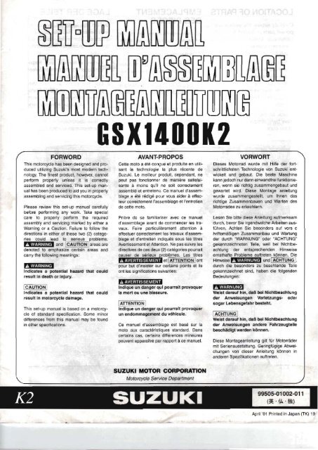
Before assembling the motorcycle, thoroughly<br />
understand the "Safety Check Out" described on<br />
page 46. After completion of assembly, carefully<br />
check the motorcycle referring to the "Safety<br />
Check Out", then deliver the motorcycle to the<br />
customer.<br />
ASSEMBLY<br />
REMOVING THE BRACKET<br />
Loosen the front brake and clutch master cylinder<br />
bolts and remove the master cylinder from the<br />
bracket.<br />
NOTE:<br />
Keep the front brake and clutch [master cylinder<br />
with Its cap facing upwards until it is<br />
installed.<br />
A: Clutch master cylinder<br />
B: Front brake master cylinder<br />
C: Bolt<br />
0: Bracket<br />
Remove the bracket from the handlebar mounting<br />
position.<br />
NOTE:<br />
The bracket and bolts 8're ,no longer needed<br />
and these may be discarded.<br />
A: Bracket<br />
B: Bolt<br />
HANDLEBARS<br />
Insert the handlebar right switch and throttle assembly<br />
onto the handlebars.<br />
A: Throttle assembly<br />
B: Right switch<br />
C: Handlebars
17<br />
CD, Lift the front of motorcycle by using a hoist.<br />
(2), Raise the rear of motorcycle.<br />
@. Pull the crate base forward, then balance th1<br />
motorcycle.<br />
Place the motorcycle on the center-stand, the!<br />
remove the hoist hook.<br />
REAR VIEW MIRROR<br />
Instal! the rear view mirror and tighten lock nut!<br />
securely after positioning them properly.<br />
Replace the rubber boots.<br />
NOTE:<br />
Fix the mirror In the position so as to secure<br />
rear view.<br />
A: Rear view mirror<br />
B: Lock nut<br />
REMOVING THE TAPE<br />
Remove the tape from the muffler.<br />
Remove the tape from the throttle body.<br />
A: Tape<br />
B: Muffler<br />
C: Throttle body
®<br />
SERVICING<br />
BATTERY<br />
The battery is located under the seat.<br />
Remove the seat using the key.<br />
A: Seat lock<br />
B: Seat<br />
Remove the document tray by pulling its rear end<br />
upward.<br />
Remove the battery from the motorcycle.<br />
A: Document tray<br />
Filling electrolyte<br />
Remove the aluminium tape sealing the battery electrolyte<br />
filler holes.<br />
A: Aluminium ape<br />
B: Electrolyte filler hare<br />
Remove the caps from the electrolyte container.<br />
NOTE:<br />
Use the removed caps as the sealed caps of<br />
@ battery tiller holes.<br />
Do not remove or pierce the sealed areas of<br />
the electrolyte container.<br />
21<br />
A Caps<br />
B: Sealed area
®<br />
®<br />
23<br />
With just enough force to break the nozzle seal of<br />
electrolyte container, push each nozzle of the electrolyte<br />
container into the battery's electrolyte filler ports<br />
and holding the container firmly so that it does not<br />
fall.<br />
Take precaution not to allow any of the fluid to spill.<br />
A: Electrolyte containers<br />
Make sure air bubbles are coming up each electrolyte<br />
container, and leave in this position for about 20 minutes.<br />
A: Air bubbles<br />
NOTE:<br />
If no air bubbles are coming up from a filler<br />
port, tap the bottom of the container two or<br />
three times, Never remove the container from<br />
the battery.<br />
After confirming that the electrolyte has entered the<br />
battery completely, remove the electrolyte containers<br />
from the battery. Wait for around 20 minutes.<br />
Insert the caps into the filler holes, pressing in firmly<br />
so that the top of the each caps does not protrude<br />
above the upper surface of the battery's top cover.<br />
A: Caps<br />
!CAUT10N!<br />
Never use anything except the specified bat·<br />
teryelectrolyte.<br />
Once the sealing cap has been installed in the<br />
battery, do not remove the sealing cap.
29<br />
The procedure to bleed the rear brake is identical to<br />
that of the front.<br />
A: Bleeder valve<br />
CLUTCH FLUID<br />
Keep the motorcycle upright and place the handlebars<br />
stra,ight. Check the clutch fluid level in the master<br />
cylinder reservoir. If the fluid level is below the<br />
lower level, add the correct type of f:luid. Rejer to the<br />
chart below for the proper selection.<br />
Specification and Classification<br />
DOT 4<br />
Be careful not to spill any Clutch 'f,fuid on the<br />
paint or plastic components as they will be<br />
damaged.<br />
A: lower level line<br />
CLUTCH AIR BLEEDING<br />
Remove the engine sprocket cover.<br />
A: Engine sprocket cover<br />
B: Flange bolt<br />
Any air which may have been trapped in the clutch<br />
fluid circuit must be bled completely. If the clutch lever<br />
feels spongy or weak, then most likely there is air in<br />
the hydraulic circuit. Bleed the clutch fluid circuit in<br />
the same manner as the brake air bleeding procedure.<br />
NOTE:<br />
Do not drop clutch fluid ,level below II'ower level<br />
line while bleeding air.<br />
After bleeding the clutch fluid circuit, tighten the<br />
bleeder valve to the specified torque. Replace the<br />
rubber protective cap. Be sure to check the fluid level<br />
in the reservoir tank.<br />
Reinstall the engine sprocket cover to the original<br />
position correctly,<br />
(!J Clutch air bleeder valve:<br />
7.5 N·m (0.75 kgf-m)<br />
c: Bleeder valve
33<br />
REAR BRAKE PEDAL<br />
Check the rear brake pedal height. If the rear brake<br />
pedal height is nol correct, adjust in the following<br />
manner:<br />
Brake pedal height: 35-45 mm (1.4-1.8 in)<br />
1. Loosen the lock nut ®.<br />
2. Rotate the push rod @ to locate the pedal at 35<br />
45 mm (1.4-1.8 in) below the top face of the footrest<br />
©. Be sure to measure this height carefully.<br />
3. Tighten the lock nut ® to the specified torque.<br />
C!J Rear brake push rod lock n,ut @:<br />
18 N·m (1.8 kgf-m)<br />
DRIVE CHAIN<br />
Check the drive chain slack. If it is too tight or too<br />
loose, follow these procedures.<br />
Loosen the axle nut. Loosen the lock nut. Adjust the<br />
slack in the drive chain by turning the right and left<br />
chain adjuster bolts. Proper chain slack is obtained<br />
when there is 20-30 mm (0.8-1.2 in) up and down<br />
slack in the chain, at a point midway between the two<br />
sprockets.<br />
Drive chain slack: 20-30 mm (0'.8--1 2 in)<br />
A Axle nut C: Adjuster bolt<br />
8: Lock nut 0: Reference marks<br />
After adjusting, tighten the axle nut to the specified<br />
torque. Tighten the lock nuts securely.<br />
t:!] Rear axle nut: 100 N·m (10.0 kgf-m)<br />
ICAUTIONI<br />
!Make sure that the rear sprocket is properly<br />
aligned with the engine sprocket. Verify the<br />
reference marks on the swing-arm by sighting<br />
down along the chain from the rear end of the<br />
motorcycle.<br />
FRONT SUSPENSION<br />
Checking spring setting<br />
Make sure of the spring setting of the front suspension.<br />
The standard setting for this motorcycle is as<br />
indicated in the table below.<br />
[ Standard setting Position 5 ]<br />
,BEmIImJ<br />
Check that riglht and left spr1ing settings are rin<br />
the same position.<br />
Please refer to the owner's manual for correct adjustment.<br />
A: Adjuster
35<br />
Rebound Damping Force Setting<br />
Make sure of the setting of the rebound damping<br />
force adjustment to the standard position, turn the<br />
adjuster @ clockwise until it stops and then turn it<br />
counterclockwise 8 clicks is the standard position.<br />
8BImmJ<br />
Be sure· to adjust the damping force on both<br />
fron.t forks ,equally.<br />
Please refer to the owner's manual for correct adjustment.<br />
Compression Damping Force Setting<br />
Make sure of the setting of the compression damping<br />
force adjustment 10 the standard position, turn the<br />
adjuster © clockwise until it stops and then turn it<br />
counterclockwise 6 clicks is the standard position.<br />
Be sure to adjust the damping force on both<br />
front forks equally.<br />
Please refer to the owner's manual for correct adjustment.<br />
REAR SUSPENSION<br />
Checking spring setting<br />
Make sure of the spring setting of the rear suspension.<br />
The standard setting of this motorcycle is as indicated<br />
in the table below.<br />
I Standard setting L P_O_s_iti_o_n_1_Y:_2 _<br />
8BImmJ<br />
Check that right and left settIngs are the same<br />
position.<br />
Please refer to the owner's manual for correct adjustment.<br />
A: Adjuster<br />
Rebound Damping Force Setting<br />
Make sure of the rebound damping force setting of<br />
the rear suspension.<br />
The standard setting of this motorcycle is as indicated<br />
in the table below.<br />
[ Standard setting [ 2<br />
Check that right and left settings are the same<br />
position.<br />
Please refer to the owner's manual for correct adjustment.<br />
B: Adjuster
TIGHTENING TO,RQUE<br />
Item I Part Name I N·m I kgf·m Item Part Name N·m Kgf-m<br />
FRONT FORK K Rear brake push rod lock nut 18 1.8<br />
A Handlebar clamp bolt 23 2.3 L Brake caffper au bleeder 7.5 0.75<br />
B Steering Slem head nut 65 6.5 M Rear lor'que link nUl (Front) 26 2.8<br />
C Handlebar holder nut 45 4.5 N Rear torque 'nk nut (Rear) 35 3.5<br />
0 Front fori< upper bracket boll 23 2.3 AXLE<br />
E Front fork lower bracket boll 23 2.3 0 Fronl axle 100 10.0<br />
F Front axle clamp bolt 23 2.3 P I Rear axle nut 100 10.0<br />
f-<br />
BRAKE ABSORBER<br />
G<br />
Front brake and clutch masler cylinder<br />
mounting bolt<br />
10 1.0<br />
Q<br />
R<br />
I ReaJ shock absorber nUl (Upper)<br />
Rear shock absorber nul {Lower} I<br />
23<br />
35<br />
I<br />
I<br />
2.3<br />
3.5<br />
H Front brake caliper mounting boll 26 2.6 OTHERS<br />
I Rear brake master cylinder mounting boll 10 1.0 S Rear S'ovingarm pivot nut I 120 I 12.0<br />
J Rear brake caliper mounting b-olt 26 2.6<br />
For other bolts and nuts not listed, refer to this chart.<br />
Bolt Diameter (mm)<br />
Conventional or "4" marked bolt<br />
N·m kgl-m N·m<br />
"7" marked bolt<br />
kgt-m<br />
4 1.5 0.15 2.3 023<br />
5 3 0.3 4.5 0.45<br />
6 5.5 0.55 10 10<br />
8 13 1.3 23 2.3<br />
10 29 2.9 50 5.0<br />
12 45 4.5 85 85<br />
14 65 6.5 135 13.5<br />
16 105 10.5 210 21.0<br />
18 160 16.0 240 24.0<br />
Conventional bot "4" marked bolt<br />
"7" marked bolt<br />
CD )))))))))))) @) 1)<br />
»}»»))})))<br />
H L p J N R M K s F<br />
41