
Create successful ePaper yourself
Turn your PDF publications into a flip-book with our unique Google optimized e-Paper software.
Construction<br />
Computing<br />
WWW.CONSTRUCTION-COMPUTING.COM<br />
MAY/JUNE 2017<br />
VOL 13 NO 03<br />
Building with numbers<br />
Using maths to reduce waste and<br />
efficiency in construction<br />
Shaping the future<br />
3D Repo demonstrates the latest<br />
trends in visualisation<br />
Motion control<br />
Oasys MassMotion gives more<br />
powers to its agents<br />
COBie or not COBie?<br />
Answering the big questions at the<br />
CAD User Seminar on COBie<br />
Solibri Model Checker<br />
Validating 3D models for<br />
the asset manager<br />
@CCMagAndAwards
CONTENTS<br />
MAY/JUNE<br />
CONTENTS<br />
KEEP CALM AND COBIE ON 10<br />
David Chadwick expands on some of the<br />
issues covered during the CAD User Seminar<br />
on COBie, held at the London Transport<br />
Museum in May in association with Vectorworks<br />
SHAPING THE FUTURE 14<br />
Instead of leveraging the tools of the past,<br />
information modelling should be planning for the<br />
future and taking advantage of the latest trends<br />
in 3D, virtual reality modelling and the cloud<br />
BUILDING WITH NUMBERS 20<br />
Andrew Watts, CEO of international building<br />
engineers Newtecnic, explains how the<br />
construction industry is reducing cost, risk and<br />
waste with maths<br />
MOTION CONTROL 26<br />
Version 9.0 of MassMotion from Oasys<br />
introduces direct support for SketchUp along<br />
with the Software Development Kit, for advanced<br />
behaviour scripting<br />
I NEWS................................................INDUSTRY NEWS....................................................................................................6<br />
• TRANSFORMING TEMPORARY WORKS DESIGN<br />
• ALLPLAN OPENS NEW UK OFFICE<br />
SOFTWARE REVIEW........................SOLIBRI MODEL CHECKER............................................................................16<br />
• IT MAKES A LOT OF SENSE TO VALIDATE A MODEL BEFORE YOU CREATE YOUR COBIE DATA DROPS<br />
CASE STUDY...................................SOLID FOUNDATIONS........................................................................................18<br />
• HIGH QUALITY PRECAST CONCRETE SOLUTIONS FROM TEKLA KEEP O’REILLY CONCRETE AHEAD OF THE GAME<br />
SOFTWARE REVIEW........................PREDICTING YOUR NEXT STEP........................................................................24<br />
• PREDICTIVE DESIGN TECHNOLOGY LIES BEHIND ARCHICAD 21'S ENHANCED STAIR AND RAILING DESIGN<br />
CASE STUDY...................................TUNNEL VISION.................................................................................................28<br />
• HOLEBASE SI AND AUTOCAD CIVIL 3D HELP ATKINS DESIGN A NEW TUNNEL UNDER THE THAMES<br />
TRAINING MAP................................AUTODESK TRAINING.........................................................................................32<br />
• YOUR GUIDE TO AUTODESK TRAINING<br />
TECHNOLOGY FOCUS....................BIM WITH DMFA.................................................................................................34<br />
• USHA B TRIVEDI EXPLAINS WHY DFMA IS A NATURAL ALLY FOR BIM<br />
May/Jiune 2017 3
COMMENT<br />
Editor:<br />
David Chadwick<br />
(cad.user@btc.co.uk)<br />
News Editor:<br />
Mark Lyward<br />
(mark.lyward@btc.co.uk)<br />
Advertising Sales:<br />
Josh Boulton<br />
(josh.boulton@btc.co.uk)<br />
Production Manager:<br />
Abby Penn<br />
(abby.penn@btc.co.uk)<br />
Design/Layout:<br />
Ian Collis<br />
ian.collis@btc.co.uk<br />
Circulation/Subscriptions:<br />
Christina Willis<br />
(christina.willis@btc.co.uk)<br />
Publisher:<br />
John Jageurs<br />
john.jageurs@btc.co.uk<br />
Published by Barrow &<br />
Thompkins Connexion Ltd.<br />
35 Station Square, Petts Wood,<br />
Kent BR5 1LZ<br />
Tel: +44 (0) 1689 616 000<br />
Fax: +44 (0) 1689 82 66 22<br />
SUBSCRIPTIONS:<br />
UK £35/year, £60/two years,<br />
£80/three years;<br />
Europe:<br />
£48/year, £85 two years,<br />
£127/three years;<br />
R.O.W. £62/year<br />
£115/two years, £168/three years.<br />
Single copies can be bought for £8.50<br />
(includes postage & packaging).<br />
Published 6 times a year.<br />
© 2017 Barrow & Thompkins<br />
Connexion Ltd.<br />
All rights reserved.<br />
No part of the magazine may be<br />
reproduced, without prior consent<br />
in writing, from the publisher<br />
For more magazines from BTC, please visit:<br />
www.btc.co.uk<br />
Articles published reflect the opinions of<br />
the authors and are not necessarily those<br />
of the publisher or his employees. While<br />
every reasonable effort is made to ensure<br />
that the contents of editorial and advertising<br />
are accurate, no responsibility can be<br />
accepted by the publisher for errors, misrepresentations<br />
or any resulting effects<br />
Comment<br />
Capable COBie<br />
by David Chadwick<br />
The CAD User seminar on COBie, held<br />
in May at the London Transport<br />
Museum in association with<br />
Vectorworks, has certainly given us plenty of<br />
food for thought - so much so that,<br />
alongside an overview of the event itself, I felt<br />
that some of the issues raised warranted<br />
further exploration in this issue of the<br />
magazine. Hence the article on 3D Repo<br />
and its ability to handle asset management,<br />
and the use of Solibri to evaluate the validity<br />
of information being provided by COBie files.<br />
The 3D virtual models provided by 3D Repo<br />
are assembled from data objects held in a<br />
NoSQL database. As an OpenSource<br />
application this allows geometric and<br />
associated data to be held independently of<br />
the dedicated file structures of an SQL<br />
database, providing a degree of flexibility<br />
that allows unlimited access to, and use of,<br />
the cloud based data. Asset management is<br />
just one example, but pertinent in that it can<br />
be used as an alternative to COBIe, and the<br />
article looks at how the asset information is<br />
shared, modified and kept up to date.<br />
One of the issues that arose during the<br />
seminar discussions was the potentially<br />
huge size of COBie submissions that could<br />
be supplied to asset managers - thousands<br />
of tabulated pages on information on a large<br />
project. Not having the wherewithal<br />
(software) or ability to verify the accuracy of<br />
the information supplied, the COBie tables<br />
are tending to end up being filed as 'for<br />
reference purposes only'. Solibri was<br />
suggested as the ideal tool to guarantee the<br />
accuracy of the information in COBie, and<br />
we look at how this can be achieved in the<br />
article on page 16.<br />
Solibri, of course, is also well engrained in<br />
Graphisoft's Open BIM collaborative<br />
approach to architectural design, as<br />
evidenced in the latest edition of ARCHICAD,<br />
Version 21. This is facilitated by Graphisoft's<br />
cloud-based collaboration application<br />
Teamwork, which allows project members<br />
worldwide to work concurrently on the same<br />
building model. Graphisoft are a leading<br />
proponent of BIM, and as such we also take<br />
a look at the latest version of ARCHICAD in<br />
this issue, highlighting the new features and<br />
the way that they enhance the design<br />
process, and facilitate collaboration.<br />
The COBie seminar proved to be a great<br />
success, with attendees coming from all<br />
sectors of the industry, from beginners to<br />
experienced practitioners. Read the article<br />
on page 10 of this issue for more.<br />
ARTIFICIAL INTELLIGENCE<br />
I was going to base this comment piece<br />
around artificial intelligence, and the driving<br />
demands of the construction industry that<br />
highlight the growing need for information<br />
rich environments and Smart Cities. 'Driving<br />
demands' is pretty apt, as the trend towards<br />
autonomous public transport relies quite<br />
heavily on the vehicles 'learning' how to get<br />
from A to B and being able to integrate<br />
within a whole city full of autonomous<br />
vehicles.<br />
A pointer to the way this can be achieved is<br />
provided by Oasys and its MassMotion<br />
application, which gives simulated<br />
pedestrian agents in a crowded concourse<br />
the same degree of flexibility to react with<br />
other agents to achieve their aim of getting<br />
from A to B, according to their own particular<br />
requirements and idiosyncrasies.<br />
I recently discussed the development of AI<br />
with my undergraduate grandson, and we<br />
wondered whether Artificial Intelligence was<br />
just that - artificial. In spite of the immense<br />
capabilities of AI software, processing<br />
capabilities and feedback routines to<br />
enhance cognitive abilities, it currently<br />
seems unable to transcend beyond the<br />
capabilities of self-generated and externally<br />
applied algorithms. In short, at what stage<br />
does it escape from its origins and become<br />
'sentient'? More, potentially fascinating<br />
research is required.<br />
4 May/June 2017
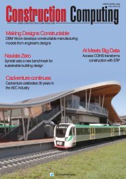
LINDE AG Engineering<br />
embraces HP PageWide XL<br />
Thomas Riedl,<br />
Reprographic Department Manager at Linde AG<br />
The installation of a HP PageWide<br />
XL 8000 Printer plus online folder<br />
marks the end of a time consuming<br />
and costly printing process<br />
at Linde AG Engineering. With HP<br />
PageWide XL the overall costs for<br />
printing large format documents<br />
could be reduced by 40%.<br />
Prior to installing the HP Page-<br />
Wide XL 8000 MFP plus online<br />
folder back in October 2015, the<br />
company was using three large<br />
format printers to manage their<br />
print volume which in peak times<br />
could reach up to 10.000m² per<br />
month. One black & white LED<br />
printer was used for printing pages<br />
and two additional color printers<br />
based on waxed toner pearls were<br />
needed to print an ever increasing<br />
number of coloured pages. “In the<br />
past technical drawings used to<br />
be printed only in black and white<br />
but lately we have seen a significant<br />
increase of colour pages,”<br />
says Thomas Riedl, Reprographic<br />
Department Manager at the Linde<br />
Headquarter in Pullach, Germany.<br />
The value of color<br />
“Already five years ago we were<br />
dreaming of a large format printer<br />
who could produce black and white<br />
and colour pages in one go. However<br />
the available solutions back<br />
then didn’t meet our expectations<br />
in terms of cost and quality”, remembers<br />
Mr. Riedl.<br />
It has been proven that color documents<br />
are more easily understood<br />
and the information is retained at<br />
higher rates versus monochrome<br />
documents - it can decrease human<br />
error rates 1) .<br />
Significant cost savings from<br />
day one<br />
The consolidation of the previous<br />
printers into one HP PageWide XL<br />
8000 plus online folder has paid off<br />
rapidly: the internal reprographic<br />
department could cut their overall<br />
large format printing costs by<br />
40%. In addition Linde AG is very<br />
satisfied that there is no minimum<br />
purchase commitment anymore.<br />
“The price per square meter is very<br />
competitive and we have gained<br />
a lot of flexibility”. Another positive<br />
side-effect is the low energy<br />
consumption compared to LED<br />
technology. “We are very conscious<br />
about our environmental impact<br />
including energy consumption, resources<br />
and materials,” confirms<br />
Mr. Riedl.<br />
Seamless integration with existing<br />
output management system<br />
Another argument in favor of the<br />
HP solution was the seamless integration<br />
into Linde’s corporate<br />
output management system called<br />
Plossys Netdome. The System<br />
now meets Linde’s requirements<br />
for enterprise-wide print and distribution<br />
of documents and information.<br />
The HP PageWide XL 8000 printer<br />
offers the fastest large-format<br />
printing available in color<br />
and black-and-white with speeds<br />
up to 30 D/A1-size prints per<br />
minute, as well as two 775 milliliter<br />
ink cartridges per color 2) .<br />
HP PageWide Technology consists<br />
of more than 200,000 nozzles on a<br />
stationary print bar and spans the<br />
width of the page, enabling breakthrough<br />
printing speeds. Extended<br />
time between service station cycles<br />
also enables outstanding sustained<br />
productivity capacity.<br />
More information: www.linde.com • www.hp.com/go/pagewidexl<br />
HP 841 PageWide XL Print head<br />
1)<br />
According to “Why Color Matters,” by Jill Morton, 2010. 2) Printing at up to 30 D/A1 pages/minute and up to 1500 D/A1 pages/hour, the HP PageWide XL 8000 Printer is faster than alternatives for large-format printing of<br />
technical documents, GIS maps, and point-of-sale (POS) posters under $200,000 USD as of March, 2015 including 36-inch wide LED printers (printing up 22 D/A1 pages/minute) and wide-format printers based on Memjet<br />
technology (printing up to 800 D/A1 pages/hour). Based on internal HP testing of the HP PageWide XL 8000 Printer in line drawing print mode on uncoated bond paper printing in D/A1 landscape.
INDUSTRY news<br />
TRANSFORMING TEMPORARY WORKS DESIGN<br />
Swanton Consulting has<br />
transformed the design of<br />
temporary works - such as<br />
façade and basement retention<br />
- using a software innovation<br />
that creates instant 3D models<br />
from laser scanner data. Processing<br />
of the millions of individual<br />
3D laser scan measurements,<br />
known collectively as<br />
point clouds, used to take<br />
Swanton up to two weeks.<br />
However, since introducing<br />
Pointfuse V2 point cloud processing<br />
software, Swanton can<br />
now produce highly accurate<br />
vector models, suitable for<br />
immediate use by design engineers,<br />
in less than a day.<br />
Swanton Consulting specialises<br />
in the design of temporary<br />
works, deep basements,<br />
façade retentions, retaining<br />
walls, specialist structural elements<br />
and contractor delegated<br />
design elements. Working<br />
alongside design teams and<br />
contractors, Swanton is one of<br />
the leading providers of façade<br />
retention engineering solutions<br />
in London.<br />
"One of the first projects we<br />
tested Pointfuse on was the<br />
design of steel structure to support<br />
the façade of two Grade II<br />
listed structures in London's<br />
prestigious Mayfair," commented<br />
Pearse McMahon, Senior<br />
Technician at Swanton Consulting.<br />
"The façade scheme was<br />
developed and coordinated<br />
with the permanent works, with<br />
the layout driven heavily by the<br />
use of 3D modeling from point<br />
cloud surveys."<br />
Data to support the design of<br />
the façade steel work was collected<br />
by Swanton's Testing and<br />
Monitoring division using a<br />
Leica ScanStation laser scanner.<br />
Originally, the vast point<br />
cloud was imported into the 3D<br />
construction modeling software<br />
using Tekla Structures, produced<br />
by Trimble. The 1.5 Gb<br />
DXF CAD file, comprising more<br />
the six million cross hair points,<br />
then took the best part of two<br />
weeks to process into a usable<br />
model onto which the steel<br />
structure framework could be<br />
positioned.<br />
Following the acquisition of<br />
Pointfuse V2 software, the original<br />
point cloud was<br />
reprocessed to create a 3D<br />
model of the façade in the open<br />
IFC format for onward use in a<br />
variety of software packages,<br />
including Trimble's Tekla and<br />
AutoCAD Revit. However, rather<br />
than taking two weeks to create<br />
usable models, the Pointfuse<br />
output was ready for use by the<br />
designers in under a day.<br />
www.pointfuse.com<br />
SAGE PARTNERS WITH AUTODESK, ETAKEOFF<br />
Sage has launched a new<br />
integrated BIM, takeoff,<br />
and estimating solution<br />
developed through a collaboration<br />
with Autodesk and<br />
eTakeoff. This BIM solution is<br />
a unique best-of-breed<br />
approach to automating the<br />
time-consuming, manual<br />
process estimators face when<br />
trying to produce detail cost<br />
estimates from 3D models<br />
and 2D digital plans. It also<br />
paves the way for integration<br />
with cloud based solutions<br />
used in field project collaboration,<br />
on mobile devices and<br />
in today’s digital plan rooms.<br />
The amount of estimatingrelated<br />
information included<br />
in a model can vary greatly.<br />
As a result, estimators have<br />
to refer to 2D drawings to get<br />
details, such as floor coverings,<br />
that are often missing<br />
from the model.<br />
The new model-based cost<br />
estimating solution integrates<br />
eTakeoff software and<br />
Autodesk Navisworks with<br />
Sage Estimating. It provides<br />
an easier way to do detailed<br />
takeoff simultaneously from<br />
ALLPLAN OPENS NEW UK OFFICE<br />
BIM solutions provider<br />
ALLPLAN has expanded its<br />
team with the opening of a new<br />
office in the UK in order support<br />
its growth in the European market<br />
and further help influence<br />
BIM for engineering. The new<br />
office will cover the UK and<br />
North European markets, supported<br />
by a strong, industryexperienced<br />
team.<br />
Richard Brotherton, Managing<br />
Director at ALLPLAN GmbH<br />
commented: “The new UK<br />
office is part of ALLPLAN‘s international<br />
growth strategy. The UK<br />
and North European markets<br />
have a strong potential and this<br />
both 3D models and 2D<br />
drawings. With this new integration<br />
estimators can:<br />
• Drag and drop objects from<br />
a BIM model onto selected<br />
estimating assemblies, eliminating<br />
the time-consuming<br />
task of transferring quantities<br />
and measurements.<br />
• Obtain information missing<br />
in the BIM model directly<br />
from 2D drawings, all in the<br />
same integration tool.<br />
• Drill down from the estimate<br />
spreadsheet all the way<br />
back to the 3D model to<br />
review the original takeoff<br />
source and any changes that<br />
have been introduced.<br />
"We’re providing a way for<br />
construction firms to integrate<br />
these best-in-class<br />
solutions to effortlessly move<br />
between 2D and 3D content<br />
for production-level estimating,"<br />
said Curtis Peltz, CEO<br />
of eTakeoff. "It’s all part of<br />
our efforts to provide the<br />
most innovative and practical<br />
BIM takeoff and estimating<br />
solution available today."<br />
www.sage.com<br />
opening furthermore demonstrates<br />
our vision and investment<br />
to strengthen client acquisition<br />
and marketing activities.”<br />
Leading the team is Business<br />
Development Director, Kevin<br />
Lea, who said “It is an exciting<br />
time to join ALLPLAN and to be<br />
part of its international expansion.<br />
I am impressed with<br />
ALLPLAN’s innovative BIM solutions<br />
and how they improve the<br />
design process for engineers.<br />
We have an experienced team<br />
in place and we are looking forward<br />
to bringing the benefits of<br />
Allplan to the UK market”.<br />
www.allplan.com<br />
6<br />
May/June 2017
60<br />
50.35<br />
50.35<br />
6.20<br />
7.30<br />
32.40<br />
YOU SEE<br />
THE WORLD<br />
DIFFERENTLY.<br />
ST 17H<br />
TRANSFORM IT.<br />
DESIGN WITH VECTORWORKS 2017.<br />
VECTORWORKS.NET/EXPLORE2017<br />
Our intuitive software enhances your design process,<br />
enabling you to collaborate from inspiration to execution<br />
and explore the possibilities of BIM and beyond.<br />
IN PARTNERSHIP WITH
INDUSTRY news<br />
EARTH PYRAMID GETS ARUP BACKING<br />
It's almost six years since<br />
Leeds-based engineer Mark<br />
Steele took a call from Steve<br />
Ward, the pioneering force<br />
behind a bid to construct a<br />
giant pyramid dedicated to<br />
peace and the environment.<br />
The rest, as they say, is history<br />
in a very real sense.<br />
Mark, an engineering specialist<br />
at the global construction<br />
consultancy Arup, commented:<br />
"In late 2011, Steve was seeking<br />
guidance on how to construct<br />
the pyramid and he was<br />
put in touch with me. Since<br />
then I have been supporting<br />
Steve on a pro bono basis, providing<br />
design & construction<br />
related technical advice to help<br />
realise his vision."<br />
The Earth Pyramid Project<br />
started 8 years ago when<br />
Steve's young daughter asked<br />
him ‘what about our future?'<br />
after watching the Copenhagen<br />
climate talks break down. "As a<br />
result," explained Steve. "We<br />
decided to come up with a project<br />
that would allow people to<br />
record their emotions about our<br />
planet and its direction of travel<br />
within thousands of time capsules<br />
incorporated within a<br />
giant pyramid, the biggest built<br />
since the time of the Egyptian<br />
Pharaohs and the largest time<br />
capsule in the world!"<br />
Steve has already pulled<br />
together a core team of people,<br />
including Mark, with the key<br />
skills to advise on the different<br />
aspects of the project and is<br />
currently working hard to<br />
secure land and seed funding<br />
for a Yorkshire-based pyramid,<br />
which will give him the opportunity<br />
to make a start on a more<br />
manageable scale and will no<br />
doubt provide valuable experience<br />
for the full scale Pyramid.<br />
Mark is advising Steve on all<br />
matters related to the design<br />
and construction of the Pyramid<br />
and the infrastructure and facilities<br />
required to support it. He<br />
continued, "Because it is unique<br />
in so many respects, there are<br />
many challenges which will test<br />
modern construction. For<br />
example the materials will need<br />
to have as low an environmental<br />
impact as possible and<br />
remain stable for over 1000<br />
years. The form of construction<br />
is essentially a huge 3D jigsaw<br />
puzzle, which will test our modeling<br />
skills and we want to test<br />
theories on the construction of<br />
the great Pyramids in Egypt."<br />
Steve summed up the project.<br />
"There will be four chambers<br />
within the pyramid dedicated to<br />
children, digital preservation,<br />
government and indigenous<br />
peoples and founders with<br />
each containing records and<br />
testimonials from millions of<br />
people. It's a legacy for future<br />
generations about our time on<br />
this planet."<br />
www.earthpyramid.org<br />
VIEWPOINT ENTERPRISE CLOUD LAUNCHED<br />
Viewpoint has launched the<br />
next evolution of its hosted<br />
services with Viewpoint Enterprise<br />
Cloud (VEC). "It's widely<br />
acknowledged that intelligent<br />
technology can make the critical<br />
difference in increasing profitability<br />
and managing risk in<br />
the construction industry," says<br />
senior vice president of product<br />
management, Matt Harris. "With<br />
Viewpoint Enterprise Cloud, our<br />
customers get all the benefits of<br />
an integrated construction platform<br />
without the hassle of having<br />
to host their software solutions,<br />
freeing them up to focus<br />
on what matters most to their<br />
business: managing risk, controlling<br />
cost and delivering<br />
exceptional projects,"<br />
VEC provides an integrated<br />
solution suite that serves their<br />
needs across all areas of the<br />
business:<br />
• Viewpoint OFFICE solutions<br />
for data-intensive jobs like<br />
accounting and payroll.<br />
• Viewpoint TEAM solutions<br />
offer collaborative project management<br />
capabilities for functions<br />
like submittals and RFI's.<br />
• Viewpoint FIELD solutions<br />
provide the ability to collect<br />
data such as field observations,<br />
time and productivity.<br />
VEC's construction platform<br />
ensures users have access to a<br />
single source of data, while<br />
maintaining the ability to work in<br />
the user interface most appropriate<br />
for the job at hand.<br />
"It was important to us to<br />
make sure that customers didn't<br />
lose any of the flexibility they<br />
need in their solutions, while at<br />
the same time simplifying how<br />
they manage their IT. VEC offers<br />
higher performance than onpremises<br />
solutions. We manage<br />
software updates and data<br />
back-ups, so users have<br />
access to the most up-to-date<br />
technology and data in an<br />
always on mobile ready platform,"<br />
says product manager,<br />
Eric Vasbinder.<br />
3D REPO GETS NAVISWORKS, BCF SUPPORT<br />
3D Repo has launched a new<br />
version of its cloud based<br />
BIM collaboration platform that<br />
offers additional support for<br />
some of the leading software<br />
packages used within the AEC<br />
sector, such as Autodesk Navisworks.<br />
The latest release also<br />
provides enhanced support for<br />
large 3D models typical of infrastructure<br />
projects, as well as<br />
integrated VR functionality for<br />
applications such as training,<br />
safety and project consultation.<br />
"We want to make project<br />
information as accessible and<br />
usable as possible, which is<br />
why we engage with as many<br />
open source and proprietary<br />
formats as we can, allowing<br />
users to share 3D models,<br />
issues and ultimately knowledge<br />
with the wider project<br />
team, in the cloud, but still in the<br />
context of the original model,"<br />
said Dr Jozef Dobos, CEO of<br />
3D Repo.<br />
The latest versions of 3D<br />
Repo's Open Source, Starter,<br />
Professional and Enterprise<br />
packages include advanced<br />
integration with Autodesk Navisworks<br />
project review software,<br />
along with support for the BCF<br />
file format, allowing<br />
import/export of collaboration<br />
and mark up data for issues<br />
tracking to software such as<br />
Solibri quality assurance solutions,<br />
Trimble's Tekla product<br />
family and Graphisoft's ARCH-<br />
CAD. For more on 3D Repo<br />
read our feature on page 14.<br />
www.3drepo.com<br />
8<br />
May/June 2017
Get more from Asta Powerproject BIM<br />
with new functionality<br />
Join a free webinar and see how to:<br />
◊ Combine a 3D model with your project schedule<br />
◊ Explore powerful options to take 4D planning to the next level<br />
For more information and to register:<br />
elecosoft.com/bimdemos<br />
elecosoft.com
EVENTfocus<br />
COBie or not COBie?<br />
David Chadwick looks at some of the issues covered during the CAD User Seminar on COBie, held at<br />
the London Transport Museum in May in association with Vectorworks<br />
When the idea of running a<br />
question and answer session on<br />
Information Modelling was first<br />
mooted, my immediate reaction was one<br />
of very mild panic! Having attended<br />
many, many conferences as a journalist I<br />
am acutely aware of the fine balancing<br />
act involved in making a subject as<br />
complex as COBie an engaging and<br />
rewarding one for an audience whose<br />
knowledge of the subject will naturally<br />
range from novices genuinely seeking<br />
answers to a couple of confusing or<br />
contradictory points, to experts on the<br />
subject who have highly technical<br />
questions to put to the panel. It's a skill<br />
that, in my experience, few conferences<br />
have mastered.<br />
Well I’m happy to report that the CAD<br />
User Seminar on COBie, held in<br />
association with Vectorworks at the<br />
London Transport Museum in May, was<br />
deemed a success by attendees and<br />
speakers alike. The aim was to highlight<br />
the importance of the information created<br />
using 3D building modelling, and where<br />
and how it should be used. Our<br />
attendees were able to take advantage of<br />
the subject being thoroughly aired, with<br />
its pros and its cons, by experts on all<br />
sides of BIM. These ranged from creators<br />
of the Information Model, software<br />
experts who demonstrated a number of<br />
alternative methods of presenting that<br />
information, and even a representative of<br />
the eventual users of the model - a rare<br />
beast on BIM panels - along with a<br />
consultant with years of experience in<br />
watching both developers and users<br />
getting to grips with the problem.<br />
The aim of the seminar was certainly<br />
achieved - namely to widen the discourse<br />
surrounding BIM and the way it should<br />
be delivered. The salient issues<br />
stemming from both COBie and the use<br />
of a Federated Model to deliver BIM were<br />
not wholly resolved, but our informed and<br />
well-briefed audience were provided with<br />
sufficient information to make their own<br />
decisions as to what would best suit their<br />
particular requirements, or to encourage<br />
them to research the subject more<br />
thoroughly. We were, after all, debating a<br />
subject that will fundamentally change a<br />
company's working practices going into<br />
the future.<br />
GENERATING INFORMATION FROM<br />
A 3D MODEL<br />
With a lot of ground to cover, and a range<br />
of expectations within the audience, we<br />
worked through a logical sequence of<br />
presentations, starting with an<br />
introduction which looked at designing<br />
buildings in 3D and the way in which this<br />
automatically generated building<br />
information, and how it’s used and<br />
supplemented on even small projects.<br />
This was given by Jonathan Reeves of<br />
Jonathan Reeves Architects (JRA) and<br />
the author of an invaluable guide on<br />
'Innovative Vectorworks BIM'. This was<br />
followed by an exploration of COBie, the<br />
UK Government's BIM Level 2 delivery<br />
mechanisms and Soft Landings concepts<br />
by Martyn Horne of Vectorworks.<br />
Next on the agenda was a presentation<br />
from Andrew Norrie at 3D Repo, offering<br />
an alternative method of providing<br />
building information using the latest<br />
digital technologies - the federated<br />
building model. This combined building<br />
information in a single 3D model and<br />
used the latest visual and virtual reality<br />
techniques to display the information,<br />
provide access to it within the model, and<br />
maintain it within a cloud-based<br />
environment as a single source of truth,<br />
totally up to date and accessible to all.<br />
With two alternative methods of<br />
delivering building information to the<br />
building operators - who are, after all, the<br />
prime reason for embarking on COBie in<br />
the first place - we decided that it would<br />
be salutary to listen to an asset manager<br />
to find out whether promised deliverables<br />
were supplied, correct and used. We<br />
were fortunate therefore to have Andy<br />
Stanton of Transport for London talk<br />
about his own experiences and those of<br />
his team during the extensive works<br />
being undertaken on London<br />
Underground and a number of stations -<br />
comprehensive projects that involved a<br />
great deal of collaboration between<br />
10<br />
May/June 2017
EVENTfocus<br />
building contractors, civil engineers,<br />
electrical engineers and all other<br />
disciplines involved in underground work.<br />
The final presentation before we started<br />
the Q and A session was given by<br />
Stephen Holmes of Cadventure advising<br />
on the implementation and working<br />
processes of large-scale BIM projects.<br />
AN INTRODUCTION TO COBIE<br />
COBie (Construction Operation Building<br />
information exchange) is, of course, the<br />
UK Government's mandated scheme for<br />
delivering BIM data. As we were<br />
reminded on a couple of occasions<br />
throughout the morning by Martyn Horne,<br />
who presented the overview alongside<br />
Jonathan Reeves, COBie is not a<br />
spreadsheet, although it may look like<br />
one, but a database. It is a convenient<br />
method of presenting all of the<br />
information in a 3D model of a building in<br />
a common data format that can be read<br />
by anyone - whether they have the<br />
authoring tool available or not, and is<br />
accessible to those with no CAD training<br />
or background.<br />
To show where that information came<br />
from Jonathan Reeves took us through a<br />
number of his projects, explaining his<br />
philosophy as an architect, and how the<br />
acquisition of building information is a<br />
natural asset, rather than a conscious<br />
burden. "Architects want to use their<br />
software as a design tool, and not as a<br />
sketch pad," said Jonathan. "It is easier to<br />
design roof frame members in 3D than to<br />
draw them in 2D." Each element or object<br />
included in a 3D model comes with its<br />
own IFC tag, whether the object is<br />
created locally or imported from an<br />
object library such as BIM Object, which<br />
would bring with it a wealth of<br />
manufacturer's object information.<br />
In design mode, Jonathan explained,<br />
you aren't particularly concerned about<br />
the amount of information you have with<br />
each object because when you wish to<br />
start sharing your model with others, you<br />
can go into the Resource Manager in<br />
Vectorworks at any time and add<br />
whatever information you wish.<br />
Even on the smallest projects, Jonathan<br />
explained, there are advantages to being<br />
able to access the information you are<br />
building up in a model. The ability to<br />
create component schedules and<br />
organise the design process, for example<br />
creating a structure with different design<br />
layers - walls/floors, doors and windows,<br />
MEP, lighting systems and so on - is<br />
particularly useful, and while not<br />
absolutely necessary for smaller projects,<br />
they provide great practice for when the<br />
requirement becomes mandatory.<br />
THE VIEW FROM THE FRONTLINE<br />
Stephen Holmes of Cadventure was<br />
given the opportunity to point out a few<br />
home truths. With 25 year’s experience in<br />
the industry, covering all aspects of<br />
project delivery, his first statement set the<br />
tone for the conference. "The reality of<br />
BIM depends on who you are talking to. It<br />
all starts with the client, and they differ so<br />
widely it is unbelievable," he said.<br />
Having worked on projects worldwide,<br />
including three airports, stadiums,<br />
hospitals and residential projects, Steve<br />
said that they all have had widely<br />
different ideas about what information<br />
there is available and what they need. At<br />
one end of the scale you have the "Worst<br />
case clients who don't care about<br />
information and wouldn't know COBie if it<br />
bit them." These are typically developers<br />
who want to sell on the building as soon<br />
as it is built. And at the other end, he<br />
said, is the client who asks for everything<br />
- and who copy and paste it all, so that it<br />
looks as if their aim is merely to force<br />
penalty payments!<br />
The perfect client, though incredibly rare<br />
(less than 1%), understands the value of<br />
data, knows what they want, and can<br />
explain it to you in clear, plain language.<br />
The challenge in the industry, therefore, is<br />
educating owner-operators to ask for the<br />
right information at the right time.<br />
There are, of course, clients at all levels<br />
between these extremes, and you can<br />
help them get data in pretty much<br />
whatever format they like. But that raises<br />
the next challenge - Bad Data in equals<br />
Bad Data out. Stephen explained that<br />
ensuring consistency comes down to<br />
how individuals model, and even on the<br />
same project people can use three or<br />
four different ways of modelling skirting<br />
boards, resulting in garbage when you<br />
try to extract the data in a single format.<br />
DON'T OVERPROVIDE DATA<br />
"Don't overprovide data and learn how<br />
to map data properly," Stephen advised.<br />
When delivering COBie data drops for<br />
Level 2 it is important to know exactly<br />
what needs to be delivered, to know not<br />
to overprovide as well as underprovide.<br />
Download just what you need and<br />
validate it. Do you want liability for all of<br />
the objects you are putting in a model if<br />
it is not your ultimate responsibility?<br />
"Furthermore, is the data clean? if not,<br />
don't put it in the model."<br />
Know how to map data, Stephen added,<br />
so that if there is a problem with the data it<br />
May/June 2017 11
EVENTfocus<br />
Stephen Holmes<br />
is not down to the mapping, but to the<br />
source data. That way you can go back<br />
to source, identify it and correct it.<br />
Mapping is essential because of the<br />
different ways in which technologies work<br />
and export data, but you need to sort that<br />
out up front. Don't forget that the COBie<br />
dataset has been separated from the live<br />
model, so ensure that you validate and<br />
verify wherever possible - and don't sign<br />
your name against something with a big<br />
price tag on it.<br />
Five years ago exporting COBie and IFC<br />
was a bit of a black art. Now, software<br />
vendors have set up their software to<br />
help people deliver COBie - but if you<br />
start going 'off-piste' or custom design<br />
then you are left to own devices.<br />
DATA DELIVERY<br />
"COBie," Stephen said, "Gives structure to<br />
data - consistency - as long as everybody<br />
is working to the same rules. Who actually<br />
reads it, though?" On one large BIM<br />
project, he explained, the management<br />
company defining deliverables etc. asked<br />
contractors to deliver COBie at concept,<br />
and thirty companies had no option but to<br />
send the minimal info available - the<br />
name of the project and not much more.<br />
Nobody opened the files received in the<br />
first six months.<br />
Furthermore, when you do receive<br />
completed COBie data, how do you<br />
check 100,000 lines of data with 50<br />
columns? Everything has to be filled in,<br />
but it doesn't tell you if anything is<br />
missing - and the recipients don't have<br />
the right expertise to properly validate the<br />
information they've getting either.<br />
It is better to check it at source using tools<br />
like Solibri (see the article on page 16 of<br />
this issue) where it can be validated<br />
properly. COBie has its place, Stephen<br />
said, but needs to be used properly. It's<br />
also useful to know who doesn't need<br />
COBie. Design teams for example have no<br />
advantage having COBie and need to work<br />
at native file-level. It's only when the project<br />
starts getting complex that the consistency<br />
of COBie comes into its own, and it begins<br />
to serve as originally intended.<br />
Design collaboration works better if you<br />
share the model. If the data is exported<br />
via IFCs it becomes static and can't be<br />
progressed or built on until the<br />
parametric elements needed to modify<br />
the model have been reinserted. That<br />
raises the pertinent question of whether<br />
the only reason you are issuing COBie<br />
data is for the BIM Consultant - patently<br />
not the right reason.<br />
Do all projects evolve beyond<br />
recognition once they have been started?<br />
It almost appears so from Stephen's<br />
presentation. He argued against putting<br />
in too much information - detailed MEP<br />
equipment, rather than basic<br />
performance requirements - because, as<br />
likely as not, the detailed equipment is<br />
likely to change when it all goes out to<br />
tender, with the supplier substituted for a<br />
cheaper one. Data moves, and so does<br />
accountability. It's better to understand<br />
the lifecycle of your data and what is<br />
likely to happen to it.<br />
Finally, the virtual building. How do we<br />
plan for that? The software we're using<br />
now may not be the same as that we'll be<br />
using in five year's time. COBie data is<br />
structured, but it will continually have to<br />
adapt to include things like IoT, the ability<br />
to feed lifecycle data back into the<br />
model, the use of Smart Geometry, Big<br />
Data Analytics and so on, without losing<br />
sight of the basic requirement: "I've got<br />
100 air filters to replace, what is the<br />
optimum path for engineers to take to go<br />
round and replace them?" You can't do<br />
that with a flat data structure.<br />
KEEP CALM AND COBIE ON<br />
Stephen's talk gave us all quite a lot of<br />
food for thought. In the next issue of the<br />
magazine we'll look at the issues raised<br />
in the seminar from a user's perspective,<br />
and then focus on the Question and<br />
Answer session that concluded the<br />
event. For now we will conclude with this<br />
wise piece of advice, again from Stephen<br />
Holmes: "Start by understanding where<br />
you want to go to as a business and<br />
understand the client's needs before you<br />
start pushing from your end."<br />
www.caduser.com/seminars<br />
12<br />
May/June 2017
From design<br />
to reality<br />
Louis Vuitton Foundation (France)<br />
Tekla Structures is intelligent 3D modelling software at the heart of the digital<br />
construction process. From concept drawing to reality, collaboration between<br />
people and across technologies becomes more efficient and rewarding.<br />
Together we are shaping a smarter future for construction.<br />
www.tekla.com/uk/solutions<br />
TRANSFORMING THE WAY THE WORLD WORKS
EVENTfocus<br />
Looking Ahead, not Back<br />
Instead of leveraging the tools of the past, information modelling should be planning for the future and<br />
taking advantage of the latest trends in 3D, virtual reality modelling and the cloud<br />
Iam sure you will be familiar with<br />
Moore's Law, which states that the<br />
number of transistors on a chip will<br />
double every year. That has held since<br />
the 1970s, and despite a bit of a<br />
slowdown we are now into nano-sized<br />
transistors, and in more recent<br />
developments IBM has announced its<br />
ability to place 30 billion 5nm transistors<br />
on a chip the size of a fingernail. But you<br />
don't need such incredible stats to tell<br />
you that the pace of change in<br />
computing is still as blindingly fast,<br />
because the evidence is, literally, right<br />
before your eyes.<br />
Andrew Norrie of 3D Repo highlighted<br />
this at the recent CAD User seminar on<br />
COBie, pointing out that the<br />
development of handheld computing<br />
devices and high-performance gaming<br />
devices, supported by ultra-realistic<br />
videogames, virtual reality software and<br />
3D visualisations, have conditioned both<br />
children and adults to become<br />
completely au fait with new technologies.<br />
This is even more pronounced in the<br />
new generation entering the design<br />
industry who, besides being completely<br />
proficient in traditional CAD/BIM<br />
platforms, are now happy to play around<br />
with advanced computational design<br />
packages like Grasshopper and<br />
Dynamo, and are fluent in programming<br />
languages like Python and JavaScript.<br />
It makes sense, therefore, as Andrew<br />
pointed out, to create and manage data<br />
in a format that we are now familiar with,<br />
rather than a manufactured format from a<br />
few short years ago when BIM was first<br />
mandated. To really harness the power of<br />
that data, though, 3D Repo realised it<br />
would be better to treat it as individual<br />
objects, rather than in the file format that<br />
we see within COBie.<br />
Instead of holding the data in the<br />
model, the elements are broken down<br />
and stored at object level in a NoSQL<br />
database, where additional information<br />
can be attached to support many<br />
different functions. NoSQL means exactly<br />
that - an SQL database accumulates<br />
data in formal rows and columns, rather<br />
like COBie in fact.<br />
NoSQL databases avoid rigid table<br />
structures and can be optimised for large<br />
read/write operations. This allows easy<br />
access to associated objects, to track<br />
semantic relationships and individual<br />
revisions done in 3D Repo, and to create<br />
associations with other data or objects.<br />
3D Repo then recreates the 3D model in<br />
a web browser, giving access to any data<br />
associated with each object.<br />
A CENTRAL BIM HUB<br />
As 3D Repo is able to take files in<br />
multiple formats - currently most open<br />
standards, but also native formats - it is<br />
able to incorporate objects from all<br />
disciplines working on a project, break<br />
them down into small component parts,<br />
and store them in the NoSQL database.<br />
Deployed in either public or private<br />
clouds, or even hosted locally on servers<br />
then recreated, models can be viewed<br />
and analysed by all members of a project<br />
team, providing a single source of truth at<br />
all stages of the project. Because the<br />
data is held as individual objects, models<br />
can be put together in any configuration -<br />
architectural and structural, MEP, or<br />
infrastructure, etc. This enables project<br />
members to share data on the project at<br />
any stage of its design and construction<br />
using BCF standard within authoring<br />
tools. It also acts as a version control<br />
system, ensuring that data from whatever<br />
source is always up to date, or,<br />
alternatively, able to be rolled back to<br />
previous versions. 3D Repo's pending 3D<br />
Diff technology also visualises changes<br />
between any two revisions in real time<br />
regardless of which modelling package<br />
they came from.<br />
VIEWING THE DATA<br />
Building the model from the data<br />
objects is then quite straightforward,<br />
and with it comes all of the tools you<br />
would expect from a visual navigation<br />
tool. These include sections, slicing,<br />
different model views, adding object<br />
time and cost information to conduct 4D<br />
and 5D simulations, and the ability to<br />
add comments, ask questions, raise<br />
14<br />
May/June 2017
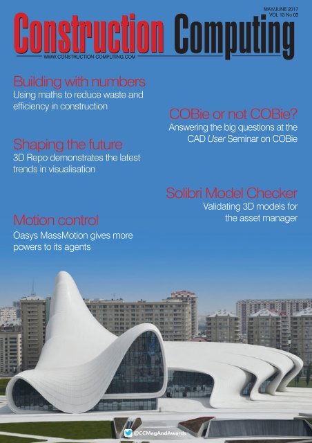
EVENT focus<br />
3D Repo - a montage of London’s skyline<br />
3D Repo - the Navisworks plug-in<br />
issues and to interact with other project<br />
members.<br />
Although there is considerable freedom<br />
in the way the model is accumulated,<br />
when members are engaged in project<br />
review processes, a system of<br />
administration and authority levels can be<br />
established for designated roles,<br />
ensuring only concluded actions can be<br />
closed by those with the correct authority.<br />
Issues created can be tracked and<br />
measured in order to give insight into<br />
how the project is performing and what<br />
risks may be ahead.<br />
ASSET MANAGEMENT<br />
Storing data in the NoSQL database<br />
means that multiple models can be<br />
uploaded and enriched with data from<br />
other sources such as asset registers or<br />
ERP systems as required. Storing data in<br />
this way and optimising the models<br />
means 3D Repo can federate models on<br />
a large scale in the web browser for easy<br />
collaboration, with no need to install<br />
expensive software packages.<br />
In the case of asset management, the<br />
amount of information that can be<br />
uploaded can be substantial, ranging<br />
from equipment and maintenance<br />
manuals, supplier information, and even<br />
operation videos and training material.<br />
Whilst not provided as an integrated<br />
asset management application, any<br />
company wishing to use the data stored<br />
in the cloud for such purposes will be<br />
assisted by 3D Repo to set up the<br />
required links and processes, using the<br />
company's App manager.<br />
MAINTAINING ASSETS IN 3D REPO<br />
One of the biggest issues discussed at<br />
the COBie seminar was the need to<br />
maintain all of the data assets in a large<br />
3D visualisation model when they come<br />
from many different sources, and from<br />
authors with different skills and tools,<br />
whilst retaining consistency of the<br />
model. In the largest projects, it is also<br />
inevitable that a number of people will<br />
be working concurrently on the same<br />
part of a 3D scene.<br />
Faced with this issue Dr Jozef Dobos,<br />
founder and CEO of 3D Repo, described<br />
in a whitepaper how the company<br />
developed a unified and integrated<br />
framework that supports collaborative<br />
editing and the distribution of 3D assets,<br />
and which tracks multiple revisions of 3D<br />
assets for integration at a later date. As it<br />
is based around the NoSQL database, it<br />
also avoids the constraints of a filebased<br />
system.<br />
ENVIRONMENTAL MONITORING<br />
3D Repo can be used in the performance<br />
monitoring of structures, either during<br />
construction or in operation. This can<br />
involve the installation of cameras on<br />
building sites to provide sequential<br />
records of construction, and<br />
environmental or pressure sensors to<br />
record any external conditions that affect<br />
the integrity of comfort in the building.<br />
This is possible due to the structure of 3D<br />
Repo, making it a perfect tool to receive<br />
real time data and act as an integration<br />
point and visualisation engine for any<br />
type of IoT device needing a big data<br />
repository for all project information.<br />
Once data is stored in the system, it<br />
becomes accessible to various querying<br />
opportunities for analysis. The simplest of<br />
these is an easy to use command line<br />
utility to query projects and allow for<br />
model checking and data validation.<br />
KEEPING IT SIMPLE<br />
Despite the somewhat complex sounding<br />
technology behind the 3D Repo solution,<br />
Andrew Norrie was keen to emphasise<br />
the simplicity of use. The support of<br />
formats familiar to the user, made<br />
accessible through the platform, reduces<br />
the need to learn new software or<br />
techniques. The use of common<br />
browsers to view data makes it<br />
accessible regardless of discipline or<br />
location, and the inclusion of version<br />
control, system administration and<br />
authority levels allow for management<br />
and retrospective reporting.<br />
Finally, the integration with advancing<br />
technologies such as VR, AR and gaming<br />
make it instantly engaging and<br />
accessible while enabling information to<br />
be shared with a wider audience.<br />
www.3drepo.org<br />
May/June 2017 15
SOFTWARE review<br />
Solibri Model Checker<br />
It makes a lot of sense to validate a model using Solibri Model Checker before you create your<br />
COBie data drops. Leaving it to the asset manager to verify the data is an impossible 'ask', says<br />
David Chadwick<br />
Solibri Model Checker - Spaces<br />
An interesting point was raised at<br />
the CAD User Seminar on COBie<br />
in May which I felt deserved a<br />
more thorough response than just being<br />
mentioned in passing. When asked how<br />
a recipient of a COBie document could<br />
verify the accuracy of its content, it was<br />
casually asserted that the model would,<br />
of course, already have been checked<br />
by the Solibri Model Checker.<br />
With COBie submissions running to<br />
potentially thousands of pages, it would<br />
be quite understandable if the average<br />
asset manager, faced with the<br />
metaphorical thud as it lands in their intray,<br />
would quail at the task of actually<br />
opening the thing and starting to use it<br />
to plan an asset maintenance schedule.<br />
How would one even begin to go about<br />
verifying the accuracy of the volumes of<br />
tables, links, documents and other<br />
information contained within?<br />
Does its impenetrability lead one to<br />
suggest that its purpose is not to assist<br />
the asset manager in their role, but<br />
rather that it is more of an administration<br />
tool that only comes into its own<br />
following a dispute on the construction<br />
site, its value being that of a legally<br />
binding document of a set of<br />
deliverables? Before we attempt to<br />
answer such vexatious and controversial<br />
questions, we need to take a closer look<br />
at Solibri and how it lends itself to<br />
facilitating asset management.<br />
SOLIBRI<br />
Solibri was ahead of its time, having<br />
been around as a model checker<br />
before most of the software application<br />
vendors got round to talking about<br />
BIM. It is totally vendor neutral, working<br />
with IFCs and any AEC system on the<br />
market - Revit, Graphisoft,<br />
Vectorworks, Tekla and so on. It is sold<br />
as a tool for checking and assuring<br />
BIM output, rather than input, and it<br />
supports an Open BIM platform. It is<br />
big process based, supporting open<br />
protocols, and works by combining<br />
numbers of models, coordinating and<br />
interrogating them.<br />
THE FOUR ROLES OF SOLIBRI<br />
Solibri works on four principles. The first<br />
ensures that everybody is working<br />
together. IFC models from different<br />
vendors have minor differences,<br />
principally because they handle the<br />
design geometry in small but<br />
significantly different ways - how walls<br />
meet floor plans, for instance, and how<br />
columns are inserted. Solibri's job here<br />
is to ensure that such minor<br />
discrepancies are ironed out, validating<br />
the model import in the process.<br />
The second role of Solibri is to<br />
coordinate the models with each other -<br />
MEP with the structural model and both<br />
with the architectural. Solibri<br />
interrogates the model, using tools like<br />
clash detection, or load management,<br />
to weed out inconsistencies.<br />
The third role is where the majority of<br />
work is done. All of the different<br />
elements of the model are assigned<br />
sets of rules and building codes, such<br />
as minimum heights in rooms. Solibri<br />
sets up all of the analysis rules that<br />
enable the building to meet inspection<br />
standards.<br />
Solibri is a quality assurance tool, with<br />
a flexibility that enables rules to be<br />
defined to cover any construction and<br />
usage eventuality. Egress analysis,<br />
anybody? Simple - set up rules that<br />
govern the maximum occupancy of<br />
rooms and the rate at which they can all<br />
leave the room, and then set up a<br />
network of egress routes and the<br />
maximum flowthrough. That way a<br />
designer can satisfy himself that his<br />
building works under prescribed<br />
conditions. This is where the information<br />
required for asset management can be<br />
checked, and the rules establlshed to<br />
quantify that information.<br />
This brings us to Solibri's fourth role -<br />
information take-off. Simple<br />
16<br />
May/June 2017
SOFTWAREreview<br />
Solibri Model Checker - doors and windows<br />
Solibri Model Checker - Infroview issues<br />
interrogation of the data under the rules<br />
that have been set up provides an<br />
unlimited amount of report possibilities,<br />
with every contractor and project<br />
member being enabled to define<br />
exactly what is needed to be checked.<br />
It should therefore be theoretically<br />
possible to check those parts of the<br />
model that are critical for asset<br />
management, knowing that the quality<br />
of the model geometry and data (once<br />
issues are addressed) is assured.<br />
RULESETS<br />
Solibri does a lot of the work for you,<br />
and this is where the real value of the<br />
software lies. On first running Solibri<br />
each user's role has to be defined -<br />
admin, architect, owner, etc. Each user<br />
type also has a number of roles they<br />
need to perform. The architect, for<br />
instance, needs to validate the model,<br />
perform space and object checks and<br />
inititate construction analysis.<br />
Additional rulesets can be established<br />
to refine the roles, perhaps to meet the<br />
needs of individual countries that differ<br />
in the standards applicable in each -<br />
with Solibri used as the 'de facto'<br />
application in Norway, the USA and<br />
other countries, each with their own<br />
particular Solibri rulesets.<br />
Solibri uses a classification system<br />
that allows the software to identify<br />
components in a model. Standard<br />
classification systems include things<br />
like doors and windows, and can be<br />
extended to probe the model further,<br />
adding finer levels of detail and<br />
performance characteristics.<br />
SOLIBRI IN ACTION<br />
Unless it is integrated within the core<br />
application (ARCHICAD), all that one<br />
needs to do to start using Solibri is to<br />
import those elements of the model<br />
that need to be checked - not the<br />
complete model - and to start model<br />
validation, whereupon it looks at the<br />
structures, components, spaces and<br />
data property sets, and draws out the<br />
deficiencies, producing a list of<br />
graded results.<br />
A critical area here is the intersection<br />
between domains - architectural,<br />
structural and building services - where<br />
intersection walls, structural members<br />
and MEP may need particular attention.<br />
Critical deficiencies would, for<br />
example, show a room with no doors,<br />
whilst deficiencies of a less critical<br />
nature, but still notable, would take the<br />
form of, say, a small room with a surfeit<br />
of doors. The final report colour codes<br />
problems, which can be visually<br />
checked against the validation rulesets<br />
and, if necessary, displayed in the<br />
model. The information compiled has to<br />
be communicated back to the design<br />
team. Solibri does this by allowing the<br />
checker to paste in comments,<br />
measurements and text annotations -<br />
sharing the location, pictures and any<br />
other pertinent information and sending<br />
it back to the project members<br />
responsible for correcting the<br />
information.<br />
Reports can be provided in simple<br />
PDF format or Excel spreadsheets or<br />
via the growing usage of BCF (BIM<br />
Collaboration Format), allowing the<br />
authors and checkers to view exactly<br />
the same location and issues and<br />
accompanying notes. This advanced<br />
BIM workflow allows originators to add<br />
thier own comments, which are then<br />
sent back into the Solibri Model<br />
checker to be marked as resolved.<br />
COMPLIANCE CHECKING<br />
Architects typically spend half their<br />
time compliance checking - either<br />
local building codes or access/egress<br />
problems (particularly for disabled<br />
access) even down to details like stair<br />
riser heights. Architects can’t check<br />
every riser in a building, or whethera<br />
wheelchair user has space to turn<br />
around in a toilet. Solibri takes all of<br />
the repetitious, mind-numbing work<br />
out of the process, as long as rulesets<br />
and classification systems are<br />
correctly defined.<br />
Besides providing complete quality<br />
control and a validated model, I believe<br />
that some of Solibri outputs could also<br />
be geared toward asset management.<br />
Would that come at the expense of<br />
adding another huge file of<br />
information, though?<br />
www.solibri.com<br />
May/June 2017 17
CASEstudy<br />
Solid Foundations<br />
High quality precast concrete solutions from Tekla keep O’Reilly Concrete ahead of the industry<br />
O'Reilly Concrete, Ireland's<br />
leading precast concrete<br />
manufacturer, moved from 2D<br />
design to 3D design over ten years ago,<br />
by incorporating Tekla software from<br />
Trimble into its business - and has been<br />
saving an impressive amount of time<br />
and money ever since.<br />
With an unrivalled track record in design<br />
and build construction projects, along with<br />
its complete range of precast concrete<br />
solutions, O'Reilly Concrete is one of the<br />
largest, and leading, precast<br />
manufacturers in Ireland and the UK.<br />
Established in the early 1930s, the<br />
manufacturer provides precast concrete<br />
solutions to all sectors of the Irish<br />
construction industry, including education,<br />
healthcare, industrial and infrastructure.<br />
Like most manufacturers in the past,<br />
O’Reilly Concrete produced all of its<br />
designs and fabrication drawings using 2D<br />
CAD software. However, with the company<br />
dedicated to researching new products to<br />
increase its range, it knew it had to<br />
upgrade its software. In 2005 the company<br />
moved to 3D design by adopting Tekla<br />
Structures in its drawing office to develop<br />
improved precast solutions, a key<br />
differentiator for O’Reilly Concrete, with 3D<br />
design allowing them to deliver projects to<br />
clients more efficiently.<br />
WHY CHANGE FROM 2D TO 3D?<br />
Richard Kowalski, Technical Director at<br />
O’Reilly Concrete, said: "Prior to<br />
incorporating Tekla software within the<br />
business, we employed traditional 2D<br />
design methods; these were slow and time<br />
consuming. We used 2D CAD software for<br />
fabrication drawings with no link between<br />
GA drawings and individual cast unit<br />
drawings. Alterations made in the general<br />
design had to be changed manually on the<br />
production drawings - and any late<br />
changes made to a design from the<br />
architects or engineers resulted in<br />
mistakes and time delays.<br />
"After a lot of market research, we<br />
implemented Tekla Structures as our<br />
main design package - a very clever<br />
piece of software, as you can view the<br />
future development in a 3D model and<br />
identify and correct all design clashes. It<br />
also highlights sections where the design<br />
could be improved - not possible in 2D -<br />
as well as helping to split a building into<br />
precast elements, create accurate<br />
drawings, and to manage transport, the<br />
erection of the building and all<br />
associated design processes."<br />
Richard continued: "At first we only<br />
purchased two licenses for Tekla<br />
Structures, as we weren't completely aware<br />
of what the benefits of using 3D tools were.<br />
However, after quickly realising the many<br />
benefits, we purchased four extra licenses.<br />
Looking back, I wish we had started with<br />
more licenses to make the transition from<br />
2D to 3D quicker.<br />
"When we purchased Tekla Structures, we<br />
received training on the software, which<br />
was quite intensive and at the time, we<br />
thought it was a lot to absorb in a short<br />
period. Nevertheless, when we started<br />
using the software we realised how easy<br />
and self-explanatory it was to use - you<br />
learn as you go, so in all honesty the<br />
learning process was quite fast. At first we<br />
didn't use all of the automated tools that<br />
Tekla Structures offers, but it was brilliant to<br />
see exactly how a building was going to be<br />
built, how our connections featured in the<br />
design and to show our installers the<br />
sequence of the erection."<br />
NEW WAY OF WORKING REDUCES<br />
THE PROGRAMME TIME<br />
O’Reilly Concrete baptised the software on<br />
one of the biggest residential<br />
developments in Dublin: Adamstown.<br />
Richard said: "Using the software on this<br />
project was a completely new way of<br />
working for our drawing office, but it came<br />
with a lot of benefits and time-savings. In<br />
fact, we managed to reduce the<br />
programme of Adamstown from 20 weeks<br />
to 16 weeks and reduced design errors by<br />
80 per cent. These savings were made<br />
mainly in the design and detailing phase; if<br />
the 3D model was correct then the<br />
production drawings generated directly<br />
from the model, were accurate too.<br />
"The 3D model also allowed for any late<br />
changes to be accommodated easily and<br />
update all of the drawings. With a model<br />
based process we avoided a lot of drilling<br />
and coring on site - quite common when<br />
18<br />
May/June 2017
CASEstudy<br />
we were working in 2D."<br />
When O’Reilly Concrete started using<br />
Tekla, it already had company specific<br />
standard connections and details created<br />
for precast production. The functionality<br />
within Tekla Structures enabled these to<br />
be accurately replicated. Richard<br />
continued: "It is always beneficial to create<br />
any custom components and macros that<br />
are used repeatedly as it really helps with<br />
time savings."<br />
COMPLETE TRANSPARENCY<br />
ACROSS PROJECT TEAMS<br />
In addition to its constructible Building<br />
Information Modelling software, Trimble<br />
also offers a free viewing product, Tekla<br />
BIMsight, which allows everyone on the<br />
project to look at the building and check<br />
the designs. O’Reilly Concrete quickly<br />
recognised the potential of using this<br />
software as a project and production<br />
management tool.<br />
"The 3D model, which all project<br />
stakeholders can easily view on Tekla<br />
BIMsight, is a graphical representation of<br />
the huge database of information, which<br />
sits behind the model in Tekla Structures,"<br />
says Richard. "With Tekla Structures we can<br />
easily create visual reports that tells us<br />
when each particular element was<br />
designed, manufactured, delivered to site<br />
and then finally erected. We originally used<br />
Tekla BIMsight as a production-tracking tool<br />
and a few years ago we also introduced the<br />
software into our offices for people who are<br />
not strictly in design. Now our project,<br />
quality control and transport managers, as<br />
well as our fitting crews can all view the<br />
model before they go to site.<br />
"It's a very useful piece of software that<br />
allows everyone on the project to keep<br />
track of the design and production, using<br />
colour coding to show the progression of a<br />
project to the client. Tekla software has<br />
indeed become a centre point of project<br />
organisation for our company."<br />
The software has also acted as a sales<br />
tool, helping the company to win projects.<br />
One example is the Waterford project,<br />
which originally had no precast within the<br />
building at all. O’Reilly Concrete helped the<br />
design team to prepare a completely new,<br />
precast proposal, which led them to<br />
successfully win the job.<br />
BENEFICIAL COLLABORATION<br />
Although O’Reilly Concrete has been using<br />
3D software to design and manage<br />
projects for many years, the company<br />
completed its first BIM project in 2014,<br />
where information was exchanged using<br />
3D IFC models. This was when the industry<br />
was still learning about the new ways of<br />
digital construction.<br />
"All design parties were using different<br />
software, but sent IFC models to the main<br />
contractor's BIM coordinator, who<br />
combined the models to check for clashes<br />
and create reports. We did experience a<br />
few data exchange problems at the<br />
beginning, but it was a learning curve for<br />
everyone involved and in the end, the<br />
project was a real success."<br />
On this project, O’Reilly Concrete<br />
managed to save a lot of time - instead of<br />
producing hundreds of 2D drawings, the<br />
IFC model was exported to check against<br />
other design elements. What's more,<br />
exchanging information with IFC was a<br />
huge step forward for coordination<br />
between M&E, precast and structural<br />
design and detailing teams.<br />
Another example is an 11-storey<br />
residential building in Dublin, which O’Reilly<br />
Concrete worked on in 2015. For this<br />
project, it supplied complete structural<br />
precast frames for the building and worked<br />
alongside another precast manufacturer<br />
that was supplying architectural cladding<br />
panels for the project. Both companies<br />
used Tekla Structures to design the building<br />
- particularly beneficial as they could<br />
coordinate all of the connections between<br />
the architectural and structural precast,<br />
plan the erection process and deliver and<br />
exchange information easily. A combined<br />
precast model was then sent as an IFC<br />
model to the engineer and the architect for<br />
review and approval.<br />
Richard concludes: "At O’Reilly Concrete,<br />
we don't only just use Tekla Structures and<br />
Tekla BIMsight, we also use Tekla Structural<br />
Designer and Tekla Tedds, and our future<br />
plan is to integrate Tekla software more into<br />
our production planning and management<br />
process. We are currently researching<br />
suitable ERP packages to create a robust,<br />
bidirectional link between Tekla software<br />
and the ERP software to transfer data<br />
directly from model into production.<br />
"If you have already invested in a package<br />
like Tekla Structures, it would be a waste of<br />
potential and a waste of investment not to<br />
use it to its full extent. From my point of<br />
view, the only way is to keep driving<br />
forward; always be ahead of the game in<br />
terms of solutions efficiency and<br />
technology. The technology has not been<br />
designed to replace people, it has been<br />
designed to make companies work quicker<br />
and importantly, more efficiently."<br />
www.tekla.com/uk/solutions<br />
May/June 2017 19
TECHNOLOGY focus<br />
Building with numbers<br />
Andrew Watts, CEO of international building engineers Newtecnic, explains how the construction<br />
industry is reducing cost, risk and waste with maths, and looks at how new research and practices<br />
are delivering construction industry innovation from concept to fabrication and operation<br />
Because industry players perceive it<br />
as increasing risk, the construction<br />
industry is notoriously resistant to<br />
change through technology adoption. The<br />
idea of following tried and tested solutions<br />
is almost universal because 'if it worked<br />
before it will work again'.<br />
This attitude has restricted industry<br />
progress producing waste of up to 50% on<br />
many projects. And, negative<br />
environmental impacts, caused by easily<br />
correctable inefficiencies persist as long as<br />
the building stands.<br />
RISKIER BUSINESS?<br />
Industry players and stakeholders are<br />
mistaken in the belief that new methods<br />
and technologies present increased risk. In<br />
fact, the opposite is true because by using<br />
technology it is possible to reduce risk<br />
while creating more imaginatively<br />
conceived buildings at lower cost that use<br />
less energy, are more durable, look better<br />
and are interesting to inhabit. They also<br />
take less time to make and on completion<br />
appear effortless. This seemingly<br />
impossible list of advantages has been<br />
proven across the world where, in<br />
partnerships with developers, architects<br />
and engineers, collaboration over data<br />
reveals absolute truths about buildings.<br />
Much of this technology was developed to<br />
facilitate the highly complex structures of<br />
Zaha Hadid Architects and others who<br />
bravely defy convention. Such audacious<br />
geometry comprising curves and sweeping<br />
planes cannot be built using traditional<br />
methods. And by engineering these<br />
structures, new technology and practices<br />
have been devised that have revolutionised<br />
the construction of many buildings.<br />
In practice, architects and developers use<br />
their local knowledge to imagine culturally<br />
appropriate buildings. The universal truth of<br />
mathematics is then applied to minutely<br />
examine myriad building details, as a lack<br />
of understanding of them adds cost and<br />
complexity at every stage of construction<br />
and operation.<br />
JOIST DIVISION<br />
Traditionally rigid steel joists (RSJs) are<br />
used to support structures. They often<br />
dominate the building even though they are<br />
inevitably concealed behind panels. They<br />
make their presence felt at the design<br />
stage because the design must be worked<br />
around them. This restricts designers to<br />
using straight lines when curves could<br />
deliver a better realisation of the original<br />
intention. In finished buildings joists take up<br />
space, adding bulk, weight and as their<br />
name implies, inflexibility. This becomes<br />
problematic when other elements of the<br />
structure are more flexible.<br />
At a technical level the junctions between<br />
components must be understood to ensure<br />
predicable building performance. The<br />
physical properties and capabilities of<br />
structural components is well documented<br />
but often building designers overspecify "to<br />
reduce risk". Technology and methods now<br />
exist to precisely simulate not just the<br />
performance of these components<br />
themselves but also the interfaces between<br />
them and other components. This spells<br />
the end of considerable waste of materials,<br />
resources, and space design options when<br />
20<br />
May/June 2017
MODEL<br />
CHECKING<br />
FOR<br />
QUALITY.<br />
Use Solibri Model Checker to guarantee the quality<br />
on your construction projects. As the industry moves<br />
on from clash detection and geometry checks our<br />
solution offers:<br />
• Second Generation Class Detection<br />
• Model version comparison and reporting<br />
• COBie validation and export<br />
• Instant and visual BIM data mining<br />
• Customisable and user defined rulesets<br />
• Supports collaborative workflows<br />
• And much more...<br />
TRIAL<br />
DOWNLOAD THE FREE TRIAL AT SOLIBRI.COM<br />
AND START SAVING TIME & MONEY RIGHT AWAY.
TECHNOLOGYfocus<br />
components are over specified.<br />
Arcs in curved buildings are inherently<br />
strong. Their flexibly can, when properly<br />
understood, bring many advantages to<br />
structures and the commercial ecosystem<br />
that produces them. Arcs can be made<br />
from thin, light material that enhances<br />
structural integrity and sparks creativity<br />
from the endless possibilities that their<br />
profiles offer. That means completely new<br />
shapes can be developed and their<br />
behaviours precisely known before they<br />
have been physically made. The whole<br />
building can then be optimised to accord<br />
with any other functional parameters.<br />
When design is freed from traditional<br />
industry practices shapes and<br />
components can be based on the<br />
interpretation of physics and mathematics.<br />
And, they can be 'generatively' created. In<br />
other words, rather than being designed<br />
by a person geometry is created<br />
automatically based purely on its function.<br />
In many cases the shapes have never<br />
been seen before yet they are perfectly<br />
suited to purpose. Generative designs are<br />
often the starting point for human<br />
designers to adapt these shapes and to<br />
be inspired to develop new types of façade<br />
and detailing.<br />
SAFETY IN NUMBERS<br />
Many landmark commercial and cultural<br />
buildings represent the aspirations and<br />
dreams of developers, architects,<br />
governments and owners. They want to<br />
build ideal structures with the confidence<br />
that projects will deliver in terms of design,<br />
performance and cost. They also want to<br />
fully understand risk. It is therefore crucial<br />
to find explore and solve potential<br />
problems at the earliest stage. This is<br />
achieved when newly developed<br />
algorithms and methods are deployed.<br />
Based on sound engineering principles<br />
these examine the physics of components<br />
and junctions allowing a realistic<br />
examination of potential problems, their<br />
resolutions and outcomes.<br />
One example of this is the analysis of the<br />
relationship between concrete and steel<br />
building components. Because these<br />
behave differently under load and stress,<br />
and it is often at the junctions of these two<br />
materials that problems such as leaking or<br />
fractures arise, mathematical methods<br />
have been devised to understand the<br />
real-life consequences of different design<br />
options. Using algorithms removes guess<br />
work from the construction of complex<br />
buildings. These risk reducing solutions<br />
have a parallel with financial analysis<br />
models which find the 'gaps' inside data<br />
to solve problems and create new<br />
solutions to problems that have not yet<br />
been fully defined.<br />
In a building, the forces of compression,<br />
tension, sheer and buckling must be<br />
understood and controlled. And it is by<br />
solving these interrelated energies that<br />
unexpectedly elegant solutions arise.<br />
When these aspects of the building are<br />
explained to architects, developers, clients<br />
and city partners, creative possibilities<br />
expand and risks reduce because there<br />
will be no surprises. Also, because these<br />
revelations are made available to all<br />
stakeholders, including building<br />
component manufactures, they more fully<br />
understand their role and the levels of risk<br />
that they are undertaking. This increases<br />
confidence throughout the supply chain by<br />
removing the uncertainly that so often<br />
leads to disputes between stakeholders. It<br />
also has the positive advantage of<br />
showing regulators, planners and the<br />
public exactly how the building will perform<br />
far in to the future. This is possible by<br />
simulating, wind load, weather events and<br />
energy consumption for decades ahead.<br />
SEEING THE LIGHT<br />
Around 40% of the world's energy is<br />
consumed by buildings. It is therefore<br />
important to understand how to reduce<br />
consumption. This can be done by<br />
modeling climate in relation to the building<br />
and analysing the structure's thermal<br />
conductivity, weather tightness and airflow.<br />
Glazing is also a significant factor in<br />
controlling the inside temperature. By<br />
taking these considerations into account a<br />
balance can be achieved that reduces<br />
energy consumption and makes the<br />
building a better place to be.<br />
While it may be thought that more glass<br />
equals more light, it is possible to reduce<br />
the amount of glazing without affecting<br />
interior light levels to create interesting<br />
illumination, shadow and consequent<br />
cooling effects as a result.<br />
In the hot climate construction projects<br />
that we work on, airflow and cooling are<br />
key priorities. In many cities, urban<br />
pollution levels mean that windows cannot<br />
be opened so the 'standard solution' is<br />
often to install air-conditioning with all its<br />
inherent commissioning, maintenance and<br />
long term operating costs. However,<br />
buildings can and do successfully operate<br />
as their own cooling systems by allowing<br />
filtered air to naturally circulate throughout<br />
the interior. This possibility stems from<br />
designing the building and its façade to<br />
maximize airflow. When algorithms<br />
automatically generate designs based on<br />
air-flow the outcomes are genuinely unique<br />
and often very beautiful as well as being<br />
literally cool.<br />
AN APPEALING FUTURE<br />
It might be imagined that this way of<br />
conceiving, designing, making and<br />
operating buildings is exotic and therefore<br />
more expensive. It has been proven on<br />
many of our partnerships that the opposite<br />
is the case. A significant contributing factor<br />
to cost reduction is that quality assured<br />
and validated building components can be<br />
made in factories for onsite assembly.<br />
It has been said that the worst place to<br />
make a building is on a building site<br />
because the human, financial and waste<br />
costs of this way of working, often in<br />
hazardous conditions, is high. Quality<br />
suffers and previously unseen problems<br />
are revealed during - or worse, after the<br />
construction phase. Rethinking the<br />
construction process along industrial lines<br />
so that as much of the building as<br />
possible is fabricated under controlled<br />
conditions is the surest way to guarantee<br />
a successful outcome.<br />
The global construction industry is<br />
growing fast and we are proud to be<br />
contributing to Britain's export success in<br />
this sector. Some truly innovative buildings<br />
have been constructed in recent years and<br />
cities are clamouring for more. In this time<br />
of huge opportunity, it the responsibility of<br />
the construction industry to examine first<br />
principles and consider how today's<br />
buildings, developers and owners, may be<br />
judged a century from now.<br />
www.newtecnic.com<br />
22<br />
May/June 2017
THE YEAR IN INFRASTRUCTURE 2017 CONFERENCE<br />
SINGAPORE<br />
October 10 – 12, 2017 I Marina Bay Sands<br />
Join Us in Singapore and Experience the Infrastructure Event of the Year<br />
Join infrastructure leaders and executives to explore best practices<br />
for and Advancing Infrastructure. You will have the opportunity to<br />
hear keynotes and technology updates, participate in industry<br />
forums and more.<br />
See presentations on each Be Inspired nominated project and join us<br />
at the Awards gala ceremony to see who is recognized among the<br />
outstanding projects for 2017. Network with your peers and take<br />
home best practices and innovative ideas in design, engineering,<br />
construction, and operations. Learn what Bentley and others are<br />
doing to help the industry in its journey of going digital.<br />
Conference Highlights:<br />
• Network with the best and brightest who<br />
are Advancing Infrastructure<br />
• Hear industry speakers and learn about<br />
the benefits of going digital<br />
• Learn from technology demonstrations<br />
and presentations from industry leaders in<br />
the Alliance Partner Pavilion: Bureau Veritas,<br />
Microsoft, Siemens, and Topcon<br />
• See first hand the Be Inspired Awards finalists<br />
projects, and meet the people behind them<br />
Make plans now to join us at the world-class Sands Expo and Convention Centre<br />
at Marina Bay Sands, one of Singapore’s most iconic buildings.<br />
To learn more and to register, visit: www.bentley.com/YII2017
SOFTWARE review<br />
Predicting your next step<br />
Predictive Design Technology lies behind ARCHICAD 21's enhanced stair and railing design<br />
Graphisoft has chosen to focus on<br />
patent pending Predictive Design<br />
Technology in its latest release of<br />
ARCHICAD, Version 21, highlighting it as a<br />
part of the new stair and railing tools, which<br />
are designed to take much of the hard<br />
work out of the problem. It's along the lines<br />
of another recent addition to ARCHICAD,<br />
Predictive Background Processing, which<br />
tries to work out what you are trying to do<br />
with your designs, and prepares the next<br />
processing steps in the background using<br />
your computer's spare capacity. Here<br />
though the Predictive Design Technology<br />
compares what the architect is trying to<br />
achieve, based on the position of the stairs<br />
within the model and defined by its polyline<br />
outline, with thousands of alternative<br />
design options, using the software's Stair<br />
Tool algorithms.<br />
This is all carried out in real time. The<br />
software throws up a selection of optimal<br />
designs that may satisfy the architect's<br />
creative aspirations - and which will, of<br />
course, conform to local building codes.<br />
The intention is to give architects as many<br />
opportunities as possible to exercise their<br />
creative juices, instead of having to worry<br />
about design details. Once the stairs have<br />
been established the design can be<br />
tweaked using ARCHICAD’s intuitive<br />
design tools and finished off with other<br />
structural elements, materials and finishes.<br />
Adding railings to match the design is<br />
another complex task that is accomplished<br />
just as easily with 'one click' using the<br />
Railing Tool, and coming up with a<br />
selection of railing types to add to the<br />
stairs and associated features.<br />
ARCHICAD's customising capabilities<br />
can then be brought into play using the<br />
Railing Pattern Editor to fine-tune the<br />
patterns and add material finishes to<br />
posts, panels and other stair features. And,<br />
much like Stairs, Railings are constrained<br />
predefined rules and standards.<br />
In fact the Railing Tool can handle more<br />
than just railing design, as it can be used<br />
to do a similar job with trees, lamp posts<br />
and railings on a site plan, or even roof<br />
eave and guttering details - anything with a<br />
linear repetition of elements.<br />
It's an interesting choice on which to hang<br />
the latest release, but I am reminded here<br />
of the complex issues that sometimes<br />
bedevil stair layout, compared to all other<br />
elements of a building, having sweated<br />
over a bespoke piece of stair design<br />
myself. Working here in my barn<br />
conversion, I spat on my thumb and<br />
carved out a hole roughly eight foot by<br />
eight foot in an old pine floor, and then set<br />
about fitting in a two-turn staircase with two<br />
mini-landings - only to discover that the<br />
outer wall was not true but cut back by 5%.<br />
I spent a couple of days minutely<br />
calculating angles, risers, stringers and so<br />
on before we cut the first piece of oak.<br />
This exercise would have been shortened<br />
to minutes, had I used Graphisoft's Stair<br />
Tool, and I would have probably had half a<br />
dozen alternative style options at my<br />
disposal. It would also have rejected an<br />
earlier design that failed to provide more<br />
than a 5 foot head height on the final<br />
two steps.<br />
ARCHICAD 21 FEATURES<br />
I wonder if that last statement comes under<br />
the heading of Collision Detection - now<br />
one of ARCHICAD's standard features,<br />
instead of previously being available within<br />
BIM collaboration tools? Groups of<br />
elements can be compared through userdefined<br />
criteria sets - Element Types,<br />
Classification values, Property values and<br />
attributes like Layer Names and Building<br />
materials. Detected collisions can be<br />
identified, highlighted and even edited<br />
using ARCHICAD's Mark-up Palette and<br />
shared using BCF file formats.<br />
ARCHICAD 21 also includes a new<br />
flexible way of classifying elements and<br />
spaces, enabling architects to support<br />
national standards - Uniclass, Omniclass<br />
and UniFormat. These classifications,<br />
together with their properties, can be<br />
displayed with any output, allowing for<br />
better distribution of element related BIM<br />
data. Examples of this are Labels and<br />
Zone stamps, where they can be used as<br />
criteria for searching and scheduling, or as<br />
Fields in Element Schedules, or they can<br />
be just mapped as IFC data for IFC model<br />
exchange. This is designed to simplify<br />
classification and allow it to be coordinated<br />
centrally using the new Classification<br />
Manager function.<br />
24<br />
May/June 2017
SOFTWAREreview<br />
ARCHICAD 21 - The Stair Tool uses the new Predictive<br />
Design Technology to simplify the creation<br />
of complex stair designs<br />
Collision Detection, and its ability to use Hotlinks, is now an integral<br />
part of ARCHICAD 21<br />
Speaking of which, you can place<br />
externally created IFC model Hotlinks<br />
inside ARCHICAD 21 projects - as many<br />
as you need - using the Model Filter to<br />
keep the referenced IFC data, and file<br />
sizes, within acceptable limits. The Hotlinks<br />
remain linked to the model through<br />
subsequent updates and are easily<br />
updated, streamlining the model<br />
collaboration process quite considerably.<br />
COLLLISION DETECTION<br />
Collision Detection is a prime reason for<br />
using Hotlinked IFC models. Running<br />
Collision Detection between MEP elements<br />
and the Architectural model, for instance,<br />
can be done by displaying only the load<br />
bearing elements in the design model, and<br />
then introducing the Hotlink MEP model in<br />
the same context. The model view is set to<br />
Core Only display, ensuring only load<br />
bearing elements are displayed, and then<br />
the IFC file provided by the MEP engineers<br />
is Hotlinked to the model, setting all of the<br />
appropriate parameters in the Hotlink<br />
Dialogue box, and the Collision Detection<br />
analysis is initiated.<br />
To see the results in 3D, users switch<br />
back the layers of the 3D model and the<br />
Hotlink IFC file, to show not only the core<br />
of the load-bearing structure, but also the<br />
Hotlinked MEP systems in situ, as well. An<br />
additional Collision Detection dialogue box<br />
allows users to set up the defining criteria<br />
for Collision Detection. This allows multiple<br />
collision criteria within a group to be set up,<br />
which can be used as a filter or saved for<br />
future reference.<br />
Collision Detection can also be used for<br />
other purposes, including one which,<br />
sadly, has become all too relevant in light<br />
of recent horrific events, namely ensuring<br />
escape zones within high-rise buildings<br />
meet relevant standards. Evaluating<br />
problems with public egress from a<br />
building is partly based on the fire-resistant<br />
status of doors. Selecting doors using the<br />
Property Manager with greater than 60<br />
minute fire-resistant status can be<br />
achieved more rapidly using Collision<br />
Detection to verify that doors in escape<br />
routes can withstand fire for at least sixty<br />
minutes - information which is provided in<br />
classification and properties tabs.<br />
All doors can be checked in one step<br />
using Collision Detection, rather than<br />
going through the building design in<br />
piecemeal fashion.<br />
ENHANCEMENTS AND UPGRADES<br />
We have written before about ARCHICAD’s<br />
Rhino and Grasshopper connection that<br />
allows architects to create and manipulate<br />
a BIM model using Grasshopper's visual<br />
scripting interface. Users in this<br />
environment can leverage the Live<br />
Connection - an associative, bidirectional<br />
workflow that allows users to build<br />
complex and versatile workflows and use<br />
them for multiple design scenarios.<br />
Cinerender, based on Maxon's Cinema<br />
4D Release 18 rendering engine, provides<br />
high quality renders in a BIM context. It<br />
introduces Light Mapping and secondary<br />
GI methods for faster and more accurate<br />
rendering. Reflectance channel<br />
improvements enable designers to work<br />
on an unlimited number of layers with new<br />
Reflection types. Alternatively, architects<br />
can create special effects using uniform<br />
Surfaces by rendering their projects using<br />
a custom, single colour.<br />
A couple of other rendering tools allow<br />
designers to randomly vary surface colours<br />
and shaders across several elements, and<br />
a new Parallax shader effect inside the<br />
Bump channel works like Displacement<br />
but requires less render time.<br />
CURTAIN WALL UPDATES<br />
In ARCHICAD, any placed Curtain Wall<br />
instance is defined by Curtain Wall System<br />
Settings, but by using the Edit mode and<br />
its dedicated member-specific tools you<br />
can access and change the individual<br />
members of a selected Curtain Wall or add<br />
new custom members using the input,<br />
selection and editing methods in the<br />
ARCHICAD workspace. In Edit mode,<br />
each member (Scheme, Frame, Panel,<br />
Accessory, Junction) has its own Settings<br />
dialog box and its own tool, and you can<br />
use the edit mode to get deeper access to<br />
the member, but once you have done, it is<br />
no longer tied to the Curtain Wall System<br />
Settings, having become a custom item<br />
with locally defined parameters.<br />
Enhancements in the latest release<br />
enable users to remain in edit mode when<br />
switching between views, and to create,<br />
select and edit a number of elements, not<br />
just in 3D, but also in the floor plan,<br />
elevation or section modes.<br />
www.graphisoft.co.uk<br />
May/June 2017 25
SOFTWARE review<br />
Motion control<br />
Version 9.0 of MassMotion from Oasys introduces direct support for SketchUp along with the<br />
Software Development Kit, for advanced behaviour scripting<br />
Recent tragic events have brought<br />
home the value of pedestrian<br />
simulation or crowd analysis<br />
software. Used principally for assessing<br />
the behavior of large groups of people in<br />
population and transport hubs, such as<br />
train stations and airport terminals, the<br />
ability to customise the behaviour of<br />
individual agents (pedestrians) in a<br />
virtual environment, created as a 3D<br />
model, enables the software to be used<br />
to predict the behaviour of crowds at<br />
arena events subject to terrorist attack,<br />
fire or other catastrophes. Tools like<br />
MassMotion from Oasys can be used to<br />
dictate the optimum positions and sizes<br />
of exit points to facilitate the quickest of<br />
exits from any large public venue.<br />
We have written about it in the past,<br />
and alluded to its usefulness in planning<br />
escape routes in buildings for more<br />
traditional eventualities, but we must not<br />
overlook the primary purpose of the<br />
software, which is to analyse pedestrian<br />
traffic flows during the design phases of<br />
a building, so that the circulation of large<br />
numbers of pedestrians during the<br />
busiest of periods can be<br />
accommodated efficiently and safely.<br />
MassMotion has established itself as<br />
the most advanced pedestrian<br />
simulation and crowd analysis tool<br />
available anywhere, and with the latest<br />
release, Version 9.0, the software will<br />
only advance its lead. It is now easier<br />
and faster to build 3D models, and users<br />
have more control over agent behaviour,<br />
enabling them to test and validate a<br />
wider range of scenarios.<br />
Since its original development in 2003,<br />
the successful role that MassMotion has<br />
played in urban infrastructure and<br />
transport hub projects globally has been<br />
instrumental in establishing 3D pedestrian<br />
simulation as a necessary element of<br />
infrastructure projects of any size.<br />
NEW FEATURES<br />
The latest version introduces direct<br />
support for SketchUp and comes with a<br />
number of new features, including the<br />
ability to import assets from all the<br />
leading 3D and 2D CAD packages which<br />
can then be combined into a single BIMcompatible<br />
3D model, with object snap<br />
for even faster model building. This<br />
provides 'live' links between different<br />
levels and areas of complex structures,<br />
providing a window on the entire and<br />
continuous pedestrian experience. In a<br />
3D MassMotion model agents don't just<br />
disappear from one area and pop up in<br />
another - you can follow them up the<br />
stairs and escalators etc. where the<br />
risks of congestion or obstruction are<br />
just as high.<br />
MassMotion's intelligent agents can<br />
now respond dynamically to both<br />
personal agendas and user-defined<br />
external stimuli (triggers). This is<br />
particularly useful as pedestrian<br />
simulation is now routinely used in<br />
virtually every stage of major projects,<br />
not just for evacuation planning.<br />
Designers and engineers want to<br />
investigate a much wider range of<br />
scenarios and opportunities.<br />
Version 9.0 also introduces the<br />
Software Development Kit. The SDK<br />
tools have been developed in<br />
conjunction with the global pedestrian<br />
simulation research community, and<br />
enable advanced users to define a wider<br />
range of agent parameters if required,<br />
making it easier to factor in exceptional<br />
or unusual events or pedestrian<br />
behaviour such as for older people, who<br />
26<br />
May/June 2017
SOFTWAREreview<br />
MassMotion’s scaleable analysis tools combined in a<br />
multi-format dashboard<br />
MassMotion calculation of agent traffic times through escalators<br />
and stairs, highlighting critical areas of congestion<br />
move more slowly, or children, who don't<br />
slow down on stairs and who defy the<br />
normal speed/density ratios.<br />
MassMotion is regarded as one of the<br />
most intuitive tools of its kind, but it is<br />
also the most accurate and certainly the<br />
fastest, putting intelligent agents in 3D<br />
models to give insight into how a<br />
building will perform, a logical extension<br />
to the design process for any project<br />
where efficient pedestrian flow is critical.<br />
It is also the most powerful tool available<br />
for evacuation planning, and licences<br />
ideally-tailored for dedicated egress use<br />
ae available.<br />
The software quickly reveals the way<br />
that crowds will move through a building<br />
as they encounter stairs, doors, ticket<br />
gates and each other. It highlights points<br />
of congestion and its 3D visualisations<br />
reveal opportunities for improvement.<br />
What's more it does all of this<br />
remarkably quickly - once the model is<br />
built, analyses can be run in minutes or<br />
hours with little or no additional<br />
programming. Designers and engineers<br />
have the information they need to move<br />
forward with a project. Testing alternative<br />
scenarios becomes easy, economical,<br />
and risk free. MassMotion saves time,<br />
money and manpower during planning,<br />
construction and operational phases of<br />
a building lifecycle.<br />
What makes MassMotion special is its<br />
ability to cater for the idiosyncrasies of<br />
large groups of people. It has been<br />
described as offering analyses that are<br />
as near to real life as is possible, a<br />
feature that has been developed further<br />
with V9.0. It does not determine what<br />
agents do: rather their behaviour is<br />
based on decades of academic<br />
research and social modelling. Each<br />
agent is given an individual agenda, to<br />
get from A to B, and shows users how<br />
they behave.<br />
With MassMotion Version 9.0 users<br />
now have tools to tailor the built-in<br />
algorithms and define venue-specific<br />
external trigger events such as crowd<br />
density, time of day, running out of<br />
seating space or even exceptional<br />
weather or events. Agents in a<br />
MassMotion model will then respond<br />
intelligently to these external triggers as<br />
well as the internal agendas they have<br />
been given.<br />
3D MODELLING<br />
Users can either build complete 3D<br />
models or use the software's modelling<br />
tools to import 3D and 2D assets from a<br />
range of different CAD programmes,<br />
with improved IFC import and automatic<br />
geometry mapping to save time and<br />
effort, combining them to create a<br />
single, BIM compliant MassMotion 3D<br />
model. This enhanced support for all the<br />
leading file interchange formats ensure<br />
that pedestrian simulation fits<br />
seamlessly with any project workflow.<br />
SCALABLE ANALYSIS<br />
Whilst it is tremendous fun watching the<br />
massed ranks of agents moving through<br />
models on their self-determined<br />
trajectories, there is a large amount of<br />
information that can be gleaned from the<br />
analysis tools that MassMotion supplies.<br />
These are industry leading tools that use<br />
a high performance database to store<br />
and retrieve simulation results which use<br />
a variety of built-in graphing, mapping<br />
and filtering tools.<br />
This methodology is highly scalable for<br />
very large crowds and for simulation<br />
scenarios that can cover multiple days. It<br />
enables users to develop custom<br />
analysis based on spatial, temporal,<br />
operational, and even the personal<br />
characteristics of people and their<br />
environment, their behaviour patterns<br />
having been transcribed to agents. It is<br />
also possible to combine multiple result<br />
sets at the same time and view as a<br />
single analysis.<br />
USER INTERFACE<br />
MassMotion's intuitive user interface<br />
streamlines the creation of actions,<br />
process chains, timetables and agent<br />
development, as well as offering quick<br />
access to enhanced analysis options.<br />
Native high quality real-time 3D<br />
graphics, direct image/video capture<br />
and straightforward data export give<br />
users the power and flexibility to create<br />
building diagrams, animations and<br />
presentations with ease.<br />
If you are interested in trying<br />
MassMotion out for yourself then it's<br />
worth noting that all Oasys software is<br />
available as a free 30 day trial.<br />
www.oasys-software.com<br />
May/June 2017 27
CASEstudy<br />
The Silvertown Tunnel under the River Thames in East London<br />
The Holobase SI extension to Civil 3D quickly combines,<br />
organises and manages geology data<br />
Tunnel vision<br />
Combining geological modelling and BIM for infrastructure, HoleBASE SI and AutoCAD Civil 3D helps<br />
Atkins design a new tunnel under the River Thames<br />
Transport for London (TfL) - the<br />
statutory authority responsible for<br />
most aspects of Greater London's<br />
transport system - is planning a new<br />
road tunnel under the River Thames in<br />
East London. The proposed Silvertown<br />
Tunnel between Silvertown and North<br />
Greenwich will ease the strain on the<br />
nearby Blackwall Tunnel and other<br />
existing crossings. Engineering and<br />
design consultancy Atkins developed<br />
the project's reference design.<br />
The principal challenge was running<br />
the south portal of the tunnel route<br />
through the site of a demolished<br />
gasworks. The soil in that area is<br />
contaminated and there are still<br />
remnants of the underground<br />
foundations of the plant. On the south<br />
and north banks, the proposed tunnel<br />
location comes close to the pylon<br />
foundations of the Emirates Air Line<br />
cable car. Additionally, the north bank<br />
tunnel portal is in the area of the nowfilled<br />
western entrance to the Royal<br />
Victoria Dock and some demolished<br />
warehouses. Like the gasworks on the<br />
south bank, there are still underground<br />
remnants of these features.<br />
"The tunnel on both sides of the river<br />
will need to thread through heavily<br />
industrialised areas of London, with a<br />
myriad of existing soil types, roads,<br />
foundations, and other subsurface<br />
structures, as well as subsurface<br />
remnants of demolished structures,"<br />
explains Simon Miles, a principal<br />
geotechnical engineer with Atkins. "To<br />
reduce the overall project cost and<br />
risk, we needed ways to better see and<br />
understand subsurface soil conditions<br />
in the context of existing built<br />
conditions, and calculate earthwork<br />
quantities and areas that will be<br />
impacted by construction."<br />
The increased costs of treating<br />
contaminated materials makes<br />
accurate volume calculations vital for<br />
assessing cost implications.<br />
HOLEBASE SI AND AUTOCAD<br />
CIVIL 3D<br />
For many years, Atkins has been using<br />
AutoCAD Civil 3D from Autodesk for<br />
civil engineering design and<br />
documentation, and HoleBASE SI from<br />
Keynetix for geotechnical knowledge<br />
management. For its preliminary<br />
design of the Silvertown Tunnel, the<br />
firm used the HoleBASE SI Extension<br />
for AutoCAD Civil 3D to quickly<br />
visualise geotechnical data in the<br />
28<br />
May/June 2017
CASEstudy<br />
"The HoleBASE SI Extension for Civil 3D streamlined the flow of information from<br />
our site investigation and testing to drawing production and visualisation. As a<br />
result, we had more time to refine our design and were more responsive to<br />
changes from new geotechnical data."<br />
Jerome Chamfray BIM Manager Atkins<br />
model-based, multidisciplinary Civil 3D<br />
environment.<br />
"With the HoleBASE SI Extension for<br />
Civil 3D, we could quickly combine,<br />
organise, and manage geology data,<br />
and then see that data in the context of<br />
existing and proposed above and<br />
below-ground structures," says Jerome<br />
Chamfray, an Atkins BIM Manager. "This<br />
helped us visually understand and<br />
evaluate the design alignment, pinpoint<br />
potential construction obstructions, and<br />
determine what new site investigations<br />
were needed." Moreover, Atkins used<br />
Civil 3D to automatically generate<br />
earthworks quantities for project costing<br />
and risk assessment.<br />
GEOLOGICAL MODELLING<br />
Atkins planned its ground investigation<br />
by importing historical data (from<br />
previous Atkins projects in the same<br />
area and British Geological Survey<br />
data) into HoleBASE SI to determine<br />
requirements for new borehole data.<br />
"By reusing this historical data in<br />
HoleBASE SI, we significantly reduced<br />
the amount of exploratory holes that<br />
were required on-site, which translated<br />
into reduced project time and cost for<br />
our client," says Miles. After completing<br />
the on-site ground investigation, the<br />
data was merged with the historical<br />
information in HoleBASE SI for<br />
engineering interpretation and stratum<br />
identification.<br />
In parallel, the firm used Civil 3D to<br />
create an existing conditions model of<br />
the project area (both above and below<br />
the surface) based on a variety of data<br />
sources such as TfL's as-built data for<br />
the cable car foundations, and<br />
historical data for the demolished<br />
gasworks foundations, warehouses, and<br />
piers and foundations of the old dock<br />
entrance. Next, Atkins added the<br />
proposed tunnel alignment and other<br />
proposed structures relating to the tunnel.<br />
The firm then used the HoleBASE SI<br />
Extension for Civil 3D to automatically<br />
layer the geotechnical data into the<br />
Civil 3D model. This enabled Atkins<br />
engineers to visualise the geotechnical<br />
data in relation to the existing site and<br />
proposed design. "Having a live link<br />
between the HoleBASE SI database<br />
and Civil 3D dramatically improved our<br />
design process," says Chamfray.<br />
"Whenever the HoleBASE SI database<br />
was updated, those changes were<br />
automatically reflected in the Civil 3D<br />
model and we didn't have to waste time<br />
recreating or manually synchronising<br />
the geotechnical data in Civil 3D, which<br />
gave us more time to refine and<br />
improve our design."<br />
EXCAVATION AND EXTRACTION<br />
ISSUES<br />
Atkins also used Civil 3D to extract<br />
volumes for the different materials that<br />
will be excavated. "We were able to<br />
identify areas that will require specific<br />
treatment on-site during excavations,<br />
such as the treatment of hazardous<br />
material for example," says Miles. "This<br />
gave us a clearer picture as to what<br />
material could be reused for<br />
construction and helped us refine our<br />
cost estimate."<br />
Production of geological sections and<br />
other inter-disciplinary checks were<br />
also facilitated by having all the<br />
information in a common data<br />
environment. "The Civil 3D model<br />
helped us maximise efficiency and<br />
increase our level of design<br />
confidence," says Miles. "This 3D<br />
design environment allowed us to<br />
visualise the subsurface conditions in a<br />
new way - giving us a better<br />
understanding of the site for more<br />
informed decision making."<br />
For example, the original design for<br />
the road as it entered one of the portals<br />
placed the road's ground slab below the<br />
local water table level, which would<br />
have led to a continuous flow of ground<br />
water into the tunnel. "With the ground<br />
slab and the geological model in the<br />
same 3D environment, we could easily<br />
see and quickly make the necessary<br />
design changes," says Miles. Atkins<br />
also used the Civil 3D project model in<br />
Autodesk Navisworks for client and<br />
partner design reviews and<br />
walkthroughs, and in Autodesk 3ds Max<br />
to create high-end project renderings<br />
for TfL's public outreach efforts.<br />
THE RESULT<br />
"The HoleBASE SI Extension for Civil<br />
3D streamlined the flow of information<br />
from our site investigation and testing<br />
to drawing production and<br />
visualisation," says Chamfray. "As a<br />
result, we had more time to refine our<br />
design and were more responsive to<br />
changes from new geotechnical data."<br />
"The use of a fully integrated,<br />
multidisciplinary Civil 3D model,<br />
including subsurface geology, has<br />
been a real eye-opener for the team,"<br />
says Miles. "By visualising ground<br />
conditions in a design context, we can<br />
reduce project risk and project costs<br />
during construction."<br />
www.autodesk.com/civil3D<br />
www.keynetix.com/holebase/civil3d<br />
May/June 2017 29
CASEstudy<br />
Building bridges<br />
The opportunity to compare the results of photogrammetry with laser scanning at the London Bridge<br />
Station redevelopment, using Bentley's ContextCapture, has provided some fascinating results<br />
of passengers who pass through the<br />
station every day," commented Andrew<br />
Wyllie, chief executive of Costain.<br />
The redevelopment of London Bridge<br />
Station will meet growing<br />
transportation needs by increasing<br />
passenger and rail capacity at the<br />
station by 40 percent, and upon<br />
completion in 2018, the reconstructed<br />
station will connect many regional<br />
destinations on either side of London<br />
for the first time.<br />
As part of its vision to improve the<br />
safety, reliability, and efficiency<br />
of railway travel within the city of<br />
London and throughout the UK,<br />
Network Rail undertook responsibility<br />
for the government-sponsored<br />
Thameslink project, a GBP 6.5 billion<br />
railway initiative that, upon completion<br />
in 2018, will transform UK rail travel,<br />
increasing passenger capacity and<br />
improving travel time.<br />
The project was initiated in 2009 with<br />
an expected completion in January<br />
2018, when new spacious trains will<br />
travel through central London at peak<br />
times every two to three minutes. The<br />
massive railway improvement scheme<br />
includes platform lengthening, station<br />
renovations, new railway infrastructure,<br />
and additional railway vehicles. It<br />
involves collaborative efforts among<br />
UK train companies, architects,<br />
engineering and design firms, and<br />
construction organisations - all<br />
managed by Network Rail.<br />
At the heart of the Thameslink<br />
initiative is the redevelopment of<br />
London Bridge Station, the UK's<br />
largest and fourth busiest station,<br />
handling over 56 million passengers<br />
each year. Plans for the London Bridge<br />
Station involve reconstructing its<br />
concourse to unify the station for the<br />
first time, allowing passengers access<br />
to all platforms in one place, as well as<br />
establishing new retail stores and<br />
station facilities. Upon completion, the<br />
new street-level concourse will be the<br />
largest in the country, exceeding the<br />
size of the pitch at the iconic Wembley<br />
Stadium.<br />
To manage the refurbishment,<br />
Network Rail awarded the GBP 400<br />
million contract for the redevelopment<br />
of the 180-year-old station to the<br />
Costain Group, one of the UK's leading<br />
provider of engineering solutions The<br />
contract includes the construction of<br />
the country's largest concourse, with<br />
Costain responsible for delivering<br />
detailed design and reconstruction<br />
plans. "Our focus is to design and<br />
deliver a world-class London Bridge<br />
Station that enhances the capital's<br />
infrastructure and improves the<br />
journeys of the hundreds of thousands<br />
CHALLENGES RECONSTRUCTING<br />
LONDON BRIDGE STATION<br />
The sheer scale of reconstructing<br />
London Bridge Station to include<br />
fifteen new platforms presented<br />
numerous demands, ranging from<br />
reconfiguring the station's tracks and<br />
the installation of new signaling, to<br />
demolishing existing platforms and<br />
removing the existing roof - all while<br />
keeping the station operational.<br />
In order to minimise passenger<br />
impact it was decided that the project<br />
would be completed in nine phases,<br />
and to implement its phased<br />
construction approach, Costain and<br />
the project team needed to obtain<br />
reliable data for the nearly 200-yearold<br />
site.<br />
Originally constructed between 1836<br />
and 1839, London Bridge Station<br />
housed a considerable amount of<br />
masonry arches that required<br />
surveying to determine the optimal<br />
approach for designing and<br />
constructing the new concourse. To<br />
obtain this information Costain needed<br />
cost-efficient survey techniques that<br />
could generate an accurate 3D<br />
representation of the aging structures,<br />
to understand the subsurface for<br />
reconstruction potential and enable<br />
stakeholders to make informed<br />
decisions on a tight deadline.<br />
30<br />
May/June 2017
CASEstudy<br />
Horizontal cut of the rebars showing accurate comparison<br />
of photogrammetry to terrestrial laser scanning (TLS): blue<br />
circles represent photogrammetry, and red circles represent<br />
TLS; maximum deviation is ~6-10 millimeters<br />
ContextCapture automatically processed images into<br />
accurate 3D mesh models, documenting existing conditions<br />
of London Bridge Station and facilitating decision<br />
making for redevelopment<br />
PHOTOGRAMMETRY VS. LASER<br />
SCANNING<br />
The project provided Costain with an<br />
opportunity to determine the most<br />
efficient, cost-effective method for<br />
surveying and documenting existing<br />
site conditions of the 180-year-old<br />
station, and to deliver accurate 3D<br />
data to accelerate and enhance<br />
decision making for optimal<br />
construction planning.<br />
For years laser scanners have been<br />
the preferred method of capturing<br />
digital data to survey and document<br />
site conditions with precise accuracy.<br />
Laser scanning provides the ability to<br />
capture a point cloud so dense that it's<br />
almost a 3D picture. Points in the scan<br />
are given 3D coordinates and this<br />
virtual geo-referenced representation<br />
can be shared among the design team.<br />
Costain has invested in this<br />
technology to successfully deliver<br />
numerous projects. However, given the<br />
age of the structures they had to 1)<br />
ensure they are clearly visible in the<br />
photos; 2) take pictures from varying<br />
angles and elevations surrounding the<br />
area; 3) survey the GCPs (at least three<br />
are needed to scale and geo-reference<br />
the model); and 4) process photos and<br />
GCPs together using ContextCapture to<br />
produce the final model in a range of<br />
deliverables.<br />
The first two steps can be implemented<br />
by anyone with five minutes training on<br />
determining the best method to mark<br />
GCPs and take the photos to ensure<br />
optimal deliverables. The final step uses<br />
Bentley's reality modeling software,<br />
ContextCapture and is completely<br />
automated, aside from the limited user<br />
time required for uploading the pictures<br />
and identifying the GCPs. While the<br />
overall processing time varies depending<br />
on the number of photos and GCPs, the<br />
entire workflow - from taking the photos,<br />
surveying the GCPs and processing -<br />
can be completed in under an hour.<br />
AUTOMATIC 3D RECONSTRUCTION<br />
Comparing the accuracy of<br />
photogrammetry to that of laser<br />
scanning on the project, Richard Bath, a<br />
graduate surveyor at Costain and user of<br />
ContextCapture, observed there was a<br />
difference of a few milimetres for many<br />
uses on site, such as excavations. And,<br />
while the accuracy of the final 3D reality<br />
mesh predominantly relies on the<br />
comprehensiveness of the photos<br />
acquired, it is not imperative to invest in<br />
an expensive camera. The entire<br />
process, from initial photography<br />
through to the 3D model is automated;<br />
and for the London Bridge Station<br />
reconstruction project, produced<br />
sufficiently accurate results that<br />
optimised costs and other project<br />
deliverables.<br />
Photogrammetry saved time for data<br />
collection and eliminated the bottleneck<br />
associated with sharing a scanner<br />
among two dozen surveyors.<br />
Furthermore, using a camera is much<br />
less expensive than the cost of a laser<br />
scanner. Photogrammetry and<br />
ContextCapture provided a safe, reliable<br />
non-contact survey technique that<br />
streamlined workflows and improved<br />
efficiency. Using Bentley software for the<br />
London Bridge Station reconstruction<br />
saved time and costs while reducing the<br />
chance of misinterpretation, enhancing<br />
reliability and decision making on this<br />
railway redevelopment initiative that,<br />
upon completion in 2018, will transform<br />
travel throughout London and the UK,<br />
expanding through-station passenger<br />
capacity to 90 million people annually.<br />
Concluding, Richard Bath said<br />
"ContextCapture is providing Bentley<br />
users like Costain a software<br />
environment that is progressing the use<br />
of reality 3D capture on a construction<br />
site. With just a smartphone, the entire<br />
workforce has the potential to document<br />
visually-rich 3D construction progress<br />
with a minimal amount of training.<br />
ContextCapture is changing data<br />
capture onsite."<br />
www.bentley.com<br />
May/June 2017 31
YOUR GUIDE TO<br />
4<br />
5<br />
6/10<br />
9<br />
7<br />
8<br />
1<br />
2<br />
12<br />
14<br />
15<br />
17 11/13<br />
35<br />
41<br />
40<br />
16<br />
18<br />
20<br />
33<br />
32<br />
29<br />
23/42<br />
21<br />
25 26<br />
24/27<br />
19/30<br />
22 28<br />
3<br />
31<br />
42<br />
*location guide<br />
not 100% accurate<br />
SCOTLAND<br />
GLASGOW 6<br />
CADASSIST<br />
Contact:<br />
Gordon McGlathery<br />
Tel: 0141 354 8993<br />
Fax: 0141 353 9315<br />
training@cadassist.co.uk<br />
www.cadassist.co.uk<br />
ACDEGHIJKLMNOPQTX<br />
FIFE 7<br />
GlenCo Development<br />
Solutions<br />
Contact: Jack Meldrum<br />
Tel: 01592 223300<br />
Fax: 01592 223301<br />
jackm@glenco.org<br />
www.glenco.org<br />
A C M K<br />
ABERDEENSHIRE 8<br />
Symetri<br />
Contact: Craig Snell<br />
Tel: 01467 629900<br />
training@symetri.co.uk<br />
www.symetri.co.uk<br />
A B D H I J K M N O P S X<br />
ABERDEEN 1<br />
TMS CADcentre<br />
Contact: Craig Hamilton<br />
Tel: 01224 224421<br />
info@thom-micro.com<br />
www.tmscadcentre.com<br />
A C E L H O<br />
LARBERT 9<br />
TMS CADcentre<br />
Contact: Craig Hamilton<br />
Tel: 01324-550760<br />
info@thom-micro.com<br />
www.tmscadcentre.com<br />
A C E L H O<br />
GLASGOW 10<br />
Excitech Ltd<br />
Contact: Alan Skipp<br />
Tel: 01992 807500<br />
Fax: 01992 807574<br />
info@excitech.co.uk<br />
www.excitech.co.uk/cut2015<br />
A B C D E H K L M N Q S X<br />
IRELAND<br />
DUBLIN 4<br />
Paradigm Technology Ltd<br />
Contact: Des McGrane<br />
Tel: +353-1-2960155<br />
Fax: +353-1-2960080<br />
dmcgrane@paradigm.ie<br />
www.paradigm.ie<br />
A C M G K L<br />
SOUTHWEST<br />
BRISTOL 2<br />
Excitech Ltd<br />
Contact: Alan Skipp<br />
Tel: 01992 807500<br />
Fax: 01992 807574<br />
info@excitech.co.uk<br />
www.excitech.co.uk/cut2015<br />
A B C D E H K L M N Q S X<br />
NEWBURY 3<br />
RWTC Ltd<br />
Contact: Richard Willis<br />
Tel: 01488 689005<br />
Fax: 01635 32718<br />
richard@rwtc.co.uk<br />
www.rwtc.co.uk<br />
A M<br />
Bristol 12<br />
Micro Concepts Ltd<br />
Contact: Peter Hurst<br />
Tel: +44 (0) 8432 898162<br />
training@microconcepts.co.uk<br />
www.microconcepts.co.uk<br />
A B D I J K M N O P S T X<br />
N.I<br />
BELFAST 5<br />
Pentagon Solutions Ltd<br />
Contact: Tony Dalton – Training<br />
Services Manager<br />
Tel: +44 (0) 2890 455 355<br />
Fax: +44 (0) 2890 456 355<br />
tony@pentagonsolutions.com<br />
www.pentagonsolutions.com<br />
A C D E G K L<br />
TRAINING COURSES OFFERED KEY:<br />
AUTOCAD AND LT :<br />
AUTOCAD P&ID TRAINING:<br />
AEC/BUILDING SOLUTIONS :<br />
3D MODELLING & ANIMATION:<br />
AUTOCAD ARCHITECTURE:<br />
FM DESKTOP:<br />
GIS/MAPPING :<br />
REVIT:<br />
VAULT FUNDAMENTALS<br />
AUTODESK VAULT FOR INVENTOR USERS<br />
A<br />
B<br />
C<br />
D<br />
E<br />
F<br />
G<br />
H<br />
I<br />
J<br />
VISUALISATION :<br />
AUTODESK CIVIL :<br />
INVENTOR SERIES/MECHANICAL :<br />
NAVISWORKS TRAINING :<br />
PRODUCT UPDATE COURSES<br />
INVENTOR PUBLISHER :<br />
GOOGLE SKETCHUP<br />
CHARACTER ANIMATION :<br />
AUTODESK SIMULATION :<br />
FACTORY DESIGN SUITE :<br />
AUTOCAD ELECTRICAL :<br />
K<br />
L<br />
M<br />
N<br />
O<br />
P<br />
Q<br />
R<br />
S<br />
T<br />
X<br />
For further information about authorised CAD training or to advertise on these pages please contact:<br />
Josh Boulton on 01689 616 000 or email: josh.boulton@btc.co.uk
SOUTH/EAST<br />
GUILDFORD 22<br />
Blue Graphics Ltd<br />
Contact: Matt Allen<br />
Tel: 01483 467 200<br />
Fax: 01483 467 201<br />
matta@bluegfx.com<br />
www.bluegfx.com<br />
A D R K<br />
HERTFORDSHIRE 23<br />
Computer Aided<br />
Business Systems Ltd<br />
Contact: Gillian Haynes<br />
Tel: 01707 258 338<br />
Fax: 01707 258 339<br />
training@cabs-cad.com<br />
A C D E K H<br />
BUCKINGHAMSHIRE 42<br />
Causeway<br />
Technologies Ltd<br />
Contact: Sue Farnfield<br />
Tel: +44 (0)1628 552134<br />
Sue.Farnfield<br />
@causeway.com<br />
www.causeway.com<br />
A C D E K<br />
LONDON 24<br />
CADASSIST<br />
Contact:<br />
Gordon McGlathery<br />
Tel: +44 (0)208 622 3027<br />
Fax: +44 (0)208 622 3200<br />
training@cadassist.co.uk<br />
www.cadassist.co.uk<br />
ACDEGHIJKLMNOPQTX<br />
BERKSHIRE 26<br />
Cadpoint<br />
Contact: Clare Keston<br />
Tel: 01344 751300<br />
Fax: 01344 779700<br />
sales@cadpoint.co.uk<br />
www.cadpoint.co.uk<br />
A C D E K<br />
CENTRAL LONDON 27<br />
Excitech Ltd<br />
Contact: Alan Skipp<br />
Tel: 01992 807500<br />
Fax: 01992 807574<br />
info@excitech.co.uk<br />
www.excitech.co.uk/cut2015<br />
A B C D E H K L M N Q S X<br />
SOUTHHAMPTON 42<br />
TRAINING<br />
NORTH LONDON 28<br />
Excitech Ltd<br />
Contact: Alan Skipp<br />
Tel: 01992 807500<br />
Fax: 01992 807574<br />
info@excitech.co.uk<br />
www.excitech.co.uk/cut2015<br />
A B C D E H K L M N Q S X<br />
OXFORDSHIRE 25<br />
Man and Machine<br />
Contact: Robert Kenny<br />
Tel: 01844 263700<br />
Fax: 01844 216761<br />
training@manandmachine.co.uk<br />
www.manandmachine.co.uk<br />
A D I J M N O P Q X<br />
BERKSHIRE 30<br />
Mass Systems Ltd<br />
Contact: Luke Bolt<br />
Tel: 01344 304 000<br />
Fax: 01344 304 010<br />
info@mass-plc.com<br />
www.mass-plc.com<br />
A E F<br />
HAMPSHIRE 31<br />
Universal CAD Ltd<br />
Contact: Nick Lambden<br />
Tel: [44] 01256 352700<br />
Fax: [44] 01256 352927<br />
sales@universalcad.co.uk<br />
www.universalcad.co.uk<br />
A C M E K H<br />
MILTON KEYNES 21<br />
MicroCAD - Milton Keynes<br />
Contact: David Huke<br />
Tel: 01908 410026<br />
training@microcad.co.uk<br />
www.microcad.co.uk<br />
A B C D E G H I J K L M N O P Q S T X<br />
High Wycombe 19<br />
Micro Concepts Ltd<br />
Contact: Kerrie Braybrook<br />
Tel: +44 (0) 8432 898162<br />
training@microconcepts.co.uk<br />
www.microconcepts.co.uk<br />
A B D I J K M N O P S T X<br />
Cambridge 29<br />
THE NORTH<br />
MIDLANDS<br />
MANCHESTER 11<br />
CADASSIST<br />
Contact:<br />
Gordon McGlathery<br />
Tel: 0161 440 8122<br />
Fax: 0161 439 9635<br />
training@cadassist.co.uk<br />
www.cadassist.co.uk<br />
ACDEGHIJKLMNOPQTX<br />
MANCHESTER 13<br />
Excitech Ltd<br />
Contact: Alan Skipp<br />
Tel: 01992 807500<br />
Fax: 01992 807574<br />
info@excitech.co.uk<br />
www.excitech.co.uk/cut2015<br />
A B C D E H K L M N Q S X<br />
NORTH EAST 14<br />
Symetri<br />
Contact: Craig Snell<br />
Tel: 0191 213 5555<br />
training@symetri.co.uk<br />
www.symetri.co.uk<br />
A B D H I J K M N O P S X<br />
YORKSHIRE 15<br />
MicroCAD - Bradford<br />
Contact: Darren I’Anson<br />
Tel: 01274 532919<br />
training@microcad.co.uk<br />
www.microcad.co.uk<br />
A B C D E G H I J K L M N O P Q S T X<br />
NOTTINGHAM 33<br />
MicroCAD - Nottingham<br />
Contact: George Gubas<br />
Tel: 0115 969 1114<br />
training@microcad.co.uk<br />
www.microcad.co.uk<br />
A B C D E G H I J K L M N O P Q S T X<br />
NORTHAMPTONSHIRE 32<br />
AIT Spatial Ltd<br />
Contact: Philip Madeley<br />
Tel: 01933 303034<br />
Fax: 01933 303001<br />
training@aitspatial.co.uk<br />
www.aitspatial.co.uk<br />
A C D E F G K L<br />
BIRMINGHAM 35<br />
NORTH EAST 16<br />
MicroCAD - Durham<br />
Contact: Chris Swinhoe<br />
Tel: 0191 374 2020<br />
training@microcad.co.uk<br />
www.microcad.co.uk<br />
A B C D E G H I J K L M N O P Q S T X<br />
LANCASHIRE 17<br />
QUADRA SOLUTIONS<br />
Contact: Simon Dobson<br />
Tel: 01254 301 888<br />
Fax: 01254 301 323<br />
training@quadrasol.co.uk<br />
www.quadrasol.co.uk<br />
A C M K<br />
YORKSHIRE 18<br />
Symetri<br />
Contact: Craig Snell<br />
Tel: 01924 266262<br />
training@symetri.co.uk<br />
www.symetri.co.uk<br />
A B D H I J K M N O P S X<br />
SOUTH YORKSHIRE 20<br />
THE JUICE GROUP LTD<br />
Contact: Sarah Thorpe<br />
Tel: 0800 018 1501<br />
Fax: 0114 275 5888<br />
training@thejuice.co.uk<br />
www.thejuicetraining.com<br />
A C D E K R<br />
CHESHIRE 41<br />
Excelat CAD Ltd<br />
Contact: Vaughn Markey<br />
Tel: 0161 926 3609<br />
Fax: 0870 051 1537<br />
Vaughn.markey@ExcelatCAD.com<br />
www.ExcelatCAD.com<br />
B N<br />
Excitech Ltd<br />
Contact: Alan Skipp<br />
Tel: 01992 807500<br />
Fax: 01992 807574<br />
info@excitech.co.uk<br />
www.excitech.co.uk/cut2015<br />
A B C D E H K L M N Q S X<br />
Head Office<br />
Riverside House<br />
Brunel Road<br />
Southampton<br />
Hants<br />
SO40 3WX<br />
A B C D E G H I J K L M N O P Q S T X<br />
Micro Concepts Ltd<br />
Contact: Emily Howe<br />
Tel: +44 (0) 1223 716200<br />
training@microconcepts.co.uk<br />
www.microconcepts.co.uk<br />
A B D I J K M N O P S T X<br />
Armada Autodesk<br />
Training Centre<br />
Contact: Steven Smith<br />
Tel: 01527 834783<br />
Fax: 01527 834785<br />
training@armadaonline.co.uk<br />
www.armadaonline.co.uk<br />
A D E M K H
TECHNOLOGYfocus<br />
BIM with DFMA<br />
Usha B Trivedi explains why<br />
DFMA is a natural ally for BIM,<br />
helping to change the way<br />
buildings will be put together in<br />
the future<br />
Design for Manufacturing and<br />
Assembly (DFMA) has already<br />
become prominent within the<br />
fabrication industry through optimising<br />
the design and cost output on the factory<br />
floor. Lately, however, its application has<br />
gained a significant momentum in the<br />
construction industry. This is because<br />
general contractors have started to<br />
incorporate prefabrication of construction<br />
elements, to speed up the construction<br />
time and minimise construction waste.<br />
But by combining DFMA with Building<br />
Information Modeling (BIM), it can add to<br />
the value of construction projects and<br />
also bring profitability to EPC firms and<br />
general contractors, and improve their<br />
coordination with building product<br />
manufacturers.<br />
DEVELOPING EFFICIENT<br />
STRUCTURAL PERFORMANCE<br />
BIM and DFMA, together, facilitate<br />
greater onsite efficiency by completing a<br />
major chunk of construction offsite,<br />
leaving only the need to assemble the<br />
various building elements onsite. The<br />
biggest advantage of combining the two<br />
work processes, however, is that it<br />
doesn't compromise at all on quality, nor<br />
does it impede creative designs with<br />
limitations of assembly.<br />
And there is still more to be gained in<br />
sharing information between BIM and<br />
DFMA. When all the details pertaining to<br />
building elements are embedded in 3D<br />
as-built models, the relevance of hybrid<br />
structures and all the connections across<br />
the structure become transparent. It is<br />
therefore necessary to design and plan<br />
the construction with BIM to create and<br />
maintain the relationship between<br />
building elements and their assets.<br />
Adopting an offsite construction<br />
approach with BIM supported by DFMA,<br />
entails a simple rationalisation of designs<br />
and an optimisation of profits for<br />
contractors. Connecting BIM to DFMA<br />
benefits both manufacturing and<br />
construction teams because of the much<br />
lauded discipline inherent in BIM and its<br />
collaborative work approach, which is<br />
geared towards prefabrication.<br />
BIM's comprehensive handling of every<br />
aspect of 3D information modeling and<br />
its ability to promote early design<br />
coordination even facilitates the<br />
prefabrication of core structural elements.<br />
The final federated, BIM-ready, as-built<br />
model can be directly imported to<br />
fabrication software to generate<br />
fabrication drawings, which will<br />
dramatically reduce construction<br />
timescales. It also reduces the risks of<br />
design glitches or mismatches between<br />
BIM models and fabrication drawings of<br />
building products - the need to verify<br />
design information against fabrication<br />
drawings is essentially eliminated.<br />
Conception to fabrication and<br />
construction is thereby completed with<br />
significant reductions in time, risk and of<br />
course cost.<br />
TIMES OF NEED FOR BIM AND DFMA<br />
At a time when the AEC industry is facing<br />
a skills and labour shortage, taking the<br />
prefabrication approach is an efficient<br />
alternative. BIM with DFMA will essentially<br />
reduce the high level of skill required and<br />
eliminate resource problems onsite, as<br />
most onsite construction processes are<br />
avoided by the building elements being<br />
'assembled' rather than 'constructed'.<br />
Investment in BIM will fetch savings in<br />
the long term. There might be significant<br />
initial investment involved, but most EPC<br />
firms have seen positive and quick ROIs<br />
with BIM workflows. The combined use of<br />
BIM and DFMA will require fewer people<br />
on site, leading to minimised risk factors.<br />
In addition to BIM and DFMA, when<br />
contractors, architects, and engineers<br />
work together on tracts in the future they<br />
will have a plethora of opportunities to<br />
enhance construction processes and<br />
improve efficiency.<br />
A CHANGE OF MINDSET<br />
The DFMA plan demonstrates how<br />
design teams can collaborate with<br />
contractors and building product<br />
manufacturers to contribute efficiency to<br />
the construction process. Fundamentally,<br />
all that is needed for BIM and DFMA's<br />
collaborative implementation is a shift in<br />
the way of thinking about construction<br />
and designs.<br />
AEC industry professionals and building<br />
product manufacturers should embrace<br />
scenarios where building elements are<br />
assembled instead of constructed. This<br />
should not only maximise the profitability<br />
of contractors, but also open new<br />
avenues for building product<br />
manufacturers for efficient collaboration.<br />
About the Author:<br />
Usha B. Trivedi, is a Technical Writer at<br />
TrueCADD. She is a qualified engineer<br />
and contributes in-depth articles for<br />
building construction and infrastructure<br />
development. Her contributions are<br />
primarily focused on coordination<br />
between engineering design<br />
professionals, fabricators, and building<br />
contractors to accelerate designs and<br />
improve project efficiencies through BIM<br />
and CAD tools.<br />
34<br />
May/June 2017
NOMINATIONS OPEN 5TH JULY<br />
AWARDS CEREMONY<br />
16th November 2017, London<br />
www.constructioncomputingawards.co.uk<br />
For more information or to get involved in the leading<br />
industry event please contact::<br />
josh.boulton@btc.co.uk or call: 01689 616 000<br />
@CCMagAndAwards<br />
Sponsored by:<br />
Champagne Reception Sponsors:
Comprehensive Project Delivery<br />
“With ProjectWise, we<br />
completed a complex project<br />
50 percent faster – on time and<br />
under budget.”<br />
– Larry Ehlers, Project Manager<br />
AECOM<br />
“ProjectWise securely<br />
managed 1.5 million<br />
documents, with 4.8 terabytes<br />
of data accessed by more<br />
than 2,000 users in 50 global<br />
locations – saving us 23,000<br />
hours locating data,<br />
AUD 1 million controlling<br />
documents, 260 weeks<br />
updating drawings, and<br />
AUD 3.6 million in<br />
travel expenses.”<br />
– Mark Patis, Technical Executive, Design<br />
Parsons Brinckerhoff<br />
Reduce Project Delivery Risk<br />
with ProjectWise ®<br />
Improve the accuracy, reliability, and integrity of design and construction<br />
documentation in a controlled, collaborative environment. Eliminate redesigns and<br />
reduce the risk of error. Discover how ProjectWise’s industry proven project delivery<br />
capabilities will help your team make great decisions, effectively use resources,<br />
increase productivity, and improve performance.<br />
“ProjectWise gives us a<br />
centralized environment<br />
for sharing information –<br />
allowing the design and<br />
permitting teams to quickly and<br />
confidently respond to requests<br />
and direction.”<br />
– Mark Williams, Senior Vice President<br />
Tetra Tech, Inc.<br />
www.bentley.com/ProjectWise<br />
© 2016 Bentley Systems, Incorporated. Bentley, the “B” Bentley logo, and ProjectWise are either registered or unregistered trademarks or service marks<br />
of Bentley Systems, Incorporated or one of its direct or indirect wholly owned subsidiaries. Other brands and product names are trademarks of their<br />
respective owners.