Linear Motions and Control Solutions - Thomson
Linear Motions and Control Solutions - Thomson
Linear Motions and Control Solutions - Thomson

You also want an ePaper? Increase the reach of your titles
YUMPU automatically turns print PDFs into web optimized ePapers that Google loves.
&<br />
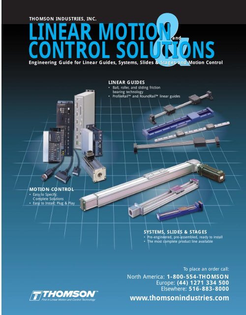
LINEAR MOTION<br />
CONTROL SOLUTIONS<br />
Engineering Guide for <strong>Linear</strong> Guides, Systems, Slides & Stages <strong>and</strong> Motion <strong>Control</strong><br />
THOMSON INDUSTRIES, INC.<br />
MOTION CONTROL<br />
• Easy to Specify;<br />
Complete <strong>Solutions</strong><br />
• Easy to Install; Plug & Play<br />
TM<br />
<strong>and</strong><br />
Engineering Guide for <strong>Linear</strong> Guides, Systems, Slides & Stages <strong>and</strong> Motion <strong>Control</strong><br />
LINEAR GUIDES<br />
• Ball, roller, <strong>and</strong> sliding friction<br />
bearing technology<br />
• ProfileRail <strong>and</strong> RoundRail linear guides<br />
SYSTEMS, SLIDES & STAGES<br />
• Pre-engineered, pre-assembled, ready to install<br />
• The most complete product line available<br />
To place an order call:<br />
North America: 1-800-554-THOMSON<br />
Europe: (44) 1271 334 500<br />
Elsewhere: 516-883-8000<br />
www.thomsonindustries.com
Part Number Index (Alphabetical)<br />
Part<br />
Number Page<br />
Prefix Description Number<br />
1AA Single Race Unsupported <strong>Linear</strong> Guide 98<br />
1AB Double Race Unsupported <strong>Linear</strong> Guide 100<br />
1AC Unsupported <strong>Linear</strong> Guide with Carriage 102<br />
1BA Single Race End Supported <strong>Linear</strong> Guide 110<br />
1BB Double Race End Supported <strong>Linear</strong> Guide 112<br />
1BC End Supported <strong>Linear</strong> Guide with Carriage 114<br />
1CA Single Race Continuously Supported <strong>Linear</strong> Guide 62<br />
1CB Double Race Continuously Supported <strong>Linear</strong> Guide 64<br />
1CC Continuously Supported <strong>Linear</strong> Guide with Carriage 66<br />
1DA Single Race Side Mounted <strong>Linear</strong> Guide 76<br />
1DB Double Race Side Mounted <strong>Linear</strong> Guide 78<br />
1DC Side Mounted <strong>Linear</strong> Guide with Carriage 80<br />
1FA Single Race Smart Rail* <strong>Linear</strong> Guide 124<br />
1FB Double Race Smart Rail <strong>Linear</strong> Guide 126<br />
1FC Smart Rail <strong>Linear</strong> Guide with Carriage 128<br />
1GA Single Race Bolt from Bottom <strong>Linear</strong> Guide 84<br />
1GB Double Race Bolt from Bottom <strong>Linear</strong> Guide 86<br />
1GC Bolt from Bottom <strong>Linear</strong> Guide with Carriage 88<br />
1MA Single Race Unsupported <strong>Linear</strong> Guide (metric) 104<br />
1MB Double Race Unsupported <strong>Linear</strong> Guide (metric) 106<br />
1MC Unsupported <strong>Linear</strong> Guide with Carriage (metric) 108<br />
1NA Single Race End Supported <strong>Linear</strong> Guide (metric) 116<br />
1NB Double Race End Supported <strong>Linear</strong> Guide (metric) 118<br />
1NC End Supported <strong>Linear</strong> Guide with Carriage (metric) 120<br />
1PA Single Race Continuously Supported <strong>Linear</strong> Guide (metric) 68<br />
1PB Double Race Continuously Supported <strong>Linear</strong> Guide (metric) 70<br />
1PC Continuously Supported <strong>Linear</strong> Guide with Carriage (metric) 72<br />
1QA Single Race Smart Rail <strong>Linear</strong> Guide (metric) 130<br />
1QB Double Race Smart Rail <strong>Linear</strong> Guide (metric) 132<br />
1QC Smart Rail <strong>Linear</strong> Guide with Carriage (metric) 134<br />
1RA Single Race Bolt from Bottom <strong>Linear</strong> Guide (metric) 90<br />
1RB Double Race Bolt from Bottom <strong>Linear</strong> Guide (metric) 92<br />
1RC Bolt from Bottom <strong>Linear</strong> Guide with Carriage (metric) 94<br />
1VA Single Race Unsupported Corrosion Resistant <strong>Linear</strong> Guide 42<br />
1VA Single Race End Supported Corrosion Resistant <strong>Linear</strong> Guide 48<br />
1VA Single Race Continuously Supported Corrosion Resistant <strong>Linear</strong> Guide 54<br />
1VB Double Race Unsupported Corrosion Resistant <strong>Linear</strong> Guide 44<br />
1VB Double Race End Supported Corrosion Resistant <strong>Linear</strong> Guide 50<br />
1VB Double Race Continuously Supported Corrosion Resistant <strong>Linear</strong> Guide 56<br />
1VC Unsupported Corrosion Resistant <strong>Linear</strong> Guide with Carriage 46<br />
1VC End Supported Corrosion Resistant <strong>Linear</strong> Guide with Carriage 52<br />
1VC Continuously Supported Corrosion Resistant <strong>Linear</strong> Guide with Carriage 58<br />
1WA RoundWay* Bolt from Bottom <strong>Linear</strong> Guide-Single Type 138<br />
1WA RoundWay Bolt from Bottom <strong>Linear</strong> Guide-Dual Type 140<br />
2AA Double Race End Supported Quickslide* <strong>Linear</strong> Guide with Carriage 168<br />
2AB Ball Screw Actuated Double Race End Supported Superslide* System 224<br />
PART NUMBER INDEX<br />
Part Number Index (Alphabetical)<br />
Part<br />
Number Page<br />
Prefix Description Number<br />
2BA Twin Shaft Quickslide* <strong>Linear</strong> Guide 154<br />
2BB Twin Shaft Superslide* <strong>Linear</strong> Motion System 226<br />
2CA Twin Shaft Web QuickSlide <strong>Linear</strong> Guide 160<br />
2CB Twin Shaft Web Superslide <strong>Linear</strong> Motion System 228<br />
2DA Dual Shaft Rail QuickSlide <strong>Linear</strong> Guide 146<br />
2DA Dual Shaft Rail QuickSlide with Manual Brake 294<br />
2DB Dual Shaft Rail SuperSlide <strong>Linear</strong> Motion System 230<br />
2DB Dual Shaft Rail SuperSlide <strong>Linear</strong> Motion System (metric) 258<br />
2EA Double Race Continuous Support <strong>Linear</strong> Guide 172<br />
2EB Double Race Continuous Support SuperSlide <strong>Linear</strong> Motion System 234<br />
2GE Turbo Module* Belt Driven <strong>Linear</strong> Motion System 284<br />
2HB AccuSlide Ball Screw Driven <strong>Linear</strong> Motion System 260<br />
2HE AccuSlide Belt Driven <strong>Linear</strong> Motion System 274<br />
2NB End Supported SuperSlide Ball Screw Driven <strong>Linear</strong> Motion System 256<br />
2NE End Supported SuperSlide Belt Driven <strong>Linear</strong> Motion System 272<br />
2RB Continuous Support SuperSlide Ball Screw Driven <strong>Linear</strong> Motion System 262<br />
2RE Continuous Support SuperSlide Belt Driven <strong>Linear</strong> Motion System 276<br />
AT AccuGlide* T-Series* <strong>Linear</strong> Guide 35<br />
AP AXI-PAK* Motion <strong>Control</strong> Package 397<br />
APi AXI-PAK* Motion <strong>Control</strong> Package with Indexing 401<br />
ASC Aluminum Shroud Cover 302<br />
BEL Bellows Way Covers 74,122, 152, 166, 170, 174, 291<br />
BLX Brushless Servo Motors 431<br />
BSA Ball Screw Assemblies 236<br />
CD AccuGlide* <strong>Linear</strong> Guide (Miniature Series Carriage) 29<br />
CG AccuGlide <strong>Linear</strong> Guide (St<strong>and</strong>ard Carriage) 17<br />
CM AccuMax* <strong>Linear</strong> Guide (Carriage) 11<br />
HW H<strong>and</strong>wheels 308<br />
LSP Limit Switch Package (for Metric Size Systems) 296<br />
MAB Motor Adaptor Blocks 289<br />
MC Motor Couplings 288<br />
MS MicroStage* <strong>Linear</strong> Guide 175<br />
MS Micro Stage Actuated <strong>Linear</strong> Motion System 245<br />
OD OMNIDRIVE* Digital Servo Drive (Full Size) 417<br />
ODM OMNIDRIVE Digital Servo Drive (Mini Size) 416<br />
RADMO Radial Mount Ball Screw Shaft Extenders 292<br />
RD AccuGlide <strong>Linear</strong> Guide (Miniature Series Rail) 29<br />
RG AccuGlide <strong>Linear</strong> Guide (St<strong>and</strong>ard Rail) 17<br />
RM AccuMax <strong>Linear</strong> Guide (Rail) 11<br />
RMC Radial Mount Couplings 293<br />
TBC7 Electric Brake <strong>Control</strong>ler 306<br />
TEB Spring Set Electric Brakes 304<br />
TMC TMC 2000 Motion <strong>Control</strong>ler 385<br />
TNUT Tee Nut Mounting Hardware 308<br />
TP Touch Pad 411<br />
For Application Engineering assistance contact the <strong>Thomson</strong> Technical HelpLine at 1-800-554-8466.<br />
* Trademark of <strong>Thomson</strong> Industries, Inc. THOMSON is registered in the U.S. Patent <strong>and</strong> Trademark Office <strong>and</strong> in other countries.<br />
Page 1<br />
<strong>Linear</strong> Guides Systems, Slides, <strong>and</strong> Stages Motion <strong>Control</strong>
<strong>Linear</strong> Guides<br />
AccuMax* <strong>Linear</strong> Guide<br />
Page 2<br />
LINEAR GUIDES PRODUCT SELECTOR<br />
LINEAR GUIDE NUMBER 1<br />
Extremely High Rigidity, High Accuracy<br />
• Dynamic Load Capacity: up to 40,700 lb f per carriage<br />
• Maximum Speed: 6.5 ft/sec<br />
• Maximum Acceleration: 5g<br />
• Mounting: continuously supported, dual rail<br />
LINEAR GUIDE NUMBER 2<br />
High Rigidity, Industry St<strong>and</strong>ard Envelope<br />
• Dynamic Load Capacity: up to 21,800 lb f per carriage<br />
• Maximum Speed: 10 ft/sec<br />
• Maximum Acceleration: 5g<br />
• Mounting: continuously supported, single or dual rail<br />
AccuGlide* <strong>Linear</strong> Guide<br />
LINEAR GUIDE NUMBER 3<br />
Low Profile, Compact Design<br />
• Dynamic Load Capacity: up to 2,700 lb f per carriage<br />
• Maximum Speed: 10 ft/sec<br />
• Maximum Acceleration: 5g<br />
• Mounting: continuously supported, single or dual rail<br />
AccuGlide (Mini) <strong>Linear</strong> Guide<br />
LINEAR GUIDE NUMBER 4<br />
Low Cost, Compliant Structure, Industry St<strong>and</strong>ard Envelope<br />
• Dynamic Load Capacity: up to 5,620 lb f per carriage<br />
• Maximum Speed: 10 ft/sec<br />
• Maximum Acceleration: 5g<br />
• Mounting: continuously supported, dual rail<br />
T-Series* <strong>Linear</strong> Guide<br />
LINEAR GUIDE NUMBER 5<br />
Corrosive/Contaminated Environments<br />
• Dynamic Load Capacity: up to 12,000 lb f per carriage<br />
• Maximum Speed: 6.67 ft/sec ‡<br />
• Maximum Acceleration: unlimited ‡<br />
• Mounting: continuously or end supported, dual rail<br />
‡ Load, speed <strong>and</strong> acceleration are dependent variables<br />
FluoroNyliner* <strong>Linear</strong> Guide<br />
Page<br />
11<br />
Page<br />
17<br />
Page<br />
29<br />
Page<br />
35<br />
Page<br />
41<br />
LINEAR GUIDE NUMBER 6<br />
Fully Supported, Industry St<strong>and</strong>ard Dimensions<br />
• Dynamic Load Capacity: up to 54,800 lb f per carriage<br />
• Maximum Speed: 10 ft/sec<br />
• Maximum Acceleration: 5g<br />
• Mounting: continuously supported, dual rail<br />
Continuous Support <strong>Linear</strong> Guide<br />
LINEAR GUIDE NUMBER 7<br />
Side Mounted for Multiple Orientations<br />
• Dynamic Load Capacity: up to 2,480 lb f per carriage<br />
• Maximum Speed: 10 ft/sec<br />
• Maximum Acceleration: 5g<br />
• Mounting: continuously supported, dual rail<br />
Side Mounted <strong>Linear</strong> Guide<br />
LINEAR GUIDE NUMBER 8<br />
Low Profile, Enhanced Sealing<br />
• Dynamic Load Capacity: up to 12,320 lb f per carriage<br />
• Maximum Speed: 10 ft/sec<br />
• Maximum Acceleration: 5g<br />
• Mounting: continuously supported, dual rail<br />
Bolt From Bottom <strong>Linear</strong> Guide<br />
LINEAR GUIDE NUMBER 9<br />
End Supported, Industry St<strong>and</strong>ard Dimension<br />
• Dynamic Load Capacity: up to 12,320 lb f per carriage<br />
• Maximum Speed: 10 ft/sec<br />
• Maximum Acceleration: 5g<br />
• Mounting: end supported, dual rail<br />
End Support <strong>Linear</strong> Guide<br />
LINEAR GUIDE NUMBER 10<br />
Low Profile, Easy to Install<br />
• Dynamic Load Capacity: up to 12,320 lb f per carriage<br />
• Maximum Speed: 10 ft/sec<br />
• Maximum Acceleration: 5g<br />
• Mounting: continuously supported, dual rail<br />
Smart Rail* <strong>Linear</strong> Guide<br />
For Application Engineering assistance contact the <strong>Thomson</strong> Technical HelpLine at 1-800-554-8466.<br />
* Trademark of <strong>Thomson</strong> Industries, Inc. THOMSON is registered in the U.S. Patent <strong>and</strong> Trademark Office <strong>and</strong> in other countries.<br />
Page<br />
61<br />
Page<br />
75<br />
Page<br />
83<br />
Page<br />
97<br />
Page<br />
123
LINEAR GUIDE NUMBER 11<br />
Contaminated Environments, High Shock Loads<br />
• Dynamic Load Capacity: up to 70,000 lb f per carriage<br />
• Maximum Speed: 100 ft/sec<br />
• Maximum Acceleration: 14g<br />
• Mounting: continuously supported, dual rail<br />
RoundWay* <strong>Linear</strong> Guide<br />
LINEAR GUIDE NUMBER 12<br />
Unpack <strong>and</strong> Install<br />
• Dynamic Load Capacity: up to 2,480 lb f per carriage<br />
• Maximum Speed: 10 ft/sec<br />
• Maximum Acceleration: 5g<br />
• Mounting: continuously supported, single axis assembly<br />
Dual Shaft Rail* <strong>Linear</strong> Guide<br />
LINEAR GUIDE NUMBER 13<br />
Unpack <strong>and</strong> Install<br />
• Dynamic Load Capacity: up to 50 lb f per carriage<br />
• Maximum Speed: 10 ft/sec<br />
• Maximum Acceleration: 5g<br />
• Mounting: end supported, single axis assembly<br />
Twin Shaft* <strong>Linear</strong> Guide<br />
LINEAR GUIDE NUMBER 14<br />
Unpack <strong>and</strong> Install<br />
• Dynamic Load Capacity: up to 3,000 lb f per carriage<br />
• Maximum Speed: 10 ft/sec<br />
• Maximum Acceleration: 5g<br />
• Mounting: end supported, single axis assembly<br />
Twin Shaft Web* <strong>Linear</strong> Guide<br />
LINEAR GUIDE NUMBER 15<br />
Unpack <strong>and</strong> Install<br />
• Dynamic Load Capacity: up to 12,320 lb f per carriage<br />
• Maximum Speed: 10 ft/sec<br />
• Maximum Acceleration: 5g<br />
• Mounting: end supported, single axis assembly<br />
Double End Support <strong>Linear</strong> Guide<br />
Page<br />
137<br />
Page<br />
145<br />
Page<br />
153<br />
Page<br />
159<br />
Page<br />
167<br />
LINEAR GUIDES PRODUCT SELECTOR<br />
LINEAR GUIDE NUMBER 16<br />
Unpack <strong>and</strong> Install<br />
• Dynamic Load Capacity: up to 12,320 lb f per carriage<br />
• Maximum Speed: 10 ft/sec<br />
• Maximum Acceleration: 5g<br />
• Mounting: continuously supported, single axis assembly<br />
Double Continuous Support <strong>Linear</strong> Guide<br />
LINEAR GUIDE NUMBER 17<br />
Unpack <strong>and</strong> Install<br />
• Dynamic Load Capacity: up to 33 lb f per carriage<br />
• Maximum Speed: 10 ft/sec<br />
• Maximum Acceleration: 5g<br />
• Mounting: continuously supported, single axis assembly<br />
MicroStage* <strong>Linear</strong> Guide<br />
LINEAR GUIDES<br />
Installation Guidelines<br />
LINEAR GUIDES<br />
Engineering Support<br />
COMING SOON!<br />
E-Series<br />
• 1-piece, low cost, shaft rail assembly for sliding<br />
contact guides<br />
R-Series<br />
• Stainless steel miniature profile rail guidessizes<br />
7, 9, <strong>and</strong> 12<br />
Rail Covers<br />
• for profile rail products (with optional integral linear scale)<br />
Noise Dampening Lubricants<br />
Call <strong>Thomson</strong> Technical Helpline for technical information <strong>and</strong><br />
product availability:<br />
1-800-554-8466<br />
New <strong>Linear</strong> Guides <strong>and</strong> Accessories<br />
For Application Engineering assistance contact the <strong>Thomson</strong> Technical HelpLine at 1-800-554-8466.<br />
* Trademark of <strong>Thomson</strong> Industries, Inc. THOMSON is registered in the U.S. Patent <strong>and</strong> Trademark Office <strong>and</strong> in other countries.<br />
Page<br />
171<br />
Page<br />
175<br />
Page<br />
178<br />
Page<br />
185<br />
Page 3<br />
<strong>Linear</strong> Guides
Systems, Slides, <strong>and</strong> Stages<br />
MicroStage* MS<br />
SuperSlide* 2AB<br />
Twin Shaft* SuperSlide 2BB<br />
Page 4<br />
SYSTEMS, SLIDES, & STAGES<br />
PRODUCT SELECTOR<br />
A miniature lead screw actuated double race continuously<br />
supported linear motion system available with:<br />
• pre-aligned <strong>Linear</strong>Race* ways<br />
• the segmented Super Ball Bushing* bearing<br />
• an integral lead screw assembly<br />
• nominal sizes of 25mm <strong>and</strong> 33mm overall heights<br />
• screw leads from .25 inch to 1.2 inch<br />
A ball screw actuated double race end supported system<br />
available with:<br />
• pre-aligned <strong>Linear</strong>Race ways<br />
• the Super Smart Ball Bushing* bearing<br />
• an integral ball screw assembly<br />
• nominal sizes from 1/2 inch to 1 1/2 inch shaft diameters<br />
• ball screw leads from .200 inch to 1.875 inch<br />
A lead screw actuated welded double race end supported<br />
system available with:<br />
• pre-aligned <strong>and</strong> welded <strong>Linear</strong>Race ways<br />
• the segmented Super Ball Bushing bearing<br />
• an integral lead screw assembly<br />
• screw leads from .100 inch to 1.00 inch<br />
• end supports for use when bridging or spanning a gap<br />
A ball screw actuated welded double race end supported<br />
system available with:<br />
• pre-aligned <strong>and</strong> welded <strong>Linear</strong>Race ways<br />
• the Super Smart Ball Bushing bearing<br />
• an integral ball screw assembly<br />
• nominal sizes in 1/2, 3/4, <strong>and</strong> 1.00 inch shaft diameters<br />
• end supports for use when bridging or spanning a gap<br />
Twin Shaft Web* SuperSlide 2CB<br />
A ball or lead screw actuated double race continuously<br />
supported system available with:<br />
• pre-aligned <strong>and</strong> continuously supported <strong>Linear</strong>Race ways<br />
• the Super Smart Ball Bushing bearing<br />
• an integral ball screw assembly<br />
• nominal sizes in 1/2, 3/4, <strong>and</strong> 1.00 inch shaft diameters<br />
• ball screw leads from .200 inch to 1.00 inch<br />
Dual Shaft Rail* SuperSlide 2DB<br />
Page<br />
245<br />
Page<br />
224<br />
Page<br />
226<br />
Page<br />
228<br />
Page<br />
230<br />
SuperSlide 2EB<br />
For Application Engineering assistance contact the <strong>Thomson</strong> Technical HelpLine at 1-800-554-8466.<br />
* Trademark of <strong>Thomson</strong> Industries, Inc. THOMSON is registered in the U.S. Patent <strong>and</strong> Trademark Office <strong>and</strong> in other countries.<br />
A ball screw actuated double race continuously supported system<br />
available with:<br />
• pre-aligned <strong>and</strong> continuously supported <strong>Linear</strong>Race ways<br />
• the Super Smart Ball Bushing bearing<br />
• an integral ball screw assembly<br />
• nominal sizes from 1/2 inch to 1 1/2 inch shaft diameters<br />
• ball screw leads from .200 inch to 1.875 inch<br />
A linear actuation system with integral end supports available with:<br />
• integral end supports for a fixed/simple mounting arrangement<br />
• angular contact thrust bearings for high axial load capacity<br />
• nominal sizes from 1/2 inch to 1 1/2 inch screw diameters<br />
• ball screw leads from .200 inch to 1.875 inch<br />
• ball nut mounting heights that adapt to appropriately<br />
sized linear guides<br />
Ball Screw Assemblies-Model BSA<br />
A ball screw actuated double race end supported system in metric<br />
dimensions available with:<br />
• pre-aligned <strong>Linear</strong>Race ways<br />
• the Super Smart Ball Bushing bearing<br />
• an integral ball screw assembly<br />
• 20mm nominal size shaft diameter<br />
• ball screw leads from 5mm to 20mm<br />
SuperSlide 2NB<br />
A ball or lead screw actuated double race continuously<br />
supported system in metric dimensions available with:<br />
• pre-aligned <strong>and</strong> continuously supported <strong>Linear</strong>Race ways<br />
• the Super Smart Ball Bushing bearing<br />
• an integral ball screw assembly<br />
• nominal sizes in 1/2, 3/4, <strong>and</strong> 1.00 inch shaft diameters<br />
• 5mm ball screw lead<br />
Dual Shaft Rail* SuperSlide 2DB - Metric<br />
A ball screw actuated double race contiuously supported<br />
system in metric dimensions available with:<br />
• pre-aligned <strong>and</strong> continuously supported <strong>Linear</strong>Race ways<br />
• the Super Smart Ball Bushing bearing<br />
• an integral ball screw assembly<br />
• 12mm <strong>and</strong> 16mm nominal size shaft diameters<br />
• ball screw leads from 5mm to 20mm<br />
SuperSlide 2RB<br />
Page<br />
234<br />
Page<br />
236<br />
Page<br />
256<br />
Page<br />
258<br />
Page<br />
262
A ball screw actuated double linear ball guide contiuously<br />
supported system in metric dimensions available with:<br />
• pre-aligned <strong>and</strong> continuously supported AccuGlide* linear ball<br />
guides<br />
• an integral ball screw assembly<br />
• 10mm <strong>and</strong> 20mm nominal size systems<br />
• ball screw leads from 5mm to 25mm<br />
AccuSlide* 2HB<br />
A belt driven double race end supported system in metric<br />
dimensions available with:<br />
• pre-aligned <strong>Linear</strong>Race* ways<br />
• the Super Smart Ball Bushing* bearing<br />
• an integral belt drive assembly<br />
• a NemaTRUE* planetary gearhead in 4 st<strong>and</strong>ard ratios<br />
• 20mm nominal size shaft diameter<br />
SuperSlide 2NE<br />
A belt driven double race contiuously supported system in<br />
metric dimensions available with:<br />
• pre-aligned <strong>and</strong> continuously supported <strong>Linear</strong>Race ways<br />
• the Super Smart Ball Bushing bearing<br />
• an integral belt drive assembly<br />
• a NemaTRUE* planetary gearhead in 4 st<strong>and</strong>ard ratios<br />
• 12mm <strong>and</strong> 16mm nominal size shaft diameters<br />
SuperSlide 2RE<br />
A belt driven double linear ball guide contiuously supported<br />
system in metric dimensions available with:<br />
• pre-aligned <strong>and</strong> continuously supported AccuGlide<br />
linear ball guides<br />
• an integral belt drive assembly<br />
• a NemaTRUE planetary gearhead in 4 st<strong>and</strong>ard ratios<br />
• 10mm <strong>and</strong> 20mm nominal size systems<br />
AccuSlide 2HE<br />
A belt driven single linear ball guide system for heavy duty<br />
overhung load or gantry applications available with:<br />
• a base assembly that is designed to be its own support structure<br />
• pre-aligned <strong>and</strong> continuously supported AccuGlide<br />
linear ball guides<br />
• an integral belt drive assembly<br />
• an AccuTRUE* planetary gearhead in 3 st<strong>and</strong>ard ratios<br />
Turbo Module* 2GE<br />
Page<br />
260<br />
Page<br />
272<br />
Page<br />
276<br />
Page<br />
274<br />
Page<br />
284<br />
SYSTEMS, SLIDES, & STAGES<br />
PRODUCT SELECTOR<br />
• motor couplings <strong>and</strong> motor adaptor blocks<br />
• protective bellows<br />
• radial mount ball screw shaft extender<br />
• QuickSlide* with manual brake<br />
• limit switch packages<br />
• TEB spring set brakes<br />
• TBC7 brake controller<br />
• H<strong>and</strong> wheels<br />
• T-nuts<br />
Accessories<br />
SuperSlide ball screw actuated systems<br />
Inch size<br />
System selection requirements<br />
Engineering Support-Inch<br />
SuperSlide ball screw actuated systems<br />
Metric size<br />
System selection requirements<br />
Engineering Support-Metric<br />
SuperSlide belt actuated systems<br />
Metric size<br />
System selection requirements<br />
Engineering Support-Metric<br />
Turbo module belt actuated systems<br />
Metric size<br />
System selection requirements<br />
Engineering Support-Metric<br />
For Application Engineering assistance contact the <strong>Thomson</strong> Technical HelpLine at 1-800-554-8466.<br />
* Trademark of <strong>Thomson</strong> Industries, Inc. THOMSON is registered in the U.S. Patent <strong>and</strong> Trademark Office <strong>and</strong> in other countries.<br />
Page<br />
287<br />
Page<br />
310<br />
Page<br />
327<br />
Page<br />
342<br />
Page<br />
359<br />
Page 5<br />
Systems, Slides, <strong>and</strong> Stages
Motion <strong>Control</strong><br />
Page 6<br />
MOTION CONTROL SOLUTION SELECTOR<br />
TMC 2000 MOTION CONTROLLER<br />
AXI-PAK* Complete Servo Axis Package<br />
OMNIDRIVE Digital Servo Drives<br />
BLX Brushless Servo Motors<br />
• High performance, st<strong>and</strong> alone, multi axis servo <strong>and</strong> stepper motor controller<br />
• Performs point to point motion, linear <strong>and</strong> circular interpolation, contouring, electronic gearing, electronic cam,<br />
<strong>and</strong> jogging<br />
• Powerful yet simple instruction set supports multitasking, user variables <strong>and</strong> arrays, arithmetic <strong>and</strong><br />
logic functions, position latch, event triggers, error h<strong>and</strong>ling <strong>and</strong> more.<br />
• Servo Setup Kit* software for Windows® provides communications, program editing,<br />
tuning <strong>and</strong> diagnostics<br />
• All optoisolated I/O<br />
• A complete servo axis that operates either with a motion controller or as a smart st<strong>and</strong> alone drive<br />
• Includes a matched BLX brushless motor, OMNIDRIVE* digital servo drive, professionally molded cables,<br />
OMNI LINK* setup software, <strong>and</strong> documentation for a fast <strong>and</strong> worry free installation<br />
• The latest technology <strong>and</strong> most rugged design for a high performance industrial quality turn key<br />
motion control solution<br />
• Fully digital “smart” brushless servo amplifier with integrated power supply<br />
• Configurable for analog input, step <strong>and</strong> direction, serial link, encoder follower, electronic gearing.<br />
• Indexing option for st<strong>and</strong> alone positioning capabilities<br />
• Available in 0.5, 1, 2, 3, 7.5, <strong>and</strong> 15 kW continuous power ratings<br />
• Included OMNI LINK setup <strong>and</strong> diagnostic software<br />
• Superior magnetic <strong>and</strong> thermal design gives exceptional performance <strong>and</strong> the highest torque per frame size<br />
• St<strong>and</strong>ard IP65 sealing, MS style fluid tight connectors, oversize bearings, <strong>and</strong> thermal switch ensure a long<br />
<strong>and</strong> worry free service life<br />
• A variety of frame sizes <strong>and</strong> winding configurations are available to suit your precise application needs<br />
• Internal bearing mounted commutating encoder provides precision <strong>and</strong> reliability<br />
• Available with planetary gearheads <strong>and</strong> internal brakes<br />
www.thomsoncontrol.com<br />
Call: 1-800-554-THOMSON<br />
For Application Engineering assistance contact the <strong>Thomson</strong> Technical HelpLine at 1-800-554-8466.<br />
* Trademark of <strong>Thomson</strong> Industries, Inc. THOMSON is registered in the U.S. Patent <strong>and</strong> Trademark Office <strong>and</strong> in other countries.<br />
Page<br />
385<br />
Page<br />
397<br />
Page<br />
413<br />
Page<br />
431
THOMSON INDUSTRIES, INC.<br />
LINEAR GUIDE<br />
SOLUTIONS<br />
Engineering Guide for <strong>Linear</strong> Guides<br />
TM<br />
For Application Engineering assistance contact the <strong>Thomson</strong> Technical HelpLine at 1-800-554-8466.<br />
* Trademark of <strong>Thomson</strong> Industries, Inc. THOMSON is registered in the U.S. Patent <strong>and</strong> Trademark Office <strong>and</strong> in other countries.<br />
LINEAR GUIDES<br />
• Ball, roller, <strong>and</strong> sliding friction<br />
bearing technology<br />
• ProfileRail* <strong>and</strong> RoundRail* linear guides<br />
www.linearguides.com<br />
Page 7<br />
<strong>Linear</strong> Guides Section
<strong>Linear</strong> Guides<br />
Page 8<br />
<strong>Linear</strong> Guide Selection Criteria:<br />
• Load/Life<br />
• Travel Accuracy<br />
• Rigidity<br />
• Smoothness of Travel<br />
• Speed & Acceleration<br />
• Envelope<br />
• Environment<br />
Application Selector Guide<br />
AccuMax*<br />
AccuGlide*<br />
Application Criteria 1 2 3 4 5 6 7 8 9 10 11 12 13 14 15 16 17<br />
High Loads ✔ ✔ ✔ ✔ ✔ ✔ ✔ ✔ ✔ ✔<br />
Equivalent Load in All Directions ✔ ✔ ✔ ✔<br />
Ultra Compactness ✔ ✔ ✔ ✔<br />
High Travel Accuracy ✔ ✔ ✔<br />
High Rigidity ✔ ✔ ✔<br />
Extreme Smoothness ✔ ✔ ✔ ✔ ✔ ✔ ✔ ✔ ✔ ✔ ✔ ✔<br />
End Supported ✔ ✔✔ ✔<br />
Single Rail ✔ ✔ ✔ ✔<br />
Harsh Environment ✔ ✔ ✔<br />
Low Cost Installation (multiple rail) ✔ ✔ ✔ ✔ ✔ ✔ ✔<br />
Complete Axis Solution ✔ ✔ ✔ ✔ ✔ ✔<br />
Page No. 11 17 29 35 41 61 75 83 97 123 137 145 153 159 167 171 175<br />
Application Examples:<br />
• Machine Tools<br />
• Packaging Machinery<br />
• Automotive Assembly Equipment<br />
The specifications <strong>and</strong> data in this publication are believed to be accurate <strong>and</strong> reliable. However, it is the responsibility of the product user to determine the<br />
suitability of <strong>Thomson</strong> products for a specific application. While defective products will be replaced without charge if promptly returned, no liability is<br />
assumed beyond such replacement.<br />
* Trademark of <strong>Thomson</strong> Industries, Inc. THOMSON is registered in the U.S. Patent <strong>and</strong> Trademark Office <strong>and</strong> in other countries.<br />
T-Series*<br />
AccuGlide (mini)<br />
FluoroNyliner*<br />
Continuous Support<br />
Side Mounted<br />
Bolt From Bottom<br />
• Cost of Product<br />
• Cost of Installation<br />
• Cost of Replacement<br />
<strong>Linear</strong> Guide<br />
End Support<br />
Smart Rail*<br />
RoundWay*<br />
Dual Shaft Rail<br />
Twin Shaft*<br />
Twin Shaft Web*<br />
• Semiconductor Equipment<br />
• Medical Equipment<br />
• Food Processing Equipment<br />
Double End Support<br />
Double Continuous Support<br />
For more information, or to place an order, please contact your local authorized <strong>Thomson</strong> distributor or<br />
<strong>Thomson</strong> Industries, at 1-800-554-THOMSON, Fax: 1-800-445-0329, or E-mail at linearguides@thomsonmail.com.<br />
MicroStage*
<strong>Linear</strong> Guide Selection Process:<br />
The selection of a type of linear guide will greatly effect machine performance <strong>and</strong> overall cost.<br />
For example, selecting a guide with too much rigidity will decrease the allowable installation tolerances,<br />
therefore greatly increasing surface preparation costs. If the costs are not incurred by properly preparing the<br />
mounting surface, the guide will run rough <strong>and</strong> need to be replaced more frequently due to a reduced life.<br />
In order to meet the widely varying dem<strong>and</strong>s of today’s applications, proper selection from a broad<br />
product range will optimize performance <strong>and</strong> reduce costs. The following selection process will assist you in<br />
choosing the appropriate linear guide for your application. See Engineering Section for more details.<br />
(page 185)<br />
• Review the <strong>Linear</strong> Guide Selection Criteria on page 8, considering all criteria for the application.<br />
• Using the Application Selection Guide on page 8, select the appropriate type of guide.<br />
• Determine the load on the most heavily loaded carriage or bearing.<br />
• Calculate the minimum required dynamic load rating, Cmin, for the bearing life required between<br />
replacements.<br />
• Select the size which offers the load rating, C, equal to or greater than the minimum required<br />
dynamic load rating, Cmin.<br />
• If the guide selected offers various preload levels, select a preload based upon the allowable bearing<br />
deflection.<br />
• If the guide selected offers various accuracy classes, select an accuracy class based upon the<br />
required travel accuracy.<br />
• Determine the need for accessories/options.<br />
• Select the appropriate part number.<br />
If you require any assistance selecting the appropriate linear guide for your application, please contact<br />
<strong>Thomson</strong>’s Application Engineering Group: In North America: (800) 554-8466<br />
In Europe: (44) 1271 334 500<br />
Elsewhere: (516) 883-8937<br />
The specifications <strong>and</strong> data in this publication are believed to be accurate <strong>and</strong> reliable. However, it is the responsibility of the product user to determine the<br />
suitability of <strong>Thomson</strong> products for a specific application. While defective products will be replaced without charge if promptly returned, no liability is<br />
assumed beyond such replacement.<br />
* Trademark of <strong>Thomson</strong> Industries, Inc. THOMSON is registered in the U.S. Patent <strong>and</strong> Trademark Office <strong>and</strong> in other countries.<br />
Page 9<br />
<strong>Linear</strong> Guides
<strong>Linear</strong> Guides<br />
Page 10<br />
Maintenance-Free<br />
The new LL Option can provide maintenance-free operation <strong>and</strong> enhanced<br />
protection for a broad range of applications.<br />
• Only <strong>Thomson</strong> offers both RoundRail* <strong>and</strong> ProfileRail* self-lubricating linear guides<br />
• Reduces system cost by eliminating the need for expensive lubrication systems<br />
• Clean, self-lubricating applicator eliminates oil-related contamination<br />
• Increases bearing life by offering enhanced protection<br />
Oil-saturated Polymer<br />
Double Lip Seal<br />
Contact Spring<br />
All <strong>Thomson</strong> Industries Manufacturing Locations are<br />
ISO 9000 Certified <strong>and</strong> Automotive Facilities<br />
Operate to QS-9000 St<strong>and</strong>ards<br />
Three-time Winner General Motors Supplier of the Year<br />
ISO 9000<br />
* Trademark of <strong>Thomson</strong> Industries, Inc. THOMSON is registered in<br />
the U.S. Patent <strong>and</strong> Trademark Office <strong>and</strong> in other countries.<br />
©1999 <strong>Thomson</strong> Industries, Inc. Printed in the U.S.A.<br />
8-12-99 HAP 9906-08.QXD<br />
DESIGN<br />
The LL option<br />
consists of a section<br />
of oil-saturated<br />
polymer, custom made<br />
to fit the rail. These sections<br />
are installed on each<br />
end, inside the double lip seal.<br />
A proprietary spring assembly<br />
assures continuous contact with the<br />
rail, releasing oil as the carriage moves.<br />
This ensures a film of lubricant between<br />
the balls <strong>and</strong> bearing races, <strong>and</strong> provides<br />
enhanced protection, maintaining long-term<br />
running efficiency.<br />
PERFORMANCE<br />
<strong>Thomson</strong> has incorporated a proven oil-saturated<br />
polymer used for over 10 years to lubricate radial<br />
bearings. This product has a successful track record in<br />
applications ranging from food processing to automotive<br />
assembly.<br />
See Page 210 for technical data.<br />
PATENT PENDING<br />
THOMSON INDUSTRIES, INC.<br />
2 Channel Drive • Port Washington, NY 11050 USA<br />
� 1 (800) 554-8466 • Fax: 1 (516) 883-9039<br />
Internet: www.thomsonindustries.com • E-mail: thomson@thomsonmail.com<br />
<strong>Linear</strong>Fax*: 1 (800) 55-4-THOMSON • Employment Opportunities Fax: 1 (516) 883-4109<br />
The specifications <strong>and</strong> data in this publication are believed to be accurate <strong>and</strong> reliable. However, it is the responsibility of the product user to determine the<br />
suitability of <strong>Thomson</strong> products for a specific application. While defective products will be replaced without charge if promptly returned, no liability is<br />
assumed beyond such replacement.<br />
* Trademark of <strong>Thomson</strong> Industries, Inc. THOMSON is registered in the U.S. Patent <strong>and</strong> Trademark Office <strong>and</strong> in other countries.
AccuMax <strong>Linear</strong> Roller Guides #1<br />
3<br />
1 4<br />
NEW<br />
2<br />
5<br />
NEW<br />
■ Approximately twice the load capacity of<br />
equally-sized linear ball guides. This<br />
improvement in bearing capacity provides<br />
10X increase in bearing life; costly service <strong>and</strong><br />
maintenance is reduced<br />
■ Approximately twice the rigidity of equally-sized<br />
linear ball guides for a dramatic improvement in<br />
machine tool accuracy<br />
■ The Arcuate Advantage*, a patented design<br />
which utilize cylindrical roller elements on<br />
continuously crowned races, ensuring reliable<br />
bearing performance<br />
6<br />
7<br />
8<br />
NEW<br />
HIGH LOADS, EXTREME PRECISION,<br />
HIGH RIGIDITY<br />
<strong>Thomson</strong> AccuMax* <strong>Linear</strong> Roller Guides Offer:<br />
9<br />
10<br />
NEW<br />
■ Four easily accessible lubrication points<br />
■ An industry-st<strong>and</strong>ard envelope for drop-in<br />
replacement of most linear ball guide systems…<br />
the added performance benefits are realized<br />
immediately<br />
For more information, or to place an order, please contact your local authorized <strong>Thomson</strong> distributor or<br />
<strong>Thomson</strong> Industries, at 1-800-554-THOMSON, Fax: 1-800-445-0329, or E-mail at linearguides@thomsonmail.com.<br />
11<br />
The specifications <strong>and</strong> data in this publication are believed to be accurate <strong>and</strong> reliable. However, it is the responsibility of the product user to determine the<br />
suitability of <strong>Thomson</strong> products for a specific application. While defective products will be replaced without charge if promptly returned, no liability is<br />
assumed beyond such replacement.<br />
* Trademark of <strong>Thomson</strong> Industries, Inc. THOMSON is registered in the U.S. Patent <strong>and</strong> Trademark Office <strong>and</strong> in other countries.<br />
12<br />
13<br />
14<br />
15<br />
16<br />
17<br />
NEW<br />
Page 11<br />
<strong>Linear</strong> Guides
<strong>Linear</strong> Guides<br />
For more information, or to place an order, please contact your local authorized <strong>Thomson</strong> distributor or<br />
<strong>Thomson</strong> Industries, at 1-800-554-THOMSON, Fax: 1-800-445-0329, or E-mail at linearguides@thomsonmail.com.<br />
Page 12<br />
AccuMax<br />
<strong>Linear</strong> Guide #1<br />
Extremely High Rigidity, High Accuracy<br />
H<br />
H1<br />
L<br />
N7<br />
N8<br />
N5<br />
A3<br />
A1<br />
A2<br />
E1<br />
AccuMax* <strong>Linear</strong> Guide Series<br />
A<br />
S2 Thread<br />
N2<br />
E3 E2 B<br />
(mm)<br />
Size A A1 A2 A3 H H1 H2 B E1 E2 E3 S1 S2 S3 S5 S6<br />
35 100 50 34 33 48 42,5 31 109 82 62 52 M8 M10 M8 9 15<br />
45 120 60 45 37,5 60 53 38,5 137 100 80 60 M10 M12 M12 14 20<br />
55 140 70 53 43,5 70 62,5 45,5 163 116 95 70 M12 M14 M14 16 24<br />
65** 170 85 63 53,5 90 80 56,5 200 142 110 82 M14 M16 M16 18 26<br />
The specifications <strong>and</strong> data in this publication are believed to be accurate <strong>and</strong> reliable. However, it is the responsibility of the product user to determine the<br />
suitability of <strong>Thomson</strong> products for a specific application. While defective products will be replaced without charge if promptly returned, no liability is<br />
assumed beyond such replacement.<br />
* Trademark of <strong>Thomson</strong> Industries, Inc. THOMSON is registered in the U.S. Patent <strong>and</strong> Trademark Office <strong>and</strong> in other countries.<br />
N1<br />
S1<br />
Screw Size<br />
H2<br />
N6<br />
Y †<br />
X<br />
45°<br />
15<br />
Supplied<br />
Lubrication Fittings<br />
9<br />
S3 Screw Size<br />
S6<br />
S5<br />
† “Y” dimension will be equal on both ends unless specified by customer.<br />
M6<br />
Tapered Thread<br />
M6<br />
Tapered Thread<br />
NOTE: AccuMax linear guides are normally not<br />
recommended for single rail applications.<br />
Contact the <strong>Thomson</strong> Technical Helpline<br />
at 1-800-554-THOMSON for immediate<br />
application assistance.<br />
**Note: Contact Factory for availability.
Dynamic Load <strong>and</strong> Moment Ratings<br />
C = Dynamic load rating<br />
M p = Dynamic pitch moment rating<br />
M r = Dynamic roll moment rating<br />
M y = Dynamic yaw moment rating<br />
The dynamic load <strong>and</strong> moment ratings are based upon a 100 km travel<br />
life. In order to compare with bearings rated for 50 km, divide the<br />
dynamic capacity of the bearing rated for 50 km by 1.26.<br />
Static Load <strong>and</strong> Moment Capacities<br />
Co = Static load capacity, N<br />
Mpo = Static pitch moment capacity, Nm<br />
Mro = Static roll moment capacity, Nm<br />
Myo = Static yaw moment capacity, Nm<br />
The static load <strong>and</strong> moment capacities are the maximum radial load<br />
<strong>and</strong> moment load that should be applied to the bearing while there is no<br />
relative motion between the carriage <strong>and</strong> rail.<br />
Bearing Travel Life Calculation<br />
L = (C/F) 10/3 x 100 km<br />
where:<br />
L = travel life, km<br />
C = dynamic load rating, N<br />
F = applied dynamic load, N<br />
Maximum Velocity = 2 m/s<br />
Maximum Acceleration = 50 m/s2 Operating Parameters<br />
Maximum Temperature = 80 °C<br />
AccuMax* <strong>Linear</strong> Guide Series<br />
(mm)<br />
C min = F ( L ) 1/3<br />
100<br />
Size N1 N2 N5 N6 N7 N8 X L max ‡ C(@100km) C o M p ,M y M po ,M yo M r M ro kg kg/m<br />
35 12 7 7 21 7 7 40 3 000<br />
45 16 9,5 7 24,5 7 8,5 52,5 3 000<br />
55 21 10,5 8 29,5 8 10,25 60 3 000<br />
65** 23 15 9,5 34,5 9,5 10,5 75 3 000<br />
where:<br />
C min = minimum required dynamic load rating, N<br />
F = applied dynamic load, N<br />
L = required travel life, km<br />
Load N<br />
Rating (lbf)<br />
My , Myo<br />
Moment Nm<br />
Rating (lbf-ft)<br />
46 600 79 500 195 480 590 1 010<br />
(10,500) (17,850) (145) (355) (435) (745)<br />
80 000 132 400 425 935 990 1 690<br />
(18,000) (29,750) (315) (690) (730) (1,250)<br />
115 700 191 100 770 1 615 1 470 2 510<br />
(26,000) (42,950) (570) (1,190) (1,080) (1,850)<br />
181 000 281 000 1 530 3 150 3 860 5 970<br />
(47,000) (63,150) (1,130) (2,320) (2,850) (4,400)<br />
The specifications <strong>and</strong> data in this publication are believed to be accurate <strong>and</strong> reliable. However, it is the responsibility of the product user to determine the<br />
suitability of <strong>Thomson</strong> products for a specific application. While defective products will be replaced without charge if promptly returned, no liability is<br />
assumed beyond such replacement.<br />
* Trademark of <strong>Thomson</strong> Industries, Inc. THOMSON is registered in the U.S. Patent <strong>and</strong> Trademark Office <strong>and</strong> in other countries.<br />
Mr , Mro<br />
Mp , Mpo<br />
MASS<br />
Carriage Rail<br />
1,5 7,5<br />
2,8 11,2<br />
4,7 16,3<br />
7,2 22,5<br />
‡ Maximum rail length in one section. Multiple sections can be butted for longer lengths. **Note: Contact Factory for availability.<br />
For more information, or to place an order, please contact your local authorized <strong>Thomson</strong> distributor or<br />
<strong>Thomson</strong> Industries, at 1-800-554-THOMSON, Fax: 1-800-445-0329, or E-mail at linearguides@thomsonmail.com.<br />
C, Co<br />
Page 13<br />
<strong>Linear</strong> Guides
<strong>Linear</strong> Guides<br />
AccuMax*<br />
<strong>Linear</strong> Guide #1<br />
Part Number Description <strong>and</strong> Specification<br />
Carriage<br />
CM 35 AA C S<br />
For more information, or to place an order, please contact your local authorized <strong>Thomson</strong> distributor or<br />
<strong>Thomson</strong> Industries, at 1-800-554-THOMSON, Fax: 1-800-445-0329, or E-mail at linearguides@thomsonmail.com.<br />
Page 14<br />
Type Description<br />
CM AccuMax<br />
Size: 35, 45, 55, 65 **<br />
Style Description<br />
AA St<strong>and</strong>ard<br />
† Where C=Dynamic Load Capacity<br />
**Contact ** Factory for Availability<br />
Rail<br />
Type Description<br />
RM AccuMax<br />
Size: 35, 45, 55, 65** **<br />
**Contact ** Factory for Availability<br />
Assembly<br />
Type Description<br />
AM AccuMax<br />
Size: 35, 45, 55, 65**<br />
Style Description<br />
A St<strong>and</strong>ard<br />
**Available ** in AA, CE Styled Carriage Only, Preloads A & B Only.<br />
Preload Designation Description<br />
B Approx. 0,03 C †<br />
C Approx. 0,08 C †<br />
D Approx. 0,13 C †<br />
RM 35 S LXXXX Y=<br />
Accuracy Class<br />
P = Precision<br />
S = Super Precision<br />
U = Ultra Precision<br />
The specifications <strong>and</strong> data in this publication are believed to be accurate <strong>and</strong> reliable. However, it is the responsibility of the product user to determine the<br />
suitability of <strong>Thomson</strong> products for a specific application. While defective products will be replaced without charge if promptly returned, no liability is<br />
assumed beyond such replacement.<br />
* Trademark of <strong>Thomson</strong> Industries, Inc. THOMSON is registered in the U.S. Patent <strong>and</strong> Trademark Office <strong>and</strong> in other countries.<br />
Carriage Suffix<br />
(See chart below)<br />
Accuracy Class<br />
P = Precision<br />
S = Super Precision<br />
U = Ultra Precision<br />
(See Note 1 below)<br />
Rail Suffix<br />
(See chart below)<br />
Rail Length<br />
XXXX (mm)<br />
AM 35 A 2 S C LXXXX S Y=<br />
# of Carriages<br />
Note 1 - Y= Distance from end of rail to center of 1st<br />
mounting hole<br />
Seal Configuration<br />
S = Full Seals<br />
U = End Seals<br />
Note 2 - For assembly with modified carriage or rail only, use<br />
M000 as suffix for non-modified component.<br />
Rail Length<br />
(mm)<br />
Preload Designation Description<br />
B Light Preload<br />
C Medium Preload<br />
D Heavy Preload<br />
Carriage Suffix<br />
(See chart &<br />
Note 2 below<br />
Rail Suffix<br />
(See chart &<br />
Note 2 below)<br />
(See Note 1 Below)<br />
Accuracy Class<br />
P = Precision S = Super Precision<br />
U = Ultra Precision<br />
Suffix<br />
Product Options Carriage Rail<br />
Armoloy® Plating<br />
Bellows Attachment Clips<br />
Self-Lubricating<br />
Double Seals<br />
Scrapers<br />
Self-Lubricating & Scrapers<br />
Double Seals & Scrapers<br />
Low Drag Seals (End Seals Only)<br />
Other Modifications<br />
(Dowel Holes, Special Lube Points,<br />
Special Lubricants, Other)<br />
-A<br />
-C2C2<br />
-LL<br />
-KK<br />
-ZZ<br />
-LLZZ<br />
-KKZZ<br />
-LDS-<br />
-A<br />
-R3R3<br />
-<br />
-<br />
-<br />
-<br />
-<br />
-<br />
MXXX<br />
-MXXX<br />
Contact factory
Figure 1 - Dimensions H <strong>and</strong> A3 Figure 2 - Running Parallelism<br />
H<br />
P1<br />
P1<br />
Table 1 - Tolerances (µm)<br />
Accuracy Classes<br />
1. Assembly Accuracy<br />
Dim. H <strong>and</strong> A3 (measured<br />
at middle of carriage at any<br />
point along rail)<br />
P S U<br />
Precision Super Ultra<br />
Precision Precision<br />
±20 ±10 ±5<br />
2. Pair Variation<br />
Max variation in dimensions<br />
H <strong>and</strong> A3 measured on<br />
multiple carriages mounted 7 5 3<br />
on the same rail (measured<br />
at middle of carriage at<br />
same position on rail)<br />
3. Running Parallelism<br />
(applies to the system)<br />
A3<br />
P1<br />
See Figures 1 <strong>and</strong> 2<br />
Table 2 - Preload/Accuracy Combinations<br />
Accuracy approx. approx. approx.<br />
Class 0,03 C †<br />
0,08 C †<br />
0,13 C †<br />
P, S, U B C D<br />
† Where C=Dynamic Load Capacity<br />
End View<br />
Preload<br />
To determine proper carriage size:<br />
C min = F • ( L ) 3/10<br />
100<br />
C min = minimum required dynamic<br />
load capacity of carriage (N)<br />
F = equivalent load on carriage<br />
(N)<br />
L = required travel life (km)<br />
Rail Length (mm)<br />
To determine travel life:<br />
L = ( C ) 10/3 • 100<br />
F<br />
1 lb f = 4,448 N<br />
1 kg f = 9,8 N<br />
1 km = 39,370 inches<br />
1 Nm = 0.7376 lb f -ft<br />
For more information, or to place an order, please contact your local authorized <strong>Thomson</strong> distributor or<br />
<strong>Thomson</strong> Industries, at 1-800-554-THOMSON, Fax: 1-800-445-0329, or E-mail at linearguides@thomsonmail.com.<br />
P1<br />
(µm)<br />
The specifications <strong>and</strong> data in this publication are believed to be accurate <strong>and</strong> reliable. However, it is the responsibility of the product user to determine the<br />
suitability of <strong>Thomson</strong> products for a specific application. While defective products will be replaced without charge if promptly returned, no liability is<br />
assumed beyond such replacement.<br />
* Trademark of <strong>Thomson</strong> Industries, Inc. THOMSON is registered in the U.S. Patent <strong>and</strong> Trademark Office <strong>and</strong> in other countries.<br />
40<br />
30<br />
20<br />
10<br />
1000<br />
Table 3 - Calculations<br />
Table 4 - Conversions<br />
Operating Parameters<br />
Maximum Velocity = 2 m/s<br />
Maximum Acceleration = 50 m/s 2<br />
Maximum Temperature = 80 °C<br />
L = normal travel life (km)<br />
C = rated dynamic load capacity<br />
of carriage (N)<br />
F = equivalent load on carriage (N)<br />
P<br />
S<br />
U<br />
2000 3000<br />
Page 15<br />
<strong>Linear</strong> Guides
<strong>Linear</strong> Guides<br />
Page 16<br />
-LL Self-Lubricating<br />
Option<br />
The new LL Option provides maintenancefree<br />
operation <strong>and</strong> enhanced bearing<br />
protection.<br />
• Eliminates the need for expensive<br />
lubrication system in most applications<br />
• Increases effective bearing life by<br />
increasing protection from contamination<br />
• Environmentally friendly<br />
NOTE: Carriage drag with the -LL option will be<br />
approximately 2x the seal drag.<br />
Scraper<br />
Option<br />
Scrapers for AccuMax* linear guidecarriages<br />
are manufactured from hardened<br />
steel, approximately 1mm thick,<br />
<strong>and</strong> match the profile of the rail within<br />
0.080mm. A scraper is attached to<br />
each end of the carriage outside the<br />
st<strong>and</strong>ard double lip seal.<br />
Bellows (Way Covers) Option<br />
F<br />
Part Number<br />
BM35 ❶_<br />
LXXXX<br />
BM45❶_ LXXXX<br />
BM55❶_ LXXXX<br />
Rail Size<br />
35<br />
45<br />
55<br />
AccuMax <strong>Linear</strong> Roller Guide Accessories<br />
F<br />
64<br />
76.8<br />
92.5<br />
G<br />
H<br />
Full Seal<br />
Low Profile Bellows<br />
Type B<br />
G H<br />
41.3<br />
51<br />
60<br />
Full Seal Double Lip<br />
Self-Lubricating<br />
Material & Spring (both ends)<br />
Scraper (2 pl)<br />
A A<br />
View A-A<br />
The specifications <strong>and</strong> data in this publication are believed to be accurate <strong>and</strong> reliable. However, it is the responsibility of the product user to determine the<br />
suitability of <strong>Thomson</strong> products for a specific application. While defective products will be replaced without charge if promptly returned, no liability is<br />
assumed beyond such replacement.<br />
* Trademark of <strong>Thomson</strong> Industries, Inc. THOMSON is registered in the U.S. Patent <strong>and</strong> Trademark Office <strong>and</strong> in other countries.<br />
B<br />
AccuMax<br />
Carriage Part#<br />
CM35..-LL<br />
CM45..-LL<br />
CM55..-LL<br />
AccuMax<br />
Carriage Part#<br />
CM35..-ZZ<br />
CM45..-ZZ<br />
CM55..-ZZ<br />
B (mm)<br />
121<br />
151<br />
176<br />
To order: Add -ZZ suffix to<br />
the end of the carriage<br />
part number<br />
(i.e. CM35AABP-ZZ).<br />
Materials Specifications<br />
Type B = Polyurethane coated polyester, maximum ambient temperature = 80 ºC (175 ºF)<br />
Type C = Teflon ® coated fiberglass, maximum ambient temperature = 260 ºC (500 ºF)<br />
Type W = Silcone coated Aramid ® , maximum ambient temperature = 149 ºC (300 ºF)<br />
47.5<br />
58<br />
68<br />
CR<br />
0.15<br />
0.15<br />
0.10<br />
❶ Bellows Type<br />
NOTE: Type B (Low Profile Bellows) is below the carriage top, Type C <strong>and</strong> Type W are above the carriage top.<br />
XXXX = Bellows Extended Length (mm) CR = Compression Ratio (bellows compressed length divided by the bellows extended length).<br />
A<br />
View A-A<br />
High Compression Bellows<br />
Type C<br />
F G H CR<br />
84<br />
96.8<br />
112.5<br />
49.5<br />
58<br />
65<br />
57.5<br />
68<br />
78<br />
0.07<br />
0.07<br />
0.06<br />
A<br />
F<br />
77<br />
101<br />
111<br />
B<br />
B<br />
(mm)<br />
Contact Factory<br />
Contact Factory<br />
Contact Factory<br />
To order: Add -LL suffix to<br />
the end of the carriage<br />
part number<br />
(i.e. CM35AACP-LL).<br />
To Order: Add -C2C2 Suffix to carriage for attachment clips<br />
Add -R3R3 Suffix to rail for end machining <strong>and</strong> attachment clips<br />
Walk-On Bellows<br />
Type W<br />
G H CR<br />
For more information, or to place an order, please contact your local authorized <strong>Thomson</strong> distributor or<br />
<strong>Thomson</strong> Industries, at 1-800-554-THOMSON, Fax: 1-800-445-0329, or E-mail at linearguides@thomsonmail.com.<br />
42<br />
53<br />
60<br />
48<br />
61<br />
70<br />
0.19<br />
0.15<br />
0.15
AccuGlide <strong>Linear</strong> Ball Guides #2<br />
1<br />
2<br />
3<br />
4<br />
NEW<br />
5<br />
NEW<br />
6<br />
7<br />
8<br />
NEW 10<br />
NEW<br />
9<br />
■ Interchangeability in all accuracy classes <strong>and</strong><br />
preloads, eliminating the need to prematch<br />
carriages <strong>and</strong> rails ––ordering is simplified <strong>and</strong><br />
downtime is minimized<br />
■ Four easily accessible lubrication points<br />
■ A continuous full length wiper mounted on the<br />
carriage to exclude contaminants <strong>and</strong> retain<br />
lubrication<br />
For more information, or to place an order, please contact your local authorized <strong>Thomson</strong> distributor or<br />
<strong>Thomson</strong> Industries, at 1-800-554-THOMSON, Fax: 1-800-445-0329, or E-mail at linearguides@thomsonmail.com.<br />
11<br />
The specifications <strong>and</strong> data in this publication are believed to be accurate <strong>and</strong> reliable. However, it is the responsibility of the product user to determine the<br />
suitability of <strong>Thomson</strong> products for a specific application. While defective products will be replaced without charge if promptly returned, no liability is<br />
assumed beyond such replacement.<br />
* Trademark of <strong>Thomson</strong> Industries, Inc. THOMSON is registered in the U.S. Patent <strong>and</strong> Trademark Office <strong>and</strong> in other countries.<br />
12<br />
13<br />
14<br />
15<br />
16<br />
17<br />
NEW<br />
INDUSTRY STANDARD ENVELOPE,<br />
INTERCHANGEABLE COMPONENTS<br />
<strong>Thomson</strong> AccuGlide* <strong>Linear</strong> Ball Guides Offer:<br />
■ A reduced lead time for all accuracy classes<br />
<strong>and</strong> preloads<br />
■ Product availability from over 1800 authorized<br />
distributor locations, worldwide<br />
■ An industry-st<strong>and</strong>ard envelope for interchangeability<br />
with existing ball guide systems. This<br />
provides a U.S. manufactured source, with<br />
off-the-shelf availability<br />
FOR ACTUATED SYSTEMS CONTAINING THIS TYPE OF LINEAR GUIDE,<br />
SEE PAGES 260, 274, <strong>and</strong> 284<br />
Page 17<br />
<strong>Linear</strong> Guides
<strong>Linear</strong> Guides<br />
For more information, or to place an order, please contact your local authorized <strong>Thomson</strong> distributor or<br />
<strong>Thomson</strong> Industries, at 1-800-554-THOMSON, Fax: 1-800-445-0329, or E-mail at linearguides@thomsonmail.com.<br />
Page 18<br />
AccuGlide<br />
<strong>Linear</strong> Guide #2 (St<strong>and</strong>ard)<br />
High Rigidity, Industry St<strong>and</strong>ard Envelope<br />
H<br />
H1<br />
L<br />
N7<br />
N8<br />
A3<br />
A1<br />
N5<br />
A2<br />
A<br />
E1<br />
E3<br />
S2 Thread<br />
N2<br />
E2 B<br />
(mm)<br />
The specifications <strong>and</strong> data in this publication are believed to be accurate <strong>and</strong> reliable. However, it is the responsibility of the product user to determine the<br />
suitability of <strong>Thomson</strong> products for a specific application. While defective products will be replaced without charge if promptly returned, no liability is<br />
assumed beyond such replacement.<br />
* Trademark of <strong>Thomson</strong> Industries, Inc. THOMSON is registered in the U.S. Patent <strong>and</strong> Trademark Office <strong>and</strong> in other countries.<br />
N1<br />
S1<br />
Screw Size<br />
AccuGlide* <strong>Linear</strong> Guide Series “AA” – St<strong>and</strong>ard<br />
H2<br />
N6<br />
Y †<br />
X<br />
S3 Screw Size<br />
† “Y” dimension will be equal on both ends unless specified by customer.<br />
Size A A1 A2 A3 H H1 H2 B E1 E2 E3 S1 S2 S3 S5 S6<br />
15** 47 23,5 15 16 24 20,9 15 57 38 30 26 M4 M5 M4 4,5 7,5<br />
20 63 31,5 20 21,5 30 25 18 80 53 40 35 M5 M6 M5 6 9,5<br />
25 70 35 23 23,5 36 29,5 24,5 86 57 45 40 M6 M8 M6 7 10,7<br />
30 90 45 28 31 42 35 28,25 100 72 52 44 M8 M10 M8 9 15<br />
35 100 50 34 33 48 40 32 109 82 62 52 M8 M10 M8 9 15<br />
45 120 60 45 37,5 60 50 40 139 100 80 60 M10 M12 M12 14 20<br />
55 140 70 53 43,5 70 57 46 163 116 95 70 M12 M14 M14 16 24<br />
45°<br />
15<br />
S6<br />
S5<br />
Supplied<br />
Lubrication Fittings<br />
9<br />
M6<br />
Tapered Thread<br />
M6<br />
Tapered Thread<br />
Drop-in replacement for type HSR A, B, CA, & CB<br />
style guides manufactured by THK Co., LTD. (Japan)<br />
**Note: Contact Factory for availability.
Dynamic Load <strong>and</strong> Moment Ratings<br />
C = Dynamic load rating<br />
M p = Dynamic pitch moment rating<br />
M r = Dynamic roll moment rating<br />
M y = Dynamic yaw moment rating<br />
The dynamic load <strong>and</strong> moment capacities are based upon a 100 km<br />
travel life. In order to compare with bearings rated for 50 km, divide the<br />
dynamic capacity of the bearing rated for 50 km by 1.26.<br />
Static Load <strong>and</strong> Moment Capacities<br />
Co = Static load capacity, N<br />
Mpo = Static pitch moment capacity, Nm<br />
Mro = Static roll moment capacity, Nm<br />
Myo = Static yaw moment capacity, Nm<br />
The static load <strong>and</strong> moment capacities are the maximum radial load<br />
<strong>and</strong> moment load that should be applied to the bearing while there is<br />
no relative motion between the carriage <strong>and</strong> rail.<br />
Bearing Travel Life Calculation<br />
L = (C/F) 3 x 100 km<br />
where:<br />
L = travel life, km<br />
C = dynamic load rating, N<br />
F = applied dynamic load, N<br />
Maximum Velocity = 3 m/s<br />
Maximum Acceleration = 50 m/s 2<br />
Operating Parameters<br />
Maximum Temperature = 80 °C<br />
C min = F ( L ) 1/3<br />
100<br />
where:<br />
C min = minimum required dynamic load rating, N<br />
F = applied dynamic load, N<br />
L = required travel life, km<br />
AccuGlide* <strong>Linear</strong> Guide Series “AA” – St<strong>and</strong>ard<br />
My , Myo<br />
Mr , Mro<br />
Mp , Mpo<br />
Load<br />
Rating<br />
N<br />
Size N1 N2 N5 N6 N7 N8 X Lmax ‡ C(@100km) Co Mp ,My Mpo ,Myo Mr Mro kg kg/m<br />
15** 7,2 3,5 4 9,2 5,8 4 60 3 000<br />
6 000<br />
(1,350)<br />
13 500<br />
(3,030)<br />
31<br />
(23)<br />
71<br />
(53)<br />
57<br />
(43)<br />
130<br />
(98)<br />
0,23 1,4<br />
20 9,75 6,25 5 9,5 7,5 6 60 3 000<br />
13 000<br />
(2,990)<br />
21 000<br />
(4,720)<br />
52<br />
(39)<br />
125<br />
(92)<br />
150<br />
(112)<br />
245<br />
(180)<br />
0,55 2,4<br />
25 9 4,5 5 16 8 5,5 60 3 000<br />
18 200<br />
(4,100)<br />
28 000<br />
(6,290)<br />
86<br />
(65)<br />
195<br />
(145)<br />
260<br />
(190)<br />
400<br />
(295)<br />
0,75 3,2<br />
30 10,75 5 6,3 16,3 8 7,6 80 3 000<br />
24 800<br />
(5,600)<br />
37 000<br />
(8,320)<br />
150<br />
(110)<br />
300<br />
(220)<br />
450<br />
(330)<br />
650<br />
(480)<br />
1,30 5,0<br />
35 14 4,5 6,3 20 10 6,8 80 3 000<br />
32 000<br />
(7,200)<br />
47 000<br />
(10,550)<br />
240<br />
(180)<br />
460<br />
(340)<br />
730<br />
(540)<br />
1 010<br />
(745)<br />
1,85 6,8<br />
45 15 8 7,4 24 14 9,5 105 3 000<br />
52 500<br />
(11,800)<br />
76 000<br />
(17,100)<br />
470<br />
(350)<br />
900<br />
(665)<br />
1 450 2 070<br />
(1,090) (1,530)<br />
3,40 10,5<br />
55 17,75 10,25 9,3 27 14,5 11,6 120 3 000<br />
77 000<br />
(17,300)<br />
107 000<br />
(24,050)<br />
820<br />
(615)<br />
1 510<br />
(1,110)<br />
2 430 3 385<br />
(1,830) (2,500)<br />
5,65 16,2<br />
† (mm)<br />
(lbf)<br />
Moment<br />
Rating<br />
Nm<br />
(lbf-ft)<br />
MASS<br />
Carriage Rail<br />
‡<br />
Maximum rail length in one section. Multiple sections can be butted for longer lengths. **Note: Contact Factory for availability.<br />
†<br />
Load Ratings per DIN 636<br />
For more information, or to place an order, please contact your local authorized <strong>Thomson</strong> distributor or<br />
<strong>Thomson</strong> Industries, at 1-800-554-THOMSON, Fax: 1-800-445-0329, or E-mail at linearguides@thomsonmail.com.<br />
The specifications <strong>and</strong> data in this publication are believed to be accurate <strong>and</strong> reliable. However, it is the responsibility of the product user to determine the<br />
suitability of <strong>Thomson</strong> products for a specific application. While defective products will be replaced without charge if promptly returned, no liability is<br />
assumed beyond such replacement.<br />
* Trademark of <strong>Thomson</strong> Industries, Inc. THOMSON is registered in the U.S. Patent <strong>and</strong> Trademark Office <strong>and</strong> in other countries.<br />
C, Co<br />
Page 19<br />
<strong>Linear</strong> Guides
<strong>Linear</strong> Guides<br />
AccuGlide<br />
<strong>Linear</strong> Guide #2 (St<strong>and</strong>ard Long)<br />
High Rigidity, Industry St<strong>and</strong>ard Envelope<br />
For more information, or to place an order, please contact your local authorized <strong>Thomson</strong> distributor or<br />
<strong>Thomson</strong> Industries, at 1-800-554-THOMSON, Fax: 1-800-445-0329, or E-mail at linearguides@thomsonmail.com.<br />
Page 20<br />
H<br />
H1<br />
L<br />
N7<br />
N8<br />
A3<br />
A1<br />
N5<br />
A2<br />
A<br />
E1<br />
S2 Thread<br />
N2<br />
E3 E2 B<br />
(mm)<br />
The specifications <strong>and</strong> data in this publication are believed to be accurate <strong>and</strong> reliable. However, it is the responsibility of the product user to determine the<br />
suitability of <strong>Thomson</strong> products for a specific application. While defective products will be replaced without charge if promptly returned, no liability is<br />
assumed beyond such replacement.<br />
* Trademark of <strong>Thomson</strong> Industries, Inc. THOMSON is registered in the U.S. Patent <strong>and</strong> Trademark Office <strong>and</strong> in other countries.<br />
N1<br />
S1<br />
Screw Size<br />
AccuGlide* <strong>Linear</strong> Guide Series “BA” – St<strong>and</strong>ard Long<br />
H2<br />
45°<br />
15<br />
N6<br />
Supplied<br />
Lubrication Fittings<br />
9<br />
Y †<br />
X<br />
S6<br />
S5<br />
M6<br />
Tapered Thread<br />
M6<br />
Tapered Thread<br />
S3 Screw Size<br />
† “Y” dimension will be equal on both ends unless specified by customer.<br />
Drop-in replacement for type HSR LA, LB, HA, & HB<br />
style guides manufactured by THK Co., LTD. (Japan)<br />
Size A A1 A2 A3 H H1 H2 B E1 E2 E3 S1 S2 S3 S5 S6<br />
20 63 31,5 20 21,5 30 25 18 102 53 40 35 M5 M6 M5 6 9,5<br />
25 70 35 23 23,5 36 29,5 24,5 105 57 45 40 M6 M8 M6 7 10,7<br />
30 90 45 28 31 42 35 28,25 122 72 52 44 M8 M10 M8 9 15<br />
35 100 50 34 33 48 40 32 134 82 62 52 M8 M10 M8 9 15<br />
45 120 60 45 37,5 60 50 40 171 100 80 60 M10 M12 M12 14 20<br />
55 140 70 53 43,5 70 57 46 201 116 95 70 M12 M14 M14 16 24
Dynamic Load <strong>and</strong> Moment Ratings<br />
C = Dynamic load rating<br />
M p = Dynamic pitch moment rating<br />
M r = Dynamic roll moment rating<br />
M y = Dynamic yaw moment rating<br />
The dynamic load <strong>and</strong> moment ratings are based upon a 100 km travel<br />
life. In order to compare with bearings rated for 50 km, divide the<br />
dynamic capacity of the bearing rated for 50 km by 1.26.<br />
Static Load <strong>and</strong> Moment Capacities<br />
Co = Static load capacity<br />
Mpo = Static pitch moment capacity<br />
Mro = Static roll moment capacity<br />
Myo = Static yaw moment capacity<br />
The static load <strong>and</strong> moment capacities are the maximum radial load<br />
<strong>and</strong> moment load that should be applied to the bearing while there is no<br />
relative motion between the carriage <strong>and</strong> rail.<br />
Bearing Travel Life Calculation<br />
L = (C/F) 3 x 100 km<br />
where:<br />
L = travel life, km<br />
C = dynamic load rating, N<br />
F = applied dynamic load, N<br />
Maximum Velocity = 3 m/s<br />
Maximum Acceleration = 50 m/s 2<br />
Operating Parameters<br />
Maximum Temperature = 80 °C<br />
(mm)<br />
C min = F ( L ) 1/3<br />
100<br />
where:<br />
C min = minimum required dynamic load rating, N<br />
F = applied dynamic load, N<br />
L = required travel life, km<br />
AccuGlide* <strong>Linear</strong> Guide Series “BA” – St<strong>and</strong>ard Long<br />
Load N<br />
Rating† (lbf)<br />
My , Myo<br />
Moment Nm<br />
Rating (lbf-ft)<br />
Mr , Mro<br />
Mp , Mpo<br />
For more information, or to place an order, please contact your local authorized <strong>Thomson</strong> distributor or<br />
<strong>Thomson</strong> Industries, at 1-800-554-THOMSON, Fax: 1-800-445-0329, or E-mail at linearguides@thomsonmail.com.<br />
The specifications <strong>and</strong> data in this publication are believed to be accurate <strong>and</strong> reliable. However, it is the responsibility of the product user to determine the<br />
suitability of <strong>Thomson</strong> products for a specific application. While defective products will be replaced without charge if promptly returned, no liability is<br />
assumed beyond such replacement.<br />
* Trademark of <strong>Thomson</strong> Industries, Inc. THOMSON is registered in the U.S. Patent <strong>and</strong> Trademark Office <strong>and</strong> in other countries.<br />
C, Co<br />
MASS<br />
Carriage Rail<br />
Size N1 N2 N5 N6 N7 N8 X Lmax‡ C(@100km) Co Mp ,My Mpo ,Myo Mr Mro kg kg/m<br />
20 9,75 6,25 5 9,5 7,5 6 60 3 000<br />
17 400<br />
(3,900)<br />
30 000<br />
(6,740)<br />
64<br />
(48)<br />
160<br />
(120)<br />
210<br />
(160)<br />
350<br />
(260)<br />
0,71 2,4<br />
25 9 4,5 5 16 8 5,5 60 3 000<br />
22 700<br />
(5,100)<br />
39 000<br />
(8,770)<br />
102<br />
(77)<br />
255<br />
(190)<br />
320<br />
(240)<br />
550<br />
(405)<br />
1,00 3,2<br />
30 10,75 5 6,3 16,3 8 7,6 80 3 000<br />
31 000<br />
(7,000)<br />
50 000<br />
(11,250)<br />
170<br />
(130)<br />
390<br />
(290)<br />
550<br />
(410)<br />
900<br />
(665)<br />
1,60 5,0<br />
35 14 4,5 6,3 20 10 6,8 80 3 000<br />
40 200<br />
(9,050)<br />
66 000<br />
(14,850)<br />
270<br />
(205)<br />
600<br />
(445)<br />
870<br />
(650)<br />
1 410<br />
(1,040)<br />
2,45 6,8<br />
45 15 8 7,4 24 14 9,5 105 3 000<br />
66 000<br />
(14,800)<br />
106 000<br />
(23,850)<br />
550<br />
(410)<br />
1 180<br />
(870)<br />
1 780 2 850<br />
(1,330) (2,100)<br />
4,50 10,5<br />
55 17,75 10,25 9,3 27 14,5 11,6 120 3 000<br />
97 000<br />
(21,800)<br />
148 000<br />
(33,250)<br />
965<br />
(710)<br />
1 970<br />
(1,450)<br />
3 050 4 670<br />
(2,250) (3,440)<br />
7,50 16,2<br />
‡<br />
Maximum rail length in one section. Multiple sections can be butted for longer lengths.<br />
†<br />
Load Ratings per DIN 636<br />
Page 21<br />
<strong>Linear</strong> Guides
<strong>Linear</strong> Guides<br />
AccuGlide<br />
<strong>Linear</strong> Guide #2 (Narrow & Narrow High)<br />
High Rigidity, Industry St<strong>and</strong>ard Envelope<br />
Page 22<br />
H1<br />
H N7<br />
L<br />
N8<br />
A1<br />
N5<br />
A3<br />
A<br />
A2<br />
E1<br />
E2 B<br />
S2 Thread x N3 Deep<br />
AccuGlide* <strong>Linear</strong> Guide Series “CE” – Narrow<br />
AccuGlide <strong>Linear</strong> Guide Series “EE” – Narrow High<br />
(mm)<br />
For more information, or to place an order, please contact your local authorized <strong>Thomson</strong> distributor or<br />
<strong>Thomson</strong> Industries, at 1-800-554-THOMSON, Fax: 1-800-445-0329, or E-mail at linearguides@thomsonmail.com.<br />
The specifications <strong>and</strong> data in this publication are believed to be accurate <strong>and</strong> reliable. However, it is the responsibility of the product user to determine the<br />
suitability of <strong>Thomson</strong> products for a specific application. While defective products will be replaced without charge if promptly returned, no liability is<br />
assumed beyond such replacement.<br />
* Trademark of <strong>Thomson</strong> Industries, Inc. THOMSON is registered in the U.S. Patent <strong>and</strong> Trademark Office <strong>and</strong> in other countries.<br />
H2<br />
N6<br />
Y †<br />
45°<br />
15<br />
X<br />
S6<br />
S5<br />
Supplied<br />
Lubrication Fittings<br />
9<br />
S3 Screw Size<br />
† “Y” dimension will be equal on both ends unless specified<br />
by customer.<br />
M6<br />
Tapered Thread<br />
M6<br />
Tapered Thread<br />
‡ “EE” style is a drop-in replacement for type HSR R<br />
& TR style guides manufactured by THK Co., LTD.<br />
(Japan).<br />
CE EE ‡<br />
Size A A1 A2 A3 H H1 H H1 H2 B E1 E2 S2 S3 S5 S6<br />
15** 34 17 15 9,5 24 20,9 24 20,9 15 57 26 26 M4 M4 4,5 7,5<br />
20 44 22 20 12 30 25 30 25 18 80 32 36 M5 M5 6 9,5<br />
25 48 24 23 12,5 36 29,5 40 33,5 24,5 86 35 35 M6 M6 7 10,7<br />
30 60 30 28 16 42 35 45 38 28,25 100 40 40 M8 M8 9 15<br />
35 70 35 34 18 48 40 55 47 32 109 50 50 M8 M8 9 15<br />
45 86 43 45 20.5 60 50 70 60 40 139 60 60 M10 M12 14 20<br />
55 100 50 53 23,5 70 57 80 67 46 163 75 75 M12 M14 16 24<br />
**Note: Contact Factory for availability.
Dynamic Load <strong>and</strong> Moment Ratings<br />
C = Dynamic load rating<br />
M p = Dynamic pitch moment rating<br />
M r = Dynamic roll moment rating<br />
M y = Dynamic yaw moment rating<br />
The dynamic load <strong>and</strong> moment ratings are based upon a 100 km travel<br />
life. In order to compare with bearings rated for 50 km, divide the<br />
dynamic capacity of the bearing rated for 50 km by 1.26.<br />
Static Load <strong>and</strong> Moment Capacities<br />
Co = Static load capacity<br />
Mpo = Static pitch moment capacity<br />
Mro = Static roll moment capacity<br />
Myo = Static yaw moment capacity<br />
The static load <strong>and</strong> moment capacities are the maximum radial load<br />
<strong>and</strong> moment load that should be applied to the bearing while there is<br />
no relative motion between the carriage <strong>and</strong> rail.<br />
Bearing Travel Life Calculation<br />
L = (C/F) 3 x 100 km<br />
where:<br />
L = travel life, km<br />
C = dynamic load rating, N<br />
F = applied dynamic load, N<br />
Operating Parameters<br />
Maximum Velocity = 3 m/s<br />
Maximum Acceleration = 50 m/s 2<br />
Maximum Temperature = 80 °C<br />
AccuGlide* <strong>Linear</strong> Guide Series “CE” – Narrow<br />
AccuGlide <strong>Linear</strong> Guide Series “EE” - Narrow High<br />
(mm)<br />
C min = F ( L ) 1/3<br />
100<br />
Load N<br />
Rating† (lbf)<br />
My , Myo<br />
Moment Nm<br />
Rating (lbf-ft)<br />
Mr , Mro<br />
Mp , Mpo<br />
For more information, or to place an order, please contact your local authorized <strong>Thomson</strong> distributor or<br />
<strong>Thomson</strong> Industries, at 1-800-554-THOMSON, Fax: 1-800-445-0329, or E-mail at linearguides@thomsonmail.com.<br />
The specifications <strong>and</strong> data in this publication are believed to be accurate <strong>and</strong> reliable. However, it is the responsibility of the product user to determine the<br />
suitability of <strong>Thomson</strong> products for a specific application. While defective products will be replaced without charge if promptly returned, no liability is<br />
assumed beyond such replacement.<br />
* Trademark of <strong>Thomson</strong> Industries, Inc. THOMSON is registered in the U.S. Patent <strong>and</strong> Trademark Office <strong>and</strong> in other countries.<br />
C, Co<br />
MASS<br />
Carriage Rail<br />
Size N3 N5 N6 N7 N8 X L max‡ C(@100km) C o M p ,M y M po ,M yo M r M ro kg kg/m<br />
15** 4 4 9,2 n/a n/a 60 3 000<br />
20 6 5 9,5 n/a n/a 60 3 000<br />
25 9 5 16 5,3 5,5 60 3 000<br />
30 12 6,3 16,3 6,3 7,6 80 3 000<br />
35 13 6,3 20 6,3 8,2 80 3 000<br />
45 18 7,3 24 7,3 9 105 3 000<br />
55 18,7 9,3 27 9,3 11,6 120 3 000<br />
where:<br />
C min = minimum required dynamic load rating, N<br />
F = applied dynamic load, N<br />
L = required travel life, km<br />
6 000 13 500 31 71 57 130<br />
(1,350) (3,030) (23) (53) (43) (98)<br />
13 000 21 000 52 125 150 245<br />
(2,990) (4,720) (39) (92) (112) (180)<br />
18 200 28 000 86 195 260 400<br />
(4,100) (6,290) (65) (145) (190) (295)<br />
24 800 37 000 150 300 450 650<br />
(5,600) (8,320) (110) (220) (330) (480)<br />
32 000 47 000 240 460 730 1 010<br />
(7,200) (10,550) (180) (340) (540) (745)<br />
52 500 76 000 470 900 1 450 2 070<br />
(11,800) (17,100) (350) (665) (1,090) (1,530)<br />
77 000 107 000 820 1 510 2 430 3 385<br />
(17,300) (24,050) (615) (1,110) (1,830) (2,500)<br />
0,20 1,4<br />
0,40 2,4<br />
0,55 3,2<br />
0,90 5,0<br />
1,20 6,8<br />
2,30 10,5<br />
3,80 16,2<br />
‡ Maximum rail length in one section. Multiple sections can be butted for longer lengths. **Note: Contact Factory for availability.<br />
† Load Ratings per DIN 636<br />
Page 23<br />
<strong>Linear</strong> Guides
<strong>Linear</strong> Guides<br />
For more information, or to place an order, please contact your local authorized <strong>Thomson</strong> distributor or<br />
<strong>Thomson</strong> Industries, at 1-800-554-THOMSON, Fax: 1-800-445-0329, or E-mail at linearguides@thomsonmail.com.<br />
Page 24<br />
AccuGlide<br />
<strong>Linear</strong> Guide #2 (Narrow Long)<br />
High Rigidity, Industry St<strong>and</strong>ard Envelope<br />
H<br />
H1<br />
N7<br />
L<br />
N8<br />
A1<br />
N5<br />
A3<br />
A<br />
A2<br />
E1<br />
E2 B<br />
S2 Thread x N3 Deep<br />
AccuGlide* <strong>Linear</strong> Guide Series “DE” – Narrow Long<br />
AccuGlide <strong>Linear</strong> Guide Series “HE” – Narrow Long High<br />
(mm)<br />
DE HE ‡<br />
The specifications <strong>and</strong> data in this publication are believed to be accurate <strong>and</strong> reliable. However, it is the responsibility of the product user to determine the<br />
suitability of <strong>Thomson</strong> products for a specific application. While defective products will be replaced without charge if promptly returned, no liability is<br />
assumed beyond such replacement.<br />
* Trademark of <strong>Thomson</strong> Industries, Inc. THOMSON is registered in the U.S. Patent <strong>and</strong> Trademark Office <strong>and</strong> in other countries.<br />
H2<br />
N6<br />
Y †<br />
X<br />
S6<br />
S5<br />
Supplied<br />
Lubrication Fittings<br />
S3 Screw Size<br />
† “Y” dimension will be equal on both ends unless specified by customer.<br />
45°<br />
15<br />
9<br />
M6<br />
Tapered Thread<br />
M6<br />
Tapered Thread<br />
‡ “HE” style is a drop-in replacement for<br />
type HSR LR & HTR style guides<br />
manufactured by THK Co., LTD. (Japan).<br />
Size A A1 A2 A3 H H1 H H1 H2 B E1 E2 S2 S3 S5 S6<br />
20 44 22 20 12 30 25 30 25 18 102 32 50 M5 M5 6 9,5<br />
25 48 24 23 12,5 36 29,5 36 29,5 24,5 105 32 50 M6 M6 7 10,7<br />
30 60 30 28 16 42 35 45 38 28,25 122 40 60 M8 M8 9 15<br />
35 70 35 34 18 48 40 55 47 32 134 50 72 M8 M8 9 15<br />
45 86 43 45 20.5 60 50 70 60 40 171 60 80 M10 M12 14 20<br />
55 100 50 53 23,5 70 57 80 67 46 201 75 95 M12 M14 16 24
Dynamic Load <strong>and</strong> Moment Ratings<br />
C = Dynamic load rating<br />
M p = Dynamic pitch moment rating<br />
M r = Dynamic roll moment rating<br />
M y = Dynamic yaw moment rating<br />
The dynamic load <strong>and</strong> moment ratings are based upon a 100 km travel<br />
life. In order to compare with bearings rated for 50 km, divide the<br />
dynamic capacity of the bearing rated for 50 km by 1.26.<br />
Static Load <strong>and</strong> Moment Capacities<br />
Co = Static load capacity<br />
Mpo = Static pitch moment capacity<br />
Mro = Static roll moment capacity<br />
Myo = Static yaw moment capacity<br />
The static load <strong>and</strong> moment capacities are the maximum radial load<br />
<strong>and</strong> moment load that should be applied to the bearing while there is no<br />
relative motion between the carriage <strong>and</strong> rail.<br />
Bearing Travel Life Calculation<br />
L = (C/F) 3 x 100 km<br />
where:<br />
L = travel life, km<br />
C = dynamic load rating, N<br />
F = applied dynamic load, N<br />
Operating Parameters<br />
Maximum Velocity = 3 m/s<br />
Maximum Acceleration = 50 m/s 2<br />
Maximum Temperature = 80 °C<br />
AccuGlide* <strong>Linear</strong> Guide Series “DE” – Narrow Long<br />
AccuGlide <strong>Linear</strong> Guide Series “HE” – Narrow Long High<br />
(mm)<br />
C min = F ( L ) 1/3<br />
100<br />
where:<br />
C min = minimum required dynamic load rating, N<br />
F = applied dynamic load, N<br />
L = required travel life, km<br />
‡ Maximum rail length in one section. Multiple sections can be butted for longer lengths.<br />
† Load Ratings per DIN 636<br />
Load N<br />
Rating† (lbf)<br />
My , Myo<br />
Moment Nm<br />
Rating (lbf-ft)<br />
Mr , Mro<br />
Mp , Mpo<br />
For more information, or to place an order, please contact your local authorized <strong>Thomson</strong> distributor or<br />
<strong>Thomson</strong> Industries, at 1-800-554-THOMSON, Fax: 1-800-445-0329, or E-mail at linearguides@thomsonmail.com.<br />
The specifications <strong>and</strong> data in this publication are believed to be accurate <strong>and</strong> reliable. However, it is the responsibility of the product user to determine the<br />
suitability of <strong>Thomson</strong> products for a specific application. While defective products will be replaced without charge if promptly returned, no liability is<br />
assumed beyond such replacement.<br />
* Trademark of <strong>Thomson</strong> Industries, Inc. THOMSON is registered in the U.S. Patent <strong>and</strong> Trademark Office <strong>and</strong> in other countries.<br />
C, Co<br />
MASS<br />
Carriage Rail<br />
Size N3 N5 N6 N7 N8 X Lmax‡ C(@100km) Co Mp, My Mpo ,Myo Mr Mro kg kg/m<br />
20 6 5 9,5 n/a n/a 60 3 000<br />
17 400<br />
(3,900)<br />
30 000<br />
(6,740)<br />
64<br />
(48)<br />
160<br />
(120)<br />
210<br />
(160)<br />
350<br />
(260)<br />
0,50 2,4<br />
25 9 5 16 5,3 5,5 60 3 000<br />
22 700<br />
(5,100)<br />
39 000<br />
(8,770)<br />
102<br />
(77)<br />
255<br />
(190)<br />
320<br />
(240)<br />
550<br />
(405)<br />
0,70 3,2<br />
30 12 6,3 16,3 6,3 7,6 80 3 000<br />
31 000<br />
(7,000)<br />
50 000<br />
(11,250)<br />
170<br />
(130)<br />
390<br />
(290)<br />
550<br />
(410)<br />
900<br />
(665)<br />
1,10 5,0<br />
35 13 6,3 20 6,3 8,2 80 3 000<br />
40 200<br />
(9,050)<br />
66 000<br />
(14,850)<br />
270<br />
(205)<br />
600<br />
(445)<br />
870<br />
(650)<br />
1 410<br />
(1,040)<br />
1,70 6,8<br />
45 18 7,3 24 7,3 9 105 3 000<br />
66 000<br />
(14,800)<br />
106 000<br />
(23,850)<br />
550<br />
(410)<br />
1 180<br />
(870)<br />
1 780 2 850<br />
(1,330) (2,100)<br />
3,10 10,5<br />
55 18,7 9,3 27 9,3 11,6 120 3 000<br />
97 000<br />
(21,800)<br />
148 000<br />
(33,250)<br />
965<br />
(710)<br />
1 970<br />
(1,450)<br />
3 050 4 670<br />
(2,250) (3,440)<br />
4,80 16,2<br />
Page 25<br />
<strong>Linear</strong> Guides
<strong>Linear</strong> Guides<br />
AccuGlide*<br />
<strong>Linear</strong> Guide #2<br />
Part Number Description <strong>and</strong> Specification<br />
Carriage<br />
For more information, or to place an order, please contact your local authorized <strong>Thomson</strong> distributor or<br />
<strong>Thomson</strong> Industries, at 1-800-554-THOMSON, Fax: 1-800-445-0329, or E-mail at linearguides@thomsonmail.com.<br />
Page 26<br />
Type Description<br />
CG AccuGlide<br />
Size: 15**, 20, 25, 30, 35, 45, 55<br />
Style Description<br />
AA St<strong>and</strong>ard<br />
BA St<strong>and</strong>ard Long<br />
CE Narrow<br />
DE Narrow Long<br />
EE Narrow High<br />
HE Narrow High Long<br />
† Where C=Dynamic Load Capacity<br />
**Available ** in AA & CE Styled Carriage Only <strong>and</strong> Preloads A & B Only.<br />
Rail<br />
Type Description<br />
RG AccuGlide<br />
Size: 15, 20, 25, 30, 35, 45, 55<br />
Assembly<br />
Type Description<br />
AG AccuGlide Assembly<br />
Size: 15**, 20, 25, 30, 35, 45, 55<br />
Style Description<br />
A St<strong>and</strong>ard<br />
B St<strong>and</strong>ard Long<br />
C Narrow<br />
D Narrow Long<br />
E Narrow High<br />
H Narrow High Long<br />
**Available ** in AA & CE Styled Carriage Only <strong>and</strong><br />
Preloads A & B Only.<br />
CG 25 AA A N<br />
Preload Designation Description<br />
A Clearance<br />
B Approx. 0,03 C †<br />
C Approx. 0,08 C †<br />
D Approx. 0,13 C †<br />
RG 25 N LXXXX Y=<br />
Accuracy Class<br />
N = Normal P = Precision<br />
H = High S = Super<br />
U = Ultra Precision<br />
The specifications <strong>and</strong> data in this publication are believed to be accurate <strong>and</strong> reliable. However, it is the responsibility of the product user to determine the<br />
suitability of <strong>Thomson</strong> products for a specific application. While defective products will be replaced without charge if promptly returned, no liability is<br />
assumed beyond such replacement.<br />
* Trademark of <strong>Thomson</strong> Industries, Inc. THOMSON is registered in the U.S. Patent <strong>and</strong> Trademark Office <strong>and</strong> in other countries.<br />
Carriage Suffix<br />
(See Chart Below)<br />
Accuracy Class<br />
N = Normal P = Precision<br />
H = High S = Super<br />
U = Ultra Precision<br />
Rail Suffix<br />
(See Chart Below)<br />
Rail Length<br />
XXXX (mm)<br />
AG 25 A 2 S B LXXXX N Y=<br />
# of Carriages<br />
Seal Configuration<br />
S = Full Seals<br />
U = End Seals<br />
Note 1 - Y= Distance from end of rail to center of 1st<br />
mounting hole<br />
Note 2 - For assembly with modified carriage or rail only,<br />
use M000 as suffix for non-modified component.<br />
Note 3 - For a Ball Screw Actuated System using AccuGlide* linear<br />
guides, see page 260 in the Systems section of this catalog.<br />
Note 4 - For a Belt Actuated System using AccuGlide* linear<br />
guides, see page 274 <strong>and</strong> 284 in the Systems section of<br />
this catalog.<br />
Rail Length<br />
(mm)<br />
Preload Designation Description<br />
A Clearance<br />
B Light Preload<br />
C Medium Preload<br />
D Heavy Preload<br />
Accuracy Class<br />
N = Normal P = Precision<br />
H = High S = Super Precision<br />
U = Ultra Precision<br />
Suffix<br />
Product Options Carriage Rail<br />
Armoloy® Plating<br />
Bellows Attachment Clips<br />
Self-Lubricating<br />
Double Seals<br />
Scrapers<br />
Self-Lubricating & Scrapers<br />
Double Seals & Scrapers<br />
Low Drag Seals (End Seals Only)<br />
Other Modifications<br />
(Dowel Holes, Special Lube Points,<br />
Special Lubricants, Other)<br />
(See Note 1 Below)<br />
Carriage Suffix<br />
(See chart &<br />
Note 2 below)<br />
Rail Suffix<br />
(See chart &<br />
Note 2 below)<br />
-A<br />
-C2C2<br />
-LL<br />
-KK<br />
-ZZ<br />
-LLZZ<br />
-KKZZ<br />
-LDS<br />
-MXXX<br />
(See Note 1<br />
Below)<br />
-A<br />
-R3R3<br />
-<br />
-<br />
-<br />
-<br />
-<br />
-<br />
-MXXX<br />
Contact Factory
Figure 1 - Running Parallelism Figure 2 - Running Parallelism<br />
H<br />
P1<br />
P1<br />
A3<br />
End View<br />
Table 1 - Tolerances (µm)<br />
Accuracy Classes<br />
N H P S U<br />
Normal High Precision Super Ultra<br />
Precision Precision<br />
1. Dim. H <strong>and</strong> A3<br />
(measured at middle<br />
of carriage at any<br />
point along rail)<br />
2. Max variation in<br />
dimensions H <strong>and</strong> A3<br />
measured on multiple<br />
±100 ±40 ±20 ±10 ±5<br />
carriages mounted<br />
on the same rail<br />
(measured at middle<br />
of carriage at same<br />
position on rail)<br />
3. Parallelism<br />
30 15 7 5 3<br />
(applies to the<br />
system)<br />
See Figures 1 <strong>and</strong> 2<br />
Table 2 - Preload/Accuracy Combinations<br />
P1<br />
Clearance Preload<br />
Accuracy up to approx. approx. approx.<br />
Class 10 µm 0,03 C †<br />
0,08 C †<br />
0,13 C †<br />
P,S,U --- B C D<br />
N,H A B C ---<br />
† Where C=Dynamic Load Rating<br />
Table 3 - Calculations<br />
To determine proper carriage size:<br />
C min = F • ( 100 ) 1/3<br />
L<br />
C min = minimum required dynamic<br />
load capacity of carriage (N)<br />
F = equivalent load on carriage (N)<br />
L = required travel life (km)<br />
Rail Length (mm)<br />
To determine travel life:<br />
L = ( C ) 3 • 100<br />
F<br />
1 lb f = 4,448 N<br />
1 kg f = 9,8 N<br />
1 km = 39,370 inches<br />
1 Nm = 0.7376 lb f -ft<br />
For more information, or to place an order, please contact your local authorized <strong>Thomson</strong> distributor or<br />
<strong>Thomson</strong> Industries, at 1-800-554-THOMSON, Fax: 1-800-445-0329, or E-mail at linearguides@thomsonmail.com.<br />
P1<br />
(µm)<br />
The specifications <strong>and</strong> data in this publication are believed to be accurate <strong>and</strong> reliable. However, it is the responsibility of the product user to determine the<br />
suitability of <strong>Thomson</strong> products for a specific application. While defective products will be replaced without charge if promptly returned, no liability is<br />
assumed beyond such replacement.<br />
* Trademark of <strong>Thomson</strong> Industries, Inc. THOMSON is registered in the U.S. Patent <strong>and</strong> Trademark Office <strong>and</strong> in other countries.<br />
40<br />
30<br />
20<br />
10<br />
1000<br />
Table 4 - Conversions<br />
Operating Parameters<br />
Maximum Velocity = 3 m/s<br />
Maximum Acceleration = 50 m/s 2<br />
Maximum Temperature = 80 °C<br />
N<br />
H<br />
L = normal travel life (km)<br />
C = rated dynamic load capacity<br />
of carriage (N)<br />
F = equivalent load on carriage (N)<br />
P<br />
S<br />
U<br />
2000 3000<br />
Page 27<br />
<strong>Linear</strong> Guides
<strong>Linear</strong> Guides<br />
Scrapers for AccuGlide* linear guide<br />
carriages are manufactured from hardened<br />
steel, approximately 1mm thick, <strong>and</strong><br />
match the profile of the rail within<br />
0.080mm. A scraper is attached to each<br />
end of the carriage outside the st<strong>and</strong>ard<br />
double lip seal.<br />
Page 28<br />
-LL Self-Lubricating<br />
Option<br />
The new LL Option provides maintenancefree<br />
operation <strong>and</strong> enhanced bearing<br />
protection.<br />
• Eliminates the need for expensive<br />
lubrication system in most applications<br />
• Increases effective bearing life by<br />
increasing protection from contamination<br />
• Environmentally friendly<br />
NOTE: Carriage drag with the -LL option will be<br />
approximately 2x the seal drag.<br />
Scraper<br />
Option<br />
Bellows (Way Covers) Option<br />
F<br />
Part Number<br />
BG15 ❶_<br />
LXXXX<br />
BG20 ❶_<br />
LXXXX<br />
BG25 ❶_<br />
LXXXX<br />
BG30 ❶_<br />
LXXXX<br />
BG35 ❶_<br />
LXXXX<br />
BG45 ❶_<br />
LXXXX<br />
BG55 ❶_<br />
LXXXX<br />
Rail Size<br />
15<br />
20<br />
25<br />
30<br />
35<br />
45<br />
55<br />
F<br />
45<br />
41.6<br />
43.7<br />
51.2<br />
64<br />
76.8<br />
92.5<br />
AccuGlide <strong>Linear</strong> Ball Guide Accessories<br />
G<br />
H<br />
Low Profile Bellows<br />
Type B<br />
G<br />
23<br />
24<br />
29<br />
33.3<br />
39.5<br />
48<br />
55<br />
Full Seal Double Lip<br />
Self-Lubricating<br />
Material & Spring (both ends)<br />
Spacer (2 pl)<br />
Full Seal<br />
Scraper (2 pl)<br />
A A<br />
View A-A<br />
The specifications <strong>and</strong> data in this publication are believed to be accurate <strong>and</strong> reliable. However, it is the responsibility of the product user to determine the<br />
suitability of <strong>Thomson</strong> products for a specific application. While defective products will be replaced without charge if promptly returned, no liability is<br />
assumed beyond such replacement.<br />
* Trademark of <strong>Thomson</strong> Industries, Inc. THOMSON is registered in the U.S. Patent <strong>and</strong> Trademark Office <strong>and</strong> in other countries.<br />
B<br />
AccuGlide<br />
Carriage Part#<br />
CG20..-LL<br />
CG25..-LL<br />
CG30..-LL<br />
CG35..-LL<br />
CG45..-LL<br />
CG55..-LL<br />
Note: AA style carriage shown.<br />
Length (B) for CE style<br />
carriages is the same.<br />
AccuGlide<br />
Carriage Part#<br />
CG20..-ZZ<br />
CG25..-ZZ<br />
CG30..-ZZ<br />
CG35..-ZZ<br />
CG45..-ZZ<br />
CG55..-ZZ<br />
AA<br />
&<br />
CE<br />
CG15..-ZZ 68<br />
90<br />
96<br />
110<br />
121<br />
151<br />
176<br />
B (mm)<br />
BA<br />
&<br />
DE<br />
N/A<br />
112<br />
115<br />
132<br />
146<br />
183<br />
214<br />
To order: Add -ZZ suffix to<br />
the end of the carriage<br />
part number<br />
(i.e. CG25AAAN-ZZ).<br />
Materials Specifications<br />
Type B = Polyurethane coated polyester, maximum ambient temperature = 80 ºC (175 ºF)<br />
Type C = Teflon ® coated fiberglass, maximum ambient temperature = 260 ºC (500 ºF)<br />
Type W = Silcone coated Aramid ® , maximum ambient temperature = 149 ºC (300 ºF)<br />
H<br />
26<br />
29<br />
35.5<br />
40.25<br />
47.5<br />
58<br />
68<br />
CR<br />
0.17<br />
0.17<br />
0.17<br />
0.17<br />
0.15<br />
0.15<br />
0.10<br />
F<br />
59<br />
61.6<br />
63.7<br />
71.5<br />
84<br />
96.8<br />
112.5<br />
❶ Bellows Type<br />
NOTE: Type B (Low Profile Bellows) is below the carriage top, Type C <strong>and</strong> Type W are above the carriage top.<br />
XXXX = Bellows Extended Length (mm)<br />
CR = Compression Ratio (bellows compressed length divided by the bellows extended length).<br />
A<br />
H<br />
36<br />
39<br />
45.5<br />
50.25<br />
57.5<br />
68<br />
78<br />
View A-A<br />
High Compression Bellows<br />
Type C<br />
G<br />
33<br />
34<br />
39<br />
43.3<br />
49.5<br />
58<br />
65<br />
CR<br />
0.10<br />
0.10<br />
0.10<br />
0.10<br />
0.07<br />
0.07<br />
0.06<br />
F<br />
55<br />
61<br />
65<br />
70<br />
77<br />
101<br />
111<br />
A<br />
B<br />
G<br />
30<br />
33<br />
36<br />
39<br />
42<br />
53<br />
60<br />
B<br />
(mm)<br />
CG15..-LL 75<br />
106<br />
110<br />
128<br />
140<br />
178<br />
208<br />
To order: Add -LL suffix to<br />
the end of the carriage<br />
part number<br />
(i.e. CG25AAAN-LL).<br />
-LL option is available on<br />
AA <strong>and</strong> CE style<br />
carriages only.<br />
To Order: Add -C2C2 Suffix to carriage for attachment clips<br />
Add -R3R3 Suffix to rail for end machining <strong>and</strong> attachment clips<br />
Walk-On Bellows<br />
Type W<br />
H<br />
31<br />
34<br />
40.5<br />
44.2<br />
48<br />
61<br />
70<br />
CR<br />
0.19<br />
0.19<br />
0.19<br />
0.19<br />
0.19<br />
0.15<br />
0.15
AccuGlide Miniature <strong>Linear</strong> Ball Guides #3<br />
1<br />
2<br />
3<br />
4<br />
NEW<br />
5<br />
NEW<br />
6<br />
7<br />
8<br />
NEW<br />
9<br />
10<br />
11<br />
The specifications <strong>and</strong> data in this publication are believed to be accurate <strong>and</strong> reliable. However, it is the responsibility of the product user to determine the<br />
suitability of <strong>Thomson</strong> products for a specific application. While defective products will be replaced without charge if promptly returned, no liability is<br />
assumed beyond such replacement.<br />
* Trademark of <strong>Thomson</strong> Industries, Inc. THOMSON is registered in the U.S. Patent <strong>and</strong> Trademark Office <strong>and</strong> in other countries.<br />
12<br />
13<br />
14<br />
NEW 17<br />
NEW<br />
<strong>Thomson</strong> AccuGlide* Miniature <strong>Linear</strong> Ball Guides offer:<br />
■ A superior, patented ball control design for<br />
smooth, quiet, low friction linear motion even<br />
at high speeds<br />
■ A patented full length integral wiper which<br />
protects important bearing components<br />
from contaminants…effective system life is<br />
maximized<br />
■ A Gothic Arch design, which provides high roll<br />
moment capacity...an important requirement<br />
for st<strong>and</strong>-alone applications<br />
ULTRA COMPACT,<br />
HIGH ROLL MOMENT CAPACITY<br />
■ A wear-resistant, engineered polymer retainer<br />
which reduces system inertia <strong>and</strong> noise<br />
■ An American manufacturing source with<br />
off-the-shelf availability for all accuracy classes<br />
<strong>and</strong> preload levels<br />
■ Worldwide availability from over 1800<br />
authorized distributor locations<br />
For more information, or to place an order, please contact your local authorized <strong>Thomson</strong> distributor or<br />
<strong>Thomson</strong> Industries, at 1-800-554-THOMSON, Fax: 1-800-445-0329, or E-mail at linearguides@thomsonmail.com.<br />
15<br />
16<br />
Page 29<br />
<strong>Linear</strong> Guides
<strong>Linear</strong> Guides<br />
AccuGlide<br />
<strong>Linear</strong> Guide #3 (Miniature Series)<br />
Low Profile, Compact Design<br />
Page 30<br />
H<br />
H1<br />
A3<br />
L<br />
A1<br />
A2<br />
A<br />
E1<br />
E2 B<br />
S2 Thread X N3 Deep<br />
AccuGlide* <strong>Linear</strong> Guide Miniature Series<br />
(mm)<br />
Size A A1 A2 A3 H H1 H2 B E1 E2 S2 S3 S5 S6<br />
10 26 13 10 8 15 13 9 40 17 20 M2,5 M2,5 3 5,5<br />
15 38 19 15 11,5 21 19 13 58 28 30 M4 M4 4,5 8<br />
20 50 25 20 15 28 25,6 18 76 37 40 M5 M5 5,5 9,5<br />
For more information, or to place an order, please contact your local authorized <strong>Thomson</strong> distributor or<br />
<strong>Thomson</strong> Industries, at 1-800-554-THOMSON, Fax: 1-800-445-0329, or E-mail at linearguides@thomsonmail.com.<br />
The specifications <strong>and</strong> data in this publication are believed to be accurate <strong>and</strong> reliable. However, it is the responsibility of the product user to determine the<br />
suitability of <strong>Thomson</strong> products for a specific application. While defective products will be replaced without charge if promptly returned, no liability is<br />
assumed beyond such replacement.<br />
* Trademark of <strong>Thomson</strong> Industries, Inc. THOMSON is registered in the U.S. Patent <strong>and</strong> Trademark Office <strong>and</strong> in other countries.<br />
H2<br />
NOTE:<br />
N6<br />
Y †<br />
X<br />
S3 Screw Size<br />
The AccuGlide linear guide Miniature Series carriages do not<br />
have retained balls. Removing the carriage from the rail without<br />
an arbor will result in the balls falling out.<br />
S6<br />
S5<br />
† “Y” dimension will be equal on both ends unless specified by customer.
Dynamic Load <strong>and</strong> Moment Ratings<br />
C = Dynamic load rating<br />
M p = Dynamic pitch moment rating<br />
M r = Dynamic roll moment rating<br />
M y = Dynamic yaw moment rating<br />
The dynamic load <strong>and</strong> moment ratings are based upon a 100 km travel<br />
life. In order to compare with bearings rated for 50 km, divide the<br />
dynamic capacity of the bearing rated for 50 km by 1.26.<br />
Static Load <strong>and</strong> Moment Capacities<br />
Co = Static load capacity<br />
Mpo = Static pitch moment capacity<br />
Mro = Static roll moment capacity<br />
Myo = Static yaw moment capacity<br />
The static load <strong>and</strong> moment capacities are the maximum radial load<br />
<strong>and</strong> moment load that should be applied to the bearing while there is no<br />
relative motion between the carriage <strong>and</strong> rail.<br />
Bearing Travel Life Calculation<br />
L = (C/F) 3 x 100 km<br />
where:<br />
L = travel life, km<br />
C = dynamic load rating, N<br />
F = applied dynamic load, N<br />
Maximum Velocity = 3 m/s<br />
Maximum Acceleration = 50 m/s 2<br />
Operating Parameters<br />
Maximum Temperature = 80 °C<br />
(mm)<br />
C min = F ( L ) 1/3<br />
100<br />
where:<br />
C min = minimum required dynamic load rating, N<br />
F = applied dynamic load, N<br />
L = required travel life, km<br />
AccuGlide* <strong>Linear</strong> Guide Miniature Series<br />
Load N<br />
Rating (lbf)<br />
My , Myo<br />
Moment Nm<br />
Rating (lbf-ft)<br />
Mr , Mro<br />
Mp , Mpo<br />
For more information, or to place an order, please contact your local authorized <strong>Thomson</strong> distributor or<br />
<strong>Thomson</strong> Industries, at 1-800-554-THOMSON, Fax: 1-800-445-0329, or E-mail at linearguides@thomsonmail.com.<br />
The specifications <strong>and</strong> data in this publication are believed to be accurate <strong>and</strong> reliable. However, it is the responsibility of the product user to determine the<br />
suitability of <strong>Thomson</strong> products for a specific application. While defective products will be replaced without charge if promptly returned, no liability is<br />
assumed beyond such replacement.<br />
* Trademark of <strong>Thomson</strong> Industries, Inc. THOMSON is registered in the U.S. Patent <strong>and</strong> Trademark Office <strong>and</strong> in other countries.<br />
C, Co<br />
MASS<br />
Carriage Rail<br />
Size N3 N6 X L max‡ C(@100km) C o M p ,M y M po ,M yo M r M ro kg kg/m<br />
10 4,5 5,5 25 1 500<br />
15 6 7,5 40 1 500<br />
20 8 9,5 60 3 000<br />
‡ Maximum rail length in one section. Multiple sections can be butted for longer lengths.<br />
2 820 5 300 10 20 15 28<br />
(635) 1,190 (7) (15) (11) (21)<br />
6 375 15 200 35 66 51 96<br />
(1,430) (3,420) (26) (49) (38) (71)<br />
11 870<br />
(2,670)<br />
23 000<br />
(5,170)<br />
75<br />
(55)<br />
140<br />
(105)<br />
125<br />
(92)<br />
235<br />
(175)<br />
0,045 0,65<br />
0,141 1,42<br />
0,345 2,55<br />
Page 31<br />
<strong>Linear</strong> Guides
<strong>Linear</strong> Guides<br />
<strong>Linear</strong> Guide #3<br />
Part Number Description <strong>and</strong> Specification<br />
Page 32<br />
Miniature Carriage<br />
Type Description<br />
CD AccuGlide* Miniature<br />
Size: 10, 15, 20<br />
† Where C=Dynamic Load Capacity<br />
Miniature Rail<br />
Type Description<br />
RD AccuGlide Miniature<br />
Size: 10, 15, 20<br />
CD 10 AA A H<br />
RD 10 H LXXXX Y=<br />
Accuracy Class<br />
H = High P = Precision<br />
Armoloy® Plating<br />
Self-Lubricating<br />
Low Drag Seals (End Seals Only)<br />
Other Modifications (Dowel Holes,<br />
Special Lube Points, Special<br />
Lubricants, Other)<br />
For more information, or to place an order, please contact your local authorized <strong>Thomson</strong> distributor or<br />
<strong>Thomson</strong> Industries, at 1-800-554-THOMSON, Fax: 1-800-445-0329, or E-mail at linearguides@thomsonmail.com.<br />
The specifications <strong>and</strong> data in this publication are believed to be accurate <strong>and</strong> reliable. However, it is the responsibility of the product user to determine the<br />
suitability of <strong>Thomson</strong> products for a specific application. While defective products will be replaced without charge if promptly returned, no liability is<br />
assumed beyond such replacement.<br />
* Trademark of <strong>Thomson</strong> Industries, Inc. THOMSON is registered in the U.S. Patent <strong>and</strong> Trademark Office <strong>and</strong> in other countries.<br />
Carriage Suffix<br />
(See Chart Below)<br />
Style Description<br />
AA St<strong>and</strong>ard<br />
Preload Designation Description<br />
Accuracy Class<br />
A Clearance<br />
H = High P = Precision<br />
B Approx. 0,03 C †<br />
Miniature Assembly<br />
Type Description<br />
AD AccuGlide Miniature<br />
Size: 10, 15, 20<br />
Style Description<br />
A St<strong>and</strong>ard<br />
**Available ** in AA & CE Styled Carriage Only <strong>and</strong> Preloads A & B Only.<br />
(See Note 1 Below)<br />
Rail Suffix<br />
(See Chart Below)<br />
Rail Length<br />
XXXX (mm)<br />
AD 10 A 2 S B LXXXX H Y=<br />
# of Carriages<br />
Note 1 - Y= Distance from end of rail to center of 1st<br />
mounting hole<br />
Seal Configuration<br />
S = Full Seals<br />
U = End Seals<br />
Note 2 - For assembly with modified carriage or rail only,<br />
use M000 as suffix for non-modified component.<br />
Rail Length<br />
(mm)<br />
Preload Designation Description<br />
A Clearance<br />
B Light Preload<br />
Carriage Suffix<br />
(See chart &<br />
Note 2 below)<br />
Rail Suffix<br />
(See chart &<br />
Note 2 below)<br />
Accuracy Class<br />
H = High P = Precision<br />
Suffix<br />
Product Options Carriage Rail<br />
-A<br />
-LL<br />
-LDS<br />
(See Note 1<br />
Below)<br />
-A<br />
-<br />
-<br />
-MXXX<br />
(Contact Factory)
Figure 1 - Dimensions H <strong>and</strong> A3 Figure 2 - Running Parallelism<br />
H<br />
P1<br />
P1<br />
A3<br />
P1<br />
Table 1 - Tolerances (µm)<br />
Accuracy Classes<br />
H P<br />
High Precision<br />
1. Dim. H <strong>and</strong> A3 (measured<br />
at middle of carriage at any<br />
point along rail)<br />
2. Max variation in dimensions<br />
H <strong>and</strong> A3 measured on<br />
±40 ±20<br />
multiple carriages mounted<br />
on the same rail (measured<br />
at middle of carriage at<br />
same position on rail)<br />
3. Parallelism<br />
15 7<br />
(applies to the system) See Figures 1 <strong>and</strong> 2<br />
Table 2 - Preload/Accuracy Combinations<br />
Clearance Light<br />
Accuracy up to approximately<br />
Class 10 µm 0,03 C †<br />
P ___ B<br />
H A B<br />
† Where C=Dynamic Load Rating<br />
End View<br />
Preload<br />
Rail Length (mm)<br />
For more information, or to place an order, please contact your local authorized <strong>Thomson</strong> distributor or<br />
<strong>Thomson</strong> Industries, at 1-800-554-THOMSON, Fax: 1-800-445-0329, or E-mail at linearguides@thomsonmail.com.<br />
P1<br />
(µm)<br />
The specifications <strong>and</strong> data in this publication are believed to be accurate <strong>and</strong> reliable. However, it is the responsibility of the product user to determine the<br />
suitability of <strong>Thomson</strong> products for a specific application. While defective products will be replaced without charge if promptly returned, no liability is<br />
assumed beyond such replacement.<br />
* Trademark of <strong>Thomson</strong> Industries, Inc. THOMSON is registered in the U.S. Patent <strong>and</strong> Trademark Office <strong>and</strong> in other countries.<br />
40<br />
30<br />
20<br />
10<br />
1000<br />
Table 3 - Calculations<br />
To determine proper carriage size:<br />
C min = F • ( L ) 1/3<br />
100<br />
C min = minimum required dynamic<br />
load capacity of carriage (N)<br />
F = equivalent load on carriage<br />
(N)<br />
L = required travel life (km)<br />
Table 4 - Conversions<br />
H<br />
P<br />
2000 3000<br />
To determine travel life:<br />
L = ( C ) 3 • 100<br />
F<br />
L = normal travel life (km)<br />
C = rated dynamic load capacity<br />
of carriage (N)<br />
F = equivalent load on carriage (N)<br />
1 lb f = 4,448 N<br />
1 kg f = 9,8 N<br />
1 km = 39,370 inches<br />
1 Nm = 0.7376 lb f - ft<br />
Maximum Velocity = 3 m/s<br />
Maximum Acceleration = 50 m/s 2<br />
Operating Parameters<br />
Maximum Temperature = 80 °C<br />
Page 33<br />
<strong>Linear</strong> Guides Section
<strong>Linear</strong> Guides<br />
Page 34<br />
PROJECT TITLE:<br />
APPLICATION WORKSHEET<br />
NOTES<br />
For more information, or to place an order, please contact your local authorized <strong>Thomson</strong> distributor or<br />
<strong>Thomson</strong> Industries, at 1-800-554-THOMSON, Fax: 1-800-445-0329, or E-mail at linearguides@thomsonmail.com.<br />
The specifications <strong>and</strong> data in this publication are believed to be accurate <strong>and</strong> reliable. However, it is the responsibility of the product user to determine the<br />
suitability of <strong>Thomson</strong> products for a specific application. While defective products will be replaced without charge if promptly returned, no liability is<br />
assumed beyond such replacement.<br />
* Trademark of <strong>Thomson</strong> Industries, Inc. THOMSON is registered in the U.S. Patent <strong>and</strong> Trademark Office <strong>and</strong> in other countries.
AccuGlide* T-Series* <strong>Linear</strong> Ball Guides #4<br />
1<br />
2<br />
3<br />
4<br />
NEW<br />
5<br />
NEW<br />
6<br />
7<br />
8<br />
NEW 10<br />
Low Cost, High Loads, Reduced Weight<br />
■ Low purchase price<br />
■ Easy, low cost installation. T-Series is approx.<br />
5 times more forgiving of bed preparation<br />
errors than all steel profile rail linear guides<br />
■ High loads up to 25 000 N (5,620 lbf)<br />
■ Longer travel life. Proprietary design decreases<br />
induced loads caused by installation errors<br />
■ 60% lower inertia of traveling guides in<br />
multi-axis systems<br />
9<br />
NEW<br />
11<br />
LOW COST, COMPLIANT,<br />
INDUSTRY STANDARD ENVELOPE<br />
The specifications <strong>and</strong> data in this publication are believed to be accurate <strong>and</strong> reliable. However, it is the responsibility of the product user to determine the<br />
suitability of <strong>Thomson</strong> products for a specific application. While defective products will be replaced without charge if promptly returned, no liability is<br />
assumed beyond such replacement.<br />
* Trademark of <strong>Thomson</strong> Industries, Inc. THOMSON is registered in the U.S. Patent <strong>and</strong> Trademark Office <strong>and</strong> in other countries.<br />
12<br />
13<br />
14<br />
15<br />
16<br />
17<br />
NEW<br />
■ N-grade radial runout accuracy of 33 µm<br />
(0.0015 in.) over a 3 m (10 ft) length<br />
■ Drop-in replacement with industry-st<strong>and</strong>ard<br />
envelope <strong>and</strong> hole pattern<br />
■ Long life/easy maintenance with two lubrication<br />
ports per carriage <strong>and</strong> full seals<br />
■ Less downtime with quick-turnaround from a<br />
U.S. supplier<br />
For more information, or to place an order, please contact your local authorized <strong>Thomson</strong> distributor or<br />
<strong>Thomson</strong> Industries, at 1-800-554-THOMSON, Fax: 1-800-445-0329, or E-mail at linearguides@thomsonmail.com.<br />
Page 35<br />
<strong>Linear</strong> Guides
<strong>Linear</strong> Guides<br />
AccuGlide T-Series<br />
<strong>Linear</strong> Guide #4 (“A” Style)<br />
Low Cost, Compliant Structure, Industry St<strong>and</strong>ard Envelope<br />
Page 36<br />
H<br />
H1<br />
L<br />
N1<br />
N5<br />
A3<br />
A1<br />
A2<br />
A<br />
E1<br />
S2 Thread<br />
Lubrication Access<br />
Both Ends<br />
S1<br />
Screw Size<br />
E2 B<br />
AccuGlide* T-Series* <strong>Linear</strong> Guides “A” Style<br />
Size A A1 A2 A3 H H1 H2 B E1 E2 S1 S2 S3 S5 S6<br />
15 47 23,5 15 16 24 19,3 15 58 38 30 M4 M5 M4 4,5 7,5<br />
20 63 31,5 20 21,5 30 25 18 76 53 40 M5 M6 M5 5,8 9,5<br />
25 70 35 23 23,5 36 29,5 22 88 57 45 M6 M8 M6 7 10,7<br />
30 90 45 28 31 42 35 26 103 72 52 M8 M10 M8 9 14<br />
35 100 50 34 33 48 40 29 117 82 62 M8 M10 M8 9 14<br />
(mm)<br />
(mm)<br />
Size N1 N5 N6 X L max<br />
15 7,7 4,3 7,4 60 5750<br />
20 10 6,25 7,5 60 5750<br />
25 12 8 10 60 5750<br />
30 14 5,8 11 80 5750<br />
35 15,26 6,6 11 80 5750<br />
For more information, or to place an order, please contact your local authorized <strong>Thomson</strong> distributor or<br />
<strong>Thomson</strong> Industries, at 1-800-554-THOMSON, Fax: 1-800-445-0329, or E-mail at linearguides@thomsonmail.com.<br />
The specifications <strong>and</strong> data in this publication are believed to be accurate <strong>and</strong> reliable. However, it is the responsibility of the product user to determine the<br />
suitability of <strong>Thomson</strong> products for a specific application. While defective products will be replaced without charge if promptly returned, no liability is<br />
assumed beyond such replacement.<br />
* Trademark of <strong>Thomson</strong> Industries, Inc. THOMSON is registered in the U.S. Patent <strong>and</strong> Trademark Office <strong>and</strong> in other countries.<br />
H2<br />
N6<br />
45°<br />
15<br />
Y †<br />
Supplied<br />
Lubrication Fittings<br />
9<br />
X<br />
S3 Screw Size<br />
S6<br />
S5<br />
†- Will be equal on both ends,<br />
unless otherwise specified.<br />
M6<br />
Tapered Thread<br />
M6<br />
Tapered Thread<br />
Dimensional replacement for type HSR A, B, CA,<br />
& CB style guides manufactured by THK Co.,LTD.<br />
(Japan). <strong>Thomson</strong> AccuGlide T-Series linear guide<br />
is approximately 4x more compliant.<br />
Load<br />
Ratings N (lbf)<br />
MASS<br />
Carriage Rail<br />
C (@100km) C o kg kg/m<br />
5 000 (1,125) 7 050 (1,575) 0,10 0,50<br />
9 000 (2,025) 11 000 (2,475) 0,22 0,79<br />
13 000 (2,925) 15 000 (3,375) 0,30 1,06<br />
20 000 (4,500) 23 000 (5,170) 0,52 1,67<br />
25 000 (5,620) 28 000 (6,295) 0,74 2,27
AccuGlide T-Series<br />
<strong>Linear</strong> Guide #4 (“E” Style)<br />
Low Cost, Compliant Structure, Industry St<strong>and</strong>ard Envelope<br />
L<br />
H<br />
H1<br />
A3<br />
A<br />
A2<br />
A1<br />
A4<br />
E1<br />
S2 Thread x N3 Deep<br />
Lubrication Access<br />
Both Ends<br />
E2 B<br />
AccuGlide* T-Series* <strong>Linear</strong> Guide “E” Style<br />
M6<br />
Tapered Thread<br />
M6<br />
Tapered Thread<br />
Size A A1 A2 A3 A4 H H1 H2 B E1 E2 S2 S3 S5 S6<br />
15 28 14 15 9,5 33,7 28 23,3 15 58 26 26 M4 M4 4,5 7,5<br />
20 44 22 20 12 41,5 30 25 18 76 32 36 M5 M5 5,8 9,5<br />
25 48 24 23 12,5 50,9 40 33,5 22 88 35 35 M6 M6 7 10,7<br />
30 60 30 28 16 61,1 45 38 26 103 40 40 M8 M8 9 14<br />
35 70 35 34 18 68,0 55 47 29 117 50 50 M8 M8 9 14<br />
(mm)<br />
(mm)<br />
Size N3 N5 N6 X Lmax 15 5 8,3 7,4 60 5 750<br />
20 6 6,25 7,5 60 5 750<br />
25 8 12 10 60 5 750<br />
30 10 8,8 11 80 5 750<br />
35 12 13,6 11 80 5 750<br />
For more information, or to place an order, please contact your local authorized <strong>Thomson</strong> distributor or<br />
<strong>Thomson</strong> Industries, at 1-800-554-THOMSON, Fax: 1-800-445-0329, or E-mail at linearguides@thomsonmail.com.<br />
The specifications <strong>and</strong> data in this publication are believed to be accurate <strong>and</strong> reliable. However, it is the responsibility of the product user to determine the<br />
suitability of <strong>Thomson</strong> products for a specific application. While defective products will be replaced without charge if promptly returned, no liability is<br />
assumed beyond such replacement.<br />
* Trademark of <strong>Thomson</strong> Industries, Inc. THOMSON is registered in the U.S. Patent <strong>and</strong> Trademark Office <strong>and</strong> in other countries.<br />
H2<br />
N6<br />
45°<br />
15<br />
Y †<br />
Supplied<br />
Lubrication Fittings<br />
9<br />
X<br />
S3 Screw Size<br />
S6<br />
S5<br />
†- Will be equal on both ends,<br />
unless otherwise specified.<br />
Dimensional replacement for type HSR R & TR<br />
style guides manufactured by THK Co., LTD.<br />
(Japan). <strong>Thomson</strong> AccuGlide T-Series linear<br />
guide is approximately 4x more compliant.<br />
Load<br />
RATINGS N (lbf)<br />
MASS<br />
Carriage Rail<br />
C (@100km) Co kg kg/m<br />
5 000 (1,125) 7 000 (1,575) 0,10 0,50<br />
9 000 (2,025) 11 000 (2,475) 0,22 0,79<br />
13 000 (2,925) 15 000 (3,375) 0,30 1,06<br />
20 000 (4,500) 23 000 (5,170) 0,52 1,67<br />
25 000 (5,620) 28 000 (6,295) 0,74 2,27<br />
Page 37<br />
<strong>Linear</strong> Guides
<strong>Linear</strong> Guides<br />
Page 38<br />
AccuGlide T-Series<br />
<strong>Linear</strong> Guide #4 (“F” Style)<br />
Low Cost, Compliant Structure, Industry St<strong>and</strong>ard Envelope<br />
L<br />
H<br />
H1<br />
A3<br />
A<br />
N5<br />
A2<br />
A1<br />
A4<br />
E1<br />
15 34 17 15 16 33,7 24 19,3 15 58 26 26 M4 M4 4,5 7,5<br />
20 42 21 20 11 41,5 28 23 18 76 32 32 M5 M5 5,8 9,5<br />
25 48 24 23 12,5 51,0 33 26,5 22 88 35 35 M6 M6 7 10,7<br />
30 60 30 28 16 61,1 42 35 26 103 40 40 M8 M8 9 14<br />
35 70 35 34 18 68,0 48 40 29 117 50 50 M8 M8 9 14<br />
(mm)<br />
E2 B<br />
AccuGlide* T-Series* <strong>Linear</strong> Guide “F” Style<br />
S2 Thread x N3 Deep<br />
Lubrication Access<br />
Both Ends<br />
H2<br />
N6<br />
(mm)<br />
15 7 4,3 7,4 60 5 750<br />
20 6 4,25 7,5 60 5 750<br />
25 8 5 10 60 5 750<br />
30 8 5,8 11 80 5 750<br />
35 12 6,6 11 80 5 750<br />
For more information, or to place an order, please contact your local authorized <strong>Thomson</strong> distributor or<br />
<strong>Thomson</strong> Industries, at 1-800-554-THOMSON, Fax: 1-800-445-0329, or E-mail at linearguides@thomsonmail.com.<br />
The specifications <strong>and</strong> data in this publication are believed to be accurate <strong>and</strong> reliable. However, it is the responsibility of the product user to determine the<br />
suitability of <strong>Thomson</strong> products for a specific application. While defective products will be replaced without charge if promptly returned, no liability is<br />
assumed beyond such replacement.<br />
* Trademark of <strong>Thomson</strong> Industries, Inc. THOMSON is registered in the U.S. Patent <strong>and</strong> Trademark Office <strong>and</strong> in other countries.<br />
45°<br />
15<br />
Y †<br />
Supplied<br />
Lubrication Fittings<br />
9<br />
X<br />
S3 Screw Size<br />
S6<br />
S5<br />
†- Will be equal on both ends,<br />
unless otherwise specified.<br />
M6<br />
Tapered Thread<br />
M6<br />
Tapered Thread<br />
Size A A1 A2 A3 A4 H H1 H2 B E1 E2 S2 S3 S5 S6<br />
Size N3 N5 N6 X L max<br />
Dimensional replacement for type SR W<br />
style guides manufactured by THK Co., LTD.<br />
(Japan). <strong>Thomson</strong> AccuGlide T-Series linear<br />
guide is approximately 4x more compliant.<br />
Load Ratings<br />
N (lbf)<br />
Mass<br />
Carriage Rail<br />
C (@100km) Co kg kg/m<br />
5 000 (1,125) 7 050 (1,575) 0,10 0,50<br />
9 000 (2,025) 11 000 (2,475) 0,22 0,79<br />
13 000 (2,925) 15 000 (3,375) 0,30 1,06<br />
20 000 (4,500) 23 000 (5,170) 0,52 1,67<br />
25 000 (5,620) 28 000 (6,295) 0,74 2,27
AccuGlide T-Series<br />
<strong>Linear</strong> Guide #4 (“G” Style)<br />
Low Cost, Compliant Structure, Industry St<strong>and</strong>ard Envelope<br />
H<br />
H1<br />
L<br />
N1<br />
A3<br />
A1<br />
AccuGlide* T-Series* <strong>Linear</strong> Guide “G” Style<br />
N5<br />
A2<br />
A<br />
E1<br />
S2 Thread<br />
Lubrication Access<br />
Both Ends<br />
S1<br />
Screw Size<br />
E2 B<br />
(mm)<br />
15 52 26 15 16 24 19,3 15 58 41 26 M4 M5 M4 4,5 7,5<br />
20 59 29,5 20 19,5 28 23 18 76 49 32 M5 M6 M5 5,8 9,5<br />
25 73 36,5 23 25 33 26,5 22 88 60 35 M6 M8 M6 7 10,7<br />
30 90 45 28 31 42 35 26 103 72 40 M8 M10 M8 9 14<br />
35 100 50 34 33 48 40 29 117 82 50 M8 M10 M8 9 14<br />
15 7,7 4,3 7,4 60 5 750<br />
20 8 4,25 7,5 60 5 750<br />
25 9 5 10 60 5 750<br />
30 14 5,8 11 80 5 750<br />
35 15,26 6,6 11 80 5 750<br />
M6<br />
Tapered Thread<br />
M6<br />
Tapered Thread<br />
For more information, or to place an order, please contact your local authorized <strong>Thomson</strong> distributor or<br />
<strong>Thomson</strong> Industries, at 1-800-554-THOMSON, Fax: 1-800-445-0329, or E-mail at linearguides@thomsonmail.com.<br />
The specifications <strong>and</strong> data in this publication are believed to be accurate <strong>and</strong> reliable. However, it is the responsibility of the product user to determine the<br />
suitability of <strong>Thomson</strong> products for a specific application. While defective products will be replaced without charge if promptly returned, no liability is<br />
assumed beyond such replacement.<br />
* Trademark of <strong>Thomson</strong> Industries, Inc. THOMSON is registered in the U.S. Patent <strong>and</strong> Trademark Office <strong>and</strong> in other countries.<br />
H2<br />
N6<br />
45°<br />
15<br />
Y †<br />
Supplied<br />
Lubrication Fittings<br />
9<br />
X<br />
S3 Screw Size<br />
S6<br />
S5<br />
†- Will be equal on both ends,<br />
unless otherwise specified.<br />
Size A A1 A2 A3 H H1 H2 B E1 E2 S1 S2 S3 S5 S6<br />
(mm)<br />
Size N1 N5 N6 X L max<br />
Dimensional Replacement for type SR TB<br />
style guides manufactured by THK Co., LTD.<br />
(Japan). <strong>Thomson</strong> AccuGlide T-Series linear<br />
guide is approximately 4x more compliant.<br />
Load Ratings<br />
N (lbf)<br />
Mass<br />
Carriage Rail<br />
C (@100km) C o kg kg/m<br />
5 000 (1,125) 7 050 (1,575) 0,10 0,50<br />
9 000 (2,025) 11 000 (2,475) 0,22 0,79<br />
13 000 (2,925) 15 000 (3,375) 0,30 1,06<br />
20 000 (4,500) 23 000 (5,170) 0,52 1,67<br />
25 000 (5,620) 28 000 (6,295) 0,74 2,27<br />
Page 39<br />
<strong>Linear</strong> Guides
<strong>Linear</strong> Guides<br />
C = Dynamic load rating<br />
The dynamic load rating is based<br />
upon a 100 km travel life. In order to<br />
compare with bearings rated for 50<br />
km, divide the dynamic rating of the<br />
bearing rated for 50 km by 1.26.<br />
For more information, or to place an order, please contact your local authorized <strong>Thomson</strong> distributor or<br />
<strong>Thomson</strong> Industries, at 1-800-554-THOMSON, Fax: 1-800-445-0329, or E-mail at linearguides@thomsonmail.com.<br />
Page 40<br />
Dynamic Load Rating<br />
Static Load Capacity<br />
Co = Static load capacity<br />
The static load capacity is the<br />
maximum radial load that should be<br />
applied to the bearing while there is<br />
no relative motion between the<br />
carriage <strong>and</strong> rail.<br />
How to determine AccuGlide<br />
T-Series <strong>Linear</strong> Guide Part Number:<br />
NOTE: Carriages are dimensionally matched to rails during assembly.<br />
F s<br />
1. Based on load calculations <strong>and</strong> life<br />
requirements, determine the proper<br />
AccuGlide T-Series linear guide size.<br />
2. Select the assembly part number.<br />
3. The “Y” dimension (distance from rail end<br />
to first mounting hole) will be equal on both<br />
ends, unless otherwise specified.<br />
F c<br />
The specifications <strong>and</strong> data in this publication are believed to be accurate <strong>and</strong> reliable. However, it is the responsibility of the product user to determine the<br />
suitability of <strong>Thomson</strong> products for a specific application. While defective products will be replaced without charge if promptly returned, no liability is<br />
assumed beyond such replacement.<br />
* Trademark of <strong>Thomson</strong> Industries, Inc. THOMSON is registered in the U.S. Patent <strong>and</strong> Trademark Office <strong>and</strong> in other countries.<br />
F t<br />
Maximum Velocity = 3 m/s<br />
Maximum Acceleration = 50 m/s2 Operating Parameters<br />
Maximum Temperature = 80 °C<br />
Bearing Travel Life Calculation<br />
L = (C/F) 3 x 100 km<br />
where:<br />
L = travel life, km<br />
C = dynamic load rating, N<br />
F = applied dynamic load, N<br />
AccuGlide* T-Series* <strong>Linear</strong> Guide Part Number Descriptions <strong>and</strong> Specifications<br />
Type Description<br />
AT AccuGlide T-Series<br />
Rail Size: 20, 25, 30, 35<br />
Dynamic Load<br />
Load Rating Limit<br />
F c C C<br />
F t C 0.6C<br />
F s C 0.6C<br />
Carriage Type<br />
A = Interchange for THK E = Interchange for THK<br />
HSR A, B, CA, & CB HSR R & TR<br />
F = Interchange for THK SR W G = Interchange for THK SR TB<br />
AT 20 A 2 L XXXX Y= (See Note 3 Below)<br />
No. of<br />
Carriages<br />
Per Rail<br />
Rail<br />
Length<br />
LXXXX (mm)<br />
Suffix (See Chart Below)<br />
Part<br />
Product Options Number Suffix<br />
Armoloy® Plating<br />
Low Drag Seals<br />
Other Modifications<br />
(Dowel Holes, Special Lube<br />
Points, Special Lubricants,<br />
Other)<br />
A<br />
LDS<br />
SXXX<br />
(Contact Factory)
FluoroNyliner <strong>Linear</strong> Guides #5<br />
1<br />
2<br />
3<br />
4<br />
NEW<br />
5<br />
NEW<br />
6<br />
FluoroNyliner* <strong>Linear</strong> Guides Offer:<br />
■ <strong>Thomson</strong>’s new FluoroNyliner Bushing bearings<br />
that are made from the most advanced<br />
polymer components to achieve maximum<br />
performance levels<br />
■ Contamination resistance. The FluoroNyliner<br />
<strong>Linear</strong> Guides are practically immune to<br />
adverse environments, such as water washdown<br />
conditions <strong>and</strong> magnetic interference<br />
■ Self-Aligning Pillow Blocks for ease of use<br />
7<br />
8<br />
9<br />
For more information, or to place an order, please contact your local authorized <strong>Thomson</strong> distributor or<br />
<strong>Thomson</strong> Industries, at 1-800-554-THOMSON, Fax: 1-800-445-0329, or E-mail at linearguides@thomsonmail.com.<br />
11<br />
The specifications <strong>and</strong> data in this publication are believed to be accurate <strong>and</strong> reliable. However, it is the responsibility of the product user to determine the<br />
suitability of <strong>Thomson</strong> products for a specific application. While defective products will be replaced without charge if promptly returned, no liability is<br />
assumed beyond such replacement.<br />
* Trademark of <strong>Thomson</strong> Industries, Inc. THOMSON is registered in the U.S. Patent <strong>and</strong> Trademark Office <strong>and</strong> in other countries.<br />
12<br />
13<br />
NEW 10<br />
17<br />
NEW<br />
NEW<br />
CORROSION RESISTANT, SMOOTH,<br />
QUIET, INDUSTRY STANDARD ENVELOPE<br />
14<br />
■ Increased bearing load capacities (or ‘PV’<br />
ratings) <strong>and</strong> obtainable travel life, when used<br />
with <strong>Thomson</strong> stainless steel, 60 Case* <strong>Linear</strong><br />
Race* shaft, when compared to competitive<br />
assemblies<br />
■ Specification conformance with FDA <strong>and</strong><br />
non-lubricated applications<br />
■ Use in linear <strong>and</strong> rotary motion applications<br />
■ Operates in temperatures from -400 ˚F<br />
(-240 ˚C) to 550 ˚F (270 ˚C).<br />
15<br />
16<br />
Page 41<br />
<strong>Linear</strong> Guides
<strong>Linear</strong> Guides<br />
FluoroNyliner 1VA<br />
<strong>Linear</strong> Guide #5<br />
Corrosive/Contaminated<br />
Environments<br />
Page 42<br />
INCH<br />
H8<br />
H9<br />
H8<br />
H9<br />
B9<br />
B9<br />
Single Unsupported <strong>Linear</strong> Guide<br />
with 2 Pillow Blocks<br />
1VA-06-AOO .375 1.31 .500 .94 1.75 FNYBUPB06A-XS<br />
1VA-08-AOO .500 1.69 .687 1.25 2.00 FNYBUPB08A-XS<br />
1VA-10-AOO .625 1.94 .875 1.63 2.50 FNYBUPB10A-XS<br />
1VA-12-AOO .750 2.06 .937 1.75 2.75 FNYBUPB12A-XS<br />
1VA-16-AOO 1.000 2.81 1.187 2.19 3.25 FNYBUPB16A-XS<br />
1VA-20-AOO 1.250 3.63 1.500 2.81 4.00 FNYBUPB20A-XS<br />
1VA-24-AOO 1.500 4.00 1.750 3.25 4.75 FNYBUPB24A-XS<br />
1VA-06-BOO .375 2.75 .500 .94 1.75 FNYBUTWN06A-XS<br />
1VA-08-BOO .500 3.50 .687 1.25 2.00 FNYBUTWN08A-XS<br />
1VA-10-BOO .625 4.00 .875 1.63 2.50 FNYBUTWN10A-XS<br />
1VA-12-BOO .750 4.50 .937 1.75 2.75 FNYBUTWN12A-XS<br />
1VA-16-BOO 1.000 6.00 1.187 2.19 3.25 FNYBUTWN16A-XS<br />
1VA-20-BOO 1.250 7.50 1.500 2.81 4.00 FNYBUTWN20A-XS<br />
1VA-24-BOO 1.500 9.00 1.750 3.25 4.75 FNYBUTWN24A-XS<br />
For more information, or to place an order, please contact your local authorized <strong>Thomson</strong> distributor or<br />
<strong>Thomson</strong> Industries, at 1-800-554-THOMSON, Fax: 1-800-445-0329, or E-mail at linearguides@thomsonmail.com.<br />
The specifications <strong>and</strong> data in this publication are believed to be accurate <strong>and</strong> reliable. However, it is the responsibility of the product user to determine the<br />
suitability of <strong>Thomson</strong> products for a specific application. While defective products will be replaced without charge if promptly returned, no liability is<br />
assumed beyond such replacement.<br />
* Trademark of <strong>Thomson</strong> Industries, Inc. THOMSON is registered in the U.S. Patent <strong>and</strong> Trademark Office <strong>and</strong> in other countries.<br />
L1<br />
FluoroNyliner* <strong>Linear</strong> Guide 1VA Single Unsupported with 2 Pillow Blocks (Dimensions in inches)<br />
Part Nominal L1 H8 H9 B9 Pillow<br />
Number Diameter Block<br />
FluoroNyliner <strong>Linear</strong> Guide 1VA Single Unsupported with 1 Twin Pillow Block (Dimensions in inches)<br />
Part Nominal L2 H8 H9 B9 Pillow<br />
Number Diameter Block<br />
Shaft Deflection Note:<br />
Load limit may be below the dynamic load rating due to shaft<br />
deflection. Bearings can accommodate up to 1/2º deflection.<br />
See Engineering Section (pg 204) for deflection calculations.<br />
L<br />
Single Unsupported <strong>Linear</strong> Guide<br />
with 1 Twin Pillow Block<br />
L<br />
L2<br />
Maximum Operating Parameters per Bearing<br />
Characteristic Limit<br />
Liner Temperature Range -240 ˚C to 288 ˚C<br />
(-400 ˚F to 550 ˚F)<br />
Velocity, dry<br />
Velocity, dry<br />
Velocity, lubricated<br />
Pressure<br />
PV<br />
42.7 m/min. Continuous<br />
122 m/min. Intermittent<br />
122 m/min. Continuous<br />
10.35 MPa<br />
21 MPa/m/min
FluoroNyliner* <strong>Linear</strong> Guide<br />
1VA Benefits:<br />
■ Requires only one part number to<br />
specify entire <strong>Linear</strong> Guide.<br />
■ Design flexibility with custom end<br />
supports.<br />
■ Used in end supported applications<br />
when spanning or bridging a gap.<br />
FluoroNyliner <strong>Linear</strong> Guide Pillow Block Dimensions<br />
L1<br />
B9<br />
J1 J<br />
H8<br />
H9<br />
B7<br />
A-A<br />
FluoroNyliner <strong>Linear</strong> Guide Twin Pillow Block Dimensions<br />
L2<br />
J3<br />
H8<br />
H9<br />
FNYBUPB06A-XS .375 .131 .94 .500 .19 1.75 1.12 1.44 .88 (2) #6 .16 .13<br />
FNYBUPB08A-XS .500 1.69 1.25 .687 .25 2.00 1.38 1.69 1.00 #6 .16 .20<br />
FNYBUPB10A-XS .625 1.94 1.63 .875 .28 2.50 1.75 2.125 1.125 #8 .19 .50<br />
FNYBUPB12A-XS .750 2.06 1.75 .937 .31 2.75 1.88 2.38 1.25 #8 .19 .62<br />
FNYBUPB16A-XS 1.000 2.81 2.19 1.187 .38 3.25 2.38 2.88 1.75 #10 .22 1.24<br />
FNYBUPB20A-XS 1.250 3.63 2.81 1.500 .43 4.00 3.00 3.50 2.00 #10 .22 2.57<br />
FNYBUPB24A-XS 1.500 4.00 3.25 1.750 .50 4.75 3.50 4.12 2.50 1<br />
⁄4 .28 3.94<br />
Housing Material: Aluminum Alloy Black Anodized<br />
(2) Two mounting holes as shown in view A-A for size .375<br />
FNYBUTWN06A-XS .375 2.75 2.25 .25<br />
FNYBUTWN08A-XS .500 3.50 2.50 .40<br />
FNYBUTWN10A-XS .625 4.00 3.00 1.00<br />
FNYBUTWN12A-XS .750 4.50 3.50 1.24<br />
FNYBUTWN16A-XS 1.000 6.00 4.50 2.48<br />
FNYBUTWN20A-XS 1.250 7.50 5.50 5.14<br />
FNYBUTWN24A-XS 1.500 9.00 6.50 8.08<br />
Housing Material: Aluminum Alloy Black Anodized<br />
FluoroNyliner <strong>Linear</strong> Guide<br />
1VA Components:<br />
■ 2 self-aligning FluoroNyliner<br />
Bushing bearing pillow blocks or<br />
1 self-aligning FluoroNyliner<br />
bushing bearing Twin Pillow block.<br />
■ 1 Stainless Steel 60 Case*<br />
<strong>Linear</strong>Race* shaft.<br />
Pillow Block<br />
Mounting Hole Position for<br />
Size .375<br />
View A-A<br />
Specifying a <strong>Thomson</strong> <strong>Linear</strong> Guide:<br />
1. Determine the proper system for your load <strong>and</strong><br />
life requirements. 2. Select the part number. 3. Add<br />
the letter “L” followed by the overall length in<br />
inches, as a suffix to the part number.<br />
Part Numbering System<br />
1VA-12-AOO L24<br />
<strong>Linear</strong> Guide <strong>Linear</strong> Guide<br />
Designation Length<br />
Nominal Diameter<br />
Type of Bearing Block<br />
Self-Aligning Pillow Blocks (Dimensions in inches)<br />
Self-Aligning Twin Pillow Blocks<br />
Part Nom. L2 J3 Wt.<br />
Number Dia. lb<br />
H5<br />
B9<br />
J<br />
B7<br />
F<br />
H5<br />
F<br />
Part Nom. L1 H9 H8 H5 B9 B7 J J1 F Wt.<br />
Number Dia. Bolt Hole lb<br />
Performance Note: For detailed explanations of FluoroNyliner <strong>Linear</strong> Guide<br />
Dynamic <strong>and</strong> Static Load Capacities, Frictional Characteristics, Wear Rates,<br />
Speeds, <strong>and</strong> Life Expectancy please contact <strong>Thomson</strong> <strong>Linear</strong> Guides<br />
Applications Engineering department.<br />
Product Note: FluoroNyliner linear guides are shipped free of all lubricants.<br />
It is the responsibility of the product user to determine lubricant compatibility<br />
with the FluoroNyliner bearing material.<br />
Product Options: FluoroNyliner linear guides are available with various inner<br />
race materials <strong>and</strong> platings to accommodate different environments.<br />
For more information, or to place an order, please contact your local authorized <strong>Thomson</strong> distributor or<br />
<strong>Thomson</strong> Industries, at 1-800-554-THOMSON, Fax: 1-800-445-0329, or E-mail at linearguides@thomsonmail.com.<br />
The specifications <strong>and</strong> data in this publication are believed to be accurate <strong>and</strong> reliable. However, it is the responsibility of the product user to determine the<br />
suitability of <strong>Thomson</strong> products for a specific application. While defective products will be replaced without charge if promptly returned, no liability is<br />
assumed beyond such replacement.<br />
* Trademark of <strong>Thomson</strong> Industries, Inc. THOMSON is registered in the U.S. Patent <strong>and</strong> Trademark Office <strong>and</strong> in other countries.<br />
J<br />
J1<br />
Page 43<br />
<strong>Linear</strong> Guides
<strong>Linear</strong> Guides<br />
FluoroNyliner 1VB<br />
<strong>Linear</strong> Guide #5<br />
Corrosive/Contaminated<br />
Environments<br />
Page 44<br />
INCH<br />
H8<br />
H9<br />
H8<br />
H9<br />
B9<br />
B9<br />
Double Unsupported <strong>Linear</strong> Guide<br />
with 4 Pillow Blocks<br />
1VB-06-AOO .375 1.31 .500 .94 1.75 FNYBUPB06A-XS<br />
1VB-08-AOO .500 1.69 .687 1.25 2.00 FNYBUPB08A-XS<br />
1VB-10-AOO .625 1.94 .875 1.63 2.50 FNYBUPB10A-XS<br />
1VB-12-AOO .750 2.06 .937 1.75 2.75 FNYBUPB12A-XS<br />
1VB-16-AOO 1.000 2.81 1.187 2.19 3.25 FNYBUPB16A-XS<br />
1VB-20-AOO 1.250 3.63 1.500 2.81 4.00 FNYBUPB20A-XS<br />
1VB-24-AOO 1.500 4.00 1.750 3.25 4.75 FNYBUPB24A-XS<br />
1VB-06-BOO .375 2.75 .500 .94 1.75 FNYBUTWN06A-XS<br />
1VB-08-BOO .500 3.50 .687 1.25 2.00 FNYBUTWN08A-XS<br />
1VB-10-BOO .625 4.00 .875 1.63 2.50 FNYBUTWN10A-XS<br />
1VB-12-BOO .750 4.50 .937 1.75 2.75 FNYBUTWN12A-XS<br />
1VB-16-BOO 1.000 6.00 1.187 2.19 3.25 FNYBUTWN16A-XS<br />
1VB-20-BOO 1.250 7.50 1.500 2.81 4.00 FNYBUTWN20A-XS<br />
1VB-24-BOO 1.500 9.00 1.750 3.25 4.75 FNYBUTWN24A-XS<br />
For more information, or to place an order, please contact your local authorized <strong>Thomson</strong> distributor or<br />
<strong>Thomson</strong> Industries, at 1-800-554-THOMSON, Fax: 1-800-445-0329, or E-mail at linearguides@thomsonmail.com.<br />
The specifications <strong>and</strong> data in this publication are believed to be accurate <strong>and</strong> reliable. However, it is the responsibility of the product user to determine the<br />
suitability of <strong>Thomson</strong> products for a specific application. While defective products will be replaced without charge if promptly returned, no liability is<br />
assumed beyond such replacement.<br />
* Trademark of <strong>Thomson</strong> Industries, Inc. THOMSON is registered in the U.S. Patent <strong>and</strong> Trademark Office <strong>and</strong> in other countries.<br />
L1<br />
L<br />
Double Unsupported <strong>Linear</strong> Guide<br />
with 2 Twin Pillow Blocks<br />
FluoroNyliner* <strong>Linear</strong> Guide 1VB Double Unsupported with 4 Pillow Blocks (Dimensions in inches)<br />
Part Nominal L1 H8 H9 B9 Pillow<br />
Number Diameter Block<br />
FluoroNyliner <strong>Linear</strong> Guide 1VB Double Unsupported with 2 TWIN Pillow Blocks (Dimensions in inches)<br />
Part Nominal L2 H8 H9 B9 Pillow<br />
Number Diameter Block<br />
Shaft Deflection Note:<br />
Load limit may be below the dynamic load rating due to shaft<br />
deflection. Bearings can accommodate up to 1/2º deflection.<br />
See Engineering Section (pg 204) for deflection calculations.<br />
L<br />
L2<br />
Maximum Operating Parameters per Bearing<br />
Characteristic Limit<br />
Liner Temperature Range -240˚ C to 288˚ C<br />
(-400˚ F to 550˚ F)<br />
Velocity, dry<br />
Velocity, dry<br />
Velocity, lubricated<br />
Pressure<br />
PV<br />
42.7 m/min. Continuous<br />
122 m/min. Intermittent<br />
122 m/min. Continuous<br />
10.35 MPa<br />
21 MPa/m/min
FluoroNyliner* <strong>Linear</strong> Guide<br />
1VB Benefits:<br />
■ Allows for custom table mounting.<br />
■ Design flexibility for custom end<br />
supports.<br />
■ Double <strong>Linear</strong>Race* shaft<br />
configuration resists torque.<br />
■ Used in end supported applications<br />
when spanning or bridging a gap.<br />
FluoroNyliner <strong>Linear</strong> Guide Pillow Block Dimensions<br />
L1<br />
B9<br />
J1 J<br />
H8<br />
H9<br />
B7<br />
A-A<br />
FluoroNyliner <strong>Linear</strong> Guide Twin Pillow Block Dimensions<br />
L2<br />
J3<br />
H8<br />
H9<br />
FNYBUPB06A-XS .375 .131 .94 .500 .19 1.75 1.12 1.44 .88 (2) #6 .16 .13<br />
FNYBUPB08A-XS .500 1.69 1.25 .687 .25 2.00 1.38 1.69 1.00 #6 .16 .20<br />
FNYBUPB10A-XS .625 1.94 1.63 .875 .28 2.50 1.75 2.125 1.125 #8 .19 .50<br />
FNYBUPB12A-XS .750 2.06 1.75 .937 .31 2.75 1.88 2.38 1.25 #8 .19 .62<br />
FNYBUPB16A-XS 1.000 2.81 2.19 1.187 .38 3.25 2.38 2.88 1.75 #10 .22 1.24<br />
FNYBUPB20A-XS 1.250 3.63 2.81 1.500 .43 4.00 3.00 3.50 2.00 #10 .22 2.57<br />
FNYBUPB24A-XS 1.500 4.00 3.25 1.750 .50 4.75 3.50 4.12 2.50 1<br />
⁄4 .28 3.94<br />
Housing Material: Aluminum Alloy Black Anodized<br />
(2) Two mounting holes as shown in view A-A for size .375<br />
FNYBUTWN06A-XS .375 2.75 2.25 .25<br />
FNYBUTWN08A-XS .500 3.50 2.50 .40<br />
FNYBUTWN10A-XS .625 4.00 3.00 1.00<br />
FNYBUTWN12A-XS .750 4.50 3.50 1.24<br />
FNYBUTWN16A-XS 1.000 6.00 4.50 2.48<br />
FNYBUTWN20A-XS 1.250 7.50 5.50 5.14<br />
FNYBUTWN24A-XS 1.500 9.00 6.50 8.08<br />
H5<br />
B9<br />
J<br />
B7<br />
F<br />
H5<br />
F<br />
FluoroNyliner <strong>Linear</strong> Guide<br />
1VB Components:<br />
■ 4 self-aligning FluoroNyliner Bushing<br />
bearing pillow blocks or<br />
2 self-aligning FluoroNyliner<br />
Bushing bearing Twin Pillow blocks.<br />
■ 2 Stainless Steel 60 Case*<br />
<strong>Linear</strong>Race shafts.<br />
Specifying a <strong>Thomson</strong> <strong>Linear</strong> Guide:<br />
1. Determine the proper system for your load <strong>and</strong><br />
life requirements. 2. Select the part number.<br />
3. Add the letter “L” followed by the overall length<br />
in inches, as a suffix to the part number.<br />
Part Numbering System<br />
1VB-12-AOO L24<br />
<strong>Linear</strong> Guide <strong>Linear</strong> Guide<br />
Designation Length<br />
Nominal Diameter<br />
Type of Bearing Block<br />
Pillow Block<br />
Mounting Hole Position for<br />
Size .375<br />
View A-A<br />
Self-Aligning Pillow Blocks (Dimensions in inches)<br />
Part Nom. L1 H9 H8 H5 B9 B7 J J1 F Wt.<br />
Number Dia. Bolt Hole lb.<br />
Self-Aligning Twin Pillow Blocks<br />
Part Nom. L2 J3 Wt.<br />
Number Dia. lb<br />
Housing Material: Aluminum Alloy Black Anodized<br />
Performance Note: For detailed explanations of FluoroNyliner <strong>Linear</strong> Guide<br />
Dynamic <strong>and</strong> Static Load Capacities, Frictional Characteristics, Wear Rates,<br />
Speeds, <strong>and</strong> Life Expectancy please contact <strong>Thomson</strong> <strong>Linear</strong> Guides<br />
Applications Engineering department.<br />
Product Note: FluoroNyliner linear guides are shipped free of all lubricants.<br />
It is the responsibility of the product user to determine lubricant compatibility<br />
with the FluoroNyliner bearing material.<br />
Product Options: FluoroNyliner linear guides are available with various inner<br />
race materials <strong>and</strong> platings to accommodate different environments.<br />
For more information, or to place an order, please contact your local authorized <strong>Thomson</strong> distributor or<br />
<strong>Thomson</strong> Industries, at 1-800-554-THOMSON, Fax: 1-800-445-0329, or E-mail at linearguides@thomsonmail.com.<br />
The specifications <strong>and</strong> data in this publication are believed to be accurate <strong>and</strong> reliable. However, it is the responsibility of the product user to determine the<br />
suitability of <strong>Thomson</strong> products for a specific application. While defective products will be replaced without charge if promptly returned, no liability is<br />
assumed beyond such replacement.<br />
* Trademark of <strong>Thomson</strong> Industries, Inc. THOMSON is registered in the U.S. Patent <strong>and</strong> Trademark Office <strong>and</strong> in other countries.<br />
J<br />
J1<br />
Page 45<br />
<strong>Linear</strong> Guides
<strong>Linear</strong> Guides<br />
FluoroNyliner 1VC<br />
<strong>Linear</strong> Guide #5<br />
with Table Top<br />
Corrosive/Contaminated<br />
Environments<br />
Page 46<br />
INCH<br />
H8<br />
H9<br />
H8<br />
H9<br />
Double Unsupported <strong>Linear</strong> Guide with 4 Pillow Blocks<br />
<strong>and</strong> Size B Table Top<br />
L<br />
T T1<br />
B2<br />
T<br />
B2<br />
H<br />
H<br />
1VC-06-AOB .375 1.31 1.19 2.50 .500 .94 4.50 4.50 FNYBUPB06A-XS<br />
1VC-08-AOB .500 1.69 1.63 3.25 .687 1.25 5.50 5.50 FNYBUPB08A-XS<br />
1VC-10-AOB .625 N\A N\A N\A N\A N\A N\A N\A FNYBUPB10A-XS<br />
1VC-12-AOB .750 2.06 2.25 4.50 .937 1.75 7.50 7.50 FNYBUPB12A-XS<br />
1VC-16-AOB 1.000 2.81 2.69 5.50 1.187 2.19 9.00 9.00 FNYBUPB16A-XS<br />
1VC-20-AOB 1.250 3.63 3.56 6.75 1.500 2.81 11.00 11.00 FNYBUPB20A-XS<br />
1VC-24-AOB 1.500 4.00 4.00 8.00 1.750 3.25 13.00 13.00 FNYBUPB24A-XS<br />
1VC-06-BOA .375 1.19 2.50 .500 .94 4.50 2.75 FNYBUTWN06A-XS<br />
1VC-08-BOA .500 1.63 3.25 .687 1.25 5.50 3.50 FNYBUTWN08A-XS<br />
1VC-10-BOA .625 N\A N\A N\A N\A N\A N\A FNYBUTWN10A-XS<br />
1VC-12-BOA .750 2.25 4.50 .937 1.75 7.50 4.50 FNYBUTWN12A-XS<br />
1VC-16-BOA 1.000 2.69 5.50 1.187 2.19 9.00 6.00 FNYBUTWN26A-XS<br />
1VC-20-BOA 1.250 3.56 6.75 1.500 2.81 11.00 7.50 FNYBUTWN20A-XS<br />
1VC-24-BOA 1.500 4.00 8.00 1.750 3.25 13.00 9.00 FNYBUTWN24A-XS<br />
For more information, or to place an order, please contact your local authorized <strong>Thomson</strong> distributor or<br />
<strong>Thomson</strong> Industries, at 1-800-554-THOMSON, Fax: 1-800-445-0329, or E-mail at linearguides@thomsonmail.com.<br />
The specifications <strong>and</strong> data in this publication are believed to be accurate <strong>and</strong> reliable. However, it is the responsibility of the product user to determine the<br />
suitability of <strong>Thomson</strong> products for a specific application. While defective products will be replaced without charge if promptly returned, no liability is<br />
assumed beyond such replacement.<br />
* Trademark of <strong>Thomson</strong> Industries, Inc. THOMSON is registered in the U.S. Patent <strong>and</strong> Trademark Office <strong>and</strong> in other countries.<br />
L1<br />
Double Unsupported <strong>Linear</strong> Guide with 2 Twin Pillow<br />
Blocks <strong>and</strong> Size A Table Top<br />
L<br />
FluoroNyliner* <strong>Linear</strong> Guide 1VC Double Unsupported with 4 Pillow Blocks <strong>and</strong> Table Top (Size B) (Dimensions in inches)<br />
Part Nom. L1 H B2 H8 H9 T T1 Pillow<br />
Number Dia. Block<br />
FluoroNyliner <strong>Linear</strong> Guide 1VC Double Unsupported with 2 Twin Pillow Blocks <strong>and</strong> Table Top (Size A) (Dimensions in inches)<br />
Part Nom. H B2 H8 H9 T T2 Pillow<br />
Number Dia. Block<br />
Shaft Deflection Note:<br />
Load limit may be below the dynamic load rating due to shaft<br />
deflection. Bearings can accommodate up to 1/2º deflection.<br />
See Engineering Section (pg 204) for deflection calculations.<br />
T2<br />
Maximum Operating Parameters per Bearing<br />
Characteristic Limit<br />
Liner Temperature Range -240˚ C to 288˚ C<br />
(-400˚ F to 550˚ F)<br />
Velocity, dry<br />
Velocity, dry<br />
Velocity, lubricated<br />
Pressure<br />
PV<br />
42.7 m/min. Continuous<br />
122 m/min. Intermittent<br />
122 m/min. Continuous<br />
10.35 MPa<br />
21 MPa/m/min
FluoroNyliner* <strong>Linear</strong> Guide<br />
1VC Benefits:<br />
■ Includes table top with st<strong>and</strong>ard<br />
tapped holes for quick <strong>and</strong> easy<br />
mounting of the work piece.<br />
■ Includes Ball Screw Assembly<br />
attachment holes for ease of<br />
assembly <strong>and</strong> actuation.<br />
■ Used in end supported applications<br />
when spanning or bridging a gap.<br />
FluoroNyliner <strong>Linear</strong> Guide Pillow Block Dimensions<br />
L1<br />
B9<br />
J1 J<br />
L2<br />
J3<br />
H8<br />
H9<br />
B7<br />
A-A<br />
FNYBUPB06A-XS .375 .131 .94 .500 .19 1.75 1.12 1.44 .88 (2) Self-Aligning Pillow Blocks (Dimensions in inches)<br />
Part Nom. L1 H9 H8 H5 B9 B7 J J1 F Wt.<br />
Number Dia. Bolt Hole lb.<br />
#6 .16 .13<br />
FNYBUPB08A-XS .500 1.69 1.25 .687 .25 2.00 1.38 1.69 1.00 #6 .16 .20<br />
FNYBUPB10A-XS .625 N/A N/A N/A N/A N/A N/A N/A N/A N/A N/A N/A<br />
FNYBUPB12A-XS .750 2.06 1.75 .937 .31 2.75 1.88 2.38 1.25 #8 .19 .62<br />
FNYBUPB16A-XS 1.000 2.81 2.19 1.187 .38 3.25 2.38 2.88 1.75 #10 .22 1.24<br />
FNYBUPB20A-XS 1.250 3.63 2.81 1.500 .43 4.00 3.00 3.50 2.00 #10 .22 2.57<br />
FNYBUPB24A-XS 1.500 4.00 3.25 1.750 .50 4.75 3.50 4.12 2.50 1<br />
⁄4 .28 3.94<br />
Housing Material: Aluminum Alloy Black Anodized<br />
(2) Two mounting holes as shown in view A-A for size .375<br />
Self-Aligning Twin Pillow Blocks<br />
Part Nom. L2 J3 Wt.<br />
Number Dia. lb.<br />
FNYBUTWN06A-XS .375 2.75 2.25 .25<br />
FNYBUTWN08A-XS .500 3.50 2.50 .40<br />
FNYBUTWN10A-XS .625 4.00 3.00 1.00<br />
FNYBUTWN12A-XS .750 4.50 3.50 1.24<br />
FNYBUTWN16A-XS 1.000 6.00 4.50 2.48<br />
FNYBUTWN20A-XS 1.250 7.50 5.50 5.14<br />
FNYBUTWN24A-XS 1.500 9.00 6.50 8.08<br />
Housing Material: Aluminum Alloy Black Anodized<br />
H5<br />
FluoroNyliner <strong>Linear</strong> Guide Twin Pillow<br />
Block Dimensions<br />
H8<br />
H9<br />
F<br />
B9<br />
J<br />
B7<br />
FluoroNyliner <strong>Linear</strong> Guide<br />
1VC Components:<br />
■ 4 self-aligning FluoroNyliner Bushing<br />
bearing pillow blocks or 2 self-aligning<br />
FluoroNyliner Bushing bearing Twin<br />
Pillow blocks.<br />
■ 2 stainless steel 60 Case* <strong>Linear</strong>Race*<br />
shafts.<br />
■ 1 mounting table top with work piece<br />
<strong>and</strong> Ball Screw Assembly attachment<br />
holes.<br />
H5<br />
F<br />
Specifying a <strong>Thomson</strong> <strong>Linear</strong> Guide<br />
1. Determine the proper system for your load <strong>and</strong> life<br />
requirements. 2. Select the part number. 3. Add the<br />
letter “L” followed by the overall length in inches, as<br />
a suffix to the part number.<br />
Part Numbering System<br />
1VC-12-AOB L24<br />
<strong>Linear</strong> Guide <strong>Linear</strong> Guide<br />
Designation Length<br />
Nominal Diameter Type of Table Top<br />
Type of Bearing Block<br />
J<br />
View A-A<br />
Mounting Table Top (Dimensions in inches)<br />
Nominal All Table Tops Table Top Size B Table Top Size A<br />
Diameter T M J H6 F5 T1 J1 J4 J5 N T2 J3 J4 J5 N1<br />
.375 4.5 2.50 1.44 .250 #10-32 4.5 .88 (2) .22 .28 3.75 2.75 2.25 .25 .28 2.0<br />
.500 5.5 3.25 1.69 .375 1/4-20 5.5 1.00 .34 .28 4.50 3.50 2.50 .50 .31 2.5<br />
.625 N/A N/A N/A N/A N/A N/A N/A N/A N/A N/A N/A N/A N/A N/A N/A<br />
.750 7.5 4.50 2.38 .500 5 /16-18 7.5 1.25 .41 .31 6.00 4.50 3.50 .50 .31 3.0<br />
1.000 9.0 5.50 2.88 .500 3 /8-16 9.0 1.75 .53 .31 7.00 6.00 4.50 .75 .31 4.0<br />
1.250 11.0 6.75 3.50 .750 1 /2-13 11.0 2.00 .82 .38 8.50 7.50 5.50 1.00 .38 5.0<br />
1.500 13.0 8.00 4.12 .750 1 /2-13 13.0 2.50 .75 .44 10.00 9.00 6.50 1.25 .44 6.0<br />
Carriage Material: Aluminum Alloy Black Anodized (2) Two mounting holes as shown in view A-A for size .375<br />
J5<br />
M<br />
Mounting Table Top<br />
J4<br />
For more information, or to place an order, please contact your local authorized <strong>Thomson</strong> distributor or<br />
<strong>Thomson</strong> Industries, at 1-800-554-THOMSON, Fax: 1-800-445-0329, or E-mail at linearguides@thomsonmail.com.<br />
T1, T2<br />
N, N1<br />
J3<br />
The specifications <strong>and</strong> data in this publication are believed to be accurate <strong>and</strong> reliable. However, it is the responsibility of the product user to determine the<br />
suitability of <strong>Thomson</strong> products for a specific application. While defective products will be replaced without charge if promptly returned, no liability is<br />
assumed beyond such replacement.<br />
* Trademark of <strong>Thomson</strong> Industries, Inc. THOMSON is registered in the U.S. Patent <strong>and</strong> Trademark Office <strong>and</strong> in other countries.<br />
J1<br />
J<br />
H6<br />
T<br />
F5<br />
Pillow Block<br />
Mounting Hole Position for<br />
Sizes .375<br />
Performance Note: For detailed explanations of FluoroNyliner <strong>Linear</strong> Guide<br />
Dynamic <strong>and</strong> Static Load Capacities, Frictional Characteristics, Wear Rates,<br />
Speeds, <strong>and</strong> Life Expectancy please contact <strong>Thomson</strong> <strong>Linear</strong> Guides<br />
Applications Engineering department.<br />
Product Note: FluoroNyliner linear guides are shipped free of all<br />
lubricants. It is the responsibility of the product user to determine<br />
lubricant compatibility with the FluoroNyliner bearing material.<br />
Product Options: FluoroNyliner linear guides are available with various inner<br />
race materials <strong>and</strong> platings to accommodate different environments.<br />
J1<br />
Page 47<br />
<strong>Linear</strong> Guides
<strong>Linear</strong> Guides<br />
FluoroNyliner 1VA<br />
<strong>Linear</strong> Guide #5<br />
Corrosive/Contaminated<br />
Environments<br />
Page 48<br />
INCH<br />
H<br />
HS<br />
B9<br />
B<br />
Bb<br />
<strong>Linear</strong> Guide 1VA<br />
with Type SB<br />
End Support Block<br />
Single End Supported <strong>Linear</strong> Guide with 2 Pillow Blocks<br />
1VA-06-AHO – .375 1.31 .56 1.062 – 1.63 – 1.75 FNYBUPB06A-XS ASB-6-XS –<br />
1VA-08-AHO 1VA-08-AJO .500 1.69 .63 1.562 1.687 2.00 2.00 2.00 FNYBUPB08A-XS ASB-8-XS SB-8-XS<br />
– 1VA-10-AJO .625 1.94 .67 – 1.875 – 2.50 2.50 FNYBUPB10A-XS SB-10-XS<br />
1VA-12-AHO 1VA-12-AJO .750 2.06 .75 2.062 2.187 2.50 2.75 2.75 FNYBUPB12A-XS ASB-12-XS SB-12-XS<br />
1VA-16-AHO 1VA-16-AJO 1.000 2.81 1.00 2.562 2.687 3.25 3.25 3.25 FNYBUPB16A-XS ASB-16-XS SB-16-XS<br />
– 1VA-20-AJO 1.250 3.63 1.13 – 3.250 – – 4.00 FNYBUPB20A-XS – SB-20-XS<br />
1VA-24-AHO 1VA-24-AJO 1.500 4.00 1.25 3.750 3.750 4.75 4.75 4.75 FNYBUPB24A-XS ASB-24-XS SB-24-XS<br />
1VA-06-BHO – .375 2.75 .56 1.062 – 1.63 – 1.75 L-(3.88) FNYBUTWN06A-XS ASB-6-XS –<br />
1VA-08-BHO 1VA-08-BJO .500 3.50 .63 1.562 1.687 2.00 2.00 2.00 L-(4.75) FNYBUTWN08A-XS ASB-8-XS SB-8-XS<br />
– 1VA-10-BJO .625 4.00 .69 – 1.875 – 2.50 2.50 L-(5.38) FNYBUTWN10A-XS – SB-10-XS<br />
1VA-12-BHO 1VA-12-BJO .750 4.50 .75 2.062 2.187 2.50 2.75 2.75 L-(6.00) FNYBUTWN12A-XS ASB-12-XS SB-12-XS<br />
1VA-16-BHO 1VA-16-BJO 1.000 6.00 1.00 2.562 2.687 3.25 3.25 3.25 L-(8.00) FNYBUTWN16A-XS ASB-16-XS SB-16-XS<br />
– 1VA-20-BJO 1.250 7.50 1.13 – 3.250 – 4.00 4.00 L-(9.75) FNYBUTWN20A-XS – SB-20-XS<br />
1VA-24-BHO 1VA-24-BJO 1.500 9.00 1.25 3.750 3.750 4.75 4.75 4.75 L-(11.50) FNYBUTWN24A-XS ASB-24-XS SB-24-XS<br />
For more information, or to place an order, please contact your local authorized <strong>Thomson</strong> distributor or<br />
<strong>Thomson</strong> Industries, at 1-800-554-THOMSON, Fax: 1-800-445-0329, or E-mail at linearguides@thomsonmail.com.<br />
The specifications <strong>and</strong> data in this publication are believed to be accurate <strong>and</strong> reliable. However, it is the responsibility of the product user to determine the<br />
suitability of <strong>Thomson</strong> products for a specific application. While defective products will be replaced without charge if promptly returned, no liability is<br />
assumed beyond such replacement.<br />
* Trademark of <strong>Thomson</strong> Industries, Inc. THOMSON is registered in the U.S. Patent <strong>and</strong> Trademark Office <strong>and</strong> in other countries.<br />
L1<br />
L<br />
Single End Supported <strong>Linear</strong> Guide with 1 Twin Pillow Block<br />
L<br />
FluoroNyliner* <strong>Linear</strong> Guide 1VA Single End Supported with 2 Pillow Blocks (Dimensions in inches)<br />
Part Number Nominal L1 L3 H HS B Bb B9 Pillow Shaft Support<br />
W/ Type ASB W/ Type SB Diameter Block Type Type<br />
Shaft Shaft ASB SB<br />
Support Support<br />
FluoroNyliner <strong>Linear</strong> Guide 1VA Single End Supported with 1 Twin Pillow Block (Dimensions in inches)<br />
Part Number Nom. L2 L3 H HS B Bb B9 Max. Pillow Shaft Support<br />
W/ Type ASB W/ Type SB Dia. Stroke Block Type Type<br />
Shaft Shaft Length ASB SB<br />
Support Support<br />
Shaft Deflection Note:<br />
Load limit may be below the dynamic load rating due to shaft<br />
deflection. Bearings can accommodate up to 1/2º deflection.<br />
See Engineering Section (pg 204) for deflection calculations.<br />
L2<br />
L3<br />
L3<br />
Maximum Operating Parameters per Bearing<br />
Characteristic Limit<br />
Liner Temperature Range -240˚ C to 288˚ C<br />
(-400˚ F to 550˚ F)<br />
Velocity, dry<br />
Velocity, dry<br />
Velocity, lubricated<br />
Pressure<br />
PV<br />
42.7 m/min. Continuous<br />
122 m/min. Intermittent<br />
122 m/min. Continuous<br />
10.35 MPa<br />
21 MPa/m/min
FluoroNyliner <strong>Linear</strong> Guide<br />
1VA Benefits:<br />
■ Requires only one part number to<br />
specify entire linear guide.<br />
■ Available with 60 Case* <strong>Linear</strong>Race*<br />
shaft end support blocks in either<br />
light weight aluminum or rigid iron<br />
materials.<br />
■ Used to provide increased stability<br />
or torque resistance in linear system<br />
applications.<br />
FluoroNyliner <strong>Linear</strong> Guide<br />
Pillow Block Dimensions<br />
L1<br />
B9<br />
J1 J<br />
L2<br />
J3<br />
H8<br />
H9<br />
B7<br />
A-A<br />
H8<br />
H9<br />
B9<br />
J<br />
FNYBUPB06A-XS .375 .131 .94 .500 .19 1.75 1.12 1.44 .88 (2) #6 .16 .13<br />
FNYBUPB08A-XS .500 1.69 1.25 .687 .25 2.00 1.38 1.69 1.00 #6 .16 .20<br />
FNYBUPB10A-XS .625 1.94 1.63 .875 .28 2.50 1.75 2.125 1.125 #8 .19 .50<br />
FNYBUPB12A-XS .750 2.06 1.75 .937 .31 2.75 1.88 2.38 1.25 #8 .19 .62<br />
FNYBUPB16A-XS 1.000 2.81 2.19 1.187 .38 3.25 2.38 2.88 1.75 #10 .22 1.24<br />
FNYBUPB20A-XS 1.250 3.63 2.81 1.500 .43 4.00 3.00 3.50 2.00 #10 .22 2.57<br />
FNYBUPB24A-XS 1.500 4.00 3.25 1.750 .50 4.75 3.50 4.12 2.50 1<br />
⁄4 .28 3.94<br />
Housing Material: Aluminum Alloy Black Anodized<br />
(2) Two mounting holes as shown in view A-A for size .375<br />
FNYBUTWN06A-XS .375 2.75 2.25 .25<br />
FNYBUTWN08A-XS .500 3.50 2.50 .40<br />
FNYBUTWN10A-XS .625 4.00 3.00 1.00<br />
FNYBUTWN12A-XS .750 4.50 3.50 1.24<br />
FNYBUTWN16A-XS 1.000 6.00 4.50 2.48<br />
FNYBUTWN20A-XS 1.250 7.50 5.50 5.14<br />
FNYBUTWN24A-XS 1.500 9.00 6.50 8.08<br />
Housing Material: Aluminum Alloy Black Anodized<br />
B7<br />
H5<br />
FluoroNyliner <strong>Linear</strong> Guide<br />
Twin Pillow Block Dimensions<br />
F<br />
ASB-06-XS .375 .56 1.00 .562 1.62 1.25 #6 .16 .08<br />
ASB-08-XS .500 .63 1.48 .875 2.00 1.50 #8 .19 .11<br />
ASB-10-XS .625 – – – – – – – –<br />
ASB-12-XS .750 .75 1.95 1.125 2.50 2.00 #10 .22 .22<br />
ASB-16-XS 1.000 1.00 2.48 1.375 3.25 2.50 1 ⁄4 .28 .44<br />
ASB-24-XS 1.500 1.250 3.50 2.000 4.75 3.50 5 ⁄16 .34 1.16<br />
H5<br />
F<br />
FluoroNyliner <strong>Linear</strong> Guide<br />
1VA Components:<br />
■ 2 self-aligning FluoroNyliner Bushing<br />
bearing pillow blocks or<br />
1 self-aligning FluoroNyliner Bushing<br />
bearing twin pillow block.<br />
■ 1 stainless steel 60 Case <strong>Linear</strong>Race<br />
shaft.<br />
■ 2 shaft end support blocks.<br />
Type ASB <strong>Linear</strong>Race<br />
Shaft End Support Block<br />
G G<br />
H3 Hh<br />
H1 Hc<br />
End Support Material: Aluminum Alloy Black Anodized Material: Iron<br />
Specifying a <strong>Thomson</strong> <strong>Linear</strong> Guide<br />
1. Determine the proper system for your load <strong>and</strong><br />
life requirements. 2. Select the part number. 3. Add<br />
the letter “L” followed by the overall length in<br />
inches, as a suffix to the part number.<br />
Part Numbering System<br />
1VA-12-AHO L24<br />
<strong>Linear</strong> Guide <strong>Linear</strong> Guide<br />
Designation Length<br />
Nominal Diameter<br />
Type of Bearing Block Type of Support<br />
Type ASB <strong>Linear</strong>Race Shaft End Support Block Type SB <strong>Linear</strong>Race Shaft End Support Block<br />
B3<br />
B<br />
Part Nom. L3 H3 H1 B B3 G Wt.<br />
Number Dia. Bolt Hole lb<br />
L3<br />
Type SB <strong>Linear</strong>Race<br />
Shaft End Support Block<br />
Part Nom. L3 Hh Hc Bb B3 G Wt.<br />
Number Dia. Bolt Hole lb<br />
SB-8-XS .500 .63 1.62 1.000 2.00 1.50 #8 .19 .3<br />
SB-10-XS .625 .69 1.75 1.00 2.50 1.875 #10 .22 .4<br />
SB-12-XS .750 .75 2.12 1.250 2.75 2.00 #10 .22 .5<br />
SB-16-XS 1.000 1.00 2.56 1.500 3.25 2.50 1 ⁄4 .28 1.0<br />
SB-20-XS 1.250 1.13 3.00 1.750 4.00 3.00 5 ⁄16 .34 2.0<br />
SB-24-XS 1.500 1.25 3.50 2.000 4.75 3.50 5 ⁄16 .34 2.6<br />
For more information, or to place an order, please contact your local authorized <strong>Thomson</strong> distributor or<br />
<strong>Thomson</strong> Industries, at 1-800-554-THOMSON, Fax: 1-800-445-0329, or E-mail at linearguides@thomsonmail.com.<br />
The specifications <strong>and</strong> data in this publication are believed to be accurate <strong>and</strong> reliable. However, it is the responsibility of the product user to determine the<br />
suitability of <strong>Thomson</strong> products for a specific application. While defective products will be replaced without charge if promptly returned, no liability is<br />
assumed beyond such replacement.<br />
* Trademark of <strong>Thomson</strong> Industries, Inc. THOMSON is registered in the U.S. Patent <strong>and</strong> Trademark Office <strong>and</strong> in other countries.<br />
B3<br />
Bb<br />
Pillow Block<br />
Mounting Hole Position for<br />
Size .375<br />
View A-A<br />
Self-Aligning Pillow Blocks (Dimensions in inches)<br />
Part Nom. L1 H9 H8 H5 B9 B7 J J1 F Wt.<br />
Number Dia. Bolt Hole lb<br />
Self-Aligning Twin Pillow Blocks<br />
Part Nom. L2 J3 Wt.<br />
Number Dia. lb.<br />
Performance Note: For detailed explanations of FluoroNyliner <strong>Linear</strong> Guide<br />
Dynamic <strong>and</strong> Static Load Capacities, Frictional Characteristics, Wear Rates,<br />
Speeds, <strong>and</strong> Life Expectancy please contact <strong>Thomson</strong> <strong>Linear</strong> Guides<br />
Applications Engineering department.<br />
Product Note: FluoroNyliner linear guides are shipped free of all<br />
lubricants. It is the responsibility of the product user to determine lubricant<br />
compatibility with the FluoroNyliner bearing material.<br />
Product Options: FluoroNyliner linear guides are available with various inner<br />
race materials <strong>and</strong> platings to accommodate different environments.<br />
J<br />
J1<br />
Page 49<br />
<strong>Linear</strong> Guides
<strong>Linear</strong> Guides<br />
FluoroNyliner 1VB<br />
<strong>Linear</strong> Guide #5<br />
Corrosive/Contaminated<br />
Environments<br />
Page 50<br />
INCH<br />
H<br />
H1<br />
HS<br />
B9<br />
B<br />
Bb<br />
<strong>Linear</strong> Guide 1VB<br />
with Type SB<br />
End Support Block<br />
Double End Supported <strong>Linear</strong> Guide with 4 Pillow Blocks<br />
1VB-06-AHO – .375 1.31 .56 1.062 – 1.63 – 1.75 FNYBUPB06A-XS ASB-6-XS –<br />
1VB-08-AHO 1VB-08-AJO .500 1.69 .63 1.562 1.687 2.00 2.00 2.00 FNYBUPB08A-XS ASB-8-XS SB-8-XS<br />
– 1VB-10-AJO .625 1.94 .69 – 1.875 – 2.50 2.50 FNYBUPB10A-XS – SB-10-XS<br />
1VB-12-AHO 1VB-12-AJO .750 2.06 .75 2.062 2.187 2.50 2.75 2.75 FNYBUPB12A-XS ASB-12-XS SB-12-XS<br />
1VB-16-AHO 1VB-16-AJO 1.000 2.81 1.00 2.562 2.687 3.25 3.25 3.25 FNYBUPB16A-XS ASB-16-XS SB-16-XS<br />
– 1VB-20-AJO 1.250 3.63 1.13 – 3.250 – – 4.00 FNYBUPB20A-XS – SB-20-XS<br />
1VB-24-AHO 1VB-24-AJO 1.500 4.00 1.25 3.750 3.750 4.75 4.75 4.75 FNYBUPB24A-XS ASB-24-XS SB-24-XS<br />
1VB-06-BHO – .375 2.75 .56 1.062 – 1.63 – 1.75 L-(3.88) FNYBUTWN06A-XS ASB-6-XS –<br />
1VB-08-BHO 1VB-08-BJO .500 3.50 .63 1.562 1.687 2.00 2.00 2.00 L-(4.75) FNYBUTWN08A-XS ASB-8-XS SB-8-XS<br />
– 1VB-10-BJO .625 4.00 .69 – 1.875 – 2.50 2.50 L-(5.38) FNYBUTWN10A-XS – SB-10-XS<br />
1VB-12-BHO 1VB-12-BJO .750 4.50 .75 2.062 2.187 2.50 2.75 2.75 L-(6.00) FNYBUTWN12A-XS ASB-12-XS SB-12-XS<br />
1VB-16-BHO 1VB-16-BJO 1.000 6.00 1.00 2.562 2.687 3.25 3.25 3.25 L-(8.00) FNYBUTWN16A-XS ASB-16-XS SB-16-XS<br />
– 1VB-20-BJO 1.250 7.50 1.13 – 3.250 – 4.00 4.00 L-(9.75) FNYBUTWN20A-XS – SB-20-XS<br />
1VB-24-BHO 1VB-24-BJO 1.500 9.00 1.25 3.750 3.750 4.75 4.75 4.75 L-(11.50) FNYBUTWN24A-XS ASB-24-XS SB-24-XS<br />
For more information, or to place an order, please contact your local authorized <strong>Thomson</strong> distributor or<br />
<strong>Thomson</strong> Industries, at 1-800-554-THOMSON, Fax: 1-800-445-0329, or E-mail at linearguides@thomsonmail.com.<br />
The specifications <strong>and</strong> data in this publication are believed to be accurate <strong>and</strong> reliable. However, it is the responsibility of the product user to determine the<br />
suitability of <strong>Thomson</strong> products for a specific application. While defective products will be replaced without charge if promptly returned, no liability is<br />
assumed beyond such replacement.<br />
* Trademark of <strong>Thomson</strong> Industries, Inc. THOMSON is registered in the U.S. Patent <strong>and</strong> Trademark Office <strong>and</strong> in other countries.<br />
L1<br />
L<br />
Double End Supported <strong>Linear</strong> Guide<br />
with 2 Twin Pillow Blocks<br />
L<br />
FluoroNyliner* <strong>Linear</strong> Guide 1VB Double End Supported with 4 Pillow Blocks (Dimensions in inches)<br />
Part Number Nominal L1 L3 H HS B Bb B9 Pillow Shaft Support<br />
W/ Type ASB W/ Type SB Diameter Block Type Type<br />
Shaft Shaft ASB SB<br />
Support Support<br />
FluoroNyliner <strong>Linear</strong> Guide 1VB Double End Supported with 2 Twin Pillow Blocks (Dimensions in inches)<br />
Part Number Nom. L2 L3 H HS B Bb B9 Max. Pillow Shaft Support<br />
W/ Type ASB W/ Type SB Dia. Stroke Block Type Type<br />
Shaft Shaft Length ASB SB<br />
Support Support<br />
Shaft Deflection Note:<br />
Load limit may be below the dynamic load rating due to shaft<br />
deflection. Bearings can accommodate up to 1/2º deflection.<br />
See Engineering Section (pg 204) for deflection calculations.<br />
L2<br />
L3<br />
L3<br />
Maximum Operating Parameters per Bearing<br />
Characteristic Limit<br />
Liner Temperature Range -240˚ C to 288˚ C<br />
(-400˚ F to 550˚ F)<br />
Velocity, dry<br />
Velocity, dry<br />
Velocity, lubricated<br />
Pressure<br />
PV<br />
42.7 m/min. Continuous<br />
122 m/min. Intermittent<br />
122 m/min. Continuous<br />
10.35 MPa<br />
21 MPa/m/min
FluoroNyliner* <strong>Linear</strong> Guide<br />
1VB Benefits:<br />
■ Requires only one part number to<br />
specify entire linear guide.<br />
■ Available with 60 Case* <strong>Linear</strong>Race*<br />
shaft end support blocks in either<br />
light weight aluminum or rigid iron<br />
materials.<br />
■ Used in end supported applications<br />
when spanning or bridging a gap.<br />
FluoroNyliner <strong>Linear</strong> Guide<br />
Pillow Block Dimensions<br />
L1<br />
B9<br />
J1 J<br />
H8<br />
H5<br />
H9<br />
F<br />
B7<br />
A-A<br />
FluoroNyliner <strong>Linear</strong> Guide<br />
Twin Pillow Block Dimensions<br />
L2<br />
J3<br />
H8<br />
H9<br />
B9<br />
J<br />
FNYBUPB06A-XS .375 .131 .94 .500 .19 1.75 1.12 1.44 .88 (2) #6 .16 .13<br />
FNYBUPB08A-XS .500 1.69 1.25 .687 .25 2.00 1.38 1.69 1.00 #6 .16 .20<br />
FNYBUPB10A-XS .625 1.94 1.63 .875 .28 2.50 1.75 2.125 1.125 #8 .19 .50<br />
FNYBUPB12A-XS .750 2.06 1.75 .937 .31 2.75 1.88 2.38 1.25 #8 .19 .62<br />
FNYBUPB16A-XS 1.000 2.81 2.19 1.187 .38 3.25 2.38 2.88 1.75 #10 .22 1.24<br />
FNYBUPB20A-XS 1.250 3.63 2.81 1.500 .43 4.00 3.00 3.50 2.00 #10 .22 2.57<br />
FNYBUPB24A-XS 1.500 4.00 3.25 1.750 .50 4.75 3.50 4.12 2.50 1<br />
⁄4 .28 3.94<br />
Housing Material: Aluminum Alloy Black Anodized<br />
(2) Two mounting holes as shown in view A-A for size .375<br />
FNYBUTWN06A-XS .375 2.75 2.25 .25<br />
FNYBUTWN08A-XS .500 3.50 2.50 .40<br />
FNYBUTWN10A-XS .625 4.00 3.00 1.00<br />
FNYBUTWN12A-XS .750 4.50 3.50 1.24<br />
FNYBUTWN16A-XS 1.000 6.00 4.50 2.48<br />
FNYBUTWN20A-XS 1.250 7.50 5.50 5.14<br />
FNYBUTWN24A-XS 1.500 9.00 6.50 8.08<br />
Housing Material: Aluminum Alloy Black Anodized<br />
FluoroNyliner <strong>Linear</strong> Guide<br />
1VB Components:<br />
■ 4 self-aligning FluoroNyliner Bushing<br />
bearing pillow blocks or<br />
2 self-aligning FluoroNyliner<br />
Bushing bearing twin pillow blocks.<br />
■ 2 stainless steel 60 Case <strong>Linear</strong>Race<br />
shafts.<br />
■ 4 shaft end support blocks.<br />
Type ASB <strong>Linear</strong>Race Shaft End Support Block<br />
Part Nom. L3 H3 H1 B B3 G Wt.<br />
Number Dia. Bolt Hole lb<br />
ASB-06-XS .375 .56 1.00 .562 1.62 1.25 #6 .16 .08<br />
ASB-08-XS .500 .63 1.48 .875 2.00 1.50 #8 .19 .11<br />
ASB-10-XS .625 – – – – – – – –<br />
ASB-12-XS .750 .75 1.95 1.125 2.50 2.00 #10 .22 .22<br />
ASB-16-XS 1.000 1.00 2.48 1.375 3.25 2.50 1 ⁄4 .28 .44<br />
ASB-24-XS 1.500 1.250 3.50 2.000 4.75 3.50 5 ⁄16 .34 1.16<br />
End Support Material: Aluminum Alloy Black Anodized<br />
B7<br />
H5<br />
F<br />
Type ASB <strong>Linear</strong>Race<br />
Shaft End Support Block<br />
L3<br />
G G<br />
H3 Hh<br />
H1 Hc<br />
Specifying a <strong>Thomson</strong> <strong>Linear</strong> Guide:<br />
1. Determine the proper system for your load <strong>and</strong> life<br />
requirements. 2. Select the part number. 3. Add the<br />
letter “L” followed by the overall length in inches, as<br />
a suffix to the part number.<br />
Part Numbering System<br />
1VB-12-AHO L24<br />
<strong>Linear</strong> Guide <strong>Linear</strong> Guide<br />
Designation Length<br />
Nominal Diameter<br />
Type of Bearing Block Type of Support<br />
SB-8-XS .500 .63 1.62 1.000 2.00 1.50 #8 .19 .3<br />
SB-10-XS .625 .69 1.75 1.00 2.50 1.875 #10 .22 .4<br />
SB-12-XS .750 .75 2.12 1.250 2.75 2.00 #10 .22 .5<br />
SB-16-XS 1.000 1.00 2.56 1.500 3.25 2.50 1 ⁄4 .28 1.0<br />
SB-20-XS 1.250 1.13 3.00 1.750 4.00 3.00 5 ⁄16 .34 2.0<br />
SB-24-XS 1.500 1.25 3.50 2.000 4.75 3.50 5 Material: Iron<br />
⁄16 .34 2.6<br />
For more information, or to place an order, please contact your local authorized <strong>Thomson</strong> distributor or<br />
<strong>Thomson</strong> Industries, at 1-800-554-THOMSON, Fax: 1-800-445-0329, or E-mail at linearguides@thomsonmail.com.<br />
B3<br />
B<br />
Type SB <strong>Linear</strong>Race<br />
Shaft End Support Block<br />
The specifications <strong>and</strong> data in this publication are believed to be accurate <strong>and</strong> reliable. However, it is the responsibility of the product user to determine the<br />
suitability of <strong>Thomson</strong> products for a specific application. While defective products will be replaced without charge if promptly returned, no liability is<br />
assumed beyond such replacement.<br />
* Trademark of <strong>Thomson</strong> Industries, Inc. THOMSON is registered in the U.S. Patent <strong>and</strong> Trademark Office <strong>and</strong> in other countries.<br />
B3<br />
Bb<br />
Pillow Block<br />
Mounting Hole Position for<br />
Size .375<br />
View A-A<br />
Self-Aligning Pillow Blocks (Dimensions in inches)<br />
Part Nom. L1 H9 H8 H5 B9 B7 J J1 F Wt.<br />
Number Dia. Bolt Hole lb<br />
Self-Aligning Twin Pillow Blocks<br />
Part Nom. L2 J3 Wt.<br />
Number Dia. lb<br />
Performance Note: For detailed explanations of FluoroNyliner <strong>Linear</strong> Guide<br />
Dynamic <strong>and</strong> Static Load Capacities, Frictional Characteristics, Wear Rates,<br />
Speeds, <strong>and</strong> Life Expectancy please contact <strong>Thomson</strong> <strong>Linear</strong> Guides<br />
Applications Engineering department.<br />
Product Note: FluoroNyliner linear guides are shipped free of all<br />
lubricants. It is the responsibility of the product user to determine lubricant<br />
compatibility with the FluoroNyliner bearing material.<br />
Product Options: FluoroNyliner linear guides are available with various inner<br />
race materials <strong>and</strong> platings to accommodate different environments.<br />
Type SB <strong>Linear</strong>Race Shaft End Support Block<br />
Part Nom. L3 Hh Hc Bb B3 G Wt.<br />
Number Dia. Bolt Hole lb<br />
J<br />
J1<br />
Page 51<br />
<strong>Linear</strong> Guides
<strong>Linear</strong> Guides<br />
FluoroNyliner 1VC<br />
<strong>Linear</strong> Guide #5<br />
with Table Top<br />
Corrosive/Contaminated<br />
Environments<br />
INCH<br />
Page 52<br />
H<br />
HS<br />
T<br />
B2<br />
B<br />
<strong>Linear</strong> Guide 1VC<br />
with Type SB<br />
End Support Block<br />
Double End Supported <strong>Linear</strong> Guide with 4 Pillow Blocks<br />
<strong>and</strong> Size B Table Top<br />
L<br />
T1<br />
1VC-06-AHB – .375 1.31 .56 1.312 – 4.13 2.50 4.50 4.50 L-(5.62) FNYBUPB06A-XS ASB-6-XS –<br />
1VC-08-AHB 1VC-08-AJB .500 1.69 .63 1.937 2.062 5.25 3.25 5.50 5.50 L-(6.76) FNYBUPB08A-XS ASB-8-XS SB-8-XS<br />
– 1VC-10-AJB .625 N/A N/A N/A N/A N/A N/A N/A N/A N/A FNYBUPB10A-XS N/A N/A<br />
1VC-12-AHB 1VC-12-AJB .750 2.06 .75 2.562 2.687 7.00 4.50 7.50 7.50 L-(9.0) FNYBUPB12A-XS ASB-12-XS SB-12-XS<br />
1VC-16-AHB 1VC-16-AJB 1.000 2.81 1.00 3.062 3.187 8.75 5.50 9.00 9.00 L-(11.0) FNYBUPB16A-XS ASB-16-XS SB-16-XS<br />
– 1VC-20-AJB 1.250 3.63 1.13 – 4.000 – 6.75 11.00 11.00 L-(13.26) FNYBUPB20A-XS – SB-20-XS<br />
1VC-24-AHB 1VC-24-AJB 1.500 4.00 1.25 4.500 4.500 12.75 8.00 13.00 13.00 L-(15.5) FNYBUPB24A-XS ASB-24-XS SB-24-XS<br />
1VC-06-BHA – .375 2.75 .56 1.132 – 4.13 2.50 4.50 L-(3.88) FNYBUTWN06A-XS ASB-6-XS –<br />
1VC-08-BHA 1VC-08-BJA .500 3.50 .63 1.937 2.062 5.25 3.25 5.50 L-(4.75) FNYBUTWN08A-XS ASB-8-XS SB-8-XS<br />
– 1VC-10-BJA .625 N/A N/A N/A N/A N/A N/A N/A N/A FNYBUTWN10A-XS N/A N/A<br />
1VC-12-BHA 1VC-12-BJA .750 4.50 .75 2.562 2.687 7.00 4.50 7.50 L-(6.00) FNYBUTWN12A-XS ASB-12-XS SB-12-XS<br />
1VC-16-BHA 1VC-16-BJA 1.000 6.00 1.00 3.062 3.187 8.75 5.50 9.00 L-(8.00) FNYBUTWN16A-XS ASB-16-XS SB-16-XS<br />
– 1VC-20-BJA 1.250 7.50 1.13 – 4.000 – 6.75 11.00 L-(9.75) FNYBUTWN20A-XS – SB-20-XS<br />
1VC-24-BHA 1VC-24-BJA 1.500 9.00 1.25 4.500 4.500 12.75 8.00 13.00 L-(11.50) FNYBUTWN24A-XS ASB-24-XS SB-24-XS<br />
For more information, or to place an order, please contact your local authorized <strong>Thomson</strong> distributor or<br />
<strong>Thomson</strong> Industries, at 1-800-554-THOMSON, Fax: 1-800-445-0329, or E-mail at linearguides@thomsonmail.com.<br />
The specifications <strong>and</strong> data in this publication are believed to be accurate <strong>and</strong> reliable. However, it is the responsibility of the product user to determine the<br />
suitability of <strong>Thomson</strong> products for a specific application. While defective products will be replaced without charge if promptly returned, no liability is<br />
assumed beyond such replacement.<br />
* Trademark of <strong>Thomson</strong> Industries, Inc. THOMSON is registered in the U.S. Patent <strong>and</strong> Trademark Office <strong>and</strong> in other countries.<br />
L1<br />
Double End Supported <strong>Linear</strong> Guide with 2 Twin Pillow Blocks<br />
<strong>and</strong> Size A Table Top<br />
L<br />
T2<br />
FluoroNyliner* <strong>Linear</strong> Guide 1VC Double End Supported with 4 Pillow Blocks <strong>and</strong> Table Top (Size B) (Dimensions in inches)<br />
Part Number Nom. L1 L3 H HS B B2 T T1 Max. Pillow Shaft Support<br />
W/Type ASB W/Type SB Dia. Stroke Block Type Type<br />
Shaft Shaft Length ASB SB<br />
Support Support<br />
FluoroNyliner <strong>Linear</strong> Guide 1VC Double End Supported with 2 Twin Pillow Blocks <strong>and</strong> Table Top (Size A) (Dimensions in inch)<br />
Part Number Nom. T2 L3 H HS B B2 T Max. Pillow Shaft Support<br />
W/ Type ASB W/ Type SB Dia. Stroke Block Type Type<br />
Shaft Shaft Length ASB SB<br />
Support Support<br />
Shaft Deflection Note:<br />
Load limit may be below the dynamic load rating due to shaft<br />
deflection. Bearings can accommodate up to 1/2º deflection.<br />
See Engineering Section (pg 204) for deflection calculations.<br />
Performance Note: For detailed explanations of FluoroNyliner<br />
<strong>Linear</strong> Guide Dynamic <strong>and</strong> Static Load Capacities, Frictional<br />
Characteristics, Wear Rates, Speeds, <strong>and</strong> Life Expectancy<br />
please contact <strong>Thomson</strong> <strong>Linear</strong> Guides Applications<br />
Engineering department.<br />
L3<br />
L3<br />
Product Note: FluoroNyliner linear guides are shipped free of all<br />
lubricants. It is the responsibility of the product user to determine<br />
lubricant compatibility with the FluoroNyliner bearing material.<br />
Product Options: FluoroNyliner linear guides are available with<br />
various inner race materials <strong>and</strong> platings to accommodate different<br />
environments.
FluoroNyliner* <strong>Linear</strong> Guide<br />
1VC Benefits:<br />
■ Includes table top with st<strong>and</strong>ard tapped<br />
holes for quick <strong>and</strong> easy mounting of the<br />
work piece.<br />
■ Includes Ball Screw Assembly attachment<br />
holes for ease of assembly <strong>and</strong> actuation.<br />
■ Available with 60 Case* <strong>Linear</strong>Race* shaft<br />
end support blocks in either light weight<br />
aluminum or rigid iron materials.<br />
FluoroNyliner <strong>Linear</strong> Guide<br />
Pillow Block Dimensions<br />
L1<br />
B9<br />
J1 J<br />
FluoroNyliner <strong>Linear</strong> Guide<br />
Twin Pillow Block Dimensions<br />
L2<br />
J3<br />
H8<br />
H9<br />
B7<br />
A-A<br />
H8<br />
H9<br />
B9<br />
J<br />
FluoroNyliner <strong>Linear</strong> Guide<br />
1VC Components:<br />
■ 4 self-aligning FluoroNyliner Bushing<br />
bearing pillow blocks or 2 self-aligning<br />
FluoroNyliner Bushing bearing twin pillow<br />
blocks.<br />
■ 2 Stainless Steel 60 Case <strong>Linear</strong>Race<br />
shafts.<br />
■ 4 Shaft End Support Blocks.<br />
■ 1 mounting table top with work piece <strong>and</strong><br />
Ball Screw Assembly attachment holes.<br />
H3 H1<br />
FNYBUPB06A-XS .375 .131 .94 .500 .19 1.75 1.12 1.44 .88 (2) Self-Aligning Pillow Blocks (Dimensions in inches)<br />
Part Nom. L1 H9 H8 H5 B9 B7 J J1 F Wt.<br />
Number Dia. Bolt Hole lb<br />
#6 .16 .13<br />
FNYBUPB08A-XS .500 1.69 1.25 .687 .25 2.00 1.38 1.69 1.00 #6 .16 .20<br />
FNYBUPB10A-XS .625 – – – – – – – – – – –<br />
FNYBUPB12A-XS .750 2.06 1.75 .937 .31 2.75 1.88 2.38 1.25 #8 .19 .62<br />
FNYBUPB16A-XS 1.000 2.81 2.19 1.187 .38 3.25 2.38 2.88 1.75 #10 .22 1.24<br />
FNYBUPB20A-XS 1.250 3.63 2.81 1.500 .43 4.00 3.00 3.50 2.00 #10 .22 2.57<br />
FNYBUPB24A-XS 1.500 4.00 3.25 1.750 .50 4.75 3.50 4.12 2.50 1<br />
⁄4 .28 3.94<br />
Housing Material: Aluminum Alloy Black Anodized<br />
(2) Two mounting holes as shown in view A-A for size .375<br />
ASB-06-XS .375 .56 1.00 .562 1.62 1.25 #6 .16 .08<br />
ASB-08-XS .500 .63 1.48 .875 2.00 1.50 #8 .19 .11<br />
ASB-10-XS .625 – – – – – – – –<br />
ASB-12-XS .750 .75 1.95 1.125 2.50 2.00 #10 .22 .22<br />
ASB-16-XS 1.000 1.00 2.48 1.375 3.25 2.50 1 ⁄4 .28 .44<br />
ASB-24-XS 1.500 1.250 3.50 2.000 4.75 3.50 5 ⁄16 .34 1.16<br />
End Support Material: Aluminum Alloy Black Anodized<br />
B7<br />
H5<br />
F<br />
H5<br />
Type ASB <strong>Linear</strong>Race<br />
Shaft End Support Block<br />
L3<br />
Hh<br />
Hc<br />
B3<br />
Bb<br />
B3<br />
B<br />
G<br />
G<br />
Type SB <strong>Linear</strong>Race<br />
Shaft End Support Block<br />
Type ASB <strong>Linear</strong>Race Shaft End Support Block<br />
Part Nom. L3 H3 H1 B B3 G Wt.<br />
Number Dia. Bolt Hole lb<br />
F<br />
Specifying a <strong>Thomson</strong> <strong>Linear</strong> Guide:<br />
1. Determine the proper system for your load <strong>and</strong><br />
life requirements. 2. Select the part number. 3. Add<br />
the letter “L” followed by the overall length in<br />
inches, as a suffix to the part number.<br />
Part Numbering System<br />
1VC-12-AHB L24<br />
<strong>Linear</strong> Guide <strong>Linear</strong> Guide<br />
Designation Length<br />
Nominal Diameter Type of Table Top<br />
Type of Bearing Block Type of Support<br />
J<br />
View A-A<br />
Self-Aligning Twin Pillow Blocks<br />
Part Nom. L2 J3 Wt.<br />
Number Dia. lb.<br />
FNYBUTWN06A-XS .375 2.75 2.25 .25<br />
FNYBUTWN08A-XS .500 3.50 2.50 .40<br />
FNYBUTWN10A-XS .625 – – –<br />
FNYBUTWN12A-XS .750 4.50 3.50 1.24<br />
FNYBUTWN16A-XS 1.000 6.00 4.50 2.48<br />
FNYBUTWN20A-XS 1.250 7.50 5.50 5.14<br />
FNYBUTWN24A-XS 1.500 9.00 6.50 8.08<br />
SB-8-XS .500 .63 1.62 1.000 2.00 1.50 #8 .19 .3<br />
SB-10-XS .625 .69 1.75 1.00 2.50 1.875 #10 .22 .4<br />
SB-12-XS .750 .75 2.12 1.250 2.75 2.00 #10 .22 .5<br />
SB-16-XS 1.000 1.00 2.56 1.500 3.25 2.50 1 ⁄4 .28 1.0<br />
SB-20-XS 1.250 1.13 3.00 1.750 4.00 3.00 5 ⁄16 .34 2.0<br />
SB-24-XS 1.500 1.25 3.50 2.000 4.75 3.50 5 Type SB <strong>Linear</strong>Race Shaft End Support Block<br />
Part Nom. L3 Hh Hc Bb B3 G Wt.<br />
Number Dia. Bolt Hole lb<br />
⁄16 .34 2.6<br />
.375 4.5 2.50 1.44 .250 #10-32 4.5 .88 (2) .22 .28 3.75 2.75 2.25 .25 .28 2.0<br />
.500 5.5 3.25 1.69 .375 1/4-20 5.5 1.00 .34 .28 4.50 3.50 2.50 .50 .31 2.5<br />
.625 N/A N/A N/A N/A N/A N/A N/A N/A N/A N/A N/A N/A N/A N/A N/A<br />
.750 7.5 4.50 2.38 .500 5/16-18 7.5 1.25 .41 .31 6.00 4.50 3.50 .50 .31 3.0<br />
1.000 9.0 5.50 2.88 .500 3 /8-16 9.0 1.75 .53 .31 7.00 6.00 4.50 .75 .31 4.0<br />
1.250 11.0 6.75 3.50 .750 1/2-13 11.0 2.00 .82 .38 8.50 7.50 5.50 1.00 .38 5.0<br />
1.500 13.0 8.00 4.12 .750 1 /2-13 13.0 2.50 .75 .44 10.00 9.00 6.50 1.25 .44 6.0<br />
For more information, or to place an order, please contact your local authorized <strong>Thomson</strong> distributor or<br />
<strong>Thomson</strong> Industries, at 1-800-554-THOMSON, Fax: 1-800-445-0329, or E-mail at linearguides@thomsonmail.com.<br />
J5<br />
M<br />
Mounting Table Top<br />
J4<br />
T1, T2<br />
N, N1<br />
The specifications <strong>and</strong> data in this publication are believed to be accurate <strong>and</strong> reliable. However, it is the responsibility of the product user to determine the<br />
suitability of <strong>Thomson</strong> products for a specific application. While defective products will be replaced without charge if promptly returned, no liability is<br />
assumed beyond such replacement.<br />
* Trademark of <strong>Thomson</strong> Industries, Inc. THOMSON is registered in the U.S. Patent <strong>and</strong> Trademark Office <strong>and</strong> in other countries.<br />
J3<br />
Material: Iron<br />
J1<br />
J<br />
H6<br />
T<br />
F5<br />
Pillow Block<br />
Mounting Hole Position for<br />
Size .375<br />
Housing Material: Aluminum Alloy Black Anodized<br />
Mounting Table Top (Dimensions in inches)<br />
Nominal All Table Tops Table Top Size B Table Top Size A<br />
Diameter T M J H6 F5 T1 J1 J4 J5 N T2 J3 J4 J5 N1<br />
Carriage Material: Aluminum Alloy Black Anodized.<br />
(2) Two mounting holes as shown in view A-A for size .375<br />
J1<br />
Page 53<br />
<strong>Linear</strong> Guides
<strong>Linear</strong> Guides<br />
FluoroNyliner 1VA<br />
<strong>Linear</strong> Guide #5<br />
Corrosive/Contaminated<br />
Environments<br />
Page 54<br />
INCH<br />
H<br />
B9<br />
Br<br />
Single Continuously Supported <strong>Linear</strong> Guide<br />
with 2 Pillow Blocks<br />
L<br />
1VA-08-FAO .50 1.50 1.812 1.50 2.00 FNYBUPBO08A-XS SRA-8-XS-SS<br />
1VA-12-FAO .75 1.88 2.437 1.75 2.75 FNYBUPBO12A-XS SRA-12-XS-SS<br />
1VA-16-FAO 1.00 2.63 2.937 2.13 3.25 FNYBUPBO16A-XS SRA-16-XS-SS<br />
1VA-20-FAO 1.25 3.38 3.625 2.50 4.00 FNYBUPBO20A-XS SRA-20-XS-SS<br />
1VA-24-FAO 1.50 3.75 4.250 3.00 4.75 FNYBUPBO24A-XS SRA-24-XS-SS<br />
1VA-08-HAO .50 3.5 1.812 1.50 2.00 L-(3.5) FNYBUTWNO08A-XS SRA-8-XS-SS<br />
1VA-12-HAO .75 4.5 2.437 1.75 2.75 L-(4.5) FNYBUTWNO10A-XS SRA-12-XS-SS<br />
1VA-16-HAO 1.00 6.0 2.937 2.13 3.25 L-(6.0) FNYBUTWNO16A-XS SRA-16-XS-SS<br />
1VA-20-HAO 1.25 7.5 3.625 2.50 4.00 L-(7.5) FNYBUTWNO20A-XS SRA-20-XS-SS<br />
1VA-24-HAO 1.50 9.0 4.250 3.00 4.75 L-(9.0) FNYBUTWNO24A-XS SRA-24-XS-SS<br />
For more information, or to place an order, please contact your local authorized <strong>Thomson</strong> distributor or<br />
<strong>Thomson</strong> Industries, at 1-800-554-THOMSON, Fax: 1-800-445-0329, or E-mail at linearguides@thomsonmail.com.<br />
The specifications <strong>and</strong> data in this publication are believed to be accurate <strong>and</strong> reliable. However, it is the responsibility of the product user to determine the<br />
suitability of <strong>Thomson</strong> products for a specific application. While defective products will be replaced without charge if promptly returned, no liability is<br />
assumed beyond such replacement.<br />
* Trademark of <strong>Thomson</strong> Industries, Inc. THOMSON is registered in the U.S. Patent <strong>and</strong> Trademark Office <strong>and</strong> in other countries.<br />
L1<br />
Single Continuously Supported System<br />
with 1 Twin Pillow Block<br />
L<br />
L2<br />
FluoroNyliner* <strong>Linear</strong> Guide 1VA Single Continuously Supported with 2 Pillow Blocks (Dimensions in inches)<br />
Part Nominal L1 H Br B9 Pillow Shaft<br />
Number Diameter Block Support<br />
Rail<br />
Assembly<br />
FluoroNyliner <strong>Linear</strong> Guide 1VA Single Continuously Supported with 1 Twin Pillow Block (Dimensions in inches)<br />
Part Nominal L2 H Br B9 Maximum Pillow Shaft<br />
Number Diameter Stroke Block Support<br />
Length Rail<br />
Assembly<br />
Maximum Operating Parameters per Bearing<br />
Characteristic Limit<br />
Liner Temperature Range -240˚ C to 288˚ C<br />
(-400˚ F to 550˚ F)<br />
Velocity, dry<br />
Velocity, dry<br />
Velocity, lubricated<br />
Pressure<br />
PV<br />
F c<br />
F t<br />
F s<br />
Load Rating <strong>and</strong><br />
Limit by Direction<br />
F s<br />
F c<br />
Dynamic<br />
Load Rating<br />
PV<br />
0.3PV<br />
0.6PV<br />
F t<br />
Load Limit<br />
PV<br />
0.3PV<br />
0.6PV<br />
Dynamic Load Rating<br />
PV value used in life calculation.<br />
Load Limit<br />
Maximum allowable PV applied to bearing.<br />
42.7 m/min. Continuous<br />
122 m/min. Intermittent<br />
122 m/min. Continuous<br />
10.35 MPa<br />
21 MPa/m/min
FluoroNyliner* <strong>Linear</strong> Guide<br />
1VA Benefits:<br />
■ Requires only one part number to<br />
specify the entire linear guide.<br />
■ Used as a load support, transport,<br />
<strong>and</strong> guidance solution.<br />
■ Used in continuously supported<br />
applications when rigidity is required.<br />
L1<br />
B9<br />
J1 J<br />
L2<br />
J3<br />
Access for<br />
Lubrication †<br />
H8<br />
H9<br />
Access for<br />
Lubrication ‡<br />
B8 B6<br />
H8<br />
H9<br />
Part Nom. L1 H9 H8 H5 B9 B8 B7 J J1 F Wt.<br />
Number Dia. Bolt Hole lb<br />
FNYBUPBO08A-XS .50 1.50 1.12 .687 .25 2.00 .75 .69 1.69 1.00 #6 .16 .20<br />
FNYBUPBO12A-XS .75 1.88 1.56 .937 .31 2.75 1.00 .94 2.38 1.25 #8 .19 .51<br />
FNYBUPBO16A-XS 1.00 2.63 2.00 1.187 .38 3.25 1.25 1.19 2.88 1.75 #10 .22 1.03<br />
FNYBUPBO20A-XS<br />
FNYBUPBO24A-XS<br />
1.25<br />
1.50<br />
3.38<br />
3.75<br />
2.56<br />
2.94<br />
1.500<br />
1.750<br />
.43<br />
.50<br />
4.00<br />
4.75<br />
1.63<br />
1.88<br />
1.50<br />
1.75<br />
3.50<br />
4.12<br />
2.00<br />
2.50<br />
#10<br />
1<br />
⁄4<br />
.22<br />
.28<br />
2.15<br />
3.29<br />
Housing Material: Aluminum Alloy Black Anodized<br />
Part Nom. L2 J3 Wt.<br />
Number Dia. lb.<br />
FNYBUTWNO08A-XS .500 3.50 2.50 .40<br />
FNYBUTWNO12A-XS .750 4.50 3.50 1.02<br />
FNYBUTWNO16A-XS 1.00 6.00 4.50 2.06<br />
FNYBUTWNO20A-XS 1.25 7.50 5.50 4.30<br />
FNYBUTWNO24A-XS 1.50 9.00 6.50 6.88<br />
H5<br />
F<br />
B9<br />
J<br />
B8 B6<br />
FluoroNyliner <strong>Linear</strong> Guide<br />
1VA Components:<br />
■ 2 self-aligning FluoroNyliner* Bushing<br />
bearing open pillow blocks or<br />
1 self-aligning FluoroNyliner Bushing<br />
bearing open twin pillow block.<br />
■ 1 stainless steel 60 Case*<br />
linearRace* shaft support rail<br />
assembly.<br />
H5<br />
F<br />
H1<br />
Br<br />
G<br />
H7<br />
Specifying this <strong>Thomson</strong> <strong>Linear</strong> Guide:<br />
1. Determine the proper <strong>Linear</strong> Guide for your load<br />
<strong>and</strong> life requirements. 2. Select the part number.<br />
3. Add the letter “L” followed by the overall length in<br />
inches, as a suffix to the part number.<br />
Part Numbering System<br />
1VA-12-FAO L24<br />
<strong>Linear</strong> Guide <strong>Linear</strong> Guide<br />
Designation Length<br />
Nominal Diameter<br />
Type of Bearing Block Type of Support<br />
FluoroNyliner <strong>Linear</strong> Guide Pillow Block Dimensions Type SRA <strong>Linear</strong>Race Shaft Support Rail Assembly<br />
FluoroNyliner <strong>Linear</strong> Guide Twin Pillow Block Dimensions<br />
Self-Aligning Pillow Blocks (Dimensions in inches)<br />
Self-Aligning Twin Pillow Blocks<br />
Housing Material: Aluminum Alloy Black Anodized<br />
Y X<br />
Performance Note: For detailed explanations of FluoroNyliner <strong>Linear</strong> Guide<br />
Dynamic <strong>and</strong> Static Load Capacities, Frictional Characteristics, Wear Rates,<br />
Speeds, <strong>and</strong> Life Expectancy please contact <strong>Thomson</strong> <strong>Linear</strong> Guides<br />
Applications Engineering department.<br />
Product Note: FluoroNyliner linear guides are shipped free of all<br />
lubricants. It is the responsibility of the product user to determine lubricant<br />
compatibility with the FluoroNyliner bearing material.<br />
Product Options: FluoroNyliner linear guides are available with various<br />
inner race materials <strong>and</strong> platings to accommodate different environments.<br />
Type SRA <strong>Linear</strong>Race Shaft Support Rail Assembly<br />
(Dimensions in Inches)<br />
Part Nom. H1 H7 Br K X Y G Wt.<br />
Number Dia. Bolt Hole lb/ft<br />
SRA-8-XS-SS .50 1.125 .19 1.50 1.00 4 2 #6 .17 1.26<br />
SRA-12-XS-SS .75 1.500 .25 1.75 1.25 6 3 #10 .22 2.50<br />
SRA-16-XS-SS 1.00 1.750 .25 2.13 1.50 6 3<br />
1<br />
⁄4 .28 4.06<br />
SRA-20-XS-SS 1.25 2.125 .31 2.50 1.88 6 3 5<br />
⁄16 .34 6.30<br />
SRA-24-XS-SS 1.50 2.500 .38 3.00 2.25 8 4 5<br />
⁄16 .34 8.60<br />
<strong>Linear</strong>Race Support Rail Material: Aluminum Alloy Black Anodized Maximum length of <strong>Linear</strong>Race Shaft Support Rail is 72 inches. If longer continuous<br />
one-piece <strong>Linear</strong>Race Shaft Support Rails are required, contact the <strong>Thomson</strong> <strong>Linear</strong> Guide<br />
Application Engineering department.<br />
For more information, or to place an order, please contact your local authorized <strong>Thomson</strong> distributor or<br />
<strong>Thomson</strong> Industries, at 1-800-554-THOMSON, Fax: 1-800-445-0329, or E-mail at linearguides@thomsonmail.com.<br />
The specifications <strong>and</strong> data in this publication are believed to be accurate <strong>and</strong> reliable. However, it is the responsibility of the product user to determine the<br />
suitability of <strong>Thomson</strong> products for a specific application. While defective products will be replaced without charge if promptly returned, no liability is<br />
assumed beyond such replacement.<br />
* Trademark of <strong>Thomson</strong> Industries, Inc. THOMSON is registered in the U.S. Patent <strong>and</strong> Trademark Office <strong>and</strong> in other countries.<br />
L<br />
K<br />
Page 55<br />
<strong>Linear</strong> Guides
<strong>Linear</strong> Guides<br />
FluoroNyliner 1VB<br />
<strong>Linear</strong> Guide #5<br />
Corrosive/Contaminated<br />
Environments<br />
Page 56<br />
INCH<br />
H<br />
B9<br />
Br<br />
Double Continuously Supported <strong>Linear</strong> Guide<br />
with 4 Pillow Blocks<br />
L<br />
L1<br />
Double Continuously Supported <strong>Linear</strong> Guide<br />
with 2 Twin Pillow Blocks<br />
1VB-08-FAO .50 1.50 1.812 1.50 2.00 FNYBUPBO08A-XS SRA-8-XS-SS<br />
1VB-12-FAO .75 1.88 2.437 1.75 2.75 FNYBUPBO12A-XS SRA-12-XS-SS<br />
1VB-16-FAO 1.00 2.63 2.937 2.13 3.25 FNYBUPBO16A-XS SRA-16-XS-SS<br />
1VB-20-FAO 1.25 3.38 3.625 2.50 4.00 FNYBUPBO20A-XS SRA-20-XS-SS<br />
1VB-24-FAO 1.50 3.75 4.250 3.00 4.75 FNYBUPBO24A-XS SRA-24-XS-SS<br />
1VB-08-HAO .50 3.5 1.812 1.50 2.00 L-(3.5) FNYBUTWNO08A-XS SRA-8-XS-SS<br />
1VB-12-HAO .75 4.5 2.437 1.75 2.75 L-(4.5) FNYBUTWNO12A-XS SRA-12-XS-SS<br />
1VB-16-HAO 1.00 6.0 2.937 2.13 3.25 L-(6.0) FNYBUTWNO16A-XS SRA-16-XS-SS<br />
1VB-20-HAO 1.25 7.5 3.625 2.50 4.00 L-(7.5) FNYBUTWNO20A-XS SRA-20-XS-SS<br />
1VB-24-HAO 1.50 9.0 4.250 3.00 4.75 L-(9.0) FNYBUTWNO24A-XS SRA-24-XS-SS<br />
For more information, or to place an order, please contact your local authorized <strong>Thomson</strong> distributor or<br />
<strong>Thomson</strong> Industries, at 1-800-554-THOMSON, Fax: 1-800-445-0329, or E-mail at linearguides@thomsonmail.com.<br />
The specifications <strong>and</strong> data in this publication are believed to be accurate <strong>and</strong> reliable. However, it is the responsibility of the product user to determine the<br />
suitability of <strong>Thomson</strong> products for a specific application. While defective products will be replaced without charge if promptly returned, no liability is<br />
assumed beyond such replacement.<br />
* Trademark of <strong>Thomson</strong> Industries, Inc. THOMSON is registered in the U.S. Patent <strong>and</strong> Trademark Office <strong>and</strong> in other countries.<br />
L<br />
FluoroNyliner* <strong>Linear</strong> Guide 1VB Double Continuously Supported with 4 Pillow Blocks (Dimensions in inches)<br />
Part Nominal L1 H Br B9 Pillow Shaft<br />
Number Diameter Block Support<br />
Rail<br />
Assembly<br />
FluoroNyliner <strong>Linear</strong> Guide 1VB Double Continuously Supported with 2 Twin Pillow Blocks (Dimensions in inches)<br />
L2<br />
Part Nominal L2 H Br B9 Maximum Pillow Shaft<br />
Number Diameter Stroke Block Support<br />
Length Rail<br />
Assembly<br />
Maximum Operating Parameters per Bearing<br />
Characteristic Limit<br />
Liner Temperature Range -240˚ C to 288˚ C<br />
(-400˚ F to 550˚ F)<br />
Velocity, dry<br />
Velocity, dry<br />
Velocity, lubricated<br />
Pressure<br />
PV<br />
F s<br />
F c<br />
F t<br />
F s<br />
Load Rating <strong>and</strong><br />
Limit by Direction<br />
F c<br />
Dynamic<br />
Load Rating<br />
PV<br />
0.3PV<br />
0.6PV<br />
F t<br />
Load Limit<br />
PV<br />
0.3PV<br />
0.6PV<br />
Dynamic Load Rating<br />
PV value used in life calculation.<br />
Load Limit<br />
Maximum allowable PV applied to bearing.<br />
42.7 m/min. Continuous<br />
122 m/min. Intermittent<br />
122 m/min. Continuous<br />
10.35 MPa<br />
21 MPa/m/min
FluoroNyliner* <strong>Linear</strong> Guide<br />
1VB Benefits:<br />
■ Requires only one part number to<br />
specify the entire linear guide.<br />
■ Allows for custom table mounting.<br />
■ Used in continuously supported<br />
applications when rigidity is<br />
required.<br />
FluoroNyliner <strong>Linear</strong> Guide<br />
Pillow Block Dimensions<br />
L1<br />
B9<br />
J1 J<br />
Access for<br />
Lubrication †<br />
H8<br />
H9<br />
FluoroNyliner <strong>Linear</strong> Guide<br />
Twin Pillow Block Dimensions<br />
L2<br />
J3<br />
Access for<br />
Lubrication ‡<br />
B8 B6<br />
H8<br />
H9<br />
Part Nom. L1 H9 H8 H5 B9 B8 B7 J J1 F Wt.<br />
Number Dia. Bolt Hole lb<br />
FNYBUPBO08A-XS .50 1.50 1.12 .687 .25 2.00 .75 .69 1.69 1.00 #6 .16 .20<br />
FNYBUPBO12A-XS .75 1.88 1.56 .937 .31 2.75 1.00 .94 2.38 1.25 #8 .19 .51<br />
FNYBUPBO16A-XS 1.00 2.63 2.00 1.187 .38 3.25 1.25 1.19 2.88 1.75 #10 .22 1.03<br />
FNYBUPBO20A-XS<br />
FNYBUPBO24A-XS<br />
1.25<br />
1.50<br />
3.38<br />
3.75<br />
2.56<br />
2.94<br />
1.500<br />
1.750<br />
.43<br />
.50<br />
4.00<br />
4.75<br />
1.63<br />
1.88<br />
1.50<br />
1.75<br />
3.50<br />
4.12<br />
2.00<br />
2.50<br />
#10<br />
1<br />
⁄4<br />
.22<br />
.28<br />
2.15<br />
3.29<br />
Housing Material: Aluminum Alloy Black Anodized<br />
Part Nom. L2 J3 Wt.<br />
Number Dia. lb.<br />
FNYBUTWNO08A-XS .500 3.50 2.50 .40<br />
FNYBUTWNO12A-XS .750 4.50 3.50 1.02<br />
FNYBUTWNO16A-XS 1.00 6.00 4.50 2.06<br />
FNYBUTWNO20A-XS 1.25 7.50 5.50 4.30<br />
FNYBUTWNO24A-XS 1.50 9.00 6.50 6.88<br />
Housing Material: Aluminum Alloy Black Anodized<br />
H5<br />
F<br />
B9<br />
J<br />
B8 B6<br />
FluoroNyliner <strong>Linear</strong> Guide<br />
1VB Components:<br />
■ 4 self-aligning FluoroNyliner*<br />
Bushing bearing open pillow blocks<br />
or 2 self-aligning FluoroNyliner<br />
Bushing bearing open twin pillow<br />
blocks.<br />
■ 2 Stainless Steel 60 Case*<br />
<strong>Linear</strong>Race* Shaft Support Rail<br />
Assemblies.<br />
H5<br />
F<br />
H1<br />
Br<br />
G<br />
H7<br />
Y X<br />
Specifying a <strong>Thomson</strong> <strong>Linear</strong> Guide:<br />
1. Determine the proper system for your load <strong>and</strong> life<br />
requirements. 2. Select the part number. 3. Add the<br />
letter “L” followed by the overall length in inches, as<br />
a suffix to the part number.<br />
Part Numbering System<br />
1VB-12-FAO L24<br />
<strong>Linear</strong> guide <strong>Linear</strong> Guide<br />
Designation Length<br />
Nominal Diameter<br />
Type of Bearing Block Type of Support<br />
Type SRA <strong>Linear</strong>Race Shaft Support Rail Assembly<br />
Self-Aligning Pillow Blocks (Dimensions in inches)<br />
Self-Aligning Twin Pillow Blocks<br />
Type SRA <strong>Linear</strong>Race Shaft Support Rail Assembly<br />
(Dimensions in Inches)<br />
Part Nom. H1 H7 Br K X Y G Wt.<br />
Number Dia. Bolt Hole lb/ft<br />
SRA-8-XS-SS .50 1.125 .19 1.50 1.00 4 2 #6 .17 1.26<br />
SRA-12-XS-SS .75 1.500 .25 1.75 1.25 6 3 #10 .22 2.50<br />
SRA-16-XS-SS 1.00 1.750 .25 2.13 1.50 6 3<br />
1<br />
⁄4 .28 4.06<br />
SRA-20-XS-SS 1.25 2.125 .31 2.50 1.88 6 3 5<br />
⁄16 .34 6.30<br />
SRA-24-XS-SS 1.50 2.500 .38 3.00 2.25 8 4 5<br />
⁄16 .34 8.60<br />
<strong>Linear</strong>Race Support Rail Material: Aluminum Alloy Black Anodized Maximum length of <strong>Linear</strong>Race shaft support rail is 72 inches. If longer continuous one-piece <strong>Linear</strong>Race<br />
Support Rails are required, contact the <strong>Thomson</strong> <strong>Linear</strong> Guide Application Engineering department.<br />
For more information, or to place an order, please contact your local authorized <strong>Thomson</strong> distributor or<br />
<strong>Thomson</strong> Industries, at 1-800-554-THOMSON, Fax: 1-800-445-0329, or E-mail at linearguides@thomsonmail.com.<br />
The specifications <strong>and</strong> data in this publication are believed to be accurate <strong>and</strong> reliable. However, it is the responsibility of the product user to determine the<br />
suitability of <strong>Thomson</strong> products for a specific application. While defective products will be replaced without charge if promptly returned, no liability is<br />
assumed beyond such replacement.<br />
* Trademark of <strong>Thomson</strong> Industries, Inc. THOMSON is registered in the U.S. Patent <strong>and</strong> Trademark Office <strong>and</strong> in other countries.<br />
L<br />
Performance Note: For detailed explanations of FluoroNyliner <strong>Linear</strong> Guide<br />
Dynamic <strong>and</strong> Static Load Capacities, Frictional Characteristics, Wear Rates,<br />
Speeds, <strong>and</strong> Life Expectancy please contact <strong>Thomson</strong> <strong>Linear</strong> Guides<br />
Applications Engineering department.<br />
Product Note: FluoroNyliner linear guides are shipped free of all lubricants.<br />
It is the responsibility of the product user to determine lubricant<br />
compatibility with the FluoroNyliner bearing material.<br />
Product Options: FluoroNyliner linear guides are available with various<br />
inner race materials <strong>and</strong> platings to accommodate different environments.<br />
K<br />
Page 57<br />
<strong>Linear</strong> Guides
<strong>Linear</strong> Guides<br />
FluoroNyliner 1VC<br />
<strong>Linear</strong> Guide #5<br />
with Table Top<br />
Corrosive/Contaminated<br />
Environments<br />
Page 58<br />
INCH<br />
H<br />
T<br />
B2<br />
B<br />
Double Continuously Supported <strong>Linear</strong> Guide<br />
with 4 Pillow Blocks <strong>and</strong> Size B Table Top<br />
1VC-08-FAB .50 5.5 5.5 2.187 4.75 3.25 L-(5.5) FNYBUPBO08A-XS SRA-8-XS-SS<br />
1VC-12-FAB .75 7.5 7.5 2.937 6.25 4.50 L-(7.5) FNYBUPBO12A-XS SRA-12-XS-SS<br />
1VC-16-FAB 1.00 9.0 9.0 3.437 7.63 5.50 L-(9.0) FNYBUPBO16A-XS SRA-16-XS-SS<br />
1VC-20-FAB 1.25 11.0 11.0 4.375 9.25 6.75 L-(11.0) FNYBUPBO20A-XS SRA-20-XS-SS<br />
1VC-24-FAB 1.50 13.0 13.0 5.000 11.00 8.00 L-(13.0) FNYBUPBO24A-XS SRA-24-XS-SS<br />
1VC-08-HAA .50 3.5 5.5 2.187 4.75 3.25 L-(3.5) FNYBUTWNO08A-XS SRA-8-XS-SS<br />
1VC-12-HAA .75 4.5 7.5 2.937 6.25 4.50 L-(4.5) FNYBUTWNO12A-XS SRA-12-XS-SS<br />
1VC-16-HAA 1.00 6.0 9.0 3.437 7.63 5.50 L-(6.0) FNYBUTWNO16A-XS SRA-16-XS-SS<br />
1VC-20-HAA 1.25 7.5 11.0 4.375 9.25 6.75 L-(7.5) FNYBUTWNO20A-XS SRA-20-XS-SS<br />
1VC-24-HAA 1.50 9.0 13.0 5.000 11.00 8.00 L-(9.0) FNYBUTWNO24A-XS SRA-24-XS-SS<br />
For more information, or to place an order, please contact your local authorized <strong>Thomson</strong> distributor or<br />
<strong>Thomson</strong> Industries, at 1-800-554-THOMSON, Fax: 1-800-445-0329, or E-mail at linearguides@thomsonmail.com.<br />
The specifications <strong>and</strong> data in this publication are believed to be accurate <strong>and</strong> reliable. However, it is the responsibility of the product user to determine the<br />
suitability of <strong>Thomson</strong> products for a specific application. While defective products will be replaced without charge if promptly returned, no liability is<br />
assumed beyond such replacement.<br />
* Trademark of <strong>Thomson</strong> Industries, Inc. THOMSON is registered in the U.S. Patent <strong>and</strong> Trademark Office <strong>and</strong> in other countries.<br />
L<br />
FluoroNyliner* <strong>Linear</strong> Guide 1VC Double Continuously Supported with 4 Pillow Blocks <strong>and</strong> Table Top (size B) (Dimensions in inches)<br />
Part Nominal T1 T H B B2 Maximum Pillow Shaft<br />
Number Diameter Stroke Block Support<br />
Length Rail<br />
Assembly<br />
FluoroNyliner <strong>Linear</strong> Guide 1VC Double Continuously Supported with 2 Twin Pillow Blocks <strong>and</strong> Table Top (size A) (Dimensions in inches)<br />
Part Nom. T2 T H B B2 Maximum Pillow Shaft<br />
Number Dia. Stroke Block Support<br />
Length Rail<br />
Assembly<br />
L<br />
T1<br />
Double Continuously Supported <strong>Linear</strong> Guide<br />
with 2 Twin Pillow Blocks <strong>and</strong> Size A Table Top<br />
T 2<br />
Maximum Operating Parameters per Bearing<br />
Characteristic Limit<br />
Liner Temperature Range -240˚ C to 288˚ C<br />
(-400˚ F to 550˚ F)<br />
Velocity, dry<br />
Velocity, dry<br />
Velocity, lubricated<br />
Pressure<br />
PV<br />
F s<br />
F c<br />
F t<br />
F s<br />
Load Rating <strong>and</strong><br />
Limit by Direction<br />
F c<br />
Dynamic<br />
Load Rating<br />
PV<br />
0.3PV<br />
0.6PV<br />
F t<br />
Load Limit<br />
PV<br />
0.3PV<br />
0.6PV<br />
Dynamic Load Rating<br />
PV value used in life calculation.<br />
Load Limit<br />
Maximum allowable PV applied to bearing.<br />
42.7 m/min. Continuous<br />
122 m/min. Intermittent<br />
122 m/min. Continuous<br />
10.35 MPa<br />
21 MPa/m/min
FluoroNyliner* <strong>Linear</strong> Guide<br />
1VC Benefits:<br />
■ Requires only one part number to specify<br />
the entire linear guide.<br />
■ Includes table top with st<strong>and</strong>ard tapped<br />
holes for quick <strong>and</strong> easy mounting of the<br />
work piece.<br />
■ Includes Ball Screw Assembly attachment<br />
holes for ease of assembly <strong>and</strong> actuation.<br />
■ Used in continuously supported<br />
applications when rigidity is required.<br />
FluoroNyliner <strong>Linear</strong> Guide<br />
Pillow Block Dimensions<br />
L1<br />
B9<br />
J1 J<br />
Access for<br />
Lubrication †<br />
H8<br />
H9<br />
FluoroNyliner <strong>Linear</strong> Guide<br />
Twin Pillow Block Dimensions<br />
L2<br />
J3<br />
Access for<br />
Lubrication ‡<br />
B8 B6<br />
H8<br />
H9<br />
H5<br />
F<br />
B9<br />
J<br />
B8 B6<br />
H5<br />
F<br />
FluoroNyliner <strong>Linear</strong> Guide<br />
1VC Components:<br />
■ 4 self-aligning FluoroNyliner polymer<br />
linear guides open type pillow blocks or<br />
2 self-aligning FluoroNyliner open twin<br />
pillow blocks.<br />
■ 2 stainless steel 60 Case* <strong>Linear</strong>Race*<br />
Shaft Support Rail Assemblies.<br />
■ 1 mounting table top with work piece <strong>and</strong><br />
Ball Screw Assembly attachment holes.<br />
Part Nom. L1 H9 H8 H5 B9 B8 B6 J J1 F Wt.<br />
Number Dia. Bolt Hole lb<br />
FNYBUPBO08A-XS .50 1.50 1.12 .687 .25 2.00 .75 .69 1.69 1.00 #6 .16 .20<br />
FNYBUPBO12A-XS .75 1.88 1.56 .937 .31 2.75 1.00 .94 2.38 1.25 #8 .19 .51<br />
FNYBUPBO16A-XS 1.00 2.63 2.00 1.187 .38 3.25 1.25 1.19 2.88 1.75 #10 .22 1.03<br />
FNYBUPBO20A-XS 1.25 3.38 2.56 1.500 .43 4.00 1.63 1.50 3.50 2.00 #10 .22 2.15<br />
FNYBUPBO24A-XS 1.50 3.75 2.94 1.750 .50 4.75 1.88 1.75 4.12 2.50 1<br />
⁄4 .28 3.29<br />
Housing Material: Aluminum Alloy Black Anodized<br />
H1<br />
Type SRA <strong>Linear</strong>Race Shaft Support Rail Assembly<br />
Br<br />
Y X<br />
Self-Aligning Pillow Blocks (Dimensions in inches)<br />
G<br />
H7<br />
Specifying a <strong>Thomson</strong> <strong>Linear</strong> Guide:<br />
1. Determine the proper system for your load <strong>and</strong> life<br />
requirements. 2. Select the part number. 3. Add the<br />
letter “L” followed by the overall length in inches, as a<br />
suffix to the part number.<br />
Part Numbering System<br />
1VC-12-FAB L24<br />
<strong>Linear</strong> Guide <strong>Linear</strong> Guide<br />
Designation Length<br />
Nominal Diameter Type of Table Top<br />
Type of Bearing Block Type of Support<br />
FNYBUTWNO08A-XS .50 3.5 2.5 .40<br />
FNYBUTWNO12A-XS .75 4.5 3.5 1.02<br />
FNYBUTWNO16A-XS 1.00 6.0 4.5 2.06<br />
FNYBUTWNO20A-XS 1.25 7.5 5.5 4.30<br />
FNYBUTWNO24A-XS 1.50 9.0 6.5 6.88<br />
Housing Material: Aluminum Alloy Black Anodized<br />
SRA- 8-XS-SS .50 1.125 .19 1.50 1.00 4 2 #6 .17 1.26<br />
SRA-12-XS-SS .75 1.500 .25 1.75 1.25 6 3 #10 .22 2.50<br />
SRA-16-XS-SS 1.00 1.750 .25 2.13 1.50 6 3 1<br />
⁄4 .28 4.06<br />
SRA-20-XS-SS 1.25 2.125 .31 2.50 1.88 6 3 5<br />
⁄16 .34 6.30<br />
SRA-24-XS-SS 1.50 2.500 .38 3.00 2.25 8 4 5<br />
⁄16 .34 8.60<br />
Mounting Table Top (Dimensions in inches)<br />
Nominal All Table Tops Table Top Size B Table Top Size A<br />
Diameter T M J H6 F5 T1 J1 J4 J5 N T2 J3 J4 J5 N1<br />
.50 5.5 3.25 1.69 .375 1 /4-20 5.5 1.00 .34 .28 4.5 3.5 2.5 .50 .31 2.5<br />
.75 7.5 4.50 2.38 .500 5/16-18 7.5 1.25 .41 .31 6.0 4.5 3.5 .50 .31 3.0<br />
1.00 9.0 5.50 2.88 .500 3/8-16 9.0 1.75 .53 .31 7.0 6.0 4.5 .75 .31 4.0<br />
1.25 11.0 6.75 3.50 .750 1 /2-13 11.0 2.00 .82 .38 8.5 7.5 5.5 1.00 .38 5.0<br />
1.50 13.0 8.00 4.12 .750 1 /2-13 13.0 2.50 .75 .44 10.0 9.0 6.5 1.25 .44 6.0<br />
Material: Aluminum Alloy Black Anodized<br />
For more information, or to place an order, please contact your local authorized <strong>Thomson</strong> distributor or<br />
<strong>Thomson</strong> Industries, at 1-800-554-THOMSON, Fax: 1-800-445-0329, or E-mail at linearguides@thomsonmail.com.<br />
L<br />
The specifications <strong>and</strong> data in this publication are believed to be accurate <strong>and</strong> reliable. However, it is the responsibility of the product user to determine the<br />
suitability of <strong>Thomson</strong> products for a specific application. While defective products will be replaced without charge if promptly returned, no liability is<br />
assumed beyond such replacement.<br />
* Trademark of <strong>Thomson</strong> Industries, Inc. THOMSON is registered in the U.S. Patent <strong>and</strong> Trademark Office <strong>and</strong> in other countries.<br />
K<br />
J5<br />
M<br />
J4<br />
Mounting Table Top<br />
Type SRA <strong>Linear</strong>Race Shaft Support Rail Assembly (Dimensions in inches)<br />
Part Nom. H1 H7 Br K X Y G Wt.<br />
Number Dia. Bolt Hole lb/ft<br />
<strong>Linear</strong>Race Shaft Support Rail Material:<br />
Aluminum Alloy Black Anodized<br />
Performance Note: For detailed explanations of<br />
FluoroNyliner <strong>Linear</strong> Guide Dynamic <strong>and</strong> Static Load<br />
Capacities, Frictional Characteristics, Wear Rates, Speeds,<br />
<strong>and</strong> Life Expectancy please contact <strong>Thomson</strong> <strong>Linear</strong> Guides<br />
Applications Engineering department.<br />
T1, T2<br />
N, N1<br />
Self-Aligning Twin Pillow Blocks<br />
Part Nom. L2 J3 Wt.<br />
Number Dia. lb<br />
Maximum length of <strong>Linear</strong>Race Shaft Support Rail is 72 inches. If longer continuous one-piece <strong>Linear</strong>Race<br />
Shaft Support Rails are required, contact the <strong>Thomson</strong> <strong>Linear</strong> Guides application engineering<br />
department.<br />
Product Note: FluoroNyliner linear guides are shipped free of all<br />
lubricants. It is the responsibility of the product user to determine<br />
lubricant compatibility with the FluoroNyliner bearing material.<br />
Product Options: FluoroNyliner linear guides are available with<br />
various inner race materials <strong>and</strong> platings to accommodate different<br />
environments.<br />
J3<br />
J1<br />
J<br />
H6<br />
T<br />
F5<br />
Page 59<br />
<strong>Linear</strong> Guides
<strong>Linear</strong> Guides<br />
Page 60<br />
PROJECT TITLE:<br />
APPLICATION WORKSHEET<br />
NOTES<br />
For more information, or to place an order, please contact your local authorized <strong>Thomson</strong> distributor or<br />
<strong>Thomson</strong> Industries, at 1-800-554-THOMSON, Fax: 1-800-445-0329, or E-mail at linearguides@thomsonmail.com.<br />
The specifications <strong>and</strong> data in this publication are believed to be accurate <strong>and</strong> reliable. However, it is the responsibility of the product user to determine the<br />
suitability of <strong>Thomson</strong> products for a specific application. While defective products will be replaced without charge if promptly returned, no liability is<br />
assumed beyond such replacement.<br />
* Trademark of <strong>Thomson</strong> Industries, Inc. THOMSON is registered in the U.S. Patent <strong>and</strong> Trademark Office <strong>and</strong> in other countries.
Continuous Support <strong>Linear</strong> Ball Guides #6<br />
1<br />
2<br />
3<br />
4<br />
NEW<br />
5<br />
NEW<br />
6<br />
7<br />
8<br />
NEW<br />
9<br />
10<br />
NEW<br />
Continuous Support <strong>Linear</strong> Ball Guides Offer:<br />
■ Increased life within the same envelope.<br />
RoundRail* linear guides feature the new<br />
patented Super Smart Ball Bushing* bearings<br />
for up to 216X the life or 6X the load capacity<br />
of conventional bearings<br />
■ Cost savings: save time <strong>and</strong> money preparing<br />
your mounting surfaces before bolting down<br />
RoundRail linear guides<br />
■ Superior performance. Continuously supported<br />
for maximum (down- & side-) load applications<br />
without concerns for shaft deflection<br />
For more information, or to place an order, please contact your local authorized <strong>Thomson</strong> distributor or<br />
<strong>Thomson</strong> Industries, at 1-800-554-THOMSON, Fax: 1-800-445-0329, or E-mail at linearguides@thomsonmail.com.<br />
11<br />
The specifications <strong>and</strong> data in this publication are believed to be accurate <strong>and</strong> reliable. However, it is the responsibility of the product user to determine the<br />
suitability of <strong>Thomson</strong> products for a specific application. While defective products will be replaced without charge if promptly returned, no liability is<br />
assumed beyond such replacement.<br />
* Trademark of <strong>Thomson</strong> Industries, Inc. THOMSON is registered in the U.S. Patent <strong>and</strong> Trademark Office <strong>and</strong> in other countries.<br />
12<br />
HIGH SPEED, SMOOTH OPERATION,<br />
EASY TO INSTALL<br />
13<br />
14<br />
15<br />
16<br />
17<br />
NEW<br />
■ The RoundRail Advantage*. The inherent<br />
self-aligning-in-all-directions design of the<br />
Super Smart Ball Bushing bearing allows for<br />
ultra smooth travel when mounted to wider<br />
toleranced prepared surfaces<br />
■ Unlimited travel lengths without concerns<br />
for machined reference edges or butt joint<br />
alignment<br />
■ The Super Smart Ball Bushing bearing…the<br />
most technologically advanced <strong>and</strong> most<br />
robust linear bearing in the world<br />
■ Corrosion resistant versions for maximum<br />
performance in harsh environments.<br />
Page 61<br />
<strong>Linear</strong> Guides
<strong>Linear</strong> Guides<br />
Continuous Support 1CA<br />
<strong>Linear</strong> Guide #6<br />
Fully Supported, Highest Performance<br />
Industry St<strong>and</strong>ard Dimensions<br />
Page 62<br />
INCH<br />
H<br />
B9<br />
Br<br />
Single Continuously Supported <strong>Linear</strong> Guide with 2<br />
Pillow Blocks<br />
L1<br />
L<br />
F c<br />
F t<br />
F s<br />
Load Rating <strong>and</strong><br />
Limit by Direction<br />
Dynamic<br />
Load Rating<br />
C<br />
0.5C<br />
C<br />
Load Limit<br />
Continuously Supported <strong>Linear</strong> Guide 1CA Single with 2 Pillow Blocks (Dimensions in inches)<br />
Part Nominal L1 H Br B9 Pillow Shaft<br />
Number Diameter Block Support<br />
Rail<br />
Assembly<br />
1CA-08-FAO .50 1.50 1.812 1.50 2.00 SPB-8-OPN-XS SRA-8-XS<br />
1CA-12-FAO .75 1.88 2.437 1.75 2.75 SSUPBO-12-XS SRA-12-XS<br />
1CA-16-FAO 1.00 2.63 2.937 2.13 3.25 SSUPBO-16-XS SRA-16-XS<br />
1CA-20-FAO 1.25 3.38 3.625 2.50 4.00 SSUPBO-20-XS SRA-20-XS<br />
1CA-24-FAO 1.50 3.75 4.250 3.00 4.75 SSUPBO-24-XS SRA-24-XS<br />
Continuously Supported <strong>Linear</strong> Guide 1CA Single with 1 Twin Pillow Block (Dimensions in inches)<br />
Part Nominal L2 H Br B9 Maximum Pillow Shaft<br />
Number Diameter Stroke Block Support<br />
Length Rail<br />
Assembly<br />
1CA-08-HAO .50 3.5 1.812 1.50 2.00 L-(3.5) TWN-8-OPN-XS SRA-8-XS<br />
1CA-12-HAO .75 4.5 2.437 1.75 2.75 L-(4.5) SSUTWNO-12-XS SRA-12-XS<br />
1CA-16-HAO 1.00 6.0 2.937 2.13 3.25 L-(6.0) SSUTWNO-16-XS SRA-16-XS<br />
1CA-20-HAO 1.25 7.5 3.625 2.50 4.00 L-(7.5) SSUTWNO-20-XS SRA-20-XS<br />
1CA-24-HAO 1.50 9.0 4.250 3.00 4.75 L-(9.0) SSUTWNO-24-XS SRA-24-XS<br />
For more information, or to place an order, please contact your local authorized <strong>Thomson</strong> distributor or<br />
<strong>Thomson</strong> Industries, at 1-800-554-THOMSON, Fax: 1-800-445-0329, or E-mail at linearguides@thomsonmail.com.<br />
The specifications <strong>and</strong> data in this publication are believed to be accurate <strong>and</strong> reliable. However, it is the responsibility of the product user to determine the<br />
suitability of <strong>Thomson</strong> products for a specific application. While defective products will be replaced without charge if promptly returned, no liability is<br />
assumed beyond such replacement.<br />
* Trademark of <strong>Thomson</strong> Industries, Inc. THOMSON is registered in the U.S. Patent <strong>and</strong> Trademark Office <strong>and</strong> in other countries.<br />
L<br />
Single Continuously Supported <strong>Linear</strong> Guide with 1 Twin<br />
Pillow Block<br />
L2<br />
F s<br />
F c<br />
F t<br />
C<br />
0.5C<br />
0.5C<br />
Dynamic Load Rating<br />
Load value used in life calculation.<br />
Load Limit<br />
Maximum allowable load applied to bearing.
Continuously Supported<br />
<strong>Linear</strong> Guide 1CA Benefits:<br />
■ Requires only one part number to<br />
specify the entire linear guide.<br />
■ Used as a load support, transport,<br />
<strong>and</strong> guidance solution.<br />
■ Used in continuously supported<br />
applications when rigidity is<br />
required.<br />
L1<br />
B9<br />
J1 J<br />
L2<br />
J3<br />
Access for<br />
Lubrication †<br />
H8<br />
H9<br />
Access for<br />
Lubrication ‡<br />
B8 B6<br />
H8<br />
H9<br />
SPB-8-OPN-XS .50 1.50 1.12 .687 .25 2.00 .75 .69 1.69 1.00 #6 .16 .20<br />
SSUPBO-12-XS .75 1.88 1.56 .937 .31 2.75 1.00 .94 2.38 1.25 #8 .19 .51<br />
SSUPBO-16-XS 1.00 2.63 2.00 1.187 .38 3.25 1.25 1.19 2.88 1.75 #10 .22 1.03<br />
SSUPBO-20-XS 1.25 3.38 2.56 1.500 .43 4.00 1.63 1.50 3.50 2.00 #10 .22 2.15<br />
SSUPBO-24-XS 1.50 3.75 2.94 1.750 .50 4.75 1.88 1.75 4.12 2.50 1 ⁄4 .28 3.29<br />
1CA-08-FAO 290 SPB-8-OPN-XS 145<br />
1CA-12-FAO 1800 SSUPBO-12-XS 900<br />
1CA-16-FAO 3000 SSUPBO-16-XS 1500<br />
1CA-20-FAO 3730 SSUPBO-20-XS 1865<br />
1CA-24-FAO 6160 SSUPBO-24-XS 3080<br />
H5<br />
F<br />
B9<br />
J<br />
B8 B6<br />
Continuously Supported<br />
<strong>Linear</strong> Guides 1CA Components: †<br />
Type SSUPBO Open Type Super Smart Ball Bushing Pillow Block<br />
Type SPB-OPN Open Type Ball Bushing Pillow Block<br />
■ 2 Super Smart Ball Bushing* open<br />
type pillow blocks or 1 Super Smart<br />
Ball Bushing open twin pillow blocks.<br />
■ 1 60 Case* <strong>Linear</strong>Race* shaft<br />
Support Rail Assembly.<br />
Type SSUTWN Open Type Super Smart Ball Bushing Twin Pillow Block<br />
Type TWN-OPN Open Type Ball Bushing Twin Pillow Block<br />
H5<br />
F<br />
Type SPB-OPN <strong>and</strong> SSUPBO Pillow Blocks (Dimensions in Inches)<br />
Part Nom. L1 H9 H8 H5 B9 B8 B6 J J1 F Wt.<br />
Number Dia. Bolt Hole lb<br />
H1<br />
Br<br />
G<br />
H7<br />
Y X<br />
Specifying this <strong>Thomson</strong> <strong>Linear</strong> Guide:<br />
1. Determine the proper <strong>Linear</strong> Guide for your load<br />
<strong>and</strong> life requirements. 2. Select the part number.<br />
3. Add the letter “L” followed by the overall length in<br />
inches, as a suffix to the part number.<br />
Part Numbering System<br />
1CA-12-FAO L24<br />
<strong>Linear</strong> Guide <strong>Linear</strong> Guide<br />
Designation Length<br />
Nominal Diameter<br />
Type of Bearing Block Type of Support<br />
Type TWN-OPN <strong>and</strong> SSUTWNO Pillow Blocks<br />
Part Nom. L2 J3 Wt.<br />
Number Dia. lb<br />
TWN-8-OPN-XS .50 3.5 2.5 .40<br />
SSUTWNO-12-XS .75 4.5 3.5 1.02<br />
SSUTWNO-16-XS 1.00 6.0 4.5 2.06<br />
SSUTWNO-20-XS 1.25 7.5 5.5 4.30<br />
SSUTWNO-24-XS 1.50 9.0 6.5 6.88<br />
Housing Material: Aluminum Alloy Black Anodized Housing Material: Aluminum Alloy Black<br />
Anodized<br />
Type SRA <strong>Linear</strong>Race Shaft Support Rail Assembly (Dimensions in Inches)<br />
Part Nom. H1 H7 Br K X Y G Wt.<br />
Number Dia. Bolt Hole lb/ft<br />
SRA-8-XS .50 1.125 .19 1.50 1.00 4 2 #6 .17 1.26<br />
SRA-12-XS .75 1.500 .25 1.75 1.25 6 3 #10 .22 2.50<br />
SRA-16-XS 1.00 1.750 .25 2.13 1.50 6 3<br />
1<br />
⁄4 .28 4.06<br />
SRA-20-XS 1.25 2.125 .31 2.50 1.88 6 3 5<br />
⁄16 .34 6.30<br />
SRA-24-XS 1.50 2.500 .38 3.00 2.25 8 4 5<br />
⁄16 .34 8.60<br />
<strong>Linear</strong>Race Shaft Support Rail Material:<br />
Maximum length of <strong>Linear</strong>Race Shaft Support Rail is 72 inches. If longer continuous one-piece <strong>Linear</strong>Race<br />
Aluminum Alloy Black Anodized<br />
Shaft Support Rails are required, contact the <strong>Thomson</strong> <strong>Linear</strong> Guides Application Engineering department.<br />
Dynamic Load Rating (C) Matrix (4 million inches travel)<br />
<strong>Linear</strong> Guide Dynamic Load Pillow Block Pillow Block<br />
Assembly<br />
Part No.<br />
Rating, C (lbf )<br />
(Even Distribution)<br />
Part No. Dynamic Load<br />
Rating, C (lbf )<br />
† Super Ball Bushing* bearings are used in .500 inch size pillow blocks.<br />
Type SRA <strong>Linear</strong>Race Shaft Support Rail Assembly<br />
‡ Size .500 inch has oil lubricant fitting.<br />
Sizes .625 <strong>and</strong> above have 1 ⁄4-28 access for lubrication.<br />
Dynamic Load Rating (C) Matrix (4 million inches travel)<br />
<strong>Linear</strong> Guide Dynamic Load Pillow Block Pillow Block<br />
Assembly<br />
Part No.<br />
Rating, C (lbf )<br />
(Even Distribution)<br />
Part No. Dynamic Load<br />
Rating, C (lbf )<br />
1CA-08-HAO 290 TWN-8-OPN-XS 290<br />
1CA-12-HAO 1800 SSUTWNO-12-XS 1800<br />
1CA-16-HAO 3000 SSUTWNO-16-XS 3000<br />
1CA-20-HAO 3730 SSUTWNO-20-XS 3730<br />
1CA-24-HAO 6160 SSUTWNO-24-XS 6160<br />
For more information, or to place an order, please contact your local authorized <strong>Thomson</strong> distributor or<br />
<strong>Thomson</strong> Industries, at 1-800-554-THOMSON, Fax: 1-800-445-0329, or E-mail at linearguides@thomsonmail.com.<br />
The specifications <strong>and</strong> data in this publication are believed to be accurate <strong>and</strong> reliable. However, it is the responsibility of the product user to determine the<br />
suitability of <strong>Thomson</strong> products for a specific application. While defective products will be replaced without charge if promptly returned, no liability is<br />
assumed beyond such replacement.<br />
* Trademark of <strong>Thomson</strong> Industries, Inc. THOMSON is registered in the U.S. Patent <strong>and</strong> Trademark Office <strong>and</strong> in other countries.<br />
L<br />
K<br />
Page 63<br />
<strong>Linear</strong> Guides
<strong>Linear</strong> Guides<br />
Continuous Support 1CB<br />
<strong>Linear</strong> Guide #6<br />
Fully Supported, Highest Performance<br />
Industry St<strong>and</strong>ard Dimensions<br />
Page 64<br />
INCH<br />
H<br />
B9<br />
Br<br />
Double Continuously Supported <strong>Linear</strong> Guide<br />
with 4 Pillow Blocks<br />
Double Continuously Supported System<br />
with 2 Twin Pillow Blocks<br />
Continuously Supported <strong>Linear</strong> Guide 1CB Double with 4 Pillow Blocks (Dimensions in inches)<br />
Part Nominal L1 H Br B9 Pillow Shaft<br />
Number Diameter Block Support<br />
Rail<br />
Assembly<br />
1CB-08-FAO .50 1.50 1.812 1.50 2.00 SPB-8-OPN-XS SRA-8-XS<br />
1CB-12-FAO .75 1.88 2.437 1.75 2.75 SSUPBO-12-XS SRA-12-XS<br />
1CB-16-FAO 1.00 2.63 2.937 2.13 3.25 SSUPBO-16-XS SRA-16-XS<br />
1CB-20-FAO 1.25 3.38 3.625 2.50 4.00 SSUPBO-20-XS SRA-20-XS<br />
1CB-24-FAO 1.50 3.75 4.250 3.00 4.75 SSUPBO-24-XS SRA-24-XS<br />
Continuously Supported <strong>Linear</strong> Guide 1CB Double with 2 Twin Pillow Blocks (Dimensions in inches)<br />
Part Nominal L2 H Br B9 Maximum Pillow Shaft<br />
Number Diameter Stroke Block Support<br />
Length Rail<br />
Assembly<br />
1CB-08-HAO .50 3.5 1.812 1.50 2.00 L-(3.5) TWN-8-OPN-XS SRA-8-XS<br />
1CB-12-HAO .75 4.5 2.437 1.75 2.75 L-(4.5) SSUTWNO-12-XS SRA-12-XS<br />
1CB-16-HAO 1.00 6.0 2.937 2.13 3.25 L-(6.0) SSUTWNO-16-XS SRA-16-XS<br />
1CB-20-HAO 1.25 7.5 3.625 2.50 4.00 L-(7.5) SSUTWNO-20-XS SRA-20-XS<br />
1CB-24-HAO 1.50 9.0 4.250 3.00 4.75 L-(9.0) SSUTWNO-24-XS SRA-24-XS<br />
For more information, or to place an order, please contact your local authorized <strong>Thomson</strong> distributor or<br />
<strong>Thomson</strong> Industries, at 1-800-554-THOMSON, Fax: 1-800-445-0329, or E-mail at linearguides@thomsonmail.com.<br />
The specifications <strong>and</strong> data in this publication are believed to be accurate <strong>and</strong> reliable. However, it is the responsibility of the product user to determine the<br />
suitability of <strong>Thomson</strong> products for a specific application. While defective products will be replaced without charge if promptly returned, no liability is<br />
assumed beyond such replacement.<br />
* Trademark of <strong>Thomson</strong> Industries, Inc. THOMSON is registered in the U.S. Patent <strong>and</strong> Trademark Office <strong>and</strong> in other countries.<br />
L1<br />
L<br />
L<br />
L2<br />
F s<br />
F c<br />
F t<br />
F s<br />
Load Rating <strong>and</strong><br />
Limit by Direction<br />
F c<br />
Dynamic<br />
Load Rating<br />
C<br />
0.5C<br />
C<br />
F t<br />
Load Limit<br />
C<br />
0.5C<br />
0.5C<br />
Dynamic Load Rating<br />
Load value used in life calculation.<br />
Load Limit<br />
Maximum allowable load applied to bearing.
Continuously Supported<br />
<strong>Linear</strong> Guide 1CB Benefits:<br />
■ Requires only one part number to<br />
specify the entire linear guide.<br />
■ Allows for custom table mounting.<br />
■ Used in continuously supported<br />
applications when rigidity is<br />
required.<br />
Type SSUPBO Open Type Super Smart Ball Bushing Pillow Block<br />
Type SPB-OPN Open Type Ball Bushing Pillow Block<br />
L1<br />
B9<br />
J1 J<br />
Access for<br />
Lubrication †<br />
H8<br />
H9<br />
B8 B6<br />
L2<br />
B9<br />
J3<br />
H8<br />
H9<br />
J<br />
H5<br />
H1<br />
G<br />
Access for<br />
Lubrication<br />
B8 B6<br />
F<br />
Br<br />
H7<br />
‡<br />
Type SSUTWN Open Type Super Smart Ball Bushing Twin Pillow Block<br />
Type TWN-OPN Open Type Ball Bushing Twin Pillow Block<br />
L<br />
‡ Size .500 inch has oil lubricant fitting.<br />
Sizes .625 <strong>and</strong> above have 1 ⁄4-28 access for lubrication.<br />
Type SPB-OPN <strong>and</strong> SSUPBO Pillow Blocks (Dimensions in Inches)<br />
Part Nom. L1 H9 H8 H5 B9 B8 B6 J J1 F Wt.<br />
Number Dia. Bolt Hole lb<br />
SPB-8-OPN-XS .50 1.50 1.12 .687 .25 2.00 .75 .69 1.69 1.00 #6 .16 .20<br />
SSUPBO-12-XS .75 1.88 1.56 .937 .31 2.75 1.00 .94 2.38 1.25 #8 .19 .51<br />
SSUPBO-16-XS 1.00 2.63 2.00 1.187 .38 3.25 1.25 1.19 2.88 1.75 #10 .22 1.03<br />
SSUPBO-20-XS 1.25 3.38 2.56 1.500 .43 4.00 1.63 1.50 3.50 2.00 #10 .22 2.15<br />
SSUPBO-24-XS 1.50 3.75 2.94 1.750 .50 4.75 1.88 1.75 4.12 2.50 1<br />
⁄4 .28 3.29<br />
Dynamic Load Rating (C) Matrix (4 million inches travel)<br />
<strong>Linear</strong> Guide Dynamic Load Pillow Block Pillow Block<br />
Assembly<br />
Part No.<br />
Rating, C (lbf )<br />
(Even Distribution)<br />
Part No. Dynamic Load<br />
Rating, C (lbf )<br />
1CB-08-FAO 580 SPB-8-OPN-XS 145<br />
1CB-12-FAO 3600 SSUPBO-12-XS 900<br />
1CB-16-FAO 6000 SSUPBO-16-XS 1500<br />
1CB-20-FAO 7460 SSUPBO-20-XS 1865<br />
1CB-24-FAO 12320 SSUPBO-24-XS 3080<br />
H5<br />
F<br />
Continuously Supported<br />
<strong>Linear</strong> Guide 1CB Components: †<br />
■ 4 Super Smart Ball Bushing* open<br />
type pillow blocks or 2 Super<br />
Smart Ball Bushing open type twin<br />
pillow blocks.<br />
■ 2 60 Case* <strong>Linear</strong>Race* shaft<br />
Support Rail Assemblies.<br />
Y X<br />
Specifying a <strong>Thomson</strong> <strong>Linear</strong> Guide:<br />
1. Determine the proper system for your load <strong>and</strong> life<br />
requirements. 2. Select the part number. 3. Add the<br />
letter “L” followed by the overall length in inches, as<br />
a suffix to the part number.<br />
Part Numbering System<br />
1CB-12-FAO L24<br />
<strong>Linear</strong> Guide <strong>Linear</strong> Guide<br />
Designation Length<br />
Nominal Diameter<br />
Type of Bearing Block Type of Support<br />
Type SRA <strong>Linear</strong>Race Shaft Support Rail Assembly<br />
Type TWN-OPN <strong>and</strong> SSUTWNO Pillow Blocks<br />
Part Nom. L2 J3 Wt.<br />
Number Dia. lb<br />
TWN-8-OPN-XS .50 3.5 2.5 .40<br />
SSUTWNO-12-XS .75 4.5 3.5 1.02<br />
SSUTWNO-16-XS 1.00 6.0 4.5 2.06<br />
SSUTWNO-20-XS 1.25 7.5 5.5 4.30<br />
SSUTWNO-24-XS 1.50 9.0 6.5 6.88<br />
Housing Material: Aluminum Alloy Black Anodized Housing Material: Aluminum Alloy Black<br />
Anodized<br />
Type SRA <strong>Linear</strong>Race Shaft Support Rail Assembly (Dimensions in Inches)<br />
Part Nom. H1 H7 Br K X Y G Wt.<br />
Number Dia. Bolt Hole lb/ft<br />
SRA-8-XS .50 1.125 .19 1.50 1.00 4 2 #6 .17 1.26<br />
SRA-12-XS .75 1.500 .25 1.75 1.25 6 3 #10 .22 2.50<br />
SRA-16-XS 1.00 1.750 .25 2.13 1.50 6 3 1<br />
⁄4 .28 4.06<br />
SRA-20-XS 1.25 2.125 .31 2.50 1.88 6 3 5<br />
⁄16 .34 6.30<br />
SRA-24-XS 1.50 2.500 .38 3.00 2.25 8 4 5<br />
⁄16 .34 8.60<br />
<strong>Linear</strong>Race Shaft Support Rail Material:<br />
Aluminum Alloy Black Anodized<br />
† Super Ball Bushing* bearings are used in .500 inch size pillow blocks.<br />
Maximum length of <strong>Linear</strong>Race Shaft Support Rail is 72 inches. If longer continuous one-piece <strong>Linear</strong>Race<br />
Shaft Support Rails are required, contact the <strong>Thomson</strong> <strong>Linear</strong> Guide Application Engineering department.<br />
Dynamic Load Rating (C) Matrix (4 million inches travel)<br />
<strong>Linear</strong> Guide Dynamic Load Pillow Block Pillow Block<br />
Assembly<br />
Part No.<br />
Rating, C (lbf )<br />
(Even Distribution)<br />
Part No. Dynamic Load<br />
Rating, C (lbf )<br />
1CB-08-HAO 580 TWN-8-OPN-XS 290<br />
1CB-12-HAO 3600 SSUTWNO-12-XS 1800<br />
1CB-16-HAO 6040 SSUTWNO-16-XS 3020<br />
1CB-20-HAO 7460 SSUTWNO-20-XS 3730<br />
1CB-24-HAO 12320 SSUTWNO-24-XS 6160<br />
For more information, or to place an order, please contact your local authorized <strong>Thomson</strong> distributor or<br />
<strong>Thomson</strong> Industries, at 1-800-554-THOMSON, Fax: 1-800-445-0329, or E-mail at linearguides@thomsonmail.com.<br />
The specifications <strong>and</strong> data in this publication are believed to be accurate <strong>and</strong> reliable. However, it is the responsibility of the product user to determine the<br />
suitability of <strong>Thomson</strong> products for a specific application. While defective products will be replaced without charge if promptly returned, no liability is<br />
assumed beyond such replacement.<br />
* Trademark of <strong>Thomson</strong> Industries, Inc. THOMSON is registered in the U.S. Patent <strong>and</strong> Trademark Office <strong>and</strong> in other countries.<br />
K<br />
Page 65<br />
<strong>Linear</strong> Guides
<strong>Linear</strong> Guides<br />
Continuous Support 1CC<br />
<strong>Linear</strong> Guide #6<br />
with Table Top<br />
Fully Supported, Highest Performance<br />
Industry St<strong>and</strong>ard Dimensions<br />
Page 66<br />
INCH<br />
H<br />
T<br />
B2<br />
B<br />
1CC-08-FAB .50 5.5 5.5 2.187 4.75 3.25 L-(5.5) SPB-8-OPN-XS SRA-8-XS<br />
1CC-12-FAB .75 7.5 7.5 2.937 6.25 4.50 L-(7.5) SSUPBO-12-XS SRA-12-XS<br />
1CC-16-FAB 1.00 9.0 9.0 3.437 7.63 5.50 L-(9.0) SSUPBO-16-XS SRA-16-XS<br />
1CC-20-FAB 1.25 11.0 11.0 4.375 9.25 6.75 L-(11.0) SSUPBO-20-XS SRA-20-XS<br />
1CC-24-FAB 1.50 13.0 13.0 5.000 11.00 8.00 L-(13.0) SSUPBO-24-XS SRA-24-XS<br />
1CC-08-HAA .50 3.5 5.5 2.187 4.75 3.25 L-(3.5) TWN-8-OPN-XS SRA-8-XS<br />
1CC-12-HAA .75 4.5 7.5 2.937 6.25 4.50 L-(4.5) SSUTWNO-12-XS SRA-12-XS<br />
1CC-16-HAA 1.00 6.0 9.0 3.437 7.63 5.50 L-(6.0) SSUTWNO-16-XS SRA-16-XS<br />
1CC-20-HAA 1.25 7.5 11.0 4.375 9.25 6.75 L-(7.5) SSUTWNO-20-XS SRA-20-XS<br />
1CC-24-HAA 1.50 9.0 13.0 5.000 11.00 8.00 L-(9.0) SSUTWNO-24-XS SRA-24-XS<br />
1CC-08-FAB 580 SPB-8-OPN-XS 145<br />
1CC-12-FAB 3600 SSUPBO-12-XS 900<br />
1CC-16-FAB 6000 SSUPBO-16-XS 1500<br />
1CC-20-FAB 7460 SSUPBO-20-XS 1865<br />
1CC-24-FAB 12320 SSUPBO-24-XS 3080<br />
Double Continuously Supported <strong>Linear</strong> Guide<br />
with 4 Pillow Blocks <strong>and</strong> Size B Table Top<br />
L<br />
The specifications <strong>and</strong> data in this publication are believed to be accurate <strong>and</strong> reliable. However, it is the responsibility of the product user to determine the<br />
suitability of <strong>Thomson</strong> products for a specific application. While defective products will be replaced without charge if promptly returned, no liability is<br />
assumed beyond such replacement.<br />
* Trademark of <strong>Thomson</strong> Industries, Inc. THOMSON is registered in the U.S. Patent <strong>and</strong> Trademark Office <strong>and</strong> in other countries.<br />
L<br />
T1<br />
Double Continuously Supported <strong>Linear</strong> Guide<br />
with 2 Twin Pillow Blocks <strong>and</strong> Size A Table Top<br />
T 2<br />
Continuously Supported <strong>Linear</strong> Guide 1CC Double with 4 Pillow Blocks <strong>and</strong> Table Top (Size B) (Dimensions in inches)<br />
Part Nominal T1 T H B B2 Maximum Pillow Shaft<br />
Number Diameter Stroke Block Support<br />
Length Rail<br />
Assembly<br />
Continuously Supported <strong>Linear</strong> Guide 1CC Double with 2 Twin Pillow Blocks <strong>and</strong> Table Top (Size A) (Dimensions in inches)<br />
Part Nom. T2 T H B B2 Maximum Pillow Shaft<br />
Number Dia. Stroke Block Support<br />
Length Rail<br />
Assembly<br />
Dynamic Load Rating (C) Matrix (4 million inches travel)<br />
<strong>Linear</strong> Guide Dynamic Load Pillow Block Pillow Block<br />
Assembly Rating, C (lb f ) Part No. Dynamic Load<br />
Part No. (Even Distribution) Rating, C (lb f )<br />
Load Rating <strong>and</strong><br />
Limit by Direction<br />
Dynamic Load Rating<br />
Load value used in life calculation.<br />
Load Limit<br />
Maximum allowable load applied to bearing.<br />
Dynamic Load Rating (C) Matrix (4 million inches travel)<br />
<strong>Linear</strong> Guide Dynamic Load Pillow Block Pillow Block<br />
Assembly Rating, C (lb f ) Part No. Dynamic Load<br />
Part No. (Even Distribution) Rating, C (lb f )<br />
1CC-08-HAA 580 TWN-8-OPN-XS 290<br />
1CC-12-HAA 3600 SSUTWNO-12-XS 1800<br />
1CC-16-HAA 6040 SSUTWNO-16-XS 3020<br />
1CC-20-HAA 7460 SSUTWNO-20-XS 3730<br />
1CC-24-HAA 12320 SSUTWNO-24-XS 6160<br />
For more information, or to place an order, please contact your local authorized <strong>Thomson</strong> distributor or<br />
<strong>Thomson</strong> Industries, at 1-800-554-THOMSON, Fax: 1-800-445-0329, or E-mail at linearguides@thomsonmail.com.<br />
F s<br />
F c<br />
F t<br />
F s<br />
F c<br />
Dynamic<br />
Load Rating<br />
C<br />
0.5C<br />
C<br />
F t<br />
Load Limit<br />
C<br />
0.5C<br />
0.5C
Continuously Supported<br />
<strong>Linear</strong> Guide 1CC Benefits:<br />
■ Requires only one part number to<br />
specify the entire linear guide.<br />
■ Includes table top with st<strong>and</strong>ard tapped<br />
holes for quick <strong>and</strong> easy mounting of the<br />
work piece.<br />
■ Includes Ball Screw Assembly attachment<br />
holes for ease of assembly <strong>and</strong> actuation<br />
■ Used in continuously supported<br />
applications when rigidity is required.<br />
Type SSUPBO Open Type Super Smart Ball Bushing<br />
Pillow Block<br />
Type SPB Open Type Ball Bushing Pillow Block<br />
L1<br />
B9<br />
J1 J<br />
L2<br />
J3<br />
H8<br />
H9<br />
B8 B6<br />
H8<br />
H9<br />
H5<br />
Access for<br />
Lubrication †<br />
Type SSUTWNO Open Type Super Smart Ball Bushing<br />
Twin Pillow Block<br />
Type TWN-OPN Open Type Ball Bushing Twin Pillow Block<br />
Access for<br />
Lubrication ‡<br />
F<br />
B9<br />
J<br />
B8 B6<br />
Continuously Supported<br />
<strong>Linear</strong> Guide 1CC Components: †<br />
■ 4 Super Smart Ball Bushing* open type<br />
pillow blocks or 2 Super Smart Ball<br />
Bushing open type twin pillow blocks.<br />
■ 2 60 Case* <strong>Linear</strong>Race* shaft Support Rail<br />
Assemblies.<br />
■ 1 mounting table top with work piece<br />
<strong>and</strong> Ball Screw Assembly attachment<br />
holes.<br />
H5<br />
F<br />
H1<br />
Y X<br />
Br<br />
G<br />
H7<br />
Specifying a <strong>Thomson</strong> <strong>Linear</strong> Guide:<br />
1. Determine the proper system for your load <strong>and</strong> life<br />
requirements. 2. Select the part number. 3. Add the<br />
letter “L” followed by the overall length in inches, as<br />
a suffix to the part number.<br />
Part Numbering System<br />
1CC-12-FAB L24<br />
<strong>Linear</strong> Guide <strong>Linear</strong> Guide<br />
Designation Length<br />
Nominal Diameter Type of Table Top<br />
Type of Bearing Block Type of Support<br />
SRA-8-XS .50 1.125 .19 1.50 1.00 4 2 #6 .17 1.26<br />
SRA-12-XS .75 1.500 .25 1.75 1.25 6 3 #10 .22 2.50<br />
SRA-16-XS 1.00 1.750 .25 2.13 1.50 6 3 1 ⁄4 .28 4.06<br />
SRA-20-XS 1.25 2.125 .31 2.50 1.88 6 3 5 ⁄16 .34 6.30<br />
SRA-24-XS 1.50 2.500 .38 3.00 2.25 8 4 5 ⁄16 .34 8.60<br />
Mounting Table Top (Dimensions in inches)<br />
Nominal All Table Tops Table Top Size B Table Top Size A<br />
Diameter T M J H6 F5 T1 J1 J4 J5 N T2 J3 J4 J5 N1<br />
.50 5.5 3.25 1.69 .375 1/4-20 5.5 1.00 .34 .28 4.5 3.5 2.5 .50 .31 2.5<br />
.75 7.5 4.50 2.38 .500 5/16-18 7.5 1.25 .41 .31 6.0 4.5 3.5 .50 .31 3.0<br />
1.00 9.0 5.50 2.88 .500 3/8-16 9.0 1.75 .53 .31 7.0 6.0 4.5 .75 .31 4.0<br />
1.25 11.0 6.75 3.50 .750 1 /2-13 11.0 2.00 .82 .38 8.5 7.5 5.5 1.00 .38 5.0<br />
1.50 13.0 8.00 4.12 .750 1 /2-13 13.0 2.50 .75 .44 10.0 9.0 6.5 1.25 .44 6.0<br />
Material: Aluminum Alloy Black Anodized<br />
Type SRA <strong>Linear</strong>Race Shaft Support Rail Assembly<br />
For more information, or to place an order, please contact your local authorized <strong>Thomson</strong> distributor or<br />
<strong>Thomson</strong> Industries, at 1-800-554-THOMSON, Fax: 1-800-445-0329, or E-mail at linearguides@thomsonmail.com.<br />
The specifications <strong>and</strong> data in this publication are believed to be accurate <strong>and</strong> reliable. However, it is the responsibility of the product user to determine the<br />
suitability of <strong>Thomson</strong> products for a specific application. While defective products will be replaced without charge if promptly returned, no liability is<br />
assumed beyond such replacement.<br />
* Trademark of <strong>Thomson</strong> Industries, Inc. THOMSON is registered in the U.S. Patent <strong>and</strong> Trademark Office <strong>and</strong> in other countries.<br />
L<br />
K<br />
J5<br />
M<br />
J4<br />
Mounting Table Top<br />
Type SPB-OPN <strong>and</strong> SSUPBO Pillow Blocks (Dimensions in Inches) Type TWN-OPN <strong>and</strong> SSUTWNO Pillow Blocks<br />
Part Nom. L1 H9 H8 H5 B9 B8 B6 J J1 F Wt. Part Nom. L2 J3 Wt.<br />
Number Dia. Bolt Hole lb Number Dia. lb<br />
SPB-8-OPN-XS .50 1.50 1.12 .687 .25 2.00 .75 .69 1.69 1.00 #6 .16 .20 TWN-8-OPN-XS .50 3.5 2.5 .40<br />
SSUPBO-12-XS .75 1.88 1.56 .937 .31 2.75 1.00 .94 2.38 1.25 #8 .19 .51 SSUTWNO-12-XS .75 4.5 3.5 1.02<br />
SSUPBO-16-XS 1.00 2.63 2.00 1.187 .38 3.25 1.25 1.19 2.88 1.75 #10 .22 1.03 SSUTWNO-16-XS 1.00 6.0 4.5 2.06<br />
SSUPBO-20-XS 1.25 3.38 2.56 1.500 .43 4.00 1.63 1.50 3.50 2.00 #10 .22 2.15 SSUTWNO-20-XS 1.25 7.5 5.5 4.30<br />
SSUPBO-24-XS 1.50 3.75 2.94 1.750 .50 4.75 1.88 1.75 4.12 2.50 1<br />
⁄4 .28 3.29 SSUTWNO-24-XS 1.50 9.0 6.5 6.88<br />
Housing Material: Aluminum Alloy Black Anodized Housing Material: Aluminum Alloy Black<br />
Anodized<br />
Type SRA <strong>Linear</strong>Race Shaft Support Rail Assembly (Dimensions in Inches)<br />
Part Nom. H1 H7 Br K X Y G Wt.<br />
Number Dia. Bolt Hole lb/ft<br />
<strong>Linear</strong>Race Shaft Support Rail Material:<br />
Aluminum Alloy Black Anodized<br />
† Super Ball Bushing* bearings are used in .500 inch size pillow blocks.<br />
‡ Size .500 inch has oil lubricant fitting.<br />
Sizes .625 <strong>and</strong> above have 1 ⁄4-28<br />
access for lubrication.<br />
T1, T2<br />
N, N1<br />
Maximum length of <strong>Linear</strong>Race Shaft Support Rail is 72 inches. If longer continuous one-piece <strong>Linear</strong>Race<br />
Shaft Support Rails are required, contact the <strong>Thomson</strong> <strong>Linear</strong> Guide Application Engineering department.<br />
J3<br />
J1<br />
J<br />
H6<br />
T<br />
F5<br />
Page 67<br />
<strong>Linear</strong> Guides
<strong>Linear</strong> Guides<br />
Continuous Support 1PA<br />
<strong>Linear</strong> Guide #6<br />
Fully Supported, Highest Performance<br />
Industry St<strong>and</strong>ard Dimensions<br />
Page 68<br />
METRIC<br />
H H1<br />
B9<br />
B1<br />
A1<br />
A<br />
Single Continuously Supported <strong>Linear</strong> Guide<br />
with 2 Pillow Blocks<br />
L1<br />
1PA-M12-LWO 12 39 46 28 43 21,5 21,5 43 SPPBO-M12-XS SRA-M12-XS<br />
1PA-M16-LWO 16 43 52 30 48 24,0 26,5 53 SSEPBO-M16-XS SRA-M16-XS<br />
1PA-M20-LWO 20 54 63 38 56 28,0 30,0 60 SSEPBO-M20-XS SRA-M20-XS<br />
1PA-M25-LWO 25 67 72 42 60 30,0 39,0 78 SSEPBO-M25-XS SRA-M25-XS<br />
1PA-M30-LWO 30 79 88 53 74 37,0 43,5 87 SSEPBO-M30-XS SRA-M30-XS<br />
1PA-M40-LWO 40 91 105 60 78 39,0 54,0 108 SSEPBO-M40-XS SRA-M40-XS<br />
Continuously Supported <strong>Linear</strong> Guide 1PA Single with 1 Twin Pillow Block (Dimensions in mm)<br />
Part Nominal L2 H H1 A A1 B1 B9 Maximum Pillow Shaft<br />
Number Diameter Stroke Block Support<br />
Length Rail<br />
Assembly<br />
1PA-M12-MWO 12 76 46 28 43 21,5 21,5 43 L-(76) SPTWNO-M12-XS SRA-M12-XS<br />
1PA-M16-MWO 16 84 52 30 48 24,0 26,5 53 L-(84) SSETWNO-M16-XS SRA-M16-XS<br />
1PA-M20-MWO 20 104 63 38 56 28,0 30,0 60 L-(104) SSETWNO-M20-XS SRA-M20-XS<br />
1PA-M25-MWO 25 130 72 42 60 30,0 39,0 78 L-(130) SSETWNO-M25-XS SRA-M25-XS<br />
1PA-M30-MWO 30 152 88 53 74 37,0 43,5 87 L-(152) SSETWNO-M30-XS SRA-M30-XS<br />
1PA-M40-MWO 40 176 105 60 78 39,0 54,0 108 L-(176) SSETWNO-M40-XS SRA-M40-XS<br />
For more information, or to place an order, please contact your local authorized <strong>Thomson</strong> distributor or<br />
<strong>Thomson</strong> Industries, at 1-800-554-THOMSON, Fax: 1-800-445-0329, or E-mail at linearguides@thomsonmail.com.<br />
The specifications <strong>and</strong> data in this publication are believed to be accurate <strong>and</strong> reliable. However, it is the responsibility of the product user to determine the<br />
suitability of <strong>Thomson</strong> products for a specific application. While defective products will be replaced without charge if promptly returned, no liability is<br />
assumed beyond such replacement.<br />
* Trademark of <strong>Thomson</strong> Industries, Inc. THOMSON is registered in the U.S. Patent <strong>and</strong> Trademark Office <strong>and</strong> in other countries.<br />
L<br />
Single Continuously Supported <strong>Linear</strong> Guide<br />
with 1 Twin Pillow Block<br />
L2<br />
Load Rating <strong>and</strong><br />
Limit by Direction<br />
Dynamic Load Rating<br />
Load value used in life calculation.<br />
Load Limit<br />
Maximum allowable load applied to bearing.<br />
Continuously Supported <strong>Linear</strong> Guide 1PA Single with 2 Pillow Blocks (Dimensions in mm)<br />
Part Nominal L1 H H1 A A1 B1 B9 Pillow Block Shaft<br />
Number Diameter Support<br />
Rail<br />
Assembly<br />
F c<br />
F t<br />
F s<br />
F s<br />
F c<br />
Dynamic<br />
Load Rating<br />
C<br />
0.5C<br />
C<br />
F t<br />
Load Limit<br />
C<br />
0.5C<br />
0.5C
Continuously Supported<br />
<strong>Linear</strong> Guide 1PA Benefits:<br />
■ Requires only one part number to<br />
specify the entire linear guide.<br />
■ Used as load support, transport <strong>and</strong><br />
guidance solution.<br />
■ Used in continuously supported<br />
applications when rigidity is<br />
required.<br />
Type SSEPBO Open Type Super Smart Ball Bushing<br />
Pillow Block<br />
L1<br />
J1<br />
B1<br />
B9<br />
J N2<br />
H8<br />
J6<br />
H9<br />
J6<br />
J7<br />
L2<br />
J3<br />
J9<br />
Access for<br />
Lubrication<br />
M6 x 1<br />
Type SSETWNO Open Type Super Smart Ball Bushing<br />
Twin Pillow Block<br />
J8 J8<br />
Access for<br />
Lubrication<br />
M6 x 1 (2 Plcs.)<br />
SPPBO-M12-XS 12 39 18 28 21,5 43 16,7 19,5 32 23 4,3 M5 66 0,11<br />
SSEPBO-M16-XS 16 43 22 35 26,5 53 22,0 21,5 40 26 5,3 M6 66 0,17<br />
SSEPBO-M20-XS 20 54 25 41 30,0 60 25,0 27,0 45 32 6,6 M8 60 0,30<br />
SSEPBO-M25-XS 25 67 30 50 39,0 78 31,5 33,5 60 40 8,4 M10 60 0,57<br />
SSEPBO-M30-XS 30 79 35 60 43,5 87 33,0 39,5 68 45 8,4 M10 60 0,87<br />
SRA-M12-XS 12 28 5 43 21,5 29 75 37,5 4,5 4,1<br />
SRA-M16-XS 16 30 5 48 24,0 33 100 50 5,5 6,2<br />
SRA-M20-XS 20 38 6 56 28,0 37 100 50 6,6 9,5<br />
SRA-M25-XS 25 42 6 60 30,0 42 120 60 6,6 13,7<br />
SRA-M30-XS 30 53 8 74 37,0 51 150 75 8,6 20,0<br />
SRA-M40-XS 40 60 8 78 39,0 55 200 100 8,6 32,5<br />
1PA-M12-LWO 1500 SPPBO-M12-XS 750<br />
1PA-M16-LWO 4400 SSEPBO-M16-XS 2200<br />
1PA-M20-LWO 8000 SSEPBO-M20-XS 4000<br />
1PA-M25-LWO 13400 SSEPBO-M25-XS 6700<br />
1PA-M30-LWO 16600 SSEPBO-M30-XS 8300<br />
1PA-M40-LWO 27400 SSEPBO-M40-XS 13700<br />
α<br />
B1<br />
N<br />
B9<br />
J<br />
α<br />
N2<br />
H8<br />
N<br />
H9<br />
Continuously Supported<br />
<strong>Linear</strong> Guide 1PA Components: †<br />
■ 2 Super Smart Ball Bushing* open<br />
type pillow blocks or 1 Super Smart<br />
Ball Bushing open type twin pillow<br />
block.<br />
■ 1 60 Case* <strong>Linear</strong>Race* shaft<br />
Support Rail Assembly.<br />
N3<br />
H7<br />
A1<br />
A<br />
Type SSEPBO Pillow Blocks (Dimensions in mm)<br />
Part Nom. L1 H8 H9 B1 B9 J6 J7 J J1 N N2 α Mass<br />
Number Dia. Dia. Deg kg<br />
Specifying this <strong>Thomson</strong> <strong>Linear</strong> Guide:<br />
1. Determine the proper <strong>Linear</strong> Guide for your load <strong>and</strong><br />
life requirements. 2. Select the part number. 3. Add the<br />
letter “L” followed by the overall length in millimeters,<br />
as a suffix to the part number.<br />
Part Numbering System<br />
1PA-M12-LWO L600<br />
<strong>Linear</strong> Guide <strong>Linear</strong> Guide<br />
Designation Length<br />
Nominal Diameter<br />
Type of Bearing Block Type of Support<br />
Type SRA <strong>Linear</strong>Race Shaft Support Rail Assembly<br />
Y X<br />
SPTWNO-M12-XS 12 76 56 19,5 28 0,22<br />
SSETWNO-M16-XS 16 84 64 21,5 32 0,34<br />
SSETWNO-M20-XS 20 104 76 27,0 38 0,63<br />
SSETWNO-M25-XS 25 130 94 33,6 47 1,18<br />
SSETWNO-M30-XS 30 152 106 39,5 53 1,70<br />
SSEPBO-M40-XS 40 91 45 77 54,0 108 43,5 45,5 86 58 10,5 M12 60 1,62 SSETWNO-M40-XS 40 176 124 45,5 62 3,18<br />
Housing Material: Aluminum Alloy Grey Anodized Housing Material: Aluminum Alloy Grey Anodized<br />
Type SRA <strong>Linear</strong>Race Shaft Support Rail Assembly (Dimensions in mm)<br />
Part Nom. H1 H7 A A1 E X Y N3 Mass<br />
Number Dia. Dia. kg/m<br />
<strong>Linear</strong>Race Shaft Support Rail Material:<br />
Aluminum Alloy Grey Anodized<br />
Dynamic Load Rating (C) Matrix (100 km travel)<br />
<strong>Linear</strong> Guide Dynamic Load Pillow Block Pillow Block<br />
Assembly Rating, C (N) Part No. Dynamic Load<br />
Part No. (Even Distribution) Rating, C (N)<br />
† Super Plus Ball Bushing* bearings are used in 12 mm size pillow blocks.<br />
1PA-M12-MWO 1220 SPTWNO-M12-XS 1500<br />
1PA-M16-MWO 4400 SSETWNO-M16-XS 4400<br />
1PA-M20-MWO 8000 SSETWNO-M20-XS 8000<br />
1PA-M25-MWO 13400 SSETWNO-M25-XS 13400<br />
1PA-M30-MWO 16600 SSETWNO-M30-XS 16600<br />
1PA-M40-MWO 27400 SSETWNO-M40-XS 27400<br />
For more information, or to place an order, please contact your local authorized <strong>Thomson</strong> distributor or<br />
<strong>Thomson</strong> Industries, at 1-800-554-THOMSON, Fax: 1-800-445-0329, or E-mail at linearguides@thomsonmail.com.<br />
H1<br />
Type SSETWNO Pillow Blocks<br />
Part Nom. L2 J3 J8 J9 Mass<br />
Number Dia. kg<br />
Maximum length of <strong>Linear</strong>Race Shaft Support Rail is 600 mm. If longer continuous one-piece <strong>Linear</strong>Race<br />
Shaft Support Rails are required, contact the <strong>Thomson</strong> <strong>Linear</strong> Guides application engineering department.<br />
Dynamic Load Rating (C) Matrix (100 km travel)<br />
<strong>Linear</strong> Guide Dynamic Load Pillow Block Pillow Block<br />
Assembly Rating, C (N) Part No. Dynamic Load<br />
Part No. (Even Distribution) Rating, C (N)<br />
The specifications <strong>and</strong> data in this publication are believed to be accurate <strong>and</strong> reliable. However, it is the responsibility of the product user to determine the<br />
suitability of <strong>Thomson</strong> products for a specific application. While defective products will be replaced without charge if promptly returned, no liability is<br />
assumed beyond such replacement.<br />
* Trademark of <strong>Thomson</strong> Industries, Inc. THOMSON is registered in the U.S. Patent <strong>and</strong> Trademark Office <strong>and</strong> in other countries.<br />
E<br />
Page 69<br />
<strong>Linear</strong> Guides
<strong>Linear</strong> Guides<br />
Continuous Support 1PB<br />
<strong>Linear</strong> Guide #6<br />
Fully Supported, Highest Performance<br />
Industry St<strong>and</strong>ard Dimensions<br />
Page 70<br />
METRIC<br />
H<br />
H1<br />
B9<br />
B1<br />
A1<br />
A<br />
Double Continuously Supported <strong>Linear</strong> Guide<br />
with 4 Pillow Blocks<br />
1PB-M12-LWO 12 39 46 28 43 21,5 21,5 43 SPPBO-M12-XS SRA-M12-XS<br />
1PB-M16-LWO 16 43 52 30 48 24,0 26,5 53 SSEPBO-M16-XS SRA-M16-XS<br />
1PB-M20-LWO 20 54 63 38 56 28,0 30,0 60 SSEPBO-M20-XS SRA-M20-XS<br />
1PB-M25-LWO 25 67 72 42 60 30,0 39,0 78 SSEPBO-M25-XS SRA-M25-XS<br />
1PB-M30-LWO 30 79 88 53 74 37,0 43,5 87 SSEPBO-M30-XS SRA-M30-XS<br />
1PB-M40-LWO 40 91 105 60 78 39,0 54,0 108 SSEPBO-M40-XS SRA-M40-XS<br />
1PB-M12-MWO 12 76 46 28 43 21,5 21,5 43 L-(76) SPTWNO-M12-XS SRA-M12-XS<br />
1PB-M16-MWO 16 84 52 30 48 24,0 26,5 53 L-(84) SSETWNO-M16-XS SRA-M16-XS<br />
1PB-M20-MWO 20 104 63 38 56 28,0 30,0 60 L-(104) SSETWNO-M20-XS SRA-M20-XS<br />
1PB-M25-MWO 25 130 72 42 60 30,0 39,0 78 L-(130) SSETWNO-M25-XS SRA-M25-XS<br />
1PB-M30-MWO 30 152 88 53 74 37,0 43,5 87 L-(152) SSETWNO-M30-XS SRA-M30-XS<br />
1PB-M40-MWO 40 176 105 60 78 39,0 54,0 108 L-(176) SSETWNO-M40-XS SRA-M40-XS<br />
For more information, or to place an order, please contact your local authorized <strong>Thomson</strong> distributor or<br />
<strong>Thomson</strong> Industries, at 1-800-554-THOMSON, Fax: 1-800-445-0329, or E-mail at linearguides@thomsonmail.com.<br />
The specifications <strong>and</strong> data in this publication are believed to be accurate <strong>and</strong> reliable. However, it is the responsibility of the product user to determine the<br />
suitability of <strong>Thomson</strong> products for a specific application. While defective products will be replaced without charge if promptly returned, no liability is<br />
assumed beyond such replacement.<br />
* Trademark of <strong>Thomson</strong> Industries, Inc. THOMSON is registered in the U.S. Patent <strong>and</strong> Trademark Office <strong>and</strong> in other countries.<br />
L1<br />
L<br />
L<br />
Double Continuously Supported <strong>Linear</strong> Guide<br />
with 2 Twin Pillow Blocks<br />
L2<br />
Load Rating <strong>and</strong><br />
Limit by Direction<br />
Dynamic Load Rating<br />
Load value used in life calculation.<br />
Load Limit<br />
Maximum allowable load applied to bearing.<br />
Continuously Supported <strong>Linear</strong> Guide 1PB Double with 4 Pillow Blocks (Dimensions in mm)<br />
Part Nominal L1 H H1 A A1 B1 B9 Pillow Block Shaft<br />
Number Diameter Support<br />
Rail<br />
Assembly<br />
Continuously Supported <strong>Linear</strong> Guide 1PB Double with 2 Twin Pillow Blocks (Dimensions in mm)<br />
Part Nominal L2 H H1 A A1 B1 B9 Maximum Pillow Shaft<br />
Number Diameter Stroke Block Support<br />
Length Rail<br />
Assembly<br />
F s<br />
F c<br />
F t<br />
F s<br />
F c<br />
Dynamic<br />
Load Rating<br />
C<br />
0.5C<br />
C<br />
F t<br />
Load Limit<br />
C<br />
0.5C<br />
0.5C
Continuously Supported<br />
<strong>Linear</strong> Guide 1PB Benefits:<br />
■ Requires only one part number to<br />
specify the entire linear guide.<br />
■ Allows for custom table mounting<br />
■ Used in continuously supported<br />
applications when rigidity is<br />
required.<br />
Type SSEPBO Open Type Super Smart Ball Bushing<br />
Pillow Block<br />
L1<br />
J1<br />
B1<br />
B9<br />
J N2<br />
H8<br />
J6<br />
Access for<br />
H9<br />
J7 Lubrication<br />
α<br />
N<br />
L2<br />
J3<br />
J9<br />
SPPBO-M12-XS 12 39 18 28 21,5 43 16,7 19,5 32 23 4,3 M5 66 0,11<br />
SSEPBO-M16-XS 16 43 22 35 26,5 53 22,0 21,5 40 26 5,3 M6 66 0,17<br />
SSEPBO-M20-XS 20 54 25 41 30,0 60 25,0 27,0 45 32 6,6 M8 60 0,30<br />
SSEPBO-M25-XS 25 67 30 50 39,0 78 31,5 33,5 60 40 8,4 M10 60 0,57<br />
SSEPBO-M30-XS 30 79 35 60 43,5 87 33,0 39,5 68 45 8,4 M10 60 0,87<br />
SPTWNO-M12-XS 12 76 56 19,5 28 0,22<br />
SSETWNO-M16-XS 16 84 64 21,5 32 0,34<br />
SSETWNO-M20-XS 20 104 76 27,0 38 0,63<br />
SSETWNO-M25-XS 25 130 94 33,6 47 1,18<br />
SSETWNO-M30-XS 30 152 106 39,5 53 1,70<br />
SSEPBO-M40-XS 40 91 45 77 54,0 108 43,5 45,5 86 58 10,5 M12 60 1,62 SSETWNO-M40-XS 40 176 124 45,5 62 3,18<br />
Housing Material: Aluminum Alloy Grey Anodized Housing Material: Aluminum Alloy Grey Anodized<br />
SRA-M12-XS 12 28 5 43 21,5 29 75 37,5 4,5 4,1<br />
SRA-M16-XS 16 30 5 48 24,0 33 100 50 5,5 6,2<br />
SRA-M20-XS 20 38 6 56 28,0 37 100 50 6,6 9,5<br />
SRA-M25-XS 25 42 6 60 30,0 42 120 60 6,6 13,7<br />
SRA-M30-XS 30 53 8 74 37,0 51 150 75 8,6 20,0<br />
SRA-M40-XS 40 60 8 78 39,0 55 200 100 8,6 32,5<br />
1PB-M12-LWO 3000 SPPBO-M12-XS 750<br />
1PB-M16-LWO 8800 SSEPBO-M16-XS 2200<br />
1PB-M20-LWO 16000 SSEPBO-M20-XS 4000<br />
1PB-M25-LWO 26800 SSEPBO-M25-XS 6700<br />
1PB-M30-LWO 33200 SSEPBO-M30-XS 8300<br />
1PB-M40-LWO 54800 SSEPBO-M40-XS 13700<br />
Continuously Supported<br />
<strong>Linear</strong> Guide 1PB Components: †<br />
■ 4 Super Smart Ball Bushing* open<br />
type pillow blocks or 2 Super Smart<br />
Ball Bushing open type twin pillow<br />
blocks.<br />
■ 2 60 Case* <strong>Linear</strong>Race* shaft<br />
Support Rail Assemblies.<br />
N3<br />
H7<br />
H1<br />
M6 x 1<br />
Type SSETWNO Open Type Super Smart Ball Bushing<br />
Twin Pillow Block<br />
A1<br />
A<br />
Y X<br />
J6<br />
J8 J8<br />
Access for<br />
Lubrication<br />
M6 x 1 (2 Plcs.)<br />
Type SSEPBO Pillow Blocks (Dimensions in mm)<br />
Part Nom. L1 H8 H9 B1 B9 J6 J7 J J1 N N2 α Mass<br />
Number Dia. Dia. Deg kg<br />
Specifying a <strong>Thomson</strong> <strong>Linear</strong> Guide:<br />
1. Determine the proper system for your load <strong>and</strong> life<br />
requirements. 2. Select the part number. 3. Add the<br />
letter “L” followed by the overall length in<br />
millimeters,as a suffix to the part number.<br />
Part Numbering System<br />
1PB-M12-LWO L600<br />
<strong>Linear</strong> Guide <strong>Linear</strong> Guide<br />
Designation Length<br />
Nominal Diameter<br />
Type of Bearing Block Type of Support<br />
Type SRA <strong>Linear</strong>Race Shaft Support Rail Assembly (Dimensions in mm)<br />
Part Nom. H1 H7 A A1 E X Y N3 Mass<br />
Number Dia. Dia. kg/m<br />
<strong>Linear</strong>Race Shaft Support Rail Material:<br />
Aluminum Alloy Grey Anodized<br />
B1<br />
Dynamic Load Rating (C) Matrix (100 km travel)<br />
<strong>Linear</strong> Guide Dynamic Load Pillow Block Pillow Block<br />
Assembly Rating, C (N) Part No. Dynamic Load<br />
Part No. (Even Distribution) Rating, C (N)<br />
B9<br />
J<br />
α<br />
N2<br />
H8<br />
† Super Plus Ball Bushing* bearings are used in 12 mm size pillow blocks.<br />
N<br />
H9<br />
Type SRA <strong>Linear</strong>Race Shaft Support Rail Assembly<br />
Type SSETWNO Pillow Blocks<br />
Part Nom. L2 J3 J8 J9 Mass<br />
Number Dia. kg<br />
Maximum length of <strong>Linear</strong>Race Shaft Support Rail is 600 mm. If longer continuous one-piece<br />
<strong>Linear</strong>Race Shaft Support Rails are required, contact the <strong>Thomson</strong> <strong>Linear</strong> Guide application<br />
engineering department.<br />
Dynamic Load Rating (C) Matrix (100 km travel)<br />
<strong>Linear</strong> Guide Dynamic Load Pillow Block Pillow Block<br />
Assembly Rating, C (N) Part No. Dynamic Load<br />
Part No. (Even Distribution) Rating, C (N)<br />
1PB-M12-MWO 2440 SPTWNO-M12-XS 1500<br />
1PB-M16-MWO 8800 SSETWNO-M16-XS 4400<br />
1PB-M20-MWO 16000 SSETWNO-M20-XS 8000<br />
1PB-M25-MWO 26800 SSETWNO-M25-XS 13400<br />
1PB-M30-MWO 33200 SSETWNO-M30-XS 16600<br />
1PB-M40-MWO 54800 SSETWNO-M40-XS 27400<br />
For more information, or to place an order, please contact your local authorized <strong>Thomson</strong> distributor or<br />
<strong>Thomson</strong> Industries, at 1-800-55-4-THOMSON, Fax: 1-800-445-0329, or E-mail at linearguides@thomsonmail.com.<br />
The specifications <strong>and</strong> data in this publication are believed to be accurate <strong>and</strong> reliable. However, it is the responsibility of the product user to determine the<br />
suitability of <strong>Thomson</strong> products for a specific application. While defective products will be replaced without charge if promptly returned, no liability is<br />
assumed beyond such replacement.<br />
* Trademark of <strong>Thomson</strong> Industries, Inc. THOMSON is registered in the U.S. Patent <strong>and</strong> Trademark Office <strong>and</strong> in other countries.<br />
E<br />
Page 71<br />
<strong>Linear</strong> Guides
<strong>Linear</strong> Guides<br />
Continuous Support 1PC<br />
<strong>Linear</strong> Guide #6<br />
with Table Top<br />
Fully Supported,<br />
Industry St<strong>and</strong>ard Dimensions<br />
Page 72<br />
METRIC<br />
H<br />
H1<br />
B1<br />
A1<br />
A<br />
T<br />
B2<br />
B<br />
1PC-M12-LWF 12 39 56 28 43 21,5 98 22,5 55 100 100 L-(100) SPPBO-M12-XS SRA-M12-XS<br />
1PC-M16-LWF 16 43 65 30 48 24,0 118 27,5 70 125 125 L-(125) SSEPBO-M16-XS SRA-M16-XS<br />
1PC-M20-LWF 20 54 79 38 56 28,0 166 32,0 110 175 175 L-(175) SSEPBO-M20-XS SRA-M20-XS<br />
1PC-M25-LWF 25 67 92 42 60 30,0 203 42,5 140 225 225 L-(225) SSEPBO-M25-XS SRA-M25-XS<br />
1PC-M30-LWF 30 79 108 53 74 37,0 254 47,5 180 275 275 L-(275) SSEPBO-M30-XS SRA-M30-XS<br />
1PC-M40-LWF 40 91 130 60 78 39,0 288 57,5 210 325 325 L-(325) SSEPBO-M40-XS SRA-M40-XS<br />
1PC-M12-MWE 12 56 28 43 21,5 98 22,5 55 100 76 L-(76) SPTWNO-M12-XS SRA-M12-XS<br />
1PC-M16-MWE 16 65 30 48 24,0 118 27,5 70 125 84 L-(84) SSETWNO-M16-XS SRA-M16-XS<br />
1PC-M20-MWE 20 79 38 56 28,0 166 32,5 110 175 104 L-(104) SSETWNO-M20-XS SRA-M20-XS<br />
1PC-M25-MWE 25 92 42 60 30,0 203 42,5 140 225 130 L-(130) SSETWNO-M25-XS SRA-M25-XS<br />
1PC-M30-MWE 30 108 53 74 37,0 254 47,5 180 275 152 L-(152) SSETWNO-M30-XS SRA-M30-XS<br />
1PC-M40-MWE 40 130 60 78 39,0 288 57,5 210 325 176 L-(176) SSETWNO-M40-XS SRA-M40-XS<br />
1PC-M12-LWF 3000 SPPBO-M12-XS 750<br />
1PC-M16-LWF 8800 SSEPBO-M16-XS 2200<br />
1PC-M20-LWF 16000 SSEPBO-M20-XS 4000<br />
1PC-M25-LWF 26800 SSEPBO-M25-XS 6700<br />
1PC-M30-LWF 33200 SSEPBO-M30-XS 8300<br />
1PC-M40-LWF 54800 SSEPBO-M40-XS 13700<br />
Double Continuously Supported <strong>Linear</strong> Guide<br />
with 4 Pillow Blocks <strong>and</strong> Size F Table Top<br />
L<br />
T1<br />
The specifications <strong>and</strong> data in this publication are believed to be accurate <strong>and</strong> reliable. However, it is the responsibility of the product user to determine the<br />
suitability of <strong>Thomson</strong> products for a specific application. While defective products will be replaced without charge if promptly returned, no liability is<br />
assumed beyond such replacement.<br />
* Trademark of <strong>Thomson</strong> Industries, Inc. THOMSON is registered in the U.S. Patent <strong>and</strong> Trademark Office <strong>and</strong> in other countries.<br />
L1<br />
Double Continuously Supported <strong>Linear</strong> Guide<br />
with 2 Twin Pillow Blocks <strong>and</strong> Size E Table Top<br />
L<br />
T2<br />
Continuously Supported <strong>Linear</strong> Guide 1PC Double with 4 Pillow Blocks <strong>and</strong> Table Top (Size F) (Dimensions in mm)<br />
Part Nom. L1 H H1 A A1 B B1 B2 T T1 Maximum Pillow Shaft<br />
Number Dia. Stroke Block Support<br />
Length Rail<br />
Assembly<br />
Continuously Supported <strong>Linear</strong> Guide 1PC Double with 2 Twin Pillow Blocks <strong>and</strong> Table Top (Size E) (Dimensions in mm)<br />
Part Nom. H H1 A A1 B B1 B2 T T2 Maximum Pillow Shaft<br />
Number Dia. Stroke Block Support<br />
Length Rail<br />
Assembly<br />
Dynamic Load Rating (C) Matrix (100 km travel)<br />
<strong>Linear</strong> Guide Dynamic Load Pillow Block Pillow Block<br />
Assembly Rating, C (N) Part No. Dynamic Load<br />
Part No. (Even Distribution) Rating, C (N)<br />
Load Rating <strong>and</strong><br />
Limit by Direction<br />
Dynamic Load Rating<br />
Load value used in life calculation.<br />
Load Limit<br />
Maximum allowable load applied to bearing.<br />
Dynamic Load Rating (C) Matrix (100 km travel)<br />
<strong>Linear</strong> Guide Dynamic Load Pillow Block Pillow Block<br />
Assembly Rating, C (N) Part No. Dynamic Load<br />
Part No. (Even Distribution) Rating, C (N)<br />
1PC-M12-MWE 2440 SPTWNO-M12-XS 1500<br />
1PC-M16-MWE 8800 SSETWNO-M16-XS 4400<br />
1PC-M20-MWE 16000 SSETWNO-M20-XS 8000<br />
1PC-M25-MWE 26800 SSETWNO-M25-XS 13400<br />
1PC-M30-MWE 33200 SSETWNO-M30-XS 16600<br />
1PC-M40-MWE 54800 SSETWNO-M40-XS 27400<br />
For more information, or to place an order, please contact your local authorized <strong>Thomson</strong> distributor or<br />
<strong>Thomson</strong> Industries, at 1-800-554-THOMSON, Fax: 1-800-445-0329, or E-mail at linearguides@thomsonmail.com.<br />
F s<br />
F c<br />
F t<br />
F s<br />
F c<br />
Dynamic<br />
Load Rating<br />
C<br />
0.5C<br />
C<br />
F t<br />
Load Limit<br />
C<br />
0.5C<br />
0.5C
Continuously Supported<br />
<strong>Linear</strong> Guide 1PC Benefits:<br />
■ Requires only one part number to<br />
specify the entire linear guide.<br />
■ Includes table top with st<strong>and</strong>ard tapped<br />
holes for quick <strong>and</strong> easy mounting of the<br />
work piece.<br />
■ Includes Ball Screw Assembly attachment<br />
holes for ease of assembly <strong>and</strong> actuation.<br />
■ Used in continuously supported<br />
applications when rigidity is required.<br />
Type SSEPBO Open Type Super Smart Ball<br />
Bushing Pillow Block<br />
L1<br />
J1<br />
B1<br />
B9<br />
J N2<br />
H8<br />
J6<br />
H9<br />
J7<br />
Access for<br />
Lubrication<br />
M6 x 1<br />
Type SSETWNO Open Type Super Smart Ball<br />
Bushing Twin Pillow Block<br />
J6<br />
L2<br />
J3<br />
J9<br />
J8 J8<br />
Access for<br />
Lubrication<br />
M6 x 1 (2 Plcs.)<br />
α<br />
B1<br />
N<br />
B9<br />
J<br />
α<br />
N2<br />
H8<br />
H9<br />
N<br />
Continuously Supported<br />
<strong>Linear</strong> Guide 1PC Components: †<br />
■ 4 Super Smart Ball Bushing* open type<br />
pillow blocks or 2 Super Smart Ball<br />
Bushing open type twin pillow blocks.<br />
■ 2 60 Case* <strong>Linear</strong>Race* shaft Support<br />
Rail Assemblies.<br />
■ 1 mounting table top with work piece <strong>and</strong><br />
Ball Screw Assembly attachment holes.<br />
Y X<br />
Type SSEPBO Pillow Blocks (Dimensions in mm)<br />
Part Nom. L1 H8 H9 B1 B9 J6 J7 J J1 N N2 α Mass<br />
Number Dia. Dia. Deg kg<br />
SPPBO-M12-XS 12 39 18 28 21,5 43 16,7 19,5 32 23 4,3 M5 66 0,11<br />
SSEPBO-M16-XS 16 43 22 35 26,5 53 22,0 21,5 40 26 5,3 M6 66 0,17<br />
SSEPBO-M20-XS 20 54 25 41 30,0 60 25,0 27,0 45 32 6,6 M8 60 0,30<br />
SSEPBO-M25-XS 25 67 30 50 39,0 78 31,5 33,5 60 40 8,4 M10 60 0,57<br />
SSEPBO-M30-XS 30 79 35 60 43,5 87 33,0 39,5 68 45 8,4 M10 60 0,87<br />
Specifying a <strong>Thomson</strong> <strong>Linear</strong> Guide:<br />
1. Determine the proper system for your load <strong>and</strong> life<br />
requirements. 2. Select the part number. 3. Add the<br />
letter “L” followed by the overall length in<br />
millimeters,as a suffix to the part number.<br />
Part Numbering System<br />
1PC-M12-LWF L600<br />
<strong>Linear</strong> Guide <strong>Linear</strong> Guide<br />
Designation Length<br />
Nominal Diameter Type of Table Top<br />
Type of Bearing Block Type of Support<br />
Type SRA <strong>Linear</strong>Race Shaft Support Rail Assembly Mounting Table Top<br />
N3<br />
H7<br />
A1<br />
A<br />
SPTWNO-M12-XS 12 76 56 19,5 28 0,22<br />
SSETWNO-M16-XS 16 84 64 21,5 32 0,34<br />
SSETWNO-M20-XS 20 104 76 27,0 38 0,63<br />
SSETWNO-M25-XS 25 130 94 33,6 47 1,18<br />
SSETWNO-M30-XS 30 152 106 39,5 53 1,70<br />
SSEPBO-M40-XS 40 91 45 77 54,0 108 43,5 45,5 86 58 10,5 M12 60 1,62 SSETWNO-M40-XS 40 176 124 45,5 62 3,18<br />
Housing Material: Aluminum Alloy Grey Anodized Housing Material: Aluminum Alloy Grey Anodized<br />
Type SRA <strong>Linear</strong>Race Shaft Support Rail Assembly (Dimensions in mm)<br />
Part Nom. H1 H7 A A1 E X Y N3 Mass<br />
Number Dia. Dia. kg/m<br />
SRA-M12-XS 12 28 5 43 21,5 29 75 37,5 4,5 4,1<br />
SRA-M16-XS 16 30 5 48 24,0 33 100 50 5,5 6,2<br />
SRA-M20-XS 20 38 6 56 28,0 37 100 50 6,6 9,5<br />
SRA-M25-XS 25 42 6 60 30,0 42 120 60 6,6 13,7<br />
SRA-M30-XS 30 53 8 74 37,0 51 150 75 8,6 20,0<br />
SRA-M40-XS 40 60 8 78 39,0 55 200 100 8,6 32,5<br />
<strong>Linear</strong>Race Shaft Support Rail Material:<br />
Aluminum Alloy Grey Anodized<br />
Mounting Table Top (Dimensions in mm)<br />
System All Table Tops Table Top Size F Table Top Size E<br />
T M J H6 F5 (2) T1 J1 J4 J5 M1 T2 J3 J4 J5 J9 M2<br />
1PC-M12 100 55 32 10 M6 100 23 8,0 6,5 55 76 56 10 6,5 28 40<br />
1PC-M16 125 70 40 13 M6 125 26 10,0 7,5 70 84 64 10 7,5 32 45<br />
1PC-M20 175 110 45 16 M8 175 32 11,0 10,0 110 104 76 14 10,0 38 55<br />
1PC-M25 225 140 60 20 M8 225 40 13,5 12,5 140 130 94 18 12,5 47 65<br />
1PC-M30 275 180 68 20 M8 275 45 17,0 13,5 180 152 106 23 13,5 53 75<br />
1PC-M40 325 210 86 25 M10 325 58 16,5 14,5 210 176 124 26 14,5 62 85<br />
Material: Aluminum Alloy Grey Anodized<br />
(2) Customer Mounting hole.<br />
† Super Plus Ball Bushing* bearings are used in 12 mm size pillow blocks.<br />
For more information, or to place an order, please contact your local authorized <strong>Thomson</strong> distributor or<br />
<strong>Thomson</strong> Industries, at 1-800-554-THOMSON, Fax: 1-800-445-0329, or E-mail at linearguides@thomsonmail.com.<br />
H1<br />
The specifications <strong>and</strong> data in this publication are believed to be accurate <strong>and</strong> reliable. However, it is the responsibility of the product user to determine the<br />
suitability of <strong>Thomson</strong> products for a specific application. While defective products will be replaced without charge if promptly returned, no liability is<br />
assumed beyond such replacement.<br />
* Trademark of <strong>Thomson</strong> Industries, Inc. THOMSON is registered in the U.S. Patent <strong>and</strong> Trademark Office <strong>and</strong> in other countries.<br />
E<br />
J5<br />
M<br />
J4<br />
J9<br />
T1, T2<br />
M1, M2<br />
Type SSETWNO Pillow Blocks<br />
Part Nom. L2 J3 J8 J9 Mass<br />
Number Dia. kg<br />
Maximum length of <strong>Linear</strong>Race Shaft Support Rail is 600 mm. If longer continuous one-piece <strong>Linear</strong>Race<br />
Shaft Support Rails are required, contact the <strong>Thomson</strong> <strong>Linear</strong> Guide application engineering department.<br />
J3<br />
J1<br />
J<br />
H6<br />
T<br />
F5<br />
Page 73<br />
<strong>Linear</strong> Guides
<strong>Linear</strong> Guides<br />
Page 74<br />
-LL Self-Lubricating Option ‡<br />
The new LL Option provides maintenancefree<br />
operation <strong>and</strong> enhanced bearing<br />
protection.<br />
• Eliminates the need for expensive<br />
lubrication system in most applications<br />
• Increases effective bearing life by<br />
increasing protection from contamination<br />
• Environmentally friendly<br />
NOTE: Carriage drag with the -LL option will be<br />
approximately 2x the seal drag.<br />
‡ See page 210 for technical data.<br />
Bellows (Way Covers) Option<br />
BEL-1C †<br />
For Systems 1CA, 1CB, 1CC,<br />
2EA, 2EB<br />
Continuous Support Ball Guide Accessories<br />
This illustration describes the proper<br />
usage for stationary <strong>and</strong> moveable<br />
bellows for System 1CA.<br />
Stationary Protective Bellows are<br />
designed to fit between two fixed<br />
pillow blocks <strong>and</strong> underneath the<br />
profile of the carrriage mounting top.<br />
BEL-1C Moveable Protective Bellows<br />
Part Nom. Dimension (in.)<br />
Number Shaft Dia. H H1 B<br />
BEL-1C-08 1/2 1.375 .968 2.062 .088<br />
BEL-1C-12 3/4 1.812 1.062 2.312 .120<br />
BEL-1C-16 1 2.375 1.218 2.625 .088<br />
BEL-1C-24 1 1 /2 3.125 1.531 3.125 .088<br />
B1<br />
† Each moveable bellows comes with 1 section of bellows <strong>and</strong> 2 pairs of Velcro® Fasteners.<br />
B<br />
For more information, or to place an order, please contact your local authorized <strong>Thomson</strong> distributor or<br />
<strong>Thomson</strong> Industries, at 1-800-554-THOMSON, Fax: 1-800-445-0329, or E-mail at linearguides@thomsonmail.com.<br />
The specifications <strong>and</strong> data in this publication are believed to be accurate <strong>and</strong> reliable. However, it is the responsibility of the product user to determine the<br />
suitability of <strong>Thomson</strong> products for a specific application. While defective products will be replaced without charge if promptly returned, no liability is<br />
assumed beyond such replacement.<br />
® Viton is a registered trademark of E.I. DuPont de Nemours & Company.<br />
* Trademark of <strong>Thomson</strong> Industries, Inc. THOMSON is registered in the U.S. Patent <strong>and</strong> Trademark Office <strong>and</strong> in other countries.<br />
H1<br />
H<br />
CR<br />
SBEL-1C †<br />
For Systems 1CA, 1CB, 1CC,<br />
2EA, 2EB<br />
L1<br />
L<br />
SBEL-1C Stationary Protective Bellows<br />
Part Nom. Dimension (in.)<br />
Number Shaft Dia. H H1 B<br />
SBEL-1C-08 1/2 1.125 0.656 2.062<br />
SBEL-1C-12 3/4 1.625 0.843 2.281<br />
SBEL-1C-16 1 2.250 1.031 2.625<br />
SBEL-1C-24 11 /2 3.062 1.531 3.125<br />
B<br />
H1<br />
H
Side Mounted <strong>Linear</strong> Ball Guides #7<br />
1<br />
2<br />
3<br />
4<br />
NEW<br />
5<br />
NEW<br />
6<br />
7<br />
8<br />
NEW<br />
9<br />
10<br />
NEW<br />
Side Mounted <strong>Linear</strong> Ball Guides Offer:<br />
■ Increased life within the same envelope.<br />
RoundRail* linear guides feature the new<br />
patented Super Smart Ball Bushing* bearings<br />
for up to 216X the life or 6X the load capacity<br />
of conventional bearings<br />
■ Cost savings: save time <strong>and</strong> money preparing<br />
your mounting surfaces before bolting down<br />
RoundRail linear guides<br />
■ Side mounted geometry for increased<br />
mounting flexibility<br />
■ Superior performance. Continuously supported<br />
for maximum (down- & side-) load applications<br />
without concerns for shaft deflection<br />
For more information, or to place an order, please contact your local authorized <strong>Thomson</strong> distributor or<br />
<strong>Thomson</strong> Industries, at 1-800-554-THOMSON, Fax: 1-800-445-0329, or E-mail at linearguides@thomsonmail.com.<br />
11<br />
The specifications <strong>and</strong> data in this publication are believed to be accurate <strong>and</strong> reliable. However, it is the responsibility of the product user to determine the<br />
suitability of <strong>Thomson</strong> products for a specific application. While defective products will be replaced without charge if promptly returned, no liability is<br />
assumed beyond such replacement.<br />
* Trademark of <strong>Thomson</strong> Industries, Inc. THOMSON is registered in the U.S. Patent <strong>and</strong> Trademark Office <strong>and</strong> in other countries.<br />
12<br />
13<br />
14<br />
15<br />
16<br />
17<br />
NEW<br />
LOW PROFILE, HIGH LOADS IN ALL<br />
DIRECTIONS, EASY TO INSTALL<br />
■ The RoundRail Advantage*. The inherent<br />
self-aligning-in-all-directions design of the<br />
Super Smart Ball Bushing bearing allows for<br />
ultra smooth travel when mounted to wider<br />
toleranced prepared surfaces<br />
■ Unlimited travel lengths without concerns for<br />
machined reference edges or butt joint<br />
alignment<br />
■ The Super Smart Ball Bushing bearing…<br />
the most technologically advanced <strong>and</strong> most<br />
robust linear bearing in the world<br />
■ Corrosion resistant versions for maximum<br />
performance in harsh environments.<br />
Page 75<br />
<strong>Linear</strong> Guides
<strong>Linear</strong> Guides<br />
Page 76<br />
Side Mounted 1DA<br />
<strong>Linear</strong> Guide #7<br />
Side Mounted for<br />
Low Profile<br />
INCH<br />
H<br />
B1<br />
B<br />
Single Side Mounted <strong>Linear</strong> Guide with<br />
2 Pillow Blocks<br />
L1<br />
1DA-08-JOO .50 1.562 1.44 2.61 1.50 SPB-8-OPN-MOD SSRA-8<br />
1DA-12-JOO .75 2.062 1.94 3.55 1.88 SSUPBO-12-MOD SSRA-12<br />
1DA-16-JOO 1.00 2.562 2.44 4.49 2.63 SSUPBO-16-MOD SSRA-16<br />
1DA-08-KOO .50 1.562 1.44 2.61 3.5 L-(3.5) TWN-8-OPN-MOD SSRA-8<br />
1DA-12-KOO .75 2.062 1.94 3.55 4.5 L-(4.5) SSUTWNO-12-MOD SSRA-12<br />
1DA-16-KOO 1.00 2.562 2.44 4.49 6.0 L-(6.0) SSUTWNO-16-MOD SSRA-16<br />
For more information, or to place an order, please contact your local authorized <strong>Thomson</strong> distributor or<br />
<strong>Thomson</strong> Industries, at 1-800-554-THOMSON, Fax: 1-800-445-0329, or E-mail at linearguides@thomsonmail.com.<br />
The specifications <strong>and</strong> data in this publication are believed to be accurate <strong>and</strong> reliable. However, it is the responsibility of the product user to determine the<br />
suitability of <strong>Thomson</strong> products for a specific application. While defective products will be replaced without charge if promptly returned, no liability is<br />
assumed beyond such replacement.<br />
* Trademark of <strong>Thomson</strong> Industries, Inc. THOMSON is registered in the U.S. Patent <strong>and</strong> Trademark Office <strong>and</strong> in other countries.<br />
L<br />
L<br />
Single Side Mounted <strong>Linear</strong> Guide with<br />
1 Twin Pillow Block<br />
Side Mounted <strong>Linear</strong> Guide 1DA Single Side Mounted with 2 Pillow Blocks (Dimensions in inches)<br />
Part Nominal H B B1 L1 Pillow Shaft<br />
Number Diameter Block Support<br />
Rail<br />
Assembly<br />
Side Mounted <strong>Linear</strong> Guide 1DA Single Side Mounted with 1 Twin Pillow Block (Dimensions in inches)<br />
Part Nominal H B B1 L2 Maximum Pillow Shaft<br />
Number Diameter Stroke Block Support<br />
Length Rail<br />
Assembly<br />
L2<br />
F c<br />
F t<br />
F s<br />
Load Rating <strong>and</strong><br />
Limit by Direction<br />
F s<br />
Dynamic<br />
Load Rating<br />
C<br />
0.5C<br />
C<br />
F c<br />
F t<br />
Load Limit<br />
0.5C<br />
0.5C<br />
C<br />
Dynamic Load Rating<br />
Load value used in life calculation.<br />
Load Limit<br />
Maximum allowable load applied to bearing.
Side Mounted <strong>Linear</strong> Guide<br />
1DA Benefits:<br />
■ Continuously supported design increases<br />
rigidity <strong>and</strong> provides for unlimited linear<br />
guide travel lengths.<br />
■ Versatile Side Support Rail Assembly<br />
geometry for optimizing mounting ability.<br />
■ Side mounted design provides an<br />
increase in pull-off load capacity.<br />
Type SSUPBO-MOD Open<br />
Type Pillow Block<br />
Type SPB-OPN-MOD Open<br />
Type Pillow Block<br />
H8<br />
H9<br />
F<br />
J<br />
J1 L1<br />
B9 B9<br />
A<br />
H8<br />
H9<br />
F<br />
J<br />
Side Mounted <strong>Linear</strong> Guide<br />
1DA Components: †<br />
■ 2 Super Smart Ball Bushing* modified<br />
open type pillow blocks or 1 Super Smart<br />
Ball Bushing modified open type twin<br />
pillow block.<br />
■ 1 60 Case* <strong>Linear</strong>Race* shaft Side<br />
Mounted Support Rail Assembly.<br />
J2 L2<br />
A<br />
B<br />
R<br />
E<br />
D<br />
SPB-08-OPN-MOD .50 .687 1.44 .67 1.12 1.50 .812 1.250 #8-32 .18 TWN-8-OPN-MOD .50 3.5 3.00 .39<br />
SSUPBO-12-MOD .75 .937 1.94 .92 1.56 1.88 1.187 1.562 #10-32 .45 SSUTWNO-12-MOD .75 4.5 4.00 1.00<br />
SSUPBO-16-MOD 1.00 1.187 2.44 1.17 2.00 2.63 1.438 2.250 1 /4-20 .98 SSUTWNO-16-MOD 1.00 6.0 5.25 2.11<br />
Housing Material: Aluminum Alloy Black Anodized Housing Material: Aluminum Alloy Black<br />
Anodized<br />
SSRA-08 .500 .875 1.44 .500 1.00 .49 1.06 4 2 1 ⁄4 .28 2.05<br />
SSRA-12 .750 1.125 1.94 .688 1.31 .75 1.44 6 3 5 ⁄16 .34 4.00<br />
SSRA-16 1.000 1.375 2.44 .875 1.63 .88 1.81 6 3 3 ⁄8 .41 6.25<br />
H1<br />
G<br />
1DA-08-JOO 240 SPB-8-OPN-MOD 120<br />
1DA-12-JOO 1600 SSUPBO-12-MOD 800<br />
1DA-16-JOO 2700 SSUPBO-16-MOD 1350<br />
1DA-08-KOO 240 TWN-8-OPN-MOD 240<br />
1DA-12-KOO 1600 SSUTWNO-12-MOD 1600<br />
1DA-16-KOO 2700 SSUTWNO-16-MOD 2700<br />
The specifications <strong>and</strong> data in this publication are believed to be accurate <strong>and</strong> reliable. However, it is the responsibility of the product user to determine the<br />
suitability of <strong>Thomson</strong> products for a specific application. While defective products will be replaced without charge if promptly returned, no liability is<br />
assumed beyond such replacement.<br />
* Trademark of <strong>Thomson</strong> Industries, Inc. THOMSON is registered in the U.S. Patent <strong>and</strong> Trademark Office <strong>and</strong> in other countries.<br />
C<br />
Y CX<br />
Type SPB-OPN-MOD <strong>and</strong> SSUPBO-MOD Pillow Block (Dimensions in inches)<br />
Part Nom. H8 H9 A B9 L1 J J1 F Wt.<br />
Number Dia. lb<br />
Specifying this <strong>Thomson</strong> <strong>Linear</strong> Guide:<br />
1. Determine the proper <strong>Linear</strong> Guide for your load<br />
<strong>and</strong> life requirements. 2. Select the part number.<br />
3. Add the letter “L” followed by the overall length in<br />
inches, as a suffix to the part number.<br />
Part Numbering System<br />
1DA-12-JOO L24<br />
<strong>Linear</strong> Guide <strong>Linear</strong> Guide<br />
Designation Length<br />
Nominal Diameter<br />
Type of Bearing Block Type of Support<br />
L<br />
Type TWN-OPN-MOD <strong>and</strong> SSUTWNO-MOD Pillow Blocks<br />
Part Nom. L2 J2 Wt.<br />
Number Dia. lb<br />
Part Nom. H1 B R E D C X Y (1) Type SSRA Side Mounted <strong>Linear</strong>Race Shaft Support Rail Assembly (Dimensions in Inches)<br />
G Wt.<br />
Number Dia. Bolt Hole lb/ft<br />
(1) For st<strong>and</strong>ard lengths<br />
<strong>Linear</strong>Race Shaft Support Rail Material: Aluminum<br />
Black Anodized<br />
Type SSUTWNO-MOD<br />
Pillow Block<br />
Type TWN-OPN-MOD<br />
Pillow Block<br />
Mounting Configurations<br />
The following mounting configurations depict ideas for<br />
combining the Side Mounted Continuously Supported<br />
<strong>Linear</strong> Guides into your linear motion application. If you<br />
need further information, contact the <strong>Thomson</strong><br />
Application Engineering Department.<br />
1<br />
3<br />
2<br />
**<br />
**Pillow blocks shown are the st<strong>and</strong>ard SSUPBO or SPB-OPN style. To<br />
order System 1DA with st<strong>and</strong>ard pillow blocks, order the Side Mounted<br />
Shaft Rail Assembly (SSRA) <strong>and</strong> the SSUPBO or SPB-OPN separately.<br />
4<br />
Type SSRA Side Mounted <strong>Linear</strong>Race Shaft<br />
Support Rail Assembly<br />
Maximum length of <strong>Linear</strong>Race Shaft Support Rail is 72 inches. If longer continuous one-piece<br />
<strong>Linear</strong>Race Shaft Support Rails are required, contact the <strong>Thomson</strong> <strong>Linear</strong> Guides Application<br />
Engineering department.<br />
Dynamic Load Rating (C) Matrix (4 million inches travel)<br />
<strong>Linear</strong> Guide Dynamic Load Pillow Block Pillow Block<br />
Assembly<br />
Part No.<br />
Rating, C (lbf)<br />
(Even Distribution)<br />
Part No. Dynamic Load<br />
Rating, C (lbf)<br />
** † Super Ball Bushing* bearings are used in .500 inch size<br />
pillow blocks.<br />
Page 77<br />
<strong>Linear</strong> Guides
<strong>Linear</strong> Guides<br />
Side Mounted 1DB<br />
<strong>Linear</strong> Guide #7<br />
Side Mounted for<br />
Low Profile<br />
Side Mounted <strong>Linear</strong> Guide 1DB Double Side Mounted with 4 Pillow Blocks (Dimensions in inches)<br />
Part Nominal H B B1 L1 Pillow Shaft<br />
Number Diameter Block Support<br />
Rail<br />
Assembly<br />
1DB-08-JOO .50 1.562 1.44 2.61 1.50 SPB-8-OPN-MOD SSRA-8<br />
1DB-12-JOO .75 2.062 1.94 3.55 1.88 SSUPBO-12-MOD SSRA-12<br />
1DB-16-JOO 1.00 2.562 2.44 4.49 2.63 SSUPBO-16-MOD SSRA-16<br />
Side Mounted <strong>Linear</strong> Guide 1DB Double Side Mounted with 2 Twin Pillow Blocks (Dimensions in inches)<br />
Part Nominal H B B1 L2 Maximum Pillow Shaft<br />
Number Diameter Stroke Block Support<br />
Length Rail<br />
Assembly<br />
1DB-08-KOO .50 1.562 1.44 2.61 3.5 L-(3.5) TWN-8-OPN-MOD SSRA-8<br />
1DB-12-KOO .75 2.062 1.94 3.55 4.5 L-(4.5) SSUTWNO-12-MOD SSRA-12<br />
1DB-16-KOO 1.00 2.562 2.44 4.49 6.0 L-(6.0) SSUTWNO-16-MOD SSRA-16<br />
For more information, or to place an order, please contact your local authorized <strong>Thomson</strong> distributor or<br />
<strong>Thomson</strong> Industries, at 1-800-554-THOMSON, Fax: 1-800-445-0329, or E-mail at linearguides@thomsonmail.com.<br />
Page 78<br />
INCH<br />
H<br />
B1<br />
B<br />
Double Side Mounted <strong>Linear</strong> Guide with 4 Pillow Blocks<br />
The specifications <strong>and</strong> data in this publication are believed to be accurate <strong>and</strong> reliable. However, it is the responsibility of the product user to determine the<br />
suitability of <strong>Thomson</strong> products for a specific application. While defective products will be replaced without charge if promptly returned, no liability is<br />
assumed beyond such replacement.<br />
* Trademark of <strong>Thomson</strong> Industries, Inc. THOMSON is registered in the U.S. Patent <strong>and</strong> Trademark Office <strong>and</strong> in other countries.<br />
L1<br />
Double Side Mounted <strong>Linear</strong> Guide<br />
with 2 Twin Pillow Blocks<br />
L<br />
L<br />
L2<br />
F c<br />
F t<br />
F s<br />
F s<br />
Load Rating <strong>and</strong><br />
Limit by Direction<br />
Dynamic<br />
Load Rating<br />
C<br />
0.5C<br />
C<br />
F c<br />
F t<br />
Load Limit<br />
0.5C<br />
0.5C<br />
C<br />
Dynamic Load Rating<br />
Load value used in life calculation.<br />
Load Limit<br />
Maximum allowable load applied to bearing.
Side Mounted <strong>Linear</strong> Guide<br />
1DB Benefits:<br />
■ Requires only one part number to order the<br />
entire <strong>Linear</strong> Guide.<br />
■ Continuously supported design increases<br />
rigidity <strong>and</strong> provides for unlimited system<br />
travel lengths.<br />
■ Low profile, side mounted design allows for<br />
compact machines.<br />
■ Side mounted design provides an increase in<br />
pull off load capacity.<br />
■ Allows for custom table mounting.<br />
Type SSUPBO-MOD Open Type<br />
Pillow Block<br />
Type SPB-OPN-MOD Open<br />
Type Pillow Block<br />
H8<br />
H9<br />
F<br />
J<br />
J1 L1<br />
B9 B9<br />
A<br />
Type SSUTWNO-MOD<br />
Pillow Block<br />
Type TWN-OPN-MOD<br />
Pillow Block<br />
H8<br />
H9<br />
F<br />
J<br />
Side Mounted <strong>Linear</strong> Guide<br />
1DB Components: †<br />
■ 4 Super Smart Ball Bushing* modified open<br />
type pillow blocks or 2 Super Smart Ball<br />
Bushing modified open type twin pillow<br />
blocks.<br />
■ 2 60 Case* <strong>Linear</strong>Race* shaft Side Mounted<br />
Support Rail Assemblies.<br />
J2 L2<br />
A<br />
R<br />
E<br />
B<br />
Part Nom. H8 H9 A B9 L1 J J1 F Wt. Part Nom. L2 J2 Wt.<br />
Number Dia. lb Number Dia. lb<br />
SPB-8-OPN-MOD .50 .687 1.44 .67 1.12 1.50 .812 1.250 #8-32 .18 TWN-8-OPN-MOD .50 3.5 3.00 .39<br />
SSUPBO-12-MOD .75 .937 1.94 .92 1.56 1.88 1.187 1.562 #10-32 .45 SSUTWNO-12-MOD .75 4.5 4.00 1.00<br />
SSUPBO-16-MOD 1.00 1.187 2.44 1.17 2.00 2.63 1.438 2.250 1/4-20 .98 SSUTWNO-16-MOD 1.00 6.0 5.25 2.11<br />
Housing Material: Aluminum Alloy Black Anodized Housing Material: Aluminum Alloy Black<br />
Anodized<br />
SSRA-08 .50 .875 1.44 .500 1.00 .49 1.06 4 2 1<br />
⁄4 .28 2.05<br />
SSRA-12 .75 1.125 1.94 .688 1.31 .75 1.44 6 3 5<br />
⁄16 .34 4.00<br />
SSRA-16 1.00 1.375 2.44 .875 1.63 .88 1.81 6 3 3<br />
⁄8 .41 6.25<br />
H1<br />
D<br />
G<br />
1DB-08-JOO 480 SPB-8-OPN-MOD 120<br />
1DB-12-JOO 3200 SSUPBO-12-MOD 800<br />
1DB-16-JOO 5400 SSUPBO-16-MOD 1350<br />
1DB-08-KOO 480 TWN-8-OPN-MOD 240<br />
1DB-12-KOO 3200 SSUTWNO-12-MOD 1600<br />
1DB-16-KOO 5400 SSUTWNO-16-MOD 2700<br />
The specifications <strong>and</strong> data in this publication are believed to be accurate <strong>and</strong> reliable. However, it is the responsibility of the product user to determine the<br />
suitability of <strong>Thomson</strong> products for a specific application. While defective products will be replaced without charge if promptly returned, no liability is<br />
assumed beyond such replacement.<br />
*Trademark of <strong>Thomson</strong> Industries, Inc. THOMSON is registered in the U.S. Patent <strong>and</strong> Trademark Office <strong>and</strong> in other countries.<br />
C<br />
Y CX<br />
Type SPB-OPN-MOD <strong>and</strong> SSUPBO-MOD Pillow Block (Dimensions in Inches)<br />
Specifying a <strong>Thomson</strong> <strong>Linear</strong> Guide:<br />
1. Determine the proper system for your load <strong>and</strong> life<br />
requirements. 2. Select the part number. 3. Add the<br />
letter “L” followed by the overall length in inches, as<br />
a suffix to the part number.<br />
Part Numbering System<br />
1DB-12-JOO L24<br />
<strong>Linear</strong> Guide <strong>Linear</strong> Guide<br />
Designation Length<br />
Nominal Diameter<br />
Type of Bearing Block Type of Support<br />
Type SSRA Side Mounted <strong>Linear</strong>Race Shaft Support Rail Assembly<br />
L<br />
Type TWN-OPN-MOD <strong>and</strong> SSUTWNO-MOD Pillow Blocks<br />
Part Nom. H1 B R E D C X Y (1) Type SSRA Side Mounted <strong>Linear</strong>Race Shaft Support Rail Assembly (Dimensions in Inches)<br />
G Wt.<br />
Number Dia. Bolt Hole lb/ft<br />
(1) For st<strong>and</strong>ard lengths<br />
<strong>Linear</strong>Race Shaft Support Rail Material: Aluminum Black Anodized<br />
Mounting Configurations<br />
The following mounting configurations depict ideas for<br />
combining the Side Mounted Continuously Supported<br />
linear guides into your linear motion application. If you<br />
need further information, contact the <strong>Thomson</strong><br />
Application Engineering Department.<br />
1<br />
3<br />
2<br />
**<br />
4<br />
**<br />
**Pillow blocks shown are the st<strong>and</strong>ard SSUPBO or SPB-OPN style. To<br />
order System 1DA with st<strong>and</strong>ard pillow blocks, order the Side Mounted<br />
Shaft Rail Assembly (SSRA) <strong>and</strong> the SSUPBO or SPB-OPN separately.<br />
Maximum length of <strong>Linear</strong>Race Shaft Support Rail is 72 inches. If longer continuous onepiece<br />
<strong>Linear</strong>Race Shaft Support Rails are required, contact the <strong>Thomson</strong> <strong>Linear</strong> Guides<br />
Application Engineering department.<br />
Dynamic Load Rating (C) Matrix (4 million inches travel)<br />
<strong>Linear</strong> Guide Dynamic Load Pillow Block Pillow Block<br />
Assembly<br />
Part No.<br />
Rating, C (lbf)<br />
(Even Distribution)<br />
Part No. Dynamic Load<br />
Rating, C (lbf)<br />
† Super Ball Bushing* bearings are used in .500 inch size<br />
pillow blocks.<br />
Page 79<br />
<strong>Linear</strong> Guides
<strong>Linear</strong> Guides<br />
Side Mounted 1DC<br />
<strong>Linear</strong> Guide #7<br />
with Table Top<br />
Side Mounted for<br />
Low Profile<br />
Page 80<br />
INCH<br />
H<br />
S<br />
T<br />
B2<br />
B<br />
Double Side Mounted <strong>Linear</strong> Guide with<br />
4 Pillow Blocks <strong>and</strong> Size D Table Top<br />
1DC-08-JOD .50 2.062 7.25 5.50 4.63 5.63 1.75 L-(5.5) SPB-8-OPN-MOD SSRA-8<br />
1DC-12-JOD .75 2.562 9.75 7.50 6.13 7.50 2.25 L-(7.5) SSUTWNO-12-MOD SSRA-12<br />
1DC-16-JOD 1.00 3.062 12.00 9.00 7.63 9.38 2.75 L-(9.0) SSUTWNO-16-MOD SSRA-16<br />
1DC-08-KOC .50 2.062 7.25 3.5 4.63 5.63 L-(3.5) TWN-8-OPN-MOD SSRA-8<br />
1DC-12-KOC .75 2.562 9.75 4.5 6.13 7.50 L-(4.5) SSUTWNO-12-MOD SSRA-12<br />
1DC-16-KOC 1.00 3.062 12.00 6.0 7.63 9.38 L-(6.0) SSUTWNO-16-MOD SSRA-16<br />
For more information, or to place an order, please contact your local authorized <strong>Thomson</strong> distributor or<br />
<strong>Thomson</strong> Industries, at 1-800-554-THOMSON, Fax: 1-800-445-0329, or E-mail at linearguides@thomsonmail.com.<br />
The specifications <strong>and</strong> data in this publication are believed to be accurate <strong>and</strong> reliable. However, it is the responsibility of the product user to determine the<br />
suitability of <strong>Thomson</strong> products for a specific application. While defective products will be replaced without charge if promptly returned, no liability is<br />
assumed beyond such replacement.<br />
* Trademark of <strong>Thomson</strong> Industries, Inc. THOMSON is registered in the U.S. Patent <strong>and</strong> Trademark Office <strong>and</strong> in other countries.<br />
L<br />
T1<br />
Double Side Mounted <strong>Linear</strong> Guide with<br />
2 Twin Pillow Blocks <strong>and</strong> Size C Table Top<br />
L<br />
Side Mounted <strong>Linear</strong> Guide 1DC Double Side Mounted with 4 Pillow Blocks <strong>and</strong> Table Top (Size D) (Dimensions in inches)<br />
Part Nominal H T T1 B B2 S Maximum Pillow Shaft<br />
Number Diameter Stroke Block Support<br />
Length Rail<br />
Assembly<br />
Side Mounted <strong>Linear</strong> Guide 1DC Double Side Mounted with 2 Twin Pillow Blocks <strong>and</strong> Table Top (Size C) (Dimensions in inches)<br />
Part Nominal H T T2 B B2 Maximum Pillow Shaft<br />
Number Diameter Stroke Block Support<br />
Length Rail<br />
Assembly<br />
T2<br />
F c<br />
F t<br />
F s<br />
F s<br />
Load Rating <strong>and</strong><br />
Limit by Direction<br />
F c<br />
Dynamic<br />
Load Rating<br />
C<br />
0.5C<br />
C<br />
F t<br />
Load Limit<br />
0.5C<br />
0.5C<br />
C<br />
Dynamic Load Rating<br />
Load value used in life calculation.<br />
Load Limit<br />
Maximum allowable load applied to bearing.
Side Mounted <strong>Linear</strong> Guide<br />
1DC Benefits:<br />
■ Requires only one part number to order the<br />
entire linear guide.<br />
■ Continuously supported design increases<br />
rigidity <strong>and</strong> provides for unlimited system<br />
travel lengths.<br />
■ Low profile, side mounted design allows<br />
for compact machines.<br />
■ Side mounted design provides an increase<br />
in pull-off load capacity.<br />
■ Includes table top with st<strong>and</strong>ard tapped<br />
holes for quick <strong>and</strong> easy mounting of the<br />
work piece.<br />
Type SSUPBO-MOD Open<br />
Type Pillow Block<br />
Type SPB-OPN-MOD Open<br />
Type Pillow Block<br />
H8<br />
H9<br />
F<br />
J<br />
J1 L1<br />
B9 B9<br />
A<br />
H8<br />
H9<br />
F<br />
Type SSUTWNO-MOD<br />
Pillow Block<br />
Type TWN-OPN-MOD<br />
Pillow Block<br />
J<br />
J2 L2<br />
SPB-08-OPN-MOD .50 .687 1.44 .67 1.12 1.50 .812 1.250 #8-32 .18<br />
SSUPBO-12-MOD .75 .937 1.94 .92 1.56 1.88 1.187 1.562 #10-32 .45<br />
SSUPBO-16-MOD 1.00 1.187 2.44 1.17 2.00 2.63 1.438 2.250 1/4-20 .98<br />
E<br />
B<br />
TWN-8-OPN-MOD .50 3.5 3.00 .39<br />
SSUTWNO-12-MOD .75 4.5 4.00 1.00<br />
SSUTWNO-16--MOD 1.00 6.0 5.25 2.11<br />
SSRA-08 .500 .875 1.44 .500 1.00 .49 1.06 4 2 1<br />
⁄4 .28 2.05<br />
SSRA-12 .750 1.125 1.94 .688 1.31 .75 1.44 6 3 5<br />
⁄16 .34 4.00<br />
SSRA-16 1.000 1.375 2.44 .875 1.63 .88 1.81 6 3 3<br />
⁄8 .41 6.25<br />
.50 7.25 4.0 .81 .50 1 /4-20 5.5 1.25 .25 .28 2.63 3.5 3.00 .25 .28 .75<br />
.75 9.75 6.0 1.19 .50 5 /16-18 7.5 1.56 .25 .38 3.50 4.5 4.00 .25 .38 1.00<br />
1.00 12.00 6.0 1.44 .50 3 /8-16 9.0 2.25 .34 .40 4.38 6.0 5.25 .38 .40 1.25<br />
(2) Mounting hole spacing facilitates attachment of Dual Shaft Rail 2DA <strong>Linear</strong> Guide in an X-Y orientation.<br />
1DC-08-JOD 480 SPB-8-OPN-MOD 120<br />
1DC-12-JOD 3200 SSUTWNO-12-MOD 800<br />
1DC-16-JOD 5400 SSUTWNO-16-MOD 1350<br />
1DC-08-KOC 480 TWN-8-OPN-MOD 240<br />
1DC-12-KOC 3200 SSUTWNO-12-MOD 1600<br />
1DC-16-KOC 5400 SSUTWNO-16-MOD 2700<br />
A<br />
Side Mounted <strong>Linear</strong> Guide<br />
1DC Components:<br />
■ 4 Super Smart Ball Bushing* modified open<br />
type pillow blocks or 2 Super Smart Ball<br />
Bushing modified open type twin pillow<br />
blocks.<br />
■ 2 60 Case* <strong>Linear</strong>Race* shaft Side<br />
Mounted Support Rail Assemblies.<br />
■ 1 mounting table top with work piece<br />
attachment holes.<br />
R<br />
H1<br />
D<br />
G<br />
C<br />
Y CX<br />
Type SPB-OPN-MOD <strong>and</strong> SSUPBO-MOD Pillow Block (Dimensions in Inches)<br />
Part Nom. H8 H9 A B9 L1 J J1 F Wt.<br />
Number Dia. lb<br />
The specifications <strong>and</strong> data in this publication are believed to be accurate <strong>and</strong> reliable. However, it is the responsibility of the product user to determine the<br />
suitability of <strong>Thomson</strong> products for a specific application. While defective products will be replaced without charge if promptly returned, no liability is<br />
assumed beyond such replacement.<br />
* Trademark of <strong>Thomson</strong> Industries, Inc. THOMSON is registered in the U.S. Patent <strong>and</strong> Trademark Office <strong>and</strong> in other countries.<br />
L<br />
Specifying a <strong>Thomson</strong> <strong>Linear</strong> Guide:<br />
1. Determine the proper system for your load <strong>and</strong> life<br />
requirements. 2. Select the part number. 3. Add the<br />
letter “L” followed by the overall length in inches, as<br />
a suffix to the part number.<br />
Part Numbering System<br />
1DC-12-JOD L24<br />
<strong>Linear</strong> Guide <strong>Linear</strong> Guide<br />
Designation Length<br />
Nominal Diameter Type of Table Top<br />
Type of Bearing Block Type of Support<br />
Type TWN-OPN-MOD <strong>and</strong> SSUTWNO-MOD Pillow Blocks<br />
Part Nom. L2 J2 Wt.<br />
Number Dia. lb<br />
Part Nom. H1 B R E D C X Y (1) Type SSRA Side Mounted <strong>Linear</strong>Race Shaft Support Rail Assembly (Dimensions in Inches)<br />
G Wt.<br />
Number Dia. Bolt Hole lb/ft<br />
(1) For st<strong>and</strong>ard lengths<br />
<strong>Linear</strong>Race Shaft Support Rail Material: Aluminum Black Anodized<br />
Mounting Table Top (Dimensions in inches)<br />
Nominal All Table Tops Table Top Size D Table Top Size C<br />
Diameter T M J H6 F5 T1 J1 J4 J5 N T2 J3 J4 J5 N1 (2)<br />
Dynamic Load Rating (C) Matrix (4 million inches travel)<br />
<strong>Linear</strong> Guide Dynamic Load Pillow Block Pillow Block<br />
Assembly<br />
Part No.<br />
Rating, C (lbf)<br />
(Even Distribution)<br />
Part No. Dynamic Load<br />
Rating, C (lbf)<br />
Type SSRA Side Mounted<br />
<strong>Linear</strong>Race Shaft Support Rail Assembly<br />
J5<br />
M<br />
J<br />
F5<br />
J4<br />
H6<br />
Mounting Table Top<br />
T1, T2<br />
J3<br />
Maximum length of <strong>Linear</strong>Race Shaft Support Rail is 72 inches. If longer continuous<br />
one-piece <strong>Linear</strong>Race Shaft Support Rails are required, contact the <strong>Thomson</strong> <strong>Linear</strong> Guide<br />
Application Engineering department.<br />
N, N1<br />
† Super Ball Bushing* bearings are used in<br />
.500 inch size pillow blocks.<br />
J1<br />
T<br />
Page 81<br />
<strong>Linear</strong> Guides
<strong>Linear</strong> Guides<br />
Page 82<br />
-LL Self-Lubricating Option ‡<br />
The new LL Option provides maintenancefree<br />
operation <strong>and</strong> enhanced bearing<br />
protection.<br />
• Eliminates the need for expensive<br />
lubrication system in most applications<br />
• Increases effective bearing life by<br />
increasing protection from contamination<br />
• Environmentally friendly<br />
NOTE: Carriage drag with the -LL option will be<br />
approximately 2x the seal drag.<br />
‡ See page 210 for technical data.<br />
Side Mounted <strong>Linear</strong> Ball Guide Accessories<br />
For more information, or to place an order, please contact your local authorized <strong>Thomson</strong> distributor or<br />
<strong>Thomson</strong> Industries, at 1-800-554-THOMSON, Fax: 1-800-445-0329, or E-mail at linearguides@thomsonmail.com.<br />
The specifications <strong>and</strong> data in this publication are believed to be accurate <strong>and</strong> reliable. However, it is the responsibility of the product user to determine the<br />
suitability of <strong>Thomson</strong> products for a specific application. While defective products will be replaced without charge if promptly returned, no liability is<br />
assumed beyond such replacement.<br />
* Trademark of <strong>Thomson</strong> Industries, Inc. THOMSON is registered in the U.S. Patent <strong>and</strong> Trademark Office <strong>and</strong> in other countries.
Bolt From Bottom <strong>Linear</strong> Ball Guides #8<br />
1<br />
2<br />
3<br />
4<br />
NEW<br />
5<br />
NEW<br />
6<br />
7<br />
8<br />
NEW<br />
10<br />
NEW<br />
9 11<br />
Bolt From Bottom <strong>Linear</strong> Ball Guides Offer:<br />
■ Bolt from bottom design to ensure maximum<br />
sealing area between the Super Smart Ball<br />
Bushing* bearing <strong>and</strong> the 60 Case*<br />
<strong>Linear</strong>Race* shaft<br />
■ Increased life within the same envelope.<br />
RoundRail* linear guides feature the new<br />
patented Super Smart Ball Bushing bearings<br />
for up to 216X the life or 6X the load capacity<br />
of conventional bearings<br />
■ The RoundRail Advantage*. The inherent<br />
self-aligning-in-all-directions design of the<br />
Super Smart Ball Bushing bearing allows for<br />
ultra smooth travel when mounted to wider<br />
toleranced prepared surfaces<br />
For more information, or to place an order, please contact your local authorized <strong>Thomson</strong> distributor or<br />
<strong>Thomson</strong> Industries, at 1-800-554-THOMSON, Fax: 1-800-445-0329, or E-mail at linearguides@thomsonmail.com.<br />
The specifications <strong>and</strong> data in this publication are believed to be accurate <strong>and</strong> reliable. However, it is the responsibility of the product user to determine the<br />
suitability of <strong>Thomson</strong> products for a specific application. While defective products will be replaced without charge if promptly returned, no liability is<br />
assumed beyond such replacement.<br />
* Trademark of <strong>Thomson</strong> Industries, Inc. THOMSON is registered in the U.S. Patent <strong>and</strong> Trademark Office <strong>and</strong> in other countries.<br />
12<br />
13<br />
14<br />
LOW PROFILE,<br />
SMOOTH OPERATION,<br />
BOLT FROM BOTTOM<br />
15<br />
16<br />
17<br />
NEW<br />
■ Cost savings: save time <strong>and</strong> money preparing<br />
your mounting surfaces before bolting down<br />
RoundRail linear guides<br />
■ Superior performance. Continuously supported<br />
for maximum down load applications without<br />
concerns for shaft deflection<br />
■ Unlimited travel lengths without concerns<br />
for machined reference edges or butt joint<br />
alignment<br />
■ The Super Smart Ball Bushing bearing…the<br />
most technologically advanced <strong>and</strong> most<br />
robust linear bearing in the world<br />
■ Corrosion resistant versions for maximum<br />
performance in harsh environments.<br />
Page 83<br />
<strong>Linear</strong> Guides
<strong>Linear</strong> Guides<br />
Bolt From Bottom 1GA<br />
<strong>Linear</strong> Guide #8<br />
Low Profile, Enhanced Sealing<br />
Page 84<br />
INCH<br />
H<br />
B9<br />
A<br />
Single Continuously Supported<br />
<strong>Linear</strong> Guide with 2 Pillow Blocks<br />
L<br />
L1<br />
Single Continuously Supported<br />
<strong>Linear</strong> Guide with 1 Twin Pillow Block<br />
L<br />
1GA-12-FBO .75 1.88 1.687 .51 2.75 SSUPBO-12-XS ULSRA-12-XS<br />
1GA-16-FBO 1.00 2.63 2.187 .69 3.25 SSUPBO-16-XS ULSRA-16-XS<br />
1GA-20-FBO 1.25 3.38 2.687 .78 4.00 SSUPBO-20-XS ULSRA-20-XS<br />
1GA-24-FBO 1.50 3.75 3.125 .93 4.75 SSUPBO-24-XS ULSRA-24-XS<br />
1GA-12-HBO .75 4.5 1.687 .51 2.75 L-(4.5) SSUTWNO-12-XS ULSRA-12-XS<br />
1GA-16-HBO 1.00 6.0 2.287 .69 3.25 L-(6.0) SSUTWNO-16-XS ULSRA-16-XS<br />
1GA-20-HBO 1.25 7.5 2.687 .78 4.00 L-(7.5) SSUTWNO-12-XS ULSRA-20-XS<br />
1GA-24-HBO 1.50 9.0 3.125 .93 4.75 L-(9.0) SSUTWNO-24-XS ULSRA-24-XS<br />
For more information, or to place an order, please contact your local authorized <strong>Thomson</strong> distributor or<br />
<strong>Thomson</strong> Industries, at 1-800-554-THOMSON, Fax: 1-800-445-0329, or E-mail at linearguides@thomsonmail.com.<br />
The specifications <strong>and</strong> data in this publication are believed to be accurate <strong>and</strong> reliable. However, it is the responsibility of the product user to determine the<br />
suitability of <strong>Thomson</strong> products for a specific application. While defective products will be replaced without charge if promptly returned, no liability is<br />
assumed beyond such replacement.<br />
* Trademark of <strong>Thomson</strong> Industries, Inc. THOMSON is registered in the U.S. Patent <strong>and</strong> Trademark Office <strong>and</strong> in other countries.<br />
L2<br />
Bolt From Bottom <strong>Linear</strong> Guide 1GA Single Continuously Supported with 2 Pillow Blocks (Dimensions in inches)<br />
Part Nom. L1 H A B9 Pillow Shaft<br />
Number Dia. Block Support<br />
Rail<br />
Assembly<br />
Bolt From Bottom <strong>Linear</strong> Guide 1GA Single Continuously Supported with 1 Twin Pillow Block (Dimensions in inches)<br />
Part Nom. L2 H A B9 Maximum Pillow Shaft<br />
Number Dia. Stroke Block Support<br />
Length Rail<br />
Assembly<br />
F c<br />
F t<br />
F s<br />
Load Rating <strong>and</strong><br />
Limit by Direction<br />
F s<br />
Dynamic<br />
Load Rating<br />
C<br />
0.5C<br />
C<br />
F c<br />
F t<br />
Load Limit<br />
C<br />
0.5C<br />
0.5C<br />
Dynamic Load Rating<br />
Load value used in life calculation.<br />
Load Limit<br />
Maximum allowable load applied to bearing.
Bolt From Bottom <strong>Linear</strong> Guide<br />
1GA Benefits:<br />
■ Requires only one part number to<br />
specify the linear guide system.<br />
■ More mounting flexibility through bolt<br />
up from the bottom access.<br />
■ Used in continuously supported<br />
applications when rigidity is required.<br />
■ Lower overall linear guide height.<br />
Type SSUPBO Open Type Super Smart<br />
Ball Bushing Pillow Block<br />
L1<br />
J1<br />
1/4-28 Access<br />
for Lubrication<br />
H8<br />
H9<br />
B9<br />
J<br />
B8 B6<br />
SSUPBO-12-XS .75 1.88 1.56 .937 .31 2.75 1.00 .94 2.38 1.25 #8 .19 .51<br />
SSUPBO-16-XS 1.00 2.63 2.00 1.187 .38 3.25 1.25 1.19 2.88 1.75 #10 .22 1.03<br />
SSUPBO-20-XS 1.25 3.38 2.56 1.500 .43 4.00 1.63 1.50 3.50 2.00 #10 .22 2.15<br />
SSUPBO-24-XS 1.50 3.75 2.94 1.750 .50 4.75 1.88 1.75 4.12 2.50 1 ⁄4 .25 3.29<br />
ULSRA-12-XS .75 .750 .51 6 3 #10 - 32 2.09<br />
ULSRA-16-XS 1.00 1.000 .69 6 3 1 ⁄4 -20 3.67<br />
ULSRA-20-XS 1.25 1.187 .78 6 3 5 ⁄16 -18 5.86<br />
ULSRA-24-XS 1.50 1.375 .93 8 4 3 ⁄8 -16 7.68<br />
1GA-12-FBO 1800 SSUPBO-12-XS 900<br />
1GA-16-FBO 3000 SSUPBO-16-XS 1500<br />
1GA-20-FBO 3730 SSUPBO-20-XS 1865<br />
1GA-24-FBO 6160 SSUPBO-24-XS 3080<br />
1GA-12-HBO 1800 SSUTWNO-12-XS 1800<br />
1GA-16-HBO 3020 SSUTWNO-16-XS 3020<br />
1GA-20-HBO 3730 SSUTWNO-12-XS 3730<br />
1GA-24-HBO 6160 SSUTWNO-24-XS 6160<br />
H5<br />
Type SSUTWNO Open Type Super Smart<br />
Ball Bushing Twin Pillow Block<br />
J3<br />
L2<br />
1/4-28 Access<br />
for Lubrication<br />
H8<br />
H9<br />
B9<br />
J<br />
B8 B6<br />
F<br />
H5<br />
F<br />
Bolt From Bottom <strong>Linear</strong> Guide<br />
1GA Components:<br />
■ 2 Super Smart Ball Bushing* open<br />
type pillow blocks or 1 Super<br />
Smart Ball Bushing open twin<br />
pillow block.<br />
■ 1 60 Case* <strong>Linear</strong>Race* shaft<br />
Support Rail Assembly.<br />
Type ULSRA Low Profile <strong>Linear</strong>Race Shaft<br />
Support Rail Assembly<br />
Type SSUPBO Pillow Blocks (Dimensions in Inches)<br />
Part Nom. L1 H9 H8 H5 B9 B8 B6 J J1 F Wt.<br />
Number Dia. Bolt Hole lb<br />
Part Nom. L2 J3 Wt.<br />
Number Dia. lb<br />
SSUTWNO-12-XS .75 4.5 3.5 1.02<br />
SSUTWNO-16-XS 1.00 6.0 4.5 2.06<br />
SSUTWNO-20-XS 1.25 7.5 5.5 4.30<br />
SSUTWNO-24-XS 1.50 9.0 6.5 6.88<br />
For more information, or to place an order, please contact your local authorized <strong>Thomson</strong> distributor or<br />
<strong>Thomson</strong> Industries, at 1-800-554-THOMSON, Fax: 1-800-445-0329, or E-mail at linearguides@thomsonmail.com.<br />
Y<br />
The specifications <strong>and</strong> data in this publication are believed to be accurate <strong>and</strong> reliable. However, it is the responsibility of the product user to determine the<br />
suitability of <strong>Thomson</strong> products for a specific application. While defective products will be replaced without charge if promptly returned, no liability is<br />
assumed beyond such replacement.<br />
* Trademark of <strong>Thomson</strong> Industries, Inc. THOMSON is registered in the U.S. Patent <strong>and</strong> Trademark Office <strong>and</strong> in other countries.<br />
X<br />
L<br />
Specifying this <strong>Thomson</strong> <strong>Linear</strong> Guide:<br />
1. Determine the proper <strong>Linear</strong> Guide for your load<br />
<strong>and</strong> life requirements. 2. Select the part number.<br />
3. Add the letter “L” followed by the overall length<br />
n inches, as a suffix to the part number.<br />
Part Numbering System<br />
1GA-12-FBO L24<br />
<strong>Linear</strong> Guide <strong>Linear</strong> Guide<br />
Designation Length<br />
Nominal Diameter<br />
Type of Bearing Block Type of Support<br />
N3<br />
H1<br />
Type SSUTWNO Pillow Blocks<br />
Housing Material: Aluminum Alloy Black Anodized Housing Material: Aluminum Alloy Black<br />
Anodized<br />
Type ULSRA Low Profile <strong>Linear</strong>Race Shaft Support Rail Assembly (Dimensions in Inches)<br />
Part Nom. H1 A X Y N3 Wt.<br />
Number Dia. lb/ft<br />
<strong>Linear</strong>Race Shaft Support Rail Material: Black Oxided Steel Maximum length of <strong>Linear</strong>Race Shaft Support Rail is 144 inches. If longer<br />
continuous one-piece <strong>Linear</strong>Race Shaft Support Rails are required,<br />
contact the <strong>Thomson</strong> <strong>Linear</strong> Guides Application Engineering department.<br />
Dynamic Load Rating (C) Matrix (4 million inches travel)<br />
<strong>Linear</strong> Guide Dynamic Load Pillow Block Pillow Block<br />
Assembly<br />
Part No.<br />
Rating, C (lbf)<br />
(Even Distribution)<br />
Part No. Dynamic Load<br />
Rating, C (lbf)<br />
A<br />
Page 85<br />
<strong>Linear</strong> Guides
<strong>Linear</strong> Guides<br />
Bolt From Bottom 1GB<br />
<strong>Linear</strong> Guide #8<br />
Low Profile, Enhanced Sealing<br />
Page 86<br />
INCH<br />
H<br />
B9<br />
A<br />
Double Continuously Supported <strong>Linear</strong> Guide<br />
with 4 Pillow Blocks<br />
L1<br />
L<br />
1GB-12-FBO .75 1.88 1.687 .51 2.75 SSUPBO-12-XS ULSRA-12-XS<br />
1GB-16-FBO 1.00 2.63 2.187 .69 3.25 SSUPBO-16-XS ULSRA-16-XS<br />
1GB-20-FBO 1.25 3.38 2.687 .78 4.00 SSUPBO-20-XS ULSRA-20-XS<br />
1GB-24-FBO 1.50 3.75 3.125 .93 4.75 SSUPBO-24-XS ULSRA-24-XS<br />
1GB-12-HBO .75 4.5 1.687 .51 2.75 L-(4.5) SSUTWNO-12-XS ULSRA-12-XS<br />
1GB-16-HBO 1.00 6.0 2.287 .69 3.25 L-(6.0) SSUTWNO-16-XS ULSRA-16-XS<br />
1GB-20-HBO 1.25 7.5 2.687 .78 4.00 L-(7.5) SSUTWNO-20-XS ULSRA-20-XS<br />
1GB-24-HBO 1.50 9.0 3.125 .93 4.75 L-(9.0) SSUTWNO-24-XS ULSRA-24-XS<br />
For more information, or to place an order, please contact your local authorized <strong>Thomson</strong> distributor or<br />
<strong>Thomson</strong> Industries, at 1-800-554-THOMSON, Fax: 1-800-445-0329, or E-mail at linearguides@thomsonmail.com.<br />
The specifications <strong>and</strong> data in this publication are believed to be accurate <strong>and</strong> reliable. However, it is the responsibility of the product user to determine the<br />
suitability of <strong>Thomson</strong> products for a specific application. While defective products will be replaced without charge if promptly returned, no liability is<br />
assumed beyond such replacement.<br />
* Trademark of <strong>Thomson</strong> Industries, Inc. THOMSON is registered in the U.S. Patent <strong>and</strong> Trademark Office <strong>and</strong> in other countries.<br />
L<br />
Double Continuously Supported <strong>Linear</strong> Guide<br />
with 2 Twin Pillow Blocks<br />
L2<br />
Bolt From Bottom <strong>Linear</strong> Guide 1GB Double Continuously Supported with 4 Pillow Blocks (Dimensions in inches)<br />
Part Nom. L1 H A B9 Pillow Shaft<br />
Number Dia. Block Support<br />
Rail<br />
Assembly<br />
Bolt From Bottom <strong>Linear</strong> Guide 1GB Double Continuously Supported with 2 Twin Pillow Blocks (Dimensions in inches)<br />
Part Nom. L2 H A B9 Maximum Pillow Shaft<br />
Number Dia. Stroke Block Support<br />
Length Rail<br />
Assembly<br />
F c<br />
F t<br />
F s<br />
Load Rating <strong>and</strong><br />
Limit by Direction<br />
F s<br />
Dynamic<br />
Load Rating<br />
C<br />
0.5C<br />
C<br />
F c<br />
F t<br />
Load Limit<br />
C<br />
0.5C<br />
0.5C<br />
Dynamic Load Rating<br />
Load value used in life calculation.<br />
Load Limit<br />
Maximum allowable load applied to bearing.
Bolt From Bottom <strong>Linear</strong> Guide<br />
1GB Benefits:<br />
■ Requires only one part number to<br />
specify the entire linear guide.<br />
■ More mounting flexibility through<br />
bolt up from the bottom access.<br />
■ Used in continuously supported<br />
applications when rigidity is<br />
required.<br />
■ Lower overall linear guide height.<br />
Type SSUPBO Open Type Super Smart<br />
Ball Bushing Pillow Block<br />
L1<br />
J1<br />
L1<br />
J1<br />
1/4-28 Access<br />
for<br />
for Lubrication Lubrication<br />
J3<br />
L2<br />
1/4-28 Access<br />
for Lubrication<br />
Access for<br />
Lubrication<br />
B9<br />
J<br />
B9<br />
J<br />
H8<br />
H9 H8<br />
H9<br />
B8 B6<br />
B8 B6<br />
B9<br />
J<br />
B9<br />
J<br />
H8<br />
H9 H8<br />
H9<br />
B8 B6<br />
B8 B6<br />
Bolt From Bottom <strong>Linear</strong> Guide<br />
1GB Components:<br />
■ 4 Super Smart Ball Bushing*<br />
bearing open type pillow blocks<br />
or 2 Super Smart Ball Bushing open<br />
type twin pillow blocks.<br />
■ 2 60 Case* <strong>Linear</strong>Race* shaft<br />
Support Rail Assemblies.<br />
H5<br />
H5<br />
F<br />
F<br />
Type SSUTWNO Open Type Super Smart<br />
Ball Bushing Twin Pillow Block<br />
J3<br />
L2<br />
H5<br />
H5<br />
F<br />
F<br />
SSUPBO-12-XS .75 1.88 1.56 .937 .31 2.75 1.00 .94 2.38 1.25 #8 .19 .51<br />
SSUPBO-16-XS 1.00 2.63 2.00 1.187 .38 3.25 1.25 1.19 2.88 1.75 #10 .22 1.03<br />
SSUPBO-20-XS 1.25 3.38 2.56 1.500 .43 4.00 1.63 1.50 3.50 2.00 #10 .23 2.15<br />
SSUPBO-24-XS 1.50 3.75 2.94 1.750 .50 4.75 1.88 1.75 4.12 2.50 1 ⁄4 .25 3.20<br />
ULSRA-12-XS .75 .750 .51 6 3 #10 - 32 2.09<br />
ULSRA-16-XS 1.00 1.000 .69 6 3 1 ⁄4 -20 3.67<br />
ULSRA-20-XS 1.25 1.187 .78 6 3 5 ⁄16 -18 5.86<br />
ULSRA-24-XS 1.50 1.375 .93 8 4 3 ⁄8 -16 7.68<br />
<strong>Linear</strong>Race Shaft Support Rail Material: Black Oxidized Steel<br />
1GB-12-FBO 3600 SSUPBO-12-XS 900<br />
1GB-16-FBO 6000 SSUPBO-16-XS 1500<br />
1GB-20-FBO 7460 SSUPBO-20-XS 1865<br />
1GB-24-FBO 12320 SSUPBO-24-XS 3080<br />
1GB-12-HBO 3600 SSUTWNO-12-XS 1800<br />
1GB-16-HBO 6040 SSUTWNO-16-XS 3020<br />
1GB-20-HBO 7460 SSUTWNO-12-XS 3730<br />
1GB-24-HBO 12320 SSUTWNO-24-XS 6160<br />
Y<br />
Type ULSRA Low Profile <strong>Linear</strong>Race Shaft<br />
Support Rail Assembly<br />
Type SSUPBO Pillow Blocks (Dimensions in Inches)<br />
Part Nom. L1 H9 H8 H5 B9 B8 B6 J J1 F Wt.<br />
Number Dia. Bolt Hole lb<br />
Part Nom. L2 J3 Wt.<br />
Number Dia. lb<br />
SSUTWNO-12-XS .75 4.5 3.5 1.02<br />
SSUTWNO-16-XS 1.00 6.0 4.5 2.06<br />
SSUTWNO-20-XS 1.25 7.5 5.5 4.30<br />
SSUTWNO-24-XS 1.50 9.0 6.5 6.88<br />
For more information, or to place an order, please contact your local authorized <strong>Thomson</strong> distributor or<br />
<strong>Thomson</strong> Industries, at 1-800-554-THOMSON, Fax: 1-800-445-0329, or E-mail at linearguides@thomsonmail.com.<br />
The specifications <strong>and</strong> data in this publication are believed to be accurate <strong>and</strong> reliable. However, it is the responsibility of the product user to determine the<br />
suitability of <strong>Thomson</strong> products for a specific application. While defective products will be replaced without charge if promptly returned, no liability is<br />
assumed beyond such replacement.<br />
* Trademark of <strong>Thomson</strong> Industries, Inc. THOMSON is registered in the U.S. Patent <strong>and</strong> Trademark Office <strong>and</strong> in other countries.<br />
X<br />
L<br />
Specifying a <strong>Thomson</strong> <strong>Linear</strong> Guide:<br />
1. Determine the proper system for your load <strong>and</strong> life<br />
requirements. 2. Select the part number. 3. Add the<br />
letter “L” followed by the overall length in inches, as<br />
a suffix to the part number.<br />
Part Numbering System<br />
1GB-12-FBO L24<br />
<strong>Linear</strong> Guide <strong>Linear</strong> Guide<br />
Designation Length<br />
Nominal Diameter<br />
Type of Bearing Block Type of Support<br />
N3<br />
Maximum length of <strong>Linear</strong>Race Shaft Support Rail is 144 inches. If longer<br />
continuous one-piece <strong>Linear</strong>Race Shaft Support Rails are required,<br />
contact the <strong>Thomson</strong> <strong>Linear</strong> Guide Application Engineering department.<br />
H1<br />
Type SSUTWNO Pillow Blocks<br />
Housing Material: Aluminum Alloy Black Anodized Housing Material: Aluminum Alloy Black<br />
Anodized<br />
Type ULSRA Low Profile <strong>Linear</strong>Race Shaft Support Rail Assembly (Dimensions in Inches)<br />
Part Nom. H1 A X Y N3 Wt.<br />
Number Dia. lb/ft<br />
Dynamic Load Rating (C) Matrix (4 million inches travel)<br />
<strong>Linear</strong> Guide Dynamic Load Pillow Block Pillow Block<br />
Assembly<br />
Part No.<br />
Rating, C (lbf)<br />
(Even Distribution)<br />
Part No. Dynamic Load<br />
Rating, C (lbf)<br />
A<br />
Page 87<br />
<strong>Linear</strong> Guides
<strong>Linear</strong> Guides<br />
Bolt From Bottom 1GC<br />
<strong>Linear</strong> Guide #8<br />
with Table Top<br />
Low Profile, Enhanced Sealing<br />
Page 88<br />
INCH<br />
H<br />
H1<br />
A<br />
T<br />
B2<br />
B<br />
Double Continuously Supported <strong>Linear</strong> Guide<br />
with 4 Pillow Blocks <strong>and</strong> Size B Table Top<br />
L1<br />
L<br />
1GC-12-FBB .75 .51 7.5 7.5 2.187 .750 5.01 4.50 1.88 L-(7.5) SSUPBO-12-XS ULSRA-12-XS<br />
1GC-16-FBB 1.00 .69 9.0 9.0 2.687 1.000 6.19 5.50 2.63 L-(9.0) SSUPBO-16-XS ULSRA-16-XS<br />
1GC-20-FBB 1.25 .78 11.0 11.0 3.437 1.187 7.53 6.75 3.38 L-(11.0) SSUPBO-20-XS ULSRA-20-XS<br />
1GC-24-FBB 1.50 .93 13.0 13.0 3.875 1.375 8.93 8.00 3.75 L-(13.0) SSUPBO-24-XS ULSRA-24-XS<br />
1GC-12-HBA .75 .51 4.5 7.5 2.187 .750 5.01 4.50 L-(4.5) SSUTWNO-12-XS ULSRA-12-XS<br />
1GC-16-HBA 1.00 .69 6.0 9.0 2.687 1.000 6.19 5.50 L-(6.0) SSUTWNO-16-XS ULSRA-16-XS<br />
1GC-20-HBA 1.25 .78 7.5 11.0 3.437 1.187 7.53 6.75 L-(7.5) SSUTWNO-20-XS ULSRA-20-XS<br />
1GC-24-HBA 1.50 .93 9.0 13.0 3.875 1.375 8.93 8.00 L-(9.0) SSUTWNO-24-XS ULSRA-24-XS<br />
1GC-12-FBB 3600 SSUPBO-12-XS 900<br />
1GC-16-FBB 6000 SSUPBO-16-XS 1500<br />
1GC-20-FBB 7460 SSUPBO-20-XS 1865<br />
1GC-24-FBB 12320 SSUPBO-24-XS 3080<br />
1GC-12-HBA 3600 SSUTWNO-12-XS 1800<br />
1GC-16-HBA 6040 SSUTWNO-16-XS 3020<br />
1GC-20-HBA 7460 SSUTWNO-12-XS 3730<br />
1GC-24-HBA 12320 SSUTWNO-24-XS 6160<br />
For more information, or to place an order, please contact your local authorized <strong>Thomson</strong> distributor or<br />
<strong>Thomson</strong> Industries, at 1-800-554-THOMSON, Fax: 1-800-445-0329, or E-mail at linearguides@thomsonmail.com.<br />
The specifications <strong>and</strong> data in this publication are believed to be accurate <strong>and</strong> reliable. However, it is the responsibility of the product user to determine the<br />
suitability of <strong>Thomson</strong> products for a specific application. While defective products will be replaced without charge if promptly returned, no liability is<br />
assumed beyond such replacement.<br />
* Trademark of <strong>Thomson</strong> Industries, Inc. THOMSON is registered in the U.S. Patent <strong>and</strong> Trademark Office <strong>and</strong> in other countries.<br />
L<br />
T1<br />
Double Continuously Supported <strong>Linear</strong> Guide<br />
with 2 Twin Pillow Blocks <strong>and</strong> Size A Table Top<br />
T2<br />
Bolt From Bottom <strong>Linear</strong> Guide 1GC Double Continuously Supported with 4 Pillow Blocks <strong>and</strong> Table Top (Size B) (Dimensions in inches)<br />
Part Nom. A T1 T H H1 B B2 L1 Maximum Pillow Shaft<br />
Number Dia. Stroke Block Support<br />
Length Rail<br />
Assembly<br />
Bolt From Bottom <strong>Linear</strong> Guide 1FC Double Continuously Supported with 2 Twin Pillow Blocks <strong>and</strong> Table Top (Size A) (Dimensions in inches)<br />
Part Nom. A T2 T H H1 B B2 Maximum Pillow Shaft<br />
Number Dia. Stroke Block Support<br />
Length Rail<br />
Assembly<br />
Dynamic Load Rating (C) Matrix (4 million inches travel)<br />
<strong>Linear</strong> Guide Dynamic Load Pillow Block Pillow Block<br />
Assembly<br />
Part No.<br />
Rating, C (lbf)<br />
(Even Distribution)<br />
Part No. Dynamic Load<br />
Rating, C (lbf)<br />
F c<br />
F t<br />
F s<br />
Load Rating <strong>and</strong><br />
Limit by Direction<br />
F s<br />
Dynamic<br />
Load Rating<br />
C<br />
0.5C<br />
C<br />
F c<br />
F t<br />
Load Limit<br />
C<br />
0.5C<br />
0.5C<br />
Dynamic Load Rating<br />
Load value used in life calculation.<br />
Load Limit<br />
Maximum allowable load applied to bearing.
Bolt From Bottom <strong>Linear</strong> Guide<br />
1GC Benefits:<br />
■ Requires only one part number to specify the<br />
entire linear guide.<br />
■ Includes table top with st<strong>and</strong>ard tapped holes<br />
for quick <strong>and</strong> easy mounting of the work<br />
piece.<br />
■ More mounting flexibility through bolt up from<br />
the bottom access.<br />
■ Used in continuously supported applications<br />
when rigidity is required.<br />
■ Lower overall linear guide height.<br />
Type SSUPBO Open Type Ball<br />
Super Smart Bushing Pillow Block<br />
L1<br />
J1<br />
1/4-28 Access<br />
for Lubrication<br />
H8<br />
H9<br />
B9<br />
J<br />
B8 B6<br />
H5<br />
Type SSUTWNO Open Type Super<br />
Smart Ball Bushing Twin Pillow Block<br />
J3<br />
L2<br />
1/4-28 Access<br />
for Lubrication<br />
H8<br />
H9<br />
B9<br />
J<br />
B8 B6<br />
SSUPBO-12-XS .75 1.88 1.56 .937 .31 2.75 1.00 .94 2.38 1.25 #8 .19 .51<br />
SSUPBO-16-XS 1.00 2.63 2.00 1.187 .38 3.25 1.25 1.19 2.88 1.75 #10 .22 1.03<br />
SSUPBO-20-XS 1.25 3.38 2.56 1.500 .43 4.00 1.63 1.50 3.50 2.00 #10 .23 2.15<br />
SSUPBO-24-XS 1.50 3.75 2.94 1.750 .50 4.75 1.88 1.75 4.12 2.50 1 ⁄4 .25 3.20<br />
Type ULSRA Low Profile <strong>Linear</strong>Race Shaft Support Rail Assembly (Dimensions in Inches)<br />
Part Nom. H1 A X Y N3 Wt.<br />
Number Dia. lb/ft<br />
ULSRA-12-XS .75 .750 .51 6 3 #10 - 32 2.09<br />
ULSRA-16-XS 1.00 1.000 .69 6 3 1<br />
⁄4 -20 3.67<br />
ULSRA-20-XS 1.25 1.187 .78 6 3 5<br />
⁄16 -18 5.86<br />
ULSRA-24-XS 1.50 1.375 .93 8 4 3<br />
⁄8 -16 7.68<br />
Mounting Table Top (Dimensions in inches)<br />
Nominal All Table Tops Table Top Size B Table Top Size A<br />
Diameter T M J H6 F5 (2) T1 J1 J4 J5 N T2 J3 J4 J5 N1<br />
.75 7.5 4.50 2.38 .500 5 /16-18 7.5 1.25 .41 .31 6.0 4.5 3.5 .50 .31 3.0<br />
1.00 9.0 5.50 2.88 .500 3 /8-16 9.0 1.75 .53 .31 7.0 6.0 4.5 .75 .31 4.0<br />
1.25 11.0 6.75 3.50 .750 1 ⁄2-13 11.0 2.00 .82 .38 8.5 7.5 5.5 1.00 .38 5.0<br />
1.50 13.0 8.00 4.12 .750 1/2-13 13.0 2.50 .75 .44 10.0 9.0 6.5 1.25 .44 6.0<br />
Material: Aluminum Alloy Black Anodized<br />
(2) Customer Mounting Hole<br />
F<br />
H5<br />
F<br />
Y<br />
Bolt From Bottom <strong>Linear</strong> Guide<br />
1GC Components:<br />
■ 4 Super Smart Ball Bushing* open<br />
type pillow blocks or 2 Super Smart<br />
Ball Bushing open type twin pillow<br />
blocks.<br />
■ 2 60 Case* <strong>Linear</strong>Race* shaft<br />
Support Rail Assemblies.<br />
■ 1 mounting table top with work<br />
piece attachment holes.<br />
Type ULSRA Low Profile <strong>Linear</strong>Race Shaft<br />
Support Rail Assembly<br />
Type SSUPBO Pillow Blocks (Dimensions in Inches)<br />
Part Nom. L1 H9 H8 H5 B9 B8 B6 J J1 F Wt.<br />
Number Dia. Bolt Hole lb<br />
X<br />
L<br />
Type SSUTWNO Pillow Blocks<br />
Part Nom. L2 J3 Wt.<br />
Number Dia. lb<br />
SSUTWNO-12-XS .75 4.5 3.5 1.02<br />
SSUTWNO-16-XS 1.00 6.0 4.5 2.06<br />
SSUTWNO-20-XS 1.25 7.5 5.5 4.30<br />
SSUTWNO-24-XS 1.50 9.0 6.5 6.88<br />
NOTE: To determine the proper <strong>Linear</strong> Guide size for your application refer<br />
to the Dynamic Load Rating (C) Matrix <strong>and</strong> substitiute 1GB with 1GC<br />
for <strong>Linear</strong> Guide assembly part number.<br />
For more information, or to place an order, please contact your local authorized <strong>Thomson</strong> distributor or<br />
<strong>Thomson</strong> Industries, at 1-800-554-THOMSON, Fax: 1-800-445-0329, or E-mail at linearguides@thomsonmail.com.<br />
N3<br />
Specifying a <strong>Thomson</strong> <strong>Linear</strong> Guide:<br />
1. Determine the proper system for your load <strong>and</strong> life<br />
requirements. 2. Select the part number. 3. Add the<br />
letter “L” followed by the overall length in inches, as<br />
a suffix to the part number.<br />
Part Numbering System<br />
1GC-12-FBB L24<br />
<strong>Linear</strong> Guide <strong>Linear</strong> Guide<br />
Designation Length<br />
Nominal Diameter Type of Table Top<br />
Type of Bearing Block Type of Support<br />
The specifications <strong>and</strong> data in this publication are believed to be accurate <strong>and</strong> reliable. However, it is the responsibility of the product user to determine the<br />
suitability of <strong>Thomson</strong> products for a specific application. While defective products will be replaced without charge if promptly returned, no liability is<br />
assumed beyond such replacement.<br />
* Trademark of <strong>Thomson</strong> Industries, Inc. THOMSON is registered in the U.S. Patent <strong>and</strong> Trademark Office <strong>and</strong> in other countries.<br />
H1<br />
A<br />
J5<br />
M<br />
J4<br />
Mounting Table Top<br />
T1, T2<br />
N, N1<br />
Housing Material: Aluminum Alloy Black Anodized Housing Material: Aluminum Alloy Black<br />
Anodized<br />
<strong>Linear</strong>Race Shaft Support Rail Material: Black Oxidized Steel Maximum length of <strong>Linear</strong>Race Shaft Support Rail is 144 inches. If longer continuous<br />
one-piece <strong>Linear</strong>Race Shaft Support Rails are required, contact the <strong>Thomson</strong> <strong>Linear</strong><br />
Guide Application Engineering department.<br />
J3<br />
J1<br />
J<br />
F5<br />
T<br />
H6<br />
Page 89<br />
<strong>Linear</strong> Guides
<strong>Linear</strong> Guides<br />
Bolt From Bottom 1RA<br />
<strong>Linear</strong> Guide #8<br />
Low Profile, Enhanced Sealing<br />
Page 90<br />
METRIC<br />
H H1<br />
B9<br />
B1<br />
A1<br />
A<br />
Single Continuously Supported <strong>Linear</strong> Guide<br />
with 2 Pillow Blocks<br />
L1<br />
L<br />
1RA-M16-LLO 16 43 40 18 14 7,0 26,5 53 SSEPBO-M16-XS ULSRA-M16-XS<br />
1RA-M20-LLO 20 54 47 22 17 8,5 30,0 60 SSEPBO-M20-XS ULSRA-M20-XS<br />
1RA-M25-LLO 25 67 56 26 21 10,5 39,0 78 SSEPBO-M25-XS ULSRA-M25-XS<br />
1RA-M30-LLO 30 79 65 30 23 11,5 43,5 87 SSEPBO-M30-XS ULSRA-M30-XS<br />
1RA-M40-LLO 40 91 84 39 30 15,0 54,0 108 SSEPBO-M40-XS ULSRA-M40-XS<br />
1RA-M16-MLO 16 84 40 18 14 7,0 26,5 53 L-(84) SSETWNO-M16-XS ULSRA-M16-XS<br />
1RA-M20-MLO 20 104 47 22 17 8,5 30,0 60 L-(104) SSETWNO-M20-XS ULSRA-M20-XS<br />
1RA-M25-MLO 25 130 56 26 21 10,5 39,0 78 L-(130) SSETWNO-M25-XS ULSRA-M25-XS<br />
1RA-M30-MLO 30 152 65 30 23 11,5 43,5 87 L-(152) SSETWNO-M30-XS ULSRA-M30-XS<br />
1RA-M40-MLO 40 176 84 39 30 15,0 54,0 108 L-(176) SSETWNO-M40-XS ULSRA-M40-XS<br />
For more information, or to place an order, please contact your local authorized <strong>Thomson</strong> distributor or<br />
<strong>Thomson</strong> Industries, at 1-800-554-THOMSON, Fax: 1-800-445-0329, or E-mail at linearguides@thomsonmail.com.<br />
The specifications <strong>and</strong> data in this publication are believed to be accurate <strong>and</strong> reliable. However, it is the responsibility of the product user to determine the<br />
suitability of <strong>Thomson</strong> products for a specific application. While defective products will be replaced without charge if promptly returned, no liability is<br />
assumed beyond such replacement.<br />
* Trademark of <strong>Thomson</strong> Industries, Inc. THOMSON is registered in the U.S. Patent <strong>and</strong> Trademark Office <strong>and</strong> in other countries.<br />
L<br />
Single Continuously Supported <strong>Linear</strong> Guide<br />
with 1 Twin Pillow Block<br />
L2<br />
Bolt From Bottom <strong>Linear</strong> Guide 1RA Single Continuously Supported with 2 Pillow Blocks (Dimensions in mm)<br />
Part Nominal L1 H H1 A A1 B1 B9 Pillow Block Shaft<br />
Number Diameter Support<br />
Rail<br />
Assembly<br />
Bolt From Bottom <strong>Linear</strong> Guide 1RA Single Continuously Supported with 1 Twin Pillow Block (Dimensions in mm)<br />
Part Nominal L2 H H1 A A1 B1 B9 Maximum Pillow Shaft<br />
Number Diameter Stroke Block Support<br />
Length Rail<br />
Assembly<br />
F c<br />
F t<br />
F s<br />
Load Rating <strong>and</strong><br />
Limit by Direction<br />
F s<br />
Dynamic<br />
Load Rating<br />
C<br />
0.5C<br />
C<br />
F c<br />
F t<br />
Load Limit<br />
C<br />
0.5C<br />
0.5C<br />
Dynamic Load Rating<br />
Load value used in life calculation.<br />
Load Limit<br />
Maximum allowable load applied to bearing.
Bolt From Bottom <strong>Linear</strong> Guide<br />
1RA Benefits:<br />
■ Requires only one part number to<br />
specify the entire linear guide.<br />
■ Used to provide increased stability<br />
or torque resistance in linear<br />
system applications.<br />
■ Used in continuously supported<br />
applications when rigidity is<br />
required.<br />
■ Lower overall linear guide height.<br />
J6<br />
J6<br />
Type SSEPBO Open Type<br />
Super Smart Ball Bushing Pillow Block<br />
L1<br />
J1<br />
J7<br />
Access for<br />
Lubrication<br />
M6 x 1<br />
L2<br />
J3<br />
J9<br />
B1<br />
SSEPBO-M16-XS 16 43 22 35 26,5 53 22,0 21,5 40 26 5,3 M6 66 0,17<br />
SSEPBO-M20-XS 20 54 25 41 30,0 60 25,0 27,0 45 32 6,6 M8 60 0,30<br />
SSEPBO-M25-XS 25 67 30 50 39,0 78 31,5 33,5 60 40 8,4 M10 60 0,57<br />
SSEPBO-M30-XS 30 79 35 60 43,5 87 33,0 39,5 68 45 8,4 M10 60 0,87<br />
SSEPBO-M40-XS 40 91 45 77 54,0 108 43,5 45,5 86 58 10,5 M12 60 1,62<br />
1RA-M16-LLO 4400 SSEPBO-M16-XS 2200<br />
1RA-M20-LLO 8000 SSEPBO-M20-XS 4000<br />
1RA-M25-LLO 13400 SSEPBO-M25-XS 6700<br />
1RA-M30-LLO 16600 SSEPBO-M30-XS 8300<br />
1RA-M40-LLO 27400 SSEPBO-M40-XS 13700<br />
B9<br />
J<br />
α<br />
B1<br />
N2<br />
H8<br />
N<br />
B9<br />
J<br />
α<br />
H9<br />
Type SSETWNO Open Type<br />
Super Smart Ball Bushing Twin Pillow Block<br />
J8 J8<br />
Access for<br />
Lubrication<br />
M6 x 1 (2 Plcs.)<br />
N2<br />
H8<br />
N<br />
H9<br />
Bolt From Bottom <strong>Linear</strong> Guide<br />
1RA Components:<br />
■ 2 Super Smart Ball Bushing* open<br />
type pillow blocks or 1 Super Smart<br />
Ball Bushing open type twin pillow<br />
block.<br />
■ 1 60 Case* <strong>Linear</strong>Race* shaft<br />
Support Rail Assembly.<br />
Type SSEPBO Pillow Blocks (Dimensions in mm)<br />
Part Nom. L1 H8 H9 B1 B9 J6 J7 J J1 N N2 α Mass<br />
Number Dia. Dia. Deg kg<br />
Y X<br />
Specifying a <strong>Thomson</strong> <strong>Linear</strong> Guide:<br />
1. Determine the proper system for your load <strong>and</strong><br />
life requirements. 2. Select the part number.<br />
3. Add the letter “L” followed by the overall length<br />
in millimeters, as a suffix to the part number.<br />
Part Numbering System<br />
1RA-M16-LLO L600<br />
<strong>Linear</strong> Guide <strong>Linear</strong> Guide<br />
Designation Length<br />
Nominal Diameter<br />
Type of Bearing Block Type of Support<br />
Type SSETWNO Pillow Blocks<br />
Part Nom. L2 J3 J8 J9 Mass<br />
Number Dia. kg<br />
SSETWNO-M16-XS 16 84 64 21,5 32 0,34<br />
SSETWNO-M20-XS 20 104 76 27,0 38 0,63<br />
SSETWNO-M25-XS 25 130 94 33,6 47 1,18<br />
SSETWNO-M30-XS 30 152 106 39,5 53 1,70<br />
SSETWNO-M40-XS 40 176 124 45,5 62 3,18<br />
Housing Material: Aluminum Alloy Grey Anodized Housing Material: Aluminum Alloy Grey Anodized<br />
ULSRA-M16-XS 16 18 14 7,0 100 20 M3 x 30 3,6<br />
ULSRA-M20-XS 20 22 17 8,5 100 30 M4 x 35 5,5<br />
ULSRA-M25-XS 25 26 21 10,5 120 30 M5 x 45 8,5<br />
ULSRA-M30-XS 30 30 23 11,5 150 40 M6 x 50 13,0<br />
ULSRA-M40-XS 40 39 30 15,0 200 52,5 M10 x 65 21,0<br />
<strong>Linear</strong>Race Shaft Support Rail Material: Black Oxided Steel Maximum continuous length of <strong>Linear</strong>Race Shaft Support Rail is 3650 mm. If longer<br />
continuous one-piece <strong>Linear</strong>Race Shaft Support Rails are required, contact the <strong>Thomson</strong><br />
<strong>Linear</strong> Guides Application Engineering department.<br />
1RA-M16-MLO 4400 SSETWNO-M16-XS 4400<br />
1RA-M20-MLO 8000 SSETWNO-M20-XS 8000<br />
1RA-M25-MLO 13400 SSETWNO-M25-XS 13400<br />
1RA-M30-MLO 16600 SSETWNO-M30-XS 16600<br />
1RA-M40-MLO 27400 SSETWNO-M40-XS 27400<br />
For more information, or to place an order, please contact your local authorized <strong>Thomson</strong> distributor or<br />
<strong>Thomson</strong> Industries, at 1-800-554-THOMSON, Fax: 1-800-445-0329, or E-mail at linearguides@thomsonmail.com.<br />
H1<br />
The specifications <strong>and</strong> data in this publication are believed to be accurate <strong>and</strong> reliable. However, it is the responsibility of the product user to determine the<br />
suitability of <strong>Thomson</strong> products for a specific application. While defective products will be replaced without charge if promptly returned, no liability is<br />
assumed beyond such replacement.<br />
* Trademark of <strong>Thomson</strong> Industries, Inc. THOMSON is registered in the U.S. Patent <strong>and</strong> Trademark Office <strong>and</strong> in other countries.<br />
A<br />
Type ULSRA Low Profile <strong>Linear</strong>Race Shaft<br />
Support Rail Assembly<br />
Part Nominal H1 A A1 X Y † N3 (1) Type ULSRA Low Profile <strong>Linear</strong>Race Shaft Support Rail Assembly (Dimensions in mm)<br />
Mass<br />
Number Diameter kg/m<br />
Dynamic Load Rating (C) Matrix (100 km travel)<br />
<strong>Linear</strong> Guide Dynamic Load Pillow Block Pillow Block<br />
Assembly Rating, C (N) Part No. Dynamic Load<br />
Part No. (Even Distribution) Rating, C (N)<br />
Dynamic Load Rating (C) Matrix (100 km travel)<br />
<strong>Linear</strong> Guide Dynamic Load Pillow Block Pillow Block<br />
Assembly Rating, C (N) Part No. Dynamic Load<br />
Part No. (Even Distribution) Rating, C (N)<br />
L<br />
N3<br />
Page 91<br />
<strong>Linear</strong> Guides
<strong>Linear</strong> Guides<br />
Bolt From Bottom 1RB<br />
<strong>Linear</strong> Guide #8<br />
Low Profile, Enhanced Sealing<br />
Page 92<br />
METRIC<br />
H<br />
H1<br />
B9<br />
B1<br />
A1<br />
A<br />
Double Continuously Supported <strong>Linear</strong> Guide<br />
with 4 Pillow Blocks<br />
1RB-M16-LLO 16 43 40 18 14 7,0 26,5 53 SSEPBO-M16-XS ULSRA-M16-XS<br />
1RB-M20-LLO 20 54 47 22 17 8,5 30,0 60 SSEPBO-M20-XS ULSRA-M20-XS<br />
1RB-M25-LLO 25 67 56 26 21 10,5 39,0 78 SSEPBO-M25-XS ULSRA-M25-XS<br />
1RB-M30-LLO 30 79 65 30 23 11,5 43,5 87 SSEPBO-M30-XS ULSRA-M30-XS<br />
1RB-M40-LLO 40 91 84 39 30 15,0 54,0 108 SSEPBO-M40-XS ULSRA-M40-XS<br />
1RB-M16-MLO 16 84 40 18 14 7,0 26,5 53 L-(84) SSETWNO-M16-XS ULSRA-M16-XS<br />
1RB-M20-MLO 20 104 47 22 17 8,5 30,0 60 L-(104) SSETWNO-M20-XS ULSRA-M20-XS<br />
1RB-M25-MLO 25 130 56 26 21 10,5 39,0 78 L-(130) SSETWNO-M25-XS ULSRA-M25-XS<br />
1RB-M30-MLO 30 152 65 30 23 11,5 43,5 87 L-(152) SSETWNO-M30-XS ULSRA-M30-XS<br />
1RB-M40-MLO 40 176 84 39 30 15,0 54,0 108 L-(176) SSETWNO-M40-XS ULSRA-M40-XS<br />
For more information, or to place an order, please contact your local authorized <strong>Thomson</strong> distributor or<br />
<strong>Thomson</strong> Industries, at 1-800-554-THOMSON, Fax: 1-800-445-0329, or E-mail at linearguides@thomsonmail.com.<br />
The specifications <strong>and</strong> data in this publication are believed to be accurate <strong>and</strong> reliable. However, it is the responsibility of the product user to determine the<br />
suitability of <strong>Thomson</strong> products for a specific application. While defective products will be replaced without charge if promptly returned, no liability is<br />
assumed beyond such replacement.<br />
* Trademark of <strong>Thomson</strong> Industries, Inc. THOMSON is registered in the U.S. Patent <strong>and</strong> Trademark Office <strong>and</strong> in other countries.<br />
L1<br />
L<br />
L<br />
Double Continuously Supported <strong>Linear</strong> Guide<br />
with 2 Twin Pillow Blocks<br />
L2<br />
Bolt From Bottom <strong>Linear</strong> Guide 1RB Double Continuously Supported with 4 Pillow Blocks (Dimensions in mm)<br />
Part Nominal L1 H H1 A A1 B1 B9 PillowBlock Shaft<br />
Number Diameter Support<br />
Rail<br />
Assembly<br />
Bolt From Bottom <strong>Linear</strong> Guide 1RB Double Continuously Supported with 2 Twin Pillow Blocks (Dimensions in mm)<br />
Part Nominal L2 H H1 A A1 B1 B9 Maximum Pillow Shaft<br />
Number Diameter Stroke Block Support<br />
Length Rail<br />
Assembly<br />
F c<br />
F t<br />
F s<br />
Load Rating <strong>and</strong><br />
Limit by Direction<br />
F s<br />
Dynamic<br />
Load Rating<br />
C<br />
0.5C<br />
C<br />
F c<br />
F t<br />
Load Limit<br />
C<br />
0.5C<br />
0.5C<br />
Dynamic Load Rating<br />
Load value used in life calculation.<br />
Load Limit<br />
Maximum allowable load applied to bearing.
Bolt From Bottom <strong>Linear</strong> Guide<br />
1RB Benefits:<br />
■ Requires only one part number to<br />
specify the entire linear guide.<br />
■ Allows for custom table top<br />
mounting.<br />
■ Used in continuously supported<br />
applications when rigidity is<br />
required.<br />
■ Lower overall linear guide height.<br />
Type SSEPBO Open Type<br />
Super Smart Ball Bushing Pillow Block<br />
J6<br />
L1<br />
J1<br />
J7<br />
Access for<br />
Lubrication<br />
M6 x 1<br />
L2<br />
J3<br />
J9<br />
B1<br />
SSEPBO-M16-XS 16 43 22 35 26,5 53 22,0 21,5 40 26 5,3 M6 66 0,17<br />
SSEPBO-M20-XS 20 54 25 41 30,0 60 25,0 27,0 45 32 6,6 M8 60 0,30<br />
SSEPBO-M25-XS 25 67 30 50 39,0 78 31,5 33,5 60 40 8,4 M10 60 0,57<br />
SSEPBO-M30-XS 30 79 35 60 43,5 87 33,0 39,5 68 45 8,4 M10 60 0,87<br />
ULSRA-M16-XS 16 18 14 7,0 100 20 M3 x 30 3,6<br />
ULSRA-M20-XS 20 22 17 8,5 100 30 M4 x 35 5,5<br />
ULSRA-M25-XS 25 26 21 10,5 120 30 M5 x 45 8,5<br />
ULSRA-M30-XS 30 30 23 11,5 150 40 M6 x 50 13,0<br />
ULSRA-M40-XS 40 39 30 15,0 200 52,5 M10 x 65 21,0<br />
<strong>Linear</strong>Race Shaft Support Rail Material: Black Oxided Steel Maximum continuous length of <strong>Linear</strong>Race Shaft Support Rail is 3650 mm. If longer<br />
continuous one-piece <strong>Linear</strong>Race Shaft Support Rails are required, contact the <strong>Thomson</strong><br />
<strong>Linear</strong> Guides Application Engineering department.<br />
1RB-M16-LLO 8800 SSEPBO-M16-XS 2200<br />
1RB-M20-LLO 16000 SSEPBO-M20-XS 4000<br />
1RB-M25-LLO 26800 SSEPBO-M25-XS 6700<br />
1RB-M30-LLO 33200 SSEPBO-M30-XS 8300<br />
1RB-M40-LLO 54800 SSEPBO-M40-XS 13700<br />
B9<br />
J<br />
α<br />
B1<br />
N2<br />
H8<br />
N<br />
B9<br />
J<br />
α<br />
H9<br />
Type SSETWNO Open Type<br />
Super Smart Ball Bushing Twin Pillow Block<br />
J6<br />
J8<br />
J8<br />
Access for<br />
Lubrication<br />
M6 x 1 (2 Plcs.)<br />
N2<br />
H8<br />
N<br />
Bolt From Bottom <strong>Linear</strong> Guide<br />
1RB Components:<br />
■ 4 Super Smart Ball Bushing*<br />
open type pillow blocks or 2<br />
Super Smart Ball Bushing open<br />
type twin pillow blocks.<br />
■ 2 60 Case* <strong>Linear</strong>Race* shaft<br />
Support Rail Assemblies.<br />
Type SSEPBO Pillow Blocks (Dimensions in mm)<br />
Part Nom. L1 H8 H9 B1 B9 J6 J7 J J1 N N2 α Mass<br />
Number Dia. Dia. Deg kg<br />
H9<br />
Y X<br />
Specifying a <strong>Thomson</strong> <strong>Linear</strong> Guide:<br />
1. Determine the proper system for your load <strong>and</strong><br />
life requirements. 2. Select the part number.<br />
3. Add the letter “L” followed by the overall length<br />
in millimeters, as a suffix to the part number.<br />
Part Numbering System<br />
1RB-M16-LLO L600<br />
<strong>Linear</strong> Guide <strong>Linear</strong> Guide<br />
Designation Length<br />
Nominal Diameter<br />
Type of Bearing Block Type of Support<br />
SSETWNO-M16-XS 16 84 64 21,5 32 0,34<br />
SSETWNO-M20-XS 20 104 76 27,0 38 0,63<br />
SSETWNO-M25-XS 25 130 94 33,6 47 1,18<br />
SSETWNO-M30-XS 30 152 106 39,5 53 1,70<br />
SSEPBO-M40-XS 40 91 45 77 54,0 108 43,5 45,5 86 58 10,5 M12 60 1,62 SSETWNO-M40-XS 40 176 124 45,5 62 3,18<br />
Housing Material: Aluminum Alloy Grey Anodized Housing Material: Aluminum Alloy Grey Anodized<br />
1RB-M16-MLO 8800 SSETWNO-M16-XS 4400<br />
1RB-M20-MLO 16000 SSETWNO-M20-XS 8000<br />
1RB-M25-MLO 26800 SSETWNO-M25-XS 13400<br />
1RB-M30-MLO 33200 SSETWNO-M30-XS 16600<br />
1RB-M40-MLO 54800 SSETWNO-M40-XS 27400<br />
For more information, or to place an order, please contact your local authorized <strong>Thomson</strong> distributor or<br />
<strong>Thomson</strong> Industries, at 1-800-554-THOMSON, Fax: 1-800-445-0329, or E-mail at linearguides@thomsonmail.com.<br />
H1<br />
The specifications <strong>and</strong> data in this publication are believed to be accurate <strong>and</strong> reliable. However, it is the responsibility of the product user to determine the<br />
suitability of <strong>Thomson</strong> products for a specific application. While defective products will be replaced without charge if promptly returned, no liability is<br />
assumed beyond such replacement.<br />
* Trademark of <strong>Thomson</strong> Industries, Inc. THOMSON is registered in the U.S. Patent <strong>and</strong> Trademark Office <strong>and</strong> in other countries.<br />
A<br />
Type ULSRA Low Profile <strong>Linear</strong>Race Shaft<br />
Support Rail Assembly<br />
L<br />
N3<br />
Type SSETWNO Pillow Blocks<br />
Part Nom. L2 J3 J8 J9 Mass<br />
Number Dia. kg<br />
Part Nominal H1 A A1 X Y † N3 (1) Type ULSRA Low Profile <strong>Linear</strong>Race Shaft Support Rail Assembly (Dimensions in mm)<br />
Mass<br />
Number Diameter kg/m<br />
Dynamic Load Rating (C) Matrix (100 km travel)<br />
<strong>Linear</strong> Guide Dynamic Load Pillow Block Pillow Block<br />
Assembly Rating, C (N) Part No. Dynamic Load<br />
Part No. (Even Distribution) Rating, C (N)<br />
Dynamic Load Rating (C) Matrix (100 km travel)<br />
<strong>Linear</strong> Guide Dynamic Load Pillow Block Pillow Block<br />
Assembly Rating, C (N) Part No. Dynamic Load<br />
Part No. (Even Distribution) Rating C (N)<br />
Page 93<br />
<strong>Linear</strong> Guides
<strong>Linear</strong> Guides<br />
Bolt From Bottom 1RC<br />
<strong>Linear</strong> Guide #8<br />
with Table Top<br />
Low Profile, Enhanced Sealing<br />
1RC-M16-LLF 16 125 125 53 18 14 7,0 86 70 L-(125) SSEPBO-M16-XS ULSRA-M16-XS<br />
1RC-M20-LLF 20 175 175 63 22 17 8,5 132 110 L-(175) SSEPBO-M20-XS ULSRA-M20-XS<br />
1RC-M25-LLF 25 225 225 76 26 21 10,5 168 140 L-(225) SSEPBO-M25-XS ULSRA-M25-XS<br />
1RC-M30-LLF 30 275 275 85 30 23 11,5 211 180 L-(275) SSEPBO-M30-XS ULSRA-M30-XS<br />
1RC-M40-LLF 40 325 325 109 39 30 15,0 247 210 L-(325) SSEPBO-M40-XS ULSRA-M40-XS<br />
1RC-M16-MLE 16 84 125 53 18 14 7,0 86 70 L-(84) SSETWNO-M16-XS ULSRA-M16-XS<br />
1RC-M20-MLE 20 104 175 63 22 17 8,5 132 110 L-(104) SSETWNO-M20-XS ULSRA-M20-XS<br />
1RC-M25-MLE 25 130 225 76 26 21 10,5 168 140 L-(130) SSETWNO-M25-XS ULSRA-M25-XS<br />
1RC-M30-MLE 30 152 275 85 30 23 11,5 211 180 L-(152) SSETWNO-M30-XS ULSRA-M30-XS<br />
1RC-M40-MLE 40 176 325 109 39 30 15,0 247 210 L-(176) SSETWNO-M40-XS ULSRA-M40-XS<br />
1RC-M16-LLF 8800 SSEPBO-M16-XS 2200<br />
1RC-M20-LLF 16000 SSEPBO-M20-XS 4000<br />
1RC-M25-LLF 26800 SSEPBO-M25-XS 6700<br />
1RC-M30-LLF 33200 SSEPBO-M30-XS 8300<br />
1RC-M40-LLF 54800 SSEPBO-M40-XS 13700<br />
Page 94<br />
METRIC<br />
H<br />
H1<br />
A1<br />
A<br />
T<br />
B2<br />
B<br />
Double Continuously Supported <strong>Linear</strong> Guide<br />
with 4 Pillow Blocks <strong>and</strong> Size F Table Top<br />
L<br />
T1<br />
Double Continuously Supported <strong>Linear</strong> Guide<br />
with 2 Twin Pillow Blocks <strong>and</strong> Size E Table Top<br />
The specifications <strong>and</strong> data in this publication are believed to be accurate <strong>and</strong> reliable. However, it is the responsibility of the product user to determine the<br />
suitability of <strong>Thomson</strong> products for a specific application. While defective products will be replaced without charge if promptly returned, no liability is<br />
assumed beyond such replacement.<br />
* Trademark of <strong>Thomson</strong> Industries, Inc. THOMSON is registered in the U.S. Patent <strong>and</strong> Trademark Office <strong>and</strong> in other countries.<br />
L<br />
T2<br />
Bolt From Bottom <strong>Linear</strong> Guide 1RC Double Continuously Supported with 4 Pillow Blocks <strong>and</strong> Table Top (Size F) (Dimensions in mm)<br />
Part Nom. T1 T H H1 A A1 B B2 Maximum Pillow Shaft<br />
Number Dia. Stroke Block Support<br />
Length Rail<br />
Assembly<br />
Bolt From Bottom <strong>Linear</strong> Guide 1RC Double Continuously Supported with 2 Twin Pillow Blocks <strong>and</strong> Table Top (Size E) (Dimensions in mm)<br />
Part Nom. T2 T H H1 A A1 B B2 Maximum Pillow Shaft<br />
Number Dia. Stroke Block Support<br />
Length Rail<br />
Assembly<br />
Dynamic Load Rating (C) Matrix (100 km travel)<br />
<strong>Linear</strong> Guide Dynamic Load Pillow Block Pillow Block<br />
Assembly Rating, C (N) Part No. Dynamic Load<br />
Part No. (Even Distribution) Rating, C (N)<br />
Dynamic Load Rating (C) Matrix (100 km travel)<br />
<strong>Linear</strong> Guide Dynamic Load Pillow Block Pillow Block<br />
Assembly Rating, C (N) Part No. Dynamic Load<br />
Part No. (Even Distribution) Rating, C (N)<br />
1RC-M16-MLE 8800 SSETWNO-M16-XS 4400<br />
1RC-M20-MLE 16000 SSETWNO-M20-XS 8000<br />
1RC-M25-MLE 26800 SSETWNO-M25-XS 13400<br />
1RC-M30-MLE 33200 SSETWNO-M30-XS 16600<br />
1RC-M40-MLE 54800 SSETWNO-M40-XS 27400<br />
For more information, or to place an order, please contact your local authorized <strong>Thomson</strong> distributor or<br />
<strong>Thomson</strong> Industries, at 1-800-554-THOMSON, Fax: 1-800-445-0329, or E-mail at linearguides@thomsonmail.com.<br />
F c<br />
F t<br />
F s<br />
Load Rating <strong>and</strong><br />
Limit by Direction<br />
F s<br />
Dynamic<br />
Load Rating<br />
C<br />
0.5C<br />
C<br />
F c<br />
F t<br />
Load Limit<br />
C<br />
0.5C<br />
0.5C<br />
Dynamic Load Rating<br />
Load value used in life calculation.<br />
Load Limit<br />
Maximum allowable load applied to bearing.
Bolt From Bottom <strong>Linear</strong> Guide<br />
1RC Benefits:<br />
■ Requires only one part number to specify the<br />
entire linear guide.<br />
■ Includes table top with st<strong>and</strong>ard tapped<br />
holes for quick <strong>and</strong> easy mounting of the<br />
work piece.<br />
■ Includes Ball Screw Assembly attachment<br />
holes for ease of assembly <strong>and</strong> actuation.<br />
■ Used in continuously supported applications<br />
when rigidity is required.<br />
Type SSEPBO Open Type Super Smart<br />
Ball Bushing Pillow Block<br />
J6<br />
L1<br />
J1<br />
J7<br />
Access for<br />
Lubrication<br />
M6 x 1<br />
B1<br />
B9<br />
J<br />
Type SSETWN Open Type<br />
Super Smart Ball Bushing Twin Pillow Block<br />
L2<br />
J3<br />
J9<br />
B1<br />
J6<br />
Access for<br />
Lubrication<br />
M6 x 1 (2 Plcs.)<br />
J8 J8<br />
α<br />
N2<br />
H8<br />
N<br />
B9<br />
J<br />
α<br />
H9<br />
N2<br />
H8<br />
N<br />
H9<br />
Bolt From Bottom <strong>Linear</strong> Guide<br />
1RC Components:<br />
■ 4 Super Smart Ball Bushing* open type<br />
pillow blocks or 2 Super Smart Ball<br />
Bushing open type twin pillow blocks.<br />
■ 2 60 Case* <strong>Linear</strong>Race* shaft Support<br />
Rail Assemblies.<br />
■ 1 mounting table top with work piece<br />
<strong>and</strong> Ball Screw Assembly attachment<br />
holes.<br />
Type ULSRA Low Profile <strong>Linear</strong>Race Shaft<br />
Support Rail Assembly<br />
Type SSEPBO Pillow Blocks (Dimensions in mm)<br />
Part Nom. L1 H8 H9 B1 B9 J6 J7 J J1 N N2 α Mass<br />
Number Dia. Dia. Deg kg<br />
SSEPBO-M16-XS 16 43 22 35 26,5 53 22,0 21,5 40 26 5,3 M6 66 0,17<br />
SSEPBO-M20-XS 20 54 25 41 30,0 60 25,0 27,0 45 32 6,6 M8 60 0,30<br />
SSEPBO-M25-XS 25 67 30 50 39,0 78 31,5 33,5 60 40 8,4 M10 60 0,57<br />
SSEPBO-M30-XS 30 79 35 60 43,5 87 33,0 39,5 68 45 8,4 M10 60 0,87<br />
H1<br />
A<br />
Y<br />
Specifying a <strong>Thomson</strong> <strong>Linear</strong> Guide:<br />
1. Determine the proper system for your load <strong>and</strong><br />
life requirements. 2. Select the part number.<br />
3. Add the letter “L” followed by the overall length<br />
in millimeters, as a suffix to the part number.<br />
Part Numbering System<br />
1RC-M16-MLE L600<br />
<strong>Linear</strong> Guide <strong>Linear</strong> Guide<br />
Designation Length<br />
Nominal Diameter Type of Table Top<br />
Type of Bearing Block Type of Support<br />
SSETWNO-M16-XS 16 84 64 21,5 32 0,34<br />
SSETWNO-M20-XS 20 104 76 27,0 38 0,63<br />
SSETWNO-M25-XS 25 130 94 33,6 47 1,18<br />
SSETWNO-M30-XS 30 152 106 39,5 53 1,70<br />
SSEPBO-M40-XS 40 91 45 77 54,0 108 43,5 45,5 86 58 10,5 M12 60 1,62 SSETWNO-M40-XS 40 176 124 45,5 62 3,18<br />
Housing Material: Aluminum Alloy Grey Anodized Housing Material: Aluminum Alloy Grey Anodized<br />
ULSRA-M16-XS 16 18 14 7,0 100 20 M3 x 30 3,6<br />
ULSRA-M20-XS 20 22 17 8,5 100 30 M4 x 35 5,5<br />
ULSRA-M25-XS 25 26 21 10,5 120 30 M5 x 45 8,5<br />
ULSRA-M30-XS 30 30 23 11,5 150 40 M6 x 50 13,0<br />
ULSRA-M40-XS 40 39 30 15,0 200 52,5 M10 x 65 21,0<br />
System All Table Tops Table Top Size F Table Top Size E<br />
T M J H6 F5 (2) Mounting Table Top (Dimensions in mm)<br />
T1 J1 J4 J5 M1 T2 J3 J4 J5 J9 M2<br />
1RC-M16 125 70 40 13 M6 125 26 10,0 7,5 70 84 64 10 7,5 32 45<br />
1RC-M20 175 110 45 16 M8 175 32 11,0 10,0 110 104 76 14 10,0 38 55<br />
1RC-M25 225 140 60 20 M8 225 40 13,5 12,5 140 130 94 18 12,5 47 65<br />
1RC-M30 275 180 68 20 M8 275 45 17,0 13,5 180 152 106 23 13,5 53 75<br />
1RC-M40 325 210 86 25 M10 325 58 16,5 14,5 210 176 124 26 14,5 62 85<br />
Material: Aluminum Alloy Grey Anodized<br />
(2) Customer Mounting Hole<br />
For more information, or to place an order, please contact your local authorized <strong>Thomson</strong> distributor or<br />
<strong>Thomson</strong> Industries, at 1-800-554-THOMSON, Fax: 1-800-445-0329, or E-mail at linearguides@thomsonmail.com.<br />
L<br />
The specifications <strong>and</strong> data in this publication are believed to be accurate <strong>and</strong> reliable. However, it is the responsibility of the product user to determine the<br />
suitability of <strong>Thomson</strong> products for a specific application. While defective products will be replaced without charge if promptly returned, no liability is<br />
assumed beyond such replacement.<br />
* Trademark of <strong>Thomson</strong> Industries, Inc. THOMSON is registered in the U.S. Patent <strong>and</strong> Trademark Office <strong>and</strong> in other countries.<br />
N3<br />
J5<br />
M<br />
J4<br />
J9<br />
Mounting Table Top<br />
T1, T2<br />
M1, M2<br />
Type SSETWNO Pillow Blocks<br />
Part Nom. L2 J3 J8 J9 Mass<br />
Number Dia. kg<br />
Part Nominal H1 A A1 X Y † N3 (1) Type ULSRA Low Profile <strong>Linear</strong>Race Shaft Support Rail Assembly (Dimensions in mm)<br />
Mass<br />
Number Diameter kg/m<br />
<strong>Linear</strong>Race Shaft Support Rail Material: Black Oxided Steel Maximum continuous length of <strong>Linear</strong>Race Shaft Support Rail is 3650 mm. If longer continuous<br />
one-piece <strong>Linear</strong>Race Shaft Support Rails are required, contact the <strong>Thomson</strong> <strong>Linear</strong> Guides<br />
Application Engineering department.<br />
J3<br />
J1<br />
J<br />
H6<br />
T<br />
F5<br />
Page 95<br />
<strong>Linear</strong> Guides
<strong>Linear</strong> Guides<br />
Page 96<br />
Bolt From Bottom <strong>Linear</strong> Ball Guide Accessories<br />
-LL Self-Lubricating Option ‡<br />
The new LL Option provides maintenancefree<br />
operation <strong>and</strong> enhanced bearing<br />
protection.<br />
• Eliminates the need for expensive<br />
lubrication system in most applications<br />
• Increases effective bearing life by<br />
increasing protection from contamination<br />
• Environmentally friendly<br />
NOTE: Carriage drag with the -LL option will be<br />
approximately 2x the seal drag.<br />
‡ See page 210 for technical data.<br />
For more information, or to place an order, please contact your local authorized <strong>Thomson</strong> distributor or<br />
<strong>Thomson</strong> Industries, at 1-800-554-THOMSON, Fax: 1-800-445-0329, or E-mail at linearguides@thomsonmail.com.<br />
The specifications <strong>and</strong> data in this publication are believed to be accurate <strong>and</strong> reliable. However, it is the responsibility of the product user to determine the<br />
suitability of <strong>Thomson</strong> products for a specific application. While defective products will be replaced without charge if promptly returned, no liability is<br />
assumed beyond such replacement.<br />
* Trademark of <strong>Thomson</strong> Industries, Inc. THOMSON is registered in the U.S. Patent <strong>and</strong> Trademark Office <strong>and</strong> in other countries.
End Support <strong>Linear</strong> Ball Guides #9<br />
3<br />
1 4<br />
NEW<br />
2<br />
5<br />
NEW<br />
6<br />
7<br />
8<br />
NEW<br />
9<br />
10<br />
NEW<br />
End Support <strong>Linear</strong> Ball Guides Offer:<br />
■ Increased life within the same envelope.<br />
RoundRail* linear guides feature the new<br />
patented Super Smart Ball Bushing* bearings<br />
for up to 216X the life or 6X the load capacity<br />
of conventional bearings<br />
■ Cost savings: save time <strong>and</strong> money preparing<br />
your mounting surfaces before bolting down<br />
RoundRail linear guides<br />
■ End supported for gantry style or ‘bridge’<br />
applications<br />
For more information, or to place an order, please contact your local authorized <strong>Thomson</strong> distributor or<br />
<strong>Thomson</strong> Industries, at 1-800-554-THOMSON, Fax: 1-800-445-0329, or E-mail at linearguides@thomsonmail.com.<br />
11<br />
The specifications <strong>and</strong> data in this publication are believed to be accurate <strong>and</strong> reliable. However, it is the responsibility of the product user to determine the<br />
suitability of <strong>Thomson</strong> products for a specific application. While defective products will be replaced without charge if promptly returned, no liability is<br />
assumed beyond such replacement.<br />
* Trademark of <strong>Thomson</strong> Industries, Inc. THOMSON is registered in the U.S. Patent <strong>and</strong> Trademark Office <strong>and</strong> in other countries.<br />
12<br />
13<br />
14<br />
EASY TO INSTALL, SMOOTH<br />
OPERATION, SELF-ALIGNING,<br />
HIGH SPEED<br />
■ The RoundRail Advantage*. The inherent<br />
self-aligning-in-all-directions design of the<br />
Super Smart Ball Bushing bearing allows for<br />
ultra smooth travel when mounted to wider<br />
toleranced prepared surfaces<br />
■ The Super Smart Ball Bushing bearing…<br />
the most technologically advanced <strong>and</strong><br />
most robust linear bearing in the world<br />
■ Corrosion resistant versions for maximum<br />
performance in harsh environments.<br />
15<br />
16<br />
17<br />
NEW<br />
Page 97<br />
<strong>Linear</strong> Guides
<strong>Linear</strong> Guides<br />
End Support 1AA<br />
<strong>Linear</strong> Guide #9<br />
Unsupported,<br />
Industry St<strong>and</strong>ard Dimension<br />
Page 98<br />
INCH<br />
H8<br />
H9<br />
H8<br />
H9<br />
B9<br />
B9<br />
Single Unsupported <strong>Linear</strong> Guide<br />
with 2 Pillow Blocks<br />
1AA-04-AOO .250 1.19 .437 .81 1.63 SPB-4-XS<br />
1AA-06-AOO .375 1.31 .500 .94 1.75 SPB-6-XS<br />
1AA-08-AOO .500 1.69 .687 1.25 2.00 SSUPB-8-XS<br />
1AA-12-AOO .750 2.06 .937 1.75 2.75 SSUPB-12-XS<br />
1AA-16-AOO 1.000 2.81 1.187 2.19 3.25 SSUPB-16-XS<br />
1AA-20-AOO 1.250 3.63 1.500 2.81 4.00 SSUPB-20-XS<br />
1AA-24-AOO 1.500 4.00 1.750 3.25 4.75 SSUPB-24-XS<br />
1AA-04-BOO .250 2.50 .437 .81 1.63 TWN-4-XS<br />
1AA-06-BOO .375 2.75 .500 .94 1.75 TWN-6-XS<br />
1AA-08-BOO .500 3.50 .687 1.25 2.00 SSUTWN-8-XS<br />
1AA-12-BOO .750 4.50 .937 1.75 2.75 SSUTWN-12-XS<br />
1AA-16-BOO 1.000 6.00 1.187 2.19 3.25 SSUTWN-16-XS<br />
1AA-20-BOO 1.250 7.50 1.500 2.81 4.00 SSUTWN-20-XS<br />
1AA-24-BOO 1.500 9.00 1.750 3.25 4.75 SSUTWN-24-XS<br />
For more information, or to place an order, please contact your local authorized <strong>Thomson</strong> distributor or<br />
<strong>Thomson</strong> Industries, at 1-800-554-THOMSON, Fax: 1-800-445-0329, or E-mail at linearguides@thomsonmail.com.<br />
The specifications <strong>and</strong> data in this publication are believed to be accurate <strong>and</strong> reliable. However, it is the responsibility of the product user to determine the<br />
suitability of <strong>Thomson</strong> products for a specific application. While defective products will be replaced without charge if promptly returned, no liability is<br />
assumed beyond such replacement.<br />
* Trademark of <strong>Thomson</strong> Industries, Inc. THOMSON is registered in the U.S. Patent <strong>and</strong> Trademark Office <strong>and</strong> in other countries.<br />
L1<br />
L<br />
Single Unsupported <strong>Linear</strong> Guide<br />
with 1 Twin Pillow Block<br />
End Support <strong>Linear</strong> Guide 1AA Single with 2 Pillow Blocks (Dimensions in inches)<br />
Part Nominal L1 H8 H9 B9 Pillow<br />
Number Diameter Block<br />
End Support <strong>Linear</strong> Guide 1AA Single with 1 Twin Pillow Block (Dimensions in inches)<br />
Part Nominal L2 H8 H9 B9 Pillow<br />
Number Diameter Block<br />
Shaft Deflection Note:<br />
Load limit may be below the dynamic load rating due to shaft deflection. Bearings can accommodate up to 1/2º deflection.<br />
See Engineering Section (pg 204) for Deflection calculations.<br />
L<br />
L2
End Support <strong>Linear</strong> Guide<br />
1AA Benefits:<br />
■ Requires only one part number to<br />
specify entire linear guide.<br />
■ Design flexibility with custom end<br />
supports.<br />
■ Used in end supported applications<br />
when spanning or bridging a gap.<br />
Type SSUPB Super Smart Ball Bushing Pillow Block<br />
Type SPB Super Ball Bushing Pillow Block<br />
L1<br />
J1<br />
L2<br />
J3<br />
Access for<br />
†<br />
Lubrication<br />
H8<br />
H9<br />
B9<br />
J<br />
B7<br />
A-A<br />
H8<br />
H9<br />
Access for<br />
Lubrication<br />
‡<br />
H5<br />
B9<br />
J<br />
B7<br />
End Support <strong>Linear</strong> Guide<br />
1AA Components: †<br />
Type SSUTWN Super Smart Ball Bushing Twin Pillow Block<br />
Type TWN Super Ball Bushing Twin Pillow Block<br />
■ 2 Super Smart Ball Bushing* pillow<br />
blocks or 1 Super Smart Ball<br />
Bushing twin pillow block.<br />
■ 1 60 Case* <strong>Linear</strong>Race* shaft.<br />
1AA-04-AOO 100 SPB-4-XS 50<br />
1AA-06-AOO 160 SPB-6-XS 80<br />
1AA-08-AOO 800 SSUPB-8-XS 400<br />
1AA-12-AOO 1800 SSUPB-12-XS 900<br />
1AA-16-AOO 3000 SSUPB-16-XS 1500<br />
1AA-20-AOO 3730 SSUPB-20-XS 1865<br />
1AA-24-AOO 6160 SSUPB-24-XS 3080<br />
1AA-04-BOO 100 TWN-4-XS 100<br />
1AA-06-BOO 160 TWN-6-XS 160<br />
1AA-08-BOO 800 SSUTWN-8-XS 800<br />
1AA-12-BOO 1800 SSUTWN-12-XS 1800<br />
1AA-16-BOO 3020 SSUTWN-16-XS 3020<br />
1AA-20-BOO 3730 SSUTWN-20-XS 3730<br />
1AA-24-BOO 6160 SSUTWN-24-XS 6160<br />
F<br />
H5<br />
F<br />
‡ Sizes .250, .375 <strong>and</strong> .500 have oil lubricant fitting.<br />
Sizes .625 <strong>and</strong> above have 1 /4-28 access for lubrication.<br />
SPB-4-XS .250 1.19 .81 .437 .19 1.63 1.00 1.31 .75 (2) Type SPB <strong>and</strong> SSUPB Pillow Blocks (Dimensions in inches)<br />
#6 .16 .10<br />
SPB-6-XS .375 1.31 .94 .500 .19 1.75 1.12 1.44 .88<br />
SSUPB-8-XS .500 1.69 1.25 .687 .25 2.00 1.38 1.69 1.00 #6 .16 .20<br />
SSUPB-16-XS 1.000 2.81 2.19 1.187 .38 3.25 2.38 2.88 1.75 #10 .22 1.24<br />
SSUPB-24-XS 1.500 4.00 3.25 1.750 .50 4.75 3.50 4.12 2.50 1<br />
/4 .28 3.94<br />
Housing Material: Aluminum Alloy Black Anodized<br />
(2) Two mounting holes as shown in view A-A for sizes .250 <strong>and</strong> .375<br />
(2) Part Nom. L1 H9 H8 H5 B9 B7 J J1 F Wt.<br />
Number Dia. Bolt Hole lb<br />
#6 .16 .13<br />
SSUPB-12-XS .750 2.06 1.75 .937 .31 2.75 1.88 2.38 1.25 #8 .19 .62<br />
SSUPB-20-XS 1.250 3.63 2.81 1.500 .43 4.00 3.00 3.50 2.00 #10 .22 2.57<br />
Dynamic Load Capacity Matrix (4 million inches travel)<br />
<strong>Linear</strong> Guide Dynamic Load Pillow Block Pillow Block<br />
Assembly<br />
Part No.<br />
Capacity (lbf )<br />
(Even Distribution)<br />
Part No. Dynamic Load<br />
Capacity (lbf )<br />
Specifying this <strong>Thomson</strong> <strong>Linear</strong> Guide:<br />
1. Determine the proper <strong>Linear</strong> Guide for your load<br />
<strong>and</strong> life requirements. 2. Select the part number.<br />
3. Add the letter “L” followed by the overall length in<br />
inches, as a suffix to the part number.<br />
Part Numbering System<br />
1AA-12-AOO L24<br />
<strong>Linear</strong> Guide <strong>Linear</strong> Guide<br />
Designation Length<br />
Nominal Diameter<br />
Type of Bearing Block<br />
Type SPB Super Ball Bushing<br />
Pillow Block<br />
Mounting Hole Position for<br />
Sizes .250 <strong>and</strong> .375<br />
View A-A<br />
For more information, or to place an order, please contact your local authorized <strong>Thomson</strong> distributor or<br />
<strong>Thomson</strong> Industries, at 1-800-554-THOMSON, Fax: 1-800-445-0329, or E-mail at linearguides@thomsonmail.com.<br />
The specifications <strong>and</strong> data in this publication are believed to be accurate <strong>and</strong> reliable. However, it is the responsibility of the product user to determine the<br />
suitability of <strong>Thomson</strong> products for a specific application. While defective products will be replaced without charge if promptly returned, no liability is<br />
assumed beyond such replacement.<br />
* Trademark of <strong>Thomson</strong> Industries, Inc. THOMSON is registered in the U.S. Patent <strong>and</strong> Trademark Office <strong>and</strong> in other countries.<br />
J<br />
Type TWN <strong>and</strong> SSUTWN Pillow Blocks<br />
Part Nom. L2 J3 Wt.<br />
Number Dia. lb<br />
TWN-4-XS .250 2.50 2.00 .19<br />
TWN-6-XS .375 2.75 2.25 .25<br />
SSUTWN-8-XS .500 3.50 2.50 .40<br />
SSUTWN-12-XS .750 4.50 3.50 1.24<br />
SSUTWN-16-XS 1.000 6.00 4.50 2.48<br />
SSUTWN-20-XS 1.250 7.50 5.50 5.14<br />
SSUTWN-24-XS 1.500 9.00 6.50 8.08<br />
Housing Material: Aluminum Alloy Black<br />
Anodized<br />
† Super Ball Bushing* bearings are used in .250<br />
<strong>and</strong> .375 inch size pillow blocks.<br />
J1<br />
Page 99<br />
<strong>Linear</strong> Guides
<strong>Linear</strong> Guides<br />
End Support 1AB<br />
<strong>Linear</strong> Guide #9<br />
Unsupported,<br />
Industry St<strong>and</strong>ard Dimension<br />
Page 100<br />
INCH<br />
H8<br />
H9<br />
H8<br />
H9<br />
B9<br />
B9<br />
Double Unsupported <strong>Linear</strong> Guide<br />
with 4 Pillow Blocks<br />
1AB-04-AOO .250 1.19 .437 .81 1.63 SPB-4-XS<br />
1AB-06-AOO .375 1.31 .500 .94 1.75 SPB-6-XS<br />
1AB-08-AOO .500 1.69 .687 1.25 2.00 SSUPB-8-XS<br />
1AB-12-AOO .750 2.06 .937 1.75 2.75 SSUPB-12-XS<br />
1AB-16-AOO 1.000 2.81 1.187 2.19 3.25 SSUPB-16-XS<br />
1AB-20-AOO 1.250 3.63 1.500 2.81 4.00 SSUPB-20-XS<br />
1AB-24-AOO 1.500 4.00 1.750 3.25 4.75 SSUPB-24-XS<br />
1AB-04-BOO .250 2.50 .437 .81 1.63 TWN-4-XS<br />
1AB-06-BOO .375 2.75 .500 .94 1.75 TWN-6-XS<br />
1AB-08-BOO .500 3.50 .687 1.25 2.00 SSUTWN-8-XS<br />
1AB-12-BOO .750 4.50 .937 1.75 2.75 SSUTWN-12-XS<br />
1AB-16-BOO 1.000 6.00 1.187 2.19 3.25 SSUTWN-16-XS<br />
1AB-20-BOO 1.250 7.50 1.500 2.81 4.00 SSUTWN-20-XS<br />
1AB-24-BOO 1.500 9.00 1.750 3.25 4.75 SSUTWN-24-XS<br />
For more information, or to place an order, please contact your local authorized <strong>Thomson</strong> distributor or<br />
<strong>Thomson</strong> Industries, at 1-800-554-THOMSON, Fax: 1-800-445-0329, or E-mail at linearguides@thomsonmail.com.<br />
The specifications <strong>and</strong> data in this publication are believed to be accurate <strong>and</strong> reliable. However, it is the responsibility of the product user to determine the<br />
suitability of <strong>Thomson</strong> products for a specific application. While defective products will be replaced without charge if promptly returned, no liability is<br />
assumed beyond such replacement.<br />
* Trademark of <strong>Thomson</strong> Industries, Inc. THOMSON is registered in the U.S. Patent <strong>and</strong> Trademark Office <strong>and</strong> in other countries.<br />
L1<br />
L<br />
Double Unsupported <strong>Linear</strong> Guide<br />
with 2 Twin Pillow Blocks<br />
End Support <strong>Linear</strong> Guide 1AB Double with 4 Pillow Blocks (Dimensions in inches)<br />
Part Nominal L1 H8 H9 B9 Pillow<br />
Number Diameter Block<br />
End Support <strong>Linear</strong> Guide 1AB Double with 2 TWIN Pillow Blocks (Dimensions in inches)<br />
Part Nominal L2 H8 H9 B9 Pillow<br />
Number Diameter Block<br />
Shaft Deflection Note:<br />
Load limit may be below the dynamic load rating due to shaft deflection. Bearings can accommodate up to 1/2º deflection.<br />
See Engineering Section (pg 204) for Deflection calculations.<br />
L<br />
L2
End Support <strong>Linear</strong> Guide<br />
1AB Benefits:<br />
■ Allows for custom table mounting.<br />
■ Design flexibility for custom end<br />
supports.<br />
■ Double <strong>Linear</strong>Race* shaft<br />
configuration resists torque.<br />
■ Used in end supported<br />
applications when spanning or<br />
bridging a gap.<br />
Type SSUPB Super Smart Ball Bushing Pillow<br />
Block Type SPB Super Ball Bushing Pillow Block<br />
L1<br />
B9<br />
J1<br />
J<br />
H8<br />
H9<br />
H5<br />
Access for<br />
†<br />
Lubrication<br />
B7<br />
A-A<br />
F<br />
Type SSUTWN Super Smart Ball Bushing Twin<br />
Pillow Block<br />
Type TWN Super Ball Bushing Twin Pillow Block<br />
L2<br />
J3<br />
H8<br />
H9<br />
Access for<br />
Lubrication<br />
‡<br />
B9<br />
J<br />
B7<br />
End Support <strong>Linear</strong> Guide<br />
1AB Components: †<br />
SPB-4-XS .250 1.19 .81 .437 .19 1.63 1.00 1.31 .75 TWN-4-XS .250 2.50 2.00 .19<br />
SSUPB-8-XS<br />
SSUTWN-8-XS .500 3.50 2.50 .40<br />
SSUPB-16-XS<br />
SSUTWN-16-XS 1.000 6.00 4.50 2.48<br />
SSUPB-24-XS<br />
SSUTWN-24-XS 1.500 9.00 6.50 8.08<br />
(2) Part Nom. L1 H9 H8 H5 B9 B7 J J1 F Wt. Part Nom. L2 J3 Wt.<br />
Number Dia. Bolt Hole lb Number Dia. lb<br />
#6 .16 .10<br />
SPB-6-XS .375 1.31 .94 .500 .19 1.75 1.12 1.44 .88 TWN-6-XS .375 2.75 2.25 .25<br />
.500 1.69 1.25 .687 .25 2.00 1.38 1.69 1.00 #6 .16 .20<br />
SSUTWN-12-XS .750 4.50 3.50 1.24<br />
1.000 2.81 2.19 1.187 .38 3.25 2.38 2.88 1.75 #10 .22 1.24<br />
SSUTWN-20-XS 1.250 7.50 5.50 5.14<br />
1.500 4.00 3.25 1.750 .50 4.75 3.50 4.12 2.50 1<br />
/4 .28 3.94<br />
Housing Material: Aluminum Alloy Black Anodized<br />
(2) Two mounting holes as shown in view A-A for sizes .250 <strong>and</strong> .375<br />
(2) #6 .16 .13<br />
SSUPB-12-XS .750 2.06 1.75 .937 .31 2.75 1.88 2.38 1.25 #8 .19 .62<br />
SSUPB-20-XS 1.250 3.63 2.81 1.500 .43 4.00 3.00 3.50 2.00 #10 .22 2.57<br />
Housing Material: Aluminum Alloy Black<br />
Anodized<br />
1AB-04-AOO 200 SPB-4-XS 50<br />
1AB-06-AOO 320 SPB-6-XS 80<br />
1AB-08-AOO 1600 SSUPB-8-XS 400<br />
1AB-12-AOO 2600 SSUPB-12-XS 900<br />
1AB-16-AOO 6000 SSUPB-16-XS 1500<br />
1AB-20-AOO 7460 SSUPB-20-XS 1865<br />
1AB-24-AOO 12320 SSUPB-24-XS 3080<br />
1AB-04-BOO 200 TWN-4-XS 100<br />
■ 4 Super Smart Ball Bushing*<br />
pillow blocks or 2 Super Smart Ball<br />
Bushing twin pillow blocks.<br />
■ 2 60 Case* <strong>Linear</strong>Race shafts.<br />
1AB-06-BOO 320 TWN-6-XS 160<br />
1AB-08-BOO 1600 SSUTWN-8-XS 800<br />
1AB-12-BOO 3600 SSUTWN-12-XS 1800<br />
1AB-16-BOO 6040 SSUTWN-16-XS 3020<br />
1AB-20-BOO 7460 SSUTWN-20-XS 3730<br />
1AB-24-BOO 12320 SSUTWN-24-XS 6160<br />
H5<br />
F<br />
‡ Sizes .250, .375 <strong>and</strong> .500 have oil lubricant fitting.<br />
Sizes .625 <strong>and</strong> above have 1 /4-28 access for lubrication.<br />
Type SPB <strong>and</strong> SSUPB Pillow Blocks (Dimensions in inches)<br />
Dynamic Load Capacity Matrix (4 million inches travel)<br />
<strong>Linear</strong> Guide Dynamic Load Pillow Block Pillow Block<br />
Assembly<br />
Part No.<br />
Capacity (lbf )<br />
(Even Distribution)<br />
Part No. Dynamic Load<br />
Capacity (lbf )<br />
Specifying a <strong>Thomson</strong> <strong>Linear</strong> guide:<br />
1. Determine the proper system for your load <strong>and</strong> life<br />
requirements. 2. Select the part number. 3. Add the<br />
letter “L” followed by the overall length in inches, as<br />
a suffix to the part number.<br />
Part Numbering System<br />
1AB-12-AOO L24<br />
<strong>Linear</strong> Guide <strong>Linear</strong> Guide<br />
Designation Length<br />
Nominal Diameter<br />
Type of Bearing Block<br />
Type SPB Super Ball Bushing<br />
Pillow Block<br />
Mounting Hole Position for<br />
Sizes .250 <strong>and</strong> .375<br />
View A-A<br />
For more information, or to place an order, please contact your local authorized <strong>Thomson</strong> distributor or<br />
<strong>Thomson</strong> Industries, at 1-800-554-THOMSON, Fax: 1-800-445-0329, or E-mail at linearguides@thomsonmail.com.<br />
The specifications <strong>and</strong> data in this publication are believed to be accurate <strong>and</strong> reliable. However, it is the responsibility of the product user to determine the<br />
suitability of <strong>Thomson</strong> products for a specific application. While defective products will be replaced without charge if promptly returned, no liability is<br />
assumed beyond such replacement.<br />
* Trademark of <strong>Thomson</strong> Industries, Inc. THOMSON is registered in the U.S. Patent <strong>and</strong> Trademark Office <strong>and</strong> in other countries.<br />
J<br />
Type TWN <strong>and</strong> SSUTWN Pillow Blocks<br />
† Super Ball Bushing* bearings are used in .250<br />
<strong>and</strong> .375 inch size pillow blocks.<br />
J1<br />
Page 101<br />
<strong>Linear</strong> Guides
<strong>Linear</strong> Guides<br />
End Support 1AC<br />
<strong>Linear</strong> Guide #9<br />
with Table Top<br />
Unsupported,<br />
Industry St<strong>and</strong>ard Dimension<br />
Page 102<br />
INCH<br />
H8<br />
H9<br />
H8<br />
H9<br />
Double Unsupported <strong>Linear</strong> Guide with 4 Pillow Blocks<br />
<strong>and</strong> Size B Table Top<br />
L<br />
T T1<br />
B2<br />
T<br />
B2<br />
H<br />
H<br />
1AC-04-AOB .250 1.19 1.06 2.25 .437 .81 4.00 4.00 SPB-4-XS<br />
1AC-06-AOB .375 1.31 1.19 2.50 .500 .94 4.50 4.50 SPB-6-XS<br />
1AC-08-AOB .500 1.69 1.63 3.25 .687 1.25 5.50 5.50 SSUPB-8-XS<br />
1AC-12-AOB .750 2.06 2.25 4.50 .937 1.75 7.50 7.50 SSUPB-12-XS<br />
1AC-16-AOB 1.000 2.81 2.69 5.50 1.187 2.19 9.00 9.00 SSUPB-16-XS<br />
1AC-20-AOB 1.250 3.63 3.56 6.75 1.500 2.81 11.00 11.00 SSUPB-20-XS<br />
1AC-24-AOB 1.500 4.00 4.00 8.00 1.750 3.25 13.00 13.00 SSUPB-24-XS<br />
1AC-04-BOA .250 1.06 2.25 .437 .81 4.00 2.50 TWN-4-XS<br />
1AC-06-BOA .375 1.19 2.50 .500 .94 4.50 2.75 TWN-6-XS<br />
1AC-08-BOA .500 1.63 3.25 .687 1.25 5.50 3.50 SSUTWN-8-XS<br />
1AC-12-BOA .750 2.25 4.50 .937 1.75 7.50 4.50 SSUTWN-12-XS<br />
1AC-16-BOA 1.000 2.69 5.50 1.187 2.19 9.00 6.00 SSUTWN-16-XS<br />
1AC-20-BOA 1.250 3.56 6.75 1.500 2.81 11.00 7.50 SSUTWN-20-XS<br />
1AC-24-BOA 1.500 4.00 8.00 1.750 3.25 13.00 9.00 SSUTWN-24-XS<br />
For more information, or to place an order, please contact your local authorized <strong>Thomson</strong> distributor or<br />
<strong>Thomson</strong> Industries, at 1-800-554-THOMSON, Fax: 1-800-445-0329, or E-mail at linearguides@thomsonmail.com.<br />
The specifications <strong>and</strong> data in this publication are believed to be accurate <strong>and</strong> reliable. However, it is the responsibility of the product user to determine the<br />
suitability of <strong>Thomson</strong> products for a specific application. While defective products will be replaced without charge if promptly returned, no liability is<br />
assumed beyond such replacement.<br />
* Trademark of <strong>Thomson</strong> Industries, Inc. THOMSON is registered in the U.S. Patent <strong>and</strong> Trademark Office <strong>and</strong> in other countries.<br />
L1<br />
Double Unsupported <strong>Linear</strong> Guide with 2 Twin Pillow<br />
Blocks <strong>and</strong> Size A Table Top<br />
L<br />
End Support <strong>Linear</strong> Guide 1AC Double with 4 Pillow Blocks <strong>and</strong> Table Top (Size B) (Dimensions in inches)<br />
Part Nom. L1 H B2 H8 H9 T T1 Pillow<br />
Number Dia. Block<br />
End Support <strong>Linear</strong> Guide 1AC Double with 2 Twin Pillow Blocks <strong>and</strong> Table Top (Size A) (Dimensions in inches)<br />
Part Nom. H B2 H8 H9 T T2 Pillow<br />
Number Dia. Block<br />
Shaft Deflection Note:<br />
Load limit may be below the dynamic load rating due to shaft deflection. Bearings can accommodate up to 1/2º deflection.<br />
See Engineering Section (pg 204) for Deflection calculations.<br />
T2
End Support <strong>Linear</strong> Guide<br />
1AC Benefits:<br />
■ Includes table top with st<strong>and</strong>ard<br />
tapped holes for quick <strong>and</strong> easy<br />
mounting of the work piece.<br />
■ Includes Ball Screw Assembly<br />
attachment holes for ease of assembly<br />
<strong>and</strong> actuation.<br />
■ Used in end supported applications<br />
when spanning or bridging a gap.<br />
Type SSUPB Super Smart Ball Bushing Pillow Block<br />
Type SPB Super Ball Bushing Pillow Block<br />
L1<br />
B9<br />
J1 J<br />
L2<br />
J3<br />
Access for<br />
Lubrication †<br />
H8<br />
H9<br />
B7<br />
A-A<br />
Type SSUTWN Super Smart Ball Bushing Twin<br />
Pillow Block<br />
Type TWN Super Ball Bushing Twin Pillow Block<br />
H8<br />
H9<br />
Access for<br />
Lubrication ‡<br />
Part Nom. L2 J3 Wt.<br />
Number Dia. lb<br />
SPB-4-XS .250 1.19 .81 .437 .19 1.63 1.00 1.31 .75 TWN-4-XS .250 2.50 2.00 .19<br />
TWN-6-XS .375 2.75 2.25 .25<br />
SSUTWN-8-XS .500 3.50 2.50 .40<br />
SSUTWN-12-XS .750 4.50 3.50 1.24<br />
SSUTWN-16-XS 1.000 6.00 4.50 2.48<br />
SSUTWN-20-XS 1.250 7.50 5.50 5.14<br />
SSUPB-24-XS 1.500 4.00 3.25 1.750 .50 4.75 3.50 4.12 2.50 1<br />
/4 .28 3.94 SSUTWN-24-XS 1.500 9.00 6.50 8.08<br />
Housing Material: Aluminum Alloy Black Anodized<br />
Housing Material: Aluminum Alloy Black<br />
(2) Two mounting holes as shown in view A-A for sizes .250 <strong>and</strong> .375<br />
Anodized<br />
(2) #6 .16 .10<br />
SPB-6-XS .375 1.31 .94 .500 .19 1.75 1.12 1.44 .88 (2) Part Nom. L1 H9 H8 H5 B9 B7 J J1 F Wt.<br />
Number Dia. Bolt Hole lb<br />
#6 .16 .13<br />
SSUPB-8-XS .500 1.69 1.25 .687 .25 2.00 1.38 1.69 1.00 #6 .16 .20<br />
SSUPB-12-XS .750 2.06 1.75 .937 .31 2.75 1.88 2.38 1.25 #8 .19 .62<br />
SSUPB-16-XS 1.000 2.81 2.19 1.187 .38 3.25 2.38 2.88 1.75 #10 .22 1.24<br />
SSUPB-20-XS 1.250 3.63 2.81 1.500 .43 4.00 3.00 3.50 2.00 #10 .22 2.57<br />
.250 4.0 2.25 1.31 .250 #8-32 4.0 .75 (2) .22 .22 3.50 2.50 2.00 .25 .22 2.0<br />
.375 4.5 2.50 1.44 .250 #10-32 4.5 .88 (2) .22 .28 3.75 2.75 2.25 .25 .28 2.0<br />
.500 5.5 3.25 1.69 .375 1 /4-20 5.5 1.00 .34 .28 4.50 3.50 2.50 .50 .31 2.5<br />
.750 7.5 4.50 2.38 .500 5/16-18 7.5 1.25 .41 .31 6.00 4.50 3.50 .50 .31 3.0<br />
1.000 9.0 5.50 2.88 .500 3/8-16 9.0 1.75 .53 .31 7.00 6.00 4.50 .75 .31 4.0<br />
1.250 11.0 6.75 3.50 .750 1 /2-13 11.0 2.00 .82 .38 8.50 7.50 5.50 1.00 .38 5.0<br />
1.500 13.0 8.00 4.12 .750 1/2-13 13.0 2.50 .75 .44 10.00 9.00 6.50 1.25 .44 6.0<br />
1AC-04-AOB 200 SPB-4-XS 50<br />
1AC-06-AOB 320 SPB-6-XS 80<br />
1AC-08-AOB 1600 SSUPB-8-XS 400<br />
1AC-12-AOB 3600 SSUPB-12-XS 900<br />
1AC-16-AOB 6000 SSUPB-16-XS 1500<br />
1AC-20-AOB 7460 SSUPB-20-XS 1865<br />
1AC-24-AOB 12320 SSUPB-24-XS 3080<br />
H5<br />
F<br />
B9<br />
J<br />
B7<br />
H5<br />
F<br />
End Support <strong>Linear</strong> Guide<br />
1AC Components: †<br />
■ 4 Super Smart Ball Bushing*<br />
pillow blocks or 2 Super Smart Ball<br />
Bushing twin pillow blocks.<br />
■ 2 60 Case* <strong>Linear</strong>Race* shafts.<br />
■ 1 mounting table top with work piece<br />
<strong>and</strong> Ball Screw Assembly attachment<br />
holes.<br />
J5<br />
M<br />
Mounting Table Top<br />
J4<br />
Specifying a <strong>Thomson</strong> <strong>Linear</strong> Guide:<br />
1. Determine the proper system for your load <strong>and</strong> life<br />
requirements. 2. Select the part number. 3. Add the<br />
letter “L” followed by the overall length in inches, as<br />
a suffix to the part number.<br />
Part Numbering System<br />
1AC-12-AOO L24<br />
<strong>Linear</strong> Guide <strong>Linear</strong> Guide<br />
Designation Length<br />
Nominal Diameter Type of Table Top<br />
Type of Bearing Block<br />
J<br />
View A-A<br />
1AC-04-BOA 200 TWN-4-XS 100<br />
1AC-06-BOA 320 TWN-6-XS 160<br />
1AC-08-BOA 1600 SSUTWN-8-XS 800<br />
1AC-12-BOA 3600 SSUTWN-12-XS 1800<br />
1AC-16-BOA 6040 SSUTWN-16-XS 3020<br />
1AC-20-BOA 7460 SSUTWN-20-XS 3730<br />
1AC-24-BOA 12320 SSUTWN-24-XS 6160<br />
For more information, or to place an order, please contact your local authorized <strong>Thomson</strong> distributor or<br />
<strong>Thomson</strong> Industries, at 1-800-554-THOMSON, Fax: 1-800-445-0329, or E-mail at linearguides@thomsonmail.com.<br />
T1, T2<br />
N, N1<br />
Type SPB <strong>and</strong> SSUPB Pillow Blocks (Dimensions in inches)<br />
Carriage Material: Aluminum Alloy Black Anodized.<br />
(2) Two mounting holes as shown in view A-A for sizes .250 <strong>and</strong> .375<br />
J3<br />
The specifications <strong>and</strong> data in this publication are believed to be accurate <strong>and</strong> reliable. However, it is the responsibility of the product user to determine the<br />
suitability of <strong>Thomson</strong> products for a specific application. While defective products will be replaced without charge if promptly returned, no liability is<br />
assumed beyond such replacement.<br />
* Trademark of <strong>Thomson</strong> Industries, Inc. THOMSON is registered in the U.S. Patent <strong>and</strong> Trademark Office <strong>and</strong> in other countries.<br />
J1<br />
J<br />
H6<br />
T<br />
F5<br />
Type SPB Super Ball Bushing<br />
Pillow Block<br />
Mounting Hole Position for<br />
Sizes .250 <strong>and</strong> .375<br />
‡ Sizes .250, .375 <strong>and</strong> .500 have oil lubricant fitting.<br />
Sizes, .625 <strong>and</strong> above have 1 /4-28 access for lubrication.<br />
Type TWN <strong>and</strong> SSUTWN Pillow Blocks<br />
Mounting Table Top (Dimensions in inches)<br />
Nominal All Table Tops Table Top Size B Table Top Size A<br />
Diameter T M J H6 F5 T1 J1 J4 J5 N T2 J3 J4 J5 N1<br />
Dynamic Load Capacity Matrix (4 million inches travel)<br />
<strong>Linear</strong> Guide Dynamic Load Pillow Block Pillow Block<br />
Assembly<br />
Part No.<br />
Capacity (lbf )<br />
(Even Distribution)<br />
Part No. Dynamic Load<br />
Capacity (lbf )<br />
† Super Ball Bushing* bearings are used in .250<br />
<strong>and</strong> .375 inch size pillow blocks.<br />
Dynamic Load Capacity Matrix (4 million inches travel)<br />
<strong>Linear</strong> Guide Dynamic Load Pillow Block Pillow Block<br />
Assembly<br />
Part No.<br />
Capacity (lbf )<br />
(Even Distribution)<br />
Part No. Dynamic Load<br />
Capacity (lbf )<br />
J1<br />
Page 103<br />
<strong>Linear</strong> Guides
<strong>Linear</strong> Guides<br />
End Support 1MA<br />
<strong>Linear</strong> Guide #9<br />
Unsupported,<br />
Industry St<strong>and</strong>ard Dimension<br />
Page 104<br />
METRIC<br />
H8<br />
H9<br />
B9<br />
B1<br />
Single <strong>Linear</strong> Guide<br />
with 2 Pillow Blocks<br />
Part Nominal L1 H8 H9 B1 B9 Pillow<br />
Number Diameter Block<br />
1MA-M08-NOO 8 32 15 28 17,5 35 SPPB-M08-XS<br />
1MA-M12-NOO 12 39 18 35 21,5 43 SSEPB-M12-XS<br />
1MA-M16-NOO 16 43 22 42 26,5 53 SSEPB-M16-XS<br />
1MA-M20-NOO 20 54 25 50 30,0 60 SSEPB-M20-XS<br />
1MA-M25-NOO 25 67 30 60 39,0 78 SSEPB-M25-XS<br />
1MA-M30-NOO 30 79 35 70 43,5 87 SSEPB-M30-XS<br />
1MA-M40-NOO 40 91 45 90 54,0 108 SSEPB-M40-XS<br />
Part Nominal L2 H8 H9 B1 B9 Pillow<br />
Number Diameter Block<br />
1MA-M08-POO 8 62 15 28 17,5 35 SPTWN-M08-XS<br />
1MA-M12-POO 12 76 18 35 21,5 43 SSETWN-M12-XS<br />
1MA-M16-POO 16 84 22 42 26,5 53 SSETWN-M16-XS<br />
1MA-M20-POO 20 104 25 50 30,0 60 SSETWN-M20-XS<br />
1MA-M25-POO 25 130 30 60 39,0 78 SSETWN-M25-XS<br />
1MA-M30-POO 30 152 35 70 43,5 87 SSETWN-M30-XS<br />
1MA-M40-POO 40 176 45 90 54,0 108 SSETWN-M40-XS<br />
For more information, or to place an order, please contact your local authorized <strong>Thomson</strong> distributor or<br />
<strong>Thomson</strong> Industries, at 1-800-554-THOMSON, Fax: 1-800-445-0329, or E-mail at linearguides@thomsonmail.com.<br />
The specifications <strong>and</strong> data in this publication are believed to be accurate <strong>and</strong> reliable. However, it is the responsibility of the product user to determine the<br />
suitability of <strong>Thomson</strong> products for a specific application. While defective products will be replaced without charge if promptly returned, no liability is<br />
assumed beyond such replacement.<br />
* Trademark of <strong>Thomson</strong> Industries, Inc. THOMSON is registered in the U.S. Patent <strong>and</strong> Trademark Office <strong>and</strong> in other countries.<br />
L1<br />
L<br />
Single <strong>Linear</strong> Guide<br />
with 1 Twin Pillow Block<br />
End Support <strong>Linear</strong> Guide 1MA Single with 2 Pillow Blocks (Dimensions in mm)<br />
End Support <strong>Linear</strong> Guide 1MA Single with 1 Twin Pillow Block (Dimensions in mm)<br />
Shaft Deflection Note:<br />
Load limit may be below the dynamic load rating due to shaft deflection. Bearings can accommodate up to 1/2º deflection.<br />
See Engineering Section (pg 204) for Deflection calculations.<br />
L<br />
L2
End Support <strong>Linear</strong> Guide<br />
1MA Benefits:<br />
■ Requires only one part number to<br />
specify entire linear guide.<br />
■ Design flexibility with custom end<br />
supports.<br />
■ Used in end supported applications<br />
when spanning or bridging a gap.<br />
Type SPPB Super Plus Ball Bushing Pillow Block<br />
Type SSEPB Super Smart Ball Bushing Pillow Block<br />
J6<br />
J7<br />
L1<br />
J1<br />
Access for<br />
Lubrication<br />
M6 x 1<br />
End Support <strong>Linear</strong> Guide<br />
1MA Components: †<br />
■ 2 Super Smart Ball Bushing* pillow<br />
blocks or 1 Super Smart Ball<br />
Bushing twin pillow block.<br />
■ 1 60 Case* <strong>Linear</strong>Race* shaft.<br />
SPPB-M08-XS 8 32 15 28 17,5 35 25 20 15 19,5 3,3 M4 0,07<br />
SSEPB-M12-XS 12 39 18 35 21,5 43 32 23 18 23,0 4,3 M5 0,13<br />
SSEPB-M16-XS 16 43 22 42 26,5 53 40 26 22 25,0 5,3 M6 0,20<br />
SSEPB-M20-XS 20 54 25 50 30,0 60 45 32 25 30,5 6,6 M8 0,35<br />
SSEPB-M25-XS 25 67 30 60 39,0 78 60 40 30 37 8,4 M10 0,66<br />
SSEPB-M30-XS 30 79 35 70 43,5 87 68 45 35 43 8,4 M10 0,99<br />
1MA-M08-NOO 620 SPPB-M08-XS 310<br />
1MA-M12-NOO 1300 SSEPB-M12-XS 650<br />
1MA-M16-NOO 4400 SSEPB-M16-XS 2200<br />
1MA-M20-NOO 8000 SSEPB-M20-XS 4000<br />
1MA-M25-NOO 13400 SSEPB-M25-XS 6700<br />
1MA-M30-NOO 16600 SSEPB-M30-XS 8300<br />
1MA-M40-NOO 27400 SSEPB-M40-XS 13700<br />
1MA-M08-POO 500 SPTWN-M08-XS 500<br />
1MA-M12-POO 1060 SSETWN-M12-XS 1060<br />
1MA-M16-POO 4400 SSETWN-M16-XS 4400<br />
1MA-M20-POO 8000 SSETWN-M20-XS 8000<br />
1MA-M25-POO 13400 SSETWN-M25-XS 13400<br />
1MA-M30-POO 16600 SSETWN-M30-XS 16600<br />
1MA-M40-POO 27400 SSETWN-M40-XS 27400<br />
B1<br />
H9<br />
B9<br />
J<br />
L2<br />
J3<br />
J9<br />
Type SPPB <strong>and</strong> SSEPB Pillow Blocks (Dimensions in mm)<br />
Part Nom. L1 H8 H9 B1 B9 J J1 J6 J7 N N2 Mass<br />
Number Dia. Dia. kg<br />
Specifying this <strong>Thomson</strong> <strong>Linear</strong> Guide:<br />
1. Determine the proper <strong>Linear</strong> Guide for your load<br />
<strong>and</strong> life requirements. 2. Select the part number.<br />
3. Add the letter “L” followed by the overall length in<br />
millimeters,as a suffix to the part number.<br />
Part Numbering System<br />
1MA-M12-NOO L600<br />
<strong>Linear</strong> Guide <strong>Linear</strong> Guide<br />
Designation Length<br />
Nominal Diameter<br />
Type of Bearing Block<br />
SPTWN-M08-XS 8 62 50 19,5 25 0,15<br />
SSETWN-M12-XS 12 76 56 23,0 28 0,27<br />
SSETWN-M16-XS 16 84 64 25,0 32 0,41<br />
SSETWN-M20-XS 20 104 76 30,5 38 0,73<br />
SSETWN-M25-XS 25 130 94 37,0 47 1,37<br />
SSETWN-M30-XS 30 152 106 43,0 53 2,04<br />
SSEPB-M40-XS 40 91 45 90 54,0 108 86 58 45 49 10,5 M12 1,83 SSETWN-M40-XS 40 176 124 49,0 62 3,73<br />
Housing Material: Aluminum Alloy Grey Anodized Housing Material: Aluminum Alloy Grey Anodized<br />
Dynamic Load Capacity Matrix (100 km travel)<br />
<strong>Linear</strong> Guide Dynamic Load Pillow Block Pillow Block<br />
Assembly Capacity (N) Part No. Dynamic Load<br />
Part No. (Even Distribution) Capacity (N)<br />
N<br />
N2<br />
H8<br />
Type SPTWN Super Plus Ball Bushing Twin Pillow Block<br />
Type SSETWN Super Smart Ball Bushing Twin Pillow Block<br />
For more information, or to place an order, please contact your local authorized <strong>Thomson</strong> distributor or<br />
<strong>Thomson</strong> Industries, at 1-800-554-THOMSON, Fax: 1-800-445-0329, or E-mail at linearguides@thomsonmail.com.<br />
J6<br />
J8<br />
The specifications <strong>and</strong> data in this publication are believed to be accurate <strong>and</strong> reliable. However, it is the responsibility of the product user to determine the<br />
suitability of <strong>Thomson</strong> products for a specific application. While defective products will be replaced without charge if promptly returned, no liability is<br />
assumed beyond such replacement.<br />
* Trademark of <strong>Thomson</strong> Industries, Inc. THOMSON is registered in the U.S. Patent <strong>and</strong> Trademark Office <strong>and</strong> in other countries.<br />
J8<br />
Access for<br />
Lubrication<br />
M6 x 1 (2 Plcs.)<br />
B1<br />
H9<br />
B9<br />
J<br />
N<br />
N2<br />
H8<br />
Type SPTWN <strong>and</strong> SSETWN Pillow Blocks<br />
Part Nom. L2 J3 J8 J9 Mass<br />
Number Dia. kg<br />
† Super Plus Ball Bushing* bearings are used in 8 mm<br />
size pillow blocks.<br />
Page 105<br />
<strong>Linear</strong> Guides
<strong>Linear</strong> Guides<br />
End Support 1MB<br />
<strong>Linear</strong> Guide #9<br />
Unsupported,<br />
Industry St<strong>and</strong>ard Dimension<br />
Part Nominal L1 H8 H9 B1 B9 Pillow<br />
Number Diameter Block<br />
1MB-M08-NOO 8 32 15 28 17,5 35 SPPB-M08-XS<br />
1MB-M12-NOO 12 39 18 35 21,5 43 SSEPB-M12-XS<br />
1MB-M16-NOO 16 43 22 42 26,5 53 SSEPB-M16-XS<br />
1MB-M20-NOO 20 54 25 50 30,0 60 SSEPB-M20-XS<br />
1MB-M25-NOO 25 67 30 60 39,0 78 SSEPB-M25-XS<br />
1MB-M30-NOO 30 79 35 70 43,5 87 SSEPB-M30-XS<br />
1MB-M40-NOO 40 91 45 90 54,0 108 SSEPB-M40-XS<br />
End Support <strong>Linear</strong> Guide 1MB Double with 2 Twin Pillow Blocks (Dimensions in mm)<br />
Part Nominal L2 H8 H9 B1 B9 Pillow<br />
Number Diameter Block<br />
1MB-M08-POO 8 62 15 28 17,5 35 SPTWN-M08-XS<br />
1MB-M12-POO 12 76 18 35 21,5 43 SSETWN-M12-XS<br />
1MB-M16-POO 16 84 22 42 26,5 53 SSETWN-M16-XS<br />
1MB-M20-POO 20 104 25 50 30,0 60 SSETWN-M20-XS<br />
1MB-M25-POO 25 130 30 60 39,0 78 SSETWN-M25-XS<br />
1MB-M30-POO 30 152 35 70 43,5 87 SSETWN-M30-XS<br />
1MB-M40-POO 40 176 45 90 54,0 108 SSETWN-M40-XS<br />
For more information, or to place an order, please contact your local authorized <strong>Thomson</strong> distributor or<br />
<strong>Thomson</strong> Industries, at 1-800-554-THOMSON, Fax: 1-800-445-0329, or E-mail at linearguides@thomsonmail.com.<br />
Page 106<br />
METRIC<br />
H8<br />
H9<br />
B1<br />
B9<br />
Double <strong>Linear</strong> Guide<br />
with 4 Pillow Blocks<br />
The specifications <strong>and</strong> data in this publication are believed to be accurate <strong>and</strong> reliable. However, it is the responsibility of the product user to determine the<br />
suitability of <strong>Thomson</strong> products for a specific application. While defective products will be replaced without charge if promptly returned, no liability is<br />
assumed beyond such replacement.<br />
* Trademark of <strong>Thomson</strong> Industries, Inc. THOMSON is registered in the U.S. Patent <strong>and</strong> Trademark Office <strong>and</strong> in other countries.<br />
L1<br />
L<br />
Double <strong>Linear</strong> Guide<br />
with 2 Twin Pillow Blocks<br />
End Support <strong>Linear</strong> Guide 1MB Double with 4 Pillow Blocks (Dimensions in mm)<br />
Shaft Deflection Note:<br />
Load limit may be below the dynamic load rating due to shaft deflection. Bearings can accommodate up to 1/2º deflection.<br />
See Engineering Section (pg 204) for Deflection calculations.<br />
L<br />
L2
End Support <strong>Linear</strong> Guide<br />
1MB Benefits:<br />
■ Allows for custom table mounting.<br />
■ Design flexibility for custom end<br />
supports.<br />
■ Double <strong>Linear</strong>Race* shaft<br />
configuration resists torque.<br />
■ Used in end supported<br />
applications when spanning or<br />
bridging a gap.<br />
Type SPPB Super Plus Ball Bushing Pillow Block<br />
Type SSEPB Super Smart Ball Bushing Pillow Block<br />
J6<br />
J7<br />
L1<br />
J1<br />
Access for<br />
Lubrication<br />
M6 x 1<br />
B1<br />
H9<br />
End Support <strong>Linear</strong> Guide<br />
1MB Components: †<br />
■ 4 Super Smart Ball Bushing* pillow<br />
blocks or 2 Super Smart Ball<br />
Bushing twin pillow blocks.<br />
■ 2 60 Case* <strong>Linear</strong>Race shafts.<br />
Type SPPB <strong>and</strong> SSEPB Pillow Blocks (Dimensions in mm)<br />
Part Nom. L1 H8 H9 B1 B9 J J1 J6 J7 N N2 Mass<br />
Number Dia. Dia. kg<br />
SPPB-M08-XS 8 32 15 28 17,5 35 25 20 15 19,5 3,3 M4 0,07<br />
SSEPB-M12-XS 12 39 18 35 21,5 43 32 23 18 23,0 4,3 M5 0,13<br />
SSEPB-M16-XS 16 43 22 42 26,5 53 40 26 22 25,0 5,3 M6 0,20<br />
SSEPB-M20-XS 20 54 25 50 30,0 60 45 32 25 30,5 6,6 M8 0,35<br />
SSEPB-M25-XS 25 67 30 60 39,0 78 60 40 30 37,0 8,4 M10 0,66<br />
SSEPB-M30-XS 30 79 35 70 43,5 87 68 45 35 43,0 8,4 M10 0,99<br />
1MB-M08-NOO 1240 SPPB-M08-XS 310<br />
1MB-M12-NOO 2600 SSEPB-M12-XS 650<br />
1MB-M16-NOO 8800 SSEPB-M16-XS 2200<br />
1MB-M20-NOO 16000 SSEPB-M20-XS 4000<br />
1MB-M25-NOO 26800 SSEPB-M25-XS 6700<br />
1MB-M30-NOO 33200 SSEPB-M30-XS 8300<br />
1MB-M40-NOO 54800 SSEPB-M40-XS 13700<br />
1MB-M08-POO 1000 SPTWN-M08-XS 500<br />
1MB-M12-POO 2120 SSETWN-M12-XS 1060<br />
1MB-M16-POO 8800 SSETWN-M16-XS 4400<br />
1MB-M20-POO 16000 SSETWN-M20-XS 8000<br />
1MB-M25-POO 26800 SSETWN-M25-XS 13400<br />
1MB-M30-POO 33200 SSETWN-M30-XS 16600<br />
1MB-M40-POO 54800 SSETWN-M40-XS 27400<br />
L2<br />
J3<br />
J9<br />
Specifying a <strong>Thomson</strong> <strong>Linear</strong> Guide:<br />
1. Determine the proper system for your load <strong>and</strong> life<br />
requirements. 2. Select the part number. 3. Add the<br />
letter “L” followed by the overall length in<br />
millimeters,as a suffix to the part number.<br />
Part Numbering System<br />
1MB-M12-NOO L600<br />
<strong>Linear</strong> guide <strong>Linear</strong> guide<br />
Designation Length<br />
Nominal Diameter<br />
Type of Bearing Block<br />
Type SPTWN <strong>and</strong> SSETWN Pillow Blocks<br />
Part Nom. L2 J3 J8 J9 Mass<br />
Number Dia. kg<br />
SPTWN-M08-XS 8 62 50 19,5 25 0,15<br />
SSETWN-M12-XS 12 76 56 23,0 28 0,27<br />
SSETWN-M16-XS 16 84 64 25,0 32 0,41<br />
SSETWN-M20-XS 20 104 76 30,5 38 0,73<br />
SSETWN-M25-XS 25 130 94 37,0 47 1,37<br />
SSETWN-M30-XS 30 152 106 43,0 53 2,04<br />
SSEPB-M40-XS 40 91 45 90 54,0 108 86 58 45 49,0 10,5 M12 1,83 SSETWN-M40-XS 40 176 124 49,0 62 3,73<br />
Housing Material: Aluminum Alloy Grey Anodized Housing Material: Aluminum Alloy Grey Anodized<br />
Dynamic Load Capacity Matrix (100 km travel)<br />
<strong>Linear</strong> Guide Dynamic Load Pillow Block Pillow Block<br />
Assembly Capacity (N) Part No. Dynamic Load<br />
Part No. (Even Distribution) Capacity (N)<br />
B9<br />
J<br />
N<br />
N2<br />
H8<br />
Type SPTWN Super Plus Ball Bushing Twin Pillow Block<br />
Type SSETWN Super Smart Ball Bushing Twin Pillow Block<br />
For more information, or to place an order, please contact your local authorized <strong>Thomson</strong> distributor or<br />
<strong>Thomson</strong> Industries, at 1-800-554-THOMSON, Fax: 1-800-445-0329, or E-mail at linearguides@thomsonmail.com.<br />
J6<br />
J8<br />
The specifications <strong>and</strong> data in this publication are believed to be accurate <strong>and</strong> reliable. However, it is the responsibility of the product user to determine the<br />
suitability of <strong>Thomson</strong> products for a specific application. While defective products will be replaced without charge if promptly returned, no liability is<br />
assumed beyond such replacement.<br />
* Trademark of <strong>Thomson</strong> Industries, Inc. THOMSON is registered in the U.S. Patent <strong>and</strong> Trademark Office <strong>and</strong> in other countries.<br />
J8<br />
Access for<br />
Lubrication<br />
M6 x 1 (2 Plcs.)<br />
B1<br />
H9<br />
B9<br />
J<br />
N<br />
N2<br />
H8<br />
† Super Plus Ball Bushing* bearings are used in 8 mm<br />
size pillow blocks.<br />
Page 107<br />
<strong>Linear</strong> Guides
<strong>Linear</strong> Guides<br />
End Support 1MC<br />
<strong>Linear</strong> Guide #9<br />
with Table Top<br />
Unsupported,<br />
Industry St<strong>and</strong>ard Dimension<br />
Page 108<br />
METRIC<br />
H8<br />
H9<br />
B1<br />
T<br />
B2<br />
H<br />
Double <strong>Linear</strong> Guide with 4 Pillow Blocks<br />
<strong>and</strong> Size F Table Top<br />
1MC-M08-NOF 8 32 38 15 28 17,5 50 35 85 85 SPPB-M08-XS<br />
1MC-M12-NOF 12 39 45 18 35 21,5 57 43 100 100 SSEPB-M12-XS<br />
1MC-M16-NOF 16 43 55 22 42 26,5 70 53 125 125 SSEPB-M16-XS<br />
1MC-M20-NOF 20 54 66 25 50 30,0 110 60 175 175 SSEPB-M20-XS<br />
1MC-M25-NOF 25 67 80 30 60 39,0 147 78 225 225 SSEPB-M25-XS<br />
1MC-M30-NOF 30 79 90 35 70 43,5 188 87 275 275 SSEPB-M30-XS<br />
1MC-M40-NOF 40 91 115 45 90 54,0 217 108 325 325 SSEPB-M40-XS<br />
1MC-M08-POE 8 38 15 28 17,5 50 35 85 62 SPTWN-M08-XS<br />
1MC-M12-POE 12 45 18 35 21,5 55 43 100 76 SSETWN-M12-XS<br />
1MC-M16-POE 16 55 22 42 26,5 70 53 125 84 SSETWN-M16-XS<br />
1MC-M20-POE 20 66 25 50 30,0 110 60 175 104 SSETWN-M20-XS<br />
1MC-M25-POE 25 80 30 60 39,0 140 78 225 130 SSETWN-M25-XS<br />
1MC-M30-POE 30 90 35 70 43,5 180 87 275 152 SSETWN-M30-XS<br />
1MC-M40-POE 40 115 45 90 54,0 210 108 325 176 SSETWN-M40-XS<br />
For more information, or to place an order, please contact your local authorized <strong>Thomson</strong> distributor or<br />
<strong>Thomson</strong> Industries, at 1-800-554-THOMSON, Fax: 1-800-445-0329, or E-mail at linearguides@thomsonmail.com.<br />
The specifications <strong>and</strong> data in this publication are believed to be accurate <strong>and</strong> reliable. However, it is the responsibility of the product user to determine the<br />
suitability of <strong>Thomson</strong> products for a specific application. While defective products will be replaced without charge if promptly returned, no liability is<br />
assumed beyond such replacement.<br />
* Trademark of <strong>Thomson</strong> Industries, Inc. THOMSON is registered in the U.S. Patent <strong>and</strong> Trademark Office <strong>and</strong> in other countries.<br />
L1<br />
End Support <strong>Linear</strong> Guide 1MC Double with 4 Pillow Blocks <strong>and</strong> Table Top (Size F) (Dimensions in mm)<br />
Part Nominal L1 H H8 H9 B1 B2 B9 T T1 Pillow<br />
Number Diameter Block<br />
End Support <strong>Linear</strong> Guide 1MC Double with 2 Twin Pillow Blocks <strong>and</strong> Table Top (Size E) (Dimensions in mm)<br />
Part Nominal H H8 H9 B1 B2 B9 T T2 Pillow<br />
Number Diameter Block<br />
L<br />
T1<br />
Double <strong>Linear</strong> Guide with 2 Twin<br />
Pillow Blocks <strong>and</strong> Size E Table Top<br />
Shaft Deflection Note:<br />
Load limit may be below the dynamic load rating due to shaft deflection. Bearings can accommodate up to 1/2º deflection.<br />
See Engineering Section (pg 204) for Deflection calculations.<br />
L<br />
T2
End Support <strong>Linear</strong> Guide<br />
1MC Benefits:<br />
■ Includes table top with st<strong>and</strong>ard<br />
tapped holes for quick <strong>and</strong> easy<br />
mounting of the work piece.<br />
■ Includes Ball Screw Assembly<br />
attachment holes for ease of<br />
assembly <strong>and</strong> actuation.<br />
■ Used in end supported applications<br />
when spanning or bridging a gap.<br />
Type SPPB Super Plus Ball Bushing Pillow Block<br />
Type SSEPB Super Smart Ball Bushing Pillow Block<br />
J6<br />
L1<br />
J1<br />
J7<br />
Access for<br />
Lubrication<br />
M6 x 1<br />
08 85 50 25 10 M6 85 20 6,0 5,0 50 62 50 6 5,0 25 35<br />
12 100 55 32 10 M6 100 23 8,0 6,5 55 76 56 10 6,5 28 40<br />
16 125 70 40 13 M6 125 26 10,0 7,5 70 84 64 10 7,5 32 45<br />
20 175 110 45 16 M8 175 32 11,0 10,0 110 104 76 14 10,0 38 55<br />
25 225 140 60 20 M8 225 40 13,5 12,5 140 130 94 18 12,5 47 65<br />
30 275 180 68 20 M8 275 45 17,0 13,5 180 152 106 23 13,5 53 75<br />
40 325 210 86 25 M10 325 58 16,5 14,5 210 176 124 26 14,5 62 85<br />
Carriage Material: Aluminum Alloy Grey Anodized<br />
(2) Customer Mounting hole.<br />
1MC-M08-NOF 1240 SPPB-M08-XS 310<br />
1MC-M12-NOF 2600 SSEPB-M12-XS 650<br />
1MC-M16-NOF 8800 SSEPB-M16-XS 2200<br />
1MC-M20-NOF 16000 SSEPB-M20-XS 4000<br />
1MC-M25-NOF 26800 SSEPB-M25-XS 6700<br />
1MC-M30-NOF 33200 SSEPB-M30-XS 8300<br />
1MC-M40-NOF 54800 SSEPB-M40-XS 13700<br />
B1<br />
H9<br />
Type SPTWN Super Plus Ball Bushing Twin Pillow Block<br />
Type SSETWN Super Smart Ball Bushing Twin Pillow Block<br />
J6<br />
J8<br />
L2<br />
J3<br />
J9<br />
J8<br />
Access for<br />
Lubrication<br />
M6 x 1 (2 Plcs.)<br />
B9<br />
J<br />
B1<br />
H9<br />
N<br />
B9<br />
J<br />
End Support <strong>Linear</strong> Guide<br />
1MC Components: †<br />
■ 4 Super Smart Ball Bushing* pillow<br />
blocks or 2 Super Smart Ball Bushing<br />
twin pillow blocks.<br />
■ 2 60 Case* <strong>Linear</strong>Race* shafts.<br />
■ 1 mounting table top with work piece<br />
<strong>and</strong> Ball Screw Assembly attachment<br />
holes.<br />
N2<br />
H8<br />
N<br />
N2<br />
H8<br />
Specifying a <strong>Thomson</strong> <strong>Linear</strong> Guide:<br />
1. Determine the proper system for your load <strong>and</strong> life<br />
requirements. 2. Select the part number. 3. Add the<br />
letter “L” followed by the overall length in<br />
millimeters,as a suffix to the part number.<br />
Part Numbering System<br />
1MC-M12-NOF L600<br />
<strong>Linear</strong> Guide <strong>Linear</strong> Guide<br />
Designation Length<br />
Nominal Diameter Type of Table Top<br />
Type of Bearing Block<br />
Mounting Table Top (Dimensions in mm)<br />
1MC-M08-POE 1000 SPTWN-M08-XS 500<br />
1MC-M12-POE 2120 SSETWN-M12-XS 1060<br />
1MC-M16-POE 8800 SSETWN-M16-XS 4400<br />
1MC-M20-POE 16000 SSETWN-M20-XS 8000<br />
1MC-M25-POE 26800 SSETWN-M25-XS 13400<br />
1MC-M30-POE 33200 SSETWN-M30-XS 16600<br />
1MC-M40-POE 54800 SSETWN-M40-XS 27400<br />
For more information, or to place an order, please contact your local authorized <strong>Thomson</strong> distributor or<br />
<strong>Thomson</strong> Industries, at 1-800-554-THOMSON, Fax: 1-800-445-0329, or E-mail at linearguides@thomsonmail.com.<br />
The specifications <strong>and</strong> data in this publication are believed to be accurate <strong>and</strong> reliable. However, it is the responsibility of the product user to determine the<br />
suitability of <strong>Thomson</strong> products for a specific application. While defective products will be replaced without charge if promptly returned, no liability is<br />
assumed beyond such replacement.<br />
* Trademark of <strong>Thomson</strong> Industries, Inc. THOMSON is registered in the U.S. Patent <strong>and</strong> Trademark Office <strong>and</strong> in other countries.<br />
J5<br />
M<br />
J4<br />
Mounting Table Top<br />
Type SPPB <strong>and</strong> SSEPB Pillow Blocks (Dimensions in mm) Type SPTWN <strong>and</strong> SSETWN Pillow Blocks<br />
Part Nom. L1 H8 H9 B1 B9 J J1 J6 J7 N N2 Mass Part Nom. L2 J3 J8 J9 Mass<br />
Number Dia. Dia. kg Number Dia. kg<br />
SPPB-M08-XS 8 32 15 28 17,5 35 25 20 15 19,5 3,3 M4 0,07 SPTWN-M08-XS 8 62 50 19,5 25 0,15<br />
SSEPB-M12-XS 12 39 18 35 21,5 43 32 23 18 23,0 4,3 M5 0,13 SSETWN-M12-XS 12 76 56 23,0 28 0,27<br />
SSEPB-M16-XS 16 43 22 42 26,5 53 40 26 22 25,0 5,3 M6 0,20 SSETWN-M16-XS 16 84 64 25,0 32 0,41<br />
SSEPB-M20-XS 20 54 25 50 30,0 60 45 32 25 30,5 6,6 M8 0,35 SSETWN-M20-XS 20 104 76 30,5 38 0,73<br />
SSEPB-M25-XS 25 67 30 60 39,0 78 60 40 30 37,0 8,4 M10 0,66 SSETWN-M25-XS 25 130 94 37,0 47 1,37<br />
SSEPB-M30-XS 30 79 35 70 43,5 87 68 45 35 43,0 8,4 M10 0,99 SSETWN-M30-XS 30 152 106 43,0 53 2,04<br />
SSEPB-M40-XS 40 91 45 90 54,0 108 86 58 45 49,0 10,5 M12 1,83 SSETWN-M40-XS 40 176 124 49,0 62 3,73<br />
Housing Material: Aluminum Alloy Grey Anodized Housing Material: Aluminum Alloy Grey Anodized<br />
Nominal All Table Tops Table Top Size F Table Top Size E<br />
Diameter T M J H6 F5 (2) T1 J1 J4 J5 M1 T2 J3 J4 J5 J9 M2<br />
Dynamic Load Capacity Matrix (100 km travel)<br />
<strong>Linear</strong> Guide Dynamic Load Pillow Block Pillow Block<br />
Assembly Capacity (N) Part No. Dynamic Load<br />
Part No. (Even Distribution) Capacity (N)<br />
† Super Plus Ball Bushing* bearings are used in 8 mm size pillow blocks.<br />
J9<br />
T1, T2<br />
M1, M2<br />
Dynamic Load Capacity Matrix (100 km travel)<br />
<strong>Linear</strong> Guide Dynamic Load Pillow Block Pillow Block<br />
Assembly Capacity (N) Part No. Dynamic Load<br />
Part No. (Even Distribution) Capacity (N)<br />
J3<br />
J1<br />
J<br />
H6<br />
T<br />
F5<br />
Page 109<br />
<strong>Linear</strong> Guides
<strong>Linear</strong> Guides<br />
End Support 1BA<br />
<strong>Linear</strong> Guide #9<br />
End Supported,<br />
Industry St<strong>and</strong>ard Dimension<br />
INCH<br />
Page 110<br />
H<br />
HS<br />
Type ASB<br />
End Support Block<br />
B9<br />
B<br />
Bb<br />
Type SB<br />
End Support Block<br />
Single End Supported <strong>Linear</strong> Guide with 2 Pillow Blocks<br />
1BA-04-AHO – .250 1.19 .50 .937 – 1.50 – 1.63 SPB-4-XS ASB-4-XS –<br />
1BA-06-AHO – .375 1.31 .56 1.062 – 1.63 – 1.75 SPB-6-XS ASB-6-XS –<br />
1BA-08-AHO 1BA-08-AJO .500 1.69 .63 1.562 1.687 2.00 2.00 2.00 SSUPB-8-XS ASB-8-XS SB-8-XS<br />
1BA-12-AHO 1BA-12-AJO .750 2.06 .75 2.062 2.187 2.50 2.75 2.75 SSUPB-12-XS ASB-12-XS SB-12-XS<br />
1BA-16-AHO 1BA-16-AJO 1.000 2.81 1.00 2.562 2.687 3.25 3.25 3.25 SSUPB-16-XS ASB-16-XS SB-16-XS<br />
– 1BA-20-AJO 1.250 3.63 1.13 – 3.250 – – 4.00 SSUPB-20-XS – SB-20-XS<br />
1BA-24-AHO 1BA-24-AJO 1.500 4.00 1.25 3.750 3.750 4.75 4.75 4.75 SSUPB-24-XS ASB-24-XS SB-24-XS<br />
1BA-04-BHO – .250 2.50 .50 .937 – 1.50 – 1.63 L-(3.50) TWN-4-XS ASB-4-XS –<br />
1BA-06-BHO – .375 2.75 .56 1.062 – 1.63 – 1.75 L-(3.88) TWN-6-XS ASB-6-XS –<br />
1BA-08-BHO 1BA-08-BJO .500 3.50 .63 1.562 1.687 2.00 2.00 2.00 L-(4.75) SSUTWN-8-XS ASB-8-XS SB-8-XS<br />
1BA-12-BHO 1BA-12-BJO .750 4.50 .75 2.062 2.187 2.50 2.75 2.50 L-(6.00) SSUTWN-12-XS ASB-12-XS SB-12-XS<br />
1BA-16-BHO 1BA-16-BJO 1.000 6.00 1.00 2.562 2.687 3.25 3.25 3.25 L-(8.00) SSUTWN-16-XS ASB-16-XS SB-16-XS<br />
– 1BA-20-BJO 1.250 7.50 1.13 – 3.250 – 4.00 4.00 L-(9.75) SSUTWN-20-XS – SB-20-XS<br />
1BA-24-BHO 1BA-24-BJO 1.500 9.00 1.25 3.750 3.750 4.75 4.75 4.75 L-(11.50) SSUTWN-24-XS ASB-24-XS SB-24-XS<br />
The specifications <strong>and</strong> data in this publication are believed to be accurate <strong>and</strong> reliable. However, it is the responsibility of the product user to determine the<br />
suitability of <strong>Thomson</strong> products for a specific application. While defective products will be replaced without charge if promptly returned, no liability is<br />
assumed beyond such replacement.<br />
* Trademark of <strong>Thomson</strong> Industries, Inc. THOMSON is registered in the U.S. Patent <strong>and</strong> Trademark Office <strong>and</strong> in other countries.<br />
L1<br />
End Support <strong>Linear</strong> Guide 1BA with 2 Pillow Blocks (Dimensions in inches)<br />
Part Number Nominal L1 L3 H HS B Bb B9 Pillow Shaft Support<br />
W/ Type ASB W/ Type SB Diameter Block Type Type<br />
Shaft Shaft ASB SB<br />
Supports Supports<br />
End Support <strong>Linear</strong> Guide 1BA with 1 Twin Pillow Block (Dimensions in inches)<br />
Part Number Nom. L2 L3 H HS B Bb B9 Max. Pillow Shaft Support<br />
W/ Type ASB W/ Type SB Dia. Stroke Block Type Type<br />
Shaft Shaft Length ASB SB<br />
Supports Supports<br />
L<br />
Single End Supported <strong>Linear</strong> Guide with 1 Twin Pillow Block<br />
Shaft Deflection Note:<br />
Load limit may be below the dynamic load rating due to shaft deflection. Bearings can accommodate up to 1/2º deflection.<br />
See Engineering Section (pg 204) for Deflection calculations.<br />
For more information, or to place an order, please contact your local authorized <strong>Thomson</strong> distributor or<br />
<strong>Thomson</strong> Industries, at 1-800-554-THOMSON, Fax: 1-800-445-0329, or E-mail at linearguides@thomsonmail.com.<br />
L<br />
L2<br />
L3<br />
L3
End Support <strong>Linear</strong> Guide<br />
1BA Benefits:<br />
■ Requires only one part number to<br />
specify entire linear guide.<br />
■ Available with 60 Case* <strong>Linear</strong>Race*<br />
Shaft end support blocks in either<br />
light weight aluminum or rigid iron<br />
materials.<br />
■ Used to provide increased stability or<br />
torque resistance in linear system<br />
applications.<br />
Type SSUPB Super Smart Ball Bushing Pillow Block<br />
Type SPB Super Ball Bushing Pillow Block<br />
L1<br />
B9<br />
J1 J<br />
H8<br />
H9<br />
L2<br />
J3<br />
Access for<br />
Lubrication †<br />
B7<br />
A-A<br />
Type SSUTWN Super Smart Ball Bushing<br />
Twin Pillow Block<br />
Type TWN Super Ball Bushing Twin Pillow Block<br />
Access for<br />
Lubrication ‡<br />
H8<br />
H9<br />
B9<br />
J<br />
SPB-4-XS .250 1.19 .81 .437 .19 1.63 1.00 1.31 .75 TWN-4-XS .250 2.50 2.00 .19<br />
SSUTWN-8-XS .500 3.50 2.50 .40<br />
SSUTWN-16-XS 1.000 6.00 4.50 2.48<br />
SSUTWN-24-XS 1.500 9.00 6.50 8.08<br />
(2) Part Nom. L1 H9 H8 H5 B9 B7 J J1 F Wt. Part Nom. L2 J3 Wt.<br />
Number Dia. Bolt Hole lb Number Dia. lb<br />
#6 .16 .10<br />
SPB-6-XS .375 1.31 .94 .500 .19 1.75 1.12 1.44 .88 TWN-6-XS .375 2.75 2.25 .25<br />
SSUPB-8-XS .500 1.69 1.25 .687 .25 2.00 1.38 1.69 1.00 #6 .16 .20<br />
SSUTWN-12-XS .750 4.50 3.50 1.24<br />
SSUPB-16-XS 1.000 2.81 2.19 1.187 .38 3.25 2.38 2.88 1.75 #10 .22 1.24<br />
SSUTWN-20-XS 1.250 7.50 5.50 5.14<br />
SSUPB-24-XS 1.500 4.00 3.25 1.750 .50 4.75 3.50 4.12 2.50 1<br />
⁄4 .28 3.94<br />
Housing Material: Aluminum Alloy Black Anodized<br />
Housing Material: Aluminum Alloy Black<br />
(2) Two mounting holes as shown in view A-A for sizes .250 <strong>and</strong> .375<br />
Anodized<br />
(2) #6 .16 .13<br />
SSUPB-12-XS .750 2.06 1.75 .937 .31 2.75 1.88 2.38 1.25 #8 .19 .62<br />
SSUPB-20-XS 1.250 3.63 2.81 1.500 .43 4.00 3.00 3.50 2.00 #10 .22 2.57<br />
ASB-04-XS .250 .50 .88 .500 1.50 1.12 #6 .16 .06<br />
ASB-06-XS .375 .56 1.00 .562 1.62 1.25 #6 .16 .08<br />
ASB-08-XS .500 .63 1.48 .875 2.00 1.50 #8 .19 .11<br />
ASB-12-XS .750 .75 1.95 1.125 2.50 2.00 #10 .22 .22<br />
ASB-16-XS 1.000 1.00 2.48 1.375 3.25 2.50 1 ⁄4 .28 .44<br />
ASB-24-XS 1.500 1.250 3.50 2.000 4.75 3.50 5 ⁄16 .34 1.16<br />
End Support Material: Aluminum Alloy Black Anodized<br />
1BA-04-AHO – 100 SPB-4-XS 50<br />
1BA-06-AHO – 160 SPB-6-XS 80<br />
1BA-08-AHO 1BA-08-AJO 800 SSUPB-8-XS 400<br />
1BA-12-AHO 1BA-12-AJO 1800 SSUPB-12-XS 900<br />
B7<br />
1BA-16-AHO 1BA-16-AJO 3000 SPSUB-16-XS 1500<br />
– 1BA-20-AJO 3730 SSUPB-20-XS 1865<br />
1BA-24-AHO 1BA-24-AJO 6160 SSUPB-24-XS 3080<br />
H5<br />
F<br />
H5<br />
F<br />
End Support <strong>Linear</strong> Guide<br />
1BA Components: †<br />
■ 2 Super Smart Ball Bushing* pillow<br />
blocks or 1 Super Smart Ball Bushing<br />
twin pillow block.<br />
■ 1 60 Case <strong>Linear</strong>Race shaft.<br />
■ 2 Shaft End Support Blocks.<br />
Type ASB <strong>Linear</strong>Race<br />
Shaft End Support Block<br />
Type SPB <strong>and</strong> SSUPB Pillow Blocks (Dimensions in Inches)<br />
Specifying this <strong>Thomson</strong> <strong>Linear</strong> Guide:<br />
1. Determine the proper <strong>Linear</strong> Guide for your load<br />
<strong>and</strong> life requirements. 2. Select the part number.<br />
3. Add the letter “L” followed by the overall length in<br />
inches, as a suffix to the part number.<br />
Part Numbering System<br />
1BA-12-AHO L24<br />
<strong>Linear</strong> Guide <strong>Linear</strong> Guide<br />
Designation Length<br />
Nominal Diameter<br />
Type of Bearing Block Type of Support<br />
SB-8-XS .500 .63 1.62 1.000 2.00 1.50 #8 .19 .3<br />
SB-12-XS .750 .75 2.12 1.250 2.75 2.00 #10 .22 .5<br />
SB-16-XS 1.000 1.00 2.56 1.500 3.25 2.50 1 ⁄4 .28 1.0<br />
SB-20-XS 1.250 1.13 3.00 1.750 4.00 3.00 5 ⁄16 .34 2.0<br />
SB-24-XS 1.500 1.25 3.50 2.000 4.75 3.50 5 Material: Iron<br />
⁄16 .34 2.6<br />
1BA-04-BHO – 100 TWN-4-XS 100<br />
1BA-06-BHO – 160 TWN-6-XS 160<br />
1BA-08-BHO 1BA-08-BJO 800 SSUTWN-8-XS 800<br />
1BA-12-BHO 1BA-12-BJO 1800 SSUTWN-12-XS 1800<br />
1BA-16-BHO 1BA-16-BJO 3000 SPSTWN-16-XS 3020<br />
– 1BA-20-BJO 3730 SSUTWN-20-XS 1865<br />
1BA-24-BHO 1BA-24-BJO 6160 SSUTWN-24-XS 6160<br />
The specifications <strong>and</strong> data in this publication are believed to be accurate <strong>and</strong> reliable. However, it is the responsibility of the product user to determine the<br />
suitability of <strong>Thomson</strong> products for a specific application. While defective products will be replaced without charge if promptly returned, no liability is<br />
assumed beyond such replacement.<br />
* Trademark of <strong>Thomson</strong> Industries, Inc. THOMSON is registered in the U.S. Patent <strong>and</strong> Trademark Office <strong>and</strong> in other countries.<br />
J<br />
J1<br />
Type TWN <strong>and</strong> SSUTWN Pillow Blocks<br />
Type ASB <strong>Linear</strong>Race Shaft End Support Block Type SB <strong>Linear</strong>Race Shaft End Support Block<br />
Part Nom. L3 H3 H1 B B3 G Wt.<br />
Number Dia. Bolt Hole lb<br />
L3<br />
G G<br />
H3 Hh<br />
H1 Hc<br />
B3<br />
B<br />
Type SB <strong>Linear</strong>Race<br />
Shaft End Support Block<br />
B3<br />
Bb<br />
‡ Sizes .250, .375 <strong>and</strong> .500 have oil lubricant fitting.<br />
Sizes .625 <strong>and</strong> above have 1 ⁄4-28 access for lubrication.<br />
Type SPB Super Ball Bushing<br />
Pillow Block<br />
Mounting Hole Position for<br />
Sizes .250 <strong>and</strong> .375<br />
View A-A<br />
Part Nom. L3 Hh Hc Bb B3 G Wt.<br />
Number Dia. Bolt Hole lb<br />
Dynamic Load Capacity Matrix (4 million inches travel) Dynamic Load Capacity Matrix (4 million inches travel)<br />
<strong>Linear</strong> Guide Dynamic Load Pillow Block Pillow Block<br />
<strong>Linear</strong> Guide Dynamic Load Pillow Block Pillow Block<br />
Assembly<br />
Part No.<br />
Capacity (lbf )<br />
(Even Distribution)<br />
Part No. Dynamic Load<br />
Capacity (lbf )<br />
Assembly<br />
Part No.<br />
Capacity (lbf )<br />
(Even Distribution)<br />
Part No. Dynamic Load<br />
Capacity (lbf )<br />
† Super Ball Bushing* bearings are used in .250 <strong>and</strong> .375 inch size pillow blocks.<br />
For more information, or to place an order, please contact your local authorized <strong>Thomson</strong> distributor or<br />
<strong>Thomson</strong> Industries, at 1-800-554-THOMSON, Fax: 1-800-445-0329, or E-mail at linearguides@thomsonmail.com.<br />
Page 111<br />
<strong>Linear</strong> Guides
<strong>Linear</strong> Guides<br />
End Support 1BB<br />
<strong>Linear</strong> Guide #9<br />
End Supported,<br />
Industry St<strong>and</strong>ard Dimension<br />
Page 112<br />
INCH<br />
HS<br />
Type ASB<br />
End Support Block<br />
H<br />
H1<br />
B9<br />
B<br />
Bb<br />
Type SB<br />
End Support Block<br />
Double End Supported <strong>Linear</strong> Guide with 4 Pillow Blocks<br />
1BB-04-AHO – .250 1.19 .50 .937 – 1.50 – 1.63 SPB-4-XS ASB-4-XS –<br />
1BB-06-AHO – .375 1.31 .56 1.062 – 1.63 – 1.75 SPB-6-XS ASB-6-XS –<br />
1BB-08-AHO 1BB-08-AJO .500 1.69 .63 1.562 1.687 2.00 2.00 2.00 SSUPB-8-XS ASB-8-XS SB-8-XS<br />
1BB-12-AHO 1BB-12-AJO .750 2.06 .75 2.062 2.187 2.50 2.75 2.75 SSUPB-12-XS ASB-12-XS SB-12-XS<br />
1BB-16-AHO 1BB-16-AJO 1.000 2.81 1.00 2.562 2.687 3.25 3.25 3.25 SSUPB-16-XS ASB-16-XS SB-16-XS<br />
– 1BB-20-AJO 1.250 3.63 1.13 – 3.250 – – 4.00 SSUPB-20-XS – SB-20-XS<br />
1BB-24-AHO 1BB-24-AJO 1.500 4.00 1.25 3.750 3.750 4.75 4.75 4.75 SSUPB-24-XS ASB-24-XS SB-24-XS<br />
1BB-04-BHO – .250 2.50 .50 .937 – 1.50 – 1.63 L-(3.50) TWN-4-XS ASB-4-XS –<br />
1BB-06-BHO – .375 2.75 .56 1.062 – 1.63 – 1.75 L-(3.88) TWN-6-XS ASB-6-XS –<br />
1BB-08-BHO 1BB-08-BJO .500 3.50 .63 1.562 1.687 2.00 2.00 2.00 L-(4.75) SSUTWN-8-XS ASB-8-XS SB-8-XS<br />
1BB-12-BHO 1BB-12-BJO .750 4.50 .75 2.062 2.187 2.50 2.75 2.50 L-(6.00) SSUTWN-12-XS ASB-12-XS SB-12-XS<br />
1BB-16-BHO 1BB-16-BJO 1.000 6.00 1.00 2.562 2.687 3.25 3.25 3.25 L-(8.00) SSUTWN-16-XS ASB-16-XS SB-16-XS<br />
– 1BB-20-BJO 1.250 7.50 1.13 – 3.250 – 4.00 4.00 L-(9.75) SSUTWN-20-XS – SB-20-XS<br />
1BB-24-BHO 1BB-24-BJO 1.500 9.00 1.25 3.750 3.750 4.75 4.75 4.75 L-(11.50) SSUTWN-24-XS ASB-24-XS SB-24-XS<br />
For more information, or to place an order, please contact your local authorized <strong>Thomson</strong> distributor or<br />
<strong>Thomson</strong> Industries, at 1-800-554-THOMSON, Fax: 1-800-445-0329, or E-mail at linearguides@thomsonmail.com.<br />
The specifications <strong>and</strong> data in this publication are believed to be accurate <strong>and</strong> reliable. However, it is the responsibility of the product user to determine the<br />
suitability of <strong>Thomson</strong> products for a specific application. While defective products will be replaced without charge if promptly returned, no liability is<br />
assumed beyond such replacement.<br />
* Trademark of <strong>Thomson</strong> Industries, Inc. THOMSON is registered in the U.S. Patent <strong>and</strong> Trademark Office <strong>and</strong> in other countries.<br />
L1<br />
L<br />
Double End Supported <strong>Linear</strong> Guide with 2 Twin Pillow Blocks<br />
L<br />
L2<br />
L3<br />
L3<br />
Maximum Stroke Length<br />
is determined by subtracting<br />
pillow block length (L2) <strong>and</strong><br />
2x support block length (L3)<br />
from total <strong>Linear</strong> Guide<br />
length (L).<br />
End Support <strong>Linear</strong> Guide 1BB with 4 Pillow Blocks (Dimensions in inches)<br />
Part Number Nominal L1 L3 H HS B Bb B9 Pillow Shaft Support<br />
W/ Type ASB W/ Type SB Diameter Block Type Type<br />
Shaft Shaft ASB SB<br />
Supports Supports<br />
End Support <strong>Linear</strong> Guide 1BB with 2 Twin Pillow Blocks (Dimensions in inches)<br />
Part Number Nom. L2 L3 H HS B Bb B9 Max. Pillow Shaft Support<br />
W/ Type ASB W/ Type SB Dia. Stroke Block Type Type<br />
Shaft Shaft Length ASB SB<br />
Supports Supports<br />
Shaft Deflection Note:<br />
Load limit may be below the dynamic load rating due to shaft deflection. Bearings can accommodate up to 1/2º deflection.<br />
See Engineering Section (pg 204) for Deflection calculations.
End Support <strong>Linear</strong> Guide<br />
1BB Benefits:<br />
■ Requires only one part number to<br />
specify entire linear guide.<br />
■ Available with 60 Case* <strong>Linear</strong>Race*<br />
Shaft end support blocks in either<br />
light weight aluminum or rigid iron<br />
■ Used in end supported applications<br />
when spanning or bridging a gap.<br />
Type SSUPB Super Smart Ball Bushing Pillow Block<br />
Type SPB Super Ball Bushing Pillow Block<br />
L1<br />
B9<br />
J1 J<br />
H8<br />
H9<br />
L2<br />
J3<br />
Access for<br />
Lubrication †<br />
Access for<br />
Lubrication ‡<br />
B7<br />
A-A<br />
Type SSUTWN Super Smart Ball Bushing<br />
Twin Pillow Block<br />
Type TWN Super Ball Bushing Twin Pillow Block<br />
H8<br />
H9<br />
B9<br />
J<br />
SPB-4-XS .250 1.19 .81 .437 .19 1.63 1.00 1.31 .75 TWN-4-XS .250 2.50 2.00 .19<br />
SSUTWN-8-XS .500 3.50 2.50 .40<br />
SSUTWN-16-XS 1.000 6.00 4.50 2.48<br />
SSUTWN-24-XS 1.500 9.00 6.50 8.08<br />
(2) Part Nom. L1 H9 H8 H5 B9 B7 J J1 F Wt. Part Nom. L2 J3 Wt.<br />
Number Dia. Bolt Hole lb Number Dia. lb<br />
#6 .16 .10<br />
SPB-6-XS .375 1.31 .94 .500 .19 1.75 1.12 1.44 .88 TWN-6-XS .375 2.75 2.25 .25<br />
SSUPB-8-XS .500 1.69 1.25 .687 .25 2.00 1.38 1.69 1.00 #6 .16 .20<br />
SSUTWN-12-XS .750 4.50 3.50 1.24<br />
SSUPB-16-XS 1.000 2.81 2.19 1.187 .38 3.25 2.38 2.88 1.75 #10 .22 1.24<br />
SSUTWN-20-XS 1.250 7.50 5.50 5.14<br />
SSUPB-24-XS 1.500 4.00 3.25 1.750 .50 4.75 3.50 4.12 2.50 1<br />
⁄4 .28 3.94<br />
Housing Material: Aluminum Alloy Black Anodized<br />
Housing Material: Aluminum Alloy Black<br />
(2) Two mounting holes as shown in view A-A for sizes .250 <strong>and</strong> .375<br />
Anodized<br />
(2) #6 .16 .13<br />
SSUPB-12-XS .750 2.06 1.75 .937 .31 2.75 1.88 2.38 1.25 #8 .19 .62<br />
SSUPB-20-XS 1.250 3.63 2.81 1.500 .43 4.00 3.00 3.50 2.00 #10 .22 2.57<br />
ASB-04-XS .250 .50 .88 .500 1.50 1.12 #6 .16 .06<br />
ASB-06-XS .375 .56 1.00 .562 1.62 1.25 #6 .16 .08<br />
ASB-08-XS .500 .63 1.48 .875 2.00 1.50 #8 .19 .11<br />
ASB-12-XS .750 .75 1.95 1.125 2.50 2.00 #10 .22 .22<br />
ASB-16-XS 1.000 1.00 2.48 1.375 3.25 2.50 1<br />
⁄4 .28 .44<br />
ASB-24-XS 1.500 1.250 3.50 2.000 4.75 3.50 5<br />
⁄16 .34 1.16<br />
End Support Material: Aluminum Alloy Black Anodized<br />
1BB-04-AHO – 200 SPB-4-XS 50<br />
1BB-06-AHO – 320 SPB-6-XS 80<br />
1BB-08-AHO 1BB-08-AJO 1600 SSUPB-8-XS 400<br />
1BB-12-AHO 1BB-12-AJO 3600 SSUPB-12-XS 900<br />
B7<br />
End Support <strong>Linear</strong> Guide<br />
1BB Components: †<br />
■ 4 Super Smart Ball Bushing*<br />
pillow blocks or Super Smart Ball<br />
Bushing twin pillow blocks.<br />
■ 2 60 Case <strong>Linear</strong>Race shafts.<br />
■ 4 Shaft End Support Blocks.<br />
Type SPB <strong>and</strong> SSUPB Pillow Blocks (Dimensions in Inches)<br />
1BB-16-AHO 1BB-16-AJO 6000 SPSUB-16-XS 1500<br />
– 1BB-20-AJO 7460 SSUPB-20-XS 1865<br />
1BB-24-AHO 1BB-24-AJO 12320 SSUPB-24-XS 3080<br />
H5<br />
F<br />
H5<br />
Specifying a <strong>Thomson</strong> <strong>Linear</strong> Guide:<br />
1. Determine the proper system for your load <strong>and</strong> life<br />
requirements. 2. Select the part number. 3. Add the<br />
letter “L” followed by the overall length in inches, as<br />
a suffix to the part number.<br />
Part Numbering System<br />
1BB-12-AHO L24<br />
<strong>Linear</strong> Guide <strong>Linear</strong> Guide<br />
Designation Length<br />
Nominal Diameter<br />
Type of Bearing Block Type of Support<br />
Type TWN <strong>and</strong> SSUTWN Pillow Blocks<br />
Type ASB <strong>Linear</strong>Race Shaft End Support Block Type SB <strong>Linear</strong>Race Shaft End Support Block<br />
Part Nom. L3 H3 H1 B B3 G Wt.<br />
Number Dia. Bolt Hole lb<br />
F<br />
Type ASB <strong>Linear</strong>Race<br />
Shaft End Support Block<br />
Dynamic Load Capacity Matrix (4 million inches travel)<br />
<strong>Linear</strong> Guide Dynamic Load Pillow Block Pillow Block<br />
Assembly<br />
Part No.<br />
Capacity (lbf )<br />
(Even Distribution)<br />
Part No. Dynamic Load<br />
Capacity (lbf )<br />
L3<br />
G G<br />
H3 Hh<br />
H1 Hc<br />
Part Nom. L3 Hh Hc Bb B3 G Wt.<br />
Number Dia. Bolt Hole lb<br />
SB-8-XS .500 .63 1.62 1.000 2.00 1.50 #8 .19 .3<br />
SB-12-XS .750 .75 2.12 1.250 2.75 2.00 #10 .22 .5<br />
SB-16-XS 1.000 1.00 2.56 1.500 3.25 2.50 1<br />
⁄4 .28 1.0<br />
SB-20-XS 1.250 1.13 3.00 1.750 4.00 3.00 5<br />
⁄16 .34 2.0<br />
SB-24-XS 1.500 1.25 3.50 2.000 4.75 3.50<br />
Material: Iron<br />
5<br />
⁄16 .34 2.6<br />
1BB-04-BHO – 200 TWN-4-XS 100<br />
1BB-06-BHO – 320 TWN-6-XS 160<br />
1BB-08-BHO 1BB-08-BJO 1600 SSUTWN-8-XS 800<br />
1BB-12-BHO 1BB-12-BJO 3600 SSUTWN-12-XS 1800<br />
1BB-16-BHO 1BB-16-BJO 6040 SPSTWN-16-XS 3020<br />
– 1BB-20-BJO 7460 SSUTWN-20-XS 3730<br />
1BB-24-BHO 1BB-24-BJO 12320 SSUTWN-24-XS 6160<br />
For more information, or to place an order, please contact your local authorized <strong>Thomson</strong> distributor or<br />
<strong>Thomson</strong> Industries, at 1-800-554-THOMSON, Fax: 1-800-445-0329, or E-mail at linearguides@thomsonmail.com.<br />
B3<br />
B<br />
Type SB <strong>Linear</strong>Race<br />
Shaft End Support Block<br />
The specifications <strong>and</strong> data in this publication are believed to be accurate <strong>and</strong> reliable. However, it is the responsibility of the product user to determine the<br />
suitability of <strong>Thomson</strong> products for a specific application. While defective products will be replaced without charge if promptly returned, no liability is<br />
assumed beyond such replacement.<br />
* Trademark of <strong>Thomson</strong> Industries, Inc. THOMSON is registered in the U.S. Patent <strong>and</strong> Trademark Office <strong>and</strong> in other countries.<br />
B3<br />
Bb<br />
‡ Sizes .250, .375 <strong>and</strong> .500 have oil lubricant fitting.<br />
Sizes .625 <strong>and</strong> above have 1 ⁄4-28 access for lubrication.<br />
† Super Ball Bushing* bearings are used in .250 <strong>and</strong> .375 inch pillow blocks.<br />
Type SPB Super Ball Bushing<br />
Pillow Block<br />
Mounting Hole Position for<br />
Sizes .250 <strong>and</strong> .375<br />
View A-A<br />
Dynamic Load Capacity Matrix (4 million inches travel)<br />
<strong>Linear</strong> Guide Dynamic Load Pillow Block Pillow Block<br />
Assembly<br />
Part No.<br />
Capacity (lbf )<br />
(Even Distribution)<br />
Part No. Dynamic Load<br />
Capacity (lbf )<br />
J<br />
J1<br />
Page 113<br />
<strong>Linear</strong> Guides
<strong>Linear</strong> Guides<br />
End Support 1BC<br />
<strong>Linear</strong> Guide #9<br />
with Table Top<br />
End Supported,<br />
Industry St<strong>and</strong>ard Dimension<br />
INCH<br />
1BC-04-AHB – .250 1.19 .50 1.187 – 3.75 2.25 4.00 4.00 L-(5.0) SPB-4-XS ASB-4-XS –<br />
1BC-06-AHB – .375 1.31 .56 1.312 – 4.13 2.50 4.50 4.50 L-(5.62) SPB-6-XS ASB-6-XS –<br />
1BC-08-AHB 1BC-08-AJB .500 1.69 .63 1.937 2.062 5.25 3.25 5.50 5.50 L-(6.76) SSUPB-8-XS ASB-8-XS SB-8-XS<br />
1BC-12-AHB 1BC-12-AJB .750 2.06 .75 2.562 2.687 7.00 4.50 7.50 7.50 L-(9.0) SSUPB-12-XS ASB-12-XS SB-12-XS<br />
1BC-16-AHB 1BC-16-AJB 1.000 2.81 1.00 3.062 3.187 8.75 5.50 9.00 9.00 L-(11.0) SSUPB-16-XS ASB-16-XS SB-16-XS<br />
– 1BC-20-AJB 1.250 3.63 1.13 – 4.000 – 6.75 11.00 11.00 L-(13.26) SSUPB-20-XS – SB-20-XS<br />
1BC-24-AHB 1BC-24-AJB 1.500 4.00 1.25 4.500 4.500 12.75 8.00 13.00 13.00 L-(15.5) SSUPB-24-XS ASB-24-XS SB-24-XS<br />
1BC-04-BHA – .250 2.50 .50 1.187 – 3.75 2.25 4.00 L-(3.50) TWN-4-XS ASB-4-XS –<br />
Page 114<br />
HS<br />
Type ASB<br />
End Support Block<br />
H<br />
T<br />
B2<br />
B<br />
Type SB<br />
End Support Block<br />
Double End Supported <strong>Linear</strong> Guide with 4 Pillow Blocks<br />
<strong>and</strong> Size B Table Top<br />
L<br />
T1<br />
1BC-06-BHA – .375 2.75 .56 1.132 – 4.13 2.50 4.50 L-(3.88) TWN-6-XS ASB-6-XS –<br />
1BC-08-BHA 1BC-08-BJA .500 3.50 .63 1.937 2.062 5.25 3.25 5.50 L-(4.75) SSUTWN-8-XS ASB-8-XS SB-8-XS<br />
1BC-12-BHA 1BC-12-BJA .750 4.50 .75 2.562 2.687 7.00 4.50 7.50 L-(6.00) SSUTWN-12-XS ASB-12-XS SB-12-XS<br />
1BC-16-BHA 1BC-16-BJA 1.000 6.00 1.00 3.062 3.187 8.75 5.50 9.00 L-(8.00) SSUTWN-16-XS ASB-16-XS SB-16-XS<br />
– 1BC-20-BJA 1.250 7.50 1.13 – 4.000 – 6.75 11.00 L-(9.75) SSUTWN-20-XS – SB-20-XS<br />
1BC-24-BHA 1BC-24-BJA 1.500 9.00 1.25 4.500 4.500 12.75 8.00 13.00 L-(11.50) SSUTWN-24-XS ASB-24-XS SB-24-XS<br />
For more information, or to place an order, please contact your local authorized <strong>Thomson</strong> distributor or<br />
<strong>Thomson</strong> Industries, at 1-800-554-THOMSON, Fax: 1-800-445-0329, or E-mail at linearguides@thomsonmail.com.<br />
The specifications <strong>and</strong> data in this publication are believed to be accurate <strong>and</strong> reliable. However, it is the responsibility of the product user to determine the<br />
suitability of <strong>Thomson</strong> products for a specific application. While defective products will be replaced without charge if promptly returned, no liability is<br />
assumed beyond such replacement.<br />
* Trademark of <strong>Thomson</strong> Industries, Inc. THOMSON is registered in the U.S. Patent <strong>and</strong> Trademark Office <strong>and</strong> in other countries.<br />
L1<br />
Double End Supported <strong>Linear</strong> Guide with 2 Twin Pillow Blocks<br />
<strong>and</strong> Size A Table Top<br />
L<br />
End Support <strong>Linear</strong> Guide 1BC with 4 Pillow Blocks <strong>and</strong> Table Top (Size B) (Dimensions in inch)<br />
Part Number Nom. L1 L3 H HS B B2 T T1 Max. Pillow Shaft Support<br />
W/Type ASB W/Type SB Dia. Stroke Block Type Type<br />
Shaft Shaft Length ASB SB<br />
Supports Supports<br />
End Support <strong>Linear</strong> Guide 1BC with 2 Twin Pillow Blocks <strong>and</strong> Table Top (Size A) (Dimensions in inch)<br />
Part Number Nom. T2 L3 H HS B B2 T Max. Pillow Shaft Support<br />
W/ Type ASB W/ Type SB Dia. Stroke Block Type Type<br />
Shaft Shaft Length ASB SB<br />
Supports Supports<br />
Shaft Deflection Note:<br />
Load limit may be below the dynamic load rating due to shaft deflection. Bearings can accommodate up to 1/2º deflection.<br />
See Engineering Section (pg 204) for Deflection calculations.<br />
T2<br />
L3<br />
L3
End Support <strong>Linear</strong> Guide<br />
1BC Benefits:<br />
■ Includes table top with st<strong>and</strong>ard tapped<br />
holes for quick <strong>and</strong> easy mounting of the<br />
work piece.<br />
■ Includes Ball Screw Assembly<br />
attachment holes for ease of assembly<br />
<strong>and</strong> actuation.<br />
■ Available with 60 Case* <strong>Linear</strong>Race* shaft<br />
end support blocks in either light weight<br />
aluminum or rigid iron materials.<br />
Type SSUPB Super Smart Ball Bushing<br />
Pillow Block<br />
Type SPB Super Ball Bushing Pillow Block<br />
L1<br />
B9<br />
J1<br />
J<br />
H8<br />
H9<br />
H5<br />
Access for<br />
†<br />
Lubrication<br />
B7<br />
A-A<br />
F<br />
Type SSUTWN Super Smart Ball Bushing<br />
Twin Pillow Block<br />
Type TWN Super Ball Bushing Twin Pillow Block<br />
L2<br />
J3<br />
H8<br />
H9<br />
Access for<br />
Lubrication<br />
‡<br />
B9<br />
J<br />
B7<br />
SPB-4-XS .250 1.19 .81 .437 .19 1.63 1.00 1.31 .75 TWN-4-XS .250 2.50 2.00 .19<br />
SSUTWN-8-XS .500 3.50 2.50 .40<br />
SSUTWN-16-XS 1.000 6.00 4.50 2.48<br />
SSUTWN-24-XS 1.500 9.00 6.50 8.08<br />
(2) Part Nom. L1 H9 H8 H5 B9 B7 J J1 F Wt. Part Nom. L2 J3 Wt.<br />
Number Dia. Bolt Hole lb Number Dia. lb<br />
#6 .16 .10<br />
SPB-6-XS .375 1.31 .94 .500 .19 1.75 1.12 1.44 .88 TWN-6-XS .375 2.75 2.25 .25<br />
SSUPB-8-XS .500 1.69 1.25 .687 .25 2.00 1.38 1.69 1.00 #6 .16 .20<br />
SSUTWN-12-XS .750 4.50 3.50 1.24<br />
SSUPB-16-XS 1.000 2.81 2.19 1.187 .38 3.25 2.38 2.88 1.75 #10 .22 1.24<br />
SSUTWN-20-XS 1.250 7.50 5.50 5.14<br />
SSUPB-24-XS 1.500 4.00 3.25 1.750 .50 4.75 3.50 4.12 2.50 1<br />
⁄4 .28 3.94<br />
Housing Material: Aluminum Alloy Black Anodized<br />
Housing Material: Aluminum Alloy Black<br />
(2) Two mounting holes as shown in view A-A for sizes .250 <strong>and</strong> .375<br />
Anodized<br />
(2) #6 .16 .13<br />
SSUPB-12-XS .750 2.06 1.75 .937 .31 2.75 1.88 2.38 1.25 #8 .19 .62<br />
SSUPB-20-XS 1.250 3.63 2.81 1.500 .43 4.00 3.00 3.50 2.00 #10 .22 2.57<br />
ASB-04-XS .250 .50 .88 .500 1.50 1.12 #6 .16 .06<br />
ASB-06-XS .375 .56 1.00 .562 1.62 1.25 #6 .16 .08<br />
ASB-08-XS .500 .63 1.48 .875 2.00 1.50 #8 .19 .11<br />
ASB-12-XS .750 .75 1.95 1.125 2.50 2.00 #10 .22 .22<br />
ASB-16-XS 1.000 1.00 2.48 1.375 3.25 2.50 1 ⁄4 .28 .44<br />
ASB-24-XS 1.500 1.250 3.50 2.000 4.75 3.50 5 ⁄16 .34 1.16<br />
End Support Material: Aluminum Alloy Black Anodized<br />
SB-8-XS .500 .63 1.62 1.000 2.00 1.50 #8 .19 .3<br />
SB-12-XS .750 .75 2.12 1.250 2.75 2.00 #10 .22 .5<br />
SB-16-XS 1.000 1.00 2.56 1.500 3.25 2.50 1 ⁄4 .28 1.0<br />
SB-20-XS 1.250 1.13 3.00 1.750 4.00 3.00 5⁄16 .34 2.0<br />
SB-24-XS 1.500 1.25 3.50 2.000 4.75 3.50 5 Material: Iron<br />
⁄16 .34 2.6<br />
.250 4.0 2.25 1.31 .250 #8-32 4.0 .75 (2) .22 .22 3.50 2.50 2.00 .25 .22 2.0<br />
.375 4.5 2.50 1.44 .250 #10-32 4.5 .88 (2) .22 .28 3.75 2.75 2.25 .25 .28 2.0<br />
.500 5.5 3.25 1.69 .375 1/4-20 5.5 1.00 .34 .28 4.50 3.50 2.50 .50 .31 2.5<br />
.750 7.5 4.50 2.38 .500 5/16-18 7.5 1.25 .41 .31 6.00 4.50 3.50 .50 .31 3.0<br />
1.000 9.0 5.50 2.88 .500 3 /8-16 9.0 1.75 .53 .31 7.00 6.00 4.50 .75 .31 4.0<br />
1.250 11.0 6.75 3.50 .750 1/2-13 11.0 2.00 .82 .38 8.50 7.50 5.50 1.00 .38 5.0<br />
1.500 13.0 8.00 4.12 .750 1 /2-13 13.0 2.50 .75 .44 10.00 9.00 6.50 1.25 .44 6.0<br />
Carriage Material: Aluminum Alloy Black Anodized<br />
(2) Two mounting holes as shown in view A-A for sizes .250 <strong>and</strong> .375<br />
H5<br />
F<br />
End Support <strong>Linear</strong> Guide<br />
1BC Components: †<br />
■ 4 Super Smart Ball Bushing* pillow<br />
blocks or 2 Super Smart Ball<br />
Bushing twin pillow blocks.<br />
■ 2 60 Case <strong>Linear</strong>Race shafts.<br />
■ 4 Shaft End Support Blocks.<br />
■ 1 mounting table top with work piece<br />
<strong>and</strong> Ball Screw Assembly attachment<br />
holes.<br />
Type ASB <strong>Linear</strong>Race<br />
Shaft End Support Block<br />
H3 H1<br />
Hh<br />
Hc<br />
B3<br />
Bb<br />
G<br />
Specifying a <strong>Thomson</strong> <strong>Linear</strong> Guide:<br />
1. Determine the proper system for your load <strong>and</strong> life<br />
requirements. 2. Select the part number. 3. Add the<br />
letter “L” followed by the overall length in inches, as<br />
a suffix to the part number.<br />
Part Numbering System<br />
1BC-12-AHB L24<br />
<strong>Linear</strong> Guide <strong>Linear</strong> Guide<br />
Designation Length<br />
Nominal Diameter Type of Table Top<br />
Type of Bearing Block Type of Support<br />
‡<br />
Sizes .250, .375 <strong>and</strong> .500 have oil<br />
lubricant fitting.<br />
Sizes, .625 <strong>and</strong> above have 1 /4-28 access for lubrication.<br />
Mounting Table Top (Dimensions in inches)<br />
Nominal All Table Tops Table Top Size B Table Top Size A<br />
Diameter T M J H6 F5 T1 J1 J4 J5 N T2 J3 J4 J5 N1<br />
For more information, or to place an order, please contact your local authorized <strong>Thomson</strong> distributor or<br />
<strong>Thomson</strong> Industries, at 1-800-554-THOMSON, Fax: 1-800-445-0329, or E-mail at linearguides@thomsonmail.com.<br />
G<br />
L3<br />
B3<br />
B<br />
Type SB <strong>Linear</strong>Race<br />
Shaft End Support Block<br />
J5<br />
The specifications <strong>and</strong> data in this publication are believed to be accurate <strong>and</strong> reliable. However, it is the responsibility of the product user to determine the<br />
suitability of <strong>Thomson</strong> products for a specific application. While defective products will be replaced without charge if promptly returned, no liability is<br />
assumed beyond such replacement.<br />
* Trademark of <strong>Thomson</strong> Industries, Inc. THOMSON is registered in the U.S. Patent <strong>and</strong> Trademark Office <strong>and</strong> in other countries.<br />
M<br />
J4<br />
Mounting Table Top<br />
Type SPB <strong>and</strong> SSUPB Pillow Blocks (Dimensions in Inches)<br />
T1, T2<br />
N, N1<br />
J3<br />
J1<br />
J<br />
H6<br />
T<br />
F5<br />
View A-A<br />
Type SPB Super Ball Bushing<br />
Pillow Block<br />
Mounting Hole Position for<br />
Sizes .250 <strong>and</strong> .375<br />
J<br />
J1<br />
Type TWN <strong>and</strong> SSUTWN Pillow Blocks<br />
Type ASB <strong>Linear</strong>Race Shaft End Support Block Type SB <strong>Linear</strong>Race Shaft End Support Block<br />
Part Nom. L3 H3 H1 B B3 G Wt.<br />
Number Dia. Bolt Hole lb<br />
Part Nom. L3 Hh Hc Bb B3 G Wt.<br />
Number Dia. Bolt Hole lb<br />
† Super Ball Bushing* bearings are used in .250 <strong>and</strong> .375 inch<br />
size pillow blocks.<br />
Page 115<br />
<strong>Linear</strong> Guides
<strong>Linear</strong> Guides<br />
End Support 1NA<br />
<strong>Linear</strong> Guide #9<br />
End Supported,<br />
Industry St<strong>and</strong>ard Dimension<br />
Page 116<br />
METRIC<br />
Type ASB<br />
End Support Block<br />
H H1<br />
H<br />
B9<br />
B3<br />
B L3<br />
B4<br />
Bb<br />
H1<br />
L4<br />
Type SB<br />
End Support Block<br />
L3<br />
Supported <strong>Linear</strong> Guide with<br />
2 Pillow Blocks<br />
1NA-M08-NMO 1NA-M08-NNO 8 32 18 10 30 15 32 32 35 SPPB-M08-XS ASB-M08-XS SB-M08-XS<br />
1NA-M12-NMO 1NA-M12-NNO 12 39 20 12 38 20 43 42 43 SSEPB-M12-XS ASB-M12-XS SB-M12-XS<br />
1NA-M16-NMO 1NA-M16-NNO 16 43 24 16 47 25 53 50 53 SSEPB-M16-XS ASB-M16-XS SB-M16-XS<br />
1NA-M20-NMO 1NA-M20-NNO 20 54 30 20 55 30 60 60 60 SSEPB-M20-XS ASB-M20-XS SB-M20-XS<br />
1NA-M25-NMO 1NA-M25-NNO 25 67 38 25 65 35 78 74 78 SSEPB-M25-XS ASB-M25-XS SB-M25-XS<br />
1NA-M30-NMO 1NA-M30-NNO 30 79 40 28 75 40 87 84 87 SSEPB-M30-XS ASB-M30-XS SB-M30-XS<br />
1NA-M40-NMO 1NA-M40-NNO 40 91 48 32 95 50 108 108 108 SSEPB-M40-XS ASB-M40-XS SB-M40-XS<br />
1NA-M08-PMO 1NA-M08-PNO 8 62 18 10 30 15 32 32 35 SPTWN-M08-XS ASB-M08-XS SB-M08-XS<br />
1NA-M12-PMO 1NA-M12-PNO 12 76 20 12 38 20 43 42 43 SSETWN-M12-XS ASB-M12-XS SB-M12-XS<br />
1NA-M16-PMO 1NA-M16-PNO 16 84 24 16 47 25 53 50 53 SSETWN-M16-XS ASB-M16-XS SB-M16-XS<br />
1NA-M20-PMO 1NA-M20-PNO 20 104 30 20 55 30 60 60 60 SSETWN-M20-XS ASB-M20-XS SB-M20-XS<br />
1NA-M25-PMO 1NA-M25-PNO 25 130 38 25 65 35 78 74 78 SSETWN-M25-XS ASB-M25-XS SB-M25-XS<br />
1NA-M30-PMO 1NA-M30-PNO 30 152 40 28 75 40 87 84 87 SSETWN-M30-XS ASB-M30-XS SB-M30-XS<br />
1NA-M40-PMO 1NA-M40-PNO 40 176 48 32 95 50 108 108 108 SSETWN-M40-XS ASB-M40-XS SB-M40-XS<br />
For more information, or to place an order, please contact your local authorized <strong>Thomson</strong> distributor or<br />
<strong>Thomson</strong> Industries, at 1-800-554-THOMSON, Fax: 1-800-445-0329, or E-mail at linearguides@thomsonmail.com.<br />
The specifications <strong>and</strong> data in this publication are believed to be accurate <strong>and</strong> reliable. However, it is the responsibility of the product user to determine the<br />
suitability of <strong>Thomson</strong> products for a specific application. While defective products will be replaced without charge if promptly returned, no liability is<br />
assumed beyond such replacement.<br />
* Trademark of <strong>Thomson</strong> Industries, Inc. THOMSON is registered in the U.S. Patent <strong>and</strong> Trademark Office <strong>and</strong> in other countries.<br />
L1<br />
End Support <strong>Linear</strong> Guide 1NA with 2 Pillow Blocks (Dimensions in mm)<br />
Part Number Nom. L1 L3 L4 H H1 B Bb B9 Pillow Shaft Support<br />
W/ Type ASB W/ Type SB Dia. Block Type Type<br />
Shaft Shaft ASB SB<br />
Supports Supports<br />
End Support <strong>Linear</strong> Guide 1NA with 1 Twin Pillow Block (Dimensions in mm)<br />
Part Number Nom. L2 L3 L4 H H1 B Bb B9 Pillow Shaft Support<br />
W/ Type ASB W/ Type SB Dia. Block Type Type<br />
Shaft Shaft ASB SB<br />
Supports Supports<br />
L<br />
Supported <strong>Linear</strong> Guide with<br />
1 Twin Pillow Block<br />
L<br />
L2<br />
Maximum Stroke Length<br />
is determined by subtracting<br />
pillow block length (L2) <strong>and</strong><br />
2x support block length (L3)<br />
or (L4) from total <strong>Linear</strong> Guide<br />
length (L).<br />
Shaft Deflection Note:<br />
Load limit may be below the dynamic load rating due to shaft deflection. Bearings can accommodate up to 1/2º deflection.<br />
See Engineering Section (pg 204) for Deflection calculations.
End Support <strong>Linear</strong> Guide<br />
1NA Benefits:<br />
■ Requires only one part number to<br />
specify entire linear guide.<br />
■ Available with 60 Case* <strong>Linear</strong>Race*<br />
shaft end support blocks in either light<br />
weight aluminum or rigid iron materials.<br />
■ Used as a load support, transport <strong>and</strong><br />
guidance solution.<br />
Type SPPB Super Plus Ball Bushing Pillow Block<br />
Type SSEPB Super Smart Ball Bushing Pillow Block<br />
L1<br />
J1<br />
B1<br />
B9<br />
J N2<br />
J6<br />
Access for<br />
Lubrication<br />
H9<br />
H8<br />
J7 M6 x 1<br />
N<br />
Type SPTWN Super Plus Ball Bushing Twin Pillow Block<br />
Type SSETWN Super Smart Ball Bushing Twin Pillow Block<br />
J6<br />
L2<br />
J3<br />
J9<br />
J8 J8<br />
Access for<br />
Lubrication<br />
M6 x 1 (2 Plcs.)<br />
SPPB-M08-XS 8 32 15 28 17,5 35 25 20 15 19,5 3,3 M4 0,07<br />
SSEPB-M12-XS 12 39 18 35 21,5 43 32 23 18 23,0 4,3 M5 0,13<br />
SSEPB-M16-XS 16 43 22 42 26,5 53 40 26 22 25,0 5,3 M6 0,20<br />
ASB-M08-XS 8 16,0 32 22 15 28 18 3,5 M4 0,04<br />
ASB-M12-XS 12 21,5 43 30 20 36 20 5,3 M6 0,10<br />
ASB-M16-XS 16 26,5 53 38 25 43 24 6,6 M8 0,15<br />
ASB-M20-XS 20 30,0 60 42 30 51 30 8,4 M10 0,23<br />
ASB-M25-XS 25 39,0 78 56 35 61 38 10,5 M12 0,41<br />
ASB-M30-XS 30 43,5 87 64 40 71 40 10,5 M12 0,53<br />
ASB-M40-XS 40 54,0 108 82 50 88 48 13,5 M16 0,99<br />
1NA-M08-NMO 1NA-M08-NNO 620 SPPB-M08-XS 310<br />
1NA-M12-NMO 1NA-M12-NNO 1300 SSEPB-M12-XS 650<br />
1NA-M16-NMO 1NA-M16-NNO 4400 SSEPB-M16-XS 2200<br />
1NA-M20-NMO 1NA-M20-NNO 8000 SSEPB-M20-XS 4000<br />
1NA-M25-NMO 1NA-M25-NNO 13400 SSEPB-M25-XS 6700<br />
1NA-M30-NMO 1NA-M30-NNO 16600 SSEPB-M30-XS 8300<br />
1NA-M40-NMO 1NA-M40-NNO 27400 SSEPB-M40-XS 13700<br />
B1<br />
H9<br />
B9<br />
J<br />
End Support <strong>Linear</strong> Guide<br />
1NA Components: †<br />
■ 2 Super Smart Ball Bushing* pillow<br />
blocks or 1 Super Smart Ball<br />
Bushing twin pillow block.<br />
■ 1 60 Case <strong>Linear</strong>Race shaft.<br />
Type SPPB <strong>and</strong> SSEPB Pillow Blocks (Dimensions in mm)<br />
Part Nom. L1 H8 H9 B1 B9 J J1 J6 J7 N N2 Mass<br />
Number Dia. Dia. kg<br />
N<br />
SPTWN-M08-XS 8 62 50 19,5 25 0,15<br />
SSETWN-M12-XS 12 76 56 23,0 28 0,27<br />
SSETWN-M16-XS 16 84 64 25,0 32 0,41<br />
SSEPB-M20-XS 20 54 25 50 30,0 60 45 32 25 30,5 6,6 M8 0,35 SSETWN-M20-XS 20 104 76 30,5 38 0,73<br />
SSEPB-M25-XS 25 67 30 60 39,0 78 60 40 30 37,0 8,4 M10 0,66 SSETWN-M25-XS 25 130 94 37,0 47 1,37<br />
SSEPB-M30-XS 30 79 35 70 43,5 87 68 45 35 43,0 8,4 M10 0,99 SSETWN-M30-XS 30 152 106 43,0 53 2,04<br />
SSEPB-M40-XS 40 91 45 90 54,0 108 86 58 45 49,0 10,5 M12 1,83 SSETWN-M40-XS 40 176 124 49,0 62 3,73<br />
Housing Material: Aluminum Alloy Grey Anodized Housing Material: Aluminum Alloy Grey Anodized<br />
End Support Material: Aluminum Alloy Grey Anodized End Support Material: Iron<br />
N2<br />
H8<br />
Specifying a <strong>Thomson</strong> <strong>Linear</strong> Guide:<br />
1. Determine the proper <strong>Linear</strong> Guide for your load <strong>and</strong><br />
life requirements. 2. Select the part number. 3. Add the<br />
letter “L” followed by the overall length in millimeters,<br />
as a suffix to the part number.<br />
Part Numbering System<br />
1NA-M12-NMO L600<br />
<strong>Linear</strong> Guide <strong>Linear</strong> Guide<br />
Designation Length<br />
Nominal Diameter<br />
Type of Bearing Block Type of Support<br />
Type SPTWN <strong>and</strong> SSETWN Pillow Blocks<br />
Part Nom. L2 J3 J8 J9 Mass<br />
Number Dia. kg<br />
Type ASB <strong>Linear</strong>Race Shaft End Support Block Type SB <strong>Linear</strong>Race Shaft End Support Block<br />
Part Nom. A1 B B3 H1 H3 L3 N3 N4 Mass Part Nom. A2 B4 Bb H1 H2 H4 L4 N5 Mass<br />
Number Dia. Dia. kg Number Dia. Dia. kg<br />
Dynamic Load Capacity Matrix (100 km travel)<br />
<strong>Linear</strong> Guide Dynamic Load Pillow Block Pillow Block<br />
Assembly Capacity (N) Part No. Dynamic Load<br />
Part No. (Even Distribution) Capacity (N)<br />
† Super Plus Ball Bushing* bearings are used in 8 mm size pillow blocks.<br />
Type ASB <strong>Linear</strong>Race<br />
Shaft End Support Block<br />
SB-M08-XS 8 16 25 32 15 5,2 27 10 4,5 0,03<br />
SB-M12-XS 12 21 32 42 20 5,5 35 12 5,5 0,06<br />
SB-M16-XS 16 25 40 50 25 6,5 42 16 5,5 0,11<br />
SB-M20-XS 20 30 45 60 30 8,0 50 20 5,5 0,21<br />
SB-M25-XS 25 37 60 74 35 9,0 58 25 6,6 0,35<br />
SB-M30-XS 30 42 68 84 40 10,0 68 28 9,0 0,52<br />
SB-M40-XS 40 54 86 108 50 12,0 86 32 11,0 0,92<br />
Dynamic Load Capacity Matrix (100 km travel)<br />
<strong>Linear</strong> Guide Dynamic Load Pillow Block Pillow Block<br />
Assembly Capacity (N) Part No. Dynamic Load<br />
Part No. (Even Distribution) Capacity (N)<br />
1NA-M08-PMO 1NA-M08-PNO 500 SPTWN-M08-XS 500<br />
1NA-M12-PMO 1NA-M12-PNO 1060 SSETWN-M12-XS 1060<br />
1NA-M16-PMO 1NA-M16-PNO 4400 SSETWN-M16-XS 4400<br />
1NA-M20-PMO 1NA-M20-PNO 8000 SSETWN-M20-XS 8000<br />
1NA-M25-PMO 1NA-M25-PNO 13400 SSETWN-M25-XS 13400<br />
1NA-M30-PMO 1NA-M30-PNO 16600 SSETWN-M30-XS 16600<br />
1NA-M40-PMO 1NA-M40-PNO 27400 SSETWN-M40-XS 27400<br />
For more information, or to place an order, please contact your local authorized <strong>Thomson</strong> distributor or<br />
<strong>Thomson</strong> Industries, at 1-800-554-THOMSON, Fax: 1-800-445-0329, or E-mail at linearguides@thomsonmail.com.<br />
H4<br />
H2<br />
The specifications <strong>and</strong> data in this publication are believed to be accurate <strong>and</strong> reliable. However, it is the responsibility of the product user to determine the<br />
suitability of <strong>Thomson</strong> products for a specific application. While defective products will be replaced without charge if promptly returned, no liability is<br />
assumed beyond such replacement.<br />
* Trademark of <strong>Thomson</strong> Industries, Inc. THOMSON is registered in the U.S. Patent <strong>and</strong> Trademark Office <strong>and</strong> in other countries.<br />
H1<br />
N3<br />
H3 H<br />
B3<br />
B<br />
A1<br />
L3<br />
N4<br />
Type SB <strong>Linear</strong>Race<br />
Shaft End Support Block<br />
B4<br />
Bb<br />
A2<br />
L4<br />
N5 H1<br />
Page 117<br />
<strong>Linear</strong> Guides
<strong>Linear</strong> Guides<br />
End Support 1NB<br />
<strong>Linear</strong> Guide #9<br />
End Supported,<br />
Industry St<strong>and</strong>ard Dimension<br />
Page 118<br />
METRIC<br />
Type ASB<br />
End Support Block<br />
H H1<br />
H<br />
B9<br />
B3<br />
B<br />
B4<br />
Bb<br />
H1<br />
L4<br />
Type SB<br />
End Support Block<br />
L3<br />
L3<br />
Double End Supported <strong>Linear</strong> Guide with<br />
4 Pillow Blocks<br />
1NB-M08-NMO 1NB-M08-NNO 8 32 18 10 30 15 32 32 35 SPPB-M08-XS ASB-M08-XS SB-M08-XS<br />
1NB-M12-NMO 1NB-M12-NNO 12 39 20 12 38 20 43 42 43 SSEPB-M12-XS ASB-M12-XS SB-M12-XS<br />
1NB-M16-NMO 1NB-M16-NNO 16 43 24 16 47 25 53 50 53 SSEPB-M16-XS ASB-M16-XS SB-M16-XS<br />
1NB-M20-NMO 1NB-M20-NNO 20 54 30 20 55 30 60 60 60 SSEPB-M20-XS ASB-M20-XS SB-M20-XS<br />
1NB-M25-NMO 1NB-M25-NNO 25 67 38 25 65 35 78 74 78 SSEPB-M25-XS ASB-M25-XS SB-M25-XS<br />
1NB-M30-NMO 1NB-M30-NNO 30 79 40 28 75 40 87 84 87 SSEPB-M30-XS ASB-M30-XS SB-M30-XS<br />
1NB-M40-NMO 1NB-M40-NNO 40 91 48 32 95 50 108 108 108 SSEPB-M40-XS ASB-M40-XS SB-M40-XS<br />
1NB-M08-PMO 1NB-M08-PNO 8 62 18 10 30 15 32 32 35 SPTWN-M08-XS ASB-M08-XS SB-M08-XS<br />
1NB-M12-PMO 1NB-M12-PNO 12 76 20 12 38 20 43 42 43 SSETWN-M12-XS ASB-M12-XS SB-M12-XS<br />
1NB-M16-PMO 1NB-M16-PNO 16 84 24 16 47 25 53 50 53 SSETWN-M16-XS ASB-M16-XS SB-M16-XS<br />
1NB-M20-PMO 1NB-M20-PNO 20 104 30 20 55 30 60 60 60 SSETWN-M20-XS ASB-M20-XS SB-M20-XS<br />
1NB-M25-PMO 1NB-M25-PNO 25 130 38 25 65 35 78 74 78 SSETWN-M25-XS ASB-M25-XS SB-M25-XS<br />
1NB-M30-PMO 1NB-M30-PNO 30 152 40 28 75 40 87 84 87 SSETWN-M30-XS ASB-M30-XS SB-M30-XS<br />
1NB-M40-PMO 1NB-M40-PNO 40 176 48 32 95 50 108 108 108 SSETWN-M40-XS ASB-M40-XS SB-M40-XS<br />
For more information, or to place an order, please contact your local authorized <strong>Thomson</strong> distributor or<br />
<strong>Thomson</strong> Industries, at 1-800-554-THOMSON, Fax: 1-800-445-0329, or E-mail at linearguides@thomsonmail.com.<br />
The specifications <strong>and</strong> data in this publication are believed to be accurate <strong>and</strong> reliable. However, it is the responsibility of the product user to determine the<br />
suitability of <strong>Thomson</strong> products for a specific application. While defective products will be replaced without charge if promptly returned, no liability is<br />
assumed beyond such replacement.<br />
* Trademark of <strong>Thomson</strong> Industries, Inc. THOMSON is registered in the U.S. Patent <strong>and</strong> Trademark Office <strong>and</strong> in other countries.<br />
L1<br />
L<br />
Double End Supported <strong>Linear</strong> Guide with<br />
2 Twin Pillow Blocks<br />
L<br />
End Support <strong>Linear</strong> Guide 1NB with 4 Pillow Blocks (Dimensions in mm)<br />
Part Number Nom. L1 L3 L4 H H1 B Bb B9 Pillow Shaft Support<br />
W/ Type ASB W/ Type SB Dia. Block Type Type<br />
Shaft Shaft ASB SB<br />
Supports Supports<br />
End Support <strong>Linear</strong> Guide 1NB with 2 Twin Pillow Blocks (Dimensions in mm)<br />
Part Number Nom. L2 L3 L4 H H1 B Bb B9 Pillow Shaft Support<br />
W/ Type ASB W/ Type SB Dia. Block Type Type<br />
Shaft Shaft ASB SB<br />
Supports Supports<br />
Shaft Deflection Note:<br />
Load limit may be below the dynamic load rating due to shaft deflection. Bearings can accommodate up to 1/2º deflection.<br />
See Engineering Section (pg 204) for Deflection calculations.<br />
L2
End Support <strong>Linear</strong> Guide<br />
1NB Benefits:<br />
■ Requires only one part number to<br />
specify entire linear guide.<br />
■ Available with 60 Case* <strong>Linear</strong>Race*<br />
shaft end support blocks in either<br />
light weight aluminum or rigid iron<br />
materials.<br />
■ Used in end supported applications<br />
when spanning or bridging a gap.<br />
Type SPPB Super Plus Ball Bushing Pillow Block<br />
Type SSEPB Super Smart Ball Bushing Pillow Block<br />
L1<br />
J1<br />
B1<br />
B9<br />
J N2<br />
J6<br />
Access for<br />
Lubrication<br />
H9<br />
H8<br />
J7 M6 x 1<br />
N<br />
Type SPTWN Super Plus Ball Bushing Twin Pillow Block<br />
Type SSETWN Super Smart Ball Bushing Twin Pillow Block<br />
J6<br />
L2<br />
J3<br />
J9<br />
J8 J8<br />
Access for<br />
Lubrication<br />
M6 x 1 (2 Plcs.)<br />
B1<br />
H9<br />
B9<br />
J<br />
SPPB-M08-XS 8 32 15 28 17,5 35 25 20 15 19,5 3,3 M4 0,07<br />
SSEPB-M12-XS 12 39 18 35 21,5 43 32 23 18 23,0 4,3 M5 0,13<br />
SSEPB-M16-XS 16 43 22 42 26,5 53 40 26 22 25,0 5,3 M6 0,20<br />
N<br />
End Support <strong>Linear</strong> Guide<br />
1NB Components: †<br />
■ 4 Super Smart Ball Bushing*<br />
pillow blocks or 2 Super Smart<br />
Ball Bushing twin pillow blocks.<br />
■ 2 60 Case <strong>Linear</strong>Race shafts.<br />
Type SPPB <strong>and</strong> SSEPB Pillow Blocks (Dimensions in mm)<br />
Part Nom. L1 H8 H9 B1 B9 J J1 J6 J7 N N2 Mass<br />
Number Dia. Dia. kg<br />
N2<br />
H8<br />
Type ASB <strong>Linear</strong>Race<br />
Shaft End Support Block<br />
Specifying a <strong>Thomson</strong> <strong>Linear</strong> guide:<br />
1. Determine the proper system for your load <strong>and</strong> life<br />
requirements. 2. Select the part number. 3. Add the<br />
letter “L” followed by the overall length in millimeters,<br />
as a suffix to the part number.<br />
Part Numbering System<br />
1NB-M12-NMO L600<br />
<strong>Linear</strong> Guide <strong>Linear</strong> Guide<br />
Designation Length<br />
Nominal Diameter<br />
Type of Bearing Block Type of Support<br />
SPTWN-M08-XS 8 62 50 19,5 25 0,15<br />
SSETWN-M12-XS 12 76 56 23,0 28 0,27<br />
SSETWN-M16-XS 16 84 64 25,0 32 0,41<br />
SSEPB-M20-XS 20 54 25 50 30,0 60 45 32 25 30,5 6,6 M8 0,35 SSETWN-M20-XS 20 104 76 30,5 38 0,73<br />
SSEPB-M25-XS 25 67 30 60 39,0 78 60 40 30 37,0 8,4 M10 0,66 SSETWN-M25-XS 25 130 94 37,0 47 1,37<br />
SSEPB-M30-XS 30 79 35 70 43,5 87 68 45 35 43,0 8,4 M10 0,99 SSETWN-M30-XS 30 152 106 43,0 53 2,04<br />
SSEPB-M40-XS 40 91 45 90 54,0 108 86 58 45 49,0 10,5 M12 1,83 SSETWN-M40-XS 40 176 124 49,0 62 3,73<br />
Housing Material: Aluminum Alloy Grey Anodized Housing Material: Aluminum Alloy Grey Anodized<br />
Type ASB <strong>Linear</strong>Race Shaft End Support Block Type SB <strong>Linear</strong>Race Shaft End Support Block<br />
Part Nom. A1 B B3 H1 H3 L3 N3 N4 Mass Part Nom. A2 B4 Bb H1 H2 H4 L4 N5 Mass<br />
Number Dia. Dia. kg Number Dia. Dia. kg<br />
ASB-M08-XS 8 16,0 32 22 15 28 18 3,5 M4 0,04 SB-M08-XS 8 16 25 32 15 5,2 27 10 4,5 0,03<br />
ASB-M12-XS 12 21,5 43 30 20 36 20 5,3 M6 0,10 SB-M12-XS 12 21 32 42 20 5,5 35 12 5,5 0,06<br />
ASB-M16-XS 16 26,5 53 38 25 43 24 6,6 M8 0,15 SB-M16-XS 16 25 40 50 25 6,5 42 16 5,5 0,11<br />
ASB-M20-XS 20 30,0 60 42 30 51 30 8,4 M10 0,23 SB-M20-XS 20 30 45 60 30 8,0 50 20 5,5 0,21<br />
ASB-M25-XS 25 39,0 78 56 35 61 38 10,5 M12 0,41 SB-M25-XS 25 37 60 74 35 9,0 58 25 6,6 0,35<br />
ASB-M30-XS 30 43,5 87 64 40 71 40 10,5 M12 0,53 SB-M30-XS 30 42 68 84 40 10,0 68 28 9,0 0,52<br />
ASB-M40-XS 40 54,0 108 82 50 88 48 13,5 M16 0,99 SB-M40-XS 40 54 86 108 50 12,0 86 32 11,0 0,92<br />
End Support Material: Aluminum Alloy Grey Anodized End Support Material: Iron<br />
Dynamic Load Capacity Matrix (100 km travel)<br />
<strong>Linear</strong> Guide Dynamic Load Pillow Block Pillow Block<br />
Assembly Capacity (N) Part No. Dynamic Load<br />
Part No. (Even Distribution) Capacity (N)<br />
1NB-M08-NMO 1NB-M08-NNO 1240 SPPB-M08-XS 310<br />
1NB-M12-NMO 1NB-M12-NNO 2600 SSEPB-M12-XS 650<br />
1NB-M16-NMO 1NB-M16-NNO 8800 SSEPB-M16-XS 2200<br />
1NB-M20-NMO 1NB-M20-NNO 16000 SSEPB-M20-XS 4000<br />
1NB-M25-NMO 1NB-M25-NNO 26800 SSEPB-M25-XS 6700<br />
1NB-M30-NMO 1NB-M30-NNO 33200 SSEPB-M30-XS 8300<br />
1NB-M40-NMO 1NB-M40-NNO 54800 SSEPB-M40-XS 13700<br />
H3<br />
H1<br />
N3<br />
B3<br />
B<br />
A1<br />
L3<br />
N4<br />
Type SB <strong>Linear</strong>Race<br />
Shaft End Support Block<br />
H4<br />
H2<br />
B4<br />
Bb<br />
A2<br />
N5 H1<br />
Dynamic Load Capacity Matrix (100 km travel)<br />
1NB-M08-PMO 1NB-M08-PNO 1000 SPTWN-M08-XS 500<br />
1NB-M12-PMO 1NB-M12-PNO 2120 SSETWN-M12-XS 1060<br />
1NB-M16-PMO 1NB-M16-PNO 8800 SSETWN-M16-XS 4400<br />
1NB-M20-PMO 1NB-M20-PNO 16000 SSETWN-M20-XS 8000<br />
1NB-M25-PMO 1NB-M25-PNO 26800 SSETWN-M25-XS 13400<br />
1NB-M30-PMO 1NB-M30-PNO 33200 SSETWN-M30-XS 16600<br />
1NB-M40-PMO 1NB-M40-PNO 54800 SSETWN-M40-XS 27400<br />
L4<br />
Type SPTWN <strong>and</strong> SSETWN Pillow Blocks<br />
Part Nom. L2 J3 J8 J9 Mass<br />
Number Dia. kg<br />
<strong>Linear</strong> Guide Dynamic Load Cap Pillow Block Pillow Block<br />
Assembly Capacity (N) Part No. Dynamic Load<br />
Part No. (Even Distribution) Capacity (N)<br />
† Super Plus Ball Bushing* bearings are used in 8 mm size pillow blocks.<br />
For more information, or to place an order, please contact your local authorized <strong>Thomson</strong> distributor or<br />
<strong>Thomson</strong> Industries, at 1-800-554-THOMSON, Fax: 1-800-445-0329, or E-mail at linearguides@thomsonmail.com.<br />
The specifications <strong>and</strong> data in this publication are believed to be accurate <strong>and</strong> reliable. However, it is the responsibility of the product user to determine the<br />
suitability of <strong>Thomson</strong> products for a specific application. While defective products will be replaced without charge if promptly returned, no liability is<br />
assumed beyond such replacement.<br />
* Trademark of <strong>Thomson</strong> Industries, Inc. THOMSON is registered in the U.S. Patent <strong>and</strong> Trademark Office <strong>and</strong> in other countries.<br />
Page 119<br />
<strong>Linear</strong> Guides
<strong>Linear</strong> Guides<br />
End Support 1NC<br />
<strong>Linear</strong> Guide #9<br />
with Table Top<br />
End Supported,<br />
Industry St<strong>and</strong>ard Dimension<br />
METRIC<br />
Page 120<br />
Type ASB<br />
End Support Block<br />
H H1<br />
H<br />
B3<br />
B<br />
B4<br />
Bb<br />
T<br />
B2<br />
H1<br />
L4<br />
Type SB<br />
End Support Block<br />
Double End Supported <strong>Linear</strong> Guide with 4 Pillow Blocks<br />
<strong>and</strong> Size F Table Top<br />
L3<br />
L3<br />
1NC-M08-NMF 1NC-M08-NNF 8 32 18 10 40 15 32 32 50 35 85 85 SPPB-M08-XS ASB-M08-XS SB-M08-XS<br />
1NC-M12-NMF 1NC-M12-NNF 12 39 20 12 48 20 43 42 55 43 100 100 SSEPB-M12-XS ASB-M12-XS SB-M12-XS<br />
1NC-M16-NMF 1NC-M16-NNF 16 43 24 16 60 25 53 50 70 53 125 125 SSEPB-M16-XS ASB-M16-XS SB-M16-XS<br />
1NC-M20-NMF 1NC-M20-NNF 20 54 30 20 71 30 60 60 110 60 175 175 SSEPB-M20-XS ASB-M20-XS SB-M20-XS<br />
1NC-M25-NMF 1NC-M25-NNF 25 67 38 25 85 35 78 74 140 78 225 225 SSEPB-M25-XS ASB-M25-XS SB-M25-XS<br />
1NC-M30-NMF 1NC-M30-NNF 30 79 40 28 95 40 87 84 180 87 275 275 SSEPB-M30-XS ASB-M30-XS SB-M30-XS<br />
1NC-M40-NMF 1NC-M40-NNF 40 91 48 32 120 50 108 108 210 108 325 325 SSEPB-M40-XS ASB-M40-XS SB-M40-XS<br />
1NC-M08-PME 1NC-M08-PNE 8 18 10 40 15 32 32 50 35 85 62 SPTWN-M08-XS ASB-M0B8-XS SB-M08-XS<br />
1NC-M12-PME 1NC-M12-PNE 12 20 12 48 20 43 43 55 43 100 76 SSETWN-M12-XS ASB-M12-XS SB-M12-XS<br />
1NC-M16-PME 1NC-M16-PNE 16 24 16 60 25 53 53 70 53 125 84 SSETWN-M16-XS ASB-M16-XS SB-M16-XS<br />
1NC-M20-PME 1NC-M20-PNE 20 30 20 71 30 60 60 110 60 175 104 SSETWN-M20-XS ASB-M20-XS SB-M20-XS<br />
1NC-M25-PME 1NC-M25-PNE 25 38 25 85 35 78 74 140 78 225 130 SSETWN-M25-XS ASB-M25-XS SB-M25-XS<br />
1NC-M30-PME 1NC-M30-PNE 30 40 28 95 40 87 84 180 87 275 152 SSETWN-M30-XS ASB-M30-XS SB-M30-XS<br />
1NC-M40-PME 1NC-M40-PNE 40 48 32 120 50 108 108 210 108 325 176 SSETWN-M40-XS ASB-M40-XS SB-M40-XS<br />
The specifications <strong>and</strong> data in this publication are believed to be accurate <strong>and</strong> reliable. However, it is the responsibility of the product user to determine the<br />
suitability of <strong>Thomson</strong> products for a specific application. While defective products will be replaced without charge if promptly returned, no liability is<br />
assumed beyond such replacement.<br />
* Trademark of <strong>Thomson</strong> Industries, Inc. THOMSON is registered in the U.S. Patent <strong>and</strong> Trademark Office <strong>and</strong> in other countries.<br />
L1<br />
L<br />
T1<br />
Double End Supported <strong>Linear</strong> Guide with 2 Twin<br />
Pillow Blocks <strong>and</strong> Size E Table Top<br />
L<br />
T2<br />
End Support <strong>Linear</strong> Guide 1NC with 4 Pillow Blocks <strong>and</strong> Table Top (Size F) (Dimensions in mm)<br />
Part Number Nom. L1 L3 L4 H H1 B Bb B2 B9 T T1 Pillow Shaft Support<br />
W/ Type ASB W/ Type SB Dia. Block Type Type<br />
Shaft Shaft ASB SB<br />
Supports Supports<br />
End Support <strong>Linear</strong> Guide 1NC with 2 Twin Pillow Blocks <strong>and</strong> Table Top (Size E) (Dimension in mm)<br />
Part Number Nom. L3 L4 H H1 B Bb B2 B9 T T2 Pillow Shaft Support<br />
W/ Type ASB W/ Type SB Dia. Block Type Type<br />
Shaft Shaft ASB SB<br />
Supports Supports<br />
Dynamic Load Capacity Matrix (100 km travel)<br />
<strong>Linear</strong> Guide Dynamic Load Pillow Block Pillow Block<br />
Assembly Capacity (N) Part No. Dynamic Load<br />
Part No. (Even Distribution) Capacity (N)<br />
1NC-M08-NMF 1NC-M08-NNF 1240 SPPB-M08-XS 310<br />
1NC-M12-NMF 1NC-M12-NNF 2600 SSEPB-M12-XS 650<br />
1NC-M16-NMF 1NC-M16-NNF 8800 SSEPB-M16-XS 2200<br />
1NC-M20-NMF 1NC-M20-NNF 16000 SSEPB-M20-XS 4000<br />
1NC-M25-NMF 1NC-M25-NNF 26800 SSEPB-M25-XS 6700<br />
1NC-M30-NMF 1NC-M30-NNF 33200 SSEPB-M30-XS 8300<br />
1NC-M40-NMF 1NC-M40-NNF 54800 SSEPB-M40-XS 13700<br />
Dynamic Load Capacity Matrix (100 km travel)<br />
<strong>Linear</strong> Guide Dynamic Load Cap Pillow Block Pillow Block<br />
Assembly Capacity (N) Part No. Dynamic Load<br />
Part No. (Even Distribution) Capacity (N)<br />
1NC-M08-PME 1NC-M08-PNE 1000 SPTWN-M08-XS 500<br />
1NC-M12-PME 1NC-M12-PNE 2120 SSETWN-M12-XS 1060<br />
1NC-M16-PME 1NC-M16-PNE 8800 SSETWN-M16-XS 4400<br />
1NC-M20-PME 1NC-M20-PNE 16000 SSETWN-M20-XS 8000<br />
1NC-M25-PME 1NC-M25-PNE 26800 SSETWN-M25-XS 13400<br />
1NC-M30-PME 1NC-M30-PNE 33200 SSETWN-M30-XS 16600<br />
1NC-M40-PME 1NC-M40-PNE 54800 SSETWN-M40-XS 27400
End Support <strong>Linear</strong> Guide<br />
1NC Benefits:<br />
■ Includes table top with st<strong>and</strong>ard tapped<br />
holes for quick <strong>and</strong> easy mounting of the<br />
work piece.<br />
■ Includes Ball Screw Assembly attachment<br />
holes for ease of assembly <strong>and</strong> actuation.<br />
■ Available with 60 Case* <strong>Linear</strong>Race* shaft<br />
end support blocks in either light weight<br />
aluminum or rigid iron materials.<br />
Type SPPB Super Plus Ball Bushing Pillow Block<br />
Type SSEPB Super Smart Ball Bushing Pillow Block<br />
J6<br />
J6<br />
L1<br />
J1<br />
J7<br />
Access for<br />
Lubrication<br />
M6 x 1<br />
L2<br />
J3<br />
J9<br />
B1<br />
H9<br />
Type SPTWN Super Plus Ball Bushing Twin Pillow Block<br />
Type SSETWN Super Smart Ball Bushing Twin Pillow Block<br />
J8 J8<br />
Access for<br />
Lubrication<br />
M6 x 1 (2 Plcs.)<br />
B9<br />
J<br />
B1<br />
H9<br />
N<br />
B9<br />
J<br />
SPPB-M08-XS 8 32 15 28 17,5 35 25 20 15 19,5 3,3 M4 0,07<br />
SSEPB-M12-XS 12 39 18 35 21,5 43 32 23 18 23,0 4,3 M5 0,13<br />
SSEPB-M16-XS 16 43 22 42 26,5 53 40 26 22 25,0 5,3 M6 0,20<br />
SSEPB-M20-XS 20 54 25 50 30,0 60 45 32 25 30,5 6,6 M8 0,35<br />
SSEPB-M25-XS 25 67 30 60 39,0 78 60 40 30 37,0 8,4 M10 0,66<br />
SSEPB-M30-XS 30 79 35 70 43,5 87 68 45 35 43,0 8,4 M10 0,99<br />
SSEPB-M40-XS 40 91 45 90 54,0 108 86 58 45 49,0 10,5 M12 1,83<br />
ASB-M08-XS 8 16,0 32 22 15 28 18 3,5 M4 0,04<br />
ASB-M12-XS 12 21,5 43 30 20 36 20 5,3 M6 0,10<br />
ASB-M16-XS 16 26,5 53 38 25 43 24 6,6 M8 0,15<br />
ASB-M20-XS 20 30,0 60 42 30 51 30 8,4 M10 0,23<br />
ASB-M25-XS 25 39,0 78 56 35 61 38 10,5 M12 0,41<br />
ASB-M30-XS 30 43,5 87 64 40 71 40 10,5 M12 0,53<br />
N2<br />
H8<br />
N<br />
N2<br />
H8<br />
End Support <strong>Linear</strong> Guide<br />
1NC Components: †<br />
■ 4 Super Smart Ball Bushing* pillow<br />
blocks or 2 Super Smart Ball<br />
Bushing twin pillow blocks.<br />
■ 2 60 Case <strong>Linear</strong>Race shafts.<br />
■ 1 mounting table top with work<br />
piece <strong>and</strong> Ball Screw Assembly<br />
attachment holes.<br />
Type ASB <strong>Linear</strong>Race<br />
Shaft End Support Block<br />
H3<br />
H1<br />
B3<br />
B<br />
A1<br />
L3<br />
N3<br />
Specifying a <strong>Thomson</strong> <strong>Linear</strong> guide:<br />
1. Determine the proper system for your load <strong>and</strong> life<br />
requirements. 2. Select the part number. 3. Add the<br />
letter “L” followed by the overall length in<br />
millimeters, as a suffix to the part number.<br />
Part Numbering System<br />
1NC-12-NMF L600<br />
<strong>Linear</strong> Guide <strong>Linear</strong> Guide<br />
Designation Length<br />
Nominal Diameter Type of Table Top<br />
Type of Bearing Block Type of Support<br />
SPTWN-M08-XS 8 62 50 19,5 25 0,15<br />
SSETWN-M12-XS 12 76 56 23,0 28 0,27<br />
SSETWN-M16-XS 16 84 64 25,0 32 0,41<br />
SSETWN-M20-XS 20 104 76 30,5 38 0,73<br />
SSETWN-M25-XS 25 130 94 37,0 47 1,37<br />
SSETWN-M30-XS 30 152 106 43,0 53 2,04<br />
SSETWN-M40-XS 40 176 124 49,0 62 3,73<br />
SB-M08-XS 8 16 25 32 15 5,2 27 10 4,5 0,03<br />
SB-M12-XS 12 21 32 42 20 5,5 35 12 5,5 0,06<br />
SB-M16-XS 16 25 40 50 25 6,5 42 16 5,5 0,11<br />
SB-M20-XS 20 30 45 60 30 8,0 50 20 5,5 0,21<br />
SB-M25-XS 25 37 60 74 35 9,0 58 25 6,6 0,35<br />
SB-M30-XS 30 42 68 84 40 10,0 68 28 9,0 0,52<br />
ASB-M40-XS 40 54,0 108 82 50 88 48 13,5 M16 0,99 SB-M40-XS 40 54 86 108 50 12,0 86 32 11,0 0,92<br />
End Support Material: Aluminum Alloy Grey Anodized End Support Material: Iron<br />
1NC-M08 85 50 25 10 M6 85 20 6,0 5,0 50 62 50 6 5,0 25 35<br />
1NC-M12 100 55 32 10 M6 100 23 8,0 6,5 55 76 56 10 6,5 28 40<br />
1NC-M16 125 70 40 13 M6 125 26 10,0 7,5 70 84 64 10 7,5 32 45<br />
1NC-M20 175 110 45 16 M8 175 32 11,0 10,0 110 104 76 14 10,0 38 55<br />
1NC-M25 225 140 60 20 M8 225 40 13,5 12,5 140 130 94 18 12,5 47 65<br />
1NC-M30 275 180 68 20 M8 275 45 17,0 13,5 180 152 106 23 13,5 53 75<br />
1NC-M40 325 210 86 25 M10 325 58 16,5 14,5 210 176 124 26 14,5 62 85<br />
Material: Aluminum Alloy Grey Anodized<br />
(2) Customer Mounting hole.<br />
N4<br />
Type SB <strong>Linear</strong>Race<br />
Shaft End Support Block<br />
H4<br />
H2<br />
Type SPPB <strong>and</strong> SSEPB Pillow Blocks (Dimensions in mm)<br />
Part Nom. L1 H8 H9 B1 B9 J J1 J6 J7 N N2 Mass<br />
Number Dia. Dia. kg<br />
B4<br />
Bb<br />
A2<br />
N5 H1<br />
The specifications <strong>and</strong> data in this publication are believed to be accurate <strong>and</strong> reliable. However, it is the responsibility of the product user to determine the<br />
suitability of <strong>Thomson</strong> products for a specific application. While defective products will be replaced without charge if promptly returned, no liability is<br />
assumed beyond such replacement.<br />
* Trademark of <strong>Thomson</strong> Industries, Inc. THOMSON is registered in the U.S. Patent <strong>and</strong> Trademark Office <strong>and</strong> in other countries.<br />
L4<br />
Mounting Table Top<br />
System All Table Tops Table Top Size F Table Top Size E<br />
T M J H6 F5 (2)<br />
Mounting Table Top (Dimensions in mm)<br />
T1 J1 J4 J5 M1 T2 J3 J4 J5 J9 M2<br />
J5<br />
M<br />
J4<br />
T1, T2<br />
M1, M2<br />
Type SPTWN <strong>and</strong> SSETWN Pillow Blocks<br />
J9<br />
Part Nom. L2 J3 J8 J9 Mass<br />
Number Dia. kg<br />
Housing Material: Aluminum Alloy Grey Anodized Housing Material: Aluminum Alloy Grey Anodized<br />
Type ASB <strong>Linear</strong>Race Shaft End Support Block Type SB <strong>Linear</strong>Race Shaft End Support Block<br />
Part Nom. A1 B B3 H1 H3 L3 N3 N4 Mass<br />
Number Dia. Dia. kg<br />
† Super Plus Ball Bushing* bearings are used in 8 mm size pillow blocks.<br />
Part Nom. A2 B4 Bb H1 H2 H4 L4 N5 Mass<br />
Number Dia. Dia. kg<br />
J3<br />
J1<br />
J<br />
H6<br />
T<br />
F5<br />
Page 121<br />
<strong>Linear</strong> Guides
<strong>Linear</strong> Guides<br />
Page 122<br />
-LL Self-Lubricating Option ‡<br />
The new LL Option provides maintenancefree<br />
operation <strong>and</strong> enhanced bearing<br />
protection.<br />
• Eliminates the need for expensive<br />
lubrication system in most applications<br />
• Increases effective bearing life by<br />
increasing protection from contamination<br />
• Environmentally friendly<br />
NOTE: Carriage drag with the -LL option will be<br />
approximately 2x the seal drag.<br />
‡ See page 210 for technical data.<br />
End Support <strong>Linear</strong> Ball Guide Accessories<br />
Bellows (Way Covers) Option<br />
BEL-1B †<br />
For Systems 1AA, 1AB, 1AC,<br />
1BA, 1BB, 1BC, 2AA, 2AB<br />
BEL-1B Moveable Protective Bellows<br />
Part Nom. Dimension (in.)<br />
Number Shaft Dia. H H1 B<br />
BEL-1B-04 1/4 1.187 .906 1.812<br />
BEL-1B-06 3/8 1.312 .968 1.937<br />
BEL-1B-08 1 /2 1.687 1.156 2.062<br />
BEL-1B-12 3/4 2.000 1.156 2.312<br />
BEL-1B-16 1 2.375 1.281 2.625<br />
BEL-1B-24 1 1 /2 3.062 1.531 3.125<br />
The specifications <strong>and</strong> data in this publication are believed to be accurate <strong>and</strong> reliable. However, it is the responsibility of the product user to determine the<br />
suitability of <strong>Thomson</strong> products for a specific application. While defective products will be replaced without charge if promptly returned, no liability is<br />
assumed beyond such replacement.<br />
* Trademark of <strong>Thomson</strong> Industries, Inc. THOMSON is registered in the U.S. Patent <strong>and</strong> Trademark Office <strong>and</strong> in other countries.<br />
B1<br />
B<br />
H1<br />
H<br />
SBEL-1B †<br />
For Systems 1AA, 1AB, 1AC,<br />
1BA, 1BB, 1BC, 2AA, 2AB<br />
L<br />
SBEL-1B Stationary Protective Bellows<br />
Part Nom. Dimension (in.)<br />
Number Shaft Dia. H H1 B<br />
SBEL-1B-08 1<br />
/2 1.281 0.656 2.062<br />
SBEL-1B-12 3<br />
/4 1.822 0.906 2.312<br />
SBEL-1B-16 1 2.281 1.031 2.625<br />
SBEL-1B-24 11 /2 3.031 1.531 3.125<br />
† Each moveable bellows comes with 1 section of bellows <strong>and</strong> 2 pairs of Velcro® Fasteners.<br />
CR<br />
.163<br />
.108<br />
.163<br />
.108<br />
.163<br />
.108<br />
This illustration describes the<br />
proper usage for stationary<br />
<strong>and</strong> moveable bellows for<br />
System 1AA.<br />
Stationary Protective Bellows<br />
are designed to fit between<br />
two fixed pillow blocks <strong>and</strong><br />
underneath the profile of the<br />
carrriage mounting top.<br />
B<br />
H1<br />
H
Smart Rail <strong>Linear</strong> Ball Guides #10<br />
1<br />
2<br />
3<br />
4<br />
NEW<br />
5<br />
NEW<br />
6<br />
7<br />
8<br />
NEW<br />
9<br />
10<br />
NEW<br />
Smart Rail* <strong>Linear</strong> Ball Guides Offer:<br />
■ Bolt down from the top mounting for quick <strong>and</strong><br />
easy installation<br />
■ Increased life within the same envelope.<br />
RoundRail* linear guides feature the new<br />
patented Super Smart Ball Bushing* bearings<br />
for up to 216X the life or 6X the load capacity<br />
of conventional bearings<br />
■ Cost savings: save time <strong>and</strong> money preparing<br />
your mounting surfaces before bolting down<br />
RoundRail linear guides<br />
■ Maximum performance. Fully supported for<br />
maximum down load applications without<br />
concerns for shaft deflection<br />
For more information, or to place an order, please contact your local authorized <strong>Thomson</strong> distributor or<br />
<strong>Thomson</strong> Industries, at 1-800-554-THOMSON, Fax: 1-800-445-0329, or E-mail at linearguides@thomsonmail.com.<br />
11<br />
The specifications <strong>and</strong> data in this publication are believed to be accurate <strong>and</strong> reliable. However, it is the responsibility of the product user to determine the<br />
suitability of <strong>Thomson</strong> products for a specific application. While defective products will be replaced without charge if promptly returned, no liability is<br />
assumed beyond such replacement.<br />
* Trademark of <strong>Thomson</strong> Industries, Inc. THOMSON is registered in the U.S. Patent <strong>and</strong> Trademark Office <strong>and</strong> in other countries.<br />
12<br />
EASY INSTALLATION,<br />
LOW PROFILE, SMOOTH, HIGH LOAD<br />
13<br />
14<br />
15<br />
16<br />
17<br />
NEW<br />
■ The RoundRail Advantage*. The inherent<br />
self-aligning-in-all-directions design of the<br />
Super Smart Ball Bushing bearing allows for<br />
ultra smooth travel when mounted to wider<br />
toleranced prepared surfaces<br />
■ Unlimited travel lengths without concerns<br />
for machined reference edges or butt joint<br />
alignment<br />
■ The Super Smart Ball Bushing bearing…<br />
the most technologically advanced <strong>and</strong> most<br />
robust linear bearing in the world<br />
■ Corrosion resistant versions for maximum<br />
performance in harsh environments.<br />
Page 123<br />
<strong>Linear</strong> Guides
<strong>Linear</strong> Guides<br />
Smart Rail* 1FA<br />
<strong>Linear</strong> Guide #10<br />
Low Profile, Easy to Install<br />
Page 124<br />
INCH<br />
H<br />
B9<br />
A<br />
Single Continuously Supported<br />
<strong>Linear</strong> Guide with 2 Pillow Blocks<br />
L<br />
L1<br />
Single Continuously Supported<br />
<strong>Linear</strong> Guide with 1 Twin Pillow Block<br />
L<br />
L2<br />
Smart Rail <strong>Linear</strong> Guide 1FA Single Continuously Supported with 2 Pillow Blocks (Dimensions in inches)<br />
Part Nom.† L1 H A B9 Pillow Shaft<br />
Number Dia. Block Support<br />
Rail<br />
Assembly<br />
1FA-12-FBO .75 1.88 1.687 .51 2.75 SSUPBO-12-XS LSRA-12-XS<br />
1FA-16-FBO 1.00 2.63 2.187 .69 3.25 SSUPBO-16-XS LSRA-16-XS<br />
1FA-20-FBO 1.25 3.38 2.687 .78 4.00 SSUPBO-20-XS LSRA-20-XS<br />
1FA-24-FBO 1.50 3.75 3.125 .93 4.75 SSUPBO-24-XS LSRA-24-XS<br />
Smart Rail <strong>Linear</strong> Guide 1FA Single Continuously Supported with 1 Twin Pillow Block (Dimensions in inches)<br />
Part Nom.† L2 H A B9 Maximum Pillow Shaft<br />
Number Dia. Stroke Block Support<br />
Length Rail<br />
Assembly<br />
1FA-12-HBO .75 4.5 1.687 .51 2.75 L-(4.5) SSUTWNO-12-XS LSRA-12-XS<br />
1FA-16-HBO 1.00 6.0 2.287 .69 3.25 L-(6.0) SSUTWNO-16-XS LSRA-16-XS<br />
1FA-20-HBO 1.25 7.5 2.687 .78 4.00 L-(7.5) SSUTWNO-12-XS LSRA-20-XS<br />
1FA-24-HBO 1.50 9.0 3.125 .93 4.75 L-(9.0) SSUTWNO-24-XS LSRA-24-XS<br />
† .625" diameter Smart Rail <strong>Linear</strong> Guide also available, contact factory for specifications.<br />
For more information, or to place an order, please contact your local authorized <strong>Thomson</strong> distributor or<br />
<strong>Thomson</strong> Industries, at 1-800-554-THOMSON, Fax: 1-800-445-0329, or E-mail at linearguides@thomsonmail.com.<br />
The specifications <strong>and</strong> data in this publication are believed to be accurate <strong>and</strong> reliable. However, it is the responsibility of the product user to determine the<br />
suitability of <strong>Thomson</strong> products for a specific application. While defective products will be replaced without charge if promptly returned, no liability is<br />
assumed beyond such replacement.<br />
* Trademark of <strong>Thomson</strong> Industries, Inc. THOMSON is registered in the U.S. Patent <strong>and</strong> Trademark Office <strong>and</strong> in other countries.<br />
F c<br />
F t<br />
F s<br />
Load Rating <strong>and</strong><br />
Limit by Direction<br />
F s<br />
Dynamic<br />
Load Rating<br />
C<br />
0.5C<br />
C<br />
F c<br />
F t<br />
Load Limit<br />
C<br />
0.25C<br />
0.25C<br />
Dynamic Load Rating<br />
Load value used in life calculation.<br />
Load Limit<br />
Maximum allowable load applied to bearing.
Smart Rail* <strong>Linear</strong> Guide<br />
1FA Benefits:<br />
■ Requires only one part number to<br />
specify the entire linear guide.<br />
■ More mounting flexibility through bolt<br />
down from the top access.<br />
■ Used in continuously supported<br />
applications when rigidity is<br />
required.<br />
■ Lower overall linear guide height.<br />
Type SSUPBO Open Type Super Smart<br />
Ball Bushing Pillow Block<br />
L1<br />
J1<br />
1/4-28 Access<br />
for Lubrication<br />
H8<br />
H9<br />
B9<br />
J<br />
B8 B6<br />
SSUPBO-12-XS .75 1.88 1.56 .937 .31 2.75 1.00 .94 2.38 1.25 #8 .19 .51<br />
SSUPBO-16-XS 1.00 2.63 2.00 1.187 .38 3.25 1.25 1.19 2.88 1.75 #10 .22 1.03<br />
SSUPBO-20-XS 1.25 3.38 2.56 1.500 .43 4.00 1.63 1.50 3.50 2.00 #10 .22 2.15<br />
SSUPBO-24-XS 1.50 3.75 2.94 1.750 .50 4.75 1.88 1.75 4.12 2.50 1 ⁄4 .25 3.29<br />
LSRA-12-XS .75 .750 .51 3 1.5 #6 - 32 x 1 1 / 4 2.09<br />
LSRA-16-XS 1.00 1.000 .69 3 1.5 #10 - 32 x 1 1 / 2 3.67<br />
LSRA-20-XS 1.25 1.187 .78 3 1.5 5 / 16 - 18 x 2 5.86<br />
LSRA-24-XS 1.50 1.375 .93 4 2 3 / 8 - 16 x 2 1 / 2 7.68<br />
1FA-12-FBO 1800 SSUPBO-12-XS 900<br />
1FA-16-FBO 3000 SSUPBO-16-XS 1500<br />
1FA-20-FBO 3730 SSUPBO-20-XS 1865<br />
1FA-24-FBO 6160 SSUPBO-24-XS 3080<br />
1FA-12-HBO 1800 SSUTWNO-12-XS 1800<br />
1FA-16-HBO 3020 SSUTWNO-16-XS 3020<br />
1FA-20-HBO 3730 SSUTWNO-12-XS 3730<br />
1FA-24-HBO 6160 SSUTWNO-24-XS 6160<br />
Smart Rail <strong>Linear</strong> Guide<br />
1FA Components:<br />
■ 2 Super Smart Ball Bushing* open<br />
type pillow blocks or 1 Super Smart<br />
Ball Bushing open twin pillow block.<br />
■ 1 60 Case* <strong>Linear</strong>Race* shaft<br />
Support Rail Assembly.<br />
Part Nom. L2 J3 Wt.<br />
Number Dia. lb<br />
SSUTWNO-12-XS .75 4.5 3.5 1.02<br />
SSUTWNO-16-XS 1.00 6.0 4.5 2.06<br />
SSUTWNO-20-XS 1.25 7.5 5.5 4.30<br />
SSUTWNO-24-XS 1.50 9.0 6.5 6.88<br />
For more information, or to place an order, please contact your local authorized <strong>Thomson</strong> distributor or<br />
<strong>Thomson</strong> Industries, at 1-800-554-THOMSON, Fax: 1-800-445-0329, or E-mail at linearguides@thomsonmail.com.<br />
Y<br />
The specifications <strong>and</strong> data in this publication are believed to be accurate <strong>and</strong> reliable. However, it is the responsibility of the product user to determine the<br />
suitability of <strong>Thomson</strong> products for a specific application. While defective products will be replaced without charge if promptly returned, no liability is<br />
assumed beyond such replacement.<br />
* Trademark of <strong>Thomson</strong> Industries, Inc. THOMSON is registered in the U.S. Patent <strong>and</strong> Trademark Office <strong>and</strong> in other countries.<br />
X1<br />
L<br />
Specifying this <strong>Thomson</strong> <strong>Linear</strong> Guide:<br />
1. Determine the proper <strong>Linear</strong> Guide for your load<br />
<strong>and</strong> life requirements. 2. Select the part number.<br />
3. Add the letter “L” followed by the overall length in<br />
inches, as a suffix to the part number.<br />
Part Numbering System<br />
1FA-12-FBO L24<br />
<strong>Linear</strong> Guide <strong>Linear</strong> Guide<br />
Designation Length<br />
Nominal Diameter<br />
Type of Bearing Block Type of Support<br />
Type SSUPBO Pillow Blocks (Dimensions in Inches) Type SSUTWNO Pillow Blocks<br />
Part Nom. L1 H9 H8 H5 B9 B8 B6 J J1 F Wt.<br />
Number Dia. Bolt Hole lb<br />
Part Nom. H1 A X1 Y N3 (1) Housing Material: Aluminum Alloy Black Anodized Housing Material: Aluminum Alloy Black<br />
Anodized<br />
Type LSRA Low Profile <strong>Linear</strong>Race Shaft Support Rail Assembly (Dimensions in Inches)<br />
Wt.<br />
Number Dia. lb/ft<br />
<strong>Linear</strong>Race Shaft Support Rail Material: Black Oxided Steel<br />
(1) Each system is shipped with attachment screws as noted by N3 <strong>and</strong> cap plugs.<br />
If a non-st<strong>and</strong>ard screw length is required, it must be user supplied.<br />
H5<br />
Type SSUTWNO Open Type Super Smart<br />
Ball Bushing Twin Pillow Block<br />
J3<br />
L2<br />
1/4-28 Access<br />
for Lubrication<br />
H8<br />
H9<br />
B9<br />
J<br />
B8 B6<br />
Dynamic Load Rating (C) Matrix (4 million inches travel)<br />
<strong>Linear</strong> Guide Dynamic Load Pillow Block Pillow Block<br />
Assembly Rating, C (lbf) Part No. Dynamic Load<br />
Part No. (Even Distribution) Rating, C (lbf)<br />
F<br />
H5<br />
F<br />
Type LSRA Low Profile <strong>Linear</strong>Race Shaft<br />
Support Rail Assembly<br />
N3<br />
Maximum length of <strong>Linear</strong>Race Shaft Support Rail is 144 inches. If longer<br />
continuous one-piece <strong>Linear</strong>Race Shaft Support Rails are required,<br />
contact the <strong>Thomson</strong> <strong>Linear</strong> Guides Application Engineering department.<br />
H1<br />
A<br />
Page 125<br />
<strong>Linear</strong> Guides
<strong>Linear</strong> Guides<br />
Smart Rail* 1FB<br />
<strong>Linear</strong> Guide #10<br />
Low Profile, Easy to Install<br />
Page 126<br />
INCH<br />
H<br />
B9<br />
A<br />
Double Continuously Supported <strong>Linear</strong> Guide<br />
with 4 Pillow Blocks<br />
1FB-12-FBO .75 1.88 1.687 .51 2.75 SSUPBO-12-XS LSRA-12-XS<br />
1FB-16-FBO 1.00 2.63 2.187 .69 3.25 SSUPBO-16-XS LSRA-16-XS<br />
1FB-20-FBO 1.25 3.38 2.687 .78 4.00 SSUPBO-20-XS LSRA-20-XS<br />
1FB-24-FBO 1.50 3.75 3.125 .93 4.75 SSUPBO-24-XS LSRA-24-XS<br />
1FB-12-HBO .75 4.5 1.687 .51 2.75 L-(4.5) SSUTWNO-12-XS LSRA-12-XS<br />
1FB-16-HBO 1.00 6.0 2.287 .69 3.25 L-(6.0) SSUTWNO-16-XS LSRA-16-XS<br />
1FB-20-HBO 1.25 7.5 2.687 .78 4.00 L-(7.5) SSUTWNO-20-XS LSRA-20-XS<br />
1FB-24-HBO 1.50 9.0 3.125 .93 4.75 L-(9.0) SSUTWNO-24-XS LSRA-24-XS<br />
For more information, or to place an order, please contact your local authorized <strong>Thomson</strong> distributor or<br />
<strong>Thomson</strong> Industries, at 1-800-554-THOMSON, Fax: 1-800-445-0329, or E-mail at linearguides@thomsonmail.com.<br />
The specifications <strong>and</strong> data in this publication are believed to be accurate <strong>and</strong> reliable. However, it is the responsibility of the product user to determine the<br />
suitability of <strong>Thomson</strong> products for a specific application. While defective products will be replaced without charge if promptly returned, no liability is<br />
assumed beyond such replacement.<br />
* Trademark of <strong>Thomson</strong> Industries, Inc. THOMSON is registered in the U.S. Patent <strong>and</strong> Trademark Office <strong>and</strong> in other countries.<br />
L1<br />
L<br />
L<br />
Double Continuously Supported <strong>Linear</strong> Guide<br />
with 2 Twin Pillow Blocks<br />
L2<br />
Smart Rail <strong>Linear</strong> Guide 1FB Double Continuously Supported with 4 Pillow Blocks (Dimensions in inches)<br />
Part Nom.† L1 H A B9 Pillow Shaft<br />
Number Dia. Block Support<br />
Rail<br />
Assembly<br />
Smart Rail <strong>Linear</strong> Guide 1FB Double Continuously Supported with 2 Twin Pillow Blocks (Dimensions in inches)<br />
Part Nom.† L2 H A B9 Maximum Pillow Shaft<br />
Number Dia. Stroke Block Support<br />
Length Rail<br />
Assembly<br />
† .625" diameter Smart Rail <strong>Linear</strong> Guide also available, contact factory for specifications.<br />
F c<br />
F t<br />
F s<br />
Load Rating <strong>and</strong><br />
Limit by Direction<br />
F s<br />
Dynamic<br />
Load Rating<br />
C<br />
0.5C<br />
C<br />
F c<br />
F t<br />
Load Limit<br />
C<br />
0.25C<br />
0.25C<br />
Dynamic Load Rating<br />
Load value used in life calculation.<br />
Load Limit<br />
Maximum allowable load applied to bearing.
Smart Rail* <strong>Linear</strong> Guide<br />
1FB Benefits:<br />
■ Requires only one part number to<br />
specify the entire linear guide.<br />
■ More mounting flexibility through<br />
bolt down from the top access.<br />
■ Used in continuously supported<br />
applications when rigidity is<br />
required.<br />
■ Lower overall linear guide height.<br />
Type SSUPBO Open Type Super Smart<br />
Ball Bushing Pillow Block<br />
L1<br />
J1<br />
1/4-28 Access<br />
for Lubrication<br />
H8<br />
H9<br />
B9<br />
J<br />
B8 B6<br />
SSUPBO-12-XS .75 1.88 1.56 .937 .31 2.75 1.00 .94 2.38 1.25 #8 .19 .51<br />
SSUPBO-16-XS 1.00 2.63 2.00 1.187 .38 3.25 1.25 1.19 2.88 1.75 #10 .22 1.03<br />
SSUPBO-20-XS 1.25 3.38 2.56 1.500 .43 4.00 1.63 1.50 3.50 2.00 #10 .23 2.15<br />
SSUPBO-24-XS 1.50 3.75 2.94 1.750 .50 4.75 1.88 1.75 4.12 2.50 1 ⁄4 .25 3.20<br />
Part Nom. H1 A X1 Y N3 (1) Type LSRA Low Profile <strong>Linear</strong>Race Shaft Support Rail Assembly (Dimensions in Inches)<br />
Wt.<br />
Number Dia. lb/ft<br />
LSRA-12-XS .75 .750 .51 3 1.5 #6 - 32 x 1 1 /4 2.09<br />
LSRA-16-XS 1.00 1.000 .69 3 1.5 #10 - 32 x 1 1 /2 3.67<br />
LSRA-20-XS 1.25 1.187 .78 3 1.5 5 /16 - 18 x 2 5.86<br />
LSRA-24-XS 1.50 1.375 .93 4 2 3 /8 - 16 x 2 1 /2 7.68<br />
1FB-12-FBO 3600 SSUPBO-12-XS 900<br />
1FB-16-FBO 6000 SSUPBO-16-XS 1500<br />
1FB-20-FBO 7460 SSUPBO-20-XS 1865<br />
1FB-24-FBO 12320 SSUPBO-24-XS 3080<br />
1FB-12-HBO 3600 SSUTWNO-12-XS 1800<br />
1FB-16-HBO 6040 SSUTWNO-16-XS 3020<br />
1FB-20-HBO 7460 SSUTWNO-12-XS 3730<br />
1FB-24-HBO 12320 SSUTWNO-24-XS 6160<br />
H5<br />
Type SSUTWNO Open Type Super Smart<br />
Ball Bushing Twin Pillow Block<br />
J3<br />
L2<br />
1/4-28 Access<br />
for Lubrication<br />
H8<br />
H9<br />
B9<br />
J<br />
B8 B6<br />
F<br />
Smart Rail <strong>Linear</strong> Guide<br />
1FB Components:<br />
■ 4 Super Smart Ball Bushing* open<br />
type pillow blocks or 2 Super Smart<br />
Ball Bushing open type twin pillow<br />
blocks.<br />
■ 2 60 Case* <strong>Linear</strong>Race* shaft<br />
Support Rail Assemblies.<br />
Y<br />
Type SSUTWNO Pillow Blocks<br />
Part Nom. L2 J3 Wt.<br />
Number Dia. lb<br />
SSUTWNO-12-XS .75 4.5 3.5 1.02<br />
SSUTWNO-16-XS 1.00 6.0 4.5 2.06<br />
SSUTWNO-20-XS 1.25 7.5 5.5 4.30<br />
SSUTWNO-24-XS 1.50 9.0 6.5 6.88<br />
Maximum length of <strong>Linear</strong>Race Shaft Support Rail is 144 inches. If longer<br />
continuous one-piece <strong>Linear</strong>Race Shaft Support Rails are required,<br />
contact the <strong>Thomson</strong> <strong>Linear</strong> Guide Application Engineering department.<br />
For more information, or to place an order, please contact your local authorized <strong>Thomson</strong> distributor or<br />
<strong>Thomson</strong> Industries, at 1-800-554-THOMSON, Fax: 1-800-445-0329, or E-mail at linearguides@thomsonmail.com.<br />
The specifications <strong>and</strong> data in this publication are believed to be accurate <strong>and</strong> reliable. However, it is the responsibility of the product user to determine the<br />
suitability of <strong>Thomson</strong> products for a specific application. While defective products will be replaced without charge if promptly returned, no liability is<br />
assumed beyond such replacement.<br />
* Trademark of <strong>Thomson</strong> Industries, Inc. THOMSON is registered in the U.S. Patent <strong>and</strong> Trademark Office <strong>and</strong> in other countries.<br />
X1<br />
L<br />
Specifying a <strong>Thomson</strong> <strong>Linear</strong> Guide:<br />
1. Determine the proper system for your load <strong>and</strong> life<br />
requirements. 2. Select the part number. 3. Add the<br />
letter “L” followed by the overall length in inches, as<br />
a suffix to the part number.<br />
Part Numbering System<br />
1FB-12-FBO L24<br />
<strong>Linear</strong> Guide <strong>Linear</strong> Guide<br />
Designation Length<br />
Nominal Diameter<br />
Type of Bearing Block Type of Support<br />
Type LSRA Low Profile <strong>Linear</strong>Race Shaft<br />
Support Rail Assembly<br />
Type SSUPBO Pillow Blocks (Dimensions in Inches)<br />
Part Nom. L1 H9 H8 H5 B9 B8 B6 J J1 F Wt.<br />
Number Dia. Bolt Hole lb<br />
Housing Material: Aluminum Alloy Black Anodized Housing Material: Aluminum Alloy Black<br />
Anodized<br />
<strong>Linear</strong>Race Shaft Support Rail Material: Black Oxided Steel<br />
(1) Each system is shipped with attachment screws as noted by N3 <strong>and</strong> cap plugs.<br />
If a non-st<strong>and</strong>ard screw length is required, it must be user supplied.<br />
Dynamic Load Rating (C) Matrix (4 million inches travel)<br />
<strong>Linear</strong> Guide Dynamic Load Pillow Block Pillow Block<br />
Assembly<br />
Part No.<br />
Rating, C (lbf)<br />
(Even Distribution)<br />
Part No. Dynamic Load<br />
Rating, C (lbf)<br />
H5<br />
F<br />
N3<br />
H1<br />
A<br />
Page 127<br />
<strong>Linear</strong> Guides
<strong>Linear</strong> Guides<br />
Smart Rail* 1FC<br />
<strong>Linear</strong> Guide #10<br />
with Table Top<br />
Low Profile, Easy to Install<br />
1FC-12-FBB .75 .51 7.5 7.5 2.187 .750 5.01 4.50 1.88 L-(7.5) SSUPBO-12-XS LSRA-12-XS<br />
1FC-16-FBB 1.00 .69 9.0 9.0 2.687 1.000 6.19 5.50 2.63 L-(9.0) SSUPBO-16-XS LSRA-16-XS<br />
1FC-20-FBB 1.25 .78 11.0 11.0 3.437 1.187 7.53 6.75 3.38 L-(11.0) SSUPBO-20-XS LSRA-20-XS<br />
1FC-24-FBB 1.50 .93 13.0 13.0 3.875 1.375 8.93 8.00 3.75 L-(13.0) SSUPBO-24-XS LSRA-24-XS<br />
1FC-12-HBA .75 .51 4.5 7.5 2.187 .750 5.01 4.50 L-(4.5) SSUTWNO-12-XS LSRA-12-XS<br />
1FC-16-HBA 1.00 .69 6.0 9.0 2.687 1.000 6.19 5.50 L-(6.0) SSUTWNO-16-XS LSRA-16-XS<br />
1FC-20-HBA 1.25 .78 7.5 11.0 3.437 1.187 7.53 6.75 L-(7.5) SSUTWNO-20-XS LSRA-20-XS<br />
1FC-24-HBA 1.50 .93 9.0 13.0 3.875 1.375 8.93 8.00 L-(9.0) SSUTWNO-24-XS LSRA-24-XS<br />
1FC-12-FBB 3600 SSUPBO-12-XS 900<br />
1FC-16-FBB 6000 SSUPBO-16-XS 1500<br />
1FC-20-FBB 7460 SSUPBO-20-XS 1865<br />
1FC-24-FBB 12320 SSUPBO-24-XS 3080<br />
Page 128<br />
INCH<br />
H<br />
H1<br />
A<br />
T<br />
B2<br />
B<br />
Double Continuously Supported <strong>Linear</strong> Guide<br />
with 4 Pillow Blocks <strong>and</strong> Size B Table Top<br />
L1<br />
L<br />
L<br />
The specifications <strong>and</strong> data in this publication are believed to be accurate <strong>and</strong> reliable. However, it is the responsibility of the product user to determine the<br />
suitability of <strong>Thomson</strong> products for a specific application. While defective products will be replaced without charge if promptly returned, no liability is<br />
assumed beyond such replacement.<br />
* Trademark of <strong>Thomson</strong> Industries, Inc. THOMSON is registered in the U.S. Patent <strong>and</strong> Trademark Office <strong>and</strong> in other countries.<br />
T1<br />
Double Continuously Supported <strong>Linear</strong> Guide<br />
with 2 Twin Pillow Blocks <strong>and</strong> Size A Table Top<br />
T2<br />
Smart Rail <strong>Linear</strong> Guide 1FC Double Continuously Supported with 4 Pillow Blocks <strong>and</strong> Table Top (Size B) (Dimensions in inches)<br />
Part Nom.† A T1 T H H1 B B2 L1 Maximum Pillow Shaft<br />
Number Dia. Stroke Block Support<br />
Length Rail<br />
Assembly<br />
Smart Rail <strong>Linear</strong> Guide 1FC Double Continuously Supported with 2 Twin Pillow Blocks <strong>and</strong> Table Top (Size A) (Dimensions in inches)<br />
Part Nom.† A T2 T H H1 B B2 Maximum Pillow Shaft<br />
Number Dia. Stroke Block Support<br />
Length Rail<br />
Assembly<br />
† .625" diameter Smart Rail <strong>Linear</strong> Guide also available, contact factory for specifications.<br />
Dynamic Load Rating (C) Matrix (4 million inches travel)<br />
<strong>Linear</strong> Guide Dynamic Load Pillow Block Pillow Block<br />
Assembly Rating, C (lbf) Part No. Dynamic Load<br />
Part No. (Even Distribution) Rating, C (lbf)<br />
Dynamic Load Rating (C) Matrix (4 million inches travel)<br />
<strong>Linear</strong> Guide Dynamic Load Pillow Block Pillow Block<br />
Assembly Rating, C (lbf) Part No. Dynamic Load<br />
Part No. (Even Distribution) Rating, C (lbf)<br />
1FC-12-HBA 3600 SSUTWNO-12-XS 1800<br />
1FC-16-HBA 6040 SSUTWNO-16-XS 3020<br />
1FC-20-HBA 7460 SSUTWNO-12-XS 3730<br />
1FC-24-HBA 12320 SSUTWNO-24-XS 6160<br />
For more information, or to place an order, please contact your local authorized <strong>Thomson</strong> distributor or<br />
<strong>Thomson</strong> Industries, at 1-800-554-THOMSON, Fax: 1-800-445-0329, or E-mail at linearguides@thomsonmail.com.<br />
F c<br />
F t<br />
F s<br />
Load Rating <strong>and</strong><br />
Limit by Direction<br />
F s<br />
Dynamic<br />
Load Rating<br />
C<br />
0.5C<br />
C<br />
F c<br />
F t<br />
Load Limit<br />
C<br />
0.25C<br />
0.25C<br />
Dynamic Load Rating<br />
Load value used in life calculation.<br />
Load Limit<br />
Maximum allowable load applied to bearing.
Smart Rail* <strong>Linear</strong> Guide<br />
1FC Benefits:<br />
■ Requires only one part number to specify the<br />
entire linear guide.<br />
■ Includes table top with st<strong>and</strong>ard tapped<br />
holes for quick <strong>and</strong> easy mounting of the<br />
work piece.<br />
■ More mounting flexibility through bolt down<br />
from the top access.<br />
■ Used in continuously supported applications<br />
when rigidity is required.<br />
■ Lower overall linear guide height.<br />
Type SSUPBO Open Type Ball Super<br />
Smart Bushing Pillow Block<br />
L1<br />
J1<br />
1/4-28 Access<br />
for Lubrication<br />
H8<br />
H9<br />
B9<br />
J<br />
B8 B6<br />
SSUPBO-12-XS .75 1.88 1.56 .937 .31 2.75 1.00 .94 2.38 1.25 #8 .19 .51<br />
SSUPBO-16-XS 1.00 2.63 2.00 1.187 .38 3.25 1.25 1.19 2.88 1.75 #10 .22 1.03<br />
SSUPBO-20-XS 1.25 3.38 2.56 1.500 .43 4.00 1.63 1.50 3.50 2.00 #10 .23 2.15<br />
SSUPBO-24-XS 1.50 3.75 2.94 1.750 .50 4.75 1.88 1.75 4.12 2.50 1 ⁄4 .25 3.20<br />
LSRA-12-XS .75 .750 .51 3 1.5 #6 - 32 x 11 /4 2.09<br />
LSRA-16-XS 1.00 1.000 .69 3 1.5 #10 - 32 x 11 Part Nom. H1 A X1 Y N3<br />
/2 3.67<br />
LSRA-20-XS 1.25 1.187 .78 3 1.5 5<br />
/16 - 18 x 2 5.86<br />
LSRA-24-XS 1.50 1.375 .93 4 2 3 1<br />
/8 - 16 x 2 /2 7.68<br />
(1) Type LSRA Low Profile <strong>Linear</strong>Race Shaft Support Rail Assembly (Dimensions in Inches)<br />
Wt.<br />
Number Dia. lb/ft<br />
Mounting Table Top (Dimensions in inches)<br />
Nominal All Table Tops Table Top Size B Table Top Size A<br />
Diameter T M J H6 F5 (2) T1 J1 J4 J5 N T2 J3 J4 J5 N1<br />
.75 7.5 4.50 2.38 .500 5/16-18 7.5 1.25 .41 .31 6.0 4.5 3.5 .50 .31 3.0<br />
1.00 9.0 5.50 2.88 .500 3 /8-16 9.0 1.75 .53 .31 7.0 6.0 4.5 .75 .31 4.0<br />
1.25 11.0 6.75 3.50 .750 1 ⁄2-13 11.0 2.00 .82 .38 8.5 7.5 5.5 1.00 .38 5.0<br />
1.50 13.0 8.00 4.12 .750 1/2-13 13.0 2.50 .75 .44 10.0 9.0 6.5 1.25 .44 6.0<br />
Material: Aluminum Alloy Black Anodized<br />
(2) Customer Mounting Hole<br />
H5<br />
Type SSUTWNO Open Type Super<br />
Smart Ball Bushing Twin Pillow Block<br />
J3<br />
L2<br />
1/4-28 Access<br />
for Lubrication<br />
H8<br />
H9<br />
B9<br />
J<br />
B8 B6<br />
F<br />
H5<br />
F<br />
Smart Rail <strong>Linear</strong> Guide<br />
1FC Components:<br />
■ 4 Super Smart Ball Bushing* open type<br />
pillow blocks or 2 Super Smart Ball<br />
Bushing open type twin pillow blocks.<br />
■ 2 60 Case* <strong>Linear</strong>Race* shaft Support<br />
Rail Assemblies.<br />
■ 1 mounting table top with work piece<br />
attachment holes.<br />
Y<br />
Type LSRA Low Profile <strong>Linear</strong>Race Shaft<br />
Support Rail Assembly<br />
Type SSUPBO Pillow Blocks (Dimensions in Inches)<br />
Part Nom. L1 H9 H8 H5 B9 B8 B6 J J1 F Wt.<br />
Number Dia. Bolt Hole lb<br />
X1<br />
Type SSUTWNO Pillow Blocks<br />
Part Nom. L2 J3 Wt.<br />
Number Dia. lb<br />
SSUTWNO-12-XS .75 4.5 3.5 1.02<br />
SSUTWNO-16-XS 1.00 6.0 4.5 2.06<br />
SSUTWNO-20-XS 1.25 7.5 5.5 4.30<br />
SSUTWNO-24-XS 1.50 9.0 6.5 6.88<br />
For more information, or to place an order, please contact your local authorized <strong>Thomson</strong> distributor or<br />
<strong>Thomson</strong> Industries, at 1-800-554-THOMSON, Fax: 1-800-445-0329, or E-mail at linearguides@thomsonmail.com.<br />
L<br />
N3<br />
Specifying a <strong>Thomson</strong> <strong>Linear</strong> Guide:<br />
1. Determine the proper system for your load <strong>and</strong> life<br />
requirements. 2. Select the part number. 3. Add the<br />
letter “L” followed by the overall length in inches, as<br />
a suffix to the part number.<br />
Part Numbering System<br />
1FC-12-FBB L24<br />
<strong>Linear</strong> Guide <strong>Linear</strong> Guide<br />
Designation Length<br />
Nominal Diameter Type of Table Top<br />
Type of Bearing Block Type of Support<br />
The specifications <strong>and</strong> data in this publication are believed to be accurate <strong>and</strong> reliable. However, it is the responsibility of the product user to determine the<br />
suitability of <strong>Thomson</strong> products for a specific application. While defective products will be replaced without charge if promptly returned, no liability is<br />
assumed beyond such replacement.<br />
* Trademark of <strong>Thomson</strong> Industries, Inc. THOMSON is registered in the U.S. Patent <strong>and</strong> Trademark Office <strong>and</strong> in other countries.<br />
H1<br />
A<br />
J5<br />
M<br />
J4<br />
Mounting Table Top<br />
T1, T2<br />
N, N1<br />
Housing Material: Aluminum Alloy Black Anodized Housing Material: Aluminum Alloy Black<br />
Anodized<br />
<strong>Linear</strong>Race Shaft Support Rail Material: Black Oxided Steel<br />
(1) Each system is shipped with attachment screws as noted by N3 <strong>and</strong> cap plugs.<br />
If a non-st<strong>and</strong>ard screw length is required, it must be user supplied.<br />
Maximum length of <strong>Linear</strong>Race Shaft Support Rail is 144 inches. If longer<br />
continuous one-piece <strong>Linear</strong>Race Shaft Support Rails are required, contact<br />
the <strong>Thomson</strong> <strong>Linear</strong> Guides application engineering department.<br />
J3<br />
J1<br />
J<br />
F5<br />
T<br />
H6<br />
Page 129<br />
<strong>Linear</strong> Guides
<strong>Linear</strong> Guides<br />
Smart Rail* 1QA<br />
<strong>Linear</strong> Guide #10<br />
Low Profile, Easy to Install<br />
Page 130<br />
METRIC<br />
H H1<br />
B9<br />
B1<br />
A1<br />
A<br />
Single Continuously Supported <strong>Linear</strong> Guide<br />
with 2 Pillow Blocks<br />
L1<br />
L<br />
L<br />
Single Continuously Supported <strong>Linear</strong> Guide<br />
with 1 Twin Pillow Block<br />
L2<br />
Smart Rail <strong>Linear</strong> Guide 1QA Single Continuously Supported with 2 Pillow Blocks (Dimensions in mm)<br />
Part Nominal L1 H H1 A A1 B1 B9 Pillow Block Shaft<br />
Number Diameter Support<br />
Rail<br />
Assembly<br />
1QA-M16-LLO 16 43 40 18 14 7,0 26,5 53 SSEPBO-M16-XS LSRA-M16-XS<br />
1QA-M20-LLO 20 54 47 22 17 8,5 30,0 60 SSEPBO-M20-XS LSRA-M20-XS<br />
1QA-M25-LLO 25 67 56 26 21 10,5 39,0 78 SSEPBO-M25-XS LSRA-M25-XS<br />
1QA-M30-LLO 30 79 65 30 23 11,5 43,5 87 SSEPBO-M30-XS LSRA-M30-XS<br />
1QA-M40-LLO 40 91 84 39 30 15,0 54,0 108 SSEPBO-M40-XS LSRA-M40-XS<br />
Smart Rail <strong>Linear</strong> Guide 1QA Single Continuously Supported with 1 Twin Pillow Block (Dimensions in mm)<br />
Part Nominal L2 H H1 A A1 B1 B9 Maximum Pillow Shaft<br />
Number Diameter Stroke Block Support<br />
Length Rail<br />
Assembly<br />
1QA-M16-MLO 16 84 40 18 14 7,0 26,5 53 L-(84) SSETWNO-M16-XS LSRA-M16-XS<br />
1QA-M20-MLO 20 104 47 22 17 8,5 30,0 60 L-(104) SSETWNO-M20-XS LSRA-M20-XS<br />
1QA-M25-MLO 25 130 56 26 21 10,5 39,0 78 L-(130) SSETWNO-M25-XS LSRA-M25-XS<br />
1QA-M30-MLO 30 152 65 30 23 11,5 43,5 87 L-(152) SSETWNO-M30-XS LSRA-M30-XS<br />
1QA-M40-MLO 40 176 84 39 30 15,0 54,0 108 L-(176) SSETWNO-M40-XS LSRA-M40-XS<br />
For more information, or to place an order, please contact your local authorized <strong>Thomson</strong> distributor or<br />
<strong>Thomson</strong> Industries, at 1-800-554-THOMSON, Fax: 1-800-445-0329, or E-mail at linearguides@thomsonmail.com.<br />
The specifications <strong>and</strong> data in this publication are believed to be accurate <strong>and</strong> reliable. However, it is the responsibility of the product user to determine the<br />
suitability of <strong>Thomson</strong> products for a specific application. While defective products will be replaced without charge if promptly returned, no liability is<br />
assumed beyond such replacement.<br />
* Trademark of <strong>Thomson</strong> Industries, Inc. THOMSON is registered in the U.S. Patent <strong>and</strong> Trademark Office <strong>and</strong> in other countries.<br />
F c<br />
F t<br />
F s<br />
Load Rating <strong>and</strong><br />
Limit by Direction<br />
F s<br />
Dynamic<br />
Load Rating<br />
C<br />
0.5C<br />
C<br />
F c<br />
F t<br />
Load Limit<br />
C<br />
0.25C<br />
0.25C<br />
Dynamic Load Rating<br />
Load value used in life calculation.<br />
Load Limit<br />
Maximum allowable load applied to bearing.
Smart Rail* <strong>Linear</strong> Guide<br />
1QA Benefits:<br />
■ Requires only one part number to<br />
specify the entire linear guide.<br />
■ More mounting flexibility through<br />
bolt down from the top access.<br />
■ Used in continuously supported<br />
applications when rigidity is<br />
required.<br />
■ Lower overall linear guide height.<br />
Type SSEPBO Open Type<br />
Super Smart Ball Bushing Pillow Block<br />
J6<br />
L1<br />
J1<br />
J7<br />
Access for<br />
Lubrication<br />
M6 x 1<br />
B1<br />
SSEPBO-M16-XS 16 43 22 35 26,5 53 22,0 21,5 40 26 5,3 M6 66 0,17<br />
SSEPBO-M20-XS 20 54 25 41 30,0 60 25,0 27,0 45 32 6,6 M8 60 0,30<br />
SSEPBO-M25-XS 25 67 30 50 39,0 78 31,5 33,5 60 40 8,4 M10 60 0,57<br />
SSEPBO-M30-XS 30 79 35 60 43,5 87 33,0 39,5 68 45 8,4 M10 60 0,87<br />
SSEPBO-M40-XS 40 91 45 77 54,0 108 43,5 45,5 86 58 10,5 M12 60 1,62<br />
LSRA-M16-XS 16 18 14 7,0 40 20 M3 x 30 3,6<br />
LSRA-M20-XS 20 22 17 8,5 60 30 M4 x 35 5,5<br />
LSRA-M25-XS 25 26 21 10,5 60 30 M5 x 45 8,5<br />
LSRA-M30-XS 30 30 23 11,5 80 40 M6 x 50 13,0<br />
LSRA-M40-XS 40 39 30 15,0 105 52,5 M10 x 65 21,0<br />
<strong>Linear</strong>Race Shaft Support Rail Material: Black Oxided Steel<br />
(1) Each system is shipped with attachment screws as noted by N3 <strong>and</strong> cap plugs.<br />
If a non-st<strong>and</strong>ard screw length is required, it must be user supplied.<br />
Dynamic Load Rating (C) Matrix (100 km travel)<br />
<strong>Linear</strong> Guide Dynamic Load Pillow Block Pillow Block<br />
Assembly Rating, C (N) Part No. Dynamic Load<br />
Part No. (Even Distribution) Rating, C (N)<br />
1QA-M16-LLO 4400 SSEPBO-M16-XS 2200<br />
1QA-M20-LLO 8000 SSEPBO-M20-XS 4000<br />
1QA-M25-LLO 13400 SSEPBO-M25-XS 6700<br />
1QA-M30-LLO 16600 SSEPBO-M30-XS 8300<br />
1QA-M40-LLO 27400 SSEPBO-M40-XS 13700<br />
B9<br />
J<br />
N2<br />
H8<br />
Type SSETWNO Open Type<br />
Super Smart Ball Bushing Twin Pillow Block<br />
J6<br />
L2<br />
J3<br />
J9<br />
J8 J8<br />
Access for<br />
Lubrication<br />
M6 x 1 (2 Plcs.)<br />
α<br />
B1<br />
N<br />
B9<br />
J<br />
α<br />
H9<br />
N2<br />
H8<br />
N<br />
Smart Rail <strong>Linear</strong> Guide<br />
1QA Components:<br />
■ 2 Super Smart Ball Bushing* open<br />
type pillow blocks or 1 Super Smart<br />
Ball Bushing open type twin pillow<br />
block.<br />
■ 1 60 Case* <strong>Linear</strong>Race* shaft Support<br />
Rail Assembly.<br />
H9<br />
Y T4<br />
Type SSEPBO Pillow Blocks (Dimensions in mm)<br />
Part Nom. L1 H8 H9 B1 B9 J6 J7 J J1 N N2 α Mass<br />
Number Dia. Dia. Deg kg<br />
Specifying this <strong>Thomson</strong> <strong>Linear</strong> Guide:<br />
1. Determine the proper <strong>Linear</strong> Guide for your load<br />
<strong>and</strong> life requirements. 2. Select the part number.<br />
3. Add the letter “L” followed by the overall length in<br />
millimeters, as a suffix to the part number.<br />
Part Numbering System<br />
1QA-M16-LLO L600<br />
<strong>Linear</strong> Guide <strong>Linear</strong> Guide<br />
Designation Length<br />
Nominal Diameter<br />
Type of Bearing Block Type of Support<br />
Type SSETWNO Pillow Blocks<br />
Part Nom. L2 J3 J8 J9 Mass<br />
Number Dia. kg<br />
SSETWNO-M16-XS 16 84 64 21,5 32 0,34<br />
SSETWNO-M20-XS 20 104 76 27,0 38 0,63<br />
SSETWNO-M25-XS 25 130 94 33,6 47 1,18<br />
SSETWNO-M30-XS 30 152 106 39,5 53 1,70<br />
SSETWNO-M40-XS 40 176 124 45,5 62 3,18<br />
Housing Material: Aluminum Alloy Grey Anodized Housing Material: Aluminum Alloy Grey Anodized<br />
1QA-M16-MLO 4400 SSETWNO-M16-XS 4400<br />
1QA-M20-MLO 8000 SSETWNO-M20-XS 8000<br />
1QA-M25-MLO 13400 SSETWNO-M25-XS 13400<br />
1QA-M30-MLO 16600 SSETWNO-M30-XS 16600<br />
1QA-M40-MLO 27400 SSETWNO-M40-XS 27400<br />
For more information, or to place an order, please contact your local authorized <strong>Thomson</strong> distributor or<br />
<strong>Thomson</strong> Industries, at 1-800-554-THOMSON, Fax: 1-800-445-0329, or E-mail at linearguides@thomsonmail.com.<br />
H1<br />
Type LSRA Low Profile <strong>Linear</strong>Race Shaft<br />
Support Rail Assembly<br />
Part Nominal H1 A A1 T4 Y N3 (1) Type LSRA Low Profile <strong>Linear</strong>Race Shaft Support Rail Assembly (Dimensions in mm)<br />
Mass<br />
Number Diameter kg/m<br />
The specifications <strong>and</strong> data in this publication are believed to be accurate <strong>and</strong> reliable. However, it is the responsibility of the product user to determine the<br />
suitability of <strong>Thomson</strong> products for a specific application. While defective products will be replaced without charge if promptly returned, no liability is<br />
assumed beyond such replacement.<br />
* Trademark of <strong>Thomson</strong> Industries, Inc. THOMSON is registered in the U.S. Patent <strong>and</strong> Trademark Office <strong>and</strong> in other countries.<br />
A<br />
L<br />
Dynamic Load Rating (C) Matrix (100 km travel)<br />
<strong>Linear</strong> Guide Dynamic Load Pillow Block Pillow Block<br />
Assembly Rating, C (N) Part No. Dynamic Load<br />
Part No. (Even Distribution) Rating, C (N)<br />
N3<br />
Page 131<br />
<strong>Linear</strong> Guides
<strong>Linear</strong> Guides<br />
Smart Rail* 1QB<br />
<strong>Linear</strong> Guide #10<br />
Low Profile, Easy to Install<br />
Page 132<br />
METRIC<br />
H<br />
H1<br />
B9<br />
B1<br />
A1<br />
A<br />
Double Continuously Supported <strong>Linear</strong> Guide<br />
with 4 Pillow Blocks<br />
L1<br />
1QB-M16-LLO 16 43 40 18 14 7,0 26,5 53 SSEPBO-M16-XS LSRA-M16-XS<br />
1QB-M20-LLO 20 54 47 22 17 8,5 30,0 60 SSEPBO-M20-XS LSRA-M20-XS<br />
1QB-M25-LLO 25 67 56 26 21 10,5 39,0 78 SSEPBO-M25-XS LSRA-M25-XS<br />
1QB-M30-LLO 30 79 65 30 23 11,5 43,5 87 SSEPBO-M30-XS LSRA-M30-XS<br />
1QB-M40-LLO 40 91 84 39 30 15,0 54,0 108 SSEPBO-M40-XS LSRA-M40-XS<br />
1QB-M16-MLO 16 84 40 18 14 7,0 26,5 53 L-(84) SSETWNO-M16-XS LSRA-M16-XS<br />
1QB-M20-MLO 20 104 47 22 17 8,5 30,0 60 L-(104) SSETWNO-M20-XS LSRA-M20-XS<br />
1QB-M25-MLO 25 130 56 26 21 10,5 39,0 78 L-(130) SSETWNO-M25-XS LSRA-M25-XS<br />
1QB-M30-MLO 30 152 65 30 23 11,5 43,5 87 L-(152) SSETWNO-M30-XS LSRA-M30-XS<br />
1QB-M40-MLO 40 176 84 39 30 15,0 54,0 108 L-(176) SSETWNO-M40-XS LSRA-M40-XS<br />
For more information, or to place an order, please contact your local authorized <strong>Thomson</strong> distributor or<br />
<strong>Thomson</strong> Industries, at 1-800-554-THOMSON, Fax: 1-800-445-0329, or E-mail at linearguides@thomsonmail.com.<br />
The specifications <strong>and</strong> data in this publication are believed to be accurate <strong>and</strong> reliable. However, it is the responsibility of the product user to determine the<br />
suitability of <strong>Thomson</strong> products for a specific application. While defective products will be replaced without charge if promptly returned, no liability is<br />
assumed beyond such replacement.<br />
* Trademark of <strong>Thomson</strong> Industries, Inc. THOMSON is registered in the U.S. Patent <strong>and</strong> Trademark Office <strong>and</strong> in other countries.<br />
L<br />
L<br />
Double Continuously Supported <strong>Linear</strong> Guide<br />
with 2 Twin Pillow Blocks<br />
L2<br />
Smart Rail <strong>Linear</strong> Guide 1QB Double Continuously Supported with 4 Pillow Blocks (Dimensions in mm)<br />
Part Nominal L1 H H1 A A1 B1 B9 Pillow Block Shaft<br />
Number Diameter Support<br />
Rail<br />
Assembly<br />
Smart Rail <strong>Linear</strong> Guide 1QB Double Continuously Supported with 2 Twin Pillow Blocks (Dimensions in mm)<br />
Part Nominal L2 H H1 A A1 B1 B9 Maximum Pillow Shaft<br />
Number Diameter Stroke Block Support<br />
Length Rail<br />
Assembly<br />
F c<br />
F t<br />
F s<br />
Load Rating <strong>and</strong><br />
Limit by Direction<br />
F s<br />
Dynamic<br />
Load Rating<br />
C<br />
0.5C<br />
C<br />
F c<br />
Load Limit<br />
C<br />
0.25C<br />
0.25C<br />
F t<br />
Dynamic Load Rating<br />
Load value used in life calculation.<br />
Load Limit<br />
Maximum allowable load applied to bearing.
Smart Rail* <strong>Linear</strong> Guide<br />
1QB Benefits:<br />
■ Requires only one part number to<br />
specify the entire linear guide.<br />
■ Allows for custom table mounting.<br />
■ Used in continuously supported<br />
applications when rigidity is<br />
required.<br />
■ More mounting flexibility through<br />
bolt down from the top access.<br />
Type SSEPBO Open Type<br />
Super Smart Ball Bushing Pillow Block<br />
J6<br />
L1<br />
J1<br />
J7<br />
Access for<br />
Lubrication<br />
M6 x 1<br />
B1<br />
SSEPBO-M16-XS 16 43 22 35 26,5 53 22,0 21,5 40 26 5,3 M6 66 0,17<br />
SSEPBO-M20-XS 20 54 25 41 30,0 60 25,0 27,0 45 32 6,6 M8 60 0,30<br />
SSEPBO-M25-XS 25 67 30 50 39,0 78 31,5 33,5 60 40 8,4 M10 60 0,57<br />
SSEPBO-M30-XS 30 79 35 60 43,5 87 33,0 39,5 68 45 8,4 M10 60 0,87<br />
LSRA-M16-XS 16 18 14 7,0 40 20 M3 x 30 3,6<br />
LSRA-M20-XS 20 22 17 8,5 60 30 M4 x 35 5,5<br />
LSRA-M25-XS 25 26 21 10,5 60 30 M5 x 45 8,5<br />
LSRA-M30-XS 30 30 23 11,5 80 40 M6 x 50 13,0<br />
LSRA-M40-XS 40 39 30 15,0 105 52,5 M10 x 65 21,0<br />
1QB-M16-LLO 8800 SSEPBO-M16-XS 2200<br />
1QB-M20-LLO 16000 SSEPBO-M20-XS 4000<br />
1QB-M25-LLO 26800 SSEPBO-M25-XS 6700<br />
1QB-M30-LLO 33200 SSEPBO-M30-XS 8300<br />
1QB-M40-LLO 54800 SSEPBO-M40-XS 13700<br />
B9<br />
J<br />
N2<br />
H8<br />
Type SSETWNO Open Type<br />
Super Smart Ball Bushing Twin Pillow Block<br />
J6<br />
L2<br />
J3<br />
J9<br />
J8 J8<br />
Access for<br />
Lubrication<br />
M6 x 1 (2 Plcs.)<br />
α<br />
B1<br />
N<br />
B9<br />
J<br />
α<br />
H9<br />
Smart Rail <strong>Linear</strong> Guide<br />
1QB Components:<br />
■ 4 Super Smart Ball Bushing* open<br />
type pillow blocks or 2 Super Smart<br />
Ball Bushing open type twin pillow<br />
blocks.<br />
■ 2 60 Case* <strong>Linear</strong>Race* shaft<br />
Support Rail Assemblies.<br />
N2<br />
H8<br />
H9<br />
N<br />
Type SSEPBO Pillow Blocks (Dimensions in mm)<br />
Part Nom. L1 H8 H9 B1 B9 J6 J7 J J1 N N2 α Mass<br />
Number Dia. Dia. Deg kg<br />
Specifying a <strong>Thomson</strong> <strong>Linear</strong> Guide:<br />
1. Determine the proper system for your load <strong>and</strong> life<br />
requirements. 2. Select the part number. 3. Add the<br />
letter “L” followed by the overall length in<br />
millimeters, as a suffix to the part number.<br />
Part Numbering System<br />
1QB-M16-LLO L600<br />
<strong>Linear</strong> Guide <strong>Linear</strong> Guide<br />
Designation Length<br />
Nominal Diameter<br />
Type of Bearing Block Type of Support<br />
Type SSETWNO Pillow Blocks<br />
Part Nom. L2 J3 J8 J9 Mass<br />
Number Dia. kg<br />
SSETWNO-M16-XS 16 84 64 21,5 32 0,34<br />
SSETWNO-M20-XS 20 104 76 27,0 38 0,63<br />
SSETWNO-M25-XS 25 130 94 33,6 47 1,18<br />
SSETWNO-M30-XS 30 152 106 39,5 53 1,70<br />
SSEPBO-M40-XS 40 91 45 77 54,0 108 43,5 45,5 86 58 10,5 M12 60 1,62 SSETWNO-M40-XS 40 176 124 45,5 62 3,18<br />
Housing Material: Aluminum Alloy Grey Anodized Housing Material: Aluminum Alloy Grey Anodized<br />
Part Nominal H1 A A1 T4 Y N3 (1) Type LSRA Low Profile <strong>Linear</strong>Race Shaft Support Rail Assembly (Dimensions in mm)<br />
Mass<br />
Number Diameter kg/m<br />
<strong>Linear</strong>Race Shaft Support Rail Material: Black Oxided Steel<br />
(1) Each system is shipped with attachment screws as noted by N3 <strong>and</strong> cap plugs.<br />
If a non-st<strong>and</strong>ard screw length is required, it must be user supplied.<br />
Dynamic Load Rating (C) Matrix (100 km travel)<br />
<strong>Linear</strong> Guide Dynamic Load Pillow Block Pillow Block<br />
Assembly Rating, C (N) Part No. Dynamic Load<br />
Part No. (Even Distribution) Rating, C (N)<br />
Y T4<br />
1QB-M16-MLO 8800 SSETWNO-M16-XS 4400<br />
1QB-M20-MLO 16000 SSETWNO-M20-XS 8000<br />
1QB-M25-MLO 26800 SSETWNO-M25-XS 13400<br />
1QB-M30-MLO 33200 SSETWNO-M30-XS 16600<br />
1QB-M40-MLO 54800 SSETWNO-M40-XS 27400<br />
For more information, or to place an order, please contact your local authorized <strong>Thomson</strong> distributor or<br />
<strong>Thomson</strong> Industries, at 1-800-554-THOMSON, Fax: 1-800-445-0329, or E-mail at linearguides@thomsonmail.com.<br />
H1<br />
Type LSRA Low Profile <strong>Linear</strong>Race Shaft<br />
Support Rail Assembly<br />
The specifications <strong>and</strong> data in this publication are believed to be accurate <strong>and</strong> reliable. However, it is the responsibility of the product user to determine the<br />
suitability of <strong>Thomson</strong> products for a specific application. While defective products will be replaced without charge if promptly returned, no liability is<br />
assumed beyond such replacement.<br />
* Trademark of <strong>Thomson</strong> Industries, Inc. THOMSON is registered in the U.S. Patent <strong>and</strong> Trademark Office <strong>and</strong> in other countries.<br />
A<br />
L<br />
Dynamic Load Rating (C) Matrix (100 km travel)<br />
<strong>Linear</strong> Guide Dynamic Load Pillow Block Pillow Block<br />
Assembly Rating, C (N) Part No. Dynamic Load<br />
Part No. (Even Distribution) Rating, C (N)<br />
N3<br />
Page 133<br />
<strong>Linear</strong> Guides
<strong>Linear</strong> Guides<br />
Smart Rail* 1QC<br />
<strong>Linear</strong> Guide #10<br />
with Table Top<br />
Low Profile, Easy to Install<br />
1QC-M16-LLF 16 125 125 53 18 14 7,0 86 70 L-(125) SSEPBO-M16-XS LSRA-M16-XS<br />
1QC-M20-LLF 20 175 175 63 22 17 8,5 132 110 L-(175) SSEPBO-M20-XS LSRA-M20-XS<br />
1QC-M25-LLF 25 225 225 76 26 21 10,5 168 140 L-(225) SSEPBO-M25-XS LSRA-M25-XS<br />
1QC-M30-LLF 30 275 275 85 30 23 11,5 211 180 L-(275) SSEPBO-M30-XS LSRA-M30-XS<br />
1QC-M40-LLF 40 325 325 109 39 30 15,0 247 210 L-(325) SSEPBO-M40-XS LSRA-M40-XS<br />
1QC-M16-MLE 16 84 125 53 18 14 7,0 86 70 L-(84) SSETWNO-M16-XS LSRA-M16-XS<br />
1QC-M20-MLE 20 104 175 63 22 17 8,5 132 110 L-(104) SSETWNO-M20-XS LSRA-M20-XS<br />
1QC-M25-MLE 25 130 225 76 26 21 10,5 168 140 L-(130) SSETWNO-M25-XS LSRA-M25-XS<br />
1QC-M30-MLE 30 152 275 85 30 23 11,5 211 180 L-(152) SSETWNO-M30-XS LSRA-M30-XS<br />
1QC-M40-MLE 40 176 325 109 39 30 15,0 247 210 L-(176) SSETWNO-M40-XS LSRA-M40-XS<br />
1QC-M16-LLF 8800 SSEPBO-M16-XS 2200<br />
1QC-M20-LLF 16000 SSEPBO-M20-XS 4000<br />
1QC-M25-LLF 26800 SSEPBO-M25-XS 6700<br />
1QC-M30-LLF 33200 SSEPBO-M30-XS 8300<br />
1QC-M40-LLF 54800 SSEPBO-M40-XS 13700<br />
Page 134<br />
METRIC<br />
H<br />
H1<br />
A1<br />
A<br />
T<br />
B2<br />
B<br />
Double Continuously Supported <strong>Linear</strong> Guide<br />
with 4 Pillow Blocks <strong>and</strong> Size F Table Top<br />
L<br />
T1<br />
Double Continuously Supported <strong>Linear</strong> Guide<br />
with 2 Twin Pillow Blocks <strong>and</strong> Size E Table Top<br />
The specifications <strong>and</strong> data in this publication are believed to be accurate <strong>and</strong> reliable. However, it is the responsibility of the product user to determine the<br />
suitability of <strong>Thomson</strong> products for a specific application. While defective products will be replaced without charge if promptly returned, no liability is<br />
assumed beyond such replacement.<br />
* Trademark of <strong>Thomson</strong> Industries, Inc. THOMSON is registered in the U.S. Patent <strong>and</strong> Trademark Office <strong>and</strong> in other countries.<br />
L<br />
T2<br />
Smart Rail <strong>Linear</strong> Guide 1QC Double Continuously Supported with 4 Pillow Blocks <strong>and</strong> Table Top (Size F) (Dimensions in mm)<br />
Part Nom. T1 T H H1 A A1 B B2 Maximum Pillow Shaft<br />
Number Dia. Stroke Block Support<br />
Length Rail<br />
Assembly<br />
Smart Rail <strong>Linear</strong> Guide 1QC Double Continuously Supported with 2 Twin Pillow Blocks <strong>and</strong> Table Top (Size E) (Dimensions in mm)<br />
Part Nom. T2 T H H1 A A1 B B2 Maximum Pillow Shaft<br />
Number Dia. Stroke Block Support<br />
Length Rail<br />
Assembly<br />
Dynamic Load Capacity Matrix (100 km travel)<br />
<strong>Linear</strong> Guide Dynamic Load Pillow Block Pillow Block<br />
Assembly Capacity (N) Part No. Dynamic Load<br />
Part No. (Even Distribution) Capacity (N)<br />
Dynamic Load Capacity Matrix (100 km travel)<br />
<strong>Linear</strong> Guide Dynamic Load Pillow Block Pillow Block<br />
Assembly Capacity (N) Part No. Dynamic Load<br />
Part No. (Even Distribution) Capacity (N)<br />
1QC-M16-MLE 8800 SSETWNO-M16-XS 4400<br />
1QC-M20-MLE 16000 SSETWNO-M20-XS 8000<br />
1QC-M25-MLE 26800 SSETWNO-M25-XS 13400<br />
1QC-M30-MLE 33200 SSETWNO-M30-XS 16600<br />
1QC-M40-MLE 54800 SSETWNO-M40-XS 27400<br />
For more information, or to place an order, please contact your local authorized <strong>Thomson</strong> distributor or<br />
<strong>Thomson</strong> Industries, at 1-800-554-THOMSON, Fax: 1-800-445-0329, or E-mail at linearguides@thomsonmail.com.<br />
F c<br />
F t<br />
F s<br />
Load Rating <strong>and</strong><br />
Limit by Direction<br />
F s<br />
Dynamic<br />
Load Rating<br />
C<br />
0.5C<br />
C<br />
F c<br />
F t<br />
Load Limit<br />
C<br />
0.25C<br />
0.25C<br />
Dynamic Load Rating<br />
Load value used in life calculation.<br />
Load Limit<br />
Maximum allowable load applied to bearing.
Smart Rail* <strong>Linear</strong> Guide<br />
1QC Benefits:<br />
■ Requires only one part number to specify<br />
the entire linear guide.<br />
■ Includes table top with st<strong>and</strong>ard tapped<br />
holes for quick <strong>and</strong> easy mounting of the<br />
work piece.<br />
■ Includes Ball Screw Assembly attachment<br />
holes for ease of assembly <strong>and</strong> actuation.<br />
■ Used in continuously supported<br />
applications when rigidity is required.<br />
Type SSEPBO Open Type<br />
Super Smart Ball Bushing Pillow Block<br />
J6<br />
L1<br />
J1<br />
J7<br />
Access for<br />
Lubrication<br />
M6 x 1<br />
B1<br />
B9<br />
J<br />
N2<br />
H8<br />
Type SSETWNO Open Type<br />
Super Smart Ball Bushing Twin Pillow Block<br />
J6<br />
L2<br />
J3<br />
J9<br />
J8 J8<br />
Access for<br />
Lubrication<br />
M6 x 1 (2 Plcs.)<br />
α<br />
B1<br />
N<br />
B9<br />
J<br />
α<br />
H9<br />
N2<br />
H8<br />
H9<br />
N<br />
Smart Rail <strong>Linear</strong> Guide<br />
1QC Components:<br />
■ 4 Super Smart Ball Bushing* open<br />
type pillow blocks or 2 Super Smart<br />
Ball Bushing open type twin pillow<br />
blocks.<br />
■ 2 60 Case* <strong>Linear</strong>Race* shaft Support<br />
Rail Assemblies.<br />
■ 1 mounting table top with work piece<br />
<strong>and</strong> Ball Screw Assembly attachment<br />
holes.<br />
Type SSEPBO Pillow Blocks (Dimensions in mm)<br />
Part Nom. L1 H8 H9 B1 B9 J6 J7 J J1 N N2 α Mass<br />
Number Dia. Dia. Deg kg<br />
SSEPBO-M16-XS 16 43 22 35 26,5 53 22,0 21,5 40 26 5,3 M6 66 0,17<br />
SSEPBO-M20-XS 20 54 25 41 30,0 60 25,0 27,0 45 32 6,6 M8 60 0,30<br />
SSEPBO-M25-XS 25 67 30 50 39,0 78 31,5 33,5 60 40 8,4 M10 60 0,57<br />
SSEPBO-M30-XS 30 79 35 60 43,5 87 33,0 39,5 68 45 8,4 M10 60 0,87<br />
H1<br />
Type LSRA Low Profile <strong>Linear</strong>Race Shaft<br />
Support Rail Assembly<br />
A<br />
Y T4<br />
Specifying a <strong>Thomson</strong> <strong>Linear</strong> Guide:<br />
1. Determine the proper system for your load <strong>and</strong> life<br />
requirements. 2. Select the part number. 3. Add the<br />
letter “L” followed by the overall length in<br />
millimeters, as a suffix to the part number.<br />
Part Numbering System<br />
1QC-M16-MLE L600<br />
<strong>Linear</strong> Guide <strong>Linear</strong> Guide<br />
Designation Length<br />
Nominal Diameter Type of Table Top<br />
Type of Bearing Block Type of Support<br />
Type SSETWNO Pillow Blocks<br />
Part Nom. L2 J3 J8 J9 Mass<br />
Number Dia. kg<br />
SSETWNO-M16-XS 16 84 64 21,5 32 0,34<br />
SSETWNO-M20-XS 20 104 76 27,0 38 0,63<br />
SSETWNO-M25-XS 25 130 94 33,6 47 1,18<br />
SSETWNO-M30-XS 30 152 106 39,5 53 1,70<br />
SSEPBO-M40-XS 40 91 45 77 54,0 108 43,5 45,5 86 58 10,5 M12 60 1,62 SSETWNO-M40-XS 40 176 124 45,5 62 3,18<br />
Housing Material: Aluminum Alloy Grey Anodized Housing Material: Aluminum Alloy Grey Anodized<br />
Part Nominal H1 A A1 T4 Y N3 (1) Type LSRA Low Profile <strong>Linear</strong>Race Shaft Support Rail Assembly (Dimensions in mm)<br />
Mass<br />
Number Diameter kg/m<br />
LSRA-M16-XS 16 18 14 7,0 40 20 M3 x 30 3,6<br />
LSRA-M20-XS 20 22 17 8,5 60 30 M4 x 35 5,5<br />
LSRA-M25-XS 25 26 21 10,5 60 30 M5 x 45 8,5<br />
LSRA-M30-XS 30 30 23 11,5 80 40 M6 x 50 13,0<br />
LSRA-M40-XS 40 39 30 15,0 105 52,5 M10 x 65 21,0<br />
<strong>Linear</strong>Race Shaft Support Rail Material: Black Oxided Steel<br />
(1) Each system is shipped with attachment screws as noted by N3 <strong>and</strong> cap plugs.<br />
If a non-st<strong>and</strong>ard screw length is required, it must be user supplied.<br />
System All Table Tops Table Top Size F Table Top Size E<br />
T M J H6 F5 (2) Mounting Table Top (Dimensions in mm)<br />
T1 J1 J4 J5 M1 T2 J3 J4 J5 J9 M2<br />
1QC-M16 125 70 40 13 M6 125 26 10,0 7,5 70 84 64 10 7,5 32 45<br />
1QC-M20 175 110 45 16 M8 175 32 11,0 10,0 110 104 76 14 10,0 38 55<br />
1QC-M25 225 140 60 20 M8 225 40 13,5 12,5 140 130 94 18 12,5 47 65<br />
1QC-M30 275 180 68 20 M8 275 45 17,0 13,5 180 152 106 23 13,5 53 75<br />
1QC-M40 325 210 86 25 M10 325 58 16,5 14,5 210 176 124 26 14,5 62 85<br />
Material: Aluminum Alloy Grey Anodized<br />
(2) Customer Mounting Hole<br />
For more information, or to place an order, please contact your local authorized <strong>Thomson</strong> distributor or<br />
<strong>Thomson</strong> Industries, at 1-800-554-THOMSON, Fax: 1-800-445-0329, or E-mail at linearguides@thomsonmail.com.<br />
L<br />
The specifications <strong>and</strong> data in this publication are believed to be accurate <strong>and</strong> reliable. However, it is the responsibility of the product user to determine the<br />
suitability of <strong>Thomson</strong> products for a specific application. While defective products will be replaced without charge if promptly returned, no liability is<br />
assumed beyond such replacement.<br />
* Trademark of <strong>Thomson</strong> Industries, Inc. THOMSON is registered in the U.S. Patent <strong>and</strong> Trademark Office <strong>and</strong> in other countries.<br />
N3<br />
J5<br />
M<br />
J4<br />
Mounting Table Top<br />
J9<br />
T1, T2<br />
M1, M2<br />
J3<br />
J1<br />
J<br />
H6<br />
T<br />
F5<br />
Page 135<br />
<strong>Linear</strong> Guides
<strong>Linear</strong> Guides<br />
Page 136<br />
-LL Self-Lubricating Option ‡<br />
The new LL Option provides maintenancefree<br />
operation <strong>and</strong> enhanced bearing<br />
protection.<br />
• Eliminates the need for expensive<br />
lubrication system in most applications<br />
• Increases effective bearing life by<br />
increasing protection from contamination<br />
• Environmentally friendly<br />
NOTE: Carriage drag with the -LL option will be<br />
approximately 2x the seal drag.<br />
‡ See Page 210 for technical data.<br />
Smart Rail* <strong>Linear</strong> Ball Guide Accessories<br />
For more information, or to place an order, please contact your local authorized <strong>Thomson</strong> distributor or<br />
<strong>Thomson</strong> Industries, at 1-800-554-THOMSON, Fax: 1-800-445-0329, or E-mail at linearguides@thomsonmail.com.<br />
The specifications <strong>and</strong> data in this publication are believed to be accurate <strong>and</strong> reliable. However, it is the responsibility of the product user to determine the<br />
suitability of <strong>Thomson</strong> products for a specific application. While defective products will be replaced without charge if promptly returned, no liability is<br />
assumed beyond such replacement.<br />
* Trademark of <strong>Thomson</strong> Industries, Inc. THOMSON is registered in the U.S. Patent <strong>and</strong> Trademark Office <strong>and</strong> in other countries.
RoundWay <strong>Linear</strong> Roller Guides #11<br />
2<br />
3<br />
1 4<br />
NEW<br />
5<br />
NEW<br />
6<br />
7<br />
8<br />
NEW<br />
10<br />
NEW<br />
9 11<br />
RoundWay* <strong>Linear</strong> Roller Guides Offer:<br />
■ Up to twenty times the load capacity of<br />
conventional linear ball bearings. This dramatic<br />
increase allows for more compact machine<br />
designs with a reduction in hardware costs<br />
■ Industry’s highest load capacity. RoundWay<br />
<strong>Linear</strong> Roller bearings h<strong>and</strong>le up to 35<br />
tons/bearing <strong>and</strong> speeds up to 100 ft/second<br />
■ Virtual insensitivity to contamination without<br />
concerns of stroke length reduction from way<br />
covers<br />
For more information, or to place an order, please contact your local authorized <strong>Thomson</strong> distributor or<br />
<strong>Thomson</strong> Industries, at 1-800-554-THOMSON, Fax: 1-800-445-0329, or E-mail at linearguides@thomsonmail.com.<br />
The specifications <strong>and</strong> data in this publication are believed to be accurate <strong>and</strong> reliable. However, it is the responsibility of the product user to determine the<br />
suitability of <strong>Thomson</strong> products for a specific application. While defective products will be replaced without charge if promptly returned, no liability is<br />
assumed beyond such replacement.<br />
* Trademark of <strong>Thomson</strong> Industries, Inc. THOMSON is registered in the U.S. Patent <strong>and</strong> Trademark Office <strong>and</strong> in other countries.<br />
12<br />
13<br />
14<br />
15<br />
16<br />
17<br />
NEW<br />
HIGHEST LOADS, MOST RUGGED,<br />
HIGHEST SPEED AND ACCELERATION<br />
■ A self-aligning capability that reduces installation<br />
time <strong>and</strong> cost by compensating for rail<br />
misalignment errors<br />
■ Interchangeable components for quick, costeffective<br />
machine maintenance.<br />
■ Curved rollers running on a curved inner race<br />
which make this linear guide resistant to severe<br />
shock loads<br />
■ Corrosion resistant versions for maximum<br />
performance in harsh environments.<br />
Page 137<br />
<strong>Linear</strong> Guides
<strong>Linear</strong> Guides<br />
RoundWay 1WA<br />
<strong>Linear</strong> Guide #11<br />
Single Type<br />
Contaminated Environments,<br />
High Shock Loads<br />
Page 138<br />
INCH<br />
B<br />
C<br />
D<br />
E<br />
Infinitely adjustable within<br />
A ±.015" range except RW-64-S<br />
<strong>and</strong> RW-48-S which are ±.030"<br />
1WA-08-WCO .500 1.00 .45 3.0 2.38 1.50 1.25 .19 .94 .31 #6 .16 .88 .4995/.4990 168 .06 .50 970<br />
1WA-16-WCO 1.000 1.75 .80 5.0 3.75 2.50 2.13 .25 1.63 .50 #10 .25 1.50 .9995/.9990 180 .22 2.20 3020<br />
1WA-24-WCO 1.500 2.50 1.15 6.5 5.38 3.50 2.88 .31 2.13 .63 5/16 .38 2.13 1.4994/1.4989 204 .50 5.60 6020<br />
1WA-32-WCO 2.000 3.25 1.50 8.5 7.38 4.50 3.63 .38 2.75 .75 3/8 .44 2.88 1.9994/1.9987 204 .89 12.40 12360<br />
1WA-48-WCO 3.000 5.00 2.30 13.0 11.00 7.00 6.00 .50 4.25 1.25 3/8 .69 4.25 2.9992/2.9983 204 2.00 48.00 24000<br />
1WA-64-WCO 4.000 6.50 3.00 17.0 14.88 9.00 7.75 .50 5.50 1.50 3/4 .81 5.88 3.9988/3.9976 204 3.56 105.00 48000<br />
(1) Dynamic Load Capacity is based on 10 million inches of travel.<br />
The specifications <strong>and</strong> data in this publication are believed to be accurate <strong>and</strong> reliable. However, it is the responsibility of the product user to determine the<br />
suitability of <strong>Thomson</strong> products for a specific application. While defective products will be replaced without charge if promptly returned, no liability is<br />
assumed beyond such replacement.<br />
* Trademark of <strong>Thomson</strong> Industries, Inc. THOMSON is registered in the U.S. Patent <strong>and</strong> Trademark Office <strong>and</strong> in other countries.<br />
J<br />
G<br />
60 Case<br />
<strong>Linear</strong>Race<br />
shaft<br />
d<br />
F<br />
H<br />
45º<br />
60 Case <strong>Linear</strong>Race shaft<br />
RoundWay* <strong>Linear</strong> Guide 1WA (Single Type) <strong>and</strong> 60 Case* <strong>Linear</strong>Race* Shaft (Dimensions in inches)<br />
Part Nom. A B C D E F G H J K L 60 Case 60 Case 60 Case Bearing Dynamic (1)<br />
Number Dia. <strong>Linear</strong>Race <strong>Linear</strong>Race Solid Mass Load<br />
shaft Dia. shaft Max. <strong>Linear</strong>Race lb Capacity<br />
Bolt Hole d Length ‡<br />
shaft lb/in lbf ROUNDWAY<br />
ROUNDWAY LINEAR GUIDE PART NUMBER<br />
1WA 24 W C O L<br />
SIZE<br />
08<br />
16<br />
24<br />
32<br />
48<br />
64<br />
‡ Maximum length of 60 Case <strong>Linear</strong>Race Shafts are indicated<br />
above. If longer 60 Case <strong>Linear</strong>Race Shafts Support Rails are<br />
required, contact the <strong>Thomson</strong> <strong>Linear</strong> Guide Application<br />
Engineering department.<br />
LENGTH (IN.)<br />
SUPPORT<br />
TYPE DESCRIPTION<br />
For more information, or to place an order, please contact your local authorized <strong>Thomson</strong> distributor or<br />
<strong>Thomson</strong> Industries, at 1-800-554-THOMSON, Fax: 1-800-445-0329, or E-mail at linearguides@thomsonmail.com.<br />
A<br />
I<br />
C<br />
SRA<br />
XSRA<br />
ULSRA<br />
K<br />
L
60 Case* <strong>Linear</strong>Race* Shaft Support Rails <strong>and</strong> Assemblies<br />
for Continuously Supported Applications<br />
H<br />
d<br />
H1<br />
LSR-PD with PreDrilled mounting holes.<br />
Y X N2<br />
20º<br />
H<br />
H1<br />
d<br />
A<br />
M<br />
20ºTYP<br />
12ºTYP<br />
48 in. St<strong>and</strong>ard Length<br />
Material: Steel Alloy<br />
Longer lengths are available<br />
A1<br />
E<br />
A<br />
Lock washers<br />
recommended<br />
E<br />
SUPPORT TYPE C<br />
SUPPORT TYPE A<br />
H<br />
H1<br />
M<br />
N3<br />
E<br />
A<br />
Y X<br />
Base<br />
Mounting<br />
Surface<br />
24 in. St<strong>and</strong>ard Length<br />
Material: Aluminum Alloy<br />
Longer lengths are available<br />
SUPPORT TYPE I<br />
�<br />
M N2<br />
N3<br />
X<br />
REF<br />
Y X X X X<br />
23 13 ⁄16 ± 1 ⁄8<br />
Waymount 60 Case<br />
Waymount <strong>Linear</strong>Race Shaft Support Support Block Block J,K are Total Adjustment<br />
Vertical<br />
Adjustment<br />
F<br />
d<br />
K<br />
J Horizontal<br />
G<br />
Adjustment<br />
L<br />
E<br />
H<br />
C<br />
M N<br />
P A B<br />
W<br />
Rough Base<br />
ULSRA Low Profile Shaft Support Rail Assemblies (Dimensions in inches)<br />
Part Nominal N2<br />
Number <strong>Linear</strong>Race<br />
Shaft H H1 A M X Y<br />
Diameter d ±.002 Hole Bolt<br />
ULSRA-08-XS .500 .562 .34 .37 .25 .17 #6-32 4 2<br />
ULSRA-16-XS 1.000 1.000 .56 .69 .50 .28 1⁄4-20 6 3<br />
ULSRA-24-XS 1.500 1.375 .70 .93 .69 .41 3⁄8-16 8 4<br />
ULSRA-32-XS 2.000 1.750 .85 1.18 .88 .53 1⁄2-13 8 4<br />
ULSRA-48-XS 3.000 2.750 1.40 1.88 1.38 .81 3⁄4-10 8 4<br />
ULSRA-64-XS 4.000 3.500 1.75 2.50 1.88 1.06 1-8 8 4<br />
SRA <strong>Linear</strong>Race Shaft Support Rail Assemblies (Dimensions in inches)<br />
Assembly<br />
With<br />
Nom.<br />
<strong>Linear</strong>Race H H1 A A1 E M N3<br />
Shaft<br />
Mounting X Y<br />
Solid<br />
<strong>Linear</strong>Race<br />
Shaft Dia.<br />
d ±.002 ±.002 Hole Bolt<br />
Bolt<br />
N1<br />
SRA-08-XS .500 1.125 .19 1.50 .750 1.00 .25 .17 #6 #6-32 x .88 4 2<br />
SRA-16-XS 1.000 1.750 .25 2.13 1.063 1.50 .50 .28 1<br />
⁄4<br />
1 ⁄4-20 x 1.50 6 3<br />
SRA-24-XS 1.500 2.500 .38 3.00 1.500 2.25 .69 .34 5<br />
⁄16<br />
3 ⁄8-16 x 2.50 8 4<br />
SRA-32-XS 2.000 3.250 .50 3.75 1.875 2.75 .88 .41 3<br />
⁄8<br />
1 ⁄2-13 x 2.50 8 4<br />
XSRA <strong>Linear</strong>Race Support Rail Assemblies (Dimensions in inches)<br />
Assy.<br />
Nominal H H1 A E M<br />
N2 N3 a X Y<br />
With<br />
<strong>Linear</strong>Race<br />
Solid<br />
Shaft –.001<br />
<strong>Linear</strong>Race Diameter +.000<br />
Hole Bolt Counterbore Hole Bolt Counterbore deg<br />
XSRA-32 2.000 2.750 1.00 4.50 3.13 .88 .56 1 ⁄2-13 x 2 1 x .75 DP .56 .50 1 x .63 DP 15 4 1.97<br />
XSRA-48<br />
3.000 4.000 1.31 6.00 4.25 1.25 .81 3 ⁄4-10 x 2.75 1.44 x 1.13 DP .69 .63 1.25 x .75 DP 25 6 2.97<br />
WM-8 .500 1.50 1.06 1.75 .50 .88 .25 .75 .22 #8-32 .05 .09 .69 .50 .44 .20<br />
WM-24 1.500 2.50 2.00 3.50 1.19 1.63 .44 1.19 .34 5 Waymount<br />
Part<br />
Number<br />
Nominal<br />
<strong>Linear</strong>Race<br />
Shaft<br />
Diameter<br />
d<br />
L H W A B C E F G<br />
⁄16-24 .13 .13 1.00 .75 .75 1.10<br />
WM-48 3.000 5.00 4.31 6.75 2.38 3.38 .75 2.63 .66 5 ⁄8-18 .13 .13 2.25 1.63 1.50 10.20<br />
(4) Waymount* <strong>Linear</strong>Race Shaft Support Block (Dimensions in inches)<br />
J K M N P<br />
Weight<br />
lbf<br />
WM-16 1.000 2.00 1.50 2.50 .75 1.25 .31 1.06 .28 1 ⁄4-28 .06 .13 .81 .69 .69 .50<br />
WM-32 2.000 3.00 2.50 4.00 1.44 1.88 .50 1.38 .41 3 ⁄8-24 .13 .13 1.25 .94 1.00 1.80<br />
WM-64 4.000 6.50 5.44 8.50 3.00 4.25 1.00 3.13 .78 3 ⁄4-16 .13 .13 2.75 2.00 2.00 21.20<br />
(4) Supplied with Waymount <strong>Linear</strong>Race Shaft support block<br />
For more information, or to place an order, please contact your local authorized <strong>Thomson</strong> distributor or<br />
<strong>Thomson</strong> Industries, at 1-800-554-THOMSON, Fax: 1-800-445-0329, or E-mail at linearguides@thomsonmail.com.<br />
The specifications <strong>and</strong> data in this publication are believed to be accurate <strong>and</strong> reliable. However, it is the responsibility of the product user to determine the<br />
suitability of <strong>Thomson</strong> products for a specific application. While defective products will be replaced without charge if promptly returned, no liability is<br />
assumed beyond such replacement.<br />
* Trademark of <strong>Thomson</strong> Industries, Inc. THOMSON is registered in the U.S. Patent <strong>and</strong> Trademark Office <strong>and</strong> in other countries.<br />
Page 139<br />
<strong>Linear</strong> Guides
<strong>Linear</strong> Guides<br />
RoundWay 1WA<br />
<strong>Linear</strong> Guide #11<br />
Dual Type<br />
Contaminated Environments,<br />
High Shock Loads<br />
Page 140<br />
INCH<br />
C<br />
D<br />
E<br />
A<br />
Infinitely adjustable<br />
within ±.015" range<br />
except RW-64-S<br />
<strong>and</strong> RW-48-S<br />
which are ±.030"<br />
1WA-08-VCO .500 1.00 .45 1.38 2.38 1.00 3.00 .19 2.25 .31 #8 .19 1.38 .69 .4995/.4990 168 .06 1.10 1370<br />
1WA-16-VCO 1.000 1.75 .80 2.25 3.75 1.63 5.75 .25 4.0 .50 #10 .25 2.38 1.56 .9995/.9990 180 .22 4.90 4300<br />
1WA-24-VCO<br />
1WA-32-VCO<br />
1.500 2.50 1.15 2.75<br />
2.000 3.25 1.50 3.50<br />
5.38<br />
7.38<br />
2.00<br />
2.50<br />
7.88<br />
9.75<br />
.31<br />
.38<br />
6.0<br />
7.5<br />
.63<br />
.75<br />
5/16 .38 3.38<br />
3/8 .44 4.38<br />
2.13<br />
2.50<br />
4.25<br />
1.4994/1.4989<br />
1.9994/1.9987<br />
204<br />
204<br />
.50<br />
.89<br />
11.70<br />
25.20<br />
8600<br />
17500<br />
1WA-48-VCO 3.000 5.00 2.30 5.50 11.00 4.00 15.50 .63 12.0 1.25 5/8 .69 7.00 5.00 2.9992/2.9983 204 2.00 90 35000<br />
1WA-64-VCO 4.000 6.50 3.00 7.00 14.88 5.00 19.25 .75 15.0 1.50 3/4 .81 8.63 3.9988/3.9976 204 3.56 193 70000<br />
(1) Dynamic Load Capacity is based on 10 million inches of travel.<br />
The specifications <strong>and</strong> data in this publication are believed to be accurate <strong>and</strong> reliable. However, it is the responsibility of the product user to determine the<br />
suitability of <strong>Thomson</strong> products for a specific application. While defective products will be replaced without charge if promptly returned, no liability is<br />
assumed beyond such replacement.<br />
* Trademark of <strong>Thomson</strong> Industries, Inc. THOMSON is registered in the U.S. Patent <strong>and</strong> Trademark Office <strong>and</strong> in other countries.<br />
45º<br />
B<br />
F<br />
H<br />
60 Case <strong>Linear</strong>Race<br />
d<br />
RoundWay* <strong>Linear</strong> Guide 1WA (Single Type) <strong>and</strong> 60 Case* <strong>Linear</strong>Race* Shaft (Dimensions in inches)<br />
Part Nom. A B C D E F G H J K L 60* Case* 60 Case 60 Case Bearing Dyn. (1)<br />
Number Dia. <strong>Linear</strong>Race <strong>Linear</strong>Race Solid Mass Load<br />
Shaft Dia. Shaft Max. <strong>Linear</strong>Race lb Cap.<br />
Bolt Hole d Length ‡<br />
M<br />
shaft lb/in lbf ROUNDWAY<br />
ROUNDWAY LINEAR GUIDE PART NUMBER<br />
1WA 24 V C O L<br />
SIZE<br />
08<br />
16<br />
24<br />
32<br />
48<br />
64<br />
‡ Maximum length of 60 Case <strong>Linear</strong>Race Shafts are indicated<br />
above. If longer 60 Case <strong>Linear</strong>Race Shafts Support Rails are<br />
required, contact the <strong>Thomson</strong> <strong>Linear</strong> Guide Application<br />
Engineering department.<br />
LENGTH (IN.)<br />
SUPPORT<br />
TYPE DESCRIPTION<br />
For more information, or to place an order, please contact your local authorized <strong>Thomson</strong> distributor or<br />
<strong>Thomson</strong> Industries, at 1-800-554-THOMSON, Fax: 1-800-445-0329, or E-mail at linearguides@thomsonmail.com.<br />
A<br />
I<br />
C<br />
SRA<br />
XSRA<br />
ULSRA<br />
M<br />
G<br />
K<br />
L
60 Case* <strong>Linear</strong>Race* Shaft Support Rails <strong>and</strong> Assemblies<br />
for Continuously Supported Applications<br />
20º<br />
H<br />
H1<br />
H<br />
d<br />
H1<br />
LSR-PD with PreDrilled mounting holes.<br />
Y X N2<br />
d<br />
A<br />
M<br />
20ºTYP<br />
12ºTYP<br />
48 in. St<strong>and</strong>ard Length<br />
Material: Steel Alloy<br />
Longer lengths are available<br />
A1<br />
E<br />
A<br />
Lock washers<br />
recommended<br />
E<br />
SUPPORT TYPE C<br />
SUPPORT TYPE A<br />
M<br />
N3<br />
H<br />
H1<br />
E<br />
A<br />
Y X<br />
Base<br />
Mounting<br />
Surface<br />
24 in. St<strong>and</strong>ard Length<br />
SUPPORT TYPE I<br />
Material: Aluminum Alloy<br />
Longer lengths are available<br />
�<br />
M N2<br />
N3<br />
X<br />
REF<br />
Y X X X X<br />
23 13 ⁄16 ± 1 ⁄8<br />
Waymount<br />
Waymount<br />
Support<br />
60<br />
Block<br />
Case<br />
<strong>Linear</strong>Race Shaft Support Block J,K are Total Adjustment<br />
Vertical<br />
Adjustment<br />
F<br />
d<br />
K<br />
J Horizontal<br />
G<br />
Adjustment<br />
L<br />
E<br />
H<br />
C<br />
M N<br />
P A B<br />
W<br />
Rough Base<br />
ULSRA Low Profile Shaft Support Rail Assemblies (Dimensions in inches)<br />
Part Nominal N2<br />
Number <strong>Linear</strong>Race<br />
Shaft H H1 A M X Y<br />
Diameter d ±.002 Hole Bolt<br />
ULSRA-08-XS .500 .562 .34 .37 .25 .17 #6-32 4 2<br />
ULSRA-16-XS 1.000 1.000 .56 .69 .50 .28 1⁄4-20 6 3<br />
ULSRA-24-XS 1.500 1.375 .70 .93 .69 .41 3⁄8-16 8 4<br />
ULSRA-32-XS 2.000 1.750 .85 1.18 .88 .53 1⁄2-13 8 4<br />
ULSRA-48-XS 3.000 2.750 1.40 1.88 1.38 .81 3⁄4-10 8 4<br />
ULSRA-64-XS 4.000 3.500 1.75 2.50 1.88 1.06 1-8 8 4<br />
SRA <strong>Linear</strong>Race Shaft Support Rail Assemblies (Dimensions in inches)<br />
Assembly<br />
With<br />
Nom.<br />
<strong>Linear</strong>Race H H1 A A1 E M N3<br />
Shaft<br />
Mounting X Y<br />
Solid<br />
<strong>Linear</strong>Race<br />
Shaft Dia.<br />
d ±.002 ±.002 Hole Bolt<br />
Bolt<br />
N1<br />
SRA-08-XS .500 1.125 .19 1.50 .750 1.00 .25 .17 #6 #6-32 x .88 4 2<br />
SRA-16-XS 1.000 1.750 .25 2.13 1.063 1.50 .50 .28 1<br />
⁄4<br />
1 ⁄4-20 x 1.50 6 3<br />
SRA-24-XS 1.500 2.500 .38 3.00 1.500 2.25 .69 .34 5<br />
⁄16<br />
3 ⁄8-16 x 2.50 8 4<br />
SRA-32-XS 2.000 3.250 .50 3.75 1.875 2.75 .88 .41 3<br />
⁄8<br />
1 ⁄2-13 x 2.50 8 4<br />
XSRA <strong>Linear</strong>Race Shaft Support Rail Assemblies (Dimensions in inches)<br />
Assy.<br />
Nominal H H1 A E M<br />
N2 N3 a X Y<br />
With<br />
<strong>Linear</strong>Race<br />
Solid<br />
Shaft –.001<br />
<strong>Linear</strong>Race Diameter +.000<br />
Hole Bolt Counterbore Hole Bolt Counterbore deg<br />
XSRA-32 2.000 2.750 1.00 4.50 3.13 .88 .56 1 ⁄2-13 x 2 1 x .75 DP .56 .50 1 x .63 DP 15 4 1.97<br />
XSRA-48<br />
3.000 4.000 1.31 6.00 4.25 1.25 .81 3 ⁄4-10 x 2.75 1.44 x 1.13 DP .69 .63 1.25 x .75 DP 25 6 2.97<br />
Waymount* <strong>Linear</strong>Race Shaft Support Block (Dimensions in inches)<br />
WM-8 .500 1.50 1.06 1.75 .50 .88 .25 .75 .22 8-32 .05 .09 .69 .50 .44 .20<br />
WM-24 1.500 2.50 2.00 3.50 1.19 1.63 .44 1.19 .34 5 Waymount<br />
Nominal<br />
<strong>Linear</strong>Race L H W A B C E F G<br />
Part Shaft Dia.<br />
Number d<br />
⁄16-24 .13 .13 1.00 .75 .75 1.10<br />
WM-48 3.000 5.00 4.31 6.75 2.38 3.38 .75 2.63 .66 5 ⁄8-18 .13 .13 2.25 1.63 1.50 10.20<br />
(4) J K M N P<br />
Weight<br />
lbf<br />
WM-16 1.000 2.00 1.50 2.50 .75 1.25 .31 1.06 .28 1 ⁄4-28 .06 .13 .81 .69 .69 .50<br />
WM-32 2.000 3.00 2.50 4.00 1.44 1.88 .50 1.38 .41 3 ⁄8-24 .13 .13 1.25 .94 1.00 1.80<br />
WM-64 4.000 6.50 5.44 8.50 3.00 4.25 1.00 3.13 .78 3 ⁄4-16 .13 .13 2.75 2.00 2.00 21.20<br />
(4) Supplied with Waymount <strong>Linear</strong>Race Shaft support block<br />
For more information, or to place an order, please contact your local authorized <strong>Thomson</strong> distributor or<br />
<strong>Thomson</strong> Industries, at 1-800-554-THOMSON, Fax: 1-800-445-0329, or E-mail at linearguides@thomsonmail.com.<br />
The specifications <strong>and</strong> data in this publication are believed to be accurate <strong>and</strong> reliable. However, it is the responsibility of the product user to determine the<br />
suitability of <strong>Thomson</strong> products for a specific application. While defective products will be replaced without charge if promptly returned, no liability is<br />
assumed beyond such replacement.<br />
* Trademark of <strong>Thomson</strong> Industries, Inc. THOMSON is registered in the U.S. Patent <strong>and</strong> Trademark Office <strong>and</strong> in other countries.<br />
Page 141<br />
<strong>Linear</strong> Guides
<strong>Linear</strong> Guides<br />
RoundWay <strong>Linear</strong> Roller Bearings<br />
RoundWay Operating Principle<br />
For more information, or to place an order, please contact your local authorized <strong>Thomson</strong> distributor or<br />
<strong>Thomson</strong> Industries, at 1-800-554-THOMSON, Fax: 1-800-445-0329, or E-mail at linearguides@thomsonmail.com.<br />
Page 142<br />
60 Case<br />
<strong>Linear</strong>Race<br />
Shaft<br />
Eccentric<br />
trunnion pin<br />
Roller<br />
assembly<br />
Load<br />
carrying<br />
rollers<br />
St<strong>and</strong>ard<br />
mounting block<br />
<strong>Thomson</strong> invented the RoundWay* <strong>Linear</strong> roller<br />
bearing for use in high load, heavy duty applications.<br />
Each RoundWay bearing combines the high load<br />
capacity of hardened <strong>and</strong> ground steel recirculating<br />
rollers with a rigid malleable iron pillow block providing<br />
extremely high load capacity with smooth linear<br />
travel. The RoundWay linear roller bearing comes in<br />
both a single <strong>and</strong> dual version. A single RoundWay<br />
linear roller bearing does not resist side loads <strong>and</strong> is<br />
therefore always used in conjunction with a dual<br />
version.<br />
Each RoundWay linear roller bearing is designed for<br />
use on 60 Case* <strong>Linear</strong>Race* shaft. The 60 Case<br />
<strong>Linear</strong>Race shaft can be continuously supported<br />
using type LSR, SR, or XSR 60 Case <strong>Linear</strong>Race<br />
shaft support rails or intermittently supported using<br />
the adjustable Waymount* <strong>Linear</strong>Race shaft supports<br />
type WM.<br />
The RoundWay linear roller bearing consists of four<br />
basic parts: the bearing race, the roller assembly, the<br />
eccentric trunnion pin <strong>and</strong> the mounting block. The<br />
rolling elements of a RoundWay linear roller bearing<br />
are a series of concave rollers interconnected <strong>and</strong><br />
linked by a chain assembly. As load is applied to the<br />
mounting block it is transferred through the bearing<br />
race <strong>and</strong> roller assembly to the supported 60 Case<br />
<strong>Linear</strong>Race shaft. Connecting the mounting block to<br />
Unloaded rollers<br />
in return portion<br />
of circuit<br />
Infinitely adjustable within<br />
±.015" range except RW-64-S<br />
<strong>and</strong> RW-48-S which are ±.030"<br />
Lock screw may be<br />
inserted from opposite<br />
end of hole for improved<br />
access<br />
Eccentric<br />
trunnion<br />
pin<br />
High carbon bearing<br />
quality steel inner race<br />
Lock<br />
screw<br />
The specifications <strong>and</strong> data in this publication are believed to be accurate <strong>and</strong> reliable. However, it is the responsibility of the product user to determine the<br />
suitability of <strong>Thomson</strong> products for a specific application. While defective products will be replaced without charge if promptly returned, no liability is<br />
assumed beyond such replacement.<br />
* Trademark of <strong>Thomson</strong> Industries, Inc. THOMSON is registered in the U.S. Patent <strong>and</strong> Trademark Office <strong>and</strong> in other countries.<br />
St<strong>and</strong>ard<br />
mounting block<br />
Bearing<br />
race<br />
Roller<br />
assembly<br />
60 Case<br />
<strong>Linear</strong>Race<br />
Shaft<br />
the RoundWay bearing <strong>and</strong> roller assembly is an<br />
eccentric trunnion pin that allows the height of the<br />
RoundWay linear roller bearing to be adjusted to<br />
compensate for variations in the mounting surfaces<br />
or the build-up of tolerances between component<br />
elements. The eccentric trunnion pin can also be<br />
used to preload the RoundWay bearing by eliminating<br />
internal bearing clearance. After the eccentric trunnion<br />
pin has been adjusted it can be held in place by<br />
simply tightening the lock screw.<br />
Self-Aligning<br />
The RoundWay single <strong>and</strong> dual bearings are designed<br />
with a built-in self-aligning capability that absorbs<br />
misalignment caused by inaccuracies in carriage or<br />
base machining. The RoundWay single bearing has<br />
an additional built-in self-aligning capability that<br />
allows it to absorb misalignment caused by two<br />
slightly out of parallel 60 Case <strong>Linear</strong>Race shafts.<br />
This feature is realized when two RoundWay single<br />
bearings are mounted on one 60 Case <strong>Linear</strong>Race<br />
shaft <strong>and</strong> two dual RoundWay bearings are on a<br />
parallel 60 Case <strong>Linear</strong>Race shaft.
RoundWay <strong>Linear</strong> Roller Bearings<br />
for Continuously Supported Applications<br />
RoundWay* <strong>Linear</strong> Roller Bearing (Single Type)<br />
• Available in 1 ⁄2 through 4 inch<br />
diameters.<br />
• Load capacity range between 970<br />
<strong>and</strong> 48,000 lb f .<br />
• Travel speeds up to 100 ft/s.<br />
• Accelerations up to 450 ft/s 2 .<br />
• Can be adjusted to compensate<br />
for variations in the mounting<br />
surface.<br />
• Self-aligning in all directions.<br />
• Designed to compensate for two<br />
60 Case* <strong>Linear</strong>Race* shafts that<br />
are slightly out of parallel<br />
• Should always be used in<br />
conjunction with RoundWay Dual<br />
version.<br />
• Can be mounted in a custom<br />
housing.<br />
RoundWay <strong>Linear</strong> Roller Bearing (Dual Type)<br />
• Available in 1 ⁄2 through 4 inch<br />
diameters.<br />
• Load capacity range between<br />
1370 <strong>and</strong> 70,000 lb f .<br />
• Travel speeds up to 100 ft/s.<br />
• Accelerations up to 450 ft/s 2 .<br />
• Can be adjusted to compensate<br />
for variations in the mounting<br />
surface.<br />
• Self-aligning in all directions.<br />
• Available with a two piece seal<br />
that retains lubrication while<br />
protecting the bearing from the<br />
ingress of dirt or contaminants.<br />
• Easily mounted to carriage with<br />
four mounting bolts.<br />
• Available with a two piece seal<br />
that retains lubrication while<br />
protecting the bearing from the<br />
ingress of dirt or contaminants.<br />
• Easily mounted to carriage with<br />
four mounting bolts.<br />
For more information, or to place an order, please contact your local authorized <strong>Thomson</strong> distributor or<br />
<strong>Thomson</strong> Industries, at 1-800-554-THOMSON, Fax: 1-800-445-0329, or E-mail at linearguides@thomsonmail.com.<br />
The specifications <strong>and</strong> data in this publication are believed to be accurate <strong>and</strong> reliable. However, it is the responsibility of the product user to determine the<br />
suitability of <strong>Thomson</strong> products for a specific application. While defective products will be replaced without charge if promptly returned, no liability is<br />
assumed beyond such replacement.<br />
* Trademark of <strong>Thomson</strong> Industries, Inc. THOMSON is registered in the U.S. Patent <strong>and</strong> Trademark Office <strong>and</strong> in other countries.<br />
Page 143<br />
<strong>Linear</strong> Guides
<strong>Linear</strong> Guides<br />
Page 144<br />
PROJECT TITLE:<br />
APPLICATION WORKSHEET<br />
NOTES<br />
For more information, or to place an order, please contact your local authorized <strong>Thomson</strong> distributor or<br />
<strong>Thomson</strong> Industries, at 1-800-554-THOMSON, Fax: 1-800-445-0329, or E-mail at linearguides@thomsonmail.com.<br />
The specifications <strong>and</strong> data in this publication are believed to be accurate <strong>and</strong> reliable. However, it is the responsibility of the product user to determine the<br />
suitability of <strong>Thomson</strong> products for a specific application. While defective products will be replaced without charge if promptly returned, no liability is<br />
assumed beyond such replacement.<br />
* Trademark of <strong>Thomson</strong> Industries, Inc. THOMSON is registered in the U.S. Patent <strong>and</strong> Trademark Office <strong>and</strong> in other countries.
Dual Shaft Rail <strong>Linear</strong> Ball Guides #12<br />
1<br />
2<br />
3<br />
4<br />
NEW<br />
5<br />
NEW<br />
6<br />
7<br />
8<br />
NEW<br />
9<br />
10<br />
NEW<br />
Dual Shaft Rail* <strong>Linear</strong> Ball Guides Offer:<br />
■ Increased life within the same envelope.<br />
RoundRail* linear guides feature the new<br />
patented Super Smart Ball Bushing* bearings<br />
for up to 216X the life or 6X the load capacity<br />
of conventional bearings<br />
■ Cost savings: save time <strong>and</strong> money preparing<br />
your mounting surfaces before bolting down<br />
RoundRail linear guides<br />
■ The RoundRail Advantage*. The inherent<br />
self-aligning-in-all-directions design of the<br />
Super Smart Ball Bushing bearing allows for<br />
ultra smooth travel when mounted to wider<br />
toleranced prepared surfaces<br />
For more information, or to place an order, please contact your local authorized <strong>Thomson</strong> distributor or<br />
<strong>Thomson</strong> Industries, at 1-800-554-THOMSON, Fax: 1-800-445-0329, or E-mail at linearguides@thomsonmail.com.<br />
11<br />
The specifications <strong>and</strong> data in this publication are believed to be accurate <strong>and</strong> reliable. However, it is the responsibility of the product user to determine the<br />
suitability of <strong>Thomson</strong> products for a specific application. While defective products will be replaced without charge if promptly returned, no liability is<br />
assumed beyond such replacement.<br />
* Trademark of <strong>Thomson</strong> Industries, Inc. THOMSON is registered in the U.S. Patent <strong>and</strong> Trademark Office <strong>and</strong> in other countries.<br />
12<br />
13<br />
14<br />
15<br />
16<br />
17<br />
NEW<br />
HIGH LOADS IN ALL DIRECTIONS,<br />
PRE-ALIGNED SHAFTS,<br />
SMOOTH OPERATION, EASY TO INSTALL<br />
■ Maximum performance. Fully supported for<br />
maximum (multidirectional) load applications<br />
without concerns for shaft deflection<br />
■ Unlimited travel lengths without concerns<br />
for machined reference edges or butt joint<br />
alignment<br />
■ The Super Smart Ball Bushing bearing…<br />
the most technologically advanced <strong>and</strong> most<br />
robust linear bearing in the world<br />
■ Pre-aligned 60 Case* <strong>Linear</strong>Race* shaft for<br />
quick <strong>and</strong> easy mounting<br />
■ Corrosion resistant versions for maximum<br />
performance in harsh environments.<br />
Page 145<br />
<strong>Linear</strong> Guides
<strong>Linear</strong> Guides<br />
Dual Shaft Rail* 2DA<br />
<strong>Linear</strong> Guide #12<br />
with Modular Carriage<br />
Unpack <strong>and</strong> Install<br />
Page 146<br />
INCH<br />
<strong>Linear</strong> Guide Cross Section<br />
H6<br />
H<br />
H1<br />
C1<br />
R<br />
C<br />
T<br />
B2<br />
B<br />
B1<br />
H2<br />
Z<br />
Y<br />
Dual Shaft Rail <strong>Linear</strong> Guide<br />
with Modular Full length Carriage<br />
X<br />
2DA-08-JOB .50 1.50 4.5 2.062 .875 1.94 .50 4.5 2.00 4.37 .500 3.0<br />
2DA-12-JOB .75 1.88 6.0 2.562 1.125 2.44 .50 6.0 2.62 5.87 .688 4.0<br />
2DA-16-JOB 1.00 2.63 7.5 3.062 1.375 2.97 .50 7.5 3.25 7.37 .875 5.0<br />
2DA-08-JOB 1.25 1.07 4.0 .25 3.25 .63 4.0 2.0 .75 1 /4-20 1 /4 .28 L-(4.5) DSRC-08-BB DSRA-08<br />
2DA-12-JOB 1.62 1.31 5.0 .50 4.50 .75 6.0 3.0 1.00 1 /4-20 5 /16 .34 L-(6.0) DSRC-12-BB DSRA-12<br />
2DA-16-JOB 2.00 1.68 6.5 .50 5.50 1.00 6.0 3.0 1.25 1 /4-20 3 /8 .41 L-(7.5) DSRC-16-BB DSRA-16<br />
For more information, or to place an order, please contact your local authorized <strong>Thomson</strong> distributor or<br />
<strong>Thomson</strong> Industries, at 1-800-554-THOMSON, Fax: 1-800-445-0329, or E-mail at linearguides@thomsonmail.com.<br />
The specifications <strong>and</strong> data in this publication are believed to be accurate <strong>and</strong> reliable. However, it is the responsibility of the product user to determine the<br />
suitability of <strong>Thomson</strong> products for a specific application. While defective products will be replaced without charge if promptly returned, no liability is<br />
assumed beyond such replacement.<br />
* Trademark of <strong>Thomson</strong> Industries, Inc. THOMSON is registered in the U.S. Patent <strong>and</strong> Trademark Office <strong>and</strong> in other countries.<br />
L<br />
L1<br />
T1<br />
F<br />
M1<br />
M<br />
N N1<br />
Dual Shaft Rail <strong>Linear</strong> Guide 2DA with Modular Full Length Carriage (Dimensions in inches)<br />
Part Nominal L1 T1 H H1 H2 H6 T B B1 R B2<br />
Number Diameter<br />
Dual Shaft Rail <strong>Linear</strong> Guide 2DA with Modular Full Length Carriage (Dimensions in inches)<br />
Part C1 C N N1 M M1 X Y Z F G Max. Carriage Dual Shaft<br />
Number Bolt Hole Stroke Part Rail Asmbly.<br />
Length Number Part No.<br />
Dual Shaft Rail Support Material: Black Anodized Aluminum Alloy<br />
Maximum continuous length of support rails is 72”. If longer continuous shaft<br />
support rails are required, please contact the <strong>Thomson</strong> <strong>Linear</strong> Guides<br />
Application Engineering department.<br />
G<br />
F c<br />
F t<br />
F s<br />
Load Rating <strong>and</strong><br />
Limit by Direction<br />
F s<br />
Dynamic<br />
Load Rating<br />
C<br />
C<br />
0.5C<br />
F c<br />
F t<br />
Load Limit<br />
0.5C<br />
0.5C<br />
0.5C<br />
Dynamic Load Rating<br />
Load value used in life calculation.<br />
Load Limit<br />
Maximum allowable load applied to bearing.
Dual Shaft Rail* <strong>Linear</strong> Guide<br />
2DA Benefits:<br />
■ Used in continuously supported<br />
applications when rigidity is<br />
required.<br />
■ Adaptable to any drive system.<br />
■ Pre-aligned <strong>and</strong> preassembled for<br />
immediate installation <strong>and</strong> use.<br />
■ Designed for medium to heavy loads.<br />
<strong>Linear</strong> Guide Cross Section<br />
H<br />
H6<br />
H1<br />
C1<br />
R<br />
C<br />
T<br />
B2<br />
B<br />
B1<br />
H2<br />
Dual Shaft Rail <strong>Linear</strong> Guide<br />
2DA Components: †<br />
■ 1 Dual <strong>Linear</strong>Race* shaft rail<br />
assembly.<br />
■ 1 modular carriage with 4 open<br />
type Super Smart Ball Bushing*<br />
pillow blocks.<br />
2DA-08-KOA .500 1.50 3.5 2.062 .875 1.94 .50 4.5 2.00 .500 4.37 3.0<br />
2DA-12-KOA .750 1.88 4.5 2.562 1.125 2.44 .50 6.0 2.62 .688 5.87 4.0<br />
2DA-16-KOA 1.000 2.63 6.0 3.062 1.375 2.97 .50 7.5 3.25 .875 7.37 5.0<br />
2DA-08-KOA 1.25 1.07 .250 3.00 3.25 .63 4.0 2.0 .75 1 /4-20 1 /4 .28 L-(3.5) DSRC-08-BA DSRA-08<br />
2DA-12-KOA 1.62 1.31 .250 4.00 4.50 .75 6.0 3.0 1.00 1 /4-20 5 /16 .34 L-(4.5) DSRC-12-BA DSRA-12<br />
2DA-16-KOA 2.00 1.68 .375 5.25 5.50 1.00 6.0 3.0 1.25 1 /4-20 3 /8 .41 L-(6.0) DSRC-16-BA DSRA-16<br />
2DA-08-JOB 480 120 720<br />
2DA-12-JOB 3200 800 6400<br />
2DA-16-JOB 5400 1350 13500<br />
2DA-08-KOA 480 240* 720<br />
2DA-12-KOA 3200 1600* 6400<br />
2DA-16-KOA 5400 2700* 13500<br />
Z<br />
Y<br />
Dual Shaft Rail <strong>Linear</strong> Guide with Modular<br />
Short length Carriage<br />
X<br />
L<br />
Specifying this <strong>Thomson</strong> <strong>Linear</strong> Guide:<br />
1. Determine the proper <strong>Linear</strong> Guide for your load<br />
<strong>and</strong> life requirements. 2. Select the part number.<br />
3. Add the letter “L” followed by the overall length in<br />
inches, as a suffix to the part number.<br />
Part Numbering System<br />
2DA-12-JOB L24<br />
<strong>Linear</strong> Guide <strong>Linear</strong> Guide<br />
Designation Length<br />
Nominal Diameter Type of Carriage<br />
For more information, or to place an order, please contact your local authorized <strong>Thomson</strong> distributor or<br />
<strong>Thomson</strong> Industries, at 1-800-554-THOMSON, Fax: 1-800-445-0329, or E-mail at linearguides@thomsonmail.com.<br />
F<br />
M1<br />
N2 N1<br />
Dual Shaft Rail <strong>Linear</strong> Guide 2DA with Modular Short Length Carriage (Dimensions in inches)<br />
Part Nominal L1 T2 H H1 H2 H6 T B R B1 B2<br />
Number Diameter<br />
Dual Shaft Rail <strong>Linear</strong> Guide 2DA with Modular Short Length Carriage (Dimensions in inches)<br />
Part C1 C N1 N2 M M1 X Y Z F G Max. Carriage Dual Shaft<br />
Number Bolt Hole Stroke Part Rail Asmbly.<br />
Length Number Part No.<br />
Dual Shaft Rail Support Material: Black Anodized Aluminum Alloy<br />
Maximum continuous length of support rails is 72”. If longer continuous shaft<br />
support rails are required, please contact the <strong>Thomson</strong> <strong>Linear</strong> Guides<br />
Application Engineering department.<br />
Dynamic Load Rating (C) Matrix (4 million inches travel)<br />
<strong>Linear</strong> Guide Dynamic Load Pillow Block Dynamic<br />
Assembly<br />
Part No.<br />
Rating, C (lbf)<br />
(Even Distribution)<br />
Dynamic Load<br />
Rating, C (lbf)<br />
Roll Moment<br />
Rating, C (in - lbf)<br />
* Twin Pillow Block<br />
T2<br />
The specifications <strong>and</strong> data in this publication are believed to be accurate <strong>and</strong> reliable. However, it is the responsibility of the product user to determine the<br />
suitability of <strong>Thomson</strong> products for a specific application. While defective products will be replaced without charge if promptly returned, no liability is<br />
assumed beyond such replacement.<br />
* Trademark of <strong>Thomson</strong> Industries, Inc. THOMSON is registered in the U.S. Patent <strong>and</strong> Trademark Office <strong>and</strong> in other countries.<br />
M<br />
G<br />
F c<br />
F t<br />
F s<br />
F s<br />
Load Rating <strong>and</strong><br />
Limit by Direction<br />
C<br />
C<br />
0.5C<br />
F c<br />
Dynamic<br />
Load Rating<br />
F t<br />
Load Limit<br />
0.5C<br />
0.5C<br />
0.5C<br />
Dynamic Load Rating<br />
Load value used in life calculation.<br />
Load Limit<br />
Maximum allowable load applied to bearing.<br />
† Super Ball Bushing bearings are<br />
used in .500 inch size carriages.<br />
Page 147<br />
<strong>Linear</strong> Guides
<strong>Linear</strong> Guides<br />
Page 148<br />
Dual Shaft Rail* 2DA<br />
<strong>Linear</strong> Guide #12<br />
with Integrated Carriage<br />
Unpack <strong>and</strong> Install<br />
INCH<br />
C1<br />
C<br />
Rail Cross Section<br />
B1<br />
B2<br />
H2 H<br />
H1<br />
R<br />
B<br />
Dual Shaft Rail <strong>Linear</strong> Guide with Integrated full length Carriage<br />
S<br />
2DA-08-OOB .50 4.5 1.625 .875 1.43 2.00 .500 4.6 3.0 .64 1.25<br />
2DA-12-OOB .75 6.0 2.125 1.125 1.93 2.63 .688 6.1 4.0 .75 1.62<br />
2DA-16-OOB 1.00 7.5 2.625 1.375 2.44 3.25 .875 7.6 5.0 .99 2.00<br />
2DA-08-OOB 4.00 .25 4.00 .30 4.0 2.0 .75 .50 #10-32 1 /4 .28 L-(4.5) DSRC-08-SB DSRA-08<br />
2DA-12-OOB 5.25 .37 5.25 .42 6.0 3.0 1.00 .70 1/4-20 5/16 .34 L-(6.0) DSRC-12-SB DSRA-12<br />
2DA-16-OOB 6.75 .37 6.75 .42 6.0 3.0 1.25 .90 5/16-18 3/8 .41 L-(7.5) DSRC-16-SB DSRA-16<br />
For more information, or to place an order, please contact your local authorized <strong>Thomson</strong> distributor or<br />
<strong>Thomson</strong> Industries, at 1-800-554-THOMSON, Fax: 1-800-445-0329, or E-mail at linearguides@thomsonmail.com.<br />
The specifications <strong>and</strong> data in this publication are believed to be accurate <strong>and</strong> reliable. However, it is the responsibility of the product user to determine the<br />
suitability of <strong>Thomson</strong> products for a specific application. While defective products will be replaced without charge if promptly returned, no liability is<br />
assumed beyond such replacement.<br />
* Trademark of <strong>Thomson</strong> Industries, Inc. THOMSON is registered in the U.S. Patent <strong>and</strong> Trademark Office <strong>and</strong> in other countries.<br />
F<br />
T1<br />
M1<br />
M<br />
N N1<br />
L<br />
X Y<br />
Dual Shaft Rail <strong>Linear</strong> Guide 2DA with Integrated Carriage (Dimensions in inches)<br />
Part Nominal T1 H H1 H2 B R B1 B2 C C1<br />
Number Diameter<br />
Dual Shaft Rail <strong>Linear</strong> Guide 2DA with Integrated Carriage (Dimensions in inches)<br />
Part N N1 M M1 X Y Z S F G Max. Carriage Dual Shaft<br />
Number As Bolt Hole Stroke Part Rail Asmbly.<br />
Extruded Length Number Part No.<br />
Dual Shaft Rail Support Material: Black Anodized Aluminum Alloy<br />
Maximum continuous length of support rails is 72”. If longer continuous shaft<br />
support rails are required, please contact the <strong>Thomson</strong> <strong>Linear</strong> Guides<br />
Application Engineering department.<br />
G<br />
Z<br />
F c<br />
F t<br />
F s<br />
Load Rating <strong>and</strong><br />
Limit by Direction<br />
F s<br />
Dynamic<br />
Load Rating<br />
C<br />
C<br />
0.5C<br />
F c<br />
Load Limit<br />
0.5C<br />
0.5C<br />
0.5C<br />
F t<br />
Dynamic Load Rating<br />
Load value used in life calculation.<br />
Load Limit<br />
Maximum allowable load applied to bearing.
Dual Shaft Rail* <strong>Linear</strong> Guide<br />
2DA Benefits:<br />
■ Used in continuously supported<br />
applications when rigidity is<br />
required.<br />
■ Adaptable to any drive system.<br />
■ Pre-aligned <strong>and</strong> preassembled for<br />
immediate installation <strong>and</strong> use.<br />
■ Designed for medium to heavy loads.<br />
C1<br />
C<br />
Rail Cross Section<br />
2DA-08-OOA .500 3.5 1.625 .875 1.43 2.00 .500 4.60 3.0 .64 1.25<br />
2DA-12-OOA .750 4.5 2.125 1.125 1.93 2.63 .688 6.10 4.0 .75 1.62<br />
2DA-16-OOA 1.000 6.0 2.625 1.375 2.44 3.25 .875 7.60 5.0 .99 2.00<br />
2DA-08-OOA .25 3.00 4.00 .30 4.0 2.0 .75 .50 #10-32 1 /4 .28 L-(3.5) DSRC-08-SA DSRA-08<br />
2DA-12-OOA .37 3.75 5.25 .42 6.0 3.0 1.00 .70 1/4-20 5/16 .34 L-(4.5) DSRC-12-SA DSRA-12<br />
2DA-16-OOA .37 5.25 6.75 .42 6.0 3.0 1.25 .90 5/16-18 3/8 .41 L-(6.0) DSRC-16-SA DSRA-16<br />
2DA-08-OOB 480 720<br />
2DA-12-OOB 3200 6400<br />
2DA-16-OOB 5400 13500<br />
2DA-08-OOA 480 720<br />
2DA-12-OOA 3200 6400<br />
2DA-16-OOA 5400 13500<br />
B1<br />
B2<br />
H2 H<br />
H1<br />
R<br />
B<br />
S<br />
Dual Shaft Rail <strong>Linear</strong> Guide<br />
2DA Components: †<br />
■ 1 Dual <strong>Linear</strong>Race* shaft rail<br />
assembly.<br />
■ 1 integrated carriage with 4 open<br />
type Super Smart Ball Bushing*<br />
bearings.<br />
F<br />
N2 N1<br />
T2<br />
Specifying this <strong>Thomson</strong> <strong>Linear</strong> Guide:<br />
1. Determine the proper <strong>Linear</strong> Guide for your load<br />
<strong>and</strong> life requirements. 2. Select the part number.<br />
3. Add the letter “L” followed by the overall length in<br />
inches, as a suffix to the part number.<br />
Part Numbering System<br />
2DA-12-OOB L24<br />
<strong>Linear</strong> Guide <strong>Linear</strong> Guide<br />
Designation Length<br />
Nominal Diameter Type of Carriage<br />
For more information, or to place an order, please contact your local authorized <strong>Thomson</strong> distributor or<br />
<strong>Thomson</strong> Industries, at 1-800-554-THOMSON, Fax: 1-800-445-0329, or E-mail at linearguides@thomsonmail.com.<br />
L<br />
M1<br />
M<br />
X Y<br />
Dual Shaft Rail <strong>Linear</strong> Guide 2DA with Integrated Carriage (Dimensions in inches)<br />
Part Nominal T2 H H1 H2 B R B1 B2 C C1<br />
Number Diameter<br />
Dual Shaft Rail <strong>Linear</strong> Guide 2DA with Integrated Carriage (Dimensions in inches)<br />
Part N N2 M M1 X Y Z S F G Max. Carriage Dual Shaft<br />
Number As Bolt Hole Stroke Part Rail Asmbly.<br />
Extruded Length Number Part No.<br />
Dual Shaft Rail Support Material: Black Anodized Aluminum Alloy<br />
Maximum continuous length of support rails is 72”. If longer continuous shaft<br />
support rails are required, please contact the <strong>Thomson</strong> <strong>Linear</strong> Guides<br />
Application Engineering department.<br />
Dynamic Load Rating (C) Matrix (4 million inches travel)<br />
<strong>Linear</strong> Guide Dynamic Load Dynamic<br />
Assembly<br />
Part No.<br />
Rating, C (lbf)<br />
(Even Distribution)<br />
Roll Moment<br />
Rating, C (in - lbf)<br />
Note: Above load ratings used for life calculations. Load limit of<br />
assembly 50%.<br />
Dual Shaft Rail <strong>Linear</strong> Guide with Integrated short length Carriage<br />
The specifications <strong>and</strong> data in this publication are believed to be accurate <strong>and</strong> reliable. However, it is the responsibility of the product user to determine the<br />
suitability of <strong>Thomson</strong> products for a specific application. While defective products will be replaced without charge if promptly returned, no liability is<br />
assumed beyond such replacement.<br />
* Trademark of <strong>Thomson</strong> Industries, Inc. THOMSON is registered in the U.S. Patent <strong>and</strong> Trademark Office <strong>and</strong> in other countries.<br />
G<br />
Z<br />
F c<br />
F t<br />
F s<br />
Load Rating <strong>and</strong><br />
Limit by Direction<br />
F s<br />
Dynamic<br />
Load Rating<br />
C<br />
C<br />
0.5C<br />
F c<br />
F t<br />
Load Limit<br />
0.5C<br />
0.5C<br />
0.5C<br />
Dynamic Load Rating<br />
Load value used in life calculation.<br />
Load Limit<br />
Maximum allowable load applied to bearing.<br />
† Super Ball Bushing* bearings are used in<br />
500 inch size carriages<br />
Page 149<br />
<strong>Linear</strong> Guides
<strong>Linear</strong> Guides<br />
Dual Shaft Rail* 2DA<br />
<strong>Linear</strong> Guide #12<br />
with Integrated Carriage<br />
Unpack <strong>and</strong> Install<br />
Page 150<br />
METRIC<br />
C1<br />
C<br />
Dual Shaft Rail Support<br />
Cross Section<br />
B1<br />
B2<br />
H2 H<br />
H1<br />
R<br />
B<br />
S<br />
Dual Shaft Rail <strong>Linear</strong> Guide<br />
with Integrated Carriage (Full Length)<br />
2DA-08-OOK 110 41 22,2 36,3 50,8 12,7 116,8 76,2 16 32<br />
2DA-12-OOK 150 54 28,6 49,0 66,8 17,5 155 101,6 19 41<br />
2DA-16-OOK 190 66 34,9 61,3 82,5 22,3 193 127 25 51<br />
2DA-08-OOK 100 5 105 5,9 120 60 20 13 M5 M6 L-(110) DSRC-08-SK DSRA-08M<br />
2DA-12-OOK 130 10 135 10,0 150 75 25 18 M6 M8 L-(150) DSRC-12-SK DSRA-12M<br />
2DA-16-OOK 170 10 175 9,0 200 100 30 23 M8 M10 L-(190) DSRC-16-SK DSRA-16M<br />
For more information, or to place an order, please contact your local authorized <strong>Thomson</strong> distributor or<br />
<strong>Thomson</strong> Industries, at 1-800-554-THOMSON, Fax: 1-800-445-0329, or E-mail at linearguides@thomsonmail.com.<br />
The specifications <strong>and</strong> data in this publication are believed to be accurate <strong>and</strong> reliable. However, it is the responsibility of the product user to determine the<br />
suitability of <strong>Thomson</strong> products for a specific application. While defective products will be replaced without charge if promptly returned, no liability is<br />
assumed beyond such replacement.<br />
* Trademark of <strong>Thomson</strong> Industries, Inc. THOMSON is registered in the U.S. Patent <strong>and</strong> Trademark Office <strong>and</strong> in other countries.<br />
F<br />
T1<br />
M1<br />
M<br />
N N1<br />
L<br />
Dual Shaft Rail <strong>Linear</strong> Guide 2DA with Integrated Carriage (Dimensions in mm)<br />
Part<br />
Number<br />
T1 H H1 H2 B R B1 B2 C C1<br />
Dual Shaft Rail <strong>Linear</strong> Guide 2DA with Integrated Carriage (Dimensions in mm)<br />
Part N N1 M M1 X Y Z S F G Max. Carriage Dual Shaft<br />
Number As Stroke Part Rail Asmbly.<br />
Extruded Length Number Part No.<br />
Maximum continuous length of 2DA <strong>Linear</strong>Race* shaft support rail is 1828 mm.<br />
If longer continuous one-piece <strong>Linear</strong>Race Shaft support rails are required,<br />
contact the <strong>Thomson</strong> Systems Application Engineering Department.<br />
X Y<br />
G<br />
Z<br />
F c<br />
F t<br />
F s<br />
Load Rating <strong>and</strong><br />
Limit by Direction<br />
F s<br />
Dynamic<br />
Load Rating<br />
C<br />
C<br />
0.5C<br />
F c<br />
Load Limit<br />
0.5C<br />
0.5C<br />
0.5C<br />
F t<br />
Dynamic Load Rating<br />
Load value used in life calculation.<br />
Load Limit<br />
Maximum allowable load applied to bearing.
Dual Shaft Rail* <strong>Linear</strong> Guide<br />
2DA Benefits:<br />
■ Used in continuously supported<br />
applications when rigidity is<br />
required.<br />
■ Adaptable to any drive system.<br />
■ Pre-aligned <strong>and</strong> preassembled for<br />
immediate installation <strong>and</strong> use.<br />
■ Designed for medium to heavy loads.<br />
C1<br />
C<br />
Dual Shaft Rail Support<br />
Cross Section<br />
2DA-08-OOJ 85 41 22,2 36,3 50,8 12,7 116,8 76,2 16 32<br />
2DA-12-OOJ 110 54 28,6 49,0 66,8 17,5 155 101,6 19 41,3<br />
2DA-16-OOJ 150 66 34,9 61,2 82,4 22,3 193 127 25 50,8<br />
2DA-08-OOJ 5 75 105 5,9 120 60 20 13 M5 M6 L-(85) DSRC-08-SJ DSRA-08M<br />
2DA-12-OOJ 10 90 135 10,0 150 75 25 18 M6 M8 L-(110) DSRC-12-SJ DSRA-12M<br />
2DA-16-OOJ 10 130 175 9,0 200 100 30 23 M8 M10 L-(150) DSRC-16-SJ DSRA-16M<br />
2DA-08-OOK 2140 82<br />
2DA-12-OOK 14250 725<br />
2DA-16-OOK 24000 1525<br />
2DA-08-OOJ 2140 82<br />
2DA-12-OOJ 14250 725<br />
2DA-16-OOJ 24000 1525<br />
B1<br />
B2<br />
H2 H<br />
H1<br />
R<br />
B<br />
S<br />
Dual Shaft Rail <strong>Linear</strong> Guide<br />
2DA Components: †<br />
■ 1 Dual <strong>Linear</strong>Race* shaft rail<br />
assembly<br />
■ 1 integrated carriage with 4 open<br />
type Super Smart Ball Bushing*<br />
bearings.<br />
F<br />
N2 N1<br />
T2<br />
L<br />
Specifying this <strong>Thomson</strong> <strong>Linear</strong> Guide:<br />
1. Determine the proper <strong>Linear</strong> Guide for your load<br />
<strong>and</strong> life requirements. 2. Select the part number.<br />
3. Add the letter “L” followed by the overall length in<br />
millimeters, as a suffix to the part number.<br />
Part Numbering System<br />
2DA-12-OOK L600<br />
<strong>Linear</strong> Guide <strong>Linear</strong> Guide<br />
Designation Length<br />
Nominal Diameter Type of Carriage<br />
For more information, or to place an order, please contact your local authorized <strong>Thomson</strong> distributor or<br />
<strong>Thomson</strong> Industries, at 1-800-554-THOMSON, Fax: 1-800-445-0329, or E-mail at linearguides@thomsonmail.com.<br />
M<br />
X Y<br />
Dual Shaft Rail <strong>Linear</strong> Guide 2DA with Integrated Carriage (Dimensions in mm)<br />
Part T2 H H1 H2 B R B1 B2 C C1<br />
Number<br />
Dual Shaft Rail <strong>Linear</strong> Guide 2DA with Integrated Carriage (Dimensions in mm)<br />
Part N1 N2 M M1 X Y Z S F G Max. Carriage Dual Shaft<br />
Number As Stroke Part Rail Asmbly.<br />
Extruded Length Number Part No.<br />
Maximum continuous length of 2DA <strong>Linear</strong>Race* Shaft support rail is 1828 mm.<br />
If longer continuous one-piece <strong>Linear</strong>Race shaft support rails are required, contact<br />
the <strong>Thomson</strong> Systems Application Engineering Department.<br />
Dynamic Load Rating (C) Matrix (100 km travel)<br />
<strong>Linear</strong> Guide Dynamic Load Dynamic<br />
Assembly Rating, C (N) Roll Moment<br />
Part No. (Even Distribution) Rating, C (N • M)<br />
Dual Shaft Rail <strong>Linear</strong> Guide<br />
with Integrated Carriage (Short Length)<br />
M1<br />
The specifications <strong>and</strong> data in this publication are believed to be accurate <strong>and</strong> reliable. However, it is the responsibility of the product user to determine the<br />
suitability of <strong>Thomson</strong> products for a specific application. While defective products will be replaced without charge if promptly returned, no liability is<br />
assumed beyond such replacement.<br />
* Trademark of <strong>Thomson</strong> Industries, Inc. THOMSON is registered in the U.S. Patent <strong>and</strong> Trademark Office <strong>and</strong> in other countries.<br />
G<br />
Z<br />
F c<br />
F t<br />
F s<br />
Load Rating <strong>and</strong><br />
Limit by Direction<br />
F s<br />
Dynamic<br />
Load Rating<br />
C<br />
C<br />
0.5C<br />
F c<br />
F t<br />
Load Limit<br />
0.5C<br />
0.5C<br />
0.5C<br />
Dynamic Load Rating<br />
Load value used in life calculation.<br />
Load Limit<br />
Maximum allowable load applied to bearing.<br />
† Super Ball Bushing* bearings are used in<br />
500 inch size carriages<br />
Page 151<br />
<strong>Linear</strong> Guides
<strong>Linear</strong> Guides<br />
Page 152<br />
Dual Shaft Rail <strong>Linear</strong> Ball Guide Accessories<br />
Bellow (Way Covers) Option<br />
BEL-2D<br />
For Dual Shaft Web QuickSlide System 2DA † <strong>and</strong><br />
SuperSlide System 2DB<br />
BEL-2D Dual Shaft Rail Bellows<br />
Part Nom. Dimension (in.)<br />
Number Shaft Dia. H H1 B<br />
BEL-2DA-08 1 /2 1.50 0.85 4.60 .163<br />
BEL-2DB-08 1 /2 1.89 1.34 5.13 .163<br />
BEL-2D-12 3 /4 2.406 1.437 6.000 .163<br />
BEL-2D-16 1 2.875 1.687 7.500 .108<br />
Each moveable bellows comes with 1 section of bellowS <strong>and</strong> 2<br />
mounting brackets <strong>and</strong> mounting screws.<br />
† Appropriate arrangements for afixing the Bellows at each end of the QuickSlide 2DA<br />
System are required.<br />
Note 1: For Dual Shaft Rail <strong>Linear</strong> Ball Guide with Manual Brake see page<br />
294 in Systems section of this catalog<br />
Note 2: For a Ball Screw Actuated version of a Dual Shaft Rail <strong>Linear</strong> Ball<br />
Guide, see page 230 <strong>and</strong> 258 in the Systems section of this catalog.<br />
For more information, or to place an order, please contact your local authorized <strong>Thomson</strong> distributor or<br />
<strong>Thomson</strong> Industries, at 1-800-554-THOMSON, Fax: 1-800-445-0329, or E-mail at linearguides@thomsonmail.com.<br />
The specifications <strong>and</strong> data in this publication are believed to be accurate <strong>and</strong> reliable. However, it is the responsibility of the product user to determine the<br />
suitability of <strong>Thomson</strong> products for a specific application. While defective products will be replaced without charge if promptly returned, no liability is<br />
assumed beyond such replacement.<br />
* Trademark of <strong>Thomson</strong> Industries, Inc. THOMSON is registered in the U.S. Patent <strong>and</strong> Trademark Office <strong>and</strong> in other countries.<br />
B<br />
H1<br />
H<br />
CR
Twin Shaft <strong>Linear</strong> Ball Guides #13<br />
1<br />
2<br />
3<br />
4<br />
NEW<br />
5<br />
NEW<br />
6<br />
7<br />
8<br />
NEW<br />
10<br />
NEW<br />
9 11<br />
Twin Shaft* <strong>Linear</strong> Ball Guides Offer:<br />
■ Pre-aligned shafts, very compact, ultra<br />
smooth travel<br />
■ Pre-aligned shafts, end supported for gantry<br />
style or ‘bridge’ applications<br />
■ Available in horizontal <strong>and</strong> vertical orientations<br />
for increased mounting flexibility<br />
■ Compact, twin shaft design for use in<br />
applications with over turning loads<br />
■ End supported for quick <strong>and</strong> easy installation<br />
For more information, or to place an order, please contact your local authorized <strong>Thomson</strong> distributor or<br />
<strong>Thomson</strong> Industries, at 1-800-554-THOMSON, Fax: 1-800-445-0329, or E-mail at linearguides@thomsonmail.com.<br />
The specifications <strong>and</strong> data in this publication are believed to be accurate <strong>and</strong> reliable. However, it is the responsibility of the product user to determine the<br />
suitability of <strong>Thomson</strong> products for a specific application. While defective products will be replaced without charge if promptly returned, no liability is<br />
assumed beyond such replacement.<br />
* Trademark of <strong>Thomson</strong> Industries, Inc. THOMSON is registered in the U.S. Patent <strong>and</strong> Trademark Office <strong>and</strong> in other countries.<br />
12<br />
EASY TO INSTALL, ULTRA COMPACT,<br />
HIGH SPEED, SMOOTH OPERATION<br />
13<br />
14<br />
15<br />
16<br />
17<br />
NEW<br />
■ RoundRail* linear guides feature the new<br />
patented Super Smart Ball Bushing* bearing<br />
for up to 216X the life or 6X the load capacity<br />
of conventional bearings<br />
■ Cost savings: save time <strong>and</strong> money preparing<br />
your mounting surfaces before bolting down<br />
RoundRail linear guides<br />
■ Corrosion resistant versions for maximum<br />
performance in harsh environments.<br />
Page 153<br />
<strong>Linear</strong> Guides
<strong>Linear</strong> Guides<br />
Twin Shaft* 2BA<br />
<strong>Linear</strong> Guide #13<br />
Unpack <strong>and</strong> Install<br />
2BA-04-OOE .250 1.25 1.75 .75 .25 L-(1.75)<br />
2BA-06-OOE .375 1.50 2.00 .87 .37 L-(2.00)<br />
2BA-08-OOE .500 2.00 2.75 1.25 .50 L-(2.75)<br />
(1) Allowance must be made for user supplied end supports.<br />
Page154<br />
INCH<br />
T2<br />
T<br />
B2<br />
Twin Shaft <strong>Linear</strong> Guide<br />
Unsupported Configuration<br />
N<br />
†<br />
L<br />
T1<br />
F N1<br />
J1<br />
N2<br />
F<br />
J<br />
M2<br />
2BA-04-OPE .250 .50 1.25 1.75 .75 .875 .50 .80 1.75 .750 1.38 1.05 #6 .17 L-(2.75) TSB-04-H TS-04<br />
2BA-06-OPE .375 .56 1.50 2.00 .87 1.000 .56 .94 2.00 .813 1.63 1.30 #6 .17 L-(3.12) TSB-06-H TS-06<br />
2BA-08-OPE .500 .62 2.00 2.75 1.25 1.375 .75 1.25 2.60 1.050 2.13 1.70 #8 .19 L-(4.00) TSB-08-H TS-08<br />
TSC-04-U .250 1.25 1.75 .75 1.375 1.00 .37 1.00 .50 .12 .13 .19 #6-32<br />
TSC-06-U .375 1.50 2.00 .87 1.62 1.25 .37 1.25 .62 .12 .13 .19 #6-32<br />
TSC-08-U .500 2.00 2.75 1.25 2.37 2.00 .37 1.62 .87 .18 .19 .19 #8-32<br />
For more information, or to place an order, please contact your local authorized <strong>Thomson</strong> distributor or<br />
<strong>Thomson</strong> Industries, at 1-800-554-THOMSON, Fax: 1-800-445-0329, or E-mail at linearguides@thomsonmail.com.<br />
The specifications <strong>and</strong> data in this publication are believed to be accurate <strong>and</strong> reliable. However, it is the responsibility of the product user to determine the<br />
suitability of <strong>Thomson</strong> products for a specific application. While defective products will be replaced without charge if promptly returned, no liability is<br />
assumed beyond such replacement.<br />
* Trademark of <strong>Thomson</strong> Industries, Inc. THOMSON is registered in the U.S. Patent <strong>and</strong> Trademark Office <strong>and</strong> in other countries.<br />
M<br />
M1<br />
H H1<br />
T<br />
B4<br />
B2 R<br />
B<br />
H3<br />
L3<br />
M1<br />
N F G<br />
Twin Shaft <strong>Linear</strong> Guide Unsupported 2BA (Dimensions in inches)<br />
Part Nominal T T1 T2 B2 MAX.<br />
Number Diameter Stroke<br />
Length (1)<br />
Twin Shaft <strong>Linear</strong> Guide End Supported 2BA (Horizontal Configuration) (Dimensions in inches)<br />
Part Nom. L3 T T1 T2 H H1 H3 B R B3 B4 G MAX. End Twin<br />
Number Dia. Bolt Hole Stroke Support Shaft<br />
Length Part No. Part No.<br />
Universal Carriage (Dimensions in inches)<br />
Part Nominal T T1 T2 N N1 N2 M M1 M2 J J1 Mounting<br />
Number Diameter Screw<br />
F<br />
† Maximum Overall Length is 36 inches.<br />
Twin Shaft <strong>Linear</strong> Guide<br />
Horizontal Configuration<br />
Shaft Deflection Note:<br />
Load limit may be below the dynamic load rating due to shaft deflection. Bearings can accommodate up to 1/2º deflection.<br />
See Engineering Section (pg 204) for Deflection calculations.<br />
L<br />
T1<br />
N1<br />
J1<br />
F<br />
M<br />
J<br />
B3
Twin Shaft* <strong>Linear</strong> Guide<br />
2BA Benefits:<br />
■ Used when spanning or bridging<br />
a gap.<br />
■ Twin welded <strong>Linear</strong>Race* shaft<br />
design resists torque.<br />
■ Compact low profile design allows<br />
for minimal machine size.<br />
■ Designed to move light loads with<br />
virtually frictionless travel.<br />
H B2<br />
H1<br />
T2<br />
B4<br />
R<br />
B<br />
H3<br />
2BA-04-ONE .250 .50 1.25 1.75 .75 1.375 1.50 .625 1.31 .750 1.13 .68 #6 .17 L-(2.75) TSB-04-V TS-04<br />
2BA-06-ONE .375 .56 1.50 2.00 .87 1.620 1.62 .688 1.56 .813 1.25 .80 #6 .17 L-(3.12) TSB-06-V TS-06<br />
2BA-08-ONE .500 .62 2.00 2.75 1.25 2.125 2.00 .875 2.00 1.000 1.50 1.10 #8 .19 L-(4.00) TSB-08-V TS-08<br />
2BA-04-OOE 10 2.5<br />
2BA-06-OOE 20 7.4<br />
2BA-08-OOE 50 25<br />
2BA-04-OPE 10 2.5<br />
2BA-06-OPE 20 7.4<br />
2BA-08-OPE 50 25<br />
L3<br />
Twin Shaft <strong>Linear</strong> Guide<br />
Vertical Configuration<br />
L<br />
T1<br />
Twin Shaft <strong>Linear</strong> Guide<br />
2BA Components:<br />
■ Universal integrated, carriage with<br />
4 special open type Super Ball<br />
Bushing* bearings.<br />
■ Twin welded 60 Case* <strong>Linear</strong>Race<br />
shafts.<br />
■ 2 vertical or horizontal double end<br />
supports.<br />
F<br />
F<br />
G<br />
B3<br />
2BA-04-ONE 10 2.5<br />
2BA-06-ONE 20 7.4<br />
2BA-08-ONE 50 25<br />
Specifying this <strong>Thomson</strong> <strong>Linear</strong> Guide:<br />
1. Determine the proper <strong>Linear</strong> Guide for your load<br />
<strong>and</strong> life requirements. 2. Select the part number.<br />
3. Add the letter “L” followed by the overall length in<br />
inches, as a suffix to the part number.<br />
Part Numbering System<br />
2BA-08-ONE L24<br />
<strong>Linear</strong> Guide <strong>Linear</strong> Guide<br />
Designation Length<br />
Nominal Diameter Type of Carriage<br />
Type of Support<br />
For more information, or to place an order, please contact your local authorized <strong>Thomson</strong> distributor or<br />
<strong>Thomson</strong> Industries, at 1-800-554-THOMSON, Fax: 1-800-445-0329, or E-mail at linearguides@thomsonmail.com.<br />
T2<br />
T N1<br />
The specifications <strong>and</strong> data in this publication are believed to be accurate <strong>and</strong> reliable. However, it is the responsibility of the product user to determine the<br />
suitability of <strong>Thomson</strong> products for a specific application. While defective products will be replaced without charge if promptly returned, no liability is<br />
assumed beyond such replacement.<br />
* Trademark of <strong>Thomson</strong> Industries, Inc. THOMSON is registered in the U.S. Patent <strong>and</strong> Trademark Office <strong>and</strong> in other countries.<br />
T1<br />
N<br />
Twin Shaft <strong>Linear</strong> Guide<br />
Universal Carriage<br />
J1<br />
N2<br />
M<br />
J<br />
M1<br />
M2<br />
Maximum Stroke Length<br />
is determined by subtracting the<br />
carriage a length (T1) <strong>and</strong> 2x<br />
the end support length (L3) from<br />
the total linear guide length.<br />
For optimal performance <strong>and</strong><br />
smooth anti-friction motion<br />
2BA systems are offered<br />
without seals.<br />
Twin Shaft <strong>Linear</strong> Guide End Supported 2BA (Vertical Configuration) (Dimensions in inches)<br />
Part Nom. L3 T T1 T2 H B H1 H3 R B3 B4 G Max. End Twin<br />
Number Dia. Bolt Hole Stroke Support Shaft<br />
Length Part No. Part No.<br />
Dynamic Load Capacity Matrix (4 million inches travel)<br />
<strong>Linear</strong> Guide Dynamic Load Dynamic<br />
Assembly<br />
Part No.<br />
Capacity (lbf)<br />
(Even Distribution)<br />
Roll Moment<br />
Capacity (in - lbf)<br />
Dynamic Load Capacity Matrix (4 million inches travel)<br />
<strong>Linear</strong> Guide Dynamic Load Dynamic<br />
Assembly<br />
Part No.<br />
Capacity (lbf)<br />
(Even Distribution)<br />
Roll Moment<br />
Capacity (in - lbf)<br />
Page 155<br />
<strong>Linear</strong> Guides
<strong>Linear</strong> Guides<br />
Twin Shaft * 2BA<br />
<strong>Linear</strong> Guide #13<br />
Unpack <strong>and</strong> Install<br />
Page 156<br />
METRIC<br />
T2<br />
T<br />
B2<br />
N<br />
†<br />
L<br />
T1<br />
F N1<br />
J1<br />
N2<br />
F<br />
J<br />
M2<br />
2BA-04-OOG 31,8 45 19,1 6,34 L-(45)<br />
2BA-06-OOG 38,1 50 22,2 9,50 L-(50)<br />
2BA-08-OOG 50,8 70 31,8 12,70 L-(70)<br />
Part L3 T T1 T2 H H1 H3 B R B3 B4 G Max. End Twin<br />
Number Stroke Support Shaft<br />
Length Part No. Part No.<br />
2BA-04-ORG 15 31,8 45 19 22 12,5 20,1 44,3 19,0 35 26,7 M3 L-(75) TSB-04-HM TS-04<br />
2BA-06-ORG 15 38,1 50 22,2 25 13,9 23,5 50 20,0 41 33 M3 L-(80) TSB-06-HM TS-06<br />
2BA-08-ORG 15 50,8 70 31,8 35 19,1 31,8 65,5 26,5 54 43,2 M4 L-(100) TSB-08-HM TS-08<br />
TSC-04-UM 31,8 45 19 35 25 10 24 12 3,5 3,9 5,0 M3<br />
TSC-06-UM 38,1 50 22,2 40 30 10 30 15 3,6 4,0 5,0 M3<br />
TSC-08-UM 50,8 70 31,8 60 50 10 40 22 4,9 5,4 5,0 M4<br />
For more information, or to place an order, please contact your local authorized <strong>Thomson</strong> distributor or<br />
<strong>Thomson</strong> Industries, at 1-800-554-THOMSON, Fax: 1-800-445-0329, or E-mail at linearguides@thomsonmail.com.<br />
The specifications <strong>and</strong> data in this publication are believed to be accurate <strong>and</strong> reliable. However, it is the responsibility of the product user to determine the<br />
suitability of <strong>Thomson</strong> products for a specific application. While defective products will be replaced without charge if promptly returned, no liability is<br />
assumed beyond such replacement.<br />
* Trademark of <strong>Thomson</strong> Industries, Inc. THOMSON is registered in the U.S. Patent <strong>and</strong> Trademark Office <strong>and</strong> in other countries.<br />
M<br />
M1<br />
H H1<br />
T<br />
B4<br />
B2 R<br />
B<br />
H3<br />
L3<br />
M1<br />
N F G<br />
Twin Shaft <strong>Linear</strong> Guide Unsupported 2BA (Dimensions in mm)<br />
Part T T1 T2 B2 Max.<br />
Number Stroke<br />
Length (1)<br />
(1) Allowance must be made for user supplied end supports.<br />
Twin Shaft <strong>Linear</strong> Guide End Supported 2BA (Horizontal Configuration) (Dimensions in mm)<br />
Universal Carriage (Dimensions in mm)<br />
Part T T1 T2 N N1 N2 M M1 M2 J J1 Mounting<br />
Number Screw<br />
F<br />
† Maximum Overall Length is 900 mm.<br />
Twin Shaft <strong>Linear</strong> Guide<br />
Unsupported Configuration<br />
(Type OOG)<br />
Twin Shaft <strong>Linear</strong> Guide<br />
Horizontal Configuration<br />
(Type ORG)<br />
Shaft Deflection Note:<br />
Load limit may be below the dynamic load rating due to shaft deflection. Bearings can accommodate up to 1/2º deflection.<br />
See Engineering Section (pg 204) for Deflection calculations.<br />
L<br />
T1<br />
N1<br />
J1<br />
F<br />
M<br />
J<br />
B3
Twin Shaft* <strong>Linear</strong> Guide<br />
2BA Benefits:<br />
■ Used when spanning or bridging<br />
a gap.<br />
■ Twin welded <strong>Linear</strong>Race* shaft<br />
design resists torque.<br />
■ Compact low profile design allows<br />
for minimal machine size.<br />
■ Designed to move light loads with<br />
virtually frictionless travel.<br />
H B2<br />
H1<br />
T2<br />
B4<br />
R<br />
B<br />
Twin Shaft <strong>Linear</strong> Guide End Supported 2BA (Vertical Configuration) (Dimensions in mm)<br />
Part L3 T T1 T2 H H1 H3 R B B3 B4 G Max. End Twin<br />
Number Stroke Support Shaft<br />
Length Part No. Part No.<br />
2BA-04-OSG 15 31,8 45 19 35 16 33,4 18,95 38 28 17,3 M3 L-(75) TSB-04-VM TS-04<br />
2BA-06-OSG 15 38,1 50 22,2 40 16,2 38,4 20,25 40 31 20,3 M3 L-(80) TSB-06-VM TS-06<br />
2BA-08-OSG 15 50,8 70 31,8 54 22,2 50,9 25,00 50 38 27,9 M4 L-(100) TSB-08-VM TS-08<br />
2BA-04-OOG 45 285<br />
2BA-06-OOG 90 855<br />
2BA-08-OOG 225 2860<br />
2BA-04-ORG 45 285<br />
2BA-06-ORG 90 855<br />
2BA-08-ORG 225 2860<br />
H3<br />
L3<br />
Twin Shaft <strong>Linear</strong> Guide<br />
Vertical Configuration<br />
(Type OSG)<br />
Dynamic Load Capacity Matrix (100 km travel)<br />
<strong>Linear</strong> Guide Dynamic Load Dynamic<br />
Assembly Capacity (N) Roll Moment<br />
Part No. (Even Distribution) Capacity (N • mm)<br />
Twin Shaft <strong>Linear</strong> Guide<br />
2BA Components:<br />
■ Universal integrated carriage with<br />
4 special open type Super Ball<br />
Bushing* bearings.<br />
■ Twin welded 60 Case* <strong>Linear</strong>Race<br />
shafts.<br />
■ 2 vertical or horizontal double end<br />
supports.<br />
L<br />
T1<br />
F<br />
F<br />
G<br />
B3<br />
2BA-04-OSG 45 285<br />
2BA-06-OSG 90 855<br />
2BA-08-OSG 225 2860<br />
Specifying this <strong>Thomson</strong> <strong>Linear</strong> Guide:<br />
1. Determine the proper <strong>Linear</strong> Guide for your load<br />
<strong>and</strong> life requirements. 2. Select the part number.<br />
3. Add the letter “L” followed by the overall length<br />
in millimeters, as a suffix to the part number.<br />
Part Numbering System<br />
2BA-08-ORG L600<br />
<strong>Linear</strong> Guide <strong>Linear</strong> Guide<br />
Designation Length<br />
Nominal Diameter Type of Carriage<br />
Type of Support<br />
For more information, or to place an order, please contact your local authorized <strong>Thomson</strong> distributor or<br />
<strong>Thomson</strong> Industries, at 1-800-554-THOMSON, Fax: 1-800-445-0329, or E-mail at linearguides@thomsonmail.com.<br />
T2<br />
T N1<br />
Twin Shaft <strong>Linear</strong> Guide<br />
Universal Carriage<br />
(Type TSC)<br />
Dynamic Load Capacity Matrix (100 km travel)<br />
<strong>Linear</strong> Guide Dynamic Load Dynamic<br />
Assembly Capacity (N) Roll Moment<br />
Part No. (Even Distribution) Capacity (N • mm)<br />
The specifications <strong>and</strong> data in this publication are believed to be accurate <strong>and</strong> reliable. However, it is the responsibility of the product user to determine the<br />
suitability of <strong>Thomson</strong> products for a specific application. While defective products will be replaced without charge if promptly returned, no liability is<br />
assumed beyond such replacement.<br />
* Trademark of <strong>Thomson</strong> Industries, Inc. THOMSON is registered in the U.S. Patent <strong>and</strong> Trademark Office <strong>and</strong> in other countries.<br />
T1<br />
N<br />
J1<br />
N2<br />
M<br />
J<br />
M1<br />
M2<br />
Maximum Stroke Length<br />
is determined by subtracting the<br />
carriage a length (T1) <strong>and</strong> 2x the<br />
end support length (L3) from the<br />
total <strong>Linear</strong> Guide length.<br />
For optimal performance <strong>and</strong><br />
smooth anti-friction motion<br />
2BA systems are offered<br />
without seals.<br />
Page 157<br />
<strong>Linear</strong> Guides
<strong>Linear</strong> Guides<br />
Page 158<br />
Twin Shaft <strong>Linear</strong> Ball Guide Accessories<br />
Note: For a Lead Screw Actuated version of a Twin Shaft <strong>Linear</strong> Ball Guide,<br />
see page 226 in the systems section of this catalog.<br />
For more information, or to place an order, please contact your local authorized <strong>Thomson</strong> distributor or<br />
<strong>Thomson</strong> Industries, at 1-800-554-THOMSON, Fax: 1-800-445-0329, or E-mail at linearguides@thomsonmail.com.<br />
The specifications <strong>and</strong> data in this publication are believed to be accurate <strong>and</strong> reliable. However, it is the responsibility of the product user to determine the<br />
suitability of <strong>Thomson</strong> products for a specific application. While defective products will be replaced without charge if promptly returned, no liability is<br />
assumed beyond such replacement.<br />
* Trademark of <strong>Thomson</strong> Industries, Inc. THOMSON is registered in the U.S. Patent <strong>and</strong> Trademark Office <strong>and</strong> in other countries.
Twin Shaft Web <strong>Linear</strong> Ball Guides #14<br />
1<br />
2<br />
3<br />
4<br />
NEW<br />
5<br />
NEW<br />
6<br />
7<br />
8<br />
NEW<br />
9<br />
10<br />
NEW<br />
11<br />
The specifications <strong>and</strong> data in this publication are believed to be accurate <strong>and</strong> reliable. However, it is the responsibility of the product user to determine the<br />
suitability of <strong>Thomson</strong> products for a specific application. While defective products will be replaced without charge if promptly returned, no liability is<br />
assumed beyond such replacement.<br />
* Trademark of <strong>Thomson</strong> Industries, Inc. THOMSON is registered in the U.S. Patent <strong>and</strong> Trademark Office <strong>and</strong> in other countries.<br />
12<br />
HIGH ROLL MOMENT TORQUE RESISTANCE,<br />
HIGH RIGIDITY, SMOOTH, EASY TO INSTALL<br />
Twin Shaft Web* <strong>Linear</strong> Ball Guides Offer:<br />
■ Twin Shaft Web design for high roll moment<br />
capacity, high rigidity <strong>and</strong> ultra smooth travel<br />
■ Pre-aligned shafts, end supported for gantry<br />
style or ‘bridge’ applications<br />
■ Available in horizontal <strong>and</strong> vertical orientations<br />
for increased mounting flexibility<br />
■ End supported for quicker <strong>and</strong> easy installation<br />
■ The Super Smart Ball Bushing* bearing…<br />
the most technologically advanced <strong>and</strong> most<br />
robust linear bearing in the world<br />
For more information, or to place an order, please contact your local authorized <strong>Thomson</strong> distributor or<br />
<strong>Thomson</strong> Industries, at 1-800-554-THOMSON, Fax: 1-800-445-0329, or E-mail at linearguides@thomsonmail.com.<br />
13<br />
14<br />
15<br />
16<br />
17<br />
NEW<br />
■ The RoundRail Advantage*. The inherent<br />
self-aligning-in-all-directions design of the<br />
Super Smart Ball Bushing bearing allows for<br />
ultra smooth travel when mounted to wider<br />
toleranced prepared surfaces<br />
■ Cost savings: save time <strong>and</strong> money preparing<br />
your mounting surfaces before bolting down<br />
RoundRail* linear guides<br />
■ Corrosion resistant versions for maximum<br />
performance in harsh environments.<br />
Page 159<br />
<strong>Linear</strong> Guides
<strong>Linear</strong> Guides<br />
Twin Shaft Web* 2CA<br />
<strong>Linear</strong> Guide #14<br />
with Universal Carriage<br />
Unpack <strong>and</strong> Install<br />
Page 160<br />
INCH<br />
H<br />
H7<br />
B4<br />
R<br />
B<br />
B2<br />
H1<br />
2CA-08-OKE .50 .63 2.750 .875 2.56 .38 2.25 1.125 1.13 1.63 1.12 .31 3.5 3.00<br />
2CA-12-OKE .75 .75 3.625 1.125 3.44 .56 3.00 1.500 1.50 2.25 1.63 .38 4.5 4.00<br />
2CA-16-OKE 1.00 1.00 4.625 1.375 4.50 .75 4.00 2.000 2.00 3.00 2.25 .50 6.0 5.25<br />
2CA-08-OKE .25 2.5 .50 1.5 2.62 2.00 .31 .88 .31 #10-32 #10 .22 L-(4.75) TSW-08<br />
2CA-12-OKE .25 3.5 .50 2.0 3.50 2.87 .31 1.38 .31 1/4-20 1/4 .28 L-(6.00) TSW-12<br />
2CA-16-OKE .38 4.5 .75 2.5 4.50 3.62 .44 1.62 .44 5/16-18 5/16 .34 L-(8.00) TSW-16<br />
2CA-08-OKE WC-08 WSB-08-V<br />
2CA-12-OKE WC-12 WSB-12-V<br />
2CA-16-OKE WC-16 WSB-16-V<br />
For more information, or to place an order, please contact your local authorized <strong>Thomson</strong> distributor or<br />
<strong>Thomson</strong> Industries, at 1-800-554-THOMSON, Fax: 1-800-445-0329, or E-mail at linearguides@thomsonmail.com.<br />
The specifications <strong>and</strong> data in this publication are believed to be accurate <strong>and</strong> reliable. However, it is the responsibility of the product user to determine the<br />
suitability of <strong>Thomson</strong> products for a specific application. While defective products will be replaced without charge if promptly returned, no liability is<br />
assumed beyond such replacement.<br />
* Trademark of <strong>Thomson</strong> Industries, Inc. THOMSON is registered in the U.S. Patent <strong>and</strong> Trademark Office <strong>and</strong> in other countries.<br />
L3<br />
M2<br />
N1<br />
Twin Shaft Web <strong>Linear</strong> Guide End Supported 2CA (Vertical Configuration) (Dimensions in inches)<br />
Part Nominal L3 H H1 H3 H7 B R B2 B3 B4 B6 T1 N<br />
Number Diameter<br />
Twin Shaft Web <strong>Linear</strong> Guide End Supported 2CA (Vertical Configuration) (Dimensions in inches)<br />
Part N1 N2 N3 H2 B1 M M1 M2 M3 F G Max. Twin Shaft<br />
Number Bolt Hole Stroke Web<br />
Length Part Number<br />
2CA (Vertical Configuration) Carriage <strong>and</strong> End Support Part No.<br />
<strong>Linear</strong> Guide Carriage End Support<br />
Part Number Part Number Part Number<br />
Maximum Length is 72 inches.<br />
Twin Shaft Web <strong>Linear</strong> Guide with Universal<br />
Carriage (Vertical Configuration)<br />
Shaft Deflection Note:<br />
Load limit may be below the dynamic load rating due to shaft deflection. Bearings can accommodate up to 1/2º deflection.<br />
See Engineering Section (pg 204) for Deflection calculations.<br />
F<br />
N2<br />
L<br />
T1<br />
N<br />
N3<br />
M3<br />
M<br />
M1<br />
F<br />
G<br />
B3<br />
H3<br />
B6<br />
B1<br />
H2
Twin Shaft Web* <strong>Linear</strong> Guide<br />
2CA Benefits:<br />
■ Used when spanning or bridging a gap.<br />
■ Double <strong>Linear</strong>Race* shaft <strong>and</strong> welded<br />
integral web design maximizes torque<br />
<strong>and</strong> dramatically improves deflection<br />
characteristics.<br />
■ Pre-aligned for quick <strong>and</strong> easy<br />
installation.<br />
■ Designed to move medium loads with<br />
virtually frictionless travel.<br />
2CA-08-OME .50 .63 1.625 .875 1.5 2.62 .750 1.13 2.00 .31 3.5 3.00<br />
2CA-12-OME .75 .75 2.125 1.125 2.0 3.50 1.000 1.50 2.75 .37 4.5 4.00<br />
2CA-16-OME 1.00 1.00 2.625 1.375 2.5 4.50 1.250 2.00 3.62 .50 6.0 5.25<br />
2CA-08-OME .25 2.5 .50 1.5 2.62 2.00 .31 .88 .31 #10-32 #10 .22 L-(4.75) TSW-08<br />
2CA-12-OME .25 3.5 .50 2.0 3.50 2.87 .31 1.38 .31 1 /4-20 1 /4 .28 L-(6.00) TSW-12<br />
2CA-16-OME .38 4.5 .75 2.5 4.50 3.62 .44 1.62 .44 5/16-18 5/16 .34 L-(8.00) TSW-16<br />
2CA-08-OME WC-08 WSB-08-H<br />
2CA-12-OME WC-12 WSB-12-H<br />
2CA-16-OME WC-16 WSB-16-H<br />
2CA-08-OKE 290 165<br />
2CA-12-OKE 1800 1350<br />
2CA-16-OKE 3000 3000<br />
2CA-08-OME 290 165<br />
2CA-12-OME 1800 1350<br />
2CA-16-OME 3000 3000<br />
H<br />
B2<br />
B<br />
R<br />
Twin Shaft Web <strong>Linear</strong> Guide<br />
2CA Components: †<br />
■ Universal integrated, carriage with<br />
4 open type Super Smart Ball Bushing*<br />
bearings.<br />
■ Twin welded 60 Case* <strong>Linear</strong>Race<br />
shafts with integral web.<br />
■ 2 vertical or horizontal double end<br />
supports.<br />
H1<br />
Twin Shaft Web <strong>Linear</strong> Guide with Universal<br />
Carriage (Horizontal Configuration)<br />
L3<br />
N1 N<br />
F G<br />
Specifying this <strong>Thomson</strong> <strong>Linear</strong> Guide:<br />
1. Determine the proper <strong>Linear</strong> Guide for your load<br />
<strong>and</strong> life requirements. 2. Select the part number.<br />
3. Add the letter “L” followed by the overall length in<br />
inches, as a suffix to the part number.<br />
Part Numbering System<br />
2CA-12-OME L24<br />
<strong>Linear</strong> Guide <strong>Linear</strong> Guide<br />
Designation Length<br />
Nominal Diameter Type of Carriage<br />
Type of Support<br />
Twin Shaft Web <strong>Linear</strong> Guide End Supported 2CA (Horizontal Configuration) (Dimensions in inches)<br />
Part Nominal L3 H H1 H3 B R B2 B3 B6 T1 N<br />
Number Diameter<br />
Twin Shaft Web <strong>Linear</strong> Guide End Supported 2CA (Horizontal Configuration) (Dimensions in inches)<br />
Part N1 N2 N3 H2 B1 M M1 M2 M3 F G Max. Twin Shaft<br />
Number Bolt Hole Stroke Web<br />
Length Part Number<br />
2CA (Horizontal Configuration) Carriage <strong>and</strong> End Support Part No.<br />
<strong>Linear</strong> Guide Carriage End Support<br />
Part Number Part Number Part Number<br />
Dynamic Load Capacity Matrix (4 million inches travel)<br />
<strong>Linear</strong> Guide Dynamic Load Dynamic<br />
Assembly Capacity (lbf) Roll Moment<br />
Part No. (Even Distribution) Capacity (in - lbf)<br />
† Super Ball Bushing* bearings are used in .500 inch size carriages.<br />
For more information, or to place an order, please contact your local authorized <strong>Thomson</strong> distributor or<br />
<strong>Thomson</strong> Industries, at 1-800-554-THOMSON, Fax: 1-800-445-0329, or E-mail at linearguides@thomsonmail.com.<br />
L<br />
L2<br />
N2<br />
N3<br />
The specifications <strong>and</strong> data in this publication are believed to be accurate <strong>and</strong> reliable. However, it is the responsibility of the product user to determine the<br />
suitability of <strong>Thomson</strong> products for a specific application. While defective products will be replaced without charge if promptly returned, no liability is<br />
assumed beyond such replacement.<br />
* Trademark of <strong>Thomson</strong> Industries, Inc. THOMSON is registered in the U.S. Patent <strong>and</strong> Trademark Office <strong>and</strong> in other countries.<br />
M<br />
M1<br />
M2<br />
M3<br />
F<br />
B3<br />
B6<br />
H3<br />
H2<br />
B1<br />
Page 161<br />
<strong>Linear</strong> Guides
<strong>Linear</strong> Guides<br />
Twin Shaft Web* 2CA<br />
<strong>Linear</strong> Guide #14<br />
with Flanged Carriage<br />
Unpack <strong>and</strong> Install<br />
INCH<br />
Page 162<br />
H<br />
H7<br />
B4<br />
B<br />
R<br />
F G<br />
Twin Shaft Web <strong>Linear</strong> Guide End Supported 2CA (Vertical Configuration) (Dimensions in inches)<br />
Part Nominal L3 H H1 H3 H7 B R B2 B3 B4 B6 T1 N<br />
Number Diameter<br />
2CA-08-OKA .50 .63 2.750 .875 2.56 .38 2.25 1.125 1.13 1.63 1.12 .31 3.5 3.00<br />
2CA-12-OKA .75 .75 3.625 1.125 3.44 .56 3.00 1.500 1.50 2.25 1.63 .38 4.5 4.00<br />
2CA-16-OKA 1.00 1.00 4.625 1.375 4.50 .75 4.00 2.000 2.00 3.00 2.25 .50 6.0 5.25<br />
Twin Shaft Web <strong>Linear</strong> Guide End Supported 2CA (Vertical Configuration) (Dimensions in inches)<br />
Part N1 H2 H5 B1 B5 M M1 F G Max. Twin Shaft<br />
Number Bolt Hole Stroke Web<br />
Length Part Number<br />
2CA-08-OKA .25 2.62 .37 3.5 1.5 3.00 .25 #10-32 #10 .22 L-(4.75) TSW-08<br />
2CA-12-OKA .25 3.50 .50 4.5 2.0 4.00 .25 1/4-20 1 /4 .28 L-(6.00) TSW-12<br />
2CA-16-OKA .38 4.50 .62 6.0 2.5 5.25 .38 5/16-18 5/16 .34 L-(8.00) TSW-16<br />
2CA-08-OKA FWC-08-V WSB-08-V<br />
2CA-12-OKA FWC-12-V WSB-12-V<br />
2CA-16-OKA FWC-16-V WSB-16-V<br />
B2<br />
Twin Shaft Web <strong>Linear</strong> Guide with Flanged<br />
Carriage (Vertical Configuration)<br />
2CA (Vertical Configuration) Flanged Carriage <strong>and</strong> End Support Part No.<br />
<strong>Linear</strong> Guide Carriage End Support<br />
Part Number Part Number Part Number<br />
† Maximum Overall Length is 72 inches.<br />
H1<br />
H5<br />
For more information, or to place an order, please contact your local authorized <strong>Thomson</strong> distributor or<br />
<strong>Thomson</strong> Industries, at 1-800-55-4-THOMSON, Fax: 1-800-445-0329, or E-mail at linearguides@thomsonmail.com.<br />
The specifications <strong>and</strong> data in this publication are believed to be accurate <strong>and</strong> reliable. However, it is the responsibility of the product user to determine the<br />
suitability of <strong>Thomson</strong> products for a specific application. While defective products will be replaced without charge if promptly returned, no liability is<br />
assumed beyond such replacement.<br />
* Trademark of <strong>Thomson</strong> Industries, Inc. THOMSON is registered in the U.S. Patent <strong>and</strong> Trademark Office <strong>and</strong> in other countries.<br />
L3<br />
Shaft Deflection Note:<br />
Load limit may be below the dynamic load rating due to shaft deflection. Bearings can accommodate up to 1/2º deflection.<br />
See Engineering Section (pg 204) for Deflection calculations.<br />
N1<br />
N<br />
†<br />
L<br />
T1<br />
M<br />
M1<br />
B3<br />
B6<br />
H3<br />
H2<br />
B1<br />
B5
Twin Shaft Web* <strong>Linear</strong> Guide<br />
2CA Benefits:<br />
■ Used when spanning or bridging a gap.<br />
■ Double <strong>Linear</strong>Race* Shaft <strong>and</strong> welded<br />
integral web design maximizes torque <strong>and</strong><br />
dramatically improves deflection<br />
characteristics.<br />
■ Pre-aligned for quick <strong>and</strong> easy installation.<br />
■ Designed to move medium loads with<br />
virtually frictionless travel.<br />
■ Flanged carriage provides a larger<br />
mounting surface.<br />
Twin Shaft Web <strong>Linear</strong> Guide End Supported 2CA (Vertical Configuration) (Dimensions in inches)<br />
Part Nominal L3 H H1 H3 B R B2 B3 B6 T1 N<br />
Number Diameter<br />
2CA-08-OMB .50 .63 1.625 .875 1.5 2.62 .75 1.13 2.00 .31 3.5 3.00<br />
2CA-12-OMB .75 .75 2.125 1.125 2.0 3.50 1.00 1.50 2.75 .37 4.5 4.00<br />
2CA-16-OMB 1.00 1.00 2.625 1.375 2.5 4.50 1.25 2.00 3.62 .50 6.0 5.25<br />
2CA-08-OMB .25 3.5 2.62 3.00 .25 1.5 .37 #10-32 #10 .22 L-(4.75) TSW-08<br />
2CA-12-OMB .25 4.5 3.50 4.00 .25 2.0 .50 1/4-20 1/4 .28 L-(6.00) TSW-12<br />
2CA-16-OMB .38 6.0 4.50 5.25 .38 2.0 .62 5 /16-18 5 /16 .34 L-(8.00) TSW-16<br />
2CA-08-OMB FWC-08-H WSB-08-H<br />
2CA-12-OMB FWC-12-H WSB-12-H<br />
2CA-16-OMB FWC-16-H WSB-16-H<br />
2CA-08-OKA 290 165<br />
2CA-12-OKA 1800 1350<br />
2CA-16-OKA 3000 3000<br />
2CA-08-OMB 290 165<br />
2CA-12-OMB 1800 1350<br />
2CA-16-OMB 3000 3000<br />
H<br />
B2<br />
B<br />
R<br />
H1<br />
Twin Shaft Web <strong>Linear</strong> Guide<br />
2CA Components: †<br />
■ Flanged integrated, carriage with 4 open<br />
type Super Smart Ball Bushing* bearings.<br />
■ Twin welded 60 Case* <strong>Linear</strong>Race shafts<br />
with integral web.<br />
■ 2 vertical or horizontal double end<br />
supports.<br />
H5<br />
Twin Shaft Web <strong>Linear</strong> Guide with Flanged<br />
Carriage (Horizontal Configuration)<br />
L3<br />
N1<br />
F G<br />
Specifying this <strong>Thomson</strong> <strong>Linear</strong> Guide:<br />
1. Determine the proper <strong>Linear</strong> Guide for your load<br />
<strong>and</strong> life requirements. 2. Select the part number.<br />
3. Add the letter “L” followed by the overall length in<br />
inches, as a suffix to the part number.<br />
Part Numbering System<br />
2CA-12-OKA L24<br />
<strong>Linear</strong> Guide <strong>Linear</strong> Guide<br />
Designation Length<br />
Nominal Diameter Type of Carriage<br />
Type of Support<br />
Twin Shaft Web <strong>Linear</strong> Guide End Supported 2CA (Horizontal Configuration) (Dimensions in inches)<br />
Part N1 B1 B5 M M1 H2 H5 F G Max. Twin Shaft<br />
Number Bolt Hole Stroke Web<br />
Length Part Number<br />
2CA (Horizontal Configuration) Flanged Carriage <strong>and</strong> End Support Part No.<br />
<strong>Linear</strong> Guide Carriage End Support<br />
Part Number Part Number Part Number<br />
Dynamic Load Capacity Matrix (4 million inches travel)<br />
<strong>Linear</strong> Guide Dynamic Load Dynamic<br />
Assembly Capacity (lbf) Roll Moment<br />
Part No. (Even Distribution) Capacity (in - lbf)<br />
† Super Ball Bushing* bearings are used in .500 inch size carriages.<br />
For more information, or to place an order, please contact your local authorized <strong>Thomson</strong> distributor or<br />
<strong>Thomson</strong> Industries, at 1-800-554-THOMSON, Fax: 1-800-445-0329, or E-mail at linearguides@thomsonmail.com.<br />
N<br />
L<br />
T1<br />
M<br />
The specifications <strong>and</strong> data in this publication are believed to be accurate <strong>and</strong> reliable. However, it is the responsibility of the product user to determine the<br />
suitability of <strong>Thomson</strong> products for a specific application. While defective products will be replaced without charge if promptly returned, no liability is<br />
assumed beyond such replacement.<br />
* Trademark of <strong>Thomson</strong> Industries, Inc. THOMSON is registered in the U.S. Patent <strong>and</strong> Trademark Office <strong>and</strong> in other countries.<br />
M1<br />
B3<br />
B6<br />
H3<br />
H2<br />
B1<br />
B5<br />
Page 163<br />
<strong>Linear</strong> Guides
<strong>Linear</strong> Guides<br />
Page 164<br />
Twin Shaft Web* 2CA<br />
<strong>Linear</strong> Guide #14<br />
with Universal Carriage<br />
Unpack <strong>and</strong> Install<br />
METRIC<br />
H<br />
H7<br />
B4<br />
R<br />
B<br />
B2<br />
H1<br />
2CA-08-OTH 15 70 22,5 65,0 10,6 55 27,5 28,6 41 28,6 7,5 90 75<br />
2CA-12-OTH 20 92 28,4 87,3 15,4 74 36,9 38,1 56 41,3 10 115 100<br />
2CA-16-OTH 25 117 34,6 114,0 19,6 100 50,0 50,7 76 57,2 12,5 155 135<br />
Twin Shaft Web <strong>Linear</strong> Guide End Supported 2CA (Vertical Configuration) (Dimensions in mm)<br />
Part N1 N2 N3 H2 B1 M M1 M2 M3 F G Max. Twin Shaft<br />
Number Stroke Web<br />
Length Part Number<br />
2CA-08-OTH 7,5 60 15 38,1 66,6 50 8,3 25 6,6 M5 M5 L-(120) TSW-08<br />
2CA-12-OTH 7,5 85 15 50,8 88,9 75 7,0 35 7,9 M6 M6 L-(155) TSW-12<br />
2CA-16-OTH 10 115 20 63,3 114,1 90 12,0 45 9,0 M8 M8 L-(205) TSW-16<br />
2CA (Vertical Configuration) Carriage <strong>and</strong> End Support Part No.<br />
<strong>Linear</strong> Guide Part Number Carriage Part Number End Support Part Number<br />
2CA-08-OTH WC-08-SM WSB-08-VM<br />
2CA-12-OTH WC-12-SM WSB-12-VM<br />
2CA-16-OTH WC-16-SM WSB-16-VM<br />
For more information, or to place an order, please contact your local authorized <strong>Thomson</strong> distributor or<br />
<strong>Thomson</strong> Industries, at 1-800-55-4-THOMSON, Fax: 1-800-445-0329, or E-mail at linearguides@thomsonmail.com.<br />
The specifications <strong>and</strong> data in this publication are believed to be accurate <strong>and</strong> reliable. However, it is the responsibility of the product user to determine the<br />
suitability of <strong>Thomson</strong> products for a specific application. While defective products will be replaced without charge if promptly returned, no liability is<br />
assumed beyond such replacement.<br />
* Trademark of <strong>Thomson</strong> Industries, Inc. THOMSON is registered in the U.S. Patent <strong>and</strong> Trademark Office <strong>and</strong> in other countries.<br />
L3<br />
M2<br />
N1<br />
F<br />
N2<br />
L<br />
T1<br />
N<br />
Twin Shaft Web <strong>Linear</strong> Guide End Supported 2CA (Vertical Configuration) (Dimensions in mm)<br />
Part L3 H H1 H3 H7 B R B2 B3 B4 B6 T1 N<br />
Number<br />
Maximum Length is 1800 mm.<br />
Twin Shaft Web <strong>Linear</strong> Guide with Universal<br />
Carriage Vertical Configuration<br />
Shaft Deflection Note:<br />
Load limit may be below the dynamic load rating due to shaft deflection. Bearings can accommodate up to 1/2º deflection.<br />
See Engineering Section (pg 204) for Deflection calculations.<br />
N3<br />
M3<br />
M<br />
M1<br />
F<br />
G<br />
B3<br />
H3<br />
B6<br />
B1<br />
H2
Twin Shaft Web* <strong>Linear</strong> Guide<br />
2CA Benefits:<br />
■ Used when spanning or bridging a gap.<br />
■ Double <strong>Linear</strong>Race* shaft <strong>and</strong> welded<br />
integral web design maximizes torque<br />
<strong>and</strong> dramatically improves deflection<br />
characteristics.<br />
■ Prealigned for quick <strong>and</strong> easy installation.<br />
■ Designed to move medium loads with<br />
virtually frictionless travel.<br />
2CA-08-OWH 15 41 21,9 37,8 65,3 18,5 28,6 50 8 90 75<br />
2CA-12-OWH 20 54 28,6 50,8 88 24,5 38,1 70 8,5 115 100<br />
2CA-16-OWH 25 65 33,5 62,1 114 31,5 50,8 90 12 155 135<br />
2CA-08-OWH 7,5 60 15 38,1 66,6 50 8,3 25 6,6 M5 M5 L-(120) TSW-08<br />
2CA-12-OWH 7,5 85 15 50,8 88,9 75 7,0 35 7,9 M6 M6 L-(155) TSW-12<br />
2CA-16-OWH 10,0 115 20 63,3 114,1 90 12,0 45 9,0 M8 M8 L-(205) TSW-16<br />
2CA (Horizontal Configuration) Carriage <strong>and</strong> End Support Part No.<br />
<strong>Linear</strong> Guide Part Number Carriage Part Number End Support Part Number<br />
2CA-08-OWH WC-08-SM WSB-08-HM<br />
2CA-12-OWH WC-12-SM WSB-12-HM<br />
2CA-16-OWH WC-16-SM WSB-16-HM<br />
2CA-08-OTH 1290 18.5<br />
2CA-12-OTH 8000 150<br />
2CA-16-OTH 13,350 3385<br />
2CA-08-OWH 1290 18.5<br />
2CA-12-OWH 8000 150<br />
2CA-16-OWH 13,350 340<br />
H<br />
B2<br />
B<br />
R<br />
H1<br />
Twin Shaft Web <strong>Linear</strong> Guide<br />
2CA Components: †<br />
■ Universal integrated, carriage with<br />
4 open type Super Smart Ball Bushing*<br />
bearings.<br />
■ Twin welded 60 Case* <strong>Linear</strong>Race shafts<br />
with integral web.<br />
■ 2 vertical or horizontal double end<br />
supports.<br />
L3<br />
N1 N<br />
F G<br />
L<br />
L2<br />
N2<br />
Specifying this <strong>Thomson</strong> <strong>Linear</strong> Guide:<br />
1. Determine the proper <strong>Linear</strong> Guide for your load<br />
<strong>and</strong> life requirements. 2. Select the part number.<br />
3. Add the letter “L” followed by the overall length in<br />
millimeters, as a suffix to the part number.<br />
Part Numbering System<br />
2CA-12-OWH L600<br />
<strong>Linear</strong> Guide <strong>Linear</strong> Guide<br />
Designation Length<br />
Nominal Diameter Type of Carriage<br />
Type of Support<br />
Twin Shaft Web <strong>Linear</strong> Guide End Supported 2CA (Horizontal Configuration) (Dimensions in mm)<br />
Part<br />
Number<br />
L3 H H1 H3 B R B2 B3 B6 T1 N<br />
Twin Shaft Web <strong>Linear</strong> Guide End Supported 2CA (Horizontal Configuration) (Dimensions in mm)<br />
Part N1 N2 N3 H2 B1 M M1 M2 M3 F G Max. Twin Shaft<br />
Number Stroke Web<br />
Length Part Number<br />
Dynamic Load Capacity Matrix (100 km travel)<br />
<strong>Linear</strong> Guide Dynamic Load Dynamic<br />
Assembly Capacity (N) Roll Moment<br />
Part No. (Even Distribution) Capacity (N • M)<br />
Twin Shaft Web <strong>Linear</strong> Guide<br />
with Universal Carriage<br />
Horizontal Configuration<br />
† Super Ball Bushing* bearings are used in .500 inch size carriages.<br />
For more information, or to place an order, please contact your local authorized <strong>Thomson</strong> distributor or<br />
<strong>Thomson</strong> Industries, at 1-800-554-THOMSON, Fax: 1-800-445-0329, or E-mail at linearguides@thomsonmail.com.<br />
N3<br />
M<br />
M1<br />
M2<br />
M3<br />
The specifications <strong>and</strong> data in this publication are believed to be accurate <strong>and</strong> reliable. However, it is the responsibility of the product user to determine the<br />
suitability of <strong>Thomson</strong> products for a specific application. While defective products will be replaced without charge if promptly returned, no liability is<br />
assumed beyond such replacement.<br />
* Trademark of <strong>Thomson</strong> Industries, Inc. THOMSON is registered in the U.S. Patent <strong>and</strong> Trademark Office <strong>and</strong> in other countries.<br />
F<br />
B3<br />
B6<br />
H3<br />
H2<br />
B1<br />
Page 165<br />
<strong>Linear</strong> Guides
<strong>Linear</strong> Guides<br />
Bellows (Way Covers) Option<br />
Page 166<br />
Twin Shaft Web <strong>Linear</strong> Ball Guide Accessories<br />
BEL-2C-H<br />
For Horizontal Twin Shaft Web<br />
Quickslide* System 2CA<br />
BEL-2C-H Moveable Protective Bellows<br />
Part Nom. Dimension (in.)<br />
Number Shaft Dia. H H1 B<br />
BEL-2C-08-H 1 /2 1.688 1.031 3.250 .108<br />
BEL-2C-12-H 3 /4 2.062 1.156 3.812 .108<br />
BEL-2C-16-H 1 2.437 1.281 4.625 .108<br />
Each moveable bellows comes with 1 section of bellows <strong>and</strong> 2 pairs of<br />
Velcro® Fasteners.<br />
BEL-2C-V<br />
For Vertical Twin Shaft Web<br />
Quickslide System 2CA<br />
BEL-2C-V Moveable Protective Bellows<br />
Part Nom. Dimension (in.)<br />
Number Shaft Dia. H H1 B<br />
BEL-2C-08-V 1 /2 2.750 1.000 2.125 .163<br />
BEL-2C-12-V 3 /4 3.750 1.125 2.375 .163<br />
BEL-2C-16-V 1 4.375 1.250 2.625 .108<br />
Each moveable bellows comes with 1 section of bellows <strong>and</strong> 2 pairs of<br />
Velcro® Fasteners.<br />
Note: For a Ball Screw Actuated version of a Twin Shaft Web <strong>Linear</strong> Ball Guide,<br />
see page 228 in the systems section of this catalog.<br />
For more information, or to place an order, please contact your local authorized <strong>Thomson</strong> distributor or<br />
<strong>Thomson</strong> Industries, at 1-800-554-THOMSON, Fax: 1-800-445-0329, or E-mail at linearguides@thomsonmail.com.<br />
The specifications <strong>and</strong> data in this publication are believed to be accurate <strong>and</strong> reliable. However, it is the responsibility of the product user to determine the<br />
suitability of <strong>Thomson</strong> products for a specific application. While defective products will be replaced without charge if promptly returned, no liability is<br />
assumed beyond such replacement.<br />
* Trademark of <strong>Thomson</strong> Industries, Inc. THOMSON is registered in the U.S. Patent <strong>and</strong> Trademark Office <strong>and</strong> in other countries.<br />
B1<br />
B1<br />
B<br />
B<br />
H1<br />
H1<br />
H<br />
H<br />
CR<br />
CR
Double End Support <strong>Linear</strong> Ball Guides #15<br />
1<br />
2<br />
3<br />
4<br />
NEW<br />
5<br />
NEW<br />
6<br />
7<br />
8<br />
NEW<br />
9<br />
10<br />
NEW<br />
Double End Support <strong>Linear</strong> Ball Guides Offer:<br />
■ Increased life within the same envelope.<br />
RoundRail* linear guides feature the new<br />
patented Super Smart Ball Bushing* bearings<br />
for up to 216X the life or 6X the load capacity<br />
of conventional bearings<br />
■ Cost savings: save time <strong>and</strong> money preparing<br />
your mounting surfaces before bolting down<br />
RoundRail linear guides<br />
■ End supported for gantry style or ‘bridge’<br />
applications<br />
For more information, or to place an order, please contact your local authorized <strong>Thomson</strong> distributor or<br />
<strong>Thomson</strong> Industries, at 1-800-554-THOMSON, Fax: 1-800-445-0329, or E-mail at linearguides@thomsonmail.com.<br />
11<br />
The specifications <strong>and</strong> data in this publication are believed to be accurate <strong>and</strong> reliable. However, it is the responsibility of the product user to determine the<br />
suitability of <strong>Thomson</strong> products for a specific application. While defective products will be replaced without charge if promptly returned, no liability is<br />
assumed beyond such replacement.<br />
* Trademark of <strong>Thomson</strong> Industries, Inc. THOMSON is registered in the U.S. Patent <strong>and</strong> Trademark Office <strong>and</strong> in other countries.<br />
12<br />
13<br />
14<br />
■ The RoundRail Advantage*. The inherent<br />
self-aligning-in-all-directions design of the<br />
Super Smart Ball Bushing bearing allows for<br />
ultra smooth travel when mounted to wider<br />
toleranced prepared surfaces<br />
■ The Super Smart Ball Bushing bearing…<br />
the most technologically advanced <strong>and</strong><br />
most robust linear bearing in the world<br />
■ Pre aligned 60 Case* <strong>Linear</strong>Race* shaft for<br />
quick <strong>and</strong> easy mounting<br />
15<br />
16<br />
17<br />
NEW<br />
Page 167<br />
<strong>Linear</strong> Guides
<strong>Linear</strong> Guides<br />
Double End Support 2AA<br />
<strong>Linear</strong> Guide #15<br />
with Intergrated End Supports <strong>and</strong> Carriage<br />
Unpack <strong>and</strong> Install<br />
Page 168<br />
INCH<br />
H<br />
H7<br />
B4<br />
T<br />
B2<br />
B<br />
H1<br />
H3<br />
L3<br />
2AA-08-AXB .50 1.69 1.5 .75 .38 5.5 2.187 1.13 2.37 .38 .48 1.25<br />
2AA-12-AXB .75 2.06 2.0 1.00 .50 7.5 2.937 1.50 2.70 .50 .60 1.75<br />
2AA-16-AXB 1.00 2.81 2.2 1.20 .50 9.0 3.437 1.75 3.45 .50 .60 2.19<br />
2AA-24-AXB 1.50 4.00 2.8 1.50 .65 13.0 5.000 2.50 5.00 .75 .81 3.25<br />
For more information, or to place an order, please contact your local authorized <strong>Thomson</strong> distributor or<br />
<strong>Thomson</strong> Industries, at 1-800-554-THOMSON, Fax: 1-800-445-0329, or E-mail at linearguides@thomsonmail.com.<br />
The specifications <strong>and</strong> data in this publication are believed to be accurate <strong>and</strong> reliable. However, it is the responsibility of the product user to determine the<br />
suitability of <strong>Thomson</strong> products for a specific application. While defective products will be replaced without charge if promptly returned, no liability is<br />
assumed beyond such replacement.<br />
* Trademark of <strong>Thomson</strong> Industries, Inc. THOMSON is registered in the U.S. Patent <strong>and</strong> Trademark Office <strong>and</strong> in other countries.<br />
L1<br />
Double End Support <strong>Linear</strong> Guide 2AA with Carriage (Dimensions in inches)<br />
Part Nominal L1 L3 L5 L6 T1 H H1 H3 H6 H7 H9<br />
Number Diameter<br />
Shaft Deflection Note:<br />
Load limit may be below the dynamic load rating due to shaft deflection. Bearings can accommodate up to 1/2º deflection.<br />
See Engineering Section (pg 204) for Deflection calculations.<br />
N<br />
L<br />
T1<br />
N1<br />
M<br />
M1<br />
F<br />
L5<br />
B3<br />
G<br />
B6<br />
L6
Double End Support <strong>Linear</strong> Guide<br />
2AA Benefits:<br />
■ Used when spanning or bridging<br />
a gap.<br />
■ System is pre-aligned for quick <strong>and</strong><br />
easy installation.<br />
■ Easily adaptable to any drive system.<br />
■ Single part number is all that is<br />
required to specify.<br />
Double End Support <strong>Linear</strong> Guide<br />
2AA Components: †<br />
■ 4 Super Smart Ball Bushing*<br />
pillow blocks.<br />
■ 2 60 Case* <strong>Linear</strong>Race* shafts.<br />
■ 2 integrated double end supports.<br />
■ 1 mounting carriage top.<br />
2AA-08-AXB 5.3 1.025 5.5 3.25 4.8 4.25 .24 1.25 4.5 .50 3.25 1.13 1/4-20 #8 .19 L-(8.5)<br />
2AA-12-AXB 7.2 1.350 7.5 4.50 6.7 6.00 .25 1.75 6.0 .75 4.50 1.50 5 /16-18 #10 .22 L-(11.50)<br />
2AA-16-AXB 8.7 1.600 9.0 5.50 8.0 7.25 .35 2.25 7.0 1.00 5.50 1.75 3 /8-16 1/4 .28 L-(13.40)<br />
2AA-24-AXB 13.0 2.500 13.00 8.00 12.0 10.75 .50 3.25 10.0 1.50 8.00 2.50 1 /2-13 5/16 .34 L-(18.60)<br />
2AA-08-AXB 800 200 1300<br />
2AA-12-AXB 3600 900 8100<br />
2AA-16-AXB 6000 1500 16,500<br />
2AA-24-AXB 12320 3080 57,280<br />
Carriage Cross Section<br />
For more information, or to place an order, please contact your local authorized <strong>Thomson</strong> distributor or<br />
<strong>Thomson</strong> Industries, at 1-800-554-THOMSON, Fax: 1-800-445-0329, or E-mail at linearguides@thomsonmail.com.<br />
C1<br />
The specifications <strong>and</strong> data in this publication are believed to be accurate <strong>and</strong> reliable. However, it is the responsibility of the product user to determine the<br />
suitability of <strong>Thomson</strong> products for a specific application. While defective products will be replaced without charge if promptly returned, no liability is<br />
assumed beyond such replacement.<br />
* Trademark of <strong>Thomson</strong> Industries, Inc. THOMSON is registered in the U.S. Patent <strong>and</strong> Trademark Office <strong>and</strong> in other countries.<br />
R<br />
Specifying this <strong>Thomson</strong> <strong>Linear</strong> Guide:<br />
1. Determine the proper <strong>Linear</strong> Guide for your load<br />
<strong>and</strong> life requirements. 2. Select the part number.<br />
3. Add the letter “L” followed by the overall length in<br />
inches, as a suffix to the part number.<br />
Part Numbering System<br />
2AA-12-AXB L24<br />
<strong>Linear</strong> Guide <strong>Linear</strong> Guide<br />
Designation Length<br />
Nominal Diameter Type of Carriage<br />
Type of Bearing Block Type of Support<br />
Double End Support <strong>Linear</strong> Guide 2AA with Carriage (Dimensions in inches)<br />
Part B R T B2 B3 B4 B6 C1 N N1 M M1 F G Max.<br />
Number Bolt Hole Stroke<br />
Length<br />
Dynamic Load Capacity Matrix (4 million inches travel)<br />
<strong>Linear</strong> Guide Dynamic Load Pillow Block Dynamic<br />
Assembly<br />
Part No.<br />
Capacity (lbf)<br />
(Even Distribution)<br />
Dynamic Load<br />
Capacity (lbf)<br />
Roll Moment<br />
Capacity (in - lbf)<br />
† Super Ball Bushing* bearings are used in .500 inch size carriages.<br />
H9<br />
H6<br />
Page 169<br />
<strong>Linear</strong> Guides
<strong>Linear</strong> Guides<br />
Page 170<br />
Double End Support <strong>Linear</strong> Ball Guide Accessories<br />
Bellows (Way Covers) Option<br />
BEL-2AE<br />
For QuickSlide* Systems 2AA, 2EA<br />
<strong>and</strong> SuperSlide* Systems 2AB, 2EB<br />
BEL-2AE Moveable Protective Bellows<br />
Part Nom. Dimension (in.)<br />
Number Shaft Dia. H H1 B<br />
BEL-2AE-08 1/2 1.400 1.240 5.250 .163<br />
BEL-2AE-12 3/4 2.098 1.348 6.850 .163<br />
BEL-2AE-16 1 2.800 1.675 8.100 .163<br />
BEL-2AE-24 1 1/2 4.200 2.435 11.180 .163<br />
Note: For a Ball Screw Actuated version of a Double End Support <strong>Linear</strong> Ball<br />
Guide, see page 224 in the systems section of this catalog.<br />
For more information, or to place an order, please contact your local authorized <strong>Thomson</strong> distributor or<br />
<strong>Thomson</strong> Industries, at 1-800-554-THOMSON, Fax: 1-800-445-0329, or E-mail at linearguides@thomsonmail.com.<br />
The specifications <strong>and</strong> data in this publication are believed to be accurate <strong>and</strong> reliable. However, it is the responsibility of the product user to determine the<br />
suitability of <strong>Thomson</strong> products for a specific application. While defective products will be replaced without charge if promptly returned, no liability is<br />
assumed beyond such replacement.<br />
* Trademark of <strong>Thomson</strong> Industries, Inc. THOMSON is registered in the U.S. Patent <strong>and</strong> Trademark Office <strong>and</strong> in other countries.<br />
B<br />
H1<br />
H<br />
CR
Double Continuous Support <strong>Linear</strong> Ball Guides #16<br />
1<br />
2<br />
3<br />
4<br />
NEW<br />
5<br />
NEW<br />
6<br />
7<br />
8<br />
NEW<br />
Double Continuous Support <strong>Linear</strong> Ball Guides Offer:<br />
■ Increased life within the same envelope.<br />
RoundRail* linear guides feature the new<br />
patented Super Smart Ball Bushing* bearings<br />
for up to 216X the life or 6X the load capacity<br />
of conventional bearings<br />
■ Maximum performance. Fully supported for<br />
maximum (multidirectional) load applications<br />
without concerns for shaft deflection<br />
■ The RoundRail Advantage*. The inherent<br />
self-aligning-in-all-directions design of the<br />
Super Smart Ball Bushing bearing allows for<br />
ultra smooth travel when mounted to wider<br />
toleranced prepared surfaces<br />
9<br />
10<br />
NEW<br />
For more information, or to place an order, please contact your local authorized <strong>Thomson</strong> distributor or<br />
<strong>Thomson</strong> Industries, at 1-800-554-THOMSON, Fax: 1-800-445-0329, or E-mail at linearguides@thomsonmail.com.<br />
11<br />
The specifications <strong>and</strong> data in this publication are believed to be accurate <strong>and</strong> reliable. However, it is the responsibility of the product user to determine the<br />
suitability of <strong>Thomson</strong> products for a specific application. While defective products will be replaced without charge if promptly returned, no liability is<br />
assumed beyond such replacement.<br />
* Trademark of <strong>Thomson</strong> Industries, Inc. THOMSON is registered in the U.S. Patent <strong>and</strong> Trademark Office <strong>and</strong> in other countries.<br />
12<br />
13<br />
14<br />
15<br />
16<br />
17<br />
NEW<br />
■ Unlimited travel lengths without concerns<br />
for machined reference edges or butt joint<br />
alignment<br />
■ The Super Smart Ball Bushing bearing…the<br />
most technologically advanced <strong>and</strong> most<br />
robust linear bearing in the world<br />
■ Pre aligned 60 Case* <strong>Linear</strong>Race* shaft for<br />
quick <strong>and</strong> easy mounting<br />
■ Cost savings: save time <strong>and</strong> money preparing<br />
your mounting surfaces before bolting down<br />
RoundRail linear guides.<br />
Page 171<br />
<strong>Linear</strong> Guides
<strong>Linear</strong> Guides<br />
Double Continuous Support 2EA<br />
<strong>Linear</strong> Guide #16<br />
with Integrated End Supports<br />
<strong>and</strong> Carriage<br />
Unpack <strong>and</strong> Install<br />
Page 172<br />
INCH<br />
H<br />
T<br />
B4<br />
B2<br />
B<br />
H1<br />
H3<br />
Y<br />
X<br />
L3 L1<br />
2EA-08-FAB .50 1.50 1.5 5.5 1.00 2.187 1.13 2.38 .38 .19 1.12<br />
2EA-12-FAB .75 1.88 2.0 7.5 1.25 2.937 1.50 2.75 .50 .25 1.56<br />
2EA-16-FAB 1.00 2.63 2.2 9.0 1.50 3.437 1.75 3.37 .50 .25 2.00<br />
2EA-24-FAB 1.50 3.75 2.8 13.0 2.25 5.000 2.50 4.87 .75 .30 2.94<br />
For more information, or to place an order, please contact your local authorized <strong>Thomson</strong> distributor or<br />
<strong>Thomson</strong> Industries, at 1-800-554-THOMSON, Fax: 1-800-445-0329, or E-mail at linearguides@thomsonmail.com.<br />
The specifications <strong>and</strong> data in this publication are believed to be accurate <strong>and</strong> reliable. However, it is the responsibility of the product user to determine the<br />
suitability of <strong>Thomson</strong> products for a specific application. While defective products will be replaced without charge if promptly returned, no liability is<br />
assumed beyond such replacement.<br />
* Trademark of <strong>Thomson</strong> Industries, Inc. THOMSON is registered in the U.S. Patent <strong>and</strong> Trademark Office <strong>and</strong> in other countries.<br />
F<br />
N<br />
T1<br />
N<br />
N1<br />
M<br />
M1<br />
Double Continuously Supported <strong>Linear</strong> Guide 2EA with Carriage (Dimensions in inches)<br />
Part Nominal L1 L3 T1 K H H1 H3 H6 H7 H9<br />
Number Diameter<br />
Maximum continuous length of support rails is 24”. If longer continuous shaft<br />
support rails are required, please contact the <strong>Thomson</strong> <strong>Linear</strong> Guides Application<br />
Engineering department.<br />
G<br />
K<br />
F c<br />
F t<br />
F s<br />
Load Rating <strong>and</strong><br />
Limit by Direction<br />
F s<br />
Dynamic<br />
Load Rating<br />
C<br />
0.5C<br />
C<br />
F c<br />
Load Limit<br />
C<br />
0.5C<br />
0.5C<br />
F t<br />
Dynamic Load Rating<br />
Load value used in life calculation.<br />
Load Limit<br />
Maximum allowable load applied to bearing.
Double Continuous Support<br />
<strong>Linear</strong> Guide 2EA Benefits:<br />
■ Used in continuously supported<br />
applications when rigidity is<br />
required.<br />
■ Adaptable to any drive system.<br />
■ Pre-aligned <strong>and</strong> preassembled for<br />
immediate installation <strong>and</strong> use.<br />
■ Designed for medium to heavy loads.<br />
2EA-08-FAB 5.5 4.75 .750 1.50 3.25 4.25 1.25 4.5 .50 3.25 1.13 4.0 2.0 1/4-20 #8 .19 L-(8.5)<br />
2EA-12-FAB 7.5 6.25 .875 1.75 4.50 6.00 1.75 6.0 .75 4.50 1.50 6.0 3.0 5 /16-18 #10 .22 L-(11.5)<br />
2EA-16-FAB 9.0 7.63 1.062 2.12 5.50 7.25 2.25 7.0 1.00 5.50 1.75 6.0 3.0 3 /8-16 1 /4 .28 L-(13.4)<br />
2EA-24-FAB 13.0 11.00 1.500 3.00 8.00 10.75 3.25 10.0 1.50 8.00 2.50 8.0 4.0 1 /2-13 5 /16 .34 L-(18.6)<br />
(1) For 18, 30 ad 42 inch St<strong>and</strong>ard lengths Y is 3.0<br />
2EA-08-FAB 580 145<br />
2EA-12-FAB 3600 900<br />
2EA-16-FAB 6000 1500<br />
2EA-24-FAB 12320 3080<br />
Double Continuous Support<br />
<strong>Linear</strong> Guide 2EA Components:<br />
■ 4 open type Super Smart<br />
Ball Bushing* pillow blocks.<br />
■ 2 60 Case* <strong>Linear</strong>Race* shaft<br />
assemblies.<br />
■ 2 integrated double end supports.<br />
■ 1 mounting table top.<br />
Specifying this <strong>Thomson</strong> <strong>Linear</strong> Guide:<br />
1. Determine the proper <strong>Linear</strong> Guide for your load<br />
<strong>and</strong> life requirements. 2. Select the part number.<br />
3. Add the letter “L” followed by the overall length in<br />
inches, as a suffix to the part number.<br />
Part Numbering System<br />
2EA-12-FAB L24<br />
<strong>Linear</strong> Guide <strong>Linear</strong> Guide<br />
Designation Length<br />
Nominal Diameter Type of Carriage<br />
Type of Bearing Block Type of Support<br />
Double Continuously Supported <strong>Linear</strong> Guide 2EA with Carriage (Dimensions in inches)<br />
Part T B R B1 B2 B4 C1 N N1 M M1 X Y (1) F G Max.<br />
Number Bolt Hole Stroke<br />
Length<br />
Maximum continuous length of support rails is 24”. If longer continuous shaft<br />
support rails are required, please contact the <strong>Thomson</strong> <strong>Linear</strong> Guides Application<br />
Engineering department.<br />
Dynamic Load Rating (C) Matrix (4 million inches travel)<br />
<strong>Linear</strong> Guide Dynamic Load Pillow Block<br />
Assembly Rating, C (lbs) Dynamic Load<br />
Part No. (Even Distribution) Rating, C (lbs)<br />
† Super Ball Bushing* bearings are used in .500 inch size carriages.<br />
For more information, or to place an order, please contact your local authorized <strong>Thomson</strong> distributor or<br />
<strong>Thomson</strong> Industries, at 1-800-554-THOMSON, Fax: 1-800-445-0329, or E-mail at linearguides@thomsonmail.com.<br />
C1<br />
The specifications <strong>and</strong> data in this publication are believed to be accurate <strong>and</strong> reliable. However, it is the responsibility of the product user to determine the<br />
suitability of <strong>Thomson</strong> products for a specific application. While defective products will be replaced without charge if promptly returned, no liability is<br />
assumed beyond such replacement.<br />
* Trademark of <strong>Thomson</strong> Industries, Inc. THOMSON is registered in the U.S. Patent <strong>and</strong> Trademark Office <strong>and</strong> in other countries.<br />
B1<br />
R<br />
H7<br />
H9<br />
H6<br />
Page 173<br />
<strong>Linear</strong> Guides
<strong>Linear</strong> Guides<br />
Page 174<br />
Double Continuous Support <strong>Linear</strong> Ball Guide Accessories<br />
Bellows (Way Covers) Option<br />
BEL-2AE<br />
For QuickSlide* Systems 2AA, 2EA<br />
<strong>and</strong> SuperSlide* Systems 2AB, 2EB<br />
BEL-2AE-08 1/2 1.400 1.240 5.250 .163<br />
BEL-2AE-12 3/4 2.098 1.348 6.850 .163<br />
BEL-2AE-16 1 2.800 1.675 8.100 .163<br />
BEL-2AE-24 11/2 BEL-2AE Moveable Protective Bellows<br />
Part<br />
Number<br />
Nom.<br />
Shaft Dia. H<br />
Dimension (in.)<br />
H1 B<br />
CR<br />
4.200 2.435 11.180 .163<br />
Note: For a Ball Screw Actuated version of a Double Continuous Support<br />
<strong>Linear</strong> Ball Guide, see page 234 in the systems section of this catalog.<br />
For more information, or to place an order, please contact your local authorized <strong>Thomson</strong> distributor or<br />
<strong>Thomson</strong> Industries, at 1-800-554-THOMSON, Fax: 1-800-445-0329, or E-mail at linearguides@thomsonmail.com.<br />
The specifications <strong>and</strong> data in this publication are believed to be accurate <strong>and</strong> reliable. However, it is the responsibility of the product user to determine the<br />
suitability of <strong>Thomson</strong> products for a specific application. While defective products will be replaced without charge if promptly returned, no liability is<br />
assumed beyond such replacement.<br />
* Trademark of <strong>Thomson</strong> Industries, Inc. THOMSON is registered in the U.S. Patent <strong>and</strong> Trademark Office <strong>and</strong> in other countries.<br />
B<br />
H1<br />
H
MicroStage <strong>Linear</strong> Ball Guides #17<br />
NEW<br />
MicroStage* <strong>Linear</strong> Guides Offer:<br />
■ Smooth precision <strong>Linear</strong> Motion. <strong>Thomson</strong><br />
MicroStage linear guide features unique bearing<br />
segment design <strong>and</strong> offers a backlash free<br />
slide assembly without sacrificing load capacity<br />
or smoothness.<br />
■ Rugged but light-weight MicroStage linear<br />
guides are manufactured from aerospace alloys<br />
providing the optimum in strength <strong>and</strong> rigidity,<br />
while dramatically decreasing the mass of the<br />
system. This provides for lower inertia <strong>and</strong><br />
higher performance than either built-in, or<br />
external actuators.<br />
■ Flexible mounting configuration. MicroStage<br />
linear guides offer hole patterns <strong>and</strong> T-slots<br />
that allow them to be easily interchanged <strong>and</strong><br />
also provide simple X-Y mounting.<br />
For more information, or to place an order, please contact your local authorized <strong>Thomson</strong> distributor or<br />
<strong>Thomson</strong> Industries, at 1-800-554-THOMSON, Fax: 1-800-445-0329, or E-mail at linearguides@thomsonmail.com.<br />
The specifications <strong>and</strong> data in this publication are believed to be accurate <strong>and</strong> reliable. However, it is the responsibility of the product user to determine the<br />
suitability of <strong>Thomson</strong> products for a specific application. While defective products will be replaced without charge if promptly returned, no liability is<br />
assumed beyond such replacement.<br />
* Trademark of <strong>Thomson</strong> Industries, Inc. THOMSON is registered in the U.S. Patent <strong>and</strong> Trademark Office <strong>and</strong> in other countries.<br />
Page 175<br />
<strong>Linear</strong> Guides
<strong>Linear</strong> Guides<br />
MicroStage* MS25<br />
<strong>Linear</strong> Guide #17<br />
Unpack <strong>and</strong> Install<br />
For more information, or to place an order, please contact your local authorized <strong>Thomson</strong> distributor or<br />
<strong>Thomson</strong> Industries, at 1-800-554-THOMSON, Fax: 1-800-445-0329, or E-mail at linearguides@thomsonmail.com.<br />
Page 176<br />
METRIC<br />
End View<br />
Cross Section<br />
A – A<br />
H5<br />
L3<br />
B M<br />
K<br />
Y X<br />
Part Numbering System<br />
MS25-L120<br />
<strong>Linear</strong> Guide<br />
Designation <strong>Linear</strong> Guide Length<br />
A<br />
A<br />
N1<br />
L<br />
M1<br />
The specifications <strong>and</strong> data in this publication are believed to be accurate <strong>and</strong> reliable. However, it is the responsibility of the product user to determine the<br />
suitability of <strong>Thomson</strong> products for a specific application. While defective products will be replaced without charge if promptly returned, no liability is<br />
assumed beyond such replacement.<br />
* Trademark of <strong>Thomson</strong> Industries, Inc. THOMSON is registered in the U.S. Patent <strong>and</strong> Trademark Office <strong>and</strong> in other countries.<br />
T1<br />
T1<br />
N<br />
F G<br />
MicroStage <strong>Linear</strong> Guide MS25 (Dimensions in mm)<br />
Part B F G H H4 H5 K L3<br />
Number<br />
MS25 50 M3 x 0,5 M3 Screw 25 18,6 6 42 12<br />
MicroStage <strong>Linear</strong> Guide MS25 (Dimensions in mm)<br />
Part N N1 M M1 T1 Base Mounting Hole Load<br />
Number X Y Rating<br />
MS25 42 4 42 4 55 42 39 425N<br />
MicroStage <strong>Linear</strong> Guide MS25 (Dimensions in mm)<br />
Part Length Stroke Weight<br />
Number (L) (kg)<br />
MS25-L120 120 41 0,31<br />
MS25-L204 204 125 0,45<br />
MS25-L288 288 209 0,59<br />
MS25-L372 372 293 0,72<br />
H<br />
H4<br />
F c<br />
F t<br />
F s<br />
Load Rating <strong>and</strong><br />
Limit by Direction<br />
F s<br />
Dynamic<br />
Load Rating<br />
C<br />
C<br />
C<br />
F c<br />
Load Limit<br />
C<br />
C<br />
C<br />
F t<br />
Dynamic Load Rating<br />
Load value used in life calculation.<br />
Load Limit<br />
Maximum allowable load applied to bearing.<br />
Note: For a Lead Screw Actuated version of a<br />
MicroStage <strong>Linear</strong> Ball Guide, see page 245 in<br />
the systems section of this catalog.
MicroStage* MS33<br />
<strong>Linear</strong> Guide #17<br />
Unpack <strong>and</strong> Install<br />
METRIC<br />
D4<br />
T-slots<br />
D2<br />
End View<br />
D1<br />
D3<br />
Part Numbering System<br />
Cross Section<br />
A – A<br />
MS33-L200<br />
<strong>Linear</strong> Guide<br />
Designation <strong>Linear</strong> Guide Length<br />
L3<br />
B<br />
H5A<br />
A<br />
M<br />
M1<br />
T1<br />
Y X N<br />
T1<br />
For more information, or to place an order, please contact your local authorized <strong>Thomson</strong> distributor or<br />
<strong>Thomson</strong> Industries, at 1-800-554-THOMSON, Fax: 1-800-445-0329, or E-mail at linearguides@thomsonmail.com.<br />
L<br />
N1<br />
F G<br />
MicroStage <strong>Linear</strong> Guide MS33 (Dimensions in mm)<br />
Part B D1 D2 D3 D4 F G H H4 H5<br />
Number<br />
MS33 60 8,0 4,2 2,75 2 M5 x 0,8 M5 Screw 33 25,5 7<br />
MicroStage <strong>Linear</strong> Guide MS33 (Dimensions in mm)<br />
Part K L3 N N1 M M1 T1 Base Mounting Hole Load<br />
Number X Y Rating<br />
MS33 30 13 30 15 30 15 65 100 50 850N<br />
MicroStage <strong>Linear</strong> Guide MS33 (Dimensions in mm)<br />
Part Length Stroke Weight<br />
Number (L) (kg)<br />
MS33-L200 200 109 0,74<br />
MS33-L300 300 209 1,00<br />
MS33-L400 400 309 1,27<br />
The specifications <strong>and</strong> data in this publication are believed to be accurate <strong>and</strong> reliable. However, it is the responsibility of the product user to determine the<br />
suitability of <strong>Thomson</strong> products for a specific application. While defective products will be replaced without charge if promptly returned, no liability is<br />
assumed beyond such replacement.<br />
* Trademark of <strong>Thomson</strong> Industries, Inc. THOMSON is registered in the U.S. Patent <strong>and</strong> Trademark Office <strong>and</strong> in other countries.<br />
K<br />
H<br />
H4<br />
F c<br />
F t<br />
F s<br />
Load Rating <strong>and</strong><br />
Limit by Direction<br />
F s<br />
C<br />
C<br />
C<br />
F c<br />
Dynamic<br />
Load Rating<br />
Load Limit<br />
C<br />
C<br />
C<br />
F t<br />
Dynamic Load Rating<br />
Load value used in life calculation.<br />
Load Limit<br />
Maximum allowable load applied to bearing.<br />
Note: For a Lead Screw Actuated version of a<br />
MicroStage <strong>Linear</strong> Ball Guide, see page 245 in<br />
the systems section of this catalog.<br />
Page 177<br />
<strong>Linear</strong> Guides
<strong>Linear</strong> Guides<br />
Installation Guidelines<br />
Installation Guidelines for :<br />
Page 178<br />
3<br />
1 4<br />
NEW<br />
2<br />
5<br />
NEW<br />
6<br />
7<br />
8<br />
NEW<br />
<strong>Linear</strong> Guides #1 – 4 Pages 179 – 182<br />
<strong>Linear</strong> Guides #5 – 11 Pages 183– 184<br />
<strong>Linear</strong> Guides #12 – 17 Page 184<br />
For more information, or to place an order, please contact your local authorized <strong>Thomson</strong> distributor or<br />
<strong>Thomson</strong> Industries, at 1-800-554-THOMSON, Fax: 1-800-445-0329, or E-mail at linearguides@thomsonmail.com.<br />
The specifications <strong>and</strong> data in this publication are believed to be accurate <strong>and</strong> reliable. However, it is the responsibility of the product user to determine the<br />
suitability of <strong>Thomson</strong> products for a specific application. While defective products will be replaced without charge if promptly returned, no liability is<br />
assumed beyond such replacement.<br />
* Trademark of <strong>Thomson</strong> Industries, Inc. THOMSON is registered in the U.S. Patent <strong>and</strong> Trademark Office <strong>and</strong> in other countries.<br />
9<br />
10<br />
NEW<br />
11<br />
12<br />
13<br />
14<br />
15<br />
16<br />
17<br />
NEW
Installation Guidelines for <strong>Linear</strong> Guides #1–4<br />
Surface Preparation<br />
ProfileRail* bearings are generally mounted to structures that<br />
are inherently stiffer than the rail. For this reason, the bearings<br />
tend to assume the orientation of the surfaces to which they<br />
are fastened, through bearing deflection. When a deflection is<br />
imposed upon a bearing, especially a preloaded one, resultant<br />
forces occur. These forces are applied to the rolling elements<br />
<strong>and</strong> races, causing an increase in system friction <strong>and</strong> a<br />
decrease in system resolution, precision <strong>and</strong> life.<br />
Various sources contribute to the overall error of the mounting<br />
surfaces. These include the surface flatness of the base<br />
surfaces, the location <strong>and</strong> parallelism of the reference<br />
surfaces, <strong>and</strong> the attendant errors of the bearing as described<br />
within the accuracy classes.<br />
The surfaces that contact the base <strong>and</strong> reference edges may<br />
be milled, scraped, ground, or prepared by any other method<br />
that will produce a flat surface free of inconsistencies, which<br />
will tend to distort or skew the bearing. A simple stone may<br />
be used to remove high spots. Dirt <strong>and</strong> debris also contribute<br />
to the inaccuracies.<br />
Associated with preload is a slight concavity of the carriage<br />
top surface. The preload is established when all the<br />
carriage screws are affixed to a planar surface, flattening the<br />
carriage base. Deviations from planarity of the carriage<br />
mounting surface will result in a preload change.<br />
Mounting Tolerances<br />
The tolerances found in Tables 1-3 are intended to yield<br />
an installation for which the associated derating is<br />
negligible. These specifications are based upon the<br />
assumption that the structures of the application are<br />
infinitely rigid <strong>and</strong> are based upon the bearing reactions<br />
only.<br />
Rail Parallelism<br />
A variation in the distance between the rails will induce<br />
a shear or side load on the bearings.<br />
Figure 1<br />
In order to reduce the effect of this shear load, tolerances<br />
for rail reference edge parallelism may be found in Table 1.<br />
Table 1. Parallelism Between Multiple Rails, mm<br />
†<br />
Where C=Dynamic Load Capacity<br />
Preload<br />
Bearing Type Clearance 0,03 C † 0,08 C † 0,13 C †<br />
AccuMax* linear guide<br />
35 – 0,008 0,005 0,003<br />
45 – 0,010 0,007 0,004<br />
55 – 0,012 0,008 0,005<br />
65 – 0,014 0,010 0,007<br />
AccuGlide* linear guide<br />
20 0,016 0,011 0,007 0,005<br />
25 0,017 0,012 0,008 0,005<br />
30 0,021 0,014 0,009 0,006<br />
35 0,023 0,015 0,010 0,007<br />
45 0,027 0,018 0,012 0,008<br />
55 0,035 0,024 0,015 0,011<br />
AccuGlide Miniature linear guide<br />
10 0,009 0,004 – –<br />
15 0,011 0,006 – –<br />
20 0,013 0,008 – –<br />
AccuGlide T-Series* linear guide<br />
For more information, or to place an order, please contact your local authorized <strong>Thomson</strong> distributor or<br />
<strong>Thomson</strong> Industries, at 1-800-55-4-THOMSON, Fax: 1-800-445-0329, or E-mail at linearguides@thomsonmail.com.<br />
The specifications <strong>and</strong> data in this publication are believed to be accurate <strong>and</strong> reliable. However, it is the responsibility of the product user to determine the<br />
suitability of <strong>Thomson</strong> products for a specific application. While defective products will be replaced without charge if promptly returned, no liability is<br />
assumed beyond such replacement.<br />
* Trademark of <strong>Thomson</strong> Industries, Inc. THOMSON is registered in the U.S. Patent <strong>and</strong> Trademark Office <strong>and</strong> in other countries.<br />
P1<br />
20 – 0,045 – –<br />
25 – 0,050 – –<br />
30 – 0,055 – –<br />
35 – 0,060 – –<br />
Page 179<br />
<strong>Linear</strong> Guides
<strong>Linear</strong> Guides<br />
Rail Vertical Offset<br />
A vertical offset of the rails across the axis will induce a roll<br />
moment onto the carriages.<br />
In order to reduce the effect of this roll moment, tolerances for<br />
the vertical offset may be found in Table 2. This tolerance<br />
describes the attributes of the mounting surface,<br />
perpendicular to the rail axis.<br />
Table 2. Allowable Vertical Offsets Between Rails (S1/a)<br />
Vertical Carriage Offset<br />
A vertical offset between fore <strong>and</strong> aft carriages will induce a<br />
pitch moment on the bearings.<br />
Figure 4<br />
For more information, or to place an order, please contact your local authorized <strong>Thomson</strong> distributor or<br />
<strong>Thomson</strong> Industries, at 1-800-554-THOMSON, Fax: 1-800-445-0329, or E-mail at linearguides@thomsonmail.com.<br />
Page 180<br />
Bearing Type Clearance 0,03 C<br />
†<br />
Where C=Dynamic Load Capacity<br />
† 0,08 C † 0,13 C †<br />
AccuMax* <strong>Linear</strong> Guide – 0,0007 0,0005 0,0004<br />
AccuGlide* <strong>Linear</strong> Guide 0,0006 0,0004 0,0003 0,0002<br />
AccuGlide Miniature <strong>Linear</strong> Guide 0,0006 0,0004 – –<br />
AccuGlide T-Series* <strong>Linear</strong> Guide .0020 - – –<br />
Figure 3<br />
Lateral Carriage Offset<br />
A lateral offset of the carriage reference edges will induce a<br />
yaw moment.<br />
S 2<br />
a<br />
Figure 2<br />
Preload<br />
b<br />
b<br />
The specifications <strong>and</strong> data in this publication are believed to be accurate <strong>and</strong> reliable. However, it is the responsibility of the product user to determine the<br />
suitability of <strong>Thomson</strong> products for a specific application. While defective products will be replaced without charge if promptly returned, no liability is<br />
assumed beyond such replacement.<br />
* Trademark of <strong>Thomson</strong> Industries, Inc. THOMSON is registered in the U.S. Patent <strong>and</strong> Trademark Office <strong>and</strong> in other countries.<br />
S 1<br />
S 2<br />
In order to reduce the effects of these pitch <strong>and</strong> yaw moments,<br />
tolerances may be found in Table 3. This tolerance describes<br />
the attributes of the mounting surface parallel to the rail axis,<br />
<strong>and</strong> the reference edge straightness.<br />
Table 3. Allowable Carriage Offsets (S 2/b)<br />
Preload<br />
Clearance 0,03 C<br />
†<br />
Where C=Dynamic Load Capacity<br />
† 0,08 C † 0,13 C †<br />
0,00006 0,00005 0,00004 0,00003<br />
T-Series* <strong>Linear</strong> Guide 0,00012<br />
NOTE: All mounting tolerances should be inclusive of<br />
the H <strong>and</strong> A3 tolerances. Thus, a lower accuracy class<br />
bearing may require a more accurate installation.<br />
Mounting Hole Tolerances<br />
The positional tolerance between the through holes in the<br />
rails is 0,5 mm.<br />
The positional tolerance of the first rail mounting hole<br />
dimensioned from the datum end (called the<br />
“Y-dimension”) is ±1,0 mm.<br />
The overall rail length tolerance is ±2,0 mm.<br />
The positional tolerance between the mounting holes in the<br />
carriages is 0,2 mm.<br />
Reference Edge Specifications<br />
The maximum shoulder heights <strong>and</strong> corner radii are listed in<br />
Table 4.<br />
Figure 5. Shoulder Heights <strong>and</strong> Corner Radii<br />
h 2<br />
r 2<br />
h 1<br />
r 1
Table 4. Shoulder heights <strong>and</strong> corner radii, mm<br />
Guide Type Rail Carriage<br />
h1 max r1 max h2 r2 max<br />
AccuMax* linear guide<br />
30 4 0,8 6 0,5<br />
35 5 0,8 8 0,8<br />
45 6,5 1 9 1<br />
55 7 1,2 10 1,2<br />
65<br />
AccuGlide* linear guide<br />
9 1,5 12 1,2<br />
20 4 0,5 8 0,4<br />
25 5,5 0,8 10 0,4<br />
30 5,25 0,8 12 0,6<br />
35 6 0,8 14 0,6<br />
45 8,25 1,2 18 0,9<br />
55 11 1,2 22 1,2<br />
AccuGlide Miniature linear guide<br />
10 1,75 0,4 3,5 0,4<br />
15 1,75 0,4 5 0,4<br />
20 2 0,5 7 0,5<br />
AccuGlide T-Series* linear guide<br />
20 3,9 0,4 10 0,3<br />
25 5,5 0,5 12 0,4<br />
30 5,9 0,7 14 0,5<br />
35 5,9 0,8 15 0,6<br />
Installation Procedure<br />
Clean <strong>and</strong> inspect all mating surfaces for burrs, nicks, dirt,<br />
etc. A simple stone can be used to remove minor<br />
imperfections in the mounting surfaces.<br />
Recommended Bolt<br />
Tightening Torque, Nm<br />
Table 5<br />
Bolt Size Class 8.8 Class 12.9<br />
M2.5 0,7 1,2<br />
M4 2,8 4,6<br />
M5 5,7 9,5<br />
M6 9,5 16<br />
M8 23 39<br />
M10 46 77<br />
M12 80 135<br />
M14 129 215<br />
M16 198 330<br />
Rail Mounting<br />
1. Carefully place the rail on the mounting surface.<br />
2. Insert screws into the mounting holes <strong>and</strong> tighten lightly.<br />
3. Clamp the reference edge of the rail against a locating<br />
edge on the mounting surface.<br />
The locating edge can be a machined reference edge, a<br />
straight edge, a row of dowels or keys, or some other edge<br />
which the rail can be clamped against. It should be straight,<br />
either within the mounting tolerances shown in Table 3 or<br />
according to the application requirements, whichever is<br />
tighter.<br />
4. Starting from the center of the rail, tighten each screw to<br />
the recommended tightening torque in Table 5.<br />
5. If parallel rails are to be used, one of the following methods<br />
may be employed to obtain the parallelism recommended in<br />
Table 1.<br />
a. 2 parallel locating edges<br />
b. a gage block or parallel between the rails<br />
c. the use of the top plate with the carriages<br />
mounted, to locate or “float” the second rail into<br />
place.<br />
6. Repeat steps 1-4 to install the second rail.<br />
7. Insert a rail plug into each counterbore in the rail. Carefully<br />
tap rail plugs into place using a soft material such as brass or<br />
wood. When properly installed, the rail plugs should be flush<br />
with the top surface of the rail. Do not countersink the rail<br />
plugs.<br />
Note: Rail plugs are available <strong>and</strong> are shipped with all rails<br />
except for the AccuGlide* Miniature <strong>Linear</strong> Guide size 10.<br />
8. If desired, rail tape can then be applied to the top of the<br />
rail. For sizes 35 <strong>and</strong> below, the rail tape may be used<br />
without the rail plugs.<br />
For more information, or to place an order, please contact your local authorized <strong>Thomson</strong> distributor or<br />
<strong>Thomson</strong> Industries, at 1-800-554-THOMSON, Fax: 1-800-445-0329, or E-mail at linearguides@thomsonmail.com.<br />
The specifications <strong>and</strong> data in this publication are believed to be accurate <strong>and</strong> reliable. However, it is the responsibility of the product user to determine the<br />
suitability of <strong>Thomson</strong> products for a specific application. While defective products will be replaced without charge if promptly returned, no liability is<br />
assumed beyond such replacement.<br />
* Trademark of <strong>Thomson</strong> Industries, Inc. THOMSON is registered in the U.S. Patent <strong>and</strong> Trademark Office <strong>and</strong> in other countries.<br />
Page 181<br />
<strong>Linear</strong> Guides
<strong>Linear</strong> Guides<br />
Page 182<br />
Butt Joints<br />
For rails longer than the longest length available in one<br />
piece, a butt joint is required. A butt joint is formed by<br />
butting the end of two matched rails together. The ends of<br />
rails to be butt jointed are specially machined <strong>and</strong> marked<br />
with same letter (A, B, C, etc.).<br />
We strongly recommend the use of a locating edge when<br />
using butt jointed rails. This will ensure proper alignment of<br />
the raceways across the joint.<br />
For AccuGlide* <strong>and</strong> AccuGlide Miniature linear guide rails, the<br />
mounting hole spacing across the joint, Z, will be 1/2 the<br />
st<strong>and</strong>ard mounting hole spacing, X. For AccuMax* linear<br />
guide rails, the mounting hole spacing across the joint, Z, will<br />
be equal to the st<strong>and</strong>ard mounting hole spacing, X.<br />
Figure 6. Butt jointed rails<br />
Joint Indicator<br />
Once mounted, a gap between the ends of the butt jointed<br />
rails of 0,5 mm or less is acceptable.<br />
Carriage Mounting<br />
1. Carefully place the table top on the carriages.<br />
2. Insert the screws into the mounting holes <strong>and</strong><br />
tighten lightly.<br />
3. Clamp the reference edge of the carriages to<br />
locating edges under the top plate.<br />
Note: This is only required if the location of the center of the<br />
top plate is critical to the application, or if the top plate is<br />
being used to position a second rail parallel.<br />
4. Tighten each screw to the recommended tightening<br />
torque in Table 5. For carriages with six mounting screws,<br />
the tightening sequence shown in Figure 7 is<br />
recommended.<br />
Figure 7. Recommended Tightening Sequence<br />
5. Lubricate bearings.<br />
3 4<br />
1<br />
2<br />
5 6<br />
Reference Edge<br />
Joint<br />
A A<br />
Z<br />
X<br />
(TYP)<br />
For more information, or to place an order, please contact your local authorized <strong>Thomson</strong> distributor or<br />
<strong>Thomson</strong> Industries, at 1-800-554-THOMSON, Fax: 1-800-445-0329, or E-mail at linearguides@thomsonmail.com.<br />
The specifications <strong>and</strong> data in this publication are believed to be accurate <strong>and</strong> reliable. However, it is the responsibility of the product user to determine the<br />
suitability of <strong>Thomson</strong> products for a specific application. While defective products will be replaced without charge if promptly returned, no liability is<br />
assumed beyond such replacement.<br />
* Trademark of <strong>Thomson</strong> Industries, Inc. THOMSON is registered in the U.S. Patent <strong>and</strong> Trademark Office <strong>and</strong> in other countries.<br />
Note: Extreme care should be taken when mounting<br />
the carriages to the rails. Forcing a carriage onto a rail can<br />
knock out rolling elements <strong>and</strong>/or damage the carriage<br />
<strong>and</strong> rail.<br />
For large side forces, hard mounting is recommended to<br />
resist any translation. Some methods for hard mounting are<br />
the use of tapered gibs, retaining plates, or set screws in<br />
combination with machined reference edges. Other methods<br />
include the use of an epoxy/replicating material, dowels, <strong>and</strong><br />
keys. Upon request, carriages <strong>and</strong> rails can be special<br />
machined to accommodate dowels or keys. Consult the<br />
factory for details.
Installation Guidelines for <strong>Linear</strong> Guides #5–11<br />
<strong>Thomson</strong> Ball Bushing* bearings are manufactured to exceptionally<br />
close tolerances <strong>and</strong> offer smooth, virtually frictionfree<br />
linear motion. The performance features of the bearings<br />
will only be realized, however, if care is taken during<br />
their installation.<br />
Two areas of primary importance are the bearing<br />
alignment <strong>and</strong> the 60 Case* <strong>Linear</strong>Race* shaft<br />
parallelism. Two bearings are normally used on each 60 Case<br />
<strong>Linear</strong>Race shaft to assure smooth operation. The housing<br />
should be carefully aligned using the method given below. If a<br />
single twin-type housing is used, these procedures are not<br />
necessary.<br />
It is also necessary to assure that the height from the housing<br />
mounting surface to the 60 Case <strong>Linear</strong>Race shaft is consistent<br />
within .001 in. Shimming may be necessary depending on the<br />
accuracy of the mounting surfaces to which the housings are<br />
bolted.<br />
The housing can be mounted to the plate using the<br />
following procedure:<br />
a. Prepare the table top with one side having an abutting<br />
surface.<br />
b. Mount two housings with the reference edges<br />
located against the abutting surface <strong>and</strong> tighten the hold<br />
down bolts. Figure 1<br />
c. Mount the second pair of housings on the opposite side of<br />
the carriage <strong>and</strong> tighten the bolts finger tight.<br />
d. Insert a locating 60 Case <strong>Linear</strong>Race shaft of correct<br />
diameter <strong>and</strong> tolerance through these two housings <strong>and</strong><br />
reference the distance from the abutting surface in [b]<br />
above, to this locating 60 Case <strong>Linear</strong>Race shaft. Figure 2<br />
e. After appropriate alignment of this pair of housings,<br />
tighten bolts to secure housings to table top, now<br />
considered a “carriage assembly”.<br />
Figure 1<br />
Figure 2<br />
Figure 3<br />
For more information, or to place an order, please contact your local authorized <strong>Thomson</strong> distributor or<br />
<strong>Thomson</strong> Industries, at 1-800-554-THOMSON, Fax: 1-800-445-0329, or E-mail at linearguides@thomsonmail.com.<br />
The specifications <strong>and</strong> data in this publication are believed to be accurate <strong>and</strong> reliable. However, it is the responsibility of the product user to determine the<br />
suitability of <strong>Thomson</strong> products for a specific application. While defective products will be replaced without charge if promptly returned, no liability is<br />
assumed beyond such replacement.<br />
* Trademark of <strong>Thomson</strong> Industries, Inc. THOMSON is registered in the U.S. Patent <strong>and</strong> Trademark Office <strong>and</strong> in other countries.<br />
Page 183<br />
<strong>Linear</strong> Guides
<strong>Linear</strong> Guides<br />
After the carriage assembly is properly prepared, the 60 Case*<br />
<strong>Linear</strong>Race* shaft must be mounted to the surface. To achieve<br />
smooth, accurate motion, the 60 Case <strong>Linear</strong>Race shaft must<br />
be mounted parallel within .001 inch over the length of the<br />
stroke. This can be done by using the following procedure:<br />
a. Mount one 60 Case <strong>Linear</strong>Race shaft (either end<br />
supported or continuously supported) to the surface with<br />
mounting bolts finger tight.<br />
b. Using an aligning device such as a laser, autocollimator<br />
or other optics, sight the 60 Case <strong>Linear</strong>Race<br />
shaft straight to .002”/ft or less <strong>and</strong> secure to mounting<br />
surface.<br />
c. After this first 60 Case <strong>Linear</strong>Race shaft is fixed, the<br />
second 60 Case <strong>Linear</strong>Race shaft can be positioned <strong>and</strong><br />
held down with bolts finger tight.<br />
d. The carriage assembly is then mounted <strong>and</strong> its movement<br />
will pull this second 60 Case <strong>Linear</strong>Race shaft parallel to<br />
the first. Figures 3, 4<br />
e. If the second 60 Case <strong>Linear</strong>Race shaft is then secured<br />
into position, the procedure is complete. Note that for<br />
continuously supported systems, this securing should be<br />
done when the carriage is close to the bolts. For end<br />
supported systems, the securing should be done when<br />
the carriage is at the ends of the 60 Case <strong>Linear</strong>Race<br />
shaft. Figure 5<br />
f. An additional check can be done at this time to assure that<br />
the carriage assembly is tracking correctly (i.e., that the<br />
carriage assembly edge is moving parallel to the 60 Case<br />
<strong>Linear</strong>Race shaft). An indicator touching the carriage<br />
assembly edge should not vary, as the carriage assembly<br />
is moved along the 60 Case <strong>Linear</strong>Race shaft. Figure 6<br />
For more information, or to place an order, please contact your local authorized <strong>Thomson</strong> distributor or<br />
<strong>Thomson</strong> Industries, at 1-800-554-THOMSON, Fax: 1-800-445-0329, or E-mail at linearguides@thomsonmail.com.<br />
Page 184<br />
Figure 4<br />
Figure 5<br />
Figure 6<br />
Installation Guidelines for <strong>Linear</strong> Guides #12–17<br />
1 Remove linear guide from shipping package.<br />
2 Fasten linear guide to mounting surface.<br />
The specifications <strong>and</strong> data in this publication are believed to be accurate <strong>and</strong> reliable. However, it is the responsibility of the product user to determine the<br />
suitability of <strong>Thomson</strong> products for a specific application. While defective products will be replaced without charge if promptly returned, no liability is<br />
assumed beyond such replacement.<br />
* Trademark of <strong>Thomson</strong> Industries, Inc. THOMSON is registered in the U.S. Patent <strong>and</strong> Trademark Office <strong>and</strong> in other countries.
<strong>Linear</strong> Guide Engineering Section<br />
• <strong>Linear</strong> Guide Selection<br />
• Technology Overview<br />
• Sizing & Defining Guide Characteristics<br />
• Applied Loading Calculations<br />
• Load Ratings: Rolling Element Guides<br />
Sliding Contact Guides<br />
• Preloading & <strong>Linear</strong> Guide Deflection<br />
• Accuracy Class<br />
• Actuation Force<br />
• Lubrication<br />
• Way Cover Length Calculations<br />
• Butt Joint fax-back Worksheet<br />
• Conversion Table<br />
The specifications <strong>and</strong> data in this publication are believed to be accurate <strong>and</strong> reliable. However, it is the responsibility of the product user to determine the<br />
suitability of <strong>Thomson</strong> products for a specific application. While defective products will be replaced without charge if promptly returned, no liability is<br />
assumed beyond such replacement.<br />
* Trademark of <strong>Thomson</strong> Industries, Inc. THOMSON is registered in the U.S. Patent <strong>and</strong> Trademark Office <strong>and</strong> in other countries.<br />
Page 185<br />
<strong>Linear</strong> Guides<br />
Engineering Support
<strong>Linear</strong> Guides<br />
Engineering Support<br />
<strong>Linear</strong> Guide Selection<br />
The selection of the type of linear guide can greatly affect machine performance <strong>and</strong> overall cost. In order to<br />
meet the wide variety of dem<strong>and</strong>s created by today’s applications, proper selection from a broad range of<br />
linear guides is required.<br />
For example, selecting a guide with too much rigidity will decrease the allowable installation tolerances,<br />
therefore, greatly increasing surface preparation costs. If the mounting surface is not prepared properly, the<br />
guide will run rough, <strong>and</strong> need to be replaced more frequently due to an unexpected reduction in travel life.<br />
Consider all criteria appropriate for the application. Selection criteria include:<br />
For more information, or to place an order, please contact your local authorized <strong>Thomson</strong> distributor or<br />
<strong>Thomson</strong> Industries, at 1-800-554-THOMSON, Fax: 1-800-445-0329, or E-mail at linearguides@thomsonmail.com.<br />
Page 186<br />
■ Rigidity ■ Envelope<br />
■ Travel accuracy ■ Environment<br />
■ Travel life ■ Cost of Product<br />
■ Smoothness of travel ■ Cost of Installation<br />
■ Speed & Acceleration ■ Cost of Replacement<br />
Selection of the most appropriate type of guide, should be based on quantitative/qualitative requirements<br />
<strong>and</strong> ranking by importance of the above selection criteria, as well as the following guidelines for the<br />
technology available.<br />
Technology Overview<br />
The performance of a linear guide is based upon contact type, rolling element type, inner race geometry<br />
(Round Rail <strong>and</strong> Profile Rail), <strong>and</strong> other characteristics such as self-aligning capabilities. It is important to<br />
recognize that the options available for each characteristic have performance attributes. The selection<br />
process should be focused on matching these attributes with the most critical requirements of the application.<br />
The following technology guidelines can be used to assist in selecting the most appropriate type of linear<br />
guide. For a detailed application analysis, contact the <strong>Thomson</strong> Technical Helpline* at (800) 554-8466<br />
or your local <strong>Thomson</strong> <strong>Linear</strong> Motion Specialist.<br />
<strong>Linear</strong> Guide Contact Types: Rolling Element <strong>and</strong> Sliding Contact<br />
Rolling Element Type Guide Advantages<br />
■ Better resolution, due to minimal difference<br />
between the static & dynamic coefficients<br />
of friction<br />
■ Reduced drive costs, due to a coefficient of<br />
friction approximately 100 times less than that<br />
of sliding contact.<br />
■ Higher speeds<br />
■ Predictable life due to minimal wear which<br />
also eliminates bearing play concerns<br />
<strong>Linear</strong> Guides: 1, 2, 3, 4, 6, 7, 8, 9, 10, 11,<br />
12, 13, 14, 15, 16, 17<br />
The specifications <strong>and</strong> data in this publication are believed to be accurate <strong>and</strong> reliable. However, it is the responsibility of the product user to determine the<br />
suitability of <strong>Thomson</strong> products for a specific application. While defective products will be replaced without charge if promptly returned, no liability is<br />
assumed beyond such replacement.<br />
* Trademark of <strong>Thomson</strong> Industries, Inc. THOMSON is registered in the U.S. Patent <strong>and</strong> Trademark Office <strong>and</strong> in other countries.<br />
Sliding Contact Type Guide Advantages<br />
■ Greater rigidity<br />
■ Better shock load capacity, due to maximum<br />
bearing surface contact<br />
■ Low corrosive materials, (i.e., aluminum<br />
<strong>and</strong> polymer) which provide greater reliability<br />
in extreme environmental conditions<br />
<strong>Linear</strong> Guide: 5
<strong>Linear</strong> Guide Rolling Element Types: Ball <strong>and</strong> Roller<br />
Ball Type Guide Advantages:<br />
■ Less sensitivity to installation error<br />
■ Smoother operation due to minimized<br />
bearing surface contact<br />
<strong>Linear</strong> Guides: 2, 3, 4, 6, 7, 8, 9, 10,<br />
12, 13, 14, 15, 16, 17<br />
Round Rail Type Guide Advantages:<br />
■ Greatly increased allowable installation<br />
tolerances yield lower installation cost.<br />
This results from the compliance offered<br />
by the RoundRail Advantage 1 <strong>and</strong> inherent<br />
self-aligning capabilities of the bearings..<br />
■ Smoother operation due to minimal<br />
bearing surface contact<br />
■ Higher profile allows easy access for<br />
the addition of an actuator<br />
■ End supported configurations for spanning<br />
gaps<br />
■ Lower replacement costs due to st<strong>and</strong>ard<br />
replaceable sub components<br />
<strong>Linear</strong> Guides: 5, 6, 7, 8, 9, 10, 11,<br />
12, 13, 14, 15, 16, 17<br />
Roller Type Guide Advantages:<br />
■ Approximately 2X the load capacity<br />
(or 10X the life) vs. the same size ball guide<br />
■ Up to 2X the rigidity<br />
<strong>Linear</strong> Guides: 1, 11<br />
<strong>Linear</strong> Guide Inner Race Geometry Types: Round Rail <strong>and</strong> Profile Rail<br />
Profile Rail Type Guide Advantages:<br />
■ Greater lateral rigidity, yielding minimal<br />
deflection<br />
■ Maximum bearing element surface<br />
contact enables maximized rigidity <strong>and</strong><br />
load capacity for use in extremely critical<br />
applications (i.e, machine tools)<br />
■ Roll, pitch, <strong>and</strong> yaw moment capacity<br />
enables use in single rail/single carriage<br />
applications<br />
■ Better damping characteristics<br />
<strong>Linear</strong> Guides: 1, 2, 3, 4<br />
1 The RoundRail Advantage* describes the ability for this type of bearing technology to compensate for<br />
flatness errors of the mounting surface & top plate without any negative effects on the life of the bearings.<br />
For more information, or to place an order, please contact your local authorized <strong>Thomson</strong> distributor or<br />
<strong>Thomson</strong> Industries, at 1-800-554-THOMSON, Fax: 1-800-445-0329, or E-mail at linearguides@thomsonmail.com.<br />
The specifications <strong>and</strong> data in this publication are believed to be accurate <strong>and</strong> reliable. However, it is the responsibility of the product user to determine the<br />
suitability of <strong>Thomson</strong> products for a specific application. While defective products will be replaced without charge if promptly returned, no liability is<br />
assumed beyond such replacement.<br />
* Trademark of <strong>Thomson</strong> Industries, Inc. THOMSON is registered in the U.S. Patent <strong>and</strong> Trademark Office <strong>and</strong> in other countries.<br />
Page 187<br />
<strong>Linear</strong> Guides<br />
Engineering Support
<strong>Linear</strong> Guides<br />
Engineering Support<br />
Sizing & Defining Guide Characteristics<br />
For more information, or to place an order, please contact your local authorized <strong>Thomson</strong> distributor or<br />
<strong>Thomson</strong> Industries, at 1-800-554-THOMSON, Fax: 1-800-445-0329, or E-mail at linearguides@thomsonmail.com.<br />
Page 188<br />
The previous sections along with the “Application Selector Guide” (Page 8) should help narrow down the<br />
selection to one or two types of linear guides. From here, it is necessary to formulate the appropriate part<br />
number so that other comparisons, such as “Cost of Product” can be made.<br />
The following 9 step procedure can be used to select the characteristics necessary to generate the<br />
appropriate part number:<br />
1. Determine the load on the most heavily loaded carriage or bearing (see Applied Loading<br />
Calculations). Multiply by a safety factor if desired in your application.<br />
2. Determine the minimum required travel life for the application based on the intended duty cycle.<br />
3. Calculate the Minimum Required Dynamic Load Rating, C min (see Page 192).<br />
4. Select the size which offers the load rating, C, equal to or greater than the minimum required<br />
dynamic load rating, C min . Also, consider Dynamic Load Limit <strong>and</strong> Static Capacities.<br />
5. If the guide selected offers various preload † levels, select a preload based upon the allowable<br />
bearing deflection. Contact the factory for detailed deflection information. Some carriage or bearing<br />
Deflection Charts are provided in this catalog, (pg195 through 203).<br />
6. If the guide selected offers various accuracy classes, select an accuracy class based upon the<br />
required travel accuracy.<br />
7. Determine the need for accessories or options.<br />
8. Calculate the guide length based upon the stroke <strong>and</strong> platten length. Remember to include<br />
additional length of accessories (i.e. self-lubricating option) <strong>and</strong> the stroke reduction caused by the<br />
use of bellows, if applicable.<br />
9. Once the above characteristics have been determined, assign the appropriate part number based<br />
on the part numbering instructions located in the catalog section corresponding to the linear guide<br />
selected.<br />
Note:<br />
†<br />
Choosing a higher preload level will reduce the allowable installation tolerances. For this reason,<br />
the minimum preload which meets the applications requirements should be selected. If the highest<br />
preload level does not meet the deflection requirements, a larger size may be required.<br />
The specifications <strong>and</strong> data in this publication are believed to be accurate <strong>and</strong> reliable. However, it is the responsibility of the product user to determine the<br />
suitability of <strong>Thomson</strong> products for a specific application. While defective products will be replaced without charge if promptly returned, no liability is<br />
assumed beyond such replacement.<br />
* Trademark of <strong>Thomson</strong> Industries, Inc. THOMSON is registered in the U.S. Patent <strong>and</strong> Trademark Office <strong>and</strong> in other countries.
Applied Loading Calculations<br />
The majority of applications utilize a<br />
four carriage or bearing <strong>and</strong> two rail<br />
design for stability. Shown are four<br />
typical configurations <strong>and</strong> calculations<br />
for the resultant loads applied to each<br />
bearing. Resultant loads are divided<br />
into a horizontal <strong>and</strong> a vertical<br />
components, which represent the<br />
static or constant velocity condition<br />
<strong>and</strong> account for gravity but not<br />
acceleration.<br />
Use the appropriate configuration to<br />
determine the horizontal <strong>and</strong> vertical<br />
components of the resultant applied<br />
load on the most heavily loaded<br />
carriage or bearing. These values will<br />
be referred to henceforth as FH & FV ,<br />
respectively.<br />
Terms:<br />
d0 = distance between centerlines of<br />
carriages or bearings (in) or (mm)<br />
d 1 = distance between centerlines<br />
of rails (in) or (mm)<br />
d2 = distance from centerline of<br />
carriage or bearing to load action<br />
point (in) or (mm)<br />
d3 = distance from centerline of<br />
carriage or bearing to load action<br />
point (in) or (mm)<br />
W = Applied Load (lb f ) or (N)<br />
FNH= Horizontal component of<br />
resultant applied load with<br />
respect to each carriage or<br />
bearing (lb f ) or (N)<br />
FNV= Vertical component of<br />
resultant applied load with<br />
respect to each carriage or<br />
bearing (lb f ) or (N)<br />
Reminder:<br />
• Be sure to use consistent units<br />
(english or metric).<br />
• Be sure to use the appropriate<br />
sign (positive or negative).<br />
• A negative number is used when<br />
the actual force is in the opposite<br />
direction represented by the arrow.<br />
Horizontal Application I<br />
At the time of movement with uniform<br />
velocity or at the time of stop.<br />
1 2<br />
4 3<br />
Horizontal Application II<br />
At the time of movement with uniform<br />
velocity or at the time of stop.<br />
Side Mounted Application<br />
At the time of movement with uniform<br />
velocity or at the time of stop.<br />
Vertical Application<br />
At the time of movement with uniform<br />
velocity or at the time of stop.<br />
At the time of start & stop, the load varies<br />
because of inertia.<br />
For more information, or to place an order, please contact your local authorized <strong>Thomson</strong> distributor or<br />
<strong>Thomson</strong> Industries, at 1-800-554-THOMSON, Fax: 1-800-445-0329, or E-mail at linearguides@thomsonmail.com.<br />
(<br />
F1v = W W d2 + • - W • d3 4 2 d0 2 d1 (<br />
F2v = W W d2 - • -<br />
W • d3 4 2 d0 2 d1 (<br />
F3v = W W d2 W d3 - • + •<br />
4 2 d0 2 d1 (<br />
F4v = W W d2 + • + W • d3 4 2 d0 2 d1 (<br />
F1v = W W d2 + • - W • d3 4 2 d0 2 d1 (<br />
F2v = W W d2 - • - W • d3 4 2 d0 2 d1 (<br />
F3v = W W d2 W d3 - • + •<br />
4 2 d0 2 d1 (<br />
F4v = W W d2 + • + W • d3 4 2 d0 2 d1 F1v = F2v = W d3 •<br />
2 d1 F3v = F4v = + W d3 •<br />
2 d1 F1H = F4H = W W d2 + •<br />
4 2 d0 F 2H = F 3H = W - W • d 2<br />
(<br />
(<br />
4 2 d 0<br />
F1v = F4v = W d2 •<br />
2 d0 F2v = F3v = + W d2 •<br />
2 d0 (<br />
(<br />
The specifications <strong>and</strong> data in this publication are believed to be accurate <strong>and</strong> reliable. However, it is the responsibility of the product user to determine the<br />
suitability of <strong>Thomson</strong> products for a specific application. While defective products will be replaced without charge if promptly returned, no liability is<br />
assumed beyond such replacement.<br />
* Trademark of <strong>Thomson</strong> Industries, Inc. THOMSON is registered in the U.S. Patent <strong>and</strong> Trademark Office <strong>and</strong> in other countries.<br />
(<br />
F 1H = - F 2H = - F 3H = F 4H = W • d 3<br />
2 d 0<br />
(<br />
(<br />
(<br />
(<br />
(<br />
(<br />
(<br />
(<br />
(<br />
(<br />
(<br />
(<br />
(<br />
(<br />
(<br />
(<br />
(<br />
(<br />
(<br />
(<br />
(<br />
(<br />
(<br />
(<br />
(<br />
(<br />
(<br />
(<br />
(<br />
(<br />
(<br />
d3<br />
W<br />
d2<br />
W<br />
d0<br />
2<br />
d0<br />
F1v F4v F2v F3v<br />
1 2<br />
4 3<br />
d1<br />
2<br />
W W<br />
d2<br />
d3<br />
F1H F2H<br />
F1H<br />
d0<br />
F2H<br />
d3<br />
F4H<br />
4 3<br />
1 2<br />
d0<br />
2<br />
d0<br />
F1v<br />
L<br />
d2<br />
d0<br />
2<br />
d0<br />
F1v F4v W F2v F3v<br />
F3H<br />
F4v<br />
d1 F2v<br />
d1<br />
F1v, F2v<br />
F3v, F4v<br />
d2<br />
d1<br />
2<br />
W<br />
d1<br />
d3<br />
d1<br />
Page 189<br />
<strong>Linear</strong> Guides<br />
Engineering Support
<strong>Linear</strong> Guides<br />
Engineering Support<br />
Page 190<br />
Equivalent Load †<br />
An equivalent load is used to consolidate applied load components into one value which can later be used to<br />
calculate the minimum required load rating <strong>and</strong> the expected life of the carriage/bearing selected.<br />
For ProfileRail* Carriages & Closed RoundRail* Bearings:<br />
FEQ = FH + Fv FEQ = Equivalent Load<br />
FH = Horizontal Component of Resultant Applied Load<br />
Fv = Vertical Component of Resultant Applied Load<br />
For Open RoundRail Bearings: ‡<br />
When Fv is negative:<br />
F EQ = F H + (F v/ 0.5)<br />
When Fv is positive:<br />
F EQ = F H + F v<br />
For Single Carriage or Single Rail Configurations:<br />
FEQ = FH + Fv + (M/Mc ) x C M = Applied Moment Load<br />
Mc = Dynamic Moment Capacity of Bearing<br />
C = Dynamic Load Capacity of Bearing<br />
For Preloaded Carriages [ Only when F EQ < (3 x F p ) ] :<br />
Even with no external load applied, a preloaded bearing has a load on the races. A load greater than the<br />
externally applied load is present within a bearing with an externally applied load less than the preload end<br />
point. In order to calculate the loads on the load sets, the following formulae may be employed:<br />
F EQ = F p + 2 /3 (F H + F v ) F p = Initial Preload Force<br />
Equivalent Load<br />
(i.e., for ‘B’ Preload Designation F p = .03 x C)<br />
† Before calculating FEQ , make sure that neither FH or FV exceeds the Dynamic Load Limit of the<br />
guide intended for use. (See Dynamic Load Limit on Page 192).<br />
‡ The 0.5 value used accounts for a derating factor of the capacity during tensile loading. Therefore,<br />
when calculating expected life based on F EQ , the Full Dynamic Load Rating (C) may be used.<br />
For more information, or to place an order, please contact your local authorized <strong>Thomson</strong> distributor or<br />
<strong>Thomson</strong> Industries, at 1-800-554-THOMSON, Fax: 1-800-445-0329, or E-mail at linearguides@thomsonmail.com.<br />
The specifications <strong>and</strong> data in this publication are believed to be accurate <strong>and</strong> reliable. However, it is the responsibility of the product user to determine the<br />
suitability of <strong>Thomson</strong> products for a specific application. While defective products will be replaced without charge if promptly returned, no liability is<br />
assumed beyond such replacement.<br />
* Trademark of <strong>Thomson</strong> Industries, Inc. THOMSON is registered in the U.S. Patent <strong>and</strong> Trademark Office <strong>and</strong> in other countries.<br />
F V<br />
F H
Mean Dynamic Load<br />
In applications with loads of varying magnitude, a mean dynamic load should be calculated.<br />
Where: FEQ1 ..FEQn = equivalent dynamic loads for distances d1 through dn<br />
D = total distance of stroke = d1+d2...+dm<br />
P = 3 (linear guides w/Ball Type Rolling Elements)<br />
10/3 (linear guides w/Roller Type Rolling Elements)<br />
Load Ratings for Rolling Element Guides<br />
Dynamic Load Rating, C, <strong>and</strong> Travel Life<br />
The dynamic load rating, C, is the load at which when applied will yield the rated travel life. The rated<br />
travel life, Lr, for most linear guides is 100km for metric products <strong>and</strong> 4 million inches for inch products<br />
(the rated travel life is listed on the page with the dynamic load rating). For a given applied load, P, the<br />
dynamic load rating <strong>and</strong> rated travel life are used to calculate the travel life using the following load/life<br />
equation:<br />
L = (C/F EQ ) n x Lr<br />
Where:<br />
F = F +<br />
P ( d1 EQ1 D ) F + …+<br />
P ( d2 EQ2 D ) F P ( dn P<br />
EQ<br />
EQn D)<br />
L = calculated travel life<br />
C = dynamic load rating<br />
F EQ = equivalent applied load<br />
n = 3 for ball guides, 10/3 for roller guides<br />
L r = rated travel life<br />
Note: Some manufacturers dynamic load ratings are based upon a 50km life. To compare dynamic load<br />
ratings for guides with a 50km rated life with a 100km life, divide the 50km dynamic load rating by 1.26.<br />
C 100km = C 50km /1.26<br />
Some types of linear guides do not have the same dynamic load rating in all directions. The dynamic<br />
load rating for orthogonal load directions is shown as a percentage of C. (It is not necessary to use this<br />
percentage of C in the load/life equation provided that the Equivalent Applied Load Section has been<br />
adhered to, because the calculations for equivalent applied load already account for it.)<br />
For more information, or to place an order, please contact your local authorized <strong>Thomson</strong> distributor or<br />
<strong>Thomson</strong> Industries, at 1-800-554-THOMSON, Fax: 1-800-445-0329, or E-mail at linearguides@thomsonmail.com.<br />
The specifications <strong>and</strong> data in this publication are believed to be accurate <strong>and</strong> reliable. However, it is the responsibility of the product user to determine the<br />
suitability of <strong>Thomson</strong> products for a specific application. While defective products will be replaced without charge if promptly returned, no liability is<br />
assumed beyond such replacement.<br />
* Trademark of <strong>Thomson</strong> Industries, Inc. THOMSON is registered in the U.S. Patent <strong>and</strong> Trademark Office <strong>and</strong> in other countries.<br />
Page 191<br />
<strong>Linear</strong> Guides<br />
Engineering Support
<strong>Linear</strong> Guides<br />
Engineering Support<br />
For more information, or to place an order, please contact your local authorized <strong>Thomson</strong> distributor or<br />
<strong>Thomson</strong> Industries, at 1-800-554-THOMSON, Fax: 1-800-445-0329, or E-mail at linearguides@thomsonmail.com.<br />
Page 192<br />
Calculating the Minimum Required Dynamic Load Rating, C min<br />
The load/life equation above can be rewritten to calculate the minimum required dynamic load<br />
rating which should be selected for a given applied load <strong>and</strong> minimum required travel life:<br />
C min = P(L m /L r ) 1 /n<br />
Where:<br />
Cmin = minimum required dynamic load rating<br />
P = applied load<br />
Lm = minimum required travel life<br />
Lr = rated travel life<br />
n = 3 for ball guides, 10/3 for roller guides<br />
Note: Check that the applied load, P does not exceed the dynamic load limit.<br />
Dynamic Load Limit<br />
The dynamic load limit, is the maximum load which should be applied to the carriage/pillowblock. In<br />
some cases, the dynamic load capacity equals the dynamic load rating. In others, a limit shown as percentage<br />
of the dynamic load rating is the maximum load which should be applied. A dynamic load limit<br />
less then the dynamic load rating does not derate the life of the guide.<br />
Static Capacities<br />
Load Rating <strong>and</strong><br />
Limit by Direction<br />
F s<br />
F c<br />
F t<br />
The static capacities are the maximum loads that should be applied to the bearing while there is no<br />
relative motion between the rolling elements <strong>and</strong> the raceways. The value C0 is the static load capacity<br />
for a radial load acting orthogonal to the axis of travel. The values Mro , Mpo , <strong>and</strong> Myo are the static roll,<br />
pitch, <strong>and</strong> yaw moment capacities.<br />
It is important to analyze the application so that shock loads do not exceed these capacities. Exceeding<br />
these capacities may permanently deform the rolling elements <strong>and</strong> raceways. This type of damage will be<br />
realized by an increase in friction, noise, <strong>and</strong> vibration, as well as by an increase in clearance between<br />
the carriage <strong>and</strong> the rail.<br />
Note: For systems experiencing repetitive shock loading less than the static load capacities, the bearing<br />
life should be determined by means of fatigue calculations.<br />
The specifications <strong>and</strong> data in this publication are believed to be accurate <strong>and</strong> reliable. However, it is the responsibility of the product user to determine the<br />
suitability of <strong>Thomson</strong> products for a specific application. While defective products will be replaced without charge if promptly returned, no liability is<br />
assumed beyond such replacement.<br />
* Trademark of <strong>Thomson</strong> Industries, Inc. THOMSON is registered in the U.S. Patent <strong>and</strong> Trademark Office <strong>and</strong> in other countries.<br />
F c<br />
F t<br />
F s<br />
Dynamic<br />
Load Rating<br />
C<br />
0.5C<br />
C<br />
Load Limit<br />
C<br />
0.25C<br />
0.25C<br />
Dynamic Load Rating<br />
Load value used in life calculation.<br />
Load Limit<br />
Maximum allowable load applied to bearing.
Load Capacities for Sliding Contact Guides<br />
Dynamic Load Rating, Pv, <strong>and</strong> Travel Life<br />
For sliding contact linear guides, dynamic load ratings are represented as PV (Pressure•Velocity) ratings.<br />
To determine if the guide is adequately sized, the following variables must be examined:<br />
Pressure (P)<br />
P = F EQ<br />
A<br />
Where: A = Projected Area = Shaft Diameter x Bearing Length<br />
Velocity (V)<br />
If motion is linear:<br />
V = Travel speed of guide<br />
If motion is rotational:<br />
V = RPM x Shaft Diameter x 3.14<br />
PV Value<br />
PV = Pressure x Velocity<br />
As well as a maximum PV rating, each sliding contact linear guide is also rated for maximum velocity <strong>and</strong><br />
maximum pressure.<br />
Wear Rates & Life Expectancy<br />
I) Wear rates: The wear rates of a plain bearing are dependent upon a number of variables, including<br />
characteristics of the counter-face, velocity, lubrication, load <strong>and</strong> contamination. Tests conducted on<br />
FNYBEM-25 bearings operating in the linear mode at approximately 21 m/min, <strong>and</strong> at a pressure of<br />
approximately 0.23 MPa, demonstrated an average radial wear change of 0.028 mm, after 2 million<br />
meters of travel. This yields the following formula:<br />
Where:<br />
W R = 14x(10 -6 )xT<br />
W R = Radial Wear (microns)<br />
T = Travel (meters)<br />
II) Life expectancy: The life expectancy may be calculated from the wear rate. This is normally associated<br />
with the allowable radial clearance for a given application. The absolute wear limit is the bearing<br />
material thickness, which is 0,71 mm.<br />
For more information, or to place an order, please contact your local authorized <strong>Thomson</strong> distributor or<br />
<strong>Thomson</strong> Industries, at 1-800-554-THOMSON, Fax: 1-800-445-0329, or E-mail at linearguides@thomsonmail.com.<br />
The specifications <strong>and</strong> data in this publication are believed to be accurate <strong>and</strong> reliable. However, it is the responsibility of the product user to determine the<br />
suitability of <strong>Thomson</strong> products for a specific application. While defective products will be replaced without charge if promptly returned, no liability is<br />
assumed beyond such replacement.<br />
* Trademark of <strong>Thomson</strong> Industries, Inc. THOMSON is registered in the U.S. Patent <strong>and</strong> Trademark Office <strong>and</strong> in other countries.<br />
Page 193<br />
<strong>Linear</strong> Guides<br />
Engineering Support
<strong>Linear</strong> Guides<br />
Engineering Support<br />
For more information, or to place an order, please contact your local authorized <strong>Thomson</strong> distributor or<br />
<strong>Thomson</strong> Industries, at 1-800-554-THOMSON, Fax: 1-800-445-0329, or E-mail at linearguides@thomsonmail.com.<br />
Page 194<br />
Preloading & <strong>Linear</strong> Guide Deflection<br />
Preload<br />
A preloaded bearing has a condition of interference between the races of the rails, the rolling elements,<br />
<strong>and</strong> the races of the carriage.<br />
Preloading decreases the deflection due to external loads. This occurs because the contact reaction has<br />
already developed, eliminating much of the initial non-linear deflection associated with rolling elements.<br />
The rolling element reactions within a preloaded bearing may be considered as having two components.<br />
One component acts in the direction of external load, <strong>and</strong> one component acts in the opposing direction<br />
in order to maintain static equilibrium. These components are referred to as load sets. As external load is<br />
applied, one load set increases in load, as the opposite load set decreases in load. At some point, the<br />
load on the decreasing load set becomes zero. This point, at which the preload is relieved, is called the<br />
preload end point. Preload end typically occurs when the external load is approximately three times the<br />
preload.<br />
Preload end point : F ext = 3F p<br />
where:<br />
F ext = externally applied load<br />
F p = preload<br />
By definition, a preloaded bearing, loaded beyond the preload endpoint, has the same deflection<br />
characteristics of an unpreloaded bearing externally loaded to that percentage of its dynamic load<br />
capacity. A preload level is assigned as a percentage of the dynamic load capacity of the bearing.<br />
Deflection Curves<br />
The following pages contain deflection curves for linear guides typically selected when rigidity is critical.<br />
Note that the deflection decreases as the preload level is increased & also as the bearing size increases.<br />
Curves shown are for the AA (st<strong>and</strong>ard) type carriages.<br />
For deflection characteristics of guide types not shown, contact the <strong>Thomson</strong> Technical Helpline at<br />
(800) 554-8466.<br />
The specifications <strong>and</strong> data in this publication are believed to be accurate <strong>and</strong> reliable. However, it is the responsibility of the product user to determine the<br />
suitability of <strong>Thomson</strong> products for a specific application. While defective products will be replaced without charge if promptly returned, no liability is<br />
assumed beyond such replacement.<br />
* Trademark of <strong>Thomson</strong> Industries, Inc. THOMSON is registered in the U.S. Patent <strong>and</strong> Trademark Office <strong>and</strong> in other countries.
Deflection vs. Applied Load<br />
AccuMax* <strong>Linear</strong> Guide Size 35 †<br />
Compression<br />
Tension<br />
Shear<br />
Deflection (µm)<br />
Deflection (µm)<br />
Deflection (µm)<br />
45<br />
40<br />
35<br />
30<br />
25<br />
20<br />
15<br />
10<br />
5<br />
0<br />
120<br />
100<br />
† Curves shown are for the AA (st<strong>and</strong>ard) type carriages.<br />
80<br />
60<br />
40<br />
20<br />
0<br />
90<br />
80<br />
70<br />
60<br />
50<br />
40<br />
30<br />
20<br />
10<br />
0<br />
0 5 10 15 20 25 30 35 40 45 50<br />
Load (kN)<br />
For more information, or to place an order, please contact your local authorized <strong>Thomson</strong> distributor or<br />
<strong>Thomson</strong> Industries, at 1-800-554-THOMSON, Fax: 1-800-445-0329, or E-mail at linearguides@thomsonmail.com.<br />
0,03 C<br />
0,03 C<br />
0,08 C<br />
0,08 C<br />
The specifications <strong>and</strong> data in this publication are believed to be accurate <strong>and</strong> reliable. However, it is the responsibility of the product user to determine the<br />
suitability of <strong>Thomson</strong> products for a specific application. While defective products will be replaced without charge if promptly returned, no liability is<br />
assumed beyond such replacement.<br />
* Trademark of <strong>Thomson</strong> Industries, Inc. THOMSON is registered in the U.S. Patent <strong>and</strong> Trademark Office <strong>and</strong> in other countries.<br />
0,13 C<br />
0,13 C<br />
0 5 10 15 20 25 30 35 40 45 50<br />
Load (kN)<br />
0,03 C<br />
0,08 C<br />
0,13 C<br />
0 5 10 15 20 25 30 35 40 45 50<br />
Load (kN)<br />
Page 195<br />
<strong>Linear</strong> Guides<br />
Engineering Support
<strong>Linear</strong> Guides<br />
Engineering Support<br />
For more information, or to place an order, please contact your local authorized <strong>Thomson</strong> distributor or<br />
<strong>Thomson</strong> Industries, at 1-800-554-THOMSON, Fax: 1-800-445-0329, or E-mail at linearguides@thomsonmail.com.<br />
Page 196<br />
Deflection vs. Applied Load<br />
AccuMax* <strong>Linear</strong> Guide Size 45 †<br />
Compression<br />
Tension<br />
Shear<br />
Deflection (µm)<br />
Deflection (µm)<br />
Deflection (µm)<br />
70<br />
60<br />
50<br />
40<br />
30<br />
20<br />
10<br />
0<br />
140<br />
120<br />
100<br />
80<br />
60<br />
40<br />
20<br />
0<br />
160<br />
140<br />
120<br />
100<br />
† Curves shown are for the AA (st<strong>and</strong>ard) type carriages.<br />
80<br />
60<br />
40<br />
20<br />
0<br />
0 10 20 30 40<br />
Load (kN)<br />
50 60 70 80<br />
The specifications <strong>and</strong> data in this publication are believed to be accurate <strong>and</strong> reliable. However, it is the responsibility of the product user to determine the<br />
suitability of <strong>Thomson</strong> products for a specific application. While defective products will be replaced without charge if promptly returned, no liability is<br />
assumed beyond such replacement.<br />
* Trademark of <strong>Thomson</strong> Industries, Inc. THOMSON is registered in the U.S. Patent <strong>and</strong> Trademark Office <strong>and</strong> in other countries.<br />
0,03 C<br />
0,03 C<br />
0,08 C<br />
0,08 C<br />
0,13 C<br />
0,13 C<br />
0 10 20 30 40 50 60 70 80<br />
Load (kN)<br />
0,03 C<br />
0,08 C<br />
0,13 C<br />
0 10 20 30 40 50 60 70 80<br />
Load (kN)
Deflection vs. Applied Load<br />
AccuMax* <strong>Linear</strong> Guide Size 55 †<br />
Compression<br />
Tension<br />
Shear<br />
Deflection (µm)<br />
Deflection (µm)<br />
Deflection (µm)<br />
80<br />
70<br />
60<br />
50<br />
40<br />
30<br />
20<br />
10<br />
0<br />
180<br />
160<br />
140<br />
120<br />
100<br />
80<br />
60<br />
40<br />
20<br />
0<br />
160<br />
140<br />
120<br />
100<br />
† Curves shown are for the AA (st<strong>and</strong>ard) type carriages.<br />
80<br />
60<br />
40<br />
20<br />
0<br />
0 20 40 60 80 100 120<br />
Load (kN)<br />
For more information, or to place an order, please contact your local authorized <strong>Thomson</strong> distributor or<br />
<strong>Thomson</strong> Industries, at 1-800-554-THOMSON, Fax: 1-800-445-0329, or E-mail at linearguides@thomsonmail.com.<br />
0,03 C<br />
0,03 C<br />
0,08 C<br />
0,08 C<br />
The specifications <strong>and</strong> data in this publication are believed to be accurate <strong>and</strong> reliable. However, it is the responsibility of the product user to determine the<br />
suitability of <strong>Thomson</strong> products for a specific application. While defective products will be replaced without charge if promptly returned, no liability is<br />
assumed beyond such replacement.<br />
* Trademark of <strong>Thomson</strong> Industries, Inc. THOMSON is registered in the U.S. Patent <strong>and</strong> Trademark Office <strong>and</strong> in other countries.<br />
0,13 C<br />
0,13 C<br />
0 20 40 60 80 100 120<br />
Load (kN)<br />
0,03 C<br />
0,08 C<br />
0,13 C<br />
0 20 40 60 80 100 120<br />
Load (kN)<br />
Page 197<br />
<strong>Linear</strong> Guides<br />
Engineering Support
<strong>Linear</strong> Guides<br />
Engineering Support<br />
Page 198<br />
Deflection vs. Applied Load<br />
AccuGlide* <strong>Linear</strong> Guide Size 20 †<br />
Compression<br />
Tension<br />
Shear<br />
Deflection (µm)<br />
Deflection (µm)<br />
Deflection (µm)<br />
† Curves shown are for the AA (st<strong>and</strong>ard) type carriages.<br />
40<br />
35<br />
30<br />
25<br />
20<br />
15<br />
10<br />
5<br />
0<br />
50<br />
45<br />
40<br />
35<br />
30<br />
25<br />
20<br />
15<br />
10<br />
5<br />
0<br />
60<br />
50<br />
40<br />
30<br />
20<br />
10<br />
0<br />
0 2 4 6 8 10 12<br />
Load (kN)<br />
For more information, or to place an order, please contact your local authorized <strong>Thomson</strong> distributor or<br />
<strong>Thomson</strong> Industries, at 1-800-554-THOMSON, Fax: 1-800-445-0329, or E-mail at linearguides@thomsonmail.com.<br />
0,03 C<br />
0,03 C<br />
The specifications <strong>and</strong> data in this publication are believed to be accurate <strong>and</strong> reliable. However, it is the responsibility of the product user to determine the<br />
suitability of <strong>Thomson</strong> products for a specific application. While defective products will be replaced without charge if promptly returned, no liability is<br />
assumed beyond such replacement.<br />
* Trademark of <strong>Thomson</strong> Industries, Inc. THOMSON is registered in the U.S. Patent <strong>and</strong> Trademark Office <strong>and</strong> in other countries.<br />
0,08 C<br />
0,08 C<br />
0,13 C<br />
0,13 C<br />
0 2 4 6 8 10 12<br />
Load (kN)<br />
0,03 C<br />
0,08 C<br />
0,13 C<br />
0 2 4 6 8 10 12<br />
Load (kN)
Deflection vs. Applied Load<br />
AccuGlide* <strong>Linear</strong> Guide Size 25 †<br />
Compression<br />
Tension<br />
Shear<br />
Deflection (µm)<br />
Deflection (µm)<br />
Deflection (µm)<br />
† Curves shown are for the AA (st<strong>and</strong>ard) type carriages.<br />
45<br />
40<br />
35<br />
30<br />
25<br />
20<br />
15<br />
10<br />
5<br />
0<br />
60<br />
50<br />
40<br />
30<br />
20<br />
10<br />
0<br />
60<br />
50<br />
40<br />
30<br />
20<br />
10<br />
0<br />
0 2 4 6 8 10 12 14 16<br />
Load (kN)<br />
For more information, or to place an order, please contact your local authorized <strong>Thomson</strong> distributor or<br />
<strong>Thomson</strong> Industries, at 1-800-554-THOMSON, Fax: 1-800-445-0329, or E-mail at linearguides@thomsonmail.com.<br />
0,03 C<br />
0,03 C<br />
0,08 C<br />
0,08 C<br />
The specifications <strong>and</strong> data in this publication are believed to be accurate <strong>and</strong> reliable. However, it is the responsibility of the product user to determine the<br />
suitability of <strong>Thomson</strong> products for a specific application. While defective products will be replaced without charge if promptly returned, no liability is<br />
assumed beyond such replacement.<br />
* Trademark of <strong>Thomson</strong> Industries, Inc. THOMSON is registered in the U.S. Patent <strong>and</strong> Trademark Office <strong>and</strong> in other countries.<br />
0,13 C<br />
0,13 C<br />
0 2 4 6 8 10 12 14 16<br />
Load (kN)<br />
0,03 C<br />
0,08 C<br />
0,13 C<br />
0 2 4 6 8 10 12 14 16<br />
Load (kN)<br />
Page 199<br />
<strong>Linear</strong> Guides<br />
Engineering Support
<strong>Linear</strong> Guides<br />
Engineering Support<br />
Page 200<br />
Deflection vs. Applied Load<br />
AccuGlide* <strong>Linear</strong> Guide Size 30 †<br />
Compression<br />
Tension<br />
Shear<br />
Deflection (µm)<br />
Deflection (µm)<br />
Deflection (µm)<br />
† Curves shown are for the AA (st<strong>and</strong>ard) type carriages.<br />
50<br />
45<br />
40<br />
35<br />
30<br />
25<br />
20<br />
15<br />
10<br />
5<br />
0<br />
60<br />
50<br />
40<br />
30<br />
20<br />
10<br />
0<br />
60<br />
50<br />
40<br />
30<br />
20<br />
10<br />
0<br />
0 5 10 15 20 25<br />
Load (kN)<br />
For more information, or to place an order, please contact your local authorized <strong>Thomson</strong> distributor or<br />
<strong>Thomson</strong> Industries, at 1-800-554-THOMSON, Fax: 1-800-445-0329, or E-mail at linearguides@thomsonmail.com.<br />
The specifications <strong>and</strong> data in this publication are believed to be accurate <strong>and</strong> reliable. However, it is the responsibility of the product user to determine the<br />
suitability of <strong>Thomson</strong> products for a specific application. While defective products will be replaced without charge if promptly returned, no liability is<br />
assumed beyond such replacement.<br />
* Trademark of <strong>Thomson</strong> Industries, Inc. THOMSON is registered in the U.S. Patent <strong>and</strong> Trademark Office <strong>and</strong> in other countries.<br />
0,03 C<br />
0,03 C<br />
0,08 C<br />
0,08 C<br />
0,13 C<br />
0,13 C<br />
0 5 10 15 20 25<br />
Load (kN)<br />
0,03 C<br />
0,08 C<br />
0,13 C<br />
0 5 10 15 20 25<br />
Load (kN)
Deflection vs. Applied Load<br />
AccuGlide* <strong>Linear</strong> Guide Size 35 †<br />
Compression<br />
Tension<br />
Shear<br />
Deflection (µm)<br />
Deflection (µm)<br />
Deflection (µm)<br />
† Curves shown are for the AA (st<strong>and</strong>ard) type carriages.<br />
60<br />
50<br />
40<br />
30<br />
20<br />
10<br />
0<br />
80<br />
70<br />
60<br />
50<br />
40<br />
30<br />
20<br />
10<br />
0<br />
80<br />
70<br />
60<br />
50<br />
40<br />
30<br />
20<br />
10<br />
0<br />
0 5 10 15 20 25 30<br />
For more information, or to place an order, please contact your local authorized <strong>Thomson</strong> distributor or<br />
<strong>Thomson</strong> Industries, at 1-800-554-THOMSON, Fax: 1-800-445-0329, or E-mail at linearguides@thomsonmail.com.<br />
0,03 C<br />
Load (kN)<br />
0,03 C<br />
0,08 C<br />
0,08 C<br />
The specifications <strong>and</strong> data in this publication are believed to be accurate <strong>and</strong> reliable. However, it is the responsibility of the product user to determine the<br />
suitability of <strong>Thomson</strong> products for a specific application. While defective products will be replaced without charge if promptly returned, no liability is<br />
assumed beyond such replacement.<br />
* Trademark of <strong>Thomson</strong> Industries, Inc. THOMSON is registered in the U.S. Patent <strong>and</strong> Trademark Office <strong>and</strong> in other countries.<br />
0,13 C<br />
0,13 C<br />
0 5 10 15 20 25 30<br />
Load (kN)<br />
0,03 C<br />
0,08 C<br />
0,13 C<br />
0 5 10 15 20 25 30<br />
Load (kN)<br />
Page 201<br />
<strong>Linear</strong> Guides<br />
Engineering Support
<strong>Linear</strong> Guides<br />
Engineering Support<br />
Page 202<br />
Deflection vs. Applied Load<br />
AccuGlide* <strong>Linear</strong> Guide Size 45 †<br />
Compression<br />
Tension<br />
Shear<br />
Deflection (µm)<br />
Deflection (µm)<br />
Deflection (µm)<br />
70<br />
60<br />
50<br />
40<br />
30<br />
20<br />
10<br />
0<br />
100<br />
90<br />
80<br />
70<br />
60<br />
50<br />
40<br />
30<br />
20<br />
10<br />
0<br />
120<br />
100<br />
† Curves shown are for the AA (st<strong>and</strong>ard) type carriages.<br />
80<br />
60<br />
40<br />
20<br />
0<br />
0 5 10 15 20 25 30 35 40 45 50<br />
For more information, or to place an order, please contact your local authorized <strong>Thomson</strong> distributor or<br />
<strong>Thomson</strong> Industries, at 1-800-554-THOMSON, Fax: 1-800-445-0329, or E-mail at linearguides@thomsonmail.com.<br />
The specifications <strong>and</strong> data in this publication are believed to be accurate <strong>and</strong> reliable. However, it is the responsibility of the product user to determine the<br />
suitability of <strong>Thomson</strong> products for a specific application. While defective products will be replaced without charge if promptly returned, no liability is<br />
assumed beyond such replacement.<br />
* Trademark of <strong>Thomson</strong> Industries, Inc. THOMSON is registered in the U.S. Patent <strong>and</strong> Trademark Office <strong>and</strong> in other countries.<br />
0,03 C<br />
Load (kN)<br />
0,03 C<br />
0,08 C<br />
0,08 C<br />
0,13 C<br />
0,13 C<br />
0 5 10 15 20 25 30 35 40 45 50<br />
Load (kN)<br />
0,03 C<br />
0,08 C<br />
0,13 C<br />
0 5 10 15 20 25 30 35 40 45 50<br />
Load (kN)
Deflection vs. Applied Load<br />
AccuGlide* <strong>Linear</strong> Guide Size 55 †<br />
Compression<br />
Tension<br />
Shear<br />
Deflection (µm)<br />
Deflection (µm)<br />
Deflection (µm)<br />
80<br />
70<br />
60<br />
50<br />
40<br />
30<br />
20<br />
10<br />
0<br />
120<br />
100<br />
80<br />
60<br />
40<br />
20<br />
0<br />
140<br />
120<br />
100<br />
† Curves shown are for the AA (st<strong>and</strong>ard) type carriages.<br />
80<br />
60<br />
40<br />
20<br />
0<br />
0 10 20 30 40 50 60 70<br />
For more information, or to place an order, please contact your local authorized <strong>Thomson</strong> distributor or<br />
<strong>Thomson</strong> Industries, at 1-800-554-THOMSON, Fax: 1-800-445-0329, or E-mail at linearguides@thomsonmail.com.<br />
0,03 C<br />
Load (kN)<br />
0,03 C<br />
0,08 C<br />
0,08 C<br />
The specifications <strong>and</strong> data in this publication are believed to be accurate <strong>and</strong> reliable. However, it is the responsibility of the product user to determine the<br />
suitability of <strong>Thomson</strong> products for a specific application. While defective products will be replaced without charge if promptly returned, no liability is<br />
assumed beyond such replacement.<br />
* Trademark of <strong>Thomson</strong> Industries, Inc. THOMSON is registered in the U.S. Patent <strong>and</strong> Trademark Office <strong>and</strong> in other countries.<br />
0,13 C<br />
0,13 C<br />
0 10 20 30 40 50 60 70<br />
Load (kN)<br />
0,03 C<br />
0,08 C<br />
0,13 C<br />
0 10 20 30 40 50 60 70<br />
Load (kN)<br />
Page 203<br />
<strong>Linear</strong> Guides<br />
Engineering Support
<strong>Linear</strong> Guides<br />
Engineering Support<br />
When a linear guide is used in<br />
an end supported configuration<br />
it is important to ensure that<br />
system deflections at the<br />
bearing locations are kept within<br />
performance limitations.<br />
These equations give the<br />
deflection at the center of an<br />
end supported system. <strong>Linear</strong><br />
guides with continuous support<br />
are not subject to the same<br />
types of deflection.<br />
Page 204<br />
End Supported <strong>Linear</strong> Guide Deflection<br />
Simply Supported <strong>Linear</strong> Guide with One Block<br />
DEFLECTION AT CENTER (D)<br />
1/2 L<br />
Simply Supported <strong>Linear</strong> Guide with Two Blocks<br />
L<br />
W<br />
D = WL3 5SL4 +<br />
48El 384El<br />
L<br />
a a<br />
W 2<br />
W 2<br />
D = Wa(3L2-4a2) 5SL4 +<br />
48El 384El<br />
1<br />
/4 5.8 x 10³ 0.014 8 3,83 x 10⁷ 0,0038<br />
3<br />
/8 2.9 x 10⁴ 0.031 12 1,94 x 10⁸ 0,0087<br />
1<br />
/2 9.2 x 10⁴ 0.055 16 6,12 x 10⁸ 0,0154<br />
5<br />
/8 2.3 x 10⁵ 0.086 20 1,50 x 10⁹ 0,0240<br />
3<br />
/4 4.7 x 10⁵ 0.125 25 3,65 x 10⁹ 0,0379<br />
1 1.5 x 10⁶ 0.222 30 7,57 x 10⁹ 0,0542<br />
11/4 3.6 x 10⁶ 0.348 40 2,39 x 10 10 0,0968<br />
11/2 7.5 x 10⁶ 60 Case* <strong>Linear</strong>Race* Shaft Stiffness <strong>and</strong> Weights<br />
Inch Size Metric Size<br />
Diameter (in) EI (lbf • in<br />
0.500<br />
2) S (lbf / in) Diameter (mm) EI (N • mm2) S (N/mm)<br />
LEGEND<br />
D = Deflection (in) or (mm)<br />
W = Load (lbf) or (mm)<br />
L = Length of unsupported 60 Case <strong>Linear</strong>Race shaft (in) or (mm)<br />
a = Distance to first bearing with carriage at center position (in) or (mm)<br />
S = Unit weight of <strong>Linear</strong>Race shaft (lbf/in) or (N/mm)<br />
E = Modulus of Elasticity (lbf/in 2) of (N/mm 2)<br />
I = Moment of inertia of area through diameter of <strong>Linear</strong>Race shaft (in 4 ) of (mm 4 )<br />
The specifications <strong>and</strong> data in this publication are believed to be accurate <strong>and</strong> reliable. However, it is the responsibility of the product user to determine the<br />
suitability of <strong>Thomson</strong> products for a specific application. While defective products will be replaced without charge if promptly returned, no liability is<br />
assumed beyond such replacement.<br />
* Trademark of <strong>Thomson</strong> Industries, Inc. THOMSON is registered in the U.S. Patent <strong>and</strong> Trademark Office <strong>and</strong> in other countries.<br />
Deflection for Twin Shaft<br />
Web* <strong>Linear</strong> Guide<br />
Since the Twin Shaft Web rail has<br />
different stiffness depending on its<br />
orientation, an appropriate El value<br />
must be used based upon the<br />
direction of loading. Select the<br />
orientation of your load from the<br />
figure below <strong>and</strong> then use the<br />
appropriate El value in the deflection<br />
equation.<br />
Values of El<br />
Shaft El Horizontal El Vertical<br />
Dia. (in) (lbf in2) (lbf in2)<br />
1 /2 1.9 x 10 5 3.7 x 10 6<br />
3 /4 9.4 x 10⁵ 1.5 x 10⁷ 1 3.0 x 10⁶ 4.7 x 10⁷ For more information, or to place an order, please contact your local authorized <strong>Thomson</strong> distributor or<br />
<strong>Thomson</strong> Industries, at 1-800-554-THOMSON, Fax: 1-800-445-0329, or E-mail at linearguides@thomsonmail.com.<br />
D<br />
D<br />
x x<br />
Horizontal<br />
y y<br />
Vertical
Accuracy Class<br />
Three tolerances describe the accuracy of a ProfileRail<br />
bearing: Running Parallelism, Pair Variation, <strong>and</strong><br />
Assembly Accuracy. These are measured from the rail<br />
base to the center of the carriage top (H), <strong>and</strong> from<br />
the rail reference edge to the center of the carriage<br />
reference edge (A3). (Figure 1)<br />
Figure 1. Dimensions H <strong>and</strong> A3<br />
H<br />
Running Parallelism describes the tolerance on H <strong>and</strong><br />
A3 as a function of axial travel, measured from one<br />
carriage down the length of rail (Figure 2). This is<br />
analogous to straightness of travel. As such, parallelism<br />
describes attributes of the rail only.<br />
Figure 2. Running Parallelism<br />
P1<br />
(µm)<br />
40<br />
30<br />
20<br />
10<br />
P1<br />
P1<br />
A3<br />
1000<br />
Rail Length (mm)<br />
Assembly Accuracy [Table 1] describes the tolerance on<br />
H <strong>and</strong> A3 as a function of a carriage - rail assembly,<br />
measured from the nominal dimensions.<br />
P1<br />
N<br />
H<br />
P<br />
S<br />
U<br />
2000 3000<br />
Pair Variation [Table 1] describes the tolerance on<br />
H <strong>and</strong> A3 as a function of carriages, measured with<br />
multiple carriages at the same position on a common<br />
rail. Pair variation describes carriage precision only.<br />
Table 1. Tolerances on H <strong>and</strong> A3, µm<br />
Accuracy Class<br />
N H P S U<br />
Normal High Precision Super Ultra<br />
Precision Precision<br />
1. Assembly Accuracy<br />
Tolerance on dim. H<br />
<strong>and</strong> A3 (measured<br />
at middle of carriage<br />
at any point along rail)<br />
2.Pair Variation<br />
Max variation in<br />
dimensions H <strong>and</strong> A3<br />
measured on multiple<br />
±100 ±40 ±20 ±10 ±5<br />
carriages mounted<br />
on the same rail<br />
(measured at middle<br />
of carriage at same<br />
position on rail)<br />
30 15 7 5 3<br />
The accuracy class selected will partially determine<br />
the accuracy of the system. Other factors such as<br />
mounting surface flatness <strong>and</strong> straightness also<br />
significantly affects system accuracy.<br />
For more information, or to place an order, please contact your local authorized <strong>Thomson</strong> distributor or<br />
<strong>Thomson</strong> Industries, at 1-800-554-THOMSON, Fax: 1-800-445-0329, or E-mail at linearguides@thomsonmail.com.<br />
The specifications <strong>and</strong> data in this publication are believed to be accurate <strong>and</strong> reliable. However, it is the responsibility of the product user to determine the<br />
suitability of <strong>Thomson</strong> products for a specific application. While defective products will be replaced without charge if promptly returned, no liability is<br />
assumed beyond such replacement.<br />
* Trademark of <strong>Thomson</strong> Industries, Inc. THOMSON is registered in the U.S. Patent <strong>and</strong> Trademark Office <strong>and</strong> in other countries.<br />
Page 205<br />
<strong>Linear</strong> Guides<br />
Engineering Support
<strong>Linear</strong> Guides<br />
Engineering Support<br />
For more information, or to place an order, please contact your local authorized <strong>Thomson</strong> distributor or<br />
<strong>Thomson</strong> Industries, at 1-800-554-THOMSON, Fax: 1-800-445-0329, or E-mail at linearguides@thomsonmail.com.<br />
Page 206<br />
Actuation Force<br />
The force required to actuate a linear guide (F A ) has four basic components:<br />
1. Frictional resistance (F f )<br />
2. Intrinsic resistance (D int ) F A = F f + D int + F inertia + D l<br />
3. Inertia of the moving components (F inertia )<br />
4. Viscose drag of the lubrication (D l )<br />
Frictional Resistance<br />
Rolling Element Guides<br />
Friction occurs in rolling element guides as a result of slipping of the rolling elements on the raceways.<br />
The frictional resistance can be calculated by means of the following equation:<br />
Ff = µ x Fi Where:<br />
µ = coefficient of friction (dependent upon type of guide type, rolling element type <strong>and</strong> load)<br />
Fi = force internal to the linear guide<br />
The following table lists the coefficient of friction for different types of guides:<br />
Round Rail Profile Rail<br />
Ball Type Roller Type<br />
0.001 - 0.002 0.005 - 0.010<br />
Ball Type Roller Type<br />
0.002 - 0.003 0.001 - 0.002<br />
The value for the coefficient of friction is a function of the applied load. The coefficient of friction increases<br />
as load is applied. This is due to the increased contact area between the rolling elements <strong>and</strong> races.<br />
The force internal to the linear guide is equal to the external force (F ext ) applied to the<br />
linear guide in non-preloaded guides, <strong>and</strong> preloaded guides loaded beyond 3 times the preload value (F p ).<br />
F i = F ext<br />
For preloaded guides loaded below a level of 3 times the preload value (F p ), the internal force can be<br />
approximated with the following equation:<br />
F i = 2F p + 1/3 F ext<br />
The specifications <strong>and</strong> data in this publication are believed to be accurate <strong>and</strong> reliable. However, it is the responsibility of the product user to determine the<br />
suitability of <strong>Thomson</strong> products for a specific application. While defective products will be replaced without charge if promptly returned, no liability is<br />
assumed beyond such replacement.<br />
* Trademark of <strong>Thomson</strong> Industries, Inc. THOMSON is registered in the U.S. Patent <strong>and</strong> Trademark Office <strong>and</strong> in other countries.
Sliding Contact Guide<br />
I) Static: Tests performed on dry FNYBU-16<br />
bearings indicate that the force required to<br />
initiate motion is dependent upon the<br />
applied load according to the following<br />
equation:<br />
F f = 1.3 + 0.18 F a<br />
Where:<br />
F f = Friction force, static (Newtons)<br />
F a = Applied force (Newtons)<br />
II) Dynamic: The coefficient of friction is dependent upon both the pressure <strong>and</strong> the velocity.<br />
Pressure: Coefficient of friction decreases rapidly with increase in pressure.<br />
Velocity: Coefficient of friction increases with an increase in velocity, <strong>and</strong> quickly stabilizes.<br />
For example, at .69 MPa, the coefficient of friction is approximately 0.25 for velocities of<br />
30.5 m/min <strong>and</strong> higher.<br />
COEFFICIENT OF FRICTION (m)<br />
COEFFICIENT OF FRICTION VS. PRESSURE<br />
(AT LOW SPEEDS)<br />
PRESSURE (MPa)<br />
Maximum Operating Parameters per Bearing<br />
COEFFICIENT OF FRICTION VS. SPEED<br />
(AT .69 MPa)<br />
SLIDING SPEED (m/min)<br />
For more information, or to place an order, please contact your local authorized <strong>Thomson</strong> distributor or<br />
<strong>Thomson</strong> Industries, at 1-800-554-THOMSON, Fax: 1-800-445-0329, or E-mail at linearguides@thomsonmail.com.<br />
COEFFICIENT OF FRICTION (m)<br />
Characteristic Limit<br />
Liner Temperature Range<br />
Velocity, dry<br />
Velocity, dry<br />
Velocity, lubricated<br />
Pressure<br />
The specifications <strong>and</strong> data in this publication are believed to be accurate <strong>and</strong> reliable. However, it is the responsibility of the product user to determine the<br />
suitability of <strong>Thomson</strong> products for a specific application. While defective products will be replaced without charge if promptly returned, no liability is<br />
assumed beyond such replacement.<br />
* Trademark of <strong>Thomson</strong> Industries, Inc. THOMSON is registered in the U.S. Patent <strong>and</strong> Trademark Office <strong>and</strong> in other countries.<br />
PV<br />
-240˚ C to 288˚ C<br />
(-400˚ F to 550˚ F)<br />
42.7 m/min. Continuous<br />
122 m/min. Intermittent<br />
122 m/min. Continuous<br />
10.35 MPa<br />
21 MPa/m/min<br />
Page 207<br />
<strong>Linear</strong> Guides<br />
Engineering Support
<strong>Linear</strong> Guides<br />
Engineering Support<br />
Intrinsic Resistance<br />
The intrinsic resistance is the measured actuation force required to move the guide at a constant velocity,<br />
without lubrication, regardless of load. It consists of the seal drag (larger component) <strong>and</strong> force required to<br />
circulate the rolling elements (smaller component). The intrinsic resistance can be assumed to be a constant<br />
for linear guides carrying more than 5% of their dynamic load rating (C). For guides loaded below that value,<br />
the force required to circulate the rolling elements will increase.<br />
Page 208<br />
The following chart shows the intrinsic resistance, D int , for different types <strong>and</strong> sizes of linear guides.<br />
AccuMax* linear guide<br />
Size Carriage Style AA<br />
Dint (N)<br />
30 13,5<br />
35 14,7<br />
45 27,5<br />
55 46,1<br />
65 70,6<br />
AccuGlide* Miniature<br />
linear guide<br />
Size Carriage Style AA<br />
Dint (N)<br />
10 0,9<br />
15 2,8<br />
20 7<br />
Inertia of Moving Components<br />
Inertia is directly related to the mass <strong>and</strong> acceleration by the following equation: F inertia = Ma<br />
Viscose Drag of the Lubrication<br />
AccuGlide* linear guide<br />
Size Carriage Style AA, CE Carriage Style BA, DE<br />
Dint (N) Dint (N) Dint (N)<br />
20 5,5 7<br />
25 7,5 10<br />
30 12,5 15,5<br />
35 18 24<br />
45 33,5 44<br />
55 55,5 73,5<br />
The viscose drag of the lubricant is dependent upon the visiosity of the lubricant selected.<br />
For information on linear guides not shown, contact<br />
the <strong>Thomson</strong> Technical Hotline at (800) 554-8466<br />
For more information, or to place an order, please contact your local authorized <strong>Thomson</strong> distributor or<br />
<strong>Thomson</strong> Industries, at 1-800-554-THOMSON, Fax: 1-800-445-0329, or E-mail at linearguides@thomsonmail.com.<br />
The specifications <strong>and</strong> data in this publication are believed to be accurate <strong>and</strong> reliable. However, it is the responsibility of the product user to determine the<br />
suitability of <strong>Thomson</strong> products for a specific application. While defective products will be replaced without charge if promptly returned, no liability is<br />
assumed beyond such replacement.<br />
* Trademark of <strong>Thomson</strong> Industries, Inc. THOMSON is registered in the U.S. Patent <strong>and</strong> Trademark Office <strong>and</strong> in other countries.
Lubrication<br />
Lubrication provides protection against wear, corrosion, heat, <strong>and</strong> friction. Application-specific variables, such<br />
as load, speed, <strong>and</strong> environmental conditions, determine the most suitable lubricant <strong>and</strong> lubrication schedule<br />
for that specific application.<br />
<strong>Thomson</strong>’s general lubricant recommendation for linear guides is a grade 2 grease. A maximum of one year or<br />
100km, whichever comes first, between applications of lubricant is recommended. A grease with an extreme<br />
pressure additive should be used for guides loaded beyond 50 of their dynamic load rating (C). Oil can also be<br />
used <strong>and</strong> is recommended in applications where the bearings experience high speeds. Use the uppermost<br />
lubrication port on oil-lubricated bearings that are vertically oriented to ensure gravity-assisted lubricant<br />
dispersal.<br />
<strong>Linear</strong> guide products are supplied with a light coating of preservative oil. This preservative oil is for storage<br />
purposes only <strong>and</strong> is not recommended as lubrication for the bearing. AccuGlide* Miniature Series carriages are<br />
shipped prelubricated with an EP2 grease should always be lubricated before use.<br />
Lubrication Procedure<br />
For best lubrication dispersal, the carriage should be moved on the rail while applying lubricant to ensure<br />
circulation to all internal bearing surfaces. It is not possible to over lubricate the bearings, as excess<br />
lubricant will merely exit the carriage under the seals.<br />
Recommended initial volumes of lubricant for AccuMax <strong>and</strong> AccuGlide bearings are shown in Tables 2 <strong>and</strong> 3.<br />
The recommended volume for relubrication is 1/2 the initial volume.<br />
Initial Lubricant Volume for AccuMax Bearings<br />
Size Carriage Style AA<br />
cm3 30 6<br />
35 10<br />
45 20<br />
55 38<br />
65 60<br />
Initial Lubricant Volume for AccuGlide Bearings<br />
Size Carriage Style AA, CE Carriage Style BA, DE<br />
cm 3 cm 3<br />
20 4 6<br />
25 6 8<br />
30 10 12<br />
35 14 18<br />
45 30 38<br />
55 54 66<br />
For more information, or to place an order, please contact your local authorized <strong>Thomson</strong> distributor or<br />
<strong>Thomson</strong> Industries, at 1-800-554-THOMSON, Fax: 1-800-445-0329, or E-mail at linearguides@thomsonmail.com.<br />
The specifications <strong>and</strong> data in this publication are believed to be accurate <strong>and</strong> reliable. However, it is the responsibility of the product user to determine the<br />
suitability of <strong>Thomson</strong> products for a specific application. While defective products will be replaced without charge if promptly returned, no liability is<br />
assumed beyond such replacement.<br />
* Trademark of <strong>Thomson</strong> Industries, Inc. THOMSON is registered in the U.S. Patent <strong>and</strong> Trademark Office <strong>and</strong> in other countries.<br />
Page 209<br />
<strong>Linear</strong> Guides<br />
Engineering Support
<strong>Linear</strong> Guides<br />
Engineering Support<br />
The self-lubricating option utilizes self-lubricating attachments at both ends of the carriage <strong>and</strong> includes an<br />
initial EP2 grease pack of the carriage. The self-lubricating attachments consist of a section of oil saturated<br />
polymer actively compressed by a contact spring, inside a double lip seal.<br />
A contact spring assures continuous contact with the rail, releasing oil as the carriage moves. This ensures a<br />
film of lubricant between the rolling elements <strong>and</strong> races. When the carriage is at rest, oil is re-absorbed by the<br />
polymer.<br />
Performance<br />
The design has incorporated a proven oil-saturated polymer used for over 10 years to lubricate radial<br />
bearings. This method of lubrication has a successful track record in applications ranging from food<br />
processing to automotive assembly.<br />
The graph below shows the theoretical L10 life expectancy <strong>and</strong> actual test results for the following two<br />
methods of lubrication:<br />
1. Bearing with self-lubricating<br />
attachments only.<br />
2. Bearing initially packed with EP2<br />
grease only.<br />
This chart illustrates how using the self-lubricating option, which combines the self-lubricating attachments<br />
<strong>and</strong> initial grease pack, will enable the bearing to achieve the L10 life expectancy under all loading condition.<br />
Note that for travel lives exceeding 30,000 km, recharging or replacing of the self-lubricating polymer is<br />
recommended.<br />
For more information, or to place an order, please contact your local authorized <strong>Thomson</strong> distributor or<br />
<strong>Thomson</strong> Industries, at 1-800-554-THOMSON, Fax: 1-800-445-0329, or E-mail at linearguides@thomsonmail.com.<br />
Page 210<br />
Self-Lubricating <strong>Linear</strong> Guides<br />
The self-lubricating option offers maintenance free operation <strong>and</strong> enhanced protection for a broad range<br />
of applications.<br />
It offers:<br />
• Reduced system cost by eliminating the need for designing, purchasing, <strong>and</strong> installing expensive<br />
lubrication systems.<br />
• Environmentally friendly operation<br />
• Increased bearing life by offering enhanced protection<br />
Design<br />
Testing Parameters<br />
Stroke: 500 mm<br />
Speed: 0,6 m/s<br />
The specifications <strong>and</strong> data in this publication are believed to be accurate <strong>and</strong> reliable. However, it is the responsibility of the product user to determine the<br />
suitability of <strong>Thomson</strong> products for a specific application. While defective products will be replaced without charge if promptly returned, no liability is<br />
assumed beyond such replacement.<br />
* Trademark of <strong>Thomson</strong> Industries, Inc. THOMSON is registered in the U.S. Patent <strong>and</strong> Trademark Office <strong>and</strong> in other countries.
Calculations for Way Cover Extended Length & Rail Length<br />
Given the Stroke <strong>and</strong> Distance Between Carriage Extremes:<br />
Way Cover Extended Length (mm) = Stroke (mm) / (1-CR). After dividing, round number up to the next<br />
increment of 5mm. This value is used as the length in the way cover part number when ordering.<br />
Note: The Way Cover Extended Length will be cut to next vee at the factory.<br />
Way Cover Compressed Length (mm) = Way Cover Extended Length (mm) - Stroke (mm)<br />
Rail Length = Compressed Length + Extended Length + Distance Between Carriage Extremes.<br />
Example:<br />
Product: AccuGlide* <strong>Linear</strong> Guide Size 35<br />
Stroke Length = 200mm<br />
Distance Between Carriage Extremes = 520mm<br />
Bellows Type = Walk-On<br />
CR = 0.19 for size 35 AccuGlide Walk-on type bellows<br />
Way Cover Extended Length = Stroke / (1-CR) = 200mm / (1-0.19) = 200mm / .81 = 246.91mm<br />
Round up to next increment of 5mm, therefore, Way Cover Extended Length = 250 mm<br />
Way Cover Compressed Length = Way Cover Extended Length - Stroke = 250mm - 200mm = 50mm<br />
Rail Length = Compressed Length + Extended Length + Distance Between Carriage Extremes<br />
= 50mm + 250mm + 520mm = 820mm<br />
For more information, or to place an order, please contact your local authorized <strong>Thomson</strong> distributor or<br />
<strong>Thomson</strong> Industries, at 1-800-554-THOMSON, Fax: 1-800-445-0329, or E-mail at linearguides@thomsonmail.com.<br />
The specifications <strong>and</strong> data in this publication are believed to be accurate <strong>and</strong> reliable. However, it is the responsibility of the product user to determine the<br />
suitability of <strong>Thomson</strong> products for a specific application. While defective products will be replaced without charge if promptly returned, no liability is<br />
assumed beyond such replacement.<br />
* Trademark of <strong>Thomson</strong> Industries, Inc. THOMSON is registered in the U.S. Patent <strong>and</strong> Trademark Office <strong>and</strong> in other countries.<br />
Page 211<br />
<strong>Linear</strong> Guides<br />
Engineering Support
<strong>Linear</strong> Guides<br />
Engineering Support<br />
Page 212<br />
Specification sheet for the butting of 2 rails †<br />
A butt joint will be require for rail lengths longer than the maximum shown in the chart below. If a butt<br />
joint is required, the 1st <strong>and</strong> 2nd rail lengths must each be less than the maximum shown. The “Y1”<br />
<strong>and</strong> “Y2” dimensions must be between the minimum <strong>and</strong> maximum shown below to avoid cutting into<br />
a mounting hole. The st<strong>and</strong>ard “Z” dimension should be used for best performance.<br />
Specification sheet for the butting of 3 or more rails †<br />
<strong>Linear</strong> Guide<br />
Product<br />
AccuMini* 10<br />
AccuMini 15<br />
AccuMini 20<br />
AccuGlide* 15<br />
AccuGlide 20<br />
AccuGlide 25<br />
AccuGlide 30<br />
AccuGlide 35<br />
AccuGlide 45<br />
AccuGlide 55<br />
AccuMax* 35<br />
AccuMax 45<br />
AccuMax 55<br />
AccuMax 65* †<br />
“X” dim<br />
25<br />
40<br />
60<br />
60<br />
60<br />
60<br />
80<br />
80<br />
105<br />
120<br />
40<br />
52.5<br />
60<br />
75<br />
† Contact Factory for Availability<br />
St<strong>and</strong>ard<br />
“Z” dim<br />
12.5<br />
20<br />
30<br />
30<br />
30<br />
30<br />
40<br />
40<br />
52.5<br />
60<br />
40<br />
52.5<br />
60<br />
75<br />
Minimum<br />
“Y” dim<br />
For more information, or to place an order, please contact your local authorized <strong>Thomson</strong> distributor or<br />
<strong>Thomson</strong> Industries, at 1-800-554-THOMSON, Fax: 1-800-445-0329, or E-mail at linearguides@thomsonmail.com.<br />
The specifications <strong>and</strong> data in this publication are believed to be accurate <strong>and</strong> reliable. However, it is the responsibility of the product user to determine the<br />
suitability of <strong>Thomson</strong> products for a specific application. While defective products will be replaced without charge if promptly returned, no liability is<br />
assumed beyond such replacement.<br />
* Trademark of <strong>Thomson</strong> Industries, Inc. THOMSON is registered in the U.S. Patent <strong>and</strong> Trademark Office <strong>and</strong> in other countries.<br />
5<br />
7<br />
8<br />
8<br />
8<br />
8<br />
10<br />
10<br />
13<br />
15<br />
10<br />
13<br />
15<br />
17<br />
Maximum<br />
“Y” dim<br />
20<br />
33<br />
52<br />
52<br />
52<br />
52<br />
70<br />
70<br />
92<br />
105<br />
30<br />
39.5<br />
45<br />
58<br />
Fastener<br />
size<br />
M2.5<br />
M4<br />
M5<br />
M4<br />
M5<br />
M5<br />
M8<br />
M8<br />
M12<br />
M14<br />
M8<br />
M12<br />
M14<br />
M16<br />
Maximum length<br />
without a joint<br />
1,500<br />
1,500<br />
3,000<br />
3,000<br />
3,000<br />
3,000<br />
3,000<br />
3,000<br />
3,000<br />
3,000<br />
3,000<br />
3,000<br />
3,000<br />
3,000
THOMSON INDUSTRIES, INC.<br />
SYSTEMS, SLIDES, &<br />
STAGES SOLUTIONS<br />
Engineering Guide for Systems, Slides & Stages<br />
SYSTEMS, SLIDES & STAGES<br />
• Pre-engineered, pre-assembled, ready to install<br />
• The most complete product line available<br />
www.thomsonsystems.com<br />
For Application Engineering assistance contact the <strong>Thomson</strong> Technical HelpLine at 1-800-554-8466.<br />
* Trademark of <strong>Thomson</strong> Industries, Inc. THOMSON is registered in the U.S. Patent <strong>and</strong> Trademark Office <strong>and</strong> in other countries. Page 213<br />
Systems, Slides, <strong>and</strong> Stages
Systems, Slides, <strong>and</strong> Stages<br />
Put Over 50 Years Of <strong>Linear</strong> Motion<br />
<strong>Thomson</strong> 60 Case* shafting<br />
Provides Superior <strong>Linear</strong>Race*<br />
Way Performance<br />
<strong>Thomson</strong> Precision Balls–<br />
Load Carrying Element for the<br />
Super Smart Ball Bushing Bearing<br />
Page 214<br />
<strong>Thomson</strong> Saginaw Ball Screws<br />
Provide High Efficiency <strong>and</strong><br />
Reliable Performance<br />
<strong>Thomson</strong> IBL Ball Screws for<br />
High Accuracy <strong>and</strong> Repeatability<br />
For Application Engineering assistance contact the <strong>Thomson</strong> Technical HelpLine at 1-800-554-8466.<br />
* Trademark of <strong>Thomson</strong> Industries, Inc. THOMSON is registered in the U.S. Patent <strong>and</strong> Trademark Office <strong>and</strong> in other countries.<br />
Super Smart Ball Bushing* bearing<br />
• 216 Times the Travel Life or<br />
• 6 Times the Load Capacity<br />
• 5 Times the Shaft Life<br />
Metric SuperSlide* 2RB<br />
Ball Screw Drive System<br />
(See page 262 for more details)
System Experience to Work for You<br />
Super Plus Ball Bushing* bearing<br />
• 3 times the load capacity<br />
• 27 times the travel life or<br />
• Self-aligning up to 0,5˚<br />
<strong>Thomson</strong> Precision Balls—<br />
Load Carrying Element<br />
for the Super Smart<br />
Ball Bushing* bearing<br />
<strong>Thomson</strong> Micron NemaTRUE*<br />
Planetary* gearheads for Torque<br />
Multiplication <strong>and</strong> Inertia Matching<br />
For Application Engineering assistance contact the <strong>Thomson</strong> Technical HelpLine at 1-800-554-8466.<br />
* Trademark of <strong>Thomson</strong> Industries, Inc. THOMSON is registered in the U.S. Patent <strong>and</strong> Trademark Office <strong>and</strong> in other countries.<br />
<strong>Thomson</strong> Nyliner* Engineered<br />
Polymer Products Serve<br />
as Lightweight <strong>and</strong> High Strength<br />
Retainers for the Super Smart<br />
Ball bushing bearing<br />
Metric SuperSlide* 2NE<br />
Belt Drive System<br />
(See page 272 for more details)<br />
<strong>Thomson</strong> 60 Case* Shafting<br />
Provides Superior <strong>Linear</strong>Race*<br />
Way Performance<br />
Page 215<br />
Systems, Slides, <strong>and</strong> Stages
Systems, Slides, <strong>and</strong> Stages<br />
Page 216<br />
<strong>Thomson</strong> Systems...Modular,<br />
Pre-engineered,<br />
<strong>Thomson</strong> Saginaw Ball Screws<br />
Provide High Efficiency <strong>and</strong><br />
Reliable Performance<br />
<strong>Thomson</strong> Precision Balls—<br />
Load Carrying Elements<br />
for ProfileRail Systems <strong>and</strong><br />
Ball Screw Assemblies<br />
<strong>Thomson</strong> Molded Products<br />
Serve as Lightweight <strong>and</strong> High<br />
Strength Ball Retainers in the<br />
ProfileRail* System Carriage<br />
<strong>Thomson</strong> IBL Ball Screws for High<br />
Accuracy <strong>and</strong> Reliability<br />
For Application Engineering assistance contact the <strong>Thomson</strong> Technical HelpLine at 1-800-554-8466.<br />
* Trademark of <strong>Thomson</strong> Industries, Inc. THOMSON is registered in the U.S. Patent <strong>and</strong> Trademark Office <strong>and</strong> in other countries.<br />
<strong>Thomson</strong> ProfileRail Products<br />
Provide High Rigidity in<br />
a Compact Design<br />
Metric AccuSlide* 2HB<br />
Ball Screw Driven System<br />
See page 260 for more details
Pre-assembled, Ready to Ship,<br />
Ready to Install<br />
AccuMax* <strong>Linear</strong> Roller<br />
Bearing System<br />
• Twice the load capacity of linear<br />
ball guide systems<br />
• Twice the rigidity of linear ball<br />
guide systems<br />
• Offers the Arcuate Advantage*<br />
a patented design which<br />
includes cylindrical rollers on<br />
continuously crowned races<br />
Turbo Module* 2GE<br />
Belt Driven System<br />
<strong>Thomson</strong> Precision Balls—<br />
Load Carrying Elements for<br />
ProfileRail* <strong>Linear</strong> Bearing<br />
Systems<br />
For Application Engineering assistance contact the <strong>Thomson</strong> Technical HelpLine at 1-800-554-8466.<br />
* Trademark of <strong>Thomson</strong> Industries, Inc. THOMSON is registered in the U.S. Patent <strong>and</strong> Trademark Office <strong>and</strong> in other countries.<br />
<strong>Thomson</strong> Nyliner* Engineered<br />
Polymer Products Serve as<br />
Lightweight <strong>and</strong> High Strength<br />
Ball Retainers in the ProfileRail<br />
System Carriage<br />
<strong>Thomson</strong> Micron AccuTRUE*<br />
Planetary Gearheads for Torque<br />
Multiplication <strong>and</strong> Inertia Matching<br />
See page 279 for more details.<br />
Page 217<br />
Systems, Slides, <strong>and</strong> Stages
Systems, Slides, <strong>and</strong> Stages<br />
Page 218<br />
Smooth Precision <strong>Linear</strong><br />
Motion incorporates a unique<br />
bearing segment design <strong>and</strong><br />
offers a backlash-free<br />
slide assembly without<br />
sacrificing load capacity or<br />
smoothness.<br />
<strong>Thomson</strong> Systems . . .<br />
MicroStage*<br />
Lead Screw Actuated <strong>Linear</strong> Motion System<br />
See page 245 for more details.<br />
Rugged, but lightweight<br />
construction is manufactured<br />
from aluminum alloys to<br />
provide strength <strong>and</strong> rigidity. This<br />
unique design provides for lower<br />
inertia <strong>and</strong> higher<br />
performance versus either<br />
built-in, or external actuators.<br />
For Application Engineering assistance contact the <strong>Thomson</strong> Technical HelpLine at 1-800-554-8466.<br />
* Trademark of <strong>Thomson</strong> Industries, Inc. THOMSON is registered in the U.S. Patent <strong>and</strong> Trademark Office <strong>and</strong> in other countries.<br />
Flexible Mounting<br />
Configuration MicroStage linear<br />
guides offer hole patterns <strong>and</strong><br />
T-slots for easy interchange <strong>and</strong><br />
simple X-Y mounting.<br />
Drive Options<br />
A wide range of leads are<br />
available. A variety of motor<br />
control options are also available<br />
from <strong>Thomson</strong>. Integral motor<br />
adaptor <strong>and</strong> coupling are<br />
st<strong>and</strong>ard for easy connection of<br />
industry st<strong>and</strong>ard stepper <strong>and</strong><br />
servo motors.
SuperSlide*<br />
Ball Screw Actuated Systems<br />
For End Supported Applications<br />
Ball Screw<br />
Assemblies<br />
Accessories<br />
2AB 2BB<br />
2CB<br />
Page 224 Page 226 Page 228<br />
For Continuously Supported Applications<br />
2DB 2EB<br />
Page 230 Page 234<br />
Preloaded <strong>and</strong> Non-Preloaded<br />
Radial Mount Shaft Extender H<strong>and</strong> Wheels<br />
Brake Options<br />
Protective Bellows Couplings <strong>and</strong> Motor<br />
Mounting Blocks<br />
Page 236<br />
Page 292 Page 308 Page 304<br />
Electric Brake<br />
<strong>Control</strong>ler<br />
Page 291 Page 288 Page 306<br />
The specifications <strong>and</strong> data in this publication are believed to be accurate <strong>and</strong> reliable. However, it is the responsibility of the product user to determine the<br />
suitability of <strong>Thomson</strong> products for a specific application. While defective products will be replaced without charge if promptly returned, no liability is<br />
assumed beyond such replacement.<br />
* Trademark of <strong>Thomson</strong> Industries, Inc. THOMSON is registered in the U.S. Patent <strong>and</strong> Trademark Office <strong>and</strong> in other countries.<br />
Page 219<br />
Systems, Slides, <strong>and</strong> Stages - Inch
Systems, Slides, <strong>and</strong> Stages - Inch<br />
For more information, or to place an order, please contact <strong>Thomson</strong> Industries, at 1-800-554-THOMSON,<br />
Fax: 1-800-445-0329, or E-mail at systems@thomsonmail.com.<br />
Page 220<br />
The specifications <strong>and</strong> data in this publication are believed to be accurate <strong>and</strong> reliable. However, it is the responsibility of the product user to determine the<br />
suitability of <strong>Thomson</strong> products for a specific application. While defective products will be replaced without charge if promptly returned, no liability is<br />
assumed beyond such replacement.<br />
* Trademark of <strong>Thomson</strong> Industries, Inc. THOMSON is registered in the U.S. Patent <strong>and</strong> Trademark Office <strong>and</strong> in other countries.<br />
SuperSlide Ball Screw Actuated Systems<br />
for End <strong>and</strong> Continuously Supported Applications<br />
SuperSlide* Ball Screw Driven Systems are available in five configurations with over<br />
fifty different drive diameters <strong>and</strong> leads designed to meet the most stringent of<br />
applications. End supported systems are designed to be used when spanning or<br />
bridging a gap. Continuously supported systems are used when rigidity is required.<br />
St<strong>and</strong>ard system positioning accuracy is less than .002 inch per foot <strong>and</strong> st<strong>and</strong>ard<br />
repeatability is less than .002 inch. Most SuperSlide systems are available with<br />
preloaded ball screw assemblies achieving repeatabilities as low as .0002 inch. All<br />
SuperSlide systems are available with polyurethane coated polyester bellows for<br />
corrosion resistant applications. Superslide systems are shipped in less than a week<br />
with special length systems shipped in less than two weeks. Available from over<br />
1800 authorized distributor locations worldwide. (See page 221)<br />
Ball Screw Assemblies<br />
Ball Screw Assemblies are available in metric or inch sizes in over fifty diameters <strong>and</strong><br />
lead combinations. Each Ball Screw Assembly consists of a ball screw, a ball screw nut<br />
with mounting surfaces <strong>and</strong> two mounting blocks equipped with sealed angular contact<br />
bearings. The motor end block is designed for mounting to NEMA 23, 34 <strong>and</strong> 42<br />
st<strong>and</strong>ards. Inch size Ball Screw assemblies are available in sizes .500 x .200 through<br />
1.500 x 1.875 in both preloaded <strong>and</strong> non-preloaded versions. Metric Ball Screw<br />
Assemblies are available in sizes 12 mm x 5 mm through 40 mm x 40 mm in both<br />
preloaded <strong>and</strong> non-preloaded versions. They are designed to easily mount to the<br />
carriage of Building Block System 1CC <strong>and</strong> can be modified to mount to any manually<br />
driven system. St<strong>and</strong>ard Ball Screw Assembly positioning accuracy is better than<br />
.002 inch per foot (.025 mm per 300 mm) <strong>and</strong> st<strong>and</strong>ard repeatability is less than .002<br />
inch (0.05 mm). Most Ball Screw Assembly Systems are available with preloaded ball<br />
screw assemblies achieving repeatabilities as low as .0002 inch (.005 mm). St<strong>and</strong>ard<br />
Ball Screw Assemblies are shipped in less than a week with special length Assemblies<br />
shipped in less than two weeks. (See page 236)<br />
Accessories<br />
Motor Couplings, <strong>and</strong> Motor Adaptor Blocks, Limit Switch<br />
Packages, Protective Shroud Covers, Radial Mount, Protective<br />
Bellows <strong>and</strong> Brake Options<br />
The uniquely designed Radial Mount Ball screw shaft extender consists of an<br />
oversized shaft, a heavy duty radial bearing, a housing with a st<strong>and</strong>ard NEMA mounting<br />
face <strong>and</strong> an easy to mount coupling. The Radial Mount provides a dramatic increase in<br />
side or cantilever load capacity. All Protective Bellows are manufactured from a durable<br />
polyurethane coated polyester material which will protect your <strong>Linear</strong> Motion System<br />
from most contaminants or corrosive environments. The flexible convoluted folding<br />
construction reinforced with bonded integral stiffeners minimizes the reduction in system<br />
stroke length. Compact design eliminates work surface interference <strong>and</strong> assures<br />
uninterrupted movement of the carriage during operation. Brake Options are available in<br />
three versions. QuickSlide* 2DA Manual Brake System allows the system carriage to<br />
have infinite fixed positioning capability. The Electric Brake is used with all Superslide<br />
Systems <strong>and</strong> Ball Screw Assemblies. The Electric Brake is designed to engage when<br />
power is lost. The Electric Brake can be equipped with a controller option that interfaces<br />
directly with a PLC, switch, relay, computer, or controller output. Available from over 1800<br />
authorized distributor locations worldwide. (See page 287)
SuperSlide<br />
Ball Screw Actuated Systems<br />
<strong>Thomson</strong> SuperSlide* Systems offer:<br />
• A pre-engineered, pre-assembled linear motion<br />
system complete with prealigned <strong>Linear</strong>Race*<br />
ways <strong>and</strong> an integral ball screw assembly. A<br />
single part number specifies a complete<br />
system.<br />
• A variety of highly efficient ball screw<br />
assemblies with diameters <strong>and</strong> leads designed<br />
to meet the most stringent motion control<br />
requirements.<br />
• Available with the Super Smart Ball Bushing*<br />
bearings which provide up to twice the load<br />
capacity or eight times the travel life of<br />
st<strong>and</strong>ard Super Ball Bushing* bearing based<br />
systems.<br />
• Positioning accuracy as low as .001 inch per<br />
foot with repeatability better than .0002 inch.<br />
• An end supported or continuously supported<br />
version. End Supported Systems are used<br />
when spanning or bridging a gap.<br />
Continuously Supported Systems are used<br />
when rigidity is required.<br />
• Easy integration to the TMC 1000 Motion<br />
<strong>Control</strong> options using the st<strong>and</strong>ard NEMA<br />
face mounted hole spacing. Motion control of<br />
exacting st<strong>and</strong>ards is realized immediately.<br />
• Available with st<strong>and</strong>ard carriages that provide<br />
smooth <strong>and</strong> virtually frictionless linear<br />
movement.<br />
• Four drilled <strong>and</strong> tapped holes for quick <strong>and</strong><br />
easy mounting of the work piece to the<br />
carriage.<br />
• Optional protective bellows, a black anodized<br />
coating, lubrication fittings <strong>and</strong> integral double<br />
acting seals for protection in corrosive<br />
environments.<br />
• Travel speeds up to 10 ft/s with high<br />
positioning accuracy <strong>and</strong> repeatability.<br />
• Available from over 1800 distributors<br />
worldwide.<br />
For more information, or to place an order, please contact <strong>Thomson</strong> Industries, at 1-800-554-THOMSON,<br />
Fax: 1-800-445-0329, or E-mail at systems@thomsonmail.com.<br />
The specifications <strong>and</strong> data in this publication are believed to be accurate <strong>and</strong> reliable. However, it is the responsibility of the product user to determine the<br />
suitability of <strong>Thomson</strong> products for a specific application. While defective products will be replaced without charge if promptly returned, no liability is<br />
assumed beyond such replacement.<br />
* Trademark of <strong>Thomson</strong> Industries, Inc. THOMSON is registered in the U.S. Patent <strong>and</strong> Trademark Office <strong>and</strong> in other countries.<br />
Page 221<br />
Systems, Slides, <strong>and</strong> Stages - Inch
Systems, Slides, <strong>and</strong> Stages - Inch<br />
Page 222<br />
SuperSlide*<br />
Ball Screw Actuated Systems<br />
SuperSlide Solution Matrix<br />
For End Supported Applications<br />
2AB 2BB 2CB<br />
Page 224 Page 226 Page 228<br />
For Continuously Supported Applications<br />
2DB 2EB<br />
Page 230 Page 234<br />
For more information, or to place an order, please contact <strong>Thomson</strong> Industries, at 1-800-554-THOMSON,<br />
Fax: 1-800-445-0329, or E-mail at systems@thomsonmail.com.<br />
The specifications <strong>and</strong> data in this publication are believed to be accurate <strong>and</strong> reliable. However, it is the responsibility of the product user to determine the<br />
suitability of <strong>Thomson</strong> products for a specific application. While defective products will be replaced without charge if promptly returned, no liability is<br />
assumed beyond such replacement.<br />
* Trademark of <strong>Thomson</strong> Industries, Inc. THOMSON is registered in the U.S. Patent <strong>and</strong> Trademark Office <strong>and</strong> in other countries.
SuperSlide* Ball Screw Actuated Systems<br />
Selection Criteria<br />
Many variables influence the selection of a <strong>Linear</strong> Motion System. The best solution<br />
dem<strong>and</strong>s a thorough evaluation of the application; only then can design criteria be<br />
established. Issues such as envelope limitations, system load capacity, actuator load<br />
capacity, speed <strong>and</strong> acceleration, drive requirements, accuracy <strong>and</strong> repeatability, <strong>and</strong><br />
operating environment are looked at from a broad perspective to determine the type of<br />
system, type of actuator, <strong>and</strong> whether the system need be built of special materials.<br />
Typically, a ball screw actuated linear motion system is ideal for tight precision, highly<br />
repeatable, high load, moderate speed applications. Long lead ball screws are available<br />
for most style systems, but it is important to be mindful of the critical speed (first<br />
harmonic of the resonant ball screw whirling vibration) in longer stroke systems when<br />
attempting to reach higher linear velocities. If an application requires rigidity, then a fully<br />
supported system should be specified in lieu of an end supported type system. When<br />
zero backlash is required for the best repeatability, then a preloaded version ball screw<br />
assembly need be specified. For extremely heavy-duty applications, the AccuSlide (2HB<br />
series) system, with its use of ProfileRail type linear guides is adept at h<strong>and</strong>ling normal<br />
axis, overhung, or cantilever loads of increased magnitude. In environments that are<br />
corrosive or high temperature, special materials may be required <strong>and</strong> are available.<br />
Contact Application Engineering for details on special materials.<br />
In order to determine the Ball Screw Actuated SuperSlide System that meets the needs<br />
of your application, it is first necessary to evaluate the following detail design criteria:<br />
• System support requirements<br />
• System stroke length<br />
• Maximum allowable shaft deflection<br />
• Required travel life<br />
• Force on the most heavily loaded bearing<br />
• Load correction factor<br />
• Load/Life requirements - linear bearings<br />
• Load/Life requirements - ball screws<br />
• Motion (move) profile (velocity, acceleration)<br />
• Maximum acceptable travel rate<br />
• Torque considerations<br />
• Size motor using torque/speed curves<br />
A detailed explanation of the procedure for selecting a Ball Screw Actuated <strong>Linear</strong><br />
Motion System is given on page 310 in the Engineering Support Section.<br />
For more information, or to place an order, please contact <strong>Thomson</strong> Industries, at 1-800-554-THOMSON,<br />
Fax: 1-800-445-0329, or E-mail at systems@thomsonmail.com.<br />
The specifications <strong>and</strong> data in this publication are believed to be accurate <strong>and</strong> reliable. However, it is the responsibility of the product user to determine the<br />
suitability of <strong>Thomson</strong> products for a specific application. While defective products will be replaced without charge if promptly returned, no liability is<br />
assumed beyond such replacement.<br />
* Trademark of <strong>Thomson</strong> Industries, Inc. THOMSON is registered in the U.S. Patent <strong>and</strong> Trademark Office <strong>and</strong> in other countries.<br />
Page 223<br />
Systems, Slides, <strong>and</strong> Stages - Inch
Systems, Slides, <strong>and</strong> Stages - Inch<br />
Superslide * 2AB<br />
Double End Supported System<br />
with Carriage <strong>and</strong> Integral Ball Screw Assembly<br />
New... Super Smart<br />
Ball Bushing* Bearing...<br />
Now Available in Select Sizes<br />
For more information, or to place an order, please contact <strong>Thomson</strong> Industries, at 1-800-554-THOMSON,<br />
Fax: 1-800-445-0329, or E-mail at systems@thomsonmail.com.<br />
Page 224<br />
H<br />
H7<br />
T<br />
B4<br />
B2<br />
B<br />
H1<br />
H3<br />
L3<br />
L1<br />
The specifications <strong>and</strong> data in this publication are believed to be accurate <strong>and</strong> reliable. However, it is the responsibility of the product user to determine the<br />
suitability of <strong>Thomson</strong> products for a specific application. While defective products will be replaced without charge if promptly returned, no liability is<br />
assumed beyond such replacement.<br />
* Trademark of <strong>Thomson</strong> Industries, Inc. THOMSON is registered in the U.S. Patent <strong>and</strong> Trademark Office <strong>and</strong> in other countries.<br />
L<br />
T1<br />
N<br />
N1<br />
M<br />
M1<br />
F<br />
L5<br />
B3<br />
G<br />
B6<br />
L6 Maximum Stroke Length<br />
is determined by subtracting the<br />
carriage length (T1) <strong>and</strong> 2x the<br />
end support length (L3) from<br />
the total system length.<br />
Superslide 2AB with Carriage <strong>and</strong> Integral Ball Screw Assembly (Dimensions in inches)<br />
Part Nom. Ball Screw Accuracy Repeatability L1 L3 L5 L6 T1 H H1 H3 H6 H7<br />
Number Dia. Assembly in/ft in<br />
2AB-08-ARB-B .50 12mm x 5mm NP
SuperSlide* 2AB Benefits:<br />
■ Used when spanning or bridging a gap.<br />
■ System is prealigned for quick <strong>and</strong><br />
easy installation.<br />
■ Integrated Ball Screw Assembly<br />
with st<strong>and</strong>ard NEMA motor mounting.<br />
■ Single part number is all that is<br />
required to specify.<br />
■ Designed for medium loads.<br />
Determining the SuperSlide System<br />
for your application:<br />
To determine the System which best meets your<br />
needs, calculate travel life vs. load based on<br />
your application criteria. Calculate the load on the<br />
most heavily loaded bearing <strong>and</strong> total travel life<br />
requirements from stroke length <strong>and</strong> duty cycle.<br />
Select the System with a rated load life above<br />
your plotted point.<br />
SuperSlide 2AB Components:<br />
■ 4 Super Smart* Ball Bushing* pillow<br />
blocks<br />
■ 2 60 Case* <strong>Linear</strong>Race* ways<br />
■ 2 Integrated double end supports<br />
with angular contact bearings<br />
■ 1 mounting carriage top<br />
Specifying a <strong>Thomson</strong> System:<br />
1. Determine the proper system for your load <strong>and</strong> life<br />
requirements. 2. Select the part number. 3. Add the<br />
letter “L” followed by the overall length in inches, as a<br />
suffix to the part number (choosing a st<strong>and</strong>ard length<br />
will reduce costs <strong>and</strong> speed delivery).<br />
4. Place your order with your local authorized<br />
<strong>Thomson</strong> distributor.<br />
Part Numbering System<br />
2AB-12-ARB-D L24<br />
System System<br />
Designation Length<br />
Nominal Diameter Ball Screw<br />
Type of Bearing Block Type of Carriage<br />
Type of Support<br />
SuperSlide 2AB with Carriage <strong>and</strong> Integral Ball Screw Assembly (Dimensions in inches)<br />
Part H9 B R T B2 B3 B4 B6 N N1 M M1 F G Max.<br />
Number Bolt Hole Stroke<br />
Length<br />
2AB-08-ARB-B<br />
2AB-08-ARB-F<br />
2AB-08-ARB-V<br />
2AB-08-ARB-Q<br />
1.25 5.3 1.025 5.5 3.25 4.8 4.25 .25 4.5 .50 3.25 1.13 1 /4-20 #8 .19 L-(8.5)<br />
2AB-12-ARB-D<br />
2AB-12-ARB-G<br />
2AB-12-ARB-W<br />
2AB-12-ARB-L<br />
2AB-12-ARB-U<br />
1.75 7.2 1.350 7.5 4.50 6.7 6.0 .25 6.0 .75 4.5 1.50 5 /16-18 #10 .22 L-(11.5)<br />
2AB-16-ARB-T<br />
2AB-16-ARB-H<br />
2.19 8.7 1.600 9.0 5.50 8.0 7.25 .35 7.0 1.00 5.5 1.75 3 /8-16 1 /4 .28 L-(13.4)<br />
2AB-24-ARB-J<br />
2AB-24-ARB-I<br />
2AB-12-ARB-Z<br />
3.25 13.0 2.500 13.0 8.00 12.0 10.75 .50 10.0 1.50 8.0 2.50 1 /2-13 5 /16 .34 L-(18.6)<br />
The SuperSlide has a pre-designed Maximum<br />
Acceptable Travel Rate. Calculate maximum<br />
rotational speed (rpm) by dividing your required<br />
maximum linear speed (in/min) by the corresponding<br />
system ball screw lead (in/rev.). Enter the chart<br />
with the required system length <strong>and</strong> your maximum<br />
rotational speed. Select the system with a maximum<br />
acceptable travel rate curve above the plotted line.<br />
Rotational Speed (rpm)<br />
R<br />
H6 Maximum Recommended Load on System<br />
Load/Life Graph<br />
Lines indicate limiting load for given shaft size<br />
10 000<br />
10,000<br />
H9<br />
Maximum AcceptableTravel Rate*<br />
5000<br />
2000<br />
1000<br />
500<br />
200<br />
100<br />
10 20 30 40 60 100<br />
System Length (in)<br />
*80% of Critical Speed<br />
12 x 5 NP<br />
.5 x .2 P/NP<br />
.5 X .5 P<br />
.75 x .2 P/NP<br />
20 x 5 NP<br />
20 x 20 NP<br />
1 x .25 P<br />
1 x 1 P<br />
1.5 x 1 P<br />
1.5 x 1.875 P<br />
Load on System (lbf)<br />
5 000<br />
2 000<br />
2AB-24<br />
1 000<br />
500<br />
2AB-16<br />
200<br />
100<br />
2AB-12<br />
50<br />
20<br />
2AB-08<br />
10<br />
6 12 18 24 30 36 42 48 54 60 66 72<br />
System Length (in)<br />
Compressive load on the ball screw is a key<br />
factor in selecting the proper System. Using<br />
maximum load <strong>and</strong> acceleration requirements,<br />
plot compressive load on the left side of the chart.<br />
Using System length <strong>and</strong> compressive load. plot<br />
the maximum allowable compressive force on the<br />
right chart. Select the System with a rated maximum<br />
compressive force above your plotted point.<br />
Compressive Load on Screw (lbf)<br />
10000<br />
6000<br />
4000<br />
3000<br />
2000<br />
1000<br />
600<br />
400<br />
300<br />
200<br />
If you have questions concerning your system<br />
requirements, contact the <strong>Thomson</strong> Systems<br />
application engineering department.<br />
Note: Ball screw should never exceed recommended<br />
critical speed.<br />
For more information, or to place an order, please contact <strong>Thomson</strong> Industries, at 1-800-554-THOMSON,<br />
Fax: 1-800-445-0329, or E-mail at systems@thomsonmail.com.<br />
The specifications <strong>and</strong> data in this publication are believed to be accurate <strong>and</strong> reliable. However, it is the responsibility of the product user to determine the<br />
suitability of <strong>Thomson</strong> products for a specific application. While defective products will be replaced without charge if promptly returned, no liability is<br />
assumed beyond such replacement.<br />
* Trademark of <strong>Thomson</strong> Industries, Inc. THOMSON is registered in the U.S. Patent <strong>and</strong> Trademark Office <strong>and</strong> in other countries.<br />
1,000<br />
100<br />
10<br />
1<br />
10 100 1,000 10,000<br />
Required Travel Life (million of inches)<br />
100<br />
80<br />
100<br />
80<br />
200 10 100 1000 10000 100000 12 18 24 30 36 42 48 54 60 66 72<br />
Load on Carriage (lbf)<br />
Acceleration (ft/s2) 100 60 40 30 10 6 4<br />
20 x 20 NP<br />
12 x 5 NP<br />
.5 X .5 P<br />
.5 x .2 P/NP<br />
20 x 5 NP<br />
System Length (in)<br />
1.5 x 1 P<br />
1.5 x 1.875 P<br />
1 x 1 P<br />
1 x .25 P<br />
.75 x .2 P/NP<br />
10000<br />
6000<br />
4000<br />
3000<br />
2000<br />
1000<br />
600<br />
400<br />
200<br />
Compressive Load on Screw (lbf)<br />
2AB-24<br />
2AB-16<br />
2AB-12<br />
2AB-08<br />
Page 225<br />
Systems, Slides, <strong>and</strong> Stages - Inch
Systems, Slides, <strong>and</strong> Stages - Inch<br />
For more information, or to place an order, please contact <strong>Thomson</strong> Industries, at 1-800-554-THOMSON,<br />
Fax: 1-800-445-0329, or E-mail at systems@thomsonmail.com.<br />
Page 226<br />
SuperSlide * 2BB<br />
TwinRace * End Supported System<br />
with Integrated Screw Actuator Assembly<br />
B2<br />
H1<br />
H8<br />
T<br />
B4<br />
B<br />
H7<br />
H3<br />
L6<br />
B3<br />
B6<br />
SuperSlide 2BB TwinRace End Supported System with Integrated Screw Actuator Assembly (Dimensions in inches)<br />
Part Nom. Lead Screw Accuracy Repeatability H T T1 T2 T3 B B2 B3 B4 B6 Motor<br />
Number Dia. in/ft in size<br />
2BB-06-0TH-AA .375 .375 x .100 P
SuperSlide* 2BB Benefits:<br />
■ Used when spanning or bridging a gap.<br />
■ Welded <strong>Linear</strong>Race* design provides<br />
torque resistance.<br />
■ Ultra compact design allows for<br />
minimal machine size.<br />
■ Integrated screw actuator assembly<br />
provides accurate movement of<br />
carriage.<br />
Determining the SuperSlide System<br />
for your application:<br />
To determine the System which best meets your<br />
needs, calculate travel life vs. load based on<br />
your application criteria. Calculate the load on the<br />
most heavily loaded bearing <strong>and</strong> total travel life<br />
requirements from stroke length <strong>and</strong> duty cycle.<br />
Select the System with a rated load life above<br />
your plotted point.<br />
SuperSlide 2BB Components:<br />
■ Universal integrated, carriage with 4<br />
special open type Super Ball Bushing*<br />
bearings<br />
■ Welded Twin Shaft rail assembly<br />
■ 2 vertical end support blocks<br />
■ Integrated screw actuator assembly<br />
Specifying a <strong>Thomson</strong> System:<br />
1. Determine the proper system for your load <strong>and</strong> life<br />
requirements. 2. Select the part number. 3. Add the<br />
letter “L” followed by the overall length in inches, as a<br />
suffix to the part number (choosing a st<strong>and</strong>ard length<br />
will reduce costs <strong>and</strong> speed delivery). 4. Place your<br />
order with your local authorized <strong>Thomson</strong> distributor.<br />
Part Numbering System<br />
2BB-06-0TH-AA L24<br />
System System Length<br />
Designation Screw Size<br />
Nominal Diameter Screw Type<br />
Type of Support Type of Carriage<br />
Load/Life Graph<br />
Lines indicate limiting load for given shaft size<br />
1,000<br />
SuperSlide 2BB TwinRace* End Supported System with Integrated Screw Actuator Assembly (Dimensions in inches)<br />
H1 H2 H3 H7 H8 L3 L6 M M1 M2 M3 F G N N1 N2 N3 Max.<br />
Stroke<br />
Length<br />
2.057 2.81 3.00 1.75 .875 .625 .31 2.0 .41 1.00 .18 #16-32 #10 1.0 .50 1.5 .25 L-(3.44)<br />
The SuperSlide has a pre-designed Maximum<br />
Acceptable Travel Rate. Calculate maximum<br />
rotational speed (rpm) by dividing your required<br />
maximum linear speed (in/min) by the corresponding<br />
system screw lead (in/rev.). Enter the chart<br />
with the required system length <strong>and</strong> your maximum<br />
rotational speed. Select the system with a maximum<br />
acceptable travel rate curve above the plotted line.<br />
Maximum AcceptableTravel Rate*<br />
Rotational Speed (rpm)<br />
5000<br />
2000<br />
1000<br />
500<br />
200<br />
.375 X .1/.25/.5/.75/1.0<br />
100<br />
10 20 30 40 60 100<br />
System Length (in)<br />
*80% of Critical Speed<br />
200<br />
For more information, or to place an order, please contact <strong>Thomson</strong> Industries, at 1-800-554-THOMSON,<br />
Fax: 1-800-445-0329, or E-mail at systems@thomsonmail.com.<br />
Load on System (lb f )<br />
Compressive load on the lead screw is a key<br />
factor in selecting the proper System. Using<br />
maximum load <strong>and</strong> acceleration requirements,<br />
plot compressive load on the left side of the chart.<br />
Using System length <strong>and</strong> compressive load. plot<br />
the maximum allowable compressive force on the<br />
right chart. Select the System with a rated maximum<br />
compressive force above your plotted point.<br />
Compressive Load on Screw (lbf)<br />
50.0<br />
40.0<br />
30.0<br />
20.0<br />
10.0<br />
6.0<br />
4.0<br />
2.0<br />
1.0<br />
0.1<br />
1.0 10.0 100.0<br />
Load on Carriage (lbf)<br />
Acceleration (ft/s2) 10080 60 40 30 20<br />
10<br />
8<br />
6<br />
4<br />
2<br />
1<br />
1 10 100 1,000 10,000<br />
Required Travel Life (million of inches)<br />
The specifications <strong>and</strong> data in this publication are believed to be accurate <strong>and</strong> reliable. However, it is the responsibility of the product user to determine the<br />
suitability of <strong>Thomson</strong> products for a specific application. While defective products will be replaced without charge if promptly returned, no liability is<br />
assumed beyond such replacement.<br />
* Trademark of <strong>Thomson</strong> Industries, Inc. THOMSON is registered in the U.S. Patent <strong>and</strong> Trademark Office <strong>and</strong> in other countries.<br />
100<br />
10<br />
2BB-06<br />
If you have questions concerning your system<br />
requirements, contact the <strong>Thomson</strong> Systems<br />
application engineering department.<br />
Note: Lead screw should never exceed recommended<br />
critical speed.<br />
System Length (in)<br />
.375 X .1/.25/.5/.75/1.0<br />
50.0<br />
40.0<br />
30.0<br />
20.0<br />
10.0<br />
6.0<br />
4.0<br />
2.0<br />
1.0<br />
12 18 24 30 36 42 48 54 60 66 72<br />
Compressive Load on Screw (lbf)<br />
Page 227<br />
Systems, Slides, <strong>and</strong> Stages - Inch
Systems, Slides, <strong>and</strong> Stages - Inch<br />
SuperSlide * 2CB<br />
Twin Shaft Web End Supported System<br />
with Flanged Carriage <strong>and</strong><br />
For more information, or to place an order, please contact <strong>Thomson</strong> Industries, at 1-800-554-THOMSON,<br />
Fax: 1-800-445-0329, or E-mail at systems@thomsonmail.com.<br />
Page 228<br />
Integral Ball Screw Assembly<br />
New... Super Smart<br />
Ball Bushing* Bearing...<br />
Now Available in Select Sizes<br />
H<br />
H1<br />
B2<br />
T<br />
B<br />
H7<br />
N1 N F<br />
SuperSlide 2CB with Flanged Carriage <strong>and</strong> Integral Ball Screw Assembly (Dimensions in inches)<br />
Part Nom. Ball Screw Accuracy Repeatability H T T1 B R B1 B2 B3 B4 B5 B6<br />
Number Dia. in/ft in<br />
2CB-08-OVA-B .50 12mm x 5mm NP
SuperSlide* 2CB Benefits:<br />
■ Used when spanning or bridging a<br />
gap.<br />
■ Double <strong>Linear</strong>Race* <strong>and</strong> welded integral<br />
web design maximizes torque<br />
resistance <strong>and</strong> dramatically improves<br />
deflection characteristics.<br />
■ Prealigned for quick <strong>and</strong> easy installation.<br />
■ Designed to move medium loads with<br />
virtually frictionless travel.<br />
H5<br />
H2<br />
R<br />
B5<br />
Determining the SuperSlide System<br />
for your application:<br />
To determine the System which best meets<br />
your needs, calculate travel life vs. load<br />
based on your application criteria. Calculate<br />
the load on the most heavily loaded bearing<br />
<strong>and</strong> total travel life requirements from stroke<br />
length <strong>and</strong> duty cycle. Select the system with<br />
a rated load life above your plotted point.<br />
B1<br />
SuperSlide 2CB Components:<br />
■ Universal integrated, carriage with<br />
4 open type Super Smart Ball<br />
Bushing* bearings<br />
■ Twin welded 60 Case* <strong>Linear</strong>Race*<br />
with integral web<br />
■ 2 vertical double end supports with<br />
integral angular contact bearings<br />
■ 1 integrated ball screw assembly<br />
Specifying a <strong>Thomson</strong> System:<br />
1. Determine the proper system for your load <strong>and</strong> life<br />
requirements. 2. Select the part number. 3. Add the<br />
letter “L” followed by the overall length in inches, as a<br />
suffix to the part number (choosing a st<strong>and</strong>ard length<br />
will reduce costs <strong>and</strong> speed delivery). 4. Place your<br />
order with your local authorized <strong>Thomson</strong> distributor.<br />
Part Numbering System<br />
Load/Life Graph<br />
Lines indicate limiting load for given shaft size<br />
10,000<br />
2CB-12-OVA-C L24<br />
System System Length<br />
Designation Ball Screw<br />
Nominal Diameter Type of Carriage<br />
Type of Support<br />
SuperSlide 2CB with Flanged Carriage <strong>and</strong> Integral Ball Screw Assembly (Dimensions in inches)<br />
Part L3 L5 L6 H1 H2 H3 H5 H7 N N1 M M1 F G Max.<br />
Number Bolt Hole Stroke<br />
Length<br />
2CB-08-OVA-B<br />
2CB-08-OVA-F<br />
2CB-08-OVA-V<br />
1.5 .88 .31 .88 2.62 2.62 .37 .44 3.00 .25 3.00 .25 #10-32 #10 .22 L-(6.5)<br />
2CB-12-OVA-C 1.5 .75 .38 1.13 3.50 3.30 .50 .62 4.00 .25 4.00 .25 1 /4-20 5 /16 .34 L-(7.5)<br />
2CB-16-OVA-G<br />
2CB-16-OVA-W<br />
2CB-16-OVA-D<br />
2.0 1.00 .50 1.38 4.50 4.50 .62 .75 5.25 .38 5.25 .38 5 /16-18 5 /16 .34 L-(10.0)<br />
The SuperSlide has a pre-designed Maximum<br />
Acceptable Travel Rate. Calculate maximum<br />
rotational speed (rpm) by dividing your required<br />
maximum linear speed (in/min) by the corresponding<br />
system ball screw lead (in/rev.). Enter the chart<br />
with the required system length <strong>and</strong> your maximum<br />
rotational speed. Select the system with a maximum<br />
acceptable travel rate curve above the plotted line.<br />
Rotational Speed (rpm)<br />
Maximum AcceptableTravel Rate*<br />
5000<br />
12 x 5 NP<br />
2000 20 x 5NP<br />
1000<br />
500<br />
200<br />
.5 x .2 P/NP<br />
.75 x .2 P/NP<br />
100<br />
10 20 30 40 60 100<br />
System Length (in)<br />
*80% of Critical Speed<br />
For more information, or to place an order, please contact <strong>Thomson</strong> Industries, at 1-800-554-THOMSON,<br />
Fax: 1-800-445-0329, or E-mail at systems@thomsonmail.com.<br />
Load on most heavily loaded bearing (lb f )<br />
1,000<br />
The specifications <strong>and</strong> data in this publication are believed to be accurate <strong>and</strong> reliable. However, it is the responsibility of the product user to determine the<br />
suitability of <strong>Thomson</strong> products for a specific application. While defective products will be replaced without charge if promptly returned, no liability is<br />
assumed beyond such replacement.<br />
* Trademark of <strong>Thomson</strong> Industries, Inc. THOMSON is registered in the U.S. Patent <strong>and</strong> Trademark Office <strong>and</strong> in other countries.<br />
100<br />
10<br />
1<br />
Compressive load on the ball screw is a key<br />
factor in selecting the proper System. Using<br />
maximum load <strong>and</strong> acceleration requirements,<br />
plot compressive load on the left side of the chart.<br />
Using System length <strong>and</strong> compressive load. plot<br />
the maximum allowable compressive force on the<br />
right chart. Select the System with a rated maximum<br />
compressive force above your plotted point.<br />
Compressive Load on Screw (lbf)<br />
10000<br />
6000<br />
4000<br />
3000<br />
2000<br />
1000<br />
600<br />
400<br />
300<br />
200<br />
10 100 1,000 10,000<br />
Required Travel Life (million of inches)<br />
2CB-16<br />
2CB-12<br />
2CB-08<br />
If you have questions concerning your system<br />
requirements, contact the <strong>Thomson</strong> Systems<br />
application engineering department.<br />
Note: Ball screw should never exceed recommended<br />
critical speed.<br />
100<br />
80<br />
100<br />
80<br />
200 10 100 1000 10000 100000 12 18 24 30 36 42 48 54 60 66 72<br />
Load on Carriage (lbf)<br />
Acceleration (ft/s2) 100 60 40 30 10 6 4<br />
20 x 5NP<br />
12 x 5 NP<br />
.5 x .2 P/NP<br />
.75 x .2 P/NP<br />
System Length (in)<br />
10000<br />
6000<br />
4000<br />
3000<br />
2000<br />
1000<br />
600<br />
400<br />
200<br />
Compressive Load on Screw (lbf)<br />
Page 229<br />
Systems, Slides, <strong>and</strong> Stages - Inch
Systems, Slides, <strong>and</strong> Stages - Inch<br />
For more information, or to place an order, please contact <strong>Thomson</strong> Industries, at 1-800-554-THOMSON,<br />
Fax: 1-800-445-0329, or E-mail at systems@thomsonmail.com.<br />
Page 230<br />
SuperSlide * 2DB<br />
Continuously Supported System<br />
with Carriage <strong>and</strong> Integral Ball Screw Assembly<br />
New... Super Smart<br />
Ball Bushing* Bearing...<br />
Now Available in Select Sizes<br />
H4<br />
H1<br />
T<br />
B4<br />
Y X F<br />
SuperSlide 2DB with Carriage <strong>and</strong> Integral Ball Screw Assembly (Dimensions in inches)<br />
Part Nominal Ball or Lead Accuracy Repeatability T1 L3 H H1 H2 H3 H4 B R T<br />
Number Diameter Screw<br />
(Dia. x Lead)<br />
in/ft in<br />
2DB-08-OUB-AA .50 .375 x .10 P
SuperSlide* 2DB Benefits:<br />
■ Used in continuously supported<br />
applications when rigidity is required.<br />
■ Pre-aligned <strong>and</strong> preassembled for<br />
immediate installation <strong>and</strong> use.<br />
■ Designed for medium to<br />
heavy loads.<br />
■ Integrated ball screw assembly with<br />
st<strong>and</strong>ard NEMA motor mounting.<br />
R<br />
B<br />
B2<br />
H2 H<br />
SuperSlide 2DB Components:<br />
■ 1 Dual <strong>Linear</strong>Race* Rail Assembly<br />
■ 1 modular carriage with 4 open type<br />
Super Smart Ball Bushing* Pillow<br />
blocks.<br />
■ 1 integrated ball screw assembly<br />
SuperSlide 2DB with Carriage <strong>and</strong> Integral Ball Screw Assembly (Dimensions in inches)<br />
Part<br />
Number<br />
C1 C2 D1 D3 E J K P<br />
2DB-08-OUB- 1.75 1.25 1.50 .188 .300 .275 10-32 .05<br />
2DB-12-OUB- 1.86 1.86 2.150 .250 .335 .300 10-32 .05<br />
2DB-16-OUB-D 2.74 2.74 2.876 .375 .560 .425 10-32 .05<br />
Maximum continuous length of support rails is 24". If longer continuous shaft support<br />
rails are required, contact the <strong>Thomson</strong> Systems application engineering department.<br />
For Motor Adaptor <strong>and</strong> Motor Coupling information, see page 288.<br />
For Bellows Way Covers, see page 291.<br />
For Radial Mount Ball Screw Shaft Extenders, see page 292.<br />
For Spring Set electric brakes, see page 304.<br />
For H<strong>and</strong>wheels, see page 308.<br />
The SuperSlide has a pre-designed Maximum<br />
Acceptable Travel Rate. Calculate maximum<br />
rotational speed (rpm) by dividing your required<br />
maximum linear speed (in/min) by the corresponding<br />
system ball screw lead (in/rev.). Enter the chart<br />
with the required system length <strong>and</strong> your maximum<br />
rotational speed. Select the system with a maximum<br />
acceptable travel rate curve above the plotted line.<br />
Rotational Speed (rpm)<br />
Maximum Acceptable Travel Rate*<br />
5000<br />
2000<br />
1000<br />
500<br />
200<br />
100<br />
10 20 30 40 60 100<br />
System Length (in)<br />
*80% of Critical Speed<br />
12 x 5 NP<br />
.5x .2 P/NP<br />
.75 x 2 P/NP<br />
20 x 5 NP<br />
J<br />
A<br />
Specifying a <strong>Thomson</strong> System:<br />
1. Determine the proper system for your load <strong>and</strong> life<br />
requirements. 2. Select the part number. 3. Add the<br />
letter “L” followed by the overall length in inches, as a<br />
suffix to the part number (choosing a st<strong>and</strong>ard length<br />
will reduce costs <strong>and</strong> speed delivery). 4. Place your<br />
order with your local authorized <strong>Thomson</strong><br />
distributor.<br />
Part Numbering System<br />
2DB-12-OUB-F L24<br />
System System Length<br />
Designation Ball Screw<br />
Nominal Diameter Type of Carriage<br />
Type of Bearing Block Type of Support<br />
Ball Screw<br />
<strong>Thomson</strong> actuated systems utilize<br />
st<strong>and</strong>ard NEMA motor mounting<br />
configurations for each system size.<br />
System Motor Size<br />
2DB-08 NEMA 23<br />
2DB-12 NEMA 23<br />
2DB-16 NEMA 23 or 34<br />
For more information, or to place an order, please contact <strong>Thomson</strong> Industries, at 1-800-554-THOMSON,<br />
Fax: 1-800-445-0329, or E-mail at systems@thomsonmail.com.<br />
D3<br />
Compressive load on the ball screw is a key<br />
factor in selecting the proper System. Using<br />
maximum load <strong>and</strong> acceleration requirements,<br />
plot compressive load on the left side of the graph.<br />
Using System length <strong>and</strong> compressive load, plot<br />
the maximum allowable compressive force on the<br />
right chart. Select the System with a rated maximum<br />
compressive force above your plotted point.<br />
200<br />
Compressive Load on Screw (lbf)<br />
5000<br />
4000<br />
3000<br />
2000<br />
1000<br />
600<br />
400<br />
300<br />
200<br />
100<br />
60<br />
40<br />
20<br />
10<br />
10<br />
A<br />
100 1000 10000<br />
Load on Carriage (lbf)<br />
Acceleration (ft/s2) 100 80 6040<br />
30 20<br />
10<br />
8<br />
6<br />
4<br />
2<br />
The specifications <strong>and</strong> data in this publication are believed to be accurate <strong>and</strong> reliable. However, it is the responsibility of the product user to determine the<br />
suitability of <strong>Thomson</strong> products for a specific application. While defective products will be replaced without charge if promptly returned, no liability is<br />
assumed beyond such replacement.<br />
* Trademark of <strong>Thomson</strong> Industries, Inc. THOMSON is registered in the U.S. Patent <strong>and</strong> Trademark Office <strong>and</strong> in other countries.<br />
C2<br />
20 x 5 NP<br />
12 x 5 NP<br />
.75 x .2 P/NP<br />
.5 x .2 P/NP<br />
Load on most heavily loaded bearing (lb f )<br />
P<br />
E<br />
D1<br />
D3<br />
If you have questions concerning your system<br />
requirements, contact the <strong>Thomson</strong> Systems<br />
application engineering department.<br />
Angular Contact<br />
Bearing<br />
Bearing<br />
Locking Ring<br />
K<br />
(for motor<br />
attachment)<br />
Load/Life Graph<br />
Lines indicate limiting load for given shaft size<br />
10,000<br />
1,000<br />
100<br />
10<br />
1<br />
Note: Ball screw should never exceed recommended<br />
critical speed.<br />
System Length (in)<br />
10 100 1,000 10,000<br />
Required Travel Life (million of inches)<br />
5000<br />
4000<br />
3000<br />
2000<br />
1000<br />
600<br />
400<br />
200<br />
100<br />
10 20 30 40 60 100<br />
60<br />
40<br />
20<br />
10<br />
200<br />
Compressive Load on Screw (lbf)<br />
2DB-16<br />
2DB-12<br />
2DB-08<br />
Page 231<br />
Systems, Slides, <strong>and</strong> Stages - Inch
Systems, Slides, <strong>and</strong> Stages - Inch<br />
For more information, or to place an order, please contact <strong>Thomson</strong> Industries, at 1-800-554-THOMSON,<br />
Fax: 1-800-445-0329, or E-mail at systems@thomsonmail.com.<br />
Page 232<br />
SuperSlide * 2DB<br />
Continuously Supported System<br />
with Modular Carriage<br />
<strong>and</strong> Integral Ball Screw Assembly<br />
New... Super Smart<br />
Ball Bushing* Bearing...<br />
Now Available in Select Sizes<br />
Maximum Stroke Length (without<br />
Bellows) is determined by<br />
subtracting the carriage length (T1)<br />
<strong>and</strong> 2x the end support length (L3)<br />
from the total system length.<br />
SuperSlide 2DB with Modular Carriage <strong>and</strong> Integral Ball Screw Assembly (Dimensions in inches)<br />
Part Nominal Ball Accuracy Repeatability L3 H H1 H2 H3 H4 B R<br />
Number Diameter Screw<br />
(Dia. x Lead)<br />
(in/ft) in<br />
2DB-12-JUB-Q .75 .500 x .500 P
Superslide* 2DB Benefits:<br />
■ Used in continuously supported<br />
applications when rigidity is required.<br />
■ Pre-aligned <strong>and</strong> preassembled for<br />
immediate installation <strong>and</strong> use.<br />
■ Designed for medium to heavy<br />
loads.<br />
■ Integrated ball screw assembly with<br />
st<strong>and</strong>ard NEMA motor mounting.<br />
H<br />
H6<br />
H1<br />
R<br />
T<br />
B2<br />
B<br />
B1<br />
H2<br />
Superslide 2DB Components:<br />
■ 1 Dual <strong>Linear</strong>Race* Rail Assembly<br />
■ 1 modular carriage with 4 open type<br />
Super Smart Ball Bushing* Pillow<br />
blocks<br />
■ 1 integrated ball screw assembly<br />
Superslide 2DB with Modular Carriage <strong>and</strong> Integral Ball Screw Assembly (Dimensions in inches)<br />
Part<br />
Number<br />
C1 C2 D1 D3 E J K P<br />
2DB-12-JUB-Q 1.86 1.86 2.15 .250 .335 .300 10-32 .05<br />
2DB-16-JUB-L<br />
2DB-16-JUB-R<br />
2.74 2.74 2.876 .375 .560 .425 10-32 .05<br />
Maximum continuous length of support rails is 24". If longer continuous shaft support<br />
rails are required, contact the <strong>Thomson</strong> Systems application engineering department.<br />
For Bellows Way Covers, see page 291.<br />
For Radial Mount Ball Screw Shaft Extenders, see page 292.<br />
For Spring Set electric brakes, see page 304.<br />
For H<strong>and</strong>wheels, see page 308.<br />
The SuperSlide has a pre-designed Maximum<br />
Acceptable Travel Rate. Calculate maximum<br />
rotational speed (rpm) by dividing your required<br />
maximum linear speed (in/min) by the corresponding system<br />
ball screw lead (in/rev.). Enter the chart<br />
with the required system length <strong>and</strong> your maximum<br />
rotational speed. Select the system with a maximum<br />
acceptable travel rate curve above the plotted line.<br />
Rotational Speed (rpm)<br />
Maximum AcceptableTravel Rate*<br />
5000<br />
.75 x.5 P<br />
2000<br />
1000<br />
500<br />
200<br />
.5 x.5 P<br />
100<br />
10 20 30 40 60 100<br />
System Length (in)<br />
*80% of Critical Speed<br />
J<br />
A<br />
C1 A<br />
Compressive load on the ball screw is a key<br />
factor in selecting the proper System. Using<br />
maximum load <strong>and</strong> acceleration requirements,<br />
plot compressive load on the left side of the chart.<br />
Using System length <strong>and</strong> compressive load. plot<br />
the maximum allowable compressive force on the<br />
right chart. Select the System with a rated maximum<br />
compressive force above your plotted point.<br />
Compressive Load on Screw (lbf)<br />
10000<br />
6000<br />
4000<br />
3000<br />
2000<br />
1000<br />
600<br />
400<br />
300<br />
200<br />
Specifying a <strong>Thomson</strong> System:<br />
1. Determine the proper system for your load <strong>and</strong> life<br />
requirements. 2. Select the part number. 3. Add the<br />
letter “L” followed by the overall length in inches, as a<br />
suffix to the part number (choosing a st<strong>and</strong>ard length<br />
will reduce costs <strong>and</strong> speed delivery). 4. Place your<br />
order with your local authorized <strong>Thomson</strong> distributor.<br />
Part Numbering System<br />
2DB-12-JUB-Q L24<br />
System System Length<br />
Designation Ball Screw<br />
Nominal Diameter Type of Carriage<br />
Type of Bearing Block Type of Support<br />
Ball Screw<br />
<strong>Thomson</strong> actuated systems utilize<br />
st<strong>and</strong>ard NEMA motor mounting<br />
configurations for each system size.<br />
System Motor Size<br />
2DB-12 NEMA 23<br />
2DB-16 NEMA 23 or 34<br />
For more information, or to place an order, please contact <strong>Thomson</strong> Industries, at 1-800-554-THOMSON,<br />
Fax: 1-800-445-0329, or E-mail at systems@thomsonmail.com.<br />
D3<br />
The specifications <strong>and</strong> data in this publication are believed to be accurate <strong>and</strong> reliable. However, it is the responsibility of the product user to determine the<br />
suitability of <strong>Thomson</strong> products for a specific application. While defective products will be replaced without charge if promptly returned, no liability is<br />
assumed beyond such replacement.<br />
* Trademark of <strong>Thomson</strong> Industries, Inc. THOMSON is registered in the U.S. Patent <strong>and</strong> Trademark Office <strong>and</strong> in other countries.<br />
C2<br />
P<br />
E<br />
D1<br />
D3<br />
Angular Contact<br />
Bearing<br />
Bearing<br />
Locking Ring<br />
If you have questions concerning your system<br />
requirements, contact the <strong>Thomson</strong> Systems<br />
application engineering department.<br />
K<br />
(for motor<br />
attachment)<br />
Note: Ball screw should never exceed recommended<br />
critical speed.<br />
100<br />
80<br />
100<br />
80<br />
200 10 100 1000 10000 100000 12 18 24 30 36 42 48 54 60 66 72<br />
Load on Carriage (lbf)<br />
Acceleration (ft/s2) 100 60 40 30 10 6 4<br />
.75x .5 P<br />
.5x .5 P<br />
Load on most heavily loaded bearing (lb f )<br />
System Length (in)<br />
Load/Life Graph<br />
Lines indicate limiting load for given shaft size<br />
10,000<br />
1,000<br />
100<br />
10<br />
1<br />
10 100 1,000 10,000<br />
Required Travel Life (million of inches)<br />
10000<br />
6000<br />
4000<br />
3000<br />
2000<br />
1000<br />
600<br />
400<br />
200<br />
Compressive Load on Screw (lbf)<br />
2DB-16<br />
2DB-12<br />
2DB-08<br />
Page 233<br />
Systems, Slides, <strong>and</strong> Stages - Inch
Systems, Slides, <strong>and</strong> Stages - Inch<br />
Page 234<br />
SuperSlide * 2EB<br />
Double Continuously Supported System<br />
with Carriage <strong>and</strong> Integral Ball Screw Assembly<br />
New... Super Smart<br />
Ball Bushing* Bearing...<br />
Now Available in Select Sizes<br />
B1<br />
T<br />
B4<br />
B2<br />
B<br />
H<br />
H1<br />
Y<br />
X<br />
N1<br />
L3 L1<br />
For more information, or to place an order, please contact <strong>Thomson</strong> Industries, at 1-800-554-THOMSON,<br />
Fax: 1-800-445-0329, or E-mail at systems@thomsonmail.com.<br />
The specifications <strong>and</strong> data in this publication are believed to be accurate <strong>and</strong> reliable. However, it is the responsibility of the product user to determine the<br />
suitability of <strong>Thomson</strong> products for a specific application. While defective products will be replaced without charge if promptly returned, no liability is<br />
assumed beyond such replacement.<br />
* Trademark of <strong>Thomson</strong> Industries, Inc. THOMSON is registered in the U.S. Patent <strong>and</strong> Trademark Office <strong>and</strong> in other countries.<br />
N<br />
L<br />
T1<br />
M<br />
M1<br />
F<br />
G<br />
K<br />
H3<br />
Maximum Stroke Length<br />
is determined by subtracting the<br />
carriage length (T1) <strong>and</strong> 2x the<br />
end support length (L3) from the<br />
total system length.<br />
SuperSlide 2EB with Carriage <strong>and</strong> Integral Ball Screw Assembly (Dimensions in inches)<br />
Part Nom. Ball Screw Accuracy Repeatability L1 L3 T1 K H H1 H3 H6 H7 H9<br />
Number Dia. in /ft<br />
2EB-08-FTB-B .50 12mm x 5mm NP
SuperSlide* 2EB Benefits:<br />
■ Used in continuously supported<br />
appli cations when rigidity is required.<br />
■ Integrated ball screw assembly with<br />
st<strong>and</strong>ard NEMA motor mounting.<br />
■ Pre-aligned <strong>and</strong> preassembled for<br />
immediate installation <strong>and</strong> use.<br />
■ Designed for medium to heavy<br />
loads.<br />
SuperSlide 2EB Components:<br />
■ 4 open type Super Smart Ball<br />
Bushing* pillow blocks<br />
■ 2 60 Case* <strong>Linear</strong>Race* Assemblies<br />
■ 2 integrated double end supports<br />
■ 1 mounting carriage top<br />
■ 1 integrated ball screw assembly<br />
Determining the SuperSlide System<br />
for your application:<br />
To determine the System which best meets<br />
your needs, calculate travel life vs. load<br />
based on your application criteria. Calculate<br />
the load on the most heavily loaded bearing<br />
<strong>and</strong> total travel life requirements from stroke<br />
length <strong>and</strong> duty cycle. Select the system with<br />
a rated load life above your plotted point.<br />
Specifying a <strong>Thomson</strong> System:<br />
1. Determine the proper system for your load <strong>and</strong> life<br />
requirements. 2. Select the part number. 3. Add the<br />
letter “L” followed by the overall length in inches, as a<br />
suffix to the part number (choosing a st<strong>and</strong>ard length<br />
will reduce costs <strong>and</strong> speed delivery). 4. Place your<br />
order with your local authorized <strong>Thomson</strong> distributor.<br />
Part Numbering System<br />
2EB-12-FTB-G L24<br />
System System Length<br />
Designation Ball Screw<br />
Nominal Diameter Type of Carriage<br />
Type of Bearing Block Type of Support<br />
Load/Life Graph<br />
Lines indicate limiting load for given shaft size<br />
10,000<br />
For more information, or to place an order, please contact <strong>Thomson</strong> Industries, at 1-800-554-THOMSON,<br />
Fax: 1-800-445-0329, or E-mail at systems@thomsonmail.com.<br />
The specifications <strong>and</strong> data in this publication are believed to be accurate <strong>and</strong> reliable. However, it is the responsibility of the product user to determine the<br />
suitability of <strong>Thomson</strong> products for a specific application. While defective products will be replaced without charge if promptly returned, no liability is<br />
assumed beyond such replacement.<br />
* Trademark of <strong>Thomson</strong> Industries, Inc. THOMSON is registered in the U.S. Patent <strong>and</strong> Trademark Office <strong>and</strong> in other countries.<br />
Load on most heavily loaded bearing (lb f )<br />
1,000<br />
100<br />
10<br />
1<br />
2EB-24<br />
2EB-16<br />
2EB-12<br />
10 100 1,000<br />
2EB-08<br />
10,000<br />
Required Travel Life (million of inches)<br />
SuperSlide 2EB with Carriage <strong>and</strong> Integral Ball Screw Assembly (Dimensions in inches)<br />
Part T B R B1 B2 B4 N N1 M M1 X Y F G Max.<br />
Number Bolt Hole Stroke<br />
Length<br />
2EB-08-FTB-B<br />
2EB-08-FTB-F<br />
2EB-08-FTB-V<br />
2EB-08-FTB-Q<br />
5.5 4.75 .750 1.50 3.25 4.25 4.5 .50 3.25 1.13 4.0 2.0 1 /4-20 #8 .19 L-(8.5)<br />
2EB-12-FTB-D<br />
2EB-12-FTB-G<br />
2EB-12-FTB-W<br />
2EB-12-FTB-L<br />
2EB-12-FTB-U<br />
7.5 6.25 .875 1.75 4.50 6.00 6.0 .75 4.50 1.50 6.0 3.0 5 /16-18 #10 .22 L-(11.5)<br />
2EB-16-FTB-H<br />
2EB-16-FTB-T<br />
2EB-24-FTB-I<br />
9.0 7.63 1.062 2.12 5.50 7.25 7.0 1.00 5.50 1.75 6.0 3.0 3 /8-16 1 /4 .28 L-(13.4)<br />
2EB-24-FTB-J<br />
2EB-24-FTB-Z<br />
13.0 11.00 1.500 3.00 8.00 10.75 10.0 1.50 8.00 2.50 8.0 4.0 1/2-13 5/16 .34 L-(18.6)<br />
Maximum continuous length of support rails is 24". If longer continuous shaft support rails are required,<br />
contact the <strong>Thomson</strong> Systems application engineering department.<br />
The SuperSlide has a pre-designed Maximum<br />
Acceptable Travel Rate. Calculate maximum<br />
rotational speed (rpm) by dividing your required<br />
maximum linear speed (in/min) by the corresponding<br />
system ball screw lead (in/rev.). Enter the chart<br />
with the required system length <strong>and</strong> your maximum<br />
rotational speed. Select the system with a maximum<br />
acceptable travel rate curve above the plotted line.<br />
Rotational Speed (rpm)<br />
Maximum AcceptableTravel Rate*<br />
5000<br />
2000<br />
1000<br />
500<br />
200<br />
100<br />
10 20 30 40 60 100<br />
System Length (in)<br />
*80% of Critical Speed<br />
Compressive load on the ball screw is a key<br />
factor in selecting the proper System. Using<br />
maximum load <strong>and</strong> acceleration requirements,<br />
plot compressive load on the left side of the chart.<br />
Using System length <strong>and</strong> compressive load. plot<br />
the maximum allowable compressive force on the<br />
right chart. Select the System with a rated maximum<br />
compressive force above your plotted point.<br />
12 x 5 NP<br />
.5 x .2 P/NP<br />
.5 X .5 P<br />
.75 x .2 P/NP<br />
20 x 5 NP<br />
20 x 20 NP<br />
1 x .25 P<br />
1 x 1 P<br />
1.5 x 1 P<br />
1.5 x 1.875 P<br />
Compressive Load on Screw (lbf)<br />
10000<br />
6000<br />
4000<br />
3000<br />
2000<br />
1000<br />
600<br />
400<br />
300<br />
200<br />
If you have questions concerning your system<br />
requirements, contact the <strong>Thomson</strong> Systems<br />
application engineering department.<br />
Note: Ball screw should never exceed recommended<br />
critical speed.<br />
100<br />
80<br />
100<br />
80<br />
200 10 100 1000 10000 100000 12 18 24 30 36 42 48 54 60 66 72<br />
Load on Carriage (lbf)<br />
Acceleration (ft/s2) 100 60 40 30 10 6 4<br />
20 x 20 NP<br />
12 x 5 NP<br />
.5 X .5 P<br />
.5 x .2 P/NP<br />
20 x 5 NP<br />
System Length (in)<br />
1.5 x 1 P<br />
1.5 x 1.875 P<br />
1 x 1 P<br />
1 x .25 P<br />
.75 x .2 P/NP<br />
10000<br />
6000<br />
4000<br />
3000<br />
2000<br />
1000<br />
600<br />
400<br />
200<br />
Compressive Load on Screw (lbf)<br />
Page 235<br />
Systems, Slides, <strong>and</strong> Stages - Inch
Systems, Slides, <strong>and</strong> Stages - Inch<br />
For more information, or to place an order, please contact <strong>Thomson</strong> Industries, at 1-800-554-THOMSON,<br />
Fax: 1-800-445-0329, or E-mail at systems@thomsonmail.com.<br />
Page 236<br />
Ball Screw Assemblies<br />
Ball Screw Assembly<br />
Preloaded<br />
Ball Screw Nut<br />
Mounting Block<br />
Cross-Section<br />
Ball Screw Assemblies - (Preloaded) (Dimensions in inches)<br />
Part Ball Screw Y V1 W W1 F3 L9 A A1 A5 A7 Motor<br />
Number Dia. x Lead Frame Size<br />
BSA-08-Q .500 x .500 1.00 0.25 0.95 0.14 #6-32 1.23 1.20 0.23 0.76 NEMA 23<br />
BSA-12-L .631 x 1.00 1.93 0.25 1.33 0.18 #8-32 1.69 1.80 - - NEMA 23<br />
BSA-16-H 1.00 x .250 1.90 0.25 1.63 0.26 #10-32 2.15 2.03 0.44 2.12 NEMA 34<br />
BSA-16-T 1.00 x 1.00 NEMA 34<br />
BSA-24-I 1.50 x .250 NEMA 42<br />
BSA-24-J 1.50 x 1.00 2.00 0.41 2.00 0.37 1/4-20 2.75 3.25 0.63 2.25 NEMA 42<br />
BSA-24-Z 1.50 x 1.875 NEMA 42<br />
Ball Screw Assembly St<strong>and</strong>ard Lengths (Lengths in inches)<br />
Part No. 18 24 30 32 36 40 42 48 54 60 64 66 72 80 84 88 96<br />
BSA-08-Q ■ ■ ■ ■ ■ ■<br />
BSA-12-L ■ ■ ■ ■ ■ ■ ■ ■ ■ ■<br />
BSA-16-H ■ ■ ■ ■ ■ ■ ■ ■ ■ ■ ■ ■<br />
BSA-16-T ■ ■ ■ ■ ■ ■ ■ ■ ■ ■ ■ ■<br />
BSA-24-I ■ ■ ■ ■ ■ ■ ■ ■ ■<br />
BSA-24-J ■ ■ ■ ■ ■ ■ ■ ■ ■<br />
BSA-24-Z ■ ■ ■ ■ ■ ■ ■ ■ ■<br />
The specifications <strong>and</strong> data in this publication are believed to be accurate <strong>and</strong> reliable. However, it is the responsibility of the product user to determine the<br />
suitability of <strong>Thomson</strong> products for a specific application. While defective products will be replaced without charge if promptly returned, no liability is<br />
assumed beyond such replacement.<br />
* Trademark of <strong>Thomson</strong> Industries, Inc. THOMSON is registered in the U.S. Patent <strong>and</strong> Trademark Office <strong>and</strong> in other countries.<br />
Preloaded Ball Screw Assemblies<br />
are predesigned to match the<br />
base to pillow block height of<br />
1CA, 1CB <strong>and</strong> 1CC linear guides.<br />
To utilize Ball Screw Assemblies<br />
with other linear guides contact the<br />
<strong>Thomson</strong> Systems application<br />
engineering department.<br />
Ball Screw Assemblies - (Preloaded) (Dimensions in inches)<br />
Part Ball Screw L3 L5 L6 L8 H H3 H1 B B3 B4 R G<br />
Number Dia. x Lead<br />
BSA-08-Q .500 x .500 1.50 0.75 0.38 2.25 1.812 2.35 1.200 3.80 3.20 2.50 1.900 0.19<br />
BSA-12-L .631 x 1.00 2.00 1.00 0.50 2.437 2.70 1.500 3.80 3.20 2.50 1.900 0.22<br />
BSA-16-H 1.00 x .250 2.20 1.20 0.50 2.40 2.937 3.45 1.750 5.00 4.20 3.50 2.500 0.28<br />
BSA-16-T 1.00 x 1.00<br />
BSA-24-I 1.50 x .250<br />
BSA-24-J 1.50 x 1.00 2.80 1.50 0.65 2.82 4.250 5.000 2.500 7.25 6.20 5.00 3.625 0.34<br />
BSA-24-Z 1.50 x 1.875<br />
Custom Lengths <strong>and</strong> Delivery<br />
Information<br />
Systems ordered in st<strong>and</strong>ard lengths<br />
are typically shipped in three to four<br />
weeks. Custom length systems are<br />
available <strong>and</strong> require four to six weeks<br />
for delivery. For special requirements,<br />
please contact the <strong>Thomson</strong> Systems<br />
application engineering department.<br />
For Motion <strong>Control</strong> Options, refer to the Motion <strong>Control</strong> Section, see page 381.<br />
To determine system Torque Requirements of Ball Screw travel life refer to the Engineering Support Appendix, page 310.<br />
For Motor Adaptor <strong>and</strong> Motor Coupling information, see page 288.
Ball Screw Assembly Benefits:<br />
■ Integrated ball screw, end support,<br />
motors <strong>and</strong> controllers provide<br />
complete drive capabilities.<br />
■ Designed to fit appropriately sized<br />
linear guides.<br />
■ Pre-engineered to meet your<br />
system needs.<br />
Ball Screw Assembly<br />
Non-Preloaded<br />
Ball Screw Assembly<br />
Components:<br />
■ 1 Ball Screw Assembly with Ball Nut<br />
Mounting Surface<br />
(Preloaded or Non-Loaded)<br />
■ 2 Integrated End Supports with<br />
Angular Contact Bearings<br />
■ 1 Motor <strong>and</strong> <strong>Control</strong>ler with<br />
integrated indexer (optional)<br />
Ball Screw Nut<br />
Mounting Block<br />
Cross-Section<br />
Specifying a <strong>Thomson</strong> Ball Screw Assembly:<br />
1. Determine your drive requirements (torque,<br />
speed, acceleration, etc. 2. Select the part<br />
number of the ball screw you have chosen.<br />
3. Place your order with your local authorized<br />
<strong>Thomson</strong> distributor.<br />
Part Numbering System<br />
BSA-12-B L24<br />
Type of Assembly<br />
Non-Preloaded Ball Screw<br />
Assemblies are predesigned to<br />
match the base to pillow block<br />
height of 1CA, 1CB <strong>and</strong> 1CC<br />
linear guides.<br />
To utilize Ball Screw Assemblies<br />
with other linear guides contact the<br />
<strong>Thomson</strong> Systems application<br />
engineering department.<br />
Ball Screw Assemblies (Non-Preloaded) (Dimension in inches)<br />
Part Ball Screw L3 L5 L6 L9 H H3 H1 B B3 B4 R G<br />
Number Dia. x Lead<br />
BSA-08-F .500 x .200 1.50 0.75 0.38 2.25 1.812 2.35 1.200 3.80 3.20 2.50 1.90 0.19<br />
BSA-12-G .750 x .200 2.00 1.00 0.50 2.437 2.70 1.500 3.80 3.20 2.50 1.90 0.22<br />
BSA-M12-B 12mm x 5mm 1.50 0.75 0.38 2.25 1.812 2.35 1.200 3.80 3.20 2.50 1.90 0.19<br />
BSA-M20-D 20mm x 5mm 2.00 1.00 0.50 2.46 2.437 2.70 1.500 3.80 3.20 2.50 1.90 0.22<br />
Ball Screw Assemblies (Non-Preloaded) (Dimension in inches)<br />
Part Ball Screw A2 A3 A8 V2 V3 W2 W3 W4 F3<br />
Number Dia. x Lead<br />
BSA-08-F .500 x .200 1.19 1.23 0.48 1.00 0.25 0.95 0.12 1.19 #6-32<br />
BSA-12-G .750 x .200 1.69 1.80 0.72 1.93 0.25 1.33 0.18 1.69 #8-32<br />
BSA-M12-B 12mm x 5mm 1.19 1.23 0.48 1.00 0.25 0.95 0.12 1.19 #6-32<br />
BSA-M20-D 20mm x 5mm 1.69 1.80 0.72 1.93 0.25 1.33 0.18 1.69 #8-32<br />
The SuperSlide has a pre-designed Maximum<br />
Acceptable Travel Rate. Calculate maximum<br />
rotational speed (rpm) by dividing your required<br />
maximum linear speed (in/min) by the corresponding<br />
system ball screw lead (in/rev.). Enter the chart<br />
with the required system length <strong>and</strong> your maximum<br />
rotational speed. Select the system with a maximum<br />
acceptable travel rate curve above the plotted line.<br />
Rotational Speed (rpm)<br />
Maximum AcceptableTravel Rate*<br />
5000<br />
2000<br />
1000<br />
500<br />
200<br />
100<br />
10 20 30 40 60 100<br />
System Length (in)<br />
*80% of Critical Speed<br />
12 x 5 NP<br />
.5 x .2 P/NP<br />
.5 X .5 P<br />
.75 x .2 P/NP<br />
20 x 5 NP<br />
1 x .25 P<br />
1 x 1 P<br />
1.5 x 1 P<br />
1.5 x 1.875 P<br />
Compressive load on the ball screw is a key<br />
factor in selecting the proper System. Using<br />
maximum load <strong>and</strong> acceleration requirements,<br />
plot compressive load on the left side of the chart.<br />
Using System length <strong>and</strong> compressive load. plot<br />
the maximum allowable compressive force on the<br />
right chart. Select the System with a rated maximum<br />
compressive force above your plotted point.<br />
Compressive Load on Screw (lbf)<br />
10000<br />
6000<br />
4000<br />
3000<br />
2000<br />
1000<br />
600<br />
400<br />
300<br />
200<br />
Length<br />
Ball Screw<br />
System Size<br />
If you have questions concerning your system<br />
requirements, contact the <strong>Thomson</strong> Systems<br />
application engineering department.<br />
Note: Ball screw should never exceed recommended<br />
critical speed.<br />
100<br />
80<br />
100<br />
80<br />
200 10 100 1000 10000 100000 12 18 24 30 36 42 48 54 60 66 72<br />
Load on Carriage (lbf)<br />
Acceleration (ft/s2) 100 60 40 30 10 6 4<br />
For more information, or to place an order, please contact <strong>Thomson</strong> Industries, at 1-800-554-THOMSON,<br />
Fax: 1-800-445-0329, or E-mail at systems@thomsonmail.com.<br />
The specifications <strong>and</strong> data in this publication are believed to be accurate <strong>and</strong> reliable. However, it is the responsibility of the product user to determine the<br />
suitability of <strong>Thomson</strong> products for a specific application. While defective products will be replaced without charge if promptly returned, no liability is<br />
assumed beyond such replacement.<br />
* Trademark of <strong>Thomson</strong> Industries, Inc. THOMSON is registered in the U.S. Patent <strong>and</strong> Trademark Office <strong>and</strong> in other countries.<br />
12 x 5 NP<br />
.5 X .5 P<br />
.5 x .2 P/NP<br />
20 x 5 NP<br />
System Length (in)<br />
1.5 x 1 P<br />
1.5 x 1.875 P<br />
1 x 1 P<br />
1 x .25 P<br />
.75 x .2 P/NP<br />
10000<br />
6000<br />
4000<br />
3000<br />
2000<br />
1000<br />
600<br />
400<br />
200<br />
Compressive Load on Screw (lbf)<br />
Page 237<br />
Systems, Slides, <strong>and</strong> Stages - Inch
Systems, Slides, <strong>and</strong> Stages - Inch<br />
Systems Applications<br />
Determining the system which best meets the dem<strong>and</strong>s of your application <strong>and</strong><br />
provides optimum performance requires the evaluation of a number of variables.<br />
Application<br />
Analysis<br />
The accompanying form establishes basic criteria to initiate the analysis of your<br />
application. In addition, the Engineering Support Appendix has been designed<br />
with pertinent data <strong>and</strong> formulas used to specify the proper system for your<br />
application.<br />
If you have questions or special needs a <strong>Thomson</strong> systems engineer can assist<br />
you in evaluating your application <strong>and</strong> recommending a system solution.<br />
Simply call 1-800-554-8466.<br />
Application Description: ❑ Horizontal ❑ Vertical<br />
For more information, or to place an order, please contact <strong>Thomson</strong> Industries, at 1-800-554-THOMSON,<br />
Fax: 1-800-445-0329, or E-mail at systems@thomsonmail.com.<br />
Page 238<br />
System Part Number:<br />
Quantity Required:<br />
Weight of Load (lbs):<br />
Space Requirements (LxHxW):<br />
Stroke Length Requirements (in):<br />
Support Requirements:<br />
Maximum Velocity Requirements (in/s):<br />
Maximum Acceleration Requirements (in/s<br />
❑ End Supported ❑ Full Support<br />
2 ):<br />
Required Straightness of Travel Accuracy (in/ft):<br />
Required Positioning Accuracy (in):<br />
Required Repeatability (in):<br />
Life Requirement (in):<br />
Cycle (in/yr):<br />
Environmental Considerations:<br />
Other Design Criteria:<br />
Production Time Frame:<br />
Company:<br />
Name:<br />
Title:<br />
Address:<br />
City: State: Zip:<br />
Telephone: Fax:<br />
Please Fax your Application Analysis to 516-883-9039 Attention: Application Engineering.<br />
The specifications <strong>and</strong> data in this publication are believed to be accurate <strong>and</strong> reliable. However, it is the responsibility of the product user to determine the<br />
suitability of <strong>Thomson</strong> products for a specific application. While defective products will be replaced without charge if promptly returned, no liability is<br />
assumed beyond such replacement.<br />
* Trademark of <strong>Thomson</strong> Industries, Inc. THOMSON is registered in the U.S. Patent <strong>and</strong> Trademark Office <strong>and</strong> in other countries.
Systems, Slides, <strong>and</strong> Stages<br />
Engineering Selection Guide for<br />
<strong>Linear</strong> Motion System <strong>Solutions</strong><br />
Metric Products<br />
For more information, or to place an order, please contact <strong>Thomson</strong> Industries, at 1-800-554-THOMSON,<br />
Fax: 1-800-445-0329, or E-mail at systems@thomsonmail.com.<br />
The specifications <strong>and</strong> data in this publication are believed to be accurate <strong>and</strong> reliable. However, it is the responsibility of the product user to determine the<br />
suitability of <strong>Thomson</strong> products for a specific application. While defective products will be replaced without charge if promptly returned, no liability is<br />
assumed beyond such replacement.<br />
* Trademark of <strong>Thomson</strong> Industries, Inc. THOMSON is registered in the U.S. Patent <strong>and</strong> Trademark Office <strong>and</strong> in other countries.<br />
Page 239<br />
Systems, Slides, <strong>and</strong> Stages - Metric
Systems, Slides, <strong>and</strong> Stages- Metric<br />
MicroStage*<br />
Actuated <strong>Linear</strong> Motion System<br />
SuperSlide*<br />
Ball Screw Actuated Systems<br />
For End Supported Applications<br />
Page 240<br />
Page 245<br />
AccuSlide*<br />
Ball Screw Actuated Systems<br />
Page 260<br />
SuperSlide<br />
Belt Actuated Systems<br />
For End Supported Applications<br />
For Application Engineering assistance contact the <strong>Thomson</strong> Technical HelpLine at 1-800-554-8466.<br />
* Trademark of <strong>Thomson</strong> Industries, Inc. THOMSON is registered in the U.S. Patent <strong>and</strong> Trademark Office <strong>and</strong> in other countries.<br />
For Continuously Supported Applications<br />
2NB 2DB 2RB<br />
2HB<br />
2NE<br />
Metric<br />
Product<br />
Matrix<br />
Page 256 Page 258 Page 262<br />
For Continuously Supported Applications<br />
2RE<br />
Page 272 Page 276
AccuSlide*<br />
Belt Actuated Systems<br />
2HE<br />
Turbo Module*<br />
Belt Actuated Systems<br />
2GE<br />
Metric<br />
Product<br />
Matrix<br />
Page 274<br />
Page 279<br />
For more information, or to place an order, please contact <strong>Thomson</strong> Industries, at 1-800-554-THOMSON,<br />
Fax: 1-800-445-0329, or E-mail at systems@thomsonmail.com.<br />
The specifications <strong>and</strong> data in this publication are believed to be accurate <strong>and</strong> reliable. However, it is the responsibility of the product user to determine the<br />
suitability of <strong>Thomson</strong> products for a specific application. While defective products will be replaced without charge if promptly returned, no liability is<br />
assumed beyond such replacement.<br />
* Trademark of <strong>Thomson</strong> Industries, Inc. THOMSON is registered in the U.S. Patent <strong>and</strong> Trademark Office <strong>and</strong> in other countries.<br />
Page 241<br />
Systems, Slides, <strong>and</strong> Stages - Metric
Systems, Slides, <strong>and</strong> Stages- Metric<br />
Page 242<br />
Product Selector<br />
MicroStage* Actuated <strong>Linear</strong> Motion Systems<br />
for lightly loaded, smooth travel applications<br />
The MicroStage system incorporates a unique bearing segment design that offers<br />
smooth anti-friction linear motion in a very compact envelope for applications<br />
where high precision in a tight space are absolute requirements. The lead screw<br />
actuated stage is available in two different nominal sizes of 25mm <strong>and</strong> 33mm overall<br />
carriage mounting surface height. The lead screw is offered in both inch <strong>and</strong> metric<br />
dimensions with leads ranging from .025 inches to 1.2 inches <strong>and</strong> 1mm to 3mm.<br />
The slide is st<strong>and</strong>ard with a motor coupling <strong>and</strong> motor adapter block. The motor<br />
mounting arrangements are to recognized industry st<strong>and</strong>ards or custom stepper or<br />
servo motors can be configured to meet your needs. A st<strong>and</strong>ardized bolt hole pattern<br />
in the base assembly <strong>and</strong> on the carriage top as well as T-slots on the size 33<br />
system allow for easy interchange <strong>and</strong> simple X-Y mounting. A range of st<strong>and</strong>ard<br />
overall lengths for each size stage is offered, while custom lengths can be accommodated.<br />
(Refer to page 245).<br />
AccuSlide* Ball Screw Actuated Systems<br />
for high load, tight precision continuously supported applications<br />
AccuSlide Ball Screw Actuated Systems are continuously supported linear motion<br />
systems complete with pre-aligned ProfileRail* linear guides <strong>and</strong> an integral ball<br />
screw assembly. The load bearing members on the AccuSlide system are the<br />
AccuGlide* linear guides which provide high precision, tight tolerance positioning<br />
on a modular base assembly with T-slot mounting. A uniquely designed carriage<br />
provides a bolt hole mounting pattern on pedestal table mounts which allow for an<br />
optional shroud cover that protects the moving elements from contamination with<br />
no stroke reduction <strong>and</strong> provides easy workpiece mounting. Integral ball screw<br />
assemblies are available in a wide range of diameters <strong>and</strong> leads for the most stringent<br />
motion control requirements. The motor end block is designed for<br />
industry st<strong>and</strong>ard servo motors to adapt directly to the system with only the use of<br />
a shaft coupling. Once the AccuSlide system has been selected, simply specify a<br />
st<strong>and</strong>ard <strong>Thomson</strong> AXI-PAK* motion control package for a complete turnkey<br />
motion control solution. (Refer to page 260).<br />
AccuSlide Belt Driven Systems<br />
for high load, high speed continuously supported applications<br />
AccuSlide Belt Driven Systems are continuously supported linear motion systems<br />
complete with pre-aligned ProfileRail linear guides <strong>and</strong> an integral belt drive<br />
assembly. The load bearing members on the AccuSlide system are the AccuGlide<br />
linear guides which provide high precision, tight tolerance positioning on a<br />
modular base assembly with T-slot mounting. A uniquely designed carriage<br />
provides a bolt hole mounting pattern on pedestal table mounts which allow for an<br />
optional shroud cover that protects the moving elements from contamination with<br />
no stroke reduction <strong>and</strong> provides easy workpiece mounting. A <strong>Thomson</strong> Micron<br />
NemaTRUE* Planetary* gearhead provides speed reduction, torque multiplication<br />
<strong>and</strong> inertia matching <strong>and</strong> mounts directly to industry st<strong>and</strong>ard servo motors. Once<br />
the AccuSlide system has been selected, simply specify a st<strong>and</strong>ard <strong>Thomson</strong> AXI-<br />
PAK motion control package for a complete turnkey motion control solution.<br />
(Refer to page 274).<br />
For more information, or to place an order, please contact <strong>Thomson</strong> Industries, at 1-800-554-THOMSON,<br />
Fax: 1-800-445-0329, or E-mail at systems@thomsonmail.com.<br />
The specifications <strong>and</strong> data in this publication are believed to be accurate <strong>and</strong> reliable. However, it is the responsibility of the product user to determine the<br />
suitability of <strong>Thomson</strong> products for a specific application. While defective products will be replaced without charge if promptly returned, no liability is<br />
assumed beyond such replacement.<br />
* Trademark of <strong>Thomson</strong> Industries, Inc. THOMSON is registered in the U.S. Patent <strong>and</strong> Trademark Office <strong>and</strong> in other countries.
Product Selector<br />
SuperSlide* Ball Screw Actuated Systems<br />
for End <strong>and</strong> Continuously Supported Applications<br />
SuperSlide Ball Screw Actuated Systems are available in an end <strong>and</strong> continuously<br />
supported version complete with prealigned <strong>Linear</strong>Race* ways <strong>and</strong> an integral ball<br />
screw assembly. Uniquely designed carriages <strong>and</strong> <strong>Linear</strong>Race assemblies offer<br />
modularity with integrated T-slots for easy assembly <strong>and</strong> work piece mounting. All<br />
SuperSlide Ball Screw Actuated Systems can be mounted in any direction <strong>and</strong> are<br />
st<strong>and</strong>ard with Super Smart Ball Bushing* bearings which provide up to 216 times the<br />
travel life of conventional linear bearing based systems. A uniquely designed<br />
lubrication system is available for all SuperSlide systems which disperses the proper<br />
amount of lubrication to the system. Integral ball screw assemblies are available in a<br />
wide range of diameters <strong>and</strong> leads <strong>and</strong> are designed to meet the most stringent<br />
motion control requirements. Once the SuperSlide system has been selected simply<br />
specify a st<strong>and</strong>ard Axi-Pak* Motion <strong>Control</strong> package <strong>and</strong> your motion control needs<br />
are complete. (Refer to page 262).<br />
SuperSlide Belt Actuated Systems<br />
for End <strong>and</strong> Continuously Supported Applications<br />
This belt drive system is available with uniquely designed carriages <strong>and</strong> <strong>Linear</strong>Race<br />
assemblies which offer modularity with integral T-slots for easy assembly <strong>and</strong> work<br />
piece mounting. The steel cable reinforced tooth belt provides high speed <strong>and</strong><br />
acceleration combined with good positioning accuracy <strong>and</strong> repeatability. All<br />
SuperSlide Belt Actuated Systems offer the Super Smart Ball Bushing bearings which<br />
provide up to six times the load capacity of conventional linear bearing based<br />
systems. An anodized coating, double acting integral wipers combined with a<br />
uniquely designed lubrication system maximizes system reliability. A st<strong>and</strong>ard<br />
precision gearhead provides needed inertia matching <strong>and</strong> torque multiplication. The<br />
gearheads True Planetary* design provides thrust capacity up to 1400 Nm at speeds<br />
as high as 4000 RPM. To specify all that is required is the system diameter <strong>and</strong> length.<br />
Once the SuperSlide Belt Actuated system has been selected, simply specify the<br />
st<strong>and</strong>ard Axi-Pak Motion <strong>Control</strong> package that meets your application needs.<br />
(Refer to page 276).<br />
For more information, or to place an order, please contact <strong>Thomson</strong> Industries, at 1-800-554-THOMSON,<br />
Fax: 1-800-445-0329, or E-mail at systems@thomsonmail.com.<br />
The specifications <strong>and</strong> data in this publication are believed to be accurate <strong>and</strong> reliable. However, it is the responsibility of the product user to determine the<br />
suitability of <strong>Thomson</strong> products for a specific application. While defective products will be replaced without charge if promptly returned, no liability is<br />
assumed beyond such replacement.<br />
* Trademark of <strong>Thomson</strong> Industries, Inc. THOMSON is registered in the U.S. Patent <strong>and</strong> Trademark Office <strong>and</strong> in other countries.<br />
Page 243<br />
Systems, Slides, <strong>and</strong> Stages - Metric
Systems, Slides, <strong>and</strong> Stages- Metric<br />
Page 244<br />
Product Selector<br />
Turbo Module* Belt Drive System<br />
The <strong>Thomson</strong> Turbo Module combines the high load capacity of ProfileRail* <strong>Linear</strong><br />
bearing systems with high speed belt actuation. The Turbo Module is designed to<br />
meet the most stringent motion control requirements. The steel cable reinforced<br />
toothed belt in the Turbo Module provides rapid motion control with quick<br />
responsiveness <strong>and</strong> high acceleration. All Turbo Modules are designed with T-slots<br />
on the carriage top for easy mounting of the workpiece. T-slots down three sides<br />
of the Turbo Module allow for easy system mounting as well as multi-axis<br />
capability. Each Turbo Module is designed using the new advanced <strong>Thomson</strong><br />
ProfileRail* <strong>Linear</strong> bearing technology. Compared to other belt driven systems, the<br />
Turbo Module provides a dramatic increase in dynamic load capacity, moment<br />
loading <strong>and</strong> travel life. For maximum system performance, the Turbo Module<br />
comes st<strong>and</strong>ard with a precision gearhead. This True Planetary designed gearhead<br />
provides strong torque multiplication <strong>and</strong> inertia matching capabilities that are<br />
commonly required in belt drive applications. Available in sizes 15, 25 <strong>and</strong> 35 with<br />
load capacities up to 60 kN. Available from over 1800 authorized distributor<br />
locations worldwide. (Refer to page 279).<br />
Accessories<br />
Radial Mount, Protective Bellows <strong>and</strong> Brake Options<br />
The uniquely designed Radial Mount Ball screw shaft extender consists of an<br />
oversized shaft, a heavy duty radial bearing, a housing with a st<strong>and</strong>ard NEMA<br />
mounting face <strong>and</strong> an easy to mount coupling. The Radial Mount provides a<br />
dramatic increase in side or cantilever load capacity. All Protective Bellows are<br />
manufactured from a durable polyurethane coated polyester material which will<br />
protect your <strong>Linear</strong> Motion System from most contaminants or corrosive<br />
environments. The flexible convoluted folding construction reinforced with bonded<br />
integral stiffeners minimizes the reduction in system stroke length. Compact<br />
design eliminates work surface interference <strong>and</strong> assures uninterrupted movement<br />
of the carriage during operation. Brake Options are available in three versions.<br />
QuickSlide* 2DA Manual Brake System allows the system carriage to have<br />
infinite fixed positioning capability. The Electric Brake is used with all SuperSlide<br />
Systems <strong>and</strong> Ball Screw Assemblies. The Electric Brake is designed to engage<br />
when power is lost. The Electric Brake can be equipped with a<br />
controller option that interfaces directly with a PLC, switch, relay, computer, or<br />
controller output. Available from over 1800 authorized distributor locations<br />
worldwide. (Refer to page 287).<br />
For more information, or to place an order, please contact <strong>Thomson</strong> Industries, at 1-800-554-THOMSON,<br />
Fax: 1-800-445-0329, or E-mail at systems@thomsonmail.com.<br />
The specifications <strong>and</strong> data in this publication are believed to be accurate <strong>and</strong> reliable. However, it is the responsibility of the product user to determine the<br />
suitability of <strong>Thomson</strong> products for a specific application. While defective products will be replaced without charge if promptly returned, no liability is<br />
assumed beyond such replacement.<br />
* Trademark of <strong>Thomson</strong> Industries, Inc. THOMSON is registered in the U.S. Patent <strong>and</strong> Trademark Office <strong>and</strong> in other countries.
<strong>Thomson</strong> MicroStage *<br />
Actuated <strong>Linear</strong> Motion Systems<br />
Features:<br />
• Smooth Precision <strong>Linear</strong> Motion<br />
Incorporates a unique bearing segment<br />
design <strong>and</strong> offers a backlash-free slide<br />
assembly without sacrificing load capacity<br />
or smoothness.<br />
• Rugged, But Lightweight Construction<br />
It is manufactured from aluminum alloys to<br />
provide the optimum in strength <strong>and</strong> rigidity,<br />
<strong>and</strong> to dramatically decrease the mass of<br />
the system. This unique design provides for<br />
lower inertia <strong>and</strong> higher performance versus<br />
either built-in, or external actuators.<br />
• Flexible Mounting Configuration<br />
MicroStage linear guides offer hole patterns<br />
<strong>and</strong> T-slots for easy interchange <strong>and</strong> simple<br />
X-Y mounting.<br />
• Drive Options<br />
A wide range of leads are available for the<br />
lead screw driven MicroStage <strong>Linear</strong> Motion<br />
System. MicroStage Systems are readily<br />
adaptable to most industry st<strong>and</strong>ard air<br />
cylinders <strong>and</strong> micrometer movement devices.<br />
A variety of motor control options are also<br />
available from <strong>Thomson</strong>.<br />
For more information, or to place an order, please contact <strong>Thomson</strong> Industries, at 1-800-554-THOMSON,<br />
Fax: 1-800-445-0329, or E-mail at systems@thomsonmail.com.<br />
The specifications <strong>and</strong> data in this publication are believed to be accurate <strong>and</strong> reliable. However, it is the responsibility of the product user to determine the<br />
suitability of <strong>Thomson</strong> products for a specific application. While defective products will be replaced without charge if promptly returned, no liability is<br />
assumed beyond such replacement.<br />
* Trademark of <strong>Thomson</strong> Industries, Inc. THOMSON is registered in the U.S. Patent <strong>and</strong> Trademark Office <strong>and</strong> in other countries.<br />
Page 245<br />
Systems, Slides, <strong>and</strong> Stages - Metric
Systems, Slides, <strong>and</strong> Stages- Metric<br />
Page 246<br />
<strong>Thomson</strong><br />
MicroStage* MS25<br />
Actuated <strong>Linear</strong> Motion System<br />
B1<br />
End View of<br />
Adaptor Block<br />
∅D5<br />
H1<br />
L7<br />
MicroStage MS25 Lead Screw Actuated <strong>Linear</strong> Motion System (Dimensions in mm)<br />
Part B B1 D5 F G H H1 H2 H3 H4 H5 K L3<br />
Number<br />
MS25-LXA-LXXX 50 32,0 3,0 M3 x 0,5 M3 Screw 25 22,0 3,25 0,45 18,6 6 42 12<br />
MS25-LXB-LXXX 50 39,9 6,35 M3 x 0,5 M3 Screw 25 39,9 5,7 † 9,4 18,6 6 42 12<br />
MicroStage MS25 Lead Screw Actuated <strong>Linear</strong> Motion System (Dimensions in mm)<br />
Part L4 L5 L6 L7 N N1 M M1 T1 Base Mounting Hole Load<br />
Number X Y Capacity<br />
MS25-LXA-LXXX 12 27,75 18,75 3,0 42 4 42 4 52,5 42 39 100N<br />
MS25-LXB-LXXX 12 43,25 19,25 18,0 42 4 42 4 52,5 42 39 100N<br />
MicroStage MS25 System<br />
Part Length Stroke Weight<br />
Number (L) (mm) (mm) (kg)<br />
MS25-LXA-L120 120 31,5 0,42<br />
MS25-LXA-L204 204 115,5 0,56<br />
MS25-LXA-L288 288 199,5 0,71<br />
MS25-LXA-L372 372 283,5 0,86<br />
MS25-LXB-L120 120 31,5 0,45<br />
MS25-LXB-L204 204 115,5 0,60<br />
MS25-LXB-L288 288 199,5 0,75<br />
MS25-LXB-L372 372 283,5 0,89<br />
L3<br />
L5<br />
L6<br />
Y X<br />
Specifying a <strong>Thomson</strong> <strong>Linear</strong> Motion System:<br />
1. Determine the proper system for your load <strong>and</strong> life requirements.<br />
2. Select the part number.<br />
3. Place your order with your local authorized <strong>Thomson</strong> distributor.<br />
Part Numbering System<br />
MS25-LEA-L204<br />
System Designation Overall Length<br />
Actuator Type Coupling <strong>and</strong> Motor<br />
Screw Lead Adaptor Combination<br />
H2<br />
H3<br />
L4<br />
A<br />
A<br />
For more information, or to place an order, please contact <strong>Thomson</strong> Industries, at 1-800-554-THOMSON,<br />
Fax: 1-800-445-0329, or E-mail at systems@thomsonmail.com.<br />
The specifications <strong>and</strong> data in this publication are believed to be accurate <strong>and</strong> reliable. However, it is the responsibility of the product user to determine the<br />
suitability of <strong>Thomson</strong> products for a specific application. While defective products will be replaced without charge if promptly returned, no liability is<br />
assumed beyond such replacement.<br />
* Trademark of <strong>Thomson</strong> Industries, Inc. THOMSON is registered in the U.S. Patent <strong>and</strong> Trademark Office <strong>and</strong> in other countries.<br />
N1<br />
M1<br />
M<br />
L<br />
T1<br />
N<br />
T1<br />
F<br />
G<br />
H<br />
K B<br />
H4<br />
End View<br />
MicroStage MS25 System<br />
Part Screw Screw<br />
Number Lead Diameter<br />
MS25-LAX-LXXX 0,025" 0,250"<br />
MS25-LBX-LXXX 0,050" 0,250"<br />
MS25-LCX-LXXX 0,062" 0,250"<br />
MS25-LDX-LXXX 0,200" 0,250"<br />
MS25-LEX-LXXX 0,250" 0,250"<br />
MS25-LFX-LXXX 0,500" 0,250"<br />
MS25-LGX-LXXX 1,000" 0,250"<br />
MS25-LHX-LXXX 1,5mm 0,250"<br />
MS25-LIX-LXXX 2mm 0,250"<br />
MS25-LJX-LXXX 3mm 0,250"<br />
Maximum Stroke Length<br />
is determined by subtracting<br />
the carriage length (T1), 2x<br />
the end block length (L3) <strong>and</strong><br />
the nut extension (L4) from<br />
the total System length (L).<br />
Cross Section<br />
A – A<br />
Custom Lengths <strong>and</strong> Delivery Information<br />
Systems ordered in st<strong>and</strong>ard lengths are<br />
typically shipped in one week. For special<br />
requirements, please contact the <strong>Thomson</strong><br />
Systems Application Engineering Department.<br />
H5<br />
† Adaptor Block extends below the<br />
mounting surface of the System Rail<br />
Assembly.
<strong>Thomson</strong><br />
MicroStage* MS33<br />
Actuated <strong>Linear</strong> Motion System<br />
B1<br />
∅D5<br />
End View of<br />
L5<br />
Adaptor Block L7 L6<br />
H1<br />
MS33-LXA-LXXX 60 39,9 8,0 4,2 2,75 2 6,35 M5 x 0,8 M5 Screw 33 39,9 1,05 8,45 25,5 7<br />
MS33-LXB-LXXX 60 57,66 8,0 4,2 2,75 2 6,35 M5 x 0,8 M5 Screw 33 57,66 7,83 † MicroStage MS33 Lead Screw Actuated <strong>Linear</strong> Motion System (Dimensions in mm)<br />
Part<br />
Number<br />
B B1 D1 D2 D3 D4 D5 F G H H1 H2 H3 H4 H5<br />
17,33 25,5 7<br />
MicroStage MS33 Lead Screw Actuated <strong>Linear</strong> Motion System (Dimensions in mm)<br />
Part K L3 L5 L6 L7 N N1 M M1 T1 Base Mounting Hole Load<br />
Number X Y Capacity<br />
MS33-LXA-LXXX 30 13 43,25 19,25 18,0 30 15 30 15 65 100 50 150N<br />
MS33-LXB-LXXX 30 13 39,75 17,75 14,0 30 15 30 15 65 100 50 150N<br />
MicroStage MS33 System<br />
Part Length Stroke Weight<br />
Number (L) (mm) (mm) (kg)<br />
MS33-LXA-L200 200 100 0,95<br />
MS33-LXA-L300 300 200 1,25<br />
MS33-LXA-L400 400 300 1,56<br />
MS33-LXB-L200 200 100 1,07<br />
MS33-LXB-L300 300 200 1,37<br />
MS33-LXB-L400 400 300 1,68<br />
Specifying a <strong>Thomson</strong> <strong>Linear</strong> Motion System:<br />
1. Determine the proper system for your load <strong>and</strong> life requirements.<br />
2. Select the part number.<br />
3. Place your order with your local authorized <strong>Thomson</strong> distributor.<br />
Part Numbering System<br />
MS33-LFB-L400<br />
System Designation Overall Length<br />
Actuator Type Coupling <strong>and</strong> Motor<br />
Screw Lead Adaptor Combination<br />
L3<br />
H2<br />
H3<br />
A<br />
A<br />
M<br />
M1<br />
T1<br />
Y X N<br />
T1<br />
L<br />
N1<br />
F G<br />
End View<br />
Cross Section<br />
A – A<br />
Custom Lengths <strong>and</strong> Delivery Information<br />
Systems ordered in st<strong>and</strong>ard lengths are<br />
typically shipped in one week. For special<br />
requirements, please contact the <strong>Thomson</strong><br />
Systems Application Engineering Department.<br />
For more information, or to place an order, please contact <strong>Thomson</strong> Industries, at 1-800-554-THOMSON,<br />
Fax: 1-800-445-0329, or E-mail at systems@thomsonmail.com.<br />
H<br />
The specifications <strong>and</strong> data in this publication are believed to be accurate <strong>and</strong> reliable. However, it is the responsibility of the product user to determine the<br />
suitability of <strong>Thomson</strong> products for a specific application. While defective products will be replaced without charge if promptly returned, no liability is<br />
assumed beyond such replacement.<br />
* Trademark of <strong>Thomson</strong> Industries, Inc. THOMSON is registered in the U.S. Patent <strong>and</strong> Trademark Office <strong>and</strong> in other countries.<br />
K<br />
H4<br />
MicroStage MS33 System<br />
Part Screw Screw<br />
Number Lead Diameter<br />
MS33-LAX-LXXX 0,0625" 0,375"<br />
MS33-LBX-LXXX 0,100" 0,375"<br />
MS33-LCX-LXXX 0,125" 0,375"<br />
MS33-LDX-LXXX 0,200" 0,375"<br />
MS33-LEX-LXXX 0,250" 0,375"<br />
MS33-LFX-LXXX 0,375" 0,375"<br />
MS33-LGX-LXXX 0,500" 0,375"<br />
MS33-LHX-LXXX 1,000" 0,375"<br />
MS33-LIX-LXXX 1,200" 0,375"<br />
MS33-LJX-LXXX 2mm 0,375"<br />
B<br />
Maximum Stroke Length<br />
is determined by subtracting the<br />
carriage length (T1) <strong>and</strong> 2x the<br />
end block length (L3) from the<br />
total <strong>Linear</strong> Guide length (L).<br />
D4<br />
T-slots<br />
D2<br />
D1<br />
D3<br />
H5<br />
† Adaptor Block extends below the<br />
mounting surface of the System Rail<br />
Assembly.<br />
Page 247<br />
Systems, Slides, <strong>and</strong> Stages - Metric
Systems, Slides, <strong>and</strong> Stages- Metric<br />
MicroStage* Actuated<br />
<strong>Linear</strong> Motion System Accessories<br />
Page 248<br />
Motor Mount Block with Four Bolt Hole Pattern<br />
ØD6<br />
H5<br />
ØD7<br />
B2<br />
B1<br />
B4<br />
B3<br />
H6<br />
S2<br />
H7<br />
H1<br />
Motor Couplings (Dimensions in mm)<br />
Part Number ØD9 ØD10 ØD11 L9 Used w/System Used w/Motor Adaptor Block<br />
MCMS25-22 M5 3,0 12 19 MS25-LXA-LXXX MMBMS25-22<br />
MCMS25-17 M5 6,35 15 22 MS25-LXB-LXXX MMBMS25-17<br />
MCMS33-17 M5 6,35 15 22 MS33-LXA-LXXX MMBMS33-17<br />
MCMS33-23 M5 6,35 15 22 MS33-LXB-LXXX MMBMS33-23<br />
For more information, or to place an order, please contact <strong>Thomson</strong> Industries, at 1-800-554-THOMSON,<br />
Fax: 1-800-445-0329, or E-mail at systems@thomsonmail.com.<br />
The specifications <strong>and</strong> data in this publication are believed to be accurate <strong>and</strong> reliable. However, it is the responsibility of the product user to determine the<br />
suitability of <strong>Thomson</strong> products for a specific application. While defective products will be replaced without charge if promptly returned, no liability is<br />
assumed beyond such replacement.<br />
* Trademark of <strong>Thomson</strong> Industries, Inc. THOMSON is registered in the U.S. Patent <strong>and</strong> Trademark Office <strong>and</strong> in other countries.<br />
L8<br />
L7<br />
For Motor Blocks<br />
Part Number MMBMS25-17, MMBMS33-17, MMBMS33-23<br />
Motor Mount Block with Two Bolt Hole Pattern<br />
H5<br />
ØD6<br />
ØD7<br />
B2<br />
Motor Couplings<br />
B1<br />
B3<br />
B4<br />
H1<br />
S2<br />
L7<br />
L8<br />
L5<br />
L6<br />
L5<br />
L6<br />
H8<br />
S1<br />
ØD8<br />
For Motor Blocks Part Number MMBMS25-22 Only<br />
Motor Mount Blocks (Dimensions in mm)<br />
Part Number B1 B2 B3 B4 B5 B6 ØD6 ØD7 ØD8 H1 H5 H6 H7 H8 L5 L6 L7 L8 S1 S2<br />
ØD9<br />
L9<br />
ØD11<br />
ØD10<br />
Outboard End Side Inboard End<br />
Outboard End Side Inboard End<br />
MMBMS25-22 32 16 5 10 11,38 22,75 6,02 4,0 14,5 22 11 – – 18,75 27,75 18,75 3,0 1,7 4,60 2,40<br />
MMBMS25-17 39,9 19,95 15,5 31 11,38 22,75 22,03 8,5 16,4 39,9 19,95 15,5 31 29 43,25 19,25 18,0 2,75 4,60 M4<br />
MMBMS33-17 39,9 19,95 15,5 31 11,15 22,3 22,03 8,5 16,4 39,9 19,95 15,5 31 29 43,25 19,25 18,0 2,75 M4 M4<br />
MMBMS33-23 57,7 28,83 23,57 47,14 11,15 22,3 38,18 8,5 16,4 57,7 28,83 23,57 47,14 38 39,75 17,75 14,0 4,0 M4 M4<br />
H8<br />
S1<br />
ØD8<br />
B5<br />
B5<br />
B6<br />
B6<br />
Used w/System Used w/Coupling<br />
MS25-LXA-LXXX MCMS25-22<br />
MS25-LXB-LXXX MCMS25-17<br />
MS33-LXA-LXXX MCMS33-17<br />
MS33-LXB-LXXX MCMS33-23
Motors<br />
22mm DC Gearmotor<br />
M2 x 3Dp<br />
2 places<br />
Size 17 Step Motor<br />
Ø4,32<br />
2 places<br />
Ø21,98<br />
39,1<br />
2<br />
15<br />
Ø5<br />
20<br />
FLAT<br />
4.5<br />
Ø22<br />
305<br />
MOUNTING<br />
END<br />
41,9 sq.<br />
Size 17 Brushless Servo Motor<br />
39,9 sq.<br />
39,9 sq.<br />
Ø22 74,2<br />
Ø6<br />
18,75<br />
16 31,9<br />
10<br />
Ø16<br />
31<br />
Ø38,1<br />
31<br />
Ø3<br />
Ø5,21 thru 4 holes equally spaced<br />
on 66,68 bolt circle<br />
0,3<br />
Ø6,35<br />
20,1<br />
Ø6,35<br />
1,6<br />
24,9<br />
1,5<br />
11,7<br />
63<br />
141<br />
116,8<br />
102,4<br />
79,8<br />
4 x #4 – 40<br />
4,32 Deep<br />
NEMA 23 Brushless Servo Motor<br />
31 sq.<br />
Rated Power † Watts 3<br />
Cont. Stall Torque † mNm 29.2<br />
No Load Speed † rpm 1500<br />
Resistance ohm 13.6<br />
Feedback – 2 channel 100 line encoder<br />
Gear Ratio<br />
† At gear box output<br />
n:1 4.4<br />
For more information, or to place an order, please contact <strong>Thomson</strong> Industries, at 1-800-554-THOMSON,<br />
Fax: 1-800-445-0329, or E-mail at systems@thomsonmail.com.<br />
51<br />
14,5<br />
33,7<br />
38,1<br />
Parameter Units BRD22M715D10100<br />
Parameter Units AMPHT17-071<br />
Holding Torque oz-in 36.1<br />
Leads – 8<br />
Current amp 1.2<br />
Resistance ohm 3.3<br />
Parameter Units BLD1715D10100<br />
Rated Power Watts 40<br />
Cont. Stall Torque Nm 0.20<br />
Peak Torque NM 0.55<br />
Inertia Kg-cm2 0.0275<br />
Torque Const. Nm/A 0.06<br />
Voltage Const. Vrms/krpm 6.47<br />
Feedback – 1000 line encoder & Halls<br />
Parameter Units BLX232A2E000 BLX234A2E000<br />
Rated Power Watts 160 360<br />
Cont. Stall Torque Nm 0.56 1.12<br />
Peak Torque NM 1.7 3.36<br />
Inertia Kg-cm2 0.109 .179<br />
Torque Const. Nm/A 0.204 0.204<br />
Voltage Const. Vrms/krpm 18.2 17.8<br />
Feedback – 2000 line commutating encoder<br />
The specifications <strong>and</strong> data in this publication are believed to be accurate <strong>and</strong> reliable. However, it is the responsibility of the product user to determine the<br />
suitability of <strong>Thomson</strong> products for a specific application. While defective products will be replaced without charge if promptly returned, no liability is<br />
assumed beyond such replacement.<br />
* Trademark of <strong>Thomson</strong> Industries, Inc. THOMSON is registered in the U.S. Patent <strong>and</strong> Trademark Office <strong>and</strong> in other countries.<br />
Page 249<br />
Systems, Slides, <strong>and</strong> Stages - Metric
Systems, Slides, <strong>and</strong> Stages- Metric<br />
Systems Applications<br />
Determining the system which best meets the dem<strong>and</strong>s of your application <strong>and</strong><br />
provides optimum performance requires the evaluation of a number of variables.<br />
Application<br />
Analysis<br />
The accompanying form establishes basic criteria to initiate the analysis of your<br />
application. In addition, the Engineering Support Appendix has been designed<br />
with pertinent data <strong>and</strong> formulas used to specify the proper system for your<br />
application.<br />
If you have questions or special needs a <strong>Thomson</strong> systems engineer can assist<br />
you in evaluating your application <strong>and</strong> recommending a system solution.<br />
Simply call 1-800-554-8466.<br />
Application Description: ❑ Horizontal ❑ Vertical<br />
For more information, or to place an order, please contact <strong>Thomson</strong> Industries, at 1-800-554-THOMSON,<br />
Fax: 1-800-445-0329, or E-mail at systems@thomsonmail.com.<br />
Page 250<br />
System Part Number:<br />
Quantity Required:<br />
Weight of Load (lbs):<br />
Space Requirements (LxHxW):<br />
Stroke Length Requirements (in):<br />
Support Requirements: ❑ End Supported ❑ Full Support<br />
Maximum Velocity Requirements (in/s):<br />
Maximum Acceleration Requirements (in/s 2 ):<br />
Required Straightness of Travel Accuracy (in/ft):<br />
Required Positioning Accuracy (in):<br />
Required Repeatability (in):<br />
Life Requirement (in):<br />
Cycle (in/yr):<br />
Environmental Considerations:<br />
Other Design Criteria:<br />
Production Time Frame:<br />
Company:<br />
Name:<br />
Title:<br />
Address:<br />
City: State: Zip:<br />
Telephone: Fax:<br />
Please Fax your Application Analysis to 516-883-9039 Attention: Application Engineering<br />
The specifications <strong>and</strong> data in this publication are believed to be accurate <strong>and</strong> reliable. However, it is the responsibility of the product user to determine the<br />
suitability of <strong>Thomson</strong> products for a specific application. While defective products will be replaced without charge if promptly returned, no liability is<br />
assumed beyond such replacement.<br />
* Trademark of <strong>Thomson</strong> Industries, Inc. THOMSON is registered in the U.S. Patent <strong>and</strong> Trademark Office <strong>and</strong> in other countries.
SuperSlide<br />
Ball Screw Actuated Systems<br />
SuperSlide * Ball Screw Actuated<br />
Systems offer:<br />
• An end supported <strong>and</strong> continuously<br />
supported version complete with prealigned<br />
<strong>Linear</strong>Race* ways <strong>and</strong> an integral ball screw<br />
assembly. End Supported Systems are used<br />
when spanning or bridging a gap.<br />
Continuously Supported Systems are used<br />
when rigidity is required.<br />
• Available with uniquely designed carriages<br />
<strong>and</strong> <strong>Linear</strong>Race assemblies with integrated<br />
T-slots for easy assembly <strong>and</strong> mounting.<br />
• Positioning accuracy better than 0,01 mm<br />
with repeatability as low as 0,025 mm/<br />
300mm. Improvement in system performance<br />
is realized immediately.<br />
• Available with integrated Super Smart Ball<br />
Bushing* bearings which provide up to six<br />
times the load capacity or 216 times the travel<br />
life of conventional linear bearing based<br />
systems.<br />
• Anodized coating, double acting integral<br />
wipers <strong>and</strong> bellows for protection in corrosive<br />
environments. A uniquely designed lubrication<br />
system option is available for all systems.<br />
• A variety of highly efficient ball screw<br />
assemblies with diameters <strong>and</strong> leads<br />
designed to meet the most stringent motion<br />
control requirements.<br />
• A single part number system. All that is<br />
required to order is to specify the system<br />
nominal size <strong>and</strong> length.<br />
• Easy integration to the <strong>Thomson</strong> AXI-PAK*<br />
motion control system. Once the Superslide<br />
system has been selected simply specify a<br />
st<strong>and</strong>ard <strong>Thomson</strong> Motion <strong>Control</strong> package<br />
that meets your complete motion control<br />
needs.<br />
(See the Motion <strong>Control</strong> Section on page 381)<br />
For more information, or to place an order, please contact <strong>Thomson</strong> Industries, at 1-800-554-THOMSON,<br />
Fax: 1-800-445-0329, or E-mail at systems@thomsonmail.com.<br />
The specifications <strong>and</strong> data in this publication are believed to be accurate <strong>and</strong> reliable. However, it is the responsibility of the product user to determine the<br />
suitability of <strong>Thomson</strong> products for a specific application. While defective products will be replaced without charge if promptly returned, no liability is<br />
assumed beyond such replacement.<br />
* Trademark of <strong>Thomson</strong> Industries, Inc. THOMSON is registered in the U.S. Patent <strong>and</strong> Trademark Office <strong>and</strong> in other countries.<br />
Page 251<br />
Systems, Slides, <strong>and</strong> Stages - Metric
Systems, Slides, <strong>and</strong> Stages - Metric<br />
For more information, or to place an order, please contact <strong>Thomson</strong> Industries, at 1-800-554-THOMSON,<br />
Fax: 1-800-445-0329, or E-mail at systems@thomsonmail.com.<br />
Page 252<br />
SuperSlide* Ball Screw Actuated Systems<br />
Super Smart<br />
Ball Bushing bearing<br />
Ball Screw Assembly<br />
System Support End Block<br />
Open Type Super Smart<br />
Ball Bushing bearing<br />
Ball Screw Assembly<br />
Reference Edge<br />
SuperSlide 2NB Ball Screw Actuated System<br />
Features:<br />
• End Supported System • Long Travel Life<br />
• Integral Ball Screw Assembly • Double Acting Wipers<br />
• T-Slots in Carriage • Optional Lubrication System<br />
• T-Slots in Base Mounting System • Speeds up to 1 m/s<br />
• Positioning Accuracy is 0,025/300 mm • Single Part Number System<br />
• Repeatability as Low as 0,01 mm • St<strong>and</strong>ard Motor Mounting<br />
• Super Smart Ball Bushing* bearing • Protective Bellows Option<br />
System 2NB<br />
Cross Section<br />
The specifications <strong>and</strong> data in this publication are believed to be accurate <strong>and</strong> reliable. However, it is the responsibility of the product user to determine the<br />
suitability of <strong>Thomson</strong> products for a specific application. While defective products will be replaced without charge if promptly returned, no liability is<br />
assumed beyond such replacement.<br />
* Trademark of <strong>Thomson</strong> Industries, Inc. THOMSON is registered in the U.S. Patent <strong>and</strong> Trademark Office <strong>and</strong> in other countries.<br />
T-Slots in Carriage<br />
60 Case* <strong>Linear</strong>Race* ways<br />
External Accessory T-Slots<br />
in End Support<br />
SuperSlide 2DB Ball Screw Actuated System<br />
Features:<br />
• Continuously Supported System • Load Capacities up to 33 kN<br />
• Integral Ball Screw Assembly • Double Acting Wipers<br />
• Drilled <strong>and</strong> Tapped Holes in Carriage • Optional Lubrication System<br />
• Double Hole Spacing in Base • Speeds up to 1 m/s<br />
• Positioning Accuracy is 0,025/300 mm • Single Part Number System<br />
• Repeatability as Low as 0,01 mm • St<strong>and</strong>ard Motor Mounting<br />
• Super Smart Ball Bushing bearing • Protective Bellows Option<br />
System 2DB<br />
Cross Section<br />
End Block<br />
Carriage<br />
60 Case <strong>Linear</strong>Race ways<br />
System Support Base
SuperSlide* Ball Screw Actuated Systems<br />
Anti-Contaminant Covers<br />
Ball Screw Assembly<br />
System Support Base<br />
Open Type Super Smart<br />
Ball Bushing* bearing<br />
Ball Screw Assembly<br />
System Support Base<br />
AccuSlide* 2HB Ball Screw Driven System<br />
Features:<br />
• Continuously Supported System • Long travel life Capability<br />
• Integral Ball Screw Assembly • Double Acting Seals<br />
• T-Slots in Carriage • Optional Lubrication System<br />
• AccuGlide* ProfileRail* system • Speeds up to 1 m/s<br />
• Positioning Accuracy is 0,025/300 mm • Single Part Number System<br />
• Repeatability as Low as 0,01 mm • St<strong>and</strong>ard Motor Mounting<br />
• Low Profile <strong>and</strong> Compact • Protective Bellows Option<br />
System 2HB<br />
Cross Section<br />
System 2RB<br />
Cross Section<br />
Carriage Mounting Sufaces<br />
AccuGlide<br />
ProfileRail System<br />
Accessory T-Slots in<br />
Support Base<br />
SuperSlide 2RB Ball Screw Actuated System<br />
Features:<br />
• Continuously Supported System • Long Travel Life Capability<br />
• Integral Ball Screw Assembly • Double Acting Wipers<br />
• T-Slots in Carriage • Optional Lubrication System<br />
• T-Slots in Base Mounting System • Speeds up to 1 m/s<br />
• Positioning Accuracy is 0,025/300 mm • Single Part Number System<br />
• Repeatability as Low as 0,01 mm • St<strong>and</strong>ard Motor Mounting<br />
• Super Smart Ball Bushing* bearing • Protective Bellows Option<br />
T-Slots in Carriage<br />
60 Case* <strong>Linear</strong>Race* ways<br />
External Accessory T-Slots in Base<br />
Internal Accessory T-Slots in Base<br />
For more information, or to place an order, please contact <strong>Thomson</strong> Industries, at 1-800-554-THOMSON,<br />
Fax: 1-800-445-0329, or E-mail at systems@thomsonmail.com.<br />
The specifications <strong>and</strong> data in this publication are believed to be accurate <strong>and</strong> reliable. However, it is the responsibility of the product user to determine the<br />
suitability of <strong>Thomson</strong> products for a specific application. While defective products will be replaced without charge if promptly returned, no liability is<br />
assumed beyond such replacement.<br />
* Trademark of <strong>Thomson</strong> Industries, Inc. THOMSON is registered in the U.S. Patent <strong>and</strong> Trademark Office <strong>and</strong> in other countries.<br />
Page 253<br />
Systems, Slides, <strong>and</strong> Stages - Metric
Systems, Slides, <strong>and</strong> Stages - Metric<br />
For more information, or to place an order, please contact <strong>Thomson</strong> Industries, at 1-800-554-THOMSON,<br />
Fax: 1-800-445-0329, or E-mail at systems@thomsonmail.com.<br />
Page 254<br />
SuperSlide Ball Screw Actuated Systems<br />
Solution Matrix<br />
SuperSlide*<br />
Ball Screw Actuated Systems<br />
For End Supported Applications<br />
Page 256<br />
2NB<br />
For Continuously Supported Applications<br />
2DB 2HB<br />
2RB<br />
Page 258 Page 260 Page 262<br />
The specifications <strong>and</strong> data in this publication are believed to be accurate <strong>and</strong> reliable. However, it is the responsibility of the product user to determine the<br />
suitability of <strong>Thomson</strong> products for a specific application. While defective products will be replaced without charge if promptly returned, no liability is<br />
assumed beyond such replacement.<br />
* Trademark of <strong>Thomson</strong> Industries, Inc. THOMSON is registered in the U.S. Patent <strong>and</strong> Trademark Office <strong>and</strong> in other countries.
SuperSlide* Ball Screw Actuated Systems<br />
Selection Criteria<br />
Many variables influence the selection of a <strong>Linear</strong> Motion System. The best solution<br />
dem<strong>and</strong>s a thorough evaluation of the application; only then can design criteria be<br />
established. Issues such as envelope limitations, system load capacity, actuator load<br />
capacity, speed <strong>and</strong> acceleration, drive requirements, accuracy <strong>and</strong> repeatability, <strong>and</strong><br />
operating environment are looked at from a broad perspective to determine the type of<br />
system, type of actuator, <strong>and</strong> whether the system need be built of special materials.<br />
Typically, a ball screw actuated linear motion system is ideal for tight precision, highly<br />
repeatable, high load, moderate speed applications. Long lead ball screws are available<br />
for most style systems, but it is important to be mindful of the critical speed (first<br />
harmonic of the resonant ball screw whirling vibration) in longer stroke systems when<br />
attempting to reach higher linear velocities. If an application requires rigidity, then a fully<br />
supported system should be specified in lieu of an end supported type system. When<br />
zero backlash is required for the best repeatability, then a preloaded version ball screw<br />
assembly need to be specified. For extremely heavy-duty applications, the AccuSlide*<br />
(2HB series) system, with its use of ProfileRail* type linear guides is adept at h<strong>and</strong>ling<br />
normal axis, overhung, or cantilever loads of increased magnitude. In environments that<br />
are corrosive or high temperature special materials may be required <strong>and</strong> are available.<br />
Contact Application Engineering for details on special materials.<br />
In order to determine the Ball Screw Actuated SuperSlide System that meets the needs<br />
of your application, it is first necessary to evaluate the following detail design criteria:<br />
• System support requirements<br />
• System stroke length<br />
• Maximum allowable shaft deflection<br />
• Required travel life<br />
• Force on the most heavily loaded bearing<br />
• Load correction factor<br />
• Load/Life requirements-linear bearings<br />
• Load/Life requirements-ball screws<br />
• Motion (move) profile (velocity, acceleration)<br />
• Maximum acceptable travel rate<br />
• Torque considerations<br />
• Size motor using torque/speed curves<br />
A detailed explanation of the procedure for selecting a Ball Screw Actuated <strong>Linear</strong><br />
Motion System is given on page 327 in the Engineering Support Section.<br />
For more information, or to place an order, please contact <strong>Thomson</strong> Industries, at 1-800-554-THOMSON,<br />
Fax: 1-800-445-0329, or E-mail at systems@thomsonmail.com.<br />
The specifications <strong>and</strong> data in this publication are believed to be accurate <strong>and</strong> reliable. However, it is the responsibility of the product user to determine the<br />
suitability of <strong>Thomson</strong> products for a specific application. While defective products will be replaced without charge if promptly returned, no liability is<br />
assumed beyond such replacement.<br />
* Trademark of <strong>Thomson</strong> Industries, Inc. THOMSON is registered in the U.S. Patent <strong>and</strong> Trademark Office <strong>and</strong> in other countries.<br />
Page 255<br />
Systems, Slides, <strong>and</strong> Stages - Metric
Systems, Slides, <strong>and</strong> Stages - Metric<br />
SuperSlide * 2NB<br />
End Supported System<br />
with Integral Ball Screw Assembly <strong>and</strong> T-Slot Carriage<br />
New... Super Smart<br />
Ball Bushing* Bearing...<br />
Now Available For All Sizes<br />
For more information, or to place an order, please contact <strong>Thomson</strong> Industries, at 1-800-554-THOMSON,<br />
Fax: 1-800-445-0329, or E-mail at systems@thomsonmail.com.<br />
Page 256<br />
H1<br />
B2<br />
B<br />
H4<br />
B1 B3 B3<br />
L4<br />
H2<br />
L3<br />
SuperSlide 2NB System with Integral Ball Screw Assembly <strong>and</strong> T-Slot Carriage (Dimensions in mm)<br />
Part Nominal Ball Accuracy Repeatability B B1 B2 B3 B9 Max.<br />
Number Dia. Screw mm/300 mm Stroke<br />
(Dia. x Lead) Length<br />
2NB-M16-OGL-G 16 16 x 5 P 0,025 ± 0,005 L-(000)<br />
2NB-M16-OGL-H 16 16 x 10 P 0,025 ± 0,005<br />
2NB-M20-OGL-I 20 20 x 5 P 0,025 ± 0,005 160 75 110 60 120 L-200<br />
2NB-M20-OGL-J 20 20 x 10 P 0,025 ± 0,005<br />
2NB-M20-OGL-K 20 20 x 20 P 0,025 ± 0,005<br />
2NB-M16-OGL<br />
2NB-M20-OGL 66 34 65 60 20 75 31,5 M6 11,25 160 23<br />
The specifications <strong>and</strong> data in this publication are believed to be accurate <strong>and</strong> reliable. However, it is the responsibility of the product user to determine the<br />
suitability of <strong>Thomson</strong> products for a specific application. While defective products will be replaced without charge if promptly returned, no liability is<br />
assumed beyond such replacement.<br />
* Trademark of <strong>Thomson</strong> Industries, Inc. THOMSON is registered in the U.S. Patent <strong>and</strong> Trademark Office <strong>and</strong> in other countries.<br />
L<br />
T1<br />
H<br />
L3<br />
L5<br />
H4<br />
Maximum Stroke Length<br />
is determined by subtracting<br />
the carriage length (T1) <strong>and</strong><br />
2 times the end block length<br />
(L3) from the total system<br />
length (L).<br />
SuperSlide 2NB System with Integral Ball Screw Assembly <strong>and</strong> T-Slot Carriage (Dimensions in mm)<br />
Part H H1 H2 H4 L3 L4 L5 N N1 T1 NEMA<br />
Number Bolt Hole SIZE<br />
System 2NB St<strong>and</strong>ard Lengths (Lengths in mm)<br />
System 300 375 400 450 500 525 600 675 700 750 800 825 900 975 1000 1050 1100 11251200 1275 1300 1350 1400 1425 1500 X MAX<br />
2NB-M16 ■ ■ ■ ■ ■ ■ ■ ■ ■ ■ ■ ■ ■ ■ ■ ■ ■ 75 1500<br />
2NB-M20 ■ ■ ■ ■ ■ ■ ■ ■ ■ ■ ■ ■ ■ 100 2000<br />
For Motion <strong>Control</strong> Options refer to the Motion <strong>Control</strong> Section on page 381.<br />
For Motor Coupling specifications, see page 290.<br />
For Bellows Way Covers, see page 291.<br />
For Radial Mount Ball Screw Shaft Extenders, see page 292.<br />
For Spring Set electric brakes, see page 304.<br />
For TNUT mounting hardware, see page 308.<br />
N/N1<br />
Custom Lengths <strong>and</strong> Delivery Information<br />
Systems ordered in st<strong>and</strong>ard lengths <strong>and</strong> longer<br />
lengths in increments of (X) are typically shipped in<br />
two to three weeks. Custom length systems are available<br />
<strong>and</strong> require three to four weeks for delivery. For<br />
special requirements, please contact the <strong>Thomson</strong><br />
Systems application engineering department.
SuperSlide* 2NB Benefits:<br />
■ Used in end supported applications<br />
when spanning or bridging<br />
a gap is required.<br />
■ Single part number is all that is<br />
required<br />
■ T-Slot in carriage provides quick<br />
<strong>and</strong> easy mounting <strong>and</strong> removal<br />
of the workpiece.<br />
T6<br />
C3<br />
T4<br />
C3<br />
B1<br />
B9<br />
End Block<br />
N/N1<br />
T4<br />
H5<br />
T6<br />
SuperSlide 2NB Components:<br />
■ 2 <strong>Linear</strong>Race* End Support blocks<br />
with T-Slots for mounting ease.<br />
■ 1 T-Slot integrated carriage with<br />
4 Super Smart open type Ball<br />
Bushing* bearings.<br />
■ 1 Integral Ball Screw Assembly<br />
T6<br />
T6<br />
E3<br />
E4<br />
T4<br />
B5<br />
H3<br />
B7<br />
T5<br />
E1<br />
E2<br />
E7<br />
E8<br />
T<br />
B4<br />
B6<br />
Carriage X-Section<br />
E6<br />
E5<br />
Specifying a <strong>Thomson</strong> System:<br />
1. Determine the proper system for your load <strong>and</strong> life<br />
requirements. 2. Select the part number. 3. Add the<br />
letter “L” followed by the overall length in millimeters, as<br />
a suffix to the part number (choosing a st<strong>and</strong>ard length<br />
will reduce costs <strong>and</strong> speed delivery). 4.Place your<br />
order with your local authorized <strong>Thomson</strong> distributor.<br />
Part Numbering System<br />
2NB-M16-OGL-I L600<br />
System System<br />
Designation Length<br />
Nominal Diameter Type of Ball Screw<br />
Type of Carriage<br />
Type of Support<br />
SuperSlide 2NB System with Integral Ball Screw Assembly <strong>and</strong> T-Slot Carriage (Dimensions in mm)<br />
Part Nominal B1 B4 B5 B6 B7 B9 D1 D2 D3 D4<br />
Number Diameter<br />
2NB-M16-OGL 16<br />
2NB-M20-OGL 20 75 120 20 120 20 120 6 10,5 4 3<br />
SuperSlide 2NB System with Integral Ball Screw Assembly <strong>and</strong> T-Slot Carriage (Dimensions in mm)<br />
Part<br />
Number<br />
E1 E2 E3 E4 E5 E6 E7 E8 H H3 H5 H6 H7 T<br />
2NB-M16-OGL<br />
2NB-M20-OGL 8,1 16,5 6,8 3 8,1 16,5 6,8 4,5 66 63,5 19 32 15 160<br />
The SuperSlide has a pre-designed Maximum<br />
Acceptable Travel Rate. Calculate maximum<br />
rotational speed (rpm) by dividing your required<br />
maximum linear speed (m/s) by the corresponding<br />
system ball screw lead (m/rev). Enter the chart<br />
with the required system length <strong>and</strong> your maximum<br />
rotational speed. Select the system with a maximum<br />
acceptable travel rate curve above the plotted line.<br />
Rotational Speed (rev/min)<br />
Maximum Acceptable<br />
Travel Rate✝<br />
5000<br />
1000<br />
500<br />
16 x 5 P, 16 x 10P, 10P 16 x 16P<br />
20 x 5 P, 20 x 10 P, 20 x 20 P<br />
25 x 5 P, 25 x 10 P, 25 x 25 P<br />
100<br />
400 1000 2000 3000<br />
System Length (mm)<br />
✝80% of Critical Speed<br />
Compressive Load on Screw (N)<br />
10000<br />
1000<br />
500<br />
100<br />
10<br />
Compressive Load<br />
100<br />
For more information, or to place an order, please contact <strong>Thomson</strong> Industries, at 1-800-554-THOMSON,<br />
Fax: 1-800-445-0329, or E-mail at systems@thomsonmail.com.<br />
D4<br />
D1<br />
T4<br />
T6<br />
H7<br />
H6<br />
H<br />
T6<br />
T5<br />
T4 T-Slots T5 T-Slots T6 T-Slots<br />
Acceleration (m/s2)<br />
30 20 10<br />
8<br />
6<br />
5<br />
4<br />
3<br />
1000<br />
Mass on Carriage (kg)<br />
Compressive load on the ball screw is a key<br />
factor in selecting the proper System. Using<br />
maximum load <strong>and</strong> acceleration requirements,<br />
plot compressive load on the left side of the chart.<br />
Using System length <strong>and</strong> compressive load. plot<br />
the maximum allowable compressive force on the<br />
right chart. Select the System with a rated maximum<br />
compressive force above your plotted point.<br />
2<br />
1<br />
2000<br />
25 x 10 P<br />
25 x 5 P<br />
25 x 25 P<br />
20 x 5 P<br />
20 x 20 P<br />
20 x 10 P<br />
16 x 5 P<br />
16 x 10 P<br />
16 x 16 P<br />
Maximum Allowable<br />
Compressive Load<br />
D3<br />
The specifications <strong>and</strong> data in this publication are believed to be accurate <strong>and</strong> reliable. However, it is the responsibility of the product user to determine the<br />
suitability of <strong>Thomson</strong> products for a specific application. While defective products will be replaced without charge if promptly returned, no liability is<br />
assumed beyond such replacement.<br />
* Trademark of <strong>Thomson</strong> Industries, Inc. THOMSON is registered in the U.S. Patent <strong>and</strong> Trademark Office <strong>and</strong> in other countries.<br />
D2<br />
Load on most heavily loaded bearing (N)<br />
10000<br />
1000<br />
500<br />
100 1000<br />
100<br />
2000 3000<br />
System Length (mm)<br />
Maximum Allowable Compressive Load (N)<br />
Load/Life Graph<br />
Lines indicate limiting load for given shaft size<br />
10 000<br />
1 000<br />
100<br />
10<br />
10<br />
100 000<br />
50 000<br />
100 1 000 10 000<br />
Required Travel Life (km)<br />
100 000<br />
If you have questions concerning your system<br />
requirements, contact the <strong>Thomson</strong> Systems<br />
application engineering department.<br />
Load on System (N)<br />
2NB-M40<br />
2NB-M30<br />
2NB-M25<br />
2NB-M20<br />
2NB-M16<br />
2NB-M12<br />
Note: Ball screw should never exceed recommended<br />
critical speed.<br />
Maximum Recommended Load on System<br />
20 000<br />
10 000<br />
5 000<br />
2 000<br />
1 000<br />
500<br />
2NB-M20<br />
200<br />
100<br />
2NB-M16<br />
0 1<br />
System Length (m)<br />
2<br />
Page 257<br />
Systems, Slides, <strong>and</strong> Stages - Metric
Systems, Slides, <strong>and</strong> Stages - Metric<br />
SuperSlide * 2DB<br />
Continuously Supported System<br />
with Integral Ball Screw Assembly <strong>and</strong> Carriage<br />
New... Super Smart<br />
Ball Bushing* Bearing...<br />
Now Available For All Sizes<br />
SuperSlide 2DB with Carriage <strong>and</strong> Integral Ball Screw Assembly (Dimensions in mm)<br />
Part Ball Accuracy Repeatability T1 L3 H H1 H2 H3 H4 B R T<br />
Number Screw<br />
(Dia. x Lead)<br />
mm/300 mm<br />
2DB-12-OUK-B 12 x 5 NP
SuperSlide* 2DB Benefits:<br />
■ Used in continuously supported<br />
applications when stiffness <strong>and</strong><br />
rigidity is required.<br />
■ Pre-aligned <strong>and</strong> preassembled for<br />
immediate installation <strong>and</strong> use.<br />
■ Designed for medium to<br />
heavy loads.<br />
■ Compact <strong>and</strong> low profile<br />
J<br />
R<br />
A<br />
B<br />
B2<br />
C1 A<br />
D3<br />
H2 H<br />
C2<br />
Ball Screw<br />
SuperSlide 2DB Components:<br />
■ 1 Dual <strong>Linear</strong>Race* Rail Assembly<br />
■ 1 modular carriage with 4 open type<br />
Super Smart Ball Bushing* Pillow<br />
blocks.<br />
■ 1 integrated ball screw assembly<br />
P<br />
E<br />
D1<br />
Nilos Seal<br />
Specifying a <strong>Thomson</strong> System:<br />
1. Determine the proper system for your load <strong>and</strong> life<br />
requirements. 2. Select the part number. 3. Add the<br />
letter “L” followed by the overall length in millimeters, as<br />
a suffix to the part number (choosing a st<strong>and</strong>ard length will<br />
reduce costs <strong>and</strong> speed delivery). 4. Place your order with<br />
your local authorized <strong>Thomson</strong> distributor.<br />
Part Numbering System<br />
2DB-12-OUK-B L600<br />
System System Length<br />
Designation Ball Screw<br />
Nominal Diameter Type of Carriage<br />
Type of Bearing Block Type of Support<br />
SuperSlide 2DB with Carriage <strong>and</strong> Integral Ball Screw Assembly (Dimensions in mm)<br />
Part<br />
Number<br />
C1 C2 D1 D3 E J K P<br />
2DB-12-OUK-B 47,1 47,1 54,61 6 8,5 7,62 M5 x 0,8 1,3<br />
2DB-16-OUK-D 69,6 69,6 73,05 10 14,2 10,80 M5 x 0,8 1,3<br />
Maximum continuous length of 2DB <strong>Linear</strong>Race support rails is 600 mm. If longer<br />
continuous one-piece <strong>Linear</strong>Race support rails are required, contact the <strong>Thomson</strong><br />
Systems Application Engineering Department.<br />
The SuperSlide has a pre-designed Maximum<br />
Acceptable Travel Rate. Calculate maximum<br />
rotational speed (rpm) by dividing your required<br />
maximum linear speed (m/s) by the corresponding<br />
system ball screw lead (m/rev). Enter the<br />
chart with the required system length <strong>and</strong> your<br />
maximum rotational speed. Select the system<br />
with a maximum acceptable travel rate curve<br />
above the plotted line.<br />
Rotational Speed (rev/min)<br />
Maximum Acceptable<br />
Travel Rate✝<br />
5000<br />
1000<br />
500<br />
12 x 5 NP<br />
20 x 5 NP<br />
100<br />
400 1000 2000 3000<br />
System Length (mm)<br />
✝80% of Critical Speed<br />
Compressive Load on Screw (N)<br />
10000<br />
1000<br />
For more information, or to place an order, please contact <strong>Thomson</strong> Industries, at 1-800-554-THOMSON,<br />
Fax: 1-800-445-0329, or E-mail at systems@thomsonmail.com.<br />
D3<br />
Compressive load on the ball screw is a key<br />
factor in selecting the proper System. Using<br />
maximum load <strong>and</strong> acceleration requirements,<br />
plot compressive load on the left side of the<br />
chart.Using System length <strong>and</strong> compressive<br />
load. plot the maximum allowable compressive<br />
force on the right chart. Select the<br />
System with a rated maximum compressive<br />
force above your plotted point.<br />
500<br />
100<br />
10<br />
Compressive Load<br />
Acceleration (m/s2)<br />
30 20 10<br />
8<br />
6<br />
5<br />
4<br />
3<br />
100<br />
1000<br />
Mass on Carriage (kg)<br />
2<br />
1<br />
2000<br />
Angular Contact<br />
Bearing<br />
Bearing<br />
Locking Ring<br />
K<br />
(for motor<br />
attachment)<br />
Maximum Allowable<br />
Compressive Load<br />
20 x 5 NP<br />
12 x 5 NP<br />
Load/Life Graph<br />
Lines indicate limiting load for given shaft size<br />
10 000<br />
The specifications <strong>and</strong> data in this publication are believed to be accurate <strong>and</strong> reliable. However, it is the responsibility of the product user to determine the<br />
suitability of <strong>Thomson</strong> products for a specific application. While defective products will be replaced without charge if promptly returned, no liability is<br />
assumed beyond such replacement.<br />
* Trademark of <strong>Thomson</strong> Industries, Inc. THOMSON is registered in the U.S. Patent <strong>and</strong> Trademark Office <strong>and</strong> in other countries.<br />
Load on most heavily loaded bearing (N)<br />
1 000<br />
100<br />
10<br />
10<br />
If you have questions concerning your system<br />
requirements, contact the <strong>Thomson</strong> Systems<br />
application engineering department.<br />
Note: Ball screw should never exceed<br />
recommended critical speed.<br />
10000<br />
1000<br />
500<br />
100 1000<br />
100<br />
2000 3000<br />
System Length (mm)<br />
Maximum Allowable Compressive Load (N)<br />
100 1 000 10 000<br />
Required Travel Life (km)<br />
100 000<br />
2DB-16<br />
2DB-12<br />
Page 259<br />
Systems, Slides, <strong>and</strong> Stages - Metric
Systems, Slides, <strong>and</strong> Stages - Metric<br />
Metric AccuSlide 2HB ProfileRail System with Integral Ball Screw Assembly <strong>and</strong> Carriage (Dimensions in mm)<br />
Part Ball Accuracy Repeatability B B1 B2 B3 B9 C3 F G H H1<br />
Number Screw<br />
(Dia. x Lead)<br />
mm/300mm<br />
2HBM10OYPG 16 x 5 P 0,025 ± 0,005 100 60 70 60 105 47,15 M5 M5 60 31<br />
2HBM10OYPH 16 x 10 P 0,025 ± 0,005<br />
2HBM20OYPL 25 x 5 P 0,025 ± 0,005 200 88 145 88 205 69,6 M10 M8 90 45<br />
2HBM20OYPM 25x10 P 0,025 ± 0,005<br />
2HBM20OYPN 25x 25 P 0,025 ± 0,005<br />
Metric AccuSlide 2HB ProfileRail System with Integral Ball Screw Assembly <strong>and</strong> Carriage (Dimensions in mm)<br />
Part H2 H4 K M M1 N N1 L3 L4 L5 T1 X Y Max. Stroke<br />
Number Central Length Without<br />
Bellows<br />
2HB-M10 61 60 35 70 15 70 15 12,5 70 26,5 100 75 37,5 L-125<br />
2HB-M20 89 88 85 145 27,5 145 27,5 20 105 40 200 120 42,5 L-240<br />
Metric System 2HB St<strong>and</strong>ard Lengths (Lengths in mm)<br />
System 300 325 375 450 445 525 565 600 675 685 750 825 805 900 925 975 1045 1165 1285 1405 X MAX<br />
2HB-M10 ■ ■ ■ ■ ■ ■ ■ ■ ■ ■<br />
75 1000<br />
2HB-M20 ■ ■ ■ ■ ■ ■ ■ ■ ■■<br />
120 3000<br />
For more information, or to place an order, please contact <strong>Thomson</strong> Industries, at 1-800-554-THOMSON,<br />
Fax: 1-800-445-0329, or E-mail at systems@thomsonmail.com.<br />
Page 260<br />
AccuSlide * 2HB<br />
Continuously Supported ProfileRail* System<br />
with Integral Ball Screw Assembly<br />
<strong>and</strong> Carriage<br />
H1<br />
C3<br />
B9<br />
B<br />
C3<br />
H2 H4<br />
B3 M K<br />
B1 B2<br />
For Motion <strong>Control</strong> Options refer to the Motion <strong>Control</strong> Section on page 381.<br />
For Motor Coupling specifications, see page 290.<br />
For Bellows Way Covers, see page 291.<br />
For Shroud Covers, see pages 302 <strong>and</strong> 303.<br />
For Limit Switch Packages, see pages 296 <strong>and</strong> 298.<br />
For Radial Mount Ball Screw Shaft extenders, see page 292.<br />
For Spring Set electric brakes, see page 304.<br />
For TNUT mounting hardware, see page 308.<br />
L4<br />
L3<br />
Y<br />
The specifications <strong>and</strong> data in this publication are believed to be accurate <strong>and</strong> reliable. However, it is the responsibility of the product user to determine the<br />
suitability of <strong>Thomson</strong> products for a specific application. While defective products will be replaced without charge if promptly returned, no liability is<br />
assumed beyond such replacement.<br />
* Trademark of <strong>Thomson</strong> Industries, Inc. THOMSON is registered in the U.S. Patent <strong>and</strong> Trademark Office <strong>and</strong> in other countries.<br />
X<br />
N1<br />
M1 F G<br />
N<br />
L<br />
T1<br />
Image depicts optional shroud cover.<br />
H<br />
L3<br />
H4<br />
L5<br />
Maximum Stroke Length<br />
is determined by subtracting<br />
the carriage length<br />
(T1) <strong>and</strong> 2 times the end<br />
block length (L3) from the<br />
total system length (L).<br />
Custom Lengths <strong>and</strong> Delivery Information<br />
Systems ordered in st<strong>and</strong>ard lengths <strong>and</strong> longer<br />
lengths in increments of (X) are typically shipped in<br />
three to four weeks. Custom length systems are<br />
available <strong>and</strong> require four to six weeks for delivery.<br />
Lengths exceeding MAX length will require butt<br />
joints <strong>and</strong> will need 6 to 8 weeks for delivery. For<br />
special requirements, please contact the <strong>Thomson</strong><br />
Systems application engineering department.
AccuSlide* 2HB Benefits:<br />
■ Used in continuously supported<br />
applications that require high<br />
stiffness <strong>and</strong> rigidity.<br />
■ Single part number is all that is<br />
required<br />
■ Equipped with high load <strong>and</strong><br />
moment capacity AccuGlide*<br />
ProfileRail* System.<br />
D8<br />
D6<br />
D7<br />
D5<br />
T-Slots<br />
H1<br />
B7<br />
AccuSlide 2HB Components:<br />
■ 1 double ProfileRail System<br />
Assembly.<br />
■ 1 carriage with 4 mounting holes<br />
■ 1 Integral Ball Screw Assembly<br />
T<br />
B6<br />
Specifying a <strong>Thomson</strong> System:<br />
1. Determine the proper system for your load <strong>and</strong> life<br />
requirements. 2. Select the part number. 3. Add the<br />
letter “L” followed by the overall length in illimeters, as<br />
a suffix to the part number (choosing a st<strong>and</strong>ard length<br />
will reduce costs <strong>and</strong> speed delivery). 4.Place your<br />
order with your local authorized <strong>Thomson</strong> distributor.<br />
Part Numbering System<br />
2HB-M20-OYP L L685<br />
System System<br />
Designation Length<br />
Nominal Diameter Type of Ball Screw<br />
Type of Carriage<br />
Type of Support<br />
Metric AccuSlide 2HB ProfileRail System with Integral Ball Screw Assembly <strong>and</strong> Carriage (Dimensions in mm)<br />
Part Nominal D5 D6 D7 D8 B6 B7 H H1 H6 H9 T<br />
Number Diameter<br />
2HB-M10 10 10,5 6 3 2,5 70 15 60 31 15 13 100<br />
2HB-M20 20 16,5 8,1 6 4 155 22,5 90 45 22,5 20 200<br />
Appropriate mounting holes can be added for mounting the base of one system<br />
to the carriage of another for x–y configurations.<br />
The AccuSlide has a pre-designed Maximum<br />
Acceptable Travel Rate. Calculate maximum<br />
rotational speed (rpm) by dividing your required<br />
maximum linear speed (m/s) by the corresponding<br />
system ball screw lead (m/rev). Enter the<br />
chart with the required system length <strong>and</strong> your<br />
maximum rotational speed. Select the system<br />
with a maximum acceptable travel rate curve<br />
above the plotted line.<br />
Rotational Speed (rev/min)<br />
Maximum Acceptable<br />
Travel Rate✝<br />
5000<br />
1000<br />
500<br />
16 x 5 P, 16 x 10P, 16 x 16P<br />
20 x 5 P, 20 x 10 P, 20 x 20 P<br />
25 x 5 P, 25 x 10 P, 25 x 25 P<br />
100<br />
400 1000 2000 3000<br />
System Length (mm)<br />
✝80% of Critical Speed<br />
Image depicts optional shroud cover.<br />
Compressive Load on Screw (N)<br />
10000<br />
1000<br />
500<br />
100<br />
Compressive load on the ball screw is a key<br />
factor in selecting the proper System. Using<br />
maximum load <strong>and</strong> acceleration requirements,<br />
plot compressive load on the left side of the<br />
chart.Using System length <strong>and</strong> compressive<br />
load. plot the maximum allowable compressive<br />
force on the right chart. Select the<br />
System with a rated maximum compressive<br />
force above your plotted point.<br />
10<br />
Compressive Load<br />
Acceleration (m/s2)<br />
30 20 10<br />
8<br />
6<br />
5<br />
4<br />
3<br />
100<br />
1000<br />
Mass on Carriage (kg)<br />
2<br />
1<br />
2000<br />
For more information, or to place an order, please contact <strong>Thomson</strong> Industries, at 1-800-554-THOMSON,<br />
Fax: 1-800-445-0329, or E-mail at systems@thomsonmail.com.<br />
25 x 10 P<br />
25 x 5 P<br />
25 x 25 P<br />
20 x 5 P<br />
20 x 20 P<br />
20 x 10 P<br />
16 x 5 P<br />
16 x 10 P<br />
16 x 16 P<br />
H9<br />
H6<br />
H<br />
Maximum Allowable<br />
Compressive Load<br />
Load/Life Graph<br />
Lines indicate limiting load for given shaft size<br />
100 000<br />
The specifications <strong>and</strong> data in this publication are believed to be accurate <strong>and</strong> reliable. However, it is the responsibility of the product user to determine the<br />
suitability of <strong>Thomson</strong> products for a specific application. While defective products will be replaced without charge if promptly returned, no liability is<br />
assumed beyond such replacement.<br />
* Trademark of <strong>Thomson</strong> Industries, Inc. THOMSON is registered in the U.S. Patent <strong>and</strong> Trademark Office <strong>and</strong> in other countries.<br />
Load on most heavily loaded bearing (N)<br />
10 000<br />
1 000<br />
If you have questions concerning your system<br />
requirements, contact the <strong>Thomson</strong> Systems<br />
application engineering department.<br />
Note: Ball screw should never exceed<br />
recommended critical speed.<br />
100<br />
10 100 1 000 10 000 100 000<br />
Required Travel Life (km)<br />
10000<br />
1000<br />
500<br />
100 1000<br />
100<br />
2000 3000<br />
System Length (mm)<br />
Maximum Allowable Compressive Load (N)<br />
2HB-M20<br />
2HB-M15<br />
2HB-M10<br />
Page 261<br />
Systems, Slides, <strong>and</strong> Stages - Metric
Systems, Slides, <strong>and</strong> Stages - Metric<br />
SuperSlide * 2RB<br />
Continuously Supported System<br />
with Integral Ball Screw Assembly <strong>and</strong> T-Slot Carriage<br />
New... Super Smart<br />
Ball Bushing* Bearing...<br />
Now Available For All Sizes<br />
Page 262<br />
H2<br />
H1<br />
C3<br />
B2<br />
B<br />
C3<br />
H2 H4<br />
B3<br />
L4<br />
L3<br />
Y X<br />
SuperSlide 2RB System with Integral Ball Screw Assembly <strong>and</strong> T-Slot Carriage (Dimensions in mm)<br />
Part<br />
Number<br />
H2 H4 K L3 L4 L5 T1 Base Mounting Holes Max.<br />
Stroke<br />
X Y Length<br />
2RB-M12-ODM 75 60 110 9,5 70 26,5 130 75 75 L-149<br />
2RB-M16-ODM 79 60 135 12,5 75 31,5 160 100 100 L-185<br />
2RB-M20-ODM L-(000)<br />
2RB-M12 ■ ■ ■ ■ ■ ■ ■ ■ ■ ■ ■ ■ ■<br />
2RB-M16 ■ ■ ■ ■ ■ ■ ■ ■ ■ ■<br />
■ ■ ■ ■ 75 2100<br />
■ ■ ■ 100 3000<br />
For more information, or to place an order, please contact <strong>Thomson</strong> Industries, at 1-800-554-THOMSON,<br />
Fax: 1-800-445-0329, or E-mail at systems@thomsonmail.com.<br />
The specifications <strong>and</strong> data in this publication are believed to be accurate <strong>and</strong> reliable. However, it is the responsibility of the product user to determine the<br />
suitability of <strong>Thomson</strong> products for a specific application. While defective products will be replaced without charge if promptly returned, no liability is<br />
assumed beyond such replacement.<br />
* Trademark of <strong>Thomson</strong> Industries, Inc. THOMSON is registered in the U.S. Patent <strong>and</strong> Trademark Office <strong>and</strong> in other countries.<br />
L<br />
SuperSlide 2RB System with Integral Ball Screw Assembly <strong>and</strong> T-Slot Carriage (Dimensions in mm)<br />
Part Nominal Ball Accuracy Repeatability B B2 B3 C3 G H1<br />
Number Dia. Screw<br />
(Dia. x Lead)<br />
mm/300 mm<br />
2RB-M12-ODM-G 12 16x 5 P 0,025 ± 0,005 130 75 60 47,15 M4 40<br />
2RB-M12-ODM-H 12 16x 10 P 0,025 ± 0,005<br />
2RB-M16-ODM-I 16 20 x 5 P 0,025 ± 0,005 160 95 60 47,15 M5 48<br />
2RB-M16-ODM-J 16 20 x 10 P 0,025 ± 0,005<br />
2RB-M16-ODM-K 16 20 x 20 P 0,025 ± 0,005<br />
2RB-M20-ODM 20<br />
T1<br />
H<br />
G<br />
L3<br />
B3 K<br />
L5<br />
H4<br />
Maximum Stroke Length<br />
is determined by subtracting<br />
the carriage length (T1) <strong>and</strong><br />
2x end block length (L3) from<br />
the total system length.<br />
System 2RB St<strong>and</strong>ard Lengths (Lengths in mm)<br />
System 300 375 400 450 500 525 600 675 700 750 800 825 900 975 1000 1050 1100 11251200 1275 1300 1350 1400 1425 1500 X MAX<br />
For Motion <strong>Control</strong> Options refer to the Motion <strong>Control</strong> Section on page 381.<br />
For Motor Coupling specifications, see page 290.<br />
For Bellows Way Covers, see page 291.<br />
For Limit Switch Packages, see pages 300-301.<br />
For Radial Mount Ball Screw Shaft Extenders, see page 292.<br />
For Spring Set electric brakes, see page 304.<br />
For TNUT mounting hardware, see page 308.<br />
Custom Lengths <strong>and</strong> Delivery Information<br />
Systems ordered in st<strong>and</strong>ard lengths <strong>and</strong> longer<br />
lengths in increments of (X) are typically shipped in<br />
two to three weeks. Custom length systems are<br />
available <strong>and</strong> require three to four weeks for delivery.<br />
Lengths exceeding MAX length will require butt<br />
joints <strong>and</strong> will need 4 to 6 weeks for delivery. For<br />
special requirements, please contact the <strong>Thomson</strong><br />
Systems application engineering department.
SuperSlide* 2RB Benefits:<br />
■ Used in continuously supported<br />
applications when stiffness <strong>and</strong><br />
rigidity is required.<br />
■ Single part number is all that is<br />
required<br />
■ T-Slot in carriage provides quick<br />
<strong>and</strong> easy mounting <strong>and</strong> removal<br />
of the workpiece.<br />
T4 T-Slots<br />
E1<br />
E2<br />
E4<br />
E3<br />
T8 T-Slots<br />
D4<br />
D2<br />
D1<br />
D3<br />
T7 T-Slots<br />
D7<br />
D8<br />
D6<br />
D5<br />
T8<br />
H1<br />
T8<br />
SuperSlide 2RB Components:<br />
■ 1 double <strong>Linear</strong>Race* Rail Assembly<br />
with T-Slots for mounting ease.<br />
■ 1 T-Slot integrated carriage with<br />
4 open type Super Smart Ball<br />
Bushing* bearings.<br />
■ 1 Integral Ball Screw Assembly<br />
H9<br />
T<br />
B5 B4<br />
B7<br />
T4<br />
C2<br />
C1<br />
B6<br />
T7<br />
Specifying a <strong>Thomson</strong> System:<br />
1. Determine the proper system for your load <strong>and</strong> life<br />
requirements. 2. Select the part number. 3. Add the<br />
letter “L” followed by the overall length in millimeters, as<br />
a suffix to the part number (choosing a st<strong>and</strong>ard length<br />
will reduce costs <strong>and</strong> speed delivery). 4.Place your order<br />
with your local authorized <strong>Thomson</strong> distributor.<br />
Part Numbering System<br />
2RB-M16-ODM-I L600<br />
System System<br />
Designation Length<br />
Nominal Diameter Type of Ball Screw<br />
Type of Carriage<br />
Type of Support<br />
Load/Life Graph<br />
Lines indicate limiting load for given shaft size<br />
10 000<br />
2RB-M12-ODM 12 75 27,5 65 32,5 8,0 4,2 2,75 2 8,0 4,2<br />
2RB-M16-ODM 16 100 30 80 40 10,5 6 3,5 2,5 10,5 6<br />
2RB-M20-ODM 20<br />
2RB-M12-ODM 2,75 2 7,5 13 4 3 65 40 35 7 14 130<br />
2RB-M16-ODM 3,5 2,5 8,1 16,5 6,8 3 80 48 41,5 10 20 160<br />
2RB-M20-ODM<br />
For more information, or to place an order, please contact <strong>Thomson</strong> Industries, at 1-800-554-THOMSON,<br />
Fax: 1-800-445-0329, or E-mail at systems@thomsonmail.com.<br />
The specifications <strong>and</strong> data in this publication are believed to be accurate <strong>and</strong> reliable. However, it is the responsibility of the product user to determine the<br />
suitability of <strong>Thomson</strong> products for a specific application. While defective products will be replaced without charge if promptly returned, no liability is<br />
assumed beyond such replacement.<br />
* Trademark of <strong>Thomson</strong> Industries, Inc. THOMSON is registered in the U.S. Patent <strong>and</strong> Trademark Office <strong>and</strong> in other countries.<br />
Load on most heavily loaded bearing (N)<br />
1 000<br />
100<br />
10<br />
10<br />
100 1 000 10 000<br />
Required Travel Life (km)<br />
100 000<br />
2RB-M30<br />
2RB-M25<br />
2RB-M20<br />
2RB-M16<br />
SuperSlide 2RB System with Integral Ball Screw Assembly <strong>and</strong> T-Slot Carriage (Dimensions in mm)<br />
Part Nominal B4 B5 B6 B7 D1 D2 D3 D4 D5 D6<br />
Number Diameter<br />
SuperSlide 2RB System with Integral Ball Screw Assembly <strong>and</strong> T-Slot Carriage (Dimensions in mm)<br />
Part<br />
Number<br />
D7 D8 E1 E2 E3 E4 H H1 H6 H7 H9 T<br />
The SuperSlide has a pre-designed Maximum<br />
Acceptable Travel Rate. Calculate maximum<br />
rotational speed (rpm) by dividing your required<br />
maximum linear speed (m/s) by the corresponding<br />
system ball screw lead (m/rev). Enter the<br />
chart with the required system length <strong>and</strong> your<br />
maximum rotational speed. Select the system<br />
with a maximum acceptable travel rate curve<br />
above the plotted line.<br />
Rotational Speed (rev/min)<br />
Maximum Acceptable<br />
Travel Rate✝<br />
5000<br />
1000<br />
500<br />
16 x 5 P, 16 x 10P, 16 x 16P<br />
20 x 5 P, 20 x 10 P, 20 x 20 P<br />
25 x 5 P, 25 x 10 P, 25 x 25 P<br />
100<br />
400 1000 2000 3000<br />
System Length (mm)<br />
✝80% of Critical Speed<br />
Compressive Load on Screw (N)<br />
10000<br />
1000<br />
500<br />
100<br />
10<br />
Compressive Load<br />
100<br />
T4<br />
T7<br />
Carriage X-Section<br />
Compressive load on the ball screw is a key<br />
factor in selecting the proper System. Using<br />
maximum load <strong>and</strong> acceleration requirements,<br />
plot compressive load on the left side of the<br />
chart.Using System length <strong>and</strong> compressive<br />
load. plot the maximum allowable compressive<br />
force on the right chart. Select the<br />
System with a rated maximum compressive<br />
force above your plotted point.<br />
Acceleration (m/s2)<br />
30 20 10<br />
8<br />
6<br />
5<br />
4<br />
3<br />
1000<br />
Mass on Carriage (kg)<br />
2<br />
1<br />
2000<br />
25 x 10 P<br />
25 x 5 P<br />
25 x 25 P<br />
20 x 5 P<br />
20 x 20 P<br />
20 x 10 P<br />
16 x 5 P<br />
16 x 10 P<br />
16 x 16 P<br />
H7<br />
H6<br />
T8<br />
H<br />
T8<br />
If you have questions concerning your system<br />
requirements, contact the <strong>Thomson</strong> Systems<br />
application engineering department.<br />
Note: Ball screw should never exceed<br />
recommended critical speed.<br />
Maximum Allowable<br />
Compressive Load<br />
10000<br />
1000<br />
500<br />
100 1000<br />
100<br />
2000 3000<br />
System Length (mm)<br />
Maximum Allowable Compressive Load (N)<br />
2RB-M12<br />
Page 263<br />
Systems, Slides, <strong>and</strong> Stages - Metric
Systems, Slides, <strong>and</strong> Stages - Metric<br />
Systems Applications<br />
Application<br />
Analysis<br />
For more information, or to place an order, please contact <strong>Thomson</strong> Industries, at 1-800-554-THOMSON,<br />
Fax: 1-800-445-0329, or E-mail at systems@thomsonmail.com.<br />
Page 264<br />
Determining the system which best meets the dem<strong>and</strong>s of your application <strong>and</strong><br />
provides optimum performance requires the evaluation of a number of variables.<br />
The accompanying form establishes basic criteria to initiate the analysis of your<br />
application. In addition, the Engineering Support Appendix has been designed<br />
with pertinent data <strong>and</strong> formulas used to specify the proper system for your<br />
application.<br />
If you have questions or special needs a <strong>Thomson</strong> systems engineer can assist<br />
you in evaluating your application <strong>and</strong> recommending a system solution.<br />
Simply call 1-800-554-8466.<br />
Application Description: ❑ Horizontal ❑ Vertical<br />
System Part Number:<br />
Quantity Required<br />
Weight of Load (N):<br />
Space Requirements (LxHxW):<br />
Stroke Length Requirements (mm):<br />
Support Requirements:<br />
Maximum Velocity Requirements (m/s):<br />
Maximum Acceleration Requirements (m/s<br />
❑ End Supported ❑ Full Support<br />
2 ):<br />
Required Straightness of Travel Accuracy (μm/m):<br />
Required Positioning Accuracy (μm):<br />
Required Repeatability (μm):<br />
Life Requirement (km):<br />
Cycle (km/yr):<br />
Environmental Considerations:<br />
Other Design Criteria:<br />
Production Time Frame:<br />
Company:<br />
Name:<br />
Title:<br />
Address:<br />
City: State: Zip:<br />
Telephone: Fax:<br />
Please Fax your Application Analysis to 516-883-9039 Attention: Application Engineering<br />
The specifications <strong>and</strong> data in this publication are believed to be accurate <strong>and</strong> reliable. However, it is the responsibility of the product user to determine the<br />
suitability of <strong>Thomson</strong> products for a specific application. While defective products will be replaced without charge if promptly returned, no liability is<br />
assumed beyond such replacement.<br />
* Trademark of <strong>Thomson</strong> Industries, Inc. THOMSON is registered in the U.S. Patent <strong>and</strong> Trademark Office <strong>and</strong> in other countries.
SuperSlide<br />
Belt Actuated Systems<br />
SuperSlide * Belt Actuated Systems<br />
offer:<br />
• An end supported <strong>and</strong> continuously<br />
supported version complete with prealigned<br />
<strong>Linear</strong>Race* ways <strong>and</strong> an integral belt drive<br />
assembly. End Supported Systems are used<br />
when spanning or bridging a gap. While<br />
Continuously Supported Systems are used<br />
when rigidity is required.<br />
• Available with uniquely designed carriages<br />
<strong>and</strong> <strong>Linear</strong>Race assemblies with integrated<br />
T-slots for easy assembly <strong>and</strong> mounting.<br />
• High speed <strong>and</strong> acceleration with positioning<br />
accuracy better than 0,2 mm/ 300 mm <strong>and</strong><br />
repeatability within 0,10 mm. Improvement in<br />
system performance is realized immediately.<br />
• Available with integrated Super Smart Ball<br />
Bushing* bearings which provide up to six<br />
times the load capacity or 216 times the<br />
travel life of conventional linear bearing<br />
based systems.<br />
• Anodized coating, double acting integral<br />
wipers <strong>and</strong> bellows for protection in<br />
corrosive environments. A uniquely designed<br />
lubrication system option is available for all<br />
systems.<br />
• A precision gearhead for matching the inertia<br />
between the belt drive system payload <strong>and</strong><br />
the servo motor. The True Planetary*<br />
gearhead design provides torque capacity up<br />
to 28 N-m at speeds as high as 4000 rpm.<br />
• A single part number system. All that is<br />
required to order is to specify the system<br />
nominal size <strong>and</strong> length.<br />
• Easy adaptation to the <strong>Thomson</strong> AXI-PAK*<br />
Motion <strong>Control</strong> system. Once the Superslide<br />
Belt Drive system has been selected simply<br />
specify a st<strong>and</strong>ard <strong>Thomson</strong> Motion <strong>Control</strong><br />
package that meets your complete motion<br />
control needs.<br />
(See the Motion <strong>Control</strong> section on page 381)<br />
For more information, or to place an order, please contact <strong>Thomson</strong> Industries, at 1-800-554-THOMSON,<br />
Fax: 1-800-445-0329, or E-mail at systems@thomsonmail.com.<br />
The specifications <strong>and</strong> data in this publication are believed to be accurate <strong>and</strong> reliable. However, it is the responsibility of the product user to determine the<br />
suitability of <strong>Thomson</strong> products for a specific application. While defective products will be replaced without charge if promptly returned, no liability is<br />
assumed beyond such replacement.<br />
* Trademark of <strong>Thomson</strong> Industries, Inc. THOMSON is registered in the U.S. Patent <strong>and</strong> Trademark Office <strong>and</strong> in other countries.<br />
Page 265<br />
Systems, Slides, <strong>and</strong> Stages - Metric
Systems, Slides, <strong>and</strong> Stages - Metric<br />
Page 266<br />
SuperSlide* 2NE Belt Actuated System<br />
Drive Pulley<br />
Assembly<br />
SuperSlide 2NE End Supported Belt Actuated System Features:<br />
• End Supported System • Integral Precision Gearhead<br />
• Precision Steel Reinforced Timing Belt • Double Acting Seals<br />
• T-Slots in Carriage • Optional Lubrication System<br />
• T-Slots in Base Mounting System • Speeds in excess of 3 m/s<br />
• Positioning Accuracy less than 0,2 mm/300 mm • Single Part Number System<br />
• Long Travel Life • St<strong>and</strong>ard NEMA Motor Mounting<br />
• Super Smart Ball Bushing bearings • Protective Bellows Option<br />
Super Smart Ball<br />
Bushing bearing<br />
Belt Drive Assembly<br />
System End Support<br />
Carriage<br />
Idler Pulley Assembly<br />
T-Slotted End Supports<br />
Steel Cable<br />
Reinforced<br />
Precision<br />
Timing Belt 60 Case*<br />
NemaTRUE*<br />
TRUE Planetary* gearhead<br />
System 2NE<br />
Cross Section<br />
The specifications <strong>and</strong> data in this publication are believed to be accurate <strong>and</strong> reliable. However, it is the responsibility of the product user to determine the<br />
suitability of <strong>Thomson</strong> products for a specific application. While defective products will be replaced without charge if promptly returned, no liability is<br />
assumed beyond such replacement.<br />
* Trademark of <strong>Thomson</strong> Industries, Inc. THOMSON is registered in the U.S. Patent <strong>and</strong> Trademark Office <strong>and</strong> in other countries.<br />
T-Slots in Carriage<br />
60 Case <strong>Linear</strong>Race ways<br />
External Accessory T-Slots<br />
in Base<br />
T-Slots in Carriage<br />
<strong>Linear</strong>Race*<br />
ways<br />
T-Slotted Carriage<br />
Super Smart Ball Bushing* bearing<br />
For more information, or to place an order, please contact <strong>Thomson</strong> Industries, at 1-800-554-THOMSON,<br />
Fax: 1-800-445-0329, or E-mail at systems@thomsonmail.com.
SuperSlide* 2RE Belt Actuated System<br />
Steel Cable Reinforced<br />
Precision Belt Timing<br />
Drive Pulley Assembly<br />
Open Type Super Smart<br />
Ball Bushing bearing<br />
Belt Drive Assembly<br />
System Support Base<br />
60 Case* <strong>Linear</strong>Race* ways<br />
T-Slotted Carriage<br />
Idler Pulley Assembly<br />
NemaTRUE*<br />
TRUE Planetary* gearhead<br />
SuperSlide 2RE Belt Actuated System Features:<br />
• Continuously Supported System • Load Capacities up to 5446 N at 250 Km of travel life.<br />
• Precision Steel Reinforced Timing Belt • Double Acting Seals<br />
• T-Slots in Carriage • Optional Lubrication System<br />
• T-Slots in Base Mounting System • Speeds in excess of 3 m/s<br />
• Positioning Accuracy less than 0,2 mm/300 mm • Integral Precision Gearhead<br />
• Long Travel Life • St<strong>and</strong>ard NEMA Motor Mounting<br />
• Super Smart Ball Bushing bearing • Protective Bellows Option<br />
System 2RE<br />
Cross Section<br />
Super Smart Ball Bushing* bearing<br />
T-Slots in Carriage<br />
60 Case <strong>Linear</strong>Race ways<br />
External Accessory T-Slots<br />
in Base<br />
Internal Accessory T-Slots<br />
in Base<br />
For more information, or to place an order, please contact <strong>Thomson</strong> Industries, at 1-800-554-THOMSON,<br />
Fax: 1-800-445-0329, or E-mail at systems@thomsonmail.com.<br />
The specifications <strong>and</strong> data in this publication are believed to be accurate <strong>and</strong> reliable. However, it is the responsibility of the product user to determine the<br />
suitability of <strong>Thomson</strong> products for a specific application. While defective products will be replaced without charge if promptly returned, no liability is<br />
assumed beyond such replacement.<br />
* Trademark of <strong>Thomson</strong> Industries, Inc. THOMSON is registered in the U.S. Patent <strong>and</strong> Trademark Office <strong>and</strong> in other countries.<br />
Page 267<br />
Systems, Slides, <strong>and</strong> Stages - Metric
Systems, Slides, <strong>and</strong> Stages - Metric<br />
Page 268<br />
AccuSlide* 2HE Belt Actuated System<br />
Steel Cable<br />
Reinforced Precision<br />
Timing Belt<br />
Drive Pulley Assembly<br />
• Continuously Supported System<br />
• Precision Steel Reinforced Timing Belt<br />
• Mounting holes in Carriage<br />
• T-Slots in Base Mounting System<br />
• Positioning Accuracy less than 0,2 mm/300 mm<br />
• Long Travel Life<br />
AccuGlide ProfileRail system<br />
Belt Drive Assembly<br />
System Support Base<br />
Carriage<br />
• AccuGlide ProfileRail system<br />
Idler Pulley Assembly<br />
Protective Shroud<br />
NemaTRUE*<br />
TRUE Planetary* gearhead<br />
AccuSlide 2HE Belt Actuated System Features:<br />
System 2HE<br />
Cross Section<br />
• High Dynamic Moment Capacity<br />
• Integral Full Length Wipers<br />
• Optional Lubrication System<br />
• Speeds up to 3 m/s<br />
• Integral Precision Gearhead<br />
• St<strong>and</strong>ard NEMA Motor Mounting<br />
For more information, or to place an order, please contact <strong>Thomson</strong> Industries, at 1-800-554-THOMSON,<br />
Fax: 1-800-445-0329, or E-mail at systems@thomsonmail.com.<br />
The specifications <strong>and</strong> data in this publication are believed to be accurate <strong>and</strong> reliable. However, it is the responsibility of the product user to determine the<br />
suitability of <strong>Thomson</strong> products for a specific application. While defective products will be replaced without charge if promptly returned, no liability is<br />
assumed beyond such replacement.<br />
* Trademark of <strong>Thomson</strong> Industries, Inc. THOMSON is registered in the U.S. Patent <strong>and</strong> Trademark Office <strong>and</strong> in other countries.<br />
AccuGlide* ProfileRail* system<br />
• Optional Integral Protective Shroud<br />
Mounting Holes in Carriage<br />
External Accessory T-Slots<br />
in Base<br />
Mounting T-Slots in Base
Metric SuperSlide Belt Actuated System<br />
Solution Matrix<br />
Metric SuperSlide*<br />
Belt Actuated Systems<br />
For End Supported Applications<br />
Page 272<br />
For more information, or to place an order, please contact <strong>Thomson</strong> Industries, at 1-800-554-THOMSON,<br />
Fax: 1-800-445-0329, or E-mail at systems@thomsonmail.com.<br />
2NE<br />
For Continuously Supported Applications<br />
2RE 2HE<br />
Page 276 Page 274<br />
The specifications <strong>and</strong> data in this publication are believed to be accurate <strong>and</strong> reliable. However, it is the responsibility of the product user to determine the<br />
suitability of <strong>Thomson</strong> products for a specific application. While defective products will be replaced without charge if promptly returned, no liability is<br />
assumed beyond such replacement.<br />
* Trademark of <strong>Thomson</strong> Industries, Inc. THOMSON is registered in the U.S. Patent <strong>and</strong> Trademark Office <strong>and</strong> in other countries.<br />
Page 269<br />
Systems, Slides, <strong>and</strong> Stages - Metric
Systems, Slides, <strong>and</strong> Stages - Metric<br />
SuperSlide*<br />
Belt Actuated System<br />
Precision True Planetary* gearhead<br />
For more information, or to place an order, please contact <strong>Thomson</strong> Industries, at 1-800-554-THOMSON,<br />
Fax: 1-800-445-0329, or E-mail at systems@thomsonmail.com.<br />
Page 270<br />
NemaTRUE<br />
Precision True Planetary gearheads<br />
Features:<br />
• 13 Arc-minutes Maximum Backlash<br />
• Long Service Life<br />
• True Planetary gearing<br />
• Compact Design<br />
• Ratios Between 1:1 <strong>and</strong> 50:1<br />
• 90% Efficient<br />
• High Torque Capacity<br />
• Low Inertia<br />
• High Speed Capacity<br />
• Single Part Number System<br />
• Lifetime Lubrication<br />
• St<strong>and</strong>ard NEMA Motor Mounting<br />
NemaTRUE<br />
Precision True Planetary gearheads<br />
Materials:<br />
• AGMA Stainless Steel Gears<br />
• Angular Contact Ball Bearings<br />
• Stainless Steel Output Shaft<br />
• Lightweight Aluminum Input Housing<br />
The specifications <strong>and</strong> data in this publication are believed to be accurate <strong>and</strong> reliable. However, it is the responsibility of the product user to determine the<br />
suitability of <strong>Thomson</strong> products for a specific application. While defective products will be replaced without charge if promptly returned, no liability is<br />
assumed beyond such replacement.<br />
* Trademark of <strong>Thomson</strong> Industries, Inc. THOMSON is registered in the U.S. Patent <strong>and</strong> Trademark Office <strong>and</strong> in other countries.<br />
NemaTRUE Planetary* Precision Gearheads<br />
Torque Multiplication <strong>and</strong> Inertia Matching.<br />
Precision True Planetary gearheads are available in ratios<br />
1:1, 3.1, 5:1 <strong>and</strong> 10:1 providing maximum application<br />
flexibility. To specify the proper precision True Planetary<br />
gearhead all that is required is the torque, speed <strong>and</strong> inertia<br />
requirements for the belt actuated system <strong>and</strong> the AXI-PAK*<br />
motion control system selection. True Planetary gearheads<br />
reduce the inertia reflected from the system load <strong>and</strong> allow<br />
for higher accelerations. Motor torque capacity is multiplied<br />
while accuracy is increased due to improvements in<br />
torsional stiffness.<br />
Lightweight<br />
Anodized Aluminum<br />
Housing<br />
Motor Input Flange<br />
AGMA 12 Hardened<br />
Stainless Steel Gears<br />
Heat Resistant Input Seal<br />
Stainless Steel Output Shaft<br />
Needle Roller Bearings<br />
Balanced Collar Clamp <strong>and</strong> Pinion
SuperSlide* Belt Driven System<br />
System Selection<br />
Many variables influence the selection of a <strong>Linear</strong> Motion System. The best solution<br />
dem<strong>and</strong>s a thorough evaluation of the application, only then can design criteria be<br />
established. Issues such as envelope limitations, system load capacity, actuator load<br />
capacity, speed <strong>and</strong> acceleration, drive requirements, accuracy <strong>and</strong> repeatability, <strong>and</strong><br />
operating environment are looked at from a broad perspective to determine the type of<br />
system, type of actuator, <strong>and</strong> whether the system need be built of special materials.<br />
Typically, a belt actuated linear motion system is ideal for moderate precision, high load,<br />
<strong>and</strong> high-speed applications. When compared to a Ball Screw Actuated <strong>Linear</strong> Motion<br />
System, the Belt Actuated System can attain higher linear speeds in longer stroke<br />
applications. A degree of positioning accuracy, however, is sacrificed, as the belt is not<br />
capable of meeting the accuracy of that of the ball screw. Since the belt actuated is<br />
actuated through a True Planetary* gearhead, the torque, speed, <strong>and</strong> system inertia can<br />
be matched by varying the gear ratio. If an application requires rigidity, then a fully<br />
supported system should be specified in lieu of an end supported type system. For<br />
extremely heavy-duty applications, the AccuSlide* (2HE series) system, with its use of<br />
ProfileRail* type <strong>Linear</strong> Guides is adept at h<strong>and</strong>ling normal axis, overhung, or cantilever<br />
loads of increased magnitude. In environments that are corrosive or high temperature<br />
special materials may be required <strong>and</strong> are available. Contact Application Engineering for<br />
details on special materials.<br />
In order to determine the Belt Actuated SuperSlide System that meets the needs of your<br />
application, it is first necessary to evaluate the following detail design criteria:<br />
• System support requirements<br />
• System stroke length<br />
• Maximum allowable shaft deflection<br />
• Required travel life<br />
• Force on the most heavily loaded bearing<br />
• Load correction factor<br />
• Load/Life requirements-linear bearings<br />
• Motion (move) profile (velocity, acceleration)<br />
• Maximum belt tooth shear strength<br />
• Gear motor rotational speed (gear reduction)<br />
• Torque considerations<br />
• Size motor using torque/speed curves<br />
A detailed explanation of the procedure for selecting a Belt Actuated <strong>Linear</strong> Motion<br />
System is given on page 342 in the Engineering Support Section.<br />
For more information, or to place an order, please contact <strong>Thomson</strong> Industries, at 1-800-554-THOMSON,<br />
Fax: 1-800-445-0329, or E-mail at systems@thomsonmail.com.<br />
The specifications <strong>and</strong> data in this publication are believed to be accurate <strong>and</strong> reliable. However, it is the responsibility of the product user to determine the<br />
suitability of <strong>Thomson</strong> products for a specific application. While defective products will be replaced without charge if promptly returned, no liability is<br />
assumed beyond such replacement.<br />
* Trademark of <strong>Thomson</strong> Industries, Inc. THOMSON is registered in the U.S. Patent <strong>and</strong> Trademark Office <strong>and</strong> in other countries.<br />
Page 271<br />
Systems, Slides, <strong>and</strong> Stages - Metric
Systems, Slides, <strong>and</strong> Stages - Metric<br />
SuperSlide * 2NE<br />
End Supported System<br />
with Integral Belt Drive Assembly <strong>and</strong> T-Slot Carriage<br />
New... Super Smart<br />
Ball Bushing* Bearing...<br />
Now Available For All Sizes<br />
Page 272<br />
Maximum Stroke Length<br />
is determined by subtracting<br />
the carriage length (T1) <strong>and</strong><br />
end block length (L3) from the<br />
total system length (L).<br />
2NE-M16-OLL-<br />
2NE-M20-OLL- 20 61,5 61,5 71,6 24,1 M6 11,25 160 23<br />
System 2NE St<strong>and</strong>ard Lengths (Lengths in mm)<br />
System 300 375 400 450 500 525 600 675 700 750 800 825 900 975 1000 1050 1100 11251200 1275 1300 1350 1400 1425 1500 X MAX<br />
2NE-M16 ■ ■ ■ ■ ■ ■ ■ ■ ■ ■ ■ ■ ■ ■■<br />
■ ■75 1500<br />
2NE-M20 ■ ■ ■ ■ ■ ■ ■ ■ ■ ■ ■ ■ 100 2000<br />
2NE-M16-OLL-A 1:1 NEMA23 NT-23-1<br />
2NE-M16-OLL-B 3:1 NEMA23 NT-23-3<br />
2NE-M16-OLL-C 5:1 NEMA23 NT-23-5<br />
2NE-M16-OLL-D 10:1 NEMA23 NT-23-10<br />
2NE-M20-OLL-A 1:1 NEMA23 NT-23-1<br />
2NE-M20-OLL-B 3:1 NEMA23 NT-23-3<br />
2NE-M20-OLL-C 5:1 NEMA23 NT-23-5<br />
2NE-M20-OLL-D 10:1 NEMA23 NT-23-10<br />
B8<br />
B3<br />
L7<br />
C3<br />
L4<br />
B1<br />
For more information, or to place an order, please contact <strong>Thomson</strong> Industries, at 1-800-554-THOMSON,<br />
Fax: 1-800-445-0329, or E-mail at systems@thomsonmail.com.<br />
The specifications <strong>and</strong> data in this publication are believed to be accurate <strong>and</strong> reliable. However, it is the responsibility of the product user to determine the<br />
suitability of <strong>Thomson</strong> products for a specific application. While defective products will be replaced without charge if promptly returned, no liability is<br />
assumed beyond such replacement.<br />
* Trademark of <strong>Thomson</strong> Industries, Inc. THOMSON is registered in the U.S. Patent <strong>and</strong> Trademark Office <strong>and</strong> in other countries.<br />
L<br />
T1<br />
H4 C3 H2 H<br />
L3<br />
SuperSlide 2NE System with Integral Belt Actuated Assembly <strong>and</strong> T-Slot Carriage (Dimensions in mm)<br />
Part Nominal B B1 B2 B3 B8 C3 H H1 H2 H4 Max.<br />
Number Dia. Stroke<br />
Length<br />
2NE-M16-OLL- 16<br />
2NE-M20-OLL- 20 160 75 110 65 7,5 47,15 66 34 65 60 L-200<br />
SuperSlide 2NE System with Integral Belt Actuated Assembly <strong>and</strong> T-Slot Carriage (Dimensions in mm)<br />
Part L3 L4 L5 L7 L8 N N1 T1 NEMA<br />
Number Bolt Hole Size<br />
Metric SuperSlide 2NE<br />
System Gear Motor Gearbox<br />
Part Number Ratio Frame Size Part Number<br />
For Motion <strong>Control</strong> Options refer to the Motion <strong>Control</strong> Section on page 381.<br />
For Bellows Way Covers, see page 291.<br />
For Spring Set electric brakes, see page 304.<br />
For TNUT mounting hardware, see page 308.<br />
L3<br />
N/N1<br />
L5<br />
B3<br />
H4<br />
L8<br />
Custom Lengths <strong>and</strong> Delivery Information<br />
Systems ordered in st<strong>and</strong>ard lengths <strong>and</strong> longer<br />
lengths in increments of (X) are typically shipped in two<br />
to three weeks. Custom length systems are available<br />
<strong>and</strong> require three to four weeks for delivery. For special<br />
requirements, please contact the <strong>Thomson</strong> Systems<br />
application engineering department.<br />
B2<br />
B<br />
H1
SuperSlide* 2NE Benefits:<br />
■ Used in end supported applications<br />
when spanning or bridging<br />
a gap is required.<br />
■ High speed <strong>and</strong> acceleration.<br />
■ T-Slots in carriage provides quick<br />
<strong>and</strong> easy mounting <strong>and</strong> removal<br />
of the workpiece.<br />
T6<br />
T4<br />
B1<br />
B9<br />
SuperSlide 2NE Components:<br />
■ 2 <strong>Linear</strong>Race* End Support blocks<br />
with T-Slots for mounting ease.<br />
■ 1 T-Slot integrated carriage with<br />
4 Super Smart Ball Bushing* bearings.<br />
■ 1 Integral steel cable reinforced Belt<br />
Assembly.<br />
■ 1 Integral NemaTRUE* Precision<br />
Planetary Gearhead<br />
N/N1<br />
H5<br />
T4<br />
T6<br />
Specifying a <strong>Thomson</strong> System:<br />
1. Determine the proper system for your load <strong>and</strong> life<br />
requirements. 2. Select the part number. 3. Add the<br />
letter “L” followed by the overall length in millimeters, as<br />
a suffix to the part number (choosing a st<strong>and</strong>ard length<br />
will reduce costs <strong>and</strong> speed delivery). 4.Place your<br />
order with your local authorized <strong>Thomson</strong> distributor.<br />
Part Numbering System<br />
2NE-M20-OLL-A-L600<br />
System System<br />
Designation Length<br />
Nominal Diameter Type of Gearbox<br />
Type of Carriage<br />
Type of Support<br />
SuperSlide 2NE System with Integral Belt Actuated Assembly <strong>and</strong> T-Slot Carriage (Dimensions in mm)<br />
Part Nominal B1 B4 B5 B6 B7 B9 D1 D2 D3 D4<br />
Number Diameter<br />
2NE-M16-OLL- 16<br />
2NE-M20-OLL- 20 75 120 20 120 20 120 6 10,5 4 3<br />
SuperSlide 2NE System with Integral Belt Actuated Assembly <strong>and</strong> T-Slot Carriage (Dimensions in mm)<br />
Part<br />
Number<br />
E1 E2 E3 E4 E5 E6 E7 E8 H H3 H5 H6 H7 T<br />
2NE-M16-OLL-<br />
2NE-M20-OLL- 8,1 16,5 6,8 3,0 8,1 16,5 6,8 4,5 66 63,5 19 32 15 160<br />
Load on System (N)<br />
End Block<br />
100 000<br />
50 000<br />
20 000<br />
10 000<br />
5 000<br />
Maximum Recommended Load on System<br />
2 000<br />
1 000<br />
500<br />
2NE-M20<br />
200<br />
100<br />
2NE-M16<br />
0 1<br />
System Length (m)<br />
2<br />
(T4) T-slots<br />
For more information, or to place an order, please contact <strong>Thomson</strong> Industries, at 1-800-554-THOMSON,<br />
Fax: 1-800-445-0329, or E-mail at systems@thomsonmail.com.<br />
E3<br />
E7<br />
E4<br />
E8<br />
D4<br />
D1<br />
E1<br />
E2<br />
(T5) T-slots<br />
E6<br />
E5<br />
(T6) T-slots<br />
D3<br />
D2<br />
The specifications <strong>and</strong> data in this publication are believed to be accurate <strong>and</strong> reliable. However, it is the responsibility of the product user to determine the<br />
suitability of <strong>Thomson</strong> products for a specific application. While defective products will be replaced without charge if promptly returned, no liability is<br />
assumed beyond such replacement.<br />
* Trademark of <strong>Thomson</strong> Industries, Inc. THOMSON is registered in the U.S. Patent <strong>and</strong> Trademark Office <strong>and</strong> in other countries.<br />
Load on most heavily loaded bearing (N)<br />
T6<br />
T6<br />
T4<br />
B5<br />
H3<br />
B7<br />
T5<br />
T<br />
B4<br />
B6<br />
Carriage X-Section<br />
Load/Life Graph<br />
Lines indicate limiting load for given shaft size<br />
10 000<br />
1 000<br />
100<br />
10<br />
10<br />
100 1 000 10 000<br />
Required Travel Life (km)<br />
T4<br />
T6<br />
H7<br />
H6<br />
H<br />
T6<br />
T5<br />
100 000<br />
2NE-M40<br />
2NE-M30<br />
2NE-M25<br />
2NE-M20<br />
2NE-M16<br />
2NE-M12<br />
Page 273<br />
Systems, Slides, <strong>and</strong> Stages - Metric
Systems, Slides, <strong>and</strong> Stages - Metric<br />
Page 274<br />
AccuSlide * 2HE<br />
Continuously Supported ProfileRail* System<br />
with Integral Belt Drive Assembly<br />
<strong>and</strong> Carriage<br />
B9<br />
B<br />
L8<br />
B8<br />
B3<br />
L7<br />
H2 H4 C3<br />
C3<br />
L4<br />
H1<br />
Y<br />
L3<br />
2HE-M10-OZP 10 100 70 65 6,6 105 47,15 M5 M5 60 31 61 60<br />
2HE-M20-OZP 20 200 145 95 10 205 69,6 M10 M8 90 45 89 88<br />
2HE-M10-OZP 10 35 12,5 61,5 61,5 71,6 54,1 70 15 70 15 100 75 37,5<br />
2HE-M20-OZP 20 85 20 101,5 101,5 95 42,5 145 27,5 145 27,5 200 120 42,5<br />
Metric System 2HE St<strong>and</strong>ard Lengths (Lengths in mm)<br />
System 300 325 375 450 445 525 565 600 675 685 750 825 805 900 925<br />
2HE-M10 ■ ■ ■ ■ ■ ■ ■ ■ ■<br />
2HE-M20 ■ ■ ■ ■ ■ ■<br />
X<br />
The specifications <strong>and</strong> data in this publication are believed to be accurate <strong>and</strong> reliable. However, it is the responsibility of the product user to determine the<br />
suitability of <strong>Thomson</strong> products for a specific application. While defective products will be replaced without charge if promptly returned, no liability is<br />
assumed beyond such replacement.<br />
* Trademark of <strong>Thomson</strong> Industries, Inc. THOMSON is registered in the U.S. Patent <strong>and</strong> Trademark Office <strong>and</strong> in other countries.<br />
N1<br />
M1<br />
M K<br />
B3 B2 B<br />
N<br />
975 1045 1165 1285 1405 X MAX<br />
■ 75 1000<br />
■ ■ ■ ■ 120 3000<br />
For more information, or to place an order, please contact <strong>Thomson</strong> Industries, at 1-800-554-THOMSON,<br />
Fax: 1-800-445-0329, or E-mail at systems@thomsonmail.com.<br />
L<br />
T1<br />
F G<br />
Image depicts optional shroud cover<br />
Metric AccuSlide 2HE ProfileRail System with Integral Belt Actuated Assembly <strong>and</strong> Carriage (Dimensions in mm)<br />
Part Nominal B B2 B3 B8 B9 C3 F G H H1 H2 H4<br />
Number Size<br />
Metric AccuSlide 2HE ProfileRail System with Integral Belt Actuated Assembly <strong>and</strong> Carriage (Dimensions in mm)<br />
Part Nominal K L3 L4 L5 L7 L8 M M1 N N1 T1 X Y<br />
Number Size Central<br />
For Motion <strong>Control</strong> Options refer to the Motion <strong>Control</strong> Section on page 381.<br />
For Bellows Way Covers, see page 291.<br />
For Shroud Covers, see pages 302 <strong>and</strong> 303.<br />
For Limit Switch Packages, see pages 297 <strong>and</strong> 299.<br />
For Spring Set electric brakes, see page 304.<br />
For TNUT mounting hardware, see page 308.<br />
H<br />
L3<br />
L5<br />
H4<br />
Maximum Stroke Length<br />
is determined by subtracting<br />
the carriage length (T1) <strong>and</strong><br />
2X end block length (L3)<br />
from the total system length (L).<br />
Custom Lengths <strong>and</strong> Delivery Information<br />
Systems ordered in st<strong>and</strong>ard lengths <strong>and</strong> longer<br />
lengths in increments of (X) are typically shipped in<br />
three to four weeks. Custom length systems are<br />
available <strong>and</strong> require four to six weeks for delivery.<br />
Lengths exceeding MAX length will require butt<br />
joints <strong>and</strong> will need 6 to 8 weeks for delivery. For<br />
special requirements, please contact the <strong>Thomson</strong><br />
Systems application engineering department.
AccuSlide* 2HE Benefits:<br />
■ Used in continuously supported<br />
applications that require high<br />
rigidity.<br />
■ Single part number is all that is<br />
required.<br />
■ Equipped with high load <strong>and</strong><br />
moment capacity AccuGlide*<br />
ProfileRail* System.<br />
D8<br />
D6<br />
D7<br />
AccuSlide 2HE Components:<br />
■ 1 double ProfileRail System<br />
Assembly.<br />
■ 1 carriage with 4 mounting holes.<br />
■ 1 Integral Belt Actuated Assembly.<br />
■ 1 integral NemaTRUE*<br />
Planetary* Precision gearhead.<br />
T-Slots<br />
2HE-M10-OZP 10 70 15 10,5 6 3,0 2,5 60 31 15 13 100<br />
2HE-M20-OZP 20 155 22,5 16,5 8,1 6 4 90 45 22,5 20 200<br />
2HE-M10-OZP-A 1:1 NEMA23 NT-23-1<br />
2HE-M10-OZP-B 3:1 NEMA23 NT-23-3<br />
2HE-M10-OZP-C 5:1 NEMA23 NT-23-5<br />
2HE-M10-OZP-D 10:1 NEMA23 NT-23-10<br />
2HE-M20-OZP-E 1:1 NEMA34 NT-34-1<br />
2HE-M20-OZP-F 3:1 NEMA34 NT-34-3<br />
2HE-M20-OZP-G 5:1 NEMA34 NT-34-5<br />
2HE-M20-OZP-H 10:1 NEMA34 NT-34-10<br />
Specifying a <strong>Thomson</strong> System:<br />
1. Determine the proper system for your load <strong>and</strong> life<br />
requirements. 2. Select the part number. 3. Add the<br />
letter “L” followed by the overall length in millimeters, as<br />
a suffix to the part number (choosing a st<strong>and</strong>ard length<br />
will reduce costs <strong>and</strong> speed delivery). 4.Place your<br />
order with your local authorized <strong>Thomson</strong> distributor.<br />
Part Numbering System<br />
2HE-M20-OZP-E-L600<br />
System System<br />
Designation Length<br />
Nominal Diameter Type of Gearbox<br />
Type of Carriage<br />
Type of Support<br />
Metric AccuSlide 2HE ProfileRail System with Integral Belt Actuated Assembly <strong>and</strong> Carriage (Dimensions in mm)<br />
Part Nominal B6 B7 D5 D6 D7 D8 H H1 H6 H9 T<br />
Number Diameter<br />
Appropriate mounting holes can be added for mounting the base of one system<br />
to the carriage of another for x–y configurations.<br />
D5<br />
H1<br />
B7<br />
Load/Life Graph<br />
Lines indicate limiting load for given shaft size<br />
100 000<br />
For more information, or to place an order, please contact <strong>Thomson</strong> Industries, at 1-800-554-THOMSON,<br />
Fax: 1-800-445-0329, or E-mail at systems@thomsonmail.com.<br />
T<br />
B6<br />
The specifications <strong>and</strong> data in this publication are believed to be accurate <strong>and</strong> reliable. However, it is the responsibility of the product user to determine the<br />
suitability of <strong>Thomson</strong> products for a specific application. While defective products will be replaced without charge if promptly returned, no liability is<br />
assumed beyond such replacement.<br />
* Trademark of <strong>Thomson</strong> Industries, Inc. THOMSON is registered in the U.S. Patent <strong>and</strong> Trademark Office <strong>and</strong> in other countries.<br />
H9<br />
H6<br />
Image depicts optional shroud cover<br />
Metric AccuSlide 2HE Belt Actuated System<br />
System Gear Motor Gearbox<br />
Part Number Ratio Frame Size Part Number<br />
H<br />
Load on most heavily loaded bearing (N)<br />
10 000<br />
1 000<br />
100<br />
10 100 1 000 10 000 100 000<br />
Required Travel Life (km)<br />
2HE-M20<br />
2HE-M15<br />
2HE-M10<br />
Page 275<br />
Systems, Slides, <strong>and</strong> Stages - Metric
Systems, Slides, <strong>and</strong> Stages - Metric<br />
Superslide * 2RE<br />
Continuously Supported System<br />
with Integral Belt Drive Assembly <strong>and</strong> T-Slot Carriage<br />
New... Super Smart<br />
Ball Bushing* Bearing...<br />
Now Available For All Sizes<br />
SuperSlide 2RE System with Integral Belt Actuated Assembly <strong>and</strong> T-Slot Carriage (Dimensions in mm)<br />
Part<br />
Number<br />
L3 L4 L5 L7 T1 Base Mounting Hole Max.<br />
Stroke<br />
X Y<br />
Length<br />
2RE-M12-OEM 9,5 61,5 61,5 71,6 130 75 75 L-149<br />
2RE-M16-OEM<br />
2RE-M20-OEM<br />
12,5 61,5 61,5 71,6 160 100 100 L-185<br />
System 2RE St<strong>and</strong>ard Lengths (Lengths in mm)<br />
System 300 375 400 450 500 525 600 675 700 750 800 825 900 975 1000 1050 1100 11251200 1275 1300 1350 1400 1425 1500 X MAX<br />
2RE-M12 ■ ■ ■ ■ ■ ■ ■ ■ ■ ■ ■ ■ ■ ■ ■ ■ ■ 75 3000<br />
2RE-M16 ■ ■ ■ ■ ■ ■ ■ ■ ■ ■ ■ ■ ■ 100 3000<br />
For more information, or to place an order, please contact <strong>Thomson</strong> Industries, at 1-800-554-THOMSON,<br />
Fax: 1-800-445-0329, or E-mail at systems@thomsonmail.com.<br />
Page 276<br />
B2<br />
B<br />
L8<br />
B8<br />
B3<br />
L7<br />
C3<br />
H2 H4 C3<br />
H<br />
H4<br />
L4<br />
L3<br />
Y X<br />
The specifications <strong>and</strong> data in this publication are believed to be accurate <strong>and</strong> reliable. However, it is the responsibility of the product user to determine the<br />
suitability of <strong>Thomson</strong> products for a specific application. While defective products will be replaced without charge if promptly returned, no liability is<br />
assumed beyond such replacement.<br />
* Trademark of <strong>Thomson</strong> Industries, Inc. THOMSON is registered in the U.S. Patent <strong>and</strong> Trademark Office <strong>and</strong> in other countries.<br />
L<br />
SuperSlide 2RE System with Integral Belt Actuated Assembly <strong>and</strong> T-Slot Carriage (Dimensions in mm)<br />
Part Nominal B B2 B3 C3 G H H2 H4 K<br />
Number Dia.<br />
T1<br />
G<br />
L3<br />
L5<br />
B3 K<br />
Maximum Stroke Length<br />
is determined by subtracting<br />
the carriage length (T1) <strong>and</strong><br />
2X end block length (L3) from<br />
the total system length.<br />
2RE-M12-OEM 12 130 75 65 47,15 M4 65 75 60 110<br />
2RE-M16-OEM 16 160 95 65 47,15 M5 80 79 60 135<br />
2RE-M20-OEM 20<br />
For Motion <strong>Control</strong> Options refer to the Motion <strong>Control</strong> Section on page 381.<br />
For Bellows Way Covers, see page 291.<br />
For Limit Switch Packages, see pages 300 <strong>and</strong> 301.<br />
For Spring Set electric brakes, see page 304.<br />
For TNUT mounting hardware, see page 308.<br />
Custom Lengths <strong>and</strong> Delivery Information<br />
Systems ordered in st<strong>and</strong>ard lengths <strong>and</strong> longer<br />
lengths in increments of (X) are typically shipped in<br />
two to three weeks. Custom length systems are available<br />
<strong>and</strong> require three to four weeks for delivery.<br />
Lengths exceeding MAX length will require butt joints<br />
<strong>and</strong> will need 4 to 6 weeks for delivery. For special<br />
requirements, please contact the <strong>Thomson</strong> Systems<br />
application engineering department.
SuperSlide* 2RE Benefits:<br />
■ Used in continuously supported<br />
applications when rigidity is<br />
required.<br />
■ High speed <strong>and</strong> acceleration.<br />
■ T-Slot in carriage provides quick<br />
<strong>and</strong> easy mounting <strong>and</strong> removal<br />
of the workpiece.<br />
(T4) T-slots<br />
E1<br />
E2<br />
T4<br />
E4<br />
E3<br />
(T8) T-slots<br />
D4<br />
D2<br />
SuperSlide 2RE Components:<br />
■ 1 double <strong>Linear</strong>Race* Rail Assembly<br />
with T-Slots for mounting ease.<br />
■ 1 T-Slot integrated carriage with<br />
4 open type Super Smart Ball<br />
Bushing* bearings.<br />
■ 1 Integral Belt Actuated Assembly.<br />
■ 1 Integral NemaTRUE* Planetary<br />
Precision gearhead.<br />
2RE-M12-OEM 12 75 27,5 65 32,5 8,0 4,2 2,75 2 8,0 4,2<br />
2RE-M16-OEM 16 100 30 80 40 10,5 6 3,5 2,5 10,5 6<br />
2RE-M20-OEM 20<br />
2RE-M12-OEM 2,75 2 7,5 13 4 3 65 40 35 7 14 130<br />
2RE-M16-OEM 3,5 2,5 8,1 16,5 6,8 3 80 48 41,5 10 20 160<br />
2RE-M20-OEM<br />
2RE-M12-OEM-A 1:1 NEMA23 NT-23-1<br />
2RE-M12-OEM-B 3:1 NEMA23 NT-23-3<br />
2RE-M12-OEM-C 5:1 NEMA23 NT-23-5<br />
2RE-M12-OEM-D 10:1 NEMA23 NT-23-10<br />
2RE-M16-OEM-A 1:1 NEMA23 NT-23-1<br />
2RE-M16-OEM-B 3:1 NEMA23 NT-23-3<br />
2RE-M16-OEM-C 5:1 NEMA23 NT-23-5<br />
2RE-M16-OEM-D 10:1 NEMA23 NT-23-10<br />
T8<br />
D1<br />
D3<br />
(T7) T-slots<br />
Specifying a <strong>Thomson</strong> System:<br />
1. Determine the proper system for your load <strong>and</strong> life<br />
requirements. 2. Select the part number. 3. Add the<br />
letter “L” followed by the overall length in millimeters, as<br />
a suffix to the part number (choosing a st<strong>and</strong>ard length<br />
will reduce costs <strong>and</strong> speed delivery). 4.Place your<br />
order with your local authorized <strong>Thomson</strong> distributor.<br />
Part Numbering System<br />
2RE-M16 OEM-A-L600<br />
System System<br />
Designation Length<br />
Nominal Diameter Type of Gearbox<br />
Type of Carriage<br />
Type of Support<br />
SuperSlide 2RE System with Integral Belt Actuated Assembly <strong>and</strong> T-Slot Carriage (Dimensions in mm)<br />
Part Nominal B4 B5 B6 B7 D1 D2 D3 D4 D5 D6<br />
Number Diameter<br />
SuperSlide 2RE System with Integral Belt Actuated Assembly <strong>and</strong> T-Slot Carriage (Dimensions in mm)<br />
Part<br />
Number<br />
D7 D8 E1 E2 E3 E4 H H1 H6 H7 H9 T<br />
SuperSlide 2RE Belt Actuated System<br />
System Gear Motor Gearbox<br />
Part Number Ratio Frame Size Part Number<br />
D7<br />
D8<br />
T7<br />
D6<br />
D5<br />
For more information, or to place an order, please contact <strong>Thomson</strong> Industries, at 1-800-554-THOMSON,<br />
Fax: 1-800-445-0329, or E-mail at systems@thomsonmail.com.<br />
H9<br />
T8<br />
T8<br />
H1<br />
The specifications <strong>and</strong> data in this publication are believed to be accurate <strong>and</strong> reliable. However, it is the responsibility of the product user to determine the<br />
suitability of <strong>Thomson</strong> products for a specific application. While defective products will be replaced without charge if promptly returned, no liability is<br />
assumed beyond such replacement.<br />
* Trademark of <strong>Thomson</strong> Industries, Inc. THOMSON is registered in the U.S. Patent <strong>and</strong> Trademark Office <strong>and</strong> in other countries.<br />
B5<br />
B7<br />
T4<br />
T<br />
B4<br />
B6<br />
T7<br />
T4<br />
T7<br />
Carriage X-Section<br />
Load on most heavily loaded bearing (N)<br />
H7<br />
T8<br />
H6<br />
H<br />
T8<br />
Load/Life Graph<br />
Lines indicate limiting load for given shaft size<br />
10 000<br />
1 000<br />
100<br />
10<br />
10<br />
100 1 000 10 000<br />
Required Travel Life (km)<br />
100 000<br />
2RE-M30<br />
2RE-M25<br />
2RE-M20<br />
2RE-M16<br />
2RE-M12<br />
Page 277<br />
Systems, Systems, Slides, Slides, <strong>and</strong> <strong>and</strong> Stages Stages - Metric
Systems, Slides, <strong>and</strong> Stages - Metric<br />
Systems Applications<br />
Application<br />
Analysis<br />
For more information, or to place an order, please contact <strong>Thomson</strong> Industries, at 1-800-554-THOMSON,<br />
Fax: 1-800-445-0329, or E-mail at systems@thomsonmail.com.<br />
Page 278<br />
Determining the system which best meets the dem<strong>and</strong>s of your application <strong>and</strong><br />
provides optimum performance requires the evaluation of a number of variables.<br />
The accompanying form establishes basic criteria to initiate the analysis of your<br />
application. In addition, the Engineering Support Section has been designed<br />
with pertinent data <strong>and</strong> formulas used to specify the proper system for your<br />
application.<br />
If you have questions or special needs a <strong>Thomson</strong> systems engineer can assist<br />
you in evaluating your application <strong>and</strong> recommending a system solution.<br />
Simply call 1-800-554-8466.<br />
Application Description: ❑ Horizontal ❑ Vertical<br />
System Part Number:<br />
Quantity Required<br />
Weight of Load (N):<br />
Space Requirements (LxHxW):<br />
Stroke Length Requirements (mm):<br />
Support Requirements:<br />
Maximum Velocity Requirements (m/s):<br />
Maximum Acceleration Requirements (m/s<br />
❑ End Supported ❑ Full Support<br />
2 ):<br />
Required Straightness of Travel Accuracy (μm/m):<br />
Required Positioning Accuracy (μm):<br />
Required Repeatability (μm):<br />
Life Requirement (km):<br />
Cycle (km/yr):<br />
Environmental Considerations:<br />
Other Design Criteria:<br />
Production Time Frame:<br />
Company:<br />
Name:<br />
Title:<br />
Address:<br />
City: State: Zip:<br />
Telephone: Fax:<br />
Please Fax your Application Analysis to 516-883-9039 Attention: Application Engineering<br />
The specifications <strong>and</strong> data in this publication are believed to be accurate <strong>and</strong> reliable. However, it is the responsibility of the product user to determine the<br />
suitability of <strong>Thomson</strong> products for a specific application. While defective products will be replaced without charge if promptly returned, no liability is<br />
assumed beyond such replacement.<br />
* Trademark of <strong>Thomson</strong> Industries, Inc. THOMSON is registered in the U.S. Patent <strong>and</strong> Trademark Office <strong>and</strong> in other countries.
Turbo Module<br />
Belt Actuated Systems<br />
Turbo Module* Belt Actuated<br />
Systems offer:<br />
• A structurally rigid design with mounting<br />
flexibility, the Turbo Module System can be<br />
used when spanning or bridging a gap or<br />
mounted continuously when maximum rigidity<br />
is required.<br />
• Available with a uniquely designed carriage<br />
<strong>and</strong> mounting base with integrated T-slots<br />
for quick <strong>and</strong> easy multi-axis assembly<br />
<strong>and</strong> control.<br />
• High speed <strong>and</strong> acceleration with positioning<br />
accuracy better than +/- 0,15 mm.<br />
• Integrated AccuGlide* ProfileRail* Systems<br />
providing high rigidity combined with<br />
dynamic load capacities up to 56 kN <strong>and</strong><br />
moment capacities up to 7900 Nm.<br />
• A single point integrated lubrication system<br />
that maximizes reliability <strong>and</strong> reduces<br />
down time.<br />
• St<strong>and</strong>ard integrated True Planetary* gearhead<br />
for speed reduction <strong>and</strong> torque multiplication.<br />
Gearhead motor mounting flanges are<br />
stocked, awaiting your motor specifications.<br />
• A single part number system. All that is<br />
required to order is to specify the system size<br />
<strong>and</strong> length.<br />
• Easy adaptation to industry st<strong>and</strong>ard servo<br />
motor systems. Refer to the Motion <strong>Control</strong><br />
Section on page 381.<br />
For more information, or to place an order, please contact <strong>Thomson</strong> Industries, at 1-800-554-THOMSON,<br />
Fax: 1-800-445-0329, or E-mail at systems@thomsonmail.com.<br />
The specifications <strong>and</strong> data in this publication are believed to be accurate <strong>and</strong> reliable. However, it is the responsibility of the product user to determine the<br />
suitability of <strong>Thomson</strong> products for a specific application. While defective products will be replaced without charge if promptly returned, no liability is<br />
assumed beyond such replacement.<br />
* Trademark of <strong>Thomson</strong> Industries, Inc. THOMSON is registered in the U.S. Patent <strong>and</strong> Trademark Office <strong>and</strong> in other countries.<br />
Page 279<br />
Systems, Slides, <strong>and</strong> Stages - Metric
Systems, Slides, <strong>and</strong> Stages - Metric<br />
For more information, or to place an order, please contact <strong>Thomson</strong> Industries, at 1-800-554-THOMSON,<br />
Fax: 1-800-445-0329, or E-mail at systems@thomsonmail.com.<br />
Page 280<br />
Turbo Module* Belt Actuated Systems<br />
AccuGlide* ProfileRail* System<br />
End Block Housing<br />
with Heavy Duty<br />
Pulley <strong>and</strong> Bearing<br />
Assembly<br />
Drive End Block Housing<br />
Steel Reinforced Belt<br />
True Planetary*<br />
Precision Gearhead<br />
Turbo Module 2GE Belt Actuated System Features:<br />
• Compact <strong>and</strong> Rigid Aluminum<br />
Mounting Base<br />
• Integral Steel Reinforced Belt<br />
• T-Slots in Carriage<br />
• T-Slots in Base Mounting System<br />
• St<strong>and</strong>ard Built-in Gearhead<br />
• Repeatability better than +/- 0,15 mm<br />
• AccuGlide* ProfileRail* System<br />
True Planetary<br />
Precision Gearhead<br />
T-Slots in Module Base<br />
for Mounting<br />
System Material Specifications:<br />
• Belt Material:<br />
White Polyurethane Steel Cable<br />
Reinforced<br />
• Mounting Base Material<br />
High Strength Aluminum Alloy<br />
• ProfileRail Systems<br />
Hardened Bearing Quality Steel Rail<br />
Hardened Bearing Quality Steel Carriage<br />
Assembly<br />
Hardened <strong>and</strong> Precision Ground Bearing<br />
Ball Elements<br />
T-Slots in Carriage<br />
T-Slots in Module Base for Mounting<br />
• Load Capacities up to 56 kN<br />
• Easy to install<br />
• Integral Lubrication System<br />
• Speeds up to 5 m/s<br />
• St<strong>and</strong>ard Motor Mounting<br />
• Single Part Number System<br />
• Simple or Continuous Support<br />
Capabilities<br />
T-Slots in Carriage<br />
System 2GE<br />
Cross Section<br />
The specifications <strong>and</strong> data in this publication are believed to be accurate <strong>and</strong> reliable. However, it is the responsibility of the product user to determine the<br />
suitability of <strong>Thomson</strong> products for a specific application. While defective products will be replaced without charge if promptly returned, no liability is<br />
assumed beyond such replacement.<br />
* Trademark of <strong>Thomson</strong> Industries, Inc. THOMSON is registered in the U.S. Patent <strong>and</strong> Trademark Office <strong>and</strong> in other countries.<br />
Heavy Duty Pulley<br />
<strong>and</strong> Bearing Assembly<br />
Anodized Aluminum Frame<br />
Steel Reinforced Belt<br />
AccuGlide ProfileRail System<br />
T-Slots in Module Base<br />
for Mounting<br />
• AccuTRUE* True Planetary* Precision<br />
Gearheads<br />
AGMA Stainless Steel Gears<br />
Tapered Roller Bearings<br />
Stainless Steel Output Shaft<br />
Stainless Steel Output Housing<br />
Light Weight Aluminum Housing<br />
• End Support Systems<br />
High Quality Steel Toothed Pulley<br />
Heavy Duty Bearings
Turbo Module* 2GE<br />
Belt Actuated Systems<br />
True Planetary* Gearheads<br />
AccuTRUE<br />
True Planetary Gear Reduction<br />
Features:<br />
• 6 Arc-minutes Maximum Backlash<br />
• Long Service Life<br />
• True Planetary Gearing<br />
• Compact Design<br />
• Ratios Between 1:1 <strong>and</strong> 50:1<br />
• Up to 90% Efficient<br />
• High Torque Capacity<br />
• Low Inertia<br />
• High Speed Capacity<br />
• Lifetime Lubrication<br />
• St<strong>and</strong>ard Motor Mounting<br />
AccuTRUE*<br />
True Planetary Gearheads<br />
Speed reduction choices.<br />
True Planetary gearheads are available in st<strong>and</strong>ard ratios<br />
between 1:1 <strong>and</strong> 10:1 providing maximum application<br />
flexibility. Motor torque capacity is multiplied while output<br />
speed is reduced. True Planetary gearheads reduce the<br />
inertia reflected from the system load <strong>and</strong> allow for higher<br />
accelerations. To specify the proper precision gearhead all<br />
that is required is the torque <strong>and</strong> speed requirements for<br />
the belt actuated system <strong>and</strong> your selection of a servo<br />
motor. Simply follow the step by step selection process<br />
on pages 359 through 370.<br />
AccuTRUE<br />
True Planetary Precision Gearhead<br />
Materials:<br />
• AGMA Stainless Steel Gears<br />
• Tapered Roller Bearings<br />
• Stainless Steel Output Shaft <strong>and</strong> Housing<br />
• Light Aluminum Input Housing<br />
Lightweight<br />
Anodized Aluminum<br />
Housing<br />
Motor Input Flange<br />
AGMA 12 Hardened Stainless<br />
Steel Gears<br />
Heat Resistant Input Seal<br />
Stainless Steel<br />
Output Shaft<br />
Tapered Roller Bearings<br />
Needle Roller Bearings<br />
Balanced Collar Clamp <strong>and</strong> Pinion<br />
For more information, or to place an order, please contact <strong>Thomson</strong> Industries, at 1-800-554-THOMSON,<br />
Fax: 1-800-445-0329, or E-mail at systems@thomsonmail.com.<br />
The specifications <strong>and</strong> data in this publication are believed to be accurate <strong>and</strong> reliable. However, it is the responsibility of the product user to determine the<br />
suitability of <strong>Thomson</strong> products for a specific application. While defective products will be replaced without charge if promptly returned, no liability is<br />
assumed beyond such replacement.<br />
* Trademark of <strong>Thomson</strong> Industries, Inc. THOMSON is registered in the U.S. Patent <strong>and</strong> Trademark Office <strong>and</strong> in other countries.<br />
Page 281<br />
Systems, Slides, <strong>and</strong> Stages - Metric
Systems, Slides, <strong>and</strong> Stages - Metric<br />
For more information, or to place an order, please contact <strong>Thomson</strong> Industries, at 1-800-554-THOMSON,<br />
Fax: 1-800-445-0329, or E-mail at systems@thomsonmail.com.<br />
Page 282<br />
Turbo Module 2GE<br />
Belt Actuated System<br />
The specifications <strong>and</strong> data in this publication are believed to be accurate <strong>and</strong> reliable. However, it is the responsibility of the product user to determine the<br />
suitability of <strong>Thomson</strong> products for a specific application. While defective products will be replaced without charge if promptly returned, no liability is<br />
assumed beyond such replacement.<br />
* Trademark of <strong>Thomson</strong> Industries, Inc. THOMSON is registered in the U.S. Patent <strong>and</strong> Trademark Office <strong>and</strong> in other countries.<br />
Turbo Module* Multi-Axis Options<br />
High Speed Multi Axis Positioning<br />
The Turbo Module 2GE system provides the basis for<br />
multi-axis motion control. The built-in flexibility of the<br />
T-slots in the base <strong>and</strong> the carriage allow for quick<br />
<strong>and</strong> easy x-y, x-z <strong>and</strong> x-y-z assembly <strong>and</strong> positioning<br />
capability. The illustrations below provide a sampling<br />
of the types of configurations that can be achieved. In<br />
many cases a SuperSlide ball screw actuated system<br />
can be used to provide an additional axis of motion.<br />
Adapter plates can be provided for the mounting of<br />
each system. For your next multi-axis application<br />
contact <strong>Thomson</strong> Systems application engineering.<br />
2GE-2X-Y 2GE-X-Z<br />
2GE-2X-Z<br />
2GE-2X-Y-Z
Turbo Module* Belt Actuated System<br />
Selection Criteria<br />
Many variables influence the selection of a <strong>Linear</strong> Motion System. The best solution<br />
dem<strong>and</strong>s a thorough evaluation of the application, only then can design criteria be<br />
established. Issues such as envelope limitations, system load capacity, actuator load<br />
capacity, speed <strong>and</strong> acceleration, drive requirements, accuracy <strong>and</strong> repeatability, <strong>and</strong><br />
operating environment are looked at from a broad perspective to determine the type of<br />
system, type of actuator, <strong>and</strong> whether the system need be built of special materials.<br />
Typically, a belt driven linear motion system is ideal for moderate precision, high load,<br />
<strong>and</strong> high-speed applications. When compared to a Ball Screw Actuated <strong>Linear</strong> Motion<br />
System, the Belt Actuated System can attain higher linear speeds in longer stroke<br />
applications. A degree of positioning accuracy, however, is sacrificed, as the belt is not<br />
capable of meeting the accuracy of that of the ball screw. The Turbo Module is designed<br />
to act as its own support structure by virtue of its robust base support member <strong>and</strong> is<br />
thereby suited for applications that require gantry or overhung loads. Since the Turbo<br />
Module belt drive is actuated through a True Planetary* gearhead, the torque, speed, <strong>and</strong><br />
system inertia can be matched by varying the gear ratio. In environments that are<br />
corrosive or high temperature special materials may be required <strong>and</strong> are available.<br />
Contact Application Engineering for details on special materials.<br />
In order to determine the Turbo Module Belt Actuated SuperSlide* System that meets the<br />
needs of your application, it is first necessary to evaluate the following detail design<br />
criteria:<br />
• System support requirements<br />
• System stroke length<br />
• Maximum allowable shaft deflection<br />
• Required travel life<br />
• Force on the most heavily loaded bearing<br />
• Load correction factor<br />
• Load/Life requirements-linear bearings<br />
• Motion (move) profile (velocity, acceleration)<br />
• Maximum belt tooth shear strength<br />
• Gear motor rotational speed (gear reduction)<br />
• Torque considerations<br />
• Size motor using torque/speed curves<br />
A detailed explanation of the procedure for selecting a Turbo Module Belt Actuated<br />
<strong>Linear</strong> Motion System is given on page 359 in the Engineering Support Section.<br />
For more information, or to place an order, please contact <strong>Thomson</strong> Industries, at 1-800-554-THOMSON,<br />
Fax: 1-800-445-0329, or E-mail at systems@thomsonmail.com.<br />
The specifications <strong>and</strong> data in this publication are believed to be accurate <strong>and</strong> reliable. However, it is the responsibility of the product user to determine the<br />
suitability of <strong>Thomson</strong> products for a specific application. While defective products will be replaced without charge if promptly returned, no liability is<br />
assumed beyond such replacement.<br />
* Trademark of <strong>Thomson</strong> Industries, Inc. THOMSON is registered in the U.S. Patent <strong>and</strong> Trademark Office <strong>and</strong> in other countries.<br />
Page 283<br />
Systems, Slides, <strong>and</strong> Stages - Metric
Systems, Slides, <strong>and</strong> Stages - Metric<br />
Turbo Module 2GE<br />
Belt Actuated System<br />
with T-Slot Integrated Carriage<br />
New... AccuGlide*<br />
ProfileRail* System...<br />
Now Available in Select Sizes<br />
System 410 530 610 650 770 890 930 1010 1090 1130 1250 X Max.<br />
2GE-M25 ■ ■ ■ ■ ■ ■ ■ ■ 120 4010<br />
2GE-M35 ■ ■ ■ ■ ■ 160 3970<br />
For more information, or to place an order, please contact <strong>Thomson</strong> Industries, at 1-800-554-THOMSON,<br />
Fax: 1-800-445-0329, or E-mail at systems@thomsonmail.com.<br />
Page 284<br />
H3<br />
B B1<br />
L3 L<br />
2GE-M25-OQN 25 102 131 112 138 153 305 L+(316) L-(305)<br />
2GE-M35-OQN 35 160 162 190 206 250 400 L+(456) L-(400)<br />
2GE-M25-OQN 32000 3500 450 3500 4.3 3960 600 829 155,9+0,186x L<br />
2GE-M35-OQN 56000 7950 1270 7950 12.5 3960 2840 3730 503,0+0,353x L<br />
The specifications <strong>and</strong> data in this publication are believed to be accurate <strong>and</strong> reliable. However, it is the responsibility of the product user to determine the<br />
suitability of <strong>Thomson</strong> products for a specific application. While defective products will be replaced without charge if promptly returned, no liability is<br />
assumed beyond such replacement.<br />
* Trademark of <strong>Thomson</strong> Industries, Inc. THOMSON is registered in the U.S. Patent <strong>and</strong> Trademark Office <strong>and</strong> in other countries.<br />
L2<br />
T1<br />
Maximum Stroke Length<br />
is determined by subtracting<br />
the carriage length (T1)<br />
from the system length (L).<br />
(Belt Not Shown for Clarity)<br />
Turbo Module* 2GE Belt Actuated System with T-Slot Integrated Carriage (Dimensions in mm)<br />
Part Nominal B B1 H3 L3 L4 T1 L2 Max.<br />
Number Size Total System Stroke<br />
Length Length<br />
Turbo Module 2GE Belt Actuated System with T-Slot Integrated Carriage Technical Data (Dimensions in mm)<br />
Part Dyn Dynamic Moment Carriage Max Moment of Inertia Weight<br />
Number Load Myaw Mroll Mpitch Mass Length Ix Iy Formula<br />
Cap. (N) (Nm) (Nm) (Nm) (kg) (mm) (cm4) (cm4) (N)<br />
For Motion <strong>Control</strong> Options refer to the Motion <strong>Control</strong> Section on page 381.<br />
For TNUT mounting hardware, see page 308.<br />
System 2GE St<strong>and</strong>ard Lengths (L) (Lengths in mm) Custom Lengths <strong>and</strong> Delivery Information<br />
L4<br />
Systems ordered in st<strong>and</strong>ard lengths <strong>and</strong> longer<br />
lengths in increments of (X) are typically shipped in<br />
two to three weeks. Custom length systems are<br />
available <strong>and</strong> require three to four weeks for delivery.<br />
For special requirements, please contact the<br />
<strong>Thomson</strong> Systems application engineering<br />
department.
Turbo Module* 2GE Benefits:<br />
■ Used in high speed <strong>and</strong> high<br />
load applications.<br />
■ Compact <strong>and</strong> rigid design<br />
minimizes machine size.<br />
■ T-Slot in carriage provides<br />
quick <strong>and</strong> easy mounting <strong>and</strong><br />
removal of the workpiece.<br />
(T9) T-slots<br />
D4<br />
D2<br />
D1<br />
D3<br />
2GE-M25-OQN 25 65 17,5 75 13,5 110 16,5 8,1 6,8 2,2 129 75 17,5 36 59,5 108<br />
2GE-M35-OQN 35 90 37 110 27,5 165 20,1 10 7 6 195 110 27,5 48 90 163<br />
2GE-M25-OQN-K 1:1 AT-10-1 7,0 x 10⁻² 2GE-M25-OQN-L 3:1 AT-10-3 2,34 x 10⁻³ 2GE-M25-OQN-M 6:1 AT-10-6 1,00 x 10⁻³ 2GE-M35-OQN-N 1:1 AT-14-1 1,99 x 10⁻¹ 2GE-M35-OQN-P 6:1 AT-14-6 3,43 x 10⁻³ 2GE-M35-OQN-Q 10:1 AT-14-10 2,55 x 10⁻³ System Gear Gearbox Gearbox<br />
Part Number Ratio Part Number inertia (Kg • m2) Turbo Module 2GE Gearbox Data<br />
Turbo Module 2GE Components:<br />
■ 1 Structural Frame Assembly with<br />
st<strong>and</strong>ard T-Slots for mounting ease.<br />
■ 1 AccuGlide* ProfileRail* System<br />
Carriage assembly.<br />
■ 1 steel cable reinforced belt system<br />
including heavy duty pulleys <strong>and</strong> bearings.<br />
■ 1 Integral AccuTRUE* True Planetary*<br />
Precision gearhead.<br />
T9<br />
B7<br />
B5<br />
Specifying a <strong>Thomson</strong> System:<br />
1. Determine the proper system for your load <strong>and</strong> life<br />
requirements. 2. Select the part number. 3. Add the<br />
letter “L” followed by the overall length in millimeters, as<br />
a suffix to the part number (choosing a st<strong>and</strong>ard length<br />
will reduce costs <strong>and</strong> speed delivery). 4.Place your<br />
order with your local authorized <strong>Thomson</strong> distributor.<br />
Part Numbering System<br />
2GE-M35-OQN-N L610<br />
System System Length<br />
Designation Type of Gearbox<br />
Nominal Size Type of Carriage<br />
Type of Support<br />
Turbo Module 2GE Belt Actuated System with T-Slot Integrated Carriage (Dimensions in mm)<br />
Part Nominal B4 B5 B6 B7 B8 D1 D2 D3 D4 H H6 H7 H8 H9 T<br />
Number Size<br />
For more information, or to place an order, please contact <strong>Thomson</strong> Industries, at 1-800-554-THOMSON,<br />
Fax: 1-800-445-0329, or E-mail at systems@thomsonmail.com.<br />
T<br />
B4<br />
B6<br />
B8<br />
Carriage X-Section<br />
The specifications <strong>and</strong> data in this publication are believed to be accurate <strong>and</strong> reliable. However, it is the responsibility of the product user to determine the<br />
suitability of <strong>Thomson</strong> products for a specific application. While defective products will be replaced without charge if promptly returned, no liability is<br />
assumed beyond such replacement.<br />
* Trademark of <strong>Thomson</strong> Industries, Inc. THOMSON is registered in the U.S. Patent <strong>and</strong> Trademark Office <strong>and</strong> in other countries.<br />
H9<br />
H8<br />
H6<br />
H7<br />
H<br />
Load on most heavily loaded bearing (N)<br />
Load/Life Graph<br />
Lines indicate limiting load for given shaft size<br />
100 000<br />
10 000<br />
1 000<br />
100<br />
10<br />
100 1 000 10 000<br />
Required Travel Life (km)<br />
100 000<br />
2GE-35<br />
2GE-25<br />
Page 285<br />
Systems, Slides, <strong>and</strong> Stages - Metric
Systems, Slides, <strong>and</strong> Stages - Metric<br />
Systems Applications<br />
Application<br />
Analysis<br />
For more information, or to place an order, please contact <strong>Thomson</strong> Industries, at 1-800-554-THOMSON,<br />
Fax: 1-800-445-0329, or E-mail at systems@thomsonmail.com.<br />
Page 286<br />
Determining the system which best meets the dem<strong>and</strong>s of your application <strong>and</strong><br />
provides optimum performance requires the evaluation of a number of variables.<br />
The accompanying form establishes basic criteria to initiate the analysis of your<br />
application. In addition, the Engineering Support Section has been designed<br />
with pertinent data <strong>and</strong> formulas used to specify the proper system for your<br />
application.<br />
If you have questions or special needs a <strong>Thomson</strong> systems engineer can assist<br />
you in evaluating your application <strong>and</strong> recommending a system solution.<br />
Simply call 1-800-554-8466.<br />
Application Description: ❑ Horizontal ❑ Vertical<br />
System Part Number:<br />
Quantity Required<br />
Weight of Load (N):<br />
Space Requirements (LxHxW):<br />
Stroke Length Requirements (mm):<br />
Support Requirements:<br />
Maximum Velocity Requirements (m/s):<br />
Maximum Acceleration Requirements (m/s<br />
❑ End Supported ❑ Full Support<br />
2 ):<br />
Required Straightness of Travel Accuracy (μm/m):<br />
Required Positioning Accuracy (μm):<br />
Required Repeatability (μm):<br />
Life Requirement (km):<br />
Cycle (km/yr):<br />
Environmental Considerations:<br />
Other Design Criteria:<br />
Production Time Frame:<br />
Company:<br />
Name:<br />
Title:<br />
Address:<br />
City: State: Zip:<br />
Telephone: Fax:<br />
Please Fax your Application Analysis to 516-883-9039 Attention: Application Engineering<br />
The specifications <strong>and</strong> data in this publication are believed to be accurate <strong>and</strong> reliable. However, it is the responsibility of the product user to determine the<br />
suitability of <strong>Thomson</strong> products for a specific application. While defective products will be replaced without charge if promptly returned, no liability is<br />
assumed beyond such replacement.<br />
* Trademark of <strong>Thomson</strong> Industries, Inc. THOMSON is registered in the U.S. Patent <strong>and</strong> Trademark Office <strong>and</strong> in other countries.
THOMSON INDUSTRIES, INC.<br />
ACCESSORIES<br />
Accessories for Systems, Slides & Stages, <strong>and</strong> Motion <strong>Control</strong> Products<br />
HARDWARE FOR YOUR APPLICATION<br />
• Motor Adaptor <strong>and</strong> Couplings<br />
• Bellows <strong>and</strong> Shroud Way Covers<br />
• Limit Switch <strong>and</strong> Sensor Packages<br />
• Electric Brakes<br />
• T-Nuts for Multi-Axis adaptation<br />
www.thomsonindustries.com<br />
For Application Engineering assistance contact the <strong>Thomson</strong> Technical HelpLine at 1-800-554-8466.<br />
* Trademark of <strong>Thomson</strong> Industries, Inc. THOMSON is registered in the U.S. Patent <strong>and</strong> Trademark Office <strong>and</strong> in other countries. Page 287<br />
Accessories
Accessories<br />
Page 288<br />
Couplings <strong>and</strong> Motor Adaptor Blocks<br />
Motor Couplings for Mounting NEMA frame size motors to Inch Size Systems<br />
D4 D8 D5<br />
D5 D4<br />
Aluminum Oldham Type with Clamp Attachment (Acetal Disc)<br />
Part Motor Dimensions (in.) Maximum<br />
Number Size D5 D4 D8 L1 L2 L9 Torque (lbf-in)<br />
MC-OLD-12-23 NEMA 23 1.00 .250 .250 .46 .36 1.28 30.1<br />
MC-OLD-16-23 NEMA 23 1.00 .250 .375 .46 .36 1.28 30.1<br />
MC-OLD-16-34 NEMA 34 1.31 .375 .375 .59 .71 1.89 79.6<br />
MC-OLD-16-34 AE NEMA 34 1.31 .375 .500 .59 .71 1.89 79.6<br />
MC-OLD-24-42 NEMA 42 1.63 .625 .625 .70 .60 2.00 159.3<br />
Stainless Steel Bellows Type with Clamp Attachment<br />
Part Motor Dimensions (in.) Maximum<br />
Number Size D5 D4 D8 L1 L2 L9 Torque (lbf-in)<br />
MC-BEL-12-23 NEMA 23 .98 .250 .250 .51 .24 1.26 17.7<br />
MC-BEL-16-23 NEMA 23 .98 .250 .375 .51 .24 1.26 17.7<br />
MC-BEL-16-34 NEMA 34 1.57 .375 .375 .67 .51 1.85 88.5<br />
MC-BEL-16-34 AE NEMA 34 1.57 .375 .500 .67 .51 1.85 88.5<br />
MC-BEL-24-42 NEMA 42 1.77 .625 .625 .47 1.54 2.48 159.3<br />
Motor Couplings for Mounting BLX Series Servo Motors to Inch Size Systems<br />
D5 D4<br />
L1<br />
L1<br />
L1<br />
L9<br />
disc<br />
L2<br />
L2<br />
L9<br />
L2<br />
L9<br />
D8<br />
D8<br />
Stainless Steel Bellows Type with Clamp Attachment<br />
Coupling Motor Dimensions (in.) Maximum<br />
Part No. Part No. D5 D4 D8 L1 L2 L9 Torque (lbf-in)<br />
MC324104760635 BLX232, BLX234 1.26 0.188 0.250 0.55 0.51 1.614 39.8<br />
MC324106350635 BLX232, BLX234 1.26 0.250 0.250 0.55 0.51 1.614 39.8<br />
MC324109530635 BLX232, BLX234 1.26 0.375 0.250 0.55 0.51 1.614 39.8<br />
MC324112700635 BLX232, BLX234 1.26 0.500 0.250 0.55 0.51 1.614 39.8<br />
MC456309531270 BLX341, BLX342, BLX343 1.77 0.375 0.500 0.47 0.95 2.48 159.3<br />
MC456312701270 BLX341, BLX342, BLX343 1.77 0.500 0.500 0.47 0.95 2.48 159.3<br />
MC667815881900 BLX421 2.60 0.625 0.748 0.77 0.79 3.07 354.0<br />
MC667815882400 BLX422, BLX423 2.60 0.625 0.945 0.77 0.79 3.07 354.0<br />
For Dimensional information <strong>and</strong> specifications of BLX series servo motors, see page 431.<br />
For more information, or to place an order, please contact <strong>Thomson</strong> Industries, at 1-800-554-THOMSON,<br />
Fax: 1-800-445-0329, or E-mail at systems@thomsonmail.com.<br />
The specifications <strong>and</strong> data in this publication are believed to be accurate <strong>and</strong> reliable. However, it is the responsibility of the product user to determine the<br />
suitability of <strong>Thomson</strong> products for a specific application. While defective products will be replaced without charge if promptly returned, no liability is<br />
assumed beyond such replacement.<br />
* Trademark of <strong>Thomson</strong> Industries, Inc. THOMSON is registered in the U.S. Patent <strong>and</strong> Trademark Office <strong>and</strong> in other countries.
Motor Adaptor Blocks for mounting NEMA frame size Motors to Inch Size Systems<br />
H8<br />
H8 D6<br />
H5<br />
H5<br />
L8<br />
D7<br />
Motor Adaptor Block – Black Anodized Aluminum<br />
Part Motor Dimension (in.)<br />
Number Size L8 H5 H8 D6 D7<br />
MAB 12-23 NEMA 23 1.425 2.24 1.86 1.503 2.149<br />
MAB 16-23 NEMA 23 1.245 3.26 2.74 1.503 2.875<br />
MAB 16-34 NEMA 34 1.994 3.26 2.74 2.878 2.875<br />
MAB 24-42 NEMA 42 2.285 4.38 3.50 2.189 4.100<br />
Motor Adaptor Blocks for mounting BLX Series Servo Motors frame size Motors to Inch Size Systems<br />
H8<br />
H8 D6<br />
H5<br />
H5<br />
L8<br />
D7<br />
Motor Adaptor Block - Black Anodized Aluminum<br />
Motor Adaptor Motor Dimensions (in.)<br />
Part No. Part No. L8 H5 H8 D6 D7<br />
MAB2DB08-BLX23 BLX232, BLX234 1.685 2.24 1.856 1.503 1.498<br />
MAB08/12-BLX23 BLX232, BLX234 1.59 2.24 1.856 1.503 2.148<br />
MAB12-BLX23 BLX232, BLX234 1.41 2.24 1.856 1.503 2.148<br />
MAB16-BLX23 BLX232, BLX234 1.40 3.26 2.740 1.503 2.875<br />
MAB16-BLX34 BLX341, BLX342, BLX343 2.40 3.26 2.740 2.878 2.875<br />
MAB24-BLX42 BLX421, BLX422, BLX423 3.40 4.50 3.619 4.332 4.099<br />
Motor Coupling, Motor Adaptor, Motor, <strong>and</strong> Inch Size SuperSlide Interchange Matrix<br />
NEMA frame size motors<br />
Coupling Motor Adaptor Motor<br />
Part No. Part No. Frame Size<br />
MC324104760635 MAB2DB08-BLX23 NEMA23<br />
MCBEL 12-23 MAB12-23<br />
NEMA23<br />
MCBEL12-23 MAB12-23<br />
NEMA23<br />
MCBEL16-23 MAB16-23<br />
NEMA23<br />
MCBEL16-34 MAB16-34<br />
NEMA34<br />
MCBEL16-34AE MAB16-34<br />
NEMA34<br />
MCBEL24-42 MAB24-42<br />
NEMA42<br />
Coupling<br />
Part No.<br />
MC324104760635<br />
MC324106350635<br />
MC324106350635<br />
MC324109530635<br />
MC456309531270<br />
MC456312701270<br />
MC667815881900<br />
MC667815882400<br />
† Accessories for 2CB-16 <strong>and</strong> 2DB-16 Systems available for both NEMA 23 <strong>and</strong> NEMA 34 or BLX 23X <strong>and</strong> BLX 34X frame size motors.<br />
Motor Mounting Dimensions<br />
Dimensional Information for mounting motors to Inch size Ball Screw Actuated<br />
SuperSlide* Systems.<br />
SuperSlide End Block End View Section A-A<br />
2DB08<br />
2AB08, 2CB08, 2CB12, 2DB12, 2EB08, BSA08, BSAM12<br />
2AB12, 2EB12, BSA12, BSAM20<br />
2CB16 † , 2DB16 †<br />
2CB16 † , 2DB16 †<br />
BLX series motors Used with<br />
Motor Adaptor<br />
Part No.<br />
Motor<br />
Part No.<br />
SuperSlide System<br />
Part No.<br />
MAB2DB08-BLX23 BLX232, BLX234<br />
MAB08/12-BLX23 BLX232, BLX234<br />
MAB12-BLX23 BLX232, BLX234<br />
MAB16-BLX23 BLX232, BLX234<br />
MAB16-BLX34 BLX341, BLX342, BLX343<br />
MAB16-BLX34 BLX341, BLX342, BLX343 2AB16, 2EB16, BSA16<br />
MAB24-BLX42 BLX421<br />
2AB24, 2EB24, BSA24<br />
MAB24-BLX42 BLX422, BLX423<br />
2AB24, 2EB24, BSA24<br />
Ball Screw<br />
Ball Screw Actuated SuperSlide<br />
Part Number Motor Size Dimensions (in.)<br />
Prefix Size C1 C2 D1 D3 E J K P<br />
2DB08† NEMA 23 1.75 1.25 1.50 .188 .30 .275 10-32 .05<br />
2AB08, 2CB08, 2CB12, 2DB12, 2EB08 NEMA 23 1.86 1.86 2.15 .250 .34 .300 10-32 .05<br />
2AB12, 2EB12 NEMA 23 1.86 1.86 2.15 .375 .56 0 10-32 .05<br />
2CB16, 2DB16 NEMA 34 2.74 2.74 2.88 .375 .56 .425 10-32 .05<br />
2AB16, 2EB16 NEMA 34 2.74 2.74 2.88 .500 .42 0 10-32 .05<br />
2AB24, 2EB24 NEMA 42 3.50 3.50 4.10 .625 .59 0 1 /4-20 .05<br />
† Dimensions for the 2DB08 SuperSlide system are for lead screw actuation only.<br />
For more information, or to place an order, please contact <strong>Thomson</strong> Industries, at 1-800-554-THOMSON,<br />
Fax: 1-800-445-0329, or E-mail at systems@thomsonmail.com.<br />
The specifications <strong>and</strong> data in this publication are believed to be accurate <strong>and</strong> reliable. However, it is the responsibility of the product user to determine the<br />
suitability of <strong>Thomson</strong> products for a specific application. While defective products will be replaced without charge if promptly returned, no liability is<br />
assumed beyond such replacement.<br />
* Trademark of <strong>Thomson</strong> Industries, Inc. THOMSON is registered in the U.S. Patent <strong>and</strong> Trademark Office <strong>and</strong> in other countries.<br />
P<br />
E<br />
D1<br />
D3<br />
Angular Contact<br />
Bearing<br />
Bearing<br />
Locking Ring<br />
K<br />
(for motor<br />
attachment)<br />
Page 289<br />
Accessories
Accessories<br />
Metric Motor Couplings<br />
Motor Couplings for Mounting NEMA frame size motors to Metric Size Systems<br />
Motor Mounting Dimensions<br />
Page 290<br />
D4 D8 D5<br />
D5 D4<br />
L1<br />
L1<br />
L9<br />
disc<br />
L2<br />
L2<br />
L9<br />
D8<br />
Aluminum Oldham Type with Clamp Attachment (Acetal Disc)<br />
Part Motor Dimension (mm) Maximum<br />
Number Size D5 D4 D8 L1 L2 L9 Torque (N • m)<br />
MCM-OLD-08-23 NEMA 23 25,4 6,35 8 11,6 9,2 32,4 3,4<br />
MCM-OLD-10-23 NEMA 23 25,4 6,35 10 11,6 9,2 32,4 3,4<br />
MCM-OLD-14-34 NEMA 34 41,3 9,53 14 15,0 18,0 48,0 9,0<br />
Stainless Steel Bellows Type with Clamp Attachment<br />
Part Motor Dimension (mm) Maximum<br />
Number Size D5 D4 D8 L1 L2 L9 Torque (N • m)<br />
MCM-BEL-08-23 NEMA 23 25 6,35 8 13 6 32 2,0<br />
MCM-BEL-10-23 NEMA 23 25 6,35 10 13 6 32 2,0<br />
MCM-BEL-14-34 NEMA 34 40 9,53 14 17 13 47 10,0<br />
Motor Couplings for Mounting BLX Series Servo Motors to Metric Size Systems<br />
System Model <strong>Thomson</strong> Motor Model Motor Adaptor Block Shaft Coupling<br />
2RBM12<br />
2RBM16<br />
2NBM20<br />
2HBM10<br />
2HBM20<br />
BLX23<br />
BLX23<br />
BLX34<br />
BLX23<br />
BLX34<br />
BLX23<br />
BLX34<br />
BLX421<br />
BLX422, BLX423<br />
Dimensional Information for mounting of NEMA frame size motors to<br />
Metric size Ball Screw Actuated SuperSlide* Systems<br />
B3<br />
C3<br />
H4<br />
MCM-BEL-08-23<br />
MCM-BEL-10-23<br />
MCM-BEL-10-34-GB<br />
MCM-BEL-10-23<br />
MCM-BEL-10-34-GB<br />
MCM-BEL-08-23<br />
MCM-BEL-14-34-GB<br />
MCM-BEL-14-421<br />
MCM-BEL-14-422<br />
Ball Screw Actuated SuperSlide<br />
Part Motor Dimension (mm)<br />
Number Size B3 C3 H4 D1 D3 E P<br />
2RB M12 NEMA 23 60,0 47,15 60,0 38,2 8,0 42,0 34,0<br />
2RB M16 NEMA 23 60,0 47,15 60,0 38,2 10,0 42,5 32,5<br />
2NB M20 NEMA 23 60,0 47,15 60,0 38,2 10,0 42,5 32,5<br />
2HB M10 NEMA 23 60,0 47,15 60,0 38,2 8,0 42,0 34,0<br />
2HB M20 NEMA 34 88,9 69,6 88,9 73,10† 14,0 66,0 52,0<br />
† ∅ DI is for the first 5mm only; remainder is ∅ 50.8mm<br />
For more information, or to place an order, please contact <strong>Thomson</strong> Industries, at 1-800-554-THOMSON,<br />
Fax: 1-800-445-0329, or E-mail at systems@thomsonmail.com.<br />
The specifications <strong>and</strong> data in this publication are believed to be accurate <strong>and</strong> reliable. However, it is the responsibility of the product user to determine the<br />
suitability of <strong>Thomson</strong> products for a specific application. While defective products will be replaced without charge if promptly returned, no liability is<br />
assumed beyond such replacement.<br />
* Trademark of <strong>Thomson</strong> Industries, Inc. THOMSON is registered in the U.S. Patent <strong>and</strong> Trademark Office <strong>and</strong> in other countries.<br />
C3<br />
None Required<br />
None Required<br />
MABM34<br />
None Required<br />
MABM34<br />
None Required<br />
None Required<br />
MABM42<br />
MABM42<br />
D1 D3<br />
P<br />
E
Protective Bellows<br />
Way Covers<br />
BEL-2AE<br />
For QuickSlide* Systems 2AA, 2EA<br />
<strong>and</strong> SuperSlide* Systems 2AB, 2EB<br />
BEL-2AE Moveable Protective Bellows<br />
Part Nom. Dimension (in.)<br />
Number Shaft Dia. H H1 B<br />
BEL-2AE-08 1/2 1.4 1.24 5.25<br />
BEL-2AE-12 3/4 2.1 1.35 6.85<br />
BEL-2AE-16 1 2.8 1.68 8.10<br />
BEL-2AE-24 1 1 /2 4.2 2.44 11.18<br />
Each moveable bellows comes with 1 section of bellows <strong>and</strong><br />
2 pairs of Velcro ® fasteners.<br />
BEL-2D<br />
For Dual Shaft Rail QuickSlide System 2DA †<br />
<strong>and</strong> SuperSlide System 2DB<br />
BEL-2D Dual Shaft Rail Bellows<br />
Part Nom. Dimension (in.)<br />
Number Shaft Dia. H H1 B<br />
BEL-2DA-08 1/2 1.50 0.85 4.60<br />
BEL-2DB-08 1/2 1.89 1.34 5.13<br />
BEL-2D-12 3/4 2.406 1.437 6.000<br />
BEL-2D-16 1 2.875 1.687 7.500<br />
Each moveable bellows comes with 1 section of bellows<br />
<strong>and</strong> 2 mounting brackets <strong>and</strong> mounting screws.<br />
†<br />
Appropriate arrangements for afixing the Bellows at each end of the QuickSlide 2DA<br />
System are required.<br />
BEL-2H<br />
For SuperSlide Systems 2HB, 2HE<br />
BEL-2H Moveable Protective Bellows<br />
H<br />
Part Nom. Dimension (mm)<br />
Number Sys. size B B2 H H1 H2 H4<br />
BEL-2H-10 10 103 81 26 11 10 0<br />
BEL-2H-20 20 199 167 48 30 15 5<br />
Each moveable bellows comes with 1 section of bellows <strong>and</strong><br />
2 mounting brackets <strong>and</strong> mounting screws.<br />
B<br />
B<br />
B<br />
B2<br />
H1<br />
H<br />
H4<br />
H1<br />
H<br />
H2 H1<br />
BEL-2CB<br />
For Twin Shaft Web<br />
SuperSlide System 2CB<br />
BEL-2CB-08 1 /2 2.750 1.062 1.500 3.750 1.125 1.250<br />
BEL-2CB-12 3 /4 3.438 1.125 1.750 4.125 1.250 1.375<br />
BEL-2CB-16 1 4.250 1.313 2.250 4.750 1.313 1.313<br />
BEL-2NB <strong>and</strong> BEL-2NE<br />
For QuickSlide Systems 2NA<br />
<strong>and</strong> SuperSlide Systems 2NB <strong>and</strong> 2NE<br />
BEL-2NB <strong>and</strong> BEL-2NE Moveable Protective Bellows<br />
Part Nom. Dimension (mm)<br />
Number Shaft Dia. B B2 H H1 H2 H3 H4<br />
BEL-2NB-20 20 176 110 81 52 41 20 30<br />
BEL-2NE-20 20 166 110 70 38 28 15 6<br />
Each moveable bellows comes with 1 section of bellows <strong>and</strong><br />
2 mounting brackets <strong>and</strong> mounting screws.<br />
BEL-2R<br />
For QuickSlide Systems 2RA<br />
<strong>and</strong> SuperSlide Systems 2RB, 2RE<br />
H3 B<br />
H4<br />
BEL-2R-12 12 128 75 48 37 29 15 12<br />
BEL-2R-16 16 158 95 52 426 30 150 10<br />
Each moveable bellows comes with 1 section of bellows <strong>and</strong><br />
2 mounting brackets <strong>and</strong> mounting screws.<br />
For more information, or to place an order, please contact <strong>Thomson</strong> Industries, at 1-800-554-THOMSON,<br />
Fax: 1-800-445-0329, or E-mail at systems@thomsonmail.com.<br />
H3<br />
H2<br />
H1 H2<br />
BEL-2R Moveable Protective Bellows<br />
Part Nom. Dimension (mm)<br />
Number Shaft Dia. B B2 H H1 H2 H3 H4<br />
The specifications <strong>and</strong> data in this publication are believed to be accurate <strong>and</strong> reliable. However, it is the responsibility of the product user to determine the<br />
suitability of <strong>Thomson</strong> products for a specific application. While defective products will be replaced without charge if promptly returned, no liability is<br />
assumed beyond such replacement.<br />
® Velcro is a registered trademark of Velcro Industries B.V.<br />
* Trademark of <strong>Thomson</strong> Industries, Inc. THOMSON is registered in the U.S. Patent <strong>and</strong> Trademark Office <strong>and</strong> in other countries.<br />
B<br />
B1 B2<br />
BEL-2CB Moveable Protective Bellows<br />
Part Nom. Dimension (in.)<br />
Number Shaft Dia. H H1 H2 B B1 B2<br />
Each moveable bellows comes with 1 section of bellows<br />
<strong>and</strong> 2 pairs of Velcro ® Fasteners.<br />
2NE<br />
2NB<br />
H1<br />
B<br />
B2<br />
B2<br />
H2<br />
H<br />
H4<br />
H<br />
H1<br />
H<br />
Page 291<br />
Accessories
Accessories<br />
Radial Mount Ball<br />
Ball Screw Shaft Extenders for SuperSlide* Systems<br />
Page 292<br />
• Allows for the mounting of actuating devices<br />
that will impart a cantilever load to the ball<br />
screw shaft extension.<br />
• May be used with:<br />
– Pulley <strong>and</strong> Belt Drives<br />
– H<strong>and</strong> Cranks<br />
– Pinion Gears<br />
For more information, or to place an order, please contact <strong>Thomson</strong> Industries, at 1-800-554-THOMSON,<br />
Fax: 1-800-445-0329, or E-mail at systems@thomsonmail.com.<br />
The specifications <strong>and</strong> data in this publication are believed to be accurate <strong>and</strong> reliable. However, it is the responsibility of the product user to determine the<br />
suitability of <strong>Thomson</strong> products for a specific application. While defective products will be replaced without charge if promptly returned, no liability is<br />
assumed beyond such replacement.<br />
* Trademark of <strong>Thomson</strong> Industries, Inc. THOMSON is registered in the U.S. Patent <strong>and</strong> Trademark Office <strong>and</strong> in other countries.<br />
• Radial Mount* couplings provide attachment of<br />
ball screw <strong>and</strong> extender shafts without<br />
the need for painstaking alignment procedures.<br />
• The heavy duty cantilever torque capacity of<br />
the Radial Mount shaft extender resists ball<br />
screw stub shaft fatigue <strong>and</strong> failure.
Radial Mount<br />
Ball Screw Shaft Extenders for SuperSlide* Systems<br />
X<br />
F<br />
B<br />
Q<br />
3/16<br />
Square<br />
Keyway<br />
P<br />
B A flD C V1 V2<br />
F<br />
E<br />
S<br />
E<br />
A<br />
X<br />
Output shaft is a non-hardened steel.<br />
Radial Mount* Shaft Extender Technical Information<br />
RADMO-23A ††† FR<br />
120 .5 NEMA-23 2.24 1.86 1.75 2.15 1.12 .93 3.625 2.15 .25 .16 1.15 .62 .22 1.26 .626 .626 .43<br />
RADMO-23B 120 .5 NEMA-23 2.24 1.86 1.75 2.15 1.12 .93 3.625 2.15 .25 .16 1.15 .62 .22 1.26 .626 .626 .43<br />
RADMO-23C 120 .5 NEMA-23 2.24 1.86 1.75 2.15 1.12 .93 3.625 2.15 .25 .16 1.15 .62 .22 1.26 .626 .626 .43<br />
RADMO-34A 120 .5 NEMA-34 3.26 2.74 1.75 2.88 1.63 1.37 3.625 3.0 .25 .16 1.2 .50 .22 1.26 .626 .626 .48<br />
RADMO-34B 120 .5 NEMA-34 3.26 2.74 1.75 2.88 1.63 1.37 3.625 3.0 .25 .16 1.2 .50 .22 1.26 .626 .626 .48<br />
RADMO-42A 210 1.0 NEMA-42 4.19 3.50 2.37 4.10 2.09 1.75 4.225 3.5 .38 .16 1.43 .50 .27 2.19 .747 .747 .68<br />
†<br />
Part Max. J Frame<br />
Dimensions (in.)<br />
Number (lbf.) (in.) Size A B C D E F G H K L M N P S V1 V2 Q<br />
† Based on a bearing life of 2 x 10 8 revolutions.<br />
††Radial Mount shaft extenders are supplied with their corresponding Radial Mount Coupling.<br />
Radial Mount Couplings<br />
Couples the SuperSlide Ball Screw shaft<br />
to the Smart Mount Shaft Extender<br />
Radial Mount Coupling Technical Information<br />
For more information, or to place an order, please contact <strong>Thomson</strong> Industries, at 1-800-55-4-THOMSON,<br />
Fax: 1-800-445-0329, or E-mail at systems@thomsonmail.com.<br />
The specifications <strong>and</strong> data in this publication are believed to be accurate <strong>and</strong> reliable. However, it is the responsibility of the product user to determine the<br />
suitability of <strong>Thomson</strong> products for a specific application. While defective products will be replaced without charge if promptly returned, no liability is<br />
assumed beyond such replacement.<br />
* Trademark of <strong>Thomson</strong> Industries, Inc. THOMSON is registered in the U.S. Patent <strong>and</strong> Trademark Office <strong>and</strong> in other countries.<br />
M<br />
L<br />
K<br />
G<br />
N<br />
Section X-X<br />
D1<br />
D3<br />
F R<br />
J<br />
L1<br />
disc<br />
Dimensions (in.) Supplied<br />
Max. Used with<br />
Part Torque with Smart Mount<br />
Number in-lbf. L1 D1 D2 D3 System Extender<br />
RMC-23A<br />
††† The RADMO-23A shaft extender is supplied with an adaptor block part number MB08-23.<br />
††† 80 1.89 .188 .626 1.31 2DB08 RADMO-23A<br />
RMC-23B 80 1.89 .250 .626 1.31 2AB08, 2CB08, 2CB12, 2DB12, 2EB08, BSA08, BSAM12 RADMO-23B<br />
RMC-23C 80 1.89 .375 .626 1.31 2AB12, 2EB12, BSA12, BSAM20 RADMO-23C<br />
RMC-34A 80 1.89 .375 .626 1.31 2CB16, 2DB16 RADMO-34A<br />
RMC-34B 160 2.00 .500 .626 1.63 2AB16, 2EB16, BSA16 RADMO-34B<br />
RMC-42A 230 2.35 .625 .748 1.97 2AB24, 2EB24, BSA24 RADMO-42A<br />
H<br />
D2<br />
Page 293<br />
Accessories
Accessories<br />
Page 294<br />
2DA QuickSlide System with Brake<br />
A manual locking mechanism for the Dual Shaft Rail System<br />
2DA QuickSlide* System with<br />
Brake offers:<br />
• A manual locking mechanism with<br />
infinite positioning capability.<br />
• No carriage mounting surface<br />
deflection when the locking<br />
mechanism is activated.<br />
• Immediate off-the-shelf availability in<br />
1/2, 3/4 <strong>and</strong> 1 inch sizes.<br />
• A locking mechanism that, when<br />
activated, will not apply an increase in<br />
load on the system’s Ball Bushing*<br />
bearing.<br />
• Zero axial movement during the<br />
activation of the locking mechanism.<br />
• A fully supported Dual Shaft assembly<br />
for maximum rigidity <strong>and</strong> unlimited<br />
travel.<br />
• High load capacity in any direction.<br />
For more information, or to place an order, please contact <strong>Thomson</strong> Industries, at 1-800-554-THOMSON,<br />
Fax: 1-800-445-0329, or E-mail at systems@thomsonmail.com.<br />
The specifications <strong>and</strong> data in this publication are believed to be accurate <strong>and</strong> reliable. However, it is the responsibility of the product user to determine the<br />
suitability of <strong>Thomson</strong> products for a specific application. While defective products will be replaced without charge if promptly returned, no liability is<br />
assumed beyond such replacement.<br />
* Trademark of <strong>Thomson</strong> Industries, Inc. THOMSON is registered in the U.S. Patent <strong>and</strong> Trademark Office <strong>and</strong> in other countries.
2DA QuickSlide *<br />
System with Brake<br />
Dual Shaft Rail<br />
Fully Supported System<br />
with Integrated Carriage <strong>and</strong> Locking Mechanism<br />
C1<br />
C<br />
Dual Shaft Rail Supported<br />
Cross-Section<br />
Dual Shaft Rail Fully Supported<br />
System with Integrated Carriage<br />
2DA-08-OOL 1 ⁄2 600 150 4.50 1.625 0.875 1.43 2.00 0.500 4.60 3.00 0.64 1.25<br />
2DA-12-OOL 3 ⁄4 1880 470 6.00 2.125 1.125 1.93 2.63 0.688 6.10 4.00 0.75 1.62<br />
2DA-16-OOL 1 3120 780 7.50 2.625 1.375 2.44 3.25 0.875 7.60 5.00 0.99 2.00<br />
2DA-08-OOL 4.00 0.25 4.00 0.30 4.00 2.00 0.75 1.63 1.19 0.88 #10-23 1 ⁄4 0.28 L-(6.13) DSRC-08-SL<br />
2DA-12-OOL 5.25 0.37 5.25 0.42 6.00 3.00 1.00 1.63 1.19 1.00 1 ⁄4-20 5 ⁄16 0.34 L-(7.63) DSRC-12-SL<br />
2DA-16-OOL 6.75 0.37 6.75 0.42 6.00 3.00 1.25 1.63 1.19 1.00 5 ⁄16-18 3 ⁄8 0.41 L-(9.13) DSRC-16-SL<br />
2DA-08-OOM 1 ⁄2 3.50 3.00 L-(5.13) DSRC-08-SM<br />
2DA-12-OOM 3 ⁄4 4.50 3.75 L-(6.13) DSRC-12-SM<br />
2DA-16-OOM 1 6.00 5.25 L-(7.63) DSRC-16-SM<br />
J1<br />
J2<br />
F<br />
QuickSlide Brake Holding Force<br />
System Axial Holding Force (lbf.)<br />
2DA-08 125<br />
2DA-12 130<br />
2DA-16 140<br />
Systems ordered in st<strong>and</strong>ard lengths <strong>and</strong><br />
System<br />
2DA-08<br />
2DA-12<br />
8”<br />
■<br />
12”<br />
■<br />
■<br />
16” 18”<br />
■<br />
■<br />
20” 24” 28”<br />
■ ■<br />
■<br />
30” 32”<br />
■<br />
■<br />
36”<br />
■<br />
40”<br />
■<br />
■<br />
42” 44”<br />
■<br />
■<br />
48” longer lengths in increments of (X) are typically<br />
■ shipped ■ in two to three weeks. Custom length<br />
■systems<br />
are available <strong>and</strong> require three to four<br />
weeks for delivery. For special requirements,<br />
please contact the <strong>Thomson</strong> Systems<br />
application engineering department.<br />
For more information, or to place an order, please contact <strong>Thomson</strong> Industries, at 1-800-554-THOMSON,<br />
Fax: 1-800-445-0329, or E-mail at systems@thomsonmail.com.<br />
T1<br />
M1<br />
M<br />
N N1<br />
Dual Shaft Rail Fully Supported System with Integrated Carriage (Long Style) (Dimensions in inches)<br />
Part Nom. Max.Load Max.Load on T1 H H1 H2 B R B1 B2 C C1<br />
Number Shaft on System (1) One Bearing (1)<br />
Dia. (lbf) (lbf)<br />
Dual Shaft Rail Fully Supported System with Integrated Carriage (Long Style) (Dimensions in inches)<br />
Part N N1 M M1 X Y Z J1 J2 J3 F G Max. Carriage<br />
Number Bolt Hole Stroke Part<br />
Length No.<br />
L<br />
X Y<br />
(1) For rated travel life of 2 million inches.<br />
Note: Manual Brake can be adjusted in order to position h<strong>and</strong>le to any radial location.<br />
Dual Shaft Rail Support Material: Aluminum Alloy Black Anodized. St<strong>and</strong>ard length of one-piece Aluminum Dual Shaft Rails is 72”.<br />
Dual Shaft Rail Fully Supported System with Integrated Carriage (Short Style)<br />
Part Nom. T2 N2 Max. Carriage<br />
Number Shaft Stroke Part<br />
Dia. Length No.<br />
System 2DA St<strong>and</strong>ard Lengths (Lengths in inches)<br />
The specifications <strong>and</strong> data in this publication are believed to be accurate <strong>and</strong> reliable. However, it is the responsibility of the product user to determine the<br />
suitability of <strong>Thomson</strong> products for a specific application. While defective products will be replaced without charge if promptly returned, no liability is<br />
assumed beyond such replacement.<br />
* Trademark of <strong>Thomson</strong> Industries, Inc. THOMSON is registered in the U.S. Patent <strong>and</strong> Trademark Office <strong>and</strong> in other countries.<br />
G<br />
Z<br />
B1<br />
B2<br />
H2 H<br />
H1<br />
R<br />
B<br />
Maximum Stroke Length<br />
is determined by subtracting the<br />
carriage length (T1 or T2) plus the<br />
brake h<strong>and</strong>le length (J1) from the<br />
total system length.<br />
Custom Lengths <strong>and</strong> Delivery Information<br />
J3<br />
S<br />
Page 295<br />
Accessories
Accessories<br />
Limit Switch/Sensor Package for AccuSlide*<br />
2HBM10 System<br />
An inductive proximity sensor<br />
for end of travel limit <strong>and</strong> home<br />
position sensing. St<strong>and</strong>ard part<br />
numbers are packages for either<br />
home positioning, end of travel<br />
limits or both home <strong>and</strong> end of<br />
travel limit sensing together.<br />
Options include NPN or PNP<br />
output types, normally closed<br />
or normally open output<br />
operations, <strong>and</strong> st<strong>and</strong>ard or<br />
varied frequencies. All sensors<br />
include 12-24 VDC supply<br />
voltages <strong>and</strong> 5 meter length<br />
cables.<br />
5<br />
End Plates not shown for clarity<br />
End Plates not shown for clarity<br />
Each 2HBM10 AccuSlide system is provided with access holes on each side of each end plate for<br />
passage of the sensor cable. Normal orientation of the sensor package will detract approximately<br />
30mm from the effective stroke of the system at each end. Orientation of the sensor can be<br />
reversed so as to retain full system stroke. When Limit <strong>and</strong> Home Sensor Packages are ordered<br />
together with their respective <strong>Linear</strong> Motion System, the package is assembled to the system with<br />
their appropriate shim packs at no extra charge. When the End of Travel Limit Sensors are ordered<br />
in conjunction with the Home Position Sensor (the -3 option) the Home Sensor will be located<br />
between the Limit Sensors on the <strong>Linear</strong> Motion System.<br />
Page 296<br />
2<br />
3<br />
Dimension “A”<br />
(mm)<br />
up to 8.15<br />
8.16-8.65<br />
8.66-9.15<br />
9.16-9.65<br />
1<br />
Dimension “A”<br />
(in.)<br />
up to .320<br />
.321-.340<br />
.341-.360<br />
.361-.380<br />
4<br />
Shim<br />
Part No.<br />
none<br />
22723A-02<br />
22723A-04<br />
22723A-02+<br />
22723A-04<br />
Part Number<br />
LSP2HBM10-N-1<br />
LSP2HBM10-P-1<br />
LSP2HBM10-N-2<br />
LSP2HBM10-P-2<br />
LSP2HBM10-N-3<br />
LSP2HBM10-P-3<br />
(1) NPN<br />
(1) PNP<br />
(2) NPN<br />
(2) PNP<br />
(3) NPN<br />
(3) PNP<br />
For more information, or to place an order, please contact <strong>Thomson</strong> Industries, at 1-800-554-THOMSON,<br />
Fax: 1-800-445-0329, or E-mail at systems@thomsonmail.com.<br />
The specifications <strong>and</strong> data in this publication are believed to be accurate <strong>and</strong> reliable. However, it is the responsibility of the product user to determine the<br />
suitability of <strong>Thomson</strong> products for a specific application. While defective products will be replaced without charge if promptly returned, no liability is<br />
assumed beyond such replacement.<br />
* Trademark of <strong>Thomson</strong> Industries, Inc. THOMSON is registered in the U.S. Patent <strong>and</strong> Trademark Office <strong>and</strong> in other countries.<br />
Output Type Output Operation Frequency<br />
Home Sensor<br />
(1) Normally Open<br />
(1) Normally Open<br />
End of Travel Sensors<br />
(1) Normally Closed<br />
(1) Normally Closed<br />
Home Sensor & End of Travel Sensors<br />
Shim<br />
Thickness<br />
0<br />
.51mm (0.20”)<br />
1.02mm (0.40”)<br />
1.52mm (0.60”)<br />
Item<br />
1<br />
2<br />
3<br />
4<br />
5<br />
(1) N.O., (2) N.C.<br />
(1) N.O., (2) N.C.<br />
Quantity Description<br />
1<br />
1<br />
2<br />
1<br />
1<br />
(1) Varied<br />
(1) Varied<br />
(1) St<strong>and</strong>ard<br />
(1) St<strong>and</strong>ard<br />
(1) Var. (2) Std<br />
(1) Var. (2) Std<br />
Proximity Sensor<br />
Sensor Bracket<br />
Tee Nut (TNUT01-M3)<br />
Button Head Cap Screw<br />
Shim Kit<br />
’A ’
Limit Switch/Sensor Package for AccuSlide*<br />
2HEM10 System<br />
An inductive proximity sensor<br />
for end of travel limit <strong>and</strong> home<br />
position sensing. St<strong>and</strong>ard<br />
part numbers are packages<br />
for either home positioning,<br />
end of travel limits or both<br />
home <strong>and</strong> end of travel limit<br />
sensing together. Options<br />
include NPN or PNP output<br />
types, normally closed or<br />
normally open output operations,<br />
<strong>and</strong> st<strong>and</strong>ard or varied frequencies.<br />
All sensors include 12-24 VDC<br />
supply voltages <strong>and</strong> 5 meter<br />
length cables.<br />
2<br />
3<br />
6<br />
End Plates not shown for clarity<br />
7<br />
1 4<br />
Part Number<br />
LSP2HEM10-N-1<br />
LSP2HEM10-P-1<br />
Each 2HEM10 AccuSlide system is provided with<br />
access holes on each side of each end plate for<br />
passage of the sensor cable. Normal orientation of<br />
the sensor package will detract approximately<br />
30mm from the effective stroke of the system at<br />
each end. Orientation of the sensor can be reversed<br />
so as to retain full system stroke. When Limit <strong>and</strong><br />
Home Sensor Packages are ordered together with<br />
their respective <strong>Linear</strong> Motion System, the package<br />
is assembled to the system at no extra charge.<br />
When the End of Travel Limit Sensors are ordered in<br />
conjunction with the Home Position Sensor<br />
(the -3 option) the Home Sensor will be located<br />
between the Limit Sensors on the <strong>Linear</strong> Motion System.<br />
5<br />
LSP2HEM10-N-2<br />
LSP2HEM10-P-2<br />
LSP2HEM10-N-3<br />
LSP2HEM10-P-3<br />
Output Type Output Operation Frequency<br />
(1) NPN<br />
(1) PNP<br />
(2) NPN<br />
(2) PNP<br />
(3) NPN<br />
(3) PNP<br />
Home Sensor<br />
(1) Normally Open<br />
(1) Normally Open<br />
End of Travel Sensors<br />
(1) Normally Closed<br />
(1) Normally Closed<br />
Home Sensor & End of Travel Sensors<br />
(1) N.O., (2) N.C.<br />
(1) N.O., (2) N.C.<br />
For more information, or to place an order, please contact <strong>Thomson</strong> Industries, at 1-800-554-THOMSON,<br />
Fax: 1-800-445-0329, or E-mail at systems@thomsonmail.com.<br />
Item<br />
1<br />
2<br />
3<br />
4<br />
5<br />
6<br />
7<br />
Quantity Description<br />
The specifications <strong>and</strong> data in this publication are believed to be accurate <strong>and</strong> reliable. However, it is the responsibility of the product user to determine the<br />
suitability of <strong>Thomson</strong> products for a specific application. While defective products will be replaced without charge if promptly returned, no liability is<br />
assumed beyond such replacement.<br />
* Trademark of <strong>Thomson</strong> Industries, Inc. THOMSON is registered in the U.S. Patent <strong>and</strong> Trademark Office <strong>and</strong> in other countries.<br />
1<br />
1<br />
2<br />
1<br />
1<br />
1<br />
2<br />
(1) Varied<br />
(1) Varied<br />
(1) St<strong>and</strong>ard<br />
(1) St<strong>and</strong>ard<br />
(1) Var. (2) Std<br />
(1) Var. (2) Std<br />
Proximity Sensor<br />
Sensor Bracket<br />
Tee Nut (TNUT01-M3)<br />
Button Head Cap Screw (M3)<br />
Sensor Flag<br />
Sensor Flag Nutplate<br />
Low Head Cap Screw (M5)<br />
End Plates not shown for clarity<br />
Page 297<br />
Accessories
Accessories<br />
Page 298<br />
Limit Switch/Sensor Package for AccuSlide*<br />
2HBM20 System<br />
An inductive proximity sensor<br />
for end of travel limit <strong>and</strong> home<br />
position sensing. St<strong>and</strong>ard part<br />
numbers are packages for either<br />
home positioning, end of travel<br />
limits or both home <strong>and</strong> end of<br />
travel limit sensing together.<br />
Options include NPN or PNP<br />
output types, normally closed<br />
or normally open output<br />
operations, <strong>and</strong> st<strong>and</strong>ard or<br />
varied frequencies. All sensors<br />
include 12-24 VDC supply<br />
voltages <strong>and</strong> 5 meter length<br />
cables.<br />
End Plates not shown for clarity<br />
5<br />
Each 2HBM20 AccuSlide system is provided<br />
with access holes on each side of each end<br />
plate for passage of the sensor cable. Normal<br />
orientation of the sensor package will detract<br />
approximately 30mm from the effective stroke<br />
of the system at each end. Orientation of the<br />
sensor can be reversed so as to retain full<br />
system stroke. When Limit <strong>and</strong> Home Sensor<br />
Packages are ordered together with their<br />
respective <strong>Linear</strong> Motion System, the package<br />
is assembled to the system with their<br />
appropriate shim packs at no extra charge.<br />
When the End of Travel Limit Sensors are<br />
ordered in conjunction with the Home Position<br />
Sensor (the -3 option) the Home Sensor will<br />
be located between the Limit Sensors on<br />
the <strong>Linear</strong> Motion System.<br />
1<br />
4<br />
3<br />
Part Number<br />
LSP2HBM20-N-1<br />
LSP2HBM20-P-1<br />
LSP2HBM20-N-2<br />
LSP2HBM20-P-2<br />
LSP2HBM20-N-3<br />
LSP2HBM20-P-3<br />
2<br />
(1) NPN<br />
(1) PNP<br />
(2) NPN<br />
(2) PNP<br />
(3) NPN<br />
(3) PNP<br />
For more information, or to place an order, please contact <strong>Thomson</strong> Industries, at 1-800-554-THOMSON,<br />
Fax: 1-800-445-0329, or E-mail at systems@thomsonmail.com.<br />
The specifications <strong>and</strong> data in this publication are believed to be accurate <strong>and</strong> reliable. However, it is the responsibility of the product user to determine the<br />
suitability of <strong>Thomson</strong> products for a specific application. While defective products will be replaced without charge if promptly returned, no liability is<br />
assumed beyond such replacement.<br />
* Trademark of <strong>Thomson</strong> Industries, Inc. THOMSON is registered in the U.S. Patent <strong>and</strong> Trademark Office <strong>and</strong> in other countries.<br />
Output Type Output Operation Frequency<br />
Home Sensor<br />
(1) Normally Open<br />
(1) Normally Open<br />
End of Travel Sensors<br />
(1) Normally Closed<br />
(1) Normally Closed<br />
Home Sensor & End of Travel Sensors<br />
Item<br />
1<br />
2<br />
3<br />
4<br />
5<br />
1<br />
1<br />
2<br />
2<br />
2<br />
(1) N.O., (2) N.C.<br />
(1) N.O., (2) N.C.<br />
Quantity Description<br />
(1) Varied<br />
(1) Varied<br />
(1) St<strong>and</strong>ard<br />
(1) St<strong>and</strong>ard<br />
(1) Var. (2) Std<br />
(1) Var. (2) Std<br />
Proximity Sensor<br />
Sensor Mounting Plate<br />
Tee Nut (TNUT01-M3)<br />
Button Head Cap Screw (M3)<br />
Button Head Cap Screw (M3)<br />
End Plates not shown for clarity
Limit Switch/Sensor Package for AccuSlide*<br />
2HEM20 System<br />
An inductive proximity sensor<br />
for end of travel limit <strong>and</strong> home<br />
position sensing. St<strong>and</strong>ard part<br />
numbers are packages for either<br />
home positioning, end of travel<br />
limits or both home <strong>and</strong> end of<br />
travel limit sensing together.<br />
Options include NPN or PNP<br />
output types, normally closed<br />
or normally open output<br />
operations, <strong>and</strong> st<strong>and</strong>ard or<br />
varied frequencies. All sensors<br />
include 12-24 VDC supply<br />
voltages <strong>and</strong> 5 meter length<br />
cables.<br />
End Plates not shown for clarity<br />
Each 2HEM20 AccuSlide system is provided with<br />
access holes on each side of each end plate for<br />
passageof the sensor cable. Normal orientation<br />
of the sensor package will detract approximately<br />
30mm from the effective stroke of the system<br />
at each end. Orientation of the sensor can be<br />
reversed so as to retain full system stroke.<br />
When Limit <strong>and</strong> Home Sensor Packages are<br />
ordered together with their respective <strong>Linear</strong><br />
Motion System, the package is assembled to<br />
the system at no extra charge. When the<br />
End of Travel Limit Sensors are ordered in<br />
conjunction with the Home Position Sensor<br />
(the -3 option) the Home Sensor will be<br />
located between the Limit Sensors on the<br />
<strong>Linear</strong> Motion System.<br />
5<br />
8<br />
7<br />
6<br />
1<br />
4<br />
Part Number<br />
LSP2HEM20-N-1<br />
LSP2HEM20-P-1<br />
LSP2HEM20-N-2<br />
LSP2HEM20-P-2<br />
LSP2HEM20-N-3<br />
LSP2HEM20-P-3<br />
3<br />
2<br />
Output Type Output Operation Frequency<br />
(1) NPN<br />
(1) PNP<br />
(2) NPN<br />
(2) PNP<br />
(3) NPN<br />
(3) PNP<br />
Home Sensor<br />
(1) Normally Open<br />
(1) Normally Open<br />
End of Travel Sensors<br />
(1) Normally Closed<br />
(1) Normally Closed<br />
Home Sensor & End of Travel Sensors<br />
(1) N.O., (2) N.C.<br />
(1) N.O., (2) N.C.<br />
For more information, or to place an order, please contact <strong>Thomson</strong> Industries, at 1-800-554-THOMSON,<br />
Fax: 1-800-445-0329, or E-mail at systems@thomsonmail.com.<br />
Item<br />
1<br />
2<br />
3<br />
4<br />
5<br />
6<br />
7<br />
8<br />
Quantity Description<br />
The specifications <strong>and</strong> data in this publication are believed to be accurate <strong>and</strong> reliable. However, it is the responsibility of the product user to determine the<br />
suitability of <strong>Thomson</strong> products for a specific application. While defective products will be replaced without charge if promptly returned, no liability is<br />
assumed beyond such replacement.<br />
* Trademark of <strong>Thomson</strong> Industries, Inc. THOMSON is registered in the U.S. Patent <strong>and</strong> Trademark Office <strong>and</strong> in other countries.<br />
1<br />
1<br />
2<br />
2<br />
2<br />
1<br />
2<br />
2<br />
(1) Varied<br />
(1) Varied<br />
(1) St<strong>and</strong>ard<br />
(1) St<strong>and</strong>ard<br />
(1) Var. (2) Std<br />
(1) Var. (2) Std<br />
Proximity Sensor<br />
Sensor Mounting Plate<br />
Tee Nut (TNUT01-M3)<br />
Button Head Cap Screw (M3)<br />
Button Head Cap Screw (M3)<br />
Sensor Flag<br />
Hat Washer<br />
Low Head Cap Screw (M4)<br />
End Plates not shown for clarity<br />
Page 299<br />
Accessories
Accessories<br />
For more information, or to place an order, please contact <strong>Thomson</strong> Industries, at 1-800-55-4-THOMSON,<br />
Fax: 1-800-445-0329, or E-mail at systems@thomsonmail.com.<br />
Page 300<br />
Limit Switch/Sensor Package for SuperSlide*<br />
2RBM12 <strong>and</strong> 2REM12 Systems<br />
An inductive proximity sensor<br />
for end of travel limit <strong>and</strong> home<br />
position sensing. St<strong>and</strong>ard part<br />
numbers are packages for either<br />
home positioning, end of travel<br />
limits or both home <strong>and</strong> end of<br />
travel limit sensing together.<br />
Options include NPN or PNP<br />
output types, normally closed<br />
or normally open output<br />
operations, <strong>and</strong> st<strong>and</strong>ard or<br />
varied frequencies. All sensors<br />
include 12-24 VDC supply<br />
voltages <strong>and</strong> 5 meter length<br />
cables.<br />
2<br />
5<br />
1<br />
3<br />
4<br />
End Plates not shown for clarity<br />
Part Number<br />
LSP2RM12-N-1<br />
LSP2RM12-P-1<br />
LSP2RM12-N-2<br />
LSP2RM12-P-2<br />
LSP2RM12-N-3<br />
LSP2RM12-P-3<br />
Each 2RBM12 <strong>and</strong> 2REM12 SuperSlide system is<br />
provided with access holes on each side of each<br />
end plate for passage of the sensor cable.<br />
Normal orientation of the sensor package will<br />
detract approximately 35mm from the effective<br />
stroke of the system at each end. Orientation of the<br />
sensor can be reversed so as to retain full system<br />
stroke. When Limit <strong>and</strong> Home Sensor Packages are<br />
ordered together with their respective <strong>Linear</strong> Motion<br />
System, the package is assembled to the system<br />
at no extra charge. When the End of Travel Limit<br />
Sensors are ordered in conjunction with the Home<br />
Position Sensor (the -3 option) the Home Sensor<br />
will be located between the Limit Sensors on the<br />
<strong>Linear</strong> Motion System.<br />
(1) NPN<br />
(1) PNP<br />
(2) NPN<br />
(2) PNP<br />
(3) NPN<br />
(3) PNP<br />
The specifications <strong>and</strong> data in this publication are believed to be accurate <strong>and</strong> reliable. However, it is the responsibility of the product user to determine the<br />
suitability of <strong>Thomson</strong> products for a specific application. While defective products will be replaced without charge if promptly returned, no liability is<br />
assumed beyond such replacement.<br />
* Trademark of <strong>Thomson</strong> Industries, Inc. THOMSON is registered in the U.S. Patent <strong>and</strong> Trademark Office <strong>and</strong> in other countries.<br />
Output Type Output Operation Frequency<br />
Home Sensor<br />
(1) Normally Open<br />
(1) Normally Open<br />
End of Travel Sensors<br />
(1) Normally Closed<br />
(1) Normally Closed<br />
Home Sensor & End of Travel Sensors<br />
Item<br />
1<br />
2<br />
3<br />
4<br />
5<br />
1<br />
1<br />
2<br />
2<br />
2<br />
(1) N.O., (2) N.C.<br />
(1) N.O., (2) N.C.<br />
Quantity Description<br />
(1) Varied<br />
(1) Varied<br />
(1) St<strong>and</strong>ard<br />
(1) St<strong>and</strong>ard<br />
(1) Var. (2) Std<br />
(1) Var. (2) Std<br />
Proximity Sensor<br />
Sensor Mounting Plate<br />
Tee Nut (TNUT01-M3)<br />
Button Head Cap Screw (M3)<br />
Button Head Cap Screw (M3)<br />
End Plates not shown for clarity
Limit Switch/Sensor Package for SuperSlide*<br />
2RBM16 <strong>and</strong> 2REM16 System<br />
An inductive proximity sensor<br />
for end of travel limit <strong>and</strong> home<br />
position sensing. St<strong>and</strong>ard part<br />
numbers are packages for either<br />
home positioning, end of travel<br />
limits or both home <strong>and</strong> end of<br />
travel limit sensing together.<br />
Options include NPN or PNP<br />
output types, normally closed<br />
or normally open output<br />
operations, <strong>and</strong> st<strong>and</strong>ard or<br />
varied frequencies. All sensors<br />
include 12-24 VDC supply<br />
voltages <strong>and</strong> 5 meter length<br />
cables.<br />
2<br />
1<br />
5<br />
3<br />
4<br />
End Plates not shown for clarity<br />
Part Number<br />
LSP2RM16-N-1<br />
LSP2RM16-P-1<br />
LSP2RM16-N-2<br />
LSP2RM16-P-2<br />
LSP2RM16-N-3<br />
LSP2RM16-P-3<br />
Output Type Output Operation Frequency<br />
(1) NPN<br />
(1) PNP<br />
(2) NPN<br />
(2) PNP<br />
(3) NPN<br />
(3) PNP<br />
Home Sensor<br />
(1) Normally Open<br />
(1) Normally Open<br />
End of Travel Sensors<br />
(1) Normally Closed<br />
(1) Normally Closed<br />
Home Sensor & End of Travel Sensors<br />
(1) N.O., (2) N.C.<br />
(1) N.O., (2) N.C.<br />
Each 2RBM16 <strong>and</strong> 2REM16 SuperSlide system is provided<br />
with access holes on each side of each end plate for passage<br />
of the sensor cable. Normal orientation of the sensor<br />
package will detract approximately 35mm from the<br />
effective stroke of the system at each end. Orientation<br />
of the sensor can be reversed so as to retain full system<br />
stroke. When Limit <strong>and</strong> Home Sensor Packages are<br />
ordered together with their respective <strong>Linear</strong> Motion<br />
System, the package is assembled to the system<br />
at no extra charge. When the End of Travel Limit<br />
Sensors are ordered in conjunction with the Home<br />
Position Sensor (the -3 option) the Home Sensor<br />
will be located between the Limit Sensors on the End Plates not shown for clarity<br />
<strong>Linear</strong> Motion System.<br />
For more information, or to place an order, please contact <strong>Thomson</strong> Industries, at 1-800-554-THOMSON,<br />
Fax: 1-800-445-0329, or E-mail at systems@thomsonmail.com.<br />
Item<br />
1<br />
2<br />
3<br />
4<br />
5<br />
Quantity Description<br />
The specifications <strong>and</strong> data in this publication are believed to be accurate <strong>and</strong> reliable. However, it is the responsibility of the product user to determine the<br />
suitability of <strong>Thomson</strong> products for a specific application. While defective products will be replaced without charge if promptly returned, no liability is<br />
assumed beyond such replacement.<br />
* Trademark of <strong>Thomson</strong> Industries, Inc. THOMSON is registered in the U.S. Patent <strong>and</strong> Trademark Office <strong>and</strong> in other countries.<br />
1<br />
1<br />
2<br />
2<br />
2<br />
(1) Varied<br />
(1) Varied<br />
(1) St<strong>and</strong>ard<br />
(1) St<strong>and</strong>ard<br />
(1) Var. (2) Std<br />
(1) Var. (2) Std<br />
Proximity Sensor<br />
Sensor Mounting Plate<br />
Tee Nut (TNUT01-M3)<br />
Button Head Cap Screw (M3)<br />
Button Head Cap Screw (M3)<br />
Page 301<br />
Accessories
Accessories<br />
Page 302<br />
Shroud Cover for AccuSlide* 2HBM10 <strong>and</strong> 2HEM10 Systems<br />
The AccuSlide Shroud Cover is designed to protect the AccuSlide system from contaminants <strong>and</strong><br />
particulate matter with a minimal reduction in system stroke length. The shroud cover is a threepiece<br />
design, consisting of two side shrouds <strong>and</strong> one top shroud, each made of grey anodized<br />
aluminum. The AccuSlide system carriage top is designed with pedestal mounts so as to allow the<br />
passage of the carriage assembly without interference with the cover. This arrangement leaves two<br />
uncovered slots that run the length of the stroke. Bellows way covers are also available for full<br />
coverage of the AccuSlide system (see page 291).<br />
3<br />
6<br />
Part No. ASC2HM10 x (length in mm) includes the following components:<br />
Item<br />
1<br />
2<br />
3<br />
4<br />
5<br />
6<br />
7<br />
8<br />
9<br />
Quantity Description<br />
2<br />
as req’d<br />
1<br />
2<br />
4<br />
8<br />
4<br />
4<br />
as req’d<br />
For more information, or to place an order, please contact <strong>Thomson</strong> Industries, at 1-800-554-THOMSON,<br />
Fax: 1-800-445-0329, or E-mail at systems@thomsonmail.com.<br />
The specifications <strong>and</strong> data in this publication are believed to be accurate <strong>and</strong> reliable. However, it is the responsibility of the product user to determine the<br />
suitability of <strong>Thomson</strong> products for a specific application. While defective products will be replaced without charge if promptly returned, no liability is<br />
assumed beyond such replacement.<br />
* Trademark of <strong>Thomson</strong> Industries, Inc. THOMSON is registered in the U.S. Patent <strong>and</strong> Trademark Office <strong>and</strong> in other countries.<br />
8<br />
4<br />
Side Shroud<br />
TNUT02-M4<br />
Top Shroud<br />
Top Shroud Bracket<br />
Set Screw M3<br />
Flat Head Screw M2<br />
Washer<br />
Hexagonal Nut M3<br />
Button Head Cap Screw M4<br />
Each shroud cover for the 2HBM10 <strong>and</strong> 2HEM10 AccuSlide systems is provided with all of the<br />
necessary hardware to mount the covers. On the top shroud this includes an end mounting<br />
bracket at each end of the system with set-screws <strong>and</strong> associated nuts <strong>and</strong> washers. These set<br />
screws pull the brackets outboard in the axial direction, thus tensioning the top shroud <strong>and</strong><br />
removing most of the sag in the cover on long axis systems. The side shrouds are attached to the<br />
system via tee nuts <strong>and</strong> button head cap screws. The screw/nut assemblies on the side shrouds<br />
are spaced every 75 mm.<br />
1<br />
5<br />
7<br />
2<br />
9
Shroud Cover for AccuSlide* 2HBM20 <strong>and</strong> 2HEM20 Systems<br />
The AccuSlide Shroud Cover is designed to protect the AccuSlide system from contaminants <strong>and</strong><br />
particulate matter with a minimal reduction in system stroke length. The shroud cover is a threepiece<br />
design, consisting of two side shrouds <strong>and</strong> one top shroud, each made of grey anodized aluminum.<br />
The AccuSlide system carriage top is designed with pedestal mounts so as to allow the<br />
passage of the carriage assembly without interference with the cover. This arrangement leaves two<br />
uncovered slots that run the length of the stroke. Bellows way covers are also available for full<br />
coverage of the AccuSlide system (see page 291).<br />
4<br />
7<br />
6<br />
Part No. ASC2HM20 x (length in mm) includes the following components:<br />
Item<br />
1<br />
2<br />
3<br />
4<br />
5<br />
6<br />
7<br />
8<br />
9<br />
For more information, or to place an order, please contact <strong>Thomson</strong> Industries, at 1-800-554-THOMSON,<br />
Fax: 1-800-445-0329, or E-mail at systems@thomsonmail.com.<br />
8<br />
Quantity Description<br />
2<br />
as req’d<br />
1<br />
2<br />
4<br />
8<br />
4<br />
4<br />
as req’d<br />
The specifications <strong>and</strong> data in this publication are believed to be accurate <strong>and</strong> reliable. However, it is the responsibility of the product user to determine the<br />
suitability of <strong>Thomson</strong> products for a specific application. While defective products will be replaced without charge if promptly returned, no liability is<br />
assumed beyond such replacement.<br />
* Trademark of <strong>Thomson</strong> Industries, Inc. THOMSON is registered in the U.S. Patent <strong>and</strong> Trademark Office <strong>and</strong> in other countries.<br />
2<br />
3<br />
Side Shroud<br />
TNUT04-M6<br />
Top Shroud<br />
Top Shroud Bracket<br />
Set Screw M4<br />
Flat Head Screw M3<br />
Washer<br />
Hexagonal Nut M4<br />
Button Head Cap Screw M6<br />
Each shroud cover for the 2HBM20 <strong>and</strong> 2HEM20 AccuSlide systems is provided with all of the<br />
necessary hardware to mount the covers. On the top shroud this includes an end mounting<br />
bracket at each end of the system with set-screws <strong>and</strong> associated nuts <strong>and</strong> washers. These set<br />
screws pull the brackets outboard in the axial direction, thus tensioning the top shroud <strong>and</strong><br />
removing most of the sag in the cover on long axis systems. The side shrouds are attached to the<br />
system via tee nuts <strong>and</strong> button head cap screws. The screw/nut assemblies on the side shrouds<br />
are spaced every 120 mm.<br />
5<br />
1<br />
9<br />
Page 303<br />
Accessories
Accessories<br />
Page 304<br />
TEB Spring Set Electric Brakes<br />
For use on Ball Screw Assembly, SuperSlide <strong>and</strong> PowerSlide <strong>Linear</strong> Motion Systems<br />
Electric Brake:<br />
• Mounts to support end of all<br />
SuperSlide*, PowerSlide* <strong>and</strong> Ball<br />
Screw assembly systems<br />
• Engages upon loss of a 24-VDC Power<br />
Supply (see TBC-7 data on page 306)<br />
• Provides resistance to back drive<br />
rotation of ball screws due to<br />
gravitational force when power is<br />
interrupted to the brake unit<br />
For immediate Application<br />
Engineering Assistance contact<br />
the <strong>Thomson</strong> Toll Free Helpline*:<br />
� 800-554-THOMSON (800-554-8466)<br />
• Pre-burnished for maximum torque<br />
capacity<br />
• St<strong>and</strong>ard NEMA 23, 34 <strong>and</strong> 42<br />
mounting patterns for easy field retrofit<br />
• Compact size minimizes change<br />
to overall system envelope<br />
• Easily integrates with TBC-7 Brake<br />
<strong>Control</strong>ler to offer a complete<br />
braking solution, see page 306<br />
For more information, or to place an order, please contact <strong>Thomson</strong> Industries, at 1-800-554-THOMSON,<br />
Fax: 1-800-445-0329, or E-mail at systems@thomsonmail.com.<br />
The specifications <strong>and</strong> data in this publication are believed to be accurate <strong>and</strong> reliable. However, it is the responsibility of the product user to determine the<br />
suitability of <strong>Thomson</strong> products for a specific application. While defective products will be replaced without charge if promptly returned, no liability is<br />
assumed beyond such replacement.<br />
* Trademark of <strong>Thomson</strong> Industries, Inc. THOMSON is registered in the U.S. Patent <strong>and</strong> Trademark Office <strong>and</strong> in other countries.
<strong>Thomson</strong> Spring Set Electric Brakes<br />
.625<br />
HEX<br />
*All brakes require 24 VDC<br />
Spring Set Brake Data<br />
Electric Brake<br />
Part No.<br />
TEB23A<br />
TEB23B<br />
TEB23C<br />
TEB23D<br />
TEB23E<br />
TEB23F<br />
TEB34A<br />
TEB34B<br />
TEB34C<br />
TEB34D<br />
TEB42A<br />
A<br />
C<br />
12 ± 1 ⁄2<br />
Ø B E<br />
Brake Hub Data<br />
Brake Hub<br />
Part No.<br />
HEXHUB23A<br />
HEXHUB23B<br />
HEXHUB23C<br />
HEXHUB23D<br />
HEXHUB23E<br />
HEXHUB23F<br />
HEXHUB34A<br />
HEXHUB34B<br />
HEXHUB34C<br />
HEXHUB34D<br />
SPLHUB42A<br />
Frame<br />
Size<br />
NEMA 23<br />
NEMA 23<br />
NEMA 23<br />
NEMA 23<br />
NEMA 23<br />
NEMA 23<br />
NEMA 34<br />
NEMA 34<br />
NEMA 34<br />
NEMA 34<br />
NEMA 42<br />
D<br />
Ø F<br />
Hex-Hubs for all NEMA 23 <strong>and</strong> 34 Size Brakes<br />
A<br />
1.53 in.<br />
1.31 in.<br />
1.67 in.<br />
20 mm<br />
20 mm<br />
15.6 mm<br />
1.67 in.<br />
0.82 in.<br />
32 mm<br />
22 mm<br />
1.66 in.<br />
Static<br />
Torque<br />
(lbf-in.)<br />
NEMA 23<br />
NEMA 23<br />
NEMA 23<br />
NEMA 23<br />
NEMA 23<br />
NEMA 23<br />
NEMA 34<br />
NEMA 34<br />
NEMA 34<br />
NEMA 34<br />
NEMA 42<br />
F<br />
2.25<br />
2.25<br />
2.25<br />
2.25<br />
2.25<br />
2.25<br />
2.25<br />
2.25<br />
2.25<br />
2.25<br />
4.19<br />
Dimensions (in.)<br />
G H J K L HEX<br />
1.10 0.11 2.25 0.22 2.625 5/8<br />
1.10 0.11 2.25 0.22 2.625 5/8<br />
1.10 0.11 2.25 0.22 2.625 5/8<br />
1.10 0.11 2.25 0.22 2.625 5/8<br />
1.10 0.11 2.25 0.22 2.625 5/8<br />
1.10 0.11 2.25 0.22 2.625 7/8<br />
1.10 0.11 3.25 0.22 3.875 5/8<br />
1.31 0.11 3.25 0.22 3.875 7/8<br />
1.31 0.11 3.25 0.22 3.875 7/8<br />
1.31 0.11 3.25 0.22 3.875 7/8<br />
2.38 0.36 4.25 0.27 4.950 Splined<br />
B<br />
Dimensions<br />
C D<br />
3/16 in. 0.15 in. #10-32<br />
1/4 in. 0.26 in. #10-32<br />
3/8 in. 0.44 in. #10-32.<br />
8 mm 5 mm M4<br />
10 mm 5 mm M4<br />
12 mm 10.8 mm M4<br />
3/8 in. 0.44 in. #10-32<br />
1/2 in. 0.21 in. #10-32<br />
14 mm 6 mm M5<br />
15 mm 6 mm M5<br />
5/8 in. 0.50 in. 1/4 20<br />
(1)<br />
G<br />
MAX.<br />
For more information, or to place an order, please contact <strong>Thomson</strong> Industries, at 1-800-554-THOMSON,<br />
Fax: 1-800-445-0329, or E-mail at systems@thomsonmail.com.<br />
120º<br />
NOTE 1: Suggested torque for hub set screws are 36 in-lb for #10-32, M4, M5, <strong>and</strong> 87 in-lb for 1/4-20.<br />
Additionally, it is suggested a serviceable thread locking compound be used.<br />
D<br />
E<br />
5/8 in.<br />
5/8 in.<br />
5/8 in.<br />
5/8 in.<br />
5/8 in.<br />
7/8 in.<br />
5/8 in.<br />
7/8 in.<br />
7/8 in.<br />
7/8 in.<br />
-<br />
Brake Hub<br />
Part No<br />
HEXHUB23A<br />
HEXHUB23B<br />
HEXHUB23C<br />
HEXHUB23D<br />
HEXHUB23E<br />
HEXHUB23F<br />
HEXHUB34A<br />
HEXHUB34B<br />
HEXHUB34C<br />
HEXHUB34D<br />
SPLHUB42A<br />
The specifications <strong>and</strong> data in this publication are believed to be accurate <strong>and</strong> reliable. However, it is the responsibility of the product user to determine the<br />
suitability of <strong>Thomson</strong> products for a specific application. While defective products will be replaced without charge if promptly returned, no liability is<br />
assumed beyond such replacement.<br />
* Trademark of <strong>Thomson</strong> Industries, Inc. THOMSON is registered in the U.S. Patent <strong>and</strong> Trademark Office <strong>and</strong> in other countries.<br />
H<br />
Brake Adaptor<br />
Part No<br />
MB08-23<br />
None Required<br />
None Required<br />
None Required<br />
None Required<br />
EBA23F<br />
None Required<br />
None Required<br />
None Required<br />
EBA34D<br />
None Required<br />
4X Ø K EQ. SP.<br />
ON A Ø L B.C.<br />
D<br />
90º<br />
J (SQ.)<br />
Splined Hub Part No. SPLHUB42A<br />
For Brake Part No. TEB-42A<br />
Used with System<br />
Part Number<br />
Used with System<br />
Part Number<br />
2DB08<br />
2AB08, 2CB08, 2CB12, 2DB12, 2EB08, BSA08, BSDAM12<br />
2AB12, 2EB12, BSA12, BSAM20<br />
2HBM10, 2RBM12<br />
2NBM20, 2RBM16<br />
2HEM10, 2NEM20, 2REM12, 2REM16<br />
2DB16, 2CB16<br />
2AB16, 2EB16, BSA16<br />
2HBM20<br />
2HEM20<br />
2AB24, 2EB24, BSA24<br />
2DB08<br />
2AB08, 2CB08, 2CB12, 2DB12, 2EB08, BSA08, BSDAM12<br />
2AB12, 2EB12, BSA12, BSAM20<br />
2HBM10, 2RBM12<br />
2NBM20, 2RBM16<br />
2HEM10, 2NEM20, 2REM12, 2REM16<br />
2DB16, 2CB16<br />
2AB16, 2EB16, BSA16<br />
2HBM20<br />
2HEM20<br />
2AB24, 2EB24, BSA24<br />
D<br />
Used with<br />
Spring Set Brake<br />
TEB23A<br />
TEB23B<br />
TEB23C<br />
TEB23D<br />
TEB23E<br />
TEB23F<br />
TEB34A<br />
TEB34B<br />
TEB34C<br />
TEB34D<br />
TEB42A<br />
Page 305<br />
Accessories
Accessories<br />
Page 306<br />
TBC-7 ELECTRIC BRAKE CONTROLLER<br />
Features:<br />
• Operates <strong>Thomson</strong>’s TEB series electric brakes or<br />
any 24 VDC spring set brake, 1 amp max<br />
• Optical isolated control input<br />
• Direct connection to any PLC, switch, relay, or<br />
computer, or CNC output.<br />
• Black textured ABS enclosure with mounting feet,<br />
U.L. 94VO rated<br />
• Overexcite spiking dramatically reduces brake<br />
response time<br />
• Underexcite feature for cooler operating brake<br />
• 115/220 VAC 50/60 Hz input, switch selectable<br />
• Fused for protection<br />
• Solid state design for highest reliability<br />
The TBC-7 Brake <strong>Control</strong>/Power Supply is designed to operate most 24 VDC rated brakes.<br />
Flexible control inputs allow the brake to be switched on <strong>and</strong> off in a variety of ways:<br />
- a 3 to 28 volt DC signal<br />
- any dry contact switch or relay<br />
- function as a simple power supply, switching the brake on <strong>and</strong> off with input power.<br />
This flexibility allows the TBC-7 to interface directly to almost any PLC, switch, relay, computer,<br />
CNC, or motion controller output.<br />
Incorporating the latest in MOSFET switching technology, the TBC-7 features overexcite/<br />
underexcite operation. Overexcite operation applies a high voltage spike to decrease the brake’s<br />
response time, while underexcite operation reduces the brake’s average operating current making<br />
for a much cooler running brake. The TBC-7 may be powered by 115 VAC or 220 VAC, <strong>and</strong> is<br />
switch selectable. In addition, it has an optically isolated control input which completely eliminates<br />
noise feedback into the control system.<br />
Electrical Specifications:<br />
Input Power: 115/220VAC switch selectable<br />
50/60 Hz single phase<br />
1 amp maximum<br />
Output Power: Underexcite/overexcite sequence suitable for any 24VDC<br />
brake rated up to 1.0 amp<br />
Overexcite: 36VDC nominal for 200ms<br />
Underexcite: 18VDC after overexcite complete<br />
<strong>Control</strong> Interface: H11AA1 type optoisolator for voltage source switching or<br />
internal pullup to own supply for dry contact switching<br />
For more information, or to place an order, please contact <strong>Thomson</strong> Industries, at 1-800-554-THOMSON,<br />
Fax: 1-800-445-0329, or E-mail at systems@thomsonmail.com.<br />
The specifications <strong>and</strong> data in this publication are believed to be accurate <strong>and</strong> reliable. However, it is the responsibility of the product user to determine the<br />
suitability of <strong>Thomson</strong> products for a specific application. While defective products will be replaced without charge if promptly returned, no liability is<br />
assumed beyond such replacement.<br />
* Trademark of <strong>Thomson</strong> Industries, Inc. THOMSON is registered in the U.S. Patent <strong>and</strong> Trademark Office <strong>and</strong> in other countries.
3.350<br />
(85,1)<br />
115/220 vac<br />
.125<br />
(3,2) .500<br />
(12,7)<br />
.187 (4,8)<br />
thru<br />
n Line 1<br />
n Line 2<br />
n Gnd<br />
n 115<br />
n 220<br />
AC<br />
Power<br />
Input<br />
Voltage<br />
Selector<br />
TBC-7 Dimensions<br />
4.588<br />
(116,5)<br />
2.524<br />
(64,1)<br />
For more information, or to place an order, please contact <strong>Thomson</strong> Industries, at 1-800-554-THOMSON,<br />
Fax: 1-800-445-0329, or E-mail at systems@thomsonmail.com.<br />
C/L<br />
TBC-7 Wiring Diagram<br />
<strong>Control</strong><br />
Interface<br />
Brake<br />
Coil<br />
Brake n<br />
Gnd n<br />
Brake n<br />
3-28 V Input n<br />
Switch Input n<br />
Switch Input n<br />
3-28 V Input n<br />
Brake<br />
GND<br />
Brake<br />
switch or relay<br />
1.330<br />
(33,8)<br />
1.675<br />
(42,6)<br />
24 VDC<br />
Brake coil<br />
3-28 volts<br />
NOTE: choose EITHER switch or<br />
voltage source operation.<br />
The specifications <strong>and</strong> data in this publication are believed to be accurate <strong>and</strong> reliable. However, it is the responsibility of the product user to determine the<br />
suitability of <strong>Thomson</strong> products for a specific application. While defective products will be replaced without charge if promptly returned, no liability is<br />
assumed beyond such replacement.<br />
* Trademark of <strong>Thomson</strong> Industries, Inc. THOMSON is registered in the U.S. Patent <strong>and</strong> Trademark Office <strong>and</strong> in other countries.<br />
Page 307<br />
Accessories
Accessories<br />
Page 308<br />
H<strong>and</strong>wheels for Manual Actuation of SuperSlide* Systems<br />
T-Nuts for Mounting<br />
E<br />
Part No. O.D. Thru Hole H<strong>and</strong>le<br />
HW4R-188<br />
HW4R-250<br />
HW4R-375<br />
HW4R-500<br />
HW4R-625<br />
HW4R-M8<br />
HW4R-M10<br />
HW4R-M14<br />
HW4R-747<br />
45 o<br />
B<br />
A<br />
4.0 inch<br />
4.0 inch<br />
4.0 inch<br />
4.0 inch<br />
4.0 inch<br />
4.0 inch<br />
4.0 inch<br />
4.0 inch<br />
4.0 inch<br />
F<br />
D<br />
C<br />
0.188 in<br />
0.250 in<br />
0.375 in<br />
0.500 in<br />
0.625 in<br />
8 mm<br />
10 mm<br />
14 mm<br />
0.747 in<br />
Revolving<br />
Revolving<br />
Revolving<br />
Revolving<br />
Revolving<br />
Revolving<br />
Revolving<br />
Revolving<br />
Revolving<br />
Part No. O.D. Thru Hole H<strong>and</strong>le<br />
HW4F-188<br />
HW4F-250<br />
HW4F-375<br />
HW4F-500<br />
HW4F-625<br />
HW4F-M8<br />
HW4F-M10<br />
HW4F-M14<br />
HW4F-747<br />
4.0 inch<br />
4.0 inch<br />
4.0 inch<br />
4.0 inch<br />
4.0 inch<br />
4.0 inch<br />
4.0 inch<br />
4.0 inch<br />
4.0 inch<br />
0.188 in<br />
0.250 in<br />
0.375 in<br />
0.500 in<br />
0.625 in<br />
8 mm<br />
10 mm<br />
14 mm<br />
0.747 in<br />
Folding<br />
Folding<br />
Folding<br />
Folding<br />
Folding<br />
Folding<br />
Folding<br />
Folding<br />
Folding<br />
For more information, or to place an order, please contact <strong>Thomson</strong> Industries, at 1-800-554-THOMSON,<br />
Fax: 1-800-445-0329, or E-mail at systems@thomsonmail.com.<br />
The specifications <strong>and</strong> data in this publication are believed to be accurate <strong>and</strong> reliable. However, it is the responsibility of the product user to determine the<br />
suitability of <strong>Thomson</strong> products for a specific application. While defective products will be replaced without charge if promptly returned, no liability is<br />
assumed beyond such replacement.<br />
* Trademark of <strong>Thomson</strong> Industries, Inc. THOMSON is registered in the U.S. Patent <strong>and</strong> Trademark Office <strong>and</strong> in other countries.<br />
OD<br />
TAPPED HOLE FOR<br />
SET SCREW<br />
R = REVOLVING<br />
F = FOLDING<br />
THRU HOLE SIZE<br />
Part No. O.D. Thru Hole H<strong>and</strong>le<br />
HW5R-188<br />
HW5R-250<br />
HW5R-375<br />
HW5R-500<br />
HW5R-625<br />
HW5R-M8<br />
HW5R-M10<br />
HW5R-M14<br />
HW5R-747<br />
5.0 inch<br />
5.0 inch<br />
5.0 inch<br />
5.0 inch<br />
5.0 inch<br />
5.0 inch<br />
5.0 inch<br />
5.0 inch<br />
5.0 inch<br />
0.188 in<br />
0.250 in<br />
0.375 in<br />
0.500 in<br />
0.625 in<br />
8 mm<br />
10 mm<br />
14 mm<br />
0.747 in<br />
Revolving<br />
Revolving<br />
Revolving<br />
Revolving<br />
Revolving<br />
Revolving<br />
Revolving<br />
Revolving<br />
Revolving<br />
Part No. O.D. Thru Hole H<strong>and</strong>le<br />
HW5F-188<br />
HW5F-250<br />
HW5F-375<br />
HW5F-500<br />
HW5F-625<br />
HW5F-M8<br />
HW5F-M10<br />
HW5F-M14<br />
HW5F-747<br />
5.0 inch<br />
5.0 inch<br />
5.0 inch<br />
5.0 inch<br />
5.0 inch<br />
5.0 inch<br />
5.0 inch<br />
5.0 inch<br />
5.0 inch<br />
0.188 in<br />
0.250 in<br />
0.375 in<br />
0.500 in<br />
0.625 in<br />
8 mm<br />
10 mm<br />
14 mm<br />
0.747 in<br />
Folding<br />
Folding<br />
Folding<br />
Folding<br />
Folding<br />
Folding<br />
Folding<br />
Folding<br />
Folding<br />
St<strong>and</strong>ard T-Nut Dimensions (Dimensions in mm)<br />
Part Number<br />
A B<br />
Dimensions<br />
C D E F<br />
Used in conjunction with Systems<br />
TNUT-01-M3 7 4 1,75 1,25 3 M3 2RxM12, 2HxM10, 2HxM20<br />
TNUT-02-M4 9,5 5,5 2,25 1,75 4 M4 2NxM20, 2RxM16, 2HxM10<br />
TNUT-03-M4 12 7 2,5 2,5 5 M4 2RxM12<br />
TNUT-03-M5 12 7 2,5 2,5 5 M5 2RxM12<br />
TNUT-04-M4 16,5 7,9 4,8 1,2 6 M4 2NxM20, 2RxM16, 2HxM20,<br />
TNUT-04-M5<br />
M5 2GEM25<br />
TNUT-04-M6<br />
M6<br />
TNUT-05-M4 19,5 9,8 5,8 2,8 8,6 M4<br />
TNUT-05-M5<br />
M5 2GEM35<br />
TNUT-05-M6<br />
M6<br />
TNUT-05-M8<br />
M8
THOMSON INDUSTRIES, INC.<br />
ENGINEERING<br />
SUPPORT<br />
Engineering Guide for Systems, Slides & Stages, <strong>and</strong> Motion <strong>Control</strong><br />
SYSTEM SIZING CALCULATIONS FOR:<br />
• Inch size SuperSlide* ball screw actuated systems<br />
• Metric size SuperSlide ball screw actuated systems<br />
• Metric size SuperSlide belt actuated systems<br />
• Turbo Module* belt actuated systems<br />
www.thomsonindustries.com<br />
For Application Engineering assistance contact the <strong>Thomson</strong> Technical HelpLine at 1-800-554-8466.<br />
* *Trademark of <strong>Thomson</strong> Industries, Inc. THOMSON is registered in the U.S. Patent <strong>and</strong> Trademark Office <strong>and</strong> in other countries. Page 309<br />
Systems Engineering Support
Engineering Support - Inch<br />
INCH<br />
SuperSlide* Ball Screw Actuated System<br />
System Selection<br />
To determine the system that fits your SuperSlide Ball Screw Actuated System application<br />
requirements the following design criteria needs to be evaluated:<br />
Page 310<br />
• System Support Requirements • Load/Life Requirements – Ball Screws<br />
• System Stroke Length • Motion (Move) Profile (Velocity, Acceleration)<br />
• Maximum Allowable Shaft Deflection • Maximum Acceptable Travel Rate<br />
• Required Travel Life • Maximum Compressive (Column) Load<br />
• Force on the Most Heavily Loaded Bearing • Torque Calculations<br />
• Load Correction Factor • Size Motor Using Torque/Speed Curves<br />
• Load/Life Requirements – <strong>Linear</strong> Bearings<br />
After each criteria is determined, system selection will become quick <strong>and</strong> easy. The following procedure<br />
will guide you through the proper system selection.<br />
Step 1. Based on your application needs determine the mounting support requirements.<br />
SuperSlide 2CB<br />
End Supported System<br />
End Support Block End Support Block<br />
Mounting Surfaces<br />
SuperSlide Ball Screw Actuated System 2AB, 2BB<br />
<strong>and</strong> 2CB are designed to quickly mount over a gap as<br />
shown in the above illustration. For other mounting<br />
ideas contact <strong>Thomson</strong> Systems application<br />
engineering.<br />
SuperSlide 2DB<br />
Continuously Supported System<br />
The specifications <strong>and</strong> data in this publication are believed to be accurate <strong>and</strong> reliable. However, it is the responsibility of the product user to determine the<br />
suitability of <strong>Thomson</strong> products for a specific application. While defective products will be replaced without charge if promptly returned, no liability is<br />
assumed beyond such replacement.<br />
* Trademark of <strong>Thomson</strong> Industries, Inc. THOMSON is registered in the U.S. Patent <strong>and</strong> Trademark Office <strong>and</strong> in other countries.<br />
Mounting Surface<br />
SuperSlide Ball Screw Actuated System 2DB <strong>and</strong> 2EB<br />
are designed to be mounted continuously over a surface<br />
for reduced deflection as shown in the above illustration.<br />
For other mounting ideas contact <strong>Thomson</strong> Systems<br />
application engineering.<br />
For more information, or to place an order, please contact <strong>Thomson</strong> Industries, at 1-800-554-THOMSON,<br />
Fax: 1-800-445-0329, or E-mail at systems@thomsonmail.com.
INCH<br />
SuperSlide* Ball Screw Actuated System<br />
System Stroke Length<br />
Step 2. Determine the Stroke Length (L S) required. The maximum Stroke Length (L S) is determined by<br />
subtracting the carriage length (T1) <strong>and</strong> twice end block lengths (L3) from the total system length (L).<br />
The application or required stroke length should not exceed this number.<br />
H3<br />
SuperSlide System 2DB St<strong>and</strong>ard Lengths (Lengths in inches)<br />
System 12 16 18 20 24 28 30 32 36 40 42 44 48 54 60 72 X MAX<br />
2DB-08 ■ ■ ■ ■ ■ ■ ■ ■ ■ ■ 4 48<br />
2DB-12 ■ ■ ■ ■ ■ ■ 6 72<br />
2DB-16 ■ ■ ■ ■ ■ ■ ■ ■6 96 ■<br />
L3<br />
LS = L - (T1 + 2 L3)<br />
Should your application require the use of bellows way covers, it is important to recognize that the<br />
bellows will detract from the available stroke of the system. The bellows will retract to approximately<br />
14% of the available stroke at each end of the system. The stroke length with bellows (LS/B) is<br />
calculated by subtracting 2 times the stroke (LS) times .14 from the stroke (LS).<br />
L<br />
T1<br />
L S/B = LS - (2 x LS x .14)<br />
St<strong>and</strong>ard Length <strong>and</strong> Delivery. For each SuperSlide Ball Screw Actuated System there is a st<strong>and</strong>ard<br />
length chart <strong>and</strong> delivery information that also includes the st<strong>and</strong>ard length increment <strong>and</strong> the<br />
maximum system length. Selecting a st<strong>and</strong>ard system length will minimize shipment time. Once you<br />
have selected a length that best fits your application requirements, simply determine the maximum<br />
stroke length. The required stroke length should not exceed this number. Refer to the product<br />
specification section for the st<strong>and</strong>ard length charts not shown.<br />
Custom Lengths <strong>and</strong> Delivery Information<br />
Systems ordered in st<strong>and</strong>ard lengths <strong>and</strong> longer<br />
lengths in increments of (X) are typically shipped in<br />
two to three weeks. Custom length systems are<br />
available <strong>and</strong> require three to four weeks for delivery.<br />
Lengths exceeding MAX length will require butt joints<br />
<strong>and</strong> will need 4 to 6 weeks for delivery. For special<br />
requirements, please contact the <strong>Thomson</strong> Systems<br />
application engineering department.<br />
For more information, or to place an order, please contact <strong>Thomson</strong> Industries, at 1-800-554-THOMSON,<br />
Fax: 1-800-445-0329, or E-mail at systems@thomsonmail.com.<br />
The specifications <strong>and</strong> data in this publication are believed to be accurate <strong>and</strong> reliable. However, it is the responsibility of the product user to determine the<br />
suitability of <strong>Thomson</strong> products for a specific application. While defective products will be replaced without charge if promptly returned, no liability is<br />
assumed beyond such replacement.<br />
* Trademark of <strong>Thomson</strong> Industries, Inc. THOMSON is registered in the U.S. Patent <strong>and</strong> Trademark Office <strong>and</strong> in other countries.<br />
Page 311<br />
Engineering Support - Inch
Engineering Support - Inch<br />
INCH<br />
SuperSlide* Ball Screw Actuated System<br />
End Supported System<br />
Maximum Allowable Deflection<br />
Step 3. Determine if the system selected meets the Maximum Allowable Deflection criteria.<br />
Load on System (lbf)<br />
Step 4. Determine the Required Application Travel Life (in).<br />
Page 312<br />
10 000<br />
5 000<br />
Maximum Recommended Load on System<br />
2 000<br />
1 000<br />
500<br />
2AB-24<br />
200<br />
2AB-16<br />
100<br />
50<br />
2AB-12<br />
20<br />
2AB-08<br />
10<br />
6 12 18 24 30 36 42 48 54 60 66 72<br />
System Length (in)<br />
Travel Life<br />
2AB<br />
Graph (SBSU 5.1)<br />
L t = required travel life (in)<br />
Lt= 2 • s • f • L h • 60 s = stroke (in)<br />
f = frequency (cycles/minute)<br />
L h= service life (hrs)<br />
The specifications <strong>and</strong> data in this publication are believed to be accurate <strong>and</strong> reliable. However, it is the responsibility of the product user to determine the<br />
suitability of <strong>Thomson</strong> products for a specific application. While defective products will be replaced without charge if promptly returned, no liability is<br />
assumed beyond such replacement.<br />
* Trademark of <strong>Thomson</strong> Industries, Inc. THOMSON is registered in the U.S. Patent <strong>and</strong> Trademark Office <strong>and</strong> in other countries.<br />
2BB 2CB<br />
In end supported applications the bearing system can<br />
withst<strong>and</strong> an enormous amount of system deflection<br />
<strong>and</strong> still run smoothly due to the universal self-aligning<br />
feature of the Super Smart Ball Bushing* bearing. In a<br />
ball screw actuated end supported application,<br />
deflection is limited by the small amount of radial load<br />
that a ball screw assembly can withst<strong>and</strong>. Step 3 will<br />
determine if the system size <strong>and</strong> length can h<strong>and</strong>le the<br />
applied load. For SuperSlide Ball Screw Actuated<br />
System 2AB there is a graph (SBSU 5.1) that gives the<br />
maximum recommended load on the system based on<br />
shaft <strong>and</strong> ball screw deflection. To determine the<br />
system that best meets your application requirements,<br />
simply enter the graph with the total load on the<br />
system <strong>and</strong> the overall system length. Select a system<br />
characteristic curve that is above or to the right of the<br />
plotted point. To determine the actual deflection see<br />
the Engineering Support Appendix, page 378.<br />
For more information, or to place an order, please contact <strong>Thomson</strong> Industries, at 1-800-554-THOMSON,<br />
Fax: 1-800-445-0329, or E-mail at systems@thomsonmail.com.
INCH<br />
SuperSlide* Ball Screw Actuated System<br />
System Loading<br />
Step 5. Determine the Force on the Most Heavily<br />
Loaded Bearing. When selecting a SuperSlide Ball<br />
Screw Actuated System, it is necessary to evaluate the<br />
bearing forces that are generated based on the position<br />
of the load <strong>and</strong> its movement during application. The<br />
free body diagram (SBSU 6.1) is an example of the type<br />
of calculations that are required when determining resultant<br />
bearing forces. For other free body diagram examples<br />
see Load Considerations in the Engineering<br />
Support Appendix, page 377. The determination of the<br />
force on the most heavily loaded bearing allows you to<br />
enter the load life graph <strong>and</strong> select the system that best<br />
fits your application needs.<br />
L L<br />
d2<br />
d3<br />
F1z F2z<br />
1 2<br />
Step 6. Determine the Load Correction Factor (K �). The dynamic load capacity of SuperSlide Ball<br />
Screw Actuated system is determined by the orientation of the system <strong>and</strong> the direction of the<br />
resultant bearing load. To determine the load correction factor, simply enter the polar graph with<br />
the applied or resultant load direction until it intersects the polar curve. If the load correction factor<br />
is 1,0 the resultant force (Presultant) is equal to the Force on the Most Heavily Loaded Bearing<br />
(Pmax). If the direction of the resultant bearing load cannot be determined, then use the minimum<br />
K � value (0,7 for closed bearings <strong>and</strong> 0,5 for open bearings).<br />
Load Correction Factor Polar Charts<br />
SuperSlide 2AB<br />
Size: 08 ( 1 /2 inch)<br />
P<br />
P<br />
K θ<br />
The specifications <strong>and</strong> data in this publication are believed to be accurate <strong>and</strong> reliable. However, it is the responsibility of the product user to determine the<br />
suitability of <strong>Thomson</strong> products for a specific application. While defective products will be replaced without charge if promptly returned, no liability is<br />
assumed beyond such replacement.<br />
* Trademark of <strong>Thomson</strong> Industries, Inc. THOMSON is registered in the U.S. Patent <strong>and</strong> Trademark Office <strong>and</strong> in other countries.<br />
4<br />
F4z F3z<br />
d0<br />
2<br />
d0<br />
L<br />
2<br />
d3<br />
F1Y ~ F4Y =(( X<br />
d1<br />
L<br />
F1z F4z<br />
4<br />
+<br />
F1z F4z = +<br />
L<br />
2<br />
3<br />
=( X<br />
L d2<br />
d0<br />
= ( X<br />
SuperSlide 2AB<br />
Sizes: 12, 16, 24<br />
( 3 /4 , 1, <strong>and</strong> 1 1 /2 inch)<br />
d1<br />
F1Y, F2Y<br />
F3Y, F4Y<br />
F2z = F3z = L L d2 -<br />
4 (( X<br />
2 d0<br />
(SBSU 6.1)<br />
These Load Correction Factor Polar charts show values of K � for load orientations on a single<br />
Ball Bushing* bearing. Appropriate load orientation should be considered for the most heavily loaded<br />
Ball Bushing bearing.<br />
For more information, or to place an order, please contact <strong>Thomson</strong> Industries, at 1-800-554-THOMSON,<br />
Fax: 1-800-445-0329, or E-mail at systems@thomsonmail.com.<br />
P<br />
P<br />
K θ<br />
Page 313<br />
Engineering Support - Inch
Engineering Support - Inch<br />
Page 314<br />
INCH<br />
SuperSlide* Ball Screw Actuated System<br />
Load Correction Factor Polar Charts<br />
SuperSlide 2CB<br />
Size: 08 ( 1 /2 inch)<br />
SuperSlide 2DB<br />
Size: 08 ( 1 /2 inch)<br />
P<br />
P<br />
P<br />
P<br />
K θ<br />
K θ<br />
SuperSlide 2CB<br />
Sizes: 12, 16<br />
( 3 /4 <strong>and</strong> 1 inch)<br />
SuperSlide 2DB<br />
Sizes: 12, 16<br />
( 3 /4 <strong>and</strong> 1 inch)<br />
These Load Correction Factor Polar charts show values of K � for load orientations on a single<br />
Ball Bushing* bearing. Appropriate load orientation should be considered for the most heavily<br />
loaded Ball Bushing bearing.<br />
For more information, or to place an order, please contact <strong>Thomson</strong> Industries, at 1-800-554-THOMSON,<br />
Fax: 1-800-445-0329, or E-mail at systems@thomsonmail.com.<br />
The specifications <strong>and</strong> data in this publication are believed to be accurate <strong>and</strong> reliable. However, it is the responsibility of the product user to determine the<br />
suitability of <strong>Thomson</strong> products for a specific application. While defective products will be replaced without charge if promptly returned, no liability is<br />
assumed beyond such replacement.<br />
* Trademark of <strong>Thomson</strong> Industries, Inc. THOMSON is registered in the U.S. Patent <strong>and</strong> Trademark Office <strong>and</strong> in other countries.<br />
P<br />
P<br />
P<br />
P<br />
K θ<br />
K θ
INCH<br />
SuperSlide* Ball Screw Actuated System<br />
Load Correction Factor Polar Charts<br />
SuperSlide 2EB<br />
Size: 08 ( 1 /2 inch)<br />
If the Load Correction Factor is less than 1.0 the following formula should be used to determine the<br />
Corrected Force on the Most Heavily Loaded Bearing.<br />
P max = Presultant<br />
P<br />
P<br />
K θ<br />
SuperSlide 2EB<br />
Sizes: 12, 16, 24<br />
( 3 /4 , 1, <strong>and</strong> 1 1 /2 inch)<br />
These Load Correction Factor Polar charts show values of K � for load orientations on a single<br />
Ball Bushing* bearing. Appropriate load orientation should be considered for the most heavily<br />
loaded Ball Bushing bearing.<br />
Pmax = Force on the Most Heavily Loaded Bearing (N)<br />
Presultant = Resultant of Externally Applied loads (N)<br />
K � K� = Load Correction Factor<br />
For more information, or to place an order, please contact <strong>Thomson</strong> Industries, at 1-800-554-THOMSON,<br />
Fax: 1-800-445-0329, or E-mail at systems@thomsonmail.com.<br />
The specifications <strong>and</strong> data in this publication are believed to be accurate <strong>and</strong> reliable. However, it is the responsibility of the product user to determine the<br />
suitability of <strong>Thomson</strong> products for a specific application. While defective products will be replaced without charge if promptly returned, no liability is<br />
assumed beyond such replacement.<br />
* Trademark of <strong>Thomson</strong> Industries, Inc. THOMSON is registered in the U.S. Patent <strong>and</strong> Trademark Office <strong>and</strong> in other countries.<br />
P<br />
P<br />
K θ<br />
Page 315<br />
Engineering Support - Inch
Engineering Support - Inch<br />
INCH<br />
SuperSlide* Ball Screw Actuated System<br />
System Loading (continued)<br />
Page 316<br />
Step 7. Select the system that meets the application load <strong>and</strong> life requirements.<br />
Load on most heavily loaded bearing (lbf )<br />
Load on most heavily loaded bearing (lbf )<br />
10,000<br />
1,000<br />
100<br />
10<br />
1<br />
Load/Life Graph<br />
Lines indicate limiting load for given shaft size<br />
10 100 1,000 10,000<br />
Required Travel Life (million of inches)<br />
(SBSU 9.1)<br />
Ball Screw Load/Life<br />
2DB-16<br />
2DB-12<br />
2DB-08<br />
The specifications <strong>and</strong> data in this publication are believed to be accurate <strong>and</strong> reliable. However, it is the responsibility of the product user to determine the<br />
suitability of <strong>Thomson</strong> products for a specific application. While defective products will be replaced without charge if promptly returned, no liability is<br />
assumed beyond such replacement.<br />
* Trademark of <strong>Thomson</strong> Industries, Inc. THOMSON is registered in the U.S. Patent <strong>and</strong> Trademark Office <strong>and</strong> in other countries.<br />
For each SuperSlide Belt Actuated System there<br />
is a graph (e.g. graph SBSU 9.1) that allows for<br />
system selection based on the Required Travel<br />
Life <strong>and</strong> the Force on the Most Heavily<br />
Loaded Bearing. To determine the system<br />
which best meets your application requirements,<br />
simply enter the graph with your Required<br />
Travel Life from step 4 <strong>and</strong> the Corrected<br />
Force on the Most Heavily Loaded Bearing<br />
from step 6. Select a system<br />
characteristic curve that is above or to the right<br />
of the plotted point.<br />
Note: Use Corrected Force on the Most<br />
Heavily Loaded Bearing if load correction<br />
factor is less than 1.0.<br />
Step 8. Confirm that the Ball Screw in the SuperSlide selected will achieve Load <strong>and</strong> Life<br />
requirements. Once the SuperSlide Ball Screw Actuated System is selected refer to the Ball Screw<br />
Compatibility charts on the next two pages <strong>and</strong> select a ball screw that meets your application needs.<br />
With the ball screw axial load <strong>and</strong> the required travel life enter the graph (SBSU 9.2) below.<br />
Axial Load on Ball Screw (lb f )<br />
5000<br />
1000<br />
100<br />
10 6<br />
10<br />
Load/Life Graph<br />
Ball Screw Travel Life vs. Load<br />
10 7<br />
10 8<br />
Required Travel Life (inches)<br />
(SBSU 9.2)<br />
10 9<br />
1.50 x 1.00P<br />
1.50 x 1.875P<br />
1.50 x .25P<br />
.75 x .5P<br />
20 x .20NP<br />
1.00 x 1.00P<br />
1.00 x .25P<br />
20 x 5NP<br />
12 x 5NP<br />
.5 x .5P<br />
.75 x .2P/NP<br />
.631 x 1.0P<br />
.5 x .2P/NP<br />
To use the Ball Screw Load/Life<br />
graph (e.g. graph SBSU 9.2),<br />
simply enter the graph with the<br />
axial load on the ball screw <strong>and</strong><br />
the required travel life. Select a<br />
SuperSlide System characteristic<br />
curve to the right or above of<br />
where the two lines intersect.<br />
For more information, or to place an order, please contact <strong>Thomson</strong> Industries, at 1-800-554-THOMSON,<br />
Fax: 1-800-445-0329, or E-mail at systems@thomsonmail.com.
INCH<br />
SuperSlide* Ball Screw Actuated System<br />
Ball Screw <strong>and</strong> System Compatibility<br />
SuperSlide 2AB<br />
End Supported System<br />
P-Preloaded<br />
NP- Non-Preloaded<br />
SuperSlide 2AB Ball Screw Compatibility Chart<br />
Part Number<br />
Ball Screw Diameter <strong>and</strong> Lead Metric<br />
2AB-08<br />
2AB-12<br />
2AB-16<br />
2AB-24<br />
SuperSlide 2BB/ 2CB<br />
End Supported System<br />
P-Preloaded<br />
NP- Non-Preloaded<br />
SuperSlide 2BB/2CB Lead Screw or Ball Screw Actuator Compatibility Chart<br />
Part Number<br />
Lead Screw or Ball Screw Diameter <strong>and</strong> Lead Metric<br />
SuperSlide 2DB<br />
Continuously Supported System<br />
P-Preloaded<br />
NP- Non-Preloaded<br />
2BB-06<br />
2CB-08<br />
2CB-12<br />
2CB-16<br />
.50 x .20 .50 x .20 .50 x .50 .631 x 1.0 .75 x .20 .75 x .20 1.0 X .25 1.0 X 1.0 1.5 X .25 1.5 X 1.0 1.5 X 1.875 12 X 5 20 X 5 20 X 20<br />
NP P P P NP P P P P P P NP NP NP<br />
■ ■ ■ ■<br />
■ ■ ■ ■ ■<br />
■ ■<br />
■ ■ ■<br />
.375 x .10 .375 x .25 .375 x .50 .375 x .75 .375 x 1.0 .50 x .20 50 x .20 .75 x .20 .75 x .20 12 X 5 16 X 5 20 X 5<br />
P P P P P NP P NP P NP NP NP<br />
■ ■ ■ ■ ■<br />
■ ■ ■<br />
■<br />
■ ■ ■<br />
SuperSlide 2DB Ball Screw <strong>and</strong> Screw Actuator Compatibility Chart<br />
Part Number<br />
Lead Screw or Ball Screw Diameter <strong>and</strong> Lead Metric<br />
.375 x .1 .375 x .25 .375 x .50 .375 x .75 .375 x 1.0 .50 x .20 .50 x .20 .50 x .50 .631 x 1.0 .75 x .20 .75 x .20 .75 x.50 12 x 5 20 x 5<br />
P P P P P P NP P P P NP P NP NP<br />
2DB-08 ■ ■ ■ ■ ■<br />
2DB-12<br />
■ ■ ■ ■<br />
2DB-16<br />
■ ■ ■ ■ ■<br />
For more information, or to place an order, please contact <strong>Thomson</strong> Industries, at 1-800-554-THOMSON,<br />
Fax: 1-800-445-0329, or E-mail at systems@thomsonmail.com.<br />
The specifications <strong>and</strong> data in this publication are believed to be accurate <strong>and</strong> reliable. However, it is the responsibility of the product user to determine the<br />
suitability of <strong>Thomson</strong> products for a specific application. While defective products will be replaced without charge if promptly returned, no liability is<br />
assumed beyond such replacement.<br />
* Trademark of <strong>Thomson</strong> Industries, Inc. THOMSON is registered in the U.S. Patent <strong>and</strong> Trademark Office <strong>and</strong> in other countries.<br />
Page 317<br />
Engineering Support - Inch
Engineering Support - Inch<br />
INCH<br />
SuperSlide* Ball Screw Actuated System<br />
Ball Screw <strong>and</strong> System Compatibility (continued)<br />
Page 318<br />
SuperSlide 2EB<br />
Continuously Supported System<br />
P-Preloaded<br />
NP- Non-Preloaded<br />
SuperSlide 2EB Ball Screw Compatibility Chart<br />
Part Number<br />
Ball Screw Diameter <strong>and</strong> Lead Metric<br />
2EB-08<br />
2EB-12<br />
2EB-16<br />
2EB-24<br />
Motion Profile<br />
.50 x .20 .50 x .20 .50 x .50 .631 x 1.0 .75 x .20 .75 x .20 1.0 X .25 1.0 X 1.0 1.5 X .25 1.5 X 1.0 1.5 X 1.875 12 X 5 20 X 5 20 X 20<br />
NP P P P NP P P P P P P NP NP NP<br />
■ ■ ■ ■<br />
■ ■ ■ ■ ■<br />
■ ■<br />
■ ■ ■<br />
A typical linear ball screw actuated application normally consists of a series of motion profiles. The drive<br />
torque required to move the system should be evaluated for each motion profile. There are two basic motion<br />
profile types. The first <strong>and</strong> most simple move is a triangular motion profile which consists of two legs. The<br />
first leg is for acceleration <strong>and</strong> the second is for deceleration. The second motion profile type is trapezoidal<br />
which consists of an acceleration leg; a leg of constant velocity <strong>and</strong> a deceleration leg.<br />
Step 9. Determine the Motion Profile that fits your application requirements. Calculate Vmax <strong>and</strong> a.<br />
V max<br />
Velocity<br />
Triangular Motion Profile Trapezoidal Motion Profile<br />
t a<br />
Accelerate<br />
(Time in seconds)<br />
t d<br />
Decelerate<br />
(Time in seconds)<br />
V max<br />
For more information, or to place an order, please contact <strong>Thomson</strong> Industries, at 1-800-554-THOMSON,<br />
Fax: 1-800-445-0329, or E-mail at systems@thomsonmail.com.<br />
The specifications <strong>and</strong> data in this publication are believed to be accurate <strong>and</strong> reliable. However, it is the responsibility of the product user to determine the<br />
suitability of <strong>Thomson</strong> products for a specific application. While defective products will be replaced without charge if promptly returned, no liability is<br />
assumed beyond such replacement.<br />
* Trademark of <strong>Thomson</strong> Industries, Inc. THOMSON is registered in the U.S. Patent <strong>and</strong> Trademark Office <strong>and</strong> in other countries.<br />
Velocity<br />
t a<br />
Accelerate<br />
(Time in seconds)<br />
t c<br />
Constant Velocity<br />
(Time in seconds)<br />
t d<br />
Decelerate<br />
(Time in seconds)<br />
Triangular Motion Profile:<br />
Trapezoidal Motion Profile:<br />
Assume: ta = td = t/2 <strong>and</strong> xa = xd = x/2 Assume: ta = tc = td = t/3 <strong>and</strong> xa = xd = x/4, xc = x/2<br />
Then: Vavg = x/t<br />
Vmax = 2 • Vavg = 2x/t<br />
Then: Vavg = x/t<br />
Vmax = 1.5 • Vavg a = Vmax / ta = 4 x/t a = -d = Vmax / ta = 4.5x/t2<br />
t = Total Move Time (s)<br />
ta = Acceleration Time (s)<br />
tc = Time at Constant Velocity (s)<br />
td = Deceleration Time (s)<br />
Vavg = Average Velocity (in/s)<br />
Vmax = Maximum Velocity (in/s)<br />
2<br />
Where: a = acceleration (in/s2) d = Deceleration (in/s2) x = Total Distance (in)<br />
xa = Distance to Accelerate (in)<br />
xc = Distance at Constant Velocity (in)<br />
xd = Distance to Decelerate (in)
INCH<br />
SuperSlide* Ball Screw Actuated System<br />
Step 10. Determine the Ball Screw <strong>and</strong> Motor Rotational Speed required to move at V max for the<br />
selected SuperSlide Ball Screw Actuated system.<br />
SuperSlide Ball Screw Actuated Systems are equipped with a ball screw assembly already<br />
mounted. In Some SuperSlide sizes there are multiple ball screw leads available. To determine the<br />
availability of ball screw leads for each superslide system see the Ball Screw Compatibility charts<br />
on page 317-318. To calculate the rotational speed (rpm) required to achieve Vmax, simply divide<br />
the linear speed (in/s) by the corresponding ball screw lead (in/rev).<br />
RPM = ( V max)<br />
x 60 sec/min P = Ball Screw Lead (in/rev)<br />
P Vmax = Maximum <strong>Linear</strong> Speed (in/s)<br />
Maximum Acceptable Travel Rate<br />
Step 11. Confirm the system application Ball Screw Rotational Speed is below the Maximum<br />
Acceptable Travel Rate.<br />
Each SuperSlide Ball Screw Actuated System has a Maximum Acceptable Travel Rate based on<br />
the natural frequency of the whirling vibration of the ball screw. To determine the SuperSlide<br />
system that is capable of achieving the applications speeds, simply enter the graph with the<br />
Maximum Ball Screw Rotational Speed from step 10 <strong>and</strong> the required system length. Select the<br />
SuperSlide system characteristic curve to the right or above the plotted point.<br />
Rotational Speed (rpm)<br />
Maximum AcceptableTravel Rate*<br />
5000<br />
2000<br />
1000<br />
500<br />
200<br />
100<br />
10 20 30 40 60 100<br />
System Length (in)<br />
*80% of Critical Speed<br />
12 x 5 NP<br />
.5x .2 P/NP<br />
.75 x 2 P/NP<br />
20 x 5 NP<br />
For more information, or to place an order, please contact <strong>Thomson</strong> Industries, at 1-800-554-THOMSON,<br />
Fax: 1-800-445-0329, or E-mail at systems@thomsonmail.com.<br />
The specifications <strong>and</strong> data in this publication are believed to be accurate <strong>and</strong> reliable. However, it is the responsibility of the product user to determine the<br />
suitability of <strong>Thomson</strong> products for a specific application. While defective products will be replaced without charge if promptly returned, no liability is<br />
assumed beyond such replacement.<br />
* Trademark of <strong>Thomson</strong> Industries, Inc. THOMSON is registered in the U.S. Patent <strong>and</strong> Trademark Office <strong>and</strong> in other countries.<br />
200<br />
Page 319<br />
Engineering Support - Inch
Engineering Support - Inch<br />
Page 320<br />
INCH<br />
SuperSlide* Ball Screw Actuated System<br />
Maximum Compressive Load<br />
Step 12. Determine if the application loads on the SuperSlide exceed the maximum compressive load<br />
limits of the ball screw. Determine the Actual Compressive Load <strong>and</strong> the Maximum Allowable<br />
Compressive Load.<br />
Graph SBSU 13.1 is used to determine the Actual Compressive Load on the system ball screw<br />
caused by the load on the carriage <strong>and</strong> the system acceleration. To determine the Actual<br />
Compressive Load, enter the graph with the load on the carriage <strong>and</strong> intersect this line with the<br />
system acceleration <strong>and</strong> locate the compressive load on the ball screw.<br />
Compressive Load on Screw (lbf)<br />
5000<br />
4000<br />
3000<br />
2000<br />
1000<br />
600<br />
400<br />
300<br />
200<br />
100<br />
60<br />
40<br />
20<br />
10<br />
10<br />
Actual Compressive Load Maximum Allowable Compressive Load<br />
Acceleration (ft/s2) 100 80 6040<br />
30 20<br />
100 1000 10000<br />
Load on Carriage (lbf)<br />
Graph SBSU 13.1<br />
Graph 13.2 is used to determine the Maximum Allowable Compressive Load for each<br />
SuperSlide Ball Screw Actuated system. To determine the Maximum Allowable Compressive<br />
Load enter the graph with the Actual Compressive Load from (Graph 13.1) <strong>and</strong> intersect this line<br />
with the system length. Select a system with a rated maximum Compressive Load characteristic<br />
curve above or to the right of your plotted point.<br />
Note: If the Actual Compressive Load is higher than the Maximum Allowable Compressive<br />
Load than the system size, length, load or acceleration should be reconsidered.<br />
For more information, or to place an order, please contact <strong>Thomson</strong> Industries, at 1-800-554-THOMSON,<br />
Fax: 1-800-445-0329, or E-mail at systems@thomsonmail.com.<br />
The specifications <strong>and</strong> data in this publication are believed to be accurate <strong>and</strong> reliable. However, it is the responsibility of the product user to determine the<br />
suitability of <strong>Thomson</strong> products for a specific application. While defective products will be replaced without charge if promptly returned, no liability is<br />
assumed beyond such replacement.<br />
* Trademark of <strong>Thomson</strong> Industries, Inc. THOMSON is registered in the U.S. Patent <strong>and</strong> Trademark Office <strong>and</strong> in other countries.<br />
10<br />
8<br />
6<br />
4<br />
2<br />
20 x 5 NP<br />
12 x 5 NP<br />
.75 x .2 P/NP<br />
.5 x .2 P/NP<br />
System Length (in)<br />
Graph SBSU 13.2<br />
5000<br />
4000<br />
3000<br />
2000<br />
1000<br />
600<br />
400<br />
200<br />
100<br />
60<br />
40<br />
10<br />
10 20 30 40 60 100 200<br />
20<br />
Compressive Load on Screw (lbf)
INCH<br />
SuperSlide* Ball Screw Actuated System<br />
Torque Calculations<br />
Step 13. In order to size a motor for your SuperSlide system it is important to calculate the torque required to<br />
meet your application requirements with all of the parameters in mind. If you are actuating your system with a<br />
stepping motor, then a maximum or peak torque (Tpeak) calculation is required. Peak torque is usually seen<br />
at the time of maximum acceleration, however, other factors such as torque due to external forces can affect<br />
when peak torque occurs. It is important to calculate for all torque conditions (Torque due to acceleration<br />
(T A ), Torque at constant velocity (T cv), Torque due to deceleration (T D), <strong>and</strong> Torque required to hold at<br />
rest (T H)), <strong>and</strong> take that torque with the largest magnitude as the Peak Torque (T peak).<br />
T A = TJ + TF + Tg + Te (oz • in)<br />
T cv = T F + T g + T e (oz • in)<br />
TD = T J - T F - T g - T e (oz • in)<br />
T H = -T F + T g + T e (oz • in)<br />
where: TJ = Torque due to system inertia (oz • in)<br />
T F = Torque due to friction (oz • in)<br />
T g = Torque due to gravity (oz • in)<br />
T e = Torque due to external forces (oz • in)<br />
Should you be actuating your SuperSlide system with a servo motor system then it is also necessary to<br />
calculate a Root-Mean-Square Torque (T RMS) or Continuous Torque.<br />
TRMS = ta ( TA) 2 + tcv (Tcv) 2 + td (TD) 2 + th (TH ) 2 ( oz • in)<br />
ta + tcv + td + th where: t a = time to accelerate (s)<br />
t cv = time at constant velocity (s)<br />
t d = time to decelerate (s)<br />
t h = time at rest (s)<br />
Step 13a. Calculate Torque due to system inertia (T J ):<br />
Calculate Load inertia (J L):<br />
TJ = � JL + JB + JM (oz • in)<br />
g • ta �screw ]<br />
where: w = angular velocity (rad/s)<br />
JL = Load inertia (oz • in 2)<br />
J B = Ball or Lead Screw inertia (oz • in 2)<br />
J M = Motor inertia (oz • in 2) (1) (1 oz • in 2 = 386 oz • in • s 2)<br />
t a = Time for acceleration (s) (from step 9)<br />
g = Acceleration due to gravity = 386 in/s 2<br />
�screw = Efficiency of screw (from table on page 323)<br />
(1) For motor inertia data see the Motion <strong>Control</strong> Section, page 431<br />
J L = (W c + W p) P 2 (oz • in 2)<br />
(2�) 2<br />
]<br />
where: W c = Weight of the Carriage (oz) (from table on next page)<br />
W p = Weight of Payload (oz) (from Application Data)<br />
P = Lead of Ball or Lead Screw (in/rev) (from table on page 323)<br />
� = 3.1416<br />
The specifications <strong>and</strong> data in this publication are believed to be accurate <strong>and</strong> reliable. However, it is the responsibility of the product user to determine the<br />
suitability of <strong>Thomson</strong> products for a specific application. While defective products will be replaced without charge if promptly returned, no liability is<br />
assumed beyond such replacement.<br />
* Trademark of <strong>Thomson</strong> Industries, Inc. THOMSON is registered in the U.S. Patent <strong>and</strong> Trademark Office <strong>and</strong> in other countries.<br />
Page 321<br />
Engineering Support - Inch
Engineering Support - Inch<br />
For more information, or to place an order, please contact <strong>Thomson</strong> Industries, at 1-800-554-THOMSON,<br />
Fax: 1-800-445-0329, or E-mail at systems@thomsonmail.com.<br />
Page 322<br />
INCH<br />
Superslide* Ball Screw Actuated System<br />
Calculate Ball or Lead Screw inertia (Jb):<br />
Calulate angular velocity (�):<br />
SuperSlide 2AB<br />
JB = � L � d4 32<br />
2AB-08 .50 30.4 .002 8 1.6<br />
2AB-12 .75 76.8 .002 8 2.4<br />
2AB-16 1.0 128.0 .002 8 4.8<br />
2AB-24 1.5 403.2 .002 8 6.4<br />
2DB-08-OUB .50 24.5 .002 4 1.6<br />
2DB-12-OUB .75 63.5 .002 4 2.4<br />
2DB-12-JUB .75 64.0 .002 8 2.4<br />
2DB-16-OUB 1.0 120.5 .002 4 4.8<br />
2DB-16-JUB 1.0 108.0 .002 8 4.8<br />
(oz • in 2)<br />
L = Length of Ball or Lead Screw (in)<br />
� = Density of Ball or Lead Screw = 4.48 oz /in 3<br />
d = Diameter of Ball or Lead Screw (in) (from table on next page)<br />
� = 2� Vmax (rad/S)<br />
P<br />
where: Vmax = Maximum <strong>Linear</strong> Speed (in/s) (from step 9)<br />
P = Lead of Ball or Lead Screw ( in /rev) (from table on next page)<br />
SuperSlide 2AB Ball Screw Actuated System Data<br />
Part Nominal Carriage Coefficient Number Seal<br />
Number Dia. Weight Friction of Drag<br />
(oz) Carriage Seals (oz)<br />
SuperSlide 2DB<br />
SuperSlide 2DB Ball Screw Actuated System Data<br />
Part Nominal Carriage Coefficient Number Seal<br />
Number Dia. Weight Friction of Drag<br />
(oz) Carriage Seals (oz)<br />
SuperSlide 2BB/2CB<br />
SuperSlide 2EB<br />
The specifications <strong>and</strong> data in this publication are believed to be accurate <strong>and</strong> reliable. However, it is the responsibility of the product user to determine the<br />
suitability of <strong>Thomson</strong> products for a specific application. While defective products will be replaced without charge if promptly returned, no liability is<br />
assumed beyond such replacement.<br />
* Trademark of <strong>Thomson</strong> Industries, Inc. THOMSON is registered in the U.S. Patent <strong>and</strong> Trademark Office <strong>and</strong> in other countries.<br />
SuperSlide 2BB/2CB Lead Screw/Ball Screw Act. System Data<br />
Part Nominal Carriage Coefficient Number Seal<br />
Number Dia. Weight Friction of Drag<br />
(oz) Carriage Seals (oz)<br />
2BB-06 .375 8.5 .002 0 —<br />
2CB-08 .50 20.3 .002 4 1.6<br />
2CB-12 .75 48.0 .002 4 2.4<br />
2CB-16 1.0 100.0 .002 4 4.8<br />
SuperSlide 2EB Ball Screw Actuated System Data<br />
Part Nominal Carriage Coefficient Number Seal<br />
Number Dia. Weight Friction of Drag<br />
(oz) Carriage Seals (oz)<br />
2EB-08 .50 30.4 .002 8 1.6<br />
2EB-12 .75 76.8 .002 8 2.4<br />
2EB-16 1.0 128.0 .002 8 4.8<br />
2EB-24 1.5 403.2 .002 8 6.4
INCH<br />
SuperSlide* Ball Screw Actuated System<br />
SuperSlide 2AB<br />
SuperSlide 2AB Ball Screw Actuated System Data<br />
Part System Ball Screw Preload Frictional Screw<br />
Number Nom. Dia. x lead Condition Torque Efficiency<br />
Dia. oz-in �screw<br />
T r †<br />
2AB-08-ARB-B .50 12 mm x 5 mm NP 6.4 0.90<br />
2AB-08-ARB-F .50 .50 x .20 NP 6.4 0.90<br />
2AB-08-ARB-Q .50 .50 x .50 P 7.2 0.90<br />
2AB-12-ARB-D .75 20 mm x 5 mm NP 9.6 0.90<br />
2AB-12-ARB-G .75 .75 x .20 NP 9.6 0.90<br />
2AB-12-ARB-L .75 .631 x 1.0 P 7.2 0.90<br />
2AB-12-ARB-U .75 20 mm x 20 mm NP 10.0 0.90<br />
2AB-16-ARB-T 1.0 1.0 x 1.0 P 12.8 0.90<br />
2AB-16-ARB-H 1.0 1.0 x .25 P 16.0 0.90<br />
2AB-24-ARB-J 1.5 1.5 x 1.0 P 19.2 0.90<br />
2AB-24-ARB-I 1.5 1.5 x .25 P 24.0 0.90<br />
2AB-24-ARB-Z 1.5 1.5 x 1.875 P 16.0 0.90<br />
SuperSlide 2DB<br />
SuperSlide 2DB Lead Screw or Ball Screw Act. System Data<br />
Part System Ball Screw Preload Frictional Screw<br />
Number Nom. Dia. x lead Condition Torque Efficiency<br />
Dia. oz-in �screw<br />
T r †<br />
2DB-08-OUB-AA .50 .375 x .1 P 3 to 6 0.53<br />
2DB-08-OUB-AB .50 .375 x .25 P 3 to 6 0.60<br />
2DB-08-OUB-AC .50 .375 x .50 P 3 to 6 0.81<br />
2DB-08-OUB-AD .50 .375 x .75 P 3 to 6 0.84<br />
2DB-08-OUB-AE .50 .375 x 1.0 P 3 to 6 0.84<br />
2DB-12-OUB-B .75 12 mm x 5 mm NP 6.4 0.90<br />
2DB-12-OUB-F .75 .50 x .20 NP 6.4 0.90<br />
2DB-12-OUB-V .75 .50 x .20 P 9.6 0.90<br />
2DB-12-JUB-Q .75 .50 x .50 P 7.2 0.90<br />
2DB-16-OUB-D 1.0 20 mm x 5 mm NP 9.6 0.90<br />
2DB-16-OUB-G 1.0 .75 x .20 NP 9.6 0.90<br />
2DB-16-OUB-W 1.0 .75 x .20 P 12.4 0.90<br />
2DB-16-OUB-L 1.0 .631 X 1.0 P 7.2 0.90<br />
2DB-16-OUB-R 1.0 .75 X .50 P 8.4 0.90<br />
2BB-06-OTH-AA .375 .375 x .1 P 3 to 6 0.53<br />
2BB-06-OTH-AB .375 .375 x .25 P 3 to 6 0.60<br />
2BB-06-OTH-AC .375 .375 x .50 P 3 to 6 0.81<br />
2BB-06-OTH-AD .375 .375 x .75 P 3 to 6 0.84<br />
2BB-06-OTH-AE .375 .375 x 1.0 P 3 to 6 0.84<br />
2CB-08-OVA-B .75 12 mm x 5 mm NP 6.4 0.90<br />
2CB-08-OVA-F .75 .50 x .20 NP 6.4 0.90<br />
2CB-12-OVA-C 1.0 16 mm x 5 mm P 8.5 0.90<br />
2CB-16-OVA-G 1.0 .75 x .20 NP 9.6 0.90<br />
2CB-16-OVA-D 1.5 20 mm x 5 mm NP 9.6 0.90<br />
SuperSlide 2EB<br />
SuperSlide 2EB Ball Screw Actuated System Data<br />
Part System Ball Screw Preload Frictional Screw<br />
Number Nom. Dia. x lead Condition Torque Efficiency<br />
Dia. oz-in<br />
T †<br />
r<br />
�screw<br />
2EB-08-FTB-B .50 12 mm x 5 mm NP 6.4 0.90<br />
2EB-08-FTB-F .50 .50 x .20 NP 6.4 0.90<br />
2EB-08-FTB-Q .50 .50 x .50 P 7.2 0.90<br />
2EB-12-FTB-D .75 20 mm x 5 mm NP 9.6 0.90<br />
2EB-12-FTB-G .75 .75 x .20 NP 9.6 0.90<br />
2EB-12-FTB-L .75 .631 x 1.0 P 7.2 0.90<br />
2EB-12-FTB-U .75 20 mm x 20 mm NP 10.0 0.90<br />
2EB-16-FTB-T 1.0 1.0 x 1.0 P 12.8 0.90<br />
2EB-16-FTB-H 1.0 1.0 x .25 P 16.0 0.90<br />
2EB-24-FTB-J 1.5 1.5 x 1.0 P 19.2 0.90<br />
2EB-24-FTB-I 1.5 1.5 x .25 P 24.0 0.90<br />
2EB-24-FTB-Z 1.5 1.5 x 1.875 P 16.0 0.90<br />
† Values of Tr are provided for calculation purposes. Measured<br />
values of T r will vary with radial bearing <strong>and</strong> ball nut preload.<br />
With the calculated values of Load inertia (JL), Ball or Lead Screw inertia (JB), <strong>and</strong> Angular Velocity (�)<br />
you can now calculate Torque due to system inertia (TJ):<br />
TJ = � JL + JB + JM �screw (oz • in)<br />
g • t a<br />
]<br />
SuperSlide 2BB/CB Lead Screw or Ball Screw Act. System Data<br />
For more information, or to place an order, please contact <strong>Thomson</strong> Industries, at 1-800-554-THOMSON,<br />
Fax: 1-800-445-0329, or E-mail at systems@thomsonmail.com.<br />
]<br />
SuperSlide 2BB/CB<br />
Part System Ball Screw Preload Frictional Screw<br />
Number Nom. Dia. x lead Condition Torque Efficiency<br />
Dia. oz-in �screw<br />
T r †<br />
† Values of Tr are provided for calculation purposes. Measured<br />
values of T r will vary with radial bearing <strong>and</strong> ball nut preload.<br />
The specifications <strong>and</strong> data in this publication are believed to be accurate <strong>and</strong> reliable. However, it is the responsibility of the product user to determine the<br />
suitability of <strong>Thomson</strong> products for a specific application. While defective products will be replaced without charge if promptly returned, no liability is<br />
assumed beyond such replacement.<br />
* Trademark of <strong>Thomson</strong> Industries, Inc. THOMSON is registered in the U.S. Patent <strong>and</strong> Trademark Office <strong>and</strong> in other countries.<br />
Page 323<br />
Engineering Support - Inch
Engineering Support - Inch<br />
Step 13b. Calculate Torque due to friction (TF)<br />
Calculate Friction Force (P f ):<br />
Page 324<br />
INCH<br />
SuperSlide* Ball Screw Actuated System<br />
TF = P • Pf<br />
2� �screw + Tr (oz • in)<br />
where: P = Lead of Ball or Lead Screw (in/rev) (from table on previous page)<br />
� = 3.1416<br />
�screw = Efficiency of Ball or Lead Screw (from table on previous page)<br />
Pf = (Wc + Wp) • msys + n• Ds (oz)<br />
where: Wc = Weight of Carriage (oz) (from table on page 322)<br />
Wp = Weight of Payload (oz) (from Application Data)<br />
�sys = Coefficient of friction of carriage (from table on page 322)<br />
n = number of seals (from table on page 322)<br />
Ds = Seal Drag (oz) (from table on page 322)<br />
With the calculated value of Frictional Force (P F ), locate Frictional Torque (T r ) (oz • in) in the<br />
appropriate table on previous page <strong>and</strong> calculate Torque due to friction (T F ) using the formula, above.<br />
Step 13c. Calculate Torque due to gravity (Tg):<br />
Tg = P • Pg (oz • in)<br />
2� �screw Calculate Gravity Force (P g ):<br />
where: P = Lead of Ball or Lead Screw ( in /rev) (from table on previous page)<br />
� = 3.1416<br />
� screw = Efficiency of Ball or Lead Screw (from table on previous page)<br />
P g = (W c + W p) SIN � (oz)<br />
where: Wc = Weight of Carriage (oz) (from table on page 322)<br />
Wp = Weight of Payload (oz) (from Application Data)<br />
� = Angle from horizontal (for horizontal � = 0°; vertical � = 90° for<br />
upstroke, � = 270° for downstroke)<br />
With the calculated value of Gravity Force (P g ), the torque due to gravity (T g ) can be calculated using<br />
the formula, above.<br />
Step 13d. Calculate Torque due to external forces (T e):<br />
T e = P • Pe<br />
2� � screw<br />
(oz • in)<br />
where: P = Lead of Ball or Lead Screw (in/rev) (from table on previous page)<br />
� = 3.1416<br />
� screw = Efficiency of Ball or Lead Screw (from table on previous page)<br />
The value of external force(s) (P e ) (oz) must be calculated or estimated from the application<br />
specifications. Any outside forces that have a component that acts along the axis of the Superslide<br />
system should be included as an external force (P e ) (oz).<br />
With the calculated or estimated value of external force (P e ) the Torque due to external forces (T e )<br />
can be calculated using the formula, above.<br />
The specifications <strong>and</strong> data in this publication are believed to be accurate <strong>and</strong> reliable. However, it is the responsibility of the product user to determine the<br />
suitability of <strong>Thomson</strong> products for a specific application. While defective products will be replaced without charge if promptly returned, no liability is<br />
assumed beyond such replacement.<br />
* Trademark of <strong>Thomson</strong> Industries, Inc. THOMSON is registered in the U.S. Patent <strong>and</strong> Trademark Office <strong>and</strong> in other countries.
INCH<br />
SuperSlide* Ball Screw Actuated System<br />
Step 13e. Calculate Peak Torque (T peak), the largest of the following:<br />
Torque due to acceleration (TA):<br />
TA = TJ + TF + Tg + Te (oz • in)<br />
where: TJ = Torque due to system inertia (oz • in) (from step 13a)<br />
T F = Torque due to friction (oz • in) (from step 13b)<br />
Tg = Torque due to gravity (oz • in) (from step 13c)<br />
T e = Torque due to external forces (oz • in) (from step 13d)<br />
Torque at constant velocity (Tcv):<br />
Torque due to deceleration (T D):<br />
Torque required to hold at rest (TH):<br />
Tcv = T F + T g + T e (oz • in)<br />
TD = T J - T F - T g - T e (oz • in)<br />
T H = -T F + T g + T e (oz • in)<br />
Step 13f. Calculate Root-Mean-Square Torque (TRMS) or Continuous Torque:<br />
Speed vs Torque<br />
TRMS = t a (T A) 2 + t cv (T cv) 2 + t d ( T D) 2 + t h ( T H) 2 (oz•in)<br />
ta + t cv + td + t h<br />
where: T A , T cv , T D , <strong>and</strong> T H are from step 13e.<br />
ta = time to accelerate (s)<br />
t cv = time at constant velocity (s)<br />
t d = time to decelerate (s)<br />
t h = time at rest (s)<br />
Step 14. Determine the proper TMC-1000 motor selection. Plot Peak Torque (T peak) against the<br />
Required Motor Speed from step 10 <strong>and</strong> enter the Motor Speed vs. Torque graph (Graph SBSU<br />
19.1). If the plotted point is below the curve for intermittent duty, then you have made a proper<br />
selection. Now plot Continuous Torque (T RMS) against the Required Motor Speed from step 10<br />
<strong>and</strong> enter the graph again. If the plotted point is below the curve for continuous duty, then you<br />
have made a proper selection. If either of the plotted points fall above their respective curve then<br />
either a larger frame motor or a speed reducing gearhead must be employed. Check mounting<br />
flange availability when increasing the motor frame size. See the example at the bottom of the next<br />
page if you choose to employ a speed reducing gearhead.<br />
For more information, or to place an order, please contact <strong>Thomson</strong> Industries, at 1-800-554-THOMSON,<br />
Fax: 1-800-445-0329, or E-mail at systems@thomsonmail.com.<br />
The specifications <strong>and</strong> data in this publication are believed to be accurate <strong>and</strong> reliable. However, it is the responsibility of the product user to determine the<br />
suitability of <strong>Thomson</strong> products for a specific application. While defective products will be replaced without charge if promptly returned, no liability is<br />
assumed beyond such replacement.<br />
* Trademark of <strong>Thomson</strong> Industries, Inc. THOMSON is registered in the U.S. Patent <strong>and</strong> Trademark Office <strong>and</strong> in other countries.<br />
Page 325<br />
Engineering Support - Inch
Engineering Support - Inch<br />
INCH<br />
SuperSlide* Ball Screw Actuated System<br />
For more information, or to place an order, please contact <strong>Thomson</strong> Industries, at 1-800-554-THOMSON,<br />
Fax: 1-800-445-0329, or E-mail at systems@thomsonmail.com.<br />
Page 326<br />
Motor Speed vs. Torque Curve<br />
Graph SBSU 19.1 is an example of a speed vs.<br />
torque curve for a NEMA 23 motor from the<br />
Motion <strong>Control</strong> section. BLX Series motors are<br />
available in st<strong>and</strong>ard NEMA frame sizes 23, 34<br />
<strong>and</strong> 42 <strong>and</strong> can be combined with either a one,<br />
two, three or four axis controller. To determine the<br />
motor speed vs. torque curve that best suits the<br />
application <strong>and</strong> for a continuation of features <strong>and</strong><br />
specifications refer to the Motion <strong>Control</strong> section,<br />
page 371.<br />
Speed vs. Torque Curve with Gearhead<br />
There is an increased torque capability when<br />
using a gearhead. The use of a gearhead also<br />
requires the motor to run at a higher speed.<br />
Gearheads are available in st<strong>and</strong>ard NEMA frame<br />
sizes 23, 34 <strong>and</strong> 42 <strong>and</strong> in ratios 1:1, 3:1; 5:1 <strong>and</strong><br />
10:1 (other ratios are available). To determine the<br />
motor speed vs. torque curve that best suits the<br />
application <strong>and</strong> for a continuation of features <strong>and</strong><br />
specifications refer to the Motion <strong>Control</strong> section,<br />
page 371.<br />
To determine motor speed, use the following formula:<br />
RPM = V max • 60 • i<br />
P<br />
where: Vmax = maximum linear speed (in/s) (from step 9)<br />
P = lead of Ball or Lead screw (in/rev) (from table on page 323)<br />
i = gearhead ratio<br />
The specifications <strong>and</strong> data in this publication are believed to be accurate <strong>and</strong> reliable. However, it is the responsibility of the product user to determine the<br />
suitability of <strong>Thomson</strong> products for a specific application. While defective products will be replaced without charge if promptly returned, no liability is<br />
assumed beyond such replacement.<br />
* Trademark of <strong>Thomson</strong> Industries, Inc. THOMSON is registered in the U.S. Patent <strong>and</strong> Trademark Office <strong>and</strong> in other countries.<br />
in-lb<br />
16<br />
14<br />
12<br />
10<br />
8<br />
6<br />
4<br />
2<br />
APx-232A-D010-Lxx<br />
0<br />
0 1000 2000 3000 4000 5000 6000<br />
rpm<br />
Graph SBSU 19.1
METRIC<br />
SuperSlide* Ball Screw Actuated System<br />
System Selection<br />
To determine the SuperSlide Ball Screw Actuated System that best fits your application<br />
requirements, the following design criteria will be evaluated:<br />
• System Support Requirements<br />
• System Stroke Length<br />
• Maximum Allowable Shaft Deflection<br />
• Required Travel Life<br />
• Force on the Most Heavily Loaded Bearing<br />
• Load Correction Factor<br />
• Load/Life Requirements–<strong>Linear</strong> Bearings<br />
After each criteria is determined system selection will become quick <strong>and</strong> easy. The following procedure<br />
will guide you through the proper system selection.<br />
Step 1. Based on your application needs determine the mounting support requirements.<br />
SuperSlide 2NB<br />
End Supported System<br />
End Support Block End Support Block<br />
Mounting Surface<br />
SuperSlide Ball Screw Actuated System 2NB is<br />
designed to quickly mount over a gap as shown in<br />
the above illustration. For other mounting ideas<br />
contact <strong>Thomson</strong> Systems application<br />
engineering.<br />
• Load/Life Requirements–Ball Screws<br />
• Motion (Move) Profile (Velocity,<br />
Acceleration)<br />
• Maximum Acceptable Travel Rate<br />
• Maximum Compressive (Column) Load<br />
• Torque Calculations<br />
• Size Motor Using Torque/Speed Curves<br />
SuperSlide 2RB<br />
Continuously Supported System<br />
Mounting Surface<br />
SuperSlide Ball Screw Actuated System 2DB, 2HB,<br />
<strong>and</strong> 2RB are designed to be mounted continuously<br />
over a surface for reduced deflection as shown in<br />
the above illustration. For other mounting ideas<br />
contact <strong>Thomson</strong> Systems application engineering.<br />
For more information, or to place an order, please contact <strong>Thomson</strong> Industries, at 1-800-554-THOMSON,<br />
Fax: 1-800-445-0329, or E-mail at systems@thomsonmail.com.<br />
The specifications <strong>and</strong> data in this publication are believed to be accurate <strong>and</strong> reliable. However, it is the responsibility of the product user to determine the<br />
suitability of <strong>Thomson</strong> products for a specific application. While defective products will be replaced without charge if promptly returned, no liability is<br />
assumed beyond such replacement.<br />
* Trademark of <strong>Thomson</strong> Industries, Inc. THOMSON is registered in the U.S. Patent <strong>and</strong> Trademark Office <strong>and</strong> in other countries.<br />
Page 327<br />
Engineering Support - Metric
Engineering Support - Metric<br />
METRIC<br />
SuperSlide* Ball Screw Actuated System<br />
System Travel Lengths<br />
Step 2. Determine the Stroke Length (L s). For each SuperSlide Ball Screw Actuated System the<br />
maximum Stroke Length (LS)can easily be determined. The following example describes how<br />
Maximum Stroke Length is calculated. By subtracting the carriage length (T1) <strong>and</strong> two times the end<br />
block length (L3) from the total system length (L) the Maximum Stroke Length is determined. The<br />
application or required stroke length should not exceed this number.<br />
Should your application require the use of bellows way covers, it is important to recognize that the<br />
bellows will detract from the available stroke of the system. The bellows will retract to approximately<br />
14% of the available stroke at each end of the system. The stroke length with bellows (L S/B) is<br />
calculated by subracting 2 times the stroke (L S) times .14 from the stroke (L S).<br />
For more information, or to place an order, please contact <strong>Thomson</strong> Industries, at 1-800-554-THOMSON,<br />
Fax: 1-800-445-0329, or E-mail at systems@thomsonmail.com.<br />
Page 328<br />
H4<br />
L4<br />
H2<br />
L3<br />
L S = L - (T1 + 2 L3)<br />
L S/B = L S - (2 x L S x .14)<br />
St<strong>and</strong>ard Length <strong>and</strong> Delivery. For each SuperSlide Ball Screw Actuated System there is a st<strong>and</strong>ard<br />
length chart <strong>and</strong> delivery information that also includes the st<strong>and</strong>ard length increment <strong>and</strong> the<br />
maximum system length. Selecting a st<strong>and</strong>ard system length will minimize shipment time. Once you<br />
have selected a length that best fits your application requirements, simply determine the maximum<br />
stroke length. The required stroke length should not exceed this number. Refer to the product<br />
specification section for the st<strong>and</strong>ard length charts not shown.<br />
System 2RB St<strong>and</strong>ard Lengths (Lengths in mm)<br />
System 300 375 400 450 500 525 600 675 700 750 800 825 900 975 1000 1050 1100 1125 1200 1275 1300 1350 1400 1425 1500 X MAX<br />
2RB-M12 ■ ■ ■ ■ ■ ■ ■ ■ ■ ■ ■ ■ ■ ■■<br />
■ ■75 2100<br />
2RB-M16 ■ ■ ■ ■ ■ ■ ■ ■ ■ ■ ■ ■100 3000<br />
The specifications <strong>and</strong> data in this publication are believed to be accurate <strong>and</strong> reliable. However, it is the responsibility of the product user to determine the<br />
suitability of <strong>Thomson</strong> products for a specific application. While defective products will be replaced without charge if promptly returned, no liability is<br />
assumed beyond such replacement.<br />
* Trademark of <strong>Thomson</strong> Industries, Inc. THOMSON is registered in the U.S. Patent <strong>and</strong> Trademark Office <strong>and</strong> in other countries.<br />
L<br />
T1<br />
H<br />
L3<br />
L5<br />
H4<br />
Custom Lengths <strong>and</strong> Delivery Information<br />
Systems ordered in st<strong>and</strong>ard lengths <strong>and</strong> longer<br />
lengths in increments of (X) are typically shipped in<br />
two to three weeks. Custom length systems are<br />
available <strong>and</strong> require three to four weeks for delivery.<br />
Lengths exceeding MAX length will require butt joints<br />
<strong>and</strong> will need 4 to 6 weeks for delivery. For special<br />
requirements, please contact the <strong>Thomson</strong> Systems<br />
application engineering department.
METRIC<br />
SuperSlide* Ball Screw Actuated System<br />
Maximum Allowable Deflection<br />
End Supported Systems<br />
Step 3. For end supported systems, determine if the system selected meets the Maximum Allowable<br />
Deflection criteria.<br />
SuperSlide 2NB<br />
End Supported System<br />
Load on System (N)<br />
100 000<br />
50 000<br />
20 000<br />
10 000<br />
5 000<br />
2 000<br />
1 000<br />
500<br />
2NB-M20<br />
200<br />
100<br />
2NB-M16<br />
0 1<br />
System Length (m)<br />
2<br />
Travel Life<br />
Maximum Recommended Load on System<br />
Graph (SBSM 7.1)<br />
Step 4. Determine the Required Travel Life (km).<br />
In end supported applications the bearing system can<br />
withst<strong>and</strong> an enormous amount of system deflection <strong>and</strong><br />
still run smoothly due to the universal self-aligning<br />
feature of the Super Smart Ball Bushing* bearing. In a<br />
Ball Screw actuated end supported application, deflection<br />
is limited by the amount of radial load that a ball<br />
screw assembly can withst<strong>and</strong>. Step 3 will determine if<br />
the system size <strong>and</strong> length can h<strong>and</strong>le the applied load.<br />
For SuperSlide Ball Screw Actuated System 2NB there is<br />
a graph (SBSM 7.1) that gives the maximum recommended<br />
load on the system based on shaft <strong>and</strong> ball<br />
screw deflection. To determine the system that best<br />
meets your application requirements, simply enter the<br />
graph with the total load on the system <strong>and</strong> the overall<br />
system length. Select a system characteristic curve that<br />
is above or to the right of the plotted point. To determine<br />
the actual deflection see the Engineering Support<br />
Section, page 378.<br />
Lt = required travel life (km)<br />
Lt = 2 • s • f • Lh • 60 s = stroke (mm)<br />
f = frequency (cycles/minute)<br />
10 Lh= service life (hrs)<br />
6<br />
For more information, or to place an order, please contact <strong>Thomson</strong> Industries, at 1-800-554-THOMSON,<br />
Fax: 1-800-445-0329, or E-mail at systems@thomsonmail.com.<br />
The specifications <strong>and</strong> data in this publication are believed to be accurate <strong>and</strong> reliable. However, it is the responsibility of the product user to determine the<br />
suitability of <strong>Thomson</strong> products for a specific application. While defective products will be replaced without charge if promptly returned, no liability is<br />
assumed beyond such replacement.<br />
* Trademark of <strong>Thomson</strong> Industries, Inc. THOMSON is registered in the U.S. Patent <strong>and</strong> Trademark Office <strong>and</strong> in other countries.<br />
Page 329<br />
Engineering Support - Metric
Engineering Support - Metric<br />
For more information, or to place an order, please contact <strong>Thomson</strong> Industries, at 1-800-554-THOMSON,<br />
Fax: 1-800-445-0329, or E-mail at systems@thomsonmail.com.<br />
Page 330<br />
METRIC<br />
SuperSlide* Ball Screw Actuated System<br />
System Loading<br />
Step 5. Determine the Force on the Most Heavily<br />
Loaded Bearing. When selecting a SuperSlide Ball Screw<br />
Actuated System, it is necessary to evaluate the bearing<br />
forces that are generated based on the position of the<br />
load <strong>and</strong> its movement during application. The free body<br />
diagram (SBSM 8.1) is an example of the type of calculations<br />
that are required when determining resultant bearing<br />
forces. For other free body diagram examples see Load<br />
Considerations in the Engineering Support Section,<br />
page 377. The determination of the force on the most<br />
heavily loaded bearing allows you to enter the load life<br />
graph <strong>and</strong> select the system that best fits your application<br />
needs.<br />
Step 6. Determine the Load Correction Factor (K �). The dynamic load capacity of the SuperSlide Ball Screw<br />
Actuated system is determined by the orientation of the system <strong>and</strong> the direction of the resultant bearing load.<br />
To determine the load correction factor, simply enter the polar graph with the applied or resultant load direction<br />
until it intersects the polar curve. If the load correction factor is 1,0 the resultant force (P resultant) is equal to the<br />
Force on the Most Heavily Loaded Bearing (P max). If the direction of the resultant bearing load cannot be<br />
determined, then use the minimum K � value (0,7 for closed bearings <strong>and</strong> 0,5 for open bearings).<br />
SuperSlide 2NB<br />
P<br />
If the Load Correction Factor is less than 1,0 the following formula should be used to determine the<br />
Corrected Force on the Most Heavily Loaded Bearing.<br />
Pmax = Presultant K� SuperSlide 2RB<br />
1 2<br />
4 3<br />
Note: AccuSlide* 2HB has a load correction factor in all directions of 1,0.<br />
d0<br />
2<br />
d0<br />
The specifications <strong>and</strong> data in this publication are believed to be accurate <strong>and</strong> reliable. However, it is the responsibility of the product user to determine the<br />
suitability of <strong>Thomson</strong> products for a specific application. While defective products will be replaced without charge if promptly returned, no liability is<br />
assumed beyond such replacement.<br />
* Trademark of <strong>Thomson</strong> Industries, Inc. THOMSON is registered in the U.S. Patent <strong>and</strong> Trademark Office <strong>and</strong> in other countries.<br />
P<br />
L L<br />
d2<br />
d3<br />
F1z F2z<br />
F4z<br />
L<br />
2<br />
F3z<br />
d3<br />
F1Y ∼ F4Y =(( X<br />
d1<br />
+(<br />
L L d2<br />
F1z = F4z =<br />
4 ( 2 d0<br />
X<br />
Pmax = Force on the Most Heavily Loaded Bearing (N)<br />
Presultant = Resultant of Externally Applied loads (N)<br />
K� = Load Correction Factor<br />
d1<br />
(SBSM 8.1)<br />
F1Y, F2Y<br />
F3Y, F4Y<br />
F2z = F3z = L L d2 -<br />
4 (( X<br />
2 d0<br />
SuperSlide 2DB P<br />
P P P<br />
K θ<br />
These Load Correction Factor Polar charts show values of K � for load orientations on a single Ball Bushing*<br />
bearing. Appropriate load orientation should be considered for the most heavily loaded Ball Bushing bearing.<br />
K θ<br />
K θ
METRIC<br />
SuperSlide* Ball Screw Actuated System<br />
Load <strong>and</strong> Life Requirements<br />
Step 7. Select the system that meets the application Load <strong>and</strong> Life Requirements.<br />
Load on most heavily loaded bearing (N)<br />
10 000<br />
1 000<br />
100<br />
10<br />
10<br />
Load/Life Graph<br />
Lines indicate limiting load for given shaft size<br />
100 1 000 10 000<br />
Required Travel Life (km)<br />
Graph (SBSM 9.1)<br />
100 000<br />
2RB-M30<br />
2RB-M25<br />
2RB-M20<br />
2RB-M16<br />
2RB-M12<br />
For each SuperSlide Ball Screw Actuated System<br />
there is a graph (SBSM 9.1) that allows for system<br />
selection based on the Required Travel Life <strong>and</strong><br />
the Force on the Most Heavily Loaded Bearing.<br />
To determine the system which best meets your<br />
application Load <strong>and</strong> Life requirements, simply<br />
enter the graph with your Required Travel Life<br />
from step 4 <strong>and</strong> the Corrected Force on the Most<br />
Heavily Loaded Bearing from step 6. Select a system<br />
characteristic curve that is above or to the right<br />
of the plotted point.<br />
Note: Use Corrected Force on the Most Heavily<br />
Loaded Bearing if load correction factor is less<br />
than 1,0.<br />
Step 8. Confirm that the Ball Screw in the SuperSlide selected will achieve Load <strong>and</strong> life<br />
Requirements. Once the SuperSlide Ball Screw Actuated System is selected refer to the Ball Screw<br />
Compatability Charts on the next page <strong>and</strong> select a ball screw that meets your application needs.<br />
With the Ball Screw axial load <strong>and</strong> the required travel life enter the graph below.<br />
To use the Ball Screw<br />
Load/Life graph (SBSM 9.2),<br />
simply enter the graph with<br />
the axial load on the ball<br />
screw <strong>and</strong> the required travel<br />
life. Select a SuperSlide Ball<br />
Screw characteristic curve to<br />
the right or above of where<br />
the two lines intersect.<br />
Axial Load on Ball Screw (N)<br />
20 000<br />
10 000<br />
1 000<br />
300<br />
Load/Life Graph<br />
Ball Screw Travel Life vs. Load<br />
100 1 000<br />
10 000<br />
Required Travel Life (km)<br />
Graph (SBSM 9.2)<br />
25 x 10P<br />
25 x 5P<br />
25 x 25P<br />
20 x 5P<br />
20 x 20P<br />
16 x 5P, 20 x 10P<br />
16 x 10P, 16 x 16P<br />
100 000<br />
For more information, or to place an order, please contact <strong>Thomson</strong> Industries, at 1-800-554-THOMSON,<br />
Fax: 1-800-445-0329, or E-mail at systems@thomsonmail.com.<br />
The specifications <strong>and</strong> data in this publication are believed to be accurate <strong>and</strong> reliable. However, it is the responsibility of the product user to determine the<br />
suitability of <strong>Thomson</strong> products for a specific application. While defective products will be replaced without charge if promptly returned, no liability is<br />
assumed beyond such replacement.<br />
* Trademark of <strong>Thomson</strong> Industries, Inc. THOMSON is registered in the U.S. Patent <strong>and</strong> Trademark Office <strong>and</strong> in other countries.<br />
Page 331<br />
Engineering Support - Metric
Engineering Support - Metric<br />
For more information, or to place an order, please contact <strong>Thomson</strong> Industries, at 1-800-554-THOMSON,<br />
Fax: 1-800-445-0329, or E-mail at systems@thomsonmail.com.<br />
Page 332<br />
METRIC<br />
SuperSlide* Ball Screw Actuated System<br />
Ball Screw Compatibility<br />
To determine the availability of ball screw diameters <strong>and</strong> leads for each SuperSlide system see the Ball<br />
Screw Compatibility charts below.<br />
SuperSlide 2NB<br />
End Supported System<br />
P-Preload<br />
NP- Non-Preload<br />
SuperSlide 2NB Ball Screw Compatibility Chart<br />
Part Number Ball Screw Diameter <strong>and</strong> Lead<br />
12 x 5 12 x10 16 x 5 16 x 10 20 x 5 20 x 10 20 x 20 25 x 5 25 x 10 25 x 25<br />
Preload P P P P P P P P P P<br />
2NB-M16 ■ ■<br />
2NB-M20 ■ ■ ■<br />
AccuSlide* 2HB<br />
Continuously Supported System<br />
P-Preload<br />
NP- Non-Preload<br />
AccuSlide 2HB Ball Screw Compatibility Chart<br />
Part Number Ball Screw Diameter <strong>and</strong> Lead<br />
12 x 5 12 x10 16 x 5 16 x 10 20 x 5 20 x 10 20 x 20 25 x 5 25 x 10 25 x 25<br />
Preload P P P P P P P P P P<br />
2HB-M10 ■ ■<br />
2HB-M20 ■ ■ ■<br />
SuperSlide 2DB<br />
Continuously Supported System<br />
P-Preload<br />
NP- Non-Preload<br />
The specifications <strong>and</strong> data in this publication are believed to be accurate <strong>and</strong> reliable. However, it is the responsibility of the product user to determine the<br />
suitability of <strong>Thomson</strong> products for a specific application. While defective products will be replaced without charge if promptly returned, no liability is<br />
assumed beyond such replacement.<br />
* Trademark of <strong>Thomson</strong> Industries, Inc. THOMSON is registered in the U.S. Patent <strong>and</strong> Trademark Office <strong>and</strong> in other countries.<br />
SuperSlide 2DB Ball Screw Compatibility Chart<br />
Part Number Ball Screw Diameter <strong>and</strong> Lead<br />
12 x 5 12 x10 16 x 5 16 x 10 20 x 5 20 x 10 20 x 20 25 x 5 25 x 10 25 x 25<br />
Preload NP P P P NP P P P P P<br />
2DB-12 ■<br />
2DB-16 ■<br />
SuperSlide 2RB<br />
Continuously Supported System<br />
P-Preload<br />
NP- Non-Preload<br />
SuperSlide 2RB Ball Screw Compatibility Chart<br />
Part Number Ball Screw Diameter <strong>and</strong> Lead<br />
12 x 5 12 x10 16 x 5 16 x 10 20 x 5 20 x 10 20 x 20 25 x 5 25 x 10 25 x 25<br />
Preload P P P P P P P P P P<br />
2RB-M12 ■ ■<br />
2RB-M16 ■ ■ ■
METRIC<br />
SuperSlide* Ball Screw Actuated System<br />
Motion Profile<br />
A typical linear ball screw actuated application normally consists of a series of motion profiles. The drive torque<br />
required to move the system should be evaluated for each motion profile. There are two basic motion profile<br />
types. The first <strong>and</strong> most simple move is a triangular motion profile which consists of two legs. The first leg is<br />
for acceleration <strong>and</strong> the second is for deceleration. The second motion profile type is trapezoidal which<br />
consists of an acceleration leg; a leg of constant velocity <strong>and</strong> a deceleration leg.<br />
Step 9. Determine the Motion Profile that fits your application requirements. Calculate V max <strong>and</strong> a.<br />
V max<br />
Velocity<br />
Triangular Motion Profile Trapezoidal Motion Profile<br />
t a<br />
Accelerate<br />
(Time in seconds)<br />
t d<br />
Decelerate<br />
(Time in seconds)<br />
V max<br />
Velocity<br />
For more information, or to place an order, please contact <strong>Thomson</strong> Industries, at 1-800-554-THOMSON,<br />
Fax: 1-800-445-0329, or E-mail at systems@thomsonmail.com.<br />
t a<br />
Accelerate<br />
(Time in seconds)<br />
The specifications <strong>and</strong> data in this publication are believed to be accurate <strong>and</strong> reliable. However, it is the responsibility of the product user to determine the<br />
suitability of <strong>Thomson</strong> products for a specific application. While defective products will be replaced without charge if promptly returned, no liability is<br />
assumed beyond such replacement.<br />
* Trademark of <strong>Thomson</strong> Industries, Inc. THOMSON is registered in the U.S. Patent <strong>and</strong> Trademark Office <strong>and</strong> in other countries.<br />
t c<br />
Constant Velocity<br />
(Time in seconds)<br />
t d<br />
Decelerate<br />
(Time in seconds)<br />
Trapezoidal Motion Profile:<br />
Assume: ta = tc = td = t/3 <strong>and</strong> xa = xd = x/4, xc = x/2<br />
Then: Vavg = x/t<br />
Vmax = 1.5 • Vavg<br />
a = -d = Vmax / ta = 4.5x/t2 Triangular Motion Profile:<br />
Assume: ta = td = t/2 <strong>and</strong> xa = xd = x/2<br />
Then: Vavg = x/t<br />
Vmax = 2 • Vavg = 2x/t<br />
a = Vmax / ta = 4 x/t<br />
t = total Move Time (s)<br />
ta = acceleration Time (s)<br />
tc = time at Constant Velocity (s)<br />
td = deceleration Time (s)<br />
Vavg = average Velocity (m/s)<br />
Vmax = maximum Velocity (m/s)<br />
2<br />
Where: a = acceleration (m/s2) d = deceleration (m/s2) x = total Distance (m)<br />
xa = distance to Accelerate (m)<br />
xc = distance at Constant Velocity (m)<br />
xd = distance to Decelerate (m)<br />
Step 10. Determine the Ball Screw <strong>and</strong> Motor Rotational Speed required to move at V max for the<br />
selected SuperSlide Ball Screw Actuated system.<br />
SuperSlide Ball Screw Actuated Systems are equipped with a ball screw assembly already mounted. In<br />
some Superslide sizes there are multiple ball screw leads available. To determine the availability of ball<br />
screw leads for each SuperSlide system see the Ball Screw Compatibility charts on page 332. To<br />
calculate the rotational speed (rpm) required to achieve V max simply divide the linear speed (m/s) by the<br />
corresponding ball screw lead (mm/rev).<br />
RPM = ( Vmax )<br />
P<br />
x 1000 mm/m x 60 sec/min P = Ball Screw Lead (mm/rev)<br />
Page 333<br />
Engineering Support - Metric
Engineering Support - Metric<br />
For more information, or to place an order, please contact <strong>Thomson</strong> Industries, at 1-800-554-THOMSON,<br />
Fax: 1-800-445-0329, or E-mail at systems@thomsonmail.com.<br />
Page 334<br />
METRIC<br />
SuperSlide* Ball Screw Actuated System<br />
Maximum Acceptable Travel Rate<br />
Step 11. Confirm the system application Maximum Ball Screw Rotational Speed is below the<br />
Maximum Acceptable Travel Rate.<br />
Each SuperSlide Ball Screw Actuated System has a Maximum Acceptable Travel Rate based on<br />
the natural frequency of the whirling vibration of the ball screw. To determine the SuperSlide<br />
system that is capable of achieving the applications speeds, simply enter the graph with the<br />
Maximum Ball Screw Rotational Speed from step 10 <strong>and</strong> the required system length. Select the<br />
Superslide system characteristic curve to the right or above the plotted point.<br />
Rotational Speed (rev/min)<br />
5000<br />
1000<br />
Maximum Acceptable<br />
Travel Rate✝<br />
The specifications <strong>and</strong> data in this publication are believed to be accurate <strong>and</strong> reliable. However, it is the responsibility of the product user to determine the<br />
suitability of <strong>Thomson</strong> products for a specific application. While defective products will be replaced without charge if promptly returned, no liability is<br />
assumed beyond such replacement.<br />
* Trademark of <strong>Thomson</strong> Industries, Inc. THOMSON is registered in the U.S. Patent <strong>and</strong> Trademark Office <strong>and</strong> in other countries.<br />
500<br />
16 x 5 P, 16 x 10P, 16 x 16P<br />
20 x 5 P, 20 x 10 P, 20 x 20 P<br />
25 x 5 P, 25 x 10 P, 25 x 25 P<br />
100<br />
400 1000 2000 3000<br />
System Length (mm)<br />
✝80% of Critical Speed
METRIC<br />
SuperSlide* Ball Screw Actuated System<br />
Maximum Compressive Load<br />
Step 12. Determine if the application loads on the SuperSlide exceed the maximum compressive<br />
load limits of the ball screw. Determine the Actual Compressive Load <strong>and</strong> the Maximum<br />
Allowable Compressive Load.<br />
Graph SBSM13.1 is used to determine the Actual Compressive Load on the system ball screw<br />
caused by the load on the carriage <strong>and</strong> the system acceleration. To determine the Actual<br />
Compressive Load, enter the graph with the mass on the carriage <strong>and</strong> intersect this line with<br />
the system acceleration <strong>and</strong> locate the compressive load on the ball screw.<br />
Compressive Load on Screw (N)<br />
10000<br />
1000<br />
500<br />
100<br />
10<br />
Compressive Load<br />
Acceleration (m/s2)<br />
30 20 10<br />
8<br />
6<br />
5<br />
4<br />
3<br />
100<br />
1000<br />
Mass on Carriage (kg)<br />
2<br />
1<br />
2000<br />
Maximum Allowable<br />
Compressive Load<br />
For more information, or to place an order, please contact <strong>Thomson</strong> Industries, at 1-800-554-THOMSON,<br />
Fax: 1-800-445-0329, or E-mail at systems@thomsonmail.com.<br />
25 x 10 P<br />
25 x 5 P<br />
25 x 25 P<br />
20 x 5 P<br />
20 x 20 P<br />
20 x 10 P<br />
16 x 5 P<br />
16 x 10 P<br />
16 x 16 P<br />
10000<br />
The specifications <strong>and</strong> data in this publication are believed to be accurate <strong>and</strong> reliable. However, it is the responsibility of the product user to determine the<br />
suitability of <strong>Thomson</strong> products for a specific application. While defective products will be replaced without charge if promptly returned, no liability is<br />
assumed beyond such replacement.<br />
* Trademark of <strong>Thomson</strong> Industries, Inc. THOMSON is registered in the U.S. Patent <strong>and</strong> Trademark Office <strong>and</strong> in other countries.<br />
1000<br />
500<br />
100 1000<br />
100<br />
2000 3000<br />
System Length (mm)<br />
Graph (SBSM 13.1) Graph (SBSM 13.2)<br />
Graph SBSM13.2 is used to determine the Maximum Allowable Compressive Load for each<br />
Superslide Ball Screw Actuated system. To determine the Maximum Allowable Compressive<br />
Load, enter the graph with the actual compressive load from (Graph 13.1) <strong>and</strong> intersect this line<br />
with the system length. Select a system with a rated maximum compressive load characteristic<br />
curve above or to the right of your plotted point.<br />
Note: If the Actual Compressive Load is higher that the Maximum Allowable Compressive<br />
Load than the system size, length, load or acceleration should be reconsidered.<br />
Maximum Allowable Compressive Load (N)<br />
Page 335<br />
Engineering Support - Metric
Engineering Support - Metric<br />
METRIC<br />
SuperSlide Ball Screw Actuated System<br />
Torque Calculations<br />
Step 13. In order to size a motor for your SuperSlide Ball Screw Actuated system it is important to calculate<br />
the torque required to meet your application requirements with all of the parameters in mind. If you are actuating<br />
your system with a stepping motor, then a maximum or peak torque (Tpeak) calculation is required.<br />
Peak torque is usually seen at the time of maximum acceleration, however, other factors such as torque due<br />
to external forces can affect when peak torque occurs. It is important to calculate for all torque conditions<br />
(Torque due to acceleration (T A), Torque at constant velocity (T cv ), Torque due to deceleration (T D), <strong>and</strong><br />
Torque required to hold at rest (T H)), <strong>and</strong> take that torque with the largest magnitude as the Peak Torque<br />
(T peak).<br />
For more information, or to place an order, please contact <strong>Thomson</strong> Industries, at 1-800-554-THOMSON,<br />
Fax: 1-800-445-0329, or E-mail at systems@thomsonmail.com.<br />
Page 336<br />
TA = TJ + TF + Tg + Te (N • m)<br />
Tcv = TF + Tg + Te (N • m)<br />
TD = TJ - TF - Tg - Te (N • m)<br />
T H = -TF + Tg + Te (N • m)<br />
where: TJ = Torque due to system inertia (N • m)<br />
TF = Torque due to friction (N • m)<br />
Tg = Torque due to gravity (N • m)<br />
Te = Torque due to external forces (N • m)<br />
Should you be actuating your Superslide system with a servo motor system then it is also<br />
necessary to calculate a Root-Mean-Square Torque (T RMS) or Continuous Torque.<br />
TRMS = ta ( TA) 2 + tcv (Tcv) 2 + td (TD) 2 + th (TH ) 2 (N • m)<br />
ta + tcv + td + th where: ta<br />
tcv<br />
td<br />
th<br />
= time to accelerate (s)<br />
= time at constant velocity (s)<br />
= time to decelerate (s)<br />
= time at rest (s)<br />
Step 13a. Calculate Torque due to system inertia (T J ):<br />
Calculate Load inertia (J L):<br />
TJ = � JL + JB + JM (N • m)<br />
g • ta �screw ]<br />
where: � = angular velocity (rad/s)<br />
JL = Load inertia (N • m 2)<br />
JB = Ball Screw inertia (N • m 2)<br />
JM = Motor inertia (N • m 2) (1) (1 g • cm 2 = 10 - 8 N • m 2)<br />
ta = Time for acceleration (s) (from step 9)<br />
g = Acceleration due to gravity = 9.81 m/s 2<br />
�screw = Efficiency of Ball Screw = 90%<br />
(1) For motor inertia data see the Motion <strong>Control</strong> Section, page 431<br />
JL = (Wc + Wp) (P/1000) 2 (N • m 2)<br />
(2�) 2<br />
where: Wc = Weight of the Carriage (N) (from table on next page)<br />
Wp = Weight of Payload (N) (from Application Data)<br />
P = Lead of Ball or Lead Screw (mm) (from table on page 338)<br />
� = 3.1416<br />
The specifications <strong>and</strong> data in this publication are believed to be accurate <strong>and</strong> reliable. However, it is the responsibility of the product user to determine the<br />
suitability of <strong>Thomson</strong> products for a specific application. While defective products will be replaced without charge if promptly returned, no liability is<br />
assumed beyond such replacement.<br />
* Trademark of <strong>Thomson</strong> Industries, Inc. THOMSON is registered in the U.S. Patent <strong>and</strong> Trademark Office <strong>and</strong> in other countries.<br />
]
METRIC<br />
SuperSlide* Ball Screw Actuated System<br />
Calculate Ball or Lead Screw inertia (JB):<br />
Calulate angular velocity (�):<br />
SuperSlide 2NB<br />
SuperSlide 2NB Ball Screw Actuated System Data<br />
Part System Carriage Carriage Number Seal<br />
Number Size Weight Friction of Drag<br />
(N) Coefficient Seals (N)<br />
2NB-M16 16 0,002 8 0,7<br />
2NB-M20 20 22,6 0,002 8 1,2<br />
AccuSlide 2HB<br />
J B = � L � (d/1000) 4 (N • m 2 )<br />
32<br />
AccuSlide 2NB Ball Screw Actuated System Data<br />
Part System Carriage Carriage Number Seal<br />
Number Size Weight Friction of Drag<br />
(N) Coefficient Seals (N)<br />
2HB-M10 10 3,9 0,003 4 0,9<br />
2HB-M20 20 26,5 0,003 4 7,0<br />
L = Length of Ball Screw (m)<br />
� = Density of Ball Screw = 76,400 N/m 3<br />
d = Diameter of Ball Screw (mm) (from table on next page)<br />
� = 2� Vmax (rad/S)<br />
(P/1000)<br />
where: Vmax = Maximum <strong>Linear</strong> Speed (m/s) (from step 9)<br />
P = Lead of Ball Screw (mm) (from table on next page)<br />
SuperSlide 2DB<br />
SuperSlide 2RB Ball Screw Actuated System Data<br />
Part System Carriage Carriage Number Seal<br />
Number Size Weight Friction of Drag<br />
(N) Coefficient Seals (N)<br />
2DB-12 12 16,7 0,002 4 0,7<br />
2DB-16 16 34,3 0,002 4 1,2<br />
SuperSlide 2RB<br />
SuperSlide 2RB Ball Screw Actuated System Data<br />
Part System Carriage Carriage Number Seal<br />
Number size Weight Friction of Drag<br />
(N) Coefficient Seals (N)<br />
2RB-M12 12 8,8 0,002 8 0,5<br />
2RB-M16 16 16,7 0,002 8 0,7<br />
With the calculated values of Load inertia (J L), Ball or Lead Screw inertia (J B), <strong>and</strong> Angular Velocity (� )<br />
you can now calculate Torque due to system inertia (TJ):<br />
TJ = � JL + JB + JM<br />
�screw (N • m)<br />
g • t a<br />
Step 13b. Calculate Torque due to friction (TF)<br />
]<br />
T F = (P/1000) • P f + T r (N • m)<br />
2� �screw<br />
For more information, or to place an order, please contact <strong>Thomson</strong> Industries, at 1-800-554-THOMSON,<br />
Fax: 1-800-445-0329, or E-mail at systems@thomsonmail.com.<br />
]<br />
The specifications <strong>and</strong> data in this publication are believed to be accurate <strong>and</strong> reliable. However, it is the responsibility of the product user to determine the<br />
suitability of <strong>Thomson</strong> products for a specific application. While defective products will be replaced without charge if promptly returned, no liability is<br />
assumed beyond such replacement.<br />
* Trademark of <strong>Thomson</strong> Industries, Inc. THOMSON is registered in the U.S. Patent <strong>and</strong> Trademark Office <strong>and</strong> in other countries.<br />
Page 337<br />
Engineering Support - Metric
Engineering Support - Metric<br />
For more information, or to place an order, please contact <strong>Thomson</strong> Industries, at 1-800-554-THOMSON,<br />
Fax: 1-800-445-0329, or E-mail at systems@thomsonmail.com.<br />
Page 338<br />
METRIC<br />
SuperSlide* Ball Screw Actuated System<br />
SuperSlide 2NB<br />
SuperSlide 2NB Ball Screw Act. System Data<br />
Part Nominal Ball Screw Frictional<br />
Number Dia. Dia.x lead Torque N-m<br />
(mm) Tr †<br />
2NB-M20-OGL-I 20 20 X 5 0,1<br />
2NB-M20-OGL-J 20 20 X 10 0,1<br />
2NB-M20-OGL-K 20 20 X 20 0,1<br />
AccuSlide* 2HB SuperSlide 2RB<br />
AccuSlide 2HB Ball Screw Act. System Data<br />
Part Nominal Ball Screw Frictional<br />
Number Size Dia.x lead Torque N-m<br />
(mm) Tr †<br />
2HB-M10-OYP-G 10 16 x 5 0,09<br />
2HB-M10-OYP-H 10 16 x 10 0,09<br />
2HB-M20-OYP-L 20 25 x 5 0,1<br />
2HB-M20-OYP-M 20 25 x 10 0,1<br />
2HB-M10-OYP-N 20 25 x 25 0,1<br />
SuperSlide 2DB<br />
SuperSlide 2DB Ball Screw Act. System Data<br />
Part System Ball Screw Frictional<br />
Number Dia. Dia.x lead Torque N-m<br />
(mm) Tr †<br />
2DB-12-OUK-B 12 12 x 5 0,05<br />
2DB-16-OUK-D 16 20 x 5 0,07<br />
SuperSlide 2RB Ball Screw Act. System Data<br />
Part Nominal Ball Screw Frictional<br />
Number Dia. Dia.x lead Torque N-m<br />
(mm) Tr †<br />
2RB-M12-ODM-G 12 16 x 5 0,09<br />
2RB-M12-ODM-H 12 16 x 10 0,09<br />
2RB-M16-ODM-I 16 20 x 5 0,1<br />
2RB-M16-ODM-J 16 20 x 10 0,1<br />
2RB-M16-ODM-K 16 20 x 20 0,1<br />
† Values of T r are provided for calculation purposes. Measured values of T r will vary with radial bearing <strong>and</strong> ball nut preload.<br />
where: P = Lead of Ball Screw (mm) (from table above)<br />
� = 3.1416<br />
� screw = Efficiency of Ball Screw = 90%<br />
Calculate Friction Force (P f):<br />
P f = (Wc + Wp) • �sys + n• Ds (N)<br />
where: W c = Weight of Carriage (N) (from table on previous page)<br />
Wp = Weight of Payload (N) (from Application Data)<br />
�sys = Coefficient of friction of carriage (from table on previous page)<br />
n = number of seals (from table on previous page)<br />
Ds = Seal Drag (N) (from table on previous page)<br />
With the calculated value of Frictional Force (P F), locate Frictional Torque (Tr) (N • m) in the<br />
appropriate table above <strong>and</strong> calculate Torque due to friction (TF) from the formula on the previous<br />
page.<br />
Step 13c. Calculate Torque due to gravity (Tg):<br />
Tg = (P/1000) • Pg (N • m)<br />
2� �screw where: P = Lead of Ball Screw (mm) (from table above)<br />
� = 3.1416<br />
�screw = Efficiency of Ball Screw = 90%<br />
The specifications <strong>and</strong> data in this publication are believed to be accurate <strong>and</strong> reliable. However, it is the responsibility of the product user to determine the<br />
suitability of <strong>Thomson</strong> products for a specific application. While defective products will be replaced without charge if promptly returned, no liability is<br />
assumed beyond such replacement.<br />
* Trademark of <strong>Thomson</strong> Industries, Inc. THOMSON is registered in the U.S. Patent <strong>and</strong> Trademark Office <strong>and</strong> in other countries.
METRIC<br />
SuperSlide* Ball Screw Actuated System<br />
Calculate Gravity Force (Pg):<br />
P g = (W c + W p) SIN θ (N)<br />
where: Wc = Weight of Carriage (N) (from table on page 337)<br />
W p = Weight of Payload (N) (from Application Data)<br />
� = Angle from horizontal (for horizontal � = 0°; vertical � = 90° for<br />
upstroke, � = 270° for downstroke)<br />
With the calculated value of Gravity Force (P g) (N), the torque due to gravity (Tg) can be<br />
calculated from the formula on the previous page.<br />
Step 13d. Calculate Torque due to external forces (Te):<br />
T e = (P/1000) • Pe<br />
2� ξ screw<br />
(N • m)<br />
where: P = Lead of Ball Screw (mm/rev) (from table on previous page)<br />
� = 3.1416<br />
� screw = Efficiency of Ball Screw = 90%<br />
The value of external force(s) (Pe) (N) must be calculated or estimated from the application<br />
specifications. Any outside forces that have a component that acts along the axis of the Superslide<br />
system should be included as an external force (Pe) (N).<br />
With the calculated or estimated value of external force (Pe) the Torque due to external forces<br />
(Te) can be calculated using the formula, above.<br />
Step 13e. Calculate Peak Torque (T peak), the largest of the following:<br />
Torque due to acceleration (T A):<br />
TA = TJ + TF + Tg + Te (N • m)<br />
where: TJ = Torque due to system inertia (N • m) (from step 13a)<br />
T F = Torque due to friction (N • m) (from step 13b)<br />
T g = Torque due to gravity (N • m) (from step 13c)<br />
T e = Torque due to external forces (N • m) (from step 13d)<br />
Torque at constant velocity (Tcv):<br />
Tcv = TF + Tg + Te (N • m)<br />
Torque due to deceleration (T D):<br />
TD = T J - T F - T g - T e (N • m)<br />
Torque required to hold at rest (TH): TH = -TF + Tg + Te (N • m)<br />
Step 13f. Calculate Root-Mean-Square Torque (TRMS) or Continuous Torque:<br />
TRMS = ta (TA) 2 + tcv (Tcv) 2 + td (TD) 2 + th (TH) 2 (N • m)<br />
ta + t cv + td + t h<br />
where: TA , Tcv , TD , <strong>and</strong> TH are from step 13e.<br />
ta = time to accelerate (s)<br />
t cv = time at constant velocity (s)<br />
t d = time to decelerate (s)<br />
t h = time at rest (s)<br />
For more information, or to place an order, please contact <strong>Thomson</strong> Industries, at 1-800-554-THOMSON,<br />
Fax: 1-800-445-0329, or E-mail at systems@thomsonmail.com.<br />
The specifications <strong>and</strong> data in this publication are believed to be accurate <strong>and</strong> reliable. However, it is the responsibility of the product user to determine the<br />
suitability of <strong>Thomson</strong> products for a specific application. While defective products will be replaced without charge if promptly returned, no liability is<br />
assumed beyond such replacement.<br />
* Trademark of <strong>Thomson</strong> Industries, Inc. THOMSON is registered in the U.S. Patent <strong>and</strong> Trademark Office <strong>and</strong> in other countries.<br />
Page 339<br />
Engineering Support - Metric
Engineering Support - Metric<br />
METRIC<br />
SuperSlide* Ball Screw Actuated System<br />
Speed vs Torque<br />
Step 14. Determine the proper motor selection. Plot Peak Torque (Tpeak) against the Required Motor<br />
Speed from step 10 <strong>and</strong> enter the Motor Speed vs. Torque graph (SBSM 18.1). If the plotted point is<br />
below the curve for intermittent duty, then you have made a proper selection. Now plot Continuous<br />
Torque (TRMS) against the Required Motor Speed from step 10 <strong>and</strong> enter the graph again. If the<br />
plotted point is below the curve for continuous duty, then you have made a proper selection. If either of<br />
the plotted points fall above their respective curve then either a larger frame motor or a speed reducing<br />
gearhead must be employed. Check mounting flange availability when increasing the motor frame size.<br />
See the example at the bottom of this page if you choose to employ a speed reducing gearhead.<br />
For more information, or to place an order, please contact <strong>Thomson</strong> Industries, at 1-800-554-THOMSON,<br />
Fax: 1-800-445-0329, or E-mail at systems@thomsonmail.com.<br />
Page 340<br />
Motor Speed vs. Torque Curve<br />
Graph SBSM18.1 is an example of a speed<br />
vs. torque curve for a NEMA 23 motor from<br />
the Motion <strong>Control</strong> section. BLX Series<br />
motors are available in st<strong>and</strong>ard NEMA frame<br />
sizes 23, 34 <strong>and</strong> 42 <strong>and</strong> can be combined<br />
with either a one, two, three or four axis<br />
controller. To determine the motor speed vs.<br />
torque curve that best suits the application<br />
<strong>and</strong> for a continuation of features <strong>and</strong><br />
specifications refer to the Motion <strong>Control</strong><br />
section, page 381.<br />
Speed vs. Torque Curve with Gearhead<br />
The specifications <strong>and</strong> data in this publication are believed to be accurate <strong>and</strong> reliable. However, it is the responsibility of the product user to determine the<br />
suitability of <strong>Thomson</strong> products for a specific application. While defective products will be replaced without charge if promptly returned, no liability is<br />
assumed beyond such replacement.<br />
* Trademark of <strong>Thomson</strong> Industries, Inc. THOMSON is registered in the U.S. Patent <strong>and</strong> Trademark Office <strong>and</strong> in other countries.<br />
Graph SBSM18.1<br />
There is an increased torque capability when using a<br />
gearhead. The use of a gearhead also requires the motor to<br />
run at a higher speed. Gearheads are available in st<strong>and</strong>ard<br />
NEMA frame sizes 23, 34 <strong>and</strong> 42 <strong>and</strong> in ratios 1:1, 3:1, 5:1 <strong>and</strong><br />
10:1. (other ratios are available). To determine the motor speed<br />
vs. torque curve that best suits the application <strong>and</strong> for a<br />
continuation of features <strong>and</strong> specifications refer to the Motion<br />
<strong>Control</strong> section, page 381.<br />
To determine motor speed, use the following formula:<br />
RPM = Vmax • 60000 • i<br />
P<br />
APx-232A-D010-Lxx<br />
0<br />
0 1000 2000 3000 4000 5000 6000<br />
where: Vmax = maximum linear speed (m/s) (from step 9)<br />
P = lead of Ball Screw (mm/rev)<br />
i = gearhead ratio (from Application Data)<br />
in-lb<br />
16<br />
14<br />
12<br />
10<br />
8<br />
6<br />
4<br />
2<br />
rpm
METRIC<br />
SuperSlide* Ball Screw Actuated System<br />
System Mounting<br />
The SuperSlide 2NB <strong>and</strong> 2RB Ball Screw Actuated Systems can be mounted using the T-nuts <strong>and</strong> T-slots<br />
from above with clamping fixtures as shown below. In addition, SuperSlide Ball Screw Actuated Systems<br />
2NB <strong>and</strong> 2RB can be mounted using the bolt down attachment holes found in each end block (System<br />
2NB) or system support base (System 2RB). For other mounting fixity contact <strong>Thomson</strong> Systems<br />
Application Engineering.<br />
Figure 2: Mounting from below using T-slots<br />
or from above through mounting holes.<br />
T-Nuts for Mounting<br />
E<br />
45 o<br />
SuperSlide 2NB<br />
B<br />
A<br />
F<br />
D<br />
St<strong>and</strong>ard T-Nut Dimensions<br />
C<br />
SuperSlide 2RB<br />
Figure 1: Mounting from above using T-slots<br />
or from above through mounting holes.<br />
St<strong>and</strong>ard T-Nut Dimensions (Dimensions in mm)<br />
Part Number A B C D E F<br />
TNUT-01-M3 7 4 1,75 1,25 3 M3<br />
TNUT-02-M4 9,5 5,5 2,25 1,75 4 M4<br />
TNUT-03-M4 12 7 2,5 2,5 5 M4<br />
TNUT-03-M5 12 7 2,5 2,5 5 M5<br />
TNUT-04-M4 16,5 7,9 4,8 1,2 6 M4<br />
TNUT-04-M5 M5<br />
TNUT-04-M6 M6<br />
TNUT-05-M4 19,5 9,8 5,8 2,8 8,6 M4<br />
TNUT-05-M5 M5<br />
TNUT-05-M6 M6<br />
TNUT-05-M8 M8<br />
For more information, or to place an order, please contact <strong>Thomson</strong> Industries, at 1-800-554-THOMSON,<br />
Fax: 1-800-445-0329, or E-mail at systems@thomsonmail.com.<br />
The specifications <strong>and</strong> data in this publication are believed to be accurate <strong>and</strong> reliable. However, it is the responsibility of the product user to determine the<br />
suitability of <strong>Thomson</strong> products for a specific application. While defective products will be replaced without charge if promptly returned, no liability is<br />
assumed beyond such replacement.<br />
* Trademark of <strong>Thomson</strong> Industries, Inc. THOMSON is registered in the U.S. Patent <strong>and</strong> Trademark Office <strong>and</strong> in other countries.<br />
Page 341<br />
Engineering Support - Metric
Engineering Support - Metric<br />
Page 342<br />
METRIC<br />
SuperSlide* Belt Actuated System<br />
System Selection<br />
To determine the system that fits your SuperSlide Belt Actuated System application requirements the<br />
following design criteria needs to be evaluated:<br />
• System Support Requirements • Load/Life Requirements – <strong>Linear</strong> Bearings<br />
• System Stroke Length • Motion (Move) Profile (Velocity, Acceleration)<br />
• Maximum Allowable Shaft Deflection • Maximum Belt Tooth Shear Strength<br />
• Required Travel Life • Gear Motor Rotational Speed (Gear Reduction)<br />
• Force on the Most Heavily Loaded Bearing • Torque Calculations<br />
• Load Correction Factor • Size Motor using Torque/Speed Curves<br />
After the above are determined, the system selection will become quick <strong>and</strong> easy. The following<br />
procedure will guide you through the proper system selection.<br />
Step 1. Based on your application needs determine the Mounting Support Requirements. Will the<br />
application require end or continuous support?<br />
SuperSlide 2NE<br />
End Supported System<br />
End Support Block<br />
Mounting Surfaces<br />
End Support Block<br />
SuperSlide Belt Actuated System 2NE is designed<br />
to quickly mount over a gap as shown in the above<br />
illustration. For other mounting ideas contact<br />
<strong>Thomson</strong> Systems application engineering.<br />
SuperSlide 2RE<br />
Continuously Supported System<br />
For more information, or to place an order, please contact <strong>Thomson</strong> Industries, at 1-800-554-THOMSON,<br />
Fax: 1-800-445-0329, or E-mail at systems@thomsonmail.com.<br />
The specifications <strong>and</strong> data in this publication are believed to be accurate <strong>and</strong> reliable. However, it is the responsibility of the product user to determine the<br />
suitability of <strong>Thomson</strong> products for a specific application. While defective products will be replaced without charge if promptly returned, no liability is<br />
assumed beyond such replacement.<br />
* Trademark of <strong>Thomson</strong> Industries, Inc. THOMSON is registered in the U.S. Patent <strong>and</strong> Trademark Office <strong>and</strong> in other countries.<br />
Mounting Surface<br />
SuperSlide Belt Actuated System 2RE <strong>and</strong> 2HE are<br />
designed to be mounted continuously over a<br />
surface for reduced deflection as shown in the<br />
above illustration. For other mounting ideas contact<br />
<strong>Thomson</strong> Systems application engineering.
METRIC<br />
SuperSlide* Belt Actuated System<br />
System Travel Lengths<br />
Step 2. Determine the Stroke Length (Ls). For each SuperSlide Belt Actuated System, the maximum<br />
Stroke Length (LS) can easily be determined. By subtracting the carriage length (T1) <strong>and</strong> two times end<br />
block length (L3) from the total system length (L) the maximum stroke length is determined. The<br />
application or required stroke length should not exceed this number.<br />
C3<br />
L4<br />
Should your application require the use of bellows way covers, it is important to recognize that the<br />
bellows will detract from the available stroke of the system. The bellows will retract to approximately<br />
14% of the available stroke at each end of the system. The stroke length with bellows (L S/B) is<br />
calculated by subtracting 2 times the stroke (L S) times .14 from the stroke (L S).<br />
L S/B = L S - (2 x L S x .14)<br />
St<strong>and</strong>ard Length <strong>and</strong> Delivery. For each SuperSlide Belt Actuated System there is a st<strong>and</strong>ard length<br />
chart <strong>and</strong> delivery information that also includes the st<strong>and</strong>ard length increment <strong>and</strong> the maximum<br />
system length. Selecting a st<strong>and</strong>ard system length will minimize shipment time. Once you have selected<br />
a length that best fits your application requirements, simply determine the maximum stroke length. The<br />
required stroke length should not exceed this number.<br />
System 2NE St<strong>and</strong>ard Lengths (Lengths in mm)<br />
System 300 375 400 450 500 525 600 675 700 750 800 825 900 975 1000 1050 1100 11251200 1275 1300 1350 1400 1425 1500 X MAX<br />
2NE-M16 ■ ■ ■ ■ ■ ■ ■ ■ ■ ■ ■ ■ ■ ■■<br />
■ ■75 1500<br />
2NE-M20 ■ ■ ■ ■ ■ ■ ■ ■ ■ ■ ■ ■ 100 2000<br />
For more information, or to place an order, please contact <strong>Thomson</strong> Industries, at 1-800-554-THOMSON,<br />
Fax: 1-800-445-0329, or E-mail at systems@thomsonmail.com.<br />
L<br />
T1<br />
H4 C3 H2 H<br />
L3<br />
L S = L - (T1 + 2 L3)<br />
The specifications <strong>and</strong> data in this publication are believed to be accurate <strong>and</strong> reliable. However, it is the responsibility of the product user to determine the<br />
suitability of <strong>Thomson</strong> products for a specific application. While defective products will be replaced without charge if promptly returned, no liability is<br />
assumed beyond such replacement.<br />
* Trademark of <strong>Thomson</strong> Industries, Inc. THOMSON is registered in the U.S. Patent <strong>and</strong> Trademark Office <strong>and</strong> in other countries.<br />
L3<br />
L5<br />
H4<br />
Custom Lengths <strong>and</strong> Delivery Information<br />
Systems ordered in st<strong>and</strong>ard lengths <strong>and</strong> longer<br />
lengths in increments of (X) are typically shipped in<br />
two to three weeks. Custom length systems are<br />
available <strong>and</strong> require three to four weeks for delivery.<br />
Lengths exceeding MAX length will require butt joints<br />
<strong>and</strong> will need 4 to 6 weeks for delivery. For special<br />
requirements, please contact the <strong>Thomson</strong> Systems<br />
application engineering department.<br />
Page 343<br />
Engineering Support - Metric
Engineering Support - Metric<br />
METRIC<br />
SuperSlide* Belt Actuated System<br />
System Deflection<br />
Step 3. For end supported systems, determine if the system selected meets the Maximum Allowable<br />
Deflection criteria.<br />
For more information, or to place an order, please contact <strong>Thomson</strong> Industries, at 1-800-554-THOMSON,<br />
Fax: 1-800-445-0329, or E-mail at systems@thomsonmail.com.<br />
Page 344<br />
SuperSlide 2NE<br />
End Supported System – Horizontal Orientation<br />
Load on System (N)<br />
100 000<br />
50 000<br />
20 000<br />
10 000<br />
5 000<br />
2 000<br />
1 000<br />
500<br />
2NE-M20<br />
200<br />
100<br />
2NE-M16<br />
0 1<br />
System Length (m)<br />
2<br />
Travel Life<br />
Maximum Recommended Load on System<br />
Graph (SBM 9)<br />
Step 4. Determine the Required Travel Life (km).<br />
Lt = required travel life (km)<br />
Lt= 2 • s • f • Lh • 60 s = stroke (mm)<br />
f = frequency (cycles/minute)<br />
10 Lh = service life (hrs)<br />
6<br />
The specifications <strong>and</strong> data in this publication are believed to be accurate <strong>and</strong> reliable. However, it is the responsibility of the product user to determine the<br />
suitability of <strong>Thomson</strong> products for a specific application. While defective products will be replaced without charge if promptly returned, no liability is<br />
assumed beyond such replacement.<br />
* Trademark of <strong>Thomson</strong> Industries, Inc. THOMSON is registered in the U.S. Patent <strong>and</strong> Trademark Office <strong>and</strong> in other countries.<br />
In end supported applications the bearing system can<br />
withst<strong>and</strong> a substantial amount of system deflection <strong>and</strong><br />
still run smoothly due to the universal self-aligning<br />
feature of the Super Smart Ball Bushing* bearing. In a<br />
Belt actuated end supported application, deflection is<br />
limited by the amount of <strong>Linear</strong>Race* shaft curvature a<br />
Ball Bushing bearing can withst<strong>and</strong>. Step 3 will determine<br />
if the system size <strong>and</strong> length can h<strong>and</strong>le the<br />
applied load with respect to the deflection limit. For<br />
SuperSlide Belt Actuated System 2NE there is a graph<br />
(SBM 9) that gives the maximum recommended load on<br />
the system based on <strong>Linear</strong>Race deflection. To determine<br />
the system that best meets your application<br />
requirements, simply enter the graph with the total load<br />
(including any dynamic loads) on the system <strong>and</strong> the<br />
overall system length. Select a system characteristic<br />
curve that is above or to the right of the plotted point. To<br />
determine the actual deflection see the Engineering<br />
Support Appendix, page 378.
METRIC<br />
SuperSlide* Belt Actuated System<br />
System Loading<br />
Step 5. Determine the Force on the Most Heavily<br />
Loaded Bearing. When selecting a SuperSlide Belt<br />
Actuated System, it is necessary to evaluate the bearing<br />
forces that are generated based on the position of<br />
the load <strong>and</strong> its movement during application. The<br />
free body diagram (SBM 10.1) is an example of the<br />
type of calculations that are required when<br />
determining resultant bearing forces. For other free<br />
body diagram examples see Load Considerations in<br />
the Engineering Support Appendix, page 377. The<br />
determination of the force on the most heavily loaded<br />
bearing allows you to enter the load life graph <strong>and</strong><br />
select the system that best fits your application<br />
needs.<br />
Step 6. Determine the Load Correction Factor (Kθ). The dynamic load capacity of SuperSlide Belt<br />
Actuated system is determined by the orientation of the system <strong>and</strong> the direction of the resultant bearing<br />
load.To determine the load correction factor, simply enter the polar graph with the applied or resultant load<br />
direction until it intersects the polar curve. If the load correction factor is 1,0 the resultant force (Presultant)<br />
is equal to the Force on the Most Heavily Loaded Bearing (Pmax). If the direction of the resultant bearing<br />
load cannot be determined, then use the minimum K θ value (0,7 for closed bearings <strong>and</strong> 0,5 for open<br />
bearings.)<br />
Superslide 2NE<br />
P<br />
P P<br />
K θ<br />
1 2<br />
4 3<br />
Superslide 2RE P<br />
For more information, or to place an order, please contact <strong>Thomson</strong> Industries, at 1-800-554-THOMSON,<br />
Fax: 1-800-445-0329, or E-mail at systems@thomsonmail.com.<br />
The specifications <strong>and</strong> data in this publication are believed to be accurate <strong>and</strong> reliable. However, it is the responsibility of the product user to determine the<br />
suitability of <strong>Thomson</strong> products for a specific application. While defective products will be replaced without charge if promptly returned, no liability is<br />
assumed beyond such replacement.<br />
* Trademark of <strong>Thomson</strong> Industries, Inc. THOMSON is registered in the U.S. Patent <strong>and</strong> Trademark Office <strong>and</strong> in other countries.<br />
P<br />
d2<br />
F1z F2z<br />
F4z<br />
d0<br />
2<br />
d0<br />
P<br />
2<br />
F3z<br />
d3<br />
F1Y ∼ F4Y =(( X<br />
d1<br />
+(<br />
F1z = P P<br />
F4z =<br />
d2<br />
4 ( 2 d0<br />
X<br />
K θ<br />
d1<br />
P<br />
F1Y, F2Y<br />
d3<br />
F3Y, F4Y<br />
F2z = F3z = P P d2 -<br />
4 (( X<br />
2 d0<br />
(SBM 10.1)<br />
These Load Correction Factor Polar charts show values of Kθ for load orientations on a single Ball<br />
Bushing* bearing. Appropriate load orientation should be considered for the most heavily loaded Ball<br />
Bushing bearing.<br />
Page 345<br />
Engineering Support - Metric
Engineering Support - Metric<br />
Load on most heavily loaded bearing (N)<br />
For more information, or to place an order, please contact <strong>Thomson</strong> Industries, at 1-800-554-THOMSON,<br />
Fax: 1-800-445-0329, or E-mail at systems@thomsonmail.com.<br />
Page 346<br />
METRIC<br />
SuperSlide* Belt Actuated System<br />
If the Load Correction Factor is less than 1,0 the following formula should be used to determine the<br />
Corrected Force on the Most Heavily Loaded Bearing.<br />
10 000<br />
1 000<br />
100<br />
10<br />
10<br />
Pmax = Presultant K� Load <strong>and</strong> Life Requirements<br />
Step 7. Select the system that meets the application load <strong>and</strong> life requirements.<br />
Load/Life Graph<br />
Lines indicate limiting load for given shaft size<br />
100 1 000 10 000<br />
Required Travel Life (km)<br />
(SBM 11.1)<br />
100 000<br />
2RE-M30<br />
2RE-M25<br />
2RE-M20<br />
2RE-M16<br />
2RE-M12<br />
Pmax = Force on the Most Heavily Loaded Bearing (N)<br />
Presultant = Resultant of Externally Applied loads (N)<br />
K� = Load Correction Factor<br />
Note: AccuSlide* 2HE has a load correction factor in all directions of 1,0.<br />
The specifications <strong>and</strong> data in this publication are believed to be accurate <strong>and</strong> reliable. However, it is the responsibility of the product user to determine the<br />
suitability of <strong>Thomson</strong> products for a specific application. While defective products will be replaced without charge if promptly returned, no liability is<br />
assumed beyond such replacement.<br />
* Trademark of <strong>Thomson</strong> Industries, Inc. THOMSON is registered in the U.S. Patent <strong>and</strong> Trademark Office <strong>and</strong> in other countries.<br />
For each SuperSlide Belt Actuated System there is a<br />
graph (SBM 11.1) that allows for system selection<br />
based on the Required Travel Life <strong>and</strong> the Force on<br />
the Most Heavily Loaded Bearing. To determine the<br />
system which best meets your application<br />
requirements, simply enter the graph with your<br />
Required Travel Life from step 4 <strong>and</strong> the Corrected<br />
Force on the Most Heavily Loaded Bearing from<br />
step 6. Select a system characteristic curve that is<br />
above or to the right of the plotted point.<br />
Note: Use Corrected Force on the Most Heavily<br />
Loaded Bearing if load correction factor is less<br />
than 1,0.
METRIC<br />
SuperSlide* Belt Actuated System<br />
Motion Profile<br />
A typical linear belt actuated application normally consists of a series of motion profiles. The actuated<br />
torque required to move the system should be evaluated for each motion profile. There are two basic<br />
motion profile types. The first <strong>and</strong> most simple move is a triangular motion profile which consists of two<br />
legs. The first leg is for acceleration <strong>and</strong> the second is for deceleration. The second motion profile type is<br />
trapezoidal which consists of an acceleration leg, a leg of constant velocity <strong>and</strong> a deceleration leg.<br />
Step 8. Determine the Motion Profile that fits your application requirements. Calculate Vmax <strong>and</strong> a.<br />
V max<br />
Velocity<br />
Triangular Motion Profile Trapezoidal Motion Profile<br />
t a<br />
Accelerate<br />
(Time in seconds)<br />
t d<br />
Decelerate<br />
(Time in seconds)<br />
V max<br />
Velocity<br />
For more information, or to place an order, please contact <strong>Thomson</strong> Industries, at 1-800-554-THOMSON,<br />
Fax: 1-800-445-0329, or E-mail at systems@thomsonmail.com.<br />
t a<br />
Accelerate<br />
(Time in seconds)<br />
Decelerate<br />
(Time in seconds)<br />
The specifications <strong>and</strong> data in this publication are believed to be accurate <strong>and</strong> reliable. However, it is the responsibility of the product user to determine the<br />
suitability of <strong>Thomson</strong> products for a specific application. While defective products will be replaced without charge if promptly returned, no liability is<br />
assumed beyond such replacement.<br />
* Trademark of <strong>Thomson</strong> Industries, Inc. THOMSON is registered in the U.S. Patent <strong>and</strong> Trademark Office <strong>and</strong> in other countries.<br />
t c<br />
Constant Velocity<br />
(Time in seconds)<br />
Triangular Motion Profile:<br />
Trapezoidal Motion Profile:<br />
Assume: ta = td = t/2 <strong>and</strong> xa = xd = x/2 Assume: ta = tc = td = t/3 <strong>and</strong> xa = xd = x/4, xc = x/2<br />
Then: Vavg = x/t<br />
Vmax = 2 • Vavg = 2x/t<br />
Then: Vavg = x/t<br />
Vmax = 1.5 • Vavg<br />
a = Vmax / ta = 4 x/t2<br />
a = -d = Vmax / ta = 4.5x/t2<br />
Where: a = acceleration (m/s t = total Move Time (s)<br />
ta = acceleration Time (s)<br />
tc = time at Constant Velocity (s)<br />
td = deceleration Time (s)<br />
Vavg = average Velocity (m/s)<br />
Vmax = maximum Velocity (m/s)<br />
2)<br />
d = deceleration (m/s2) x = total Distance (m)<br />
xa = distance to Accelerate (m)<br />
xc = distance at Constant Velocity (m)<br />
xd = distance to Decelerate (m)<br />
Maximum Belt Tooth Shear Strength<br />
Step 9. Calculate the Total Axial Forces on the system belt <strong>and</strong> determine whether they are within the limits<br />
of the Belt Pre-Tension Force <strong>and</strong> Maximum Allowable Tooth Shear of the belt. The Total Axial System<br />
Belt Force (P s) is the summation of External Force (P e), Acceleration Force (P a) <strong>and</strong> Frictional Force (P f).<br />
Ps = P e + P a + P f<br />
Step 9a. Determine the External Axial Forces (P e). External axial forces seen by the Superslide Belt<br />
Actuated system can be the result of application forces such as stretching fabric in a textile application<br />
or compressing boxing in a packaging application. In a vertical application, the external force is the<br />
addition of gravity acting on the payload. In those vertical applications the motor must be mounted<br />
above the load on the carriage.<br />
t d<br />
Page 347<br />
Engineering Support - Metric
Engineering Support - Metric<br />
METRIC<br />
SuperSlide* Belt Actuated System<br />
Maximum Belt Tooth Shear Strength (continued)<br />
Step 9b. Determine the Acceleration force (P a). To overcome the inertia generated by the payload, the<br />
carriage assembly <strong>and</strong> the belt force due to acceleration must be evaluated.<br />
For more information, or to place an order, please contact <strong>Thomson</strong> Industries, at 1-800-554-THOMSON,<br />
Fax: 1-800-445-0329, or E-mail at systems@thomsonmail.com.<br />
Page 348<br />
Pa = a • (Wc + Wp + (Wb • L • 2))<br />
g<br />
a = Vmax / ta = linear acceleration (m/s2 = 4.5 • x<br />
) (from step 8)<br />
t2 Wc = carriage Weight (N) (from table below)<br />
W p = weight of Payload (N) (from Application Data)<br />
Wb = weight of Belt (N/m) (from table below)<br />
g = acceleration due to gravity = 9,81 m/s2<br />
SuperSlide 2NE<br />
SuperSlide 2NE Belt Actuated System Data<br />
Part Nominal Carriage Belt Coefficient Number Seal Belt Pre- Maximum<br />
Number Dia. Weight Weight Friction of Seals Drag Tension Axial Force,<br />
(N) (N/m) Carriage (N) Force (N) Belt (N)<br />
2NE-M16 16 0,4 0,002 8 0,7 225 485<br />
2NE-M20 20 22,6 1,12 0,002 8 1,2 780 817<br />
SuperSlide 2RE<br />
SuperSlide 2RE Belt Actuated System Data<br />
Part Nominal Carriage Belt Coefficient Number Seal Belt Pre- Maximum<br />
Number Dia. Weight Weight Friction of Seals Drag Tension Axial Force,<br />
(N) (N/m) Carriage (N) Force (N) Belt (N)<br />
2RE-M12 12 8,8 0,4 0,002 8 0,5 225 485<br />
2RE-M16 16 16,7 1,12 0,002 8 0,7 780 817<br />
AccuSlide* 2HE<br />
AccuSlide 2HE Belt Actuated System Data<br />
Part Nominal Carriage Belt Coefficient Number Seal Belt Pre- Maximum<br />
Number Size Weight Weight Friction of Seals Drag Tension Axial Force,<br />
(N) (N/m) Carriage (N) Force (N) Belt (N)<br />
2HE-M10 10 3,9 0,4 0,003 4 0,9 225 485<br />
2HE-M20 20 26,5 1,75 0,003 4 7,0 1260 1488<br />
The specifications <strong>and</strong> data in this publication are believed to be accurate <strong>and</strong> reliable. However, it is the responsibility of the product user to determine the<br />
suitability of <strong>Thomson</strong> products for a specific application. While defective products will be replaced without charge if promptly returned, no liability is<br />
assumed beyond such replacement.<br />
* Trademark of <strong>Thomson</strong> Industries, Inc. THOMSON is registered in the U.S. Patent <strong>and</strong> Trademark Office <strong>and</strong> in other countries.<br />
Vmax = maximum velocity (m/s) (from Step 8)<br />
ta = acceleration time (s)<br />
x a = distance to accelerate (m)<br />
L = overall length of system (m)<br />
x = total distance (m)<br />
t = total move time (s)<br />
Step 9c. Determine the<br />
Frictional Force (Pf). The total<br />
Frictional force is the sum of the<br />
payload <strong>and</strong> carriage weight<br />
times the system coefficient of<br />
friction plus the additional seal<br />
drag.<br />
Pf = [ � sys• (Wp + Wc) + n • Ds]<br />
W p= payload weight (N)<br />
W c= carriage weight (N)<br />
(see table at left)<br />
� sys= system coefficient of<br />
friction (see table at left)<br />
D S= seal Drag (N)<br />
(see table at left)<br />
n= number of seals<br />
(see table at left)<br />
In the case of vertical axis<br />
orientation, this P f term may be<br />
omitted.<br />
Step 9d. Calculate Total Axial<br />
System Belt Force (P s):<br />
P s = P e + P a + P f
METRIC<br />
SuperSlide* Belt Actuated System<br />
Step 9e. Compare the calculated Total Axial System Belt Force (PS) with the Belt Pre-Tension Force<br />
in the tables on the previous page. If the calculated value exceeds the Pre-Tension Force in the table<br />
then the application parameters or the size of the system should be reconsidered, as the possibility<br />
exists that the belt could go into a slackened condition causing slippage on the pulley. In no case<br />
should the Total Axial Belt Force (P S) ever exceed the Maximum Axial Force for the belt in the tables<br />
on the previous page.<br />
Maximum Belt Tooth Shear Capacity<br />
Step 10. It is also important to check that the application parameters are within the limits of the Belt<br />
Tooth Shear Capacity.<br />
SuperSlide 2NE<br />
SuperSlide 2NE Belt Actuated System Data<br />
Part Nominal Pitch Circle Lead Number of Belt Belt St<strong>and</strong>ard Maximum<br />
Number Dia. Diameter (mm/rev.) Effective Width Pitch Gear Axial<br />
(mm) Teeth (mm) (mm) Ratios Force (N)<br />
2NE-M16 16 26,74 84 12 20 3 1:1, 3:1, 5:1, 10:1 485<br />
2NE-M20 20 35,01 110 11 32 5 1:1, 3:1, 5:1, 10:1 817<br />
AccuSlide* 2HE<br />
AccuSlide 2HE Belt Actuated System Data<br />
Part Nominal Pitch Circle Lead Number of Belt Belt St<strong>and</strong>ard Maximum<br />
Number Size Diameter (mm/rev.) Effective Width Pitch Gear Axial<br />
(mm) Teeth (mm) (mm) Ratios Force (N)<br />
2HE-M10 10 26,74 84 12 20 3 1:1, 3:1, 5:1, 10:1 485<br />
2HE-M20 20 47,75 150 12 50 5 1:1, 3:1, 5:1, 10:1 1488<br />
SuperSlide 2RE<br />
SuperSlide 2RE Belt Actuated System Data<br />
Part Nominal Pitch Circle Lead Number of Belt Belt St<strong>and</strong>ard Maximum<br />
Number Dia. Diameter (mm/rev.) Effective Width Pitch Gear Axial<br />
(mm) Teeth (mm) (mm) Ratios Force (N)<br />
2RE-M12 12 26,74 84 12 20 3 1:1, 3:1, 5:1, 10:1 485<br />
2RE-M16 16 35,01 110 11 32 5 1:1, 3:1, 5:1, 10:1 817<br />
For more information, or to place an order, please contact <strong>Thomson</strong> Industries, at 1-800-554-THOMSON,<br />
Fax: 1-800-445-0329, or E-mail at systems@thomsonmail.com.<br />
The specifications <strong>and</strong> data in this publication are believed to be accurate <strong>and</strong> reliable. However, it is the responsibility of the product user to determine the<br />
suitability of <strong>Thomson</strong> products for a specific application. While defective products will be replaced without charge if promptly returned, no liability is<br />
assumed beyond such replacement.<br />
* Trademark of <strong>Thomson</strong> Industries, Inc. THOMSON is registered in the U.S. Patent <strong>and</strong> Trademark Office <strong>and</strong> in other countries.<br />
Page 349<br />
Engineering Support - Metric
Engineering Support - Metric<br />
Page 350<br />
METRIC<br />
SuperSlide* Belt Actuated System<br />
Maximum Belt Tooth Shear Capacity (continued)<br />
The formula for calculating Belt Tooth Shear Capacity (Cts) is as follows:<br />
C ts = Csp • Ze • W Csp = Specific Axial Force Capacity (N/mm)<br />
Ze = Number of Effective Belt Teeth (from previous page)<br />
W = Belt Width (mm) (from previous page)<br />
Step 10a. The Csp value is taken from the above graphs. Enter the graph for the appropriate Belt<br />
Pitch with the Pulley Speed (Np) calculated as follows:<br />
Np = Pulley Speed (RPM)<br />
N p = Vmax • 60000 = Vmax • 60000 Vmax= Maximum <strong>Linear</strong> Speed (m/s)(from Step 8)<br />
p b � d 0 P b = �d 0 = Lead (mm/rev.) (from previous page)<br />
d0 = Pitch Circle Diameter (mm)(from previous page)<br />
� = 3,1416<br />
4,0<br />
Csp<br />
( N )<br />
mm<br />
3,0<br />
2,0<br />
1,0<br />
0<br />
Specific Axial Force Capacity<br />
vs. Pulley Speed for 3mm pitch belt<br />
10 100<br />
10 100<br />
Np Pulley Speed (RPM)<br />
1 000 10 000<br />
For more information, or to place an order, please contact <strong>Thomson</strong> Industries, at 1-800-554-THOMSON,<br />
Fax: 1-800-445-0329, or E-mail at systems@thomsonmail.com.<br />
The specifications <strong>and</strong> data in this publication are believed to be accurate <strong>and</strong> reliable. However, it is the responsibility of the product user to determine the<br />
suitability of <strong>Thomson</strong> products for a specific application. While defective products will be replaced without charge if promptly returned, no liability is<br />
assumed beyond such replacement.<br />
* Trademark of <strong>Thomson</strong> Industries, Inc. THOMSON is registered in the U.S. Patent <strong>and</strong> Trademark Office <strong>and</strong> in other countries.<br />
4,0<br />
Csp<br />
( N )<br />
mm<br />
3,0<br />
2,0<br />
1,0<br />
0<br />
Specific Axial Force Capacity<br />
vs. Pulley Speed for 5mm pitch belt<br />
10 100<br />
Np Pulley Speed (RPM)<br />
1 000 10 000<br />
Step 10b. Once Pulley Speed (N p) is calculated, <strong>and</strong> the Specific Axial Force Capacity (Csp) is determined<br />
from the above graph, locate the number of Effective Belt Teeth (Z e) <strong>and</strong> the Belt Width (W)<br />
from the tables on the previous page <strong>and</strong> calculate the Belt Tooth Shear Capacity (C ts):<br />
C ts = C sp • Z e • W<br />
Step 10c. Compare the Belt Tooth Shear Force Capacity (C ts) with the calculated Maximum Axial<br />
System Belt Force (Ps) from step 9d. If the calculated value for Ps exceeds the maximum allowable<br />
capacity from step 10b, the application parameters or the size of the system must be reconsidered.<br />
C ts>P s
METRIC<br />
SuperSlide* Belt Actuated System<br />
Speed Requirements<br />
Rotational vs. <strong>Linear</strong><br />
Step 11. Determine the Motor Rotational Speed required to move at Vmax for all system ratios.<br />
The SuperSlide Belt Actuated System is equipped with a <strong>Thomson</strong> Micron True Planetary* Precision<br />
Gearhead already mounted. Each gearhead ratio (greater than 1:1) provides an increase in output torque<br />
<strong>and</strong> requires the motor to operate at a higher speed.<br />
SuperSlide 2NE<br />
SuperSlide 2NE Belt Actuated System Data<br />
Part Nominal Pitch Lead Motor St<strong>and</strong>ard<br />
Number Dia. Circle (mm/rev) Frame Gear<br />
Dia. (mm) Size Ratios<br />
2NE-M16 16 26,74 84 NEMA 23 1:1, 3:1, 5:1, 10:1<br />
2NE-M20 20 35,01 110 NEMA 23 1:1, 3:1, 5:1, 10:1<br />
AccuSlide* 2HE<br />
SuperSlide 2RE<br />
AccuSlide 2HE Belt Actuated System Data<br />
Part Nominal Pitch Lead Motor St<strong>and</strong>ard<br />
Number Size Circle (mm/rev) Frame Gear<br />
Dia. (mm) Size Ratios<br />
SuperSlide 2RE Belt Actuated System Data<br />
Part Nominal Pitch Lead Motor St<strong>and</strong>ard<br />
Number Dia. Circle (mm/rev) Frame Gear<br />
Dia. (mm) Size Ratios<br />
2HE-M10 10 26,74 84 NEMA 23 1:1, 3:1, 5:1, 10:1<br />
2HE-M20 20 47,75 150 NEMA 34 1:1, 3:1, 5:1, 10:1<br />
2RE-M12 12 26,74 84 NEMA 23 1:1, 3:1, 5:1, 10:1<br />
2RE-M16 16 35,01 110 NEMA 23 1:1, 3:1, 5:1, 10:1<br />
Calculate the Maximum Motor Speed (Nmax) at the system Maximum <strong>Linear</strong> Speed (Vmax) from<br />
Step 8 using the following formula:<br />
V max= Maximum <strong>Linear</strong> Speed (m/s)<br />
N max = V max i i = Gear Ratio<br />
pb<br />
d0 = Pitch Circle Diameter (mm) (from tables above)<br />
or with unit conversions <strong>and</strong> constants:<br />
p = �d b 0 = Lead (mm/rev.) (from tables above)<br />
�= 3,1416<br />
Nmax = Vmax • i • (1000mm/m) • (60 sec/min) = Vmax • i • (19 100) (RPM)<br />
�d 0 d0<br />
For more information, or to place an order, please contact <strong>Thomson</strong> Industries, at 1-800-554-THOMSON,<br />
Fax: 1-800-445-0329, or E-mail at systems@thomsonmail.com.<br />
The specifications <strong>and</strong> data in this publication are believed to be accurate <strong>and</strong> reliable. However, it is the responsibility of the product user to determine the<br />
suitability of <strong>Thomson</strong> products for a specific application. While defective products will be replaced without charge if promptly returned, no liability is<br />
assumed beyond such replacement.<br />
* Trademark of <strong>Thomson</strong> Industries, Inc. THOMSON is registered in the U.S. Patent <strong>and</strong> Trademark Office <strong>and</strong> in other countries.<br />
Page 351<br />
Engineering Support - Metric
Engineering Support - Metric<br />
For more information, or to place an order, please contact <strong>Thomson</strong> Industries, at 1-800-554-THOMSON,<br />
Fax: 1-800-445-0329, or E-mail at systems@thomsonmail.com.<br />
Page 352<br />
METRIC<br />
SuperSlide* Belt Actuated System<br />
Torque Calculations<br />
Step 12. In order to size a motor for your SuperSlide Belt Actuated system it is important to calculate<br />
the torque required to meet your application requirements with all of the parameters in mind. If you are<br />
actuating your system with a stepping motor, then a maximum or peak torque (Tpeak) calculation is<br />
required. Peak torque is usually seen at the time of maximum acceleration, however, other factors<br />
such as torque due to external forces can affect when peak torque occurs. It is important to calculate<br />
for all torque conditions (Torque due to acceleration (T A), Torque at constant velocity (Tcv), Torque<br />
due to deceleration (TD), <strong>and</strong> Torque required to hold at rest (TH)), <strong>and</strong> take that torque with the<br />
largest magnitude as the Peak Torque (T peak).<br />
TA = TJ + TF + Tg + Te (N • m)<br />
T cv = TF + Tg + Te (N • m)<br />
T D = T J - T F - T g - T e (N • m)<br />
T H = -TF + Tg + Te (N • m)<br />
where: T J = Torque due to system inertia (N • m)<br />
TF = Torque due to friction (N • m)<br />
Tg = Torque due to gravity (N • m)<br />
Te = Torque due to external forces (N • m)<br />
Should you be actuating your SuperSlide system with a servo motor system then it is also necessary<br />
to calculate a Root-Mean-Square Torque (T RMS) or Continuous Torque.<br />
TRMS = ta ( TA) 2 + tcv (Tcv) 2 + td (TD) 2 + th (TH ) 2 (N • m)<br />
ta + tcv + td + th where: ta = time to accelerate (s)<br />
tcv = time at constant velocity (s)<br />
td = time to decelerate (s)<br />
th = time at rest (s)<br />
Step 12a. Calculate Torque due to system inertia (T J ):<br />
<strong>and</strong><br />
TJ = 1000 • 2 • a • Jp + JM • i + Jg • i + TL (N • m)<br />
i2 • �g ]<br />
d 0<br />
T L = P a • d 0 (N • m)<br />
1000 • 2 • i • � g • � b<br />
where: T L = Torque due to payload (N • m)<br />
a = required linear acceleration (m/s 2) (from step 8)<br />
d0 = pulley pitch circle diameter (mm) (from table on next page)<br />
Jp = drive pulley inertia (Kg• m 2) (from table on next page)<br />
JM = motor inertia (Kg• m 2) (1) (g • cm 2 = Kg• m 2 x 10 -7)<br />
Jg = gearbox inertia (Kg• m 2) (from table on next page)<br />
i = gearbox ratio (from Application Data)<br />
�g = gearbox efficiency = 90%<br />
�b = belt efficiency = 90%<br />
Pa = acceleration force (N)<br />
(1) For motor inertia data see the Motion <strong>Control</strong> Section, page 431.<br />
The specifications <strong>and</strong> data in this publication are believed to be accurate <strong>and</strong> reliable. However, it is the responsibility of the product user to determine the<br />
suitability of <strong>Thomson</strong> products for a specific application. While defective products will be replaced without charge if promptly returned, no liability is<br />
assumed beyond such replacement.<br />
* Trademark of <strong>Thomson</strong> Industries, Inc. THOMSON is registered in the U.S. Patent <strong>and</strong> Trademark Office <strong>and</strong> in other countries.<br />
]<br />
]<br />
]
METRIC<br />
SuperSlide* Belt Actuated System<br />
Calculate acceleration force (P a) (N)<br />
SuperSlide 2NE<br />
Part System Pitch Pulley Carriage Belt<br />
Number Size Circle inertia Weight Weight<br />
Diameter (kg • m2 SuperSlide 2NE Belt Actuated System Data<br />
(mm)<br />
) (N) (N/m)<br />
2NE-M16 16 26,74 7,3 x 10 -6 0,4<br />
2NE-M20 20 35,01 3,02 x 10 -5 22,6 1,12<br />
SuperSlide 2RE<br />
Part System Pitch Pulley Carriage Belt<br />
Number Size Circle inertia Weight Weight<br />
Diameter (kg • m2 SuperSlide 2RE Belt Actuated System Data<br />
(mm)<br />
) (N) (N/m)<br />
2RE-M12 12 26,74 7,3 x 10⁻⁶ 8,8 0,4<br />
2RE-M16 16 35,01 3,02 x 10⁻⁵ 16,7 1,12<br />
AccuSlide* 2HE<br />
2HE-M10 10 26,74 7,3 x 10 -6 3,9 0,4<br />
2HE-M20 20 47,75 1,54x 10 -4 26,5 1,75<br />
Pa = a • (Wc + Wp + WB • L • 2) (N)<br />
g<br />
W c = weight of carriage (N) (from table below)<br />
Wp= weight of payload (N) (from application data)<br />
WB= weight of belt (N/m) (from table below)<br />
L= overall system length (m)<br />
a= required linear acceleration (m/s 2) (from step 8)<br />
g = acceleration due to gravity = 9,81 m/s 2<br />
Part System Pitch Pulley Carriage Belt<br />
Number Size Circle inertia Weight Weight<br />
Diameter (kg • m2 AccuSlide 2HE Belt Actuated System Data<br />
(mm)<br />
) (N) (N/m)<br />
SuperSlide 2NE<br />
System Gear Motor Gearbox Gearbox<br />
Part Number Ratio Frame Size Part Number inertia (Kg•m 2)<br />
2NE-M16-OLL-A 1:1 NEMA23 NT-23-1 8,14 x 10 -4<br />
2NE-M16-OLL-B 3:1 NEMA23 NT-23-3 7,82 x 10 -4<br />
2NE-M16-OLL-C 5:1 NEMA23 NT-23-5 2,58 x 10 -4<br />
2NE-M16-OLL-D 10:1 NEMA23 NT-23-10 1,61 x 10 -4<br />
2NE-M20-OLL-A 1:1 NEMA23 NT-23-1 8,14 x 10 -4<br />
2NE-M20-OLL-B 3:1 NEMA23 NT-23-3 7,82 x 10 -4<br />
2NE-M20-OLL-C 5:1 NEMA23 NT-23-5 2,58 x 10 -4<br />
2NE-M20-OLL-D 10:1 NEMA23 NT-23-10 1,61 x 10 -4<br />
SuperSlide 2RE<br />
System Gear Motor Gearbox Gearbox<br />
Part Number Ratio Frame Size Part Number inertia (Kg•m 2)<br />
2RE-M12-OEM-A 1:1 NEMA23 NT-23-1 8,14 x 10 -4<br />
2RE-M12-OEM-B 3:1 NEMA23 NT-23-3 7,82 x 10 -4<br />
2RE-M12-OEM-C 5:1 NEMA23 NT-23-5 2,58 x 10 -4<br />
2RE-M12-OEM-D 10:1 NEMA23 NT-23-10 1,61 x 10 -4<br />
2RE-M16-OEM-A 1:1 NEMA23 NT-23-1 8,14 x 10 -4<br />
2RE-M16-OEM-B 3:1 NEMA23 NT-23-3 7,82 x 10 -4<br />
2RE-M16-OEM-C 5:1 NEMA23 NT-23-5 2,58 x 10 -4<br />
2RE-M16-OEM-D 10:1 NEMA23 NT-23-10 1,61 x 10 -4<br />
AccuSlide 2HE<br />
System Gear Motor Gearbox Gearbox<br />
Part Number Ratio Frame Size Part Number inertia (Kg•m 2 )<br />
2HE-M10-OZP-A 1:1 NEMA23 NT-23-1 8,14 x 10 -4<br />
2HE-M10-OZP-B 3:1 NEMA23 NT-23-3 7,82 x 10 -4<br />
2HE-M10-OZP-C 5:1 NEMA23 NT-23-5 2,58 x 10 -4<br />
2HE-M10-OZP-D 10:1 NEMA23 NT-23-10 1,61 x 10 -4<br />
2HE-M20-OZP-E 1:1 NEMA34 NT-34-1 4,9 x 10 -3<br />
2HE-M20-OZP-F 3:1 NEMA34 NT-34-3 4,51 x 10 -3<br />
2HE-M20-OZP-G 5:1 NEMA34 NT-34-5 1,39 x 10 -3<br />
2HE-M20-OZP-H 10:1 NEMA34 NT-34-10 7,56 x 10 -4<br />
For more information, or to place an order, please contact <strong>Thomson</strong> Industries, at 1-800-554-THOMSON,<br />
Fax: 1-800-445-0329, or E-mail at systems@thomsonmail.com.<br />
The specifications <strong>and</strong> data in this publication are believed to be accurate <strong>and</strong> reliable. However, it is the responsibility of the product user to determine the<br />
suitability of <strong>Thomson</strong> products for a specific application. While defective products will be replaced without charge if promptly returned, no liability is<br />
assumed beyond such replacement.<br />
* Trademark of <strong>Thomson</strong> Industries, Inc. THOMSON is registered in the U.S. Patent <strong>and</strong> Trademark Office <strong>and</strong> in other countries.<br />
Page 353<br />
Engineering Support - Metric
Engineering Support - Metric<br />
METRIC<br />
SuperSlide* Belt Actuated System<br />
For more information, or to place an order, please contact <strong>Thomson</strong> Industries, at 1-800-554-THOMSON,<br />
Fax: 1-800-445-0329, or E-mail at systems@thomsonmail.com.<br />
Page 354<br />
Calculate Torque due to payload (T L):<br />
TL = P a • d 0<br />
1000 • 2 • i • � g • � b<br />
Calculate Torque due to system inertia (T J) :<br />
]<br />
SuperSlide 2NE<br />
SuperSlide 2NE Belt Actuated System Data<br />
Part Nominal Carriage Belt Coefficient Number Seal<br />
Number Dia. Weight Weight Friction of Seals Drag<br />
(N) (N/m) Carriage (N)<br />
2NE-M16 16 0,4 0,002 8 0,7<br />
2NE-M20 20 22,6 1,12 0,002 8 1,2<br />
SuperSlide 2RE<br />
SuperSlide 2RE Belt Actuated System Data<br />
Part Nominal Carriage Belt Coefficient Number Seal<br />
Number Dia. Weight Weight Friction of Seals Drag<br />
(N) (N/m) Carriage (N)<br />
2RE-M12 12 8,8 0,4 0,002 8 0,5<br />
2RE-M16 16 16,7 1,12 0,002 8 0,7<br />
AccuSlide* 2HE<br />
(N • m)<br />
TJ = 1000 • 2 • a • Jp + JM • i + Jg • i + TL (N • m)<br />
d0 i2 • �g AccuSlide 2HE Belt Actuated System Data<br />
Part Nominal Carriage Belt Coefficient Number Seal<br />
Number Size Weight Weight Friction of Seals Drag<br />
(N) (N/m) Carriage (N)<br />
2HE-M10 10 3,9 0,4 0,003 4 0,9<br />
2HE-M20 20 26,5 1,75 0,003 4 7,0<br />
The specifications <strong>and</strong> data in this publication are believed to be accurate <strong>and</strong> reliable. However, it is the responsibility of the product user to determine the<br />
suitability of <strong>Thomson</strong> products for a specific application. While defective products will be replaced without charge if promptly returned, no liability is<br />
assumed beyond such replacement.<br />
* Trademark of <strong>Thomson</strong> Industries, Inc. THOMSON is registered in the U.S. Patent <strong>and</strong> Trademark Office <strong>and</strong> in other countries.<br />
]<br />
]<br />
]
METRIC<br />
SuperSlide* Belt Actuated System<br />
Step 12b. Calculate Torque due to Friction (T F) :<br />
<strong>and</strong><br />
T F =<br />
d 0 •<br />
For more information, or to place an order, please contact <strong>Thomson</strong> Industries, at 1-800-554-THOMSON,<br />
Fax: 1-800-445-0329, or E-mail at systems@thomsonmail.com.<br />
P f<br />
1000 • 2 i • � g • � b<br />
P f = (W p + W c) • � sys + n • D s<br />
where: P f = Force due to Friction (N)<br />
W p = Weight of Payload (N) (from Application Data)<br />
W c = Weight of Carriage (N) (from table on previous page)<br />
� sys = Coefficient of friction of carriage (from table on previous page)<br />
n = Number of seals (from table on previous page)<br />
D s = Seal Drag (N) (from table on previous page)<br />
d 0 = Pulley pitch circle diameter (mm) (from table on page 353)<br />
i = Gearbox ratio (from Application Data)<br />
� g = Gearbox efficiency = 90%<br />
� b = Belt efficiency = 90%<br />
First calculate Force due to friction (P f) <strong>and</strong> with this value calculate Torque due to friction (T f) using<br />
the formula, above.<br />
Step 12c. Calculate Torque due to gravity (Tg):<br />
<strong>and</strong><br />
Tg = d0 • Pg (N • m)<br />
1000 • 2 i • �g • �b Pg = (Wp + Wc) SIN� (N)<br />
where: P g = Force due to Gravity (N)<br />
W p = Weight of Payload (N) (from Application Data)<br />
W c = Weight of Carriage (N) (from table on previous page)<br />
� = Angle from horizontal (for horizontal � = 0˚, vertical � = 90˚ for<br />
upstroke � = 270° for downstroke)<br />
d 0 = Pulley pitch circle diameter (mm) (from table on page 353)<br />
i = Gearbox ratio (from Application Data)<br />
� g = Gearbox efficiency = 90%<br />
� b = Belt efficiency = 90%<br />
First calculate Force due to gravity (Pg) <strong>and</strong> with this value calculate Torque due to gravity (T g) using<br />
the formula, above.<br />
Step 12d. Calculate Torque due to external forces (T e ):<br />
]<br />
]<br />
]<br />
d 0 •<br />
Te =<br />
Pe 1000 • 2 i •<br />
(N • m)<br />
�g • �b where: d0 = Pulley pitch circle diameter (mm) (from table on page 353)<br />
i = Gearbox ratio (from Application Data)<br />
�g = Gearbox efficiency = 90%<br />
�b = Belt efficiency = 90%<br />
]<br />
]<br />
]<br />
]<br />
]<br />
]<br />
]<br />
]<br />
]<br />
The specifications <strong>and</strong> data in this publication are believed to be accurate <strong>and</strong> reliable. However, it is the responsibility of the product user to determine the<br />
suitability of <strong>Thomson</strong> products for a specific application. While defective products will be replaced without charge if promptly returned, no liability is<br />
assumed beyond such replacement.<br />
* Trademark of <strong>Thomson</strong> Industries, Inc. THOMSON is registered in the U.S. Patent <strong>and</strong> Trademark Office <strong>and</strong> in other countries.<br />
Page 355<br />
Engineering Support - Metric
Engineering Support - Metric<br />
METRIC<br />
SuperSlide* Belt Actuated System<br />
For more information, or to place an order, please contact <strong>Thomson</strong> Industries, at 1-800-554-THOMSON,<br />
Fax: 1-800-445-0329, or E-mail at systems@thomsonmail.com.<br />
Page 356<br />
The value of external force(s) (Pe) (N) must be calculated or estimated from the application<br />
specifications. Any outside forces that have a component that acts along the axis of the Superslide<br />
system should be included as an external force (P e) (N).<br />
With the calculated or estimated value of external force (Pe), the Torque due to external force (Te)<br />
can be calculated from the formula on the previous page.<br />
Step 12e. Calculate Peak Torque (T peak), the largest of the following:<br />
Torque due to acceleration (TA):<br />
TA = TJ + TF + Tg + Te (N • m)<br />
where: TJ = Torque due to system inertia (N • m) (from step 12a)<br />
TF = Torque due to friction (N • m) (from step 12b)<br />
Tg = Torque due to gravity (N • m) (from step 12c)<br />
Te = Torque due to external forces (N • m) (from step 12d)<br />
Torque at constant velocity (Tcv):<br />
Tcv = TF + Tg + Te (N • m)<br />
Torque due to deceleration (TD): TD = TJ - TF - Tg - Te (N • m)<br />
Torque required to hold at rest (TH): T H = -TF + Tg + Te (N • m)<br />
Step 12f. Calculate Root-Mean-Square Torque (TRMS) or Continuous Torque:<br />
TRMS = ta (TA) 2 + tcv (Tcv) 2 + td (TD) 2 + th (TH) 2 ta + tcv + td + th<br />
(N • m)<br />
where: TA, Tcv, TD, <strong>and</strong> TH are from step 12e.<br />
ta = time to accelerate (s)<br />
tcv = time at constant velocity (s)<br />
td = time to decelerate (s)<br />
th = time at rest (s)<br />
The specifications <strong>and</strong> data in this publication are believed to be accurate <strong>and</strong> reliable. However, it is the responsibility of the product user to determine the<br />
suitability of <strong>Thomson</strong> products for a specific application. While defective products will be replaced without charge if promptly returned, no liability is<br />
assumed beyond such replacement.<br />
* Trademark of <strong>Thomson</strong> Industries, Inc. THOMSON is registered in the U.S. Patent <strong>and</strong> Trademark Office <strong>and</strong> in other countries.
METRIC<br />
SuperSlide* Belt Actuated System<br />
Speed vs Torque<br />
Step 13. Determine the proper motor selection. Plot Peak Torque (Tpeak) against the Required Motor<br />
Speed from step 11 <strong>and</strong> enter the Motor Speed vs. Torque graph. (See the Motion <strong>Control</strong> Section,<br />
page 381). If the plotted point is below the curve for intermittent duty, then you have made a proper<br />
selection. Now plot Continuous Torque (TRMS) against the Required Motor Speed from step 11 <strong>and</strong><br />
enter the graph again. If the plotted point is below the curve for continuous duty, then you have made a<br />
proper selection. If either of the plotted points fall above their respective curve then either a larger frame<br />
motor or a different gear ratio gearbox must be employed. Check mounting flange availability when<br />
increasing the motor frame size. Use of a system with a gearbox with a different gear ratio entails<br />
recalculating steps 11 <strong>and</strong> 12 with the new gear ratio in mind.<br />
Motor Speed vs. Torque Curve<br />
Graph SBSM22.1 is an example of a Speed<br />
vs. Torque curve for a NEMA 23 motor from<br />
the Motion <strong>Control</strong> section. BLX Series<br />
motors are available in st<strong>and</strong>ard NEMA frame<br />
sizes 23, 34 <strong>and</strong> 42 <strong>and</strong> can be combined<br />
with either a one, two, three or four axis<br />
controller. To determine the motor speed vs.<br />
torque curve that best suits the application<br />
<strong>and</strong> for a continuation of features <strong>and</strong><br />
specifications refer to the Motion <strong>Control</strong><br />
section, page 381.<br />
To determine motor speed, use the following formula:<br />
Motor RPM = V max • 60 • i<br />
(PB/1000)<br />
Graph SBSM22.1<br />
where: V max = maximum linear speed (m/s) (from step 8)<br />
i = gearhead ratio (from Application Data)<br />
P B = belt lead (mm)(from table in step 10)<br />
For more information, or to place an order, please contact <strong>Thomson</strong> Industries, at 1-800-554-THOMSON,<br />
Fax: 1-800-445-0329, or E-mail at systems@thomsonmail.com.<br />
in-lb<br />
16<br />
14<br />
12<br />
10<br />
APx-232A-D010-Lxx<br />
0<br />
0 1000 2000 3000 4000 5000 6000<br />
The specifications <strong>and</strong> data in this publication are believed to be accurate <strong>and</strong> reliable. However, it is the responsibility of the product user to determine the<br />
suitability of <strong>Thomson</strong> products for a specific application. While defective products will be replaced without charge if promptly returned, no liability is<br />
assumed beyond such replacement.<br />
* Trademark of <strong>Thomson</strong> Industries, Inc. THOMSON is registered in the U.S. Patent <strong>and</strong> Trademark Office <strong>and</strong> in other countries.<br />
8<br />
6<br />
4<br />
2<br />
rpm<br />
Page 357<br />
Engineering Support - Metric
Engineering Support - Metric<br />
Page 358<br />
METRIC<br />
SuperSlide* Belt Actuated System<br />
System Mounting<br />
The SuperSlide Belt Actuated System can be mounted using the T-nuts <strong>and</strong> T-slots from above with<br />
clamping fixtures <strong>and</strong> below as shown below. In addition, SuperSlide Belt Actuated System can also<br />
be mounted using the bolt down attachment holes found in each end block (System 2NE) or system<br />
support base (System 2RE). For other mounting fixity contact <strong>Thomson</strong> Systems Application<br />
Engineering.<br />
Figure 1: Mounting from below using T-slots<br />
or from above through mounting holes.<br />
T-Nuts for Mounting<br />
E<br />
45 o<br />
SuperSlide 2NE<br />
B<br />
A<br />
F<br />
D<br />
St<strong>and</strong>ard T-Nut Dimensions<br />
C<br />
St<strong>and</strong>ard T-Nut Dimensions (Dimensions in mm)<br />
Part Number A B C D E F<br />
TNUT-01-M3 7 4 1,75 1,25 3 M3<br />
TNUT-02-M4 9,5 5,5 2,25 1,75 4 M4<br />
TNUT-03-M4 12 7 2,5 2,5 5 M4<br />
TNUT-03-M5 12 7 2,5 2,5 5 M5<br />
TNUT-04-M4 16,5 7,9 4,8 1,2 6 M4<br />
TNUT-04-M5 M5<br />
TNUT-04-M6 M6<br />
TNUT-05-M4 19,5 9,8 5,8 2,8 8,6 M4<br />
TNUT-05-M5 M5<br />
TNUT-05-M6 M6<br />
TNUT-05-M8 M8<br />
For more information, or to place an order, please contact <strong>Thomson</strong> Industries, at 1-800-554-THOMSON,<br />
Fax: 1-800-445-0329, or E-mail at systems@thomsonmail.com.<br />
The specifications <strong>and</strong> data in this publication are believed to be accurate <strong>and</strong> reliable. However, it is the responsibility of the product user to determine the<br />
suitability of <strong>Thomson</strong> products for a specific application. While defective products will be replaced without charge if promptly returned, no liability is<br />
assumed beyond such replacement.<br />
* Trademark of <strong>Thomson</strong> Industries, Inc. THOMSON is registered in the U.S. Patent <strong>and</strong> Trademark Office <strong>and</strong> in other countries.<br />
SuperSlide 2RE<br />
Figure 2: Mounting from above using T-slots<br />
or from above through mounting holes.
METRIC<br />
Turbo Module* Belt Actuated System<br />
System Selection<br />
To determine the Turbo Module Belt Actuated System that best fits the application requirements the<br />
following design criteria should be evaluated:<br />
• System Support Requirements<br />
• System Stroke Length<br />
• Maximum Allowable System Deflection<br />
• Required Travel Life<br />
• Force on the Most Heavily Loaded Bearing<br />
• Load/Life Requirements – <strong>Linear</strong> Bearings<br />
Mounting<br />
Surface<br />
End Supported System Continuously Supported System<br />
Mounting<br />
Surface<br />
Turbo Module Belt Actuated System 2GE can be<br />
mounted at each end as shown above in gantry or in<br />
cantilevered configurations. Stiffness of the<br />
mounting base <strong>and</strong> allowable deflection in the<br />
application should be considered. For other<br />
mounting ideas contact <strong>Thomson</strong> Systems<br />
application engineering.<br />
Note: Only the system<br />
length (L) should be<br />
supported. The Turbo<br />
Module end blocks are<br />
not designed to carry<br />
the system load <strong>and</strong><br />
should be mounted<br />
with clearance.<br />
Note: For multi-axis application mounting <strong>and</strong> specifications contact the<br />
<strong>Thomson</strong> Systems Application Engineering Department<br />
End Block<br />
Min:1mm<br />
• Motion (Move) Profile (Velocity, Acceleration)<br />
• Maximum Belt Tooth Shear Strength<br />
• Gear Motor Rotational Speed (Gear<br />
Reduction)<br />
• Torque Calculations<br />
• Size Motor using Torque/Speed Curves<br />
Step 1. Based on your application needs determine the Mounting Support Requirements. Will the<br />
application require end or continuous support?<br />
Turbo Module Belt Actuated System 2GE is<br />
designed to be mounted continuously over a surface<br />
for reduced deflection as shown in the above<br />
illustration. For other mounting ideas contact<br />
<strong>Thomson</strong> Systems application engineering.<br />
For more information, or to place an order, please contact <strong>Thomson</strong> Industries, at 1-800-554-THOMSON,<br />
Fax: 1-800-445-0329, or E-mail at systems@thomsonmail.com.<br />
The specifications <strong>and</strong> data in this publication are believed to be accurate <strong>and</strong> reliable. However, it is the responsibility of the product user to determine the<br />
suitability of <strong>Thomson</strong> products for a specific application. While defective products will be replaced without charge if promptly returned, no liability is<br />
assumed beyond such replacement.<br />
* Trademark of <strong>Thomson</strong> Industries, Inc. THOMSON is registered in the U.S. Patent <strong>and</strong> Trademark Office <strong>and</strong> in other countries.<br />
L<br />
Mounting Surface<br />
End Block<br />
Page 359<br />
Engineering Support - Metric
Engineering Support - Metric<br />
For more information, or to place an order, please contact <strong>Thomson</strong> Industries, at 1-800-554-THOMSON,<br />
Fax: 1-800-445-0329, or E-mail at systems@thomsonmail.com.<br />
Page 360<br />
METRIC<br />
Turbo Module* Belt Actuated System<br />
System Travel Lengths<br />
Step 2. Determine the Maximum Stroke Length. For each Turbo Module Belt Actuated System, the<br />
Maximum Stroke Length can easily be determined. By subtracting the carriage length (T1) from the<br />
total system length (L) the maximum stroke length is determined. The application or required stroke<br />
length should not exceed this number.<br />
H3<br />
L3 L<br />
St<strong>and</strong>ard Length <strong>and</strong> Delivery. For each Turbo Module Belt Actuated System there is a st<strong>and</strong>ard<br />
length chart <strong>and</strong> delivery information that also includes the st<strong>and</strong>ard length increment <strong>and</strong> the<br />
maximum system length. Selecting a st<strong>and</strong>ard system length will minimize shipment time. Once you<br />
have selected a length that best fits your application requirements, simply determine the Maximum<br />
stroke length. The required stroke length should not exceed this number.<br />
System 2GE St<strong>and</strong>ard Lengths (L) (Lengths in mm)<br />
System 410 530 610 650 770 890 930 1010 1090 1130 1250 X Max.<br />
2GE-M25 ■ ■ ■ ■ ■ ■ ■ ■ 120 4010<br />
2GE-M35 ■ ■ ■ ■ ■ 160 3970<br />
Custom Lengths <strong>and</strong> Delivery Information<br />
Systems ordered in st<strong>and</strong>ard lengths <strong>and</strong> longer<br />
lengths in increments of (X) are typically shipped in<br />
two to three weeks. Custom length systems are<br />
available <strong>and</strong> require three to four weeks for delivery.<br />
For special requirements, please contact the<br />
<strong>Thomson</strong> Systems application engineering<br />
department.<br />
The specifications <strong>and</strong> data in this publication are believed to be accurate <strong>and</strong> reliable. However, it is the responsibility of the product user to determine the<br />
suitability of <strong>Thomson</strong> products for a specific application. While defective products will be replaced without charge if promptly returned, no liability is<br />
assumed beyond such replacement.<br />
* Trademark of <strong>Thomson</strong> Industries, Inc. THOMSON is registered in the U.S. Patent <strong>and</strong> Trademark Office <strong>and</strong> in other countries.<br />
T1<br />
L4
METRIC<br />
Turbo Module* Belt Actuated System<br />
System Deflection<br />
Step 3. Determine the Turbo Module System Deflection. The Turbo Module 2GE is designed for the<br />
most stringent motion control requirements. Due to its unique structure, the Turbo Module can be<br />
mounted on simple or cantilevered supports. To maximize system reliability maximum system deflection<br />
should be considered in any simply supported application. Calculate deflection (�) using one of<br />
the following formulae for the appropriate system support condition:<br />
Step 3a. The end or simply supported case – deflection at center.<br />
L/2<br />
L<br />
P<br />
Load<br />
Step 3b. The cantilevered case – deflection at end.<br />
δ<br />
P<br />
Load<br />
Turbo Module 2GE<br />
a<br />
x<br />
x<br />
δ<br />
L<br />
� = Px 3<br />
+ 5Wx4<br />
48EI 384EI<br />
P = Load on System (N)<br />
x = Distance between supports (mm)<br />
EI= Stiffness (from table below)<br />
(N • mm 2 )<br />
W = Weight per Unit Length (N/mm)<br />
� = Px 3<br />
+ Wa4<br />
3EI 8EI<br />
P = Load on System (N)<br />
x = Distance between center of gravity<br />
of load to support (mm)<br />
EI= Stiffness (from table below)<br />
(N • mm 2 )<br />
W = Weight per Unit Length (N/mm)<br />
a = Unsupported length of base (mm)<br />
Turbo Module 2GE Belt Actuated System Data<br />
Part Nominal Moment of Inertia Stiffness Unit Weight Weight of Weight of<br />
Number Size Motor End Support End<br />
Ixx (mm4 )<br />
Iyy (mm4 )<br />
EIxx (N•mm2 )<br />
EIyy (N•mm2 )<br />
W<br />
(N/mm)<br />
Block Assy. Block Assy.<br />
(N) (N)<br />
2GE-M15 15<br />
2GE-M25 25 5.76 X 10 6 8.23 X 10 6 3.97 X 10 11 5.67 X 10 11 0,186 93,2 20,6<br />
2GE-M35 35 2.84 X 10 7 3.73 X 10 7 1.96 X 10 12 2.57 X 10 12 0,353 270,6 109,8<br />
For more information, or to place an order, please contact <strong>Thomson</strong> Industries, at 1-800-554-THOMSON,<br />
Fax: 1-800-445-0329, or E-mail at systems@thomsonmail.com.<br />
The specifications <strong>and</strong> data in this publication are believed to be accurate <strong>and</strong> reliable. However, it is the responsibility of the product user to determine the<br />
suitability of <strong>Thomson</strong> products for a specific application. While defective products will be replaced without charge if promptly returned, no liability is<br />
assumed beyond such replacement.<br />
* Trademark of <strong>Thomson</strong> Industries, Inc. THOMSON is registered in the U.S. Patent <strong>and</strong> Trademark Office <strong>and</strong> in other countries.<br />
Page 361<br />
Engineering Support - Metric
Engineering Support - Metric<br />
For more information, or to place an order, please contact <strong>Thomson</strong> Industries, at 1-800-554-THOMSON,<br />
Fax: 1-800-445-0329, or E-mail at systems@thomsonmail.com.<br />
Page 362<br />
METRIC<br />
Turbo Module* Belt Actuated System<br />
Travel Life<br />
Step 4. Determine the Required Travel Life (km).<br />
System Loading<br />
Lt = required travel life (km)<br />
Lt= 2 • s • f • Lh • 60 s = stroke (mm)<br />
106 f = frequency (cycles/minute)<br />
Lh = service life (hrs)<br />
Step 5. Determine the Force on the Most Heavily Loaded Bearing.<br />
When selecting a Turbo Module Belt Actuated System, it is necessary to evaluate the bearing forces<br />
that are generated based on the position of the load <strong>and</strong> its movement during application. The free<br />
body diagram (figure TM9.1) is an example of the type of calculations that are required when<br />
determining resultant bearing forces. For other free body diagram examples see Load Considerations<br />
in the Engineering Support Appendix, page 377. The determination of the force on the most heavily<br />
loaded bearing allows you to enter the load life graph <strong>and</strong> select the system that best fits your<br />
application needs.<br />
P<br />
d2<br />
1 2<br />
P1z<br />
P1z = P/2 • [1 + (d2/d0)]<br />
P2z = P/2 • [1 - (d2/d0)]<br />
Mmax ≤ P • (d3 + k)<br />
d0<br />
P2z<br />
P = Applied Load at distance d3 from<br />
carriage top <strong>and</strong> distance d2 from<br />
carriage axial centerline. (N)<br />
Turbo Module 2GE<br />
(Figure TM9.1)<br />
P1z, P2z = reaction loads at bearings (N)<br />
Turbo Module 2GE Belt Act. System Data (Dimensions in mm)<br />
Part Nominal do K<br />
Number Size (mm) (mm)<br />
2GE-M15 15<br />
2GE-M25 25 219 59,5<br />
2GE-M35 35 284 90,0<br />
The specifications <strong>and</strong> data in this publication are believed to be accurate <strong>and</strong> reliable. However, it is the responsibility of the product user to determine the<br />
suitability of <strong>Thomson</strong> products for a specific application. While defective products will be replaced without charge if promptly returned, no liability is<br />
assumed beyond such replacement.<br />
* Trademark of <strong>Thomson</strong> Industries, Inc. THOMSON is registered in the U.S. Patent <strong>and</strong> Trademark Office <strong>and</strong> in other countries.<br />
M<br />
P<br />
d3<br />
d 0 = axial distance between<br />
bearings–from table below (mm)<br />
K = moment arm of system–from<br />
table below (mm)<br />
K
METRIC<br />
Turbo Module* Belt Actuated System<br />
Load <strong>and</strong> Life Requirements<br />
Step 6. Selecting the system that meets load <strong>and</strong> life requirements.<br />
Load on most heavily loaded bearing (N)<br />
Motion Profile<br />
A typical linear belt actuated application normally consists of a series of motion profiles. The drive<br />
torque required to move the system should be evaluated for each motion profile. There are two basic<br />
motion profile types. The first <strong>and</strong> most simple move is a triangular motion profile which consists of two<br />
legs. The first leg is for acceleration <strong>and</strong> the second is for deceleration. The second motion profile type<br />
is trapezoidal which consists of an acceleration leg, a leg of constant velocity <strong>and</strong> a deceleration leg.<br />
Step 7. Determine the Motion Profile that fits your application requirements. Calculate Vmax <strong>and</strong> a.<br />
V max<br />
Velocity<br />
Load/Life Graph<br />
Lines indicate limiting load for given shaft size<br />
100 000<br />
10 000<br />
1 000<br />
100<br />
10<br />
Triangular Motion Profile Trapezoidal Motion Profile<br />
ta Accelerate<br />
(Time in seconds)<br />
Triangular Motion Profile:<br />
100 1 000 10 000<br />
Required Travel Life (km)<br />
(Figure TM 10.2)<br />
td Decelerate<br />
(Time in seconds)<br />
Assume: t a = t d = t/2 <strong>and</strong> x a = x d = x/2<br />
Then: V avg = x/t<br />
V max = 2 • V avg = 2x/t<br />
a = V max / t a = 4 x/t2<br />
100 000<br />
2GE-35<br />
2GE-25<br />
V max<br />
Velocity<br />
Where: a = acceleration (m/s 2)<br />
d = deceleration (m/s 2)<br />
x = total Distance (m)<br />
x a = distance to Accelerate (m)<br />
x c = distance at Constant Velocity (m)<br />
x d = distance to Decelerate (m)<br />
For each Turbo Module Belt Actuated System<br />
there is a graph (figure TM10.2) that allows<br />
for system selection based on the Required<br />
Travel Life <strong>and</strong> the Force on the Most<br />
Heavily Loaded Bearing. To determine the<br />
system which best meets your application<br />
requirements, simply enter the graph with<br />
your required travel life from step 4 <strong>and</strong> the<br />
load on the most heavily loaded bearing from<br />
step 5. Select a system with a characteristic<br />
curve that is above or to the right of the<br />
plotted point.<br />
ta Accelerate<br />
(Time in seconds)<br />
tc Constant Velocity<br />
(Time in seconds)<br />
Trapezoidal Motion Profile:<br />
td Decelerate<br />
(Time in seconds)<br />
Assume: t a = t c = t d = t/3 <strong>and</strong> x a = x d = x/4, x c = x/2<br />
Then: V avg = x/t<br />
V max = 1.5 • V avg<br />
a = -d = V max / t a = 4.5x/t2<br />
t = tTotal Move Time (s)<br />
t a = acceleration Time (s)<br />
tc = time at Constant Velocity (s)<br />
t d = deceleration Time (s)<br />
V avg = average Velocity (m/s)<br />
V max = maximum Velocity (m/s)<br />
For more information, or to place an order, please contact <strong>Thomson</strong> Industries, at 1-800-554-THOMSON,<br />
Fax: 1-800-445-0329, or E-mail at systems@thomsonmail.com.<br />
The specifications <strong>and</strong> data in this publication are believed to be accurate <strong>and</strong> reliable. However, it is the responsibility of the product user to determine the<br />
suitability of <strong>Thomson</strong> products for a specific application. While defective products will be replaced without charge if promptly returned, no liability is<br />
assumed beyond such replacement.<br />
* Trademark of <strong>Thomson</strong> Industries, Inc. THOMSON is registered in the U.S. Patent <strong>and</strong> Trademark Office <strong>and</strong> in other countries.<br />
Page 363<br />
Engineering Support - Metric
Engineering Support - Metric<br />
Page 364<br />
METRIC<br />
Turbo Module* Belt Actuated System<br />
Maximum Belt Tooth Shear Strength<br />
Step 8. Calculate the Total Axial Forces on the system belt <strong>and</strong> determine whether they are within the limits<br />
of the Belt Pre-Tension Force <strong>and</strong> Maximum Allowable Tooth Shear of the belt. The Total Axial System<br />
Belt Force (Ps) is the summation of External Force (Pe), Acceleration Force (Pa), <strong>and</strong> Frictional Force (Pf).<br />
Ps = Pe + Pa + Pf<br />
Step 8a. Determine the External Axial Forces (Pe ). External axial forces seen by the Turbo Module Belt Actuated<br />
system can be the result of application forces such as stretching fabric in a textile application or<br />
compressing boxing in a packaging application. In a vertical application, the external force is the addition of<br />
gravity acting on the payload. In those vertical applications the motor must be mounted above the load on the<br />
carriage.<br />
Turbo Module 2GE<br />
Turbo Module 2GE Belt Actuated System Data<br />
Part Nominal Carriage Belt Carriage Seal Number Belt Pre Maximum<br />
Number Size Weight Weight Friction Drag of Tension Axial Force,<br />
(N) (N/m) Coefficient (N) Seals Force (N) Belt (N)<br />
2GE-M15 15 0,003 2,8 2<br />
2GE-M25 25 42,07 2,75 0,003 7,5 2 2250 3307<br />
2GE-M35 35 122,58 7,80 0,003 18,0 2 5400 9234<br />
Step 8b. Determine the Acceleration force (P a). To overcome the inertia generated by the payload, the<br />
carriage assembly <strong>and</strong> the belt force due to acceleration must be evaluated.<br />
Pa = a • (W c + W p + (W b • L • 2))<br />
g<br />
t2 W c = carriage Weight (N)<br />
W p = Weight of Payload (N)<br />
W b = Weight of Belt (N/m)<br />
g = acceleration due to gravity = 9,81 m/s 2<br />
a = Vmax / ta = linear acceleration (m/s2 = ) (from step 7)<br />
4.5 • x<br />
Step 8c. Determine the Frictional Force (P f ). The total Frictional force is the sum of the payload <strong>and</strong><br />
carriage mass times the system coefficient of friction plus the additional seal drag.<br />
P f = [ � sys • (Wp + W c ) + n • D s ]<br />
Wp = payload weight (N) (from Application Data)<br />
Wc = carriage weight (N) (see table above)<br />
�sys= system coefficient of friction (see table above)<br />
Step 8d. Calculate Total Axial System Belt Force (P s): Ps = P e + P a + P f<br />
Vmax = maximum velocity (m/s) (from Step 8)<br />
t a = acceleration time (s)<br />
x a = distance to accelerate (m)<br />
L = overall length of system (m)<br />
x = total distance (m)<br />
t = total time (s)<br />
DS = seal Drag (N) (see table above)<br />
n = number of seals (see table above)<br />
Step 8e. Compare the calculated Total Axial System Belt Force (P s) with the Belt Pre-Tension Force<br />
in the tables above. If the calculated value exceeds the Pre-Tension Force in the table then the application<br />
parameters or the size of the system should be reconsidered, as the possibility exists that the<br />
belt could go into a slackened condition causing slippage on the pulley. In no case should the Total<br />
Axial Belt Force (P S) ever exceed the Maximum Axial Force for the belt in the tables above.<br />
For more information, or to place an order, please contact <strong>Thomson</strong> Industries, at 1-800-554-THOMSON,<br />
Fax: 1-800-445-0329, or E-mail at systems@thomsonmail.com.<br />
The specifications <strong>and</strong> data in this publication are believed to be accurate <strong>and</strong> reliable. However, it is the responsibility of the product user to determine the<br />
suitability of <strong>Thomson</strong> products for a specific application. While defective products will be replaced without charge if promptly returned, no liability is<br />
assumed beyond such replacement.<br />
* Trademark of <strong>Thomson</strong> Industries, Inc. THOMSON is registered in the U.S. Patent <strong>and</strong> Trademark Office <strong>and</strong> in other countries.
METRIC<br />
Turbo Module* Belt Actuated System<br />
Maximum Belt Tooth Shear Capacity<br />
Step 9. It is also important to check that the application parameters are within the limits of the<br />
Belt Tooth Shear Capacity.<br />
Turbo Module 2GE<br />
Turbo Module 2GE Belt Actuated System Data<br />
Part Nominal Pitch Circle Lead Number of Belt Belt St<strong>and</strong>ard Maximum<br />
Number Size Diameter (mm/rev.) Effective Width Pitch Gear Axial<br />
(mm) Teeth (mm) (mm) Ratios Force (N)<br />
2GE-M15 15<br />
2GE-M25 25 92,31 290 12 50 10 1:1, 3:1, 6:1 3307<br />
2GE-M35 35 140,06 440 11 75 20 1:1,6:1,10:1 9234<br />
The formula for calculating Belt Tooth Shear Capacity (C ts) is as follows:<br />
Cts = Csp • Ze • W Csp = specific Axial Force Capacity (N/mm)<br />
Z e = number of Effective Belt Teeth (from table above)<br />
W = belt Width (mm) (from table above)<br />
Step 9a. The C sp value is taken from the graphs below. Enter the graph for the appropriate Belt Pitch<br />
with the Pulley Speed (N p) calculated as follows:<br />
Np = pulley Speed (RPM)<br />
Vmax = maximum <strong>Linear</strong> Speed (m/s) (from step 7)<br />
Np = Vmax • 60000 = Vmax • 60000 (RPM) d0 = pitch Circle Diameter (mm) (from tables above)<br />
p b �d0 p b = �d0 = Lead (mm/rev.) (from tables above)<br />
� = 3,1416<br />
Csp<br />
[ N ]<br />
mm<br />
8,0<br />
6,0<br />
4,0<br />
2,0<br />
0<br />
Specific Axial Force Capacity<br />
vs. Pulley Speed for 10mm width belt<br />
10 100<br />
Np Pulley Speed (RPM)<br />
1 000 10 000<br />
For more information, or to place an order, please contact <strong>Thomson</strong> Industries, at 1-800-554-THOMSON,<br />
Fax: 1-800-445-0329, or E-mail at systems@thomsonmail.com.<br />
Csp<br />
[ N ]<br />
mm<br />
20,0<br />
15,0<br />
10,0<br />
5,0<br />
Specific Axial Force Capacity<br />
vs. Pulley Speed for 20mm width belt<br />
10 100<br />
Np Pulley Speed (RPM)<br />
1 000 10 000<br />
The specifications <strong>and</strong> data in this publication are believed to be accurate <strong>and</strong> reliable. However, it is the responsibility of the product user to determine the<br />
suitability of <strong>Thomson</strong> products for a specific application. While defective products will be replaced without charge if promptly returned, no liability is<br />
assumed beyond such replacement.<br />
* Trademark of <strong>Thomson</strong> Industries, Inc. THOMSON is registered in the U.S. Patent <strong>and</strong> Trademark Office <strong>and</strong> in other countries.<br />
0<br />
Page 365<br />
Engineering Support - Metric
Engineering Support - Metric<br />
METRIC<br />
Turbo Module* Belt Actuated System<br />
Step 9b. Once Pulley Speed (Np) is calculated, <strong>and</strong> the Specific Axial Force Capacity (Csp) is<br />
determined from the graph on the previous page, locate the number of Effective Belt Teeth (Ze) <strong>and</strong> the<br />
Belt Width (W) from the tables on the previous page <strong>and</strong> calculate the Belt Tooth Shear Capacity (C ts):<br />
For more information, or to place an order, please contact <strong>Thomson</strong> Industries, at 1-800-554-THOMSON,<br />
Fax: 1-800-445-0329, or E-mail at systems@thomsonmail.com.<br />
Page 366<br />
Cts = Csp • Ze • W<br />
Step 9c. Compare the Belt Tooth Shear Force Capacity (C ts) with the calculated Total Axial System<br />
Belt Force (P s) from step 8e. If the calculated value exceeds the maximum allowable capacitiy from<br />
step 9c, the application parameters or the size of the system must be reconsidered.<br />
Speed Requirements<br />
Rotational vs. <strong>Linear</strong><br />
C ts>Ps<br />
Step 10. Determine the Motor Rotational Speed required to move at Vmax for all system ratios.<br />
The Turbo Module Belt Actuated System is equipped with an AccuTRUE* Planetary Precision Gearhead<br />
already mounted. Each gearhead ratio (greater than 1:1) provides an increase in output torque <strong>and</strong><br />
requires the motor to operate at a higher speed.<br />
Turbo Module 2GE<br />
Turbo Module 2GE Belt Actuated System Data<br />
Part Nominal Pitch Lead St<strong>and</strong>ard<br />
Number Size Circle (mm/rev) Gear<br />
Dia. (mm) Ratios<br />
2GE-M15 15<br />
2GE-M25 25 92,31 290 1:1, 3:1, 6:1<br />
2GE-M35 35 140,06 440 1:1, 6:1,10:1<br />
Calculate the Maximum Motor Speed (Nmax) at the system Maximum <strong>Linear</strong> Speed (Vmax) from<br />
Step 7. using the following formula:<br />
V max = Maximum <strong>Linear</strong> Speed (m/s)<br />
N max = V max i i = Gear Ratio(input/output)<br />
pb d0 = Pitch Circle Diameter (mm) (from table above)<br />
pb = �d0 = Lead (mm/rev.) (from table above)<br />
or with unit conversions <strong>and</strong> constants: � = 3,1416<br />
Nmax = V max • i • (1000mm/m) • (60 sec/min) = Vmax • i • (19 100) (RPM)<br />
�d 0 d0<br />
The specifications <strong>and</strong> data in this publication are believed to be accurate <strong>and</strong> reliable. However, it is the responsibility of the product user to determine the<br />
suitability of <strong>Thomson</strong> products for a specific application. While defective products will be replaced without charge if promptly returned, no liability is<br />
assumed beyond such replacement.<br />
* Trademark of <strong>Thomson</strong> Industries, Inc. THOMSON is registered in the U.S. Patent <strong>and</strong> Trademark Office <strong>and</strong> in other countries.
METRIC<br />
Turbo Module* Belt Actuated System<br />
Torque Calculations<br />
Step 11. In order to size a motor for your Turbo Module Belt Actuated system it is important to calculate<br />
the torque required to meet your application requirements with all of the parameters in mind. A<br />
maximum or peak torque (Tpeak) calculation is required. Peak torque is usually seen at the time of<br />
maximum acceleration, however, other factors such as torque due to external forces can affect when<br />
peak torque occurs. It is important to calculate for all torque conditions (Torque due to acceleration<br />
(T A), Torque at constant velocity (Tcv), Torque due to deceleration (TD), <strong>and</strong> Torque required to<br />
hold at rest (T H)), <strong>and</strong> take that torque with the largest magnitude as the Peak Torque (Tpeak).<br />
TA = TJ + TF + Tg + Te (N • m)<br />
T cv = TF + Tg + Te (N • m)<br />
TD = TJ - TF - Tg - Te (N • m)<br />
T H = -TF + Tg + Te (N • m)<br />
where: TJ = Torque due to system inertia (N • m)<br />
TF = Torque due to friction (N • m)<br />
Tg = Torque due to gravity (N • m)<br />
Te = Torque due to external forces (N • m)<br />
It is also necessary to calculate a Root-Mean-Square Torque (T RMS) or Continuous Torque.<br />
TRMS = t a ( T A) 2 + t cv (T cv) 2 + t d (T D) 2 + t h (T H ) 2 (N • m)<br />
ta + tcv + td + th<br />
where: t a = time to accelerate (s)<br />
tcv = time at constant velocity (s)<br />
td = time to decelerate (s)<br />
t h = time at rest (s)<br />
Step 11a. Calculate Torque due to system inertia (T J ):<br />
<strong>and</strong><br />
]<br />
TJ = 1000 • 2 • a • Jp + JM • i + Jg • i + TL (N • m)<br />
i2 • �g d 0<br />
]<br />
T L = P a • d 0 (N • m)<br />
1000 • 2 • i • � g • � b<br />
]<br />
where: T L = torque due to payload (N •m)<br />
a = required linear acceleration (m/s2) (from step 7)<br />
d 0 = pulley pitch circle diameter (mm) (from table on next page)<br />
J p = drive pulley inertia (Kg• m 2) (from table on next page)<br />
J M = motor inertia (Kg• m 2) (1) (g • cm 2 x 10 -6 = Kg• m 2)<br />
Jg = gearbox inertia (Kg• m 2) (from table on next page)<br />
i = gearbox ratio (from Application Data)<br />
� g = gearbox efficiency = 90%<br />
�b = belt efficiency = 90%<br />
Pa = acceleration force (N)<br />
(1) For motor inertia data refer to technical information for your Motion<br />
<strong>Control</strong> System, page 431.<br />
For more information, or to place an order, please contact <strong>Thomson</strong> Industries, at 1-800-554-THOMSON,<br />
Fax: 1-800-445-0329, or E-mail at systems@thomsonmail.com.<br />
The specifications <strong>and</strong> data in this publication are believed to be accurate <strong>and</strong> reliable. However, it is the responsibility of the product user to determine the<br />
suitability of <strong>Thomson</strong> products for a specific application. While defective products will be replaced without charge if promptly returned, no liability is<br />
assumed beyond such replacement.<br />
* Trademark of <strong>Thomson</strong> Industries, Inc. THOMSON is registered in the U.S. Patent <strong>and</strong> Trademark Office <strong>and</strong> in other countries.<br />
]<br />
Page 367<br />
Engineering Support - Metric
Engineering Support - Metric<br />
METRIC<br />
Turbo Module* Belt Actuated System<br />
For more information, or to place an order, please contact <strong>Thomson</strong> Industries, at 1-800-554-THOMSON,<br />
Fax: 1-800-445-0329, or E-mail at systems@thomsonmail.com.<br />
Page 368<br />
Calculate acceleration force (P a) (N)<br />
Calculate Torque due to payload (TL):<br />
Pa = a • (Wc + Wp + WB • L • 2) (N)<br />
g<br />
Wc = weight of carriage (N) (from table on next page)<br />
Wp = weight of payload (N) (from application data)<br />
WB = weight of belt (N/m) (from table on next page)<br />
L = overall system length (m)<br />
a = required linear acceleration (m/s 2)<br />
g = acceleration due to gravity = 9,81 m/s 2<br />
TL = Pa • d0<br />
1000 • 2 • i • �g • � b<br />
Turbo Module 2GE System Gear Gearbox Gearbox<br />
Part Number Ratio Part Number inertia (Kg • m2) Turbo Module 2GE Gearbox Data<br />
Part<br />
Number<br />
System<br />
Size<br />
Pitch Circle<br />
Dia. (mm)<br />
Pulley Inertia<br />
(kg • m<br />
Carriage Belt<br />
2GE-M15 15<br />
2GE-M25 25 92,31 2,18 x 10⁻³ 42,07 2,75<br />
2GE-M35 35 140,06 1,94 x 10⁻² 122,58 7,80<br />
2) Turbo Module 2GE Belt Actuated System Data<br />
Weight (N) Weight (N/m)<br />
Calculate Torque due to system inertia (TJ) :<br />
Step 11b. Calculate Torque due to Friction (T F) :<br />
<strong>and</strong><br />
(N • m)<br />
The specifications <strong>and</strong> data in this publication are believed to be accurate <strong>and</strong> reliable. However, it is the responsibility of the product user to determine the<br />
suitability of <strong>Thomson</strong> products for a specific application. While defective products will be replaced without charge if promptly returned, no liability is<br />
assumed beyond such replacement.<br />
* Trademark of <strong>Thomson</strong> Industries, Inc. THOMSON is registered in the U.S. Patent <strong>and</strong> Trademark Office <strong>and</strong> in other countries.<br />
2GE-M25-OQN-K 1:1 AT-10-1 7,0 x 10 -2<br />
2GE-M25-OQN-L 3:1 AT-10-3 2,34 x 10 -3<br />
2GE-M25-OQN-M 6:1 AT-10-6 1,00 x 10 -3<br />
2GE-M35-OQN-N 1:1 AT-14-1 1,99 x 10 -1<br />
2GE-M35-OQN-P 6:1 AT-14-6 3,43 x 10 -3<br />
2GE-M35-OQN-Q 10:1 AT-14-10 2,55 x 10 -3<br />
TJ = 1000 • 2 • a • Jp + JM • i + Jg • i + TL (N • m)<br />
d0 i2 • �g T F =<br />
]<br />
]<br />
d0 P<br />
• f<br />
1000 • 2 i • �g • �b P f = (W p + W c) • � sys + n • D s<br />
]<br />
]<br />
]<br />
]<br />
where: P f = force due to Friction (N)<br />
W p = weight of Payload (N) (from Application Data)<br />
W c = weight of Carriage (N) (from table on next page)<br />
� sys = coefficient of friction of carriage (from table on next page)<br />
n = number of seals (from table on next page)<br />
D s = seal Drag (N) (from table on next page)<br />
d 0 = pulley pitch circle diameter (mm) (from table on next page)<br />
i = gearbox ratio (from Application Data)<br />
� g = gearbox efficiency = 90%<br />
� b = belt efficiency = 90%<br />
First calculate Force due to friction (P f) <strong>and</strong> with this value calculate Torque due to friction (T f) using<br />
the formula, above.<br />
]<br />
]
METRIC<br />
Turbo Module* Belt Actuated System<br />
Turbo Module 2GE<br />
Turbo Module 2GE Belt Actuated System Data<br />
Part Nominal Carriage Belt Coefficient Number Seal<br />
Number Size Weight Weight Friction of Seals Drag<br />
(N) (N/m) Carriage (N)<br />
2GE-M15 15<br />
2GE-M25 25 42,07 2,75 0,003 2 7,5<br />
2GE-M35 35 122,58 7,80 0,003 2 18<br />
Step 11c. Calculate Torque due to gravity (Tg):<br />
<strong>and</strong><br />
T g = d 0 • P g (N • m)<br />
]<br />
1000 • 2 i • � g • � b<br />
P g = (W p + W c) SIN� (N)<br />
where: P g = Force due to Gravity (N)<br />
W p = Weight of Payload (N) (from Application Data)<br />
W c = Weight of Carriage (N) (from table above)<br />
� = Angle from horizontal (for horizontal � = 0˚, vertical � = 90˚ for<br />
upstroke � = 270° for downstroke<br />
d 0 = Pulley pitch circle diameter (mm) (from table on previous page)<br />
i = Gearbox ratio (from Application Data)<br />
� g = Gearbox efficiency = 90%<br />
� b = Belt efficiency = 90%<br />
First calculate Force due to gravity (Pg) <strong>and</strong> with this value calculate Torque due to gravity (Tg) using<br />
the formula, above.<br />
Step 11d. Calculate Torque due to external forces (Te ):<br />
Te =<br />
d0 P<br />
• e<br />
1000 • 2 i •<br />
(N • m)<br />
�g • � ] ] b<br />
]<br />
]<br />
]<br />
]<br />
where: d0 = Pulley pitch circle diameter (mm) (from table on previous page)<br />
i = Gearbox ratio (from Application Data)<br />
�g = Gearbox efficiency = 90%<br />
�b = Belt efficiency = 90%<br />
The value of external force(s) (Pe) (N) must be calculated or estimated from the application specifications.<br />
Any outside forces that have a component that acts along the axis of the Turbo Module system should<br />
be included as an external force (Pe) (N).<br />
With the calculated or estimated value of external force (Pe), the Torque due to external forces (Te)<br />
can be calculated from the formula above.<br />
Step 11e. Calculate Peak Torque (Tpeak), the largest of the following:<br />
Torque due to acceleration (TA): TA = TJ + TF + Tg + Te (N • m)<br />
where: TJ = Torque due to system inertia (N • m) (from step 11a)<br />
TF = Torque due to friction (N • m) (from step 11b)<br />
Tg = Torque due to gravity (N • m) (from step 11c)<br />
Te = Torque due to external forces (N • m) (from step 11d)<br />
For more information, or to place an order, please contact <strong>Thomson</strong> Industries, at 1-800-554-THOMSON,<br />
Fax: 1-800-445-0329, or E-mail at systems@thomsonmail.com.<br />
]<br />
The specifications <strong>and</strong> data in this publication are believed to be accurate <strong>and</strong> reliable. However, it is the responsibility of the product user to determine the<br />
suitability of <strong>Thomson</strong> products for a specific application. While defective products will be replaced without charge if promptly returned, no liability is<br />
assumed beyond such replacement.<br />
* Trademark of <strong>Thomson</strong> Industries, Inc. THOMSON is registered in the U.S. Patent <strong>and</strong> Trademark Office <strong>and</strong> in other countries.<br />
Page 369<br />
Engineering Support - Metric
Engineering Support - Metric<br />
For more information, or to place an order, please contact <strong>Thomson</strong> Industries, at 1-800-554-THOMSON,<br />
Fax: 1-800-445-0329, or E-mail at systems@thomsonmail.com.<br />
Page 370<br />
METRIC<br />
Turbo Module* Belt Actuated System<br />
Torque at constant velocity (Tcv): Tcv = TF + Tg + Te (N • m)<br />
Torque due to deceleration (T D): TD = TJ - TF - Tg - Te (N • m)<br />
Torque required to hold at rest (TH): T H = -TF + Tg + Te (N • m)<br />
Step 11f. Calculate Root-Mean-Square Torque (TRMS) or Continuous Torque:<br />
Speed vs Torque<br />
Motor Speed vs. Torque Curve<br />
TRMS = t a (T A) 2 + t cv (T cv) 2 + t d (T D) 2 + t h (T H) 2 (N • m)<br />
Graph TM 17.1 is an example of a Speed vs.<br />
Torque curve for a typical DC Servo motor. To<br />
determine the motor Speed vs. Torque curve<br />
that best suits your application a review of the<br />
application parameters with our Application<br />
Engineers <strong>and</strong> your selection of a motion<br />
control system will be required. See the Motion<br />
<strong>Control</strong> Section, page 381.<br />
ta + tcv + td + th<br />
where: TA, Tcv, TD, <strong>and</strong> TH are from step 11e.<br />
ta = time to accelerate (s)<br />
t cv = time at constant velocity (s)<br />
td = time to decelerate (s)<br />
t h = time at rest (s)<br />
Step 12. Determine the proper Servo motor selection. Plot Peak Torque (T peak) against the Required<br />
Motor Speed from step 10 <strong>and</strong> enter the Motor Speed vs. Torque graph (Graph TM 17.1). If the plotted<br />
point is below the curve for intermittent duty, then you have made a proper selection. Now plot<br />
Continuous Torque (TRMS) against the Required Motor Speed from step 10 <strong>and</strong> enter the graph again.<br />
If the plotted point is below the curve for continuous duty, then you have made a proper selection. If<br />
either of the plotted points fall above their respective curve then either a larger frame motor or a different<br />
gear ratio gearbox must be employed. Check mounting flange availability when increasing the motor<br />
frame size. Use of a system with a gearbox with a different gear ratio entails recalculating steps 10<br />
<strong>and</strong> 11 with the new gear ratio in mind.<br />
The specifications <strong>and</strong> data in this publication are believed to be accurate <strong>and</strong> reliable. However, it is the responsibility of the product user to determine the<br />
suitability of <strong>Thomson</strong> products for a specific application. While defective products will be replaced without charge if promptly returned, no liability is<br />
assumed beyond such replacement.<br />
* Trademark of <strong>Thomson</strong> Industries, Inc. THOMSON is registered in the U.S. Patent <strong>and</strong> Trademark Office <strong>and</strong> in other countries.<br />
Torque (oz-in)<br />
Motor RPM = V max • 60 • i<br />
(PB/1000)<br />
4000<br />
3000<br />
2000<br />
1000<br />
Torque vs. Speed<br />
Intermittent<br />
Continuous<br />
0 2000 4000 6000 8000<br />
Speed (RPM)<br />
Example (TM 17.1)<br />
where: Vmax = maximum linear speed (m/s) (from step 7)<br />
i = gearhead ratio (from Application Data)<br />
PB = belt lead (mm) (from table in step 9a)<br />
10000<br />
28,24<br />
21,18<br />
14,12<br />
7,06<br />
Torque (Nm)
Engineering Support Appendix<br />
Evaluating your needs <strong>and</strong> providing you with the information to make the system<br />
selection that’s right for you.<br />
<strong>Thomson</strong> <strong>Linear</strong> Motion Systems have been designed to fit a broad spectrum of<br />
linear motion applications. From light to heavy loads from short stroke to nearly<br />
infinite length from modular to completely integrated units, our Systems are built to<br />
meet your needs. Unactuated or actuated with ball screws or belts in both inch<br />
<strong>and</strong> metric sizes, we provide a complete solution to your <strong>Linear</strong> Motion<br />
requirements.<br />
This support section includes the basic engineering data <strong>and</strong> formulae to<br />
determine deflection, load-life relationships, free body diagrams, <strong>and</strong> material<br />
specifications needed to select the proper system for your design needs.<br />
Each section of the catalog is preceded with a concise selection section designed<br />
to be a road map to your <strong>Linear</strong> Motion Solution. Each section concludes with an<br />
Application Analysis required for a proper system selection. Simply fax your<br />
Application Analysis to <strong>Thomson</strong> Application Engineering at 1-516-883-9039 <strong>and</strong><br />
receive quick, accurate answers to your selection questions.<br />
For more information, or to place an order, please contact <strong>Thomson</strong> Industries, at 1-800-554-THOMSON,<br />
Fax: 1-800-445-0329, or E-mail at systems@thomsonmail.com.<br />
The specifications <strong>and</strong> data in this publication are believed to be accurate <strong>and</strong> reliable. However, it is the responsibility of the product user to determine the<br />
suitability of <strong>Thomson</strong> products for a specific application. While defective products will be replaced without charge if promptly returned, no liability is<br />
assumed beyond such replacement.<br />
* Trademark of <strong>Thomson</strong> Industries, Inc. THOMSON is registered in the U.S. Patent <strong>and</strong> Trademark Office <strong>and</strong> in other countries.<br />
Page 371<br />
Engineering Support Appendix
Engineering Support Appendix<br />
Engineering Support<br />
Choosing A <strong>Thomson</strong> <strong>Linear</strong> Motion System<br />
Many variables influence the<br />
selection of a <strong>Linear</strong> Motion<br />
System. The best solution<br />
dem<strong>and</strong>s a thorough evaluation of<br />
the design application. Only then<br />
can the design criteria be<br />
established.<br />
The following basic design<br />
criteria should be considered when<br />
selecting a linear motion system:<br />
• system support requirements<br />
• system stroke length<br />
• system deflection<br />
• envelope limitations<br />
• system load capacity<br />
• actuator load capacity<br />
• speed <strong>and</strong> acceleration<br />
• drive requirements<br />
• accuracy <strong>and</strong> repeatability<br />
• environment<br />
If your application has special<br />
requirements, they should be<br />
added to the list of criteria.<br />
Calculating Bearing <strong>and</strong> Inner<br />
Race Size<br />
The factors which influence bearing<br />
size are maximum load on a<br />
single bearing <strong>and</strong> total travel<br />
life. Calculating stroke length <strong>and</strong><br />
duty cycle will provide an accurate<br />
travel life requirement.<br />
Applied load <strong>and</strong> travel life are<br />
related through the following<br />
formula:<br />
Page 372<br />
Life = ( C/ F) 3 x 10 7 (in) = ( C/ F) 3 x 250 (km)<br />
where:<br />
c = dynamic load rating of the<br />
Super Smart Ball bushing*<br />
bearing<br />
F = applied load<br />
<strong>Thomson</strong> Super Smart Ball bushing<br />
bearings will provide 10 million<br />
inches or 250 km of travel life at<br />
their rated load capacities, <strong>and</strong><br />
extended life under reduced load.<br />
The load/life graph<br />
provides a quick<br />
evaluation of bearing<br />
performance<br />
based on maximum<br />
load on a single<br />
bearing <strong>and</strong> travel<br />
life requirements.<br />
To determine your<br />
bearing/inner race<br />
size, plot your maximum<br />
load on the<br />
most heavily loaded<br />
bearing <strong>and</strong> required<br />
travel life. If the<br />
plotted point occurs<br />
above a bearing performance<br />
curve, specify the next largest size<br />
System.<br />
It is also important to keep in mind<br />
that the orientation of load can<br />
effect the load carrying capacity of<br />
the Ball Bushing bearing. For this<br />
reason polar graphs are provided<br />
in each system selection section.<br />
The force on the must heavily<br />
loaded bearing used in the<br />
Load/Life graph should be the<br />
quotient of the resultant applied<br />
load <strong>and</strong> the K θ value from the<br />
polar graph.<br />
SuperSlide 2RB<br />
The specifications <strong>and</strong> data in this publication are believed to be accurate <strong>and</strong> reliable. However, it is the responsibility of the product user to determine the<br />
suitability of <strong>Thomson</strong> products for a specific application. While defective products will be replaced without charge if promptly returned, no liability is<br />
assumed beyond such replacement.<br />
* Trademark of <strong>Thomson</strong> Industries, Inc. THOMSON is registered in the U.S. Patent <strong>and</strong> Trademark Office <strong>and</strong> in other countries.<br />
P<br />
F<br />
Load on most heavily loaded bearing (N)<br />
K θ<br />
10 000<br />
1 000<br />
100<br />
10<br />
10<br />
Load/Life Graph<br />
Lines indicate limiting load for given shaft size<br />
100 1 000 10 000<br />
Required Travel Life (km)<br />
100 000<br />
2RB-M30<br />
2RB-M25<br />
2RB-M20<br />
2RB-M16<br />
2RB-M12<br />
Determining Stroke, System<br />
Length, Envelope.<br />
A primary consideration for your<br />
application will be the maximum<br />
stroke required. Each <strong>Thomson</strong><br />
System dimension chart lists the<br />
formula for maximum stroke <strong>and</strong> a<br />
pre-calculated summation of components<br />
which limit the stroke.<br />
Maximum Stroke Length is<br />
determined by subtracting the<br />
carriage length (T1 or T2) <strong>and</strong> 2<br />
times the end support block length<br />
(L3), where necessary, from the<br />
total system length (L). For systems<br />
requiring protective bellows,<br />
consult the appropriate selection<br />
section for stroke reduction formulae.<br />
<strong>Thomson</strong> systems are<br />
supplied in a variety of st<strong>and</strong>ard<br />
lengths which vary with System<br />
type <strong>and</strong> size. A st<strong>and</strong>ard length<br />
chart has been provided which<br />
accompanies each System’s<br />
technical data. St<strong>and</strong>ard lengths<br />
require shorter lead times <strong>and</strong> are<br />
more economical.<br />
Custom lengths are available in<br />
most linear motion systems.<br />
Careful consideration <strong>and</strong> evaluation<br />
of design criteria should occur<br />
before specifying a custom length<br />
System. Contact the <strong>Thomson</strong><br />
Systems application engineering<br />
department for assistance in<br />
addressing custom requirements.
Engineering Support<br />
Lubrication, Materials <strong>and</strong> Part Number Specifications<br />
<strong>Thomson</strong> <strong>Linear</strong> Motion Systems<br />
are pre-lubricated with a rust preventative<br />
oil. This process is<br />
designed to inhibit the corrosion of<br />
the steel components within the<br />
system during transport.<br />
Available upon special request,<br />
<strong>Linear</strong>Lube* lubricant can be<br />
applied to the ball tracks of the<br />
Ball Bushing* bearings. This<br />
specially formulated lubricant<br />
provides optimum performance for<br />
most applications. <strong>Linear</strong>Lube is a<br />
synthetic lubricant utilizing suspended<br />
Teflon ® in a specially<br />
formulated base compound.<br />
<strong>Linear</strong>Lube provides excellent<br />
performance characteristics in a<br />
wide range of applications. It is<br />
FDA listed, non-polluting, noncorrosive.<br />
<strong>Linear</strong>Lube will not stain<br />
<strong>and</strong> adheres tightly to parts, forming<br />
a water resistant barrier <strong>and</strong><br />
airtight seal against contaminant’s.<br />
<strong>Linear</strong>Lube reduces overall<br />
maintenance <strong>and</strong> extends service<br />
intervals, which helps decrease<br />
your maintenance costs.<br />
• Maintains properties in<br />
operating temperatures from -<br />
65˚F to 450˚F<br />
• U.S.D.A. Rated H1 (Non-Toxic)<br />
• Inhibits wear, rust, <strong>and</strong><br />
corrosion<br />
• Will not oxidize in use<br />
• 100% water resistant<br />
*<strong>Linear</strong>Lube is an NLGI Grade II class material<br />
which contains PTFE (Teflon ®) particles suspended<br />
in a specially compounded base.<br />
All <strong>Thomson</strong> Ball Bushing bearings<br />
require a small amount of grease<br />
or oil to operate. For most<br />
applications, lubricant is recommended<br />
to prevent wearing <strong>and</strong><br />
rusting of the bearing surfaces.<br />
When linear speeds are high, a<br />
light oil should be used <strong>and</strong> the<br />
bearing should be prevented from<br />
running dry for a prolonged period<br />
of time.<br />
A medium to heavy oil or light<br />
grease has greater adhesion<br />
properties that afford longer<br />
bearing protection <strong>and</strong> minimize<br />
sealing problems. The numerous<br />
built-in pockets in the Ball Bushing<br />
bearing retainer allow grease to be<br />
stored for an extended period of<br />
time. Though not generally recommended,<br />
in some lightly loaded,<br />
low speed <strong>and</strong> highly contaminated<br />
applications, Ball Bushing<br />
bearings have been used without<br />
lubrication. For these types of<br />
applications contact <strong>Thomson</strong><br />
application engineering.<br />
Specifying a <strong>Thomson</strong> linear<br />
motion system.<br />
<strong>Thomson</strong> linear motion systems<br />
are specified quickly <strong>and</strong> easily<br />
with a single part number. When<br />
you have evaluated your linear<br />
motion requirements <strong>and</strong> selected<br />
a System which best meets your<br />
criteria, review the System part<br />
number, System length, <strong>and</strong> any<br />
special options to generate a<br />
single order number.<br />
Custom lengths or special requirements<br />
should be reviewed with the<br />
<strong>Thomson</strong> systems application<br />
engineering department.<br />
System Replacement<br />
Components<br />
Replacement components form<br />
systems are available from<br />
<strong>Thomson</strong>. Assure the accuracy<br />
<strong>and</strong> repeatability of your system by<br />
specifying a -XS after the component<br />
part number.<br />
<strong>Thomson</strong> <strong>Linear</strong> Motion systems<br />
are designed <strong>and</strong> manufactured<br />
through advanced processes with<br />
high grade materials chosen for<br />
their strength, durability, <strong>and</strong> hardness.<br />
The following is a comprehensive<br />
list of the materials utilized<br />
throughout <strong>Thomson</strong> systems.<br />
Ball Bushing Bearing<br />
Components<br />
Super Smart Ball Bushing* bearings<br />
Material<br />
• Sleeve <strong>and</strong> Retainers <strong>Thomson</strong> Engineered Plastic††<br />
• Bearing Plates Hardened Bearing Steel<br />
• Balls Chrome Alloy Steel<br />
• Seals Synthetic Rubber<br />
Pillow Block Housing<br />
Supports<br />
Aluminum Alloy†<br />
• Type ASB End Support Aluminum Alloy†<br />
• Type SB End Support Iron<br />
• Type SRA Rail Support Aluminum Alloy†<br />
• Twin Shaft End Support Aluminum Alloy†<br />
• Twin Shaft Web End Support Aluminum Alloy†<br />
• Integrated End Support Aluminum Alloy†<br />
• Dual Shaft Support Rail Aluminum Alloy†<br />
Inner Race (60 Case Shafting)<br />
Carriage<br />
Case Hardened High Carbon Steel<br />
• Universal Carriage Aluminum Alloy†<br />
• Twin Shaft Carriage Aluminum Alloy†<br />
• Twin Shaft Web Carriage Aluminum Alloy†<br />
• Modular Dual Shaft Carriage Aluminum Alloy†<br />
• Integrated Dual Shaft Carriage Aluminum Alloy†<br />
†Custom Black Anodized for inch size systems<br />
Custom Grey Anodized for metric size systems<br />
††Limited to a Max. Temperature of 185˚F (85˚C)<br />
Custom system lengths may require black paint to protect machine cut-off ends on Dual shaft Rail<br />
Assemblies <strong>and</strong> Shaft support Rails. If a specific surface finish is required contact the <strong>Thomson</strong><br />
Systems application engineering department.<br />
For more information, or to place an order, please contact <strong>Thomson</strong> Industries, at 1-800-554-THOMSON,<br />
Fax: 1-800-445-0329, or E-mail at systems@thomsonmail.com.<br />
The specifications <strong>and</strong> data in this publication are believed to be accurate <strong>and</strong> reliable. However, it is the responsibility of the product user to determine the<br />
suitability of <strong>Thomson</strong> products for a specific application. While defective products will be replaced without charge if promptly returned, no liability is<br />
assumed beyond such replacement.<br />
® Teflon is a registered trademark of E.I. DuPont de Nemours & Company.<br />
* Trademark of <strong>Thomson</strong> Industries, Inc. THOMSON is registered in the U.S. Patent <strong>and</strong> Trademark Office <strong>and</strong> in other countries.<br />
Page 373<br />
Engineering Support Appendix
Engineering Support Appendix<br />
Engineering Support<br />
Part Number Specifications<br />
Coefficient of Friction<br />
The coefficient of friction of <strong>Thomson</strong> Ball Bushing*<br />
bearings ranges from 0.001 to 0.004. There are two<br />
components of the coefficient of friction, the rolling or<br />
operating friction <strong>and</strong> the static or breakaway friction.<br />
Coefficient of Rolling Friction<br />
The rolling coefficient of friction is measured by the<br />
force required to operate the Ball Bushing at a constant<br />
rate of travel. The formula for determining frictional<br />
resistance during operation is as follows:<br />
Pf = P x fr<br />
where: Pf =Frictional resistance (lbf)<br />
P =Resultant of externally applied loads (lbf)<br />
fr =Coefficient of rolling friction<br />
The following table describes the coefficient of rolling<br />
friction of Ball Bushing bearings operating on<br />
<strong>Thomson</strong> 60 Case* <strong>Linear</strong>Race*. These values are<br />
grouped according to the number of ball circuits in<br />
each bearing. Friction coefficients are constant among<br />
bearings having three <strong>and</strong> four ball circuits, but slightly<br />
less for bearings with five or six ball circuits. A dry<br />
Ball Bushing bearing has the lowest coefficient of friction<br />
due to the complete absence of lubricant surface<br />
tension effects. Values for grease lubrication ranges<br />
from 100% greater in the smaller sizes to 20% to<br />
50% greater in the larger sizes. Oil lubrication<br />
For more information, or to place an order, please contact <strong>Thomson</strong> Industries, at 1-800-554-THOMSON,<br />
Fax: 1-800-445-0329, or E-mail at systems@thomsonmail.com.<br />
Page 374<br />
The following is an<br />
explanation of the part<br />
numbering system:<br />
System Basic Prefix<br />
"M" signifies Metric Size<br />
Shaft Diameter or System<br />
Size for inch: 1/16 inch increments<br />
i.e. size 12 = 3/4 inch dia.<br />
for metric: size is the dia. in mm<br />
Type of Bearing Block<br />
Coefficient of Friction <strong>and</strong> Seal Drag<br />
Ball bushing Bearing coefficients of rolling friction (f r)<br />
Bearing Number Condition Load in % of Rolling Load Rating<br />
I.D. of Ball of (for 2,000,000 inches of travel)<br />
Circuits Lubrication 125% 100% 75% 50% 25%<br />
1 /4”, 3 /8” No Lube .0011 .0011 .0012 .0016 .0025<br />
1 /2”, 5 /8” 3 & 4 Grease Lube .0019 .0021 .0024 .0029 .0044<br />
8 mm Oil Lube .0022 .0023 .0027 .0032 .0045<br />
3 /4”, 1” No Lube .0011 .0011 .0012 .0024 .0033<br />
12, 16 mm 5 Grease Lube .0018 .0019 .0021 .0024 .0033<br />
Oil Lube .0020 .0021 .0023 .0027 .0036<br />
11 /4” No Lube .0011 .0011 .0012 .0014 .0019<br />
thru 4” 6 Grease Lube .0016 .0016 .0017 .0018 .0022<br />
20 thru 40 mm Oil Lube .0011 .0011 .0012 .0013 .0018<br />
5 /8” thru No Lube .0011 .0011 .0012 .0013 .0019<br />
11 /2” 10 Grease Lube .0014 .0014 .0015 .0016 .0019<br />
12 thru 40 mm Oil Lube .0016 .0016 .0017 .0019 .0025<br />
2RE-M16-OEM-A- L800<br />
The specifications <strong>and</strong> data in this publication are believed to be accurate <strong>and</strong> reliable. However, it is the responsibility of the product user to determine the<br />
suitability of <strong>Thomson</strong> products for a specific application. While defective products will be replaced without charge if promptly returned, no liability is<br />
assumed beyond such replacement.<br />
* Trademark of <strong>Thomson</strong> Industries, Inc. THOMSON is registered in the U.S. Patent <strong>and</strong> Trademark Office <strong>and</strong> in other countries.<br />
System Length<br />
for inch sizes in inches<br />
for metric sizes in mm<br />
Type of Ball Screw,<br />
Type of Lead Screw, or<br />
Type of Gearbox<br />
Type of Carriage<br />
Type of <strong>Linear</strong> Race Support<br />
(medium/heavy, viscosity 64 cs @ 100˚F) achieves<br />
frictional values slightly higher than those for grease<br />
lubrication.<br />
Coefficient of Static Friction<br />
The coefficient of static or breakaway friction is<br />
measured by the force required to initiate Ball Bushing<br />
bearing movement. The formula used to determine<br />
static frictional resistance is:<br />
Pf = P x fo where: fo = Coefficient of static friction<br />
Ball bushing Bearing coefficients of static friction (f0) Load in % of Rolling Load Rating<br />
125% 100% 75% 50% 25%<br />
.0028 .0030 .0033 .0036 .0040<br />
The values for the coefficient of static friction or breakaway<br />
friction are not measurably affected by the<br />
number of ball circuits in the bearing or by the<br />
lubrication condition.<br />
Seal Drag<br />
Another variable that affects the frictional resistance in<br />
a Ball Bushing bearing system is seal drag. When<br />
seals are used to retain lubricant or to prevent entry of<br />
foreign particles, frictional resistance must be taken<br />
into account for determining total frictional drag. In<br />
applications where contamination is minimal, the seals<br />
can be removed to reduce frictional drag. In highly<br />
contaminated applications, seals, wipers <strong>and</strong> or scrapers<br />
are used to minimize the ingress of contamination<br />
into the bearing. This protective measure adds to the<br />
frictional drag of the bearing system. There is a fine<br />
line between minimizing frictional drag <strong>and</strong> maximizing<br />
contaminant protection which is controlled by the<br />
addition or removal of seals, wipers or scrapers. In<br />
applications that require low frictional drag in highly<br />
contaminated environments, contact <strong>Thomson</strong><br />
application engineering.
Engineering Support<br />
Super Smart Ball Bushing Bearing<br />
The new Super Smart Ball Bushing* bearing represents<br />
a major advancement in linear bearing technology<br />
worldwide. The Super Smart Ball Bushing bearing<br />
offers twice the load capacity or eight times the travel<br />
life of the industry st<strong>and</strong>ard <strong>Thomson</strong> Super Ball<br />
Bushing bearing. An enormous technological breakthrough,<br />
considering the Super Ball Bushing Bearing<br />
already offers three times the load capacity or twentyseven<br />
times the travel life of conventional linear<br />
bearings.<br />
Technologically Advanced Design<br />
The load carrying component of the Super Smart Ball<br />
Bushing bearing is the combination four hardened <strong>and</strong><br />
precision ground, bearing quality steel components<br />
(Figures 1 & 2).<br />
The first component is the steel outer ring, which<br />
allows the bearing to maintain its diametrical fit-up<br />
even when installed in a housing that is slightly out-ofround.<br />
The unique ring design also allows for bearing<br />
adjustment <strong>and</strong> the removal of diametrical clearance.<br />
The second component is the precision ground double<br />
track bearing plate that provides twice the load<br />
capacity <strong>and</strong> features universal self-alignment.<br />
Retainer<br />
Hardened<br />
Precision Ring<br />
Cross-section of Super Smart<br />
Ball Bushing Bearing<br />
Double Track<br />
Bearing Plate<br />
Figure 1<br />
Double Track<br />
Bearing Plate<br />
Hardened<br />
Precision Ring<br />
Cut-away view of the Super Smart<br />
Ball Bushing Bearing<br />
The third component is the rolling element. Each<br />
Super Smart Ball Bushing utilizes precision ground<br />
balls manufactured to the highest quality st<strong>and</strong>ards for<br />
roundness <strong>and</strong> sphericity. The result is maximum load<br />
capacity, travel life <strong>and</strong> performance.<br />
The last component is the 60 Case* <strong>Linear</strong>Race* that<br />
acts as the inner race to the Super Smart Ball Bushing<br />
Bearing. Each 60 Case <strong>Linear</strong>Race is manufactured to<br />
the highest quality st<strong>and</strong>ards for roundness, straightness,<br />
surface finish <strong>and</strong> hardness. Roundness is held<br />
under eighty millionths of an inch (2μm); straightness<br />
to .002 inches per foot (0,050mm per 0,3m); surface<br />
finish under twelve microinch <strong>and</strong> hardness between<br />
60-65 HRC. The combination of inner <strong>and</strong> outer race<br />
or 60 Case <strong>Linear</strong>Race <strong>and</strong> Super Smart Ball Bushing<br />
bearing provides the basis for the RoundRail<br />
Advantage.<br />
The RoundRail Advantage<br />
The RoundRail Advantage is the inherent ability of<br />
Super Smart Ball Bushing bearing system to accommodate<br />
torsional misalignment (caused by inaccuracies<br />
in carriage or base machining or by machine<br />
deflection) with little increase in stress to bearing components.<br />
Installation time <strong>and</strong> cost are minimized <strong>and</strong><br />
system performance is maximized.<br />
For more information, or to place an order, please contact <strong>Thomson</strong> Industries, at 1-800-554-THOMSON,<br />
Fax: 1-800-445-0329, or E-mail at systems@thomsonmail.com.<br />
The specifications <strong>and</strong> data in this publication are believed to be accurate <strong>and</strong> reliable. However, it is the responsibility of the product user to determine the<br />
suitability of <strong>Thomson</strong> products for a specific application. While defective products will be replaced without charge if promptly returned, no liability is<br />
assumed beyond such replacement.<br />
* Trademark of <strong>Thomson</strong> Industries, Inc. THOMSON is registered in the U.S. Patent <strong>and</strong> Trademark Office <strong>and</strong> in other countries.<br />
Figure 2<br />
Page 375<br />
Engineering Support Appendix
Engineering Support Appendix<br />
Engineering Support<br />
Super Smart Ball Bushing Bearing<br />
Universal Self-Alignment<br />
The bearing plate of the Super Smart Ball Bushing*<br />
Bearing is designed with many unique <strong>and</strong> technologically<br />
advanced features. The Universal Self-Alignment<br />
feature assures that the Super Smart Ball Bushing<br />
Bearing will achieve maximum performance regarding<br />
load capacity, travel life, smooth operation <strong>and</strong> coefficient<br />
of friction. The three components that make up<br />
universal self-alignment are Rock, Roll <strong>and</strong> Yaw.<br />
Rock<br />
The bearing plate is designed to rock 0.5˚ about the<br />
hardened precision ground outer ring (Figures 3 & 4).<br />
This self-aligning feature allows the Super Smart Ball<br />
Bushing bearing to absorb misalignment caused by<br />
inaccuracies in housing bore alignment or 60 Case<br />
<strong>Linear</strong>Race deflection.<br />
This rocking capability provides smooth entry <strong>and</strong> exit<br />
of the precision balls into <strong>and</strong> out of the load zone<br />
assuring a constant low coefficient of friction. By<br />
compensation for misalignment, each bearing ball in<br />
the load carrying area is uniformly loaded providing<br />
maximum load capacity.<br />
For more information, or to place an order, please contact <strong>Thomson</strong> Industries, at 1-800-554-THOMSON,<br />
Fax: 1-800-445-0329, or E-mail at systems@thomsonmail.com.<br />
Page 376<br />
Hardened Precision Ring<br />
Double Lip Wiper<br />
The specifications <strong>and</strong> data in this publication are believed to be accurate <strong>and</strong> reliable. However, it is the responsibility of the product user to determine the<br />
suitability of <strong>Thomson</strong> products for a specific application. While defective products will be replaced without charge if promptly returned, no liability is<br />
assumed beyond such replacement.<br />
* Trademark of <strong>Thomson</strong> Industries, Inc. THOMSON is registered in the U.S. Patent <strong>and</strong> Trademark Office <strong>and</strong> in other countries.<br />
0.5 o<br />
Figure 3<br />
Close-up of hardened precision ring, showing<br />
how the bearing plate self-aligns (rocks) about<br />
the curved surface of the ring.<br />
Figure 4<br />
Close-up of double track bearing plates showing<br />
how they self-align (roll) to evenly distribute<br />
the load on each of their two ball tracks.<br />
Figure 5<br />
Roll<br />
The second key design feature of the Super Smart Ball<br />
Bushing bearing plate is its ability to Roll. The bearing<br />
plate is designed with the radius of its outer surface<br />
smaller than the inside radius of the precision outer<br />
ring (Figure 5). This allows the bearing plate to<br />
compensate for torsional misalignment <strong>and</strong> evenly<br />
distribute the load on each of its two ball tracks. The<br />
roll component assures maximum load capacity <strong>and</strong><br />
travel life.<br />
Yaw<br />
LOAD<br />
Bearing plates rotate about their center to prevent<br />
skewing relative to the 60 Case <strong>Linear</strong>Race.<br />
Figure 6<br />
The shape formed by the Rock <strong>and</strong> Roll features<br />
allows the Super Smart Ball Bushing bearing plate to<br />
rotate about its center (Figure 6). This allows the<br />
Super Smart Ball Bushing bearing to absorb skew<br />
caused by misalignment. The result is a constant<br />
low coefficient of friction <strong>and</strong> maximum bearing<br />
performance.
Engineering Support<br />
Load Considerations<br />
When designing a linear motion system, it is necessary to consider the<br />
effect the variables of operation will have on performance.<br />
The following examples demonstrate how the position of the load <strong>and</strong> the<br />
center of gravity can influence the system selection. When evaluating<br />
your application, review each of the forces acting on your system <strong>and</strong><br />
determine the System best for your needs.<br />
F1Z = L L d2 L d3 + x - x<br />
4 2 d0 2 d1 F2Z = L L d2 L d3 - x - x<br />
4 2 d0 2 d1 F3Z = L L d2 L d3 - x + x<br />
4 2 d0 2 d1 F4Z = L L d2 L d3 + x + x<br />
4 2 d0 2 d1 Horizontal Application I<br />
At the time of movement with uniform<br />
velocity or at the time of stop.<br />
d3<br />
L<br />
(<br />
(<br />
(<br />
(<br />
(<br />
F1Z = L L d2 + x - L x d3 4 2 d0 2 d1 (<br />
F2Z = L L d2 L d3 - x - x<br />
4 2 d0 2 d1 (<br />
F3Z = L L d2 L d3 - x + x<br />
4 2 d0 2 d1 (<br />
d2<br />
1 2<br />
4 3<br />
F4Z = L L d2 L d3 + x + x<br />
4 2 d0 2 d1 Horizontal Application II<br />
At the time of movement with<br />
uniform velocity or at the time<br />
of stop.<br />
(<br />
(<br />
(<br />
(<br />
L<br />
d0<br />
2<br />
d0<br />
F1z F4z F2z F3z<br />
(<br />
(<br />
(<br />
(<br />
(<br />
(<br />
(<br />
(<br />
(<br />
(<br />
(<br />
(<br />
(<br />
(<br />
(<br />
(<br />
(<br />
(<br />
d1<br />
2<br />
(<br />
(<br />
d1<br />
d3<br />
4 3<br />
L<br />
d2<br />
1 2<br />
d0<br />
2<br />
F1z F4z<br />
d0<br />
L F2z F3z<br />
1 2<br />
4 3<br />
d0<br />
2<br />
d0<br />
Side Mounted Application<br />
At the time of movement with<br />
uniform velocity or at the time<br />
of stop.<br />
Terms<br />
d 0 = distance between centerlines<br />
of pillow blocks (in) or (mm)<br />
d 1 = distance between centerlines<br />
of shafts (in) or (mm)<br />
d 2 = distance from centerline of<br />
carriage to load action point<br />
(in) or (mm)<br />
d 3 = distance from centerline of<br />
carriage to load action point<br />
(in) or (mm)<br />
F NX= Force in the X-axis direction<br />
(lbf) or (N)<br />
F NY= Force in the Y-axis direction<br />
(lb f) or (N)<br />
F NZ= Force in the Z-axis direction<br />
(lb f) or (N)<br />
Vertical Application<br />
At the time of movement with<br />
uniform velocity or at the time<br />
of stop.<br />
At the time of start <strong>and</strong> stop, the<br />
load varies because of inertia.<br />
For more information, or to place an order, please contact <strong>Thomson</strong> Industries, at 1-800-554-THOMSON,<br />
Fax: 1-800-445-0329, or E-mail at systems@thomsonmail.com.<br />
d1<br />
2<br />
The specifications <strong>and</strong> data in this publication are believed to be accurate <strong>and</strong> reliable. However, it is the responsibility of the product user to determine the<br />
suitability of <strong>Thomson</strong> products for a specific application. While defective products will be replaced without charge if promptly returned, no liability is<br />
assumed beyond such replacement.<br />
* Trademark of <strong>Thomson</strong> Industries, Inc. THOMSON is registered in the U.S. Patent <strong>and</strong> Trademark Office <strong>and</strong> in other countries.<br />
d1<br />
L L<br />
d2<br />
d3<br />
F1z F2z<br />
F4z<br />
F3z<br />
F1Y ~ F4Y = L d3 2<br />
x<br />
d1 (<br />
F1Z = F4Z = L L d2 + x<br />
4 2 d0 F2Z = F3Z = L L d2 - x<br />
4 2 d0 (<br />
(<br />
(<br />
(<br />
(<br />
d1<br />
F1Y,F2Y<br />
F3Y, F4Y<br />
F1Y<br />
d0<br />
F2Y<br />
F1x<br />
F4x<br />
d1 F2x<br />
F 1X ~ F 4X = L x d 2<br />
2 d 0<br />
F 1Y ~ F 4Y = L x d 3<br />
2 d 0<br />
F 1X + F 4X ~ F 2X + F 3X<br />
F 1Y + F 4Y ~ F 2Y + F 3Y<br />
d2<br />
L<br />
d3<br />
Z<br />
X<br />
Y<br />
Page 377<br />
Engineering Support Appendix
Engineering Support Appendix<br />
For more information, or to place an order, please contact <strong>Thomson</strong> Industries, at 1-800-554-THOMSON,<br />
Fax: 1-800-445-0329, or E-mail at systems@thomsonmail.com.<br />
Page 378<br />
Engineering Support<br />
System <strong>Linear</strong>Race Deflection<br />
When a <strong>Linear</strong> Motion System is<br />
used in an end supported configuration<br />
it is important to ensure<br />
that system deflections at the<br />
bearing locations are kept within<br />
performance limitations.<br />
These equations give the<br />
deflection at the center of an end<br />
supported system. Systems with<br />
continuous 60 Case* <strong>Linear</strong>Race*<br />
support are not subject to the<br />
same types of deflection.<br />
For more detailed information of<br />
the deflection characteristics of<br />
<strong>Thomson</strong> linear motion products<br />
contact application engineering.<br />
Simply Supported 60 Case <strong>Linear</strong>Race with One Block<br />
DEFLECTION AT CENTER (D)<br />
1/2 L<br />
Simply Supported 60 Case <strong>Linear</strong>Race with Two Blocks<br />
L<br />
LEGEND<br />
D = Deflection (in) or (mm)<br />
W = Load (lbf) or (mm)<br />
L = Length of unsupported 60 Case <strong>Linear</strong>Race (in) or (mm)<br />
a = Distance to first bearing with carriage at center position (in) or (mm)<br />
S = Unit weight of <strong>Linear</strong>Race (lbf/in) or (N/mm)<br />
E = Modulus of Elasticity (lb f/in 2) or (N/mm 2)<br />
I = Moment of inertia of area through diameter of <strong>Linear</strong>Race (in 4) or (mm 4)<br />
W<br />
D = WL3 5SL4 +<br />
48El 384El<br />
L<br />
a a<br />
W<br />
2<br />
60 Case <strong>Linear</strong>Race Stiffness <strong>and</strong> Weights<br />
Inch Size Metric Size<br />
Diameter (in) EI (lbf • in2) Weight (lbf / in) Diameter (mm) EI (N • mm2) Weight (N/mm)<br />
1/4 5.8 x 10³ 0.014 8 3,83 x 10⁷ 0,0038<br />
3/8 2.9 x 10⁴ 0.031 12 1,94 x 10⁸ 0,0087<br />
1<br />
/2 9.2 x 10⁴ 0.055 16 6,12 x 10⁸ 0,0154<br />
5/8 2.3 x 10⁵ 0.086 20 1,50 x 10⁹ 0,0240<br />
3/4 4.7 x 10⁵ 0.125 25 3,65 x 10⁹ 0,0379<br />
1 1.5 x 10⁶ 0.222 30 7,57 x 10⁹ 0,0542<br />
11/4 3.6 x 10⁶ 0.348 40 2,39 x 10 10 0,0968<br />
11 /2 7.5 x 10⁶ 0.500<br />
W<br />
2<br />
D = Wa(3L2-4a2) 5SL4 +<br />
48El 384El<br />
The specifications <strong>and</strong> data in this publication are believed to be accurate <strong>and</strong> reliable. However, it is the responsibility of the product user to determine the<br />
suitability of <strong>Thomson</strong> products for a specific application. While defective products will be replaced without charge if promptly returned, no liability is<br />
assumed beyond such replacement.<br />
* Trademark of <strong>Thomson</strong> Industries, Inc. THOMSON is registered in the U.S. Patent <strong>and</strong> Trademark Office <strong>and</strong> in other countries.<br />
D<br />
D<br />
Deflection for Twin Shaft<br />
Web System<br />
Since the Twin Shaft Web rail has<br />
different stiffness depending on its<br />
orientation, an appropriate El value<br />
must be used based upon the direction<br />
of loading. Select the orientation<br />
of your load from the figure<br />
below <strong>and</strong> then use the appropriate<br />
El value in the deflection equation.<br />
Values of El<br />
Shaft El Horizontal El Vertical<br />
Dia. (in) (lbf in2) (lbf in2)<br />
1/2 1.9 x 10 5 3.7 x 10 6<br />
3 /4 9.4 x 10 5 1.5 x 10 7<br />
1 3.0 x 10 6 4.7 x 10 7<br />
x x<br />
Horizontal<br />
y y<br />
Vertical
Engineering Support<br />
60 Case <strong>Linear</strong>Race Specifications<br />
<strong>Thomson</strong> 60 Case* <strong>Linear</strong>Race* provides the inner<br />
race for <strong>Thomson</strong> Ball bushing bearings. All 60 Case<br />
<strong>Linear</strong>Race is manufactured to extremely close tolerances<br />
for surface finish, roundness, hardness <strong>and</strong><br />
straightness to provide long service life with reduced<br />
maintenance.<br />
Specifications:<br />
Hardness: HRC 60-65<br />
Surface Finish: 12Ra microinch (Ra 0,30 μm)<br />
Roundness: 80 millionths of an inch (2μm)<br />
Straightness: St<strong>and</strong>ard–.001 inch per foot<br />
(0,050mm per 0,3m)<br />
(.002 in or 0,050mm TIR)<br />
Special–.0005 inch per foot<br />
(0,025mm per 0,3m)<br />
cumulative (.001 in or 0,025mm TIR)<br />
Length Tolerance St<strong>and</strong>ard +/-.030 (+/-0,75mm) for<br />
diameters up to 1 1/2 inch or 40mm.<br />
Special length tolerances available.<br />
Chamfer: St<strong>and</strong>ard chamfer on diameters up<br />
to 1 inch or 25mm is .030 x 45˚ or<br />
0.8mm x 45˚ <strong>and</strong> .060 x 45˚ or<br />
1,6mm x 45˚ for diameters larger than<br />
1 inch or 25mm.<br />
Tensile Strength: Case: 335,000 psi, Core: 100,000 psi<br />
2,31 GPa 0,69 GPa<br />
Yield Strength: Case: 250,000 psi, Core: 75,000 psi<br />
1,72 GPa 0,52 GPa<br />
Short Stroke Applications<br />
In applications when the stroke length is short, the life<br />
of the shaft is shorter than that of the Ball Bushing<br />
bearing. In short stroke applications, the required<br />
dynamic load capacity must be multiplied by the factor<br />
KC found on Figure ESA 9.1.<br />
Figure ESA 9.1<br />
Application Tips<br />
Two Ball Bushing Bearings per 60 Case <strong>Linear</strong>Race<br />
When using the Super Smart, Super or Precision Steel<br />
Ball Bushing bearing it is recommended that two Ball<br />
Bushings bearings be used on each 60 Case <strong>Linear</strong><br />
Race. This will assure system stability as well optimum<br />
performance. If envelope constraints prohibit the use<br />
of two Ball Bushing bearings per 60 Case <strong>Linear</strong>Race<br />
contact application engineering.<br />
Ball Bushing Bearing Spacing v. 60 Case<br />
<strong>Linear</strong>Race Spacing<br />
In parallel 60 Case <strong>Linear</strong>Race applications, the ratio<br />
of 60 Case <strong>Linear</strong>Race spacing to Ball Bushing bearing<br />
spacing should always be less than three to one.<br />
This will assure a constant breakaway <strong>and</strong> operating<br />
friction.<br />
60 Case <strong>Linear</strong>Race Parallelism<br />
In most applications the maximum acceptable out of<br />
parallelism condition is .001 inch (0,025 mm) over the<br />
entire full system length. In applications where preload<br />
is present a closer 60 Case <strong>Linear</strong>Race parallelism is<br />
recommended.<br />
Measuring 60 Case <strong>Linear</strong>Race Alignment<br />
Methods for establishing or checking 60 Case<br />
<strong>Linear</strong>Race straightness <strong>and</strong> parallelism depends on<br />
the accuracy required. Lasers, collimator or alignment<br />
telescopes can be used for very precise applications,<br />
while accurate levels, straight edges, micrometers <strong>and</strong><br />
indicators will suffice for the majority of applications<br />
which have less stringent accuracy requirements.<br />
Access for Lubrication<br />
<strong>Thomson</strong> Super Smart <strong>and</strong> Super Ball Bushing Pillow<br />
blocks in inch sizes are equipped with either an oil<br />
lubrication fitting or a 1/4-28 access hole for lubrication.<br />
To use the oil fitting simply insert a lubrication<br />
device into the oil nipple by depressing the spring<br />
loaded ball. The 1/4-28 tapped hole is a st<strong>and</strong>ard size<br />
for most grease <strong>and</strong> lubrication fittings. Simply install<br />
the lubrication fitting of your choice <strong>and</strong> it is ready for<br />
immediate use. super Ball Bushing Pillow blocks in<br />
sizes .250 through .500 inch diameter are equipped<br />
with oil lubrication fittings. Super Ball Bushing pillow<br />
blocks in sizes .625 inch <strong>and</strong> above <strong>and</strong> all Super<br />
smart Ball Bushing Pillow Blocks are equipped with a<br />
1/4-28 access for lubrication.<br />
Super smart Ball Bushing Bearing pillow blocks in<br />
metric sizes are provided with an M6 x 0,1 access for<br />
lubrication. Simply install the appropriate lubrication<br />
fitting <strong>and</strong> it is ready for immediate use.<br />
For more information, or to place an order, please contact <strong>Thomson</strong> Industries, at 1-800-554-THOMSON,<br />
Fax: 1-800-445-0329, or E-mail at systems@thomsonmail.com.<br />
The specifications <strong>and</strong> data in this publication are believed to be accurate <strong>and</strong> reliable. However, it is the responsibility of the product user to determine the<br />
suitability of <strong>Thomson</strong> products for a specific application. While defective products will be replaced without charge if promptly returned, no liability is<br />
assumed beyond such replacement.<br />
* Trademark of <strong>Thomson</strong> Industries, Inc. THOMSON is registered in the U.S. Patent <strong>and</strong> Trademark Office <strong>and</strong> in other countries.<br />
Page 379<br />
Engineering Support Appendix
Engineering Support Appendix<br />
Systems Applications<br />
Application<br />
Analysis<br />
For more information, or to place an order, please contact <strong>Thomson</strong> Industries, at 1-800-554-THOMSON,<br />
Fax: 1-800-445-0329, or E-mail at systems@thomsonmail.com.<br />
Page 380<br />
Determining the system which best meets the dem<strong>and</strong>s of your application <strong>and</strong><br />
provides optimum performance requires the evaluation of a number of variables.<br />
The accompanying form establishes basic criteria to initiate the analysis of your<br />
application. In addition, the Engineering Support Appendix has been designed<br />
with pertinent data <strong>and</strong> formulas used to specify the proper system for your<br />
application.<br />
If you have questions or special needs a <strong>Thomson</strong> systems engineer can assist<br />
you in evaluating your application <strong>and</strong> recommending a system solution.<br />
Simply call 1-800-554-8466.<br />
Application Description: ❑ Horizontal ❑ Vertical<br />
System Part Number:<br />
Quantity Required:<br />
Weight of Load (lbs) or (N):<br />
Space Requirements (LxHxW):<br />
Stroke Length Requirements (in) or (mm):<br />
Support Requirements: ❑ End Supported ❑ Full Support<br />
Maximum Velocity Requirements (in/s) or (m/s):<br />
Maximum Acceleration Requirements (in/s 2 ) or (m/s 2):<br />
Required Straightness of Travel Accuracy (in/ft) or (μm/300mm):<br />
Required Positioning Accuracy (in) or (μm):<br />
Required Repeatability (in) or (μm):<br />
Life Requirement (in) or (km):<br />
Cycle (in/yr) or (km/yr):<br />
Environmental Considerations:<br />
Other Design Criteria:<br />
Production Time Frame:<br />
Company:<br />
Name:<br />
Title:<br />
Address:<br />
City: State: Zip:<br />
Telephone: Fax:<br />
Please Fax your Application Analysis to 516-883-9039 Attention: Application Engineering<br />
The specifications <strong>and</strong> data in this publication are believed to be accurate <strong>and</strong> reliable. However, it is the responsibility of the product user to determine the<br />
suitability of <strong>Thomson</strong> products for a specific application. While defective products will be replaced without charge if promptly returned, no liability is<br />
assumed beyond such replacement.<br />
* Trademark of <strong>Thomson</strong> Industries, Inc. THOMSON is registered in the U.S. Patent <strong>and</strong> Trademark Office <strong>and</strong> in other countries.
THOMSON INDUSTRIES, INC.<br />
MOTION CONTROL<br />
SOLUTIONS<br />
Engineering Guide for Motion <strong>Control</strong><br />
MOTION CONTROL<br />
• Easy to Specify; Complete <strong>Solutions</strong><br />
• Easy to Install; Plug & Play<br />
www.thomsoncontrol.com<br />
For Application Engineering assistance contact the <strong>Thomson</strong> Technical HelpLine at 1-800-554-8466.<br />
* Trademark of <strong>Thomson</strong> Industries, Inc. THOMSON is registered in the U.S. Patent <strong>and</strong> Trademark Office <strong>and</strong> in other countries. Page 381<br />
Motion <strong>Control</strong>
Motion <strong>Control</strong><br />
MOTION CONTROL SOLUTION GUIDE<br />
PRODUCT SUMMARY<br />
Page 382<br />
The specifications <strong>and</strong> data in this publication are believed to be accurate <strong>and</strong> reliable. However, it is the responsibility of the product user to determine the<br />
suitability of <strong>Thomson</strong> products for a specific application. While defective products will be replaced without charge if promptly returned, no liability is<br />
assumed beyond such replacement.<br />
* Trademark of <strong>Thomson</strong> Industries, Inc. THOMSON is registered in the U.S. Patent <strong>and</strong> Trademark Office <strong>and</strong> in other countries.<br />
MOTION CONTROL SOLUTION GUIDE<br />
INTRODUCTION AND OVERVIEW<br />
TMC-2000 MOTION CONTROLLER Page 385<br />
• High performance, st<strong>and</strong> alone, multi axis servo <strong>and</strong> stepper motor controller<br />
• Performs point to point motion, linear <strong>and</strong> circular interpolation, contouring,<br />
electronic gearing, electronic cam, <strong>and</strong> jogging<br />
• Powerful yet simple instruction set supports multitasking, user variables <strong>and</strong><br />
arrays, arithmetic <strong>and</strong> logic functions, position latch, event triggers, error<br />
h<strong>and</strong>ling <strong>and</strong> more.<br />
• Servo Setup Kit* software for Windows ® provides communications, program<br />
editing, tuning <strong>and</strong> diagnostics<br />
• All optoisolated I/O<br />
AXI-PAK* Complete Servo Axis Packages Page 397<br />
• A complete servo axis that operates either with a motion controller or as a<br />
smart st<strong>and</strong> alone drive<br />
• Includes a matched BLX brushless motor, OMNIDRIVE* digital servo drive,<br />
professionally molded cables, OMNI LINK* setup software, <strong>and</strong> documentation<br />
for a fast <strong>and</strong> worry free installation<br />
• The latest technology <strong>and</strong> most rugged design for a high performance industrial<br />
quality turn key motion control solution<br />
OMNIDRIVE Digital Servo Drives Page 413<br />
• Fully digital “smart” brushless servo amplifier with integrated power supply<br />
• Configurable for analog input, step <strong>and</strong> direction, serial link, encoder follower,<br />
electronic gearing.<br />
• Indexing option for st<strong>and</strong> alone positioning capabilities<br />
• Available in 0.5, 1, 2, 3, 7.5, <strong>and</strong> 15 kW continuous power ratings<br />
• Included OMNI LINK setup <strong>and</strong> diagnostic software<br />
BLX Brushless Servo Motors Page 431<br />
• Superior magnetic <strong>and</strong> thermal design gives exceptional performance <strong>and</strong> the<br />
highest torque per frame size<br />
• St<strong>and</strong>ard IP65 sealing, MS style fluid tight connectors, oversize bearings, <strong>and</strong><br />
thermal switch ensure a long <strong>and</strong> worry free service life<br />
• A variety of frame sizes <strong>and</strong> winding configurations are available to suit your<br />
precise application needs<br />
• Internal bearing mounted commutating encoder provides precision <strong>and</strong><br />
reliability<br />
• Available with planetary gearheads <strong>and</strong> internal brakes<br />
For more information, or to place an order, please contact <strong>Thomson</strong> Industries, at 1-800-554-THOMSON,<br />
Fax: 1-800-445-0329, or E-mail at motioncontrol@thomsonmail.com.
MOTION CONTROL SOLUTION GUIDE<br />
TABLE OF CONTENTS<br />
TMC-2000 Multi-axis Motion <strong>Control</strong>ler . . . . . . . . . . . . . . . . . . . . . . . . . . . . . . . . . . . . . . . 385 Ð 396<br />
Description . . . . . . . . . . . . . . . . . . . . . . . . . . . . . . . . . . . . . . . . . . . . . . . . . . . . . . . . . . . . . . . . 386 – 387<br />
Software . . . . . . . . . . . . . . . . . . . . . . . . . . . . . . . . . . . . . . . . . . . . . . . . . . . . . . . . . . . . . . . . . . 388 – 389<br />
Comm<strong>and</strong> Summary . . . . . . . . . . . . . . . . . . . . . . . . . . . . . . . . . . . . . . . . . . . . . . . . . . . . . . . . . . . . . . 390<br />
Programming/Application Examples . . . . . . . . . . . . . . . . . . . . . . . . . . . . . . . . . . . . . . . . . . . . . . 391 – 392<br />
Specifications . . . . . . . . . . . . . . . . . . . . . . . . . . . . . . . . . . . . . . . . . . . . . . . . . . . . . . . . . . . . . . . . . . . 393<br />
Connection Pinouts . . . . . . . . . . . . . . . . . . . . . . . . . . . . . . . . . . . . . . . . . . . . . . . . . . . . . . . . . . . . . . . 394<br />
Dimensions . . . . . . . . . . . . . . . . . . . . . . . . . . . . . . . . . . . . . . . . . . . . . . . . . . . . . . . . . . . . . . . . . . . . . 395<br />
Accessories <strong>and</strong> Ordering Information. . . . . . . . . . . . . . . . . . . . . . . . . . . . . . . . . . . . . . . . . . . . . . . . . 396<br />
AXI-PAK* Servo Axis Packages. . . . . . . . . . . . . . . . . . . . . . . . . . . . . . . . . . . . . . . . . . . . . . . . 397 Ð 412<br />
Modes of Operation. . . . . . . . . . . . . . . . . . . . . . . . . . . . . . . . . . . . . . . . . . . . . . . . . . . . . . . . . . . . . . . 398<br />
Description . . . . . . . . . . . . . . . . . . . . . . . . . . . . . . . . . . . . . . . . . . . . . . . . . . . . . . . 399 – 400, & 402 – 404<br />
Indexing Option. . . . . . . . . . . . . . . . . . . . . . . . . . . . . . . . . . . . . . . . . . . . . . . . . . . . . . . . . . . . . . . . . . 401<br />
Speed-Torque Curves . . . . . . . . . . . . . . . . . . . . . . . . . . . . . . . . . . . . . . . . . . . . . . . . . . . . . . . . . 405 – 410<br />
Dimensions <strong>and</strong> Specifications, <strong>and</strong> Accessories. . . . . . . . . . . . . . . . . . . . . . . . . . . . . . . . . . . . . . . . . 411<br />
Ordering Information . . . . . . . . . . . . . . . . . . . . . . . . . . . . . . . . . . . . . . . . . . . . . . . . . . . . . . . . . . . . . . 412<br />
OMNIDRIVE* Digital Servo Drives . . . . . . . . . . . . . . . . . . . . . . . . . . . . . . . . . . . . . . . . . . . . . 413 Ð 430<br />
Features. . . . . . . . . . . . . . . . . . . . . . . . . . . . . . . . . . . . . . . . . . . . . . . . . . . . . . . . . . . . . . . . . . . 414 – 417<br />
OMNI LINK* (software) . . . . . . . . . . . . . . . . . . . . . . . . . . . . . . . . . . . . . . . . . . . . . . . . . . . . . . . . 418 – 419<br />
Indexing Options . . . . . . . . . . . . . . . . . . . . . . . . . . . . . . . . . . . . . . . . . . . . . . . . . . . . . . . . . . . . . . . . . 420<br />
Specifications . . . . . . . . . . . . . . . . . . . . . . . . . . . . . . . . . . . . . . . . . . . . . . . . . . . . . . . . . . . . . . 421 – 422<br />
Connector Pinouts. . . . . . . . . . . . . . . . . . . . . . . . . . . . . . . . . . . . . . . . . . . . . . . . . . . . . . . . . . . . . . . . 423<br />
Dimensions . . . . . . . . . . . . . . . . . . . . . . . . . . . . . . . . . . . . . . . . . . . . . . . . . . . . . . . . . . . . . . . . 424 – 429<br />
Accessories . . . . . . . . . . . . . . . . . . . . . . . . . . . . . . . . . . . . . . . . . . . . . . . . . . . . . . . . . . . . . . . . . . . . 430<br />
BLX Brushless Servo Motors. . . . . . . . . . . . . . . . . . . . . . . . . . . . . . . . . . . . . . . . . . . . . . . . . 431 Ð 440<br />
BLX 23 Series. . . . . . . . . . . . . . . . . . . . . . . . . . . . . . . . . . . . . . . . . . . . . . . . . . . . . . . . . . . . . . . 432 – 433<br />
BLX 34 Series. . . . . . . . . . . . . . . . . . . . . . . . . . . . . . . . . . . . . . . . . . . . . . . . . . . . . . . . . . . . . . . 434 – 435<br />
BLX 42 Series. . . . . . . . . . . . . . . . . . . . . . . . . . . . . . . . . . . . . . . . . . . . . . . . . . . . . . . . . . . . . . . 436 – 437<br />
BLX 60 Series. . . . . . . . . . . . . . . . . . . . . . . . . . . . . . . . . . . . . . . . . . . . . . . . . . . . . . . . . . . . . . . 438 – 439<br />
Common Specs <strong>and</strong> Ordering Information . . . . . . . . . . . . . . . . . . . . . . . . . . . . . . . . . . . . . . . . . . . . . . 440<br />
Application Examples. . . . . . . . . . . . . . . . . . . . . . . . . . . . . . . . . . . . . . . . . . 441 Ð 443<br />
For more information, or to place an order, please contact <strong>Thomson</strong> Industries, at 1-800-554-THOMSON,<br />
Fax: 1-800-445-0329, or E-mail at motioncontrol@thomsonmail.com.<br />
The specifications <strong>and</strong> data in this publication are believed to be accurate <strong>and</strong> reliable. However, it is the responsibility of the product user to determine the<br />
suitability of <strong>Thomson</strong> products for a specific application. While defective products will be replaced without charge if promptly returned, no liability is<br />
assumed beyond such replacement.<br />
* Trademark of <strong>Thomson</strong> Industries, Inc. THOMSON is registered in the U.S. Patent <strong>and</strong> Trademark Office <strong>and</strong> in other countries.<br />
Page 383<br />
Motion <strong>Control</strong>
Motion <strong>Control</strong><br />
MOTION CONTROL SOLUTION GUIDE<br />
RECOMMENDED PRODUCT APPLICATION GUIDE<br />
single axis, point to point<br />
positioning<br />
multi-axis, point to point<br />
positioning<br />
multi-axis, linear <strong>and</strong><br />
circular interpolation<br />
For more information, or to place an order, please contact <strong>Thomson</strong> Industries, at 1-800-554-THOMSON,<br />
Fax: 1-800-445-0329, or E-mail at motioncontrol@thomsonmail.com.<br />
Page 384<br />
contouring<br />
electronic gearing<br />
torque control<br />
analog position control<br />
control by PLC I/O<br />
control by another<br />
stepper card (step/dir)<br />
control by another servo<br />
card (+/- 10V)<br />
control by a host PC<br />
electronic cam<br />
encoder following<br />
electronic gearing<br />
torque control<br />
analog position control<br />
serial port control<br />
auto program execute<br />
TMC-2000 motion<br />
controller <strong>and</strong><br />
non-indexing<br />
AXI-PAK* servo<br />
axis packages<br />
The specifications <strong>and</strong> data in this publication are believed to be accurate <strong>and</strong> reliable. However, it is the responsibility of the product user to determine the<br />
suitability of <strong>Thomson</strong> products for a specific application. While defective products will be replaced without charge if promptly returned, no liability is<br />
assumed beyond such replacement.<br />
* Trademark of <strong>Thomson</strong> Industries, Inc. THOMSON is registered in the U.S. Patent <strong>and</strong> Trademark Office <strong>and</strong> in other countries.<br />
4<br />
4<br />
4<br />
4<br />
4<br />
4<br />
4<br />
4<br />
4<br />
4<br />
4<br />
4<br />
4<br />
4<br />
4<br />
4<br />
Indexing<br />
AXI-PAK servo<br />
axis packages<br />
4<br />
4<br />
4<br />
4<br />
4<br />
4<br />
4<br />
4<br />
4<br />
4<br />
4<br />
4<br />
4<br />
4<br />
4<br />
4<br />
Non-indexing<br />
AXI-PAK servo<br />
axis packages<br />
4<br />
4<br />
4<br />
except for<br />
positioning<br />
4<br />
4<br />
except for<br />
positioning<br />
4<br />
4<br />
4<br />
4<br />
4<br />
4<br />
except for<br />
positioning
The TMC-2000 is a packaged high performance<br />
multi-axis motion controller designed for st<strong>and</strong> alone<br />
operation. It is capable of controlling 1 - 4 axes of<br />
servo or stepper motors independently, coordinated<br />
(linear <strong>and</strong> circular interpolation) or synchronized to<br />
external events. Flexible inputs <strong>and</strong> outputs allow<br />
interfacing to a wide variety of industrial sensors,<br />
relays, or PLCs. A powerful yet easy to use instruction<br />
set allows solving any motion control problem quickly<br />
<strong>and</strong> easily.<br />
Windows ¨ based support software allows<br />
quick program editing, system setup <strong>and</strong> tuning.<br />
Programs may be permanently stored in memory<br />
<strong>and</strong> automatically executed upon power up.<br />
FEATURES<br />
■ <strong>Control</strong>s 1-4 axes of servo <strong>and</strong>/or stepper motors<br />
■ St<strong>and</strong> alone operation with automatic program<br />
execution upon power up<br />
■ Various modes of motion include point to point,<br />
linear <strong>and</strong> circular interpolation, contouring,<br />
electronic gearing, electronic cam, <strong>and</strong> jogging<br />
■ 2 serial RS-232/RS-422 communication ports<br />
■ 32 bit microprocessor gives high performance<br />
servo control through: Full digital PID control with<br />
feed forward; S-curve profiling with accel,<br />
velocity, <strong>and</strong> position changes on the fly; <strong>and</strong><br />
auxiliary encoder inputs for dual loop <strong>and</strong><br />
backlash compensation<br />
■ Enhanced I/O including:<br />
8 optoisolated digital inputs<br />
8 optoisolated digital outputs<br />
Dedicated reset <strong>and</strong> abort inputs <strong>and</strong> error output<br />
7 analog inputs<br />
72 additional OPTO-22 compatible I/O option<br />
■ Dedicated limit <strong>and</strong> home inputs (optoisolated)<br />
■ Servo Setup Kit * for Windows ® software provides:<br />
communications, program editing, various auto<br />
<strong>and</strong> manual tuning methods, motion <strong>and</strong><br />
I/O diagnostics<br />
■ Multitasking allows up to 4 programs running<br />
simultaneously<br />
TMC-2000 MOTION CONTROLLER<br />
■ Compact industrial enclosure<br />
■ 110V/220V operation<br />
■ Powerful, yet simple two letter instruction set<br />
supports: 254 user variables <strong>and</strong> 8000 array<br />
elements; arithmetic <strong>and</strong> logic functions; high<br />
speed position latch; <strong>and</strong>, event triggers <strong>and</strong><br />
sophisticated error h<strong>and</strong>ling<br />
For Application Engineering assistance contact the <strong>Thomson</strong> Technical HelpLine at 1-800-554-8466.<br />
* Trademark of <strong>Thomson</strong> Industries, Inc. THOMSON is registered in the U.S. Patent <strong>and</strong> Trademark Office <strong>and</strong> in other countries. Page 385<br />
The specifications <strong>and</strong> data in this publication are believed to be accurate <strong>and</strong> reliable. However, it is the responsibility of the product user to determine the<br />
suitability of <strong>Thomson</strong> products for a specific application. While defective products will be replaced without charge if promptly returned, no liability is<br />
assumed beyond such replacement.<br />
* Trademark of <strong>Thomson</strong> Industries, Inc. THOMSON is registered in the U.S. Patent <strong>and</strong> Trademark Office <strong>and</strong> in other countries.<br />
Motion <strong>Control</strong>
Motion <strong>Control</strong><br />
THE TMC-2000 MOTION CONTROLLER<br />
DESCRIPTION<br />
MODES OF MOTION<br />
I/O<br />
The TMC-2000 supports various modes of motion to allow<br />
solving any motion problem.<br />
Fully independent positioning allows each axis to follow its own<br />
prescribed profile regardless of any other axis motion. <strong>Linear</strong><br />
interpolation is supported for any combination of axes <strong>and</strong> provides<br />
coordinated motion along any prescribed vector path.<br />
Circular interpolation allows circular moves <strong>and</strong> arc segments<br />
between any pair of axes.<br />
Coordinated motion allows the following of a two dimensional<br />
path consisting of a continuous vector feed of an infinite number<br />
of linear <strong>and</strong> arc segments, while maintaining a constant vector<br />
speed. A third axis can be comm<strong>and</strong>ed to remain tangent to the<br />
path.<br />
Contouring mode allows the user to completely define any<br />
arbitrary position trajectory which is useful when specialized<br />
computer generated trajectories must be followed. Position<br />
increments over a time interval are specified. An automatic<br />
recording feature allows the controller to learn <strong>and</strong> play back this<br />
path.<br />
Electronic gearing allows any number of axes to be electronically<br />
geared to one master axis or external encoder <strong>and</strong> gear<br />
ratio may be changed on the fly. Electronic cam mode allows<br />
synchronizing axes with a master axis according to a user<br />
defined table, point by point along the motion cycle, for repetitive<br />
periodic operations such as flying shears <strong>and</strong> rotating<br />
knives.<br />
Jogging allows any axis to move at a constant speed for an<br />
indefinite time.<br />
All motion may be synchronized with outside events through<br />
the controller’s I/O, <strong>and</strong> motion profiles may be smoothed<br />
through the use of S-Curve velocity profiling.<br />
The TMC-2000 comes st<strong>and</strong>ard with 8 uncommitted digital<br />
inputs, 8 uncommitted digital outputs, <strong>and</strong> dedicated home, forward<br />
<strong>and</strong> reverse travel limits for each axis. There are also dedicated<br />
reset <strong>and</strong> abort inputs <strong>and</strong> an error output. All of the I/O is<br />
optoisolated. Additionally, 7 analog inputs are st<strong>and</strong>ard. Up to 72<br />
more I/O points (OPTO-22 compatible) are optionally available.<br />
PROGRAMMING<br />
The TMC-2000 has a powerful yet intuitive <strong>and</strong> simple programming<br />
language allowing complex <strong>and</strong> dem<strong>and</strong>ing applications to<br />
be solved quickly. Programming is BASIC-like <strong>and</strong> instructions<br />
consist of two letter comm<strong>and</strong>s such as BG for Begin <strong>and</strong> SP for<br />
Speed. The comm<strong>and</strong> set includes comm<strong>and</strong>s for defining<br />
motion profiles, configuring your system, h<strong>and</strong>ling I/O, checking<br />
status, <strong>and</strong> tuning the axes. Conditional instructions, subroutines,<br />
<strong>and</strong> jump statements allow the building of a complete<br />
For more information, or to place an order, please contact <strong>Thomson</strong> Industries, at 1-800-554-THOMSON,<br />
Fax: 1-800-445-0329, or E-mail at motioncontrol@thomsonmail.com.<br />
Page 386<br />
The specifications <strong>and</strong> data in this publication are believed to be accurate <strong>and</strong> reliable. However, it is the responsibility of the product user to determine the<br />
suitability of <strong>Thomson</strong> products for a specific application. While defective products will be replaced without charge if promptly returned, no liability is<br />
assumed beyond such replacement.<br />
* Trademark of <strong>Thomson</strong> Industries, Inc. THOMSON is registered in the U.S. Patent <strong>and</strong> Trademark Office <strong>and</strong> in other countries.
machine control program. Use of the arithmetic <strong>and</strong> logic functions<br />
<strong>and</strong> the flexibility of 254 user defined symbolic variables allow writing<br />
complete self contained application programs. Multiple arrays<br />
may contain up to 8000 elements to capture real time data for<br />
teach modes or data collection. Programs can be controlled by<br />
event triggers, timers, <strong>and</strong> definable input interrupts And the controller’s<br />
multitasking capabilities allow up to 4 independent or<br />
related programs to run simultaneously. Programs, arrays, <strong>and</strong><br />
variables can be stored in nonvolatile memory <strong>and</strong> programs may<br />
be set for automatic execution upon power up.<br />
Programming can be performed with the controller’s own<br />
internal editor <strong>and</strong> can be quickly entered <strong>and</strong> edited with any dumb<br />
terminal or PC. However, you’ll probably prefer using the supplied<br />
Servo Setup Kit* Windows ® based software. Servo Setup Kit will<br />
allow you to edit, upload <strong>and</strong> download your programs. A terminal<br />
mode allows direct communication with the controller. Tuning the<br />
axes is simplified through an advanced assortment of autotuning<br />
<strong>and</strong> manual tuning methods. Built in scope <strong>and</strong> plotting capabilities<br />
allow graphical representation of position, velocity, position error,<br />
motor comm<strong>and</strong>, system response, <strong>and</strong> many other parameters. All<br />
system configuration parameters may be viewed <strong>and</strong> set.<br />
COMMUNICATIONS<br />
The TMC-2000 has two RS-232 serial communication ports which<br />
also can be configured as RS-422. Baud rates from 300 to 38.4k<br />
bps can be used with or without h<strong>and</strong>shaking. Up to 8 controllers<br />
may be daisy chained together for control by a single host<br />
computer or by each other. Because all instructions are simple 2<br />
letter ASCII comm<strong>and</strong>s, most any PLC, computer, or controller with<br />
a serial port can communicate with the TMC-2000.<br />
SERVO PERFORMANCE<br />
The controller supports up to 4 axes of servo <strong>and</strong> step motors. High<br />
performance operation is ensured through a fast servo update<br />
rate, 16 bit DAC motor comm<strong>and</strong>, <strong>and</strong> a fully digital PID filter with<br />
velocity <strong>and</strong> acceleration feedforward <strong>and</strong> integration limits.<br />
S-Curve velocity profiling with different acceleration <strong>and</strong> deceleration<br />
rates is supported along with the ability to change position,<br />
velocity, <strong>and</strong> acceleration on the fly. Each axis may utilize an<br />
auxiliary encoder for automatic dual loop damping <strong>and</strong> backlash<br />
compensation. And for those applications where a potentiometer<br />
or other sensor is used for feedback, the controller can close the<br />
loop around the analog inputs.<br />
SAFETY FEATURES AND ERROR HANDLING<br />
Prudent design of any piece of machinery dictates consideration<br />
of unexpected problems. The TMC-2000 has both software <strong>and</strong><br />
hardware limits. The axes may be configured for automatic shut-off<br />
on excessive error. Dedicated optoisolated inputs are provided for<br />
Abort <strong>and</strong> Reset. And, sophisticated error h<strong>and</strong>ling may be<br />
employed through user definable error <strong>and</strong> limit routines.<br />
THE TMC-2000 MOTION CONTROLLER<br />
DESCRIPTION<br />
APPLICATIONS<br />
XYZ systems<br />
General Automation<br />
Specialty Machinery<br />
Pick <strong>and</strong> Place<br />
Dispensing<br />
Laser & Water Jet Cutting<br />
Welding Robots<br />
Food Processing<br />
Coil Winding<br />
Metalworking<br />
Packaging Machinery<br />
Material H<strong>and</strong>ling<br />
Web Synchronization<br />
Tension <strong>Control</strong><br />
Printing <strong>and</strong> Labeling<br />
<strong>and</strong> more!<br />
For more information, or to place an order, please contact <strong>Thomson</strong> Industries, at 1-800-554-THOMSON,<br />
Fax: 1-800-445-0329, or E-mail at motioncontrol@thomsonmail.com.<br />
The specifications <strong>and</strong> data in this publication are believed to be accurate <strong>and</strong> reliable. However, it is the responsibility of the product user to determine the<br />
suitability of <strong>Thomson</strong> products for a specific application. While defective products will be replaced without charge if promptly returned, no liability is<br />
assumed beyond such replacement.<br />
* Trademark of <strong>Thomson</strong> Industries, Inc. THOMSON is registered in the U.S. Patent <strong>and</strong> Trademark Office <strong>and</strong> in other countries.<br />
Page 387<br />
Motion <strong>Control</strong>
Motion <strong>Control</strong><br />
THE TMC-2000 MOTION CONTROLLER<br />
SOFTWARE<br />
TERMINAL<br />
For programming, development, troubleshooting, or<br />
operation, use the built in terminal for direct<br />
interaction with the controller. The program editor<br />
may be launched from here to edit, save, upload,<br />
download, <strong>and</strong> print your programs. You also may<br />
create a log file to capture all activity for later<br />
review.<br />
TUNING<br />
Choose from one of five tuning routines that best<br />
suits your application. You can completely h<strong>and</strong>s<br />
off auto-tune or, if you prefer, interact by specifying a<br />
crossover frequency, gain, or damping. Either way,<br />
the resulting system response is displayed.<br />
STORAGE SCOPES<br />
You can create up to four channels of storage to<br />
capture important parameters for any combination<br />
of axes. View critical signals such as comm<strong>and</strong>ed<br />
position, actual position, position error, motor<br />
comm<strong>and</strong>, auxiliary encoder, <strong>and</strong> I/O levels. Adjust<br />
the trigger method, sample time, trace colors, grid<br />
types, values, min/max levels, <strong>and</strong> more.<br />
For more information, or to place an order, please contact <strong>Thomson</strong> Industries, at 1-800-554-THOMSON,<br />
Fax: 1-800-445-0329, or E-mail at motioncontrol@thomsonmail.com.<br />
Page 388<br />
The specifications <strong>and</strong> data in this publication are believed to be accurate <strong>and</strong> reliable. However, it is the responsibility of the product user to determine the<br />
suitability of <strong>Thomson</strong> products for a specific application. While defective products will be replaced without charge if promptly returned, no liability is<br />
assumed beyond such replacement.<br />
* Trademark of <strong>Thomson</strong> Industries, Inc. THOMSON is registered in the U.S. Patent <strong>and</strong> Trademark Office <strong>and</strong> in other countries.
THE TMC-2000 MOTION CONTROLLER<br />
SOFTWARE<br />
SYSTEM EVALUATION<br />
Evaluate the servo performance though an absolute<br />
stability test, step response test, or frequency<br />
response on either the open-loop or closed loop<br />
response. Check for problems with gain or damping<br />
<strong>and</strong> get a graphical look at the responsiveness of<br />
your system.<br />
SYSTEM OVERVIEW<br />
A quick overview of the state of important system<br />
variables such as encoder positions, digital <strong>and</strong><br />
analog I/O status, limit <strong>and</strong> home switch states.<br />
SYSTEM INFORMATION<br />
A detailed listing of all system parameters can be<br />
viewed for diagnostic or troubleshooting purposes.<br />
Check the status of error codes, motion related<br />
variables, all I/O, limit switches <strong>and</strong> more.<br />
For more information, or to place an order, please contact <strong>Thomson</strong> Industries, at 1-800-554-THOMSON,<br />
Fax: 1-800-445-0329, or E-mail at motioncontrol@thomsonmail.com.<br />
The specifications <strong>and</strong> data in this publication are believed to be accurate <strong>and</strong> reliable. However, it is the responsibility of the product user to determine the<br />
suitability of <strong>Thomson</strong> products for a specific application. While defective products will be replaced without charge if promptly returned, no liability is<br />
assumed beyond such replacement.<br />
* Trademark of <strong>Thomson</strong> Industries, Inc. THOMSON is registered in the U.S. Patent <strong>and</strong> Trademark Office <strong>and</strong> in other countries.<br />
Page 389<br />
Motion <strong>Control</strong>
Motion <strong>Control</strong><br />
THE TMC-2000 MOTION CONTROLLER<br />
COMMAND SUMMARY<br />
MOTION<br />
AB Abort Motion<br />
AC Acceleration<br />
BG Begin Motion<br />
CD Contour Data<br />
CM Contour Mode<br />
CR Circle<br />
CS Clear Motion<br />
Sequence<br />
DC Deceleration<br />
DT Contour Time<br />
Interval<br />
ES Ellipse Scaling<br />
FE Find Edge<br />
FI Find Index<br />
GA Master Axis for<br />
Gearing<br />
GR Gear Ratio<br />
HM Home<br />
IP Increment Position<br />
JG Jog Mode<br />
LE <strong>Linear</strong> Interpolation<br />
End<br />
LI <strong>Linear</strong> Interpolation<br />
Distance<br />
LM <strong>Linear</strong> Interpolation<br />
mode<br />
PA Position Absolute<br />
PR Position Relative<br />
SP Speed<br />
ST Stop<br />
TN Tangent<br />
VA Vector Acceleration<br />
VD Vector Deceleration<br />
VE Vector Sequence<br />
End<br />
VM Coordinated Motion<br />
Mode<br />
VR Vector Speed Ratio<br />
VP Vector Position<br />
VS Vector Speed<br />
PROGRAM FLOW<br />
AD After Distance<br />
AI After Input<br />
MF After Motion–<br />
Forward Direction<br />
AM After Motion–<br />
Complete<br />
AP After Absolute<br />
Position<br />
AR After Relative<br />
Distance<br />
For more information, or to place an order, please contact <strong>Thomson</strong> Industries, at 1-800-554-THOMSON,<br />
Fax: 1-800-445-0329, or E-mail at motioncontrol@thomsonmail.com.<br />
Page 390<br />
AS At Speed<br />
AT After Time<br />
AV After Vector<br />
Distance<br />
EA Choose ECAM<br />
Master<br />
EB Enable CAM<br />
EG Engage ECAM<br />
EM CAM Cycle<br />
Comm<strong>and</strong><br />
EN End Program<br />
EP CAM Interval <strong>and</strong><br />
Starting Point<br />
EQ Disengage ECAM<br />
ET ECAM Table Entry<br />
HX Halt Execution<br />
JP Jump to Location<br />
JS Jump to Subroutine<br />
MC After In Position<br />
MF After Motion —<br />
Forward Direction<br />
MG Message<br />
MR After Motion —<br />
Reverse Direction<br />
NO No Operation<br />
RE Return from Error<br />
Subroutine<br />
RI Return from<br />
Interrupt<br />
TW Timeout for In<br />
Position<br />
WC Wait for Contour<br />
Data<br />
WT Wait<br />
XQ Execute Program<br />
ZS Zero Subroutine<br />
Stack<br />
GENERAL<br />
CONFIGURATION<br />
AF Analog Feedback<br />
AL Arm Latch<br />
BN Burn<br />
BP Burn Program<br />
BV Burn Variables<br />
CB Clear Bit<br />
CC Configure Com Port<br />
CE Configure Encoder<br />
Type<br />
CI Communication<br />
Interrupt<br />
CN Configure Switches<br />
<strong>and</strong> Stepper<br />
CO Configure Outputs<br />
DA Deallocate Arrays<br />
DE Define Dual<br />
Encoder Position<br />
DL Download<br />
DM Dimension Arrays<br />
DP Define Position<br />
ED Edit Mode<br />
EI Enable Interrupts<br />
EO Echo Off<br />
LS List<br />
MO Motor Off<br />
MT Motor Type Define<br />
OB Output Bit<br />
OP Output Port<br />
PF Position Format<br />
QU Upload Array<br />
QD Download Array<br />
RA Record Array<br />
RC Record<br />
RD Record Data<br />
RI Interrupt Mask<br />
RS Reset<br />
SB Set Bit<br />
UI User Interrupt<br />
UL Upload<br />
VF Variable Format<br />
CONTROL FILTER<br />
SETTINGS<br />
DV Damping for Dual<br />
Loop<br />
FA Acceleration<br />
Feedforward<br />
FV Velocity Feedforward<br />
GN Gain<br />
IL Integrator Limit<br />
IT Smoothing Time<br />
Constant –<br />
Independent<br />
KD Derivative<br />
Constant<br />
KI Integrator Constant<br />
KP Proportional<br />
Constant<br />
KS Stepper Smoothing<br />
Constant<br />
OF Offset<br />
SH Servo Here<br />
TL Torque Limit<br />
TM Sample Time<br />
VT Smoothing Time<br />
Constant – Vector<br />
ZR Zero<br />
The specifications <strong>and</strong> data in this publication are believed to be accurate <strong>and</strong> reliable. However, it is the responsibility of the product user to determine the<br />
suitability of <strong>Thomson</strong> products for a specific application. While defective products will be replaced without charge if promptly returned, no liability is<br />
assumed beyond such replacement.<br />
* Trademark of <strong>Thomson</strong> Industries, Inc. THOMSON is registered in the U.S. Patent <strong>and</strong> Trademark Office <strong>and</strong> in other countries.<br />
STATUS<br />
RP Report Comm<strong>and</strong><br />
Position<br />
RL Report Latch<br />
SC Stop Code<br />
TB Tell Status<br />
TC Tell Error Code<br />
TD Tell Dual Encoder<br />
TE Tell Error<br />
TI Tell Input<br />
TP Tell Position<br />
TR Trace<br />
TS Tell Switches<br />
TT Tell Torque<br />
TV Tell Velocity<br />
ERROR AND LIMITS<br />
BL Reverse Software<br />
Limit<br />
ER Error Limit<br />
FL Forward Software<br />
Limit<br />
OE Off on Error<br />
EDITOR<br />
ED Edit Mode<br />
Save Line<br />
P Previous Line<br />
I Insert Line<br />
D Delete Line<br />
Q Quit Editor<br />
ARITHMETIC FUNCTIONS<br />
@SIN Sine<br />
@COM Complement<br />
@COS Cosine<br />
@ABS Absolute Value<br />
@FRAC Fraction Portion<br />
@INT Integer Portion<br />
@RND Round<br />
@SQR Square Root<br />
@IN Return Digital Input<br />
@AN Return Analog Input<br />
+ Add<br />
- Subtract<br />
* Multiply<br />
/ Divide<br />
& And<br />
| Or<br />
( ) Parentheses
Example #1: Coordinated Motion<br />
Applications such as dispensing, machining, welding,<br />
<strong>and</strong> water jet cutting often require coordinated motion<br />
amongst a set of XY axes. This code sample shows<br />
typical straight line <strong>and</strong> circular motion.<br />
Motion Path for XY<br />
D (-6000,2000)<br />
E (-6000,0) A (0,0)<br />
Example #2: Inputs <strong>and</strong> Outputs<br />
On machines, inputs <strong>and</strong> outputs are often used to read<br />
sensors, turn on equipment, or h<strong>and</strong>shake with other<br />
controllers. This code sample waits for an input, performs<br />
motion, <strong>and</strong> sets an output to notify a PLC. Additionally,<br />
the speed of the motion is set proportional to an analog<br />
input, which could be wired to a potentiometer or some<br />
type of sensor.<br />
THE TMC-2000 MOTION CONTROLLER<br />
PROGRAMMING/APPLICATION EXAMPLES<br />
C (6000,2000)<br />
B (6000,0)<br />
Instruction Interpretation<br />
#M Label<br />
VM XY Specify XY plane<br />
VP6000,0 Move to point B<br />
CR 1000,270,180 Move to point C<br />
VP -6000,2000 Move to point D<br />
CR 1000,90,180 Move to point E<br />
VP 0,0 Return to point A<br />
VE End of path<br />
VS 20000 Vector speed<br />
VA 100000 Vector acceleration<br />
VD 100000 Vector deceleration<br />
BGS Start motion<br />
EN End program<br />
Instruction Interpretation<br />
#CYCLE Label<br />
PA 50000 Specify position<br />
AI1 Wait for input 1<br />
A=@AN[1] Read analog input 1<br />
V=A*2500 Scale voltage to desired<br />
speed<br />
SP V Update feedrate<br />
BGX Start motion<br />
AMX Wait for completion of<br />
move<br />
SB1 Turn on output 1<br />
PA 0 Specify return position<br />
BGX Start motion<br />
AMX Wait for completion of<br />
move<br />
CB1 Turn off output 1<br />
JP#CYCLE Repeat the cycle<br />
For more information, or to place an order, please contact <strong>Thomson</strong> Industries, at 1-800-554-THOMSON,<br />
Fax: 1-800-445-0329, or E-mail at motioncontrol@thomsonmail.com.<br />
The specifications <strong>and</strong> data in this publication are believed to be accurate <strong>and</strong> reliable. However, it is the responsibility of the product user to determine the<br />
suitability of <strong>Thomson</strong> products for a specific application. While defective products will be replaced without charge if promptly returned, no liability is<br />
assumed beyond such replacement.<br />
* Trademark of <strong>Thomson</strong> Industries, Inc. THOMSON is registered in the U.S. Patent <strong>and</strong> Trademark Office <strong>and</strong> in other countries.<br />
Page 391<br />
Motion <strong>Control</strong>
Motion <strong>Control</strong><br />
THE TMC-2000 MOTION CONTROLLER<br />
PROGRAMMING/APPLICATION EXAMPLES<br />
Example #3: Loops <strong>and</strong> Variables<br />
Machines often need to repeat a cycle a certain number<br />
of times. This code sample shows how a variable, V1,<br />
can be used to create a counter. The motion cycles<br />
back <strong>and</strong> forth, each time incrementing the counter.<br />
When 10 cycles are complete, the program ends.<br />
Example #4: Electronic Gearing<br />
Some applications require axes to follow another master<br />
encoder in a synchronized or geared configuration. In<br />
this example, three rotating dies repetitively stamp<br />
material traversing on a conveyor. It is important that<br />
the dies rotate at the same surface speed as the material.<br />
When the operator presses the start switch, the axes<br />
rotate <strong>and</strong> cycle the dies by following the conveyor<br />
motor. The gear ratio is set by an operator depending on<br />
the size of the die.<br />
For more information, or to place an order, please contact <strong>Thomson</strong> Industries, at 1-800-554-THOMSON,<br />
Fax: 1-800-445-0329, or E-mail at motioncontrol@thomsonmail.com.<br />
Page 392<br />
The specifications <strong>and</strong> data in this publication are believed to be accurate <strong>and</strong> reliable. However, it is the responsibility of the product user to determine the<br />
suitability of <strong>Thomson</strong> products for a specific application. While defective products will be replaced without charge if promptly returned, no liability is<br />
assumed beyond such replacement.<br />
* Trademark of <strong>Thomson</strong> Industries, Inc. THOMSON is registered in the U.S. Patent <strong>and</strong> Trademark Office <strong>and</strong> in other countries.<br />
Instruction Interpretation<br />
#MAIN Label<br />
V1=1 Set counter variable to 1<br />
#LOOP Label for loop<br />
PA 25000 Set move distance<br />
BG X Begin move<br />
AM X Wait for move completion<br />
PA 0 Set move distance<br />
BG X Begin move<br />
AM X Wait for move completion<br />
V1=V1+1<br />
JP #LOOP,<br />
Increment cycle counter<br />
V1
SERVO<br />
THE TMC-2000 MOTION CONTROLLER<br />
SPECIFICATIONS<br />
Number of axes 4 axes, any combination of servo <strong>and</strong> stepper<br />
Feedback Incremental encoder, single ended or differential. Can also use analog voltage<br />
from potentiometer or transducer<br />
Servo Loop Update Time 500 μs<br />
Position Accuracy +/-1 quadrature count<br />
Position Range +/-2147483647 counts per move; automatic rollover <strong>and</strong> no limit in jog<br />
or vector modes<br />
Velocity Accuracy: Long Term Phase-locked, better than .003%<br />
Short Term System dependent<br />
Velocity Range Up to 8,000,000 counts/sec<br />
Velocity Resolution 2 counts/sec<br />
Accel/Decel Range 1024 to 67,107,840 counts/s2 Motor Comm<strong>and</strong> Resolution 16-bit or 0.0003V<br />
Block Execution Time In contour mode, up to 1000 (moves)/sec with full trajectory generation<br />
Synchronization All axes in the same unit are perfectly synchronized <strong>and</strong> share the same servo<br />
cycle. Multiple controllers may share the same synchronization signal <strong>and</strong> be<br />
perfectly synchronized in the same servo cycle<br />
Position Capture Accuracy 25μs with optoisolation, 0.1μs bypassed optoisolation<br />
Gear Ratio +/- 127.9999<br />
Step Pulse Frequency<br />
PROGRAMMING<br />
2,000,000 pulses/sec maximum<br />
Number of Variables 254<br />
Variable Range +/-2 billion<br />
Variable Resolution 1•10 -4<br />
Array Size 8000 elements in up to 30 arrays<br />
Program Size<br />
INPUTS / OUTPUTS<br />
1000 lines x 80 characters<br />
General Purpose Inputs 8 uncommitted optoisolated, open collector 28V@ 25mA max<br />
General Purpose Outputs 8 uncommitted optoisolated, open collector 28V@ 25mA max<br />
General Purpose Analog Inputs 7 +/- 10V, 12 bit resolution<br />
Limit Inputs Dedicated forward <strong>and</strong> reverse limit inputs for each axis, optoisolated<br />
Home Inputs Dedicated home input for each axis, optoisolated<br />
Other<br />
ELECTRICAL<br />
Reset input, Abort input, <strong>and</strong> Error output<br />
Servo ACMD Amplifier Comm<strong>and</strong> +/-10 Volts analog signal. Resolution 16-bit, .0003 Volts. 3 mA maximum<br />
Encoder A+,A-,B+,B-,IDX+,IDX- TTL compatible, but can accept up to +/-12 Volts. Quadrature phase<br />
on CHA,CHB. Can accept single-ended (A+,B+ only) or differential<br />
(A+,A-,B+,B-). Maximum A, B edge rate: 8 MHz.<br />
Minimum IDX pulse width: 120 nsec.<br />
Stepper Pulse TTL (0-5 Volts) level at 50% duty cycle.<br />
2,000,000 pulses/sec maximum frequency<br />
Stepper Direction<br />
Uncommitted Inputs, Limits,<br />
TTL (0-5 Volts)<br />
Home, Reset <strong>and</strong> Abort Inputs 2.2K ohm in series with optoisolator. Requires at least 1 mA for on. Can accept<br />
up to 28 Volts without additional series resistor. Above 28 Volts requires<br />
additional resistor.<br />
AN[1] thru AN[7] Analog Inputs St<strong>and</strong>ard configuration is +/-10 Volt. 12-Bit Analog-to-Digital converter.<br />
OUT[1] thru OUT[8] Outputs Optoisolated, open collector<br />
Available Power For External Devices<br />
COMMUNICATIONS<br />
+ 5V 1.5 A<br />
+12V 750 mA<br />
-12V 200 mA<br />
Number of Communication Ports 2 serial RS-232 (can be configured for RS-422)<br />
Speed 300, 1200, 4800, 9600, 19200, 38400 bps<br />
H<strong>and</strong>shaking Hardware or none<br />
For more information, or to place an order, please contact <strong>Thomson</strong> Industries, at 1-800-554-THOMSON,<br />
Fax: 1-800-445-0329, or E-mail at motioncontrol@thomsonmail.com.<br />
The specifications <strong>and</strong> data in this publication are believed to be accurate <strong>and</strong> reliable. However, it is the responsibility of the product user to determine the<br />
suitability of <strong>Thomson</strong> products for a specific application. While defective products will be replaced without charge if promptly returned, no liability is<br />
assumed beyond such replacement.<br />
* Trademark of <strong>Thomson</strong> Industries, Inc. THOMSON is registered in the U.S. Patent <strong>and</strong> Trademark Office <strong>and</strong> in other countries.<br />
Page 393<br />
Motion <strong>Control</strong>
Motion <strong>Control</strong><br />
THE TMC-2000 MOTION CONTROLLER<br />
CONNECTION PINOUTS<br />
RS-232 Main Serial Port<br />
Connector Type: 9 pin male D sub<br />
Pin Function<br />
1 CTS – output<br />
2 Transmit Data – output<br />
3 Receive Data – input<br />
4 RTS – input<br />
5 Ground<br />
6 CTS – output<br />
7 RTS – input<br />
8 CTS – output<br />
9 No connect/ or<br />
5V or sample clock<br />
with jumpers<br />
AC Power Connector<br />
Connector Type: 25 pin female D sub<br />
Pin Function<br />
15,16,17 <strong>Control</strong>ler supplied 5V<br />
18,19,20,21 <strong>Control</strong>ler supplied<br />
22,23,24,25 ground<br />
1,14 User isolated inputs<br />
Vcc, LSCOM<br />
2 X + limit<br />
3 X - limit<br />
4 X home<br />
For more information, or to place an order, please contact <strong>Thomson</strong> Industries, at 1-800-554-THOMSON,<br />
Fax: 1-800-445-0329, or E-mail at motioncontrol@thomsonmail.com.<br />
Page 394<br />
RS-232 Ð Auxiliary Serial<br />
Port Connector<br />
Connector Type: 9 pin female D sub<br />
Pin Function<br />
1 CTS – input<br />
2 Transmit Data – input<br />
3 Receive Data – output<br />
4 RTS – output<br />
5 Ground<br />
6 CTS – input<br />
7 RTS – output<br />
8 CTS – input<br />
9 5V / or no connect or<br />
sample clock with jumpers<br />
*RS-232 ports can be configured for<br />
RS-422 by factory<br />
Connector Type: 4 position Phoenix screw terminal<br />
Pin Function<br />
LINE Hot wire of AC power cord – black<br />
N.C. Do not connect (used for key)<br />
NEUTRAL Return of AC power cord – white<br />
EARTH Chassis ground – green<br />
I/O Connector<br />
Connector Type: 37 pin female D sub<br />
Pin Function<br />
28,17 <strong>Control</strong>ler<br />
supplied 5V<br />
10,11, <strong>Control</strong>ler<br />
29,30, supplied<br />
36 Ground<br />
16,35 User isolated<br />
inputs<br />
Vcc INCOM<br />
1,20 User isolated<br />
outputs ground<br />
HOME/LIMITS Connector<br />
Pin Function<br />
34 input 1 (latch X)<br />
15 input 2 (latch Y)<br />
33 input 3 (latch Z)<br />
14 input 4 (latch W)<br />
32 input 5<br />
13 input 6<br />
31 input 7<br />
12 input 8<br />
Pin Function<br />
5 Y + limit<br />
6 Y - limit<br />
7 Y home<br />
8 Z + limit<br />
9 Z - limit<br />
10 Z home<br />
11 W + limit<br />
12 W - limit<br />
13 W home<br />
Pin Function<br />
2 output 1<br />
21 output 2<br />
3 output 3<br />
22 output 4<br />
4 output 5<br />
23 output 6<br />
5 output 7<br />
24 output 8<br />
6 analog 1<br />
The specifications <strong>and</strong> data in this publication are believed to be accurate <strong>and</strong> reliable. However, it is the responsibility of the product user to determine the<br />
suitability of <strong>Thomson</strong> products for a specific application. While defective products will be replaced without charge if promptly returned, no liability is<br />
assumed beyond such replacement.<br />
* Trademark of <strong>Thomson</strong> Industries, Inc. THOMSON is registered in the U.S. Patent <strong>and</strong> Trademark Office <strong>and</strong> in other countries.<br />
X, Y, Z, W Axis Connectors<br />
Connector Type: 26 pin high density<br />
female D sub, one per axis<br />
Pin # Function<br />
1 enc A+<br />
2 enc A-<br />
3 enc B+<br />
4 enc B-<br />
5 enc I+<br />
6 enc I-<br />
7 enc gnd<br />
8 enc 5V<br />
9 enc shield<br />
10 amp cmd<br />
11 amp enable<br />
12 amp PWM/step<br />
13 amp sign/dir<br />
14 amp enable Vx<br />
15 stepper mode enable<br />
17 amp gnd<br />
18 amp shield<br />
16, 23 gnd<br />
24 +5V<br />
26 +12V<br />
25 -12V<br />
19,20,21,22 N.C.<br />
Auxiliary Encoder Connector J3<br />
Pin Function<br />
25 analog 2<br />
7 analog 3<br />
26 analog 4<br />
8 analog 5<br />
27 analog 6<br />
9 analog 7<br />
19 abort input<br />
37 error output<br />
18 reset input<br />
Connector Type: 20 pin male ribbon header. It is internally<br />
mounted <strong>and</strong> noted as J3. Remove side cover for access.<br />
Pin Function Pin Function Pin Function<br />
1 Sample<br />
clock<br />
2 Synch<br />
3 B-Aux W<br />
4 B+Aux W<br />
5 A-Aux W<br />
6 A+Aux W<br />
7 B-Aux Z<br />
8 B+Aux Z<br />
9 A-Aux Z<br />
10 A+Aux Z<br />
11 B-Aux Y<br />
12 B+Aux Y<br />
13 A-Aux Y<br />
14 A+Aux Y<br />
15 B-Aux X<br />
16 B+Aux X<br />
17 A-Aux X<br />
18 A+Aux X<br />
19 5 Volt<br />
20 Ground
Ø.187<br />
MOTION CONTROLLER<br />
.733<br />
1.288<br />
MAIN<br />
SERIAL<br />
PORT<br />
AUX<br />
SERIAL<br />
PORT<br />
EARTH<br />
NEUTRAL<br />
N.C.<br />
LINE<br />
2.58<br />
.190<br />
1.11<br />
Ø.357<br />
THE TMC-2000 MOTION CONTROLLER<br />
DIMENSIONS<br />
13.48 14.00<br />
For more information, or to place an order, please contact <strong>Thomson</strong> Industries, at 1-800-554-THOMSON,<br />
Fax: 1-800-445-0329, or E-mail at motioncontrol@thomsonmail.com.<br />
8.00<br />
NOTE:<br />
DIMENSIONS ARE IN INCHES<br />
The specifications <strong>and</strong> data in this publication are believed to be accurate <strong>and</strong> reliable. However, it is the responsibility of the product user to determine the<br />
suitability of <strong>Thomson</strong> products for a specific application. While defective products will be replaced without charge if promptly returned, no liability is<br />
assumed beyond such replacement.<br />
* Trademark of <strong>Thomson</strong> Industries, Inc. THOMSON is registered in the U.S. Patent <strong>and</strong> Trademark Office <strong>and</strong> in other countries.<br />
Page 395<br />
Motion <strong>Control</strong>
Motion <strong>Control</strong><br />
THE TMC-2000 MOTION CONTROLLER<br />
ORDERING INFORMATION<br />
Ordering Information<br />
TMC 2004-CO 4 axis Motion <strong>Control</strong>ler<br />
Accessories<br />
19260A TMC-2000 manual. Note: one manual is included with each controller.<br />
21365B Cable for direct connection of the TMC-2000 motion controller to any OMNIDRIVE* digital<br />
servo drive or AXI-PAK* servo axis package. 36” length<br />
21210B Cable, same as above 21365B, with the addition of a separate pigtail to access all signals<br />
of the OMNIDRIVE that are unused by the TMC-2000 motion controller.<br />
For more information, or to place an order, please contact <strong>Thomson</strong> Industries, at 1-800-554-THOMSON,<br />
Fax: 1-800-445-0329, or E-mail at motioncontrol@thomsonmail.com.<br />
Page 396<br />
The specifications <strong>and</strong> data in this publication are believed to be accurate <strong>and</strong> reliable. However, it is the responsibility of the product user to determine the<br />
suitability of <strong>Thomson</strong> products for a specific application. While defective products will be replaced without charge if promptly returned, no liability is<br />
assumed beyond such replacement.<br />
* Trademark of <strong>Thomson</strong> Industries, Inc. THOMSON is registered in the U.S. Patent <strong>and</strong> Trademark Office <strong>and</strong> in other countries.
A THOMSON AXI-PAK<br />
servo axis package is the simplest way to a high<br />
performance <strong>and</strong> cost effective servo solution.<br />
An AXI-PAK is a tested <strong>and</strong> proven combination<br />
of a BLX brushless servo motor, an OMNIDRIVE*<br />
digital servo drive, <strong>and</strong> the required cables all<br />
under a single part number. Pre-engineered <strong>and</strong><br />
pre-matched components ensure optimized<br />
performance <strong>and</strong> take the guesswork <strong>and</strong> worry<br />
out of compatibility <strong>and</strong> installation issues. We<br />
put it together so you can put it to work.<br />
An AXI-PAK can operate as a smart st<strong>and</strong><br />
alone drive, or if the application requires it, can<br />
easily connect to a motion controller (such as in<br />
coordinated multi-axis systems). As a smart<br />
digital drive, it can be configured to operate in<br />
FEATURES<br />
■ A turnkey motor <strong>and</strong> drive<br />
package<br />
■ Operates with a motion controller<br />
or as a smart st<strong>and</strong> alone drive<br />
■ Four motor frame sizes to fit your<br />
requirements<br />
■ Continuous torque ratings from 4.2<br />
to 280 in-lb, peak torque ratings<br />
from 11.0 in-lb to 840 in-lb<br />
■ Includes all cabling<br />
■ Digital drives operate in torque,<br />
velocity, or position modes<br />
■ High torque maintenance free<br />
brushless servo motors feature<br />
IP65 sealing, MS style fluid tight<br />
connectors, oversize bearings,<br />
<strong>and</strong> a winding thermal switch <strong>and</strong><br />
internal 2000 (8000 count) line<br />
commutating encoder<br />
■ Simple one cable connection to<br />
TMC-2000 controller for complex<br />
or multi axis applications<br />
■ All components carry UL, cUL,<br />
<strong>and</strong> CE approvals<br />
■ Off-the-shelf delivery<br />
AXI-PAK* SERVO AXIS PACKAGE<br />
torque, velocity, or position modes. It can accept<br />
the st<strong>and</strong>ard +/- 10V analog comm<strong>and</strong> signal<br />
from a motion control card, digital comm<strong>and</strong>s<br />
from a host computer via its serial link, or step<br />
<strong>and</strong> direction inputs <strong>and</strong> function as a high<br />
performance alternative to a stepper drive.<br />
Its programmable I/O <strong>and</strong> preset speeds<br />
allow it to be used as a variable speed drive.<br />
It can even follow a master encoder with<br />
electronic gearing.<br />
AXI-PAK servo axis packages are also available<br />
in an indexing version capable of executing up to<br />
eight different position moves initiated by the digital<br />
I/O as well as a user defined homing routine.<br />
This indexing option eliminates the need for a<br />
separate motion control card in many applications.<br />
For Application Engineering assistance contact the <strong>Thomson</strong> Technical HelpLine at 1-800-554-8466.<br />
* Trademark of <strong>Thomson</strong> Industries, Inc. THOMSON is registered in the U.S. Patent <strong>and</strong> Trademark Office <strong>and</strong> in other countries.<br />
Page 397<br />
Motion <strong>Control</strong>
Motion <strong>Control</strong><br />
AXI-PAK* SERVO AXIS PACKAGE<br />
MODES OF OPERATION<br />
CONTROL BY SERVO OR STEPPER CONTROLLER<br />
Use an AXI-PAK servo axis package without indexing for direct control by any servo or stepper controller. Either a<br />
+/- 10V torque/velocity comm<strong>and</strong> or step <strong>and</strong> direction signals may be used as a comm<strong>and</strong> source. Ideal for use<br />
with the TMC-2000 multi-axis controller.<br />
For more information, or to place an order, please contact <strong>Thomson</strong> Industries, at 1-800-554-THOMSON,<br />
Fax: 1-800-445-0329, or E-mail at motioncontrol@thomsonmail.com.<br />
Page 398<br />
+/-10 V analog<br />
or step/dir<br />
STAND ALONE BASIC POSITIONING<br />
For basic point to point positioning applications, the AXI-PAK with servo axis package indexing option allows the<br />
drive to execute up to eight different position moves initiated by the drive’s digital I/O. In many cases, a separate<br />
motion control card is not needed. Connect to your I/O card, PLC, or switch panel for a simple solution<br />
12-24 VDC<br />
Digital I/O<br />
SLAVE TO A MASTER ENCODER<br />
Any AXI-PAK servo axis package can use an incremental encoder source as a comm<strong>and</strong> signal. This feature can<br />
be used to have an AXI-PAK follow a master encoder or even another AXI-PAK. Multiple axes can be a slave to<br />
a master without requiring a multi-axis controller or a gantry configuration can be easily implemented. The gear<br />
ratio of this electronic gearing feature is easily set in OMNILINK* setup software.<br />
CONTROL BY HOST THROUGH SERIAL INTERFACE<br />
An AXI-PAK servo axis package can be controlled through its host comm<strong>and</strong> language via its serial interface port.<br />
In this way, a PC, PLC, or any host computer may constantly change all parameters including acceleration, velocity,<br />
move distance, <strong>and</strong> I/O configuration. This gives the AXI-PAK maximum flexibility.<br />
RS-232/RS-485<br />
In general, an AXI-PAK without indexing is used when a separate servo or stepper controller (such as the TMC-2000)<br />
is utilized. The indexing option is required to give the AXI-PAK basic st<strong>and</strong> alone positioning capabilities.<br />
The specifications <strong>and</strong> data in this publication are believed to be accurate <strong>and</strong> reliable. However, it is the responsibility of the product user to determine the<br />
suitability of <strong>Thomson</strong> products for a specific application. While defective products will be replaced without charge if promptly returned, no liability is<br />
assumed beyond such replacement.<br />
* Trademark of <strong>Thomson</strong> Industries, Inc. THOMSON is registered in the U.S. Patent <strong>and</strong> Trademark Office <strong>and</strong> in other countries.
OMNIDRIVE Ð Power <strong>and</strong> Flexibility<br />
The heart of every AXI-PAK servo axis package is an<br />
OMNIDRIVE* digital servo drive. Available in both full<br />
size <strong>and</strong> mini versions, this fully digital drive is suitable<br />
for a myriad of motion control applications. With the<br />
optional indexing functionality, it makes an ideal st<strong>and</strong><br />
Communications are provided<br />
through an RS-232/RS-485 serial<br />
port (2 ports on full size drive).<br />
OMNI LINK* software running on<br />
your PC is used for quick point <strong>and</strong><br />
click configuration.<br />
Various Modes of Operation are<br />
possible including analog torque,<br />
velocity, <strong>and</strong> position, digital preset<br />
velocity or torque, master encoder<br />
follower with electronic gearing,<br />
step/dir input, <strong>and</strong> serial comm<strong>and</strong>s<br />
from a host computer. The indexing<br />
option adds eight preset positions<br />
as well as homing.<br />
Precise Motor <strong>Control</strong> of brushless<br />
motors is provided through fully<br />
digital position, velocity, <strong>and</strong> current<br />
loops. Sine wave commutation via<br />
encoder feedback, special control<br />
algorithms, <strong>and</strong> latest generation<br />
IGBT power modules ensure peak<br />
performance <strong>and</strong> reliability.<br />
Fully Digital Design provides the<br />
ultimate in performance, features,<br />
<strong>and</strong> functionality as well as providing<br />
a system that is stable over<br />
time <strong>and</strong> temperature<br />
MINI SIZE FULL SIZE<br />
AXI-PAK* SERVO AXIS PACKAGE<br />
DESCRIPTION<br />
alone positioner for basic point to point motion. Without<br />
the indexing option, it is a high performance drive using<br />
a comm<strong>and</strong> source from a servo or stepper motion<br />
controller (such as the TMC-2000), PLC, master<br />
encoder, or host computer.<br />
The Indexing Option extends the<br />
drives functionality by allowing up<br />
to eight different move profiles<br />
initiated by the digital I/O as well as<br />
a user defined homing routine.<br />
Flexible I/O is user definable.<br />
Inputs can be set as: various enable<br />
<strong>and</strong> preset selects, start index,<br />
start home, fault reset, drive mode<br />
select, mode override, <strong>and</strong> more.<br />
Outputs can be set as: in position or<br />
speed window, in motion, sequence<br />
complete, various fault indicators,<br />
home status, <strong>and</strong> more. Analog<br />
outputs can reproduce important<br />
voltage, current, error, <strong>and</strong> feedback<br />
signals.<br />
Power Ratings are 0.5, 1, <strong>and</strong> 2 kW<br />
for the mini version <strong>and</strong> 1, 2, 3, 7.5,<br />
<strong>and</strong> 15 kW for the full size version.<br />
Full size drives add a 24V user I/O<br />
supply <strong>and</strong> internal regeneration<br />
resistor.<br />
For more information, or to place an order, please contact <strong>Thomson</strong> Industries, at 1-800-554-THOMSON,<br />
Fax: 1-800-445-0329, or E-mail at motioncontrol@thomsonmail.com.<br />
The specifications <strong>and</strong> data in this publication are believed to be accurate <strong>and</strong> reliable. However, it is the responsibility of the product user to determine the<br />
suitability of <strong>Thomson</strong> products for a specific application. While defective products will be replaced without charge if promptly returned, no liability is<br />
assumed beyond such replacement.<br />
* Trademark of <strong>Thomson</strong> Industries, Inc. THOMSON is registered in the U.S. Patent <strong>and</strong> Trademark Office <strong>and</strong> in other countries.<br />
Page 399<br />
Motion <strong>Control</strong>
Motion <strong>Control</strong><br />
AXI-PAK* SERVO AXIS PACKAGE<br />
DESCRIPTION<br />
OMNI LINK* Setup Software<br />
Every AXI-PAK servo axis package comes with OMNI<br />
LINK software, a Windows ® based interface tool for<br />
setup, configuration, <strong>and</strong> diagnostics. OMNI LINK software<br />
provides a complete graphical interface to the drive<br />
with absolutely no programming language to learn. A<br />
With just a click, the drive can be configured for a<br />
wide variety of operational modes (torque, velocity,<br />
position, step/dir, follower, etc.) Communications<br />
parameters may be set for single or multi-drop<br />
operation.<br />
Although an AXI-PAK package comes pre-configured<br />
for its motor, there may be times where an application<br />
requires special settings. The Drive Parameters<br />
screen may be used to set current limits, error limits,<br />
scaling, offsets, <strong>and</strong> more.<br />
For more information, or to place an order, please contact <strong>Thomson</strong> Industries, at 1-800-554-THOMSON,<br />
Fax: 1-800-445-0329, or E-mail at motioncontrol@thomsonmail.com.<br />
Page 400<br />
The specifications <strong>and</strong> data in this publication are believed to be accurate <strong>and</strong> reliable. However, it is the responsibility of the product user to determine the<br />
suitability of <strong>Thomson</strong> products for a specific application. While defective products will be replaced without charge if promptly returned, no liability is<br />
assumed beyond such replacement.<br />
* Trademark of <strong>Thomson</strong> Industries, Inc. THOMSON is registered in the U.S. Patent <strong>and</strong> Trademark Office <strong>and</strong> in other countries.<br />
drive is configured by simply clicking on the appropriate<br />
option box or entering values in existing fields. A variety<br />
of intuitive screens guide you through configuration,<br />
signal monitoring, <strong>and</strong> diagnostics.<br />
Digital inputs can be configured for homing, reset,<br />
enable, indexing, <strong>and</strong> more. Digital outputs may be<br />
defined for various signals as well. Analog outputs<br />
may be set for a variety of position, velocity, current,<br />
voltage <strong>and</strong> error signals.<br />
All important drive signals may be plotted realtime<br />
using the oscilloscope utility. Additional windows<br />
allow a numerical display of all signals as well as<br />
error codes, status codes, fault history, tuning parameters,<br />
<strong>and</strong> more.
Indexing Option<br />
When not using an AXI-PAK servo axis package in<br />
conjunction with a separate motion controller, you’ll<br />
likely be interested in the indexing option. This indexing<br />
capability allows an AXI-PAK to act as a simple controller<br />
for basic point-to-point positioning applications.<br />
Using the OMNI LINK* setup software, the drive may be<br />
configured for up to eight different position moves (indexes)<br />
initiated by the drive’s digital I/O. As the OMNI LINK<br />
software only requires you to enter parameters in existing<br />
fields, there is no programming language to learn. The<br />
moves may be incremental (a distance relative to the<br />
current position), absolute (a distance relative to home<br />
AXI-PAK* SERVO AXIS PACKAGE<br />
INDEXING OPTION<br />
position), or registration (a distance relative to<br />
the registration sensor input). Velocity, acceleration, <strong>and</strong><br />
move distance may be specified for each index, as well<br />
as a batch count that will automatically repeat any index<br />
a specified number of times. A dwell time between moves<br />
also may be set. Through an “action when complete”<br />
setting, each index may be linked to any other for automatic<br />
subsequent execution. And for those cases where<br />
a host computer is employed, an infinite number<br />
of moves may be executed by sending parameter information<br />
to the drive via the serial interface. The indexing<br />
option also includes a user defined homing routine.<br />
No Programming Language to Learn!<br />
Up to eight indexes are defined using OMNI LINK setup<br />
software with a simple point <strong>and</strong> click. Absolute, relative,<br />
<strong>and</strong> registration moves are supported. Moves are<br />
initiated by the drive’s digital I/O.<br />
User Defined Homing Routine<br />
You can home to a sensor switch <strong>and</strong>/or encoder marker,<br />
as well as set homing speed <strong>and</strong> acceleration, <strong>and</strong> enter<br />
an offset distance. Homing may begin automatically upon<br />
drive enable or through an assignable input.<br />
For more information, or to place an order, please contact <strong>Thomson</strong> Industries, at 1-800-554-THOMSON,<br />
Fax: 1-800-445-0329, or E-mail at motioncontrol@thomsonmail.com.<br />
The specifications <strong>and</strong> data in this publication are believed to be accurate <strong>and</strong> reliable. However, it is the responsibility of the product user to determine the<br />
suitability of <strong>Thomson</strong> products for a specific application. While defective products will be replaced without charge if promptly returned, no liability is<br />
assumed beyond such replacement.<br />
* Trademark of <strong>Thomson</strong> Industries, Inc. THOMSON is registered in the U.S. Patent <strong>and</strong> Trademark Office <strong>and</strong> in other countries.<br />
Page 401<br />
Motion <strong>Control</strong>
Motion <strong>Control</strong><br />
AXI-PAK* SERVO AXIS PACKAGE<br />
DESCRIPTION<br />
A Motor Built To Last<br />
Each AXI-PAK servo axis package includes a <strong>Thomson</strong> BLX Series<br />
brushless servo motor. There are four frame sizes of motors available,<br />
each with a variety of winding configurations that are an<br />
engineered match to the OMNIDRIVE* servo drive. This high<br />
performance, industrial quality motor is built to last. Brushless<br />
construction, oversize lifetime lubricated bearings, MS style fluid<br />
tight connectors, IP65 sealing, <strong>and</strong> a winding thermal switch<br />
ensure a long <strong>and</strong> trouble free life in the harshest <strong>and</strong> most<br />
challenging applications. An internally mounted 2000 line encoder<br />
(8000 counts) with integral commutation sensors <strong>and</strong> its own<br />
bearing system provides the precision <strong>and</strong> resolution for your high<br />
performance application.<br />
• Maintenance free brushless construction<br />
• High energy rare earth magnets<br />
• St<strong>and</strong>ard IP65 for washdown environments<br />
• MS style connectors for durability<br />
• Internal winding thermal switch<br />
• UL <strong>and</strong> cUL recognized<br />
The Right Cables<br />
“The devil is in the details” – a saying quite appropriate for such<br />
a seemingly simple item as cabling. Experienced engineers <strong>and</strong><br />
technicians know very well that properly built cables make the<br />
difference in getting a machine up <strong>and</strong> running quickly – <strong>and</strong><br />
keeping it running. That is why <strong>Thomson</strong> has tooled up to<br />
provide you with professionally molded, high quality cable assemblies<br />
that just drop in, saving you time <strong>and</strong> worry. Our cables<br />
incorporate features such as 360° shielding of both cable <strong>and</strong><br />
connectors for EMC compliance, UL approved oil <strong>and</strong> chemical<br />
resistant cable, <strong>and</strong> fully molded connector housings with integral<br />
strain reliefs. Each AXI-PAK includes all cables for a quick,<br />
complete <strong>and</strong> trouble-free installation.<br />
For more information, or to place an order, please contact <strong>Thomson</strong> Industries, at 1-800-554-THOMSON,<br />
Fax: 1-800-445-0329, or E-mail at motioncontrol@thomsonmail.com.<br />
Page 402<br />
The specifications <strong>and</strong> data in this publication are believed to be accurate <strong>and</strong> reliable. However, it is the responsibility of the product user to determine the<br />
suitability of <strong>Thomson</strong> products for a specific application. While defective products will be replaced without charge if promptly returned, no liability is<br />
assumed beyond such replacement.<br />
* Trademark of <strong>Thomson</strong> Industries, Inc. THOMSON is registered in the U.S. Patent <strong>and</strong> Trademark Office <strong>and</strong> in other countries.
Your choice: AXI-PAK<br />
with mini size drive or with full size drive<br />
Choose the Mini Size when:<br />
• power levels are from 0.5kW to 2kW<br />
• space is a premium<br />
• a more cost effective solution is needed<br />
• any application requires a feature rich, high performance,<br />
digital servo drive<br />
Choose the Full Size when:<br />
• power levels are from 1kW to 15 kW<br />
• internal shunt is needed for fast deceleration <strong>and</strong> high<br />
inertia applications<br />
• the most flexibility is required by a second serial port <strong>and</strong> a<br />
few extra I/O<br />
• any application requires a feature rich, high performance,<br />
digital servo drive<br />
The majority of features <strong>and</strong> performance are common to both size<br />
drives. However, some important differences are noted below.<br />
Mini <strong>and</strong> Full Size Drive Comparison<br />
Mini Full<br />
Size roughly 1/4 of full size see p.46-50<br />
Power Output 0.5, 1.0, 2.0 kW 1.0, 2.0, 3.0, 7.5, 15 kW<br />
Comm<strong>and</strong> sources <strong>and</strong><br />
operational modes<br />
Same Same<br />
Setup Software Same Same<br />
Connectors/Cables Same Same<br />
Indexing option available yes yes<br />
I/O power supply requires external 12-24V source internal 24V supply<br />
Regenerative shunt external kit internal<br />
Digital Inputs/Outputs 3 inputs, 2 outputs 4 inputs, 4 outputs<br />
Serial Ports 1 2<br />
Front Panel Status Display no yes<br />
AXI-PAK* SERVO AXIS PACKAGE<br />
DESCRIPTION<br />
For more information, or to place an order, please contact <strong>Thomson</strong> Industries, at 1-800-554-THOMSON,<br />
Fax: 1-800-445-0329, or E-mail at motioncontrol@thomsonmail.com.<br />
The specifications <strong>and</strong> data in this publication are believed to be accurate <strong>and</strong> reliable. However, it is the responsibility of the product user to determine the<br />
suitability of <strong>Thomson</strong> products for a specific application. While defective products will be replaced without charge if promptly returned, no liability is<br />
assumed beyond such replacement.<br />
* Trademark of <strong>Thomson</strong> Industries, Inc. THOMSON is registered in the U.S. Patent <strong>and</strong> Trademark Office <strong>and</strong> in other countries.<br />
Page 403<br />
Motion <strong>Control</strong>
Motion <strong>Control</strong><br />
AXI-PAK* SERVO AXIS PACKAGE<br />
DESCRIPTION<br />
AXI-PAK with Mini Size Drive<br />
Axis Package PN Cont. Cont. Speed Peak Stall Peak Rated Speed Motor Model Drive Model<br />
Stall Rated at Cont. Torque Torque at Peak Included Included<br />
Torque Torque Rated Rated<br />
Torque Torque<br />
For more information, or to place an order, please contact <strong>Thomson</strong> Industries, at 1-800-554-THOMSON,<br />
Fax: 1-800-445-0329, or E-mail at motioncontrol@thomsonmail.com.<br />
Page 404<br />
in-lb Nm in-lb Nm rpm in-lb Nm in-lb Nm rpm<br />
APx-232A-DM005-Lxx 4.5 0.51 3.5 0.40 4500 12.3 1.39 11.0 1.24 3500 BLX232A2E000 ODM-005<br />
APx-232A-DM010-Lxx 5.0 0.56 3.5 0.40 4500 15.0 1.69 13.0 1.47 3200 BLX232A2E000 ODM-010<br />
APx-234A-DM005-Lxx 4.2 0.47 3.4 0.38 5700 12.0 1.36 11.2 1.27 5000 BLX234A2E000 ODM-005<br />
APx-234A-DM010-Lxx 8.3 0.94 8.0 0.90 5700 24.0 2.71 22.0 2.49 5050 BLX234A2E000 ODM-010<br />
APx-234A-DM020-Lxx 10.0 1.13 8.0 0.90 5600 30.0 3.39 27.0 3.05 4800 BLX234A2E000 ODM-020<br />
APx-341B-DM005-Lxx 16.0 1.81 14.5 1.64 2100 48.0 5.42 43.0 4.86 1500 BLX341B2E000 ODM-005<br />
APx-342A-DM010-Lxx 17.9 2.02 17.0 1.92 4100 53.6 6.05 48.0 5.42 3000 BLX342A2E000 ODM-010<br />
APx-342A-DM020-Lxx 30.0 3.39 25.5 2.88 4000 90.0 10.2 81.0 9.15 2950 BLX342A2E000 ODM-020<br />
APx-343A-DM010-Lxx 26.9 3.04 25.0 2.82 3100 80.0 9.04 72.0 8.13 2550 BLX343A2E000 ODM-010<br />
APx-343A-DM020-Lxx 39.0 4.41 34.4 3.89 3000 119.0 13.4 105 11.9 2200 BLX343A2E000 ODM-020<br />
APx-421B-DM010-Lxx 51.0 5.76 47.0 5.31 1400 146.0 16.5 140 15.8 1000 BLX421B2M000 ODM-010<br />
APx-421B-DM020-Lxx 54.0 6.10 50.0 5.65 1400 162.0 18.3 150 16.9 1000 BLX421B2M000 ODM-020<br />
APx-422A-DM020-Lxx 50.0 5.65 44.0 4.97 3000 159.0 18.0 142 16.0 2300 BLX422A2M000 ODM-020<br />
APx-423B-DM020-Lxx 103 11.6 93.0 10.5 1400 303.0 34.2 271 30.6 1000 BLX423B2M000 ODM-020<br />
AXI-PAK with Full Size Drive<br />
Axis Package PN Cont. Cont. Speed Peak Stall Peak Rated Speed Motor Model Drive Model<br />
Stall Rated at Cont. Torque Torque at Peak Included Included<br />
Torque Torque Rated Rated<br />
Torque Torque<br />
in-lb Nm in-lb Nm rpm in-lb Nm in-lb Nm rpm<br />
APx-232A-D010-Lxx 5.0 0.56 3.5 0.40 4500 15.0 1.69 13.0 1.47 3200 BLX232A2E000 OD-010<br />
APx-234A-D010-Lxx 8.3 0.94 8.0 0.90 5600 16.7 1.88 15.0 1.69 5200 BLX234A2E000 OD-010<br />
APx-234A-D020-Lxx 10.0 1.13 8.0 0.90 5600 30.0 3.39 27.0 3.05 4800 BLX234A2E000 OD-020<br />
APx-341B-D010-Lxx 16.0 1.81 14.5 1.64 2100 48.0 5.42 43.0 4.86 1500 BLX341B2E000 OD-010<br />
APx-342A-D010-Lxx 17.9 2.02 17.0 1.92 4100 35.7 4.04 33.0 3.73 3550 BLX342A2E000 OD-010<br />
APx-342A-D020-Lxx 30.0 3.39 25.5 2.88 4000 71.4 8.07 64.0 7.23 3200 BLX342A2E000 OD-020<br />
APx-342A-D030-Lxx 30.0 3.39 25.5 2.88 4000 90.0 10.2 81.0 9.15 2950 BLX342A2E000 OD-030<br />
APx-343A-D010-Lxx 26.9 3.04 25.0 2.82 3100 54.7 6.2 50.0 5.65 2800 BLX343A2E000 OD-010<br />
APx-343A-D020-Lxx 39.0 4.41 34.4 3.89 3000 105 11.9 94.0 10.6 2300 BLX343A2E000 OD-020<br />
APx-343A-D030-Lxx 39.0 4.41 34.4 3.89 3000 119 13.4 105 11.9 2200 BLX343A2E000 OD-030<br />
APx-421B-D010-Lxx 51.0 5.76 47.0 5.31 1400 101 11.4 93.0 10.5 1200 BLX421B2M000 OD-010<br />
APx-421B-D020-Lxx 54.0 6.10 50.0 5.65 1400 162 18.3 150 16.9 1000 BLX421B2M000 OD-020<br />
APx-422A-D020-Lxx 50.0 5.65 44.0 4.97 3000 103 11.6 90.0 10.2 2700 BLX422A2M000 OD-020<br />
APx-422A-D030-Lxx 80.0 9.04 69.1 7.81 3000 159 18.0 137 15.5 2700 BLX422A2M000 OD-030<br />
APx-422A-D075-Lxx 83.0 9.38 69.1 7.81 3000 245 27.7 215 24.3 2400 BLX422A2M000 OD-075<br />
APx-423A-D030-Lxx 81.0 9.15 72.0 8.13 3000 147 16.6 138 15.6 2700 BLX423A2M000 OD-030<br />
APx-423A-D075-Lxx 116 13.1 96.8 10.9 3000 348 39.3 308 34.8 2300 BLX423A2M000 OD-075<br />
APx-423B-D020-Lxx 103 11.6 93 10.5 1400 204 23.0 181 20.5 1200 BLX423B2M000 OD-020<br />
APx-423B-D030-Lxx 116 13.1 104 11.8 1400 295 33.3 280 31.6 1050 BLX423B2M000 OD-030<br />
APx-602B-D030-Lxx 170 19.2 152 17.2 1350 340 38.4 306 34.6 1100 BLX602B2M000 OD-030<br />
APx-602B-D075-Lxx 210 23.7 190 21.5 1400 630 71.2 570 64.4 1000 BLX602B2M000 OD-075<br />
APx-603A-D075-Lxx 235 26.6 220 24.9 2200 490 55.4 450 50.8 1800 BLX603A2M000 OD-075<br />
APx-603A-D150-Lxx 280 31.6 238 26.9 2150 840 94.9 750 84.7 1200 BLX603A2M000 OD-150<br />
The specifications <strong>and</strong> data in this publication are believed to be accurate <strong>and</strong> reliable. However, it is the responsibility of the product user to determine the<br />
suitability of <strong>Thomson</strong> products for a specific application. While defective products will be replaced without charge if promptly returned, no liability is<br />
assumed beyond such replacement.<br />
* Trademark of <strong>Thomson</strong> Industries, Inc. THOMSON is registered in the U.S. Patent <strong>and</strong> Trademark Office <strong>and</strong> in other countries.
23 FRAME AXI-PAK<br />
in-lb<br />
in-lb<br />
in-lb<br />
in-lb<br />
14<br />
12<br />
10<br />
8<br />
6<br />
4<br />
2<br />
16<br />
14<br />
12<br />
10<br />
8<br />
6<br />
4<br />
2<br />
APx-232A-D010-Lxx<br />
0<br />
0 1000 2000 3000 4000 5000 6000<br />
30<br />
25<br />
20<br />
15<br />
10<br />
5<br />
APx-232A-DM005-Lxx<br />
0<br />
0 1000 2000 3000 4000 5000 6000<br />
rpm<br />
APx-234A-DM010-Lxx<br />
0<br />
0 1000 2000 3000 4000 5000 6000 7000<br />
35<br />
30<br />
25<br />
20<br />
15<br />
10<br />
5<br />
rpm<br />
rpm<br />
APx-234A-DM020-Lxx<br />
0<br />
0 1000 2000 3000 4000 5000 6000 7000<br />
rpm<br />
AXI-PAK* SERVO AXIS PACKAGE<br />
SPEED TORQUE CURVES<br />
Peak, 230 VAC Continuous, 230 VAC 115 VAC<br />
APx-232A-DM010-Lxx<br />
0<br />
0 1000 2000 3000 4000 5000 6000<br />
For more information, or to place an order, please contact <strong>Thomson</strong> Industries, at 1-800-554-THOMSON,<br />
Fax: 1-800-445-0329, or E-mail at motioncontrol@thomsonmail.com.<br />
The specifications <strong>and</strong> data in this publication are believed to be accurate <strong>and</strong> reliable. However, it is the responsibility of the product user to determine the<br />
suitability of <strong>Thomson</strong> products for a specific application. While defective products will be replaced without charge if promptly returned, no liability is<br />
assumed beyond such replacement.<br />
* Trademark of <strong>Thomson</strong> Industries, Inc. THOMSON is registered in the U.S. Patent <strong>and</strong> Trademark Office <strong>and</strong> in other countries.<br />
in-lb<br />
in-lb<br />
in-lb<br />
in-lb<br />
16<br />
14<br />
12<br />
10<br />
8<br />
6<br />
4<br />
2<br />
14<br />
12<br />
10<br />
8<br />
6<br />
4<br />
2<br />
18<br />
16<br />
14<br />
12<br />
10<br />
35<br />
30<br />
25<br />
20<br />
15<br />
10<br />
5<br />
8<br />
6<br />
4<br />
2<br />
rpm<br />
APx-234A-DM005-Lxx<br />
0<br />
0 1000 2000 3000 4000 5000 6000 7000<br />
rpm<br />
APx-234A-D010-Lxx<br />
0<br />
0 1000 2000 3000 4000 5000 6000 7000<br />
rpm<br />
APx-234A-D020-Lxx<br />
0<br />
0 1000 2000 3000 4000 5000 6000 7000<br />
rpm<br />
Page 405<br />
Motion <strong>Control</strong>
Motion <strong>Control</strong><br />
AXI-PAK* SERVO AXIS PACKAGE<br />
SPEED TORQUE CURVES<br />
34 FRAME AXI-PAK<br />
in-lb<br />
in-lb<br />
in-lb<br />
in-lb<br />
60<br />
50<br />
40<br />
30<br />
20<br />
10<br />
For more information, or to place an order, please contact <strong>Thomson</strong> Industries, at 1-800-554-THOMSON,<br />
Fax: 1-800-445-0329, or E-mail at motioncontrol@thomsonmail.com.<br />
Page 406<br />
APx-341B-DM005-Lxx<br />
0<br />
0 500 1000 1500 2000 2500<br />
60<br />
50<br />
40<br />
30<br />
20<br />
10<br />
100<br />
90<br />
80<br />
70<br />
60<br />
50<br />
40<br />
30<br />
20<br />
10<br />
0<br />
100<br />
90<br />
80<br />
70<br />
60<br />
50<br />
40<br />
30<br />
20<br />
10<br />
0<br />
rpm<br />
APx-342A-DM010-Lxx<br />
0<br />
0 1000 2000 3000 4000 5000<br />
rpm<br />
APx-342A-DM020-Lxx<br />
0 1000 2000 3000 4000 5000<br />
rpm<br />
APx-342A-D030-Lxx<br />
0 1000 2000 3000 4000 5000<br />
rpm<br />
The specifications <strong>and</strong> data in this publication are believed to be accurate <strong>and</strong> reliable. However, it is the responsibility of the product user to determine the<br />
suitability of <strong>Thomson</strong> products for a specific application. While defective products will be replaced without charge if promptly returned, no liability is<br />
assumed beyond such replacement.<br />
* Trademark of <strong>Thomson</strong> Industries, Inc. THOMSON is registered in the U.S. Patent <strong>and</strong> Trademark Office <strong>and</strong> in other countries.<br />
Peak, 230 VAC Continuous, 230 VAC 115 VAC<br />
in-lb<br />
in-lb<br />
in-lb<br />
in-lb<br />
60<br />
50<br />
40<br />
30<br />
20<br />
10<br />
40<br />
35<br />
30<br />
25<br />
20<br />
15<br />
10<br />
5<br />
0<br />
APx-341B-D010-Lxx<br />
0<br />
0 500 1000 1500 2000 2500<br />
80<br />
70<br />
60<br />
50<br />
40<br />
30<br />
20<br />
10<br />
0<br />
90<br />
80<br />
70<br />
60<br />
50<br />
40<br />
30<br />
20<br />
10<br />
0<br />
rpm<br />
APx-342A-D010-Lxx<br />
0 1000 2000 3000 4000 5000<br />
rpm<br />
APx-342A-D020-Lxx<br />
0 1000 2000 3000 4000 5000<br />
rpm<br />
APx-343A-DM010-Lxx<br />
0 500 1000 1500 2000 2500 3000 3500<br />
rpm
34 FRAME AXI-PAK<br />
in-lb<br />
in-lb<br />
60<br />
50<br />
40<br />
30<br />
20<br />
10<br />
0<br />
140<br />
120<br />
100<br />
80<br />
60<br />
40<br />
20<br />
0<br />
APx-343A-D010-Lxx<br />
0 500 1000 1500 2000 2500 3000 3500<br />
rpm<br />
APx-343A-DM020-Lxx<br />
0 500 1000 1500 2000 2500 3000 3500<br />
rpm<br />
AXI-PAK* SERVO AXIS PACKAGE<br />
SPEED TORQUE CURVES<br />
Peak, 230 VAC Continuous, 230 VAC 115 VAC<br />
APx-343A-D020-Lxx<br />
For more information, or to place an order, please contact <strong>Thomson</strong> Industries, at 1-800-554-THOMSON,<br />
Fax: 1-800-445-0329, or E-mail at motioncontrol@thomsonmail.com.<br />
The specifications <strong>and</strong> data in this publication are believed to be accurate <strong>and</strong> reliable. However, it is the responsibility of the product user to determine the<br />
suitability of <strong>Thomson</strong> products for a specific application. While defective products will be replaced without charge if promptly returned, no liability is<br />
assumed beyond such replacement.<br />
* Trademark of <strong>Thomson</strong> Industries, Inc. THOMSON is registered in the U.S. Patent <strong>and</strong> Trademark Office <strong>and</strong> in other countries.<br />
in-lb<br />
in-lb<br />
120<br />
100<br />
80<br />
60<br />
40<br />
20<br />
0<br />
140<br />
120<br />
100<br />
80<br />
60<br />
40<br />
20<br />
0<br />
0 500 1000 1500 2000 2500 3000 3500<br />
rpm<br />
APx-343A-D030-Lxx<br />
0 500 1000 1500 2000 2500 3000 3500<br />
rpm<br />
Page 407<br />
Motion <strong>Control</strong>
Motion <strong>Control</strong><br />
AXI-PAK* SERVO AXIS PACKAGE<br />
SPEED TORQUE CURVES<br />
42 FRAME AXI-PAK<br />
in-lb<br />
in-lb<br />
in-lb<br />
in-lb<br />
160<br />
140<br />
120<br />
100<br />
Page 408<br />
80<br />
60<br />
40<br />
20<br />
0<br />
180<br />
160<br />
140<br />
120<br />
100<br />
80<br />
60<br />
40<br />
20<br />
0<br />
180<br />
160<br />
140<br />
120<br />
100<br />
80<br />
60<br />
40<br />
20<br />
0<br />
180<br />
160<br />
140<br />
120<br />
100<br />
80<br />
60<br />
40<br />
20<br />
0<br />
APx-421B-DM010-Lxx<br />
0 500 1000 1500 2000<br />
rpm<br />
APx-421B-DM020-Lxx<br />
0 500 1000 1500 2000<br />
rpm<br />
APx-422A-DM020-Lxx<br />
0 500 1000 1500 2000 2500 3000 3500<br />
rpm<br />
APx-422A-D030-Lxx<br />
0 500 1000 1500 2000 2500 3000 3500<br />
rpm<br />
in-lb<br />
180<br />
160<br />
140<br />
120<br />
100<br />
80<br />
60<br />
40<br />
20<br />
0<br />
APx-421B-D020-Lxx<br />
0 500 1000 1500 2000<br />
rpm<br />
For more information, or to place an order, please contact <strong>Thomson</strong> Industries, at 1-800-554-THOMSON,<br />
Fax: 1-800-445-0329, or E-mail at motioncontrol@thomsonmail.com.<br />
The specifications <strong>and</strong> data in this publication are believed to be accurate <strong>and</strong> reliable. However, it is the responsibility of the product user to determine the<br />
suitability of <strong>Thomson</strong> products for a specific application. While defective products will be replaced without charge if promptly returned, no liability is<br />
assumed beyond such replacement.<br />
* Trademark of <strong>Thomson</strong> Industries, Inc. THOMSON is registered in the U.S. Patent <strong>and</strong> Trademark Office <strong>and</strong> in other countries.<br />
Peak, 230 VAC Continuous, 230 VAC 115 VAC<br />
in-lb<br />
in-lb<br />
in-lb<br />
120<br />
100<br />
80<br />
60<br />
40<br />
20<br />
0<br />
120<br />
100<br />
80<br />
60<br />
40<br />
20<br />
0<br />
250<br />
200<br />
150<br />
100<br />
50<br />
0<br />
APx-421B-D010-Lxx<br />
0 500 1000 1500 2000<br />
rpm<br />
APx-422A-D020-Lxx<br />
0 500 1000 1500 2000 2500 3000 3500<br />
rpm<br />
APx-422A-D075-Lxx<br />
(1 phase)<br />
0 500 1000 1500 2000 2500 3000 3500<br />
rpm
42 FRAME AXI-PAK<br />
in-lb<br />
in-lb<br />
in-lb<br />
in-lb<br />
250<br />
200<br />
150<br />
100<br />
50<br />
0<br />
300<br />
250<br />
200<br />
150<br />
100<br />
50<br />
0<br />
350<br />
300<br />
250<br />
200<br />
150<br />
100<br />
50<br />
0<br />
350<br />
300<br />
250<br />
200<br />
150<br />
100<br />
50<br />
0<br />
APx-422A-D075-Lxx<br />
(3 phase)<br />
0 500 1000 1500 2000 2500 3000 3500<br />
rpm<br />
APx-423A-D075-Lxx<br />
(1 phase)<br />
0 500 1000 1500 2000 2500 3000 3500<br />
rpm<br />
APx-423B-DM020-Lxx<br />
0 500 1000 1500 2000<br />
rpm<br />
APx-423B-D030-Lxx<br />
0 500 1000 1500 2000<br />
rpm<br />
AXI-PAK* SERVO AXIS PACKAGE<br />
SPEED TORQUE CURVES<br />
APx-423B-D020-Lxx<br />
For more information, or to place an order, please contact <strong>Thomson</strong> Industries, at 1-800-554-THOMSON,<br />
Fax: 1-800-445-0329, or E-mail at motioncontrol@thomsonmail.com.<br />
The specifications <strong>and</strong> data in this publication are believed to be accurate <strong>and</strong> reliable. However, it is the responsibility of the product user to determine the<br />
suitability of <strong>Thomson</strong> products for a specific application. While defective products will be replaced without charge if promptly returned, no liability is<br />
assumed beyond such replacement.<br />
* Trademark of <strong>Thomson</strong> Industries, Inc. THOMSON is registered in the U.S. Patent <strong>and</strong> Trademark Office <strong>and</strong> in other countries.<br />
in-lb<br />
in-lb<br />
in-lb<br />
in-lb<br />
160<br />
140<br />
120<br />
100<br />
80<br />
60<br />
40<br />
20<br />
0<br />
400<br />
350<br />
300<br />
250<br />
200<br />
150<br />
100<br />
50<br />
0<br />
250<br />
200<br />
150<br />
100<br />
50<br />
0<br />
400<br />
350<br />
300<br />
250<br />
200<br />
150<br />
100<br />
50<br />
0<br />
Peak, 230 VAC Continuous, 230 VAC<br />
APx-423A-D030-Lxx<br />
0 500 1000 1500 2000 2500 3000 3500<br />
rpm<br />
APx-423A-D075-Lxx<br />
(3 phase)<br />
0 500 1000 1500 2000 2500 3000 3500<br />
rpm<br />
0 500 1000 1500 2000<br />
rpm<br />
APx-423B-D075-Lxx<br />
(1 or 3 phase)<br />
0 500 1000 1500 2000<br />
rpm<br />
Page 409<br />
Motion <strong>Control</strong>
Motion <strong>Control</strong><br />
AXI-PAK* SERVO AXIS PACKAGE<br />
SPEED TORQUE CURVES<br />
60 FRAME AXI-PAK<br />
in-lb<br />
in-lb<br />
in-lb<br />
400<br />
350<br />
300<br />
250<br />
200<br />
150<br />
100<br />
50<br />
0<br />
700<br />
600<br />
500<br />
400<br />
300<br />
200<br />
100<br />
For more information, or to place an order, please contact <strong>Thomson</strong> Industries, at 1-800-554-THOMSON,<br />
Fax: 1-800-445-0329, or E-mail at motioncontrol@thomsonmail.com.<br />
Page 410<br />
0<br />
900<br />
800<br />
700<br />
600<br />
500<br />
400<br />
300<br />
200<br />
100<br />
0<br />
APx-602B-D030-Lxx<br />
0 500 1000 1500 2000<br />
rpm<br />
APx-602B-D075-Lxx<br />
(3 phase)<br />
0 500 1000 1500 2000<br />
rpm<br />
APx-603A-D150-Lxx<br />
0 500 1000 1500 2000 2500 3000<br />
rpm<br />
The specifications <strong>and</strong> data in this publication are believed to be accurate <strong>and</strong> reliable. However, it is the responsibility of the product user to determine the<br />
suitability of <strong>Thomson</strong> products for a specific application. While defective products will be replaced without charge if promptly returned, no liability is<br />
assumed beyond such replacement.<br />
* Trademark of <strong>Thomson</strong> Industries, Inc. THOMSON is registered in the U.S. Patent <strong>and</strong> Trademark Office <strong>and</strong> in other countries.<br />
in-lb<br />
in-lb<br />
600<br />
500<br />
400<br />
300<br />
200<br />
100<br />
0<br />
600<br />
500<br />
400<br />
300<br />
200<br />
100<br />
0<br />
Peak, 230 VAC Continuous, 230 VAC<br />
APx-602B-D075-Lxx<br />
(1 phase)<br />
0 500 1000 1500 2000<br />
rpm<br />
APx-603A-D075-Lxx<br />
(3 phase)<br />
0 500 1000 1500 2000 2500 3000<br />
rpm
Dimensions <strong>and</strong> Specifications<br />
For details on motors used in an AXI-PAK servo axis package, see the<br />
BLX Brushless Motor section starting on page 53.<br />
For details on Servo Drives used in an AXI-PAK servo axis package, see the<br />
OMNIDRIVE* section starting on page 35.<br />
Accessories<br />
Touchpad TP-001<br />
The optional Touchpad gives you the convenience of OMNI LINK* software in<br />
the palm of your h<strong>and</strong>. The Touchpad plugs into the RS-232/RS-485 port on<br />
the drive. One Touchpad communicates with all drive types. The Touchpads<br />
can be left attached to the drive for constant operator use, or in a toolbox<br />
to be used as needed. The Touchpad is the best solution for maintenance<br />
technicians <strong>and</strong> engineers troubleshooting <strong>and</strong> testing on the floor.<br />
Touchpad comm<strong>and</strong>s are entered by pressing a single key or combination of<br />
keys. Two modes of operation are available. Display mode allows you to<br />
move through the touchpad comm<strong>and</strong> tree to each parameter. Modify mode<br />
allows you to monitor <strong>and</strong> change each parameter. Most parameters can be<br />
modified or viewed while the drive is running or disabled.<br />
Cables<br />
Professionally molded, high quality cable assemblies just drop in, saving you<br />
time <strong>and</strong> worry. Our cables incorporate features such as 360° shielding of both<br />
cable <strong>and</strong> connectors for EMC compliance, UL approved oil <strong>and</strong> chemical<br />
resistant cable, <strong>and</strong> fully molded connector housings with integral strain reliefs.<br />
21365B Cable for direct connection of any AXI-PAK servo axis package<br />
to the TMC-2000 motion controller. 36” length<br />
21210B Cable, same as above 21365B with the addition of a separate<br />
pigtail to access all signals of the OMNIDRIVE digital servo<br />
drive that are unused by the TMC-2000 motion controller.<br />
21380B10 Serial interface cable for connection to a PC or any<br />
RS-232/RS-485. 10ft. length. Note: one serial interface cable<br />
is included in each AXI-PAK servo axis package.<br />
21468B-xx J1 interface cable. Available in lengths of 10 ft (xx=10)<br />
<strong>and</strong> 25 ft (xx=25). Note: one 10 ft cable is included in each<br />
AXI-PAK with indexing.<br />
AXI-PAK* SERVO AXIS PACKAGE<br />
ACCESSORIES<br />
For more information, or to place an order, please contact <strong>Thomson</strong> Industries, at 1-800-554-THOMSON,<br />
Fax: 1-800-445-0329, or E-mail at motioncontrol@thomsonmail.com.<br />
The specifications <strong>and</strong> data in this publication are believed to be accurate <strong>and</strong> reliable. However, it is the responsibility of the product user to determine the<br />
suitability of <strong>Thomson</strong> products for a specific application. While defective products will be replaced without charge if promptly returned, no liability is<br />
assumed beyond such replacement.<br />
* Trademark of <strong>Thomson</strong> Industries, Inc. THOMSON is registered in the U.S. Patent <strong>and</strong> Trademark Office <strong>and</strong> in other countries.<br />
TOUCHPAD TP-001<br />
Page 411<br />
Motion <strong>Control</strong>
Motion <strong>Control</strong><br />
AXI-PAK* SERVO AXIS PACKAGE<br />
ORDERING INFORMATION<br />
Ordering Information<br />
For more information, or to place an order, please contact <strong>Thomson</strong> Industries, at 1-800-554-THOMSON,<br />
Fax: 1-800-445-0329, or E-mail at motioncontrol@thomsonmail.com.<br />
Page 412<br />
AXI-PAK<br />
AP - Std. axis package<br />
APi - Axis package w/indexing<br />
AB - Std. axis package w/brake motor<br />
ABi - Axis package w/indexing <strong>and</strong> w/brake motor<br />
Motor Models<br />
232A<br />
234A<br />
342A<br />
343A<br />
422A<br />
423A<br />
603A<br />
341B<br />
421B<br />
423B<br />
602B<br />
Note: See page 404 for valid AXI-PAK part numbering<br />
APx-232A-DM-005-Lxx<br />
Drive Type<br />
D - Full Size OmniDrive*<br />
DM - Mini Size OmniDrive<br />
The specifications <strong>and</strong> data in this publication are believed to be accurate <strong>and</strong> reliable. However, it is the responsibility of the product user to determine the<br />
suitability of <strong>Thomson</strong> products for a specific application. While defective products will be replaced without charge if promptly returned, no liability is<br />
assumed beyond such replacement.<br />
* Trademark of <strong>Thomson</strong> Industries, Inc. THOMSON is registered in the U.S. Patent <strong>and</strong> Trademark Office <strong>and</strong> in other countries.<br />
Motor Cable Length<br />
15 - 15 ft.<br />
30 - 30 ft.<br />
50- 50 ft.<br />
Drive Power Ratings<br />
005 - 0.5 kW<br />
010 - 1.0 kW<br />
020 - 2.0 kW<br />
030 - 3.0 kW<br />
075 - 7.5 kW<br />
150 - 15 kW
The <strong>Thomson</strong> OMNIDRIVE line of<br />
digital brushless servo drives delivers the<br />
high performance <strong>and</strong> reliability required<br />
for any motion control application. Available<br />
in continuous output power ratings from<br />
0.5 kW to 15 kW, an OMNIDRIVE digital<br />
servo drive flexibility allows it to be configured<br />
for various comm<strong>and</strong> sources for<br />
operation with a separate motion controller,<br />
PLC, or as a st<strong>and</strong> alone drive or positioner.<br />
The setup, operation, <strong>and</strong> control of an<br />
OMNIDRIVE is just a point <strong>and</strong> click away<br />
with full featured Windows ¨ based OMNI<br />
LINK* software or the available touchpad.<br />
There is no programming language to learn.<br />
OMNIDRIVE* DIGITAL SERVO DRIVE<br />
FEATURES<br />
■ High performance microcontroller<br />
technology provides fully digital velocity,<br />
position, <strong>and</strong> current loop control as well<br />
as motor commutation<br />
■ Software configurable for various modes<br />
including analog velocity <strong>and</strong> torque,<br />
encoder follower, step/direction, preset<br />
velocities, <strong>and</strong> serial comm<strong>and</strong>s<br />
■ Indexing versions are capable of storing<br />
multiple move profiles for basic st<strong>and</strong> alone<br />
positioning applications<br />
■ Includes OMNI LINK Windows ® based<br />
setup software – no programming<br />
language to learn!<br />
■ Output power ratings from 0.5kW to 15kW<br />
■ User configurable optically isolated I/O<br />
■ Available in both space saving mini <strong>and</strong> full<br />
size versions<br />
For Application Engineering assistance contact the <strong>Thomson</strong> Technical HelpLine at 1-800-554-8466.<br />
* Trademark of <strong>Thomson</strong> Industries, Inc. THOMSON is registered in the U.S. Patent <strong>and</strong> Trademark Office <strong>and</strong> in other countries. Page 413<br />
The specifications <strong>and</strong> data in this publication are believed to be accurate <strong>and</strong> reliable. However, it is the responsibility of the product user to determine the<br />
suitability of <strong>Thomson</strong> products for a specific application. While defective products will be replaced without charge if promptly returned, no liability is<br />
assumed beyond such replacement.<br />
* Trademark of <strong>Thomson</strong> Industries, Inc. THOMSON is registered in the U.S. Patent <strong>and</strong> Trademark Office <strong>and</strong> in other countries.<br />
Motion <strong>Control</strong>
Motion <strong>Control</strong><br />
OMNIDRIVE* DIGITAL SERVO DRIVE<br />
FEATURES<br />
For more information, or to place an order, please contact <strong>Thomson</strong> Industries, at 1-800-554-THOMSON,<br />
Fax: 1-800-445-0329, or E-mail at motioncontrol@thomsonmail.com.<br />
Page 414<br />
A Fully Digital Design Gives Unrivaled Functionality <strong>and</strong> Performance<br />
OMNIDRIVE digital servo drives incorporate high performance microcontrollers<br />
giving the features, flexibility, performance, <strong>and</strong> ease of use only<br />
possible in a fully digital design. An OMNIDRIVE can be configured to<br />
control a brushless servo motor in conjunction with a separate motion<br />
controller, PLC, or as a st<strong>and</strong> alone drive or positioner. All aspects of<br />
configuration, adjustments, <strong>and</strong> diagnostics are done completely in<br />
software. Current, velocity, <strong>and</strong> position loops are controlled digitally, as<br />
well as motor commutation. Intelligent Power Module (IPM) technology<br />
based on the latest generation IGBTs provides the highest possible<br />
reliability. Brushless motors are controlled with a pulse width modulated<br />
(PWM) sine wave in a smooth <strong>and</strong> efficient method utilizing feedback from<br />
a motor mounted encoder. Onboard electrically erasable programmable<br />
read only memory (EEPROM) stores all motor <strong>and</strong> configuration parameters<br />
to ensure reliability <strong>and</strong> repeatability over time <strong>and</strong> temperature.<br />
Multiple Comm<strong>and</strong> Sources<br />
■ +/- 10V analog input for torque, velocity, or position modes<br />
■ Step/Direction input or step up/step down with electronic gearing for a high<br />
performance replacement for step motors<br />
■ Auxiliary master encoder input with electronic gearing<br />
■ Eight preset torques or speeds selected via the digital inputs<br />
■ Basic positioning capability through eight preset move profiles <strong>and</strong><br />
a homing routine (indexing version only)<br />
■ RS-232/RS-485 serial host comm<strong>and</strong> language control for unlimited torque,<br />
velocity, position, <strong>and</strong> configuration control<br />
■ Comm<strong>and</strong> source <strong>and</strong> mode of operation may be changed during operation<br />
by toggling of an input<br />
An Easy to Use Package<br />
All sizes of the OMNIDIVE digital servo drive share the same connectors for<br />
commonality. All connector locations are clearly marked on the front panel.<br />
Electronics <strong>and</strong> power supplies are fully enclosed in a single panel mounted<br />
package, eliminating the need for external transformers.<br />
Host Comm<strong>and</strong> Language<br />
A serial port provides the connection for the OMNIDRIVE to PCs, PLCs, or<br />
other smart systems that can communicate via a RS-232/RS-485 interface.<br />
The host comm<strong>and</strong> language is a rich serial comm<strong>and</strong> set which allows real<br />
time control of multiple drives up to 32 addresses. The comm<strong>and</strong> language<br />
gives remote access to all OMNIDRIVE parameters <strong>and</strong> functions.<br />
Flexible I/O<br />
Optically isolated digital inputs <strong>and</strong> outputs work with 12-24VDC <strong>and</strong> are user<br />
definable for various functions.<br />
The specifications <strong>and</strong> data in this publication are believed to be accurate <strong>and</strong> reliable. However, it is the responsibility of the product user to determine the<br />
suitability of <strong>Thomson</strong> products for a specific application. While defective products will be replaced without charge if promptly returned, no liability is<br />
assumed beyond such replacement.<br />
* Trademark of <strong>Thomson</strong> Industries, Inc. THOMSON is registered in the U.S. Patent <strong>and</strong> Trademark Office <strong>and</strong> in other countries.
Inputs may be configured as:<br />
drive mode select<br />
integrator inhibit<br />
follower enable<br />
forward enable<br />
reverse enable<br />
mode override<br />
preset/index select<br />
start index<br />
define home<br />
start homing<br />
fault reset<br />
registration sensor<br />
Choose the Mini Size when:<br />
■ power levels are 0.5kW to 2kW<br />
■ space is a premium<br />
Outputs may be configured as:<br />
in position<br />
within window<br />
zero speed<br />
speed window<br />
current limit<br />
up to speed<br />
drive enabled<br />
bus charged<br />
disabling fault<br />
in motion<br />
in dwell<br />
sequence complete<br />
registered<br />
at home<br />
OMNIDRIVE Mini <strong>and</strong> OMNIDRIVE Full Size<br />
To satisfy the widest range of application requirements, OMNIDRIVE<br />
digital servo drivers are available in a full size version as well as<br />
a reduced size mini version.<br />
■ a more cost effective solution is needed<br />
OMNIDRIVE* DIGITAL SERVO DRIVE<br />
FEATURES<br />
■ any application requires a feature rich, high performance, digital servo drive<br />
Choose the Full Size when:<br />
■ power levels are 1kW to 15 kW<br />
■ internal shunt is needed for fast deceleration <strong>and</strong> high inertia applications<br />
■ the most flexibility is required by a second serial port <strong>and</strong> a few extra I/O<br />
■ any application requires a feature rich, high performance, digital servo drive<br />
Multiple Protection Features<br />
Multiple protection circuits monitor all critical parameters so in the unlikely<br />
event of trouble, your system shuts down safely <strong>and</strong> predictably. OMNI LINK*<br />
software provides a fault history which stores error messages allowing you to<br />
easily troubleshoot what went wrong. OMNIDRIVE digital servo drives<br />
self-protect from input over/under voltage, phase to phase <strong>and</strong> phase<br />
to ground short circuit, overcurrent, drive <strong>and</strong> motor overtemperature, motor<br />
overspeed, <strong>and</strong> various other errors. Additionally, watchdog timers provide<br />
additional protection.<br />
For more information, or to place an order, please contact <strong>Thomson</strong> Industries, at 1-800-554-THOMSON,<br />
Fax: 1-800-445-0329, or E-mail at motioncontrol@thomsonmail.com.<br />
The specifications <strong>and</strong> data in this publication are believed to be accurate <strong>and</strong> reliable. However, it is the responsibility of the product user to determine the<br />
suitability of <strong>Thomson</strong> products for a specific application. While defective products will be replaced without charge if promptly returned, no liability is<br />
assumed beyond such replacement.<br />
* Trademark of <strong>Thomson</strong> Industries, Inc. THOMSON is registered in the U.S. Patent <strong>and</strong> Trademark Office <strong>and</strong> in other countries.<br />
Page 415<br />
Motion <strong>Control</strong>
Motion <strong>Control</strong><br />
OMNIDRIVE* DIGITAL SERVO DRIVE<br />
FEATURES<br />
OMNIDRIVE Mini<br />
Compact Frame, Digital Servo Drives<br />
(ODM)<br />
■ Continuous output power ratings of 0.5kW, 1kW,<br />
2kW available<br />
■ Large scale integration with custom ASICs <strong>and</strong><br />
IPMs for performance <strong>and</strong> reliability<br />
■ Superior performance in a package 1/4 the size of<br />
most drives<br />
■ On board electrically erasable programmable read<br />
only memory (EEPROM)<br />
■ 115 to 240 VAC single phase input power<br />
■ Phase to phase <strong>and</strong> phase to ground short circuit<br />
protection<br />
■ Sinusoidal current control<br />
■ DC bus available externally for power leveling<br />
■ Scalable motor encoder output<br />
■ 4 dedicated I/O with 5 selectable optically isolated<br />
digital I/O<br />
■ 1 analog input for external current limiting<br />
■ 1 analog output for variable monitoring or torque<br />
sharing<br />
■ Serial port for RS-232/RS-485 for host<br />
communications<br />
■ Internally shielded output filters for electromagnetic<br />
compatibility<br />
■ UL <strong>and</strong> cUL listed, <strong>and</strong> CE marked<br />
■ Flash memory for easy upgrades<br />
■ Wireless construction for reliability<br />
■ User selectable comm<strong>and</strong> source configuration<br />
For more information, or to place an order, please contact <strong>Thomson</strong> Industries, at 1-800-554-THOMSON,<br />
Fax: 1-800-445-0329, or E-mail at motioncontrol@thomsonmail.com.<br />
Page 416<br />
The specifications <strong>and</strong> data in this publication are believed to be accurate <strong>and</strong> reliable. However, it is the responsibility of the product user to determine the<br />
suitability of <strong>Thomson</strong> products for a specific application. While defective products will be replaced without charge if promptly returned, no liability is<br />
assumed beyond such replacement.<br />
* Trademark of <strong>Thomson</strong> Industries, Inc. THOMSON is registered in the U.S. Patent <strong>and</strong> Trademark Office <strong>and</strong> in other countries.<br />
OMNIDRIVE Mini
OMNIDRIVE Full Size<br />
OMNIDRIVE* DIGITAL SERVO DRIVE<br />
FEATURES<br />
OMNIDRIVE Full Size<br />
Full Featured Digital Servo Drives (OD)<br />
■ Continuous output power ratings of 1kW, 2kW,<br />
3kW, 7.5kW, 15kW available<br />
■ Advanced multi-processor design for all digital<br />
current, velocity <strong>and</strong> position loops<br />
■ On board electrically erasable programmable read<br />
only memory (EEPROM)<br />
■ 115 to 240 VAC input power single phase<br />
(for OD-075 <strong>and</strong> OD-150 max power with 3 phase)<br />
■ Phase to phase <strong>and</strong> phase to ground short circuit<br />
protection<br />
■ Internal power supplies including a 24 V I/O supply,<br />
only AC line required<br />
■ Sinusoidal current control<br />
■ Removable personality module to store setup<br />
parameters<br />
■ Large scale integration with custom ASICs <strong>and</strong><br />
IPMs for performance <strong>and</strong> reliability<br />
■ Flash memory for easy upgrades<br />
■ DC bus available externally for power leveling<br />
■ Scalable motor encoder output<br />
■ 4 dedicated I/O with 8 selectable optically isolated<br />
digital I/O<br />
■ 2 analog input for external current limiting<br />
■ 2 analog output for variable monitoring or torque<br />
sharing<br />
■ 2 serial ports for RS-232/RS-485 host<br />
communications<br />
■ Internally shielded output filters for electromagnetic<br />
compatibility<br />
■ Wireless construction for reliability<br />
■ Internal or external resistive shunt<br />
■ UL <strong>and</strong> cUL listed, <strong>and</strong> CE marked<br />
For more information, or to place an order, please contact <strong>Thomson</strong> Industries, at 1-800-554-THOMSON,<br />
Fax: 1-800-445-0329, or E-mail at motioncontrol@thomsonmail.com.<br />
The specifications <strong>and</strong> data in this publication are believed to be accurate <strong>and</strong> reliable. However, it is the responsibility of the product user to determine the<br />
suitability of <strong>Thomson</strong> products for a specific application. While defective products will be replaced without charge if promptly returned, no liability is<br />
assumed beyond such replacement.<br />
* Trademark of <strong>Thomson</strong> Industries, Inc. THOMSON is registered in the U.S. Patent <strong>and</strong> Trademark Office <strong>and</strong> in other countries.<br />
Page 417<br />
Motion <strong>Control</strong>
Motion <strong>Control</strong><br />
OMNIDRIVE* DIGITAL SERVO DRIVE<br />
OMNI LINK* SOFTWARE<br />
OMNI LINK SOFTWARE<br />
A powerful Windows ® based setup <strong>and</strong> operation<br />
software package allows the user to fully exploit<br />
OMNIDRIVE digital servo drive features specific to each<br />
application. Program tasks are organized for easy<br />
setup, control <strong>and</strong> maintenance. A context sensitive,<br />
on-line help file provides immediate assistance every<br />
step of the way. Operation is simplified by a series of<br />
logically arranged setup screens. Files can be stored<br />
<strong>and</strong> printed for on-line or off-line modification or<br />
back-up. Diagnostic tools ease system integration.<br />
System tuning <strong>and</strong> debugging is added with on-screen<br />
■ The Drive Window is the main window for<br />
performing functions. It becomes active after<br />
communications are established or the<br />
software enters the off-line mode.<br />
■ The Drive Set Up window displays the basic<br />
parameter set required to connect with a servo<br />
system. This window, along with the Drive<br />
Parameters <strong>and</strong> I/O Configuration windows,<br />
defines the necessary drive parameters for<br />
an application.<br />
For more information, or to place an order, please contact <strong>Thomson</strong> Industries, at 1-800-554-THOMSON,<br />
Fax: 1-800-445-0329, or E-mail at motioncontrol@thomsonmail.com.<br />
Page 418<br />
OMNI LINK Servo Setup Software<br />
The specifications <strong>and</strong> data in this publication are believed to be accurate <strong>and</strong> reliable. However, it is the responsibility of the product user to determine the<br />
suitability of <strong>Thomson</strong> products for a specific application. While defective products will be replaced without charge if promptly returned, no liability is<br />
assumed beyond such replacement.<br />
* Trademark of <strong>Thomson</strong> Industries, Inc. THOMSON is registered in the U.S. Patent <strong>and</strong> Trademark Office <strong>and</strong> in other countries.<br />
dual channel digital oscilloscope <strong>and</strong> drive signals.<br />
OMNI LINK contains a complete Host Comm<strong>and</strong><br />
Language reference library for setting up the drives<br />
to be controlled via host computer or PLC.
OMNIDRIVE* DIGITAL SERVO DRIVE<br />
OMNI LINK* SOFTWARE<br />
■ The I/O Configuration window routes<br />
signals from digital inputs, assigns drive<br />
signals to digital or analog outputs, <strong>and</strong><br />
sets both active <strong>and</strong> inactive BRAKE<br />
delays. This window, along with the Drive<br />
Set Up <strong>and</strong> the Drive Parameters windows,<br />
define the necessary drive parameters for<br />
an application.<br />
■ The Tuning window displays the connected<br />
drive’s velocity <strong>and</strong> position servo loop<br />
gains. It provides various means for tuning<br />
the servo loops <strong>and</strong> monitoring drive<br />
performance.<br />
■ The <strong>Control</strong> Panel window is used as a set<br />
up <strong>and</strong> testing tool to verify that the drive is<br />
functioning.<br />
■ The Oscilloscope window, along with the<br />
Drive Signals window, display the values of<br />
selected drive signals in the connected<br />
drive.<br />
■ The Encoder Diagnostics window is used<br />
for diagnosing encoder problems. It is used<br />
to display the count from the motor<br />
encoder, the resolution <strong>and</strong> the position of<br />
the encoder index. If the drive’s Operation<br />
Mode is set to Step/Direction or Step<br />
Up/Step Down, it also displays the count<br />
from the master input. If the drive’s<br />
Operation Mode is set to Master Encoder,<br />
it also displays the count from the master<br />
encoder, the resolution <strong>and</strong> the position of<br />
the encoder index.<br />
■ The Output Diagnostics window provides<br />
controlled outputs for verification of analog<br />
<strong>and</strong> digital output signals. When this<br />
window is opened, the drive firmware<br />
enters a special mode where the outputs<br />
are controlled by this window, rather than<br />
by the state of the drive.<br />
■ The Fault History window displays the<br />
faults that are stored in the drive’s nonvolatile<br />
memory. The fault list is arranged<br />
from the most recent to the least recent.<br />
■ The Fault Status window displays the state<br />
of various potential fault sources. Faults<br />
which are active appear “lighted.” Refer to<br />
the troubleshooting guide in the Hardware<br />
<strong>and</strong> Installation Manual for determining the<br />
cause <strong>and</strong> appropriate actions.<br />
For more information, or to place an order, please contact <strong>Thomson</strong> Industries, at 1-800-554-THOMSON,<br />
Fax: 1-800-445-0329, or E-mail at motioncontrol@thomsonmail.com.<br />
The specifications <strong>and</strong> data in this publication are believed to be accurate <strong>and</strong> reliable. However, it is the responsibility of the product user to determine the<br />
suitability of <strong>Thomson</strong> products for a specific application. While defective products will be replaced without charge if promptly returned, no liability is<br />
assumed beyond such replacement.<br />
* Trademark of <strong>Thomson</strong> Industries, Inc. THOMSON is registered in the U.S. Patent <strong>and</strong> Trademark Office <strong>and</strong> in other countries.<br />
Page 419<br />
Motion <strong>Control</strong>
Motion <strong>Control</strong><br />
OMNIDRIVE* DIGITAL SERVO DRIVE<br />
INDEXING OPTIONS<br />
INDEXING OPTION<br />
When not using an AXI-PAK* digital servo drive in<br />
conjunction with a separate motion controller, you’ll<br />
likely be interested in the indexing option. This indexing<br />
capability allows an AXI-PAK to act as a simple<br />
controller for basic point to point positioning applications.<br />
Using the OMNI LINK* setup software, the drive<br />
may be configured for up to eight different position<br />
moves (indexes) initiated by the drive’s digital I/O. As<br />
the OMNI LINK software only requires you to enter<br />
parameters in existing fields, there is no programming<br />
language to learn. The moves may be incremental<br />
(a distance relative to the current position), absolute<br />
(a distance relative to home position) or registration<br />
For more information, or to place an order, please contact <strong>Thomson</strong> Industries, at 1-800-554-THOMSON,<br />
Fax: 1-800-445-0329, or E-mail at motioncontrol@thomsonmail.com.<br />
Page 420<br />
The specifications <strong>and</strong> data in this publication are believed to be accurate <strong>and</strong> reliable. However, it is the responsibility of the product user to determine the<br />
suitability of <strong>Thomson</strong> products for a specific application. While defective products will be replaced without charge if promptly returned, no liability is<br />
assumed beyond such replacement.<br />
* Trademark of <strong>Thomson</strong> Industries, Inc. THOMSON is registered in the U.S. Patent <strong>and</strong> Trademark Office <strong>and</strong> in other countries.<br />
(a distance relative to the registration sensor input).<br />
Velocity, acceleration, <strong>and</strong> move distance may be<br />
specified for each index, as well as a batch count that<br />
will automatically repeat any index a specified number<br />
of times. A dwell time between moves may also be set.<br />
Through an “action when complete” setting, each index<br />
may be linked to any other for automatic subsequent<br />
execution. And for those cases where a host computer<br />
is employed, an infinite number of moves may be<br />
executed by sending parameter information to the drive<br />
via the serial interface. The indexing option also<br />
includes a user defined homing routine.<br />
No Programming Language to Learn!<br />
Up to eight indexes are defined using OMNI LINK setup software<br />
with a simple point <strong>and</strong> click. Absolute, relative, <strong>and</strong><br />
registration moves are supported. Moves are initiated by the<br />
drive’s digital I/O.<br />
User Defined Homing Routine<br />
You can home to a sensor switch <strong>and</strong>/or encoder marker, as<br />
well as set homing speed <strong>and</strong> acceleration, <strong>and</strong> enter a offset<br />
distance. Homing may begin automatically upon drive enable<br />
or through an assignable input.
SERIAL COMMUNICATION PORT (ALL DRIVES)<br />
RS-232, Four wire RS-485<br />
1200-19200 Baud rate<br />
Maximum 32 drives connected for<br />
multiple drive addressing<br />
INTERNAL POWER SUPPLY SPECIFICATIONS<br />
OD-010/020/030/075 Min Max Max Output Current<br />
24 Vdc power supply 21.6 26.4 500 mA<br />
5 Vdc power supply 4.75 5.25 250 mA<br />
ENVIRONMENTAL<br />
Operating Temperature -5°C to 55°C<br />
Humidity 5% to 90% non-condensing<br />
Altitude 1500m/5000ft<br />
Vibration 10 to 2000 Hz at 2g<br />
Shock 15g 11msec half sine<br />
OD-010/020/030/075/150 I/O (FULL SIZE)<br />
4 Digital INPUTS<br />
4 Digital OUTPUTS<br />
Dedicated Digital ENABLE Input<br />
Dedicated Digital FAULT RESET<br />
Dedicated BRAKE <strong>and</strong> DRIVE READY Relay Outputs<br />
2 External Current Limit Analog Input 0–10 volt<br />
2 User Set Analog Output +/-10 v<br />
Encoder Output Scalable by 1, 1/2, 1/4, 1/8<br />
SELECTABLE I/O<br />
Inputs <strong>and</strong> outputs are configurable in software as follows:<br />
Selectable Outputs Selectable Inputs<br />
In Position Drive Mode Select<br />
Within Window Integrator Inhibit<br />
Zero Speed Forward Enable<br />
Speed Window Follower Enable<br />
Current Limit Reverse Enable<br />
Up to Speed Operation Mode Override<br />
Drive Enabled Preset Select 0–7<br />
Bus Charged Start Index<br />
Disabling Fault Define Home<br />
In Motion Remove Comm<strong>and</strong> Offset<br />
In Dwell Registration Sensor<br />
Sequence Complete<br />
Registered<br />
At Home<br />
OMNIDRIVE* DIGITAL SERVO DRIVE<br />
SPECIFICATIONS<br />
ODM-005/010/020 I/O (MINI SIZE)<br />
3 Selectable Digital INPUTS<br />
2 Selectable Digital OUTPUTS<br />
Dedicated Digital ENABLE Input<br />
Dedicated Digital FAULT RESET<br />
Dedicated BRAKE <strong>and</strong> DRIVE READY Relay Outputs<br />
1 External Current Limit Analog Input 0–10 volt<br />
1 User Set Analog Output +/-10 v<br />
Encoder Output Scalable by 1, 1/2, 1/4, 1/8<br />
For more information, or to place an order, please contact <strong>Thomson</strong> Industries, at 1-800-554-THOMSON,<br />
Fax: 1-800-445-0329, or E-mail at motioncontrol@thomsonmail.com.<br />
The specifications <strong>and</strong> data in this publication are believed to be accurate <strong>and</strong> reliable. However, it is the responsibility of the product user to determine the<br />
suitability of <strong>Thomson</strong> products for a specific application. While defective products will be replaced without charge if promptly returned, no liability is<br />
assumed beyond such replacement.<br />
* Trademark of <strong>Thomson</strong> Industries, Inc. THOMSON is registered in the U.S. Patent <strong>and</strong> Trademark Office <strong>and</strong> in other countries.<br />
Page 421<br />
Motion <strong>Control</strong>
Motion <strong>Control</strong><br />
OMNIDRIVE* DIGITAL SERVO DRIVE<br />
SPECIFICATIONS<br />
For more information, or to place an order, please contact <strong>Thomson</strong> Industries, at 1-800-554-THOMSON,<br />
Fax: 1-800-445-0329, or E-mail at motioncontrol@thomsonmail.com.<br />
Page 422<br />
MINI<br />
ODM-005 ODM-010 ODM-020<br />
Peak Output 7.5 Amps 15 Amps 30 Amps<br />
Current (Amps)<br />
Continuous Output 2.5 Amps 5 Amps 10 Amps<br />
Current (Amps)<br />
Continuous Output 0.5 kW 1 kW 2 kW<br />
Power (kW)<br />
Continuous Input 5 9 18<br />
Current (Amps)<br />
Input Voltage 100 to 240 VAC 100 to 240 VAC 100 to 240 VAC<br />
<strong>and</strong> Frequency 47-63 Hz 47-63 Hz 47-63 Hz<br />
Velocity Loop 300 Hz 300 Hz 300 Hz<br />
B<strong>and</strong>width Maximum<br />
Weight Lbs (kg) 3.7 (1.68) 4.5 (2.03) 4.4 (2.0)<br />
FULL SIZE<br />
OD-010 OD-020 OD-030 OD-075 OD-075 OD-150<br />
The specifications <strong>and</strong> data in this publication are believed to be accurate <strong>and</strong> reliable. However, it is the responsibility of the product user to determine the<br />
suitability of <strong>Thomson</strong> products for a specific application. While defective products will be replaced without charge if promptly returned, no liability is<br />
assumed beyond such replacement.<br />
* Trademark of <strong>Thomson</strong> Industries, Inc. THOMSON is registered in the U.S. Patent <strong>and</strong> Trademark Office <strong>and</strong> in other countries.<br />
Single Phase Three Phase Three Phase<br />
Input Input Input<br />
Peak Output 10 Amps 20 Amps 30 Amps 50 Amps 75 Amps 150 Amps<br />
Current (Amps)<br />
Continuous Output 5 Amps 10 Amps 15 Amps 15 Amps 35 Amps 65 Amps<br />
Current (Amps)<br />
Continuous Output 1 kW 2 kW 3 kW 3 kW 7.5 kW 15 kW<br />
Power (kW)<br />
Continuous Input 19 28 28 28 30 46<br />
Current (Amps)<br />
Input Voltage 100-240 VAC 100-240 VAC 100-240 VAC 100-240 VAC 100-240 VAC 100-240 VAC<br />
<strong>and</strong> Frequency 47-63 Hz 47-63 Hz 47-63 Hz 47-63 Hz 47-63 Hz 47-63 Hz<br />
Velocity Loop 400 Hz 400 Hz 400 Hz 400 Hz 400 Hz 400 Hz<br />
B<strong>and</strong>width Maximum<br />
Weight Lbs (kg) 12.8 (5.80) 14 (6.36) 14.3 (6.48) 21.3 (9.67) 21.3 (9.67) 31 (14.06)
OD-010, OD-020, OD-030, OD-075, <strong>and</strong> OD-150<br />
J4<strong>and</strong> J5 - Serial Port<br />
Pin Function<br />
1 RCV + RS-485<br />
2 RCV RS-232<br />
3 XMT RS-232<br />
4 XMT + RS-485<br />
5 COM<br />
6 Reserved<br />
7 RCV - RS-485<br />
8 XMT - RS-485<br />
9 Reserved<br />
J1 - <strong>Control</strong>ler<br />
Pin Function<br />
1 Encoder +5V DC<br />
2 Encoder Com<br />
3 Encoder +5V DC<br />
4 Encoder Com<br />
5 External +24 VDC<br />
6 External 24V COM<br />
7 Mtr Output Chnl A+<br />
8 Mtr Output Chnl A-<br />
9 Mtr Output Chnl B+<br />
10 Mtr Output Chnl B-<br />
11 Mtr Output Chnl I+<br />
12 Mtr Output Chnl I-<br />
13 Isolated 24V Com<br />
J5 - Serial Port<br />
Pin Function<br />
1 RCV + RS-485<br />
2 RCV RS-232<br />
3 XMT RS-232<br />
4 XMT + RS-485<br />
5 COM<br />
6 Reserved<br />
7 RCV - RS-485<br />
8 XMT - RS-485<br />
9 Reserved<br />
J1 - <strong>Control</strong>ler<br />
Pin Function<br />
1 Encoder +5VDC<br />
2 Encoder COM<br />
3 Encoder +5VDC<br />
4 Encoder COM<br />
5 External +24 VDC<br />
6 External 24VCOM<br />
7 Mtr Encdr Output Chnl A+<br />
8 Mtr Encdr Output Chnl A-<br />
9 Mtr Encdr Output Chnl B+<br />
10 Mtr Encdr Output Chnl B-<br />
11 Mtr Encdr Output Chnl I+<br />
12 Mtr Encdr Output Chnl I-<br />
13 External 24V Com<br />
J3 - Auxiliary Port<br />
Pin Function<br />
Duplicates J1 pins 1–26<br />
Pin Function<br />
14 Auxiliary Chnl A+<br />
15 Auxiliary Chnl A-<br />
16 Auxiliary Chnl B+<br />
17 Auxiliary Chnl B-<br />
18 Auxiliary Chnl I+<br />
19 Auxiliary Chnl I-<br />
20 Drive Enable<br />
21 Fault Reset<br />
22 Analog Cmnd +<br />
23 Analog Cmnd -<br />
24 Drive Ready +<br />
25 Drive Ready -<br />
26 Isolated +24 VDC<br />
ODM-005, ODM010 <strong>and</strong> ODM-020<br />
J2 - Encoder<br />
Pin Function<br />
1 Encoder +5V Pwr<br />
2 Encoder VCOM<br />
3 Encoder +5V Pwr<br />
4 Encoder VCOM<br />
5 Reserved<br />
6 Reserved<br />
7 Mtr Encdr Input Chnl A+<br />
8 Mtr Encdr Input Chnl A-<br />
9 Mtr Encdr Input Chnl B+<br />
10 Mtr Encdr Input Chnl B-<br />
Pin Function<br />
14 Auxiliary Chnl A+<br />
15 Auxiliary Chnl A-<br />
16 Auxiliary Chnl B+<br />
17 Auxiliary Chnl B-<br />
18 Auxiliary Chnl I+<br />
19 Auxiliary Chnl I-<br />
20 Drive Enable<br />
21 Fault Reset<br />
22 Analog Cmnd +<br />
23 Analog Cmnd -<br />
24 Drive Ready +<br />
25 Drive Ready -<br />
26 External +24 VDC<br />
J2 - Encoder<br />
Pin Function<br />
1 Encoder Pwr<br />
2 Encoder Com<br />
3 Encoder Pwr<br />
4 Encoder Com<br />
5 Encoder Pwr Sense +<br />
6 Encoder Pwr Sense -<br />
7 Mtr Encdr Input Chnl A+<br />
8 Mtr Encdr Input Chnl A-<br />
9 Mtr Encdr Input Chnl B+<br />
10 Mtr Encdr Input Chnl B-<br />
Pin Function<br />
27 +I Limit<br />
28 Analog Com<br />
29 -I Limit<br />
30 Analog Output 1<br />
31 Analog Output 2<br />
32 Selectable Input 1<br />
33 Selectable Input 2<br />
34 Selectable Input 3<br />
35 Selectable Input 4<br />
36 Reserved<br />
37 Reserved<br />
38 Reserved<br />
39 Reserved<br />
Pin Function<br />
11 Mtr Encdr Input Chnl I+<br />
12 Mtr Encdr Input Chnl I-<br />
13 Hall A<br />
14 Hall B<br />
15 Hall C<br />
16 Absolute Position<br />
17 Reserved<br />
18 Reserved<br />
19 Thermal Switch +<br />
20 Thermal Switch -<br />
Pin Function<br />
27 +I Limit<br />
28 Analog Com<br />
29 -I Limit<br />
30 Reserved<br />
31 Analog Output 1<br />
32 Selectable Input 1<br />
33 Selectable Input 2<br />
34 Selectable Input 3<br />
35 Reserved<br />
36 Reserved<br />
37 Reserved<br />
38 Reserved<br />
39 Reserved<br />
OMNIDRIVE* DIGITAL SERVO DRIVE<br />
CONNECTOR PINOUTS<br />
Pin Function<br />
Pin Function<br />
40 Reserved<br />
41 Reserved<br />
42 Selectable Output 1<br />
43 Selectable Output 2<br />
44 Reserved<br />
45 Reserved<br />
46 Reserved<br />
47 Reserved<br />
48 Reserved<br />
49 Brake Enable +<br />
50 Brake Enable -<br />
For more information, or to place an order, please contact <strong>Thomson</strong> Industries, at 1-800-554-THOMSON,<br />
Fax: 1-800-445-0329, or E-mail at motioncontrol@thomsonmail.com.<br />
The specifications <strong>and</strong> data in this publication are believed to be accurate <strong>and</strong> reliable. However, it is the responsibility of the product user to determine the<br />
suitability of <strong>Thomson</strong> products for a specific application. While defective products will be replaced without charge if promptly returned, no liability is<br />
assumed beyond such replacement.<br />
* Trademark of <strong>Thomson</strong> Industries, Inc. THOMSON is registered in the U.S. Patent <strong>and</strong> Trademark Office <strong>and</strong> in other countries.<br />
11 Mtr Encdr Input Chnl I+<br />
12 Mtr Encdr Input Chnl I-<br />
13 Hall Effect A<br />
14 Hall Effect B<br />
15 Hall Effect C<br />
16 Absolute Position<br />
17 Reserved<br />
18 Reserved<br />
19 Thermal Switch +<br />
20 Thermal Switch -<br />
Pin Function<br />
40 Reserved<br />
41 Reserved<br />
42 Selectable Output 1<br />
43 Selectable Output 2<br />
44 Selectable Output 3<br />
45 Selectable Output 4<br />
46 Reserved<br />
47 Reserved<br />
48 Reserved<br />
49 Brake Enable +<br />
50 Brake Enable -<br />
Page 423<br />
Motion <strong>Control</strong>
Motion <strong>Control</strong><br />
OMNIDRIVE* DIGITAL SERVO DRIVE<br />
DIMENSIONS<br />
For more information, or to place an order, please contact <strong>Thomson</strong> Industries, at 1-800-554-THOMSON,<br />
Fax: 1-800-445-0329, or E-mail at motioncontrol@thomsonmail.com.<br />
Page 424<br />
ODM-005<br />
7.35<br />
[186.70]<br />
.25<br />
[6.30]<br />
.22 (REF)<br />
[5.50]<br />
.73<br />
[18.60]<br />
2.56<br />
[65.10]<br />
1.50<br />
[38.10]<br />
J5<br />
.52<br />
[13.30]<br />
1.09<br />
[27.60]<br />
.10<br />
[2.50]<br />
OPTIONAL<br />
TOUCH PAD<br />
ASSEMBLY<br />
The specifications <strong>and</strong> data in this publication are believed to be accurate <strong>and</strong> reliable. However, it is the responsibility of the product user to determine the<br />
suitability of <strong>Thomson</strong> products for a specific application. While defective products will be replaced without charge if promptly returned, no liability is<br />
assumed beyond such replacement.<br />
* Trademark of <strong>Thomson</strong> Industries, Inc. THOMSON is registered in the U.S. Patent <strong>and</strong> Trademark Office <strong>and</strong> in other countries.<br />
J2<br />
J1<br />
CLEARANCE HOLE<br />
FOR #10<br />
[M5] SCREWS<br />
2<br />
2<br />
5.08<br />
[129.00]<br />
NOTE:<br />
DIMENSIONS ARE IN INCHES<br />
MILLIMETER DIMEMSIONS ARE SHOWN IN BRACKETS<br />
7.80<br />
[198.00]<br />
2.86<br />
[72.60]
7.35<br />
[186.70]<br />
ODM-010 AND ODM-020<br />
.25<br />
[6.30]<br />
.22 (REF)<br />
[5.50]<br />
2.56<br />
[65.10]<br />
1.50<br />
[38.10]<br />
.73<br />
[18.60]<br />
J5<br />
OPTIONAL<br />
TOUCH PAD<br />
ASSEMBLY<br />
OMNIDRIVE* DIGITAL SERVO DRIVE<br />
DIMENSIONS<br />
For more information, or to place an order, please contact <strong>Thomson</strong> Industries, at 1-800-554-THOMSON,<br />
Fax: 1-800-445-0329, or E-mail at motioncontrol@thomsonmail.com.<br />
J2<br />
J1<br />
.52<br />
[13.30]<br />
CLEARANCE HOLE<br />
FOR #10<br />
[M5] SCREWS<br />
1.09<br />
[27.60]<br />
.09<br />
[2.40]<br />
5.08<br />
[129.00]<br />
AIR EXHAUST<br />
AIR INTAKE<br />
The specifications <strong>and</strong> data in this publication are believed to be accurate <strong>and</strong> reliable. However, it is the responsibility of the product user to determine the<br />
suitability of <strong>Thomson</strong> products for a specific application. While defective products will be replaced without charge if promptly returned, no liability is<br />
assumed beyond such replacement.<br />
* Trademark of <strong>Thomson</strong> Industries, Inc. THOMSON is registered in the U.S. Patent <strong>and</strong> Trademark Office <strong>and</strong> in other countries.<br />
2<br />
2 FAN ON ODM-020 ONLY<br />
7.80<br />
[198.00]<br />
3.83<br />
[97.30]<br />
NOTE:<br />
DIMENSIONS ARE IN INCHES<br />
MILLIMETER DIMEMSIONS ARE SHOWN IN BRACKETS<br />
Page 425<br />
Motion <strong>Control</strong>
Motion <strong>Control</strong><br />
OMNIDRIVE* DIGITAL SERVO DRIVE<br />
DIMENSIONS<br />
13.75<br />
[349.3]<br />
For more information, or to place an order, please contact <strong>Thomson</strong> Industries, at 1-800-554-THOMSON,<br />
Fax: 1-800-445-0329, or E-mail at motioncontrol@thomsonmail.com.<br />
Page 426<br />
OD-010, OD-020 AND OD-030<br />
0.25<br />
[6.4]<br />
MOTOR<br />
100-240 VAC 50/60 Hz<br />
EXTERNAL SHUNT<br />
INTERNAL<br />
DC BUS+<br />
DC BUS-<br />
L1<br />
L2/N<br />
L1 AUX<br />
L2/N AUX<br />
DC BUS<br />
R<br />
S<br />
T<br />
1<br />
2<br />
3<br />
1.05<br />
[26.6]<br />
TB2<br />
WARNING: HIGH VOLTAGE MAY<br />
EXIST UP TO FIVE MINUTES<br />
AFTER REMOVING POWER.<br />
TB1<br />
OMNIDRIVE<br />
4.10<br />
[104.1]<br />
2.00<br />
[50.8]<br />
STATUS<br />
A 1<br />
A 2<br />
COM<br />
CONTROLLER MOTOR ENCODER<br />
AUXILIARY<br />
SERIAL 2 SERIAL 1<br />
J5<br />
J4<br />
J3<br />
J2<br />
J1<br />
0 2<br />
1 3456789ABCDEF<br />
1.00<br />
[25.4]<br />
CLEARANCE HOLES<br />
FOR #10<br />
[M5] MOUNTING SCREWS<br />
14.20<br />
[360.6]<br />
The specifications <strong>and</strong> data in this publication are believed to be accurate <strong>and</strong> reliable. However, it is the responsibility of the product user to determine the<br />
suitability of <strong>Thomson</strong> products for a specific application. While defective products will be replaced without charge if promptly returned, no liability is<br />
assumed beyond such replacement.<br />
* Trademark of <strong>Thomson</strong> Industries, Inc. THOMSON is registered in the U.S. Patent <strong>and</strong> Trademark Office <strong>and</strong> in other countries.<br />
8.93<br />
[226.8]<br />
AIR<br />
EXHAUST<br />
AIR INTAKE<br />
NOTE:<br />
DIMENSIONS ARE IN INCHES<br />
MILLIMETER DIMEMSIONS ARE SHOWN IN BRACKETS
0.27<br />
[7.0]<br />
13.75<br />
[349.3]<br />
OD-075<br />
MOTOR<br />
100-240 VAC 50/60 Hz<br />
EXTERNAL SHUNT<br />
INTERNAL<br />
DC BUS-<br />
L2/N AUX<br />
1.99<br />
[50.5]<br />
1<br />
2<br />
3<br />
R<br />
S<br />
T<br />
DC BUS+<br />
L1<br />
L2/N<br />
L3<br />
L1 AUX<br />
DC BUS<br />
1.00<br />
[25.4]<br />
TB2<br />
WARNING: HIGH VOLTAGE MAY<br />
EXIST UP TO FIVE MINUTES<br />
AFTER REMOVING POWER.<br />
TB1<br />
5.97<br />
[151.7]<br />
OMNIDRIVE<br />
1.00<br />
[25.4]<br />
STATUS<br />
A 1<br />
A 2<br />
COM<br />
J3<br />
CONTROLLER MOTOR ENCODER AUXILIARY<br />
SERIAL 2 SERIAL 1<br />
J5<br />
J4<br />
J2<br />
J1<br />
00 2 2<br />
F<br />
EE<br />
1 3<br />
14.20<br />
[360.7]<br />
OMNIDRIVE* DIGITAL SERVO DRIVE<br />
DIMENSIONS<br />
For more information, or to place an order, please contact <strong>Thomson</strong> Industries, at 1-800-554-THOMSON,<br />
Fax: 1-800-445-0329, or E-mail at motioncontrol@thomsonmail.com.<br />
345 56 6<br />
DD<br />
C<br />
77<br />
8<br />
9<br />
AA<br />
B<br />
AIR INTAKE<br />
8.84<br />
[224.5]<br />
AIR EXHAUST<br />
AIR INTAKE<br />
NOTE:<br />
DIMENSIONS ARE IN INCHES<br />
MILLIMETER DIMEMSIONS ARE<br />
SHOWN IN BRACKETS<br />
The specifications <strong>and</strong> data in this publication are believed to be accurate <strong>and</strong> reliable. However, it is the responsibility of the product user to determine the<br />
suitability of <strong>Thomson</strong> products for a specific application. While defective products will be replaced without charge if promptly returned, no liability is<br />
assumed beyond such replacement.<br />
* Trademark of <strong>Thomson</strong> Industries, Inc. THOMSON is registered in the U.S. Patent <strong>and</strong> Trademark Office <strong>and</strong> in other countries.<br />
Page 427<br />
Motion <strong>Control</strong>
Motion <strong>Control</strong><br />
OMNIDRIVE* DIGITAL SERVO DRIVE<br />
DIMENSIONS<br />
13.74<br />
[349.00]<br />
For more information, or to place an order, please contact <strong>Thomson</strong> Industries, at 1-800-554-THOMSON,<br />
Fax: 1-800-445-0329, or E-mail at motioncontrol@thomsonmail.com.<br />
Page 428<br />
OD-150<br />
1.25<br />
[31.70]<br />
EXTERNAL SHUNT<br />
INTERNAL<br />
1<br />
2<br />
3<br />
1.25<br />
[31.70]<br />
TB2<br />
2.75<br />
[69.80]<br />
8.00<br />
[203.20]<br />
5.50<br />
[139.70]<br />
5.50<br />
[139.70]<br />
14.20<br />
[360.70]<br />
The specifications <strong>and</strong> data in this publication are believed to be accurate <strong>and</strong> reliable. However, it is the responsibility of the product user to determine the<br />
suitability of <strong>Thomson</strong> products for a specific application. While defective products will be replaced without charge if promptly returned, no liability is<br />
assumed beyond such replacement.<br />
* Trademark of <strong>Thomson</strong> Industries, Inc. THOMSON is registered in the U.S. Patent <strong>and</strong> Trademark Office <strong>and</strong> in other countries.<br />
STATUS<br />
A 1<br />
A 2<br />
COM<br />
J5<br />
SERIAL 2 SERIAL 1<br />
J4<br />
J3<br />
AUXILIARY<br />
J2<br />
MOTOR ENCODER<br />
J1<br />
CONTROLLER<br />
0 2<br />
F<br />
E<br />
7<br />
1 3456<br />
D<br />
C<br />
8<br />
9<br />
A<br />
B<br />
8.84<br />
[224.50]<br />
NOTE:<br />
DIMENSIONS ARE IN INCHES<br />
MILLIMETER DIMEMSIONS ARE SHOWN IN BRACKETS
TOUCHPAD TP-001<br />
2.00<br />
Ordering Information: OmniDrive Digital Servo Drive<br />
OD = OMNIDRIVE Full Size<br />
ODM = OMNIDRIVE Mini Size<br />
OMNIDRIVE* DIGITAL SERVO DRIVE<br />
DIMENSIONS & ORDERING INFORMATION<br />
2.25<br />
For more information, or to place an order, please contact <strong>Thomson</strong> Industries, at 1-800-554-THOMSON,<br />
Fax: 1-800-445-0329, or E-mail at motioncontrol@thomsonmail.com.<br />
1.09<br />
ODM-020 i<br />
Blank = No indexing<br />
i = Indexing Option<br />
Continuous Power Rating<br />
Mini Size<br />
005 0.5 kW<br />
010 1.0 kW<br />
020 2.0 kW<br />
Full Size<br />
010 1 kW<br />
020 2 kW<br />
030 3 kW<br />
075 7 1 /2 kW<br />
150 15 kW<br />
The specifications <strong>and</strong> data in this publication are believed to be accurate <strong>and</strong> reliable. However, it is the responsibility of the product user to determine the<br />
suitability of <strong>Thomson</strong> products for a specific application. While defective products will be replaced without charge if promptly returned, no liability is<br />
assumed beyond such replacement.<br />
* Trademark of <strong>Thomson</strong> Industries, Inc. THOMSON is registered in the U.S. Patent <strong>and</strong> Trademark Office <strong>and</strong> in other countries.<br />
Page 429<br />
Motion <strong>Control</strong>
Motion <strong>Control</strong><br />
OMNIDRIVE* DIGITAL SERVO DRIVE<br />
ACCESSORIES<br />
For more information, or to place an order, please contact <strong>Thomson</strong> Industries, at 1-800-554-THOMSON,<br />
Fax: 1-800-445-0329, or E-mail at motioncontrol@thomsonmail.com.<br />
Page 430<br />
TouchPad P/N TP-001<br />
The optional Touchpad gives you the flexibility <strong>and</strong> power of OMNI LINK*<br />
software in the palm of your h<strong>and</strong>. The Touchpad plugs into the<br />
RS-232/RS-485 port on the drive. One Touchpad communicates with all drive<br />
types. The Touchpads can be left attached to the drive for constant operator<br />
use or in a toolbox to be used as needed. The Touchpad is a convenient solution<br />
for maintenance technicians <strong>and</strong> engineers troubleshooting <strong>and</strong> testing on<br />
the floor.<br />
Touchpad comm<strong>and</strong>s are entered by pressing a single key or combination of<br />
keys. Two modes of operation are available. Display mode allows you to<br />
move through the touchpad comm<strong>and</strong> tree to each parameter. Modify mode<br />
allows you to monitor <strong>and</strong> change each parameter. Most parameters can be<br />
modified or viewed while the drive is running or disabled.<br />
CABLES<br />
Professionally molded, high quality cable assemblies just drop in, saving you<br />
time <strong>and</strong> worry. Our cables incorporate features such as 360° shielding of both<br />
cable <strong>and</strong> connectors for EMC compliance, UL approved oil <strong>and</strong> chemical<br />
resistant cable, <strong>and</strong> fully molded connector housings with integral strain reliefs.<br />
21209B-xx Power/feedback cable for all BLX23 motors w/o brake<br />
21305B-xx Power/feedback cable for all BLX23 motors w/ brake<br />
21207B-xx Feedback cable for all BLX 34, 42, 60 motors<br />
21290B-xx Power cable for BLX 34x, 421, 422 motors w/o brake<br />
21206B-xx Power cable for BLX 34x, 421, 422 motors w/ brake<br />
21208B-xx Power cable for BLX 423, 60x motors w/o brake<br />
21306B-xx Power cable for BLX 423, 60x motors w/ brake<br />
21210B OMNIDRIVE to TMC-2000 interface w/breakout<br />
21365B OMNIDRIVE to TMC-2000 interface<br />
21380B10 RS232 serial cable, 10 ft<br />
21468B-xx J1 interface pigtail, xx= 10 ft. or 25 ft. only<br />
xx = st<strong>and</strong>ard cable length designator, 15=15ft, 30=30ft, 50=50ft except for 21468B-xx which is<br />
10ft or 25ft only.<br />
AXI-PAK* Servo Axis Packages<br />
The specifications <strong>and</strong> data in this publication are believed to be accurate <strong>and</strong> reliable. However, it is the responsibility of the product user to determine the<br />
suitability of <strong>Thomson</strong> products for a specific application. While defective products will be replaced without charge if promptly returned, no liability is<br />
assumed beyond such replacement.<br />
* Trademark of <strong>Thomson</strong> Industries, Inc. THOMSON is registered in the U.S. Patent <strong>and</strong> Trademark Office <strong>and</strong> in other countries.<br />
<strong>Thomson</strong> Industries engineered AXI-PAK servo axis<br />
packages are proven combinations of OMNIDRIVE<br />
digital dervo drives, BLX servo motors <strong>and</strong> cabling<br />
designed to deliver the best performing, lowest cost<br />
solutions for the widest variety of applications. See<br />
page 431 for details.
The BLX Series of brushless servo motors are industrial quality motors designed for high<br />
performance <strong>and</strong> durability. A superior magnetic <strong>and</strong> thermal design gives exceptional<br />
performance <strong>and</strong> the highest torque per frame size. A wide variety of frame sizes <strong>and</strong><br />
winding configurations are available to suit your application needs.<br />
BLX servo motors are built to last. Brushless construction <strong>and</strong> lifetime lubricated bearings<br />
eliminate all maintenance issues. St<strong>and</strong>ard IP65 sealing, MS style fluid tight connectors, oversize<br />
bearings, <strong>and</strong> a winding thermal switch ensure a long <strong>and</strong> worry-free service life in the<br />
harshest <strong>and</strong> most challenging applications.<br />
For a complete motor control solution, BLX motors are available with matched OMNIDRIVE*<br />
digital servo drives <strong>and</strong> pre-made cables for a quick, easy <strong>and</strong> trouble-free installation.<br />
FEATURES<br />
■ Four frame sizes to fit your requirements<br />
■ High energy magnets for extremely high torque<br />
■ Maintenance free brushless construction<br />
■ St<strong>and</strong>ard IP65 sealing for wash down environments<br />
■ MS style connectors for durability<br />
■ Internal 2000 line (8000 count) commutating<br />
encoder<br />
BLX BRUSHLESS SERVO MOTORS<br />
■ Internal thermal switch<br />
■ UL <strong>and</strong> cUL recognized<br />
■ Optional internal 24VDC brake<br />
■ Optional <strong>Thomson</strong> Micron True Planetary*<br />
gearheads<br />
■ Available matching OMNIDRIVE digital servo<br />
drives <strong>and</strong> pre-made cables<br />
■ Off-the-shelf delivery<br />
For Application Engineering assistance contact the <strong>Thomson</strong> Technical HelpLine at 1-800-554-8466.<br />
* Trademark of <strong>Thomson</strong> Industries, Inc. THOMSON is registered in the U.S. Patent <strong>and</strong> Trademark Office <strong>and</strong> in other countries. Page 431<br />
Motion <strong>Control</strong>
Motion <strong>Control</strong><br />
BLX BRUSHLESS SERVO MOTORS<br />
BLX 23 SERIES<br />
NOTES:<br />
1. With 230VAC drive line input voltage.<br />
2. 25°C ambient, motor mounted on a 8”x8”x1/2” aluminum heat sink <strong>and</strong><br />
the lower of 155°C winding or 100°C encoder temperature.<br />
3. Peak value of a sinusoidal waveform.<br />
4. Add brake inertia if applicable.<br />
COMMENTS:<br />
a) Thermostat in stator windings will open if<br />
winding temperature exceeds 155°C.<br />
b) Above data represent typical values. Actual performance is dependent<br />
on amplifier, controller, <strong>and</strong> system installed.<br />
For more information, or to place an order, please contact <strong>Thomson</strong> Industries, at 1-800-554-THOMSON,<br />
Fax: 1-800-445-0329, or E-mail at motioncontrol@thomsonmail.com.<br />
Page 432<br />
MOTOR DATA<br />
PARAMETER SYMBOL UNITS BLX232A BLX234A<br />
Rated Power (1)(2) Pr Hp 0.22 0.47<br />
Kw 0.16 0.36<br />
Speed at Rated Power N rated rpm 4000 5000<br />
Max Operating Speed (1) N max rpm 5000 6500<br />
Continuous Stall Torque (2) Tc in-lb 5 10<br />
Nm 0.56 1.12<br />
Peak Torque Tp in-lb 15 30<br />
Nm 1.7 3.36<br />
Rotor Inertia (4) Jm lb-in-s 2 0.000097 0.000184<br />
Kg-m 2 0.0000109 0.0000207<br />
Weight W lb 3 3.7<br />
Kg 1.3 1.68<br />
Number of Poles - - 4 4<br />
Torque Constant, sinewave<br />
(line-line) (3) Kt in-lb/A 1.81 1.81<br />
Nm/A 0.204 0.204<br />
Voltage Constant<br />
(line-line)<br />
Ke Vrms /Krpm 18.2 17.8<br />
Vrms /rad/sec 0.174 0.17<br />
Resistance (cold)<br />
(line-line)<br />
Rc ohm 8.4 3.1<br />
Resistance (hot)<br />
(line-line)<br />
Rh ohm 12.6 4.65<br />
Inductance<br />
(line-line)<br />
L mH 11.6 5.1<br />
Peak Current (3) Ip A 8.28 18<br />
Continuous Current (3) Ic A 2.76 6<br />
The specifications <strong>and</strong> data in this publication are believed to be accurate <strong>and</strong> reliable. However, it is the responsibility of the product user to determine the<br />
suitability of <strong>Thomson</strong> products for a specific application. While defective products will be replaced without charge if promptly returned, no liability is<br />
assumed beyond such replacement.<br />
* Trademark of <strong>Thomson</strong> Industries, Inc. THOMSON is registered in the U.S. Patent <strong>and</strong> Trademark Office <strong>and</strong> in other countries.
MODEL L1 † L2 †<br />
BLX232 5.55 4.60<br />
[140.9] [116.8]<br />
BLX234 6.75 5.75<br />
[171.5] [146.1]<br />
†Add 1.2" for brake option<br />
NOTE:<br />
1-Dimensions are in inches.<br />
Millimeters dimensions are<br />
shown in brackets.<br />
2-Max axial load: 15 lb<br />
3-Max radial load: 20 lb<br />
4-Motor finish: black epoxy<br />
5-Motor sealed to IP65<br />
6-Front shaft seal installed,<br />
type: Viton ®<br />
Motor/Encoder/Therm/Brake Connector PT02E-16-23P<br />
Pin Function<br />
Pin Function<br />
T ENC GROUND<br />
E ENC +5VDC<br />
F ENC CH A<br />
U ENC CH A\<br />
G ENC CH B<br />
V ENC CH B\<br />
H ENC CH Z<br />
W ENC CH Z\<br />
J HALL CH U<br />
K HALL CH U\<br />
X HALL CH V<br />
L HALL CH V\<br />
Y HALL CH W<br />
M HALL CH W\<br />
N GND/CABLE SHIELD<br />
S THERM<br />
R THERM<br />
D GND<br />
A MOTOR PHASE R<br />
B MOTOR PHASE S<br />
C MOTOR PHASE T<br />
P BRAKE (+) DIODE<br />
Z BRAKE (-) IN4007<br />
BLX BRUSHLESS SERVO MOTORS<br />
BLX 23 SERIES<br />
For more information, or to place an order, please contact <strong>Thomson</strong> Industries, at 1-800-554-THOMSON,<br />
Fax: 1-800-445-0329, or E-mail at motioncontrol@thomsonmail.com.<br />
The specifications <strong>and</strong> data in this publication are believed to be accurate <strong>and</strong> reliable. However, it is the responsibility of the product user to determine the<br />
suitability of <strong>Thomson</strong> products for a specific application. While defective products will be replaced without charge if promptly returned, no liability is<br />
assumed beyond such replacement.<br />
Viton ® is a registered trademark of E. I. DuPont de Nemours & Company.<br />
* Trademark of <strong>Thomson</strong> Industries, Inc. THOMSON is registered in the U.S. Patent <strong>and</strong> Trademark Office <strong>and</strong> in other countries.<br />
NEMA 23<br />
Page 433<br />
Motion <strong>Control</strong>
Motion <strong>Control</strong><br />
BLX BRUSHLESS SERVO MOTORS<br />
BLX 34 SERIES<br />
NOTES:<br />
1. With 230VAC drive line input voltage.<br />
2. 25°C ambient, motor mounted on a 8"x 8"x 1/2" aluminum heat sink <strong>and</strong><br />
the lower of 155°C winding or 100°C encoder temperature.<br />
3. Peak value of a sinusoidal waveform.<br />
4. Add brake inertia if applicable.<br />
COMMENTS:<br />
a) Thermostat in stator windings will open if winding temperature exceeds<br />
155°C.<br />
b) Above data represent typical values. Actual performance is dependent<br />
on amplifier, controller, <strong>and</strong> system installed.<br />
For more information, or to place an order, please contact <strong>Thomson</strong> Industries, at 1-800-554-THOMSON,<br />
Fax: 1-800-445-0329, or E-mail at motioncontrol@thomsonmail.com.<br />
Page 434<br />
MOTOR DATA<br />
PARAMETER SYMBOL UNITS BLX341B BLX342A BLX343A<br />
Rated Power (1)(2) Pr Hp 0.55 1.62 1.96<br />
Kw 0.41 1.20 1.46<br />
Speed at Rated Power N rated rpm 2400 4000 3600<br />
Max Operating Speed (1) N max rpm 3000 5000 4100<br />
Continuous Stall Torque (2) Tc in-lb 16.0 30 39<br />
Nm 1.81 3.4 4.4<br />
Peak Torque Tp in-lb 48.0 90 117<br />
Nm 5.43 10.2 13.2<br />
Rotor Inertia (4) Jm lb-in-s 2 0.000615 0.000991 0.00137<br />
Kg-m 2 0.0000693 0.0001116 0.000154<br />
Weight W lb 8.3 9.3 14.6<br />
Kg 3.8 4.2 6.6<br />
Number of Poles - - 6 6 6<br />
Torque Constant, sinewave Kt in-lb/A 7.65 3.91 5.58<br />
( line-line) (3)<br />
Nm/A 0.864 0.442 0.63<br />
Voltage Constant Ke V rms /Krpm 75.2 36.6 55<br />
(line-line)<br />
V rms /rad/sec 0.72 0.35 0.53<br />
Resistance (cold) Rc ohm 15.4 1.5 1.9<br />
(line-line)<br />
Resistance (hot)<br />
(line-line)<br />
Rh ohm 23.1 2.25 2.85<br />
Inductance<br />
(line-line)<br />
L mH 39.6 5.1 7.5<br />
Peak Current (3) Ip A 6.57 25.2 21.75<br />
Continuous Current (3) Ic A 2.19 8.4 7.25<br />
The specifications <strong>and</strong> data in this publication are believed to be accurate <strong>and</strong> reliable. However, it is the responsibility of the product user to determine the<br />
suitability of <strong>Thomson</strong> products for a specific application. While defective products will be replaced without charge if promptly returned, no liability is<br />
assumed beyond such replacement.<br />
* Trademark of <strong>Thomson</strong> Industries, Inc. THOMSON is registered in the U.S. Patent <strong>and</strong> Trademark Office <strong>and</strong> in other countries.
MODEL L1 † L2 †<br />
BLX341 7.24 5.89<br />
[183.9] [149.6]<br />
BLX342 8.74 7.39<br />
[222] [187.7]<br />
BLX343 10.24 8.79<br />
[260.1] [223.3]<br />
† Add 1.5" for brake<br />
option<br />
NOTE:<br />
1-Dimensions are in inches.<br />
Millimeters dimensions are<br />
shown in brackets.<br />
2-Max Axial Load: 15 lb<br />
3-Max Radial Load: 20 lb<br />
4-Motor Finish: Black Epoxy<br />
5-Motor Sealed to IP65<br />
6-Front Shaft Seal Installed,<br />
Type: Viton ®<br />
Encoder/Therm Connector PT02E-16-23P<br />
Pin Function<br />
Pin Function<br />
T ENC GROUND<br />
E ENC +5VDC<br />
F ENC CH A<br />
U ENC CH A\<br />
G ENC CH B<br />
V ENC CH B\<br />
H ENC CH Z<br />
W ENC CH Z\<br />
J HALL CH U<br />
K HALL CH U\<br />
X HALL CH V<br />
L HALL CH V\<br />
Y HALL CH W<br />
M HALL CH W\<br />
N GND/CABLE SHIELD<br />
S THERM<br />
R THERM<br />
D GND<br />
A NO CONNECTION<br />
B NO CONNECTION<br />
C NO CONNECTION<br />
P NO CONNECTION<br />
Z NO CONNECTION<br />
BLX BRUSHLESS SERVO MOTORS<br />
BLX 34 SERIES<br />
Motor/Brake Connector PT02E-16-8P<br />
Pin Function<br />
A MOTOR PHASE R<br />
B MOTOR PHASE S<br />
C MOTOR PHASE T<br />
D PE GND<br />
E BRAKE SHLD<br />
F BRAKE (+) DIODE<br />
G BRAKE (-) IN4007<br />
H NO CONNECTION<br />
For more information, or to place an order, please contact <strong>Thomson</strong> Industries, at 1-800-554-THOMSON,<br />
Fax: 1-800-445-0329, or E-mail at motioncontrol@thomsonmail.com.<br />
The specifications <strong>and</strong> data in this publication are believed to be accurate <strong>and</strong> reliable. However, it is the responsibility of the product user to determine the<br />
suitability of <strong>Thomson</strong> products for a specific application. While defective products will be replaced without charge if promptly returned, no liability is<br />
assumed beyond such replacement.<br />
Viton ® is a registered trademark of E. I. DuPont de Nemours & Company.<br />
* Trademark of <strong>Thomson</strong> Industries, Inc. THOMSON is registered in the U.S. Patent <strong>and</strong> Trademark Office <strong>and</strong> in other countries.<br />
NEMA 34<br />
Page 435<br />
Motion <strong>Control</strong>
Motion <strong>Control</strong><br />
BLX BRUSHLESS SERVO MOTORS<br />
BLX 42 SERIES<br />
For more information, or to place an order, please contact <strong>Thomson</strong> Industries, at 1-800-554-THOMSON,<br />
Fax: 1-800-445-0329, or E-mail at motioncontrol@thomsonmail.com.<br />
Page 436<br />
MOTOR DATA<br />
PARAMETER SYMBOL UNITS BLX421B BLX422A BLX423A BLX423B<br />
Rated Power (1)(2) Pr Hp 1.2 3.3 4.6 2.0<br />
Kw 0.88 2.5 3.4 1.8<br />
Speed at Rated Power N rated rpm 1500 3000 3000 1500<br />
Max Operating Speed (1) N max rpm 2100 4200 4200 2100<br />
Continuous Stall Torque (2) Tc in-lb 54.0 83 116.2 116.2<br />
Nm 6.1 9.3 13.1 13.1<br />
Peak Torque Tp in-lb 162.0 249 348.6 348.6<br />
Nm 18.3 27.9 39.3 39.3<br />
Rotor Inertia (4) Jm lb-in-s 2 0.0035 0.0066 0.0095 0.0095<br />
Kg-m 2 0.00039 0.00074 0.00107 0.00107<br />
Weight W lb 20 26.4 37 37<br />
Kg 9.1 12 16.8 16.8<br />
Number of Poles - - 6 6 6 6<br />
Torque Constant, sinewave Kt in-lb/A 11.16 5.66 5.58 11.16<br />
( line-line) (3)<br />
Nm/A 1.26 0.64 0.64 1.28<br />
Voltage Constant Ke V rms /Krpm 110 55.0 55.0 110<br />
(line-line)<br />
V rms /rad/sec 1.05 0.525 0.525 1.05<br />
Resistance (cold) Rc ohm 3.3 0.4 0.27 1.1<br />
(line-line)<br />
Resistance (hot)<br />
(line-line)<br />
Rh ohm 4.95 0.6 0.4 2.25<br />
Inductance<br />
(line-line)<br />
L mH 24.4 21.8 2 8.1<br />
Peak Current (3) Ip A 15.18 46.2 64.5 32.4<br />
Continuous Current (3) Ic A 5.06 15.4 21.5 10.8<br />
NOTES:<br />
1. With 230VAC drive line input voltage.<br />
2. 25°C ambient, motor mounted on a 10"x 10"x 1/2" aluminum heat sink<br />
<strong>and</strong> the lower of 155°C winding or 100°C encoder temperature.<br />
3. Peak value of a sinusoidal waveform.<br />
4. Add brake inertia if applicable.<br />
COMMENTS:<br />
a) Thermostat in stator windings will open if winding temperature exceeds<br />
155°C.<br />
b) Above data represent typical values. Actual performance is dependent<br />
on amplifier, controller, <strong>and</strong> system installed.<br />
The specifications <strong>and</strong> data in this publication are believed to be accurate <strong>and</strong> reliable. However, it is the responsibility of the product user to determine the<br />
suitability of <strong>Thomson</strong> products for a specific application. While defective products will be replaced without charge if promptly returned, no liability is<br />
assumed beyond such replacement.<br />
* Trademark of <strong>Thomson</strong> Industries, Inc. THOMSON is registered in the U.S. Patent <strong>and</strong> Trademark Office <strong>and</strong> in other countries.
MODEL L1 † L2 † A<br />
BLX421 218.2 183.7 19.0<br />
[8.59] [7.209] [0.748]<br />
BLX422 281.7 246.4 24.00<br />
[11.09] [9.70] [0.9449]<br />
BLX423 345.2 308.9 24.00<br />
[13.59] [12.20] [0.9449]<br />
† Add 2.0" for brake option<br />
NOTE:<br />
1-Dimensions are in millimeters.<br />
Inch dimensions are shown in<br />
brackets.<br />
2-Max Axial Load: 25 lb<br />
3-Max Radial Load: 40 lb<br />
4-Motor Finish: Black Epoxy<br />
5-Motor Sealed to IP65<br />
6-Front Shaft Seal Installed,<br />
Type: Viton ®<br />
Encoder/Therm Connector PT02E-16-23P<br />
Pin Function<br />
Pin Function<br />
T ENC GROUND<br />
E ENC +5VDC<br />
F ENC CH A<br />
U ENC CH A\<br />
G ENC CH B<br />
V ENC CH B\<br />
H ENC CH Z<br />
W ENC CH Z\<br />
J HALL CH U<br />
K HALL CH U\<br />
X HALL CH V<br />
L HALL CH V\<br />
Y HALL CH W<br />
M HALL CH W\<br />
N GND/CABLE SHIELD<br />
S THERM<br />
R THERM<br />
D GND<br />
A NO CONNECTION<br />
B NO CONNECTION<br />
C NO CONNECTION<br />
P NO CONNECTION<br />
Z NO CONNECTION<br />
BLX BRUSHLESS SERVO MOTORS<br />
BLX 42 SERIES<br />
Motor/Brake Connector PT02E-16-8P<br />
Pin Function<br />
A MOTOR PHASE R<br />
B MOTOR PHASE S<br />
C MOTOR PHASE T<br />
D PE GND<br />
E BRAKE SHLD<br />
F BRAKE (+) DIODE<br />
G BRAKE (-) IN4007<br />
H NO CONNECTION<br />
For more information, or to place an order, please contact <strong>Thomson</strong> Industries, at 1-800-554-THOMSON,<br />
Fax: 1-800-445-0329, or E-mail at motioncontrol@thomsonmail.com.<br />
The specifications <strong>and</strong> data in this publication are believed to be accurate <strong>and</strong> reliable. However, it is the responsibility of the product user to determine the<br />
suitability of <strong>Thomson</strong> products for a specific application. While defective products will be replaced without charge if promptly returned, no liability is<br />
assumed beyond such replacement.<br />
Viton ® is a registered trademark of E. I. DuPont de Nemours & Company.<br />
* Trademark of <strong>Thomson</strong> Industries, Inc. THOMSON is registered in the U.S. Patent <strong>and</strong> Trademark Office <strong>and</strong> in other countries.<br />
Page 437<br />
Motion <strong>Control</strong>
Motion <strong>Control</strong><br />
BLX BRUSHLESS SERVO MOTORS<br />
BLX 60 SERIES<br />
NOTES:<br />
1. With 230VAC drive line input voltage.<br />
2. 25°C ambient, motor mounted on a 12" x 12" x 1/2" aluminum heat sink<br />
<strong>and</strong> the lower of 155°C winding or 100°C encoder temperature.<br />
3. Peak value of a sinusoidal waveform.<br />
4. Add brake inertia if applicable.<br />
COMMENTS:<br />
a) Thermostat in stator windings will open if winding temperature exceeds<br />
155°C.<br />
b) Above data represent typical values. Actual performance is dependent<br />
on amplifier, controller, <strong>and</strong> system installed.<br />
For more information, or to place an order, please contact <strong>Thomson</strong> Industries, at 1-800-554-THOMSON,<br />
Fax: 1-800-445-0329, or E-mail at motioncontrol@thomsonmail.com.<br />
Page 438<br />
MOTOR DATA<br />
PARAMETER SYMBOL UNITS BLX602B BLX603A<br />
Rated Power (1)(2) Pr Hp 4.5 9.1<br />
The specifications <strong>and</strong> data in this publication are believed to be accurate <strong>and</strong> reliable. However, it is the responsibility of the product user to determine the<br />
suitability of <strong>Thomson</strong> products for a specific application. While defective products will be replaced without charge if promptly returned, no liability is<br />
assumed beyond such replacement.<br />
* Trademark of <strong>Thomson</strong> Industries, Inc. THOMSON is registered in the U.S. Patent <strong>and</strong> Trademark Office <strong>and</strong> in other countries.<br />
Kw 3.4 6.8<br />
Speed at Rated Power N rated rpm 1500 2400<br />
Max Operating Speed (1) N max rpm 1750 2700<br />
Continuous Stall Torque (2) Tc in-lb 210 280<br />
Nm 23.7 31.5<br />
Peak Torque Tp in-lb 630 840<br />
Nm 70.8 94.4<br />
Rotor Inertia (4) Jm lb-in-s 2 0.0016 0.0276<br />
Kg-m 2 0.00212 0.00307<br />
Weight W lb 51 64<br />
Kg 23.1 29<br />
Number of Poles - - 6 6<br />
Torque Constant, sinewave Kt in-lb/A 12.0 7.11<br />
(line-line) (3)<br />
Nm/A 1.35 0.8<br />
Voltage Constant Ke V rms /Krpm 1.1 0.669<br />
(line-line)<br />
V rms /rad/sec 0.72 0.13<br />
Resistance (cold) Rc ohm 1.08 0.2<br />
(line-line)<br />
Resistance (hot)<br />
(line-line)<br />
Rh ohm 12.6 4.65<br />
Inductance<br />
(line-line)<br />
L mH 6.1 1.4<br />
Peak Current (3) Ip A 54.5 122<br />
Continuous Current (3) Ic A 18.2 40.7
MODEL L1 † L2 † A<br />
BLX602 355.3 325.3 24.00<br />
[13.99] [12.806] [0.9449]<br />
BLX603 423.9 388.4 32.00<br />
[16.69] [15.29] [1.2598]<br />
† Add 1.2" for brake option<br />
NOTE:<br />
1-Dimensions are in millimeters.<br />
Inch dimensions are shown in<br />
brackets.<br />
2-Max Axial Load: 50 lb<br />
3-Max Radial Load: 100 lb<br />
4-Motor Finish: Black Epoxy<br />
5-Motor Sealed to IP65<br />
6-Front Shaft Seal Installed,<br />
Type: Viton ®<br />
Encoder/Therm Connector PT02E-16-23P<br />
Pin Function<br />
Pin Function<br />
T ENC GROUND<br />
E ENC +5VDC<br />
F ENC CH A<br />
U ENC CH A\<br />
G ENC CH B<br />
V ENC CH B\<br />
H ENC CH Z<br />
W ENC CH Z\<br />
J HALL CH U<br />
K HALL CH U\<br />
X HALL CH V<br />
L HALL CH V\<br />
Y HALL CH W<br />
M HALL CH W\<br />
N GND/CABLE SHIELD<br />
S THERM<br />
R THERM<br />
D GND<br />
A NO CONNECTION<br />
B NO CONNECTION<br />
C NO CONNECTION<br />
P NO CONNECTION<br />
Z NO CONNECTION<br />
BLX BRUSHLESS SERVO MOTORS<br />
BLX 60 SERIES<br />
Motor/Brake Connector PT02E-16-8P<br />
Pin Function<br />
A MOTOR PHASE R<br />
B MOTOR PHASE S<br />
C MOTOR PHASE T<br />
D PE GND<br />
E BRAKE SHLD<br />
F BRAKE (+) DIODE<br />
G BRAKE (-) IN4007<br />
For more information, or to place an order, please contact <strong>Thomson</strong> Industries, at 1-800-554-THOMSON,<br />
Fax: 1-800-445-0329, or E-mail at motioncontrol@thomsonmail.com.<br />
The specifications <strong>and</strong> data in this publication are believed to be accurate <strong>and</strong> reliable. However, it is the responsibility of the product user to determine the<br />
suitability of <strong>Thomson</strong> products for a specific application. While defective products will be replaced without charge if promptly returned, no liability is<br />
assumed beyond such replacement.<br />
Viton ® is a registered trademark of E. I. DuPont de Nemours & Company.<br />
* Trademark of <strong>Thomson</strong> Industries, Inc. THOMSON is registered in the U.S. Patent <strong>and</strong> Trademark Office <strong>and</strong> in other countries.<br />
Page 439<br />
Motion <strong>Control</strong>
Motion <strong>Control</strong><br />
BLX BRUSHLESS SERVO MOTORS<br />
COMMON SPECS<br />
Note: All motor <strong>and</strong> sensor timing for CW rotation as viewed<br />
from shaft end<br />
For more information, or to place an order, please contact <strong>Thomson</strong> Industries, at 1-800-554-THOMSON,<br />
Fax: 1-800-445-0329, or E-mail at motioncontrol@thomsonmail.com.<br />
Page 440<br />
ENCODER NOTES<br />
1. Resolution = 2000 lines/rev. (8000 counts)<br />
2. Power Supply = 5VDC±5%, 200mA max.<br />
3. Output circuit is 26LS31 differential line driver,<br />
20mA max sink/source<br />
4. Commutation sensors in encoder have differential<br />
outputs.<br />
The specifications <strong>and</strong> data in this publication are believed to be accurate <strong>and</strong> reliable. However, it is the responsibility of the product user to determine the<br />
suitability of <strong>Thomson</strong> products for a specific application. While defective products will be replaced without charge if promptly returned, no liability is<br />
assumed beyond such replacement.<br />
* Trademark of <strong>Thomson</strong> Industries, Inc. THOMSON is registered in the U.S. Patent <strong>and</strong> Trademark Office <strong>and</strong> in other countries.
Application: Draw <strong>and</strong> cut to length<br />
Application Description<br />
Flat stock clamped to a positioning stage is drawn through two rolling dies which form the<br />
material into a profile. At the end of a pre-determined stroke length, the clamp releases, the slide<br />
retracts, <strong>and</strong> the material is cut off. The material is once again clamped <strong>and</strong> the action repeats.<br />
The actual cutoff <strong>and</strong> clamping mechanisms are located on a <strong>Thomson</strong> belt driven linear motion<br />
slide which is energized by outputs from the drives. The length of the material must be altered<br />
as required for the job.<br />
Requirements<br />
• One axis st<strong>and</strong> alone capability<br />
• Configurable I/O<br />
• On the floor programmability<br />
The Solution<br />
(1) APi-421B-DM020-L15 AXI-PAK* digital servo drive package with indexing<br />
(1) TP-001 Touchpad<br />
A <strong>Thomson</strong> Industries AXI-PAK drive/motor combination with indexing capability <strong>and</strong> touch pad<br />
has been selected to satisfy this application. The drive’s programmable outputs are configured<br />
to fire when moves are complete thus initiating the clamp <strong>and</strong> cut operations. The touch<br />
pad allows the move lengths, speeds, accelerations, etc. to be set on the factory floor without<br />
a separate computer. The drive is homed automatically upon power up.<br />
MOTION CONTROL SOLUTION GUIDE<br />
APPLICATION EXAMPLE<br />
For more information, or to place an order, please contact <strong>Thomson</strong> Industries, at 1-800-554-THOMSON,<br />
Fax: 1-800-445-0329, or E-mail at motioncontrol@thomsonmail.com.<br />
The specifications <strong>and</strong> data in this publication are believed to be accurate <strong>and</strong> reliable. However, it is the responsibility of the product user to determine the<br />
suitability of <strong>Thomson</strong> products for a specific application. While defective products will be replaced without charge if promptly returned, no liability is<br />
assumed beyond such replacement.<br />
* Trademark of <strong>Thomson</strong> Industries, Inc. THOMSON is registered in the U.S. Patent <strong>and</strong> Trademark Office <strong>and</strong> in other countries.<br />
Rolling Dies<br />
DRVINFO<br />
Page 441<br />
Motion <strong>Control</strong>
Motion <strong>Control</strong><br />
MOTION CONTROL SOLUTION GUIDE<br />
APPLICATION EXAMPLE<br />
Application Description<br />
Sheet stock, which has been clamped in place on an X-Y table, will be guided under the head<br />
of a focusing beam laser. As these pre-programmed patterns are being traced, any height<br />
deviations of the sheet metal with respect to the laser head will jeopardize the integrity <strong>and</strong><br />
accuracy of the cut. This condition will be compensated for by a sensor attached to the laser<br />
head mounted on the Z axis.<br />
Requirements<br />
• Three axis control, smooth motion, high accuracy<br />
• St<strong>and</strong> alone operation<br />
• <strong>Linear</strong> <strong>and</strong> circular Interpolation, <strong>and</strong> contouring<br />
• Analog inputs<br />
• Multi-tasking capabilities<br />
• User defined I/O<br />
The Solution<br />
(1) TMC-2004-CO multi-axis motion controller<br />
(2) AP-342A-DM020-L15 AXI-PAK* servo axis packages for X <strong>and</strong> Y<br />
(1) AP-232A-DM005-L15 AXI-PAK servo axis packages for Z<br />
<strong>Thomson</strong> Industries TMC-2004-CO multi-tasking controller has been selected to control three<br />
AXI-PAK servo axis packages. The controller provides coordinated motion between the X <strong>and</strong><br />
Y axes while, at the same time closing a position loop around the Z axis <strong>and</strong> the analog input to<br />
which the height sensor is connected. The cut progresses smoothly <strong>and</strong> accurately as the<br />
controller processes these two programs simultaneously, while having the additional capability<br />
to run two more programs, for a total capacity of four. These two additional programs can be<br />
used to monitor laser beam quality <strong>and</strong>/or safety devices located on the machine.<br />
For more information, or to place an order, please contact <strong>Thomson</strong> Industries, at 1-800-554-THOMSON,<br />
Fax: 1-800-445-0329, or E-mail at motioncontrol@thomsonmail.com.<br />
Page 442<br />
The specifications <strong>and</strong> data in this publication are believed to be accurate <strong>and</strong> reliable. However, it is the responsibility of the product user to determine the<br />
suitability of <strong>Thomson</strong> products for a specific application. While defective products will be replaced without charge if promptly returned, no liability is<br />
assumed beyond such replacement.<br />
* Trademark of <strong>Thomson</strong> Industries, Inc. THOMSON is registered in the U.S. Patent <strong>and</strong> Trademark Office <strong>and</strong> in other countries.
Application: Offload transfer line<br />
Application Description<br />
Automate a material transfer process by integrating assembly workstations <strong>and</strong> the necessary<br />
linear <strong>and</strong> rotary motion stages into one machine. All motion is to be coordinated with an<br />
existing PLC. Finished assemblies will be sensed <strong>and</strong> picked on a first in first out basis <strong>and</strong><br />
transferred to an offload conveyor which will index as necessary. Product is then forwarded to a<br />
packaging station.<br />
Requirements<br />
• Smooth, quick motion<br />
• High reliability<br />
• High-speed indexing for increased throughput<br />
• Interface with a PLC<br />
• Accurate position control<br />
• Non-volatile memory for move profiles<br />
The Solution<br />
(3) APi-234A-DM010-L15 AXI-PAK* digital servo drive packages with indexing<br />
Three <strong>Thomson</strong> Industries AXI-PAK digital servo drive packages have been selected. Each will<br />
use its indexing capability to execute up to 8 preset move profiles while communicating with<br />
the PLC through user defined I/O. Finished assemblies are placed in “out” boxes by their<br />
respective assemblers <strong>and</strong> sensed by the PLC. A <strong>Thomson</strong> linear motion belt driven slide,<br />
controlled by an AXI-PAK, will be directed to the out box. The rotary stage indexes as required<br />
<strong>and</strong> pneumatics make the pick. Product is then transferred to the offload conveyor, which<br />
indexes ahead as necessary. The process repeats itself, with the PLC sequencing a total of 24<br />
move profiles provided by the <strong>Thomson</strong> drives.<br />
MOTION CONTROL SOLUTION GUIDE<br />
APPLICATION EXAMPLE<br />
For more information, or to place an order, please contact <strong>Thomson</strong> Industries, at 1-800-554-THOMSON,<br />
Fax: 1-800-445-0329, or E-mail at motioncontrol@thomsonmail.com.<br />
The specifications <strong>and</strong> data in this publication are believed to be accurate <strong>and</strong> reliable. However, it is the responsibility of the product user to determine the<br />
suitability of <strong>Thomson</strong> products for a specific application. While defective products will be replaced without charge if promptly returned, no liability is<br />
assumed beyond such replacement.<br />
* Trademark of <strong>Thomson</strong> Industries, Inc. THOMSON is registered in the U.S. Patent <strong>and</strong> Trademark Office <strong>and</strong> in other countries.<br />
Page 443<br />
Motion <strong>Control</strong>
Motion <strong>Control</strong><br />
Page 444<br />
Servo<br />
Sizing<br />
Software<br />
Selecting the right servo solution has never<br />
been easier or more accurate. <strong>Thomson</strong><br />
servo sizing software gives you the exact part<br />
number(s) for the solution to your motion<br />
control application. Ballscrew (leadscrew), belt<br />
drive, <strong>and</strong> direct drive configurations are<br />
supported. If using a <strong>Thomson</strong> linear motion<br />
system, simply choose the part number from<br />
a list box <strong>and</strong> all system parameters are auto-<br />
matically entered. You can also design your<br />
own system with <strong>Thomson</strong> components or<br />
your own. Then, specify your move profile<br />
<strong>and</strong> the suitable AXI-PAK* engineered servo<br />
axis packages are listed.<br />
FREE<br />
In addition to the program’s rich graphical output both<br />
on screen <strong>and</strong> printed, tabulated values are available for<br />
all design parameters, move profile, torque requirements,<br />
<strong>and</strong> chosen motion control components.<br />
Call 1-800-55-4-THOMSON<br />
for your FREE copy of <strong>Thomson</strong><br />
servo sizing software<br />
For Application Engineering assistance contact the <strong>Thomson</strong> Technical HelpLine at 1-800-554-8466.<br />
The specifications <strong>and</strong> data in this publication are believed to be accurate <strong>and</strong> reliable. However, it is the responsibility of the product user to determine the<br />
suitability of <strong>Thomson</strong> products for a specific application. While defective products will be replaced without charge if promptly returned, no liability is<br />
* Trademark assumed beyond of <strong>Thomson</strong> such replacement. Industries, Inc. THOMSON is registered in the U.S. Patent <strong>and</strong> Trademark Office <strong>and</strong> in other countries.<br />
* Trademark of <strong>Thomson</strong> Industries, Inc. THOMSON is registered in the U.S. Patent <strong>and</strong> Trademark Office <strong>and</strong> in other countries.<br />
If using a <strong>Thomson</strong> system, simply enter its part number to<br />
have all system parameters automatically entered. You<br />
may also design your own system using <strong>Thomson</strong><br />
components or your own/generic components. Screw,<br />
belt, <strong>and</strong> direct driven systems are supported.<br />
Your move profile is easily entered in a graphical way.<br />
Simply drag the profile as desired <strong>and</strong> all values are<br />
updated. Triangular, trapezoidal, or complex multispeed/acceleration/deceleration<br />
moves are supported.<br />
Actual AXI-PAK servo axis package part numbers are<br />
generated for a matched motor-drive-cable solution. All<br />
available solutions are listed with the suitable packages<br />
highlighted. Torque margins are displayed for convenience.
Free from the<br />
<strong>Thomson</strong> Technology Library<br />
It’s as easy as checking a box.<br />
Make sure your <strong>Thomson</strong> Engineering Library is up to date.<br />
*Trademark of <strong>Thomson</strong> Industries, Inc. THOMSON is registered in the U.S. Patent <strong>and</strong> Trademark Office <strong>and</strong> in other countries.<br />
Page 445
Page 446<br />
<strong>Linear</strong> Bearings & Components (Inch)<br />
ADVANCED LINEAR MOTION<br />
TECHNOLOGY GUIDE<br />
144-page guide includes specifications of all linear<br />
Ball Bushing* bearings, pillow blocks <strong>and</strong> support<br />
rails. Also featured are the new Super Smart Ball<br />
Bushing* bearings, Super Ball Bushing* bearings <strong>and</strong><br />
RoundWay* linear roller bearings.<br />
Literature No. 01-00-000-6001-03<br />
<strong>Linear</strong> Bearings & Components (Metric)<br />
<strong>Thomson</strong> 60 Case<br />
<strong>Thomson</strong> Saginaw<br />
<strong>Thomson</strong> Saginaw<br />
ADVANCED LINEAR MOTION<br />
METRIC PRODUCTS<br />
A 66-page comprehensive catalog provides<br />
information <strong>and</strong> specifications on advanced linear<br />
motion metric products. These include Super Smart<br />
Ball Bushing bearings, Smart MultiTrac Ball<br />
Bushing* bearings <strong>and</strong> Smart Rail* linear guides.<br />
Literature No. 01-50-000-6001-02<br />
THOMSON 60 CASE LINEARRACE<br />
SHAFTING CATALOG<br />
60-page catalog describing the features, benefits <strong>and</strong><br />
technical specifications of the complete line of 60<br />
Case* <strong>Linear</strong>Race* shafting. Engineering templates<br />
are provided for ease of ordering.<br />
Literature No. 02-00-000-6001<br />
ADVANCED LINEAR ACTUATOR GUIDE<br />
This 92-page technology guide is a complete source<br />
of information on high performance <strong>Thomson</strong><br />
Saginaw* ball screws, including rolled thread<br />
assemblies, precision ground assemblies <strong>and</strong> ball<br />
splines. Also included are product descriptions,<br />
applications, specifications, design <strong>and</strong> selection<br />
criteria <strong>and</strong> mounting instructions.<br />
Literature No. 06-00-000-6001-02<br />
PERFORMANCE PAK ACTUATORS–<br />
ENGINEERING AND SELECTION GUIDE<br />
This 28-page catalog describes the <strong>Thomson</strong><br />
Saginaw* Performance Pak, PPA*, actuators <strong>and</strong><br />
accessories for commercial, institutional <strong>and</strong><br />
industrial linear actuation. PPA’s combine the<br />
efficiency of a ball screw with an electric motor<br />
for a ready-to-install positioning system. Includes<br />
complete engineering <strong>and</strong> selection data <strong>and</strong><br />
application examples.<br />
Literature No. 09-00-000-6001-01<br />
<strong>Thomson</strong> Saginaw<br />
<strong>Thomson</strong> Micron*<br />
<strong>Thomson</strong> Micron<br />
TRUE PLANETARY GEARHEADS<br />
HIGH PRECISION • LOW BACKLASH • EASY TO MOUNT<br />
1-888-55-4-MOTION<br />
<strong>Thomson</strong> Airpax Mechatronics<br />
<strong>Linear</strong> Motion <strong>Solutions</strong><br />
*Trademark of <strong>Thomson</strong> Industries, Inc. THOMSON is registered in the U.S. Patent <strong>and</strong> Trademark Office <strong>and</strong> in other countries.<br />
<br />
EXPERT BALL SCREW RECONDITIONING<br />
FOR ANY DESIGN OR MAKE<br />
Brochure describes ball screw repair services from<br />
<strong>Thomson</strong> Saginaw that can save a customer up to<br />
90% of the cost of a new ball screw. Topics include<br />
repair capabilities, inspection procedures, <strong>and</strong><br />
special programs such as emergency repairs, training<br />
seminars, <strong>and</strong> preventive maintenance. Brochure<br />
also includes information on how a ball screw<br />
operates <strong>and</strong> what causes damage <strong>and</strong> wear.<br />
Literature No. 06-16-000-6400-01<br />
TRUE PLANETARY GEARHEAD SELECTION GUIDE<br />
AND ENGINEERING CATALOG<br />
Complete engineering data <strong>and</strong> selection guide for<br />
True Planetary* gearheads <strong>and</strong> position feedback<br />
transducers.<br />
Literature No. 10-00-000-6001<br />
GEARHEAD EXPRESS<br />
Gearhead Express* ships True Planetary* gearheads<br />
within 24 hours–the fastest delivery of planetary<br />
gearheads available from any industry source. The<br />
program offers two precision classes; high precision<br />
DuraTrue* gearheads <strong>and</strong> Ultra precision UltraTrue*<br />
gearheads. Both gearhead product groups mount<br />
with the error-free Redimount* motor mounting<br />
system.<br />
Literature No. 10-08-000-6001<br />
PRODUCT SELECTION AND<br />
ENGINEERING GUIDE<br />
Features the largest <strong>and</strong> most powerful capability<br />
per size in the industry <strong>and</strong>:<br />
•Ideal for valve actuators, fluid displacement<br />
pumps, copiers, printers, fax machines, paper feed<br />
devices, character positioning devices, climate control,<br />
<strong>and</strong> fluid flow-rate management<br />
•Customization to meet your precise design needs<br />
•Fast, powerful, precise positioning<br />
•Large selection of permanent magnet stepper<br />
motors – from 15mm to 60mm<br />
•Pioneer in digital linear actuator (DLA) technology<br />
Literature No. 12-00-000-6001<br />
LINEAR GUIDES, SYSTEMS, SLIDES & STAGES,<br />
AND MOTION CONTROL SOLUTION GUIDE<br />
450-page guide permits quick selection of st<strong>and</strong>ard<br />
off-the-shelf linear motion systems <strong>and</strong> accessories.<br />
Easy to use, it presents inch <strong>and</strong> metric systems separately<br />
<strong>and</strong> has special sections on motion control,<br />
accessories <strong>and</strong> engineering support. Using the<br />
graphs, formulas <strong>and</strong> illustrations included throughout,<br />
complete systems can be designed, specified<br />
<strong>and</strong> ordered with a single part number.<br />
Literature No. 99-40-000-6100
Molded Products<br />
<strong>Thomson</strong> Precision Ball<br />
Systems<br />
Systems<br />
NYLINER BEARING DESIGNER’S GUIDE<br />
20-page design guide for Nyliner engineered<br />
polymer bearings includes easy-to-use technical <strong>and</strong><br />
selection data, specification <strong>and</strong> application guidelines.<br />
Special section included on Nyliner Plus*<br />
bearings. They are composed of advanced thermoplastics<br />
for increased PV ratings <strong>and</strong> operation at<br />
higher temperature <strong>and</strong> lower friction.<br />
Literature No. 04-00-000-6001-03<br />
THOMSON PRECISION BALL CATALOG<br />
A 22-page catalog covers st<strong>and</strong>ard <strong>and</strong> custom<br />
precision balls, guaranteed to meet ABMA<br />
st<strong>and</strong>ards. Available in chrome <strong>and</strong> stainless steel<br />
<strong>and</strong> many special materials-<strong>and</strong> in 0.005” to 1”<br />
diameters, in grades 3-1000. The catalog also<br />
features a full-line of balls in ferrous, non-ferrous<br />
<strong>and</strong> ceramic materials: from 0.0525 in.; <strong>and</strong> in<br />
Grades 10-1000.<br />
Literature No. 07-00-000-6001-02<br />
LINEAR MOTION SYSTEMS FOR<br />
SEMICONDUCTOR PROCESSING<br />
This brochure presents an overview of<br />
<strong>Thomson</strong> linear motion systems, both<br />
pre-engineered, off-the-shelf designs <strong>and</strong><br />
currently engineered custom designs for<br />
proprietary equipment. Typical applications<br />
in the semiconductor industry<br />
include wafer processing <strong>and</strong> inspection,<br />
wafer furnaces, robotic wafer arms, transport<br />
<strong>and</strong> flat panel display processing.<br />
Literature No. 03-00-000-6402<br />
THOMSON LINEAR MOTION SYSTEMS<br />
FOR PACKAGING MACHINERY<br />
This brochure shows 1-to 4-axis modular<br />
servo systems complete with motors <strong>and</strong><br />
controls. These systems reduce product<br />
development time <strong>and</strong> time-to-market for<br />
new packaging equipment with such applications<br />
as width adjustment, stretch wrapping<br />
<strong>and</strong> fluid dispensing. The components<br />
of these systems are stocked for quick<br />
assembly, matching of motors <strong>and</strong> controls,<br />
shipment <strong>and</strong> ease of in-plant operation.<br />
Literature No. 03-00-000-6403<br />
Download literature from<br />
www.thomsonindustries.com<br />
or<br />
literature by fax:<br />
<strong>Linear</strong>Fax* 1-800-554-THOMSON<br />
Corporate<br />
Corporate<br />
Corporate<br />
WHY YOU SHOULD SPECIFY<br />
THOMSON LINEAR MOTION PRODUCTS<br />
When buying linear motion products you want to<br />
get the very best. This brochure explains why you<br />
should specify <strong>Thomson</strong> products. <strong>Thomson</strong><br />
products offer the highest loads, longest life, <strong>and</strong><br />
the most advanced features <strong>and</strong> benefits available<br />
in the world. <strong>Thomson</strong> offers 10,000 st<strong>and</strong>ard offthe-shelf<br />
linear motion products.<br />
Literature No. 99-00-000-6416-01<br />
INFORMATION BY FAX!<br />
A simple one-page brochure that explains<br />
how to use the <strong>Linear</strong>Fax* technical data<br />
system. Lists the product information<br />
available through this service.<br />
Literature No. 99-00-000-6401<br />
THE WORLD’S MOST COMPLETE<br />
LINEAR MOTION & CONTROL LINE<br />
An eight-page brochure featuring a listing of<br />
<strong>Thomson</strong>’s linear motion products. Included are<br />
brief descriptions of each product line.<br />
Literature No. 99-00-000-6430<br />
THOMSON INDUSTRIES, INC.<br />
2 Channel Drive • Port Washington, NY 11050 USA<br />
�1 (800) 554-8466 • Fax: 1 (800) 445-0329<br />
E-mail: thomson@thomsonmail.com<br />
*Trademark of <strong>Thomson</strong> Industries, Inc. THOMSON is registered in the<br />
U.S. Patent <strong>and</strong> Trademark Office <strong>and</strong> in other countries.<br />
Page 447
FAX ALL REQUESTS TO 516-944-1045 (in UK 0800 9751001)<br />
To request, simply check the box next to the literature listing <strong>and</strong> enter the quantity desired.<br />
All requests filled within 72 hours after receipt of form.<br />
LINEAR MOTION SYSTEMS QTY<br />
<strong>Linear</strong> Motion & <strong>Control</strong> <strong>Solutions</strong> Catalog<br />
CT Literature No. 99-40-000-6100<br />
Advanced <strong>Linear</strong> Motion Systems<br />
Product Overview<br />
CT Literature No. 03-00-000-6005-03<br />
<strong>Thomson</strong> <strong>Linear</strong> Motion Systems<br />
for Semiconductor Processing<br />
CT Literature No. 03-00-000-6402<br />
<strong>Thomson</strong> <strong>Linear</strong> Motion Systems<br />
for Packaging Machinery<br />
CT Literature No. 03-00-000-6403<br />
MicroStage* Systems<br />
TB Literature No. 03-55-000-6001<br />
Motion <strong>Control</strong> <strong>Solutions</strong> Catalog<br />
CT Literature No. 03-14-000-6001<br />
<strong>Linear</strong> Motion System Catalog on CD ROM<br />
including 2D DFX CAD Files <strong>and</strong> <strong>Linear</strong><br />
Selector* Software<br />
CD Literature No. 03-00-000-6005<br />
LINEAR BEARINGS QTY<br />
Advanced <strong>Linear</strong> Motion Technology Guide<br />
CT Literature No. 01-00-000-6001-03<br />
Advanced <strong>Linear</strong> Motion Metric Products<br />
CT Literature No. 01-50-000-6001-02<br />
UltraProof* Ball Bushing* bearing<br />
TB Literature No. 01-01-100-6501<br />
Smart MultiTrac Ball Bushing* block<br />
TB Literature No. 01-58-300-6501<br />
Super Smart Ball Bushing* bearing<br />
Rigid Pillow Block<br />
TB Literature No. 01-01-200-6501<br />
Miniature Instrument Ball Bushing bearings<br />
<strong>and</strong> Matched Sets<br />
TB Literature No. 01-03-104-6001<br />
Metric Miniature Ball Bushing* bearings<br />
TB Literature No. 01-03-104-6500-01<br />
Super Smart Ball Bushing* bearings (JIS)<br />
TB Literature No. 01-81-100-6001-03<br />
Super Smart Ball Bushing* bearings<br />
(6-Track) Inch & ISO<br />
TB Literature No. 01-01-400-6001<br />
<strong>Linear</strong> Motion Products Price Book<br />
PL Literature No. 01-00-000-6901<br />
<strong>Thomson</strong> <strong>Linear</strong> Motion Products Metric<br />
Interchange Guide<br />
MS Literature No. 01-50-000-6003<br />
60 CASE LINEARRACE shafting QTY<br />
Genuine 60 Case* <strong>Linear</strong>Race* shafting<br />
CT Literature No. 02-00-000-6001<br />
Thomsalloy* 60 Case <strong>Linear</strong>Race shafting<br />
TB Literature No. 02-02-006-6002<br />
60 Case Flanged Shaft Support Blocks<br />
TB Literature No.02-03-103-6001-01<br />
60 Case <strong>Linear</strong>Race JIT shafting<br />
TB Literature No.02-02-005-6001-01<br />
<strong>Linear</strong> Motion Products Price Book<br />
PL Literature No.01-00-000-6901<br />
60 Case shafting Poster (Rolled in Tube)<br />
MS Literature No. 02-02-000-6402<br />
60 Case shafting Poster (Folded)<br />
MS Literature No. 02-02-000-6402<br />
60 Case shafting & Super Smart<br />
Ball Bushing* bearing Poster<br />
MS Literature No. 99-00-000-6424<br />
Page 448<br />
LINEAR GUIDES QTY<br />
<strong>Linear</strong> Motion & <strong>Control</strong> <strong>Solutions</strong> Catalog<br />
CT Literature No. 99-40-000-6100<br />
Maintenance-Free <strong>Linear</strong> Guides<br />
TB Literature No. 14-00-000-6800<br />
AccuGlide* Miniature R-Series <strong>Linear</strong> Guides<br />
TB Literature No. 14-03-100-6001<br />
AccuGlide Protective Bellows<br />
TB Literature No. 05-02-100-6001<br />
AccuGlide Scraper Option<br />
TB Literature No. 14-50-100-6001<br />
<strong>Linear</strong> Guides Price Book<br />
PL Literature No. 14-00-000-6901<br />
<strong>Linear</strong> Guides Interchange Guide<br />
(THK/STAR to <strong>Thomson</strong>)<br />
MS Literature No. 05-02-000-6014<br />
Choosing <strong>Linear</strong> Guides for Smooth Moves<br />
(MD Article 5/98)<br />
MS Literature No. 14-00-000-6200<br />
<strong>Linear</strong> Guide CAD (.dxf) files<br />
CD Literature No. 14-00-000-6301<br />
AccuMax* <strong>Linear</strong> Guide Video<br />
VO Literature No. 05-03-000-6800<br />
SAGINAW* BALL SCREWS QTY<br />
Advanced <strong>Linear</strong> Actuator Guide<br />
CT Literature No. 06-00-000-6001-02<br />
Expert Ball Screw Reconditioning for<br />
any Design or Make<br />
CT Literature No. 06-16-000-6400-01<br />
Performance Pak* Actuators/<br />
Engineering <strong>and</strong> Selection Guide<br />
CT Literature No. 09-00-000-6001-01<br />
Ball Screw Alignment Procedures<br />
CT Literature No. 06-00-000-6403<br />
High Capacity Miniature Ball Screws<br />
TB Literature No. 06-01-005-6001-02<br />
Ball Screw Inspection Kit<br />
TB Literature No. 06-16-000-6001<br />
Quick Mount* V-Series Bearing<br />
Support Blocks<br />
TB Literature No: 06-21-100-6001<br />
<strong>Thomson</strong> T/K Modified Acme Assemblies<br />
Literature No. 06-30-000-6001-01<br />
Telescoping Ball Screws<br />
TB Literature No. 06-35-000-6001<br />
Precision Gear Drive Units<br />
TB Literature No. 06-36-000-6001<br />
Class 5 Metric Precision Ball Screw Assembly<br />
TB Literature No. 06-51-000-6001-01<br />
Class 3 Metric Precision Ball Screw Assembly<br />
TB Literature No. 06-52-000-6001<br />
High-Speed HPD In-Line Ball Screw Actuator<br />
TB Literature No. 09-11-100-6001<br />
Ball Screw <strong>and</strong> PPA Price List<br />
PL Literature No. 06-00-000-6900-1<br />
Actuators for All-Weather Antenna Positioning<br />
MS Literature No. 09-10-000-6400<br />
MOLDED PRODUCTS QTY<br />
Nyliner* Bearing Designer’s Guide<br />
CT Literature No. 04-00-000-6001-03<br />
Nyliner Plus* Bearing Test & Evaluation Kit<br />
TB Literature No. 04-01-100-6001-02<br />
Nyliner Bushing Bearings<br />
TB Literature No. 04-02-000-6501<br />
Repair Tool Kit<br />
MS Literature No 04-02-100-6001<br />
FluoroNyliner* Bushing Bearings<br />
TB Literature No. 04-03-000-6001-3<br />
Zero Clearance Bearings<br />
TB Literature No. 04-04-000-6001<br />
Nyliner, Nylined*, & Nyliner Plus Engineered<br />
Polymer Bearings - Complete Price Guide<br />
PL Literature No. 04-00-000-6902<br />
Nyliner Bushing Bearings/FluoroNyliner<br />
Bushing Bearings - Complete Price Guide<br />
PL Literature No. 04-00-000-6903<br />
FluoroNyliner Bushing Bearings Complete<br />
Interchange List<br />
PL Literature No. 04-03-000-6003<br />
MICRON* TRUE PLANETARY* GEARHEADS QTY<br />
Micron Consolidated Catalog<br />
CT Literature No. 10-00-000-6001<br />
Gearhead Express Brochure<br />
CT Literature No. 10-008-000-6001<br />
Programmable Limit Switches<br />
TB Literature No. 10-05-000-6001<br />
THOMSON AIRPAX MECHATRONICS QTY<br />
Airpax Consolidated Catalog<br />
TB Literature No. 12-00-000-6001<br />
THOMSON PRECISION BALL QTY<br />
<strong>Thomson</strong> Precision Ball Catalog<br />
CT Literature No. 07-00-000-6001-02<br />
CORPORATE CATALOGS & BROCHURES QTY<br />
Why You Should Specify <strong>Thomson</strong><br />
<strong>Linear</strong> Motion Products<br />
CT Literature No. 199-00-000-6416-01<br />
<strong>Linear</strong>Fax* Technical Data<br />
TB Literature No. 99-00-000-6401<br />
The World's Most Complete<br />
<strong>Linear</strong> Bearing Line<br />
TB Literature No. 99-00-000-6430<br />
<strong>Thomson</strong> 2000<br />
VO Literature No. 99-00-000-6301<br />
IBL BALL SCREWS QTY<br />
CT LITERATURE NO. 08-00-000-6002<br />
Code: CT-Catalog/Brochure; TB-Technical Bulletin; PL-Price List; CD-CD ROM; MS-Miscellaneous; VO-Video<br />
COMPANY NAME<br />
NAME<br />
ADDRESS<br />
CITY STATE ZIP<br />
COUNTRY<br />
PHONE FAX E-MAIL<br />
*Trademark of <strong>Thomson</strong> Industries, Inc. THOMSON is registered in the U.S. Patent <strong>and</strong> Trademark Office <strong>and</strong> in other countries.
QUANTITY<br />
LENGTH<br />
AREA<br />
MASS<br />
FORCE<br />
STRESS<br />
or<br />
PRESSURE<br />
TORQUE<br />
or<br />
WORK<br />
POWER<br />
VELOCITY<br />
ACCELERA-<br />
TION<br />
ENGINEERING CONVERSION FACTORS<br />
CONVENTIONAL<br />
Inch Unit Metric Unit (MKS)<br />
Inch<br />
in.<br />
Square Inch<br />
in. 2<br />
Pound<br />
lb m<br />
Pound Force<br />
lb f<br />
Pounds per<br />
square inch<br />
lb f /in. 2<br />
Inch<br />
Pounds<br />
lb f -in.<br />
Foot pound per<br />
minute<br />
lb f -ft./min.<br />
Feet per<br />
second<br />
ft./s<br />
Feet per<br />
second<br />
squared<br />
ft./s 2<br />
Meter<br />
m<br />
Square Meter<br />
m 2<br />
Kilogram<br />
kg<br />
Kilogram Force<br />
kg f<br />
Kilograms per<br />
square meter<br />
kg f /m 2<br />
Kilogram<br />
Meters<br />
kg f -m<br />
Force per<br />
second<br />
kg f -m/s<br />
Meters per<br />
second<br />
m/s<br />
Meters per<br />
second<br />
squared<br />
m/s 2<br />
SI UNIT CONVERSION FACTORS<br />
Metre<br />
m<br />
Square Metre<br />
m 2<br />
Kilogram<br />
kg<br />
Newton<br />
N<br />
Pascal<br />
Pa<br />
Newton-<br />
Metres<br />
Nm<br />
Newton Metre<br />
per<br />
second<br />
Nm/s<br />
Meters per<br />
second<br />
m/s<br />
Metres per<br />
second<br />
squared<br />
m/s 2<br />
1 in. = 25.4 mm<br />
1 mm = 0.03937 in.<br />
1 m = 3.2808 ft.<br />
1 ft. = 0.3048 m<br />
1 in. 2 = 6.4516 cm 2<br />
1 cm 2 = 0.155 in. 2<br />
1 m 2 = 10.764 ft 2<br />
1 ft. 2 = 0.092903 m 2<br />
1 lbm = 0.45359237 kg<br />
1 kg = 2.2046 lb<br />
1 lbf = 0.45359237 kgf 1 lbf = 4.44822 N<br />
1 kgf = 2.2046lbf<br />
1 kgf = 9.80665 N<br />
1 N = 0.1019716 kgf 1 N = 0.224809 lbf 1 MPa = 10 6 N/m 2 = N/mm 2<br />
1 kPa = 10 3 N/m 2<br />
1 lb f /inch 2 = 0.070307 kg f /cm 2<br />
1 lb f /inch 2 = 7.0307 x 10 -4 kg f /mm 2<br />
1 lb f /inch 2 = 6.8947 x 10 -3 N/mm 2 (MPa)<br />
1 kg f /cm 2 = 14.2233 lb f /in. 2<br />
1 kg f /cm 2 = 9.80665 x 10⁻² N/mm 2 (MPa)<br />
1 lbf-in. = 1.1521 kg f -cm<br />
1 kg f -cm = 0.8679 lb f -in.<br />
1 lb f -in. = 0.1129848 Nm<br />
1 kg f -m = 9.80665 Nm<br />
1 kg f -cm = 9.80665 x 10 -2 Nm<br />
1 Nm = 8.85 lb f -in.<br />
1 Nm = 10.19716 kg f -cm<br />
1 kW = 1000Nm/s<br />
1 kW = 60,000 Nm/s<br />
1 kW = 44,220 lb f -ft./min.<br />
1 kW = 1.341 hp<br />
1 hp = 75 kg f -m/s<br />
1 hp = 44,741 Nm/min.<br />
1 hp = 33,000 lb f -ft.min.<br />
1 hp = 0.7457 kW<br />
1 ft./sec. = 0.3048 m/s<br />
1 in./sec. = 2.54 cm/s<br />
1 ft./sec. = 0.00508 m/s<br />
1 mile/hr. = 0.44704 m/s<br />
1 km/hr. = 0.27777 m/s<br />
1 mile/hr = 1.609344 km/hr.<br />
1 ft./s 2 = 0.3048 m/s 2<br />
For Application Engineering assistance contact the <strong>Thomson</strong> Technical HelpLine at 1-800-554-8466.<br />
* Trademark of <strong>Thomson</strong> Industries, Inc. THOMSON is registered in the U.S. Patent <strong>and</strong> Trademark Office <strong>and</strong> in other countries. Page 449
Worldwide Manufacturing, Service & Sales<br />
1800 DISTRIBUTORS WORLD WIDE!<br />
In North America: 1-800-554-THOMSON<br />
Europe: (44) 1271 334 500<br />
Elsewhere: 516-883-8000<br />
ONE SOURCE FOR ALL LINEAR MOTION<br />
AND CONTROL APPLICATIONS<br />
www.thomsonindustries.com<br />
2 Channel Drive<br />
Port Washington, NY 11050 USA<br />
Two-time winner<br />
Gold Award<br />
ITT Industries<br />
All <strong>Thomson</strong> Industries Manufacturing Locations are<br />
ISO 9000 Certified <strong>and</strong> Automotive Facilities<br />
Operate to QS-9000 St<strong>and</strong>ards<br />
Three-time winner General Motors Supplier of the Year<br />
ISO 9000<br />
* Trademark of <strong>Thomson</strong> Industries, Inc. THOMSON is registered in the U.S. Patent <strong>and</strong> Trademark Office <strong>and</strong> in other countries. The specifications in this publication are believed to be accurate<br />
<strong>and</strong> reliable. However, it is the responsibility of the product user to determine the suitability of <strong>Thomson</strong> products for a specific application. While defective products will be replaced without charge<br />
if promptly returned, no liability is assumed beyond such replacement. ©1999 <strong>Thomson</strong> Industries, Inc. Printed in the U.S.A. RIPON 250K HAP/CP 12-14-99 9808-16.qxd 99-40-000-6100<br />
FOR IMMEDIATE ASSISTANCE:<br />
USA, Canada Free �: 1 (800) 554-8466<br />
or Mexico: Free Fax: 1 (800) 445-0329<br />
Internet: www.thomsonindustries.com<br />
E-mail: thomson@thomsonmail.com<br />
Literature: litrequest@thomsonmail.com<br />
<strong>Linear</strong>Fax*: 1 (800) 55-4-THOMSON<br />
Europe: �: (44) 1271 334 500<br />
Sales Fax: (44) 1271 334 502<br />
UK Free �: 0800 9751000<br />
Free Fax: 0800 9751001<br />
France Free �: 0800 90 5721<br />
Free Fax: 0800 91 6315<br />
Germany Free �: 0130 816 553<br />
Free Fax: 0130 816 552<br />
USA • HEADQUARTERS: Port Washington, NY<br />
• Farmingdale, NY • Ronkonkoma, NY<br />
• Lancaster, PA<br />
• Bristol, CT • Unionville, CT • Cheshire, CT<br />
• Saginaw, MI • Bay City, MI<br />
Mexico • Tijuana<br />
United Kingdom • Barnstaple • Farnborough<br />
Malaysia • Kluang<br />
Singapore<br />
Elsewhere: �: 1 (516) 883-8937<br />
Fax: 1 (516) 883-7109<br />
or write:<br />
<strong>Thomson</strong> Industries, Inc.<br />
2 Channel Drive<br />
Port Washington, NY 11050 USA<br />
GM<br />
SUPPLIER<br />
OF THE<br />
YEAR<br />
PRESORTED<br />
STANDARD<br />
U.S. POSTAGE PAID<br />
THOMSON<br />
INDUSTRIES, INC.