
You also want an ePaper? Increase the reach of your titles
YUMPU automatically turns print PDFs into web optimized ePapers that Google loves.
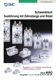
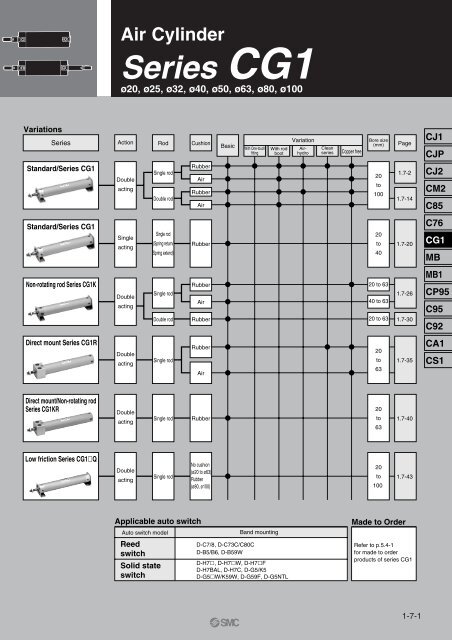
Variations<br />
<strong>Series</strong><br />
Standard/<strong>Series</strong> <strong>CG1</strong><br />
Standard/<strong>Series</strong> <strong>CG1</strong><br />
Non-rotating rod <strong>Series</strong> <strong>CG1</strong>K<br />
Direct mount <strong>Series</strong> <strong>CG1</strong>R<br />
Direct mount/Non-rotating rod<br />
<strong>Series</strong> <strong>CG1</strong>KR<br />
Low friction <strong>Series</strong> <strong>CG1</strong>�Q<br />
Air Cylinder<br />
<strong>Series</strong> <strong>CG1</strong><br />
ø20, ø25, ø32, ø40, ø50, ø63, ø80, ø100<br />
Action<br />
Double<br />
acting<br />
Single<br />
acting<br />
Double<br />
acting<br />
Double<br />
acting<br />
Double<br />
acting<br />
Double<br />
acting<br />
Rod<br />
Single rod<br />
Double rod<br />
Single rod<br />
(Spring return/<br />
Spring extend)<br />
Single rod<br />
Double rod<br />
Single rod<br />
Single rod<br />
Single rod<br />
Cushion<br />
Rubber<br />
Air<br />
Rubber<br />
Air<br />
Rubber<br />
Rubber<br />
Air<br />
Rubber<br />
Rubber<br />
Air<br />
Rubber<br />
No cushion<br />
(ø20 to ø63)<br />
Rubber<br />
(ø80, ø100)<br />
Applicable auto switch<br />
Auto switch model<br />
Reed<br />
switch<br />
Solid state<br />
switch<br />
Basic<br />
With One-touch<br />
fitting<br />
Band mounting<br />
With rod<br />
boot<br />
D-C7/8, D-C73C/C80C<br />
D-B5/B6, D-B59W<br />
D-H7�, D-H7�W, D-H7�F<br />
D-H7BAL, D-H7C, D-G5/K5<br />
D-G5�W/K59W, D-G59F, D-G5NTL<br />
Variation<br />
Air-<br />
hydro<br />
Clean<br />
series<br />
Copper free<br />
Bore size<br />
(mm)<br />
20<br />
to<br />
100<br />
20<br />
to<br />
40<br />
20 to 63<br />
40 to 63<br />
20 to 63<br />
20<br />
to<br />
63<br />
20<br />
to<br />
63<br />
20<br />
to<br />
100<br />
Page<br />
1.7-2<br />
1.7-14<br />
1.7-20<br />
1.7-26<br />
1.7-30<br />
1.7-35<br />
1.7-40<br />
1.7-43<br />
Made to Order<br />
Refer to p.5.4-1<br />
for made to order<br />
products of series <strong>CG1</strong><br />
1-7-1<br />
CJ1<br />
CJP<br />
CJ2<br />
CM2<br />
C85<br />
C76<br />
<strong>CG1</strong><br />
MB<br />
MB1<br />
CP95<br />
C95<br />
C92<br />
CA1<br />
CS1
Standard<br />
With auto switch<br />
1-7-2<br />
<strong>CG1</strong><br />
CDG1<br />
L N 25<br />
L<br />
With auto switch<br />
(magnet)<br />
Mounting<br />
B Basic<br />
L Axial foot<br />
F Front flange<br />
G Rear flange<br />
U Front trunnion<br />
Rear trunnion<br />
Clevis<br />
∗<br />
T∗ D<br />
∗ Not available for bore<br />
sizes ø80 and ø100.<br />
∗∗ Mounting brackets are<br />
included, not mounted.<br />
Cushion<br />
N Rubber bumper<br />
A Air cushion<br />
Style Special function<br />
Electrical<br />
entry<br />
Indicator<br />
Grommet<br />
No<br />
Diagnostic indication (2 color) Grommet Yes<br />
Diagnostic indication<br />
(2 color)<br />
Grommet<br />
Water resistant (2 color) Grommet<br />
With timer<br />
Diagnostic output (2 color)<br />
Latch with diagnostic output<br />
(2 color)<br />
Wiring<br />
(Output)<br />
3 wire<br />
(NPN)<br />
N 25<br />
Bore size<br />
20<br />
25<br />
32<br />
40<br />
5V<br />
100<br />
100<br />
20mm<br />
25mm<br />
32mm<br />
40mm<br />
Load voltage<br />
12V 100V<br />
2 wire 24V<br />
5V, 12V 100V or less<br />
12V<br />
5V, 12V 24V or less<br />
3 wire (NPN)<br />
3 wire (PNP)<br />
2 wire<br />
5V, 12V<br />
12V<br />
3 wire (NPN)<br />
5V, 12V<br />
Yes 3 wire (PNP) 24V<br />
2 wire<br />
3 wire (NPN)<br />
4 wire<br />
(NPN)<br />
12V<br />
5V, 12V<br />
50<br />
63<br />
80<br />
100<br />
Rod boot (at one side)<br />
—<br />
J<br />
K<br />
50mm<br />
63mm<br />
80mm<br />
100mm<br />
Applicable Auto Switches/Refer to p.5.3-2 for further information on auto switch.<br />
Reed switch<br />
Solid state switch<br />
Standard: Double Acting Single Rod<br />
<strong>Series</strong> <strong>CG1</strong><br />
ø20, ø25, ø32, ø40, ø50, ø63, ø80, ø100<br />
Yes<br />
Connector<br />
No<br />
Connector<br />
Yes<br />
Yes<br />
No<br />
How to Order<br />
DC AC<br />
200V<br />
or less<br />
Without rod boot<br />
Nylon tarpaulin<br />
Heat resistant tarpaulin<br />
∗ Foot brackets and front flanges are fitted<br />
when rod boots are mounted.<br />
Auto switch model<br />
Applicable bore size<br />
ø20 to ø63 ø20 to ø100<br />
C76<br />
C73<br />
C80<br />
C73C<br />
C80C<br />
H7A1<br />
H7A2<br />
H7B<br />
H7C<br />
H7NW<br />
H7PW<br />
H7BW<br />
H7BA<br />
H7NF<br />
H7LF<br />
∗ Lead wire length 0.5m······– e.g.) C73C 5m·········Z e.g.) C73CZ<br />
3m·········L C73CL None·····N C73CN<br />
∗ Solid state switches marked with " " are manufactured upon receipt of order.<br />
12V<br />
B53<br />
B53<br />
B54<br />
B64<br />
B59W<br />
G59<br />
G5P<br />
K59<br />
G59W<br />
G5PW<br />
K59W<br />
G5BA<br />
G5NT<br />
G59F<br />
Cylinder stroke (mm)<br />
Refer to p.1.7-3 for Standard Stroke Table.<br />
Lead wire (m) ∗<br />
0.5<br />
(–)<br />
—<br />
—<br />
3<br />
(L)<br />
5 None<br />
(Z) (N)<br />
— —<br />
—<br />
—<br />
—<br />
—<br />
—<br />
—<br />
—<br />
—<br />
—<br />
—<br />
—<br />
—<br />
—<br />
—<br />
—<br />
—<br />
—<br />
—<br />
—<br />
Applicable<br />
load<br />
IC<br />
IC<br />
IC<br />
IC<br />
IC<br />
IC<br />
Number of auto switches<br />
—<br />
S<br />
n<br />
PLC<br />
Relay<br />
PLC<br />
Relay<br />
PLC<br />
2<br />
1<br />
n<br />
Auto switch<br />
Without auto switch<br />
—<br />
(Built-in magnet)<br />
∗ Refer to the table below for<br />
selecting applicable auto<br />
switches.
Substantially shorter length:<br />
ø20 to ø40: –15 to –30mm<br />
(in comparison with CM2 <strong>Series</strong>)<br />
ø40 to ø63: –17 to –28mm<br />
(in comparison with CA1 <strong>Series</strong>)<br />
ø80 to ø100: –9 to –33mm<br />
(in comparison with CA1 <strong>Series</strong>)<br />
High speed operation: 1000mm/s<br />
(ø80 and ø100 operate at 700mm/s)<br />
Provided with an air cushion as<br />
standard<br />
Two cushions are available:<br />
an air cushion or rubber bumper<br />
Weight reduction of 10 to 50%<br />
(50mm stroke, in-house comparison)<br />
Highly accurate mounting<br />
brackets<br />
(Axial foot, front flange)<br />
JIS symbol<br />
Double acting<br />
Made to Order<br />
Standard stroke<br />
Refer to p.5.4-1 for made to order products<br />
of series <strong>CG1</strong>.<br />
Mounting Bracket<br />
Refer to p.1.7-4 for part numbers for the<br />
mounting brackets.<br />
Auto Switch Mounting Band<br />
Refer to p.1.7-4 for part numbers for the<br />
mounting bands.<br />
Standard: Double Acting Single Rod <strong>Series</strong> <strong>CG1</strong><br />
Specifications<br />
Bore size (mm)<br />
Action<br />
Lubrication<br />
Fluid<br />
Proof pressure<br />
Max. operating pressure<br />
Min. operating pressure<br />
Ambient and fluid temperature<br />
Piston speed<br />
Stroke tolerance<br />
Thread tolerance<br />
Cushion<br />
Mounting ∗<br />
20 25 32 40 50 63 80 100<br />
Double acting/Single rod<br />
Non-lube<br />
Air<br />
1.5MPa<br />
1.0MPa<br />
0.05MPa<br />
Without auto switch: –10 to +70°C (No freezing)<br />
With auto switch: –10 to +60°C (No freezing)<br />
50 to 1000mm/s<br />
50 to 700mm/s<br />
+1.4<br />
+1.4<br />
+1.8 Up to 1000 0 mm<br />
Up to 1000 0 mm, Up to 1200 0 mm<br />
+1.8<br />
Up to 1500 0 mm<br />
JIS class 2<br />
Rubber bumper/Air cushion<br />
Basic, Axial foot, Front flange, Rear flange, Front trunnion,<br />
Rear trunnion, Clevis<br />
(Used for changing the port location by 90° degrees.)<br />
Front/Rear trunnion styles are not available for bore sizes ø80 and ø100.<br />
Accessories<br />
Mounting<br />
Rod end nut<br />
Standard<br />
Clevis pin<br />
Single knuckle joint<br />
Double knuckle<br />
joint<br />
Option<br />
∗∗<br />
(With pins)<br />
Pivot bracket<br />
Rod boot<br />
Basic<br />
—<br />
—<br />
Axial<br />
foot<br />
∗ Pivot bracket is not available for bore sizes ø80 and ø100.<br />
∗∗ Pins and snap rings for double knuckle joint are included, not mounted.<br />
Stroke<br />
Bore size<br />
(mm)<br />
Standard stroke (1)<br />
(mm)<br />
20 25, 50, 75, 100, 125, 150, 200 201 to 350<br />
25<br />
301 to 400<br />
32<br />
301 to 450<br />
40 25, 50, 75, 100, 125, 301 to 800 1500<br />
150, 200, 250, 300<br />
50/63<br />
301 to 1200<br />
80<br />
301 to 1400<br />
100<br />
301 to 1500<br />
Note 1) Other intermediate strokes can be<br />
manufactured upon receipt of order.<br />
Spacers are not used for the<br />
intermediate strokes. Refer to<br />
p.1.7-8 to 1.7-10 for dimensions.<br />
Note 2) Long stroke applies to the axial foot<br />
and the front flange style. If other<br />
mounting brackets are used or the<br />
length exceeds the stroke limit,<br />
the stroke should be determined<br />
based on the stroke selection table<br />
in the technical data.<br />
Rod Boot Materials<br />
—<br />
—<br />
Long<br />
stroke (2)<br />
Max<br />
stroke<br />
(mm) (mm)<br />
Symbol Material Max. operating temp<br />
J Nylon tarpaulin 70°C00<br />
K Heat resistant tarpaulin 110°C<br />
∗ Maximum ambient temperature for the rod boot only.<br />
∗<br />
Front<br />
flange<br />
—<br />
—<br />
Rear<br />
flange<br />
— — —<br />
—<br />
Front<br />
trunnion<br />
Rear<br />
trunnion Clevis<br />
Minimum Strokes for Auto Switch Mounting<br />
Auto switch model<br />
D-C7/C8<br />
D-B5/B6<br />
D-H7<br />
D-G5/K5<br />
D-B59W<br />
D-H7LF<br />
∗ ∗<br />
Number of switches<br />
2<br />
15mm<br />
20mm<br />
20mm<br />
1<br />
10mm<br />
15mm<br />
10mm<br />
1-7-3<br />
CJ1<br />
CJP<br />
CJ2<br />
CM2<br />
C85<br />
C76<br />
<strong>CG1</strong><br />
MB<br />
MB1<br />
CP95<br />
C95<br />
C92<br />
CA1<br />
CS1
<strong>Series</strong> <strong>CG1</strong><br />
Mounting Bracket Part No.<br />
Axial foot∗ Flange<br />
Trunnion<br />
Clevis∗∗ Mounting bracket<br />
20 25 32<br />
Bore size (mm)<br />
40 50 63 80 100<br />
CG-L020 CG-L025 CG-L032 CG-L040 CG-L050 CG-L063 CG-L080 CG-L100<br />
CG-F020 CG-F025 CG-F032 CG-F040 CG-F050 CG-F063 CG-F080 CG-F100<br />
CG-T020 CG-T025 CG-T032 CG-T040 CG-T050 CG-T063 — —<br />
CG-D020 CG-D025 CG-D032 CG-D040 CG-D050 CG-D063 CG-D080 CG-D100<br />
Pivot bracket CG-020-24A CG-025-24A CG-032-24A CG-040-24A CG-050-24A CG-063-24A CG-080-24A CG-100-24A<br />
∗ Order two foot brackets per a cylinder.<br />
∗∗ Clevis pins, snap rings and mounting bolts are attached for the clevis.<br />
∗∗∗ Mounting bolts are attached for the foot type and the flange type.<br />
Auto Switch Mounting Bracket Part No.<br />
Auto switch<br />
model<br />
D-C7/C8<br />
D-H7<br />
D-B5/B6<br />
D-G5/K5<br />
1-7-4<br />
20<br />
Bore size (mm)<br />
BMA2-020 BMA2-025 BMA2-032 BMA2-040 BMA2-050 BMA2-063<br />
BA-01<br />
25<br />
BA-02<br />
32<br />
BA-32<br />
40<br />
BA-04<br />
50<br />
BA-05<br />
63<br />
BA-06<br />
80<br />
—<br />
BA-08<br />
100<br />
—<br />
BA-10<br />
Weight (kg)<br />
Bore size (mm)<br />
Basic<br />
Axial foot<br />
Flange<br />
Trunnion<br />
Clevis<br />
Pivot bracket<br />
Single knuckle joint<br />
Double knuckle joint (with pins)<br />
Additional weight by each 50 stroke<br />
Additional weight by air cushion<br />
Additional weight by long stroke<br />
Basic weight<br />
∗ A set of following stainless steel mounting screws is attached.<br />
(A switch mounting band is not attached. Please order the band separately.)<br />
BBA3: D-B5/B6/G5 types<br />
BBA4: D-C7/C8/H7 types<br />
· "D-G5BAL" and "D-H7BAL"switches are set on the cylinder with the screws above when shipped.<br />
When a switch only is shipped, “BBA3” or "BBA4" screws are attached.<br />
20<br />
0.10<br />
0.21<br />
0.18<br />
0.11<br />
0.15<br />
0.08<br />
0.05<br />
0.05<br />
0.05<br />
0.01<br />
0.01<br />
Calculation example: <strong>CG1</strong>LA20-100<br />
(Foot, ø20, 100 stroke)<br />
25<br />
0.17<br />
0.30<br />
0.27<br />
0.19<br />
0.25<br />
0.09<br />
0.09<br />
0.09<br />
0.07<br />
0.01<br />
0.01<br />
32<br />
0.26<br />
0.42<br />
0.40<br />
0.29<br />
0.41<br />
0.17<br />
0.09<br />
0.09<br />
0.09<br />
0.02<br />
0.02<br />
40<br />
0.41<br />
0.63<br />
0.61<br />
0.46<br />
0.64<br />
0.25<br />
0.10<br />
0.13<br />
0.15<br />
0.02<br />
0.03<br />
50<br />
0.77<br />
1.25<br />
1.11<br />
0.91<br />
1.17<br />
0.44<br />
0.22<br />
0.26<br />
0.22<br />
0.03<br />
0.06<br />
63<br />
1.07<br />
1.79<br />
1.57<br />
1.21<br />
1.75<br />
0.80<br />
0.22<br />
0.26<br />
0.26<br />
0.03<br />
0.10<br />
80<br />
2.04<br />
3.00<br />
2.75<br />
—<br />
2.75<br />
0.98<br />
0.39<br />
0.64<br />
0.35<br />
0.03<br />
0.19<br />
• Basic weight·································0.21 (Foot, ø20)<br />
• Additional weight··························0.05/50 stroke<br />
• Cylinder stroke·····························100 stroke<br />
• Additional weight by air cushion···0.01kg<br />
0.21+0.05 X 100/50+0.014=0.32kg<br />
100<br />
3.17<br />
4.92<br />
4.52<br />
—<br />
4.45<br />
1.75<br />
0.57<br />
1.31<br />
0.49<br />
0.03<br />
0.26<br />
Mounting Procedures<br />
Trunnion<br />
Follow the procedures below when mounting a<br />
pivot bracket on the trunnion.<br />
ø20 to ø63<br />
Clevis<br />
Follow the procedures below when mounting a<br />
pivot bracket on the clevis.<br />
ø20 to ø63<br />
ø80, ø100
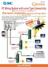
Built-in One-touch Fitting<br />
<strong>CG1</strong> Mounting N Bore size F Stroke<br />
Built-in One-touch fitting<br />
A style in which One-touch fittings are built into the cylinder. It dramatically<br />
reduces the piping labour and installation space.<br />
Specifications<br />
Bore size (mm) ø20, ø25, ø32, ø40, ø50, ø63<br />
Action<br />
Double acting/Single rod<br />
Fluid<br />
Air<br />
Max. operating pressure<br />
1.0MPa<br />
Min. operating pressure<br />
0.05MPa<br />
Piston speed<br />
50 to 750mm/s<br />
Cushion<br />
Rubber bumper<br />
Mounting<br />
Applicable Tube O.D./I.D.<br />
Basic, Axial foot, Front flange, Rear flange,<br />
Front trunnion, Rear trunnion, Clevis<br />
(Used for changing the port location by 90° degrees.)<br />
∗ Auto switch can be mounted.<br />
Bore size (mm)<br />
ø20 ø25 ø32 ø40 ø50 ø63<br />
Applicable tube (mm) ø6/4 ø6/4 ø6/4 ø8/6 ø10/7.5 ø10/7.5<br />
Applicable tube material<br />
∗ Refer to p.1.7-3 for other specifications.<br />
Nylon, Soft nylon, Polyurethane<br />
Clean <strong>Series</strong><br />
10-<strong>CG1</strong> Mounting N Bore size Stroke<br />
20-<strong>CG1</strong><br />
Clean series (with relief port)<br />
The rod portion of the actuator has a double seal construction, and a relief<br />
port is provided to discharge the exhaust air directly outside of the clean<br />
room. Thus, it is a style that can be used in a Class 100 clean room.<br />
Specifications<br />
Bore size (mm) ø20, ø25, ø32, ø40, ø50, ø63, ø80, ø100<br />
Action<br />
Double acting/Single rod<br />
Fluid<br />
Air<br />
Max. operating pressure<br />
1.0MPa<br />
Min. operating pressure<br />
0.05MPa<br />
Cushion<br />
Rubber bumper<br />
Piston speed<br />
50 to 400mm/s<br />
Relief port size<br />
M5<br />
Mounting<br />
∗ Auto switch can be mounted.<br />
Basic, Axial foot, Front flange, Rear flange<br />
Standard: Double Acting Single Rod <strong>Series</strong> <strong>CG1</strong><br />
Air-hydro<br />
<strong>CG1</strong> Mounting H Bore size Stroke<br />
Air-hydro<br />
A low hydraulic pressure cylinder used at a pressure of 1.0MPa or below.<br />
Through the concurrent use of a CC series air-hydro unit, it is possible to<br />
operate at a constant or low speed or to effect an intermediate stop, just<br />
like a hydraulic unit, while using pneumatic equipment such as a valve.<br />
Specifications<br />
Style Air-hydro Cylinder<br />
Bore size (mm)<br />
Action<br />
Fluid<br />
Proof pressure<br />
Max. operating pressure<br />
Min. operating pressure<br />
Piston speed<br />
Cushion<br />
Ambient and fluid temperature<br />
Thread tolerance<br />
Stroke tolerance<br />
Mounting<br />
∗ Auto switch can be mounted.<br />
Copper Free<br />
Copper free<br />
ø20, ø25, ø32, ø40, ø50, ø63<br />
Double acting/Single rod<br />
Turbine oil<br />
1.5MPa<br />
1.0MPa<br />
0.18MPa<br />
15 to 300mm/s<br />
None<br />
+5 to 60°C<br />
JIS class 2<br />
+1.4<br />
+1.8<br />
Up to 1000 0 mm, Up to 1200 0 mm<br />
Basic, Axial foot, Front flange, Rear flange,<br />
Front trunnion, Rear trunnion, Clevis<br />
(Used for changing the port location by 90° degrees.)<br />
Mounting Cushion Bore size Stroke<br />
This cylinder eliminates any influences of copper ions or fluororesins on<br />
colour CRTs. Copper materials have been nickel plated or replaced with<br />
non-copper materials to prevent the generation of copper ions.<br />
Specifications<br />
Bore size (mm) ø20, ø25, ø32, ø40, ø50, ø63, ø80, ø100<br />
Action<br />
Fluid<br />
Max. operating pressure<br />
Min. operating pressure<br />
Cushion<br />
Piston speed<br />
N<br />
A<br />
ø20 to 63<br />
ø80/100<br />
Double acting/Single rod<br />
Air<br />
1.0MPa<br />
0.05MPa<br />
Rubber bumper<br />
Air cushion<br />
50 to 1000mm/s<br />
50 to 700mm/s<br />
Basic, Axial foot, Front flange, Rear flange,<br />
Mounting Front trunnion, Rear trunnion, Clevis<br />
(Used for changing the port location by 90° degrees.)<br />
∗<br />
∗ Front/Rear trunnion styles are not available for bore sizes ø80 and ø100. Refer to p.1.7-8<br />
for dimensions.<br />
∗ Auto switch can be mounted.<br />
1-7-5<br />
CJ1<br />
CJP<br />
CJ2<br />
CM2<br />
C85<br />
C76<br />
<strong>CG1</strong><br />
MB<br />
MB1<br />
CP95<br />
C95<br />
C92<br />
CA1<br />
CS1
<strong>Series</strong> <strong>CG1</strong><br />
Water Resistant<br />
CDG1 Mounting Style Bore size Stroke<br />
With auto switch<br />
(built-in magnet)<br />
Specifications<br />
Action<br />
Bore size (mm)<br />
Cushion<br />
Auto switch mounting method<br />
Made to order<br />
Dimensions<br />
Rubber bumper<br />
Air cushion<br />
1-7-6<br />
R<br />
R<br />
V<br />
∗ Other specifications are the same as the standard model.<br />
Water resistant<br />
G5BAL -XC6<br />
Made to order<br />
Solid state switch<br />
(Water resistant/<br />
2 color indicator)<br />
Seal: NBR (Nitrile rubber)<br />
Seal: FKM (Fluorine rubber)<br />
Ideal for use in a machine tool environment exposed to coolant mist. Also<br />
suited for use in areas in which water splashes, such as food processing<br />
equipment or car washers.<br />
Double acting/Single rod<br />
ø32, ø40, ø50, ø63, ø80, ø100<br />
Rubber bumper/Air cushion<br />
Band mounting<br />
Material of the piston rod and rod end nut is stainless steel. (-XC6)<br />
Bore (mm) (E1) E<br />
32 17<br />
40 21<br />
50 26<br />
63 26<br />
80 32<br />
100 37<br />
∗ (F1) F<br />
18 2<br />
25 2<br />
30 2<br />
32 2<br />
40 3<br />
50 3<br />
∗ GA S TA WA<br />
(mm)<br />
ZZ<br />
2 18 77 (85) 17 20 119 (127)<br />
2 19 84 (93) 18 21 136 (145)<br />
2 21 97 (109) 20 23 157 (169)<br />
2 21 97 (109) 20 23 157 (169)<br />
3 28 116 (130) — 30 190 (204)<br />
3 29 117 (131) — 31 191 (205)<br />
∗ These dimensions and other dimensions not indicated here are the same as standard.<br />
Note) ( ): Long stroke<br />
Precautions<br />
Be sure to read before handling.<br />
Refer to p.0-39 to 0-46 for Safety Instructions<br />
and common precautions.<br />
Precautions on handling<br />
Warning<br />
q Do not operate the cushion valve in the fully closed or fully<br />
opened state.<br />
� Using it in the fully closed state will cause the cushion seal to<br />
be damaged. Using it in the fully opened state will cause the<br />
piston rod assembly or the cover to be damaged.<br />
w Operate within the specified cylinder speed.<br />
� Failure to do so will damage the cylinder and the seals.<br />
Caution<br />
q Do not use the air cylinder as an air-hydro cylinder. This<br />
will cause an oil leak.<br />
w Install without twisting the bellows.<br />
� If the cylinder is installed with its bellows twisted, it could<br />
damage the bellows.<br />
Disassembly/Replacement<br />
Caution<br />
q Do not replace the bushings or the cushion seals.<br />
� The bushings and the cushion seals are press-fit. To replace<br />
them, they must be replaced together with the cover assembly.<br />
w To replace a seal, apply grease to the new seal before<br />
installing it.<br />
� If the cylinder is put into operation without applying grease to<br />
the seal, it could cause the seal to wear significantly, leading to<br />
premature air leakage.<br />
e Do not replace One-touch fittings.<br />
� Because pipe fittings are press-fit, they must be replaced<br />
together with the cover assembly.<br />
r Those with a bore of ø50 or more cannot be disassembled.<br />
� When disassembling a cylinder with a bore of ø20 to ø 40, use<br />
a vise or the like to hold the wrench flats portion of the tube<br />
cover or the rod cover on one side, while placing a wrench or<br />
an adjustable wrench on the other side to loosen and remove<br />
the cover. To replace, tighten it an additional 2… from the<br />
installed position. (Those with a bore of ø50 or more cannot be<br />
disassembled because they have been tightened with greater<br />
torque. If they must be disassembled, contact <strong>SMC</strong>.
Construction<br />
Component Parts<br />
No.<br />
q<br />
w<br />
e<br />
r<br />
t<br />
y<br />
u<br />
i<br />
o<br />
!0<br />
!1<br />
!2<br />
!3<br />
!4<br />
!5<br />
!6<br />
!7<br />
!8<br />
!9<br />
@0<br />
@1<br />
@2<br />
@3<br />
Replacement Parts/With rubber bumper<br />
No. Description<br />
@4<br />
@5<br />
@6<br />
With rubber bumper<br />
With air cushion<br />
Description Material<br />
Rod cover<br />
Tube cover<br />
Piston<br />
Piston rod<br />
Bushing<br />
Bumper A<br />
Bumper B<br />
Snap ring<br />
Wear ring<br />
Rod end nut<br />
Piston gasket<br />
Cushion ring A<br />
Cushion ring B<br />
Seal retainer<br />
Cushion valve<br />
Valve retainer<br />
Lock nut<br />
Cushion seal A<br />
Cushion seal B<br />
Cushion ring gasket A<br />
Cushion ring gasket B<br />
Head cover<br />
Cylinder tube<br />
Rod seal<br />
Piston seal<br />
Tube gasket<br />
Aluminum alloy<br />
Aluminum alloy<br />
Aluminum alloy<br />
Carbon steel<br />
Oil impregnated sintered alloy<br />
Urethane<br />
Urethane<br />
Stainless steel<br />
Resin<br />
Rolled steel<br />
NBR<br />
Brass<br />
Brass<br />
Rolled steel<br />
Rolled steel<br />
Rolled steel<br />
Rolled steel<br />
Urethane<br />
Urethane<br />
NBR<br />
NBR<br />
Aluminum alloy<br />
Aluminum alloy<br />
Note) A magnet is equipped on the piston of the cylinder with auto switch.<br />
∗ The material is stainless steel on auto switch equipped styles ø20 and ø25.<br />
Standard: Double Acting Single Rod <strong>Series</strong> <strong>CG1</strong><br />
Bore size (mm)/Part No.<br />
Material<br />
ø20 ø25 ø32 ø40 ø50 ø63 ø80 ø100<br />
NBR PDU-8Z PDU-10Z PDU-12LZ PDU-16Z PDU-20Z PDU-20Z PDU-25Z PDU-30Z<br />
NBR PPD-20 PPD-25-19 PPD-32 PPD-40 PPD-50 PPD-63 PPD-80 PPD-100<br />
NBR CM-020-16-123 CM-025-16-124 CM-032-16-126 CM-040-16-127 CM-050-16-128 CM-063-16-129 CM-080-16-152 CM-100-16-153<br />
With air cushion (Parts @4 to @6 are the same as rubber bumper style.)<br />
@7<br />
@8<br />
Valve seal<br />
Gasket for valve retainer<br />
NBR<br />
NBR<br />
ø80, ø100 ø80, ø100<br />
Note<br />
White hard anodized<br />
White hard anodized<br />
Chromated<br />
Hard chrome plated<br />
ø40 or larger: Lead bronze cast<br />
ø40 or larger: the same as damper A<br />
Except for ø80 and ø100<br />
Nickel plated<br />
ø32 or more: the same as A<br />
Nickel plated/Except for long stroke<br />
Electroless nickel plated<br />
Electroless nickel plated<br />
Nickel plated<br />
ø32 or larger: the same as A ∗<br />
ø32 or larger: the same as A<br />
White hard anodized<br />
Hard anodized<br />
O ring ø4.5 X ø2.5 X ø1<br />
O ring ø6.4 X ø5.2 X ø0.6<br />
O ring ø5.5 X ø3.5 X ø1<br />
O ring ø7.4 X ø5.8 X ø0.8<br />
O ring ø6.5 X ø4.5 X ø1<br />
O ring ø11.4 X ø9.4 X ø1<br />
1-7-7<br />
CJ1<br />
CJP<br />
CJ2<br />
CM2<br />
C85<br />
C76<br />
<strong>CG1</strong><br />
MB<br />
MB1<br />
CP95<br />
C95<br />
C92<br />
CA1<br />
CS1
<strong>Series</strong> <strong>CG1</strong><br />
Basic/<strong>CG1</strong>BN: With Rubber Bumper<br />
1-7-8<br />
TA/TB<br />
cross section<br />
Basic: With rod boot<br />
Built-in One-touch fitting<br />
Other dimensions are the same as standard.<br />
Bore<br />
(mm)<br />
20<br />
25<br />
32<br />
40<br />
50<br />
63<br />
80<br />
100<br />
Standard Long stroke<br />
stroke (mm) (mm)<br />
Up to 200<br />
Up to 300<br />
Up to 300<br />
Up to 300<br />
Up to 300<br />
Up to 300<br />
Up to 300<br />
Up to 300<br />
201 to 350<br />
301 to 400<br />
301 to 450<br />
301 to 800<br />
301 to 1200<br />
301 to 1200<br />
301 to 1400<br />
301 to 1500<br />
A<br />
18<br />
22<br />
22<br />
30<br />
35<br />
35<br />
40<br />
40<br />
AL<br />
15.5<br />
19.5<br />
19.5<br />
27<br />
32<br />
32<br />
37<br />
37<br />
B1<br />
13<br />
17<br />
17<br />
19<br />
27<br />
27<br />
32<br />
41<br />
C<br />
14<br />
16.5<br />
20<br />
26<br />
32<br />
38<br />
50<br />
60<br />
D<br />
8<br />
10<br />
12<br />
16<br />
20<br />
20<br />
25<br />
30<br />
E<br />
12<br />
14<br />
18<br />
25<br />
30<br />
32<br />
40<br />
50<br />
F<br />
2<br />
2<br />
2<br />
2<br />
2<br />
2<br />
3<br />
3<br />
GA<br />
12<br />
12<br />
12<br />
13<br />
14<br />
14<br />
20<br />
20<br />
GB<br />
12<br />
10 (12)<br />
10 (12)<br />
10 (13)<br />
12 (14)<br />
12 (14)<br />
16 (20)<br />
16 (20)<br />
H<br />
35<br />
40<br />
40<br />
50<br />
58<br />
58<br />
71<br />
71<br />
H1<br />
5<br />
6<br />
6<br />
8<br />
11<br />
11<br />
13<br />
16<br />
I<br />
26<br />
31<br />
38<br />
47<br />
58<br />
72<br />
89<br />
110<br />
Air-hydro<br />
J<br />
M4 Depth 7<br />
M5 Depth 7.5<br />
M5 Depth 8<br />
M6 Depth 12<br />
M8 Depth 16<br />
M10Depth 16<br />
M10 Depth 22<br />
M12 Depth 22<br />
Other dimensions are the same as the long stroke standard.<br />
K<br />
5<br />
5.5<br />
5.5<br />
6<br />
7<br />
7<br />
10<br />
10<br />
KA<br />
6<br />
8<br />
10<br />
14<br />
18<br />
18<br />
22<br />
26<br />
MM<br />
M8<br />
M10 X 1.25<br />
M10 X 1.25<br />
M14 X 1.5<br />
M18 X 1.5<br />
M18 X 1.5<br />
M22 X 1.5<br />
M26 X 1.5<br />
NA<br />
24<br />
29<br />
35.5<br />
44<br />
55<br />
69<br />
80<br />
100<br />
P<br />
1/8<br />
1/8<br />
1/8<br />
1/8<br />
1/4<br />
1/4<br />
3/8<br />
1/2<br />
S<br />
69 (77)<br />
69 (77)<br />
71 (79)<br />
78 (87)<br />
90 (102)<br />
90 (102)<br />
108 (122)<br />
108 (122)<br />
TA<br />
11<br />
11<br />
11<br />
12<br />
13<br />
13<br />
—<br />
—<br />
TB<br />
11<br />
11<br />
10 (11)<br />
10 (12)<br />
12 (13)<br />
12 (13)<br />
—<br />
—<br />
(mm)<br />
ZZ<br />
106 (114)<br />
111 (119)<br />
113 (121)<br />
130 (139)<br />
150 (162)<br />
150 (162)<br />
182 (196)<br />
182 (196)<br />
Note 1) ( ): Long stroke Note 2) Trunnion mounting taps with width across flats NA are not attached for bore size 80 and 100.<br />
TA/TB cross section With rod boot<br />
Bore<br />
(mm)<br />
20<br />
25<br />
32<br />
40<br />
50<br />
63<br />
80<br />
100<br />
TC ∗<br />
M5<br />
M6 X 0.75<br />
M8 X 1.0<br />
M10 X 1.25<br />
M12 X 1.25<br />
M14 X 1.5<br />
—<br />
—<br />
TDH9<br />
+0.08<br />
8 0<br />
+0.08<br />
10 0<br />
+0.08<br />
12 0<br />
+0.08<br />
14 0<br />
+0.08<br />
16 0<br />
+0.08<br />
18 0<br />
—<br />
—<br />
TE<br />
4<br />
5<br />
5.5<br />
6<br />
7.5<br />
11.5<br />
—<br />
—<br />
TF<br />
0.5<br />
1<br />
1<br />
1.25<br />
2<br />
3<br />
—<br />
—<br />
(mm) (mm)<br />
TG<br />
5.5<br />
6.5<br />
7.5<br />
8.5<br />
10<br />
14.5<br />
—<br />
—<br />
Bore<br />
(mm)<br />
20<br />
25<br />
32<br />
40<br />
50<br />
63<br />
80<br />
100<br />
e<br />
30<br />
30<br />
35<br />
35<br />
40<br />
40<br />
52<br />
62<br />
f<br />
16<br />
17<br />
17<br />
17<br />
17<br />
18<br />
10<br />
7<br />
h<br />
55<br />
62<br />
62<br />
70<br />
78<br />
78<br />
80<br />
80<br />
IJ<br />
27<br />
32<br />
38<br />
48<br />
59<br />
72<br />
59<br />
71<br />
JH<br />
(14.5)<br />
(17.5)<br />
(19.5)<br />
(22.5)<br />
(25)<br />
(25)<br />
—<br />
—<br />
JW<br />
(11.5)<br />
(11.5)<br />
(11.5)<br />
(13)<br />
(13)<br />
(13)<br />
—<br />
—<br />
ZZ<br />
126 (134)<br />
133 (141)<br />
135 (143)<br />
150 (159)<br />
170 (182)<br />
170 (182)<br />
191 (205)<br />
191 (205)<br />
Bore<br />
(mm)<br />
20<br />
25<br />
32<br />
40<br />
50<br />
63<br />
GA<br />
12<br />
12<br />
12<br />
12<br />
13<br />
13<br />
∗ The minimum stroke for rod boot equipped style is 20mm. Note) ( ): Long stroke<br />
l<br />
0.25 stroke<br />
Built-in One-touch fitting Air-hydro<br />
GB<br />
10 (12)<br />
10 (12)<br />
10 (12)<br />
10 (12)<br />
13<br />
13<br />
HD HH PD<br />
13<br />
13<br />
13<br />
16<br />
20<br />
20<br />
24.2<br />
26.7<br />
30.2<br />
34.6<br />
40.6<br />
47.1<br />
6<br />
6<br />
6<br />
8<br />
10<br />
10<br />
Bore<br />
(mm)<br />
20<br />
25<br />
32<br />
40<br />
50<br />
63<br />
S<br />
70<br />
70<br />
72<br />
80<br />
95<br />
95<br />
ZZ<br />
107<br />
112<br />
114<br />
132<br />
155<br />
155
With Mounting Bracket<br />
Standard: Double Acting Single Rod <strong>Series</strong> <strong>CG1</strong><br />
Axial foot<br />
Flange<br />
Bore<br />
(mm)<br />
20<br />
25<br />
32<br />
40<br />
50<br />
63<br />
80<br />
100<br />
Stroke range<br />
Front<br />
Up to 350<br />
Up to 400<br />
Up to 450<br />
Up to 800<br />
Up to 1200<br />
Up to 1200<br />
Up to 1400<br />
Up to 1500<br />
Rear<br />
Up to 200<br />
Up to 300<br />
Up to 300<br />
Up to 500<br />
Up to 600<br />
Up to 600<br />
Up to 750<br />
Up to 750<br />
B<br />
40<br />
44<br />
53<br />
61<br />
76<br />
92<br />
104<br />
128<br />
E<br />
12<br />
14<br />
18<br />
25<br />
30<br />
32<br />
40<br />
50<br />
F<br />
2<br />
2<br />
2<br />
2<br />
2<br />
2<br />
3<br />
3<br />
Note 1) ( ): Long stroke<br />
Note 2) End boss is machined on the flange for øE.<br />
Trunnion<br />
Bore<br />
(mm)<br />
20<br />
25<br />
32<br />
40<br />
50<br />
63<br />
Bore<br />
(mm)<br />
Stroke range<br />
Front Rear<br />
B<br />
Up to 200 Up to 200 38<br />
Up to 300 Up to 300 45.5<br />
Up to 300 Up to 300 54<br />
Up to 500 Up to 500 63.5<br />
Up to 600 Up to 600 79<br />
Up to 600 Up to 600 96<br />
TW<br />
TX<br />
TY<br />
TZ<br />
TDe8 TE<br />
–0.025<br />
8 –0.047<br />
–0.025<br />
10 –0.047<br />
–0.032<br />
12 –0.059<br />
–0.032<br />
14 –0.059<br />
–0.032<br />
16 –0.059<br />
–0.032<br />
18 –0.059<br />
Front<br />
Z<br />
10<br />
10<br />
10<br />
10<br />
20<br />
20<br />
FX<br />
28<br />
32<br />
38<br />
46<br />
58<br />
70<br />
82<br />
100<br />
TF<br />
5.5<br />
5.5<br />
6.6<br />
6.6<br />
9<br />
11<br />
FD<br />
5.5<br />
5.5<br />
6.6<br />
6.6<br />
9<br />
11<br />
11<br />
14<br />
TH<br />
25<br />
30<br />
35<br />
40<br />
50<br />
60<br />
Z<br />
FT<br />
6<br />
7<br />
7<br />
8<br />
9<br />
9<br />
11<br />
14<br />
TR<br />
39<br />
43<br />
54.5<br />
65.5<br />
80<br />
98<br />
(mm)<br />
Bore<br />
(mm)<br />
B LC LD LH LS LT LX LZ M W X<br />
Z<br />
ZZ<br />
Y Without With rod Without With rod<br />
rod boot boot rod boot boot<br />
20 34 4 6 20 45 (53) 3 32 44 3 10 15 7 47 67+l 110 (118) 130 (138) +l<br />
25 38.5 4 6 22 45 (53) 3 36 49 3.5 10 15 7 52 74+l 115.5 (123.5) 137.5 (145.5) +l<br />
32 45 4 6.6 25 45 (53) 3 44 58 3.5 10 16 8 53 75+l 117.5 (125.5) 139.5 (147.5) +l<br />
40 54.5 4 6.6 30 51 (60) 3 54 71 4 10 16.5 8.5 63.5 83.5+l 135 (144) 155 (164) +l<br />
50 70.5 5 9 40 55 (67) 4.5 66 86 5 17.5 22 11 75.5 95.5+l 157.5 (169.5) 177.5 (189.5) +l<br />
63 82.5 5 11 45 55 (67) 4.5 82 106 5 17.5 22 13 75.5 95.5+l 157.5 (169.5) 177.5 (189.5) +l<br />
80 101 6 11 55 60 (74) 4.5 100 125 5 20 28.5 14 95 104+l 188.5 (202.5) 197.5 (211.5) +l<br />
100 121 6 14 65 60 (74) 6 120 150 7 20 30 16 95 104+l 192 (206) 201 (215) +l<br />
Note) ( ): Long stroke<br />
(mm)<br />
Rear flange<br />
ZZ<br />
Without With rod<br />
rod boot boot<br />
112 132+l<br />
118 140+l<br />
120 142+l<br />
138 (147) 158 (167) +l<br />
159 (171) 179 (191) +l<br />
159 (171) 179 (191) +l<br />
193 (207) 202 (216) +l<br />
196 (210) 202 (219) +l<br />
TS<br />
28<br />
33<br />
40<br />
49<br />
60<br />
74<br />
Rear<br />
TT<br />
3.2<br />
3.2<br />
4.5<br />
4.5<br />
6<br />
8<br />
ZZ<br />
(mm)<br />
TV<br />
35.8<br />
39.8<br />
49.4<br />
58.4<br />
72.4<br />
90.4<br />
Without<br />
rod boot<br />
With rod<br />
boot<br />
Without<br />
rod boot<br />
With rod<br />
boot<br />
Without<br />
rod boot<br />
With rod<br />
boot<br />
20 42 16 28 47.6 46 66+l 93 113+l 114 134+l<br />
25 42 20 28 53 51 73+l 98 120+l 119 141+l<br />
32 48 22 28 67.7 51 73+l 101 123+l 125 147+l<br />
40 56 30 30 78.7 62 82+l 118 (125) 138 (145) +l 146 (153) 166 (173) +l<br />
50 64 36 36 98.6 71 91+l 136 (147) 156 (167) +l 168 (179) 188 (199) +l<br />
63 74 46 46 119.2 71 91+l 136 (147) 156 (167) +l 173 (184) 193 (204) +l<br />
∗ Consists of pins, flat washer and hexagon socket head cap bolt.<br />
Note 1) ( ): Long stroke<br />
Note 2) Refer to p.1.7-11 for pivot bracket.<br />
1-7-9<br />
CJ1<br />
CJP<br />
CJ2<br />
CM2<br />
C85<br />
C76<br />
<strong>CG1</strong><br />
MB<br />
MB1<br />
CP95<br />
C95<br />
C92<br />
CA1<br />
CS1
<strong>Series</strong> <strong>CG1</strong><br />
With Mounting Bracket<br />
Clevis/<strong>CG1</strong>DN<br />
ø20 to ø63<br />
(The above shows the case port location is changed by 90° degrees.)<br />
ø80, ø100<br />
∗ Clevis pins and snap rings are attached for the clevis style.<br />
Basic/With Air Cushion: <strong>CG1</strong>BA<br />
Bore<br />
(mm)<br />
20<br />
25<br />
32<br />
40<br />
50<br />
63<br />
80<br />
100<br />
1-7-10<br />
With rod boot<br />
Standard stroke<br />
range (mm)<br />
Up to 200<br />
Up to 300<br />
Up to 300<br />
Up to 300<br />
Up to 300<br />
Up to 300<br />
Up to 300<br />
Up to 300<br />
Long stroke<br />
range (mm)<br />
201to350<br />
301to400<br />
301to450<br />
301to800<br />
301to1200<br />
301to1200<br />
301to1400<br />
301to1500<br />
A<br />
18<br />
22<br />
22<br />
30<br />
35<br />
35<br />
40<br />
40<br />
AL<br />
15.5<br />
19.5<br />
19.5<br />
27<br />
32<br />
32<br />
37<br />
37<br />
B1<br />
13<br />
17<br />
17<br />
19<br />
27<br />
27<br />
32<br />
41<br />
C<br />
14<br />
16.5<br />
20<br />
26<br />
32<br />
38<br />
50<br />
60<br />
D<br />
8<br />
10<br />
12<br />
16<br />
20<br />
20<br />
25<br />
30<br />
E<br />
12<br />
14<br />
18<br />
25<br />
30<br />
32<br />
40<br />
50<br />
F GA GB<br />
2<br />
2<br />
2<br />
2<br />
2<br />
2<br />
3<br />
3<br />
12<br />
12<br />
12<br />
13<br />
14<br />
14<br />
20<br />
20<br />
10 (12)<br />
10 (12)<br />
10 (12)<br />
10 (13)<br />
12 (14)<br />
12 (14)<br />
16 (20)<br />
16 (20)<br />
H<br />
35<br />
40<br />
40<br />
50<br />
58<br />
58<br />
71<br />
71<br />
H1<br />
5<br />
6<br />
6<br />
8<br />
11<br />
11<br />
13<br />
16<br />
I<br />
26<br />
31<br />
38<br />
47<br />
58<br />
72<br />
89<br />
110<br />
J<br />
M4 Depth 7<br />
M5 Depth 7.5<br />
M5 Depth 8<br />
M6 Depth 12<br />
M8 Depth 16<br />
M10 Depth 16<br />
M10 Depth 22<br />
M12 Depth 22<br />
Clevis<br />
Bore<br />
(mm)<br />
20<br />
25<br />
32<br />
40<br />
50<br />
63<br />
80<br />
100<br />
Bore<br />
(mm)<br />
20<br />
25<br />
32<br />
40<br />
50<br />
63<br />
80<br />
100<br />
Stroke range<br />
(mm)<br />
B<br />
Up to 200 38<br />
Up to 300 45.5<br />
Up to 300 54<br />
Up to 500 63.5<br />
Up to 600 79<br />
Up to 600 96<br />
Up to 750 99.5<br />
Up to 750 120<br />
TT<br />
3.2<br />
3.2<br />
4.5<br />
4.5<br />
6<br />
8<br />
11<br />
12<br />
TV<br />
35.8<br />
39.8<br />
49.4<br />
58.4<br />
72.4<br />
90.4<br />
110<br />
130<br />
TW<br />
42<br />
42<br />
48<br />
56<br />
64<br />
74<br />
72<br />
93<br />
CD<br />
8<br />
10<br />
12<br />
14<br />
16<br />
18<br />
18<br />
22<br />
TX<br />
16<br />
20<br />
22<br />
30<br />
36<br />
46<br />
85<br />
100<br />
CX<br />
—<br />
—<br />
—<br />
—<br />
—<br />
—<br />
28<br />
32<br />
TY<br />
28<br />
28<br />
28<br />
30<br />
36<br />
46<br />
45<br />
60<br />
Note 1) ( ): Long stroke<br />
Note 2) Refer to p.1.7-11 for pivot bracket.<br />
K KA<br />
Note 1) ( ): Long stroke<br />
Note 2) Trunnion mounting taps with width across flats NA are not attached for bore size ø80 and ø100.<br />
Note 3) Refer to p.1.7-11 for mounting brackets.<br />
5<br />
5.5<br />
5.5<br />
6<br />
7<br />
7<br />
10<br />
10<br />
6<br />
8<br />
10<br />
14<br />
18<br />
18<br />
22<br />
26<br />
MM<br />
M8<br />
M10 X 1.25<br />
M10 X 1.25<br />
M14 X 1.5<br />
M18 X 1.5<br />
M18 X 1.5<br />
M22 X 1.5<br />
M26 X 1.5<br />
NA<br />
24<br />
29<br />
35.5<br />
44<br />
55<br />
69<br />
80<br />
100<br />
P<br />
M5<br />
M5<br />
Rc(PT)1/8<br />
Rc(PT)1/8<br />
Rc(PT)1/4<br />
Rc(PT)1/4<br />
Rc(PT)3/8<br />
Rc(PT)1/2<br />
CZ<br />
29<br />
33<br />
40<br />
49<br />
60<br />
74<br />
56<br />
64<br />
TZ<br />
43.4<br />
48<br />
59.4<br />
71.4<br />
86<br />
105.4<br />
64<br />
72<br />
e<br />
30<br />
30<br />
35<br />
35<br />
40<br />
40<br />
52<br />
62<br />
Z<br />
L<br />
14<br />
16<br />
20<br />
22<br />
25<br />
30<br />
35<br />
43<br />
118<br />
125<br />
131<br />
150<br />
(159)<br />
173<br />
(185)<br />
178<br />
(190)<br />
214<br />
(228)<br />
222<br />
(236)<br />
With rod boot<br />
Bore<br />
(mm)<br />
20<br />
25<br />
32<br />
40<br />
50<br />
63<br />
80<br />
100<br />
f<br />
16<br />
17<br />
17<br />
17<br />
17<br />
18<br />
10<br />
7<br />
ZZ<br />
RR<br />
11<br />
13<br />
15<br />
18<br />
20<br />
22<br />
18<br />
22<br />
139<br />
146<br />
155<br />
178<br />
(187)<br />
205<br />
(217)<br />
215<br />
(227)<br />
272.5<br />
(286.5)<br />
298.5<br />
(312.5)<br />
h<br />
55<br />
62<br />
62<br />
70<br />
78<br />
78<br />
80<br />
80<br />
V<br />
—<br />
—<br />
—<br />
—<br />
—<br />
—<br />
26<br />
32<br />
TE<br />
10<br />
10<br />
10<br />
10<br />
20<br />
20<br />
—<br />
—<br />
TF<br />
5.5<br />
5.5<br />
6.6<br />
6.6<br />
9<br />
11<br />
11<br />
13.5<br />
(mm)<br />
TH<br />
25<br />
30<br />
35<br />
40<br />
50<br />
60<br />
55<br />
65<br />
With rod boot Applicable<br />
Z ZZ pin part no.<br />
138+l 159+l CD-G02<br />
147+l 168+l CD-G25<br />
153+l 177+l CD-G03<br />
170+l 198+l<br />
(179+l) (207+l)<br />
CD-G04<br />
193+l 225+l<br />
(205+l) (237+l)<br />
CD-G05<br />
198+l 235+l<br />
(210+l) (247+l)<br />
CD-G06<br />
223+l 281.5+l<br />
(237+l) (295.5+l)<br />
IY-G08<br />
231+l 307.5+l<br />
(245+l) (321.5+l)<br />
IY-G10<br />
IJ<br />
27<br />
32<br />
38<br />
48<br />
59<br />
72<br />
59<br />
71<br />
JH<br />
(14.5)<br />
(17.5)<br />
(19.5)<br />
(22.5)<br />
(25)<br />
(25)<br />
—<br />
—<br />
JW<br />
(11.5)<br />
(11.5)<br />
(11.5)<br />
(13)<br />
(13)<br />
(13)<br />
—<br />
—<br />
l<br />
0.25 stroke<br />
(mm)<br />
ZZ<br />
126 (134)<br />
133 (141)<br />
135 (143)<br />
150 (159)<br />
170 (182)<br />
170 (182)<br />
191 (205)<br />
191 (205)<br />
∗ The minimum stroke for rod boot equipped type is 20mm.<br />
S<br />
TA<br />
69 (77) 11<br />
69 (77) 11<br />
71 (79) 11<br />
78 (87) 12<br />
90 (102) 13<br />
90 (102) 13<br />
108 (122) —<br />
108 (122) —<br />
TB<br />
11<br />
11<br />
10 (11)<br />
10 (12)<br />
12 (13)<br />
12 (13)<br />
—<br />
—<br />
TC ∗<br />
M5<br />
M6 X 0.75<br />
M8 X 1.0<br />
M10 X 1.25<br />
M12 X 1.25<br />
M14 X 1.5<br />
—<br />
—<br />
ZZ<br />
106 (114)<br />
111 (119)<br />
113 (121)<br />
130 (139)<br />
150 (162)<br />
150 (162)<br />
182 (196)<br />
182 (196)<br />
WA WB WH Wθ<br />
16 15 (16) 23 30°<br />
16 15 (16) 25 30°<br />
16 15 (16) 28.5 25°<br />
16 15 (16) 33 20°<br />
18 17 (18) 40.5 20°<br />
18 17 (18) 47.5 20°<br />
22 22 60.5 20°<br />
22 22 71 20°
I-G02, G03 I-G04, G05, G08, G10 Material:<br />
Cast iron<br />
Material: Rolled steel<br />
Part No.<br />
Bore size<br />
(mm)<br />
A<br />
I-G02 20 34<br />
I-G03 25, 32 41<br />
I-G04 40 42<br />
I-G05 50, 63 56<br />
I-G08 80 71<br />
I-G10 100 79<br />
A1<br />
8.5<br />
10.5<br />
14<br />
18<br />
21<br />
21<br />
E1<br />
�16<br />
�20<br />
ø22<br />
ø28<br />
ø38<br />
ø44<br />
L1<br />
25<br />
30<br />
30<br />
40<br />
50<br />
55<br />
MM<br />
M8<br />
M10 X 1.25<br />
M14 X 1.5<br />
M18 X 1.5<br />
M22 X 1.5<br />
M26 X 1.5<br />
R1<br />
10.3<br />
12.8<br />
12<br />
16<br />
21<br />
24<br />
U1<br />
11.5<br />
14<br />
14<br />
20<br />
27<br />
31<br />
NDH10<br />
8<br />
10<br />
10<br />
14<br />
18<br />
22<br />
+0.058<br />
0<br />
+0.058<br />
0<br />
+0.058<br />
0<br />
+0.070<br />
0<br />
+0.070<br />
0<br />
+0.084<br />
0<br />
(mm)<br />
NX<br />
8<br />
10<br />
18<br />
22<br />
28<br />
32<br />
–0.2<br />
–0.4<br />
–0.2<br />
–0.4<br />
–0.3<br />
–0.5<br />
–0.3<br />
–0.5<br />
–0.3<br />
–0.5<br />
–0.3<br />
–0.5<br />
Material: Carbon steel<br />
(mm)<br />
Part No. Bore size<br />
(mm)<br />
Dd9 L d l m t<br />
Applicable<br />
snap ring<br />
IY-G02 20<br />
–0.040<br />
8 –0.076 21 7.6 16.2 1.5 0.9 C-8 type for pivot<br />
IY-G03 25, 32<br />
–0.040<br />
10 –0.076 25.6 9.6 20.2 1.55 1.15 C-10 type for pivot<br />
IY-G04 40<br />
–0.040<br />
10 –0.076 41.6 9.6 36.2 1.55 1.15 C-10 type for pivot<br />
IY-G05 50, 63<br />
–0.050<br />
14 –0.093 50.6 13.4 44.2 2.05 1.15 C-14 type for pivot<br />
IY-G08 80<br />
–0.050<br />
18 –0.093 64 17 56.2 2.55 1.35 C-18 type for pivot<br />
IY-G10 100<br />
–0.065<br />
22 72 21 64.2 2.55 1.35 C-22 type for pivot<br />
Material: Carbon steel<br />
–0.117<br />
(mm)<br />
Part No. Bore size<br />
(mm)<br />
Dd9 L d l m t<br />
Applicable<br />
snap ring<br />
CD-G02 20<br />
–0.040<br />
8 –0.076 43.4 7.6 38.6 1.5 0.9 C-8 type for pivot<br />
CD-G25 25<br />
–0.040<br />
10 –0.076 48 9.6 42.6 1.55 1.15 C-10 type for pivot<br />
CD-G03 32<br />
–0.050<br />
12 –0.093 59.4 11.5 54 1.55 1.15 C-12 type for pivot<br />
CD-G04 40<br />
–0.050<br />
14 –0.093 71.4 13.4 65 2.05 1.15 C-14 type for pivot<br />
CD-G05 50<br />
–0.050<br />
16 –0.093 86 15.2 79.6 2.05 1.15 C-16 type for pivot<br />
CD-G06 63<br />
–0.050<br />
18 –0.093 105.4 17 97.8 2.45 1.35 C-18 type for pivot<br />
∗ Clevis pins and knuckle pins are common for bore size ø80 and ø100.<br />
Part No.<br />
NT-02<br />
NT-03<br />
NT-G04<br />
NT-05<br />
NT-08<br />
NT-10<br />
Bore size<br />
(mm)<br />
20<br />
25, 32<br />
40<br />
50, 63<br />
80<br />
100<br />
<strong>Series</strong> <strong>CG1</strong><br />
Accessory Dimensions<br />
Single Knuckle Joint Double Knuckle Joint<br />
Knuckle Pin<br />
Clevis Pin<br />
Rod End Nut<br />
d<br />
M8<br />
M10 X 1.25<br />
M14 X 1.5<br />
M18 X 1.5<br />
M22 X 1.5<br />
M26 X 1.5<br />
H1<br />
5<br />
6<br />
8<br />
11<br />
13<br />
16<br />
B1<br />
13<br />
17<br />
19<br />
27<br />
32<br />
41<br />
Material: Rolled steel<br />
C<br />
(15)<br />
(19.6)<br />
(21.9)<br />
(31.2)<br />
(37.0)<br />
(47.3)<br />
(mm)<br />
D<br />
12.5<br />
16.5<br />
18<br />
26<br />
31<br />
39<br />
Y-G02, G03<br />
Y-G04, G05, G08, G10<br />
Material: Rolled steel Material: Cast iron<br />
Part<br />
No.<br />
Bore<br />
size<br />
(mm)<br />
A A1 E1 L1 MM R1 U1 ND NX<br />
Y-G02 20 34 8.5 �16 25 M8 10.3 11.5 8<br />
+0.4<br />
8+0.2<br />
Y-G03 25, 32 41 10.5 �20 30 M10 X 1.25 12.8 14 10<br />
+0.4<br />
10+0.2<br />
Y-G04 40 42 16 ø22 30 M14 X 1.5 12 14 10<br />
+0.5<br />
18+0.3<br />
Y-G05 50, 63 56 20 ø28 40 M18 X 1.5 16 20 14<br />
+0.5<br />
22+0.3<br />
Y-G08 80 71 23 ø38 50 M22 X 1.5 21 27 18<br />
+0.5<br />
28+0.3<br />
Y-G10 100 79 24 ø44 55 M26 X 1.5 24 31 22<br />
+0.5<br />
32+0.3<br />
∗ Knuckle pins and snap rings are attached.<br />
Pivot Bracket<br />
ø20 to ø63<br />
Material: Rolled steel<br />
ø80 to ø100<br />
Material: Cast iron<br />
NZ L<br />
(mm)<br />
Applicable<br />
pin<br />
16 21 IY-G02<br />
20 25.6 IY-G03<br />
36 41.6 IY-G04<br />
44 50.6 IY-G05<br />
56 64 IY-G08<br />
64 72 IY-G10<br />
(mm)<br />
Part No. TB Td TE TF TH TN<br />
CG-020-24A<br />
36 8 10 5.5 25 (29.3)<br />
CG-025-24A<br />
43 10 10 5.5 30 (33.1)<br />
CG-032-24A<br />
50 12 10 6.6 35 (40.4)<br />
CG-040-24A<br />
58 14 10 6.6 40 (49.2)<br />
CG-050-24A<br />
70 16 20 9 50 (60.4)<br />
CG-063-24A<br />
82 18 20 11 60 (74.6)<br />
CG-080-24A<br />
73 18 — 11 55 28<br />
CG-100-24A<br />
90 22 — 13.5 65<br />
-01<br />
32 -01<br />
Bore size<br />
(mm)<br />
TR<br />
20<br />
13<br />
25<br />
15<br />
32<br />
17<br />
40<br />
21<br />
50<br />
24<br />
63<br />
26<br />
80<br />
-03 36<br />
100<br />
-03 50<br />
Part No.<br />
Bore size<br />
(mm)<br />
TU TV TW TX TY TZ<br />
Applicable<br />
pin O.D.<br />
CG-020-24A 20 18.1 35.8 42 16 28 38.3 8d9<br />
CG-025-24A 25 20.7 39.8 42 20 28 42.1 10d9<br />
CG-032-24A 32 23.6 49.4 48 22 28 53.8 12d9<br />
CG-040-24A 40 27.3 58.4 56 30 30 64.6 14d9<br />
CG-050-24A 50 29.7 72.4 64 36 36 79.2 16d9<br />
CG-063-24A 63 34.3 90.4 74 46 46 97.2 18d9<br />
CG-080-24A 80 — — 72 85 45 110 18d9<br />
CG-100-24A 100 — — 93 100 60 130 22d9<br />
TT<br />
3.2<br />
3.2<br />
4.5<br />
4.5<br />
6<br />
8<br />
11<br />
12<br />
–0.040<br />
–0.076<br />
–0.040<br />
–0.076<br />
–0.050<br />
–0.093<br />
–0.050<br />
–0.093<br />
–0.050<br />
–0.093<br />
–0.050<br />
–0.093<br />
–0.050<br />
–0.093<br />
–0.065<br />
–0.117<br />
1-7-11<br />
CJ1<br />
CJP<br />
CJ2<br />
CM2<br />
C85<br />
C76<br />
<strong>CG1</strong><br />
MB<br />
MB1<br />
CP95<br />
C95<br />
C92<br />
CA1<br />
CS1
1-7-12<br />
<strong>Series</strong> CDG1<br />
Auto Switch Specifications<br />
Refer to p.5.3-2 for details of the auto switch.<br />
Applicable auto switch<br />
Auto switch model<br />
D-C7, C8<br />
D-C73C, C80C<br />
Reed<br />
switch D-B5, B6<br />
D-B59W<br />
D-H7�<br />
D-H7�W<br />
D-H7LF<br />
D-H7NF<br />
D-H7BA<br />
Solid state<br />
switch D-H7C<br />
D-G5, K5<br />
D-G5�W, K59W<br />
D-G59F<br />
D-G5NT<br />
D-G5BA<br />
Electrical entry (Function)<br />
Applicable<br />
bore size Page<br />
Grommet<br />
ø20 to ø63<br />
5.3-9<br />
Connector<br />
5.3-11<br />
Grommet<br />
ø20 to ø100<br />
5.3-10<br />
Grommet (2 colour indicator)<br />
5.3-25<br />
Grommet<br />
5.3-29<br />
Grommet (2 colour)<br />
5.3-42<br />
Grommet (2 colour, Latch with diagnostic output)<br />
ø20 to ø63<br />
5.3-49<br />
Grommet (2 colour, Diagnostic output)<br />
5.3-50<br />
Grommet (2 colour, Water resistant)<br />
5.3-55<br />
Connector<br />
5.3-31<br />
Grommet<br />
5.3-30<br />
Grommet (2 colour)<br />
5.3-43<br />
Grommet (2 colour, Diagnostic output) ø20 to ø100 5.3-51<br />
Grommet (With timer)<br />
5.3-59<br />
Grommet (2 colour, Water resistant)<br />
5.3-56<br />
Precautions<br />
Be sure to read before handling.<br />
Refer to p.0-44 to 0-46 for Safety Instructions and common<br />
precautions.
Auto Switch Mounting Position and Mounting Height<br />
D-C7, D-C8<br />
ø20 to ø63<br />
D-H7, D-H7�W<br />
D-H7�F, D-H7BA<br />
ø20 to ø63<br />
D-B5, D-B6, D-B59W<br />
ø20 to ø100<br />
Auto Switch Mounting Position (mm)<br />
Auto switch<br />
model D-C7,C8<br />
D-C73C<br />
D-C80C<br />
D-B5,B6<br />
D-G5�W, K59W<br />
D-B59W<br />
D-G59F<br />
D-G5BAL<br />
Bore A<br />
A<br />
A<br />
A<br />
A<br />
A<br />
HS<br />
HS<br />
HS<br />
20 30 24 27 29 27.5 25.5<br />
24.5<br />
27<br />
27.5<br />
D-H7�<br />
Mounting Height (mm)<br />
D-H7C<br />
D-H7�W<br />
D-H7�F<br />
D-H7BAL<br />
D-G5<br />
D-K5<br />
D-G5NTL<br />
D-C7,C8<br />
D-H7�<br />
D-H7�W<br />
D-H7�F<br />
D-H7BAL<br />
D-C73C<br />
D-C80C<br />
D-B5,B6<br />
D-B59W<br />
D-G5, K5<br />
D-G5�W<br />
D-K59W<br />
D-G5NTL<br />
D-G59F<br />
D-H7C<br />
D-G5BAL<br />
25<br />
32<br />
40<br />
50<br />
63<br />
80<br />
100<br />
30<br />
31<br />
35.5<br />
43<br />
43<br />
—<br />
—<br />
Mounting<br />
surface<br />
B<br />
20.5<br />
(28. 5)<br />
20.5<br />
(28.5)<br />
21.5<br />
(29.5)<br />
24<br />
(33)<br />
28.5<br />
(40.5)<br />
28.5<br />
(40.5)<br />
—<br />
—<br />
24<br />
25<br />
29.5<br />
37<br />
37<br />
46.5<br />
46.5<br />
B<br />
15<br />
(22.5)<br />
15<br />
(22.5)<br />
15.5<br />
(23.5)<br />
18<br />
(27)<br />
22.5<br />
(34.5)<br />
22.5<br />
(34.5)<br />
31<br />
(45)<br />
31<br />
(45)<br />
27<br />
28<br />
32.5<br />
40<br />
40<br />
49.5<br />
49.5<br />
B<br />
17.5<br />
(25.5)<br />
17.5<br />
(25.5)<br />
18.5<br />
(26.5)<br />
21<br />
(30)<br />
25.5<br />
(37.5)<br />
25.5<br />
(37.5)<br />
34<br />
(48)<br />
34<br />
(48)<br />
29<br />
30<br />
34.5<br />
42<br />
42<br />
—<br />
—<br />
B<br />
19.5<br />
(27.5)<br />
19.5<br />
(27.5)<br />
20.5<br />
(28.5)<br />
23<br />
(32)<br />
27.5<br />
(39.5)<br />
27.5<br />
(39.5)<br />
—<br />
—<br />
27.5<br />
28.5<br />
33<br />
40.5<br />
40.5<br />
—<br />
—<br />
B<br />
18<br />
(26)<br />
18<br />
(26)<br />
19<br />
(27)<br />
21.5<br />
(30.5)<br />
26<br />
(38)<br />
26<br />
(38)<br />
—<br />
—<br />
25.5<br />
26.5<br />
31<br />
38.5<br />
38.5<br />
48<br />
48<br />
B<br />
16<br />
(24)<br />
16<br />
(24)<br />
17<br />
(25)<br />
19.5<br />
(28.5)<br />
24<br />
(36)<br />
24<br />
(36)<br />
32.5<br />
(46.5)<br />
32.5<br />
(46.5)<br />
( ): Long stroke, bore size ø20 to ø100, Double rod<br />
Auto Switch Mounting Bracket and Surface St: Stroke (mm)<br />
Mounting bracket Basic/Foot/Flange/Clevis<br />
Trunnion<br />
Number of switches<br />
1<br />
(Front side)<br />
1<br />
∗<br />
Surface<br />
with port<br />
2<br />
On different<br />
( surfaces )<br />
Surface<br />
with port<br />
2<br />
On the same<br />
( surface )<br />
Surface<br />
with port<br />
Auto switch<br />
model<br />
D-C7, C8 10st or more 15 to 49st 50st or more 10st or more<br />
D-H7�, H7�W<br />
D-H7BA, H7NF<br />
10st or more 15 to 59st 60st or more 10st or more<br />
D-C73C, C80C, H7C 10st or more 15 to 64st 65st or more 10st or more<br />
D-H7LF<br />
D-B5, B6, G5�, K5<br />
10st or more 20 to 64st 65st or more 10st or more<br />
D-G5�W, K59W, G5BA<br />
D-G59F, G5NT<br />
10st or more 15 to 74st 75st or more 10st or more<br />
D-B59W 15st or more 20 to 74st 75st or more 15st or more<br />
∗ Trunnion style is not available for bore sizes 80 and 100.<br />
Standard: Double Acting Single Rod <strong>Series</strong> <strong>CG1</strong><br />
D-G5, D-K5, D-G5�W, D-G5BA<br />
D-K59W, D-G59F, D-G5NT<br />
D-C73C, D-C80C<br />
ø20 to ø63<br />
2<br />
On different<br />
( surfaces )<br />
15 to 74st<br />
20 to 74st<br />
D-H7C<br />
ø20 to ø63<br />
27<br />
30.5<br />
35<br />
40.5<br />
47.5<br />
—<br />
—<br />
2<br />
On the same<br />
( surface )<br />
15 to 49st 50st or more<br />
15 to 59st 60st or more<br />
15 to 64st 65st or more<br />
20 to 64st 65st or more<br />
75st or more<br />
75st or more<br />
29.5<br />
33<br />
37.5<br />
43<br />
50<br />
—<br />
—<br />
30<br />
33.5<br />
38<br />
43.5<br />
50.5<br />
59<br />
69.5<br />
1-7-13<br />
CJ1<br />
CJP<br />
CJ2<br />
CM2<br />
C85<br />
C76<br />
<strong>CG1</strong><br />
MB<br />
MB1<br />
CP95<br />
C95<br />
C92<br />
CA1<br />
CS1
Standard<br />
With auto switch<br />
20<br />
25<br />
32<br />
40<br />
N<br />
A<br />
1-7-14<br />
With auto switch<br />
(magnet)<br />
20mm<br />
25mm<br />
32mm<br />
40mm<br />
Standard: Double Acting Double Rod<br />
<strong>Series</strong> <strong>CG1</strong>W<br />
ø20, ø25, ø32, ø40, ø50, ø63, ø80, ø100<br />
B<br />
L<br />
F<br />
U ∗<br />
Cushion<br />
Rubber bumper<br />
Air cushion<br />
50<br />
63<br />
80<br />
100<br />
<strong>CG1</strong>W<br />
CDG1W<br />
Double acting/Double rod<br />
Mounting<br />
Basic<br />
Axial foot<br />
Front flange<br />
Front trunnion<br />
Bore size<br />
50mm<br />
63mm<br />
80mm<br />
100mm<br />
Style<br />
L N 25<br />
L<br />
∗ Not available for bore sizes ø80<br />
and ø100.<br />
∗∗ Mounting brackets are included,<br />
not mounted.<br />
Special<br />
function<br />
Diagnostic indication<br />
(2 colour)<br />
N 25<br />
Electrical<br />
entry<br />
Grommet<br />
Grommet<br />
100<br />
100<br />
Indicator<br />
Cylinder stroke (mm)<br />
Wiring<br />
(output)<br />
3 wire<br />
(NPN)<br />
Refer to p.1.7-15 for<br />
Standard Stroke Table.<br />
Applicable Auto Switches/Refer to p.5.3-2 for further information on auto switch.<br />
Reed switch<br />
Solid state switch<br />
Yes<br />
Connector<br />
No<br />
Diagnostic indication (2 colour) Grommet Yes<br />
How to Order<br />
∗ Mounting accessories are not mounted, should be order<br />
separate.Please refer order keys in next pages.<br />
Connector<br />
Yes<br />
No<br />
Yes<br />
No<br />
Load voltage<br />
5V<br />
100V<br />
2 wire 24V<br />
5V, 12V 100V or less<br />
12V<br />
5V, 12V 24V or less<br />
3 wire (NPN)<br />
3 wire (PNP)<br />
2 wire<br />
DC AC<br />
5V, 12V<br />
12V<br />
3 wire (NPN)<br />
5V, 12V<br />
Yes 3 wire (PNP) 24V<br />
200V<br />
or less<br />
Water resistant (2 colour) Grommet<br />
2 wire 12V<br />
With timer<br />
Diagnostic output (2 colour)<br />
Latch with diagnostic output<br />
(2 colour)<br />
3 wire (NPN)<br />
4 wire<br />
(NPN)<br />
5V, 12V<br />
∗Lead wire length 0.5m······– e.g.) C73C 5m·········Z e.g.) C73CZ<br />
3m·········L C73CL None·····N C73CN<br />
∗Solid state switches marked with " " are manufactured upon receipt of order.<br />
12V<br />
B53<br />
Applicable auto switch<br />
Without auto switch<br />
— (Built-in magnet)<br />
∗ Refer to the table below<br />
for selecting applicable<br />
auto switches.<br />
C76<br />
C73<br />
C80<br />
C73C<br />
C80C<br />
H7A1<br />
H7A2<br />
H7B<br />
H7C<br />
H7NW<br />
H7PW<br />
H7BW<br />
H7BA<br />
H7NF<br />
H7LF<br />
Rod boot<br />
— Without rod boot<br />
One J Nylon tarpaulin<br />
side K Heat resistant tarpaulin<br />
Both JJ Nylon tarpaulin<br />
sides KK Heat resistant tarpaulin<br />
∗ In case of foot brackets and front flanges,<br />
rod boots are mounted when shipped.<br />
Auto switch model<br />
Applicable bore size<br />
ø20 to ø63 ø20 to ø100<br />
B53<br />
B54<br />
B64<br />
B59W<br />
G59<br />
G5P<br />
K59<br />
G59W<br />
G5PW<br />
K59W<br />
G5BA<br />
G5NT<br />
G59F<br />
Lead wire (m) ∗<br />
0.5<br />
(–)<br />
—<br />
—<br />
Number of<br />
auto switches<br />
3<br />
(L)<br />
—<br />
S<br />
n<br />
5 None<br />
(Z) (N)<br />
— —<br />
—<br />
—<br />
—<br />
—<br />
—<br />
—<br />
—<br />
—<br />
—<br />
—<br />
—<br />
—<br />
—<br />
—<br />
—<br />
—<br />
—<br />
—<br />
—<br />
2<br />
1<br />
n<br />
Applicable<br />
load<br />
IC<br />
IC<br />
IC<br />
IC<br />
IC<br />
IC<br />
PLC<br />
Relay<br />
PLC<br />
Relay<br />
PLC
JIS symbol<br />
Made to Order<br />
Refer to p.5.4-1 for made to order<br />
products of series <strong>CG1</strong>.<br />
Mounting Bracket<br />
Refer to p.1.7-19 for part<br />
numbers of the mounting brackets.<br />
Auto Switch Mounting Band<br />
Refer to p.1.7-19 for part<br />
numbers of the mounting bands.<br />
Standard: Double Acting Double Rod <strong>Series</strong> <strong>CG1</strong>W<br />
Specifications<br />
Bore size (mm)<br />
Action<br />
Lubrication<br />
Fluid<br />
Proof pressure<br />
Max. operating pressure<br />
Min. operating pressure<br />
Ambient and fluid temperature<br />
Piston speed<br />
Stroke tolerance<br />
Thread tolerance<br />
Cushion<br />
Mounting∗ Accessories<br />
Standard<br />
Option<br />
Mounting<br />
Rod end nut<br />
Single knuckle joint<br />
Double knuckle<br />
joint∗∗ (With pins)<br />
Pivot bracket∗ Rod boot<br />
∗ Pivot bracket is not available for bore size ø80 and ø100.<br />
∗∗ Pins and snap rings for double knuckle joint are included, not mounted.<br />
Stroke<br />
∗ Front trunnion style is not available for bore sizes ø80 and ø100. ∗∗ No freezing<br />
Bore size(mm)<br />
20<br />
25<br />
32<br />
40<br />
50/63<br />
With Auto Switch<br />
Basic<br />
Standard stroke (mm) (1)<br />
25, 50, 75, 100, 125, 150, 200<br />
25, 50, 75, 100, 125, 150, 200<br />
250, 300<br />
Axial<br />
foot<br />
Front<br />
flange<br />
Long stroke (mm)<br />
201 to 350<br />
301 to 400<br />
301 to 450<br />
301 to 800<br />
301 to 1200<br />
Rod Boot Materials<br />
Symbol Material Max. operating temp<br />
J Nylon tarpaulin 70°C<br />
K Heat resistant tarpaulin 110°C∗ ∗ Maximum ambient temperature for the<br />
rod boot only.<br />
Front<br />
trunnion<br />
80<br />
301 to 1400<br />
100<br />
301 to 1500<br />
Note 1) Other intermediate strokes can be manufactured upon receipt of order. Spacers are not used for the<br />
intermediate strokes. Refer to p.1.7-17 to 1.7-19 for dimensions.<br />
Note 2) Long stroke applies to the axial foot style and the front flange style. If other mounting brackets are used,<br />
or the length exceeds the long stroke limit,the stroke should be determined based on the stroke selection<br />
table in the technical data.<br />
The auto switch can be mounted. Refer to<br />
p.1.7-12 to 1.7-14 for the details.<br />
20 25 32 40 50 63 80 100<br />
Double acting/Double rod<br />
Non-lube<br />
Air<br />
1.5MPa<br />
1.0MPa<br />
0.05MPa<br />
Without auto switch: –10°C to +70°C (No freezing)<br />
With auto switch: –10°C to +60°C (No freezing)<br />
50 to 1000mm/s<br />
50 to 700mm/s<br />
Up to 1000 +1.4<br />
+1.4<br />
mm,<br />
Up to 1000<br />
0<br />
0 mm<br />
+1.8<br />
+1.8<br />
Up to 1200 mm<br />
Up to 1500 mm<br />
0<br />
0<br />
JIS class 2<br />
Rubber bumper/Air cushion<br />
Basic, Axial foot, Front flange, Front trunnion<br />
— — — ∗<br />
Max. stroke<br />
1500<br />
1-7-15<br />
CJ1<br />
CJP<br />
CJ2<br />
CM2<br />
C85<br />
C76<br />
<strong>CG1</strong><br />
MB<br />
MB1<br />
CP95<br />
C95<br />
C92<br />
CA1<br />
CS1
<strong>Series</strong> <strong>CG1</strong>W<br />
Weight (kg)<br />
Bore size (mm) 20 25 32 40 50 63<br />
Basic<br />
0.13 0.22 0.33 0.55 1.02 1.37<br />
Axial foot<br />
0.24 0.35 0.49 0.77 1.50 2.09<br />
Flange<br />
0.21 0.32 0.47 0.75 1.36 1.87<br />
Trunnion<br />
0.14 0.24 0.36 0.60 1.16 1.51<br />
Pivot bracket<br />
0.08 0.09 0.17 0.25 0.44 0.80<br />
Single knuckle joint<br />
0.05 0.09 0.09 0.10 0.22 0.22<br />
Double knuckle joint (with pins) 0.05 0.09 0.09 0.13 0.26 0.26<br />
Additional weight by each 50 stroke 0.07 0.10 0.13 0.23 0.34 0.38<br />
Additional weight by air cushion 0.01 0.01 0.02 0.02 0.03 0.03<br />
Calculation example: <strong>CG1</strong>WLN32-100 (Foot, ø32, 100 stroke)<br />
• Basic weight···············0.49 (Foot, ø32) • Cylinder stroke········100 stroke<br />
• Additional weight········0.13/50 stroke 0.49+0.13 X 100/50=0.75kg<br />
Basic weight<br />
Construction<br />
With rubber bumper<br />
With air cushion<br />
Component Parts<br />
No.<br />
q<br />
w<br />
e<br />
r<br />
t<br />
y<br />
u<br />
i<br />
o<br />
!0<br />
!1<br />
!2<br />
!3<br />
!4<br />
!5<br />
!6<br />
Replacement Parts/With rubber bumper<br />
No. Description<br />
!7<br />
!8<br />
!9<br />
1-7-16<br />
Description Material<br />
Rod cover<br />
Cylinder tube<br />
Piston<br />
Piston rod A<br />
Bushing<br />
Bumper A<br />
Bumper B<br />
Rod end nut<br />
Piston gasket<br />
Piston holder<br />
Cushion ring A<br />
Cushion valve<br />
Valve retainer<br />
Lock nut<br />
Cushion seal A<br />
Cushion ring gasket A<br />
Rod seal<br />
Piston seal<br />
Tube gasket<br />
Aluminum alloy<br />
Aluminum alloy<br />
Aluminum alloy<br />
Carbon steel<br />
Oil impregnated sintered alloy<br />
Urethane<br />
Urethane<br />
Rolled steel<br />
NBR<br />
Urethane<br />
Brass<br />
Rolled steel<br />
Rolled steel<br />
Carbon steel<br />
Urethane<br />
NBR<br />
Material<br />
NBR<br />
NBR<br />
NBR<br />
ø20<br />
PDU-8Z<br />
PPD-20<br />
CM-020-16-123<br />
ø25<br />
PDU-10Z<br />
PPD-25-19<br />
CM-025-16-124<br />
With air cushion (Parts !7 to !9 are the same as rubber bumper style.)<br />
@0<br />
@1<br />
Valve seal<br />
Gasket for valve retainer<br />
NBR<br />
NBR<br />
ø32<br />
PDU-12LZ<br />
PPD-32<br />
CM-032-16-126<br />
80<br />
2.64<br />
3.60<br />
3.35<br />
—<br />
—<br />
0.39<br />
0.64<br />
0.54<br />
0.09<br />
Note<br />
White hard anodized<br />
Hard anodized<br />
Chromated<br />
Hard chrome plated<br />
ø40 or more: Lead bronze cast<br />
100<br />
4.09<br />
5.84<br />
5.44<br />
—<br />
—<br />
0.57<br />
1.31<br />
0.77<br />
0.10<br />
ø40 or more: the same as bumper A<br />
Nickel plated<br />
ø40 or more ∗<br />
Electroless nickel plated<br />
Electroless nickel plated<br />
Nickel plated<br />
O ring ø4.5 X ø2.5 X ø1<br />
O ring ø6.4 X ø5.2 X ø0.6<br />
Precautions<br />
Be sure to read before handling.<br />
Refer to p.0-39 to 0-46 for Safety<br />
Instructions and common precautions.<br />
Refer to p.1.1-6 for precautions on<br />
series <strong>CG1</strong>.<br />
Note) A rubber magnet is equipped on the piston of the<br />
cylinder with auto switch.<br />
∗ The material is stainless steel on auto switch equipped<br />
styles ø20 and ø25.<br />
Bore size (mm)/Part No.<br />
ø40 ø50 ø63 ø80 ø100<br />
PDU-16Z PDU-20Z<br />
PDU-20Z PDU-25Z PDU-30Z<br />
PPD-40 PPD-50 PPD-63 PPD-80 PPD-100<br />
CM-040-16-127 CM-050-16-128 CM-063-16-129 CM-080-16-152 CM-100-16-153<br />
O ring ø5.5 X ø3.5 X ø1<br />
O ring ø7.4 X ø5.8 X ø0.8<br />
O ring ø6.5 X ø4.5 X ø1<br />
O ring ø11.4 X ø9.4 X ø1
Air-hydro<br />
<strong>CG1</strong>W Mounting H Bore size Stroke 20-<strong>CG1</strong>W Mounting Cushion Bore size Stroke<br />
Air-hydro<br />
A low hydraulic pressure cylinder used at a pressure of 1.0MPa or below.<br />
Through the concurrent use of a CC series air-hydro unit, it is possible to<br />
operate at a constant or low speed or to effect an intermediate stop, just<br />
like a hydraulic unit, while using pneumatic equipment such as a valve.<br />
Specifications<br />
Style Air-hydro Cylinder<br />
Bore size (mm)<br />
Action<br />
Fluid<br />
Proof pressure<br />
Max. operating pressure<br />
Min. operating pressure<br />
Piston speed<br />
Cushion<br />
Ambient and fluid temperature<br />
Thread tolerance<br />
Stroke tolerance<br />
Mounting<br />
∗ Auto switch can be mounted.<br />
ø20, ø25, ø32, ø40, ø50, ø63<br />
Double acting<br />
Turbine oil<br />
1.5MPa<br />
1.0MPa<br />
0.18MPa<br />
15 to 300mm/s<br />
None<br />
+5 to 60°C<br />
JIS class 2<br />
+1.4<br />
+1.8<br />
Up to 1000 0 mm, Up to 1200 0 mm<br />
Basic, Axial foot, Front flange, Front trunnion.<br />
Bore size ø20 ø25 ø32 ø40<br />
S 70 70 72 80<br />
ZZ 140 150 152 180<br />
Other dimensions are the same as double rod standard (p.1.7-18).<br />
Basic <strong>CG1</strong>WBA: With Air Cushion<br />
Bore size<br />
(mm)<br />
20<br />
25<br />
32<br />
40<br />
50<br />
63<br />
80<br />
100<br />
Bore size<br />
(mm)<br />
20<br />
25<br />
32<br />
40<br />
50<br />
63<br />
80<br />
100<br />
Standard stroke<br />
range (mm)<br />
Up to 200<br />
Up to 300<br />
Up to 300<br />
Up to 300<br />
Up to 300<br />
Up to 300<br />
Up to 300<br />
Up to 300<br />
Long stroke<br />
range (mm)<br />
201 to 350<br />
301 to 400<br />
301 to 450<br />
301 to 800<br />
301 to 1200<br />
301 to 1200<br />
301 to 1400<br />
301 to 1500<br />
MM NA<br />
M8 24<br />
M10 X 1.25 29<br />
M10 X 1.25 35.5<br />
M14 X 1.5 44<br />
M18 X 1.5 55<br />
M18 X 1.5 69<br />
M22 X 1.5 80<br />
M26 X 1.5 100<br />
A<br />
18<br />
22<br />
22<br />
30<br />
35<br />
35<br />
40<br />
40<br />
P<br />
M5<br />
M5<br />
Rc(PT)1/8<br />
Rc(PT)1/8<br />
Rc(PT)1/4<br />
Rc(PT)1/4<br />
Rc(PT)3/8<br />
Rc(PT)1/2<br />
AL<br />
15.5<br />
19.5<br />
19.5<br />
27<br />
32<br />
32<br />
37<br />
37<br />
S<br />
77<br />
77<br />
79<br />
87<br />
102<br />
102<br />
122<br />
122<br />
Standard: Double Acting Double Rod <strong>Series</strong> <strong>CG1</strong>W<br />
ø50<br />
95<br />
211<br />
B1<br />
13<br />
17<br />
17<br />
19<br />
27<br />
27<br />
32<br />
41<br />
TA<br />
11<br />
11<br />
11<br />
12<br />
13<br />
13<br />
—<br />
—<br />
C<br />
14<br />
16.5<br />
20<br />
26<br />
32<br />
38<br />
50<br />
60<br />
ø63<br />
95<br />
211<br />
TC ∗∗<br />
D<br />
8<br />
10<br />
12<br />
16<br />
20<br />
20<br />
25<br />
30<br />
M5<br />
M6 X 0.75<br />
M8 X 1.0<br />
M10 X 1.25<br />
M12 X 1.25<br />
M14 X 1.5<br />
—<br />
—<br />
Copper Free<br />
Copper free<br />
This cylinder eliminates any influences of copper ions or fluororesins on<br />
colour CRTs. Copper materials have been nickel plated or replaced with<br />
non-copper materials to prevent the generation of copper ions.<br />
Specifications<br />
Bore (mm) ø20, ø25, ø32, ø40, ø50, ø63, ø80, ø100<br />
Action<br />
Fluid<br />
Max. operating pressure<br />
Min. operating pressure<br />
Cushion<br />
Piston speed<br />
N<br />
A<br />
ø20 to ø63<br />
ø80, ø100<br />
Double acting<br />
Air<br />
1.0MPa<br />
0.05MPa<br />
Rubber bumper<br />
Air cushion<br />
50 to 1000mm/s<br />
50 to 700mm/s<br />
Mounting Basic, Axial foot , Front flange, Front trunnion<br />
∗<br />
∗ Front trunnion style is not available for bore sizes ø80 and ø100. Refer to p.1.7-18<br />
for dimensions.<br />
∗ Auto switch can be mounted.<br />
E<br />
12<br />
14<br />
18<br />
25<br />
30<br />
32<br />
40<br />
50<br />
ZZ<br />
147<br />
157<br />
159<br />
187<br />
218<br />
218<br />
264<br />
264<br />
F<br />
2<br />
2<br />
2<br />
2<br />
2<br />
2<br />
3<br />
3<br />
WA<br />
16<br />
16<br />
16<br />
16<br />
18<br />
18<br />
22<br />
22<br />
∗ Refer to rubber bumper equipped type for rod boot equipped type. (mm)<br />
GA<br />
12<br />
12<br />
12<br />
13<br />
14<br />
14<br />
20<br />
20<br />
WH<br />
23<br />
25<br />
28.5<br />
33<br />
40.5<br />
47.5<br />
60.5<br />
71<br />
H<br />
35<br />
40<br />
40<br />
50<br />
58<br />
58<br />
71<br />
71<br />
Wθ<br />
30°<br />
30°<br />
25°<br />
20°<br />
20°<br />
20°<br />
20°<br />
20°<br />
H1<br />
5<br />
6<br />
6<br />
8<br />
11<br />
11<br />
13<br />
16<br />
I<br />
J K KA<br />
26 M4 Depth 7 5 6<br />
31 M5 Depth 7.5 5.5 8<br />
38 M5 Depth 8 5.5 10<br />
47 M6 Depth 12 6 14<br />
58 M8 Depth 16 7 18<br />
72 M10 Depth 16 7 18<br />
89 M10 Depth 22 10 22<br />
110 M12 Depth 22 10 26<br />
∗ Refer to p.1.6-19 for mounting brackets.<br />
∗∗ Trunnion mounting taps with width across<br />
flats NA are not attached for bore sizes ø80<br />
and ø100.<br />
1-7-17<br />
CJ1<br />
CJP<br />
CJ2<br />
CM2<br />
C85<br />
C76<br />
<strong>CG1</strong><br />
MB<br />
MB1<br />
CP95<br />
C95<br />
C92<br />
CA1<br />
CS1
<strong>Series</strong> <strong>CG1</strong>W<br />
Basic/<strong>CG1</strong>WBN: With Rubber Bumper<br />
With rod boot on one side<br />
With rod boot on both sides<br />
Bore<br />
(mm)<br />
20<br />
25<br />
32<br />
40<br />
50<br />
63<br />
80<br />
100<br />
Bore<br />
(mm)<br />
20<br />
25<br />
32<br />
40<br />
50<br />
63<br />
80<br />
100<br />
1-7-18<br />
A AL �C D E F GA I<br />
J K KA MM NA P S<br />
18 15.5 14 8 12 2 12 26 M4 Depth 7 5 6 M8 24 1/8 77<br />
22 19.5 16.5 10 14 2 12 31 M5 Depth 7.5 5.5 8 M10 X 1.25 29 1/8 77<br />
22 19.5 20 12 18 2 12 38 M5 Depth 8 5.5 10 M10 X 1.25 35.5 1/8 79<br />
30 27 26 16 25 2 13 47 M6 Depth 12 6 14 M14 X 1.5 44 1/8 87<br />
35 32 32 20 30 2 14 58 M8 Depth 16 7 18 M18 X 1.5 55 1/4 102<br />
35 32 38 20 32 2 14 72 M10 Depth 16 7 18 M18 X 1.5 69 1/4 102<br />
40 37 50 25 40 3 20 89 M10 Depth 22 10 22 M22 X 1.5 80 3/8 122<br />
40 37 60 30 50 3 20 110 M12 Depth 22 10 26 M26 X 1.5 100 1/2 122<br />
TA TC<br />
11<br />
11<br />
11<br />
12<br />
13<br />
13<br />
—<br />
—<br />
∗∗ W/o rod boot<br />
H<br />
W/ rod boot on one side<br />
M5<br />
M6 X 0.75<br />
35<br />
40<br />
M8 X 1.0 40<br />
M10 X 1.25 50<br />
M12 X 1.25 58<br />
M14 X 1.5 58<br />
— 71<br />
— 71<br />
∗<br />
ZZ e f h IJ JH JW l ZZ<br />
W/ rod boot on both sides<br />
147<br />
157<br />
30<br />
30<br />
16<br />
17<br />
55<br />
62<br />
27<br />
32<br />
(14.5)<br />
(17.5)<br />
(11.5)<br />
(11.5)<br />
167<br />
179<br />
S ZZ<br />
159 35 17 62 38 (19.5) (11.5) 181<br />
70 140<br />
187 35 17 70 48 (22.5) (13) 207<br />
70 150<br />
218 40 17 78 59 (25) (13) 238<br />
72 152<br />
218 40 18 78 72 (25) (13) 238<br />
80 180<br />
264 52 10 80 59 — — 273<br />
95 211<br />
264 62 7 80 71 — — 273<br />
95 211<br />
∗<br />
Stroke range<br />
(mm)<br />
B1<br />
H1<br />
Up to 350<br />
13<br />
5<br />
Up to 400<br />
17<br />
6<br />
Up to 450<br />
17<br />
6<br />
Up to 800<br />
19<br />
8<br />
Up to 1200<br />
27<br />
11<br />
Up to 1200<br />
27<br />
11<br />
Up to 1400<br />
32<br />
13<br />
Up to 1500<br />
41<br />
16<br />
ZZ Air hydro<br />
187<br />
201<br />
Bore<br />
(mm)<br />
203<br />
20<br />
227<br />
25<br />
258<br />
32<br />
258<br />
40<br />
282<br />
50<br />
282<br />
63<br />
∗ The minimum stroke for rod boot equipped style is 20mm.<br />
∗∗ Trunnion mounting taps with width across flats NA are not attached for bore sizes 80 and 100.<br />
0.25 stroke<br />
(mm)
With Mounting Bracket<br />
Axial foot/<strong>CG1</strong>WLN<br />
Front flange/<strong>CG1</strong>WFN<br />
Front trunnion/<strong>CG1</strong>WUN<br />
Mounting Bracket Part No.<br />
Mounting<br />
bracket<br />
Axial foot∗ Flange<br />
Trunnion pin<br />
Pivot bracket<br />
Auto switch<br />
model<br />
D-C7, C8<br />
D-H7<br />
D-B5, B6<br />
D-G5, K5<br />
20<br />
CG-L020<br />
CG-F020<br />
CG-T020<br />
CG-020<br />
-24A<br />
20<br />
BMA2<br />
-020<br />
BA-01<br />
25<br />
CG-L025<br />
CG-F025<br />
CG-T025<br />
CG-025<br />
-24A<br />
25<br />
BMA2<br />
-025<br />
BA-02<br />
32<br />
CG-L032<br />
CG-F032<br />
CG-T032<br />
CG-032<br />
-24A<br />
32<br />
BMA2<br />
-032<br />
BA-32<br />
Standard: Double Acting Double Rod <strong>Series</strong> <strong>CG1</strong>W<br />
Bore size (mm)<br />
40<br />
CG-L040<br />
CG-F040<br />
CG-T040<br />
CG-040<br />
-24A<br />
∗ Order two foot brackets per a cylinder.<br />
∗∗ Mounting bolts are attached for the foot and the flange styles.<br />
Bore size (mm)<br />
40 50<br />
BMA2 BMA2<br />
-040 -050<br />
BA-04<br />
50<br />
CG-L050<br />
CG-F050<br />
CG-T050<br />
CG-050<br />
-24A<br />
Auto Switch Mounting Bracket Part No.<br />
BA-05<br />
63<br />
CG-L063<br />
CG-F063<br />
CG-T063<br />
CG-063<br />
-24A<br />
63<br />
BMA2<br />
-063<br />
BA-06<br />
80<br />
CG-L080<br />
CG-F080<br />
—<br />
—<br />
80<br />
—<br />
BA-08<br />
Foot<br />
Bore<br />
(mm)<br />
20<br />
25<br />
32<br />
40<br />
50<br />
63<br />
80<br />
100<br />
Stroke range<br />
B<br />
(mm)<br />
Up to 350 34<br />
Up to 400 38.5<br />
Up to 450 45<br />
Up to 800 54.5<br />
Up to 1200 70.5<br />
Up to 1200 82.5<br />
Up to 1400 101<br />
Up to 1500 121<br />
Front flange<br />
LC<br />
4<br />
4<br />
4<br />
4<br />
5<br />
5<br />
6<br />
6<br />
LD<br />
6<br />
6<br />
6.6<br />
6.6<br />
9<br />
11<br />
11<br />
14<br />
LH<br />
20<br />
22<br />
25<br />
30<br />
40<br />
45<br />
55<br />
65<br />
LS<br />
53<br />
53<br />
53<br />
60<br />
67<br />
67<br />
74<br />
74<br />
LT<br />
3<br />
3<br />
3<br />
3<br />
4.5<br />
4.5<br />
4.5<br />
6<br />
Bore<br />
(mm)<br />
Stroke range<br />
(mm)<br />
B E F FX<br />
20 Up to 350 40 12 2 28<br />
25 Up to 400 44 14 2 32<br />
32 Up to 450 53 18 2 38<br />
40 Up to 800 61 25 2 46<br />
50 Up to 1200 76 30 2 58<br />
63 Up to 1200 92 32 2 70<br />
80 Up to 1400 104 40 3 82<br />
100 Up to 1500 128 50 3 100<br />
∗ End boss is machined on the flange for øE.<br />
Front trunnion<br />
Bore<br />
(mm)<br />
20<br />
25<br />
32<br />
40<br />
50<br />
63<br />
Stroke range<br />
(mm)<br />
Up to 200<br />
Up to 300<br />
Up to 300<br />
Up to 500<br />
Up to 600<br />
Up to 600<br />
B<br />
38<br />
45.5<br />
54<br />
63.5<br />
79<br />
96<br />
LX<br />
32<br />
36<br />
44<br />
54<br />
66<br />
82<br />
100<br />
120<br />
FD<br />
5.5<br />
5.5<br />
6.6<br />
6.6<br />
9<br />
11<br />
11<br />
14<br />
TDe8 TE<br />
–0.025<br />
8 –0.047<br />
–0.025<br />
10 –0.047<br />
–0.032<br />
12 –0.059<br />
–0.032<br />
14 –0.059<br />
–0.032<br />
16 –0.059<br />
–0.032<br />
18 –0.059<br />
LZ<br />
44<br />
49<br />
58<br />
71<br />
86<br />
106<br />
125<br />
150<br />
(mm)<br />
10<br />
10<br />
10<br />
10<br />
20<br />
20<br />
FT<br />
6<br />
7<br />
7<br />
8<br />
9<br />
9<br />
11<br />
14<br />
M<br />
3<br />
3.5<br />
3.5<br />
4<br />
5<br />
5<br />
5<br />
7<br />
W<br />
10<br />
10<br />
10<br />
10<br />
17.5<br />
17.5<br />
20<br />
20<br />
X<br />
15<br />
15<br />
16<br />
16.5<br />
22<br />
22<br />
28.5<br />
30<br />
Bore<br />
(mm)<br />
TT TV TW TX TY TZ Without<br />
rod boot<br />
Z<br />
With rod boot<br />
20 3.2 35.8 42 16 28 47.6 46 66 + l<br />
25 3.2 39.8 42 20 28 53 51 73 + l<br />
32 4.5 49.4 48 22 28 67.7 51 73 + l<br />
40 4.5 58.4 56 30 30 78.7 62 82 + l<br />
50 6 72.4 64 36 36 98.6 71 91 + l<br />
63 8 90.4 74 46 46 119.2 71 91 + l<br />
∗ Consists of pins, flat washer and hexagon socket head cap bolt.<br />
100<br />
CG-L100<br />
CG-F100<br />
—<br />
—<br />
100<br />
—<br />
BA-10<br />
TF<br />
5.5<br />
5.5<br />
6.6<br />
6.6<br />
9<br />
11<br />
TH<br />
25<br />
30<br />
35<br />
40<br />
50<br />
60<br />
TR<br />
Y<br />
7<br />
7<br />
8<br />
8.5<br />
11<br />
13<br />
14<br />
16<br />
39<br />
43<br />
54.5<br />
65.5<br />
80<br />
98<br />
(mm)<br />
(mm)<br />
Z<br />
47<br />
52<br />
53<br />
63.5<br />
75.5<br />
75.5<br />
95<br />
95<br />
(mm)<br />
TS<br />
28<br />
33<br />
40<br />
49<br />
60<br />
74<br />
Note) A set of following stainless steel mounting screws is attached.<br />
(A switch mounting band is not attached. Please order the<br />
band separately.)<br />
BBA3: D-B5/B6/G5 types<br />
BBA4: D-C7/C8/H7 types<br />
· "D-G5BAL" and "D-H7BAL"switches are set on the cylinder with<br />
the screws above when shipped.<br />
When a switch only is shipped, “BBA3” or "BBA4" screws are<br />
attached.<br />
1-7-19<br />
CJ1<br />
CJP<br />
CJ2<br />
CM2<br />
C85<br />
C76<br />
<strong>CG1</strong><br />
MB<br />
MB1<br />
CP95<br />
C95<br />
C92<br />
CA1<br />
CS1
B<br />
L<br />
F<br />
G<br />
Standard<br />
With auto switch<br />
Basic<br />
Axial foot<br />
Front flange<br />
Rear flange<br />
With auto switch<br />
(magnet)<br />
20<br />
25<br />
32<br />
40<br />
U<br />
T<br />
D<br />
∗ Mounting brackets are included, not mounted.<br />
20mm<br />
25mm<br />
32mm<br />
40mm<br />
<strong>CG1</strong><br />
CDG1<br />
Mounting<br />
Front trunnion<br />
Rear trunnion<br />
Clevis<br />
L N 25<br />
L<br />
N 25<br />
100<br />
100<br />
N<br />
Cushion<br />
Rubber bumper S Single acting/Spring return<br />
Bore size<br />
Cylinder stroke (mm)<br />
Refer to p.1.7-21 for Standard<br />
Stroke Table.<br />
T Single acting/Spring extend<br />
1-7-20<br />
Applicable Auto Switches/Refer to p.5.3-2 for further information on auto switch.<br />
Style Special function<br />
Reed switch<br />
Solid state switch<br />
Standard: Single Acting Spring Return/Extend<br />
<strong>Series</strong> <strong>CG1</strong><br />
ø20, ø25, ø32, ø40<br />
Electrical<br />
entry<br />
Indicator<br />
Grommet Yes<br />
No<br />
Connector Yes<br />
No<br />
Diagnostic indication (2 colour) Grommet Yes<br />
Wiring<br />
(output)<br />
3 wire<br />
(NPN)<br />
2 wire<br />
2 wire<br />
How to Order<br />
Load voltage<br />
DC AC<br />
5V<br />
12V<br />
200V<br />
or less<br />
100V<br />
24V 5V, 12V 100V or less<br />
12V<br />
5V, 12V 24V or less<br />
C76<br />
C73<br />
C80<br />
C73C<br />
C80C<br />
Grommet<br />
3 wire (NPN)<br />
3 wire (PNP)<br />
5V, 12V<br />
H7A1<br />
H7A2<br />
Connector<br />
2 wire 12V<br />
H7B<br />
H7C<br />
3 wire (NPN)<br />
Diagnostic indication<br />
Yes<br />
24V 5V, 12V<br />
3 wire (PNP)<br />
(2 colour)<br />
2 wire 12V<br />
Water resistant (2 colour) Grommet<br />
H7NW<br />
H7PW<br />
H7BW<br />
H7BA<br />
With timer<br />
Diagnostic output (2 colour)<br />
Latch with diagnostic output<br />
(2 colour)<br />
3 wire (NPN)<br />
4 wire<br />
(NPN)<br />
5V, 12V<br />
H7NF<br />
H7LF<br />
∗ Lead wire length 0.5m······– e.g.) C73C 5m·········Z e.g.) C73CZ<br />
3m·········L C73CL None·····N C73CN<br />
∗ Solid state switches marked with " " are manufactured upon receipt of order.<br />
12V<br />
S<br />
S<br />
Auto switch model<br />
B53<br />
B54<br />
B64<br />
B59W<br />
K59<br />
G59<br />
G5P<br />
G59W<br />
G5PW<br />
K59W<br />
G5BA<br />
G5NT<br />
G59F<br />
B53<br />
Auto switch<br />
Without auto switch<br />
—<br />
(Built-in magnet)<br />
∗ Refer to the table below for<br />
selecting applicable auto switches.<br />
Lead wire (m) ∗<br />
0.5<br />
(–)<br />
—<br />
—<br />
3<br />
(L)<br />
5 None<br />
(Z) (N)<br />
— —<br />
—<br />
—<br />
—<br />
—<br />
—<br />
—<br />
—<br />
—<br />
—<br />
—<br />
—<br />
—<br />
—<br />
—<br />
—<br />
—<br />
—<br />
—<br />
—<br />
—<br />
Applicable<br />
load<br />
IC<br />
IC<br />
IC<br />
IC<br />
IC<br />
IC<br />
PLC<br />
Relay<br />
PLC<br />
Relay<br />
PLC<br />
Number of<br />
auto switches<br />
— 2<br />
S 1<br />
n n
JIS symbol<br />
Made to Order<br />
Mounting Bracket Part No.<br />
Mounting<br />
bracket<br />
Axial foot∗ Flange<br />
Trunnion pin<br />
Clevis∗∗ Pivot bracket<br />
Spring return<br />
Spring extend<br />
Spring return Spring extend<br />
Refer to p.5.4-1 for made to order products<br />
of series <strong>CG1</strong>.<br />
20<br />
CG-L020<br />
CG-F020<br />
CG-T020<br />
CG-D020<br />
CG-020-24A<br />
Bore size (mm)<br />
25<br />
32<br />
CG-L025 CG-L032<br />
CG-F025 CG-F032<br />
CG-T025 CG-T032<br />
CG-D025 CG-D032<br />
CG-025-24A CG-032-24A<br />
Accessories<br />
Standard<br />
Option<br />
Rod end nut<br />
Clevis pin<br />
Single knuckle joint<br />
Double knuckle joint ∗<br />
(with pins)<br />
—<br />
Pivot bracket — — — —<br />
∗ Pins and snap rings for double knuckle joint are included, not mounted.<br />
Stroke<br />
Bore size<br />
(mm)<br />
20<br />
25, 32, 40<br />
Mounting<br />
Basic<br />
Axial<br />
foot<br />
—<br />
Standard stroke (mm) (1)<br />
25, 50, 75, 100, 125<br />
25, 50, 75, 100, 125, 150, 200<br />
Note 1) Other intermediate strokes can be manufactured<br />
upon receipt of order. Spacers are not used for<br />
the intermediate strokes.<br />
40<br />
CG-L040<br />
CG-F040<br />
CG-T040<br />
CG-D040<br />
CG-040-24A<br />
∗ Order two foot brackets per a cylinder.<br />
∗∗ Mounting bolts are attached for foot and flange styles, and clevis pins, snap rings<br />
and mounting bolts for the clevis style.<br />
Precautions<br />
Specifications<br />
Action<br />
Bore size (mm)<br />
Lubrication<br />
Fluid<br />
Proof pressure<br />
Max. operating pressure<br />
Min. operating pressure<br />
Ambient and fluid temperature<br />
Piston speed<br />
Stroke tolerance<br />
Thread tolerance<br />
Cushion<br />
Mounting<br />
Be sure to read before handling.<br />
Refer to p.0-39 to 0-43 for Safety Instructions<br />
and common precautions.<br />
Refer to p.1.7-6 for precautions for series <strong>CG1</strong>.<br />
Standard: Single Acting Spring Return/Extend <strong>Series</strong> <strong>CG1</strong><br />
Front<br />
flange<br />
—<br />
Rear<br />
flange<br />
—<br />
Front<br />
trunnion<br />
Auto Switch Mounting Bracket Part No.<br />
Auto switch<br />
model<br />
D-C7·C8<br />
D-H7<br />
D-B5·B6<br />
D-G5·K5<br />
Single acting/Spring return<br />
0.18MPa<br />
20<br />
BMA2-020<br />
BA-01<br />
20, 25, 32, 40<br />
Non-lube<br />
Air<br />
1.5MPa<br />
1.0MPa<br />
—<br />
Bore size (mm)<br />
25 32<br />
BMA2-025<br />
BA-02<br />
Single acting/Spring extend<br />
Without auto switch: –10°C to +70°C (No freezing)<br />
With auto switch: –10°C to +60°C (No freezing)<br />
50 to 1000mm/s<br />
+1.4<br />
Up to 200 0 mm<br />
JIS class 2<br />
Rubber bumper<br />
BMA2-032<br />
BA-32<br />
0.23MPa<br />
Basic, Axial foot , Front flange,<br />
Rear flange, Front trunnion,<br />
Rear trunnion, Clevis<br />
(Used for changing the port location by 90° degrees.)<br />
Rear<br />
trunnion Clevis<br />
—<br />
40<br />
BMA2-040<br />
BA-04<br />
Note) A set of following stainless steel mounting screws is attached.<br />
(A switch mounting band is not attached. Please order the band separately.)<br />
BBA3: D-B5/B6/G5 types<br />
BBA4: D-C7/C8/H7 types<br />
·"D-G5BAL" and "D-H7BAL"switches are set on the cylinder with the screws above<br />
when shipped.<br />
When a switch only is shipped, “BBA3” or "BBA4" screws are attached.<br />
1-7-21<br />
CJ1<br />
CJP<br />
CJ2<br />
CM2<br />
C85<br />
C76<br />
<strong>CG1</strong><br />
MB<br />
MB1<br />
CP95<br />
C95<br />
C92<br />
CA1<br />
CS1
<strong>Series</strong> <strong>CG1</strong><br />
Weight (kg)<br />
Spring return<br />
Basic<br />
weight<br />
Mounting<br />
bracket<br />
weight<br />
Accessory<br />
Calculation example: <strong>CG1</strong>LN20-100S (Foot, ø20, 100 stroke)<br />
• Basic weight······ 0.28kg (ø20) • Mounting bracket weight······0.11kg (Foot)<br />
0.28+0.11=0.39kg<br />
1-7-22<br />
Bore size (mm)<br />
Construction<br />
Component Parts<br />
25st<br />
50st<br />
75st<br />
100st<br />
125st<br />
150st<br />
200st<br />
Axial foot<br />
Flange<br />
Trunnion<br />
Clevis<br />
Pivot bracket<br />
Single knuckle joint<br />
Double knuckle joint (with pins)<br />
Single acting/Spring return<br />
Single acting/Spring extend<br />
20<br />
0.17<br />
0.19<br />
0.26<br />
0.28<br />
0.35<br />
—<br />
—<br />
0.11<br />
0.08<br />
0.01<br />
0.05<br />
0.08<br />
0.05<br />
0.05<br />
25<br />
0.27<br />
0.30<br />
0.40<br />
0.43<br />
0.53<br />
0.56<br />
0.69<br />
0.13<br />
0.10<br />
0.02<br />
0.08<br />
0.09<br />
0.09<br />
0.09<br />
32<br />
0.40<br />
0.45<br />
0.58<br />
0.62<br />
0.76<br />
0.81<br />
0.98<br />
0.16<br />
0.14<br />
0.03<br />
0.15<br />
0.17<br />
0.09<br />
0.09<br />
40<br />
0.63<br />
0.71<br />
0.91<br />
0.99<br />
1.20<br />
1.28<br />
1.56<br />
0.22<br />
0.20<br />
0.05<br />
0.23<br />
0.25<br />
0.10<br />
0.13<br />
No. Description Material<br />
Note<br />
q Rod cover<br />
Aluminum alloy White hard anodized<br />
w Tube cover<br />
Aluminum alloy White hard anodized<br />
e Piston<br />
Aluminum alloy Chromated<br />
r Piston rod Carbon steel Hard chrome plated<br />
t<br />
Oil impregnated sintered alloy ø40 or larger: Lead bronze cast<br />
y<br />
Urethane<br />
u<br />
Urethane<br />
i<br />
Stainless steel<br />
o<br />
Resin<br />
!0<br />
Rolled steel Nickel plated<br />
!1<br />
NBR<br />
!2<br />
Steel wire Zinc chromated<br />
!3<br />
Aluminum alloy Chromated<br />
!4<br />
Aluminum alloy Chromated<br />
!5<br />
Sintered metal BC<br />
!6<br />
Steel wire<br />
∗<br />
Bushing<br />
Bumper A<br />
Bumper B<br />
Snap ring<br />
Wear ring<br />
Rod end nut<br />
Piston gasket<br />
Return spring<br />
Spring guide<br />
Spring seat<br />
Element<br />
Snap ring<br />
Note) A rubber magnet is equipped on the piston of the cylinder with auto switch.<br />
∗ The material is stainless steel on auto switch equipped styles ø20 and ø25.<br />
Spring extend<br />
Bore size (mm)<br />
20 25 32 40<br />
25st<br />
0.16 0.25 0.38 0.59<br />
50st<br />
0.18 0.28 0.43 0.67<br />
75st<br />
0.24 0.37 0.54 0.83<br />
Basic<br />
weight<br />
100st<br />
125st<br />
0.26<br />
0.32<br />
0.40<br />
0.48<br />
0.58<br />
0.69<br />
0.91<br />
1.08<br />
150st<br />
— 0.50 0.72 1.12<br />
200st<br />
— 0.63 0.89 1.40<br />
Axial foot<br />
0.11 0.13 0.16 0.22<br />
Mounting<br />
bracket<br />
weight<br />
Flange<br />
Trunnion<br />
0.08<br />
0.01<br />
0.10<br />
0.02<br />
0.14<br />
0.03<br />
0.20<br />
0.05<br />
Clevis<br />
0.05 0.08 0.15 0.23<br />
Pivot bracket<br />
0.08 0.09 0.17 0.25<br />
Accessory Single knuckle joint 0.05 0.09 0.09 0.10<br />
Double knuckle joint (with pins) 0.05 0.09 0.09 0.13<br />
Calculation example: <strong>CG1</strong>LN20-100T (Foot, ø20, 100 stroke)<br />
• Basic weight······0.26kg (ø20) • Mounting bracket weight······0.11kg (Foot)<br />
0.28+0.11=0.39kg<br />
Replacement Parts: Single acting/Spring return<br />
No. Description Material<br />
20<br />
Bore size (mm)/Part No.<br />
25 32 40<br />
!8 Piston seal NBR PPD-20 PPD-25-19 PPD-32 PPD-40<br />
Single acting/Spring extend (!7 is the same as the spring return style.)<br />
No. Description Material<br />
20<br />
Bore size (mm)/Part No.<br />
25 32 40<br />
!7 Rod seal NBR PDU-8Z PDU-10Z PDU-12LZ PDU-16Z<br />
!9 Tube gasket NBR<br />
CM-020-<br />
16-123<br />
CM-025-<br />
16-124<br />
CM-032-<br />
16-126<br />
CM-040-<br />
16-127
1-7-23<br />
CJ1<br />
CJP<br />
CJ2<br />
CM2<br />
C85<br />
C76<br />
<strong>CG1</strong><br />
MB<br />
MB1<br />
CP95<br />
C95<br />
C92<br />
CA1<br />
CS1<br />
D-H7, D-H7�W<br />
D-H7�F, D-H7BAL<br />
D-B5, D-B6, D-B59W<br />
D-C7, D-C8<br />
D-C73C, D-C80C<br />
D-H7C<br />
D-G5, D-K5, D-G5�W, D-G5BAL<br />
D-K59W, D-G59F, D-G5NTL<br />
Standard: Single Acting Spring Return/Extend <strong>Series</strong> <strong>CG1</strong><br />
Auto Switch Mounting Position and Mounting Height<br />
20<br />
25<br />
32<br />
40<br />
20<br />
25<br />
32<br />
40<br />
20<br />
25<br />
32<br />
40<br />
20<br />
25<br />
32<br />
40<br />
20<br />
25<br />
32<br />
40<br />
20<br />
25<br />
32<br />
40<br />
Single acting/Spring return (mm)<br />
Auto switch<br />
model<br />
D-C7<br />
D-C8<br />
D-C73C<br />
D-C80C<br />
D-H7�<br />
D-H7C<br />
D-B59W<br />
D-B5<br />
D-B6<br />
D-G50W<br />
D-K59W<br />
D-G59F<br />
D-G5BA<br />
Bore<br />
size<br />
Auto switch<br />
model<br />
Bore<br />
size<br />
A<br />
25<br />
55<br />
55<br />
56<br />
60.5<br />
54<br />
54<br />
55<br />
59.5<br />
49<br />
49<br />
50<br />
54.5<br />
50.5<br />
50.5<br />
51.5<br />
56<br />
52<br />
52<br />
53<br />
57.5<br />
52.5<br />
52.5<br />
53.5<br />
58<br />
50<br />
55<br />
55<br />
56<br />
60.5<br />
54<br />
54<br />
55<br />
59.5<br />
49<br />
49<br />
50<br />
54.5<br />
50.5<br />
50.5<br />
51.5<br />
56<br />
52<br />
52<br />
53<br />
57.5<br />
52.5<br />
52.5<br />
53.5<br />
58<br />
( ): With connector<br />
75<br />
80<br />
80<br />
81<br />
85.5<br />
79<br />
79<br />
80<br />
84.5<br />
74<br />
74<br />
75<br />
79.5<br />
75.5<br />
75.5<br />
76.5<br />
81<br />
77<br />
77<br />
78<br />
82.5<br />
77.5<br />
77.5<br />
78.5<br />
83<br />
100<br />
80<br />
80<br />
81<br />
85.5<br />
79<br />
79<br />
80<br />
84.5<br />
74<br />
74<br />
75<br />
79.5<br />
75.5<br />
75.5<br />
76.5<br />
81<br />
77<br />
77<br />
78<br />
82.5<br />
77.5<br />
77.5<br />
78.5<br />
83<br />
125<br />
105<br />
105<br />
106<br />
110.5<br />
104<br />
104<br />
105<br />
109.5<br />
99<br />
99<br />
100<br />
104.5<br />
100.5<br />
100.5<br />
101.5<br />
106<br />
102<br />
102<br />
103<br />
107.5<br />
102.5<br />
102.5<br />
103.5<br />
108<br />
150<br />
—<br />
130<br />
131<br />
135.5<br />
—<br />
129<br />
130<br />
134.5<br />
—<br />
124<br />
125<br />
129.5<br />
—<br />
125.5<br />
126.5<br />
131<br />
—<br />
127<br />
128<br />
132.5<br />
—<br />
127.5<br />
128.5<br />
133<br />
200<br />
—<br />
130<br />
131<br />
135.5<br />
—<br />
129<br />
130<br />
134.5<br />
—<br />
124<br />
125<br />
129.5<br />
—<br />
125.5<br />
126.5<br />
131<br />
—<br />
127<br />
128<br />
132.5<br />
—<br />
127.5<br />
128.5<br />
133<br />
B<br />
All strokes<br />
20.5<br />
20.5<br />
21.5<br />
24<br />
19.5<br />
19.5<br />
20.5<br />
23<br />
15<br />
15<br />
15.5<br />
18<br />
16<br />
16<br />
17<br />
19.5<br />
17.5<br />
17.5<br />
18.5<br />
21<br />
18<br />
18<br />
19<br />
21.5<br />
A<br />
All strokes<br />
30<br />
30<br />
31<br />
35.5<br />
29<br />
29<br />
30<br />
34.5<br />
24<br />
24<br />
25<br />
29.5<br />
25.5<br />
25.5<br />
26.5<br />
31<br />
27<br />
27<br />
28<br />
32.5<br />
27.5<br />
27.5<br />
28.5<br />
33<br />
Hs<br />
24.5 (27)<br />
27 (29.5)<br />
30.5 (33)<br />
35 (37.5)<br />
24.5 (27.5)<br />
27 (30)<br />
30.5 (33.5)<br />
35 (38)<br />
27.5<br />
30<br />
33.5<br />
38<br />
27.5<br />
30<br />
33.5<br />
38<br />
27.5<br />
30<br />
33.5<br />
38<br />
24.5<br />
27<br />
30.5<br />
35<br />
20<br />
25<br />
32<br />
40<br />
20<br />
25<br />
32<br />
40<br />
20<br />
25<br />
32<br />
40<br />
20<br />
25<br />
32<br />
40<br />
20<br />
25<br />
32<br />
40<br />
20<br />
25<br />
32<br />
40<br />
Single acting/Spring extend (mm)<br />
D-C7<br />
D-C8<br />
D-C73C<br />
D-C80C<br />
D-H7�<br />
D-H7C<br />
D-B59W<br />
D-B5<br />
D-B6<br />
D-G50W<br />
D-K59W<br />
D-G59F<br />
D-G5BA<br />
B<br />
25<br />
45.5<br />
45.5<br />
46.5<br />
49<br />
44.5<br />
44.5<br />
45.5<br />
48<br />
40<br />
40<br />
40.5<br />
43<br />
41<br />
41<br />
42<br />
44.5<br />
42.5<br />
42.5<br />
43.5<br />
46<br />
43<br />
43<br />
44<br />
46.5<br />
50<br />
45.5<br />
45.5<br />
46.5<br />
49<br />
44.5<br />
44.5<br />
45.5<br />
48<br />
40<br />
40<br />
40.5<br />
43<br />
41<br />
41<br />
42<br />
44.5<br />
42.5<br />
42.5<br />
43.5<br />
46<br />
43<br />
43<br />
44<br />
46.5<br />
( ): With connector<br />
75<br />
70.5<br />
70.5<br />
71.5<br />
74<br />
69.5<br />
69.5<br />
70.5<br />
73<br />
65<br />
65<br />
65.5<br />
68<br />
66<br />
66<br />
67<br />
69.5<br />
67.5<br />
67.5<br />
68.5<br />
71<br />
68<br />
68<br />
69<br />
71.5<br />
100<br />
70.5<br />
70.5<br />
71.5<br />
74<br />
69.5<br />
69.5<br />
70.5<br />
73<br />
65<br />
65<br />
65.5<br />
68<br />
66<br />
66<br />
67<br />
69.5<br />
67.5<br />
67.5<br />
68.5<br />
71<br />
68<br />
68<br />
69<br />
71.5<br />
125<br />
95.5<br />
95.5<br />
96.5<br />
99<br />
94.5<br />
94.5<br />
95.5<br />
98<br />
90<br />
90<br />
90.5<br />
93<br />
91<br />
91<br />
92<br />
94.5<br />
92.5<br />
92.5<br />
93.5<br />
96<br />
93<br />
93<br />
94<br />
96.5<br />
150<br />
—<br />
120.5<br />
121.5<br />
124<br />
—<br />
119.5<br />
120.5<br />
123<br />
—<br />
115<br />
115.5<br />
118<br />
—<br />
116<br />
117<br />
119.5<br />
—<br />
117.5<br />
118.5<br />
121<br />
—<br />
118<br />
119<br />
121.5<br />
200<br />
—<br />
120.5<br />
121.5<br />
124<br />
—<br />
119.5<br />
120.5<br />
123<br />
—<br />
115<br />
115.5<br />
118<br />
—<br />
116<br />
117<br />
119.5<br />
—<br />
117.5<br />
118.5<br />
121<br />
—<br />
118<br />
119<br />
121.5<br />
Hs<br />
24.5 (27)<br />
27 (29.5)<br />
30.5 (33)<br />
35 (37.5)<br />
24.5 (27.5)<br />
27 (30)<br />
30.5 (33.5)<br />
35 (38)<br />
27.5<br />
30<br />
33.5<br />
38<br />
27.5<br />
30<br />
33.5<br />
38<br />
27.5<br />
30<br />
33.5<br />
38<br />
24.5<br />
27<br />
30.5<br />
35<br />
D-G5<br />
D-K5<br />
D-G5NT<br />
D-H7�W<br />
D-H7�F<br />
D-H7BA<br />
D-H7�W<br />
D-H7�F<br />
D-H7BA<br />
D-G5<br />
D-K5<br />
D-G5NT
<strong>Series</strong> <strong>CG1</strong><br />
Basic<br />
Spring return/<strong>CG1</strong>BN<br />
Spring extend/<strong>CG1</strong>BN<br />
Bore<br />
(mm)<br />
20<br />
25<br />
32<br />
40<br />
Bore<br />
(mm)<br />
20<br />
25<br />
32<br />
40<br />
Axial foot/<strong>CG1</strong>LN<br />
1-7-24<br />
Stroke range<br />
(mm)<br />
Up to 125<br />
Up to 200<br />
Up to 200<br />
Up to 200<br />
TA<br />
11<br />
11<br />
11<br />
12<br />
TB<br />
11<br />
11<br />
10<br />
10<br />
A<br />
18<br />
22<br />
22<br />
30<br />
AL<br />
15.5<br />
19.5<br />
19.5<br />
27<br />
TC<br />
M5<br />
M6 X 0.75<br />
M8 X 1.0<br />
M10 X 1.25<br />
B1<br />
13<br />
17<br />
17<br />
19<br />
With Mounting Bracket<br />
C<br />
14<br />
16.5<br />
20<br />
26<br />
D<br />
8<br />
10<br />
12<br />
16<br />
E<br />
12<br />
14<br />
18<br />
25<br />
F<br />
2<br />
2<br />
2<br />
2<br />
GA<br />
12<br />
12<br />
12<br />
13<br />
GB<br />
10<br />
10<br />
10<br />
10<br />
H<br />
35<br />
40<br />
40<br />
50<br />
1 to 50st 51 to 100st 101 to 125st 126 to 200st<br />
S ZZ S ZZ S ZZ S ZZ<br />
94 131 119 156 144 181 — —<br />
94 136 119 161 144 186 169 211<br />
96 138 121 163 146 188 171 213<br />
103 155 128 180 153 205 178 230<br />
H1<br />
5<br />
6<br />
6<br />
8<br />
I<br />
26<br />
31<br />
38<br />
47<br />
Note) The drawing below shows the single acting/spring return style.<br />
The rod is retracted in case of the spring extend style<br />
Axial foot<br />
Bore<br />
(mm)<br />
20<br />
25<br />
32<br />
40<br />
Bore<br />
(mm)<br />
20<br />
25<br />
32<br />
40<br />
Stroke range<br />
(mm)<br />
Up to 125<br />
Up to 200<br />
Up to 200<br />
Up to 200<br />
B<br />
34<br />
38.5<br />
45<br />
54.5<br />
M<br />
3<br />
3.5<br />
3.5<br />
4<br />
J<br />
M4 Depth 7<br />
M5 Depth 7.5<br />
M5 Depth 8<br />
M6 Depth 12<br />
LC<br />
4<br />
4<br />
4<br />
4<br />
LD<br />
6<br />
6<br />
6.6<br />
6.6<br />
LH<br />
20<br />
22<br />
25<br />
30<br />
K<br />
5<br />
5.5<br />
5.5<br />
6<br />
LT<br />
3<br />
3<br />
3<br />
3<br />
KA<br />
6<br />
8<br />
10<br />
14<br />
LX<br />
32<br />
36<br />
44<br />
54<br />
1 to 50st 51 to 100st 101 to 125st 126 to 200st<br />
LS ZZ LS ZZ LS ZZ LS ZZ<br />
70 135 95 160 120 185 — —<br />
70 140.5 95 165.5 120 190.5 145 215.5<br />
70 142.5 95 167.5 120 192.5 145 217.5<br />
76 160 101 185 126 210 151 235<br />
MM<br />
M8<br />
M10 X 1.25<br />
M10 X 1.25<br />
M14 X 1.5<br />
LZ<br />
44<br />
49<br />
58<br />
71<br />
W<br />
10<br />
10<br />
10<br />
10<br />
X<br />
15<br />
15<br />
16<br />
16.5<br />
NA<br />
24<br />
29<br />
35.5<br />
44<br />
Y<br />
7<br />
7<br />
8<br />
8.5<br />
(mm)<br />
P<br />
1/8<br />
1/8<br />
1/8<br />
1/8<br />
(mm)<br />
Z<br />
47<br />
52<br />
53<br />
63.5
With Mounting Bracket<br />
Front flange/<strong>CG1</strong>FN<br />
Rear flange/<strong>CG1</strong>GN<br />
Front trunnion/<strong>CG1</strong>UN<br />
∗ Clevis pins and snap rings are attached.<br />
Rear trunnion/<strong>CG1</strong>TN<br />
Clevis/<strong>CG1</strong>DN<br />
Standard: Single Acting Spring Return/Extend <strong>Series</strong> <strong>CG1</strong><br />
Bore size<br />
(mm)<br />
20<br />
25<br />
32<br />
40<br />
Front flange (mm)<br />
Bore size<br />
(mm)<br />
20<br />
25<br />
32<br />
40<br />
Clevis<br />
Bore size<br />
(mm)<br />
20<br />
25<br />
32<br />
40<br />
Bore size<br />
(mm)<br />
20<br />
25<br />
32<br />
40<br />
Stroke range<br />
(mm)<br />
Up to 125<br />
Up to 200<br />
Up to 200<br />
Up to 200<br />
40<br />
44<br />
53<br />
61<br />
∗ End boss is machined on the flange for øE.<br />
12<br />
14<br />
18<br />
25<br />
2<br />
2<br />
2<br />
2<br />
ZZ<br />
1 to 50st 51 to 100st 101 to 125st 126 to 200st<br />
131 156 181 —<br />
136 161 186 211<br />
138 163 188 213<br />
155 180 205 230<br />
Stroke range<br />
(mm)<br />
B CD<br />
Up to 125 38 8<br />
Up to 200 45.5 10<br />
Up to 200 54 12<br />
Up to 200 63.5 14<br />
TW<br />
42<br />
42<br />
48<br />
56<br />
TX<br />
16<br />
20<br />
22<br />
30<br />
28<br />
32<br />
38<br />
46<br />
5.5<br />
5.5<br />
6.6<br />
6.6<br />
(mm)<br />
B E F FX FD FT<br />
Rear flange (mm)<br />
Bore size<br />
ZZ<br />
(mm) 1 to 50st 51 to 100st 101 to 125st 126 to 200st<br />
20 137 162 187 —<br />
25 143 168 193 218<br />
32 145 170 195 220<br />
40 163 188 213 238<br />
(mm)<br />
Bore size Stroke range<br />
(mm) (mm)<br />
B TDe8 TE TF TH TR TS TT TV TW TX TY TZ<br />
20<br />
25<br />
Up to 125 38 8<br />
–0.025<br />
–0.047 10<br />
Up to 200 45.5<br />
–0.025<br />
10–0.047<br />
10<br />
5.5<br />
5.5<br />
25<br />
30<br />
39<br />
43<br />
28<br />
33<br />
3.2<br />
3.2<br />
35.8<br />
39.8<br />
42<br />
42<br />
16<br />
20<br />
28<br />
28<br />
47.6<br />
53<br />
32 Up to 200 54<br />
–0.032<br />
12–0.059<br />
10 6.6 35 54.5 40 4.5 49.4 48 22 28 67.7<br />
40 Up to 200 63.5<br />
–0.032<br />
14–0.059<br />
10 6.6 40 65.5 49 4.5 58.4 56 30 30 78.7<br />
Front trunnion<br />
∗ Consists of pins, flat washer and hexagon socket head cap bolt.<br />
(mm)<br />
Bore size<br />
(mm)<br />
Z<br />
ZZ<br />
1 to 50st 51 to 100st 101 to 125st 126 to 200st<br />
20 46 131 156 181 —<br />
25 51 136 161 186 211<br />
32 51 138 163 188 213<br />
40 62 155 180 205 230<br />
Rear trunnion<br />
Bore size<br />
(mm)<br />
20<br />
25<br />
32<br />
40<br />
1 to 50st 51 to 100st 101 to 125st<br />
(mm)<br />
126 to 200st<br />
Z ZZ Z ZZ Z ZZ Z ZZ<br />
118 139 143 164 168 189 — —<br />
123 144 148 169 173 194 198 219<br />
126 150 151 175 176 200 201 225<br />
143 171 168 196 193 221 218 246<br />
CZ<br />
29<br />
33<br />
40<br />
49<br />
L<br />
14<br />
16<br />
20<br />
22<br />
RR<br />
11<br />
13<br />
15<br />
18<br />
TE<br />
10<br />
10<br />
10<br />
10<br />
TF<br />
5.5<br />
5.5<br />
6.6<br />
6.6<br />
H<br />
25<br />
30<br />
35<br />
40<br />
6<br />
7<br />
7<br />
8<br />
TT<br />
3.2<br />
3.2<br />
4.5<br />
4.5<br />
(mm)<br />
TV<br />
35.8<br />
39.8<br />
49.4<br />
58.4<br />
TY TZ<br />
1 to 50st 51 to 100st 10 1to 125st 126 to 200st<br />
Z ZZ Z ZZ Z ZZ Z ZZ<br />
28 43.4 143 164 168 189 193 214 — —<br />
28 48 150 171 175 196 200 221 225 246<br />
28 59.4 156 180 181 205 206 230 231 255<br />
30 71.4 175 200 200 228 225 253 250 278<br />
∗ Refer to p.1.7-11 for dimensions of the pivot bracket.<br />
1-7-25<br />
CJ1<br />
CJP<br />
CJ2<br />
CM2<br />
C85<br />
C76<br />
<strong>CG1</strong><br />
MB<br />
MB1<br />
CP95<br />
C95<br />
C92<br />
CA1<br />
CS1
B<br />
L<br />
F<br />
G<br />
U<br />
T<br />
D<br />
N<br />
A<br />
Standard <strong>CG1</strong>K L<br />
With auto switch<br />
CDG1K<br />
Double acting Non-rotating rod<br />
Basic<br />
Axial foot<br />
Front flange<br />
Rear flange<br />
Front trunnion<br />
Rear trunnion<br />
Clevis<br />
With auto switch<br />
(magnet)<br />
Mounting<br />
∗ Mounting brackets are<br />
included, not mounted.<br />
Cushion<br />
Rubber bumper<br />
Air cushion<br />
(ø40 to ø63 only)<br />
20<br />
25<br />
32<br />
40<br />
50<br />
63<br />
Bore size<br />
20mm<br />
25mm<br />
32mm<br />
40mm<br />
50mm<br />
63mm<br />
Mounting Bracket Part No.<br />
L<br />
N<br />
N<br />
25<br />
25<br />
Mounting<br />
bracket 20 25 32 40 50 63<br />
Axial foot CG-L020 CG-L025 CG-L032 CG-L040 CG-L050 CG-L063<br />
CG-F020 CG-F025 CG-F032 CG-F040 CG-F050 CG-F063<br />
CG-T020 CG-T025 CG-T032 CG-T040 CG-T050 CG-T063<br />
CG-D020 CG-D025 CG-D032 CG-D040 CG-D050 CG-D063<br />
CG-020-24A CG-025-24A CG-032-24A CG-040-24A CG-050-24A CG-063-24A<br />
∗<br />
Flange<br />
Trunnion pin<br />
Clevis∗∗ Bore size (mm)<br />
Pivot bracket<br />
∗ Order two foot brackets per a cylinder.<br />
∗∗ Mounting bolts are attached for foot and flange styles, and clevis pins,<br />
snap rings and mounting bolts for the clevis style.<br />
1-7-26<br />
Non-rotating Rod: Double Acting<br />
<strong>Series</strong> <strong>CG1</strong>K<br />
ø20, ø25, ø32, ø40, ø50, ø63<br />
100<br />
100<br />
Stroke (mm)<br />
3 wire<br />
(NPN)<br />
Refer to p.1.7-27 for Standard<br />
Stroke Table.<br />
Applicable Auto Switches/Refer to p.5.3-2 for further information on auto switch.<br />
Load voltage<br />
Style Special function Electrical Wiring<br />
Auto switch model<br />
entry (Output) DC AC<br />
Reed switch<br />
Solid state switch<br />
How to Order<br />
Indicator<br />
Yes<br />
B53<br />
5V<br />
20<br />
BMA2-020 BMA2-025 BMA2-032 BMA2-040 BMA2-050 BMA2-063<br />
BA-01<br />
C76<br />
Grommet<br />
No<br />
12V<br />
200V<br />
or less<br />
Yes<br />
No<br />
2 wire<br />
100V<br />
24V<br />
5V, 12V 100V or less<br />
C73<br />
C80<br />
Yes<br />
Connector<br />
No<br />
Diagnostic indication (2 colour) Grommet Yes<br />
12V<br />
5V, 12V 24V or less<br />
C73C<br />
C80C<br />
Grommet<br />
3 wire (NPN)<br />
3 wire (PNP)<br />
5V, 12V<br />
H7A1<br />
H7A2<br />
Connector<br />
2 wire 12V<br />
H7B<br />
H7C<br />
3 wire (NPN)<br />
Diagnostic indication<br />
5V, 12V<br />
3 wire (PNP)<br />
(2 colour)<br />
Yes<br />
24V<br />
2 wire 12V<br />
Water resistant (2 colour) Grommet<br />
H7NW<br />
H7PW<br />
H7BW<br />
H7BA<br />
With timer<br />
Diagnostic output (2 colour)<br />
Latch with diagnostic output<br />
(2 colour)<br />
3 wire (NPN)<br />
4 wire<br />
(NPN)<br />
5V, 12V<br />
H7NF<br />
H7LF<br />
∗Lead wire length 0.5m······ – e.g.) C73C 5m··········Z e.g.) C73CZ<br />
3m··········L C73CL None······N C73CN<br />
∗Solid state switches marked with " " are manufactured upon receipt of order.<br />
25<br />
BA-02<br />
B53<br />
B54<br />
B64<br />
B59W<br />
G59<br />
G5P<br />
K59<br />
G59W<br />
G5PW<br />
K59W<br />
G5BA<br />
G5NT<br />
G59F<br />
Bore size (mm)<br />
32 40<br />
BA-32<br />
Lead wire (m) ∗<br />
0.5<br />
(–)<br />
—<br />
—<br />
BA-04<br />
3<br />
(L)<br />
Auto Switch Mounting Bracket Part No.<br />
Auto switch<br />
model<br />
D-C7·C8<br />
D-H7<br />
D-B5·B6<br />
D-G5·K5<br />
Auto switch<br />
Without auto switch<br />
—<br />
(Built-in magnet)<br />
∗ Refer to the table below for<br />
selecting applicable auto switches.<br />
Number of<br />
auto switches<br />
— 2<br />
S 1<br />
n n<br />
5 None<br />
(Z) (N)<br />
— —<br />
—<br />
—<br />
—<br />
50<br />
—<br />
—<br />
—<br />
—<br />
—<br />
—<br />
—<br />
—<br />
—<br />
—<br />
—<br />
—<br />
—<br />
—<br />
—<br />
—<br />
BA-05<br />
Note) A set of following stainless steel mounting screws is attached.<br />
(A switch mounting band is not attached. Please order the band separately.)<br />
BBA3: D-B5/B6/G5 types<br />
BBA4: D-C7/C8/H7 types<br />
·"D-G5BAL" and "D-H7BAL"switches are set on the cylinder with the screws above<br />
when shipped.<br />
When a switch only is shipped, “BBA3” or "BBA4" screws are attached.<br />
Applicable<br />
load<br />
IC<br />
IC<br />
IC<br />
IC<br />
IC<br />
IC<br />
Relay<br />
PLC<br />
Relay<br />
PLC<br />
63<br />
PLC<br />
BA-06
High non-rotating accuracy<br />
ø20, ø25 ±1°<br />
ø32 ±0.8°<br />
ø40 to ø63 ±0.5°<br />
High speed operation/Long life<br />
Piston speed is between 50 and 500mm/s<br />
and long life is expected.<br />
Can operate without lubrication.<br />
The same installation dimensions<br />
as the standard cylinder.<br />
Auto switches can also be<br />
mounted.<br />
It can be installed with auto switches to simplify<br />
the detection of the stroke position of the cylinder.<br />
JIS symbol<br />
Made to Order<br />
Refer to p.5.4-1 for made to<br />
order products of series <strong>CG1</strong>K.<br />
With auto switch<br />
Auto switches can be mounted. Mounting position/<br />
height is the same as the double acting/single<br />
rod style. Refer to p.1.7-13.<br />
Non-rotating Rod: Double Acting <strong>Series</strong> <strong>CG1</strong>K<br />
Specifications<br />
Bore size (mm)<br />
Action<br />
Lubrication<br />
Fluid<br />
Proof pressure<br />
Max. operating pressure<br />
Min. operating pressure<br />
Ambient and fluid temperature<br />
Piston speed<br />
Thread tolerance<br />
Stroke tolerance<br />
Cushion<br />
Rod non-rotating accuracy<br />
Mounting<br />
Accessories<br />
Standard<br />
Option<br />
Stroke<br />
Mounting<br />
Rod end nut<br />
Clevis pin<br />
Single knuckle joint<br />
Double knuckle joint ∗<br />
(with pins)<br />
Basic<br />
Axial<br />
foot<br />
Front<br />
flange<br />
Rear<br />
flange<br />
Pivot bracket — — — —<br />
Front<br />
trunnion<br />
— — — — — —<br />
∗ Pins and snap rings for double knuckle joint are attached, not mounted.<br />
20<br />
25 32 40 50 63<br />
Double acting/Single rod<br />
Non-lube<br />
Air<br />
1.5MPa<br />
1.0MPa<br />
0.05MPa<br />
Without auto switch: –10°C to +70°C (No freezing)<br />
With auto switch: –10°C to +60°C (No freezing)<br />
50 to 500mm/s<br />
JIS class 2<br />
+1.4<br />
Up to 600 0 mm<br />
Rubber bumper, Air cushion (ø40 to ø63 only)<br />
±1° ±0.8° ±0.5°<br />
Basic, Axial foot, Front flange, Rear flange, Front trunnion,<br />
Rear trunnion, Clevis<br />
(Used for changing the port location by 90° degrees.)<br />
Rear<br />
trunnion Clevis<br />
Bore size (mm) Standard stroke<br />
20<br />
25<br />
32<br />
40<br />
50/63<br />
(1) (mm) Long stroke (mm)<br />
25, 50, 75, 100, 125, 150, 200 —<br />
—<br />
25, 50, 75, 100, 125, 150, 200, 250, 300<br />
—<br />
301 to 500<br />
301 to 600<br />
Note 1) Other intermediate strokes can be manufactured upon receipt of order. Spacers are not used for<br />
the intermediate strokes.<br />
Note 2) The maximum limit is 1500 stroke, but the products that exceed the standard or the long stroke<br />
limit are not guaranteed.<br />
1-7-27<br />
CJ1<br />
CJP<br />
CJ2<br />
CM2<br />
C85<br />
C76<br />
<strong>CG1</strong><br />
MB<br />
MB1<br />
CP95<br />
C95<br />
C92<br />
CA1<br />
CS1
<strong>Series</strong> <strong>CG1</strong>K<br />
Weight<br />
(kg)<br />
Bore size (mm)<br />
20 25 32 40 50 63<br />
Basic<br />
0.10 0.17 0.26 0.41 0.77 1.07<br />
Axial foot<br />
0.21 0.30 0.42 0.63 1.25 1.79<br />
Flange<br />
0.18 0.27 0.40 0.61 1.11 1.57<br />
Trunnion<br />
0.11 0.19 0.29 0.46 0.91 1.21<br />
Clevis<br />
0.15 0.25 0.41 0.64 1.17 1.75<br />
Pivot bracket<br />
0.08 0.09 0.17 0.25 0.44 0.80<br />
Single knuckle joint<br />
0.05 0.09 0.09 0.10 0.22 0.22<br />
Double knuckle joint (with pins) 0.05 0.09 0.09 0.13 0.26 0.26<br />
Additional weight by each 50 stroke 0.05 0.07 0.09 0.15 0.22 0.26<br />
Additional weight by air cushion — — — 0.02 0.03 0.03<br />
Additional weight by long stroke — — — 0.03 0.06 0.10<br />
Calculation example:<br />
• Basic weight·············0.21 (Foot, ø20)<br />
CGIKLN20-100<br />
• Additional weight······0.05/50 stroke<br />
(Foot, ø20, 100 stroke) • Cylinder stroke·········100 stroke<br />
0.21+0.05 X 100/50=0.31kg<br />
Basic weight<br />
Construction<br />
With rubber bumper<br />
With air cushion<br />
Component Parts<br />
No. Description Material Note<br />
q Rod cover Aluminum alloy White hard anodized<br />
w Tube cover Aluminum alloy White hard anodized<br />
e Piston<br />
Aluminum alloy Chromated, Hard anodized (in case of air cushion)<br />
r Piston rod Carbon steel<br />
Hard chrome plated<br />
t<br />
Oil impregnated sintered alloy<br />
y<br />
Urethane<br />
u<br />
Resin<br />
i<br />
Rolled steel<br />
Nickel plated<br />
∗<br />
Non-rotating guide<br />
Bumper<br />
Wear ring<br />
Rod end nut<br />
Replacement Parts/With rubber bumper<br />
No.<br />
!7<br />
!8<br />
!9<br />
Description Material<br />
Rod seal<br />
Piston seal<br />
Tube gasket<br />
NBR<br />
NBR<br />
NBR<br />
With air cushion (Parts !7 to !9 are the same as rubber bumper style.)<br />
@0 Valve seal<br />
NBR — —<br />
@1 Valve retaining gasket<br />
NBR — —<br />
1-7-28<br />
Copper Free<br />
20-<strong>CG1</strong>K Mounting N Bore size Stroke<br />
Copper free<br />
This cylinder eliminates any influences of copper ions or fluororesins on<br />
colour CRTs. Copper materials have been nickel plated or replaced with<br />
non-copper materials to prevent the generation of copper ions.<br />
Specifications<br />
Bore size (mm)<br />
Action<br />
Fluid<br />
Max. operating pressure<br />
Min. operating pressure<br />
Piston speed<br />
Mounting<br />
Bore size (mm)/Part No.<br />
ø20 ø25 ø32 ø40 ø50 ø63<br />
SS-9 X 8k2Q SS-11 X 10k2 SS-12 SS-16S SS-20S SS-20S<br />
PPD-20 PPD-25-19 PPD-32 PPD-40 PPD-50 PPD-63<br />
CM-020-16-123 CM-025-16-124 CM-032-16-126 CM-040-16-127 CM-050-16-128 CM-063-16-129<br />
ø20, ø25, ø32, ø40, ø50, ø63<br />
Double acting<br />
Air<br />
1.0MPa<br />
0.05MPa<br />
50 to 500mm/s<br />
Basic, Axial foot, Front flange, Rear flange,<br />
Front trunnion, Rear trunnion, Clevis<br />
(Used for changing the port location by 90°<br />
degrees.)<br />
No. Description Material Note<br />
o Seal retainer Rolled steel Nickel plated (Except for long stroke)<br />
!0 Cushion valve Rolled steel Electroless nickel plated<br />
!1 Valve retainer Rolled steel Electroless nickel plated<br />
!2 Lock nut<br />
Carbon steel<br />
Nickel plated<br />
!3 Cushion seal NBR<br />
!4 Cushion seal holder Aluminum alloy<br />
!5 Head cover Aluminum alloy White hard anodized<br />
!6 Cylinder tube Aluminum alloy<br />
Hard anodized<br />
—<br />
—<br />
Long stroke<br />
Long stroke<br />
O ring ø4.5 X<br />
ø2.5 X ø1<br />
O ring ø6.4 X<br />
ø5.2 X ø0.6<br />
O ring ø5.5 X ø3.5 X ø1<br />
O ring ø7.4 X ø5.8 X ø0.8<br />
Note) A rubber magnet is<br />
equipped on the piston of the<br />
cylinder with auto switch.<br />
∗ The material is stainless steel<br />
on ø20 to ø32.
Basic<br />
With rubber bumper/<strong>CG1</strong>KBN<br />
ø20 to ø63<br />
With air cushion/<strong>CG1</strong>KBA<br />
ø40 to ø63<br />
Bore<br />
(mm)<br />
Stroke range<br />
(mm)<br />
A AL B1 C D E<br />
20 Up to 200 18 15.5 13 14 9.2 12<br />
25 Up to 300 22 19.5 17 16.5 11 14<br />
32 Up to 300 22 19.5 17 20 12 18<br />
40 Up to 300 (500) 30 27 19 26 16 25<br />
50 Up to 300 (600) 35 32 27 32 20 30<br />
63 Up to 300 (600) 35 32 27 38 20 32<br />
Note 1) Dimensions for each mounting bracket are the same as those for <strong>CG1</strong> standard or long stroke model. Refer to p.1.7-8 to 1.7-10. Also, refer to p.1.7-12 for auto switch equipped style.<br />
Note 2) ( ): Long stroke<br />
With air cushion<br />
Bore<br />
(mm)<br />
P WA<br />
40 Rc (PT) 1/8 16<br />
50 Rc (PT) 1/4 18<br />
63 Rc (PT) 1/4 18<br />
Note) ( ): Long stroke<br />
Allowable rotational torque<br />
(Nm)<br />
WB<br />
15 (16)<br />
17 (18)<br />
17 (18)<br />
F<br />
2<br />
2<br />
2<br />
2<br />
2<br />
2<br />
GA<br />
12<br />
12<br />
12<br />
13<br />
14<br />
14<br />
GB<br />
10<br />
10<br />
10<br />
10 (13)<br />
12 (14)<br />
12 (14)<br />
q Avoid using the air cylinder in such a way that rotational torque would be<br />
applied to the piston rod.<br />
� If rotational torque is applied, the non-rotating guide will become deformed.<br />
Refer to the table below for the allowable range of rotational torque.<br />
ø20<br />
0.2<br />
WH<br />
33<br />
40.5<br />
47.5<br />
H<br />
35<br />
40<br />
40<br />
50<br />
58<br />
58<br />
H1<br />
5<br />
6<br />
6<br />
8<br />
11<br />
11<br />
� To screw a bracket or a nut onto the piston rod, make sure to retract the piston<br />
rod entirely, and place a wrench over the flat portion of the rod that protrudes.<br />
Wθ<br />
20°<br />
20°<br />
20°<br />
I<br />
26<br />
31<br />
38<br />
47<br />
58<br />
72<br />
J<br />
M4 Depth 7<br />
M5 Depth 7.5<br />
M5 Depth 8<br />
M6 Depth 12<br />
M8 Depth 16<br />
M10 Depth 16<br />
KA<br />
8<br />
10<br />
10<br />
14<br />
18<br />
18<br />
MM<br />
M8<br />
M10 X 1.25<br />
M10 X 1.25<br />
M14 X 1.5<br />
M18 X 1.5<br />
M18 X 1.5<br />
NA<br />
24<br />
29<br />
35.5<br />
44<br />
55<br />
69<br />
P<br />
1/8<br />
1/8<br />
1/8<br />
1/8<br />
1/4<br />
1/4<br />
S<br />
69<br />
69<br />
71<br />
78 (87)<br />
90 (102)<br />
90 (102)<br />
Be sure to read before handling. Refer to p.0-39 to 0-46 for Safety Instruction and common precautions.<br />
Cautions<br />
ø25/ø32<br />
0.25<br />
Non-rotating Rod: Double Acting <strong>Series</strong> <strong>CG1</strong>K<br />
ø40/ø50/ø63<br />
0.44<br />
Precautions<br />
Handling<br />
TA<br />
11<br />
11<br />
11<br />
12<br />
13<br />
13<br />
TB<br />
11<br />
11<br />
10<br />
10 (12)<br />
12 (13)<br />
12 (13)<br />
TC<br />
M5<br />
M6 X 0.75<br />
M8 X 1.0<br />
M10 X 1.25<br />
M12 X 1.25<br />
M14 X 1.5<br />
ZZ<br />
106<br />
111<br />
113<br />
130 (139)<br />
150 (162)<br />
150 (162)<br />
To tighten, take precautions to prevent the tightening torque from being applied to<br />
the non-rotating guide.<br />
w To replace a rod seal, contact <strong>SMC</strong>.<br />
A rod seal could lead to an air leak, depending on the position in which it is fitted.<br />
Therefore, make sure to contact <strong>SMC</strong> if a rod seal must be replaced.<br />
1-7-29<br />
CJ1<br />
CJP<br />
CJ2<br />
CM2<br />
C85<br />
C76<br />
<strong>CG1</strong><br />
MB<br />
MB1<br />
CP95<br />
C95<br />
C92<br />
CA1<br />
CS1
Standard <strong>CG1</strong>KW L<br />
With auto switch<br />
B<br />
L<br />
F<br />
U<br />
With auto switch<br />
(magnet)<br />
CDG1KW<br />
Non-rotating rod<br />
Double acting/Double rod<br />
Mounting<br />
Basic<br />
Axial foot<br />
Front flange<br />
Front trunnion<br />
Note) Mounting brackets are<br />
included, not mounted.<br />
Cushion<br />
N Rubber bumper<br />
1-7-30<br />
Non-rotating Rod: Double Acting Double Rod<br />
<strong>Series</strong> <strong>CG1</strong>KW<br />
ø20, ø25, ø32, ø40, ø50, ø63<br />
Style<br />
L<br />
Special function<br />
N<br />
N<br />
25<br />
25<br />
20<br />
25<br />
32<br />
40<br />
50<br />
63<br />
100<br />
100<br />
Stroke<br />
Bore size<br />
Wiring<br />
(output)<br />
20mm<br />
25mm<br />
32mm<br />
40mm<br />
50mm<br />
63mm<br />
3 wire<br />
(NPN) — 5V — C76 —<br />
Yes<br />
— — B53<br />
—<br />
Grommet<br />
No<br />
Yes<br />
No<br />
2 wire 24V<br />
12V<br />
5V, 12V<br />
200V<br />
or less<br />
100V<br />
100V or less<br />
—<br />
—<br />
C73<br />
C80<br />
B54<br />
B64<br />
—<br />
—<br />
Yes<br />
Connector<br />
No<br />
12V<br />
5V, 12V<br />
—<br />
24V or less<br />
C73C<br />
C80C<br />
—<br />
—<br />
Diagnostic indication<br />
(2 colour) Grommet Yes — — — B59W<br />
—<br />
Grommet<br />
Connector<br />
3 wire (NPN)<br />
3 wire (PNP)<br />
2 wire<br />
5V, 12V<br />
12V<br />
H7A1<br />
H7A2<br />
H7B<br />
H7C<br />
G59<br />
G5P<br />
K59<br />
—<br />
3 wire (NPN)<br />
Diagnostic indication<br />
3 wire (PNP)<br />
(2 colour)<br />
Yes<br />
2 wire<br />
Water resistant (2 colour)<br />
Grommet<br />
With timer<br />
3 wire (NPN)<br />
Diagnostic output (2 colour)<br />
4 wire<br />
Latch with diagnostic output<br />
(NPN)<br />
(2 colour)<br />
5V, 12V<br />
24V<br />
12V<br />
5V, 12V<br />
—<br />
—<br />
H7NW<br />
H7PW<br />
H7BW<br />
H7BA<br />
—<br />
H7NF<br />
H7LF<br />
G59W<br />
G5PW<br />
K59W<br />
G5BA<br />
G5NT<br />
G59F<br />
—<br />
∗ Lead wire length 0.5m······– e.g.) C73C 5m·········Z e.g.) C73CZ<br />
3m·········L C73CL None·····N C73CN<br />
DC<br />
→ Refer to p.1.7-31 for<br />
Standard Stroke Table.<br />
Applicable Auto Switches/Refer to p.5.3-2 for further information on auto switch.<br />
Reed switch<br />
Solid state switch<br />
How to Order<br />
Electrical<br />
entry<br />
Indicator<br />
B53<br />
Load voltage<br />
Auto switch<br />
Without auto switch<br />
—<br />
(Built-in magnet)<br />
∗ Refer to the table below for<br />
selecting applicable auto<br />
switches.<br />
AC<br />
Auto switch model<br />
∗ Solid state switches marked with " " are manufactured upon receipt of order.<br />
Lead wire (m) ∗<br />
0.5<br />
(–)<br />
—<br />
—<br />
Number of<br />
auto switches<br />
— 2<br />
S 1<br />
n n<br />
3<br />
(L)<br />
5 None<br />
(Z) (N)<br />
— —<br />
—<br />
—<br />
— —<br />
—<br />
— —<br />
— —<br />
—<br />
—<br />
—<br />
—<br />
—<br />
—<br />
—<br />
—<br />
—<br />
—<br />
Applicable<br />
load<br />
IC<br />
—<br />
—<br />
IC<br />
—<br />
IC<br />
—<br />
IC<br />
—<br />
IC<br />
—<br />
IC<br />
—<br />
—<br />
PLC<br />
Relay<br />
PLC<br />
Relay<br />
PLC
High non-rotating accuracy<br />
ø20, ø25 ± 1°<br />
ø32 ± 0.8°<br />
ø40 to ø63 ± 0.5°<br />
High speed operation/Long life<br />
Piston speed is between 50 and 500mm/s<br />
and long life is expected.<br />
Can operate without lubrication.<br />
The same installation dimensions<br />
as the standard cylinder.<br />
Auto switches can also be<br />
mounted.<br />
It can be installed with auto switches to simplify<br />
the detection of the stroke position of the<br />
cylinder.<br />
JIS symbol<br />
Precautions<br />
Be sure to read before handling.<br />
Refer to p.0-39 to 0-46 for Safety<br />
Instruction and common precautions.<br />
Refer to p.1.7-6 for precautions on<br />
series <strong>CG1</strong>K.<br />
With Auto Switch<br />
Auto switch can be mounted. Refer to<br />
p.1.7-34 for details.<br />
Non-rotaing Rod: Double Acting Double Rod <strong>Series</strong> <strong>CG1</strong>KW<br />
Specifications<br />
Bore size (mm)<br />
Action<br />
Lubrication<br />
Fluid<br />
Proof pressure<br />
Max. operating pressure<br />
Min. operating pressure<br />
Ambient and fluid temperature<br />
Piston speed<br />
Thread tolerance<br />
Stroke tolerance<br />
Cushion<br />
Rod non-rotating accuracy<br />
Mounting<br />
Accessories<br />
Standard<br />
Option<br />
Stroke<br />
20<br />
25<br />
32<br />
40<br />
50/63<br />
Mounting Basic Axial foot<br />
Rod end nut<br />
Single knuckle joint<br />
Double knuckle joint∗∗ (with pins)<br />
Pivot bracket<br />
∗ Pins and snap rings for double knuckle joint are included, not mounted.<br />
Bore size (mm) Standard stroke (mm) (1)<br />
20<br />
25 32 40 50 63<br />
Double acting/Double rod<br />
Non-lube<br />
Air<br />
1.5MPa<br />
1.0MPa<br />
0.08MPa<br />
Without auto switch: –10°C to +70°C (No freezing)<br />
With auto switch: –10°C to +60°C (No freezing)<br />
50 to 500mm/s<br />
JIS class 2<br />
up to 600 +1.4<br />
0 mm<br />
Rubber bumper<br />
± 1° ± 0.8° ± 0.5°<br />
Basic, Axial foot, Front flange,<br />
Front trunnion<br />
Front<br />
flange<br />
Front<br />
trunnion<br />
— — — ∗<br />
Long stroke (mm)<br />
25, 50, 75, 100, 125, 150, 200 —<br />
—<br />
25, 50, 75, 100, 125, 150, 200,<br />
—<br />
250, 300<br />
301 to 500<br />
301 to 600<br />
Note 1) Other intermediate strokes can be manufactured upon receipt of order. Spacers are not used for the<br />
intermediate strokes.<br />
Note 2) The maximum limit is 1500 stroke, but the products that exceed the standard or long stroke limit are not<br />
guaranteed.<br />
1-7-31<br />
CJ1<br />
CJP<br />
CJ2<br />
CM2<br />
C85<br />
C76<br />
<strong>CG1</strong><br />
MB<br />
MB1<br />
CP95<br />
C95<br />
C92<br />
CA1<br />
CS1
<strong>Series</strong> <strong>CG1</strong>KW<br />
Weight (kg)<br />
Bore size (mm)<br />
20 25 32 40 50 63<br />
Basic<br />
0.13 0.22 0.33 0.55 1.02 1.37<br />
Axial foot<br />
0.24 0.35 0.49 0.77 1.50 2.09<br />
Flange<br />
0.21 0.32 0.47 0.75 1.36 1.87<br />
Trunnion<br />
0.14 0.24 0.36 0.60 1.16 1.51<br />
Pivot bracket<br />
0.08 0.09 0.17 0.25 0.44 0.80<br />
Single knuckle joint<br />
0.05 0.09 0.09 0.10 0.22 0.22<br />
Double knuckle joint (with pins) 0.05 0.09 0.09 0.13 0.26 0.26<br />
Additional weight by each 50 stroke 0.07 0.10 0.13 0.23 0.34 0.38<br />
Basic weight<br />
Calculation example: <strong>CG1</strong>KWLN32-100 (Foot, ø32, 100 stroke)<br />
• Basic weight·············0.49 (Foot, ø32)<br />
• Additional weight······0.13/50 stroke<br />
Construction<br />
Component Parts<br />
Replacement Parts/With rubber bumper<br />
No.<br />
!1<br />
!2<br />
!3<br />
!4<br />
1-7-32<br />
Description Material<br />
• Cylinder stroke········100 stroke<br />
0.49+0.13 X 100/50=0.75kg<br />
No. Description<br />
Material Note<br />
q<br />
w<br />
e<br />
r<br />
t<br />
y<br />
u<br />
i<br />
o<br />
!0<br />
Rod cover A<br />
Aluminum alloy<br />
Rod cover B<br />
Aluminum alloy<br />
Cylinder tube<br />
Aluminum alloy<br />
Piston<br />
Aluminum alloy<br />
Piston rod A<br />
Carbon steel<br />
Piston rod B<br />
Non-rotating guide<br />
Bushing<br />
Bumper<br />
Rod end nut<br />
∗<br />
Carbon steel∗∗ White hard anodized<br />
White hard anodized<br />
Hard anodized<br />
Chromated<br />
Hard chrome plated<br />
Hard chrome plated<br />
Oil impregnated sintered alloy<br />
Oil impregnated sintered alloy ø40 or larger: Lead bronze cast<br />
Urethane<br />
Rolled steel<br />
∗ The material is stainless steel for ø20 to ø32.<br />
∗∗ The material is stainless steel on auto switch equipped style ø20 and ø25.<br />
∗∗∗ A magnet is equipped on the piston of the cylinder with auto switch.<br />
Rod seal A<br />
Rod seal B<br />
Piston seal<br />
Tube gasket<br />
NBR<br />
NBR<br />
NBR<br />
NBR<br />
ø20<br />
PDU-8Z<br />
SS-9 X 8K2Q<br />
PPD-20<br />
CM-020-16-123<br />
ø25<br />
PDU-10Z<br />
SS-11 X 10K2<br />
PPD-25-19<br />
CM-025-16-124<br />
Mounting Bracket Part No.<br />
Mounting bracket<br />
Axial foot∗ Flange<br />
Trunnion pin<br />
Pivot bracket<br />
Auto switch<br />
model<br />
D-C7·C8<br />
D-H7<br />
D-B5·B6<br />
D-G5·K5<br />
20<br />
CG-L020<br />
CG-F020<br />
CG-T020<br />
CG-020<br />
-24A<br />
BMA2<br />
-020<br />
25<br />
CG-L025<br />
CG-F025<br />
CG-T025<br />
CG-025<br />
-24A<br />
BMA2<br />
-025<br />
Bore size (mm)<br />
32 40<br />
CG-L032 CG-L040<br />
CG-F032 CG-F040<br />
CG-T032 CG-T040<br />
CG-032 CG-040<br />
-24A -24A<br />
∗ Order two foot brackets per a cylinder.<br />
∗∗ Mounting bolts are attached for the foot style and the flange style.<br />
Auto Switch Mounting Bracket Part No.<br />
BMA2<br />
-032<br />
BMA2<br />
-040<br />
50<br />
CG-L050<br />
CG-F050<br />
CG-T050<br />
CG-050<br />
-24A<br />
BMA2<br />
-050<br />
63<br />
CG-L063<br />
CG-F063<br />
CG-T063<br />
CG-063<br />
-24A<br />
Bore size (mm)<br />
20 25 32 40 50 63<br />
BMA2<br />
-063<br />
BA-01 BA-02 BA-32 BA-04 BA-05 BA-06<br />
Note) A set of following stainless steel mounting screws is attached.<br />
(A switch mounting band is not attached. Please order the band separately.)<br />
BBA3: D-B5/B6/G5 types<br />
BBA4: D-C7/C8/H7 types<br />
·"D-G5BAL" and "D-H7BAL" switches are set on the cylinder with the screws above when<br />
shipped.<br />
When a switch only is shipped, "BBA3" or "BBA4" screws are attached.<br />
Bore size (mm)/Part No.<br />
ø32<br />
PDU-12LZ<br />
SS-12<br />
PPD-32<br />
CM-032-16-126<br />
ø40<br />
PDU-16Z<br />
SS-16S<br />
PPD-40<br />
CM-040-16-127<br />
ø50<br />
ø63<br />
PDU-20Z<br />
SS-20S<br />
PPD-50<br />
PPD-63<br />
CM-050-16-128 CM-063-16-129
Basic <strong>CG1</strong>KWBN: With rubber bumper<br />
Bore<br />
(mm)<br />
20<br />
25<br />
32<br />
40<br />
50<br />
63<br />
Bore<br />
(mm)<br />
20<br />
25<br />
32<br />
40<br />
50<br />
63<br />
Stroke range<br />
(mm)<br />
Up to 200<br />
Up to 300<br />
Up to 300<br />
Up to 500<br />
Up to 600<br />
Up to 600<br />
TA<br />
11<br />
11<br />
11<br />
12<br />
13<br />
13<br />
A AL B1 �C D DK E F GA H1 I<br />
18<br />
22<br />
22<br />
30<br />
35<br />
35<br />
15.5<br />
19.5<br />
19.5<br />
27<br />
32<br />
32<br />
13<br />
17<br />
17<br />
19<br />
27<br />
27<br />
14<br />
16.5<br />
20<br />
26<br />
32<br />
38<br />
8<br />
10<br />
12<br />
16<br />
20<br />
20<br />
9.2<br />
11<br />
12<br />
16<br />
20<br />
20<br />
qAvoid using the air cylinder in such a way that rotational torque<br />
would be applied to the piston rod.<br />
� If rotational torque is applied, the non-rotating guide will become<br />
deformed, thus affecting the non-rotating accuracy.<br />
Refer to the table below for the approximate values of the allowable<br />
range of rotational torque.<br />
Allowable rotational torque ø20 ø25/ø32 ø40/ø50/ø63<br />
(Nm)<br />
0.2 0.25<br />
0.44<br />
� To screw a bracket or a nut onto the piston rod, make sure to retract<br />
the piston rod entirely, and place a wrench over the flat portion of the<br />
rod that protrudes.<br />
12<br />
14<br />
18<br />
25<br />
30<br />
32<br />
2<br />
2<br />
2<br />
2<br />
2<br />
2<br />
12<br />
12<br />
12<br />
13<br />
14<br />
14<br />
5<br />
6<br />
6<br />
8<br />
11<br />
11<br />
26<br />
31<br />
38<br />
47<br />
58<br />
72<br />
Note 1) Dimensions are the same as <strong>CG1</strong>W standard. Refer to p.1.7-19.<br />
Note 2) Old number is made-to-order <strong>CG1</strong>∗N∗-∗-XC21.<br />
Precautions<br />
J<br />
M4 Depth 7<br />
M5 Depth 7.5<br />
M5 Depth 8<br />
M6 Depth 12<br />
M8 Depth 16<br />
M10 Depth 16<br />
Be sure to read before handling. Refer to p.0-39 to 0-46 for Safety Instruction and common precautions.<br />
Cautions<br />
TC<br />
M5<br />
M6 X 0.75<br />
M8 X 1.0<br />
M10 X 1.25<br />
M12 X 1.25<br />
M14 X 1.5<br />
Non-rotaing Rod: Double Acting Double Rod <strong>Series</strong> <strong>CG1</strong>KW<br />
H<br />
35<br />
40<br />
40<br />
50<br />
58<br />
58<br />
ZZ<br />
147<br />
157<br />
159<br />
187<br />
218<br />
218<br />
Handling<br />
K<br />
5<br />
5.5<br />
5.5<br />
6<br />
7<br />
7<br />
KA KB MM NA P S<br />
6<br />
8<br />
10<br />
14<br />
18<br />
18<br />
8<br />
10<br />
10<br />
14<br />
18<br />
18<br />
M8 24 1/8 77<br />
M10 X 1.25 29 1/8 77<br />
M10 X 1.25 35.5 1/8 79<br />
M14 X 1.5 44 1/8 87<br />
M18 X 1.5 55 1/4 102<br />
M18 X 1.5 69 1/4 102<br />
To tighten, take precautions to prevent the tightening torque from<br />
being applied to the non-rotating guide.<br />
wTo replace a rod seal, contact <strong>SMC</strong>.<br />
A rod seal could lead to an air leak, depending on the position in<br />
which it is fitted. Therefore, make sure to contact <strong>SMC</strong> if a rod seal<br />
must be replaced.<br />
1-7-33<br />
CJ1<br />
CJP<br />
CJ2<br />
CM2<br />
C85<br />
C76<br />
<strong>CG1</strong><br />
MB<br />
MB1<br />
CP95<br />
C95<br />
C92<br />
CA1<br />
CS1
Precautions<br />
Be sure to read before handling.<br />
Refer to p.0-44 to 0-46 for Safety<br />
Instructions and common<br />
precautions.<br />
Applicable auto switch<br />
Auto Switch Mounting Position and Mounting Height<br />
D-B5/B6<br />
D-G5/K5/G5DW/G5BAL D-K59W/G59F/G5NT<br />
D-H7�/H7�W/H7�F/H7BAL<br />
( ): D-H7LF<br />
Auto Switch Mounting Height<br />
Bore<br />
D-C7/D-C8<br />
(mm) A B Hs<br />
20 30 28.5 24.5<br />
25 30 28.5 27<br />
32 31 29.5 30.5<br />
40 35.5 33 35<br />
50 43 40.5 40.5<br />
63 43 40.5 47.5<br />
80 — — —<br />
100 — — —<br />
Bore<br />
(mm)<br />
20<br />
25<br />
32<br />
40<br />
50<br />
63<br />
80<br />
100<br />
1-7-34<br />
<strong>Series</strong> CDG1KW<br />
Auto Switch Specifications<br />
Refer to p.5.3-2 for details of the auto switch.<br />
D-H7�<br />
D-H7�W D-H7C<br />
D-H7BAL<br />
A<br />
29<br />
29<br />
30<br />
34.5<br />
42<br />
42<br />
—<br />
—<br />
B<br />
27.5<br />
27.5<br />
28.5<br />
32<br />
39.5<br />
39.5<br />
—<br />
—<br />
Hs<br />
27<br />
30<br />
33<br />
37.5<br />
43<br />
50<br />
—<br />
—<br />
A<br />
30<br />
30<br />
31<br />
35.5<br />
43<br />
43<br />
—<br />
—<br />
A<br />
27.5<br />
27.5<br />
28.5<br />
33<br />
40.5<br />
40.5<br />
—<br />
—<br />
Auto switch model Electrical entry (Function)<br />
D-C7, C8<br />
Grommet<br />
Reed D-C73C, C80C<br />
Connector<br />
switch D-B5, B6<br />
Grommet<br />
D-B59W<br />
Grommet (2 colour indicator)<br />
D-H7�<br />
Grommet<br />
D-H7�W<br />
Grommet (2 colour indicator)<br />
D-H7LF Grommet (2 colour, Latch with diagnostic output)<br />
D-H7NF Grommet (2 colour, Diagnostic output)<br />
Solid<br />
state<br />
switch<br />
D-H7BAL<br />
D-H7C<br />
D-G5, K5<br />
Grommet (2 colour, Water resistant)<br />
Connector<br />
Grommet<br />
D-G5�W, K59W Grommet (2 colour indicator)<br />
D-G59F Grommet (2 colour, Diagnostic output)<br />
D-G5NTL<br />
Grommet (With timer)<br />
D-G5BAL<br />
Grommet (2 colour, Water resistant)<br />
B<br />
28.5<br />
28.5<br />
29.5<br />
33<br />
40.5<br />
40.5<br />
—<br />
—<br />
Hs<br />
27<br />
29.5<br />
33<br />
37.5<br />
43<br />
50<br />
—<br />
—<br />
A<br />
24<br />
24<br />
25<br />
29.5<br />
37<br />
37<br />
46.5<br />
46.5<br />
D-C7/C8<br />
D-H7C<br />
D-C73C<br />
D-C73C/D-C80C D-B5/D-B6 D-B59W<br />
D-H7�F<br />
B<br />
26<br />
26<br />
27<br />
30.5<br />
38<br />
38<br />
—<br />
—<br />
Hs<br />
24.5<br />
27<br />
30.5<br />
35<br />
40.5<br />
47.5<br />
—<br />
—<br />
D-G5<br />
D-G5N<br />
D-K59N<br />
A<br />
25.5<br />
25.5<br />
26.5<br />
31<br />
38.5<br />
38.5<br />
48<br />
48<br />
B<br />
22.5<br />
22.5<br />
23.5<br />
27<br />
34.5<br />
34.5<br />
45<br />
45<br />
B<br />
24<br />
24<br />
25<br />
28.5<br />
36<br />
36<br />
46.5<br />
46.5<br />
Hs<br />
27<br />
30<br />
33.5<br />
38<br />
43.5<br />
50.5<br />
59<br />
69.5<br />
Hs<br />
27.5<br />
30<br />
33.5<br />
38<br />
43.5<br />
50.5<br />
59<br />
69.5<br />
A<br />
27<br />
27<br />
28<br />
32.5<br />
40<br />
40<br />
49.5<br />
49.5<br />
A<br />
24<br />
24<br />
25<br />
29.5<br />
37<br />
37<br />
46.5<br />
46.5<br />
B<br />
25.5<br />
25.5<br />
26.5<br />
30<br />
37.5<br />
37.5<br />
48<br />
48<br />
D-K5<br />
D-G5�W D-G59F<br />
B<br />
22.5<br />
22.5<br />
23.5<br />
27<br />
34.5<br />
34.5<br />
45<br />
45<br />
(mm)<br />
Hs<br />
27.5<br />
30<br />
33.5<br />
38<br />
43.5<br />
50.5<br />
59<br />
69.5<br />
(mm)<br />
Hs<br />
27.5<br />
30<br />
33.5<br />
38<br />
43.5<br />
50.5<br />
59<br />
69.5<br />
Page<br />
5.3- 9<br />
5.3-11<br />
5.3-10<br />
5.3-25<br />
5.3-29<br />
5.3-42<br />
5.3-49<br />
5.3-50<br />
5.3-55<br />
5.3-31<br />
5.3-30<br />
5.3-43<br />
5.3-51<br />
5.3-59<br />
5.3-56
Standard<br />
With auto switch<br />
With auto switch<br />
(magnet)<br />
Bore size<br />
20<br />
25<br />
32<br />
40<br />
50<br />
63<br />
N<br />
A<br />
20mm<br />
25mm<br />
32mm<br />
40mm<br />
50mm<br />
63mm<br />
Style Special function<br />
<strong>CG1</strong>R<br />
CDG1R<br />
Cushion<br />
Rubber bumper<br />
Air cushion<br />
Electrical<br />
entry<br />
Indicator<br />
N<br />
N<br />
25<br />
25<br />
Wiring<br />
(output)<br />
3 wire<br />
(NPN)<br />
100<br />
100<br />
Load voltage<br />
5V<br />
Stroke (mm)<br />
Refer to p.1.7-36 for Standard Stroke Table.<br />
Applicable Auto Switches/Refer to p.5.3-2 for further information on auto switch.<br />
Reed switch<br />
Solid state switch<br />
Direct Mount: Double Acting<br />
<strong>Series</strong> <strong>CG1</strong>R<br />
ø20, ø25, ø32, ø40, ø50, ø63<br />
Yes<br />
How to Order<br />
DC AC<br />
B53<br />
Auto switch model<br />
C76<br />
Grommet<br />
No<br />
12V<br />
200V<br />
or less<br />
Yes<br />
No<br />
2 wire<br />
100V<br />
24V<br />
5V, 12V 100V or less<br />
C73<br />
C80<br />
Yes<br />
Connector<br />
No<br />
Diagnostic indication (2 colour) Grommet Yes<br />
12V<br />
5V, 12V 24V or less<br />
C73C<br />
C80C<br />
Grommet<br />
3 wire (NPN)<br />
3 wire (PNP)<br />
5V, 12V<br />
H7A1<br />
H7A2<br />
Connector<br />
2 wire 12V<br />
H7B<br />
H7C<br />
3 wire (NPN)<br />
Diagnostic indication<br />
5V, 12V<br />
3 wire (PNP)<br />
(2 colour)<br />
Yes<br />
24V<br />
2 wire 12V<br />
Water resistant (2 colour) Grommet<br />
H7NW<br />
H7PW<br />
H7BW<br />
H7BA<br />
With timer<br />
Diagnostic output (2 colour)<br />
Latch with diagnostic output<br />
(2 colour)<br />
3 wire (NPN)<br />
4 wire<br />
(NPN)<br />
5V, 12V<br />
H7NF<br />
H7LF<br />
∗ Lead wire length 0.5m······– e.g.) C73C 5m·········Z e.g.) C73CZ<br />
3m·········L C73CL None·····N C73CN<br />
∗ Solid state switches marked with " " are manufactured upon receipt of order.<br />
Auto switch<br />
Without auto switch<br />
— (Built-in magnet)<br />
∗ Refer to the table below for<br />
selecting applicable auto<br />
switches.<br />
B53<br />
B54<br />
B64<br />
B59W<br />
G59<br />
G5P<br />
K59<br />
G59W<br />
G5PW<br />
K59W<br />
G5BA<br />
G5NT<br />
G59F<br />
Lead wire (m) ∗<br />
0.5<br />
(–)<br />
—<br />
—<br />
3<br />
(L)<br />
Number of<br />
auto switches<br />
— 2<br />
S 1<br />
n n<br />
5 None<br />
(Z) (N)<br />
— —<br />
—<br />
—<br />
—<br />
—<br />
—<br />
—<br />
—<br />
—<br />
—<br />
—<br />
—<br />
—<br />
—<br />
—<br />
—<br />
—<br />
—<br />
—<br />
—<br />
Applicable<br />
load<br />
IC<br />
IC<br />
IC<br />
IC<br />
IC<br />
IC<br />
PLC<br />
Relay<br />
PLC<br />
Relay<br />
PLC<br />
1-7-35<br />
CJ1<br />
CJP<br />
CJ2<br />
CM2<br />
C85<br />
C76<br />
<strong>CG1</strong><br />
MB<br />
MB1<br />
CP95<br />
C95<br />
C92<br />
CA1<br />
CS1
<strong>Series</strong> <strong>CG1</strong>R<br />
The <strong>CG1</strong>R <strong>Series</strong> direct mount cylinder<br />
can be installed directly through the use<br />
of a square rod cover.<br />
Space saving configuration<br />
Because it is directly mounted without<br />
using brackets, its overall length is shorter,<br />
and its installation pitch can be made<br />
smaller. Thus, the space that is required for<br />
installation has been dramatically reduced.<br />
JIS symbol<br />
Order<br />
Made Made to order<br />
Refer to P.5.4-1 for made to order products of<br />
series <strong>CG1</strong>R.<br />
1-7-36<br />
Precautions<br />
Be sure to read before handling.<br />
Refer to p.0-39 to 0-43 for Safety<br />
Instruction and common precautions.<br />
Refer to p.1.7-6 for precautions on<br />
series <strong>CG1</strong>K.<br />
Specifications<br />
Bore size (mm)<br />
Action<br />
Lubrication<br />
Fluid<br />
Proof pressure<br />
Max. operating pressure<br />
Min. operating pressure<br />
Ambient and fluid temperature<br />
Piston speed<br />
Thread tolerance<br />
Stroke tolerance<br />
Cushion<br />
Weight<br />
Bore size (mm) 20<br />
Basic weight<br />
Single knuckle joint<br />
Double knuckle joint (with pins)<br />
Additional weight by each 50 stroke<br />
Additional weight by air cushion<br />
20 25 32 40 50 63<br />
Double acting/Single rod<br />
Non-lube<br />
Air<br />
1.5MPa<br />
1.0MPa<br />
0.05MPa<br />
Without auto switch: –10 to +70°C (No freezing)<br />
With auto switch: –10 to +60°C (No freezing)<br />
50 to 1000mm/s<br />
JIS class 2<br />
+1.4<br />
up to 300 0mm<br />
Rubber bumper/Air cushion<br />
0.14<br />
0.05<br />
0.05<br />
0.05<br />
0.01<br />
25<br />
0.23<br />
0.09<br />
0.09<br />
0.07<br />
0.01<br />
32<br />
0.35<br />
0.09<br />
0.09<br />
0.09<br />
0.02<br />
Calculation example: <strong>CG1</strong>RN32-100 • Basic weight·············0.35<br />
(ø32, 100 stroke) • Additional weight······0.09/50 stroke<br />
• Cylinder stroke·········100 stroke<br />
0.35+0.09 X 100/50=0.53kg<br />
Accessories<br />
Stroke<br />
Auto Switch Mounting Bracket Part No.<br />
40<br />
0.57<br />
0.10<br />
0.13<br />
0.15<br />
0.02<br />
50<br />
1.04<br />
0.22<br />
0.26<br />
0.22<br />
0.03<br />
(kg)<br />
63<br />
1.49<br />
0.22<br />
0.26<br />
0.26<br />
0.03<br />
Mounting<br />
Standard stroke∗ Basic<br />
Standard Rod end nut<br />
Single knuckle joint<br />
Option<br />
Double knuckle joint<br />
Bore size<br />
(mm)<br />
20<br />
25/32<br />
40/50/63<br />
(mm)<br />
25, 50, 75, 100, 125, 150<br />
25, 50, 75, 100, 125, 150, 200<br />
25, 50, 75, 100, 125, 150,<br />
200, 250, 300<br />
∗<br />
(with pins)<br />
∗ Pins and snap rings for double knuckle joint are<br />
included, not mounted. ∗Other intermediate strokes can be manufactured upon<br />
receipt of order. Long strokes are not available.<br />
Spacers are not used for the intermediate strokes.<br />
Auto switch<br />
Bore size (mm)<br />
model<br />
20 25 32 40 50 63<br />
D-C7/C8<br />
D-H7<br />
BMA2-020 BMA2-025 BMA2-032 BMA2-040 BMA2-050 BMA2-063<br />
D-B5/B6<br />
D-G5/K5<br />
BA-01 BA-02 BA-32 BA-04 BA-05 BA-06<br />
Note) A set of following stainless steel mounting screws is attached. (A switch mounting band is not attached.<br />
Please order the band separately.)<br />
BBA3: D-B5/B6/G5 types<br />
BBA4: D-C7/C8/H7 types<br />
· "D-G5BAL" and "D-H7BAL"switches are set on the cylinder with the screws above when shipped.<br />
When a switch only is shipped, “BBA3” or "BBA4" screws are attached.
Clean <strong>Series</strong><br />
10-<strong>CG1</strong>RN<br />
Clean series (with relief port)<br />
The rod portion of the actuator has a double seal construction, and a relief<br />
port is provided to discharge the exhaust air directly outside of the clean room.<br />
Thus, it can be used in a Class 100 clean room.<br />
Specifications<br />
Bore size (mm)<br />
Action<br />
Fluid<br />
Max. operating pressure<br />
Min. operating pressure<br />
Cushion<br />
Piston speed<br />
Relief port size<br />
∗ Auto switch can be mounted.<br />
Construction<br />
Component Parts<br />
Bore size Stroke<br />
ø20, ø25, ø32, ø40, ø50, ø63<br />
Double acting<br />
Air<br />
1.0MPa<br />
0.05MPa<br />
Rubber bumper<br />
50 to 400mm/s<br />
M5<br />
No. Description<br />
Material<br />
Note<br />
q<br />
w<br />
e<br />
r<br />
t<br />
y<br />
u<br />
i<br />
o<br />
!0<br />
!1<br />
Replacement Parts/With rubber bumper<br />
No.<br />
@2<br />
@3<br />
@4<br />
@5<br />
@6<br />
Rod cover<br />
Tube cover<br />
Piston<br />
Piston rod∗ Bushing<br />
Bumper A<br />
Bumper B<br />
Snap ring<br />
Wear ring<br />
Rod end nut<br />
Piston gasket<br />
Description Material<br />
Rod seal<br />
Piston seal<br />
Tube gasket<br />
Valve seal<br />
Valve retaining gasket<br />
Aluminum alloy White hard anodized<br />
Aluminum alloy White hard anodized<br />
Aluminum alloy<br />
Chromated<br />
Carbon steel Hard chrome plated<br />
Oil impregnated sintered alloy<br />
Urethane<br />
ø40 or larger: Lead bronze cast<br />
Urethane<br />
Stainless steel<br />
Resin<br />
ø40 or larger: the same as bumper A<br />
Rolled steel<br />
NBR<br />
Nickel plated<br />
NBR<br />
NBR<br />
NBR<br />
NBR<br />
NBR<br />
ø20<br />
PDU-8Z<br />
PPD-20<br />
CM-020-16-123<br />
With air cushion (Parts @2 to @4 are the same as rubber bumper style.)<br />
Direct Mount: Double Acting <strong>Series</strong> <strong>CG1</strong>R<br />
ø25<br />
PDU-10Z<br />
PPD-25-19<br />
CM-025-16-124<br />
Copper Free<br />
20-<strong>CG1</strong>R Cushion Bore size Stroke<br />
Copper free<br />
This cylinder eliminates any influences of copper ions or fluororesins on colour<br />
CRTs. Copper materials have been nickel plated or replaced with non-copper<br />
materials to prevent the generation of copper ions.<br />
Specifications<br />
Bore size (mm)<br />
Action<br />
Fluid<br />
Max. operating pressure<br />
Min. operating pressure<br />
Cushion<br />
Piston speed<br />
Symbol N<br />
Symbol A<br />
∗ Auto switch can be mounted.<br />
O ring ø4.5 X ø2.5 X ø1<br />
O ring ø6.4 X ø5.2 X ø0.6<br />
Bore size (mm)/Part No.<br />
ø32<br />
ø40<br />
PDU-12LZ<br />
PPD-32<br />
CM-032-16-126<br />
PDU-16Z<br />
PPD-40<br />
CM-040-16-127<br />
ø20, ø25, ø32, ø40, ø50, ø63<br />
Double acting<br />
Air<br />
1.0MPa<br />
0.05MPa<br />
Rubber bumper<br />
Air cushion<br />
50 to 1000mm/s<br />
Standard/Bottom mounting/With rubber bumper With air cushion<br />
No. Description<br />
Material<br />
Note<br />
!2 Cushion ring A<br />
Brass<br />
!3 Cushion ring B<br />
Brass ø32 or larger: the same as ring A<br />
!4 Seal retainer Rolled steel<br />
!5 Cushion valve Rolled steel Electroless nickel plated<br />
!6 Valve retainer Rolled steel Electroless nickel plated<br />
!7 Lock nut<br />
Carbon steel<br />
Nickel plated<br />
!8 Cushion seal A Urethane<br />
!9 Cushion seal B Urethane<br />
@0 Cushion ring gasket A NBR<br />
@1 Cushion ring gasket B NBR ø32 or larger: the same as gasket A<br />
Note) A rubber magnet is equipped on the piston of the cylinder with auto switch.<br />
∗ The material is stainless steel on auto switch equipped styles ø20 and ø25.<br />
ø50<br />
PDU-20Z PDU-20Z<br />
PPD-50<br />
CM-050-16-128<br />
ø63<br />
PPD-63<br />
CM-063-16-129<br />
O ring ø5.5 X ø3.5 X ø1<br />
O ring ø7.4 X ø5.8 X ø0.8<br />
1-7-37<br />
CJ1<br />
CJP<br />
CJ2<br />
CM2<br />
C85<br />
C76<br />
<strong>CG1</strong><br />
MB<br />
MB1<br />
CP95<br />
C95<br />
C92<br />
CA1<br />
CS1
<strong>Series</strong> <strong>CG1</strong>R<br />
Basic: Bottom Mounting<br />
With rubber bumper/<strong>CG1</strong>RN<br />
With air cushion/<strong>CG1</strong>RA<br />
Bore<br />
(mm)<br />
20<br />
25<br />
32<br />
40<br />
50<br />
63<br />
1-7-38<br />
Stroke range<br />
(mm)<br />
Up to 150<br />
Up to 200<br />
Up to 200<br />
Up to 300<br />
Up to 300<br />
Up to 300<br />
A AL B1 D E<br />
18<br />
22<br />
22<br />
30<br />
35<br />
35<br />
15.5<br />
19.5<br />
19.5<br />
27<br />
32<br />
32<br />
13<br />
17<br />
17<br />
19<br />
27<br />
27<br />
8<br />
10<br />
12<br />
16<br />
20<br />
20<br />
12<br />
14<br />
18<br />
25<br />
30<br />
32<br />
GA GB H H1 I<br />
With air cushion (mm)<br />
Bore<br />
(mm)<br />
20<br />
25<br />
32<br />
40<br />
50<br />
63<br />
Stroke range<br />
(mm)<br />
Up to 150<br />
Up to 200<br />
Up to 200<br />
Up to 300<br />
Up to 300<br />
Up to 300<br />
20<br />
22<br />
26<br />
30<br />
33<br />
39<br />
10<br />
10<br />
10<br />
10<br />
12<br />
12<br />
P WA WB WC WD<br />
M5 20 15 8.5 2<br />
M5 24 15 11 2<br />
Rc(PT)1/8 28 15 14.5 —<br />
Rc(PT)1/8 32 15 18.5 —<br />
Rc(PT)1/4 35 17 22 —<br />
Rc(PT)1/4 41 17 29 —<br />
27<br />
32<br />
32<br />
39<br />
45<br />
45<br />
WH<br />
25<br />
27.5<br />
30.5<br />
35.5<br />
43.5<br />
49.5<br />
5<br />
6<br />
6<br />
8<br />
11<br />
11<br />
WH2<br />
23<br />
25<br />
28.5<br />
33<br />
40.5<br />
47.5<br />
26<br />
31<br />
38<br />
47<br />
58<br />
72<br />
Wθ<br />
30°<br />
30°<br />
25°<br />
20°<br />
20°<br />
20°<br />
K KA �L<br />
5<br />
5.5<br />
5.5<br />
6<br />
7<br />
7<br />
6<br />
8<br />
10<br />
14<br />
18<br />
18<br />
LD<br />
30.4 ø5.5,ø9.5 Depth<br />
of counter bore6<br />
36.4 ø6.6,ø11 Depth<br />
of counter bore7<br />
42.4 ø9,ø14 Depth<br />
of counter bore9<br />
52.4 ø11,ø17.5 Depth<br />
of counter bore12<br />
64.5 ø14,ø20 Depth<br />
of counter bore14<br />
76.6 ø18,ø26 Depth<br />
of counter bore18<br />
LH LX<br />
15<br />
18<br />
21<br />
26<br />
32<br />
38<br />
MM<br />
N P S X Y<br />
18 M8 27 1/8 75 38<br />
22 M10 X 1.25 29 1/8 77 44<br />
24 M10 X 1.25 33 1/8 83 45<br />
32 M14 X 1.5 37 1/8 94 55<br />
41 M18 X 1.5 44 1/4 108 62<br />
46 M18 X 1.5 50 1/4 114 64<br />
11<br />
12<br />
13<br />
16<br />
17<br />
19<br />
(mm)<br />
ZZ<br />
104<br />
111<br />
117<br />
135<br />
155<br />
161
Auto Switch Mounting Position and Mounting Height<br />
20<br />
25<br />
32<br />
40<br />
50<br />
63<br />
A B<br />
9 20.5<br />
9 20.5<br />
10 21.5<br />
14.5 24<br />
17 28.5<br />
17 28.5<br />
Direct Mount: Double Acting <strong>Series</strong> <strong>CG1</strong>R<br />
Auto Switch Mounting Position Mounting Height<br />
Bore size<br />
Auto<br />
switch<br />
model D-B5, B6<br />
D-C7, C8 D-G5�W, K59W<br />
D-C73C, C80C D-G59F<br />
D-G5BAL<br />
A B<br />
3 14.5<br />
3 14.5<br />
4 15.5<br />
8.5 18<br />
11 22.5<br />
11 22.5<br />
D-B59W<br />
A B<br />
6 17.5<br />
6 17.5<br />
7 18.5<br />
11.5 21<br />
14 25.5<br />
14 25.5<br />
D-H7�<br />
D-H7C<br />
A B<br />
8 19.5<br />
8 19.5<br />
9 20.5<br />
13.5 23<br />
16 27.5<br />
16 27.5<br />
D-H7�W<br />
D-H7�F<br />
D-H7BAL<br />
A B<br />
6.5 18<br />
6.5 18<br />
7.5 19<br />
12 21.5<br />
14.5 26<br />
14.5 26<br />
D-G5<br />
D-K5<br />
D-G5NTL<br />
A B<br />
4.5 16<br />
4.5 16<br />
5.5 17<br />
10 19.5<br />
12.5 24<br />
12.5 24<br />
D-C7, C8<br />
D-H7�<br />
D-H7�W<br />
D-H7�F<br />
D-H7BAL<br />
HS<br />
24.5<br />
27<br />
30.5<br />
35<br />
40.5<br />
47.5<br />
D-C73C<br />
D-C80C<br />
HS<br />
27<br />
29.5<br />
33<br />
37.5<br />
43<br />
50<br />
D-B5, B6<br />
D-B59W<br />
D-G5, K5<br />
D-G5�W<br />
D-K59W<br />
D-G5NTL<br />
D-G59F<br />
D-G5BAL<br />
HS<br />
27.5<br />
30<br />
33.5<br />
38<br />
43.5<br />
50.5<br />
(mm)<br />
1-7-39<br />
CJ1<br />
CJP<br />
CJ2<br />
CM2<br />
C85<br />
C76<br />
<strong>CG1</strong><br />
MB<br />
MB1<br />
CP95<br />
C95<br />
C92<br />
CA1<br />
CS1
Standard <strong>CG1</strong>KRN 25 100<br />
With auto switch<br />
1-7-40<br />
With auto switch<br />
(magnet)<br />
CDG1KRN 25 100<br />
Non-rotating rod<br />
N<br />
Bore size<br />
20<br />
25<br />
32<br />
40<br />
50<br />
63<br />
Direct Mount Non-rotating Rod: Double Acting<br />
<strong>Series</strong> <strong>CG1</strong>KR<br />
ø20, ø25, ø32, ø40, ø50, ø63<br />
Cushion<br />
Rubber bumper<br />
Note)Air cushion “<strong>CG1</strong>KRA”<br />
is a made to order product.<br />
20mm<br />
25mm<br />
32mm<br />
40mm<br />
50mm<br />
63mm<br />
How to Order<br />
Stroke (mm)<br />
→ Refer to p.1.7-41<br />
for Standerd Stroke<br />
Table.<br />
Applicable Auto Switches/Refer to p.5.3-2 for further information on auto switch.<br />
Style<br />
Reed switch<br />
Solid state switch<br />
Special<br />
function<br />
Diagnostic indication<br />
(2 colour)<br />
Diagnostic indication<br />
(2 colour)<br />
Water resistant<br />
(2 colour)<br />
With timer<br />
Diagnostic output<br />
(2 colour)<br />
Latch with diagnostic output<br />
(2 colour)<br />
Electrical<br />
entry<br />
Indicator<br />
Grommet<br />
No<br />
Grommet<br />
Grommet<br />
Wiring<br />
(output)<br />
3 wire<br />
(NPN)<br />
3 wire (NPN)<br />
3 wire (PNP)<br />
2 wire<br />
Load voltage<br />
5V<br />
5V, 12V<br />
12V<br />
3 wire (NPN)<br />
5V, 12V<br />
Yes 3 wire (PNP) 24V<br />
2 wire<br />
3 wire (NPN)<br />
4 wire<br />
(NPN)<br />
12V<br />
5V, 12V<br />
Auto switch<br />
model<br />
C76<br />
Yes<br />
No<br />
2 wire<br />
12V 100V<br />
24V<br />
5V, 12V 100V or less<br />
C73<br />
C80<br />
Yes<br />
Connector<br />
No<br />
12V C73C<br />
5V, 12V 24V or less C80C<br />
Grommet Yes<br />
Connector<br />
B53<br />
Yes<br />
Auto switch<br />
Without auto switch<br />
— (Built-in magnet)<br />
∗Refer to the table below for<br />
selecting applicable auto<br />
switches.<br />
DC AC<br />
200V<br />
or less<br />
B53<br />
B54<br />
B64<br />
B59W<br />
H7A1 G59<br />
H7A2 G5P<br />
H7B K59<br />
H7C<br />
H7NW G59W<br />
H7PW G5PW<br />
H7BW K59W<br />
H7BA G5BA<br />
G5NT<br />
H7NF G59F<br />
H7LF<br />
∗ Lead wire length 0.5m······– e.g.) C73C, 5m·········Z e.g.) C73CZ,<br />
3m·········L C73CL None·····N C73CN<br />
∗ Solid state switches marked with " " are manufactured upon receipt of order.<br />
12V<br />
Auto Switch Mounting Bracket Part No.<br />
Number of<br />
auto switches<br />
Lead wire (m) ∗<br />
0.5<br />
(–)<br />
—<br />
—<br />
3<br />
(L)<br />
5 None<br />
(Z) (N)<br />
— —<br />
—<br />
—<br />
—<br />
—<br />
—<br />
—<br />
—<br />
—<br />
—<br />
—<br />
—<br />
—<br />
—<br />
—<br />
—<br />
—<br />
—<br />
—<br />
—<br />
Applicable<br />
load<br />
IC<br />
IC<br />
IC<br />
IC<br />
IC<br />
IC<br />
PLC<br />
Relay<br />
PLC<br />
Relay<br />
PLC<br />
Auto switch<br />
Bore size (mm)<br />
model<br />
20 25 32 40 50 63<br />
D-C7/C8<br />
D-H7<br />
BMA2-020 BMA2-025 BMA2-032 BMA2-040 BMA2-050 BMA2-063<br />
D-B5/B6<br />
D-G5/K5<br />
BA-01 BA-02 BA-32 BA-04 BA-05 BA-06<br />
Note) A set of following stainless steel mounting screws is attached. (A switch mounting band is not attached.<br />
Please order the band separately.)<br />
BBA3: D-B5/B6/G5 types<br />
BBA4: D-C7/C8/H7 types<br />
· "D-G5BAL" and "D-H7BAL"switches are set on the cylinder with the screws above when shipped.<br />
When a switch only is shipped, “BBA3” or "BBA4" screws are attached.<br />
—<br />
S<br />
n<br />
2<br />
1<br />
n
The <strong>CG1</strong>R <strong>Series</strong> direct mount<br />
cylinder can be installed directly<br />
through the use of a square rod<br />
cover.<br />
Space saving configuration<br />
Because it is directly mounted without<br />
using brackets, its overall length is shorter,<br />
and its installation pitch can be made<br />
smaller. Thus, the space that is required for<br />
installation has been dramatically reduced.<br />
JIS symbol<br />
Direct Mount Non-rotating Rod: Double Acting <strong>Series</strong> <strong>CG1</strong>KR<br />
Specifications<br />
Bore size (mm)<br />
Action<br />
Lubrication<br />
Fluid<br />
Proof pressure<br />
Max. operating pressure<br />
Min. operating pressure<br />
Ambient and fluid temperature<br />
Piston speed<br />
Stroke tolerance<br />
Thread tolerance<br />
Cushion<br />
Rod non-rotating accuracy<br />
Weight (kg)<br />
Bore size (mm)<br />
Basic weight<br />
Single knuckle joint<br />
Double knuckle joint (with pins)<br />
Additional weight by each 50 stroke<br />
Calculation example: <strong>CG1</strong>KRN32-100<br />
(ø32, 100 stroke)<br />
Stroke<br />
20<br />
0.14<br />
0.05<br />
0.05<br />
0.05<br />
Bore size<br />
(mm)<br />
Standard stroke∗ (mm)<br />
20<br />
25, 50, 75, 100, 125, 150<br />
25/32 25, 50, 75, 100, 125, 150, 200<br />
25, 50, 75, 100, 125, 150,<br />
40/50/63<br />
200, 250, 300<br />
∗ Other intermediate strokes can be manufactured upon receipt<br />
of order. Long strokes are not available.<br />
Spacers are not used for the intermediate strokes.<br />
Allowable rotational torque<br />
Nm<br />
ø20<br />
0.2<br />
25<br />
0.24<br />
0.09<br />
0.09<br />
0.07<br />
32<br />
0.35<br />
0.09<br />
0.09<br />
0.09<br />
• Basic weight·············0.35<br />
• Additional weight······0.09/50 stroke<br />
• Cylinder stroke·········100 stroke<br />
0.35+0.09 X 100/50=0.53kg<br />
ø25/ø32<br />
0.25<br />
Accessories<br />
40<br />
0.56<br />
0.10<br />
0.13<br />
0.15<br />
50<br />
1.04<br />
0.22<br />
0.26<br />
0.22<br />
63<br />
1.48<br />
0.22<br />
0.26<br />
0.26<br />
Mounting Basic type<br />
Standard Rod end nut<br />
Single knuckle joint<br />
Option<br />
Double knuckle joint∗ (with pins)<br />
∗ Pins and snap rings for double knuckle joint are attached,<br />
not mounted.<br />
Precautions<br />
Be sure to read before handling.<br />
Refer to p.0-39 to 0-46 for Safety Instruction and common precautions.<br />
Refer to p.1.7-6 for precautions on <strong>CG1</strong>K series.<br />
Cautions<br />
20 25 32 40 50<br />
Double acting/Single rod<br />
Non-lube<br />
Air<br />
1.5MPa<br />
1.0MPa<br />
0.05MPa<br />
Without auto switch: –10°C to +70°C (No freezing)<br />
With auto switch: –10°C to +60°C (No freezing)<br />
50 to 500mm/s<br />
JIS class 2<br />
+1.4<br />
up to 300 0 mm<br />
Rubber bumper<br />
± 1° ± 0.8° ± 0.5°<br />
Handling<br />
q Avoid using the air cylinder in such a way that rotational torque would be applied<br />
to the piston rod.<br />
� If rotational torque is applied, the non-rotating guide will become deformed, thus affecting the<br />
non-rotating accuracy. Refer to the table below for the allowable range of rotational torque.<br />
ø40/ø50/ø63<br />
0.44<br />
� To screw a bracket or a nut onto the piston rod, make sure to retract the piston rod entirely, and<br />
place a wrench over the flat portion of the rod that protrudes. To tighten, take precautions to<br />
prevent the tightening torque from being applied to the non-rotating guide.<br />
w To replace a rod seal, contact <strong>SMC</strong>.<br />
A rod seal could lead to an air leak, depending on the position in which it is fitted.<br />
Therefore, make sure to contact <strong>SMC</strong> if a rod seal must be replaced.<br />
63<br />
1-7-41<br />
CJ1<br />
CJP<br />
CJ2<br />
CM2<br />
C85<br />
C76<br />
<strong>CG1</strong><br />
MB<br />
MB1<br />
CP95<br />
C95<br />
C92<br />
CA1<br />
CS1
<strong>Series</strong> <strong>CG1</strong>KR<br />
Construction<br />
Non-rotating rod/Bottom mounting<br />
Component Parts<br />
No.<br />
Rod cover<br />
Tube gasket<br />
Piston<br />
Piston rod∗ Description<br />
q<br />
w<br />
e<br />
r<br />
t Non-rotating guide<br />
y Bushing<br />
u Rod end nut<br />
i Bumper<br />
o Wear ring<br />
Replacement Parts<br />
No. Description<br />
!0<br />
!1<br />
!2<br />
Rod seal<br />
Piston seal<br />
Tube gasket<br />
Aluminum alloy<br />
Aluminum alloy<br />
Aluminum alloy<br />
Carbon steel<br />
Oil impregnated sintered alloy<br />
Oil impregnated sintered alloy<br />
Rolled steel<br />
Urethane<br />
Resin<br />
Material<br />
NBR<br />
NBR<br />
NBR<br />
Basic/Bottom mounting: <strong>CG1</strong>KRN<br />
Bore<br />
(mm)<br />
20<br />
25<br />
32<br />
40<br />
50<br />
63<br />
Stroke range<br />
(mm)<br />
Up to 150<br />
Up to 200<br />
Up to 200<br />
Up to 300<br />
Up to 300<br />
Up to 300<br />
A<br />
18<br />
22<br />
22<br />
30<br />
35<br />
35<br />
AL<br />
15.5<br />
19.5<br />
19.5<br />
27<br />
32<br />
32<br />
Auto switch mounting position is the same as that on p.1.7-39.<br />
1-7-42<br />
B1<br />
13<br />
17<br />
17<br />
19<br />
27<br />
27<br />
Material Note<br />
ø20<br />
D E GA GB H<br />
9.2 12 20 10 27<br />
11 14 22 10 32<br />
12 18 26 10 32<br />
16 25 30 10 39<br />
20 30 33 12 45<br />
20 32 39 12 45<br />
White hard anodized<br />
White hard anodized<br />
Chromated<br />
Hard chrome plated<br />
ø20 to ø32 only<br />
Nickel plated<br />
ø25<br />
∗ The material is stainless steel for ø20, ø25. and ø32<br />
Bore size (mm)/Part No.<br />
ø32 ø40<br />
SS-9 X 8K2Q SS-11 X 10K2 SS-12 SS-16S<br />
SS-20S<br />
PPD-20 PPD-25-19 PPD-32 PPD-40 PPD-50 PPD-63<br />
CM-020-16-123 CM-025-16-124 CM-032-16-126 CM-040-16-127 CM-050-16-128 CM-063-16-129<br />
H1<br />
5<br />
6<br />
6<br />
8<br />
11<br />
11<br />
I KA<br />
26 8<br />
31 10<br />
38 10<br />
47 14<br />
58 18<br />
72 18<br />
L LD LH LX MM N<br />
30.4 ø5.5, ø9.5 Depth of counter bore6 15 18 M8 27<br />
36.4 ø6.6, ø11 Depth of counter bore7 18 22 M10 X 1.25 29<br />
42.4 ø9, ø14 Depth of counter bore9 21 24 M10 X 1.25 33<br />
52.4 ø11, ø17.5 Depth of counter bore12 26 32 M14 X 1.5 37<br />
64.5 ø14, ø20 Depth of counter bore14 32 41 M18 X 1.5 44<br />
76.6 ø18, ø26 Depth of counter bore18 38 46 M18 X 1.5 50<br />
ø50<br />
P<br />
1/8<br />
1/8<br />
1/8<br />
1/8<br />
1/4<br />
1/4<br />
75<br />
77<br />
83<br />
94<br />
108<br />
114<br />
ø63<br />
(mm)<br />
S X Y ZZ<br />
38 11 104<br />
44 12 111<br />
45 13 117<br />
55 16 135<br />
62 17 155<br />
64 19 161
With auto switch<br />
B<br />
L<br />
F<br />
G<br />
U ∗<br />
T ∗<br />
D<br />
Standard<br />
With auto switch<br />
(magnet)<br />
Mounting<br />
Basic<br />
Axial foot<br />
Front flange<br />
Rear flange<br />
Front trunnion<br />
Rear trunnion<br />
Clevis<br />
∗ Not available for bore sizes<br />
ø80 and ø100.<br />
∗∗ Mounting brackets are<br />
included, not mounted.<br />
Low Friction: Double Acting Single rod<br />
<strong>Series</strong> <strong>CG1</strong>�Q<br />
ø20, ø25, ø32, ø40, ø50, ø63, ø80, ø100<br />
<strong>CG1</strong> L Q 25 100 F<br />
CDG1 L Q 25 100 F<br />
Style<br />
Low friction<br />
20<br />
25<br />
32<br />
40<br />
50<br />
63<br />
80<br />
100<br />
Special<br />
function<br />
Bore size<br />
20mm<br />
25mm<br />
32mm<br />
40mm<br />
50mm<br />
63mm<br />
80mm<br />
100mm<br />
Electrical<br />
entry<br />
Grommet<br />
Indicator<br />
Yes<br />
Connector<br />
No<br />
Diagnostic indication(2 colour) Grommet Yes<br />
Diagnostic indication<br />
(2 colour)<br />
Grommet<br />
Wiring<br />
(Output)<br />
3 wire<br />
(NPN)<br />
Cylinder stroke<br />
Refer to p.1.7-44 for<br />
Standard Stroke Table.<br />
Load voltage<br />
5V<br />
12V 100V<br />
2 wire 24V<br />
5V, 12V 100V or less<br />
12V<br />
5V, 12V 24V or less<br />
3 wire (NPN)<br />
3 wire (PNP)<br />
2 wire<br />
5V, 12V<br />
12V<br />
Low friction direction<br />
F When pressurized on head side<br />
B When pressurized on rod side<br />
Applicable Auto Switches/Refer to p.5.3-2 for further information on auto switch.<br />
Reed switch<br />
Solid state switch<br />
Connector<br />
How to Order<br />
Yes<br />
No<br />
Yes<br />
No<br />
DC AC<br />
3 wire (NPN)<br />
5V, 12V<br />
Yes 3 wire (PNP) 24V<br />
200V<br />
or less<br />
Water resistant (2 colour) Grommet<br />
2 wire<br />
12V<br />
With timer<br />
Diagnostic output<br />
(2 colour)<br />
Latch with diagnostic output<br />
(2 colour)<br />
3 wire (NPN)<br />
4 wire<br />
(NPN)<br />
5V, 12V<br />
∗ Lead wire length 0.5m······– e.g.) C73C 5m··········Z e.g.) C73CZ<br />
3m·········L C73CL None······N C73CN<br />
∗ Solid state switches marked with " " are manufactured upon receipt of order.<br />
12V<br />
B53<br />
Auto switch<br />
Without auto switch<br />
—<br />
(Built-in magnet)<br />
∗ Refer to the table below for selecting<br />
applicable auto switches.<br />
Auto switch model<br />
Applicable bore size<br />
ø20 to ø63 ø20 to ø100<br />
C76<br />
C73<br />
C80<br />
C73C<br />
C80C<br />
H7A1<br />
H7A2<br />
H7B<br />
H7C<br />
H7NW<br />
H7PW<br />
H7BW<br />
H7BA<br />
H7NF<br />
H7LF<br />
B53<br />
B54<br />
B64<br />
B59W<br />
G59<br />
G5P<br />
K59<br />
G59W<br />
G5PW<br />
K59W<br />
G5BA<br />
G5NT<br />
G59F<br />
Lead wire (m) ∗<br />
0.5<br />
(–)<br />
—<br />
—<br />
3<br />
(L)<br />
Number of<br />
auto switches<br />
— 2<br />
S 1<br />
n n<br />
5 None<br />
(Z) (N)<br />
— —<br />
—<br />
—<br />
—<br />
—<br />
—<br />
—<br />
—<br />
—<br />
—<br />
—<br />
—<br />
—<br />
—<br />
—<br />
—<br />
—<br />
—<br />
—<br />
—<br />
Applicable<br />
load<br />
IC<br />
IC<br />
IC<br />
IC<br />
IC<br />
IC<br />
PLC<br />
Relay<br />
PLC<br />
Relay<br />
PLC<br />
1-7-43<br />
CJ1<br />
CJP<br />
CJ2<br />
CM2<br />
C85<br />
C76<br />
<strong>CG1</strong><br />
MB<br />
MB1<br />
CP95<br />
C95<br />
C92<br />
CA1<br />
CS1
<strong>Series</strong> <strong>CG1</strong>�Q<br />
Designed with a low sliding resistance of the<br />
piston, this air cylinder is ideal for applications<br />
such as contact pressure control, which<br />
requires smooth movements at low pressures.<br />
Low sliding resistance<br />
Stable sliding resistance<br />
The sliding resistance remains stable even<br />
when the operating pressure changes.<br />
Long strokes can be manufactured.<br />
Auto switches can be mounted.<br />
JIS symbol<br />
Precautions<br />
Be sure to read before handling.<br />
Refer to p.0-39 to 0-43 for Safety<br />
Instruction and common precautions.<br />
Refer to p.1.7-6 for precautions<br />
on series <strong>CG1</strong>.<br />
Handling<br />
Warning<br />
q In the direction of low friction operation,<br />
speed control must be effected through<br />
the meter-in system.<br />
With meter-out control, the exhaust pressure<br />
will increase and create a greater sliding<br />
resistance.<br />
With auto switch<br />
Auto switches can be mounted. Mounting<br />
position/height is the same as the double<br />
acting/single rod style. Refer to p.1.7-12 and 1.7-<br />
13.1.<br />
Mounting Bracket Part No.<br />
Refer to p.1.7-45 for other mounting brackets.<br />
Auto Switch Mounting Bracket Part No.<br />
Refer to p.1.7-45 for part number of the switch<br />
mounting band for adding auto switches on<br />
built-in magnet cylinders.<br />
1-7-44<br />
Application Example<br />
A low friction cylinder is used in combination with a precision regulator (IR <strong>Series</strong>, etc.).<br />
Drive roller<br />
Specifications<br />
Bore size (mm)<br />
Action<br />
Lubrication<br />
Fluid<br />
Proof pressure<br />
Max. operating pressure<br />
Min. operating pressure<br />
Ambient and fluid temperature<br />
Piston speed<br />
Stroke tolerance<br />
Cushion<br />
Mounting<br />
Low friction direction<br />
Allowable leakage<br />
∗ Long stroke applies to the axial foot type and the front flange type.<br />
Front/Rear trunnion types are not available for bore sizes ø80 and ø100.<br />
Accessories<br />
Mounting Basic<br />
Axial<br />
foot<br />
Front<br />
flange<br />
Rear<br />
flange<br />
Clevis<br />
Standard<br />
Double knuckle joint∗∗ Front Rear<br />
trunnion trunnion<br />
Rod end nut<br />
Clevis pin<br />
Single knuckle joint<br />
Option<br />
(with pins)<br />
Pivot bracket<br />
∗ ∗<br />
∗ There are no pivot brackets for bore size ø80 and ø100.<br />
∗∗ Pins and snap rings for double knuckle joint are included, not mounted.<br />
Stroke Table<br />
Bore size (mm)<br />
20<br />
25<br />
32<br />
40<br />
50/63<br />
80<br />
100<br />
Winding roller<br />
Precision<br />
regulator<br />
q Even if the external<br />
diameter of the winding<br />
roller changes, the<br />
changes in the pressing<br />
force against the drive<br />
roller are kept small.<br />
20 25 32 40 50 63 80 100<br />
Standard stroke (mm) (1)<br />
25, 50, 75, 100, 125, 150, 200<br />
25, 50, 75, 100, 125, 150, 200<br />
250, 300<br />
Precision<br />
regulator<br />
(Moving object)<br />
Double acting/Single rod<br />
Non-lube<br />
Air<br />
1.05MPa<br />
0.7MPa<br />
w Even if there is any change<br />
in the shape of the moving<br />
object, the changes in the f<br />
value of the cylinder's<br />
pressing force are kept<br />
small, resulting in a stable<br />
pressing force.<br />
0.025MPa 0.01MPa<br />
Without auto switch: –10°C to +70°C (No freezing)<br />
With auto switch: –10°C to +60°C (No freezing)<br />
500mm/s<br />
+1.4<br />
up to 700 0mm<br />
None Rubber bumper<br />
Basic, Axial foot, Front flange, Rear flange,<br />
Front trunnion, Rear trunnion, Clevis<br />
(Used for changing the port location by 90 degrees.)<br />
One direction (Refer to "Selection of the direction".)<br />
0.5 l /min (ANR) or less<br />
Long stroke (2) (mm)<br />
201 to 350<br />
301 to 400<br />
301 to 450<br />
301 to 500<br />
301 to 600<br />
301 to 700<br />
301 to 700<br />
Note 1) Other intermediate strokes can be manufactured upon receipt of order. Refer to p.1.7-46 for dimensions.<br />
Note 2) The longer the stroke, the greater the sliding resistance could become, due to the sagging of the piston rod.<br />
Therefore, consider installing a guide for such operation.<br />
Note 3) Contact <strong>SMC</strong> for applications that exceed the stroke range shown above.<br />
(The maximum manufacturable stroke is 1500mm.)
Sliding Resistance of the Low Friction Side<br />
Sliding resistance ∗ (MPa)<br />
0.025<br />
0.02<br />
0.01<br />
ø25 ø20<br />
ø32<br />
ø50 ø40<br />
ø63<br />
ø80<br />
ø100<br />
0 0.1 0.2 0.3 0.4 0.5 0.6 0.7<br />
Operating pressure (MPa)<br />
∗ Conversion into the cylinder operating pressure:<br />
Selecting the Low Friction Direction<br />
q To use the air cylinder as a balancer,<br />
pressurize it only from one of the ports as<br />
shown in the application example, and<br />
keep the other port open to the<br />
atmosphere.<br />
To operate by applying pressure from<br />
the rod cover port: Low friction direction<br />
B type <br />
To operate by applying pressure from the<br />
head cover port: Low friction direction F<br />
type <br />
In either case, if the piston rod is moved<br />
by an external force, it will effect low<br />
friction operation both in the extending<br />
and retracting directions.<br />
w When it is necessary to operate it as an<br />
ordinary double acting cylinder at an even<br />
lower operating speeds, use a low speed<br />
cylinder (see "Made to Order" on Page<br />
SPECIALS-1 ).<br />
Low Friction: Double Acting Single Rod <strong>Series</strong> <strong>CG1</strong>�Q<br />
Weight (mm)<br />
Bore size (mm)<br />
Basic<br />
Axial foot<br />
Flange<br />
Trunnion<br />
Clevis<br />
Pivot bracket<br />
Single knuckle joint<br />
Double knuckle joint (with pins)<br />
Additional weight by each 50 stroke<br />
Calculation example: <strong>CG1</strong>LQ20-100B<br />
(Foot, ø20, 100 stroke)<br />
Basic weight<br />
Mounting Bracket Part No.<br />
Mounting<br />
bracket<br />
Axial foot∗ Flange<br />
Trunnion<br />
Clevis∗∗ 20<br />
0.11<br />
0.22<br />
0.19<br />
0.12<br />
0.16<br />
0.08<br />
0.05<br />
0.05<br />
0.05<br />
25<br />
0.18<br />
0.31<br />
0.28<br />
0.20<br />
0.26<br />
0.09<br />
0.09<br />
0.09<br />
0.07<br />
32<br />
0.28<br />
0.44<br />
0.42<br />
0.31<br />
0.43<br />
0.17<br />
0.09<br />
0.09<br />
0.09<br />
40<br />
0.44<br />
0.66<br />
0.64<br />
0.49<br />
0.67<br />
0.25<br />
0.10<br />
0.13<br />
0.15<br />
50<br />
0.83<br />
1.31<br />
1.17<br />
0.97<br />
1.23<br />
0.44<br />
0.22<br />
0.26<br />
0.22<br />
• Basic weight·············0.22 (Foot, ø20)<br />
• Additional weight······0.05/50 stroke<br />
• Cylinder stroke·········100 stroke<br />
0.22+0.05 X 100/50=0.32kg<br />
63<br />
1.17<br />
1.89<br />
1.67<br />
1.31<br />
1.85<br />
0.80<br />
0.22<br />
0.26<br />
0.26<br />
80<br />
2.23<br />
3.19<br />
2.94<br />
—<br />
2.94<br />
0.98<br />
0.39<br />
0.64<br />
0.35<br />
(mm)<br />
Bore size (mm)<br />
20 25 32 40 50 63 80 100<br />
CG-L020 CG-L025 CG-L032 CG-L040 CG-L050 CG-L063 CG-L080 CG-L100<br />
CG-F020 CG-F025 CG-F032 CG-F040 CG-F050 CG-F063 CG-F080 CG-F100<br />
CG-T020 CG-T025 CG-T032 CG-T040 CG-T050 CG-T063 — —<br />
CG-D020 CG-D025 CG-D032 CG-D040 CG-D050 CG-D063 CG-D080 CG-D100<br />
Pivot bracket CG-020-24A CG-025-24A CG-032-24A CG-040-24A CG-050-24A CG-063-24A CG-080-24A CG-100-24A<br />
∗ Order two foot brackets per cylinder.<br />
∗∗ Clevis pins, snap rings and mounting bolts are attached for the clevis style.<br />
∗∗∗ Mounting bolts are attached for the foot style and the flange style.<br />
Auto Switch Mounting Bracket Part No.<br />
Auto switch<br />
model<br />
D-C7/C8<br />
D-H7<br />
D-B5/B6<br />
D-G5/K5<br />
(mm)<br />
Bore size (mm)<br />
20 25 32 40 50 63 80 100<br />
BMA2-020 BMA2-025 BMA2-032 BMA2-040 BMA2-050 BMA2-063<br />
BA-01<br />
BA-02<br />
BA-32<br />
BA-04<br />
BA-05<br />
BA-06<br />
—<br />
BA-08<br />
—<br />
BA-10<br />
Note 1) A set of following stainless steel mounting screws is attached.<br />
(A switch mounting band is not attached. Please order the band separately.)<br />
BBA3: D-B5/B6/G5 types<br />
BBA4: D-C7/C8/H7 types<br />
"D-G5BAL" and "D-H7BAL"switches are set on the cylinder with the screws above when shipped.<br />
When a switch only is shipped, "BBA3" or "BBA4" screws are attached.<br />
Note 2) The material is stainless steel on auto switch equipped styles ø20 and ø25.<br />
100<br />
3.43<br />
5.18<br />
4.78<br />
—<br />
4.71<br />
1.75<br />
0.57<br />
1.31<br />
0.49<br />
1-7-45<br />
CJ1<br />
CJP<br />
CJ2<br />
CM2<br />
C85<br />
C76<br />
<strong>CG1</strong><br />
MB<br />
MB1<br />
CP95<br />
C95<br />
C92<br />
CA1<br />
CS1
<strong>Series</strong> <strong>CG1</strong>�Q<br />
Construction<br />
Replacement Parts<br />
No.<br />
Description<br />
u Piston seal<br />
i Rod seal<br />
o Tube gasket<br />
!1 Back up O ring<br />
Material<br />
NBR<br />
NBR<br />
NBR<br />
NBR<br />
ø20<br />
PDU-8Z<br />
GY-20 X 11 X 4<br />
Component Parts<br />
No. Description Material<br />
Note<br />
q Rod cover<br />
Aluminum alloy White hard anodized<br />
w Head cover<br />
Aluminum alloy White hard anodized<br />
e Cylinder tube Aluminum alloy Hard anodized<br />
r Piston<br />
Aluminum alloy Chromated<br />
t Piston rod Carbon steel Hard chrome plated<br />
y<br />
Oil impregnated sintered alloy ø40 or larger: Lead bronze cast<br />
!0<br />
Resin<br />
!2<br />
Urethane<br />
!3<br />
Stainless steel<br />
!4<br />
Rolled steel Nickel plated<br />
!5<br />
NBR<br />
∗<br />
Bushing<br />
Wear ring<br />
Bumper<br />
Snap ring<br />
Rod end nut<br />
Piston gasket<br />
Bore size (mm)/Part No.<br />
ø40 ø50<br />
CM-020-16-123 CM-025-16-124 CM-032-16-126 CM-040-16-127 CM-050-16-128 CM-063-16-129 CM-080-16-152 CM-100-16-153<br />
CM20-1552<br />
ø25<br />
PDU-10Z<br />
GY-25 X 16 X 4<br />
CM25-1553<br />
∗ A rubber magnet is equipped on the piston of the cylinder with auto switch.<br />
Basic/<strong>CG1</strong>BQ<br />
Bore<br />
(mm)<br />
20<br />
25<br />
32<br />
40<br />
50<br />
63<br />
80<br />
100<br />
1-7-46<br />
Stroke range<br />
(mm)<br />
Up to 350<br />
Up to 400<br />
Up to 450<br />
Up to 800<br />
Up to 1200<br />
Up to 1200<br />
Up to 1400<br />
Up to 1500<br />
A AL B1 C D E F<br />
18<br />
22<br />
22<br />
30<br />
35<br />
35<br />
40<br />
40<br />
15.5<br />
19.5<br />
19.5<br />
27<br />
32<br />
32<br />
37<br />
37<br />
13<br />
17<br />
13<br />
19<br />
27<br />
27<br />
32<br />
41<br />
14<br />
16.5<br />
20<br />
26<br />
32<br />
38<br />
50<br />
60<br />
8<br />
10<br />
12<br />
16<br />
20<br />
20<br />
25<br />
30<br />
12<br />
14<br />
18<br />
25<br />
30<br />
32<br />
40<br />
50<br />
2<br />
2<br />
2<br />
2<br />
2<br />
2<br />
3<br />
3<br />
ø32<br />
PDU-12LZ<br />
GY-32 X 21 X 5<br />
CG032-15-64685<br />
∗ The material is stainless steel on auto switch equipped styles ø20 and ø25.<br />
PDU-16Z<br />
GY-40 X 28 X 5<br />
CA40-1546<br />
GA GB H H1 I<br />
12<br />
12<br />
12<br />
13<br />
14<br />
14<br />
20<br />
20<br />
12<br />
12<br />
12<br />
13<br />
14<br />
14<br />
20<br />
20<br />
35<br />
40<br />
40<br />
50<br />
58<br />
58<br />
71<br />
71<br />
5<br />
6<br />
6<br />
8<br />
11<br />
11<br />
13<br />
16<br />
26<br />
31<br />
38<br />
47<br />
58<br />
72<br />
89<br />
110<br />
GY-50 X 38 X 5<br />
CA50-1545<br />
J<br />
M4 Depth 7<br />
M5 Depth 7.5<br />
M5 Depth 8<br />
M6 Depth 12<br />
M8 Depth 16<br />
M10 Depth 16<br />
M10 Depth 22<br />
M12 Depth 22<br />
PDU-20Z<br />
ø63<br />
GY-63 X 51 X 5<br />
CA63-1544<br />
ø80<br />
PDU-25Z<br />
GY-80 X 66 X 6<br />
CA80-1549<br />
TA/TB cross section<br />
K KA<br />
5<br />
5.5<br />
5.5<br />
6<br />
7<br />
7<br />
10<br />
10<br />
6<br />
8<br />
10<br />
14<br />
18<br />
18<br />
22<br />
26<br />
MM<br />
M8<br />
M10 X 1.25<br />
M10 X 1.25<br />
M14 X 1.5<br />
M18 X 1.5<br />
M18 X 1.5<br />
M22 X 1.5<br />
M26 X 1.5<br />
ø100<br />
PDU-30Z<br />
GY-100 X 86 X 6<br />
CM100-1543<br />
TA/TB cross section (mm)<br />
Bore size<br />
(mm)<br />
TC TE TF TG<br />
20<br />
M5<br />
4 0.5 5.5<br />
25 M6 X 0.75<br />
5 1 6.5<br />
32 M8 X 1.0<br />
5.5 1 7.5<br />
40 M10 X 1.25<br />
6 1.25 8.5<br />
50<br />
63<br />
M12 X 1.25<br />
M14 X 1.5<br />
7.5<br />
11.5<br />
2<br />
3<br />
10<br />
14.5<br />
∗ TDH9<br />
8<br />
+0.08<br />
0<br />
+0.08<br />
10 0<br />
+0.08<br />
12 0<br />
+0.08<br />
14 0<br />
+0.08<br />
16 0<br />
+0.08<br />
18 0<br />
∗ Trunnion mounting taps with width across flats NA are not<br />
attached for bore sizes ø80 and ø100.<br />
NA P S TA TB<br />
24<br />
29<br />
35.5<br />
44<br />
55<br />
69<br />
80<br />
100<br />
1/8<br />
1/8<br />
1/8<br />
1/8<br />
1/4<br />
1/4<br />
3/8<br />
1/2<br />
77<br />
77<br />
79<br />
87<br />
102<br />
102<br />
122<br />
122<br />
11<br />
11<br />
11<br />
12<br />
13<br />
13<br />
—<br />
—<br />
11<br />
11<br />
11<br />
12<br />
13<br />
13<br />
—<br />
—<br />
(mm)<br />
ZZ<br />
114<br />
119<br />
121<br />
139<br />
162<br />
162<br />
196<br />
196
With Mounting Bracket<br />
Axial foot/<strong>CG1</strong>LQ<br />
Front flange/<strong>CG1</strong>FQ<br />
Rear flange/<strong>CG1</strong>GQ<br />
Front trunnion/<strong>CG1</strong>UQ<br />
Rear trunnion/<strong>CG1</strong>TQ<br />
Low Friction: Double Acting Single Rod <strong>Series</strong> <strong>CG1</strong>�Q<br />
Axial foot<br />
Bore<br />
(mm)<br />
20<br />
25<br />
32<br />
40<br />
50<br />
63<br />
80<br />
100<br />
B LC LD LH LS LT LX LZ M W<br />
34<br />
38.5<br />
45<br />
54.5<br />
70.5<br />
82.5<br />
101<br />
121<br />
Flange<br />
Bore<br />
(mm)<br />
20<br />
25<br />
32<br />
40<br />
50<br />
63<br />
80<br />
100<br />
4<br />
4<br />
4<br />
4<br />
5<br />
5<br />
6<br />
6<br />
6<br />
6<br />
6.6<br />
6.6<br />
9<br />
11<br />
11<br />
14<br />
20<br />
22<br />
25<br />
30<br />
40<br />
45<br />
55<br />
65<br />
Front<br />
Up to 350<br />
Up to 400<br />
Up to 450<br />
Up to 800<br />
Up to 1200<br />
Up to 1200<br />
Up to 1400<br />
Up to 1500<br />
53<br />
53<br />
53<br />
60<br />
67<br />
67<br />
74<br />
74<br />
Stroke range<br />
3<br />
3<br />
3<br />
3<br />
4.5<br />
4.5<br />
4.5<br />
6<br />
Rear<br />
Up to 200<br />
Up to 300<br />
Up to 300<br />
Up to 500<br />
Up to 600<br />
Up to 600<br />
Up to 750<br />
Up to 750<br />
32<br />
36<br />
44<br />
54<br />
66<br />
82<br />
100<br />
120<br />
B<br />
40<br />
44<br />
53<br />
61<br />
76<br />
92<br />
104<br />
128<br />
44<br />
49<br />
58<br />
71<br />
86<br />
106<br />
125<br />
150<br />
E<br />
12<br />
14<br />
18<br />
25<br />
30<br />
32<br />
40<br />
50<br />
3<br />
3.5<br />
3.5<br />
4<br />
5<br />
5<br />
5<br />
7<br />
Note) End boss is machined on the flange for øE.<br />
Trunnion<br />
10<br />
10<br />
10<br />
10<br />
17.5<br />
17.5<br />
20<br />
20<br />
F<br />
2<br />
2<br />
2<br />
2<br />
2<br />
2<br />
3<br />
3<br />
X<br />
15<br />
15<br />
16<br />
16.5<br />
22<br />
22<br />
28.5<br />
30<br />
FX<br />
28<br />
32<br />
38<br />
46<br />
58<br />
70<br />
82<br />
100<br />
Y<br />
7<br />
7<br />
8<br />
8.5<br />
11<br />
13<br />
14<br />
16<br />
FD<br />
5.5<br />
5.5<br />
6.6<br />
6.6<br />
9<br />
11<br />
11<br />
14<br />
(mm)<br />
Z ZZ<br />
Without rod boot<br />
47 118<br />
52 123.5<br />
53 125.5<br />
63.5 144<br />
75.5 169.5<br />
75.5 169.5<br />
95 202.5<br />
95 206<br />
FT<br />
6<br />
7<br />
7<br />
8<br />
9<br />
9<br />
11<br />
14<br />
Rear flange<br />
ZZ<br />
(mm)<br />
Without rod boot<br />
120<br />
126<br />
128<br />
147<br />
171<br />
171<br />
207<br />
210<br />
Bore<br />
(mm)<br />
Stroke range<br />
Front Rear<br />
B TDe8 TE TF TH TR TS TT<br />
(mm)<br />
TV<br />
20 Up to 200 Up to 200 38<br />
–0.025<br />
8 –0.047 10 5.5 25 39 28 3.2 35.8<br />
25 Up to 300 Up to 300 45.5<br />
–0.025<br />
10 –0.047 10 5.5 30 43 33 3.2 39.8<br />
32 Up to 300 Up to 300 54<br />
–0.032<br />
12 –0.059 10 6.6 35 54.5 40 4.5 49.4<br />
40 Up to 500 Up to 500 63.5<br />
–0.032<br />
14 –0.059 10 6.6 40 65.5 49 4.5 58.4<br />
50 Up to 600 Up to 600 79<br />
–0.032<br />
16 –0.059 20 9 50 80 60 6 72.4<br />
63 Up to 600 Up to 600 96<br />
–0.032<br />
18 –0.059 20 11 60 98 74 8 90.4<br />
Bore<br />
(mm)<br />
TW TX TY TZ<br />
Front<br />
Rear<br />
Z<br />
Z<br />
ZZ<br />
Without rod boot Without rod boot Without rod boot<br />
20 42 16 28 47.6 46<br />
101<br />
122<br />
25 42 20 28 53 51<br />
106<br />
127<br />
32 48 22 28 67.7 51<br />
108<br />
132<br />
40 56 30 30 78.7 62<br />
125<br />
153<br />
50 64 36 36 98.6 71<br />
147<br />
179<br />
63 74 46 46 119.2 71<br />
147<br />
184<br />
∗ Consists of pins, flat washer and hexagon socket head cap bolt.<br />
Note) Refer to p.1.7-11 for pivot bracket.<br />
1-7-47<br />
CJ1<br />
CJP<br />
CJ2<br />
CM2<br />
C85<br />
C76<br />
<strong>CG1</strong><br />
MB<br />
MB1<br />
CP95<br />
C95<br />
C92<br />
CA1<br />
CS1
<strong>Series</strong> <strong>CG1</strong>�Q<br />
With Mounting Bracket<br />
Clevis/<strong>CG1</strong>DQ<br />
ø20 to ø63<br />
(The above shows the case port location is changed by 90 degrees.)<br />
ø20, ø63<br />
∗ Clevis pins and snap rings are attached.<br />
1-7-48<br />
Clevis<br />
Bore<br />
(mm)<br />
20<br />
25<br />
32<br />
40<br />
50<br />
63<br />
80<br />
100<br />
Bore<br />
(mm)<br />
20<br />
25<br />
32<br />
40<br />
50<br />
63<br />
80<br />
100<br />
Stroke range<br />
(mm)<br />
Up to 200<br />
Up to 300<br />
Up to 300<br />
Up to 500<br />
Up to 600<br />
Up to 600<br />
Up to 750<br />
Up to 750<br />
TT<br />
3.2<br />
3.2<br />
4.5<br />
4.5<br />
6<br />
8<br />
11<br />
12<br />
B<br />
38<br />
45.5<br />
54<br />
63.5<br />
79<br />
96<br />
99.5<br />
120<br />
TV<br />
35.8<br />
39.8<br />
49.4<br />
58.4<br />
72.4<br />
90.4<br />
110<br />
130<br />
CD<br />
8<br />
10<br />
12<br />
14<br />
16<br />
18<br />
18<br />
22<br />
TW<br />
42<br />
42<br />
48<br />
56<br />
64<br />
74<br />
72<br />
93<br />
CX<br />
—<br />
—<br />
—<br />
—<br />
—<br />
—<br />
28<br />
32<br />
TX<br />
16<br />
20<br />
22<br />
30<br />
36<br />
46<br />
85<br />
100<br />
Note) ∗Refer to p.1.7-11 for pivot bracket.<br />
CZ<br />
29<br />
33<br />
40<br />
49<br />
60<br />
74<br />
56<br />
64<br />
TY<br />
28<br />
28<br />
28<br />
30<br />
36<br />
46<br />
45<br />
60<br />
L<br />
14<br />
16<br />
20<br />
22<br />
25<br />
30<br />
35<br />
43<br />
TZ<br />
43.4<br />
48<br />
59.4<br />
71.4<br />
86<br />
105.4<br />
64<br />
72<br />
RR<br />
11<br />
13<br />
15<br />
18<br />
20<br />
22<br />
18<br />
22<br />
Z<br />
126<br />
133<br />
139<br />
159<br />
185<br />
190<br />
228<br />
236<br />
V<br />
—<br />
—<br />
—<br />
—<br />
—<br />
—<br />
26<br />
32<br />
ZZ<br />
TE<br />
10<br />
10<br />
10<br />
10<br />
20<br />
20<br />
—<br />
—<br />
147<br />
154<br />
163<br />
187<br />
217<br />
227<br />
286.5<br />
312.5<br />
TF<br />
5.5<br />
5.5<br />
6.6<br />
6.6<br />
9<br />
11<br />
11<br />
13.5<br />
(mm)<br />
CD-G02<br />
CD-G25<br />
CD-G03<br />
CD-G04<br />
CD-G05<br />
CD-G06<br />
IY-G08<br />
IY-G10<br />
TH<br />
25<br />
30<br />
35<br />
40<br />
50<br />
60<br />
55<br />
65<br />
Pin part No.