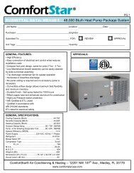
Installation &Operation Instructions For R410A (MAH ... - ComfortStar
Installation &Operation Instructions For R410A (MAH ... - ComfortStar
Installation &Operation Instructions For R410A (MAH ... - ComfortStar

Create successful ePaper yourself
Turn your PDF publications into a flip-book with our unique Google optimized e-Paper software.
<strong>Installation</strong> &<strong>Operation</strong> <strong>Instructions</strong><br />
<strong>For</strong> <strong>R410A</strong> (<strong>MAH</strong> & MHH) Series<br />
13SEER<br />
RECOGNIZE THIS SYMBOL AS A SAFETY PRECAUTION<br />
ATTENTION INSTALLING PERSONNEL<br />
Prior to installation, thoroughly familiarize yourself with this <strong>Installation</strong> Manual. Observe all safety warnings.<br />
During installation or repair, caution is to be observed<br />
It is your responsibility to install the product safe ly and to educate the customer on its safe use<br />
Eair LLC<br />
12201 N.W. 107 th Avenue, Medley, FL 33178<br />
www.comfortstarusa.com<br />
1
2<br />
TABLE OF CONTENTS<br />
1.0 SAFETY..................................................................................................................3<br />
1.1 INSPECTION....................................................................................................4<br />
1.2 LIMITATIONS....................................................................................................4<br />
2.0 GENERAL..............................................................................................................4<br />
3.0 UNIT INSTALLATION............................................................................................6<br />
3.1 LOCATION.......................................................................................................6<br />
3.2 GROUND INSTALLATION...............................................................................6<br />
3.3 ROOF INSTALLATION.....................................................................................6<br />
3.4 UNIT PLACEMENT..........................................................................................6<br />
3.5 PRECAUTIONS DURING LINE INSTALLATION.............................................7<br />
3.6 PRECAUTIONS DURING BRAZING OF LINES..............................................8<br />
3.7 PRECAUTIONS DURING BRAZING SERVICE VALVE..................................9<br />
3.8 UNIT MOUNTING...........................................................................................10<br />
3.9 FACTORY-PREFERRED TIE-DOWN METHOD............................................11<br />
3.10 REMOVING THE TOP PANEL AND MOTOR..............................................12<br />
4.0 ELECTRICAL CONNECTIONS...........................................................................13<br />
4.1 GENERAL INFORMATION & GROUNDING .................................................13<br />
4.2 FIELD CONNECTIONS POWER WIRING ....................................................13<br />
5.0 EVACUATION......................................................................................................14<br />
6.0 INTERCONNECTING TUBING............................................................................14<br />
6.1 VAPOR AND LIQUID LINES .........................................................................14<br />
6.2 MAXIMUM LENGTH OF LINES ....................................................................14<br />
6.3 VERTICAL SEPARATION .............................................................................14<br />
7.0 SYSTEM OPERATION........................................................................................14<br />
7.1 COMPRESSOR CRANKCASE HEATER (CCH)...........................................14<br />
7.2 PROTECTION FUNCTION INTRODUCTION...............................................16<br />
7.3 DEFROST MODE INTRODUCTION.............................................................16<br />
8.0 CHECKING REFRIGERANT CHARGE .............................................................16<br />
8.1 CHARGING BY LIQUID PRESSURE............................................................17<br />
8.2 CHARGING BY WEIGHT ..............................................................................17<br />
8.3 FINAL LEAK TESTING ..................................................................................17<br />
9.0 INSTRUCTING THE OWNER..............................................................................20<br />
10.0 WIRING DIAGRAM............................................................................................20
This document is customer property and is to remain with this unit.<br />
These instructions do not cover all the different variations of systems nor does<br />
it provide for every possible contingency to be met in connection with installation.<br />
All phases of this installation must comply with NATIONAL STATE AND LOCAL<br />
CODES. If additional information is required please contact your local distributor.<br />
1.0 SAFETY<br />
This is a safety alert symbol. When you see this symbol on labels or in<br />
manuals, be alert to the potential for personal injury.<br />
This is an attention alert symbol. When you see this symbol on labels or in<br />
manuals, be alert to the potential for personal injury.<br />
Understand and pay particular attention to the signal words DANGER, WARNING, or<br />
CAUTION.<br />
DANGER indicates an imminently hazardous situation, which, if not avoided, will result<br />
in death or serious injury.<br />
WARNING indicates a potentially hazardous situation, which, if not avoided, could result<br />
in death or serious injury.<br />
CAUTION indicates a potentially hazardous situation, which, if not avoided may result<br />
in minor or moderate injury. It is also used to alert against unsafe practices and hazards<br />
involving only property damage.<br />
WARNING<br />
Improper installation may create a condition where the operation of the product<br />
could cause personal injury or property damage.<br />
Improper installation, adjustment, alteration, service or maintenance can cause<br />
injury or property damage. Refer to this manual for assistance or for additional<br />
information, consult a qualified contractor, installer or service agency.<br />
CAUTION<br />
This product must be installed in strict compliance with the installation instructions<br />
and any applicable local, state, and national codes including, but not<br />
limited to building, electrical, and mechanical codes.<br />
WARNING<br />
FIRE OR ELECTRICAL HAZARD<br />
Failure to follow the safety warnings exactly could result in serious injury, death<br />
or property damage.<br />
A fire or electrical hazard may result causing property damage, personal injury<br />
or loss of life.<br />
3
4<br />
1.1 INSPECTION<br />
As soon as a unit is received, it should be inspected for possible damage during transit.<br />
If damage is evident, the extent of the damage should be noted on the carrier's delivery<br />
receipt. A separate request for inspection by the carrier's agent should be made in<br />
writing. See Local distributor for more information.<br />
Requirements <strong>For</strong> Installing/Servicing <strong>R410A</strong> Equipment<br />
Gauge sets, hoses, refrigerant containers, and recovery system must be designed<br />
to handle the POE or PVE type oils.<br />
Manifold sets should be 800 PSIG high side and 250 PSIG low side with 550 PSIG<br />
Iow side restart.<br />
All hoses must have a 700 PSIG service pressure rating.<br />
Leak detectors should be designed to detect refrigerant.<br />
Recovery equipment (including refrigerant recovery containers) must be specifi-<br />
cally designed to handle <strong>R410A</strong>.<br />
Do not use an R-22 TXV.<br />
It will be more convenient to open the Service valve after removing the Underside<br />
Clpboard. see the Fig.1<br />
Underside Clapboard<br />
LARGE SERVICE VALVE<br />
SMALL SERVICE VALVE<br />
1.2 LIMITATIONS<br />
The unit should be installed in accordance with all National, State and Local Safety<br />
Codes and the limitations listed below:<br />
1.Limitations for the indoor unit, coil and appropriate accessories must also be observed.<br />
2.The outdoor unit must not be installed with any duct work in the air stream. The outdoor fan is<br />
the propeller type and is not designed to operate against any additional external static<br />
pressure.<br />
3.The maximum and minimum conditions for operation must be observed to assure a system<br />
that will give maximum performance with minimum service.<br />
4.This unit is not designed to operate with a low ambient kit. Do not modify the control system<br />
to operate with any kind of Iow ambient kit.<br />
5.The maximum allowable line length for this product is 150 feet Just for Scroll compressor .<br />
2.0 GENERAL<br />
Fig.1 Underside Clapboard location<br />
The outdoor units are designed to be connected to a matching indoor coil with sweat<br />
connect lines. Sweat connect units are factory charged with refrigerant for a matching<br />
indoor coil plus 25 feet of field supplied lines.<br />
Matching indoor coils are available with a thermostatic expansion valve or an orifice<br />
for the most common usage. The orifice size and/or refrigerant charge may need to<br />
be changed for some indoor-outdoor unit combinations, elevation differences or<br />
total line lengths.
SERVICE ACCESS<br />
ALLOW 24” CLEARANCE<br />
DETAIL A<br />
DIMENSIONAL DATA<br />
L<br />
POWER WIRING<br />
SEE DETAIL A<br />
KNOCKOUT<br />
1-11/32” (34.5mm)<br />
HOLE<br />
1-3/32” (27.8mm)<br />
SERVICE<br />
FITTING<br />
LIQUID LINE<br />
CONNECTION<br />
FIG.2 DIMENSIONS<br />
AIR DISCHARGE: ALLOW 60”<br />
MINIMUM CLEARANCE.<br />
CONTROL WIRING<br />
7/8” (22.2mm)<br />
VAPOR LINE<br />
CONNECTION<br />
AIR INLETS<br />
LOUVERED PANELS<br />
ALLOW 18”<br />
MINIMUM<br />
CLEARANCE<br />
NOTE: GRILL APPEARANCE<br />
MAY VARY.<br />
ACCESS VALVLE<br />
FOR LOW PRESSURE<br />
SERVICE<br />
FITTING<br />
Unit Model (Btu/h)<br />
Dimensions (Inches)<br />
Refrigerant Connection<br />
Service Valve Size<br />
"H" in [mm] "W" in [mm] "L" in [mm] Liquid in Vapor in<br />
18(cooling unit) 24-15/16[633] 21-7/8[554] 21-7/8[554] 3 /8 3 /4<br />
18(heat pump unit) 24-15/16[633] 23-5/8[600] 23-5/8[600] 3 /8 3 /4<br />
24 24-15/16[633] 23-5/8[600] 23-5/8[600] 3 /8 3 /4<br />
30 24-15/16[633] 28[710] 28[710] 3 /8 3 /4<br />
36 24-15/16[633] 29-1/8[740] 29-1/8[740] 3 /8 3 /4<br />
42 29-7/8[759] 28[710] 28[710] 3 /8 3 /4<br />
48 33-3/16[843] 28[710] 28[710] 3 /8 7/8<br />
60 33-3/16[843] 29-1/8[740] 29-1/8[740] 3 /8 7/8<br />
W<br />
H<br />
NOTE:<br />
ONLY ADOPTED BY HEAT PUMP,<br />
CAN BE USED FOR MEASURING<br />
PRESSURE AFTER SWITCHOVER<br />
VALVE-SUCTION TO COMPRESSOR OR<br />
REFRIGERANT CHARGE.<br />
5
6<br />
3.0 UNIT INSTALLATION<br />
3.1 LOCATION<br />
Before starting the installation, select and check the suitability of the location for both<br />
the indoor and outdoor unit. Observe all limitations and clearance requirements. The<br />
outdoor unit must have sufficient clearance for air entrance to the condenser coil, for air<br />
discharge and for service access. See Fig.2<br />
NOTE<br />
<strong>For</strong> multiple unit installations, units must be spaced a minimum of 18 inches<br />
apart. (Coil face to coil face.)<br />
If the unit is to be installed on a hot sun exposed roof or a black-topped ground area, the<br />
unit should be raised sufficiently above the roof or ground to avoid taking the accumulated<br />
layer of hot air into the outdoor unit.<br />
Provide an adequate structural support.<br />
3.2 GROUND INSTALLATION<br />
The unit may be installed at ground level on a solid base that will not shift or settle, causing<br />
strain on the refrigerant lines and possible leaks. Maintain the clearances shown in<br />
Fig.2 and install the unit in a level position.<br />
Normal operating sound levels may be objectionable if the unit is placed directly under<br />
windows of certain rooms (bedrooms, study, etc.).<br />
Top of unit discharge area must be unrestricted for at least 60 inches above the unit.<br />
WARNING<br />
The outdoor unit should not be installed in an area where mud or ice could cause<br />
personal injury.<br />
Elevate the unit sufficiently to prevent any blockage of the air entrances by snow in<br />
areas where there will be snow accumulation. Check the local weather bureau for the<br />
expected snow accumulation in your area. Isolate the unit from rain gutters to avoid any<br />
possible wash out of the foundation.<br />
3.3 ROOF INSTALLATION<br />
When installing units on a roof, the structure must be capable of supporting the total<br />
weight of the unit, including a padded frame unit, rails, etc., which should be used to<br />
minimize the transmission of sound or vibration into the conditioned space.<br />
3.4 UNIT PLACEMENT<br />
1. Provide a base in the pre-determined location.<br />
2. Remove the shipping carton and inspect for possible damage.<br />
3. Compressor tie-down bolts should remain tightened.<br />
4. Position the unit on the base provided.
CAUTION<br />
This system uses <strong>R410A</strong> refrigerant which operates at higher pressure than<br />
R-22. No other refrigerant may be used in this system. Gauge sets, hoses,<br />
refrigerant containers, and recovery system must be designed to handle<br />
<strong>R410A</strong>. If you are unsure, consult the equipment manufacturer.<br />
The outdoor unit must be connected to the indoor coil using field supplied refrigerant<br />
grade copper tubing that is internally clean and dry. Units should be installed only with<br />
the tubing sizes for approved system combinations. The charge given is applicable for<br />
total tubing lengths up to 25 feet.<br />
NOTE<br />
Using a larger than specified line size could result in oil return problems. Using<br />
too small a line will result in loss of capacity and other problems caused by insufficient<br />
refrigerant flow. Slope horizontal vapor lines at least 1" every 20 feet<br />
toward the outdoor unit to facilitate proper oil return.<br />
3.5 PRECAUTIONS DURING LINE INSTALLATION<br />
1. Install the lines with as few bends as possible. Care must be taken not to damage<br />
the couplings or kink the tubing. Use clean hard drawn Copper tubing where no<br />
appreciable amount of bending around obstruction is necessary, if soft copper must<br />
be used, care must be taken to avoid sharp bends which may cause a restriction.<br />
2. The lines should be installed so that they will not obstruct service access to the coil,<br />
air handling system or filter.<br />
3. Care must also be taken to isolate the refrigerant lines to minimize noise transmis-<br />
sion from the equipment to the structure.<br />
4. The vapor line and liquid line must be insulated with a minimum of 1/2" foam rubber<br />
insulation (Armafiex or equivalent). Tape and suspend the refrigerant lines as shown.<br />
DO NOT allow tube metal-to-metal contact. See Fig. 3.<br />
5. Use PVC piping as a conduit for all underground installations as shown in Fig. 4.<br />
Buried lines should be kept as short as possible to minimize the build up of liquid<br />
refrigerant in the vapor line during long periods of shutdown.<br />
6. Pack fiberglass insulation and a sealing material such as perma gum around refrig-<br />
erant lines where they penetrate a wall to reduce vibration and to retain some flexi-<br />
bility.<br />
7
8<br />
TO<br />
INDOOR<br />
BLOWER<br />
TO<br />
COIL<br />
TO<br />
POWER<br />
SUPPLY<br />
Correct Incorrect<br />
Seal opening(s) with<br />
permagumor equivalent<br />
Sheet Metal Hanger<br />
Insulated Vapor Line<br />
Fig.3 Tubing Hanger<br />
Fig.5 Typical Installtion<br />
Tape<br />
Insulated Liquid Line<br />
Fig.4 Underground <strong>Installation</strong><br />
3.6 PRECAUTIONS DURING BRAZING OF LINES<br />
WEATHERPROOF<br />
DISCONNECT<br />
SWITCH<br />
NOTE:All outdoor wiring must be weather proof<br />
All outdoor unit and evaporator coil connections are copper-to-copper and should be<br />
brazed with a phosphorous-copper alloy material such as Silfos-5 or equivalent. DO<br />
NOT use soft solder. The outdoor units have reusable service valves on both the liquid<br />
and vapor connections. The total system refrigerant charge is retained within the<br />
outdoor unit during shipping and installation. The reusable service valves are provided<br />
to evacuate and charge per this instruction.<br />
Serious service problems can be avoided by taking adequate precautions to assure an<br />
internally clean and dry system.
CAUTION<br />
Dry nitrogen should always be supplied through the tubing while it is being<br />
brazed, because the temperature required is high enough to cause oxidation<br />
of the copper unless an inert atmosphere is provide. The flow of dry nitrogen<br />
should continue until the joint has cooled. Always use a pressure regulator<br />
and safety valve to insure that only low pressure dry nitrogen is introduced into<br />
the tubing.Only a small flow is necessary to displace air and prevent oxidation.<br />
3.7 PRECAUTIONS DURING BRAZING SERVICE VALVE<br />
Precautions should be taken to prevent heat damage to service valve by wrapping a wet<br />
rag around it as shown in Fig. 6. Also, protect all painted surfaces, insulation, during<br />
brazing. After brazing cool joint with wet rag.<br />
Valve can be opened by removing the plunger cap and fully inserting a hex wrench into<br />
the stem and backing out counter-clockwise until valve stem just touches the chamfered<br />
retaining wall.<br />
Connect the refrigerant lines using the following procedure:<br />
1. Remove the cap and Schrader core from both the liquid and vapor service valve<br />
service ports at the outdoor unit. Connect Iow pressure nitrogen to the liquid line<br />
service port.<br />
wet rag<br />
service valve<br />
Fig.6 Heat Protection<br />
2. Braze the liquid line to the liquid valve at the outdoor unit. Be sure to wrap the valve<br />
body with a wet rag. Allow the nitrogen to continue flowing. Refer to the Tabular Data<br />
Sheet for proper liquid line sizing.<br />
3. Carefully remove the rubber plugs from the evaporator liquid and vapor connections<br />
at the indoor coil.<br />
4. Braze the liquid line to the evaporator liquid connection. Nitrogen should be flowing<br />
through the evaporator coil.<br />
5. Slide the plastie cap away from the vapor connection at the indoor coil. Braze the<br />
vapor line to the evaporator vapor connection. Refer to the Table 1 for proper vapor<br />
line sizing.<br />
6. Protect the vapor valve with a wet rag and braze the vapor line connection to the<br />
outdoor unit. The nitrogen flow should be exiting the system from the vapor service<br />
port connection. After this connection has cooled, remove the nitrogen source from<br />
the liquid fitting service port.<br />
7. Replace the Schrader core in the liquid and vapor valves.<br />
8. Leak test all refrigerant piping connections including the service port flare caps to be<br />
sure they are leak tight. DO NOT OVER TIGHTEN (between 40 and 60 inch -lbs.<br />
maximum).<br />
9. Evacuate the vapor line, evaporator and the liquid line, to 500 microns or less.<br />
9
10<br />
Table 1: Refrigerant Connections and Recommended Liquid and Vapor Tube<br />
Diameters (ln.)<br />
UNIT LIQUID VAPOR LIQUID (LONG-LINE)<br />
SIZE Tube Diameter Tube Diameter Tube Diameter<br />
18 3/8 3/4 3/8<br />
24 3/8 3/4 3/8<br />
30 3/8 3/4 3/8<br />
36 3/8 3/4 3/8<br />
42 3/8 3/4<br />
3/8<br />
48 3/8 7/8<br />
3/8<br />
60 3/8 7/8 3/8<br />
10. Replace cap on service ports. Do not remove the flare caps from the service ports<br />
except when necessary for servicing the system.<br />
CAUTION<br />
Do not connect manifold gauges unless trouble is suspected. Approximately 3/4<br />
ounce of refrigerant will be lost each time a standard manifold gauge is<br />
connected.<br />
11. Release the refrigerant charge into the system. Open both the liquid and vapor<br />
valves by removing the plunger cap and with an hex wrench back out counter<br />
-clockwise until valve stem just touches the chamfered retaining wall.<br />
12. Replace plunger cap finger tight, then tighten an additional 1/12 turn (1/2 hex flat).<br />
Cap must be replaced to prevent leaks.<br />
WARNING<br />
Never attempt to repair any brazed connections while the system is under pressure.<br />
Personal injury could result.<br />
See "System Charge" section for checking and recording system charge.<br />
3.8 UNIT MOUNTING<br />
If elevating the heat pump, either on a flat roof or on a slab, observe the following guidelines.<br />
1.The base pan provided elevates the heat pump 2 ” above the base pad.<br />
2 . If elevating a unit on a flat roof , use 4 ”× 4”(or equivalent) stringers<br />
positioned to distribute unit weight evenly and prevent noise and vibration<br />
(See fig. 7) .<br />
NOTE:Do not block drain openings shown in fig.7.<br />
3. If unit must be elevated because of anticipated snow fall, secure unit and<br />
elevating stand such that unit and/or stand will not tip over or fall off.<br />
NOTE: To tie down unit, see 3.9.
BASE PAD<br />
(CONCRETE OR<br />
OTHER SUITABLE<br />
MATERIAL)<br />
Fig.7 RECOMMENDED ELEVATED INSTALLATION<br />
3.9 FACTORY-PREFERRED TIE-DOWN METHOD<br />
Step 1: Prior to installing clear pad of debris.<br />
IMPORTANT<br />
Then cement pad must be made of HVAC-approved materials and must be the<br />
proper thickness to accommodate fasteners.<br />
Step 2: Center and level unit onto pad.<br />
BASE PAN (BOTTOM VIEW) DO NOT<br />
OBSTRUCT DRAIN HOLES<br />
(SHADED)<br />
ELEVATION ABOVE ANTICIPATED<br />
SNOW IS NECESSARY<br />
Step 3: Using L-shaped bracket to locate holes on concrete and drill pilot holes which is<br />
at least 1/4” deeper than fastener being used.<br />
IMPORTANT<br />
Self drilling screws to base pan should not exceed 3/8” long to avoid damaging<br />
coil.<br />
Step 4: Using conventional practices to install brackets, tighten concrete fasteners and<br />
self-tapping screws (See Fig.8).<br />
NOTE: 1. One bracket for each side. <strong>For</strong> extra stability, 2 brackets for each side.<br />
2. Do not over-tighten the concrete fastener to avoid weakening the concrete.<br />
IMPORTANT NOTE:<br />
These instructions are intended to provide a method to tie-down system to cement slab<br />
as a securing procedure for high wind areas. It is recommended to check Local Codes<br />
for tie-down methods and protocols.<br />
11
12<br />
#7 X 3/8” Self Tapping Screws<br />
(Don’t Exceed 3/8” long)<br />
3.10 REMOVING THE TOP PANEL AND MOTOR<br />
NOTE:<br />
Fig.8 FACTORY-PREFERRED REQUIRED PARTS TIE-DOWN LIST METHOD<br />
Damage will occur to condenser unit<br />
if you remove fan bolts prior to cover removal.<br />
1/2” bolt<br />
Fig. 9 COVER AND FAN<br />
DETAIL B<br />
(3/16” Pilot Hole Needed. Pilot Hole Should Be1/4” Deeper<br />
Than The Fastener Embedment)<br />
SEE DETAIL B<br />
5/16” bolts<br />
Brackets:<br />
2” width, 1/16 ” thickness,<br />
height as required.<br />
Available from distributor<br />
or in market place.<br />
When motor requires changing follow the steps below:<br />
Step 1: Go into electrical panel, disconnect motor power lines.<br />
IMPORTANT NOTE<br />
Disconnect main power to unit. Severe burns and electrical shock will occur if<br />
you do not disconnect main power.<br />
Step 2: Remove cover (be careful of motor wires)<br />
Step 3: Be sure to place fan cover unit on the ground as indicated in Fig. 9<br />
IMPROTANT NOTE<br />
Do not place or lean fan blades on ground or against surface.<br />
Step 4: Remove fan motor by removing 5/16” bolts from cover.<br />
Step 5: Remove fan blade from motor by removing 1/2” bolt and place fan on the ground.<br />
Step 6: Reverse removal process to reinstall the fan and motor.<br />
IMPROTANT NOTE<br />
When connecting motor wires be sure to check motor direction.
4.0 ELECTRICAL CONNECTIONS<br />
4.1 GENERAL INFORMATION & GROUNDING<br />
Check the electrical supply to be sure that it meets the values specified on the unit<br />
nameplate and wiring label.<br />
Power wiring, control (Iow voltage) wiring, disconnect switches and over current<br />
protection must be supplied by the installer. Wire size should be sized per requirements.<br />
CAUTION<br />
All field wiring must USE COPPER CONDUCTORS ONLY and be in accordance<br />
with Local, National Fire, Safety & Electrical Codes. This unit must be grounded<br />
with a separate ground wire in accordance with the above codes.<br />
The complete connection diagram and schematic wiring label is located on the inside<br />
surface of the unit service access panel and this instruction.<br />
4.2 FIELD CONNECTIONS POWER WIRING<br />
1. Install the proper size weatherproof disconnect switch outdoors and within sight of<br />
the unit.<br />
2. Remove the screws at the side of the corner cover. Slide corner cover down and<br />
remove from unit. See Fig. 10.<br />
3. Run power wiring from the disconnect switch to the unit.<br />
4. Route wires from disconnect through power wiring opening provided and into the<br />
unit control box.<br />
POWER<br />
WIRING<br />
CONTROL<br />
WIRING<br />
Fig.10 Typical Field Wiring<br />
5. Install the proper size time-delay fuses or circuit breaker, and make the power<br />
supply connections.<br />
6. Energize the crankcase heater if equipped to save time by preheating the compres-<br />
sor oil while the remaining installation is completed.<br />
NOTE: When changing the motor, remove top cover first.<br />
CORNER<br />
COVER<br />
13
14<br />
5.0 EVACUATION<br />
It will be necessary to evacuate the system to 500 microns or less. If a leak is<br />
suspected, leak test with dry nitrogen to locate the leak. Repair the leak and test again.<br />
To verify that the system has no leaks, simply close the valve to the vacuum pump<br />
suction to isolate the pump and hold the system under vacuum. Watch the micron<br />
gauge for a few minutes. If the micron gauge indicates a steady and continuous rise,<br />
it's an indication of a leak. If the gauge shows a rise, then levels off after a few minutes<br />
and remains fairly constant, its an indication that the system is leak free but still<br />
contains moisture and may require further evacuation if the reading is above 500<br />
microns.<br />
6 .0 INTERCONNECTING TUBING<br />
6 .1 VAPOR AND LIQUID LINES<br />
Keep all lines sealed until connection is made.<br />
Make connections at the indoor coil first.<br />
Refer to Li ne Size Information in Ta bles 2 and 3 for correct size and multipliers to be<br />
used to determine capacity for various vapor line diameters and lengths of run. The<br />
losses due to the lines being exposed to outdoor conditions are not included.<br />
The factory refrigerant charge in the o utdoor unit is s ufficient for 25 feet of<br />
interc onnecting lines. The factory refrigerant charge in the outdoor unit is sufficient<br />
for the unit and 25 feet of standard size interconnecting l iquid and vapor lines. <strong>For</strong><br />
diff erent lengths, adjust the charge as indicated below.<br />
1/4” ± .3 oz. per foot<br />
5/16” ± .4 oz. per foot<br />
3/8” ± .6 oz . per foot<br />
1/2” ± 1.2 oz . per foot<br />
6 .2 M AXIMUM LENGTH OF LINES<br />
T h e maximum length of interconnecting line is 150 feet.<br />
Always use the shortest length possible with a minimu m number of bends. Additional<br />
compressor oil is not required for any length up to 150 feet.<br />
NOTE: Excessively long refrigerant lines cause loss of equipment capacity.<br />
6 .3 V ERTICAL SEPARATION<br />
Keep the vertical separation to a minimum. Use the following g uidelines when<br />
installing the unit:<br />
1. DO NOT exceed the vertical separations as indicated on Table 3.<br />
2. It is recommended to use the smallest liquid line size permitted to minimize sys -<br />
t em charge which will maximize compressor reliability.<br />
3. Table 3 may be used for sizing horizontal runs.<br />
7.0 SYSTEM OPERATION<br />
7.1 COMPRESSOR CRANKCASE HEATER (CCH)<br />
Refrigerant migration during the off cycle can result in a noisy start up. Add a crankcase<br />
heater to minimize refrigeration migration, and to help eliminate any start up<br />
noise or bearing “wash out”.<br />
All heaters are located on the lower half of the compressor shell. Its purpose is to drive<br />
refrigerant from the compressor shell during long off cycles, thus preventing damage<br />
to the compressor during start-up.<br />
At initial start-up or after extended shutdown periods, make sure the heater is energized<br />
for at least 12 hours before the compressor is started. (Disconnect switch on and<br />
wall thermostat off.)<br />
The crankcase heating belt’s drive-up conditions:<br />
When outdoor temp. is < 37.4 ° F, compressor will pause for no less than 3<br />
hours or be plugged in power at such kind of ambient temperature.<br />
Crankcase heating belt’s shut-down conditions:<br />
When outdoor temp. is > 44.6 ° F or the compressor start up, the crankcase<br />
heating belt will be shut down.
TABLE 2: SUCTION LINE LENGTH/SIZE VS CAPACITY MULTIPLIER(<strong>R410A</strong>)<br />
Unit Size<br />
Suction Line Connection Size<br />
Suction Line Run-Feet<br />
25'<br />
50'<br />
100'<br />
150'<br />
TABLE 3 :LIQUID LINE SIZING (R-410A)<br />
1 1/2 Ton 2 Ton 2 1/2 Ton 3 Ton 3 1/2 Ton 4 Ton 5 Ton<br />
3/4" I.D. 3/4" I.D. 3/4" I.D. 3/4" I.D. 3/4" I.D. 7/8" I.D. 7/8" I.D.<br />
5/8 Opt. 5/8 Opt. 5/8 Opt. 5/8 Opt. 5/8 Opt. 3/4 Opt. 1 1/8 Opt.<br />
3/4* Std. 3/4* Std. 3/4* Std. 3/4* Std. 3/4* Std. 7/8* Std. 7/8* Std.<br />
Optional 1.00 1.00 1.00 1.00 1.00 1.00 1.00<br />
Standard 1.00 1.00 1.00 1.00 1.00 1.00 0.99<br />
Optional 0.97 0.97 0.97 0.97 0.98 0.98 0.99<br />
Standard 0.98 0.98 0.98 0.99 0.98 0.98 0.98<br />
Optional 0.94 0.94 0.94 0.94 0.95 0.95 0.98<br />
Standard 0.95 0.95 0.96 0.97 0.97 0.97 0.94<br />
Optional 0.90 0.90 0.90 0.90 0.91 0.92 0.97<br />
Standard 0.92 0.92 0.93 0.96 0.96 0.96 0.90<br />
NOTES:<br />
* Standard size<br />
Using suction line larger than shown in chart will result in poor oil return and is not recommended.<br />
System<br />
Capacity<br />
3 Ton<br />
Line Size<br />
Connection Size<br />
(Inch I.D.)<br />
1 1/2 Ton 3/8"<br />
2 Ton 3/8"<br />
2 1/2 Ton<br />
3/8"<br />
3 1/2 Ton<br />
4 Ton<br />
5 Ton<br />
3/8"<br />
3/8"<br />
3/8"<br />
3/8"<br />
NOTES:<br />
* Standard line size<br />
N/A Application not recommended.<br />
Compressor<br />
Type<br />
Line Size<br />
Connection And<br />
Line Size<br />
(Inch I.D.)<br />
Liquid Line Size<br />
Outdoor unit above or below indoor coil<br />
(Heat Pumps Only)<br />
Total Equivalent Length - Feet<br />
25 50 75 100 125 150<br />
Maximum Vertical Separation - Feet<br />
Rotary 3/8* 25 30 30 27 24 20<br />
Rotary 3/8* 25 30 30 24 20 15<br />
Rotary 3/8* 25 30 30 22 17 10<br />
Scroll<br />
5/16<br />
3/8*<br />
25<br />
25<br />
50<br />
50<br />
37<br />
68<br />
22<br />
63<br />
7<br />
58<br />
N/A<br />
53<br />
Scroll<br />
5/16<br />
3/8*<br />
25<br />
25<br />
23<br />
50<br />
4<br />
43<br />
N/A<br />
36<br />
N/A<br />
30<br />
N/A<br />
24<br />
Scroll<br />
3/8*<br />
1/2<br />
25<br />
25<br />
46<br />
50<br />
38<br />
56<br />
30<br />
55<br />
22<br />
53<br />
15<br />
52<br />
Scroll<br />
3/8*<br />
1/2<br />
25<br />
25<br />
50<br />
50<br />
56<br />
75<br />
44<br />
81<br />
32<br />
79<br />
20<br />
76<br />
TABLE 4 :PISTON SIZE/TXV VALVE OF INDOOR UNIT:<br />
Condensing Unit Air Handler<br />
Piston Size/TXV<br />
Valve Model<br />
SEER Condensing Unit Air Handler<br />
Piston Size/TXV<br />
Valve Model<br />
SEER HSPF<br />
HD2-18 054 13 HD2-18 054 13 7.7<br />
<strong>MAH</strong>-18-410 AC1818A 050 13 MHH-18-410 AC1818A 050 13 7.7<br />
AC1818B 050 13 AC1818B 050 13 7.7<br />
HD2-24 061 13 HD2-24 061 13 7.7<br />
<strong>MAH</strong>-24-410 AC1824A 053 13 MHH-24-410 AC1824A 053 13 7.7<br />
AC1824B 053 13 AC1824B 053 13 7.7<br />
HD2-30 065 13 HD2-30 068 13 7.7<br />
<strong>MAH</strong>-30-410 AC2430A 059 13 MHH-30-410 AC2430A 064 13 7.7<br />
AC2430B 059 13 AC2430B 064 13 7.7<br />
HD2-36 073 13 HD2-36 068 13 8.2<br />
AC3036A 070 13 AC3036A 071 13 7.7<br />
<strong>MAH</strong>-36-410 AC3036B 070 13 MHH-36-410 AC3036B 066 13 7.7<br />
AC3036C 070 13 AC3036C 068 13 7.7<br />
HD2-36+TXV TR6-4TON 14 HD2-36+TXV TR6-4TON 14 8.3<br />
HD2-42 077 13 HD2-42 080 13 8.2<br />
AC3642B 072 13 AC3642B 079 13 7.7<br />
<strong>MAH</strong>-42-410<br />
AC3642C<br />
AC3642D<br />
072<br />
072<br />
13<br />
13<br />
MHH-42-410<br />
AC3642C<br />
AC3642D<br />
078<br />
080<br />
13<br />
13<br />
7.7<br />
7.7<br />
HD2-42+TXV TR6-4TON 14 HD2-42+TXV TR6-4TON 14 8.3<br />
HD2-43 080 14 HD2-43 080 14 8.3<br />
HD2-48 105 13 HD2-48 090 13 8.2<br />
AC4248B 088 13 AC4248B 088 13 7.7<br />
<strong>MAH</strong>-48-410 AC4248C 088 13 MHH-48-410 AC4248C 092 13 7.7<br />
AC4248D 088 13 AC4248D 096 13 7.7<br />
HD2-48+TXV TR6-5TON 14 HD2-48+TXV TR6-5TON 14 8.3<br />
HD2-60 097 13 HD2-60 108 13 8.2<br />
<strong>MAH</strong>-60-410 AC4860C 098 13 MHH-60-410<br />
AC4860C 118 13 7.7<br />
AC4860D 098 13 AC4860D 111 13 7.7<br />
15
16<br />
7.2 PROTECTION FUNCTION INTRODUCTION<br />
Sensor T3 (condenser pipe temperature) and T4 (outdoor ambient temperature)<br />
When open-circuit, compressor, outdoor fan motor and reverse valve will be OFF.<br />
When T4 is < 5 °F the compressor will stop. If the electrical heater kit is installed in the<br />
indoor unit, the outdoor unit provides the signal when it is to work.<br />
When T4 is > 10.4 °F the compressor will restart.<br />
Discharge temperature protection (Heat pump only)<br />
When discharge temp. is > 275 °F the compressor will stop.<br />
When discharge temp. is < 194 °F the compressor will restart.<br />
High perssure protection (Heat pump only)<br />
When high pressure is > 638 PSIG, the compressor and the outdoor fan motor will stop.<br />
When high pressure is < 464 PSIG, the compressor and the outdoor fan motor will restart<br />
(3 minutes delay necessary).<br />
Low pressure protection (Heat pump only)<br />
Low pressure is < 21 PSIG, the compressor and the outdoor fan motor will stop.<br />
Low pressure is > 44 PSIG, the compressor and the outdoor fan motor will restart<br />
(3 minutes delay necessary).<br />
In stand-by status, the compressor will not start in low pressure protection.<br />
Within 30 mins, if 4 protection cycles occurs, system will restore after power cut-down.<br />
7.3 DEFROST MODE INTRODUCTION<br />
Start-up conditions of defrost mode:<br />
When JUMP switch is set to “1”(See in Fig 11), the mode will start up in either of<br />
the two following conditions:<br />
1. Compressor operating, when T4 is > 28.4 °F and T3 is < 32 °F last for 40 minutes;<br />
2. Compressor operating, when T4 is < 28.4 °F and T3 is < 32 °F last for 50 minutes.<br />
When JUMP switch is set to “0”:<br />
Compressor operating, when T3 is < 32 °F last for 30 minutes.<br />
Shut-down conditions of defrost mode:<br />
The mode will shut down in either of the two following conditions:<br />
1. The defrosted time lasting for 10 minutes;<br />
JUMP Switch<br />
Fig.11 JUMP Switch Location in the PCB Borad<br />
8.0.CHECKING REFRIGERANT CHARGE<br />
Charge for all systems should be checked against the Charging Chart inside the<br />
access panel cover.<br />
IMPORTANT:Do not operate the compressor without charge in system. Additio n of<br />
R - 410A will raise pressures (vapor, liquid and discharge).<br />
If adding R - 410A raises both vapor pressure and temperature, the unit is over -<br />
c harged.<br />
IMPORTANT: Use industry - approved charging methods to ensure proper system<br />
charge.
TABLE 5: REFRIGERANT CHARGE FOR A/C SYSTEM.<br />
8 .1 CHARGING BY LI Q UID PRESSURE<br />
The liquid pressure method is used for charging systems in the cooling and heating<br />
mode. The service port on the liquid (small valve) and suction (large valve) is used<br />
for this purpose.<br />
Verify that the outdoor unit is running and the indoor air mover is delivering the<br />
maximum airflow for this system size. Read and record the outdoor ambient tem -<br />
p erature. Read and record the liquid and suction pressures at the ports on the liquid<br />
and suction valves.<br />
If refrigerant lines are sized using the n ameplate charge, the correct liquid pressure is<br />
found at the intersection of the suction pressure and the outdoor ambient.<br />
1. Remove refrigerant charge if the liquid pressure is above the chart value.<br />
2. Add refrigerant charge if the liquid pressure is below the chart value.<br />
8 .2 CHARGING BY WEIGHT<br />
<strong>For</strong> a new installation, evacuation of interconnecting tubing and indoor coil is<br />
adeq uate; otherwise, evacuate the entire system. Note that charge value includes<br />
charge required for 25 ft. of standard size interconnecti ng liquid line. Calculate actua l<br />
charge required with installed liquid line size and length using:<br />
1/4” O.D. = . 3 oz./ft.<br />
5/16” O.D. = .4 oz./ft<br />
3/8” O.D. = .6 oz./ft<br />
1/2” O.D. = 1.2 oz./ft<br />
With an accurate scale (+/ - 1 oz.) or volumetric char ging device, adjust charge<br />
diff erence between that shown on the unit data plate and that calculated for the new<br />
system <strong>Installation</strong>. if the entire system has been evacua ted, add the total calculated<br />
charge.<br />
8.3 FINAL LEAK TESTING<br />
After the unit has been properly evacuated and charged, a halogen leak detector<br />
should be used to detect leaks in the system. All piping within the condensing unit,<br />
evaporator, and interconnec ting tubing should be checked for leaks. If a leak is<br />
detected, the refrigerant should be recovered before repairing the leak. The Clean Air<br />
Act prohibits releasing refrigerant into the atmosphere .<br />
Cooling Charge Chart 1.5 TON<br />
Cooling Charge Chart 2 TON<br />
Cooling Mode<br />
55 60 65 70<br />
Outdoor Ambient Temperature( )<br />
75 80 85 90 95 100 105 110 115<br />
Cooling Mode<br />
55 60 65 70<br />
Outdoor Ambient Temperature( )<br />
75 80 85 90 95 100 105 110 115<br />
Lipuid Pressure at Small Service Valve(psig)<br />
Lipuid Pressure at Small Service Valve(psig)<br />
165 236 253 270 287 304 324 345 368 391 414 440 464 165 245 265 282 301 321 340 361 385 406 430 456 483<br />
161 234 251 268 285 302 322 343 366 389 411 437 462 161 243 262 279 299 318 317 357 383 404 427 453 480<br />
157 232 249 266 283 300 319 341 364 387 409 435 459 157 241 259 276 296 315 314 354 381 401 325 450 478<br />
153 230 247 264 281 298 317 339 362 385 407 433 457 153 240 257 274 294 312 331 351 378 398 423 447 475<br />
149 211 228 245 262 279 296 315 337 360 383 406 431 455 149 223 238 255 272 292 309 328 349 374 395 421 445 473<br />
145 209 226 243 260 277 294 313 335 358 381 404 429 453 145 221 237 253 270 289 307 326 347 371 393 419 443 470<br />
141 207 224 241 258 275 292 311 333 356 379 402 427 451 141 219 235 251 268 287 305 324 345 369 391 417 441 468<br />
137 205 222 239 256 273 290 309 331 354 377 400 425 449 137 218 234 249 266 285 303 322 343 367 389 414 439 466<br />
133 203 220 237 254 271 288 307 329 352 375 398 423 446 133 216 232 247 264 283 301 320 341 365 387 411 437 463<br />
129 201 218 235 252 269 286 305 327 350 372 396 420 443 129 214 230 245 262 280 299 318 339 363 385 408 434 460<br />
125 199 216 233 250 267 284 303 325 348 370 393 418 441 125 211 328 243 260 278 296 316 337 360 382 405 432 456<br />
121 197 214 231 248 265 282 301 323 345 368 391 415 439 121 208 225 241 258 275 294 314 335 358 379 402 428 452<br />
117 195 212 229 246 263 280 299 321 343 366 389 413 436 117 205 222 239 256 273 292 312 333 356 376 399 425 450<br />
113 193 210 227 244 261 278 297 319 341 364 386 410 433 113 203 220 237 254 272 289 309 331 355 372 396 421 445<br />
109 191 208 225 242 259 276 295 317 339 361 383 406 429 109 200 218 235 252 270 287 307 329 351 369 393 418 443<br />
105 189 206 223 240 257 274 293 315 337 359 381 403 426 105 198 216 233 250 268 285 305 326 347 366 390 415 440<br />
Cooling Charge Chart 2.5TON<br />
Cooling Charge Chart 3 TON(FOR HD2-36)<br />
Cooling Mode<br />
55 60 65 70<br />
Outdoor Ambient Temperature( )<br />
75 80 85 90 95 100 105 110 115<br />
Cooling Mode<br />
55 60 65 70<br />
Outdoor Ambient Temperature( )<br />
75 80 85 90 95 100 105 110 115<br />
Lipuid Pressure at Small Service Valve(psig)<br />
Lipuid Pressure at Small Service Valve(psig)<br />
165 255 272 289 307 326 348 370 392 414 438 465 165 251 269 287 305 323 345 367 389 411 434 458<br />
161 253 270 287 305 324 346 368 390 412 435 462 161 249 267 285 303 321 343 365 387 409 432 456<br />
157 251 268 285 303 322 344 366 388 410 433 460 157 247 265 283 301 319 340 362 385 407 430 454<br />
153 232 249 266 283 301 319 341 363 385 407 431 458 153 227 245 263 281 299 317 338 360 382 405 428 452<br />
149 230 247 264 281 299 317 339 361 383 405 429 456 149 225 243 261 279 297 314 336 358 380 403 426 450<br />
145 228 245 262 279 296 314 336 358 380 402 424 454 145 223 241 259 277 295 312 334 356 378 400 423 447<br />
141 209 226 243 260 277 294 311 333 355 377 399 422 452 141 203 221 239 257 275 293 310 332 353 375 397 420 445<br />
137 207 224 241 258 275 292 309 331 353 375 397 420 450 137 201 219 237 255 273 291 307 329 351 373 395 418 443<br />
133 205 222 239 256 273 290 307 329 351 373 395 418 448 133 199 217 235 253 271 289 305 327 349 371 393 415 440<br />
129 203 220 237 254 271 288 304 326 348 370 392 415 446 129 197 215 232 250 268 286 303 324 347 368 390 412 437<br />
125 201 218 235 252 269 286 302 324 346 368 390 413 442 125 195 212 229 247 265 283 301 322 344 365 387 409 433<br />
121 199 216 233 250 267 284 300 322 344 366 388 411 440 121 193 210 227 244 262 280 299 319 341 362 384 405 428<br />
117 197 214 231 248 265 282 298 320 342 364 386 408 437 117 191 208 225 242 259 277 296 317 338 359 380 401 424<br />
113 195 212 229 246 263 280 296 318 340 362 384 406 435 113 189 206 223 240 257 274 294 315 335 356 377 397 419<br />
109 191 209 226 243 260 277 295 317 339 361 383 405 433 109 187 204 221 238 255 272 292 313 332 353 373 394 415<br />
105 189 206 223 240 257 274 293 315 337 359 381 403 431 105 185 202 219 236 253 270 290 310 330 350 370 390 412<br />
Cooling Charge Chart 3 TON(FOR HD2-36+TXV)<br />
Cooling Charge Chart 3.5 TON(FOR HD2-42)<br />
Cooling Mode<br />
55 60 65 70<br />
Outdoor Ambient Temperature( )<br />
75 80 85 90 95 100 105 110 115<br />
Cooling Mode<br />
55 60 65 70<br />
Outdoor Ambient Temperature( )<br />
75 80 85 90 95 100 105 110 115<br />
Lipuid Pressure at Small Service Valve(psig)<br />
Lipuid Pressure at Small Service Valve(psig)<br />
165 255 273 292 315 338 362 387 439 491 514 538 165 283 299 313 333 353 373 397 423 449 475 502<br />
161 253 271 290 313 336 360 385 437 489 512 536 161 281 296 311 331 351 371 395 421 447 473 500<br />
157 251 269 288 311 334 357 382 435 487 510 534 157 279 294 309 329 348 369 393 419 444 470 495<br />
153 230 249 267 286 309 332 355 380 432 485 508 532 153 263 277 291 307 327 346 367 391 417 442 468 493<br />
149 228 247 265 284 307 329 353 378 430 483 506 530 149 260 274 289 305 325 344 365 389 415 440 465 490<br />
145 226 245 263 282 305 327 351 376 428 480 503 527 145 258 272 287 303 323 342 363 386 412 437 462 487<br />
141 173 224 243 261 280 303 325 349 373 425 477 500 525 141 240 256 270 285 301 321 340 361 384 409 433 458 485<br />
137 171 222 241 259 278 301 322 346 371 423 475 498 523 137 237 254 268 283 299 319 338 359 381 406 430 454 482<br />
133 169 220 239 257 276 299 320 344 369 421 473 495 520 133 235 251 266 281 296 317 336 357 379 403 427 451 478<br />
129 167 218 236 254 273 296 318 341 367 418 470 492 517 129 232 248 264 278 294 314 334 355 377 401 423 449 475<br />
125 165 215 233 251 270 293 316 339 364 415 467 489 513 125 229 244 261 275 291 311 332 353 375 399 420 447 472<br />
121 163 213 231 248 267 290 314 336 361 412 464 485 508 121 225 240 257 272 288 308 329 350 373 396 418 445 469<br />
117 161 211 229 246 264 287 311 334 358 409 460 481 504 117 221 237 253 269 286 306 327 348 370 394 416 442 466<br />
113 159 209 227 244 262 284 309 332 355 406 457 477 499 113 217 234 251 267 284 304 325 346 368 391 414 438 462<br />
109 157 207 225 242 260 282 307 330 352 403 453 474 495 109 213 231 248 265 282 302 323 343 365 387 410 434 459<br />
105 155 205 223 240 258 280 305 327 350 400 450 470 492 105 211 228 245 262 280 300 320 340 362 384 406 430 456<br />
17
Cooling Charge Chart 3.5 TON(FOR HD2-42+TXV)<br />
Cooling Charge Chart 4 TON(FOR HD2-48)<br />
Cooling Mode<br />
55 60 65 70<br />
Outdoor Ambient Temperature( )<br />
75 80 85 90 95 100 105 110 115<br />
Cooling Mode<br />
55 60 65 70<br />
Outdoor Ambient Temperature( )<br />
75 80 85 90 95 100 105 110 115<br />
Lipuid Pressure at Small Service Valve(psig)<br />
Lipuid Pressure at Small Service Valve(psig)<br />
165 255 273 288 308 328 351 377 423 479 505 532 165 253 270 287 304 322 345 368 391 414 439 466<br />
161 253 270 286 306 326 349 375 421 477 503 530 161 251 268 285 302 320 343 366 389 412 437 463<br />
157 251 268 284 304 323 347 373 419 474 500 525 157 249 266 283 300 318 341 364 387 410 435 460<br />
153 233 249 265 282 302 321 345 371 417 472 498 523 153 230 247 264 281 298 316 339 362 385 408 433 458<br />
149 230 246 263 280 300 319 343 369 415 470 495 520 149 228 245 262 279 296 314 337 360 383 406 430 456<br />
145 228 244 261 278 298 317 341 366 412 467 492 517 145 226 243 260 277 294 312 334 358 380 403 427 453<br />
141 210 226 242 259 276 296 315 339 364 409 463 488 515 141 207 224 241 258 275 292 310 332 355 377 400 423 450<br />
137 207 224 240 257 274 294 313 337 361 406 460 484 512 137 205 222 239 256 273 290 308 330 353 375 397 419 447<br />
133 205 221 238 255 271 292 311 335 359 403 457 481 508 133 203 220 237 254 271 288 306 328 350 372 394 416 444<br />
129 202 218 236 252 269 289 309 333 357 401 453 479 505 129 200 218 235 251 268 285 304 325 347 368 390 411 438<br />
125 199 214 233 249 266 286 307 331 355 399 450 477 502 125 197 215 232 248 265 283 302 323 343 364 386 406 432<br />
121 195 210 229 246 263 283 304 328 353 396 448 475 499 121 195 213 229 245 263 281 300 320 341 361 382 402 426<br />
117 191 207 225 243 261 281 302 326 350 394 446 472 496 117 192 209 226 243 260 279 298 318 338 358 378 398 422<br />
113 187 204 223 241 259 279 300 324 348 391 444 468 492 113 190 207 223 241 257 277 296 316 336 356 376 396 418<br />
109 183 201 220 239 257 277 298 321 345 387 440 464 489 109 188 205 221 238 255 275 294 314 334 354 374 394 415<br />
105 181 198 217 236 255 275 295 318 342 384 436 460 486 105 185 202 219 236 253 273 292 312 332 352 372 392 413<br />
Cooling Charge Chart 4 TON(FOR HD2-48+TXV)<br />
Cooling Charge Chart 5 TON<br />
Cooling Mode<br />
55 60 65 70<br />
Outdoor Ambient Temperature( )<br />
75 80 85 90 95 100 105 110 115<br />
Cooling Mode<br />
55 60 65 70<br />
Outdoor Ambient Temperature( )<br />
75 80 85 90 95 100 105 110 115<br />
Lipuid Pressure at Small Service Valve(psig)<br />
Lipuid Pressure at Small Service Valve(psig)<br />
165 253 270 287 304 327 350 373 401 429 459 486 165 310 329 333 337 341 362 384 405 428 450 473<br />
161 251 268 285 302 325 348 371 399 427 457 483 161 316 321 326 330 335 357 379 400 423 446 469<br />
157 249 266 283 300 323 346 369 397 425 455 480 157 322 310 316 323 329 353 376 399 423 446 470<br />
153 230 247 264 281 298 321 344 367 395 423 453 478 153 279 290 299 308 318 327 350 373 396 420 444 468<br />
149 228 245 262 279 296 319 342 365 393 421 450 476 149 270 280 288 299 311 322 346 370 393 418 442 467<br />
145 226 243 260 277 294 317 339 363 390 418 447 473 145 261 271 280 294 308 322 344 367 389 414 439 464<br />
141 207 224 241 258 275 292 315 337 360 387 415 443 470 141 239 250 261 272 287 302 317 341 365 389 414 438 463<br />
137 205 222 239 256 273 290 313 335 358 385 412 439 467 137 227 237 248 259 277 296 315 340 364 389 413 437 461<br />
133 203 220 237 254 271 288 311 333 355 382 409 436 464 133 213 228 243 257 276 295 314 338 362 386 410 435 459<br />
129 200 218 235 251 268 285 309 330 352 378 405 431 458 129 203 220 237 254 273 293 313 337 361 386 408 431 454<br />
125 197 215 232 248 265 283 307 328 348 374 401 426 452 125 202 218 234 250 271 291 312 336 360 384 407 430 452<br />
121 195 213 229 245 263 281 305 325 346 371 397 422 446 121 201 217 232 248 269 289 309 333 357 381 402 424 446<br />
117 192 209 226 243 260 279 303 323 343 368 393 418 442 117 200 216 232 248 268 289 309 332 355 378 400 423 445<br />
113 190 207 223 241 257 277 301 321 341 366 391 416 438 113 197 214 230 247 270 293 316 334 353 372 393 415 436<br />
109 188 205 221 238 255 275 299 319 339 364 389 414 435 109 195 211 227 243 263 283 304 326 347 369 390 411 431<br />
105 185 202 219 236 253 273 297 317 337 362 387 412 433 105 190 207 225 242 262 282 302 323 344 365 386 407 427<br />
TABLE 6: REFRIGERANT CHARGE FOR H/P SYSTEM.<br />
Cooling Charge Chart 1.5 TON<br />
Heating Charge Chart 1.5 TON<br />
Cooling Mode<br />
55 60 65 70<br />
Outdoor Ambient Temperature( )<br />
75 80 85 90 95 100 105 110 115<br />
Heating Mode<br />
60 62 64<br />
Indoor Dry Bulb Temperature(<br />
66 68 70 72 74<br />
)<br />
76 78 80 82<br />
Lipuid Pressure at Small Service Valve(psig) Lipuid Pressure at Small Service Valve(psig)<br />
165 236 253 270 287 304 324 345 368 391 414 440 464 135 332 339 346 353 360 367 375 382 389 397 405 414<br />
161 234 251 268 285 302 322 343 366 389 411 437 462 128 320 327 334 341 348 355 363 370 377 384 392 400<br />
157 232 249 266 283 300 319 341 364 387 409 435 459 121 309 316 323 330 337 344 351 358 365 372 380 388<br />
153 230 247 264 281 298 317 339 362 385 407 433 457 114 297 304 311 318 325 333 341 348 355 362 369 375<br />
149 211 228 245 262 279 296 315 337 360 383 406 431 455 107 289 296 303 310 317 324 331 338 345 352 359 364<br />
145 209 226 243 260 277 294 313 335 358 381 404 429 453 100 278 285 292 299 306 313 320 327 334 341 348 353<br />
141 207 224 241 258 275 292 311 333 356 379 402 427 451 93 269 276 283 290 297 304 310 317 323 329 335 342<br />
137 205 222 239 256 273 290 309 331 354 377 400 425 449 86 259 266 273 280 287 294 300 306 312 318 324 330<br />
133 203 220 237 254 271 288 307 329 352 375 398 423 446 79 250 257 264 270 277 284 290 296 302 308 314 321<br />
129 201 218 235 252 269 286 305 327 350 372 396 420 443 72 240 246 253 259 266 274 282 288 294 301 308 315<br />
125 199 216 233 250 267 284 303 325 348 370 393 418 441 65 231 238 245 252 259 266 275 281 287 294 201 309<br />
121 197 214 231 248 265 282 301 323 345 368 391 415 439 58 245 253 268 268 275 282 289 296 302<br />
117 195 212 229 246 263 280 299 321 343 366 389 413 436 51 248 256 261 267 274 281 288 296<br />
113 193 210 227 244 261 278 297 319 341 364 386 410 433 44 250 255 260 267 274 281 290<br />
109 191 208 225 242 259 276 295 317 339 361 383 406 429 37 246 254 261 268 275 284<br />
105 189 206 223 240 257 274 293 315 337 359 381 403 426<br />
Cooling Charge Chart 2 TON<br />
Heating Charge Chart 2 TON<br />
Cooling Mode<br />
55 60 65 70<br />
Outdoor Ambient Temperature( )<br />
75 80 85 90 95 100 105 110 115<br />
Heating Mode<br />
60 62 64<br />
Indoor Dry Bulb Temperature(<br />
66 68 70 72 74<br />
)<br />
76 78 80 82<br />
Lipuid Pressure at Small Service Valve(psig) Lipuid Pressure at Small Service Valve(psig)<br />
165 245 265 282 301 321 340 361 385 406 430 456 483 135 311 319 327 335 343 352 360 368 376 384 392 404<br />
161 243 262 279 299 318 317 357 383 404 427 453 480 128 304 310 317 325 333 342 350 357 365 373 382 391<br />
157 241 259 276 296 315 314 354 381 401 325 450 478 121 297 301 308 316 324 332 340 347 354 362 370 378<br />
153 240 257 274 294 312 331 351 378 398 423 447 475 114 287 292 299 307 316 323 330 337 344 351 358 366<br />
149 223 238 255 272 292 309 328 349 374 395 421 445 473 107 278 284 291 299 306 313 320 327 334 341 348 355<br />
145 221 237 253 270 289 307 326 347 371 393 419 443 470 100 271 276 283 290 296 303 310 317 324 332 339 346<br />
141 219 235 251 268 287 305 324 345 369 391 417 441 468 93 263 268 275 282 288 294 299 307 315 324 331 338<br />
137 218 234 249 266 285 303 322 343 367 389 414 439 466 86 253 260 267 274 281 288 295 302 309 316 323 330<br />
133 216 232 247 264 283 301 320 341 365 387 411 437 463 79 244 252 259 266 273 280 285 294 301 308 315 324<br />
129 214 230 245 262 280 299 318 339 363 385 408 434 460 72 237 244 251 258 265 272 279 286 293 300 307 315<br />
125 211 328 243 260 278 296 316 337 360 382 405 432 456 65 231 238 245 252 259 265 272 279 286 293 300 308<br />
121 208 225 241 258 275 294 314 335 358 379 402 428 452 58 249 253 260 266 272 279 286 293 300<br />
117 205 222 239 256 273 292 312 333 356 376 399 425 450 51 348 253 260 266 272 279 286 294<br />
113 203 220 237 254 272 289 309 331 355 372 396 421 445 44 248 253 260 266 272 279 287<br />
109 200 218 235 252 270 287 307 329 351 369 393 418 443 37 248 253 260 266 272 280<br />
105 198 216 233 250 268 285 305 326 347 366 390 415 440<br />
Cooling Charge Chart 2.5TON<br />
Heating Charge Chart 2.5 TON<br />
Cooling Mode<br />
55 60 65 70<br />
Outdoor Ambient Temperature( )<br />
75 80 85 90 95 100 105 110 115<br />
Heating Mode<br />
60 62 64<br />
Indoor Dry Bulb Temperature(<br />
66 68 70 72 74<br />
)<br />
76 78 80 82<br />
Lipuid Pressure at Small Service Valve(psig) Lipuid Pressure at Small Service Valve(psig)<br />
165 255 272 289 307 326 348 370 392 414 438 465 135 299 307 315 323 331 339 349 360 371 382 393 415<br />
161 253 270 287 305 324 346 368 390 412 435 462 128 292 300 308 316 324 332 341 351 361 371 381 404<br />
157 251 268 285 303 322 344 366 388 410 433 460 121 287 295 303 311 318 325 333 342 351 360 370 393<br />
153 232 249 266 283 301 319 341 363 385 407 431 458 114 280 287 294 301 308 315 324 333 342 353 365 382<br />
149 230 247 264 281 299 317 339 361 383 405 429 456 107 273 280 287 294 301 308 314 324 334 344 354 371<br />
145 228 245 262 279 296 314 336 358 380 402 424 454 100 265 272 279 286 293 300 308 317 326 335 345 359<br />
141 209 226 243 260 277 294 311 333 355 377 399 422 452 93 258 264 270 276 282 288 299 308 317 326 335 346<br />
137 207 224 241 258 275 292 309 331 353 375 397 420 450 86 249 256 263 270 277 284 293 301 309 317 325 336<br />
133 205 222 239 256 273 290 307 329 351 373 395 418 448 79 243 250 257 264 271 278 287 295 303 311 319 330<br />
129 203 220 237 254 271 288 304 326 348 370 392 415 446 72 236 243 250 257 264 271 281 290 297 305 313 321<br />
125 201 218 235 252 269 286 302 324 346 368 390 413 442 65 230 237 244 251 258 265 275 285 292 298 306 313<br />
121 199 216 233 250 267 284 300 322 344 366 388 411 440 58 253 260 271 280 288 293 297 305<br />
117 197 214 231 248 265 282 298 320 342 364 386 408 437 51 256 268 276 287 290 294 298<br />
113 195 212 229 246 263 280 296 318 340 362 384 406 435 44 265 272 284 286 290 294<br />
109 191 209 226 243 260 277 295 317 339 361 383 405 433 37 269 280 284 287 290<br />
105 189 206 223 240 257 274 293 315 337 359 381 403 431<br />
Cooling Charge Chart 3 TON(FOR HD2-36)<br />
Heating Charge Chart 3 TON(FOR HD2-36)<br />
Cooling Mode<br />
55 60 65 70<br />
Outdoor Ambient Temperature( )<br />
75 80 85 90 95 100 105 110 115<br />
Heating Mode<br />
60 62 64<br />
Indoor Dry Bulb Temperature(<br />
66 68 70 72 74<br />
)<br />
76 78 80 82<br />
Lipuid Pressure at Small Service Valve(psig)<br />
Lipuid Pressure at Small Service Valve(psig)<br />
165 251 269 287 305 323 345 367 389 411 434 458 135 294 301 308 315 322 329 336 343 350 357 364 371<br />
161 249 267 285 303 321 343 365 387 409 432 456 128 288 295 302 309 316 323 330 337 344 351 358 365<br />
157 247 265 283 301 319 340 362 385 407 430 454 121 282 289 296 303 310 317 324 331 338 345 352 359<br />
153 227 245 263 281 299 317 338 360 382 405 428 452 114 276 283 290 297 304 311 318 325 332 339 346 353<br />
149 225 243 261 279 297 314 336 358 380 403 426 450 107 270 277 284 291 298 305 312 319 326 333 340 347<br />
145 223 241 259 277 295 312 334 356 378 400 423 447 100 264 271 278 285 292 299 306 313 320 327 334 341<br />
141 203 221 239 257 275 293 310 332 353 375 397 420 445 93 258 265 272 279 286 293 300 307 314 321 328 335<br />
137 201 219 237 255 273 291 307 329 351 373 395 418 443 86 251 258 265 272 279 286 293 300 307 314 321 328<br />
133 199 217 235 253 271 289 305 327 349 371 393 415 440 79 244 251 258 265 272 279 286 293 300 307 314 321<br />
129 197 215 232 250 268 286 303 324 347 368 390 412 437 72 238 245 252 259 266 273 280 287 294 301 308 315<br />
125 195 212 229 247 265 283 301 322 344 365 387 409 433 65 231 238 245 252 259 266 273 280 287 294 301 308<br />
121 193 210 227 244 262 280 299 319 341 362 384 405 428 58 254 260 267 274 281 288 295 302<br />
117 191 208 225 242 259 277 296 317 338 359 380 401 424 51 255 262 269 276 283 289 297<br />
113 189 206 223 240 257 274 294 315 335 356 377 397 419 44 256 263 270 278 284 292<br />
109 187 204 221 238 255 272 292 313 332 353 373 394 415 37 258 264 274 279 288<br />
105 185 202 219 236 253 270 290 310 330 350 370 390 412<br />
18
Cooling Charge Chart 3 TON(FOR HD2-36+TXV)<br />
Heating Charge Chart 3 TON(FOR HD2-36+TXV)<br />
Cooling Mo de<br />
55 60 65 70<br />
Outdoor Ambient Temperature( )<br />
75 80 85 90 95 100 105 110 115<br />
Heating M ode<br />
60 62 64<br />
Indoor Dry Bulb Temperature(<br />
66 68 70 72 74<br />
)<br />
76 78 80 82<br />
Lipuid Pressure at Small Service Valve(psig) Lipuid Pressure at Small Service Valve(psig)<br />
165 255 273 292 315 338 362 387 439 491 514 538 135 294 301 308 315 322 329 336 343 350 357 364 371<br />
161 253 271 290 313 336 360 385 437 489 512 536 128 288 295 302 309 316 323 330 337 344 351 358 365<br />
157 251 269 288 311 334 357 382 435 487 510 534 121 282 289 296 303 310 317 324 331 338 345 352 359<br />
153 230 249 267 286 309 332 355 380 432 485 508 532 114 276 283 290 297 304 311 318 325 332 339 346 353<br />
149 228 247 265 284 307 329 353 378 430 483 506 530 107 270 277 284 291 298 305 312 319 326 333 340 347<br />
145 226 245 263 282 305 327 351 376 428 480 503 527 100 264 271 278 285 292 299 306 313 320 327 334 341<br />
141 173 224 243 261 280 303 325 349 373 425 477 500 525 93 258 265 272 279 286 293 300 307 314 321 328 335<br />
137 171 222 241 259 278 301 322 346 371 423 475 498 523 86 251 258 265 272 279 286 293 300 307 314 321 328<br />
133 169 220 239 257 276 299 320 344 369 421 473 495 520 79 244 251 258 265 272 279 286 293 300 307 314 321<br />
129 167 218 236 254 273 296 318 341 367 418 470 492 517 72 238 245 252 259 266 273 280 287 294 301 308 315<br />
125 165 215 233 251 270 293 316 339 364 415 467 489 513 65 231 238 245 252 259 266 273 280 287 294 301 308<br />
121 163 213 231 248 267 290 314 336 361 412 464 485 508 58 254 260 267 274 281 288 295 302<br />
117 161 211 229 246 264 287 311 334 358 409 460 481 504 51 255 262 269 276 283 289 297<br />
113 159 209 227 244 262 284 309 332 355 406 457 477 499 44 256 263 270 278 284 292<br />
109 157 207 225 242 260 282 307 330 352 403 453 474 495 37 258 264 274 279 288<br />
105 155 205 223 240 258 280 305 327 350 400 450 470 492<br />
Cooling Charge Chart 3.5 TON(FOR HD2-42)<br />
Heating Charge Chart 3.5 TON(FOR HD2-42)<br />
Cooling Mo de<br />
55 60 65 70<br />
Outdoor Ambient Temperature( )<br />
75 80 85 90 95 100 105 110 115<br />
Heating M ode<br />
60 62 64<br />
Indoor Dry Bulb Temperature(<br />
66 68 70 72 74<br />
)<br />
76 78 80 82<br />
Lipuid Pressure at Small Service Valve(psig) Lipuid Pressure at Small Service Valve(psig)<br />
165 283 299 313 333 353 373 397 423 449 475 502 135 347 355 363 371 379 387 395 403 411 419 427 435<br />
161 281 296 311 331 351 371 395 421 447 473 500 128 337 345 353 361 369 377 385 393 401 409 417 425<br />
157 279 294 309 329 348 369 393 419 444 470 495 121 327 335 343 351 359 367 375 383 391 399 407 415<br />
153 263 277 291 307 327 346 367 391 417 442 468 493 114 315 323 331 339 347 355 363 371 379 387 395 404<br />
149 260 274 289 305 325 344 365 389 415 440 465 490 107 313 319 325 331 337 343 351 359 367 375 383 393<br />
145 258 272 287 303 323 342 363 386 412 437 462 487 100 301 307 313 319 325 331 339 347 355 363 371 382<br />
141 240 256 270 285 301 321 340 361 384 409 433 458 485 93 290 296 302 308 314 320 328 336 344 352 360 371<br />
137 237 254 268 283 299 319 338 359 381 406 430 454 482 86 279 285 291 297 303 309 317 325 333 341 349 359<br />
133 235 251 266 281 296 317 336 357 379 403 427 451 478 79 268 274 280 286 292 298 306 314 322 330 338 346<br />
129 232 248 264 278 294 314 334 355 377 401 423 449 475 72 260 266 272 278 284 290 297 304 312 320 328 336<br />
125 229 244 261 275 291 311 332 353 375 399 420 447 472 65 285 292 298 307 314 320 328<br />
121 225 240 257 272 288 308 329 350 373 396 418 445 469 58 288 294 303 309 314 320<br />
117 221 237 253 269 286 306 327 348 370 394 416 442 466 51 291 298 305 309 314<br />
113 217 234 251 267 284 304 325 346 368 391 414 438 462 44 293 301 305 309<br />
109 213 231 248 265 282 302 323 343 365 387 410 434 459 37 297 301 305<br />
105 211 228 245 262 280 300 320 340 362 384 406 430 456<br />
Cooling Charge Chart 3.5 TON(FOR HD2-42+TXV)<br />
Heating Charge Chart 3.5 TON(FOR HD2-42+TXV)<br />
Cooling Mo de<br />
55 60 65 70<br />
Outdoor Ambient Temperature( )<br />
75 80 85 90 95 100 105 110 115<br />
Heating M ode<br />
60 62 64<br />
Indoor Dry Bulb Temperature(<br />
66 68 70 72 74<br />
)<br />
76 78 80 82<br />
Lipuid Pressure at Small Service Valve(psig) Lipuid Pressure at Small Service Valve(psig)<br />
165 255 273 288 308 328 351 377 423 479 505 532 135 347 355 363 371 379 387 395 403 411 419 427 435<br />
161 253 270 286 306 326 349 375 421 477 503 530 128 337 345 353 361 369 377 385 393 401 409 417 425<br />
157 251 268 284 304 323 347 373 419 474 500 525 121 327 335 343 351 359 367 375 383 391 399 407 415<br />
153 233 249 265 282 302 321 345 371 417 472 498 523 114 315 323 331 339 347 355 363 371 379 387 395 404<br />
149 230 246 263 280 300 319 343 369 415 470 495 520 107 313 319 325 331 337 343 351 359 367 375 383 393<br />
145 228 244 261 278 298 317 341 366 412 467 492 517 100 301 307 313 319 325 331 339 347 355 363 371 382<br />
141 210 226 242 259 276 296 315 339 364 409 463 488 515 93 290 296 302 308 314 320 328 336 344 352 360 371<br />
137 207 224 240 257 274 294 313 337 361 406 460 484 512 86 279 285 291 297 303 309 317 325 333 341 349 359<br />
133 205 221 238 255 271 292 311 335 359 403 457 481 508 79 268 274 280 286 292 298 306 314 322 330 338 346<br />
129 202 218 236 252 269 289 309 333 357 401 453 479 505 72 260 266 272 278 284 290 297 304 312 320 328 336<br />
125 199 214 233 249 266 286 307 331 355 399 450 477 502 65 285 292 298 307 314 320 328<br />
121 195 210 229 246 263 283 304 328 353 396 448 475 499 58 288 294 303 309 314 320<br />
117 191 207 225 243 261 281 302 326 350 394 446 472 496 51 291 298 305 309 314<br />
113 187 204 223 241 259 279 300 324 348 391 444 468 492 44 293 301 305 309<br />
109 183 201 220 239 257 277 298 321 345 387 440 464 489 37 297 301 305<br />
105 181 198 217 236 255 275 295 318 342 384 436 460 486<br />
Cooling Charge Chart 4 TON(FOR HD2-48)<br />
Heating Charge Chart 4 TON(FOR HD2-48)<br />
Cooling M ode<br />
55 60 65 70<br />
Outdoor Ambient Temperature( )<br />
75 80 85 90 95 100 105 110 115<br />
Heating Mo de<br />
60 62 64<br />
Indoor Dry Bulb Temperature(<br />
66 68 70 72 74<br />
)<br />
76 78 80 82<br />
Lipuid Pressure at Small Service Valve(psig) Lipuid Pressure at Small Service Valve(psig)<br />
165 253 270 287 304 322 345 368 391 414 439 466 135 319 326 333 340 347 356 368 376 384 392 400 412<br />
161 251 268 285 302 320 343 366 389 412 437 463 128 311 318 325 332 339 346 362 369 376 383 390 402<br />
157 249 266 283 300 318 341 364 387 410 435 460 121 304 311 318 325 332 339 353 360 367 374 382 394<br />
153 230 247 264 281 298 316 339 362 385 408 433 458 114 296 303 310 317 324 333 344 352 360 368 376 388<br />
149 228 245 262 279 296 314 337 360 383 406 430 456 107 288 295 302 309 316 323 334 341 348 355 365 377<br />
145 226 243 260 277 294 312 334 358 380 403 427 453 100 281 288 295 302 309 316 324 331 338 345 355 365<br />
141 207 224 241 258 275 292 310 332 355 377 400 423 450 93 273 280 287 294 301 308 316 323 330 337 345 354<br />
137 205 222 239 256 273 290 308 330 353 375 397 419 447 86 264 271 278 285 292 299 305 313 321 329 337 345<br />
133 203 220 237 254 271 288 306 328 350 372 394 416 444 79 255 262 269 276 283 290 296 304 312 320 328 336<br />
129 200 218 235 251 268 285 304 325 347 368 390 411 438 72 244 251 258 265 273 281 291 298 305 312 319 328<br />
125 197 215 232 248 265 283 302 323 343 364 386 406 432 65 283 290 296 305 312 320<br />
121 195 213 229 245 263 281 300 320 341 361 382 402 426 58 285 291 299 307 314<br />
117 192 209 226 243 260 279 298 318 338 358 378 398 422 51 287 294 302 309<br />
113 190 207 223 241 257 277 296 316 336 356 376 396 418 44 290 297 303<br />
109 188 205 221 238 255 275 294 314 334 354 374 394 415 37 293 300<br />
105 185 202 219 236 253 273 292 312 332 352 372 392 413<br />
Cooling Charge Chart 4 TON(FOR HD2-48+TXV)<br />
Heating Charge Chart 4 TON(FOR HD2-48+TXV)<br />
Cooling M ode<br />
55 60 65 70<br />
Outdoor Ambient Temperature( )<br />
75 80 85 90 95 100 105 110 115<br />
Heating Mo de<br />
60 62 64<br />
Indoor Dry Bulb Temperature(<br />
66 68 70 72 74<br />
)<br />
76 78 80 82<br />
Lipuid Pressure at Small Service Valve(psig) Lipuid Pressure at Small Service Valve(psig)<br />
165 253 270 287 304 327 350 373 401 429 459 486 135 319 326 333 340 347 356 368 376 384 392 400 412<br />
161 251 268 285 302 325 348 371 399 427 457 483 128 311 318 325 332 339 346 362 369 376 383 390 402<br />
157 249 266 283 300 323 346 369 397 425 455 480 121 304 311 318 325 332 339 353 360 367 374 382 394<br />
153 230 247 264 281 298 321 344 367 395 423 453 478 114 296 303 310 317 324 333 344 352 360 368 376 388<br />
149 228 245 262 279 296 319 342 365 393 421 450 476 107 288 295 302 309 316 323 334 341 348 355 365 377<br />
145 226 243 260 277 294 317 339 363 390 418 447 473 100 281 288 295 302 309 316 324 331 338 345 355 365<br />
141 207 224 241 258 275 292 315 337 360 387 415 443 470 93 273 280 287 294 301 308 316 323 330 337 345 354<br />
137 205 222 239 256 273 290 313 335 358 385 412 439 467 86 264 271 278 285 292 299 305 313 321 329 337 345<br />
133 203 220 237 254 271 288 311 333 355 382 409 436 464 79 255 262 269 276 283 290 296 304 312 320 328 336<br />
129 200 218 235 251 268 285 309 330 352 378 405 431 458 72 244 251 258 265 273 281 291 298 305 312 319 328<br />
125 197 215 232 248 265 283 307 328 348 374 401 426 452 65 283 290 296 305 312 320<br />
121 195 213 229 245 263 281 305 325 346 371 397 422 446 58 285 291 299 307 314<br />
117 192 209 226 243 260 279 303 323 343 368 393 418 442 51 287 294 302 309<br />
113 190 207 223 241 257 277 301 321 341 366 391 416 438 44 290 297 303<br />
109 188 205 221 238 255 275 299 319 339 364 389 414 435 37 293 300<br />
105 185 202 219 236 253 273 297 317 337 362 387 412 433<br />
Cooling Charge Chart 5 TON<br />
Heating Charge Chart 5 TON<br />
Cooling M ode<br />
55 60 65 70<br />
Outdoor Ambient Temperature( )<br />
75 80 85 90 95 100 105 110 115<br />
Heating Mo de<br />
60 62 64<br />
Indoor Dry Bulb Temperature(<br />
66 68 70 72 74<br />
)<br />
76 78 80 82<br />
Lipuid Pressure at Small Service Valve(psig) Lipuid Pressure at Small Service Valve(psig)<br />
165 310 329 333 337 341 362 384 405 428 450 473 135 357 364 372 381 392 398 406 417 426 435 446 459<br />
161 316 321 326 330 335 357 379 400 423 446 469 128 349 354 362 373 381 390 398 406 415 423 432 441<br />
157 322 310 316 323 329 353 376 399 423 446 470 121 341 348 354 360 369 377 386 394 402 410 418 426<br />
153 279 290 299 308 318 327 350 373 396 420 444 468 114 325 332 338 345 354 363 372 381 389 396 404 411<br />
149 270 280 288 299 311 322 346 370 393 418 442 467 107 309 318 327 335 343 351 359 366 375 384 393 402<br />
145 261 271 280 294 308 322 344 367 389 414 439 464 100 302 309 316 323 332 341 350 359 367 376 384 393<br />
141 239 250 261 272 287 302 317 341 365 389 414 438 463 93 290 297 305 312 321 329 337 346 354 361 369 377<br />
137 227 237 248 259 277 296 315 340 364 389 413 437 461 86 276 284 292 301 309 318 326 335 342 349 355 362<br />
133 213 228 243 257 276 295 314 338 362 386 410 435 459 79 270 279 287 296 302 309 315 322 329 337 344 352<br />
129 203 220 237 254 273 293 313 337 361 386 408 431 454 72 255 264 273 282 288 295 302 309 316 323 330 336<br />
125 202 218 234 250 271 291 312 336 360 384 407 430 452 65 287 294 303 312 320 329<br />
121 201 217 232 248 269 289 309 333 357 381 402 424 446 58 287 295 303 311 319<br />
117 200 216 232 248 268 289 309 332 355 378 400 423 445 51 287 294 302 309<br />
113 197 214 230 247 270 293 316 334 353 372 393 415 436 44 282 290 298<br />
109 195 211 227 243 263 283 304 326 347 369 390 411 431 37 279 288<br />
105 190 207 225 242 262 282 302 323 344 365 386 407 427<br />
19
20<br />
9.0 INSTRUCTING THE OWNER<br />
Assist owner with processing Warranty cards and/or online registration. Review Owners<br />
Guide and provide a copy to the ower and guidance on proper operation and main-<br />
teance. Instruct the owner or the operator how to start, stop and adjust temperature<br />
setting. The installer should instruct the owner on proper operation and maintenance of<br />
all other system components.<br />
9.1 MAINTENANCE<br />
1. . Dirt should not be allowed to accumulate on the outdoor coils or other parts in the air<br />
circuit. Clean as often as necessary to keep the unit clean. Use a brush, vacuum<br />
cleaner attachment, or other suitable means.<br />
2. The outdoor fan motor is permanently lubricated and does not require periodic oiling.<br />
3. If the coil needs to be cleaned, it should be washed with Calgon Coilclean (mix one<br />
part Coilclean to seven parts water). Allow solution to remain on coil for 30 minutes<br />
before rinsing with clean water. Solution should not be permitted to come in contact<br />
with painted surfaces.<br />
4. Refer to the furnace or air handler instructions for filter and blower motor maintenance.<br />
5. The indoor coil and drain pan should be inspected and cleaned regularly to assure<br />
proper drainage.<br />
CAUTION<br />
It is unlawful to knowingly vent, release or discharge refrigerant into the open air<br />
during repair, service, maintenance or the final disposal of this unit. When the<br />
system is functioning properly and the owner has been fully instructed, secure the<br />
owner’s approval.<br />
10.0 WIRING DIAGRAM<br />
CAUTION<br />
These units must be wired and installed in accordance with all National and<br />
Local Safety Codes.<br />
CC COMPRESSORCONTACTOR<br />
COMP COMPRESSOR<br />
RC 1 RUN CAPACITOR 1<br />
RC 2 RUN CAPACITOR 2<br />
LINEVOLTAGE<br />
FACTORYSTANDARD<br />
FIELDINSTALLED<br />
FACTORY OPTIONAL<br />
LOW VOLTAGE<br />
FACTORYSTANDARD<br />
FIELDINSTALLED<br />
FACTORYOPTIONAL<br />
USECOPPERCONDUCTORSONLY<br />
WARNING:<br />
CABINETMUSTBEPERMANMENTLY GROUNDED<br />
ANDALLWIRINGTO CONFORMTO I.E.C, N.E.C,<br />
C.E.C, C.L.C, ANDLOCALCODESAS APPLICABLE<br />
REPLACEMENTWIREMUSTBETHESAMEGAUGE<br />
AND INSULATION TYPE ASORIGINALWIRE.<br />
A1<br />
RC1<br />
PLUGPLATE<br />
Fig.12 Outdoor Unit Wiring Diagram for A/C Systems(208/230V 1P 60Hz).<br />
CC<br />
A2<br />
L1<br />
L2<br />
G R O U N D<br />
PLUGEPLATE
CC COMPRESSOR CONTACTOR<br />
CCH CRANKCASEHEATER<br />
COMP COMPRESSOR<br />
DFC DEFROST CONTROL<br />
T4 AMBIENT TEMPERATURE<br />
T3 PIPE TEMPERATURE<br />
HPC HIGHT PRESSURECUT-OUTCONTROL<br />
L PC LOW PRESSURE CUT-OUTCONTROL<br />
OFM OUTDOOR FAN MOTOR<br />
RC 1 RUN CAPACITOR 1<br />
RC 2 RUN CAPACITOR 2<br />
RV REVER SING VALVE<br />
GND GROUND CHASSIS<br />
HGS HOT GAS SENSOR<br />
JUMP DEFROST JUMP 1 NORMAL / 0 FORCE<br />
LINE VOLTAGE<br />
FACTORYSTANDARD<br />
FIELD INSTALLED<br />
FACTORY OPTIONAL<br />
LOW VOLTAGE<br />
FACTORYSTANDARD<br />
FIELD INSTALLED<br />
FACTORYOPTIONAL<br />
USE COPPER CONDUCTORSONLY<br />
WARNING:<br />
CABINETMUSTBE PERMANMENTLY<br />
GROUNDEDANDALLWIRINGTOCONFORMTO<br />
I.E.C, N.E.C, C.E.C, C.L.C, ANDLOCALCODESAS<br />
APPLICABLE REPLACEMENTWIREMUSTBETHESAME<br />
GAUGEAND INSULATION TYPE AS ORIGINALWIRE.<br />
Fig.13 Outdoor Unit Wiring Diagram for H/P Systems(208/230V 1P 60Hz).<br />
THERMOSTAT<br />
C<br />
R<br />
Y<br />
G<br />
O F M<br />
G R C<br />
Y C<br />
INDOOR UNIT OUTDOOR UNIT<br />
Fig.14 Control Wiring for A/C Systems.<br />
C C<br />
L P C<br />
PLUG PLATE<br />
C N 2 0<br />
F A N<br />
T4<br />
T3<br />
D F C<br />
J U M P<br />
0 1<br />
C N 1 5<br />
C R V<br />
RV<br />
R<br />
C<br />
Y<br />
B<br />
D<br />
C C H<br />
G R O U N D<br />
L 1<br />
L 2<br />
21
22<br />
W2<br />
B<br />
C<br />
R<br />
Y<br />
G<br />
E<br />
THERMOSTAT<br />
TABLE 7: Electrical Data:<br />
W2 G R C W1<br />
R C Y<br />
INDOOR UNIT OUTDOOR UNIT<br />
Fig.15 Control Wiring for H/P Systems.<br />
Model Min. Circuit Ampacity(A) Maximum Circuit Protector(A)<br />
<strong>MAH</strong>-18-410 8.9 15<br />
<strong>MAH</strong>-24-410 11.5 20<br />
<strong>MAH</strong>-30-410 16 30<br />
<strong>MAH</strong>-36-410 18 30<br />
<strong>MAH</strong>-42-410 22.1 40<br />
<strong>MAH</strong>-48-410 24.7 40<br />
<strong>MAH</strong>-60-410 29.1 50<br />
MHH-18-410 9.3 15<br />
MHH-24-410 11.5 20<br />
MHH-30-410 16 30<br />
MHH-36-410 18 30<br />
MHH-42-410 23.6 40<br />
MHH-48-410 24.7 40<br />
MHH-60-410 29.1 50<br />
B<br />
D