Series - Tika Energy Management
Series - Tika Energy Management
Series - Tika Energy Management

You also want an ePaper? Increase the reach of your titles
YUMPU automatically turns print PDFs into web optimized ePapers that Google loves.
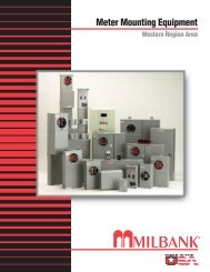
Meter Mounting Equipment<br />
Western Region Area
Charles A. Milbank<br />
1879-1966<br />
Bill Martin<br />
1916-1998<br />
Robert F. Waldrop<br />
1922-2002<br />
1<br />
Robert F. Waldrop, II<br />
Chairman<br />
MILBANK OVERVIEW<br />
Katrina Waldrop Henke<br />
Vice Chairman<br />
Milbank–Quality Metering Products for 80 Years<br />
Milbank Manufacturing<br />
Company was established<br />
in 1927 by<br />
Charles A. Milbank.<br />
Originally, the company<br />
manufactured high voltage<br />
switches; however, by 1941<br />
Milbank devoted itself primarily<br />
to the manufacture of sheet metal<br />
enclosures and related equipment<br />
for the electrical generation and<br />
distribution industry. Today we<br />
are an industry leader in the<br />
manufacture of electrical meter<br />
sockets. Through a national<br />
network of manufacturer’s<br />
representatives we provide<br />
wholesale electrical distributors<br />
with quality electrical products<br />
for the utility, contractor,<br />
industrial and OEM markets.<br />
As the meter standards have<br />
changed, Milbank has been<br />
successful in adapting its product<br />
line to these changes. Our full<br />
scale engineering department<br />
designs products to meet<br />
customer specifications and<br />
satisfy all utility requirements.<br />
Milbank’s employee base of over<br />
1,000 workers, along with our<br />
five manufacturing facilities<br />
comprising almost 550,000<br />
square feet give us the flexibility<br />
to schedule, produce, and ship<br />
orders quickly. Currently,<br />
Milbank manufactures over<br />
10,000 different catalog items,<br />
and this list continues to grow.<br />
Our unique product offering<br />
includes: Residential &<br />
Commercial Meter Sockets;<br />
Residential & Commercial Meter<br />
Pedestals; RV/MH Power Outlets,<br />
Service Pedestals, and<br />
Transformers; Commercial &<br />
Industrial Electrical Enclosures;<br />
Circuit Breakers; Disconnects &<br />
Safety Switches; Safety Sockets;<br />
Utility & Residential Secondary<br />
Pedestals; Hubs, and related<br />
accessories. If you don’t find a<br />
unit in this catalog to service your<br />
needs, send us your specifications<br />
and we will be happy to work<br />
with you.<br />
Our success has come from a<br />
loyal customer base that can rely<br />
on us to build quality products at<br />
a fair price in a timely manner.<br />
Our willingness and ability to<br />
design and produce new products<br />
to meet our customer demands is<br />
an important factor to remain<br />
competitive in today’s electrical<br />
market.<br />
Milbank has been serving the<br />
electric utility & wholesale<br />
distribution industries for 80 years<br />
with innovative, quality<br />
engineered products. So<br />
remember us for all of your meter<br />
mounting and related<br />
requirements, and we will be<br />
happy to serve you as we have in<br />
the past – with dependable<br />
service and quality products!<br />
We take great pride in being<br />
one of the few family-owned<br />
businesses left in our industry.<br />
We are a third generation run<br />
business and truly believe that...<br />
FAMILY MAKES A<br />
DIFFERENCE!<br />
1<br />
MILBANK OVERVIEW
2<br />
PRODUCT INDEX BY CATEGORY<br />
PRODUCT INDEX BY CATEGORY<br />
AC DISCONNECTS SECTION A<br />
30 & 60 Amp – Fusible/Non-Fusible Air Conditioner Disconnects....................................................................................1<br />
Combination AC Disconnect / 20 Amp GFCI Receptacle..................................................................................................2<br />
Hot Tub Disconnect or Sub Panel Breaker Enclosure – Type 3R .......................................................................................2<br />
METER SOCKETS SECTION B<br />
SINGLE POSITION (NO BYPASS)<br />
30-100 Amp – Economy Cast Socket – Ring Type, 4T.......................................................................................................1<br />
125-200 Amp, Ringless, 4T, 5T & 7T.............................................................................................................................2-3<br />
125-200 Amp, Ring Type, 4T & 7T................................................................................................................................2,4<br />
125-200 Amp, Ring Type with Manual Circuit Closing Blocks, 4T & 7T ...........................................................................9<br />
200 Amp, Ring Type, Flush Mount, 4T .............................................................................................................................5<br />
320 Amp, Ringless (Non-Lever Bypass), 4T.....................................................................................................................10<br />
SINGLE POSITION (WITH BYPASS)<br />
125-200 Amp, Ringless (Non-Jaw Clamping Lever Bypass), 4T, 5T & 7T .......................................................................6-7<br />
200 Amp, Ringless (Jaw Clamping Lever Bypass), 4T, 5T & 7T .........................................................................................8<br />
320 Amp, Ringless (Lever Bypass), 4T.............................................................................................................................10<br />
320 Amp, Ring Type (Link Bypass), 4T ...........................................................................................................................11<br />
320 Amp, Ringless (Lever Bypass), Side Wireway, 7T .....................................................................................................11<br />
MULTIPLE POSITION<br />
100-125 Amp, Ringless/Ring Type Horizontal Gang Sockets, 4T ....................................................................................12<br />
200 Amp, Ringless/Ring Type Horizontal Gang Sockets, 4T ...........................................................................................13<br />
125-200 Amp, Condominium Metering Banks, Ringless............................................................................................15-16<br />
METER MAINS AND SERVICE ENTRANCE EQUIPMENT SECTION C<br />
100/150/200 Amp, Ringless/Ring Type Meter Main, 4T & 5T – 22K AIC...........................................................................2<br />
200 Amp, Ring Type, 4T & 7T ..........................................................................................................................................1<br />
200 Amp, Unmetered, Service Entrance Main Breaker, 4T ...............................................................................................3<br />
400 Amp, 320 Amp Continuous, Ringless Meter Main with Split Load, 4T .......................................................................4<br />
400 Amp, 320 Amp Continuous, Ring Type Meter Main with Split Load, 4T ....................................................................5<br />
400 Amp, 320 Amp Continuous, Ring Type Plug-In Socket – Meter Main with Split Load, 4T ..........................................6<br />
400 Amp, 320 Amp Continuous, Ring Type Meter Main Combination, 4T ....................................................................7-8<br />
COMMERCIAL METERING –<br />
SAFETY SOCKETS, METER MAINS, TERMINATION BOXES, BUSSED GUTTERS SECTION D<br />
SAFETY SOCKETS<br />
100/200 Amp – TB <strong>Series</strong> – 600 Volt Self-Contained / Socket Only, 4T, 5T & 7T..............................................................1<br />
100 Amp, MTB <strong>Series</strong> – 10K AIC – 240 Volt Self-Contained Meter Main / CB, 4T, 5T & 7T..............................................2<br />
100 Amp, MTB <strong>Series</strong> – 22K AIC – 240 Volt Self-Contained Meter Main / CB, 4T & 7T....................................................3<br />
100 Amp, MTB <strong>Series</strong> – 14K AIC – 480 Volt Self-Contained Meter Main / CB, 4T, 5T & 7T..............................................4<br />
100 Amp, MTB-P & MTB-P48 <strong>Series</strong> – 200K AIC – 240 & 480 Volt Self-Contained Meter Main /<br />
T-Fuse Pullout, 4T, 5T & 7T.........................................................................................................................................5<br />
200 Amp, MTB <strong>Series</strong> – 10K AIC – 240 Volt Self-Contained Meter Main / CB, 4T, 5T & 7T..............................................6<br />
200 Amp, MTB <strong>Series</strong> – 22K AIC – 240 Volt Self-Contained Meter Main / CB, 4T & 7T....................................................7<br />
200 Amp, MTB <strong>Series</strong> – 35K AIC – 480 Volt Self-Contained Meter Main / CB, 4T & 7T....................................................8<br />
200 Amp, Test Block Bypass – MTB-P & MTB-P48 <strong>Series</strong> – 200K AIC – 240/480 Volt Self-Contained Meter Main /<br />
T-Fuse Pullout, 4T, 5T & 7T.........................................................................................................................................9<br />
100 & 200 Amp, MTBL All-In-One <strong>Series</strong>, 10K & 200K AIC – 240 Volt Meter Main – Circuit Breaker /<br />
T-Fuse Pullout ................................................................................................................................................................10<br />
Safety Socket Replacement Circuit Breakers & Pullouts .............................................................................................14-15<br />
Safety Socket & T-Fuse Replacement Parts......................................................................................................................16<br />
UNDERGROUND TERMINATION BOXES & BUSSED GUTTERS<br />
Underground Termination Boxes – 600 VAC..................................................................................................................11<br />
Bussed Gutters – Type 3R - 3Ø4W – 600 VAC ...............................................................................................................12<br />
Bussed Gutters – Type 3R - 3Ø4W – 600 VAC ...............................................................................................................13<br />
COMMERCIAL METER PEDESTALS SECTION E<br />
Commercial Meter Pedestals Overview ............................................................................................................................1<br />
Applications & Accessories...............................................................................................................................................2<br />
Catalog Number Logic......................................................................................................................................................3<br />
ML <strong>Series</strong> – Main Load Center ..........................................................................................................................................4<br />
SL <strong>Series</strong> – Switched Load Center .....................................................................................................................................5<br />
400 Amp <strong>Series</strong> ................................................................................................................................................................6<br />
IR <strong>Series</strong> – Irrigation Control .............................................................................................................................................7<br />
BBS/UPS <strong>Series</strong>.................................................................................................................................................................8<br />
2
PRODUCT INDEX BY CATEGORY<br />
Power Transfer <strong>Series</strong> – Metered & Unmetered.................................................................................................................9<br />
General Specifications....................................................................................................................................................10<br />
Commercial Meter Pedestal Drawings – 16” Metered & Unmetered...............................................................................11<br />
Commercial Meter Pedestal Drawings – 24” Metered & Unmetered...............................................................................12<br />
Commercial Meter Pedestal Drawings – 32” Metered.....................................................................................................13<br />
Commercial Meter Pedestal Drawings – Metered ...........................................................................................................14<br />
CT CABINETS, TEST SWITCHES, POLYPHASE ENCLOSURES SECTION F<br />
Current Transformer Cabinets – Type 3R – Door Mount CT Rated Socket .........................................................................1<br />
Current Transformer Cabinets ...........................................................................................................................................2<br />
Current Transformer Cabinets – Mounting Racks ..............................................................................................................3<br />
Metered Transformer Cabinets – Overhead & Underground .............................................................................................4<br />
20 Amp – 4, 5, 6, 7, 8 & 13 Terminal Current Transformer Rated – Ringless/Ring Type ....................................................5<br />
20 Amp – 600 VAC – 5, 6, 8, 13 & 15 Terminal Current Transformer – Test Switch Provision ..........................................6<br />
Milbank Test Switches – 4, 7 & 10 Pole............................................................................................................................7<br />
Test Switches – 4, 7 & 10 Pole – 600 VAC – Per ANSI C12.9 Standard.............................................................................8<br />
Milbank Test Switch Worksheet........................................................................................................................................9<br />
SERVICE PEDESTALS SECTION G<br />
125 Amp – Mobile Home Metered Pedestal – Hardwired – 120/240VAC.........................................................................1<br />
200 Amp – Mobile Home Metered Pedestal – Hardwired – 120/240VAC.........................................................................2<br />
100/200 Amp – Load Center Power Pedestals – All Purpose & RV Applications ...............................................................3<br />
200 Amp <strong>Series</strong> U5240 & U5241 Ring Type Metered Pedestals ....................................................................................4-5<br />
200 Amp <strong>Series</strong> U5136 & 5137 Ringless Metered Pedestals ..........................................................................................6-7<br />
U5706 & U5707 Temp to Final Service Pedestal – Ringless/Ring Type..........................................................................8-9<br />
Mobile Home Rebuild Kits ........................................................................................................................................10-11<br />
RV SECTION H<br />
<strong>Series</strong> U5000 – Unmetered – Surface Mount Power Outlet ...........................................................................................1-2<br />
<strong>Series</strong> U5100 – Metered – Surface Mount Power Outlet ................................................................................................3-4<br />
<strong>Series</strong> U5200 – Unmetered – Pedestal Power Outlet .....................................................................................................5-6<br />
<strong>Series</strong> U5300 – Metered – Pedestal Power Outlet..........................................................................................................7-8<br />
Millennium Features....................................................................................................................................................9-10<br />
600/1200 Amp – Pad Mounted Panel Board...................................................................................................................11<br />
100, 200 & 400 Amp – Terminal Box .............................................................................................................................12<br />
Lighting Accessories .......................................................................................................................................................13<br />
Telecommunications and Pedestal Accessories...............................................................................................................14<br />
Pedestal Mounting Accessories.......................................................................................................................................15<br />
Metering & Single Receptacle Accessories......................................................................................................................16<br />
RV Replacement Parts & Accessories.........................................................................................................................17-18<br />
RV Product Information – Wiring Diagram Label – Warranty.........................................................................................19<br />
TEMPORARY POWER SECTION I<br />
U4908/U4909 Underground Service Power Outlet – Ringless/Ring Type ......................................................................1-2<br />
<strong>Series</strong> U5000 – Unmetered – Surface Mount Power Outlet ...........................................................................................3-4<br />
<strong>Series</strong> U5001 – Unmetered – Surface Mount Power Outlet...............................................................................................5<br />
<strong>Series</strong> U5100 & U5101 Overhead – Ringless/Ring Type – Metered – Surface Mount Power Outlet ...............................6-7<br />
Replacement Parts for MPAP/MPRV/HP Pedestals ............................................................................................................8<br />
TRANSFORMERS SECTION J<br />
Galvanized Steel Distribution Transformer – 1∅...............................................................................................................1<br />
MISCELLANEOUS SECTION K<br />
Accessories....................................................................................................................................................................1,2<br />
UQFP Plug-In <strong>Series</strong> Circuit Breakers ...............................................................................................................................3<br />
UQFB Bolt-On <strong>Series</strong> Circuit Breakers..............................................................................................................................4<br />
Conduit, Ampacity, SCCR Information..............................................................................................................................5<br />
Energization of Electrical Equipment.................................................................................................................................6<br />
Materials and Finishes ......................................................................................................................................................7<br />
Meter Forms .....................................................................................................................................................................8<br />
Watthour Meter Forms – Standard Forms, Transformer Rated or Self-Contained ...............................................................9<br />
Standard NEMA Configurations ......................................................................................................................................10<br />
Additional Milbank Products ..........................................................................................................................................11<br />
ALPHA-NUMERIC INDEX SECTION L<br />
Alpha-Numeric Index....................................................................................................................................................1-2<br />
3<br />
3<br />
PRODUCT INDEX BY CATEGORY
4<br />
CATALOG NUMBER LOGIC<br />
CATALOG NUMBER LOGIC<br />
4
U3800<br />
(No deadfront required)<br />
30 & 60 AMP–FUSIBLE / NON-FUSIBLE–AIR CONDITIONER DISCONNECTS<br />
Milbankʼs air conditioner disconnect has a removable hinged cover which makes wiring a breeze. Our<br />
compact design meets all wire bending space requirements in the NEC and, also, complies with article<br />
440-14 in the NEC. To insure the safest conditions, we designed our disconnect pullers to be<br />
removable or they may be reinstalled in the off position. Another safety feature is the padlock provision<br />
on the front cover. As with all Milbank products, our enclosure is constructed of G90U galvanized steel<br />
and finished with an attractive, light gray, baked powder coating. Our state of the art finish combines<br />
epoxy and polyester hybrid resins into a hybrid powder coating which is then electrostatically applied.<br />
This offers a durable, nonfading finish.<br />
AMP TYPE<br />
✓<br />
✓<br />
CATALOG<br />
NUMBER<br />
MAX<br />
H.P.<br />
WT.<br />
@<br />
#<br />
30 FUSIBLE U3830 3 2.7<br />
60 FUSIBLE U3860 10 3.3<br />
60 NONFUSIBLE U3800 10 3.25<br />
60 NONFUSIBLE U3801 10 2.5<br />
U/L listed as Enclosed Pullout Switch<br />
1∅, 240 VAC<br />
U3801<br />
PROFILE<br />
TECHNICAL INFORMATION<br />
✓<br />
✓<br />
U3860<br />
LINE & LOAD<br />
WIRE RANGE<br />
GROUND<br />
WIRE RANGE DIMENSIONS WIRE RATING<br />
CU AL CU/AL D" W" H" CU °C AL °C<br />
#14-#3<br />
AWG<br />
#14-#3<br />
AWG #14-3 AWG 2-5/8 5 7 60°/75° 60°/75°<br />
#14-#3<br />
AWG<br />
#14-#3<br />
AWG #14-3 AWG 3 5 9<br />
#14-#2<br />
AWG<br />
#12-#2<br />
AWG #14-3 AWG<br />
1 ⁄4 60°/75° 60°/75°<br />
3 5 8 60°/75° 60°/75°<br />
#14-#3<br />
AWG<br />
#14-#3<br />
AWG #14-3 AWG 2-3/8 5 6-3/4 60°/75° 60°/75°<br />
Type 3R Rainproof<br />
Six one-inch concentric knockouts<br />
Utility requirements for this equipment may vary. Always consult the serving utility for their requirements before ordering or<br />
installing equipment in this catalog.<br />
A1<br />
A1<br />
SECTION A<br />
AC DISCONNECTS
A2<br />
SECTION A<br />
AC DISCONNECTS<br />
AC DISCONNECT / SPA BOX<br />
Combination AC Disconnect / 20 Amp GFCI Receptacle–Together in 1 Box<br />
AMP TYPE<br />
Meets NEC # 210.63 Requirements *<br />
UL Listed as Power Outlet<br />
Type 3R Enclosure<br />
In-Use Cover**<br />
Duplex Ground Connector<br />
1” Concentric Knockouts<br />
AC DISCONNECT<br />
1∅, 240 Volt<br />
60 amp, Non-Fused<br />
GFCI RECEPTACLE<br />
20 amp<br />
Reset/Test Button<br />
Padlock provision<br />
To ensure the safest conditions, Milbank disconnect pullers are designed to be reversible so they may be reinstalled in the OFF position.<br />
All units are designed with a padlock provision on the cover for security.<br />
**Note: U3822-20GR cover rated as IN-USE COVER (Cover may be closed with cords plugged into receptacle).<br />
*Reprinted with permission from NFPA 70-2002, National Electrical Code ® , Copyright 2001, National Fire Protection Association, Quincy, MA 02269. This reprinted material is not the complete<br />
and official position of the NFPA on the referenced subject, which is represented only by the standard in its entirety. National Electrical Code ® and NEC ® are registered trademarks of the<br />
National Fire Protection Association, Quincy, MA.<br />
U4881-O-50GB<br />
AMP TYPE<br />
50<br />
60<br />
CATALOG<br />
NUMBER<br />
BREAKER<br />
BREAKER<br />
U3822-20GR<br />
MAX<br />
H.P.<br />
CATALOG<br />
NUMBER<br />
U4881-O-50GB<br />
U4881-O-60GB<br />
60 amp,<br />
Non-Fused<br />
AC Disconnect<br />
Duplex 20 amp<br />
GFCI Receptacle<br />
Type 3R<br />
Enclosure with<br />
In-Use Cover<br />
WT.<br />
#<br />
60 NONFUSIBLE U3822-20GR 10 6<br />
LINE & LOAD CONNECTOR<br />
WIRE RANGE<br />
CU AL CU/AL<br />
#14-#2 #12-#2 #14-4<br />
WT.<br />
#<br />
8<br />
8<br />
LINE & LOAD CONNECTOR<br />
WIRE RANGE<br />
A2<br />
GROUND CONNECTOR<br />
WIRE RANGE<br />
* NEC ® #210.63 Heating, Air-<br />
Conditioning and Refrigeration<br />
Equipment Outlet.<br />
...The receptacle shall be<br />
located on the same level and<br />
within 7.5 m (25 ft.) of the<br />
heating, air-conditioning and<br />
refrigeration equipment.<br />
* NEC ® #210.08 Ground-Fault<br />
Circuit– Interruptor protection<br />
for personnel.<br />
Hot Tub Disconnect or Sub Panel Breaker Enclosure–Type 3R<br />
Spa Box with GFCI Protection<br />
• 240 volt ground fault protection<br />
• UL listed, Type 3R rainproof<br />
• Milbank reliability<br />
• Easy installation<br />
• 2 pole, 50 amp GFCI breaker protection<br />
• Compact size:<br />
8-1/2” H x 7-1/2” W x 3-3/4” D<br />
• 3 or 4 wire installation<br />
• 1∅, 120 / 240 VAC<br />
• Standard package of 12<br />
• 2 extra one-pole breaker spaces<br />
• 100 amp overall rating<br />
Sub Panel Breaker Enclosure<br />
• Use as a 100 amp, 4 circuit sub panel<br />
enclosure<br />
DIMENSIONS<br />
CU AL CU/AL D" W" H"<br />
#14-1/0<br />
#14-1/0<br />
GROUND CONNECTOR<br />
WIRE RANGE DIMENSIONS WIRE RATING<br />
#14-1/0<br />
#14-1/0<br />
#14-1/0<br />
#14-1/0<br />
D" W" H" CU °C AL °C<br />
4.8 5.25 7.4 60°/75° 60°/75°<br />
3 3 ⁄4<br />
3 3 ⁄4<br />
7 1 ⁄2<br />
7 1 ⁄2<br />
8 1 ⁄2<br />
8 1 ⁄2
FOR USE WITH SINGLE PHASE<br />
SELF-CONTAINED 4 TERMINAL METERS<br />
30/60/100 AMP—4 TERMINAL—ECONOMY CAST SOCKET—RING TYPE<br />
Our enclosure is made of die cast aluminum. The electrostatically applied epoxy and<br />
polyester resins, which are baked on, form a durable, light gray exterior. The current carrying<br />
parts are of copper alloy. The ground connector is designed to insure a positive electrical<br />
connection by effectively clamping the conductor against a serrated surface.<br />
SERVICE<br />
ECONOMY SOCKET<br />
100 amp max rated is ideal for use on:<br />
● Temporary Service<br />
● Outdoor Advertising<br />
● Small Customer Service<br />
● Other Low Amperage Requirements<br />
30-100 AMP—4 TERMINAL—ECONOMY CAST SOCKET—RING TYPE<br />
CATALOG<br />
NUMBER<br />
HUB<br />
SIZE<br />
CONNECTOR<br />
CU/AL<br />
QUANTITY<br />
PER PACKAGE<br />
CONCENTRIC<br />
KNOCKOUTS<br />
OH/UG AP2300-03 1" #12-#1 12 3/4", 1"<br />
OH/UG AP2300-04 1 1 ⁄4" #12-#1 12 3/4", 1"<br />
FIFTH & SIXTH TERMINAL: Contact factory.<br />
SEALING RING: Supplied with a snap action sealing ring.<br />
HUB: Units supplied with cast in hub on top and bottom. Consult factory for availability of other hub sizes.<br />
BYPASS: Also available with auto bypass. Contact factory.<br />
Utility requirements for this equipment may vary. Always consult the serving utility for their requirements before ordering or<br />
installing equipment in this catalog.<br />
B1<br />
B1<br />
SECTION B<br />
METER SOCKETS
B2<br />
METER SOCKETS SECTION B<br />
125 AMP—4 & 7 TERMINAL—SINGLE POSITION—RINGLESS / RING TYPE—600 VAC<br />
AMP<br />
125<br />
AMP<br />
125<br />
SERVICE<br />
AMP SERVICE<br />
SERVICE<br />
U7487-RL<br />
CATALOG<br />
NUMBER<br />
CATALOG<br />
NUMBER<br />
CATALOG<br />
NUMBER<br />
HUB<br />
UG U7487-O BLANK<br />
125 AMP–7 TERMINAL–RING TYPE<br />
HUB<br />
OH U1681-RL H.O.<br />
1 2<br />
4 3 5 6 4 7487<br />
CONNECTORS<br />
CU/AL<br />
#6-2/0<br />
HUB CONNECTORS<br />
CU/AL<br />
CONNECTORS<br />
CU/AL<br />
#6-2/0<br />
DIMENSIONS CONCENTRIC K.O.ʼS<br />
D" W" H"<br />
1 2<br />
4 3 4<br />
5 6<br />
1 2<br />
10 18 1 ⁄2<br />
1 2 3 4 5 6<br />
2 2 2 — 1 ⁄4, 1 ⁄2<br />
FIFTH TERMINAL: For field mounted fifth terminal on the U7487 & U7490 order catalog number 5T8K2 to fit into round<br />
opening at the 9 oʼclock position.<br />
HUBS: For proper hub selection see the hub suffix chart on the accessory page.<br />
CONNECTORS: Extruded aluminum connectors are tin plated.<br />
SEALING RINGS: Ring type units supplied with an MR-2 snap action sealing ring as standard.<br />
Utility requirements for this equipment may vary. Always consult the serving utility for their requirements before ordering or<br />
installing equipment in this catalog.<br />
B2<br />
5<br />
3<br />
6<br />
6<br />
DIMENSIONS CONCENTRIC K.O.ʼS<br />
D" W" H"<br />
1 2 3 4 5 6<br />
125 OH/UG U7490-RL H.O. 1 1 ⁄2 1 1 ⁄2 2 1 1 ⁄4 — 1 8 11 ⁄4<br />
1 #6-2/0 3 ⁄2<br />
5 ⁄16<br />
125 UG U7490-O BLANK 1 1 ⁄2 1 1 ⁄2 2 1 1 ⁄4 — 1 8 11 ⁄4<br />
1 #6-2/0 3 ⁄2<br />
5 ⁄16<br />
1681<br />
7490<br />
125 AMP–SINGLE POSITION–4 TERMINAL–RINGLESS<br />
U7490-O<br />
DIMENSIONS CONCENTRIC K.O.ʼS<br />
D" W" H"<br />
8 11 1 ⁄2<br />
1 2 3 4 5 6<br />
1 1 ⁄2 1 1 ⁄2 2 1 1 ⁄4 — 1 ⁄4<br />
125 OH/UG U7487-RL H.O. 1 1 ⁄2 1 1 ⁄2 2 1 1 ⁄4 — 1 8 11 ⁄4<br />
1 #6-2/0 3 ⁄2<br />
5 ⁄16<br />
3 5 ⁄16<br />
125 AMP–SINGLE POSITION–4 TERMINAL–RING TYPE<br />
4 7 ⁄8<br />
3 ⁄4
AMP<br />
200<br />
SERVICE<br />
CATALOG<br />
NUMBER<br />
HUB<br />
OH U1060-RL H.O.<br />
200 AMP—4 TERMINAL—SINGLE POSITION—RINGLESS—600 VAC<br />
U7040-XL-TG U1060-RL<br />
1 2<br />
4 3 5 6 4<br />
7040<br />
CONNECTORS<br />
CU/AL<br />
#2-350<br />
DIMENSIONS CONCENTRIC K.O.ʼS<br />
D" W" H"<br />
4 1 ⁄8 8 15 1 ⁄2<br />
1 2 3 4 5 6<br />
2 2 2 — — 1 ⁄4<br />
200 UG U1527-O BLANK 2 2 2 2 1 4 ⁄2<br />
1 ⁄8 11 15 1 #2-350<br />
⁄2<br />
200 UG U1980-O BLANK 2 1 ⁄2 2 1 ⁄2 3 1 1 ⁄2 2 1 1 1<br />
#6-350 4 ⁄2 13 15 ⁄4<br />
⁄2<br />
200 OH U7021-RL-TG H.O. 2 1 ⁄2 2 1 ⁄2 2 1 ⁄2 — 1 1 1<br />
#6-350 4 ⁄8 8 15 ⁄2<br />
⁄4<br />
200 OH/UG U7040-XL-TG C.P. 2 1 ⁄2 2 1 ⁄2 2 1 ⁄2 2 1 1 1<br />
#6-350 4 ⁄8 11 15 ⁄2<br />
⁄2<br />
200 OH/UG U7043-XL-TG C.P. 2 1 ⁄2 2 1 7 1<br />
#6-350 4 ⁄8 13 15 ⁄2<br />
⁄2 3 3<br />
5<br />
1 2<br />
200 AMP–SINGLE POSITION–4 TERMINAL–RINGLESS<br />
FIFTH TERMINAL: For field mounted fifth terminal order catalog number K5T to fit into square opening at the 9 oʼclock<br />
position.<br />
HUBS: For proper hub selection see the hub suffix chart on accessory page.<br />
CONNECTORS: Extruded aluminum connectors are tin plated.<br />
Utility requirements for this equipment may vary. Always consult the serving utility for their requirements before ordering or<br />
installing equipment in this catalog.<br />
B3<br />
3<br />
6<br />
1060<br />
7021<br />
3 4 5<br />
1 2<br />
6<br />
1980<br />
1 ⁄4, 1 ⁄2<br />
1 ⁄4, 1 ⁄2<br />
1 ⁄4<br />
1 ⁄4<br />
1 ⁄4, 1 ⁄2<br />
1 ⁄4, 1 ⁄2<br />
1 ⁄4<br />
1 ⁄4, 1 ⁄2<br />
B3<br />
SECTION B<br />
METER SOCKETS
B4<br />
METER SOCKETS SECTION B<br />
200 AMP—4 & 7 TERMINAL—SINGLE POSITION—RING TYPE—600 VAC<br />
1 2<br />
4 3 5 6 4<br />
3328<br />
AMP SERVICE<br />
5<br />
1 2<br />
3<br />
CATALOG<br />
NUMBER<br />
6<br />
4518<br />
HUB CONNECTORS<br />
CU/AL<br />
3<br />
4 5 6<br />
FIFTH TERMINAL: For field mounted fifth terminal order catalog number K5T to fit into square opening at the 9 oʼclock<br />
position.<br />
HUBS: For proper hub selection see the hub suffix chart on the accessory page.<br />
CONNECTORS: Extruded aluminum connectors are tin plated.<br />
SEALING RINGS: The above ring type units are supplied with an MR-4 screw type sealing ring as standard.<br />
Utility requirements for this equipment may vary. Always consult the serving utility for their requirements before ordering or<br />
installing equipment in this catalog.<br />
B4<br />
1<br />
4015<br />
DIMENSIONS CONCENTRIC K.O.ʼS<br />
D" W" H"<br />
1 2 3 4 5 6<br />
200 OH U4517-DL-M4 2" 2 1 ⁄2 2 1 ⁄2 2 1 ⁄2 — 1 #6-350<br />
⁄4<br />
4 1 ⁄8 8 15 1 ⁄2<br />
200 OH/UG U4518-XL-W C.P. 2 2 2 2 1 1 1<br />
#6-350 4 ⁄8 11 15 ⁄2<br />
⁄2<br />
200 UG U4518-O-W BLANK 2 2 2 2 1 1 1<br />
#6-350 4 ⁄8 11 15 ⁄2<br />
⁄2<br />
200 UG U4015-O BLANK 2 1 ⁄2 2 1 ⁄2 3 1 1 ⁄2 2 1 6 14 16 ⁄2<br />
1 #6-350<br />
⁄4<br />
AMP<br />
200<br />
SERVICE<br />
200 AMP–SINGLE POSITION–4 TERMINAL–RING TYPE<br />
CATALOG<br />
NUMBER<br />
U3328-RXL<br />
200 AMP–7 TERMINAL–RING TYPE<br />
HUB<br />
OH/UG U3328-RXL C.P.<br />
CONNECTORS<br />
CU/AL<br />
#6-350<br />
1 2<br />
3 3 5 6 4<br />
4517<br />
1 ⁄4, 1 ⁄2<br />
1 ⁄4, 1 ⁄2<br />
DIMENSIONS CONCENTRIC K.O.ʼS<br />
D" W" H"<br />
4 7 ⁄8 13 19<br />
U4518-O-W<br />
2<br />
1 ⁄4, 1 ⁄2<br />
1 ⁄4<br />
1 ⁄4<br />
1 ⁄4, 1 ⁄2<br />
1 2 3 4 5 6<br />
3 2 1 ⁄2 3 3 1 ⁄4<br />
1 ⁄4, 1 ⁄2
TERM.<br />
4<br />
4<br />
4<br />
200 AMP—4 TERMINAL–FLUSH MOUNT—SINGLE POSITION–RING TYPE—600 VAC<br />
200 AMP—4 (1∅3W) TERMINAL—FACTORY WELDED FLUSH MOUNT—RING TYPE<br />
AMP SERVICE<br />
200<br />
200<br />
3 4 4<br />
1 2<br />
3 4 4<br />
5 6<br />
OH<br />
OH/UG<br />
UF4518-KO UF4015-KO<br />
4518<br />
CATALOG<br />
NUMBER<br />
UF4517-KO<br />
UF4518-KO<br />
HUB CONNECTORS<br />
CU/AL<br />
K.O.<br />
K.O.<br />
3<br />
3<br />
1 2<br />
5<br />
4<br />
4<br />
#6-350<br />
#6-350<br />
DIMENSIONS CONCENTRIC K.O.ʼS<br />
D" W" H"<br />
1 2 3 4 5 6<br />
200 UG UF4015-KO K.O. 2 1 ⁄2 2 1 ⁄2 2 1 ⁄2 2 1 ⁄2 1 1 5 14 16 ⁄2<br />
1 #6-350<br />
⁄4<br />
4 200 UG UF4969-KO* K.O. 2 1 ⁄2 2 1 ⁄2 2 1 ⁄2 3 1 1 7 ⁄2<br />
1 ⁄2 14 16 1 #6-350<br />
⁄4<br />
FIFTH TERMINAL: For field mounted fifth terminal order catalog number K5T to fit into square opening at the 9 oʼclock position.<br />
CONNECTORS: Extruded aluminum connectors are tin plated.<br />
SEALING RINGS: Ring type units supplied with an MR-4 screw type sealing ring as standard.<br />
* UF4969 can only be used in a 2 x 6 wall.<br />
6<br />
Utility requirements for this equipment may vary. Always consult the serving utility for their requirements before ordering or<br />
installing equipment in this catalog.<br />
B5<br />
4517<br />
5 1 ⁄8<br />
5 1 ⁄8<br />
8<br />
11<br />
15 1 ⁄2<br />
15 1 ⁄2<br />
2<br />
2<br />
2<br />
2<br />
3<br />
4 3<br />
5 6<br />
1 2<br />
2<br />
2 1 ⁄2<br />
4015<br />
4969<br />
2<br />
2<br />
1 ⁄4<br />
1 ⁄4, 1 ⁄2<br />
1 ⁄4, 1 ⁄2<br />
1 ⁄4<br />
1 ⁄4, 1 ⁄2<br />
1 ⁄4, 1 ⁄2<br />
B5<br />
SECTION B<br />
METER SOCKETS
B6<br />
SECTION B<br />
METER SOCKETS<br />
200 AMP—4 & 5 TERMINAL—SINGLE POSITION—RINGLESS<br />
NON-JAW CLAMPING LEVER BYPASS—600 VAC<br />
TERM SERVICE<br />
TERM SERVICE<br />
U9319-XL<br />
CATALOG<br />
NUMBER<br />
CATALOG<br />
NUMBER<br />
HUB<br />
HUB<br />
CONNECTORS<br />
CU/AL<br />
LINE & LOAD<br />
FIFTH TERMINAL: Fifth terminal is not available for this unit.<br />
TRIPLEX GROUND: Factory installed as standard.<br />
200 AMP—4 & 5 TERMINAL—RINGLESS—1∅3W OR 3∅3W<br />
CONNECTORS<br />
CU/AL<br />
LINE & LOAD<br />
Utility requirements for this equipment may vary. Always consult the serving utility for their requirements before ordering or<br />
installing equipment in this catalog.<br />
B6<br />
BY-<br />
PASS<br />
BY-<br />
PASS<br />
DIMENSIONS CONCENTRIC K.O.ʼS<br />
D" W" H"<br />
1 2 3 4 5 6<br />
4 OH/UG U1211-RXL C.P. LEVER 3 2 1 7<br />
#6-350<br />
4 ⁄8 13 19<br />
⁄2 3 3<br />
5 OH/UG U9319-XL C.P. LEVER 3 2 1 7<br />
#6-350<br />
4 ⁄8 13 19<br />
⁄2 3 3<br />
FIFTH TERMINAL: For field mounted fifth terminal, order as extra K3866 for the U1211.<br />
HUBS: For proper hub selection see the hub suffix chart on the accessory page.<br />
BYPASS: 200 amp continuous duty bypass. Lever operates bypass only. Not jaw clamping.<br />
CONNECTORS: Units are supplied with extruded aluminum connectors and bonded, triplex neutral.<br />
4<br />
5<br />
1<br />
3 4<br />
6<br />
2<br />
1211<br />
9319<br />
DIMENSIONS CONCENTRIC K.O.ʼS<br />
D" W" H"<br />
1 2 3 4 5 6<br />
4 OH/UG U3852-XL C.P. LEVER 3 2 1 ⁄2 2 1 ⁄2 2 1 7<br />
#2-350<br />
4 ⁄8 13 19<br />
⁄2<br />
4<br />
5<br />
200 AMP—4 TERMINAL—RINGLESS—1∅3W<br />
3<br />
1<br />
6<br />
4<br />
2<br />
3852<br />
1 ⁄4<br />
1 ⁄4<br />
1 ⁄4<br />
1 ⁄4, 1 ⁄2<br />
1 ⁄4, 1 ⁄2<br />
1 ⁄4, 1 ⁄2
AMP<br />
125<br />
125<br />
125<br />
SERVICE<br />
OH<br />
OH<br />
OH/UG<br />
AMP SERVICE<br />
U7573-RL<br />
CATALOG<br />
NUMBER<br />
U7573-RL<br />
U8100-RL<br />
U9320-RXL<br />
CATALOG<br />
NUMBER<br />
5<br />
4<br />
1 2<br />
3<br />
1<br />
3 4<br />
5 6<br />
6<br />
125-200 AMP–7 TERMINAL–SINGLE POSITION–RINGLESS<br />
NON-JAW CLAMPING LEVER BYPASS–600 VAC<br />
Utility requirements for this equipment may vary. Always consult the serving utility for their requirements before ordering or<br />
installing equipment in this catalog.<br />
B7<br />
2<br />
6<br />
7573<br />
8100<br />
9320<br />
7422<br />
7423<br />
125 AMP—7 TERMINAL—RINGLESS—3∅4W<br />
HUB<br />
H.O.<br />
H.O.<br />
C.P.<br />
CONNECTORS<br />
CU/AL<br />
#6-2/0<br />
#6-2/0<br />
#6-2/0<br />
BY-<br />
PASS<br />
LEVER<br />
HUBS: For proper hub selection, see hub suffix chart in accessories page.<br />
BYPASS: 200 amp continuous duty bypass. Lever operates bypass only. Not jaw clamping.<br />
CONNECTORS: Extruded aluminum connectors are tin plated. Units supplied with bonded, duplex neutral.<br />
NONE<br />
LEVER<br />
DIMENSIONS CONCENTRIC K.O.ʼS<br />
D" W" H"<br />
4 7 ⁄8<br />
4 7 ⁄8<br />
4 7 ⁄8<br />
10<br />
10<br />
13<br />
18 1 ⁄2<br />
18 1 ⁄2<br />
200 AMP—7 TERMINAL—RINGLESS—3∅4W<br />
HUB CONNECTORS<br />
CU/AL<br />
BY-<br />
PASS<br />
19<br />
1 2 3 4 5 6<br />
2<br />
2<br />
3<br />
2<br />
2<br />
2 1 ⁄2<br />
2<br />
2<br />
3<br />
—<br />
—<br />
3<br />
1 ⁄4, 1 ⁄2<br />
1 ⁄4, 1 ⁄2<br />
DIMENSIONS CONCENTRIC K.O.ʼS<br />
D" W" H"<br />
U7423-RXL<br />
1 ⁄4<br />
3 ⁄4<br />
3 ⁄4<br />
1 ⁄4, 1 ⁄2<br />
1 2 3 4 5 6<br />
200 OH/UG U7422-RXL C.P. NONE 3 2 1 4 ⁄2 3 3<br />
7 #6-350<br />
⁄8 13 19<br />
200 OH/UG U7423-RXL C.P. LEVER 3 2 1 4 ⁄2 3 3<br />
7 #6-350<br />
⁄8 13 19<br />
1 ⁄4<br />
1 ⁄4<br />
1 ⁄4, 1 ⁄2<br />
1 ⁄4, 1 ⁄2<br />
B7<br />
SECTION B<br />
METER SOCKETS
B8<br />
METER SOCKETS SECTION B<br />
200 AMP—4, 5 & 7 TERMINAL—SINGLE POSITION—RINGLESS<br />
JAW CLAMPING LEVER BYPASS–600 VAC<br />
AMP<br />
200<br />
200<br />
AMP<br />
200<br />
200<br />
AMP<br />
200<br />
200<br />
SERVICE<br />
OH<br />
OH/UG<br />
SERVICE<br />
OH<br />
OH/UG<br />
SERVICE<br />
OH<br />
OH/UG<br />
U9701-RXL U9800-RRL<br />
U9551-RXL<br />
5<br />
CATALOG<br />
NUMBER<br />
U9800-RRL ➀<br />
U9801-RXL ➀<br />
CATALOG<br />
NUMBER<br />
U9550-RRL<br />
U9551-RXL<br />
CATALOG<br />
NUMBER<br />
U9700-RRL<br />
U9701-RXL<br />
1 2<br />
3<br />
6<br />
6<br />
9550<br />
9700<br />
200 AMP—4 TERMINAL—RINGLESS—1∅3W OR 3∅3W<br />
HUB<br />
H.O.<br />
C.P.<br />
200 AMP—5 TERMINAL—RINGLESS—1∅3W OR 3∅3W<br />
HUB<br />
H.O.<br />
C.P.<br />
CONNECTORS<br />
CU/AL<br />
#6-350<br />
#6-350<br />
CONNECTORS<br />
CU/AL<br />
#6-350<br />
#6-350<br />
BY-<br />
PASS<br />
LEVER<br />
LEVER<br />
BY-<br />
PASS<br />
LEVER<br />
LEVER<br />
DIMENSIONS CONCENTRIC K.O.ʼS<br />
D" W" H"<br />
DIMENSIONS CONCENTRIC K.O.ʼS<br />
D" W" H"<br />
1 2 3 4 5 6<br />
Utility requirements for this equipment may vary. Always consult the serving utility for their requirements before ordering or<br />
installing equipment in this catalog.<br />
B8<br />
4 7 ⁄8<br />
4 7 ⁄8<br />
4 7 ⁄8<br />
4 7 ⁄8<br />
10<br />
13<br />
10<br />
13<br />
18 1 ⁄2<br />
18 1 ⁄2<br />
200 AMP—7 TERMINAL—RINGLESS—3∅4W<br />
HUB<br />
H.O.<br />
C.P.<br />
CONNECTORS<br />
CU/AL<br />
#6-350<br />
#6-350<br />
5<br />
1 2<br />
3<br />
BY-<br />
PASS<br />
LEVER<br />
LEVER<br />
19<br />
19<br />
1 2 3 4 5 6<br />
3<br />
3<br />
3<br />
3<br />
2 1 ⁄2<br />
2 1 ⁄2<br />
2 1 ⁄2<br />
2 1 ⁄2<br />
3<br />
3<br />
3<br />
3<br />
—<br />
3<br />
—<br />
3<br />
1 ⁄4, 1 ⁄2<br />
1 ⁄4<br />
1 ⁄4, 1 ⁄2<br />
DIMENSIONS CONCENTRIC K.O.ʼS<br />
D" W" H"<br />
4 7 ⁄8<br />
4 7 ⁄8<br />
10<br />
13<br />
18 1 ⁄2<br />
19<br />
1<br />
3 4<br />
5 6<br />
1 ⁄4<br />
3 ⁄4<br />
1 ⁄4, 1 ⁄2<br />
3 ⁄4<br />
1 ⁄4, 1 ⁄2<br />
1 2 3 4 5 6<br />
HUBS: For proper hub selection, see hub suffix chart in accessories page.<br />
BYPASS: Lever supplies clamping action and also operates bypass device.<br />
CONNECTORS: Extruded aluminum connectors are tin plated. U9550 and U9551 units are supplied with duplex neutral, with<br />
removable bonding strap for insulated neutral. U9700 series units are supplied with duplex neutral.<br />
➀ Internal Hex Connectors. For main and/or service disconnect, use with U5484-O enclosed circuit breaker.<br />
6<br />
6<br />
9800<br />
4<br />
3<br />
3<br />
2 1 ⁄2<br />
2 1 ⁄2<br />
2<br />
9551<br />
9701<br />
3<br />
3<br />
—<br />
3<br />
1 ⁄4, 1 ⁄2<br />
1 ⁄4<br />
3 ⁄4<br />
1 ⁄4, 1 ⁄2
TERM.<br />
4<br />
7<br />
TERM.<br />
4<br />
7<br />
SERVICE<br />
OH/UG<br />
OH/UG<br />
SERVICE<br />
OH/UG<br />
OH/UG<br />
U3504-XL<br />
CATALOG<br />
NUMBER<br />
U3504-XL<br />
U3507-XL<br />
CATALOG<br />
NUMBER<br />
U3514-XL<br />
U3517-XL<br />
HUB<br />
C.P.<br />
C.P.<br />
HUB<br />
C.P.<br />
C.P.<br />
125-200 AMP—4 & 7 TERMINAL<br />
MANUAL CIRCUIT CLOSING BLOCKS—RING TYPE—600 VAC<br />
125 AMP—RING TYPE<br />
CONNECTORS<br />
CU/AL<br />
#6-2/0<br />
#6-2/0<br />
BY-<br />
PASS<br />
Utility requirements for this equipment may vary. Always consult the serving utility for their requirements before ordering or<br />
installing equipment in this catalog.<br />
B9<br />
LINK<br />
LINK<br />
DIMENSIONS CONCENTRIC K.O.ʼS<br />
D" W" H"<br />
4 7 ⁄8<br />
4 7 ⁄8<br />
200 AMP—RING TYPE<br />
CONNECTORS<br />
CU/AL<br />
#6-350<br />
#6-350<br />
1<br />
4 3 4<br />
5<br />
6<br />
BY-<br />
PASS<br />
LINK<br />
LINK<br />
2<br />
10<br />
10<br />
18 1 ⁄2<br />
21<br />
1 2 3 4 5 6<br />
2<br />
2<br />
DIMENSIONS CONCENTRIC K.O.ʼS<br />
D" W" H"<br />
4 7 ⁄8<br />
4 7 ⁄8<br />
13<br />
13<br />
21<br />
24 1 ⁄2<br />
2<br />
2<br />
2<br />
2<br />
2<br />
2<br />
—<br />
1 ⁄4<br />
1 ⁄4<br />
—<br />
1 2 3 4 5 6<br />
2 1 ⁄2<br />
2 1 ⁄2<br />
2 1 ⁄2<br />
2 1 ⁄2<br />
U3517-XL<br />
FIFTH TERMINAL: For field mounted fifth terminal order catalog number 5T8K2 for the U3504; order K5T for the U3514.<br />
CONNECTORS: Extruded aluminum connectors are tin plated.<br />
SEALING RINGS: Ring type units supplied with an MR-4 screw type sealing ring as standard.<br />
LINK BYPASS: Links provided by utility.<br />
3504<br />
3507<br />
3514<br />
3517<br />
3<br />
2 1 ⁄2<br />
3<br />
2 1 ⁄2<br />
1 ⁄4<br />
1 ⁄4<br />
1 ⁄2<br />
1 ⁄2<br />
B9<br />
SECTION B<br />
METER SOCKETS
B10<br />
SECTION B<br />
METER SOCKETS<br />
320 AMP—4 TERMINAL—SINGLE POSITION—RINGLESS—600 VAC<br />
AMP<br />
320<br />
320<br />
SVC.<br />
OH<br />
UG<br />
U1797-O-K3L-K2L<br />
CATALOG<br />
NUMBER<br />
U1079-R<br />
U1129-O-K3L-K2L<br />
320 AMP—4 TERMINAL—RINGLESS—600 VAC<br />
HUB<br />
H.O.<br />
BLANK<br />
CONNECTORS<br />
CU/AL<br />
LINE LOAD<br />
3 ⁄8"-16 STUDS<br />
#4-600 or<br />
(2) 1/0-250<br />
TWIN<br />
#6-350<br />
K3865 BLANK TWIN LEVER<br />
#6-350 4 3 3 3 3<br />
7 #4-600 or<br />
⁄8 15 30<br />
(2) 1/0-250<br />
HUBS: For proper hub selection, see hub suffix chart in accessories page.<br />
BYPASS: *Lever supplies clamping action on meter spades only on the U1431, U1432 and U1819. Lever supplies clamping<br />
action and also operates bypass device on the U1079, U1129 & U1797.<br />
CONNECTOR KITS: Stud type units are supplied with 3 ⁄8"-16 hex head nuts with Belleville washers. Order two connector kits to<br />
cover both line and load. Order K1539 (single #350), K1540 (single #600) or K1350 (twin #350). See accessories page.<br />
NOTE: The U1129 unit has a single connector on the line side only.<br />
FIFTH TERMINAL: For field mounted fifth terminal, order as extra K3866 for the U1079 & U1431. Order as extra K3865 for units<br />
U1129, U1432, U1819, and U1797.<br />
LUG SIZE RANGE: See accessories page for lug size range for the U1129 & U1797 units.<br />
Utility requirements for this equipment may vary. Always consult the serving utility for their requirements before ordering or<br />
installing equipment in this catalog.<br />
B10<br />
BY-<br />
PASS<br />
LEVER<br />
LEVER<br />
DIMENSIONS CONCENTRIC K.O.ʼS<br />
D" W" H"<br />
4 7 ⁄8<br />
4 7 ⁄8<br />
13<br />
15<br />
38 3 ⁄4<br />
30<br />
1 2 3 4 5 6<br />
320 OH/UG U1431-R* H.O. NONE 3 2 1 4 ⁄2 3 3<br />
7 ⁄8 13 38 3 3 K3866<br />
⁄8"-16 STUDS<br />
⁄4<br />
320 UG U1432-O* BLANK NONE 3 2 1 4 ⁄2 3 3<br />
7 ⁄8 13 29 3 3 K3865<br />
⁄8"-16 STUDS<br />
⁄4<br />
320 UG U1819-X* C.P. NONE 4 3 3 3 3<br />
7 3 K3865<br />
⁄8"-16 STUDS<br />
⁄8 15 30<br />
320 UG U1797-O-K3L-K2L<br />
FIFTH<br />
TERM.<br />
K3866<br />
K3865<br />
4<br />
5<br />
400 AMP MAX<br />
320 AMP CONTINUOUS<br />
3<br />
1<br />
6<br />
4<br />
2<br />
1129<br />
1797<br />
1819<br />
1<br />
3 3 4<br />
5<br />
6<br />
2<br />
1079<br />
1432<br />
1431<br />
3<br />
3<br />
U1129-O-K3L-K2L<br />
2 1 ⁄2<br />
2 1 ⁄2<br />
3<br />
3<br />
3<br />
3<br />
1 ⁄4<br />
1 ⁄4<br />
1 ⁄4<br />
1 ⁄4<br />
1 ⁄4<br />
1 ⁄4<br />
1 ⁄4, 1 ⁄2<br />
1 ⁄4, 1 ⁄2<br />
1 ⁄4, 1 ⁄2<br />
1 ⁄4, 1 ⁄2<br />
1 ⁄4, 1 ⁄2<br />
1 ⁄4, 1 ⁄2
SERVICE<br />
OH/ UG<br />
AMP<br />
320<br />
UG<br />
SERVICE<br />
U3548-X<br />
CATALOG<br />
NUMBER<br />
U3548-X*<br />
U5056-O**<br />
U5056-O<br />
320 AMP—4 & 7 TERMINAL—SINGLE POSITION–RINGLESS / RING TYPE—600 VAC<br />
320 AMP—4 TERMINAL—LINK BYPASS—RING TYPE—1∅3W<br />
HUB<br />
C.P.<br />
BLANK 1<br />
⁄2"-13 STUDS<br />
CATALOG<br />
NUMBER<br />
1<br />
CONNECTORS<br />
CU/AL<br />
LINE<br />
LOAD<br />
SINGLE = 4-600<br />
PARALLEL = 1/0-250<br />
#4-600 or<br />
twin 1/0-250<br />
BY-<br />
PASS<br />
LINK<br />
LINK<br />
DIMENSIONS CONCENTRIC K.O.ʼS<br />
D" W" H"<br />
320 AMP—7 TERMINAL—SIDE WIREWAY—RINGLESS<br />
HUB<br />
UG U2120-X C.P.<br />
3 3<br />
4<br />
CONNECTORS<br />
CU/AL<br />
3 ⁄8"-16 STUDS<br />
1 2 3 4 5 6<br />
Utility requirements for this equipment may vary. Always consult the serving utility for their requirements before ordering or<br />
installing equipment in this catalog.<br />
B11<br />
BY-<br />
PASS<br />
LEVER<br />
BYPASS: Lever supplies clamping action on meter spades and operates bypass device.<br />
CONNECTOR KITS: Stud type units are supplied with 3 ⁄8"-16 hex head nuts with Belleville washers. Order two connector kits to<br />
cover both line and load. For single lug connector kits for the U2120 and U2594 units, order as extra K3082 (350 kcmil) or<br />
K3441 (600 kcmil). For twin lug connectors order as extra: K3442 (350 kcmil). Separate kits are required for both line and load.<br />
6<br />
6<br />
14<br />
24<br />
33<br />
32<br />
3<br />
3<br />
3<br />
—<br />
3<br />
4<br />
3<br />
1 ⁄4, 1 ⁄2<br />
DIMENSIONS CONCENTRIC K.O.ʼS<br />
D" W" H"<br />
6 1 ⁄2 17 3 ⁄4 31 3 ⁄4<br />
1 ⁄4<br />
1 ⁄4<br />
1 ⁄4, 1 ⁄2<br />
—<br />
1 2 3 4 5 6<br />
4 3 4 4<br />
320 OH/UG U2594-X C.P. LEVER 6 — 3 4 4<br />
1 ⁄2 19 34 1 3<br />
⁄8"-16 STUDS<br />
⁄8<br />
1<br />
4 3 4<br />
5<br />
1<br />
3 4<br />
5 6<br />
6<br />
1<br />
2<br />
2120<br />
2594<br />
SEALING RING: Ring type units are supplied with an MR-4, screw type, sealing ring as standard.<br />
TRIPLE TAP LUG: For triple tap lug kit order K5049.<br />
LINK BYPASS: Links provided by utility.<br />
*FLUSH MOUNT KIT: For field mounted flush mount kit order K4086.<br />
**This is a PP&L approved unit.<br />
5<br />
5056<br />
2<br />
3548<br />
U2120-X<br />
1 ⁄4 1<br />
1 ⁄4<br />
1 ⁄2, 3 ⁄4,1<br />
B11<br />
SECTION B<br />
METER SOCKETS
B12<br />
METER SOCKETS SECTION B<br />
100-125 AMP—4 TERMINAL—HORIZONTAL GANGS–RINGLESS / RING TYPE—300 VAC<br />
NO.<br />
OF<br />
POS.<br />
2<br />
3<br />
4<br />
SERVICE CATALOG<br />
NUMBER<br />
OH/UG<br />
OH/UG<br />
OH/UG<br />
100 AMP / POSITION—CONTINUOUS—4 TERMINAL—RINGLESS<br />
U8032-XL<br />
U8033-XL<br />
U8034-XL<br />
HUB<br />
C.P.<br />
C.P.<br />
C.P.<br />
CONNECTORS<br />
CU/AL<br />
LINE LOAD<br />
#2-350 #6-2/0<br />
#6-2/0<br />
#6-2/0<br />
DIMENSIONS CONCENTRIC K.O.ʼS<br />
D" W" H"<br />
1 2 3 4 5 6 7<br />
5 OH/UG U8035-XL C.P. #6-2/0<br />
2 2 2 1 4 ⁄2 (5) 1 2 ⁄2<br />
1 ⁄2 49 1 #2-350<br />
⁄16 16<br />
6 OH/UG U8036-XL C.P. #6-2/0<br />
2 2 2 1 4 ⁄2 (6) 1 2 ⁄2<br />
1 ⁄2 57 1 #2-350<br />
⁄4 16<br />
NO.<br />
OF<br />
POS.<br />
2<br />
3<br />
4<br />
SERVICE<br />
OH/UG<br />
OH/UG<br />
OH/UG<br />
U8032-XL U3522-XL<br />
1 1 1 2<br />
1 1 2<br />
7 4 3 7 4<br />
6 5 5 6<br />
7<br />
7<br />
#2-350<br />
#2-350<br />
4 1 ⁄2<br />
4 1 ⁄2<br />
4 1 ⁄2<br />
Utility requirements for this equipment may vary. Always consult the serving utility for their requirements before ordering or<br />
installing equipment in this catalog.<br />
B12<br />
24 1 ⁄2<br />
32 3 ⁄4<br />
40 7 ⁄8<br />
125 AMP / POSITION—CONTINUOUS—4 TERMINAL—RING TYPE<br />
CATALOG<br />
NUMBER<br />
U3522-XL-K1<br />
U3523-XL-K1<br />
U3524-XL-K2<br />
HUB<br />
C.P.<br />
C.P.<br />
C.P.<br />
8032 4 3 4 3522<br />
5 5<br />
CONNECTORS<br />
CU/AL<br />
LINE LOAD<br />
#2-350 #6-2/0<br />
#2-350<br />
#2-350<br />
#6-2/0<br />
#6-2/0<br />
16<br />
16<br />
16<br />
2<br />
2<br />
2<br />
2<br />
2<br />
2<br />
2 1 ⁄2<br />
2 1 ⁄2<br />
2 1 ⁄2<br />
2<br />
(3) 2<br />
(4) 2<br />
1 ⁄2<br />
1 ⁄2<br />
1 ⁄2<br />
1 ⁄4, 1 ⁄2<br />
1 ⁄4, 1 ⁄2<br />
1 ⁄4, 1 ⁄2<br />
1 ⁄4, 1 ⁄2<br />
1 ⁄4, 1 ⁄2<br />
DIMENSIONS CONCENTRIC K.O.ʼS<br />
D" W" H"<br />
4 1 ⁄2<br />
4 1 ⁄2<br />
4 1 ⁄2<br />
24 1 ⁄2<br />
32 3 ⁄4<br />
40 7 ⁄8<br />
14<br />
14<br />
14<br />
5 ⁄16<br />
5 ⁄16<br />
5 ⁄16<br />
5 ⁄16<br />
5 ⁄16<br />
1 2 3 4 5 6<br />
5 UG U3525-XL-K2* C.P. #6-2/0<br />
1 1 ⁄2 1 1 ⁄2 2 1 ⁄2 (5)2 1 ⁄2 1 ⁄4, 1 4 ⁄2 —<br />
1 ⁄2 49 1 #2-350<br />
⁄16 16<br />
*FOR OVERHEAD SERVICE: The U3525 is factory configured for underground service. If overhead service is desired,<br />
an extension kit is required. Order separately, catalog number K3937.<br />
FIFTH TERMINAL: For field mounted fifth terminal, order catalog number 5T8K2 (6 oʼclock only on 100 amp units,<br />
9 oʼclock only on 125 amp units.)<br />
HUBS: For proper hub selection, see the hub suffix chart in accessories page.<br />
SEALING RINGS: Ring type units are supplied with one MR-4 screw type sealing ring per position.<br />
MAIN BUS RATING: See general engineering page.<br />
1 1 ⁄2<br />
1 1 ⁄2<br />
1 1 ⁄2<br />
1 1 ⁄2<br />
1 1 ⁄2<br />
1 1 ⁄2<br />
2 1 ⁄2<br />
2 1 ⁄2<br />
2 1 ⁄2<br />
2 1 ⁄2<br />
(3)2 1 ⁄2<br />
(4)2 1 ⁄2<br />
1 ⁄4, 1 ⁄2<br />
1 ⁄4, 1 ⁄2<br />
1 ⁄4, 1 ⁄2<br />
—<br />
—<br />
—
NO.<br />
OF<br />
POS.<br />
2<br />
3<br />
4<br />
SERVICE<br />
OH/UG<br />
OH/UG<br />
UG<br />
CATALOG<br />
NUMBER<br />
U1252-X-K1<br />
U1253-X-K3<br />
U1254-X-K3*<br />
200 AMP—4 TERMINAL—HORIZONTAL GANGS–RINGLESS / RING TYPE—300 VAC<br />
200 AMP / POSITION—4 TERMINAL—RINGLESS<br />
HUB<br />
C.P.<br />
C.P.<br />
C.P.<br />
CONNECTORS<br />
CU/AL<br />
LINE LOAD<br />
#6-350 #2-350<br />
#2-350<br />
#2-350<br />
DIMENSIONS CONCENTRIC K.O.ʼS<br />
D" W" H"<br />
1 2 3 4 5 6<br />
Utility requirements for this equipment may vary. Always consult the serving utility for their requirements before ordering or<br />
installing equipment in this catalog.<br />
B13<br />
5 1 ⁄8<br />
5 1 ⁄8<br />
5 1 ⁄8<br />
26 1 ⁄2<br />
34 3 ⁄4<br />
42 7 ⁄8<br />
14<br />
14<br />
16<br />
2 1 ⁄2<br />
2 1 ⁄2<br />
2 1 ⁄2<br />
3<br />
3<br />
3<br />
2 1 ⁄2<br />
(3)2 1 ⁄2<br />
(4)2 1 ⁄2<br />
5 UG U1255-X-K4* C.P. #2-350<br />
2 1 ⁄2 3 (5)2 1 5 ⁄2<br />
1 ⁄8 54 7 (2)#2-600<br />
⁄8 16<br />
6 UG U1256-X-K4* C.P. #2-350<br />
2 1 ⁄2 3 (6)2 1 5 ⁄2<br />
1 ⁄8 63 1 (2)#2-600<br />
⁄16 18<br />
NO.<br />
OF<br />
POS.<br />
2<br />
3<br />
SERVICE<br />
OH/UG<br />
OH/UG<br />
1 1 1<br />
3 2 3<br />
4 5 6 4<br />
CATALOG<br />
NUMBER<br />
U3532-X-K1<br />
U3533-X-K3<br />
1252<br />
3532<br />
#4-600<br />
#4-600<br />
200 AMP / POSITION—4 TERMINAL—RING TYPE<br />
HUB<br />
C.P.<br />
C.P.<br />
CONNECTORS<br />
CU/AL<br />
LINE LOAD<br />
#6-350 #2-350<br />
#4-600<br />
U1252-X-K1<br />
#2-350<br />
DIMENSIONS CONCENTRIC K.O.ʼS<br />
D" W" H"<br />
5 1 ⁄8<br />
5 1 ⁄8<br />
26 1 ⁄2<br />
34 3 ⁄4<br />
1 1 1 1<br />
1 ⁄2<br />
1 ⁄2<br />
1 ⁄2<br />
1 ⁄2<br />
1 ⁄2<br />
1 ⁄4<br />
1 ⁄4<br />
1 ⁄4<br />
1<br />
1<br />
1<br />
1 ⁄4 1<br />
1 ⁄4 1<br />
1 2 3 4 5 6<br />
*FOR OVERHEAD SERVICE: These units are factory configured for underground service. If overhead service is<br />
desired, an extension kit is required. Order as extra, K3923 (4 & 5 position), K3955 (6 position).<br />
FIFTH TERMINAL: For field mounted fifth terminal order catalog number K5T to fit into square opening at the 9 oʼclock<br />
position.<br />
HUBS: For proper hub selection, see the hub suffix chart in accessories page.<br />
SEALING RINGS: Ring type units are supplied with one MR-4 screw type sealing ring per position.<br />
MAIN BUS RATING: See general engineering page. U1252 & U3532 only rated 400 amp overall.<br />
3<br />
14<br />
14<br />
2<br />
4 6 5 4<br />
2 1 ⁄2<br />
2 1 ⁄2<br />
3<br />
3<br />
3 3<br />
4<br />
2 1 ⁄2<br />
(3)2 1 ⁄2<br />
—<br />
—<br />
1253-6<br />
3533-6<br />
1 ⁄4<br />
1 ⁄4<br />
1<br />
1<br />
B13<br />
SECTION B<br />
METER SOCKETS
B14<br />
CONDOMINIUM METERING BANKS—RINGLESS SECTION B<br />
CONDOMINIUM METERING BANKS—RINGLESS<br />
NO.<br />
OF<br />
POS.<br />
2<br />
3<br />
NO.<br />
OF<br />
POS.<br />
4<br />
5<br />
6<br />
CATALOG<br />
NUMBER<br />
MAIN BUS<br />
RATING<br />
U2852-X 200 AMP<br />
U2853-X 200 AMP<br />
CATALOG<br />
NUMBER<br />
SIZE SUFFIX<br />
SINGLE<br />
TWIN<br />
U2866-X<br />
125 AMP/POSITION<br />
MAIN BUS<br />
RATING<br />
U2854-X 400 AMP<br />
U2855-X 400 AMP<br />
U2856-X 400 AMP<br />
-K1<br />
-K3<br />
-K2<br />
-K4<br />
125 AMP/POSITION<br />
CONNECTOR KITS *<br />
KIT<br />
NUMBER<br />
K1539<br />
K1540<br />
K1350<br />
K1541<br />
COMPATIBLE<br />
WITH<br />
U2852-56<br />
U2862-66<br />
U2854-56<br />
U2864-66<br />
U2854-56<br />
U2863-66<br />
U2864-66<br />
LINE<br />
CONNECTOR<br />
SIZE<br />
*3/8"-16 STUD<br />
*3/8"-16 STUD<br />
LINE<br />
CONNECTOR<br />
SIZE<br />
*3/8"-16 STUD<br />
*3/8"-16 STUD<br />
*3/8"-16 STUD<br />
WIRE<br />
RANGE<br />
#6-350<br />
#4-600<br />
#6-350<br />
#2-600<br />
VERTICAL<br />
CATALOG<br />
NUMBER<br />
Utility requirements for this equipment may vary. Always consult the serving utility for their requirements before ordering or<br />
installing equipment in this catalog.<br />
B14<br />
NO.<br />
OF<br />
POS.<br />
2<br />
3<br />
RECTANGULAR<br />
NO.<br />
OF<br />
POS.<br />
4<br />
5<br />
6<br />
U2854-X-4/125<br />
(Order circuit breakers as extra)<br />
200 AMP/POSITION<br />
MAIN BUS<br />
RATING<br />
U2862-X 250 AMP<br />
U2863-X 300 AMP<br />
CATALOG<br />
NUMBER<br />
200 AMP/POSITION<br />
MAIN BUS<br />
RATING<br />
U2864-X 400 AMP<br />
U2865-X 600 AMP<br />
U2866-X 600 AMP<br />
LINE<br />
CONNECTOR<br />
SIZE<br />
*3/8"-16 STUD<br />
*3/8"-16 STUD<br />
LINE<br />
CONNECTOR<br />
SIZE<br />
*3/8"-16 STUD<br />
*3/8"-16 STUD<br />
*3/8"-16 STUD<br />
*CONNECTORS: For line wire connector kits, order separately.<br />
FIFTH TERMINALS: For field mounted fifth terminal order catalog<br />
number K2381. Order one per meter position (9 oʼclock position<br />
only).<br />
BREAKERS: Units have provision for one double pole main per<br />
meter position. Breakers not included. Order as extra Milbank.<br />
PLUG-IN BREAKER COMPATIBILITY CHART<br />
AMPS CUTLER-HAMMER SIEMENS SIEMENS<br />
(WESTINGHOUSE)<br />
MURRAY /<br />
(ITE)<br />
CROUSE-HINDS<br />
G.E. SQ-D<br />
125-200 HQP / BR / WBJ — MD THQ —<br />
≤ 100 QP / BR / HQP QP MP THQ HOMELINE
CONDOMINIUM<br />
METERING BANKS<br />
FIG.<br />
A<br />
B<br />
C<br />
D<br />
E<br />
U2852-X<br />
DIMENSIONS<br />
1 1 ⁄4 " CONCENTRIC K.O.<br />
1 ⁄4, 1 ⁄2" CONCENTRIC K.O.<br />
3" CONCENTRIC K.O.<br />
4 " HUB OPENING<br />
2" CONCENTRIC K.O.<br />
125 &200 amp/pos.<br />
(single position)<br />
21"<br />
C C<br />
B<br />
A<br />
A A<br />
CONDOMINIUM METERING BANKS<br />
D D D<br />
13"<br />
or<br />
18"<br />
5 13/16" E E E C<br />
B<br />
E E E<br />
B C<br />
Utility requirements for this equipment may vary. Always consult the serving utility for their requirements before ordering or<br />
installing equipment in this catalog.<br />
B15<br />
D<br />
5 13/16"<br />
125 amp/pos.<br />
(4,5 & 6 position)<br />
C<br />
A A<br />
A A A<br />
B<br />
31"<br />
VERTICAL<br />
125 amp/pos.<br />
(2-3 position)<br />
18"<br />
37" or<br />
25"<br />
4 7/8"<br />
25" or<br />
37"<br />
RECTANGULAR<br />
200 amp/pos.<br />
(2-3 position)<br />
D<br />
C<br />
21"<br />
200 amp/pos.<br />
(4,5 & 6 position)<br />
E E E<br />
B<br />
E E E<br />
36"<br />
29" or<br />
41"<br />
5 13/16"<br />
29" or<br />
41"<br />
4 7/8"<br />
B15<br />
SECTION B<br />
CONDOMINIUM METERING BANKS
B16<br />
NOTES SECTION B<br />
NOTES<br />
B16
NO.<br />
OF<br />
TERMS<br />
SERVICE<br />
CATALOG<br />
NUMBER<br />
U3574-RL-200<br />
200 AMP—4 & 7 TERMINAL—METER MAIN—RING TYPE—240 VOLT<br />
200 AMP—4 & 7 TERMINAL—RING TYPE<br />
BREAKER<br />
4 OH U3574-RL-200 200A-2P<br />
CONNECTORS<br />
CU/AL<br />
LINE LOAD<br />
#2-350 #3-300<br />
DIMENSIONS CONCENTRIC K.O.ʼS<br />
D" W" H"<br />
4 1 ⁄8 8 30<br />
1 2 3 4 5 6<br />
2 2 2 1 ⁄2<br />
7 OH U3577-RL-200 200A-3P 2 2 2 1 4 ⁄2<br />
7 #2-350 #3-300 ⁄8 10 34<br />
Utility requirements for this equipment may vary. Always consult the serving utility for their requirements before ordering or<br />
installing equipment in this catalog.<br />
C1<br />
1 ⁄4<br />
1 ⁄4<br />
1 ⁄4, 1 ⁄2 —<br />
1 ⁄4, 1 ⁄2 —<br />
4 UG U3584-O-200 200A-2P 1 3 3 3 ⁄4, 1 5 ⁄2 — —<br />
1 ⁄2 14 1 #6-350 #3-300<br />
⁄8 26<br />
7 UG U3587-O-200 200A-3P 1 3 3 3 ⁄4, 1 5 ⁄2 — —<br />
1 ⁄2 14 1 #6-350 #3-300<br />
⁄8 26<br />
BREAKERS: Units are supplied with bolt-on 200 amp circuit breakers where specified above.<br />
SEALING RINGS: Units are supplied with an MR-4 screw type sealing ring.<br />
2<br />
4<br />
4<br />
1<br />
3<br />
4<br />
3584<br />
3587<br />
1<br />
3<br />
5<br />
2<br />
3574<br />
3577<br />
C1<br />
SECTION C<br />
METER MAINS AND SERVICE ENTRANCE EQUIPMENT
C2<br />
METER MAINS AND SERVICE ENTRANCE EQUIPMENT SECTION C<br />
100/150/200 AMP–RING TYPE / RINGLESS METER MAINS–4 & 5 TERMINAL–22K AIC<br />
NO. OF<br />
TERMS<br />
AMP CIRCUITS<br />
4<br />
4<br />
4<br />
4<br />
4<br />
4<br />
5<br />
5<br />
4<br />
4<br />
4<br />
4<br />
4<br />
4<br />
4<br />
4<br />
100<br />
150<br />
200<br />
100<br />
150<br />
200<br />
100<br />
150<br />
U5168-XTL-200<br />
CATALOG<br />
NUMBER<br />
1<br />
1<br />
5 5<br />
3 4 5<br />
HUB CONNECTORS<br />
6<br />
5<br />
LINE<br />
Utility requirements for this equipment may vary. Always consult the serving utility for their requirements before ordering or<br />
installing equipment in this catalog.<br />
C2<br />
BY-<br />
PASS<br />
DIMENSIONS CONCENTRIC K.O.ʼS<br />
D" W" H"<br />
1 2 3 4 5 6<br />
HUB: Supplied with (2) closing plates packed inside. Order hubs as a separate item. See accessory page for hub options.<br />
INTERIOR: U5168 units have 8-circuit interior; U5268 units have 20-circuit interior.<br />
FIFTH TERMINAL: Order K5T and field install for 208Y/120 network systems. Installs in the 9 oʼclock position only.<br />
BREAKERS: Rated 22K AIC with Milbank QNR2200H main installed.<br />
INTERLOCK KIT: For generator auxiliary circuit breaker interlock, order K5815 for large QN with small frame Q; order K5820 for<br />
large frame QN with large frame QN.<br />
SUB-FEED LUGS: #6-350 kcmil sub-feed lugs provided on 8 and 10 circuit interior. Not available on 20 circuit interior.<br />
*Amperage rating limited to main breaker rating. Interior has 10 branch circuit breaker provisions.<br />
**RINGLESS<br />
6<br />
6<br />
10 U5168-XTL-100 ** C.P. NONE 2 2 3 2 1 4 ⁄2<br />
1 ⁄2 14 1 #6-350<br />
⁄8 32<br />
8 U5168-XTL-150 ** C.P. NONE 2 2 3 2 1 4 ⁄2<br />
1 ⁄2 14 1 #6-350<br />
⁄8 32<br />
8 U5168-XTL-200 ** C.P. NONE 2 2 3 2 1 4 ⁄2<br />
1 ⁄2 14 1 #6-350<br />
⁄8 32<br />
10 U5168-XTL-100-KK ** C.P. HORN 2 2 3 2 1 4 ⁄2<br />
1 ⁄2 14 1 #6-350<br />
⁄8 32<br />
8 U5168-XTL-150-KK ** C.P. HORN 2 2 3 2 1 4 ⁄2<br />
1 ⁄2 14 1 #6-350<br />
⁄8 32<br />
8 U5168-XTL-200-KK ** C.P. HORN 2 2 3 2 1 4 ⁄2<br />
1 ⁄2 14 1 #6-350<br />
⁄8 32<br />
10 U5168-XTL-100-KK-5T ** C.P. HORN 2 2 3 2 1 4 ⁄2<br />
1 ⁄2 14 1 #6-350<br />
⁄8 32<br />
8 U5168-XTL-150-KK-5T ** C.P. HORN 2 2 3 2 1 4 ⁄2<br />
1 ⁄2 14 1 #6-350<br />
⁄8 32<br />
2<br />
5168<br />
5169<br />
5268<br />
5269<br />
U5268-XTL-200-KK<br />
100/150/200 AMP–4 & 5 TERMINAL–METER MAIN–22K AIC–120/240 VOLT–1∅3W–RINGLESS / RING TYPE<br />
OVERHEAD / UNDERGROUND–8 & 20 CIRCUIT INTERIOR<br />
100<br />
150<br />
200<br />
150<br />
200<br />
150<br />
200<br />
200<br />
10 U5169-XTL-100 C.P. NONE 2 2 3 2 1 4 ⁄2<br />
1 ⁄2 14 1 #6-350<br />
⁄8 32<br />
8 U5169-XTL-150 C.P. NONE 2 2 3 2 1 4 ⁄2<br />
1 ⁄2 14 1 #6-350<br />
⁄8 32<br />
8 U5169-XTL-200 C.P. NONE 2 2 3 2 1 4 ⁄2<br />
1 ⁄2 14 1 #6-350<br />
⁄8 32<br />
20 U5268-XTL-150 ** C.P. NONE 2 2 3 2 1 4 ⁄2<br />
1 ⁄2 14 1 #6-350<br />
⁄8 32<br />
20 U5268-XTL-200 ** C.P. NONE 2 2 3 2 1 4 ⁄2<br />
1 ⁄2 14 1 #6-350<br />
⁄8 32<br />
20 U5268-XTL-150-KK ** C.P. HORN 2 2 3 2 1 4 ⁄2<br />
1 ⁄2 14 1 #6-350<br />
⁄8 32<br />
20 U5268-XTL-200-KK ** C.P. HORN 2 2 3 2 1 4 ⁄2<br />
1 ⁄2 14 1 #6-350<br />
⁄8 32<br />
20 U5269-XTL-200 C.P. NONE 2 2 3 2 1 4 ⁄2<br />
1 ⁄2 14 1 #6-350<br />
⁄8 32<br />
1<br />
⁄2, 1 3<br />
⁄2, ⁄4<br />
3 ⁄4, 1<br />
1<br />
⁄2, 1 3<br />
⁄2, ⁄4<br />
3 ⁄4, 1<br />
1<br />
⁄2, 1 3<br />
⁄2, ⁄4<br />
3 ⁄4, 1<br />
1<br />
⁄2, 1 3<br />
⁄2, ⁄4<br />
3 ⁄4, 1<br />
1<br />
⁄2, 1 3<br />
⁄2, ⁄4<br />
3 ⁄4, 1<br />
1<br />
⁄2, 1 3<br />
⁄2, ⁄4<br />
3 ⁄4, 1<br />
1<br />
⁄2, 1 3<br />
⁄2, ⁄4<br />
3 ⁄4, 1<br />
1<br />
⁄2, 1 3<br />
⁄2, ⁄4<br />
3 ⁄4, 1<br />
1<br />
⁄2, 1 3<br />
⁄2, ⁄4<br />
3 ⁄4, 1<br />
1<br />
⁄2, 1 3<br />
⁄2, ⁄4<br />
3 ⁄4, 1<br />
1<br />
⁄2, 1 3<br />
⁄2, ⁄4<br />
3 ⁄4, 1<br />
1<br />
⁄2, 1 3<br />
⁄2, ⁄4<br />
3 ⁄4, 1<br />
1<br />
⁄2, 1 3<br />
⁄2, ⁄4<br />
3 ⁄4, 1<br />
1<br />
⁄2, 1 3<br />
⁄2, ⁄4<br />
3 ⁄4, 1<br />
1<br />
⁄2, 1 3<br />
⁄2, ⁄4<br />
3 ⁄4, 1<br />
1<br />
⁄2, 1 3<br />
⁄2, ⁄4<br />
3 ⁄4, 1
N<br />
NO.<br />
OF<br />
TERM.<br />
4<br />
G<br />
26"<br />
5"<br />
USE-AP-200-MB<br />
1<br />
8"<br />
3 4<br />
2 4<br />
A B<br />
USE-AP<br />
N<br />
G<br />
USE-AP-200-ML<br />
A B<br />
200 AMP—4 TERMINAL—SERVICE ENTRANCE<br />
MAIN BREAKER—UNMETERED—120/240 VAC<br />
USE-AP-200-ML<br />
200 AMP—4 TERMINAL—BREAKER ENCLOSURE—1∅3W, 120/240V—10K AIC RATING<br />
SERVICE<br />
OH<br />
CATALOG<br />
NUMBER<br />
USE-AP-200-MB<br />
HUB<br />
4 OH USE-AP-200-ML 2"<br />
2"<br />
CONNECTORS<br />
Utility requirements for this equipment may vary. Always consult the serving utility for their requirements before ordering or<br />
installing equipment in this catalog.<br />
C3<br />
LINE<br />
#4-250<br />
#4-250<br />
DIMENSIONS CONCENTRIC K.O.ʼS<br />
D" W" H"<br />
1 2 3 4<br />
NOTE: The neutral bus / ground bar is factory installed.<br />
USE-AP-200-MB: 200 Amp main wired in series with plug-in style bus. UQFP-M-200 factory installed Additional 4<br />
branch circuits available for (1) two-pole and (2) one-pole, or (4) one pole breakers. One 2" hub included.<br />
USE-AP-200-ML: 200 Amp breaker wired in parallel with plug-in style bus. UQFP-200 factory installed. Additional 4<br />
branch circuits available for (1) two-pole and (2) one-pole, or (4) one pole breakers. One 2" hub included.<br />
5<br />
5<br />
8<br />
8<br />
26<br />
26<br />
1<br />
1<br />
2<br />
2<br />
1 ⁄2, 3 ⁄4<br />
1 ⁄2, 3 ⁄4<br />
1 ⁄2, 3 ⁄4<br />
1 ⁄2, 3 ⁄4<br />
C3<br />
SECTION C<br />
METER MAINS AND SERVICE ENTRANCE EQUIPMENT
C4<br />
METER MAINS AND SERVICE ENTRANCE EQUIPMENT SECTION C<br />
400 AMP—320 AMP CONTINUOUS<br />
METER MAIN WITH SPLIT LOAD—120/240 VAC<br />
U5059-X-2/200<br />
SERV.<br />
CATALOG<br />
NUMBER<br />
5059<br />
5759<br />
4 TERMINAL—1∅3W—RINGLESS / 22K AIC<br />
PRIMARY<br />
DISCONNECT<br />
OH M400-PAR<br />
➀➁➂ 200 Amp / 2 Pole<br />
Circuit Breaker<br />
UG M400-PAR-UG**<br />
➀ 200 Amp / 2 Pole<br />
Circuit Breaker<br />
UG U4031-O-2/200 ➃ 200 Amp / 2 Pole<br />
Circuit Breaker<br />
OH/UG U5059-X-2/200<br />
➃ 200 Amp / 2 Pole<br />
Circuit Breaker<br />
OH/UG U5759-X-2/200*<br />
➃ 200 Amp / 2 Pole<br />
Circuit Breaker<br />
1 1 2<br />
3 4 5<br />
5<br />
3 4 4<br />
M400-PAR<br />
SECONDARY<br />
DISCONNECT<br />
See note ➀<br />
See note ➀<br />
200 Amp / 2 Pole<br />
Circuit Breaker<br />
200 Amp / 2 Pole<br />
Circuit Breaker<br />
200 Amp / 2 Pole<br />
Circuit Breaker<br />
1 1 2<br />
Utility requirements for this equipment may vary. Always consult the serving utility for their requirements before ordering or<br />
installing equipment in this catalog.<br />
C4<br />
BY-<br />
PASS<br />
LEVER<br />
DIMENSIONS CONCENTRIC K.O.ʼS<br />
D" W" H"<br />
6 1 ⁄8 9 1 ⁄2 47 1 ⁄8<br />
1 2 3 4 5<br />
2 2 2 1 1 ⁄2<br />
LEVER 2 1 ⁄2 2 1 ⁄2 4 2 1 1 1<br />
6 ⁄8 22 ⁄8 36<br />
⁄2<br />
3<br />
LEVER 5 ⁄4 25 30 3 3 4 3<br />
7<br />
LEVER 4 ⁄8 15 42 3 3 3<br />
7<br />
NONE 4 ⁄8 15 42 3 3 3<br />
NEUTRAL: Bonded neutral and ground factory Installed.<br />
FLUSH MOUNT: Flush mounting available on underground units. Order catalog number FK-M400-UG separately.<br />
SHORT CIRCUIT CURRENT WITHSTAND RATING: 22K AIC Standard.<br />
BYPASS: Lever supplies clamping action and operates bypass device.<br />
FIFTH TERMINAL: For field installed fifth terminal for the U5059 & U5759, order separately catalog number K3866.<br />
CONVERSION KIT: To field convert M400 UG units to OH, order K4787-R. Includes connectors (#2-600).<br />
➀ 200 amp primary disconnect factory installed. Order secondary disconnect separately. Specify UQFPH-100, 125, 150,<br />
175 or 200.<br />
➁ OVERHEAD: Includes one 3" hub.<br />
➂ Provided with connectors for #4-600 or twin 1/0-250.<br />
➃ LINE SIDE CONNECTOR KITS: Two 1/2" studs per phase on 1 3/4" centers. Factory installed for the U5759, for<br />
the U5059 order anti-rotation connector kit K1540L to accommodate #4-600 kcmil single or K1350L for twin 350<br />
kcmil connectors.<br />
*Lever supplies clamping action only–does NOT operate bypass on the U5759.<br />
**LUG KIT: Mechanical lug kit available for M400-APS-UG, order K4920 (#2-500).<br />
5<br />
5<br />
M400-PAR-UG<br />
3<br />
3<br />
1<br />
5<br />
1<br />
4 4<br />
2<br />
4031<br />
U4031-O-2/200<br />
1 ⁄4<br />
1 ⁄4<br />
1 ⁄2, 3 ⁄4<br />
1 ⁄2, 3 ⁄4<br />
1 ⁄4, 1 ⁄2<br />
1 ⁄4, 1 ⁄2<br />
1 ⁄4, 1 ⁄2
SERV<br />
OH<br />
OH<br />
CATALOG<br />
NUMBER<br />
M400-APS<br />
M400-APS-BS<br />
1 1 2<br />
3 4 5<br />
5<br />
400 AMP—320 AMP CONTINUOUS<br />
METER MAIN WITH SPLIT LOAD—120/240 VAC<br />
4 TERMINAL—1∅3W—TYPE 3R—RING TYPE —120/240 VAC<br />
PRIMARY<br />
DISCONNECT<br />
200 Amp / 2 Pole<br />
Circuit Breaker<br />
200 Amp / 2 Pole<br />
Circuit Breaker<br />
SECONDARY<br />
DISCONNECT<br />
See note ➀<br />
See note ➀<br />
Utility requirements for this equipment may vary. Always consult the serving utility for their requirements before ordering or<br />
installing equipment in this catalog.<br />
C5<br />
BY-<br />
PASS<br />
NONE<br />
LINK<br />
6 1 ⁄8<br />
6<br />
M400-APS-BS<br />
DIMENSIONS<br />
D" W" H"<br />
9 1 ⁄2<br />
11 1 ⁄2<br />
47 1 ⁄8<br />
47<br />
2<br />
2<br />
1-2 1 ⁄2 2-2 1 ⁄2<br />
CONCENTRIC K.O.ʼS<br />
1 2 3 4 5<br />
EUSERC: Meets EUSERC requirements. Consult local utility for acceptability before ordering or installing.<br />
NEUTRAL: Bonded neutral and ground factory Installed.<br />
LINE SIDE CONNECTORS: Connectors provided for 4-600 or twin 1/0-250.<br />
OVERHEAD: Overhead units include one 3" hub.<br />
➀ 200 amp primary disconnect factory installed. Order secondary disconnect separately. Specify UQFPH-100, 125, 150,<br />
175 or 200.<br />
2<br />
3-3<br />
1 1 ⁄2<br />
4-3<br />
1 ⁄2, 3 ⁄4<br />
5 1 ⁄2<br />
6<br />
—<br />
3 ⁄4<br />
C5<br />
SECTION C<br />
METER MAINS AND SERVICE ENTRANCE EQUIPMENT
C6<br />
METER MAINS AND SERVICE ENTRANCE EQUIPMENT SECTION C<br />
400 AMP—320 AMP CONTINUOUS<br />
METER MAIN WITH SPLIT LOAD—120/240 VAC<br />
M400-UG-APS-LC<br />
(see next page for dwg. & chart)<br />
SERV<br />
4 TERMINAL—1∅3W–TYPE 3R—RING TYPE PLUG-IN SOCKETS—120/240 VAC<br />
CATALOG<br />
NUMBER<br />
PRIMARY<br />
DISCONNECT<br />
3 4 4<br />
1 1 2<br />
SECONDARY<br />
DISCONNECT<br />
5<br />
5<br />
Utility requirements for this equipment may vary. Always consult the serving utility for their requirements before ordering or<br />
installing equipment in this catalog.<br />
C6<br />
BY-<br />
PASS<br />
DIMENSIONS<br />
D" W" H"<br />
U3251-O-200-CB<br />
CONCENTRIC K.O.ʼS<br />
1 2 3 4 5<br />
UG M400-UG-APS-F ➀ 200 Amp / 2 Pole<br />
Circuit Breaker<br />
NONE 2 1 ⁄2 2 1 ⁄2 4 2 1 6 ⁄2<br />
1 3<br />
⁄2, ⁄4 1<br />
1 ⁄8 22 1 See note ➀<br />
⁄8 36<br />
UG M400-UG-APS-P ➁ 200 Amp<br />
2 Pole—T-Fuse<br />
NONE 2 1 ⁄2 2 1 ⁄2 4 2 1 6 ⁄2<br />
1 3<br />
⁄2, ⁄4 1<br />
1 ⁄8 22 1 200 Amp<br />
2 Pole—T-Fuse<br />
⁄8 36<br />
UG U3251-O-200-CB ➂ 200 Amp / 2 Pole<br />
Circuit Breaker<br />
LINK 6 3 3 4 3<br />
1 3<br />
⁄2, ⁄4 2<br />
3 ⁄4 24 40 1 UG M400-UG-APS-LC ➃ 200 Amp / 2 Pole<br />
Circuit Breaker<br />
NONE 1<br />
200 Amp / 2 Pole<br />
Circuit Breaker<br />
⁄4<br />
1 ⁄2 2 1 6 29 41 ⁄2 4<br />
3<br />
⁄4 1 —<br />
7 UG<br />
200 Amp / 2 Pole<br />
M400-UG-APS-F-BS➀<br />
Circuit Breaker<br />
LINK 1<br />
200 Amp / 2 Pole<br />
Circuit Breaker<br />
⁄16<br />
1 ⁄2 2 1 6 29 41 ⁄2 4<br />
3<br />
⁄4 1 —<br />
7 See note ➀<br />
⁄16<br />
UG<br />
200 Amp / 2 Pole<br />
M400-UG-APS-LC-BS➃<br />
Circuit Breaker<br />
LINK 1 1 ⁄2 2 1 6 29 41 ⁄2 4<br />
3<br />
⁄4 1 —<br />
7 200 Amp / 2 Pole<br />
Circuit Breaker<br />
⁄16<br />
FIG. 1<br />
3<br />
1<br />
5<br />
1<br />
4 4<br />
2<br />
FIG. 2<br />
EUSERC: Meets EUSERC requirements. Consult local utility for acceptability before ordering or installing.<br />
NEUTRAL: Bonded neutral and ground factory Installed.<br />
LINE SIDE CONNECTORS: Two 1/2" studs per phase on 1 3/4" centers.<br />
LOAD SIDE CONNECTORS: 1/0-300<br />
FLUSH MOUNT: Flush mount kit included with M400-UG-APS-F, M400-UG-APS-BS, M400-UG-APS-LC and<br />
M400-UG-APS-LC-BS. Available for other underground units. Order catalog number FK-M400-UG separately.<br />
SHORT CIRCUIT CURRENT WITHSTAND RATING: 22K AIC standard, 200K AIC standard on T-fuse models.<br />
LUG KIT: Mechanical lug kit available, order K4920 (#2-500).<br />
CONVERSION KIT: To field convert M400 UG units to OH, order K4787-R. Includes connectors (#2-600).<br />
➀ 200 amp primary disconnect factory installed. Order secondary disconnect separately. Specify UQFPH-100, 125, 150, 175 or 200.<br />
➁ Two 200 amp T-fuse pull-outs factory installed as primary and secondary disconnects.<br />
➂ Two 200 amp 2-pole bolt-on UQFBH main breakers factory installed.<br />
➃ BREAKERS: Two 200 Amp 2-pole main breakers factory installed, and semi-flush flange kit packed inside meter section.<br />
Universal Copper 24 / 40 Circuit interior accepts Challenger, GE, Murrary, Siemens / ITE, and Cutler-Hammer / Westinghouse<br />
universal type plug-in branch circuit breakers.<br />
FIG.
SERV.<br />
4<br />
5<br />
(4)<br />
6<br />
1 1<br />
2<br />
3<br />
400 AMP—320 AMP CONTINUOUS—METER MAIN COMBINATION<br />
400 AMP MAIN BREAKER—4 TERMINAL—1∅3W—TYPE 3R—RING TYPE–120/240 VAC<br />
CATALOG<br />
NUMBER<br />
UG M401-UG<br />
UG M401-UG-BS<br />
M401-UG M400-UG-APS-LC<br />
(see previous page for details)<br />
MAIN<br />
DISCONNECT<br />
(1) 400 AMP<br />
2 POLE BREAKER<br />
(1) 400 AMP<br />
2 POLE BREAKER<br />
CONNECTORS<br />
CU/AL<br />
LINE LOAD<br />
STUDS C.B.➀<br />
STUDS C.B.➀<br />
BY-<br />
PASS<br />
NONE<br />
Utility requirements for this equipment may vary. Always consult the serving utility for their requirements before ordering or<br />
installing equipment in this catalog.<br />
C7<br />
3<br />
1<br />
2<br />
2<br />
4<br />
(32)<br />
DIMENSIONS CONCENTRIC K.O.ʼS<br />
D" W" H"<br />
6 24 38<br />
1 2 3 4 5<br />
2 1 ⁄2 3 1 ⁄2 3 1 ⁄2 4<br />
LINK 2 1 ⁄2 3 1 ⁄2 3 1 6 24 38<br />
⁄2 4<br />
EUSERC: Meets EUSERC requirements. Consult local utility for acceptability before ordering or installing.<br />
NEUTRAL: Bonded neutral and ground factory installed.<br />
LINE SIDE CONNECTORS: Two 1/2" studs per phase on 1-3/4" centers.<br />
LUG KIT: Mechanical lug kit available, order K4920 (#2-500).<br />
FLUSH MOUNT: Flush mount kits are NOT available for these units.<br />
SHORT CIRCUIT CURRENT WITHSTAND RATING: 22K AIC standard.<br />
➀ CB load side (1) or (2) copper conductors 3/0-500, (2) aluminum conductors 4/0-500 or (1) aluminum conductor 250-500.<br />
(9)<br />
1 ⁄4<br />
1 ⁄4<br />
4<br />
5<br />
6<br />
1 ⁄2<br />
1 ⁄2<br />
C7<br />
SECTION C<br />
METER MAINS AND SERVICE ENTRANCE EQUIPMENT
C8<br />
METER MAINS AND SERVICE ENTRANCE EQUIPMENT SECTION C<br />
400 AMP—320 AMP CONTINUOUS—METER MAIN COMBINATION<br />
SERV.<br />
7 8<br />
CATALOG<br />
NUMBER<br />
UG M404-UG-LC*<br />
UG M404-UG-LC-BS*<br />
M404-UG-LC<br />
1 2 3 4<br />
400 AMP MAIN WITH CIRCUIT LOAD CENTER—4 TERMINAL—1∅3W<br />
RING TYPE—120/240 VAC<br />
PRIMARY<br />
DISCONNECT<br />
400 AMP<br />
2 POLE BREAKER<br />
400 AMP<br />
2 POLE BREAKER<br />
5<br />
6<br />
6<br />
SECONDARY<br />
DISCONNECT<br />
N/A<br />
N/A<br />
Utility requirements for this equipment may vary. Always consult the serving utility for their requirements before ordering or<br />
installing equipment in this catalog.<br />
C8<br />
BY-<br />
PASS<br />
NONE<br />
LINK<br />
DIMENSIONS CONCENTRIC K.O.ʼS<br />
D" W" H"<br />
6 34 47<br />
6 34 47<br />
CONCENTRIC K.O.ʼS<br />
1= (12) 1/2" K.O.<br />
2= (4) 1/2, 3/4<br />
3= (4) 3/4, 1"<br />
4= (2) 1/2, 3/4, 1, 1 1/4"<br />
5= (3) 3/4, 1, 1 1/4, 1 1/2"<br />
6= (4) 1, 1 1/4, 1 1/2, 2"<br />
7= (1) 3, 3 1/2, 4"<br />
8= (4) 1/4 diameter hole<br />
1 2 3 4 5<br />
1 ⁄2<br />
1 ⁄2<br />
1 ⁄2, 3 ⁄4 1 1 1 ⁄4 1 1 ⁄2<br />
1 ⁄2, 3 ⁄4 1 1 1 ⁄4 1 1 ⁄2<br />
EUSERC: Meets EUSERC requirements. Consult local utility for acceptability before ordering or installing.<br />
NEUTRAL: Bonded neutral and ground factory installed.<br />
LINE SIDE CONNECTORS: (2) 1/2" studs per phase on 1-3/4" centers.<br />
LUG KIT: Mechanical lug kit available, order K4920 (#2-500).<br />
FLUSH MOUNT: Flush mounting available on underground units. Order catalog number FK-M404-UGLC separately.<br />
SHORT CIRCUIT CURRENT WITHSTAND RATING: 22K AIC standard.<br />
BRANCH BREAKERS: Use Siemens, Cutler-Hammer, GE or Siemens/Murray breakers to maintain 22K rating.<br />
* Includes a 30-circuit load center.<br />
6<br />
2<br />
2<br />
7<br />
4<br />
4<br />
8<br />
1 ⁄4<br />
1 ⁄4
NO. TYPE<br />
OF OF<br />
TERM. SERVICE<br />
4<br />
5<br />
OH/UG<br />
OH/UG<br />
TEST BLOCK BYPASS—TB SERIES<br />
100/200 AMP—600 VOLT SELF CONTAINED / SOCKET ONLY<br />
These UL Listed products<br />
are for use in areas<br />
requiring Electrical Utility<br />
Service Equipment<br />
Requirements Committee<br />
(EUSERC) compliance.<br />
100 AMP—4, 5 & 7 TERMINAL— FOR USE WITH REMOTE MAIN—RING TYPE<br />
CATALOG<br />
NUMBER<br />
114TB*<br />
115TB<br />
CONNECTORS<br />
CU/AL<br />
LINE & LOAD<br />
#6-1/0<br />
#6-1/0<br />
TYPE<br />
OF<br />
SERVICE<br />
1∅3W *<br />
3∅3W<br />
DIMENSIONS CONCENTRIC K.O.ʼS<br />
D" W" H"<br />
1 2 3 4 5 6<br />
7 OH/UG 117TB 3∅4W 2 2 1 1 4 ⁄2<br />
1 2 ⁄2 —<br />
5 #6-1/0<br />
⁄8 12 25<br />
NO. TYPE<br />
OF OF<br />
TERM. SERVICE<br />
4<br />
5<br />
OH/UG<br />
OH/UG<br />
114TB<br />
200 AMP—4, 5 & 7 TERMINAL—FOR USE WITH REMOTE MAIN—RING TYPE<br />
CATALOG<br />
NUMBER<br />
124TB*<br />
125TB<br />
1 1<br />
CONNECTORS<br />
CU/AL<br />
LINE & LOAD<br />
#1/0-250<br />
#1/0-250<br />
2<br />
4 4<br />
5<br />
3<br />
114TB<br />
115TB<br />
117TB<br />
1 2<br />
TYPE<br />
OF<br />
SERVICE<br />
1∅3W *<br />
3∅3W<br />
SHORT CIRCUIT CURRENT WITHSTAND RATING UP TO 200K AIC DEPENDING ON<br />
OVERCURRENT PROTECTION DEVICE USED<br />
Utility requirements for this equipment may vary. Always consult the serving utility for their requirements before ordering or<br />
installing equipment in this catalog.<br />
D1<br />
4 5 ⁄8<br />
4 5 ⁄8<br />
12<br />
12<br />
25<br />
25<br />
2<br />
2<br />
2<br />
2<br />
1 1 ⁄2<br />
1 1 ⁄2<br />
DIMENSIONS CONCENTRIC K.O.ʼS<br />
D" W" H"<br />
6<br />
6<br />
14<br />
14<br />
30<br />
30<br />
2<br />
2<br />
1 ⁄2<br />
1 ⁄2<br />
—<br />
—<br />
1 2 3 4 5 6<br />
7 OH/UG 127TB 3∅4W 2 1 ⁄2 2 1 ⁄2<br />
9 #1/0-250<br />
6 14 30<br />
3 3 ⁄32<br />
HUBS: OH units use hub up to 2 1 ⁄2" (see accessory page). Units provided with closing plates.<br />
SEALING RINGS: Units furnished with MR-2 snap style sealing rings.<br />
NEUTRAL: “Lay-in” connectors will accommodate #6-2/0 (for 100 amp units) and #2-250 (for 200 amp units) copper or<br />
aluminum wire.<br />
RING PROTECTOR: Add suffix -RP to catalog number for factory installed ring protector (ex. 117TB becomes 117TB-RP).<br />
* For 3W (208Y/120) network service, install field mounted fifth terminal catalog number 105J. See accessories page.<br />
4<br />
5<br />
6<br />
3 4<br />
124TB<br />
125TB<br />
127TB<br />
2 1 ⁄2<br />
2 1 ⁄2<br />
127TB<br />
2 1 ⁄2<br />
2 1 ⁄2<br />
3<br />
3<br />
3<br />
3<br />
9 ⁄32<br />
9 ⁄32<br />
1 ⁄2<br />
1 ⁄2<br />
1 ⁄2<br />
D1<br />
SECTION D<br />
COMMERCIAL METERING–SAFETY SOCKETS, METER MAINS,<br />
TERMINATION BOXES, BUSSED GUTTERS
D2<br />
SECTION D<br />
COMMERCIAL METERING–SAFETY SOCKETS, METER MAINS,<br />
TERMINATION BOXES, BUSSED GUTTERS<br />
TEST BLOCK BYPASS—MTB SERIES—100 AMP—10K AIC<br />
240 VOLT SELF CONTAINED METER MAIN / CIRCUIT BREAKERS<br />
NO. TYPE<br />
OF OF<br />
TERM. SERVICE<br />
4<br />
5<br />
OH<br />
OH<br />
U214MTB<br />
These UL Listed products<br />
are for use in areas<br />
requiring Electrical Utility<br />
Service Equipment<br />
Requirements Committee<br />
(EUSERC) compliance.<br />
100 AMP—4, 5, & 7 TERMINAL—240 VOLT—BREAKER INSTALLED—RING TYPE<br />
CATALOG<br />
NUMBER<br />
214MTB*<br />
215MTB<br />
CONNECTORS<br />
LINE<br />
LOAD<br />
NEUTRAL<br />
#6-2/0 #14-1/0<br />
#6-2/0<br />
#14-1/0<br />
TYPE<br />
OF<br />
SERVICE<br />
1∅3W *<br />
3∅3W<br />
DIMENSIONS CONCENTRIC K.O.ʼS<br />
D" W" H"<br />
1 2 3 4 5 6<br />
7 OH 217MTB #14-1/0 3∅4W 2 2 2 1 1 4 ⁄2<br />
5 #6-2/0<br />
⁄8 12 34<br />
4 OH/UG U214MTB* #14-1/0 1∅3W * 2 2 2 1 5<br />
#6-2/0<br />
4 ⁄8 18 25<br />
⁄2 2<br />
5 OH/UG U215MTB #14-1/0 3∅3W 2 2 2 1 5<br />
#6-2/0<br />
4 ⁄8 18 25<br />
⁄2 2<br />
7 OH/UG U217MTB #14-1/0 3∅4W 2 2 2 1 5<br />
#6-2/0<br />
4 ⁄8 18 25<br />
⁄2 2<br />
REPLACEMENT MAIN DISCONNECTS: For replacement main disconnect see pages D14 & D15.<br />
HUBS: OH units use hub up to 2 1 ⁄2" (see accessory page). Units provided with closing plate.<br />
1<br />
5 5<br />
4 3 4 6<br />
Utility requirements for this equipment may vary. Always consult the serving utility for their requirements before ordering or<br />
installing equipment in this catalog.<br />
D2<br />
4 5 ⁄8<br />
4 5 ⁄8<br />
12<br />
12<br />
34<br />
34<br />
2<br />
2<br />
2<br />
2<br />
2<br />
2<br />
1 1 ⁄2<br />
1 1 ⁄2<br />
9 ⁄32<br />
9 ⁄32<br />
9 ⁄32<br />
1 ⁄2<br />
1 ⁄2<br />
1 ⁄2<br />
3 ⁄4 2<br />
3 ⁄4 2<br />
3 ⁄4 2<br />
SEALING RINGS: Units furnished with MR-2 snap style sealing rings.<br />
NEUTRAL: “Lay-in” connectors will accommodate #6-2/0 (for 100 amp units) and #2-250 (for 200 amp units) copper or<br />
aluminum wire.<br />
* For 3W (208Y/120) network service, install field mounted fifth terminal catalog number 105J. See accessories page.<br />
2<br />
U214MTB<br />
U215MTB<br />
U217MTB<br />
4<br />
1<br />
5 6<br />
3<br />
4<br />
2<br />
214MTB<br />
215MTB<br />
217MTB<br />
217MTB
NO. TYPE<br />
OF OF<br />
TERM. SERVICE<br />
U214MTB/22<br />
TEST BLOCK BYPASS—MTB SERIES—100 AMP—22K AIC<br />
240 VOLT—SELF CONTAINED METER MAIN / CIRCUIT BREAKER<br />
These UL Listed products<br />
are for use in areas<br />
requiring Electrical Utility<br />
Service Equipment<br />
Requirements Committee<br />
(EUSERC) compliance.<br />
100 AMP—4 & 7 TERMINAL—240 VOLT—BREAKER INSTALLED—RING TYPE<br />
CATALOG<br />
NUMBER<br />
4 OH 214MTB/22*<br />
CONNECTORS<br />
LINE<br />
LOAD<br />
NEUTRAL<br />
#6-2/0 #14-1/0<br />
TYPE<br />
OF<br />
SERVICE<br />
1∅3W *<br />
DIMENSIONS CONCENTRIC K.O.ʼS<br />
D" W" H"<br />
4 5 ⁄8 12 34<br />
1 2 3 4 5 6<br />
2 2 2 1 1 ⁄2<br />
7 OH 217MTB/22 #14-1/0 3∅4W 2 2 2 1 1 4 ⁄2<br />
5 #6-2/0<br />
⁄8 12 34<br />
4 OH/UG U214MTB/22* #14-1/0 1∅3W * 2 2 2 1 5<br />
#6-2/0<br />
4 ⁄8 18 25<br />
⁄2 2<br />
7 OH/UG U217MTB/22 #14-1/0 3∅4W 2 2 2 1 5<br />
#6-2/0<br />
4 ⁄8 18 25<br />
⁄2 2<br />
Utility requirements for this equipment may vary. Always consult the serving utility for their requirements before ordering or<br />
installing equipment in this catalog.<br />
D3<br />
9 ⁄32<br />
9 ⁄32<br />
1 ⁄2<br />
1 ⁄2<br />
3 ⁄4 2<br />
3 ⁄4 2<br />
REPLACEMENT MAIN DISCONNECTS: For replacement main disconnect see pages D14 & D15.<br />
* For 3W (208Y/120) network service, install field mounted fifth terminal catalog number 105J. See accessories page.<br />
HUBS: OH units use hub up to 2 1 ⁄2" (see accessory page). Units provided with closing plate.<br />
1<br />
5 5<br />
4 3 4 6<br />
217MTB/22<br />
SEALING RINGS: Units furnished with MR-2 snap style sealing rings.<br />
NEUTRAL: “Lay-in” connectors will accommodate #6-2/0 (for 100 amp units) and #2-250 (for 200 amp units) copper or<br />
aluminum wire.<br />
2<br />
4<br />
U214MTB/22<br />
U217MTB/22<br />
1<br />
5 6<br />
3<br />
4<br />
2<br />
214MTB/22<br />
217MTB/22<br />
D3<br />
SECTION D<br />
COMMERCIAL METERING—SAFETY SOCKETS, METER<br />
MAINS, TERMINATION BOXES, BUSSED GUTTERS
D4<br />
SECTION D<br />
COMMERCIAL METERING–SAFETY SOCKETS, METER MAINS,<br />
TERMINATION BOXES, BUSSED GUTTERS<br />
TEST BLOCK BYPASS—MTB SERIES—100 AMP—14K AIC<br />
480 VOLT—SELF CONTAINED METER MAIN / CIRCUIT BREAKER<br />
NO. TYPE<br />
OF OF<br />
TERM. SERVICE<br />
4<br />
5<br />
217MTB-48<br />
OH<br />
OH<br />
4<br />
These UL Listed products<br />
are for use in areas<br />
requiring Electrical Utility<br />
Service Equipment<br />
Requirements Committee<br />
(EUSERC) compliance.<br />
100 AMP—4, 5 & 7 TERMINAL—480 VOLT—BREAKER INSTALLED—RING TYPE<br />
CATALOG<br />
NUMBER<br />
214MTB-48*<br />
215MTB-48<br />
1<br />
5 6<br />
3<br />
4<br />
CONNECTORS<br />
LINE<br />
LOAD<br />
NEUTRAL<br />
#6-250 #14-1/0<br />
#6-250<br />
2<br />
214MTB-48<br />
215MTB-48<br />
217MTB-48<br />
#14-1/0<br />
TYPE<br />
OF<br />
SERVICE<br />
1∅3W<br />
3∅3W<br />
DIMENSIONS CONCENTRIC K.O.ʼS<br />
D" W" H"<br />
REPLACEMENT MAIN DISCONNECTS: For replacement main disconnect see pages D14 & D15.<br />
HUBS: OH units use hub up to 2 1 ⁄2" (see accessory page.) Units provided with closing plate.<br />
1 2 3 4 5 6<br />
7 OH 217MTB-48 #14-1/0 3∅4W 2 1 ⁄2 2 1 ⁄2<br />
9 #6-250<br />
6 14 48<br />
3 3 ⁄32<br />
4 OH/UG U214MTB-48* #14-1/0 1∅3W 2 2 2 1 4 ⁄2<br />
3 2 ⁄4 2<br />
5 #6-250<br />
⁄8 18 25<br />
5 OH/UG U215MTB-48 #14-1/0 3∅3W 2 2 2 1 4 ⁄2<br />
3 2 ⁄4 2<br />
5 #6-250<br />
⁄8 18 25<br />
7 OH/UG U217MTB-48 #14-1/0 3∅4W 2 2 2 1 4 ⁄2<br />
3 2 ⁄4 2<br />
5 #6-250<br />
⁄8 18 25<br />
SEALING RINGS: Units furnished with MR-2 snap style sealing rings.<br />
NEUTRAL: “Lay-in” connectors will accommodate #6-2/0 aluminum wire.<br />
* For 3W (208Y/120) network service, install field mounted fifth terminal catalog number 105J. See accessory page.<br />
1<br />
5 5<br />
4 3 4 6<br />
Utility requirements for this equipment may vary. Always consult the serving utility for their requirements before ordering or<br />
installing equipment in this catalog.<br />
D4<br />
6<br />
6<br />
2<br />
U214MTB-48<br />
U215MTB-48<br />
U217MTB-48<br />
14<br />
14<br />
48<br />
48<br />
2 1 ⁄2<br />
2 1 ⁄2<br />
2 1 ⁄2<br />
2 1 ⁄2<br />
U214MTB-48<br />
3<br />
3<br />
3<br />
3<br />
9 ⁄32<br />
9 ⁄32<br />
1 ⁄2<br />
1 ⁄2<br />
1 ⁄2
NO. TYPE<br />
OF OF<br />
TERM. SERVICE<br />
4<br />
5<br />
OH<br />
OH<br />
TEST BLOCK BYPASS—MTB-P & MTB-P48 SERIES—100 AMP—200K AIC<br />
240 & 480 VOLT—SELF CONTAINED METER MAIN / T-FUSE PULLOUT<br />
These UL Listed products are for use in areas requiring<br />
Electrical Utility Service Equipment Requirements Committee<br />
(EUSERC) compliance.<br />
200K Short Circuit Current Withstand Rating<br />
100 AMP—4, 5, & 7 TERMINAL—240 VOLT—PULL-OUT INSTALLED—RING TYPE<br />
CATALOG<br />
NUMBER<br />
214MTB-P*<br />
215MTB-P<br />
CONNECTORS<br />
LOAD<br />
LINE<br />
NEUTRAL<br />
#1/0-250 #14-1/0<br />
#1/0-250<br />
#14-1/0<br />
TYPE<br />
OF<br />
SERVICE<br />
1∅3W *<br />
3∅3W<br />
DIMENSIONS CONCENTRIC K.O.ʼS<br />
D" W" H"<br />
1 2 3 4 5 6<br />
7 OH 217MTB-P #14-1/0 3∅4W 2 1 ⁄2 2 1 #1/0-250<br />
⁄2<br />
9 6 14 48<br />
3 3 ⁄32<br />
4 OH/UG U214MTB-P* #14-1/0 1∅3W * 2 2 2 1 4 ⁄2<br />
3 2 ⁄4 2<br />
5 #6-2/0<br />
⁄8 18 25<br />
5 OH/UG U215MTB-P #14-1/0 3∅3W 2 2 2 1 4 ⁄2<br />
3 2 ⁄4 2<br />
5 #6-2/0<br />
⁄8 18 25<br />
7 OH/UG U217MTB-P #14-1/0 3∅4W 2 2 2 1 4 ⁄2<br />
3 2 ⁄4 2<br />
5 #6-2/0<br />
⁄8 18 25<br />
NO. TYPE<br />
OF OF<br />
TERM. SERVICE<br />
4<br />
5<br />
OH<br />
OH<br />
100 AMP—4, 5, & 7 TERMINAL—480 VOLT—PULL-OUT INSTALLED—RING TYPE<br />
CATALOG<br />
NUMBER<br />
214MTB-P48*<br />
215MTB-P48<br />
1<br />
4<br />
5<br />
3<br />
6<br />
4<br />
214MTB-P<br />
215MTB-P<br />
217MTB-P<br />
214MTB-P48<br />
215MTB-P48<br />
CONNECTORS<br />
LOAD<br />
LINE<br />
NEUTRAL<br />
#6-250 #14-1/0<br />
#6-250<br />
2<br />
#14-1/0<br />
TYPE<br />
OF<br />
SERVICE<br />
1∅3W *<br />
3∅3W<br />
REPLACEMENT MAIN DISCONNECTS: For replacement main disconnect see pages D14 & D15.<br />
* For 3W (208Y/120) network service, install field mounted fifth terminal catalog number 105J. See accessory page.<br />
HUBS: OH units use hub up to 2 1 ⁄2" (see accessory page). Units provided with closing plate.<br />
SEALING RINGS: Units furnished with MR-2 snap style sealing rings.<br />
NEUTRAL: “Lay-in” connectors will accommodate #6-2/0 aluminum wire.<br />
PULL-OUTS: For use with T-fuses only. Fuses are included with fused safety sockets.<br />
Utility requirements for this equipment may vary. Always consult the serving utility for their requirements before ordering or<br />
installing equipment in this catalog.<br />
D5<br />
6<br />
6<br />
14<br />
14<br />
48<br />
48<br />
2 1 ⁄2<br />
2 1 ⁄2<br />
2 1 ⁄2<br />
2 1 ⁄2<br />
3<br />
3<br />
3<br />
3<br />
9 ⁄32<br />
9 ⁄32<br />
DIMENSIONS CONCENTRIC K.O.ʼS<br />
D" W" H"<br />
6<br />
6<br />
14<br />
14<br />
48<br />
48<br />
1 2 3 4 5 6<br />
7 OH 217MTB-P48 #14-1/0 3∅4W 2 1 ⁄2 2 1 ⁄2<br />
9 #6-250<br />
6 14 48<br />
3 3 ⁄32<br />
4 OH/UG U214MTB-P48* #14-1/0 1∅3W * 2 2 2 1 4 ⁄2<br />
3 2 ⁄4 2<br />
5 #6-250<br />
⁄8 18 25<br />
5 OH/UG U215MTB-P48 #14-1/0 3∅3W 2 2 2 1 4 ⁄2<br />
3 2 ⁄4 2<br />
5 #6-250<br />
⁄8 18 25<br />
7 OH/UG U217MTB-P48 #14-1/0 3∅4W 2 2 2 1 4 ⁄2<br />
3 2 ⁄4 2<br />
5 #6-250<br />
⁄8 18 25<br />
1<br />
5 5<br />
4 3 4 6<br />
2<br />
U214MTB-P<br />
U215MTB-P<br />
U217MTB-P<br />
U214MTB-P48<br />
U215MTB-P48<br />
U217MTB-P48<br />
217MTB-P48<br />
214MTB-P U217MTB-P<br />
2 1 ⁄2<br />
2 1 ⁄2<br />
2 1 ⁄2<br />
2 1 ⁄2<br />
3<br />
3<br />
3<br />
3<br />
9 ⁄32<br />
9 ⁄32<br />
1 ⁄2<br />
1 ⁄2<br />
1 ⁄2<br />
1 ⁄2<br />
1 ⁄2<br />
1 ⁄2<br />
D5<br />
SECTION D<br />
COMMERCIAL METERING–SAFETY SOCKETS, METER MAINS,<br />
TERMINATION BOXES, BUSSED GUTTERS
D6<br />
SECTION D<br />
COMMERCIAL METERING–SAFETY SOCKETS, METER MAINS,<br />
TERMINATION BOXES, BUSSED GUTTERS<br />
TEST BLOCK BYPASS—MTB SERIES—200 AMP—10K AIC<br />
240 VOLT—SELF CONTAINED METER MAIN / CIRCUIT BREAKER<br />
NO. TYPE<br />
OF OF<br />
TERM. SERVICE<br />
4<br />
5<br />
224MTB<br />
OH<br />
OH<br />
4<br />
These UL Listed products<br />
are for use in areas<br />
requiring Electrical Utility<br />
Service Equipment<br />
Requirements Committee<br />
(EUSERC) compliance.<br />
200 AMP—4, 5 & 7 TERMINAL—240 VOLT—BREAKER INSTALLED—RING TYPE<br />
CATALOG<br />
NUMBER<br />
224MTB*<br />
225MTB<br />
1<br />
5 6<br />
3<br />
4<br />
CONNECTORS<br />
LINE<br />
LOAD<br />
NEUTRAL<br />
#6-250 #2/0-250<br />
#6-250<br />
2<br />
224MTB<br />
225MTB<br />
227MTB<br />
#2/0-250<br />
TYPE<br />
OF<br />
SERVICE<br />
1∅3W *<br />
3∅3W<br />
DIMENSIONS CONCENTRIC K.O.ʼS<br />
D" W" H"<br />
REPLACEMENT MAIN DISCONNECTS: For replacement main disconnect see pages D14 & D15.<br />
HUBS: OH units use hub up to 2 1 ⁄2" (see accessory page). Units provided with closing plate.<br />
1 2 3 4 5 6<br />
7 OH 227MTB #2/0-250 3∅4W 2 1 ⁄2 2 1 ⁄2<br />
9 #6-250<br />
6 14 48<br />
3 3 ⁄32<br />
4 OH/UG U224MTB* #2/0-250 1∅3W * 2 1 ⁄2 2 1 ⁄2 3 2 1 6 22 ⁄2<br />
3 #6-250<br />
⁄4 30<br />
5 OH/UG U225MTB #2/0-250 3∅3W 2 1 ⁄2 2 1 ⁄2 3 2 1 6 22 ⁄2<br />
3 #6-250<br />
⁄4 30<br />
7 OH/UG U227MTB #2/0-250 3∅4W 2 1 ⁄2 2 1 ⁄2 3 2 1 6 22 ⁄2<br />
3 #6-250<br />
⁄4 30<br />
SEALING RINGS: Units furnished with MR-2 snap stye sealing rings.<br />
NEUTRAL: “Lay-in” connectors will accommodate #2-250 copper or aluminum wire.<br />
*For 3W (208Y/120) network service, install field mounted fifth terminal catalog number 105J. See accessory page.<br />
Utility requirements for this equipment may vary. Always consult the serving utility for their requirements before ordering or<br />
installing equipment in this catalog.<br />
D6<br />
6<br />
6<br />
1<br />
5 5<br />
4 3 4 6<br />
14<br />
14<br />
48<br />
48<br />
2<br />
U224MTB<br />
U225MTB<br />
U227MTB<br />
2 1 ⁄2<br />
2 1 ⁄2<br />
2 1 ⁄2<br />
2 1 ⁄2<br />
3<br />
3<br />
U227MTB<br />
3<br />
3<br />
9 ⁄32<br />
9 ⁄32<br />
1 ⁄2<br />
1 ⁄2<br />
1 ⁄2<br />
3 ⁄4 2 1 ⁄2<br />
3 ⁄4 2 1 ⁄2<br />
3 ⁄4 2 1 ⁄2
224MTB/22<br />
NO. TYPE<br />
OF OF<br />
TERM. SERVICE<br />
TEST BLOCK BYPASS—MTB SERIES—200 AMP—22K AIC<br />
240 VOLT—SELF CONTAINED METER MAIN / CIRCUIT BREAKER<br />
These UL Listed products<br />
are for use in areas<br />
requiring Electrical Utility<br />
Service Equipment<br />
Requirements Committee<br />
(EUSERC) compliance.<br />
REPLACEMENT MAIN DISCONNECTS: For replacement main disconnect see pages D14 & D15.<br />
HUBS: OH units use hub up to 2 1 ⁄2" (see accessory page). Units provided with closing plate.<br />
U227MTB/22<br />
200 AMP—4 & 7 TERMINAL—240 VOLT—BREAKER INSTALLED—RING TYPE<br />
CATALOG<br />
NUMBER<br />
4 OH 224MTB/22*<br />
4<br />
1<br />
3<br />
CONNECTORS<br />
LINE<br />
2<br />
5 6 224MTB/22<br />
4 227MTB/22<br />
LOAD<br />
NEUTRAL<br />
#6-250 #2/0-250<br />
TYPE<br />
OF<br />
SERVICE<br />
1∅3W *<br />
DIMENSIONS CONCENTRIC K.O.ʼS<br />
D" W" H"<br />
6 14 48<br />
1 2 3 4 5 6<br />
2 1 ⁄2 2 1 ⁄2 3 3 9 ⁄32<br />
7 OH 227MTB/22 #2/0-250 3∅4W 2 1 ⁄2 2 1 ⁄2<br />
9 #6-250<br />
6 14 48<br />
3 3 ⁄32<br />
4 OH/UG U224MTB/22* #2/0-250 1∅3W * 2 1 ⁄2 2 1 ⁄2 3 2 1 6 22 ⁄2<br />
3 #6-250<br />
⁄4 30<br />
7 OH/UG U227MTB/22 #2/0-250 3∅4W 2 1 ⁄2 2 1 ⁄2 3 2 1 6 22 ⁄2<br />
3 #6-250<br />
⁄4 30<br />
SEALING RINGS: Units furnished with MR-2 snap stye sealing rings.<br />
NEUTRAL: “Lay-in” connectors will accommodate #2-250 copper or aluminum wire.<br />
*For 3W (208Y/120) network service, install field mounted fifth terminal catalog number 105J. See accessory page.<br />
Utility requirements for this equipment may vary. Always consult the serving utility for their requirements before ordering or<br />
installing equipment in this catalog.<br />
D7<br />
1<br />
5 5<br />
4 3 4 6<br />
2<br />
U224MTB/22<br />
U227MTB/22<br />
1 ⁄2<br />
1 ⁄2<br />
3 ⁄4 2 1 ⁄2<br />
3 ⁄4 2 1 ⁄2<br />
D7<br />
SECTION D<br />
COMMERCIAL METERING–SAFETY SOCKETS, METER MAINS,<br />
TERMINATION BOXES, BUSSED GUTTERS
D8<br />
SECTION D<br />
COMMERCIAL METERING–SAFETY SOCKETS, METER MAINS,<br />
TERMINATION BOXES, BUSSED GUTTERS<br />
TEST BLOCK BYPASS—MTB SERIES—200 AMP—35K AIC<br />
480 VOLT—SELF CONTAINED METER MAIN / CIRCUIT BREAKER<br />
227MTB-48<br />
NO. TYPE<br />
OF OF<br />
TERM. SERVICE<br />
These UL Listed products are for use in areas requiring<br />
Electrical Utility Service Equipment Requirements<br />
Committee (EUSERC) compliance.<br />
35K Short Circuit Current Withstand Rating<br />
200 AMP—4 & 7 TERMINAL—480 VOLT—BREAKER INSTALLED—RING TYPE<br />
CATALOG<br />
NUMBER<br />
1<br />
5 6 224MTB-48<br />
4 3 4 227MTB-48<br />
2<br />
CONNECTORS<br />
LOAD<br />
LINE<br />
NEUTRAL<br />
TYPE<br />
OF<br />
SERVICE<br />
DIMENSIONS CONCENTRIC K.O.ʼS<br />
D" W" H"<br />
U227MTB-48<br />
1 2 3 4 5 6<br />
7 OH 227MTB-48 #2/0-250 3∅4W 2 1 ⁄2 2 1 ⁄2<br />
9 #6-250<br />
6 14 48<br />
3 3 ⁄32<br />
4 OH/UG U224MTB-48* #2/0-250 1∅3W * 2 1 ⁄2 2 1 ⁄2 3 2 1 6 22 ⁄2<br />
3 #6-250<br />
⁄4 30<br />
7 OH/UG U227MTB-48 #2/0-250 3∅4W 2 1 ⁄2 2 1 ⁄2 3 2 1 6 22 ⁄2<br />
3 #6-250<br />
⁄4 30<br />
1<br />
5 5<br />
4 3 4 6<br />
REPLACEMENT MAIN DISCONNECTS: For replacement main disconnect see pages D14 & D15.<br />
HUBS: OH units use hub up to 2 1 ⁄2" (see accessory page). Units provided with closing plate.<br />
SEALING RINGS: Units furnished with MR-2 snap style sealing rings.<br />
NEUTRAL: “Lay-in” connectors will accommodate #2-250 copper or aluminum wire.<br />
* For 3W (208Y/120) network service, install field mounted fifth terminal catalog number 105J. See accessory page.<br />
Utility requirements for this equipment may vary. Always consult the serving utility for their requirements before ordering or<br />
installing equipment in this catalog.<br />
D8<br />
2<br />
U224MTB-48<br />
U227MTB-48<br />
1 ⁄2<br />
3 ⁄4 2 1 ⁄2<br />
3 ⁄4 2 1 ⁄2
NO. TYPE<br />
OF OF<br />
TERM. SERVICE<br />
4<br />
5<br />
OH<br />
OH<br />
TEST BLOCK BYPASS—MTB-P SERIES & MTB-P48 SERIES—200 AMP—200K AIC<br />
240/480 VOLT—SELF-CONTAINED METER MAIN / T-FUSE PULLOUT<br />
200 AMP—4, 5 & 7 TERMINAL—240 VOLT PULLOUT INSTALLED—RING TYPE<br />
CATALOG<br />
NUMBER<br />
224MTB-P*<br />
225MTB-P<br />
CONNECTORS<br />
LINE<br />
LOAD<br />
NEUTRAL<br />
#6-250 #1/0-250<br />
#6-250<br />
#1/0-250<br />
TYPE<br />
OF<br />
SERVICE<br />
1∅3W *<br />
3∅3W<br />
DIMENSIONS CONCENTRIC K.O.ʼS<br />
D" W" H"<br />
REPLACEMENT MAIN DISCONNECTS: For replacement main disconnect see pages D14 & D15.<br />
HUBS: OH units use hub up to 2 1 ⁄2" (see accessory page). Units provided with closing plate.<br />
1 2 3 4 5 6<br />
7 OH 227MTB-P #1/0-250 3∅4W 2 1 ⁄2 2 1 ⁄2<br />
9 #6-250<br />
6 14 48<br />
3 3 ⁄32<br />
4 OH/UG U224MTB-P* #1/0-250 1∅3W * 2 2 2 1 ⁄2<br />
3 6 22 2 ⁄4 2<br />
3 #6-250<br />
⁄4 30<br />
7 OH/UG U227MTB-P #1/0-250 3∅4W 2 2 2 1 ⁄2<br />
3 6 22 2 ⁄4 2<br />
3 #6-250<br />
⁄4 30<br />
200 AMP—4, 5 & 7 TERMINAL—200 AMP-480 VOLT PULLOUT INSTALLED —RING TYPE<br />
NO. TYPE<br />
OF OF<br />
TERM. SERVICE<br />
4<br />
5<br />
OH<br />
OH<br />
CATALOG<br />
NUMBER<br />
224MTB-P48*<br />
225MTB-P48<br />
These UL Listed products are for use in areas requiring<br />
Electrical Utility Service Equipment Requirements Committee<br />
(EUSERC) compliance.<br />
200K Short Circuit Current Withstand Rating<br />
1<br />
5 6<br />
4 3 4<br />
224MTB-P<br />
225MTB-P<br />
227MTB-P<br />
224MTB-P48<br />
225MTB-P48<br />
227MTB-P48<br />
CONNECTORS<br />
LINE<br />
LOAD<br />
NEUTRAL<br />
#6-250 #1/0-250<br />
#6-250<br />
2<br />
#1/0-250<br />
TYPE<br />
OF<br />
SERVICE<br />
1∅3W *<br />
3∅3W<br />
SEALING RINGS: Units furnished with MR-2 snap style sealing rings.<br />
NEUTRAL: “Lay-in” connectors will accommodate #2-250 copper or aluminum wire.<br />
PULL-OUTS: For use with T-fuses only. Fuses are included with fused safety sockets.<br />
* For 3W (208Y/120) network service, install field mounted fifth terminal catalog number 105J. See accessory page.<br />
Utility requirements for this equipment may vary. Always consult the serving utility for their requirements before ordering or<br />
installing equipment in this catalog.<br />
D9<br />
6<br />
6<br />
14<br />
14<br />
48<br />
48<br />
2 1 ⁄2<br />
2 1 ⁄2<br />
2 1 ⁄2<br />
2 1 ⁄2<br />
3<br />
3<br />
3<br />
3<br />
9 ⁄32<br />
9 ⁄32<br />
DIMENSIONS CONCENTRIC K.O.ʼS<br />
D" W" H"<br />
6<br />
6<br />
14<br />
14<br />
48<br />
48<br />
1 2 3 4 5 6<br />
7 OH 227MTB-P48 #1/0-250 3∅4W 2 1 ⁄2 2 1 ⁄2<br />
9 #6-250<br />
6 14 48<br />
3 3 ⁄32<br />
4 OH/UG U224MTB-P48* #1/0-250 1∅3W * 2 2 2 1 ⁄2<br />
3 6 22 2 ⁄4 2<br />
3 #6-250<br />
⁄4 30<br />
7 OH/UG U227MTB-P48 #1/0-250 3∅4W 2 2 2 1 ⁄2<br />
3 6 22 2 ⁄4 2<br />
3 #6-250<br />
⁄4 30<br />
1<br />
5 5<br />
4 3 4 6<br />
U224MTB-P<br />
U227MTB-P<br />
U224MTB-P48<br />
U227MTB-P48<br />
224MTB-P U227MTB-P<br />
2<br />
2 1 ⁄2<br />
2 1 ⁄2<br />
2 1 ⁄2<br />
2 1 ⁄2<br />
3<br />
3<br />
3<br />
3<br />
9 ⁄32<br />
9 ⁄32<br />
1 ⁄2<br />
1 ⁄2<br />
1 ⁄2<br />
1 ⁄2<br />
1 ⁄2<br />
1 ⁄2<br />
D9<br />
SECTION D<br />
COMMERCIAL METERING–SAFETY SOCKETS, METER MAINS,<br />
TERMINATION BOXES, BUSSED GUTTERS
D10<br />
SECTION D<br />
COMMERCIAL METERING–SAFETY SOCKETS, METER MAINS,<br />
TERMINATION BOXES, BUSSED GUTTERS<br />
TEST BLOCK BYPASS—MTBL ALL-IN-ONE SERIES—100 & 200 AMP—10K & 200K AIC<br />
240 VOLT METER MAIN—CIRCUIT BREAKER / T-FUSE PULLOUT<br />
CATALOG<br />
NUMBER<br />
U214MTBL ➀<br />
RATING<br />
100A,120/240<br />
VAC 1∅3W<br />
NO.<br />
INTERNAL<br />
CIRCUITS<br />
12/24<br />
U214MTBPL<br />
➀ 100A,120/240<br />
VAC 1∅3W 12/24<br />
U217MTBL<br />
U217MTBPL<br />
100A,<br />
240Δ/120;<br />
208Y/120 VAC<br />
3∅4W<br />
100A,<br />
240Δ/120;<br />
208Y/120 VAC<br />
3∅4W<br />
18/36<br />
18/36<br />
U224MTBL<br />
➀ 200A,120/240<br />
VAC 1∅3W 20/40<br />
U224MTBPL<br />
➀ 200A,120/240<br />
VAC 1∅3W 20/40<br />
U227MTBL<br />
U227MTBPL<br />
200A,<br />
240Δ/120;<br />
208Y/120 VAC<br />
3∅4W<br />
200A,<br />
240Δ/120;<br />
208Y/120 VAC<br />
3∅4W<br />
These UL Listed products are for use in areas requiring<br />
Electrical Utility Service Equipment Requirements<br />
Committee (EUSERC) compliance.<br />
U227-MTBL<br />
24/42<br />
24/42<br />
MAIN CIRCUIT BREAKER<br />
OR<br />
FUSE PULLOUT<br />
100A, 2P, 10K<br />
Milbank Q2100<br />
100A, 2P, 100K<br />
Boltswitch PT223<br />
100A, 3P, 10K<br />
Siemens BQ3100<br />
100A, 3P, 100K<br />
Boltswitch PT323<br />
200A, 2P, 10K<br />
Milbank UQFP-200<br />
200A, 2P, 100K<br />
Boltswitch PT224<br />
200A, 3P, 10K<br />
Siemens QJ23B200<br />
200A, 3P, 100K<br />
Boltswitch PT324<br />
Utility requirements for this equipment may vary. Always consult the serving utility for their requirements before ordering or<br />
installing equipment in this catalog.<br />
D10<br />
25" or<br />
27"<br />
ON OFF<br />
DIMENSIONS BOTTOM<br />
D" W" H" CONDUIT K.O.ʼS<br />
4 5 ⁄8 25 24 3 ⁄4<br />
4 5 ⁄8 25 24 3 ⁄4<br />
4 5 ⁄8 25 24 3 ⁄4<br />
4 5 ⁄8 25 24 3 ⁄4<br />
6 27 30<br />
6 27 30<br />
6 27 30<br />
6 27 30<br />
UTILITY SECTION<br />
(1) 1 /2"<br />
(3) 1 1 /4",1 1 /2",2",2 1 /2"<br />
CUSTOMER<br />
SECTION<br />
(3) 1 /2", 3 /4"<br />
(1) 1 /2", 3 /4" ,1",1 1 /4"<br />
(2) 3 /4",1",1 1 /4",1 1 /2"<br />
UTILITY SECTION<br />
(1) 1 /2", 3 /4"<br />
(2) 1 1 /4",1 1 /2", 2",2 1 /2"<br />
(1) 2 1 /2",3"<br />
CUSTOMER<br />
SECTION<br />
(11) 1 /2"<br />
(2) 1 /2", 3 /4"<br />
(1) 1 /2", 3 /4",1",1 1 /4"<br />
(2) 3 /4",1",1 1 /4",1 1 /2"<br />
24 3/4"<br />
or<br />
30"<br />
4 5/8"<br />
or<br />
6"<br />
BACK<br />
CONDUIT K.O.ʼS<br />
CUSTOMER<br />
SECTION<br />
(7) 1 /2"<br />
(4) 1 /2", 3 /4"<br />
(1) 3 /4" ,1",1 1 /4",1 1 /2"<br />
CUSTOMER<br />
SECTION<br />
(6) 1 /2"<br />
(4) 1 /2", 3 /4"<br />
(1) 3 /4" ,1",1 1 /4",1 1 /2"<br />
LINE: Underground or overhead service. Line Lug: 100A, 14-2/0 and 200A 1/0-250<br />
LOAD: Underground only.<br />
BRANCH BREAKERS: Single phase units—approved for Siemens/ITE Type Q, Challenger, Cutler-Hammer/Westinghouse,<br />
General Electric, Murray. Three phase units—approved for Siemens/ITE Type Q.<br />
HUBS: OH units use hub up to 2 1 ⁄2" (see accessory page). Units provided with closing plate.<br />
PULL-OUTS: For use with T-fuses only. Fuses are included with fused safety sockets.<br />
➀ For 208Y/120 applications, order separately and field install kit 105J.
X-dim.<br />
AMPS<br />
TYPE<br />
OF<br />
SERVICE<br />
CATALOG<br />
NUMBER<br />
100 1∅-3W PB-011 ➀<br />
These UL Listed products are for use in areas requiring<br />
Electrical Utility Service Equipment Requirements<br />
Committee (EUSERC) compliance.<br />
UNDERGROUND TERMINATION BOXES<br />
UNDERGROUND TERMINATION BOXES—600 VAC<br />
CONNECTORS DIMENSIONS SHORT CIRCUIT<br />
CURRENT<br />
LINE LOAD D" W" H" X" WITHSTAND RATING<br />
#14-1/0 #14-1/0<br />
4 12 8 1 ⁄2<br />
10K AMPS<br />
200 1∅-3W PB-012 #6-250 #6-250 6 12 26<br />
10K AMPS<br />
400 1∅-3W<br />
800 1∅-3W<br />
PB-014➁<br />
PB-014-NK<br />
PB-018➁<br />
PB-018-NK<br />
1/2"-13<br />
studs<br />
1/2"-13<br />
studs ➁<br />
#4-600<br />
twin 1 ⁄0-250<br />
#4-600<br />
twin 1 ⁄0-250<br />
6 16 36<br />
11 24 48<br />
50K AMPS<br />
50K AMPS<br />
200 3∅-4W PB-032 #6-250 #6-250 6 16 26<br />
10K AMPS<br />
400 3∅-4W<br />
PB-034➁<br />
PB-034-NK<br />
1/2"-13<br />
studs ➁<br />
#4-600<br />
twin 1 ⁄0-250<br />
#4-600<br />
twin 1 ⁄0-250<br />
PB-011<br />
PB-012 PB-032<br />
PB-012<br />
PB-038<br />
X-dim.<br />
1 1/4" 1 1/4" 1 1/4" 1 1/4"<br />
6 16 36<br />
50K AMPS<br />
800 3∅-4W PB-038➁ 1/2"-13<br />
studs ➁<br />
11 24 48 26 50K AMPS *<br />
Utility requirements for this equipment may vary. Always consult the serving utility for their requirements before ordering or<br />
installing equipment in this catalog.<br />
D11<br />
PB-011<br />
X- dim.<br />
3 3 ⁄4<br />
14 1 ⁄4<br />
22<br />
26<br />
14 11 ⁄16<br />
CONNECTORS AND BUSSING: Extruded aluminum connectors and bus bars are tin plated.<br />
For no knockouts, add suffix -NK to the above catalog numbers.<br />
➀ No lift handles provided on the PB-011.<br />
➁ 2 studs per lug position provided for 400 amp units. 4 studs per lug position provided for 800 amp units.<br />
22<br />
PB-032<br />
D11<br />
SECTION D<br />
COMMERCIAL METERING–SAFETY SOCKETS, METER MAINS,<br />
TERMINATION BOXES, BUSSED GUTTERS
D12<br />
SECTION D<br />
COMMERCIAL METERING–SAFETY SOCKETS, METER MAINS,<br />
TERMINATION BOXES, BUSSED GUTTERS<br />
BUSSED GUTTERS—TYPE 3R—1∅3W AND 3∅4W—600 VAC<br />
METER<br />
POSITION<br />
These UL Listed products<br />
are for use in areas<br />
requiring Electrical Utility<br />
Service Equipment<br />
Requirements Committee<br />
(EUSERC) compliance.<br />
BC418<br />
1∅3W—BUSSED GUTTERS—TYPE 3R—600 VAC<br />
2 BC214 400 6 28 5 ⁄8 15 1 ⁄2 20" Bar (1) 600<br />
3 BC318 800 6 43 15 1 ⁄2 (2) 20" Bars (2) 600<br />
4 BC418 800 6 57 1 ⁄4 15 1 ⁄2 (2) 20" Bars (2) 600<br />
5 BC518 800 6 71 5 ⁄8 15 1 ⁄2 (2) 20" Bars (2) 600<br />
6 BC618 800 6 85 7 ⁄8 15 1 ⁄2 (2) 20" Bars (2) 600<br />
METER<br />
POSITION<br />
FOR COMMERCIAL SAFETY SOCKET APPLICATIONS<br />
CATALOG<br />
NUMBER<br />
AMPERE<br />
RATING<br />
DIMENSIONS<br />
D" W" H"<br />
LENGTH<br />
OF<br />
BUS<br />
3∅4W—BUSSED GUTTERS—TYPE 3R—600 VAC<br />
CATALOG<br />
NUMBER<br />
AMPERE<br />
RATING<br />
DIMENSIONS<br />
D" W" H"<br />
LENGTH<br />
OF<br />
BUS<br />
LINE LUGS<br />
PER<br />
EACH BUS<br />
LINE LUGS<br />
PER<br />
EACH BUS<br />
2 BC234 400 6 28 5 ⁄8 15 1 ⁄2 20" Bar (1) 600<br />
3 BC338 800 6 43 15 1 ⁄2 (2) 20" Bars (2) 600<br />
4 BC438 800 6 57 1 ⁄4 15 1 ⁄2 (2) 20" Bars (2) 600<br />
5 BC538 800 6 71 5 ⁄8 15 1 ⁄2 (2) 20" Bars (2) 600<br />
6 BC638 800 6 85 7 ⁄8 15 1 ⁄2 (2) 20" Bars (2) 600<br />
SHORT CIRCUIT CURRENT WITHSTAND RATING: Standard bracing is 42K AIC.<br />
CONNECTORS AND BUSSING: Extruded aluminum connectors and bus bars are tin plated.<br />
COVER: Lift handles provided along with a cover sealing provision. A removable, sealable<br />
cover is provided at both ends for pull box assembly.<br />
HARDWARE: Meter socket mounting hardware included.<br />
SUITABLE FOR USE ON LINE SIDE OF SERVICE EQUIPMENT.<br />
LOAD LUGS<br />
PER<br />
EACH BUS<br />
(2) 6-250<br />
(3) 6-250<br />
(4) 6-250<br />
(5) 6-250<br />
(6) 6-250<br />
LOAD LUGS<br />
PER<br />
EACH BUS<br />
(2) 6-250<br />
(3) 6-250<br />
(4) 6-250<br />
(5) 6-250<br />
(6) 6-250<br />
Utility requirements for this equipment may vary. Always consult the serving utility for their requirements before ordering or<br />
installing equipment in this catalog.<br />
D12
METER<br />
POSITION<br />
These UL Listed products<br />
are for use in areas<br />
requiring Electrical Utility<br />
Service Equipment<br />
Requirements Committee<br />
(EUSERC) compliance.<br />
3∅4W—BUSSED GUTTERS—TYPE 3R—600 VAC<br />
CATALOG<br />
NUMBER<br />
AMPERE<br />
RATING<br />
DIMENSIONS<br />
D" W" H"<br />
BUSSED GUTTERS—TYPE 3R—3∅4W—600 VAC<br />
LENGTH<br />
OF<br />
BUS<br />
LINE LUGS<br />
PER<br />
EACH BUS<br />
2 U3462-O 400 6 24 24 17" Bar (1) 600<br />
3 U3463-O 600 6 36 24 24" Bars (2) 600<br />
4 U3464-O 800 6 48 24 32" Bars (3) 600<br />
5 U3465-O 800 6 60 24 40" Bars (3) 600<br />
6 U3466-O 800 6 72 24 56" Bars (3) 600<br />
SHORT CIRCUIT CURRENT WITHSTAND RATING: The 400 and 600 amp units have a<br />
withstand rating of 50K amps, and the 800 amp units have a rating of 65K amps.<br />
SUITABLE FOR USE ON LINE SIDE OF SERVICE EQUIPMENT.<br />
Gasket attached<br />
to Pull Box<br />
Pull Box<br />
Meter Socket<br />
Bussed Gutter<br />
Enclosure without knockouts<br />
Tin plated aluminum bus bars<br />
Furnished with line lugs only<br />
Bus is drilled and tapped for easy<br />
installation of load lugs<br />
Knockouts<br />
Typical Application of<br />
Safety Sockets<br />
with Multi-Metering<br />
(shown with KOs)<br />
Utility requirements for this equipment may vary. Always consult the serving utility for their requirements before ordering or<br />
installing equipment in this catalog.<br />
D13<br />
D13<br />
SECTION D<br />
COMMERCIAL METERING–SAFETY SOCKETS, METER MAINS,<br />
TERMINATION BOXES, BUSSED GUTTERS
D14<br />
SECTION D<br />
COMMERCIAL METERING–SAFETY SOCKETS, METER MAINS,<br />
TERMINATION BOXES, BUSSED GUTTERS<br />
SAFETY SOCKET REPLACEMENT CIRCUIT BREAKERS & PULLOUTS<br />
REPLACEMENT CIRCUIT BREAKERS REPLACEMENT CIRCUIT BREAKERS, cont.<br />
CATALOG<br />
NUMBER<br />
214MTB<br />
CIRCUIT<br />
BREAKER<br />
BQ2B100L<br />
MFG.<br />
Milbank<br />
PART<br />
NUMBER<br />
917930-MO<br />
214MTB-48 ED42B100 Siemens 705831-MO<br />
214MTB/22 BQ2B100HL Milbank 917960-MO<br />
U214MTB BQ2B100L Milbank 917930-MO<br />
U214MTB-48 ED42B100 Siemens 705831-MO<br />
U214MTB/22 BQ2B100HL Milbank 917960-MO<br />
U214MTBL BQ2B100L Milbank 917915-MO<br />
215MTB BQ3B100L Milbank 917990-MO<br />
215MTB-48 ED43B100 Siemens 708571-MO<br />
U215MTB BQ3B100L Milbank 917990-MO<br />
U215MTB-48 ED43B100 Siemens 708571-MO<br />
217MTB BQ3B100L Milbank 917990-MO<br />
217MTB-48 ED43B100 Siemens 708571-MO<br />
217MTB/22 BQ3B100HL Milbank 918020-MO<br />
U217MTB BQ3B100L Milbank 917990-MO<br />
U217MTB-48 ED43B100 Siemens 708571-MO<br />
U217MTB/22 BQ3B100HL Milbank 918020-MO<br />
U217MTBL BQ3B100L Milbank 917990-MO<br />
224MTB UQFB-200 Milbank 915548-MO<br />
224MTB/22 UQFBH-200 Milbank 915748-MO<br />
U224MTB UQFB-200 Milbank 915548-MO<br />
U224MTB-48 FXD62B200 Siemens 705747-MO<br />
U224MTB/22 UQFBH-200 Milbank 915748-MO<br />
U224MTBL UQFB-200 Milbank 915548-MO<br />
U225MTB UQFB-3200 Milbank 916777-MO<br />
U225MTBL QJ23B200 Siemens 707403-MO<br />
D14<br />
CATALOG<br />
NUMBER<br />
CIRCUIT<br />
BREAKER<br />
MFG.<br />
PART<br />
NUMBER<br />
227MTB UQFB-3200 Milbank 916777-MO<br />
227MTB-125 UQFB-3125 Milbank 916759-MO<br />
227MTB-150 UQFB-3150 Milbank 916765-MO<br />
227MTB-175 UQFB-3175 Milbank 926772-MO<br />
227MTB-48 FXD63B200 Siemens 706036-MO<br />
227MTB/22 QJH23B200L Siemens 707503-MO<br />
227MTB UQFB-3200 Milbank 916777-MO<br />
U227MTB-125 UQFB-3125 Milbank 916759-MO<br />
U227MTB-150 UQFB-3150 Milbank 916765-MO<br />
U227MTB-175 UQFB-3175 Milbank 926772-MO<br />
U227MTB-48 FXD63B200 Siemens 706036-MO<br />
U227MTB/22 QJH23B200L Siemens 707503-MO<br />
U227MTBL<br />
SIEMENS<br />
CIRCUIT<br />
BREAKER<br />
QJ23B200 Siemens 707403-MO<br />
LUG KITS FOR CIRCUIT BREAKERS<br />
NUMBER OF<br />
LUG COLLARS<br />
REQUIRED<br />
PART NUMBER<br />
ED42B100 (2) LN13100 705831-MO<br />
ED43B100 (3) LN1E100 708572-AC<br />
FXD62B200 (4) TA1FD350 708573-AC<br />
FXD63B200 (6) TA1FD350 706036-MO<br />
QJ22B200H (2) TA1Q300 707523-MO<br />
QJ23B200 (1) TA1Q300 707403-MO<br />
QJH23B200L (1) TA1Q300 707503-MO<br />
When replacing Siemens Circuit Breaker (FXD,ED,QJ) in<br />
safety sockets, lug collars must be ordered separately.
REPLACEMENT T-FUSE PULLOUTS<br />
CATALOG<br />
NUMBER<br />
214MTB-P<br />
T-FUSE<br />
PULLOUT<br />
PT223<br />
SAFETY SOCKET REPLACEMENT CIRCUIT BREAKERS & PULLOUTS D15<br />
MFG.<br />
Boltswitch<br />
PART<br />
NUMBER<br />
707674-MO<br />
214MTB-P48 PT263 Boltswitch 708564-MO<br />
U214MTB-P PT223 Boltswitch 707674-MO<br />
U214MTB-P48 PT263 Boltswitch 708564-MO<br />
U214MTBPL PT223 Boltswitch 707674-MO<br />
215MTB-P PT323 Boltswitch 708565-MO<br />
215MTB-P48 PT363 Boltswitch 708566-MO<br />
U215MTB-P PT323 Boltswitch 708565-MO<br />
U215MTB-P48 PT363 Boltswitch 708566-MO<br />
217MTB-P PT323 Boltswitch 708565-MO<br />
217MTB-P48 PT363 Boltswitch 708566-MO<br />
U217MTB-P PT323 Boltswitch 708565-MO<br />
U217MTB-P48 PT363 Boltswitch 708566-MO<br />
U217MTBPL PT323 Boltswitch 708565-MO<br />
224MTB-P PT224 Boltswitch 707684-MO<br />
224MTB-P48 PT264 Boltswitch 708567-MO<br />
U224MTB-P PT224 Boltswitch 707684-MO<br />
U224MTB-P48 PT264 Boltswitch 708567-MO<br />
U224MTBPL PT224 Boltswitch 707684-MO<br />
225MTB-P48 PT364 Boltswitch 708569-MO<br />
U225MTBPL PT324 Boltswitch 708568-MO<br />
227MTB-P PT324 Boltswitch 708568-MO<br />
227MTB-P48 PT364 Boltswitch 708569-MO<br />
U227MTB-P PT324 Boltswitch 708568-MO<br />
U227MTB-P48 PT364 Boltswitch 708569-MO<br />
U227MTBPL PT324 Boltswitch 708568-MO<br />
D15<br />
LUG KITS FOR T-FUSE PULLOUTS<br />
T-FUSE<br />
PULLOUTS<br />
NUMBER OF<br />
LUG COLLARS<br />
REQUIRED<br />
PART NUMBER<br />
PT223 (2) TK100P 707682-AC<br />
PT224 (2) TK200P 708570-AC<br />
PT263 (2) TK100P 707682-AC<br />
PT264 (2) TK200P 708570-AC<br />
PT323 (3) TK100P 707682-AC<br />
PT324 (3) TK200P 708570-AC<br />
PT363 (3) TK100P 707682-AC<br />
PT364 (3) TK200P 708570-AC<br />
NOTE: T-Fuse pullouts provided with load side lugs.<br />
Order line side lugs separately from above chart.<br />
SECTION D<br />
COMMERCIAL METERING–SAFETY SOCKETS, METER MAINS,<br />
TERMINATION BOXES, BUSSED GUTTERS
D16<br />
SECTION D<br />
COMMERCIAL METERING–SAFETY SOCKETS, METER MAINS,<br />
TERMINATION BOXES, BUSSED GUTTERS<br />
SAFETY SOCKET & T-FUSE REPLACEMENT PARTS<br />
AMPS<br />
These UL Listed products<br />
are for use in areas<br />
requiring Electrical Utility<br />
Service Equipment<br />
Requirements Committee<br />
(EUSERC) compliance.<br />
TENANT METER SOCKETS REPLACEMENT TEST BLOCKS<br />
CATALOG<br />
NUMBER<br />
200 MS-24-TB 600V / 1∅3W<br />
200 MS-27-TB 600V / 3∅4W<br />
VOLTAGE / SYSTEM AMPS<br />
PT324<br />
AMPS<br />
MS-27-TB<br />
100 TB100-47 PHASE A, B & C<br />
100<br />
TB100-5<br />
CENTER BLOCK ONLY<br />
PHASE B—3∅3W<br />
200 TB200-47 PHASE A, B & C<br />
200<br />
TB200-5<br />
CENTER BLOCK ONLY<br />
PHASE B—3∅3W<br />
200 TB200-LL LUG—LUG<br />
—<br />
240 VOLT<br />
MAIN DISCONNECTS<br />
PULLOUT SWITCH<br />
(USES TYPE “T” FUSE)<br />
CATALOG<br />
NUMBER<br />
RATING<br />
100 PT223 2 POLE—240 VOLT<br />
200 PT224 2 POLE—240 VOLT<br />
100 PT323 3 POLE—240 VOLT<br />
200 PT324 3 POLE—240 VOLT<br />
CATALOG<br />
NUMBER<br />
TB-BARR<br />
#Z707371-MO<br />
AMPS<br />
TB200-47<br />
PHASE<br />
TEST BLOCK BARRIER<br />
480 VOLT<br />
MAIN DISCONNECTS<br />
PULLOUT SWITCH<br />
(USES TYPE “T” FUSE)<br />
CATALOG<br />
NUMBER<br />
RATING<br />
100 PT263 2 POLE, 480 VOLT<br />
200 PT264 2 POLE, 480 VOLT<br />
100 PT363 3 POLE, 480 VOLT<br />
200 PT364 3 POLE, 480 VOLT<br />
Utility requirements for this equipment may vary. Always consult the serving utility for their requirements before ordering or<br />
installing equipment in this catalog.<br />
D16
Un-Strut<br />
Your<br />
Stuff...<br />
Commercial Pedestals<br />
Attractive Easy to install Secure Cost effective<br />
Ringless Socket Ring-type Socket<br />
Utility Lug Landing Customer Interior<br />
OVERVIEW<br />
ilbank Commercial Pedestals are pad-mounted, weatherproof electrical<br />
enclosures consisting of a utility pull section with optional meter socket, and<br />
a customer section containing distribution and control equipment. Milbank<br />
Commercial Pedestals<br />
are an attractive, secure,<br />
easy to install and costeffective<br />
solution when<br />
underground remote<br />
site power distribution<br />
and control equipment<br />
is required, replacing<br />
unsightly and inefficient<br />
strut and backboard<br />
structures.<br />
Strut and backboard design Commercial Pedestal<br />
UL Listed as Industrial Control Equipment (File E113855).<br />
STANDARD FEATURES –COMMERCIAL PEDESTALS<br />
Type 3R rainproof, vandal-resistant cabinet of<br />
polyurethane powder-coated steel (aluminum or<br />
stainless steel also available)<br />
UL listed as enclosed industrial control<br />
equipment (UL508)<br />
Isolated, lockable & sealable utility metering &<br />
lug landing sections<br />
Lockable customer section for distribution &<br />
control equipment with internal deadfront<br />
Print pocket inside customer section door<br />
contains wiring schematics<br />
and installation instructions<br />
Most load centers are UL<br />
listed for use with various<br />
manufacturers’ circuit<br />
breakers<br />
All stainless steel external<br />
hardware (screws, bolts,<br />
hinges, handles, hasps and<br />
sealing screws)<br />
Meets EUSERC 308 and other<br />
utility standards.<br />
Utility requirements for this equipment may vary. Always consult the serving utility for their requirements before ordering or<br />
installing equipment in this catalog.<br />
E1<br />
E1<br />
SECTION E COMMERCIAL METER PEDESTALS
E2<br />
SECTION E<br />
COMMERCIAL METER PEDESTALS<br />
APPLICATIONS & ACCESSORIES<br />
APPLICATIONS<br />
These units are ideal for controlling and metering:<br />
Traffic signals<br />
Street lighting<br />
Irrigation / sprinkler systems<br />
Cell towers / telephone vaults<br />
Pump stations<br />
Temporary power for fairgrounds, swap meets, outdoor<br />
markets, portable offices, holiday lights, etc.<br />
Outdoor lighting for athletic fields, tennis and basketball courts, parking lots,<br />
landscaping and subdivision entrances, etc.<br />
Meter sockets – ring type or ringless, to 400 amp (unmetered<br />
pedestals also available)<br />
Main and branch breakers or T fuses<br />
Distribution – copper load centers & panel boards<br />
Clocks / timers / relays<br />
Photoelectric cells and controls<br />
Power receptacles – pin & sleeve, twist lock or straight blade<br />
Contactors – definite purpose, electrical or mechanically<br />
held, IEC and mercury types<br />
Surge protection & lightning arrestors<br />
Reserve inlet generator receptacle with interlocked circuit<br />
breakers<br />
ACCESSORIES<br />
K3865<br />
Fifth terminal kit for<br />
use with ringless<br />
meter sockets<br />
CP-ABK5/8<br />
Anchor bolt kit (includes four 5/8 -<br />
13 x 18" anchor bolts)<br />
AVAILABLE FACTORY-INSTALLED OPTIONS<br />
105J<br />
Fifth terminal<br />
kit for use<br />
with ring-type<br />
meter sockets<br />
Motor starters, relays<br />
Push button controls<br />
Thermostat controls, fans and heating strips<br />
Power blocks and terminal blocks<br />
Steel, aluminum and plywood back boards<br />
Transformers<br />
Interlock devices for circuit breakers<br />
Available in steel, aluminum (raw painted or anodized) or<br />
stainless steel construction with powder-coated finish<br />
available in 8 standard colors or special ordered RAL colors.<br />
Available for applications up to 400 amp, 120V, 208V,<br />
240V, 277V, 480V – 1Ø or 3Ø.<br />
CP-16PDMNT-CALT<br />
Pedestal mounting base for 16" pedestal<br />
CP-24PDMNT-CALT<br />
Pedestal mounting base for 24" pedestal<br />
(includes mounting hardware)<br />
CP-TC7D 7-day time clock kit<br />
CP-TC24H 24-hour time clock kit<br />
CP-TCWIRE Male four-pin connector<br />
and wiring harness for use<br />
with time clocks other than<br />
shown<br />
CP-PE-HOA-3POS<br />
HOA switch – for field<br />
installation<br />
Utility requirements for this equipment may vary. Always consult the serving utility for their requirements before ordering or<br />
installing equipment in this catalog.<br />
E2
Logic description subject to change and factory interpretation.<br />
E3<br />
CATALOG NUMBER LOGIC<br />
E3<br />
SECTION E<br />
COMMERCIAL METER PEDESTALS
E4<br />
SECTION E<br />
COMMERCIAL METER PEDESTALS<br />
ML SERIES–MAIN LOAD CENTER<br />
CP3B “ML” <strong>Series</strong><br />
Main Load Center <strong>Series</strong><br />
1∅ 3 wire 120/240 or 208Y/120 volt<br />
Typical applications: Remote site service<br />
for multiple loads<br />
The Milbank Main Load Center Commercial<br />
Pedestals are designed to handle the vast majority of<br />
all requirements in a standard, stocked configuration.<br />
No waiting or extra charge<br />
Units all feature a load center with a plugon,<br />
back-fed main breaker.<br />
Load center has 16 positions for the<br />
100 amp pedestals and 24 circuits for<br />
the 200 amp pedestals.<br />
Both sizes include sub-feed lugs to<br />
allow feeding an external panel<br />
If your application requires<br />
turning loads on based on “dusk-todawn”<br />
requirements, be sure to see<br />
the Milbank Switched Load Center<br />
Commercial Pedestal<br />
products on the<br />
following page.<br />
STOCKED OPTIONAL FIFTH MAIN CB LOAD CENTER<br />
PEDESTALS* TERMINAL KIT AMPS SPACES CIRCUITS<br />
Features:<br />
These units include everything required for<br />
remote site service:<br />
➥ NEMA 3R construction<br />
➥ Expandable – Load centers allow for future<br />
expansion without costly modifications<br />
➥ All units feature 200 amp meter socket with<br />
optional field-installable fifth terminal kit<br />
available<br />
➥ 22K ampere interrupting capacity (AIC)<br />
standard<br />
➥ Optional mounting base can be embedded in<br />
concrete for fast, easy installation<br />
➥ Separate sealable and lockable utility<br />
termination section<br />
➥ Separate sealable and lockable metering<br />
section with the option of:<br />
EITHER<br />
■ Milbank ring-type socket with test / bypass<br />
blocks (conforms to EUSERC 308)<br />
Utility requirements for this equipment may vary. Always consult the serving utility for their requirements before ordering or<br />
installing equipment in this catalog.<br />
E4<br />
OR<br />
■ Milbank heavy duty ringless socket with<br />
lever bypass<br />
➥ A separate sealable and lockable customer<br />
section with a load center for “always on”<br />
loads that includes:<br />
Main circuit breaker<br />
Twenty (200 or 125 amp model) or<br />
fourteen (100 amp model) blank breaker<br />
spaces<br />
A circuit directory to document<br />
configuration<br />
AIC METER SOCKET TYPE<br />
CP3B11115A22 105J 100 1,2 16 22K Ring-type with test / bypass blocks<br />
CP3B11115A42 105J 100 1,2 16 42K Ring-type with test / bypass blocks<br />
CP3B12119A22 105J 200 1,2,3,4 24 22K Ring-type with test / bypass blocks<br />
CP3B51115A22 K3865 100 1,2 16 22K Ringless socket with lever bypass<br />
CP3B52119A22 K3865 200 1,2,3,4 24 22K Ringless socket with lever bypass<br />
*NOTE: Chart shows standard, stocked items. Other options and features are available. Contact factory for options details and<br />
availability.
CP3B “SL” <strong>Series</strong><br />
Switched Load Center <strong>Series</strong><br />
1∅ 3 wire 120/240 or 208Y/120 volt<br />
Typical applications: Traffic signal, parking<br />
lot, highway, & athletic field lighting<br />
The Milbank Switched Load Center Commercial<br />
Pedestals are designed to not only provide power for<br />
various loads, but also to switch specific loads on and<br />
off under certain conditions. A photoelectric cell is<br />
used for these controlled loads, and an optional time<br />
clock is also available.<br />
SL SERIES–SWITCHED LOAD CENTER<br />
Features:<br />
These units include everything required for remote service:<br />
➥ NEMA 3R construction<br />
STOCKED OPTIONAL FIFTH MAIN CB CONTACTOR<br />
PEDESTALS* TERMINAL KIT AMPS SPACES AMPERAGE<br />
➥ Expandable – Load centers allow for future expansion<br />
without costly modifications<br />
➥ All units feature 200 amp meter socket with optional<br />
field-installable fifth terminal kit available<br />
➥ 22K ampere interrupting capacity (AIC) standard<br />
➥ Optional mounting base can be embedded in concrete<br />
for fast, easy installation<br />
➥ Separate sealable and lockable utility termination section<br />
➥ Separate sealable and lockable metering section with the<br />
option of:<br />
EITHER<br />
■ Milbank ring-type socket with test / bypass blocks<br />
(conforms to EUSERC 308)<br />
*NOTE: Chart shows standard, stocked items. Other options and features are available. Contact factory for options details and<br />
availability.<br />
Utility requirements for this equipment may vary. Always consult the serving utility for their requirements before ordering or<br />
installing equipment in this catalog.<br />
E5<br />
OR<br />
■ Milbank heavy duty ringless socket with lever bypass<br />
➥ A separate sealable and lockable customer section with:<br />
■ Control circuit including:<br />
PE receptacle, Lexan ® window and glare shield<br />
Hand-Off-Auto (HOA) switch<br />
Contactor controlling a 16-circuit load center for<br />
controlled loads<br />
Pre-mounted DIN rail and pre-wired connector to<br />
add an optional “plug and play” time clock kit for PE<br />
on and TC off operation<br />
A circuit directory to document configuration<br />
■ A load center for “always on” loads that includes:<br />
Main circuit breaker<br />
Control power circuit breaker<br />
Switched load center main breaker<br />
Nine (200 amp model) or eleven (100 amp model)<br />
blank breaker spaces<br />
A circuit directory to document configuration<br />
METER SOCKET TYPE<br />
CP3B11110A22SL1 105J 100 (1,3) 60 Ring-type with test / bypass blocks<br />
CP3B12110A22SL1 105J 200 (1,2,3,4) 100 Ring-type with test / bypass blocks<br />
CP3B51110A22SL1 K3865 100 (1,3) 60 Ringless socket with lever bypass<br />
CP3B52110A22SL1 K3865 200 (1,2,3,4) 100 Ringless socket with lever bypass<br />
E5<br />
SECTION E COMMERCIAL METER PEDESTALS
E6<br />
SECTION E<br />
COMMERCIAL METER PEDESTALS<br />
400 AMP SERIES<br />
CP3B “400” <strong>Series</strong><br />
400 amp <strong>Series</strong><br />
1∅ 3 wire 120/240 or 208Y/120 volt<br />
Typical applications: Remote site service for<br />
residential and commercial jobsites<br />
The Milbank 400 amp Commercial Pedestal is designed<br />
to provide a weather and vandal resistant metered enclosure<br />
for various loads and distribution. Each pedestal has been<br />
designed to handle a wide range of applications using<br />
standard, stocked configurations.<br />
Choice of a single main breaker or twin service disconnect<br />
breakers gives flexibility to the pedestal design.<br />
Optional distribution with feedthru<br />
lugs below the service<br />
disconnect breakers allows the<br />
pedestal to handle numerous<br />
applications.<br />
Typical applications include<br />
remote homes where the<br />
metering is best located at the<br />
curb side or other remote area.<br />
The pedestal can also provide<br />
power to secondary residence,<br />
on-site business, workshop,<br />
irrigation, lighting, security or<br />
other secondary load.<br />
Available in custom colors to<br />
match home or landscaping.<br />
STOCKED OPTIONAL FIFTH<br />
LOAD CENTER<br />
MAIN CB<br />
PEDESTALS* TERMINAL KIT CIRCUITS<br />
Features:<br />
These units include everything required for<br />
remote site service:<br />
➥ NEMA 3R construction<br />
➥ Main circuit breaker or dual service<br />
disconnects<br />
➥ Expandable – Load center units allow for<br />
future expansion without costly modifications<br />
➥ 22K ampere interrupting capacity (AIC)<br />
standard<br />
➥ Optional mounting base can be embedded in<br />
concrete for fast, easy installation<br />
➥ Separate sealable and lockable utility<br />
termination section with lug termination<br />
➥ Separate sealable and lockable metering<br />
section<br />
➥ A separate sealable and lockable customer<br />
section with a circuit directory and a print<br />
pocket to hold all documentation<br />
Meter Socket Options:<br />
Ring type with bypass studs<br />
Ringless with heavy duty lever bypass<br />
K type bolt-on<br />
AIC METER SOCKET TYPE<br />
CP3B1411JB22 N/A 320 amp (400 max) 0 22K Ring type with test / bypass studs<br />
CP3B14120B22 N/A 2-200 amp (2) 12 ckt ➀ 22K Ring type with test / bypass studs<br />
CP3B5411JB22 K3865 320 amp (400 max) 0 22K Ringless with lever bypass<br />
CP3B54120B22 K3865 2-200 amp (2) 12 ckt ➀ 22K Ringless with lever bypass<br />
CP3B8411JB22 ➁ 400 amp 0 22K K4 Bolt-on<br />
CP3B84120B22 ➁ 2-200 amp (2) 12 ckt ➀ 22K K4 Bolt-on<br />
*NOTE: Chart shows standard, stocked items. Other options and features are available. Contact factory for options details and<br />
availability.<br />
Stud utility landing is standard. Lug kits are available from factory.<br />
➀ Units with load centers have (2) #6-250 sub-feed lugs on each load center. (Each load center is 200 amp rated and UL Listed<br />
with: Siemens, General Electric and Cutler-Hammer plug-in style circuit breakers.)<br />
➁ When ordering, specify lugs or studs for utility landings.<br />
Three phase units available — contact factory.<br />
Utility requirements for this equipment may vary. Always consult the serving utility for their requirements before ordering or<br />
installing equipment in this catalog.<br />
E6
CP3B “IR” <strong>Series</strong><br />
Irrigation Control Pedestals<br />
1∅ 3 wire 120/240 or 208Y/120 volt<br />
Typical application: Metered Power Pedestal for<br />
Irrigation Systems<br />
The Milbank “IR” series Commercial Pedestals are<br />
designed to provide a weather and vandal resistant<br />
metered enclosure for irrigation controllers. Breakers and<br />
a GFI duplex receptacle are provided to power the<br />
irrigation controllers supplied<br />
by others. A plywood<br />
backboard is mounted behind<br />
the deadfront door for<br />
mounting the irrigation<br />
controller. A large plan pocket<br />
is mounted inside the<br />
customer section door to<br />
hold plans and<br />
specifications. Light green<br />
powder coated steel or<br />
stainless steel pedestals are<br />
normally in stock.<br />
STOCKED OPTIONAL FIFTH** EXTERIOR<br />
PEDESTALS* TERMINAL KIT CABINET<br />
CP3B111IRASP 105J Steel, Light Green<br />
CP3B111IRASS 105J Stainless Steel<br />
CP3B511IRASP K3865 Steel, Light Green<br />
IR SERIES–IRRIGATION CONTROL<br />
Features:<br />
These units include everything required for<br />
remote site service:<br />
➥ NEMA 3R construction<br />
➥ 2 each 20 amp single pole circuit breakers:<br />
one breaker for standard 20 amp GFCI<br />
receptacle and one breaker for irrigation<br />
control circuit<br />
➥ Large plywood back panel for mounting<br />
irrigation controller<br />
➥ All units feature 200 amp meter socket<br />
with optional field-installable fifth terminal<br />
kit available<br />
➥ 10K ampere interrupting capacity (AIC)<br />
standard<br />
➥ Optional mounting base can be embedded<br />
in concrete for fast, easy installation<br />
➥ Separate sealable and lockable utility<br />
termination section<br />
➥ Separate sealable and lockable metering<br />
section with the option of<br />
EITHER:<br />
■ Milbank ring-type socket with test /<br />
bypass blocks (conforms to EUSERC 308)<br />
Utility requirements for this equipment may vary. Always consult the serving utility for their requirements before ordering or<br />
installing equipment in this catalog.<br />
E7<br />
OR<br />
■ Milbank heavy duty ringless socket with<br />
lever bypass<br />
METER SOCKET TYPE<br />
Ring type meter socket with<br />
test / bypass blocks<br />
Ring type meter socket with<br />
test / bypass blocks<br />
Ringless heavy duty meter socket<br />
with lever bypass<br />
*NOTE: Chart shows standard, stocked items. Other options and features are available. Contact factory for options details and<br />
availability.<br />
*See page E2 for options (accessories) details.<br />
E7<br />
SECTION E COMMERCIAL METER PEDESTALS
E8<br />
SECTION E<br />
COMMERCIAL METER PEDESTALS<br />
BBS/UPS SERIES<br />
CP3B BBS & UPS <strong>Series</strong><br />
1Ø 3 wire 120/240 or 120/208 volt<br />
Typical applications: Metered emergency<br />
uninterrupted power for traffic intersections,<br />
wireless - phone, communication equipment,<br />
parking lots, camera and security locations.<br />
The Milbank BBS / UPS <strong>Series</strong> Commercial Pedestals<br />
are designed to provide continuous power for various<br />
loads, and also to switch specific loads on and off under<br />
certain conditions. A photoelectric cell or time clock may<br />
be used to control lighting circuits as an example.<br />
Metered and non-metered power distribution options are<br />
available. The back-up power pedestal is designed to<br />
handle the vast majority of todays back-up power<br />
requirements. By using 19” rack design, shelves can be<br />
adjusted to accommodate the required batteries and<br />
manufactures DC to AC inverters, transfer switches and<br />
other related equipment. This design gives the user a<br />
wide range of design and configuration options.<br />
Complete turnkey, ready to power-up pedestals are<br />
offered along with basic and custom configurations.<br />
Features:<br />
➥ NEMA 3R construction, UL listed as “Enclosed<br />
Industrial Control Equipment”<br />
➥ 100 through 320 amp meter socket with the option<br />
of either:<br />
■ Milbank ring type socket (conforms to EUSERC 309)<br />
with or without test / bypass blocks<br />
■ Milbank heavy duty ringless socket with lever bypass<br />
➥ Separate sealable utility termination compartment<br />
➥ An isolated separate customer section with:<br />
■ Service disconnects<br />
■ Power distribution options<br />
■ Power control<br />
➥ 19” wide rack in customer compartment for easy<br />
layout of equipment<br />
➥ Battery trays<br />
➥ Thermostat with cooling fan<br />
➥ Filtered louvers for heat rise flow through ventilation<br />
(UL Listed 508A)<br />
➥ Three point door latch (key or pad lockable)<br />
Options:<br />
➥ Manual Bypass switch (used for maintenance of<br />
BBS/UPS)<br />
➥ Transfer switch for generator power back-up<br />
➥ Generator inlet receptacles 30 amps through 200 amps<br />
➥ Pad lockable provision for receptacles<br />
➥ Police access door<br />
➥ Metered load center distribution<br />
➥ Non metered load center distribution<br />
➥ Photo electric controls (for street lighting)<br />
➥ Time clocks<br />
➥ HOA switches<br />
➥ Contactors<br />
➥ GFI duplex receptacles<br />
➥ Thermostat for heating control<br />
➥ Heating pads or elements<br />
➥ Roll out shelves for batteries<br />
➥ Surge arrestors and lighting arrestors<br />
Utility requirements for this equipment may vary. Always consult the serving utility for their requirements before ordering or<br />
installing equipment in this catalog.<br />
E8
CP3B “Power Transfer” <strong>Series</strong><br />
1Ø3W 120/240 volt thru 3Ø4W 277/480 volt<br />
Typical applications: Traffic intersections,<br />
Cell sites, Phone company broadband service,<br />
Cable TV, Pump and Lift stations requiring<br />
utility power with back up generator power<br />
Generator<br />
Receptacle<br />
Inside!<br />
POWER TRANSFER SERIES–METERED & UNMETERED<br />
CP3B “Power Transfer” <strong>Series</strong> – Metered<br />
The Milbank Commercial Pedestal “Power Transfer <strong>Series</strong>”<br />
provides metered AC power, distribution, surge suppression,<br />
mechanical interlock and stand by generator receptacle. All<br />
electrical equipment including the generator receptacle is built<br />
inside the pedestal, giving it a clean appearance and making it<br />
extremely vandal resistant. ▲<br />
Features & Options:<br />
➥ 120/240v 1∅3W thru 277/480v 3∅4W ratings<br />
➥ Choice of EUSERC ring type or ringless meter sockets<br />
➥ 60 amps thru 400 amp ratings<br />
➥ 10K AIC up to 50K AIC ratings<br />
➥ UL Listed 508A, NEMA 3R rated<br />
➥ Pad lockable, isolated utility compartments<br />
➥ 20 amp GFI convenience receptacle<br />
➥ Lockable recessed generator receptacle door<br />
➥ Utility and generator indicator light options<br />
➥ All stainless steel hardware<br />
➥ Galvanized steel, aluminum or stainless steel cabinet options<br />
➥ Custom designs available<br />
CP3B “Power Transfer” <strong>Series</strong> – Unmetered<br />
The Milbank Commercial Pedestal “Power Transfer <strong>Series</strong>”<br />
provides non metered AC power, distribution, surge<br />
suppression, mechanical interlock and stand-by generator<br />
receptacle – all in a neat, compact pedestal. ▲<br />
Features & Options:<br />
➥ 120/240v 1∅3W thru 277/480v 3∅4W ratings<br />
➥ 60 amps thru 400 amp ratings<br />
➥ 10K AIC up to 50K AIC ratings<br />
➥ UL listed 508A, NEMA 3R rated<br />
➥ Pad lockable, isolated utility compartments<br />
➥ 20 amp GFI convenience receptacle<br />
➥ Utility and generator indicator light options<br />
➥ All stainless steel hardware<br />
➥ Galvanized steel, aluminum or stainless steel cabinet options<br />
➥ Custom designs available<br />
Utility requirements for this equipment may vary. Always consult the serving utility for their requirements before ordering or<br />
installing equipment in this catalog.<br />
E9<br />
E9<br />
SECTION E<br />
COMMERCIAL METER PEDESTALS
E10<br />
SECTION E<br />
COMMERCIAL METER PEDESTALS<br />
GENERAL SPECIFICATIONS<br />
Example of specifications for a Metered Commercial<br />
Pedestal<br />
Commercial pedestal shall be type ______________ .<br />
Catalog # _________________<br />
Voltage rating :____(120/240v 1P 3W)__<br />
AIC rating: ____10__<br />
Amperage rating :____(100 amps)__<br />
The pedestal shall be of NEMA Type 3R rainproof<br />
construction and shall be UL Listed as “Enclosed<br />
Industrial Control Equipment” (UL 508A). External<br />
construction shall comply with UL50 requirements and<br />
shall be of G90 galvanized steel with light green #14672<br />
Federal Specification 595 polyurethane industrial grade<br />
powder paint of 1.7 mil minimum thickness (unless<br />
otherwise specified). Aluminum and stainless steel are<br />
other factory options available. Internal construction shall<br />
be G90 galvanized steel and 1.7 mil minimum thickness<br />
polyurethane industrial grade powder coat painted or<br />
bare aluminum. No fasteners except sealing screws<br />
shall be removable by external access. Hinges shall be<br />
stainless steel and of the continuous piano hinge type.<br />
The pedestal mounting bolts shall not be externally<br />
accessible. The pedestal shall be offered with an<br />
optional base designed to be embedded in concrete in<br />
place of anchor bolts. Either pedestal mounting base or<br />
anchor bolt kit is required for installation.<br />
The service pedestal must have three separate isolated<br />
sections for metering equipment, utility termination and<br />
customer equipment.<br />
The metering section must be pad-lockable and sealable<br />
and have a hinged swing back hood with an integral<br />
hinged polycarbonate sealable window for access to<br />
demand meters. An external nameplate shall be<br />
permanently attached to the hood. A stainless steel<br />
handle shall be provided on the front exterior of the hood.<br />
Meter socket type shall meet the requirements of the<br />
serving utility.<br />
The utility termination section must be pad-lockable and<br />
sealable and shall have a stainless steel handle provided<br />
on a lift-off cover. Sufficient clearance shall be provided<br />
for a 4-inch diameter conduit for utility cables entrance.<br />
Utility landing lugs shall be UL listed and shall<br />
accommodate #6 – 350 kcmil conductors.<br />
The customer compartment door to be hinged on the left<br />
hand side. A stainless pad-lockable hasp provided to<br />
secure customer compartment. A door keeper provided<br />
to keep the door in an open position. A print pocket on<br />
the inside of the door shall hold all wiring schematics,<br />
circuit directories and instructions in a clear,<br />
weatherproof sleeve. Required UL labeling shall be<br />
located on the inside of the customer door. Distribution<br />
and control equipment shall be behind an internal deadfront<br />
door with a quarter-turn securing latch and be<br />
hinged to open more than 90 degrees. The dead-front<br />
door shall be hinged on the same side as the customer<br />
section door. All distribution and control equipment shall<br />
be factory wired using 600 volt wire sized to NEC and UL<br />
requirements.<br />
The service pedestal shall be rated for operation at 10K<br />
minimum (AIC) amps interrupting capacity. The provided<br />
documentation shall list circuit breaker combinations and<br />
those to be used for de-rated operation for series ratings.<br />
Circuit breakers shall be permanently labeled with<br />
engraved name plates.<br />
Utility requirements for this equipment vary. Always<br />
consult the serving utility for their requirements before<br />
ordering or installing this equipment.<br />
E10
48"<br />
40 1/2"<br />
42"<br />
“A” Style 16" Metered Commercial Pedestal<br />
PRINT<br />
POCKET<br />
HINGED EXTERIOR DOOR<br />
WITH DOOR STOP TO HOLD<br />
DOOR IN OPEN POSITION<br />
COMMERCIAL METER PEDESTAL DRAWINGS–16" METERED & UNMETERED<br />
HINGED<br />
DEMAND<br />
METER<br />
RESET<br />
COVER<br />
WITH<br />
WINDOW<br />
REMOVEABLE<br />
TEST BYPASS<br />
BLOCK COVER<br />
(IF APPLICABLE)<br />
PADLOCK<br />
BRACKET<br />
EXTENDS<br />
THROUGH<br />
DOOR<br />
FOR<br />
SECURITY<br />
HINGED<br />
DEADFRONT<br />
CP-16PDMNT-CALT<br />
MOUNTING BASE<br />
CP-16PDMNT-CALT<br />
MOUNTING BASE<br />
FULLY HINGED<br />
METER SECTION<br />
COVER<br />
PHOTO CELL WINDOW<br />
WITH SHIELD<br />
(IF APPLICABLE)<br />
23.5" UTILITY<br />
TERMINATION<br />
LANDING MIN.<br />
Pad Mount Base or (4) 5/8-11 X 18” Anchor Bolts Recommended<br />
LIFT-OFF<br />
SERVICE<br />
COVER<br />
23 7/8" UTILITY<br />
TERMINATION<br />
LANDING MIN.<br />
14 1/2" 9 3/4"<br />
16" 12 1/4"<br />
“E” Style 16" Unmetered Commercial Pedestal–Low Profile<br />
HINGED<br />
EXTERIOR<br />
DOOR<br />
PRINT<br />
POCKET<br />
LATCH HASP<br />
EXTENDS<br />
THROUGH<br />
DOOR FOR<br />
SECURITY<br />
32 1/4"<br />
HINGED<br />
DEADFRONT<br />
CP-16PDMNT-CALT<br />
MOUNTING BASE<br />
PHOTO CELL WINDOW<br />
WITH SHIELD<br />
(IF APPLICABLE)<br />
CP-16PDMNT-CALT<br />
MOUNTING BASE<br />
Pad Mount Base or (4) 5/8-11 X 18" Anchor Bolts Recommended<br />
LIFT-OFF<br />
SERVICE<br />
COVER<br />
14 1/2" 9 3/4"<br />
16" 12 1/4"<br />
MOUNTING BASE DETAIL<br />
ANCHOR BOLT<br />
MOUNTING HOLES<br />
PEDESTAL<br />
MOUNTING HOLES<br />
3" RECOMMENDED MIN.<br />
FOUNDATION EXTENSION<br />
ALL SIDES. 6" REC.<br />
36" MIN.<br />
CLEARANCE<br />
REQUIRED PER<br />
N.E.C 110-16<br />
TYPICAL<br />
FRONT & BACK<br />
17"<br />
ENCLOSURE<br />
DEPTH<br />
Utility requirements for this equipment may vary. Always consult the serving utility for their requirements before ordering or<br />
installing equipment in this catalog.<br />
E11<br />
16"<br />
15"<br />
14 1/2"<br />
13"<br />
UTILITY<br />
SECTION<br />
CUSTOMER<br />
SECTION<br />
UTILITY<br />
SECTION<br />
CUSTOMER<br />
SECTION<br />
ANCHOR BOLT<br />
MOUNTING HOLES<br />
PEDESTAL<br />
MOUNTING HOLES<br />
3" RECOMMENDED MIN.<br />
FOUNDATION EXTENSION<br />
ALL SIDES. 6" REC.<br />
MINIMUM DEPTH.<br />
6 3/4"<br />
MOUNTING BASE DETAIL<br />
16"<br />
15"<br />
14 1/2"<br />
13"<br />
6 3/4"<br />
36" MIN.<br />
CLEARANCE<br />
REQUIRED PER<br />
N.E.C 110-16<br />
TYPICAL<br />
FRONT & BACK<br />
17"<br />
ENCLOSURE<br />
DEPTH<br />
E11<br />
SECTION E COMMERCIAL METER PEDESTALS
E12<br />
SECTION E<br />
COMMERCIAL METER PEDESTALS<br />
COMMERCIAL METER PEDESTAL DRAWINGS–24" METERED & UNMETERED<br />
48"<br />
42"<br />
PRINT<br />
POCKET<br />
PRINT<br />
POCKET<br />
“B” Style 24" Metered Commercial Pedestal<br />
(With “B” Style one or 24" two Metered meters) Commercial Pedestal<br />
HINGED EXTERIOR DOOR<br />
WITH DOOR STOP TO HOLD<br />
DOOR IN OPEN POSITION<br />
HINGED DEMAND<br />
METER RESET<br />
COVER WITH<br />
WINDOW<br />
REMOVEABLE<br />
TEST BYPASS<br />
BLOCK COVER<br />
(IF APPLICABLE)<br />
PADLOCK<br />
BRACKET<br />
EXTENDS<br />
THROUGH<br />
DOOR<br />
FOR<br />
SECURITY<br />
HINGED<br />
DEADFRONT<br />
CP-24PDMNT-CALT CP-24PDMNT-CALT<br />
MOUNTING BASE<br />
MOUNTING BASE<br />
FULLY HINGED<br />
METER SECTION<br />
COVER<br />
PHOTO CELL WINDOW<br />
WITH SHIELD<br />
(IF APPLICABLE)<br />
23.5" UTILITY<br />
TERMINATION<br />
LANDING MIN.<br />
Pad Mount Base or (4) 5/8-11 X 18" Anchor Bolts Recommended<br />
“M” “M” Style Style 24" 24" Unmetered Metered Commercial Pedestal<br />
HINGED EXTERIOR DOOR<br />
WITH DOOR STOP TO HOLD<br />
DOOR IN OPEN POSITION<br />
PADLOCK<br />
BRACKET<br />
EXTENDS<br />
THROUGH<br />
DOOR<br />
FOR<br />
SECURITY<br />
HINGED<br />
DEADFRONT<br />
PHOTO CELL WINDOW<br />
WITH SHIELD<br />
(IF APPLICABLE)<br />
CP-24PDMNT-CALT<br />
CP-24PDMNT-CALT<br />
MOUNTING BASE MOUNTING BASE<br />
14 1/2" 9 3/4"<br />
16" 12 1/4"<br />
LIFT-OFF<br />
SERVICE<br />
COVER<br />
15 3/8"<br />
17"<br />
12 1/4"<br />
14 1/4"<br />
22 1/2"<br />
UTILITY<br />
TERMINATION<br />
LANDING<br />
LIFT-OFF<br />
SERVICE<br />
COVER<br />
MOUNTING BASE DETAIL<br />
UTILITY<br />
SECTION<br />
CUSTOMER<br />
SECTION<br />
ANCHOR BOLT<br />
MOUNTING HOLES<br />
PEDESTAL<br />
MOUNTING HOLES<br />
3" RECOMMENDED MIN.<br />
FOUNDATION EXTENSION<br />
ALL SIDES. 6" REC.<br />
MINIMUM DEPTH.<br />
Utility requirements for this equipment may vary. Always consult the serving utility for their requirements before ordering or<br />
installing equipment in this catalog.<br />
E12<br />
1 7/8" "<br />
Pad Mount Base or (4) 5/8-11 X 18" Anchor Bolts Recommended<br />
24"<br />
23"<br />
22 1/2"<br />
21"<br />
CUSTOMER<br />
SECTION<br />
36" MIN.<br />
CLEARANCE<br />
REQUIRED PER<br />
N.E.C 110-16<br />
TYPICAL<br />
FRONT & BACK<br />
6 3/4"<br />
MOUNTING BASE DETAIL<br />
1 1/2" "<br />
24"<br />
22 1/2"<br />
21 1/2"<br />
21"<br />
UTILITY TERM.<br />
SECTION<br />
17"<br />
ENCLOSURE<br />
DEPTH<br />
6 1/2"<br />
3" RECOMMENDED MIN.<br />
FOUNDATION EXTENSION<br />
ALL SIDES. 6" RECOMMENDED<br />
MINIMUM DEPTH.<br />
36" MIN.<br />
CLEARANCE<br />
REQUIRED PER<br />
N.E.C 110-16<br />
TYPICAL<br />
FRONT & BACK
“K” Style 32" Metered Commercial Pedestal<br />
(With one or two meters)<br />
(4) 5/8-11 X 18" Anchor Bolts Recommended<br />
Catalog Number CP-ABK5/8<br />
COMMERCIAL METER PEDESTAL DRAWINGS–32" METERED<br />
Utility requirements for this equipment may vary. Always consult the serving utility for their requirements before ordering or<br />
installing equipment in this catalog.<br />
E13<br />
E13<br />
SECTION E COMMERCIAL METER PEDESTALS
E14<br />
SECTION E<br />
COMMERCIAL METER PEDESTALS<br />
COMMERCIAL METER PEDESTAL DRAWINGS–METERED<br />
48.56<br />
54.25<br />
B<br />
“D” Style Metered Commercial Pedestal<br />
VENTILATION FAN<br />
SECTION 1<br />
SECTION 3<br />
VENTILATED OPENINGS<br />
W/ SOFFIT<br />
LIFTING EYES<br />
SLOPED ROOF<br />
SECTION 5<br />
SECTION 2 SECTION 4<br />
SECTION 6<br />
24.50<br />
A<br />
A<br />
44.38<br />
B<br />
55.50<br />
METER DOOR<br />
CUSTOMER DOOR<br />
REMOVEABLE<br />
COVER PLATES<br />
FOR INSTALLATION<br />
19.06<br />
AVAILABLE<br />
EQUIPMENT<br />
SPACE<br />
27.31<br />
AVAILABLE<br />
EQUIPMENT SPACE<br />
PE SOCKET<br />
KNOCK-<br />
OUTS<br />
VENTILATION<br />
LOUVERS<br />
WITH FILTER<br />
“C” Style 54" Metered Commercial Pedestal<br />
DEMAND METER<br />
DOOR<br />
METER<br />
SECTION<br />
UTILITY PULL<br />
SECTION<br />
30.50<br />
SECTION A-A<br />
SCALE 1 : 16<br />
24.00<br />
REMOVEABLE<br />
AIR FILTERS<br />
PRINT<br />
POCKET<br />
3-POINT<br />
CAM LATCH<br />
1/4 TURN<br />
PADLOCKABLE<br />
HANDLES<br />
SECTION 7<br />
Utility requirements for this equipment may vary. Always consult the serving utility for their requirements before ordering or<br />
installing equipment in this catalog.<br />
E14<br />
60.00<br />
PE WINDOW<br />
19" RACK<br />
CUSTOMER<br />
DOOR<br />
PADLOCK-ABLE<br />
3-POINT CAM LATCH<br />
19" RACK<br />
DEMAND METER<br />
WINDOW<br />
REMOVEABLE<br />
UTILITY COVER<br />
PADLOCK HASP<br />
19" RACK<br />
24.12<br />
TO BOTTOM OF LUG<br />
METER DOOR<br />
PADLOCK-ABLE<br />
CAM LATCH<br />
SEAL STUD<br />
SEAL STUD
E15<br />
COMMERCIAL METER PEDESTALS WORKSHEET<br />
Commercial Pedestal Worksheet<br />
Phone (816)483-5314 � Fax (816)483-6357<br />
Please answer all of the questions as best as you can. Additional comments as to application and future requirements<br />
will help Milbank will determine the best product for your job.<br />
Distributor: __________________________ Phone: _________________ Fax: ___________________<br />
Contact Name: _____________________________ Application: ______________________________<br />
Milbank Representative: _______________________________ Salesmen: ______________________<br />
Job Name & Location: _________________________________________________________________<br />
Agency Specifications: (DOT-City-Other) _________________________________________________<br />
Unit Amperage: ___________ Voltage: ____________ Phase: ____________ Wire: _____________<br />
Meter socket (200 Amp) RING-TYPE RINGLESS Fifth Terminal? NO YES (at _____ o’clock)<br />
Meter socket (200 Amp) RING-TYPE RINGLESS Fifth Terminal? NO YES (at _____ o’clock)<br />
Main breaker requirements: Amp: __________ Poles: __________ KAIC: __________<br />
Main breaker requirements: Amp: __________ Poles: __________ KAIC: __________<br />
Interior #1 0-42 circuits ________ Load center ________ Panel board ________ Metered? YES NO<br />
Interior #2 0-42 circuits ________ Load center ________ Panel board ________ Metered? YES NO<br />
Branch breakers: Amps: Poles: KAIC: Label & Special requirements:<br />
Qty _____Breakers ______ ______ ______ __________________________<br />
Qty _____Breakers ______ ______ ______ __________________________<br />
Qty _____Breakers ______ ______ ______ __________________________<br />
Qty _____Breakers ______ ______ ______ __________________________<br />
Qty _____Breakers ______ ______ ______ __________________________<br />
Qty _____Breakers<br />
Controls:<br />
______ ______ ______ __________________________<br />
Qty _____ Time Clock: 24 Hr _____ 7 Day _____ 365 Day Astro _____ Description: _______________<br />
Qty _____ Photo Electric Control Receptacle<br />
Qty _____ Test switch: 2 Pos. _____ 3 Pos. _____ HOA Type _____ Other ________________________<br />
Qty _____ Control Transformer ___________ Voltage ___________VA Size (required for all 277/480v)<br />
Contactors:<br />
Type: Lighting - LT / Definite Purpose - DP / Mechanical Held - MH / Mercury - MV / IEC - IC<br />
Qty ______ Type ______ Amps ______ Poles ______ Coil voltage ______ Other ________<br />
Qty ______ Type ______ Amps ______ Poles ______ Coil voltage ______ Other ________<br />
Qty ______ Type ______ Amps ______ Poles ______ Coil voltage ______ Other ________<br />
Cabinet / Finish requirements: Alum – Untreated = AO / Alum Anodized = AL / Stainless Steel = SS<br />
Aluminum – Painted = A / GALVANIZED STEEL PAINTED (STANDARD) _______ (specify paint below)<br />
MINT GREEN (STANDARD) = G / Pine Green = PG / Dark Green = DG / Black = BK / Desert Tan = DT<br />
White = W / Gray = P / Summerland Gray = SG / Other (RAL finish number) ____________________<br />
Other Requirements: ___________________________________________________________________<br />
_____________________________________________________________________________________<br />
Please send any drawings, plans, specifications, and load/panel board schedules with worksheet<br />
E15<br />
SECTION E COMMERCIAL METER PEDESTALS
E16<br />
SECTION E<br />
NOTES<br />
NOTES<br />
E16
CATALOG<br />
NUMBER<br />
12184-LC3R<br />
DIMENSIONS<br />
D" W" H"<br />
CURRENT TRANSFORMER CABINETS–TYPE 3R–DOOR MOUNT CT RATED SOCKET<br />
36 or 48<br />
364812-CT3R-SP2<br />
CURRENT TRANSFORMER RATED CABINETS—TYPE 3R<br />
GAUGE<br />
OF<br />
STEEL<br />
NO. OF<br />
TERMS.<br />
363612-CT3R-SP<br />
PANEL SIZE PANEL & BACKBOARD CATALOG NUMBERS<br />
W" xH"<br />
DOOR MOUNT C.T. RATED SOCKET<br />
CATALOG<br />
NUMBER AMPS DIMENSIONS<br />
BYPASS CONNECTORS<br />
D" W" H"<br />
13 K4806-BP Plunger #14-4 Max 20 A 21 ⁄2 77 ⁄8 71 ⁄2<br />
BP: The -BP suffix indicates plunger bypass.<br />
PAINTED STEEL PANEL WOOD BACKBOARD<br />
243210-LC3R-SP 10 24 32 14 21 29 A-24P32 A-24P32W<br />
323610-LC3R-SP 10 32 36 14 29 33<br />
A-32P36 A-32P36W<br />
363016-CT3R 16 36 30 14 33 27<br />
A-36P30 A-36P30W<br />
363612-CT3R-SP 12 36 36 14 33 33<br />
A-36P36 A-36P36W INCLUDED<br />
364812-CT3R-SP2 12 36 48 14 33 45<br />
A-48P36 A-48P36W INCLUDED<br />
Utility requirements for this equipment may vary. Always consult the serving utility for their requirements before ordering or<br />
installing equipment in this catalog.<br />
F1<br />
36.00 or 48.00<br />
F1<br />
SECTION F CT CABINETS, TEST SWITCHES, POLYPHASE ENCLOSURES
F2<br />
SECTION F<br />
CT CABINETS, TEST SWITCHES, POLYPHASE ENCLOSURES<br />
CURRENT TRANSFORMER CABINETS<br />
CATALOG<br />
NUMBER<br />
C.T.<br />
RACKS<br />
SIZE<br />
W" X H" X D"<br />
FRONT<br />
COVER<br />
CT24329-SC C, M 24 X 32 X 9 1 PIECE<br />
CT242411-SC A4, C, M 24 X 24 X 11 1 PIECE<br />
CT243011-SC A4, C, M 24 X 30 X 11 1 PIECE<br />
CT243611-SC A4, C, J, M 24 X 36 X 11 1 PIECE<br />
CT244811-SC A, C, D, G, J, M 24 X 48 X 11 1 PIECE<br />
CT303011-SC A4, B4, C, E, L, M 30 X 30 X 11 1 PIECE<br />
CT303611-SC A4, B4, C, E, J, K, L, M 30 X 36 X 11 1 PIECE<br />
CT303614-SC A4, B4, C, E, J, K, L, M 30 X 36 X 14 1 PIECE<br />
CT363611-SC A4, B4, C, E, J, K, L, M 36 X 36 X 11 1 PIECE<br />
CT364211-SC A4, B4, C, E, J, K, L, M 36 X 42 X 11 2 PIECES<br />
CT364811-SC A, B, C, D, E, F, G, H, J, K, L, M 36 X 48 X 11 2 PIECES<br />
CT364814-SC A, B, C, D, E, F, G, H, J, K, L, M 36 X 48 X 14 2 PIECES<br />
CT424211-SC A4, B4, C, E, J, K, L, M 42 X 42 X 11 2 PIECES<br />
CT484811-SC A, B, C, D, E, F, G, H, J, K, L, M 48 X 48 X 11 2 PIECES<br />
CATALOG<br />
NUMBER<br />
CT18249-SC<br />
SCREW COVER<br />
C.T.<br />
RACKS<br />
HINGE COVER<br />
CT203611-HC<br />
SIZE<br />
W" X H" X D"<br />
FRONT<br />
COVER<br />
CT203611-HC C 20 X 36 X 11 1 PIECE<br />
CT243011-HC A4, C, M 24 X 30 X 11 1 PIECE<br />
CT243611-HC C, M 24 X 36 X 11 1 PIECE<br />
CT244811-HC A, C, D, G, J, M 24 X 48 X 11 1 PIECE<br />
CT303611-HC A4, B4, C, E, J, K, L, M 30 X 36 X 11 1 PIECE<br />
CT304811-HC A, B, C, D, E, F, G, H, J, K, L, M 30 X 48 X 11 1 PIECE<br />
CT363611-HC A4, B4, C, E, J, K, L, M 36 X 36 X 11 1 PIECE<br />
CT364811-HC A, B, C, D, E, F, G, H, J, K, L, M 36 X 48 X 11 1 PIECE<br />
CT484811-HC A, B, C, D, E, F, G, H, J, K, L, M 48 X 48 X 11 2 PIECE<br />
CT364814-HC A, B, C, D, E, F, G, H, J, K, L, M 36 X 48 X 14 2 PIECE<br />
CT484814-HC A, B, C, D, E, F, G, H, J, K, L, M 48 X 48 X 14 2 PIECE<br />
ENCLOSURE: These units are rated Type 3R, powder coated, and constructed of galvanized steel.<br />
MOUNTING RACK: Select CT mounting rack from next page.<br />
MOUNTING: 1/4-20 welded studs.<br />
Utility requirements for this equipment may vary. Always consult the serving utility for their requirements before ordering or<br />
installing equipment in this catalog.<br />
F2
CODE<br />
A4<br />
K4797<br />
CATALOG<br />
NUMBER<br />
K4722<br />
AIC<br />
RATING<br />
K4797 50K<br />
A K4797 50K<br />
B4 K4798 50K<br />
B K4798 50K<br />
C K4793 10K<br />
D K4795 10K<br />
E K4794 10K<br />
F K4796 10K<br />
G K4729 50K<br />
H K4722 50K<br />
J K4903 50K<br />
K K4904 50K<br />
L K5747 50K<br />
M K5752 50K<br />
Select CT enclosures from previous page.<br />
AMPS<br />
400<br />
800<br />
VOLTS<br />
600<br />
CURRENT TRANSFORMER CABINETS–MOUNTING RACKS<br />
K4798<br />
TYPE OF<br />
SERVICE<br />
K4729<br />
CURRENT TRANSFORMER ENCLOSURE MOUNTING RACKS<br />
K4793 / K4795<br />
Utility requirements for this equipment may vary. Always consult the serving utility for their requirements before ordering or<br />
installing equipment in this catalog.<br />
F3<br />
1∅3W<br />
TERMINATION TYPE<br />
1/2-13 studs on 1-3/4" centers<br />
600 1∅3W 1/2-13 studs on 1-3/4" centers<br />
400 600 3∅4W 1/2-13 studs on 1-3/4" centers<br />
800 600 3∅4W 1/2-13 studs on 1-3/4" centers<br />
201-400 600 1∅3W 1/2-13 studs on 1-3/4" centers<br />
401-800 600 1∅3W 1/2-13 studs on 1-3/4" centers<br />
201-400 600 3∅4W 1/2-13 studs on 1-3/4" centers<br />
401-800 600 3∅4W 1/2-13 studs on 1-3/4" centers<br />
800 600 1∅3W (3) #4 - 600 or (6) #1 - 250<br />
800 600 3∅4W (3) #4 - 600 or (6) #1 - 250<br />
400 600 1∅3W (1) #4 - 600 or (2) #1 - 250<br />
400 600 3∅4W (1) #4 - 600 or (2) #1 - 250<br />
800 600 3∅4W<br />
800 600 1∅3W<br />
Line: 1/2-13 studs on 1-3/4" centers<br />
Load: (3) #4 - 600 or (6) #1 - 250<br />
Line: 1/2-13 studs on 1-3/4" centers<br />
Load: (3) #4 - 600 or (6) #1 - 250<br />
F3<br />
SECTION F CT CABINETS, TEST SWITCHES, POLYPHASE ENCLOSURES
F4<br />
SECTION F<br />
CT CABINETS, TEST SWITCHES, POLYPHASE ENCLOSURES<br />
METERED TRANSFORMER CABINETS–OVERHEAD & UNDERGROUND<br />
SERVICE<br />
OH<br />
OH<br />
OH<br />
UG<br />
UG<br />
UG<br />
HUB<br />
H.O.<br />
H.O.<br />
H.O.<br />
NONE<br />
NONE<br />
NONE<br />
U3565-O<br />
METERED TRANSFORMER CABINETS—RING TYPE<br />
CATALOG<br />
NUMBER<br />
C.T.<br />
RACKS<br />
U3320-R A, C, D, J, L, M<br />
U3322-R B, E, F, G, H, L, M<br />
U3555-R B, E, F, G, H, L, M<br />
U3340-O A, C, D, J, L, M<br />
U3342-O B, E, F, G, H, L, M<br />
U3565-O B, E, F, G, H, L, M<br />
NO.<br />
OF<br />
TERMS<br />
6<br />
METER SOCKET: 20 amp current transformer meter socket built in.<br />
ENCLOSURE: NEMA Type 3R with screw cover.<br />
CURRENT TRANSFORMER MOUNTING: 1/4-20 welded studs.<br />
HUBS: For proper hub selection, see hub suffix chart in the accessory section.<br />
SEALING RINGS: Supplied with MR-4 screw type sealing ring.<br />
MOUNTING RACKS: For mounting rack information refer to previous page.<br />
Utility requirements for this equipment may vary. Always consult the serving utility for their requirements before ordering or<br />
installing equipment in this catalog.<br />
F4<br />
13<br />
15<br />
6<br />
13<br />
15<br />
DIMENSIONS<br />
D" W" H"<br />
11 24 42<br />
11 36 42<br />
11 36 42<br />
11 24 52<br />
11 36 52<br />
11 36 52<br />
TYPE OF<br />
SERVICE<br />
1∅3W<br />
3∅4W Υor Δ<br />
3∅4W Υor Δ<br />
1∅3W<br />
3∅4W Υor Δ<br />
3∅4W Υor Δ
NO.<br />
OF<br />
TERMS<br />
METER<br />
FORM<br />
1<br />
4 3 5<br />
20 AMP— 4, 5, 6, 7, 8, & 13 TERMINAL<br />
CURRENT TRANSFORMER RATED—RINGLESS / RING TYPE<br />
RINGLESS—PLUNGER TYPE BYPASS–OVERHEAD / UNDERGROUND<br />
CATALOG<br />
NUMBER<br />
HUB CONNECTORS<br />
CU<br />
Utility requirements for this equipment may vary. Always consult the serving utility for their requirements before ordering or<br />
installing equipment in this catalog.<br />
F5<br />
4<br />
BY-<br />
PASS<br />
2<br />
DIMENSIONS CONCENTRIC K.O.ʼS<br />
D" W" H"<br />
1 2 3 4 5 6<br />
5 3S UC1290-XL C.P. #14 - #10 PLUNGER* 11 ⁄2 11 ⁄4 11 ⁄4 2 11 3 ⁄4<br />
5 ⁄16 8 14<br />
6 4S UC1299-XL C.P. #14 - #10 PLUNGER* 11 ⁄2 11 ⁄4 11 ⁄4 2 11 3 ⁄4<br />
5 ⁄16 8 14<br />
7<br />
7,14,15 &<br />
24S UC7233-XL C.P. #14 - #10 PLUNGER* 11 ⁄2 11 ⁄4 11 ⁄4 2 11 3 ⁄4<br />
5 ⁄16 8 14<br />
8 5S UC7235-XL C.P. #14 - #10 PLUNGER* 11 ⁄2 11 ⁄4 11 ⁄4 2 11 3 ⁄4<br />
5 ⁄16 8 14<br />
13<br />
NO.<br />
OF<br />
TERMS<br />
13<br />
6,8,9S &<br />
(ALT) 10S UC7237-XL C.P. #14 - #10 PLUNGER* 11 ⁄2 11 ⁄4 11 ⁄4 2 11 3 ⁄4<br />
5 ⁄16 8 14<br />
METER<br />
FORM<br />
RING TYPE–PLUNGER TYPE BYPASS–OVERHEAD / UNDERGROUND<br />
CATALOG<br />
NUMBER<br />
UC7582-XL<br />
HUB CONNECTORS<br />
CU<br />
BY-<br />
PASS<br />
UC7237-RL<br />
DIMENSIONS CONCENTRIC K.O.ʼS<br />
D" W" H"<br />
6,8,9S &<br />
(ALT) 10S UC7582-XL C.P. #14 - #10 NONE 11 ⁄2 11 ⁄4 11 ⁄4 2 11 3 ⁄4<br />
5 6,8,9S &<br />
(ALT) 10S UC7545-RL H.O. #14 - #4 MAX PLUNGER* 1<br />
⁄16 8 14<br />
1 ⁄2 11 ⁄4 11 ⁄4 2 11 3 ⁄4<br />
5 ⁄16 8 14<br />
1 ⁄4<br />
1 ⁄4<br />
1 ⁄4<br />
1 ⁄4<br />
1 ⁄4<br />
1 2 3 4 5 6<br />
5 3S UC1291-RL H.O. #14 - #4 MAX PLUNGER* 11 ⁄2 11 ⁄4 11 ⁄4 2 11 3 ⁄4<br />
5 ⁄16 8 14<br />
6 4S UC1300-RL H.O. #14 - #4 MAX PLUNGER* 11 ⁄2 11 ⁄4 11 ⁄4 2 11 3 ⁄4<br />
5 ⁄16 8 14<br />
8 5S UC7544-RL H.O. #14 - #4 MAX PLUNGER* 11 ⁄2 11 ⁄4 11 ⁄4 2 11 3 ⁄4<br />
5 ⁄16 8 14<br />
13<br />
HUBS: For proper hub selection see the hub suffix chart on the accessory page.<br />
*BYPASS: Plunger type bypass automatically closes when meter is removed.<br />
CONNECTORS: Units are supplied with sleeve type connectors (#14-#2)<br />
1 ⁄4<br />
1 ⁄4<br />
1 ⁄4<br />
1 ⁄4<br />
1 ⁄4<br />
F5<br />
SECTION F<br />
CT CABINETS, TEST SWITCHES, POLYPHASE ENCLOSURES
F6<br />
CT CABINETS, TEST SWITCHES, POLYPHASE ENCLOSURES SECTION F<br />
20 AMP–600 VAC–5, 6, 8, 13, & 15 TERMINAL<br />
CURRENT TRANSFORMER—TEST SWITCH PROVISION<br />
UC3438-XL-TS080025<br />
(with test switch factory installed)<br />
NO.<br />
OF SERVICE<br />
TERMS<br />
*RING TYPE—WITH PROVISIONS FOR TEST SWITCH—EUSERC COMPLIANT–TWO PIECE FRONT<br />
NO.<br />
OF SERVICE<br />
TERMS<br />
RINGLESS—WITH PROVISION FOR TEST SWITCH–TWO PIECE FRONT<br />
CATALOG<br />
NUMBER<br />
CATALOG<br />
NUMBER<br />
HUB CONNECTORS<br />
HUB CONNECTORS<br />
BY-<br />
PASS<br />
5 OH / UG UC3425-XL C.P. #14 - #2 NONE<br />
BY-<br />
PASS<br />
5 OH / UG UC3435-XL C.P. #14 - #2 NONE<br />
DIMENSIONS CONCENTRIC K.O.ʼS<br />
D" W" H"<br />
5 1 ⁄8 12 20<br />
DIMENSIONS CONCENTRIC K.O.ʼS<br />
D" W" H"<br />
5 1 ⁄8 12 20<br />
1 2 3 4 5 6<br />
1 1 ⁄4 1 1 ⁄4 1 1 ⁄4 1 1 ⁄4 1 1 ⁄4<br />
6 OH / UG UC3426-XL C.P. #14 - #2 NONE 11 ⁄4 11 ⁄4 11 ⁄4 11 ⁄4 11 5 ⁄4<br />
1 ⁄8 12 20<br />
8 OH / UG UC3428-XL C.P. #14 - #2 NONE 11 ⁄4 11 ⁄4 11 ⁄4 11 ⁄4 11 5 ⁄4<br />
1 ⁄8 12 20<br />
13 OH / UG UC3423-XL C.P. #14 - #2 NONE 11 ⁄4 11 ⁄4 11 ⁄4 11 ⁄4 11 5 ⁄4<br />
1 ⁄8 12 20<br />
NO.<br />
OF SERVICE<br />
TERMS<br />
*RING TYPE—TEST SWITCH FACTORY PREWIRED—TWO PIECE FRONT<br />
APPROVED FOR TUCSON ELECTRIC POWER<br />
CATALOG<br />
NUMBER<br />
HUB CONNECTORS<br />
6 OH UC7636-YL-TGE-DES 11 ⁄4 " #14 - #2<br />
13 OH UC7461-YL-TGE-DES 11 ⁄4 " #14 - #2<br />
UC3423-XL<br />
BY-<br />
PASS<br />
TEST<br />
SWITCH<br />
DIMENSIONS CONCENTRIC K.O.ʼS<br />
1 2 3 4 5 6<br />
2 2 2 2 2 —<br />
6 OH / UG UC3436-XL C.P. #14 - #2 NONE 2 2 2 2 2 —<br />
5 1 ⁄8 12 20<br />
8 OH / UG UC3438-XL C.P. #14 - #2 NONE 2 2 2 2 2 —<br />
5 1 ⁄8 12 20<br />
13 OH / UG UC3433-XL C.P. #14 - #2 NONE 2 2 2 2 2 —<br />
5 1 ⁄8 12 20<br />
15 OH / UG UC3434-XL C.P. #14 - #2 NONE 2 2 2 2 2 —<br />
5 1 ⁄8 12 20<br />
Utility requirements for this equipment may vary. Always consult the serving utility for their requirements before ordering or<br />
installing equipment in this catalog.<br />
F6<br />
1<br />
3 4 5 6<br />
D" W" H"<br />
4 1 ⁄8 12 20<br />
1 ⁄4, 1 ⁄2<br />
1 ⁄4, 1 ⁄2<br />
1 ⁄4, 1 ⁄2<br />
1 ⁄4, 1 ⁄2<br />
1 2 3 4 5 6<br />
1 1 ⁄4 1 1 ⁄4 1 1 ⁄4 1 1 ⁄4 1 1 ⁄4<br />
TEST<br />
SWITCH 11 ⁄4 11 ⁄4 11 ⁄4 11 ⁄4 11 4 ⁄4<br />
1 ⁄8 12 20<br />
2<br />
3<br />
1 1<br />
*SEALING RINGS: Ring type units are supplied with one MR-4, screw type, sealing ring.<br />
PREWIRING: If factory prewiring is required consult factory before ordering. Please include meter socket catalog number, test<br />
switch number, meter form number, and a copy of your wiring diagram.<br />
TEST SWITCH COVERS: Units on this page can be used with clear lexan cover (except units 7636 and 7461).<br />
CONNECTORS: Units are supplied with sleeve type connectors (#14-#2)<br />
HUBS: For proper hub selection see the hub suffix chart in accessory section.<br />
3425<br />
3426<br />
3428<br />
3423<br />
7636<br />
7461<br />
4<br />
5<br />
2<br />
3435<br />
3436<br />
3438<br />
3433<br />
3434<br />
1 ⁄4, 1 ⁄2<br />
1 ⁄4, 1 ⁄2
SWITCH BLADES<br />
Two dimples coined into one side<br />
of the switch blade ensure<br />
positive contact in corrosive,<br />
sooty environments—even after<br />
years of inactivity.<br />
TEST SWITCH COVERS<br />
Standard test switch covers are<br />
made from break resistant, clear,<br />
thermal plastic which has<br />
excellent tracking and moisture<br />
resistant properties. If covers are<br />
required, add suffix “-WC” (with<br />
cover) to the catalog number or<br />
order separately catalog number<br />
K3388. Black flush mount<br />
covers are also available. Order<br />
catalog number K3388-BLK-FL.<br />
10 pole base only.<br />
STANDARD COVER<br />
K3388<br />
TEST SWITCH BASE<br />
The base is molded from a high<br />
strength, fiberglass reinforced,<br />
thermoset polyester. This<br />
material is track resistant, flame<br />
retardant and has low water<br />
absorption qualities. Bases are<br />
available in 7 pole and 10 pole<br />
sizes.<br />
SWITCH JAWS<br />
The switch blade jaw clips are<br />
constructed from spring grade<br />
copper alloy. The material and<br />
design ensure excellent contact<br />
which prevents overheating.<br />
Units must be<br />
5 1/8" deep<br />
for Cover<br />
MILBANK TEST SWITCHES—4, 7, & 10 POLE<br />
FACTORY INSTALLED: For cover installed add the suffix -WC or -WCFL to the catalog number of<br />
desired test switch<br />
FIELD INSTALLED: For field installed cover order kit number K3388 or K3388-BLK-FL.<br />
POLARITY BARRIER<br />
For maximum protection potential<br />
circuits are supplied with<br />
permanently mounted, rigid<br />
barriers made from high tensile<br />
strength, polycarbonate.<br />
CURRENT CARRYING PARTS<br />
Highly conductive copper and<br />
copper alloy materials are used<br />
on all current carrying parts. This<br />
ensures conductivity and deters<br />
corrosion. Spring grades are<br />
used where appropriate. Plating<br />
is available if required. Contact<br />
general offices to special order.<br />
FLUSH MOUNT COVER<br />
BLACK<br />
K3388-BLK-FL<br />
The MILBANK test switch is designed to meet the critical requirements of the electric utility industry. Not only do they meet EEI,<br />
ANSI C12.9, and UL standards but they combine several special features giving the MILBANK test switch increased safety,<br />
durability and reliability. One such feature is our unique switch blade contact points which cut through residue that builds up after<br />
years of service. Another distinction is our polarity barrier which is designed to be flexible as well as offer exceptional insulating<br />
qualities. Our test switches are constructed from the latest materials available using modern fabricating and assembly methods.<br />
Utility requirements for this equipment may vary. Always consult the serving utility for their requirements before ordering or<br />
installing equipment in this catalog.<br />
F7<br />
F7<br />
SECTION F CT CABINETS, TEST SWITCHES, POLYPHASE ENCLOSURES
F8<br />
SECTION F<br />
CT CABINETS, TEST SWITCHES, POLYPHASE ENCLOSURES<br />
TEST SWITCHES—4, 7 & 10 POLE—600 VAC–PER ANSI C12.9 STANDARD<br />
KEY<br />
P Potential Switch<br />
C+<br />
C<br />
9 1/2"<br />
7 1/2"<br />
Line side current switch with<br />
short circuit assembly<br />
Load side current switch with<br />
test jack assembly<br />
N Neutral bar ( no switch )<br />
Pn Neutral potential switch<br />
X Unused position on base<br />
Insulating barrier, isolates both<br />
sides of switch<br />
3 1/2"<br />
CUSTOM POLE ARRANGEMENTS:<br />
The key may be used to diagram your<br />
own pole arrangement. Be sure to<br />
specify base size and whether all C+<br />
line side, current switch / shunt circuit<br />
assemblies are to be bussed together.<br />
The catalog numbers shown above are<br />
connected in line-load pairs; therefore,<br />
if bussed is required, different catalog<br />
numbers will apply.<br />
3 1/2"<br />
CATALOG<br />
NUMBER<br />
TS07-0049<br />
TS07-0106<br />
CATALOG<br />
NUMBER<br />
TS10-0109<br />
TS10-0110<br />
TS10-0111<br />
TS10-0112<br />
TS10-0016<br />
CATALOG<br />
NUMBER<br />
TS04-0101<br />
TS04-0104<br />
CATALOG<br />
NUMBER<br />
TS07-0105<br />
4-POLE<br />
X P Pn X C+ C X<br />
X C+ C X P Pn X<br />
7-POLE<br />
P P Pn C+ C C+ C<br />
7-POLE ON A 10 POLE BASE<br />
P X P X Pn X C+ C C C+<br />
X P C+ C P C+ C Pn X X<br />
10-POLE<br />
P P P Pn C+ C C+<br />
P C+ C P C+ C P<br />
P P P Pn C C+ C<br />
C+ C C+ C C+ C P<br />
Utility requirements for this equipment may vary. Always consult the serving utility for their requirements before ordering or<br />
installing equipment in this catalog.<br />
F8<br />
C<br />
C+<br />
C+<br />
P<br />
C+<br />
C<br />
C<br />
P<br />
C<br />
Pn<br />
C+<br />
P P P PN C C+ C C+ C C+<br />
Pn
TEST SWITCH BASE<br />
The base is molded from a high strength, fiberglass<br />
reinforced, thermoset polyester. This material is<br />
track-resistant, flame-retardant and has low water<br />
absorption qualities. Bases are available in two<br />
standard sizes following NEMA mounting<br />
classifications.<br />
KEY<br />
P Potential Switch<br />
C+<br />
C<br />
Line side current switch with<br />
short circuit assembly<br />
Load side current switch with<br />
test jack assembly<br />
N Neutral bar ( no switch )<br />
Pn Neutral potential switch<br />
X Unused position on base<br />
Insulating barrier, isolates both<br />
sides of switch<br />
NUMBER OF POLES<br />
❑<br />
❑<br />
❑<br />
❑<br />
POLE POSITION CHART<br />
MILBANK TEST SWITCH WORKSHEET<br />
1 2 3 4 5 6 7 8 9 10<br />
FEATURE<br />
45° ANGLE STOPS<br />
GANGED HANDLES (C)<br />
BUSSING<br />
COLORED HANDLES<br />
1<br />
CUSTOMER NAME: __________________________________________<br />
ADDRESS: __________________________________________________<br />
____________________________________________________________<br />
PHONE / FAX:_____________________ / ________________________<br />
SPECIAL FEATURES<br />
HANDLE COLOR KEY<br />
BK Black P Purple<br />
2 3 4 5 6 7 8 9 10<br />
ENGINEERING INFORMATION:____________________________________________________________________________<br />
______________________________________________________________________________________________________<br />
______________________________________________________________________________________________________<br />
______________________________________________________________________________________________________<br />
______________________________________________________________________________________________________<br />
TEST SWITCH COVER*<br />
Utility requirements for this equipment may vary. Always consult the serving utility for their requirements before ordering or<br />
installing equipment in this catalog.<br />
F9<br />
R<br />
BR<br />
Red<br />
Brown<br />
BL Blue<br />
GR Grey<br />
Y Yellow<br />
W White<br />
O Orange<br />
GN Green<br />
BKS BK/Stripe<br />
WS W/Stripe<br />
CUSTOM POLE ARRANGEMENTS: The key may be used to diagram your own pole<br />
arrangement. Be sure to specify base size and whether all C+ line side, current switch /<br />
shunt circuit assemblies are to be bussed together. The catalog numbers shown above<br />
are connected in line-load pairs; therefore, if bussed is required, different catalog<br />
numbers will apply.<br />
4<br />
7<br />
10<br />
OTHER ______<br />
❑<br />
❑<br />
YES ___ CLEAR ___ BLACK<br />
NO<br />
*Test switch covers are only<br />
available for 10 pole bases.<br />
BASE SIZE<br />
❑<br />
❑<br />
7 POLE<br />
10 POLE<br />
F9<br />
SECTION F CT CABINETS, TEST SWITCHES, POLYPHASE ENCLOSURES
F10<br />
NOTES SECTION F<br />
NOTES<br />
F10
MPRV-100-MB-78<br />
CATALOG NUMBER<br />
MPRV-BLANK-78<br />
125 AMP–MOBILE HOME METERED PEDESTAL–HARDWIRED–120/240 VAC<br />
DESCRIPTION<br />
Ring type, parallel wired<br />
MPRV-BLANK-78-R-5T Ringless, horn bypass<br />
MPRV-100-78 Ring type, parallel wired<br />
MPRV-100-MB-78 Ring type, series wired<br />
MPRV-100-20GR-78 Ring type, parallel wired<br />
MPRV-50-78 Ring type<br />
MPRV-503020GR-78 Ring type<br />
STANDARD CONFIGURATIONS<br />
SPECIFICATIONS<br />
GRADE LEVEL<br />
Utility requirements for this equipment may vary. Always consult the serving utility for their requirements before ordering or<br />
installing equipment in this catalog.<br />
G1<br />
4"<br />
49-1/2"<br />
24"<br />
SINGLE<br />
• UL Listed 100 amp continuous duty meter socket.<br />
• 120/240 volt single phase service.<br />
8"<br />
78"<br />
• Twin line termination lugs #6-350 kcmil CU/AL per phase<br />
for looping.<br />
• Space for four (4) single, or one double (240V C/B centerpositions<br />
only) and two (2) single pole universal style,<br />
plug-in circuit breakers.<br />
• Ringless version equipped with horn bypass as standard.<br />
• For fifth terminal field installed order kit 105J in the<br />
3 oʼclock or 9 oʼclock position.<br />
• Direct rear feed kit PF-KR included.<br />
• Specify MPRV-100-78 for 100 amp service pedestal with<br />
direct feed kit and 100 amp CB wired in parallel. Space<br />
for two additional single pole CBs provided. <strong>Series</strong> wiring<br />
available; specify MPRV-100-MB-78.<br />
• MR-2 sealing ring standard with ring type cover.<br />
• No knockouts.<br />
G1<br />
SERVICE PEDESTALS SECTION G
G2<br />
SERVICE PEDESTALS<br />
SECTION G<br />
200 AMP–MOBILE HOME METERED PEDESTAL—HARDWIRED—120/240VAC<br />
4"<br />
BLANK<br />
49-1/2"<br />
24"<br />
GRADE LEVEL<br />
8"<br />
200-20GR 100A thru 200A<br />
1-20A/125V<br />
78"<br />
27"<br />
STANDARD CONFIGURATIONS<br />
SINGLE DOUBLE<br />
CATALOG NUMBER<br />
MPAP-BLANK-78<br />
9"<br />
4"<br />
54"<br />
DESCRIPTION<br />
Ring type, parallel wired<br />
MPAP-BLANK-78-R Ringless, horn bypass, parallel wired<br />
MPAP-100-78 Ring type, parallel wired<br />
MPAP-100-MB-78 Ring type, series wired<br />
MPAP-200-78 Ring type, parallel wired<br />
MPAP-200-MB-78 Ring type, series wired<br />
MPAP-200-20GR-78<br />
MPAPD-BLANK-78<br />
MPAPD-BLANK-78R<br />
Ring type, parallel wired<br />
Ring type, parallel wired<br />
Ringless, horn bypass, parallel wired<br />
A G N B<br />
SPECIFICATIONS<br />
MPAP-200-78<br />
• 120/240 volt single phase service.<br />
• Twin line termination lugs #6-350 CU/AL per phase<br />
for looping.<br />
• UQFP breaker provisions factory wired in parallel with<br />
branch breaker bus. <strong>Series</strong> wiring available. Specify<br />
MB after breaker rating, ex. MPAP-200-MB.<br />
• Furnished with space for four single or one double<br />
(240V C/B center-positions only) and two single pole<br />
universal style, plug-in circuit breakers in addition to<br />
main.<br />
• Ringless version equipped with horn bypass as<br />
standard.<br />
• For fifth terminal field installed order kit 105J in the<br />
3 oʼclock or 9 oʼclock position.<br />
• Direct rear feed kit PF-KR included.<br />
• MR-2 sealing ring standard with ring type cover.<br />
Utility requirements for this equipment may vary. Always consult the serving utility for their requirements before ordering or<br />
installing equipment in this catalog.<br />
G2
23-3/4"<br />
8"<br />
A B<br />
N<br />
G<br />
6"<br />
CATALOG<br />
NUMBER<br />
80"<br />
MPRV-100-MBLC-80<br />
MPAP-200-MBLC-80<br />
SPECIFICATIONS<br />
4"<br />
10" 12 5/8"<br />
??" 30"<br />
??" 27"<br />
??" 48"<br />
24"<br />
Grade Level<br />
• UL Listed 100 / 200 amp continuous duty meter socket.<br />
• Approved for 120/240 volt single phase service.<br />
• Twin line termination lugs #6-350 CU/AL per phase for looping. Rear termination<br />
• Space for (8) single, or (4) double and two single pole universal style plug-in circuit breakers<br />
• <strong>Series</strong> main breaker factory installed.<br />
• Direct feed lugs standard.<br />
G1 N1<br />
Left<br />
Side<br />
Only<br />
MPAP<br />
2<br />
DESCRIPTION<br />
100 Amp Metered Pedestal with (8) Circuit Load Center<br />
200 Amp Metered Pedestal with (8) Circuit Load Center<br />
100 / 200 AMP—LOAD CENTER POWER PEDESTALS<br />
ALL PURPOSE & RV APPLICATIONS<br />
3<br />
5 5 5 5<br />
5 5 5 5<br />
4 1 4<br />
MPRV<br />
MPAP<br />
100 & 200 AMP—LOAD CENTER POWER OUTLETS<br />
CONCENTRIC K.O.ʼS<br />
(INCHES)<br />
1 2 3 4 5<br />
Utility requirements for this equipment may vary. Always consult the serving utility for their requirements before ordering or<br />
installing equipment in this catalog.<br />
G3<br />
2 1 ⁄2<br />
2 1 ⁄2<br />
MPAP-200-MBLC-80<br />
2<br />
2<br />
1 1 ⁄2<br />
1 1 ⁄2<br />
1 1 ⁄4<br />
1 1 ⁄4<br />
1 ⁄2, 3 ⁄4<br />
1 ⁄2, 3 ⁄4<br />
G3<br />
SERVICE PEDESTALS SECTION G
G4<br />
SERVICE PEDESTALS<br />
SECTION G<br />
200 AMP SERIES U5240 & U5241 RING TYPE METERED PEDESTALS<br />
U5240-O-200S with series wired<br />
main & K5400-520GR kit<br />
SPECIFICATIONS<br />
UL Listed – conforms to EUSERC drawing number 307<br />
200 amp maximum, 120/240 volt, single phase, three wire meter socket<br />
Ring type meter socket with stainless steel screw-type sealing ring<br />
Short circuit withstand rating 22K AIC.<br />
Type 3R construction for durable outdoor use, one piece post – lockable and sealable<br />
Milbank grey polyester powder coat finish<br />
Wire terminations accept copper or aluminum conductors<br />
Line & Neutral: (2) #6-350 kcmil per phase<br />
Line Ground: (4) #14-1/0<br />
Load (CB): 2/0 to 300 kcmil per pole<br />
Load Neutral: (1) #6-350 kcmil<br />
Load Ground: (2) #14-1/0, (4) #14/6<br />
Milbank plug-in main circuit breaker. Available in 100, 125, 150 & 200 amp. Type UQFPH-M.<br />
Four-circuit plated copper interior accepts (2) 2-pole or (4) 1-pole standard plug-in type circuit breakers up to a<br />
total of 125 amps maximum. Acceptable manufacturers: Cutler-Hammer, GE or Siemens<br />
Factory or field installable receptacle bridge and receptacle / circuit breaker kits available. See accessories.<br />
Utility requirements for this equipment may vary. Always consult the serving utility for their requirements before ordering or<br />
installing equipment in this catalog.<br />
G4
SINGLE PEDESTAL (Direct Burial)<br />
200 AMP SERIES U5240 & U5241 RING TYPE METERED PEDESTALS<br />
CATALOG NUMBER MAIN BREAKER MAIN CB BRANCH WEIGHT (lbs)<br />
◆ U5240-O-100S ◆ UQFPH-M-100 100 4 Circuit 82<br />
◆ U5240-O-200S ◆ UQFPH-M-200 200 4 Circuit 82<br />
◆ U5240-O (parallel wired) provision for UQFPH-M <strong>Series</strong> — 4 Circuit 80<br />
SINGLE PEDESTAL (Pad Mount)<br />
◆ U5242-O-200S UQFPH-M-200 200 4 Circuit 82<br />
◆ U5242-O (parallel wired) provision for UQFPH-M <strong>Series</strong> — 4 Circuit 80<br />
DOUBLE PEDESTAL (Direct Burial)<br />
CATALOG NUMBER MAIN BREAKER MAIN CB BRANCH WEIGHT (lbs)<br />
◆ U5241-O-100S (2) UQFPH-M-100 100 4 Circuit 115<br />
◆ U5241-O-200S (2) UQFPH-M-200 200 4 Circuit 115<br />
◆ U5241-O (parallel wired) provision for (2) UQFPH-M <strong>Series</strong> — 4 Circuit 111<br />
DOUBLE PEDESTAL (Pad Mount)<br />
U5243-O (parallel wired) provision for (2) UQFPH-M <strong>Series</strong> — 4 Circuit 111<br />
RECEPTACLE / CIRCUIT BREAKER KITS AND ACCESSORIES (ORDER SEPARATELY)<br />
CATALOG # RECEPTACLE CIRCUIT BREAKER CONDUCTOR CONFIGURATION<br />
◆ K5400-520GR 5-20R Duplex GFI 20 Amp, 1 Pole 12 Awg GFI Rec.<br />
◆ K5400-TT30 TT30R 30 Amp, 1 Pole 10 Awg<br />
◆ K5400-1450 14-50R 50 Amp, 2 Pole 8 Awg<br />
◆ K5400-BRIDGE-1POS Self-grounded one position receptacle bridge with hardware<br />
◆ K5400-BRIDGE-2POS Self-grounded two position receptacle bridge with hardware<br />
◆ K5415 Stabilizer Foot with hardware<br />
◆ K5035 Pad Mount Kit with hardware for U5242/43 pad mount pedestals required<br />
◆ K5T 5th Terminal for 208y / 120 volt 3-wire service<br />
◆ K5193 Bus kit to convert series-wired main breaker to parallel<br />
◆ K5194 Wire kit to convert parallel-wired main breaker to series<br />
◆ K3450 Telephone / CATV mounting bracket (mounts left or right)<br />
◆ K5039 Penta bolt utility cover<br />
Up to two receptacle / circuit breaker kits can be field-installed in each powerhead. Order mounting bridge and<br />
receptacle kits separately from above. For three receptacles or factory-installed kits, contact factory.<br />
Receptacle / circuit breaker kits include receptacle, circuit breaker, connected wire, cover plate and mounting<br />
screws. Other receptacle / circuit breaker kits available.<br />
K5415 Stabilizer Foot sold separately. Recommended for double pedestals.<br />
Pad mount pedestals require K5035 pad mount kit. Order separately.<br />
◆ Stock item – availability subject to prior sale.<br />
Non-stock items – minimum order quantity required.<br />
Utility requirements for this equipment may vary. Always consult the serving utility for their requirements before ordering or<br />
installing equipment in this catalog.<br />
G5<br />
G5<br />
SERVICE PEDESTALS SECTION G
G6<br />
SERVICE PEDESTALS<br />
SECTION G<br />
200 AMP SERIES U5136 & U5137 RINGLESS METERED PEDESTALS<br />
U5136-O-200S with series wired<br />
main & K5400-520GR kit<br />
SPECIFICATIONS<br />
UL Listed – conforms to EUSERC drawing number 307<br />
200 amp maximum, 120/240 volt, single phase, three wire meter socket<br />
Ringless meter socket with horn bypass and stainless steel latch<br />
Short circuit withstand rating 22K AIC.<br />
Type 3R construction for durable outdoor use, one piece post – lockable and sealable<br />
Milbank grey polyester powder coat finish<br />
Wire terminations accept copper or aluminum conductors<br />
Line & Neutral: (2) #6-350 kcmil per phase<br />
Line Ground: (4) #14-1/0<br />
Load (CB): 2/0 to 300 kcmil per pole<br />
Load Neutral: (1) #6-350 kcmil<br />
Load Ground: (2) #14-1/0, (4) #14/6<br />
Milbank plug-in main circuit breaker. Available in 100, 125, 150 & 200 amp. Type UQFPH-M.<br />
Four-circuit plated copper interior accepts (2) 2-pole or (4) 1-pole standard plug-in type circuit breakers up to a<br />
total of 125 amps maximum. Acceptable manufacturers: Cutler-Hammer, GE or Siemens<br />
Factory or field installable receptacle bridge and receptacle / circuit breaker kits available. See accessories.<br />
Utility requirements for this equipment may vary. Always consult the serving utility for their requirements before ordering or<br />
installing equipment in this catalog.<br />
G6
SINGLE PEDESTAL (Direct Burial)<br />
200 AMP SERIES U5136 & U5137 RINGLESS METERED PEDESTALS<br />
CATALOG NUMBER MAIN BREAKER MAIN CB BRANCH WEIGHT (lbs)<br />
◆ U5136-O-100S ◆ UQFPH-M-100 100 4 Circuit 82<br />
◆ U5136-O-200S ◆ UQFPH-M-200 200 4 Circuit 82<br />
◆ U5136-O (parallel wired) provision for UQFPH-M <strong>Series</strong> — 4 Circuit 80<br />
SINGLE PEDESTAL (Pad Mount)<br />
U5138-O-200S UQFPH-M-200 200 4 Circuit 82<br />
U5138-O (parallel wired) provision for UQFPH-M <strong>Series</strong> — 4 Circuit 80<br />
DOUBLE PEDESTAL (Direct Burial)<br />
CATALOG NUMBER MAIN BREAKER MAIN CB BRANCH WEIGHT (lbs)<br />
◆ U5137-O-100S (2) UQFPH-M-100 100 4 Circuit 115<br />
◆ U5137-O-200S (2) UQFPH-M-200 200 4 Circuit 115<br />
◆ U5137-O (parallel wired) provision for (2) UQFPH-M <strong>Series</strong> — 4 Circuit 111<br />
RECEPTACLE / CIRCUIT BREAKER KITS AND ACCESSORIES (ORDER SEPARATELY)<br />
CATALOG # RECEPTACLE CIRCUIT BREAKER CONDUCTOR CONFIGURATION<br />
◆ K5400-520GR 5-20R Duplex GFI 20 Amp, 1 Pole 12 Awg GFI Rec.<br />
◆ K5400-TT30 TT30R 30 Amp, 1 Pole 10 Awg<br />
◆ K5400-1450 14-50R 50 Amp, 2 Pole 8 Awg<br />
◆ K5400-BRIDGE-1POS Self-grounded one position receptacle bridge with hardware<br />
◆ K5400-BRIDGE-2POS Self-grounded two position receptacle bridge with hardware<br />
◆ K5415 Stabilizer Foot with hardware<br />
◆ K5035 Pad Mount Kit with hardware for U5138/39 pad mount pedestals required<br />
◆ K5T 5th Terminal for 208y / 120 volt 3-wire service<br />
◆ K5193 Bus kit to convert series-wired main breaker to parallel<br />
◆ K5194 Wire kit to convert parallel-wired main breaker to series<br />
◆ K3450 Telephone / CATV mounting bracket (mounts left or right<br />
◆ K5039 Penta bolt utility cover<br />
Up to two receptacle / circuit breaker kits can be field-installed in each powerhead. Order mounting bridge and<br />
receptacle kits separately from above. For three receptacles or factory-installed kits, contact factory.<br />
Receptacle / circuit breaker kits include receptacle, circuit breaker, connected wire, cover plate and mounting<br />
screws. Other receptacle / circuit breaker kits available.<br />
K5415 Stabilizer Foot sold separately. Recommended for double pedestals.<br />
Pad mount pedestals require K5035 pad mount kit. Order separately.<br />
◆ Stock item – availability subject to prior sale.<br />
Non-stock items – minimum order quantity required.<br />
Utility requirements for this equipment may vary. Always consult the serving utility for their requirements before ordering or<br />
installing equipment in this catalog.<br />
G7<br />
G7<br />
SERVICE PEDESTALS SECTION G
G8<br />
SERVICE PEDESTALS<br />
SECTION G<br />
U5706 & U5707 TEMP TO FINAL SERVICE PEDESTAL–RINGLESS/RING TYPE<br />
SPECIFICATIONS<br />
Concentric Knockouts<br />
A (4) = 1, 1-1/2, 2, 2-1/2” B (1) = 1-1 /4, 1-1 /2, 2”<br />
C (1) = 3 /4”, 1”<br />
D (1) = 1/4”, 1/2”<br />
E (1) = 1” Solid<br />
U5706-O-200P<br />
*(Shown with (2) K5400-520GR receptacles,<br />
K5400-BRIDGE-2POS & line side<br />
conductor installed.)<br />
200 amp, 1∅, 120/240 volt, 22K AIC, underground service only.<br />
U5706 has Ringless meter socket available with or without horn bypass (-KK).<br />
U5707 has Ring type meter socket with MR-4 screw type meter ring.<br />
Suitable for use as service equipment, mobile home service equipment and temporary power<br />
service equipment.<br />
* Provisions for up to two Type 3R in-use receptacle kits.<br />
* Order receptacle and bridge kits separately. See ordering information.<br />
Direct burial pedestal suitable for free standing or structure mounted installation.<br />
Separate line and load wireways are removable, lockable and sealable for security.<br />
Left side is for utility connection. Right side is for customer underground load exit.<br />
Convenient knockouts in post for thru-wall load exit requirements.<br />
Type 3R enclosure constructed with type G90 galvanized steel.<br />
Repaintable light gray polyester powder coat finish.<br />
Wire terminations accept copper or aluminum conductors: Line & Neutral: #6-350 Ground: (4) #14-1/0.<br />
Main circuit breaker can be series or parallel connected.<br />
Universal 4 circuit branch 125 amp interior (up to (2) 2-pole) accepts most manufacturers plug-in type<br />
circuit breakers. See wiring diagram.<br />
Utility requirements for this equipment may vary. Always consult the serving utility for their requirements before ordering or<br />
installing equipment in this catalog.<br />
G8<br />
E<br />
A<br />
A<br />
A<br />
A<br />
3-1/2”<br />
8-1/2”<br />
13-1/4”<br />
Bridge Kit<br />
(4) .173” Extr. Holes<br />
19”<br />
30-3/16”<br />
D<br />
OPEN<br />
B<br />
C
U5706 & U5707 TEMP TO FINAL SERVICE PEDESTAL–RINGLESS/RING TYPE<br />
U5706 Ringless Pedestal<br />
Main Main Replacement Branch Weight<br />
Catalog Number Amps Service By-Pass Circuit Breaker Wired Main Type* Circuits LBS.<br />
◆ U5706-O-200S 200 120/240 None 200a 2p <strong>Series</strong> UQFPH-M 4 79<br />
◆ U5706-O-200S-KK 200 120/240 Horn 200a 2p <strong>Series</strong> UQFPH-M 4 79<br />
U5707 Ring Type Pedestal<br />
Main Main Replacement Branch Weight<br />
Catalog Number Amps Service By-Pass Circuit Breaker Wired Main Type* Circuits LBS.<br />
◆ U5707-O-200S 200 120/240 None 200a 2p <strong>Series</strong> UQFPH-M 4 79<br />
Up to two receptacle/circuit breaker kits can be field or factory installed. See below for ordering information. Contact factory for factory installed kits.<br />
To increase pedestal height, order field-installed post extension kit K5708.<br />
For field installed fifth terminal in the 9 oʼclock position, order kit K5T.<br />
For field converting from parallel to series wired, order kit K5194. For field converting from series to parallel wired, order kit K5193.<br />
Receptacle / Circuit Breaker Kits & Receptacle Bridge Kits<br />
Catalog Number Amps/ Volts NEMA Config Circuit Breaker Conductor Configuration<br />
◆ K5400-520GR 20a 120v 5-20R Duplex GFI 20a 1p 12 awg Fig. 1<br />
◆ K5400-620 20a 240v 6-20R Simplex 20a 2p 12 awg Fig. 2<br />
◆ K5400-620GB 20a 240v 6-20R Simplex 20a 240v GFI 12 awg Fig. 3<br />
◆ K5400-1450 50a 120/240v 14-50R 50a 120/240v 8 awg Fig. 4<br />
◆ K5400-1450GB 50a 120/240v 14-50R 50a 120/240v GFI 8 awg Fig. 4<br />
◆ K5400-BRIDGE-1POS Self-grounded ONE position bridge with hardware and instructions. Fig. 5<br />
◆ K5400-BRIDGE-2POS Self-grounded TWO position bridge with hardware and instructions. Fig. 6<br />
Receptacle kits include: receptacle, circuit breaker, connected wire, cover plate, mounting screws and instructions. Contact factory for other kits.<br />
NOTE: Receptacle grounding is provided by metal contact with bridge and pedestal. Be sure to torque all fasteners per torque requirements.<br />
◆ Stock item – availability subject to prior sale.<br />
Non-stock items – minimum order quantity required.<br />
Fig. 1 Fig. 2 Fig. 3 Fig. 4<br />
K5400-520GR K5400-620 K5400-620GB K5400-1450<br />
Fig. 5 Fig. 6 Fig. 7<br />
K5400-BRIDGE-1POS K5400-BRIDGE-2POS UQFPH-M-200<br />
Utility requirements for this equipment may vary. Always consult the serving utility for their requirements before ordering or<br />
installing equipment in this catalog.<br />
G9<br />
G9<br />
SERVICE PEDESTALS SECTION G
G10<br />
SERVICE PEDESTALS<br />
SECTION G<br />
MOBILE HOME REBUILD KITS<br />
Catalog # 020-148-00-00-0<br />
MPAP 200A interior rebuild kit<br />
Catalog # RBK-1<br />
Unicorn MPP (pre-1969)<br />
interior rebuild kit<br />
Catalog # 020-147-00-00-0<br />
MPRV 100A interior rebuild kit<br />
Catalog # Z1048284<br />
MPAP, MPRV & Unicorn MPP<br />
lug landing assembly with grounding kit<br />
Above items sold as complete assemblies only. Individual components not available.<br />
Utility requirements for this equipment may vary. Always consult the serving utility for their requirements before ordering or<br />
installing equipment in this catalog.<br />
G10
Catalog # PF-BL<br />
MPAP / MPRV blank deadfront<br />
with hinged cover<br />
Lug cover for MPAP / MPRV<br />
Order Catalog # 403456-SC<br />
(8 1 ⁄ 2" W x 20 1 ⁄ 2" H) for 72" pedestals<br />
and Cat. # 403457-SC (8 1 ⁄ 2" W x 26 1 ⁄ 2" H)<br />
for 78" pedestals.<br />
MOBILE HOME REBUILD KITS<br />
Catalog # PF-KR<br />
MPAP / MPRV rear connector kit<br />
Utility requirements for this equipment may vary. Always consult the serving utility for their requirements before ordering or<br />
installing equipment in this catalog.<br />
G11<br />
G11<br />
SERVICE PEDESTALS SECTION G
H1<br />
RV<br />
SECTION H<br />
SERIES U5000–UNMETERED–SURFACE MOUNT POWER OUTLET<br />
SPECIFICATIONS:<br />
U5000-XL-75<br />
● UL Listed 125 Amp, 120/240 Volt, 1∅ Power Outlet.<br />
● Short circuit current withstand rating 10K RMS symmetrical amperes.<br />
● Type 3R welded enclosure for durable outdoor use.<br />
● Enclosure constructed with galvanized 16 gauge steel.<br />
● ASA 61 grey polyester powder coat finish.<br />
● Convenient concentric knock-out configurations and mounting embosses.<br />
● Hub opening with closure plate allows for meter retrofit.<br />
● Wire terminations accept copper or aluminum conductors for loop feed wiring.<br />
Line: (2) 1/0-#12 Ground: (2) 1/0-#14 & (4) #6-#14 Neutral: (2) 1/0-#14 & (4) #6-#14<br />
● Six circuit plated copper interior accepts standard plug-in type circuit breakers. Rated up to 125 amps.<br />
● Three position self-grounded receptacle bridge accepts most standard NEMA receptacles with mounting plates.<br />
● Components factory wired with stranded copper wire.<br />
● Lockable hinge cover and dead front are removable for installation and maintenance. Stay-open hinge cover has<br />
safety interlock on dead front. Dead front cover must be removed before hinge cover can be removed.<br />
● Low wattage, 120 Volt fluorescent site light available. Factory or field installable.<br />
● Unit weight: 21 lbs.<br />
Utility requirements for this equipment may vary. Always consult the serving utility for their requirements before ordering or<br />
installing equipment in this catalog.<br />
H1
SERIES U5000–UNMETERED–SURFACE MOUNT POWER OUTLET<br />
U5000 STANDARD MODELS<br />
CATALOG # RECEPTACLES CIRCUIT BREAKERS<br />
◆U5000-XL-41 (1) TT30R (1) 30A, 1P, 120V<br />
(1) 5-20R GFI (1) 20A, 1P, 120V<br />
◆U5000-XL-332 (2) TT30R (2) 30A, 1P, 120V<br />
(1) 5-20R GFI (1) 20A, 1P, 120V<br />
◆U5000-XL-55 (1) 14-50R (1) 50A, 2P, 120/240V<br />
(1) 5-20R GFI (1) 20A, 1P, 120V<br />
◆U5000-XL-75 (1) 14-50R (1) 50A, 2P, 120/240V<br />
(1) TT30R (1) 30A, 1P, 120V<br />
(1) 5-20R GFI (1) 20A, 1P, 120V<br />
U5000-XL-75GB (1) 14-50R (1) 50A, 2P, 120/240V<br />
(1) TT30R (1) 30A, 1P, 120V<br />
(1) 5-20R (1) 20A, 1P, 120V, GFI<br />
U5000 STANDARD BASE MODEL<br />
Order up to (3) receptacle / breaker kits. Sold separately for field installation.<br />
CATALOG # DESCRIPTION<br />
◆U5000-XL Base model without receptacles or circuit breakers.<br />
RECEPTACLE & CIRCUIT BREAKER KITS<br />
CATALOG # RECEPTACLES CIRCUIT BREAKERS CONDUCTORS CONFIGURATION<br />
◆K5400-520GR 5-20R Duplex GFI 20 Amp, 1 Pole 12 Awg GFI Rec.<br />
K5400-520GB 5-20R Duplex 20 Amp, 1 Pole GFI 12 Awg GFI CB<br />
◆K5400-TT30 TT30R 30 Amp, 1 Pole 10 Awg<br />
K5400-TT30GB TT30R 30 Amp, 1 Pole GFI 10 Awg GFI CB<br />
◆K5400-1450 14-50R 50 Amp, 2 Pole 8 Awg<br />
◆ Stock model. Availability subject to prior sale.<br />
Note: 20 Amp GFI required at each RV site by UL and NEC 551-71<br />
INTERNAL LIGHT KITS Factory or field installed. See accessory page.<br />
Utility requirements for this equipment may vary. Always consult the serving utility for their requirements before ordering or<br />
installing equipment in this catalog.<br />
H2<br />
H2<br />
RV SECTION H
H3<br />
RV<br />
SECTION H<br />
SERIES U5100–METERED–SURFACE MOUNT POWER OUTLET<br />
SPECIFICATIONS<br />
● UL Listed 125 Amp, 120/240 Volt—1∅ Power Outlet.<br />
● This is an overhead only unit.<br />
● Short circuit current withstand rating 10K RMS symmetrical amperes.<br />
● Type 3R welded enclosure for durable outdoor use.<br />
● Enclosure constructed with galvanized 16 gauge steel.<br />
● ASA 61 grey polyester powder coat finish.<br />
● Convenient concentric knock-out configurations and mounting embosses.<br />
● Hub opening with closure plate.<br />
● Wire terminations accept copper or aluminum conductors. Loop feed not available.<br />
Line: (1) #6-250 kcmil Ground: (2) 1/0-#14 & (4) #6-#14 Neutral: (2) 1/0-#14 & (4) #6-#14<br />
● Six circuit plated copper interior accepts standard plug-in type circuit breakers. Rated up to 125 amps.<br />
● Three position self-grounded receptacle bridge accepts most standard NEMA receptacles with mounting plates.<br />
● Four terminal, drawn ring type meter socket with aluminum sealing ring. Ringless meter socket available. Use<br />
U5101 prefix.<br />
● Components factory wired with stranded copper wire.<br />
● Lockable hinge cover and dead front are removable for installation and maintenance. Stay-open hinge cover has<br />
safety interlock on dead front. Dead front must be removed before hinge cover can be removed.<br />
● Low wattage, 120 Volt fluorescent site light available. Factory or field installable.<br />
● Unit weight: 26 lbs.<br />
U5100-XL-75<br />
Loop<br />
feed not<br />
available.<br />
Utility requirements for this equipment may vary. Always consult the serving utility for their requirements before ordering or<br />
installing equipment in this catalog.<br />
H3
U5100 STANDARD MODELS<br />
CATALOG # RECEPTACLES CIRCUIT BREAKERS<br />
◆U5100-XL-41 (1) TT30R (1) 30A, 1P, 120V<br />
(1) 5-20R GFI (1) 20A, 1P, 120V<br />
◆U5100-XL-55 (1) 14-50R (1) 50A, 2P, 120/240V<br />
(1) 5-20R GFI (1) 20A, 1P, 120V<br />
◆U5100-XL-75 (1) 14-50R (1) 50A, 2P, 120/240V<br />
(1) TT30R (1) 30A, 1P, 120V<br />
(1) 5-20R GFI (1) 20A, 1P, 120V<br />
U5100-XL-75GB (1) 14-50R (1) 50A, 2P, 120/240V<br />
(1) TT30R (1) 30A, 1P, 120V<br />
(1) 5-20R (1) 20A, 1P, 120V, GFI<br />
U5100-XL-552GR (2) 14-50R (2) 50A, 2P, 120/240V<br />
(1) 5-20R GFI (1) 20A, 1P, 120V, GFI<br />
SERIES U5100–METERED–SURFACE MOUNT POWER OUTLET<br />
U5100 STANDARD BASE MODELS<br />
Order up to (3) receptacle / breaker kits. Sold separately for field installation.<br />
CATALOG # DESCRIPTION<br />
◆U5100-XL Ring-type base model without receptacles or circuit breakers.<br />
◆U5101-XL Ringless-type base model without receptacles or circuit breakers.<br />
RECEPTACLE & CIRCUIT BREAKER KITS<br />
CATALOG # RECEPTACLES CIRCUIT BREAKERS CONDUCTORS CONFIGURATION<br />
◆K5400-520GR 5-20R Duplex GFI 20 Amp, 1 Pole 12 Awg GFI Rec.<br />
K5400-520GB 5-20R Duplex 20 Amp, 1 Pole GFI 12 Awg GFI CB<br />
◆K5400-TT30 TT30R 30 Amp, 1 Pole 10 Awg<br />
K5400-TT30GB TT30R 30 Amp, 1 Pole GFI 10 Awg GFI CB<br />
◆K5400-1450 14-50R 50 Amp, 2 Pole 8 Awg<br />
◆ Stock model. Availability subject to prior sale.<br />
Note: 20 Amp GFI required at each RV site by UL and NEC 551-71<br />
INTERNAL LIGHT KITS Factory or field installed. See accessory page.<br />
Utility requirements for this equipment may vary. Always consult the serving utility for their requirements before ordering or<br />
installing equipment in this catalog.<br />
H4<br />
H4<br />
RV SECTION H
H5<br />
RV<br />
SECTION H<br />
SERIES U5200–UNMETERED–PEDESTAL POWER OUTLET<br />
SPECIFICATIONS<br />
U5200-XL-75<br />
DIRECT BURIAL<br />
● UL Listed 125 Amp, 120/240 Volt—1∅ Power Outlet.<br />
● Short circuit current withstand rating 10K RMS symmetrical amperes.<br />
● Type 3R welded enclosure for durable outdoor use.<br />
● Enclosure constructed with galvanized 16 gauge steel.<br />
● Direct burial or pad mounted post constructed with 14 gauge galvanized steel. Two removable front covers for<br />
ease of installation. Accepts up to (3) 2 1/2” conduits.<br />
● ASA 61 grey polyester powder coat finish.<br />
● Convenient concentric knock-out configurations. See note A & B above.<br />
● Hub opening with closure plate allows for meter retrofit.<br />
● Wire terminations accept copper or aluminum conductors for loop feed wiring.<br />
Line: (2) #6-350 kcmil Ground: (2) #14-2/0 Neutral: (2) #6-350 kcmil<br />
● Six circuit plated copper interior accepts standard plug-in type circuit breakers. Rated up to 125 amps.<br />
● Three position self-grounded receptacle bridge accepts most standard NEMA receptacles with mounting plates.<br />
● Components factory wired with stranded copper wire.<br />
● Lockable hinge cover and dead front are removable for installation and maintenance. Stay-open hinge cover has<br />
safety interlock on dead front. Dead front must be removed before hinge cover can be removed.<br />
● Low wattage, 120 Volt fluorescent site light available. Factory or field installable.<br />
● Unit weight: Single–48 lbs. Double–70 lbs.<br />
Utility requirements for this equipment may vary. Always consult the serving utility for their requirements before ordering or<br />
installing equipment in this catalog.<br />
H5
SERIES U5200–UNMETERED–PEDESTAL POWER OUTLET<br />
U5200 STANDARD MODELS<br />
SINGLE HEAD DBL. HEAD<br />
CATALOG # CATALOG# RECEPTACLES CIRCUIT BREAKERS<br />
◆U5200-XL-41 ◆U5220-XL-41 (1) TT30R (1) 30A, 1P, 120V<br />
(1) 5-20R GFI (1) 20A, 1P, 120V<br />
U5200-XL-41GB (1) TT30R (1) 30A, 1P, 120V<br />
(1) 5-20R (1) 20A, 1P, 120V, GFI<br />
◆U5200-XL-332 (2) TT30R (2) 30A, 1P, 120V<br />
(1) 5-20R GFI (1) 20A, 1P, 120V<br />
◆U5200-XL-75 ◆U5220-XL-75 (1) 14-50R (1) 50A, 2P, 120/240V<br />
(1) TT30R (1) 30A, 1P, 120V<br />
(1) 5-20R GFI (1) 20A, 1P, 120V<br />
U5200-XL-75GB (1) 14-50R (1) 50A, 2P, 120/240V<br />
(1) TT30R (1) 30A, 1P, 120V<br />
(1) 5-20R (1) 20A, 1P, 120V,GFI<br />
U5200 STANDARD BASE MODELS<br />
Order up to (3) receptacle / breaker kits. Sold separately for field installation.<br />
CATALOG # DESCRIPTION<br />
◆U5200-XL Single head base model on direct burial post.<br />
◆U5210-XL Single head base model on pad mount post. Order K5410 pad mount base separately.<br />
◆U5220-XL Double head base model on direct burial post.<br />
◆U5230-XL Double head base model on pad mount post. Order K5410 pad mount base separately.<br />
RECEPTACLE & CIRCUIT BREAKER KITS<br />
CATALOG # RECEPTACLES CIRCUIT BREAKERS CONDUCTORS CONFIGURATION<br />
◆K5400-520GR 5-20R Duplex GFI 20 Amp, 1 Pole 12 Awg GFI Rec.<br />
K5400-520GB 5-20R Duplex 20 Amp, 1 Pole GFI 12 Awg GFI CB<br />
◆K5400-TT30 TT30R 30 Amp, 1 Pole 10 Awg<br />
K5400-TT30GB TT30R 30 Amp, 1 Pole GFI 10 Awg GFI CB<br />
◆K5400-1450 14-50R 50 Amp, 2 Pole 8 Awg<br />
◆ Stock model. Availability subject to prior sale.<br />
Note: 20 Amp GFI required at each RV site by UL and NEC 551-71<br />
INTERNAL LIGHT KITS Factory or field installed. See accessory page.<br />
Utility requirements for this equipment may vary. Always consult the serving utility for their requirements before ordering or<br />
installing equipment in this catalog.<br />
H6<br />
H6<br />
RV SECTION H
H7<br />
RV<br />
SECTION H<br />
SERIES U5300–METERED–PEDESTAL POWER OUTLET<br />
SPECIFICATIONS<br />
U5310-O-75<br />
PAD MOUNT<br />
● UL Listed 125 Amp, 120/240 Volt—1∅ Power Outlet.<br />
● Short circuit current withstand rating 10K RMS symmetrical amperes.<br />
● Type 3R welded enclosure for durable outdoor use.<br />
● Enclosure constructed with galvanized 16 gauge steel.<br />
DIRECT BURIAL<br />
● Direct burial or pad mounted post constructed with 14 gauge galvanized steel. Two removable front covers for<br />
ease of installation. Accepts up to (3) 2 1/2” conduits.<br />
● ASA 61 grey polyester powder coat finish.<br />
● Wire terminations accept copper or aluminum conductors for loop feed wiring.<br />
Line: (2) #6-350 kcmil Ground: (2) #14-2/0 Neutral: (2) #6-350 kcmil<br />
● Six circuit plated copper interior accepts standard plug-in type circuit breakers. Rated up to 125 amps.<br />
● Three position self-grounded receptacle bridge accepts most standard NEMA receptacles with mounting plates.<br />
● Four terminal, drawn ring type meter socket with aluminum sealing ring.<br />
● Components factory wired with stranded copper wire.<br />
● Lockable hinge cover and dead front are removable for installation and maintenance. Stay-open hinge cover has<br />
safety interlock on dead front. Dead front must be removed before hinge cover can be removed.<br />
● Low wattage, 120 Volt fluorescent site light available. Factory or field installable.<br />
● Unit weight: Single–53 lbs. Double–80 lbs.<br />
Utility requirements for this equipment may vary. Always consult the serving utility for their requirements before ordering or<br />
installing equipment in this catalog.<br />
H7
SINGLE HEAD DBL. HEAD<br />
U5300 STANDARD MODELS<br />
SERIES U5300–METERED–PEDESTAL POWER OUTLET<br />
CATALOG # CATALOG# RECEPTACLES CIRCUIT BREAKERS<br />
◆U5300-O-41 (1) TT30R (1) 30A, 1P, 120V<br />
(1) 5-20R GFI (1) 20A, 1P, 120V<br />
◆U5300-O-55 (1) 14-50R (1) 50A, 2P, 120/240V<br />
(1) 5-20R GFI (1) 20A, 1P, 120V<br />
◆U5300-O-75 ◆U5320-O-75 (1) 14-50R (1) 50A, 2P, 120/240V<br />
(1) TT30R (1) 30A, 1P, 120V<br />
(1) 5-20R GFI (1) 20A, 1P, 120V<br />
U5300-O-552GR (2) 14-50R (2) 50A, 2P, 120/240V<br />
(1) 5-20R GFI (1) 20A, 1P, 120V<br />
U5300 STANDARD BASE MODELS<br />
Order up to (3) receptacle / breaker kits. Sold separately for field installation.<br />
CATALOG # DESCRIPTION<br />
◆U5300-O Single head base model on direct burial post.<br />
◆U5310-O Single head base model on pad mount post. Order K5410 pad mount base separately.<br />
◆U5320-O Double head base model on direct burial post.<br />
◆U5330-O Double head base model on pad mount post. Order K5410 pad mount base separately.<br />
RECEPTACLE & CIRCUIT BREAKER KITS<br />
CATALOG # RECEPTACLES CIRCUIT BREAKERS CONDUCTORS CONFIGURATION<br />
◆K5400-520GR 5-20R Duplex GFI 20 Amp, 1 Pole 12 Awg GFI Rec.<br />
K5400-520GB 5-20R Duplex 20 Amp, 1 Pole GFI 12 Awg GFI CB<br />
◆K5400-TT30 TT30R 30 Amp, 1 Pole 10 Awg<br />
K5400-TT30GB TT30R 30 Amp, 1 Pole GFI 10 Awg GFI CB<br />
◆K5400-1450 14-50R 50 Amp, 2 Pole 8 Awg<br />
◆ Stock model. Availability subject to prior sale.<br />
Note: 20 Amp GFI required at each RV site by UL and NEC 551-71<br />
INTERNAL LIGHT KITS Factory or field installed. See accessory page.<br />
Utility requirements for this equipment may vary. Always consult the serving utility for their requirements before ordering or<br />
installing equipment in this catalog.<br />
H8<br />
H8<br />
RV SECTION H
H9<br />
H9 MILLENNIUM FEATURES<br />
RV<br />
SECTION H<br />
MILLENNIUM SERIES BY MILBANK<br />
MULTIPLE HOLE GROUNDING BAR<br />
MILBANK UTILITY GRADE 125 AMP<br />
DRAWN RING TYPE METER SOCKET<br />
INSULATED BONDABLE MULTIPLE<br />
HOLE NEUTRAL BAR<br />
SIX CIRCUIT 125 AMP INTERIOR WITH PLATED<br />
COPPER STABS & GLASS FILLED C/B BASE<br />
SELF-GROUNDED UNIVERSAL BRIDGE FOR UP<br />
TO THREE RECEPTACLES<br />
H9<br />
RECEPTACLES MOLDED<br />
FROM DURABLE NYLON<br />
MATERIAL<br />
GFI RECEPTACLE WITH MISWIRE / TRIP<br />
INDICATOR LIGHT<br />
PAD LOCKABLE DEADFRONT PROVISION<br />
STANDARD COPPER<br />
FACTORY WIRING ON ALL<br />
RECEPTACLES AND<br />
CIRCUIT BREAKERS<br />
REMOVABLE DEADFRONT<br />
OPTIONAL LEFT OR RIGHT INSTALLATION<br />
PHOTO-ELECTRIC LIGHT CONTROL<br />
LOW WATTAGE<br />
FLUORESCENT<br />
LIGHT<br />
(OPTIONAL)<br />
LEFT & RIGHT LOCKING COVER PROVISIONS<br />
GLASS FILLED LUG LANDING WITH<br />
TWIN #6-350 KCMIL LINE CONNECTORS<br />
FOR LOOP FEED WIRING<br />
TAMPER PROOF BARRIER BETWEEN<br />
RECEPTACLES & BREAKERS
LIGHT LENS<br />
(OPTIONAL)<br />
TWIN #14-2/0 GROUND LUG<br />
EASY TWO SCREW LOWER COVER REMOVAL<br />
REMOVABLE HINGE<br />
COVER<br />
WITH STAY OPEN &<br />
CLOSED SNAPS<br />
STAINLESS STEEL LOCKING<br />
HASP& SEALING SCREW<br />
ONE PIECE WELDED POST<br />
CONSTRUCTION<br />
SLIP-ON LOCKING TABS FOR<br />
LOWER COVER<br />
H10<br />
ROLLED EDGE WIREWAY<br />
(NO SHARP EDGES)<br />
MILLENNIUM FEATURES<br />
U5300-O-75<br />
(Illustrated)<br />
H10<br />
RV SECTION H
H11<br />
RV<br />
SECTION H<br />
600 / 1200 AMP–PAD MOUNTED PANEL BOARD–120 / 240 VOLT–1∅<br />
SPECIFICATIONS<br />
● 600 to 1200 amp, 120/240 Volt, 1∅ distribution bus accepts up to (6) 2 pole, 200 amp circuit breakers. Order from chart below.<br />
● Costly main breaker not required per NEC 230-71.<br />
● Economical alternative to costly wall hung or strut-mounted panel boards and load centers.<br />
● Low profile, aesthetic design can be located near utility transformers or fed from a main service to a convenient location.<br />
● Pad mounted Type 3R powder coated aluminum enclosure – Standard color is gray.<br />
● Hinge door and lift off rear service door are lockable and sealable for security.<br />
● NOTE: Consult local code enforcement for pad size requirements. Order Catalog # CP-24-PDMNT-CALT pad mount base or<br />
Catalog # CP-ABK5/8 anchor bolt kit separately.<br />
CIRCUIT BREAKERS<br />
CATALOG # AMPS PHASE VOLTS LINE CONNECTORS D W H<br />
CP3B-AUX-1200 1200 1∅ 120/240 (3) 1-600 kcmil / ∅ or 17" 24" 41"<br />
(3) 2-250 kcmil / ∅<br />
UQFP<br />
2-POLE<br />
RATING<br />
200 AMP FRAME—PLUG-IN—10K AIC & 22K AIC<br />
TWO-POLE—COMMON TRIP<br />
10K AIC<br />
PLUG-IN<br />
100 UQFP-100<br />
125 UQFP-125<br />
150 UQFP-150<br />
175 UQFP-175<br />
200 UQFP-200<br />
22K AIC<br />
PLUG-IN<br />
UQFPH-100<br />
UQFPH-125<br />
UQFPH-150<br />
UQFPH-175<br />
UQFPH-200<br />
225 UQFP-225 UQFPH-225<br />
WIRE RANGE<br />
CU AL<br />
#3-#1 #1-1/0<br />
#3-#1 #1-1/0<br />
1/0-300 2/0-300<br />
1/0-300 2/0-300<br />
1/0-300 2/0-300<br />
1/0-300 2/0-300<br />
Utility requirements for this equipment may vary. Always consult the serving utility for their requirements before ordering or<br />
installing equipment in this catalog.<br />
H11<br />
PKG<br />
QTY<br />
1<br />
1<br />
1<br />
1<br />
1<br />
1
PHASE AMPS VOLTS<br />
1<br />
3<br />
100<br />
U4540<br />
U4542<br />
CATALOG<br />
NUMBER<br />
U4540-XL<br />
100, 200 & 400 AMP–TERMINAL BOX–1∅ & 3∅–120 / 240 VOLT–600 VAC<br />
HUB CONNECTORS<br />
CU7AL<br />
1∅ TO<br />
3∅ KIT<br />
120/240 U4544-XL C.P. (6) #12-1/0 K4543<br />
DIMENSIONS CONCENTRIC K.O.ʼS<br />
D" W" H"<br />
4 1 ⁄8 9 13 ⁄16 18<br />
1 2 3 4 5<br />
— 2 2 1 1 ⁄4, 1 ⁄2<br />
100 600 U4546-XL C.P. (6) #12-1/0 N/A 1 13 — 2 2 1 1 1<br />
4 ⁄8 9 ⁄16 18<br />
⁄4, ⁄2<br />
1 200 120/240 U4540-XL C.P. (6) #6-350 K4539 — 1 1 ⁄4 2 1 ⁄2 2 1 1 13<br />
4 ⁄8 14 ⁄16 23<br />
⁄2<br />
3 200 600 U4542-XL C.P. (6) #6-350 N/A — 1 1 ⁄4 2 1 ⁄2 2 1 1 13<br />
4 ⁄8 14 ⁄16 23<br />
⁄2<br />
1 400 120/240 U4548-RXL C.P.<br />
3 400 600 U4549-RXL C.P.<br />
(3) #6-350 or<br />
(2) #4-600<br />
(3) #6-350 or<br />
(2) #4-600<br />
HUB: Standard hub opening on top with closing plate attached.<br />
FEATURES: UL Listed pad lockable Type 3R enclosure.<br />
3∅ 120/240V APPLICATION: Field installable 3∅ lug kit converts 1∅ unit to 3∅ unit.<br />
U4548<br />
U4549<br />
100, 200, & 400 AMP—TERMINAL BOXES—1∅ & 3∅—120/240 VOLT<br />
K4547 1 3 3 3 1 1 5 15 ⁄2 27<br />
⁄4, ⁄2<br />
N/A 1 3 3 3 1 1 5 15 ⁄2 27<br />
⁄4, ⁄2<br />
Utility requirements for this equipment may vary. Always consult the serving utility for their requirements before ordering or<br />
installing equipment in this catalog.<br />
H12<br />
1 ⁄4, 1 ⁄2<br />
1 ⁄4, 1 ⁄2<br />
1 ⁄4<br />
1 ⁄4<br />
H12<br />
RV SECTION H
H13<br />
RV<br />
SECTION H<br />
LIGHTING ACCESSORIES<br />
INTERNAL LIGHT KITS FOR POWER OUTLETS<br />
Application:<br />
Internal light kit for U5000 & U5200 UNMETERED power outlets.<br />
Features:<br />
Includes 5 watt fluorescent lamp socket, ballast, lamp shield and<br />
opaque hinge cover lens. Factory wired to 20 amp GFI circuit. May<br />
be wired to separate 20 amp circuit breaker. Order Q120<br />
separately.<br />
Cover on unmetered power outlet is 19 1/8” in height.<br />
Ordering:<br />
Order with -L suffix (after catalog number) for factory installed.<br />
Order catalog number K5411 for field installed.<br />
Application:<br />
Internal light kit for U5100 & U5300 METERED power outlets.<br />
Features:<br />
Includes 5 watt fluorescent lamp socket, ballast, lamp shield and<br />
opaque hinge cover lens. Factory wired to 20 amp GFI circuit. May<br />
be wired to separate 20 amp circuit breaker. Order Q120<br />
separately.<br />
Cover on metered power outlet is 15 1/4” in height.<br />
Ordering:<br />
Order with -L suffix (after catalog number) for factory installed.<br />
Order catalog number K5412 for field installed.<br />
PHOTOELECTRIC LIGHT CONTROL KIT<br />
Application:<br />
Photoelectric light control kit for K5411 & K5412<br />
light kits.<br />
Features:<br />
2.5 amp, 120 Volt photo electrical control wired in<br />
series with K5411& K5412 light kits.<br />
Ordering:<br />
Order with -LPC suffix for factory installed light and<br />
PE control.<br />
Order catalog number K5413 for field installed.<br />
WARNING: Always disconnect power<br />
prior to installing these devices.<br />
Utility requirements for this equipment may vary. Always consult the serving utility for their requirements before ordering or<br />
installing equipment in this catalog.<br />
H13
K4709-02-3R<br />
10<br />
4<br />
K4709-02<br />
WATER SHROUD WITH HARDWARE<br />
3 5/32 ID<br />
3 3/4<br />
4 9/32 OD ref<br />
TELEPHONE AND CABLE TV KIT<br />
13 5/16<br />
2 1/2 OD<br />
TELECOMMUNICATIONS AND PEDESTAL ACCESSORIES<br />
Application:<br />
Mounts to rear of pedestal series U5200 & U5300. May also be<br />
adaptable to a wooden or similar structure.<br />
Features:<br />
Single: 16” galvanized raceway, (1) RJ11 telephone jack<br />
& (1) Type F coaxial CATV jack.<br />
Dual: 16” galvanized raceway, (2) RJ11 telephone jack<br />
& (1) Type F coaxial CATV jack.<br />
Includes mounting hardware & instructions.<br />
Ordering:<br />
Single Line Telephone & Cable TV kit order<br />
catalog number K4709-02.<br />
Weatherproof Type 3R “in-use” cover available. Add -3R to<br />
catalog numbers above.<br />
NOTE:<br />
Confirm acceptability with Cable TV & Telephone provider<br />
before ordering or installing these devices.<br />
Application:<br />
Used to cover water pipe and provide means to<br />
mount hose bib to rear of pedestal.<br />
Features:<br />
Includes mounting hardware and instructions.<br />
Matches K4709 kits when mounted side by side.<br />
Ordering:<br />
Order catalog number K4709-WS.<br />
Utility requirements for this equipment may vary. Always consult the serving utility for their requirements before ordering or<br />
installing equipment in this catalog.<br />
H14<br />
16 OD<br />
H14<br />
RV SECTION H
H15<br />
RV<br />
SECTION H<br />
PEDESTAL MOUNTING ACCESSORIES<br />
FIELD INSTALLED PAD MOUNT KIT<br />
Application:<br />
Field installed pad mount kit with (6) 3/4” mounting holes.<br />
Features:<br />
Includes 1/4-20 stainless steel hardware to attach pad mount<br />
base to post.<br />
Anchor bolt kit sold separately (order catalog number K5421).<br />
Ordering:<br />
Order catalog number K5410.<br />
STABILIZER FOOT WITH HARDWARE<br />
Application:<br />
Stabilizes direct burial type posts in unstable soil conditions.<br />
Features:<br />
Includes 1/4-20 hardware to attach to U5200 & U5300 pedestals.<br />
Ordering:<br />
Order catalog number K5415.<br />
ANCHOR BOLT KIT<br />
Application:<br />
Concrete anchor bolt kit designed to attach pad<br />
mount base to concrete.<br />
Features:<br />
(4) sets of zinc-plated 5/8-11 x 10” bolt with 2” toe.<br />
Includes nut and flat washer.<br />
Ordering:<br />
Order catalog number K5421.<br />
Utility requirements for this equipment may vary. Always consult the serving utility for their requirements before ordering or<br />
installing equipment in this catalog.<br />
H15
WARNING: Always disconnect power<br />
prior to installing these devices.<br />
FIELD INSTALLED METER KITS<br />
H16<br />
METERING & SINGLE RECEPTACLE ACCESSORIES<br />
Application:<br />
Field installed meter kit for U5000 & U5200 power outlets.<br />
Features:<br />
100 amp cast meter socket, CL200 E-Z Read Meter, sealing ring,<br />
security seal, 1” Milbank hub, nipple and mounting screws.<br />
Optional 1” liquid-tight hub available for existing units without<br />
extruded hub opening. See ordering information.<br />
See CL200 for Watt-hour meter specifications.<br />
Ordering:<br />
Order catalog number K4800-01.<br />
E-Z READ WATT-HOUR METER<br />
Application:<br />
200 Amp E-Z read watt-hour meter designed to be field installed<br />
on the U5100 & U5300 metered power outlets.<br />
Features:<br />
200 Amp Form 2S 120/240 Volt.<br />
Numeric read-out in full kilowatt increments. No “tenths” dial.<br />
Remanufactured to 1% accuracy.<br />
Ordering:<br />
Order catalog number CL200. Sold in multiples of (4) per carton.<br />
*SINGLE RECEPTACLE ONLY POWER OUTLET<br />
Application:<br />
Overhead/underground power outlet receptacle, suitable for RV,<br />
temporary service, campground, marina & boatyard equipment.<br />
Features:<br />
Type 3R, 120/240 Volt single phase.<br />
Lockable cover.<br />
Ordering:<br />
Order catalog number from chart below.<br />
Utility requirements for this equipment may vary. Always consult the serving utility for their requirements before ordering or<br />
installing equipment in this catalog.<br />
H16<br />
RV SECTION H
H17<br />
RV<br />
SECTION H<br />
RV REPLACEMENT PARTS & ACCESSORIES<br />
K5400-520GR<br />
20 amp 120V GFI receptacle and<br />
circuit breaker kit<br />
K5400-TT30<br />
30 amp 120V receptacle<br />
and circuit breaker kit<br />
K5400-BRIDGE<br />
Receptacle bridge (3) position<br />
K5400-520GB<br />
20 amp 120V receptacle<br />
and GFI circuit breaker kit<br />
K5400-1450<br />
50 amp 120 / 240V<br />
receptacle and circuit<br />
breaker kit<br />
K5400-BLANK<br />
708080-MO<br />
20 amp GFI receptacle<br />
NEMA 520<br />
701776-MO<br />
30 amp receptacle<br />
NEMA TT30<br />
708767-MO<br />
50 amp receptacle<br />
NEMA 1450<br />
K5400-NEUTRAL<br />
Neutral assembly<br />
Utility requirements for this equipment may vary. Always consult the serving utility for their requirements before ordering or<br />
installing equipment in this catalog.<br />
H17
Q120<br />
20 amp 1 pole<br />
circuit breaker<br />
708784-MO<br />
20 amp 1 pole GFI<br />
circuit breaker<br />
Q130<br />
30 amp 1 pole<br />
circuit breaker<br />
Q250<br />
50 amp 2 pole<br />
circuit breaker<br />
Z918466-AC<br />
Lug landing base<br />
HINGE COVER<br />
Z918449-SC 19” Unmetered<br />
Z918447-SC 15” Metered<br />
RV REPLACEMENT PARTS & ACCESSORIES<br />
Z917602-AC<br />
Circuit breaker base<br />
(6 circuit)<br />
Z915141-AC<br />
Left or right<br />
meter block assembly<br />
SEALING RING<br />
SNAP ACTION<br />
MR-2<br />
DEADFRONT<br />
Z818052-SC 19” Unmetered<br />
Z818480-SC 15” Metered<br />
Utility requirements for this equipment may vary. Always consult the serving utility for their requirements before ordering or<br />
installing equipment in this catalog.<br />
H18<br />
H18<br />
RV SECTION H
H19<br />
RV<br />
SECTION H<br />
RV PRODUCT INFORMATION–WIRING DIAGRAM LABEL–WARRANTY<br />
U5300-O SERIES<br />
RATING: 125 amps maximum–120/240 VAC–1∅3W<br />
METER SOCKET: 100 amp continuous–600 VAC–Rainproof NEMA<br />
Type 3R<br />
SHORT CIRCUIT CURRENT RATING: 10,000 RMS symmetrical<br />
amperes at 240 VAC maximum, but is limited to the lowest short<br />
circuit current rating of any installed circuit breaker. Watthour<br />
meter not included in short circuit current rating.<br />
REPLACEMENT CIRCUIT BREAKER: Must be the same type and<br />
rating. Use Milbank: UCP; Siemens/ITE: QP, QT; Cutler-Hammer<br />
/Westinghouse: QP, BD, BR; General Electric: TQ, THQ, THQL;<br />
Challenger: C, Q, QC, QP, A.<br />
SUITABLE FOR USE AS: Service equipment, mobile home service<br />
equipment, temporary power service equipment and recreational<br />
vehicle site supply power. See rating label below.<br />
WIRE TERMINAL INFORMATION—USE AL-CU CONDUCTORS<br />
TERMINAL WIRE RANGE TORQUE LB. / IN.<br />
Line & Neutral<br />
Twin<br />
350 kcmil - #6<br />
250<br />
Load, Neutral<br />
14 - 10<br />
35<br />
and<br />
Ground<br />
(large hole)<br />
8<br />
6 - 4<br />
3 - 1/0<br />
40<br />
45<br />
50<br />
Load, Neutral<br />
and<br />
Ground<br />
(small hole)<br />
14 - 10<br />
8<br />
6<br />
20<br />
25<br />
35<br />
WARRANTY<br />
DANGER<br />
Hazard of Electrical<br />
Shock or Burn<br />
TURN OFF POWER<br />
Supplying this equipment<br />
before working inside<br />
On<br />
Trip<br />
Off<br />
To reset breaker<br />
move to “off”<br />
then to “on”<br />
Shipping tends to<br />
loosen bolted<br />
connections.<br />
Check and tighten<br />
all hardware before<br />
energizing unit.<br />
Size of field installed conductors shall be 60°, 75°, or<br />
90°C sized to 60°C rating for 110 Amps or less, and<br />
75° C or 90°C sized to 75° C<br />
for 125 Amps and above.<br />
● If any equipment manufactured by seller fails due to defects in material or workmanship within one year from the date seller shipped the<br />
equipment, such equipment will be replaced or repaired at seller’s option. This warranty is limited to the repair or replacement of the<br />
equipment or component part or parts of the equipment and becomes void if any equipment failure is due to improper installation, purchaser’s<br />
negligence, unreasonable use, damage (not resulting from defects in material or workmanship) or misapplication. This warranty does not<br />
include reimbursement for the expense of installation, removal of the equipment from the line, transportation, or any other expenses which<br />
may be incurred.<br />
● In no event shall seller be liable for consequential or incidental damages and seller’s liability for any and all losses and damages sustained by<br />
the purchaser or any other person arising out of or by reason of the use of the equipment, a defect in the equipment (whether discoverable or<br />
latent), a claim of negligence or for any other reason, shall not exceed the purchase price paid by the purchaser.<br />
● THIS WARRANTY IS MADE EXPRESSLY IN LIEU OF ANY OTHER WARRANTY AND SELLER MAKES NO OTHER REPRESENTATION OR<br />
WARRANTY OF ANY OTHER KIND, EXPRESS OR IMPLIED, WITH RESPECT TO THE EQUIPMENT, WHETHER AS TO MERCHANTABILITY,<br />
FITNESS FOR A PARTICULAR PURPOSE OR ANY OTHER MATTER.<br />
● AUTHORIZATION MUST BE OBTAINED FROM MILBANK’S GENERAL OFFICE BEFORE EQUIPMENT IS RETURNED.<br />
FOR<br />
UNDERGROUND<br />
FEED ONLY<br />
RECEPTACLE<br />
KIT<br />
K5400-520GR<br />
K5400-520GB<br />
K5400-TT30<br />
K5400-TT30GB<br />
K5400-1450<br />
K5400-BLANK<br />
A = Acceptable<br />
R = Required<br />
➀ K5400-520GR or<br />
K5400-520GB required<br />
Utility requirements for this equipment may vary. Always consult the serving utility for their requirements before ordering or<br />
installing equipment in this catalog.<br />
H19<br />
RV<br />
R ➀<br />
R ➀<br />
A<br />
A<br />
A<br />
A
SPECIFICATIONS<br />
U4908/U4909 UNDERGROUND SERVICE POWER OUTLET–RINGLESS/RING TYPE<br />
25 15/16<br />
MILBANK<br />
Utility requirements for this equipment may vary. Always consult the serving utility for their requirements before ordering or<br />
installing equipment in this catalog.<br />
I1<br />
5 3/8<br />
MILBANK<br />
● Available in ringless style (U4908 series) or ring type (U4909 series)<br />
● UL Listed 100 Amp, 120/240 Volt – 1∅ Underground Service Power Outlet<br />
● Short circuit current withstand rating 10K RMS symmetrical amperes<br />
● Type 3R welded enclosure for durable outdoor use<br />
● Enclosure constructed with galvanized 16 gauge steel<br />
● ASA 61 grey polyester powder coat finish<br />
1 5/8<br />
4<br />
9”<br />
3 3<br />
● Convenient concentric knock-out configurations and mounting embosses<br />
● Wire terminations accept copper or aluminum conductors<br />
Service–Line & Neutral: (1) #6-2/0 Load Ground: (2) 1/0-#14 & (4) #6-#14<br />
Load Neutral: (2) 1/0-#14 & (4) #6-#14 Service Ground: #2-#8<br />
● Six circuit plated copper interior accepts standard plug-in type circuit breakers<br />
● Three position self-grounded receptacle bridge accepts most standard NEMA receptacles with mounting plates<br />
● Four terminal, ringless meter socket with stainless steel locking hasp. Ring type socket has aluminum MR-2 snap<br />
action sealing ring<br />
U4909-O-11GR<br />
● Lockable hinge cover and deadfront are removable for installation and maintenance. Stay-open hinge cover has<br />
safety interlock on deadfront. Deadfront must be removed before hinge cover can be removed.<br />
● Tamper proof fastening available<br />
C L<br />
4<br />
5 1/4<br />
3 5/16<br />
I1<br />
TEMPORARY POWER SECTION I
I2<br />
TEMPORARY POWER<br />
SECTION I<br />
U4908/U4909 UNDERGROUND SERVICE POWER OUTLET–RINGLESS/RING TYPE<br />
CATALOG # SOCKET TYPE DESCRIPTION<br />
U4908 / U4909 STANDARD CONFIGURATIONS<br />
ORDERING INFORMATION<br />
◆ U4908-O Ringless Order base model and up to three factory installed receptacle/breaker kit separately<br />
from list below. Other kits available. Consult factory.<br />
◆ U4908-O-11GR Ringless<br />
◆ U4908-O-55GBGR Ringless<br />
◆ U4909-O Ring type Order base model and up to three factory installed receptacle/breaker kit separately<br />
from list below. Other kits available. Consult factory.<br />
◆ U4909-O-11GR Ring type<br />
◆ U4909-O-55GBGR Ring type<br />
CATALOG<br />
RECEPTACLE & CIRCUIT BREAKER KITS<br />
NEMA<br />
NUMBER AMP BLADE VOLTAGE CONFIG. TYPE CIRCUIT BREAKER TYPE<br />
◆ K5400-520 20 Straight 120 5-20 Std. Duplex 20 Amp 1 Pole<br />
◆ K5400-520GR 20 Straight 120 5-20 GFI Duplex 20 Amp 1 Pole<br />
◆ K5400-620 20 Straight 240 6-20 Single 20 Amp 2 Pole<br />
◆ K5400-620GB 20 Straight 240 6-20 Single 20 Amp 2 Pole GFI<br />
◆ K5400-1450 50 Straight 120/240 14-50 Single 30 Amp 2 Pole<br />
◆ K5400-1450GB 50 Straight 120/240 14-50 Single 30 Amp 2 Pole GFI<br />
Flat cover may not close completely with twist locking devices in use.<br />
Order slope-front 3R cover # 1107681 separately to use with twist lock type receptacles.<br />
◆ Stock item – availability subject to prior sale.<br />
Non-stock items – minimum order quantity required<br />
Utility requirements for this equipment may vary. Always consult the serving utility for their requirements before ordering or<br />
installing equipment in this catalog.<br />
I2
U5000-XL-38GR<br />
SPECIFICATIONS:<br />
● UL Listed 125 Amp, 120/240 Volt, 1∅ Power Outlet.<br />
● Short circuit current withstand rating 10K RMS symmetrical amperes.<br />
● Type 3R welded enclosure for durable outdoor use.<br />
● Enclosure constructed with galvanized 16 gauge steel.<br />
● ASA 61 grey polyester powder coat finish.<br />
● Convenient concentric knock-out configurations and mounting embosses.<br />
● Hub opening with closure plate installed.<br />
SERIES U5000–UNMETERED–SURFACE MOUNT POWER OUTLET<br />
● Wire terminations accept copper or aluminum conductors for loop feed wiring.<br />
Line: (2) 1/0-#12 Ground: (2) 1/0-#14 & (4) #6-#14 Neutral: (2) 1/0-#14 & (4) #6-#14<br />
● Six circuit plated copper interior accepts standard plug-in type circuit breakers.<br />
● Three position self-grounded receptacle bridge accepts most standard NEMA receptacles with mounting plates.<br />
● Components factory wired with stranded copper wire.<br />
● Lockable hinge cover and dead front are removable for installation and maintenance. Stay-open hinge cover<br />
has safety interlock on dead front. Dead front cover must be removed before hinge cover can be removed.<br />
NOTE: Cover may not close completely with twist-locking devices in use.<br />
● Tamper proof fastening available.<br />
Utility requirements for this equipment may vary. Always consult the serving utility for their requirements before ordering or<br />
installing equipment in this catalog.<br />
I3<br />
I3<br />
TEMPORARY POWER SECTION I
I4<br />
TEMPORARY POWER<br />
SECTION I<br />
SERIES U5000–UNMETERED–SURFACE MOUNT POWER OUTLET<br />
CATALOG # DESCRIPTION<br />
U5000 STANDARD CONFIGURATIONS<br />
ORDERING INFORMATION<br />
U5000-XL-(*) (*) Add suffix from above chart to complete catalog number (ie: U5000-XL-11GR)<br />
U5000-XL Order base model and up to three factory installed receptacle/breaker kit separately from list<br />
below. Other kits available. Consult factory.<br />
CATALOG<br />
RECEPTACLE & CIRCUIT BREAKER KITS<br />
NEMA<br />
NUMBER AMP BLADE VOLTAGE CONFIG. TYPE CIRCUIT BREAKER TYPE<br />
K5400-520 20 Straight 120 5-20 Std. Duplex 20 Amp 1 Pole<br />
K5400-520GR 20 Straight 120 5-20 GFI Duplex 20 Amp 1 Pole<br />
K5400-620 20 Straight 240 6-20 Single 20 Amp 2 Pole<br />
K5400-620GB 20 Straight 240 6-20 Single 20 Amp 2 Pole GFI<br />
K5400-1450 50 Straight 120/240 14-50 Single 30 Amp 2 Pole<br />
K5400-1450GB 50 Straight 120/240 14-50 Single 30 Amp 2 Pole GFI<br />
* Cover may not close completely while in use with Twist-Locking devices.<br />
Utility requirements for this equipment may vary. Always consult the serving utility for their requirements before ordering or<br />
installing equipment in this catalog.<br />
I4
SPECIFICATIONS:<br />
U5001-RL-01<br />
● UL Listed 125 Amp, 120/240 Volt, 1∅ Power Outlet.<br />
● Short circuit current withstand rating 10K RMS symmetrical amperes.<br />
● Type 3R welded enclosure for durable outdoor use.<br />
● ASA 61 grey polyester powder coat finish.<br />
● Wire terminations accept copper or aluminum conductors.<br />
Line: 1/0-#4 Ground/Neutral: (4) 1/0-#14 & (11) #14-#6<br />
SERIES U5001–UNMETERED–SURFACE MOUNT POWER OUTLET<br />
● Six circuit plated copper interior accepts standard plug-in type circuit breakers.<br />
● Components factory wired with stranded copper wire.<br />
● Lockable hinge cover and dead front are removable for installation and maintenance.<br />
● U5001-RL-01 includes:<br />
(1) L6-30 (1) 30A, 2P, 240V GFI Breaker<br />
(2) L5-20 (2) 20A, IP, 120V GFI Breaker<br />
Utility requirements for this equipment may vary. Always consult the serving utility for their requirements before ordering or<br />
installing equipment in this catalog.<br />
I5<br />
I5<br />
TEMPORARY POWER SECTION I
I6<br />
TEMPORARY POWER<br />
SECTION I<br />
SERIES U5100 & U5101–OVERHEAD–RING & RINGLESS–<br />
METERED–SURFACE MOUNT POWER OUTLET<br />
U5100-XL-11GR<br />
SPECIFICATIONS<br />
● Available in ringless style (U5101 series) or ring type (U5100 series).<br />
● UL Listed 125 Amp, 120/240 Volt—1∅ Power Outlet.<br />
● Short circuit current withstand rating 10K RMS symmetrical amperes.<br />
● Type 3R welded enclosure for durable outdoor use.<br />
● Enclosure constructed with galvanized 16 gauge steel.<br />
● ASA 61 grey polyester powder coat finish.<br />
● Convenient concentric knock-out configurations and mounting embosses.<br />
● Hub opening with closure plate installed.<br />
● Wire terminations accept copper or aluminum conductors.<br />
Line: (1) #6-250 kcmil Ground: (2) 1/0-#14 & (4) #6-#14 Neutral: (2) 1/0-#14 & (4) #6-#14<br />
● Six circuit plated copper interior accepts standard plug-in type circuit breakers.<br />
● Three position self-grounded receptacle bridge accepts most standard NEMA<br />
receptacles with mounting plates.<br />
● Four terminal, ringless meter socket with stainless steel locking hasp.<br />
● Components factory wired with stranded copper wire.<br />
● Lockable hinge cover and dead front are removable for installation and maintenance. Stay-open hinge<br />
cover has safety interlock on dead front. Dead front must be removed before hinge cover can be removed.<br />
NOTE: Cover may not close completely with twist-locking devices in use.<br />
● Tamper proof fastening available.<br />
Utility requirements for this equipment may vary. Always consult the serving utility for their requirements before ordering or<br />
installing equipment in this catalog.<br />
I6
CATALOG # SOCKET TYPE DESCRIPTION<br />
U5100 & U5101 STANDARD CONFIGURATIONS<br />
ORDERING INFORMATION<br />
U5100-XL-(*) Ring type (*) Add suffix from above chart to complete catalog number (ie: U5100-XL-11GR)<br />
MILBANK<br />
U5100-XL Ring type Order base model and up to three factory installed receptacle/breaker kit separately<br />
from list below. Other kits available. Consult factory.<br />
U5101-XL-(*) Ringless (*) Add suffix from above chart to complete catalog number (ie: U5101-XL-11GR)<br />
U5101-XL Ringless Order base model and up to three factory installed receptacle/breaker kit separately<br />
from list below. Other kits available. Consult factory.<br />
CATALOG<br />
RECEPTACLE & CIRCUIT BREAKER KITS<br />
NEMA<br />
NUMBER AMP BLADE VOLTAGE CONFIG. TYPE CIRCUIT BREAKER TYPE<br />
K5400-520 20 Straight 120 5-20 Std. Duplex 20 Amp 1 Pole<br />
K5400-520GR 20 Straight 120 5-20 GFI Duplex 20 Amp 1 Pole<br />
K5400-620 20 Straight 240 6-20 Single 20 Amp 2 Pole<br />
K5400-620GB 20 Straight 240 6-20 Single 20 Amp 2 Pole GFI<br />
K5400-1450 50 Straight 120/240 14-50 Single 30 Amp 2 Pole<br />
K5400-1450GB 50 Straight 120/240 14-50 Single 30 Amp 2 Pole GFI<br />
* Cover may not close completely while in use with Twist-Locking devices.<br />
Utility requirements for this equipment may vary. Always consult the serving utility for their requirements before ordering or<br />
installing equipment in this catalog.<br />
I7<br />
I7<br />
TEMPORARY POWER SECTION I
I8<br />
TEMPORARY POWER<br />
SECTION I<br />
REPLACEMENT PARTS FOR MPAP / MPRV / HP PEDESTALS<br />
CATALOG # CIRCUIT BREAKER DESCRIPTION<br />
Q115<br />
Q120<br />
Q130<br />
Q220<br />
Q250<br />
Q2100<br />
708784-MO<br />
708785-MO<br />
707915-MO<br />
703997-MO<br />
15 Amp—1 Pole—120/240—Plug-In Circuit Breaker<br />
20 Amp—1 Pole—120/240—Plug-In Circuit Breaker<br />
30 Amp—1 Pole—120/240—Plug-In Circuit Breaker<br />
20 Amp—2 Pole—120/240—Plug-In Circuit Breaker<br />
50 Amp—2 Pole—120/240—Plug-In Circuit Breaker<br />
100 Amp—2 Pole—120/240—Plug-In Circuit Breaker<br />
20 Amp—GFCI—1 Pole—120/240—Plug-In Circuit Breaker<br />
30 Amp—GFCI—1 Pole—120/240—Plug-In Circuit Breaker<br />
50 Amp—GFCI—2 Pole—120/240—Plug-In Circuit Breaker<br />
50 Amp—Quad—2 Pole—120/240—Circuit Breaker<br />
CATALOG # RECEPTACLE DESCRIPTION<br />
708777-MO<br />
708080-MO<br />
704995-MO<br />
701776-MO<br />
706761-MO<br />
Z700911-MO<br />
20 Amp—120V—NEMA 5-20R—Duplex Receptacle<br />
20 Amp—120V—NEMA 5-20—GFCI Duplex Receptacle<br />
20A—250V—NEMA 6-20R—Single Receptacle<br />
30 Amp—120V—NEMA TT-30R—Travel Trailer Receptacle<br />
50A—120V—3 Pole—3 Wire—NEMA 10-50R—Receptacle<br />
50A—120/250V—3 Pole—4 Wire—NEMA 14-50R—Receptacle<br />
CATALOG # LUG LANDINGS & BREAKER BASE DESCRIPTION<br />
Z020-509-01-00-0<br />
Z020-148-00-00-0<br />
MPRV / MPAP—Lug Landing (Twin #6-350 KCMIL)<br />
MPAP—Complete Interior Assembly<br />
*NOTE: The following brand names may be supplied when replacement circuit breakers are ordered: Cutler-Hammer/<br />
Westinghouse—QP, BQC, BD, BR. Siemens/ITE—Q, QT. General Electric—TQ, THQ, THQL. Challenger—C, Q, QC,<br />
QP. Contact sales office for brand specific requirements.<br />
Utility requirements for this equipment may vary. Always consult the serving utility for their requirements before ordering or<br />
installing equipment in this catalog.<br />
I8
480 VOLTS TO 120/240 SINGLE PHASE<br />
KVA CAT. NO. WT.<br />
75 7URMD 850#<br />
100 10URMD 1050#<br />
167 1 ⁄2 16URMD 1400#<br />
200 20URMD 1650#<br />
250 25URMD 1950#<br />
2400 VOLTS TO 120/240 SINGLE PHASE<br />
J1<br />
GALVANIZED STEEL DISTRIBUTION TRANSFORMER–1∅<br />
DRY TYPE TRANSFORMERS WITH DISTRIBUTION FOR RV & MOBILE HOME PARK APPLICATIONS<br />
KVA CAT. NO.* WT.<br />
75 7URMD24 1050#<br />
100 10URMD24 1200#<br />
167 1 ⁄2 16URMD24 1650#<br />
200 20URMD24 1900#<br />
250 25URMD24 2200#<br />
VOLTAGE<br />
DIMENSIONS<br />
A B C<br />
480V, A 48″ 38″ 40″<br />
2400V, A 48″ 41″ 53″<br />
Specifications<br />
• Built in accordance with NEMA, ASA and AIEEE standards. Designed and tested to withstand 150% of rated load for<br />
two hours continuously. 480 Volt units are UL listed. Consult local utility for acceptance of this product.<br />
• Integrated design of the enclosure, core and coil, and secondary distribution panel permits convenient vertical<br />
line and load terminations.<br />
• Primary and / or secondary main circuit breaker protection available. Consult local utility for 480 volt overcurrent<br />
protection requirements. Single fuse primary overcurrent protection provided on 2400 volt and above units.<br />
• Other primary voltages available: 4160, 4800, 7200, 7960, & 12,470. Consult factory. Not UL listed.<br />
CORE AND COIL: Aluminum wound (Copper available)<br />
Standard voltage taps @ 2FCAN and 4FCBN<br />
Rated at 150° C temperature rise<br />
DISTRIBUTION BUS: 1600 Amp tin plated aluminum<br />
Space available for up to (12) circuit breakers – 1600 amp maximum<br />
Uses Milbank type UQFP-100 through 200 amp circuit breakers (See page 18)<br />
ENCLOSURE: Type 3R enclosure<br />
Powder coated galvanized steel (aluminum available)<br />
Lockable primary and secondary doors<br />
Lifting hooks and fork lift slots provided<br />
* These models are not UL listed.<br />
A<br />
B<br />
C<br />
J1<br />
TRANSFORMERS<br />
SECTION J
J2<br />
NOTES<br />
SECTION J<br />
NOTES<br />
J2
HUB ADAPTER PLATE<br />
(Converts 4″ opening to 2 1 ⁄2″)<br />
S8324<br />
SUFFIX<br />
WL<br />
YL<br />
ZL<br />
DL<br />
EL<br />
CLOSING COVERS<br />
METER CLOSING PLATE<br />
(Ring type / Ringless)<br />
6003 (Gray Plastic)<br />
6116 (Clear Plastic)<br />
SMALL “RL"<br />
OPENING (STANDARD)<br />
SIZE<br />
MILBANK<br />
NO.<br />
1″ A7514<br />
11 ⁄4″ A7515<br />
11 ⁄2″ A7516<br />
2″ A7517<br />
21⁄2 ″ A7518<br />
LARGE “R”<br />
OPENING (HEAVY DUTY)<br />
SUFFIX SIZE<br />
MILBANK<br />
NO.<br />
F 3″ A8110<br />
G 3<br />
H<br />
1 ⁄2″ A8111<br />
4″ A8112<br />
HUB SUFFIX CHART<br />
ACCESSORIES<br />
O Plain Top WL 1″ For -RL Opening<br />
RL Small Hub Opening<br />
R Large Hub Opening<br />
XL Small Closing Plate<br />
X Large Closing Plate<br />
YL 11 ⁄4″ For -RL Opening<br />
ZL 11 ⁄2″ For -RL Opening<br />
DL 2″ For -RL Opening<br />
EL 2<br />
F<br />
1 ⁄2″ For -RL Opening<br />
3″ For -R Opening<br />
Utility requirements for this equipment may vary. Always consult the serving utility for their requirements before ordering or<br />
installing equipment in this catalog.<br />
RXL<br />
RRL<br />
For use with 3/8”-16 stud<br />
type units only<br />
SINGLE<br />
SUFFIX CATALOG # (3 per set) – 1 ∅<br />
K1 K1539 6-350<br />
K3 K1540<br />
4-600 or<br />
(2) 1/0-250<br />
K3L<br />
K1540L<br />
INTERCHANGEABLE UNIT HUBS<br />
METAL CLOSING PLATE<br />
(For Ringless sockets)<br />
CP-21<br />
(For Ring type sockets)<br />
MCP<br />
SUFFIX CATALOG # (4 per set) – 3 ∅<br />
K5 K3082 6-350<br />
K7 K3441<br />
4-600 or<br />
(2) 1/0-250<br />
CONNECTOR KITS<br />
4-600 or<br />
(2) 1/0-250<br />
Non-rotating<br />
K1<br />
Large Hub Opening<br />
adapted to small Closing Plate<br />
Large Hub Opening<br />
adapted to small Hub Opening<br />
TWIN<br />
SUFFIX CATALOG # (3 per set) – 1 ∅<br />
K2 K1350 6-350<br />
K2L K1350L<br />
6-350<br />
Non-rotating<br />
K4<br />
K1541<br />
4-600<br />
SUFFIX CATALOG # (4 per set) – 3 ∅<br />
K6 K3442 6-350<br />
K8 K3083 4-600<br />
G<br />
H<br />
REMOVABLE HUB<br />
CLOSING PLATE<br />
DESCRIPTION SUFFIX CAT. #<br />
STANDARD<br />
(for -RL opening)<br />
LARGE<br />
(for -R opening)<br />
3 1 ⁄2″<br />
-XL A7551<br />
-X A9064<br />
For -R Opening<br />
4″ For -R Opening<br />
K1<br />
ACCESSORIES & MISCELLANEOUS<br />
SECTION K
K2<br />
ACCESSORIES & MISCELLANEOUS<br />
SECTION K<br />
ACCESSORIES<br />
FIFTH TERMINALS<br />
Consult factory for 5th terminal selection<br />
100-200 amp<br />
“PLUG-IN” FIFTH TERMINAL<br />
5T8K2<br />
200 amp<br />
FIFTH TERMINAL<br />
K5T<br />
(New style block with square hole)<br />
BYPASS LINK<br />
K8180<br />
(Bypass links sold in pairs)<br />
HEAVY DUTY JAW<br />
CLAMPING<br />
K3865<br />
(K3866 w/out neutral wire)<br />
SEALING RINGS<br />
SNAP ACTION<br />
MR-2<br />
STAINLESS STEEL<br />
MR2-SS<br />
SCREW TYPE<br />
(Stainless Steel)<br />
MR-4<br />
LOAD TAP CONNECTORS<br />
DISCONNECT SLEEVE *<br />
M5-144<br />
(*NOT TO BE USED WITH LEVER<br />
BYPASS SOCKETS)<br />
Utility requirements for this equipment may vary. Always consult the serving utility for their requirements before ordering or<br />
installing equipment in this catalog.<br />
K2
UQFP<br />
AMPS<br />
UQFP-M<br />
10K AIC<br />
PLUG-IN<br />
100 UQFP-100<br />
125 UQFP-125<br />
150 UQFP-150<br />
175 UQFP-175<br />
200 UQFP-200<br />
200 AMP FRAME—PLUG-IN—10,000 AIC & 22,000 AIC<br />
TWO-POLE—COMMON TRIP<br />
22K AIC<br />
PLUG-IN<br />
UQFPH-100<br />
UQFPH-125<br />
UQFPH-150<br />
UQFPH-175<br />
UQFPH-200<br />
10K AIC<br />
PLUG-IN<br />
UQFP-M-100<br />
UQFP-M-125<br />
UQFP-M-150<br />
UQFP-M-175<br />
UQFP-M-200<br />
22K AIC<br />
PLUG-IN<br />
UQFPH-M-100<br />
UQFPH-M-125<br />
UQFPH-M-150<br />
UQFPH-M-175<br />
UQFPH-M-200<br />
UQFP PLUG-IN SERIES CIRCUIT BREAKERS<br />
WIRE RANGE<br />
CU AL<br />
#3-#1 #1-1/0<br />
#3-#1 #1-1/0<br />
1/0-300 2/0-300<br />
1/0-300 2/0-300<br />
1/0-300 2/0-300<br />
UL LISTED: For use with 60°C or 75°C wire.<br />
UQFP: For parallel main circuit breaker applications<br />
UQFP-M: For series main circuit breaker applications. Split load tab features allow for feed<br />
through capability.<br />
STANDARD PACKAGING: 5 units per 16 lb. carton.<br />
Utility requirements for this equipment may vary. Always consult the serving utility for their requirements before ordering or<br />
installing equipment in this catalog.<br />
K3<br />
K3<br />
ACCESSORIES & MISCELLANEOUS<br />
SECTION K
K4<br />
ACCESSORIES & MISCELLANEOUS<br />
SECTION K<br />
UQFB BOLT-ON SERIES CIRCUIT BREAKERS<br />
UQFB-X1 UQFB-X UQFB<br />
UQFB-X-MOD<br />
AMPS<br />
100<br />
125<br />
150<br />
175<br />
200<br />
200 AMP FRAME—BOLT-ON—10K AIC & 22K AIC<br />
TWO-POLE—COMMON TRIP<br />
10K AIC<br />
BOLT-ON<br />
UQFB-100<br />
UQFB-125<br />
UQFB-150<br />
UQFB-175<br />
UQFB-200<br />
22K AIC<br />
BOLT-ON<br />
UQFBH-100<br />
UQFBH-125<br />
UQFBH-150<br />
UQFBH-175<br />
UQFBH-200<br />
10K AIC<br />
BOLT-ON<br />
UQFB-100-X1<br />
UQFB-125-X1<br />
UQFB-150-X1<br />
UQFB-175-X1<br />
UQFB-200-X1<br />
WIRE RANGE<br />
CU AL<br />
#3-#1 #1-1/0<br />
#3-#1 #1-1/0<br />
1/0-300 2/0-300<br />
1/0-300 2/0-300<br />
1/0-300 2/0-300<br />
UL LISTED: For use with 60°C or 75°C wire.<br />
UQFB: (2) 1/0-300 kcmil lugs provided on load and line side (cable-in, cable-out.)<br />
UQFB3: Three pole available. Consult factory.<br />
UQFB-X: (2) 1/0-300 kcmil lugs provided on load side and (2) line bar bus connections on line side.<br />
UQFB-M: For series main circuit breaker applications. Split load tab features allow for feed through capability.<br />
UQFB-X-MOD: Replacement circuit breaker with line barriers removed.<br />
STANDARD PACKAGING: 5 units per 16 lb. carton.<br />
Utility requirements for this equipment may vary. Always consult the serving utility for their requirements before ordering or<br />
installing equipment in this catalog.<br />
K4
TYPE<br />
RHW & RHH<br />
(without outer covering)<br />
THW<br />
TW<br />
THW<br />
FEPB (6 thru 2),<br />
RHW and<br />
RHH<br />
(without outer covering)<br />
RH, THHW<br />
CONDUCTOR<br />
SIZE<br />
AWG,MCM<br />
14<br />
12<br />
10<br />
8<br />
CONDUIT TRADE SIZES (INCHES)<br />
3<br />
⁄4 1 11 ⁄4 11 ⁄2 2 21 ⁄2 3 31 ⁄2 4<br />
1<br />
⁄2<br />
6 10 16 29 40 65 93 143 192<br />
4 8 13 24 32 53 76 117 157<br />
4 6 11 19 26 43 61 95 127 163<br />
1 3 5 10 13 22 32 49 66 85<br />
6 1 2 3 7 10 16 23 36 48 62<br />
3 1 1 2 4 6 10 15 23 31 40<br />
1/0<br />
2/0<br />
3/0<br />
4/0<br />
250<br />
300<br />
350<br />
400<br />
500<br />
600<br />
700<br />
750<br />
Overall ampere ratings of UL Listed Milbank multiple position meter sockets are<br />
based on 1993 N.E.C. Manual article 220-32 and ANSI / UL-414 (except where<br />
restricted by line connector size.) These requirements provide for a diversity factor /<br />
demand factor being utilized in determining the overall (main bus / lug) rating of a gang<br />
socket. All Milbank UL Listed gang sockets meet or exceed these diversity<br />
factor/demand factor requirements. Standard overall ampacity ratings for UL Listed<br />
and non UL Listed gang sockets are as shown in the chart below. Ampere ratings of<br />
meter sockets are based on the meter socket being wired with 75° C insulated wire<br />
conductor, sized in accordance with Table 310-16 of the National Electric Code.<br />
GANG SOCKET OVERALL AMPACITIES<br />
1<br />
1<br />
1<br />
*This table is for concentric stranded conductors only. For cables with compact conductors<br />
refer to N.E.C.<br />
NO. OF METER<br />
POSITIONS<br />
2<br />
3<br />
4<br />
5<br />
6<br />
MAXIMUM NUMBER OF CONDUCTORS IN CONDUIT*<br />
100A / POS.<br />
AMPACITY<br />
200A<br />
200A<br />
200A<br />
225A<br />
270A<br />
125A / POS.<br />
AMPACITY<br />
200A<br />
225A<br />
250A<br />
285A<br />
330A<br />
1<br />
1<br />
1<br />
1<br />
1<br />
1<br />
2<br />
1<br />
1<br />
1<br />
1<br />
1<br />
1<br />
1<br />
1<br />
150A / POS.<br />
AMPACITY<br />
200A<br />
225A<br />
270A<br />
338A<br />
396A<br />
3<br />
3<br />
2<br />
1<br />
1<br />
1<br />
1<br />
1<br />
1<br />
1<br />
1<br />
1<br />
K5<br />
5<br />
5<br />
4<br />
3<br />
2<br />
2<br />
1<br />
1<br />
1<br />
1<br />
1<br />
1<br />
200A / POS.<br />
AMPACITY<br />
200A<br />
270A<br />
360A<br />
450A<br />
528A<br />
All meter sockets are 600 volt rated unless otherwise noted.<br />
All meter socket ampacity ratings are continuous duty unless otherwise noted.<br />
8<br />
7<br />
6<br />
5<br />
4<br />
3<br />
3<br />
2<br />
1<br />
1<br />
1<br />
1<br />
CONDUIT, AMPACITY & SCCR INFORMATION<br />
12<br />
10<br />
9<br />
7<br />
6<br />
5<br />
4<br />
4<br />
3<br />
3<br />
2<br />
2<br />
16<br />
14<br />
12<br />
10<br />
8<br />
7<br />
6<br />
5<br />
4<br />
4<br />
3<br />
3<br />
21<br />
18<br />
15<br />
13<br />
10<br />
9<br />
8<br />
7<br />
6<br />
5<br />
4<br />
4<br />
AMBIENT<br />
TEMP.C°<br />
A<br />
18<br />
16<br />
14<br />
12<br />
10<br />
8<br />
6<br />
4<br />
3<br />
2<br />
1<br />
1/0<br />
2/0<br />
3/0<br />
4/0<br />
250<br />
300<br />
350<br />
400<br />
500<br />
600<br />
700<br />
750<br />
*CU<br />
B<br />
—<br />
—<br />
20✝<br />
25✝<br />
35✝<br />
50<br />
65<br />
85<br />
100<br />
115<br />
130<br />
150<br />
175<br />
200<br />
230<br />
255<br />
285<br />
310<br />
335<br />
380<br />
420<br />
460<br />
475<br />
CORRECTION<br />
FACTOR<br />
AL or Cu-Clad AL<br />
A<br />
—<br />
—<br />
—<br />
12<br />
10<br />
8<br />
6<br />
4<br />
3<br />
2<br />
1<br />
1/0<br />
2/0<br />
3/0<br />
4/0<br />
250<br />
300<br />
350<br />
400<br />
500<br />
600<br />
700<br />
750<br />
C<br />
—<br />
—<br />
—<br />
20✝<br />
30✝<br />
40<br />
50<br />
65<br />
75<br />
90<br />
100<br />
120<br />
135<br />
155<br />
180<br />
205<br />
230<br />
250<br />
270<br />
310<br />
340<br />
375<br />
385<br />
* Allowable ampacities of insulated<br />
Copper & Aluminum conductors<br />
(3W in conduit) 75°C (167°F)<br />
✝ Unless otherwise permitted elsewhere in<br />
the Code, the overcurrent protection for<br />
conductor types marked with an obelisk<br />
(✝) shall not exceed 15 amps for 14<br />
AWG, 20 amps for 12 AWG, and 30<br />
amps for 10 AWG copper: or 15 amps<br />
for 12 AWG and 25 amps for 10 AWG<br />
aluminum and copper-clad aluminum<br />
after any correction factors for ambient<br />
temperature and number of conductors<br />
have been applied.<br />
A = Size: AWG/MCM<br />
B = Ampere Rating for Insulation<br />
Types: FEPW, RH, RHW, THW,<br />
THWN, XHHW, USE, 2W.<br />
C = Ampere Rating for Insulation<br />
Types: RH, RHW, THW, THWN,<br />
XHHW, USE<br />
(Per NEC table 310-16)<br />
AMPACITY CORRECTION FACTORS<br />
AMBIENT<br />
TEMP.F°<br />
21 - 25 1.05 70 - 77<br />
26 - 30 1.00 79 - 86<br />
31 - 35 .94 88 - 95<br />
36 - 40 .88 97 - 104<br />
41 - 45 .82 106 - 113<br />
46 - 50 .75 115 - 122<br />
51 - 55 .67 124 - 131<br />
56 - 60 .58 133 - 140<br />
61 - 65 .33 142 - 158<br />
66 - 70 — 160 - 176<br />
K5<br />
ACCESSORIES & MISCELLANEOUS<br />
SECTION K
K6<br />
ACCESSORIES & MISCELLANEOUS<br />
SECTION K<br />
ENERGIZATION OF ELECTRICAL EQUIPMENT<br />
IMPORTANT NOTE<br />
In addition to national and local electrical codes, many utilities have specific requirements for metering<br />
equipment. Always consult the serving utility for their specifications and requirements prior to ordering or<br />
installing Milbank meter mounting equipment.<br />
BEFORE ENERGIZING<br />
A. Give equipment a thorough visual examination to determine that:<br />
1) No shipping or installation damage exists.<br />
2) Proper clearances have been maintained.<br />
3) All connections have been made.<br />
4) Equipment is clean and dry.<br />
B. Make a thorough examination to:<br />
1) Verify tightness of all bolted connections (see table below).<br />
2) Manually operate all circuit breakers, switches, relays, etc.<br />
3) Check rigidity of all mountings, bus bars and components.<br />
4) Use test equipment to check continuity of circuitry and integrity of insulation.<br />
C. All switches and circuit breakers should be in the “off” position.<br />
D. Verify that manual meter bypass (if applicable) is in non-bypass position.<br />
E. Install cover and/or close doors.<br />
F. If installation is not being energized at this time, follow “after-energizing” steps listed below. These<br />
steps will secure the installation in case of accidental energization.<br />
WHEN ENERGIZING<br />
A. Use caution and follow established safety procedures:<br />
1) Wear safety apparel.<br />
2) Use safety equipment.<br />
3) Take action to prevent injury to yourself and others in the event of failure of the installation.<br />
4) Take action to prevent/decrease damage to property in the event of failure of the installation.<br />
5) If you are unsure how to safely energize the installation, get someone who is knowledgeable to do it.<br />
AFTER ENERGIZING<br />
A. Secure the installation:<br />
1) To prevent accidental contact with energized parts, cover all openings with approved filler devices.<br />
2) To prevent unauthorized access, secure all covers and/or doors with approved security devices.<br />
3) Attach/post information to advise others of potential hazards associated with the installation.<br />
RECOMMENDED TORQUE FOR GENERAL APPLICATIONS*<br />
NOMINAL<br />
SIZE<br />
JOINT DESCRIPTION<br />
SCREW NUT<br />
HEAD TYPE<br />
TORQUE<br />
( INCH LBS. )<br />
10<br />
BRASS<br />
Brass Nut or Extruded Hole ALL<br />
20-25 in. lbs.<br />
10<br />
STEEL<br />
CU or AL Busbar 1/8″ ALL<br />
30-35 in. lbs<br />
12<br />
STEEL<br />
Aluminum Extruded Hole<br />
ALL<br />
30-35 in. lbs<br />
12<br />
STEEL<br />
Steel Nut or Extruded Hole<br />
ALL<br />
40-50 in. lbs.<br />
1/4<br />
STEEL<br />
Aluminum Extruded Hole<br />
ALL<br />
40-50 in. lbs.<br />
1/4<br />
STEEL<br />
Steel Nut or EH; CU or AL Busbar ALL<br />
50-60 in. lbs.<br />
5/16<br />
STEEL<br />
Aluminum Extruded Hole<br />
HEX<br />
60-70 in. lbs.<br />
5/16 STEEL Steel Nut or EH; CU or AL Busbar HEX 100-150 in. lbs.<br />
3/8 STEEL Steel Nut HEX 150-200 in. lbs.<br />
1/2 STEEL Steel Nut HEX 200-250 in. lbs.<br />
*Interior labels typically indicate the required torque for wire connectors and studs, and should be referenced first.<br />
EH: Extruded Hole<br />
CU: Copper<br />
AL: Aluminum<br />
K6
MATERIALS<br />
FINISH<br />
RATING<br />
STEEL QUALITY<br />
STEEL SHEET<br />
ALUMINUM EXTRUSION<br />
ALUMINUM SHEET<br />
COPPER SHEET & BUS<br />
INSULATING MATERIALS<br />
PROCESS<br />
METAL FASTENERS<br />
K7<br />
MATERIALS AND FINISHES<br />
The meter equipment listed in this catalog is made of galvanized steel (AISI* G90) to afford the<br />
best possible weather proofing. *American Iron and Steel Institute.<br />
16 gauge, galvanized, sheet: 1 1/4 oz./ sq.ft. class zinc-coated.<br />
(AISI G90)<br />
14 gauge, galvanized, sheet: 1 1/4 oz./ sq.ft. class zinc-coated.<br />
Wire-Terminals: Alloy; 6061-T6, Tin-plated for CU/AL wire.<br />
Bus Bar: Alloy; 6101-o & 6063-O<br />
3000 series aluminum sheet, H14, or 5052 series aluminum sheet, H32. Where applicable<br />
thicknesses range from .064 — .125<br />
Electrolytic copper with tin plating in most applications.<br />
• In most units, support bases for current-carrying components are molded from fiberglass<br />
reinforced high-strength, track resistant, thermoset polyester molding compounds.<br />
• Clear or black safety shields and polarity barriers are molded from high-strength, track resistant,<br />
polycarbonate molding compounds.<br />
• Various sheet insulating materials, as appropriate for the application are utilized in the<br />
fabrication of flat, formed and punched component parts and barriers.<br />
Light gray “state of the art” electrostatically applied powder paint offers a durable, non-fading<br />
finish. For further information concerning the chemical analysis of the weather resistant finish,<br />
please contact the factory.<br />
Zinc-coated with a chromate dip.<br />
NEMA RATING<br />
Milbank meter sockets, CT cans and meter socket / breaker units have a type 3R rating.<br />
K7<br />
ACCESSORIES & MISCELLANEOUS<br />
SECTION K
K8<br />
ACCESSORIES & MISCELLANEOUS<br />
SECTION K<br />
METER FORMS<br />
DIAGRAM A<br />
1∅2W with 1 P.T. & 1 C.T.<br />
Single Stator Meter(2W1∅) - Form 3S<br />
5T Socket, Test Switch #TS04-0101<br />
1<br />
LINE 2<br />
3<br />
+<br />
P.T.<br />
+<br />
I<br />
LINE<br />
N<br />
(BONDED)<br />
DIAGRAM A<br />
(ALT.LOC.)<br />
P1 PN C + 1 C1<br />
+<br />
+<br />
+<br />
+<br />
C.T.<br />
C.T. LOAD<br />
DIAGRAM E<br />
3∅3W “Δ” with 2 P.T.ʼs & 2 C.T.ʼs<br />
2 Stator Meter - Form 5S<br />
8T Socket, Test Switch #TS07-0105<br />
P1 C + P3 P2 1<br />
C1 C + 3 C3<br />
PT<br />
+<br />
PT<br />
+<br />
DIAGRAM E<br />
+ +<br />
C.T.<br />
LOAD<br />
DIAGRAM I<br />
3∅4W “Y” or “Δ” with 3 C.T.ʼs<br />
“Y” 3 Stator Meter - Form 9S<br />
“Δ” 2 Stator Meter - Form 8S<br />
13T Socket, Test Switch #TS10-0109<br />
1<br />
2<br />
LINE<br />
3<br />
N<br />
(BONDED)<br />
DIAGRAM I<br />
P1 P3 PN C +<br />
P2<br />
C C + C C + C<br />
+<br />
+ +<br />
C.T.<br />
+<br />
C.T.<br />
+<br />
+<br />
C.T.<br />
LOAD<br />
1<br />
LINE 2<br />
3<br />
DIAGRAM B<br />
1∅3W with 1 C.T.<br />
Single Stator Meter(2W1∅) - Form 3S<br />
5T Socket, Test Switch #TS04-0101<br />
P1 C + P3 P2 1<br />
C1 C + 3 C3<br />
+ + +<br />
+<br />
1<br />
2<br />
LINE<br />
3<br />
N<br />
+ +<br />
I<br />
LINE 2<br />
N<br />
(BONDED)<br />
+<br />
+<br />
C.T.<br />
+<br />
DIAGRAM F<br />
+ +<br />
C.T.<br />
LOAD<br />
P1 P2 P3 PN C+ C C + C C+ C<br />
PT<br />
PT<br />
PT<br />
(BONDED)<br />
DIAGRAM B<br />
(ALT.LOC.)<br />
P1 PN C + 1 C1<br />
+<br />
+<br />
C.T.<br />
DIAGRAM J<br />
LOAD<br />
DIAGRAM F<br />
3∅3W “Δ” with 2 C.T.ʼs<br />
2 Stator Meter - Form 5S<br />
8T Socket, Test Switch #TS07-0105<br />
DIAGRAM J<br />
3∅4W “Y” with 3 P.T.ʼs & 3 C.T.ʼs<br />
3 Stator Meter - Form 9S<br />
13T Socket, Test Switch #TS10-0109<br />
+ +<br />
C.T.<br />
+<br />
C.T.<br />
+ LOAD<br />
+<br />
C.T.<br />
K8<br />
1<br />
LINE 2<br />
3<br />
N<br />
DIAGRAM C<br />
1∅3W with 2 C.T.ʼs<br />
Single Stator Meter(3W1∅) - Form 4S<br />
6T Socket, Test Switch #TS07-0105<br />
I<br />
LINE N(BONDED)<br />
2<br />
P1<br />
(BONDED)<br />
DIAGRAM C<br />
P1 P2 C + 1 C+ 2 C C2<br />
+ 2<br />
DIAGRAM G<br />
P3 PN C+ C + C C C + C<br />
+<br />
+<br />
+<br />
C.T.<br />
+ +<br />
C.T.<br />
+ +<br />
C.T.<br />
+<br />
C.T.<br />
+<br />
+<br />
C.T.<br />
LOAD<br />
DIAGRAM G<br />
3∅4W “Y” with 3 C.T.ʼs<br />
2 1 ⁄2 Stator Meter - Form 6S<br />
13T Socket, Test Switch #TS10-0109<br />
LOAD<br />
1<br />
2<br />
LINE<br />
3<br />
N<br />
DIAGRAM D<br />
1∅3W or 3W Network with 2 C.T.ʼs<br />
2 Stator Meter - Form 5S<br />
8T Socket, Test Switch #TS07-0105<br />
I<br />
LINE N(BONDED)<br />
2<br />
P1<br />
+ +<br />
PT<br />
+<br />
(BONDED)<br />
P3 PN C+<br />
PT<br />
+<br />
DIAGRAM H<br />
+<br />
+<br />
+<br />
C.T.<br />
DIAGRAM D<br />
P1 P2 C + 1 C C2<br />
+ PN C1 2<br />
+ +<br />
C.T.<br />
C C+ C C+ C<br />
+ +<br />
C.T.<br />
+<br />
C.T.<br />
+<br />
+<br />
C.T.<br />
LOAD<br />
DIAGRAM H<br />
3∅4W “Y” with 2 P.T.ʼs & 3 C.T.ʼs<br />
2 1 ⁄2 Stator Meter - Form 6S<br />
13T Socket, Test Switch #TS10-0109<br />
PREWIRING: If standard factory prewiring is<br />
required, refer to wiring diagrams on this page.<br />
Determine appropriate diagram and send a<br />
copy with order. If custom factory prewiring is<br />
required, specify on order. Be sure to include<br />
meter socket catalog number, test switch make<br />
and catalog number, meter form number and<br />
provide a copy of your wiring diagram.<br />
LOAD
WATTHOUR METER FORMS—STANDARD FORMS<br />
TRANSFORMER RATED OR SELF-CONTAINED<br />
SC SC TR TR TR<br />
2 and 3-WIRE FORMS<br />
1S & 2S<br />
TR SC SC SC SC<br />
2-WIRE FORM 3S<br />
with BYPASS<br />
2 and 3-WIRE FORMS<br />
1S & 2S with BYPASS<br />
2 ELEMENT<br />
3-WIRE NETWORK<br />
FORM 12S 5th<br />
TERM. 9 o'clock<br />
TR TR SC SC TR<br />
3-WIRE FORM 4S 3-WIRE FORM 4S<br />
WITH BYPASS<br />
TR TR SC SC TR<br />
2 ELEMENT<br />
2∅3W, 2∅4W, 3∅3W<br />
FORM 5S<br />
TR = TRANSFORMER RATED<br />
SC = SELF CONTAINED<br />
2 ELEMENT 2∅3W,<br />
2∅4W, 3∅3W<br />
FORM 5S with<br />
BYPASS<br />
2-WIRE FORM 3S<br />
5th Term. 9 o'clock<br />
2-WIRE FORM 3S<br />
with BYPASS<br />
TR TR TR<br />
2 or 3 ELEMENT<br />
3∅4W Y or ∆<br />
FORMS 8S & 9S<br />
with BYPASS<br />
2 ELEMENT 3-WIRE<br />
NETWORK FORM 12S<br />
with BYPASS<br />
5th Term. 9 o'clock<br />
2 or 3 ELEMENT<br />
3∅4W Y or ∆<br />
Y FORM 14S<br />
∆ FORM 15S<br />
2 ELEMENT<br />
2∅3W, 2∅4W, 3∅3W<br />
FORM 13S<br />
2 ELEMENT<br />
3∅4W Y<br />
FORM 6S<br />
2 ELEMENT<br />
3-WIRE NETWORK<br />
FORM 12S 5th<br />
TERM. 6 o'clock<br />
2 or 3 ELEMENT<br />
3∅4W Y or ∆<br />
FORMS 14S & 15S<br />
with BYPASS<br />
2 or 3 ELEMENT<br />
2∅3W, 2∅4W, 3∅3W<br />
FORM 13S with<br />
BYPASS<br />
2 ELEMENT<br />
3∅4W Y<br />
FORM 6S<br />
with BYPASS<br />
2-WIRE FORM 3S<br />
5th Term.6 o'clock<br />
2 ELEMENT 3-WIRE<br />
NETWORK FORM 12S<br />
with BYPASS<br />
5th Term. 6 o'clock<br />
2 ELEMENT<br />
3∅4W Y or ∆<br />
Y FORM 7S<br />
∆ FORM 24S<br />
with BYPASS<br />
2 or 3 ELEMENT<br />
3∅4W Y or ∆<br />
Y FORM 9S<br />
∆ FORM 8S<br />
Utility requirements for this equipment may vary. Always consult the serving utility for their requirements before ordering or<br />
installing equipment in this catalog.<br />
K9<br />
K9<br />
ACCESSORIES & MISCELLANEOUS<br />
SECTION K
K10<br />
ACCESSORIES & MISCELLANEOUS<br />
SECTION K<br />
STANDARD NEMA CONFIGURATIONS<br />
2 POLE—3 WIRE—GROUNDING RECEPTACLES<br />
VOLTS<br />
125V 5<br />
250V 6<br />
277<br />
VAC 7<br />
3 POLE—3 WIRE—SPECIAL APPLICATIONS<br />
VOLTS<br />
STRAIGHT BLADE WIRING DEVICES TWIST-LOCK WIRING DEVICES<br />
CODE<br />
125V<br />
250V 10<br />
3 POLE—4 WIRE—GROUNDING<br />
VOLTS<br />
15<br />
AMPS<br />
20<br />
AMPS<br />
30<br />
AMPS<br />
50<br />
AMPS<br />
15<br />
AMPS<br />
20<br />
AMPS<br />
30<br />
AMPS<br />
5-15R 5-20R 5-30R 5-50R L5-15R L5-20R L5-30R<br />
STRAIGHT BLADE WIRING DEVICES TWIST-LOCK<br />
CODE<br />
125V<br />
250V 14<br />
20<br />
AMPS<br />
30<br />
AMPS<br />
50<br />
AMPS<br />
20<br />
AMPS<br />
30<br />
AMPS<br />
10-20R 10-30R 10-50R L10-20R L10-30R<br />
STRAIGHT BLADE WIRING DEVICES TWIST-LOCK<br />
CODE<br />
Y<br />
G<br />
G<br />
6-15R 6-20R 6-30R 6-50R L6-15R L6-20R L6-30R<br />
G<br />
W<br />
7-15R 7-20R 7-30R 7-50R L7-15R L7-20R L7-30R<br />
W<br />
X<br />
15<br />
AMPS<br />
G<br />
Y X<br />
W<br />
W<br />
Y<br />
W<br />
W<br />
G<br />
G<br />
G<br />
W<br />
20<br />
AMPS<br />
G<br />
X<br />
Y X<br />
W<br />
Y<br />
G<br />
G<br />
G<br />
W<br />
W<br />
W<br />
30<br />
AMPS<br />
G<br />
X<br />
Y X<br />
50<br />
AMPS<br />
20<br />
AMPS<br />
30<br />
AMPS<br />
14-15R 14-20R 14-30R 14-50R L14-20R L14-30R<br />
2 POLE—3 WIRE—GROUNDING—NEMA TRAILER<br />
VOLTS<br />
STRAIGHT BLADE<br />
CODE<br />
125V TT<br />
30<br />
AMPS<br />
G<br />
W<br />
TT-30R<br />
W<br />
Utility requirements for this equipment may vary. Always consult the serving utility for their requirements before ordering or<br />
installing equipment in this catalog.<br />
K10<br />
W<br />
G<br />
G<br />
G<br />
G<br />
W<br />
W<br />
X<br />
Y X<br />
W<br />
Y<br />
W<br />
G<br />
G<br />
G<br />
G<br />
X<br />
Y<br />
W<br />
X<br />
W<br />
Y<br />
X<br />
Y<br />
W<br />
G<br />
G<br />
G<br />
G<br />
X<br />
Y<br />
W<br />
X<br />
W<br />
Y<br />
W<br />
G<br />
G<br />
G<br />
W<br />
X<br />
W<br />
Y
Other quality products available from Milbank<br />
K11<br />
ADDITIONAL MILBANK PRODUCTS<br />
COMMERCIAL ENCLOSURES<br />
2007 PRICE LIST<br />
Effective June 26, 2006<br />
Supercedes and cancels all previous Milbank lists.<br />
All prices listed within are subject to change without notice.<br />
MILBANK MFG. CO.– ENCLOSURE GROUP<br />
1601 South St. Louis Street<br />
Concordia, MO 64020<br />
Tel: 660-463-0805 Fax: 660-463-7950<br />
Toll Free: 1-877-483-5314<br />
www.milbankmfg.com<br />
In addition to your local utility’s meter mounting<br />
equipment, Milbank also manufactures<br />
supporting products, such as...<br />
Air Conditioner Disconnects<br />
Hot Tub Disconnects<br />
RV/Mobile Home Power Outlets<br />
Terminal Boxes<br />
Temporary Power Outlets<br />
Commercial Pedestals<br />
Commercial Enclosures<br />
CT Enclosures<br />
Circuit Breakers<br />
Enclosed Circuit Breakers<br />
Safety Switches<br />
Test Switches<br />
Contact your local distributor or go to<br />
www.milbankmfg.com<br />
to find additional product literature.<br />
K11<br />
ACCESSORIES & MISCELLANEOUS<br />
SECTION K
L1<br />
ALPHA-NUMERIC INDEX<br />
SECTION L<br />
ALPHA-NUMERIC INDEX<br />
6003 .................................K1<br />
6116 .................................K1<br />
020-147-00-00-0 ............G10<br />
020-148-00-00-0 ............G10<br />
020-509-01-00-0 ............G10<br />
105J..................................E2<br />
114TB...............................D1<br />
115TB...............................D1<br />
116TB...............................D1<br />
124TB...............................D1<br />
125TB...............................D1<br />
127TB...............................D1<br />
214MTB............................D2<br />
214MTB/22.......................D3<br />
214MTB-48 ......................D4<br />
214MTB-P ........................D5<br />
214MTB-P48 ....................D5<br />
215MTB............................D2<br />
215MTB-48 ......................D4<br />
215MTB-P ........................D5<br />
215MTB-P48 ....................D5<br />
217MTB............................D2<br />
217MTB/22.......................D3<br />
217MTB-48 ......................D4<br />
217MTB-P ........................D5<br />
217MTB-P48 ....................D5<br />
224MTB............................D6<br />
224MTB/22.......................D7<br />
224MTB-P ........................D9<br />
224MTB-P48 ....................D9<br />
225MTB............................D6<br />
225MTB-P ........................D9<br />
225MTB-P48 ....................D9<br />
227MTB............................D6<br />
227MTB/22.......................D7<br />
227MTB-125 ..................D14<br />
227MTB-150 ..................D14<br />
227MTB-175 ..................D14<br />
227MTB-48 ......................D8<br />
227MTB-P ........................D9<br />
227MTB-P48 ....................D9<br />
243210-LC3R-SP .............F1<br />
323610-LC3R-SP .............F1<br />
363016-CT3R ...................F1<br />
363612-CT3R-SP .............F1<br />
364812-CT3R-SP2 ...........F1<br />
403456-SC.....................G11<br />
403457-SC.....................G11<br />
5T8K2...............................K2<br />
701776-MO ....................H17<br />
701776-MO........................I8<br />
703997-MO........................I8<br />
704995-MO........................I8<br />
706761-MO........................I8<br />
707915-MO........................I8<br />
708080-MO ....................H17<br />
708080-MO........................I8<br />
708676-MO ....................H17<br />
708777-MO........................I8<br />
708784-MO ....................H18<br />
708784-MO........................I8<br />
708785-MO........................I8<br />
A3800 ...............................A1<br />
A7514 ...............................K1<br />
A7515 ...............................K1<br />
A7516 ...............................K1<br />
A7517 ...............................K1<br />
A7518 ...............................K1<br />
A7551 ...............................K1<br />
A8110 ...............................K1<br />
A8111 ...............................K1<br />
A8112 ...............................K1<br />
A9064 ...............................K1<br />
AP-2300-03 ......................B1<br />
AP-2300-04 ......................B1<br />
BC214 ............................D12<br />
BC234 ............................D12<br />
BC318 ............................D12<br />
BC338 ............................D12<br />
BC418 ............................D12<br />
BC438 ............................D12<br />
BC518 ............................D12<br />
BC538 ............................D12<br />
BC618 ............................D12<br />
BC638 ............................D12<br />
CL200.............................H16<br />
CP-16PDMNT-CALT ........E2<br />
CP-21 ...............................K1<br />
CP-24PDMNT-CALT ........E2<br />
CP3B11110A22SL1 .........E5<br />
CP3B11115A22................E4<br />
CP3B11115A42................E4<br />
CP3B111IRASP ...............E7<br />
CP3B111IRASS ...............E7<br />
CP3B12110A22SL1 .........E5<br />
CP3B12119A22................E4<br />
CP3B1411JB22................E6<br />
CP3B14120B22................E6<br />
CP3B51110A22SL1 .........E5<br />
CP3B51115A22................E4<br />
CP3B511IRASP ...............E7<br />
CP3B52110A22SL ...........E5<br />
CP3B52119A22................E4<br />
CP3B5411JB22................E6<br />
CP3B8411JB22................E6<br />
CP3B84120B22................E6<br />
CP3B-AUX-1200 ............H11<br />
CP-ABK5/8 .......................E2<br />
CP-PE-HOA-3POS...........E2<br />
CP-TC24H........................E2<br />
CP-TC7D..........................E2<br />
CP-TCWIRE .....................E2<br />
CT203611-HC ..................F2<br />
CT242411-SC...................F2<br />
CT243011-HC ..................F2<br />
CT243011-SC...................F2<br />
CT24329-SC.....................F2<br />
CT243611-HC ..................F2<br />
CT243611-SC...................F2<br />
CT244811-HC ..................F2<br />
CT244811-SC...................F2<br />
CT303011-SC...................F2<br />
CT303611-HC ..................F2<br />
CT303614-SC...................F2<br />
CT304811-HC ..................F2<br />
CT363611-SC...................F2<br />
CT364211-SC...................F2<br />
CT364811-HC ..................F2<br />
CT364811-SC...................F2<br />
CT364814-HC ..................F2<br />
CT364814-SC...................F2<br />
CT424211-SC...................F2<br />
CT484811-HC ..................F2<br />
CT484811-SC...................F2<br />
CT484814-HC ..................F2<br />
ED42B100......................D14<br />
ED43B100......................D14<br />
FXD62B200....................D14<br />
FXD63B200....................D14<br />
K1350 .............................B15<br />
K1350 ...............................K1<br />
K1350L .............................K1<br />
K1539 .............................B15<br />
K1539 ...............................K1<br />
K1540 .............................B15<br />
K1540 ...............................K1<br />
K1540L .............................K1<br />
K1541 .............................B15<br />
K1541 ...............................K1<br />
K3082 ...............................K1<br />
K3083 ...............................K1<br />
K3441 ...............................K1<br />
K3442 ...............................K1<br />
K3450 ...........................G5-7<br />
K3865 ...............................E2<br />
K3865 ...............................K2<br />
K3866 ...............................K2<br />
K4709-02........................H14<br />
K4709-WS......................H14<br />
K4722 ...............................F3<br />
K4729 ...............................F3<br />
K4793 ...............................F3<br />
K4794 ...............................F3<br />
K4795 ...............................F3<br />
K4796 ...............................F3<br />
K4797 ...............................F3<br />
K4798 ...............................F3<br />
K4800-01........................H16<br />
K4903 ...............................F3<br />
K4904 ...............................F3<br />
K5035 ...........................G5-7<br />
K5039 ...........................G5-7<br />
K5193 ...........................G5-7<br />
K5194 ...........................G5-7<br />
K5400-1450 ......G5-9, H2-10<br />
K5400-1450....................H17<br />
K5400-1450 .......................I2<br />
K5400-1450GB ................G9<br />
K5400-1450GB ..................I2<br />
K5400-520 ......................I2-7<br />
K5400-520GB .............H2-10<br />
K5400-520GR ...G5-9, H2-10<br />
K5400-520GR ................H17<br />
L1<br />
K5400-520GR....................I2<br />
K5400-620 .......................G9<br />
K5400-620 .........................I2<br />
K5400-620GB ....................I2<br />
K5400-620GR ..................G9<br />
K5400-BLANK................H17<br />
K5400-BRIDGE..............H17<br />
K5400-BRIDGE-1POS..G5-9<br />
K5400-BRIDGE-2POS..G5-9<br />
K5400-GB ......................H17<br />
K5400-NEUTRAL...........H17<br />
K5400-TT30 ......G5-9, H2-10<br />
K5400-TT30 ...................H17<br />
K5400-TT30GB...........H2-10<br />
K5410.............................H15<br />
K5411.............................H13<br />
K5412.............................H13<br />
K5413.............................H13<br />
K5415 ...........................G5-7<br />
K5415.............................H15<br />
K5421.............................H15<br />
K5421.............................H15<br />
K5747 ...............................F3<br />
K5757 ...............................F3<br />
K5T ...............................G5-7<br />
K5T...................................K2<br />
K8180 ...............................K2<br />
KK3388.............................F7<br />
KK3388-BLK-FL ...............F7<br />
M400-APS........................C5<br />
M400-APS-BS..................C5<br />
M400-PAR........................C4<br />
M400-PAR-UG .................C4<br />
M400-UG-APS-F..............C6<br />
M400-UG-APS-F-BS........C6<br />
M400-UG-APS-LC ...........C6<br />
M400-UG-APS-LC-BS .....C6<br />
M400-UG-APS-P..............C6<br />
M401-UG..........................C7<br />
M401-UG-BS....................C7<br />
M404-UG-LC....................C8<br />
M404-UG-LC-BS..............C8<br />
M5-144 .............................K2<br />
MCP .................................K1<br />
MN1020-TVB ....................J1<br />
MN1100 ............................J1<br />
MN1100-NG......................J1<br />
MN-1100-TV .....................J1<br />
MN2200 ............................J1<br />
MN900 ..............................J1<br />
MN900-B...........................J1<br />
MPAP-100-78 ..................G2<br />
MPAP-100-MB-78............G2<br />
MPAP-200-20GR-78........G2<br />
MPAP-200-78 ..................G2<br />
MPAP-200-MB-78............G2<br />
MPAP-BLANK-78.............G2<br />
MPAP-BLANK-78-R.........G2<br />
MPAPD-BLANK-78 ..........G2<br />
MPAPD-BLANK-78R .......G2<br />
MPRV-100-20GR-78........G1<br />
MPRV-100-78 ..................G1<br />
MPRV-100-MB-78............G1<br />
MPRV-100-MBLC-80 .......G3<br />
MPRV-200-MBLC-80 .......G3<br />
MPRV-503020GR-78.......G1<br />
MPRV-50-78 ....................G1<br />
MPRV-BLANK-78 ............G1<br />
MPRV-BLANK-78-R-5T ...G1<br />
MR-2 ..............................H18<br />
MR-2.................................K2<br />
MR-2SS............................K2<br />
MR-4.................................K2<br />
MS24-TB ........................D16<br />
MS27-TB ........................D16<br />
P-10GR ..........................H16<br />
P-13................................H16<br />
P-54................................H16<br />
PB-011 ...........................D11<br />
PB-012 ...........................D11<br />
PB-014 ...........................D11<br />
PB-014-NK .....................D11<br />
PB-018 ...........................D11<br />
PB-018-NK .....................D11<br />
PB-032 ...........................D11<br />
PB-034 ...........................D11<br />
PB-034-NK .....................D11<br />
PB-038 ...........................D11<br />
PF-BL.............................G11<br />
PF-KR ............................G11<br />
PT223.............................D16<br />
PT224.............................D16<br />
PT263.............................D16<br />
PT264.............................D16<br />
PT323.............................D16<br />
PT324.............................D16<br />
PT363.............................D16<br />
PT364.............................D16<br />
Q115 ..................................I8<br />
Q120 ..............................H18<br />
Q120 ..................................I8<br />
Q130 ..............................H18<br />
Q130 ..................................I8<br />
Q220 ..................................I8<br />
Q250 ..............................H18<br />
Q250 ..................................I8<br />
QJ22B200H....................D14<br />
QJ23B200 ......................D14<br />
QJH23B200L..................D14<br />
RBK-1 ............................G10<br />
S8324 ...............................K1<br />
TB100-47 .......................D16<br />
TB100-5 .........................D16<br />
TB200-47 .......................D16<br />
TB200-LL .......................D16<br />
TB-BARR .......................D16<br />
TS04-0049........................F8<br />
TS04-0101........................F8<br />
TS04-0104........................F8<br />
TS04-0105........................F8<br />
TS04-0106........................F8<br />
TS10-0016........................F8
TS10-0109........................F8<br />
TS10-0110........................F8<br />
TS10-0111........................F8<br />
TS10-0112........................F8<br />
U1060-RL .........................B3<br />
U1079-R .........................B10<br />
U1129-O-K3L-K2L..........B10<br />
U1211-RXL.......................B7<br />
U1252-X-K1....................B13<br />
U1253-X-K3....................B13<br />
U1254-X-K3....................B13<br />
U1255-X-K4....................B13<br />
U1256-X-K4....................B13<br />
U1431-R .........................B10<br />
U1432-O.........................B10<br />
U1527-O...........................B3<br />
U1681-RL .........................B2<br />
U1797-O-K3L-K2L..........B10<br />
U1819-X .........................B10<br />
U1980-O...........................B3<br />
U2120-X .........................B11<br />
U214MTB .........................D2<br />
U214MTB/22 ....................D3<br />
U214MTB-48....................D4<br />
U214MTBL .....................D10<br />
U214MTB-P .....................D5<br />
U214MTB-P48 .................D5<br />
U214MTBPL...................D10<br />
U215MTB .........................D2<br />
U215MTB-48....................D4<br />
U215MTB-P .....................D5<br />
U215MTB-P48 .................D5<br />
U217MTB .........................D2<br />
U217MTB/22 ....................D3<br />
U217MTB-48....................D4<br />
U217MTBL .....................D10<br />
U217MTB-P .....................D5<br />
U217MTB-P48 .................D5<br />
U217MTBPL...................D10<br />
U224MTB .........................D6<br />
U224MTB/22 ....................D7<br />
U224MTB-48....................D8<br />
U224MTBL .....................D10<br />
U224MTB-P .....................D9<br />
U224MTB-P48 .................D9<br />
U224MTBPL...................D10<br />
U225MTB .........................D6<br />
U225MTBL .....................D14<br />
U227MTB .........................D6<br />
U227MTB/22 ....................D7<br />
U227MTB-125................D14<br />
U227MTB-150................D14<br />
U227MTB-175................D14<br />
U227MTB-48....................D8<br />
U227MTBL .....................D10<br />
U227MTB-P .....................D9<br />
U227MTB-P48 .................D9<br />
U227MTBPL...................D10<br />
U2594-X .........................B11<br />
U2852-X .........................B15<br />
U2853-X .........................B15<br />
U2854-X .........................B15<br />
U2855-X .........................B15<br />
U2856-X .........................B15<br />
U2862-X .........................B15<br />
U2863-X .........................B15<br />
U2864-X .........................B15<br />
U2865-X .........................B15<br />
U2866-X .........................B15<br />
U3251-O-200-CB .............C6<br />
U3320-R ...........................F4<br />
U3322-R ...........................F4<br />
U3328-RXL.......................B4<br />
U3340-O ...........................F4<br />
U3342-O ...........................F4<br />
U3462-O.........................D13<br />
U3463-O.........................D13<br />
U3464-O.........................D13<br />
U3465-O.........................D13<br />
U3466-O.........................D13<br />
U3504-XL .........................B9<br />
U3507-XL .........................B9<br />
U3514-XL .........................B9<br />
U3517-XL .........................B9<br />
U3522-XL-K1..................B12<br />
U3523-XL-K1..................B12<br />
U3524-XL-K2..................B12<br />
U3525-XL-K2..................B12<br />
U3532-X-K1....................B13<br />
U3533-X-K3....................B13<br />
U3548-X .........................B11<br />
U3555-R ...........................F4<br />
U3565-O ...........................F4<br />
U3574-RL-200..................C1<br />
U3577-RL-200..................C1<br />
U3587-O-200 ...................C1<br />
U3800...............................A1<br />
U3801...............................A1<br />
U3830...............................A1<br />
U3860...............................A1<br />
U3822-20GR ....................A2<br />
U3852-XL .........................B7<br />
U3854-O-200 ...................C1<br />
U4015-KO ........................B5<br />
U4015-O...........................B4<br />
U4031-O-2/200 ................C4<br />
U4517-DL-M4...................B4<br />
U4517-KO ........................B5<br />
U4518-KO ........................B5<br />
U4518-O-W ......................B4<br />
U4518-XL-W.....................B4<br />
U4540-XL .......................H12<br />
U4542-XL .......................H12<br />
U4544-XL .......................H12<br />
U4546-XL .......................H12<br />
U4548-RXL ....................H12<br />
U4549-RXL ....................H12<br />
U4881-O-50GB ................A2<br />
U4881-O-60GB ................A2<br />
U4908-O ............................I2<br />
U4908-O-11GR..................I2<br />
U4908-O-55GBGR ............I2<br />
U4909-O ............................I2<br />
U4909-O-11GR..................I2<br />
U4909-O-55GBGR ............I2<br />
U4969-KO ........................B5<br />
U5000-XL .........................H2<br />
U5000-XL...........................I4<br />
U5000-XL-332..................H2<br />
U5000-XL-41....................H2<br />
U5000-XL-55....................H2<br />
U5000-XL-75....................H2<br />
U5000-XL-75GB...............H2<br />
U5001-RL-01 .....................I5<br />
U5056-O.........................B10<br />
U5059-X-2/200.................C4<br />
U5100-XL .........................H4<br />
U5100-XL...........................I7<br />
U5100-XL-41....................H4<br />
U5100-XL-55....................H4<br />
U5100-XL-552GR ............H4<br />
U5100-XL-75....................H4<br />
U5100-XL-75GB...............H4<br />
U5101-XL .........................H4<br />
U5101-XL...........................I7<br />
U5136-O ..........................G7<br />
U5136-O-100S.................G7<br />
U5136-O-200S.................G7<br />
U5137-O ..........................G7<br />
U5137-O-100S.................G7<br />
U5137-O-200S.................G7<br />
U5138-O ..........................G7<br />
U5138-O-200S.................G7<br />
U5168-100-KK-5T ............C2<br />
U5168-150-KK-5T ............C2<br />
U5168-XTL-100................C2<br />
U5168-XTL-100-KK..........C2<br />
U5168-XTL-150................C2<br />
U5168-XTL-150-KK..........C2<br />
U5168-XTL-200................C2<br />
U5168-XTL-200-KK..........C2<br />
U5169-XTL-100................C2<br />
U5169-XTL-150................C2<br />
U5169-XTL-200................C2<br />
U5200-XL .........................H5<br />
U5200-XL-332..................H5<br />
U5200-XL-41....................H5<br />
U5200-XL-75....................H5<br />
U5200-XL-75GB...............H5<br />
U5210-XL .........................H5<br />
U5220-XL .........................H5<br />
U5220-XL-41....................H5<br />
U5220-XL-75....................H5<br />
U5230-XL .........................H5<br />
U5240-O ..........................G5<br />
U5240-O-100S.................G5<br />
U5240-O-200S.................G5<br />
U5241-O ..........................G5<br />
U5241-O-100S.................G5<br />
U5241-O-200S.................G5<br />
U5242-O-200S.................G5<br />
U5243-O ..........................G5<br />
U5252-O ..........................G5<br />
L2<br />
U5268-XTL-150................C2<br />
U5268-XTL-150-KK..........C2<br />
U5268-XTL-200................C2<br />
U5268-XTL-200-KK..........C2<br />
U5269-XTL-200................C2<br />
U5300-O.........................H10<br />
U5300-O-41 ...................H10<br />
U5300-O-55 ...................H10<br />
U5300-O-552GR ............H10<br />
U5300-O-75 ...................H10<br />
U5310-O.........................H10<br />
U5320-O.........................H10<br />
U5330-O.........................H10<br />
U5706-O-200S.................G9<br />
U5706-O-200S-KK...........G9<br />
U5707-O-200S.................G9<br />
U5759-X-2/200.................C4<br />
U7021-RL-TG..................`B3<br />
U7040-XL-TG ...................B3<br />
U7043-XL-TG ...................B3<br />
U7422-RXL.......................B6<br />
U7423-RXL.......................B6<br />
U7487-O...........................B2<br />
U7487-RL .........................B2<br />
U7490-O...........................B2<br />
U7490-RL .........................B2<br />
U7573-RL .........................B6<br />
U8032-XL .......................B12<br />
U8033-XL .......................B12<br />
U8034-XL .......................B12<br />
U8035-XL .......................B12<br />
U8036-XL .......................B12<br />
U8100-RL .........................B6<br />
U9319-XL .........................B7<br />
U9320-RXL.......................B6<br />
U9550-RRL ......................B8<br />
U9551-RXL.......................B8<br />
U9700-RRL ......................B8<br />
U9701-RXL.......................B8<br />
UC1290-XL.......................F5<br />
UC1291-RL.......................F5<br />
UC1299-XL.......................F5<br />
UC1300-RL.......................F5<br />
UC3423-XL.......................F6<br />
UC3425-XL.......................F6<br />
UC3426-XL.......................F6<br />
UC3428-XL.......................F6<br />
UC3433-XL.......................F6<br />
UC3434-XL.......................F6<br />
UC3435-XL.......................F6<br />
UC3436-XL.......................F6<br />
UC3438-XL.......................F6<br />
UC7233-XL.......................F5<br />
UC7235-XL.......................F5<br />
UC7237-XL.......................F5<br />
UC7461-YL-TGE-DES......F6<br />
UC7544-RL.......................F5<br />
UC7545-RL.......................F5<br />
UC7582-RL.......................F5<br />
UC7636-YL-TGE-DES......F6<br />
UQFB-100 ........................K4<br />
ALPHA-NUMERIC INDEX<br />
UQFB-100-X1...................K4<br />
UQFB-125 ........................K4<br />
UQFB-125-X1...................K4<br />
UQFB-150 ........................K4<br />
UQFB-150-X1...................K4<br />
UQFB-175 ........................K4<br />
UQFB-175-X1...................K4<br />
UQFB-200 ........................K4<br />
UQFB-200-X1...................K4<br />
UQFBH-100......................K4<br />
UQFBH-125......................K4<br />
UQFBH-150......................K4<br />
UQFBH-175......................K4<br />
UQFBH-200......................K4<br />
UQFP-100 ......................H11<br />
UQFP-100 ........................K3<br />
UQFP-125 ......................H11<br />
UQFP-125 ........................K3<br />
UQFP-150 ......................H11<br />
UQFP-150 ........................K3<br />
UQFP-175 ......................H11<br />
UQFP-175 ........................K3<br />
UQFP-200 ......................H11<br />
UQFP-200 ........................K3<br />
UQFP-225 ......................H11<br />
UQFPG-100 .....................K3<br />
UQFPG-125 .....................K3<br />
UQFPG-150 .....................K3<br />
UQFPG-175 .....................K3<br />
UQFPG-200 .....................K3<br />
UQFPH-100 ...................H11<br />
UQFPH-125 ...................H11<br />
UQFPH-150 ...................H11<br />
UQFPH-175 ...................H11<br />
UQFPH-200 ...................H11<br />
UQFPH-225 ...................H11<br />
UQFPH-M-100 .................K3<br />
UQFPH-M-125 .................K3<br />
UQFPH-M-150 .................K3<br />
UQFPH-M-175 .................K3<br />
UQFPH-M-200 .................K3<br />
UQFP-M-100 ....................K3<br />
UQFP-M-125 ....................K3<br />
UQFP-M-150 ....................K3<br />
UQFP-M-175 ....................K3<br />
UQFP-M-200 ....................K3<br />
USE-AP-200-MB ..............C3<br />
USE-AP-200-ML ..............C3<br />
Z020-148-00-00-0..............I8<br />
Z020-509-11-00-0..............I8<br />
Z818052-SC...................H18<br />
Z818480-SC...................H18<br />
Z915141-AC...................H18<br />
Z917602-AC...................H18<br />
Z918447-SC...................H18<br />
Z918449-SC...................H18<br />
Z918466-AC...................H18<br />
L2<br />
ALPHA-NUMERIC INDEX<br />
SECTION L
L3<br />
EUSERC INDEX<br />
SECTION L<br />
EUSERC INDEX<br />
EUSERC INDEX<br />
Milbank Catalog EUSERC Catalog<br />
Number Drawing Number Page<br />
U3574-RL-200 301 C1<br />
U3577-RL-200 301 C1<br />
U3584-O-200 301 C1<br />
U3587-O-200 301 C1<br />
U4015-O 301A B4<br />
UF4015-KO 301A B5<br />
U3548-X 302B B11<br />
M400-UG-APS-F 302A C6<br />
M400-UG-APS-F-BS 302 C6<br />
M400-UG-APS-P 302A C6<br />
M400-UG-APS-LC 302A C6<br />
M400-UG-APS-LC-BS 302 C6<br />
U3251-O-200-CB 302 C6<br />
M401-UG 302A C7<br />
M401-UG-BS 302 C7<br />
M404-UG-LC 302A C8<br />
M404-UG-LC-BS 302 C8<br />
114TB 304, 311 D1<br />
115TB 304, 311 D1<br />
117TB 304, 311 D1<br />
124TB 305, 311 D1<br />
125TB 305, 311 D1<br />
127TB 305, 311 D1<br />
214MTB 305A, 311 D2<br />
215MTB 305A, 311 D2<br />
217MTB 305A, 311 D2<br />
U214MTB 305A, 311 D2<br />
U215MTB 305A, 311 D2<br />
U217MTB 305A, 311 D2<br />
214MTB/22 305A, 311 D3<br />
217MTB/22 305A, 311 D3<br />
U214MTB/22 305A, 311 D3<br />
U217MTB/22 305A, 311 D3<br />
214MTB-48 305A, 311 D4<br />
215MTB-48 305A, 311 D4<br />
217MTB-48 305A, 311 D4<br />
U214MTB-48 305A, 311 D4<br />
U215MTB-48 305A, 311 D4<br />
U217MTB-48 305A, 311 D4<br />
214MTB-P 305A, 311 D5<br />
215MTB-P 305A, 311 D5<br />
217MTB-P 305A, 311 D5<br />
U214MTB-P 305A, 311 D5<br />
U215MTB-P 305A, 311 D5<br />
U217MTB-P 305A, 311 D5<br />
214MTB-P48 305A, 311 D5<br />
215MTB-P48 305A, 311 D5<br />
217MTB-P48 305A, 311 D5<br />
U214MTB-P48 305A, 311 D5<br />
U215MTB-P48 305A, 311 D5<br />
U217MTB-P48 305A, 311 D5<br />
224MTB 305A, 311 D6<br />
225MTB 305A, 311 D6<br />
227MTB 305A, 311 D6<br />
U224MTB 305A, 311 D6<br />
U225MTB 305A, 311 D6<br />
U227MTB 305A, 311 D6<br />
224MTB/22 305A, 311 D7<br />
227MTB/22 305A, 311 D7<br />
U224MTB/22 305A, 311 D7<br />
L3<br />
Milbank Catalog EUSERC Catalog<br />
Number Drawing Number Page<br />
U227MTB/22 305A, 311 D7<br />
227MTB-48 305A, 311 D8<br />
U224MTB-48 305A, 311 D8<br />
U227MTB-48 305A, 311 D8<br />
224MTB-P 305A, 311 D9<br />
225MTB-P 305A, 311 D9<br />
227MTB-P 305A, 311 D9<br />
U224MTB-P 305A, 311 D9<br />
U227MTB-P 305A, 311 D9<br />
224MTB-P48 305A, 311 D9<br />
225MTB-P48 305A, 311 D9<br />
227MTB-P48 305A, 311 D9<br />
U224MTB-P48 305A, 311 D9<br />
U227MTB-P48 305A, 311 D9<br />
U214MTBL 305A, 311 D10<br />
U214MTBPL 305A, 311 D10<br />
U217MTBL 305A, 311 D10<br />
U217MTBPL 305A, 311 D10<br />
U224MTBL 305A, 311 D10<br />
U224MTBPL 305A, 311 D10<br />
U227MTBL 305A, 311 D10<br />
U227MTBPL 305A, 311 D10<br />
PB-011 343A D11<br />
PB-012 343A D11<br />
PB-014 343 D11<br />
PB-014-NK 343 D11<br />
PB-018 343 D11<br />
PB-018-NK 343 D11<br />
PB-032 343A D11<br />
PB-034 343 D11<br />
PB-034-NK 343 D11<br />
PB-038 343 D11<br />
U3320-R 313 F4<br />
Single Phase Only<br />
U3322-R 313 F4<br />
U3555-R 313 F4<br />
U3340-O 314 F4<br />
Single Phase Only<br />
U3342-O 314 F4<br />
U3565-O 314 F4<br />
CT244811-SC 316, 317 F2<br />
CT364811-SC 316, 317, 318 F2<br />
CT364814-SC 316, 317, 318 F2<br />
CT484811-SC 316, 317 F2<br />
CT244811-HC 316, 317 F2<br />
CT304811-HC 316, 317 F2<br />
CT364811-HC 316, 317, 318 F2<br />
CT484811-HC 316, 317, 318 F2<br />
CT484814-HC 316, 317, 318 F2<br />
K4903 328B F3<br />
K4904 329B F3<br />
K4722 329B F3<br />
K4729 328B F3<br />
K4797 328A F3<br />
K4798 329A F3<br />
UC3435-XL 339 F6<br />
UC3436-XL 339 F6<br />
UC3438-XL 339 F6<br />
UC3433-XL 339 F6<br />
UC3434-XL 339 F6
Meter Mounting Equipment & More!<br />
Commercial Electrical Enclosures<br />
Residential & Commercial Metering<br />
Commercial Meter Pedestals<br />
Disconnect Devices<br />
Current Transformer Enclosures<br />
RV/MH Pedestals<br />
Temporary Power Outlets<br />
Circuit Breakers<br />
Enclosed Circuit Breakers<br />
Safety Switches<br />
Test Switches<br />
REPRESENTED BY:<br />
MILBANK MFG. CO.<br />
PO Box 419028<br />
Kansas City, MO 64141-0028<br />
Tel: 816-483-5314 Fax: 816-483-6357<br />
Toll Free: 877-483-5314<br />
www.milbankmfg.com<br />
www.milbankmfg.com<br />
WRC 4/08 (5K)