19 A proposition for a new construction method for cast-in-situ multi-span integral bridges

Create successful ePaper yourself
Turn your PDF publications into a flip-book with our unique Google optimized e-Paper software.
A <strong>proposition</strong> <strong>for</strong> a <strong>new</strong> <strong>construction</strong> <strong>method</strong> <strong>for</strong><br />
<strong>cast</strong>-<strong>in</strong>-<strong>situ</strong> <strong>multi</strong>-<strong>span</strong> <strong>in</strong>tegral <strong>bridges</strong><br />
Journal: IABSE-IASS Symposium London 2011<br />
Manuscript ID: London-0702-2011.R1<br />
Theme: Design and Construction<br />
Date Submitted by the<br />
Author:<br />
n/a<br />
Complete List of Authors: MITOULIS, STERGIOS; ARISTOTLE UNIVERSITY OF THESSALONIKI,<br />
CIVIL ENG<br />
TEGOS, IOANNIS; ARISTOTLE UNIVERSITY OF THESSALONIKI,<br />
CIVIL ENGINEERING<br />
Type of Structure: Road < Bridges<br />
Material and Equipment: Concrete, Steel, Prestress<strong>in</strong>g<br />
Other Aspects:<br />
Conceptual Design and Realization, Innovative Structural Systems,<br />
Seismic Design and Response
Page 1 of 9<br />
1<br />
2<br />
3<br />
4<br />
5<br />
6<br />
7<br />
8<br />
9<br />
10<br />
11<br />
12<br />
13<br />
14<br />
15<br />
16<br />
17<br />
18<br />
<strong>19</strong><br />
20<br />
21<br />
22<br />
23<br />
24<br />
25<br />
26<br />
27<br />
28<br />
29<br />
30<br />
31<br />
32<br />
33<br />
34<br />
35<br />
36<br />
37<br />
38<br />
39<br />
40<br />
41<br />
42<br />
43<br />
44<br />
45<br />
46<br />
47<br />
48<br />
49<br />
50<br />
51<br />
52<br />
53<br />
54<br />
55<br />
56<br />
57<br />
58<br />
59<br />
60<br />
Ioannis A. TEGOS<br />
Professor, Civil Eng<strong>in</strong>eer<strong>in</strong>g<br />
Department,<br />
Aristotle University of<br />
Thessaloniki, Greece<br />
itegos@civil.auth.gr<br />
Ioannis A. Tegos, born <strong>in</strong> <strong>19</strong>48,<br />
received his BSc, and PhD<br />
degrees from the Aristotle<br />
University of Thessaloniki,<br />
Greece. His ma<strong>in</strong> area of research<br />
is earthquake resistant <strong>bridges</strong>,<br />
creep and shr<strong>in</strong>kage effects, flat<br />
slab build<strong>in</strong>gs and design aga<strong>in</strong>st<br />
punch<strong>in</strong>g effects and<br />
experimental strength of RC<br />
members.<br />
Summary<br />
A <strong>proposition</strong> <strong>for</strong> a <strong>new</strong> <strong>construction</strong> <strong>method</strong> of<br />
<strong>cast</strong>-<strong>in</strong>-<strong>situ</strong> <strong>multi</strong>-<strong>span</strong> <strong>in</strong>tegral <strong>bridges</strong><br />
Stergios A. MITOULIS<br />
Dr. Civil Eng<strong>in</strong>eer,<br />
Aristotle University of<br />
Thessaloniki, Greece<br />
mitoulis@civil.auth.gr<br />
Stergios A. Mitoulis, born <strong>19</strong>79,<br />
received his BSc, MSc and PhD<br />
degree from the Aristotle<br />
University of Thessaloniki,<br />
Greece. His ma<strong>in</strong> area of research<br />
is earthquake resistance and<br />
serviceability effects on RC<br />
<strong>bridges</strong>.<br />
A <strong>new</strong> <strong>construction</strong> <strong>method</strong> <strong>for</strong> <strong>cast</strong>-<strong>in</strong>-<strong>situ</strong> <strong>bridges</strong> is exam<strong>in</strong>ed. The <strong>method</strong> is proper <strong>for</strong> <strong>bridges</strong><br />
with <strong>span</strong> lengths between 30 to 50 m. The <strong>construction</strong> of the bridge <strong>in</strong>cludes the follow<strong>in</strong>g stages:<br />
Two balanced cantilevers are <strong>cast</strong>ed on both sides of the elevated piers. Each cantilever has a length<br />
equal to half of the correspond<strong>in</strong>g <strong>span</strong> length of the bridge and is connected to the adjacent one at<br />
the mid-<strong>span</strong>. The height of the cross section of the deck is reduced from the support to the mid<strong>span</strong>.<br />
The prestress<strong>in</strong>g tendons are straight, while the re<strong>in</strong><strong>for</strong>cements with<strong>in</strong> the bottom flange of the<br />
deck consist of ord<strong>in</strong>ary strength steel bars. The applicability of the proposed <strong>construction</strong> <strong>method</strong><br />
has been exam<strong>in</strong>ed to a real <strong>cast</strong>-<strong>in</strong>-<strong>situ</strong> box-girder bridge. Comparative results are illustrated<br />
show<strong>in</strong>g that the proposed <strong>method</strong> has advantages concern<strong>in</strong>g not only the constructability, but also<br />
the serviceability per<strong>for</strong>mance, the earthquake resistance and the structural cost of the bridge.<br />
Keywords: bridge; <strong>new</strong> <strong>construction</strong> <strong>method</strong>; variable cross section; <strong>cast</strong>-<strong>in</strong>-<strong>situ</strong>; straight tendons.<br />
2,0-2,50m<br />
pier<br />
straight tendons<br />
15x<strong>19</strong>T15 (St 1500/1770)<br />
2X41Φ25<br />
polygonal<br />
bottom<br />
flange<br />
2X51Φ25<br />
2X51Φ25<br />
~4,50m<br />
corners of the polygon<br />
d=150mm<br />
2X61Φ25<br />
l=35,0-50,0m<br />
d>150mm<br />
2X71Φ25<br />
mid-<strong>span</strong><br />
structural jo<strong>in</strong>t<br />
1,00<br />
Pier<br />
7,00 7,00<br />
8,50 5,50<br />
5,50 8,50<br />
L=14,0 m<br />
tendons<br />
(a)<br />
(b)<br />
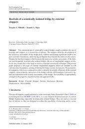
Fig. 1: (a) Longitud<strong>in</strong>al layout of the ord<strong>in</strong>ary strength steel bars at the bottom flange of the deck and (b)<br />
layout of the straight tendons and the re<strong>in</strong><strong>for</strong>cements of the deck’s top flange at the support (plan view).
Page 2 of 9<br />
1<br />
2<br />
3<br />
4<br />
5<br />
6<br />
7<br />
8<br />
9<br />
10<br />
11<br />
12<br />
13<br />
14<br />
15<br />
16<br />
17<br />
18<br />
<strong>19</strong><br />
20<br />
21<br />
22<br />
23<br />
24<br />
25<br />
26<br />
27<br />
28<br />
29<br />
30<br />
31<br />
32<br />
33<br />
34<br />
35<br />
36<br />
37<br />
38<br />
39<br />
40<br />
41<br />
42<br />
43<br />
44<br />
45<br />
46<br />
47<br />
48<br />
49<br />
50<br />
51<br />
52<br />
53<br />
54<br />
55<br />
56<br />
57<br />
58<br />
59<br />
60<br />
Ioannis A. TEGOS<br />
Professor, Civil Eng<strong>in</strong>eer<strong>in</strong>g<br />
Department,<br />
Aristotle University of<br />
Thessaloniki, Greece<br />
itegos@civil.auth.gr<br />
Ioannis A. Tegos, born <strong>in</strong> <strong>19</strong>48,<br />
received his BSc, and PhD<br />
degrees from the Aristotle<br />
University of Thessaloniki,<br />
Greece. His ma<strong>in</strong> area of research<br />
is earthquake resistant <strong>bridges</strong>,<br />
creep and shr<strong>in</strong>kage effects, flat<br />
slab build<strong>in</strong>gs and design aga<strong>in</strong>st<br />
punch<strong>in</strong>g effects and<br />
experimental strength of RC<br />
members.<br />
Summary<br />
A <strong>proposition</strong> <strong>for</strong> a <strong>new</strong> <strong>construction</strong> <strong>method</strong> <strong>for</strong><br />
<strong>cast</strong>-<strong>in</strong>-<strong>situ</strong> <strong>multi</strong>-<strong>span</strong> <strong>in</strong>tegral <strong>bridges</strong><br />
Stergios A. MITOULIS<br />
Dr. Civil Eng<strong>in</strong>eer,<br />
Aristotle University of<br />
Thessaloniki, Greece<br />
mitoulis@civil.auth.gr<br />
Stergios A. Mitoulis, born <strong>19</strong>79,<br />
received his BSc, MSc and PhD<br />
degree from the Aristotle<br />
University of Thessaloniki,<br />
Greece. His ma<strong>in</strong> area of research<br />
is earthquake resistance and<br />
serviceability effects on RC<br />
<strong>bridges</strong>.<br />
A <strong>new</strong> <strong>construction</strong> <strong>method</strong> <strong>for</strong> <strong>cast</strong>-<strong>in</strong>-<strong>situ</strong> <strong>bridges</strong> is exam<strong>in</strong>ed. The <strong>method</strong> is proper <strong>for</strong> <strong>bridges</strong><br />
with <strong>span</strong> lengths between 30 to 50 m. The <strong>construction</strong> of the bridge <strong>in</strong>cludes the follow<strong>in</strong>g stages:<br />
Two balanced cantilevers are <strong>cast</strong>ed on both sides of the elevated piers. Each cantilever has a length<br />
equal to half of the correspond<strong>in</strong>g <strong>span</strong> length of the bridge and is connected to the adjacent one at<br />
the mid-<strong>span</strong>. The height of the cross section of the deck is reduced from the support to the mid<strong>span</strong>.<br />
The prestress<strong>in</strong>g tendons are straight, while the re<strong>in</strong><strong>for</strong>cements with<strong>in</strong> the bottom flange of the<br />
deck consist of ord<strong>in</strong>ary strength steel bars. The applicability of the proposed <strong>construction</strong> <strong>method</strong><br />
has been exam<strong>in</strong>ed to a real <strong>cast</strong>-<strong>in</strong>-<strong>situ</strong> box-girder bridge. Comparative results are illustrated<br />
show<strong>in</strong>g that the proposed <strong>method</strong> has advantages concern<strong>in</strong>g not only the constructability, but also<br />
the serviceability per<strong>for</strong>mance, the earthquake resistance and the structural cost of the bridge.<br />
Keywords: bridge; <strong>new</strong> <strong>construction</strong> <strong>method</strong>; straight tendons; variable cross section; <strong>cast</strong>-<strong>in</strong>-<strong>situ</strong><br />
1. Introduction<br />
Safety, serviceability, cost-effectiveness, aesthetics and particular technical issues are typically the<br />
controll<strong>in</strong>g factors <strong>in</strong> the selection of the proper bridge type [1] [2] and <strong>construction</strong> <strong>method</strong>. The<br />
selection is further complicated by other considerations such as the deflection limit, the life-cycle<br />
cost, <strong>in</strong>clud<strong>in</strong>g traffic obstruction dur<strong>in</strong>g <strong>construction</strong> stages and dur<strong>in</strong>g ma<strong>in</strong>tenance works,<br />
schedul<strong>in</strong>g, feasibility of falsework layout and seismicity at the site [3]. In many cases, a<br />
prestressed concrete or steel bridge is a cost-effective choice. Typically, segmental concrete bridge<br />
<strong>construction</strong> is utilized, which is the most common <strong>method</strong> of bridge <strong>construction</strong>.<br />
Segmental <strong>construction</strong> <strong>method</strong> typically <strong>in</strong>troduces: (a) the conventional <strong>cast</strong>-<strong>in</strong>-<strong>situ</strong> bridge<br />
<strong>construction</strong>, (b) the pre<strong>cast</strong> prestressed I-beam deck <strong>construction</strong> with cont<strong>in</strong>uous <strong>cast</strong>-<strong>in</strong>-<strong>situ</strong> slab<br />
decks, (c) the balanced cantilever bridge <strong>construction</strong>, which either utilises scaffold<strong>in</strong>g or pre<strong>cast</strong><br />
deck segments and (d) the progressive and <strong>span</strong> by <strong>span</strong> <strong>in</strong>crementally launched bridge <strong>construction</strong>.<br />
Segmental <strong>cast</strong>-<strong>in</strong>-<strong>situ</strong> bridge <strong>construction</strong> is preferable <strong>in</strong> case of straight and curved <strong>in</strong> plan<br />
<strong>bridges</strong> with relatively small bent heights and when prestress<strong>in</strong>g is applied <strong>in</strong> the longitud<strong>in</strong>al<br />
direction of the superstructure, as shown <strong>in</strong> Fig. 1(a). The <strong>for</strong>mworks are typically supported<br />
directly to the ground or to a well compacted temporary embankment. In most cases, the first <strong>span</strong><br />
and a 15 to 20 % of the length of the second <strong>span</strong> are <strong>cast</strong>ed together. The <strong>construction</strong> of the next<br />
bridge segment follows after the application of the prestress<strong>in</strong>g <strong>for</strong>ce, while keep<strong>in</strong>g the immediate
Page 3 of 9<br />
1<br />
2<br />
3<br />
4<br />
5<br />
6<br />
7<br />
8<br />
9<br />
10<br />
11<br />
12<br />
13<br />
14<br />
15<br />
16<br />
17<br />
18<br />
<strong>19</strong><br />
20<br />
21<br />
22<br />
23<br />
24<br />
25<br />
26<br />
27<br />
28<br />
29<br />
30<br />
31<br />
32<br />
33<br />
34<br />
35<br />
36<br />
37<br />
38<br />
39<br />
40<br />
41<br />
42<br />
43<br />
44<br />
45<br />
46<br />
47<br />
48<br />
49<br />
50<br />
51<br />
52<br />
53<br />
54<br />
55<br />
56<br />
57<br />
58<br />
59<br />
60<br />
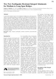
prestress losses with<strong>in</strong> normal levels. The f<strong>in</strong>al load<strong>in</strong>g of the bridge due to the self-weight of the<br />
superstructure is vary<strong>in</strong>g with time due to the <strong>in</strong>fluence of the creep effect [4] [5] [6], as shown <strong>in</strong><br />
Fig. 1(b). The f<strong>in</strong>al load<strong>in</strong>g of the deck can be estimated by the use of simple <strong>for</strong>mulas as follows:<br />
( )<br />
M =ΣΜ + Μ -ΣΜ<br />
∞<br />
Α Ε Α<br />
φ∞<br />
⋅ 1+ρ ⋅ φ<br />
∞<br />
(1)<br />
In Equation 1 where M ∞ is the f<strong>in</strong>al bend<strong>in</strong>g moment of the deck after the development of creep<br />
effects, M E is the bend<strong>in</strong>g moment of the total bridge system <strong>in</strong> the ideal case that the deck is<br />
constructed at once, ΣΜ Α is the sum of the bend<strong>in</strong>g moments of the deck at subsequent <strong>construction</strong><br />
stages consider<strong>in</strong>g elastic response of the deck, φ ∞ is the f<strong>in</strong>al value of the creep coefficient [7], and<br />
ρ is the coefficient of the losses due to the prestress<strong>in</strong>g steel relaxation [7] [8]. It is noted that the<br />
calculation of actions, that are the bend<strong>in</strong>g moments of the superstructure, the shear and the torsion<br />
actions have to be per<strong>for</strong>med at different times, that are at t=0 (time of load<strong>in</strong>g) and t=∞ when the<br />
creep effects have been fully developed.<br />
3<br />
2<br />
1<br />
M ΣMΑ<br />
(a)<br />
(b)<br />
Fig. 1: (a) The structural jo<strong>in</strong>t at the mid-<strong>span</strong> at segmental <strong>cast</strong>-<strong>in</strong>-<strong>situ</strong> bridge <strong>construction</strong> and (b) the<br />
<strong>in</strong>fluence of segmental <strong>construction</strong> on the bend<strong>in</strong>g moments of the deck.<br />
This paper proposes a <strong>new</strong> bridge <strong>construction</strong> <strong>method</strong>, which has similarities with the balanced<br />
cantilever <strong>method</strong>. However, the cantilevers do not require the standard connection accord<strong>in</strong>g to the<br />
balanced cantilever <strong>method</strong> that is the jack<strong>in</strong>g of the meet<strong>in</strong>g segments. The connection of the<br />
cantilevers is achieved by the use of tendon couplers. The tendons are straight and the scaffold<strong>in</strong>g,<br />
which is used <strong>for</strong> the deck <strong>cast</strong><strong>in</strong>g, is removed after the application of the prestress<strong>in</strong>g <strong>for</strong>ce. The<br />
applicability of the proposed <strong>construction</strong> <strong>method</strong> has been attempted to a <strong>cast</strong>-<strong>in</strong>-<strong>situ</strong> benchmark<br />
bridge actually built along a major motorway that runs across Northern Greece. The paper shows<br />
that the proposed <strong>construction</strong> <strong>method</strong> can actually facilitate <strong>construction</strong>, while provid<strong>in</strong>g an<br />
effective control of the serviceability needs of the deck. Further to that, the earthquake resistance of<br />
the result<strong>in</strong>g bridge is enhanced due to the monolithic pier-deck and abutment-deck connections,<br />
while aesthetics are improved.<br />
2. Description of the proposed <strong>construction</strong> <strong>method</strong><br />
2.1 Structural assumptions<br />
The proposed structural <strong>method</strong>, which can be utilised <strong>in</strong> the <strong>construction</strong> of <strong>cast</strong>-<strong>in</strong>-<strong>situ</strong> <strong>bridges</strong>, is<br />
based on the follow<strong>in</strong>g structural assumptions: (a) The deck cross section has a variable height<br />
1<br />
8<br />
MA,1<br />
ME<br />
2<br />
MA,2<br />
3<br />
MA,3
Page 4 of 9<br />
1<br />
2<br />
3<br />
4<br />
5<br />
6<br />
7<br />
8<br />
9<br />
10<br />
11<br />
12<br />
13<br />
14<br />
15<br />
16<br />
17<br />
18<br />
<strong>19</strong><br />
20<br />
21<br />
22<br />
23<br />
24<br />
25<br />
26<br />
27<br />
28<br />
29<br />
30<br />
31<br />
32<br />
33<br />
34<br />
35<br />
36<br />
37<br />
38<br />
39<br />
40<br />
41<br />
42<br />
43<br />
44<br />
45<br />
46<br />
47<br />
48<br />
49<br />
50<br />
51<br />
52<br />
53<br />
54<br />
55<br />
56<br />
57<br />
58<br />
59<br />
60<br />
along the longitud<strong>in</strong>al direction of the bridge with a symmetrical bottom flange, which is modulated<br />
by a polygonal shape <strong>in</strong>scribed <strong>in</strong> a parabolic arch, as shown <strong>in</strong> Fig. 2. The cross section of the deck<br />
can be either a box girder or a voided slab. (b) The prestress<strong>in</strong>g tendons are straight and cont<strong>in</strong>uous<br />
<strong>in</strong> all the deck <strong>span</strong>s and they are <strong>in</strong>stalled <strong>in</strong> the top flange of the deck. The appropriate concrete<br />
cover [7] [8] is provided to protect the tendons aga<strong>in</strong>st corrosion. With<strong>in</strong> the bottom flange of the<br />
deck only ord<strong>in</strong>ary strength steel is utilised. (c) The <strong>construction</strong> of the end <strong>span</strong>s can follow two<br />
different design alternatives: (c 1 ) The first alternative <strong>in</strong>troduces the <strong>construction</strong> of the end <strong>span</strong>s<br />
by ma<strong>in</strong>ta<strong>in</strong><strong>in</strong>g the geometry of the <strong>in</strong>termediate <strong>span</strong>s <strong>for</strong> reasons of aesthetics. In that case, the<br />
deck is chosen to be rigidly connected to the abutments, as shown <strong>in</strong> Fig. 3. Possible use of bear<strong>in</strong>gs,<br />
<strong>for</strong> the support of the deck on the abutments, would lead to the requirement <strong>for</strong> their replacement<br />
dur<strong>in</strong>g the service life of the bridge. Replacement of the bear<strong>in</strong>gs is feasible, however it is not<br />
always convenient. Thus, the monolithic connection of the abutment web with the deck is proposed<br />
<strong>in</strong> this design alternative. (c 2 ) The second design alternative <strong>in</strong>troduces the <strong>construction</strong> of the end<br />
<strong>span</strong>s with lengths smaller than the ones of the <strong>in</strong>termediate ones. Half of the length of the end <strong>span</strong><br />
has a deck cross section with variable height. This corresponds to the part of the deck which<br />
extends from the end pier towards the abutment. The other part of the <strong>span</strong> is seated through<br />
bear<strong>in</strong>gs to the abutment. It extends from the abutment towards the pier and has a constant cross<br />
section height. The need <strong>for</strong> the smaller length of the end <strong>span</strong>s was found to be dictated by the<br />
relatively small height of the deck cross section that is 0,80 m and by the use of ord<strong>in</strong>ary<br />
re<strong>in</strong><strong>for</strong>cements <strong>in</strong> the bottom fibre of the deck, as stated <strong>in</strong> (b) above.<br />
It is noted that the use of prestress<strong>in</strong>g with<strong>in</strong> the bottom flange of the deck was not deemed to be a<br />
rational design selection, as the tendons would <strong>in</strong>duce a large vertical load downwards, due to the<br />
variation of the height of the deck cross section. This constra<strong>in</strong>t load<strong>in</strong>g, namely the one <strong>in</strong>duced by<br />
possible negative prestress<strong>in</strong>g, would not be compatible with the rational use of tendons, which are<br />
typically utilised <strong>in</strong> order to compensate <strong>for</strong> the vertical load<strong>in</strong>g.<br />
a-a<br />
a<br />
a<br />
h2=0,80m<br />
h1=2.20m<br />
A1<br />
b-b<br />
P1<br />
Fig. 2: The first stage of the proposed <strong>construction</strong> <strong>method</strong>.<br />
2.2 Particular design issues<br />
a<br />
a<br />
b<br />
b<br />
c-c<br />
centre of gravity<br />
of the deck<br />
h3=0,80m<br />
Τhe rigid connection of the deck with the abutments was achieved by the <strong>construction</strong> of a<br />
counterbalance that is a cantilever which extends from the abutment towards the backfill soil, as<br />
shown <strong>in</strong> Fig. 3. The length of this cantilever is 5,0 m and its cross section height reduces from the<br />
abutment to the backfill. The end cross section of the cantilever is utilised <strong>for</strong> the anchorage of the<br />
tendons. The tendons are slightly lowered at their anchorages <strong>in</strong> order to provide the appropriate<br />
cover <strong>for</strong> their anchor<strong>in</strong>g devices, namely the bear<strong>in</strong>g plates. A structural tie, namely a re<strong>in</strong><strong>for</strong>ced<br />
concrete wall with a thickness of 0,30 m, is utilized <strong>in</strong> order to receive the bend<strong>in</strong>g moments of the<br />
counterbalance-cantilever, which are developed due to the vertical load<strong>in</strong>g of the deck. In fact this<br />
wall, namely the structural tie, is under tension, while the subdivided abutment web is under<br />
c<br />
c
Page 5 of 9<br />
1<br />
2<br />
3<br />
4<br />
5<br />
6<br />
7<br />
8<br />
9<br />
10<br />
11<br />
12<br />
13<br />
14<br />
15<br />
16<br />
17<br />
18<br />
<strong>19</strong><br />
20<br />
21<br />
22<br />
23<br />
24<br />
25<br />
26<br />
27<br />
28<br />
29<br />
30<br />
31<br />
32<br />
33<br />
34<br />
35<br />
36<br />
37<br />
38<br />
39<br />
40<br />
41<br />
42<br />
43<br />
44<br />
45<br />
46<br />
47<br />
48<br />
49<br />
50<br />
51<br />
52<br />
53<br />
54<br />
55<br />
56<br />
57<br />
58<br />
59<br />
60<br />
compression. The structural tie has a length equal to the distance between the w<strong>in</strong>g walls, with<br />
which it is <strong>in</strong> contact but not connected. The re<strong>in</strong><strong>for</strong>cement bars of the structural tie are anchored <strong>in</strong><br />
the pile cap of the abutment’s foundation. This pile cap has a relatively small thickness, as the w<strong>in</strong>g<br />
walls and the wall that reta<strong>in</strong>s the backfill soil <strong>for</strong>mulate a stiff concrete “box”, which <strong>in</strong>creases the<br />
stiffness of the pile cap. It is noted that, the web of the abutment, <strong>in</strong> case it supports the deck<br />
through bear<strong>in</strong>gs, can be compact. In case the web is <strong>in</strong>tegral with the deck, its <strong>in</strong>-service<br />
constra<strong>in</strong>ed movements can be accommodated by subdivid<strong>in</strong>g it <strong>in</strong> walls, as shown <strong>in</strong> Fig. 3, with<br />
small thicknesses <strong>in</strong> order to reduce the shear stiffness enough, while ma<strong>in</strong>ta<strong>in</strong><strong>in</strong>g adequate moment<br />
capacity [9].<br />
backfill<br />
open<strong>in</strong>g<br />
reta<strong>in</strong><strong>in</strong>g<br />
wall<br />
tendons<br />
(Detail)<br />
counterbalance<br />
cantilever<br />
structural<br />
tie<br />
pile cap<br />
tendons<br />
subdivided<br />
abutment<br />
web<br />
450mm<br />
Fig. 3: The abutment of the proposed <strong>construction</strong> <strong>method</strong>.<br />
Detail<br />
2,75<br />
R=30m<br />
2,75<br />
R=30m<br />
150mm<br />
The m<strong>in</strong>imum height of the deck cross section is proposed to be not smaller than 0,80 m. After the<br />
cur<strong>in</strong>g of the <strong>cast</strong>ed cantilevers, the tendons are stressed. The design of the prestress<strong>in</strong>g <strong>for</strong>ce is<br />
based on the objective of the <strong>method</strong> that is to provide a slight pre-camber<strong>in</strong>g of the cantilevers that<br />
is a slight bend<strong>in</strong>g deflection upwards. There<strong>for</strong>e, at this stage the cantilevers of the deck are set<br />
higher than the f<strong>in</strong>al design height of the bridge. After the application of prestress<strong>in</strong>g, the steel<br />
<strong>for</strong>mwork is removed and the <strong>construction</strong> procedure is repeated <strong>for</strong> the adjacent <strong>span</strong>s. The<br />
tendons of the subsequent <strong>span</strong>s are coupled with the ones of the <strong>cast</strong>ed cantilever and the adjacent<br />
cantilever is constructed. A detailed description of the prestress<strong>in</strong>g application and the rebar of the<br />
deck is given <strong>in</strong> section 3 of the paper.<br />
After the completion of the deck <strong>construction</strong> and the application of the prestress<strong>in</strong>g <strong>for</strong>ce, positive<br />
bend<strong>in</strong>g moments, which are caused due to the eccentricity of the straight tendons from the deck’s<br />
centre of gravity, are developed along the deck. These positive bend<strong>in</strong>g moments overbalance the<br />
negative ones that are imposed by the self-weight of the deck. Hence, a pre-camber<strong>in</strong>g of the<br />
cantilevers is achieved. The pre-camber<strong>in</strong>g was deemed necessary <strong>in</strong> order to compensate <strong>for</strong> the<br />
pre-determ<strong>in</strong>ed long-term prestress losses due to the creep and shr<strong>in</strong>kage of the deck and due to the<br />
relaxation of prestress<strong>in</strong>g steel. The rest of the vertical loads of the deck that are the additional<br />
permanent and the variable load<strong>in</strong>g [10] are imposed after the completion of the total bridge system.<br />
Thus, the frame action of the total bridge structure, <strong>in</strong> which the meet<strong>in</strong>g cantilevers are connected,<br />
receives the additional vertical load<strong>in</strong>g. The f<strong>in</strong>al bridge system is then checked aga<strong>in</strong>st the<br />
result<strong>in</strong>g bend<strong>in</strong>g moments, the shear actions and the torsion effects after consider<strong>in</strong>g the redistribution<br />
of actions. In particular, the design of the deck aga<strong>in</strong>st shear actions is facilitated due to<br />
the beneficial <strong>in</strong>cl<strong>in</strong>ation to the horizontal of the compression zone of the deck <strong>in</strong> the critical section<br />
<strong>for</strong> shear, namely where the maximum shear stress is act<strong>in</strong>g. Possible deficiency of the deck at the<br />
supports aga<strong>in</strong>st the bend<strong>in</strong>g moments caused by either the ultimate or the serviceability limit states<br />
[8][11] shall be covered by additional re<strong>in</strong><strong>for</strong>cement bars of ord<strong>in</strong>ary strength steel. The additional<br />
re<strong>in</strong><strong>for</strong>cements cover the safety criteria set by codes [8] [11] and the serviceability requirements by<br />
limit<strong>in</strong>g the crack width accord<strong>in</strong>g to the code provisions [7] [8].
Page 6 of 9<br />
1<br />
2<br />
3<br />
4<br />
5<br />
6<br />
7<br />
8<br />
9<br />
10<br />
11<br />
12<br />
13<br />
14<br />
15<br />
16<br />
17<br />
18<br />
<strong>19</strong><br />
20<br />
21<br />
22<br />
23<br />
24<br />
25<br />
26<br />
27<br />
28<br />
29<br />
30<br />
31<br />
32<br />
33<br />
34<br />
35<br />
36<br />
37<br />
38<br />
39<br />
40<br />
41<br />
42<br />
43<br />
44<br />
45<br />
46<br />
47<br />
48<br />
49<br />
50<br />
51<br />
52<br />
53<br />
54<br />
55<br />
56<br />
57<br />
58<br />
59<br />
60<br />
3. Application of the <strong>construction</strong> <strong>method</strong> to a <strong>cast</strong>-<strong>in</strong>-<strong>situ</strong> bridge<br />
3.1 Description of the benchmark bridge<br />
The bridge of Kleidi-Kouloura belongs to Egnatia Motorway that runs across Northern Greece. It is<br />
a <strong>cast</strong>-<strong>in</strong>-<strong>situ</strong> structure with a total of three <strong>span</strong>s and a total length equal to 135.8 m. Figure 4<br />
illustrates the longitud<strong>in</strong>al section of the bridge, the abutment and the cross sections of the boxgirder<br />
deck, the pier and its foundation. The deck of the bridge has a constant height of 2.18 m,<br />
while prestress<strong>in</strong>g consists of tendons 20x<strong>19</strong>T15 (20 tendons of <strong>19</strong> wires with diameter 15mm each)<br />
with a parabolic geometry. The bridge has a seat-type abutment on which the deck is supported<br />
through two slid<strong>in</strong>g bear<strong>in</strong>gs, while is rigidly connected to the piers. The clearance between the<br />
deck slab and the backwall is bridged by an expansion jo<strong>in</strong>t with a movement capacity of ±100 mm.<br />
A1 P1 P2 A2<br />
KOULOURA<br />
135.80<br />
KLEIDI<br />
45.10<br />
45.60 45.10<br />
approach slab<br />
length: 4.0m<br />
backwall: 3.0m<br />
backfill soil<br />
Abutment<br />
T200 (±100mm)<br />
deck<br />
slid<strong>in</strong>g bear<strong>in</strong>g<br />
3<br />
6.5<br />
2<br />
2<br />
3 6.75<br />
3<br />
2<br />
2.18<br />
9.50 9.50<br />
0.60<br />
Pier<br />
13.50<br />
6.00<br />
2.0m<br />
Deck at the mid<strong>span</strong><br />
Fig. 4: The benchmark bridge (Kleidi-Kouloura Bridge of Egnatia Motorway).<br />
3.2 Results<br />
Foundation<br />
2.00<br />
7.50<br />
1.00 22.50<br />
The benchmark bridge was re-analysed and re-designed accord<strong>in</strong>g to current code provisions<br />
concern<strong>in</strong>g serviceability [8] [11] and earthquake resistance [12]. The re-design took <strong>in</strong>to account<br />
the <strong>construction</strong> phases of the proposed <strong>method</strong> and the follow<strong>in</strong>g predom<strong>in</strong>ant design parameters<br />
were revealed: (1) The required number of straight tendons was less than the one needed <strong>in</strong> case a<br />
classification category A or B was chosen, (table 4.118 <strong>in</strong> [8] [11]). However, the total number of<br />
tendons ensures that the bridge is classified <strong>in</strong> category C, when this requirement refers to the<br />
per<strong>for</strong>mance of the top fibre of the deck, while the use of ord<strong>in</strong>ary strength re<strong>in</strong><strong>for</strong>cements <strong>in</strong> the<br />
bottom fibre of the deck leads to the classification category D. It is noted that, the design of the<br />
prestress<strong>in</strong>g <strong>for</strong>ce and the result<strong>in</strong>g number of tendons aims at provid<strong>in</strong>g the required pre-camber<strong>in</strong>g<br />
of the cantilevers aga<strong>in</strong>st the self weight of the bridge deck, whose length was half of the total <strong>span</strong><br />
length that is 45,60/2 = 22,80 m. (2) The re-design of the prestress<strong>in</strong>g showed that 15x<strong>19</strong>T15 (15<br />
tendons of <strong>19</strong> wires with diameter 15mm each) of high strength steel St1500/1770 are adequate to<br />
receive the bend<strong>in</strong>g moment of the deck above its support. Additionally, ord<strong>in</strong>ary steel rebar 76Ø16<br />
(76 bars with diameter 16mm each) above the support were utilized, which gradually reduced to<br />
28Ø16 at the bridge mid-<strong>span</strong>. The tendons and the re<strong>in</strong><strong>for</strong>cements needed <strong>in</strong> the top flange of the<br />
deck are illustrated <strong>in</strong> Fig. 5. The ord<strong>in</strong>ary strength steel bars, which are also required by the code<br />
[8], are the ones which allow the safe transition from the uncracked to the cracked deck section and<br />
the avoidance of non-ductile failure modes. The lengths of the steel bars were chosen to be<br />
sub<strong>multi</strong>ples, namely half, of the conventionally produced ones by the steel manufactures <strong>in</strong> order<br />
to avoid material waste. Figures 6 and 7 show <strong>in</strong> detail the distribution of these re<strong>in</strong><strong>for</strong>c<strong>in</strong>g bars at<br />
the support and at the mid-<strong>span</strong>. Figure 8 shows the steel rebar of the bottom part of the deck. The<br />
bars are <strong>in</strong>stalled <strong>in</strong> couples that are 2x71Ø25 (71 couples of bars with diameters 25mm each) at the<br />
mid-<strong>span</strong>, while 2x41Ø25 were found to be required at the bottom flange of the deck at the supports.<br />
The re<strong>in</strong><strong>for</strong>cement splices were required to extend 2,15 m. The lengths of the bars were selected to<br />
be 7,0 m and they were set parallel to the sides of the polygonal shape of the bottom flange. (4) The<br />
thickness and the re<strong>in</strong><strong>for</strong>cement of the structural tie, that is the wall that restra<strong>in</strong>s the vertical<br />
movements of the counterbalance-cantilever at the abutment shown <strong>in</strong> Fig. 3, were found to be<br />
0,30m and 3xØ16/100 (3 l<strong>in</strong>es of bars with diameter 16mm at a spac<strong>in</strong>g 100 mm) correspond<strong>in</strong>gly.<br />
3.00<br />
2.00
Page 7 of 9<br />
1<br />
2<br />
3<br />
4<br />
5<br />
6<br />
7<br />
8<br />
9<br />
10<br />
11<br />
12<br />
13<br />
14<br />
15<br />
16<br />
17<br />
18<br />
<strong>19</strong><br />
20<br />
21<br />
22<br />
23<br />
24<br />
25<br />
26<br />
27<br />
28<br />
29<br />
30<br />
31<br />
32<br />
33<br />
34<br />
35<br />
36<br />
37<br />
38<br />
39<br />
40<br />
41<br />
42<br />
43<br />
44<br />
45<br />
46<br />
47<br />
48<br />
49<br />
50<br />
51<br />
52<br />
53<br />
54<br />
55<br />
56<br />
57<br />
58<br />
59<br />
60<br />
Y<br />
X<br />
28O16<br />
L=14,0m<br />
couplers<br />
52O16<br />
L=7,0m<br />
76O16<br />
L=14,0m<br />
Pier<br />
tendons 15x<strong>19</strong>T15 (St 1500/1770)<br />
52O16<br />
L=7,0m<br />
28O16<br />
L=14,0 m<br />
lapp<strong>in</strong>g<br />
3,50 m<br />
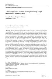
Fig. 5: The layout of the straight tendons and the ord<strong>in</strong>ary strength steel bars of the deck’s top flange at the<br />
support, (the scale is distorted: 1 unit at X equals 2 units at Y axis).<br />
1,00<br />
Pier<br />
7,00 7,00<br />
8,50 5,50<br />
5,50 8,50<br />
L=14,0 m<br />
tendons<br />
Fig. 6: Detail of the straight tendons and the ord<strong>in</strong>ary strength steel bars of the deck’s top flange at the<br />
support.
Page 8 of 9<br />
1<br />
2<br />
3<br />
4<br />
5<br />
6<br />
7<br />
8<br />
9<br />
10<br />
11<br />
12<br />
13<br />
14<br />
15<br />
16<br />
17<br />
18<br />
<strong>19</strong><br />
20<br />
21<br />
22<br />
23<br />
24<br />
25<br />
26<br />
27<br />
28<br />
29<br />
30<br />
31<br />
32<br />
33<br />
34<br />
35<br />
36<br />
37<br />
38<br />
39<br />
40<br />
41<br />
42<br />
43<br />
44<br />
45<br />
46<br />
47<br />
48<br />
49<br />
50<br />
51<br />
52<br />
53<br />
54<br />
55<br />
56<br />
57<br />
58<br />
59<br />
60<br />
7,00<br />
lapp<strong>in</strong>g<br />
14,00 3,52<br />
couplers<br />
7,00<br />
tendons<br />
structural jo<strong>in</strong>t<br />
Fig. 7: Detail of the ord<strong>in</strong>ary strength steel bars of the deck’s top flange at the mid-<strong>span</strong> and coupl<strong>in</strong>g of the<br />
tendons.<br />
~4,50m<br />
2,0-2,50m<br />
pier<br />
top flange<br />
7,0m<br />
2X41Φ25<br />
polygonal<br />
bottom<br />
flange<br />
straight tendons<br />
15x<strong>19</strong>T15 (St 1500/1770)<br />
2,15m<br />
7,0m 7,0m<br />
2X51Φ25<br />
splic<strong>in</strong>g<br />
length<br />
corners of the polygon<br />
d=150mm<br />
2X51Φ25<br />
2X61Φ25<br />
l=35,0-50,0m<br />
Fig. 8: Detail of the ord<strong>in</strong>ary strength steel bars at the bottom flange of the deck.<br />
d>150mm<br />
2X71Φ25<br />
mid-<strong>span</strong><br />
structural jo<strong>in</strong>t<br />
The study of the applicability of the proposed structural <strong>method</strong> by utilis<strong>in</strong>g <strong>bridges</strong> with shorter<br />
and longer <strong>span</strong>s showed that <strong>for</strong> <strong>span</strong> lengths up to 35,0 m the deck is not exhibit<strong>in</strong>g crack<strong>in</strong>g,<br />
while <strong>for</strong> longer <strong>span</strong>s the crack widths can be kept low, namely lower than the limit of 0,02 mm,<br />
by means of rational re<strong>in</strong><strong>for</strong>cement ratios of ord<strong>in</strong>ary strength steel nars. As far as it concerns the<br />
bottom flange of the deck, it was found that the bend<strong>in</strong>g moments of the mid-<strong>span</strong>s require<br />
re<strong>in</strong><strong>for</strong>cement ratios lower than the maximum allowable ones, which are set by codes [7][8]. This is<br />
attributed to the fact that the bend<strong>in</strong>g moments of the bridge are redistributed due to the frame<br />
action of the f<strong>in</strong>al bridge system. Hence, the deck’s bend<strong>in</strong>g moments are ma<strong>in</strong>ly received by the<br />
supports, due to the beneficial variation of the deck cross section height and the a<strong>for</strong>ementioned<br />
frame action.<br />
4. Conclusions<br />
This paper proposes a <strong>new</strong> bridge <strong>construction</strong> <strong>method</strong>, which can be used as a design alternative to<br />
the conventional <strong>construction</strong> practices. The <strong>method</strong> has many similarities with the balanced<br />
cantilever <strong>method</strong>. The prestress<strong>in</strong>g tendons are straight and <strong>in</strong>stalled with<strong>in</strong> the top flange of the<br />
deck cross section, while ord<strong>in</strong>ary strength steel is utilized <strong>for</strong> the re<strong>in</strong><strong>for</strong>cement with<strong>in</strong> the bottom<br />
flange. The deck has a variable cross section height along its longitud<strong>in</strong>al direction. A benchmark<br />
bridge, actually built along the Egnatia Motorway by the conventional segmental <strong>cast</strong>-<strong>in</strong>-<strong>situ</strong><br />
<strong>method</strong>, was utilized as benchmark to identify the applicability of the proposed <strong>method</strong>. The bridge<br />
was checked accord<strong>in</strong>g to the current code provisions and the study came up with the follow<strong>in</strong>g<br />
f<strong>in</strong>d<strong>in</strong>gs:<br />
The application of the proposed <strong>construction</strong> <strong>method</strong> revealed significant structural benefits. The<br />
use of straight tendons <strong>for</strong> the prestress<strong>in</strong>g of the deck facilitates and accelerates the <strong>construction</strong> of<br />
the bridge. The tendons are <strong>in</strong>stalled with<strong>in</strong> the upper slab of the deck’s cross section, which is<br />
more preferable than us<strong>in</strong>g tendons which are <strong>in</strong>stalled <strong>in</strong> the webs of the box girder. It is noted that<br />
the use of tendons <strong>in</strong> the webs of the box-girder decks is not allowed accord<strong>in</strong>g to current code<br />
design, at least <strong>for</strong> <strong>bridges</strong> constructed by the balanced cantilever <strong>method</strong>. Furthermore, the<br />
prestress<strong>in</strong>g losses due to friction are significantly reduced when the proposed <strong>construction</strong> <strong>method</strong>
Page 9 of 9<br />
1<br />
2<br />
3<br />
4<br />
5<br />
6<br />
7<br />
8<br />
9<br />
10<br />
11<br />
12<br />
13<br />
14<br />
15<br />
16<br />
17<br />
18<br />
<strong>19</strong><br />
20<br />
21<br />
22<br />
23<br />
24<br />
25<br />
26<br />
27<br />
28<br />
29<br />
30<br />
31<br />
32<br />
33<br />
34<br />
35<br />
36<br />
37<br />
38<br />
39<br />
40<br />
41<br />
42<br />
43<br />
44<br />
45<br />
46<br />
47<br />
48<br />
49<br />
50<br />
51<br />
52<br />
53<br />
54<br />
55<br />
56<br />
57<br />
58<br />
59<br />
60<br />
is employed. The dead load of the bridge deck, which typically constitutes the largest portion of the<br />
bridge’s vertical load<strong>in</strong>g, is decreased due to the reduction <strong>in</strong> the height of the deck cross section.<br />
However, the variation of the deck cross section along the bridge deck obstructs the falsework as<br />
the scaffold<strong>in</strong>g is more demand<strong>in</strong>g <strong>in</strong> terms of geometry, compared to the conventional segmental<br />
bridge <strong>construction</strong>.<br />
The bridge aesthetics are significantly improved compared to the conventional segmental bridge<br />
<strong>construction</strong>. This is due to the ref<strong>in</strong>ed arch-type view of the bridge constructed by the proposed<br />
<strong>method</strong> and the reduced deck cross section height.<br />
As far as it concerns the crack<strong>in</strong>g of the deck, the proposed <strong>construction</strong> <strong>method</strong> can be utilized <strong>for</strong><br />
the <strong>construction</strong> of <strong>bridges</strong> with short to medium <strong>span</strong>s up to 35 m. The check aga<strong>in</strong>st crack<strong>in</strong>g due<br />
to the short term vertical load<strong>in</strong>g of the deck, namely aga<strong>in</strong>st the <strong>in</strong>frequent load<strong>in</strong>g, showed that<br />
the deck does not exhibit crack<strong>in</strong>g. In case of <strong>bridges</strong> with longer <strong>span</strong>s up to 50 m the use of partial<br />
prestress shall be used.<br />
The deflections of the deck were significantly reduced due to the objective set dur<strong>in</strong>g the design of<br />
the prestress<strong>in</strong>g <strong>for</strong>ce, which ensured that the cantilevers had a pre-camber<strong>in</strong>g upwards, at least<br />
when the scaffold<strong>in</strong>g was removed.<br />
Possible differential settlements of the piers can be received by the result<strong>in</strong>g bridge system without<br />
develop<strong>in</strong>g high bend<strong>in</strong>g load<strong>in</strong>g to the deck, due to flexibility of the arch-type superstructure.<br />
5. References<br />
[1] CALTRANS, Bridge Design Aids Manual, Cali<strong>for</strong>nia Department of Transportation,<br />
Sacramento, <strong>19</strong>94.<br />
[2] CHEN W.F. and DUAN L., Bridge Eng<strong>in</strong>eer<strong>in</strong>g Handbook, CRC Press Boca Raton London,<br />
New York Wash<strong>in</strong>gton, D. C., <strong>19</strong>99, Chapter 1.<br />
[3] MITOULIS S.A., TEGOS I.A., K.-C. STYLIANIDIS, “Cost-effectiveness related to the<br />
earthquake resist<strong>in</strong>g system of <strong>multi</strong>-<strong>span</strong> <strong>bridges</strong>”, Eng<strong>in</strong>eer<strong>in</strong>g Structures, Vol. 32, Issue 9,<br />
2010, pp. 2658-2671.<br />
[4] TROST H., Lastverteilung bei Plattenbalkenbrucken, Werner Verlag, Dusseldorf, West<br />
Germany, <strong>19</strong>61.<br />
[5] PIETRASZEK T.T., “Deal<strong>in</strong>g with vary<strong>in</strong>g moments of <strong>in</strong>ertia of girders <strong>in</strong> bridge analysis: 1<br />
Discussion”, Canadian Journal of Civil Eng<strong>in</strong>eer<strong>in</strong>g, Vol. 16, <strong>19</strong>89, pp. 203-204.<br />
[6] KWAK H.-G., and SON J.-K., “Determ<strong>in</strong>ation of design moments <strong>in</strong> <strong>bridges</strong> constructed<br />
with a movable scaffold<strong>in</strong>g system (MSS)”, Computers and Structures, Vol. 84 Issue 31-32,<br />
2006, pp. 2141-2150.<br />
[7] EN <strong>19</strong>92-1-1:2004 Eurocode 2: Design of concrete structures, Part 1-1: General rules and<br />
rules <strong>for</strong> build<strong>in</strong>gs, 2004.<br />
[8] DIN-FACHBERICHT 102, Betonbrücken, DIN Deutsches Institut fuer Normung e.V, 2003.<br />
[9] TEGOU S.D., MITOULIS S.A., TEGOS I.A., “An unconventional earthquake resistant<br />
abutment with transversely directed R/C walls”, Eng<strong>in</strong>eer<strong>in</strong>g Structures, Vol. 32, Issue 11,<br />
2010, pp. 3801-381.<br />
[10] EN <strong>19</strong>91-2:2003 Eurocode 1: Actions on structures - Part 2: Traffic loads on <strong>bridges</strong>, 2003.<br />
[11] EN <strong>19</strong>92-2:2004 Eurocode 2: Design of concrete structures-Part 2: Bridges, 2004.<br />
[12] EN <strong>19</strong>98-2:2005 Eurocode 8: Design of structures <strong>for</strong> earthquake resistance, Part 2: Bridges,<br />
2005.