

DGLR-MTR-2000.PDF
DGLR-MTR-2000.PDF
DGLR-MTR-2000.PDF

You also want an ePaper? Increase the reach of your titles
YUMPU automatically turns print PDFs into web optimized ePapers that Google loves.
personic Exit Mach Numbers for the blading. This<br />
leads to compression shocks including additional<br />
shock-boundary layer interactions with the combined<br />
complexity and sensitivity to geometrical deviations.<br />
Much attention was given therefore to the aerodynamic<br />
design. On the other hand the minimisation of<br />
necessary airfoil cooling flows and the optimisation of<br />
the tip-clearance are important to get the best result<br />
with respect to the engine operation line.<br />
The compressor turbine design including the interturbine<br />
duct was also affected by the mechanical<br />
boundary conditions with very high temperature and<br />
stress levels for life limiting parts. This shows the<br />
excellent interaction between the necessary technical<br />
disciplines.<br />
Fig. 7 shows the loss contributors in this class of<br />
engine size in comparison with a large engine. It is<br />
evident that tip clearance and cooling losses are of<br />
the same order as aerodynamic losses and have to<br />
be taken careful into account.<br />
Fig. 7: Thermodynamic losses in the turbine module<br />
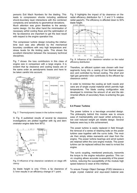
In Fig. 8 published results of several tip clearance<br />
investigations are plotted together with rig and demonstrator<br />
engine data from MTU.<br />
Fig. 8 Influence of tip clearance variations on stage efficiency<br />
As blade height is only 17mm, a tip clearance of<br />
0.1mm results in an efficiency change of 1 point.<br />
Fig. 9 highlights the impact of tip clearance on the<br />
radial efficiency distribution for 1, 2 and 3 % relative<br />
radial gap(s/h). The efficiency is affected down to 50%<br />
blade height.<br />
Fig. 9: Influence of tip clearance variation on the radial<br />
efficiency distribution<br />
Therefore, an efficient system was chosen with liner<br />
segments hung into a casing of low thermal expansion<br />
and controlled by forced cooling. The short and<br />
rigid gas generator rotor contributes to the efficient tipclearance<br />
control.<br />
In order to minimise the cooling air both nozzle and<br />
vane are of single crystal material which permits high<br />
temperatures. The blade cooling configuration was<br />
developed to minimise the amount of air and the detrimental<br />
effects of secondary flows re-entering the gas<br />
path.<br />
6.4 Power Turbine<br />
The power turbine is a two-stage uncooled design.<br />
The philosophy behind this module was to ensure<br />
ease of maintainability and repair whilst achieving a<br />
low cost reduced weight yet reliable design. Several<br />
features were key in this achievement.<br />
The power turbine is easily replaced in field through<br />
the removal of a series of retaining bolts on the power<br />
turbine case together with the curvic bolts. The module<br />
then simply slides rearwards and clear from the<br />
engine. The power turbine bearings and air/oil system<br />
are retained within the core engine module. The power<br />
turbine can be replaced without the need to re-test the<br />
engine.<br />
The curvic coupling, mentioned previously, transmits<br />
the torque to the engine reduction gearbox. This curvic<br />
coupling allows accurate re-assembly of the power<br />
turbine, reducing the susceptibility of the module high<br />
speed balance to wear at this interface.<br />
To ensure Foreign Object Damage (FOD) tolerance a<br />
single crystal material and equi-axed material was