

BOA Group_e_16-06_Mod1_Metal_Hose_Guide_complete_red

You also want an ePaper? Increase the reach of your titles
YUMPU automatically turns print PDFs into web optimized ePapers that Google loves.
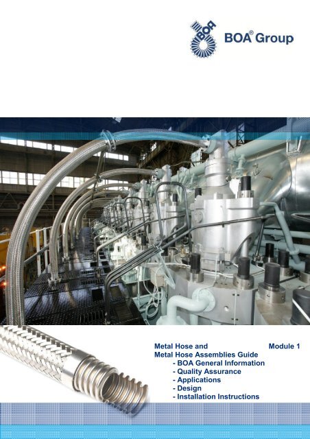
<strong>Metal</strong> <strong>Hose</strong> and Module 1<br />
<strong>Metal</strong> <strong>Hose</strong> Assemblies <strong>Guide</strong><br />
- <strong>BOA</strong> General Information<br />
- Quality Assurance<br />
- Applications<br />
- Design<br />
- Installation Instructions
2
<strong>BOA</strong><br />
<strong>Metal</strong> <strong>Hose</strong> and <strong>Metal</strong> <strong>Hose</strong> Assemblies <strong>Guide</strong><br />
<strong>Metal</strong> <strong>Hose</strong> and <strong>Metal</strong> <strong>Hose</strong> Assemblies <strong>Guide</strong><br />
1 Summary<br />
Modules:<br />
1 <strong>Metal</strong> <strong>Hose</strong>s, General Information, Installation Instructions<br />
2 <strong>BOA</strong> Standard Program <strong>Metal</strong> <strong>Hose</strong>s (bulk) and Assemblies<br />
3 Annexe/ Standards /Corrosion<br />
page<br />
1 Summary 3<br />
2 <strong>Metal</strong> <strong>Hose</strong>s General 4<br />
2.1 <strong>Metal</strong> hose 4<br />
2.2 Corrugated metal hoses – Structure and function 5<br />
2.3 Strip wound metal hoses – Structure and function 6<br />
2.4 Technical terms and notes 7<br />
2.5 Inquiry specifications 8<br />
3 Quality Assurance 10<br />
3.1 Approvals / Certificates 10<br />
3.2 Tests / Laboratory 11<br />
4 Applications 12<br />
4.1 Industrial applications 12<br />
4.2 Aerospace 12<br />
4.3 Rail traffic 12<br />
4.4 Automotive 13<br />
4.5 Solar and boiler industry 13<br />
4.6 Heating – ventilation – air conditioning 14<br />
4.7 Gas production 14<br />
4.8 Food industry 15<br />
4.9 Vacuum applications 15<br />
4.10 Steel industry 15<br />
4.11 Special applications <strong>16</strong><br />
5 Design 17<br />
5.1 Structure and function 17<br />
5.2 Pressure design 18<br />
5.3 Calculation of hose lengths 18<br />
5.4 ISO Standard 10380: 2012 - Excerpt 30<br />
5.5 EN 14585-1: 20<strong>06</strong> - Excerpt 30<br />
6 Installation Instructions 31<br />
6.1 General 31<br />
6.2 Handling and installation 31<br />
6.3 Installation to absorb thermal expansion 32<br />
6.4 Installation to compensate for misalignment 33<br />
6.5 Installation to absorb vibrations 33<br />
6.6 Installation through U-bend to absorb movements 34<br />
6.7 Installation instructions for safety gas hoses and LPG metal hoses 35<br />
Subject to changes<br />
15-07<br />
3
<strong>BOA</strong><br />
<strong>Metal</strong> <strong>Hose</strong> and <strong>Metal</strong> <strong>Hose</strong> Assemblies <strong>Guide</strong><br />
2 <strong>Metal</strong> <strong>Hose</strong>s General<br />
2.1 <strong>Metal</strong> <strong>Hose</strong><br />
Application fields<br />
<strong>Metal</strong> hoses are an indispensable part of modern technology with its high demands on piping systems for a wide variety of media and temperatures.<br />
High flexibility and highest pressure and temperature resistance characterize our product program and allow their use in many areas,<br />
notably in heating, plumbing and air conditioning systems, in the oil and gas industry, in the chemical and food industry, in machine and equipment<br />
construction, ship building, railway and automotive engineering.<br />
Reasons for the use of metal hoses rather than a solution with rigid tubes:<br />
• Stresses in the pipe system<br />
Due to stresses in the pipe system may occur<br />
- assembly inaccuracies<br />
- thermal expansion<br />
- vibrations<br />
- pressure variations<br />
To compensate for these unwanted stresses, a metal hose assembly provides the following advantages:<br />
- no pipe ruptures due to fatigue<br />
- no leaky flange connections<br />
- no difficulty in replacing pipes having been deformed by high temperatures.<br />
• Savings in assembly/ disassembly<br />
- prefabrication of pipes requires less precision<br />
- no adjustment work needed on the hose<br />
- assembly inaccuracies are easy to correct<br />
- only part of the line must be removed<br />
- flexible elements are easier to remove and especially to re-install.<br />
This results in:<br />
- significant savings in assembly and disassembly of pipe systems<br />
- higher flexibility in designing the pipe guides and in case of any modifications.<br />
Types of metal hoses<br />
Basically there are two types of metal tubes, differing in structure and application:<br />
- Corrugated metal hoses or full (all-) metal corrugated hoses<br />
- Strip wound metal hoses, with or without sealing<br />
Corrugated metal hoses<br />
Strip wound metal hoses<br />
Resistance welding<br />
Resistance welding<br />
Selecting the right metal hose depends on its use.<br />
• Corrugated metal hoses are absolutely leak-tight and are appropriate for high pressure and vacuum<br />
• Strip wound metal hoses are only of limited leak-tightness and are therefore used mainly as protection, ventilation or aspiration hoses.<br />
4
<strong>BOA</strong> <strong>Metal</strong> hose products: Overview<br />
Resistance welded<br />
metal hoses<br />
Longitudinally<br />
welded metal<br />
hoses<br />
Strip wound<br />
metal hoses<br />
Trade products<br />
<strong>BOA</strong>-DUO ®<br />
<strong>BOA</strong>-DUO ® UHP<br />
PARMECA ®<br />
SAGRA<br />
Braids<br />
<strong>BOA</strong>-SUPRA ®<br />
PARNOR ®<br />
PARRAP ®<br />
<strong>BOA</strong> PROTEX<br />
<strong>Metal</strong> <strong>Hose</strong><br />
Assemblies<br />
<strong>BOA</strong> VENTINOX<br />
HP<br />
THP<br />
XHP<br />
<strong>BOA</strong> VS<br />
<strong>BOA</strong> DE<br />
2.2 Corrugated metal hoses – Structure and function<br />
Principle of annular corrugation (parallel)/ helical corrugation (spiral)<br />
Today, the requirements for metallic piping with regard to pressure resistance, temperature, vacuum leak-tightness and corrosion resistance<br />
are very high and still increasing. <strong>BOA</strong> offers a wide range of all-metal hoses meeting these requirements.<br />
There are two types of corrugated metal hoses, which differ by the geometry of the corrugation: annularly corrugated metal hoses (parallel<br />
corrugation) and helically corrugated metal hoses (spiral corrugation).<br />
Annularly corrugated metal hose<br />
(parallel corrugation)<br />
Helically corrugated metal hose<br />
(spiral corrugation)<br />
For the manufacture of corrugated metal hoses, various methods are used:<br />
• Longitudinally welded corrugated metal hoses<br />
From a thin metal strip, a tube is formed and longitudinally welded. Then the tube is mechanically or hydraulically formed into a flexible corrugated<br />
hose. With this method, parallel and spiral corrugated metal hoses can be manufactu<strong>red</strong>.<br />
• Resistance welded metal hoses<br />
A narrow metal strip is formed into a double-S-shaped profile, and then wound around a mandrel in a way that one strip edge is overlapping the<br />
next one. The overlapping area is metallically connected by means of roller resistance welding.<br />
This method is a <strong>BOA</strong> invention and only allows the production of helically corrugated metal hoses.<br />
The shape of the corrugation profile is decisive for the metal hose’s flexibility. Upon bending, the outer corrugations are stretched and the inner<br />
compressed. Depending on the height and width of the profile, the flexibility is changing. Although the <strong>red</strong>uction of the wall thickness increases<br />
the flexibility, at the same time the pressure resistance is <strong>red</strong>uced.<br />
5
Braiding<br />
In order to increase their pressure resistance, the corrugated metal hoses get single or multiple braids. The material of the wire netting is usually<br />
similar to the corrugated metal hose. For corrosion relevant or economic reasons, however, <strong>complete</strong>ly different materials for the corrugated<br />
hose and the braid may be chosen. The braiding bears the full mechanical stress which must be absorbed by a metal hose connection. At high<br />
pressures, the inherent pressure resistance of the metal hose is almost negligible. The pressure resistance of braided metal hoses is many<br />
times higher than of metal hoses without braiding. Ultimately the braid alone is load-bearing.<br />
Braiding machine<br />
Braids made of stainless steel<br />
Pressure and temperature ranges<br />
Corrugated metal hoses can be used for pressures up to 350 bar or vacuum. The temperature resistance is dependent on the material, for<br />
stainless steel hoses it is guaranteed up to 600°C. With special materials, even higher temperatures are possible. However, when designing<br />
metal hoses, the material-dependent pressure <strong>red</strong>uction factors must be conside<strong>red</strong>. Applications in the cryogenic range are possible down to<br />
approximately -270°C without pressure <strong>red</strong>uction.<br />
<strong>BOA</strong> corrugated metal hoses are manufactu<strong>red</strong> with an inner diameter of 5 to 300 mm.<br />
High pressure metal hoses for<br />
gas bottles<br />
Use of metal hoses in a waste<br />
incineration plant<br />
2.3 Strip wound metal hoses – Structure and function<br />
Principle<br />
Strip wound metal hoses are manufactu<strong>red</strong> by winding up a cold rolled, profiled metal strip onto a mandrel in a helical (spiral)-like way. Due to<br />
the profiling, the spirally rotating windings are slidably connected to each other. Thus, high flexibility and elasticity of the strip wound metal hose<br />
is achieved.<br />
6
Sealing<br />
The sealing of the metal hose is mainly made by inserting a sealing thread during the winding process into a specially profiled sealing box.<br />
More and more, however, metallic sealed strip wound hoses become important. In this case, the additional sealing thread is <strong>complete</strong>ly unnecessary.<br />
However, in contrast to the all-metal corrugated hose, the leak-tightness of a strip wound metal hose is always limited and therefore<br />
they are not suitable for conveying liquids and gases. They are mostly used as protection hose against outside mechanical influences or as<br />
ventilation or aspiration hoses for the transport of lightweight materials.<br />
Material<br />
As basic material, surface-refined steel strips, zinc or nickel plated or chromed are used, as well as stainless steel strips of various quality, or<br />
non-ferrous metals such as brass, bronze, tombac, aluminum or aluminum alloys. For sealing, cotton, rubber, fibreglass or thermo-special<br />
threads are used. In most cases, <strong>BOA</strong> products are made of stainless steel, using fibreglass as sealing.<br />
Profile<br />
Strip wound metal hoses are available in round or polygonal cross-sectional shapes, and the profile shapes range from a simple hook profile to<br />
the crush resistant double overlapped profile.<br />
<strong>BOA</strong> DE<br />
<strong>BOA</strong> PROTEX / SAGRA<br />
2.4 Technical terms and notes<br />
<strong>Metal</strong> hoses, metal hose<br />
Bulk product without fittings, basic material (semi-finished product) for assembly.<br />
Braid, braiding<br />
Depending on the braiding type, with a wire braid, the pressure resistance can be increased in various steps. This creates a force-fit connection<br />
between the fittings mounted on both sides, which, by absorbing the pressure reaction forces, prevent an uncontrolled expansion of the hose<br />
assembly. For the braid, high-quality chrome-nickel steel 1.4301 (similar to AISI 304) is used.<br />
End ring<br />
<strong>Metal</strong> end ring covering the braid extremity, to enable a neat connection between the fitting and the braided metal hose.<br />
<strong>Metal</strong> hose fitting<br />
Connecting part to integrate the metal hose assembly into the existing pipe system (thread, screw joint, flange, coupling, etc.)<br />
Assembly<br />
Assembly of metal hoses with fittings by welding, soldering or pressing including all associated preparatory and finishing work.<br />
<strong>Metal</strong> hose assembly<br />
Completely assembled metal hose, with or without braiding, with fittings, tested.<br />
Anti-buckling<br />
Spiral spring or supporting hose, attached to the metal hose ends to <strong>red</strong>uce the bending stress at the joints between metal hose and fittings.<br />
Protection spiral<br />
Elastic spiral over the entire length of the hose assembly to protect the metal hose and its braid against mechanical damage.<br />
Protection hose<br />
Exterior protection (typically a strip wound metal hose) over the entire length of the hose assembly to protect the metal hose and its braid<br />
against mechanical damage.<br />
Nominal size DN<br />
Characteristic parameter of standard diameters. This value approximately corresponds to the inside diameter in mm.<br />
Nominal pressure PN<br />
The nominal pressure rounded down according to EN 1333, resulting from the maximum admissible design pressure.<br />
7
Nominal length NL<br />
Total length of a metal hose assembly including hose fittings. Permissible length tolerances see section 5.3 "Calculation of hose lengths."<br />
Bend radius<br />
Radius of a circular arc in relation to the hose axis. The ISO 10380 standard distinguishes between the static - for single movement (bending<br />
test) - and the dynamic bend radius - for frequent movements and /or pressure pulses (fatigue test). Falling below the minimum bend radius<br />
shortens the life of the hose assembly (see section 5, "Design").<br />
Medium<br />
Nature and composition of the material to be conveyed, the hose assembly is determined for.<br />
2.5 Inquiry specifications<br />
While planning the installation of metal hoses and metal hose assemblies ask for technical support. To collect the basic information needed for<br />
hose designing, please use the checklist below.<br />
Include, if possible, an installation sketch.<br />
Copy the following checklist if necessary.<br />
Checklist: <strong>Metal</strong> hoses<br />
Company:____________________________________________________________________________<br />
Address:______________________________<br />
Phone:_______________________________<br />
Administrator:__________________________<br />
ZIP/ town/country:______________________________<br />
Fax:_________________________________________<br />
E-mail:_______________________________________<br />
Quantity ________ pcs DN _______ mm NL ______________ mm<br />
<strong>Hose</strong> type: PARMECA ® PARNOR ® PARRAP ® HP / THP <strong>BOA</strong>-DUO ® <strong>BOA</strong>-SUPRA ®<br />
___________ _________ ___________ _________ __________ ___________<br />
<strong>Hose</strong> material:<br />
1.4541 1.4404 1.4571<br />
____________<br />
Braid: without with 1 braid with 2 braids<br />
Connection parts: 1st side<br />
2nd side<br />
Type: _______________________ ____________________<br />
Material: _______________________ ____________________<br />
Remarks: _______________________<br />
____________________<br />
Other: anti-buckling insulation protection hose<br />
_________________________________________________<br />
Operating conditions<br />
Piping<br />
PED 97/23/EC<br />
Container<br />
For piping<br />
Type of fluid:___________________________________________<br />
group 1: dangerous gaseous / dangerous liquid<br />
group 2: innocuous gaseous / innocuous liquid<br />
For containers, requi<strong>red</strong> customer’s indication: Container, category _______________________<br />
Fluid type: _______________ -_________________<br />
Fluid group: ________________ -_________________<br />
Inspection authority ___________________________________<br />
Maximum working pressure PS: ______bar constant pulsating<br />
Minimum working pressure PS: ______bar (if also used in vacuum)<br />
8
Maximum working temperature TS:<br />
Minimum working temperature TS:<br />
______°C<br />
______°C (if also used below 0°C)<br />
Installation straight 180° bend 90° bend<br />
Oscillations: amplitude ____ mm frequency ____ Hz<br />
Tests: standard PED 97/23/EC<br />
special _________________________________________<br />
Inspection certificates:<br />
EN 10204-2.2 EN 10204-3.1<br />
EN 10204-3.2<br />
Conformity declaration according to PED 97/23/EC<br />
Conformity certificate issued by the inspection authority<br />
Designation:<br />
standard EN 10380<br />
customer’s indication<br />
according to PED 97/23/EC<br />
Packaging: standard special customer’s indication<br />
Issued by:<br />
Date:<br />
Signature:<br />
________________________________<br />
________________________________<br />
________________________________<br />
Installation sketch:<br />
9
<strong>BOA</strong><br />
<strong>Metal</strong> <strong>Hose</strong> and <strong>Metal</strong> <strong>Hose</strong> Assemblies <strong>Guide</strong><br />
3 Quality Assurance<br />
3.1 Approvals / Certificates<br />
<strong>BOA</strong> metal hoses are designed, calculated, manufactu<strong>red</strong> and tested following latest professional and state of the art standards. Regular inspections<br />
by acc<strong>red</strong>ited authorities for enterprise certification confirm the efficient and professional continuity of <strong>BOA</strong> process management.<br />
Company approvals<br />
ISO 9001<br />
EN 9100<br />
ISO/TS <strong>16</strong>949<br />
Euro-Qualiflex<br />
ISO 3834-2<br />
Quality Management<br />
Quality Management for Aerospace applications<br />
Quality Management for Automotive applications<br />
Quality Management System<br />
Certification as welding company<br />
PED Conformity<br />
Pressure Equipment Directive PED 97/23/EC (and SR 819.121)<br />
authorized for CE marking<br />
Product approvals<br />
To cover the particular market orientations, we are in possession of the necessary product type approvals, issued by acc<strong>red</strong>ited certification<br />
authorities.<br />
Deutsche Vereinigung des Gasund<br />
Wasserfaches<br />
American Bureau of Shipping<br />
EN 12434 - Arrêté TMD<br />
Germanisher Lloyd<br />
Bureau Veritas<br />
Det Norske<br />
Veritas<br />
Lloyd's Register<br />
10
3.2 Tests / Laboratory<br />
<strong>BOA</strong> metal hoses may be subject to various quality tests and inspections. The scope of the testing program follows the requirements and wishes<br />
of the customer or the design and production standards, as well as the inspection authority’s conditions.<br />
Product quality however is a matter of production standards and not of the subsequent tests. Those tests only confirm the rated requi<strong>red</strong> quality<br />
level. Therefore our production methods are generally based on a high quality level. Additional tests should be requi<strong>red</strong> only where the application<br />
imperatively demands it. If in a particular case design evidence is requested, the requirements must be clearly specified for a review of the<br />
permissible operating data in our factory.<br />
Non-destructive test methods<br />
• TP - water pressure test<br />
• LT - leak-tightness test with air or nitrogen under<br />
water<br />
• LT - leak-tightness test with air and foaming agents<br />
at the welds (soap bubble test)<br />
• RT - X-ray test<br />
• PT - dye penetration test<br />
• LT - helium leakage test (
<strong>BOA</strong><br />
<strong>Metal</strong> <strong>Hose</strong> and <strong>Metal</strong> <strong>Hose</strong> Assemblies <strong>Guide</strong><br />
4 Applications<br />
4.1 Industrial applications<br />
The rapid industrial development means to machinery and electrical equipment ever increasing demands in terms of quality and reliability.<br />
Performance, durability, temperature and pressure are increasing; the material is subjected to the uttermost. Increased production and automation<br />
do no longer allow operational failures. Therefore functionally reliable hose connections with a long life span are requi<strong>red</strong>. All-metal hoses<br />
provide best guarantee for it.<br />
Double-walled, helically corrugated and braided metal hoses, from nominal diameter DN 5 to<br />
DN 300 have proven to take up vibrations very well. The double-walled hose gives major<br />
safety and the corrugations held low result in a small flow resistance. On installation site,<br />
they offer great benefits, and their application is simple because the restrictions made for the<br />
vibration absorbers regarding reaction forces do not exist. Reaction forces also occur in the<br />
metal hoses. But those are absorbed by metal braiding, so that anchor points and vibrating<br />
units will not be charged by this thrust.<br />
The <strong>BOA</strong> metal hose program offers:<br />
DN 5 to 300<br />
single and double-walled<br />
helically or annularly corrugated<br />
assembled with standard or customer<br />
specific fittings<br />
galvanized or stainless steel design<br />
4.2 Aerospace<br />
In the aerospace industry safety, reliability and efficiency are of highest priority. Today's aerospace technology is subject to constant and rapid<br />
changes. Our engineers take up this challenge using their expertise and experience in order to improve continuously the performance and<br />
durability of our products.<br />
<strong>BOA</strong> stainless steel hoses are suitable as fuel lines, which are exposed to high temperatures<br />
and strong vibration. They are used as flexible hose lines for engine control in modern training<br />
aircrafts or as protection of cable controls in large commercial aircrafts of the latest generation.<br />
Both in the air and in the space they meet the high quality standards for life span and maintain<br />
their functionality even after many years of use.<br />
Cable protection for controlling the flaps on the A380<br />
4.3 Rail traffic<br />
<strong>BOA</strong>’s flexible components ensure that at any speed, even under extreme pressure and<br />
temperature conditions, mechanical vibrations are safely absorbed. They compensate<br />
for thermal expansion and protect sensitive controls and electrical cables. Flexible hose<br />
and bellows elements ensure entire cooling and exhaust gas systems. In the rail vehicle<br />
technology, where safety, reliability and comfort are of utmost importance, devices,<br />
components and systems made by <strong>BOA</strong> play an important role as quality components at<br />
crucial intersections.<br />
<strong>BOA</strong> metal hose assemblies are used<br />
for cooling and air conditioning systems<br />
of locomotives, as aeration and<br />
ventilation systems for switchgears in<br />
high speed trains or as vibration<br />
Insulating hoses for pantographs<br />
absorbers. <strong>Metal</strong> bellows make the<br />
compensation arch in exhaust systems,<br />
expansion joints are used in the turbochargers of diesel locomotives and various special<br />
vehicles for rail maintenance. Plastic hoses are used as pantographs for railcars, trams,<br />
metropolitan rail, subways, etc.<br />
12
4.4 Automotive<br />
There is hardly another technical consumer product with as high and as special safety requirements on system partners as the vehicle technology.<br />
Often complex tasks have to be solved with the highest standards of quality and process reliability. This challenge is faced by a team of<br />
experienced engineers in our development department.<br />
In close cooperation with the customer, the components are developed and designed. To optimize the elements, computer-aided calculation<br />
programs are used and extensive, practical tests series are performed.<br />
For a clean environment, more and more metallic filler necks and fuel lines are used, in order to prevent the leakage of methane into the atmosphere<br />
and to contribute to the <strong>red</strong>uction of the greenhouse effect.<br />
Automotive: filler neck<br />
Fuel line<br />
4.5 Solar and boiler industry<br />
The production and use of renewable energy sources, including in particular the solar<br />
energy, is growing faster than average in the coming years. Nationwide conditions<br />
have been established taking into account this need. Many companies are working<br />
successfully in the field of renewable energies, expecting in the near future a much<br />
higher than average growth.<br />
Annular corrugated hose assemblies (parallel corrugation) are very suitable for the<br />
connection of individual solar panels. The assembly cost is low because the bend<br />
radii of annular hose lines can be kept small and assembly may be done on site. This<br />
eliminates the inconvenient and expensive soldering and welding work, and thermal<br />
expansions caused by temperature variations are compensated.<br />
Solar panel connections<br />
- heat exchanger units<br />
- insulated connection lines<br />
- quick couplings for installation on site<br />
Heat exchanger<br />
Water supply<br />
In the creation or renovation of residential and business buildings, energy saving standards are nowadays very important. In order to achieve<br />
an optimal energy efficiency concept with as much as possible energy production and use, the installation of a properly sized energy storage<br />
device is essential. For this purpose, <strong>BOA</strong> metal hose assemblies with their large surface area are very suitable as refrigerant or heat carrier.<br />
They also have proven themselves as flexible connections to auxiliary devices such as accumulators, or as gas lines inside the device.<br />
13
4.6 Heating - ventilation - air controlling<br />
To save money and time, design and engineering offices increasingly use flexible metal hoses instead of rigid connection elements. Boilers,<br />
chillers, dishwashers and washing machines can be easily installed without soldering and welding works. In addition, they compensate for inaccuracies<br />
in installation, compensate for thermal expansion caused by temperature fluctuations and avoid vibration and noise transmission. The<br />
material being stainless steel, they easily meet the requirements for corrosion resistance, diffusion and aging resistance.<br />
Vibration absorbers JOTA/ KAPPA with screw connections<br />
Compensation through U-bend metal hose assemblies<br />
4.7 Gas production<br />
Thanks to the high quality and absolute reliability of our stainless steel corrugated hoses, they are used for<br />
conveying industrial and medical gases under high pressure up to 300 bar, as well as for the transfer of<br />
liquefied gases at temperatures down to -271.5°C.<br />
<strong>BOA</strong> metal hoses have proven to remain leak-tight even in tough conditions and to reliably take up the<br />
frequent movements or pressure changes during the filling of gas bottles or gas containers. Also the<br />
fittings, highly stressed by frequent assembly and disassembly, withstand the high loads due to excellent<br />
quality.<br />
<strong>BOA</strong> high pressure metal hoses as flexible connecting elements offer:<br />
• high safety level thanks to double-wall corrugation<br />
• high pressure resistance<br />
• high flexibility<br />
• diffusion resistance<br />
• customer specific designs<br />
14
4.8 Food industry<br />
In the past, the brewery and dairy industries exclusively used rubber or plastic hoses. Their<br />
cleaning was conside<strong>red</strong> unproblematic. The big disadvantage was that this quality hoses<br />
had to be replaced almost every year due to material aging and therefore no longer guaranteed<br />
sterility. After a thorough market investigation, some years ago <strong>BOA</strong> put a new product<br />
on the market, the annular corrugated stainless steel tubing. Tests showed that after rinsing<br />
this hose appea<strong>red</strong> to be bright metal inside. The better cleaning effect after rinsing is on the<br />
one hand due to the smooth inner surface, a result of the hydraulic forming process. On the<br />
other hand, even though each parallel corrugation represents a real obstacle, a wide, deep<br />
corrugation profile avoids inhibiting double vortices. Thus, the rinsing process removes all<br />
residues from the corrugations. The asymmetric corrugation profile still guarantees very high<br />
flexibility.<br />
In contrast to rubber and plastic hoses, <strong>BOA</strong> metal hose assemblies may be cleaned<br />
with hot steam; they are very flexible and resistant to pressure, ageing and aggressive<br />
chemicals. They can be used at high temperatures, are tasteless and have a very favorable<br />
price-performance ratio. The abbreviation CIP stands for "Cleaning in Process", i.e.<br />
the metal hose line is rinsing itself free while the product is flowing through, and it must<br />
not be disconnected for cleaning.<br />
Use of a metal hose assembly in a brewery<br />
4.9 Vacuum applications<br />
Today's standard of living highly depends on the vacuum technology and its process engineering applications. Without vacuum we would not<br />
know many achievements of modern life, such as CDs, powerful computers, monitors, coated glasses and window glasses, food packaging, X-<br />
ray equipment, high performance microscopes and many other things we take for granted in our daily life.<br />
The flexible connections for the vacuum sector,<br />
specially developed by <strong>BOA</strong>, meet the<br />
high quality requirements of high and ultra<br />
high vacuum. The connections made of singleply<br />
annularly corrugated metal hoses made of<br />
high quality chrome-nickel steel are designed<br />
to make them operating with as little strains as<br />
possible on the connecting pieces. They are<br />
suitable for taking up axial, lateral and angular<br />
movements and for vibrations absorption.<br />
Provided with most varying connecting parts,<br />
these metal hoses are used e.g. in vacuum<br />
furnaces or as capillaries for semiconductor<br />
equipment.<br />
Equipped with small flanges ISO-KF, clamping<br />
flanges ISO-K, or CF according to DIN 28404,<br />
they connect vacuum lines efficiently and in a time saving manner, ensuring high leaktightness<br />
(leakage rate
4.11 Special applications<br />
<strong>BOA</strong> offers a range of services focused on problem solving and performance improvement, including<br />
• application test: performance analysis (dynamic and static) under simulated and real conditions.<br />
• in-house laboratory: mechanical testing, material and failure analysis, consulting on material and welding methods.<br />
• FEM calculations: engineering analysis, including Finite Element Analysis, static analysis<br />
To ensure optimal customer service, each customer is assigned to a <strong>BOA</strong> service team consisting of engineers, quality managers and customer<br />
service staff. These cross-functional teams ensure that all aspects of customer satisfaction are met, from products integrity to delivery and<br />
modified designs. As a small and directly addressable team, these people offer a fast, consistent, and personal communication with our customers.<br />
<strong>16</strong>
<strong>BOA</strong><br />
<strong>Metal</strong> <strong>Hose</strong> and <strong>Metal</strong> <strong>Hose</strong> Assemblies <strong>Guide</strong><br />
5 Design<br />
5.1 Structure and function<br />
5.1.1 Introduction<br />
For most practical applications, the fatigue life of metal hose assemblies is not an issue. The flexible connection usually achieves easily the life<br />
span of the entire plant. Where there are exceptional stresses such as major movements, pressure fluctuations etc., those must be (mathematically)<br />
taken into account. If the problem can be captu<strong>red</strong> fairly precisely, in most cases a reasonable design is possible.<br />
Nevertheless, despite ever-improving tools, especially in the field of calculation, it is often not possible to p<strong>red</strong>ict exactly the service life or the<br />
behavior of a hose. In these cases, it is inevitable to perform (as practical as possible) tests.<br />
5.1.2 Basics<br />
The basics for the design of metal hoses are<br />
• ISO 10380 (valid worldwide)<br />
• various national standards, national validity<br />
• internal standards of the manufacturer, based on years of experience<br />
Many national standards have the ISO 10380 standard as a basis.<br />
5.1.3 Fatigue life<br />
The fatigue life of a hose assembly can be influenced by the following factors:<br />
• flow rate of the medium<br />
• pressure variations (pulsations, water hammers)<br />
• temperature<br />
• installation static/dynamic<br />
• stresses during installation<br />
• environmental influences (damages, improper handling, etc.)<br />
Some of these factors can be influenced by a professional and correct design, others may not be influenced.<br />
Concerning the calculation, the fatigue life depends mainly on the parameters<br />
• working pressure (as a function of temperature)<br />
• movement<br />
• installation radius<br />
These parameters are in the following interdependence:<br />
Fatigue life constant Parameter to be influenced Consequence<br />
higher pressure<br />
- bigger radius<br />
- smaller movement<br />
smaller radius<br />
- lower pressure<br />
- smaller movement<br />
larger movement<br />
- lower pressure<br />
- bigger radius<br />
Movement constant Parameter to be influenced Consequence<br />
higher pressure<br />
- lower fatigue life<br />
- bigger radius<br />
smaller radius<br />
- lower fatigue life<br />
- lower pressure<br />
longer fatigue life<br />
- bigger radius<br />
- lower pressure<br />
Radius constant Parameter to be influenced Consequence<br />
higher pressure<br />
- lower fatigue life<br />
- smaller movement<br />
longer fatigue life<br />
- smaller movement<br />
- lower pressure<br />
larger movement<br />
- lower pressure<br />
- lower fatigue life<br />
5.1.4 Bend radius<br />
The bend radius is an absolutely crucial parameter when it comes to make a statement concerning fatigue life in case of movements. It is<br />
regulated by the ISO 10380 standard. In this norm, metal hoses are divided into four different types:<br />
• type 1-50: corrugated metal hoses of high flexibility with high fatigue life<br />
• type 1-10: corrugated metal hoses of high flexibility with medium fatigue life<br />
• type 2-10: corrugated metal hoses of average flexibility<br />
• type 3: corrugated metal hoses where only pliability is requi<strong>red</strong><br />
17
Excerpt from ISO Standard 10380:<br />
"Corresponding radii for pliability tests are given in Table 6 and corresponding radii for fatigue tests are given in Table 8“.<br />
In the technical documentation, the static (R static) and dynamic radii (R dynamic = R N) are listed. When designing, the correct radius must be selected<br />
depending on the application.<br />
5.2 Pressure design<br />
Also the pressure design is generally based on the ISO 10380 standard. It defines that the burst pressure must be 4 times higher than the<br />
nominal pressure. However, in certain circumstances and together with the customer, a compromise might be found (e.g. the pressure peak<br />
must not necessarily correspond to the design pressure). In any case, always precise knowledge of operational data is needed to create<br />
the conditions for optimum pressure design.<br />
The pressure design is mainly influenced by 3 parameters:<br />
• working pressure<br />
• working temperature ϑ working (⇒ thermal derating factor k t)<br />
• operating behaviour (⇒ dynamic derating factor k d)<br />
Calculation of the admissible working pressure<br />
Taking into account all operational factors, the admissible working pressure p max adm is calculated as follows:<br />
p max adm = PN · k t · k d<br />
PN:<br />
k t:<br />
k d:<br />
theoretical maximum operating pressure according to the catalogue tables<br />
temperature derating factor<br />
dynamic derating factor<br />
Temperature derating factor k t<br />
The temperature derating factors for materials and temperatures may be taken from ISO 10380 (Table 3 - Derating factors and limiting temperatures).<br />
Below is an excerpt of the mentioned table. If the corrugated hose and the braid are not made of the same material, the lowest value<br />
must be taken.<br />
Material<br />
k t<br />
o.r. = on request<br />
Working temperature [°C]<br />
-200 20 50 100 150 200 250 300 350 400 450 500 550 600<br />
1.4301 1 1 0.90 0.81 0.76 0.72 0.69 0.65 0.63 0.61 0.59 0.59 0.58 o.r.<br />
1.4404 1 1 0.92 0.83 0.78 0.74 0.7 0.67 0.64 0.62 0.61 0.60 0.59 o.r.<br />
1.4541 1 1 0.88 0.74 0.67 0.62 0.58 0.54 0.52 0.50 0.48 0.47 0.47 o.r.<br />
1.4571 1 1 0.88 0.73 0.66 0.60 0.56 0.52 0.50 0.48 0.47 0.46 0.42 o.r.<br />
Dynamic derating factor k d<br />
k d<br />
Movement<br />
Flow<br />
Uniform, frequent movements, oscillations Impact movements, oscillations of large amplitude<br />
of small amplitude<br />
Static or slow and uniform flow 1.00 0.80<br />
Pulsating and irregular flow 0.80 0.50<br />
Pressure shocks, pulsating flow 0.50 o.r.<br />
o.r. = on request<br />
5.3 Calculation of hose lengths<br />
Recognizing the stress<br />
The most important factor in calculating hose lengths is to recognize the stress and the subsequent evaluation of the installation situation. The<br />
investigations often end with the set of movement directions and the movements’ size. Most of time, a crucial factor is forgotten, that is the<br />
movements’ frequency and their speed. Is it really a movement at a given frequency or is it just a slowly occurring expansion?<br />
Example: A slow movement, taking place only 2 times a week, may well be treated as a thermal expansion. This in turn has consequences for<br />
the hose length, etc.<br />
Installation positions should be laid out whenever possible according to installation principles.<br />
(see sector 6 "Installation Instructions")<br />
18
Principle:<br />
In calculating the hose length, for all dynamic tasks, always the dynamic bend radius r dyn must be used, thus also for<br />
thermal expansions.<br />
To simplify the subsequent equations, first the length „I“ of the connection area is calculated.<br />
Length of connection area l<br />
l = EH + A<br />
In the subsequent equations the dimension „I“ will appear. This dimension defines the length of the connection<br />
area (I). It is calculated from the length of the end ring (EH) and the protruding length (A) of the fitting.<br />
Length of end ring EH:<br />
The end sleeve/end ring protects the weld area from overstraining. The length EH (mm) for the calculation<br />
of the length l of the connection area may be taken from the table below:<br />
DN 5 6 8 10 12 <strong>16</strong> 20 25 32 40 50 65 80 100 125 150 175 200 250 300<br />
EH <strong>16</strong> <strong>16</strong> 20 20 24 24 28 28 34 34 42 42 54 54 30 30 40 40 50 50<br />
Length of fitting A:<br />
The protruding length A (mm) of the concerned fitting can be taken either from the technical data sheet<br />
„Fittings to <strong>BOA</strong> <strong>Metal</strong> <strong>Hose</strong>s“ or from the “<strong>Metal</strong> <strong>Hose</strong> <strong>Guide</strong>”, Module 2, chapter 3).<br />
5.3.1 Straight metal hose assembly for parallel installation offset (static)<br />
(Movements perpendicular to the hose plane are not permitted)<br />
Installation type:<br />
Application:<br />
straight metal hose assembly<br />
lateral installation offset<br />
singular lateral bending<br />
(not for repetitive movement absorption!)<br />
Equations:<br />
cos α = 1 – a / (2 · R static)<br />
cos α must not be ≤ 0.5, otherwise the<br />
radius R > R static must be taken.<br />
NL = 0.035 · R static · α + 2 · (Z + l)<br />
EL = 2 · R static · sinα + 2 · (Z + l)<br />
Symbols: a: offset from the axis (mm)<br />
α: bend angle (°)<br />
R static: static bend radius (mm)<br />
Z: outside diameter of the metal hose (mm)<br />
l: length of the hose fitting (mm)<br />
NL: nominal length (mm)<br />
EL: installation length (mm)<br />
19
5.3.2 Straight metal hose assembly for lateral movements<br />
(Movements perpendicular to the hose plane are not permitted)<br />
Installation type:<br />
Application:<br />
straight metal hose assembly<br />
lateral installation offset<br />
- low amplitude (max. ± 100mm)<br />
- low movement frequency<br />
Equations: NL = 4.5 · (R dynamic · s) 1/2 + 2 · (DN + l)<br />
s = (NL - 2 · l) · 2 / (20 · R dynamic)<br />
EL ≅ NL · (1-0.15 · s / NL)<br />
Minimum nominal length NL min = 7 · s + 2 · l<br />
Symbols: s: lateral expansion absorption (mm)<br />
R dynamic: dynamic bend radius (mm)<br />
DN: nominal diameter (mm)<br />
l: length of the hose fitting (mm)<br />
NL: nominal length (mm)<br />
EL: installation length (mm)<br />
20
5.3.3 90° <strong>Metal</strong> hose assembly for lateral expansion absorption from one direction<br />
(Movements perpendicular to the hose plane are not permitted)<br />
Installation type:<br />
Application:<br />
90° metal hose assembly<br />
lateral expansion absorption in 1 axis<br />
- low amplitude (max. ± 100mm)<br />
- low movement frequency<br />
Equations:<br />
cos α = 1 – s / (2 · R dynamic)<br />
The angle α must not exceed 60°!<br />
⇒ cos α must be ≥ 0.5, otherwise the<br />
radius R > R dynamic must be taken.<br />
NL = R dynamic · (1.57 + 0.035 · α) + 2 · (DN + l)<br />
a = R dynamic + (2 · R dynamic · sinα) + DN + l<br />
b = R dynamic + R dynamic · (0.035 · α - 2 · sinα) + DN + l<br />
Symbols: s: expansion absorption lateral (mm)<br />
a: installation dimension 1 (mm)<br />
b: installation dimension 2 (mm)<br />
l: length of the hose fitting (mm)<br />
α: bend angle (°)<br />
R dynamic: dynamic bend radius (mm)<br />
DN: nominal diameter (mm)<br />
NL: nominal length (mm)<br />
21
5.3.4 90° <strong>Metal</strong> hose assembly for lateral expansion absorption from two directions<br />
(Movements perpendicular to the hose plane are not permitted)<br />
Installation type:<br />
Application:<br />
90° metal hose assembly<br />
lateral expansion absorption in 2 axes<br />
- low amplitude (max. ± 100mm)<br />
- very low frequency<br />
Equations:<br />
cos α = 1 – s 1 / (2 · R dynamic)<br />
cos β = 1 – s 2 / (2 · R dynamic)<br />
The angle α must not exceed 60°!<br />
⇒ cos α nust be ≥ 0.5, otherwise the<br />
radius R > R dynamic must be taken.<br />
NL = R dynamic · (1.57 + 0.035 · α + 0.035 · β) +2 · (DN + l)<br />
a = R dynamic + R dynamic · (2 · sinα + 0.035 · β - 2 · sinβ) + DN + l<br />
b = R dynamic + R dynamic · (2 · sinβ + 0.035 · α - 2 · sinα) + DN + l<br />
Symbols: s 1: expansion absorption 1 lateral (mm)<br />
s 2: expansion absorption 2 lateral (mm)<br />
a: installation dimension 1 (mm)<br />
b: installation dimension 2 (mm)<br />
l: length of the hose fitting (mm)<br />
α, β: bend angle (°)<br />
R dynamic: dynamic bend radius (mm)<br />
DN: nominal diameter (mm)<br />
NL: nominal length (mm)<br />
22
5.3.5 U-bend to take up expansions from one direction<br />
(Movements perpendicular to the hose plane are not permitted)<br />
Installation type:<br />
Application:<br />
vertical 180° bend<br />
absorption of expansion from 1 direction (e.g. thermal expansion)<br />
- big amplitude<br />
- very low movement frequency<br />
Equations:<br />
NL = R dynamic · π + 1.57 · s + 2 · l<br />
h 1 max = R dynamic + 0.785 · s + l<br />
h 2 min = R dynamic + 0.5 · s + l<br />
Symbols: s: movement (mm)<br />
R dynamic: dynamic bend radius (mm)<br />
DN: nominal diameter (mm)<br />
l length of the hose fitting (mm)<br />
NL: nominal length (mm)<br />
h 1: maximum height of the 180° arc (mm)<br />
h 2: minimal height of the 180° arc (mm)<br />
23
5.3.6 U-bend to take up expansions from two directions<br />
(Movements perpendicular to the hose plane are not permitted)<br />
Installation type:<br />
Application:<br />
vertical 180° bend<br />
absorption of expansions from 2 directions (e.g. thermal expansion)<br />
- big amplitude<br />
- very low movement frequency<br />
Equations:<br />
NL = R dynamic · π + 1.57 · s 1 + 0.5 · s 2 + 2 · l<br />
h 1 max = R dynamic + 0.785 · s 1 + 0.5 · s 2 + l<br />
h 2 min = R dynamic + 0.5 · s 1 + l<br />
Symbols: s 1: movement (horizontal) (mm)<br />
s 2: movement (vertical) (mm)<br />
R dynamic: dynamic bend radius (mm)<br />
DN: nominal diameter (mm)<br />
l length of the hose fitting (mm)<br />
NL: nominal length (mm)<br />
h 1: maximum height of the 180° arc (mm)<br />
h 2: minimal height of the 180° arc (mm)<br />
24
5.3.7 90° bend to take up vibrations<br />
Installation type:<br />
Application:<br />
90° metal hose elbow or<br />
90° dog-leg<br />
vibrations from all directions<br />
- small amplitude<br />
- high frequency<br />
DN ≤ 100 DN ≥ 125<br />
Equations:<br />
NL = 2.3 · R dynamic + 2 · l<br />
a = 1.365 · R dynamic + l<br />
Symbols: a: leg length (mm)<br />
R dynamic: dynamic bend radius (mm)<br />
DN: nominal diameter (mm)<br />
l: length of the hose fitting (mm)<br />
NL: nominal length (mm)<br />
25
5.3.8 U-bend for vertical movement<br />
(Movements perpendicular to the hose plane are not permitted)<br />
Installation type:<br />
Application:<br />
vertical 180° bend<br />
vertical movement<br />
- big amplitude<br />
- low movement frequency<br />
Equations:<br />
NL = 4 · R dynamic + 0.5 · s + 2 · l<br />
h 1 max = 1.43 · R dynamic + 0.5 · s + l<br />
h 2 min = 1.43 · R dynamic + l<br />
Symbols: s: movement (mm)<br />
R dynamic: dynamic bend radius (mm)<br />
DN: nominal diameter (mm)<br />
l length of the hose fitting (mm)<br />
NL: nominal length (mm)<br />
h 1: maximum height of the 180° arc (mm)<br />
h 2: minimal height of the 180° arc (mm)<br />
26
5.3.9 U-bend for horizontal movement<br />
(Movements perpendicular to the hose plane are not permitted)<br />
Installation type:<br />
Application:<br />
vertical 180° bend<br />
horizontal movement<br />
- big amplitude<br />
- low movement frequency<br />
Equations:<br />
NL = 4 · R dynamic + 1.57 · s + 2 · l<br />
h 1 max = 1.43 · R dynamic + 0.785 · s + l<br />
h 2 min = 1.43 · R dynamic + 0.5 · s + l<br />
Symbols: s: movement (mm)<br />
R dynamic: dynamic bend radius (mm)<br />
DN: nominal diameter (mm)<br />
l length of the hose fitting (mm)<br />
NL: nominal length (mm)<br />
h 1: maximum height of the 180° arc (mm)<br />
h 2: minimal height of the 180° arc (mm)<br />
27
5.3.10 U-bend for vertical and horizontal movement<br />
(Movements perpendicular to the hose plane are not permitted)<br />
Installation type:<br />
Application:<br />
vertical 180° bend<br />
vertical and horizontal movement<br />
- big amplitude<br />
- low movement frequency<br />
Equations:<br />
NL = 4 · R dynamic + 1.57 · s 1 + 0.5 · s 2 + 2 · l<br />
h 1 max = 1.43 · R dynamic + 0.785 · s 1 + 0.5 · s 2 + l<br />
h 2 min = 1.43 · R dynamic + 0.5 · s 1 + l<br />
Symbols: s 1: movement (horizontal) (mm)<br />
s 2: movement (vertical) (mm)<br />
R dynamic: dynamic bend radius (mm)<br />
DN: nominal diameter (mm)<br />
l length of the hose fitting (mm)<br />
NL: nominal length (mm)<br />
h 1: maximum height of the 180° arc (mm)<br />
h 2: minimal height of the 180° arc (mm)<br />
28
5.3.11 Straight metal hose assembly for angular movement<br />
(Movements perpendicular to the hose plane are not permitted)<br />
Installation type:<br />
Application:<br />
straight metal hose assembly becomes elbow<br />
angular movement in one plane<br />
- big amplitude<br />
- low movement frequency<br />
Equations: NL = (R dynamic · π · α) / 180 + 2 · (l + z)<br />
EL = R dynamic · sin α + (l + z) · (1 + cos α)<br />
a = R dynamic · (1 - cos α) + (l + z) · sinα<br />
Symbols: α: bend angle (°)<br />
z: additional length for hose ends (mm),<br />
see table below<br />
a: distance of the bend (mm)<br />
R dynamic: dynamic bend radius (mm)<br />
DN: nominal diameter (mm)<br />
l length of the hose fitting (mm)<br />
NL: nominal length (mm)<br />
EL: installation length (mm)<br />
Nominal diameter ≤ 12 <strong>16</strong> - 25 32 - 40 50 - 65 80-100 125-150 200-300<br />
DN<br />
Add. length z 25 50 75 100 150 200 300<br />
29
5.4 ISO Standard 10380: 2012 – Excerpt<br />
Title:<br />
Excerpt:<br />
Pipework — Corrugated metal hoses and hose assemblies<br />
The International Standard ISO 10380:2012 specifies the minimum requirements for the design, manufacture, testing and<br />
installation of corrugated metal hose and metal hose assemblies.<br />
It specifies the range for the nominal sizes from DN 4 to DN 300, the pressure range from PN 0.5 to PN 450, the derating<br />
factors of pressure at elevated temperatures, three hose types with different types of flexibility/ fatigue life of hose assemblies.<br />
5.5 EN 14585-1: 20<strong>06</strong> – Excerpt<br />
Title:<br />
Excerpt:<br />
Corrugated metal hose assemblies for pressure applications<br />
EN 14585-1 characterizes the specific properties of a corrugated metal hose assembly<br />
- by the mutual effect of their pressure bearing parts: corrugated metal hose, braid, connecting parts and non-detachable<br />
connections, and<br />
- by the opposing requirements on pressure resistance and flexibility.<br />
This standard describes the experimental design method (basis PED Annex I, Section 2.2.2)<br />
30
<strong>BOA</strong><br />
<strong>Metal</strong> <strong>Hose</strong> and <strong>Metal</strong> <strong>Hose</strong> Assemblies <strong>Guide</strong><br />
6 Installation Instructions<br />
6.1 General<br />
The metal hose must be protected from mechanical damages such as<br />
• damaging of braid wires<br />
• sharp buckling<br />
• dragging the metal hose on the floor<br />
• dragging it across sharp edges<br />
While installing, make sure that no torsional forces act on the metal hose assembly<br />
• torsion leads to early failure<br />
Under extreme mechanical stress conditions or at high temperatures the metal hose assembly must be equipped with one of the following outer<br />
protective tubes or accessories:<br />
• protection hose C150 *<br />
• protection hose Sagra *<br />
• wire spiral<br />
• fire protection hose (high temperature applications)<br />
• safety cable (high pressure applications)<br />
* for further information see sector 2.3 Strip wound metal hoses<br />
High pressure metal hose assemblies with safety cable<br />
The metal hose assemblies must be protected against corrosive environment (chlorides, etc.). In extreme conditions, the following measures are<br />
necessary:<br />
• outside leak-tight metal hose made of highest quality material (e.g. Incoloy)<br />
• fire protection hose<br />
• design relevant measures<br />
The figures below illustrate some examples of incorrect metal hose assembly installations, frequently found in practice, and how this can be<br />
easily corrected. In case of uncertainty, please contact our experts.<br />
6.2 Handling and installation<br />
Example 1 correct incorrect<br />
Lay the metal hose straight and uncoil it to avoid torsion and to fall<br />
below the minimum bend radius.<br />
Example 2<br />
Use a saddle or a roller to avoid buckling and, as a result, the hose<br />
from falling below the minimum bend radius.<br />
Example 3<br />
Install the metal hose in neutral position. Torsion leads to early failure.<br />
Therefore, as a rule, the metal hose should have one movable connection<br />
end.<br />
Example 4<br />
Tighten screws evenly crosswise to obtain better sealing.<br />
31
Example 5 correct incorrect<br />
While installing a corrugated hose system through welding or soldering,<br />
make sure that the soldering point between fitting and hose is protected<br />
and cooled by a very wet cloth. The open flame must always be<br />
directed away from the hose system. No solder paste containing chloride<br />
shall be used.<br />
Example 6<br />
For manual use the hose fitting must be protected from bending. If<br />
necessary use a rigid pipe elbow.<br />
Cover must be<br />
extra cooled!<br />
Be aware of burner<br />
flame direction!<br />
Example 7<br />
Don’t install the hose system in compressed position. The braid shall<br />
not shift from the hose.<br />
Coiled metal hose (ill. to example 1)<br />
Installation as a U-bend (ill. to example 12)<br />
6.3 Installation to absorb thermal expansion<br />
Example 8 correct incorrect<br />
Install the metal hose with lateral prerestraint to make use of the permissible<br />
movement. Avoid compression.<br />
Example 9<br />
The metal hose must be installed perpendicular to the expansion direction.<br />
The hose must only absorb lateral, no axial movements.<br />
Example 10<br />
If large lateral movements occur, install in a 90° bend.<br />
Example 11<br />
Movements may only be absorbed in one plane, the hose direction.<br />
Strictly avoid torsion.<br />
Example 12<br />
If large axial movements are to be absorbed, install the hose in a U-<br />
bend to protect it from buckling. In any case, the hose must be connected<br />
via pipe elbow to the piping system.<br />
32
6.4 Installation to compensate for misalignment<br />
Example 13 correct incorrect<br />
Calculate the exact hose length to avoid hose buckling or overstretching.<br />
Example 14<br />
The hose is too long.<br />
Example 15<br />
The hose is too short.<br />
Example <strong>16</strong><br />
The misalignment must not be too large.<br />
<strong>Metal</strong> hose assembly extendable to double length (DTFlex)<br />
6.5 Installation to absorb vibrations<br />
Example 17 correct incorrect<br />
The metal hose shall be installed perpendicular to the occurring vibrations<br />
in order to avoid compression of the metal hose in service.<br />
Example 18<br />
If vibrations occur in two directions, the metal hose shall be installed in<br />
a 90° bend.<br />
Example 19<br />
If vibrations occur in three directions, two hose assemblies are to be<br />
installed in a 90° display by a rigid elbow.<br />
Vibration absorbers in service<br />
33
6.6 Installation through U-bend to absorb movements<br />
Example 20 correct incorrect<br />
Calculate exactly the nominal hose length in order not to fall below the<br />
dynamic bend radius, which would shorten its fatigue life (for bend radii<br />
see technical data sheet „Technical Information <strong>Metal</strong> hoses and metal<br />
hose assemblies“).<br />
Example 21<br />
For correct connection always use pipe elbows to protect the hose from<br />
overbending.<br />
Example 22 +23<br />
Movement is only allowed in the hose axis to avoid torsion which leads<br />
to early failure.<br />
Torsion<br />
Example 24<br />
Installation of a U-bend system for lateral movements.<br />
Torsion<br />
Example 25<br />
If horizontally installed, the hose weight (medium filled) has to be supported,<br />
e.g. through roller or support.<br />
34
6.7 Installation instructions for safety gas hoses and LPG metal hoses<br />
The following instructions must strictly be observed:<br />
• Always install the gas hose behind a shut off device.<br />
• The gas metal hose has to be controllable over its whole length and the layout must provide easy replacement.<br />
• It has to be protected against excessive mechanical stress.<br />
• While installing, any torsion has to be avoided.<br />
• Keep a sufficient distance between metal hose and heating source to avoid overheating.<br />
• Never connect a metal hose to the gas appliance without metallic sealing or special gasket.<br />
• Never fall below the following bend radii:<br />
Safety gas hoses: static: 45 mm; dynamic: 125 mm<br />
LPG hose assemblies: static: 32 mm; dynamic: 100 mm<br />
• Coupling two or several gas metal hoses together is not permitted.<br />
• Never repair damaged gas metal hoses; they must be replaced.<br />
• Fix connections of gas metal hoses may be subject to unintentional unscrewing movement due to excessive motion of the appliance and<br />
the resulting torsion. Avoid such movements which could also damage the metal hose.<br />
Additional rules for safety gas hoses:<br />
• Check the tightness of the gas connection with soapy water (or equivalent).<br />
• Never disconnect fix gas connections (not equipped with safety gas plug) without correct interruption of the gas supply.<br />
• Movable gas appliances should be connected by hoses provided with a safety gas plug which automatically cuts the gas supply in case of<br />
decoupling.<br />
Gas metal hose assembly provided with safety gas plug<br />
Gas plug with shutoff valve<br />
35
<strong>BOA</strong><br />
<strong>Metal</strong> <strong>Hose</strong> and <strong>Metal</strong> <strong>Hose</strong> Assemblies <strong>Guide</strong><br />
Specifications are subject to changes<br />
15-07<br />
www.boagroup.com<br />
36