26 - Schaeffler Group
26 - Schaeffler Group
26 - Schaeffler Group

You also want an ePaper? Increase the reach of your titles
YUMPU automatically turns print PDFs into web optimized ePapers that Google loves.
<strong>26</strong> Chassis<br />
Ba�ery current in A<br />
40<br />
30<br />
20<br />
Direc�on of counterforce<br />
Actuator posi�on in mm<br />
Power consump�on in W<br />
The usual sector process chain for driving dynamics<br />
systems, consisti ng of Matlab/Simulik, Target Link<br />
and Autobox, is used for developing the functi ons<br />
of the ARK system which are relevant to safety.<br />
System performance and<br />
results<br />
10<br />
Alongside testi ng on test stands, vehicle tests were<br />
conducted with Schaeffl er’s own demonstrati on<br />
0<br />
10 20 30 40 50<br />
vehicle to verify the performance of the ARK. Figure<br />
7 shows the fi tti ng locati on of the actuators.<br />
Travel speed in mm/s<br />
The functi on, strength and reliability of the me-<br />
6 kN 3 kN<br />
chanical components, the electrical and electronic<br />
5 kN<br />
4 kN<br />
2 kN<br />
1 kN<br />
components and the system have been verifi ed in<br />
many endurance tests, proof tests and road tests.<br />
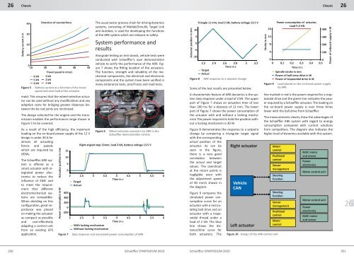
Figure 5 Batt ery current as a functi on of the travel<br />
speed and axial load of the actuator<br />
mold. This ensures that the wheel-selecti ve actuator<br />
can be used without any modifi cati ons and any<br />
adapti on costs for bridging greater distances between<br />
the ti e rod joints are minimized.<br />
The design selected for the engine and the transmission<br />
enables the performance range shown in<br />
Figure 5 to be covered.<br />
As a result of the high effi ciency, the maximum<br />
loading on the on-board power supply of the 12 V<br />
design is under 30 A for<br />
Figure 6 Wheel selecti ve actuators for ARK in the<br />
Schaeffl er demonstrati on vehicle<br />
almost all actuati ng<br />
forces and speeds<br />
Right angled step 13mm, load 2 kN, ba�ery voltage 13.5 V<br />
which are required by<br />
OEMs.<br />
15<br />
The Schaeffl er ARK sys-<br />
10<br />
tem is off ered as a<br />
5<br />
smart actuator with integrated<br />
power elec-<br />
0<br />
tronics to reduce the<br />
infl uence of EMC and<br />
to meet the require-<br />
2 2.5<br />
Target<br />
Actual<br />
3 3.5 4<br />
Time in s<br />
4.5 5 5.5 6<br />
ment that diff erent<br />
electromechanical sys- 600<br />
tems are compati ble. 400<br />
When deciding on this<br />
confi gurati on, great importance<br />
was placed<br />
on making the actuator<br />
200<br />
0<br />
-200<br />
as compact as possible<br />
2 2.5 3 3.5 4 4.5 5 5.5 6<br />
and cost-eff ecti vely<br />
Time in s<br />
adapti ng a control unit<br />
With locking mechanism<br />
from an existi ng EPS<br />
Without locking mechanism<br />
applicati on.<br />
Figure 7 Step response and associated power consumpti on of ARK<br />
2.2 2.4 2.6 2.8 3 3.2<br />
Time in s<br />
Figure 8<br />
Target<br />
Actual<br />
ARK response to a setpoint change<br />
Some of the test results are presented below.<br />
A characteristi c feature of ARK dynamics is the system<br />
step response under a load of 2 kN. The upper<br />
part of Figure 7 shows an actuati on ti me of less<br />
than 200 ms for a distance of 13 mm. The lower<br />
part of Figure 7 shows the power consumpti on of<br />
the actuator with and without a locking mechanism<br />
The power required to hold the positi on without<br />
a locking mechanism is 30 W.<br />
Figure 8 demonstrates the response to a setpoint<br />
change by comparing a triangular target signal<br />
with the corresponding<br />
actual positi on of the<br />
actuator. As can be<br />
seen in the fi gure,<br />
there is a very good<br />
correlati on between<br />
the actual and target<br />
values. The overshoot<br />
at the return points is<br />
negligible even with<br />
the adjustment speed<br />
of 40 mm/s shown in<br />
the diagram.<br />
Figure 9 compares the<br />
simulated power consumpti<br />
on curve for an<br />
actuator with a recirculati<br />
ng ball drive and an<br />
actuator with a trapezoidal<br />
thread under a<br />
load of 2 kN. The blue<br />
line shows the distance/ti<br />
me curve for<br />
both actuators. The<br />
350 Schaeffl er SYMPOSIUM 2010<br />
Schaeffl er SYMPOSIUM 2010 351<br />
Actuator posi�on in mm<br />
10<br />
5<br />
0<br />
-5<br />
-10<br />
Triangle 11 mm, load 2 kN, ba�ery voltage 13.5 V<br />
Right actuator<br />
Vehicle<br />
CAN<br />
Le� actuator<br />
Stroke in mm<br />
16<br />
12<br />
8<br />
4<br />
Power consump�on of actuator,<br />
Load F=2 KN<br />
0<br />
0<br />
0 0,1 0,2 0,3 0,4 0,5<br />
Time in s<br />
Spindle stroke in mm<br />
Power of ball-srew drive in W<br />
Power of trapezoidal drive in W<br />
Chassis<br />
400<br />
300<br />
200<br />
100<br />
Figure 9 Load placed on the on-board power supply<br />
by ARK<br />
Power of onboard supply in W<br />
line marked in red is the power required for a trapezoidal<br />
drive and the green line indicates the power<br />
required by a Schaeffl er actuator. The loading on<br />
the on-board power supply is over three ti mes<br />
lower with the ball drive from Schaeffl er.<br />
The measurements clearly show the advantages of<br />
the Schaeffl er ARK system with regard to energy<br />
consumpti on compared with current soluti ons<br />
from competi tors. The diagram also indicates the<br />
higher level of dynamics available with this system.<br />
Motor<br />
control<br />
Posi�onal<br />
control<br />
Steering<br />
func�on<br />
Steering<br />
func�on<br />
Sensor<br />
management<br />
Posi�onal<br />
control<br />
Motor<br />
control<br />
Figure 10 Design of the ARK control unit<br />
Sensor<br />
management<br />
BLDC motor<br />
and sensor<br />
Power<br />
electronics<br />
Motor control unit<br />
Motor control unit<br />
Power<br />
electronics<br />
BLDC motor<br />
and sensor<br />
<strong>26</strong><br />
<strong>26</strong>