

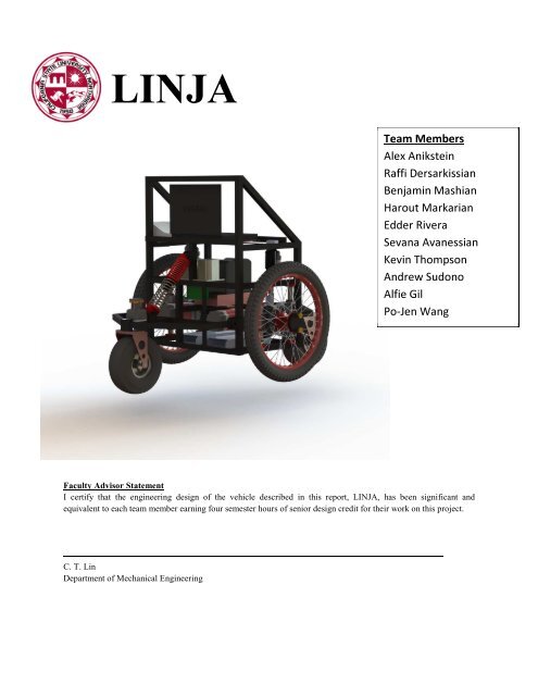
LINJA - Intelligent Ground Vehicle Competition
LINJA - Intelligent Ground Vehicle Competition
LINJA - Intelligent Ground Vehicle Competition

You also want an ePaper? Increase the reach of your titles
YUMPU automatically turns print PDFs into web optimized ePapers that Google loves.
<strong>LINJA</strong><br />
Faculty Advisor Statement<br />
I certify that the engineering design of the vehicle described in this report, <strong>LINJA</strong>, has been significant and<br />
equivalent to each team member earning four semester hours of senior design credit for their work on this project.<br />
C. T. Lin<br />
Department of Mechanical Engineering<br />
Team Members<br />
Alex Anikstein<br />
Raffi Dersarkissian<br />
Benjamin Mashian<br />
Harout Markarian<br />
Edder Rivera<br />
Sevana Avanessian<br />
Kevin Thompson<br />
Andrew Sudono<br />
Alfie Gil<br />
Po-Jen Wang
1. Introduction<br />
The <strong>Intelligent</strong> <strong>Ground</strong> <strong>Vehicle</strong> team of the College of Engineering and Computer Science at California<br />
State University, Northridge (CSUN) is proud to present <strong>LINJA</strong>. <strong>LINJA</strong> is a new and innovative IGV that was<br />
designed, built, and programmed during the 2011-2012 academic year at CSUN. Many of the innovations of <strong>LINJA</strong><br />
were inspired by the success of the previous year’s IGV platform, Red RAVEN, including a flexible frame, drive<br />
wheel decouplers, a custom printed circuit board, a new obstacle and white-line detection algorithm, and a radial<br />
path planning algorithm.<br />
1.1 Team Organization<br />
The IGV project at CSUN is a senior design course that is associated with the Mechanical Engineering<br />
Department and is completed over the course of two semesters. It consists of five sub groups: Mechanical,<br />
Electrical/Power, Cognition/Motion Control, Vision, and Navigation/JAUS (Figure 1.1). Each sub group has a<br />
leader that arranges the organization of the group and enforces open communication with the other groups so that<br />
proper integration is achieved. In addition, three team members are nominated to be a project manager, treasurer,<br />
and secretary of the IGV project. These three members are responsible for organizing team meetings, promotional<br />
events, registration forms, and finances.<br />
1.2 Overall System Integration<br />
Utilizing a Dual-Camera configuration, Laser Range Finder<br />
(LRF), GPS, and compass, <strong>LINJA</strong> scans its immediate environment<br />
and sends the data to Cognition (Figure 1.2). Cognition integrates<br />
the sensory data and evaluates an instantaneous turning radius. This<br />
information is sent Motion Control to evaluate the required angular<br />
velocity and acceleration of the IGV’s motors. Using the on board<br />
Li-Po batteries and mechanical drive wheels, the IGV navigates<br />
itself to a new location in the environment.<br />
Figure 1.1 – CSUN IGV’s Team Organization<br />
Cognition<br />
Perception/Localization<br />
•Vision (Dual-Camera)<br />
•GPS/Compass<br />
•Laser Range Finder<br />
•Integrate Sensory Data<br />
•Evaluate Instantaneous<br />
Radial Path<br />
Environment<br />
Execution<br />
1<br />
•Motion Control<br />
•Power System<br />
•Mechanical<br />
Figure 1.2 – System Integration Flow Chart
2. Mechanical Design<br />
<strong>LINJA</strong> is mechanically designed to navigate through an obstacle course fast and efficiently. <strong>LINJA</strong> is<br />
designed with a flexible frame using an independent drive-wheel suspension system, stabilizing the platform and<br />
minimizing tilt by keeping all wheels in contact with uneven surfaces at all times. The platform is designed to make<br />
the robot very maneuverable, keeping the horizontal center of gravity stabilized over the center of the differential-<br />
drive axle. The vehicle also features a drive axle decoupler to uncouple the drive wheels from the gearbox for ease<br />
of travel. <strong>LINJA</strong>’s platform is designed to be compact, lightweight and weatherproofed with a transparent<br />
polycarbonate shield. <strong>LINJA</strong> also features a Liquid Cooling System to control the ambient temperature on the<br />
underside of the laptop’s hottest area, keeping it at an operational temperature, and has a portable design to be<br />
dismounted when an onboard cooling system is not needed.<br />
<strong>LINJA</strong>’s platform design was inspired by the success of last year’s IGV platform, RED RAVEN,<br />
incorporating a flexible, diamond shaped chassis, shifting the horizontal center of gravity to be located over the<br />
driving axle, resulting in smooth turning. The component layout is lower, more compact, yet still accessible and user<br />
friendly. The Liquid Cooling System controls the ambient<br />
temperature around the laptop.<br />
2.1 Flexible Frame Design<br />
Inspired by last year’s IGV platform, a flexible yet stable<br />
chassis design was desired. During the design process, an<br />
independent drive-wheel suspension system was incorporated as<br />
well as a flexible Front Pivot. <strong>LINJA</strong>’s frame is propelled by two drive wheels (Center) which are able to slide up<br />
and down independently on linear bearings (Yellow). The frame balances itself on two floating wheels (Front and<br />
Rear). The rear wheel is fixed to the main platform (Red) while the Front Pivot (Green) uses a spring/damper to give<br />
the frame balance and flexibility. This configuration allows each wheel to move in the vertical direction<br />
independently of other wheels and the weight of the main platform is distributed equally on all four wheels, giving<br />
the ground vehicle better traction. The independent drive wheel suspension allows the platform to tackle uneven<br />
surfaces while keeping the center of gravity stabilized over the drive axle.<br />
<strong>LINJA</strong>’s chassis is constructed from 1-inch 6063-T6 Aluminum square tubing keeping the frame light weight<br />
yet strong. The frame was TIG welded with sealed corners, maximizing the frame’s strength and minimizing<br />
oxidation.<br />
� 2.1.1 Independent Drive-Wheel Spider Slider Suspension<br />
<strong>LINJA</strong>’s independent drive wheel suspension uses a unique linear bearing<br />
Spider Slider design. The Spider Aluminum pillow-block slides on linear<br />
bearings over two steel tubes to keep the drive wheel stable. The drive wheels<br />
can travel on a stroke length of 3.5-inches to handle a variety of terrain. The<br />
Evolver ISX airshock by Manitou, is used as suspension allowing for an<br />
adjustable spring constant and damping ratio.<br />
Figure 2.1 – Basic schematic of Flexible Frame<br />
2<br />
Figure 2.2 – Spider Slider Suspension
Because the drive wheels and the motors are no longer stationary, a ninety degree gearbox configuration is used<br />
to keep the motors from interfering with components and the frame itself. The gearbox is attached to the Spider<br />
Slider and moves in correspondence with the suspension system.<br />
� 2.1.2 Front Pivot Suspension<br />
Figure 2.3 – Front Pivot Suspension<br />
2.2 Compact Component Layout<br />
The Front Pivot was designed with a clearance to accomidate the motion<br />
rage of the moving motors. It pivots around two pivot points on the frame’s<br />
front end.<br />
The component layout was designed with the<br />
care to keep the CG located directly over the drive train<br />
as low as possible and as close to the center verticle axis<br />
as possible. These two goals will minimize the robot’s<br />
rotational inertia. The third goal was to lower the overall<br />
component layout and minimizing the danger of platform<br />
tipping.<br />
As shown in Figure 2.4, the components were<br />
strategically mounted to avoid interferance with moving<br />
components and to keep the CG very low, yet remain<br />
accessible. The heaviest components are placed at the<br />
The Front Pivot uses a custom built coil-shock configuration using two<br />
springs in series and an adjustable dual-action damper acting as the center<br />
axis. The Front Pivot and the Independent Spider Sliders design complement<br />
each other to provide flexibility and balance to the plaftorm.<br />
Figure 2.4 – Component layout on <strong>LINJA</strong>’s frame<br />
(back view)<br />
bottom and the lighter are placed at the top. The motors, gearboxes, batteries and motor controllers are all located on<br />
the lower level of the robot, while the PCB, laptop, GPS receiver and antenna are located higher up. The laptop is at<br />
a user-friendly accessible level. Overall, the CG is kept low and as close to the central verticle axis of the robot,<br />
allowing <strong>LINJA</strong> to perform quick turns while remaining stable.<br />
2.3 Drive Wheel Decouplers<br />
The drive wheel decouplers are redesigned and<br />
incorporated on <strong>LINJA</strong>. The decouplers allow the robot for easy<br />
transport and to eliminate damage to the drive train. This design<br />
allows the user to decouple the trive train from the drive wheels.<br />
The drive axle is attached to the wheel by means of a<br />
spring plunger mounted on a hub cap. A simple half turn of the<br />
Figure 2.5 – Drive Wheel Decoupling Mechanism<br />
spring plunger disengages the wheel from the axle and allows the wheel to spin freely. This allows the robot to roll<br />
PCB<br />
Motor Controllers<br />
(Gold)<br />
Motors<br />
(Red/black)<br />
Power Converters<br />
Laptop<br />
Li-Po Batteries<br />
CG<br />
3
freely wherever the user needs to go and significantly speeds up testing process and preserves the team members’<br />
strength and energy. If the wheel has to be removed for maintenance or repair, removing a series of three bolts on<br />
the coupler will allow the wheel to be removed completely. This design has proven to be a simple, compact and<br />
effective.<br />
2.4 Liquid Cold-Plate Cooling System<br />
In previous years, the IGV team has experienced multiple<br />
computer crashes due to the laptop overheating. CSUN’s IGV team<br />
had previously used standard 120mm computer fans to provide<br />
cooling. A high performing cooling system was needed and is now<br />
designed that could be integrated with any standard laptop, without<br />
harming any of the electrical components that surround the cooling<br />
system.<br />
Figure 2.6 – Liquid Cold Plate Cooling System<br />
A liquid cold plate, using bendable copper tubing, Aluminum plates and thermal putty was fabricated. A<br />
non-conductive heat transfer fluid called HFE-7100 is the fluid used to control the temperature. The fluid is pumped<br />
through the cold plate by a compact reservoir, radiator and pump. The laptop can be placed on the cold plate and<br />
secured with industrial Velcro. Using this design, the ambient air temperature underneath the laptop’s hottest area<br />
can be controlled. To further ensure a temperature controlled environment, a custom designed vent is attached to the<br />
laptop’s vent area to force hot air out and away from the CPU using forced convection to control the temperature<br />
inside the laptop. This design is portable and can be easily removed from the platform should conditions not require<br />
a cooling system on board.<br />
2.5 Durability and Serviceability<br />
The last major component that is featured on <strong>LINJA</strong> is the polycarbonate weather-proofing. Polycarbonate<br />
is used because of its low weight and transparent properties. Since the material is transparent, all of <strong>LINJA</strong>’s<br />
components are visible despite being covered for protective purposes. Additionally, polycarbonate can simply be<br />
bent with a sheet metal bender; there is no need to heat the material in order to get a clean bend. As a result, the<br />
polycarbonate provides <strong>LINJA</strong> protection from unwanted moisture and provides a clean, professional finish.<br />
The ease of serviceability is a necessary feature that ensures the longevity of <strong>LINJA</strong>’s design. All the<br />
screws that secure the different polycarbonate panels to the frame are medium-sized thumbscrews, allowing any<br />
panel to be removed as needed without the use of any tools. Additionally, once the shielding is removed, all<br />
components are at an accessible reach should maintenance be required. This design allows <strong>LINJA</strong> to be a swift,<br />
maneuverable and compact platform design.<br />
3. Electrical/Power Systems<br />
Increased reliability, reduced weight, and reduced power consumption were all critical goals for this year’s<br />
IGV robot, <strong>LINJA</strong>. As such, many of the designs were inspired by the success of last year’s robot design, RAVEN,<br />
including an improved custom printed circuit board, new Lithium Polymer batteries as the main power source with<br />
4
shorter charging time, an improved motion control utilizing the servo controller’s initialization code and a new<br />
wiring for motors and power system.<br />
3.1 Electrical Configuration<br />
Seeing the success of RAVEN’s electrical configuration,<br />
<strong>LINJA</strong>’s power distribution is directly inspired by last year’s<br />
platform. Like RAVEN, all electrical components tie into <strong>LINJA</strong>’s<br />
power system through a new custom made power distribution<br />
printed circuit board (PCB) (Figure 3.1). Main power is provided<br />
by a set of three series-configured Lithium Polymer batteries.<br />
Battery voltage is converted and regulated by two separate<br />
buck/boost DC to DC converters: 48V DC for the motors and 12V<br />
DC for all other electrical components and provides electrical<br />
isolation between the motors and sensitive electrical sensors. This<br />
allows the motors to function at their ideal operating voltage of 48V DC—which produces higher RPMs.<br />
A printed circuit board provides a more stable and reliable platform compared with using exposed terminals<br />
or wires only. The new PCB for <strong>LINJA</strong> is a 2.3 mm thick durable and high reliability black design consisting of 3<br />
oz/ft 2 of copper for the electrical traces, and is able to handle currents as high as 50 Amps (Figure 3.2). It features<br />
Figure 3.2 - Power Distribution Printed<br />
Circuit Board<br />
3.2 Power Analysis<br />
LED Light-Bar indicators emitting soft but bright colors indicating if current<br />
is flowing through an electrical device. Due to the new circuit design, the<br />
PCB copper trace density has increased dramatically which subsequently<br />
lead to a double layer design. Additionally, more details to the PCB silk<br />
layer (printed electrical symbols and legend) has been applied, thus making<br />
the mounting of electronic/electrical components easier. Finally, a fuse<br />
malfunction circuit detector is included for every fuse that protects each<br />
electronic device.<br />
<strong>LINJA</strong>’s power consumption analysis was<br />
conducted at nominal and extreme loads (Table 3.1).<br />
The nominal load was evaluated when <strong>LINJA</strong> traveled<br />
at 1 mph. The extreme load was evaluated at 6 mph<br />
which, based on the data obtained, requires the most<br />
power consumption (1332 watts). To prevent power<br />
outrage, new high energy density Lithium Ion Polymer<br />
(LiPo) battery packs were built (four packs in total).<br />
Each battery pack will provide a nominal and extreme<br />
Table 3.1: Power Consumption<br />
Type of Load<br />
Nominal<br />
Power (W)<br />
Maximum<br />
Power (W)<br />
Total Base Load 169<br />
Transient Motor Load 720 1000<br />
Speed Indicator 24 30<br />
Total Load 913 1199<br />
Total with 90%<br />
DC/DC Efficiency<br />
Figure 3.1 – <strong>LINJA</strong>’s Power System<br />
1014 1332<br />
voltage of 15 and 16.8 respectively. Each LiPo battery pack will yield a minimum of 450 watts and a maximum of<br />
504 watts. Internally, each LiPo battery pack is protected against over current, over voltage, deep discharge (under<br />
5
voltage) and over heat—total output current is limited to 30-Amps per pack. A series configuration of three LiPo<br />
battery packs was chosen to provide the required power consumption. This assures that <strong>LINJA</strong> receives the<br />
necessary power under nominal and extreme conditions.<br />
3.3 Emergency Stop<br />
The emergency stop system on <strong>LINJA</strong> makes use of the motor<br />
controller’s built-in stop conditions by bringing the robot to a controlled<br />
and safe stop. Two systems, a mechanical pushbutton stop and a wireless<br />
remote stop, are individually used. When activated, the motor<br />
controllers’ input/output pins receive a logic HIGH +5V signal and when<br />
not activated, a logic LOW is received. To ensure that the wireless stop<br />
and the mechanical stop do not conflict with each other, a series<br />
configuration is used as a safety design.<br />
3.4 Arduino Autonomous Light and Speed Meter<br />
<strong>LINJA</strong>’s electronic design includes the Arduino Micro-<br />
Controller Unit (MCU) to activate the autonomous light. In addition, the<br />
Arduino MCU is used to provide a visual analogous LED speed<br />
indicator. The speed indicator is interfaced with an LED Integrated<br />
Circuit Driver (LM3914) to adjust the LEDs based on <strong>LINJA</strong>’s current<br />
speed. The LabVIEW code to perform these two tasks under the<br />
Arduino MCU is short and provides real time code execution. This<br />
facilitates <strong>LINJA</strong> to comply with the IGV 2012 rules, <strong>LINJA</strong> must<br />
indicate when it is powered on through the use of a solidly lit light.<br />
Specifically, when the IGV is autonomously running, the light must<br />
begin flashing.<br />
4. Vision<br />
<strong>LINJA</strong> features a Dual-Camera configuration allowing for<br />
a real-time video feed of wide-angle images to provide boundary<br />
line and obstacle data ahead of the IGV. The Dual-Cameras are<br />
positioned on the IGV to provide the most useful boundary line<br />
and obstacle image data for the Vision algorithms to process, and<br />
oriented to allow for the dual images to be properly combined. The<br />
camera and accompanying Vision system are necessary to isolate<br />
the environmental data that cannot be detected by the other sensors of the IGV. Additional improvements over<br />
previous Vision systems allow <strong>LINJA</strong> to not only detect obstacles from the surroundings, but also to distinguish<br />
between different types of obstacles and generate a color map showing similar obstacles of different colors.<br />
6<br />
Figure 3.3 – The push button (top) and<br />
wireless (bottom) e-stops utilized on <strong>LINJA</strong><br />
Figure 3.4 – Arduino autonomous light<br />
activator and speed meter.<br />
Figure 4.1 – Sony Handycam (left) and Sony VCL-<br />
HA07A lens adapter (right)
4.1 Camera Hardware<br />
The Dual-Cameras selected for <strong>LINJA</strong> are two identical DCR-HC28 miniDV Sony Handycams. These<br />
camcorders are used for their on-board light and white balance to help the Vision system dynamically adapt to<br />
changing light conditions without the need for additional light sensors. Cameras with the IEEE1394 data transfer<br />
interface were chosen for ease of use and compatibility with almost any computer setup. Two cameras are used<br />
instead of one to increase the field of view without facing the significant distortion of a single camera with a very<br />
wide angle lens. To further enhance the data acquisition, Sony VCL-HA70A wide angle lens adapters with a factor<br />
if 0.7X view angle increase are used on each camera, providing a 52 degree vertical 76 degree horizontal view angle<br />
for each camera. The lens adapters shown in Figure 4.1 provide a noticeable increase to the view angle of each<br />
camera, and because the view angle improvements are distributed between the two cameras, the overall view angle<br />
is enhanced without a significant increase in distortion.<br />
In order to provide the right amount of<br />
separation and overlap between the two camera<br />
feeds for combining into a single image, the Dual-<br />
Cameras are mounted next to each other with each<br />
camera angled outward 60 degrees from the IGV’s<br />
forward centerline field of view, as shown in<br />
Figure 4.2. Because the cameras are angled<br />
downward to avoid direct sunlight, perspective<br />
correction is applied to the projected image, along<br />
with rotation and translation, to provide an image<br />
with accurate real-world coordinates of the environment.<br />
4.2 Vision Software<br />
Figure 4.3 – Color Edge Detection<br />
Figure 4.2 – Combined projected view for Dual-Camera<br />
configuration<br />
The main goal for improving the Vision algorithms over previous<br />
versions is to not only isolate anything that would be considered an obstacle<br />
by the IGV, but to better differentiate between the different types of obstacles<br />
in the environment. While previous versions of the Vision algorithm were<br />
focused more on isolating boundary lines, BGL Line Detection and Color<br />
Edge Detection allow for boundary lines, barrels, flags and different colored<br />
obstacles to be identified not only from the environment, but also from each<br />
other, based on color values and ranges using the RBG and HSL color scales.<br />
The Grass Filter and Canny Edge Detection provide a preliminary analysis to<br />
grayscale input images for the Dual Camera setup on <strong>LINJA</strong>. Calibrated<br />
ranges of the RBG and HSL color scales along with size analysis and noise<br />
filtering are used to isolate different colored flags. The Grass Filter is used to<br />
darken a grayscale input image to reduce noise in grassy terrain while maintaining contrast between white boundary<br />
lines and the rest of the image. Canny Edge Detection is used to enhance the boundary lines as well as detect the<br />
7
edges of obstacles in the image. These two steps provide the initial removal of unwanted noise and extraneous data<br />
for the rest of the vision algorithms.<br />
4.3 Color Edge Detection<br />
Color Edge Detection is a new vision algorithm developed for differentiating between different types of<br />
objects in the environment based on changing color values across a color input image. The first step of Color Edge<br />
Detection is to remove as much unwanted data as possible using the Grass Filter and then apply Canny Edge<br />
Detection to find the edges of any objects in the image. Canny Edge Detection uses contrast changes in a grayscale<br />
image to highlight all the edges, but does not provide any information as to where those edges are located. To find<br />
the edge locations, Color Edge Detection scans the image along a line for each angle increment specified. At each<br />
angle along the line that an edge is detected, a check is made along the line on both sides of the edge for a change in<br />
color. Several color samples on each side of the edge are used to determine average color values. Once enough line<br />
samples are taken, the average color values for a section of the image, instead of just along each line, can be<br />
determined. Based on the average color values on either side of the edge, that part of the image can be distinguished<br />
as a specific type of object in the environment.<br />
The sample camera image in Figure 4.3 shows how the color image seen by the camera is checked along a<br />
line at incremental angles. For the orange barrel, the edge locations in red are found based on the average color<br />
value changes from green to orange and orange to green along each line. The vertical line shows several color<br />
samples taken, and the blue and yellow sample groups show that a separate color edge is detected for each sample<br />
group along the line.<br />
Similarly, it can be seen in<br />
Figure 4.4 the main steps leading up to<br />
color edge detection and their results. The<br />
input image is grayscaled and preliminary<br />
filters are applied. Then Canny Edge<br />
Detection is used to find all of the edges<br />
in the image. The last step is for the Color<br />
Edge Detection algorithm to scan the<br />
color image as described in Figure 4.3,<br />
and detect color changes. Step 4 shows<br />
the edge of the grass as green and the edge<br />
of the cement path as white. Based on the<br />
color of the edges, the IGV can determine<br />
the white edge as a boundary for the grass<br />
field.<br />
Step 1: Source Image Step 2: Grayscale Image<br />
Step 3: Canny Edge Detection Step 4: Color Edge Detection<br />
Figure 4.4 – Color Edge Detection in action<br />
8
5. Navigation/JAUS<br />
5.1 Navigation Hardware<br />
<strong>LINJA</strong> uses a NovAtel SPAN (Synchronized Position Attitude &<br />
Navigation) system for navigation. This system consists of a GPS-702L<br />
antenna (Figure 5.1a) with a ProPak-LB plus receiver (Figure 5.1b).<br />
OmniSTAR provides the IGV an HP differential GPS service, which<br />
increases the accuracy to 0.1 meters. The ProPak receiver merges the GPS<br />
and the compass data and provides latitude, longitude data to the<br />
computer. The receiver interfaces with the computer via an RS232 serial<br />
connection at a baud rate of 460.8kBd while updating at 40 Hz.<br />
<strong>LINJA</strong>’s True North Revolution 2X digital compass (Figure 5.1c) identifies heading, pitch, and roll which<br />
is used primarily to guide <strong>LINJA</strong>. This compass provides heading data at 31.25 Hz, with an accuracy of ±0.5°. It<br />
communicates with the computer via an RS232 serial connection<br />
5.2 Navigation Software Strategy<br />
The overall software strategy for the Navigation part is shown in Figure 5.2. It begins by accepting a list of<br />
waypoints along with the location and direction data. For a large number of waypoints, approximation methods are<br />
used to efficiently find the shortest path. However, due to the fairly small number of waypoints a brute force<br />
algorithm was used to quickly implement a solution. The Navigation program chooses the shortest total distance<br />
after iterating through every possible path. An ordered list is created, and the vehicle uses the first point as its goal.<br />
The program continuously calculates the<br />
bearing and distance between the vehicle’s current<br />
position and its current goal waypoint using the<br />
Haversine and Great Circle formulas. The vehicle’s<br />
compass heading is compared to the bearing in order<br />
to find the relative direction to the goal (i.e. the goal<br />
angle). The goal distance is constantly monitored, and<br />
when it becomes 1 meter, or half the radius given in<br />
the IGVC rules, the current waypoint can be checked off. This angle and position are provided to Cognition, for path<br />
planning purposes.<br />
5.3 Joint Architecture for Unmanned Systems (JAUS)<br />
JAUS is a protocol designed by the Department of Defense to facilitate the communication and cooperation<br />
between autonomous systems. The purpose of the JAUS Challenge is to program a platform for remote<br />
communication between the users and the robot. In order to ease management of the design process the set of used<br />
commands are split into two categories: Non-Navigation and Navigation. The Non-Navigation commands cover<br />
Transport Discovery, Capabilities Discovery, and System Management (i.e. commands not related to the navigation<br />
process). Since these commands are one-time linear processes, they are written within the main JAUS program and<br />
put under an array of cases to perform upon receiving the commands. On the other hand, Navigation commands<br />
(a)<br />
(b) (c)<br />
9<br />
Figure 5.1 – Navigation hardware used on<br />
<strong>LINJA</strong> includes an (a) antenna, (b)<br />
receiver, and (c) compass.<br />
Figure 5.2 – Navigation software strategy flow chart
cover Velocity State Report, Position and Orientation Report, and Waypoint Navigation (i.e. commands that relate<br />
to navigation and may need to recur upon request). Considering the complexity and recurring nature, these<br />
commands are modularized and then combined into the main program in both case structures and sequential<br />
structures, depending on the application. This strategy eases the management and debugging of recurring, non-<br />
linear processes.<br />
As shown in Figure 5.3, the received signal is sent to two separate areas of the program: one to non-<br />
navigation queries to report the received information, and to local position and waypoint settings. The position and<br />
waypoint information is relayed to navigation queries, where it simultaneously executes the navigation data and<br />
reports information.<br />
Signal Receiving<br />
Set Local Position<br />
6. Cognition/Motion Control<br />
The Cognition and Motion Control System is responsible for the algorithmic<br />
calculations to decide upon and control the optimal path for <strong>LINJA</strong>. The main three<br />
inputs to these algorithms are Navigational Waypoints, Vision Data, and a polar<br />
histogram generated by a Scanning Laser Rangefinder. For <strong>LINJA</strong>, the UTM-30LX<br />
was selected, as shown in Figure 6.1. To attain the maximum amount of useful<br />
information, the sensor is placed centered on the robot directly above the front caster<br />
wheel. Although it has a scanning range of up to 270° and an angular resolution of<br />
0.25°, <strong>LINJA</strong> samples only 180° of data at an angular resolution of 1°. This allowed for the best compromise<br />
between informational accuracy and processing time, as benefits noticed from increasing the resolution or width of<br />
the scan range were minimal. The LRF is connected via USB 2.0 to an HP EliteBook 8560p running LabVIEW, in<br />
which the rest of the software is programmed, and is mounted at the lower front of the robot (right behind the IGV’s<br />
front caster wheel).<br />
6.1 Cognition Software Strategy<br />
The approach used by the IGV approximates the true movement of the robot by basing its paths on<br />
instantaneous turning radii, rather than vectors. This allows the robot to more precisely navigate the course, as the<br />
true path of the robot will be a single, curvilinear path, rather than a series of shorter, straight vectors. This general<br />
algorithmic approach has been named RPH with OPID, or Radial Polar Histogram with Optimal Path Interference<br />
Detection.<br />
Non-Navigation<br />
Queries<br />
Set Waypoints<br />
Figure 5.3 – JAUS software strategy flow chart<br />
Queries<br />
Reporting<br />
Navigation<br />
Queries<br />
Execute<br />
Navigation<br />
Figure 6.1 – UTM-30LX<br />
10
Once the laptop obtains data from both the LRF and the Vision system, it converts all of the data into a<br />
single, combined Cartesian map of the various obstacles. The map is then filtered to neglect the data that are not<br />
within a controlled range. The data is then grouped, allowing the robot to determine which areas are blocked off to<br />
the robot. The previous grouping algorithm used on last year’s platform, RED RAVEN, is optimized, reducing the<br />
overall RPH processing time by over 20% on average and ignoring thousands of unnecessary calculations per<br />
iteration. The grouped data points are then passed through another algorithm which assumes that each group<br />
represents a curved surface, such as a barrel, as shown in Figure 6.2. This algorithm returns the radius of the group,<br />
along with the coordinates corresponding to its center. If the radius is within a calibrated threshold, it will identify<br />
the group as a barrel, allowing the program to store only its center and radius data, rather than all of the individual<br />
data points which define it.<br />
Figure 6.2 – Obstacles identified as cylinders. Figure 6.3 – Left and Right radial paths. Note the<br />
offset from the true exterior radii for padding.<br />
After the groups have been clearly defined based on the dimensions of the IGV, the current navigational<br />
heading is compared to the various open paths to decide which opening will lead the robot to the navigational<br />
waypoint along the most direct path. Once the desired path is found, the IGV determines the leftmost and rightmost<br />
radii that the robot could safely travel without touching obstacles, as<br />
shown in Figure 6.3, and selects the ideal radius between the two to lead<br />
the robot towards its destination.<br />
However, as the robot bases its path selection purely on the<br />
edges of the obstacles, there was a potential for the robot to still decide<br />
on a path that intersected an obstacle in some configurations. As such,<br />
OPID was added as a safety check before the optimal path was finalized.<br />
OPID compares the projected radii of the edges of the robot as it executes<br />
its predicted turn to the original histogram. If OPID detects any obstacle<br />
that would intersect the location of the robot at a close point along its<br />
path, it forces the data filter range to be reduced to recalculate a clear<br />
path base on the intersecting obstacle. This is demonstrated in Figure 6.4.<br />
Finally, RPH will establish a theoretical location of the robot at<br />
a future time if it were to follow the path and then performs the entire set<br />
of calculations again, thus allowing the robot to determine its future<br />
location. This information is then passed on to Motion Control.<br />
11<br />
Figure 6.4 – When OPID detects obstacle<br />
interference, it reduces the data filter<br />
range to recalculate a path.
6.2 Motion Control Software Strategy<br />
Motion Control receives the turning radius desired by Cognition and sends the appropriate signals to the<br />
motors to execute the path. It determines the ideal proportionality between the motors to allow the robot to turn with<br />
a given radius. Then, based on predefined minimum and maximum speed values, along with the combined field<br />
histogram, it determines the ideal overall speed for the robot. In this way, if the histogram is particularly cluttered<br />
with obstacles, the robot will instinctively move more slowly, allowing for tighter control, and if the histogram is<br />
clear, the robot is free to accelerate to a faster pace.<br />
Additionally, by looking at the future location of the robot, Motion Control can dynamically calculate the<br />
ideal robot acceleration. This helps prevent jarring stops and allows for a much smoother transition between<br />
crowded and open areas.<br />
6.3 Mapping<br />
Due to the optimized data storage, allowing three numbers<br />
to represent a large volume of data points, the mapping algorithms<br />
allowed the IGV to track its motion as it traverses the course, while<br />
also storing the locations of any obstacles it encounters along the<br />
way. This Global Map can be used for debugging purposes, as<br />
operators can view the robot’s path and the data which led it to its<br />
decision.<br />
Additionally, as each set of data points is stored as a single<br />
circle, a real-time 3D representation of what the IGV sees can be<br />
generated, as shown in Figure 6.5. This innovative mapping<br />
technique allows users to compare what the robot perceives to the<br />
obstacles surrounding it quickly and easily on a clear and user-<br />
friendly display.<br />
6.4 Specific Obstacle Avoidance<br />
Despite the realistic path planning that RPH can perform, some configurations of obstacles can be<br />
problematic. A perfect example is when the robot finds itself trapped in a dead end. Whenever a dead end is<br />
detected, the robot will immediately stop and perform a zero radius turn, allowing it to scan its surroundings for an<br />
exit. Once an opening is detected, the original RPH algorithm would begin to execute the radial path towards the<br />
opening without taking into account that the wheels were travelling in opposite directions as the robot turned. This<br />
meant that the robot would frequently miss the turn as one wheel was much farther from its ideal velocity than the<br />
other. To handle this issue, a Velocity Control Factor, or VCF was added in. This factor begins at 0 and slowly rises<br />
to 1. The desired speeds sent to the motors are multiplied by this VCF, allowing the motors a chance to accelerate<br />
simultaneously and giving more precise control.<br />
12<br />
Figure 6.5 – GUI of IGV during trial run. The<br />
orange cylinders represent barrels perceived by<br />
the IGV.
Figure 6.6 – The previous method (left) would trap the IGV. By considering the presence of the white<br />
line, the IGV only draws one ghost line, forcing it towards the correct path (right).<br />
Another problematic configuration is the channels of flags shown in Figure 6.6. Previous IGV entries<br />
would draw an imaginary boundary line, or ghost line, from the flag to the side of the robot, forcing the robot to<br />
travel to the opposite side of the flag. However, if the robot were to approach the wrong channel, this method would<br />
create a dead end directly in front of the robot. To fix this, a specific case was added that does not create a ghost line<br />
if the specific flags are near a white line—as such, only the ghost line from the center row of flags is drawn,<br />
blocking the incorrect path and leading the robot in the correct path.<br />
6.5 System Integration<br />
Figure 6.7 shows the process that <strong>LINJA</strong> uses for the complete integration of all onboard systems. <strong>LINJA</strong><br />
uses a LRF and a Dual-Camera configuration to scan for objects and line boundaries in the robot’s environment. It<br />
also has a GPS onboard that gathers waypoint locations and the robot’s heading information. These sensor data are<br />
sent to Cognition for comparison and ghost line generation. Cognition creates a local map and, by evaluating the<br />
open blocks in a selected area, a desired radius is determined and is sent to Motion Control for execution. While<br />
Motion Control moves the robot, it provides continuous feedback of the robot’s predicted turning radius and velocity<br />
to Cognition for determining the ideal motor acceleration for each wheel that optimizes the smoothness of the<br />
robot’s motion. The sensors then rescan the environment and the process is re-iterated again.<br />
Figure 6.7 –System Integration flow chart<br />
13
7. Overall System Performance<br />
<strong>LINJA</strong> is a unique IGV that has been designed, built,<br />
and programmed to achieve efficient maneuverability, high<br />
speeds, precise path planning, and near- perfect obstacle<br />
avoidance. The overall performance parameters of <strong>LINJA</strong> are<br />
shown in Table 7.1. Due to a light weight flexible chassis, the use<br />
of a 48V DC/DC converter, and three series-configured Lithium<br />
Polymer batteries, the motors are able to drive the IGV to a top<br />
speed of 6.5 mph on pavement and 5.5 mph on grass, depending on terrain conditions. With a faster processing time,<br />
the reaction rate of <strong>LINJA</strong> is clocked at around 100ms when using the 3D mapping capabilities and 40ms with them<br />
disabled. Due to the IGV’s Spider Slider Suspension frame, <strong>LINJA</strong> is capable of tackling uneven surfaces and<br />
climbing 30 o ramps. The three series-configured Lithium Polymer batteries provide enough power to run <strong>LINJA</strong> at<br />
top speed for 4 hours. Under normal operating conditions, the battery life is approximately 9 hours. The LRF detects<br />
obstacles up to 8 meters away, and the Dual-Camera configuration detects obstacles and lines up to 7 meters away.<br />
Lastly, through the use of a Differential GPS system (DGPS), the waypoint accuracy is approximately 10 cm.<br />
8. Appendix<br />
8.1 Total Cost Estimate and Person-Hours<br />
The total retail cost of all the materials and components utilized on <strong>LINJA</strong> is approximately $48,144.87<br />
(Table 8.1). The most expensive components contributing to the cost are the GPS Antenna/Receiver, batteries,<br />
Spider Slider Assembly and LRF. However, we’ve received donations that made this year’s platform possible. Aero<br />
Seating Technologies graciously donated both Spider Slider Assemblies (which we slightly modified to fit <strong>LINJA</strong>’s<br />
body) saving a significant amount of the team’s budget. Most other components were reused from previous<br />
platforms and additional discounts were obtained when purchasing new vision equipment. Overall, the total<br />
purchase cost for <strong>LINJA</strong> is approximately $52,000. However, since many of the components were recycled from the<br />
previous IGV, the total cost to the team in constructing <strong>LINJA</strong> this year is approximately $13,018.13. In addition,<br />
each of the students spent approximately 26 hours a week on the IGV project. Thus, during the 2011-2012 academic<br />
year, each of the students spent about 1040 hours working on <strong>LINJA</strong> (Table 8.2).<br />
14<br />
Table 7.1 – <strong>LINJA</strong>’s Performance<br />
Parameter Value<br />
Top Speed 6.5mph<br />
Reaction Time 40-100ms<br />
Ramp Climbing 30 o<br />
Battery Life 4-9 hrs<br />
Obstacle Detection Distance 8m<br />
Waypoint Accuracy 10cm
Table 8.1 - Total Cost Estimate of <strong>LINJA</strong><br />
Components Retail Cost<br />
Cost at Time<br />
of Purchase<br />
Cost to Team<br />
This Year<br />
Hokuyo LRF $5,400.00 $5,400.00 $5,400.00<br />
Nuggets $1,600.00 $1,600.00 $0.00<br />
Motors/Motor Cables $2,437.00 $2,437.00 $0.00<br />
Clamp $200.00 $200.00 $0.00<br />
Black Pack Batteries $4,150.00 $4,150.00 $2620.16<br />
HP Elitebook 8560p $2,100.00 $2,100.00 $2,100.00<br />
48V/12V DC/DC Converters $450.00 $411.50 $411.50<br />
Printed Circuit Board $36.00 $36.00 $36.00<br />
Misc. Electrical Items $500.00 $500.00 $500.00<br />
GPS Receiver/Antenna $28,079.00 $8,500.00 $0.00<br />
Digital Compass $467.00 $397.00 $0.00<br />
FireWire ExpressCard $38.21 $38.21 $38.21<br />
Sony Handycam Camcorder $420.00 $324.98 $324.98<br />
Sony Wide Conversion Lens $100.00 $66.60 $66.60<br />
Gearboxes $1,204.50 $1,204.50 $0.00<br />
Driving Wheels/Rims $200.00 $195.88 $195.88<br />
Spider Sliders/Bearings $2,500.00 $2,500.00 $0.00<br />
Caster Wheels $80.00 $76.24 $76.24<br />
Metal Materials $133.16 $133.16 $133.16<br />
Misc. Mechanical Materials $159.64 $159.64 $159.64<br />
Airshocks/Springs/Dampers $849.95 $712.28 $712.28<br />
Cooling System $522.62 $522.62 $243.48<br />
Total $51,627.08 $31,665.61 $13,018.13<br />
Table 8.2 - Hours worked per student<br />
Time Period Hours<br />
In Class (per week) 12<br />
Out of Class (per week) 14<br />
Total Per Week 26<br />
2011-2012 Academic Year 1040<br />
15


