

Socomec UL General Catalog

Create successful ePaper yourself
Turn your PDF publications into a flip-book with our unique Google optimized e-Paper software.
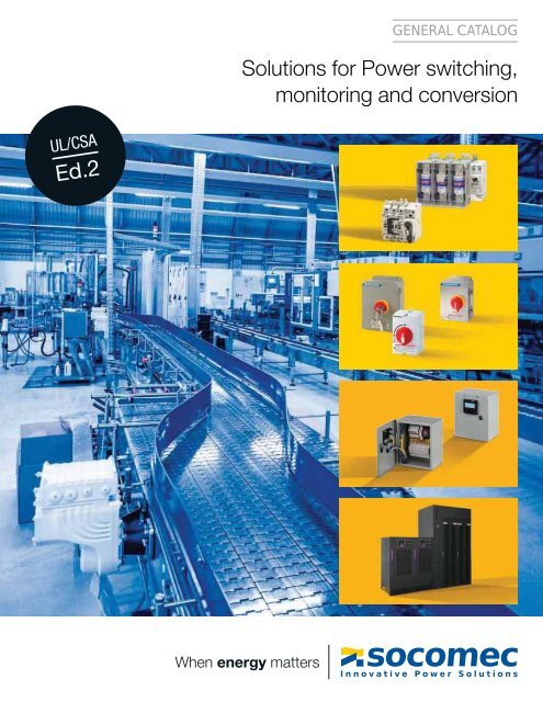
GENERAL CATALOG<br />
Solutions for Power switching,<br />
monitoring and conversion<br />
<strong>UL</strong>/CSA<br />
Ed.2<br />
When energy matters
Contents<br />
An independent manufacturer ................................... p. 4<br />
Your energy, our expertise ...................................... p. 5<br />
Adapted solutions ............................................. p. 6<br />
Expert Services your partner .................................... p. 8<br />
A cutting-edge laboratory ....................................... p. 9<br />
References list ................................................ p. 294<br />
Non-fusible disconnect switches<br />
Non-fusible disconnect switches for machine control<br />
and power distribution .......................... p.<br />
11<br />
SIRCO M<br />
<strong>UL</strong> 508<br />
p. 14<br />
Photovoltaic range<br />
Photovoltaic non-fusible disconnect switches,<br />
fuse bases and fuses ........................... p.<br />
36<br />
SIRCO MC PV<br />
<strong>UL</strong> 508i<br />
p. 42<br />
Fusible disconnect switches<br />
Fusible disconnect switches,<br />
fuses and fuse bases ........................... p.<br />
91<br />
FUSERBLOC<br />
<strong>UL</strong><br />
p. 94<br />
Transfer switches<br />
Manual & non-automatic transfer switches .......... p. 121<br />
SIRCOVER<br />
<strong>UL</strong> 8 008<br />
p. 124<br />
Enclosures & accessories<br />
All the components to facilitate<br />
the use of your electrical equipment ............... p.<br />
147<br />
Rigid copper bars<br />
p. 148<br />
Integrated products & solutions<br />
Enclosed protection and switching devices ......... p. 177<br />
Enclosed disconnect<br />
switches<br />
p. 178<br />
Metering, monitoring & power quality<br />
Measurement and monitoring system,<br />
multifunction meters & supervision software . ........ p.<br />
187<br />
DIRIS Digiware<br />
p. 204<br />
Energy storage & UPS solutions<br />
UPS & Energy Storage Solutions .................. p. 285<br />
SUNSYS PCS 2<br />
p. 286<br />
2 <strong>General</strong> <strong>Catalog</strong> <strong>UL</strong>/CSA Ed. 2
SIRCO M<br />
<strong>UL</strong> 98<br />
p. 22<br />
SIRCO<br />
<strong>UL</strong> 98<br />
p. 28<br />
TVSS<br />
Surge switch<br />
p. 36<br />
SIRCO PV<br />
<strong>UL</strong> 98B<br />
p. 50<br />
SIRCO PV<br />
<strong>UL</strong> 98B compact<br />
p. 76<br />
RM-RMS<br />
p. 108<br />
RM CC<br />
p. 114<br />
ATyS<br />
<strong>UL</strong> 1008<br />
p. 136<br />
Flexible<br />
copper bars<br />
p. 150<br />
Insulated<br />
Busbar<br />
copper braids<br />
supports<br />
p. 152 p. 154<br />
DIRIS<br />
DigiBOX<br />
p. 246<br />
TE / TR/ iTR / TF<br />
current sensors<br />
p. 220<br />
DIRIS G<br />
DIRIS A<br />
DIRIS B<br />
RS485 to Ethernet<br />
p. 242 p. 248 p. 272<br />
SUNSYS<br />
NETYS<br />
Xtend ESS<br />
NETYS PL-120V<br />
RT-120V<br />
p. 288 p. 290 p. 292<br />
<strong>General</strong> <strong>Catalog</strong> <strong>UL</strong>/CSA Ed. 2<br />
3
For the energy performance<br />
of your critical installations<br />
The benefit of a specialist<br />
innovative!<br />
Since its foundation more than 9years<br />
ago, SOCOMEC continues to design and<br />
manufacture its core products in Europe.<br />
Notably solutions for its primary mission: the<br />
availability, control and safety of low voltage<br />
electrical networks.<br />
As an independent manufacturer, the Group<br />
is committed to constant innovation to<br />
improve the energy performance of electrical<br />
installations in infrastructures as well as<br />
industrial and commercial sites.<br />
Throughout its history, SOCOMEC has<br />
constantly anticipated market changes<br />
by developing cutting-edge technologies,<br />
providing solutions that are adapted to<br />
customer requirements and fully in keeping<br />
with international standards.<br />
“Optimizing the performance of your<br />
system throughout its life cycle” - this is<br />
the commitment carried out every day by<br />
the SOCOMEC teams around the world,<br />
wherever your business islocated.<br />
SYDIV 419 A<br />
1<br />
independent<br />
manufacturer<br />
37,675 ft 2<br />
of test platforms<br />
One of the leading<br />
independent power<br />
testing labs in Europe<br />
10 %<br />
of turnover<br />
invested<br />
in<br />
Always at the<br />
cutting-edge of<br />
technology for<br />
innovative, highquality<br />
products<br />
70,000<br />
on-site<br />
interventions<br />
per year<br />
Nearly 400 experts<br />
in commissioning,<br />
technical audit,<br />
consultancy and<br />
maintenance<br />
4 <strong>General</strong> <strong>Catalog</strong> <strong>UL</strong>/CSA Ed. 2
Your energy, our expertise<br />
Power conversion<br />
Ensuring the availability and storage of<br />
high quality power<br />
With its wide range of continuously evolving<br />
products, solutions and services, <strong>Socomec</strong><br />
are recognized experts in the cutting-edge<br />
technologies used for ensuring the highest<br />
availability of the electrical power supply to<br />
critical facilities and buildings, including:<br />
static uninterruptible power supplies (UPS)<br />
for high-quality power free of distortions<br />
and interruptions occurring on the primary<br />
powersupply,<br />
changeover of static, high availability<br />
sources for transferring the supply to an<br />
operational back-up source,<br />
permanent monitoring of the electrical<br />
facilities to prevent failures and reduce<br />
operating losses,<br />
energy storage for ensuring the proper<br />
energy mix of buildings and for stabilization<br />
ofthe power grid.<br />
© Datadock<br />
Power switching<br />
Managing power and protecting persons<br />
and facilities<br />
Active in the industrial switching market since<br />
its foundation in 1922, <strong>Socomec</strong> is today an<br />
undisputed leader in the field of low voltage<br />
switchgear, providing expert solutions that<br />
ensure:<br />
isolation and on load breaking for the most<br />
demanding switching applications,<br />
continuity of the power supply to electrical<br />
facilities via manual remotely operated<br />
or automatic transfer switching equipment.<br />
protection of persons and assets via fusebased<br />
and other specialist solutions.<br />
APPLI 575A<br />
Power monitoring<br />
Managing the energy performance of<br />
buildings<br />
<strong>Socomec</strong> solutions, from current sensors<br />
through to a wide choice of innovative<br />
scalable software packages are driven by<br />
experts in energy performance. They meet the<br />
critical requirements of facility managers and<br />
operators of commercial, industrial and local<br />
authority buildings for:<br />
measuring energy consumption, identifying<br />
sources of excess consumption and raising<br />
the awareness of occupants about their<br />
impact,<br />
limiting reactive energy and avoiding the<br />
associated tariff penalties,<br />
using the best available tariffs, checking<br />
utility bills and accurately distributing energy<br />
billing among consumer entities,<br />
monitoring and detecting insulation faults.<br />
APPLI 571A<br />
Expert Services<br />
<br />
energy<br />
<strong>Socomec</strong> is committed to delivering a wide<br />
range of value-added services to ensure<br />
the reliability and optimization of end-users’<br />
equipment:<br />
prevention and service operations to lower<br />
the risks and enhance the efficiency of<br />
operations,<br />
measurement and analysis of a wide<br />
range of electrical parameters leading to<br />
recommendations for improving the site’s<br />
power quality,<br />
optimization of the total cost of ownership<br />
and support for a safe transition when<br />
migrating from an old to a new generation of<br />
equipment,<br />
consultancy, deployment and training from<br />
the project engineering stage through to final<br />
procurement,<br />
performance assessment of the electrical<br />
installation throughout the life cycle of the<br />
products via analysis of data transmitted by<br />
connected devices.<br />
APPLI 760A<br />
<strong>General</strong> <strong>Catalog</strong> <strong>UL</strong>/CSA Ed. 2<br />
5
Adapted solutions<br />
to meet your energy objectives<br />
SMART BUILDINGS<br />
Reducing your energy bills and energy dependency<br />
HEAVY<br />
Controlling and securing your ene<br />
FUSERBLOC fuse<br />
combination switches<br />
DIRIS Digiware<br />
multi-circuit<br />
measurement<br />
system<br />
ENERGY<br />
MANAGEMENT<br />
software<br />
packages<br />
ATyS<br />
non-automatic<br />
transfer switch<br />
SUNSYS XTEND ESS<br />
NAVAL SHIPS<br />
Energy conversion in environments with harsh restrictions<br />
SIRCOVER<br />
Manually operated<br />
transfer switch<br />
SIRCO<br />
Disconnect switches<br />
SHOPPING MALLS<br />
Assuring your business continuity and visitor safety<br />
DIRIS DigiBOX<br />
enclosed single<br />
& multi-point<br />
metering solution<br />
SIRCOVER<br />
Manually operated<br />
transfer switch<br />
SUNSYS<br />
XTEND ESS<br />
NETYS PL-120 &<br />
NETYS RT-120<br />
Single Phase<br />
UPS<br />
PUBLIC DISTRIBUTION AND SMART GRID<br />
Helping you to meet the challenge of energy demand and response<br />
RENEWABLE ENERGY<br />
Guaranteeing the performance, security and<br />
durability of your photovoltaic facilities<br />
SUNSYS<br />
XTEND ESS<br />
SIRCO<br />
Disconnect switches<br />
DIRIS DigiBOX<br />
enclosed single & multi-point<br />
metering solution<br />
SUNSYS<br />
XTEND ESS<br />
Disconnect switches<br />
for photovoltaic<br />
applications<br />
DIRIS Digiware<br />
DC multi-circuit<br />
measurement<br />
system<br />
6 <strong>General</strong> <strong>Catalog</strong> <strong>UL</strong>/CSA Ed. 2
POWER PLANTS<br />
Securing the piloting of your high-security installations and<br />
installations with seismic constraints<br />
INDUSTRY<br />
rgy<br />
DIRIS DigiBOX ATyS<br />
enclosed single non-automatic<br />
& multi-point transfer switch<br />
metering solution<br />
SIRCOVER<br />
manually operated<br />
transfer switch<br />
DIRIS Digiware<br />
multi-circuit<br />
measurement<br />
system<br />
Enclosed non-fusible<br />
disconnect switches,<br />
fusible switches and<br />
transfer switches<br />
TRANSPORT<br />
Securing the continuity of your installations<br />
ATyS<br />
non-automatic<br />
transfer switch<br />
SIRCOVER<br />
Manually operated<br />
transfer switch<br />
SUNSYS<br />
XTEND ESS<br />
DIRIS DigiBOX<br />
enclosed single<br />
& multi-point<br />
metering solution<br />
DATA CENTERS<br />
Meeting the challenge of the availability<br />
and performance of your energy<br />
NETYS RT-120V<br />
ATyS<br />
Non-automatic<br />
transfer switch<br />
SIRCOVER<br />
Manually operated<br />
transfer switch<br />
DIRIS Digiware AC & DC<br />
multi-circuit<br />
measurement system<br />
EXPERT SERVICES<br />
MEDICAL FACILITIES<br />
Assuring patient safety and the energy<br />
performance of your hospital<br />
SUNSYS XTEND ESS<br />
ATyS<br />
Non-automatic<br />
transfer switch<br />
SIRCOVER<br />
Manually operated<br />
transfer switch<br />
INDUSTRY<br />
Ensuring the competitiveness of your site<br />
Enclosed non-fusible<br />
disconnect switches,<br />
fusible switches and<br />
transfer switches<br />
ENERGY<br />
MANAGEMENT<br />
Software<br />
packages<br />
FUSERBLOC<br />
Fusible disconnect<br />
switches <strong>UL</strong> and CSA<br />
PREVENTION<br />
PREVENTION<br />
AND AND SERVICE SERVICE<br />
OPERATIONS<br />
OPERATIONS<br />
CONS<strong>UL</strong>TANCY,<br />
CONS<strong>UL</strong>TANCY,<br />
DEPLOYMENT<br />
DEPLOYMENT<br />
AND AND TRAINING TRAINING<br />
MEASUREMENT<br />
AND ANALYSIS<br />
UNDERSTANDING<br />
EXPERTISE<br />
PROXIMITY<br />
ADAPTATION<br />
OPTIMISATION<br />
DIRIS DigiBOX<br />
Enclosed single & multipoint<br />
metering solution<br />
DIRIS Digiware<br />
AC & DC multi-circuit<br />
measurement system<br />
SIRCOVER<br />
Manually operated<br />
transfer switch<br />
DIRIS Digiware AC & DC<br />
Multi-circuit<br />
measurement system<br />
SIRCO<br />
Disconnect<br />
switches<br />
We offer a wide range of value-added<br />
services ensuring the reliability of your<br />
equipment throughout its design life.<br />
Ask for personalized support -<br />
see more information on page 8.<br />
<strong>General</strong> <strong>Catalog</strong> <strong>UL</strong>/CSA Ed. 2<br />
7
Expert Services your partner<br />
enabling available, safe and efficient energy<br />
SOCOMEC is committed to<br />
deliver a wide range of valueadded<br />
services to ensure<br />
the availability of your critical<br />
installation, the safety of your site<br />
operations and the performance<br />
optimization of your low voltage<br />
equipment during its life cycle.<br />
The expertise and proximity of our<br />
specialists are there to ensure<br />
the reliability and durability of your<br />
equipment.<br />
APPLI 724 A<br />
Key figures<br />
More than 400 <strong>Socomec</strong> experts supported by 200 engineers and technicians from our distributors, drive the solutions to your specific needs.<br />
Our global presence includes:<br />
10 branches in France,<br />
12 European subsidiaries,<br />
8 Asian subsidiaries,<br />
representatives in 70+ countries.<br />
Subsidiaries<br />
Distributors<br />
Contact us<br />
On-site service management<br />
65,000 service operations per year (mainly<br />
preventive visits).<br />
98% Service Level Agreement compliance<br />
rate.<br />
Technical hotline network<br />
20+ languages spoken.<br />
3 advanced technical support centres.<br />
100,000+ incoming calls handled per year.<br />
Certified expertise<br />
5,000 hours of technical training deployed<br />
per year (product, methodology and safety).<br />
APPLI 571 A<br />
SITE 588 A<br />
CORPO 269 A<br />
CARTE 063 H<br />
8 <strong>General</strong> <strong>Catalog</strong> <strong>UL</strong>/CSA Ed. 2
A cutting-edge laboratory<br />
the backing of an expert<br />
Created in 1965, SOCOMEC’s<br />
laboratory brings its expertise to<br />
guarantee the reliability and the<br />
conformity of our products and<br />
solutions.<br />
Since 2015, the laboratory renamed<br />
Tesla Lab – Power Testing and<br />
Certification in 2015, offers its testing<br />
and certification services to all its<br />
customers.<br />
CORPO 441 A<br />
Proven expertise<br />
Tesla Lab is an independant laboratory<br />
specialized in testing of LV switchgears,<br />
components and switchgear assemblies.<br />
4 million dollars has been invested since 2011<br />
in this 21528 ft 2 laboratory, where 30 experts<br />
guarantee the quality of the performed tests,<br />
making the Tesla Lab one of the most modern<br />
laboratories in Europe.<br />
Vast range of tests<br />
The laboratory has 100 MVA<br />
(I cc<br />
100 kArms1s) short-circuit platform,<br />
three 10 kA overload platforms and many<br />
other test facilities covering 21528 ft 2 for:<br />
functional tests,<br />
mechanical tests: endurance,<br />
dielectric tests,<br />
environmental tests: vibrations,<br />
Ingress Protection (IP),<br />
temperature rise tests up to 60 °C/140 °F<br />
ambient.<br />
International partnership<br />
The laboratory is recognized by the major<br />
certification bodies worldwide: member<br />
of ASEFA and LOVAG, it is accredited<br />
by COFRAC, <strong>UL</strong> (CTDP), CSA (shared<br />
certification) and DERA (WMT).<br />
The partnership with many international<br />
certification bodies guarantees the quality<br />
andsafety requirements in each country.<br />
Implementation of standard IEC / EN 61439<br />
Electrical switchgear<br />
manufacturers<br />
IEC / EN61439 standards define the<br />
requirements of “Low voltage switchgear<br />
assemblies” as well as the tests necessary to<br />
ensure the achievement of the specified levels<br />
of performance. The compliance with these<br />
standards gives a guarantee of safety and<br />
performance to the user of the equipment<br />
An original manufacturer<br />
according to IEC / EN 61439<br />
standards<br />
<strong>Socomec</strong> offers a wide range of original<br />
manufacturer solutions complying with<br />
IEC61439 standards.<br />
FLEXYS and CADRYS cabinet<br />
systems designed for distribution panel<br />
applications.<br />
Local switching and equipment cabinets<br />
covering requirements in power availability<br />
and safety.<br />
Components for integration.<br />
Tesla Lab accredited by COFRAC<br />
With its world-class testing facilities, the<br />
TeslaLab can perform all of the tests<br />
required by IEC / EN61439 standards for<br />
switchgear assemblies<br />
We can therefore help you to:<br />
define a verification program,<br />
perform conformity tests,<br />
issue test reports in order to get<br />
certification from third party certification<br />
bodies (ASEFA, LOVAG, DERA, <strong>UL</strong>,<br />
CSA, COFRAC, ASTA).<br />
9 <strong>General</strong> <strong>Catalog</strong> <strong>UL</strong>/CSA Ed. 2
AC non-fusible disconnect switches<br />
Selection guide ..............................................................<br />
p. 12<br />
Non-fusible disconnect switches<br />
SIRCO M <strong>UL</strong><br />
508<br />
16 to 100 A<br />
p. 14<br />
SIRCO M<br />
<strong>UL</strong> 98<br />
30 to 100 A<br />
p. 22<br />
Enclosed solution<br />
SOCOMEC offers a<br />
range of pre-equipped<br />
enclosure in polyester,<br />
polycarbonate, stainless<br />
steel or painted steel.<br />
SIRCO<br />
<strong>UL</strong> 98<br />
100 to 1200 A<br />
p. 28<br />
TVSS Surge switch<br />
Special designs<br />
p. 36<br />
p. 178<br />
<strong>General</strong> <strong>Catalog</strong> <strong>UL</strong>/CSA Ed. 2<br />
11
Selection guide<br />
Non-fusible disconnect switches<br />
AC non-fusible<br />
disconnect switches<br />
<strong>UL</strong>/ CSA standards for disconnect switches<br />
<strong>UL</strong> 98 - Enclosed and dead front switches<br />
(equivalent to CSA-C22.2 no 4)<br />
These requirements cover enclosed or dead front switches<br />
doesn’t need to be capitalized, with or without provision for<br />
fuses, at 600 V or less.<br />
These products are used as disconnecting means without<br />
restrictions ; they are heavy duty products requiring 2 inches<br />
(50 mm) minimum of creepage distance, which gives a<br />
maximum safety for users and installation. The short circuit<br />
withstand of those products goes up to 200 kA.<br />
<strong>UL</strong> 489 - Molded case switches<br />
(equivalent to CSA-C22.2 no 5)<br />
This requirements cover Molded-case Circuit Breaker, Molded<br />
case switches and fused Molded-case switches, rated at 600<br />
volts or less and 6 000 amperes or less.<br />
Typical control panel<br />
<strong>UL</strong> 98 or <strong>UL</strong> 489<br />
Non-fusible disconnect switches<br />
SIRCO M <strong>UL</strong> 98, SIRCO <strong>UL</strong> 98<br />
or<br />
Fusible disconnect switches<br />
FUSERBLOC<br />
<strong>UL</strong> 508<br />
Non-fusible switches<br />
SIRCO M <strong>UL</strong> 508<br />
sircom_174_a sirco-ul_022_b_1_cat<br />
<strong>UL</strong> standards for electrical machinery<br />
<strong>UL</strong> 508 - Industrial Control Equipment<br />
(equivalent to CSA-C22.2 no 14)<br />
These requirements cover manual, starter, controllers, and<br />
overload don’t need to be capitalized.<br />
These products are IEC type products, requiring only a<br />
creepage distance between phases of 1/2 inch. <strong>UL</strong> 508<br />
standard requested only 5 kA or 10 kA as short circuit withstand<br />
with fuse protection. Their use as a disconnecting mean is<br />
therefore limited to local disconnection of motors. These<br />
products can only be used as a disconnect mean when they<br />
have been additionally tested “suitable as motor disconnect”.<br />
This additional testing ensures that the switch as a proper<br />
closing capacity on short circuit. <strong>UL</strong> 508 (switches or Circuit<br />
breakers) can not be used as main disconnect of a electrical<br />
panel. (i.e. in entrance of control panels).<br />
A manual motor controller marked “Suitable as motor<br />
disconnect” shall be installed only on the load side of<br />
the branch circuit protective device (<strong>UL</strong> 508A 30.3.3 and<br />
NEC 430.109(6)).<br />
12 <strong>General</strong> <strong>Catalog</strong> <strong>UL</strong>/CSA Ed. 2
Selection guide<br />
Non-fusible disconnect switches<br />
Which<br />
application?<br />
Which<br />
function?<br />
Which operation<br />
handle?<br />
Which type of<br />
breaking?<br />
Machine control<br />
Power distribution<br />
Applications<br />
SIRCO M <strong>UL</strong> 508<br />
16 to 100 A<br />
SIRCO M <strong>UL</strong> 98<br />
30 to 100 A<br />
SIRCO <strong>UL</strong> 98<br />
100 to 100A<br />
Main switchboard <br />
Distribution panel <br />
Emergency disconnect <br />
Genset output <br />
Network coupling <br />
Local safety disconnect <br />
Machine control <br />
Photovoltaic disconnect<br />
Enclosed switches <br />
Surge protection<br />
TVSS Surge Switch<br />
p. 14 p. 22 p. 28 p. 36<br />
Functions<br />
3/4 pole non-fusible disconnect switch <br />
6/8 pole non-fusible disconnect switch <br />
3/4 pole changeover switch (I-0-II) <br />
3/4 pole changeover switch (I-I+II-II) <br />
Characteristics<br />
Operation<br />
Manual (rotating) <br />
Manual toggle<br />
<br />
Motorized<br />
Direct operation handle<br />
Front <br />
External operation handle<br />
Front <br />
Right side <br />
Indication of breaking<br />
Positive break indication <br />
Switch body<br />
Modular <br />
<br />
<strong>General</strong> <strong>Catalog</strong> <strong>UL</strong>/CSA Ed. 2<br />
13
AC non-fusible<br />
disconnect switches<br />
SIRCO M <strong>UL</strong> 508<br />
Non-fusible disconnect switches standards <strong>UL</strong> and CSA<br />
from 16 to 100 A<br />
sircm_132_a<br />
sircm_133_a<br />
The solution for<br />
> Industrial control systems<br />
Rotary switch<br />
SIRCO M 3 x 80 A<br />
Toggle switch<br />
SIRCO M 3 x 80 A + 2 auxiliary contacts<br />
Strong points<br />
> Positive break indication<br />
> Direct or external operation<br />
> Compact footprint<br />
> DIN-rail or base mounting<br />
> Wide range of accessories<br />
> Up to 8 pole or 4 pole MTS<br />
sircm_174_a<br />
Rotary switch<br />
SIRCO M 3 x 80 A<br />
sircm_175_a<br />
Conformity to standards (1)<br />
> <strong>UL</strong> 508 listed,<br />
*<br />
Guide NLRV,<br />
File E173959<br />
> CSA C22.2§14,<br />
class 3211-05,<br />
File 112964<br />
> IEC 60947-3<br />
(1) Product reference on request.<br />
Function<br />
SIRCO M <strong>UL</strong> / CSA are compact and modular non-fusible disconnect switches. They make and<br />
break under all types of load conditions and provide safe isolation for any low voltage circuit,<br />
especially for machine control circuits.<br />
<strong>General</strong> characteristics<br />
Positive break indication.<br />
Direct or external operation.<br />
Compact footprint.<br />
DIN-rail, base or door mounting.<br />
Wide range of accessories.<br />
Up to 8 pole or 4 pole MTS.<br />
sircm_003_a<br />
14 <strong>General</strong> <strong>Catalog</strong> <strong>UL</strong>/CSA Ed. 2
SIRCO M <strong>UL</strong> 508<br />
Non-fusible disconnect switches standards <strong>UL</strong> and CSA<br />
from 16 to 100 A<br />
<strong>UL</strong> 508 manual motor controller “Suitable as motor disconnect”<br />
References<br />
Rating<br />
(A)<br />
No. of<br />
poles<br />
Toggle switch<br />
(direct handle<br />
included)<br />
Rotary<br />
switch<br />
Direct handle<br />
External front<br />
and right side<br />
handles (4)<br />
Shaft for<br />
external<br />
handles<br />
Switched<br />
fourth pole<br />
module<br />
Auxiliary<br />
contacts<br />
Terminal<br />
shrouds<br />
Door<br />
mounting kit<br />
16 A 3 P 2205 3000 2200 3000<br />
20 A 3 P 2205 3001 2200 3001<br />
25 A 3 P 2205 3002 2200 3002<br />
32 A 3 P 2205 3003 2200 3003<br />
40 A 3 P 2205 3004 2200 3004<br />
63 A 3 P 2205 3006 2200 3006<br />
80 A 3 P 2205 3008 2200 3008<br />
100 A<br />
CD<br />
3 P 2200 3009<br />
Blue<br />
2299 5012<br />
S00 type<br />
I - 0<br />
Black<br />
3R, 12 (1)<br />
1473 1111<br />
Red / Yellow<br />
3R, 12 (1)<br />
1474 1111<br />
Black<br />
4, 4X (1)<br />
147D 1111<br />
Red / Yellow<br />
4, 4X (1)<br />
147E 1111<br />
S0 type<br />
I - 0<br />
Black<br />
1, 3R, 12 (1)<br />
1483 1111<br />
Red / Yellow<br />
1, 3R, 12 (1)<br />
1484 1111<br />
Black 4, 4X (1)<br />
148D 1111<br />
Red / Yellow<br />
4, 4X (1)<br />
148E 1111<br />
S00 / S0 type<br />
150 mm<br />
5.9 in<br />
1407 0515<br />
200 mm<br />
7.9 in<br />
1407 0520<br />
320 mm<br />
12.6 in<br />
1407 0532 (2)<br />
1 P<br />
2200 1000<br />
1 P<br />
2200 1001<br />
1 P<br />
2200 1002<br />
1 P<br />
2200 1003<br />
1 P<br />
2200 1004<br />
1 P<br />
2200 1006<br />
1 P<br />
2200 1008<br />
1 P<br />
2200 1009<br />
M type<br />
1 AC<br />
NO + NC<br />
2299 0001<br />
1 AC 2 NC<br />
2299 0011<br />
1 P<br />
2294 1005 (3)<br />
3 P<br />
2294 3005 (3)<br />
1 P<br />
2294 1009 (3)<br />
3 P<br />
2294 3009 (3)<br />
2299 3409<br />
Common accessories - more available on next pages.<br />
(1) Nema / <strong>UL</strong> type.<br />
(2) Please order the shaft guide: 1419 0000 with the shaft.<br />
(3) Top and bottom.<br />
(4) There is no door interlocking when the switch is fitted on the side of the enclosure.<br />
<strong>UL</strong> 508 non-metallic polycarbonate 4, 4X enclosed SIRCO M<br />
coff_368_a_1_cat<br />
Function<br />
Enclosed SIRCO M switches allow safe<br />
control and disconnection of any motor<br />
application.<br />
<strong>General</strong> characteristics<br />
Grey enclosure with red handle.<br />
Equipped with a 3 pole SIRCO M <strong>UL</strong> 508.<br />
1 removable ground terminal.<br />
Possibility of adding 1 power pole<br />
and 1 auxiliary contact.<br />
Nema / <strong>UL</strong> type 1, 3R, 12, 4, 4X.<br />
Conformity to standards (1)<br />
> <strong>UL</strong> 508,<br />
Guide NLRV,<br />
file E173959<br />
> CSA C22.2#14,<br />
Class 3211-05,<br />
file 112964<br />
> IEC 60947-3<br />
(1) Product reference on request.<br />
<strong>General</strong> <strong>Catalog</strong> <strong>UL</strong>/CSA Ed. 2<br />
15
SIRCO M <strong>UL</strong> 508<br />
Non-fusible disconnect switches standards <strong>UL</strong> and CSA<br />
from 16 to 100 A<br />
Accessories<br />
Direct operation handle<br />
Rating (A) Handle color Handle type Reference<br />
16 … 100 CD Blue M00 2299 5012<br />
acces_277_a_2_cat<br />
External operation handle<br />
Use<br />
The handle locking function prevents the<br />
user from opening the door of the enclosure<br />
when the switch is in the “ON” position (only<br />
if the handle is fitted on the door).<br />
No interlock in the “OFF” position for S00<br />
and S0 handles.<br />
Opening the door when the switch is in the<br />
“ON” position is possible by defeating the<br />
interlocking function with the use of a tool<br />
(authorized persons only). The interlocking<br />
function is restored when the door is closed.<br />
The handle is padlockable with 3padlocks.<br />
M00 handle<br />
acces_264_a_2_cat<br />
Front and right side handles I - 0<br />
Rating (A) Handle color Handle type Nema / <strong>UL</strong> type Reference<br />
16 … 100 CD Black S00 3R, 12 1473 1111<br />
16 … 100 CD Red / Yellow S00 3R, 12 1474 1111<br />
16 … 100 CD Black S00 4, 4X 147D 1111<br />
16 … 100 CD Red / Yellow S00 4, 4X 147E 1111<br />
16 … 100 CD Black S0 1, 3R, 12 1483 1111<br />
16 … 100 CD Red / Yellow S0 1, 3R, 12 1484 1111<br />
16 … 100 CD Black S0 4, 4X 148D 1111<br />
16 … 100 CD Red / Yellow S0 4, 4X 148E 1111<br />
16 … 100 CD Black S01 (1) 3R, 12 140F 2111<br />
16 … 100 CD Red / Yellow S01 (1) 3R, 12 140G 2111<br />
16 … 100 CD Black S01 (1) 4, 4X 140D 2111<br />
16 … 100 CD Red / Yellow S01 (1) 4, 4X 140E 2111<br />
(1) Not compatible with door mounting kit.<br />
Front handle for heavy duty I - 0 with metallic lever<br />
Rating (A) Handle color Handle type Nema / <strong>UL</strong> type Reference<br />
16 … 100 CD Black S01 (1) 4, 4X 140D 2911<br />
16 … 100 CD Red / Yellow S01 (1) 4, 4X 140E 2911<br />
(1) Not <strong>UL</strong>.<br />
S00 handle<br />
S0 handle<br />
S01 handle<br />
acces_279_a_2_cat<br />
acces_304_a_2_cat<br />
Front handle for transfer switches I - 0 - II<br />
Rating (A) Handle color Handle type Nema / <strong>UL</strong> type Reference<br />
16 … 100 CD Black S00 IP65 1473 1113 (1)<br />
(1) Not <strong>UL</strong>.<br />
Shafts for external handle<br />
Use<br />
Standard lengths:<br />
- 5.9 in / 150 mm<br />
- 7.87 in / 200 mm<br />
- 12.59 in / 320 mm<br />
Other lengths: please consult us.<br />
For 3 / 4 pole<br />
Length<br />
Ratg (A)<br />
Handle type (in) (mm) Reference<br />
16 … 100 CD S00/S0 5.9 150 1407 0515<br />
16 … 100 CD S00/S0 7.9 200 1407 0520<br />
16 … 100 CD S00/S0 12.6 320 1407 0532<br />
16 … 100 CD S01 7.9 200 1404 0520<br />
16 … 100 CD S01 12.6 320 1404 0532<br />
16 … 100 CD S01 15.7 400 1404 0540<br />
For 3 / 4 pole switches, shaft extensions for<br />
external front and side handle.<br />
For 6 / 8 pole switches and SIRCO M<br />
transfer switches.<br />
For 6 / 8 pole<br />
Length<br />
Rating (A) Handle type (in) (mm) Reference<br />
16 … 100 CD S00/S0 5.9 150 1407 0515<br />
16 … 100 CD S00/S0 7.9 200 1407 0520<br />
16 … 100 CD S00/S0 12.6 320 1407 0532<br />
acces_280_a_2_cat<br />
16 <strong>General</strong> <strong>Catalog</strong> <strong>UL</strong>/CSA Ed. 2
SIRCO M <strong>UL</strong> 508<br />
Non-fusible disconnect switches standards <strong>UL</strong> and CSA<br />
from 16 to 100 A<br />
Accessories (continued)<br />
Shaft guide for external handle<br />
Use<br />
This accessory enables handle to engage extension shaft with a misalignment of<br />
up to 0.59 in/15 mm.<br />
Required for a shaft lenght from 12.6 in/320 mm.<br />
Handle type<br />
Reference<br />
S00 and S0 1419 0000<br />
acces_260_a_2_cat<br />
Additional pole<br />
4 th pole<br />
Rating (A) No. of poles Type Reference<br />
16 1 P switched 2200 1000<br />
20 1 P switched 2200 1001<br />
25 1 P switched 2200 1002<br />
32 1 P switched 2200 1003<br />
40 1 P switched 2200 1004<br />
63 1 P switched 2200 1006 (1)<br />
80 1 P switched 2200 1008 (1)<br />
100 CD 1 P switched 2200 1009 (1)<br />
(1) Not <strong>UL</strong>.<br />
Use<br />
Transforms:<br />
- 3 pole SIRCO M non-fusible disconnect<br />
switch into a 4pole,<br />
- 3 pole SIRCO M transfer switch into a<br />
4 pole.<br />
sircm_072_b_1_cat<br />
Solid neutral pole<br />
Rating (A) No. of poles Type Reference<br />
16 … 40 1 P unswitched 2200 5005<br />
63 … 100 CD 1 P unswitched 2200 5009<br />
Use<br />
Transforms the 3-pole switch<br />
into a 3-pole + solid neutral.<br />
N or PE<br />
N or PE<br />
Ground module<br />
Rating (A) No. of poles Type Reference<br />
16 … 40 1 P unswitched 2200 9005<br />
63 … 100 CD 1 P unswitched 2200 9009<br />
Use<br />
Adds 1 protective ground<br />
module pole to the non-fusible<br />
disconnect switch.<br />
N or PE<br />
N or PE<br />
N or PE<br />
N or PE<br />
sircm_078_a_1_gb_cat<br />
Terminal shrouds<br />
Use<br />
Top and bottom additional protection<br />
against direct contact with the<br />
terminals or connection parts.<br />
1 or 3pole are available.<br />
Perforation on each terminal cover<br />
enables remote thermographic<br />
inspection without dismantling.<br />
Rating (A) No. of poles Position Reference<br />
16 … 40 1 P top and bottom 2294 1005<br />
16 … 40 3 P top and bottom 2294 3005<br />
63 … 100 CD 1 P top and bottom 2294 1009<br />
63 … 100 CD 3 P top and bottom 2294 3009<br />
sircm_049_a_1_cat<br />
<strong>General</strong> <strong>Catalog</strong> <strong>UL</strong>/CSA Ed. 2<br />
17
SIRCO M <strong>UL</strong> 508<br />
Non-fusible disconnect switches standards <strong>UL</strong> and CSA<br />
from 16 to 100 A<br />
M type Auxiliary Contacts<br />
Use<br />
Pre-break and signaling of positions<br />
0 and I by NO+NC or 2 NO Auxiliary<br />
Contacts.<br />
They can be mounted on the left or<br />
on the right side of the device.<br />
Max 4 Auxiliary Contacts per product<br />
(2 modules).<br />
Characteristics<br />
A300.<br />
Rating (A) No. of AC AC type Reference<br />
16 … 100 CD 1 AC NO + NC 2299 0001<br />
16 … 100 CD 1 AC 2 NO 2299 0011<br />
sircm_081_a_1_x_cat sircm_075_b_2_cat<br />
Auxiliary contacts configurations for SIRCO M<br />
Conversion kit<br />
Use<br />
These accessories enable the assembly of<br />
2 switches in order to achieve:<br />
- 6 or 8 pole switches<br />
- 3 or 4 pole open or close transition<br />
transfer switches.<br />
Rating (A) Type Reference<br />
16 … 100 CD Non-fusible disconnect switches 6 / 8 pole 2269 6009<br />
16 … 100 CD Transfer switch 3 / 4 pole (I - 0 - II) 2209 6009<br />
16 ... 100 CD Transfer switch 3/4 pole (I - I+II - II) 2299 6009<br />
sircm_050_c_2_cat<br />
Conversion kit for 6 or 8 pole<br />
non-fusible disconnect switches<br />
Conversion kit for 3 and<br />
4-pole transfer switches<br />
(I - 0 - II) or (I - I+II - II)<br />
sircm_086_b_1_cat sircm_097_b_2_x_cat<br />
Door mounting kit<br />
Use<br />
This kit enables direct mounting of<br />
the switch on the panel door or on<br />
the right or left side of the panel with<br />
S00 and S0 handles.<br />
The S0 and S00 external handles are<br />
quick and easy to install due to an<br />
internal locking nut mounted on the<br />
inside of the enclosure.<br />
Rating (A) No. of poles Reference<br />
16 … 100 CD 3 / 4 P 2299 3409<br />
Not compatible with S01 handle.<br />
No need of external shaft.<br />
sircm_051_b_2_cat<br />
18 <strong>General</strong> <strong>Catalog</strong> <strong>UL</strong>/CSA Ed. 2
SIRCO M <strong>UL</strong> 508<br />
Non-fusible disconnect switches standards <strong>UL</strong> and CSA<br />
from 16 to 100 A<br />
Characteristics<br />
Characteristics according to <strong>UL</strong> 508 / CSA22.2#14 suitable as motor disconnect<br />
<strong>General</strong> use rating (A) 16 A 20 A 25 A 32 A 40 A 63 A 80 A 100 A CD<br />
Short circuit rating at 600 VAC (kA) 65 65 65 65 10 / 65 50 / 65 50 / 65 50/65<br />
Type of fuse J J J J J J J J<br />
Max fuse rating (A) 30 30 30 30 60 / 30 100 / 60 100 / 60 100/60<br />
Max. motor hp / FLA 3 ph motor max.<br />
208 VAC 3 / 0.6 5 / 16.7 7.5 / 24.2 7.5 / 24.2 7.5 / 24.2 15 / 46.2 15 / 46.2 15/46.2<br />
220-240 VAC 5 / 15.2 5 / 15.2 7.5 / 22 7.5 / 22 7.5 / 22 20 / 54 20 / 54 20/54<br />
440-480 VAC 10 / 14 10 / 14 15 / 21 20 / 27 20 / 27 40 / 52 40 / 52 40/52<br />
600 VAC 10 / 11 15 / 17 20 / 22 25 / 27 25 / 27 40 / 41 40 / 41 40/41<br />
Connection terminals<br />
Solid - 1 wire #14 - #10 #14 - #10 #14 - #10 #14 - #10 #14 - #10 #14 - #10 #14 - #10 #14 - #10<br />
Solid - 2 wires 2 x #12 2 x #12 2 x #12 2 x #12 2 x #12 2 x #12 2x #12 2x #12<br />
Stranded - 1 wire #14 - #4 #14 - #4 #14 - #4 #14 - #4 #14 - #4 #14 - #1 #14 - #1 #14 - #1<br />
Stranded - 2 wires 2 x (#14 - #12) 2 x (#14 - #12) 2 x (#14 - #12) 2 x (#14 - #12) 2 x (#14 - #12) 2 x (#10 - #6) 2 x (#10 - #6) 2 x (#10 - #6)<br />
Auxiliary contacts<br />
Electrical characteristics A300 A300 A300 A300 A300 A300 A300 A300<br />
Mechanical characteristics<br />
Endurance (number of operating cycles) 10 000 10 000 10 000 10 000 10 000 10 000 10 000 10000<br />
Operating torque (lbs.in/ Nm) 7 / 0.8 7 / 0.8 7 / 0.8 7 / 0.8 7 / 0.8 8.9 / 1 8.9 / 1 8.9/1<br />
Characteristics according to IEC 60947-3<br />
Thermal current I th (40°C) 16 A 20 A 25 A 32 A 40 A 63 A 80 A 100 A CD<br />
Rated insulation voltage U i (V) 800 800 800 800 800 800 800 800<br />
Rated impulse withstand voltage U imp (kV) 8 8 8 8 8 8 8 8<br />
Rated operational currents I e (A)<br />
Rated voltage Utilization A / B (1) A / B (1) A / B (1) A / B (1) A / B (1) A / B (1) A / B (1) A / B (1)<br />
415 VAC AC-23 A / AC-23 B 16 / 16 20 / 20 25 / 25 32 / 32 40 / 40 63 / 63 80 / 80 80/80<br />
500 VAC AC-22 A / AC-22 B 16 / 16 20 / 20 25 / 25 32 / 32 40 / 40 63 / 63 80 / 80 -<br />
500 VAC AC-23 A / AC-23 B 16 / 16 20 / 20 25 / 25 25 / 25 25 / 25 63 / 63 63 / 63<br />
690 VAC AC-21 A / AC-21 B 16 / 16 20 / 20 25 / 25 32 / 32 40 / 40 63 / 63 80 / 80 100/100<br />
690 VAC AC-22 A / AC-22 B 16 / 16 20 / 20 25 / 25 32 / 32 32 / 40 40 / 63 63 / 80 -<br />
690 VAC AC-23 A / AC-23 B 16 / 16 20 / 20 25 / 25 25 / 25 25 / 25 40 / 40 40 / 40 -<br />
Operational power in AC-23 (kW)<br />
At 400 VAC without prebreaking AC in AC-23 (kW) (1)(2) 7.5 9 11 15 18.5 30 37 -<br />
At 500 VAC without prebreaking AC in AC-23 (kW) (1)(2) 7.5 9 11 15 15 30 37 -<br />
At 690 VAC without prebreaking AC in AC-23 (kW) (1)(2) 7.5 11 15 18.5 18.5 30 37 -<br />
Fuse protected short-circuit withstand (kA rms prospective)<br />
Prospective short-circuit current (kA rms) (3) 50 50 50 50 50 50 50 25<br />
Associated fuse rating (A) (3) 16 20 25 32 40 63 80 100<br />
Overload capacity (U e 415 VAC)<br />
Rated short-time withstand current 0.3 s. I CW (kA rms) (3) 2.5 2.5 2.5 2.5 2.5 3 3 1.5<br />
Rated short-circuit making capacity I cm (kA peak) (3) 6 6 6 6 6 9 9 2.1<br />
Connection<br />
Minimum Cu cable cross section (mm²) 1.5 1.5 1.5 1.5 1.5 2.5 2.5 2.5<br />
Maximum Cu cable section (mm 2 ) 16 16 16 16 16 35 35 35<br />
Tightening torque min / max (Nm) 2 / 2.2 2 / 2.2 2 / 2.2 2 / 2.2 2 / 2.2 3.5 / 3.85 3.5 / 3.85 3.5/3.85<br />
(1) A / B: Category with index A = frequent operation - Category with index B = infrequent operation.<br />
(2) The power value is given for information only, the current values vary from one manufacturer to another.<br />
(3) For a rated operating voltage Ue = 400 VAC.<br />
<strong>General</strong> <strong>Catalog</strong> <strong>UL</strong>/CSA Ed. 2<br />
19
SIRCO M <strong>UL</strong> 508<br />
Non-fusible disconnect switches standards <strong>UL</strong> and CSA<br />
from 16 to 100 A<br />
Dimensions (in / mm)<br />
16 to 100 A<br />
Toggle operation<br />
Direct operation with handle<br />
3.19<br />
81<br />
2.87<br />
73<br />
2.52<br />
64<br />
F<br />
M 1<br />
2 1 2<br />
2.95<br />
75<br />
2.52<br />
64<br />
F 1<br />
M<br />
2 1 2<br />
sircm_052_b_1_gb_cat<br />
90°<br />
1.97<br />
50<br />
0.24<br />
6<br />
G<br />
2.68<br />
68<br />
0.35<br />
8.8<br />
F1<br />
M5<br />
T<br />
N<br />
AC<br />
F1 0.35<br />
8.8<br />
G<br />
2.67<br />
68<br />
1. Position for 1 switched fourth pole module (1 per device max.) or 1 unswitched neutral pole or 1 protective ground module or 1 auxiliary contact.<br />
2. Position for 1 auxiliary contact only.<br />
Note: Maximum of 4 additional blocks.<br />
sircm_053_b_1_gb_cat<br />
1.97<br />
50<br />
0.24<br />
6<br />
0.35<br />
8.8<br />
F1<br />
M5<br />
T<br />
F1<br />
N<br />
AC<br />
0.35<br />
8.8<br />
External front handle<br />
A<br />
B<br />
1.42<br />
36<br />
C<br />
E<br />
3.19<br />
81<br />
2.52<br />
64<br />
1.99<br />
50.6<br />
External side handle<br />
2<br />
1<br />
F<br />
M<br />
J<br />
1<br />
D<br />
2<br />
1.42<br />
36<br />
sircm-ul_002_c_1_gb_cat<br />
1.77<br />
45<br />
0.98<br />
25<br />
3.15<br />
80<br />
1.61<br />
41<br />
1.73<br />
44<br />
G<br />
2.68<br />
68<br />
N<br />
AC<br />
0.35 F1<br />
F1 0.35<br />
8.8<br />
T<br />
8.8<br />
M5<br />
0.23<br />
6<br />
1.96<br />
50<br />
1. Position for 1 switched fourth pole module (1 per device max.) or 1 unswitched neutral pole or 1 ground module or 1 auxiliary contact.<br />
2. Position for 1 auxiliary contact only.<br />
Note: Maximum of 4 additional blocks.<br />
Rating (A)<br />
16 … 40<br />
63 … 100 CD<br />
Overall dimensions Terminal shrouds Switch body Switch mounting Connection<br />
Units D min D max E min E max AC F F1 G J M N T<br />
in 1.18 9.25 3.94 14.64 4.33 1.77 0.59 2.67 0.59 1.18 2.95 0.59<br />
mm 30 235 100 372 110 45 15 68 15 30 75 15<br />
in 1.18 9.25 3.93 14.64 4.33 2.06 0.69 2.99 0.69 1.38 3.35 0.69<br />
mm 30 235 100 372 110 52.5 17.5 76 17.5 35 85 17.5<br />
ø 2.79<br />
ø 71<br />
Direct front handle for 6 / 8-pole non-fusible disconnect switches<br />
or 3 / 4-pole transfer switches<br />
sircm_055_c_1_gb_cat<br />
N<br />
G<br />
2.67<br />
J<br />
F<br />
X M F2 2.06<br />
2 1 1<br />
52.5 2<br />
68<br />
External front handle for 6 / 8-pole non-fusible disconnect switches<br />
or 3 / 4-pole transfer switches<br />
0.24<br />
0.35 F1<br />
F1 0.35<br />
8.8 T T 0.29 8.8<br />
6<br />
1.69 1.36<br />
2.06 7.5<br />
43 34.7<br />
52.5<br />
1. Position for 1 switched fourth pole module (1 per device max.) or 1 unswitched neutral pole or 1 ground module or 1 auxiliary contact.<br />
2. Position for 1 auxiliary contact only.<br />
Note: Maximum of 4 additional blocks.<br />
Rating (A)<br />
16 … 40<br />
63 … 100 CD<br />
3.50<br />
89<br />
3.07<br />
78<br />
Overall dimensions Switch body Switch mounting Connection<br />
Units E min E max F F1 F2 G J M N T X<br />
in 4.13 14.64 3.83 0.59 1.77 2.67 1.92 1.18 2.95 0.59 0.29<br />
mm 105 372 97.5 15 45 68 48.75 30 75 15 7.5<br />
in 4.13 14.65 4.13 0.69 2.06 2.99 2.06 1.38 3.35 0.69 0.34<br />
mm 105 372 105 17.5 52.5 76 52.5 35 85 17.5 8.75<br />
1.77<br />
45<br />
E<br />
1.42<br />
36<br />
ø 2.79<br />
ø 71<br />
20 <strong>General</strong> <strong>Catalog</strong> <strong>UL</strong>/CSA Ed. 2
SIRCO M <strong>UL</strong> 508<br />
Non-fusible disconnect switches standards <strong>UL</strong> and CSA<br />
from 16 to 100 A<br />
External handles dimensions (in / mm)<br />
16 to 100 A<br />
Handle type<br />
Front operation<br />
Side operation<br />
Direction of operation Direction of operation Door drilling<br />
S00 type<br />
I<br />
I<br />
With 4 fixing screws<br />
1.57<br />
40<br />
With fixing nut<br />
0.12<br />
3<br />
Ø 3.07<br />
Ø 78<br />
90°<br />
90°<br />
2 Ø 0.28<br />
2 Ø 7<br />
0.53<br />
13.5<br />
1.42<br />
36<br />
2.79<br />
71<br />
0<br />
0<br />
Ø 1.22<br />
Ø 31<br />
1.57<br />
40<br />
Ø 0.89<br />
Ø 22.5<br />
poign_059_c_1_us_cat<br />
Handle type<br />
Front operation<br />
Side operation<br />
Direction of operation Direction of operation Door drilling<br />
S0 type<br />
Ø 2.80<br />
Ø 71<br />
1.46<br />
37<br />
3.46<br />
88<br />
0<br />
90°<br />
I<br />
0<br />
90°<br />
I<br />
Ø 1.22<br />
Ø 31<br />
With 4 fixing screws<br />
1.57<br />
40<br />
2 Ø 0.28<br />
2 Ø 7<br />
1.57<br />
40<br />
0.53<br />
13.5<br />
Ø 0.89<br />
Ø 22.5<br />
With fixing nut<br />
0.12<br />
3<br />
poign_060_a_1_us_cat<br />
Handle type<br />
S01 type<br />
Front operation<br />
Side operation<br />
Direction of operation Direction of operation Door drilling<br />
With 4 fixing screws<br />
I<br />
I<br />
Ø 3.07<br />
Ø 78<br />
Handle type<br />
S00 type<br />
Transfer switches<br />
Ø 3.07<br />
Ø 78<br />
1.73<br />
44<br />
1.42<br />
36<br />
1.61<br />
41<br />
3.15<br />
80<br />
2.79<br />
71<br />
0<br />
90°<br />
I<br />
Direction of operation<br />
90°<br />
Front operation<br />
0<br />
or<br />
I+II<br />
0<br />
90°<br />
90°<br />
II<br />
With 4 fixing screws<br />
Ø 1.45<br />
Ø 37<br />
Ø 1.46<br />
Ø 37<br />
1.10<br />
28<br />
1.10<br />
28<br />
Door drilling<br />
40<br />
4 Ø 0.27<br />
4 Ø 7<br />
1.57<br />
40<br />
4 Ø 7<br />
4 Ø 0.28<br />
With fixing nut<br />
0.53<br />
Ø 0.88 13.5<br />
Ø 22.5<br />
0.12<br />
3<br />
poign_070_a_1_gb_cat poign_018_a_1_gb_cat<br />
<strong>General</strong> <strong>Catalog</strong> <strong>UL</strong>/CSA Ed. 2<br />
21
SIRCO M <strong>UL</strong> 98<br />
Non-fusible disconnect switches standards <strong>UL</strong> and CSA<br />
from 30 to 100 A<br />
AC non-fusible<br />
disconnect switches<br />
sircm_100_a_1_cat<br />
The solution for<br />
> Power distribution<br />
Strong points<br />
Function<br />
Rotary switch<br />
SIRCO M 3 x 100 A<br />
> Positive break indication<br />
> Touch safe<br />
> DIN rail or back plate-mounted<br />
> Direct or external operation<br />
handle<br />
> Contact point technology<br />
SIRCO M non-fusible disconnect switches are compact switches. They make and break under<br />
on and off load conditions and provide safe isolation.<br />
These switches are extremely durable and are tested and approved for use in the most<br />
demanding applications.<br />
<strong>General</strong> characteristics<br />
Positive break indication.<br />
Touch safe.<br />
DIN rail or back plate-mounted.<br />
Direct or external operation handle.<br />
Specific characteristics<br />
Contact point technology.<br />
Conformity to standards (1)<br />
> <strong>UL</strong> 98,<br />
*<br />
Guide WHTY,<br />
file E201138<br />
> CSA 22.2#4,<br />
Class 4651-02,<br />
file 112964<br />
> IEC 60947-3<br />
(1) Product reference on request.<br />
References<br />
<strong>UL</strong> 98 non-fusible disconnect switches<br />
Rating (A)<br />
No. of<br />
poles<br />
Switch<br />
body<br />
Direct<br />
handle<br />
External front and<br />
right side handles<br />
Shafts for external<br />
front and side<br />
handles<br />
Switched<br />
fourth pole<br />
module<br />
Unswitched<br />
neutral pole<br />
Ground<br />
module<br />
Auxiliary<br />
contacts<br />
Terminal<br />
shrouds<br />
30 A 3 P 2201 3003<br />
1 P<br />
2201 1003<br />
60 A 3 P 2201 3006<br />
Blue<br />
2299 5032<br />
S0 type<br />
I - 0<br />
Black<br />
4, 4X<br />
148D 1111<br />
Red/Yellow<br />
4, 4X<br />
148E 1111<br />
150 mm<br />
5.9 in<br />
1407 0515<br />
200 mm<br />
7.9 in<br />
1407 0520<br />
320 mm<br />
12.6 in<br />
1407 0532 (1)<br />
1 P<br />
2201 1006<br />
1 P<br />
2200 5011<br />
1 P<br />
2200 9011<br />
M type<br />
1 AC<br />
NO + NC<br />
2299 0001<br />
M type<br />
1 AC 2 NC<br />
2299 0011<br />
1 P<br />
2294 1011 (2)<br />
3 P<br />
2294 3016 (2)<br />
100 A 3 P 2200 3010<br />
1 P<br />
2200 1010<br />
Common accessories - more available on next pages.<br />
(1) Shaft guide reference 14190000, is required for shaft length over 12.6 in / 320 mm.<br />
(2) Top and bottom.<br />
22 <strong>General</strong> <strong>Catalog</strong> <strong>UL</strong>/CSA Ed. 2
SIRCO M <strong>UL</strong> 98<br />
Non-fusible disconnect switches<br />
from 30 to 100 A<br />
Accessories<br />
Direct operation handle<br />
Rating (A) Handle color Handle type Reference<br />
30 ... 100 Blue M01 2299 5032<br />
acces_283_a_2_cat<br />
M01 handle<br />
External operation handle<br />
Use<br />
The handle locking function prevents the<br />
user from opening the door of the enclosure<br />
when the switch is in the "ON" position (only<br />
if the handle is fitted on the door).<br />
No interlock in the “OFF” position for S0<br />
handles.<br />
Opening the door when the switch is in the<br />
"ON" position is possible by defeating the<br />
interlocking function with the use of a tool<br />
(authorized persons only). The interlocking<br />
function is restored when the door is closed.<br />
The handle is padlockable with 3padlocks.<br />
acces_279_a_2_cat<br />
Front and right side handles I - 0<br />
Rating (A) Handle color Handle type Nema/<strong>UL</strong> type Reference<br />
30 … 100 Black S0 1, 3R, 12 1483 1111<br />
30 … 100 Red/Yellow S0 1, 3R, 12 1484 1111<br />
30 … 100 Black S0 4, 4X 148D 1111<br />
30 … 100 Red/Yellow S0 4, 4X 148E 1111<br />
30 … 100 Black S01 3R, 12 140F 2111<br />
30 … 100 Red/Yellow S01 3R, 12 140G 2111<br />
30 … 100 Black S01 4, 4X 140D 2111<br />
30 … 100 Red/Yellow S01 4, 4X 140E 2111<br />
S0 handle<br />
acces_304_a_2_cat<br />
Front handle for heavy duty I - 0 with metallic lever<br />
Rating (A) Handle color Handle type Nema / <strong>UL</strong> type Reference<br />
16 … 100 CD Black S01 4, 4X 140D 2911<br />
16 … 100 CD Red / Yellow S01 4, 4X 140E 2911<br />
S01 handle<br />
Shafts for external handle<br />
Use<br />
Standard lengths:<br />
- 5.9 in / 150 mm,<br />
- 7.9 in / 200 mm,<br />
- 12.6 in / 320 mm.<br />
Other lengths: please consult us.<br />
For 3/4 pole switches, shaft extensions for<br />
external front and side handle.<br />
acces_280_a_2_cat<br />
For 3/4 pole<br />
Length<br />
Rating (A)<br />
Handle type (inches) (mm) Reference<br />
30 … 100 S0 5.9 150 1407 0515<br />
30 … 100 S0 7.9 200 1407 0520<br />
30 … 100 S0 12.6 320 1407 0532<br />
30 … 100 S01 7.9 200 1404 0520<br />
30 … 100 S01 12.6 320 1404 0532<br />
30 … 100 S01 15.7 400 1404 0540<br />
<strong>General</strong> <strong>Catalog</strong> <strong>UL</strong>/CSA Ed. 2<br />
23
SIRCO M <strong>UL</strong> 98<br />
Non-fusible disconnect switches<br />
from 30 to 100 A<br />
Accessories (continued)<br />
Shaft guide for external handle<br />
Use<br />
This accessory makes shaft introduction easier with up to 0.59 in / 15 mm misalignment.<br />
Required for a shaft length over 12.6 in / 320 mm.<br />
Handle type<br />
Reference<br />
S0 1419 0000<br />
acces_260_a_2_cat<br />
Additional pole for SIRCO M<br />
4 th pole<br />
Rating (A) No. of poles Type Reference<br />
30 1 P switched 2201 1003<br />
60 1 P switched 2201 1006<br />
100 1 P switched 2200 1010<br />
Solid neutral pole<br />
Rating (A) No. of poles Type Reference<br />
30 … 100 1 P unswitched 2200 5011<br />
Use<br />
Adding one or two additional poles<br />
transforms a non-fusible disconnect<br />
switch from 3 poles to 4 poles.<br />
Use<br />
Transforms the 3-pole switch<br />
into a 3-pole + solid neutral.<br />
N or PE<br />
N or PE<br />
sircm_072_b_1_cat<br />
Ground module<br />
Rating (A) No. of poles Type Reference<br />
30 … 100 1 P unswitched 2200 9011<br />
Use<br />
Adds 1 ground module pole to<br />
the switch-disconnector.<br />
N or PE<br />
N or PE<br />
N or PE<br />
N or PE<br />
sircm_078_a_1_gb_cat<br />
Terminal shrouds<br />
Use<br />
Top and bottom additional<br />
protection against direct contact<br />
with the terminals or connection<br />
parts. 1 or 3 pole are available.<br />
Perforation on each terminal cover<br />
enables remote thermographic<br />
inspection without dismantling.<br />
Rating (A) No. of poles Position Reference<br />
30 … 100 1 P top and bottom 2294 1011<br />
30 ... 100 3 P top and bottom 2294 3016<br />
sircm_049_a_1_cat<br />
M type auxiliary contacts<br />
Use<br />
Pre-break and signaling of positions 0 and I<br />
by NO+NC or 2 NO auxiliary contacts.<br />
They can be mounted on the left or on the<br />
right side of the switch.<br />
Max 4 auxiliary contacts (2 modules).<br />
Characteristics<br />
A300.<br />
sircm_075_b_2_cat<br />
Rating (A) No. of AC AC type Reference<br />
30 ... 100 1 AC NO + NC 2299 0001<br />
30 ... 100 1 AC 2 NO 2299 0011<br />
sircm_081_a_1_x_cat<br />
Auxiliary contacts configurations for SIRCO M<br />
24 <strong>General</strong> <strong>Catalog</strong> <strong>UL</strong>/CSA Ed. 2
SIRCO M <strong>UL</strong> 98<br />
Non-fusible disconnect switches<br />
from 30 to 100 A<br />
Characteristics<br />
Characteristics according to <strong>UL</strong> 98/CSA22.2#4<br />
<strong>General</strong> use rating 30 A 60 A 100 A<br />
Short-circuit rating at 480 VAC (kA) 100 100 100<br />
Short circuit rating at 600 VAC (kA) 100 100 25<br />
Type of fuse J J J<br />
Max fuse rating (A) 30 60 100<br />
Max. motor hp / FLA 3 ph motor max.<br />
220-240 VAC 10 / 28 20 / 54 20 / 54<br />
440-480 VAC 20 / 27 40 / 52 50 / 65<br />
600 VAC 25 / 27 50 / 52 50 / 52<br />
Max. motor hp / FLA 1 ph motor max.<br />
120 VAC 2 / 24 3 / 34 5 / 56<br />
240 VAC 5 / 28 10 / 50 10 / 50<br />
Connection terminals<br />
Solid - 1 wire #10 #10 #10<br />
Stranded - 1 wire #10 - 2/0 #10 - 2/0 #10 - 2/0<br />
Solid - 2 wires 2 x #10 2 x #10 2 x #10<br />
Stranded - 2 wires 2 x (#10 - #1) 2 x (#10 - #1) 2 x (#10 - #1)<br />
Mechanical characteristics<br />
Endurance (number of operating cycles) 10000 10000 10000<br />
Operating torque (lbs.in/Nm) 12.4 / 1.4 12.4 / 1.4 12.4 / 1.4<br />
Auxiliary contacts<br />
Electrical characteristics A300 A300 A300<br />
Characteristics according to IEC 60647-3<br />
Thermal current Ith at 40°C (A) 30 A 60 A 100 A<br />
Rated insulation voltage Ui (V) 800 800 800<br />
Rated impulse withstand voltage Uimp (kV) 8 8 8<br />
Rated operational currents I e (A)<br />
Rated voltage Utilization category A (1) A (1) A (1)<br />
400 VAC AC-22 A 32 63 100<br />
400 VAC AC-23 A 32 63 100<br />
690 VAC AC-22 A 32 63 80<br />
690 VAC AC-23 A 32 63 63<br />
Operational power in AC-23 (kW)<br />
At 400 VAC without prebreak AC in AC23 (kW) (2)(3) 15 30 45<br />
At 500VAC without prebreak AC in AC23 (kW) (2)(3) 15 30 45<br />
At 690VAC without prebreak AC in AC23 (kW) (2)(3) 18.5 30 45<br />
Overload capacity (U e 415 VAC)<br />
Rated short-circuit making capacity Icm (kA peak) (4) 12 12 12<br />
Connection<br />
Min. connection section/ (mm 2 ) 2.5 2.5 10<br />
Max. connection section/ (mm 2 ) 70 70 70<br />
(1) Category with index A = frequent operation.<br />
(2) A/B: Category with index A = frequent operation - Category with index B = infrequent operation.<br />
(3) The power value is given for information only, the current values vary from one manufacturer to another.<br />
(4) For a rated operating voltage Ue = 400 VAC.<br />
<strong>General</strong> <strong>Catalog</strong> <strong>UL</strong>/CSA Ed. 2<br />
25
SIRCO M <strong>UL</strong> 98<br />
Non-fusible disconnect switches<br />
from 30 to 100 A<br />
Dimensions (in/mm)<br />
30 to 100 A<br />
Direct operation with handle<br />
2.95<br />
75<br />
2.52<br />
64<br />
F<br />
1<br />
M<br />
2<br />
2 1<br />
sircm_056_d_1_gb_cat<br />
G<br />
N<br />
AC<br />
0.24<br />
0.35 F1 T F1 0.35<br />
6<br />
2.09 8.8 8.8<br />
53<br />
M5<br />
External front operation<br />
External side operation<br />
1. Location for: 1 switched fourth pole module (1 per device max.) or 1 unswitched<br />
neutral pole or 1 protective earth module or 1 auxiliary contact.<br />
2. Position for 1 auxiliary contact module only.<br />
Note: max 2 additional blocks.<br />
1.46<br />
37<br />
3.19<br />
81<br />
E<br />
2.52<br />
64<br />
1.99<br />
50.6<br />
1.46<br />
37<br />
D<br />
2<br />
1<br />
M F<br />
J<br />
D<br />
1<br />
2<br />
1.46<br />
37<br />
A<br />
B<br />
sircm_057_d_1_gb_cat<br />
3.15<br />
80<br />
1.61<br />
41<br />
1.73<br />
44<br />
G<br />
N<br />
AC<br />
2.79<br />
3.46 ø 71<br />
88<br />
2.09<br />
53<br />
0.24<br />
6<br />
0.35<br />
8.8<br />
F1 T F1<br />
M5<br />
0.35<br />
8.8<br />
1. Location for: 1 switched fourth pole module (1 per device max.) or 1<br />
unswitched neutral pole or 1 protective earth module or 1 auxiliary contact.<br />
2. Position for 1 auxiliary contact module only.<br />
Note: max 2 additional blocks.<br />
A. S01 handle<br />
B. S00 handle<br />
Rating (A) /<br />
Frame size<br />
30 … 100 / M3<br />
Overall dimensions Terminal shrouds Switch body Switch mounting Connection<br />
D min D max E min E max AC F F1 G J M N T<br />
mm 30 201 100 372 189 78 26 124,6 13 26 131,4 26<br />
in 1.18 7.93 3.94 14.64 7.44 3,07 1.02 4,90 0.51 1.02 5.17 1.02<br />
26 <strong>General</strong> <strong>Catalog</strong> <strong>UL</strong>/CSA Ed. 2
SIRCO M <strong>UL</strong> 98<br />
Non-fusible disconnect switches<br />
from 30 to 100 A<br />
External handles dimensions (in/mm)<br />
30 to 100 A<br />
Handle type<br />
Front operation<br />
Side operation<br />
Direction of operation Direction of operation Door drilling<br />
S0 type<br />
90°<br />
I<br />
90°<br />
I<br />
With 4 fixing screws<br />
1.57<br />
40<br />
2 Ø 0.28<br />
2 Ø 7<br />
0.53<br />
13.5<br />
With fixing nut<br />
0.12<br />
3<br />
Ø 2.80<br />
Ø 71<br />
1.46<br />
37<br />
3.46<br />
88<br />
0<br />
0<br />
Ø 1.22<br />
Ø 31<br />
1.57<br />
40<br />
Ø 0.89<br />
Ø 22.5<br />
poign_060_a_1_us_cat<br />
Handle type<br />
S01 type<br />
Front operation<br />
Side operation<br />
Direction of operation Direction of operation Door drilling<br />
With 4 fixing screws<br />
I<br />
I<br />
Ø 3.07<br />
Ø 78<br />
1.73<br />
44<br />
1.61<br />
41<br />
3.15<br />
80<br />
0<br />
90°<br />
0<br />
90°<br />
Ø 1.46<br />
Ø 37<br />
1.10<br />
28<br />
1.57<br />
40<br />
4 Ø 7<br />
4 Ø 0.28<br />
poign_018_a_1_us_cat<br />
<strong>General</strong> <strong>Catalog</strong> <strong>UL</strong>/CSA Ed. 2<br />
27
AC non-fusible<br />
disconnect switches<br />
SIRCO <strong>UL</strong> 98<br />
Non-fusible switches standards <strong>UL</strong> and CSA<br />
100 to 1200 A<br />
sirco-ul_022_b_1_cat<br />
The solution for<br />
> Power distribution<br />
sirco_093_b_1_cat<br />
SIRCO<br />
3 x 200 A<br />
Strong points<br />
> Reliability<br />
> Safety of property<br />
and personnel<br />
> Simplicity<br />
> Easy assembling<br />
Function<br />
SIRCO<br />
3 x 600 A<br />
SIRCO non-fusible disconnect switches are heavy duty switches that break and make power<br />
circuits on and off load and provide safety isolation.<br />
These switches are extremely durable and are tested and approved for use in the most<br />
demanding applications.<br />
<strong>General</strong> characteristics<br />
Positive break indication.<br />
Fully visualized disconnection.<br />
High thermal and dynamic withstand.<br />
Severe utilization categories.<br />
High electrical and mechanical endurance.<br />
Conformity to standards (1)<br />
> <strong>UL</strong> 98,<br />
*<br />
Guide WHTY,<br />
file E201138<br />
> CSA 22.2#4,<br />
Class 4652-04,<br />
file 112964<br />
> IEC 60947-3<br />
(1) Product reference on request.<br />
Customized solutions<br />
> Please consult us<br />
28 <strong>General</strong> <strong>Catalog</strong> <strong>UL</strong>/CSA Ed. 2
SIRCO <strong>UL</strong> 98<br />
Non-fusible disconnect switches<br />
100 to 1200 A<br />
References<br />
Rating (A)<br />
No. of<br />
poles Switch body Direct handle External handle<br />
Shaft for external<br />
handle<br />
Auxiliary contacts<br />
Terminal<br />
protection screens Terminal Lugs kits<br />
100 A<br />
200 A<br />
400 A<br />
600 A<br />
800 A<br />
1000 A<br />
3 P 2700 3011<br />
4 P 2700 4011<br />
3 P 2700 3021<br />
4 P 2700 4021<br />
3 P 2700 3041<br />
4 P 2700 4041<br />
3 P 2700 3060<br />
4 P 2700 4060<br />
3 P 2700 3080<br />
4 P 2700 4080<br />
3 P 2700 3100<br />
4 P 2700 4100<br />
3 P 2700 3120<br />
Black<br />
2699 5052<br />
Black<br />
3799 6012<br />
S2 type<br />
Black<br />
1, 3R, 12<br />
142F 2111 (1)<br />
Red/Yellow<br />
1, 3R, 12<br />
142G 2111 (1)<br />
Black<br />
4, 4X<br />
142D 2111 (1)<br />
Red/Yellow<br />
4, 4X<br />
142E 2111 (1)<br />
S3 type<br />
Black<br />
4, 4X<br />
143D 3111 (1)<br />
Red/Yellow<br />
4, 4X<br />
143E 3111 (1)<br />
200 mm<br />
7.9 inches<br />
1400 1020<br />
320 mm<br />
12.6 inches<br />
1400 1032<br />
400 mm<br />
15.7 inches<br />
1400 1040<br />
200 mm<br />
7.9 inches<br />
1401 1520<br />
320 mm<br />
12.6 Inches<br />
1401 1532<br />
400 mm<br />
15.7 Inches<br />
1401 1540<br />
1 st contact<br />
NO/NC<br />
2799 0021<br />
2 nd contact<br />
NO/NC<br />
2799 0022<br />
3 P<br />
2798 3021 (2)<br />
3 P<br />
2798 8021 (3)<br />
4 P<br />
2798 4021 (4)<br />
3 P<br />
3954 3020 (4)<br />
4 P<br />
3954 4020 (4)<br />
3 P<br />
2798 3041 (2)<br />
3 P<br />
3 P<br />
3954 3040 (4)<br />
2798 8041 (3)<br />
4 P<br />
4 P<br />
3954 4040 (4)<br />
2798 4041 (4)<br />
3 P<br />
2798 3060 (4)<br />
4 P<br />
2798 4060 (4)<br />
3 P<br />
2798 3120 (4)<br />
4 P<br />
2798 4120 (4)<br />
3 P<br />
3954 3060<br />
4 P<br />
3954 4060<br />
3 P<br />
3954 3120<br />
4 P<br />
3954 4120<br />
1200 A<br />
4 P 2700 4120<br />
Common accessories - more available on next pages<br />
(1) Defeatable handle.<br />
(2) Top.<br />
(3) Bottom.<br />
(4) Top or bottom.<br />
(5) Max. 4 ACs.<br />
Accessories<br />
Direct operation handle<br />
Rating (A) Color Handle type Reference<br />
100 ... 400 Black B 2699 5052<br />
600 ... 1200 Black H 3799 6012<br />
acces_135_a_2_cat<br />
acces_114_a_1_cat<br />
H type handle<br />
B type handle<br />
<strong>General</strong> <strong>Catalog</strong> <strong>UL</strong>/CSA Ed. 2<br />
29
SIRCO <strong>UL</strong> 98<br />
Non-fusible disconnect switches<br />
100 to 1200 A<br />
Accessories (continued)<br />
External operation handle<br />
Use<br />
The interlocking function of the front<br />
external handle prevents the user from<br />
opening the door of the enclosure when the<br />
switch is in the "ON" position or when the<br />
switch is padlocked in the "OFF" position<br />
(S1, S2, S3 and S4 type handles only).<br />
Front handle I - 0<br />
Opening the door when the switch is in the<br />
"ON" position is possible by defeating the<br />
interlocking function with the use of a tool<br />
(authorized persons only). The interlocking<br />
function is restored when the door is closed.<br />
Rating (A) Handle type Color Nema type Reference<br />
100 ... 400 S2 Black 1, 3R, 12 142F 2111<br />
100 ... 400 S2 Red/Yellow 1, 3R, 12 142G 2111<br />
100 ... 400 S2 Black 4, 4X 142D 2111<br />
100 ... 400 S2 Red/Yellow 4, 4X 142E 2111<br />
600 … 1200 S3 Black 4, 4X 143D 3111<br />
600 … 1200 S3 Red/Yellow 4, 4X 143E 3111<br />
600 … 1200 S4 Black 4, 4X 144D 3111<br />
600 … 1200 S4 Red/Yellow 4, 4X 144E 3111<br />
Front handle heavy duty I - 0 with metallic lever<br />
Rating (A) Handle type Color Nema type Reference<br />
100 ... 400 S2 Black 4, 4X 142D 2911<br />
100 ... 400 S2 Red/Yellow 4, 4X 142E 2911<br />
600 … 1200 S3 Black 4, 4X 143D 3911<br />
600 … 1200 S3 Red/Yellow 4, 4X 143E 3911<br />
600 .... 1200 S4 Black 4, 4X 144D 3911<br />
600 … 1200 S4 Red/Yellow 4, 4X 144E 3911<br />
S2 type handle<br />
S3 type handle<br />
Heavy duty S2 type handle<br />
acces_236_a_2_cat<br />
acces_166_a_2_cat<br />
acces_150_a_1_cat<br />
S4 type handle<br />
acces_152_a_2_cat<br />
Shaft for external handle<br />
Use<br />
Standard lengths:<br />
- 7.9 in / 200 mm,<br />
- 12.6 in / 320 mm,<br />
- 15.7 in / 400 mm.<br />
Other lengths: please consult us.<br />
Rating (A)<br />
Dimension<br />
X (in)<br />
Dimension<br />
X (mm)<br />
Handle<br />
type<br />
Length<br />
(inches)<br />
Length<br />
(mm) Reference<br />
100 … 400 5.31 ... 10.43 135 ... 265 S2 7.9 200 1400 1020<br />
100 … 400 5.31 ... 15.16 135 ... 385 S2 12.6 320 1400 1032<br />
100 … 400 5.31 ... 18.31 135 ... 465 S2 15.7 400 1400 1040<br />
100 … 400 5.31 … 22.25 135 … 565 S2 19.7 500 1400 1050<br />
600 … 1200 8.70 ... 13.50 221 … 343 S3, S4 7.9 200 1401 1520<br />
600 … 1200 8.70 ... 18.23 221 ... 463 S3, S4 12.6 320 1401 1532<br />
600 … 1200 8.70 ... 21.38 221 … 543 S3, S4 15.7 400 1401 1540<br />
600 … 1200 8.70 … 26.73 221 … 679 S3, S4 19.7 536 1401 1554 (1)<br />
(1) <strong>UL</strong> pending, please consult us.<br />
Alternative color S-type handle cover<br />
acces_369_a_1_cat<br />
X<br />
acces_202_a<br />
acces_144_b_1_cat<br />
Use<br />
For single lever handles type S1, S2, S3 and<br />
double lever handle, type S4.<br />
Other colors: please consult us.<br />
Handle color Pack qty Handle type Reference<br />
Light grey 50 S2, S3 1401 0001<br />
Dark grey 50 S2, S3 1401 0011<br />
Light grey 50 S4 1401 0031<br />
Dark grey 50 S4 1401 0041<br />
acces_198_a_1_cat<br />
S-type handle raiser<br />
Use<br />
Enables S-type handles to be fitted in place<br />
of existing older style <strong>Socomec</strong> handles.<br />
Adapter can also be utilized as a spacer to<br />
increase the distance between the panel<br />
door and the handle lever.<br />
Dimensions<br />
Adds 0.47 in /12 mm to the depth.<br />
Handle color Pack qty Nema type Reference<br />
Black 10 1, 3R, 12 1493 0000<br />
acces_187_a_1_cat<br />
30 <strong>General</strong> <strong>Catalog</strong> <strong>UL</strong>/CSA Ed. 2
SIRCO <strong>UL</strong> 98<br />
Non-fusible disconnect switches<br />
100 to 1200 A<br />
Shaft guide for external handle<br />
Use<br />
This accessory makes shaft introduction<br />
easier with up to 0.59 in / 15 mm<br />
misalignment.<br />
Required for a shaft length over<br />
12.6in/320 mm.<br />
Description<br />
Reference<br />
Shaft guide 1429 0000<br />
acces_260_a_2_cat<br />
Auxiliary Contacts<br />
Use<br />
Pre-break and color of positions 0 and I.<br />
To have 2 NO/NC contacts per switch,<br />
please order 1 st and 2 nd auxiliary contacts<br />
per switch. 1 st contact is mandatory to<br />
operate the 2 nd one.<br />
Electrical characteristics<br />
A300 for 100 to 400 A.<br />
A600 for 600 to 1200 A.<br />
NO/NC contact for 100 to 1200 A<br />
Rating (A) No. of AC Reference<br />
100 ... 1200 1 st 2799 0021<br />
100 ... 1200 2 nd 2799 0022<br />
acces_076_a_1_cat<br />
Low level NO/NC contact for 100 to 1200 A<br />
Rating (A) No. of AC Reference<br />
100 ... 1200 1 st 2799 0121<br />
100 ... 1200 2 nd 2799 0122<br />
Terminal screens<br />
Use<br />
Top or bottom protection against direct contact with terminals or connection parts.<br />
Rating (A) No. of poles Position Reference<br />
100 ... 200 3 P top 2798 3021<br />
100 ... 200 3 P bottom 2798 8021<br />
100 ... 200 4 P top / bottom 2798 4021<br />
400 3 P top 2798 3041<br />
400 3 P bottom 2798 8041<br />
400 4 P top / bottom 2798 4041<br />
600 3 P bottom 2798 3060 (1)<br />
600 4 P bottom 2798 4060 (1)<br />
800 … 1200 3 P bottom 2798 3120 (1)<br />
800 … 1200 4 P bottom 2798 4120 (1)<br />
(1) Load side screen, the line side is included with the switch.<br />
Terminal lugs<br />
Use<br />
Connection of bare copper cables onto the lugs (without lugs).<br />
acces_079_a_1_cat<br />
Rating max (A) Wires range<br />
No wires<br />
per lug<br />
Lugs per<br />
kit Wires Reference<br />
100 ... 200 #6 - 300MCM 1 2 Cu / Al 3954 2020<br />
100 ... 200 #6 - 300MCM 1 3 Cu / Al 3954 3020<br />
100 ... 200 #6 - 300MCM 1 4 Cu / Al 3954 4020<br />
400 #4 - 600MCM 1 2 Cu / Al 3954 2040<br />
400 #4 - 600MCM 1 3 Cu / Al 3954 3040<br />
400 #4 - 600MCM 1 4 Cu / Al 3954 4040<br />
400 2x (#6 - 350MCM) 2 2 Cu / Al 3954 2041<br />
400 2x (#6 - 350MCM) 2 3 Cu / Al 3954 3041<br />
400 2x (#6 - 350MCM) 2 4 Cu / Al 3954 4041<br />
600 2x (#2 - 600MCM) 1 2 Cu / Al 3954 2060<br />
600 2x (#2 - 600MCM) 2 3 Cu / Al 3954 3060<br />
600 2x (#2 - 600MCM) 2 4 Cu / Al 3954 4060<br />
800 … 1200 4x (#2 - 600MCM) 2 6 Cu / Al 3954 3120<br />
800 … 1200 4x (#2 - 600MCM) 2 8 Cu / Al 3954 4120<br />
ul_032_a<br />
<strong>General</strong> <strong>Catalog</strong> <strong>UL</strong>/CSA Ed. 2<br />
31
SIRCO <strong>UL</strong> 98<br />
Non-fusible disconnect switches<br />
100 to 1200 A<br />
Characteristics<br />
Characteristics according to <strong>UL</strong> 98/CSA 22.2#4<br />
SIRCO <strong>UL</strong> 98 - 100 to 1200 A<br />
<strong>General</strong> use rating (A) 100 A 200 A 400 A 600 A 800 A 1000 A 1200 A<br />
Short circuit rating at 600 VAC (kA) 200 200 200 200 100 100 100<br />
Type of fuse J J J J L L L<br />
Max. fuse rating (A) 100 200 400 600 800 1000 1200<br />
Max. motor hp / FLA 3 ph motor max.<br />
220-240 VAC 30 / 80 75 / 196 125 / 312 200 / 480 200 / 480 200 / 480 200 / 480<br />
440-480 VAC 75 / 96 150 / 180 250 / 302 400 / 477 500 / 590 500 / 590 500 / 590<br />
600 VAC 100 / 99 200 / 192 350 / 336 350 / 336 500 / 472 500 / 472 500 / 472<br />
Max. motor hp / FLA 1 ph motor max.<br />
220-240 VAC 10/50 10/50<br />
Max. motor hp / DC FLA motor max.<br />
125 VDC (1) 10 / 76 15 / 112 20 / 148 20 / 148<br />
250 VDC (2) 15 / 55 15 / 55 50 / 173 50 / 173<br />
Connection terminals<br />
Min. connection section / AWG #6 #6 2x #6 / #4 2x #2 4x #2 4x #2 4x #2<br />
Max. connection section / AWG 300MCM 300MCM<br />
2x 350 /<br />
600MCM<br />
2x 600MCM 4x 600MCM 4x 600MCM 4x 600MCM<br />
Mechanical characteristics<br />
Endurance (number of operating cycles) 10000 8000 6000 6000 3500 3500 3500<br />
Operating torque (lbs.in/Nm) 88.5/10 88.5/10 128.3/14.5 327.5/37 442.5/50 442.5/50 442.5/50<br />
Auxiliary contacts<br />
Electrical characteristics A300 A300 A300 A600 A600 A600 A600<br />
(1) 2 pole in series.<br />
(2) 3 pole in series.<br />
Characteristics according to IEC 60947-3<br />
SIRCO <strong>UL</strong> 98 - 600 to 1200 A<br />
Thermal current Ith (40°C) 600 A 800 A 1000 A 1200 A<br />
Rated insulation voltage Ui (V) 1000 1000 1000 1000<br />
Rated impulse withstand voltage Uimp (kV) 12 12 12 12<br />
Rated operational currents I e (A)<br />
Rated voltage Utilization category A (1) A (1) A (1) A (1)<br />
400 VAC AC-22 A 630 800 1000 1200<br />
400 VAC AC-23 A 630 800 1000 1000<br />
690 VAC AC-22 A 500 630 630 630<br />
690 VAC AC-23 A 200 400 400 400<br />
Connection<br />
Min. Cu cable cross section (mm²) 2 x 150 2 x 185 2 x 240<br />
Min. Cu busbar section (mm²) 2 x 30 x 5 2 x 40 x 5 2 x 50 x 5 2 x 60 x 5<br />
Operational power in AC-23 (kW)<br />
At 400 VAC without prebreaking AC in AC23 (kW) (2)(3) 355 450 560 560<br />
At 500 VAC without prebreaking AC in AC23 (kW) (2)(3) 450 560 560 560<br />
At 690 VAC without prebreaking AC in AC23 (kW) (2)(3) 185 400 400 400<br />
Overload capacity (U e 415 VAC)<br />
Rated short-circuit making capacity Icm (kA peak) (4) 48 75 48 75<br />
(1) Category with index A = frequent operation.<br />
(2) A/B: Category with index A = frequent operation - Category with index B = infrequent operation.<br />
(3) The power value is given for information only, the current values vary from one manufacturer to another.<br />
(4) For a rated operating voltage Ue = 400 VAC.<br />
32 <strong>General</strong> <strong>Catalog</strong> <strong>UL</strong>/CSA Ed. 2
SIRCO <strong>UL</strong> 98<br />
Non-fusible disconnect switches<br />
100 to 1200 A<br />
Dimensions (in/mm)<br />
100 to 400 A<br />
M<br />
J1<br />
U<br />
Z<br />
Y<br />
1<br />
W<br />
R1<br />
H<br />
N<br />
AA<br />
AC<br />
V<br />
K CA<br />
R2<br />
sirco-ul_011_a_2_x_cat<br />
T<br />
F<br />
AD<br />
C<br />
1. Terminal shrouds<br />
Rating<br />
(A)<br />
100<br />
200<br />
400<br />
Unit<br />
Overall<br />
dimensions<br />
Terminal<br />
shrouds Switch body Switch mounting Connection<br />
C AC AD F 3p. F 4p. H<br />
J1<br />
3p.<br />
J1<br />
4p. K<br />
M<br />
3p.<br />
M<br />
4p. N R1 R2 T U V W Y Z AA CA<br />
in 3.72 10.1 3.05 7.09 9.06 4.22 2.17 4.13 1.8 6.3 8.27 5.31 0.35 0.27 1.97 0.98 1.18 0.43 0.14 1.35 6.3 0.6<br />
mm 94.6 256 77.5 180 230 107 55 105 45.6 160 210 135 9 7 50 25 30 11 3.5 34.4 160 15<br />
in 3.72 10.1 3.05 7.09 9.06 4.22 2.17 4.13 1.8 6.3 8.27 5.31 0.35 0.27 1.97 0.98 1,18 0,43 0,14 1,35 6,3 0,6<br />
mm 94.6 256 77.5 180 230 107 55 105 45.6 160 210 135 9 7 50 25 30 11 3,5 34,4 160 15<br />
in 4.92 16 4.15 9.05 11.4 6.53 2.95 5.31 2.65 8.26 10.6 7.67 0.35 0.27 2.56 1.77 1.97 0.43 0.2 2.08 10.2 0.8<br />
mm 128 406 115 230 290 166 75 135 67,5 210 270 195 9 7 65 45 50 13 5 53 260 20<br />
600 A<br />
H<br />
M<br />
Z<br />
J<br />
Ø 0.51<br />
Ø 13<br />
Y<br />
X<br />
AC<br />
N<br />
AA<br />
N1<br />
3.15<br />
80<br />
F<br />
sirco_107_d_1_x_cat<br />
Rating (A)<br />
600<br />
Terminal<br />
shrouds Switch body Switch mounting Connection<br />
Unit AC F 3p. F 4p. H J 3p. J 4p. M 3p. M 4p. N N1 AA Z<br />
in 18.12 11 14.17 5.5 5 6.59 10.03 13.19 6.88 2.34 12.6 1.85<br />
mm 460 280 360 140 127.5 167.5 255 335 175 59.5 320 47<br />
<strong>General</strong> <strong>Catalog</strong> <strong>UL</strong>/CSA Ed. 2<br />
33
SIRCO <strong>UL</strong> 98<br />
Non-fusible disconnect switches<br />
100 to 1200 A<br />
Dimensions (in/mm) (continued)<br />
800 to 1200 A<br />
H<br />
Z<br />
0.78<br />
20<br />
1.57<br />
40<br />
Ø 0.43<br />
Ø 11<br />
J<br />
M<br />
Y<br />
X<br />
N1<br />
8.85<br />
225<br />
sirco_228_d_1_x_cat<br />
AC<br />
N2<br />
N<br />
0.78<br />
20<br />
4.72<br />
120<br />
F<br />
Terminal shrouds Switch body Switch mounting<br />
Rating (A) Unit AC F 3p. F 4p. H J 3p. J 4p. M 3p. M 4p. N N1<br />
800<br />
in 18.12 14.64 19.37 5.5 6.83 9.19 13.66 18.38 6.88 2.34<br />
mm 460 372 492 140 173.5 233.5 347 467 175 59.5<br />
1 000<br />
in 18.12 14.64 19.37 5.5 6.83 9.19 13.66 18.38 6.88 2.34<br />
mm 460 372 492 140 173.5 233.5 347 467 175 59.5<br />
1 200<br />
in 18.12 14.64 19.37 5.5 6.83 9.19 13.66 18.38 6.88 2.34<br />
mm 460 372 492 140 173.5 233.5 347 467 175 59.5<br />
100 to 400 A<br />
Front direct handle<br />
1.57<br />
40<br />
1.79<br />
45.5<br />
600 to 1200 A<br />
Front direct handle<br />
2.36<br />
60<br />
5.31<br />
135<br />
sirco-ul_027_a_1_x_cat<br />
7.48<br />
190<br />
sirco_267_b_1_x_cat<br />
Mounting orientation<br />
3/4 pole<br />
3.35<br />
85<br />
sirco-ul_028_a_1_x_cat<br />
34 <strong>General</strong> <strong>Catalog</strong> <strong>UL</strong>/CSA Ed. 2
SIRCO <strong>UL</strong> 98<br />
Non-fusible disconnect switches<br />
100 to 1200 A<br />
External handles dimensions (in/mm)<br />
100 to 400 A<br />
Front operation<br />
Handle type<br />
Direction of operation<br />
Door drilling<br />
S2 type<br />
0<br />
1.57<br />
40<br />
90°<br />
Ø 3.07<br />
Ø 78<br />
1.77<br />
45<br />
4.92<br />
125<br />
I<br />
Ø 1.46<br />
Ø 37<br />
4 Ø 0.27<br />
4 Ø 7<br />
1.10<br />
28<br />
poign_013_a_1_us_cat<br />
600 to 1200 A<br />
Handle type<br />
Front operation<br />
Direction of operation<br />
Door drilling<br />
S3 type<br />
Ø3.07<br />
Ø78<br />
90°<br />
I<br />
Ø 1.46<br />
Ø 37<br />
600 to 1200 A<br />
2.40<br />
8.27<br />
210<br />
0<br />
1.10<br />
28<br />
1.57<br />
40<br />
4 Ø 0.27<br />
4 Ø 7<br />
poign_046_a_1_gb_cat<br />
Front operation<br />
Handle type<br />
Direction of operation<br />
Door drilling<br />
S4 type<br />
I<br />
Ø3.07<br />
Ø78<br />
Terminal lugs (in/mm)<br />
100 to 200 A<br />
2.36<br />
60<br />
13.78<br />
350<br />
0<br />
400 A<br />
90°<br />
400 A<br />
1.10<br />
28<br />
4 Ø 0.27<br />
4 Ø 7<br />
1.57<br />
40<br />
Ø 1.46<br />
Ø 37<br />
600 to 1200 A<br />
poign_036_a_1_us_cat<br />
1.52<br />
38.8<br />
1<br />
25<br />
0.45<br />
Ø11.6<br />
1.12<br />
28.6<br />
sirco_115_b_1_us_cat<br />
1.3<br />
35<br />
1.8<br />
46<br />
2.8<br />
71.5<br />
Ø 0.4<br />
Ø 4.7<br />
0.63<br />
15.88<br />
0.44<br />
11.13<br />
sirco-ul_010_b_1_us_cat<br />
1.94<br />
49.30<br />
2.88<br />
2 73.15<br />
51 0.53<br />
13.46<br />
1.19<br />
30.23<br />
0.25<br />
6.35<br />
1.25<br />
31.75<br />
sirco-ul_026_b_1_us_cat<br />
3.15<br />
80<br />
0.40<br />
Ø10.2<br />
1.49<br />
38<br />
2.87<br />
73<br />
sirco_116_b_1_us_cat<br />
300 kcmil<br />
600 kcmil<br />
2 x 350 kcmil<br />
2 x 600 kcmil<br />
<strong>General</strong> <strong>Catalog</strong> <strong>UL</strong>/CSA Ed. 2<br />
35
AC non-fusible<br />
disconnect switches<br />
TVSS Surge switch<br />
Special designs<br />
TVSS (Transient Voltage Surge Suppressor) Surge Switch<br />
sirco_123_a_2_cat<br />
Strong points<br />
> Compact product<br />
> High performance<br />
Conformity to standards (1)<br />
> <strong>UL</strong> 508,<br />
Guide NRNT,<br />
File E224992<br />
> IEC 60947-3<br />
(1) Product reference on request.<br />
SIRCO 200A<br />
3 pole<br />
Customized solutions<br />
> Please consult us<br />
Function<br />
The TVSS Surge switch is an extremely compact, high performance, manually operated,<br />
non-fused switch. It is specifically designed to withstand the high surge current of 200 kA<br />
with an 8x 20 s waveform seen in today’s transient voltage Surge Protective Device (SPD)<br />
applications. <strong>Socomec</strong> Surge Switch uses a unique contact design that actually clamp contacts<br />
tighter during a surge.<br />
<strong>General</strong> characteristics<br />
200 kA 8/20 s shockwave withstand.<br />
Rated 100 A 600 VAC <strong>UL</strong> 508 general use.<br />
High electrical and mechanical endurance.<br />
L1<br />
L2<br />
L3<br />
L4<br />
Surge switch<br />
sirco-ul_021_a_1_x_cat<br />
TVSS<br />
36 <strong>General</strong> <strong>Catalog</strong> <strong>UL</strong>/CSA Ed. 2
0.1<br />
2.5<br />
TVSS Surge switch<br />
Special designs<br />
TVSS (Transient Voltage Surge Suppressor) Surge Switch<br />
References<br />
Characteristics<br />
TVSS Surge Switch - Front operation - 3/4 pole<br />
Rating (A) No. of poles Switch body Direct handle Door interlocked external Shaft for external handle Terminal shrouds<br />
8/20 s<br />
200 KA<br />
600 VAC<br />
3 P 2700 3017<br />
4 P 2700 4017<br />
Common accessories - more available on next pages<br />
(1) Top or bottom.<br />
<strong>UL</strong> 508 100 A 600 VAC <strong>General</strong> use<br />
Black<br />
2699 5042<br />
Red<br />
2699 5043<br />
S1 type<br />
Black<br />
141F 2111<br />
S1 type<br />
Red/Yellow<br />
141G 2111<br />
S1 type<br />
Black<br />
141D 2111<br />
S1 type<br />
Red/Yellow<br />
141E 2111<br />
200 mm<br />
1400 1020<br />
320 mm<br />
1400 1032<br />
400 mm<br />
1400 1040<br />
3 P<br />
2694 3014 (1)<br />
4 P<br />
2694 4014 (1)<br />
Dimensions (in/mm)<br />
3 pole 4 pole<br />
2.95 2.95<br />
0.79<br />
75 75<br />
20<br />
Ø0.35<br />
Ø9<br />
Ø2.16<br />
Ø5.5<br />
3.35<br />
85<br />
3.62<br />
92<br />
1.77 2.95<br />
45 75<br />
0.79<br />
20<br />
Ø0.35<br />
Ø9<br />
Ø2.16<br />
Ø5.5<br />
0.83<br />
21<br />
1.37<br />
3.5<br />
3.35<br />
85<br />
0.4<br />
10<br />
2.56<br />
65<br />
4.53<br />
115<br />
3.62<br />
92<br />
0.83<br />
21<br />
1.38<br />
3.5<br />
4.52<br />
115<br />
0.39<br />
10<br />
sirco-ul_020_a_1_gb_cat<br />
2.56<br />
65<br />
0.39<br />
10<br />
1.42<br />
1.1<br />
36<br />
28<br />
5.51<br />
140<br />
0.79<br />
20<br />
sirco-ul_019_a_1_gb_cat<br />
2.56<br />
65<br />
0.39<br />
10<br />
1.42<br />
0.86<br />
22<br />
36<br />
6.69<br />
170<br />
0.78<br />
20<br />
Front direct handle<br />
sirco-ul_081_a_1_x_cat.eps<br />
1.57<br />
40<br />
3.15<br />
80<br />
1.79<br />
45.5<br />
<strong>General</strong> <strong>Catalog</strong> <strong>UL</strong>/CSA Ed. 2<br />
37
Photovoltaic range<br />
A fully tested range for all your PV applications …………………………………………………<br />
p. 40<br />
Photovoltaic disconnect switches<br />
SIRCO MC PV<br />
<strong>UL</strong> 508i<br />
25 to 45 A<br />
p. 42<br />
SIRCO PV<br />
<strong>UL</strong>98B<br />
100 to 2000A<br />
p. 50<br />
Expert Services<br />
Our experts are here for<br />
you to make your project<br />
a success.<br />
see page 8.<br />
SIRCO PV<br />
<strong>UL</strong>98B compact<br />
320 to 600A<br />
p. 76<br />
SIRCO MOT PV<br />
2000 A<br />
p. 84<br />
RM PV<br />
30 A<br />
p. 88<br />
<strong>General</strong> <strong>Catalog</strong> <strong>UL</strong>/CSA Ed. 2<br />
39
A fully tested range<br />
for all your PV applications<br />
Photovoltaic range<br />
Using tested and certified components is key for the success of the design for any photovoltaic system.<br />
The SIRCO PV range is tested and certified according to main standards used in the photovoltaic industry.<br />
Global approvals<br />
Our SIRCO PV solar disconnect range<br />
meets <strong>UL</strong> 98B, <strong>UL</strong> 508i, IEC 60947-3<br />
Standards and bear the CE mark. Using<br />
the SOCOMEC range in your design<br />
is therefore a unique opportunity to<br />
standardize your components and use the<br />
same switches on 5 continents.<br />
PV critical current<br />
Under particular conditions (cloudy, days,<br />
evenings…) PV systems can deliver a low<br />
current at high voltage. This type of current<br />
is extremely difficult to interrupt.<br />
Standard AC or DC products are usually<br />
not tested in these particular conditions and<br />
could therefore be unable to interrupt low<br />
currents at high DC voltage. If the electrical<br />
arc produced is not interrupted it may result<br />
in operator injury or fire. The SIRCOPV<br />
range has been specifically designed and<br />
tested to interrupt the current under all<br />
current / voltage conditions.<br />
I<br />
Thermal current test<br />
Thermal tests have been performed<br />
according to both IEC and <strong>UL</strong> standards.<br />
sirco-pv 065 a<br />
According to <strong>UL</strong> 98B standard,<br />
the maximum difference<br />
authorized between T1<br />
(temperature of terminals) and<br />
T2 is 40 °K when the switch is<br />
fully loaded.<br />
According to IEC 60947-3,<br />
switches are tested in free air.<br />
Maximum temperature elevation<br />
on terminals is 70 °K.<br />
Our <strong>UL</strong>98 switches are certified up<br />
to 60 C AMIENT without derating<br />
T1<br />
T2<br />
The 5th largest European<br />
power laboratory<br />
Since 1965, the Pierre Siat test<br />
laboratory has used its expertise<br />
to guarantee the reliability and<br />
compliance of SOCOMEC products<br />
and solutions.<br />
This totally independent laboratory is<br />
recognized by the major certification<br />
bodies worldwide: member of<br />
<strong>UL</strong>, CSA and KEMA. It also works<br />
in partnership with numerous<br />
international certification organizations<br />
(CEBEC, ASTA, Lloyd’s, Bureau<br />
Véritas, GOST-R, etc.). The quality and<br />
safety requirements specific to each<br />
country are therefore fully taken into<br />
account.<br />
With its 100 MVA (I dc 100 kA rms1s)<br />
short-circuit platform, three 10 kA<br />
overload platforms and numerous<br />
other test instruments, in facilities<br />
covering 1500 m 2 , the Pierre Siat<br />
laboratory is currently the 2 nd largest<br />
French power laboratory. It combines<br />
expertise in electricity and mechanics,<br />
pneumatics and computing.<br />
sirco pv 008 a<br />
I SC<br />
Current (I) / Voltage (V) curve of a PV system.<br />
When the current decreases (in the evening or<br />
when cloudy) the voltage may increase.<br />
SC = Short-circuit, OC = Open-circuit<br />
Short Circuit<br />
V OC<br />
The complete <strong>UL</strong>98B range is tested to<br />
withstand a short circuit of 10 kA for a<br />
duration of 50 ms without any specific<br />
protection. This allows the use of any<br />
overcurrent protection device for line<br />
protection.<br />
Our <strong>UL</strong>508i have been tested at 5kA with<br />
fuses.<br />
V<br />
The standards<br />
for PV disconnect switches<br />
USA<br />
<strong>UL</strong>98B ; Disconnect switches<br />
for photovoltaïc systems,<br />
usually for rating above 40 A.<br />
<strong>UL</strong>508i ; Manual disconnect<br />
switches for photovoltaic<br />
systems, usually for<br />
ratings up to 40 A.<br />
<strong>UL</strong>1741 ; Inverters<br />
and interconnection<br />
system equipment.<br />
orldwide<br />
IEC 60947 ; Low-voltage<br />
switchgear and controlgear.<br />
Part3 ; Switches, disconnectors,<br />
switch-disconnectors and<br />
fuse-combination units.<br />
corpo 346 a<br />
corpo 349 a<br />
40 <strong>General</strong> <strong>Catalog</strong> <strong>UL</strong>/CSA Ed. 2
The SIRCO PV range provides safe disconnection and isolation at all levels within your PV installation.<br />
Typical PV architecture<br />
sirco-pv 054 b<br />
The SOCOMEC solutions<br />
LEVEL OF INSTALLATION<br />
Combiner box<br />
SOCOMEC SOLUTIONS<br />
SIRCO PV<br />
One circuit<br />
up to 400 A at 1500 VDC<br />
SIRCO MC PV <strong>UL</strong>508i<br />
One circuit or two circuits up to 1000 VDC<br />
Recombiner box<br />
SIRCO PV<br />
4 circuits up to 350 A at 1000 VDC<br />
2 circuits up to 350 A at 1500 VDC<br />
Inverter<br />
SIRCO PV<br />
One circuit<br />
up to 2000 A at 1000 VDC<br />
<strong>General</strong> <strong>Catalog</strong> <strong>UL</strong>/CSA Ed. 2<br />
41
SIRCO MC PV <strong>UL</strong> 508i<br />
Non-fusible disconnect switches for photovoltaic applications<br />
from 25 to 45 A, up to 1000 VDC<br />
Photovoltaic range<br />
The solution for<br />
> Residential<br />
> Buildings<br />
> Solar parks<br />
sirco-mc_002_a_1_cat<br />
SIRCO MC PV 25 A - 1000 VDC<br />
DIN-rail mounting<br />
Strong points<br />
> Compact<br />
> High breaking capacity<br />
up to 1000 VDC<br />
> Safety<br />
Conformity to standards<br />
Function<br />
SIRCO MC PV are DC non-fusible disconnect switches. They make and break under load<br />
conditions and provide optimum safe isolation for any PV circuit.<br />
> <strong>UL</strong> 508i,<br />
Guide NMSJ,<br />
file E365404<br />
> IEC 60947-3<br />
Advantages<br />
Compact<br />
Due to its compact design, the space needed<br />
within the combiner box or the solar inverter is<br />
greatly reduced.<br />
High breaking capacity up to 1000 VDC<br />
Making and breaking capacity under load<br />
conditions up to 1000 VDC.<br />
Specific photovoltaic test beyond<br />
requirements of <strong>UL</strong> 508i and IEC60947-3<br />
standard.<br />
Safety<br />
Bridging bars are factory fitted for easier,<br />
quicker and safer connection.<br />
Direct access to connection terminals for<br />
adequate tightening.<br />
Approvals and certifications (1)<br />
(1) Product reference on request.<br />
sirco-mc_028_a<br />
SIRCO MC PV<br />
DIN-rail mounting<br />
42 <strong>General</strong> <strong>Catalog</strong> <strong>UL</strong>/CSA Ed. 2
SIRCO MC PV <strong>UL</strong> 508i<br />
Non-fusible disconnect switches for photovoltaic applications<br />
from 25 to 45 A, up to 1000 VDC<br />
Multi-circuit switching<br />
The SIRCO MC PV for dual circuits (2 MPPT: Maximum Power Point Tracking) enables connection of two independent photovoltaic circuits to a<br />
single switch in order to reduce the costs of the global solution.<br />
Inverter 1<br />
+<br />
-<br />
Inverter 2<br />
+<br />
-<br />
sirco-mc_024_a_1_x_cat<br />
sirco-mc_016_a<br />
sirco-mc_045_a_1_gb_cat<br />
7<br />
8<br />
+<br />
1 5<br />
2<br />
-<br />
Panel 1<br />
6<br />
7<br />
8<br />
+ -<br />
Panel 2<br />
What you need to know<br />
For grounded or ungrounded networks:<br />
It is possible to use the SIRCO MC PV in both network systems, either switching one or both polarities.<br />
sirco-mc_026_a_1_x_cat<br />
sirco-mc_027_a_1_x_cat<br />
<strong>General</strong> <strong>Catalog</strong> <strong>UL</strong>/CSA Ed. 2<br />
43
SIRCO MC PV <strong>UL</strong> 508i<br />
Non-fusible disconnect switches for photovoltaic applications<br />
from 25 to 45 A, up to 1000 VDC<br />
References<br />
600 VDC<br />
Rating (A) Circuit type No. of poles Switch body Direct handle External handle<br />
Shaft for external<br />
handle<br />
Auxiliary contact<br />
Single PV circuit 2 P 21PV 2102-<strong>UL</strong><br />
25 A<br />
45 A<br />
Dual PV circuit 4 P 21PV 5102-<strong>UL</strong><br />
Single PV circuit 4 P 21PV 4144<br />
Dual PV circuit 8 P 21PV 8144<br />
MC01 type<br />
Blue<br />
2119 1012<br />
MC01 type<br />
Blue<br />
2119 1412<br />
S00 type<br />
Black<br />
4.4X<br />
147D 0111 (1)<br />
Red<br />
4.4X<br />
147R 0111 (1)<br />
S00 type<br />
265 mm<br />
10.43 in<br />
2107 0517<br />
1 contact<br />
NC+NO<br />
2119 0001<br />
Common accessories - more available on next pages.<br />
(1) Door interlocking.<br />
1000 VDC<br />
Rating (A) Circuit type No. of poles Switch body Direct handle External handle<br />
Shaft for external<br />
handle<br />
Auxiliary contact<br />
32 A<br />
Single PV circuit 4 P 21PV 4144<br />
Dual PV circuit 8 P 21PV 8144<br />
MC01 type<br />
Black<br />
2119 1012<br />
MC01 type<br />
Black<br />
2119 1412<br />
S00 type<br />
Black<br />
4.4X<br />
147D 0111 (1)<br />
Red<br />
4.4X<br />
147R 0111 (1)<br />
S00 type<br />
265 mm<br />
10.43 in<br />
2107 0517<br />
1 contact<br />
NC+NO<br />
2119 0001<br />
Common accessories - more available on next pages.<br />
(1) Door interlocking.<br />
Accessories<br />
Direct operation handle<br />
Use<br />
The direct operation conversion kit requires an additional 4mm distance on each side of the 2<br />
and 3 pole device.<br />
45 mm modular<br />
Rating (A) Handle color Type of locking Handle type DIN front plate Reference<br />
25 … 45 Blue - MC0 yes 2119 0012 (1)<br />
25 … 45 Blue 1 padlock 0.20 in / 5 mm MC01 yes 2119 1012<br />
(1) Standard handle.<br />
MC0 handle<br />
acces_305_a_1_cat<br />
2 MPPT 600 V<br />
Rating (A) Handle color Type of locking Handle type<br />
45 mm modular<br />
DIN front plate Reference<br />
25 Blue - MC0 yes 2119 0012<br />
25 Blue 1 padlock 0.20 in / 5 mm MC01 yes 2119 1012<br />
45 Blue 1 padlock 0.20 in / 5 mm MC01 yes 2119 1412<br />
MC01 handle<br />
acces_293_a_1_cat<br />
44 <strong>General</strong> <strong>Catalog</strong> <strong>UL</strong>/CSA Ed. 2
SIRCO MC PV <strong>UL</strong> 508i<br />
Non-fusible disconnect switches for photovoltaic applications<br />
from 25 to 45 A, up to 1000 VDC<br />
External operation handle<br />
Use<br />
The external control will allow the operator<br />
to safely disconnect and isolate the solar<br />
strings prior to any intervention.<br />
DIN-rail or back plate mounting<br />
External controls are user-friendly and<br />
adapted to meet requirements of residential<br />
installations, large roofs and ground-based<br />
generators.<br />
Rating (A)<br />
Handle<br />
type Handle color Type of locking Nema type Reference<br />
25 … 45 MC1 Black 3 padlocks 0.35 in / 8 mm 4.4X 2119 3312<br />
25 … 45 MC1 Red/Yellow 3 padlocks 0.35 in / 8 mm 4.4X 2119 3313<br />
25 … 45 S00 Black 3 padlocks 0.35 in / 8 mm 4.4X 147D 0111<br />
25 … 45 S00 Red/Yellow 3 padlocks 0.35 in / 8 mm 4.4X 147R 0111<br />
S00 handle<br />
acces_302_a_1_cat acces_341_a_1_cat<br />
Shaft for external handle<br />
MC1 handle<br />
Use<br />
The shaft can be adjusted and cut<br />
depending on the need.<br />
Shaft length<br />
Device + shaft:<br />
- 10.43 in / 265 mm<br />
DIN-rail or back plate mounting<br />
Rating (A)<br />
Device + shaft<br />
Length<br />
Reference<br />
25 … 45 10.43 in / 265 mm 2107 0517 (1)<br />
(1) Shaft for door interlocking.<br />
acces_297_a_1_cat<br />
Terminal shrouds<br />
Use<br />
Top or bottom protection against direct contact<br />
with the terminals or connection parts.<br />
1 and 3 poles are available.<br />
The SIRCO MC PV non-fusible disconnect switch<br />
is pre-bridged. Terminal covers are mounted on<br />
the top or bottom free space of the device.<br />
Possibility to assemble a terminal shroud on the<br />
bridge side by removing the insulating material of<br />
the series connection bar (irreversible step).<br />
Rating (A) Type of mounting No. of poles Position Reference<br />
25 … 45 DIN-rail 1 P top or bottom 2194 1004<br />
25 … 45 DIN-rail 3 P top or bottom 2194 3004<br />
+<br />
+<br />
-<br />
-<br />
-<br />
- + +<br />
+<br />
+<br />
-<br />
-<br />
-<br />
- + +<br />
+<br />
+<br />
-<br />
-<br />
sirco-mc_011_e_1_cat<br />
acces_299_a_1_cat<br />
Terminal shrouds 1 pole<br />
+<br />
-<br />
-<br />
+<br />
-<br />
+<br />
-<br />
- + +<br />
+<br />
-<br />
acces_300_a_1_cat<br />
Terminal shrouds 3 pole<br />
+<br />
+<br />
+<br />
+<br />
<strong>General</strong> <strong>Catalog</strong> <strong>UL</strong>/CSA Ed. 2<br />
45
SIRCO MC PV <strong>UL</strong> 508i<br />
Non-fusible disconnect switches for photovoltaic applications<br />
from 25 to 45 A, up to 1000 VDC<br />
Characteristics<br />
according to <strong>UL</strong> 508i<br />
25 A 45 A<br />
<strong>General</strong> use rating with 200% overload extra test<br />
Rated voltage Number of poles of the device Number of PV circuits (A) (A)<br />
600 VDC 2 P 1 25 -<br />
600 VDC 4 P 1 - 45<br />
600 VDC 2 x 2 P 2 25 -<br />
600 VDC 2 x 4 P 2 - 45<br />
1000 VDC 4 P 1 - 32<br />
1000 VDC 2 x 4 P 2 - 32<br />
Short-circuit capacity at 600 VDC<br />
Prospective short-circuit current (kA rms) 5 5<br />
Type of fuse gPV gPV<br />
Associated fuse rating (A) 25 80<br />
Short-circuit capacity at 1000 VDC<br />
Prospective short-circuit current (kA rms) 5 5<br />
Connection terminals<br />
Min. connection wire range / AWG (solid or stranded) 14 / 7 14 / 3<br />
Mechanical characteristics<br />
Durability (number of operating cycles) 30000 30000<br />
Tightening torque (Nm) 2 2<br />
according to IEC 60947-3<br />
Rated current 25 A 45 A<br />
Thermal current I th at 40°C (A) 25 45<br />
Thermal current at 50°C (A) 25 45<br />
Thermal current at 60°C (A) 25 45<br />
Rated insulation voltage U i (V) 1000 1000<br />
Rated impulse withstand voltage U imp (kV) 8 8<br />
Rated operational currents I e (A)<br />
Rated voltage Number of poles of the device Number of PV circuits (A) (A)<br />
600 VDC 2 P 1 30 -<br />
600 VDC 4 P 1 - 40<br />
600 VDC 2 x 2 P 2 30 -<br />
600 VDC 2 x 4 P 2 - 40<br />
1000 VDC 2 P 1 10 -<br />
1000 VDC 4 P 1 - 40<br />
1000 VDC 2 x 2 P 2 10 -<br />
1000 VDC 2 x 4 P 2 - 40<br />
46 <strong>General</strong> <strong>Catalog</strong> <strong>UL</strong>/CSA Ed. 2
SIRCO MC PV <strong>UL</strong> 508i<br />
Non-fusible disconnect switches for photovoltaic applications<br />
from 25 to 45 A, up to 1000 VDC<br />
Dimensions (in/mm)<br />
DIN-rail mounting - Direct operation<br />
2.89<br />
73.5<br />
2.05<br />
52<br />
0.20<br />
5<br />
1.65<br />
42<br />
3.60<br />
91.5<br />
0.20<br />
5<br />
1.65<br />
42<br />
3.60<br />
91.5<br />
0.15<br />
3.8<br />
A<br />
B<br />
2.76 / 70<br />
2.56 / 65<br />
2.36 / 60<br />
3 4 5 3<br />
3.07<br />
78<br />
sirco-mc_004_b_1_us_cat<br />
0.98<br />
25<br />
2<br />
1<br />
1.94<br />
48.5<br />
2.66<br />
67.5<br />
1.91<br />
48.5<br />
2.66<br />
67.5<br />
Ø 0.18<br />
Ø 4.65<br />
1. Terminal shrouds 1P.<br />
2. Terminal shrouds 3P.<br />
3. Auxiliary contact.<br />
4. AC power pole.<br />
5. AC or PV power pole.<br />
A. MC0 handle<br />
B. MC01 handle<br />
DIN-rail mounting - External operation<br />
2.87<br />
73.5<br />
1.75<br />
44.5<br />
3.8<br />
0.15<br />
0.20<br />
5<br />
Min. 3.46 - 3.86 / Max. 9.96 - 10.83<br />
Min. 88 - 98 / Max. 253 - 275<br />
1.65<br />
42<br />
A<br />
Max. 0.20<br />
Max. 5<br />
2.76 / 70<br />
2.56 / 65<br />
2.36 / 60<br />
3 4 5 3<br />
2 1<br />
3.07<br />
78<br />
Max. 5<br />
66<br />
sirco-mc_005_b_1_xus_cat<br />
1. Terminal shrouds 1P.<br />
2. Terminal shrouds 3P.<br />
0.98<br />
25<br />
3. Auxiliary contact.<br />
4. AC power pole.<br />
2.17<br />
55<br />
1.26<br />
32<br />
5. AC or PV power pole.<br />
A. MC1 handle<br />
2 MPPT - 45 A - 600 VDC and 32 A - 1000VDC - DIN-rail mounting - Direct operation<br />
3.82<br />
97<br />
0.20<br />
5<br />
1.65<br />
42<br />
3.74<br />
95<br />
0.15<br />
3.8<br />
A<br />
2.76 / 70<br />
2.56 / 65<br />
2.36 / 60<br />
2 3<br />
3 2<br />
3.07<br />
78<br />
0.98<br />
25<br />
1 1<br />
0.57<br />
14.5<br />
1.89<br />
48<br />
2,80<br />
71<br />
Ø 0.18<br />
Ø 4.65<br />
sirco-mc_039_a_1_us_cat<br />
1. Terminal shrouds 3P.<br />
2. Auxiliary contact.<br />
3. PV power pole. A. MC01 handle.<br />
<strong>General</strong> <strong>Catalog</strong> <strong>UL</strong>/CSA Ed. 2<br />
47
SIRCO MC PV <strong>UL</strong> 508i<br />
Non-fusible disconnect switches for photovoltaic applications<br />
from 25 to 45 A, up to 1000 VDC<br />
Dimensions (continued)<br />
DIN-rail mounting - External operation<br />
3.50<br />
89<br />
0.15<br />
3.8<br />
0.20<br />
5<br />
Min. 3.74 - 3.86 / Max. 10.24 - 10.83<br />
Min. 95 - 98 / Max. 260 - 275<br />
1.65<br />
42<br />
A<br />
Max. 0.20<br />
Max. 5<br />
2.76 / 70<br />
2.56 / 65<br />
2.36 / 60<br />
2 3<br />
0.98<br />
25<br />
1 1<br />
3 2<br />
0.57<br />
14.5<br />
3.07<br />
78<br />
2.62<br />
66.5<br />
1.26<br />
32<br />
2.60<br />
66<br />
sirco-mc_040_b_1_us_cat<br />
1. Terminal shrouds 3P. 2. Auxiliary contact. A. MC1 handle.<br />
Dimensions for external handles (in/mm)<br />
DIN-rail or back plate mounting<br />
Handle type<br />
MC1 type<br />
Front operation<br />
Direction of operation<br />
I<br />
Door drilling<br />
poign_001_a_1_us_cat<br />
0<br />
OFF<br />
2.60<br />
66<br />
2.60<br />
66<br />
1.26<br />
32<br />
1.30<br />
33<br />
0<br />
90°<br />
0<br />
OFF<br />
Ø 0.55<br />
Ø 14<br />
1.42<br />
36<br />
Ø 0,13<br />
Ø 3.4<br />
1.42<br />
36<br />
Handle type<br />
Front operation<br />
Direction of operation<br />
Door drilling<br />
S00 type<br />
Ø 3.07<br />
Ø 78<br />
90°<br />
I<br />
With 4 fixing screws<br />
1.57<br />
40<br />
4 Ø 0.28<br />
4 Ø 7<br />
With fixing nut<br />
0.12<br />
3<br />
poign_056_a_1_us_cat<br />
1.42<br />
36<br />
2.80<br />
71<br />
0<br />
Ø 1.22<br />
Ø 31<br />
1.10<br />
28<br />
13.5<br />
Ø 0.89<br />
Ø 22.5<br />
48 <strong>General</strong> <strong>Catalog</strong> <strong>UL</strong>/CSA Ed. 2
SIRCO MC PV <strong>UL</strong> 508i<br />
Non-fusible disconnect switches for photovoltaic applications<br />
from 25 to 45 A, up to 1000 VDC<br />
Poles connections<br />
Switching of polarities + and - (1)<br />
Single PV circuit<br />
Dual PV circuit<br />
sirco-mc_026_a_1_x_cat<br />
sirco-mc_024_a_1_x_cat<br />
Rating Single PV circuit Dual PV circuit<br />
25 A - 600 VDC 21PV 2102-<strong>UL</strong> 21PV 5102-<strong>UL</strong><br />
Inverter<br />
- +<br />
Inverter 1<br />
+ -<br />
Inverter 2<br />
+ -<br />
1 5<br />
7<br />
1 5<br />
7<br />
sirco-mc_044_a_1_gb_cat<br />
2 6<br />
- +<br />
Panel<br />
8 2<br />
+ -<br />
Panel 1<br />
6<br />
8<br />
+ - Panel 2<br />
sirco-mc_045_a_1_gb_cat<br />
45 A - 600 VDC<br />
32 A - 1000 VDC<br />
21PV 4144 21PV 8144<br />
Inverter<br />
+ -<br />
Inverter 1 Inverter 1<br />
Inverter 2<br />
- + + -<br />
1 3 5<br />
7<br />
7<br />
1 3 5<br />
1 3 5<br />
7<br />
sirco-mc_083_a_1_gb_cat<br />
2 4 6<br />
+<br />
Panel<br />
8<br />
-<br />
Panel<br />
8<br />
-<br />
Panel 1<br />
2 4 6<br />
+<br />
Panel 1<br />
2 4 6<br />
+<br />
Panel 2<br />
8<br />
-<br />
Panel 2<br />
sirco-mc_065_a_1_gb_cat<br />
(1) For grounded systems, single polarity switching, a bridge shall be added.<br />
For spare bridging bars, please consult use.<br />
<strong>General</strong> <strong>Catalog</strong> <strong>UL</strong>/CSA Ed. 2<br />
49
SIRCO PV <strong>UL</strong> 98B<br />
Disconnect switches for photovoltaic applications<br />
from 100 to 2000 A, up to 1500 VDC<br />
Photovoltaic range<br />
sirco-pv_058_a_1_cat<br />
sirco-pv_059_a_1_cat<br />
The solution for<br />
> Combiner box<br />
> Recombiner box<br />
> Inverter<br />
Strong points<br />
Function<br />
SIRCO PV <strong>UL</strong> 98B are manually operated<br />
multipolar disconnect switches. They<br />
make and break under load conditions and<br />
provide safety isolation for any PV circuit<br />
up to 1000VDC (as per <strong>UL</strong> 98B standard)<br />
and 1500VDC (as per IEC 60947-3). They<br />
comply with NEC Atr. 690 (US National<br />
Electrical Code) concerning photovoltaic<br />
installations. They are compliant for use within<br />
solar inverters and enclosures governed by<br />
standard <strong>UL</strong>1741.<br />
Advantages<br />
Performance<br />
A glass fiber reinforced polyester break<br />
chamber with an arc extinguishing system<br />
provides a patented safety disconnection<br />
system offering rapid extinguishing of the<br />
electric arc up to 1500VDC and current<br />
interruption up to 2000A.<br />
SIRCOPV are extremely durable switches<br />
that have been tested and approved for use in<br />
the most demanding environments.<br />
They have been designed and tested for all<br />
types of applications: Grounded, floating and<br />
bipolar.<br />
Back-to-back double disconnect switch<br />
The system of back-to-back double switches<br />
enables:<br />
- on load operation of two switches with a<br />
single handle,<br />
- compact solution when connecting two<br />
separate photovoltaic circuits compared with<br />
the use of two separate switches,<br />
- easy connection,<br />
- voltages above 1000VDC are broken by the<br />
use of two poles in series.<br />
> Patented switching<br />
technology<br />
> Positive break indication<br />
> Up to 1000 VDC as per<br />
characteristics by <strong>UL</strong> 98B<br />
> Up to 1500 VDC as<br />
per characteristics by<br />
IEC60947-3<br />
> Suitable for use in accordance<br />
with NEC Art. 690<br />
Conformity to standards<br />
> <strong>UL</strong> 98B,<br />
Guide WHVA,<br />
file E346418<br />
> CSA C22.2#4,<br />
Class 4651-02,<br />
file 112964<br />
> IEC 60947-3<br />
Approvals and certifications (1)<br />
(1) Product reference on request.<br />
50 <strong>General</strong> <strong>Catalog</strong> <strong>UL</strong>/CSA Ed. 2
SIRCO PV <strong>UL</strong> 98B<br />
Disconnect switches for photovoltaic applications<br />
from 100 to 2000 A - up to 1500 VDC<br />
New patented switching technology to break 500 VDC per pole<br />
Most PV systems today are designed at 1000 VDC. Our new range of switches allows on-load breaking of 1000 VDC on just 2 poles.<br />
This innovation provides an extremely compact solution.<br />
sirco pv 066 a<br />
sirco pv 067 a<br />
Classic solution<br />
Example of connection of a 1000 VDC disconnect.<br />
New<br />
With our new range we can break 1000VDC<br />
with 2poles in series.<br />
Optimize your investment<br />
Limit costs by reducing the number of<br />
jumpers per device.<br />
Gain time by having a less number of<br />
jumpers to install.<br />
Reduce the overall heat dissipation of<br />
the switch. A 2 pole SIRCO PV switch<br />
takes direct advantage of this, leading to<br />
possibility to use a smaller enclosure.<br />
Limit potential risk<br />
PV equipment is subject to extreme variation<br />
in temperature. Point of connection are<br />
therefore subject to potential loosening of<br />
connection due to breaking cooling effect.<br />
Limiting the number of poles greatly reduces<br />
the risk of a loose connection.<br />
Allows to disconnect up to 4 circuits with<br />
one switch (“The Worlds first”)<br />
A compact and cost effective solution for<br />
recombiner applications. Allows to break<br />
up to 24 circuits by respecting the NEC<br />
article690.<br />
Achieving 1500 VDC characteristics in a<br />
compact footprint<br />
SOCOMEC’s new technology enables<br />
utilization at 1500 VDC by connecting three<br />
poles in series.<br />
Each pole of a switch has a maximum<br />
voltage breaking capacity. To break a high<br />
DC voltage it is necessary to connect poles in<br />
series. The global on-load breaking capacity<br />
of a switch is determined by multiplying the<br />
max voltage breaking capacity per pole by<br />
the number of poles in series.<br />
Paralleling the poles on our double-stack<br />
design permits a higher current rating to be<br />
achieved.<br />
V1<br />
V2<br />
SIRCO MC 059 A<br />
V1 + V2<br />
4 MPPT switches, 4 circuits are switched together.<br />
SIRCO PV 055 A<br />
SIRCO PV 056 A<br />
SIRCO PV 052 A<br />
350 A 1000VDC 4 circuits.<br />
400 A 1500 VDC 800 A 1500VDC with a<br />
400A double stack switch.<br />
<strong>General</strong> <strong>Catalog</strong> <strong>UL</strong>/CSA Ed. 2<br />
51
SIRCO PV <strong>UL</strong> 98B<br />
Disconnect switches for photovoltaic applications<br />
from 100 to 2000 A - up to 1500 VDC<br />
References<br />
1000 VDC - Back plate mounting<br />
Rating (A) Frame size No. of poles Switch body External handle Shaft for external handle<br />
1 PV circuit<br />
100 A B4<br />
27PV 2009<br />
200 A B4 27PV 2019<br />
250 A B4 2 P<br />
27PV 2024<br />
325 A B5 27PV 2032<br />
400 A B5 27PV 2039<br />
600 A B6<br />
4 P<br />
27PV 4060<br />
800 A B7 27DC 4081<br />
1200 A B7 27DC 4121<br />
2000 A B7 DS 8 P 27DC 4201<br />
2 PV circuits<br />
S2 type<br />
Black<br />
1, 3R, 12<br />
142F 2111 (1)<br />
Red/Yellow<br />
1, 3R, 12<br />
142G 2111 (1)<br />
Black<br />
4, 4X<br />
142D 2111 (1)<br />
Red/Yellow<br />
4, 4X<br />
142E 2111 (1)<br />
S3 type<br />
Black 4, 4X<br />
143D 3111 (1)<br />
Red/Yellow<br />
4, 4X<br />
143E 3111 (1)<br />
S4 type<br />
Black<br />
4, 4X<br />
144D 3111 (1)<br />
Red/Yellow<br />
4, 4X<br />
144E 3111 (1)<br />
V1 type<br />
Black 3R, 12<br />
2799 7145<br />
200 mm<br />
7.9 inches<br />
1400 1020<br />
320 mm<br />
12.6 inches<br />
1400 1032<br />
400 mm<br />
15.7 inches<br />
1400 1040 (2)<br />
200 mm<br />
7.9 inches<br />
1401 1520<br />
320 mm<br />
12.6 inches<br />
1401 1532<br />
400 mm<br />
15.7 inches<br />
1401 1540 (2)<br />
320 mm<br />
12.6 inches<br />
4199 3018<br />
100 A<br />
250 A<br />
B4 DS<br />
B4 DS<br />
27PV 5009<br />
27PV 5024<br />
4 P<br />
325 A B5 27PV 4032<br />
400 A B5 27PV 4039<br />
S2 type<br />
Black<br />
1, 3R, 12<br />
142F 2111 (1)<br />
Red/Yellow<br />
1, 3R, 12<br />
142G 2111 (1)<br />
Black<br />
4, 4X<br />
142D 2111 (1)<br />
Red/Yellow<br />
4, 4X<br />
142E 2111 (1)<br />
200 mm<br />
7.9 inches<br />
1400 1020<br />
320 mm<br />
12.6 inches<br />
1400 1032<br />
400 mm<br />
15.7 inches<br />
1400 1040 (2)<br />
27PV 8060<br />
600 A B6 DS<br />
800 A B7 DS 8 P<br />
27DC 8081<br />
1000 A B7 DS 27DC 8101<br />
4 PV circuits<br />
350 A B5 DS 8 P 27PV 8039<br />
(1) Defeatable handle.<br />
(2) Shaft guide reference 1429 0000 is required required for a shaft length over 12.6 in / 320 mm.<br />
V1 type<br />
Black 3R, 12<br />
2799 7145<br />
S3 type<br />
Black 4, 4X<br />
143D 3111 (1)<br />
Red/Yellow<br />
4, 4X<br />
143E 3111 (1)<br />
320 mm<br />
12.6 inches<br />
4199 3018<br />
200 mm<br />
7.9 inches<br />
1401 1520<br />
320 mm<br />
12.6 inches<br />
1401 1532<br />
400 mm<br />
15.7 inches<br />
1401 1540 (2)<br />
52 <strong>General</strong> <strong>Catalog</strong> <strong>UL</strong>/CSA Ed. 2
SIRCO PV <strong>UL</strong> 98B<br />
Disconnect switches for photovoltaic applications<br />
from 100 to 2000 A - up to 1500 VDC<br />
1500 VDC - Back plate mounting<br />
Rating (A) Frame size No. of poles Switch body External handle Shaft for external handle<br />
1 PV circuit<br />
275 A B5<br />
27PV 3026<br />
325 A B5 3 P<br />
27PV 3032<br />
400 A B5 27PV 3039<br />
S2 type<br />
Black<br />
1, 3R, 12<br />
142F 2111 (2)<br />
Red/Yellow<br />
1, 3R, 12<br />
142G 2111 (2)<br />
Black<br />
4, 4X<br />
142D 2111 (2)<br />
Red/Yellow<br />
4, 4X<br />
142E 2111 (2)<br />
200 mm<br />
7.9 inches<br />
1400 1020<br />
320 mm<br />
12.6 inches<br />
1400 1032<br />
400 mm<br />
15.7 inches<br />
1400 1040 (3)<br />
27PV 8060<br />
600 A (1) B6 DS<br />
800 A (1) B7 DS 8 P<br />
27DC 8081<br />
V1 type<br />
Black 3R, 12<br />
2799 7145<br />
320 mm<br />
12.6 inches<br />
4199 3018<br />
1000 A (1) B7 DS 27DC 8101<br />
275 A B5 DS<br />
6 P<br />
2 PV circuits<br />
27PV 6026<br />
350 A B5 DS 27PV 6039<br />
(1) Not <strong>UL</strong>.<br />
(2) Defeatable handle.<br />
(3) Shaft guide reference 1429 0000 is required for a shaft length over 12.6 in / 320 mm.<br />
S3 type<br />
Black 4, 4X<br />
143D 3111 (2)<br />
Red/Yellow<br />
4, 4X<br />
143E 3111 (2)<br />
200 mm<br />
7.9 inches<br />
1401 1520<br />
320 mm<br />
12.6 inches<br />
1401 1532<br />
400 mm<br />
15.7 inches<br />
1401 1540 (3)<br />
<strong>General</strong> <strong>Catalog</strong> <strong>UL</strong>/CSA Ed. 2<br />
53
SIRCO PV <strong>UL</strong> 98B<br />
Disconnect switches for photovoltaic applications<br />
from 100 to 2000 A - up to 1500 VDC<br />
Accessories<br />
External operation<br />
Use<br />
In a combiner box, located close to the solar<br />
cell strings, or located close to the inverter, we<br />
recommend to use a door interlocked external<br />
handle for its safety features.<br />
Door interlocked external operation handles<br />
include an escutcheon, are padlockable and<br />
must be utilized with an extension shaft.<br />
Example<br />
The locking function of the enclosure in<br />
the "ON" position will force the operator to<br />
safely disconnect and isolate the solar cell<br />
strings prior to any intervention. Opening the<br />
door when the switch is on "ON" position is<br />
possible by defeating the locking function<br />
using a tool (authorized persons only). The<br />
interlocking function is restored when the<br />
door is re-closed.<br />
acces_150_a_2_cat<br />
S2 type handle<br />
acces_236_a_2_cat<br />
Reinforced<br />
S2 type handle<br />
Frame size Handle type Handle color<br />
Nema degree of<br />
protection Reference<br />
Black<br />
142F 2111<br />
1, 3R, 12<br />
B4 … B5<br />
Red/Yellow 142G 2111<br />
S2<br />
B4 DS<br />
Black<br />
142D 2111<br />
Red/Yellow 142E 2111<br />
B5 DS<br />
Black 143D 3111<br />
S3<br />
4, 4X<br />
B6<br />
Red/Yellow 143E 3111<br />
B7<br />
S4<br />
Black 144D 3111<br />
Red/Yellow 144E 3111<br />
B6 DS … B7 DS V1 Black 1, 3R, 12 2799 7145<br />
Front handle heavy duty I - 0 with metallic lever<br />
Rating (A) Handle type Color Nema type Reference<br />
100 ... 400 S2 Black 4, 4X 142D 2911<br />
100 ... 400 S2 Red/Yellow 4, 4X 142E 2911<br />
600 … 1200 S3 Black 4, 4X 143D 3911<br />
600 … 1200 S3 Red/Yellow 4, 4X 143E 3911<br />
600 .... 1200 S4 Black 4, 4X 144D 3911<br />
600 … 1200 S4 Red/Yellow 4, 4X 144E 3911<br />
acces_166_a_2_cat<br />
S3 type handle<br />
acces_152_a_2_cat<br />
S4 type handle<br />
access_189_a_2_cat<br />
V1 type handle<br />
Shaft for external handle<br />
Use<br />
Standard lengths:<br />
- 7.9 in / 200 mm,<br />
- 12.6 in / 320 mm,<br />
- 15.7 in / 400 mm.<br />
Other lengths: please consult us.<br />
19.69 in / 500 mm available.<br />
acces_144_b_1_cat<br />
Frame<br />
size<br />
Handle<br />
type<br />
Dimension<br />
(inches)<br />
Dimension X<br />
(mm)<br />
Length<br />
(inches)<br />
Length<br />
(mm)<br />
Reference<br />
6 … 11.6 150 … 295 7.9 200 1400 1020<br />
B4<br />
6 … 16.3 150 … 415 12.6 320 1400 1032<br />
S2<br />
6 … 19.4 150 … 495 15.7 400 1400 1040<br />
8 … 12.9 203 … 328 7.9 200 1400 1020<br />
B5<br />
8 … 17.6 203 … 448 12.6 320 1400 1032<br />
8 … 20.7 203 … 525 15.7 400 1400 1040<br />
8.70 … 13.50 220 … 343 7.9 200 1401 1520<br />
B6<br />
S3 8.70 … 18.23 220 … 463 12.6 320 1401 1532<br />
8.70 … 21.38 220 … 543 15.7 400 1401 1540<br />
12 … 14.4 305 … 366 7.9 200 1401 1520<br />
B7<br />
S4 12 … 19.1 305 … 485 12.6 320 1401 1532<br />
12 … 22.2 305 … 564 15.7 400 1401 1540<br />
12 … 14.3 305 … 363 7.9 200 1400 1020<br />
B4 DS<br />
S2 12 … 19 305 … 483 12.6 320 1400 1032<br />
12 … 22.10 305 … 561 15.7 400 1400 1040<br />
16 … 18.4 406 … 467 7.9 200 1401 1520<br />
B5 DS S3, S4 16 … 23.1 406 … 589 12.6 320 1401 1532<br />
16 … 26.3 406 … 668 15.7 400 1401 1540<br />
20 … 28.1 508 … 714 12.6 320 4199 3018<br />
B6 DS<br />
20 … 31.3 508 … 795 15.7 400 4199 3019<br />
V1<br />
20 … 28.1 508 … 714 12.6 320 4199 3018<br />
B7 DS<br />
20 … 39.4 508 … 795 15.7 400 4199 3019<br />
X<br />
acces_369_a_1_cat<br />
acces_202_a_1_x_cat<br />
54 <strong>General</strong> <strong>Catalog</strong> <strong>UL</strong>/CSA Ed. 2
SIRCO PV <strong>UL</strong> 98B<br />
Disconnect switches for photovoltaic applications<br />
from 100 to 2000 A - up to 1500 VDC<br />
S-type handle adapter<br />
Use<br />
For handles S2, S3 and S4.<br />
Dimensions<br />
Increases the distance between the handle<br />
grip and the door by 0.47 in / 12 mm, for<br />
better handling.<br />
To be ordered<br />
Color Nema degree of protection in multiples of Reference<br />
Black 1, 3R, 12 10 1493 0000<br />
acces_187_a_3_cat<br />
Alternative S-type handle cover colors<br />
Use<br />
For handles S2, S3 and S4.<br />
Other colors: please consult us.<br />
Handle color Handle type<br />
To be ordered<br />
in multiples of<br />
Reference<br />
Light grey S2, S3 50 1401 0001<br />
Dark grey S2, S3 50 1401 0011<br />
Light grey S4 50 1401 0031<br />
Dark grey S4 50 1401 0041<br />
acces_198_a_3_cat<br />
Auxiliary contact<br />
Use<br />
Pre-break and signaling of positions 0 and I:<br />
- 1 to 2 NO/NC auxiliary contacts,<br />
- 1 to 2 low level NO/NC auxiliary contacts.<br />
NO/NC contact<br />
Frame size Position AC Type Reference<br />
1 st 2799 0021<br />
B4 … B7<br />
2 nd NO/NC 2799 0022<br />
B4 DS … B7 DS 1 st 4159 0021<br />
Electrical characteristics<br />
A300.<br />
To have 2 NO/NC contacts per switch,<br />
please order 1 st and 2 nd auxiliary contacts<br />
per switch.<br />
Low level NO/NC auxiliary contacts<br />
Frame size Position AC Type Reference<br />
1 contact<br />
2799 0121<br />
B4 … B7<br />
2 contacts NO/NC 2799 0122<br />
B4 DS … B7 DS 1 contact 4159 0022<br />
acces_076_a_1_cat<br />
Terminal screen<br />
Use<br />
Top or bottom protection against direct contact with terminals or connection parts.<br />
Frame size<br />
B4<br />
B5<br />
No. of<br />
poles Position Pack Reference<br />
2 P Top 1 unit 2798 3021<br />
2 P Bottom 1 unit 2798 8021<br />
3 P Top 1 unit 2798 3041<br />
3 P Bottom 1 unit 2798 8041<br />
B5 4 P Top or bottom 1 unit 2798 4041<br />
B6 4 P Top or bottom 1 unit 2798 4061<br />
B4 DS 2 P Top or bottom 1 unit 4158 3021<br />
6 P Top or bottom 1 unit 4158 3041<br />
B5 DS<br />
8 P Top or bottom 1 unit 4158 4041<br />
B6 DS 8 P Top and bottom 2 units 2798 8061<br />
B7 DS 8 P Top or bottom 1 unit 2798 4121<br />
acces_079_a_1_cat<br />
<strong>General</strong> <strong>Catalog</strong> <strong>UL</strong>/CSA Ed. 2<br />
55
SIRCO PV <strong>UL</strong> 98B<br />
Disconnect switches for photovoltaic applications<br />
from 100 to 2000 A - up to 1500 VDC<br />
Jumpers for connecting poles in series<br />
1 PV circuit - 1000 VDC<br />
Switch<br />
Reference<br />
Frame<br />
size<br />
Quantity of jumper kits to be<br />
order per switch<br />
Jumper kit<br />
Reference<br />
Rating (A) Ungrounded Grounded<br />
27PV 2009 B4 100 N/A 1 2709 1020<br />
27PV 2019 B4 200 N/A 1 2709 1020<br />
27PV 2024 B4 250 N/A 1 2709 1020<br />
27PV 2032 B5 325 N/A 1 2709 1041<br />
27PV 2039 B5 400 N/A 2 2709 1041<br />
27PV 4060 B6 600 2 3 2709 0062<br />
27PV 4081 B7 800 2 3 2709 0081<br />
27PV 4121 B7 1200 2 3 2709 0121<br />
27PV 4201 B7 DS 2000 6 6 (1) 2709 0121<br />
acces_391_b_1_x_cat<br />
2709 1020<br />
Use<br />
The jumpers will make easy the connection<br />
of the poles in series, allowing the following<br />
configurations (1) .<br />
(1) Other connections: refer to mounting instructions.<br />
2709 1041<br />
2709 0062<br />
2709 0081<br />
2709 0121<br />
acces_449_a_1_x_cat<br />
acces_450_a_1_x_cat<br />
acces_381_a_1_x_cat<br />
acces_383_a_1_x_cat<br />
56 <strong>General</strong> <strong>Catalog</strong> <strong>UL</strong>/CSA Ed. 2
SIRCO PV <strong>UL</strong> 98B<br />
Disconnect switches for photovoltaic applications<br />
from 100 to 2000 A - up to 1500 VDC<br />
1 PV circuit - 1000 VDC<br />
27PV 2009 - 27PV 2019 - 27PV 2024<br />
27PV 2032<br />
27PV 2039<br />
Ungrounded<br />
Grounded<br />
Ungrounded<br />
Grounded<br />
Ungrounded<br />
Grounded<br />
+<br />
(-)<br />
-<br />
(+)<br />
+<br />
(-)<br />
-<br />
(+)<br />
+<br />
(-)<br />
-<br />
(+)<br />
+<br />
(-)<br />
-<br />
(+)<br />
sirco-ul_082_a_1_x_cat.ai<br />
+<br />
(-)<br />
+<br />
(-)<br />
sirco-ul_083_a_1_x_cat.ai<br />
+<br />
(-)<br />
-<br />
(+)<br />
sirco-ul_082_a_1_x_cat.ai<br />
+<br />
(-)<br />
+<br />
(-)<br />
sirco-ul_083_a_1_x_cat.ai<br />
+<br />
(-)<br />
-<br />
(+)<br />
sirco-ul_082_a_1_x_cat.ai<br />
+<br />
(-)<br />
+<br />
(-)<br />
sirco-ul_083_a_1_x_cat.ai<br />
No jumper kit<br />
1 x 2709 1020 jumper kit<br />
No jumper kit<br />
1 x 2709 1041 jumper kit<br />
No jumper kit<br />
2 x 2709 1041 jumper kits<br />
27PV 4060<br />
27PV 4081<br />
27PV 4121<br />
Ungrounded<br />
Grounded<br />
Ungrounded<br />
Grounded<br />
Ungrounded<br />
Grounded<br />
+<br />
(-)<br />
+<br />
(-)<br />
-<br />
(+)<br />
-<br />
(+)<br />
sirco-ul_084_a_1_x_cat.ai<br />
+<br />
(-)<br />
-<br />
(+)<br />
sirco-ul_085_a_1_x_cat.ai<br />
+<br />
(-)<br />
+<br />
(-)<br />
-<br />
(+)<br />
-<br />
(+)<br />
sirco-ul_084_a_1_x_cat.ai<br />
+<br />
(-)<br />
-<br />
(+)<br />
sirco-ul_085_a_1_x_cat.ai<br />
+<br />
(-)<br />
+<br />
(-)<br />
-<br />
(+)<br />
-<br />
(+)<br />
sirco-ul_084_a_1_x_cat.ai<br />
+<br />
(-)<br />
-<br />
(+)<br />
sirco-ul_085_a_1_x_cat.ai<br />
2 x 2709 0062 jumper kits 3 x 2709 0062 jumper kits<br />
2 x 2709 0081 jumper kits 3 x 2709 0081 jumper kits<br />
2 x 2709 0121 jumper kits 3 x 2709 0121 jumper kits<br />
27PV 4201<br />
Ungrounded<br />
Grounded<br />
-<br />
(+)<br />
+<br />
(-)<br />
-<br />
(+)<br />
+<br />
(-)<br />
sirco-ul_086_a_1_x_cat.ai<br />
+<br />
(-)<br />
+<br />
(-)<br />
sirco-ul_087_a_1_x_cat.ai<br />
6 x 2709 0121<br />
jumper kits<br />
3 x 2709 0121 jumper kits<br />
and one paralleling kit<br />
(2729 1200 or 2729 1201 or 2729 1202)<br />
<strong>General</strong> <strong>Catalog</strong> <strong>UL</strong>/CSA Ed. 2<br />
57
SIRCO PV <strong>UL</strong> 98B<br />
Disconnect switches for photovoltaic applications<br />
from 100 to 2000 A - up to 1500 VDC<br />
Jumpers for connecting poles in series (continued)<br />
2 PV circuits - 1000 VDC<br />
Switch<br />
Reference<br />
Frame<br />
size<br />
Rating (A)<br />
Quantity of jumper kits to be<br />
order per switch<br />
Ungrounded<br />
Grounded<br />
Jumper kit<br />
Reference<br />
2 PV circuits<br />
27PV 5009 B4 DS 100 N/A 2 2709 1020<br />
27PV 5024 B4 DS 250 N/A 2 2709 1020<br />
27PV 4032 B5 325 N/A 2 2709 0027<br />
27PV 4039 B5 400 N/A 2 2709 0038<br />
27PV 8060 B6 DS 600 4 6 2709 0062<br />
27PV 8081 B7 DS 800 4 6 2709 0121<br />
27PV 8101 B7 DS 1000 4 6 2709 0121<br />
2709 1020<br />
Use<br />
The jumpers will make easy the connection<br />
of the poles in series, allowing the following<br />
configurations (1) .<br />
(1) Other connections: refer to mounting instructions.<br />
4 PV circuits - 1000 VDC<br />
Switch Frame<br />
Quantity of jumper kits to be<br />
order per switch<br />
Jumper kit<br />
Reference size Rating (A) Ungrounded Grounded Reference<br />
27PV 8039 B5 DS 350 N/A 4 2709 0038<br />
acces_391_b_1_x_cat<br />
2709 0027<br />
2709 0038<br />
acces_450_a_1_x_cat<br />
acces_451_a_1_x_cat<br />
2709 0062<br />
2709 0121<br />
acces_383_a_1_x_cat<br />
acces_378_a_1_x_cat<br />
58 <strong>General</strong> <strong>Catalog</strong> <strong>UL</strong>/CSA Ed. 2
SIRCO PV <strong>UL</strong> 98B<br />
Disconnect switches for photovoltaic applications<br />
from 100 to 2000 A - up to 1500 VDC<br />
2 PV circuits - 1000 VDC<br />
27PV 5009 - 27PV 5024 27PV 4032<br />
27PV 4039<br />
Ungrounded<br />
Grounded<br />
Ungrounded<br />
Grounded<br />
Ungrounded<br />
Grounded<br />
+<br />
(-)<br />
+<br />
(-) - (+)<br />
-<br />
(+)<br />
+<br />
(-)<br />
+<br />
(-) - (+)<br />
-<br />
(+)<br />
+<br />
(-)<br />
-<br />
(+)<br />
+<br />
(-)<br />
-<br />
(+)<br />
+<br />
(-)<br />
-<br />
(+)<br />
+<br />
(-)<br />
-<br />
(+)<br />
+<br />
(-)<br />
+<br />
(-) -<br />
(+)<br />
-<br />
(+)<br />
sirco-ul_088_a_1_x_cat.ai<br />
+<br />
(-)<br />
+<br />
(-) -<br />
(+)<br />
-<br />
(+)<br />
sirco-ul_089_a_1_x_cat.ai<br />
+<br />
(-)<br />
-<br />
(+)<br />
+<br />
(-)<br />
-<br />
(+)<br />
sirco-ul_090_a_1_x_cat.ai<br />
+<br />
(-)<br />
+<br />
(-)<br />
+<br />
(-)<br />
+<br />
(-)<br />
sirco-ul_091_a_1_x_cat.ai<br />
+<br />
(-)<br />
-<br />
(+)<br />
+<br />
(-)<br />
-<br />
(+)<br />
sirco-ul_090_a_1_x_cat.ai<br />
+<br />
(-)<br />
+<br />
(-)<br />
+<br />
(-)<br />
+<br />
(-)<br />
sirco-ul_091_a_1_x_cat.ai<br />
No jumper kit required<br />
2 x 2709 1020 jumper kits No jumper kit required 1 x 2709 0027 jumper kit<br />
No jumper kit required<br />
2 x 2709 0045 jumper kits<br />
27PV 8060<br />
Ungrounded<br />
Grounded<br />
27PV 8081 - 27PV 8181<br />
Ungrounded<br />
Grounded<br />
+<br />
(-)<br />
+<br />
(-)<br />
+<br />
(-)<br />
+<br />
(-)<br />
-<br />
(+)<br />
- -<br />
(+) (+)<br />
-<br />
(+)<br />
sirco-ul_092_a_1_x_cat.ai<br />
+<br />
(-)<br />
+<br />
(-)<br />
+<br />
(-)<br />
+<br />
(-)<br />
sirco-ul_093_a_1_x_cat.ai<br />
+<br />
(-)<br />
+<br />
(-)<br />
+<br />
(-)<br />
+<br />
(-)<br />
-<br />
(+)<br />
- -<br />
(+) (+)<br />
-<br />
(+)<br />
sirco-ul_092_a_1_x_cat.ai<br />
+<br />
(-)<br />
+<br />
(-)<br />
+<br />
(-)<br />
+<br />
(-)<br />
sirco-ul_093_a_1_x_cat.ai<br />
4 x 2709 0062 jumper kits 6 x 2709 0062 jumper kits<br />
2 x 2709 0121 jumper kits 6 x 2709 0121 jumper kits<br />
4 PV circuits - 1000 VDC<br />
27PV 8039<br />
Ungrounded<br />
Grounded<br />
+<br />
(-)<br />
+<br />
(-)<br />
-<br />
(+)<br />
-<br />
(+)<br />
+<br />
(-)<br />
+<br />
(-)<br />
-<br />
(+)<br />
-<br />
(+)<br />
+<br />
(-)<br />
+<br />
(-)<br />
-<br />
(+)<br />
-<br />
(+)<br />
+<br />
(-)<br />
+<br />
(-)<br />
-<br />
(+)<br />
-<br />
(+)<br />
sirco-ul_096_a_1_x_cat.ai<br />
+<br />
(-)<br />
+<br />
(-)<br />
+<br />
(-)<br />
+<br />
(-)<br />
+<br />
(-)<br />
+<br />
(-)<br />
+<br />
(-)<br />
+<br />
(-)<br />
sirco-ul_097_a_1_x_cat.ai<br />
No jumper kit required<br />
4 x 2709 0046 jumper kits<br />
<strong>General</strong> <strong>Catalog</strong> <strong>UL</strong>/CSA Ed. 2<br />
59
SIRCO PV <strong>UL</strong> 98B<br />
Disconnect switches for photovoltaic applications<br />
from 100 to 2000 A - up to 1500 VDC<br />
Jumpers for connecting poles in series (continued)<br />
1 PV circuit - 1500 VDC<br />
Switch<br />
Reference<br />
Frame<br />
size<br />
Rating (A)<br />
Quantity of jumper kits to be<br />
order per switch<br />
Ungrounded<br />
Grounded<br />
(1) Please order paralleling kit to connect back and front switches, see paralleling connection kit.<br />
(2) Paralleling kit is needed to connect back and front switches, please consult us<br />
Fig. of one<br />
jumper kit<br />
Jumper kit<br />
Reference<br />
1 PV circuit<br />
27PV 3026 B5 275 1 2 3 2709 0027<br />
27PV 3032 B5 325 1 2 3 2709 0027<br />
27PV 3039 B5 400 1 2 4 2709 0038<br />
27PV 8060 B6 DS 600 6 6 (2) 6 2709 0062<br />
27PV 8081 B7 DS 800 6 6 (1) 8 2709 0121<br />
27PV 8101 B7 DS 1000 6 6 (1) 8 2709 0121<br />
2 PV circuits<br />
27PV 6026 B5 DS 275 2 4 3 2709 0027<br />
27PV 6039 B5 DS 350 2 4 4 2709 0038<br />
Use<br />
The jumpers will make easy the connection<br />
of the poles in series, allowing the following<br />
configurations (1) .<br />
(1) Other connections: refer to mounting instructions.<br />
2 PV circuits - 1500 VDC<br />
Switch<br />
Reference<br />
Frame<br />
size<br />
Quantity of jumper kits to be<br />
order per switch<br />
Fig. of one<br />
jumper kit<br />
Jumper kit<br />
Reference<br />
Rating (A) Ungrounded Grounded<br />
27PV 6026 B5 DS 275 2 4 3 2709 0027<br />
27PV 6039 B5 DS 350 2 4 4 2709 0038<br />
2709 0027<br />
2709 0038<br />
acces_450_a_1_x_cat<br />
acces_451_a_1_x_cat<br />
2709 0062<br />
2709 0121<br />
acces_383_a_1_x_cat<br />
acces_378_a_1_x_cat<br />
60 <strong>General</strong> <strong>Catalog</strong> <strong>UL</strong>/CSA Ed. 2
SIRCO PV <strong>UL</strong> 98B<br />
Disconnect switches for photovoltaic applications<br />
from 100 to 2000 A - up to 1500 VDC<br />
1 PV circuit - 1500 VDC<br />
27PV 3026 - 27PV 3032 27PV 3039<br />
Ungrounded<br />
Grounded<br />
Ungrounded<br />
Grounded<br />
-<br />
(+)<br />
+<br />
(-)<br />
-<br />
(+)<br />
+<br />
(-)<br />
+<br />
(-)<br />
+<br />
(-)<br />
-<br />
(+)<br />
sirco-ul_094_a_1_x_cat.ai<br />
+<br />
(-)<br />
sirco-ul_095_a_1_x_cat.ai<br />
+<br />
(-)<br />
+<br />
(-)<br />
-<br />
(+)<br />
sirco-ul_094_a_1_x_cat.ai<br />
+<br />
(-)<br />
sirco-ul_095_a_1_x_cat.ai<br />
1 x 2709 0027 jumper kit 2 x 2709 0027 jumper kits 1 x 2709 0038 jumper kit 2 x 2709 0038 jumper kit<br />
27PV 8060<br />
27DC 8081 - 27DC 8101<br />
Ungrounded<br />
Grounded<br />
Ungrounded<br />
Grounded<br />
-<br />
(+)<br />
+<br />
(-)<br />
-<br />
(+)<br />
+<br />
(-)<br />
sirco-ul_086_a_1_x_cat.ai<br />
+<br />
(-)<br />
+<br />
(-)<br />
sirco-ul_087_a_1_x_cat.ai<br />
-<br />
(+)<br />
+<br />
(-)<br />
-<br />
(+)<br />
+<br />
(-)<br />
sirco-ul_086_a_1_x_cat.ai<br />
+<br />
(-)<br />
+<br />
(-)<br />
sirco-ul_087_a_1_x_cat.ai<br />
2 x 2709 0062<br />
jumper kits<br />
6 x 2709 0062 jumper kits<br />
and one paralleling kit<br />
(272 1200 or 2729 1201 or 2729 1202)<br />
6 x 2709 0121<br />
jumper kits<br />
6 x 2709 0121 jumper kits<br />
and one paralleling kit<br />
(272 1200 or 2729 1201 or 2729 1202)<br />
2 PV circuits - 1500 VDC<br />
27PV 6026<br />
27PV 6026<br />
Ungrounded<br />
Grounded<br />
Ungrounded<br />
Grounded<br />
-<br />
(+)<br />
-<br />
(+)<br />
+<br />
(-)<br />
+<br />
(-)<br />
-<br />
(+)<br />
-<br />
(+)<br />
+<br />
(-)<br />
+<br />
(-)<br />
+<br />
(-)<br />
+<br />
(-)<br />
+<br />
(-)<br />
+<br />
(-)<br />
-<br />
(+)<br />
-<br />
(+)<br />
sirco-ul_098_a_1_x_cat.ai<br />
+<br />
(-)<br />
+<br />
(-)<br />
sirco-ul_099_a_1_x_cat.ai<br />
+<br />
(-)<br />
+<br />
(-)<br />
+<br />
(-)<br />
+<br />
(-)<br />
-<br />
(+)<br />
-<br />
(+)<br />
sirco-ul_098_a_1_x_cat.ai<br />
+<br />
(-)<br />
+<br />
(-)<br />
sirco-ul_099_a_1_x_cat.ai<br />
2 x 2709 0027 jumper kits 4 x 2709 0027 jumper kits<br />
2 x 2709 0038 jumper kits 4 x 2709 0038 jumper kits<br />
<strong>General</strong> <strong>Catalog</strong> <strong>UL</strong>/CSA Ed. 2<br />
61
SIRCO PV <strong>UL</strong> 98B<br />
Disconnect switches for photovoltaic applications<br />
from 100 to 2000 A - up to 1500 VDC<br />
Accessories (continued)<br />
Terminal lugs<br />
Use<br />
Connection of bar copper cables onto the terminals (without lugs).<br />
Optional fan out kit for ratings of 800 to 1200A for connecting several cables to the switch.<br />
Frame size<br />
Rating max<br />
(A)<br />
Numbrer and size of cables<br />
Max.<br />
number of<br />
connections<br />
per terminal<br />
Type of<br />
cable Quantity Reference<br />
B4 - B4 DS 100 … 250<br />
1 conductor (#6-300MCM) 1 Cu / Al 2 lugs 3954 2020<br />
2 conductors (#4-2/0) 1 Cu / Al 2 lugs 3954 2025<br />
B5 - B5 DS 325 … 400<br />
1 conductor (#4-600MCM) 1 Cu / Al 2 lugs 3954 2040<br />
2 conductors (#6-350MCM) 1 Cu / Al 2 lugs 3954 2041<br />
B6 - B6 DS 600 2 conductors (#2-600MCM) 1 Cu / Al 2 lugs 3954 2060<br />
B7 800 … 1200<br />
2 conductors (#2-600MCM) 2 Cu / Al 2 lugs 3954 2060<br />
2 conductors (#2-600MCM) 3 (1) Cu / Al 3 lugs 3954 3060<br />
B7 DS 2000<br />
2 conductors (#2-600MCM) 2 (2) Cu / Al 2 lugs 3954 2060<br />
2 conductors (#2-600MCM) 3 (3) Cu / Al 3 lugs 3954 3060<br />
(1) Order a fan out kit reference 2709 1203 for connecting 3 connectors per terminal (6 in total for the switch).<br />
(2) 2 connectors per terminal with the connection kit 2729 1200.<br />
(3) 3 connectors per terminal with the connection kits 2729 1201 and 2709 1202.<br />
ul_032_a<br />
Paralleling connection kit<br />
Use<br />
Allows connection of double stack switches to increase current or voltage<br />
characteristics from 800 to 2000 A.<br />
For 600 A double stack switches, please consult us.<br />
Top or bottom flat connection<br />
Frame size Rating (A) Figure<br />
B7 DS<br />
800 … 1000<br />
2000<br />
Top or bottom edgewise connection<br />
Quantity to<br />
order per<br />
pole<br />
Number of<br />
terminals<br />
Reference<br />
1 1 2 2729 1200<br />
2 1 3 2729 1202<br />
1 1 2 2729 1200<br />
2 1 3 2729 1202<br />
Quantity to<br />
Frame size Rating (A) Figure<br />
order per<br />
pole<br />
Number of<br />
terminals Reference<br />
B7 DS 800 … 2000 3 1 3 2729 1201<br />
acces_313_b_1_x_cat<br />
acces_312_b_1_x_cat<br />
Fig. 1<br />
Fig. 2<br />
acces_314_b_1_x_cat<br />
Fig. 3<br />
62 <strong>General</strong> <strong>Catalog</strong> <strong>UL</strong>/CSA Ed. 2
SIRCO PV <strong>UL</strong> 98B<br />
Disconnect switches for photovoltaic applications<br />
from 100 to 2000 A - up to 1500 VDC<br />
Characteristics<br />
Compliance to <strong>UL</strong> 98B and IEC 60947-3 standards<br />
SIRCO PV <strong>UL</strong> 98B switches comply with both <strong>UL</strong> 98B and IEC 60947-3 standards. As acceptance test criteria are different depending on one or the<br />
other standard, the same product can be referred to with two different ratings, identified in the characteristic table as follows:<br />
"Rating" for characteristics as per standard <strong>UL</strong> 98B.<br />
"Rated current" for characteristics as per standard IEC 60947-3.<br />
<strong>UL</strong> 98B<br />
Rating (A) 100 A 200 A<br />
Number of circuits Rated voltage (A)<br />
Number of<br />
pole(s) in<br />
series per<br />
polarity<br />
Number of<br />
pole(s) of<br />
the device<br />
Frame<br />
size (A)<br />
Number of<br />
pole(s) in<br />
series per<br />
polarity<br />
Number of<br />
pole(s) of<br />
the device<br />
Frame<br />
size<br />
1 circuit 1000 VDC 100 2 P 2 P B4 200 2 P 2 P B4<br />
2 circuits 600 VDC 100 1 P 2 P B4 130 1 P 2 P B4<br />
2 circuits 1000 VDC 100 2 P 4 P B4 DS 200 2 P 4 P B4 DS<br />
4 circuits 600 VDC 100 1 P 4 P B4 DS 130 1 P 4 P B4 DS<br />
Short-circuit capacity at 1000 VDC (any circuit breaker)<br />
Prospective short-circuit current (kA rms DC) 10 (1) 10 (1)<br />
Connection terminals<br />
Min. connection wire range/ AWG #6 #6<br />
Max. connection wire range/ AWG 300MCM 300MCM<br />
Mechanical characteristics<br />
Durability (number of operating cycles) 10 000 10 000<br />
Operating effort (lbs.in/Nm) 88.5/10 88.5/10<br />
Auxiliary contact<br />
Electrical characteristics A300 A300<br />
IEC 60947-3<br />
Rated current I n 160 A 250 A<br />
Thermal current at 40°C (A) 160 250<br />
Thermal current at 50°C (A) 160 250<br />
Thermal current at 60°C (A) 160 250<br />
Rated insulation voltage U i (V) 1500 1500<br />
Rated impulse withstand voltage U imp (kV) 12 12<br />
Number of<br />
pole(s) in<br />
series per<br />
polarity<br />
Number of<br />
pole(s) of<br />
the device<br />
Number of<br />
pole(s) in<br />
series per<br />
polarity<br />
Number of<br />
pole(s) of<br />
the device<br />
Rated Utilization<br />
Frame<br />
Frame<br />
Number of circuits<br />
voltage category (A)<br />
size (A)<br />
size<br />
1 circuit 1000 VDC DC-21 B 160 2 P 2 P B4 250 2 P 2 P B4<br />
1 circuit 1500 VDC DC-21 B 160 4 P 4 P B4 DS 250 4 P 4 P B4 DS<br />
2 circuits 1000 VDC DC-21 B 160 2 P 4 P B4 DS 250 2 P 4 P B4 DS<br />
4 circuits 600 VDC DC-21 B 125 1 P 4 P B4 DS 160 1 P 4 P B4 DS<br />
(1) Wwithout fuse during 50 ms.<br />
<strong>General</strong> <strong>Catalog</strong> <strong>UL</strong>/CSA Ed. 2<br />
63
SIRCO PV <strong>UL</strong> 98B<br />
Disconnect switches for photovoltaic applications<br />
from 100 to 2000 A - up to 1500 VDC<br />
Characteristics (continued)<br />
as per standards <strong>UL</strong> 98B and IEC 60947-3<br />
<strong>UL</strong> 98B<br />
Rating 250 A 275 A<br />
Number of circuits Rated voltage (A)<br />
Number of<br />
pole(s) in<br />
series per<br />
polarity<br />
Number of<br />
pole(s) of<br />
the device<br />
Frame<br />
size (A)<br />
Number of<br />
pole(s) in<br />
series per<br />
polarity<br />
Number of<br />
pole(s) of<br />
the device<br />
Frame<br />
size<br />
1 circuit 1000 VDC 250 2 P 2 P B4 275 2 P 2 P B5<br />
1 circuit 1500 VDC - - - - 275 3 P 3 P B5<br />
2 circuits 600 VDC 130 1 P 2 P B4 215 1 P 2 P B5<br />
2 circuits 1000 VDC 250 2 P 4 P B4 DS 275 2 P 4 P B5<br />
2 circuits 1500 VDC - - - - 275 3 P 6 P B5 DS<br />
4 circuits 600 VDC 130 1 P 4 P B4 DS 215 1 P 4 P B5<br />
4 circuits 1000 VDC - - - - 215 2 P 8 P B5 DS<br />
6 circuits 600 VDC - - - - 215 1 P 6 P B5 DS<br />
8 circuits 600 VDC - - - - 215 1 P 8 P B5 DS<br />
Short-circuit capacity at 1000 VDC (any circuit breaker)<br />
Prospective short-circuit current (kA rms DC) 10 (1) 10 (1)<br />
Connection terminals<br />
Min. connection wire range/ AWG #6 2x#6<br />
Max. connection wire range/ AWG 300MCM 600MCM<br />
Mechanical characteristics<br />
Durability (number of operating cycles) 10 000 6 000<br />
Operating effort (lbs.in/Nm) 88.5/10 128.3/14.5<br />
Auxiliary contact<br />
Electrical characteristics A300 A300<br />
IEC 60947-3<br />
Rated current I n 315 A 275 A<br />
Thermal current at 40°C (A) 315 275<br />
Thermal current at 50°C (A) 315 275<br />
Thermal current at 60°C (A) 315 275<br />
Rated insulation voltage U i (V) 1500 1500<br />
Rated impulse withstand voltage U imp (kV) 12 12<br />
Number of<br />
pole(s) in<br />
series per<br />
polarity<br />
Number of<br />
pole(s) of<br />
the device<br />
Number of<br />
pole(s) in<br />
series per<br />
polarity<br />
Number of<br />
pole(s) of<br />
the device<br />
Rated Utilization<br />
Frame<br />
Frame<br />
Number of circuits<br />
voltage category (A)<br />
size (A)<br />
size<br />
1 circuit 1000 VDC DC-21 B 315 2 P 2 P B4 275 2 P 2 P B5<br />
1 circuit 1500 VDC DC-21 B 315 4 P 4 P B4 DS 275 3 P 3 P B5<br />
2 circuits 1000 VDC DC-21 B 315 2 P 4 P B4 DS 275 2 P 4 P B5<br />
4 circuits 600 VDC DC-21 B 160 1 P 4 P B4 DS 275 1 P 4 P B5<br />
4 circuits 1000 VDC DC-21 B - - - - 275 2 P 8 P B5 DS<br />
6 circuits 600 VDC DC-21 B - - - - 275 1 P 6 P B5 DS<br />
8 circuits 600 VDC DC-21 B - - - - 275 1 P 8 P B5 DS<br />
(1) Without fuse during 50 ms.<br />
64 <strong>General</strong> <strong>Catalog</strong> <strong>UL</strong>/CSA Ed. 2
SIRCO PV <strong>UL</strong> 98B<br />
Disconnect switches for photovoltaic applications<br />
from 100 to 2000 A - up to 1500 VDC<br />
as per standards <strong>UL</strong> 98B and IEC 60947-3<br />
<strong>UL</strong> 98B<br />
Rating 325 A 350 A<br />
Number of circuits Rated voltage (A)<br />
Number of<br />
pole(s) in<br />
series per<br />
polarity<br />
Number of<br />
pole(s) of<br />
the device<br />
Frame<br />
size (A)<br />
Number of<br />
pole(s) in<br />
series per<br />
polarity<br />
Number of<br />
pole(s) of<br />
the device<br />
Frame<br />
size<br />
1 circuit 1000 VDC 325 2 P 2 P B5 - - - -<br />
1 circuit 1500 VDC 325 3 P 3 P B5 - - -<br />
2 circuits 600 VDC 215 1 P 2 P B5 - - - -<br />
2 circuits 1000 VDC 325 2 P 4 P B5 350 3 P 6 P B5 DS<br />
2 circuits 1500 VDC - - - - 350 3 P 6 P B5 DS<br />
4 circuits 600 VDC 215 1 P 4 P B5 - - - -<br />
4 circuits 1000 VDC 325 2 P 8 P B5 DS 350 2 P 8 P B5 DS<br />
6 circuits 600 VDC 215 1 P 6 P B5 DS 215 1 P 6 P B5 DS<br />
8 circuits 600 VDC 215 1 P 8 P B5 DS 215 1 P 8 P B5 DS<br />
Short-circuit capacity at 1000 VDC (any circuit breaker)<br />
Prospective short-circuit current (kA rms DC) 10 (1) 10 (1)<br />
Connection terminals<br />
Min. connection wire range/ AWG 2x#6 2x#6<br />
Max. connection wire range/ AWG 600MCM 600MCM<br />
Mechanical characteristics<br />
Durability (number of operating cycles) 6 000 6 000<br />
Operating effort (lbs.in/Nm) 128.3/14.5 128.3/14.5<br />
Auxiliary contact<br />
Electrical characteristics A300 A300<br />
IEC 60947-3<br />
Rated current In 400 A 500 A<br />
Thermal current at 40°C (A) 400 500<br />
Thermal current at 50°C (A) 400 500<br />
Thermal current at 60°C (A) 400 500<br />
Rated insulation voltage U i (V) 1500 1500<br />
Rated impulse withstand voltage U imp (kV) 12 12<br />
Number of<br />
pole(s) in<br />
series per<br />
polarity<br />
Number of<br />
pole(s) of<br />
the device<br />
Number of<br />
pole(s) in<br />
series per<br />
polarity<br />
Number of<br />
pole(s) of<br />
the device<br />
Rated Utilization<br />
Frame<br />
Frame<br />
Number of circuits<br />
voltage category (A)<br />
size (A)<br />
size<br />
1 circuit 1000 VDC DC-21 B 400 2 P 2 P B5 - - - -<br />
2 circuits 1000 VDC DC-21 B 400 2 P 4 P B5 500 3 P 6 P B5 DS<br />
4 circuits 600 VDC DC-21 B 275 1 P 4 P B5<br />
4 circuits 1000 VDC DC-21 B 400 2 P 8 P B5 DS 500 2 P 8 P B5 DS<br />
6 circuits 600 VDC DC-21 B 275 1 P 6 P B5 DS 275 1 P 6 P B5 DS<br />
8 circuits 600 VDC DC-21 B 275 1 P 8 P B5 DS 275 1 P 8 P B5 DS<br />
(1) Without fuse during 50 ms.<br />
<strong>General</strong> <strong>Catalog</strong> <strong>UL</strong>/CSA Ed. 2<br />
65
SIRCO PV <strong>UL</strong> 98B<br />
Disconnect switches for photovoltaic applications<br />
from 100 to 2000 A - up to 1500 VDC<br />
Characteristics (continued)<br />
as per standards <strong>UL</strong> 98B and IEC 60947-3<br />
<strong>UL</strong> 98B<br />
Rating 400 A 600 A<br />
Number of circuits Rated voltage (A)<br />
Number of<br />
pole(s) in<br />
series per<br />
polarity<br />
Number of<br />
pole(s) of<br />
the device<br />
Frame<br />
size (A)<br />
Number of<br />
pole(s) in<br />
series per<br />
polarity<br />
Number of<br />
pole(s) of<br />
the device<br />
Frame<br />
size<br />
1 circuit 1000 VDC 400 2 P 2 P B5 600 4 P 4 P B6<br />
1 circuit 1500 VDC 400 3 P 3 P B5 600 8 P 8 P B6 DS<br />
2 circuits 600 VDC 215 1 P 2 P B5 600 3 P 6 P B6 DS<br />
2 circuits 1000 VDC 400 2 P 4 P B5 600 4 P 8 P B6 DS<br />
4 circuits 600 VDC 215 1 P 4 P B5 - - - -<br />
Short-circuit capacity at 1000 VDC (any circuit breaker)<br />
Prospective short-circuit current (kA rms DC) 10 (1) 10 (1)<br />
Connection terminals<br />
Min. connection wire range/ AWG 2x#6 2x#2<br />
Max. connection wire range/ AWG 600MCM 2 x 600MCM<br />
Mechanical characteristics<br />
Durability (number of operating cycles) 6 000 6 000<br />
Operating effort (lbs.in/Nm) 128.3/14.5 327.5/37<br />
Auxiliary contact<br />
Electrical characteristics A300 A300<br />
IEC 60947-3<br />
Rated current In 500 A 800 A<br />
Thermal current at 40°C (A) 500 800<br />
Thermal current at 50°C (A) 500 800<br />
Thermal current at 60°C (A) 500 800<br />
Rated insulation voltage U i (V) 1500 1200<br />
Rated impulse withstand voltage U imp (kV) 12 12<br />
Number of<br />
pole(s) in<br />
series per<br />
polarity<br />
Number of<br />
pole(s) of<br />
the device<br />
Number of<br />
pole(s) in<br />
series per<br />
polarity<br />
Number of<br />
pole(s) of<br />
the device<br />
Number of circuits<br />
Rated<br />
voltage<br />
Utilization<br />
category (A)<br />
Frame<br />
size (A)<br />
Frame<br />
size<br />
1 circuit 1000 VDC DC-21 B 500 2 P 2 P B5 800 4 P 4 P B6<br />
1 circuit 1500 VDC DC-21 B 500 3 P 3 P B5 800 8 P 8 P B6 DS<br />
2 circuits 1000 VDC DC-21 B 275 1 P 4 P B5 800 4 P 8 P B6 DS<br />
4 circuits 600 VDC DC-21 B 275 1 P 4 P B5 - - - -<br />
(1) Without fuse during 50 ms.<br />
(2) 1200 VDC for B6.<br />
66 <strong>General</strong> <strong>Catalog</strong> <strong>UL</strong>/CSA Ed. 2
SIRCO PV <strong>UL</strong> 98B<br />
Disconnect switches for photovoltaic applications<br />
from 100 to 2000 A - up to 1500 VDC<br />
as per standards <strong>UL</strong> 98B and IEC 60947-3<br />
<strong>UL</strong> 98B<br />
Rating 800 A 1000 A<br />
Number of circuits Rated voltage (A)<br />
Number of<br />
pole(s) in<br />
series per<br />
polarity<br />
Number of<br />
pole(s) of<br />
the device<br />
Frame<br />
size<br />
(A)<br />
Number of<br />
pole(s) in<br />
series per<br />
polarity<br />
Number of<br />
pole(s) of<br />
the device<br />
Frame<br />
size<br />
1 circuit 1000 VDC 800 4 P 4 P B7 1000 8 P 8 P B7 DS<br />
1 circuit 1500 VDC 800 8 P 8 P B7 DS 1000 8 P 8 P B7 DS<br />
2 circuits 600 VDC 800 3 P 6 P B7 DS 1000 4 P 8 P B7 DS<br />
2 circuits 1000 VDC 800 4 P 8 P B7 DS 1000 4 P 8 P B7 DS<br />
Short-circuit capacity at 1000 VDC (any circuit breaker)<br />
Prospective short-circuit current (kA rms DC) 10 (1) 10 (1)<br />
Connection terminals<br />
Min. connection wire range/ AWG 4x#2 4x#2<br />
Max. connection wire range/ AWG 6x 600MCM (2) 6x 600MCM (2)<br />
Mechanical characteristics<br />
Durability (number of operating cycles) 3 500 3 500<br />
Operating effort (lbs.in/Nm) 495.7/56 495.7/56<br />
Auxiliary contact<br />
Electrical characteristics A300 A300<br />
IEC 60947-3<br />
Rated current In 1000 A 1200 A<br />
Thermal current at 40°C (A) 1000 1200<br />
Thermal current at 50°C (A) 1000 1200<br />
Thermal current at 60°C (A) 1000 1200<br />
Rated insulation voltage U i (V) 1200 1200<br />
Rated impulse withstand voltage U imp (kV) 12 12<br />
Number of circuits<br />
Rated<br />
voltage<br />
Utilization<br />
category<br />
(A)<br />
Number of<br />
pole(s) in<br />
series per<br />
polarity<br />
Number of<br />
pole(s) of<br />
the device<br />
Frame<br />
size<br />
(A)<br />
Number of<br />
pole(s) in<br />
series per<br />
polarity<br />
Number of<br />
pole(s) of<br />
the device<br />
Frame<br />
size<br />
1 circuit 1000 VDC DC-21 B 1000 4 P 4 P B7 1200 4 P 4 P B7 DS<br />
1 circuit 1500 VDC DC-21 B 1000 8 P 8 P B7 DS 1000 8 P 8 P B7 DS<br />
2 circuits 1000 VDC DC-21 B 1000 4 P 8 P B7 DS 1000 4 P 8 P B7 DS<br />
(1) Without fuse during 50 ms.<br />
(2) Maximum 6 x 600MCM with fan out kit 2729 1203.<br />
(3) 1200 VDC for B7.<br />
<strong>General</strong> <strong>Catalog</strong> <strong>UL</strong>/CSA Ed. 2<br />
67
SIRCO PV <strong>UL</strong> 98B<br />
Disconnect switches for photovoltaic applications<br />
from 100 to 2000 A - up to 1500 VDC<br />
Characteristics (continued)<br />
as per standards <strong>UL</strong> 98B and IEC 60947-3<br />
<strong>UL</strong> 98B<br />
Rating 1200 A 2000 A<br />
Number of circuits Rated voltage (A)<br />
Number of<br />
pole(s) in<br />
series per<br />
polarity<br />
Number of<br />
pole(s) of<br />
the device<br />
Frame<br />
size<br />
(A)<br />
Number of<br />
pole(s) in<br />
series per<br />
polarity<br />
Number of<br />
pole(s) of<br />
the device<br />
Frame<br />
size<br />
1 circuit 1000 VDC 1200 4 P 4 P B7 2000 8 P 8 P B7 DS<br />
1 circuit 1500 VDC<br />
2 circuits 600 VDC 1200 3 P 6 P B7 DS<br />
2 circuits 1000 VDC 1200 4 P 8 P B7 DS<br />
Short-circuit capacity at 1000 VDC (any circuit breaker)<br />
Prospective short-circuit current (kA rms DC) 10 (1) 10 (1)<br />
Connection terminals<br />
Min. connection wire range/ AWG 4x#2 4x#2<br />
Max. connection wire range/ AWG 6x 600MCM (2) 6x 600MCM (2)<br />
Mechanical characteristics<br />
Durability (number of operating cycles) 3 500 3 500<br />
Operating effort (lbs.in/Nm) 495.7/56 663.9/75<br />
Auxiliary contact<br />
Electrical characteristics A300 A300<br />
IEC 60947-3<br />
Rated current In 1400 A 2200 A<br />
Thermal current at 40°C (A) 1400 2200<br />
Thermal current at 50°C (A) 1400 1850<br />
Thermal current at 60°C (A) 1400 1600<br />
Rated insulation voltage U i (V) 1200 1200<br />
Rated impulse withstand voltage U imp (kV) 12 12<br />
Number of<br />
circuits<br />
Rated voltage<br />
Utilization<br />
category<br />
(A)<br />
Number of<br />
pole(s) in<br />
series per<br />
polarity<br />
Number of<br />
pole(s) of<br />
the device<br />
Frame<br />
size<br />
(A)<br />
Number of<br />
pole(s) in<br />
series per<br />
polarity<br />
Number of<br />
pole(s) of<br />
the device<br />
Frame<br />
size<br />
1 circuit 1000 VDC DC-21 B 1400 4 P 4 P B7 DS 2200 8 P 8 P B7 DS<br />
1 circuit 1500 VDC DC-21 B 1000 8 P 8 P B7 DS<br />
2 circuits 1000 VDC DC-21 B 1000 4 P 8 P B7 DS<br />
(1) Without fuse during 50 ms.<br />
(2) Maximum 6 x 600MCM with fan out kit 2729 1203.<br />
68 <strong>General</strong> <strong>Catalog</strong> <strong>UL</strong>/CSA Ed. 2
SIRCO PV <strong>UL</strong> 98B<br />
Disconnect switches for photovoltaic applications<br />
from 100 to 2000 A - up to 1500 VDC<br />
Dimensions (in/mm)<br />
B4-B5<br />
J1<br />
J<br />
0.29<br />
7.5<br />
Ø 0.35<br />
Ø 9<br />
Ø 0.27<br />
Ø 7<br />
Y<br />
0.53<br />
13.3<br />
B4<br />
0.98<br />
25<br />
Ø 0.43<br />
Ø 11<br />
K<br />
B<br />
K1<br />
H<br />
1.18<br />
30<br />
B5<br />
0.79<br />
20<br />
1.77<br />
45<br />
H<br />
H1<br />
Ø 0.51<br />
Ø 13<br />
sirco-ul_054_a_1_x_cat<br />
J2<br />
J3<br />
A<br />
C<br />
1.96<br />
50<br />
Frame size<br />
B4<br />
B5<br />
B5<br />
B5<br />
No. of<br />
poles Unit A B C H H1 max. J J1 J2 J3 K K1 Y<br />
2 P<br />
2 P<br />
3 P<br />
4 P<br />
inches 7.08 6.30 3.74 5.21 4.21 6.30 2.16 - 3.94 5.31 1.89 1.51<br />
mm 180 160 95 132.5 107 160 55 - 100 135 48 38.5<br />
inches 9.05 10.23 5.04 8 6.53 8.26 2.95 - 5.12 7.67 2.65 2.08<br />
mm 230 260 128 203 166 210 75 - 130 195 67.5 53<br />
inches 9.05 10.23 4.98 8 6.53 8.26 2.95 2.56 - 7.67 2.65 2.02<br />
mm 230 260 126.5 203 166 210 75 65 - 195 67.5 51.5<br />
inches 11.41 10.23 4.98 8 6.53 10.63 5.31 2.56 - 7.67 2.65 2.02<br />
mm 290 260 126.5 203 166 270 135 65 - 195 67.5 51.5<br />
B4 DS -B5 DS<br />
J1<br />
J<br />
0.29<br />
7.5<br />
Ø 0.35<br />
Ø 9<br />
Ø 0.27<br />
Ø 7<br />
Y<br />
C<br />
Y1<br />
0.53<br />
13.3<br />
B4 DS<br />
0.98<br />
25<br />
Ø 0.43<br />
Ø 11<br />
K1<br />
H<br />
1.18<br />
30<br />
B5 DS<br />
B<br />
K<br />
0.79<br />
20<br />
1.77<br />
45<br />
H<br />
H2<br />
Ø 0.51<br />
Ø 13<br />
sirco-ul_055_a_1_x_cat<br />
A<br />
J3<br />
J2<br />
H1<br />
1.96<br />
50<br />
Frame size<br />
B4 DS<br />
B5 DS<br />
B5 DS<br />
No. of<br />
poles Unit A B C H H1 H1 max. J J1 J2 J3 K K1 Y Y1<br />
4 P<br />
6 P<br />
8 P<br />
inches 9.60 6.30 6.37 5.08 6.93 4.21 6.30 1.37 - 3.93 5.31 2.65 1.51 5.21<br />
mm 244 160 162 129 176 107 160 35 - 100 135 67.5 38.5 132.5<br />
inches 11.85 10.23 9.39 8 6.51 6.53 6.26 1.37 2.56 - 7.67 2.70 2.02 7.44<br />
mm 301 260 238.5 203 165.5 166 210 35 65 - 195 68.5 51.5 189<br />
inches 14.21 10.23 9.39 8 6.51 6.53 10.63 1.37 2.56 - 7.67 2.70 2.02 7.44<br />
mm 361 260 238.5 203 165.5 166 270 35 65 - 195 68.5 51.5 189<br />
<strong>General</strong> <strong>Catalog</strong> <strong>UL</strong>/CSA Ed. 2<br />
69
SIRCO PV <strong>UL</strong> 98B<br />
Disconnect switches for photovoltaic applications<br />
from 100 to 2000 A - up to 1500 VDC<br />
Dimensions (in/mm) (continued)<br />
B6<br />
J<br />
C<br />
J1<br />
Y<br />
0.82<br />
21<br />
1.97<br />
50<br />
Ø 0.41<br />
Ø 10.5<br />
H<br />
K2 K1<br />
K<br />
B<br />
H<br />
1.95<br />
49.5<br />
2.75<br />
70<br />
sirco-ul_056_a_1_x_cat<br />
Ø 0,35<br />
Ø 9<br />
3.15<br />
80<br />
A<br />
H1<br />
B6<br />
Frame size<br />
No. of<br />
poles Unit A B C H H1 J J1 K K1 K2 Y<br />
4 P<br />
inches 14.17 13.38 5.47 10.63 5.70 13.19 6.59 6.88 2.34 1.10 1.83<br />
mm 360 340 139 270 145 335 167.5 175 59.5 28 46.5<br />
B6 DS<br />
C<br />
J<br />
J1<br />
Y<br />
Y1<br />
0.82<br />
21<br />
1.97<br />
50<br />
Ø 0.41<br />
Ø 10.5<br />
sirco-ul_057_a_1_x_cat<br />
B<br />
K<br />
K1<br />
H H<br />
1.95<br />
49.5<br />
2.75<br />
70<br />
A<br />
3.15<br />
80<br />
H1<br />
Frame size<br />
B6 DS<br />
No. of<br />
poles Unit A B C H H1 J J1 K K1 Y Y1<br />
8 P<br />
inches 18.34 13.38 14.56 10.63 13.66 13.18 2.02 9.84 4.92 2.61 9.98<br />
mm 466 340 370 270 347 335 51.5 250 125 66.5 253.5<br />
70 <strong>General</strong> <strong>Catalog</strong> <strong>UL</strong>/CSA Ed. 2
SIRCO PV <strong>UL</strong> 98B<br />
Disconnect switches for photovoltaic applications<br />
from 100 to 2000 A - up to 1500 VDC<br />
B7<br />
J1<br />
J<br />
1.73<br />
44 0.82<br />
20.85<br />
3.54<br />
90<br />
Y<br />
C<br />
Ø 0.41<br />
Ø 10.5<br />
B7 DS<br />
C<br />
J1<br />
J<br />
1.73<br />
44 0.82<br />
20.85<br />
3.54<br />
90<br />
Y1<br />
Ø 0.41<br />
Ø 10.5<br />
sirco-ul_061_a_1_x_cat<br />
B<br />
K<br />
K1<br />
0.35<br />
9<br />
H H<br />
H<br />
H2<br />
sirco-ul_058_a_1_x_cat<br />
K2<br />
K<br />
B<br />
K1<br />
H<br />
4.72<br />
120<br />
A<br />
H1<br />
Frame size<br />
B7<br />
No. of<br />
poles Unit A B C H H1 H2 J J1 K K1 K2 Y<br />
4 P<br />
inches 20.19 11.33 7.97 11.89 8.30 8.01 18.38 9.19 9.84 3.82 1.10 4.23<br />
mm 513 288 200 302 211 203.5 467 233.5 250 97 28 107.5<br />
4.72<br />
120<br />
A<br />
H1<br />
Frame size<br />
B7 DS<br />
No. of<br />
poles Unit A B C H H1 J J1 K K1 Y Y1<br />
8 P<br />
inches 23.95 11.33 13.11 11.85 15.31 18.38 2.02 9.84 4.92 4.23 11.55<br />
mm 608.5 288 333 301 389 467 51.5 250 125 107.5 293.5<br />
<strong>General</strong> <strong>Catalog</strong> <strong>UL</strong>/CSA Ed. 2<br />
71
SIRCO PV <strong>UL</strong> 98B<br />
Disconnect switches for photovoltaic applications<br />
from 100 to 2000 A - up to 1500 VDC<br />
Dimensions for external handles (in/mm)<br />
B4 - B4 DS - B5<br />
Handle type<br />
Front operation<br />
Direction of operation<br />
Door drilling<br />
S2 type<br />
0<br />
1.57<br />
40<br />
90°<br />
poign_013_a_1_us_cat<br />
Ø 3.07<br />
Ø 78<br />
1.77<br />
45<br />
4.92<br />
125<br />
I<br />
Ø 1.46<br />
Ø 37<br />
4 Ø 0.27<br />
4 Ø 7<br />
1.10<br />
28<br />
B5 DS - B6<br />
Front operation<br />
Handle type<br />
Direction of operation<br />
Door drilling<br />
S3 type<br />
Ø 3.07<br />
Ø 78<br />
90°<br />
Ø 1.46<br />
Ø 37<br />
poign_035_a_1_us_cat<br />
2.40<br />
61<br />
8.27<br />
210<br />
0<br />
1.10<br />
28<br />
1.57<br />
40<br />
4 Ø 0.27<br />
4 Ø 7<br />
72 <strong>General</strong> <strong>Catalog</strong> <strong>UL</strong>/CSA Ed. 2
SIRCO PV <strong>UL</strong> 98B<br />
Disconnect switches for photovoltaic applications<br />
from 100 to 2000 A - up to 1500 VDC<br />
B7<br />
Front operation<br />
Handle type<br />
Direction of operation<br />
Door drilling<br />
S4 type<br />
I<br />
poign_036_a_1_us_cat<br />
Ø3.07<br />
Ø78<br />
2.36<br />
60<br />
13.78<br />
350<br />
0<br />
90°<br />
1.10<br />
28<br />
4 Ø 0.27<br />
4 Ø 7<br />
1.57<br />
40<br />
Ø 1.46<br />
Ø 37<br />
Handle type<br />
V1 type<br />
Front operation<br />
Direction of operation<br />
I<br />
Door drilling<br />
1.97<br />
50<br />
poign_037_a_1_us_cat<br />
4.80<br />
122<br />
21.46<br />
545<br />
0<br />
B6 DS - B7 DS<br />
73<br />
4 Ø 0.25<br />
4 Ø 6.5<br />
Ø 1.22<br />
Ø 31<br />
1.97<br />
50<br />
<strong>General</strong> <strong>Catalog</strong> <strong>UL</strong>/CSA Ed. 2
SIRCO PV <strong>UL</strong> 98B<br />
Disconnect switches for photovoltaic applications<br />
from 100 to 2000 A - up to 1500 VDC<br />
Jumpers (in/mm)<br />
B4 - B4 DS<br />
B5 - B5 DS<br />
2709 1020<br />
2709 1041<br />
sirco-ul_062_b_1_x_cat<br />
1.71<br />
43.5<br />
0.47<br />
12<br />
0.49<br />
12.5<br />
1.06<br />
27<br />
Ø11<br />
3.94<br />
100<br />
2.80<br />
71<br />
4.92<br />
125<br />
0.28<br />
7<br />
0.12<br />
3<br />
0.75<br />
19<br />
2709 0027<br />
0.89<br />
22.5<br />
5.12<br />
130<br />
6.89<br />
175<br />
Ø 0.51<br />
Ø 13<br />
0.20<br />
5<br />
1.97<br />
50<br />
sirco-ul_063_b_1_x_cat<br />
B6 - B6 DS<br />
2709 0062<br />
4.33<br />
110<br />
0.20<br />
5<br />
0.89<br />
22.5<br />
2.56<br />
65<br />
sirco-ul_047_b_1_x_cat<br />
0.55 3.94<br />
14 100<br />
Ø 0.43<br />
Ø 11<br />
1.77<br />
45<br />
1.02<br />
26<br />
0.75<br />
19<br />
2709 0038<br />
Ø 0.51<br />
Ø 13<br />
sirco-ul_064_a_1_x_cat<br />
0.98 3.15<br />
25<br />
80<br />
0.98<br />
25<br />
0.2<br />
5<br />
4.33<br />
110<br />
0.20<br />
5<br />
B7<br />
1.81<br />
46<br />
0.71<br />
18<br />
sirco-ul_048_b_1_x_cat<br />
2709 0081<br />
3.44<br />
87.5<br />
Ø 0.41<br />
Ø 10.5<br />
1.02 1.49<br />
26 8.27<br />
38 0.315<br />
210<br />
8<br />
1.69<br />
43<br />
1.77<br />
45<br />
0.75<br />
19<br />
0.79<br />
20<br />
2.56<br />
65<br />
Ø 0.51<br />
Ø 13<br />
sirco-ul_100_a_1_x_cat.ai<br />
B7 - B7 DS<br />
2709 0121<br />
sirco-ul_049_b_1_x_cat<br />
4.82<br />
122.5<br />
Ø 0.41<br />
Ø 10.5<br />
1.02 1.49<br />
26 8.27<br />
38 0.315<br />
210<br />
8 2.8<br />
71<br />
74 <strong>General</strong> <strong>Catalog</strong> <strong>UL</strong>/CSA Ed. 2
SIRCO PV <strong>UL</strong> 98B<br />
Disconnect switches for photovoltaic applications<br />
from 100 to 2000 A - up to 1500 VDC<br />
Mounting orientation<br />
All frames B4 DS - B5 DS B6 DS - B7 DS<br />
sirco-ul_028_a_1_x_cat<br />
sirco-ul_029_a_1_x_cat<br />
sirco_030_a_1_x_cat<br />
Terminal lugs (in/mm)<br />
100 to 250 A<br />
100 to 250 A<br />
400 A<br />
1.52<br />
38.8<br />
1<br />
25<br />
0.45<br />
Ø11.6<br />
1.26<br />
32<br />
1.476<br />
0.63 37.5<br />
16 0.27<br />
7<br />
1.3<br />
35<br />
2.8<br />
71.5<br />
Ø 0.4<br />
Ø 4.7<br />
0.63<br />
15.88<br />
sirco_115_b_1_us_cat<br />
1.12<br />
28.6<br />
sirco-ul_038_a_1_us_cat<br />
0.2<br />
5<br />
0.79<br />
20<br />
sirco-ul_010_a_1_us_cat<br />
1.8<br />
46<br />
0.44<br />
11.13<br />
300MCM<br />
2/0<br />
600MCM<br />
400 A<br />
600 to 2000 A<br />
2.88<br />
2 73.15<br />
51 0.53<br />
13.46<br />
1.49<br />
38<br />
1.94<br />
49.30<br />
0.40<br />
Ø10.2<br />
sirco-ul_026_b_1_us_cat<br />
1.19<br />
30.23<br />
0.25<br />
6.35<br />
1.25<br />
31.75<br />
sirco_116_b_1_us_cat<br />
3.15<br />
80<br />
2.87<br />
73<br />
2 x 350MCM<br />
2 x 600MCM<br />
<strong>General</strong> <strong>Catalog</strong> <strong>UL</strong>/CSA Ed. 2<br />
75
SIRCO PV <strong>UL</strong> 98B compact<br />
Disconnect switches for photovoltaic applications<br />
from 320 to 650 A - up to 1000 VDC<br />
Photovoltaic range<br />
The solution for<br />
> Combiner box<br />
> Recombiner box<br />
> Inverter<br />
sirco-ul_066_a_1_cat<br />
Function<br />
Photovoltaic energy producers demand<br />
equipment and installations that combine a<br />
high production output, consistent reliability<br />
and safety with a low maintenance cost.<br />
Besides a high-efficiency production, the<br />
equipment must support the specificity<br />
and technical constraints of the severe<br />
environment related to solar applications.<br />
Specifically designed for photovoltaic<br />
applications, SIRCO PV <strong>UL</strong>98B compact<br />
solar non-fusible disconnect switches have<br />
been tested for use in applications with<br />
high performance characteristics that meet<br />
or exceed of the latest industry standard<br />
requirements. These switches are suitable<br />
for use in accordance with NEC Art. 690<br />
Photovoltaic Installations.<br />
Strong points<br />
> Patented switching<br />
technology<br />
> Positive break indication<br />
> Up to 1000 VDC<br />
as per <strong>UL</strong>98B<br />
> Suitable for use in accordance<br />
with NEC Art. 690<br />
Conformity to standards<br />
> <strong>UL</strong>98B,<br />
Guide WHVA,<br />
file E346418<br />
Advantages<br />
High switching performance in a compact<br />
footprint<br />
SIRCO PV switches are capable of breaking<br />
500 VDC per pole thanks to a patented<br />
switching technology. The ratings of 320 to<br />
650 A are achieved by putting poles in parallel<br />
which significantly reduces footprint of the<br />
product.<br />
Reliability and performance<br />
Our range of SIRCO PV non-fusible<br />
disconnect switches are compliant with<br />
<strong>UL</strong>98B standard and have been tested above<br />
the standards expectation.<br />
They are as well able to withstand 10 kA,<br />
50 ms, allowing the use of any overcurrent<br />
protection device for line protection.<br />
Guarantee safety over time<br />
SIRCO PV are extremely robust products, with<br />
all casings made from fiber glass reinforced<br />
polyester materials that allows:<br />
High mechanical withstand.<br />
High stability to temperatures (RTI of 130°C).<br />
High dielectric performance (high CTI /<br />
tested according to ASTM D 2303).<br />
76 <strong>General</strong> <strong>Catalog</strong> <strong>UL</strong>/CSA Ed. 2
SIRCO PV <strong>UL</strong> 98B compact<br />
Disconnect switches for photovoltaic applications<br />
from 320 to 650 A - up to 1000 VDC<br />
Product description<br />
320 - 400 A 500 - 650 A<br />
2<br />
2<br />
7<br />
6<br />
1<br />
7<br />
1<br />
8<br />
5<br />
sirco-ul_079_a_2_x_cat<br />
3<br />
5<br />
4<br />
5<br />
1. SIRCO PV <strong>UL</strong>98B switch<br />
2. Top jumper<br />
3. Short bottom jumper<br />
4. Long bottom jumper<br />
5. Lugs (optional)<br />
6. Auxiliary contacts<br />
7. Terminal screen<br />
8. Shaft extension<br />
9. External operation handle<br />
5<br />
7<br />
6<br />
9<br />
1. SIRCO PV <strong>UL</strong>98B switch<br />
2. Top jumper<br />
3. Bottom jumper<br />
4. Lugs (optional)<br />
5. Auxiliary contacts<br />
6. Terminal screen<br />
7. Shaft extension<br />
8. External operation handle<br />
3<br />
4<br />
6<br />
8<br />
sirco-ul_080_a_2_x_cat<br />
References<br />
1000 VDC - Back plate mounting<br />
Rating (A) Frame size No. of poles Switch body External handle<br />
Shaft for external<br />
handle<br />
Top<br />
jumpers<br />
Bottom<br />
1 PV circuit<br />
320 A B4<br />
3 P<br />
27PV 2029<br />
400 A B4 27PV 2038<br />
500 A B5<br />
4 P<br />
27PV 2050<br />
600 A B5 27PV 2065<br />
S2 type<br />
Black<br />
4, 4X<br />
142D 2111 (1)<br />
Red/Yellow<br />
4, 4X<br />
142E 2111 (1)<br />
200 mm<br />
7.9 inches<br />
1400 1020<br />
320 mm<br />
12.6 inches<br />
1400 1032<br />
2709 5032<br />
Grounded<br />
2709 5043<br />
Grounded<br />
2709 5065<br />
Grounded<br />
2x<br />
2709 0065<br />
Ungrounded<br />
Short<br />
2709 0021<br />
Long<br />
2709 0043<br />
2x<br />
2709 0065<br />
2 PV circuits<br />
500 A B5 DS<br />
8 P<br />
27PV 5050<br />
650 A B5 DS 27PV 5065<br />
S2 type<br />
Black<br />
4, 4X<br />
143D 3111 (1)<br />
Red/Yellow<br />
4, 4X<br />
143E 3111 (1)<br />
200 mm<br />
7.9 inches<br />
1401 1520<br />
320 mm<br />
12.6 inches<br />
1401 1532<br />
2x<br />
2709 5065<br />
Grounded<br />
4x<br />
2709 0065<br />
Ungrounded<br />
4x<br />
2709 0065<br />
Common accessories - more available on next pages.<br />
(1) Defeatable handle.<br />
<strong>General</strong> <strong>Catalog</strong> <strong>UL</strong>/CSA Ed. 2<br />
77
SIRCO PV <strong>UL</strong> 98B compact<br />
Disconnect switches for photovoltaic applications<br />
from 320 to 650 A - up to 1000 VDC<br />
Accessories<br />
External operation<br />
Use<br />
In a combiner box, located close to the solar<br />
cell strings, or located close to the inverter, we<br />
recommend to use a door interlocked external<br />
handle for its safety features.<br />
Door interlocked external operation handles<br />
include an escutcheon, are padlockable and<br />
must be utilized with an extension shaft.<br />
Example<br />
The locking function of the enclosure in the<br />
"ON" position will force the operator to safely<br />
disconnect and isolate the solar cell strings<br />
prior to any intervention. Opening the door<br />
when the switch is on "ON" position is possible<br />
by defeating the locking function using a tool<br />
(authorized persons only). The interlocking<br />
function is restored when the door is re-closed.<br />
Frame size Handle type Handle color Nema degree of protection Reference<br />
B4 - B5<br />
S2<br />
Black<br />
142F 2111<br />
1, 3R, 12<br />
Red/Yellow 142G 2111<br />
Black<br />
142D 2111<br />
4, 4X<br />
Red/Yellow 142E 2111<br />
B5 DS<br />
S3<br />
Black<br />
143F 3111<br />
1, 3R, 12<br />
Red/Yellow 143G 3111<br />
Black<br />
143D 3111<br />
4, 4X<br />
Red/Yellow 143E 3111<br />
Front handle heavy duty I - 0 with metallic lever<br />
Rating (A) Handle type Color Nema type Reference<br />
100 … 650 S2 Black 4, 4X 142D 2911<br />
100 … 650 S2 Red/Yellow 4, 4X 142E 2911<br />
acces_150_a_2_cat<br />
S2 type handle<br />
(1) Please consult.<br />
acces_236_a_2_cat<br />
Reinforced<br />
S2 type handle (1)<br />
acces_166_a_2_cat<br />
S3 type handle<br />
Shaft for external handle<br />
Use<br />
Standard lengths:<br />
- 7.9 in / 200 mm,<br />
- 12.6 in / 320 mm,<br />
- 15.7 in / 400 mm.<br />
Frame<br />
size<br />
B4<br />
B5<br />
Other lengths: please consult us.<br />
19.69 in / 500 mm available.<br />
Handle<br />
type Dimension (inches) Dimension X (mm) Length (inches) Length (mm) Reference<br />
S2<br />
S2<br />
6 … 11.6 150 … 295 7.9 200 1400 1020<br />
6 … 16.3 150 … 415 12.6 320 1400 1032<br />
6 … 19.4 150 … 495 15.7 400 1400 1040<br />
8 … 12.9 203 … 328 7.9 200 1400 1020<br />
8 … 17.6 203 … 448 12.6 320 1400 1032<br />
8 … 20.7 203 … 525 15.7 400 1400 1040<br />
X<br />
acces_144_a_1_cat<br />
acces_369_a_1_cat<br />
acces_202_a_1_x_cat<br />
S-type handle adapter<br />
Use<br />
For handles S2, S3 and S4.<br />
Alternative S-type handle cover colors<br />
Use<br />
For handles S2.<br />
Dimensions<br />
Increases the distance between the handle<br />
grip and the door by 0.47 in / 12 mm, for<br />
better handling.<br />
Color Nema degree of protection To be ordered in multiples of Reference<br />
Black 1, 3R, 12 10 1493 0000<br />
Other colors: please consult us.<br />
Handle color Handle type To be ordered in multiples of Reference<br />
Light grey S2 50 1401 0001<br />
Dark grey S2 50 1401 0011<br />
acces_198_a_3_cat<br />
acces_187_a_3_cat<br />
78 <strong>General</strong> <strong>Catalog</strong> <strong>UL</strong>/CSA Ed. 2
SIRCO PV <strong>UL</strong> 98B compact<br />
Disconnect switches for photovoltaic applications<br />
from 320 to 650 A - up to 1000 VDC<br />
Jumpers for connecting poles in series<br />
Use<br />
The jumpers will make easy the connection of the poles in series.<br />
Refer to mounting instructions.<br />
Frame<br />
size Position Rating (A)<br />
Quantity to be ordered<br />
per switch Figure Reference<br />
B4<br />
320 1 Fig. 1 2709 5032<br />
Top<br />
400 1 Fig. 2 2709 5043<br />
1 Fig. 3 2709 0021<br />
Bottom 320 … 400<br />
1 Fig. 4 2709 0043<br />
1 for grounded circuit Fig. 5 2709 5065<br />
Top 500 … 600<br />
B5<br />
2 for ungrounded circuit Fig. 6 2709 0065<br />
Bottom 500 … 650 2 Fig. 6 2709 0065<br />
acces_437_a_1_cat<br />
acces_440_a_1_cat<br />
Fig. 1 Fig. 2 Fig. 3<br />
Fig. 4 Fig. 5 Fig. 6<br />
acces_438_a_1_cat<br />
acces_441_a_1_cat<br />
acces_439_a_1_cat<br />
acces_442_a_1_cat<br />
Terminal screen<br />
Use<br />
Top or bottom protection against direct contact with terminals or connection parts.<br />
Frame<br />
size<br />
B4<br />
B5<br />
B5 DS<br />
No. of<br />
poles Position Utilization Pack Reference<br />
3 P<br />
4 P<br />
8 P<br />
top<br />
or<br />
bottom<br />
(1) x – any number between 0 and 9.<br />
Auxiliary contact<br />
Use<br />
Pre-break and signaling of positions 0 and I:<br />
- 1 to 2 NO/NC auxiliary contacts,<br />
- 1 to 2 low level NO/NC auxiliary contacts.<br />
Switch equipped without lugs or with NSI 350T lugs<br />
(or strictly equivalent)<br />
1 unit 2798 4021<br />
Switch equipped with 3954x020(1) or 3954x040(1)<br />
or PANDUIT LAM2SA300-38-3 lugs<br />
(or strictly equivalent)<br />
1 unit 2798 4022<br />
Switch equipped without or with PANDUIT LAM2A-350 lugs<br />
1 unit<br />
(or strictly equivalent)<br />
2798 4041<br />
Switch equipped without CMC PV2-600 lugs<br />
(or strictly equivalent)<br />
1 unit 2798 4065<br />
Switch equipped without or with PANDUIT LAM2A-350 lugs<br />
1 unit<br />
(or strictly equivalent)<br />
2798 4041<br />
Switch equipped without CMC PV2-600 lugs<br />
(or strictly equivalent)<br />
1 unit 2798 8065<br />
NO/NC contact<br />
Frame size Position AC Type Reference<br />
1 contact<br />
2799 0021<br />
B4 - B5<br />
2 contacts NO/NC 2799 0022<br />
B5 DS 1 contact 4159 0021<br />
Electrical characteristics<br />
A300.<br />
Low level NO/NC auxiliary contacts<br />
Frame size Position AC Type Reference<br />
1 contact<br />
2799 0121<br />
B4 - B5<br />
2 contacts NO/NC 2799 0122<br />
B5 DS 1 contact 4159 0021<br />
acces_079_a_1_cat<br />
acces_076_a_1_cat<br />
Terminal lugs<br />
Use<br />
Connection of bar copper cables onto the terminals.<br />
Frame<br />
size Rating (A) Numbrer and size of cables<br />
B4 320 … 400<br />
B5 -<br />
B5 DS<br />
500 … 650<br />
1 conductor (#6-300MCM)<br />
1 conductor (#2-600MCM) or<br />
2 conductors (1/0-250MCM)<br />
1 conductor (#6-350MCM)<br />
2 conductors (#6-300MCM)<br />
2 conductors (#6-350MCM)<br />
2 conductors (2-600MCM)<br />
Type of<br />
cable Quantity Reference<br />
Must be utilized<br />
with jumper<br />
Reference Figure<br />
Cu / Al 2 lugs 3954 2020 2709 0043<br />
Cu / Al 4 lugs 3954 4020 2709 0043<br />
Cu / Al 6 lugs 3954 6020 2709 0043 Fig. 2<br />
Cu / Al 2 lugs 3954 2040 2709 0043<br />
Cu / Al 4 lugs 3954 4040 2709 0043<br />
NSI 350T 2709 0021 Fig. 1<br />
check with supplier PANDUIT<br />
LAM2SA300-38-3<br />
- Fig. 3<br />
Cu / Al 2 lugs 3954 2041 2709 0065<br />
Cu / Al 4 lugs 3954 4041 2709 0065<br />
Cu / Al 4 lugs 3954 4060 2709 0065<br />
Cu / Al 8 lugs 3954 8060 2709 0065<br />
Fig.4<br />
acces_443_a_1_cat<br />
acces_445_a_1_cat<br />
Fig. 1<br />
Fig. 3<br />
acces_446_a_1_cat<br />
Fig. 4<br />
acces_444_a_1_cat<br />
Fig. 2<br />
<strong>General</strong> <strong>Catalog</strong> <strong>UL</strong>/CSA Ed. 2<br />
79
SIRCO PV <strong>UL</strong> 98B compact<br />
Disconnect switches for photovoltaic applications<br />
from 320 to 650 A - up to 1000 VDC<br />
Characteristics<br />
as per standards <strong>UL</strong>98B<br />
Rating 320 A 400 A<br />
Number of circuits Rated voltage (A)<br />
Number of<br />
pole(s) in<br />
series per<br />
polarity<br />
Number of<br />
pole(s) of<br />
the device<br />
Frame<br />
size<br />
(A)<br />
Number of<br />
pole(s) in<br />
series per<br />
polarity<br />
Number of<br />
pole(s) of<br />
the device<br />
1 circuit 1000 VDC 320 2 P in // + 1 P 3 P B4 400 2 P in // + 1 P 3 P B4<br />
Short-circuit capacity at 1000 VDC (any circuit breaker)<br />
Prospective short-circuit current (kA rms DC) 10 (1) 10 (1)<br />
Connection terminals<br />
Min. connection wire range/ AWG 2x#6 2x#6<br />
Max. connection wire range/ AWG 600MCM 600MCM<br />
Mechanical characteristics<br />
Durability (number of operating cycles) 6000 6000<br />
Operating effort (lbs.in/Nm) 88.5/10 88.5/10<br />
Auxiliary contact<br />
Electrical characteristics A300 A300<br />
Rating 500 A 650 A<br />
Number of circuits Rated voltage (A)<br />
Number of<br />
pole(s) in<br />
series per<br />
polarity<br />
Number of<br />
pole(s) of<br />
the device<br />
Frame<br />
size (A)<br />
Number of<br />
pole(s) in<br />
series per<br />
polarity<br />
Number of<br />
pole(s) of<br />
the device<br />
Frame<br />
size<br />
1 circuit 1000 VDC 500 2 P in // 4 P B5 650 2 P in // 4 P B5<br />
2 circuit 1000 VDC 500 2 P in // 8 P B5 DS 650 2 P in // 8 P B5 DS<br />
Short-circuit capacity at 1000 VDC (any circuit breaker)<br />
Prospective short-circuit current (kA rms DC) 10 (1) 10 (1)<br />
Connection terminals<br />
Min. connection wire range/ AWG 2 x #2 2 x #2<br />
Max. connection wire range/ AWG 2 x 600 MCM 2 x 600 MCM<br />
Mechanical characteristics<br />
Durability (number of operating cycles) 6000 6000<br />
Operating effort (lbs.in/Nm) 128.3 / 14.5 128.3 / 14.5<br />
Auxiliary contact<br />
Electrical characteristics A300 A300<br />
(1) Without fuse during 50 ms.<br />
Frame<br />
size<br />
Dimensions (in/mm)<br />
B4<br />
4.56<br />
116<br />
Ø 0.35<br />
Ø 9<br />
3.74<br />
95<br />
Ø 0.27<br />
Ø 7<br />
9.05<br />
230<br />
6.29<br />
160<br />
9.35<br />
237.5<br />
10.1<br />
257.5<br />
0.29<br />
7.5<br />
sirco-ul_078_a_1_x_cat<br />
3.62<br />
92<br />
1.51<br />
38.5<br />
1.38<br />
35<br />
0.59<br />
15<br />
1.38<br />
35<br />
Ø 0.43<br />
Ø 11<br />
80 <strong>General</strong> <strong>Catalog</strong> <strong>UL</strong>/CSA Ed. 2
SIRCO PV <strong>UL</strong> 98B compact<br />
Disconnect switches for photovoltaic applications<br />
from 320 to 650 A - up to 1000 VDC<br />
Dimensions (in/mm) (continued)<br />
B5<br />
J<br />
0.29<br />
7.9<br />
Ø 0.35<br />
Ø 9<br />
J1<br />
J2<br />
Y<br />
Ø 0.27<br />
Ø 7<br />
H<br />
K1<br />
K<br />
B<br />
sirco-ul_069_a_1_x_cat<br />
H H1<br />
1.77<br />
45<br />
1.96<br />
50 0.79<br />
20<br />
Ø 0.51<br />
Ø 13<br />
J3<br />
J4<br />
A<br />
C<br />
Rating (A) Units A B C H H1 J J1 J2 J3 J4 K K1 Y<br />
in 11.41 10.23 4.98 95.9 9.17 10.63 5.31 2.56 1.94 3.17 7.67 2.65 2.02<br />
500 …650<br />
mm 290 260 126 243.5 233 270 135 65 49.5 80.5 195 67.5 51.5<br />
B5 DS<br />
0.29<br />
7.9<br />
Ø 0.35<br />
Ø 9<br />
Ø 0.27<br />
Ø 7<br />
J1<br />
J<br />
J2<br />
Y<br />
Y1<br />
C<br />
H<br />
K1<br />
B<br />
K<br />
sirco-ul_070_a_1_x_cat<br />
J3<br />
A<br />
J4<br />
H<br />
H2<br />
H1<br />
1.96<br />
50 0.79<br />
20<br />
1.77<br />
45<br />
Ø 0.51<br />
Ø 13<br />
Rating (A) Units A B C H H1<br />
500 … 650<br />
H2<br />
max. J J1 J2 J3 J4 K K1 Y Y1<br />
in 14.21 10.23 9.41 95.9 6.51 9.17 10.63 1.37 2.56 1.94 3.17 7.67 2.70 2.02 7.44<br />
mm 361 260 239 243.5 165.5 233 270 35 65 49.5 80.5 195 68.5 51.5 189<br />
<strong>General</strong> <strong>Catalog</strong> <strong>UL</strong>/CSA Ed. 2<br />
81
SIRCO PV <strong>UL</strong> 98B compact<br />
Disconnect switches for photovoltaic applications<br />
from 320 to 650 A - up to 1000 VDC<br />
Dimensions for external handles (in/mm)<br />
B4 - B5<br />
Handle type<br />
Front operation<br />
Direction of operation<br />
Door drilling<br />
S2 type<br />
0<br />
1.57<br />
40<br />
90°<br />
poign_013_a_1_us_cat<br />
Ø 3.07<br />
Ø 78<br />
1.77<br />
45<br />
4.92<br />
125<br />
I<br />
Ø 1.46<br />
Ø 37<br />
4 Ø 0.27<br />
4 Ø 7<br />
1.10<br />
28<br />
B5 DS<br />
Front operation<br />
Handle type<br />
Direction of operation<br />
Door drilling<br />
S3 type<br />
Ø 3.07<br />
Ø 78<br />
90°<br />
Ø 1.46<br />
Ø 37<br />
0<br />
8.27<br />
210<br />
1.57<br />
40<br />
poign_035_a_1_us_cat<br />
2.40<br />
61<br />
1.10<br />
28<br />
4 Ø 0.27<br />
4 Ø 7<br />
Pole connections in series<br />
1000 VDC<br />
B4 - 3 P<br />
1 PV circuit Grounded<br />
B5<br />
1 PV circuit Grounded<br />
B5<br />
1 PV circuit Ungrounded<br />
B5 DS<br />
1 PV circuit Grounded<br />
B5 DS<br />
1 PV circuit Ungrounded<br />
or 2 PV circuit Grounded<br />
+<br />
(-)<br />
+<br />
(-)<br />
+<br />
(-)<br />
+<br />
(-)<br />
+<br />
(-)<br />
+<br />
(-)<br />
B<br />
B<br />
A<br />
A<br />
sirco-pv_117_a_1_x_cat<br />
+<br />
(-)<br />
+<br />
(-)<br />
sirco-ul_071_a_1_x_cat<br />
+<br />
(-)<br />
+<br />
(-)<br />
sirco-ul_072_a_1_x_cat<br />
+<br />
(-)<br />
+<br />
(-)<br />
sirco-ul_073_a_1_x_cat<br />
+<br />
(-)<br />
1<br />
+<br />
(-)<br />
+<br />
(-)<br />
2<br />
+<br />
(-)<br />
sirco-ul_074_a_1_x_cat<br />
+<br />
(-)<br />
1<br />
+<br />
(-)<br />
+<br />
(-)<br />
2<br />
+<br />
(-)<br />
82 <strong>General</strong> <strong>Catalog</strong> <strong>UL</strong>/CSA Ed. 2
SIRCO PV <strong>UL</strong> 98B compact<br />
Disconnect switches for photovoltaic applications<br />
from 320 to 650 A - up to 1000 VDC<br />
Terminal lugs (in/mm)<br />
B4<br />
3954 x020 (1)<br />
3954 x040 (1)<br />
B5 - B5 DS<br />
3954 x041 (1) - 2 x 350 MCM 3954 x060 (1) - 2 x 600 MCM<br />
sirco_115_b_1_us_cat<br />
1.52<br />
38.8<br />
1<br />
25<br />
0.45<br />
Ø11.6<br />
1.12<br />
28.6<br />
sirco-ul_010_a_1_us_cat<br />
1.3<br />
35<br />
1.8<br />
46<br />
2.8<br />
71.5<br />
Ø 0.4<br />
Ø 4.7<br />
0.63<br />
15.88<br />
300MCM<br />
600MCM<br />
(1) x – any number between 0 and 9. (1) x – any number between 0 and 9.<br />
0.44<br />
11.13<br />
sirco-ul_026_b_1_us_cat<br />
1.94<br />
49.30<br />
2.88<br />
2 73.15<br />
51 0.53<br />
13.46<br />
1.19<br />
30.23<br />
0.25<br />
6.35<br />
1.25<br />
31.75<br />
sirco_116_b_1_us_cat<br />
3.15<br />
80<br />
0.40<br />
Ø10.2<br />
1.49<br />
38<br />
2.87<br />
73<br />
Jumpers (in / mm)<br />
Ref.: 2709 5032<br />
Ref.: 2709 5043<br />
sirco-ul_074_a_1_x_cat<br />
4 x Ø 0.43<br />
4 x Ø 11<br />
1.96<br />
50<br />
1.96<br />
50<br />
7.28<br />
185<br />
1.96<br />
50<br />
0.39<br />
10<br />
2.48<br />
63<br />
0.19<br />
5<br />
4 x Ø 0.43<br />
4 x Ø 11<br />
1.96<br />
50<br />
1.96<br />
50<br />
7.28<br />
185<br />
1.96<br />
50<br />
1.48<br />
37.6<br />
0.39<br />
10<br />
2.48<br />
63<br />
0.19<br />
5<br />
sirco-ul_075_a_1_x_cat<br />
Ref.: 2709 0021<br />
Ref.: 2709 0043<br />
sirco-ul_008_a_1_x_cat<br />
0.47 0.59<br />
12 15<br />
0.49<br />
12.5<br />
1.97<br />
50<br />
0.49<br />
12.5<br />
0.16<br />
4<br />
Ø0.43<br />
Ø11<br />
sirco-ul_077_a_1_x_cat<br />
4 x Ø 0.43<br />
4 x Ø 11<br />
3.34<br />
85<br />
0.78<br />
20<br />
0.35<br />
9 0.74<br />
19<br />
1.98<br />
50.5<br />
2.47<br />
62.8<br />
0.15<br />
4<br />
Ref.: 2709 5065 Ref.: 2709 0065<br />
1.96<br />
50<br />
4 x Ø 0.51 2.56 0.89<br />
4 x Ø 13 65 22.5<br />
poign_067_a_1_x_cat<br />
3.15<br />
80<br />
18.5<br />
0.73<br />
1.08 2.56 2.56 2.56<br />
27.5 65 65 65<br />
2.56<br />
250<br />
4 x Ø 0.51<br />
4 x Ø 13<br />
0.20<br />
5<br />
poign_068_a_1_x_cat<br />
82.5<br />
82.5<br />
0.73<br />
18.5<br />
0.87<br />
22<br />
1.95<br />
49.5<br />
4.53<br />
11<br />
0.16<br />
4<br />
<strong>General</strong> <strong>Catalog</strong> <strong>UL</strong>/CSA Ed. 2<br />
83
SIRCO MOT PV<br />
Disconnect switches for photovoltaic applications<br />
remotely operated range 2000 A, up to 1000 VDC<br />
Photovoltaic range<br />
sirco-pv_107_a_1_cat<br />
The solution for<br />
> Solar parks<br />
> Solar inverters<br />
SIRCO MOT PV<br />
4 x 2000 A<br />
Function<br />
SIRCO PV are remotely operated multipolar load break switches.<br />
They make and break under load conditions and provide safety isolation for any low voltage<br />
circuit dedicated to photovoltaic applications up to 1000 VDC.<br />
Advantages<br />
Strong points<br />
> High breaking capacity<br />
up to 2000 A, 1000 VDC<br />
> Remotely operated product<br />
> Manual emergency operation<br />
High breaking performance<br />
A glass fiber reinforced polyester break<br />
chamber with an arc extinguishing system<br />
provides a patented safety disconnection<br />
system offering rapid extinguishing of the<br />
electric arc up to 1000 VDC and current<br />
interruption up to 2000 A.<br />
Remotely operated product<br />
SIRCOMOT PV are intended for use in<br />
photovoltaic installations and solar inverters.<br />
They can be remotely controlled via volt-free<br />
contacts, from either an external automatic<br />
controller or a switch.<br />
References<br />
1000 VDC - Back plate mounting<br />
Manual emergency operation<br />
In addition to its motorized operation, the<br />
SIRCOMOT PV also includes a manual<br />
operation facility, enabling the switch position<br />
to be changed directly on the device if<br />
required.<br />
<strong>General</strong> characteristics<br />
Up to 1000 VDC 2000 A.<br />
Patented switching technology.<br />
Remotely operated product (motor control).<br />
Positive break indication.<br />
2 stable positions (I, 0).<br />
Conformity to standards<br />
> <strong>UL</strong> 98B,<br />
Guide WHVA,<br />
file E346418<br />
> IEC 60947-3<br />
Rating (A) / Frame size Circuit type No. of poles Switch body<br />
2000 A / B7 Single PV circuit 4 P 19PV 4320<br />
Common accessories - more available on next pages.<br />
(1) Connection in series of 2 or 4 poles of the device.<br />
Bridging bars for<br />
connecting poles in series Inter phase barrier Terminal screens<br />
2 P<br />
2609 1200 (1) included 1509 4200<br />
Accessories<br />
Bridging bars for connecting poles in series<br />
Use<br />
The bridging bars will make easy the<br />
connection of poles in series, allowing the<br />
following configurations:<br />
- Bottom/Bottom<br />
- Top/Top<br />
- Top/Bottom<br />
- Bottom/Top<br />
Connection diagrams:<br />
see “Pole series connections”<br />
p. 87<br />
Number of poles of the device<br />
Rating (A) / Frame size<br />
in series Pack Reference<br />
2000 / B7 2 P 1 piece 2609 1200<br />
acces_392_a_1_cat<br />
84 <strong>General</strong> <strong>Catalog</strong> <strong>UL</strong>/CSA Ed. 2
SIRCO MOT PV<br />
Disconnect switches for photovoltaic applications<br />
remotely operated range 2000 A, up to 1000 VDC<br />
Accessories (continued)<br />
Auxiliary contact<br />
Use<br />
Pre-break and signalisation of position I:<br />
1 to 2 NO/NC auxiliary contacts<br />
(1 as standard).<br />
Low level auxiliary contacts: please consult us.<br />
Characteristics<br />
Connection to the control circuit<br />
By 0.25 in / 6.35 mm fast-on terminal.<br />
Electrical characteristics<br />
30 000 operations.<br />
Operating current I e (A)<br />
Nominal current 250 VAC 400 VAC 24 VDC 48 VDC<br />
Rating (A) (A)<br />
AC-13<br />
AC-13<br />
AC-13<br />
AC-13<br />
2000 16 12 8 14 6<br />
References<br />
NO/NC changeover contact<br />
Rating (A) / Frame size Contact(s) Reference<br />
2000 / B7 2 nd 1999 1032<br />
acces_065_a_1_cat<br />
svr_058_a_1_cat<br />
Terminal screens<br />
Use<br />
Top and bottom protection against direct contact with terminals or<br />
connection parts.<br />
Rating (A) / Frame size No. of poles Position Reference<br />
2000 / B7 4 P top or bottom 1509 4200<br />
acces_207_a_2_cat<br />
Inter phase barrier<br />
Use<br />
Safety isolation between the terminals.<br />
Rating (A) / Frame size No. of poles Reference<br />
2000 / B7 4 P included<br />
acces_036_a_2_cat<br />
2 position padlocking (I - 0)<br />
Use<br />
Enables padlocking in position I (product can be padlocked in position 0 as standard).<br />
Factory fitted.<br />
Rating (A) / Frame size<br />
Reference<br />
2000 / B7 9599 0004<br />
atys_854_a_1_cat<br />
Key handle interlocking system<br />
Use<br />
Motorised and manual operations can be locked<br />
in position 0 using a RONIS EL11AP lock.<br />
Factory fitted.<br />
As standard, locking in position 0.<br />
Optional padlocking in 2 positions: Locking<br />
in position 0 and I.<br />
Rating (A) /Frame size<br />
Reference<br />
2000 / B7 9599 1004<br />
atys_853_a_1_cat<br />
Other specific accessories<br />
Low level auxiliary contacts.<br />
<strong>General</strong> <strong>Catalog</strong> <strong>UL</strong>/CSA Ed. 2<br />
85
SIRCO MOT PV<br />
Disconnect switches for photovoltaic applications<br />
remotely operated range 2000 A, up to 1000 VDC<br />
Accessories (continued)<br />
Door protective surround<br />
Use<br />
When direct access to the SIRCO MOT front face (mode selection, manual<br />
operation, display…) is required, the door surround can be utilised to provide a<br />
clean and safe finish to the panel's cut-out.<br />
Rating (A) /Frame size<br />
Reference<br />
2000 / B7 1529 0080<br />
atys_595_a_2_cat<br />
Characteristics as per standards <strong>UL</strong> 98B and IEC 60947-3<br />
2000 A / B7<br />
<strong>UL</strong> 98B<br />
Rating<br />
2000 A<br />
Number of circuits Rated voltage (A) Number of pole(s) in series per polarity Number of pole(s) of the device Frame size<br />
1 circuit 1000 VDC 2000 4 P 4 P B7<br />
Short-circuit capacity at 1000 VDC (any circuit breaker)<br />
Prospective short-circuit current (kA rms DC) 10 (1)<br />
Connection terminals<br />
Use copper bar min. cross section 2 x 80 x 8<br />
Maximum bars width Cu<br />
3.94 in (100 mm)<br />
Mechanical characteristics<br />
Durability (number of operating cycles) 6 000<br />
Operating effort min./max. (lbs.in/Nm)<br />
354/398 lb.in (40/45 Nm)<br />
Thermal current I th at 40°C<br />
2000 A<br />
Rated insulation voltage U i (V) 1200<br />
Rated impulse withstand voltage U imp (kV) 12<br />
Frame size<br />
B7<br />
Rated operational currents I e (A)<br />
Rated voltage<br />
Utilisation<br />
category<br />
Number of poles of the<br />
device<br />
Number of pole(s) in series per<br />
polarity<br />
Ambient<br />
temperature (°C)<br />
(A)<br />
1000 VDC DC-21 B 4 P 2 P + and 2 P - 40 2000<br />
1000 VDC DC-21 B 4 P 2 P + and 2 P - 50 1800<br />
1000 VDC DC-21 B 4 P 2 P + and 2 P - 60 1600<br />
1000 VDC DC-21 B 4 P 2 P + and 2 P - 65 1520<br />
Switching time<br />
I - 0 1.60<br />
Power supply<br />
Power supply. 230 VAC min. / max. (VAC) 166/332<br />
Control supply power demand<br />
Power supply 230 VAC inrush / nominal (VA) 460/230<br />
Connection<br />
Rigid Cu cable cross-section (mm 2 ) -<br />
Maximum Cu busbar width (mm) 100<br />
Tightening torque min/max (Nm) 40/45<br />
Mechanical characteristics<br />
Durability (number of operating cycles) (1) 3000<br />
Weight of a 4 pole device (kg) 42<br />
(1) Improved endurances: Please consult us.<br />
86 <strong>General</strong> <strong>Catalog</strong> <strong>UL</strong>/CSA Ed. 2
SIRCO MOT PV<br />
Disconnect switches for photovoltaic applications<br />
remotely operated range 2000 A, up to 1000 VDC<br />
Dimensions (in/mm)<br />
2000 A / B7<br />
U<br />
J<br />
M 2.03<br />
51.5<br />
0.35<br />
9<br />
=<br />
6.54<br />
166<br />
6.54<br />
166<br />
AC<br />
B<br />
AA<br />
sirco-pv_109_b_1_us_cat<br />
9.84<br />
250<br />
0.49<br />
12.5<br />
8.15<br />
207<br />
11.02<br />
280<br />
=<br />
V<br />
0.20<br />
5<br />
0.49<br />
12.5<br />
X<br />
T T T<br />
F<br />
ø 0.49<br />
ø 12.5<br />
0.20<br />
5<br />
0.79<br />
20<br />
0.49<br />
12.5<br />
5.43<br />
138<br />
6.04<br />
153.5<br />
7.52<br />
191<br />
Y<br />
11.48<br />
291.5<br />
0.83<br />
21<br />
3.70<br />
94<br />
0.98<br />
25<br />
1.18<br />
30<br />
0.98<br />
25<br />
1.77<br />
45<br />
3.54<br />
90<br />
1.18<br />
30<br />
1.77<br />
45<br />
0.59<br />
15<br />
1.99<br />
50.5<br />
5.91<br />
150<br />
Rating (A) /<br />
Frame size<br />
Overall<br />
dimensions Terminal shrouds Switch body Switch mounting Connection<br />
B AC F 4p. J 4p. M 4p. T U V X Y AA<br />
2000 / B7 380 531 716 518.5 467 120 90 44 53 8 288<br />
Bridging bar<br />
2000 A / B7<br />
210<br />
Pole series connections (1)<br />
4 poles - bottom / bottom<br />
sirco-ul_062_a_1_x_cat<br />
128.5<br />
12.5 75<br />
15<br />
60<br />
5 30<br />
60<br />
5<br />
Ø 12.5<br />
22.95<br />
8<br />
71<br />
sirco_307_b_1_gb_cat<br />
+ -<br />
Load<br />
(1) Other connections: refer to mounting instructions<br />
<strong>General</strong> <strong>Catalog</strong> <strong>UL</strong>/CSA Ed. 2<br />
87
RM PV <strong>UL</strong><br />
Photovoltaic modular fuse holder<br />
for PV Midget and 10x38 fuses<br />
Photovoltaic range<br />
The solution for<br />
> Small installations<br />
up to large PV farms<br />
rm-pv_008_a.eps<br />
rm-pv_007_a.eps<br />
Strong points<br />
> Improved safety<br />
> Product dedicated to PV <strong>UL</strong><br />
and IECapplications<br />
> Features and options<br />
Function<br />
RM PV Midget / 10x38<br />
30 A <strong>UL</strong> / 32 A IEC<br />
RM PV <strong>UL</strong> are modular fuse holders for cylindrical gPV fuses. They provide safety disconnection<br />
and protection against overcurrents in photovoltaic applications up to 30 A, 1000 VDC.<br />
RM PV are available with or without blown fuse light indicators.<br />
Conformity to standards<br />
> <strong>UL</strong> 4248-18<br />
guide IZMR<br />
file E307648<br />
> CSA C22.2<br />
class 3211-37<br />
file 265615<br />
Advantages<br />
Improved safety<br />
Rated voltage of 1000 VDC.<br />
Self-extinguishing thermoplastic material.<br />
Finger safe, protection IP2X.<br />
Product dedicated to PV <strong>UL</strong> and IEC<br />
applications<br />
Protection against reverse currents thanks to<br />
gPV fuses dedicated to PV applications.<br />
Features and options<br />
Modular DIN 45 mm cut-out.<br />
Blown fuse LED indicator option<br />
Front face label slot<br />
Rated for use with 60, 75 and 90 °C copper<br />
wire or comb bus bar<br />
Sealing with 1.5 mm² wire<br />
> IEC 60269-2<br />
88 <strong>General</strong> <strong>Catalog</strong> <strong>UL</strong>/CSA Ed. 2
RM PV <strong>UL</strong><br />
Photovoltaic modular fuse holder<br />
for PV Midget and 10x38 fuses<br />
References<br />
30 A<br />
Midget, 10x38<br />
No. of poles<br />
Reference<br />
1 P 57PV 0001<br />
1 P with LED signaling 57PV 0L01<br />
Characteristics according to <strong>UL</strong> 4248-18 / CSA C22.2<br />
Rated current<br />
Rated insulation voltage U i<br />
SCCR rating<br />
Fuse link<br />
Fuse size<br />
Fuse rating<br />
Max fuse dissipated power<br />
Connection terminals<br />
Solid wire<br />
Stranded wire<br />
Tightening torque on terminals<br />
Mechanical Characteristics<br />
Weight NETTO<br />
30 A<br />
1000 V<br />
30 kA<br />
Midget<br />
1 to 30 A<br />
4 W<br />
#8 - 18 AWG / 0,75 - 16 mm²<br />
#8 - 18 AWG / 0,75 - 16 mm²<br />
22 lb.in / 2,5 Nm<br />
57 gr<br />
Characteristics according to IEC 60269-2<br />
Rated current<br />
Rated insulation voltage U i<br />
Rated impulse withstand voltage U imp<br />
Protection degree<br />
Fuse link<br />
Fuse size<br />
32 A<br />
1000 V<br />
6 kV<br />
IP20<br />
10X38<br />
Fuse holder current derating by number of poles side by side<br />
N = 1 … 3 1<br />
N = 4 … 6 0.8<br />
N = 7 … 9 0.7<br />
N 10 0.6<br />
Dimensions<br />
2.28<br />
58<br />
1.57<br />
40<br />
0.69<br />
17.5<br />
1.77<br />
45<br />
0.79<br />
20<br />
3<br />
78<br />
1.57<br />
40<br />
2.94<br />
74.8<br />
0.24<br />
6<br />
rm-pv_006_a_1_us_cat.eps<br />
<strong>General</strong> <strong>Catalog</strong> <strong>UL</strong>/CSA Ed. 2<br />
89
Fusible disconnect switches<br />
Fuse solutions: Definite advantages over circuit breakers . . . . . . . . . . . . . . . . . . . . . . . . .<br />
p. 92<br />
Fusible disconnect switches<br />
FUSERBLOC <strong>UL</strong><br />
30 to 800 A<br />
p. 94<br />
Specific products<br />
Fuse combination switches for<br />
specific applications.<br />
p. 118<br />
Modular fuse holders<br />
RM - RMS<br />
for Midget /<br />
Ferrule fuses<br />
32 to 125 A<br />
p. 108<br />
new<br />
RM CC<br />
Class CC<br />
30 A<br />
p. 114<br />
<strong>General</strong> <strong>Catalog</strong> <strong>UL</strong>/CSA Ed. 2<br />
91
Fuse solutions: definite advantages<br />
over circuit breakers<br />
Fusible<br />
disconnect switches<br />
fuser_185_e_gb<br />
Fuses: a high performance<br />
kA<br />
Fuse<br />
Prospective<br />
short circuit<br />
current<br />
time<br />
ms<br />
Due to the high current limiting<br />
CC, J and L type fuses, the best<br />
protection will be provided to<br />
downstream components, such as<br />
motor or motor starter.<br />
Our disconnects have been<br />
designed around this concept to<br />
provide 200kA as a SCCR on<br />
most of the range.<br />
fuser 192 b<br />
Safety<br />
The energy released during a short-circuit is<br />
contained in the sealed fuse cartridge, there is<br />
no release of ionized gases, thus no effect on<br />
surrounding equipment in comparison to what<br />
happens when circuit-breakers open on shortcircuit.<br />
fuser 487 a gb<br />
Circuit-breakers:<br />
reduced breaking capacity<br />
Current kA<br />
Circuit breaker<br />
Fuse<br />
Voltage<br />
Breaking capacity of circuitbreakers<br />
reduces dramatically<br />
when voltage increases: capacity<br />
can decrease from 100kA at<br />
240V to 20kA or even less at<br />
600 V.<br />
fuser 490 d gb<br />
Reliability over time<br />
Reliability<br />
Circuit breaker<br />
Fuse<br />
Time<br />
Fuses are totally sealed<br />
products, which guarantee longterm<br />
protection without any<br />
maintenance.<br />
Circuit-breakers are complex<br />
devices including lots of moving<br />
parts. Their mechanism is affected<br />
by dust, humidity… and needs<br />
maintenance.<br />
fuser 664 a<br />
Re-close or Replace ?<br />
Circuit-breakers can be re-closed after<br />
a default: that’s the biggest argument of<br />
their manufacturers.<br />
You should however consider that the<br />
circuit-breaker should be inspected each<br />
time there is a significant short-circuit.<br />
It is hard to know how many times a<br />
circuit-breaker has operated…<br />
In contrast, when a fuse blows, it is<br />
replaced by a new one, and the installation<br />
is as relia ble as prior to the fault.<br />
Thus, Re-close or replace ?<br />
fuser 610 a<br />
Last longer<br />
Our FUSERBLOC show 2 main<br />
functionalities:<br />
magneto-thermal protection, made<br />
inside the encapsulated fuses,<br />
disconnection thru moving contacts<br />
that stay closed during short-circuit<br />
(arc won’t destroy them).<br />
On a circuit-breaker both functionality<br />
are on the same mechanical element.<br />
Evolution of NEC ® regulation<br />
Requirement of panel sccr<br />
Art 409 of NEC ® 2005 & <strong>UL</strong> 508A<br />
According to NEC ® 2005, all industrial control panels must be<br />
marked with a Short-Circuit Current Rating (SCCR).<br />
This covers the entire panel and not just the primary rating of the<br />
over-current protection device, as commonly done before.<br />
Calculation of this Panel SCCR is easy with Fuse Disconnect<br />
Switch, since there is a defined table SB4.1 in <strong>UL</strong> 508 which<br />
specifies Ip (peak value) of feeder fuse that can be used for<br />
protection of downstream components, which is not the case on<br />
circuit-breakers. Thanks to the high current limiting characteristics<br />
of the fuses the SCCR of brauch circuits can be highly enhanced.<br />
Arc flash NEC ® 2005<br />
The NEC now contains requirements related to arc flash<br />
hazards. Section 110-16, Flash Protection, requires markings on<br />
switchboard, panel boards, industrial control panels and motor<br />
control centers to warn from potential arc flash hazards.<br />
Arc flash mitigation is greatly enhanced by the use of fuses and<br />
their current limiting capabilities and fast opening times.<br />
92 <strong>General</strong> <strong>Catalog</strong> <strong>UL</strong>/CSA Ed. 2
<strong>UL</strong>/ CSA standards for disconnect switches<br />
<strong>UL</strong>98 - Enclosed and dead front switches<br />
(equivalent to CSA-C22.2 no 4)<br />
These requirements cover enclosed or dead front Switches,<br />
with or without provision for fuses, at 600 V or less.<br />
These products are used as disconnecting meanswithout<br />
restrictions ; they are heavy duty products requiring 2 inches<br />
(50 mm) minimum of creepage distance, which gives a<br />
maximum safety for users and installation. The short circuit<br />
withstand of those products goes up to 200 kA.<br />
Typical control panel<br />
<strong>UL</strong> 98 or <strong>UL</strong> 489<br />
Non fusible Disconnect switches<br />
SIRCO M <strong>UL</strong>98 and SIRCO <strong>UL</strong>98<br />
or<br />
Fusible Disconnect switches<br />
FUSERBLOC <strong>UL</strong><br />
sirco-ul_005_a_1_cat<br />
<strong>UL</strong>489 - Molded case switches<br />
(equivalent to CSA-C22.2 no 5)<br />
This requirements cover Molded-case Circuit Breaker, Molded<br />
case switches and fused Molded-case switches, rated at 600<br />
volts or less and 6 000 amperes or less.<br />
<strong>UL</strong> 508<br />
Non fusible switches<br />
SIRCO M <strong>UL</strong>508<br />
sircom_174_a<br />
<strong>UL</strong> standards for Electrical Machinery<br />
<strong>UL</strong>508 - Industrial Control Equipment<br />
(equivalent to CSA-C22.2 no 14)<br />
These requirements cover Manual, magnetic and solidstate<br />
Starters and Controllers, Overload relays, pushbuttons, selector<br />
switches, control lights…<br />
These products are IEC type products, smaller requiring only<br />
a creepage distance between phases of 1/2 inch. <strong>UL</strong>508<br />
standard requested only 5 kA or 10 kA as short circuit withstand<br />
with fuse protection. Their use as a disconnecting mean is<br />
therefore limited to local disconnection of motors. These<br />
products can only be used as a disconnect mean when they<br />
have been additionally tested “suitable as motor disconnect”.<br />
This additional testing ensures that the switch as a proper<br />
closing capacity on short circuit. <strong>UL</strong>508 (switches or Circuit<br />
breakers) can not be used as main disconnect of a electrical<br />
panel. (i.e. in entrance of control panels).<br />
NFPA 79 Electrical Standard for industrial machinery<br />
The following types of machines are identified as industrial<br />
machinery:<br />
metalworking machine tools, including machines<br />
that cut or form metal,<br />
plastics machinery,<br />
wood machinery, including woodworking, laminating, and<br />
sawmill machines,<br />
assembly machines,<br />
material handling machines, including industrial robots and<br />
transfer machines,<br />
inspection and testing machines, including coordinate<br />
measuring and in-process gauging machines.<br />
A manual motor controller marked “Suitable as motor<br />
disconnect” shall be installed only on the load side of<br />
the branch circuit protective device (<strong>UL</strong>508A 30.3.3 and<br />
NEC 430.109(6)).<br />
fuser_726_a<br />
fuser_727_a<br />
<strong>General</strong> <strong>Catalog</strong> <strong>UL</strong>/CSA Ed. 2<br />
93
FUSERBLOC <strong>UL</strong><br />
Fusible disconnect switches <strong>UL</strong> and CSA<br />
from 30 to 800 A<br />
Fusible<br />
disconnect switches<br />
The solution for<br />
> Motor on-load disconnect<br />
> Protection of industrial<br />
cabinet<br />
> Electrical distribution<br />
ul_004_a<br />
Strong points<br />
fuser-ul_006_a<br />
Function<br />
FUSERBLOC <strong>UL</strong> fusible disconnect switches are heavy duty switches that break and make<br />
power circuits on and off load.<br />
The switches employ double break contacts per pole that ensure complete isolation of the fuse<br />
when the switch is in the “OFF” position. These switches are extremely durable and are tested<br />
and approved for use in the most demanding applications.<br />
The TEST position function is enabled with handles with the TEST position. This function tests<br />
the control circuit auxiliaries without switching the main contacts. It is a simple alternative to a<br />
separately wired push button.<br />
fuser-ul_005_a<br />
> Improved safety<br />
> High breaking capacity<br />
> A complet range of functions<br />
Conformity to standards (1)<br />
> <strong>UL</strong>489<br />
guide WJAZ<br />
file E255272<br />
(Frame size 1 and 2)<br />
> <strong>UL</strong> 98<br />
guide WHTY<br />
file E201138<br />
(Frame sizes 4 to 8)<br />
> CSA 22.2 #5<br />
class4652-06<br />
file112964<br />
(Frame size 1 and 2)<br />
> CSA 22.2 #4<br />
class4651-02, file112964<br />
(Frame sizes 4 to 8)<br />
> IEC 60947-3<br />
> NFPA79 (2002 Edition)<br />
> (1) Product reference on request.<br />
Advantages<br />
Improved safety<br />
On load make and break power circuit<br />
applications.<br />
Double break by phase.<br />
Touch safe covers.<br />
High breaking capacity.<br />
Up to 200 kA Short circuit rating.<br />
A complet range of functions<br />
Compact footprints.<br />
Front or side operation.<br />
Flange operation.<br />
NFPA 79 compliant kits.<br />
Voltage sensing terminals.<br />
Enclosures<br />
> Enclosed fusible disconnect<br />
switch available, please<br />
consult page 178<br />
coff-ul-032.eps<br />
94 <strong>General</strong> <strong>Catalog</strong> <strong>UL</strong>/CSA Ed. 2
FUSERBLOC <strong>UL</strong><br />
Fusible disconnect switches <strong>UL</strong> and CSA<br />
from 30 to 800 A<br />
References<br />
Fusible disconnect<br />
Rating (A)<br />
Fuses<br />
Frame size No. of poles Switch body Direct handle<br />
Front external<br />
handle<br />
External right<br />
side handle (1)<br />
Shaft external<br />
handle<br />
NFPA79 kit<br />
U-type<br />
auxiliary<br />
contacts<br />
Terminal<br />
shrouds<br />
CD 30 A<br />
CC<br />
1<br />
3 P 3710 3003<br />
3 P + switched<br />
neutral<br />
3 P + solid<br />
neutral<br />
3710 4003<br />
3710 5003<br />
Black<br />
3729 4012<br />
S0 type<br />
Black<br />
I - 0<br />
1, 3R, 12<br />
1493 0111<br />
4, 4X<br />
149D 0111<br />
S0 type<br />
200 mm<br />
7.9 inches<br />
1405 0620<br />
320 mm<br />
12.6 inches<br />
1405 0632<br />
400 mm<br />
15.7 inches<br />
1405 0640<br />
CD 30 A<br />
J<br />
2<br />
3 P 3710 3004<br />
3 P + switched<br />
neutral<br />
3 P + solid<br />
neutral<br />
3710 4004<br />
3710 5004<br />
2 P 3861 2004<br />
3729 4014<br />
S1 type<br />
Black<br />
I - 0<br />
1, 3R, 12<br />
141F 2111<br />
4, 4X<br />
141D 2111<br />
S1 type<br />
200 mm<br />
7.9 inches<br />
1401 0520<br />
320 mm<br />
12.6 inches<br />
1401 0532<br />
400 mm<br />
15.7 inches<br />
1401 0540<br />
3729 4532 (2) 1 contact NO<br />
3999 0701<br />
1 contact NC<br />
3999 0702<br />
not required<br />
30 A<br />
J<br />
4<br />
60 A<br />
J<br />
4<br />
3 P 3861 3004<br />
4 P 3861 6004<br />
2 P 3861 2005<br />
3 P 3861 3005<br />
Black<br />
3629 7910<br />
S1 type<br />
Black<br />
I - 0<br />
1, 3R, 12<br />
Defeatable<br />
141F 2111<br />
I - 0<br />
4, 4X<br />
Defeatable<br />
141D 2111<br />
I - 0 - Test<br />
4, 4X<br />
Defeatable<br />
141D 2115<br />
S1 type<br />
Black<br />
I - 0<br />
4, 4X<br />
141H 6111<br />
S1 type<br />
Red / yellow<br />
I - 0<br />
4, 4X<br />
141I 6111<br />
S1 type<br />
200 mm<br />
7.9 inches<br />
1400 1020<br />
320 mm<br />
12.6 inches<br />
1400 1032<br />
400 mm<br />
15.7 inches<br />
1400 1040<br />
3729 7540<br />
4 P 3861 6005<br />
Common accessories - more available on next pages.<br />
(1) No door interlocking.<br />
(2) Please use with S1 handle<br />
<strong>General</strong> <strong>Catalog</strong> <strong>UL</strong>/CSA Ed. 2<br />
95
FUSERBLOC <strong>UL</strong><br />
Fusible disconnect switches <strong>UL</strong> and CSA<br />
from 30 to 800 A<br />
References (continued)<br />
Rating (A)<br />
fuses<br />
Frame size<br />
No. of<br />
poles Switch body Direct handle<br />
Front external<br />
handles<br />
External right<br />
side handle (1)<br />
Shaft for<br />
external handle<br />
NFPA79 kit<br />
U-type<br />
auxiliary<br />
contacts<br />
Terminal<br />
shrouds<br />
60 A<br />
J<br />
5<br />
100 A<br />
J<br />
5<br />
200 A<br />
J<br />
6<br />
400 A<br />
J<br />
7<br />
2 P 3861 2006<br />
3 P 3861 3006<br />
4 P 3861 6006<br />
2 P 3861 2010<br />
S2 type<br />
Black<br />
I - 0<br />
S2 type<br />
Black<br />
I - 0<br />
3 P 3861 3010<br />
200 mm 3729 7540<br />
7.9 inches<br />
4, 4X 1400 1020<br />
4 P 3861 6010<br />
1, 3R, 12<br />
Black<br />
142H 6111<br />
Defeatable<br />
320 mm<br />
3629 7910<br />
2 P 3861 2020 142F 2111<br />
12.6 inches<br />
Red / yellow<br />
3898 2020<br />
1400 1032<br />
4, 4X<br />
I - 0<br />
3 P 3861 3020 Defeatable<br />
400 mm<br />
3898 3020<br />
142D 2111 4, 4X 15.7 inches<br />
1 contact type<br />
142I 6111<br />
4 P 3861 6020 1400 1040<br />
NO 3898 4020<br />
2 P 3851 2038<br />
S2 type<br />
3999 0701<br />
1 contact type<br />
NC<br />
3999 0702<br />
not required<br />
3898 2040<br />
3 P 3851 3038 3729 7544<br />
3898 3040<br />
4 P 3851 6038 3898 6040<br />
600 A<br />
J<br />
8<br />
800 A<br />
L<br />
8<br />
2 P 3850 2060<br />
3 P 3850 3060<br />
4 P 3850 6060<br />
2 P 3850 2080<br />
3 P 3850 3080<br />
4 P 3850 6080<br />
Black<br />
3859 6011<br />
S3 type<br />
Black<br />
I - 0<br />
1, 3R, 12<br />
Defeatable<br />
143F 3111<br />
4, 4X<br />
Defeatable<br />
143D 3111<br />
S3 type<br />
200 mm<br />
7.9 inches<br />
1400 1220<br />
320 mm<br />
12.6 inches<br />
1400 1232<br />
400 mm<br />
15.7 inches<br />
1400 1240<br />
3729 7552<br />
2 P<br />
3898 2080<br />
3 P<br />
3898 3080<br />
4 P<br />
3898 4080<br />
Common accessories - more available on next pages.<br />
(1) No door interlocking.<br />
Accessories<br />
Electronic fuse operation indication (FMD)<br />
Use<br />
For fuse cartridge BS88, DIN and <strong>UL</strong>.<br />
References<br />
For FUSERBLOC 100 to 800 A<br />
Nb of leds Type Operating voltage Ph/Ph Reference<br />
1 FMD10 120 - 260 VAC 3899 1120<br />
1 FMD10 380 - 690 VAC 3899 1380<br />
3 FMD30 120 - 260 VAC 3899 3120<br />
3 FMD30 380 - 690 VAC 3899 3380<br />
Accessories<br />
Reference<br />
Kit for connection accessories Standard 3819 9120<br />
Kit for connection accessories Door mounted 3829 9120<br />
Principle<br />
The FMD detects fuse operation using a bistable<br />
relay and a signaling LED.<br />
It can be mounted on a DIN rail, a back plate, next<br />
to the FUSERBLOC, or on the door.<br />
acces_319_a<br />
acces_310_a<br />
Relay characteristics<br />
Relay operating current Ic (A)<br />
Type<br />
AC-15<br />
DC-13<br />
FMD10 and FMD30 2.5 A 0.2<br />
FMD10<br />
1-led version<br />
FMD30<br />
3-leds version<br />
96 <strong>General</strong> <strong>Catalog</strong> <strong>UL</strong>/CSA Ed. 2
FUSERBLOC <strong>UL</strong><br />
Fusible disconnect switches <strong>UL</strong> and CSA<br />
from 30 to 800 A<br />
NFPA79 accessories<br />
Flange handle for flange operation<br />
Use<br />
Meets both <strong>UL</strong>508A and NFPA 79 requirements.<br />
The handle will operate the switch by cable or rod.<br />
Rating (A) Type Nema type Reference<br />
30 … 200 Standard handle 1, 3, 3R, 4, 12 3729 9002 (1)<br />
30 … 200 Chrome plated handle 1, 3, 3R, 4, 4X, 12 3729 9003 (1)<br />
For 400A rating, please consult us.<br />
(1) Defeatable handle.<br />
sirco_246_a_1_us_cat<br />
Cable operator<br />
Use<br />
Link between the flange handle and the switch, please order the flange handle,<br />
the mechanism and a cable length of your choice.<br />
Rating (A) Description Reference<br />
30 … 200 Cable flange mechanism 3729 9903<br />
Cable length (inches) Cable length (mm) Reference<br />
36 900 3729 9992<br />
60 1500 3729 9993<br />
120 3000 3729 9994<br />
For 400A rating, please consult us.<br />
ul_042_b_1 sirco_247_a_1_cat<br />
Rod operator<br />
Use<br />
Link between the flange handle and the switch. The rod flange is an<br />
economical solution, please order the flange handle and a rod kit.<br />
Rating 30 … 200 A<br />
For enclosure depth (inches) For enclosure depth (mm) Reference<br />
8 … 24 203 … 613 3729 9904<br />
For 400A rating, please consult us.<br />
ul_043_a<br />
NFPA 79 "Through the door" kit<br />
Use<br />
Meets both <strong>UL</strong>508A and NFPA 79<br />
requirements.<br />
Allows retrofit of your installations for<br />
ratings from 30 to 800 A.<br />
Please order an S-type external handle<br />
separately.<br />
Number of auxiliary contact installed on the<br />
switch will be limited to 1 layer (instead of 2).<br />
If more needed please use the Stype<br />
auxiliary contacts.<br />
Delivered with a 12.6 in / 320mm shaft.<br />
For longer shafts, please consult us.<br />
ul_121_b<br />
Rating (A) Frame size Reference<br />
CD 30 1/2 3729 4532 (1)<br />
30 … 200 3 … 6 3729 7540<br />
400 7 3729 7544<br />
600 … 800 8 3729 7552<br />
(1) Please use with S1 handle.<br />
<strong>General</strong> <strong>Catalog</strong> <strong>UL</strong>/CSA Ed. 2<br />
97
FUSERBLOC <strong>UL</strong><br />
Fusible disconnect switches <strong>UL</strong> and CSA<br />
from 30 to 800 A<br />
Accessories<br />
Direct handle<br />
Rating (A) Color Fuses Fig. Reference<br />
CD 30 Black CC 1 3729 4012<br />
CD 30 Black J 1 3729 4014<br />
30 … 400 Black J 2 3629 7910<br />
600 … 800 Black J / L 2 3859 6011<br />
Fig.1<br />
acces_147_a_2_cat<br />
Fig. 2<br />
acces_261_a<br />
External handle<br />
Use<br />
The locking function of the front external<br />
handle prevents the user from opening the<br />
door of the enclosure when the switch is in<br />
the "ON" position, and when the switch is<br />
padlocked in the “OFF” position (S1, S2, S3<br />
and S4 type handles only).<br />
Opening the door when the switch is in the<br />
"ON" position is possible by defeating the<br />
interlocking function with the use of a tool<br />
(authorized persons only).<br />
The interlocking function is restored when<br />
the door is re-closed.<br />
Front operation<br />
Rating (A) Frame size Handle type Nema type Test Handle color Reference<br />
CD 30 1/2 S0 (1) 1, 3R, 12 I - 0 Black 1493 0111<br />
CD 30 1/2 S0 (1) 1, 3R, 12 I - 0 Red/Yellow 1494 0111<br />
CD 30 1/2 S0 (1) 4, 4X I - 0 Black 149D 0111<br />
CD 30 1/2 S0 4, 4X I - 0 Red/Yellow 149E 0111<br />
CD 30 … 60 1/2/4 S1 1, 3R, 12 I - 0 Black 141F 2111<br />
CD 30 … 60 1/2/4 S1 1, 3R, 12 I - 0 Red/Yellow 141G 2111<br />
CD 30 … 60 1/2/4 S1 4, 4X I - 0 Black 141D 2111<br />
CD 30 … 60 1/2/4 S1 4, 4X I - 0 Red/Yellow 141E 2111<br />
CD 30 … 60 1/2/4 S1 4, 4X I - 0 - Test Black 141D 2115<br />
CD 30 … 60 1/2/4 S1 4, 4X I - 0 - Test Red/Yellow 141E 2115<br />
60 … 200 5 … 7 S2 4, 4X I - 0 - Test Black 142D 2115<br />
60 … 200 5 … 7 S2 4, 4X I - 0 - Test Red/Yellow 142E 2115<br />
60 … 400 5 … 7 S2 1, 3R, 12 I - 0 Black 142F 2111<br />
60 … 400 5 … 7 S2 1, 3R, 12 I - 0 Red/Yellow 142G 2111<br />
60 … 400 5 … 7 S2 4, 4X I - 0 Black 142D 2111<br />
60 … 400 5 … 7 S2 4, 4X I - 0 Red/Yellow 142E 2111<br />
600 … 800 8 S3 1, 3R, 12 I - 0 Black 143F 3111<br />
600 … 800 8 S3 1, 3R, 12 I - 0 Red/Yellow 143G 3111<br />
600 … 800 8 S3 4, 4X I - 0 Black 143D 3111<br />
600 … 800 8 S3 4, 4X I - 0 Red/Yellow 143E 3111<br />
(1) S0: No interlock in the OFF position.<br />
Front handle heavy duty I - 0 with metallic lever<br />
Rating (A) Frame size Handle type Nema type Test Handle color Reference<br />
CD 30 … 60 1/2/4 S1 4, 4X I - 0 Black 141D 2911<br />
CD 30 … 60 1/2/4 S1 4, 4X I - 0 Red/Yellow 141E 2911<br />
60 … 400 5 … 7 S2 4, 4X I - 0 Black 142D 2911<br />
60 … 400 5 … 7 S2 4, 4X I - 0 Red/Yellow 142E 2911<br />
600 … 800 8 S3 4, 4X I - 0 Black 143D 3911<br />
600 … 800 8 S3 4, 4X I - 0 Red/Yellow 143E 3911<br />
Right side operation<br />
Rating (A) Frame size Handle type Nema type Test Handle color Reference<br />
30 … 60 4 S1 4, 4X I - 0 Black 141H 6111<br />
30 … 60 4 S1 4, 4X I - 0 Red/Yellow 141I 6111<br />
100 … 400 5 … 7 S2 4, 4X I - 0 Black 142H 6111<br />
100 … 400 5 … 7 S2 4, 4X I - 0 Red/Yellow 142I 6111<br />
600 … 800 8 S3 4, 4X I - 0 Black consult us<br />
600 … 800 8 S3 4, 4X I - 0 Red/Yellow consult us<br />
S0-type handle<br />
S- type handle<br />
S2-type handle<br />
S3-type handle<br />
acces_151_a_1_cat<br />
acces_164_a_2_cat<br />
acces_149_a_2_cat<br />
acces_263_a_2_cat<br />
98 <strong>General</strong> <strong>Catalog</strong> <strong>UL</strong>/CSA Ed. 2
FUSERBLOC <strong>UL</strong><br />
Fusible disconnect switches <strong>UL</strong> and CSA<br />
from 30 to 800 A<br />
S-type handle raiser<br />
Use<br />
Enables S-type handles to be fitted in place<br />
of existing older style SOCOMEC handles.<br />
Adapter can also be used as a spacer to<br />
increase the distance between the panel<br />
door and the handle lever.<br />
Dimensions<br />
Increases distance to door by 0.47 in / 12mm.<br />
Handle color Pack qty External degree of protection (IP) Reference<br />
Black 10 IP65 1493 0000<br />
acces_187_a_1_cat<br />
Alternative color S-type handle cover<br />
Use<br />
For single lever handle S-type S1, S2, S3 and double lever handle, type S4.<br />
Other colors: please consult us.<br />
Handle color Pack qty Handle type Reference<br />
Light grey 50 S2, S3 1401 0001<br />
Dark grey 50 S2, S3 1401 0011<br />
Light grey 50 S4 1401 0031<br />
Dark grey 50 S4 1401 0041<br />
acces_198_a_1_cat<br />
Shaft for external handle<br />
Use<br />
Standard lengths:<br />
- 7.9 in / 200 mm,<br />
- 12.6 in / 320 mm,<br />
- 15.7 in / 400 mm.<br />
Other lengths: please consult us.<br />
Dimensions X<br />
Length<br />
Rating (A) (in) (mm) (in) (mm) Reference<br />
CD 30 4.02 … 9.65 102 … 245 7.9 200 1405 0620<br />
CD 30 4.02 … 14.37 102 … 365 12.6 320 1405 0632<br />
CD 30 4.02 … 17.52 102 … 445 15.7 400 1405 0640<br />
CD 30 4.02 … 9.65 102 … 245 7.9 200 1401 0520<br />
CD 30 4.02 … 14.37 102 … 365 12.6 320 1401 0532<br />
CD 30 4.02 … 17.52 102 … 445 15.7 400 1401 0540<br />
30 … 100 5.3 … 9.06 135 … 230 7.9 200 1400 1020<br />
30 … 100 5.3 … 13.78 135 … 350 12.6 320 1400 1032<br />
30 … 100 5.3 … 16.93 135 … 430 15.7 400 1400 1040<br />
30 … 100 5.3 … 20.87 135 … 530 19.7 500 1400 1050<br />
200 5.7 … 9.06 145 … 230 7.9 200 1400 1020<br />
200 5.7 … 13.78 145 … 350 12.6 320 1400 1032<br />
200 5.7 … 16.93 145 … 430 15.7 400 1400 1040<br />
200 5.7 … 20.87 145 … 530 19.7 500 1400 1050<br />
400 7.87 … 10.24 200 … 260 7.9 200 1400 1020<br />
400 7.87 … 14.96 200 … 380 12.6 320 1400 1032<br />
400 7.87 … 18.1 200 … 460 15.7 400 1400 1040<br />
400 7.87 … 22 200 … 560 19.7 500 1400 1050<br />
600 … 800 10.63 … 11.97 270 … 304 7.9 200 1400 1220<br />
600 … 800 10.63 … 16.69 270 … 424 12.6 320 1400 1232<br />
600 … 800 10.63 … 19.84 270 … 504 15.7 400 1400 1240<br />
600 … 800 10.63 … 23.78 270 … 604 19.7 500 1400 1250<br />
X<br />
acces_202_a_1_cat acces_369_a_1_cat acces_145_b_1_cat<br />
<strong>General</strong> <strong>Catalog</strong> <strong>UL</strong>/CSA Ed. 2<br />
99
FUSERBLOC <strong>UL</strong><br />
Fusible disconnect switches <strong>UL</strong> and CSA<br />
from 30 to 800 A<br />
Accessories (continued)<br />
External front operation shaft support accessory<br />
Use<br />
This support maintains shaft position for extension shafts greater than 12.6 in / 320 mm in length.<br />
Rating (A) Frame size Reference<br />
50 … 400 11 … 16 3899 0400<br />
fuser_698_a_2_cat<br />
Shaft guide for external handle<br />
Use<br />
This accessory enables handle to engage shaft with a misalignment of up to 0.59 in / 15 mm.<br />
Required for a shaft length over 400 mm for S1 to S3 handles and for a shaft<br />
from 12.6 in / 320 mm for S0 handle.<br />
Description<br />
Reference<br />
Shaft guide for S1 to S3 handles 1429 0000<br />
Shaft guide for S0 handle 1419 0000<br />
acces_260_a_2_cat<br />
U-type auxiliary contacts<br />
Use<br />
U-type AC can be configured to be<br />
operated on both, standard and TEST<br />
position switches from CD 30 to 800A.<br />
Each slot can accommodate up to<br />
2interlocked ACs.<br />
- For CD 30A/CC, a maximum of 4 ACs<br />
(8 with an additional holder):<br />
- For CD 30A/J, maximum 2 ACs<br />
(6 with an additional holder),<br />
- For 30 to 200A/J, maximum 4 ACs,<br />
- For 400 to 800A/L, maximum 8 ACs.<br />
Electrical characteristics<br />
A600.<br />
When FUSERBLOC is front operated, ACs<br />
are prebreak and signaling position I and 0.<br />
When FUSERBLOC is side operated, Acs<br />
are signaling positions I and 0.<br />
acces_056_a_1_cat<br />
NO auxiliary contacts<br />
Rating (A) Number of contacts Reference<br />
CD 30 … 800 1 3999 0701<br />
NC auxiliary contacts<br />
Rating (A) Number of contacts Reference<br />
CD 30 … 800 1 3999 0702<br />
A<br />
B<br />
acces_043_a_1_x_cat<br />
Contact holder for additional auxiliary contacts<br />
Rating (A) Fuses Reference<br />
CD 30 CC 3999 0710<br />
CD 30 J 3999 0710<br />
CD 30 : U-type auxiliary contacts cannot be mounted<br />
on switches with direct operation handle<br />
S-type auxiliary contacts<br />
Use<br />
Side operated auxiliary contacts for<br />
FUSERBLOC 30 to 400A, position OFF<br />
and ON signalled by 1 to 4NO + NC<br />
auxiliary contacts.<br />
Electrical characteristics<br />
A600/D600.<br />
S-type auxiliary contacts are signaling<br />
position I and 0.<br />
acces_051_a_1_cat<br />
NO+NC auxiliary contacts<br />
Rating (A) Number of contacts Reference<br />
30 … 800 1 3999 U041<br />
30 … 800 2 3999 U042<br />
acces_083_a_1_cat<br />
100 <strong>General</strong> <strong>Catalog</strong> <strong>UL</strong>/CSA Ed. 2
FUSERBLOC <strong>UL</strong><br />
Fusible disconnect switches <strong>UL</strong> and CSA<br />
from 30 to 800 A<br />
Terminal shrouds<br />
Use<br />
Top or bottom protection against direct contact with terminals or connection parts.<br />
2 sets required to fully shroud both line and load terminals.<br />
Front and side operation<br />
Rating (A) No. of poles Reference (1)<br />
30 … 100 2/3/4 P as standard<br />
200 2 P 3898 2020<br />
200 3 P 3898 3020<br />
200 4 P 3898 4020<br />
400 2 P 3898 2040 (2)<br />
400 3 P 3898 3040 (2)<br />
400 4 P 3898 6040 (2)<br />
600 … 800 2 P 3898 2080 (3)<br />
600 … 800 3 P 3898 3080 (3)<br />
600 … 800 4 P 3898 4080 (3)<br />
(1) Top or bottom. (2) Not compatible with 2 wire lugs (3954x041). (3) Line side delivered as standard.<br />
fuser_314_a_1_cat<br />
Terminals lugs<br />
Use<br />
Connection of cables to the terminals.<br />
Rating (A) Wires range No wires per lug Lugs per kit Wires Reference<br />
CD 30 #14 - #10 1 Cu as standard<br />
30 #14 - #10 1 Cu as standard<br />
30 … 60 #10 - #6 1 Cu as standard<br />
60 … 100 #12 - #1 1 Cu as standard<br />
200 #6 - 300MCM 1 2 Cu / Al 3954 2020<br />
200 #6 - 300MCM 1 3 Cu / Al 3954 3020<br />
200 #6 - 300MCM 1 4 Cu / Al 3954 4020<br />
400 #2 - 600MCM 1 2 Cu / Al 3954 2040<br />
400 #2 - 600MCM 1 3 Cu / Al 3954 3040<br />
400 #2 - 600MCM 1 4 Cu / Al 3954 4040<br />
400 2 x (#6 - 350 MCM) 2 2 Cu / Al 3954 2041<br />
400 2 x (#6 - 350 MCM) 2 3 Cu / Al 3954 3041<br />
400 2 x (#6 - 350 MCM) 2 4 Cu / Al 3954 4041<br />
600 … 800 2 x (#2 - 600MCM) 1 2 Cu / Al 3954 2060<br />
600 … 800 2 x (#2 - 600MCM) 2 3 Cu / Al 3954 3060<br />
600 … 800 2 x (#2 - 600MCM) 2 4 Cu / Al 3954 4060<br />
ul_032_a<br />
Solid links<br />
Rating (A) Fuses No of links per kit Reference<br />
100 J 3 3799 9010<br />
200 J 3 3799 9020<br />
400 J 3 3799 9040<br />
600 … 800 J / L 3 3799 9080<br />
fuser-ul_019_a_1_cat<br />
Class T fuse adapter<br />
Use<br />
The adapter makes it possible to fit class T fuses in the FUSERBLOC fuse switches.<br />
Size Class T fuse<br />
Rating (A) (in) (mm) No. of poles Reference<br />
100 2.34 59.5 3 P 3729 8010<br />
200 2.48 63 3 P 3729 8020<br />
400 2.71 69 3 P 3729 8040<br />
600 2.95 75 3 P 3729 8060<br />
800 3.17 80.5 3 P 3729 8080<br />
fuser-ul_014_b_1_cat<br />
<strong>General</strong> <strong>Catalog</strong> <strong>UL</strong>/CSA Ed. 2<br />
101
FUSERBLOC <strong>UL</strong><br />
Fusible disconnect switches <strong>UL</strong> and CSA<br />
from 30 to 800 A<br />
Characteristics according to <strong>UL</strong> 98/CSA 22.2 #4<br />
CD 30 to 800 A<br />
Characteristics <strong>UL</strong> and CSA CD 30 A (3) CD 30 A (3) 30 A 60 A 60 A 100 A 200 A 400 A 600 A 800 A<br />
Short circuit rating at 600 VAC (kA) 100 100 200 100 200 200 200 200 200 200<br />
Type of fuse CC J J J J J J J J L<br />
Max. fuse rating (A) 30 30 30 60 60 100 200 400 600 800<br />
Max. motor hp / FLA 1 ph motor max.<br />
120 VAC 2 / 24 2 / 24 2 / 24 5 / 56 5 / 56 7.5 / 80 15 / 135 - - -<br />
240 VAC 5 / 28 5 / 28 5 / 28 10 / 50 10 / 50 20 / 88 40 / 176 50 / 216 - -<br />
Max. motor hp / FLA 3 ph motor max.<br />
220-240 VAC 7.5 / 22 7.5 / 22 7.5 / 22 15 / 42 15 / 42 30 / 80 60 / 154 125 / 312 200 / 480 200 / 480<br />
440-480 VAC 15 / 21 15 / 21 15 / 21 30 / 40 30 / 40 60 / 77 125 / 156 250 / 302 500 / 590 500 / 590<br />
600 VAC 20 / 22 20 / 22 20 / 22 50 / 52 50 / 52 75 / 77 150 / 144 350 / 336 500 / 472 500 / 472<br />
125 VDC (1) 3 / 25 3 / 25 3 / 25 3 / 25 3 / 25 7.5 / 58 15 / 112 20 / 148 - -<br />
250 VDC (2) 5 / 20 5 / 20 5 / 20 10 / 38 10 / 38 20 / 38 40 / 140 50 / 173 - -<br />
Mechanical endurance<br />
Endurance (number of operating cycles) 10 000 10 000 10 000 10 000 10 000 10 000 8 000 6 000 5 000 5 000<br />
Operating torque (lbs.in / Nm) 31 / 3.5 31 / 3.5 71 / 8 71 / 8 71 / 8 71 / 8 90 / 10.2 150 / 17 586 / 66.2 586 / 66.2<br />
Connection<br />
Min. connection cross-section/ (mm 2 ) (2) #14 #14 #10 #10 #10 #10 #6 #2 or 2 x #6 2 x #2 2 x #2<br />
Max. connection cross-section/ (mm 2 ) (2) #10 #10 #6 #6 #2/0 #2/0 300MCM<br />
600MCM or<br />
2 x 350MCM<br />
2 x 600MCM 2 x 600MCM<br />
Common accessories - more available on next pages.<br />
(1) 2 pole in series.<br />
(2) 3 pole in series.<br />
(3) <strong>UL</strong> 489/CSA22.2 5.<br />
Dimensions (in/mm)<br />
CD 30 A / CC - Frame size 1<br />
H<br />
Z<br />
F<br />
J<br />
J1<br />
fuser_655_a_1_x_cat<br />
AA<br />
N<br />
N1<br />
H1<br />
Switch body Switch mounting Connection<br />
Rating (A) / Fuse Unit F H H1 J J1 N N1 AA Z<br />
in 3.78 3.28 5.19 1.47 0.59 3.13 1 4.56 1.12<br />
CD 30 A / CC<br />
mm 96 83.5 132 37.5 15 79.5 25.5 116 28.5<br />
102 <strong>General</strong> <strong>Catalog</strong> <strong>UL</strong>/CSA Ed. 2
FUSERBLOC <strong>UL</strong><br />
Fusible disconnect switches <strong>UL</strong> and CSA<br />
from 30 to 800 A<br />
CD 30 A / J - Frame size 2<br />
H<br />
F<br />
Z<br />
J<br />
J1<br />
fuser_656_a_1_x_cat<br />
Switch body Switch mounting Connection<br />
Rating (A) / Fuse Unit F H J J1 N N1 AA Z<br />
in 4.13 3.89 1.47 0.59 3.30 1 4.56 1.12<br />
CD 30 A / J<br />
mm 105 99 37.5 15 84 25.5 116 28.5<br />
30 to 60 A / J - Frame size 4<br />
5.87<br />
149.3<br />
1.41<br />
36<br />
1.46<br />
37.2<br />
1.41<br />
36<br />
4.84<br />
123<br />
5.35<br />
136<br />
4.02<br />
102.1<br />
fuser-ul_001_a_1_x_cat<br />
AA<br />
N<br />
N1<br />
Note for width :<br />
For 2 pole device decrease overall width by 1.41 in / 36 mm.<br />
For 4 pole device increase overall width by 1.41 in / 36 mm.<br />
<strong>General</strong> <strong>Catalog</strong> <strong>UL</strong>/CSA Ed. 2<br />
103
FUSERBLOC <strong>UL</strong><br />
Fusible disconnect switches <strong>UL</strong> and CSA<br />
from 30 to 800 A<br />
Dimensions (in/mm) (continued)<br />
60 to 100 A / J - Frame size 5<br />
5.87<br />
149.3<br />
1.41<br />
36<br />
1.46<br />
37.2<br />
1.41<br />
36<br />
4.81<br />
122.2<br />
7.32<br />
186<br />
6.77<br />
172<br />
5.23<br />
133<br />
fuser-ul_002_a_1_x_cat<br />
Note for width :<br />
For 2 pole device decrease overall width by 1.41 in / 36 mm.<br />
For 4 pole device increase overall width by 1.41 in / 36 mm.<br />
200 A / J - Frame size 6<br />
7.72<br />
196.2<br />
6.61<br />
168<br />
6.18<br />
157<br />
5.28<br />
134.2<br />
6.50<br />
165.2<br />
7.67<br />
195<br />
11.46<br />
291.3<br />
fuser-ul_003_a_1_x_cat<br />
1.41<br />
36<br />
5.11<br />
130<br />
Note for width:<br />
For 2 pole device decrease overall width by 1.96 in / 50 mm.<br />
For 4 pole device increase overall width by 1.96 in / 50 mm.<br />
1.96<br />
50<br />
104 <strong>General</strong> <strong>Catalog</strong> <strong>UL</strong>/CSA Ed. 2
FUSERBLOC <strong>UL</strong><br />
Fusible disconnect switches <strong>UL</strong> and CSA<br />
from 30 to 800 A<br />
400 A / J - Frame size 7<br />
7.09<br />
180<br />
4.37<br />
111<br />
0.29<br />
7.5<br />
Ø 0.35<br />
Ø 9<br />
Ø 0.27<br />
Ø 7<br />
10.24 (3P) - 12.83 (4P)<br />
260 (3P) - 326 (4P)<br />
198 (3P) - 264 (4P)<br />
198 (3P) - 264 (4P)<br />
7.99 / 203<br />
3.98 3.98<br />
101.5 101.5<br />
15.35<br />
390<br />
2.95 9.44<br />
75 240<br />
2.95<br />
75<br />
7.64<br />
194<br />
8.23<br />
209<br />
0.98<br />
25<br />
fuser-ul_004_d_1_x_cat<br />
2.6 2.6 3.27<br />
66 66 83<br />
Note for width:<br />
For 2 pole device decrease overall 3 pole width by 2.59 in / 66 mm.<br />
600 to 800 A / J - Frame size 8<br />
min 10.43<br />
min 265<br />
9.84<br />
250 6.10<br />
155<br />
3.12<br />
79.5<br />
3.36<br />
85.5<br />
0.43<br />
11<br />
fix 11.18 (3P) - fix 14.88 (4P)<br />
fix 284 (3P) - fix 378 (4P)<br />
2.56 1.34<br />
65 34<br />
3.54<br />
90<br />
11.81<br />
300<br />
10.23<br />
260<br />
fix 9.84<br />
fix 250<br />
5<br />
126.5<br />
18.54<br />
471<br />
0.27<br />
7<br />
14.96<br />
380<br />
0.27<br />
7<br />
2.32<br />
59<br />
0.27<br />
7<br />
11.81<br />
300<br />
Note for width:<br />
For 2 pole device decrease overall 3 pole width by 3.7 in / 94 mm.<br />
3.36<br />
85.5<br />
Ø 0.51<br />
Ø13<br />
2<br />
51 3.7 3.7<br />
94 94<br />
14.33 (3P) - 18.03 (4P)<br />
364 (3P) - 458 (4P)<br />
0.35<br />
9<br />
fuser_631_b_1_gb_cat<br />
<strong>General</strong> <strong>Catalog</strong> <strong>UL</strong>/CSA Ed. 2<br />
105
FUSERBLOC <strong>UL</strong><br />
Fusible disconnect switches <strong>UL</strong> and CSA<br />
from 30 to 800 A<br />
Dimensions (in/mm) (continued)<br />
30 to 400 A<br />
Front direct handle<br />
1.57<br />
40<br />
1.79<br />
45.5<br />
600 to 800 A<br />
Front direct handle<br />
2.36<br />
60<br />
5.31<br />
135<br />
External handle dimensions (in/mm)<br />
CD 30 A - Frame size 1 / 2<br />
sirco-ul_027_a_1_x_cat<br />
7.48<br />
190<br />
3.35<br />
85<br />
sirco_267_b_1_x_cat<br />
Handle type<br />
Front operation<br />
Direction of operation<br />
Side operation<br />
Direction of operation<br />
Door drilling<br />
S0 type<br />
Ø 3.07<br />
Ø 78<br />
1.45<br />
37<br />
3.46<br />
88<br />
0<br />
90°<br />
I<br />
0<br />
90°<br />
I<br />
With 4 fixing screws<br />
1.57<br />
40<br />
4 Ø 0.27<br />
4 Ø 7<br />
1.1<br />
28<br />
Ø 1.22<br />
Ø 31<br />
With fixing nut<br />
0.11<br />
3<br />
0.53<br />
13.5<br />
Ø 0.88<br />
Ø 22.5<br />
fuser-ul_015_a_1_gb_cat<br />
CD 30 to 60 A - Frame size 1 / 2 / 4<br />
Handle type<br />
Front operation<br />
Direction of operation Door drilling<br />
Side operation (1)<br />
Direction of operation Door drilling<br />
S1 type<br />
Ø3.07<br />
Ø78<br />
1.73<br />
44<br />
2.75<br />
70<br />
0<br />
65°<br />
90°<br />
TEST<br />
I<br />
4 Ø 0.27<br />
4 Ø 7<br />
0.55<br />
14<br />
0.55<br />
14<br />
Ø 1.46<br />
Ø 37<br />
0.78<br />
20<br />
0.78<br />
20<br />
0<br />
90°<br />
I<br />
4 Ø 0.27<br />
4 Ø 7<br />
0.55<br />
14<br />
0.55<br />
14<br />
Ø 1.46<br />
Ø 37<br />
0.78<br />
20<br />
0.78<br />
20<br />
fuser-ul_015_b_1_gb_cat<br />
(1) Not for frames 1 and 2.<br />
106 <strong>General</strong> <strong>Catalog</strong> <strong>UL</strong>/CSA Ed. 2
FUSERBLOC <strong>UL</strong><br />
Fusible disconnect switches <strong>UL</strong> and CSA<br />
from 30 to 800 A<br />
External handle dimensions (in/mm)<br />
60 to 400 A - Frame size 5 / 6 / 7<br />
Handle type<br />
S2 type<br />
Ø3.07<br />
Ø78<br />
TEST<br />
0<br />
90°<br />
Front operation<br />
Direction of operation<br />
Door drilling<br />
I<br />
Ø 1.46<br />
4 Ø 0.27 Ø 37<br />
4 Ø 7<br />
0.78<br />
20<br />
Side operation<br />
Direction of operation Door drilling<br />
I<br />
0<br />
90°<br />
4 Ø 0.27<br />
4 Ø 7<br />
Ø 1.46<br />
Ø 37<br />
0.78<br />
20<br />
1.77<br />
45<br />
4.92<br />
125<br />
65°<br />
0.55<br />
14<br />
0.55<br />
14<br />
0.78<br />
20<br />
0.55<br />
14<br />
0.55<br />
14<br />
0.78<br />
20<br />
fuser-ul_016_b_1_gb_cat<br />
600 and 800 A - Frame size 8<br />
Front operation<br />
Handle type<br />
Direction of operation<br />
Door drilling<br />
S3 type<br />
Ø 3.07<br />
Ø 78<br />
90°<br />
I<br />
4 Ø 0.27<br />
4 Ø 7<br />
Ø 1.46<br />
Ø 37<br />
0<br />
0.78<br />
20<br />
2.40<br />
61<br />
8.27<br />
210<br />
0.55<br />
14<br />
0.55<br />
14<br />
0.78<br />
20<br />
fuser-ul_017_b_1_gb_cat<br />
Terminal lugs (in/mm)<br />
200 A<br />
400 A<br />
400 A<br />
600 to 800 A<br />
1.52<br />
38.8<br />
1<br />
25<br />
0.45<br />
Ø11.6<br />
1.3<br />
35<br />
2.8<br />
71.5<br />
Ø 0.4<br />
Ø 4.7<br />
0.63<br />
15.88<br />
1.94<br />
49.30<br />
2.88<br />
2 73.15<br />
51 0.53<br />
13.46<br />
3.15<br />
80<br />
0.40<br />
Ø10.2<br />
1.49<br />
38<br />
1.12<br />
28.6<br />
sirco_115_b_1_us_cat<br />
1.8<br />
46<br />
0.44<br />
11.13<br />
sirco-ul_010_a_1_us_cat<br />
1.19<br />
30.23<br />
0.25<br />
6.35<br />
1.25<br />
31.75<br />
sirco-ul_026_b_1_us_cat<br />
2.87<br />
73<br />
sirco_116_b_1_us_cat<br />
300 kcmil<br />
600 kcmil<br />
2 x 350 kcmil<br />
2 x 600 kcmil max<br />
<strong>General</strong> <strong>Catalog</strong> <strong>UL</strong>/CSA Ed. 2<br />
107
RM and RMS<br />
Modular fuse holders<br />
for industrial and high speed (uR) for Midget / Ferrule fuses up to 125 A<br />
Fusible<br />
disconnect switches<br />
The solution for<br />
> Small outputs<br />
Strong points<br />
> Improved safety<br />
> High breaking capacity<br />
> Specific format and<br />
accessory<br />
> Label holder<br />
RM<br />
32 A<br />
rm_060_a_1_cat<br />
RMS<br />
50 A<br />
rm_066_a_1_cat<br />
RMS<br />
100 A<br />
rm_062_a_1_cat<br />
Large range<br />
> Pre-break, please consult us<br />
Compliance with standards<br />
> <strong>UL</strong> 4248-1<br />
guide IZLT<br />
file E307648<br />
> CSA C22.2<br />
class 3211-37<br />
file 265615<br />
> IEC 60269-2,-1<br />
Function<br />
RM and RMS are modular fuse disconnect switches for cylindrical fuses. They provide safety<br />
disconnection and protection against overloads and short-circuits in any low voltage electrical<br />
circuit.<br />
- RM: Non-signalling fuse disconnect switches for fuses without strikers.<br />
- RMS: Fuse disconnect switches with pre-break auxiliary contact, position and blown<br />
indication.<br />
Approvals and certifications (1)<br />
Advantages<br />
Improved safety<br />
Omnipolar and simultaneous breaking.<br />
High dielectric strength. IP2X protection.<br />
High breaking capacity<br />
Protection against overloads and shortcircuits<br />
thanks to high breaking capacity fuses<br />
(100 kA rms).<br />
Specific format and accessory<br />
Modular 45-mm cut-out.<br />
Interlocking with accessory possible.<br />
(1) Product reference on request.<br />
108 <strong>General</strong> <strong>Catalog</strong> <strong>UL</strong>/CSA Ed. 2
RM and RMS<br />
Modular fuse holders<br />
for industrial and high speed (uR) for Midget / Ferrule fuses up to 125 A<br />
References<br />
RM - Non-signalling device<br />
Basic device<br />
Fuse size<br />
32 A (1)<br />
10 x 38<br />
50 A (2)<br />
14 x 51<br />
100 A (2)<br />
22 x 58<br />
To be ordered<br />
To be ordered<br />
To be ordered<br />
No. of poles<br />
in multiples of Reference in multiples of Reference in multiples of Reference<br />
1 P 12 5701 0015 6 5702 5001 6 5703 5001<br />
1 P + N (1 module) 12 5601 5005<br />
1 P + N (2 modules) 6 5701 0017 3 5702 5005 3 5703 5005<br />
1 P LED signalling 12 5701 0011 6 5702 0011 6 5703 0011<br />
2 P 6 5701 0020 3 5702 5002 3 5703 5002<br />
3 P 4 5701 0018 2 5702 5003 2 5703 5003<br />
3 P + N 3 5701 0019 1 5702 5004 1 5703 5004<br />
4 P 1 5702 5006 1 5703 5006<br />
N 12 5701 0016 6 5702 5000 6 5703 5000<br />
(1) Devices are cURus and CSA-certified, except 5601 5005.<br />
(2) Devices are cURus-certified.<br />
RMS - Device with 1 signalling auxiliary contact (AC) (1)<br />
Basic device<br />
Fuse size<br />
No. of poles<br />
To be ordered<br />
in multiples of<br />
50 A (2)<br />
14 x 51<br />
Reference<br />
To be ordered<br />
in multiples of<br />
100 A (2)<br />
22 x 58<br />
Reference<br />
1 P 6 5702 5011 6 5703 5011<br />
2 P 3 5702 5012 3 5703 5012<br />
3 P 2 5702 5013 2 5703 5013<br />
3 P + N 1 5702 5014 1 5703 5014<br />
4 P 1 5702 5016 1 5703 5016<br />
(1) The signalling auxiliary contact provides the pre-break, the fuse presence and also blown fuse signal.<br />
(2) Devices are cURus-certified.<br />
Something to think about<br />
10x38 RMs equipped with 0.5 A Midget fuses provide effective protection for voltage inputs and<br />
auxiliary power supplies for all our electronic devices<br />
(DIRIS, DIRIS Digiware, DIRIS DigiBOX, etc.)<br />
<strong>General</strong> <strong>Catalog</strong> <strong>UL</strong>/CSA Ed. 2<br />
109
RM and RMS<br />
Modular fuse holders<br />
for industrial and high speed (uR) for Midget / Ferrule fuses up to 125 A<br />
Accessories (non <strong>UL</strong> certified)<br />
Connection accessories for RM 32 A 10 x 38<br />
Comb bridging connection (1)<br />
Designation Cross-section (mm²) Reference<br />
Unipolar comb with 12 modules 10 1749 0001<br />
Unipolar comb with 13 modules 10 1749 0011<br />
Unipolar comb with 57 modules 10 1749 0021<br />
Unipolar comb with 12 modules 16 1749 0031<br />
Unipolar comb with 13 modules 16 1749 0041<br />
Unipolar comb with 57 modules 16 1749 0051<br />
Nozzle 1749 8001<br />
(1) Not <strong>UL</strong>.<br />
Connection terminals<br />
Designation<br />
Reference<br />
Insulated neutral terminal for a 6 to 25-mm² cable, side input 1749 9001<br />
Insulated neutral terminal for a 6 to 50-mm² cable, side input 1749 9002<br />
Fully insulated power feed terminal for a 6 to 25-mm² cable, side input 1749 9003<br />
Right/left insulated terminal, 6 x 25 mm² 1749 9004<br />
access_370_a<br />
access_371_a<br />
Insulated neutral terminal.<br />
Single-pole comb.<br />
Nozzle.<br />
access_372_a<br />
Auxiliary contact<br />
Use<br />
1 or 2 NO/NC auxiliary contacts:<br />
- Pre-break, fuse presence and fuse blown signalling for RMS 50<br />
and 100.<br />
- Fuse blown signalling for RM 50 and 100.<br />
Connection<br />
By 6.35 mm fast-on terminal.<br />
Operating<br />
current I e (A)<br />
Characteristics<br />
250 VAC<br />
Rating (A) Contact type AC-13<br />
50 … 100 NO/NC contact 2.5<br />
50 … 100 Two-level NO/NC contact 0.1<br />
References<br />
NO/NC contact<br />
Rating (A) Contact Reference (1)<br />
50 1 P with 1 AC 5702 9901<br />
50 3 P with 1 AC 5702 9903<br />
50 3 P with 2 AC 5702 9030<br />
100 1 P with 1 AC 5703 9901<br />
100 3 P with 1 AC 5703 9903<br />
100 3 P with 2 AC 5703 9030<br />
(1) Not <strong>UL</strong>.<br />
Low level NO/NC auxiliary contact<br />
Rating (A) Contact Reference<br />
50 1 P with 1 AC 5702 9911<br />
50 3 P with 1 AC 5702 9913<br />
100 1 P with 1 AC 5703 9911<br />
100 3 P with 1 AC 5703 9913<br />
acces_365_a<br />
1 4 2<br />
acces_068_a_1_x_cat acces_367_a<br />
acces_366_a<br />
110 <strong>General</strong> <strong>Catalog</strong> <strong>UL</strong>/CSA Ed. 2
RM and RMS<br />
Modular fuse holders<br />
for industrial and high speed (uR) for Midget / Ferrule fuses up to 125 A<br />
Key handle interlocking system<br />
Use<br />
Padlocking of the handle (padlock not supplied).<br />
For RM and RMS<br />
Rating (A) Quantity (units) Reference (1)<br />
32 5 5701 9040<br />
50 5 5702 9040<br />
100 5 5703 9040<br />
rm_058_a_1<br />
rm_063_a_1<br />
rm_064_a_1<br />
(1) Not <strong>UL</strong>.<br />
Coupling system for RM<br />
For RM and RMS<br />
Rating (A) Quantity (units) Reference (1)<br />
32 12 5704 0003 (2)<br />
50 … 100 12 5702 9020 (2)<br />
(1) Not <strong>UL</strong>.<br />
(2) One coupling device allows to link two RM/RMS.<br />
Also sold in bags containing separate components<br />
(bags of 100 pieces) for assembling larger quantities.<br />
Contact us<br />
Reinforced insulation kit<br />
CLIC !<br />
rm_030_a_1_x_cat<br />
Rating (A) Reference (1)<br />
32 5701 9010 (2)<br />
(1) Not <strong>UL</strong>.<br />
(12) 1 reference = 1 set of 10 couplings.<br />
access_361_a<br />
<strong>General</strong> <strong>Catalog</strong> <strong>UL</strong>/CSA Ed. 2<br />
111
RM and RMS<br />
Modular fuse holders<br />
for industrial and high speed (uR) for Midget / Ferrule fuses up to 125 A<br />
Characteristics according to <strong>UL</strong> 4248-1<br />
30 to 100 A<br />
Thermal operational current 30 A 50 A 100 A<br />
Fuse size Midget / 10 x 38 14 x 51 22 x 58<br />
Rated operating voltage (V) 750 750 750<br />
Rated fuse dissipated power (W/P) 3 5 9.5 (max 12 W)<br />
Protection degree IP20 IP20 IP20<br />
gG fuse protected short-circuit withstand<br />
Rated volatge<br />
Prospective short-circuit current (kA rms.) (1) 690 VAC 100 100 100<br />
Prospective short-circuit current (kA rms.) (1) 400/500 VAC 120 120 120<br />
Design current derating coefficient for N poles side by side<br />
N = 1 … 3 1 1 1<br />
N = 4 … 6 0.8 0.8 0.8<br />
N = 7 … 9 0.7 0.7 0.7<br />
N 10 0.6 0.6 0.6<br />
Design current derating coefficient depending on the temperature<br />
20°C 1 1 1<br />
30°C 0.95 0.95 0.95<br />
40°C 0.90 0.90 0.90<br />
50°C 0.80 0.80 0.80<br />
60°C 0.70 0.70 0.70<br />
70°C 0.60 0.60 0.60<br />
Connection<br />
Minimum Cu cable cross-section SOLID / STRANDED 0.75 mm² / 18 AWG 1.5 mm² / 16 AWG 1.5 mm² / 16 AWG<br />
Maximum Cu cable cross-section SOLID 16 mm² / 8 AWG 35 mm² / 8 AWG 50 mm² / 1 AWG<br />
Maximum Cu cable cross-section STRANDED 16 mm² / 8 AWG 25 mm² / 6 AWG 35 mm² / 2 AWG<br />
Tightening torque 2.5 Nm / 22 lb.in 3 Nm / 26 lb.in 4 Nm / 35 lb.in<br />
Dimensional data<br />
Weight of 1 P / N (kg) 0.057 / 0.06 0.1 0.155<br />
Weight of 1 P + N (kg) 0.117 0.215 0.327<br />
Weight of 3 P + N (kg) 0.229 0.415 0.632<br />
(1) Connection for RM32 1 P + N (1 module).<br />
Characteristics according to IEC 60269-2<br />
32 to 100 A<br />
Thermal current I th (20°C) 32 A 50 A 100 A<br />
Fuse size 10 x 38 14 x 51 22 x 58<br />
Rated insulation voltage U i (V) 690 690 690<br />
Fuse rating (A)<br />
at 400 VAC 32 50 125<br />
at 500 VAC 32 50 125<br />
at 690 VAC 50 125<br />
112 <strong>General</strong> <strong>Catalog</strong> <strong>UL</strong>/CSA Ed. 2
RM and RMS<br />
Modular fuse holders<br />
for industrial and high speed (uR) for Midget / Ferrule fuses up to 125 A<br />
Dimensions<br />
RM 32 A<br />
RM / RMS 50 A unipolar and multipolar<br />
2.28<br />
58<br />
1.57<br />
40<br />
0.69<br />
17.5<br />
2.05<br />
52.5<br />
1.38<br />
35<br />
3.96 / 100.7<br />
2.99 / 76<br />
1.95<br />
49.5<br />
4.17 / 106<br />
3.32 / 79.5<br />
2.08<br />
53<br />
1.04<br />
26.5<br />
rm_069_b_1_us_cat rm_067_a_1_us_cat<br />
1.77<br />
45<br />
0.79<br />
20<br />
1.57<br />
40<br />
2.95<br />
74.8<br />
0.24<br />
6<br />
3.07<br />
78<br />
RM / RMS 100 A unipolar and multipolar RM 32 A Ref.: 5601 5005<br />
1.77<br />
45<br />
1.85<br />
47<br />
4<br />
102.5<br />
3<br />
76.5<br />
1.95<br />
49.5<br />
1.95<br />
49.5<br />
5.63 / 143<br />
4.23<br />
107.5<br />
2.8<br />
71.5<br />
1.4<br />
35.5<br />
4.98<br />
126.5<br />
rm_068_a_1_us_cat<br />
rm-pv_002_a_1_us_cat<br />
1.57<br />
40<br />
1.39<br />
35.3<br />
1.77<br />
45<br />
0.65<br />
16.5<br />
0.39<br />
10<br />
3.13<br />
79.5<br />
2.4<br />
61<br />
2.2<br />
56<br />
1.95<br />
49.5<br />
1.69<br />
43<br />
1<br />
2.5<br />
1.26<br />
3.2<br />
3<br />
78<br />
0.69<br />
17.5<br />
4.33<br />
110<br />
<strong>General</strong> <strong>Catalog</strong> <strong>UL</strong>/CSA Ed. 2<br />
113
RM CC<br />
Modular fuse holders<br />
for industrial class CC fuses<br />
Fusible<br />
disconnect switches<br />
new<br />
The solution for<br />
> Distribution boards<br />
> Motor and Control circuits<br />
> Transformers protection<br />
> Measuring devices and multifunction<br />
meter protection<br />
Strong points<br />
> Improved safety<br />
> High breaking capacity<br />
> Specific format and<br />
accessories<br />
> Label holder<br />
Compliance with standards<br />
RM CC<br />
30 A<br />
rm-ul_001_b.eps<br />
RM CC with LED<br />
30 A<br />
rm-ul_002_b.eps<br />
> <strong>UL</strong> 4248-1<br />
guide IZLT<br />
file E307648<br />
> CSA C22.2<br />
class 6225-01<br />
file 265615<br />
Function<br />
RM CC are modular DIN rail mounted fuse holders for <strong>UL</strong> Class CC fuses. They are available<br />
with and without LED indication in 1, 2 and 3-pole versions. RM CC fuse holders are IP20<br />
protected from touch by fingers and provide safe breaking and isolation of electrical circuits up<br />
to 600 V / 30 A.<br />
Advantages<br />
Improved safety<br />
Omnipolar and simultaneous disconnection.<br />
High dielectric strength. Protection IP2X.<br />
High breaking capacity<br />
Protection against overloads and shortcircuits<br />
thanks to high breaking capacity fuses<br />
(200 kA rms).<br />
Specific format and accessories<br />
Modular 45 mm cut-out design.<br />
Padlocking accessory available.<br />
Label holder<br />
RM CC are equipped with a label holder for<br />
an easy circuit identification.<br />
114 <strong>General</strong> <strong>Catalog</strong> <strong>UL</strong>/CSA Ed. 2
RM CC<br />
Modular fuse holders<br />
for industrial class CC fuses<br />
References<br />
RM CC<br />
Basic device<br />
Fuse size<br />
No. of poles<br />
To be ordered<br />
in multiples of<br />
30 A<br />
Class CC<br />
Reference<br />
To be ordered<br />
in multiples of<br />
30 A with LED<br />
Class CC<br />
Reference<br />
1 P 12 5705 0001 12 5705 0011<br />
2 P 6 5705 0002 6 5705 0012<br />
3 P 4 5705 0003 4 5705 0013<br />
Accessories (non <strong>UL</strong> certified)<br />
Key handle interlocking system<br />
Use<br />
Padlocking of the handle (padlock not supplied).<br />
Rating (A) Quantity (units) Reference<br />
30 5 5701 9040<br />
rm_058_a_1<br />
Coupling system<br />
Rating (A) Quantity (units) Reference<br />
30 12 5704 0003 (1)<br />
(1) One coupling to attach two RM/CC.<br />
Also sold in bags containing separate components (bags of 100 pieces) for assembling<br />
larger quantities. Please contact us.<br />
CLIC !<br />
rm_030_a_1_x_cat<br />
Reinforced insulation kit<br />
Rating (A)<br />
Reference<br />
30 5701 9010 (1)<br />
(1) 1 reference = 1 set of 10 insulation kits<br />
access_361_a<br />
<strong>General</strong> <strong>Catalog</strong> <strong>UL</strong>/CSA Ed. 2<br />
115
RM CC<br />
Modular fuse holders<br />
for industrial class CC fuses<br />
Characteristics<br />
Characteristics according to <strong>UL</strong> 4248-4<br />
Rated operational current (A)<br />
30 A<br />
Fuse size<br />
class CC<br />
Rated operating voltage (V) 600<br />
Dielectric strength (V) 2200<br />
LED working voltage (1)<br />
120 … 600 VAC<br />
Rated power dissipation (W/P) 3<br />
Protection degree<br />
IP20<br />
Class CC fuse protected short-circuit withstand<br />
Prospective short-circuit current (kA rms.) 200<br />
Design current derating coefficient for N poles side by side<br />
N = 1 … 3 1<br />
N = 4 … 6 0.8<br />
N = 7 … 9 0.7<br />
N 10 0.6<br />
Connection<br />
Wire type (solid / stranded Cu)<br />
60/75°C<br />
1 wire<br />
Minimum Cu cable cross-section solid / stranded<br />
0.75 mm 2 / 18 AWG<br />
Maximum Cu cable cross-section solid / stranded<br />
16 mm 2 / 8 AWG<br />
Minimum Cu cable cross-section solid / stranded<br />
0.75 mm² / 18 AWG<br />
2 wires Maximum Cu cable cross-section solid 10 mm² / 8 AWG<br />
Maximum Cu cable cross-section stranded<br />
6 mm² / 10 AWG<br />
Wire strip (mm / in) 10 / 0.39<br />
Maximum tightening torque<br />
2.5 Nm / 22 lb.in<br />
Fixing<br />
DIN rail 35 mm<br />
DIN 46277/1-3 (EN50022)<br />
Mechanical characteristics<br />
Weight of 1 P (kg / lb) 0.057 / 0.126<br />
Weight of 2 P (kg / lb) 0.114 / 0.251<br />
Weight of 3 P (kg / lb) 0.170 / 0.375<br />
(1) For fuse holders with LED indicator.<br />
116 <strong>General</strong> <strong>Catalog</strong> <strong>UL</strong>/CSA Ed. 2
RM CC<br />
Modular fuse holders<br />
for industrial class CC fuses<br />
Dimensions (in/mm)<br />
30 A<br />
2.28<br />
58<br />
1.57<br />
40<br />
0.69<br />
17.5<br />
2.05<br />
52.5<br />
1.38<br />
35<br />
1.77<br />
45<br />
rm_067_a_1_us_cat<br />
3.07<br />
78<br />
0.79<br />
20<br />
1.57<br />
40<br />
2.95<br />
74.8<br />
0.24<br />
6<br />
<strong>General</strong> <strong>Catalog</strong> <strong>UL</strong>/CSA Ed. 2<br />
117
Fuse combination switches<br />
for specific applications<br />
Fusible<br />
disconnect switches<br />
Despite already offering a wide range of fuse combination switches, SOCOMEC<br />
also manufactures specific products suitable for all your requirements and dedicated<br />
to specific applications. Some of these products can be seen on these two pages,<br />
however this list does not include them all. Please contact us for more information.<br />
Fused changeover switches<br />
fuser_426_a_1_cat.eps<br />
Available from 600 (1) to 800 A, the FUSERBLOC changeover switch range is a great solution<br />
for safe guarding of energy supply, protection and disconnection of stand-by pumps and other<br />
sensitive loads.<br />
(1) Other ratings: please consult us.<br />
Factory mounted <strong>UL</strong>98 certified 600 A and 800 A fusible changeover switches with three stable positions:<br />
I – 0 – II and padlockable in OFF position.<br />
References for <strong>UL</strong> listed fused changeover switches<br />
Rating (A) No. of poles Fuse Reference External operation handle Shaft<br />
600 A<br />
2 P<br />
3 P Class J<br />
3881 2060<br />
3881 3060<br />
S4 type,<br />
320 mm<br />
4 P 3881 4060<br />
4,4X,<br />
1401 1532<br />
Black<br />
2 P<br />
3881 2080<br />
144D 3113<br />
400 mm<br />
800 A<br />
3 P Class L<br />
3881 3080<br />
1401 1540<br />
4 P 3881 4080<br />
Dimensions<br />
11.81<br />
300<br />
11.02<br />
280<br />
3.11<br />
79 3.70<br />
94<br />
2.32<br />
59<br />
0.78<br />
20<br />
0.43<br />
11<br />
3.70<br />
94<br />
J1<br />
6.61<br />
168<br />
A1<br />
6.61<br />
168<br />
J1<br />
3.70<br />
94<br />
3.70<br />
94<br />
13.38<br />
340<br />
12.40<br />
315<br />
6.20<br />
157.5<br />
9.84<br />
250<br />
10.23<br />
260<br />
11.81<br />
300<br />
4.92<br />
125<br />
J<br />
3.54<br />
90<br />
2.36<br />
60<br />
A<br />
3.54<br />
90<br />
J<br />
fuser-ul_024_a_1_x_cat.ai<br />
118 <strong>General</strong> <strong>Catalog</strong> <strong>UL</strong>/CSA Ed. 2
Fuse combination switches<br />
for special applications<br />
FUSERBLOC LMDC (not <strong>UL</strong> listed)<br />
fuser-lm_002_a.eps<br />
FUSERBLOCs LMDC are designed to perform the maintenance of DC/AC speed drives or<br />
PV inverters without stopping the entire installation. This multifunctional device for performing<br />
maintenance work on a branch of the electrical system while leaving the rest of the equipment<br />
energised. FUSERBLOCs LMDC ensure a safe charge of capacitive loads by limiting high inrush<br />
current during power-up of the branch and thus reducing stress to components.<br />
DC+<br />
DC+<br />
DC+<br />
DC-<br />
DC-<br />
DC-<br />
Example: Variable speed drive disconnected<br />
from the common DC bus. The inverter<br />
capacitors discharge and the direct power<br />
up would cause a current draw that could<br />
damage the inverter, or even shut down<br />
the entire system (voltage drop). This inrush<br />
current must be limited.<br />
B+ B-<br />
PE U V W<br />
M<br />
Disconnected variable speed drive<br />
and motor<br />
B+ B-<br />
PE U V W<br />
M<br />
Manuel interlocking and capacitors<br />
charging through the precharge<br />
circuit while limiting the current draw.<br />
B+ B-<br />
PE U V W<br />
M<br />
Automatical switching over to the<br />
main protection circuit, connecting<br />
the VSD to the DC bus.<br />
fuser-lm_012_a_1_x_cat.ai<br />
References<br />
Rating (A) No. of main poles Fuse size of main poles<br />
125 A 2<br />
DIN 43620<br />
00<br />
160 A 2<br />
250 A 2<br />
400 A 2<br />
630 A 2<br />
DIN 43620<br />
1<br />
DIN 43620<br />
2<br />
DIN 43620<br />
3<br />
DIN 43620<br />
3<br />
900 A 2 KN/110<br />
1100 A 4 (2 //)<br />
DIN 43620<br />
3<br />
1600 A 4 (2 //) KN/110<br />
Pre-charge poles<br />
(DIN43620)<br />
2 x 160 A<br />
Size 00<br />
2 x 160 A<br />
Size 00<br />
2 x 160 A<br />
Size 00<br />
2 x 160 A<br />
Size 00<br />
2 x 160 A<br />
Size 00<br />
2 x 160 A<br />
Size 00<br />
2 x 160 A<br />
Size 00<br />
2 x 160 A<br />
Size 00<br />
Reference<br />
38DR 2012 (1)(2)<br />
38DR 2016 (1)(2)<br />
38DR 2025 (1)(2)<br />
38DR 2040 (1)(2)<br />
38DR 2063 (1)(2)<br />
38DR 2090 (1)(2)<br />
38DR 4110 (1)(2)<br />
38DR 4160 (1)(2)<br />
External front<br />
handle<br />
S3 type<br />
Black IP65<br />
1433 3111<br />
Red/Yellow<br />
IP65<br />
1434 3111<br />
S4 type<br />
Black IP65<br />
1443 3111<br />
Red/Yellow<br />
IP65<br />
1444 3111<br />
Direct front<br />
handle<br />
Black<br />
3899 6011<br />
Black<br />
3899 7011<br />
Shaft for<br />
external front<br />
handle<br />
200 mm<br />
1400 1220<br />
320 mm<br />
1400 1232<br />
500 mm<br />
1400 1250<br />
(1) Coil must be ordered separately.<br />
(2) Include standard fuse protection cover. If fuse microswitch is used please use specific fuse protection cover.<br />
<strong>General</strong> <strong>Catalog</strong> <strong>UL</strong>/CSA Ed. 2<br />
119
Transfer switches<br />
Manual & non-automatic transfer switches . ....................................<br />
p. 122<br />
Manual transfer switches<br />
SIRCOVER <strong>UL</strong> 98/1008<br />
100 to 1200 A<br />
p. 124<br />
Non-automatic transfer switches<br />
ATyS <strong>UL</strong> 1008<br />
100 to 1200 A<br />
p. 136<br />
<strong>General</strong> <strong>Catalog</strong> <strong>UL</strong>/CSA Ed. 2<br />
121
Manual & non-automatic<br />
transfer switches<br />
Transfer switches<br />
A range of manual or non-automatic transfer switches up to 1200 A<br />
MTSE<br />
(Manual)<br />
RTSE<br />
(Remotely operated)<br />
SIRCOVER <strong>UL</strong>1008<br />
Manual<br />
transfer switching equipment<br />
ATyS <strong>UL</strong>1008<br />
Non-automatic<br />
transfer switching equipment<br />
Typical applications<br />
The ATyS <strong>UL</strong> 1008 range provides safe transfer for mains/genset and genset/genset applications.<br />
Mains/Mains Mains/Genset Genset/Genset<br />
atys-ul_005_b_1_cat<br />
atys-ul_006_b_1_cat<br />
ATyS ATyS ATyS<br />
atys-ul_007_b_1_cat<br />
122 <strong>General</strong> <strong>Catalog</strong> <strong>UL</strong>/CSA Ed. 2
Function<br />
ATYS and SIRCOVER <strong>UL</strong> 1008 transfer switching equipment ensure:<br />
Maintenance free transfer switching equipment with a robust and<br />
reliable design.<br />
Power control and safety between a normal and an alternate source.<br />
Integrated and robust switch disconnection.<br />
A stable OFF position with integrated padlocking to facilitate safe<br />
downstream maintenance.<br />
Positive break indication with clear visible position indication I - 0 - II.<br />
An inherent failsafe mechanical interlock prevents asynchronous<br />
paralleling of the two sources.<br />
Stable positions (I – 0 – II) non-affected by typical vibration and<br />
shock.<br />
Constant pressure on the contacts non affected by network voltage<br />
perturbation.<br />
Quick, easy and extremely safe manual operation.<br />
Along with the above, the ATyS also includes:<br />
A simple and secure motorization remote controls interface.<br />
Integrated switch position auxiliary contacts.<br />
An active “product availability” status feedback.<br />
Compatibility with virtually any make of ATS, AMF and Genset<br />
controller provided with volt-free contacts.<br />
Power supply continuity for most electrically controlled total<br />
system optional standby power applications.<br />
SOCOMEC <strong>UL</strong> products<br />
The ATYS <strong>UL</strong> is a full load break transfer switch where the main<br />
switching components are from proven technology devices<br />
(SIRCOVER - Manual Transfer Switches) also fulfilling requirements<br />
in <strong>UL</strong> 98 and IEC 60947-3 standards. The transfer is done in open<br />
transition with a minimum supply interruption during transfer ensuring<br />
full compliance with <strong>UL</strong> 1008 and IEC 60947-6-1 international TSE<br />
standards.<br />
As a stand-alone product, the ATyS is a non-automatic power transfer<br />
switch (an electrically operated transfer switch that is not self-acting),<br />
generally used in applications where the load is non-emergency, does<br />
not require automatic transfer and where operating persons can be<br />
made available to initiate the transfer.<br />
The electrical control of the ATyS <strong>UL</strong> may be direct through pushbuttons<br />
and dry contacts fitted onto the enclosure door or through a<br />
dedicated local or remote ATS controller.<br />
Your preferred brand of ATS controller, genset / AMF controller or<br />
power / building management system, may easily be paired with the<br />
ATyS to provide a complete automatic transfer switch to suit your<br />
needs.<br />
ATyS have three stable positions (I-0-II) which can be selected<br />
remotely, via volt-free contacts, or directly, through use of the<br />
emergency operation handle; emergency operation requires no supply<br />
to be present. The OFF position provides disconnection of both<br />
supplies ensuring downstream isolation for safe maintenance.<br />
<strong>UL</strong> Applications<br />
ATyS <strong>UL</strong>1008 transfer switches are rated from 100 to 1200 A and designed for use in total system optional standby power applications for<br />
the safe transfer of a load supply between a normal and an alternate source.<br />
Optional standby systems are those systems installed to provide an alternate source of power for structures for which a power outage could<br />
cause discomfort or interruption or damage to products or processes.<br />
<strong>General</strong> <strong>Catalog</strong> <strong>UL</strong>/CSA Ed. 2<br />
123
SIRCOVER <strong>UL</strong> 98/1008<br />
Manually operated transfer switching equipment<br />
from 100 to 1200 A<br />
Transfer switches<br />
svr-ul_014_b_1_cat<br />
The solution for<br />
> Manufacturing industry<br />
> Power distribution<br />
> Domestic<br />
svr-ul_013_a_2_cat<br />
Function<br />
SIRCOVER <strong>UL</strong> 98/1008 are heavy duty manual transfer switches. They ensure switching<br />
transfer of sources or transfer of two low voltage circuits on load as well as their safe<br />
disconnection.<br />
These switches are extremely durable and are tested and approved for use in the most<br />
demanding applications, such as resitive load or total system applications.<br />
Advantages<br />
Stable positions<br />
SIRCOVERs have three stable positions<br />
which are not affected by voltage drops or<br />
vibrations, thus protecting your load against<br />
network interference.<br />
Compact design<br />
The SIRCOVER are based on a back-to-back<br />
switching technology, providing a compact<br />
solution.<br />
On-load switching<br />
The SIRCOVER <strong>UL</strong> enables secure and reliable<br />
switching, without the need for pre-breaking<br />
upstream.<br />
Reliability<br />
The SIRCOVER has double breaking per<br />
pole achieved through its sliding bar contacts<br />
system.<br />
The quick opening and rapid closure provides<br />
simultaneous disconnecting or making of all<br />
power contacts.<br />
Strong points<br />
> Stable positions<br />
> Compact design<br />
> On-load switching<br />
> Reliability<br />
Conformity to standards<br />
> <strong>UL</strong> 1008<br />
guide WPYV<br />
file 317092<br />
> <strong>UL</strong> 98<br />
guide WHTY<br />
file 201138<br />
> CSA 22.2#4<br />
class 4651-02<br />
<strong>UL</strong> 98 and CSA from 600-1200 A. Specific<br />
reference from 100 to 400 A on request.<br />
Enclosed solutions<br />
SOCOMEC offers a range<br />
of pre-equipped enclosures<br />
Enclosed<br />
SIRCOVER<br />
svr_136_a_2_cat<br />
124 <strong>General</strong> <strong>Catalog</strong> <strong>UL</strong>/CSA Ed. 2
SIRCOVER <strong>UL</strong> 98/1008<br />
Manually operated transfer switching equipment<br />
from 100 to 1200 A<br />
Typical application<br />
The SIRCOVER <strong>UL</strong> 98/1008 range provides safe transfer and<br />
disconnection within your LV installation for optional standby systems<br />
(as described in NEC Article 702).<br />
Standard applications also include:<br />
- Transfer from Normal power supply to the backup genset source<br />
(emergency supply).<br />
- Safe on load transfer.<br />
- Changing motor phase rotation and equipment grounding connection.<br />
The SIRCOVER <strong>UL</strong> 98/1008 can also be used as switching means<br />
to a temporary power supply in emergency systems (systems<br />
needed for human safety) as described in article 700.3(F) of the<br />
NEC<br />
(see example below “switching means and interlock”).<br />
Portable or<br />
temporary<br />
power<br />
source<br />
Emergency<br />
power<br />
source<br />
Normal<br />
power<br />
source<br />
I<br />
svr-ul_014_b_2_cat svr-ul_017_a<br />
<br />
SOCOMEC solution up to 1200 A<br />
700.3(F)<br />
Switching means<br />
and interlock<br />
700.5<br />
Transfer<br />
equipment<br />
Example of connection for temporary or portable power (1) .<br />
Emergency<br />
load<br />
(1) National Fire Protection Agency, NFPA 70: National Electrical Code ® . 2017 Edition. Quincy,<br />
MA: National Fire Protection Agency, 2016, p. 70–581.<br />
<strong>UL</strong> 1008 Manual Transfer Switch<br />
From 100 to 400 A for resistive and total systems applications.<br />
<strong>UL</strong> 98 / CSA 22.2#4 versions on request.<br />
svr-ul_018_a_1_us_cat.ai<br />
svr-ul_013_a_2_cat<br />
<strong>UL</strong> 1008 and <strong>UL</strong> 98 Manual Transfer Switch<br />
From 600 to 1200 A for resistive and total systems applications.<br />
Has <strong>UL</strong> 98/CSA 22.2#4 certification.<br />
IEC solution up to 3200 A<br />
The SIRCOVER <strong>UL</strong> 1008 is part of a large range that includes an IEC products of standalone<br />
or enclosed manual transfer switches and manual bypass switches with overlapping options.<br />
Contact us for further information on our complete range.<br />
<strong>General</strong> <strong>Catalog</strong> <strong>UL</strong>/CSA Ed. 2<br />
125
SIRCOVER <strong>UL</strong> 98/1008<br />
Manually operated transfer switching equipment<br />
from 100 to 1200 A<br />
References<br />
SIRCOVER <strong>UL</strong> 98/1008<br />
Rating (A)<br />
Frame size<br />
No. of<br />
poles Switch body Direct handle External handle<br />
Shaft for<br />
external handle<br />
Bridging bars<br />
Auxiliary<br />
contacts<br />
Terminal<br />
screens<br />
2 P 4150 2012<br />
100 A*<br />
3 P 4150 3012<br />
S2 type<br />
B4<br />
4 P 4150 4012<br />
2 P 4150 2022<br />
S2 type<br />
Black<br />
I - 0 - II<br />
4, 4X<br />
142D 2113<br />
200 mm<br />
7.9 inches<br />
1400 1020<br />
320 mm<br />
12.6 inches<br />
1400 1032<br />
2 P<br />
4159 2021<br />
3 P<br />
4159 3021<br />
4 P<br />
4159 4021<br />
2 / 3 P<br />
4158 3021<br />
4 P<br />
4158 4021<br />
200 A*<br />
3 P 4150 3022<br />
400 mm<br />
15.7 inches<br />
1400 1040<br />
4 P 4150 4022<br />
2 P 4150 2026<br />
Black<br />
4199 4012<br />
Contact NO/NC<br />
4159 0021<br />
Low level<br />
4159 0022<br />
260 A*<br />
400 A*<br />
B5<br />
3 P 4150 3026<br />
4 P 4150 4026<br />
2 P 4150 2042<br />
3 P 4150 3042<br />
S2 type<br />
Black<br />
I - 0 - II<br />
4, 4X<br />
142D 2113<br />
S3 type<br />
Black<br />
I - 0 - II<br />
4, 4X<br />
143D 3113<br />
S2 type<br />
200 mm<br />
7.9 inches<br />
1400 1020<br />
320 mm<br />
12.6 inches<br />
1400 1032<br />
2 P<br />
4159 2041<br />
3 P<br />
4159 3041<br />
4 P<br />
4159 4041<br />
2 / 3 P<br />
4158 3041<br />
4 P<br />
4158 4041<br />
4 P 4150 4042<br />
400 mm<br />
15.7 inches<br />
1400 1040<br />
600 A B6<br />
800 A<br />
B7<br />
3 P 4150 3060<br />
4 P 4150 4060<br />
3 P 4150 3080<br />
4 P 4150 4080<br />
3 P 4150 3120<br />
Black<br />
4199 7012<br />
Black<br />
4199 7062<br />
S3 type<br />
Black<br />
I - 0 - II<br />
4, 4X<br />
143D 3113<br />
S4 type<br />
Black<br />
I - 0 - II<br />
4, 4X<br />
144D 3813 (1)<br />
S3, S4 type<br />
200 mm<br />
7.9 inches<br />
1401 1520<br />
320 mm<br />
12.6 inches<br />
1401 1532<br />
400 mm<br />
15.7 inches<br />
1401 1540<br />
3 P<br />
4159 3063<br />
4 P<br />
4159 4063<br />
3 P<br />
4159 3080<br />
4 P<br />
4159 4080<br />
Contact NO/NC<br />
as standard<br />
3 P<br />
1609 3063<br />
4 P<br />
1609 4063<br />
3 P<br />
1609 3080<br />
4 P<br />
1609 4080<br />
1200 A<br />
4 P 4150 4120<br />
Common accessories - more available on next pages.<br />
* From 100 to 400 A, <strong>UL</strong> 98 Specific reference upon request.<br />
126 <strong>General</strong> <strong>Catalog</strong> <strong>UL</strong>/CSA Ed. 2
SIRCOVER <strong>UL</strong> 98/1008<br />
Manually operated transfer switching equipment<br />
from 100 to 1200 A<br />
Direct handle<br />
Rating (A) Type Color Handle type Reference<br />
100 … 400 B3 Black 1 lever 4199 4012<br />
600 J4 Black 2 levers 4199 7012<br />
800 … 1200 V1 Metal 2 levers 4199 7062<br />
acces_114_a_1_cat<br />
acces_153_a_1_cat.eps<br />
acces_189_a_1_cat<br />
External handle<br />
Type B3<br />
Type C2<br />
Type V1<br />
Rating (A)<br />
Handle<br />
type Color Nema type<br />
Lockable in<br />
3 positions Reference<br />
100 … 400 S2 Black 4, 4X no 142D 2113<br />
100 … 400 S2 Red/Yellow 4, 4X no 142E 2113<br />
100 … 400 S2 Black 1, 3R, 12 no 142F 2113<br />
100 … 400 S2 Red/Yellow 1, 3R, 12 no 142G 2113<br />
100 … 400 S2 Black 4, 4X yes 142D 2813<br />
100 … 400 S2 Red/Yellow 4, 4X yes 142E 2813<br />
100 … 400 S2 Black 1, 3R, 12 yes 142F 2813<br />
100 … 400 S2 Red/Yellow 1, 3R, 12 yes 142G 2813<br />
260 … 600 S3 Black 4, 4X no 143D 3113<br />
260 … 600 S3 Red/Yellow 4, 4X no 143E 3113<br />
260 … 600 S3 Black 1, 3R, 12 no 143F 3113<br />
260 … 600 S3 Red/Yellow 1, 3R, 12 no 143G 3113<br />
260 … 600 S3 Black 4, 4X yes 143D 3813<br />
260 … 600 S3 Red/Yellow 4, 4X yes 143E 3813<br />
260 … 600 S3 Black 1, 3R, 12 yes 143F 3813<br />
260 … 600 S3 Red/Yellow 1, 3R, 12 yes 143G 3813<br />
800 … 1200 S4 Black 4, 4X no 144D 3113<br />
800 … 1200 S4 Black 1, 3R, 12 no 144E 3113<br />
800 … 1200 S4 Black 1, 3R, 12 no 144E 3113<br />
800 … 1200 S4 Red/Yellow 1, 3R, 12 no 144G 3113<br />
800 … 1200 S4 Black 4, 4X yes 144D 3813<br />
800 … 1200 S4 Red/Yellow 4, 4X yes 144E 3813<br />
800 … 1200 S4 Black 1, 3R, 12 yes 144F 3813<br />
800 … 1200 S4 Red/Yellow 1, 3R, 12 yes 144G 3813<br />
Use<br />
The handle interlocking function prevents the user from opening<br />
the door of the enclosure when the switch is in the "ON" position.<br />
Opening the door when the switch is in the "ON" position is possible<br />
by defeating the interlocking function (not S5 and V handles) with the<br />
use of a tool (authorized persons only).<br />
The interlocking function is restored when the door is re-closed.<br />
acces_151_a_1_cat acces_150_a_1_cat<br />
acces_152_a_1_cat<br />
acces_286_a_2_cat<br />
Shaft for external handle<br />
Rating (A)<br />
Handle<br />
type<br />
Length<br />
(in)<br />
Length<br />
(mm)<br />
Dimension<br />
X (in)<br />
Dimension<br />
X (mm)<br />
Reference<br />
100 … 400 S2 7.9 200 10 … 14.3 254 … 362 1400 1020<br />
100 … 400 S2 12.6 320 10 … 19 254 … 482 1400 1032<br />
100 … 400 S2 15.7 400 10 … 22.1 254 … 562 1400 1040<br />
260 … 400 S3 7.9 200 12 … 18.4 305 … 467 1401 1520<br />
260 … 400 S3 12.6 320 12 … 23.1 305 … 587 1401 1532<br />
260 … 400 S3 15.7 400 12 … 26.3 305 … 667 1401 1540<br />
260 … 600 S3 7.9 200 20 … 23.4 508 … 594 1401 1520<br />
260 … 600 S3 12.6 320 20 … 28.1 508 … 714 1401 1532<br />
260 … 600 S3 15.7 400 20 … 31.3 508 … 794 1401 1540<br />
800 … 1200 S4 7.9 200 20 … 23.4 508 … 594 1401 1520<br />
800 … 1200 S4 12.6 320 20 … 28.1 508 … 714 1401 1532<br />
800 … 1200 S4 15.7 400 20 … 31.3 508 … 794 1401 1540<br />
800 … 1200 V1 / S5 12.6 320 20 … 28.1 508 … 714 4199 3018<br />
800 … 1200 V1 / S5 15.7 400 20 … 31.3 508 … 794 4199 3019<br />
X<br />
acces_369_a_1_cat<br />
acces_202_a_1_x_cat<br />
<strong>General</strong> <strong>Catalog</strong> <strong>UL</strong>/CSA Ed. 2<br />
127
SIRCOVER <strong>UL</strong> 98/1008<br />
Manually operated transfer switching equipment<br />
from 100 to 1200 A<br />
Accessories (continued)<br />
Bridging bars<br />
Use<br />
Creation of a common point, above or below the switch, between positions I and II.<br />
Please check the numbers of poles needed.<br />
Rating (A) No. of poles Reference<br />
100 … 200 2 P 4159 2021<br />
100 … 200 3 P 4159 3021<br />
100 … 200 4 P 4159 4021<br />
260 … 400 2 P 4159 2041<br />
260 … 400 3 P 4159 3041<br />
260 … 400 4 P 4159 4041<br />
600 3 P 4159 3063<br />
600 4 P 4159 4063<br />
800 … 1200 3 P 4159 3080<br />
800 … 1200 4 P 4159 4080<br />
acces_205_a_1_cat<br />
Terminal protection screen<br />
Use<br />
Top or bottom protection against direct contact with terminals or connecting parts.<br />
Rating (A) No. of poles Reference<br />
100 … 200 2/3 P 4158 3021<br />
100 … 200 4 P 4158 4021<br />
260 … 400 2/3 P 4158 3041<br />
260 … 400 4 P 4158 4041<br />
600 3 P 1609 3063<br />
600 4 P 1609 4063<br />
800 … 1200 3 P 1609 3080<br />
800 … 1200 4 P 1609 4080<br />
acces_207_a_1_cat<br />
Auxiliary contacts<br />
Use<br />
Pre-break and signalization of positions.<br />
For low level ACs and other ACs contact us.<br />
Electrical characteristics<br />
A300.<br />
NO/NC auxiliary contact<br />
Rating (A) Contact (s) Reference<br />
100 … 400 NO/NC on position 1 and 2 4159 0021<br />
100 … 400<br />
Low level NO/NC<br />
on position 1 and 2<br />
4159 0022<br />
600 … 1200 NO/NC on position 1 and 2 as standard<br />
acces_065_a_1_cat<br />
acces_065_a_1_cat<br />
Terminal lugs<br />
Use<br />
Connection of bar copper cables onto the terminals (without lugs).<br />
Rating (A) Wires range<br />
No wires<br />
per lug<br />
Lugs<br />
per kit Wires Reference<br />
100 … 200 6 - 300MCM 1 2 Cu / Al 3954 2020<br />
100 … 200 6 - 300MCM 1 3 Cu / Al 3954 3020<br />
100 … 200 6 - 300MCM 1 4 Cu / Al 3954 4020<br />
260 … 400 4 - 600MCM 1 2 Cu / Al 3954 2040<br />
260 … 400 4 - 600MCM 1 3 Cu / Al 3954 3040<br />
260 … 400 4 - 600MCM 1 4 Cu / Al 3954 4040<br />
600 2x (#2 - 600MCM) 2 3 Cu / Al 3954 3060<br />
600 2x (#2 - 600MCM) 2 4 Cu / Al 3954 4060<br />
800 … 1200 (1) 2x 2x(#2 - 600MCM) 2 6 Cu / Al 3954 3120<br />
800 … 1200 (1) 2x 2x(#2 - 600MCM) 2 8 Cu / Al 3954 4120<br />
(1) To be used to connect 4 wires on one terminal. In such a case, 2 lugs are placed side-by-side<br />
on one terminal. Please refer to dimensions diagram<br />
ul_032_a<br />
128 <strong>General</strong> <strong>Catalog</strong> <strong>UL</strong>/CSA Ed. 2
SIRCOVER <strong>UL</strong> 98/1008<br />
Manually operated transfer switching equipment<br />
from 100 to 1200 A<br />
Characteristics<br />
Characteristics according to <strong>UL</strong> 1008<br />
<strong>General</strong> use rating (A) 100 A 200 A 260 A 400 A 600 A 800 A 1200 A<br />
Frame size B4 B5 B6 B7<br />
Operation voltage 2 P - 3/4 P 240/600 240/600 240/600 240/600 -/600 -/600 -/600<br />
Short circuit rating at 600 VAC with fuses (kA)<br />
Short circuit rating at 600 VAC (kA) 100 100 65 65 100 100 100<br />
Type of fuse J J J J L L L<br />
Max fuse rating (A) 200 400 600 600 800 1000 1600<br />
Short circuit rating at 600 VAC with “Specific Circuit Breaker” (kA)<br />
Square D JJ breaker 250 A - 2 P 240 VAC - 3/4 P 480 VAC 65 65 - - - - -<br />
Schneider Electric NSX-F 160 A - 3/4 P 480 VAC 35 - - - - - -<br />
Short circuit rating at 600 VAC with “Any Breaker” (kA)<br />
Short circuit rating (kA) 10 10 14 14 35 35 35<br />
Short circuit capacity (ms) 25 25 50 50 50 50 50<br />
Rated operational current<br />
240 VAC “Total System” (A) 100 200 260 400 400 700 700<br />
240 VAC resistive load (A) 100 200 260 400 600 800 1200<br />
480 VAC “Total System” (A) 100 100 260 400 350 600 600<br />
480 VAC resistive load (A) 100 200 260 400 600 800 1200<br />
600 VAC “Total System” (A) 100 100 200 200 - - -<br />
600 VAC resistive load (A) 100 200 260 400 600 800 1200<br />
Mechanical endurance<br />
Endurance (number of operating cycles) 6050 6050 6050 4050 3050 3050 3050<br />
Connection terminals<br />
Min. connection section / AWG #6 #6 #4 / 2 X 1 /0 #4 / 2 X 1 /0 2 x #2 2 x #2 4 x #2<br />
Max. connection section / AWG 300MCM 300MCM<br />
600MCM / 600MCM /<br />
2 X 250MCM<br />
2x 600MCM 2x 600MCM 4 x 600MCM 129<br />
Characteristics according to <strong>UL</strong> 98/CSA 22.2#4<br />
<strong>General</strong> use rating at 600 VAC and 250 VDC (A) Specific reference upon request 600 A 800 A 1200 A<br />
Frame size B6 B7<br />
Short-circuit rating at 600 VAC (kA) - - - - 200 100 100<br />
Type of fuse - - - - J L L<br />
Max. fuse rating (A) - - - - 600 800 1200<br />
Max. motor, hp / FLA 3 ph motor max.<br />
220-240 VAC - - - - 200 / 480 - -<br />
440-480 VAC - - - - 400 / 477 - -<br />
600 VAC - - - - 500 / 472 - -<br />
Mechanical characteristics<br />
Endurance (number of operating cycles) - - - - 5000 3500 2500<br />
Operating torque (lbs.in/Nm) - - - - 327.5/37 442.5/50 442.5/50<br />
Auxiliary contacts<br />
Electrical characteristics A300 A300 A300 A300 A300 A300 A300<br />
<strong>General</strong> <strong>Catalog</strong> <strong>UL</strong>/CSA Ed. 2<br />
2 X 250MCM<br />
Mounting orientation<br />
100 to 400 A / B4 - B5<br />
600 to 1200 A / B6 - B7<br />
sirco-ul_029_a_1_x_cat<br />
sirco-ul_030_a_1_x_cat
SIRCOVER <strong>UL</strong> 98/1008<br />
Manually operated transfer switching equipment<br />
from 100 to 1200 A<br />
Dimensions (in/mm)<br />
100 to 200 A / B4<br />
0.98<br />
25<br />
0.53<br />
13.3<br />
6.30 (3P) - 8.26 (4P)<br />
160 (3P) - 210 (4P)<br />
1.37<br />
35<br />
1.51<br />
38.5<br />
6.37<br />
162<br />
5.21<br />
132.5<br />
1.18<br />
30<br />
Ø 0.43<br />
Ø 11<br />
7.67<br />
195<br />
6.30<br />
160<br />
2.67<br />
68<br />
0.29<br />
7.5<br />
5.21<br />
132.5<br />
Ø 0.35<br />
Ø 9<br />
Ø 0.27<br />
Ø 7<br />
1.97<br />
50<br />
9.60 (3P) - 11.57 (4P)<br />
244 (3P) - 294 (4P)<br />
5.21<br />
132.5<br />
5.21<br />
132.5<br />
6.93<br />
176<br />
svr-ul_015_d_1_x_cat<br />
Minimum enclosure dimensions<br />
10<br />
254<br />
18<br />
457<br />
6.30 (3P) - 8.26 (4P)<br />
160 (3P) - 210 (4P)<br />
1.37<br />
35<br />
fuser-ul_020_a_1_x_cat.ai<br />
18<br />
457<br />
5.31<br />
135<br />
2.67<br />
68<br />
12<br />
305<br />
130 <strong>General</strong> <strong>Catalog</strong> <strong>UL</strong>/CSA Ed. 2
SIRCOVER <strong>UL</strong> 98/1008<br />
Manually operated transfer switching equipment<br />
from 100 to 1200 A<br />
260 to 400 A / B5<br />
1.38<br />
45<br />
0.49<br />
20<br />
8.26 (3P) - 10.63 (4P)<br />
210 (3P) - 270 (4P)<br />
1.37<br />
35<br />
2.04<br />
52<br />
9.41<br />
239<br />
7.48<br />
190<br />
1.96<br />
50<br />
Ø 0.5<br />
Ø 13<br />
7.67<br />
195<br />
2.70<br />
68.5<br />
0.29<br />
7.5<br />
8<br />
203<br />
Ø 0.35<br />
Ø 9<br />
10.23<br />
260<br />
Ø 0.27<br />
Ø 7<br />
8<br />
203<br />
6.53<br />
166<br />
svr-ul_016_b_1_x_cat<br />
2.56<br />
65<br />
11.85 (3P) - 14.21 (4P)<br />
301 (3P) - 361 (4P)<br />
6.51<br />
165.5<br />
Minimum enclosure dimensions<br />
12<br />
305<br />
24<br />
610<br />
8.26 (2/3P) - 10.63 (4P)<br />
210 (2/3P) - 270 (4P)<br />
1.37<br />
35<br />
fuser-ul_021_a_1_x_cat.ai<br />
30<br />
762<br />
7.67<br />
195<br />
3.84<br />
97.5<br />
15<br />
381<br />
<strong>General</strong> <strong>Catalog</strong> <strong>UL</strong>/CSA Ed. 2<br />
131
SIRCOVER <strong>UL</strong> 98/1008<br />
Manually operated transfer switching equipment<br />
from 100 to 1200 A<br />
Dimensions (in/mm) (continued)<br />
600 A / B6<br />
Ø 0.41<br />
Ø 10.5<br />
1.12<br />
28.5<br />
Fix 10.04 (3P) - 13.18 (4P)<br />
Fix 255 (3P) - 335 (4P)<br />
2.02<br />
51.5<br />
2.61<br />
66.5<br />
9.98<br />
253.5<br />
14.56<br />
370<br />
0.82<br />
21<br />
0.98<br />
25<br />
1.96<br />
50<br />
9.09<br />
231<br />
9.05<br />
230<br />
svr-ul_003_b_1_x_cat<br />
9.84<br />
250<br />
4.92<br />
125<br />
13.38<br />
340<br />
9.09<br />
231<br />
3.15<br />
80<br />
15.19 (3P) - 18.34 (4P)<br />
386 (3P) - 466 (4P)<br />
13.66<br />
347<br />
Minimum enclosure dimensions<br />
36<br />
915<br />
20<br />
508<br />
10.04 (3P) - 13.18 (4P)<br />
255 (3P) - 335 (4P)<br />
2.02<br />
51.5<br />
0.35<br />
9<br />
fuser-ul_022_a_1_x_cat.ai<br />
9.84<br />
250<br />
48<br />
1220<br />
4.92<br />
125<br />
24<br />
610<br />
min. 1<br />
min. 2.54<br />
132 <strong>General</strong> <strong>Catalog</strong> <strong>UL</strong>/CSA Ed. 2
SIRCOVER <strong>UL</strong> 98/1008<br />
Manually operated transfer switching equipment<br />
from 100 to 1200 A<br />
800 to 1200 A / B7<br />
Ø 0.41<br />
Ø 10.5<br />
1.02<br />
26<br />
1.49<br />
38<br />
1.02<br />
26<br />
0.82<br />
21<br />
1.49<br />
38<br />
Fix 13.66 (3P) - 18.38 (4P)<br />
Fix 347 (3P) - 467 (4P)<br />
4.72<br />
120<br />
2.02<br />
51.5<br />
2.66<br />
67.5<br />
9.98<br />
253.5<br />
14.57<br />
370<br />
3.54<br />
90<br />
9.84<br />
250<br />
11.34<br />
288<br />
8.27<br />
210<br />
8<br />
203.5<br />
svr-ul_004_d_1_x_cat<br />
4.92<br />
125<br />
8.27<br />
210<br />
18.82 (3P) - 24.49 (4P)<br />
478 (3P) - 622 (4P)<br />
13.64<br />
346.5<br />
Minimum enclosure dimensions<br />
36<br />
915<br />
20<br />
508<br />
13.66 (3P) - 18.38 (4P)<br />
347 (3P) - 467 (4P)<br />
2.02<br />
51.5<br />
0.35<br />
9<br />
fuser-ul_023_a_1_x_cat.ai<br />
9.84<br />
250<br />
60<br />
1524<br />
4.92<br />
125<br />
30<br />
762<br />
min. 1<br />
min. 2.54<br />
<strong>General</strong> <strong>Catalog</strong> <strong>UL</strong>/CSA Ed. 2<br />
133
SIRCOVER <strong>UL</strong> 98/1008<br />
Manually operated transfer switching equipment<br />
from 100 to 1200 A<br />
Terminal lugs (in/mm)<br />
100 to 200 A / B4<br />
260 to 400 A / B5<br />
600 to 1200 A / B6 - B7<br />
1<br />
25<br />
1.3<br />
35<br />
Ø 0.4<br />
Ø 4.7<br />
1.49<br />
38<br />
1.52<br />
38.8<br />
0.45<br />
Ø11.6<br />
2.8<br />
71.5<br />
0.63<br />
15.88<br />
0.40<br />
Ø10.2<br />
3.15<br />
80<br />
sirco_115_b_1_us_cat<br />
300 kcmil<br />
1.12<br />
28.6<br />
sirco-ul_010_a_1_us_cat<br />
1.8<br />
46<br />
600 kcmil<br />
0.44<br />
11.13<br />
sirco_116_b_1_us_cat<br />
2.87<br />
73<br />
2 x 600 kcmil<br />
External handles dimensions (in/mm)<br />
100 to 400 A / B4 - B5<br />
Handle type<br />
S2 type<br />
Front operation<br />
Direction of operation<br />
Door drilling<br />
I<br />
Ø3.07<br />
Ø78<br />
90°<br />
Ø D<br />
(1)<br />
0.79<br />
20<br />
1.77<br />
45<br />
4.92<br />
125<br />
II<br />
90°<br />
0<br />
0.55 0.55<br />
14 14<br />
20<br />
0.79<br />
4 Ø 0.27<br />
4 Ø 7<br />
poign_067_a_1_us_cat<br />
260 and 600 A / B5 - B6<br />
Handle type<br />
Front operation<br />
Direction of operation<br />
Door drilling<br />
S3 type<br />
I<br />
90°<br />
4 Ø 0.27<br />
4 Ø 7<br />
Ø 3.07<br />
Ø 78<br />
0<br />
Ø D<br />
(1)<br />
0.79<br />
20<br />
8.27<br />
210<br />
II<br />
90°<br />
0.55<br />
14<br />
0.55<br />
14<br />
0.79<br />
20<br />
poign_064_a_1_fr_cat<br />
2.36<br />
61<br />
134 <strong>General</strong> <strong>Catalog</strong> <strong>UL</strong>/CSA Ed. 2
90°<br />
SIRCOVER <strong>UL</strong> 98/1008<br />
Manually operated transfer switching equipment<br />
from 100 to 1200 A<br />
External handles dimensions (in/mm) (continued)<br />
800 to 1200 A / B7<br />
Handle type<br />
Front operation<br />
Direction of operation<br />
Door drilling<br />
S4 type<br />
II<br />
0.79<br />
20<br />
0.79<br />
20<br />
Ø3.07<br />
Ø78<br />
13.77<br />
350<br />
I<br />
90°<br />
90°<br />
0<br />
Ø D<br />
(1)<br />
4 Ø 7<br />
4 Ø 7<br />
0.55 0.55<br />
14 14<br />
(2)<br />
poign_065_a_1_gb_cat<br />
2.36<br />
60<br />
Handle type<br />
S5 type<br />
with V Escutcheon<br />
Front operation<br />
Direction of operation<br />
Door drilling<br />
II<br />
50<br />
4 Ø 6,5<br />
498<br />
0<br />
71<br />
I<br />
90°<br />
Ø 31<br />
50<br />
poign_047_a_1_gb_cat<br />
102<br />
Handle type<br />
V1 type<br />
Front operation<br />
Direction of operation<br />
II<br />
Door drilling<br />
50<br />
1.97<br />
21.46<br />
545<br />
90°<br />
0<br />
4 Ø 0.25<br />
4 Ø 6.5<br />
1.97<br />
50<br />
4.80<br />
122<br />
I<br />
90°<br />
Ø 1.22<br />
Ø 31<br />
poign_066_a_1_us_cat<br />
<strong>General</strong> <strong>Catalog</strong> <strong>UL</strong>/CSA Ed. 2<br />
135
ATyS <strong>UL</strong> 1008<br />
Non-automatic Transfer Switching Equipment<br />
from 100 to 1200 A<br />
Transfer switches<br />
The solution for<br />
> Commercial<br />
> Light Industry<br />
> Residential applications<br />
Function<br />
ATyS non-automatic transfer switches are designed for use in total system optional<br />
standby applications for the safe transfer between a normal and an alternate power source.<br />
The changeover is done in open transition and with minimum supply interruption during<br />
transfer ensuring full compliance with <strong>UL</strong> 1008 and IEC 60947-6-1. The ATyS is a full on-load<br />
disconnector where the main components are based on proven technology also meeting<br />
requirements in <strong>UL</strong> 98 and IEC60947-3 standards.<br />
Advantages<br />
atys-ul_008_a_1_cat<br />
Robust and Reliable design<br />
ATyS is a remotely operated transfer switch<br />
tested in full compliance with <strong>UL</strong> 1008.<br />
The design integrates a failsafe mechanical<br />
interlock to ensure that the main source<br />
is never inadvertently connected to the<br />
alternate. The stable position design ensures<br />
that the switch is unaffected by vibration<br />
or network voltage perturbation. The ATyS<br />
also includes a removable handle for on load<br />
manual operation. This is extremely safe and<br />
easy to use. The ATyS also includes a fully<br />
rated switched neutral pole.<br />
Maintenance free<br />
The self-cleaning contacts of the ATyS allow<br />
the power section to be maintenance free.<br />
For safe downstream maintenance the ATyS<br />
includes a facility for isolation and padlocking<br />
in the zero position.<br />
In the unlikely event of a motorization failure,<br />
the ATyS is designed in a way that the<br />
motorization can be replaced easily and<br />
very quickly. Furthermore, the ATyS remains<br />
manually operational with or without the<br />
motorization in place.<br />
Compatible with virtually any ATS controls<br />
The ATyS is directly compatible with virtually any<br />
transfer switching control solution that provides<br />
volt free contacts. This allows the ATyS to be<br />
combined with most ATS controls available on<br />
the market and then used in automatic transfer<br />
switch applications.<br />
Strong points<br />
> Robust and reliable design<br />
> Compatible with virtually any<br />
ATS controller<br />
> On-load manual operation<br />
> Maintenance free<br />
Conformity to standards<br />
> <strong>UL</strong> 1008<br />
guide WPYV<br />
file 317092<br />
Product reference on request.<br />
Your choice of ATS controls<br />
> Your preferred brand of<br />
ATS controller, genset/AMF<br />
controller or power/building<br />
management system, may<br />
easily be paired with the<br />
ATyS to provide a complete<br />
automatic transfer switch that<br />
perfectly suits your needs.<br />
atys_298_b<br />
136 <strong>General</strong> <strong>Catalog</strong> <strong>UL</strong>/CSA Ed. 2
ATyS <strong>UL</strong> 1008<br />
Non-automatic Transfer Switching Equipment<br />
from 100 to 1200 A<br />
Typical applications<br />
The ATyS <strong>UL</strong> 1008 range provides safe transfer for mains/mains, mains/genset and genset/genset applications.<br />
Mains / Mains Mains / Genset Genset / Genset<br />
atys-ul_005_b_1_x_cat<br />
atys-ul_006_b_1_x_cat<br />
ATyS ATyS ATyS<br />
atys-ul_007_b_1_x_cat<br />
Part of a globally recognized range<br />
The ATyS <strong>UL</strong> 1008 is part of a large family<br />
of products including a complete range<br />
of remotely operated and fully automatic<br />
transfer switches that comply to IEC and<br />
GBstandards.<br />
The ATyS range is a world renowned<br />
product family trusted by some of the largest<br />
manufacturers in the genset industry.<br />
The key to success has been through reliable<br />
power availability provided by products that<br />
are safe and easy to use.<br />
WEB<br />
SERVER<br />
OPTION<br />
ATyS r<br />
ATyS d<br />
Remote Transfer<br />
Switching (RTS)<br />
ATyS t<br />
Automatic Transfer<br />
Switching (ATS)<br />
ATyS g<br />
Automatic Transfer<br />
Switching (ATS)<br />
ATyS p<br />
Automatic Transfer<br />
Switching (ATS)<br />
Remote<br />
Transfer<br />
Switch<br />
Dual power<br />
supply<br />
Automatic controller<br />
to manage mains /<br />
mains applications<br />
Automatic controller<br />
to manage mains /<br />
genset applications<br />
Functions for<br />
energy management<br />
Communication options<br />
Please don’t hesitate to contact SOCOMEC with any questions regarding the IEC ATyS range of products above rated from 125 to 3200 A.<br />
<strong>General</strong> <strong>Catalog</strong> <strong>UL</strong>/CSA Ed. 2<br />
137
ATyS <strong>UL</strong> 1008<br />
Non-automatic Transfer Switching Equipment<br />
from 100 to 1200 A<br />
References<br />
ATYS <strong>UL</strong> 1008<br />
Rating (A) Frame size No. of poles ATyS Bridging bars Terminal screens Auxiliary contact Lug kits<br />
2 P 9723 2010<br />
2 P<br />
100 A<br />
3 P<br />
2 P<br />
9723 3010<br />
3954 2020<br />
4159 2021<br />
2/3 P<br />
4 P 9723 4010<br />
3 P<br />
3 P<br />
4158 3021<br />
B4<br />
3954 3020<br />
2 P 9723 2020<br />
41593021<br />
4 P<br />
4 P<br />
4 P<br />
4158 4021<br />
200 A<br />
3 P 9723 3020<br />
4159 4021<br />
NO/NC<br />
3954 4020<br />
4 P 9723 4020<br />
4159 0021<br />
2 P 9723 2026<br />
Low level<br />
2 P<br />
260 A<br />
3 P<br />
2 P<br />
9723 3026<br />
4159 0022 3954 2040<br />
4159 2041<br />
2 / 3 P<br />
4 P 9723 4026<br />
3 P<br />
3 P<br />
4158 3041<br />
B5<br />
3954 3040<br />
2 P 9723 2040<br />
41593041<br />
4 P<br />
4 P<br />
4 P<br />
4158 4041<br />
400 A<br />
3 P 9723 3040<br />
3954 4040<br />
4159 4041<br />
4 P 9723 4040<br />
3 P 9723 3060 4159 3063 1609 3063<br />
3954 3060<br />
600 A B6<br />
4 P 9723 4060 4159 4063 1609 4063 3954 4060<br />
800 A<br />
1200 A<br />
B7<br />
Common accessories - more available on next pages.<br />
3 P 9723 3080<br />
4 P 9723 4080<br />
3 P 9723 3120<br />
4 P 9723 4120<br />
3 P<br />
4159 3080<br />
4 P<br />
4159 4080<br />
3 P<br />
1609 3080<br />
4 P<br />
1609 4080<br />
Contact NO/NC<br />
as Standard<br />
3 P<br />
3954 3120<br />
4 P<br />
3954 4120<br />
138 <strong>General</strong> <strong>Catalog</strong> <strong>UL</strong>/CSA Ed. 2
ATyS <strong>UL</strong> 1008<br />
Non-automatic Transfer Switching Equipment<br />
from 100 to 1200 A<br />
Accessories<br />
Terminal screens<br />
Rating (A) No. of poles Reference<br />
100 … 200 2/3 P 4158 3021<br />
100 … 200 4 P 4158 4021<br />
260 … 400 2/3 P 4158 3041<br />
260 … 400 4 P 4158 4041<br />
600 3 P 1609 3063<br />
600 4 P 1609 4063<br />
800 … 1200 3 P 1609 3080<br />
800 … 1200 4 P 1609 4080<br />
Use<br />
Top and bottom protection against direct contact with<br />
terminals or connecting parts.<br />
acces_207_a_2_cat<br />
Bridging bars<br />
Rating (A) No. of poles Reference<br />
100 … 200 2 P 4159 2021<br />
100 … 200 3 P 4159 3021<br />
100 … 200 4 P 4159 4021<br />
260 … 400 2 P 4159 2041<br />
260 … 400 3 P 4159 3041<br />
260 … 400 4 P 4159 4041<br />
600 3 P 4159 3063<br />
600 4 P 4159 4063<br />
800 … 1200 3 P 4159 3080<br />
800 … 1200 4 P 4159 4080<br />
Use<br />
For bridging power terminals on the top or bottom side of<br />
the switch. When ordering one reference is required per<br />
switch. Please check numbers of poles needed.<br />
acces_205_a_2_cat<br />
Auxiliary contacts<br />
Use<br />
Pre-break and signalling of positions I and II: each reference provides 1 NO/NC auxiliary contact for positions I and II.<br />
ATyS are supplied with 1 NO auxiliary contact for all three positions as standard.<br />
Rating (A) Contact (s) Reference<br />
100 ... 400 NO/NC on position 1 and 2 4159 0021<br />
100 ... 400<br />
Low level NO/NC<br />
on position 1 and 2<br />
A maximum of 2 Aux contacts per position may be added.<br />
4159 0022<br />
600 ... 1200 NO/NC on position 1 and 2 as standard<br />
acces_065_a_1_cat<br />
acces_065_a_1_cat<br />
Terminal lugs<br />
Use<br />
Connection of bare copper cables onto the terminals (without lugs).<br />
Rating (A) Wires range No wires per lug Lugs per kit Wires Reference<br />
100 ... 200 6 - 300MCM 1 2 Cu / Al 3954 2020<br />
100 ... 200 6 - 300MCM 1 3 Cu / Al 3954 3020<br />
100 ... 200 6 - 300MCM 1 4 Cu / Al 3954 4020<br />
260 … 400 4 - 600MCM 1 2 Cu / Al 3954 2040<br />
260 … 400 4 - 600MCM 1 3 Cu / Al 3954 3040<br />
260 … 400 4 - 600MCM 1 4 Cu / Al 3954 4040<br />
600 2x (#2 - 600MCM) 2 3 Cu / Al 3954 3060<br />
600 2x (#2 - 600MCM) 2 4 Cu / Al 3954 4060<br />
800 … 1200 (1) 2x 2x(#2 - 600MCM) 2 6 Cu / Al 3954 3120<br />
800 … 1200 (1) 2x 2x(#2 - 600MCM) 2 8 Cu / Al 3954 4120<br />
(1) To be used to connect 4 wires on one terminal. In such a case, 2 lugs are placed side-by-side on one terminal. Please refer to dimensions diagram<br />
ul_032_a<br />
<strong>General</strong> <strong>Catalog</strong> <strong>UL</strong>/CSA Ed. 2<br />
139
ATyS <strong>UL</strong> 1008<br />
Non-automatic Transfer Switching Equipment<br />
from 100 to 1200 A<br />
Spares<br />
Motorization module<br />
Rating (A) No. of poles Frame size Used for ATyS reference<br />
Motorization<br />
module<br />
References<br />
100 2 / 3 / 4 P<br />
9723 2010 - 9723 3010 - 9723 4010 9709 5010<br />
B4<br />
200 2 / 3 / 4 P 9723 2020 - 9723 3020 - 9723 4020 9709 5020<br />
260 2 / 3 / 4 P<br />
9723 2026 - 9723 3026 - 9723 4026 9709 5026<br />
B5<br />
400 2 / 3 / 4 P 9723 2040 - 9723 3040 - 9723 4040 9709 5040<br />
600 3 / 4 P B6 9723 3060 - 9723 4060 9709 5060<br />
800 3 / 4 P<br />
9723 3080 - 9723 4080 9709 5080<br />
B7<br />
1200 3 / 4 P 9723 3120 - 9723 4120 9709 5120<br />
atys_871_a_1_cat.eps<br />
Terminal lugs (in/mm)<br />
100 and 200 A / B4<br />
260 and 400 A / B5<br />
600 to 1200 A / B6 - B7<br />
1<br />
25<br />
Ø 0.4<br />
Ø 4.7<br />
3.15<br />
80<br />
Mounting orientation<br />
100 to 400 A / B4 - B5<br />
atys-ul_013 … 014_a_1_x_cat<br />
Recommended OK Not Allowed OK<br />
600 to 1200 A / B6 - B7<br />
atys-ul_013 … 014_a_1_x_cat<br />
1.3<br />
35<br />
1.49<br />
38<br />
1.52<br />
38.8<br />
0.45<br />
Ø11.6<br />
2.8<br />
71.5<br />
0.63<br />
15.88<br />
0.40<br />
Ø10.2<br />
sirco_115_b_1_us_cat<br />
300 kcmil<br />
1.12<br />
28.6<br />
sirco-ul_010_a_1_us_cat<br />
1.8<br />
46<br />
600 kcmil<br />
0.44<br />
11.13<br />
sirco_116_b_1_us_cat<br />
2.87<br />
73<br />
2 x 600 kcmil<br />
Recommended Not Allowed OK OK<br />
140 <strong>General</strong> <strong>Catalog</strong> <strong>UL</strong>/CSA Ed. 2
ATyS <strong>UL</strong> 1008<br />
Non-automatic Transfer Switching Equipment<br />
from 100 to 1200 A<br />
Characteristics<br />
Characteristics according to <strong>UL</strong> 1008 (Optional standby)<br />
<strong>General</strong> use rating (A) 100 A 200 A 260 A 400 A 600 A 800 A 1200 A<br />
Frame size B4 B5 B6 B7<br />
Operation voltage 2 P - 3/4 P 240/600 240/600 240/600 240/600 -/600 -/600 -/600<br />
Short circuit rating at 600 VAC with fuses (kA)<br />
Short circuit rating at 600 VAC (kA) 100 100 65 65 100 100 100<br />
Type of fuse J J J J L L L<br />
Short circuit rating at 600 VAC with "Specific Circuit Breaker" (kA)<br />
Square D JJ breaker 250 A - 2 P 240 VAC - 3/4 P 480 VAC 65 65 - - - - -<br />
Schneider Electric NSX-F 160 A - 3/4 P 480 VAC 35 - - - - - -<br />
Short circuit rating at 600 VAC with "Any Breaker" (kA)<br />
Short circuit rating (kA) 10 10 14 14 35 35 35<br />
Short circuit capacity (ms) 25 25 50 50 50 50 50<br />
Rated operational current<br />
240 VAC “Total System” (A) 100 200 260 400 400 700 700<br />
240 VAC resistive load (A) 100 200 260 400 600 800 1200<br />
480 VAC “Total System” (A) 100 100 260 400 350 600 600<br />
480 VAC resistive load (A) 100 200 260 400 600 800 1200<br />
600 VAC “Total System” (A) 100 100 200 200 - - -<br />
600 VAC resistive load (A) 100 200 260 400 600 800 1200<br />
Mechanical endurance<br />
Endurance (number of operating cycles) 6050 6050 6050 4050 3050 3050 3050<br />
Connection terminals<br />
Min. connection section / AWG #6 #6 #4 / 2 X 1 /0 #4 / 2 X 1 /0 2 x #2 2 x #2 4 x #2<br />
Max. connection section / AWG 300MCM 300MCM<br />
600MCM / 600MCM /<br />
2 X 250MCM 2 X 250MCM<br />
2x 600MCM 2x 600MCM 4 x 600MCM<br />
Power supply<br />
Supply voltage VAC 50/60 Hz 208-277 VAC ± 20%<br />
Switching time<br />
I to II or II to I (s) 1.3 3.2<br />
I to 0 or 0 to II (s) 0.85 1.8<br />
Duration of electrical blackout (s) 0.6 1.6<br />
Terminals and connections<br />
Typical wiring for 277/480 VAC and 120/208 VAC networks<br />
1 2<br />
2<br />
atys_873_a_1_x_cat<br />
6 7 8 9<br />
301 302<br />
312 313 314 315 316 317 63A 64A 24 14 04 13<br />
5 4 3 2 1<br />
277 VAC<br />
atys_874_a_1_x_cat<br />
301 302<br />
208 VAC<br />
1 Normal Source (transformer or generator)<br />
2 Standby source (transformer or generator)<br />
1 : position 0 order input (contactor logic if closed)<br />
2 : position I order input<br />
3 : position II order input<br />
4 : position 0 priority order input<br />
5 : Input to enable or disable inputs 1 to 4<br />
6 : product availability relay, (watchdog)<br />
7 : auxiliary contact, closed when the switch is in position II<br />
8 : auxiliary contact, closed when the switch is in position I<br />
9 : auxiliary contact, closed when the switch is in position 0<br />
<strong>General</strong> <strong>Catalog</strong> <strong>UL</strong>/CSA Ed. 2<br />
141
ATyS <strong>UL</strong> 1008<br />
Non-automatic Transfer Switching Equipment<br />
from 100 to 1200 A<br />
Dimensions (in/mm)<br />
100 to 400 A / B4 - B5<br />
Transfer switch dimensions<br />
J<br />
J1<br />
L<br />
N<br />
M<br />
ø O<br />
D<br />
Y<br />
Y1<br />
C<br />
K<br />
B<br />
K1<br />
H<br />
atys-ul_002_b_1_x_cat.ai<br />
T<br />
A<br />
H<br />
H2<br />
H1<br />
0.83<br />
21<br />
Rating<br />
(A)<br />
Frame<br />
size<br />
100 - 200 B4<br />
260 - 400 B5<br />
Reference<br />
No. of<br />
poles<br />
A B C D H H1 H2 Y Y1<br />
in mm in mm in mm in mm in mm in mm in mm in mm in mm<br />
9723 2010 - 9723 2020 2 P<br />
12.91 328<br />
9723 3010 - 9723 3020 3 P<br />
6.30 160 9.60 244 0.41 10.5 5.08 129 6.93 176 4.21 107 1.51 38.5 5.21 132.5<br />
9723 4010 - 9723 4020 4 P 14.88 378<br />
9723 2026 - 9723 2040 2 P<br />
14.84 377 9723 3026 - 9723 3040 3 P<br />
10.23 260 12.62 320.5 0.41 10.5 8 203 6.51 165.5 6.53 166 2.04 52 7.48 190<br />
9723 4026 - 9723 4040 4 P 17.20 437<br />
Rating<br />
(A)<br />
Frame<br />
size<br />
100 - 200 B4<br />
260 - 400 B5<br />
Reference<br />
No. of<br />
poles<br />
J J1 K K1 L M N O T<br />
in mm in mm in mm in mm in mm in mm in mm in mm in mm<br />
9723 2010 - 9723 2020 2 P<br />
6.30 160 9723 3010 - 9723 3020 3 P<br />
1.37 35 7.67 195 3.84 97.5 1.18 30 0.53 13.3 0.98 25 0.43 11 2 50<br />
9723 4010 - 9723 4020 4 P 8.26 210<br />
9723 2026 - 9723 2040 2 P<br />
8.26 210 9723 3026 - 9723 3040 3 P<br />
1.37 35 7.67 195 3.84 97.5 1.96 50 0.49 20 1.38 45 0.51 13 2.6 65<br />
9723 4026 - 9723 4040 4 P 10.63 270<br />
142 <strong>General</strong> <strong>Catalog</strong> <strong>UL</strong>/CSA Ed. 2
ATyS <strong>UL</strong> 1008<br />
Non-automatic Transfer Switching Equipment<br />
from 100 to 1200 A<br />
100 to 400 A / B4 - B5<br />
Minimum enclosure dimensions<br />
J<br />
A<br />
J1<br />
C<br />
atys-ul_009_b_1_x_cat.ai<br />
K<br />
B<br />
K1<br />
K2<br />
Door cut-out for front panel<br />
5.43<br />
138<br />
0.78<br />
20<br />
1.98<br />
50.5<br />
3.97<br />
101<br />
atys-ul_017_a_1_x_cat.ai<br />
Rating<br />
(A)<br />
Frame<br />
size<br />
100 - 200 B4<br />
260 - 400 B5<br />
Reference<br />
No. of<br />
poles<br />
A B C J J1 K K1 K2<br />
in mm in mm in mm in mm in mm in mm in mm in mm<br />
9723 2010 - 9723 2020 2 P<br />
6.30 160<br />
9723 3010 - 9723 3020 3 P 24 610 24 610 12 305<br />
9723 4010 - 9723 4020 4 P 8.26 210<br />
9723 2026 - 9723 2040 2 P<br />
8.26 210<br />
9723 3026 - 9723 3040 3 P 32 813 32 813 16 406<br />
9723 4026 - 9723 4040 4 P 10.63 270<br />
1.37 35 7.67 195 2.67 68 12 305<br />
1.37 35 7.67 195 3.84 97.5 15 381<br />
<strong>General</strong> <strong>Catalog</strong> <strong>UL</strong>/CSA Ed. 2<br />
143
ATyS <strong>UL</strong> 1008<br />
Non-automatic Transfer Switching Equipment<br />
from 100 to 1200 A<br />
Dimensions (in/mm) (continued)<br />
600 to 1200 A / B6 - B7<br />
Transfer switch dimensions<br />
600 A / B6<br />
Ø 0.41<br />
Ø 10.5<br />
1.96<br />
50<br />
0.98<br />
25<br />
0.82<br />
21<br />
1.12<br />
28.5<br />
Y1<br />
H3<br />
C<br />
J<br />
J1<br />
Y<br />
800 - 1200 A / B7<br />
3.54<br />
90<br />
1.02 1.49 1.02<br />
26 38 26<br />
H<br />
0.35<br />
9<br />
K1<br />
K<br />
B<br />
1.49<br />
38<br />
0.82<br />
21<br />
Ø 0.41<br />
Ø 10.5<br />
H<br />
T<br />
A<br />
H1<br />
0.83<br />
21<br />
H<br />
atys-ul_018_a_1_x_cat.ai<br />
Frame<br />
A B C H H1 H2 H3<br />
Rating (A) size Reference No. of poles in mm in mm in mm in mm in mm in mm in mm<br />
600 B6<br />
9723 3060 3 P 19.8 504<br />
9723 4060 4 P 22.99 584<br />
13.38 340 15.4 392 9.09 231 13.7 347 9.05 230 11.5 293<br />
800 - 1200 B7<br />
9723 3080 - 9723 3120 3 P 23.5 596<br />
9723 4080 - 9723 4120 4 P 28.2 716<br />
11.34 288 15.4 392 8.30 211 13.7 347 8.03 204 11.5 293<br />
Frame<br />
J J1 K K1 T Y Y1<br />
Rating (A) size Reference No. of poles in mm in mm in mm in mm in mm in mm in mm<br />
600 B6<br />
9723 3060 3 P 10 255<br />
9723 4060 4 P 13.2 335<br />
2.02 51.5 9.84 250 4.92 125 3.15 80 2.61 66.5 9.98 254<br />
800 - 1200 B7<br />
9723 3080 - 9723 3120 3 P 13.7 347<br />
9723 4080 - 9723 4120 4 P 18.4 467<br />
2.02 51.5 9.84 250 4.92 125 4.72 120 2.65 67.7 9.98 254<br />
144 <strong>General</strong> <strong>Catalog</strong> <strong>UL</strong>/CSA Ed. 2
ATyS <strong>UL</strong> 1008<br />
Non-automatic Transfer Switching Equipment<br />
from 100 to 1200 A<br />
600 to 1200 A / B6 - B7<br />
Minimum enclosure dimensions<br />
0.79<br />
20<br />
5.43<br />
138<br />
A<br />
J J1 C<br />
0.79<br />
20<br />
5.91<br />
150<br />
B<br />
K<br />
K1<br />
K2<br />
atys-ul_019_a_1_x_cat.ai<br />
Rating (A)<br />
Frame<br />
size<br />
600 B6<br />
800 - 1200 B7<br />
No. of A B C J J1 K K1 K2<br />
Reference poles in mm in mm in mm in mm in mm in mm in mm in mm<br />
9723 3060 3 P<br />
36 915 48 1220 20 508 10.04 255 9723 4060 4 P 12.18 355<br />
2.02 51.5 9.84 250 4.92 125 24 610<br />
9723 3080 - 9723 3120 3 P<br />
36 915 60 1524 20 508 13.66 347 9723 4080 - 9723 4120 4 P 18.38 467<br />
2.02 51.5 9.84 250 4.92 125 30 762<br />
<strong>General</strong> <strong>Catalog</strong> <strong>UL</strong>/CSA Ed. 2<br />
145
Enclosures & accessories<br />
Busbar<br />
Rigid copper bars<br />
p. 148<br />
Flexible copper bars<br />
p. 150<br />
new<br />
Edgewise mounting<br />
Insulated copper braids<br />
busbar supports<br />
p. 152 p. 154<br />
<strong>General</strong> <strong>Catalog</strong> <strong>UL</strong>/CSA Ed. 2<br />
147
Rigid copper bars<br />
Busbar<br />
The solution for<br />
Enclosures<br />
& accessories<br />
> Electrical distribution<br />
Amperage per number of bars<br />
barre_001_a_1_cat<br />
Function<br />
The SOCOMEC rigid copper bars are suitable for providing main or distribution connections.<br />
Composition of the range<br />
Solid bars<br />
Thickness: 4.5 and 10 mm.<br />
Width: 20 to 160 mm.<br />
Length: 1750, 2900, 5800 mm.<br />
Pre-punched bars<br />
Thickness: 5 and 10 mm.<br />
Width: 25 to 125 mm.<br />
Length: 1750 mm.<br />
Pre-punched and threaded bars<br />
Thickness: 5 mm.<br />
Width: 15 to 32 mm.<br />
Length: 990 mm.<br />
Solid bars<br />
Determination of the admissible current<br />
I z (A) for solid bars, in usual use conditions<br />
(Temperature ambient 45°C, admissible<br />
warming of the bars 35°C, 50 Hz current).<br />
Pre-punched copper bars<br />
For the pre-punched bars of same<br />
dimensions as the solid bars:<br />
pre-punched I z = 0.9 I z solid.<br />
Aluminium bars<br />
For the aluminium bars of same dimensions<br />
as the solid bars:<br />
I z aluminium = 0.78 I z solid copper.<br />
Connector for drill-free connection on the<br />
busbar<br />
Bars for thickness 10 mm.<br />
Connection Earth / Neutral<br />
Corner piece for Earth / Neutral connection,<br />
L = 1750 mm.<br />
Earth bar, L = 470 mm and L = 120 mm.<br />
Edgewise mounting<br />
Number of bars per phase<br />
Bar section<br />
l x e (mm) I II III IIII<br />
20 x 4 240 430 600 750<br />
15 x 5 220 390 540 650<br />
25 x 5 330 590 800 1000<br />
32 x 5 410 700 1000 1250<br />
40 x 5 500 850 1200 1500<br />
50 x 5 600 1050 1450 1850<br />
63 x 5 700 1250 1800 2250<br />
80 x 5 900 1550 2200 2750<br />
100 x 5 1100 1900 2650 3350<br />
125 x 5 1300 2350 3250 4100<br />
30 x 10 600 1050 1450 1800<br />
50 x 10 850 1550 2150 2700<br />
60 x 10 1000 1800 2400 3150<br />
80 x 10 1300 2300 3200 4000<br />
100 x 10 1550 2750 3850 4850<br />
125 x 10 1900 3350 4650 5900<br />
160 x 10 2350 4150 5800 7300<br />
Flat mounting<br />
Number of bars per phase<br />
Bar section<br />
l x e (mm) I II III IIII<br />
20 x 4 210 340 460 570<br />
15 x 5 190 310 420 510<br />
25 x 5 280 470 600 750<br />
32 x 5 350 580 750 950<br />
40 x 5 420 700 900 1150<br />
50 x 5 510 850 1100 1400<br />
63 x 5 620 1000 1350 1700<br />
80 x 5 750 1250 1700 2100<br />
100 x 5 900 1500 2050 2550<br />
125 x 5 1100 1850 2500 3050<br />
30 x 10 490 800 1100 1350<br />
50 x 10 750 1200 1650 2050<br />
60 x 10 850 1400 1900 2350<br />
80 x 10 1100 1800 2450 3000<br />
100 x 10 1350 2200 2950 3650<br />
125 x 10 1600 2700 3600 4400<br />
160 x 10 2000 3300 4450 5500<br />
148 <strong>General</strong> <strong>Catalog</strong> <strong>UL</strong>/CSA Ed. 2
Rigid copper bars<br />
Busbar<br />
References<br />
Solid bars<br />
Pre-punched bars<br />
L = 1750 mm<br />
To be ordered<br />
in multiples of<br />
1 bar<br />
l x e (mm) W (mm) Weight (kg/ml) No. of rows<br />
To be ordered<br />
in multiples of Reference<br />
25 x 5 1750 1.11 1 5 4511 2505<br />
50 x 5 1750 2.22 2 5 4511 5005<br />
63 x 5 1750 2.80 2 5 4511 6305<br />
80 x 5 1750 3.56 2 5 4511 8005<br />
100 x 5 1750 4.45 2 5 4511 9005<br />
125 x 5 1750 5.56 2 5 4511 9205<br />
50 x 10 1750 4.45 2 5 4511 5010<br />
60 x 10 1750 5.33 2 5 4511 6010<br />
80 x 10 1750 7.11 2 5 4511 8010<br />
100 x 10 1750 8.89 2 5 4511 9010<br />
125 x 10 1750 10.70 2 5 4511 9210<br />
Drill-free connection accessories<br />
Use<br />
Allows the drill-free connection of flexible bars or<br />
cables onto a busbar.<br />
Connection across 2 bars, 10 mm thick, placed<br />
side by side, 10 mm apart.<br />
Compatible with busbar supports in the SBC range.<br />
L = 2900 mm<br />
To be ordered<br />
in multiples of<br />
1 bar<br />
L = 5800 mm<br />
To be ordered<br />
in multiples of<br />
5 or 10 bars<br />
l x e (mm) Weight (kg/ml) Reference Reference Reference<br />
20 x 4 0.71 4510 2004 4513 2004 4514 2004 (1)<br />
25 x 5 1.11 4510 2505 4513 2505 4514 2505 (1)<br />
32 x 5 1.42 4510 3205 4513 3205 4514 3205 (1)<br />
40 x 5 1.78 4510 4005 4513 4005 4514 4005 (1)<br />
50 x 5 2.22 4510 5005 4513 5005 4514 5005 (1)<br />
63 x 5 2.80 4510 6305 4513 6305 4514 6305 (1)<br />
80 x 5 3.56 4510 8005 4513 8005 4514 8005 (2)<br />
100 x 5 4.45 4510 9005 4513 9005 4514 9005 (2)<br />
125 x 5 5.56 4510 9205 4513 9205 4514 9205 (2)<br />
30 x 10 2.67 4510 3010 4513 3010 4514 3010 (2)<br />
50 x 10 4.45 4510 5010 4513 5010 4514 5010 (2)<br />
60 x 10 5.33 4510 6010 4513 6010 4514 6010 (2)<br />
80 x 10 7.11 4510 8010 4513 8010 4514 8010 (2)<br />
100 x 10 8.89 4510 9010 4513 9010 4514 9010 (2)<br />
125 x 10 11.11 4510 9210 4513 9210 4514 9210 (2)<br />
160 x 10 14.22 4510 9610 4513 9610 4514 9610 (2) (1) To be ordered by multiple 10 bars<br />
(2) To be ordered by multiple 5 bars<br />
Pre-punched and threaded bars<br />
l x e (mm) W (mm) Weight (kg/ml) Ø A (mm)<br />
To be ordered<br />
in multiples of Reference<br />
15 x 5 990 0.67 kg 8.2 5 4512 1505<br />
20 x 5 990 0.89 kg 10.2 5 4512 2005<br />
32 x 5 990 1.42 kg 12.2 5 4512 3205<br />
Accessories<br />
Type Bar (mm) To be ordered in multiples of Reference<br />
Securing clamp M10 all 12 5119 4423<br />
Screw M10 30 100 5119 4503<br />
Screw M10 50 100 5119 4505<br />
Screw M10 60 100 5119 4506<br />
Screw M10 80 100 5119 4508<br />
Screw M10 100 100 5119 4510<br />
Screw M10 125 100 5119 4512<br />
12.5<br />
12.5<br />
e<br />
12 .5 25<br />
For terminals or flexible bars with widths greater<br />
than 40 mm, use 2 connection accessories.<br />
Secured with M10 screws, tightening torque 45Nm.<br />
To make a connection: 1 securing clamp and<br />
1 screw adapted to the height of the bars are<br />
required.<br />
e<br />
ø A<br />
e<br />
12 .5 25 ø 10<br />
e<br />
20 25<br />
M 6<br />
L<br />
ø 10<br />
L<br />
L<br />
L<br />
l<br />
=<br />
= l = 25<br />
= l<br />
l > 25<br />
barre_020_a_1_x_cat<br />
barre_004_a_1_x_cat<br />
barre_003_a_1_x_cat<br />
barre_002_a_1_x_cat<br />
<strong>General</strong> <strong>Catalog</strong> <strong>UL</strong>/CSA Ed. 2<br />
149
Insulated flexible copper bars<br />
Busbars<br />
The solution for<br />
Enclosures<br />
& accessories<br />
> Electrical distribution<br />
barre_011_a_1_cat<br />
Strong points<br />
> Easy to install<br />
> Increased safety by the<br />
elimination of crimped<br />
connections<br />
Function<br />
SOCOMEC insulated flexible copper bars are mainly utilized for providing the power<br />
connections between series of distribution busbars and the disconnection devices within an<br />
electrical panel.<br />
The insulated layered copper allows the flexible copper bar to be easily formed to provide a<br />
customized solution.<br />
Conformity to standards<br />
> <strong>UL</strong> 67 and <strong>UL</strong> 891<br />
guide QEUY2<br />
file E495516<br />
Advantages<br />
Easy to install<br />
Compact version.<br />
High level of flexibility enabling easy<br />
manipulation of the busbar.<br />
Reduced installation time with the<br />
elimination of terminal lugs and their<br />
crimping.<br />
Characteristics<br />
Width of 9 to 100 mm.<br />
Copper layer thickness from 0.8 to 1 mm.<br />
Length of 2 m.<br />
Conductor<br />
Layers of electrolytic copper Cu/ETP,<br />
final annealing state.<br />
Insulator<br />
High temperature co-extruded vinyl<br />
compound on the copper strips<br />
(insulation thickness: 1.5 to 2 mm).<br />
Self-extinguisher: NFC 32200 and <strong>UL</strong> 94 V0.<br />
Continuous temperature withstand: 105 °C.<br />
Shore hardness A: 89 +/- 2.<br />
Module 100% elongation: 16 Mpa.<br />
Resistance to elongation: 15% mini.<br />
Breaking stress: 20 Mpa.<br />
Transversal volume resistivity: 6.1015 .<br />
Oxygen index: 29.5 %.<br />
Scratch and tear resistant.<br />
Increased safety by the elimination of<br />
crimped connections<br />
Better behaviour under short-circuit<br />
conditions.<br />
Decreased number of heating points.<br />
More reliable connections.<br />
Insulated flexible busbar<br />
Operating-temperature range:<br />
from -40 °C to +105 °C.<br />
Maximum operating voltage:<br />
1000 VAC / 1500 VDC.<br />
Alternating voltage withstand<br />
(10 minute test):<br />
- between core and insulation: 16.5 kV,<br />
- between two insulating elements in<br />
contact: 33 kV,<br />
- Conductivity: 100 IACS,<br />
- HV < 50,<br />
- Resistance to traction Rm > 200 N/cm²,<br />
- Stretch before break 35 %,<br />
- Resistivity: 1.724 micro /cm at 20 °C.<br />
Available on request<br />
> Specific lengths<br />
> Halogen-free<br />
> Tin plated on request<br />
150 <strong>General</strong> <strong>Catalog</strong> <strong>UL</strong>/CSA Ed. 2
Insulated flexible copper bars<br />
Busbars<br />
References<br />
Permissible amperage for T (°C) (1)<br />
l x N x e (mm) L (mm) 40°C (A) 50°C (A) 60°C (A)<br />
To be ordered<br />
in multiples of Reference<br />
9 x 2 x 0.8 2000 113 129 143 1 4518 0902<br />
9 x 3 x 0.8 2000 140 160 178 1 4518 0903<br />
9 x 4 x 0.8 2000 165 188 209 1 4518 0904<br />
9 x 5 x 0.8 2000 187 214 238 1 4518 0905<br />
9 x 6 x 0,8 2000 208 238 264 1 4518 0906<br />
13 x 3 x 0.5 2000 142 162 180 1 4518 1303<br />
13 x 4 x 0.5 2000 165 189 210 1 4518 1304<br />
13 x 5 x 0.5 2000 186 213 237 1 4518 1305<br />
13 x 6 x 0.5 2000 206 235 261 1 4518 1306<br />
15.5 x 2 x 0.8 2000 167 191 212 1 4518 1502<br />
15.5 x 3 x 0.8 2000 207 237 263 1 4518 1503<br />
15.5 x 4 x 0.8 2000 242 277 308 1 4518 1504<br />
15.5 x 6 x 0.8 2000 304 347 386 1 4518 1506<br />
15.5 x 8 x 0.8 2000 358 409 455 1 4518 1508<br />
15.5 x 10 x 0.8 2000 408 466 519 1 4518 1510<br />
20 x 2 x 1 2000 228 261 290 1 4518 2002<br />
20 x 3 x 1 2000 283 324 360 1 4518 2003<br />
20 x 4 x 1 2000 331 378 421 1 4518 2004<br />
20 x 5 x 1 2000 374 428 476 1 4518 2005<br />
20 x 6 x 1 2000 415 474 527 1 4518 2006<br />
20 x 8 x 1 2000 488 558 621 1 4518 2008<br />
20 x 10 x 1 2000 556 635 705 1 4518 2010<br />
24 x 2 x 1 2000 263 301 335 1 4518 2402<br />
24 x 3 x 1 2000 326 373 414 1 4518 2403<br />
24 x 4 x 1 2000 380 435 483 1 4518 2404<br />
24 x 5 x 1 2000 429 491 546 1 4518 2405<br />
24 x 6 x 1 2000 475 542 603 1 4518 2406<br />
24 x 8 x 1 2000 557 636 708 1 4518 2408<br />
24 x 10 x 1 2000 632 722 803 1 4518 2410<br />
32 x 2 x 1 2000 331 379 421 1 4518 3202<br />
32 x 3 x 1 2000 409 468 520 1 4518 3203<br />
32 x 4 x 1 2000 476 544 605 1 4518 3204<br />
32 x 5 x 1 2000 536 612 681 1 4518 3205<br />
32 x 6 x 1 2000 591 675 751 1 4518 3206<br />
32 x 8 x 1 2000 689 787 876 1 4518 3208<br />
32 x 10 x 1 2000 777 887 987 (1) 1 4518 3210<br />
40 x 2 x 1 2000 398 455 506 1 4518 4002<br />
40 x 3 x 1 2000 490 560 623 1 4518 4003<br />
40 x 4 x 1 2000 569 650 723 1 4518 4004<br />
40 x 5 x 1 2000 639 730 812 1 4518 4005<br />
40 x 6 x 1 2000 703 803 893 1 4518 4006<br />
40 x 8 x 1 2000 815 932 1036 1 4518 4008<br />
40 x 10 x 1 2000 915 1045 1163 1 4518 4010<br />
50 x 3 x 1 2000 589 673 749 1 4518 5003<br />
50 x 4 x 1 2000 682 780 867 1 4518 5004<br />
50 x 5 x 1 2000 764 873 971 1 4518 5005<br />
50 x 6 x 1 2000 838 957 1062 1 4518 5006<br />
50 x 8 x 1 2000 967 1105 1229 1 4518 5008<br />
50 x 10 x 1 2000 1080 1234 1373 1 4518 5010<br />
63 x 3 x 1 2000 715 816 908 1 4518 6303<br />
63 x 4 x 1 2000 825 943 1048 1 4518 6304<br />
63 x 5 x 1 2000 921 1052 1171 1 4518 6305<br />
63 x 6 x 1 2000 1041 1187 1324 1 4518 6306<br />
63 x 8 x 1 2000 1157 1321 1470 1 4518 6308<br />
63 x 10 x 1 2000 1286 1469 1634 1 4518 6310<br />
80 x 3 x 1 2000 874 998 1110 1 4518 8003<br />
80 x 4 x 1 2000 1006 1149 1278 1 4518 8004<br />
80 x 5 x 1 2000 1119 1279 1422 1 4518 8005<br />
80 x 6 x 1 2000 1220 1393 1550 1 4518 8006<br />
80 x 8 x 1 2000 1393 1592 1771 1 4518 8008<br />
80 x 10 x 1 2000 1543 1763 1961 1 4518 8010<br />
100 x 4 x 1 2000 1211 1383 1538 1 4518 9004<br />
100 x 5 x 1 2000 1343 1534 1707 1 4518 9005<br />
100 x 6 x 1 2000 1460 1668 1855 1 4518 9006<br />
100 x 8 x 1 2000 1660 1897 2110 1 4518 9008<br />
100 x 10 x 1 2000 1833 2094 2329 1 4518 9010<br />
100 x 12 x 1 2000 1993 2277 2531 1 4518 9012<br />
(1) For ambient air temperature of 40 °C<br />
Important: max. busbar temperature = 105 °C.<br />
L: length of bar in metres.<br />
I: width of bare busbar in mm.<br />
N: number of copper layers.<br />
e: copper layer thickness in mm.<br />
amc_017_a_1_x_cat<br />
Implementation<br />
x<br />
400<br />
x<br />
x<br />
I cc max.<br />
(kA rms) Distance x between straps (mm) (1)<br />
20 350<br />
25 200<br />
35 100<br />
45 70<br />
(1) 9 mm straps, load 80 kg.<br />
400<br />
Flexible bars should be mounted on insulated<br />
supports with a maximum distance of<br />
400mm. Bars should also be held together<br />
with straps, as shown in the above diagram.<br />
The distance between successive straps<br />
depends on the electro-dynamic constraints<br />
in the event of a short-circuit. The table below<br />
gives the recommended distances between<br />
straps.<br />
<strong>General</strong> <strong>Catalog</strong> <strong>UL</strong>/CSA Ed. 2<br />
151
Insulated copper braids<br />
Busbar<br />
The solution for<br />
Enclosures<br />
& accessories<br />
barre_023_a.eps<br />
> Electrical distribution<br />
Strong points<br />
> Easy to install<br />
> Wide range of applications<br />
> Compatibility<br />
barre_022_a.eps<br />
Compliance with standards<br />
> <strong>UL</strong> 67 and <strong>UL</strong> 891<br />
guide QEUY2<br />
file E495516<br />
Function<br />
SOCOMEC insulated copper braids<br />
are mainly utilised for providing the power<br />
connections between distribution busbars and<br />
the devices within an electrical panel.<br />
Their flexibility is particularly suited to complex<br />
and diverse connections in confined spaces.<br />
Advantages<br />
Easy to install<br />
Compact design.<br />
Length and orientation are easily adapted.<br />
Prewired.<br />
Technical characteristics<br />
Electrolytic copper, annealing state<br />
Operating voltage 1000VAC - 1500VDC<br />
Dielectric strength 20 KV / mm<br />
Operating temperature: -40°C / +105°C<br />
Self-extinguishing: <strong>UL</strong> 94 V0<br />
Contact surface: Bare copper<br />
Compatibility<br />
With SOCOMEC devices.<br />
With most commercial circuit breakers.<br />
Customised solutions<br />
> Tin-plated contact surface<br />
> For any other length,<br />
please contact us<br />
Wide range of applications<br />
Amperage up to 1000 A.<br />
Suitable for various connection ranges.<br />
Lengths from 200 to 800 mm.<br />
152 <strong>General</strong> <strong>Catalog</strong> <strong>UL</strong>/CSA Ed. 2
Insulated copper braids<br />
Busbar<br />
Part numbers and dimensions<br />
Current rating<br />
at ambient temperature<br />
of 630 to 7000 A Dimensions Range<br />
Nominal<br />
rating<br />
45°C<br />
(A)<br />
A<br />
Width<br />
(mm)<br />
e<br />
Thickness<br />
(mm)<br />
X<br />
Distance<br />
(mm)<br />
L<br />
Length<br />
(mm)<br />
h<br />
Width<br />
(mm)<br />
f<br />
Thickness<br />
(mm)<br />
35°C<br />
55°C<br />
Section<br />
Ø 1 Ø 2 C1 C2<br />
B1 B2 Weight<br />
(A)<br />
(A) Reference mm 2<br />
(mm) (mm) (mm) (mm)<br />
(mm) (mm) (kg)<br />
180 160 140 4516 1620 25 20 1.5 200 220 8.5 10.5 8 12 22 3.5 25 30 0.08<br />
180 160 140 4516 1625 25 20 1.5 250 270 8.5 10.5 8 12 22 3.5 25 30 0.09<br />
180 160 140 4516 1630 25 20 1.5 300 320 8.5 10.5 8 12 22 3.5 25 30 0.11<br />
180 160 140 4516 1635 25 20 1.5 350 370 8.5 10.5 8 12 22 3.5 25 30 0.12<br />
180 160 140 4516 1640 25 20 1.5 400 420 8.5 10.5 8 12 22 3.5 25 30 0.14<br />
180 160 140 4516 1650 25 20 1.5 500 520 8.5 10.5 8 12 22 3.5 25 30 0.17<br />
280 250 220 4516 2520 50 20 3 200 220 8.5 10.5 8 12 22 5 25 30 0.14<br />
280 250 220 4516 2525 50 20 3 250 270 8.5 10.5 8 12 22 5 25 30 0.16<br />
280 250 220 4516 2530 50 20 3 300 320 8.5 10.5 8 12 22 5 25 30 0.19<br />
280 250 220 4516 2535 50 20 3 350 370 8.5 10.5 8 12 22 5 25 30 0.22<br />
280 250 220 4516 2540 50 20 3 400 420 8.5 10.5 8 12 22 5 25 30 0.25<br />
280 250 220 4516 2550 50 20 3 500 520 8.5 10.5 8 12 22 5 25 30 0.30<br />
440 400 320 4516 4020 120 32 5 200 222 10.5 10.5 10 12 34 7 25 30 0.30<br />
440 400 320 4516 4025 120 32 5 250 272 10.5 10.5 10 12 34 7 25 30 0.36<br />
440 400 320 4516 4030 120 32 5 300 322 10.5 10.5 10 12 34 7 25 30 0.43<br />
440 400 320 4516 4035 120 32 5 350 372 10.5 10.5 10 12 34 7 25 30 0.49<br />
440 400 320 4516 4040 120 32 5 400 422 10.5 10.5 10 12 34 7 25 30 0.56<br />
440 400 320 4516 4050 120 32 5 500 522 10.5 10.5 10 12 34 7 25 30 0.69<br />
440 400 320 4516 4060 120 32 5 600 622 10.5 10.5 10 12 34 7 25 30 0.82<br />
440 400 320 4516 4080 120 32 5 800 822 10.5 10.5 10 12 34 7 25 30 1.07<br />
690 630 560 4516 6325 240 32 10 250 274 12.5 10.5 12 12 34 12 35 30 0.71<br />
690 630 560 4516 6330 240 32 10 300 324 12.5 10.5 12 12 34 12 35 30 0.84<br />
690 630 560 4516 6335 240 32 10 350 374 12.5 10.5 12 12 34 12 35 30 0.96<br />
690 630 560 4516 6340 240 32 10 400 424 12.5 10.5 12 12 34 12 35 30 1.09<br />
690 630 560 4516 6350 240 32 10 500 524 12.5 10.5 12 12 34 12 35 30 1.35<br />
690 630 560 4516 6360 240 32 10 600 624 12.5 10.5 12 12 34 12 35 30 1.60<br />
690 630 560 4516 6380 240 32 10 800 824 12.5 10.5 12 12 34 12 35 30 2.10<br />
tress_001_a_1_x_cat<br />
Dimensions<br />
e<br />
A<br />
B1<br />
Ø1<br />
C1<br />
X<br />
L<br />
Ø2<br />
B2<br />
C2<br />
h f<br />
Parallel systems<br />
Putting braids in parallel increases the<br />
temperature of the air near the braid, which<br />
forms a reduction coefficient<br />
Correction factor<br />
Current<br />
2 x current x 0.8<br />
3 x current x 0.65<br />
<strong>General</strong> <strong>Catalog</strong> <strong>UL</strong>/CSA Ed. 2<br />
153
Busbar supports<br />
Busbar<br />
Enclosures<br />
& accessories<br />
new<br />
sb_214_a_1_cat.psd<br />
sb_103_a_1_cat<br />
The solution for<br />
> Electrical distribution<br />
Fixed interphase, SB C 15<br />
Insulators<br />
Compliance with standards<br />
sb_195_a_1_cat<br />
Adjustable interphase<br />
sb_084_a_1_cat<br />
> <strong>UL</strong>94 VO<br />
self-extinguishing<br />
> IEC 61439-1<br />
> IEC 60865-1<br />
Function<br />
Stair type support<br />
SOCOMEC insulating busbar supports enable the fixing of copper or aluminium busbars.<br />
Approvals and certifications (1)<br />
> ASEFA/LCIE<br />
Characteristics<br />
Insulators<br />
Polyester without halogen.<br />
<strong>UL</strong>94 VO self-extinguishing.<br />
Colour red RAL 3002.<br />
Operating temperature<br />
from -40 to +130°C.<br />
Deformation under load temperature<br />
(ASTM D643): > 200°C.<br />
Dielectric constant (ASTM D150): 4/5.<br />
Arc resistance (ASTM D495): > 180 s.<br />
Water absorption (ASTM D570): < 0.3%.<br />
Busbar supports<br />
High dielectric strength.<br />
High mechanical resistance.<br />
Amagnetism of assembly parts.<br />
High resistance to damp heat<br />
(supplied "with a conformal coating").<br />
Stair type supports<br />
Thermoplastic material.<br />
VO self-extinguishing.<br />
Insulating voltage: 1000 V.<br />
(1) Product references on request.<br />
Available on request<br />
> Please contact us<br />
Software tool for size selection<br />
Mechanical Systems is a software that<br />
can be utilised to size bar sets. It defines<br />
the configuration of the busbar system,<br />
including bar section and distance between<br />
supports, according to the required electrical<br />
characteristics of the panel in compliance with<br />
standard IEC 61439-1. The software runs on<br />
Windows ® 95, 98, 2000, NT or XP.<br />
Visir our website www.socomec.com.<br />
sb_201_b_1_fr_cat.eps<br />
154 <strong>General</strong> <strong>Catalog</strong> <strong>UL</strong>/CSA Ed. 2
Busbar supports<br />
Busbar<br />
Selection guide<br />
Edgewise mounting<br />
Busbar supports with fixed interphase<br />
I cc up to 120 kA<br />
(short circuit current)<br />
I cc up to 80 kA<br />
I cc up to 50 kA<br />
SB C 20 p. 160 SB C 30 p. 162<br />
new<br />
SB C 10<br />
p. 156<br />
SB C 15<br />
p. 158<br />
100 A 400 A 500 A 630 A 1000 A 1600 A 2500 A 4000 A 5800 A 7000 A<br />
Nominal current I n<br />
SB C ER Power<br />
p. 164<br />
I cc up to 80 kA<br />
Busbar supports with adjustable interphase<br />
Flat mounting<br />
Unipolar busbar supports<br />
I cc up to<br />
80 kA<br />
SB 205 p. 166 SB 306 p. 166<br />
100 A 400 A 500 A 630 A 1000 A 1600 A 2500 A 4000 A 5800 A 7 000 A<br />
SB 7500 p. 167<br />
Nominal current I n<br />
Multipolar busbar supports<br />
I cc up to 50 kA<br />
SB P 30 p. 168<br />
I cc up to 80 kA<br />
Other supports<br />
Unipolar busbar supports<br />
I cc up to 50 kA<br />
(1)<br />
(2) (3)<br />
1. Hexagonal insulators p. 170<br />
2. SB 1 and SB 2 p. 172<br />
3. SB 3 p. 173<br />
100 A 400 A 500 A 630 A 1000 A 1600 A 2500 A 4000 A 5800 A 7 000 A<br />
(4) (5)<br />
(6)<br />
4. SB E 44 p. 174<br />
5. SB P 10 p. 175<br />
6. SB P 44 p. 175<br />
I cc up to 30 kA<br />
Nominal current I n<br />
I cc up to 40 kA<br />
Tetrapolar busbar supports<br />
<strong>General</strong> <strong>Catalog</strong> <strong>UL</strong>/CSA Ed. 2<br />
155
Busbar supports<br />
Busbar<br />
SB C 10 multipolar edgewise mounting busbar supports with fixed interphase<br />
References<br />
2 bars of 5 mm or 1 bar of 10 mm<br />
No. of<br />
poles<br />
Insulation<br />
voltage (VAC)<br />
Number of bars max x<br />
bar thickness (mm)<br />
B<br />
(mm)<br />
R bar<br />
height (mm)<br />
Pack<br />
qty Reference<br />
3 P 1000 2 x 5 / 1 x 10 160 25 1 5024 6304<br />
3 P 1000 2 x 5 / 1 x 10 160 40 1 5024 6309<br />
3 P 1000 2 x 5 / 1 x 10 190 50 1 5024 6310<br />
3 P 1000 2 x 5 / 1 x 10 190 60 1 5024 6312<br />
3 P 1000 2 x 5 / 1 x 10 190 63 1 5024 6313<br />
3 P 1000 2 x 5 / 1 x 10 220 80 1 5024 6317<br />
4 P 1000 2 x 5 / 1 x 10 160 25 1 5024 6504<br />
4 P 1000 2 x 5 / 1 x 10 160 40 1 5024 6509<br />
4 P 1000 2 x 5 / 1 x 10 190 50 1 5024 6510<br />
4 P 1000 2 x 5 / 1 x 10 190 60 1 5024 6512<br />
4 P 1000 2 x 5 / 1 x 10 190 63 1 5024 6513<br />
4 P 1000 2 x 5 / 1 x 10 220 80 1 5024 6517<br />
4 P 1000 2 x 5 / 1 x 10 220 100 1 5024 6518<br />
1 or 2 bars of 10 mm<br />
No. of<br />
poles<br />
Insulation<br />
voltage (VAC)<br />
Number of bars max x<br />
bar thickness (mm)<br />
B<br />
(mm)<br />
R bar<br />
height (mm)<br />
Pack<br />
qty Reference<br />
3 P 800 1 x 10 / 2 x 10 160 25 1 5024 6404<br />
3 P 800 1 x 10 / 2 x 10 160 40 1 5024 6409<br />
3 P 800 1 x 10 / 2 x 10 190 50 1 5024 6410<br />
3 P 800 1 x 10 / 2 x 10 190 60 1 5024 6412<br />
3 P 800 1 x 10 / 2 x 10 190 63 1 5024 6413<br />
3 P 800 1 x 10 / 2 x 10 220 80 1 5024 6417<br />
3 P 800 1 x 10 / 2 x 10 220 100 1 5024 6418<br />
4 P 1000 1 x 10 / 2 x 10 160 25 1 5024 6604<br />
4 P 1000 1 x 10 / 2 x 10 160 40 1 5024 6609<br />
4 P 1000 1 x 10 / 2 x 10 190 50 1 5024 6610<br />
4 P 1000 1 x 10 / 2 x 10 190 60 1 5024 6612<br />
4 P 1000 1 x 10 / 2 x 10 190 63 1 5024 6613<br />
4 P 1000 1 x 10 / 2 x 10 220 80 1 5024 6617<br />
4 P 1000 1 x 10 / 2 x 10 220 100 1 5024 6618<br />
sb_174_a_2_cat<br />
sb_061_b_2_cat<br />
Accessories<br />
Use<br />
Adjustable interfixed profiles allow you to install the busbar supports at a variable depth.<br />
Adjustable interfixed profile<br />
No. of bars For Depth (mm) Pack qty Reference<br />
2 x 5 / 1 x 10 Min. 575 / Max. 675 1 5024 9050<br />
1 x 10 / 2 x 10 Min. 575 / Max. 775 1 5024 9051<br />
Bar holder<br />
No. of bars No. of poles Pack qty Reference<br />
2 x 5 / 1 x 10 3 P 1 5024 9031<br />
2 x 5 / 1 x 10 4 P 1 5024 9041<br />
1 x 10 / 2 x 10 3 P 1 5024 9034<br />
1 x 10 / 2 x 10 4 P 1 5024 9044<br />
Installation corner piece<br />
For enclosure Depth (mm) No. of poles Pack qty Reference<br />
Min. 400 3/4 P 1 5024 9000<br />
Min. 600 3/4 P 1 5024 9001<br />
Adjustable interfixed profile.<br />
sb_215_a_1_cat.psd<br />
sb_094_a_1_x_cat<br />
Bar holder<br />
Installation corner piece for bar holder<br />
sb_177_a_1_x_cat<br />
156 <strong>General</strong> <strong>Catalog</strong> <strong>UL</strong>/CSA Ed. 2
Busbar supports<br />
Busbar<br />
Characteristics<br />
Characteristics of 3 and 4 poles with bars of 5 mm for SB C 10<br />
L max. (support bars in mm) for<br />
peak I sc 15 kA 24 kA 48 kA 63 kA 82 kA 114 kA<br />
rms I sc 9 kA 12 kA 23 kA 30 kA 39 kA 52 kA<br />
Bar x qty d (mm) Iz (A) (1)<br />
25 x 5 x 1 775 475 225 175 140 100 60 330<br />
25 x 5 x 2 675 425 200 160 125 60 590<br />
40 x 5 x 1 1000 625 300 225 175 130 60 500<br />
40 x 5 x 2 950 575 275 225 170 125 60 850<br />
50 x 5 x 1 1000 700 350 250 200 130 60 600<br />
50 x 5 x 2 1000 675 325 250 200 145 60 1050<br />
60 x 5 x 1 1000 775 375 300 225 130 60 700<br />
60 x 5 x 2 1000 775 375 300 225 165 60 1200<br />
63 x 5 x 1 1000 800 400 300 225 130 60 700<br />
63 x 5 x 2 1000 800 400 300 225 170 60 1250<br />
80 x 5 x 1 1000 950 475 350 225 125 60 900<br />
80 x 5 x 2 1000 975 475 375 275 200 60 1550<br />
100 x 5 x 1 1000 1000 550 400 225 125 60 1100<br />
100 x 5 x 2 1000 1000 575 425 325 225 60 1900<br />
(1) Admissible busbar nominal current with a temperature inside the panel of between 45°C and 80°C.<br />
For other mounting configurations, please contact us.<br />
L max.<br />
Adhering to the maximum distance between two<br />
supports ensures that the busbar supports are able to<br />
withstand the given short circuit current values. At these<br />
limits, distortion of the copper bars may occur. These<br />
deformations are permitted by standard IEC 61439-1 so<br />
long as they adhere to the insulation distances.<br />
d<br />
sb_021_b_1_fr_cat<br />
Characteristics of 3 and 4 poles with bars of 10 mm for SB C 10<br />
L max. (support bars in mm) for<br />
peak I sc 15 kA 24 kA 48 kA 63 kA 82 kA 114 kA<br />
rms I sc 9 kA 12 kA 23 kA 30 kA 39 kA 52 kA<br />
Bar x qty d (mm) Iz (A) (1)<br />
25 x 10 x 1 1000 1000 500 375 275 200 65<br />
25 x 10 x 2 1000 1000 525 400 300 200 90 850<br />
40 x 10 x 1 1000 1000 650 475 375 250 65 700<br />
40 x 10 x 2 1000 1000 700 525 400 275 90 1250<br />
50 x 10 x 1 1000 1000 725 550 425 300 65 850<br />
50 x 10 x 2 1000 1000 800 600 475 325 90 1550<br />
60 x 10 x 1 1000 1000 800 625 475 325 65 1000<br />
60 x 10 x 2 1000 1000 900 675 525 350 90 1800<br />
63 x 10 x 1 1000 1000 825 625 475 350 65 1050<br />
63 x 10 x 2 1000 1000 925 700 550 350 90 1850<br />
80 x 10 x 1 1000 1000 975 725 550 400 65 1300<br />
80 x 10 x 2 1000 1000 1000 850 650 350 90 2300<br />
100 x 10 x 1 1000 1000 1000 850 650 400 65 1550<br />
100 x 10 x 2 1000 1000 1000 975 675 350 90 2750<br />
(1) Admissible busbar nominal current with a temperature inside the panel of between 45°C and 80°C.<br />
For other mounting configurations, please contact us.<br />
Mounting of one or two bars per pole<br />
Bars joined by reversing a support<br />
sb_054_b_1_x_cat<br />
sb_045_b_1_x_cat<br />
Dimensions<br />
2 bars of 5 mm or 1 bar of 10 mm 1 or 2 bars of 10 mm<br />
R<br />
250<br />
75<br />
274<br />
R+66<br />
20<br />
B<br />
R<br />
250<br />
60 20<br />
65<br />
R+66<br />
B<br />
sb_112_e_1_x_cat<br />
R<br />
250<br />
90<br />
75<br />
274<br />
sb_187_b_1_x_cat<br />
350<br />
90<br />
374<br />
R+66<br />
20<br />
B<br />
sb_178_b_1_x_cat<br />
Fixed interphase:<br />
3 poles 2 x 5, 1 x 10: 75 mm.<br />
4 poles thickness bar 5 mm: 60 mm,<br />
thickness bar 10 mm: 65 mm.<br />
Fixed interphase:<br />
3 poles 1 bar of 10 mm : 75 mm,<br />
2 bars of 10 mm per pole: 90 mm.<br />
4 poles 1 or 2 bars of 10 mm: 90 mm.<br />
<strong>General</strong> <strong>Catalog</strong> <strong>UL</strong>/CSA Ed. 2<br />
157
Busbar supports<br />
Busbar<br />
SB C 15 multipolar edgewise mounting busbar supports with fixed interphase<br />
References<br />
No. of<br />
poles<br />
Insulation voltage<br />
(VAC)<br />
Number of bars max x bar<br />
thickness (mm)<br />
B<br />
(mm)<br />
R bar height<br />
(mm)<br />
Pack<br />
qty<br />
Reference<br />
3/4 P 1000 3 x 10 160 30 1 5024 4505<br />
3/4 P 1000 3 x 10 160 32 1 5024 4506<br />
3/4 P 1000 3 x 10 160 40 1 5024 4509<br />
3/4 P 1000 3 x 10 190 50 1 5024 4510<br />
3/4 P 1000 3 x 10 190 60 1 5024 4512<br />
3/4 P 1000 3 x 10 220 80 1 5024 4517<br />
3/4 P 1000 3 x 10 220 100 1 5024 4518<br />
3/4 P 1000 3 x 10 245 120 1 5024 4520<br />
3/4 P 1000 3 x 10 245 125 1 5024 4521<br />
3/4 P 1000 3 x 10 280 160 1 5024 4524<br />
sb_213_a_1_cat.psd<br />
sb_214_a_1_cat.psd<br />
The deciding details<br />
> SB C 15 busbar supports permit<br />
the installation of 3 or 4 poles<br />
with the same support.<br />
Accessories<br />
Use<br />
Adjustable interfixed profiles allow you to install the busbar supports at a variable depth.<br />
Adjustable interfixed profile<br />
For Depth (mm) To be ordered in multiples of Reference<br />
Min. 575 / Max. 775 1 5024 9052<br />
sb_217_a_1_cat.psd<br />
Use<br />
Use reinforced profiles when installing high-load busbars. E.g. 3 x 125 x 10.<br />
Adjustable interfixed profile.<br />
Adjustable floating profile<br />
For Depth (mm) To be ordered in multiples of Reference<br />
Min. 575 / Max. 775 1 5024 9053<br />
Bar holder<br />
No. of poles To be ordered in multiples of Reference<br />
3 P 1 5024 9032<br />
4 P 1 5024 9042<br />
Adjustable floating profile.<br />
sb_218_a_1_cat.psd<br />
Installation corner piece<br />
For Depth (mm) To be ordered in multiples of Reference<br />
Min. 400 1 5024 9000<br />
Min. 600 1 5024 9001<br />
Bar holder<br />
sb_093_a_1_x_cat.eps<br />
Installation corner piece<br />
sb_177_a_1_x_cat.eps<br />
158 <strong>General</strong> <strong>Catalog</strong> <strong>UL</strong>/CSA Ed. 2
Busbar supports<br />
Busbar<br />
Connection accessories<br />
Use<br />
Allows you to fix a horizontal busbar or connect a horizontal and a vertical busbar without<br />
having to drill the bars.<br />
Amperage<br />
No. of bars/<br />
pole<br />
To be ordered in multiples of<br />
Horizontal<br />
connection<br />
Reference<br />
90° connection<br />
Reference<br />
1600 A 2 1 5119 4411 5119 4401<br />
3200 A 2 1 5119 4412 5119 4402<br />
5000 A 3 1 5119 4413 5119 4403<br />
kdrys_537_a_1_cat.eps<br />
Screws<br />
Type of screw Bar height (mm) To be ordered in multiples of Reference<br />
H M10 L80 60 1 5119 4505<br />
H M10 L90 60 1 5119 4506<br />
H M10 L110 80 1 5119 4508<br />
H M10 L130 100 1 5119 4510<br />
H M10 L150 125 1 5119 4512<br />
H M10 L180 160 1 5119 4513<br />
kdrys_538_a_1_cat.eps<br />
Characteristics<br />
Characteristics of 3 and 4 poles with bars of 10 mm for SB C 15<br />
L max. (support bars in mm) for<br />
peak I sc 63 kA 82 kA 114 kA 152 kA 165 kA 176 kA<br />
rms I sc 30 kA 39 kA 52 kA 69 kA 75 kA 80 kA<br />
Bar x qty d (mm) Iz (A) (1)<br />
32 x 10 x 1 1000 1000 600 225 200 200 90 610<br />
32 x 10 x 2 1000 1000 600 225 200 200 90 1050<br />
32 x 10 x 3 1000 1000 600 225 200 200 90 1500<br />
40 x 10 x 1 1000 1000 600 225 200 200 90 700<br />
40 x 10 x 2 1000 1000 600 225 200 200 90 1250<br />
40 x 10 x 3 1000 1000 600 225 225 200 90 1800<br />
50 x 10 x 1 1000 1000 600 225 200 200 90 850<br />
50 x 10 x 2 1000 1000 600 225 200 200 90 1550<br />
50 x 10 x 3 1000 1000 600 250 200 200 90 2150<br />
60 x 10 x 1 1000 1000 600 250 225 200 90 1000<br />
60 x 10 x 2 1000 1000 600 250 225 200 90 1800<br />
60 x 10 x 3 1000 1000 600 250 225 200 90 2500<br />
80 x 10 x 1 1000 1000 600 275 225 225 90 1300<br />
80 x 10 x 2 1000 1000 600 275 225 225 90 2300<br />
80 x 10 x 3 1000 1000 600 275 225 225 90 3200<br />
100 x 10 x 1 1000 1000 650 300 250 225 90 1550<br />
100 x 10 x 2 1000 1000 650 300 250 225 90 2750<br />
100 x 10 x 3 1000 1000 650 300 250 225 90 3250<br />
125 x 10 x 1 1000 1000 700 350 300 250 90 1900<br />
125 x 10 x 2 1000 1000 700 350 300 250 90 3350<br />
125 x 10 x 3 1000 1000 700 350 300 250 90 4650<br />
160 x 10 x 1 1000 1000 725 375 325 275 90 2350<br />
160 x 10 x 2 1000 1000 725 375 325 275 90 4150<br />
160 x 10 x 3 1000 1000 725 375 325 275 90 5800<br />
L max.<br />
Adhering to the maximum distance between two<br />
supports ensures that the busbar supports are able to<br />
withstand the given short circuit current values. At these<br />
limits, distortion of the copper bars may occur. These<br />
deformations are permitted by standard IEC 61439-1 so<br />
long as they adhere to the insulation distances.<br />
Mounting of one to three bars per pole<br />
d<br />
(1) Admissible busbar nominal current with a temperature inside the panel of between 45°C and 80°C.<br />
For other mounting configurations, please contact us.<br />
Dimensions<br />
R<br />
350<br />
110<br />
386<br />
R + 70<br />
40<br />
B<br />
sb_223_a_1_x_cat.eps<br />
R<br />
90<br />
350<br />
386<br />
R+70<br />
40<br />
B<br />
sb_222_a_1_x_cat.eps<br />
<strong>General</strong> <strong>Catalog</strong> <strong>UL</strong>/CSA Ed. 2<br />
159
Busbar supports<br />
Busbar<br />
SB C 20 multipolar edgewise mounting busbar supports with fixed interphase<br />
References<br />
No. of<br />
poles<br />
Insulation<br />
voltage (VAC)<br />
No. of<br />
bars<br />
Thickness of<br />
bar (mm)<br />
B<br />
(mm)<br />
R bar height<br />
(mm)<br />
Pack<br />
qty Reference<br />
3 P 1,000 1 - 4 5 190 50 1 5024 8310<br />
3 P 1,000 1 - 4 5 190 60 1 5024 8312<br />
3 P 1,000 1 - 4 5 190 63 1 5024 8313<br />
3 P 1,000 1 - 4 5 220 80 1 5024 8317<br />
3 P 1,000 1 - 4 5 220 100 1 5024 8318<br />
3 P 1,000 1 - 4 5 245 120 1 5024 8320<br />
3 P 1,000 1 - 4 5 245 125 1 5024 8321<br />
3 P 1,000 1 - 4 5 280 160 1 5024 8324<br />
3 P 1,000 1 - 2 10 190 50 1 5024 7310<br />
3 P 1,000 1 - 2 10 190 60 1 5024 7312<br />
3 P 1,000 1 - 2 10 190 63 1 5024 7313<br />
3 P 1,000 1 - 2 10 220 80 1 5024 7317<br />
3 P 1,000 1 - 2 10 220 100 1 5024 7318<br />
3 P 1,000 1 - 2 10 245 120 1 5024 7320<br />
3 P 1,000 1 - 2 10 245 125 1 5024 7321<br />
3 P 1,000 1 - 2 10 280 160 1 5024 7324<br />
4 P 1,000 1 - 4 5 190 50 1 5024 8410<br />
4 P 1,000 1 - 4 5 190 60 1 5024 8412<br />
4 P 1,000 1 - 4 5 190 63 1 5024 8413<br />
4 P 1,000 1 - 4 5 220 80 1 5024 8417<br />
4 P 1,000 1 - 4 5 220 100 1 5024 8418<br />
4 P 1,000 1 - 4 5 245 120 1 5024 8420<br />
4 P 1,000 1 - 4 5 245 125 1 5024 8421<br />
4 P 1,000 1 - 4 5 280 160 1 5024 8424<br />
4 P 1,000 1 - 2 10 190 50 1 5024 7410<br />
4 P 1,000 1 - 2 10 190 60 1 5024 7412<br />
4 P 1,000 1 - 2 10 190 63 1 5024 7413<br />
4 P 1,000 1 - 2 10 220 80 1 5024 7417<br />
4 P 1,000 1 - 2 10 220 100 1 5024 7418<br />
4 P 1,000 1 - 2 10 245 120 1 5024 7420<br />
4 P 1,000 1 - 2 10 245 125 1 5024 7421<br />
4 P 1,000 1 - 2 10 280 160 1 5024 7424<br />
Our advantages<br />
> The key details :<br />
SB C 20 busbar supports<br />
have threaded holes which<br />
allow a protective screen to<br />
be attached.<br />
The supports are fixed in<br />
place using threaded rods<br />
and M8 nuts.<br />
Threaded rods<br />
and nuts, M8<br />
SB C 20<br />
Tapped holes<br />
sb_077_a_1_cat<br />
Accessories<br />
Use<br />
Adjustable interfixed profiles allow you to install the busbar supports at a variable depth.<br />
Adjustable interfixed profile<br />
For depth (mm) To be ordered in multiples of Reference<br />
Min. 575 / Max. 775 1 5024 9052<br />
Use<br />
Use reinforced profiles when installing high-load busbars. E.g. 2 x 160 x 10.<br />
Adjustable floating profile<br />
For depth (mm) To be ordered in multiples of Reference<br />
Min. 575 / Max. 775 1 5024 9053<br />
Bar holder<br />
No. of poles To be ordered in multiples of Reference<br />
3 P 1 5024 9032<br />
4 P 1 5024 9042<br />
Installation corner piece<br />
For enclosure Depth (mm) To be ordered in multiples of Reference<br />
Min. 400 1 5024 9000<br />
Min. 600 1 5024 9001<br />
Adjustable interfixed profile.<br />
Adjustable floating profile.<br />
sb_219_a_1_cat.psd<br />
sb_220_a_1_cat.psd<br />
Bar holder<br />
sb_093_a_1_x_cat<br />
Installation corner piece for bar holder<br />
sb_177_a_1_x_cat<br />
160 <strong>General</strong> <strong>Catalog</strong> <strong>UL</strong>/CSA Ed. 2
Busbar supports<br />
Busbar<br />
Characteristics<br />
Characteristics of 3 and 4 poles with bars of 5 mm for SB C 20<br />
peak I sc 63 kA 82 kA 114 kA 152 kA 165 kA 187 kA 220 kA 264 kA<br />
rms I sc 30 kA 39 kA 52 kA 69 kA 75 kA 85 kA 100 kA 120 kA<br />
Bar x qty<br />
L max. (support bars in mm) for<br />
d<br />
(mm)<br />
Iz (A)<br />
(1)<br />
50 x 5 x 1 625 475 350 250 225 200 175 150 90 600<br />
50 x 5 x 2 525 400 300 225 200 175 155 130 90 1,050<br />
50 x 5 x 3 600 450 325 250 225 200 175 145 90 1,450<br />
50 x 5 x 4 675 525 375 275 250 225 175 160 90 1,850<br />
60 x 5 x 1 675 525 375 275 250 225 200 165 90 700<br />
60 x 5 x 2 600 450 325 250 225 200 175 145 90 1,200<br />
60 x 5 x 3 675 525 375 275 250 225 175 165 90 1,700<br />
60 x 5 x 4 750 575 400 300 275 250 200 175 90 2,150<br />
63 x 5 x 1 700 550 375 275 250 225 200 170 90 700<br />
63 x 5 x 2 625 475 350 250 225 200 175 150 90 1,250<br />
63 x 5 x 3 700 525 375 275 250 225 200 170 90 1,800<br />
63 x 5 x 4 775 600 425 325 275 250 200 175 90 2,250<br />
80 x 5 x 1 800 625 450 325 300 250 225 175 90 900<br />
80 x 5 x 2 725 550 400 300 275 250 200 175 90 1,550<br />
80 x 5 x 3 800 625 450 325 300 275 225 175 90 2,200<br />
80 x 5 x 4 875 675 475 350 325 300 250 200 90 2,750<br />
100 x 5 x 1 900 700 500 375 350 300 250 200 90 1,100<br />
100 x 5 x 2 850 650 475 350 325 275 225 200 90 1,900<br />
100 x 5 x 3 925 700 500 375 350 300 250 200 90 2,650<br />
100 x 5 x 4 975 750 525 400 375 325 275 225 90 3,350<br />
125 x 5 x 1 1000 800 575 425 400 350 300 250 90 1,300<br />
125 x 5 x 2 975 750 550 400 375 325 275 225 90 2,350<br />
125 x 5 x 3 1000 800 575 425 400 350 300 250 90 3,250<br />
125 x 5 x 4 1000 825 575 425 400 350 300 250 90 4,100<br />
(1) Admissible busbar nominal current with a temperature inside the panel of between 45°C and 80°C.<br />
For other mounting configurations, please contact us.<br />
Adhering to the maximum distance between two<br />
supports ensures that the busbar supports are able<br />
to withstand the given short circuit current values. At<br />
these limits, distortion of the copper bars may occur.<br />
These deformations are permitted by standard IEC<br />
61439-1 so long as they adhere to the insulation distances.<br />
Assembly of one to four<br />
bars per pole<br />
L max.<br />
d<br />
sb_021_b_1_x_cat<br />
sb_063_a_1_x_cat<br />
Characteristics of 3 and 4 poles with bars of 10 mm for SB C 20<br />
L max. (support bars in mm) for<br />
peak I sc 63 kA 82 kA 114 kA 152 kA 165 kA 187 kA 220 kA 264 kA<br />
rms I sc 30 kA 39 kA 52 kA 69 kA 75 kA 85 kA 100 kA 120 kA<br />
Bar x qty<br />
d<br />
(mm)<br />
Iz (A)<br />
(1)<br />
50 x 10 x 1 1000 925 675 500 450 400 350 275 90 850<br />
50 x 10 x 2 1000 850 600 450 400 350 300 250 90 1550<br />
60 x 10 x 1 1000 1000 725 550 500 450 375 300 90 1000<br />
60 x 10 x 2 1000 925 675 500 450 400 350 275 90 1800<br />
63 x 10 x 1 1000 1000 750 550 525 450 375 325 90 1050<br />
63 x 10 x 2 1000 950 675 500 475 400 350 275 90 1890<br />
80 x 10 x 1 1000 1000 850 625 575 525 425 350 90 1300<br />
80 x 10 x 2 1000 1000 775 575 525 475 400 325 90 2300<br />
100 x 10 x 1 1000 1000 950 700 650 575 475 400 90 1550<br />
100 x 10 x 2 1000 1000 850 625 575 525 425 350 90 2750<br />
125 x 10 x 1 1000 1000 1000 800 725 650 550 450 90 1900<br />
125 x 10 x 2 1000 1000 925 675 625 550 475 400 90 3350<br />
160 x 10 x 1 1000 1000 1000 900 825 725 625 500 90 2350<br />
160 x 10 x 2 1000 1000 950 700 650 575 475 400 90 4150<br />
(1) Admissible busbar nominal current with a temperature inside the panel of between 45°C and 80°C.<br />
For other mounting configurations, please contact us.<br />
Bars joined by reversing a support<br />
sb_045_b_1_x_cat<br />
Dimensions<br />
R<br />
350<br />
110<br />
386<br />
R + 80<br />
40<br />
B<br />
sb_066_c_1_x_cat<br />
R<br />
90<br />
350<br />
386<br />
R+80<br />
40<br />
B<br />
sb_067_c_1_x_cat<br />
Fixed interphase:<br />
3 poles: 110 mm<br />
4 poles: 90 mm<br />
<strong>General</strong> <strong>Catalog</strong> <strong>UL</strong>/CSA Ed. 2<br />
161
Busbar supports<br />
Busbar<br />
SB C 30 multipolar edgewise mounting busbar supports with fixed interphase<br />
References<br />
No.<br />
of<br />
poles<br />
Insulation<br />
voltage (VAC)<br />
No. of<br />
bars<br />
Thickness<br />
of bar (mm)<br />
B<br />
(mm)<br />
R bar<br />
height (mm)<br />
Pack<br />
qty Reference<br />
3 P 1,000 1 - 3 10 190 50 1 5024 5310<br />
3 P 1,000 1 - 3 10 190 60 1 5024 5312<br />
3 P 1,000 1 - 3 10 190 63 1 5024 5313<br />
3 P 1,000 1 - 3 10 190 70 1 5024 5315<br />
3 P 1,000 1 - 3 10 220 80 1 5024 5317<br />
3 P 1,000 1 - 3 10 220 100 1 5024 5318<br />
3 P 1,000 1 - 3 10 245 120 1 5024 5320<br />
3 P 1,000 1 - 3 10 245 125 1 5024 5321<br />
3 P 1,000 1 - 3 10 280 160 1 5024 5324<br />
3 P 1,000 1 - 3 10 325 200 1 5024 5325<br />
4 P 1,000 1 - 3 10 190 50 1 5024 5510<br />
4 P 1,000 1 - 3 10 190 60 1 5024 5512<br />
4 P 1,000 1 - 3 10 190 63 1 5024 5513<br />
4 P 1,000 1 - 3 10 190 70 1 5024 5515<br />
4 P 1,000 1 - 3 10 220 80 1 5024 5517<br />
4 P 1,000 1 - 3 10 220 100 1 5024 5518<br />
4 P 1,000 1 - 3 10 245 120 1 5024 5520<br />
4 P 1,000 1 - 3 10 245 125 1 5024 5521<br />
4 P 1,000 1 - 3 10 280 160 1 5024 5524<br />
4 P 1,000 1 - 3 10 325 200 1 5024 5525<br />
sb_173_a_2_cat<br />
Accessories<br />
Use<br />
Adjustable interfixed profiles allow you to install the busbar supports at a variable depth.<br />
Adjustable interfixed profile<br />
For depth (mm) To be ordered in multiples of Reference<br />
Min. 575 / Max. 775 1 5024 9054<br />
Use<br />
Use reinforced profiles when installing high-load busbars. E.g. 3 x 125 x 10.<br />
Adjustable interfixed profile.<br />
sb_219_a_1_cat.psd<br />
Adjustable floating profile<br />
For depth (mm) To be ordered in multiples of Reference<br />
Min. 575 / Max. 775 1 5024 9055<br />
Bar holder<br />
No. of poles To be ordered in multiples of Reference<br />
3/4 P 1 5024 9033<br />
Installation corner piece<br />
For depth (mm) To be ordered in multiples of Reference<br />
Min. 600 1 5024 9001<br />
Adjustable floating profile.<br />
sb_220_a_1_cat.psd<br />
Bar holder<br />
sb_122_b_1_x_cat<br />
Installation corner piece for bar holder<br />
sb_180_a_1_x_cat<br />
162 <strong>General</strong> <strong>Catalog</strong> <strong>UL</strong>/CSA Ed. 2
Busbar supports<br />
Busbar<br />
Connection accessories<br />
Use<br />
Allows you to fix a horizontal busbar or connect a horizontal and a vertical busbar without<br />
having to drill the bars.<br />
Amperage<br />
No. of bars/<br />
pole<br />
To be ordered in multiples of<br />
Horizontal<br />
connection<br />
Reference<br />
90° connection<br />
Reference<br />
1600 A 2 1 5119 4411 5119 4401<br />
3200 A 2 1 5119 4412 5119 4402<br />
5000 A 3 1 5119 4413 5119 4403<br />
kdrys_537_a_1_cat.eps<br />
Screws<br />
Type of screw Bar height (mm) To be ordered in multiples of Reference<br />
H M10 L80 60 1 5119 4505<br />
H M10 L90 60 1 5119 4506<br />
H M10 L110 80 1 5119 4508<br />
H M10 L130 100 1 5119 4510<br />
H M10 L150 125 1 5119 4512<br />
H M10 L180 160 1 5119 4513<br />
kdrys_538_a_1_cat.eps<br />
Characteristics<br />
Characteristics of 3 and 4 poles with bars of 10 mm for SB C 30<br />
L max. (support bars in mm) for<br />
peak I sc 63 kA 82 kA 114 kA 152 kA 165 kA 187 kA 220 kA 264 kA<br />
rms I sc 30 kA 39 kA 52 kA 69 kA 75 kA 85 kA 100 kA 120 kA<br />
Bar x qty<br />
Dimensions<br />
525<br />
130<br />
560<br />
R<br />
R + 80<br />
40<br />
B<br />
sb_157_d_1_x_cat<br />
185<br />
525<br />
560<br />
d<br />
(mm)<br />
Iz (A)<br />
(1)<br />
50 x 10 x 1 1000 1000 800 600 550 475 400 350 130 850<br />
50 x 10 x 2 1000 900 650 475 450 400 325 275 130 1,550<br />
50 x 10 x 3 725 550 400 300 275 225 200 175 130 2,150<br />
60 x 10 x 1 1000 1000 875 650 600 525 450 375 130 1,000<br />
60 x 10 x 2 1000 1000 725 525 500 425 375 300 130 1,800<br />
60 x 10 x 3 825 625 450 325 300 275 225 175 130 2,500<br />
63 x 10 x 1 1000 1000 900 675 600 550 450 375 130 1,050<br />
63 x 10 x 2 1000 1000 725 550 500 450 375 300 130 1,850<br />
63 x 10 x 3 850 650 450 350 325 275 225 200 130 2,600<br />
80 x 10 x 1 1000 1000 1000 750 675 600 500 425 130 1,300<br />
80 x 10 x 2 1000 1000 825 625 575 500 425 350 130 2,300<br />
80 x 10 x 3 1000 750 550 400 375 325 275 225 130 3,200<br />
100 x 10 x 1 1000 1000 1000 825 750 675 575 475 130 1,550<br />
100 x 10 x 2 1000 1000 925 675 625 550 475 400 130 2,750<br />
100 x 10 x 3 1000 900 650 475 425 375 325 275 130 3,250<br />
125 x 10 x 1 1000 1000 1000 925 850 750 625 525 130 1,900<br />
125 x 10 x 2 1000 1000 1000 750 675 600 500 425 130 3,350<br />
125 x 10 x 3 1000 1000 750 550 525 450 375 325 130 4,650<br />
160 x 10 x 1 1000 1000 1000 1000 925 825 700 575 130 2,350<br />
160 x 10 x 2 1000 1000 1000 750 700 625 525 425 130 4,150<br />
160 x 10 x 3 1000 1000 900 675 625 550 475 375 130 5,800<br />
200 x 10 x 1 1000 1000 1000 1000 1000 900 750 625 130 2,850<br />
200 x 10 x 2 1000 1000 925 700 625 550 475 400 130 5,050<br />
200 x 10 x 3 1000 1000 725 525 500 425 375 300 130 7,000<br />
(1) Admissible busbar nominal current with a temperature inside the panel of between 45°C and 80°C.<br />
For other mounting configurations, please contact us.<br />
R<br />
R + 80<br />
40<br />
B<br />
Mounting of one to three bars per pole<br />
sb_146_d_1_x_cat<br />
L max.<br />
Adhering to the maximum distance between two<br />
supports ensures that the busbar supports are able to<br />
withstand the given short circuit current values. At these<br />
limits, distortion of the copper bars may occur. These<br />
deformations are permitted by standard IEC 61439-1 so<br />
long as they adhere to the insulation distances.<br />
Fixed interphase:<br />
3 poles: 185 mm<br />
4 poles: 130 mm<br />
d<br />
sb_021_b_1_x_cat<br />
sb_162_a_1_x_cat<br />
<strong>General</strong> <strong>Catalog</strong> <strong>UL</strong>/CSA Ed. 2<br />
163
Busbar supports<br />
Busbar<br />
SB C ER P multipolar edgewise mounting busbar supports with adjustable interphase<br />
References<br />
Complete busbar support<br />
Thickness Width No. of No. of<br />
Designation<br />
of bar (mm) of bar (mm) bars poles Reference<br />
Complete support 10 480 1 … 3 4 5025 5135<br />
Insert<br />
Designation<br />
Thickness<br />
of bar (mm)<br />
No. of<br />
bars<br />
No. of<br />
poles<br />
Quantity<br />
To be ordered in<br />
multiples of<br />
Reference<br />
Insert for 5 mm bars 5 3 3 P 6 (1) 8 5025 5205<br />
Insert for 5 mm bars 5 3 4 P 8 (1) 8 5025 5205<br />
Insert for 10 mm bars 10 2 3 P 6 (1) 4 5025 5210<br />
Insert for 10 mm bars 10 2 4 P 8 (1) 4 5025 5210<br />
Insert for 10 mm bars 10 3 3 P 6 (1) 1 5025 5111<br />
Insert for 10 mm bars 10 3 4 P 8 (1) 1 5025 5111<br />
Ordering guide<br />
For three poles, order: 6 x insetrs, 2 x studs,<br />
2 x profiles.<br />
For four poles, order: 8 x inserts, 2 x studs,<br />
2 x profiles.<br />
sb_195_a_1_cat.eps<br />
Mounting accessories<br />
Designation Length (mm) Quantity<br />
To be ordered in<br />
multiples of Reference<br />
Stud kit<br />
(bar height 25 to 200 mm)<br />
2 (1) 4 5025 5100<br />
Stud kit metal<br />
(bar height 0 to 100 mm)<br />
Stud kit metal<br />
(bar height 0 to 200 mm)<br />
(1) Quantity required for 1 busbar support inserts.<br />
(2) Kit of 2 profiles and 4 brackets.<br />
2 2 5025 5101<br />
2 2 5025 5102<br />
380 mm profile 380 2 (1) 4 5025 5124<br />
480 mm profile 480 2 (1) 4 5025 5125<br />
580 mm profile 580 2 (1) 4 5025 5126<br />
780 mm profile 780 2 (1) 4 5025 5128<br />
2 m profile 2000 4 5025 5120<br />
Profile for Prisma enclosure (2) 525 1 (1) 1 5025 5130<br />
Characteristics<br />
5 mm inserts for up to 3 bars and 10 mm inserts for up to 2 bars<br />
L max. (support bars in mm) for<br />
peak I sc<br />
82 kA 114 kA 152 kA 165 kA 187 kA<br />
rms I sc 39 kA 52 kA 69 kA 75 kA 85 kA<br />
Bar x qty<br />
d min.<br />
(mm) Iz (A) (1)<br />
50 x 5 x 1 500 325 175 150 75 600<br />
50 x 5 x 2 500 325 175 150 100 75 1050<br />
50 x 5 x 3 500 325 175 150 100 75 1450<br />
63 x 5 x 1 525 350 200 175 75 700<br />
63 x 5 x 2 525 350 200 175 125 75 1250<br />
63 x 5 x 3 525 350 200 175 125 75 1800<br />
80 x 5 x 1 525 350 200 175 125 75 900<br />
80 x 5 x 2 525 350 200 175 125 75 1550<br />
80 x 5 x 3 525 350 200 175 125 75 2200<br />
100 x 5 x 1 550 375 225 200 175 75 1100<br />
100 x 5 x 2 550 375 225 200 175 75 1900<br />
100 x 5 x 3 550 375 225 200 175 75 2650<br />
125 x 5 x 1 575 400 250 225 200 75 1300<br />
125 x 5 x 2 575 400 250 225 200 75 2350<br />
125 x 5 x 3 575 400 250 225 200 75 3250<br />
80 x 10 x 1 1000 750 350 300 200 75 1300<br />
80 x 10 x 2 1000 750 350 300 200 75 2300<br />
100 x 10 x 1 1000 750 375 325 225 75 1550<br />
100 x 10 x 2 1000 775 375 325 225 75 2750<br />
125 x 10 x 1 1000 775 375 325 225 75 1900<br />
125 x 10 x 2 1000 775 375 325 225 75 3350<br />
160 x 10 x 1 1000 775 400 350 250 75 2350<br />
160 x 10 x 2 1000 800 400 350 250 75 4150<br />
(1) Admissible busbar nominal current with a temperature inside the panel of between 45°C and 80°C.<br />
For other mounting configurations, please contact us.<br />
sb_021_b_1_x_cat<br />
L max.<br />
Adhering to the maximum distance between two<br />
supports ensures that the busbar supports are able to<br />
withstand the given short circuit current values. At these<br />
limits, distortion of the copper bars may occur. These<br />
deformations are permitted by standard IEC 61439-1 so<br />
long as they adhere to the insulation distances.<br />
d<br />
164 <strong>General</strong> <strong>Catalog</strong> <strong>UL</strong>/CSA Ed. 2
Busbar supports<br />
Busbar<br />
Characteristics (continued)<br />
10 mm insert / 3 bars<br />
L max. (bar supports in mm)<br />
peak I sc 63 kA 82 kA 114 kA 152 kA 165 kA 187 kA<br />
rms I sc 30 kA 39 kA 52 kA 69 kA 75 kA 85 kA<br />
Bar x qty d (mm) Iz (A) (1)<br />
50 x 10 x 1 1000 1000 650 250 200 150 70 850<br />
50 x 10 x 2 1000 1000 650 250 200 150 70 1550<br />
50 x 10 x 3 1000 1000 650 250 200 150 70 2150<br />
63 x 10 x 1 1000 1000 675 275 225 175 70 1050<br />
63 x 10 x 2 1000 1000 675 275 225 175 70 1850<br />
63 x 10 x 3 1000 1000 675 275 225 175 70 2600<br />
80 x 10 x 1 1000 1000 700 300 250 175 70 1300<br />
80 x 10 x 2 1000 1000 700 300 250 175 70 2300<br />
80 x 10 x 3 1000 1000 700 300 250 175 70 3200<br />
100 x 10 x 1 1000 1000 725 325 275 175 70 1550<br />
100 x 10 x 2 1000 1000 725 325 275 175 70 2750<br />
100 x 10 x 3 1000 1000 725 325 275 175 70 3250<br />
125 x 10 x 1 1000 1000 725 350 275 200 70 1900<br />
125 x 10 x 2 1000 1000 725 350 275 200 70 3350<br />
125 x 10 x 3 1000 1000 725 350 275 200 70 4650<br />
160 x 10 x 1 1000 1000 750 350 300 200 70 2350<br />
160 x 10 x 2 1000 1000 750 350 300 200 70 4150<br />
160 x 10 x 3 1000 1000 750 350 300 200 70 5800<br />
(1) Admissible busbar nominal current with a temperature inside the panel of between 45°C and 80°C.<br />
For other mounting configurations, please contact us.<br />
L max.<br />
Adhering to the maximum distance between two<br />
supports ensures that the busbar supports are able to<br />
withstand the given short circuit current values. At these<br />
limits, distortion of the copper bars may occur. These<br />
deformations are permitted by standard IEC 61439-1 so<br />
long as they adhere to the insulation distances.<br />
d<br />
sb_021_b_1_x_cat.eps<br />
Dimensions<br />
Mounting<br />
1 to 3 bars of 5 mm thickness, per phase.<br />
1 to 3 bars of 10 mm thickness, per phase.<br />
Interphase distance: min. 70 mm and max.<br />
200 mm.<br />
Use 2 studs positioned symmetrically on the<br />
extremity of the poles or between the outermost<br />
poles.<br />
A (mm)<br />
Enclosure (mm)<br />
380 400<br />
480 500<br />
580 600<br />
780 800<br />
75<br />
5.8<br />
75<br />
10.8<br />
70<br />
10.8<br />
R<br />
R+73<br />
d<br />
A<br />
d<br />
sb_198_b_1_x_cat.ai<br />
R<br />
R+73<br />
d<br />
d<br />
A<br />
sb_199_b_1_x_cat.ai<br />
R<br />
R+73<br />
d d d<br />
A<br />
sb_221_a_1_x_cat.ai<br />
5 mm insert / 3 bars<br />
10 mm insert / 2 bars<br />
10 mm insert / 3 bars<br />
<strong>General</strong> <strong>Catalog</strong> <strong>UL</strong>/CSA Ed. 2<br />
165
Busbar supports<br />
Busbar<br />
SB 205 - SB 306 unipolar flat mounting busbar supports<br />
References<br />
Support<br />
Insulation voltage<br />
(VAC)<br />
No. of<br />
bars<br />
Bar width (mm)<br />
To be<br />
ordered in<br />
multiples of<br />
Reference<br />
SB 205 1,000 1 - 3 100 6 5022 5110<br />
SB 306 1,000 1 - 3 160 6 5023 6110<br />
Characteristics<br />
L max. (support bars in mm) for<br />
peak I sc 48 kA 63 kA 82 kA 114 kA 152 kA 165 kA<br />
rms I sc 23 kA 30 kA 39 kA 52 kA 69 kA 75 kA<br />
Support Bar x qty<br />
d min.<br />
(mm) Iz (A) (1)<br />
SB 205 100 x 10 x 1 1000 1000 1000 1000 1000 1000 125 1550<br />
SB 205 100 x 10 x 2 1000 1000 1000 1000 1000 1000 125 2750<br />
SB 205 100 x 10 x 3 1000 1000 1000 1000 1000 1000 125 3850<br />
SB 306 160 x 10 x 1 1000 1000 1000 1000 1000 1000 175 2350<br />
SB 306 160 x 10 x 2 1000 1000 1000 1000 1000 1000 175 4150<br />
SB 306 160 x 10 x 3 1000 1000 1000 1000 1000 1000 175 5800<br />
(1) Admissible busbar nominal current with a temperature inside the panel of between 45°C and 80°C.<br />
For other mounting configurations, please contact us.<br />
L max.<br />
d min.<br />
Mounting<br />
SB 205: 1 to 3 bars of max. recommended width<br />
100 mm.<br />
SB 306: 1 to 3 bars of max. recommended width<br />
160 mm.<br />
sb_152_a_1_x_cat<br />
Dimensions<br />
99<br />
35<br />
124<br />
35<br />
11 9<br />
9 11<br />
38<br />
38<br />
8<br />
8<br />
sb_117_a_1_cat.eps<br />
8<br />
6<br />
4,5<br />
= =<br />
75<br />
8<br />
sb_175_a_1_x_cat<br />
8<br />
7 5<br />
20<br />
100<br />
8<br />
sb_176_a_1_x_cat<br />
166 <strong>General</strong> <strong>Catalog</strong> <strong>UL</strong>/CSA Ed. 2
Busbar supports<br />
Busbar<br />
SB 7500 multipolar flat mounting busbar supports with fixed interphase<br />
References<br />
No. of<br />
poles<br />
Insulation voltage<br />
(VAC)<br />
Bar width<br />
(mm) Pack qty Reference<br />
3 P 1,000 40 -50 1 5027 5310<br />
4 P 1,000 40 -50 1 5027 5410<br />
sb_136_a_3_cat.eps<br />
Characteristics<br />
L max. (support bars in mm) for<br />
peak I sc 24 kA 48 kA 63 kA 82 kA 114 kA 152 kA<br />
rms I sc 12 kA 23 kA 30 kA 39 kA 52 kA 69 kA<br />
Bar x qty d (mm) Iz (A)<br />
50 x 5 x 1 1000 1000 950 725 525 450 75 600<br />
50 x 5 x 2 1000 1000 1000 1000 975 850 75 1,050<br />
L max.<br />
d<br />
sb_153_b_1_x_cat<br />
Mounting: SB 7500: 1 to 2 bars of max. width 50 mm<br />
per pole. Fixed interphase of 75 mm.<br />
Dimensions<br />
No. of poles A B C J R T 1 T 2<br />
3 P 220 38 35 75 52.5 11 6<br />
4 P 295 38 35 75 52.5 11 6<br />
A<br />
J<br />
C<br />
13<br />
7<br />
8<br />
R<br />
T1<br />
M8<br />
B<br />
sb_149_a_1_x_cat<br />
T2 75 75<br />
<strong>General</strong> <strong>Catalog</strong> <strong>UL</strong>/CSA Ed. 2<br />
167
Busbar supports<br />
Busbar<br />
SB P 30 multipolar flat mounting busbar supports with fixed interphase<br />
References<br />
No. of poles Insulation voltage (VAC) Bar width (mm) Pack qty Reference<br />
3 P 1000 50 -100 1 5023 0310<br />
4 P 1000 50 -80 1 5023 0410<br />
sb_123_a_3_cat_.eps<br />
Mounting bracket<br />
Accessories To be ordered in multiples of Reference<br />
2 mounting brackets for SB P 30 1 5024 9002<br />
sb_211_a_1_cat<br />
Bar fixing screws<br />
Accessories To be ordered in multiples of Reference<br />
Grub screws for mounting 1 bar 25 5119 4601<br />
Grub screws for mounting 2 bars back-to-back 25 5119 4602<br />
Grub screws for mounting 3 back-to-back bars 25 5119 4603<br />
sb_210_a_1_cat<br />
Characteristics<br />
d = 123 mm<br />
L max. (support bars in mm) for<br />
peak I sc 63 kA 84 kA 110 kA 143 kA 165 kA 176 kA 187 kA 220 kA<br />
rms I sc 30 kA 40 kA 50 kA 65 kA 75 kA 80 kA 85 kA 100 kA<br />
Bar x qty d (mm) Iz (A)<br />
50 x 5 x 1 1000 950 525 300 225 200 175 130 123 600<br />
63 x 5 x 1 1000 925 525 300 225 200 175 130 123 700<br />
80 x 5 x 1 1000 900 500 300 225 175 175 125 123 900<br />
80 x 5 x 2 1000 900 500 300 225 175 175 125 123 1,550<br />
50 x 10 x 1 1000 950 525 300 225 200 175 130 123 850<br />
50 x 10 x 2 1000 975 525 300 225 200 175 135 123 1,550<br />
63 x 10 x 1 1000 925 525 300 225 200 175 130 123 1,050<br />
63 x 10 x 2 1000 950 525 300 225 200 175 130 123 1,850<br />
80 x 10 x 1 1000 900 500 300 225 175 175 125 123 1,300<br />
80 x 10 x 2 1000 925 500 300 225 200 175 125 123 2,300<br />
80 x 10 x 3 1000 950 525 300 225 200 175 130 123 3,200<br />
d = 185 mm<br />
L max. (support bars in mm) for<br />
peak I sc 63 kA 84 kA 110 kA 143 kA 165 kA 176 kA 187 kA 220 kA<br />
rms I sc 30 kA 40 kA 50 kA 65 kA 75 kA 80 kA 85 kA 100 kA<br />
Bar x qty d (mm) Iz (A)<br />
50 x 5 x 1 1000 1000 800 475 350 300 275 200 185<br />
63 x 5 x 1 1000 1000 800 475 350 300 275 200 185<br />
80 x 5 x 1 1000 1000 800 475 350 300 275 200 185<br />
80 x 5 x 2 1000 1000 800 475 350 300 275 200 185<br />
100 x 5 x 1 1000 1000 775 450 325 300 250 175 185 1100<br />
100 x 5 x 2 1000 1000 775 450 325 300 250 175 185 1900<br />
100 x 5 x 3 1000 1000 775 450 350 300 250 175 185 2650<br />
50 x 10 x 1 1000 1000 800 475 350 300 275 200 185<br />
50 x 10 x 2 1000 1000 800 475 350 300 275 200 185<br />
63 x 10 x 1 1000 1000 800 475 350 300 275 200 185<br />
63 x 10 x 2 1000 1000 800 475 350 300 275 200 185<br />
80 x 10 x 1 1000 1000 800 475 350 300 275 200 185<br />
80 x 10 x 2 1000 1000 800 475 350 300 275 200 185<br />
80 x 10 x 3 1000 1000 800 475 350 300 275 200 185<br />
100 x 10 x 1 1000 1000 775 450 325 300 250 175 185 1550<br />
100 x 10 x 2 1000 1000 775 450 350 300 250 175 185 2750<br />
100 x 10 x 3 1000 1000 775 450 350 300 275 175 185 3850<br />
Dimensions<br />
L max.<br />
Mounting<br />
3 poles: 1 to 3 bars of max. width 100 mm per<br />
pole, fixed interphase of 185 mm<br />
4 poles: 1 to 3 bars of max. width 80 mm per<br />
pole, fixed interphase of 123 mm<br />
d<br />
sb_160_a_1_x_cat<br />
sb_200_a_1_x_cat<br />
M8/M10<br />
185<br />
525<br />
560<br />
185 77,5<br />
36<br />
55<br />
40<br />
M8/M10<br />
123<br />
123<br />
525<br />
560<br />
123<br />
77,5<br />
36<br />
55<br />
40<br />
sb_154_c_1_x_cat<br />
168 <strong>General</strong> <strong>Catalog</strong> <strong>UL</strong>/CSA Ed. 2
Hexagonal insulators unipolar flat mounting busbar supports<br />
Female to female hexagonal insulator<br />
References<br />
Busbar supports<br />
Busbar<br />
Height Threading Depth Diameter<br />
H (mm) M P (mm) Pu (mm) E (mm) Pack qty Reference<br />
20 M4 8 5.5 19 1 5031 2004<br />
20 M6 8 5.5 19 1 5031 2006<br />
25 M6 10 7 21 1 5031 2506<br />
30 M6 10 7 33 1 5031 3006<br />
30 M8 12 9 33 1 5031 3008<br />
35 M6 12 9 33 1 5031 3506<br />
35 M8 12 9 33 1 5031 3508<br />
35 M10 12 9 33 1 5031 3510<br />
40 M8 15 12 40 1 5031 4008<br />
40 M10 15 12 40 1 5031 4010<br />
45 M8 15 12 41 1 5031 4508<br />
45 M10 15 12 41 1 5031 4510<br />
50 M8 20 17 46 1 5031 5008<br />
50 M10 20 17 46 1 5031 5010<br />
50 M12 20 17 46 1 5031 5012<br />
60 M10 20 17 50 1 5031 6010<br />
65 M10 20 17 55 1 5031 6510<br />
70 M12 25 21 55 1 5031 7012<br />
sb_104_a_2_cat<br />
Characteristics<br />
Height<br />
Voltage<br />
Nominal (V)<br />
Insulation voltage<br />
(VAC)<br />
Mechanical<br />
characteristics (daN)<br />
Tightening<br />
torque<br />
H (mm) Threading AC/DC 50 Hz 1 min Peak Flexion Traction max. (Nm)<br />
20 M4 500 3000 5500 70 170 9<br />
20 M6 500 3000 5500 100 190 8<br />
25 M6 500 3000 5500 170 370 12<br />
30 M6 1000 6000 11000 200 650 22<br />
30 M8 1000 6000 11000 360 800 40<br />
35 M6 1400 9000 16000 230 720 25<br />
35 M8 1400 9000 16000 380 900 42<br />
35 M10 1400 9000 16000 320 800 44<br />
40 M8 2000 12000 21500 620 1200 50<br />
40 M10 2000 12000 21500 620 1100 60<br />
45 M8 2000 12000 21500 550 1200 55<br />
45 M10 2000 12000 21500 550 1100 65<br />
50 M8 2000 12000 21500 650 1800 60<br />
50 M10 2000 12000 21500 650 1700 70<br />
50 M12 2000 12000 21500 660 13000 130<br />
60 M10 2400 12000 27000 560 1600 85<br />
65 M10 2400 12000 27000 750 1600 90<br />
70 M12 2400 12000 27000 750 1500 135<br />
P<br />
Pu<br />
M<br />
E<br />
H<br />
sb_105_c_1_x_cat<br />
<strong>General</strong> <strong>Catalog</strong> <strong>UL</strong>/CSA Ed. 2<br />
169
Busbar supports<br />
Busbar<br />
Hexagonal insulators unipolar flat mounting busbar supports (continued)<br />
Male to female hexagonal insulator<br />
References<br />
Height Threading Depth Diameter Length<br />
H (mm) M P (mm) Pu (mm) E (mm) W (mm) Pack qty Reference<br />
16 M4 6 5 14 26 1 5038 1604<br />
16 M5 6 5 14 26 1 5038 1605<br />
25 M5 10 7 20 35 1 5038 2505<br />
25 M6 10 7 20 35 1 5038 2506<br />
35 M8 12 9 32 50 1 5038 3508<br />
35 M10 12 9 32 65 1 5038 3510<br />
50 M8 15 17 46 75 1 5038 5008<br />
50 M10 20 17 46 80 1 5038 5010<br />
60 M10 20 17 50 85 1 5038 6010<br />
sb_106_a_2_cat<br />
Male to male hexagonal insulator<br />
References<br />
Height Threading Depth Diameter Length<br />
H (mm) M P (mm) Pu (mm) E (mm) W (mm) Pack qty Reference<br />
16 M4 6 5 14 26 1 5038 1604<br />
16 M5 6 5 14 26 1 5038 1605<br />
25 M5 10 7 20 35 1 5038 2505<br />
25 M6 10 7 20 35 1 5038 2506<br />
35 M8 12 9 32 50 1 5038 3508<br />
35 M10 12 9 32 65 1 5038 3510<br />
50 M8 15 17 46 75 1 5038 5008<br />
50 M10 20 17 46 80 1 5038 5010<br />
60 M10 20 17 50 85 1 5038 6010<br />
sb_107_a_2_cat<br />
Male to female and male to male hexagonal insulator<br />
Characteristics<br />
Voltage<br />
Nominal (V)<br />
AC/DC<br />
Insulating voltage<br />
Mechanical<br />
characteristics (daN)<br />
Tightening<br />
torque<br />
max. (Nm)<br />
Height<br />
H (mm) Threading<br />
(VAC)<br />
50 Hz 1 min Peak Flexion Traction<br />
16 M4 500 3000 5500 100 150 3<br />
16 M5 500 3000 5500 100 150 6<br />
25 M5 500 3000 11000 180 400 6<br />
25 M6 500 3000 11000 180 400 12<br />
35 M8 1400 9000 16000 380 900 42<br />
35 M10 1400 9000 16000 320 800 44<br />
50 M8 2000 12000 21500 650 1800 60<br />
50 M10 2000 12000 21500 650 1700 70<br />
60 M10 2400 12000 27000 560 1600 85<br />
Grub screw<br />
References<br />
P<br />
Pu<br />
M<br />
E<br />
H<br />
L<br />
sb_058_d_1_x_cat<br />
Length (mm)<br />
Thread<br />
To be ordered in<br />
multiples of Reference<br />
20 M6 20 5032 2006<br />
20 M8 20 5032 2008<br />
25 M6 20 5032 2506<br />
25 M8 20 5032 2508<br />
30 M6 20 5032 3006<br />
30 M8 20 5032 3008<br />
40 M8 20 5032 4008<br />
40 M10 20 5032 4010<br />
50 M12 20 5032 5012<br />
sb_121_a_2_cat<br />
170 <strong>General</strong> <strong>Catalog</strong> <strong>UL</strong>/CSA Ed. 2
Busbar supports<br />
Busbar<br />
Define your exact busbar<br />
> For your busbar, fitted with hexagonal insulators, to be mechanically resistant to a<br />
short-circuit, it must correspond to the table below.<br />
Values according to IEC 61439-1.<br />
<strong>General</strong> characteristics<br />
L max. (support bars in mm) for<br />
peak I sc 24 kA 48 kA 63 kA 82 kA 114 kA<br />
rms I sc 12 kA 23 kA 30 kA 39 kA 52 kA<br />
Height<br />
H (mm) Threading Bar x qty<br />
d min.<br />
(mm) Iz (A) (1)<br />
20 M4 15 x 5 x 1 400 100 45 220<br />
20 M4 20 x 5 x 1 400 100 45 280<br />
25 M6 15 x 5 x 1 550 135 45 220<br />
25 M6 20 x 5 x 1 525 135 45 280<br />
25 M6 25 x 5 x 1 575 145 50 330<br />
30 M6 15 x 5 x 1 675 165 45 220<br />
30 M6 20 x 5 x 1 650 165 45 280<br />
30 M6 25 x 5 x 1 725 175 105 50 330<br />
30 M8 15 x 5 x1 850 250 155 45 220<br />
30 M8 20 x 5 x 1 1000 250 155 45 280<br />
30 M8 25 x 5 x 1 1000 275 170 100 50 330<br />
35 M6 15 x 5 x 1 700 175 100 45 220<br />
35 M6 20 x 5 x 1 675 170 100 45 280<br />
35 M6 25 x 5 x 1 750 175 110 50 330<br />
35 M8 15 x 5 x 1 850 275 160 45 220<br />
35 M8 20 x 5 x 1 1000 275 160 45 280<br />
35 M8 25 x 5 x 1 1000 300 175 105 50 330<br />
35 M8 32 x 5 x 1 1000 325 175 110 55 410<br />
35 M10 20 x 5 x 1 850 200 125 45 280<br />
35 M10 25 x 5 x 1 950 225 135 50 330<br />
35 M10 32 x 5 x 1 1000 250 150 55 410<br />
40 M8 20 x 5 x 1 1000 325 175 110 45 280<br />
40 M8 25 x 5 x 1 1000 350 200 125 50 330<br />
40 M8 32 x 5 x 1 1000 375 225 135 55 410<br />
40 M10 20 x 5 x 1 1000 325 175 110 45 280<br />
40 M10 25 x 5 x 1 1000 350 200 125 50 330<br />
40 M10 32 x 5 x 1 1000 375 225 135 55 410<br />
45 M8 25 x 5 x 1 1000 425 250 150 50 330<br />
45 M8 32 x 5 x 1 1000 475 175 160 55 410<br />
45 M8 50 x 5 x 1 1000 625 350 200 110 75 600<br />
45 M10 25 x 5 x 1 1000 425 250 145 50 330<br />
45 M10 32 x 5 x 1 1000 450 250 160 55 410<br />
45 M10 50 x 5 x 1 1000 600 350 200 110 75 600<br />
50 M8 25 x 5 x 1 1000 450 250 155 50 330<br />
50 M8 32 x 5 x 1 1000 475 275 170 55 410<br />
50 M8 50 x 5 x 1 1000 650 375 225 115 75 600<br />
50 M10 32 x 5 x 1 1000 525 300 175 55 410<br />
50 M10 50 x 5 x 1 1000 700 400 225 125 75 600<br />
60 M10 50 x 5 x 1 1000 700 400 225 125 75 600<br />
65 M10 50 x 5 x 1 1000 775 450 250 135 75 600<br />
(1) Admissible busbar nominal current with a temperature inside the panel of between 45°C and 80°C.<br />
For other mounting configurations, please contact us.<br />
L max.<br />
d min.<br />
sb_164_a_1_x_cat<br />
<strong>General</strong> <strong>Catalog</strong> <strong>UL</strong>/CSA Ed. 2<br />
171
Busbar supports<br />
Busbar<br />
SB 1 - SB 2 multipolar flat mounting busbar supports<br />
References<br />
Support<br />
Insulation<br />
voltage (VAC) No. of bars Bar width (mm)<br />
To be ordered in<br />
multiples of<br />
Reference<br />
SB 1 690 1 20 -25 6 5021 0110<br />
SB 2 690 1 32 -40 6 5022 0110<br />
Ordering guide<br />
SB 1: bar of max. width 25 mm<br />
SB 2: bar of max. width 40 mm<br />
sb_108_a_2_cat.eps<br />
Characteristics<br />
L max. (support bars in mm) for<br />
peak I sc<br />
24 kA 48 kA 63 kA 82 kA 114 kA<br />
rms I sc 12 kA 23 kA 30 kA 39 kA 52 kA<br />
Support Bar x qty d min. (mm) Iz (A) (1)<br />
SB 1 20 x 3 x 1 650 325 250 175 135 50 210<br />
SB 1 20 x 5 x 1 850 425 325 250 175 50 280<br />
SB 1 25 x 5 x 1 1000 525 400 300 200 50 330<br />
L max.<br />
sb_150_a_1_x_cat<br />
SB 2 32 x 5 x 1 1000 750 575 450 300 70 410<br />
SB 2 40 x 5 x 1 1000 950 700 550 400 70 500<br />
d min.<br />
(1) Admissible busbar nominal current with a temperature inside the panel of between 45°C and 80°C.<br />
For other mounting configurations, please contact us.<br />
Dimensions<br />
Support A B C J<br />
A<br />
C<br />
SB 1 50 23 20 34<br />
SB 2 68 23 23.5 50<br />
J<br />
ø 6<br />
B<br />
sb_014_c_1_x_cat<br />
172 <strong>General</strong> <strong>Catalog</strong> <strong>UL</strong>/CSA Ed. 2
Busbar supports<br />
Busbar<br />
SB 3 multipolar flat mounting busbar supports<br />
References<br />
Support<br />
Insulation<br />
voltage (VAC)<br />
No. of<br />
bars<br />
Bar width<br />
(mm)<br />
To be ordered<br />
in multiples of<br />
Reference<br />
SB 3 without screws 690 1 - 2 32 -63 6 5023 0111<br />
SB 3 with screws (1) 690 1 - 2 32 -63 6 5023 0110<br />
(1) SB3 bare and with screws.<br />
sb_118_a_1_cat.eps<br />
Ordering guide<br />
SB 3: 1 to 2 bars of max. recommended width 63 mm.<br />
Characteristics<br />
L max. (support bars in mm) for<br />
peak I sc 24 kA 48 kA 63 kA 82 kA 114 kA<br />
rms I sc 12 kA 23 kA 30 kA 39 kA 52 kA<br />
Bar x qty d min. (mm) Iz (A) (1)<br />
32 x 5 x 2 1000 1000 925 700 500 70 580<br />
40 x 5 x 2 1000 1000 1000 1000 1000 70 700<br />
50 x 5 x 2 1000 1000 1000 925 675 75 850<br />
63 x 5 x 2 1000 1000 1000 1000 1000 85 1000<br />
(1) Admissible busbar nominal current with a temperature inside the panel of between 45°C and 80°C.<br />
For other mounting configurations, please contact us.<br />
L maxi<br />
sb_008_a_1_x_cat<br />
sb_023_b_1_fr_cat<br />
d mini<br />
Dimensions<br />
Support A B C J<br />
SB 3 without screws 65 32 28 36<br />
SB 3 with screws 65 32 28 36<br />
A<br />
B<br />
C<br />
sb_089_b_1_x_cat<br />
J<br />
ø 8<br />
<strong>General</strong> <strong>Catalog</strong> <strong>UL</strong>/CSA Ed. 2<br />
173
Busbar supports<br />
Busbar<br />
SB E 44 tetrapolar stair type supports<br />
References<br />
No. of poles Pack qty Reference<br />
4 P 1 5028 0410<br />
Accessories Pack qty Reference<br />
270 mm long protection screen kit 1 5028 0411<br />
420 mm long protection screen kit 1 5028 0412<br />
620 mm long protection screen kit 1 5028 0413<br />
Set of 20 protection screen adaption spacers 1 5028 0415<br />
sb_038_a_3_cat.eps<br />
Characteristics<br />
L max. (support bars in mm) for<br />
peak I sc 10 kA 15 kA 24 kA 38 kA 48 kA 63 kA<br />
rms I sc 6 kA 9 kA 12 kA 19 kA 23 kA 30 kA<br />
Support Bar x qty Iz (A) (1)<br />
Type 1 15 x 3 x 1 950 625 400 250 175 160<br />
Type 1 15 x 5 x 1 1000 825 500 300 175 220<br />
Type 1 15 x 6 x 1 1000 900 550 300 200 250<br />
Type 1 15 x 8 x 1 1000 1000 650 300 200 290<br />
Type 1 20 x 3 x 1 1000 825 525 300 175 210<br />
Type 1 20 x 5 x 1 1000 1000 675 300 175 280<br />
Type 1 20 x 6 x 1 1000 1000 750 300 175 310<br />
Type 1 20 x 8 x 1 1000 1000 775 300 175 370<br />
Type 1 32 x 5 x 1 1000 1000 675 250 170 410<br />
Type 1 32 x 6 x 1 1000 1000 675 250 170 460<br />
Type 2 15 x 3 x 1 950 625 400 250 200 150 160<br />
Type 2 15 x 5 x 1 1000 825 500 325 250 175 220<br />
Type 2 15 x 6 x 1 1000 900 550 350 275 200 250<br />
Type 2 15 x 8 x 1 1000 1000 650 400 325 225 290<br />
Type 2 20 x 3 x 1 1000 825 525 325 250 200 210<br />
Type 2 20 x 5 x 1 1000 1000 675 425 325 225 280<br />
Type 2 20 x 6 x 1 1000 1000 750 450 375 225 310<br />
Type 2 20 x 8 x 1 1000 1000 850 525 375 225 370<br />
Type 2 32 x 5 x 1 1000 1000 1000 525 325 175 410<br />
Type 2 32 x 6 x 1 1000 1000 1000 525 325 175 460<br />
(1) Admissible busbar nominal current with a temperature inside the panel of between 45°C and 80°C.<br />
For other mounting configurations, please contact us. N.B.: Iz indicated is for a solid (undrilled) busbar.<br />
Dimensions<br />
25<br />
L<br />
L<br />
25<br />
25<br />
L<br />
50<br />
L<br />
25<br />
70<br />
67<br />
20.5<br />
15.5<br />
35.5<br />
35.5 35.5<br />
35<br />
35<br />
sb_041_b_1_x_cat<br />
sb_047_a_1_x_cat<br />
140<br />
180<br />
90<br />
49.5<br />
6.2<br />
sb_036_e_1_x_cat<br />
Type 1: Busbars including 3 (or more) equally spaced SB<br />
E 44 supports.<br />
Type 2: Busbars with 3 (or more) SB E 44 supports with<br />
doubled intermediary supports.<br />
Mounting with eliptical holes: 150 to 170 mm.<br />
174 <strong>General</strong> <strong>Catalog</strong> <strong>UL</strong>/CSA Ed. 2
Busbar supports<br />
Busbar<br />
SB P 10 tetrapolar flat mounting busbar supports with fixed interphase<br />
References<br />
sb_144_a_1_x_cat<br />
No. of poles Insulation voltage (VAC) Bar width (mm) Pack qty Reference<br />
4 P 690 12 -30 1 5026 0460<br />
SB P 10: 1 bar of 5 or 10 mm thickness with a width of 12, 20, 25 or 30 mm.<br />
Characteristics<br />
L max. (support bars in mm) for<br />
peak I sc<br />
10 kA 15 kA 24 kA 48 kA 63 kA<br />
rms I sc 6 kA 9 kA 12 kA 23 kA 30 kA<br />
Bar x qty<br />
d min.<br />
(mm) Iz (A)<br />
12 x 5 x 1 1000 475 175 60 180<br />
20 x 5 x 1 1000 1000 650 165 60 280<br />
25 x 5 x 1 1000 1000 650 160 60 338<br />
30 x 5 x 1 1000 1000 850 200 120 60 390<br />
25 x 10 x 1 1000 1000 1000 250 150 60 508<br />
30 x 10 x 1 1000 1000 1000 350 200 60 580<br />
Dimensions<br />
15<br />
SB P 44 tetrapolar flat mounting busbar support with fixed interphase,<br />
for mounting angled bars<br />
References<br />
Characteristics<br />
L max. (support bars in mm) for<br />
peak I sc<br />
10 kA 15 kA 24 kA 48 kA 63 kA 82 kA<br />
rms I sc 6 kA 9 kA 12 kA 23 kA 30 kA 39 kA<br />
Bar x qty<br />
d min.<br />
(mm) Iz (A)<br />
20 x 5 x 1 1000 1000 800 350 200 125 50 280<br />
25 x 5 x 1 1000 1000 1000 350 200 125 50 330<br />
32 x 5 x 1 1000 1000 1000 350 200 120 50 390<br />
25 x 10 x 1 1000 1000 1000 350 200 125 50 500<br />
30 x 10 x 1 1000 1000 1000 350 200 120 50 580<br />
32 x 10 x 1 1000 1000 1000 350 200 120 50 610<br />
245<br />
242 22<br />
62.5 67.5 54<br />
17<br />
53.5<br />
42<br />
Pack<br />
No. of poles Insulation voltage (VAC) Bar width (mm) qty Reference<br />
4 P 1,000 20 -32 1 5026 0450<br />
SB P 44: 1 bar of 5 or 10 mm thickness with a width of 20, 25, 30 or 32 mm.<br />
Please note: protection cover not supplied.<br />
Dimensions<br />
d min.<br />
d min.<br />
sb_130_a_3_cat.eps<br />
sb_165_c_1_x_cat sb_170_a_3_cat.eps<br />
sb_159_b_1_x_cat<br />
sb_147_b_1_x_cat<br />
114<br />
50 50 50<br />
150<br />
12<br />
75.5<br />
<strong>General</strong> <strong>Catalog</strong> <strong>UL</strong>/CSA Ed. 2<br />
175
Enclosed disconnect solutions<br />
Enclosed disconnect switches<br />
Enclosed non-fusible disconnect switches, fusible switches & transfer switches<br />
<strong>UL</strong> / NEMA 3R/12<br />
Painted steel<br />
p. 178 p. 178<br />
<strong>UL</strong> / NEMA 4, 4X<br />
Glass reinforced polyester<br />
<strong>UL</strong> / NEMA 4, 4X<br />
Stainless steel (304)<br />
p. 178<br />
<strong>UL</strong> / NEMA 1, 3, 3R, 12, 4, 4X<br />
Polycarbonate<br />
p. 178<br />
<strong>General</strong> <strong>Catalog</strong> <strong>UL</strong>/CSA Ed. 2<br />
177
Enclosed disconnect switches<br />
Non-fusible disconnect switches, fusible disconnect switches & transfer switches<br />
up to 1200 A<br />
Enclosed<br />
disconnect solutions<br />
The solution for<br />
> Industrial control systems<br />
<strong>UL</strong> / NEMA 4, 4X<br />
Glass reinforced polyester<br />
Ref. 221E 3903<br />
coff-ul-004.eps<br />
<strong>UL</strong> / NEMA 1, 3, 3R, 12, 4, 4X<br />
Polycarbonate<br />
Ref. 2214 3503<br />
coff-ul-008.eps<br />
Strong points<br />
Suitable for use as :<br />
> Manual motor controler<br />
> OSHA Lockout/Tagout<br />
disconnects<br />
> Safety switches<br />
> Emergency power<br />
electrical installations<br />
Function<br />
<strong>UL</strong> / NEMA 4, 4X<br />
Stainless steel<br />
Ref. 221X 3903<br />
Enclosed disconnect switches range are used as:<br />
The NEC required motor disconnect upstream from the motor.<br />
Main disconnecting means, fusible and non-fusible.<br />
OSHA Lock Out / Tag Out devices to isolate a load for maintenance, service or repair.<br />
Transferring low voltage circuits on load.<br />
coff-ul-034.eps<br />
<strong>UL</strong> / NEMA 3R, 12<br />
Painted steel<br />
Ref. 30VC 3003<br />
coff-ul-032.eps<br />
Conformity to standards (1)<br />
> <strong>UL</strong> 508A<br />
> <strong>UL</strong> 508 listed<br />
guide NLRV<br />
file E173959<br />
> <strong>UL</strong>489<br />
guide WJAZ<br />
file E255272<br />
> <strong>UL</strong>98<br />
guide WHTY<br />
file E201138<br />
> CSA<br />
Advantages<br />
A flexible range<br />
Designed for normal as well as difficult<br />
or harsh environnements (wash down,<br />
mechanical impacts, corrosion…).<br />
<strong>UL</strong> / NEMA rated enclosures up to 1, 3R, 12,<br />
4, 4X.<br />
Metallic and nonmetallic enclosures.<br />
Compact design.<br />
For applications up to 1200 A.<br />
High switching performance,<br />
simple wiring<br />
High short-circuit rating.<br />
Reliable switching technology.<br />
Large terminals.<br />
Robust and ergonomic handle<br />
Red/Yellow handle (available in black).<br />
Painted steel enclosure are equipped with<br />
heavy duty handle with metallic padlock hasp.<br />
Clear On - Off positions indication.<br />
3 padlocks capability.<br />
Door interlocking in ON position and<br />
padlocked in OFF position.<br />
Defeatable door interlock in<br />
ON position. (The interlocking is automatically<br />
reactivated when the door is closed, except<br />
for polycarbonate boxes up to 60A).<br />
> IEC<br />
versions available<br />
(1) Product reference on request.<br />
178 <strong>General</strong> <strong>Catalog</strong> <strong>UL</strong>/CSA Ed. 2
Enclosed disconnect switches<br />
Non-fusible disconnect switches, fusible disconnect switches and transfer switches<br />
up to 1200 A<br />
Applications and range overview<br />
Heavy duty industry<br />
Food and beverage<br />
processing<br />
Machinery and safety<br />
site_824_a.eps<br />
coff_486_a.eps<br />
site_712_a.eps<br />
corpo_207_a.eps<br />
Service Entrance<br />
Disconnect or Branch<br />
Disconnect<br />
Transfer switch<br />
Manual motor<br />
Disconnect<br />
Rating (A) Switch Enclosure <strong>UL</strong> / NEMA<br />
100 A<br />
non-fusible<br />
Up to 1200 A<br />
non-fusible<br />
Up to 800 A<br />
fusible<br />
Up to 400 A<br />
non-fusible<br />
Up to 1200 A<br />
non-fusible<br />
Up to 60 A<br />
non-fusible<br />
(1) Meets the requirements of the standard <strong>UL</strong>508.<br />
SIRCO M<br />
(<strong>UL</strong> 98)<br />
SIRCO<br />
(<strong>UL</strong> 98)<br />
FUSERBLOC<br />
(<strong>UL</strong> 98)<br />
SIRCOVER<br />
(<strong>UL</strong> 98)<br />
SIRCOVER<br />
(<strong>UL</strong> 98)<br />
Polycarbonate 1, 3, 3R, 12, 4, 4X<br />
Polyester<br />
4, 4X<br />
Stainless steel 4, 4X<br />
Painted steel 3R, 12<br />
Painted steel 3R, 12<br />
(<strong>UL</strong> 60947-4-1) (1) Polyester<br />
4, 4X<br />
Painted steel 3R, 12<br />
SIRCO M Polycarbonate 1, 3, 3R, 12, 4, 4X<br />
Stainless steel 4, 4X<br />
<strong>General</strong> <strong>Catalog</strong> <strong>UL</strong>/CSA Ed. 2<br />
179
Enclosed disconnect switches<br />
Non-fusible disconnect switches, fusible disconnect switches and transfer switches<br />
up to 1200 A<br />
References<br />
Non-fusible disconnect switch, suitable for use as motor disconnect and service entrance disconnect<br />
<strong>UL</strong> / NEMA enclosure, 3-pole, 600 VAC, non-fusible<br />
Approvals<br />
<strong>UL</strong> 60947-4-1<br />
<strong>UL</strong> 508A<br />
(1) Suitable for motor disconnect.<br />
(2) Handle with metallic padlocking hasp.<br />
(3) <strong>UL</strong> 98<br />
(4) 30 A in large 60 A enclosure<br />
Rating (A)<br />
<strong>UL</strong> / NEMA 3R, 12 (2)<br />
Painted steel<br />
color ANSI 61 gray<br />
<strong>UL</strong> / NEMA 1, 3R, 12, 4, 4X<br />
Glass reinforced polyester<br />
color RAL 7035 light-gray<br />
<strong>UL</strong> / NEMA 1, 3R, 12, 4, 4X<br />
Stainless steel (304)<br />
brushed finish<br />
<strong>UL</strong> / NEMA 1, 3, 3R, 12, 4, 4X<br />
Polycarbonate<br />
color RAL 7035 light-gray<br />
30 (1) 221M 3703 221E 3903 221X 3903 2214 3503<br />
60 (1) 222M 3706 222E 3906 222X 3906 2224 3506<br />
100 30UC 3010 30<strong>UL</strong> 3010 30UF 3010 30UJ 3010<br />
200 30UC 3020 - - -<br />
400 30UC 3040 - - -<br />
600 30UC 3060 - - -<br />
800 30UC 3080 - - -<br />
1200 30UC 3120 - - -<br />
Standard accessories - when ordered separately<br />
Approvals<br />
<strong>UL</strong> 60947-4-1<br />
<strong>UL</strong>508A<br />
(2) (2)<br />
30AC 0102 (7)<br />
Rating Auxiliary Unswitched Switched Terminal shrouds / screens<br />
(A) contacts neutral pole fourth pole 3 P 1 P<br />
30 1 AC NO + NC 2200 5005 2200 1003 2294 3005 2294 1005<br />
100<br />
1 AC 2 NC<br />
2299 0011 (6) 2200 5011 2200 1010 2294 3016 (2) 2294 1011 (2)<br />
60<br />
2299 0001 (6)<br />
2200 5009 2200 1006 (1) 2294 3009 (2) 2294 1009 (2)<br />
200<br />
2798 3021 (3)<br />
2798 8021 (4)<br />
1 st AC NO + NC<br />
400 2799 0021 30AC 0104 (7) 2798 3041 (3)<br />
-<br />
2798 8041 (4)<br />
600 2 nd AC NO + NC 30AC 0106 (7) 2798 3060 (5)<br />
800<br />
2799 0022<br />
1200<br />
30AC 0108 (7) 2798 3120 (5)<br />
(1) Not <strong>UL</strong>.<br />
(2) Top or bottom.<br />
(3) Top.<br />
(4) Bottom.<br />
(5) Load side screen, the line side is included with the switch.<br />
(6) Not <strong>UL</strong> only for rating 100 A.<br />
(7) <strong>UL</strong> components<br />
1<br />
1<br />
Configuration of the auxiliary contacts for enclosed SIRCO M.<br />
1. M type auxiliary contacts.<br />
2. Additional pole.<br />
1<br />
2<br />
sircm-ul_012_a_1_cat.eps<br />
180 <strong>General</strong> <strong>Catalog</strong> <strong>UL</strong>/CSA Ed. 2
Enclosed disconnect switches<br />
Non-fusible disconnect switches, fusible disconnect switches and transfer switches<br />
up to 1200 A<br />
Fusible disconnect switch, fuse class CC, J and L suitable for use as motor disconnect and service entrance disconnect<br />
<strong>UL</strong> / NEMA enclosure, 3-pole, 600 VAC, fusible (1)<br />
Standard accessories - when ordered separately<br />
Approvals<br />
<strong>UL</strong> 508A<br />
Rating<br />
(A)<br />
Fuse<br />
type<br />
<strong>UL</strong> / NEMA 3R, 12 (2)<br />
Painted Steel<br />
color ANSI 61 gray<br />
Unswitched<br />
neutral pole<br />
Class T fuses adapter<br />
U-type auxiliary<br />
contacts<br />
Terminal shrouds /<br />
screens<br />
30 CC 30VC 3A03 - -<br />
30<br />
30VC 3003 - -<br />
As standard<br />
60 30VC 3006 - -<br />
1 AC NO<br />
100 30VC 3010<br />
3729 8010<br />
3999 0701<br />
J<br />
30AC 0102<br />
200 30VC 3020 3729 8020 1 AC NC<br />
3898 3020 (3)<br />
400 30WC 3040 30AC 0104 3729 8040 3999 0702<br />
3898 3040 (3)<br />
600 30WC 3060 30AC 0106 3729 8060<br />
800 L 30WC 3080 30AC 0108 3729 8080<br />
(1) Fuses not included.<br />
(2) Handle with metallic padlocking hasp.<br />
(3) Top or bottom.<br />
(4) Load side screen, the line side is included with the switch.<br />
3898 3080 (4)<br />
Transfer switch<br />
<strong>UL</strong> / NEMA enclosure, 3-4 poles, 600 V, non-fusible<br />
Standard accessories - when ordered separately<br />
Approvals<br />
<strong>UL</strong>1008<br />
<strong>UL</strong>508A<br />
Rating (A)<br />
(1) Handle with metallic padlocking hasp.<br />
<strong>UL</strong> / NEMA 3R, 12 (1)<br />
Painted Steel<br />
color ANSI 61 gray<br />
Unswitched<br />
Terminal screens<br />
3 P 4 P neutral pole Auxiliary contacts<br />
3 P 4 P<br />
100 30WC 3010 30WC 4010<br />
200 30WC 3020 30WC 4020<br />
30AC 0102<br />
1 AC NO/NC<br />
on position 1 and 2<br />
4159 0021<br />
4158 3021 4158 4021<br />
400 30WC 3040 30WC 4040 30AC 0104 4158 3041 4158 4041<br />
600 30WC 3060 30WC 4060 30AC 0106 NO/NC<br />
1609 3063 1609 4063<br />
800 30WC 3080 30WC 4080 30AC 0108 on position 1 and 2<br />
1200 30WC 3120 30WC 4120 30AC 0112<br />
As standard<br />
1609 3080 1609 4080<br />
<strong>General</strong> <strong>Catalog</strong> <strong>UL</strong>/CSA Ed. 2<br />
181
Enclosed disconnect switches<br />
Non-fusible disconnect switches, fusible disconnect switches and transfer switches<br />
up to 1200 A<br />
Characteristics<br />
Non-fusible disconnect switch - Characteristics according to <strong>UL</strong> 60947-4-1 and <strong>UL</strong> 98<br />
Motor disconnect Service disconnect, non-fusible<br />
<strong>General</strong> use rating (A) 30 60 100 200 400 600 800 1200<br />
Short circuit at 600 VAC (kA) 65 50/65 25 (100) 200 200 200 100 100<br />
Type of fuse J J J J J J L L<br />
Max rating (A) 30 100/60 100 200 400 600 800 1200<br />
Max. motor hp / FLA 3 ph motor max.<br />
208 VAC 7.5 / 24.2 15 / 46.2 - - - - - -<br />
220-240 VAC 7.5 / 22 20 / 54 20 / 54 75 / 192 125 / 312 200 /480 200 / 480 200 / 480<br />
440-480 VAC 20 / 27 40 / 52 50 / 65 150 / 180 250 / 302 400 / 477 500 / 590 500 / 590<br />
600 VAC 25 / 27 40 / 41 50 / 52 200 / 192 350 / 336 350 / 336 500 / 472 500 / 472<br />
Connection terminals<br />
Min. connection section / AWG #14 - #14 #14 - #1 #12 -#10 #6 - 300MCM #2 - 600MCM #2 - 600MCM #2 - 600MCM #2 - 600MCM<br />
Max. connection section / AWG<br />
2x<br />
(#14 - #12)<br />
2x<br />
(#10 - #6)<br />
- -<br />
2x<br />
(#6-350MCM)<br />
2x<br />
(#2-600MCM)<br />
4x<br />
(#2-600MCM)<br />
4x<br />
(#2-600MCM)<br />
Mechanical characteristics<br />
Endurance (number of cycles) 10000 10000 10000 8000 6000 6000 3500 3500<br />
Operating torque (lbs.in/Nm) 7 / 0.8 8.9 / 1 12.4 / 1.4 88.5 / 10 128.3 / 14.5 327.5 / 37 442.5 / 50 442.5 / 50<br />
Auxiliary contacts<br />
Electrical characteristics A300 A300 A300 A300 A300 A600 A600 A600<br />
Fusible disconnect switch - Characteristics according to <strong>UL</strong> 98<br />
<strong>General</strong> use rating (A) 30 (1) 30 60 100 200 400 600 800<br />
Short circuit at 600 VAC (kA) 100 100 200 200 200 200 200 200<br />
Type of fuse CC J J J J J J L<br />
Max rating (A) 30 30 60 100 200 400 600 800<br />
Max. motor hp / FLA 3 ph motor max.<br />
220-240 VAC 7.5 / 22 7.5 / 22 15 / 42 30 / 80 60 / 154 125 / 312 200 / 480 200 / 480<br />
440-480 VAC 15 / 21 15 / 21 30 / 40 60 / 77 125 / 156 250 / 302 500 / 590 500 / 590<br />
600 VAC 20 /22 20 / 22 50 / 52 75 / 77 150 / 144 350 / 336 500 / 472 500 / 472<br />
Connection terminals<br />
Min. connection section / AWG #14 - #10 #14 - #10 #10 - #6 #10 - 2/0 #6 - 300MCM #2 - 600MCM #2 - 600MCM #2 - 600MCM<br />
Max. connection section / AWG - - - - -<br />
2x<br />
(#6-350MCM)<br />
2x<br />
(#2-600MCM)<br />
2x<br />
(#2-600MCM)<br />
Mechanical characteristics<br />
Endurance (number of cycles) 10000 10000 10000 10000 8000 6000 5000 5000<br />
Operating torque (lbs.in/Nm) 31 / 3.5 31 / 3.5 71 / 8 71 / 8 90 / 10.2 150 / 17 586 / 66.2 586 / 66.2<br />
Auxiliary contacts<br />
Electrical characteristics A600 A600 A600 A600 A600 A600 A600 A600<br />
(1) <strong>UL</strong> 489.<br />
182 <strong>General</strong> <strong>Catalog</strong> <strong>UL</strong>/CSA Ed. 2
Enclosed disconnect switches<br />
Non-fusible disconnect switches, fusible disconnect switches and transfer switches<br />
up to 1200 A<br />
Transfer switch - Characteristics according to <strong>UL</strong> 1008<br />
<strong>General</strong> use rating (A) 100 A 200 A 260 A 400 A 600 A 800 A 1200 A<br />
Frame size B4 B5 B6 B7<br />
Operation voltage 2 P - 3/4 P 240/600 240/600 240/600 240/600 -/600 -/600 -/600<br />
Short circuit rating at 600 VAC with fuses (kA)<br />
Short circuit rating at 600 VAC (kA) 100 100 65 65 100 100 100<br />
Type of fuse J J J J L L L<br />
Max fuse rating (A) 200 400 600 600 800 1000 1600<br />
Short circuit rating at 600 VAC with “Specific Circuit Breaker” (kA)<br />
Square D JJ breaker 250 A - 2 P 240 VAC - 3/4 P 480 VAC 65 65 - - - - -<br />
Schneider Electric NSX-F 160 A - 3/4 P 480 VAC 35 - - - - - -<br />
Short circuit rating at 600 VAC with “Any Breaker” (kA)<br />
Short circuit rating (kA) 10 10 14 14 35 35 35<br />
Short circuit capacity (ms) 25 25 50 50 50 50 50<br />
Rated operational current<br />
240 VAC “Total System” (A) 100 200 260 400 400 700 700<br />
240 VAC resistive load (A) 100 200 260 400 600 800 1200<br />
480 VAC “Total System” (A) 100 100 260 400 350 600 600<br />
480 VAC resistive load (A) 100 200 260 400 600 800 1200<br />
600 VAC “Total System” (A) 100 100 200 200 - - -<br />
600 VAC resistive load (A) 100 200 260 400 600 800 1200<br />
Mechanical endurance<br />
Endurance (number of operating cycles) 6050 6050 6050 4050 3050 3050 3050<br />
Connection terminals<br />
Min. connection section / AWG #6 #6 #4 / 2 X 1 /0 #4 / 2 X 1 /0 2 x #2 2 x #2 4 x #2<br />
Max. connection section / AWG 300MCM 300MCM<br />
600MCM / 600MCM /<br />
2 X 250MCM<br />
2x 600MCM 2x 600MCM 4 x 600MCM 183<br />
Transfer switch - Characteristics according to <strong>UL</strong> 98/CSA 22.2#4<br />
<strong>General</strong> use rating at 600 VAC and 250 VDC (A) Specific reference upon request 600 A 800 A 1200 A<br />
Frame size B6 B7<br />
Short-circuit rating at 600 VAC (kA) - - - - 200 100 100<br />
Type of fuse - - - - J L L<br />
Max. fuse rating (A) - - - - 600 800 1200<br />
Max. motor, hp / FLA 3 ph motor max.<br />
220-240 VAC - - - - 200 / 480 - -<br />
440-480 VAC - - - - 400 / 477 - -<br />
600 VAC - - - - 500 / 472 - -<br />
Mechanical characteristics<br />
Endurance (number of operating cycles) - - - - 5000 3500 2500<br />
Operating torque (lbs.in/Nm) - - - - 327.5/37 442.5/50 442.5/50<br />
Auxiliary contacts<br />
Electrical characteristics A300 A300 A300 A300 A300 A300 A300<br />
<strong>General</strong> <strong>Catalog</strong> <strong>UL</strong>/CSA Ed. 2<br />
2 X 250MCM
Enclosed disconnect switches<br />
Non-fusible disconnect switches, fusible disconnect switches and transfer switches<br />
up to 1200 A<br />
Dimensions (in/mm)<br />
<strong>UL</strong> / NEMA enclosure 1, 3, 3R, 12, 4, 4X - polycarbonate<br />
Non-fusible disconnect switch up to 100 A<br />
Rating (A) Unit H W D G F Y Z Weight (lbs)<br />
0 … 30<br />
in 5.9 3.9 3.62 0 6 4.37 6.38<br />
mm 150 99 92 0 152.5 111 162<br />
4.4<br />
0 … 60<br />
in 7.8 4.94 3.62 4.45 7.32 4.37 8.27<br />
mm 198 125.5 92 113 186 111 210<br />
6.6<br />
0 … 100<br />
in 11.81 8.27 5.35 7.44 9.37 7.12 11.81<br />
mm 300 210 136 189 238 181 300<br />
9<br />
Z<br />
H<br />
W<br />
Ø 0.34 x 0.2<br />
Ø 8.5 x 5<br />
F<br />
Y<br />
D<br />
G<br />
0.2<br />
5<br />
Ø 0.34 x 0.2<br />
Ø 8.5 x 5<br />
0.15<br />
4<br />
coff_491_a.eps<br />
<strong>UL</strong> / NEMA enclosure 1, 3R, 12, 4, 4X - glass reinforced polyester<br />
Non-fusible disconnect switch up to 100 A<br />
Rating (A) Unit H W D G F X Y Z Weight (lbs)<br />
0 … 30<br />
in 7.12 7.24 5.27 4.56 7.36 7.99 6.97 8.15<br />
mm 181 184 134 116 187 203 177 207<br />
4.4<br />
0 … 60<br />
in 9.13 7.24 5.27 4.56 9.37 7.99 6.97 10.16<br />
mm 232 184 134 116 238 203 177 258<br />
6.6<br />
0 … 100<br />
in 12.08 11.23 7.28 8.56 13.34 12.05 8.97 14.08<br />
mm 307 285 185 217 339 306 228 358<br />
11<br />
Z<br />
H<br />
X<br />
W<br />
F<br />
D<br />
Y<br />
G Ø 0.25 x 0.38 0.28<br />
Ø 6 x 10<br />
7<br />
coff_487_a.eps<br />
<strong>UL</strong> / NEMA enclosure 1, 3R, 12, 4, 4X - stainless steel (304)<br />
Non-fusible disconnect switch up to 100 A<br />
Rating (A) Unit H W D G F X Y Z Weight (lbs)<br />
0 … 30<br />
in 6.29 6.26 4.84 4 6.75 6.97 6.38 7.50<br />
mm 159 159 123 102 171 177 162 191<br />
4.4<br />
0 … 60<br />
in 8.26 6.26 4.84 4 8.75 6.97 6.38 9.50<br />
mm 210 159 123 102 222 177 162 241<br />
6.6<br />
0 … 100<br />
in 12 10 6 8 12.75 11 8.4 13.5<br />
mm 305 254 152 203 324 280 213 343<br />
12<br />
Z<br />
H<br />
X<br />
W<br />
F<br />
D<br />
Y<br />
G<br />
Ø 0.31<br />
Ø 8<br />
0.08<br />
2<br />
coff_489_a.eps<br />
<strong>UL</strong> / NEMA enclosure 1, 3R, 12 - painted steel<br />
Non-fusible disconnect switch up to 100 A<br />
Rating (A) Unit H W D G F X Y Z Weight (lbs)<br />
0 … 30<br />
in 6.0 6.0 4.8 4.0 6.8 6.9 6.6 7.5<br />
mm 152.4 152.4 120.7 101.6 171.5 176.3 167.6 190.5<br />
6<br />
0 … 60<br />
in 8.0 6.0 4.8 4.0 8.8 6.9 6.6 9.5<br />
mm 203.2 152.4 120.7 101.6 222.3 176.3 167.6 241.3<br />
7<br />
0 ... 100<br />
in 12.0 10.0 6.8 8.0 12.8 10.9 8.6 13.5<br />
mm 304.8 254.0 171.5 203.2 323.9 277.9 218.4 342.9<br />
16<br />
Z<br />
H<br />
X<br />
W<br />
F<br />
D<br />
Y<br />
Fusible disconnect switch up to 100 A<br />
Rating (A) Unit H W D G F X Y Z Weight (lbs)<br />
0 … 30<br />
in 10.0 8.0 6.8 6.0 10.8 8.9 8.8 11.5<br />
mm 254.0 203.2 171.5 152.4 273.1 227.1 223.5 292.1<br />
11<br />
0 … 60<br />
in 12.0 10.0 8.8 8.0 12.8 10.9 10.4 13.5<br />
mm 304.8 254.0 222.3 203.2 323.9 277.9 264.2 342.9<br />
18<br />
0 ... 100<br />
in 14.0 12.0 8.8 10.0 14.8 12.9 10.4 15.5<br />
mm 355.6 304.8 222.3 254.0 374.7 328.7 264.2 393.7<br />
24<br />
coff_488_a.eps<br />
G<br />
Ø 0.31<br />
Ø 8<br />
0.08<br />
2<br />
184 <strong>General</strong> <strong>Catalog</strong> <strong>UL</strong>/CSA Ed. 2
H<br />
Enclosed disconnect switches<br />
Non-fusible disconnect switches, fusible disconnect switches and transfer switches<br />
up to 1200 A<br />
<strong>UL</strong> / NEMA enclosure 1, 3R, 12 - painted steel<br />
Non-fusible disconnect switch > 100 A<br />
W<br />
D<br />
Rating (A) Unit H W D G F X Y Z Weight (lbs)<br />
200<br />
400<br />
600<br />
800 … 1200<br />
in 24.0 16.0 6.8 14.0 24.8 16.9 8.6 25.5<br />
mm 609.6 406.4 171.5 355.6 628.7 430.3 218.4 647.7<br />
80<br />
in 30.0 20.0 10.8 18.0 30.8 20.9 12.6 31.5<br />
mm 762.0 508.0 273.1 457.2 781.1 531.9 320.0 800.1<br />
115<br />
in 42.0 24.0 12.8 22.0 42.8 24.9 15.3 43.5<br />
mm 1066.8 609.6 323.9 558.8 1085.9 633.5 387.9 1104.9<br />
230<br />
in 60.0 36.0 12.8 34.0 60.8 36.9 15.3 61.5<br />
mm 1524.0 914.4 323.9 863.6 1543.1 938.3 387.9 1562.1<br />
332<br />
Fusible disconnect switch > 100 A<br />
Rating (A) Unit H W D G F Y Z Weight (lbs)<br />
200 A<br />
in 24.0 20.0 10.8 18.0 24.8 20.9 12.6 25.5<br />
mm 609.6 508.0 273.1 457.2 628.7 531.9 320.0 647.7<br />
92<br />
400 A<br />
in 42.0 32.0 12.8 30.0 42.8 32.9 14.6 43.5<br />
mm 1066.8 812.8 323.9 762.0 1085.9 836.7 370.8 1104.9<br />
200<br />
600 A<br />
in 48.0 36.0 12.8 34.0 48.8 36.9 15.3 49.5<br />
mm 1219.2 914.4 323.9 863.6 1238.3 938.3 387.9 1257.3<br />
268<br />
800 A<br />
in 60.0 36.0 12.8 34.0 60.8 36.9 15.3 61.5<br />
mm 1524.0 914.4 323.9 863.6 1543.1 938.3 387.9 1562.1<br />
332<br />
Z<br />
G<br />
F<br />
Y<br />
coff_490_a.eps<br />
Transfer switch 100 A<br />
Rating (A) Unit H W D G F Y Z Weight (lbs)<br />
100 … 200<br />
400<br />
600<br />
800 … 1200<br />
in 24.0 20.0 10.8 18.0 24.8 20.9 12.6 25.5<br />
mm 609.6 508.0 273.1 457.2 628.7 531.9 320.0 647.7<br />
in 30.0 24.0 16.8 22.0 30.8 24.9 19.3 31.5<br />
mm 762.0 609.6 425.5 558.8 781.1 633.5 489.5 800.1<br />
in 48.0 36.0 20.8 34.0 48.8 36.9 23.3 49.5<br />
mm 1219.2 914.4 527.1 863.6 1238.3 938.3 591.1 1257.3<br />
in 60.0 36.0 20.8 34.0 60.8 36.9 23.3 61.5<br />
mm 1524.0 914.4 527.1 863.6 1543.1 938.3 591.1 1562.1<br />
95<br />
185<br />
321<br />
460<br />
Note: dimensions are subject to change. Please consult us for verification.<br />
<strong>General</strong> <strong>Catalog</strong> <strong>UL</strong>/CSA Ed. 2<br />
185
Metering, monitoring<br />
& power quality<br />
Integrated technologies . . . . . . . . . . . . . . . . . . . . . . . . . . . . . . . . . . . . . . . . . . . . . . . . . . . . .<br />
Selection guide measurement and monitoring system for electrical installations AC . . . .<br />
Selection guide measurement and monitoring system for electrical installations DC . . .<br />
Selection guide multifunction meters . . . . . . . . . . . . . . . . . . . . . . . . . . . . . . . . . . . . . . . . . .<br />
Selection guide software solutions . . . . . . . . . . . . . . . . . . . . . . . . . . . . . . . . . . . . . . . . . . . .<br />
p. 188<br />
p. 190<br />
p. 196<br />
p. 200<br />
p. 202<br />
Multi-circuit metering & measurement<br />
DIRIS Digiware AC<br />
Current sensors<br />
DIRIS Digiware D and C<br />
p. 204<br />
DIRIS Digiware U<br />
p. 210<br />
AC current sensors<br />
TE, TR, TF<br />
p. 220<br />
DIRIS Digiware S<br />
p. 212<br />
DIRIS Digiware I<br />
DC current sensors<br />
p. 216 p. 236<br />
DIRIS Digiware DC<br />
Current transformers<br />
DIRIS Digiware Udc<br />
p. 228<br />
DIRIS Digiware Idc<br />
p. 232<br />
new<br />
Current<br />
transformers<br />
p. 270<br />
DIRIS Digiware IO<br />
p. 240<br />
Communication<br />
interfaces<br />
Single-circuit metering, measurement & analysis<br />
DIRIS G<br />
p. 272<br />
DIRIS A-40<br />
p. 242<br />
DIRIS A-30<br />
p. 256<br />
new<br />
Datalogger<br />
p. 276<br />
DIRIS A-20<br />
p. 262<br />
DIRIS A-10<br />
p. 266<br />
Enclosed metering<br />
solutions<br />
DIRIS B<br />
p. 248<br />
DIRIS DigiBOX<br />
p. 246<br />
Software suite<br />
WEBVIEW<br />
Embedded web server<br />
DIRIS<br />
Management software tools<br />
p. 278<br />
p. 280<br />
<strong>General</strong> <strong>Catalog</strong> <strong>UL</strong>/CSA Ed. 2<br />
187
Integrated technologies<br />
Groundbreaking technologies for greater simplicity<br />
and performance<br />
Multi-circuit metering<br />
& measurement<br />
PreciSense<br />
VirtualMonitor<br />
AutoCorrect<br />
Products that are setting new standards<br />
in measurement accuracy<br />
The simple and cost-saving solution<br />
for monitoring your protective devices<br />
The software that<br />
eliminates wiring errors<br />
PreciSense technology ensures<br />
100%reliable accuracy over the entire<br />
measuring chain.<br />
Virtual Monitor technology enables a<br />
monitoring solution to be installed simply<br />
and at all levels of the installation.<br />
AutoCorrect technology ensures that the<br />
equipment is properly wired at all times,<br />
thus avoiding on-site inspections.<br />
Be guaranteed of the accuracy of your<br />
measurements:<br />
For the global measurement chain.<br />
For reliable measurements.<br />
For relevant corrective actions.<br />
PreciSense technology offers the best<br />
accuracy on the market regardless of the<br />
type of current sensors used (closed,<br />
split-core, flexible or embedded in the<br />
DIRIS Digiware S module).<br />
Virtual Monitor:<br />
Detects the position and status<br />
of the device.<br />
Detects tripping of the protective device.<br />
Meters the number of operations.<br />
VirtualMonitor technology monitors<br />
the status of protective devices:<br />
On your entire electrical installation<br />
(without additional space).<br />
Remotely and in real-time.<br />
Without additional hardware or wiring<br />
(without adding an auxiliary contact).<br />
AutoCorrect technology ensures the<br />
operation of the measuring system thanks<br />
to simple and rapid detection of connection<br />
errors:<br />
Automatic wiring control (phase sequence<br />
detection and automatic configuration of<br />
the direction of the current).<br />
Correction of errors with a single click.<br />
Feature available off-load.<br />
Error correction is carried out without<br />
any modification to the wiring.<br />
Discover the video Discover the video Discover the video<br />
SYDIV_419_A<br />
188 <strong>General</strong> <strong>Catalog</strong> <strong>UL</strong>/CSA Ed. 2
Integrated technologies<br />
Groundbreaking technologies for greater simplicity and performance<br />
PreciSense, VirtualMonitor and AutoCorrect technologies are embedded<br />
in <strong>Socomec</strong>’s power monitoring devices.<br />
Power metering and monitoring system for AC electrical installations<br />
DIRIS Digiware S with its 3 integrated sensors and DIRIS Digiware I associated with iTR sensors.<br />
Multifunction meters<br />
DIRIS A-40 with iTR sensors.<br />
diris_989_a_us.eps<br />
tore_078_a.eps<br />
tore_080_a.eps<br />
tore_074_a.eps<br />
diris-dw_143_a_us.eps<br />
<strong>General</strong> <strong>Catalog</strong> <strong>UL</strong>/CSA Ed. 2<br />
189
Multi-circuit metering<br />
& measurement<br />
Selection guide<br />
Measurement and monitoring system for electrical installations<br />
DIRIS Digiware<br />
Build your own AC system<br />
Control and power supply interface<br />
(24 VDC)<br />
Voltage acquisition<br />
module<br />
Current acquisition module<br />
with integrated sensors<br />
or<br />
+ +<br />
DIRIS Digiware D<br />
with display<br />
DIRIS Digiware C<br />
without screen<br />
DIRIS<br />
Digiware U-x<br />
DIRIS<br />
Digiware S<br />
Current acquisition modules<br />
Current sensors<br />
Digital and analog<br />
input/output modules<br />
+<br />
+<br />
+<br />
DIRIS<br />
Digiware I-3x<br />
3 inputs<br />
DIRIS<br />
Digiware I-4x<br />
4 inputs<br />
DIRIS<br />
Digiware I-6x<br />
6 inputs<br />
TE<br />
Solid<br />
TR/iTR<br />
Split-core<br />
TF<br />
Flexible<br />
DIRIS<br />
Digiware IO-x<br />
Find the best DIRIS Digiware configuration!<br />
The <strong>Socomec</strong> Meter Selector is your digital assistant, helping you find the best DIRISDigiware<br />
configuration for your energy performance projects, and all in just a few clicks!<br />
Fill in information regarding your project.<br />
Download the electrical diagram and bill of material.<br />
Find all your archived projects in your personal account.<br />
190 <strong>General</strong> <strong>Catalog</strong> <strong>UL</strong>/CSA Ed. 2
Selection guide<br />
Measurement and monitoring system for electrical installations<br />
DIRIS Digiware<br />
Control and power supply interface<br />
Application Centralisation and display of data Data centralisation Repeater<br />
DIRIS Digiware D-40 D-50 D-70 C-31 C-32<br />
p. 204 p. 204 p. 204 p. 204 p. 204<br />
Function<br />
Centralising measurement points: <br />
High-resolution LCD display (configuration, selection and visualisation display of circuits) <br />
Repeater<br />
<br />
Power supply<br />
24 VDC <br />
Communication<br />
RS485 Modbus output input input <br />
Bus Digiware <br />
Ethernet<br />
Embedded web server<br />
Modbus TCP<br />
Modbus TCP<br />
BACnet IP<br />
SNMP<br />
<br />
Voltage acquisition module<br />
Application Metering Monitoring Analysis<br />
DIRIS Digiware U U-10 U-20 U-30<br />
p. 210 p. 210 p. 210<br />
Multi-measurement<br />
U12, U23, U31, V1, V2, V3, f <br />
U system, V system<br />
<br />
Ph/N unbalance<br />
<br />
Ph/Ph unbalance<br />
<br />
Quality analysis<br />
THDv1, THDv2, THDv3, THDu12, THDu23, THDu31 <br />
Crest factors V1, V2, V3, U12, U23, U31<br />
<br />
Individual harmonics U & V (up to rank 63)<br />
<br />
Voltage dips, cutoffs and surges (EN50160)<br />
<br />
Alarms<br />
On threshold<br />
<br />
History<br />
Average values<br />
<br />
Format<br />
Width/number of modules 18 mm / 1 18 mm / 1 18 mm / 1<br />
<strong>General</strong> <strong>Catalog</strong> <strong>UL</strong>/CSA Ed. 2<br />
191
Selection guide<br />
Measurement and monitoring system for electrical installations<br />
DIRIS Digiware<br />
Current acquisition modules<br />
Application Metering Monitoring Analysis Monitoring Analysis Metering<br />
DIRIS Digiware I I-30 I-31 I-33 I-35 I-43 I-45 I-60 I-61<br />
p. 216 p. 216 p. 216 p. 216 p. 216 p. 216 p. 216 p. 216<br />
Number of current inputs 3 3 3 3 4 4 6 6<br />
Metering<br />
± kWh, ± kvarh, kVAh <br />
Load curves <br />
Multi-tariff <br />
Multi-measurement<br />
I1, I2, I3, In, P, Q, S, PF <br />
P, Q, S, PF per phase <br />
Predictive power <br />
Current unbalance (Inba, Idir, Iinv, Ihom, Inb) <br />
Phi, cos Phi, tan Phi <br />
Quality<br />
THDi1, THDi2, THDi3, THDin <br />
Individual harmonics I (up to level 63) <br />
Crest factors l1, l2, l3, ln <br />
Overcurrents <br />
Alarms<br />
On threshold <br />
Inputs/outputs 2/2 2/2<br />
History<br />
Average values <br />
Format<br />
Width/number of modules 18 mm / 1 18 mm / 1 18 mm / 1 18 mm / 1 27 mm / 1.5 27 mm / 1.5 36 mm / 2 36 mm / 2<br />
192 <strong>General</strong> <strong>Catalog</strong> <strong>UL</strong>/CSA Ed. 2
Selection guide<br />
Measurement and monitoring system for electrical installations<br />
DIRIS Digiware<br />
Current acquisition module with integrated sensors<br />
Application Metering Analysis Monitoring<br />
DIRIS Digiware S<br />
S-130 S-135 S-Datacenter<br />
p. 212 p. 212 p. 212<br />
Number of current inputs 3 3 3<br />
Base current I b 10 A 10 A 10 A<br />
Maximum current I max 63 A 63 A 63 A<br />
Load type accepted<br />
Metering<br />
1P + N<br />
2P / 2P + N<br />
3P / 3P + N<br />
1P + N<br />
2P / 2P + N<br />
3P / 3P + N<br />
± kWh, ± kvarh, kVAh <br />
Multi-tariff (max 8)<br />
<br />
Load curves <br />
Multi-measurement<br />
I1, I2, I3, In, P, Q, S, PF <br />
P, Q, S, PF per phase <br />
Predictive power<br />
<br />
Current unbalance (Inba, Inb, Idir, Iinv, Ihom)<br />
<br />
Phi, cos Phi, tan Phi <br />
Quality<br />
THDi1, THDi2, THDi3, THDin <br />
Individual harmonics I (up to level 63rd)<br />
<br />
Crest factors U, V, I<br />
<br />
K factor<br />
<br />
Overcurrents<br />
<br />
Alarms<br />
Thresholds and combinations <br />
Load level<br />
<br />
Wiring errors <br />
Protective device <br />
Trends<br />
Average values <br />
Format<br />
Width 54 mm 54 mm 54 mm<br />
1P + N<br />
<strong>General</strong> <strong>Catalog</strong> <strong>UL</strong>/CSA Ed. 2<br />
193
Selection guide<br />
Measurement and monitoring system for electrical installations<br />
DIRIS Digiware<br />
Current sensors<br />
Solid-core current sensors<br />
Suitable for new installations<br />
match the pitch of protective<br />
devices<br />
TE-18 TE-25 TE-35 TE-45 TE-55 TE-90<br />
p. 220 p. 220 p. 220 p. 220 p. 220 p. 220<br />
Nominal current I n (A) 5 … 2000 5 … 20 25 … 63 40 … 160 63 … 250 160 … 630 400 … 1000 600 … 2000<br />
Actual coverage range (A) 0.1 … 2400 0.1 … 24 0.5 … 75.6 0.8 … 192 1.26 … 300 3.2 … 756 8 … 1200 12 … 2400<br />
Aperture (mm) Ø 8.4 Ø 8.4 13.5 x 13.5 21 x 21 31 x 31 41 x 41 64 x 64<br />
Dimensions (mm) 28 x 20 x 45 28 x 20 x 45 25 x 32.5 x 65 35 x 32.5 x 71 45 x 32.5 x 86 55 x 32.5 x 100 90 x 126 x 24.6<br />
Connection RJ12 RJ12 RJ12 RJ12 RJ12 RJ12 RJ12<br />
For demands greater than 2000 A, the 5 A / RJ12 adapter guarantees the compatibility of the TCs.<br />
Split-core current sensors<br />
Suitable for existing installations<br />
TR / iTR-10 TR / iTR-14 TR / iTR-21 TR / iTR-32<br />
p. 224<br />
p. 224<br />
p. 224<br />
p. 224<br />
Nominal current I n (A) 25 … 600 25 … 63 40 … 160 63 … 250 160 … 600<br />
Actual coverage range (A)<br />
0.5 … 720 0.5 ... 90 0.64 ... 120 1.26 ... 200 4 ... 720<br />
Aperture (mm) Ø 10 Ø 14 Ø 21 Ø 32<br />
Dimensions (mm) 26 x 44 x 28 29 x 67 x 28 37 x 65 x 43 53 x 86 x 47<br />
Connection RJ12 RJ12 RJ12 RJ12<br />
For demands greater than 600 A, the 5 A / RJ12 adapter guarantees the compatibility of the TCs.<br />
Suitable for existing installations<br />
with space restrictions or with<br />
a high-intensity current<br />
Flexible current sensors<br />
TF-55 TF-120 TF-300<br />
p. 226 p. 226 p. 226<br />
Nominal current I n (A) 150 … 6000 150 … 600 500 … 2000 1600 … 6000<br />
Actual coverage range (A) 3 … 7200 3 … 720 10 … 2400 32 … 7200<br />
Aperture (mm) Ø 55 Ø 120 Ø 300<br />
Connection RJ12 RJ12 RJ12<br />
194 <strong>General</strong> <strong>Catalog</strong> <strong>UL</strong>/CSA Ed. 2
Selection guide<br />
Measurement and monitoring system for electrical installations<br />
DIRIS Digiware<br />
Input/output modules<br />
Application<br />
Metering / monitoring / control<br />
DIRIS Digiware IO<br />
IO-10<br />
IO-20<br />
p. 240 p. 240<br />
Number of digital inputs/outputs 4 / 2<br />
Number of analog inputs 2<br />
Format<br />
Width/number of modules 18 mm / 1 18 mm / 1<br />
<strong>General</strong> <strong>Catalog</strong> <strong>UL</strong>/CSA Ed. 2<br />
195
Multi-circuit metering<br />
& measurement<br />
Selection guide<br />
Measurement and monitoring system for DC electrical installations<br />
DIRIS Digiware<br />
Build your own DC system<br />
Control and power supply interface (24 VDC)<br />
Direct voltage<br />
acquisition module<br />
DC voltage adaptors<br />
ou<br />
+ +<br />
DIRIS Digiware D-x<br />
with display<br />
DIRIS Digiware C<br />
without screen<br />
DIRIS<br />
Digiware Udc<br />
DIRIS Digiware<br />
U500dc / U1000dc / U1500dc<br />
DC current acquisition<br />
module<br />
DC current sensors<br />
+<br />
+<br />
DIRIS Digiware Idc<br />
3 current sensor<br />
inputs<br />
Solid-core sensors<br />
50 … 5000 A<br />
Split-core sensors<br />
50 … 2000 A<br />
196 <strong>General</strong> <strong>Catalog</strong> <strong>UL</strong>/CSA Ed. 2
Selection guide<br />
Measurement and monitoring system for DC electrical installations<br />
DIRIS Digiware<br />
Control and power supply interface<br />
Application Centralisation and display of data Data centralisation Repeater<br />
DIRIS Digiware D-40 D-50 D-70 C-31 C-32<br />
p. 204 p. 204 p. 204 p. 204 p. 204<br />
Function<br />
Centralising measurement points <br />
High-resolution LCD display (configuration, selection and visualisation display of circuits) <br />
Repeater<br />
<br />
Power supply<br />
24 VDC <br />
Communication<br />
RS485 Modbus OUT IN IN <br />
Digiware Bus <br />
Ethernet<br />
Embedded web server<br />
Modbus TCP<br />
Modbus TCP<br />
BACnet IP<br />
SNMP<br />
<br />
<strong>General</strong> <strong>Catalog</strong> <strong>UL</strong>/CSA Ed. 2<br />
197
Selection guide<br />
Measurement and monitoring system for DC electrical installations<br />
DIRIS Digiware<br />
Direct voltage acquisition module (DC)<br />
Application<br />
DC voltage measurement<br />
DIRIS Digiware Udc<br />
U-31dc<br />
U-32dc<br />
p. 228 p. 228<br />
Nominal voltage range 24 … 48 VDC 60 … 150 VDC<br />
Measuring range (min-max) 19,2 … 60 VDC 48 … 180 VDC<br />
Multi-measurement<br />
DC voltage (VDC) <br />
Power quality<br />
V ripple (voltage ripple) <br />
V rms <br />
Alarms<br />
Thresholds and combinations <br />
Trends<br />
Average values <br />
Format<br />
Width/number of modules 18 mm / 1<br />
Application<br />
DC voltage adaptors<br />
DIRIS Digiware Udc<br />
U500dc U1000dc U1500dc<br />
p. 228 p. 228 p. 228<br />
Max. voltage range 200 … 600 VDC 400 … 1200 VDC 1200 … 1650 VDC<br />
Association<br />
U-32dc <br />
Format<br />
Width/number of modules 54 mm / 3<br />
198 <strong>General</strong> <strong>Catalog</strong> <strong>UL</strong>/CSA Ed. 2
Selection guide<br />
Measurement and monitoring system for DC electrical installations<br />
DIRIS Digiware<br />
Direct current acquisition module (DC)<br />
Application<br />
Direct current (DC) measurement modules<br />
DIRIS Digiware Idc<br />
I-30dc<br />
I-35dc<br />
p. 232 p. 232<br />
Number of current inputs<br />
3 3<br />
Metering<br />
± kWh <br />
Load curves<br />
<br />
Multi-measurement<br />
DC current (I DC) <br />
DC power (P DC) <br />
Predictive power<br />
<br />
Measurement of current quality<br />
I ripple (current ripple)<br />
<br />
I rms<br />
<br />
Alarms<br />
Thresholds and combinations<br />
<br />
Trends<br />
Average values<br />
<br />
Format<br />
Width/number of modules 18 mm / 1<br />
DC current sensors<br />
TORE_071_A.EPS<br />
TORE_072_A.EPS<br />
DC current sensors measure the load currents of a DC electrical installation and transmit the<br />
information to DIRIS Digiware Idc modules via a quick RJ12 connection with color-coded cables<br />
for an easy identification of circuits.<br />
The range comprises solid-core and split-core sensors, from 50 to 5000 A in various sizes,<br />
suitable for new or retrofit applications.<br />
Easy connection to prevent wiring errors.<br />
Up to 3 sensors on each DIRIS Digiware Idc measurement module.<br />
<strong>General</strong> <strong>Catalog</strong> <strong>UL</strong>/CSA Ed. 2<br />
199
Single-circuit metering,<br />
measurement &<br />
analysis<br />
Selection guide<br />
Multifunction meters<br />
DIRIS A<br />
Which<br />
application?<br />
Which<br />
functions?<br />
<strong>General</strong> characteristics<br />
DIRISA-10 DIRISA-20 DIRISA-30<br />
p. 266 p. 262 p. 256<br />
Functions<br />
CURRENT TRANSFORMERS<br />
Remote display<br />
Number of loads 1 1 1<br />
Mounting DIN 96 x 96 96 x 96<br />
Power supply AC AC AC / DC<br />
All In One<br />
<br />
Optional modules <br />
Ethernet (Modbus TCP / Bacnet IP) o / - o / - o / -<br />
RS485 (Modbus / Bacnet MSTP) / - / - / -<br />
Profibus DPV1<br />
o<br />
Webserver / File export o / - o / o o / o<br />
Max. number of inputs (digital/ analogue) 1 / - 3 / - 6 / 4<br />
Max. number of outputs (digital/ analogue) 1 / - 1 / - 6 / 4<br />
Manage energy consumptions<br />
Monitor the electrical<br />
installation<br />
Check the power quality<br />
4-quadrant energy metering <br />
Load curves (local memory)<br />
o<br />
Rebilling of energy (MID approved)<br />
Multi-tariff management 2<br />
Instantaneous, average, min and max values <br />
Voltage unbalance measurement<br />
<br />
Neutral current (measured / calculated) - / - / - / <br />
Harmonic analysis (THD / Individual) / - / - /<br />
Dip and swell detection<br />
Overcurrent detection<br />
Operating hours <br />
Number of operations (info/ alarm) / - / -<br />
Manage the loads<br />
Protective device monitoring (on / off / tripped) <br />
Predictive power analysis and load shedding<br />
<br />
: integrated in the product. o: optional via DIRIS-G or modules.<br />
200 <strong>General</strong> <strong>Catalog</strong> <strong>UL</strong>/CSA Ed. 2
Selection guide<br />
Multifunction meters<br />
DIRIS A<br />
Which<br />
dimensions?<br />
Which<br />
communication<br />
protocol?<br />
Which<br />
options?<br />
DIRISA-40 DIRISA-40 DIRISA-40<br />
DIRIS -10 DIRIS -30<br />
Modbus Modbus + Modbus +<br />
Profibus Ethernet<br />
p. 248 p. 248 p. 242 p. 242 p. 242<br />
SMART SENSORS<br />
<br />
<br />
1 to 4 1 to 4 1<br />
DIN DIN 96 x 96<br />
AC AC AC<br />
<br />
<br />
<br />
/ o / o - / - - / - / <br />
/ o / o / - / - / -<br />
o o - -<br />
o / o o / o o / o o / o /<br />
2 / 2 3 / -<br />
2 / 2 2 / -<br />
<br />
<br />
<br />
8 8 4<br />
<br />
<br />
/ / - / <br />
/ - / / <br />
<br />
<br />
<br />
<br />
<br />
/ - / / <br />
<br />
<br />
<br />
<strong>General</strong> <strong>Catalog</strong> <strong>UL</strong>/CSA Ed. 2<br />
201
Selection guide<br />
Software solutions for energy monitoring and analysis<br />
Software suite<br />
What are the<br />
features?<br />
For what size of<br />
project?<br />
Where is the data<br />
stored?<br />
WEBVIEW-S WEBVIEW-M WEBVIEW-L<br />
Hosting of the application (1) DIRIS A-40 Ethernet DIRIS G DIRIS Digiware D-70 DATALOG H80/H81<br />
p. 278 p. 278 p. 278 p. 278<br />
Data collection<br />
Maximum number of connected<br />
measurement devices<br />
Interfacing to third-party applications<br />
1 32 32<br />
100 (WEBVIEW-L100)<br />
200 (WEBVIEW-L200)<br />
via connector<br />
Export of data in CSV format DIRIS G-50 <br />
Real time monitoring<br />
U/V voltages and currents I <br />
Powers P, Q, S, Power factor <br />
Quality monitoring THDi, THDu, THDv, K factor,<br />
Harmonic analysis up to 63 rd <br />
Energy metering Ea+, Ea-, Er+, Er-, Es <br />
Pulse counting <br />
Input/Output monitoring <br />
Measurement history U, V, I, P, Q, S, DIRIS G-50 <br />
Energy analysis<br />
Energy consumption analysis DIRIS G-50 <br />
Multi-parameter analysis<br />
<br />
Alarm management<br />
Product alarms <br />
Alarms history <br />
Transmission of alarms e-mail e-mail e-mail e-mail<br />
Reporting management<br />
Customizable user interface Photoview Photoview<br />
Hierarchy management DIRIS G-50 <br />
(1) For more information on the hardware please refer to the appropriate catalogue pages.<br />
202 <strong>General</strong> <strong>Catalog</strong> <strong>UL</strong>/CSA Ed. 2
Selection guide<br />
Software solutions for energy monitoring and analysis<br />
Architecture<br />
Level 4<br />
Cloud hosting<br />
Cloud Energy<br />
management<br />
Level 3<br />
Long-distance communication<br />
network (WAN)<br />
Ethernet<br />
Lan/Wan<br />
Level 2<br />
Local communication<br />
network (LAN)<br />
3G<br />
Ethernet<br />
DATALOG H80<br />
WEBVIEW-L<br />
Ethernet<br />
WEBVIEW-M<br />
DIRIS G<br />
RS485<br />
Level 1<br />
PMD & sensors<br />
WEBVIEW-S<br />
WEBVIEW-M<br />
DIRIS A-40<br />
DIRIS Digiware D-70<br />
Digiware Bus<br />
DIRIS A<br />
Digiware Bus<br />
DIRIS Digiware<br />
DIRIS Digiware<br />
SOFT_060_B_US<br />
Isolated or single metering points<br />
DIRIS Digiware measurement system<br />
multi-point and multi-uid<br />
DIRIS Digiware measurement system<br />
multi-point connected over RS485<br />
<strong>General</strong> <strong>Catalog</strong> <strong>UL</strong>/CSA Ed. 2<br />
203
DIRIS Digiware D and C<br />
Communication and control power interfaces<br />
Multi-circuit metering<br />
and measurement<br />
diris-dw_006_a_us_cat<br />
diris-dw_142_a<br />
The solution for<br />
> Industry<br />
> Building<br />
> Infrastructure<br />
> Data centers<br />
DIRIS Digiware D-40/D-50/D-70<br />
Centralization and display of data<br />
DIRIS Digiware C-31<br />
Centralization<br />
Function<br />
Configuration<br />
with EasyConfig,<br />
see page 280.<br />
DIRIS Digiware D-40, D-50 and D-70<br />
DIRIS Digiware D remote displays allow:<br />
- a local view of the data from<br />
DIRISDigiware U, I, S and IO modules<br />
- a power supply to the DIRIS Digiware<br />
modules,<br />
- access to this data over Ethernet<br />
(D-50/D-70) or RS485 (D-40).<br />
DIRIS Digiware D-50 and D-70 displays also<br />
act as a gateway, centralising measurements<br />
from DIRIS Digiware, DIRIS A and DIRISB<br />
devices and making them available over<br />
Ethernet.<br />
With the DIRIS Digiware D-70 display, data<br />
can be visualized on Webview,<br />
the "Power & Energy monitoring"<br />
embedded web server.<br />
DIRIS Digiware screens are 24 VDC powered.<br />
Advantages<br />
DIRIS Digiware D<br />
High-resolution graphic screen<br />
Embedded web server (DIRIS Digiware D-70)<br />
Multi-protocols (Modbus, BACnet, SNMP)<br />
24 VDC SELV (Safety Extra Low Voltage)<br />
power supply means elimination of<br />
hazardous voltage on cabinet doors.<br />
Ergonomic and easy to use with 10 direct<br />
access buttons for:<br />
- measurement information,<br />
- circuit selection,<br />
- equipment configuration.<br />
Centralizing measurement points:<br />
- circuit selection,<br />
- displaying data.<br />
DIRIS Digiware C-31<br />
For applications without a local display<br />
DIRIS Digiware C-31 interfaces centralize data<br />
for the entire system.<br />
An RS485 Modbus output allows them to<br />
provide all this information to energy efficiency<br />
software (DIRIS G communication gateways<br />
are available for communication via Ethernet -<br />
Modbus TCP).<br />
DIRIS Digiware C-31 interfaces and C-32<br />
repeaters are 24 VDC powered.<br />
DIRIS Digiware C-31<br />
Compact: Centralize your measurement data<br />
on 1 module without a local screen,<br />
for a complete system:<br />
- single 24 V power supply (no dangerous<br />
voltage on DIRIS Digiware modules for a<br />
connection with no interruption),<br />
- a single RS485 communication.<br />
Strong points<br />
> Centralizing and displaying<br />
measurement data<br />
> A single power supply<br />
for the entire system<br />
> A single RS485 or Ethernet<br />
output for the entire system<br />
> Webview embedded<br />
web server<br />
Compliance with standards<br />
> <strong>UL</strong> 61010<br />
guide FTRZ/PICQ<br />
file E257746<br />
> IEC 61557-12<br />
> ISO 14025<br />
Create your project<br />
> Find the best DIRIS Digiware<br />
configuration:<br />
www.meter-selector.com<br />
204 <strong>General</strong> <strong>Catalog</strong> <strong>UL</strong>/CSA Ed. 2
DIRIS Digiware D and C<br />
Communication and control power interfaces<br />
Application<br />
Control and power supply interface<br />
DIRIS Digiware C-31 D-40 D-50 D-70<br />
Digiware input <br />
RS485 input <br />
RS485 Modbus output <br />
Ethernet output<br />
Modbus<br />
Modbus<br />
BACnet IP<br />
SNMP<br />
Webview web server<br />
<br />
Functions<br />
Webview<br />
Embedded web server in the DIRIS Digiware D-70 display<br />
Webview allows the display and remote monitoring of all the electric parameters measured by<br />
up to 32 devices. They are displayed in the form of overview screens, graphs or tables for clear<br />
and user-friendly analysis.<br />
Access to Webview is made by a web browser on a PC or tablet and offers multiple features such<br />
as the automatic export of data by FTP or e-mail notification in the presence of alarms (SMTP). <br />
The Photoview application is available via the Webview interface embedded in the<br />
DIRISDigiware D-70 display. It allows the display of electrical quantities on a customized<br />
background picture such as a cabinet, a wiring diagram or the map of a site.<br />
<strong>General</strong> <strong>Catalog</strong> <strong>UL</strong>/CSA Ed. 2<br />
205
DIRIS Digiware D and C<br />
Communication and control power interfaces<br />
Dimensions (in/mm)<br />
DIRIS Digiware D-40/D-50 DIRIS Digiware C-31<br />
3.82<br />
92<br />
3.54<br />
90<br />
diris-dw_037<br />
3.82<br />
92<br />
1.06<br />
27<br />
0.71<br />
18<br />
diris-dw_062<br />
C-3x<br />
1.73 0.59<br />
0.70<br />
44<br />
2.56<br />
15<br />
18 65<br />
Configuration<br />
Equipment consumption<br />
Product Power delivered (W) Power consumed (W)<br />
Power supply<br />
P15 100-240 VAC / 24 VDC 15<br />
Cables<br />
164-foot package 1,5<br />
System interfaces<br />
DIRIS Digiware D-40/D-50 2<br />
DIRIS Digiware D-70 2,5<br />
DIRIS Digiware C-31 0,8<br />
Module voltage<br />
DIRIS Digiware U-xx 0,72<br />
DIRIS Digiware U-3xdc 0,6<br />
Current modules<br />
DIRIS Digiware I-3x 0,52<br />
DIRIS Digiware I-4x 1,125<br />
DIRIS Digiware I-6x 0,7<br />
DIRIS Digiware I-3xdc<br />
(+ 3 DC current sensors)<br />
2<br />
DIRIS Digiware S-xx 0,35<br />
Input/output modules<br />
DIRIS Digiware IO-10/IO-20 0,5<br />
Repeater<br />
DIRIS Digiware C-32 1,5<br />
Calculation rules for the max. number of products on the Digiware Bus<br />
The total power consumed by the equipment connected to the Digiware Bus<br />
must not exceed the power from the 24 VDC supply.<br />
The power supply must not exceed 20 W/70°C or 27 W/40°C.<br />
Size with P15 power supply (ref: 4829 0120) delivering 15 W<br />
For example, it is possible to use<br />
1 DIRIS Digiware D-50 display (2W)<br />
1 DIRIS Digiware voltage module U-xx (0.72 W)<br />
50 metres of cable (1.5 W)<br />
and<br />
20 DIRIS Digiware current modules I-3x (20 x 0.52 = 10.4 W)<br />
Total power = 14.62 W<br />
or<br />
9 DIRIS Digiware current modules I-4x (9 x 1.125 = 10.125 W)<br />
Total power = 14.345 W.<br />
Size with a 24 VDC power supply delivering a maximum of 20 W<br />
For example, it is possible to use<br />
1 DIRIS Digiware D-50 display (2W)<br />
1 DIRIS Digiware voltage module U-xx (0.72 W)<br />
164 feet of cable (1.5 W)<br />
and<br />
30 DIRIS Digiware current modules I-3x (30 x 0.52 = 15.6 W)<br />
Total power = 19.82 W<br />
or<br />
14 DIRIS Digiware current modules I-4x (14 x 1.125 = 15.72)<br />
Total power = 19.97 W.<br />
Repeater<br />
Whenever the power consumption is higher than 20 W or the distance is greater than 100 m /328 ft, a DIRIS Digiware C-32 repeater is required.<br />
In a DIRIS Digiware system, a maximum of 2 repeaters may be used.<br />
100 m / 328 ft max<br />
or max. 20 W power consumption<br />
100 m / 328 ft max<br />
or max. 20 W power consumption<br />
diris-dw_039_b_1_en_cat<br />
DIRIS Digiware<br />
D-x0<br />
24 VDC<br />
power supply<br />
U-xx I-3x C-32<br />
I-3x<br />
I-4x<br />
24 VDC<br />
power supply<br />
I-4x<br />
206 <strong>General</strong> <strong>Catalog</strong> <strong>UL</strong>/CSA Ed. 2
DIRIS Digiware D and C<br />
Communication and control power interfaces<br />
Connections (continued)<br />
DIRIS Digiware D-40<br />
RS485 Digiware<br />
NC<br />
LIYCY-CY<br />
SLAVE<br />
Digiware<br />
Bus<br />
120 <br />
Digiware Bus<br />
RS485<br />
120 <br />
diris-dw_057_b_1_cat<br />
24 V<br />
SUPPLY<br />
24 VDC<br />
(20 W max)<br />
24 VDC*<br />
(20 W max)<br />
DIRIS Digiware D-40<br />
(*) 1A / 24 VDC fuse protection is recommended if the 24 VDC power supply is not provided by <strong>Socomec</strong>.<br />
(**) On DIRIS Digiware D-40 and D-50 displays, class B radiated power is obtained using ferrites (ref. 4829 0048) on the power supply (two turns).<br />
DIRIS Digiware D-50<br />
diris-dw_056_b_1_cat<br />
Ethernet<br />
RS485 Digiware<br />
24 V<br />
SUPPLY<br />
NC<br />
Ethernet<br />
Digiware<br />
Bus<br />
LIYCY-CY<br />
MASTER<br />
24 VDC<br />
(20 W max)<br />
24 VDC *<br />
(20 W max)<br />
Ethernet<br />
DIRIS Digiware D-50<br />
Digiware Bus<br />
120 <br />
(*) 1A / 24 VDC fuse protection is recommended if the 24 VDC power supply is not provided by <strong>Socomec</strong>.<br />
(**) On DIRIS Digiware D-40 and D-50 displays, class B radiated power is obtained using ferrites (ref. 4829 0048) on the power supply (two turns).<br />
RS485<br />
DIRIS Digiware D-70<br />
diris-dw_056_a_1_cat<br />
Ethernet<br />
RS485 Digiware<br />
24 V<br />
SUPPLY<br />
NC<br />
Ethernet<br />
Digiware<br />
Bus<br />
LIYCY-CY<br />
MASTER<br />
24 VDC<br />
(20 W max)<br />
Webview<br />
DIRIS Digiware D-70<br />
Ethernet<br />
Digiware Bus<br />
RS485<br />
(*) 1A / 24 VDC fuse protection is recommended if the 24 VDC power supply is not provided by <strong>Socomec</strong>.<br />
120 <br />
<strong>General</strong> <strong>Catalog</strong> <strong>UL</strong>/CSA Ed. 2<br />
207
DIRIS Digiware D and C<br />
Communication and control power interfaces<br />
Connections<br />
DIRIS Digiware C-31<br />
Power supply<br />
Digiware bus<br />
Communication<br />
DIRIS Digiware C-31<br />
diris-dw_012_a_1_x_cat<br />
NC<br />
RS485<br />
24 V<br />
SUPPLY<br />
diris-dw_023_b_1_x_cat<br />
RJ45<br />
DIGIWARE BUS<br />
diris-dw_018_b_1_x_cat<br />
Supply<br />
24VDC<br />
RS485<br />
NC<br />
12<br />
ON<br />
LIYCY-CY<br />
DIRIS Digiware C-32<br />
Power supply<br />
Digiware bus<br />
Com<br />
RS485 Modbus<br />
Supply<br />
24VDC<br />
diris-dw_013_a_1_x_cat<br />
24 V<br />
SUPPLY<br />
diris-dw_024_b_1_x_cat<br />
RJ45<br />
OUT IN<br />
DIGIWARE BUS<br />
7 mm<br />
7 mm<br />
diris-dw_057_a_1_en_cat<br />
Technical characteristics<br />
Electrical characteristics<br />
DIRIS Digiware C-31<br />
Input voltage<br />
24 VDC ± 20 % - 20 W max<br />
Connection<br />
Removable screw terminal block, 2 positions,<br />
stranded or solid 0.2-2.5mm² cable<br />
P15 power supply Specifications 100-240 VAC/ 24 VDC - 0.63 A - 15 W<br />
Modular format - Dimensions (H x L): 3.5 x 1 in/90 x 25 mm<br />
Communication specifications<br />
Digiware Bus<br />
Function<br />
Connection between DIRIS Digiware modules<br />
Cable type<br />
Specific <strong>Socomec</strong> cable with RJ45 connections<br />
RS485<br />
Connection type 2 to 3 half duplex wires<br />
Protocol<br />
Modbus RTU<br />
Baudrate<br />
1200 to 115200 bauds<br />
Function<br />
Data configuration and reading<br />
Location<br />
Single-point on DIRIS Digiware C<br />
Mechanical features<br />
Casing type<br />
DIN-rail mounting module and base<br />
Casing protection index<br />
IP20 / IK06<br />
Front panel protection index IP40 on the nose in modular assembly / IK06<br />
Environmental specifications<br />
Ambient operating temperature -10 … +70 °C/+14 °F … +158 °F<br />
Storage temperature -25 … +70 °C/-13 °F … + 158 °F<br />
Operating humidity<br />
55 °C / 131 °F / 97% relative humidity<br />
Operating altitude<br />
6560 feet / 2000 m<br />
DIRIS Digiware D-40/D-50/D-70 features<br />
Mechanical characteristics<br />
Type of screen<br />
Capacitive touch-screen technology, 10 keys<br />
Screen resolution<br />
350 x 160 pixels<br />
Front panel protection index IP65<br />
Communication<br />
Gateway function:<br />
Ethernet RJ45 10/100 Mbs<br />
Modbus TCP (D-50/D-70)<br />
BACnet IP (D-70)<br />
SNMP v1, v2, v3 (D-70)<br />
RJ45 Digiware<br />
Control and power supply interface function<br />
RS485 2-3 wires<br />
Modbus RTU communication function<br />
(input D-50/D-70/output D-40)<br />
USB<br />
Upgrade and configuration via type B micro<br />
USB connector<br />
Electrical characteristics<br />
Power supply 24 VDC +10 % / -20%<br />
Power consumption<br />
2 VA (D-40/D-50) / 2.5 VA (D-70)<br />
Environmental specifications<br />
Storage temperature -20 … +70 °C/-4 °F … +158 °F<br />
Operating temperature -10 … +55 °C/+14 °F … +131 °F<br />
Humidity 95 % at 40 °C/104 °F<br />
Installation category,<br />
degree of pollution<br />
CAT III, 2<br />
Ports D-40 D-50/D-70<br />
Inputs<br />
Digiware<br />
Digiware<br />
RS485<br />
Outputs RS485 Ethernet<br />
208 <strong>General</strong> <strong>Catalog</strong> <strong>UL</strong>/CSA Ed. 2
DIRIS Digiware D and C<br />
Communication and control power interfaces<br />
References<br />
DIRIS Digiware<br />
Part number<br />
D-40 Multipoint display, RS485 output 4829 0199<br />
D-50 Multipoint display, Ethernet output 4829 0201<br />
D-70 Multipoint display, Ethernet output + embedded web server 4829 0202<br />
C-31 System interface 4829 0101<br />
C-32 Repeater 4829 0103<br />
Power supply<br />
Part number<br />
P15 Powers supply 100-240 VAC/ 24 VDC 15 W 4829 0120<br />
Digiware connection cables<br />
Part number<br />
0.20 feet / 0.06 m length 4829 0189<br />
0.32 feet / 0.10 m length 4829 0181<br />
0.66 feet / 0.20 m length 4829 0188<br />
1.64 feet / 0.50 m length 4829 0182<br />
RJ45 cables for Digiware Bus<br />
3.28 feet / 1 m length 4829 0183<br />
6.56 feet / 2 m length 4829 0184<br />
16.4 feet / 5 m length 4829 0186<br />
32.8 feet / 10 m length 4829 0187<br />
164 feet / 50 m + 100 connectors 4829 0185<br />
Termination for Digiware Bus (supplied with interfaces C and D) 4829 0180<br />
USB configuration cable 4829 0050<br />
Single-point display<br />
Part number<br />
DIRIS D-30 (1) Single-point display for DIRIS Digiware I-4x 4829 0200<br />
(1) DIRIS D-30 display characteristics see page 254.<br />
Accessories<br />
Description<br />
To be ordered<br />
in multiples of<br />
Part number<br />
Fuse circuit breakers to protect voltage inputs<br />
(type RM) 1 pole + neutral<br />
4 5701 0017<br />
gG 10x38 0.5 A fuses 10 6012 0000<br />
Fuse holder Class CC to protect voltage inputs 3 pole 4 5705 0003<br />
Class CC 0.5 A fuses 10 6CC0 5000<br />
<strong>General</strong> <strong>Catalog</strong> <strong>UL</strong>/CSA Ed. 2<br />
209
DIRIS Digiware U<br />
Voltage measurement module<br />
Multi-circuit metering<br />
& measurement<br />
diris-dw_005_a_cat<br />
The solution for<br />
> Industry<br />
> Building<br />
> Infrastructures<br />
> Data center<br />
DIRIS Digiware U-10/U-20/ U-30<br />
Function<br />
Configuration<br />
with EasyConfig,<br />
see page 280.<br />
The DIRIS Digiware U module measures voltage for the entire system.<br />
This pools together all voltage measurements.<br />
The Digiware RJ45 Bus allows you to pass voltage measurements as well as power supply and<br />
communication to all connected products.<br />
Strong points<br />
> 1 single voltage<br />
measurement point for the<br />
entire system<br />
> Plug & Play<br />
> Compact<br />
Communication<br />
RJ45<br />
RJ45 (Digiware Bus) cables<br />
are available.<br />
Advantages<br />
1 single voltage measurement point for the<br />
entire system.<br />
Single point of protection for voltage<br />
measuring.<br />
A complete, dedicated solution:<br />
- metering,<br />
- monitoring voltage,<br />
- quality analysis of the supplied voltage.<br />
No hazardous voltage on cabinet doors.<br />
Adapted to all types of network:<br />
single-phase, three-phase.<br />
Conformity to standards<br />
> <strong>UL</strong> 61010<br />
guide PICQ<br />
file E257746<br />
> IEC 61557-12<br />
> ISO 14025<br />
210 <strong>General</strong> <strong>Catalog</strong> <strong>UL</strong>/CSA Ed. 2
DIRIS Digiware U<br />
Voltage measurement module<br />
Voltage measurement module<br />
Application Metering Monitoring Analysis<br />
DIRIS Digiware U U-10 U-20 U-30<br />
Multi-measurement<br />
U12, U23, U31, V1, V2, V3, f <br />
U system, V system<br />
<br />
Ph/N unbalance<br />
<br />
Ph/Ph unbalance<br />
<br />
Quality analysis<br />
THDv1, THDv2, THDv3, THDu12, THDu23, THDu31 <br />
Individual harmonics U & V (up to rank 63)<br />
<br />
Voltage dips, cutoffs and surges (EN 50160)<br />
<br />
Alarms<br />
On threshold<br />
History of average values<br />
45 days (max) <br />
Format<br />
Width/number of modules 0.71 in / 1<br />
<br />
Dimensions (in/mm)<br />
DIRIS Digiware U<br />
References<br />
3.54<br />
90<br />
1.73 0.59<br />
0.70<br />
44<br />
2.56<br />
15<br />
18 65<br />
Digiware connection cables<br />
Reference<br />
0.20 feet / 0.06 m length 4829 0189<br />
0.32 feet / 0.10 m length 4829 0181<br />
0.66 feet / 0.20 m length 4829 0188<br />
RJ45 cables 1.64 feet / 0.50 m length 4829 0182<br />
for Digiware 3.28 feet / 1 m length 4829 0183<br />
Bus 6.56 feet / 2 m length 4829 0184<br />
16.4 feet / 5 m length 4829 0186<br />
32.8 feet / 10 m length 4829 0187<br />
164 feet / 50 m + 100 connectors 4829 0185<br />
Replacement reference: Digiware bus terminating resistor<br />
(supplied with C and D devices)<br />
4829 0180<br />
USB configuration cable 4829 0050<br />
diris-dw_059_a_1_us_cat<br />
Specifications<br />
Measuring characteristics<br />
Voltage measurement - DIRIS Digiware U<br />
Characteristics of the network<br />
50-300 VAC (Ph/N) - 87-520 VAC (Ph/Ph) - CAT III<br />
measured<br />
Frequency range<br />
45 … 65 Hz<br />
Frequency accuracy Class 0.02<br />
Network type<br />
Single-phase/ Two-phase / Two-phase with<br />
neutral / Three-phase / Three-phase with neutral<br />
Measurement by voltage<br />
transformer<br />
Input consumption<br />
Permanent overload<br />
0.1 VA<br />
300 VAC Ph/N<br />
Accuracy of voltage measurement Class 0.2<br />
Connection<br />
Communication specifications<br />
USB<br />
Protocol<br />
Function<br />
Location<br />
Connection<br />
Primary: 400 000 VAC<br />
Secondary: 60, 100, 110, 173, 190VAC<br />
Removable screw terminal block, 4 positions,<br />
stranded or solid AWG 10 to AWG 32<br />
or 0.2 … 2.5mm² cable<br />
Modbus RTU on USB<br />
Configuration of DIRIS Digiware U and I modules<br />
On each DIRIS Digiware U and I measurement module<br />
Type B micro USB connector<br />
DIRIS Digiware<br />
Reference<br />
U-10 Metering 4829 0105<br />
U-20 Monitoring 4829 0106<br />
U-30 Analysis 4829 0102<br />
Accessories<br />
Description of accessories<br />
To be ordered<br />
in multiples of<br />
Reference<br />
Fuse holder Class CC to protect voltage<br />
inputs 3 pole<br />
4 5705 0003<br />
Class CC 0.5 A fuses 10 6CC0 5000<br />
<strong>General</strong> <strong>Catalog</strong> <strong>UL</strong>/CSA Ed. 2<br />
211
DIRIS Digiware S<br />
Current measurement module with integrated sensors<br />
Multi-circuit metering<br />
and measurement<br />
The solution for<br />
Panelboards in:<br />
> Data center<br />
> Building<br />
> Industry<br />
Configuration<br />
with EasyConfig,<br />
see page 280.<br />
DIRIS Digiware S<br />
Strong points<br />
> Plug & Play<br />
> Multi-circuit<br />
> Compact<br />
Function<br />
DIRIS Digiware S current acquisition modules have 3 integrated current sensors<br />
for the measurement of electrical circuits up to 63 A.<br />
Positioned directly above or below the protective devices, they are associated with the<br />
DIRISDigiware U voltage measurement module to measure consumption, and to monitor the<br />
electrical installation and the quality of the power supply.<br />
Advantages<br />
Plug & Play<br />
Save wiring time: the current sensors<br />
are integrated in the module.<br />
Quick RJ45 connection between modules.<br />
Positioning possible upstream or<br />
downstream of the protective device.<br />
Multi-circuit<br />
Multiple DIRIS Digiware S modules can be<br />
used within the measurement system enabling<br />
the monitoring of a large number of loads.<br />
Compact<br />
A measurement module offering the best<br />
compactness/performance ratio<br />
of the market.<br />
Current inputs spaced at 3/4” center<br />
intervals to align appropriately with the<br />
panelboard branch circuit breakers.<br />
Accurate<br />
Better than revenue grade: Class 0.5<br />
for active energy (kWh) for the global<br />
measurement chain and on the full scale.<br />
Communication<br />
RJ45<br />
RJ45 (Digiware Bus)<br />
cables are available.<br />
Integrated technologies<br />
For more information, see page 188.<br />
Conformity to standards<br />
> <strong>UL</strong> 61010<br />
Guide FTRZ/PICQ<br />
file E257746<br />
> IEC 61557-12<br />
Functional diagram<br />
DIRIS Digiware S modules can be mounted<br />
directly on protective devices, on the left side<br />
or right side of the panelboard, solving issues<br />
of space constraints.<br />
> ISO 14025<br />
212 <strong>General</strong> <strong>Catalog</strong> <strong>UL</strong>/CSA Ed. 2
DIRIS Digiware S<br />
Current measurement module with integrated sensors<br />
Current measurement module with integrated sensors<br />
Application Metering Analysis Monitoring<br />
DIRIS Digiware S S-130 S-135 S-Datacenter<br />
Number of current inputs 3 3 3<br />
Basic current I b 10 A 10 A 10 A<br />
Maximum current I max 63 A 63 A 63 A<br />
Load type accepted<br />
Metering<br />
1P + N<br />
2P / 2P + N<br />
3P / 3P + N<br />
1P + N<br />
2P / 2P + N<br />
3P / 3P + N<br />
± kWh, ± kvarh, kVAh <br />
Multi-tariff (max 8)<br />
<br />
Demand profiles <br />
Multi-measurement<br />
I1, I2, I3, In, P, Q, S, PF <br />
P, Q, S, PF per phase <br />
Predictive power<br />
<br />
Current unbalance (Inba, Inb, Idir, Iinv, Ihom)<br />
<br />
Phi, cos Phi, tan Phi <br />
Quality<br />
THDi1, THDi2, THDi3, THDin <br />
Individual harmonics I (up to 63rd)<br />
<br />
Crest factors U, V, I<br />
<br />
K factor<br />
<br />
Overcurrents<br />
<br />
Alarms<br />
Thresholds and combinations <br />
Load level<br />
<br />
Wiring errors <br />
Protective device <br />
Trends<br />
Average values <br />
Format<br />
Width<br />
2.13 in<br />
1P + N<br />
Mounting accessories<br />
Temporary MCB insert<br />
(for use during panel assembly)<br />
DIN rail and back plate mounting<br />
Cable tie tether<br />
diris-dw_137_a.eps<br />
diris-dw_138_a.eps<br />
diris-dw_139_a.eps<br />
<strong>General</strong> <strong>Catalog</strong> <strong>UL</strong>/CSA Ed. 2<br />
213
DIRIS Digiware S<br />
Current measurement module with integrated sensors<br />
Dimensions (in/mm)<br />
0.43<br />
11.5<br />
2.12<br />
54<br />
0.59 0.59<br />
15.5 15.5<br />
1.10<br />
28<br />
0.51<br />
13<br />
0.31<br />
8<br />
1.65<br />
42.5<br />
diris-dw_117_a_us_cat.eps<br />
Connections<br />
Current is measured by the integrated inputs I01, I02 and I03 on the DIRIS Digiware S module.<br />
3P+N - 3CT<br />
3P - 3 CT<br />
2P+N - 2CT & 2P+N - 1CT<br />
L1<br />
L2<br />
L3<br />
N<br />
L1<br />
L2<br />
L3<br />
N<br />
L1<br />
L2<br />
N<br />
I01 I02 I03<br />
I01 I02 I03<br />
I01 I02 I03<br />
V1 V2 V3 VN<br />
V<br />
3<br />
diris-dw_118_a_x_cat.ai<br />
V1 V2 V3 VN<br />
V<br />
3<br />
diris-dw_119_a_x_cat.ai<br />
V1 V2 V3 VN<br />
V<br />
2 2<br />
diris-dw_120_a_x_cat.ai<br />
1P+N - 1 CT (3x)<br />
3P+N - 1CT (3x)<br />
2P+N - 1CT (3x)<br />
L1<br />
N<br />
L1<br />
L2<br />
L3<br />
N<br />
L1<br />
L2<br />
N<br />
I01 I02 I03<br />
I01 I02 I03<br />
I01 I02 I03<br />
V1 V2 V3 VN<br />
V<br />
1<br />
1<br />
1<br />
diris-dw_121_a_x_cat.ai<br />
V1 V2 V3 VN<br />
V<br />
1<br />
1<br />
1<br />
diris-dw_122_a_x_cat.ai<br />
V1 V2 V3 VN<br />
V<br />
1<br />
1<br />
1<br />
diris-dw_123_a_x_cat.ai<br />
I01 I02 I03<br />
DIRIS Digiware S<br />
3 Load Fuses : 0.5 A gG / BS 88 2 A gG / 0.5 A class CC<br />
214 <strong>General</strong> <strong>Catalog</strong> <strong>UL</strong>/CSA Ed. 2
DIRIS Digiware S<br />
Current measurement module with integrated sensors<br />
Technical characteristics<br />
Measurement characteristics<br />
Measurement of current<br />
Number of current inputs 3<br />
Associated current sensors Integrated in the product<br />
Basic current Ib<br />
10 A<br />
Maximum current I max 63 A<br />
Current measurement<br />
accuracy<br />
Class 0.5 IEC 61557-12<br />
Measurement of energy<br />
Accuracy of active energy Class 0.5 IEC 61557-12<br />
Accuracy of reactive energy Class 1 IEC 61557-12<br />
Mechanical characteristics<br />
Casing type<br />
DIN rail or back plate mounting<br />
Casing protection index IP20 / IK08<br />
Weight<br />
63 g / 2.22 oz<br />
Module power consumption 0.35 VA<br />
Communication specifications<br />
Digiware BUS<br />
Function<br />
Connection between DIRIS Digiware S, U, I modules<br />
and system interfaces<br />
Cable type<br />
Specific <strong>Socomec</strong> cable with RJ45 connections<br />
USB<br />
Protocol<br />
MODBUS RTU on USB<br />
Function<br />
Configuration of DIRIS Digiware modules<br />
Location<br />
On each DIRIS Digiware module<br />
Connection<br />
Type B micro USB connector<br />
Environmental specifications<br />
Ambient operating<br />
temperature<br />
-10 … +55 °C / +14 °F … +131 °F<br />
Storage temperature -25 … +70 °C / -13 °F … + 158 °F<br />
Operating humidity 40 °C / 104 °F / 95% RH<br />
Operating altitude<br />
< 6560 feet / 2000 m<br />
References<br />
DIRIS Digiware S<br />
Reference<br />
S-130 Metering - 3 integrated current inputs 4829 0160<br />
S-135 Analysis - 3 integrated current inputs 4829 0161<br />
S-Datacenter<br />
Single-phase monitoring -<br />
3 integrated current inputs<br />
4829 0162<br />
Accessories<br />
Reference<br />
DIN rail and back plate mounting clip (x10) 4829 0195<br />
Temporary MCB insert (x10) 4829 0196<br />
Digiware connection cables<br />
RJ45 cables<br />
for Digiware<br />
Bus<br />
Part number<br />
Length 0.20 feet / 0.06 m (1) 4829 0189<br />
Length 0.32 feet / 0.10 m 4829 0181<br />
Length 0.64 feet / 0.20 m 4829 0188<br />
Length 1.64 feet / 0.50 m 4829 0182<br />
Length 3.28 feet / 1 m 4829 0183<br />
Length 6.56 feet / 2 m 4829 0184<br />
Length 16.4 feet / 5 m 4829 0186<br />
Length 32.8 feet / 10 m 4829 0187<br />
164 feet / 50 m reel + 100 connectors 4829 0185<br />
Termination for Digiware Bus (supplied with interfaces C and D) 4829 0180<br />
USB configuration cable 4829 0050<br />
(1) The RJ45 0.20-ft cables can be used on 3-pole or 4-pole protective devices.<br />
Expert Services<br />
Do you require services for your metering system?<br />
No problem for our local team. They will fully integrate all your <strong>Socomec</strong> devices,<br />
audit your system, commission selected equipment and train your staff on its use.<br />
For further information, please contact us.<br />
<strong>General</strong> <strong>Catalog</strong> <strong>UL</strong>/CSA Ed. 2<br />
215
DIRIS Digiware I<br />
Current acquisition modules<br />
Multi-circuit metering<br />
& measurement<br />
The solution for<br />
> Industry<br />
> Building<br />
> Infrastructure<br />
> Data center<br />
diris-dw_004_a_cat<br />
diris-dw_007_a_cat<br />
diris-dw_007_a_cat<br />
DIRIS Digiware I-3x DIRIS Digiware I-4x DIRIS Digiware I-6x<br />
Function<br />
Configuration<br />
with EasyConfig,<br />
see page 280.<br />
DIRIS Digiware I modules measure<br />
consumptions and monitor the system at<br />
the closest point to the loads. The flexibility<br />
of these modules allow you to allocate the<br />
loads to be measured or monitored through<br />
independent current inputs.<br />
For example:<br />
- 1 three-phase load,<br />
- 3 single-phase loads.<br />
Advantages<br />
RJ45 and RJ12 rapid connection.<br />
Available with 3, 4 or 6 inputs.<br />
Single-output or multi-output for maximum<br />
optimization of the number of products.<br />
Compact format: 1 or 2 modules sized for<br />
integration at the closest point to the loads.<br />
A complete, dedicated solution:<br />
- metering,<br />
- monitoring,<br />
- quality analysis.<br />
The RJ45 and RJ12 connections allow you<br />
to connect modules very quickly and to<br />
automatically configure connected current<br />
sensors:<br />
- communication address,<br />
- load type,<br />
- sensor type and ratio,<br />
- automatic rating detection and verification of<br />
current flow direction.<br />
Wiring errors are also prevented and<br />
installation is simplified.<br />
Better than revenue grade.<br />
Compliant with standard ANSI C12.20 and<br />
IEC 61557-12 standards, guaranteeing the<br />
quality and accuracy of the system:<br />
- Class 0.2 for the meter alone<br />
- Class 0.5 from 2% to 120% of the<br />
rated current (full scale), for the global<br />
measurement chain (with TE/TF current<br />
sensors)<br />
Strong points<br />
> Multi-circuit<br />
> Plug and Play<br />
> Compact<br />
> High-precision measurement<br />
chain<br />
Integrated technologies<br />
For more information, see page 188.<br />
Conformity to standards<br />
> <strong>UL</strong> 61010<br />
guide PICQ<br />
file E257746<br />
> IEC 61557-12<br />
> ISO 14025<br />
Create your project<br />
> Find the best DIRIS Digiware<br />
configuration:<br />
www.meter-selector.com<br />
216 <strong>General</strong> <strong>Catalog</strong> <strong>UL</strong>/CSA Ed. 2
DIRIS Digiware I<br />
Current acquisition modules<br />
Current measurement modules<br />
Application Metering Monitoring Analysis Monitoring Analysis Metering<br />
DIRIS Digiware I I-30 I-31 I-33 I-35 I-43 I-45 I-60 I-61<br />
Number of current inputs<br />
Metering<br />
3 3 3 3 4 4 6 6<br />
± kWh, ± kvarh, kVAh <br />
Demand profiles <br />
Multi-tariff <br />
Multi-measurement<br />
I1, I2, I3, In, P, Q, S, PF <br />
P, Q, S, PF per phase <br />
Predictive power <br />
Current unbalance (Inba, Idir, Iinv,<br />
Ihom, Inb)<br />
<br />
<br />
Phi, cos Phi, tan Phi <br />
Quality<br />
THDi1, THDi2, THDi3, THDin <br />
Individual harmonics I (up to 63 rd ) <br />
Overcurrents <br />
Alarms<br />
On threshold <br />
Inputs/outputs 2/2 2/2<br />
History<br />
Average values <br />
Format<br />
Width/number of modules 0.71 in / 1 0.71 in / 1 0.71 in / 1 0.71 in / 1 1.06 in / 1.5 1.06 in / 1.5 1.42 in / 2 1.42 in / 2<br />
Accessories<br />
Digiware plug-in connector<br />
With the Digiware plug-in connector you can disconnect a DIRIS Digiware module form the Bus<br />
while ensuring the DIRIS Digiware system continues to run downstream.<br />
This accessory is particularly useful in applications with retractable drawers or<br />
criticalapplications such as data centers.<br />
diris-o_025_a.eps<br />
CLICK<br />
U-xx<br />
= TEST<br />
I-3x<br />
ON<br />
I-3x<br />
ON<br />
I-3x<br />
OFF<br />
I-3x<br />
ON<br />
diris-o_026_a_1_cat.ai<br />
<strong>General</strong> <strong>Catalog</strong> <strong>UL</strong>/CSA Ed. 2<br />
217
DIRIS Digiware I<br />
Current acquisition modules<br />
Dimensions (in/mm)<br />
DIRIS Digiware I-3x / I-6x<br />
DIRIS Digiware I-4x<br />
3.54<br />
90<br />
5.90<br />
150<br />
0.83<br />
21<br />
1.77<br />
45<br />
diris-dw_060_a_1_x_cat<br />
I-3x<br />
I-6x<br />
1.73 0.59<br />
0.70 1.42<br />
44<br />
2.56<br />
15<br />
18 36 65<br />
Connections<br />
diris-dw_022_b_1_x_cat<br />
1.06<br />
27<br />
1.06<br />
27 1.76<br />
45<br />
2.28<br />
2.83<br />
72<br />
58<br />
Associated current sensors<br />
Various types of current sensors are connected to the DIRIS Digiware: closed (TE), split core (TR) or flexible (TF). This range of sensors can be adapted to all types of<br />
new or existing installations. A rapid RJ12 connection makes wiring easy, reliable, and error-free. The DIRIS Digiware system automatically recognizes the sensor size<br />
and type. This guarantees the overall accuracy of the DIRIS Digiware + current sensor measurement chain.<br />
For more information: see page 220.<br />
Network and connection examples<br />
I3x<br />
Three-phase<br />
3P - 3CT (1 three-phase load)<br />
L1<br />
L2<br />
L3<br />
Three-phase<br />
3P - 1CT (3 balanced, three-phase loads)<br />
L1<br />
L2<br />
L3<br />
diris-dw_032_c_1_x_cat<br />
1<br />
1<br />
1<br />
V1 V2 V3 VN<br />
V<br />
3<br />
I01 I02 I03<br />
I<br />
diris-dw_033_c_1_x_cat<br />
1<br />
1<br />
1<br />
V1 V2 V3 VN<br />
V<br />
3<br />
3<br />
3<br />
I01 I02 I03<br />
I<br />
I4x<br />
Three phase + neutral<br />
3P+N - 4CT (1 three-phase load + Neutral measured)<br />
L1<br />
L2<br />
L3<br />
N<br />
Single-phase<br />
1P+N-1CT (4 single-phase loads)<br />
L1<br />
N<br />
1<br />
diris-dw_038_c_1_x_cat<br />
1 1 1<br />
V1 V2 V3 VN<br />
V<br />
3 + N<br />
I01 I02 I03 I04<br />
I<br />
diris-b_061_a_1_x_cat<br />
V1 V2 V3 VN<br />
V<br />
1 1 1 1<br />
I01 I02 I03 I04<br />
I<br />
1. 0.5 A gG / 0.5 A class CC fuses. 3<br />
CT: Current sensor<br />
Load<br />
218 <strong>General</strong> <strong>Catalog</strong> <strong>UL</strong>/CSA Ed. 2
DIRIS Digiware I<br />
Current acquisition modules<br />
Specifications<br />
Measuring characteristics<br />
Current measurement - DIRIS Digiware I<br />
Number of current inputs I-3x: 3 / I-45: 4 / I-6x: 6<br />
Associated current sensors Solid TE, split-core TR, flexible TF current sensors<br />
Accuracy of current<br />
measurement<br />
0.2 DIRIS Digiware class only<br />
Class 0.5 with TE or TF sensors<br />
Class 1 with TR sensors<br />
Specific <strong>Socomec</strong> cable with RJ12 connectors<br />
Connection<br />
Inputs - DIRIS Digiware I-45<br />
Number of inputs 2<br />
Type / Power supply Non-insulated input, internal polarisation 12 VDC max, 1mA<br />
Input functions Logical status, pulse meter, multi-tariff<br />
Connection Removable screw terminal block, stranded or<br />
solid AWG 15 to AWG 35 or 0.14-1.5 mm² cable<br />
Outputs - DIRIS Digiware I-45<br />
Number of<br />
outputs<br />
2<br />
Relay type 230 VAC ±15 % - 1 A<br />
Function Configurable alarm (current, power, etc.) when a threshold is<br />
exceeded or remote controlled status<br />
Connection Removable screw terminal block, stranded or<br />
solid AWG 10 to AWG 32 or 0.2-2.5 mm² cable<br />
Communication specifications<br />
USB<br />
Protocol<br />
Modbus RTU on USB<br />
Function Configuration of DIRIS Digiware U and I modules<br />
Location On each DIRIS Digiware U and I measurement module<br />
Connection Type B micro USB connector<br />
References<br />
DIRIS Digiware<br />
Reference<br />
I-30 Metering - 3 current inputs 4829 0110<br />
I-31 Metering + demand profiles - 3 current inputs 4829 0111<br />
I-33 Monitoring - 3 current inputs 4829 0128<br />
I-35 Analysis - 3 current inputs 4829 0130<br />
I-43 Monitoring - 2 inputs/ 2 outputs - 4 current inputs 4829 0129<br />
I-45 Analysis - 2 inputs/ 2 outputs - 4 current inputs 4829 0131<br />
I-60 Metering - 6 current inputs 4829 0112<br />
I-61 Metering + demand profiles - 6 current inputs 4829 0113<br />
Accessories<br />
Reference<br />
Digiware x 5 plug-in connector 4829 0605<br />
Digiware connection cables<br />
RJ45 cables<br />
for Digiware<br />
Bus<br />
Reference<br />
Length 0.20 feet / 0.06 m (1) 4829 0189<br />
Length 0.32 feet / 0.10 m 4829 0181<br />
Length 0.64 feet / 0.20 m 4829 0188<br />
Length 1.64 feet / 0.50 m 4829 0182<br />
Length 3.28 feet / 1 m 4829 0183<br />
Length 6.56 feet / 2 m 4829 0184<br />
Length 16.4 feet / 5 m 4829 0186<br />
Length 32.8 feet / 10 m 4829 0187<br />
164 feet / 50 m reel + 100 connectors 4829 0185<br />
Termination for Digiware Bus (supplied with interfaces C and D) 4829 0180<br />
USB configuration cable 4829 0050<br />
(1) DIRIS D-30 display characteristics<br />
<strong>General</strong> <strong>Catalog</strong> <strong>UL</strong>/CSA Ed. 2<br />
219
TE sensors<br />
Solid current sensors<br />
used with DIRIS Digiware, DIRIS A-40 and DIRIS B<br />
Current sensors<br />
The solution for<br />
> Industry<br />
> Building<br />
> Infrastructure<br />
> Data center<br />
tore_065_a<br />
diris-t_003_a_1_cat<br />
diris-t_010_a_1_cat<br />
Function<br />
TE solid sensors<br />
TE smart current sensors measure the load currents of an electrical system and send the<br />
data to meters and measurement hubs via an RJ12 plug-and-play output. Thanks to a<br />
wide measurement range, TE current sensors cover the full current range of 5 to 2000 A,<br />
with7references. TE solid current sensors can be connected to DIRIS Digiware, DIRIS A-40,<br />
orDIRIS B Power Monitoring Devices via a rapid RJ12 connection.<br />
Numerous accessories are available to aid the installation of sensors in any type of cabinet.<br />
Strong points<br />
> Plug & Play<br />
> Accuracy as per standard<br />
IEC 61557-12<br />
> Installation<br />
Conformity to standards<br />
Advantages<br />
Plug & Play<br />
A rapid RJ12 connection makes wiring<br />
easy and reliable and prevents wiring errors.<br />
This also allows automatic detection of the<br />
sensor type and size/transformation ratio.<br />
The sensors can be installed in both<br />
directions.<br />
Accuracy as per standard IEC 61557-12<br />
Class 0.5 for the global measuring chain<br />
(measurement hub + TE current sensors)<br />
from 2 to 120% of the nominal current In.<br />
Installation<br />
The TE solid sensor range is specially<br />
designed for new installations, and has the<br />
same pitch as the most common protective<br />
devices.<br />
> <strong>UL</strong> 61010<br />
guide PICQ<br />
file E257746<br />
> IEC 61557-12<br />
> ISO 14025<br />
220 <strong>General</strong> <strong>Catalog</strong> <strong>UL</strong>/CSA Ed. 2
TE sensors<br />
Solid current sensors<br />
used with DIRIS Digiware, DIRIS A-40 and DIRIS B<br />
Mounting<br />
Linear assembly with the protective devices<br />
TE-25 / TE-35 / TE-45 / TE-55 / TE-90<br />
Staggered assembly<br />
TE-18 / TE-35 / TE-45 / TE-55<br />
Cable mounting<br />
DIN rail mounted<br />
Back-plate mounting<br />
Bar mounting<br />
diris-t_033_a_1_cat<br />
diris-t_034_a_1_cat<br />
diris-t_036_a_1_cat<br />
diris-t_005_a_1_cat<br />
diris-t_005_a_1_cat<br />
diris-t_035_a_1_cat<br />
TE-90 clamps<br />
diris-t_048_a<br />
diris-t_049_a<br />
Connections<br />
TE / TR / TF current sensors<br />
DIRIS B-30 or<br />
DIRIS DIGIWARE I<br />
TF<br />
TR<br />
TE<br />
RJ12 Connection<br />
diris-b_033_a_cat<br />
<strong>General</strong> <strong>Catalog</strong> <strong>UL</strong>/CSA Ed. 2<br />
221
TE sensors<br />
Solid current sensors<br />
used with DIRIS Digiware, DIRIS A-40 and DIRIS B<br />
Mounting accessories<br />
Mounting accessories delivered with TE sensors:<br />
Switch mounting TE-18 TE-25<br />
TE-35<br />
TE-45<br />
TE-55<br />
TE-90<br />
DIN rail and<br />
back-plate<br />
1 pc 2 pcs<br />
diris-t_042_a - 043_a - 044_a - 045_a<br />
DIN rail 2 pcs 2 pcs<br />
Back-plate 4 pcs 4 pcs 6 pcs<br />
Busbar<br />
2 pcs<br />
diris-t_041_a_1_cat<br />
Compatible accessories<br />
Adapter for CT with 5A secondary<br />
With this adapter you can<br />
use a current transformer<br />
with a 5 A output on the<br />
DIRIS Digiware and DIRIS<br />
B-30.<br />
For use with standard 5<br />
A sensors for measuring<br />
applications of > 2000 A.<br />
The dimensions are the<br />
same as the TE-18.<br />
diris-t_020_a_1_cat<br />
Coupling link<br />
Associated with the TE range, this accessory is<br />
for inter-connecting the sensors when linear or<br />
staggered mounted.<br />
Sealable cover<br />
Using a sealable cover guarantees the immunity<br />
of the sensor connection on TE/TR/TF current<br />
sensors.<br />
diris-t_046_a_1_cat<br />
Dimensions (in/mm)<br />
TE - Solid current sensors<br />
TE-18<br />
TE-25 / TE-35 / TE-45 / TE-55<br />
TE-90<br />
W<br />
0.09<br />
2.2<br />
D<br />
1<br />
Ø<br />
W<br />
H<br />
D<br />
diris-t_023_b_1_en_cat<br />
T<br />
=<br />
= F =<br />
=<br />
W<br />
H<br />
D<br />
H<br />
=<br />
= F =<br />
=<br />
1. Switch mounting<br />
0.77<br />
19.7<br />
1.41<br />
36<br />
1<br />
diris-t_047_a_1_en_cat<br />
Model Nominal current range (A) Actual coverage range (A) Pitch (in/mm) H x W x D (in/mm) F (in/mm) T (in/mm)<br />
TE-18 5 … 20/25 ... 63 0.1 … 24/0.5 … 75 0.7/18 1.77 x 1.10 x 0.79/45 x 28 x 20 Ø 0.33/8.6 -<br />
TE-25 40 … 160 0.8 … 192 0.98/25 2.56 x 0.98 x 1.28/65 x 25 x 32.5 0.53 x 0.53/13.5 x 13.5 0.69/17.5<br />
TE-35 63 … 250 1.26 … 300 1.37/35 2.79 x 1.37 x 1.28/71 x 35 x 32.5 0.82 x 0.82 / 21 x 21 0.69/17.5<br />
TE-45 160 … 630 3.2 … 756 1.77/45 3.38 x 1.77 x 1.28/86 x 45 x 32.5 1.22 x 1.22 / 31 x 31 0.77/19.5<br />
TE-55 400 … 1000 8 … 1200 2.16/55 3.93 x 2.16 x 1.28/100 x 55 x 32.5 1.61 x 1.61 / 41 x 41 0.85/21.5<br />
TE-90 600 … 2000 12 … 2400 3.54/90 4.96 x 3.54 x 0.97/126 x 90 x 24.6 2.52 x 2.52 / 64 x 64 -<br />
222 <strong>General</strong> <strong>Catalog</strong> <strong>UL</strong>/CSA Ed. 2
TE sensors<br />
Solid current sensors<br />
used with DIRIS Digiware, DIRIS A-40 and DIRIS B<br />
Specifications<br />
TE - Solid current sensors<br />
Model TE-18 TE-18 TE-25 TE-35 TE-45 TE-55 TE-90<br />
Nominal current range I n (A) 5 … 20 25 … 63 40 … 160 63 … 250 160 … 630 400 … 1000 600 … 2000<br />
Actual coverage range (A) 0.1 … 24 0.5 … 75 0.8 … 192 1.26 … 300 3.2 … 756 8 … 1200 12 … 2400<br />
Max. current (A) 24 75.6 192 300 756 1200 2400<br />
Weight (oz/g) 0.84/24 0.84/24 2.4/69 3.1/89 4.9/140 6.6/187 5.75/163<br />
Max. voltage (phase/neutral) 300 V 600 V<br />
Rated withstand voltage<br />
3 kV<br />
Frequency<br />
50/60 Hz<br />
Intermittent overload<br />
10 x I n over 1 sec<br />
Measurement category<br />
CAT III<br />
Protection degree<br />
IP30 / IK06<br />
Operating temperature -10 …+70 °C / +14 °F … +158 °F<br />
Storage temperature -25 …+85 °C / -13 °F … +185 °F<br />
Relative humidity<br />
95 % non-condensing<br />
Altitude<br />
< 6560 feet / 2000 m<br />
Connection<br />
SOCOMEC cable or equivalent RJ12 straight, twisted pair, unshielded 300 V cat. III <strong>UL</strong> 61010 cable.<br />
-40 °C … +85 °C / -40 °F … +185 °F<br />
References<br />
Model Nominal current range (A) Actual coverage range (A) Pitch (mm) Reference<br />
TE-18 5 … 20 0.1 … 24 0.7/18 4829 0500<br />
TE-18 25 … 63 0.5 … 75 0.7/18 4829 0501<br />
TE-25 40 … 160 0.8 … 192 0.98/25 4829 0502<br />
TE-35 63 … 250 1.26 … 300 1.37/35 4829 0503<br />
TE-45 160 … 630 3.2 … 756 1.77/45 4829 0504<br />
TE-55 400 … 1000 8 … 1200 2.16/55 4829 0505<br />
TE-90 600 … 2000 12 … 2400 3.54/90 4829 0506<br />
Accessories<br />
Reference<br />
Coupling link (20 linear assembly parts and 10 for staggered assembly) 4829 0598<br />
CT/5A adapter (measurements of >2000 A) (max primary current 10000 A/5/A) 4829 0599<br />
Sealable caps (20 pieces) 4829 0600<br />
Cable length (ft/m)<br />
164/50<br />
RJ12 connection cables 0.32/0.1 0.64/0.2 0.96/0.3 1.64/0.5 3.3/1 6.5/2 16.4/5 32.8/10 + 100 connectors<br />
Number of cables Reference Reference Reference Reference Reference Reference Reference Reference Reference<br />
1 - - - - - - 4829 0602 4829 0603 4829 0601<br />
3 4829 0580 4829 0581 4829 0582 4829 0595 4829 0583 4829 0584 - - -<br />
4 - - - 4829 0596 4829 0588 4829 0589 - - -<br />
6 4829 0590 4829 0591 4829 0592 4829 0597 4829 0593 4829 0594 - - -<br />
<strong>General</strong> <strong>Catalog</strong> <strong>UL</strong>/CSA Ed. 2<br />
223
TR / iTR sensors<br />
Split-core AC current sensors<br />
used with DIRIS Digiware, DIRIS A-40 and DIRIS B<br />
Current sensors<br />
The solution for<br />
> Retrofit applications<br />
> Industry<br />
> Building<br />
> Infrastructure<br />
> Data centers<br />
tore_074_a.eps<br />
TR Split-core current sensors<br />
Function<br />
The range of TR and iTR split-core current sensors measures the current of electrical<br />
installations. Used with DIRIS Digiware, DIRIS A-40, or DIRIS B Power Monitoring Devices, they<br />
can measure currents between 25 and 600 A, with the same guaranteed accuracy. The quick<br />
RJ12 connection, and the integrated intelligence prevent, any configuration errors.<br />
The range of iTR current sensors revolutionizes the world of measurement and provides<br />
access to VirtualMonitor (monitoring of protective devices) and AutoCorrect (automatic<br />
wiring control) technologies.<br />
Strong points<br />
> Smart sensors<br />
> PreciSense technology:<br />
Global accuracy in<br />
accordance with the<br />
IEC61557-12 standard.<br />
> Easy installation and<br />
configuration.<br />
Advantages of the TR and iTR ranges<br />
Integrated technologies (1)<br />
Smart sensors<br />
Sensors with an extended<br />
operational range.<br />
Automatic rating detection.<br />
Safe on-load disconnection.<br />
Quick connection via RJ12 color-coded<br />
identification of cable.<br />
Accurate<br />
Measurement accuracy is guaranteed<br />
according to the most demanding standard<br />
(IEC 61557-12): class 0.5 (iTR) or class1(TR)<br />
for the global measuring chain and on the full<br />
scale (from 2% to 120% of In)<br />
(1) AutoCorrect and VirtualMonitor are only available<br />
with iTR sensors.<br />
For more information, see page188.<br />
Compliance with standards<br />
Unique advantages of the iTR range<br />
VirtualMonitor technology<br />
The VirtualMonitor technology provides<br />
monitoring of protective devices:<br />
Across the entire electrical installation.<br />
Remotely and in real-time.<br />
Without additional hardware or wiring.<br />
AutoCorrect technology<br />
The AutoCorrect technology guarantees<br />
that the measurement system is working<br />
correctly, with:<br />
Automatic identification of wiring errors<br />
(verification of phase associations and<br />
current flow direction).<br />
Software correction of errors.<br />
Available even off-load.<br />
> <strong>UL</strong> 61010<br />
guide PICQ<br />
file E257746<br />
> IEC 61557-12<br />
> ISO 14025<br />
Create your project<br />
> Find the best DIRIS Digiware<br />
configuration:<br />
www.meter-selector.com<br />
224 <strong>General</strong> <strong>Catalog</strong> <strong>UL</strong>/CSA Ed. 2
TR / iTR sensors<br />
Split-core AC current sensors<br />
used with DIRIS Digiware, DIRIS A-40 and DIRIS B<br />
Installation<br />
Cable mounting<br />
Dimensions (in/mm)<br />
TR-10 / TR-14 / TR-21 / TR-32<br />
D<br />
diris-t_038_b_1_cat.eps<br />
diris-t_037_b_1_cat.eps<br />
A<br />
B<br />
E<br />
Model<br />
Nominal current<br />
range (A)<br />
Actual coverage<br />
range (A)<br />
A<br />
(in/mm)<br />
B<br />
(in/mm)<br />
C<br />
(in/mm)<br />
D<br />
(in/mm)<br />
E<br />
(in/mm)<br />
Ø<br />
(in/mm)<br />
TR / iTR-10 25 ... 63 0.5 ... 75.6 1.73/44 1.02/26 1.10/28 - - 0.39/10<br />
TR / iTR-14 40 ... 160 0.8 ... 192 2.64/67 1.14/29 1.10/28 0.55/14 0.59/15 0.55/14<br />
TR / iTR-21 63 ... 250 1.26 ... 300 2.56/65 1.46/37 1.69/43 0.83/21 0.91/23 0.83/21<br />
TR / iTR-32 160 ... 600 3.2 ... 720 3.39/86 2.09/53 1.85/47 1.26/32 1.30/33 1.26/32<br />
C<br />
diris-t_024_c_1_x_cat.eps<br />
Technical characteristics<br />
Model TR-10 iTR-10 TR-14 iTR-14 TR-21 iTR-21 TR-32 iTR-32<br />
Nominal current range I n (A) 25 ... 63 40 ... 160 63 ... 250 160 ... 600<br />
Actual coverage range (A) 0.5 ... 75.6 0.8 ... 192 1.26 ... 300 3.2 ... 720<br />
Max. current (A) 75.6 192 300 720<br />
Weight (oz/g) 2.6/74 4.1/117 7.4/211 10.9/311<br />
Max. voltage (phase/neutral)<br />
300 V<br />
Rated withstand voltage<br />
3 kV<br />
Frequency<br />
50/60 Hz<br />
Intermittent overload<br />
10 x I n for 1 s<br />
Measurement category<br />
CAT III<br />
Global class used with DirisDigiware / A-40 / B-10 / B-30 Class 1 Class 0.5 Class 1 Class 0.5 Class 1 Class 0.5 Class 1 Class 0.5<br />
Protection degree<br />
IP20 / IK07<br />
Operating temperature range -10 … +70 °C / +14 °F … +158 °F -10 … +70 °C / +14 °F … +131 °F<br />
Storage temperature range -25 to+85°C / -13 °F … +185 °F<br />
Relative humidity<br />
95% RH non-condensing<br />
Altitude<br />
< 6560 feet / 2000 m<br />
Connection<br />
SOCOMEC RJ12 cable, straight, twisted pair, unshielded, 600 V, -10 °C ... +70 °C / +14 °F ... +158 °F - SELV<br />
References<br />
Model<br />
Nominal current<br />
range (A)<br />
Actual coverage<br />
range (A)<br />
Ø<br />
(in/mm)<br />
Part number<br />
TR-10 25 … 63 0.5 ... 75 0.39/10 4829 0555<br />
TR-14 40 … 160 0.8 ... 192 0.55/14 4829 0556<br />
TR-21 63 … 250 1.26 ... 300 0.83/21 4829 0557<br />
TR-32 160 … 600 3.2 … 720 1.26/32 4829 0558<br />
Model<br />
Nominal current<br />
range (A)<br />
Actual coverage<br />
range (A)<br />
Ø<br />
(in/mm)<br />
Part number<br />
iTR-10 25 … 63 0.5 … 75 0.39/10 4829 0655<br />
iTR-14 40 … 160 0.8 … 192 0.55/14 4829 0656<br />
iTR-21 63 … 250 1.26 … 300 0.83/21 4829 0657<br />
iTR-32 160 … 600 3.2 … 720 1.26/32 4829 0658<br />
Cable length (ft/m)<br />
164/50<br />
RJ12 connection cables 0.32/0.1 0.64/0.2 0.96/0.3 1.64/0.5 3.3/1 6.5/2 16.4/5 32.8/10 + 100 connectors<br />
Number of cables Reference Reference Reference Reference Reference Reference Reference Reference Reference<br />
1 - - - - - - 4829 0602 4829 0603 4829 0601<br />
3 4829 0580 4829 0581 4829 0582 4829 0595 4829 0583 4829 0584 - - -<br />
4 - - - 4829 0596 4829 0588 4829 0589 - - -<br />
6 4829 0590 4829 0591 4829 0592 4829 0597 4829 0593 4829 0594 - - -<br />
<strong>General</strong> <strong>Catalog</strong> <strong>UL</strong>/CSA Ed. 2<br />
225
TF sensors<br />
Flexible current sensors<br />
used with DIRIS Digiware, DIRIS A-40 and DIRIS B<br />
Current sensors<br />
The solution for<br />
> Industry<br />
> Building<br />
> Infrastructure<br />
> Data center<br />
diris-t_016_a_1_cat<br />
Function<br />
TF Flexible current sensors<br />
TF smart current sensors measure the load currents of an electrical system and send the<br />
data to meters and measurement hubs via an RJ12 plug-and-play output. Thanks to a<br />
wide measurement range, TF current sensors cover the full current range of 150 to 6000 A,<br />
with3references. TF flexible current sensors can be connected to DIRIS Digiware, DIRIS A-40,<br />
or DIRIS B Power Monitoring Devices via a rapid RJ12 connection.<br />
Strong points<br />
> Plug & Play<br />
> Accuracy as per standard<br />
IEC 61557-12<br />
> Installation<br />
Conformity to standards<br />
Advantages<br />
Plug & Play<br />
A rapid RJ12 connection makes wiring<br />
easy and reliable and prevents wiring errors.<br />
This also allows automatic detection of the<br />
sensor type and size/transformation ratio.<br />
The sensors can be installed in both<br />
directions.<br />
Accuracy as per standard IEC 61557-12<br />
Class 0.5 for the global measuring chain<br />
(measurement hub + TF current sensors)<br />
from 2 to 120% of the nominal current In.<br />
Installation<br />
The TF flexible sensor range is specially<br />
designed for existing installations restricted<br />
by strict integration constraints or with highintensity<br />
currents.<br />
> <strong>UL</strong> 61010<br />
guide PICQ<br />
file E257746<br />
> IEC 61557-12<br />
> ISO 14025<br />
226 <strong>General</strong> <strong>Catalog</strong> <strong>UL</strong>/CSA Ed. 2
TF sensors<br />
Flexible current sensors<br />
used with DIRIS Digiware, DIRIS A-40 and DIRIS B<br />
Mounting<br />
Cable mounting<br />
Bar mounting<br />
Connections<br />
TE / TR / TF current sensors<br />
DIRIS B-30<br />
or DIRIS DIGIWARE I<br />
TF<br />
diris-t_039_a_1_cat<br />
diris-t_040_a_1_cat<br />
TR<br />
Accessories<br />
TE<br />
Sealable cover<br />
Using a sealable cover<br />
guarantees the immunity of<br />
the sensor connection on<br />
TE/TR/TF current sensors.<br />
Dimensions (in/mm)<br />
TF-55<br />
59.05<br />
1500<br />
diris-t_046_a_1_cat<br />
diris-b_033_a_cat<br />
TF-120 / TF-300<br />
59.05<br />
1500<br />
RJ12 Connection<br />
Ø 0.24<br />
Ø 6<br />
diris-t_027_c_1_us_cat<br />
3.35 85<br />
0.71<br />
18<br />
L<br />
Ø<br />
1.50<br />
38<br />
diris-t_028_a_1_us_cat<br />
3.35 85<br />
Ø 0.43<br />
Ø 11<br />
L<br />
0.71<br />
18<br />
Ø<br />
1.50<br />
38<br />
Model Nominal current range (A) Actual coverage range (A) Ø loop (in/mm) L = Loop length (in/mm)<br />
TF-55 150 … 600 3 … 720 2.16/55 6.77/172<br />
TF-120 500 … 2000 10 … 2400 4.72/120 14.80/376<br />
TF-300 1600 … 6000 32 … 7200 11.81/300 37.08/942<br />
Specifications<br />
Model TF-55 TF-120 TF-300<br />
Nominal current range I n (A) 150 … 600 500 … 2000 1600 … 6000<br />
Actual coverage range (A) 3 … 720 10 … 2400 32 … 7200<br />
Weight (oz/g) 4/114 5/142 7.8/220<br />
Max. voltage (phase/neutral)<br />
600 V<br />
Rated withstand voltage<br />
3.6 kV<br />
Frequency<br />
50 / 60 Hz<br />
Intermittent overload<br />
10 x I n for 1 s<br />
Measurement category<br />
CAT III<br />
Protection degree<br />
IP30 / IK07<br />
Operating temperature -10 …+70 °C / +14 °F … +158 °F<br />
Storage temperature -25 …+85 °C / -13 °F … +185 °F<br />
Relative humidity<br />
95 % non-condensing<br />
Altitude<br />
< 6560 feet / 2000 m<br />
SOCOMEC cable or equivalent RJ12 straight,<br />
Connection<br />
twisted pair, unshielded 300 V cat. III cable.<br />
-40 °C … +85 °C / +40 °F … +185 °F<br />
References<br />
Model<br />
Nominal current<br />
range (A)<br />
Actual<br />
coverage<br />
range (A)<br />
Ø loop<br />
(in/mm)<br />
Reference<br />
TF-55 150 … 600 3 … 720 2.16/55 4829 0570<br />
TF-120 500 … 2000 10 … 2400 4.72/120 4829 0571<br />
TF-300 1600 … 6000 32 … 7200 11.81/300 4829 0572<br />
Accessories<br />
Reference<br />
Sealable caps (20 pieces) 4829 0600<br />
Cable length (ft/m)<br />
164/50<br />
RJ12 connection cables 0.32/0.1 0.64/0.2 0.96/0.3 1.64/0.5 3.3/1 6.5/2 16.4/5 32.8/10 + 100 connectors<br />
Number of cables Reference Reference Reference Reference Reference Reference Reference Reference Reference<br />
1 - - - - - - 4829 0602 4829 0603 4829 0601<br />
3 4829 0580 4829 0581 4829 0582 4829 0595 4829 0583 4829 0584 - - -<br />
4 - - - 4829 0596 4829 0588 4829 0589 - - -<br />
6 4829 0590 4829 0591 4829 0592 4829 0597 4829 0593 4829 0594 - - -<br />
<strong>General</strong> <strong>Catalog</strong> <strong>UL</strong>/CSA Ed. 2<br />
227
DIRIS Digiware Udc<br />
DC voltage measurement module<br />
Multi-circuit metering<br />
& measurement<br />
new<br />
diris-dw_116_a<br />
diris-dw_005_a_cat<br />
The solution for<br />
> Data center<br />
> Telecommunication<br />
> Renewable power<br />
> Transportation<br />
Function<br />
Configuration<br />
with EasyConfig,<br />
see page 280.<br />
The DIRIS Digiware U-3xdc module measures DC voltage for the entire system.<br />
It measures up to 180 VDC with a direct connection and is therefore compatible with typical<br />
nominal voltages (24 VDC, 48 VDC…).<br />
The voltage adaptors make the system compatible with all voltage levels<br />
up to 1650 VDC to respond to the needs of all applications.<br />
The RJ45 Digiware Bus transmits voltage measurements along with power supply and<br />
communication to all connected products.<br />
Advantages<br />
DIRIS Digiware U-31dc/U-32dc<br />
Single voltage measurement<br />
1 single voltage measurement point<br />
for the entire system.<br />
Single point of protection for the voltage<br />
measurement.<br />
No hazardous voltage on panel doors.<br />
DIRIS Digiware U500dc/U1000dc/U1500dc<br />
adaptor<br />
Flexible<br />
The voltage adaptors make the<br />
measurement system compatible with all<br />
DC electrical networks.<br />
Plug & Play<br />
Easy to configure from DIRIS DigiwareD<br />
interfaces or from the Easy Config<br />
configuration software.<br />
Strong points<br />
> Centralization of voltage<br />
measurement<br />
> Flexible<br />
> Plug & Play<br />
Communication<br />
RJ45<br />
RJ45 (Digiware Bus) cables<br />
are available.<br />
Conformity to standards<br />
> <strong>UL</strong> 61010<br />
guide FTRZ/PICQ<br />
file E257746<br />
> IEC 61557-12<br />
> ISO 14025<br />
228 <strong>General</strong> <strong>Catalog</strong> <strong>UL</strong>/CSA Ed. 2
DIRIS Digiware Udc<br />
DC voltage measurement module<br />
Application<br />
DC voltage measurement<br />
DIRIS Digiware Udc U-31dc U-32dc<br />
Nominal voltage range 24 … 48 VDC 60 … 150 VDC<br />
Measuring range (min-max) 19.2 … 60 VDC 48 … 180 VDC<br />
Multi-measurement<br />
DC voltage (VDC) <br />
Power quality<br />
V ripple (voltage ripple) <br />
V rms <br />
Alarms<br />
Thresholds and combinations <br />
Trends<br />
Average values <br />
Format<br />
Width/number of modules 0.71 in / 1<br />
Application<br />
DC voltage adaptors<br />
DIRIS Digiware Udc U500dc U1000dc U1500dc<br />
Max. voltage range 200 … 600 VDC 400 … 1200 VDC 1200 … 1650 VDC<br />
Association<br />
U-32dc <br />
Format<br />
Width/number of modules 2.13 in / 3<br />
Connections<br />
DIRIS Digiware DC wiring with optional Udc voltage adaptors<br />
DIRIS Digiware D<br />
display unit<br />
or<br />
Voltage<br />
input<br />
Digiware bus<br />
+<br />
- (0 V)<br />
End-of-line<br />
resistor RJ45<br />
380.4 v<br />
Udc adaptor<br />
24 VDC<br />
power supply<br />
+<br />
RS485 Modbus<br />
communication<br />
-<br />
U-32 dc<br />
I-3xdc with<br />
3 inputs to<br />
DC sensors<br />
diris-dw_132_a_en.ai<br />
<strong>General</strong> <strong>Catalog</strong> <strong>UL</strong>/CSA Ed. 2<br />
229
DIRIS Digiware Udc<br />
DC voltage measurement module<br />
Dimensions (in/mm)<br />
DIRIS Digiware U-3xdc<br />
DIRIS Digiware adaptors<br />
U500dc / U1000dc / U1500dc<br />
2.13<br />
54<br />
1.04<br />
26.5<br />
1.89<br />
48<br />
diris-dw_106_a_1_us_cat<br />
3.54<br />
90<br />
1.77<br />
45<br />
0.70<br />
18<br />
1.73 0.59<br />
44<br />
2.56<br />
15<br />
65<br />
5<br />
3.54<br />
90<br />
0.20<br />
0.20<br />
5<br />
2.28<br />
58<br />
diris--dw_115_a_1_us_cat<br />
Technical characteristics<br />
Measurement characteristics<br />
DC voltage measurement - DIRIS Digiware U<br />
Features of the<br />
network measured<br />
(min-max)<br />
Voltage measurement accuracy<br />
without adaptor<br />
Voltage measurement accuracy<br />
with adaptor<br />
Connection without adaptor<br />
Connection with adaptor<br />
Module power consumption<br />
Without adaptors:<br />
U-31dc : 19.2 - 60 VDC<br />
U-32dc : 48 - 180 VDC<br />
With adaptor:<br />
U-32dc + adaptor U500dc : 200 - 600 VDC<br />
U-32dc + adaptor U1000dc : 400 - 1200 VDC<br />
U-32dc + adaptor U1500dc : 1200 - 1650 VDC<br />
Class 0.5 IEC 61557-12<br />
Class 1 IEC 61557-12<br />
Removable screw terminal block, 2 positions,<br />
AWG 10 … AWG 32 or 0.2 … 2.5 mm²<br />
stranded or solid cable<br />
Adaptor input: Removable screw terminal<br />
block, 2 positions, AWG 10 … AWG 32<br />
or 0.2 … 2.5 mm² stranded or solid cable<br />
Adaptor output: Removable screw terminal<br />
block, 2 positions, AWG 10 … AWG 32<br />
or 0.2 … 2.5 mm² stranded or solid cable<br />
0.6 VA<br />
Mechanical features<br />
Casing type<br />
DIN-rail mounting module and base<br />
Casing protection index<br />
IP20 / IK06<br />
Front panel protection index IP40 front face in modular assembly / IK06<br />
Weight<br />
64 g / 2.26 oz<br />
Environmental specifications<br />
Ambient operating<br />
temperature<br />
-10 … +70 °C / +14 °F … +158 °F<br />
Storage temperature -25 … +70 °C / -13 °F … + 158 °F<br />
Operating humidity 55 °C / 131 °F / 97% relative humidity<br />
Operating altitude<br />
6560 feet / < 2000 m<br />
Communication specifications<br />
USB<br />
Protocol<br />
Modbus RTU on USB<br />
Function<br />
Configuration of DIRIS Digiware modules<br />
Location<br />
On each DIRIS Digiware measurement module<br />
Connection<br />
Type B micro USB connector<br />
Digiware bus<br />
Function<br />
Connection between DIRIS Digiware modules<br />
Cable type<br />
Specific <strong>Socomec</strong> cable with RJ45 connections<br />
230 <strong>General</strong> <strong>Catalog</strong> <strong>UL</strong>/CSA Ed. 2
DIRIS Digiware Udc<br />
DC voltage measurement module<br />
References<br />
Digiware connection cables<br />
RJ45<br />
cables for<br />
Digiware<br />
Bus<br />
Part number<br />
Length 0.20 feet / 0.06 m 4829 0189<br />
Length 0.32 feet / 0.10 m 4829 0181<br />
Length 1.64 feet / 0.50 m 4829 0182<br />
Length 3.28 feet / 1 m 4829 0183<br />
Length 6.56 feet / 2 m 4829 0184<br />
Length 16.4 feet / 5 m 4829 0186<br />
Length 32.8 feet / 10 m 4829 0187<br />
164 feet / 50 m reel + 100 connectors 4829 0185<br />
Termination for Digiware Bus (supplied with interfaces C and D) 4829 0180<br />
USB configuration cable 4829 0050<br />
DIRIS Digiware<br />
Part number<br />
U-31dc Voltage measurement 19.2 … 60 VDC 4829 0150<br />
U-32dc Voltage measurement 48 … 180 VDC 4829 0151<br />
U500dc Voltage adaptor 200 … 600 VDC 4829 0153<br />
U1000dc Voltage adaptor 400 … 1200 VDC 4829 0154<br />
U1500dc Voltage adaptor 1200 … 1650 VDC 4829 0155<br />
<strong>General</strong> <strong>Catalog</strong> <strong>UL</strong>/CSA Ed. 2<br />
231
DIRIS Digiware Idc<br />
Direct current measurement module<br />
Multi-circuit metering<br />
& measurement<br />
new<br />
The solution for<br />
> Data center<br />
> Telecommunication<br />
> Renewable power<br />
> Transportation<br />
diris-dw_095_b.eps<br />
DIRIS Digiware I-30dc/I-35dc<br />
Function<br />
Configuration<br />
with EasyConfig,<br />
see page 280.<br />
DIRIS Digiware Idc modules measure<br />
consumption and monitor the DC electrical<br />
installation. Several Idc modules can be<br />
used within the same system, allowing the<br />
measurement of a large number of<br />
DC circuits. They are associated with<br />
DIRISDigiware Udc voltage<br />
measurement modules.<br />
Direct current is measured using external<br />
sensors connected by RJ12-Molex cables,<br />
available in multiple lengths. These cables are<br />
color coded (brown, orange, white) to easily<br />
identify circuits.<br />
Advantages<br />
Multi-circuit<br />
Measurement of up to 3 DC circuits<br />
per Idc module.<br />
Multiple Idc modules can be included. This<br />
allows the measurement of a large number<br />
of DC loads simultaneously.<br />
Flexible<br />
Adapted to suit metering and quality<br />
analysis of the direct current.<br />
A complete range of solid core and split<br />
core DC current sensors from 50 to 5000 A.<br />
The associated DIRIS Digiware D screen<br />
and the embedded webserver Webview<br />
can display electrical measurements from<br />
both DIRISDigiware AC and DC systems<br />
simultaneously.<br />
Plug & Play<br />
Quick RJ45 connection between modules<br />
and RJ12-Molex to current sensors.<br />
Easy to configure from DIRIS Digiware D<br />
interfaces or from the Easy Config software.<br />
Compact<br />
One module wide to address space<br />
constraints inside electrical panels.<br />
Strong points<br />
> Multi-circuit<br />
> Plug & Play<br />
> Flexible<br />
> Compact<br />
Communication<br />
RJ45<br />
RJ45 (Digiware Bus) cables<br />
are available.<br />
Conformity to standards<br />
> <strong>UL</strong> 61010<br />
guide FTRZ/PICQ<br />
file E257746<br />
> IEC 61557-12<br />
> ISO 14025<br />
232 <strong>General</strong> <strong>Catalog</strong> <strong>UL</strong>/CSA Ed. 2
DIRIS Digiware Idc<br />
Direct current measurement module<br />
Application<br />
Direct current (DC) measurement modules<br />
DIRIS Digiware Idc I-30dc I-35dc<br />
Number of current inputs<br />
3 3<br />
Metering<br />
± kWh <br />
Demand profiles<br />
<br />
Multi-measurement<br />
DC current (I DC) <br />
DC power (P DC) <br />
Predictive power<br />
<br />
Measurement of current quality<br />
I ripple (current ripple)<br />
<br />
I rms<br />
<br />
Alarms<br />
Thresholds and combinations<br />
<br />
Trends<br />
Average values<br />
<br />
Format<br />
Width/number of modules 0.71 in / 1<br />
Dimensions (in/mm)<br />
DIRIS Digiware Idc<br />
3.54<br />
90<br />
1.77<br />
45<br />
0.70<br />
18<br />
1.73 0.59<br />
44<br />
2.56<br />
15<br />
65<br />
diris-dw_106_a_1_us_cat.eps<br />
<strong>General</strong> <strong>Catalog</strong> <strong>UL</strong>/CSA Ed. 2<br />
233
DIRIS Digiware Idc<br />
Direct current measurement module<br />
Connections<br />
DC current is measured by external sensors connected to the DIRIS Digiware I-3xdc modules via RJ12-Molex cables. Connection of the current<br />
sensors is quick and error-free. A wide range of current sensors is available from <strong>Socomec</strong> to suit all installations and applications including splitcore<br />
current sensors for retrofit applications.<br />
Open-loop Hall effect sensors<br />
Solid core or split core.<br />
Power supply voltage: ± 15 V.<br />
Power supply current: ± 25 mA depending on sensor.<br />
Output voltage: ± 4 V.<br />
4-point male Molex terminal strip.<br />
Measuring range: 16 to 6000 A.<br />
Category III overvoltage.<br />
RJ12-Molex<br />
cable<br />
DIRIS Digiware<br />
I-3xdc<br />
1 2 3 4<br />
PIN 1: + 15 V (+ Vc)<br />
PIN 2: - 15 V (- Vc)<br />
PIN 3: sensor input (M)<br />
PIN 4: 0 V sensor (0)<br />
3 DC current<br />
sensors<br />
Network and connection examples<br />
Measurement of 3 DC loads<br />
DIRIS Digiware U-31dc<br />
Voltage (VDC): 19 - 60 V<br />
0 V<br />
± 19 - 60 VDC<br />
DIRIS Digiware U-32dc<br />
Voltage (VDC): 48 - 180 V<br />
0 V<br />
± 48 - 180 VDC<br />
DIRIS Digiware U-32dc + adaptor U500dc<br />
Voltage (VDC): 200 - 600 V<br />
0 V<br />
± 200 - 600 VDC<br />
U-31dc<br />
- + NC NC<br />
V<br />
I-3xdc<br />
1 1 1<br />
I01 I02 I03<br />
I<br />
diris-dw_109_a_1_x_cat.eps<br />
U-32dc<br />
NC NC - +<br />
V<br />
I-3xdc<br />
1 1 1<br />
I01 I02 I03<br />
I<br />
diris-dw_110_a_1_x_cat.eps<br />
U500dc<br />
U-32dc<br />
- NC NC +<br />
- +<br />
NC NC - +<br />
V<br />
I-3xdc<br />
1 1 1<br />
I01 I02 I03<br />
I<br />
diris-dw_111_a_1_x_cat.eps<br />
DIRIS Digiware U-32dc + adaptor U1000dc<br />
Voltage (VDC): 400 - 1200 V<br />
0 V<br />
± 400 - 1200 VDC<br />
DIRIS Digiware U-32dc + adaptor U1500dc<br />
VDC voltage: 1200 - 1500 V +10%<br />
0 V<br />
± 1200 - 1500 VDC<br />
+ 10%<br />
U1000dc<br />
U-32dc<br />
- NC NC +<br />
- +<br />
NC NC - +<br />
V<br />
I-3xdc<br />
1 1 1<br />
I01 I02 I03<br />
I<br />
diris-dw_112_a_1_x_cat.eps<br />
U1500dc<br />
U-32dc<br />
- NC NC +<br />
- +<br />
NC NC - +<br />
V<br />
I-3xdc<br />
1 1 1<br />
I01 I02 I03<br />
I<br />
diris-dw_113_a_1_x_cat.eps<br />
1. Fuse: 2A gPV<br />
DC current sensor<br />
1<br />
DC load<br />
234 <strong>General</strong> <strong>Catalog</strong> <strong>UL</strong>/CSA Ed. 2
DIRIS Digiware Idc<br />
Direct current measurement module<br />
Technical characteristics<br />
Measurement characteristics<br />
DC current measurement - DIRIS Digiware Idc<br />
Number of current inputs 3<br />
Associated current sensors Open-loop Hall effect<br />
Accuracy of current<br />
measurement<br />
Class 0.5 IEC 61557-12<br />
Precision measurement of<br />
power and energy<br />
Connection<br />
Power consumption of<br />
module<br />
Mechanical features<br />
Casing type<br />
Casing protection index<br />
Front panel protection index<br />
Weight<br />
With U-31dc/U-32dc only: class 1 IEC 61557-12<br />
With U-32dc + adaptor: class 2 IEC 61557-12<br />
Specific <strong>Socomec</strong> cable with RJ12-Molex connectors<br />
2 VA<br />
DIN-rail mounting module and base<br />
IP20 / IK06<br />
IP40 front face in modular assembly / IK06<br />
69 g / 2.43 oz<br />
Environmental specifications<br />
Ambient operating<br />
temperature<br />
-10 … +70 °C / +14 °F … +158 °F<br />
Storage temperature -20 … +70 °C / -4 °F … +158 °F<br />
Operating humidity 55 °C / 131 °F / 97% relative humidity<br />
Operating altitude<br />
< 6560 feet / 2000 m<br />
Communication specifications<br />
USB<br />
Protocol<br />
Modbus RTU on USB<br />
Function<br />
Configuration of DIRIS Digiware U and I modules<br />
Location<br />
On each DIRIS Digiware U and I measurement<br />
module<br />
Connection<br />
Type B micro USB connector<br />
Digiware bus<br />
Function<br />
Connection between DIRIS Digiware modules<br />
Cable type<br />
Specific <strong>Socomec</strong> cable with RJ45 connections<br />
References<br />
DIRIS Digiware I-3xdc<br />
Part number<br />
I-30dc Metering - 3 current inputs 4829 0156<br />
I-35dc Analysis - 3 current inputs 4829 0157<br />
RJ12-Molex cables<br />
Number of<br />
cables<br />
Length<br />
of cables<br />
Part number<br />
3 0.98 feet / 0.3 m 4829 0782<br />
3 1.64 feet / 0.50 m 4829 0783<br />
3 3.28 feet / 1 m 4829 0784<br />
3 6.56 feet / 2 m 4829 0785<br />
1 16.4 feet / 5 m 4829 0786<br />
Digiware connection cables<br />
RJ45 cables<br />
for Digiware<br />
Bus<br />
Part number<br />
Length 0.20 feet / 0.06 m 4829 0189<br />
Length 0.32 feet / 0.10 m 4829 0181<br />
Length 1.64 feet / 0.50 m 4829 0182<br />
Length 3.28 feet / 1 m 4829 0183<br />
Length 6.56 feet / 2 m 4829 0184<br />
Length 16.4 feet / 5 m 4829 0186<br />
Length 32.8 feet / 10 m 4829 0187<br />
164 feet / 50 m reel + 100 connectors 4829 0185<br />
Termination for Digiware Bus (supplied with interfaces C and D) 4829 0180<br />
USB configuration cable 4829 0050<br />
Expert Services<br />
Do you require services for your metering system?<br />
No problem for our local team. They will fully integrate all your <strong>Socomec</strong> devices,<br />
audit your system, commission selected equipment and train your staff on its use.<br />
For further information, please contact us.<br />
<strong>General</strong> <strong>Catalog</strong> <strong>UL</strong>/CSA Ed. 2<br />
235
DC current sensors<br />
Associated with DIRIS Digiware DC<br />
Current sensors<br />
new<br />
tore_072_a.eps<br />
tore_071_a.eps<br />
The solution for<br />
> Data center<br />
> Telecommunication<br />
> Renewable power<br />
> Transportation<br />
Solid-core sensors 50 … 600 A<br />
Split-core sensors 50 … 500 A<br />
Solid-core sensors 850 ... 5000 A<br />
tore_068_a.eps<br />
Split-core sensors 800 … 2000 A<br />
tore_066_a.eps<br />
Strong points<br />
> Plug & Play<br />
> Wide selection of ratings<br />
> Simplified installation<br />
Function<br />
The DC current sensors measure the DC load currents of an electrical installation and transmit<br />
information to the DIRIS Digiware Idc measurement modules via an RJ12 cable.<br />
The range comprises solid-core and split-core sensors ranging from 50 to 5000 A in various<br />
sizes allowing them to be used in new or existing electrical installations.<br />
Up to 3 different DC sensors can be connected to the same DIRIS Digiware Idc module.<br />
Compliance with standards<br />
> <strong>UL</strong> 61010<br />
guide NMTR<br />
file E189713<br />
> IEC 61010-1<br />
Advantages<br />
Plug & Play<br />
A quick RJ12 connection makes wiring easy<br />
and reliable.<br />
Fast configuration of the sensor's rating.<br />
Flexible<br />
A complete range of solid-core and splitcore<br />
sensors from 50 to 5000 A designed<br />
for new or existing electrical installations.<br />
Installation<br />
Easy to install.<br />
Ideal for installations with limited space<br />
available.<br />
Only 4 different frame sizes cover a wide<br />
measurement range.<br />
Color-coded cables for ease of<br />
identification, and to prevent wiring errors.<br />
236 <strong>General</strong> <strong>Catalog</strong> <strong>UL</strong>/CSA Ed. 2
DC current sensors<br />
Associated with DIRIS Digiware DC<br />
Dimensions (in/mm)<br />
Solid-core sensors 50 … 600 A (frame size 1)<br />
Solid-core sensors 850 … 5000 A (frame size 2)<br />
Ø 0.18<br />
Ø 4.5<br />
1.57<br />
40<br />
0.80<br />
20.4<br />
0.41<br />
10.4<br />
0.90<br />
22.8<br />
0.63<br />
16<br />
0.41<br />
10.4<br />
Ø 0.1<br />
Ø 2.5<br />
0.12<br />
3<br />
0.39<br />
9.8<br />
0.19<br />
4.8<br />
0.20.2<br />
5 5<br />
0.79<br />
20 1.18<br />
30<br />
0.1<br />
2.5<br />
0.33<br />
8.3<br />
1.18<br />
30<br />
tore_093_a_1_us.ai<br />
2.44<br />
62<br />
0.83 0.83<br />
21 21<br />
0.16<br />
0.22<br />
5.7<br />
0.22<br />
5.5<br />
4<br />
0.50<br />
12.8<br />
0.22<br />
5.5<br />
4.25<br />
108<br />
2.52<br />
64<br />
5.67<br />
144<br />
1.46<br />
37<br />
0.59<br />
15<br />
4.96<br />
126<br />
Ø 0.22<br />
Ø 5.5<br />
0.31<br />
0.47<br />
12<br />
8<br />
0.49<br />
12.5<br />
Ø 0.22<br />
Ø 5.5<br />
0.16<br />
4<br />
(2.02)<br />
(51.3)<br />
1.81<br />
46<br />
1.69<br />
0.71 43<br />
18<br />
tore_092_a_1_us.ai<br />
Split-core sensors 50 … 500 A (frame size 1)<br />
Split-core sensors 800 … 2000 A (frame size 2)<br />
0.85<br />
21.5<br />
0.65<br />
16.5<br />
0.32<br />
8.25<br />
Ø 0.13<br />
Ø 3.2<br />
6.30<br />
160<br />
4.09<br />
104<br />
1.97<br />
50<br />
1.77<br />
45<br />
0.79<br />
20<br />
Ø 0.13<br />
Ø 3.2<br />
0.71 0.71<br />
18 18<br />
Ø 0.83<br />
Ø 21<br />
0.12<br />
3<br />
5.83<br />
148<br />
0.91 1.57<br />
23 40<br />
86<br />
86<br />
0.35<br />
9<br />
1.50<br />
38<br />
Ø 0.1<br />
Ø 2.5<br />
1.81<br />
46<br />
Ø 0.13<br />
Ø 3.2<br />
0.12<br />
3<br />
1.97<br />
50<br />
2.72<br />
69<br />
0.1<br />
2.5<br />
tore_090_a_1_us.ai<br />
4 x Ø 0.13 x 10<br />
4 x Ø 3.3 x 10<br />
2 x 0.22<br />
2 x 5.5<br />
6.85<br />
174<br />
5.91<br />
150<br />
1.16 1 1.16<br />
29.5 25.5 29.5<br />
0.31<br />
8<br />
Ø 0.22<br />
Ø 5.5<br />
0.59<br />
15<br />
0.98<br />
25<br />
tore_091_a_1_us.ai<br />
<strong>General</strong> <strong>Catalog</strong> <strong>UL</strong>/CSA Ed. 2<br />
237
DC current sensors<br />
Associated with DIRIS Digiware DC<br />
Connections<br />
DC current is measured by external sensors connected to the DIRIS Digiware I-3xdc modules via RJ12-Molex cables. Connection of the current<br />
sensors is quick and error-free. A wide range of current sensors is available from <strong>Socomec</strong> to suit all installations and applications including<br />
split-core current sensors for retrofit applications.<br />
The DC current sensors have the following technical characteristics:<br />
Open-loop Hall effect sensors.<br />
Solid-core or split-core.<br />
Power supply voltage: ± 15 V.<br />
Power supply current: ± 25 mA depending on the sensor.<br />
Output voltage: ± 4 V.<br />
4-point male Molex terminal strip.<br />
Measurement range: 16 to 5000 A.<br />
Category III overvoltage.<br />
RJ12-Molex<br />
cable<br />
DIRIS Digiware<br />
I-3xdc<br />
1 2 3 4<br />
PIN 1: + 15 V (+ Vc)<br />
PIN 2: - 15 V (- Vc)<br />
PIN 3: sensor input (M)<br />
PIN 4: 0 V sensor (0)<br />
3 DC current<br />
sensors<br />
Technical characteristics<br />
Type of current sensor<br />
Connection<br />
Accuracy of current<br />
measurement<br />
Open-loop Hall effect<br />
Specific <strong>Socomec</strong> cable with RJ12-Molex<br />
connectors<br />
Solid-core sensors: 50 ... 600 A: < 1%<br />
Solid-core sensors: 850 ... 5000 A: < 1%<br />
Split-core sensors: 50 ... 500 A: < 2%<br />
Split-core sensors: 800 ... 2000 A: < 2%<br />
Weight Solid-core sensors 50 … 600 A 60 g / 2.12 oz<br />
Solid-core sensors 850 … 5000 A 450 g / 15.87 oz<br />
Split-core sensors 50 … 500 A 80 g / 2.82 oz<br />
Split-core sensors 800 … 2000 A 590 g / 20.8 oz<br />
Operating Solid-core sensors 50 … 600 A -10 … +80 °C / +14 °F … +176 °F<br />
temperature Solid-core sensors 850 … 5000 A -25 … +85 °C / -13 °F … +185 °F<br />
Split-core sensors 50 … 500 A -10 … +70 °C / +14 °F … +158 °F<br />
Split-core sensors 800 … 2000 A -10 … +70 °C / +14 °F … +158 °F<br />
Storage Solid-core sensors 50 … 600 A -25 … +80 °C / -13 °F … +176 °F<br />
temperature Solid-core sensors 850 … 5000 A -25 … +85 °C / -13 °F … +185 °F<br />
Split-core sensors 50 ... 500 A -20 … +85 °C / -4 °F … +185 °F<br />
Split-core sensors 800 … 2000 A -25 … +85 °C / -13 °F … +185 °F<br />
238 <strong>General</strong> <strong>Catalog</strong> <strong>UL</strong>/CSA Ed. 2
DC current sensors<br />
Associated with DIRIS Digiware DC<br />
References<br />
DC current sensors<br />
Reference<br />
Solid-core sensors (frame size 1)<br />
50 A 4829 0700<br />
100 A 4829 0701<br />
200 A 4829 0702<br />
300 A 4829 0703<br />
400 A 4829 0704<br />
500 A 4829 0705<br />
600 A 4829 0706<br />
Solid-core sensors (frame size 2)<br />
850 A 4829 0707<br />
1000 A 4829 0708<br />
1500 A 4829 0709<br />
2000 A 4829 0710<br />
2500 A 4829 0711<br />
5000 A 4829 0712<br />
Split-core sensors (frame size 1)<br />
50 A 4829 0750<br />
100 A 4829 0751<br />
200 A 4829 0752<br />
300 A 4829 0753<br />
400 A 4829 0754<br />
500 A 4829 0755<br />
Split-core sensors (frame size 2)<br />
800 A 4829 0756<br />
1000 A 4829 0757<br />
1500 A 4829 0758<br />
2000 A 4829 0759<br />
RJ12-MOLEX cables<br />
Number of cables Length of cables Reference<br />
3 0.98 feet / 0.3 m 4829 0782<br />
3 1.64 feet / 0.50 m 4829 0783<br />
3 3.28 feet / 1 m 4829 0784<br />
3 6.56 feet / 2 m 4829 0785<br />
1 16.4 feet / 5 m 4829 0786<br />
<strong>General</strong> <strong>Catalog</strong> <strong>UL</strong>/CSA Ed. 2<br />
239
DIRIS Digiware IO<br />
Digital and analog input/output modules<br />
Multi-circuit metering<br />
and measurement<br />
new<br />
The solution for<br />
> Industry<br />
> Building<br />
> Data center<br />
diris-dw_092_b<br />
diris-dw_093_b<br />
Function<br />
Configuration<br />
with EasyConfig,<br />
see page 280.<br />
DIRIS Digiware IO-10<br />
4 digital inputs/2 digital outputs<br />
DIRISDigiwareIO modules enrich the<br />
measurement system with multiple features:<br />
DIRISDigiwareIO-10 modules have 4 digital<br />
inputs and 2 digital outputs.<br />
The 4 digital inputs can be used to monitor<br />
the status of protection devices and<br />
withdrawable drawers (ON/OFF, trip counter)<br />
or to collect pulses from multi-fluid meters.<br />
The 2 digital outputs allow the remote<br />
control of switching devices by sending<br />
a binary output signal. Alarms can be<br />
configured and assigned to the digital<br />
outputs.<br />
DIRIS Digiware IO-20<br />
2 analog inputs<br />
Thanks to their 2 analog inputs, DIRIS<br />
Digiware IO-20 modules can collect the<br />
data from analog sensors (pressure,<br />
humidity, temperature...).<br />
All the information reported by the IO-10<br />
and IO-20 modules can be viewed on DIRIS<br />
Digiware D-xx displays and on Webview, the<br />
web server embedded in DIRIS G gateways<br />
and in the DIRIS Digiware D-70 display unit.<br />
Strong points<br />
> Plug & Play<br />
> Multifunction<br />
> Connected<br />
> Compact<br />
Compliance with standards<br />
> <strong>UL</strong> 61010<br />
guide FTRZ<br />
file E257746<br />
> IEC 61557-12<br />
> ISO 14025<br />
Advantages<br />
Plug & Play<br />
The IO modules can be easily added<br />
anywhere within the measurement system<br />
thanks to a quick RJ45 connection.<br />
Multifunction<br />
The combination of voltage measuring<br />
modules, current measuring modules, and<br />
input/output modules makes DIRIS Digiware a<br />
complete and versatile system.<br />
Connected<br />
All the reported information is accessible<br />
from the displays, from Webview or any other<br />
centralized management software.<br />
Compact<br />
The modular format allows the quick<br />
connection of a large number of IO-10 and<br />
IO-20 modules.<br />
240 <strong>General</strong> <strong>Catalog</strong> <strong>UL</strong>/CSA Ed. 2
DIRIS Digiware IO<br />
Digital and analog input/output modules<br />
Application diagram<br />
DIRIS Digiware D-xx<br />
Connections<br />
DIRIS Digiware IO-10<br />
Digital inputs/outputs<br />
Digiware Bus<br />
Digiware Bus<br />
diris-o_027_a_1_cat.ai<br />
OUTPUT INPUT<br />
COM-<br />
IN1<br />
IN2<br />
IN3<br />
IN4<br />
13<br />
14<br />
23<br />
24<br />
12VDC<br />
OUT1<br />
12-48VDC<br />
12-24VAC<br />
OUT2 50mA<br />
DIRIS Digiware IO-20<br />
Analog inputs<br />
diris-o_028_a_1_cat.ai<br />
RJ45<br />
DIGIWARE BUS<br />
diris-g_022_b_1_x_cat.ai<br />
Digiware Bus<br />
INPUT<br />
1-<br />
1+<br />
2-<br />
2+<br />
0/4-20mA<br />
200 max<br />
diris-o_029_a_1_cat.ai<br />
RJ45<br />
DIGIWARE BUS<br />
diris-g_022_b_1_x_cat.ai<br />
Dimensions (in/mm)<br />
Technical characteristics<br />
0.19<br />
5<br />
3.94<br />
100<br />
0.70<br />
18<br />
1.73<br />
44<br />
2.56<br />
65<br />
0.59<br />
15<br />
1.77<br />
45<br />
diris-o_030_a_1_cat.ai<br />
Measuring characteristics<br />
Digital inputs/outputs- DIRIS Digiware IO-10<br />
Number of inputs 4<br />
Type/power supply Insulated input, internal polarisation 12 VDC max., 3 mA<br />
Input function - Logical status<br />
- Status of the circuit breaker, of the drawer<br />
(ON/OFF, trip counter)<br />
- Pulse counter<br />
Number of outputs 2<br />
Type<br />
Insulated output, 48VDC max., 50 mA and 24 VAC max.<br />
Output function - Remote control of status<br />
- Alarm signal linked to the inputs<br />
(exceeding threshold, status...)<br />
Input/output<br />
connection<br />
Removable screw terminal block, 9 positions<br />
(5 dedicated to inputs, 4 dedicated to outputs)<br />
Stranded or solid 0.14to1.5mm² cable<br />
Analog inputs - DIRIS Digiware IO-20<br />
Number of inputs 2<br />
Type/power supply 0/4-20 mA, 200 max<br />
Accuracy<br />
0.5% full scale<br />
Function<br />
Connection of analog sensors (pressure, humidity,<br />
temperature...) with choice of interpolation<br />
(linear or quadratic)<br />
Input connection Removable screw terminal block 2x2 positions,<br />
AWG15 to AWG35 or 0.14 to 1.5 mm² stranded or solid cable<br />
References<br />
Digiware connection cables<br />
RJ45 cables for<br />
Digiware Bus<br />
Reference<br />
Length 0.32 feet / 0.10 m 4829 0181<br />
Length 0.66 feet / 0.20 m 4829 0188<br />
Length 1.64 feet / 0.50 m 4829 0182<br />
Length 3.28 feet / 1 m 4829 0183<br />
Length 6.56 feet / 2 m 4829 0184<br />
Length 16.4 feet / 5 m 4829 0186<br />
Length 32.8 feet / 10 m 4829 0187<br />
164 feet / 50 m reel + 100 connectors 4829 0185<br />
Termination for Digiware Bus (supplied with interfaces C and D) 4829 0180<br />
USB configuration cable 4829 0050<br />
DIRIS Digiware input/output modules<br />
Reference<br />
IO-10 4 digital inputs/2 outputs module 4829 0140<br />
IO-20 2 analog input module 4829 0145<br />
<strong>General</strong> <strong>Catalog</strong> <strong>UL</strong>/CSA Ed. 2<br />
241
DIRIS A-40<br />
Multi-function meters<br />
Single-circuit metering<br />
& measurement<br />
The solution for<br />
> Industry<br />
> Building<br />
> Infrastructure<br />
Function<br />
The DIRIS A-40 is a panel-mounted power<br />
monitoring device (PMD). It is designed for<br />
measuring, monitoring and reporting electrical<br />
energy.<br />
Advantages<br />
Assisted configuration<br />
The configuration wizard guides the<br />
user step by step. It also detects and<br />
corrects configuration errors. This cuts the<br />
commissioning time in half and always delivers<br />
a reliable result.<br />
Smart sensors<br />
Three current sensor formats (solid-core TE,<br />
split-core TR/iTR and Rogowski coil TF) allow<br />
integration of the DIRIS A-40 into new and<br />
existing electrical installations.<br />
See page 220.<br />
Functions<br />
Multi-measurement<br />
Currents<br />
- I1, I2, I3, In, Isystem<br />
Voltages & frequency<br />
- V1, V2, V3, VN, Vsystem, U12, U23, U31,<br />
Usystem, f<br />
Powers<br />
- P1, P2, P3, P, Q1, Q2, Q3, Q, S1, S2, S3, S<br />
- Predictive powers P, Q, S<br />
Power factor<br />
- PF1, PF2, PF3, PF<br />
Cos & tangent <br />
- Instantaneous values per phase<br />
Metering<br />
Active energy: +/- kWh<br />
Reactive energy: +/- kvarh<br />
Apparent power: kVAh<br />
Multi-tariff (8 max.)<br />
Hour Meter<br />
242 <strong>General</strong> <strong>Catalog</strong> <strong>UL</strong>/CSA Ed. 2<br />
DIRIS A-40<br />
The DIRISA-40 offers a range of functions<br />
for measuring voltage, current, power, energy<br />
and quality.<br />
It allows the analysis of a single-phase or<br />
three-phase load.<br />
Connected to the Cloud<br />
The range comprises IoT ready connected<br />
products that enable data to be exported<br />
automatically for remote operation without any<br />
limit on time, distance and time in storage.<br />
Better than revenue grade<br />
Compliant with the IEC 61557-12 standard,<br />
guaranteeing the quality and accuracy of the<br />
Power Meter:<br />
Class 0.2 for the meter alone.<br />
Class 0.5 from 2% to 120% of the<br />
rated current (full scale), for the global<br />
measurement chain (with TE/iTR/TF<br />
current sensors).<br />
Quality<br />
Voltage Unbalance<br />
- Vdir, Vinv, Vhom, Udir, Uinv, Unba, Vnba, Vnb, Unb<br />
Current unbalance<br />
- Idir, Iinv, Ihom, Inba, Inb<br />
Total harmonic distortion<br />
- Currents THDi1, THDi2, THDi3,THDiN, TDDI<br />
- Phase-to-neutral voltage THDv1, THDv2, THDv3<br />
- Phase-to-phase voltage THDu12, THDu23,<br />
THDu31<br />
Individual harmonics up to 63rd<br />
- Currents: I1h, I2h, I3h, INh<br />
- Phase-to-neutral voltage: V1h, V2h, V3h<br />
- Phase-to-phase voltage: U12h, U23h, U31h<br />
Quality events<br />
- Voltage sags, interruptions and swells EN50160<br />
- Kfactor & Crest factor<br />
Events according to EN 50160<br />
- Voltage sags, interruptions, voltage swells<br />
Strong points<br />
> Assisted configuration<br />
> Connected to the Cloud<br />
> Compliant with IEC 61557-12<br />
> Smart sensors<br />
Integrated technologies<br />
For more information, see page 188.<br />
Conformity to standards<br />
> <strong>UL</strong> 61010<br />
guide FTRZ/PICQ<br />
file E257746<br />
> IEC 61557-12<br />
> EN 50160<br />
Monitoring of protective devices<br />
Auxiliary contact monitoring<br />
Report and alarm on trips<br />
Number of operations<br />
Demand profiles and historical records<br />
Active, reactive and apparent power<br />
Currents, voltages and frequency<br />
Alarms<br />
Alarms for all electrical values, events and input<br />
status changes, boolean combinations<br />
of multiple alarms<br />
Time-stamping of events<br />
Communication<br />
DIRIS A-40 RS485 Modbus as standard<br />
DIRIS A-40 Ethernet Modbus<br />
DIRIS A-40 PROFIBUS DPV1<br />
Inputs<br />
3 digital inputs<br />
- Power supplied from DIRIS A-40 or an external source<br />
- Function: logical status, status of circuit breaker, pulse<br />
metering of multifluid meters.<br />
2 logical outputs<br />
- Function: Command, energy pulse output,<br />
load shedding, alarm
DIRIS A-40<br />
Multi-functions meters<br />
Functions<br />
Monitoring<br />
Real-time measurement of electrical values.<br />
View data as graphs or tables.<br />
Power quality analysis of the utility supply<br />
and of loads.<br />
Metering<br />
Measurement of active, reactive<br />
and apparent energies.<br />
Historical record of measurements.<br />
Graphic display on monthly, weekly, daily or<br />
hourly basis.<br />
Alarming<br />
Display of alarms.<br />
History of alarms.<br />
soft_027_a_1_fr_cat.eps<br />
soft_036_a_1_fr_cat.eps<br />
soft_025_a_1_fr_cat.eps<br />
Terminals<br />
Dimensions (in/mm)<br />
Auxiliary power supply<br />
RS485<br />
Voltage<br />
measurement<br />
36.22<br />
92<br />
38,58<br />
98<br />
3 digital<br />
inputs<br />
USB<br />
Probus<br />
Ethernet<br />
36.22<br />
92<br />
38.58<br />
98<br />
26.77 6.69<br />
68 17<br />
diris_967_a_1_us.ai<br />
2 digital<br />
outputs<br />
Current<br />
measurement<br />
diris_968_a_1_en_cat.ai<br />
Current measurement<br />
Voltage connections<br />
inc auxiliary power supply<br />
RS485<br />
RJ12<br />
I 01 I 02 I 03<br />
diris_969_a_1_x_cat.ai<br />
3 inputs supplied by the product<br />
L1<br />
L2<br />
L3<br />
N<br />
1<br />
1<br />
1<br />
110-230VAC<br />
Slave<br />
RS485<br />
I 01<br />
NC<br />
LIYCY-CY<br />
diris-b_024_b_1_x_cat.ai<br />
IN<br />
1<br />
2<br />
3<br />
12 VDC<br />
diris_971_a_1_x_cat.ai<br />
V1<br />
V2 V3 VN<br />
1. 0.5 A gG / 0.5 A class CC fuses.<br />
L<br />
N<br />
diris_977_a.ai<br />
3 inputs with external power supply 2 outputs Earth<br />
IN<br />
1<br />
2<br />
3<br />
10-30 VDC<br />
diris_972_a_1_x_cat.ai<br />
OUTPUT<br />
<strong>General</strong> <strong>Catalog</strong> <strong>UL</strong>/CSA Ed. 2<br />
243
DIRIS A-40<br />
Multi-functions meters<br />
Connections<br />
Associated current sensors<br />
Various types of current sensors can be connected to the DIRIS A-40: solid-core (TE), split-core (TR/iTR) or Rogowski (TF). This range of sensors is suitable for all<br />
types of new or existing installations. A quick RJ12 connection makes wiring easy and reliable and prevents wiring errors. The DIRIS A-40 automatically recognizes<br />
the sensor type and rating. This guarantees the overall accuracy of the DIRIS A-40 + current sensor measurement chain.<br />
For more information:<br />
TE solid current sensors<br />
TE / TR/iTR / TF current sensors<br />
diris-t_001_a_1_cat.eps<br />
diris-t_003_a_1_cat.eps<br />
DIRISA-40<br />
TF<br />
TR/iTR<br />
TR/iTR split-core current<br />
sensors<br />
TF Rogowski current sensors<br />
TE<br />
RJ12 Connection<br />
tore_082_a.eps<br />
diris-t_016_a_1_cat.eps<br />
diris_991_a_us.eps<br />
Network and connection examples<br />
Three phase + Neutral<br />
3P+N - 3 CT (1 three-phase load + calculated Neutral)<br />
L1<br />
L2<br />
L3<br />
N<br />
Three-phase<br />
3P - 3CT (1 three-phase load)<br />
L1<br />
L2<br />
L3<br />
3 + N<br />
3<br />
V1 V2 V3 VN<br />
V<br />
I01 I02 I03<br />
I<br />
Three-phase<br />
3P - 1CT (1 balanced three-phase load)<br />
L1<br />
L2<br />
L3<br />
V1 V2 V3 VN<br />
V<br />
I01 I02 I03<br />
I<br />
3<br />
diris_975_a.ai diris_973_a.ai<br />
Single-phase<br />
1P+N - 1CT (1 single-phase load)<br />
L1<br />
N<br />
V1 V2 V3 VN<br />
V<br />
V1 V2 V3 VN<br />
V<br />
I01 I02 I03<br />
I<br />
I01<br />
1<br />
I02<br />
I<br />
I03<br />
diris_974_a.ai<br />
diris_976_a.ai<br />
1. 0.5 A gG / 0.5 A class CC fuses.<br />
If self-supplied, a fuse must always be added to the Neutral.<br />
CT: Current sensor<br />
3<br />
Load<br />
244 <strong>General</strong> <strong>Catalog</strong> <strong>UL</strong>/CSA Ed. 2
DIRIS A-40<br />
Multi-functions meters<br />
DIRIS A-40 characteristics<br />
Electrical characteristics<br />
Auxiliary power supply<br />
Alternative voltage 110/400 VAC or 120/300 VDC - Cat III<br />
Frequency 50/60 Hz<br />
Power<br />
consumption<br />
Connection Removable spring-cage terminal block, 2 x 2 positions,<br />
AWG 10 … 24 / 0.5 … 2.5 mm² solid cable or<br />
AWG 15 … 30 / 0.25 … 1.5 mm² stranded cable with ferrule<br />
Measurement characteristics<br />
Power and energy measurement<br />
Accuracy<br />
Active energy<br />
and active power<br />
5 VA AC / 1.5 VA DC (4825 0500)<br />
8 VA AC / 2.5 VA DC (4825 0501 & 4825 0502)<br />
Class 0.2 for the DIRIS A-40 only<br />
Class 0.5 with TE, TF or iTR sensors<br />
Class 1 with TR sensors<br />
Accuracy of reactive<br />
Class 2 with TE, TR or TF sensors<br />
energy<br />
Power factor measurement<br />
Accuracy<br />
Class 0.5 with TE, TF or iTR sensors<br />
Class 1 with TR sensors<br />
Voltage measurement<br />
Characteristics of the network 50-300VAC (Ph/N) - 87-520VAC (Ph/Ph) -<br />
measured<br />
CAT III<br />
Frequency range<br />
45 to 65Hz<br />
Frequency accuracy Class 0.02<br />
Network type<br />
Single-phase/ Two-phase / Two-phase with<br />
neutral / Three-phase / Three-phase with neutral<br />
Measurement by voltage transformer Primary: 400 000 VAC<br />
Secondary: 60, 100, 110, 173, 190VAC<br />
Input consumption<br />
0.1 VA<br />
Accuracy of voltage measurement Class 0.2<br />
Connection<br />
Removable spring-cage terminal block,<br />
4positions,<br />
AWG 10 … 24 / 0.5 … 2.5 mm² solid cable or<br />
AWG 15 … 30 / 0.25 … 1.5 mm² stranded cable<br />
with ferrule<br />
Current measurement<br />
Number of current inputs 3<br />
Associated current sensors Solid TE, split-core TR/iTR, flexible TF current sensors<br />
Accuracy<br />
0.2 DIRIS A-40 class only<br />
Class 0.5 with TE, TF or iTR sensors<br />
Class 1 with TR sensors<br />
Connection<br />
Specific <strong>Socomec</strong> cable with RJ12 connectors<br />
Input characteristics<br />
Number 3<br />
Type / Power<br />
supply<br />
Input function<br />
Connection<br />
Optocoupler with internal (12 VDC ± 10%) or external<br />
(12-24 VDC ± 20%) polarisation<br />
Logical status, protective device monitoring, pulse metering<br />
of multifluid meters.<br />
Removable screw terminal block, 5 positions,<br />
AWG 15 … 35 / 0.14 to 1.5 mm² stranded or solid cable<br />
Output characteristics<br />
Number 2<br />
Type<br />
Optocoupler 30 Vd.c. max 20mA max - SELV<br />
Output function Command, energy pulse output, load shedding, alarm<br />
Connection Removable screw terminal block, 4 positions,<br />
AWG 15 … 35 / 0.14 to 1.5 mm² stranded or solid cable<br />
Communication characteristics<br />
DIRIS A-40 RS485<br />
Link<br />
RS485<br />
Connection type<br />
2 to 3 half duplex wires<br />
Protocol<br />
Modbus RTU<br />
Baud rate<br />
1200 to 115 200 baud<br />
USB Configuration of DIRIS A-40<br />
References<br />
DIRIS A-40 monitoring devices<br />
Reference<br />
DIRISA-40 RS485 Modbus - 3 inputs / 2 outputs 4825 0500<br />
DIRISA-40 Ethernet Modbus TCP or Bacnet IP - webserver - RS485 Modbus - 3 inputs / 2 outputs 4825 0501<br />
DIRISA-40 Profibus DPV1 - RS485 Modbus - 3 inputs / 2 outputs 4825 0502<br />
Expert Services<br />
> Our local team offers complete support to ensure the success of your<br />
project, from consultation to implementation of your metering system.<br />
<strong>General</strong> <strong>Catalog</strong> <strong>UL</strong>/CSA Ed. 2<br />
245
DIRIS DigiBOX<br />
Enclosed solution for retrofit metering applications<br />
Single and multi-circuit applications<br />
Enclosed metering<br />
solution<br />
coff-ul_038_a.eps<br />
coff-ul_044_a.eps<br />
The solution for<br />
> Industry<br />
> Building<br />
> Infrastructure<br />
> Local authority<br />
DIRIS DigiBOX 8<br />
Centralization and display of data<br />
DIRIS DigiBOX 1<br />
Centralization<br />
Strong points<br />
> Plug & Play<br />
> Accurate<br />
> Safe & reliable<br />
Function<br />
<strong>Socomec</strong>’s enclosed metering line DIRIS DigiBOX is designed to offer a complete and modular<br />
metering solution in NEMA1/3R enclosures for indoor and outdoor use. With ease of installation<br />
for retrofit applications and factory pre-wired Plug & Play technology, DIRIS DigiBOX solutions<br />
provide considerable savings in installation costs. The solution offers the benefits of the Digiware<br />
technology.<br />
Conformity to standards<br />
> <strong>UL</strong> 508A<br />
> <strong>UL</strong> 61010<br />
guide FTRZ<br />
file E257746<br />
> IEC 61557-12<br />
Advantages<br />
Plug & Play<br />
Factory pre-wired internally.<br />
RJ12 current sensor connection.<br />
Automatic detection of ratings and<br />
verification of current flow direction.<br />
Disconnection of the current sensor<br />
secondary under load.<br />
Safe & reliable<br />
Durable NEMA 1/3R.<br />
<strong>UL</strong> listed enclosures and components.<br />
<strong>UL</strong> 508A assembly facility.<br />
Fused voltage connections.<br />
Reliable detailed wiring instructions.<br />
(1) See page 278.<br />
Accurate<br />
Accuracy of measurements guaranteed<br />
according to ANSI C12.20 and<br />
IEC standard 61557-12:<br />
Better than revenue grade:<br />
class 0.5 from 2 % to 120 % of rated<br />
current for the global measurement chain<br />
(associated with TE / TF current sensors).<br />
Class 0.2 for the meter alone.<br />
246 <strong>Catalog</strong>ue 2017 - 2018
DIRIS DigiBOX<br />
Enclosed solution for retrofit metering applications<br />
Single and multi-circuit applications<br />
Specifications<br />
DigiBOX DigiBOX Pro DigiBOX Flex<br />
Number of metered points 1 4 6 8 1 4 6 8<br />
Number of current inputs 4 12 18 24 4 12 18 24<br />
Metering modules<br />
Dimensions (in)<br />
DIRIS B10<br />
DIRIS<br />
Digiware<br />
DIRIS<br />
Digiware<br />
DIRIS<br />
Digiware<br />
DIRIS B30<br />
DIRIS<br />
Digiware<br />
DIRIS<br />
Digiware<br />
Multi-measurement<br />
Currents, voltages (ph/ph and<br />
ph/n), active / reactive /apparent<br />
<br />
powers, power factor, frequency<br />
Voltage / current unbalance <br />
Power factor, cos Phi, tan Phi <br />
Metering<br />
DIRIS<br />
Digiware<br />
kWh(+/-), kvarh (+/-), kVAh <br />
Multi-tariff <br />
Load curves <br />
Power Quality<br />
THDV, THDU, THDI <br />
Individual harmonics V, U & I<br />
(up to rank 63)<br />
<br />
Voltage dips, cut-offs and surges<br />
(EN50160)<br />
<br />
Overcurrents <br />
Alarms <br />
Communication<br />
RS485/Ethernet<br />
Enclosure rating NEMA 1/3R<br />
Display & gateway<br />
Optional<br />
Dimensions<br />
H x W x D (inches) 10 x 10 x 6.2 12 x 12 x 6.6 12 x 12 x 6.6 12 x 12 x 6.6 10 x 10 x 6.2 12 x 12 x 6.6 12 x 12 x 6.6 12 x 12 x 6.6<br />
References<br />
No display USDBB01ND0 USDBB04ND0 USDBB06ND0 USDBB08ND0 USDBP01ND0 USDBP04ND0 USDBP06ND0 USDBP08ND0<br />
With display USDBB01D30 USDBB04D50 USDBB06D50 USDBB08D50 USDBP01D30 USDBP04D50 USDBP06D50 USDBP08D50<br />
Display & gateway USDBP01D50 USDBP06D70 USDBP08D70<br />
Customized metering<br />
and communication solution<br />
Made to order - contact us<br />
DigiBOX accessory enclosures<br />
Description<br />
Reference<br />
12 x 12 x 6.6 - NEMA 3R - Enclosure only with back-plate and 2 DIN rails USDBENC-001<br />
10 x 10 x 6.2 - NEMA 1 - Enclosure only with back-plate and 1 DIN rail USDBENC-002<br />
12 x 10 x 6.2 - NEMA 3R - Polycarbonate Enclosure with display cutout USDBENC-003<br />
Customized solution<br />
W<br />
L1<br />
D1<br />
D<br />
H1<br />
H2<br />
H<br />
Ø E<br />
coff-ul_048_a.ai<br />
H H1 H2 D D1 L1 W Ø E<br />
DigiBOX and DigiBOX Pro 1 without display 10 11 12 6.2 - 7 10 0.28<br />
DigiBOX and DigiBOX Pro 1 with display 10 11 12 6.2 7 7 10 0.28<br />
DigiBOX and DigiBOX Pro 4, 6 & 8 without display 12 13.5 14.6 6.6 - 3 12 0.25<br />
DigiBOX and DigiBOX Pro 4, 6 & 8 with display 12 13.5 14.6 6.6 7 3 12 0.25<br />
<strong>Catalog</strong>ue 2017 - 2018<br />
247
DIRIS B<br />
Multifunction power monitoring devices<br />
Measurement<br />
& wireless metering<br />
Configuration<br />
with EasyConfig,<br />
see page 280.<br />
DIRIS B-xx<br />
RS485<br />
diris-b_038_a_1_cat.eps<br />
The solution for<br />
> Industry<br />
> Building<br />
> Infrastructure<br />
> Local authority<br />
Strong points<br />
Function<br />
The DIRIS B-30 is a power monitoring device in<br />
a modular format that communicates wirelessly<br />
or via RS485. The 4 RJ12 independent current<br />
inputs of the device allow it to manage several<br />
types and number of circuits: for example,<br />
4single-phase loads or 1 three-phase load +<br />
1single-phase load.<br />
The DIRIS B-30 is connected to current<br />
sensors (1) (RJ12 connection) that are suitable for<br />
all types of installation: solid TE, split-core TR,<br />
and flexible TF current sensors.<br />
> Plug & Play<br />
> Global accuracy class 0.5<br />
in accordance with<br />
IEC61557-12<br />
> Multi-circuit<br />
> Communication<br />
Integrated technologies<br />
Advantages<br />
Plug & Play<br />
A rapid RJ12 connection makes wiring easy and<br />
reliable and prevents wiring errors. Automatically<br />
addressing and configuring the product<br />
(communication address, load type, type and<br />
ratio of current sensor) allow you to simplify<br />
implementation and to save time.<br />
Class 0.5 in accordance with IEC 61557-12<br />
Class 0.2 for the meter alone.<br />
Class 0.5 from 2% to 120% of nominal<br />
current for the global measurement chain<br />
(associated with TE/TF current sensors).<br />
Multi-circuit<br />
4 current measurement inputs allow you<br />
to configure multiple circuits in order to<br />
optimise the number of measurement<br />
devices per installation.<br />
Communication<br />
The DIRIS B-30 can be connected to:<br />
- a remote DIRIS D-30 screen for displaying<br />
measurement and metering data.<br />
- a DIRIS G (1) gateway for centralisation and<br />
communication of data wirelessly or via<br />
RS485 and Ethernet.<br />
- optional modules to communicate in<br />
BACnet IP, BACnet MSTP and PROFIBUS<br />
DP protocol. Digital or analogue input/<br />
output modules can also be connected.<br />
For more information, see page.<br />
Conformity to standards<br />
> <strong>UL</strong> 61010<br />
guide PICQ<br />
file E257746<br />
> IEC 61557-12<br />
> EN 50160<br />
> ISO 14025<br />
248 <strong>General</strong> <strong>Catalog</strong> <strong>UL</strong>/CSA Ed. 2
DIRIS B<br />
Multifunction power monitoring devices<br />
Application Local metering Local analysis<br />
DIRIS B B-10 RS485 B-30 RS485<br />
Number of current inputs<br />
Metering<br />
4 4<br />
± kWh, ± kvarh, kVAh <br />
Load curves<br />
<br />
Multi-tariff <br />
Multi-measurement<br />
U12, U23, U31, V1, V2, V3, f <br />
U system, V system <br />
I1, I2, I3, In, P, Q, S, PF <br />
P, Q, S, PF per phase <br />
Predictive power <br />
Ph/N unbalance <br />
Ph/Ph unbalance <br />
Current unbalance (Inba, Idir, Iinv, Ihom, Inb) <br />
Phi, cos Phi, tan Phi <br />
Quality analysis<br />
THDv1, THDv2, THDv3, THDu12, THDu23, THDu31 <br />
THDi1, THDi2, THDi3, THDin <br />
Individual harmonics U & V (up to rank 63)<br />
<br />
Individual harmonics I (up to rank 63)<br />
<br />
Crest factor I1, I2, I3, In<br />
<br />
Crest factor V1, V2, V3, U12, U23, U31<br />
<br />
Sags, interruptions, swells (EN 50160)<br />
<br />
Overcurrents<br />
<br />
Alarms<br />
On threshold<br />
<br />
Inputs/outputs <br />
History of average values<br />
45 days (max) <br />
Communication<br />
RS485 Modbus <br />
868 Mhz radio-frequency<br />
2 inputs (status/ pulse) <br />
Accessories<br />
DIRIS B sealing cover<br />
Prevents access to the cabling of the monitoring<br />
device.<br />
USB configuration cable (2 m)<br />
Advanced configuration of DIRIS B gateways can<br />
be achieved using the EASY CONFIG software via<br />
Ethernet or direct USB connection.<br />
diris-b_039_a.eps<br />
<strong>General</strong> <strong>Catalog</strong> <strong>UL</strong>/CSA Ed. 2<br />
249
DIRIS B<br />
Multifunction power monitoring devices<br />
DIRIS D-30 display<br />
DIRIS D-30<br />
Connection<br />
diris-d_001_a_1_cat<br />
diris-d_004_b_1_x_cat<br />
DIRIS D-30<br />
RJ9<br />
DIRIS B<br />
Optional modules<br />
DIRIS O<br />
Optional modules (4 max.)*<br />
Digital inputs/outputs<br />
Analogue inputs/outputs<br />
Temperature inputs<br />
Communication protocols<br />
diris-b_031_a<br />
Optional module<br />
DIRIS B<br />
* maximum 4 optional modules with maximum 1 temperature<br />
module and 1 communication module<br />
(Modbus, PROFIBUS, BACnet IP or BACnet MSTP).<br />
<br />
DIRIS O-iod<br />
2 digital inputs centralises the metering pulses or the input<br />
status changes of the auxiliary contacts.<br />
2 digital outputs can be connected to configurable alarms<br />
warning of exceeded thresholds (power, current, etc.) or<br />
can be piloted remotely.<br />
<br />
DIRIS O-m<br />
Provides a second RS485 Modbus communication port to the<br />
DIRIS B for simultaneous sending of information via RS485 to<br />
two supervision stations.<br />
<br />
DIRIS O-ioa<br />
2 inputs (4-20 mA) centralise analogue sensors (pressure,<br />
humidity, temperature, etc.)<br />
2 outputs (4-20 mA) report the measurements (power,<br />
currents, etc.) to PLCs.<br />
<br />
<br />
DIRIS O-p<br />
Adds a PROFIBUS DPV1 communication port to the DIRIS B.<br />
DIRIS O-b/ip<br />
Adds a BACnet IP communication port to the DIRIS B.<br />
<br />
DIRIS O-it<br />
3 temperature inputs to be connected to PT100 or PT1000<br />
sensors.<br />
Ambient air temperature:<br />
<br />
DIRIS O-b/mstp<br />
Adds a BACnet MSTP communication port to the DIRIS B.<br />
250 <strong>General</strong> <strong>Catalog</strong> <strong>UL</strong>/CSA Ed. 2
DIRIS B<br />
Multifunction power monitoring devices<br />
DIRIS B terminals<br />
Voltage measurement<br />
Display<br />
DIRIS D-30<br />
Auxiliary power supply<br />
DIRIS O<br />
optional module<br />
USB<br />
diris-d_027_b_1_gb_cat<br />
RS485<br />
2 digital<br />
inputs<br />
diris-b_020_b_1_x_cat<br />
diris-b_021_a_1_x_cat<br />
diris-b_022_a_1_x_cat<br />
Current measurement<br />
I 01<br />
Voltage measurement and<br />
auxiliary power supply<br />
IN<br />
V1<br />
1<br />
2<br />
V2<br />
I 04<br />
I 02<br />
RJ12<br />
V3<br />
I 03<br />
VN<br />
I 04<br />
V1<br />
12 VDC<br />
VN<br />
diris-b_023_a_1_x_cat diris-b_025_a_1_x_cat<br />
IN<br />
Terminals of optional DIRIS O modules<br />
L<br />
N<br />
2 inputs supplied by the product<br />
Self supply<br />
Easy connection of the power supply from the<br />
measurement terminal (specific terminals)<br />
L1<br />
L2<br />
L3<br />
N<br />
V1<br />
2 inputs with external power supply<br />
1<br />
2<br />
1<br />
I 04<br />
V2<br />
1<br />
V3<br />
VN<br />
1. Fuses 0.5 A gG / 0.5 A class CC.<br />
1<br />
V1<br />
10-30 VDC<br />
VN<br />
L<br />
N<br />
110-230VAC<br />
diris-b_026_a_1_x_cat<br />
diris-b_024_b_1_x_cat<br />
Separate power supply<br />
L1<br />
L2<br />
L3<br />
N<br />
RS485 RJ9 for DIRIS D-30<br />
(self-supply and data)<br />
Slave<br />
RS485<br />
V1<br />
I 01<br />
1<br />
NC<br />
V2<br />
1<br />
V3<br />
1<br />
LIYCY-CY<br />
VN<br />
V1<br />
VN<br />
1. Fuses 0.5 A gG / 0.5 A class CC.<br />
diris-b_019_a_1_x_cat<br />
RJ9<br />
L<br />
N<br />
110-230VAC<br />
diris-o_010_a_1_x_cat<br />
Optional module power supply<br />
SUPPLY<br />
diris-o_011_a_1_x_cat<br />
DIRIS O-iod<br />
INPUT<br />
OUTPUT<br />
diris-o_012_a_1_x_cat<br />
DIRIS O-ioa<br />
INPUT<br />
OUTPUT<br />
diris-o_013_a_1_x_cat<br />
DIRIS O-it<br />
IN1<br />
IN3<br />
IN2<br />
diris-o_014_a_1_x_cat<br />
DIRIS O-m RS485<br />
DIRIS O-p<br />
DIRIS O-b/ip<br />
DIRIS O-b/mstp<br />
diris-o_015_a_1_x_cat<br />
SUBD 9<br />
diris-o_016_a_1_x_cat<br />
ETH<br />
diris-o_017_a_1_x_cat<br />
<strong>General</strong> <strong>Catalog</strong> <strong>UL</strong>/CSA Ed. 2<br />
251
DIRIS B<br />
Multifunction power monitoring devices<br />
Connections<br />
Associated current sensors<br />
Various types of current sensors can be connected to the DIRIS B: Solid TE , split-core TR , flexible TF current sensors. This range of sensors can be adapted to all types<br />
of new or existing installations. A rapid RJ12 connection makes wiring easy and reliable and prevents wiring errors. The DIRIS B automatically recognises the sensor size<br />
and type. This guarantees the overall accuracy of the DIRIS B + current sensor measurement chain.<br />
For more information:<br />
TE solid current sensors<br />
TE / TR / TF current sensors<br />
diris-t_010_a_1_cat<br />
diris-t_003_a_1_cat<br />
DIRIS B<br />
TF<br />
TR<br />
TR Split-core current<br />
sensors<br />
TF Flexible current sensors<br />
TE<br />
RJ12 Connection<br />
tore_078_a<br />
diris-t_016_a_1_cat<br />
diris-b_033_a_cat<br />
Network and connection examples<br />
Three phase + neutral<br />
3P+N - 4CTs (measurement for 1 three-phase load + Neutral)<br />
L1<br />
L2<br />
L3<br />
N<br />
Three-phase<br />
3P - 2CTs (2 three-phase loads without neutral)<br />
L1<br />
L2<br />
L3<br />
diris-b_015_b_1_x_cat<br />
1 1 1 1<br />
V1 V2 V3 VN<br />
V<br />
3 + N<br />
I01 I02 I03 I04<br />
I<br />
diris-b_016_b_1_x_cat<br />
1 1 1<br />
V1 V2 V3 VN<br />
V<br />
3 3<br />
I01 I02 I03 I04<br />
I<br />
Three-phase<br />
3P+N - 3CTs & 1P+N - 1CT (1 three-phase load & 1 single-phase load)<br />
L1<br />
L2<br />
L3<br />
N<br />
Single-phase<br />
1P+N-1CT (4 single-phase loads)<br />
L1<br />
N<br />
1<br />
1<br />
diris-b_017_b_1_x_cat<br />
1 1 1 1<br />
V1 V2 V3 VN<br />
V<br />
3 + N 1<br />
I01 I02 I03 I04<br />
I<br />
diris-b_018_b_1_x_cat<br />
V1 V2 V3 VN<br />
V<br />
1 1 1 1<br />
I01 I02 I03 I04<br />
I<br />
1. Fuses 0.5 A gG / 0.5 A class CC.<br />
In case of self-supply, a fuse must be added on the neutral.<br />
CT: Current sensors<br />
3<br />
Load<br />
252 <strong>General</strong> <strong>Catalog</strong> <strong>UL</strong>/CSA Ed. 2
DIRIS B<br />
Multifunction power monitoring devices<br />
Dimensions (mm)<br />
DIRIS B<br />
DIRIS O optional modules<br />
diris-b_004_b_1_x_cat<br />
90<br />
100<br />
45<br />
15<br />
120<br />
diris-o_001_b_1_x_cat<br />
A<br />
90<br />
44 15<br />
65<br />
54<br />
44 15<br />
65<br />
36<br />
DIRIS O optional modules<br />
DIRIS O-iod - DIRIS O-ioa - DIRIS O-it<br />
DIRIS O-m - DIRIS O-p - DIRIS O-b/ip - DIRIS O-b/mstp<br />
A<br />
45 mm<br />
54 mm<br />
DIRIS D-30<br />
diris-dw_037_b_1_x_cat<br />
92<br />
92 27 18<br />
Communication architecture<br />
Example of communication architecture with DIRIS G<br />
gateway and WEBVIEW embedded WEB server<br />
For more information about DIRIS G,<br />
Supervision<br />
WEBVIEW<br />
Ethernet<br />
DIRIS G-30 / DIRIS G-50<br />
RS485 / Ethernet<br />
RS485<br />
diris-g_003_a_1_en_cat<br />
DIRIS B<br />
RS485<br />
DIRIS B<br />
RS485<br />
DIRIS A<br />
COUNTIS E<br />
<strong>General</strong> <strong>Catalog</strong> <strong>UL</strong>/CSA Ed. 2<br />
253
DIRIS B<br />
Multifunction power monitoring devices<br />
DIRIS B characteristics<br />
Electrical characteristics<br />
Auxiliary power supply<br />
AC voltage 110-230VAC ±15 % (Ph/N ou Ph/Ph) Cat III<br />
Frequency 50/60 Hz<br />
Consumption < 2VA without display < 6VA with display<br />
Connection Removable spring-cage terminal, 2 x 2 positions, 0.5 … 2.5 mm²<br />
solid cable or 0.25 … 1.5 mm² stranded cable with ferrule<br />
Measurement characteristics<br />
Energy and power measurement<br />
Accuracy<br />
Active energy and active<br />
power<br />
Class 0.2 DIRIS B alone<br />
Class 0.5 with TE or TF current sensors<br />
Class 1 with TR current sensors<br />
Reactive energy accuracy Class 2 with TE, TR or TF current sensors<br />
Power factor measurement<br />
Accuracy<br />
Class 0.5 with TE or TF current sensors<br />
Class 1 with TR current sensors<br />
Voltage measurement<br />
Network characteristics measured 50-300VAC (Ph/N) - 87-520VAC (Ph/Ph) - CAT III<br />
Frequency range<br />
45 … 65Hz<br />
Frequency accuracy Class 0.02<br />
Network type<br />
Single-phase / Two-phase / Two-phase with<br />
neutral / Three-phase / Three-phase with neutral<br />
Measurement by voltage transformer Primary: 400 000 VAC<br />
Secondary: 60, 100, 110, 173, 190VAC<br />
Input consumption<br />
0.1 VA<br />
Permanent overload<br />
300VAC Ph/N<br />
Voltage measurement accuracy Class 0.2<br />
Connection<br />
Removable spring-cage terminal,<br />
2 x 6 positions, 0.5 … 2.5 mm² solid cable<br />
or 0.25 … 1.5 mm² stranded cable with ferrule<br />
Current measurement<br />
Number of current inputs 4<br />
Associated current sensors Solid TE , split-core TR , flexible TF current sensors<br />
Accuracy<br />
Class 0.2 DIRIS B alone<br />
Class 0.5 with TE or TF current sensors<br />
Class 1 with TR current sensors<br />
Connection<br />
RJ12 connectors with specific SOCOMEC cable<br />
Input characteristics<br />
Number 2<br />
Type / Power<br />
supply<br />
Optocoupler internal polarisation (12 VDC ± 10 %)<br />
or external polarisation (10-30VDC ± 10%)<br />
Input function Logic status, pulse meter or synchronisation pulse status (input 1)<br />
Communication characteristics<br />
DIRIS B RS485<br />
Link<br />
RS485<br />
Connection type<br />
2 … 3 half duplex wires<br />
Protocol<br />
Modbus RTU<br />
Speed<br />
1200 … 115200 bauds<br />
USB<br />
DIRIS B RS485 configuration<br />
DIRIS B-30 RF<br />
Link<br />
Wireless radio frequency<br />
Frequency band<br />
868 MHz(low frequency: 868.1 MHz and high<br />
frequency: 869.5875 MHz)<br />
Speed<br />
38400 bauds<br />
USB<br />
DIRIS B-30 RF configuration<br />
Environment characteristics<br />
Operating temperature -10 … +70 °C<br />
Storage temperature -25 … +85 °C<br />
Operating humidity<br />
55 °C / 97% relative humidity<br />
Operating altitude<br />
2000 m<br />
Vibration<br />
1G from 10 Hz to 100Hz<br />
DIRIS D-30 display characteristics<br />
Mechanical characteristics<br />
Screen type<br />
Capacitive touch-screen technology, 10 keys<br />
Screen resolution<br />
350 x 160 pixels<br />
Single product connection<br />
RJ9<br />
Self-supply and data<br />
Micro-USB<br />
Updating<br />
Degree of protection<br />
IP65 (front face)<br />
Environment<br />
Storage temperature (°C)<br />
-20 ... +70°C<br />
Operating temperature (°C)<br />
-20 ... +70°C<br />
Humidity 95 % to 40°C<br />
Installation category<br />
CAT III<br />
Degree of pollution 2<br />
DIRIS O optional modules characteristics<br />
Power supply (1)<br />
AC voltage 110-230 VAC ±15 %<br />
Frequency 50/60 Hz<br />
(1) No power supply on DIRIS O-it.<br />
DIRIS O-iod - 2 digital inputs/2 digital outputs<br />
Number of inputs 2 per optional modules - max. 4 optional modules<br />
Type<br />
Optocoupler internal polarisation (12 VDC ± 10 %)<br />
or external polarisation (10-30VDC ± 10%)<br />
Function<br />
Logic status or pulse meter<br />
Number of outputs 2 per optional modules - max. 4 optional modules<br />
Type<br />
Relay / 230VAC ±15 % - 1 A<br />
Function<br />
Configurable alarm (current, power,…) on threshold overruns<br />
or remote controlled status<br />
Inputs/Outputs<br />
connection<br />
Removable screw terminal, 4 positions,<br />
0.14 to 1.5 mm² stranded or solid cable<br />
DIRIS O-ioa - 2 analogue inputs/2 analogue outputs<br />
Number of inputs 2 per optional modules - max. 4 optional modules<br />
Type<br />
4-20 mA<br />
Function<br />
Connection of analogue sensors<br />
(pressure, humidity, temperature…)<br />
Number of outputs 2 per optional modules - max. 4 optional modules<br />
Type<br />
4-20 mA<br />
Function Transmission of measurement image (current, power…) to PLCs<br />
DIRIS O-it - 3 temperature inputs<br />
Number of inputs<br />
3 external inputs + 1 measurement for ambient temperature<br />
Dynamic -20 °Cto 150 °C<br />
Type<br />
PT100 or PT1000<br />
Function inputs 1, 2 and 3 Temperature measurement<br />
DIRIS O-m - RS485 communication<br />
Link<br />
RS485 2 … 3 half duplex wires<br />
Protocol<br />
Modbus RTU<br />
Speed<br />
1200 … 115200 bauds<br />
Connection<br />
Removable screw terminal, 3 positions,<br />
0.14 to 1.5 mm² stranded or solid cable<br />
DIRIS O-p - PROFIBUS communication<br />
Protocol<br />
PROFIBUS DPV1<br />
DIRIS O-b/ip - BACnet IP communication<br />
Protocol<br />
BACnet IP<br />
Speed<br />
10 … 100 Mbit/s<br />
DIRIS O-b/mstp - BACnet MSTP communication<br />
Protocol<br />
BACnet MSTP<br />
Speed<br />
9600 … 76800 bauds<br />
254 <strong>General</strong> <strong>Catalog</strong> <strong>UL</strong>/CSA Ed. 2
DIRIS B<br />
Multifunction power monitoring devices<br />
References<br />
DIRIS B monitoring devices<br />
Reference<br />
DIRIS B-10 RS485 - Modbus - 230 VAC 4829 0010<br />
DIRIS B-30 RS485 - Modbus - 230 VAC 4829 0000<br />
DIRIS O optional modules<br />
Reference<br />
DIRIS O-iod 2 digital inputs / 2 digital outputs 4829 0030<br />
DIRIS O-ioa 2 analogue inputs/2 analogue outputs 4-20 mA 4829 0031<br />
DIRIS O-it 3 temperature inputs PT 100 / PT 1000 4829 0032<br />
DIRIS O-m RS485 Modbus communication 4829 0033<br />
DIRIS O-p PROFIBUS communication 4829 0034<br />
DIRIS O-b/ip BACnet IP communication 4829 0035<br />
DIRIS O-b/mstp BACnet MSTP communication 4829 0036<br />
Accessories<br />
Reference<br />
DIRIS D-30 - Single-point display 4829 0200<br />
RJ9 cable for DIRIS D-30 display - 1.5 m 4829 0280<br />
RJ9 cable for DIRIS D-30 display - 3 m 4829 0281<br />
DIRIS B-30 sealing cover for I/O terminals 4829 0049<br />
USB configuration cable 4829 0050<br />
<strong>General</strong> <strong>Catalog</strong> <strong>UL</strong>/CSA Ed. 2<br />
255
DIRIS A-30<br />
Multifunction power metering & monitoring device - PMD<br />
Single-circuit metering,<br />
measurement &<br />
analysis<br />
The solution for<br />
> Industry<br />
> Building<br />
> Infrastructures<br />
DIRIS A-30<br />
diris_986_a_us.psd<br />
Strong points<br />
Function<br />
The DIRIS A-30 is a power metering and<br />
monitoring device that provides the user with<br />
all of the measurements needed to complete<br />
energy efficiency projects and to ensure the<br />
monitoring of electrical distribution.<br />
All the information can be used and analyzed<br />
remotely using energy efficiency software<br />
packages.<br />
Advantages<br />
User-friendly operation<br />
With its large backlit multiple-display screen<br />
with 6 hot keys, the DIRIS A-30 is easy to use.<br />
Detects wiring errors.<br />
The DIRIS A-30 is provided with a correction<br />
function for CT wiring errors.<br />
Customizable<br />
The DIRIS A-30 can be equipped with<br />
additional modules that give the user flexibility<br />
throughout the service life of the product.<br />
Communication modules and additional digital<br />
or analog inputs/outputs can be used to<br />
increase its range of functionality.<br />
Functional diagram<br />
DIRIS A-30<br />
DIRIS A-30 DIRIS A-30 DIRIS A-30<br />
Energy efficiency<br />
software<br />
RS485<br />
PLC<br />
Compliant with ANSI C12.20<br />
Reference standard for PMDs (Power<br />
metering & monitoring devices), IEC 61557-<br />
12 guarantees performance levels and<br />
satisfactory performance from the PMDs<br />
under the environmental conditions typical of<br />
industrial and tertiary applications.<br />
Ethernet<br />
diris_581_h_1_us_cat<br />
> User-friendly operation<br />
> Detects wiring errors.<br />
> Customizable<br />
> Web server function<br />
> Compliant with ANSI C12.20<br />
Compliance with standards<br />
> <strong>UL</strong> 61010<br />
guide PICQ<br />
file E257746<br />
> ANSI C12.20<br />
> IEC 61557-12<br />
> IEC 62053-22<br />
class 0.5 S<br />
> IEC 62053-23<br />
class 2<br />
Functions<br />
Multi-measurement<br />
Currents<br />
- instantaneous: I1, I2, I3, In, Isystem<br />
- average/max average: I1, I2, I3, In<br />
Voltages & frequency<br />
- instantaneous: V1, V2, V3, U12,<br />
U23, U31, F, Vsystem, Usystem<br />
- average/max average: V1, V2, V3,<br />
U12, U23, U31, F<br />
Powers<br />
- instantaneous: 3P, P, 3Q, Q,<br />
3S, S<br />
- max average: P, Q, S<br />
- predictive: (P), (Q), (S)<br />
Power factors<br />
- instantaneous: 3PF, PF<br />
- average/max average: PF<br />
Kfactor<br />
Metering<br />
Active energy: +/- kWh<br />
Reactive energy: +/- kvarh<br />
Effective power: kVAh<br />
Timetable:<br />
Harmonic analysis<br />
Total Harmonic Distortion<br />
- Currents: thd I1, thd I2, thd I3, thd In<br />
- Phase-to-neutral voltage: thd V1, thd<br />
V2, thd V3<br />
Phase-to-phase voltage: thd U12, thd<br />
U23, thd U31<br />
Individual harmonics up to 63rd<br />
- Currents: HI1, HI2, HI3, HIn<br />
- Phase-to-neutral voltage:<br />
HV1, HV2, HV3,<br />
- Phase-to-phase voltages:<br />
HU12, HU23, HU31<br />
Demand profiles (1)<br />
Active & reactive power: P+/- ; Q+/-<br />
Voltages & frequency: V1, V2, V3,<br />
U12, U23, U31, F<br />
Events (1)<br />
Alarms on all electrical parameters.<br />
Communications (1)<br />
RS485 (Modbus & Profibus-DP)<br />
Ethernet (Modbus/TCP or Modbus<br />
RTU over TCP and Web server)<br />
Ethernet with RS485 Modbus RTU<br />
gateway over TCP<br />
Inputs/Outputs (1)<br />
Pulse metering<br />
Remote control/command<br />
Alarm report<br />
Pulse report<br />
Analog output<br />
Analog 0/4- 20 mA<br />
(1) Available with additional storage module<br />
(see following pages).<br />
256 <strong>General</strong> <strong>Catalog</strong> <strong>UL</strong>/CSA Ed. 2
DIRIS A-30<br />
Multifunction power metering & monitoring device - PMD<br />
Front panel<br />
diris_984x_a_1_cat<br />
1 2 3 4 5 6 7<br />
Integratable modules<br />
1. Backlit LCD display<br />
2. Pushbutton for currents and for connection correction function<br />
3. Pushbutton for voltages and frequency..<br />
4. Pushbutton for active, reactive and effective powers and for power factor.<br />
5. Pushbutton for maximum and average values for currents and power levels.<br />
6. Pushbutton for harmonics.<br />
7. Pushbutton for electrical energy meters, timers and impulse counters<br />
diris_445_a_1_cat<br />
Pulse outputs<br />
2 configurable pulse outputs (type, weight and run)<br />
on ±kWh, ±kvarh and kVAh.<br />
diris_447_a_1_cat<br />
MODBUS® communication<br />
RS485 link with MODBUS ® protocol<br />
(speed up to 38400 baud).<br />
DIRIS ® A-30<br />
diris_448_a_1_cat<br />
Analog outputs<br />
You can connect a maximum of 2 modules, i.e. 4 analog outputs.<br />
2 outputs can be allocated to:<br />
3I, In, 3V, 3U, F, ±P, ±Q, S, PFL/C, I sys, Vsys, Usys, Ppred, Q pred, Spred,<br />
T°C internal, T°C 1, T°C 2, T°C3 and to 30 VDC power supply.<br />
diris_773_a<br />
diris_449_a_1_cat<br />
2 inputs - 2 outputs<br />
You can connect a maximum of 3 modules, i.e. 6 inputs / 6 outputs.<br />
2 outputs can be allocated to:<br />
- monitoring: 3I, In, 3V, 3U, F, ±P, ±Q, S, PFL/C, THD 3I, THD In, THD 3V, THD<br />
3U, Ppred, Qpred, Spred, T°C internal, T°C 1, T°C2, T°C3 and of time counter,<br />
- remote control,<br />
- timed remote control,<br />
- 2 inputs for pulse counting.<br />
diris_682_a_1_cat<br />
Storage capability<br />
Memory function up to max. 62 days for P+, P-, Q+, Q- with an internal or<br />
external synchronization signal every 5, 8, 10, 15, 20, 30 and 60 minutes.<br />
Memory function for the last 10 timed and dated alarms.<br />
Memory function for the last min and max instantaneous values for 3U, 3V, 3I, In,<br />
F, P±, Q±, S, THD 3U, THD 3V, THD, 3U, THD, 3V, THD, 3I, THD In.<br />
Memory function of average values 3U, 3V et F as a function of synchronization<br />
(maximum 60 days).<br />
diris_776_a_1_cat diris_777_a_1_cat<br />
Ethernet communication<br />
Ethernet link with MODBUS/TCP or MODBUS RTU over TCP.<br />
Integrated web server function (1) .<br />
Ethernet communication with RS485 MODBUS gateway<br />
Ethernet link with MODBUS/TCP or MODBUS RTU over TCP.<br />
Connect 1 to 247 RS485 MODBUS slaves.<br />
Integrated webserver function (1) .<br />
<strong>General</strong> <strong>Catalog</strong> <strong>UL</strong>/CSA Ed. 2<br />
257
DIRIS A-30<br />
Multifunction power metering & monitoring device - PMD<br />
Accessories<br />
<strong>UL</strong> recognized Current Transformers<br />
IP65 protection<br />
trafo_211_a_front<br />
trafo_211_a_front<br />
diris_720_a_2_cat<br />
Terminals<br />
diris_569_a_1_x_cat<br />
DIRISA-30<br />
V1 V2<br />
DIRIS A-30<br />
V3<br />
VN<br />
A U X<br />
S1 S2 S1 S2 S1 S2<br />
I1 I2 I3<br />
S1 - S2 : current inputs<br />
AUX : auxiliary power supplies U s<br />
V1- V2 - V3 - VN : voltage inputs<br />
Communication module<br />
Pulse output module<br />
Analog output module<br />
diris_571_a_1_x_cat<br />
DIRIS A-30<br />
0V - +<br />
RS485<br />
1<br />
0n<br />
R = 120<br />
RS485 link.<br />
R = 120 : internal resistance for the RS485<br />
end of line termination.<br />
diris_572_a_1_x_cat<br />
1 2 3 4<br />
OUT 1 OUT 2<br />
DIRIS A-30<br />
1 - 2 : pulse output n°1.<br />
3 - 4 : relay output n°2.<br />
diris_573_a_1_x_cat<br />
5 6 7 8<br />
+ - + -<br />
0/4-20 mA 0/4-20 mA<br />
OUT 1 OUT 2<br />
DIRIS A-30<br />
5 - 6 : analog output n°1.<br />
7 - 8 : analog output n°2.<br />
diris_574_b_1_x_cat<br />
2 input / 2 output module Memory module<br />
9 10 11 12<br />
OUT 1<br />
A-Cd<br />
OUT 2<br />
A-Cd<br />
13 14 15 16<br />
- + - +<br />
IN 1 IN 2<br />
DIRIS A-30<br />
9 - 10 : relay output n°1.<br />
11 - 12 : relay output n°2.<br />
13 - 14 : optical input n°1.<br />
15 - 16 : optical input n°2.<br />
diris_683_a_1_x_cat<br />
DIRIS A-30<br />
17 18<br />
+ -<br />
IN<br />
synchro<br />
17 - 18 : synchronization input.<br />
Ethernet module<br />
Ethernet module + RS485 MODBUS gateway<br />
diris_752_a_1_x_cat<br />
10 BASE T<br />
100 BASE T<br />
RJ45<br />
DIRIS A-30<br />
diris_751_c_1_fr_cat<br />
10 BASE T<br />
100 BASE T<br />
RJ45<br />
DIRIS A-30<br />
0 V - +<br />
RS485<br />
gateway<br />
1<br />
0n<br />
R = 120Ω<br />
258 <strong>General</strong> <strong>Catalog</strong> <strong>UL</strong>/CSA Ed. 2
DIRIS A-30<br />
Multifunction power metering & monitoring device - PMD<br />
Electrical characteristics<br />
Measurement of currents on insulated inputs (TRMS)<br />
Via CT primary<br />
9,999 A<br />
Via CT secondary<br />
1 or 5 A<br />
Measurement range<br />
0 … 11 kA<br />
Input consumption<br />
0,1 VA<br />
Measurement updating period<br />
1 s<br />
Accuracy 0.2%<br />
Permanent overload<br />
6 A<br />
Intermittent overload<br />
10 I n for 1 s<br />
Voltage measurements (TRMS)<br />
Direct measurement between phases<br />
50 to 500 VAC<br />
Direct measurement between phase and neutral 28 to 289 VAC<br />
VT primary measurement<br />
500,000 VAC<br />
VT secondary measurement<br />
60, 100, 110, 173, 190 VAC<br />
Frequency<br />
50 / 60 Hz<br />
Input consumption<br />
0,1 VA<br />
Measurement updating period<br />
1 s<br />
Accuracy 0.2%<br />
Current - voltage product<br />
Limitation for CT 1 A 10,000,000<br />
Limitation for CT 5 A 10,000,000<br />
Power measurement<br />
Measurement updating period<br />
1 s<br />
Accuracy 0.5%<br />
Power factor measurement<br />
Measurement updating period<br />
1 s<br />
Accuracy 0.5%<br />
Frequency measurement<br />
Measurement range<br />
45 … 65 Hz<br />
Measurement updating period<br />
1 s<br />
Accuracy 0.1%<br />
Energy accuracy<br />
Active (according to IEC 62053-22)<br />
Class 0.5 S<br />
Reactive (according to IEC 62053-23) Class 2<br />
Auxiliary power supply<br />
Alternative voltage<br />
110 …400 VAC<br />
AC tolerance ± 10 %<br />
Direct current<br />
120 … 350 VDC / 12 … 48 VDC<br />
DC tolerance ± 20 % / - 6 … + 20 %<br />
Frequency<br />
50 / 60 Hz<br />
Power consumption<br />
10 VA<br />
Module 2 inputs - 2 outputs: outputs (alarms / control)<br />
Number of relays 2 (1)<br />
Type<br />
250 VAC - 5 A - 1150 VA<br />
Module 2 inputs - 2 outputs: optical coupler inputs<br />
Number 2 (1)<br />
Power supply<br />
10 … 30 VDC<br />
Minimum width of signal<br />
10 ms<br />
Minimum length between 2 pulses 18 ms<br />
Type<br />
Optical couplers<br />
Pulse output module<br />
Number of relays 2<br />
Type<br />
100 VDC - 0.5 A - 10 VA<br />
Max. number of manoeuvres 10 8<br />
Analog output module<br />
Number of outputs 2 (2)<br />
Type<br />
Insulated<br />
Scale<br />
0 / 4 … 20 mA<br />
Load resistance<br />
600 <br />
Maximum current<br />
30 mA<br />
MODBUS communication module<br />
Link<br />
RS485<br />
Type<br />
2 to 3 half duplex wires<br />
Protocol<br />
MODBUS ® RTU<br />
MODBUS ® speed<br />
4800 to 38400 baud<br />
PROFIBUS DP communication module<br />
Link<br />
SUB-D9<br />
Protocol<br />
PROFIBUS ® DP<br />
PROFIBUS ® speed<br />
9.8 kbaud … 12 Mbaud<br />
Ethernet communication module<br />
Connection technology<br />
RJ45<br />
Baud rate<br />
10 base T / 100 base T<br />
Protocol<br />
MODBUS TCP or MODBUS RTU on TCP<br />
Operating conditions<br />
Operating temperature range - 10 … + 55 °C / +14 °F … +131 °F<br />
Storage temperature - 20 … + 85 °C / -4 °F … +185 °F<br />
Relative humidity 95%<br />
(1) Max. 3 modules / DIRIS.<br />
(2) Max. 2 modules / DIRIS.<br />
Dimensions (in/mm)<br />
diris_582_f_1_x_cat<br />
3.78 96<br />
3.78<br />
96<br />
DIRIS A40<br />
1.77<br />
3.62 + 0.03<br />
- 0.0<br />
92 + - 0.0<br />
0.8<br />
1.38<br />
0.59 45 35<br />
15<br />
3.62 + 0.03<br />
- 0.0<br />
92 + 0.8<br />
- 0.0<br />
Type<br />
Panel mounting<br />
Dimensions W x H x D<br />
3.78 x 3.78 x 2.36 in /<br />
96 x 96 x 60 mm<br />
Case degree of protection<br />
IP30<br />
Front degree of protection<br />
IP52<br />
Display type<br />
Backlit LCD display<br />
Type of terminal strips<br />
Fixed or detachable<br />
Section of connection for<br />
voltages and other terminals<br />
AWG 34 … 10 / 0.2 … 2.5 mm 2<br />
Section of connection for currents AWG 20 … 9 / 0.5 … 6 mm 2<br />
Weight<br />
14.11 oz / 400 g<br />
<strong>General</strong> <strong>Catalog</strong> <strong>UL</strong>/CSA Ed. 2<br />
259
DIRIS A-30<br />
Multifunction power metering & monitoring device - PMD<br />
Connections<br />
Balanced low-voltage network for DIRIS A-30<br />
Recommendation: When disconnecting the DIRIS, the secondary of each current transformer must be short-circuited. This operation can be carried out<br />
automatically by a SOCOMEC PTI: please consult us. In TNC mode, it is advisable to connect the DIRIS A-30 to earth using the functional earth module.<br />
3/4 wires with 1 CTs<br />
P1<br />
S1<br />
S2<br />
N<br />
L1<br />
L2<br />
L3<br />
Single-phase<br />
P1<br />
S1<br />
S2<br />
L1<br />
N<br />
Two-phase<br />
P1<br />
S1<br />
S2<br />
L1<br />
L2<br />
diris_392_d_1_x_cat<br />
1 1 1<br />
V1 V2 V3 VN<br />
S1 S2<br />
I1<br />
S1 S2<br />
I2<br />
S1 S2<br />
I3<br />
diris_393_e_1_x_cat<br />
1<br />
V1 V2 V3 VN<br />
S1 S2 S1 S2 S1 S2<br />
I1<br />
I2<br />
I3<br />
diris_394_d_1_x_cat<br />
1 1<br />
V1 V2 V3 VN<br />
S1 S2 S1 S2 S1 S2<br />
I1<br />
I2<br />
I3<br />
The use of 1 CT reduces by 0.5% the accuracy of the phases,<br />
the current for which is worked out by vector calculation.<br />
1. 0.5 A gG / 0.5 A class CC fuses.<br />
1. 0.5 A gG / 0.5 A class CC fuses. 1. 0.5 A gG / 0.5 A class CC fuses.<br />
diris_395_d_1_x_cat<br />
Balanced low-voltage network for DIRIS A-30<br />
3/4 wires with 3 CTs<br />
3 wires with 2 CTs<br />
1 1 1<br />
V1 V2 V3 VN<br />
P1<br />
S1<br />
I1<br />
S2<br />
I2<br />
P1<br />
S1<br />
S1 S2 S1 S2 S1 S2<br />
I3<br />
N<br />
L1<br />
L2<br />
L3<br />
S2<br />
diris_396_d_1_x_cat<br />
1 1 1<br />
V1 V2 V3 VN<br />
P1<br />
S1<br />
I1<br />
S2<br />
I2<br />
P1<br />
S1<br />
S1 S2 S1 S2 S1 S2<br />
I3<br />
L1<br />
L2<br />
L3<br />
S2<br />
diris_397_d_1_x_cat<br />
3 wires with 2 CTs<br />
1 1 1<br />
V1 V2 V3 VN<br />
P1<br />
S1<br />
S1<br />
I1<br />
S2<br />
P1<br />
S1<br />
S1<br />
I2<br />
S2<br />
S2<br />
S1<br />
I3<br />
S2<br />
L1<br />
L2<br />
L3<br />
1. 0.5 A gG / 0.5 A class CC fuses. The use of 2 CTs reduces by 0.5% the accuracy of the<br />
phase, the current for which is worked out by vector calculation.<br />
1. 0.5 A gG / 0.5 A class CC fuses.<br />
The use of 2 CTs reduces by 0.5% the accuracy of the phase,<br />
the current for which is worked out by vector calculation.<br />
1. 0.5 A gG / 0.5 A class CC fuses.<br />
Additional information<br />
Communication via RS485 link<br />
Connection of potential transformer for HV<br />
networks<br />
L1<br />
L2<br />
L3<br />
AC and DC auxiliary power supply<br />
110 / 400 VAC<br />
120 / 350 VDC<br />
1<br />
1<br />
diris_398_c_1_x_cat<br />
0V - +<br />
RS485<br />
LIYCY-CY<br />
ON<br />
diris_399_b_1_x_cat<br />
V1 V2 V3 N<br />
diris_400_i_1_x_cat<br />
A U X<br />
1. 0.5 A gG / 0.5 A class CC fuses.<br />
260 <strong>General</strong> <strong>Catalog</strong> <strong>UL</strong>/CSA Ed. 2
DIRIS A-30<br />
Multifunction power metering & monitoring device - PMD<br />
References<br />
Basic device<br />
DIRISA-30<br />
Auxiliary power supply U s<br />
Part number<br />
110 ... 400 VAC / 120 ... 350 VDC 4825 0403<br />
12 ... 48 VDC 4825 0405<br />
Options<br />
Plug-in modules (1)<br />
Part number<br />
Pulse outputs 4825 0090<br />
RS485 MODBUS ® communication 4825 0092<br />
Analog outputs 4825 0093<br />
2 inputs - 2 outputs 4825 0094<br />
Storage capability 4825 0097<br />
Ethernet communication (integrated web server function) (2) 4825 0203<br />
Ethernet communication + RS485 gateway (integrated web server function) (2) 4825 0204<br />
(1) Ease of integration of additional functions (maximum 4 slots on A-30).<br />
(2) Dimensions: 2 slots.<br />
Accessories<br />
To be ordered<br />
in multiples of<br />
Part number<br />
IP65 protection. 1 4825 0089<br />
Integration kit for 144 x 96mm cutout 1 4825 0088<br />
Fuse circuit breakers to protect voltage inputs (type RM) 3 pole 4 5701 0018<br />
Fuse circuit breakers to protect the auxiliary power supply (type RM) 1 pole + neutral 6 5701 0017<br />
gG 10x38 0.5 A fuses 10 6012 0000<br />
Range of <strong>UL</strong> recognized current transformers 1<br />
See 188.<br />
Management software for DIRIS<br />
See 188.<br />
Expert Services<br />
> Our local team offers complete support to ensure the success of your<br />
project, from consultation to implementation of your metering system.<br />
<strong>General</strong> <strong>Catalog</strong> <strong>UL</strong>/CSA Ed. 2<br />
261
Single-circuit metering,<br />
measurement &<br />
analysis<br />
DIRIS A-20<br />
Multifunction power metering & monitoring device - PMD<br />
Multi-measurement<br />
The solution for<br />
> Industry<br />
> Infrastructures<br />
> Building<br />
DIRIS A-20<br />
diris_981_a_front.eps<br />
Strong points<br />
Function<br />
DIRIS A-20 units are power metering and<br />
monitoring devices that provide the user with<br />
all of the measurements needed to complete<br />
energy efficient projects successfully and<br />
to provide assured monitoring of electrical<br />
distribution.<br />
All of this information can be used and<br />
analyzed remotely with the help of energy<br />
efficiency software programs.<br />
Advantages<br />
User-friendly operation<br />
With its large backlit multiple-display screen<br />
with 4 hot keys, the DIRIS A-20 is easy to use.<br />
Compliant with ANSI C12.20<br />
and IEC 61557-12<br />
Reference standard for PMDs (Performance<br />
metering & monitoring devices), IEC 61557-<br />
12 guarantees performance levels and<br />
satisfactory performance from the PMDs<br />
under the environmental conditions typical of<br />
industrial and tertiary applications.<br />
Detects wiring errors<br />
The DIRIS A-20 is equipped with an error<br />
correction function for TC connection.<br />
Customizable<br />
Additional communication and input/output<br />
modules can extend the basic functional<br />
scope of this product. Equipped with additional<br />
modules, the DIRIS A-20 can provide the user<br />
with flexibility and expandability throughout the<br />
service life of the product.<br />
Functional diagram<br />
DIRIS A-20<br />
RS485 DIRIS A-20<br />
DIRIS G<br />
PLC<br />
Energy efficiency software<br />
DIRIS_576_i_1_en_cat<br />
> User-friendly operation<br />
> Compliant with ANSI C12.20<br />
and IEC61557-12<br />
> Detects wiring errors<br />
> Customizable<br />
Compliance with standards<br />
> <strong>UL</strong> 61010<br />
guide PICQ<br />
file E257746<br />
> ANSI C12.20<br />
> IEC 61557-12<br />
> IEC 62053-22<br />
class 0.5S<br />
> IEC 62053-23 class 2<br />
Related software<br />
> To use <strong>Socomec</strong> PMDs<br />
effectively, we can offer you<br />
several dedicated software<br />
tools.<br />
See page 280.<br />
Functions<br />
Multi-measurement<br />
Currents<br />
- instantaneous: I1, I2, I3, In<br />
- maximum average: I1, I2, I3, In<br />
Voltages & frequency<br />
- instantaneous: V1, V2, V3, U12, U23, U31, F<br />
Powers<br />
- instantaneous: 3P, P, 3Q, Q, 3S, S<br />
- maximum average: P, Q, S<br />
Power factors<br />
- instantaneous: 3PF, PF<br />
Metering<br />
Active energy: +/- kWh<br />
Reactive energy: +/- kvarh<br />
Timetable:<br />
Harmonic analysis<br />
Total harmonic distortion (rank 51)<br />
- Currents: thd I1, thd I2, thd I3<br />
- Phase-to-neutral voltage: thd V1, thd V2, thd V3<br />
Phase-to-phase voltage: thd U12, thd U23, thd<br />
U31<br />
Events<br />
Alarms on all electrical parameters<br />
Communications (1)<br />
RS485 with MODBUS protocol<br />
Output<br />
Equipment control<br />
Alarm report<br />
Pulse report<br />
Input<br />
Information report from a dry external contact<br />
(1) Available as an option (see the following pages).<br />
262 <strong>General</strong> <strong>Catalog</strong> <strong>UL</strong>/CSA Ed. 2
DIRIS A-20<br />
Multifunction power metering & monitoring device - PMD<br />
Multi-measurement<br />
Front panel<br />
DIRIS_981x_a_1_cat<br />
1. Backlit LCD display<br />
2. Pushbutton for currents (instantaneous and maximum), THD currents<br />
and the connection correction function.<br />
3. Pushbutton for voltages, frequency and THD voltages.<br />
4. Pushbutton for power (instantaneous and maximum), active, reactive<br />
and effective, power factor.<br />
5. Pushbutton for energy sources and timer counter.<br />
1<br />
2<br />
3<br />
4<br />
5<br />
Dimensions (in/mm)<br />
DIRIS_577_e_1_x_cat<br />
3.78 96<br />
I V F P PF E<br />
5/TEST 4 OK PROG<br />
3.78<br />
96<br />
3.62 + - 0.03<br />
0.0<br />
92 + - 0.0<br />
0.8<br />
1.38<br />
0.59 45 35<br />
15<br />
1.77<br />
3.62 + - 0.03<br />
0.0<br />
92 + - 0.0<br />
0.8<br />
Type<br />
Dimensions L x H x P<br />
Plug-in<br />
3.78 x 3.78 x 2.36 in /<br />
96 x 96 x 60 mm<br />
IP30<br />
IP52<br />
Backlit LCD<br />
Fixed or removable<br />
Case degree of protection<br />
Front degree of protection<br />
Display type<br />
Type of terminal strips<br />
Section for connection of voltages and other terminals AWG 34 … 10 / 0.2 … 2.5 mm 2<br />
Section for connection of currents AWG 34 … 10 / 0.2 … 2.5 mm 2<br />
Weight<br />
14.11 oz / 400 g<br />
Plug-in optional modules<br />
DIRIS_773_a_1_cat<br />
DIRIS ® A-20<br />
diris_445_a_1_cat<br />
diris_447_a_1_cat<br />
1 output<br />
1 output that can be configured for:<br />
pulses: configurable (type, weight, duration) to kWh<br />
or kVarh.<br />
Monitoring: 3I, In, 3V, 3U, F, P, Q, S, PFL/C,<br />
THD 3I, THD 3V, THD 3U and timer meter.<br />
Equipment control<br />
Communication<br />
RS485 link with MODBUS protocol<br />
(speed up to 38 400 baud).<br />
diris_449_a_1_cat<br />
3 inputs , 1 output<br />
3 inputs can be configured into:<br />
Information report from an external contact.<br />
1 output that can be configured for:<br />
pulses: configurable (type, weight, duration) to kWh or kVarh.<br />
Monitoring: 3I, In, 3V, 3U, F, P, Q, S, PFL/C, THD 3I, THD 3V,<br />
THD 3U and timer meter.<br />
Equipment control<br />
Accessories<br />
<strong>UL</strong> recognized Current Transformers<br />
See page 270<br />
trafo_211_a_front<br />
trafo_211_a_front<br />
IP65 protection<br />
DIRIS_720_a_2_cat<br />
Accessories<br />
Description<br />
To be ordered<br />
in multiples of<br />
Part number<br />
Fuse holder Class CC to<br />
protect voltage inputs 3 pole<br />
4 5705 0003<br />
Class CC 0.5 A fuses 10 6CC0 5000<br />
<strong>General</strong> <strong>Catalog</strong> <strong>UL</strong>/CSA Ed. 2<br />
263
DIRIS A-20<br />
Multifunction power metering & monitoring device - PMD<br />
Multi-measurement<br />
Electrical characteristics<br />
Current measurement (TRMS)<br />
Via CT primary<br />
9 999 A<br />
Via CT secondary<br />
5 A<br />
Measurement range<br />
0 … 11 kA<br />
Input consumption<br />
0.6 VA<br />
Measurement updating period<br />
1 s<br />
Accuracy 0.2%<br />
Permanent overload<br />
6 A<br />
Intermittent overload<br />
10 I n over 1 sec<br />
Voltage measurements (TRMS)<br />
Direct measurement between phases 50 … 500 VAC<br />
Direct measurement between phase<br />
and neutral<br />
28 … 289 VAC<br />
Input consumption<br />
0.1 VA<br />
Measurement updating period<br />
1 s<br />
Accuracy 0.2%<br />
Power measurement<br />
Measurement updating period<br />
1 s<br />
Accuracy 0.5%<br />
Power factor measurement<br />
Measurement updating period<br />
1 s<br />
Accuracy 0.5%<br />
Frequency measurement<br />
Measurement range<br />
45 … 65 Hz<br />
Measurement updating period<br />
1 s<br />
Accuracy 0.1%<br />
Terminals<br />
Energy accuracy<br />
Active (according to IEC 62053-22) Class 0.5 S<br />
Reactive (in acc. with CEI 62053-23) Class 2<br />
Auxiliary power supply<br />
Alternative voltage<br />
110 … 400 VAC<br />
AC tolerance ± 10%<br />
DC voltage<br />
120 … 289 VDC<br />
DC tolerance ± 20%<br />
Frequency<br />
50 / 60 Hz<br />
Power consumption<br />
10 VA<br />
Pulse or alarm output<br />
Number 1<br />
Type<br />
100 VDC - 0.5 A - 10 VA<br />
Max. number of manoeuvres 10 8<br />
Inputs<br />
Number 3<br />
Power supply<br />
10 … 30 VDC<br />
Minimum width of signal<br />
10 ms<br />
Minimum length between 2 pulses 18 ms<br />
Type<br />
Optical couplers<br />
Communication<br />
Link<br />
RS485<br />
Type<br />
2 to 3 half duplex wires<br />
Protocol<br />
MODBUS ® in RTU mode<br />
MODBUS ® speed<br />
1400 … 38400 baud<br />
Operating conditions<br />
Operating temperature range - 10 … + 55 °C / +14 °F … +131 °F<br />
Storage temperature - 20 … + 70 °C / -4 °F … +158 °F<br />
Relative humidity 95%<br />
DIRIS_578_a_1_x_cat<br />
V1<br />
DIRIS A20<br />
V2<br />
V3<br />
VN<br />
A U X<br />
S1 S2 S1 S2 S1 S2<br />
I1 I2 I3<br />
S1 - S2 : current inputs.<br />
AUX : auxiliary power supply U s .<br />
V1, V2, V3 & VN : voltage inputs.<br />
Module communication<br />
Output or alarm module<br />
Module with 3 inputs, 1 output<br />
DIRIS_579_a_1_x_cat<br />
0V - +<br />
RS485<br />
Connection<br />
1<br />
0n<br />
R = 120<br />
DIRIS A20<br />
RS485 link.<br />
R = 120 : internal resistance for<br />
the RS485 link.<br />
Low voltage balanced network<br />
DIRIS_580_b_1_x_cat<br />
DIRIS A20<br />
18 19<br />
OUT 1<br />
18 - 19 : output n°1<br />
+ - + - + -<br />
12 13 14 15 16 17<br />
IN 3<br />
DIRIS A20<br />
Recommendation<br />
- For IT earthing systems, it is recommended that the CT secondary is not connected to earth.<br />
- When disconnecting the DIRIS, the secondary of each current transformer must be short-circuited. This operation can be carried out automatically<br />
by a SOCOMEC PTI: please consult us.<br />
3/4 wires with 1 CT Single-phase Two-phase<br />
N<br />
P1<br />
P1<br />
L1<br />
L1<br />
S1 S2<br />
S1 S2<br />
L2<br />
N<br />
L3<br />
IN 2<br />
IN 1<br />
P1<br />
S1<br />
19 18<br />
OUT 1<br />
S2<br />
L1<br />
L2<br />
1 1 1<br />
1<br />
1 1<br />
diris_392_d_1_x_cat<br />
V1 V2 V3 VN<br />
S1<br />
I1<br />
S2<br />
S1<br />
I2<br />
S2<br />
S1<br />
I3<br />
S2<br />
diris_393_d_1_x_cat<br />
V1 V2 V3 VN<br />
S1 S2 S1 S2 S1 S2<br />
I1 I2 I3<br />
diris_394_d_1_x_cat<br />
V1 V2 V3 VN<br />
S1 S2 S1 S2 S1 S2<br />
I1 I2 I3<br />
The 1CT solution reduces by 0.5% the accuracy of the phase<br />
for which the current is deduced by a vector calculation.<br />
1. 0.5 A gG / 0.5 A class CC fuses.<br />
1. 0.5 A gG / 0.5 A class CC fuses.<br />
1. 0.5 A gG / 0.5 A class CC fuses.<br />
264 <strong>General</strong> <strong>Catalog</strong> <strong>UL</strong>/CSA Ed. 2
DIRIS A-20<br />
Multifunction power metering & monitoring device - PMD<br />
Multi-measurement<br />
Low voltage unbalanced network<br />
3/4 wires with 3 CTs<br />
3 wires with 2 CTs<br />
3 wires with 2 CTs<br />
diris_395_d_1_fr_cat<br />
1 1 1<br />
V1 V2 V3 VN<br />
P1<br />
S1<br />
I1<br />
S2<br />
I2<br />
P1<br />
S1<br />
S1 S2 S1 S2 S1 S2<br />
I3<br />
N<br />
L1<br />
L2<br />
L3<br />
S2<br />
diris_396_d_1_fr_cat<br />
1 1 1<br />
V1 V2 V3 VN<br />
P1<br />
S1<br />
I1<br />
S2<br />
I2<br />
P1<br />
S1<br />
S1 S2 S1 S2 S1 S2<br />
I3<br />
L1<br />
L2<br />
L3<br />
S2<br />
1 1 1<br />
V1 V2 V3 VN<br />
P1<br />
S1<br />
S1<br />
I1<br />
S2<br />
P1<br />
S1<br />
S1<br />
I2<br />
S2<br />
S2<br />
S1<br />
I3<br />
S2<br />
L1<br />
L2<br />
L3<br />
diris_397_e_1_x_cat<br />
1. 0.5 A gG / 0.5 A class CC fuses.<br />
The 2CT solution reduces by 0.5% the accuracy of the phase The 2CT solution reduces by 0.5% the accuracy of the phase<br />
for which the current is deduced by a vector calculation. for which the current is deduced by a vector calculation.<br />
1. 0.5 A gG / 0.5 A class CC fuses. 1. 0.5 A gG / 0.5 A class CC fuses.<br />
Additional information<br />
Communication via RS485 link<br />
AC and DC auxiliary power supply<br />
110 / 400 VAC<br />
120 / 350 VDC<br />
diris_398_c_1_x_cat<br />
0V - +<br />
RS485<br />
LIYCY-CY<br />
ON<br />
diris_400_i_1_fr_cat<br />
1 1<br />
A U X<br />
1. 0.5 A gG / 0.5 A class CC fuses.<br />
References<br />
Basic device DIRIS A-20<br />
Auxiliary power supply U s<br />
Part number<br />
110 … 400 VAC / 120 … 350 VDC 4825 0402<br />
Options<br />
Plug-in optional modules<br />
Part number<br />
On/Off output. 4825 0080<br />
RS485 MODBUS ® communication 4825 0082<br />
3 inputs, 1 output 4825 0083<br />
Accessories<br />
Designation of accessories To be ordered in multiples of Part number<br />
Protection IP65 1 4825 0089<br />
Plug-in kit for cutout 144 x 96 mm 1 4825 0088<br />
Fuse holder Class CC to protect voltage inputs 3 pole 4 5705 0003<br />
Class CC 0.5 A fuses 10 6CC0 5000<br />
Ferrite for use with communication modules 1 4899 0011<br />
Range of <strong>UL</strong> recognized current transformers 1 See page 270<br />
Software associated with DIRIS<br />
See page 280<br />
Expert Services<br />
> Our local team offers complete support to ensure the success of your<br />
project, from consultation to implementation of your metering system.<br />
<strong>General</strong> <strong>Catalog</strong> <strong>UL</strong>/CSA Ed. 2<br />
265
TEST<br />
OK<br />
PROG<br />
TEST<br />
OK<br />
PROG<br />
DIRIS A-10<br />
Multifunction meters - PMD<br />
modular multifunction meter<br />
Single-circuit metering,<br />
measurement &<br />
analysis<br />
The solution for<br />
> Industry<br />
> Infrastructures<br />
> Building<br />
diris_978_a_front.eps<br />
Function<br />
The DIRIS A-10 is a modular multifunction<br />
meter for measuring electrical values in low<br />
voltage networks.<br />
It allows all electrical parameters to be<br />
displayed and utilized for communication<br />
and/or output functions.<br />
Advantages<br />
DIRIS A-10<br />
Principle diagram<br />
Strong points<br />
> Easy to use<br />
> Integrated temperature<br />
sensor<br />
> Detects wiring errors<br />
> Compliant with ANSI C12.20<br />
and IEC 61557-12<br />
Conformity to standards<br />
Easy to use<br />
Five direct access pushbuttons enable all<br />
measurements to be clearly viewed<br />
on the backlit LCD display.<br />
Integrated temperature sensor<br />
It allows variations in temperature to be<br />
detected.<br />
Detects wiring errors<br />
An integrated test function can be utilized to<br />
detect incorrect wiring and to automatically<br />
correct CT installation errors.<br />
Compliant with ANSI C12.20 and IEC61557-12<br />
IEC 61557-12 is a high-level standard for<br />
all PMDs (Performance Monitoring Devices)<br />
that are designed to measure and monitor<br />
electrical parameters in distribution networks.<br />
Compliance with IEC 61557-12 ensures a<br />
high level of equipment performance, in terms<br />
of metrology, as well as mechanical and<br />
environmental aspects (EMC, temperature, etc.).<br />
Functions<br />
RS485<br />
DIRIS A-10 DIRIS A-10<br />
PLC<br />
485<br />
ETH<br />
PC<br />
Energy efficiency software<br />
<strong>General</strong><br />
measurement<br />
report<br />
Curves for<br />
current<br />
per phase<br />
diris_808_f_1_gb_cat<br />
> <strong>UL</strong> 61010<br />
guide PICQ<br />
file E257746<br />
> ANSI C12.20<br />
> IEC 61557-12<br />
> IEC 62053-22<br />
class 0.5S<br />
> IEC 62053-23<br />
class 2<br />
Multi-measurement<br />
Currents<br />
- instantaneous: I1, I2, I3, In<br />
- maximum average: I1, I2, I3, In<br />
Voltages & frequency<br />
- instantaneous: V1, V2, V3, U12, U23, U31, F<br />
Power<br />
- instantaneous: 3P, P, 3Q, Q, 3S, S<br />
- maximum average: P, Q, S<br />
Power factors<br />
- instantaneous: 3PF, PF<br />
Metering<br />
Active energy: +/- kWh<br />
Reactive energy: +/- kVarh<br />
Hours:<br />
Harmonic analysis<br />
Total harmonic distortion (level 51)<br />
- Currents: thd I1, thd I2, thd I3<br />
- Phase-to-neutral voltage: thd V1, thd V2, thd V3<br />
- Phase-to-phase voltage: thd U12, thd U23,<br />
thd U31<br />
Dual tariff function<br />
Selection of one out of 2 billing tariffs<br />
Events<br />
Alarms on all electrical values<br />
Communications (1)<br />
RS485 with MODBUS protocol<br />
Input<br />
Tariff selection<br />
Remote device status<br />
Output<br />
Remote command of device<br />
Alarm report<br />
Pulse report<br />
(1) Available on specific version (see the following pages).<br />
266 <strong>General</strong> <strong>Catalog</strong> <strong>UL</strong>/CSA Ed. 2
DIRIS A-10<br />
Multifunction meters - PMD<br />
modular multifunction meter<br />
Front panel<br />
diris_978x_a_1_cat<br />
1<br />
2<br />
3<br />
4<br />
5<br />
6<br />
7<br />
1. Backlit LCD display.<br />
2. Direct access key for currents (instant and maximum), current THD and test function.<br />
3. Direct access key for voltages, frequency and voltage THD.<br />
4. Direct access key for active, reactive and apparent power (instantaneous and max. values) and<br />
power factor.<br />
5. Direct access key for energies.<br />
6. Pushbutton for hour meter, temperature and programming menu access.<br />
7. Metrological LED.<br />
Dimensions (in/mm)<br />
diris_809_b_1_x_cat<br />
2.83<br />
72<br />
1.73<br />
44<br />
2.51<br />
64<br />
3.54 90 45 1.77<br />
Type<br />
modular<br />
Number of modules 4<br />
Dimensions W x H x D<br />
2.83 x 3.54 x 2.51 in / 72 x 90 x 64 mm<br />
Case degree of protection IP 30<br />
Front degree of protection IP 52<br />
Display type<br />
backlit LCD display<br />
Voltage and current connection<br />
cross-section<br />
AWG 6 / 4 mm 2<br />
Connection cross-section for AUX<br />
supply, input, output and comms.<br />
Weight<br />
AWG 10 / 2.5 mm 2<br />
7.23 oz / 205 g (4825 0400)<br />
7.58 oz / 215 g (4825 0401)<br />
Electrical characteristics<br />
Current measurement (TRMS)<br />
Via CT primary<br />
9 999 A<br />
Via CT secondary<br />
5 A<br />
Measurement range<br />
0 … 11 kA<br />
Input consumption<br />
0.6 VA<br />
Measurement updating period<br />
1 s<br />
Accuracy 0.2 %<br />
Permanent overload<br />
6 A<br />
Intermittent overload<br />
10 I n for 1 s<br />
Voltage measurements (TRMS)<br />
Direct measurement between phases<br />
50 … 500 VAC<br />
Direct measurement between phase and neutral 28 … 289 VAC<br />
Input consumption<br />
0.1 VA<br />
Measurement updating period<br />
1 s<br />
Accuracy 0.2 %<br />
Power measurement<br />
Measurement updating period<br />
1 s<br />
Accuracy 0.5 %<br />
Power factor measurement<br />
Measurement updating period<br />
1 s<br />
Accuracy 0.5 %<br />
Frequency measurement<br />
Measurement range<br />
45 … 65 Hz<br />
Measurement updating period<br />
1 s<br />
Accuracy 0.1 %<br />
Energy accuracy<br />
Active (according to IEC 62053-22) Class 0.5 S<br />
Reactive (according to IEC 62053-23) Class 2<br />
Auxiliary power supply<br />
Alternating voltage<br />
110 … 277 VAC<br />
AC tolerance ± 15 %<br />
Frequency<br />
50 / 60 Hz<br />
Consumption<br />
< 3 VA<br />
Digital output (pulses or on/off)<br />
Number 1<br />
Type<br />
20 / 30 VDC - 0.5 A - 10 VA<br />
Max. number of operations 10 8<br />
Input (tariff)<br />
Number 1<br />
Type<br />
0 VAC: T1 / 200-277 VAC: T2<br />
Communication<br />
Link<br />
RS485<br />
Type<br />
2 … 3 half duplex wires<br />
Protocol<br />
MODBUS RTU<br />
MODBUS ® speed<br />
2400 … 38400 bauds<br />
Operating conditions<br />
Operating temperature - 10 … + 55 °C / +14 °F … +131 °F<br />
Storage temperature - 20 … + 70 °C / -4 °F … +158 °F<br />
Relative humidity 85 %<br />
Accessories<br />
Description<br />
To be ordered<br />
in multiples of<br />
Reference<br />
Fuse holder Class CC to protect voltage<br />
inputs 3 pole<br />
4 5705 0003<br />
Class CC 0.5 A fuses 10 6CC0 5000<br />
<strong>General</strong> <strong>Catalog</strong> <strong>UL</strong>/CSA Ed. 2<br />
267
DIRIS A-10<br />
Multifunction meters - PMD<br />
modular multifunction meter<br />
Connection<br />
Recommendation:<br />
- For IT earthing systems, it is recommended that the CT secondary is not connected to earth.<br />
- When disconnecting the DIRIS, the secondary of each current transformer must be short-circuited. This operation can be carried out automatically by<br />
a SOCOMEC PTI: please consult us.<br />
- It is recommended that the earthing point for the DIRIS A-10 and the current transformer secondaries are not earthed at the same time.<br />
Low voltage balanced network<br />
3/4 wires with 1 CT<br />
Single-phase<br />
Two-phase<br />
diris_810_a_1_gb_cat<br />
1 1 1<br />
V1 V2 V3 VN<br />
P1<br />
S1<br />
S1 S2<br />
I1<br />
S2<br />
S1 S2 S1 S2<br />
I2<br />
I3<br />
N<br />
L1<br />
L2<br />
L3<br />
diris_811_a_1_gb_cat<br />
1<br />
V1 V2 V3 VN<br />
P1<br />
S1<br />
S1 S2<br />
I1<br />
S2<br />
S1 S2 S1 S2<br />
I2<br />
I3<br />
L1<br />
N<br />
diris_812_a_1_gb_cat<br />
1 1<br />
V1 V2 V3 VN<br />
1. Fuses 0.5 A gG / 0.5 A class CC. 1. Fuses 0.5 A gG / 0.5 A class CC. 1. Fuses 0.5 A gG / 0.5 A class CC.<br />
Low voltage unbalanced network<br />
P1<br />
S1<br />
S1 S2<br />
I1<br />
S2<br />
S1 S2 S1 S2<br />
I2<br />
I3<br />
L1<br />
L2<br />
3/4 wires with 3 CTs<br />
3 wires with 2 CTs<br />
3 wires with 2 CTs<br />
diris_813_a_1_gb_cat<br />
1 1 1<br />
V1 V2 V3VN<br />
P1<br />
S1<br />
S2<br />
P1<br />
S1<br />
S1 S2 S1 S2 S1 S2<br />
I1 I2 I3<br />
N<br />
L1<br />
L2<br />
L3<br />
S2<br />
diris_814_a_1_gb_cat<br />
1 1 1<br />
V1 V2 V3 VN<br />
P1<br />
S1<br />
S1 S2<br />
I1<br />
S2<br />
I2<br />
P1<br />
S1<br />
S1 S2 S1 S2<br />
I3<br />
L1<br />
L2<br />
L3<br />
S2<br />
diris_815_a_1_gb_cat<br />
1 1 1<br />
V1 V2 V3 VN<br />
P1<br />
S1<br />
S1 S2<br />
I1<br />
P1<br />
S1<br />
S2<br />
S1 S2 S1 S2<br />
I2<br />
I3<br />
L1<br />
L2<br />
L3<br />
1. Fuses 0.5 A gG / 0.5 A class CC.<br />
Use of 2 CTs reduces by 0.5% the accuracy of the<br />
phases, the current of which is worked out by vector<br />
calculation.<br />
1. Fuses 0.5 A gG / 0.5 A class CC.<br />
Use of 2 CTs reduces by 0.5% the accuracy of the<br />
phases, the current of which is worked out by vector<br />
calculation.<br />
1. Fuses 0.5 A gG / 0.5 A class CC.<br />
Additional information<br />
Communication via RS485 link<br />
AC auxiliary power supply<br />
110-277 VAC<br />
LIYCY-CY<br />
1<br />
1<br />
diris_820_a_1_x_cat<br />
0V - +<br />
RS485<br />
diris_821_e_1_x_cat<br />
20 22<br />
AUX<br />
1. Fuses 0.5 A gG / 0.5 A class CC.<br />
268 <strong>General</strong> <strong>Catalog</strong> <strong>UL</strong>/CSA Ed. 2
DIRIS A-10<br />
Multifunction meters - PMD<br />
modular multifunction meter<br />
Terminals<br />
diris_816_a_1_x_cat<br />
12 14 16 2 20 22 1 3 5 7 9 11<br />
V1 V2 V3 VN A U X S1 S2 S1 S2 S1 S2<br />
I1 I2 I3<br />
DIRIS A-10<br />
18<br />
AUX: auxiliary power supply Us.<br />
V1, V2, V3 & VN: voltage inputs.<br />
S1 - S2: current inputs.<br />
Communication terminals<br />
Pulse or alarm output terminals<br />
Input terminals<br />
DIRIS A-10<br />
13 15 17<br />
0V + -<br />
RS485<br />
diris_816_a_1_x_cat<br />
4 6<br />
+ -<br />
OUT 1<br />
DIRIS A-10<br />
diris_819_b_1_x_cat<br />
DIRIS A-10<br />
8 10<br />
IN 1<br />
diris_818_a_1_x_cat<br />
RS485 link.<br />
4 - 6 : output n°1<br />
8 - 10 : input n°1<br />
References<br />
Basic device DIRIS A-10<br />
Description<br />
Reference<br />
DIRIS A-10 4825 0400<br />
DIRIS A-10 with RS485 MODBUS communication 4825 0401<br />
Description of accessories To be ordered in multiples of Reference<br />
Fuse disconnect switches for the protection of voltage inputs (type RM) 3 poles 4 5701 0018<br />
Fuse disconnect switches for the protection of the auxiliary supply (type RM) 1 pole + neutral 6 5701 0017<br />
Fuses type gG 10x38 0.5 A 10 6012 0000<br />
Range of <strong>UL</strong> recognized current transformers 1 See page 270<br />
Management software for DIRIS<br />
See page 280<br />
Expert Services<br />
> Our local team offers complete support to ensure the success of your<br />
project, from consultation to implementation of your metering system.<br />
<strong>General</strong> <strong>Catalog</strong> <strong>UL</strong>/CSA Ed. 2<br />
269
Current transformers<br />
Measurement devices<br />
from 50 to 2000 A<br />
Current<br />
transformers<br />
new<br />
TCB 26-30 <strong>UL</strong><br />
trafo_210_a_front.eps<br />
TCB 44-50 <strong>UL</strong><br />
trafo_211_a_front.eps<br />
TCB 70-100 <strong>UL</strong><br />
trafo_213_a_front.eps<br />
The solution for<br />
> Industry<br />
> Office buildings<br />
Strong points<br />
> Quick and easy to mount<br />
Conformity to standards<br />
Function<br />
SOCOMEC current transformers deliver to the secondary a standard current proportional to the<br />
primary current and adapted to the rating of the associated device.<br />
Accuracy class 1.<br />
Secondary rated current 5 A.<br />
Maximum voltage 1.2 kV Phase to phase.<br />
Dielectric strengh 6 kV 50 Hz 1 min.<br />
Permanent overload 1.2 I n .<br />
Operating voltage up to 690 V.<br />
Housing <strong>UL</strong>94-V0.<br />
> Guide XODW2<br />
file E487234<br />
> IEC 61869-2<br />
Advantages<br />
Quick and easy to mount<br />
Our current transformers are adapted to any<br />
type of mounting: edgewise or flat mounting,<br />
DIN-rail or back-plate mounting. Primary and<br />
secondary are equipped with terminal cage<br />
clamp to make installation fast and easy.<br />
An adapted accuracy class<br />
In order to get the best of your DIRIS<br />
multifunction meters and energy meters, we<br />
can provide current transformers with the<br />
following accuracy classes: 1 or 3.<br />
A wide range of ratings and dimensions<br />
Your measurement process can be optimized<br />
whatever your needs in terms of ratings,<br />
space requirements, conductor sizing or<br />
accuracy class. A wide range of combinations<br />
are available in our standard range with<br />
specific versions available on request<br />
(other ratios, tropicalization and specific<br />
frequency, class or burden).<br />
SOCOMEC current transformers are<br />
compatible for 600V network.<br />
270 <strong>General</strong> <strong>Catalog</strong> <strong>UL</strong>/CSA Ed. 2
Current transformers<br />
Measurement devices<br />
from 50 to 2000 A<br />
Cable or bar through CT<br />
References<br />
TCB 26-30 <strong>UL</strong> TCB 32-40 <strong>UL</strong> TCB 44-50 <strong>UL</strong> TCB 44-63 <strong>UL</strong> TCB 55-80 <strong>UL</strong> TCB 70-100 <strong>UL</strong><br />
Primary<br />
Secondary Class 3 Class 1 Reference Class 1 Reference Class 1 Reference Class 1 Reference Class 1 Reference Class 1 Reference<br />
50 A 5 A 1.25 193T 2305<br />
60 A 5 A 1.25 193T 2306<br />
75 A 5 A 2.5 193T 2307<br />
80 A 5 A 2.5 193T 2308<br />
100 A 5 A 2.5 193T 2310 1.25 193T 5010<br />
150 A 5 A 5 193T 2315 2.5 193T 4015 2.5 193T 5015<br />
200 A 5 A 5 193T 2320 5 193T 4020 5 193T 5020<br />
250 A 5 A 5 193T 2325 5 193T 4025 5 193T 5025 5 193T 6425<br />
300 A 5 A 5 193T 2330 5 193T 4030 5 193T 5030 5 193T 6430<br />
400 A 5 A 5 193T 2340 5 193T 4040 10 193T 5040 5 193T 6440 5 193T 8140 5 193T 9640<br />
500 A 5 A 5 193T 2350 10 193T 4050 10 193T 5050 5 193T 6450 5 193T 8150 5 193T 9650<br />
600 A 5 A 10 193T 4060 10 193T 5060 5 193T 6460 5 193T 8160 10 193T 9660<br />
750 A 5 A 10 193T 4075 10 193T 5075 5 193T 6475 10 193T 8175 5 193T 9675<br />
800 A 5 A 10 193T 4080 10 193T 5080 5 193T 6480 10 193T 8180 5 193T 9680<br />
1000 A 5 A 10 193T 4090 10 193T 5090 5 193T 6490 10 193T 8190 5 193T 9690<br />
1200 A 5 A 10 193T 5092 5 193T 6492 10 193T 8192 5 193T 9692<br />
1250 A 5 A 10 193T 5095<br />
1500 A 5 A 5 193T 6495 10 193T 8195 10 193T 9695<br />
1600 A 5 A 10 193T 8194 10 193T 9694<br />
2000 A 5 A 10 193T 9696<br />
Description of accessories<br />
Quick fix fastening for busbars up to 85° 193T 0001 193T 0001 193T 0001 193T 0001 193T 0001 193T 0001<br />
Quick fix fastening for busbars up to 130° 193T 0002 193T 0002 193T 0002 193T 0002 193T 0002 193T 0002<br />
Din fix (1) 193T 0003 193T 0003<br />
(1) DIN fix accessories is included in the product package.<br />
Dimensions<br />
Busbar 1<br />
Busbar 2<br />
Busbar 3<br />
Ø cable<br />
TCB 26-30 <strong>UL</strong> TCB 32-40 <strong>UL</strong> TCB 44-50 <strong>UL</strong> TCB 44-63 <strong>UL</strong> TCB 55-80 <strong>UL</strong> TCB 70-100 <strong>UL</strong><br />
(in/mm) (in/mm) (in/mm) (in/mm) (in/mm) (in/mm)<br />
1.18 x 0.39<br />
30 x 10<br />
0.98 x 0.47<br />
25 x 12<br />
0.79 x 0.79<br />
20 x 20<br />
0.98<br />
25.7<br />
1.57 x 0.39<br />
40 x 10<br />
1.18 x 0.59<br />
30 x 15<br />
1.22<br />
31.8<br />
1.97 x 0.47<br />
50 x 12<br />
1.57 x 1.18<br />
40 x 30<br />
1.69<br />
43.7<br />
2.48 x 0.39<br />
63 x 10<br />
1.97 x 1.18<br />
50 x 30<br />
1.69<br />
43.7<br />
3.15 x 0.39<br />
80 x 10<br />
2.36 x 1.18<br />
60 x 30<br />
2.12<br />
54.7<br />
3.94 x 0.39<br />
100 x 10<br />
3.15 x 1.18<br />
80 x 30<br />
2.76<br />
70<br />
Model<br />
L<br />
(in/mm)<br />
H<br />
(in/mm)<br />
M<br />
(in/mm)<br />
T<br />
(in/mm)<br />
TCB 26-30 <strong>UL</strong> 3.36 / 60 3.15 / 80.5 1.57 / 40 1.22 / 31.5<br />
TCB 32-40 <strong>UL</strong> 2.75 / 70 3.58 / 91.15 1.57 / 40 1.45 / 37<br />
TCB 44-50 <strong>UL</strong> 3.35 / 85 4.13 / 105.25 2.55 / 65 1.71 / 43.5<br />
TCB 44-63 <strong>UL</strong> 3.74 / 95 4.48 / 115 2.55 / 65 1.90 / 48.5<br />
TCB 55-80 <strong>UL</strong> 4.72 / 120 5.27 / 135 3.74 / 95 2.40 / 61<br />
TCB 70-100 <strong>UL</strong> 5.12 / 130 5.8 / 147.5 3.74 / 95 2.59 / 66<br />
H<br />
L<br />
2.05<br />
52<br />
1.46<br />
37<br />
T<br />
M<br />
2.68<br />
68<br />
2.09<br />
53<br />
0.26<br />
6.5<br />
trafo_214_a_x_1_cat.ai<br />
<strong>General</strong> <strong>Catalog</strong> <strong>UL</strong>/CSA Ed. 2<br />
271
DIRIS G<br />
RS485 to Ethernet communication gateways<br />
Communication<br />
interfaces<br />
diris-g_004_a_1_cat<br />
The solution for<br />
> Industry<br />
> Building<br />
> Infrastructure<br />
> Local authority<br />
Function<br />
With communication gateways DIRIS G all the<br />
information from meters and power monitors,<br />
communicating by RS485, is centralized<br />
and made available on the Ethernet Modbus<br />
(TCP).<br />
DIRIS G gateways can retrieve data from<br />
meters or <strong>Socomec</strong> remote measuring points<br />
via Ethernet.<br />
Advantages<br />
WEBVIEW (1) embedded web server<br />
DIRIS G gateways include an embedded web<br />
server. Two versions are available:<br />
Power Monitoring:<br />
- Realtime measurements and alerts.<br />
Power & Energy Monitoring:<br />
- Realtime measurements and alerts.<br />
- Trends for selected parameters and<br />
energy consumption history and analysis.<br />
Scalable<br />
Several optional modules are available:<br />
Digital inputs/outputs.<br />
Analogue inputs/outputs.<br />
Temperature inputs.<br />
(1) See page 278.<br />
Configuration<br />
with EasyConfig,<br />
see page 280.<br />
DIRIS G-30/G-50<br />
RS485/Ethernet<br />
The gateway has an embedded WEBVIEW<br />
web server, allowing real time monitoring of<br />
electrical values and analysis of consumption<br />
data. The user can be alerted of any alarms<br />
via email.<br />
Plug & Play<br />
Connected metering and measurement<br />
devices are automatically addressed and<br />
detected by the DIRISG gateway. These<br />
integrate the following:<br />
- Automatic time synchronization (SNTP)<br />
with battery recording<br />
- Synchronization of connected devices<br />
- Warning messages in the event of an alert<br />
(e-mail SMTP)<br />
- Automatic recording and storage of<br />
measurements and consumption data<br />
- Automatic tariff changes (multi-tariff).<br />
Data exported automatically via FTP server.<br />
Strong points<br />
> WEBVIEW embedded<br />
webserver<br />
> Scalable<br />
> Plug & Play<br />
Compliance with standards<br />
> <strong>UL</strong> 61010<br />
guide PICQ<br />
file E257746<br />
> IEC 61010<br />
> ISO 14025<br />
Functions<br />
Selection guide<br />
Communication<br />
WEBVIEW embedded<br />
web server<br />
Gateway DIRISG-30 DIRIS G-50<br />
RS485 Modbus <br />
Ethernet <br />
Power Monitoring <br />
Power & Energy Monitoring<br />
<br />
DIRISG-30 / DIRIS G-50<br />
RS485 and Ethernet ports<br />
(2 ports with integrated switch)<br />
Automatic addressing and detection of<br />
connected devices.<br />
Historical of measurements: max 1 year<br />
(DIRIS G-50 only)<br />
Internal clock (SNTP synchronization)<br />
Sending of alarm by email (SMTP)<br />
WEBVIEW embedded web server<br />
272 <strong>General</strong> <strong>Catalog</strong> <strong>UL</strong>/CSA Ed. 2
DIRIS G<br />
RS485 to Ethernet communication gateways<br />
Architecture<br />
Example of communication architecture with DIRIS G gateway and WEBVIEW embedded WEB server<br />
MEASURE CENTRALIZE ANALYZE<br />
RS485<br />
Ethernet<br />
DIRIS Digiware DIRIS A DIRIS A DIRIS Digiware DIRIS G-30 or G-50<br />
VERTELIS<br />
WEBVIEW<br />
diris-g_027_a_1_us_cat<br />
Embedded web server<br />
WEBVIEW (1) embedded web server<br />
Version Power Monitoring:<br />
embedded in DIRISG-30<br />
Version Power & Energy Monitoring:<br />
embedded in DIRISG-50<br />
32 devices max<br />
soft_027_a_1_fr_cat<br />
(1) For further details see page 278.<br />
DIRIS O optional modules<br />
a maximum of 4 optional modules can be connected to a DIRIS G<br />
gateway in order to integrate controls/ commands.<br />
DIRIS O-iod<br />
2 digital inputs / 2 digital outputs<br />
DIRIS O-ioa<br />
2 analogue inputs / 2 analogue outputs<br />
DIRIS O-it<br />
3 temperature inputs<br />
For more information see "DIRIS O optional modules"<br />
diris-b_031_a<br />
Optional module<br />
DIRIS G<br />
diris-b_029_a<br />
Accessories<br />
USB configuration cable<br />
Configuration of DIRISG gateways can be<br />
achieved using EASYCONFIG software via<br />
Ethernet or direct USB connection.<br />
Accessories<br />
Description To be ordered in multiples of Part number<br />
Fuse holder Class CC to protect voltage inputs 3 pole 4 5705 0003<br />
Class CC 0.5 A fuses 10 6CC0 5000<br />
<strong>General</strong> <strong>Catalog</strong> <strong>UL</strong>/CSA Ed. 2<br />
273
DIRIS G<br />
RS485 to Ethernet communication gateways<br />
DIRIS G terminals<br />
Battery (supplied)<br />
Power supply<br />
DIRIS O<br />
optional module<br />
Micro<br />
USB<br />
diris-g_020_b_1_gb_cat<br />
RS485<br />
1 digital<br />
input<br />
Ethernet<br />
Power supply<br />
Input powered by the product<br />
Input with external power supply<br />
RS485<br />
diris-g_015_a_1_x_cat<br />
L<br />
N<br />
110-230 VAC<br />
diris-g_016_a_1_x_cat<br />
IN RS485<br />
NC<br />
12 VDC<br />
diris-g_017_a_1_x_cat<br />
IN RS485<br />
NC<br />
10 - 30 VDC<br />
diris-g_018_a_1_x_cat<br />
Master<br />
RS485<br />
NC<br />
LIYCY-CY<br />
NC: not connected<br />
Terminals of DIRIS O optional modules<br />
Optional modules are common to the DIRIS B-30 monitoring device.<br />
For a description of the terminals see page 270.<br />
Dimensions (in/mm)<br />
DIRIS G-30 / G-50<br />
DIRIS O optional modules<br />
3.54<br />
90 3.93<br />
100<br />
diris-g_001_b_1_us_cat<br />
1.77<br />
45<br />
3.54<br />
90<br />
2.44<br />
62<br />
1.73 0.59<br />
2.56<br />
44 15<br />
65<br />
diris-o_001_b_1_x_cat<br />
A<br />
DIRIS O optional modules<br />
DIRIS O-iod - DIRIS O-ioa - DIRIS O-it<br />
1.73<br />
44 2.56<br />
65<br />
0.59<br />
15<br />
A<br />
45 mm<br />
274 <strong>General</strong> <strong>Catalog</strong> <strong>UL</strong>/CSA Ed. 2
DIRIS G<br />
RS485 to Ethernet communication gateways<br />
Specifications<br />
Mechanical specifications<br />
Casing type<br />
Case degree of protection<br />
Front degree of protection<br />
Weight<br />
Electrical characteristics<br />
Power supply<br />
Alternative voltage<br />
Frequency<br />
Power consumption<br />
Battery<br />
Input<br />
Number 1<br />
Type / Power<br />
supply<br />
DIN-rail mounting module and base<br />
IP20 / IK06<br />
IP40 on the nose in modular assembly / IK08<br />
DIRIS G-30, G-50 = 6.7 oz / 190 g<br />
110-230VAC ±15% (Ph/N or Ph/Ph) Cat III<br />
50/60 Hz<br />
6 VA<br />
CR 1220 3 V lithium button cell battery<br />
Optocoupler internal polarization (12 VDC ±10%)<br />
or external (10-30VDC ±10%)<br />
Input function Logic status, pulse meter or synchronizvation pulse status<br />
Communication specifications<br />
DIRIS G<br />
Link<br />
RS485<br />
Connection type 2 … 3 half duplex wires<br />
Protocol<br />
Modbus RTU<br />
Baudrate 2400… 115200 bauds<br />
Function Communication with PMDs and meters<br />
Ethernet<br />
Link<br />
Ethernet 10/100 base-T, 2 RJ45 bases with integrated switch<br />
Protocol<br />
Modbus TCP (port 502), Modbus RTU over TCP (port 503),<br />
HTTP, SMTP, SNTP, DHCP, FTP (G-50)<br />
Clock<br />
Internal<br />
SNTP protocol<br />
Gateway time updating from an NTP server.<br />
Connected PMDs time updating.<br />
SMTP protocol Sending of alarm emails from the gateway<br />
Function<br />
Configuration of the gateway, connected PMDs and meters<br />
Access to the WEBVIEW web server, data centralization<br />
USB<br />
Connection type USB 2 (required installation of Easy Config)<br />
Protocol<br />
Modbus RTU on USB<br />
Function Configuration of the gateway, connected PMDs and meters<br />
Connection Type B micro USB connector<br />
Memory characteristics<br />
Consumption history<br />
(memory extension for meters and measurement units)<br />
1 year (1 hour period)<br />
Electrical values<br />
2 months (10 min period)<br />
Number of events<br />
Alarms 1000<br />
Network quality according to EN50160: 1000<br />
Environmental specifications<br />
Ambient operating temperature -10…+70 °C / +14 °F … +158 °F<br />
Storage temperature -25…+85 °C / -13 °F … +185 °F<br />
Operating humidity<br />
55 °C / 131 °F / 97% relative humidity<br />
References<br />
DIRIS G gateways<br />
Reference<br />
DIRIS G-30 RS485 / Ethernet - WEBVIEW Power Monitoring 4829 0300<br />
DIRIS G-50 RS485 / Ethernet - WEBVIEW Power & Energy Monitoring 4829 0302<br />
DIRIS O optional modules<br />
Reference<br />
DIRIS O-iod 2 digital inputs / 2 digital outputs 4829 0030<br />
DIRIS O-ioa 2x 4-20 mA analogue inputs / 2x 4-20 mA analogue outputs 4829 0031<br />
DIRIS O-it 3 temperature inputs, PT100/PT1000 4829 0032<br />
Accessories<br />
To be ordered<br />
in multiples of Reference<br />
USB configuration cable 4829 0050<br />
Fuse circuit breakers to protect the auxiliary power supply (type RM) 1 pole + neutral 6 5601 0017<br />
gG 10x38 0.5 A fuses 10 6012 0000<br />
<strong>General</strong> <strong>Catalog</strong> <strong>UL</strong>/CSA Ed. 2<br />
275
Datalogger<br />
Communication<br />
interfaces<br />
new<br />
The solution for<br />
> Industry<br />
> Building<br />
> Infrastructure<br />
> Local authority<br />
datal_017_a<br />
DATALOG H80<br />
Function<br />
DATALOG H60 and H80 dataloggers associated with <strong>Socomec</strong> wireless interfaces enable you<br />
to create a smart energy data communication network in order to:<br />
Remotely and automatically read multi-fluid energy meters and multi-function meters, isolated<br />
or not.<br />
Pool, secure, store and provide the data to a computer application.<br />
Connect your meters and multi-function measurement units in a 2G/3G/GPRS network.<br />
Strong points<br />
> Easy to install<br />
> Reliable collection and<br />
transmission<br />
> Advanced functions<br />
Expert Services<br />
Advantages<br />
Easy to install<br />
Quick installation on DIN rail or door mounting.<br />
Compact.<br />
Remote configuration.<br />
Configuration services (SOCOMEC services).<br />
Reliable collection and transmission<br />
Configurable collection frequency for each<br />
energy and multi-function meter.<br />
Secure, regular transmission<br />
(daily, weekly, etc.).<br />
Multiple communication protocols (Modbus<br />
RTU/TCP, Wireless M-Bus, HTTP(s), FTP(s)).<br />
Collection interfaces: Ethernet - RS232/485<br />
or Wireless.<br />
Transmission interface: Ethernet or<br />
2G/3G/GPRS.<br />
Advanced functions<br />
Extended data storage capacity (1 year for<br />
index data and 2 months for load curves).<br />
Auto-detects meters and measuring<br />
equipment.<br />
Sends regular activity reports.<br />
Event alerts (communication errors, data<br />
quality, remote server connection).<br />
> Study, definition, advice,<br />
commissioning, maintenance<br />
and training... Our experts<br />
“Expert Services” offer<br />
complete support for the<br />
success of your project.<br />
276 <strong>General</strong> <strong>Catalog</strong> <strong>UL</strong>/CSA Ed. 2
Datalogger<br />
The SOCOMEC communicating energy-efficiency solution<br />
MEASURE CENTRALISE ANALYSE<br />
DATALOGGER<br />
Pulse<br />
DIRIS B-30 RF DIRIS G-40<br />
N'VIEW<br />
Hosted on Cloud<br />
Ethernet<br />
2G/3G<br />
DIRIS B-30 RF<br />
Lan/Wan<br />
DIRIS B-30 RS<br />
RS485<br />
Ethernet<br />
DIRIS G-30<br />
verte_122_c_us_nowireless<br />
DIRIS A<br />
RS485<br />
WEBVIEW<br />
Embedded<br />
in the DIRIS G gateway<br />
DIRIS Digiware<br />
Specifications<br />
Input/output interfaces<br />
DATALOG H60<br />
DATALOG H80<br />
Input<br />
3 digital or pulse inputs<br />
Output<br />
1 digital output (relay)<br />
Serial interfaces<br />
Input<br />
1 port (Modbus)<br />
Output<br />
1 port (Modbus or M-Bus)<br />
Wireless interface<br />
Wireless M-Bus<br />
868.3 - 868.95 MHz<br />
Network interface<br />
Ethernet 1 10/100 Mb port 2 10/100/1000 Mb port<br />
GSM/GPRS 850/900/1800/1900 MHz 850/900/1800/1900 MHz<br />
3G 900/2100 MHz 900/2100 MHz<br />
Protocols<br />
Data collection Modbus RTU and TCP/Wireless Mbus Ethernet/Modbus TCP:<br />
Data transmission FTP FTP(s)/ HTTP(s)<br />
Configuration<br />
Local Yes Yes<br />
Distant by text message by FTP<br />
References<br />
Datalogger<br />
Reference<br />
DATALOG H60 (power supply included) 4854 0001<br />
DATALOG H80 (without 3G connection) 4854 0010<br />
DATALOG H81 (with 3G connection) 4854 0011<br />
DATALOG H60 accessory description<br />
Reference<br />
5 m remote antenna extension 4854 0105<br />
10 m remote antenna extension 4854 0110<br />
20 m remote antenna extension 4854 0120<br />
<strong>General</strong> <strong>Catalog</strong> <strong>UL</strong>/CSA Ed. 2<br />
277
WEBVIEW<br />
Monitoring software for energy measurement and analysis<br />
The solution for<br />
Software suite<br />
> Industry<br />
> Building<br />
> Infrastructures<br />
> Local authority<br />
soft_027_a_1_fr_cat<br />
Function<br />
The WEBVIEW web server embedded in<br />
DIRIS A-40 meters and in communication<br />
gateways (DIRISG, DIRISDigiware D-70,<br />
DATALOG H80/H81) delivers real-time<br />
monitoring of all measurements from up to<br />
200 devices and displays the breakdown of<br />
energy consumption.<br />
Uncover the causes of electrical disturbances<br />
and anticipate maintenance requirements<br />
thanks to historical records of multiple<br />
electrical parameters.<br />
Pre-set alarms defined by the user can be<br />
sent by e-mail. Users can access WEBVIEW<br />
via a web browser on a laptop or a tablet.<br />
Strong points<br />
> Plug & Play<br />
> Easy to use<br />
> Various functions<br />
Compliance with standards<br />
> IEC 62974-1 (1)<br />
Advantages<br />
Plug & Play<br />
Quickly configure WEBVIEW thanks to the<br />
automatic detection of <strong>Socomec</strong> devices.<br />
Create geographical and electrical hierarchies<br />
to reflect your installation and your processes.<br />
Easy to use<br />
WEBVIEW centralizes all the device<br />
measurements via a single clear and user<br />
friendly interface. The ergonomics of the<br />
display screens allow users to easily and<br />
quickly analyse the parameters and the<br />
behaviour of the installation.<br />
Various functions<br />
Very easy to configure and to use, WEBVIEW<br />
offers a wide range of features including realtime<br />
monitoring, alarm management and<br />
transmission by e-mail, multi-utility analysis<br />
(electricity, water, gas), power parameter<br />
logging and allocation of consumption by<br />
end-use and location.<br />
(1) Energy Server standard applicable to<br />
WEBVIEW-M and L versions hosted<br />
on DIRIS G, DIRIS Digiware D-70 and<br />
DATALOG H80.<br />
Characteristics<br />
Type Hosting Functions Number of measurement devices<br />
WEBVIEW-S DIRISA-40 Monitor, Alarm, View 1<br />
DIRIS G-30 Monitor, View 32<br />
WEBVIEW-M<br />
DIRIS G-50 Monitor, Alarm, View, 32<br />
DIRIS Digiware D-70 Monitor, Alarm, View, Represent 32<br />
WEBVIEW-L DATALOG H80 / H81 Monitor, Alarm, View, Represent 100/200<br />
278 <strong>General</strong> <strong>Catalog</strong> <strong>UL</strong>/CSA Ed. 2
WEBVIEW<br />
Monitoring software for energy measurements and analysis<br />
Functions<br />
Monitor<br />
Automatic detection of connected devices.<br />
Summary of the parameters measured for the electrical network and loads.<br />
Display of voltage, current, power, power factor, total harmonic distortion (THD) and<br />
harmonics per rank.<br />
Display of average/instantaneous values with min/max limits depending on the devices.<br />
Total and partial energy consumption per load.<br />
Input / output status.<br />
Synchronization of device clocks.<br />
Graphical or table representation.<br />
Alarm<br />
Alarms for overloads, events and input status changes.<br />
Display of alarms history.<br />
Sorting by type, nature, criticality or state.<br />
Alarms displayed on the main page.<br />
Transmission of alarms by e-mail (SMTP).<br />
View<br />
Historical measurements and consumption.<br />
Historical records of multiple power parameters.<br />
Distribution of consumption by location, by end-use and by utility (water, gas, electricity…).<br />
Export of consumption data in a CSV format.<br />
Represent<br />
Photoview: customized synoptic of the WEBVIEW environment via the upload of graphical files<br />
(building plans, electrical circuit diagrams, production processes…)<br />
Real time data tracking via the insertion of parameters on the background pictures<br />
(measurement points, alarms, text…).<br />
Display of the mapping of the measurement plan by cascading of several images.<br />
References<br />
Type Hosting Part number<br />
WEBVIEW-S DIRIS A-40 4825 0501<br />
DIRIS Digiware D-70 4829 0202<br />
WEBVIEW-M<br />
DIRIS G-30 4829 0300<br />
DIRIS G-50 4829 0302<br />
WEBVIEW-L 100<br />
DATALOG H80 4854 0020<br />
DATALOG H81 (3G network) 4854 0021<br />
WEBVIEW-L 200<br />
DATALOG H80 4854 0030<br />
DATALOG H81 (3G network) 4854 0031<br />
<strong>General</strong> <strong>Catalog</strong> <strong>UL</strong>/CSA Ed. 2<br />
279
DIRIS management software tools<br />
Compatible with:<br />
Software suite<br />
Easy Config software<br />
Webserver function<br />
Function<br />
To get the most effective use from your <strong>Socomec</strong> measurement and metering devices, we can<br />
provide dedicated software tools:<br />
Easy Config software<br />
The Easy Config software enables quick<br />
and easy remote device configuration for<br />
DIRISDigiware, DIRIS B, DIRIS G and DIRISA<br />
devices. Configuration files can be copied<br />
from and sent to these devices, or they can be<br />
created without communication and sent at a<br />
later time.<br />
Multiple devices can be configured from a single<br />
file which is especially useful for OEMs and panel<br />
builders, saving time when having to program<br />
many devices with the same configuration.<br />
Webserver function<br />
The DIRIS A’s optional Ethernet modules integrate<br />
HTML pages, enabling the Webserver function<br />
to be directly accessed through a standard web<br />
browser (Internet Explorer, Firefox....), eliminating<br />
the need for software installation.<br />
The Webserver function enables:<br />
- monitoring of electrical values,<br />
- viewing of energy consumption,<br />
- managing alarms,<br />
- configuration of the main parameters<br />
of installation<br />
- viewing and extracting load curves<br />
(through a .CSV file).<br />
DIRIS A<br />
DIRIS Digiware<br />
Principle diagram<br />
DIRIS B<br />
DIRIS A-30<br />
Ethernet<br />
Software<br />
Easy Config<br />
DIRIS G<br />
diris_885_a_1_us<br />
PC<br />
PLC<br />
Software<br />
Webserver<br />
Easy Config<br />
Webserver<br />
DIRIS A10 and A20 with RS485 communication (1) <br />
DIRIS A40 with RS485 communication (1) <br />
DIRIS A40 with Ethernet communication module <br />
DIRIS B <br />
DIRIS Digiware <br />
DIRIS G <br />
(1) through DIRIS A fitted with an Ethernet communication module with RS485 gateway.<br />
WEBVIEW<br />
See page<br />
278<br />
280 <strong>General</strong> <strong>Catalog</strong> <strong>UL</strong>/CSA Ed. 2
DIRIS management software tools<br />
Easy Config software<br />
The Easy Config software enables quick and easy remote<br />
configuration of DIRIS Digiware, DIRIS B, DIRIS G and<br />
DIRIS A devices.<br />
It offers the following functions:<br />
Creating the configuration of devices prior to their connection<br />
(configuration template).<br />
Saving a configuration to a PC.<br />
Loading the configuration to devices through USB, RS485 or<br />
Ethernet.<br />
Retrieving the configuration of a device through USB, RS485 or<br />
Ethernet for saving, copying or modification purposes.<br />
diris_886_a_1_gb_cat<br />
Configuration of loads<br />
diris_884_b_1_gb_cat<br />
diris_883_a_1_gb_cat<br />
Configuration of Quality events<br />
<strong>General</strong> <strong>Catalog</strong> <strong>UL</strong>/CSA Ed. 2<br />
281
DIRIS management software tools<br />
diris_776_a_1_cat<br />
Webserver function<br />
The Webserver function comprises HTML pages embedded within the optional Ethernet<br />
communication module of the DIRIS A's multifunction meter. These pages can be accessed via<br />
an internet browser, simply by entering the DIRIS A IP address.<br />
The Webserver offers the following functions:<br />
Monitoring of electrical values.<br />
Viewing of energy consumption.<br />
Management of alarms.<br />
Remote configuration of the main parameters for meters within the installation.<br />
Viewing and extracting load curves (through a .CSV file).<br />
DIRIS A Ethernet communication module<br />
with RS485 gateway<br />
Instantaneous report of measurements<br />
diris_867_a_1_gb_cat<br />
Display for viewing instantaneous and average electrical values.<br />
Power and energy<br />
diris_869_a_1_gb_cat<br />
Display for viewing instantaneous and average power measurements and energy consumption.<br />
282 <strong>General</strong> <strong>Catalog</strong> <strong>UL</strong>/CSA Ed. 2
DIRIS management software tools<br />
Webserver function (continued)<br />
Configuration of the devices<br />
diris_868_a_1_gb_cat<br />
Alarms<br />
diris_884_a_1_gb_cat<br />
The latest alarms are date and time registered. The duration and value for each alarm (low limit<br />
value / high limit value), as well as the related output alarm number, are also displayed. Data can be<br />
extracted in *.csv format.<br />
<strong>General</strong> <strong>Catalog</strong> <strong>UL</strong>/CSA Ed. 2<br />
283
Power Conversion<br />
On-Grid Energy Storage<br />
Power Conversion System for energy storage<br />
SUNSYS PCS 2<br />
33 kW up to MW<br />
p. 288<br />
Smart Grid LV Energy Storage<br />
Energy Storage System architecture<br />
SUNSYS Xtend ESS<br />
33 kW up to MW<br />
p. 288<br />
Single-phase UPS<br />
new<br />
NETYS PL-120V<br />
350 and 750 VA<br />
new<br />
NETYS RT-120V<br />
1000 to 3000 VA<br />
p. 290 p. 292<br />
<strong>General</strong> <strong>Catalog</strong> <strong>UL</strong>/CSA Ed. 2<br />
285
SUNSYS PCS 2<br />
Power Conversion System for energy storage<br />
from 33 kW up to MW - <strong>UL</strong> 1741 SA<br />
The solution for<br />
On-Grid<br />
Energy Storage<br />
MV/LV grids with:<br />
> A high proportion<br />
of renewable energy<br />
> High peak demands<br />
Strong points<br />
> High performance<br />
> Total flexibility<br />
> Maximum availability<br />
> Easy to manage and maintain<br />
Compliance with specifications<br />
SUNSYS_194_A<br />
> <strong>UL</strong> 1741 SA<br />
Grid code & rules compliance<br />
> IEEE 1547<br />
> HECO Rule 14H<br />
> California rule 21<br />
The SUNSYS PCS 2 is a modular bidirectional power converter for energy storage.<br />
Thanks to its modular parallel configuration, several MW can be reached.<br />
Complementary solutions<br />
High performance<br />
The SUNSYS PCS 2 modular design<br />
provides high output efficiency even with<br />
low power thanks to its Dynamic Power<br />
Control function.<br />
Total flexibility<br />
The SUNSYS PCS 2 is a modular and<br />
scalable solution making it easy to adapt to<br />
future evolution. Its design also enables it<br />
to be used to update existing photovoltaic<br />
installations.<br />
What’s more, its compatibility with multiple<br />
battery technologies provides a lot of<br />
flexibility to the installation.<br />
Maximum availability<br />
Its modular design enables fully secure "hot<br />
swapping" of conversion modules, allowing<br />
the rest of the installation to continue<br />
working. This operation can be performed<br />
without special clearance.<br />
Easy to manage and maintain<br />
The SUNSYS PCS² is a full front access<br />
solution allowing quick and easy,<br />
comfortable, safe and risk-free installation<br />
and maintenance.<br />
Thanks to its display on the front face,<br />
it also enables ergonomic operation<br />
and monitoring.<br />
We can also offer you<br />
SUNSYSXTEND ESS, <strong>UL</strong>9540<br />
certified Energy Storage<br />
System Architecture including<br />
batteries and<br />
AC and DC<br />
distribution<br />
modules.<br />
The manufacturer’s guarantee<br />
We offer a comprehensive<br />
support service package:<br />
commissioning, on-site testing,<br />
preventive maintenance visits,<br />
24-hour call out and rapid on-site<br />
repairs, genuine spare parts, etc.<br />
References<br />
www.socomec.com/referencessmart-solutions_en.html<br />
286 <strong>General</strong> <strong>Catalog</strong> <strong>UL</strong>/CSA Ed. 2
SUNSYS PCS 2<br />
On-Grid Energy Storage<br />
from 33 kW up to MW - <strong>UL</strong> 1741 SA<br />
Technical data<br />
SUNSYS PCS²<br />
Configuration With transfomer Without transformer<br />
Model SUN-ES33KTR20<strong>UL</strong> SUN-ES66KTR20<strong>UL</strong> SUN-ES100TR20<strong>UL</strong> SUN-ES33KET20<strong>UL</strong> SUN-ES66KET20<strong>UL</strong> SUN-ES100ET20<strong>UL</strong><br />
INPUT (DC)<br />
Battery voltage<br />
Full power from 450 to 800 VDC - 350 to 850 VDC possible with derating<br />
Number of independent power modules 1 2 3 1 2 3<br />
Maximum discharging current 80 A 160 A 240 A 80 A 160 A 240 A<br />
Maximum recharging current 80 A 160 A 240 A 80 A 160 A 240 A<br />
OUTPUT (AC)<br />
Rated power 33.0 kW 66.0 kW 100.0 kW 33.0 kW 66.0 kW 100.0 kW<br />
Maximum power 36.3 kW 72.6 kW 110.0 kW 36.3 kW 72.6 kW 110.0 kW<br />
Rated apparent power 33.0 kVA 66.0 kVA 100.0 kVA 33.0 kVA 66.0 kVA 100.0 kVA<br />
Maximum apparent power 36.3 kVA 72.6 kVA 110.0 kVA 36.3 kVA 72.6 kVA 110.0 kVA<br />
Rated voltage 480 Vrms (1) 3ph 280 Vrms (1) 3ph<br />
Voltage tolerance 423 to 528 Vrms (1) 3ph 252 - 308 Vrms (1) 3ph<br />
Rated frequency<br />
60 Hz<br />
Frequency range<br />
59.3 - 60.5 Hz<br />
Rated current 40 Arms 80 Arms 120 Arms 69 Arms 137 Arms 206 Arms<br />
Maximum current 46 Arms 91 Arms 137 Arms 78 Arms 157 Arms 235 Arms<br />
THDI (%) < 3%<br />
Topology<br />
Single conversion<br />
EFFICIENCY<br />
Maximum efficiency 96.0% 96.2% 96.3% 97.6%<br />
ENVIRONMENT<br />
Environment category<br />
Non air-conditioned indoor space<br />
Degree of protection NEMA 1<br />
Operating ambient temperature 23 to 122 °F / -5 to +50 °C<br />
Rated temperature 32 to 104 °F / 0 to +40 °C<br />
Storage temperature 23 °F to 140 °F / -5 °C to +60 °C<br />
Relative humidity<br />
5 % to 95 % without condensation<br />
Cooling system<br />
Smart cooling<br />
Acoustic level at 1 m < 60 dB < 64 dB < 60 dB < 64 dB<br />
Altitude<br />
0 to 3300 ft. (full power) / 0 to 1000 m (full power)<br />
MECHANICAL SPECIFICATIONS<br />
Dimensions (W x D x H)<br />
in. 23.62 x 31.30 x 55.12 47.24 x 31.30 x 55.12 23.62 x 31.30 x 55.12<br />
mm 600 x 795 x 1400 1200 x 795 x 1400 600 x 795 x 1400<br />
Weight<br />
lbs. 782.64 1168.45 1798.97 326.28 390.22 454.15<br />
kg 355 530 816 148 177 206<br />
(1) Depending on the specific country and regulations.<br />
<strong>General</strong> <strong>Catalog</strong> <strong>UL</strong>/CSA Ed. 2<br />
287
SUNSYS Xtend ESS<br />
<strong>UL</strong> 9540 certified Energy Storage System architecture<br />
The solution for<br />
Smart Grid<br />
LV innovations<br />
> Commercial applications<br />
> Industrial applications<br />
Strong points<br />
> Extendable installation<br />
> Compact design<br />
> Customer oriented services<br />
> Simplified logistics<br />
Conformity to standards<br />
SUNSYS XTEND ESS - <strong>UL</strong> 9540 certified Energy Storage System architecture - combines<br />
lithium ion batteries with <strong>Socomec</strong>’s Power Converters to offer a completely integrated Energy<br />
Storage System, optimized for use in commercial and industrial applications. This architecture<br />
can be combined with third-party software to provide the widest range of energy services.<br />
Extendable installation<br />
SUNSYS XTEND ESS enables modular flexibility<br />
later on. This solution may evolve and extend at<br />
a later date by adding additional SUNSYS PCS²<br />
and/or batteries with their associated protection<br />
equipment.<br />
Because the architecture is certified <strong>UL</strong> 9540,<br />
no further certifications will be needed in case of<br />
future growth.<br />
Compact design<br />
SUNSYS XTEND ESS is designed compact<br />
installation, either indoors, or in a weather-tight<br />
outdoor enclosure.<br />
The complete system includes:<br />
SUNSYS PCS 2 bidirectional power converters<br />
Batteries<br />
AC distribution cabinet<br />
String Battery Coupling Panel (SBCP)<br />
Customer oriented services<br />
SUNSYS XTEND ESS offers services<br />
dedicated to commercial and industrial<br />
installations.<br />
This system is a fundamental component<br />
in providing peak shaving, load shifting and<br />
photovoltaic self-consumption functionalities<br />
in association with a third party EMS.<br />
> <strong>UL</strong> 1741 SA:<br />
Standard for Grid<br />
Support Inverters<br />
> <strong>UL</strong> 1642: Standard<br />
for Lithium Batteries<br />
> UN38.3: Transport<br />
of Dangerous Goods –<br />
Lithium-ion batteries<br />
> <strong>UL</strong> 1973RU: Standard<br />
for Batteries for Use in Light<br />
Electric Rail Applications<br />
and Stationary Applications<br />
> <strong>UL</strong> 9540 certified solution:<br />
Standard for Energy Storage<br />
Systems and Equipment<br />
> IEEE 1547: Standard<br />
for Interconnection and<br />
Interoperability of Distributed<br />
Energy Resources with<br />
Associated Electric Power<br />
Systems Interfaces<br />
288 <strong>General</strong> <strong>Catalog</strong> <strong>UL</strong>/CSA Ed. 2
SUNSYS Xtend ESS<br />
<strong>UL</strong> 9540 certified Energy Storage System architecture<br />
Simplified logistics<br />
SUNSYS XTEND ESS creates a complete solution with a limited number of references<br />
for easy ordering and covering a wide range of configurations, power and back-up time.<br />
AC distribution cabinet<br />
Reference<br />
74311 XXX01<br />
String Battery Coupling Panel (SBCP)<br />
Type of cabinet<br />
Reference<br />
Master protection cabinet 74401 00000<br />
Slave protection cabinet 74421 00000<br />
up to 4<br />
up to 8<br />
Bidirectional Power Converters - SUNSYS PCS²<br />
Power (kW) Architecture Reference<br />
33<br />
With transformer SUN-ES33KTR20<strong>UL</strong><br />
Transformerless SUN-ES33KET20<strong>UL</strong><br />
66<br />
With transformer SUN-ES66KTR20<strong>UL</strong><br />
Transformerless SUN-ES66KET20<strong>UL</strong><br />
100<br />
With transformer SUN-ES100TR20<strong>UL</strong><br />
Transformerless SUN-ES100ET20<strong>UL</strong><br />
Batteries<br />
Energy (kWh) Battery type Reference<br />
137 Energy 8ES_BE137_<strong>UL</strong><br />
Possible SUNSYS Xtend ESS architectures<br />
SUNSYS PCS 2<br />
Batteries<br />
1 x 137 kWh 2 x 137 kWh 3 x 137 kWh 4 x 137 kWh 5 x 137 kWh 6 x 137 kWh 7 x 137 kWh 8 x 137 kWh<br />
1 x 33 kW 3.5 hours - - - - - - -<br />
1 x 66 kW 1.5 hours 3.5 hours - - - - - -<br />
2 x 66 kW - 1.5 hours 2,5 hours 3.5 hours - - - -<br />
3 x 66 kW - 1 hour 1,5 hours 2.5 hours 3 hours 3,5 hours 4 hours -<br />
4 x 66 kW - - 1 hour 1.5 hours 2 hours 2,5 hours 3 hours 3,5 hours<br />
1 x 100 kW 1 hour 2 hours 3.5 hours 4.5 hours - - - -<br />
2 x 100 kW - 1 hour 1.5 hours 2 hours 3 hours 3,5 hours 4 hours -<br />
3 x 100 kW - - 1 hour 1.5 hours 2 hours - 2,5 hours 3 hours<br />
4 x 100 kW - - - 1 hour 1.5 hours - 2 hours -<br />
Characteristics<br />
Architecture based on<br />
SUNSYS<br />
PCS 2 33TR<br />
SUNSYS<br />
PCS 2 66TR<br />
SUNSYS<br />
PCS 2 100TR<br />
SUNSYS<br />
PCS 2 33TL<br />
SUNSYS<br />
PCS 2 66TL<br />
SUNSYS<br />
PCS 2 100TL<br />
INPUT (DC)<br />
Battery chemistry<br />
Lithium-Ion<br />
Number of independent power modules 1 2 3 1 2 3<br />
OUTPUT (AC)<br />
Rated apparent power 33.000 VA 66.000 VA 100.000 VA 33.000 VA 66.000 VA 100.000 VA<br />
Rated voltage (Un) 480 V rms 3ph 288 V rms 3ph<br />
Voltage range 423 - 528 V rms 3ph 252 - 308 V rms 3ph<br />
Rated frequency (Fn)<br />
60 Hz<br />
Frequency range<br />
59.3 - 60.5 Hz<br />
Efficiency -<br />
Maximum efficiency<br />
96 <br />
ENVIRONMENT<br />
Environmental category<br />
Non-air-conditionned indoor space<br />
Degree of protection NEMA 1<br />
Operating ambiant temperature 0 to + 40 °C<br />
CERTIFICATIONS<br />
Power converter <strong>UL</strong>1741 SA - IEEE 1557<br />
Battery<br />
<strong>UL</strong> 1642- UN 38.3 - <strong>UL</strong> 1973 RU<br />
Product certification <strong>UL</strong> 9540<br />
Dimensions<br />
Number of<br />
Number of batteries<br />
Dimensions<br />
SUNSYS PCS 2<br />
(W x D x H) (inch)<br />
1 1 55.9 x 36.6 x 90.5<br />
1 2 76.3 x 36.6 x 90.5<br />
1 3 96.8 x 36.6 x 90.5<br />
1 4 117.3 x 36.6 x 90.5<br />
2 2 100 x 36.6 x 90.5<br />
2 3 120.5 x 36.6 x 90.5<br />
2 4 141 x 36.6 x 90.5<br />
2 5 161.4 x 36.6 x 90.5<br />
2 6 181.9 x 36.6 x 90.5<br />
2 7 202.4 x 36.6 x 90.5<br />
3 2 123.6 x 36.6 x 90.5<br />
3 4 164.6 x 36.6 x 90.5<br />
3 5 185 x 36.6 x 90.5<br />
3 6 205.5 x 36.6 x 90.5<br />
3 7 226 x 36.6 x 90.5<br />
3 8 246.5 x 36.6 x 90.5<br />
4 3 167.8 x 36.6 x 90.5<br />
4 4 188.2 x 36.6 x 90.5<br />
4 5 208.7 x 36.6 x 90.5<br />
4 6 229.2 x 36.6 x 90.5<br />
4 7 249.6 x 36.6 x 90.5<br />
4 8 270.1 x 36.6 x 90.5<br />
<strong>General</strong> <strong>Catalog</strong> <strong>UL</strong>/CSA Ed. 2<br />
289
NETYS PL-120V<br />
User-friendly multi-socket protection<br />
350 and 750 VA<br />
Single-phase UPS<br />
new<br />
The solution for<br />
> PC: LCD monitors,<br />
scanners, printers, etc.<br />
> Cash registers, POS<br />
> Interactive terminals<br />
Technology<br />
> VFD "offline"<br />
Conformance<br />
NETYS PL-120V<br />
350 VA<br />
NETYS PL-120V<br />
750 VA<br />
GAMME 255 A<br />
RoHS<br />
COMPLIANT<br />
To find out more<br />
> For more information on our<br />
UPS solutions, please visit<br />
our website:<br />
An innovative solution and<br />
superior design<br />
Compact and practical pluggable power<br />
protection integrating a larger number<br />
of sockets adapted to computer and IT<br />
peripherals in small office and home office<br />
environments, facilitating connection and<br />
tidier cabling.<br />
Modern design suitable for desk positioning,<br />
floor installation and wall mounting.<br />
Easy to use<br />
Operating mode indicated by means of<br />
either a LCD touch screen display<br />
(750 VA model) or smart LED indicator<br />
lights (350 VA model).<br />
Integrated mains input cable on the side,<br />
allowing all eight sockets to be used.<br />
Adapted protection to meet all<br />
your needs<br />
8 NEMA standard sockets for easy<br />
distribution directly to your applications:<br />
- 4 sockets protected against power cuts<br />
and overvoltages, aimed at your most<br />
sensitive applications (professional desk<br />
top systems, workstation and monitors).<br />
- 4 sockets protected against overvoltage<br />
alone for use with less critical applications<br />
and high absorption consumers (e.g. laser<br />
printers).<br />
290 <strong>General</strong> <strong>Catalog</strong> <strong>UL</strong>/CSA Ed. 2
NETYS PL-120V<br />
Single-phase UPS<br />
350 and 750 VA<br />
Connections<br />
Control panel<br />
1<br />
2<br />
3<br />
4<br />
1. Inverter output sockets<br />
2. On/Off button<br />
3. LCD touch screen display<br />
4. Mains input cable<br />
5. Filtered output sockets<br />
6. NTP data line suppressor<br />
7. USB serial port<br />
The LCD touch screen display allows the easy<br />
monitoring of the UPS operating modes.<br />
1 2 3 4<br />
5<br />
5<br />
6<br />
7<br />
6<br />
10<br />
9<br />
8<br />
7<br />
1. Input measure<br />
2. Battery measure<br />
3. Load measure<br />
4. Output measure<br />
5. Rate<br />
6. Voltage<br />
7. UPS fault<br />
8. Overload<br />
9. Battery mode<br />
10. Mains present<br />
Technical data<br />
NETYS PL-120V<br />
Reference NPL-350-NA NPL-750-NA<br />
Sn 350 VA 750 VA<br />
Pn 210 W 450 W<br />
Input / output 1/1<br />
INPUT<br />
Rated voltage<br />
120 V<br />
Voltage<br />
90-145 V<br />
Rated frequency<br />
50/60Hz ith automatic selection<br />
Mains connection<br />
Cable ith NEMA 5-15 plu<br />
OUTPUT<br />
Voltage 120 V ±10%<br />
Rated frequency 50/60 Hz ±1%<br />
Efficiency<br />
Ener Star certified<br />
Wave form<br />
Step ae<br />
Protection<br />
erload, oerchare, deep dischare and short circuit<br />
Sockets<br />
4 NEMA 5-15R socets for batter bacup and sure protection, 4 NEMA 5-15R socets for sure protection<br />
BATTERIES<br />
Type Sealed lead-acid maintenance free - expected life 3/5<br />
Back-up time (1) 10 min 15 min<br />
COMMUNICATION<br />
Interfaces - US<br />
Local communication software - Local Vie<br />
UPS CABINET<br />
Dimensions W x D x H<br />
6.24 x 12.01 x 3.74 in / 158.5 x 305 x 95 mm<br />
Weight 5.51 lbs / 2.5 6.39 lbs / 2.9 <br />
Colour lac White<br />
STANDARDS<br />
Safety <strong>UL</strong> 1778 CSA C22.2 107.3<br />
EMC<br />
CC part 15 class A ICES-0003 class <br />
Product certification<br />
c<strong>UL</strong>us Ener Star<br />
ENVIRONMENT<br />
Operating ambient temperature from 32 to 104 ° / 0 to +40 °C (from 59 to 77 ° / 15 to 25 °C for best batter life)<br />
Storage temperature range<br />
from 5 to 122 ° / -15 to +50 °C (from 59 to 77 ° / 15 to 25 °C for best batter life)<br />
Relative Humidity<br />
20-90 % non-condensin<br />
Noise level at 1 meter<br />
40 d<br />
(1) Desktop PC + 20" LCD monitor (~100 W).<br />
Standard communication features<br />
LOCAL VIEW: ideal UPS monitoring<br />
and shutdown point-to-point solution<br />
for Windows ® , Linux and Mac OS X ®<br />
operating systems.<br />
Easy to adapt<br />
Example of wall mounting<br />
<strong>General</strong> <strong>Catalog</strong> <strong>UL</strong>/CSA Ed. 2<br />
291
NETYS RT-120V<br />
Professional solution for IT infrastructures<br />
from 1000 to 3000 VA - Rack/Tower<br />
Single-phase UPS<br />
new<br />
The solution for<br />
> Data storage<br />
> Servers and networking<br />
devices<br />
> VoIP communication systems<br />
> Structured cabling systems<br />
> Control systems<br />
> Video surveillance systems<br />
NETYS 267 C - NETYS 268 C<br />
Technology<br />
> VFI “online double conversion”<br />
Conformance<br />
RoHS<br />
COMPLIANT<br />
To find out more<br />
A professional solution for<br />
total power protection<br />
I deal solution for protecting small servers,<br />
networking devices and peripherals.<br />
Assures service continuity to critical<br />
applications.<br />
Designed for professional applications:<br />
the sinewave inverter technology assures<br />
full compatibility with any kind of load<br />
and power supply.<br />
High protection and high<br />
availability<br />
True online double conversion technology<br />
with sinusoidal waveform, completely filters<br />
out all disturbances from / to the mains<br />
power supply and ensures maximum<br />
protection of the utility.<br />
Permanent regulation of output voltage and<br />
frequency.<br />
Wide tolerance of the input voltage limits<br />
the number of switchovers to battery mode,<br />
prolonging the battery life.<br />
The automatic bypass takes over immediately<br />
in the event of overloads or faults, ensuring<br />
continuous power supply to the loads.<br />
Simple to install<br />
No configuration needed on first startup.<br />
USB port as standard for direct interfacing<br />
with Windows systems ® , without the need<br />
for additional specialist software.<br />
Space and time-saving tower/rack<br />
conversion mode.<br />
Easy to use<br />
Wide range of communication protocols<br />
for remote monitoring and integration<br />
into LAN networks.<br />
Clear and uncluttered LCD interface, with<br />
buzzers that immediately indicate the<br />
operating status of the UPS, even for less<br />
specialist users.<br />
Easy connections to the applications<br />
(depending on power) via NEMA standard<br />
sockets.<br />
EPO (Emergency Power Off)<br />
emergency stop.<br />
> For more information on our<br />
UPS solutions, please visit<br />
our website:<br />
292 <strong>General</strong> <strong>Catalog</strong> <strong>UL</strong>/CSA Ed. 2
NETYS RT-120V<br />
Single-phase UPS<br />
from 1000 to 3000 VA - Rack/Tower<br />
Connections<br />
Control panel<br />
3<br />
1<br />
4<br />
6<br />
3<br />
1<br />
4<br />
6<br />
1<br />
2<br />
3<br />
4<br />
NETYS 276 A<br />
5<br />
2<br />
7<br />
8<br />
NETYS 277 A<br />
5<br />
2<br />
7<br />
8<br />
LOAD<br />
V<br />
Hz<br />
BATTERY<br />
5<br />
6<br />
7<br />
8<br />
9<br />
NETYS 278 A<br />
1000-1500 VA 2200 VA<br />
3000 VA<br />
1<br />
2<br />
3<br />
4<br />
9<br />
6<br />
7<br />
8<br />
1. USB serial port<br />
2. Slot for optional boards<br />
3. EPO Emergency Power Off<br />
4. UPS output sockets<br />
5. Input<br />
6. AC input protection<br />
7. RS232 serial port<br />
8. Fan / air vents<br />
9. Input/output cords<br />
NETYS 161 A<br />
<br />
1. Input, output or<br />
battery value<br />
2. Low battery<br />
3. Short circuit<br />
4. Overload<br />
5. Load level<br />
6. Battery capacity<br />
10<br />
11<br />
12<br />
7. <strong>General</strong> Alarm/<br />
Setting configuration<br />
8. Backup time<br />
9. UPS status<br />
10. Off / Enter<br />
11. Select / Down<br />
12. On / Buzzer off / Up<br />
Technical data<br />
NETYS RT-120V<br />
Reference NRT-U1000-NA NRT-U1500-NA NRT-U2200-NA NRT-U3000-NA<br />
Sn 1000 VA 1500 VA 2200 VA 3000 VA<br />
Pn with battery 900 W 1350 W 1800 W 2700 W<br />
Architecture<br />
online double conversion VFI with input PFC and automatic bypass<br />
Input / output 1 / 1<br />
INPUT<br />
Rated voltage<br />
120 V<br />
Voltage tolerance<br />
80 to 150 VAC; up to 55 VAC @ 50% load<br />
Rated frequency<br />
50 / 60 Hz with automatic selection<br />
Power factor > 0.99<br />
Mains connection NEMA 5-15P NEMA 5-20P NEMA L5-30P<br />
OUTPUT<br />
Rated voltage<br />
120 V<br />
Rated frequency<br />
50 / 60 Hz ± 3 % (± 0.5% in battery mode)<br />
Efficiency in VFI mode<br />
Energy Star certified<br />
Crest factor 3:1<br />
Connections NEMA 5-15R x4 NEMA 5-15/20R x8<br />
BATTERIES<br />
Type<br />
Back-up time (1)<br />
COMMUNICATION<br />
Interfaces<br />
Local communication software<br />
UPS CABINET<br />
Sealed lead-acid maintenance free - expected life 3/5 years<br />
8 min<br />
RS232 - USB<br />
Local View<br />
NEMA 5-15/20R x4<br />
L5-30R x1<br />
Dimensions W x D x H<br />
17.24 x 16.53 x 3.46 in /<br />
438 x 410 x 88 mm<br />
17.24 x 20.47 x 3.46 in /<br />
438 x 510 x 88 mm<br />
17.24 x 27.16 x 3.46 in /<br />
438 x 630 x 88 mm<br />
Weight 28.66 lbs / 13.0 kg 40.78 lbs / 18.5 kg 48.50 lbs / 22.0 kg 66.14 lbs / 30.0 kg<br />
STANDARDS<br />
Safety <strong>UL</strong> 1778; CSA C22.2 107.3<br />
EMC<br />
FCC part 15 class A; ICES-0003 class A<br />
Product certification<br />
c<strong>UL</strong>us; Energy Star<br />
ENVIRONMENT<br />
Operating ambient temperature<br />
from 32 to 104 °F / 0 to +40 °C (from 59 to 77 °F / 15 to 25 °C for best battery life)<br />
Storage temperature range<br />
from 5 to 122 °F / -15 to +50 °C (from 59 to 77 °F / 15 to 25 °C for best battery life)<br />
Relative Humidity<br />
20-90 % non-condensing<br />
Noise level (ISO 7779)<br />
< 50 dB<br />
(1) @ 75% of rated load PF 0.7.<br />
Standard communication<br />
features<br />
LOCAL VIEW: ideal UPS monitoring<br />
and shutdown point-to-point solution<br />
for Windows ® , Linux and Mac OS X<br />
operating systems.<br />
Communication options<br />
Dry-contact interface.<br />
LOGIC 023 A<br />
<strong>General</strong> <strong>Catalog</strong> <strong>UL</strong>/CSA Ed. 2<br />
293
References list<br />
References Pages References Pages References Pages References Pages<br />
1400 102x 29, 30, 37, 52 to 54,<br />
77, 78, 95, 96, 99, 126, 127<br />
1400 103x 29, 30, 37, 52 to 54,<br />
77, 78, 95, 96, 99, 126, 127<br />
1400 1040 29, 30, 37, 52 to 54,<br />
78, 95, 96, 99, 126, 127<br />
1400 1050 30, 99<br />
1400 122x 96, 99<br />
1400 123x 96, 99<br />
1400 124x 96, 99<br />
1400 1250 99<br />
1401 000x 30, 55, 78, 99<br />
1401 001x 30, 55, 78, 99<br />
1401 003x 30, 55, 99<br />
1401 004x 30, 55, 99<br />
1401 05xx 95, 99<br />
1401 1520 29, 30, 52 to 54, 77, 126, 127<br />
1401 1532 29, 30, 52 to 54, 77, 118, 126, 127<br />
1401 1540 29, 30, 52 to 54, 118, 126, 127<br />
1401 1554 30<br />
1404 xxxx 16, 23<br />
1405 xxxx 95, 99<br />
1407 xxxx 15, 16, 22, 23<br />
140D xxxx 16, 23<br />
140E xxxx 16, 23<br />
140F xxxx 16, 23<br />
140G xxxx 16, 23<br />
1419 0000 17, 24, 100<br />
141D 2111 37, 95, 98<br />
141D 2115 95, 98<br />
141D 2911 98<br />
141E 2111 37, 98<br />
141E 2115 98<br />
141E 29xx 98<br />
141F 2111 37, 95, 98<br />
141G 2111 37, 98<br />
141H xxxx 95, 98<br />
141I xxxx 95, 98<br />
1429 0000 31, 100<br />
142D 2111 29, 30, 52 to 54, 77, 78, 96, 98<br />
142D 2113 126, 127<br />
142D 2115 98<br />
142D 2813 127<br />
142D 2911 30, 54, 78, 98<br />
142E 2111 29, 30, 52 to 54, 77, 78, 98<br />
142E 2113 127<br />
142E 2115 98<br />
142E 2813 127<br />
142E 2911 30, 54, 78, 98<br />
142F 2111 29, 30, 52 to 54, 78, 96, 98<br />
142F 2113 127<br />
142F 28xx 127<br />
142G 2111 29, 30, 52 to 54, 78, 98<br />
142G 2113 127<br />
142G 28xx 127<br />
142H xxxx 96, 98<br />
142I xxxx 96, 98<br />
143D 3111 29, 30, 52 to 54, 77, 78, 96, 98<br />
143D 3113 126, 127<br />
143D 3813 127<br />
143D 3911 30, 54, 98<br />
143E 3111 29, 30, 52 to 54, 77, 78, 98<br />
143E 3113 127<br />
143E 38xx 127<br />
143E 3911 30, 54, 98<br />
143F 3111 78, 96, 98<br />
143F 3113 127<br />
143F 38xx 127<br />
143G 3111 78, 98<br />
143G 3113 127<br />
143G 38xx 127<br />
144D 3111 30, 52, 54<br />
144D 3113 118, 127<br />
144D 3813 126, 127<br />
144D 3911 30, 54<br />
144E 3111 30, 52, 54<br />
144E 3113 127<br />
144E 38xx 127<br />
144E 3911 30, 54<br />
144F xxxx 127<br />
144G xxxx 127<br />
1473 1111 15, 16<br />
1473 1113 16<br />
1474 1111 15, 16<br />
147D 0111 44, 45<br />
147D 1xxx 15, 16<br />
147E xxxx 15, 16<br />
147R 0111 44, 45<br />
1483 xxxx 15, 16, 23<br />
1484 xxxx 15, 16, 23<br />
148D xxxx 15, 16, 22, 23<br />
148E xxxx 15, 16, 22, 23<br />
1493 0000 30, 55, 78, 99<br />
1493 0111 95, 98<br />
1494 0111 98<br />
149D 0111 95, 98<br />
149E 0111 98<br />
1509 4200 84, 85<br />
1529 0080 86<br />
16xx xxxx 126, 128, 138, 139, 181<br />
17xx xxxx 110<br />
193x xxxx 271<br />
1999 1032 85<br />
19PV 4320 84<br />
2107 0517 44, 45<br />
2119 0xxx 44<br />
2119 1xxx 44<br />
2119 3xxx 45<br />
219x xxxx 45<br />
21Px xxxx 44, 49<br />
2200 1000 15, 17<br />
2200 1001 15, 17<br />
2200 1002 15, 17<br />
2200 1003 15, 17, 180<br />
2200 1004 15, 17<br />
2200 1006 15, 17, 180<br />
2200 1008 15, 17<br />
2200 1009 15, 17<br />
2200 1010 22, 24, 180<br />
2200 300x 15<br />
2200 3010 22<br />
2200 500x 17, 180<br />
2200 5011 22, 24, 180<br />
2200 900x 17<br />
2200 901x 22, 24<br />
2201 1xxx 22, 24<br />
2201 3xxx 22<br />
2205 xxxx 15<br />
2209 6009 18<br />
221x xxxx 180<br />
222x xxxx 180<br />
2269 6009 18<br />
2294 100x 15, 17, 180<br />
2294 1011 22, 24, 180<br />
2294 3005 17, 180<br />
2294 3009 15, 17, 180<br />
2294 3016 22, 24, 180<br />
2299 0xxx 15, 18, 22, 24, 180<br />
2299 3409 15, 18<br />
2299 5012 15, 16<br />
2299 5032 22, 23<br />
2299 6009 18<br />
2609 1200 84<br />
2694 xxxx 37<br />
2699 504x 37<br />
2699 505x 29<br />
2700 3011 29<br />
2700 3017 37<br />
2700 302x 29<br />
2700 304x 29<br />
2700 306x 29<br />
2700 308x 29<br />
2700 31xx 29<br />
2700 4011 29<br />
2700 4017 37<br />
2700 402x 29<br />
2700 404x 29<br />
2700 406x 29<br />
2700 408x 29<br />
2700 41xx 29<br />
2709 0021 77, 79<br />
2709 0027 58, 60<br />
2709 003x 58, 60<br />
2709 0043 77, 79<br />
2709 0062 56, 58, 60<br />
2709 0065 77, 79<br />
2709 0081 56<br />
2709 0121 56, 58, 60<br />
2709 1020 56, 58<br />
2709 1041 56<br />
2709 5xxx 77, 79<br />
272x xxxx 62<br />
2798 302x 29, 31, 55, 180<br />
2798 304x 29, 31, 55, 180<br />
2798 306x 29, 31, 180<br />
2798 31xx 29, 31, 180<br />
2798 4021 29, 31, 79<br />
2798 4022 79<br />
2798 4041 29, 31, 55, 79<br />
2798 4060 29, 31<br />
2798 4061 55<br />
2798 4065 79<br />
2798 4120 29, 31<br />
2798 4121 55<br />
2798 802x 29, 31, 55, 180<br />
2798 804x 29, 31, 55, 180<br />
2798 8061 55<br />
2798 8065 79<br />
2799 00xx 29, 31, 55, 79, 180<br />
2799 01xx 31, 55, 79<br />
2799 7145 52 to 54<br />
27DC 4xxx 52<br />
27DC 8xxx 52, 53<br />
27PV 200x 52, 56<br />
27PV 201x 52, 56<br />
27PV 2024 52, 56<br />
27PV 2029 77<br />
27PV 2032 52, 56<br />
27PV 2038 77<br />
27PV 2039 52, 56<br />
27PV 205x 77<br />
27PV 206x 77<br />
27PV 3xxx 53, 60<br />
27PV 403x 52, 58<br />
27PV 4060 52, 56<br />
27PV 408x 56<br />
27PV 41xx 56<br />
27PV 42xx 56<br />
27PV 500x 52, 58<br />
27PV 502x 52, 58<br />
27PV 505x 77<br />
27PV 506x 77<br />
27PV 6xxx 53, 60<br />
27PV 8039 52, 58<br />
27PV 8060 52, 53, 58, 60<br />
27PV 808x 58, 60<br />
27PV 81xx 58, 60<br />
30AC 010x 180, 181<br />
30AC 0112 181<br />
30Ux xxxx 180<br />
30Vx xxxx 181<br />
30Wx xxxx 181<br />
3629 7910 95, 96, 98<br />
371x xxxx 95<br />
3729 40xx 95, 98<br />
3729 4532 95, 97<br />
3729 7540 95 to 97<br />
3729 7544 96, 97<br />
3729 755x 96, 97<br />
3729 8xxx 101, 181<br />
3729 9xxx 97<br />
3799 6012 29<br />
3799 9xxx 101<br />
381x xxxx 96<br />
382x xxxx 96<br />
3850 xxxx 96<br />
3851 xxxx 96<br />
3859 6011 96, 98<br />
3861 2004 95<br />
3861 2005 95<br />
3861 2006 96<br />
3861 201x 96<br />
3861 202x 96<br />
3861 3004 95<br />
3861 3005 95<br />
3861 3006 96<br />
3861 301x 96<br />
3861 302x 96<br />
3861 6004 95<br />
3861 6005 95<br />
3861 6006 96<br />
3861 601x 96<br />
3861 602x 96<br />
388x xxxx 118<br />
3898 2xxx 96, 101<br />
3898 3xxx 96, 101, 181<br />
3898 4xxx 96, 101<br />
3898 6xxx 96, 101<br />
3899 0400 100<br />
3899 1xxx 96<br />
3899 3xxx 96<br />
3954 2020 31, 62, 79, 101, 128, 138, 139<br />
3954 2025 62<br />
3954 2040 31, 62, 79, 101, 128, 138, 139<br />
3954 2041 31, 62, 79, 101<br />
3954 2060 31, 62, 101<br />
3954 302x 29, 31, 101, 128, 138, 139<br />
3954 3040 29, 31, 101, 128, 138, 139<br />
3954 3041 31, 101<br />
3954 3060 29, 31, 62, 101, 128, 138, 139<br />
3954 3120 29, 31, 128, 138, 139<br />
3954 402x 29, 31, 79, 101, 128, 138, 139<br />
3954 4040 29, 31, 79, 101, 128, 138, 139<br />
3954 4041 31, 79, 101<br />
3954 4060 29, 31, 79, 101, 128, 138, 139<br />
3954 4120 29, 31, 128, 138, 139<br />
294 <strong>General</strong> <strong>Catalog</strong> <strong>UL</strong>/CSA Ed. 2
References Pages References Pages References Pages References Pages<br />
3954 6xxx 79<br />
3954 8xxx 79<br />
3999 070x 95, 96, 100, 181<br />
3999 071x 100<br />
3999 Uxxx 100<br />
4150 xxxx 126<br />
4158 3xxx 55, 126, 128, 138, 139, 181<br />
4158 4021 126, 128, 138, 139, 181<br />
4158 4041 55, 126, 128, 138, 139, 181<br />
4159 0021 55, 79, 126, 128, 138, 139, 181<br />
4159 0022 55, 126, 128, 138, 139<br />
4159 2xxx 126, 128, 138, 139<br />
4159 3xxx 126, 128, 138, 139<br />
4159 4xxx 126, 128, 138, 139<br />
4199 3018 52 to 54, 127<br />
4199 3019 54, 127<br />
4199 4012 126, 127<br />
4199 7012 126<br />
4199 7062 126, 127<br />
4510 xxxx 149<br />
4511 xxxx 149<br />
4512 xxxx 149<br />
4513 xxxx 149<br />
4514 xxxx 149<br />
4516 xxxx 153<br />
4518 xxxx 151<br />
4825 0080 265<br />
4825 0082 265<br />
4825 0083 265<br />
4825 0088 261, 265<br />
4825 0089 261, 265<br />
4825 009x 261<br />
4825 02xx 261<br />
4825 0400 269<br />
4825 0401 269<br />
4825 0402 265<br />
4825 0403 261<br />
4825 0405 261<br />
4825 0500 245<br />
4825 0501 245, 279<br />
4825 0502 245<br />
4829 000x 255<br />
4829 001x 255<br />
4829 0030 255, 275<br />
4829 0031 255, 275<br />
4829 0032 255, 275<br />
4829 0033 255<br />
4829 0034 255<br />
4829 0035 255<br />
4829 0036 255<br />
4829 004x 255<br />
4829 0050 209, 211, 215, 219, 231, 235, 241,<br />
255, 275<br />
4829 0101 209<br />
4829 0102 211<br />
4829 0103 209<br />
4829 0105 211<br />
4829 0106 211<br />
4829 011x 219<br />
4829 0120 209<br />
4829 0128 219<br />
4829 0129 219<br />
4829 013x 219<br />
4829 014x 241<br />
4829 0150 231<br />
4829 0151 231<br />
4829 0153 231<br />
4829 0154 231<br />
4829 0155 231<br />
4829 0156 235<br />
4829 0157 235<br />
4829 016x 215<br />
4829 0180 209, 211, 215, 219, 231, 235, 241<br />
4829 0181 209, 211, 215, 219, 231, 235, 241<br />
4829 0182 209, 211, 215, 219, 231, 235, 241<br />
4829 0183 209, 211, 215, 219, 231, 235, 241<br />
4829 0184 209, 211, 215, 219, 231, 235, 241<br />
4829 0185 209, 211, 215, 219, 231, 235, 241<br />
4829 0186 209, 211, 215, 219, 231, 235, 241<br />
4829 0187 209, 211, 215, 219, 231, 235, 241<br />
4829 0188 209, 211, 215, 219, 241<br />
4829 0189 209, 211, 215, 219, 231, 235<br />
4829 0195 215<br />
4829 0196 215<br />
4829 0199 209<br />
4829 0200 209, 255<br />
4829 0201 209<br />
4829 0202 209, 279<br />
4829 028x 255<br />
4829 03xx 275, 279<br />
4829 050x 223<br />
4829 055x 225<br />
4829 057x 227<br />
4829 058x 223, 225, 227<br />
4829 0590 223, 225, 227<br />
4829 0591 223, 225, 227<br />
4829 0592 223, 225, 227<br />
4829 0593 223, 225, 227<br />
4829 0594 223, 225, 227<br />
4829 0595 223, 225, 227<br />
4829 0596 223, 225, 227<br />
4829 0597 223, 225, 227<br />
4829 0598 223<br />
4829 0599 223<br />
4829 0600 223, 227<br />
4829 0601 223, 225, 227<br />
4829 0602 223, 225, 227<br />
4829 0603 223, 225, 227<br />
4829 0605 219<br />
4829 065x 225<br />
4829 070x 239<br />
4829 071x 239<br />
4829 075x 239<br />
4829 078x 235, 239<br />
4854 000x 277<br />
4854 001x 277<br />
4854 002x 279<br />
4854 003x 279<br />
4854 01xx 277<br />
4899 0011 265<br />
5021 xxxx 172<br />
5022 0xxx 172<br />
5022 5110 166<br />
5023 01xx 173<br />
5023 03xx 168<br />
5023 04xx 168<br />
5023 6110 166<br />
5024 4xxx 158<br />
5024 5xxx 162<br />
5024 6xxx 156<br />
5024 7xxx 160<br />
5024 8xxx 160<br />
5024 9000 156, 158, 160<br />
5024 9001 156, 158, 160, 162<br />
5024 9002 168<br />
5024 9031 156<br />
5024 9032 158, 160<br />
5024 9033 162<br />
5024 9034 156<br />
5024 9041 156<br />
5024 9042 158, 160<br />
5024 9044 156<br />
5024 9050 156<br />
5024 9051 156<br />
5024 9052 158, 160<br />
5024 9053 158, 160<br />
5024 9054 162<br />
5024 9055 162<br />
5025 xxxx 164<br />
5026 xxxx 175<br />
5027 xxxx 167<br />
5028 xxxx 174<br />
5031 xxxx 169<br />
5032 xxxx 170<br />
5038 xxxx 170<br />
5119 440x 159, 163<br />
5119 441x 159, 163<br />
5119 442x 149<br />
5119 4503 149<br />
5119 4505 149, 159, 163<br />
5119 4506 149, 159, 163<br />
5119 4508 149, 159, 163<br />
5119 4510 149, 159, 163<br />
5119 4512 149, 159, 163<br />
5119 4513 159, 163<br />
5119 46xx 168<br />
5601 0017 275<br />
5601 5xxx 109<br />
5701 0011 109<br />
5701 0015 109<br />
5701 0016 109<br />
5701 0017 109, 209, 261, 269<br />
5701 0018 109, 261, 269<br />
5701 0019 109<br />
5701 002x 109<br />
5701 9xxx 111, 115<br />
5702 0xxx 109<br />
5702 5xxx 109<br />
5702 9020 111<br />
5702 9030 110<br />
5702 9040 111<br />
5702 99xx 110<br />
5703 0xxx 109<br />
5703 5xxx 109<br />
5703 9030 110<br />
5703 9040 111<br />
5703 99xx 110<br />
5704 0003 111, 115<br />
5705 0001 115<br />
5705 0002 115<br />
5705 0003 115, 209, 211, 263, 265, 267, 273<br />
5705 001x 115<br />
6012 0000 209, 261, 269, 275<br />
6CC0 5000 209, 211, 263, 265, 267, 273<br />
95xx xxxx 85<br />
970x xxxx 140<br />
9723 2xxx 138, 140, 142, 143<br />
9723 301x 138, 140, 142, 143<br />
9723 302x 138, 140, 142, 143<br />
9723 304x 138, 140, 142, 143<br />
9723 306x 138, 140, 144, 145<br />
9723 308x 138, 140, 144, 145<br />
9723 31xx 138, 140, 144, 145<br />
9723 401x 138, 140, 142, 143<br />
9723 402x 138, 140, 142, 143<br />
9723 404x 138, 140, 142, 143<br />
9723 406x 138, 140, 144, 145<br />
9723 408x 138, 140, 144, 145<br />
9723 41xx 138, 140, 144, 145<br />
Uxxx xxxx 247<br />
<strong>General</strong> <strong>Catalog</strong> <strong>UL</strong>/CSA Ed. 2<br />
295
Notes<br />
296 <strong>General</strong> <strong>Catalog</strong> <strong>UL</strong>/CSA Ed. 2
Notes<br />
297 <strong>General</strong> <strong>Catalog</strong> <strong>UL</strong>/CSA Ed. 2
Notes<br />
<strong>General</strong> <strong>Catalog</strong> <strong>UL</strong>/CSA Ed. 2<br />
298
Model: SOCOMEC<br />
Production: SOCOMEC<br />
Photography: Martin Bernhart and Studio Objectif<br />
Printing: XXXXXX
<strong>Socomec</strong>: our innovations supporting your energy performance<br />
1 independent manufacturer<br />
3,200 employees<br />
worldwide<br />
10 % of sales revenue<br />
dedicated to R&D<br />
400 experts<br />
dedicated to service provision<br />
Your power management expert<br />
POWER<br />
SWITCHING<br />
POWER<br />
MONITORING<br />
POWER<br />
CONVERSION<br />
EXPERT<br />
SERVICES<br />
The specialist for critical applications<br />
Control, command of LV<br />
facilities<br />
Safety of persons and assets<br />
Measurement of electrical<br />
parameters<br />
Energy management<br />
Energy quality<br />
Energy availability<br />
Energy storage<br />
Prevention and repairs<br />
Measurement and analysis<br />
Optimisation<br />
Consultancy, commissioning<br />
and training<br />
A worldwide presence<br />
12 production sites<br />
France (x3)<br />
Italy (x2)<br />
Tunisia<br />
India<br />
China (x2)<br />
USA (x3)<br />
27 subsidiaries<br />
Australia Belgium China France<br />
Germany India Italy Netherlands<br />
Poland Romania Singapore<br />
Slovenia Spain Switzerland Thailand<br />
Tunisia Turkey UK USA<br />
80 countries<br />
where our brand is distributed<br />
HEAD OFFICE<br />
SOCOMEC, Inc.<br />
9 Galen Street, Suite 120<br />
Watertown, MA 02472<br />
Tel. 617 245 0447<br />
Fax 617 245 0437<br />
info.us@socomec.com<br />
www.socomec.us<br />
YOUR DISTRIBUTOR / PARTNER<br />
Non contractual document. 2018, <strong>Socomec</strong> SAS. All rights reserved. - Document printed on paper from sustainably managed forests.<br />
Ref: dcg_192013us - 09/18


