MÜPRO catalog IN-EN

Create successful ePaper yourself
Turn your PDF publications into a flip-book with our unique Google optimized e-Paper software.
Support<br />
technology and<br />
vibration control<br />
systems
<strong>MÜPRO</strong><br />
1. Vibration control<br />
2. Fire protection<br />
3. Pipe clamps<br />
4. MSS products<br />
5. Support channels<br />
6. Accessories<br />
7. Anchor points/expansion points<br />
8. Heavy-duty pipe support<br />
9. MPT-Support system<br />
10. Ventilation<br />
11. Anchor plugs<br />
12. Nameplates<br />
13. Technical information
<strong>IN</strong>DEX<br />
10/16<br />
A<br />
Adapter for mounting base for flat roof<br />
10/4<br />
installation<br />
Adjustable clevis hangers (MSS) 4/1<br />
Anchor rods for injection anchors XV Plus 11/17–11/18<br />
Angle rail 5/66<br />
Angle-connection plates 5/60<br />
Anti-vibration pads 1/4<br />
B<br />
Base plates 6/4<br />
Box-section heavy slide guide 7.8 kN 7/10<br />
Button PHONOLYT® 1/3<br />
C<br />
Cantilever brackets 5/56<br />
Cap nuts 6/13<br />
Cavity plugs 11/11<br />
Ceramic fabric tapes 3/18<br />
Channel connector, heavy-duty version 5/54<br />
Clamping claws 6/9<br />
Connector plates 5/60–5/61<br />
Construction brackets 5/57<br />
Cramping connector 5/55<br />
Cramping sets 8/11<br />
Cross connector plates 5/61<br />
D<br />
DÄMMGULAST® blue 3/16<br />
DÄMMGULAST® Channel sections for<br />
1/7<br />
MPC-Profiles<br />
DÄMMGULAST® Junior 3/15<br />
DÄMMGULAST® red 3/16<br />
DÄMMGULAST® Resilient pad 1/5<br />
DÄMMGULAST® seewater proof 3/17<br />
DÄMMGULAST® Vibration control linings 3/14–3/17<br />
DÄMMGULAST® Washers 1/6<br />
DÄMMGULAST® yellow 3/15<br />
Duct clamps 10/1–10/2<br />
Duct fixing angles 10/7<br />
Duct fixing bracket 10/5–10/6<br />
E<br />
EURO-QUICK® type J 3/4–3/5<br />
G<br />
Girder clamps 6/6–6/8<br />
H<br />
Hanger brackets 6/5<br />
Hanger socket 6/3<br />
Heavy load plug (Heavy-duty anchors BZ) 11/6–11/7<br />
Heavy slide guide 7.8 kN box-section 7/10<br />
Heavy-duty anchors BZ 11/6–11/7<br />
Hex connectors 6/2<br />
Hexagon head bolts 6/12<br />
Hexagonal nuts 6/12–6/13<br />
Hollow-core slab ceiling anchors 11/10<br />
Hose clamps 3/27–3/28<br />
I<br />
I-beam clamps (MSS) 4/4<br />
Injection anchors XV Plus 11/16–11/18<br />
Insulation clamps type 170/175 EX 3/24–3/26<br />
L<br />
Load-distributing sleeves for PU shells 3/19<br />
M<br />
Machine-setting tools for steel anchors 11/3<br />
ML-Clamping bodies 12/3<br />
ML-Clamping straps 12/3<br />
ML-Fastening plates 12/1<br />
ML-Strap clamps 12/2<br />
Mounting angles 5/58–5/59<br />
Mounting bases for flat roof installation 10/3<br />
MPC-Channel connectors 5/19<br />
MPC-Channel support brackets 5/20<br />
MPC-Clamp brackets 5/18<br />
MPC-Cross channel connectors 5/27<br />
MPC-Double rail nut 5/18<br />
MPC-Girder cleats 5/28<br />
MPC-Girder support 5/29<br />
MPC-Hammer head bolts 5/17<br />
MPC-Hammer head fasteners 5/15–5/16<br />
MPC-Lateral angles 5/26<br />
MPC-Mounting angles 5/24–5/25<br />
MPC-Protection caps 5/18<br />
MPC-Quick fasteners 5/12–5/14<br />
MPC-Rail nuts 5/18<br />
MPC-Saddle support type 3 5/22<br />
MPC-Saddle supports 5/21–5/23<br />
MPC-Support channels 5/1–5/7<br />
MPC-VARIO-Saddle support 5/23<br />
MPC-Wall hanger brackets 5/8–5/11<br />
MPR-3D-Connectors type S 5/53<br />
MPR-Channel connector type S,<br />
5/50<br />
heavy-duty version<br />
MPR-Channel connectors 5/42<br />
MPR-Clamp brackets 5/41<br />
MPR-Cross channel connectors 5/46<br />
MPR-Girder cleats 5/47<br />
MPR-Hammer head fasteners 5/38–5/39<br />
MPR-Mounting angle 5/45<br />
MPR-Mounting angles type S 5/51–5/52<br />
MPR-Protection caps 5/42<br />
MPR-Quick fasteners type S 5/48<br />
MPR-Saddle supports 5/43–5/44<br />
MPR-Slide nuts type S 5/49<br />
MPR-Support channels 5/30–5/35<br />
MPR-Threaded plates 5/40<br />
© Müpro - progress and quality<br />
I
<strong>IN</strong>DEX<br />
MPR-VARIO-Saddle support 5/44<br />
MPR-Wall hanger brackets 5/36–5/37<br />
MPT-Angle plates 9/12<br />
MPT-Base plate 9/17<br />
MPT-Cantilever bracket Q100 9/8<br />
MPT-Cross channel connectors 9/5<br />
MPT-Cross plate 9/13<br />
MPT-Girder cleats 9/16<br />
MPT-Hammer head bolts 9/9<br />
MPT-Hexagon head bolt 9/10<br />
MPT-Mounting angles 45° 4-hole 9/7<br />
MPT-Mounting angles 90° 9/6<br />
MPT-Protection caps 9/11<br />
MPT-Saddle supports 9/14–9/15<br />
MPT-Support profiles Q100 9/1–9/2<br />
MPT-Support profiles Q50 9/3–9/4<br />
MPT-T-connection plate 9/12<br />
Multi-purpose plugs 11/14<br />
N<br />
Nail anchors 11/8–11/9<br />
Nail plugs 11/15<br />
Nylon plugs 11/13<br />
O<br />
OPTIMAL 3/1–3/2<br />
P<br />
PHONOLYT® 1/2<br />
PHONOLYT® Button 1/3<br />
Pipe clamp linings 3/14–3/17<br />
Pipe clamps (Single bossed clamps) 3/8–3/13<br />
Pipe clamps (Single bossed clamps),<br />
3/6–3/7<br />
heavy-duty version<br />
Pipe clips 3/29<br />
Pipe slides 8/5–8/10<br />
Pipe straps (MSS) 4/5–4/6<br />
Power hook 6/11<br />
Protection caps with inner hexagon 6/13<br />
Punched tapes 6/11<br />
R<br />
Slide guide 4 kN for crisscross arrangement 7/9<br />
Slide guides 1.75 kN 7/8<br />
Sliding shoes 7/7<br />
Sliding stirrups 7/5<br />
Special adhesive for ceramic fabric tapes 3/18<br />
StaboFix® Bolts 5/65<br />
StaboFix® Clamps 5/65<br />
StaboFix® Drilling screws 5/65<br />
StaboFix® Economy set 5/63<br />
StaboFix® Fixing system 5/62–5/65<br />
StaboFix® Pliers 5/65<br />
StaboFix® Plumbers case 5/63<br />
StaboFix® Retaining plate 5/62<br />
StaboFix® Section 5/62<br />
STATO® Brackets 7/1–7/2<br />
STATO® Clamps 7/3–7/4<br />
Steel anchors 11/2<br />
Swivel hangers 7/6<br />
Swivel hangers (MSS) 4/3<br />
T<br />
T-connection plates 5/60<br />
Threaded pins 6/1–6/2<br />
Threaded pipes 6/5<br />
Threaded rods 6/1<br />
Through anchors 11/4–11/5<br />
Toilet fastener 11/12<br />
Trapezoid-sheet hangers 6/10<br />
Turnbuckles 6/2<br />
U<br />
Universal plugs (Nylon plugs) 11/13<br />
V<br />
Vibration control linings 3/14–3/17<br />
Vibration control linings for MPC-Profiles 1/7<br />
W<br />
Washers D<strong>IN</strong> 125 6/14<br />
Washers for MPC-Support channels 6/14<br />
Riser clamps (MSS) 4/2<br />
Round connectors 6/3<br />
Rubber support inserts 3/20–3/23<br />
S<br />
Self-drilling screws 10/8<br />
Serrated lock washers 6/14<br />
Setting tools for steel anchors 11/3<br />
Single bossed clamps 3/8–3/13<br />
Single bossed clamps JUNIOR 3/3<br />
Single bossed clamps, heavy-duty version 3/6–3/7<br />
Sink fastener 11/12<br />
Sleeves for load-distributing of PU shells 3/19<br />
Slide guide 4 kN 7/9–7/10<br />
10/16<br />
II<br />
© Müpro - progress and quality
<strong>MÜPRO</strong><br />
10/16<br />
Austria<br />
<strong>MÜPRO</strong> GmbH<br />
Vienna<br />
www.muepro.at<br />
Belgium<br />
<strong>MÜPRO</strong> Belgium B.V.B.A.<br />
Aarschot<br />
www.muepro.be<br />
Croatia<br />
<strong>MÜPRO</strong> d.o.o.<br />
Zagreb<br />
www.muepro.hr<br />
Czech Republic<br />
<strong>MÜPRO</strong> CZ s.r.o.<br />
Jeneč<br />
www.muepro.cz<br />
France<br />
<strong>MÜPRO</strong> France SAS<br />
Arras Cedex<br />
www.mupro.fr<br />
Hungary<br />
<strong>MÜPRO</strong> Magyarorszàg KFT.<br />
Budapest<br />
www.muepro.hu<br />
Luxembourg<br />
<strong>MÜPRO</strong> Luxembourg S.à.r.l.<br />
Howald<br />
www.muepro.lu<br />
Netherlands<br />
<strong>MÜPRO</strong> Nederland B.V.<br />
Kerkrade<br />
www.muepro.nl<br />
Russia<br />
OOO <strong>MÜPRO</strong><br />
Moscow<br />
www.muepro.ru<br />
Slovak Republic<br />
<strong>MÜPRO</strong> SK spol. s r.o.<br />
Bratislava<br />
www.muepro.sk<br />
Spain<br />
<strong>MÜPRO</strong> Hispania S.L.<br />
Leganés (Madrid)<br />
www.muepro.es<br />
United Arab Emirates<br />
MUPRO Middle East FZE<br />
Jebel Ali, Dubai<br />
www.muepro.com<br />
Germany<br />
Headquarters Germany<br />
<strong>MÜPRO</strong> GmbH<br />
Hessenstrasse 11<br />
65719 Hofheim-Wallau<br />
Tel.: +49 (0) 6122 808-0<br />
Fax: +49 (0) 6122 4702<br />
info@muepro.de<br />
www.muepro.de<br />
<strong>MÜPRO</strong> Maritim<br />
Luisenweg 40<br />
20537 Hamburg<br />
Tel.: +49 (0) 40 23 800 478-0<br />
Fax: +49 (0) 40 23 800 478-88<br />
www.muepro-maritim.com<br />
info@muepro-maritim.de<br />
Sales partners<br />
Bahrain Malta<br />
Bangladesh Mauritious<br />
Bulgaria Maldives<br />
Denmark New Zealand<br />
Egypt<br />
Norway<br />
England Oman<br />
Finland Portugal<br />
Greece Qatar<br />
Iceland Romania<br />
Ireland Saudi Arabia<br />
Israel<br />
Slovenia<br />
Italy<br />
South Africa<br />
Jordan Sri Lanka<br />
Kuwait Switzerland<br />
Latvia<br />
United Arab Emirates<br />
Lebanon<br />
<strong>MÜPRO</strong> India Pvt. Ltd.<br />
601, Gateway Plaza,<br />
Hiranandani Gardens, Powai<br />
Mumbai - 400076<br />
Tel. +91 22 41 20 20 14<br />
Fax +91 22 41 20 20 15<br />
info@mupro.in<br />
www.mupro.in<br />
24h online order option:<br />
www.muepro.com<br />
You can find us on:<br />
<strong>MÜPRO</strong> Apps: Now you can<br />
browse through our <strong>catalog</strong>ue<br />
with your iPhone, iPad or Android<br />
smartphone - any time, anywhere!<br />
© Müpro - © A Müpro concept for - progress and quality III
<strong>MÜPRO</strong><br />
<strong>MÜPRO</strong> ‒ progress and quality<br />
<strong>MÜPRO</strong> is a fast-growing, international corporate group with subsidiaries and sales partners throughout the world.<br />
We are a leading solutions provider and premium supplier in the areas of fixing technology, vibration control and fire<br />
protection. Our products are “Engineered in Germany” – we have more than 50 years of industry experience in design<br />
and production. Today, <strong>MÜPRO</strong> products are used all over the world.<br />
Premium fastening solutions for every application<br />
Our systems solutions offer high quality and cost efficiency. They are used in all building services areas as well as in<br />
industrial and plant technology. We also offer our customers a wide range of variable products produced on a customer<br />
and order basis.<br />
Specialist with comprehensive expertise<br />
We also have many years of expertise in special areas of fixing technology such as cleanrooms and tunnels,<br />
preventative structural fire protection and fire-tested fixing or mounting in the case of heavy loads. Based in Hamburg,<br />
<strong>MÜPRO</strong> Maritim specializes in support systems for shipbuilding and, as part of the <strong>MÜPRO</strong> Group, it also offers a<br />
product portfolio which caters for the needs of the shipbuilding sector.<br />
Comprehensive customer service<br />
Our expert personnel provide comprehensive on-the-spot support at construction sites.<br />
Technical advisory service and project support. We prepare fixing proposals according to your individual<br />
requirements and support you throughout the implementation phase.<br />
We are able to produce special constructions and adapt our products corresponding to our customers´<br />
requirements.<br />
The CustomServ ® pre-assembly service offers the assembly of full component modules to your specifications<br />
followed by on-time delivery to the construction site.<br />
We reliably ensure requirements such as special packaging and deliveries as well as cost-saving storage options<br />
on site.<br />
<strong>MÜPRO</strong> planning software assists you in solving your fastening technology problems, for instance when it comes<br />
to calculating channels or anchor and expansion points.<br />
<strong>MÜPRO</strong> apps allow you to use our most important calculation programs and make orders from our online shop<br />
directly from the construction site.<br />
10/16<br />
IV<br />
© Müpro - A progress concept and for quality progress and quality
<strong>MÜPRO</strong><br />
Quality creates<br />
trust<br />
At <strong>MÜPRO</strong> quality is self-evident.<br />
Today, quality assurance is integrated<br />
into an overall quality management<br />
system in which all processes are<br />
defined and subject to permanent<br />
inspection.<br />
Our quality management system,<br />
which complies with the requirements<br />
of D<strong>IN</strong> ISO 9001:2008, is certified by<br />
one of the largest internationally recognised<br />
certifying bodies, the “DNV<br />
Zertifizierung und Umweltgutachter<br />
GmbH”.<br />
Recycling-Zertifikat 2016<br />
Transportverpackungen und gewerblich<br />
anfallende Verkaufsverpackungen<br />
SHK<br />
Müpro Services GmbH<br />
65719 Hofheim-Wallau<br />
ist Kunde der <strong>IN</strong>TERSEROH Dienstleistungs GmbH mit Vertrag Nr. 28306.<br />
Mit diesem Zertifikat bestätigen wir, dass<br />
• angemeldete Transportverpackungen und gewerblich anfallende Verkaufsverpackungen<br />
bei den Kunden des Unternehmens von Interseroh-Partnern erfasst,<br />
• erfasste Transportverpackungen und gewerblich anfallende Verkaufsverpackungen<br />
stofflich verwertet und<br />
• alle Anforderungen der Verpackungsverordnung erfüllt werden.<br />
Gemäß der Angaben der o.g. Firma sind folgende Verpackungsarten über Interseroh vom<br />
01.01.2016 bis 31.12.2016 gemeldet:<br />
angemeldet<br />
Papier/Pappe/Karton; PE-Folie (transparent, eingefärbt, Stretchfolie, Luftpolsterfolie); Bänder Stahl;<br />
Bänder Kunststoff; Dosen, Kartuschen aus PE/PP; Dosen, Kartuschen aus Aluminium<br />
nicht angemeldet<br />
Massivholz, unbehandelt; Holzwerkstoffe, unbehandelt; PUR-Schaum; PE Schaum unvernetzt; EPS<br />
(Styropor) Formteile & Chips; PE/PP-Eimer; PE/PP-Kanister; Weiß-/Schwarzblech im Holsystem;<br />
Kantenschutzecken; Sonstige Verbunde; PE-Paletten; Pappkerne<br />
Köln, Januar 2016<br />
Qualität und Nachhaltigkeit – wir machen aus gebrauchten Verpackungen Rohstoffe.<br />
Vertrauen Sie auf die Interseroh Dienstleistungs- und<br />
Servicequalität, die auf zertifizierten Managementsystemen<br />
für Qualität, Umweltschutz, Arbeitssicherheit<br />
und Gesundheitsschutz sowie der Zertifizierung als<br />
Entsorgungsfachbetrieb basiert.<br />
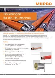
Our contribution<br />
to environmental<br />
protection<br />
When manufacturing our products,<br />
we always ensure that the methods<br />
used comply with environmental legislation<br />
and the latest technological<br />
standards. Taking care of the environment<br />
forms an equally important part<br />
of a sustainable, forwarding-looking<br />
corporate strategy as economic<br />
foresight.<br />
For this reason, <strong>MÜPRO</strong> ensures an<br />
optimum use of natural resources<br />
starting right at the development<br />
and design stages for our products.<br />
A continuous improvement in our<br />
manufacturing methods with regard<br />
to environmental aspects is a key<br />
element in our approach.<br />
Of course we also require the same<br />
environmental protection standards<br />
which we apply to ourselves of our<br />
partners and suppliers.<br />
10/16<br />
© Müpro - © A Müpro concept for - progress and quality V
<strong>MÜPRO</strong><br />
Quality mark RAL-GZ 655 “Pipe Mounting“<br />
The technical regulation RAL-GZ 655 contains rules for any kind of pipe mountings and<br />
characterises pipe clamps, brackets, mounting rails and equipment. Technical performance<br />
and quality is proven in comprehensive, neutral tests and the resulting security is<br />
an advantage to all concerned partners.<br />
RAL has given the authority to award the quality mark to the Pipe Mounting Quality<br />
Association. The RAL quality mark can only be awarded to products, which completely<br />
meet the high requirements on quality-assured pipe mountings.<br />
These requirements are defined in the RAL-GZ 655 quality and test regulations. All<br />
products are thoroughly evaluated by a neutral, independent test centre before the<br />
seal is awarded. All products awarded subject to continuous external monitoring by<br />
this test centre and by the quality association. The technical performance of these pipe<br />
mountings is neutrally determined, using modern methods. Thus the Pipe Mounting<br />
Quality Association offers safety and faciliates the selection of pipe mountings.<br />
The RAL quality mark is characterized by the high level of trust established among<br />
consultants, traders and installers.<br />
Please find further information and the current product range under:<br />
www.safe-connection.de.<br />
Overview of approvals and test marks for <strong>MÜPRO</strong> products<br />
Description<br />
European Technical Assessment, ETA, with CE mark<br />
CONSTRUCTION SUPERVISION<br />
APPROVED<br />
CERTIFIED QUALITY<br />
National approval from the German Institute for Building Technology, Dibt, Berlin<br />
Recognition from the German Association of Property Insurers (VdS), Cologne for the installation of sprinkler systems<br />
APPROVED<br />
Factory Mutual (FM), approval for the installation of sprinkler system<br />
Product in accordance with VdS regulations for fastening sprinkler systems on concrete components<br />
fire protection<br />
certified<br />
Fire-tested as specified in D<strong>IN</strong> 4102, fire resistance classes F30, F60, F90, F120<br />
Vibration control<br />
Vibration control tested<br />
Stainless Steel<br />
STA<strong>IN</strong>LESS STEEL<br />
RAL Quality mark<br />
Underwriters Laboratories (UL)<br />
Manufacturers Standardization Society (MSS), quality standard for steel castings, valves, flanges, fittings<br />
and other piping components<br />
10/16<br />
VI<br />
© Müpro - A progress concept and for quality progress and quality
<strong>MÜPRO</strong><br />
1. Vibration control<br />
2. Fire protection<br />
3. Pipe clamps<br />
4. MSS products<br />
5. Support channels<br />
6. Accessories<br />
7. Anchor points/expansion points<br />
8. Heavy-duty pipe support<br />
9. MPT-Support system<br />
10. Ventilation<br />
11. Anchor plugs<br />
12. Nameplates<br />
13. Technical information
PHONOLYT® 1/2<br />
PHONOLYT® Button 1/3<br />
Anti-vibration pads 1/4<br />
DÄMMGULAST® Resilient pad 1/5<br />
DÄMMGULAST® Washers 1/6<br />
DÄMMGULAST® Channel sections<br />
for MPC-Profiles<br />
1/7
VIBRATION CONTROL<br />
The current situation<br />
Building technology is becoming<br />
increasingly complex and technical<br />
progress has led to a parallel rise<br />
in the ambitions of building owners.<br />
After 35, 30 and 25 dB(A) starting<br />
from D<strong>IN</strong> 4109 and up to VDI 4100<br />
vibration control level III, 20 dB(A)<br />
and for waste water pipework without<br />
the associated fittings noise, we<br />
are already seeing values 5 dB(A)<br />
lower than the vibration upper limit<br />
being specified. At the same time,<br />
legal developments are increasingly<br />
oriented towards the sensitivities of<br />
the consumers.<br />
Traditionally, the standards that have<br />
always had to be redefined for best<br />
quality are the generally acknowledged<br />
handcraft rules.<br />
The almost never-ending stream of<br />
standards and regulations means that<br />
anyone working on a building site,<br />
including planners and installation<br />
engineers, is facing an ever-increasing<br />
liability risk.<br />
The challenge<br />
The greatest vibration damage occurs<br />
in building technology when noise in<br />
the installed equipment is transferred<br />
to the building structure, i.e. to the<br />
large “powerful” resonating body.<br />
An added complication is the fact<br />
that those involved in the construction<br />
cannot predict the size of the<br />
vibrations. Attachments that have to<br />
absorb forces and static loads, such<br />
as pipe anchor points, are particularly<br />
problematic, as there is mutual<br />
physical contradiction between the<br />
tasks to be solved, namely strength<br />
and vibration control.<br />
If the stipulation is that the lower<br />
vibration level must not exceed 25 or<br />
20 dB(A), or in extreme cases even<br />
5 dB(A), utmost care must be taken<br />
to ensure that only the very best<br />
products and the very latest technology<br />
are used. Vibration damage,<br />
which usually cannot be localised<br />
and can often only be eliminated by<br />
a total renovation, is one of the most<br />
expensive construction defects.<br />
Work that has not been carried out<br />
according to the regulations and<br />
the recognised technical rules can<br />
have a “time bomb” effect, even if<br />
a client overlooks existing defects<br />
during acceptance and does not<br />
make a complaint. If the work was not<br />
carried out according to the current<br />
state of technology and the generally<br />
recognised installation standards,<br />
subsequent buyers or users can still<br />
hold the planner and the installation<br />
company liable for any damage, for a<br />
period of up to 30 years.<br />
The solution<br />
The solution is vibration control!<br />
By making sure that all potential sources<br />
of vibration and vibration conducting<br />
pipes are consistently decoupled<br />
from the structure, you can avoid<br />
every conceivable vibration coupling<br />
in your area of responsibility. Even<br />
with large loads and/or high vibration<br />
intensities, the <strong>MÜPRO</strong> vibration<br />
control programme offers you system<br />
components to help you solve the<br />
diverse vibration and attachment<br />
problems in building technology.<br />
From the simplest attachment using<br />
pipe anchoring points, to the attachment<br />
of small and large assemblies,<br />
you will find a solution for every<br />
individual attachment and vibration<br />
control problem by using <strong>MÜPRO</strong><br />
system components.<br />
Remember: Vibration that you have<br />
under control cannot spread elsewhere.<br />
10/16<br />
© Müpro - progress and quality<br />
1/1
VIBRATION CONTROL<br />
PHONOLYT®<br />
galvanised<br />
Field of application<br />
• The ideal component for vibration<br />
controlled anchor points for pipes to<br />
meet the vibration control requirements<br />
of D<strong>IN</strong> 4109 and VDI 4100<br />
• Versatile use, e. g. for vibration<br />
control of support structures made<br />
from MPC-Support channels<br />
• Ideal as vibration decoupled down<br />
pipe-support for all pipe types<br />
• Ideal for vibration controlled fixing<br />
of devices such as boilers, pumps,<br />
motors, air-conditioning and ventilation<br />
systems<br />
• Suitable for ceiling, wall or floor<br />
mounting<br />
• For sound-decoupled pipeline fixed<br />
points<br />
Advantages<br />
• Vibration decoupler available in two<br />
versions for different duties<br />
• Isolates the pipe acoustically from<br />
the building structure<br />
• Reduces the structure-borne noise<br />
by up to 40 dB(A)<br />
• Predictable vibration control for<br />
planners and users<br />
• Practical design made for easy<br />
installation<br />
• High static loading capacity<br />
• Encapsulated vibration control –<br />
safety that you can rely on<br />
• Effective isolation of vibration<br />
coupling using vulcanised-in<br />
<strong>MÜPRO</strong>LAN<br />
• The cast-steel vibration-control<br />
capsule provides a high degree of<br />
safety, even in the case of fire<br />
• Approved for all installation<br />
positions<br />
• Silicone-free<br />
Down-pipe support for all pipe types<br />
vibration-decoupled<br />
Vibration-decoupled water pipe<br />
anchor points<br />
Vibration-decoupled support for<br />
equipment<br />
Features<br />
fire protection<br />
certified<br />
Type dB(A) 27 dB(A) 40<br />
Average vibration reduction [dB(A)] 27 40<br />
Safe working load tension/compression FZ,D [N] 5,400 20,000<br />
Axial safe working load Fax [N] 3,000 7,500<br />
Radial safe working load FQ [N] 2,500 3,300<br />
Vibration control<br />
Q<br />
Type<br />
Connecting<br />
thread<br />
Part no. Sales unit Pack unit Dimensions [mm]<br />
A B C H M Ø L L2<br />
dB(A) 27 M10 120292 1 pieces 80 37 147 40 10 11 122<br />
dB(A) 40 M12 120296 126 60 227 66 12 13 194<br />
10/16<br />
1/2 © Müpro - progress and quality
VIBRATION CONTROL<br />
PHONOLYT® Button<br />
galvanised<br />
Field of application<br />
• Ideal for vibration controlled fixing<br />
of devices such as boilers, pumps,<br />
motors, air-conditioning and ventilation<br />
systems; also vessels, MPC-<br />
Support channels, etc.<br />
• Suitable for ceiling, wall or floor<br />
mounting<br />
• For sound-decoupled pipeline fixed<br />
points<br />
• The ideal component for vibration<br />
controlled elevating devices to meet<br />
the vibration control requirements<br />
of D<strong>IN</strong> 4109 and VDI 4100<br />
• Various mounting options when<br />
used with cross beams and frames<br />
made of MPC-Support channels:<br />
stable, versatile and optionally<br />
expandable<br />
Advantages<br />
• High-performance anchor point<br />
attachments with outstanding<br />
structure-borne noise reduction of<br />
up to 30 dB(A)<br />
• High loading capacity in all directions<br />
• Time-saving fitting due to only one<br />
connection thread on each side<br />
• Adjustment using threaded pins or<br />
rods<br />
• Security provided by undercut<br />
vulcanised-in anchor<br />
• Effective isolation of vibration coupling<br />
using vulcanised-in <strong>MÜPRO</strong>-<br />
LAN<br />
• Silicone-free<br />
Vibration-isolated wall mounting<br />
Vibration-isolated pump baseframe<br />
made from MPC-Support channels<br />
Vibration-isolated ceiling<br />
suspension<br />
Features<br />
Average vibration reduction<br />
[dB(A)]<br />
Max. recommended loading<br />
tension/compression FZ,D [N]<br />
Max. recommended loading<br />
lateral FQ [N]<br />
Vibration control<br />
30<br />
1,500<br />
Connecting thread Part no. Sales unit Pack unit<br />
M10 120442 1 pieces<br />
10/16<br />
© Müpro - progress and quality<br />
1/3
VIBRATION CONTROL<br />
Anti-vibration pad<br />
galvanised<br />
Field of application<br />
• For the structure-borne vibration<br />
control of boilers, air-conditioning<br />
and ventilation systems<br />
• Simply slip under item to be supported:<br />
no fixings on floor or equipment<br />
are necessary<br />
Advantages<br />
• Dampens the transfer of structureborne<br />
noise to the building structure<br />
• Low overall height<br />
• Highly elastic rubber pad absorbs<br />
up to 95 % of its own and external<br />
vibrations<br />
• Oil-resistant, synthetic rubber<br />
• Resistant to temperatures from<br />
–50 °C to +120 °C<br />
• Aluminium base plate<br />
Features<br />
Vibration control<br />
Size edge length<br />
[mm]<br />
Recommended loading per anti-vibration pad<br />
[N]<br />
60 up to 500<br />
90 500−1,000<br />
125 1,000−2,000<br />
200 2,000−3,000<br />
Mounting<br />
Size edge length<br />
[mm]<br />
Part no. Sales unit Pack unit Dimensions [mm]<br />
A B C D<br />
For corner mounting 60 107117 4 pieces 60 45 14 21<br />
90 107118 90 70 20 30<br />
125 107115 125 98 25 40<br />
200 107116 200 165 37 58<br />
For side mounting 60 107113 60 45 14 21<br />
90 107114 90 70 20 30<br />
125 107111 125 98 25 40<br />
200 107112 200 165 37 58<br />
10/16<br />
1/4 © Müpro - progress and quality
VIBRATION CONTROL<br />
DÄMMGULAST® Resilient pad<br />
galvanised<br />
Field of application<br />
• Vibration control of traverses and<br />
pipe bridges made of MPC-Support<br />
channels<br />
Advantages<br />
• Effective structure-borne vibration<br />
control for many installation situations<br />
• Bushing to prevent metal contact<br />
between screws and mounted<br />
object<br />
• Very simple installation without<br />
additional work<br />
• Average sound level improvement<br />
of up to 17 dB(A)<br />
• Ideal combination with<br />
DÄMMGULAST® Washers for<br />
vibration-isolated fitting of MPC-<br />
Support channels<br />
Features<br />
Max. recommended load [N] 1,000<br />
Vibration control<br />
For thread<br />
Size<br />
[mm]<br />
Part no. Sales unit Pack unit<br />
M8/M10 43 x 25 107083 50 pieces<br />
10/16<br />
© Müpro - progress and quality<br />
1/5
VIBRATION CONTROL<br />
DÄMMGULAST® Washers<br />
Field of application<br />
• Decoupling of traverses and pipe<br />
bridges made of MPC-Support<br />
channels<br />
• Can be fitted using screws,<br />
threaded pins and rods up to M10<br />
• Ideal supplement to DÄMMGU-<br />
LAST® Resilient pad in channel<br />
installation<br />
Advantages<br />
• Highly elastic vibration decoupler<br />
for light compressive loadings<br />
• Protective bushing against metal<br />
contact<br />
• Very simple installation without<br />
additional work<br />
• Noise reduction of up to 18 dB(A)<br />
Features<br />
Vibration control<br />
For thread<br />
Size D x L1<br />
[mm]<br />
Part no. Sales unit Pack unit Dimensions [mm]<br />
D L1 L2<br />
Washers M8 24 x 8.5 107087 100 pieces 24 8.5 11<br />
28 x 8.5 107089 28<br />
M10 34 x 10.5 107086 34 10.5 14<br />
Washers, flame-resistant M8 24 x 8.5 107088 24 8.5 11<br />
Washers 127238 −<br />
28 x 8.5 127229 28<br />
M10 34 x 10.5 127235 34 10.5<br />
!<br />
For an even load distribution, always combine DÄMMGULAST® Washers with metal washers. Maximum<br />
recommended loading: 300 N.<br />
10/16<br />
1/6 © Müpro - progress and quality
VIBRATION CONTROL<br />
DÄMMGULAST® Channel sections<br />
for MPC-Profiles<br />
Field of application<br />
• Ideal for the decoupling of traverses<br />
for air duct fixtures<br />
• For secure vibration-decoupling of<br />
MPC-Support channels<br />
Advantages<br />
• Easy installation by inserting into<br />
MPC-Support channels and/or<br />
screwing onto threaded rods<br />
• Prevents structure-borne noise coupling<br />
by avoiding contact between<br />
the air duct and the threaded rods<br />
• Interlocking profile prevents channel<br />
section being pushed out<br />
• Prevents fluttering and other vibration<br />
noises in the air ducts<br />
• Small contact surface, large<br />
absorption mass<br />
Features<br />
Vibration control<br />
Design For support channels Suitable for Part no. Sales unit Pack unit<br />
27/18, 28/30 Channels with slot widths of 13‒16 mm, 107689 1 roll<br />
M8 threaded rods<br />
38/40, 39/52, 40/60, Channels with slot widths of 15‒18 mm, 107690<br />
40/80, 38/80, 40/120 M8 and M10 threaded rods<br />
107691 300 pieces<br />
DÄMMGULAST®<br />
Channel section<br />
roll of 30 m<br />
DÄMMGULAST®<br />
Channel sections<br />
section of 50 mm<br />
DÄMMGULAST®<br />
Channel sections<br />
section of 100 mm<br />
107686 200<br />
!<br />
When installing air conditioning and ventilation equipment, MPC-Support channels can be used as loadbearing<br />
traverses. Structure-borne vibration coupling bridges resulting from direct metal contact between the<br />
air duct and the traverse or threaded rods can be prevented by the use of DÄMMGULAST® Channel section as<br />
intermediate layer.<br />
The DÄMMGULAST® Channel section was developed especially for these application areas and provides the<br />
optimum solution from a practical installation point of view.<br />
10/16<br />
© Müpro - progress and quality<br />
1/7
NOTES<br />
10/16<br />
1/8<br />
© Müpro - progress and quality
<strong>MÜPRO</strong><br />
1. Vibration control<br />
2. Fire protection<br />
3. Pipe clamps<br />
4. MSS products<br />
5. Support channels<br />
6. Accessories<br />
7. Anchor points/expansion points<br />
8. Heavy-duty pipe support<br />
9. MPT-Support system<br />
10. Ventilation<br />
11. Anchor plugs<br />
12. Nameplates<br />
13. Technical information
FIRE PROTECTION<br />
Fire tested pipe support systems<br />
The situation<br />
Fire protection in building<br />
technology<br />
Constructional fire protection is<br />
becoming increasingly important<br />
in house and building technology.<br />
Increasingly complex piping systems<br />
and thus rising fire load risks tighten<br />
up the requirements on planning,<br />
design and installation of piping<br />
systems.<br />
This applies especially in the case of<br />
buildings for special purposes such<br />
as hospitals, old people’s homes,<br />
shopping centres and schools where<br />
fire protection measures are indispensable.<br />
Escape and rescue routes or wall and<br />
ceiling penetrations for pipes need<br />
to fulfill and combine the demands of<br />
constructional fire protection, such as<br />
obtaining minimum required duration<br />
of fire resistance as well as vibration<br />
control and thermal insulation.<br />
The specifications for building fire protection<br />
are given by, among others,<br />
the German Model Building Code<br />
(MBO), the German State Building<br />
Codes (LBO), D<strong>IN</strong> 4102, the German<br />
Pipe Systems Guideline LAR (MLAR)<br />
as well as by the D<strong>IN</strong> 4109 standard<br />
for vibration control considerations<br />
and the German Energy Saving Regulation<br />
(EnEV) in the area of thermal<br />
insulation.<br />
The challenge<br />
The Fire Protection Requirement<br />
according to LAR/D<strong>IN</strong> 4102<br />
The following requirements are defined<br />
for fastenings in the region above<br />
self-supporting, fire-protecting false<br />
ceilings in terms of fire resistance:<br />
• Fire resistance F30 in the region<br />
between ceiling and suspended<br />
fire-protection false ceiling<br />
• Fire-proof fastenings for piping systems<br />
in escape and rescue routes<br />
• Fastening to approved plugs and<br />
anchors made of steel with proof of<br />
fire protection<br />
• Proof of stability and deformation of<br />
support systems by fire testing<br />
• Material thickness ≥ 1,5 mm<br />
• Monuting distance according to<br />
the instructions of the pipe manufacturer<br />
regarding the maximum<br />
permissible load as per the fire test<br />
reports.<br />
• Wall hanger brackets additionally<br />
suspended at the free end.<br />
The solution<br />
Fire-tested <strong>MÜPRO</strong> attachment<br />
systems<br />
The use of fire-tested <strong>MÜPRO</strong><br />
attachment systems in combination<br />
with a proper fire-protection design of<br />
the fastening construction creates a<br />
system meeting completely the high<br />
demands of a fire resistant attachment<br />
system as laid down in D<strong>IN</strong><br />
4102 and the LAR.<br />
The modular product range of firetested<br />
<strong>MÜPRO</strong> products allows you<br />
to build up a comprehensive set of<br />
fire-protected attachment solutions.<br />
Our application technology team provides<br />
competent support in the planning<br />
and design of fixture solutions.<br />
F30 suspended ceiling<br />
holding the General<br />
Construction Supervision<br />
Test Certificate (ABP) for<br />
fire exposure from above<br />
and below<br />
10/16<br />
© Müpro - progress and quality<br />
2/1
FIRE PROTECTION<br />
Support technology products meeting the requirements of<br />
LAR 11/2005<br />
Fire-tested vibration control<br />
Product Size Page<br />
PHONOLYT® dB(A) 27‒M10<br />
1/2<br />
dB(A) 40‒M12<br />
Fire-tested pipe clamps<br />
Product Size Page<br />
galvanised<br />
Single bossed clamps, heavy-duty version,<br />
with DÄMMGULAST® yellow<br />
⅜"‒6"<br />
Connection thread ≥ M12<br />
Stainless steel<br />
3/6 upon request<br />
Single bossed clamps, heavy-duty version,<br />
with DÄMMGULAST® red<br />
Single bossed clamps,<br />
with DÄMMGULAST® yellow<br />
Single bossed clamps,<br />
with DÄMMGULAST® red<br />
Single bossed clamps,<br />
without lining<br />
⅜"‒6"<br />
Connection thread ≥ M12<br />
⅜"‒170 mm<br />
Connection thread ≥ M10<br />
⅜"‒170 mm<br />
Connection thread ≥ M10<br />
⅜"‒6"<br />
Connection thread ≥ M10<br />
3/7 ‒<br />
3/8‒3/9 upon request<br />
3/10‒3/11 ‒<br />
3/12‒3/13 upon request<br />
Fire-tested anchor points/expansion points<br />
Product Size Page<br />
galvanised Stainless steel<br />
Sliding stirrups M10 7/5 ‒<br />
Slide guides 1.75 kN ≥ M10 7/8 upon request<br />
Slide guide 4 kN ≥ M12 7/9‒7/10 ‒<br />
Box section heavy slide guide 7.8 kN<br />
Swivel hangers long/short<br />
M12<br />
M16<br />
M10<br />
M12<br />
7/10<br />
7/6<br />
10/16<br />
2/2 © Müpro - progress and quality
FIRE PROTECTION<br />
Support technology products meeting the requirements of<br />
LAR 11/2005<br />
Fire-tested support channels<br />
Product Profile Page<br />
galvanised Stainless steel<br />
MPC-Support channels 38/40, 39/52, 40/60, 40/80 5/2‒5/3 upon request<br />
MPC-Support channels, H-profiles 38/48, 38/80, 40/120 5/4 ‒<br />
MPR-Support channels 41/41/2,5, 41/62/2,5 5/30‒5/31<br />
MPR-Support channels, H-profiles 41/82/2,0, 41/124/2,5 5/32<br />
MPC-Wall hanger brackets 38/40, 40/60, 38/80<br />
≤ 700 mm<br />
5/8‒5/9 upon request<br />
MPC-Quick fasteners with external thread M10 for 38/40‒40/120 5/12 ‒<br />
MPC-Quick fasteners with internal thread M10 for 38/40‒40/120 5/13‒5/14 upon request<br />
MPC-Hammer head fasteners<br />
M10<br />
M12<br />
5/15‒5/16<br />
MPC-Hammer head bolts<br />
M10<br />
M12<br />
5/17<br />
MPC-Clamp brackets M10‒M16 5/18<br />
MPC-Saddle supports 38/40, 39/52, 40/60, 40/80 5/21<br />
MPC-Lateral angle right M10 5/26 ‒<br />
MPC-Lateral angle left<br />
M10<br />
Fire-tested accessories<br />
Product Size Page<br />
Hanger bracket M10 6/5<br />
10/16<br />
© Müpro - progress and quality<br />
2/3
FIRE PROTECTION<br />
Support technology products meeting the requirements of<br />
LAR 11/2005<br />
Fire-tested plugs<br />
Product Size Page<br />
galvanised Stainless steel<br />
Steel anchors M6, M8, M10, M12, M16 11/2 upon request<br />
Through anchors M8, M10, M12, M16 11/4‒11/5<br />
Heavy-duty anchors BZ M8, M10, M12, M16 11/6‒11/7<br />
Nail anchors type N, N-K, N-M 11/8‒11/9 ‒<br />
Hollow-core slab ceiling anchors M8, M10, M12 11/10<br />
Injection anchors XV M8, M10, M12 11/15‒11/17<br />
System assemblies tested according to D<strong>IN</strong> 4102-2 by the North-Rhine Westphalia Materials Testing Office (MPA NRW)<br />
max. 700 mm<br />
max. 700 mm<br />
max. 700 mm<br />
Single attachment<br />
Directly mounted support<br />
channel construction<br />
Suspended support<br />
channel construction<br />
Wall hanger bracket<br />
suspended at the free end<br />
1.520 mm 1.520 mm<br />
max. 3.000 mm<br />
MPC-Support channel<br />
suspended, multi-field system<br />
MPC-Support channel suspended,<br />
span width up to 1,520 mm<br />
MPC-Support channel used as traverse,<br />
span width up to 3,000 mm<br />
10/16<br />
2/4 © Müpro - progress and quality
FIRE PROTECTION<br />
Products for the attachment of sprinkler systems<br />
Minimum requirements for supports in compliance with VdS-Guideline 2092/CEA 4001<br />
Nominal-Ø<br />
[mm]<br />
Minimum load-bearing<br />
capacity at 20 °C<br />
[kg]<br />
Minimum cross-section area<br />
[mm 2 ]<br />
Thread<br />
DN ≤ 50 200 30 M8<br />
50 < DN ≤ 100 350 50 M10<br />
100 < DN ≤ 150 500 70 M12<br />
150 < DN ≤ 200 850 125 M16<br />
Pipe clamps<br />
Product Size Type Guideline Page<br />
Single bossed clamps, heavy-duty version,<br />
with DÄMMGULAST® red<br />
for pipe outer diameter<br />
from ⅜" to 2", M8<br />
from 70 mm to 4", M10<br />
from 125 mm to 6", M12<br />
galvanised VdS 2100 3/7<br />
Plugs<br />
Product Size Type Guideline Page<br />
Steel anchors<br />
M8<br />
M10<br />
M12<br />
galvanised<br />
Stainless<br />
steel A4<br />
information<br />
VdS 1) 11/2<br />
upon request<br />
Heavy-duty anchors BZ<br />
Hollow-core slab ceiling anchors<br />
M8<br />
M10<br />
M12<br />
M16<br />
M8<br />
M10<br />
M12<br />
VdS 2100 11/10<br />
11/6‒11/7<br />
upon request<br />
10/16<br />
© Müpro - progress and quality<br />
2/5
FIRE PROTECTION<br />
Products for the attachment of sprinkler systems<br />
Components for pipe suspensions<br />
Product Size Type Guideline Page<br />
Trapezoid-sheet hangers<br />
- with welded-on nut<br />
- with clearance hole<br />
- with adjusting nut<br />
M8<br />
M10<br />
galvanised VdS 2100 6/9<br />
Girder clamps with joint<br />
(type Lindapter FLS)<br />
M8<br />
M10<br />
6/6<br />
Girder clamps<br />
(type VSG TKN10)<br />
M8<br />
M10<br />
M12<br />
6/7<br />
Girder clamps<br />
(type TKM Kroko)<br />
M8<br />
M10<br />
M12<br />
VdS 2100<br />
VdS 2344<br />
6/8<br />
MPC-Girder cleats<br />
for 38/24 and 38/40 profiles, M8<br />
for 39/52 and 40/60 profiles, M8<br />
for 38/40 and 40/60 profiles, M10<br />
VdS 2100 5/28<br />
!<br />
VdS 2100: VdS-Guideline for sprinkler systems, requirements and test methods for components,<br />
Issue 1988-05.<br />
VdS 2092: VdS-Guidelines for sprinkler systems; planning and installation incl. transitional arrangement p.<br />
1/2001, Issue 1998-08.<br />
CEA 4001: VdS CEA-Guidelines for sprinkler systems; planning and installation, Issue 2005-09.<br />
Information VdS 1) : VdS circular, dated, 14.11.2007 addressed to all firms that install fire extinguishers, concerning<br />
the use of plugs and anchors for fastening in concrete.<br />
10/16<br />
2/6 © Müpro - progress and quality
FIRE PROTECTION<br />
APPROVED<br />
Products for the attachment of sprinkler systems<br />
Minimum requirements for support in compliance with FM guidelines classes 1951, 1952 and 1953<br />
Nominal-Ø<br />
Thread<br />
[mm]<br />
[inch]<br />
20 < DN ≤ 100 ¾‒4 M10<br />
125 < DN ≤ 200 5‒8 M12<br />
250 < DN ≤ 300 10‒12 M16<br />
Plugs<br />
Product Size Type Guideline Page<br />
Through anchors<br />
M10<br />
M12<br />
M16<br />
galvanised FM 1951<br />
FM 1952<br />
FM 1953<br />
11/4‒11/5<br />
Heavy-duty anchors BZ<br />
Steel anchors<br />
M10<br />
M12<br />
M16<br />
M10<br />
M12<br />
M16<br />
11/6‒11/7<br />
11/2<br />
Components for pipe suspensions<br />
Product Size Type Guideline Page<br />
Girder clamps with joint<br />
M10 galvanised FM 1951 6/6<br />
(type Lindapter FLS)<br />
Girder clamps<br />
(type VSG TKN10)<br />
M10<br />
M12<br />
6/7<br />
Girder clamps<br />
(type TKM Kroko)<br />
M10<br />
M12<br />
6/8<br />
10/16<br />
© Müpro - progress and quality<br />
2/7
NOTES<br />
10/16<br />
2/8<br />
© Müpro - progress and quality
<strong>MÜPRO</strong><br />
1. Vibration control<br />
2. Fire protection<br />
3. Pipe clamps<br />
4. MSS products<br />
5. Support channels<br />
6. Accessories<br />
7. Anchor points/expansion points<br />
8. Heavy-duty pipe support<br />
9. MPT-Support system<br />
10. Ventilation<br />
11. Anchor plugs<br />
12. Nameplates<br />
13. Technical information
Two-piece pipe clamps<br />
Indoor use<br />
Indoor and Outdoor use<br />
galvanised hot-dip galvanised Stainless steel<br />
V2A<br />
V4A<br />
OPTIMAL 3/1–3/2<br />
Single bossed clamps JUNIOR 3/3<br />
EURO-QUICK type J 3/4–3/5<br />
Single bossed clamps,<br />
heavy-duty version<br />
3/6–3/7 upon request<br />
Single bossed clamps 3/8–3/13 upon request<br />
High-temperature pipe clamps<br />
Single bossed clamps, heavy duty<br />
version, with DÄMMGULAST ® red<br />
3/7 upon request<br />
Single bossed clamps,<br />
with DÄMMGULAST ® red<br />
3/10–3/11 upon request<br />
Ventilation duct clamps<br />
Duct clamps 10/1–10/2 upon request<br />
Refrigerant pipe clamps<br />
Insulation clamps type 170/175 EX 3/24–3/26<br />
Other pipe clamps<br />
DÄMMGULAST® Vibration control<br />
linings<br />
3/14–3/17<br />
Ceramic fabric tapes 3/18<br />
Load-distributing sleeves 3/19<br />
Rubber support inserts 3/20–3/23<br />
Hose clamps 3/27–3/28<br />
Pipe clips 3/29
PIPE CLAMPS<br />
OPTIMAL<br />
galvanised<br />
Field of application<br />
• Suitable for fixings in housing and<br />
industrial areas<br />
• Suitable for fastening of drinking<br />
water and heating pipes<br />
• For indoor use<br />
Advantages<br />
Economical solution due to advanced<br />
technology:<br />
• Practical latching fastener<br />
• The 2 locking screws allow adjustment<br />
to accommodate a greater<br />
variation in pipe diameter<br />
• Installation advantages of an onepiece<br />
clamp<br />
• High security due to the positivefit<br />
edge hook-in opening<br />
• The pipe is free to move during<br />
the installation<br />
• No inadvertent opening once it has<br />
clicked in, due to the safety latching<br />
fastener<br />
• Tightening bolts with combination,<br />
captive cross-head convenient for<br />
power driver<br />
• DÄMMGULAST® Vibration<br />
control lining with green identification<br />
stripe: average sound level<br />
improvement up to 18 dB(A)<br />
• Optimum handling due to injuryproof<br />
design<br />
Features<br />
Vibration control<br />
Size<br />
Max. recommended load<br />
[N]<br />
¼"‒1¼" 800<br />
1½"‒70 mm 1,690<br />
2½"‒116 mm 2,320<br />
125 mm‒6" 2,696<br />
!<br />
The attachment of pipes, especially under the ceiling, often requires the use of two hands. It is then convenient, if<br />
the OPTIMAL latching fastener can be closed with only one hand. After closing the latch, the pipe is safely held in<br />
place but remains free to move. Consequently, adjustment of pipe can be made with two hands.<br />
And don’t forget: high security due to the positive-fit edge hook-in opening.<br />
10/16<br />
© Müpro - progress and quality<br />
3/1
PIPE CLAMPS<br />
OPTIMAL<br />
galvanised<br />
Connecting<br />
thread<br />
Size Clamping Part no. Sales unit Pack unit Dimensions [mm]<br />
[inch] [mm]<br />
range<br />
B b1 H1 H V<br />
[mm]<br />
M8 ¼ 13‒15 119822 100 pieces 55 23 42 26 M5<br />
⅜ 16‒18 119838 57 45 28<br />
½ 19‒24 119818 63 51 31<br />
¾ 25‒30 119834 70 57 34<br />
1 32‒37 119806 76 65 38<br />
1¼ 41‒44 119814 50 85 71 41<br />
1½ 48‒51 119810 93 79 45 M6<br />
57 53‒58 119842 100 86 49<br />
2 60‒63 119826 107 92 52<br />
70 69‒73 119846 116 101 56<br />
2½ 74‒78 119830 127 106 58<br />
M8/M10 ¼ 13‒15 119866 100 55 46 30 M5<br />
⅜ 16‒18 119882 57 49 32<br />
½ 19‒24 119862 63 55 35<br />
¾ 25‒30 119878 70 61 38<br />
1 32‒37 119850 76 69 42<br />
1¼ 41‒44 119858 50 85 75 45<br />
1½ 48‒51 119854 93 83 49 M6<br />
57 53‒58 119886 100 90 53<br />
2 60‒63 119870 107 96 56<br />
70 69‒73 119894 116 105 60<br />
2½ 74‒78 119874 127 28 110 62<br />
83 80‒84 119898 132 117 66<br />
3 88‒90 119794 139 122 68<br />
102 99‒103 119770 155 136 75<br />
110 108‒112 119774 163 145 80<br />
4 113‒117 119798 168 150 82<br />
116 116‒120 119778 172 153 84<br />
125 125‒129 119782 174 164 89<br />
133 133‒137 119786 185 171 93<br />
5 137‒141 119802 188 176 95<br />
160 159‒162 119790 212 197 106<br />
6 164‒168 119890 220 202 108<br />
OPTIMAL,<br />
with DÄMMGULAST®<br />
green, in polybox<br />
Connecting<br />
thread<br />
Size<br />
[inch]<br />
Part no.<br />
Sales<br />
unit<br />
Pack<br />
unit<br />
Content<br />
[clamps]<br />
Part no.<br />
Polybox excl. clamps<br />
M8 ¼ 119954 1 box 300 121019 Polybox large<br />
⅜ 119962<br />
500/450 x 300 x 180<br />
½ 119950<br />
¾ 119958 200<br />
1 119946<br />
Type<br />
10/16<br />
3/2 © Müpro - progress and quality
PIPE CLAMPS<br />
Single bossed clamps JUNIOR<br />
two-piece, galvanised<br />
Field of application<br />
• Suitable for pipe attachments in<br />
industrial areas<br />
• Suitable for fastening of drinking<br />
water and heating pipes<br />
• For indoor use<br />
Advantages<br />
• Proven two-piece clamp<br />
• High stiffness due to reinforcing<br />
bead<br />
• The 2 locking screws allow adjustment<br />
to accommodate a greater<br />
variation in pipe diameter<br />
• Tightening bolts with combination<br />
cross-head convenient for power<br />
driver<br />
• Fastener screws with captive<br />
washer<br />
• Connecting thread with combi<br />
thread M8/M10<br />
• DÄMMGULAST® Vibration<br />
control lining with green identification<br />
stripe: average sound level<br />
improvement up to 18 dB(A)<br />
• Vibration control tested<br />
Features<br />
Vibration control<br />
Connecting<br />
thread<br />
Size<br />
Max. recommended load<br />
[N]<br />
12 mm‒½" 700<br />
¾"‒2" 1,200<br />
70 mm‒3" 2,000<br />
102 mm‒6" 2,500<br />
Size Clamping Part no. Sales unit Pack unit Dimensions [mm]<br />
[inch] [mm]<br />
range<br />
B b1 H1 H V<br />
[mm]<br />
M8/M10 12 6‒15 142357 100 pieces 45 22.5 38 28 M5<br />
⅜ 15‒19 142358 51 44 30<br />
½ 20‒25 142359 57 50 33<br />
¾ 25‒30 142360 63 56 37<br />
1 33‒37 142361 70 64 40<br />
1¼ 42‒46 142362 50 80 72 45<br />
1½ 47‒52 142363 86 79 48<br />
57 54‒58 142364 91 84 50<br />
2 59‒63 142365 96 88 53<br />
70 68‒73 142366 118 104 60 M6<br />
2½ 72‒80 142367 127 113 65<br />
83 82‒85 142368 132 119 68<br />
3 88‒92 142369 139 125 71<br />
102 99‒103 142370 151 137 77<br />
110 108‒112 142371 160 145 81<br />
4 112‒118 142372 164 149 83<br />
125 125‒130 142373 25 174 159 88<br />
133 133‒137 142374 182 167 92<br />
5 137‒142 142375 191 175 96<br />
160 159‒164 142376 210 195 106<br />
6 164‒169 142377 216 201 109<br />
Single bossed<br />
clamps JUNIOR,<br />
with DÄMMGULAST®<br />
green, in polybox<br />
Connecting<br />
thread<br />
Size<br />
[inch]<br />
Part no.<br />
Sales<br />
unit<br />
Pack<br />
unit<br />
Content<br />
[clamps]<br />
Part no.<br />
Polybox excl. clamps<br />
M8/M10 ⅜ 143958 1 box 200 121019 Polybox large<br />
½ 143959<br />
500/450 x 300 x 180<br />
¾ 143960<br />
1 143961<br />
Type<br />
10/16<br />
© Müpro - progress and quality<br />
3/3
PIPE CLAMPS<br />
EURO-QUICK® type J<br />
galvanised<br />
Field of application<br />
• Suitable for pipe attachments in<br />
industrial areas<br />
• Suitable for fastening of drinking<br />
water and heating pipes<br />
• For indoor use<br />
Advantages<br />
• Proven two-piece clamp<br />
• High stiffness due to reinforcing<br />
bead<br />
• The 2 locking screws allow adjustment<br />
to accommodate a greater<br />
variation in pipe diameter<br />
• Tightening bolts with combination<br />
cross-head convenient for power<br />
driver<br />
• Fastener screws with captive<br />
washer<br />
• With highly elastic insert<br />
• Safe handling thanks to rounded<br />
flange<br />
• Clip-over edges and the guide rib<br />
of the pipe clamp insert ensures a<br />
secure hold and prevents it from<br />
being pushed out<br />
Features<br />
Connecting<br />
thread<br />
Size<br />
Max. recommended load<br />
[N]<br />
12‒15 to 25‒30 mm 1,200<br />
32‒37 to 59‒63 mm 1,300<br />
63–70 to 98–104 mm 1,900<br />
108–115 to 132–137 mm 2,300<br />
137–142 to 322–332 mm 2,700<br />
with lining<br />
For pipe outer Ø Part no. Sales unit Pack unit Dimensions [mm]<br />
without lining<br />
[mm] [inch] [mm] [inch] B b1 H H1 V<br />
M8 12–15 ¼ 17–19 ¼ 153571 50 pieces 48.5 21 28.5 40 M6<br />
15–20 ⅜ 20–24 ⅜ 153572 52.5 30.5 44<br />
21–25 ½ 26–29 ½ 153573 58.5 33.5 50<br />
25–30 ¾ 30–34 ¾ 153574 62.5 35.5 54<br />
32–37 1 38–43 1 153575 70.5 39.5 62<br />
40–45 1¼ 45–50 1¼ 153576 78.5 43.5 70<br />
46–53 1½ 52–59 1½ 153577 86.5 47.5 78<br />
54–58 60–64 153578 92.5 50.5 84<br />
59–63 2 65–70 2 153579 96.5 52.5 88<br />
M8/M10 12–15 ¼ 17–19 ¼ 153883 48.5 33.5 45<br />
15–20 ⅜ 20–24 ⅜ 153884 52.5 35.5 50<br />
21–25 ½ 26–29 ½ 153885 58.5 37.5 54<br />
25–30 ¾ 30–34 ¾ 153886 62.5 39.5 59<br />
32–37 1 38–43 1 153887 70.5 42.5 65<br />
40–45 1¼ 45–50 1¼ 153888 78.5 45.5 73<br />
46–53 1½ 52–59 1½ 153889 86.5 49.0 80<br />
54–58 60–64 153890 92.5 51.0 84<br />
59–63 2 65–70 2 153891 96.5 53.0 89<br />
63–70 71–75 153892 103.0 23 56.0 95<br />
72–78 2½ 76–84 2½ 153893 111.0 60.0 103<br />
78–86 85–90 153894 119.0 64.0 111<br />
87–93 3 92–100 3 153895 126.0 67.5 118<br />
98–104 104–110 153896 137.0 73.0 129<br />
10/16<br />
3/4 © Müpro - progress and quality
PIPE CLAMPS<br />
EURO-QUICK® type J<br />
galvanised<br />
Connecting<br />
thread<br />
with lining<br />
For pipe outer Ø Part no. Sales unit Pack unit Dimensions [mm]<br />
without lining<br />
[mm] [inch] [mm] [inch] B b1 H H1 V<br />
M8/M10 108–115 4 113–119 4 153897 50 pieces 152.0 23 79.0 141 M6<br />
114–118 120–124 153898 156.0 81.0 145<br />
119–123 124–128 153899 162.0 84.0 151<br />
124–130 128–134 153900 176.0 87.0 157 M8<br />
132–137 135–140 153901 184.0 91.0 165<br />
137–142 5 143–152 5 153902 195.0 28 96.0 175<br />
143–150 148–156 153903 202.0 99.0 181<br />
151–158 157–164 153904 210.0 103.0 189<br />
159–163 165–174 153905 217.0 107.0 197<br />
164–168 6 170–177 6 153906 224.0 109.5 202<br />
169–176 175–182 153907 230.0 112.0 208<br />
177–184 183–190 153908 238.0 116.5 216<br />
185–192 191–198 153909 246.0 121.0 225<br />
193–203 200–206 153910 25 257.0 128.0 239<br />
212–222 8 219–228 8 153911 275.0 135.0 257<br />
223–233 230–239 153912 285.0 141.0 264<br />
234–244 240–250 153913 294.0 146.0 275<br />
245–255 252–261 153914 305.0 151.0 286<br />
256–266 264–270 153915 314.0 157.0 298<br />
267–277 10 273–283 10 153916 330.0 165.5 313<br />
M10 278–288 285–294 153917 341.0 166.0 324<br />
289–299 299–304 153918 350.0 172.0 334<br />
300–310 309–315 153919 361.0 177.0 345<br />
311–321 319–326 153920 372.0 183.0 356<br />
322–332 12 325–335 12 153921 385.0 190.0 365<br />
M10/M12 278–288 285–294 153922 341.0 176.0 330<br />
289–299 299–304 153923 350.0 181.0 341<br />
300–310 309–315 153924 361.0 188.0 353<br />
311–321 319–326 153925 372.0 193.0 362<br />
322–332 12 325–335 12 153926 385.0 198.0 373<br />
M12 278–288 285–294 153927 341.0 168.0 326<br />
289–299 299–304 153928 350.0 174.0 336<br />
300–310 309–315 153929 361.0 179.0 347<br />
311–321 319–326 153930 372.0 185.0 358<br />
322–332 12 325–335 12 153931 385.0 192.0 367<br />
10/16<br />
© Müpro - progress and quality<br />
3/5
PIPE CLAMPS<br />
Single bossed clamps<br />
heavy-duty version, with DÄMMGULAST® yellow, galvanised<br />
Field of application<br />
• Suitable for pipelines with dynamic<br />
loads in combination with expansion<br />
points<br />
• Suitable for fixings in industrial<br />
areas<br />
• Suitable for fixings in air conditioning,<br />
ventilation and sanitary areas<br />
• For indoor use<br />
Advantages<br />
• Proven two-part clamp with<br />
increased material cross-section<br />
• Stronger tightening bolts for high<br />
load capacity<br />
• DÄMMGULAST® Vibration<br />
control lining with yellow identification<br />
stripe: average sound level<br />
improvement up to 22 dB(A)<br />
Features<br />
fire protection<br />
certified<br />
up to 6"<br />
Vibration control<br />
Connecting<br />
thread<br />
Size<br />
Max. recommended load<br />
[N]<br />
1½"‒2" 4,166<br />
2½"‒4" 5,000<br />
125‒315 mm 6,666<br />
323 mm upwards 8,333<br />
Size Clamping Part no. Sales unit Pack unit Dimensions [mm]<br />
[inch] [mm]<br />
range<br />
b x s B b1 H1 H V<br />
[mm]<br />
M12 1½ 48‒54 121914 50 pieces 30 x 3.0 110 34 82 49 M8<br />
2 57‒64 122099 126 99 57<br />
2½ 72‒80 122111 144 111 63 M10<br />
83 79‒85 122534 146 114 65 M8<br />
3 88‒92 122266 159 122 69 M10<br />
102 99‒103 121934 170 134 75<br />
4 108‒118 122353 184 149 82<br />
125 121‒127 121998 20 40 x 4.0 204 46 160 88<br />
133 133‒137 122018 212 176 95<br />
5 138‒144 122429 217 177 96<br />
160 159‒165 122052 235 195 105<br />
6 164‒170 122473 242 204 109<br />
180 178‒182 122079 260 220 118<br />
200 193‒203 122123 280 235 125<br />
212 208‒214 122151 10 299 245 130<br />
219 217‒224 122167 302 257 136<br />
225 222‒228 122187 260 138<br />
250 244‒254 122214 330 285 148<br />
267 267‒277 122234 360 311 163<br />
280 278‒282 122250 315 165<br />
315 313‒318 122294 394 350 183<br />
323 320‒326 122305 50 x 5.0 415 56 360 188 M12<br />
355 353‒360 122325 447 392 204<br />
! Single bossed clamps can be produced in all other pipe sizes and types according to customer specifications.<br />
i Please refer to chapter „Heavy-duty pipe support“ for pipe clamps D<strong>IN</strong> 3567.<br />
10/16<br />
3/6 © Müpro - progress and quality
PIPE CLAMPS<br />
Single bossed clamps<br />
heavy-duty version, with DÄMMGULAST® red, galvanised<br />
Field of application<br />
• Suitable for pipelines with dynamic<br />
loads in combination with expansion<br />
points<br />
• Suitable for fixings in industrial<br />
areas<br />
• Suitable for fastening of drinking<br />
water and heating pipes as well as<br />
for thermical oil pipes<br />
• Attachment of pipelines in<br />
increased temperature ranges<br />
• For indoor use<br />
Advantages<br />
• Proven two-part clamp with<br />
increased material cross-section<br />
• Stronger fastening latches for high<br />
load capacity<br />
• High strength all-round welding of<br />
the connecting nut<br />
• DÄMMGULAST® vibration control<br />
lining red, high-temperature resistant<br />
up to +225 °C<br />
• Average sound level improvement<br />
up to 24 dB(A)<br />
• Approved for the attachment of<br />
sprinkler systems by VdS<br />
Features<br />
Size<br />
Max. recommended load<br />
[N]<br />
⅜"‒3" 5,000<br />
102‒133 mm 5,830<br />
5" upwards 6,666<br />
fire protection<br />
certified<br />
≥ M12<br />
G 4000030<br />
Connecting<br />
thread<br />
Size Clamping Part no. Sales unit Pack unit Dimensions [mm]<br />
[inch] [mm]<br />
range<br />
b x s B b1 H1 H V<br />
[mm]<br />
M8 ⅜ 14‒19 124418 100 pieces 30 x 3.0 74.0 34 46.0 29.0 M8<br />
½ 20‒26 124422 83.0 52.0 32.0<br />
¾ 25‒28 124425 88.3 57.0 34.5<br />
1 30‒35 124430 91.5 61.0 36.5<br />
1¼ 40‒43 124434 50 102.5 72.0 42.0<br />
1½ 48‒54 124438 109.9 79.0 45.5<br />
2 57‒64 124442 125.6 96.0 54.0<br />
M10 70 68‒72 124302 133.6 105.0 59.5<br />
2½ 72‒80 124306 144.4 110.0 62.0 M10<br />
83 82‒86 124311 155.0 119.1 66.6<br />
3 88‒92 124315 158.6 121.0 67.5<br />
102 99‒103 124283 170.4 133.2 73.6<br />
4 108‒118 124287 184.2 147.6 80.8<br />
M12 125 125‒130 124331 40 x 4.0 202.5 46 164.0 90.0<br />
133 133‒141 124339 25 211.5 177.0 96.5<br />
5 138‒144 124343 217.0 178.0 97.0<br />
160 159‒168 124347 235.0 196.0 106.0<br />
6 164‒170 124359 242.0 205.0 110.5<br />
! Single bossed clamps can be produced in all other pipe sizes and types according to customer specifications.<br />
10/16<br />
© Müpro - progress and quality<br />
3/7
PIPE CLAMPS<br />
Single bossed clamps<br />
with DÄMMGULAST® yellow, galvanised<br />
Field of application<br />
• Suitable combination for pipelines<br />
with dynamic loads with expansion<br />
points<br />
• Suitable for fixings in housing and<br />
industrial areas<br />
• Suitable for fixings in industrial<br />
areas, as well as in air-conditioning,<br />
ventilation and sanitary areas<br />
• For indoor use<br />
Advantages<br />
• Proven two-piece single bossed<br />
clamp<br />
• The 2 locking screws allow adjustments<br />
to accommodate a greater<br />
variation in pipe diameter<br />
• Tightening bolts with combination<br />
cross-head convenient for power<br />
driver<br />
Features<br />
• Tightening bolts secured with<br />
captive washers<br />
• Heavy duty type with high load<br />
capacity due to creased shape<br />
• Acoustic insulation, positive-fit liner<br />
with wide clip-over edges prevent<br />
the lining from slipping out of the<br />
pipe clamp<br />
• DÄMMGULAST® vibration control<br />
lining with yellow identification<br />
stripe: average sound level<br />
improvement up to 22 dB(A)<br />
• This product is awarded<br />
with the „Gütezeichen<br />
Rohrbefestigung“<br />
(quality mark of pipe<br />
support) and is submitted<br />
to controls according to<br />
RAL-GZ 655-B<br />
fire protection<br />
certified<br />
≥ M10,<br />
3 /8"–170 mm Vibration control<br />
Connecting<br />
thread<br />
Size<br />
Max. recommended load<br />
[N]<br />
⅜"‒2" 1,700<br />
70‒83 mm 2,200<br />
2½"‒116 mm 3,300<br />
200 mm 3,600<br />
212‒225 mm 5,800<br />
Size Clamping Part no. Sales unit Pack unit Dimensions [mm]<br />
[inch] [mm]<br />
range<br />
B b1 H1 H V<br />
[mm]<br />
M8/M10 ⅜ 14–20 151359 100 pieces 64 23 55 35.5 M6 x 20<br />
½ 21–26 151360 71 61 38.5<br />
¾ 26–30 151361 75 65 40.5<br />
1 31–38 151362 81 71 43.5 M6 x 25<br />
1¼ 40–47 151364 50 91 81 48.5<br />
1½ 48–54 151365 100 89 52.5<br />
57 54–60 151366 105 94 55.0<br />
2 60–66 151367 111 100 58.0<br />
70 68–73 151369 126 28 109 62.5 M8 x 35<br />
2½ 73–80 151370 131 114 65.0<br />
83 82–87 151371 142 124 70.0<br />
3 87–94 151372 146 128 72.0 M8 x 40<br />
102 99–104 151373 157 139 77.5<br />
110 105–112 151374 166 148 82.0<br />
4 112–118 151375 172 154 85.0<br />
125 122–128 151376 182 164 90.0<br />
133 132–137 151377 191 173 94.5<br />
5 137–142 151378 196 178 97.0<br />
144 142–148 151379 202 184 100.0<br />
150 149–156 151380 210 192 104.0<br />
160 159–164 151422 218 200 108.0<br />
6 164–169 151423 223 205 110.5<br />
170 169–172 151424 225 207 111.5<br />
! Single bossed clamps can be produced in all other pipe sizes and types.<br />
10/16<br />
3/8 © Müpro - progress and quality
PIPE CLAMPS<br />
Connecting<br />
thread<br />
Single bossed clamps<br />
with DÄMMGULAST® yellow, galvanised<br />
Size Clamping Part no. Sales unit Pack unit Dimensions [mm]<br />
[inch] [mm]<br />
range<br />
B b1 H1 H V<br />
[mm]<br />
M10/M12 ⅜ 14–20 151425 100 pieces 64 23 60 40.5 M6 x 20<br />
½ 21–26 151426 71 66 43.5<br />
¾ 26–30 151427 75 70 45.5<br />
1 31–38 151428 81 76 48.5 M6 x 25<br />
1¼ 40–47 151430 50 91 86 53.5<br />
1½ 48–54 151431 100 94 57.5<br />
57 54–60 151432 105 99 60.0<br />
2 60–66 151433 111 105 63.0<br />
70 68–73 151435 126 28 114 67.5 M8 x 35<br />
2½ 73–80 151436 131 119 70.0<br />
83 82–87 151437 142 129 75.0<br />
3 87–94 151438 146 133 77.0 M8 x 40<br />
102 99–104 151439 157 144 82.5<br />
110 105–112 151440 166 153 87.0<br />
4 112–118 151441 172 159 90.0<br />
125 122–128 151442 182 169 95.0<br />
133 132–137 151443 191 178 99.5<br />
5 137–142 151444 196 183 102.0<br />
144 142–148 151445 202 189 105.0<br />
150 149–156 151446 210 197 109.0<br />
160 159–164 151447 218 205 113.0<br />
6 164–169 151448 223 210 115.5<br />
170 169–172 151449 225 212 116.5<br />
180 177–183 151450 25 235 223 122.0<br />
200 197–203 151451 256 243 132.0<br />
212 208–214 151452 284 46 256 138.5 M10 x 40<br />
8 217–225 151453 295 267 144.0<br />
225 225–232 151454 304 274 147.5<br />
M12/M16/½" 5 137–142 151455 50 196 28 187 106.0 M8 x 40<br />
144 142–148 151456 202 193 109.0<br />
150 149–156 151457 210 201 113.0<br />
160 159–164 151458 218 209 117.0<br />
6 164–169 151459 223 214 119.5<br />
170 169–172 151460 225 216 120.5<br />
180 177–183 151461 25 235 227 126.0<br />
200 197–203 151462 256 247 136.0<br />
212 208–214 151463 284 46 260 M10 x 40<br />
8 217–225 151464 295 271 142.5<br />
225 225–232 151465 304 278 148.0<br />
! Single bossed clamps can be produced in all other pipe sizes and types.<br />
10/16<br />
© Müpro - progress and quality<br />
3/9
PIPE CLAMPS<br />
Single bossed clamps<br />
with DÄMMGULAST® red, galvanised<br />
Field of application<br />
• Suitable for pipelines with dynamic<br />
loads in combination with expansion<br />
points<br />
• Suitable for fixings in housing and<br />
industrial areas<br />
• Suitable for fixings in industrial<br />
areas as well as in air-conditioning,<br />
ventilation and sanitary areas and<br />
thermical oil pipes<br />
• Attachment of pipelines in<br />
increased temperature ranges<br />
• For indoor use<br />
Advantages<br />
• Proven two-piece single bossed<br />
clamp<br />
• The 2 locking screws allow adjustment<br />
to accommodate a greater<br />
variation in pipe diameter<br />
Features<br />
• With high-temperature resistant<br />
DÄMMGULAST® Vibration control<br />
lining red<br />
• The high-quality DÄMMGULAST®<br />
section maintains its properties in<br />
the temperature range –60 °C to<br />
+225 °C<br />
• Average sound level improvement<br />
up to 24 dB(A)<br />
• Tightening bolts with combination<br />
cross-head convenient for power<br />
driver<br />
• Tightening bolts secured with<br />
captive washers<br />
• Heavy-duty type with high load<br />
capacity due to creased shape<br />
• Acoustic insulation, positive-fit liner<br />
with wide clip-over edges prevent<br />
the lining from slipping out of the<br />
pipe clamp<br />
fire protection<br />
certified<br />
≥ M10,<br />
3 /8"–170 mm Vibration control<br />
Connecting<br />
thread<br />
Size<br />
Max. recommended load<br />
[N]<br />
⅜"‒2" 1,700<br />
70‒83 mm 2,200<br />
2½"‒116 mm 3,300<br />
200 mm 3,600<br />
212‒225 mm 5,800<br />
Size Clamping Part no. Sales unit Pack unit Dimensions [mm]<br />
[inch] [mm]<br />
range<br />
B b1 H1 H V<br />
[mm]<br />
M8/M10 ⅜ 14–20 151532 100 pieces 64 23 55 35.5 M6 x 20<br />
½ 21–26 151533 71 61 38.5<br />
¾ 26–30 151534 75 65 40.5<br />
1 31–38 151535 81 71 43.5 M6 x 25<br />
1¼ 40–47 151537 50 91 81 48.5<br />
1½ 48–54 151538 100 89 52.5<br />
57 54–60 151539 105 94 55.0<br />
2 60–66 151540 111 100 58.0<br />
70 68–73 151542 126 28 109 62.5 M8 x 35<br />
2½ 73–80 151543 131 114 65.0<br />
83 82–87 151544 142 124 70.0<br />
3 87–94 151545 146 128 72.0 M8 x 40<br />
102 99–104 151546 157 139 77.5<br />
110 105–112 151547 166 148 82.0<br />
4 112–118 151548 172 154 85.0<br />
125 122–128 151549 182 164 90.0<br />
133 132–137 151550 191 173 94.5<br />
5 137–142 151551 196 178 97.0<br />
144 142–148 151552 202 184 100.0<br />
150 149–156 151553 210 192 104.0<br />
160 159–164 151554 218 200 108.0<br />
6 164–169 151555 223 205 110.5<br />
170 169–172 151556 225 207 111.5<br />
! Single bossed clamps can be produced in all other pipe sizes and types according to customer specifications.<br />
10/16<br />
3/10 © Müpro - progress and quality
PIPE CLAMPS<br />
Connecting<br />
thread<br />
Single bossed clamps<br />
with DÄMMGULAST® red, galvanised<br />
Size Clamping Part no. Sales unit Pack unit Dimensions [mm]<br />
[inch] [mm]<br />
range<br />
B b1 H1 H V<br />
[mm]<br />
M10/M12 ⅜ 14–20 151557 100 pieces 64 22 60 40.5 M6 x 20<br />
½ 21–26 151558 71 66 43.5<br />
¾ 26–30 151559 75 70 45.5<br />
1 31–38 151560 81 76 48.5 M6 x 25<br />
1¼ 40–47 151562 50 91 86 53.5<br />
1½ 48–54 151563 100 94 57.5<br />
57 54–60 151564 105 99 60.0<br />
2 60–66 151565 111 105 63.0<br />
70 68–73 151567 126 28 114 67.5 M8 x 35<br />
2½ 73–80 151568 131 119 70.0<br />
83 82–87 151569 142 129 75.0<br />
3 87–94 151570 146 133 77.0 M8 x 40<br />
102 99–104 151571 157 144 82.5<br />
110 105–112 151572 166 153 87.0<br />
4 112–118 151573 172 159 90.0<br />
125 122–128 151574 182 169 95.0<br />
133 132–137 151575 191 178 99.5<br />
5 137–142 151576 196 183 102.0<br />
144 142–148 151577 202 189 105.0<br />
150 149–156 151578 210 197 109.0<br />
160 159–164 151579 218 205 113.0<br />
6 164–169 151580 223 210 115.5<br />
170 169–172 151581 225 212 116.5<br />
180 177–183 151582 25 235 223 122.0<br />
200 197–203 151583 256 243 132.0<br />
212 208–214 151584 284 46 256 138.5 M10 x 40<br />
8 217–225 151585 295 267 144.0<br />
225 225–232 151586 304 274 147.5<br />
M12/M16/½" 5 137–142 151587 50 196 28 187 106.0 M8 x 40<br />
144 142–148 151588 202 193 109.0<br />
150 149–156 151589 210 201 113.0<br />
160 159–164 151590 218 209 117.0<br />
6 164–169 151591 223 214 119.5<br />
170 169–172 151592 225 216 120.5<br />
180 177–183 151593 25 235 227 126.0<br />
200 197–203 151594 256 247 136.0<br />
212 208–214 151595 284 46 260 M10 x 40<br />
8 217–225 151596 295 271 142.5<br />
225 225–232 151597 304 278 148.0<br />
! Single bossed clamps can be produced in all other pipe sizes and types according to customer specifications.<br />
10/16<br />
© Müpro - progress and quality<br />
3/11
PIPE CLAMPS<br />
Single bossed clamps<br />
without lining, galvanised<br />
Field of application<br />
• Applicable as a pipeline anchor<br />
point from ½" to 1½"<br />
• Suitable for installations without<br />
vibration control requirements<br />
• Suitable for fixings in housing and<br />
industrial areas<br />
• Suitable for fixings in air-conditioning,<br />
ventilation and sanitary areas<br />
• For indoor use<br />
Advantages<br />
• The 2 locking screws allow adjustment<br />
to accommodate a greater<br />
variation in pipe diameter<br />
• Tightening bolts secured with<br />
captive washers<br />
• Robust design<br />
• Tightening bolts with combination<br />
cross-head convenient for power<br />
driver<br />
Features<br />
fire protection<br />
certified<br />
≥ M10,<br />
3 /8"–174 mm<br />
Connecting<br />
thread<br />
Size<br />
Max. recommended load<br />
[N]<br />
⅜"‒2½" 1,700<br />
83‒174 mm 3,200<br />
179‒241 mm 4,000<br />
Size Clamping Part no. Sales unit Pack unit Dimensions [mm]<br />
[inch] [mm]<br />
range<br />
B b H1 H V<br />
[mm]<br />
M8/M10 ⅜ 14–18 151598 100 pieces 50 20 39 27.5 M6 x 20<br />
½ 19–25 151599 57 45 30.5<br />
¾ 26–30 151600 64 55 35.5<br />
1 31–37 151601 71 61 38.5<br />
40 38–42 151602 75 65 40.5<br />
1¼ 43–47 151603 81 71 43.5 M6 x 25<br />
1½ 47–52 151604 50 87 76 46.0<br />
57 53–57 151605 91 81 48.5<br />
2 58–63 151606 100 89 52.5<br />
70 64–71 151607 105 94 55.0<br />
2½ 72–78 151609 120 25 103 59.5 M8 x 35<br />
83 79–85 151610 126 109 62.5<br />
3 85–90 151611 131 114 65.0<br />
98 94–99 151612 142 124 70.0<br />
102 99–104 151613 146 128 72.0 M8 x 40<br />
4 108–115 151614 157 139 77.5<br />
122 118–123 151615 166 148 82.0<br />
125 125–130 151616 172 154 85.0<br />
5 133–140 151617 182 164 90.0<br />
147 142–148 151618 191 173 94.5<br />
152 148–153 151619 196 178 97.0<br />
160 154–160 151620 202 184 100.0<br />
6 160–169 151621 210 192 104.0<br />
174 170–175 151622 218 200 108.0<br />
! Single bossed clamps can be produced in all other pipe sizes and types according to customer specifications.<br />
i<br />
Please refer to chapter „Anchor points/expansion points" for further information regarding the attachment of<br />
anchor and expansion points.<br />
10/16<br />
3/12 © Müpro - progress and quality
PIPE CLAMPS<br />
Connecting<br />
thread<br />
Single bossed clamps<br />
without lining, galvanised<br />
Size Clamping Part no. Sales unit Pack unit Dimensions [mm]<br />
[inch] [mm]<br />
range<br />
B b H1 H V<br />
[mm]<br />
M10/M12 ¾ 26–30 151624 100 pieces 64 20 60 40.5 M6 x 20<br />
1 31–37 151625 71 66 43.5<br />
40 38–42 151626 75 70 45.5<br />
1¼ 43–47 151627 81 76 48.5 M6 x 25<br />
1½ 47–52 151628 50 87 81 51.0<br />
57 53–57 151629 91 86 53.5<br />
2 58–63 151630 100 94 57.5<br />
70 64–71 151631 105 99 60.0<br />
2½ 72–78 151633 120 25 108 64.5 M8 x 35<br />
83 79–85 151634 126 114 67.5<br />
3 85–90 151635 131 119 70.0<br />
98 94–99 151636 142 129 75.0<br />
102 99–104 151637 146 133 77.0 M8 x 40<br />
4 108–115 151638 157 144 82.5<br />
122 118–123 151639 166 153 87.0<br />
125 125–130 151640 172 159 90.0<br />
5 133–140 151641 182 169 95.0<br />
147 142–148 151642 191 178 99.5<br />
152 148–153 151643 196 183 102.0<br />
160 154–160 151644 202 189 105.0<br />
6 160–169 151645 210 197 109.0<br />
174 170–175 151646 218 205 113.0<br />
179 175–180 151647 223 210 115.5<br />
190 187–194 151649 25 235 223 122.0<br />
210 206–214 151650 256 243 132.0<br />
M12/M16/½" 5 133–140 159169 50 182 173 99.0<br />
147 142–148 159170 191 182 103.5<br />
152 148–153 159171 196 187 106.0<br />
160 154–160 159172 202 193 109.0<br />
6 160–169 159173 210 201 113.0<br />
174 170–175 159174 218 209 117.0<br />
179 175–180 159175 223 214 119.5<br />
181 180–182 159176 225 216 120.5<br />
190 187–194 159177 25 235 227 126.0<br />
210 206–214 159178 256 247 136.0<br />
223 218–226 159179 284 40 260 M10 x 40<br />
234 227–235 159180 295 271 142.5<br />
241 235–244 159181 304 278 148.0<br />
! Single bossed clamps can be produced in all other pipe sizes and types according to customer specifications.<br />
i<br />
Please refer to chapter „Anchor points/expansion points" for further information regarding the attachment of<br />
anchor and expansion points.<br />
10/16<br />
© Müpro - progress and quality<br />
3/13
PIPE CLAMPS<br />
DÄMMGULAST® Vibration control linings<br />
Field of application<br />
• Ideal for structure-borne vibration<br />
isolation of the pipeline from the<br />
pipe clamp once mounted<br />
Advantages<br />
• Optimum rolling motion due to the<br />
cylindrical profiles in the lining<br />
• Prevents the occurrence of friction<br />
and stiction noises caused by thermal,<br />
axial expansion of the pipe<br />
• Prevents the build-up of forces on<br />
the attachment due to the good rolling<br />
motion of the lining<br />
• Available in a variety of grades and<br />
sizes to suit all applications<br />
• Clip-over edges prevent the lining<br />
from slipping out of the clamp<br />
• As a mark of a real <strong>MÜPRO</strong> product,<br />
a coloured stripe on each edge<br />
remains visible after installation<br />
Mode of action<br />
Optimum rolling motion due to the cylindrical profiles in the lining prevents the<br />
occurrence of noise and the build-up of forces within the pipe clamp<br />
The low upper line-contact reduces<br />
the vibration entry area from the<br />
pipe into the vibration control lining.<br />
The highly elastic cylindrical profile<br />
absorbs the greater part of the<br />
structure-borne noise. The lower linecontact<br />
reduces yet again the transfer<br />
of the remaining vibration to the pipe<br />
anchor point.<br />
!<br />
In order to accommodate large changes of pipe lengths, pipe guides allowing axial motion should be provided<br />
at the fixing points (see chapter “Anchor/expansion points“).<br />
Vibration control linings are generally not suitable for vibration control at the pipe anchor point. For taking up the<br />
anchor point forces and providing good vibration control, PHONOLYT® Anchor point for pipes should be used.<br />
10/16<br />
3/14 © Müpro - progress and quality
PIPE CLAMPS<br />
DÄMMGULAST® yellow<br />
Field of application<br />
• Ideal pipe clamp lining for vibration<br />
reduction<br />
Advantages<br />
• Average vibration reduction up to<br />
22 dB(A) due to 6 mm cylindrical<br />
profile<br />
• Prevents the occurrence of friction<br />
and stiction noises caused by<br />
thermal, axial expansion of the pipe<br />
• Prevents the build-up of forces on<br />
the attachment due to the good<br />
rolling motion of the lining<br />
• Clip-over edges prevent the lining<br />
from slipping out of the clamp<br />
• Marked with the yellow <strong>MÜPRO</strong><br />
identification stripe<br />
• Silicone-free<br />
Vibration control<br />
Size<br />
[mm]<br />
Description<br />
Length of roll<br />
[m]<br />
Part no. Sales unit Pack unit Dimensions [mm]<br />
A B C<br />
20 x 6 3-string 30 107634 1 roll 6 3 20<br />
25 x 6 4-string 107656 4 25<br />
30 x 6 107659 30<br />
40 x 6 6-string 107681 6 40<br />
50 x 6 7-string 107682 10 50<br />
60 x 6 8-string 107683 60<br />
80 x 8 9-string 107684 8 80<br />
DÄMMGULAST® Junior<br />
Field of application<br />
• Ideal pipe clamp lining for vibration<br />
reduction<br />
Advantages<br />
• Average vibration reduction up to<br />
18 dB(A) due to 4.5 mm cylindrical<br />
profile<br />
• Prevents the occurrence of friction<br />
and stiction noises caused by<br />
thermal, axial expansion of the pipe<br />
• Prevents the build-up of forces on<br />
the attachment due to the good<br />
rolling motion of the lining<br />
• Clip-over edges prevent the lining<br />
from slipping out of the clamp<br />
• Marked with the orange <strong>MÜPRO</strong><br />
identification stripe<br />
• Silicone-free<br />
Vibration control<br />
Size<br />
[mm]<br />
Description<br />
Length of roll<br />
[m]<br />
Part no. Sales unit Pack unit Dimensions [mm]<br />
A B C<br />
16 x 4.5 2-string 30 107956 1 roll 4.5 2 16<br />
20 x 4.5 3-string 107957 3 20<br />
25 x 4.5 4-string 107959 4 25<br />
10/16<br />
© Müpro - progress and quality<br />
3/15
PIPE CLAMPS<br />
DÄMMGULAST® blue<br />
Field of application<br />
• Ideal pipe clamp lining acc. to fire<br />
classification B1 (D<strong>IN</strong> 4102)<br />
• Also suitable for outdoor use<br />
Advantages<br />
• Fire-resistant and self-extinguishing,<br />
no burning drips<br />
• Fire classification B1 according<br />
to D<strong>IN</strong> 4102, no flammable<br />
dripping<br />
• Average vibration reduction up to<br />
16.5 dB(A) due to 6 mm cylindrical<br />
profile<br />
• Prevents the occurrence of friction<br />
and stiction noises caused by<br />
thermal, axial expansion of the pipe<br />
• Prevents the build-up of forces on<br />
the attachment due to the good<br />
rolling motion of the lining<br />
• Clip-over edges prevent the lining<br />
from slipping out of the clamp<br />
• Marked with the blue <strong>MÜPRO</strong><br />
identification stripe<br />
• Silicone-free<br />
Vibration control<br />
Size<br />
[mm]<br />
Description<br />
Length of roll<br />
[m]<br />
Part no. Sales unit Pack unit Dimensions [mm]<br />
A B C<br />
20 x 6 3-string 30 107524 1 roll 6 3 20<br />
25 x 6 4-string 107525 4 25<br />
30 x 6 107527 30<br />
40 x 6 6-string 107528 6 40<br />
50 x 6 7-string 107530 10 50<br />
DÄMMGULAST® red<br />
Field of application<br />
• Ideal pipe clamp lining for high<br />
temperature range up to 225 °C<br />
Advantages<br />
• Average vibration reduction up to<br />
24 dB(A) due to 6 mm cylindrical<br />
profile<br />
• Temperature range from −60° C to<br />
+225 °C<br />
• Prevents the occurrence of friction<br />
and stiction noises caused by<br />
thermal, axial expansion of the pipe<br />
• Prevents the build-up of forces on<br />
the attachment due to the good<br />
rolling motion of the lining<br />
• Clip-over edges prevent the lining<br />
from slipping out of the clamp<br />
Vibration control<br />
Size<br />
[mm]<br />
Description<br />
Length of roll<br />
[m]<br />
Part no. Sales unit Pack unit Dimensions [mm]<br />
A B C<br />
20 x 6 3-string 30 108002 1 roll 6 3 20<br />
25 x 6 4-string 108003 4 25<br />
30 x 6 108005 30<br />
40 x 6 6-string 108006 6 40<br />
50 x 6 7-string 108008 10 50<br />
10/16<br />
3/16 © Müpro - progress and quality
PIPE CLAMPS<br />
DÄMMGULAST® seawater proof<br />
Field of application<br />
• Seawater resistant material,<br />
specially suitable for shipbuilding<br />
and off-shore applications<br />
Advantages<br />
• Average vibration reduction up to<br />
20 dB(A) due to 6 mm cylindrical<br />
profile<br />
• Prevents the occurance of friction<br />
and stiction noises caused by<br />
thermal, axial expansion of the pipe<br />
• Prevents the build-up forces on the<br />
attachment due to the good rolling<br />
motion of the lining<br />
• Clip-over edges prevent the lining<br />
from slipping out of the clamp<br />
• Silicone-free<br />
• Vibration-control certified<br />
Vibration control<br />
Size<br />
[mm]<br />
Description<br />
Length of roll<br />
[m]<br />
Part no. Sales unit Pack unit Dimensions [mm]<br />
A B C<br />
20 x 6 2-string 30 108217 1 roll 6 3 20<br />
25 x 6 4-string 108218 4 25<br />
30 x 6 3-string 108219 30<br />
40 x 6 5-string 108220 6 40<br />
50 x 6 6-string 108221 8 50<br />
60 x 6 7-string 108222 10 60<br />
10/16<br />
© Müpro - progress and quality<br />
3/17
PIPE CLAMPS<br />
Ceramic fabric tapes<br />
Field of application<br />
• Ideal pipe clamp lining for especially<br />
high temperatures up to<br />
1,150 °C<br />
• Good acoustic and electrical<br />
insulating properties<br />
• Asbestos-free<br />
Advantages<br />
• Non-fraying at both sides<br />
• Largely resistant to oil, steam,<br />
water and liquid metal<br />
• Inconel-enhanced<br />
• Good thermal shock resistance<br />
Width<br />
[mm]<br />
Thickness<br />
[mm]<br />
Length of roll<br />
[m]<br />
Part no. Sales unit Pack unit<br />
20 5 10 113093 1 roll<br />
25 113095<br />
30 113097<br />
40 113099<br />
50 113101<br />
60 113103<br />
Special adhesive<br />
for ceramic fabric tapes, asbestos-free, temperature-resistant up to 1,000 °C, tin of 1.6 kg<br />
Part no. Sales unit Pack unit<br />
113200 1 pieces<br />
10/16<br />
3/18 © Müpro - progress and quality
PIPE CLAMPS<br />
Load-distributing sleeves<br />
for insulation clamps with PU shells, galvanised<br />
For large pipe diameters or spacings<br />
between supports it is mandatory that<br />
insulation clamps with PU shells are<br />
fitted with load-distributing sleeves for<br />
improved load distribution.<br />
The use of load-distributing sleeves<br />
for pipe diameters of 2" and more is<br />
recommended.<br />
Pipe outer-Ø D<br />
Insulation thickness<br />
20 mm<br />
[inch] [mm] Part no.<br />
(1 half-sleeve)<br />
Insulation thickness<br />
30 mm<br />
Part no.<br />
(1 half-sleeve)<br />
⅜ 17.2 ‒ 116834<br />
½ 21.3 116855<br />
¾ 26.9 116897<br />
1 33.7 116968 116971<br />
1¼ 42.4 117022 117025<br />
1½ 48.3 117055 117058<br />
57.0 117082 117085<br />
2 60.3 117097 117100<br />
70.0 117109 117112<br />
2½ 76.0 117124 117127<br />
83.0 117138 117141<br />
3 88.9 117150 117153<br />
102.0 116699 116702<br />
110.0 116717 116720<br />
4 114.3 116732 116735<br />
125.0 116750 116753<br />
133.0 116765 116768<br />
5 139.7 116780 116783<br />
160.0 116804 116807<br />
6 168.3 116815 116818<br />
8 219.1 116864 116867<br />
Please submit your order as<br />
follows:<br />
• For load-distributing sleeves in<br />
half-sleeve design:<br />
Part no. of insulation clamp<br />
+ 1 piece of part no. of load<br />
distributing sleeve<br />
• For load-distributing sleeves as<br />
full-sleeve design:<br />
Part no. of insulation clamp<br />
+ 2 pieces of part no. of loaddistributing<br />
sleeve<br />
!<br />
Depending on the conduit one or, e. g. for vertical pipes, two half-sleeves are needed around the shells to<br />
distribute the load.<br />
If vapour-tight, overlapped and glued butt joints are required, 100 mm-long load-distributing sleeves should<br />
always be combined with PU shells of 250 mm length.<br />
This leaves the insulation contractor sufficient excess to mask the butts.<br />
10/16<br />
© Müpro - progress and quality<br />
3/19
PIPE CLAMPS<br />
Rubber support inserts<br />
Field of application<br />
• A cost effective support for pipes<br />
to prevent the insulated pipes from<br />
being crushed due to load and<br />
pressure<br />
• Specially suitable for chilled water,<br />
condenser water and domestic hot/<br />
cold water installations<br />
Advantages<br />
• Excellent resistance to deterioration/distortion<br />
• Very high load bearing capacity<br />
• Unique tongue and groove design<br />
reduces labour charges while<br />
installation and also eliminates possibility<br />
of air gaps or shift of insert<br />
• Resistance against vapour diffusion<br />
Features<br />
Material EPDM Rubber NR/SBR Rubber<br />
Colour black black<br />
Thermal conductivity λ = 0.20 W/mK λ = 0.15 W/mK<br />
Temperature range –35 °C to +120 °C –40 °C to +80 °C<br />
Compression strength<br />
400 kg/cm² 400 g/cm²<br />
(max. 5% deflection)<br />
Tensile strength 70 kg/cm² 65 kg/cm²<br />
Elongation at break 250 % 175 %<br />
Specific gravity 1.40 1.50<br />
Compression set max. 20 % max. 15 %<br />
Tear strength min. 40 kg/cm min. 50 kg/cm<br />
Rubber support inserts 19 mm thick<br />
Size<br />
[inch]<br />
Inside<br />
diameter<br />
[mm]<br />
Thickness<br />
[mm]<br />
Width<br />
[mm]<br />
Outside<br />
diameter<br />
[mm]<br />
EPDM<br />
Part no. Sales unit Pack unit<br />
NR/SBR<br />
½ 21.3 19 25 59.3 99171 99359 1 pieces<br />
¾ 26.7 64.7 99172 99360<br />
1 33.4 71.4 99173 99361<br />
1¼ 42.2 80.2 99174 99362<br />
1½ 48.2 86.2 99175 99363<br />
2 60.3 98.3 99176 99364<br />
2½ 73.0 111.0 99177 99365<br />
3 88.9 126.9 99178 99366<br />
4 114.3 38 152.3 99179 99367<br />
5 141.3 179.3 99180 99368<br />
6 168.3 50 206.3 99181 99369<br />
8 219.1 257.1 99182 99370<br />
10 273.0 311.0 99183 99371<br />
12 323.9 361.9 99184 99372<br />
14 355.6 393.6 99185 99373<br />
16 406.4 444.4 99186 99374<br />
18 457.2 495.2 99187 99375<br />
20 508.0 546.0 99188 99376<br />
24 609.6 647.6 99189 99377<br />
10/16<br />
3/20 © Müpro - progress and quality
PIPE CLAMPS<br />
Rubber support inserts<br />
Rubber support inserts 25 mm thick<br />
Size<br />
[inch]<br />
Inside<br />
diameter<br />
[mm]<br />
Thickness<br />
[mm]<br />
Width<br />
[mm]<br />
Outside<br />
diameter<br />
[mm]<br />
EPDM<br />
Part no. Sales unit Pack unit<br />
NR/SBR<br />
½ 21.3 25 25 71.3 99190 99378 1 pieces<br />
¾ 26.7 76.7 99191 99379<br />
1 33.4 83.4 99192 99380<br />
1¼ 42.2 92.2 99193 99381<br />
1½ 48.2 98.2 99194 99382<br />
2 60.3 110.3 99195 99383<br />
2½ 73.0 123.0 99196 99384<br />
3 88.9 30 138.9 99197 99385<br />
4 114.3 38 164.3 99198 99386<br />
5 141.3 191.3 99199 99387<br />
6 168.3 50 218.3 99200 99388<br />
8 219.1 269.1 99201 99389<br />
10 273.0 323.0 99202 99390<br />
12 323.9 373.9 99203 99391<br />
14 355.6 405.6 99204 99392<br />
16 406.4 456.4 99205 99393<br />
18 457.2 507.2 99206 99394<br />
20 508.0 558.0 99207 99395<br />
24 609.6 659.6 99208 99396<br />
Rubber support inserts 32 mm thick<br />
Size<br />
[inch]<br />
Inside<br />
diameter<br />
[mm]<br />
Thickness<br />
[mm]<br />
Width<br />
[mm]<br />
Outside<br />
diameter<br />
[mm]<br />
EPDM<br />
Part no. Sales unit Pack unit<br />
NR/SBR<br />
½ 21.3 32 25 85.3 99209 99397 1 pieces<br />
¾ 26.7 90.7 99210 99398<br />
1 33.4 97.4 99211 99399<br />
1¼ 42.2 106.2 99212 99419<br />
1½ 48.2 112.2 99213 99420<br />
2 60.3 124.3 99214 99421<br />
2½ 73.0 30 137.0 99215 99422<br />
3 88.9 152.9 99216 99423<br />
4 114.3 38 178.3 99217 99424<br />
5 141.3 205.3 99218 99425<br />
6 168.3 50 232.3 99219 99426<br />
8 219.1 283.1 99220 99427<br />
10 273.0 337.0 99221 99428<br />
12 323.9 387.9 99222 99429<br />
14 355.6 419.6 99223 99449<br />
16 406.4 470.4 99224 99450<br />
18 457.2 521.2 99225 99451<br />
20 508.0 572.0 99226 99452<br />
24 609.6 673.6 99227 99453<br />
10/16<br />
© Müpro - progress and quality<br />
3/21
PIPE CLAMPS<br />
Rubber support inserts<br />
Rubber support inserts 38 mm thick<br />
Size<br />
[inch]<br />
Inside<br />
diameter<br />
[mm]<br />
Thickness<br />
[mm]<br />
Width<br />
[mm]<br />
Outside<br />
diameter<br />
[mm]<br />
EPDM<br />
Part no. Sales unit Pack unit<br />
NR/SBR<br />
½ 21.3 38 25 97.3 99228 99454 1 pieces<br />
¾ 26.7 102.7 99229 99455<br />
1 33.4 109.4 99230 99456<br />
1¼ 42.2 118.2 99231 99457<br />
1½ 48.2 30 124.2 99232 99458<br />
2 60.3 136.3 99233 99459<br />
2½ 73.0 149.0 99234 99460<br />
3 88.9 164.9 99235 99461<br />
4 114.3 38 190.3 99236 99462<br />
5 141.3 217.3 99237 99463<br />
6 168.3 50 244.3 99238 99464<br />
8 219.1 295.1 99239 99465<br />
10 273.0 349.0 99240 99466<br />
12 323.9 399.9 99241 99467<br />
14 355.6 431.6 99242 99468<br />
16 406.4 482.4 99243 99469<br />
18 457.2 533.2 99244 99470<br />
20 508.0 584.0 99245 99471<br />
24 609.6 685.6 99246 99472<br />
Rubber support inserts 50 mm thick<br />
Size<br />
[inch]<br />
Inside<br />
diameter<br />
[mm]<br />
Thickness<br />
[mm]<br />
Width<br />
[mm]<br />
Outside<br />
diameter<br />
[mm]<br />
EPDM<br />
Part no. Sales unit Pack unit<br />
NR/SBR<br />
½ 21.3 50 25 121.3 99247 99473 1 pieces<br />
¾ 26.7 126.7 99248 99474<br />
1 33.4 30 133.4 99249 99475<br />
1¼ 42.2 142.2 99250 99476<br />
1½ 48.2 148.2 99251 99477<br />
2 60.3 160.3 99252 99478<br />
2½ 73.0 173.0 99253 99479<br />
3 88.9 38 188.9 99254 99480<br />
4 114.3 214.3 99255 99482<br />
5 141.3 241.3 99256 99483<br />
6 168.3 50 268.3 99257 99484<br />
8 219.1 319.1 99258 99485<br />
10 273.0 373.0 99259 99486<br />
12 323.9 423.9 99260 99487<br />
14 355.6 455.6 99261 99488<br />
16 406.4 506.4 99262 99489<br />
18 457.2 557.2 99263 99490<br />
20 508.0 608.0 99264 99491<br />
24 609.6 709.6 99265 99492<br />
10/16<br />
3/22 © Müpro - progress and quality
PIPE CLAMPS<br />
Rubber support inserts<br />
Rubber support inserts 65 mm thick<br />
Size<br />
[inch]<br />
Inside<br />
diameter<br />
[mm]<br />
Thickness<br />
[mm]<br />
Width<br />
[mm]<br />
Outside<br />
diameter<br />
[mm]<br />
EPDM<br />
Part no. Sales unit Pack unit<br />
NR/SBR<br />
½ 21.3 65 30 151.3 99268 99493 1 pieces<br />
¾ 26.7 156.7 99269 99494<br />
1 33.4 163.4 99270 99495<br />
1¼ 42.2 172.2 99271 99496<br />
1½ 48.2 178.2 99272 99497<br />
2 60.3 38 190.3 99273 99498<br />
2½ 73.0 203.0 99274 99499<br />
3 88.9 218.9 99275 99500<br />
4 114.3 244.3 99276 99501<br />
5 141.3 271.3 99277 99502<br />
6 168.3 50 298.3 99278 99503<br />
8 219.1 349.1 99279 99504<br />
10 273.0 403.0 99280 99505<br />
12 323.9 453.9 99281 99506<br />
14 355.6 485.6 99282 99507<br />
16 406.4 536.4 99283 99508<br />
18 457.2 587.2 99284 99509<br />
20 508.0 638.0 99285 99510<br />
24 609.6 739.6 99286 99511<br />
Rubber support inserts 75 mm thick<br />
Size<br />
[inch]<br />
Inside<br />
diameter<br />
[mm]<br />
Thickness<br />
[mm]<br />
Width<br />
[mm]<br />
Outside<br />
diameter<br />
[mm]<br />
EPDM<br />
Part no. Sales unit Pack unit<br />
NR/SBR<br />
½ 21.3 75 30 171.3 99287 99512 1 pieces<br />
¾ 26.7 176.7 99288 99513<br />
1 33.4 183.4 99289 99514<br />
1¼ 42.2 38 192.2 99290 99515<br />
1½ 48.2 198.2 99291 99516<br />
2 60.3 210.3 99292 99517<br />
2½ 73.0 223.0 99293 99518<br />
3 88.9 238.9 99294 99519<br />
4 114.3 264.3 99295 99520<br />
5 141.3 291.3 99296 99521<br />
6 168.3 50 318.3 99297 99522<br />
8 219.1 369.1 99298 99523<br />
10 273.0 423.0 99299 99524<br />
12 323.9 473.9 99300 99525<br />
14 355.6 505.6 99301 99526<br />
16 406.4 556.4 99302 99527<br />
18 457.2 607.2 99303 99528<br />
20 508.0 658.0 99304 99529<br />
24 609.6 759.6 99305 99530<br />
10/16<br />
© Müpro - progress and quality<br />
3/23
PIPE CLAMPS<br />
Insulation clamps type 170 EX<br />
galvanised<br />
Field of application<br />
• Thermal decoupled pipe attachment<br />
in the field of refrigeration<br />
• Specially suitable for attachments<br />
in ventilation, air-conditioning, heating,<br />
refrigeration installations as<br />
well as for chilled water pipes<br />
• Stable insulating element for high<br />
impacts<br />
Advantages<br />
• Exterior connection joints (without<br />
screws)<br />
• With dual-side metric connection<br />
thread<br />
• Highly resistant to water vapour<br />
diffusion<br />
• With caoutchouc lining on the pipe<br />
side and on the separation surfaces<br />
of the insulating clamp; no<br />
PU-Sealer neccessary<br />
• Ideal for separating individual pipe<br />
sections when using open diffusion<br />
insulating materials (mineral fibre)<br />
Features<br />
Material<br />
Polyurethane, black<br />
Density<br />
250 kg/m³<br />
Thermal conductivity<br />
λ = 0.049 W/mK (at 0 °C)<br />
Fire classification (according to D<strong>IN</strong> 4102) B2<br />
Temperature range –50 °C to +105 °C<br />
Water vapour diffusion resistance μ = 1,430<br />
Pipe outer<br />
diameter<br />
[mm]<br />
Connecting<br />
thread<br />
Strip<br />
perforation<br />
for L<br />
[mm]<br />
Part no. Sales unit Pack unit Dimensions [mm]<br />
s b L1 L1 tot L2 L2 tot<br />
114.3 M10 M12 111173 1 pieces 40 60 238 274<br />
133.0 111175 264 300<br />
139.7 111177<br />
159.0 M12 111179 279 319<br />
168.3 111181 288 328<br />
219.1 M16 111183 100 359 399<br />
273.0 M16 111187 413 453<br />
323.9 M20 111191 464 504<br />
406.4 M24 111199 120 556 606<br />
219.1 M16 M12 111185 60 100 399 439<br />
273.0 M16 111189 453 493<br />
323.9 M20 111193 504 544<br />
355.6 111195 536 576<br />
368.0 111197 120 548 588<br />
406.4 M24 111201 596 646<br />
457.2 111203 647 697<br />
508.0 111205 698 748<br />
609.6 111207 140 798 848<br />
!<br />
According to the AGI Working Sheet Q 11 (“Arbeitsgemeinschaft Industriebau”, an association for industrial<br />
construction works) the insulation of refrigeration lines must be made diffusion tight.<br />
The connection with the outer pipe insulation is made by using a complying adhesive for the insulating material<br />
(use adhesive suitable for PU).<br />
10/16<br />
3/24 © Müpro - progress and quality
PIPE CLAMPS<br />
Insulation clamps type 175 EX<br />
galvanised<br />
Field of application<br />
• Thermal decoupled pipe attachment<br />
in the field of refrigeration<br />
• Specially suitable for attachments<br />
in ventilation, air-conditioning, heating,<br />
refrigeration installations as<br />
well as for chilled water pipes<br />
• Stable insulating element for high<br />
impacts<br />
Advantages<br />
• Two half shells including screws,<br />
mounted<br />
• With combined connecting thread<br />
metric and inch<br />
• Highly resistant to water vapour<br />
diffusion<br />
• Ideal for separating individual pipe<br />
sections when using open diffusion<br />
insulating materials (mineral fibre)<br />
• With caoutchouc lining on the pipe<br />
side and on the separation surfaces<br />
of the insulating clamp; no<br />
PU-Sealer neccessary<br />
Features<br />
Material<br />
Polyurethane, black<br />
Density<br />
250 kg/m³<br />
Thermal conductivity<br />
λ = 0.049 W/mK (at 0 °C)<br />
Fire classification (according to D<strong>IN</strong> 4102) B2<br />
Temperature range –50 °C to +105 °C<br />
Water vapour diffusion resistance μ = 1,200<br />
Pipe outer<br />
diameter D<br />
[mm]<br />
Insulation<br />
thickness s<br />
[mm]<br />
Shell<br />
length b<br />
[mm]<br />
Connecting<br />
thread<br />
Connecting<br />
thread<br />
Part no. Sales unit Pack unit<br />
9.5 30 40 M8 / M10 / ½" 5 111360 1 pieces<br />
12.7 111304<br />
15.8 111312<br />
17.2 111318<br />
18.0 111320<br />
21.3 111326<br />
22.0 111330<br />
26.9 111332<br />
28.0 111334<br />
33.7 111336<br />
35.0 111338<br />
42.4 111340<br />
48.3 111342<br />
50.0 111344<br />
54.0 111346<br />
57.0 111348<br />
60.3 50 111350<br />
64.0 111352<br />
70.0 M10 / ½" 6 111354<br />
76.1 111356<br />
88.9 111358<br />
108.0 40 60 111299<br />
114.3 111302<br />
10/16<br />
© Müpro - progress and quality<br />
3/25
PIPE CLAMPS<br />
Insulation clamps type 175 EX<br />
galvanised<br />
Pipe outer<br />
diameter D<br />
[mm]<br />
Insulation<br />
thickness s<br />
[mm]<br />
Shell<br />
length b<br />
[mm]<br />
Connecting<br />
thread<br />
Connecting<br />
thread<br />
Part no. Sales unit Pack unit<br />
129.0 40 60 M10 / ½" 6 111306 1 pieces<br />
133.0 111308<br />
139.7 111310<br />
159.0 M12 / ½" 8 111314<br />
168.3 111316<br />
193.7 60 100 M16 / ¾" 111322<br />
204.0 111324<br />
219.1 111328<br />
Mounting instructions<br />
Screw on upper half with dual thread Position pipe Firmly screw lower half with the offset<br />
caoutchouc seating (PUR on caoutchouc,<br />
caoutchouc on PUR) firmly to<br />
the upper half. The additional use of<br />
PU-Sealer may be obmitted<br />
!<br />
According to the AGI Working Sheet Q 11 (“Arbeitsgemeinschaft Industriebau”, an association for industrial<br />
construction works) the insulation of refrigeration lines must be made diffusion tight.<br />
The connection with the outer pipe insulation is made by using a complying adhesive for the insulation material<br />
(use adhesive suitable for PU).<br />
10/16<br />
3/26 © Müpro - progress and quality
PIPE CLAMPS<br />
Hose clamps<br />
D<strong>IN</strong> 3017, galvanised<br />
Field of application<br />
• Ideally suited for fastening in<br />
demanding standard applications<br />
with industrial hoses in plumbing<br />
applications<br />
• Robust, easy and secure mounting<br />
of light and smooth-walled hoses<br />
on pipe ends, couplings or other<br />
connections in plumbing<br />
• For indoor use<br />
Advantages<br />
• Embossed inside of clamp band<br />
throughout, rounded edges for safe<br />
and easy installation and to prevent<br />
damage to the hose<br />
• Uniform distribution of tensile forces<br />
over the entire hose diameter<br />
ensures the best possible installation<br />
and reliable sealing behaviour<br />
• Central arrangement of the screw<br />
plug and the thread allows uniform<br />
distribution of the contact pressure<br />
across the clamp band width and<br />
thus simple and safe installation<br />
• Optimised helical thread guarantees<br />
higher tightening torques and a<br />
frictional connection<br />
10/16<br />
Clamping range<br />
[mm]<br />
9 Max. tightening<br />
Part no.<br />
torque<br />
[Nm]<br />
Width<br />
[mm]<br />
12 Max. tightening<br />
Part no.<br />
torque<br />
[Nm]<br />
Sales unit<br />
Pack unit<br />
8–12 153412 3,0 + 0,5 100 pieces<br />
10–16 153413 3,0 + 0,5<br />
12–19 153414 3,0 + 0,5<br />
12–20 153415 3,0 + 0,5 153444 5,0 + 0,5<br />
12–22 153416 3,0 + 0,5 153445 5,0 + 0,5<br />
16–25 153417 3,0 + 0,5 153446 5,0 + 0,5<br />
16–27 153418 3,0 + 0,5 153447 5,0 + 0,5<br />
20–32 153419 3,0 + 0,5 153448 5,0 + 0,5<br />
23–35 153420 3,0 + 0,5 153449 5,0 + 0,5<br />
25–40 153421 3,0 + 0,5 153450 5,0 + 0,5<br />
30–45 153422 3,0 + 0,5 153451 5,0 + 0,5<br />
32–50 153423 3,0 + 0,5 153452 5,0 + 0,5 50<br />
40–60 153424 3,0 + 0,5 153453 5,0 + 0,5<br />
50–70 153425 3,0 + 0,5 153454 5,0 + 0,5<br />
60–80 153426 3,0 + 0,5 153455 5,0 + 0,5<br />
70–90 153427 3,0 + 0,5 153456 5,0 + 0,5<br />
80–100 153428 3,0 + 0,5 153457 5,5 + 0,5 1<br />
90–110 153429 3,0 + 0,5 153458 5,5 + 0,5<br />
100–120 153430 3,0 + 0,5 153459 5,5 + 0,5<br />
110–130 153431 3,0 + 0,5 153460 5,5 + 0,5<br />
120–140 153432 3,0 + 0,5 153461 5,5 + 0,5<br />
130–150 153433 3,0 + 0,5 153462 5,5 + 0,5<br />
140–160 153434 3,0 + 0,5 153463 5,5 + 0,5<br />
150–170 153435 3,0 + 0,5 153464 5,5 + 0,5<br />
160–180 153436 3,0 + 0,5 153465 5,5 + 0,5<br />
170–190 153437 3,0 + 0,5 153466 5,5 + 0,5<br />
180–200 153438 3,0 + 0,5 153467 5,5 + 0,5<br />
190–210 153439 3,0 + 0,5 153468 5,5 + 0,5<br />
200–220 153440 3,0 + 0,5 153469 5,5 + 0,5<br />
210–230 153441 3,0 + 0,5 153470 5,5 + 0,5<br />
220–240 153442 3,0 + 0,5 153471 5,5 + 0,5<br />
230–250 153443 3,0 + 0,5 153472 5,5 + 0,5<br />
© Müpro - progress and quality<br />
3/27
PIPE CLAMPS<br />
Hose clamps<br />
MAXI, galvanised<br />
Field of application<br />
• Ideally suited for fastening in<br />
demanding applications with industrial<br />
hoses in plumbing<br />
• Robust, easy and secure mounting<br />
of light and smooth-walled hoses<br />
on pipe ends, couplings or other<br />
connections in plumbing<br />
• For indoor use<br />
Advantages<br />
• Embossed inside of clamp band<br />
throughout, rounded edges for safe<br />
and easy installation and to prevent<br />
damage to the hose<br />
• Uniform distribution of tensile forces<br />
over the entire hose diameter<br />
ensures the best possible installation<br />
and reliable sealing behaviour<br />
• Central arrangement of the screw<br />
plug and the thread allows uniform<br />
distribution of the contact pressure<br />
across the clamp band width and<br />
thus simple and safe installation<br />
• Optimised helical thread guarantees<br />
higher tightening torques and a<br />
frictional connection<br />
Clamping range<br />
[mm]<br />
Width<br />
[mm]<br />
Max. tightening<br />
torque<br />
[Nm]<br />
Part no. Sales unit Pack unit<br />
60–80 20 18 153473 1 pieces<br />
70–90 153474<br />
90–120 153475<br />
105–130 153476<br />
122–157 153477<br />
142–177 153478<br />
167–202 153479<br />
192–227 153480<br />
217–252 153481<br />
242–277 153482<br />
267–302 153483<br />
292–327 153484<br />
10/16<br />
3/28 © Müpro - progress and quality
PIPE CLAMPS<br />
Pipe clips<br />
galvanised<br />
Field of application<br />
• Direct mounting of pipelines on<br />
concrete floors under screed<br />
Advantages<br />
• Time-saving, easy installation<br />
• Hardened nails for pipe clips prevent<br />
from time-consuming drilling,<br />
plugging and screwing<br />
• A setting tool and a hammer will<br />
suffice for attachment<br />
Design<br />
For pipe outer<br />
diameter<br />
[mm]<br />
Fixing hole Ø<br />
[mm]<br />
Part no. Sales unit Pack unit<br />
Single 15-16 6.1 114941 100 pieces<br />
17-18 114953<br />
19-20 114965<br />
21‒22 114980<br />
23-24 114989<br />
27‒28 115004<br />
34-35 115016<br />
39-40 115025<br />
Double 15-16 115054<br />
17-18 115060<br />
19-20 115066<br />
21‒22 115072<br />
23-24 115078<br />
27‒28 115084<br />
34-35 115090<br />
39-40 115096<br />
10/16<br />
© Müpro - progress and quality<br />
3/29
NOTES<br />
10/16<br />
3/30<br />
© Müpro - progress and quality
<strong>MÜPRO</strong><br />
1. Vibration control<br />
2. Fire protection<br />
3. Pipe clamps<br />
4. MSS products<br />
5. Support channels<br />
6. Accessories<br />
7. Anchor points/expansion points<br />
8. Heavy-duty pipe support<br />
9. MPT-Support system<br />
10. Ventilation<br />
11. Anchor plugs<br />
12. Nameplates<br />
13. Technical information
Adjustable clevis hangers 4/1<br />
Riser clamps 4/2<br />
Swivel hangers 4/3<br />
I-beam clamps 4/4<br />
Pipe straps 4/5–4/6
MSS PRODUCTS<br />
Adjustable clevis hangers<br />
galvanised<br />
Field of application<br />
• To support suspended pipes<br />
Advantages<br />
• Size range from ½" to 24"<br />
• Made of carbon steel<br />
• Galvanised, other finish available<br />
upon request<br />
• Complies with Manufacturers<br />
Standardization Society<br />
MSS-SP-58 and MSS-SP-69<br />
(Type 1)<br />
• Approved by FM and UL from ½"<br />
to 8"<br />
Features<br />
Size<br />
[inch]<br />
Max. recommended load<br />
[N]<br />
Size<br />
[inch]<br />
Max. recommended load<br />
[N]<br />
½‒¾ 2,700 10 16,000<br />
1‒2 3,200 12 16,900<br />
2½‒3 6,000 14 18,600<br />
4‒5 6,300 16 20,400<br />
6 8,600 18‒24 21,300<br />
8 8,800<br />
APPROVED<br />
for ½"–8"<br />
½"–8"<br />
Pipe outer<br />
Nominal size Bolt size Hole size Part no. Sales unit Pack unit<br />
diameter<br />
[mm]<br />
[inch]<br />
[mm]<br />
21.3 ½ 15 M6 M10 148020 200 pieces<br />
26.9 ¾ 20 148021 150<br />
33.7 1 25 148022<br />
42.4 1¼ 32 148023 200<br />
48.3 1½ 40 148024<br />
60.3 2 50 148025 120<br />
76.1 2½ 65 M10 M12 148026 70<br />
88.9 3 80 148027 50<br />
114.3 4 100 M16 148028 45<br />
139.7 5 125 M12 148029 15<br />
168.3 6 150 M20 148030 10<br />
219.1 8 200 M16 148031<br />
273.1 10 250 M20 M24 148032 1<br />
323.9 12 300 148033<br />
355.6 14 350 M24 148034<br />
406.4 16 400 M30 148035<br />
457.0 18 450 148036<br />
508.0 20 500 148037<br />
610.0 24 600 M30 148038<br />
! Special sizes are available upon request.<br />
10/16<br />
© Müpro - progress and quality<br />
4/1
MSS PRODUCTS<br />
Riser clamps<br />
galvanised<br />
Field of application<br />
• For rigid support of steel pipe risers<br />
Advantages<br />
• Size range from 1" to 12"<br />
• Made of carbon steel<br />
• Galvanised, hot-dip galvanised<br />
available upon request<br />
• Complies with Manufacturers<br />
Standardization Society<br />
MSS-SP-58 and MSS-SP-69<br />
(Type 8)<br />
Features<br />
Size<br />
[inch]<br />
Max. recommended load<br />
[N]<br />
Size<br />
[inch]<br />
Max. recommended load<br />
[N]<br />
1‒2 1,000 5 5,000<br />
2½ 1,700 6 7,000<br />
3 2,300 8‒10 11,000<br />
4 3,500 12 12,000<br />
Nominal size Clamping Bolt size Part no. Sales unit Pack unit Dimensions [mm]<br />
[inch] [mm]<br />
range<br />
[mm]<br />
Strip width Strip thickness Length<br />
1 25 36‒38 M10 148435 1 pieces 25 4.5 229<br />
1¼ 32 44‒46 148436 240<br />
1½ 40 52‒54 147141 250<br />
2 50 62‒64 147143 30 260<br />
2½ 65 77‒79 148695 6.0 280<br />
3 80 92‒94 147144 300<br />
4 100 114‒116 M12 147145 40 330<br />
5 125 141‒143 148438 368<br />
6 150 168‒170 147146 406<br />
8 200 220‒223 M16 147147 50 9.5 464<br />
10 250 275‒278 148439 524<br />
12 300 327‒330 152197 12.5 570<br />
! Special sizes are available upon request.<br />
10/16<br />
4/2 © Müpro - progress and quality
MSS PRODUCTS<br />
Swivel hangers<br />
galvanised<br />
Field of application<br />
• Attachment of sprinkler lines<br />
Advantages<br />
• Size range from ¾" to 8"<br />
• Made of carbon steel<br />
• Galvanised, other finish available<br />
upon request<br />
• Knurled Swivel nut provides a<br />
gripping surface when adjusting the<br />
pipe elevation<br />
• Complies with Manufacturers<br />
Standardization Society<br />
MSS-SP-58 and MSS-SP-69<br />
(Type 10)<br />
• Approved by FM and UL<br />
Features<br />
APPROVED<br />
Size<br />
[inch]<br />
Max. recommended load<br />
[N]<br />
¾‒2 2,220<br />
2½‒4 4,440<br />
5‒8 8,450<br />
Connecting<br />
thread T<br />
Nominal size Part no. Sales unit Pack unit Dimensions [mm]<br />
[inch] [DN] H C<br />
M10 ¾ 20 147417 300 pieces 78 25<br />
1 25 147411 250 84<br />
1¼ 32 147413 200 90<br />
1½ 40 147412 97<br />
2 50 147414 150 108<br />
2½ 65 147415 124<br />
3 80 147416 100 144<br />
4 100 147418 174<br />
M12 5 125 147419 50 208 32<br />
6 150 147420 245<br />
8 200 147421 30 313<br />
10/16<br />
© Müpro - progress and quality<br />
4/3
MSS PRODUCTS<br />
I-beam clamps<br />
galvanised<br />
Field of application<br />
• For attachment with I-beams<br />
Advantages<br />
• Size range from ⅜" and ½"<br />
• Made of Ductile iron, hardened<br />
steel cup point set screw and<br />
locknut<br />
• Galvanised, black finish available<br />
upon request<br />
• Complies with Manufacturers<br />
Standardization Society<br />
MSS-SP-69 (Type 19 & 23)<br />
• Approved by FM and UL<br />
Top<br />
Bottom<br />
Features<br />
APPROVED<br />
Size Max. recommended load [N] Part no. Sales unit Pack size Dimensions<br />
[inch] [mm] Top Bottom A B<br />
M10 2,220 1,110 148963 50 pieces 19 mm 29 mm<br />
M12 4,220 3,380 148964 31 mm<br />
⅜ 2,220 1,110 148965 ¾" 1⅛"<br />
½ 4,220 3,380 148966 1¼"<br />
10/16<br />
4/4 © Müpro - progress and quality
MSS PRODUCTS<br />
Pipe straps<br />
galvanised<br />
Field of application<br />
• For supporting horizontal and<br />
vertical pipes<br />
Advantages<br />
• Size range from 2" to 24"<br />
• Made of carbon steel<br />
• Galvanised, other finish available<br />
upon request<br />
• Complies with Manufacturers<br />
Standardization Society<br />
MSS-SP-58 and MSS-SP-69<br />
(Type 26)<br />
Nominal Size<br />
[mm]<br />
Part no. Sales unit Pack unit Dimensions [mm]<br />
Width b Thickness s Earhole d<br />
48 147362 1 pieces 25 2.5 11<br />
54 149127<br />
60 147363<br />
62 147364 3.0 13<br />
67 147365<br />
72 149128<br />
75 147366<br />
77 147367<br />
82 147368<br />
86 147369<br />
90 147370<br />
93 149129<br />
98 147371<br />
100 147372<br />
103 149130 30 4.0 17<br />
108 149131<br />
111 147373<br />
115 147374<br />
122 147376<br />
126 147375<br />
129 147377<br />
137 147378<br />
140 147379<br />
143 147380 40 21<br />
148 147381<br />
153 147382<br />
160 147383<br />
161 147385<br />
164 147384<br />
167 148961<br />
173 147386<br />
179 147387<br />
182 149132<br />
190 147388<br />
194 149133<br />
205 149134<br />
10/16<br />
! Tolerance is +/- 5 %.<br />
© Müpro - progress and quality<br />
4/5
MSS PRODUCTS<br />
Pipe straps<br />
galvanised<br />
Nominal Size<br />
[mm]<br />
Part no. Sales unit Pack unit Dimensions [mm]<br />
Width b Thickness s Earhole d<br />
209 149135 1 pieces 40 4.0 21<br />
215 147389<br />
219 147390<br />
221 149136<br />
230 149137<br />
234 149142<br />
241 149178<br />
245 147391<br />
249 149143<br />
263 149144<br />
270 147392<br />
273 147393<br />
275 149145<br />
284 149146<br />
295 149147<br />
299 149148<br />
305 149149<br />
313 149150<br />
320 147394<br />
323 147395<br />
330 149151 5.0 25<br />
337 149152<br />
350 147396<br />
356 147397<br />
374 147398<br />
380 147399<br />
388 149153<br />
396 149154<br />
400 149155<br />
406 147400<br />
420 149156<br />
424 149157<br />
432 149158<br />
447 149159<br />
456 149160<br />
471 149161 50 6.0 31<br />
482 149162<br />
486 149163<br />
498 149164<br />
508 149165<br />
516 149166<br />
522 149167<br />
533 149168<br />
537 149169<br />
548 149170<br />
559 149171<br />
567 149172<br />
573 149173<br />
583 149174<br />
588 149176<br />
610 149177<br />
! Tolerance is +/- 5 %.<br />
10/16<br />
4/6 © Müpro - progress and quality
<strong>MÜPRO</strong><br />
1. Vibration control<br />
2. Fire protection<br />
3. Pipe clamps<br />
4. MSS products<br />
5. Support channels<br />
6. Accessories<br />
7. Anchor points/expansion points<br />
8. Heavy-duty pipe support<br />
9. MPT-Support system<br />
10. Ventilation<br />
11. Anchor plugs<br />
12. Nameplates<br />
13. Technical information
MPC-System components<br />
Indoor use<br />
galvanised<br />
hot-dip<br />
galvanised<br />
Indoor and Outdoor use<br />
zinc-nickel/ <strong>MÜPRO</strong>tect Stainless steel<br />
zinc lamella V2A V4A<br />
MPC-Support channels 5/1–5/7 x x x x<br />
MPC-Wall hanger brackets 5/8–5/11 x x x<br />
MPC-Quick fasteners 5/12–5/14 x<br />
MPC-Hammer head fasteners 5/15–5/16 x x<br />
MPC-Hammer head bolts 5/17 x<br />
MPC-Rail nuts 5/18 x x x<br />
MPC-Double rail nut 5/18 x x<br />
MPC-Clamp brackets 5/18 x x x<br />
MPC-Protection caps 5/18 x x x<br />
Washers 6/13<br />
MPC-Channel connectors 5/19 x x<br />
MPC-Channel support brackets 5/20 x x<br />
MPC-Saddle supports<br />
MPC-Saddle support type 3<br />
5/21–5/22 x x x<br />
MPC-VARIO-Saddle support 5/23 x x<br />
MPC-Mounting angles 5/24–5/25 x x<br />
MPC-Lateral angles 5/26 x<br />
MPC-Cross channel connectors 5/27 x x x<br />
MPC-Girder cleats 5/28 x x<br />
MPC-Girder support 5/29<br />
MPR-System components<br />
MPR-Support channels 5/30–5/35 x x<br />
MPR-Wall hanger brackets 5/36–5/37 x x<br />
MPR-Hammer head fasteners 5/38–5/39 x x<br />
MPR-Threaded plates 5/40 x x<br />
!<br />
Products marked with „x“ are also available upon request in listed surfaces.
MPR-System components<br />
Indoor use<br />
galvanised<br />
hot-dip<br />
galvanised<br />
Indoor and Outdoor use<br />
zinc-nickel/ <strong>MÜPRO</strong>tect Stainless steel<br />
zinc lamella V2A V4A<br />
MPR-Clamp brackets 5/41 x x x<br />
MPR-Protection caps 5/42 x x x<br />
MPR-Channel connectors 5/42<br />
MPR-Saddle supports 5/43 x x<br />
MPR-VARIO-Saddle support 5/44 x x<br />
MPR-Mounting angle 45° 5/45 x<br />
MPR-Cross channel connectors 5/46 x x<br />
MPR-Girder cleats 5/47 x x<br />
MPR-System components type S<br />
Not usable with MPR-Support channels 41/41/3,0<br />
MPR-Quick fasteners type S 5/48 x<br />
MPR-Slide nuts type S 5/49 x<br />
MPR-Channel connector type S,<br />
heavy-duty version<br />
5/50 x<br />
MPR-Mounting angles type S 5/51–5/52 x<br />
MPR-3D-Connectors type S 5/53 x<br />
Products for usage with MPC-/MPR-System components<br />
Channel connector,<br />
heavy-duty version<br />
5/54 x x<br />
Cramping connector 5/55<br />
Cantilever brackets 5/56 x x x<br />
Construction brackets 5/57 x<br />
Mounting angles 5/58–5/59 x x x<br />
Angle-, T- and Cross connector<br />
plates<br />
5/60–5/61 x x<br />
StaboFix® Fixing system 5/62–5/65<br />
Angle rail 5/66<br />
!<br />
Products marked with „x“ are also available upon request in listed surfaces.
Accessories<br />
Indoor use<br />
galvanised<br />
hot-dip<br />
galvanised<br />
Indoor and Outdoor use<br />
zinc-nickel/ <strong>MÜPRO</strong>tect Stainless steel<br />
zinc lamella V2A V4A<br />
Threaded rods 6/1 x x x<br />
Hexagon head bolts 6/11 x x<br />
Hexagonal nuts 6/11–6/12 x x x<br />
Washers 6/13 x x x<br />
!<br />
Products marked with „x“ are also available upon request in listed surfaces.
SUPPORT CHANNELS<br />
MPC-Support channels<br />
sendizmir galvanised<br />
Field of application<br />
• Ideal for pipe installation as<br />
support structure for air ducts<br />
in dry interiors<br />
• Variety of mounting options for<br />
pre-wall installations and shelves in<br />
combination with extensive range of<br />
system components<br />
Advantages<br />
• Quick and efficient attachment of<br />
pipe sections and multiple pipeways<br />
• Scale marks sideways and on the<br />
side with the slot simplify the alignment<br />
of the attachment elements<br />
during installation and facilitate the<br />
measuring and cutting to length of<br />
the section on site<br />
• For secure fixing that is adjustable<br />
laterally and vertically<br />
• High bending stiffness due to the<br />
cross-section design<br />
• For setting up structures with<br />
correctly measured static loads<br />
by means of diverse connection<br />
components<br />
• Suitable vibration control elements<br />
for all support channels available<br />
• Clean-cut appearance by the use of<br />
protection caps<br />
Profile 27/18<br />
Profile 28/30<br />
Profile 38/24<br />
10/16<br />
Profile<br />
Length<br />
[mm]<br />
Part no. Sales unit Pack unit<br />
27/18 1,000 129883 25 pieces<br />
2,000 129911<br />
6,000 130003 1<br />
28/30 2,000 118590 8<br />
3,040 118692 1<br />
4,000 118822 8<br />
6,000 118994 1<br />
38/24 2,000 139920 10<br />
6,000 139922 1<br />
© Müpro - progress and quality<br />
5/1
SUPPORT CHANNELS<br />
MPC-Support channels<br />
sendizmir galvanised<br />
Field of application<br />
• Ideal for pipe installation as<br />
support structure for air ducts<br />
in dry interiors<br />
• Variety of mounting options for<br />
pre-wall installations and shelves in<br />
combination with extensive range of<br />
system components<br />
Advantages<br />
• Quick and efficient attachment of<br />
pipe sections and multiple pipeways<br />
• Scale marks sideways and on the<br />
side with the slot simplify the alignment<br />
of the attachment elements<br />
during installation and facilitate the<br />
measuring and cutting to length of<br />
the section on site<br />
• For secure fixing that is adjustable<br />
laterally and vertically<br />
• High bending stiffness due to the<br />
cross-section design<br />
• For setting up structures with<br />
correctly measured static loads<br />
by means of diverse connection<br />
components<br />
• Suitable vibration control elements<br />
for all support channels available<br />
• Clean-cut appearance by the use of<br />
protection caps<br />
• Support channels 38/40 and 40/60<br />
are awarded the RAL-quality mark<br />
of the „Gütegemeinschaft Rohrbefestigung“.<br />
The following values<br />
apply:<br />
Safety factor v = 1.54<br />
Yield strength fy,k = 235 [N/mm 2 ]<br />
Material DX51D Z 275 NQA<br />
Deflection delimitation L/200<br />
C<br />
C<br />
Profile 38/40<br />
Profile 39/52<br />
Profile 40/60<br />
Features<br />
fire protection<br />
certified<br />
Profile<br />
Length<br />
Part no. Sales unit Pack unit<br />
[mm]<br />
38/40 2,000 129917 5 pieces<br />
3,040 129945 4<br />
4,000 129964<br />
6,000 130011 1<br />
39/52 130015<br />
40/60 2,000 129921<br />
3,040 129946<br />
4,000 129965<br />
6,000 130020<br />
10/16<br />
5/2 © Müpro - progress and quality
SUPPORT CHANNELS<br />
MPC-Support channels<br />
sendizmir galvanised<br />
Field of application<br />
• Ideal for pipe installation as<br />
support structure for air ducts<br />
in dry interiors<br />
• Variety of mounting options for<br />
pre-wall installations and shelves in<br />
combination with extensive range of<br />
system components<br />
Advantages<br />
• Quick and efficient attachment of<br />
pipe sections and multiple pipeways<br />
• Scale marks sideways and on the<br />
side with the slot simplify the alignment<br />
of the attachment elements<br />
during installation and facilitate the<br />
measuring and cutting to length of<br />
the section on site<br />
• For secure fixing that is adjustable<br />
laterally and vertically<br />
• High bending stiffness due to the<br />
cross-section design<br />
• For setting up structures with<br />
correctly measured static loads<br />
by means of diverse connection<br />
components<br />
Profile 40/80<br />
Features<br />
fire protection<br />
certified<br />
Profile<br />
Length<br />
[mm]<br />
Part no. Sales unit Pack unit<br />
40/80 6,000 130024 1 pieces<br />
10/16<br />
© Müpro - progress and quality<br />
5/3
SUPPORT CHANNELS<br />
MPC-Support channels<br />
H-Profiles, sendizmir galvanised<br />
Field of application<br />
• Ideal for space-saving support<br />
structure of multisection pipeways<br />
between ceiling joists<br />
• Ideal for pipe installation as well as<br />
support structure for air ducts in dry<br />
interiors<br />
• Variety of mounting options for<br />
pre-wall installations and shelves in<br />
combination with extensive range of<br />
system components<br />
Advantages<br />
• Quick and efficient attachment of<br />
pipe sections and multiple pipeways<br />
• Ideal combination of high bending<br />
stiffness and ease of installation<br />
• Channel slots on both sides allow<br />
simple and quick alignment of all<br />
suspended and floor-mounted pipe<br />
supports<br />
• Scale marks sideways and on<br />
the sides with the slots simplify<br />
the alignment of the attachment<br />
elements during installation and<br />
facilitate the measuring and cutting<br />
to length of the section on site<br />
• Suitable vibration control elements<br />
for all support channels available<br />
• Clean-cut appearance by the use of<br />
protection caps<br />
Profile 38/48<br />
Profile 38/80<br />
Profile 40/120<br />
Features<br />
fire protection<br />
certified<br />
Profile<br />
Length<br />
[mm]<br />
Part no. Sales unit Pack unit<br />
38/48 6,000 141179 1 pieces<br />
38/80 2,000 129870<br />
4,000 129872<br />
6,640 129874<br />
40/120 129875<br />
10/16<br />
5/4 © Müpro - progress and quality
SUPPORT CHANNELS<br />
Technical data of profiles:<br />
Profile Material Surface Admissible<br />
steel stress<br />
Available<br />
MPC-Rail<br />
nuts<br />
Profile<br />
weight<br />
MPC-Support channels<br />
sendizmir galvanised<br />
Profile<br />
cross-section<br />
sadm.<br />
[N/mm 2 ] [kg/m] [cm 2 ]<br />
ly<br />
[cm 4 ]<br />
Moment<br />
of inertia<br />
lz<br />
[cm 4 ]<br />
Wy<br />
[cm 3 ]<br />
Resistance<br />
moment<br />
27/18 DX51D sendizmir 153 M8, M10 0.60 0.69 0.2911 0.9554 0.310 0.707<br />
28/30 galvanised<br />
1.16 1.36 1.3999 2.0551 0.911 1.467<br />
38/24 M8, M10, 1.19 1.40 1.0871 3.6213 0.905 1.905<br />
38/40 M12, M16 1.82 2.21 4.3286 6.1000 2.164 3.210<br />
39/52 2.80 3.35 10.4472 9.7614 4.018 5.005<br />
40/60 3.50 4.44 17.5426 13.3946 5.847 6.697<br />
40/80 4.68 5.64 37.9390 17.5106 9.484 8.755<br />
38/48 H-Profile 2.28 2.79 6.1952 7.2427 2.581 3.811<br />
38/80 H-Profile 3.64 4.42 26.3479 12.2001 6.586 6.421<br />
40/120 H-Profile 7.00 8.88 115.0004 26.7890 19.166 13.394<br />
Load bearing capacities of profiles for bending around the y-axis [N]:<br />
Profile L [m] L [m]<br />
Wz<br />
[cm 3 ]<br />
0.5 1.0 1.5 2.0 4.0 6.0 0.5 1.0 1.5 2.0 4.0 6.0<br />
27/18 376 143 60 29 ‒ ‒ 280 84 35 17 ‒ ‒<br />
28/30 1,099 549 303 162 ‒ ‒ 814 410 178 95 ‒ ‒<br />
38/24 1,094 541 233 122 ‒ ‒ 812 317 136 72 ‒ ‒<br />
38/40 2,609 1,308 867 523 92 ‒ 1,927 979 559 307 54 ‒<br />
39/52 4,830 2,430 1,612 1,198 260 43 3,555 1,816 1,206 752 153 25<br />
40/60 7,019 3,537 2,349 1,748 467 117 5,157 2,643 1,758 1,272 274 69<br />
40/80 11,311 5,733 3,815 2,844 1,080 359 8,246 4,274 2,852 2,128 634 211<br />
38/48 H-Profile 3,100 1,559 1,032 753 139 ‒ 2,280 1,165 772 442 82 ‒<br />
38/80 H-Profile 7,834 3,977 2,646 1,971 741 235 5,696 2,962 1,977 1,475 435 138<br />
40/120 H-Profile 22,447 11,542 7,711 5,765 2,785 1,353 16,040 8,554 5,749 4,307 2,026 794<br />
Profile L [m] L [m]<br />
0.5 1.0 1.5 2.0 4.0 6.0 0.5 1.0 1.5 2.0 4.0 6.0<br />
27/18 187 60 25 12 ‒ ‒ 156 47 20 ‒ ‒ ‒<br />
28/30 544 274 128 68 ‒ ‒ 451 228 100 54 ‒ ‒<br />
38/24 542 228 98 52 ‒ ‒ 450 179 77 41 ‒ ‒<br />
38/40 1,287 652 401 220 39 ‒ 1,067 542 315 173 30 ‒<br />
39/52 2,374 1,210 804 540 110 18 1,965 1,006 670 424 86 14<br />
40/60 3,444 1,760 1,172 873 197 49 2,848 1,464 976 717 154 39<br />
40/80 5,508 2,847 1,901 1,420 455 151 4,541 2,365 1,593 1,182 357 119<br />
38/48 H-Profile 1,523 776 515 317 59 ‒ 1,260 645 429 249 46 ‒<br />
38/80 H-Profile 3,804 1,973 1,318 984 312 99 3,133 1,639 1,097 819 245 78<br />
40/120 H-Profile 10,711 5,697 3,833 2,873 1,391 570 8,763 4,723 3,186 2,391 1,141 447<br />
10/16<br />
!<br />
The determined loads apply for static loads. Calculation based on Eurocode (EC3).<br />
The safety coefficient γ = 1.54 takes into account the partial and combination coefficients as well as the safety<br />
factor of the material.<br />
For the given values,the permissible steel stress and the maximum permissible deflection L/200 are not exceeded,<br />
taking the deadweight into consideration.<br />
© Müpro - progress and quality<br />
5/5
SUPPORT CHANNELS<br />
MPC-Support channels<br />
sendizmir galvanised<br />
Permissible buckling loads for profiles [N]:<br />
Buckling<br />
length Lk<br />
[mm]<br />
MPC<br />
27/18<br />
MPC<br />
28/30<br />
MPC<br />
38/24<br />
MPC<br />
38/40<br />
MPC<br />
39/52<br />
MPC<br />
40/60<br />
MPC<br />
40/80<br />
MPC<br />
38/48<br />
MPC<br />
38/80<br />
MPC<br />
40/120<br />
200 10,105 20,698 20,992 33,744 51,172 67,749 86,061 42,610 67,488 135,498<br />
300 9,403 19,911 20,046 33,405 51,172 67,749 86,061 42,392 67,488 135,498<br />
400 8,553 19,069 19,000 32,478 50,269 66,660 84,785 41,299 66,644 134,144<br />
500 7,531 18,133 17,798 31,508 49,109 65,155 82,904 40,166 65,642 132,242<br />
600 6,416 17,068 16,404 30,469 47,902 63,593 80,954 38,964 64,571 130,223<br />
700 5,355 15,861 14,839 29,338 46,627 61,946 78,904 37,669 63,403 128,040<br />
800 4,444 14,529 13,190 28,095 45,264 60,190 76,721 36,258 62,104 125,636<br />
900 3,705 13,132 11,582 26,730 43,794 58,302 74,378 34,714 60,639 122,951<br />
1,000 3,116 11,749 10,109 25,245 42,206 56,263 71,852 33,033 58,966 119,914<br />
1,100 2,648 10,451 8,818 23,663 40,491 54,064 69,128 31,226 57,046 116,455<br />
1,200 2,273 9,278 7,713 22,023 38,654 51,706 66,208 29,323 54,851 112,513<br />
1,300 1,970 8,243 6,778 20,374 36,712 49,209 63,109 27,368 52,374 108,052<br />
1,400 1,722 7,343 5,987 18,765 34,696 46,605 59,869 25,417 49,641 103,084<br />
1,500 1,517 6,565 5,318 17,237 32,643 43,942 56,545 23,518 46,719 97,686<br />
1,600 1,346 5,893 4,750 15,813 30,597 41,274 53,199 21,712 43,703 91,997<br />
1,700 1,203 5,312 4,265 14,506 28,599 38,652 49,897 20,023 40,692 86,189<br />
1,800 1,080 4,809 3,848 13,317 26,680 36,121 46,695 18,463 37,772 80,436<br />
1,900 976 4,370 3,488 12,244 24,864 33,712 43,636 17,037 35,004 74,879<br />
2,000 886 3,987 3,176 11,278 23,163 31,448 40,748 15,740 32,423 69,614<br />
2,100 807 3,651 2,902 10,409 21,584 29,336 38,047 14,563 30,042 64,696<br />
2,200 739 3,355 2,663 9,628 20,126 27,380 35,539 13,499 27,862 60,148<br />
2,300 679 3,092 2,451 8,925 18,784 25,576 33,219 12,536 25,874 55,968<br />
2,400 626 2,859 2,263 8,292 17,553 23,916 31,082 11,664 24,065 52,141<br />
2,500 579 2,651 2,096 7,720 16,425 22,392 29,115 10,874 22,421 48,645<br />
2,600 537 2,464 1,947 7,203 15,391 20,993 27,308 10,157 20,927 45,454<br />
2,700 499 2,297 1,813 6,735 14,443 19,709 25,647 9,506 19,567 42,540<br />
2,800 465 2,145 1,692 6,309 13,574 18,530 24,121 8,912 18,328 39,879<br />
2,900 435 2,008 1,583 5,921 12,776 17,447 22,718 8,371 17,198 37,446<br />
3,000 407 1,884 1,484 5,567 12,043 16,451 21,425 7,875 16,165 35,217<br />
3,100 382 1,771 1,394 5,243 11,368 15,533 20,234 7,422 15,219 33,174<br />
3,200 359 1,667 1,312 4,946 10,746 14,686 19,135 7,005 14,351 31,297<br />
3,300 339 1,573 1,237 4,674 10,172 13,904 18,120 6,622 13,553 29,569<br />
3,400 320 1,486 1,168 4,422 9,641 13,181 17,180 6,269 12,819 27,977<br />
3,500 302 1,406 1,105 4,191 9,149 12,511 16,309 5,943 12,142 26,507<br />
3,600 286 1,332 1,047 3,977 8,693 11,890 15,501 5,641 11,516 25,148<br />
3,700 271 1,264 993 3,778 8,270 11,312 14,750 5,362 10,936 23,888<br />
3,800 257 1,202 943 3,594 7,876 10,775 14,051 5,102 10,398 22,719<br />
3,900 245 1,143 897 3,423 7,509 10,274 13,399 4,861 9,899 21,632<br />
4,000 233 1,089 854 3,264 7,167 9,807 12,791 4,636 9,434 20,621<br />
4,100 222 1,038 815 3,116 6,847 9,370 12,222 4,426 9,001 19,678<br />
4,200 212 991 777 2,977 6,548 8,962 11,690 4,230 8,597 18,797<br />
4,300 202 948 743 2,847 6,268 8,579 11,192 4,047 8,219 17,974<br />
4,400 193 906 710 2,726 6,005 8,220 10,724 3,875 7,865 17,203<br />
4,500 185 868 680 2,612 5,758 7,883 10,285 3,714 7,534 16,480<br />
4,600 177 832 652 2,505 5,526 7,565 9,872 3,563 7,223 15,801<br />
4,700 170 798 625 2,405 5,308 7,267 9,483 3,421 6,930 15,163<br />
4,800 163 766 600 2,310 5,102 6,986 9,116 3,287 6,655 14,563<br />
4,900 157 736 576 2,221 4,908 6,720 8,770 3,160 6,396 13,998<br />
5,000 151 708 554 2,137 4,724 6,469 8,443 3,041 6,152 13,464<br />
5,100 145 681 533 2,058 4,551 6,232 8,134 2,928 5,921 12,961<br />
5,200 139 656 513 1,983 4,387 6,008 7,841 2,822 5,703 12,485<br />
5,300 134 632 495 1,912 4,231 5,795 7,564 2,721 5,497 12,034<br />
5,400 129 610 477 1,844 4,084 5,594 7,302 2,626 5,302 11,608<br />
5,500 125 588 460 1,780 3,944 5,403 7,052 2,535 5,117 11,203<br />
5,600 121 568 444 1,720 3,812 5,221 6,815 2,449 4,941 10,819<br />
5,700 116 549 429 1,662 3,685 5,048 6,590 2,367 4,775 10,455<br />
5,800 112 531 415 1,608 3,565 4,884 6,376 2,290 4,616 10,109<br />
5,900 109 513 401 1,556 3,451 4,727 6,172 2,216 4,465 9,779<br />
6,000 105 497 388 1,506 3,342 4,578 5,977 2,145 4,322 9,466<br />
10/16<br />
5/6 © Müpro - progress and quality
SUPPORT CHANNELS<br />
MPC-Support channels<br />
sendizmir galvanised<br />
Buckling loads as per D<strong>IN</strong> <strong>EN</strong> 1993-1-1 sections 6.2 and 6.3.<br />
The values in the table apply for fully bearing cross-sections and central load transmission!<br />
The potentially lower slenderness parameter for buckling and lateral torsional buckling must be examined separately!<br />
Buckling about the z-axis and the y-axis was considered.<br />
The least favourable buckling load is documented in the table.<br />
The safety coefficient γ = 1.54 takes into account the safety and combination coefficients as well as the safety<br />
factor of the material.<br />
Determine the authoritative buckling length Lk depending on the storage conditions and the rod length l, as shown<br />
in the figure.<br />
Read off the buckling load F as Lk from the table.<br />
10/16<br />
© Müpro - progress and quality<br />
5/7
SUPPORT CHANNELS<br />
MPC-Wall hanger brackets<br />
galvanised<br />
Field of application<br />
• Ideal as cantilever support structure<br />
of multisection pipeways<br />
• Applicable as cantilever bracket for<br />
air ducts and cable trays<br />
• Applicable in combination with<br />
saddle support and channel support<br />
brackets as a cross-beam for pipe<br />
attachments in shafts and ducts<br />
• Solid wall bracket for valves and<br />
equipment<br />
• The 38/80 profile is ideally suitable<br />
for double-sided installation of pipe<br />
sections due to double channel<br />
slots<br />
Advantages<br />
• The strong base plate ensures a<br />
high load carrying capacity<br />
• The vertical and horizontal holes<br />
in the base plate allow easy height<br />
adjustment of the bracket<br />
• Variety of lengths covers all construction<br />
requirements<br />
• Clean-cut appearance by the use of<br />
protection caps<br />
Sections 27/18, 28/30, 38/40 and<br />
40/60<br />
Sections 38/80<br />
Features<br />
fire protection<br />
certified<br />
from 38/40, up to 720 mm long<br />
Profile<br />
Length L<br />
[mm]<br />
Part no. Sales unit Pack unit Dimensions [mm]<br />
A B L1 s V<br />
27/18 200 156710 25 pieces 120 40 80 4 11 x 19<br />
300 156711<br />
500 156712<br />
28/30 240 156713 5<br />
400 156714<br />
38/40 160 156715 30 125 50 8 13,5 x 20<br />
240 156716<br />
320 156717 25<br />
400 156718<br />
480 156719 20<br />
560 156720<br />
640 156721 10<br />
720 156727<br />
800 156728 1<br />
1,040 156722<br />
40/60 560 156723 165 60 120<br />
640 156724<br />
800 156725<br />
1,040 156726<br />
38/80 400 156729<br />
800 156730<br />
10/16<br />
5/8 © Müpro - progress and quality
SUPPORT CHANNELS<br />
MPC-Wall hanger brackets<br />
galvanised<br />
Technical data of brackets:<br />
Profile Base plate Support channel<br />
Dimensions<br />
H x W x D<br />
[mm]<br />
Material<br />
Admissible<br />
steel stress<br />
sadm.<br />
[N/mm 2 ]<br />
Load bearing capacities of brackets for bending around the y-axis:<br />
Material<br />
Admissible<br />
steel stress<br />
27/18 120 x 40 x 4 S355MC 231 DC01 153<br />
28/30 120 x 40 x 5 DD11<br />
38/40 125 x 50 x 8 S235 162<br />
40/60 165 x 60 x 8 S355MC 231<br />
38/80 H-Profile<br />
sadm.<br />
[N/mm 2 ]<br />
Profile<br />
Base plate<br />
Mmax.<br />
[Nmm]<br />
Length L<br />
[mm]<br />
Max. allowable load [N]<br />
27/18 52,255 200 463 235 232 155<br />
300 311 156 156 104<br />
500 186 93 93 62<br />
28/30 98,082 240 817 408 408 272<br />
400 490 245 245 163<br />
38/40 260,845 160 3,260 1,630 1,630 1,086<br />
240 2,173 1,086 1,086 724<br />
320 1,630 815 815 543<br />
400 1,304 652 652 434<br />
480 1,086 543 543 362<br />
560 931 465 465 310<br />
640 815 407 407 271<br />
720 724 362 362 241<br />
800 652 279 326 217<br />
1,040 501 161 242 156<br />
40/60 514,741 560 1,838 919 919 612<br />
640 1,608 804 804 536<br />
800 1,286 643 643 428<br />
1,040 989 494 494 329<br />
38/80 H-Profile 676,681 400 3,383 1,691 1,691 1,127<br />
800 1,691 845 845 563<br />
!<br />
The determined loads apply for static loads. Calculation based on Eurocode (EC3).<br />
The safety coefficient γ = 1.54 takes into account the partial and combination coefficients as well as the safety<br />
factor of the material.<br />
For the given values,the permissible steel stress and the maximum permissible deflection L/150 are not exceeded,<br />
taking the deadweight into consideration.<br />
The load-carrying values refer to the console support. Fastening elements such as plugs and screws, must be<br />
choosen in accordance with the loads.<br />
10/16<br />
© Müpro - progress and quality<br />
5/9
SUPPORT CHANNELS<br />
MPC-Wall hanger brackets<br />
for the attachment on support channels, galvanised<br />
Field of application<br />
• Wall hanger bracket with solid,<br />
rounded-edge base plate for the<br />
attachment on support channels<br />
• Solid cantilever construction due to<br />
support from diagonal strut<br />
Advantages<br />
• Clip-over edges of the base plate<br />
for good appearance<br />
• Variety of set lengths covers all<br />
constructional requirements<br />
• Simple height adjustment when<br />
mounted in the channel slot<br />
• Clean-cut appearance by the use of<br />
protection caps<br />
For<br />
support<br />
channels<br />
40/60,<br />
40/80,<br />
40/120<br />
Length L<br />
[mm]<br />
Part no.<br />
Sales<br />
unit<br />
Pack unit<br />
Dimensions [mm]<br />
H1 b s C V<br />
560 118401 1 pieces 200 49 4 154 13 x 30<br />
640 118405<br />
800 118413<br />
1,040 118397<br />
!<br />
See MPC-Wall hanger bracket 40/60 for load-bearing capacities.<br />
When mounted in the channel slots, the max. recommended shear and<br />
tensile loads for the accessories (e. g. MPC-Hammer head bolts) must<br />
be observed.<br />
10/16<br />
5/10 © Müpro - progress and quality
SUPPORT CHANNELS<br />
MPC-Wall hanger brackets<br />
with lateral slot, galvanised<br />
Field of application<br />
• Ideal as cantilever support structure<br />
for riser pipes<br />
• Applicable in combination with<br />
saddle support and channel support<br />
brackets as a cross-beam for<br />
pipe attachments in shafts and<br />
ducts<br />
• Applicable as a cantilever bracket<br />
for supporting air ducts<br />
Advantages<br />
• The strong base plate ensures a<br />
high load carrying capacity<br />
• The vertical and horizontal holes<br />
in the base plate allow easy height<br />
adjustment of the bracket<br />
• Fixing in the side slot of the support<br />
channel allows simple alignment of<br />
parallel pipelines<br />
For support<br />
channels<br />
Length L<br />
[mm]<br />
Part no. Sales unit Pack unit Dimensions [mm]<br />
A B s V<br />
27/18 600 156777 20 pieces 120 40 4 11 x 19<br />
28/30 400 156778 5<br />
38/40 240 156779 125 50 8 13.5 x 20<br />
480 156780<br />
10/16<br />
© Müpro - progress and quality<br />
5/11
SUPPORT CHANNELS<br />
MPC-Quick fasteners<br />
with external thread, galvanised<br />
Field of application<br />
• Secure and easy installation in slot<br />
of MPC-Support channel in order to<br />
connect pipe clamps<br />
Advantages<br />
• Time-saving attachment in the<br />
channel slot, even if subsequently<br />
fitted between existing pipe sections<br />
• Simple and secure handling: insert<br />
in the MPC-Support channels, turn<br />
and the MPC-Quick fastener is<br />
fixed. No slipping, no falling out<br />
• Adjustment marks on the side facilitate<br />
its positioning in the support<br />
channel<br />
• Reduction of installation effort due<br />
to integral threaded pin in various<br />
lengths<br />
• Threaded pins are secured against<br />
unscrewing<br />
• Subsequent height adjustment of<br />
the threaded pin facilitates corrections<br />
of the installation<br />
• Suitable for all MPC-Support channels<br />
27/18 to 40/120<br />
For profiles 27/18 and 28/30<br />
For profiles 38/24 to 40/120<br />
Features<br />
For support<br />
channels<br />
Connecting thread<br />
Usable thread<br />
length L<br />
[mm]<br />
Total length<br />
[mm]<br />
Part no. Sales unit Pack unit<br />
27/18, 28/30 M8 7 30 120890 100 pieces<br />
25 50 120870<br />
45 70 120882<br />
65 90 120886<br />
M10 30 55 120838<br />
38/24−40/120 M8 7 35 120894 50<br />
30 60 120874<br />
40 70 120878<br />
M10 7 35 120846<br />
25 55 120834<br />
50 80 120842<br />
fire protection<br />
certified<br />
≥ 38/40<br />
10/16<br />
5/12 © Müpro - progress and quality
SUPPORT CHANNELS<br />
MPC-Quick fasteners<br />
with internal thread, galvanised<br />
Field of application<br />
• Secure and easy installation in slot<br />
of MPC-Support channel in order to<br />
attach mounting accessories<br />
• Angle-mounting for fast and efficient<br />
installation of brackets and<br />
mounting angles<br />
Advantages<br />
• Time-saving attachment in the<br />
channel slot, even if subsequently<br />
fitted between existing pipe<br />
sections<br />
• Simple and secure handling: insert<br />
in the MPC-Support channels, turn<br />
and the MPC-Quick fastener is<br />
fixed. No slipping, no falling out<br />
• Adjustment marks on the side<br />
facilitate its positioning in the support<br />
channel<br />
• High quality and load capacity<br />
• Suitable for all MPC-Support<br />
channels 27/18 to 40/120<br />
For profiles 27/18 and 28/30<br />
For profiles 38/24 to 40/120<br />
For angle mounting<br />
Features<br />
Type For support channels Connecting thread Part no. Sales unit Pack unit<br />
With internal thread 27/18, 28/30 M8 120858 100 pieces<br />
M10 120822<br />
38/24−40/120 M8 120862<br />
M10 120826<br />
For angle mounting M8 120790<br />
M10 120782<br />
fire protection<br />
certified<br />
≥ 38/40<br />
10/16<br />
© Müpro - progress and quality<br />
5/13
SUPPORT CHANNELS<br />
MPC-Quick fasteners<br />
with internal thread, galvanised<br />
For support channels<br />
Connecting thread<br />
Max. recommended<br />
tensile load FZ<br />
[N]<br />
MPC-Quick fasteners<br />
Max. recommended<br />
transverse load FQ<br />
( displacement)<br />
[N]<br />
For a tightening torque of<br />
[Nm]<br />
27/18 M8 1,400 300 10<br />
M10<br />
28/30 M8 2,100 350<br />
M10<br />
For support channels<br />
Connecting thread<br />
Max. recommended<br />
tensile load FZ<br />
[N]]<br />
MPC-Quick fasteners<br />
Max. recommended<br />
transverse load FQ<br />
( displacement)<br />
[N]<br />
For a tightening torque of<br />
[Nm]<br />
38/24 M8 2,000 500 20<br />
M10 25<br />
38/40 M8 2,800 1,000 20<br />
M10 25<br />
39/52 M8 3,300 20<br />
M10 25<br />
40/60 M8 4,000 20<br />
M10 25<br />
40/80 M8 20<br />
M10 25<br />
38/80 M8 2,800 20<br />
M10 25<br />
40/120 M8 4,000 20<br />
M10 25<br />
10/16<br />
5/14 © Müpro - progress and quality
SUPPORT CHANNELS<br />
MPC-Hammer head fasteners<br />
galvanised<br />
Field of application<br />
• For time-saving, efficient attachment<br />
of pipe clamps to MPC-<br />
Support channels<br />
Advantages<br />
• Practical range of lengths<br />
• For insertion at any point into the<br />
slot of channel support profiles<br />
27/18 and 28/30<br />
• Lateral adjustment at any time,<br />
allows perfect alignment of the<br />
pipeline after installation<br />
• Various lengths and thread diameters<br />
can be combined within the<br />
same channel<br />
Features<br />
For support<br />
channels<br />
Connecting thread<br />
Length<br />
[mm]<br />
Usable thread<br />
length<br />
[mm]<br />
Part no. Sales unit Pack unit<br />
27/18, 28/30 M8 20 7 115129 100 pieces<br />
30 15 115152<br />
40 25 115166<br />
50 35 115175<br />
60 45 115178<br />
70 55 115181<br />
80 65 115190<br />
90 75 115193<br />
100 85 115113<br />
120 105 115116<br />
140 125 115119<br />
160 145 115122<br />
180 165 115125<br />
M10 35 18 115104<br />
38/24‒40/120 M8 25 7 115056 50<br />
35 20 115074<br />
40 25 115080<br />
50 35 115092<br />
80 65 115101<br />
100 85 115035<br />
120 105 115038<br />
140 125 115041<br />
160 145 115044<br />
180 165 115047<br />
M10 35 18 114990<br />
55 35 114999<br />
80 60 115002<br />
100 80 114963<br />
120 100 114966<br />
140 120 114969<br />
160 140 114972<br />
180 160 114975<br />
M12 35 15 115014<br />
fire protection<br />
certified<br />
≥ 38/40<br />
10/16<br />
© Müpro - progress and quality<br />
5/15
SUPPORT CHANNELS<br />
MPC-Hammer head fasteners<br />
galvanised<br />
For support channels<br />
Max. allowable<br />
bearing point load<br />
capacity of channel<br />
[N]<br />
Connecting thread<br />
MPC-Hammer head fasteners<br />
Max. recommended<br />
tensile load FZ<br />
[N]<br />
Max. recommended<br />
transverse load FQ<br />
( displacement)<br />
[N]<br />
For a tightening<br />
torque of<br />
[Nm]<br />
27/18 1,700 M8 1,000 400 10<br />
M10 1,700 1,200 30<br />
28/30 2,500 M8 1,000 400 10<br />
M10 2,500 1,200 30<br />
For support channels<br />
Max. allowable<br />
bearing point load<br />
capacity of channel<br />
[N]<br />
Connecting thread<br />
MPC-Hammer head fasteners<br />
Max. recommended<br />
tensile load FZ<br />
[N]<br />
Max. recommended<br />
transverse load FQ<br />
( displacement)<br />
[N]<br />
For a tightening<br />
torque of<br />
[Nm]<br />
38/24 2,200 M8 1,000 600 20<br />
M10 2,200 800 30<br />
38/40 5,000 M8 2,500 1,000 20<br />
M10 2,800 1,100 30<br />
M12 5,000 1,200 40<br />
39/52 6,700 M8 3,000 1,000 20<br />
M10 3,300 1,100 30<br />
M12 6,700 1,200 40<br />
40/60<br />
40/80<br />
8,300 M8 3,500 1,000 20<br />
M10 4,000 1,100 30<br />
M12 8,300 1,200 40<br />
38/80 5,000 M8 2,500 1,000 20<br />
M10 2,800 1,100 30<br />
M12 5,000 1,200 40<br />
40/120 8,300 M8 3,500 1,000 20<br />
M10 4,000 1,100 30<br />
M12 8,300 1,200 40<br />
10/16<br />
5/16 © Müpro - progress and quality
SUPPORT CHANNELS<br />
MPC-Hammer head bolts<br />
galvanised<br />
Field of application<br />
• For time-saving, efficient attachment<br />
to MPC-Support channels<br />
• For direct insertion in the channel<br />
slot – even between the attachment<br />
bolts<br />
Advantages<br />
• Ideal for attachment of channel<br />
constructions and connecting<br />
elements<br />
• Suitable for profiles 38/24, 38/40,<br />
39/52, 40/60, 40/80, 38/48, 38/80<br />
and 40/120<br />
Features<br />
Brandschutzgeprüft<br />
ab 38/40<br />
For support channels Connecting thread Max. allowable<br />
bearing point load<br />
capacity of channel<br />
[N]<br />
Max. recommended<br />
tensile load FZ<br />
[N]<br />
Max. recommended<br />
transverse load FQ<br />
( displacement)<br />
[N]<br />
For a tightening<br />
torque of<br />
[Nm]<br />
38/24, 38/48 M8 2,200 2,200 600 20<br />
M10 800 30<br />
M12 1,000 40<br />
38/40, 38/80 M8 5,000 5,000 20<br />
M10 1,500 30<br />
M12 1,800 40<br />
39/52 M8 6,700 6,700 1,000 20<br />
M10 1,500 30<br />
M12 1,800 40<br />
40/60, 40/80, 40/120 M8 8,300 8,300 1,000 20<br />
M10 1,500 30<br />
M12 1,800 40<br />
Connecting thread<br />
Length<br />
[mm]<br />
Usable thread length<br />
[mm]<br />
Part no. Sales unit Pack unit<br />
M8 30 20 115340 50 pieces<br />
M10 19 115298<br />
M12 17 115316<br />
10/16<br />
© Müpro - progress and quality<br />
5/17
SUPPORT CHANNELS<br />
MPC-Rail nuts<br />
for MPC-Support channels and wall hanger brackets, galvanised<br />
For support<br />
channels<br />
Thread<br />
Length<br />
[mm]<br />
Width<br />
[mm]<br />
Height<br />
[mm]<br />
Part no.<br />
MPC-Rail nuts 27/18, 28/30 M6 21.5 11.8 4.0 118013 100 pieces<br />
M8 14.0 5.0 120043<br />
38/24, 38/40, M6 31.0 16.0 6.0 148757<br />
39/52, 40/60,<br />
32.8 23.0 148759<br />
40/80, 38/80, M8 31.0 16.0 148761<br />
40/120<br />
32.8 23.0 118040<br />
M10 31.0 16.0 147854<br />
32.8 23.0 117968<br />
M12 117986<br />
MPC-Rail nuts<br />
polybox á 300 pieces<br />
Sales<br />
unit<br />
Pack<br />
unit<br />
M16 32.5 32.5 8.0 148762 25<br />
38/24‒40/120 M8 32.8 23.0 6.0 157362 1 box<br />
M10 157361<br />
Size 27/18–28/30<br />
Size 38/24–40/120<br />
For support channels Thread Part no. Sales unit Pack unit<br />
38/24, 38/40, 39/52, 40/60,<br />
40/80, 38/80, 40/120<br />
M10 117944 50 pieces<br />
MPC-Double rail nut<br />
for MPC-Support channels and wall hanger brackets, galvanised<br />
fire protection<br />
certified<br />
≥ 38/40<br />
MPC-Clamp brackets<br />
for MPC-Support channels and wall hanger brackets, galvanised<br />
For support channels For thread Part no. Sales unit Pack unit<br />
27/18, 28/30 M8 114439 100 pieces<br />
M10 114503<br />
38/24, 38/40,<br />
M8 114447<br />
38/48, 38/80<br />
39/52, 40/60,<br />
40/80, 40/120<br />
MPC-Clamp bracket heavy-duty<br />
for MPC-Support channels and wall hanger brackets, to transfer large forces, galvanised<br />
For support channels For thread Part no. Sales unit Pack unit<br />
39/52, 40/60, 40/80,<br />
38/80, 40/120<br />
M10 114450<br />
M8 114471<br />
M10 114474<br />
M12 114477<br />
M16 114459 25<br />
M10/M12 114557 25 pieces<br />
MPC-Protection caps<br />
for MPC-Support channels and wall hanger brackets<br />
For support channels Part no. Sales unit Pack unit<br />
27/18 106000 100 pieces<br />
28/30 106002<br />
38/24, 38/48 106004<br />
38/40, 38/80 106006 50<br />
39/52 106007<br />
40/60, 40/120 106008 25<br />
40/80 106009<br />
10/16<br />
5/18 © Müpro - progress and quality
SUPPORT CHANNELS<br />
MPC-Channel connectors<br />
galvanised<br />
Field of application<br />
• Quick butt-joint connection for<br />
MPC-Support channels<br />
Advantages<br />
• Enables exact alignment of the<br />
channel<br />
• Four bolts provide a frictional joint<br />
• Smooth attachment by sliding into<br />
the channel section<br />
For support Part no. Sales unit Pack unit Dimensions [mm]<br />
channels<br />
L b<br />
27/18, 28/30 120060 50 pieces 148 25<br />
38/24, 38/40,<br />
39/52, 40/60,<br />
40/80<br />
163109 25 152 40<br />
i<br />
Please refer to page 5/54 for the heavy-duty version of the channel<br />
connectors.<br />
10/16<br />
© Müpro - progress and quality<br />
5/19
SUPPORT CHANNELS<br />
MPC-Channel support brackets<br />
galvanised<br />
Field of application<br />
• Ideal for attachment of MPC-<br />
Support channels as cross-beam in<br />
shafts and ducts<br />
• For right-angled connection of two<br />
channels where section slots do not<br />
have the same alignment<br />
• Applicable as floor or ceiling<br />
mounting for vertical MPC-Support<br />
channels<br />
Advantages<br />
• The vertical and horizontal holes in<br />
the base plate enable easy height<br />
adjustment of the MPC-Channel<br />
support bracket<br />
• Supplied with two clamping bolts,<br />
pre-installed<br />
MPC-Channel support bracket,<br />
crosswise<br />
MPC-Channel support bracket,<br />
lengthwise<br />
MPC-Channel support bracket,<br />
crosswise<br />
MPC-Channel support bracket,<br />
lengthwise<br />
Description For support channels Part no. Sales unit Pack unit Dimensions b<br />
[mm]<br />
Crosswise 27/18, 28/30 156797 25 pieces 24<br />
38/24, 38/40, 39/52 156799 30<br />
Lengthwise 27/18, 28/30 156796 24<br />
38/24, 38/40, 39/52, 40/60, 40/80 156798 30<br />
10/16<br />
5/20 © Müpro - progress and quality
SUPPORT CHANNELS<br />
MPC-Saddle supports<br />
galvanised<br />
Field of application<br />
• Simple assembly of strong crossbeams<br />
using MPC-Support<br />
channels<br />
• Applicable for cramped installation<br />
conditions in shafts and ducts<br />
Advantages<br />
• The vertical and horizontal holes in<br />
the base plate enable simple alignment<br />
of the MPC-Saddle support<br />
• Good load transfer due to the high<br />
bending stiffness of the saddle connection<br />
• Ideal connecting element for<br />
channel section structures<br />
• The section 38/80 provides torqueresistant<br />
support as channel is<br />
encompassed on both sides<br />
MPC-Saddle support, crosswise<br />
MPC-Saddle support, lengthwise<br />
MPC-Saddle support lengthwise<br />
pre-assembled with double rail nut<br />
MPC-Saddle support, lengthwise for<br />
profiles 38/80, 40/80 and 40/120<br />
MPC-Saddle support, crosswise<br />
MPC-Saddle support, lengthwise<br />
MPC-Saddle support, lengthwise for<br />
profiles 38/80 and 40/120<br />
Features<br />
Description For support channels Part no. Sales<br />
unit<br />
Pack<br />
unit<br />
fire protection<br />
certified<br />
38/40, 39/52, 40/60, 40/80<br />
Dimensions [mm]<br />
A B b L L1 s C V<br />
MPC-Saddle supports Crosswise 27/18, 28/30 156818 30 pieces 125 50 30 70 80 5 11 x 19 11 x 19<br />
38/24‒40/80, 41/41 156816 25 136 42 90 91.5 6 13 x 25 13.5 x 20<br />
Lengthwise 27/18, 28/30 156811 30 125 30 70 80 5 11 x 19 11 x 19<br />
38/24‒40/60, 41/41 156809 25 144 70 42 90 100 6 13 x 25 13.5 x 20<br />
38/80, 40/80 156812 1 205 80 160 8<br />
40/120 156813 245 200<br />
MPC-Saddle supports,<br />
pre-assembled with<br />
double rail nut<br />
Crosswise 38/24‒40/80 156817 25 136 50 91.5 6<br />
Lengthwise 38/24‒40/60 156810 144 70 100<br />
10/16<br />
i MPC-Doublerail nut, please refer to page 5/18.<br />
© Müpro - progress and quality<br />
5/21
SUPPORT CHANNELS<br />
MPC-Saddle support type 3<br />
thrust piece crosswise, galvanised<br />
Field of application<br />
• Crosswise saddle support with<br />
clamping bolts for a safe and quick<br />
installation of the MPC-Support<br />
channels between the flange of<br />
structural steel sections<br />
Advantages<br />
• Fastening on the structural steel<br />
element without drilling or welding<br />
work; saves time and costs<br />
• Secure installation of the MPCSupport<br />
channels in the channel slot<br />
through double rail nuts<br />
• Can be fastened quickly and easily<br />
via clamping screws<br />
• Universal implementation at different<br />
section widths<br />
Features<br />
For girder flange expanses TW<br />
Max. recommended load F for cut length L ≤ 500 mm<br />
Max. recommended load F for cut length L ≤ 700 mm<br />
Max. recommended load F for cut length L ≤ 900 mm<br />
Cut length L of the channel section<br />
TW ≥ 260 mm<br />
3,000 N<br />
2,000 N<br />
1,000 N<br />
Girder flange expanse (inside), TW i<br />
‒ 17 mm<br />
For support<br />
channels<br />
38/40, 39/52,<br />
40/60, 40/80<br />
Part no. Sales unit Pack unit Dimensions [mm]<br />
A B b L L1 s<br />
156808 8 pieces 136 50 42 90 91.5 6<br />
10/16<br />
5/22 © Müpro - progress and quality
SUPPORT CHANNELS<br />
MPC-VARIO-Saddle support<br />
galvanised<br />
Field of application<br />
• Ideal for attachment to inclined roof<br />
trusses, vaults and in round cable<br />
shafts<br />
Advantages<br />
• Variable angle adjustment possible<br />
during installation<br />
• Simple and quick installation due to<br />
pre-installed double rail nut<br />
• Attachment to the slot of support<br />
channels 38/40 possible in all<br />
directions<br />
Attachment of a pipe run to an<br />
inclined roof truss<br />
Pipes installed on a MPC-Wall<br />
hanger with diagonal strut<br />
Installation of brackets in vaults or<br />
round cable ducts and shafts<br />
Completely pre-assembled:<br />
1 MPC-VARIO-Saddle support<br />
1 Double rail nut<br />
2 Hexagonal head bolts M10<br />
2 Washers<br />
For support channels Minimum angle [°] Part no. Sales unit Pack unit<br />
38/40, 38/48, 39/52,<br />
40/60, 40/80<br />
20 129660 1 pieces<br />
10/16<br />
© Müpro - progress and quality<br />
5/23
SUPPORT CHANNELS<br />
MPC-Mounting angles<br />
for MPC-Support channels 27/18 and 28/30, galvanised<br />
Field of application<br />
• Solid fixing element for construction<br />
of pre-wall installations, shelves as<br />
well as for channel constructions<br />
for mountings of pipelines and air<br />
ducts without welding<br />
• Also applicable for direct mounting<br />
on walls, ceilings or floors<br />
Advantages<br />
• Versatile in use due to oblong holes<br />
• Versatile in use, e. g. as:<br />
Angular support bracket<br />
Angular load-bearing bracket<br />
Connection element<br />
Angular bracket<br />
• Multi-purpose component for<br />
professional, practical installation<br />
solutions<br />
Angle [°] For support channels Part no. Sales unit Pack unit<br />
45 27/18, 28/30 118753 50 pieces<br />
90 118797<br />
10/16<br />
5/24 © Müpro - progress and quality
SUPPORT CHANNELS<br />
MPC-Mounting angle 45°<br />
for MPC-Support channels 38/24 to 40/120, galvanised<br />
Field of application<br />
• Solid fixing element for construction<br />
of pre-wall installations, shelves as<br />
well as for channel constructions<br />
for mountings of pipelines and air<br />
ducts without welding<br />
• Also applicable for direct mounting<br />
on walls, ceilings or floors<br />
Advantages<br />
• Versatile in use, e. g. as:<br />
Angular support bracket<br />
Connection element<br />
• Multi-purpose component for<br />
professional, practical installation<br />
solutions<br />
• Quick installation on site due to<br />
pre-assembled bolts and washers<br />
Completely pre-assembled:<br />
1 MPC-Mounting angle 45˚<br />
2 Hexagonal head bolts M10<br />
2 Washers<br />
For support channels Part no. Sales unit Pack unit<br />
38/24, 38/40, 39/52,<br />
40/60, 40/80, 38/48,<br />
38/80, 40/120<br />
118769 25 pieces<br />
10/16<br />
© Müpro - progress and quality<br />
5/25
SUPPORT CHANNELS<br />
MPC-Lateral angles<br />
galvanised<br />
Field of application<br />
• Connecting elements for the construction<br />
of frames, shelves and<br />
wall-mounted installations using<br />
MPC-Support channels<br />
Advantages<br />
• Creation of solid constructions<br />
without welding<br />
• Various mounting options for stable<br />
joint and angle connections with<br />
MPC-Support channels<br />
• Appropriate combination of elements<br />
allows junctions with up to<br />
four exit directions<br />
• Great flexibility – a large variety of<br />
connections can be made with only<br />
a few components<br />
• Quick and simple attachment in<br />
combination with MPC-Quick fastener<br />
for angle mounting<br />
MPC-Lateral angle, right<br />
MPC-Lateral angle, left<br />
MPC-Lateral angle, double-sided<br />
Features<br />
fire<br />
protection<br />
certified lateral angle<br />
right & left<br />
Description Angle [°] For support channels Part no. Sales unit Pack unit<br />
Right 90 38/40, 39/52, 40/60, 123068 25 pieces<br />
Left 90 40/80, 38/48, 38/80 123060<br />
Double-sided 90 123048<br />
! Stainless steel version available upon request.<br />
10/16<br />
5/26 © Müpro - progress and quality
SUPPORT CHANNELS<br />
MPC-Cross channel connectors<br />
galvanised<br />
Field of application<br />
• For cross-connections in pre-wall<br />
installations and for shelves made<br />
from MPC-Support channels<br />
Advantages<br />
• Easy-to-install connection elements<br />
for setting up structures with the<br />
correctly calculated static loads<br />
using MPC-Support channels<br />
• Greater flexibility when setting up<br />
structures made from channels<br />
• Multiple punching allows the section<br />
slots to be aligned in 4 directions<br />
• For rotation-resistant attachment to<br />
building structure<br />
For profiles 28/30 and 38/40<br />
For profiles 40/60, 40/80, 38/80 and<br />
40/120<br />
For profiles 28/30 and 38/40<br />
For profiles 38/48, 39/52, 40/60,<br />
40/80, 38/80 and 40/120<br />
10/16<br />
For support<br />
channels<br />
Part no. Sales unit Pack unit Dimensions [mm]<br />
A B C D H H1 L<br />
28/30 118243 25 pieces 31 25 80 9.0 31 13 104<br />
38/40 118246 41 40 10.5 41 18 110<br />
38/48 144838 49 ‒<br />
39/52 145069 53<br />
40/60 118316 62<br />
38/80, 40/80 118276 82<br />
40/120 118284 122<br />
© Müpro - progress and quality<br />
5/27
SUPPORT CHANNELS<br />
MPC-Girder cleats<br />
galvanised<br />
Field of application<br />
• Attachment of MPC-Support channels<br />
to steel girders without drilling<br />
or welding<br />
• For use in dry interiors<br />
Advantages<br />
• Attachment to supporting structure<br />
without welding or drilling<br />
• Allows subsequent adjustment of<br />
the channels along and across the<br />
supporting structure<br />
• Suitable for all flange thicknesses<br />
of common girders<br />
• Easy to install, pre-assembled kit<br />
• Proper attachment of suspended<br />
loads on girders<br />
• Approved by VdS if used with<br />
thread M8 or M10 for profiles 38/24<br />
to 40/60<br />
Proof of usability<br />
G 4830077<br />
Girder cleat Profiles For threaded connection with<br />
hammer head bolts,<br />
hammer head fasteners<br />
M8 38/24, 38/40, 39/52, 40/60 M8, M10, M12<br />
M10 38/40, 38/80, 39/52, 40/60,<br />
(M8), M10, M12, M16<br />
(40/80), (40/120)<br />
Features<br />
For support channels<br />
Thread<br />
U-brackets<br />
Max. permitted loading/pair [N]<br />
with hammer head fasteners<br />
M8 M10 M12<br />
38/24, 38/48 M8 2.200 2.200 2.200<br />
38/40 5.000 5.000 5.000<br />
39/52 6.700 6.700 6.700<br />
40/60 8.300 8.300 8.300<br />
38/40, 38/80 M10 5.000 5.000 5.000<br />
39/52 6.700 6.700 6.700<br />
40/60, 40/80, 40/120 8.300 8.300 8.300<br />
For support<br />
channels<br />
Thread<br />
Spanner<br />
width<br />
[SW]<br />
Part no. Sales unit Pack unit Dimensions [mm]<br />
A B C H H1 L L2 s<br />
27/18, 28/30 M6 10 130281 50 pieces 37 60 80 18,0 29,0 43.8 27.8 4<br />
38/24, 38/40 M8 13 130283 20 48 70 17,0 24,5 38.2 27.2 6<br />
39/52, 40/60 130284 100<br />
38/40, 39/52, M10 15 130273 50 80 18,5 39.7 30.7 8<br />
40/60<br />
38/80, 40/80 130274 15 125<br />
40/120 130277 180<br />
10/16<br />
5/28 © Müpro - progress and quality
SUPPORT CHANNELS<br />
MPC-Girder support<br />
galvanised<br />
Field of application<br />
• Clamping element for fastening<br />
MPC-Support channel sections<br />
between the flanges of structural<br />
steel sections<br />
Advantages<br />
• Ideal for attachment of pipelines<br />
and electrical systems to steel<br />
girders<br />
• Attachment to the girder without<br />
welding or drilling<br />
• Tight hold due to 3‐point load transfer<br />
on both sides<br />
• Lock washer for a secure hold in<br />
the channel section during installation<br />
• Simple attachment of pipelines<br />
using MPC-Hammer head fasteners<br />
• Adaptable to all girder widths on<br />
site by the length of the channel<br />
section<br />
Features<br />
For girder flange width B<br />
Max. recommended load F<br />
Cut length L of the channel section<br />
Min. 90 mm to max. 350 mm<br />
850 N<br />
L = B ‒ 25 mm<br />
For support channels Part no. Sales unit Pack unit<br />
27/18, 28/30 130286 20 pieces<br />
! Larger spans are possible, however at reduced loads.<br />
10/16<br />
© Müpro - progress and quality<br />
5/29
SUPPORT CHANNELS<br />
MPR-Support channels<br />
sendizmir galvanised<br />
Field of application<br />
• Ideal for pipe installation as<br />
support structure for air ducts<br />
in dry interiors<br />
• Variety of mounting options for<br />
pre-wall installations and shelves in<br />
combination with extensive range of<br />
system components<br />
Advantages<br />
• Quick and efficient attachment of<br />
pipe sections and multiple pipeways<br />
• High bending stiffness due to the<br />
cross-section design<br />
• Scale marks sideways and on the<br />
side with the slot simplify the alignment<br />
of the attachment elements<br />
during installation and facilitate the<br />
measuring and cutting to length of<br />
the section on site<br />
• For secure fixing that is adjustable<br />
laterally and vertically<br />
• For setting up structures with<br />
correctly measured static loads<br />
by means of diverse connection<br />
components<br />
• Interlocking rail slot for positive<br />
locking of attachments<br />
C<br />
C<br />
Profile 41/21/2.0<br />
Profile 41/41/2.0<br />
C<br />
Profile 41/41/2.5<br />
Features<br />
!<br />
Profile<br />
Length<br />
Part no. Sales unit Pack unit<br />
[mm]<br />
41/21/2.0 2,000 150930 8 pieces<br />
3,040 150931 1<br />
6,000 150932<br />
41/41/2.0 2,000 150933 4<br />
3,040 150934 1<br />
6,000 150935<br />
41/41/2.5 2,000 150864 4<br />
3,040 150937 1<br />
6,000 150938<br />
Profile 41/41 in profile thickness 3.0 mm available upon request.<br />
Fire protection certification for profile ≥ 41/41/2.5.<br />
5/30 © Müpro - progress and quality<br />
fire protection<br />
certified<br />
≥ 41/41/2,5<br />
10/16
SUPPORT CHANNELS<br />
MPR-Support channels<br />
sendizmir galvanised<br />
Field of application<br />
• Ideal for pipe installation as<br />
support structure for air ducts<br />
in dry interiors<br />
• Variety of mounting options for<br />
pre-wall installations and shelves in<br />
combination with extensive range of<br />
system components<br />
• For indoor use<br />
C<br />
Advantages<br />
• Quick and efficient attachment of<br />
pipe sections and multiple pipeways<br />
• High bending stiffness due to the<br />
cross-section design<br />
• Scale marks sideways and on the<br />
side with the slot simplify the alignment<br />
of the attachment elements<br />
during installation and facilitate the<br />
measuring and cutting to length of<br />
the section on site<br />
• For secure fixing that is adjustable<br />
laterally and vertically<br />
• For setting up structures with<br />
correctly measured static loads<br />
by means of diverse connection<br />
components<br />
• Interlocking rail slot for positive<br />
locking of attachments<br />
Profile 41/62/2.5<br />
Features<br />
fire protection<br />
certified<br />
Profile<br />
Length<br />
[mm]<br />
Part no. Sales unit Pack unit<br />
41/62/2.5 2,000 150936 1 pieces<br />
3,040 150978<br />
6,000 150979<br />
10/16<br />
© Müpro - progress and quality<br />
5/31
SUPPORT CHANNELS<br />
MPR-Support channels<br />
H-Profiles, sendizmir galvanised<br />
Field of application<br />
• Ideal for space-saving support of<br />
multisection pipeways between<br />
ceiling beams<br />
• Ideal for pipe installation as<br />
support structure for air ducts<br />
in dry interiors<br />
• Variety of mounting options for<br />
pre-wall installations and shelves in<br />
combination with extensive range of<br />
system components<br />
Advantages<br />
• Quick and efficient attachment of<br />
pipe sections and multiple pipeways<br />
• Ideal combination of high bending<br />
stiffness and ease of installation<br />
• Channel slots on both sides allow<br />
simple and quick alignment of all<br />
suspended and floor-mounted pipe<br />
supports<br />
• Scale marks sideways and on the<br />
side with the slot simplify the alignment<br />
of the attachment elements<br />
during installation and facilitate the<br />
measuring and cutting to length of<br />
the section on site<br />
• Suitable vibration control elements<br />
for all support channels available<br />
• Clean-cut appearance by the use of<br />
MPR-Protection caps<br />
• Interlocking rail slot for positive<br />
locking of attachment parts<br />
Profile 41/42/2.0<br />
Profile 41/82/2.0<br />
Profile 41/124/2.5<br />
Features<br />
fire protection<br />
certified<br />
≥ 41/82/2.0<br />
Profile<br />
Length<br />
[mm]<br />
Part no. Sales unit Pack unit<br />
41/42/2.0 6,640 150968 1 pieces<br />
41/82/2.0 150969<br />
41/124/2.5 151050<br />
10/16<br />
5/32 © Müpro - progress and quality
SUPPORT CHANNELS<br />
MPR-Support channels<br />
sendizmir galvanised<br />
Technical data of profiles:<br />
Profile Material Surface Admissible<br />
steel stress<br />
Available<br />
threaded<br />
plates<br />
Profile<br />
weight<br />
Profile<br />
crosssection<br />
Moment of inertia<br />
Resistance moment<br />
sadm.<br />
[N/mm 2 ] [kg/m] [cm 2 ]<br />
41/21/2.0 S250GD sendizmir 162 M6, M8, 1.45 1.62 0.8894 4.5246 0.839 2.207<br />
41/41/2.0 galvanised 188 M10, M12, 2.08 2.42 4.9736 7.5692 2.451 3.692<br />
41/41/2.5 M16 2.53 3.08 5.8103 9.0333 2.839 4.406<br />
41/62/2.5 3.38 3.98 17.2090 12.9297 5.671 6.307<br />
41/42/2.0 H-Profile 2.90 3.24 5.2844 9.0492 2.516 4.414<br />
41/82/2.0 H-Profile 4.16 4.83 30.6876 15.1385 7.485 7.385<br />
41/124/2.5 H-Profile 6.76 7.96 111.7528 25.8595 18.025 12.614<br />
Load bearing capacities of profiles for bending around the y-axis [N]:<br />
ly<br />
[cm 4 ]<br />
Profile L [m] L [m]<br />
lz<br />
[cm 4 ]<br />
Wy<br />
[cm 3 ]<br />
Wz<br />
[cm 3 ]<br />
0.5 1.0 1.5 2.0 4.0 6.0 0.5 1.0 1.5 2.0 4.0 6.0<br />
41/21/2.0 1,090 440 190 90 ‒ ‒ 800 260 110 60 ‒ ‒<br />
41/41/2.0 3,681 1,833 1,095 601 106 ‒ 2,755 1,376 643 353 62 ‒<br />
41/41/2.5 4,262 2,122 1,278 701 121 ‒ 3,190 1,593 750 411 71 ‒<br />
41/62/2.5 8,521 4,248 2,818 2,099 459 117 6,378 3,189 2,114 1,248 270 68<br />
41/42/2.0 H-Profile 3,080 1,878 1,157 630 95 ‒ 1,540 1,410 679 370 56 ‒<br />
41/82/2.0 H-Profile 6,563 5,608 3,722 2,774 865 277 3,281 3,281 2,791 2,079 508 162<br />
41/124/2.5 H-Profile 13,646 13,522 8,987 6,711 3,256 1,316 6,823 6,823 6,740 5,031 1,969 772<br />
Profile L [m] L [m]<br />
0.5 1.0 1.5 2.0 4.0 6.0 0.5 1.0 1.5 2.0 4.0 6.0<br />
41/21/2.0 540 180 80 40 ‒ ‒ 450 150 60 30 ‒ ‒<br />
41/41/2.0 1,841 916 461 253 44 ‒ 1,534 764 362 199 35 ‒<br />
41/41/2.5 2,131 1,061 538 295 51 ‒ 1,776 884 423 232 40 ‒<br />
41/62/2.5 4,260 2,124 1,409 896 193 49 3,550 1,770 1,174 703 152 39<br />
41/42/2.0 H-Profile 1,027 939 487 265 40 ‒ 770 770 383 208 32 ‒<br />
41/82/2.0 H-Profile 2,188 2,188 1,861 1,387 364 116 1,641 1,641 1,551 1,156 286 91<br />
41/124/2.5 H-Profile 4,549 4,549 4,493 3,356 1,412 554 3,411 3,411 3,411 2,796 1,109 435<br />
!<br />
The determined loads apply for static loads. Calculation based on Eurocode (EC3).<br />
The safety coefficient γ = 1.54 takes into account the safety and combination coefficients as well as the safety<br />
factor of the material.<br />
At the indicated values, the max. admissible steel stress according to table and the max. admissible deflection<br />
L/200 are not exceeded – dead weight has also been considered.<br />
10/16<br />
© Müpro - progress and quality<br />
5/33
SUPPORT CHANNELS<br />
MPR-Support channels<br />
sendizmir galvanised<br />
Permissible buckling loads for profiles [N]:<br />
Buckling<br />
length Lk<br />
[mm]<br />
MPR<br />
41/21/2.0<br />
MPR<br />
41/41/2.0<br />
MPR<br />
41/41/2.5<br />
MPR<br />
41/62/2.5<br />
MPR<br />
41/42/2.0<br />
MPR<br />
41/82/2.0<br />
MPR<br />
41/124/2.5<br />
200 29,182 45,557 56,946 75,004 60,984 91,020 150,007<br />
300 27,244 44,788 55,811 75,004 59,289 91,010 150,007<br />
400 24,922 43,416 54,027 73,330 57,182 89,656 147,921<br />
500 22,127 41,962 52,126 71,527 54,901 88,232 145,627<br />
600 19,030 40,383 50,048 69,639 52,369 86,698 143,164<br />
700 16,008 38,641 47,743 67,631 49,527 85,009 140,464<br />
800 13,362 36,711 45,181 65,469 46,359 83,114 137,446<br />
900 11,181 34,586 42,366 63,124 42,910 80,954 134,020<br />
1,000 9,427 32,296 39,350 60,579 39,301 78,468 130,091<br />
1,100 8,024 29,902 36,233 57,831 35,692 75,599 125,569<br />
1,200 6,896 27,489 33,134 54,898 32,234 72,317 120,394<br />
1,300 5,981 25,140 30,161 51,823 29,033 68,635 114,570<br />
1,400 5,232 22,922 27,392 48,668 26,139 64,626 108,190<br />
1,500 4,613 20,875 24,864 45,505 23,563 60,419 101,439<br />
1,600 4,095 19,015 22,589 42,406 21,289 56,168 94,553<br />
1,700 3,659 17,342 20,558 39,428 19,290 52,015 87,762<br />
1,800 3,289 15,846 18,752 36,612 17,533 48,063 81,249<br />
1,900 2,971 14,512 17,150 33,983 15,989 44,375 75,131<br />
2,000 2,697 13,324 15,728 31,550 14,629 40,978 69,467<br />
2,100 2,459 12,265 14,464 29,314 13,426 37,877 64,274<br />
2,200 2,251 11,319 13,338 27,266 12,361 35,059 59,541<br />
2,300 2,068 10,473 12,333 25,395 11,413 32,506 55,240<br />
2,400 1,907 9,715 11,433 23,688 10,568 30,194 51,340<br />
2,500 1,764 9,033 10,625 22,131 9,811 28,101 47,802<br />
2,600 1,636 8,418 9,898 20,711 9,130 26,204 44,592<br />
2,700 1,521 7,862 9,240 19,413 8,517 24,483 41,676<br />
2,800 1,419 7,358 8,645 18,227 7,963 22,918 39,022<br />
2,900 1,326 6,900 8,105 17,141 7,461 21,492 36,604<br />
3,000 1,242 6,483 7,613 16,144 7,004 20,192 34,395<br />
3,100 1,166 6,102 7,164 15,229 6,587 19,002 32,374<br />
3,200 1,096 5,753 6,753 14,387 6,206 17,912 30,522<br />
3,300 1,033 5,433 6,376 13,611 5,857 16,911 28,820<br />
3,400 975 5,138 6,029 12,894 5,536 15,990 27,254<br />
3,500 921 4,867 5,710 12,231 5,241 15,141 25,810<br />
3,600 872 4,616 5,415 11,617 4,969 14,357 24,475<br />
3,700 827 4,385 5,142 11,047 4,717 13,631 23,241<br />
3,800 785 4,170 4,889 10,517 4,484 12,959 22,096<br />
3,900 747 3,970 4,655 10,024 4,268 12,334 21,032<br />
4,000 711 3,784 4,436 9,565 4,067 11,753 20,043<br />
4,100 677 3,611 4,233 9,136 3,879 11,212 19,121<br />
4,200 646 3,450 4,043 8,734 3,705 10,707 18,261<br />
4,300 617 3,299 3,866 8,359 3,542 10,235 17,457<br />
4,400 590 3,157 3,700 8,006 3,389 9,794 16,705<br />
4,500 565 3,025 3,544 7,676 3,246 9,380 16,000<br />
4,600 541 2,900 3,398 7,365 3,112 8,992 15,338<br />
4,700 519 2,784 3,261 7,073 2,986 8,627 14,717<br />
4,800 498 2,674 3,132 6,797 2,867 8,284 14,132<br />
4,900 478 2,570 3,011 6,538 2,755 7,961 13,581<br />
5,000 459 2,472 2,896 6,293 2,650 7,656 13,062<br />
5,100 442 2,380 2,788 6,061 2,551 7,368 12,571<br />
5,200 425 2,293 2,686 5,842 2,457 7,097 12,108<br />
5,300 410 2,211 2,589 5,634 2,368 6,840 11,670<br />
5,400 395 2,132 2,497 5,437 2,284 6,596 11,255<br />
5,500 381 2,058 2,410 5,250 2,204 6,366 10,862<br />
5,600 368 1,988 2,328 5,073 2,129 6,147 10,489<br />
5,700 355 1,921 2,250 4,905 2,057 5,939 10,135<br />
5,800 343 1,858 2,175 4,744 1,989 5,742 9,798<br />
5,900 332 1,798 2,105 4,592 1,924 5,554 9,478<br />
6,000 321 1,740 2,037 4,446 1,862 5,375 9,173<br />
10/16<br />
5/34 © Müpro - progress and quality
SUPPORT CHANNELS<br />
MPR-Support channels<br />
sendizmir galvanised<br />
Buckling loads as per D<strong>IN</strong> <strong>EN</strong> 1993-1-1 sections 6.2 and 6.3.<br />
The values in the table apply for fully bearing cross-sections and central load transmission!<br />
The potentially lower slenderness parameter for buckling and lateral torsional buckling must be examined separately!<br />
Buckling about the z-axis and the y-axis was considered.<br />
The least favourable buckling load is documented in the table.<br />
The safety coefficient γ = 1.54 takes into account the safety and combination coefficients as well as the safety<br />
factor of the material.<br />
Determine the authoritative buckling length Lk depending on the storage conditions and the rod length l, as shown<br />
in the figure.<br />
Read off the buckling load F as Lk from the table.<br />
10/16<br />
© Müpro - progress and quality<br />
5/35
SUPPORT CHANNELS<br />
MPR-Wall hanger brackets<br />
galvanised<br />
Field of application<br />
• Ideal as cantilever support structure<br />
of multisection pipeways<br />
• Applicable as cantilever bracket for<br />
air ducts and cable trays<br />
• Applicable in combination with<br />
saddle support and channel support<br />
brackets as a cross-beam for<br />
pipe attachments in shafts and<br />
ducts<br />
• Solid wall bracket for valves and<br />
equipment<br />
• For indoor use<br />
Advantages<br />
• The strong base plate ensures a<br />
high load carrying capacity<br />
• Elongated- and cross-hole for<br />
flexible attachment to the building<br />
structure<br />
• Variety of lengths covers all construction<br />
requirements<br />
• Clean-cut appearance by the use of<br />
MPR-Protection caps<br />
Profile<br />
Length L<br />
[mm]<br />
Part no. Sales unit Pack unit Dimensions [mm]<br />
41/21/2.0 160 156763 30 pieces 6 13.5 x 20<br />
240 156764<br />
320 156765 25<br />
400 156766<br />
41/41/2.0 160 156767 8<br />
240 156768 20<br />
320 156769<br />
400 156770 15<br />
480 156771<br />
560 156772<br />
640 156773 10<br />
720 156774<br />
800 156775 1<br />
1,040 156776<br />
s<br />
V<br />
10/16<br />
5/36 © Müpro - progress and quality
SUPPORT CHANNELS<br />
MPR-Wall hanger brackets<br />
galvanised<br />
Technical data of brackets:<br />
Profile Base plate Support channel<br />
Dimensions<br />
H x W x D<br />
[mm]<br />
Material<br />
Admissible<br />
steel stress<br />
sadm.<br />
[N/mm 2 ]<br />
Load bearing capacities of brackets for bending around the y-axis:<br />
Material<br />
Admissible<br />
steel stress<br />
41/21/2.0 125 x 50 x 6 S235 162 S235 188<br />
41/41/2.0 125 x 50 x 8<br />
sadm.<br />
[N/mm 2 ]<br />
Profile<br />
Base plate<br />
Mmax.<br />
[Nmm]<br />
Length L<br />
[mm]<br />
Max. allowable load [N]<br />
41/21/2.0 112,154 160 1,400 700 700 467<br />
240 931 466 466 311<br />
320 696 348 348 232<br />
400 555 231 278 185<br />
41/41/2.0 275,080 160 3,435 1,717 1,717 1,145<br />
240 2,287 1,144 1,144 762<br />
320 1,713 856 856 571<br />
400 1,367 684 684 456<br />
480 1,136 568 568 379<br />
560 971 485 485 324<br />
640 847 423 423 282<br />
720 749 375 375 250<br />
800 671 336 336 224<br />
1,040 508 185 254 169<br />
!<br />
The determined loads apply for static loads. Calculation based on Eurocode (EC3).<br />
The safety coefficient γ = 1.54 takes into account the partial and combination coefficients as well as the safety<br />
factor of the material.<br />
For the given values,the permissible steel stress and the maximum permissible deflection L/150 are not exceeded,<br />
taking the deadweight into consideration.<br />
The load-carrying values refer to the console support. Fastening elements such as plugs and screws, must be<br />
choosen in accordance with the loads.<br />
10/16<br />
© Müpro - progress and quality<br />
5/37
SUPPORT CHANNELS<br />
MPR-Hammer head fasteners<br />
galvanised<br />
Field of application<br />
• For time-saving, efficient attachment<br />
of pipe clamps to MPR-<br />
Support channels<br />
• For indoor use<br />
Advantages<br />
• Easy and fast assembly in the rail<br />
slot<br />
• Lateral adjustment at any time,<br />
allows perfect alignment of the<br />
pipeline after installation<br />
• Various lengths and thread diameters<br />
can be combined within the<br />
same channel<br />
• Interlocking threaded plate for<br />
secure positive connection in the<br />
rail slot of the MPR-Support channels<br />
For support channels<br />
41/21/2.0, 41/41/2.0, 41/41/2.5,<br />
41/62/2.5, 41/42/2.0, 41/82/2.0,<br />
41/124/2.5<br />
41/21/2.0, 41/41/2.0, 41/41/2.5,<br />
41/62/2.5, 41/82/2.0, 41/124/2.5<br />
41/41/2.0, 41/41/2.5, 41/62/2.5,<br />
41/82/2.0, 41/124/2.5<br />
Connecting<br />
thread<br />
Length<br />
[mm]<br />
Usable thread<br />
length L<br />
[mm]<br />
Part no. Sales unit Pack unit<br />
M8 35 10 151057 50 pieces<br />
40 15 151058<br />
50 25 151059<br />
80 55 151060<br />
100 75 151061<br />
M10 35 8 151062<br />
40 13 151063<br />
55 28 151064<br />
60 33 151065<br />
80 53 151066 25<br />
100 73 151067<br />
M12 40 9 151069 50<br />
55 24 151070<br />
60 29 151071<br />
80 49 151072 25<br />
100 69 151073<br />
M16 65 30 151074<br />
100 65 151075<br />
10/16<br />
5/38 © Müpro - progress and quality
SUPPORT CHANNELS<br />
MPR-Hammer head fasteners<br />
galvanised<br />
For support channels<br />
Material thickness<br />
[mm]<br />
Connecting thread<br />
Max. recommended<br />
tensile load FZ<br />
[N]<br />
MPR-Hammer head fasteners<br />
Max. recommended<br />
transverse load FQ<br />
[N]<br />
For a tightening torque of<br />
[Nm]<br />
2.0 M8 4,500 2,000 9<br />
M10 2,500 17<br />
M12 29<br />
M16<br />
2.5 M8 2,000 9<br />
M10 5,000 3,000 17<br />
M12 4,000 29<br />
M16<br />
!<br />
The maximum possible tensile loads of the hammer head fasteners is limited by the permissible point load<br />
capacities of the support channels.<br />
10/16<br />
© Müpro - progress and quality<br />
5/39
SUPPORT CHANNELS<br />
MPR-Threaded plates<br />
galvanised<br />
Field of application<br />
• For fixing of attachment parts in<br />
the rail slot of the MPR-Support<br />
channels<br />
• For indoor use<br />
Advantages<br />
• Interlocking threaded plate for<br />
secure positive connection in the<br />
rail slot of the MPR-Support<br />
channels<br />
• Galvanised version for use in dry<br />
interiors<br />
For support<br />
channels<br />
41/21/2.0, 41/41/2.0, 41/41/2.5,<br />
41/62/2.5, 41/42/2.0, 41/82/2.0,<br />
41/124/2.5<br />
41/21/2.0, 41/41/2.0, 41/41/2.5,<br />
41/62/2.5, 41/82/2.0, 41/124/2.5<br />
41/41/2.0, 41/41/2.5, 41/62/2.5,<br />
41/82/2.0, 41/124/2.5<br />
Thread Part no. Sales unit Pack unit Dimensions [mm]<br />
l b h<br />
M6 151051 100 pieces 34.5 19.5 6.0<br />
M8 151052 8.0<br />
M10 151053<br />
M12 151054 11.0<br />
M16 151055 25 12.0<br />
Size<br />
Transverse load FX in rail slot direction<br />
with threaded pin 4.6 and<br />
washer 40 x 3 mm<br />
Tightening torque<br />
[Nm]<br />
Max. permissible load values of MPR-Threaded plates (channel 2.0 mm)<br />
[N]<br />
Transverse load FX in rail slot direction<br />
with hexagon screw 8.8 and<br />
clamp bracket heavy-duty<br />
Tightening torque<br />
[Nm]<br />
Tensile load FZ<br />
with threaded pin 4.6 and<br />
washer 40 x 3 mm<br />
M6 4 1,000 – – 2,400<br />
M8 9 2,000 20 3,000 4,500<br />
M10 17 2,500 30<br />
M12 29 40<br />
M16<br />
[N]<br />
[N]<br />
Size<br />
Transverse load FX in rail slot direction<br />
with threaded pin 4.6 and<br />
washer 40 x 3 mm<br />
Tightening torque<br />
[Nm]<br />
Max. permissible load values of MPR-Threaded plates (channel 2.5 mm)<br />
[N]<br />
Transverse load FX in rail slot direction<br />
with hexagon screw 8.8 and<br />
clamp bracket heavy-duty<br />
Tightening torque<br />
[Nm]<br />
[N]<br />
Tensile load FZ<br />
with threaded pin 4.6 and<br />
washer 40 x 3 mm<br />
M6 4 1,000 – – 2,400<br />
M8 9 2,000 20 4,000 4,500<br />
M10 17 3,000 30 4,500 5,000<br />
M12 29 4,000 40<br />
M16<br />
[N]<br />
!<br />
The maximum possible tensile loads of the threaded plates are limited by the permissible point load capacities of<br />
the support channels.<br />
10/16<br />
5/40 © Müpro - progress and quality
SUPPORT CHANNELS<br />
MPR-Clamp brackets<br />
galvanised<br />
Field of application<br />
• For safe force transmission when<br />
installing MPR-Support channels<br />
together with threaded rods, anchor<br />
plugs and screws<br />
Advantages<br />
• Two versions available<br />
• Heavy-duty type available for transferring<br />
large forces<br />
• Safe, folded edge prevents expansion<br />
of the rail slot<br />
Standard version<br />
Design<br />
For support<br />
channels<br />
For thread<br />
d<br />
Heavy-duty version<br />
Part no. Sales unit Pack unit<br />
Standard version 41/21–41/124 M10 151198 100 pieces<br />
M12 151195<br />
Heavy-duty version M8 151097 25<br />
M10 151098<br />
M12 114489<br />
M16 151100<br />
10/16<br />
© Müpro - progress and quality<br />
5/41
SUPPORT CHANNELS<br />
MPR-Protection caps<br />
Field of application<br />
• Plastic protection cap for mounting<br />
on open ends of the MPR-Support<br />
channels<br />
Advantages<br />
• Clean end of the MPR-Support<br />
channels protects from injury<br />
• Weather-resistant plastic material<br />
for long service life<br />
For support channels Part no. Sales unit Pack unit<br />
41/21, 41/42 151076 100 pieces<br />
41/41, 41/82 151077 50<br />
41/62, 41/124 151078 25<br />
Field of application<br />
• Quick butt-joint connection for<br />
MPR-Support channels<br />
Advantages<br />
• Enables exact alignment of the<br />
channel<br />
• Four bolts provide a frictional joint<br />
• Smooth attachment by sliding into<br />
the channel section<br />
MPR-Channel connectors<br />
galvanised<br />
For support<br />
channels<br />
41/21, 41/41,<br />
41/62<br />
Part no. Sales unit Pack unit Dimensions [mm]<br />
L b<br />
163109 25 pieces 152 40<br />
i<br />
Please refer to page 5/54 for the heavy-duty version of the channel<br />
connectors.<br />
10/16<br />
5/42 © Müpro - progress and quality
SUPPORT CHANNELS<br />
MPR-Saddle supports<br />
galvanised<br />
Field of application<br />
• Simple assembly of strong crossbeams<br />
using MPR-Support<br />
channels<br />
• Applicable for cramped installation<br />
conditions in shafts and ducts<br />
• For indoor use<br />
Advantages<br />
• Good load transfer due to the high<br />
bending stiffness of the saddle<br />
connection<br />
• Ideal connecting element for<br />
channel constructions<br />
• Type for 41/82 and 41/124 profiles<br />
with rotation-free bearing due to<br />
clamping on both sides by the<br />
MPR-Support channels<br />
MPR-Saddle support, lengthwise<br />
MPR-Saddle support, crosswise<br />
Description<br />
For support<br />
channel<br />
Part no. Sales unit Pack unit Dimensions [mm]<br />
MPR-Saddle support, lengthwise for<br />
profiles 41/82 and 41/124<br />
A B b L1 s C V<br />
Crosswise 41/41 156816 25 pieces 136 50 ‒ 91.5 6 13 x 25 13,5 x 20<br />
Lengthwise 156809 144 70 100<br />
41/82 156814 1 205 80 83 160 8<br />
41/124 156815 245 125 200<br />
10/16<br />
© Müpro - progress and quality<br />
5/43
SUPPORT CHANNELS<br />
MPR-VARIO-Saddle support<br />
galvanised<br />
Field of application<br />
• Ideal for attachment to inclined roof<br />
trusses, vaults and in round cable<br />
shafts<br />
• For use in dry interiors<br />
Advantages<br />
• Variable angle adjustment possible<br />
during installation<br />
• Simple and quick installation due<br />
to pre-installed srews and MPR-<br />
Threaded plate<br />
• Attachment to the slot of support<br />
channels 41/41 possible in all<br />
directions<br />
• Positive-fit joining due to interlocking<br />
MPR-Support channels and<br />
MPR-Threaded plates<br />
Attachment of a pipe run to an<br />
inclined roof truss<br />
Pipes installed on a wall hanger with<br />
diagonal strut<br />
Installation of brackets in vaults or<br />
round cable ducts and shafts<br />
Completely pre-assembled:<br />
1 MPR-VARIO-Saddle support<br />
2 MPR-Threaded plates M10<br />
2 Hexagonal head bolts M10<br />
2 Washers<br />
For support channels Minimum angle [°] Part no. Sales unit Pack unit<br />
41/21–41/62 20 157375 1 pieces<br />
10/16<br />
5/44 © Müpro - progress and quality
SUPPORT CHANNELS<br />
MPR-Mounting angle 45°<br />
for MPR-Support channel 41/41, galvanised<br />
Field of application<br />
• Solid fixing element for constructions<br />
of wall-mounted installations,<br />
shelves as well as for channel constructions<br />
for pipeline attachments<br />
and air ducts without welding<br />
• Also applicable for direct mounting<br />
on walls, ceilings or floors<br />
Advantages<br />
• Variable mounting options<br />
• Versatile in use, e. g. as:<br />
Angular support bracket<br />
Angular load-bearing bracket<br />
Connection element<br />
Angular bracket<br />
• Multi-purpose component for<br />
professional, practical installation<br />
solutions<br />
For support channel Part no. Sales unit Pack unit<br />
41/41 118781 25 pieces<br />
10/16<br />
© Müpro - progress and quality<br />
5/45
SUPPORT CHANNELS<br />
MPR-Cross channel connectors<br />
galvanised<br />
Field of application<br />
• For cross-connections in pre-wall<br />
mounted installations and shelves<br />
made from MPR-Support channels<br />
Advantages<br />
• Easy-to-install connection element<br />
for setting up structures with correctly<br />
designed static loads using<br />
MPR-Support channels<br />
• Greater flexibility when setting up<br />
structures made from channels<br />
• For rotation-resistant attachment<br />
to building structure<br />
For support channels Part no. Sales unit Pack unit Dimension H<br />
[mm]<br />
41/21 151093 25 pieces 23<br />
41/41, 41/42 151994 43<br />
41/62 151094 64<br />
41/82 151995 84<br />
41/124 151996 126<br />
10/16<br />
5/46 © Müpro - progress and quality
SUPPORT CHANNELS<br />
MPR-Girder cleats<br />
galvanised<br />
Field of application<br />
• Attachment of MPR-Support channels<br />
to steel girders without drilling<br />
or welding<br />
• For use in dry interiors<br />
Advantages<br />
• Ideal solution for attachment of<br />
MPR-Support channels to steel<br />
girders<br />
• Allows subsequent adjustment of<br />
the channels along and across the<br />
supporting beam<br />
• Suitable for all flange thicknesses<br />
of common support profiles<br />
(≤ 24.5 mm)<br />
• Easy to install, pre-assembled kit<br />
• Proper attachment of suspended<br />
loads on girders<br />
• Girder cleats M8 or M10 VdS<br />
approved (please observe the<br />
profile size)<br />
Proof of usability<br />
Girder cleat Profiles For threaded connection with<br />
hammer head bolts,<br />
hammer head fasteners<br />
and MPR type S<br />
M8 41/2.0 M8, M10, M12<br />
M10 41/2.0, 41/2.5 (M8), M10, M12, M16<br />
G 413048<br />
Features<br />
For support<br />
channels<br />
Thread<br />
U-brackets<br />
Max. permitted loading/pair [N]<br />
with hammer head fasteners<br />
41/21/2.0<br />
41/41/2.0<br />
41/42/2.0<br />
M8 M10 M12 M16<br />
M8 4,500 4,500 4,500 4,500<br />
41/41/2.5 5,000 5,000 5,000<br />
41/21/2.0<br />
M10 4,500 4,500 4,500<br />
41/41/2.0<br />
41/42/2.0<br />
41/41/2.5 5,000 5,000 5,000<br />
41/62/2.5<br />
41/82/2.0 4,500 4,500 4,500<br />
41/124/2.5 5,000 5,000 5,000<br />
10/16<br />
For support<br />
channels<br />
Thread<br />
Spanner<br />
width<br />
[SW]<br />
Part no. Sales unit Pack unit Dimensions [mm]<br />
A B C H H1 L L2 s<br />
41/21, 41/41, 41/42 M8 13 151992 20 pieces 48 70 90 17.0 24.5 38.2 27.2 6<br />
M10 15 151095 50 80 18.5 39.7 30.7 8<br />
41/62–41/82 151096 15 130<br />
41/124 151993 170<br />
© Müpro - progress and quality<br />
5/47
SUPPORT CHANNELS<br />
MPR-Quick fasteners type S<br />
galvanised<br />
Field of application<br />
• For safe and fast connecting of pipe<br />
clamps and mounting parts in the<br />
rail slot of MPR-Support channels<br />
• For indoor use<br />
Advantages<br />
• Simply screw into the rail slot –<br />
done<br />
• Safely retained after screwing in,<br />
alignable until screw is tightened<br />
• Secure interlocking design for a<br />
positive connection with the MPR-<br />
Support channels<br />
• Interlocking prevents shifting even<br />
on vertical rail slots<br />
Version M16 + R½”<br />
Version M6, M8, M10, M12<br />
Connection thread<br />
For support channels Thread Spanner width<br />
Part no. Sales unit Pack unit<br />
[SW]<br />
41/21–41/124 M6 – 159571 50 pieces<br />
M8 152332<br />
M10 152333<br />
M12 152334<br />
M16 22 152330<br />
R½" 27 152331<br />
Features<br />
Mounting instructions<br />
Max. recommended load F1<br />
[N]<br />
Tightening torque<br />
[Nm]<br />
M6 M8 M10 M12 M16 R½" M6 M8 M10 M12 M16 R½"<br />
MPR-Support channels 2.0 mm 4,000 4,000 4,000 4,000 4,000 4,000 4 9 17 29 29 29<br />
MPR-Support channels 2.5 mm 5,000 5,000 5,000 5,000 5,000 5,000<br />
10/16<br />
5/48 © Müpro - progress and quality
SUPPORT CHANNELS<br />
MPR-Slide nuts type S<br />
galvanised<br />
Field of application<br />
• For fast and safe fastening of flush<br />
mounting parts such as installation<br />
brackets in the rail slot of MPR-<br />
Support channels<br />
• For indoor use<br />
• Safely retained after screwing in,<br />
alignable until screw is tightened<br />
• Interlocking prevents shifting even<br />
on vertical rail slots<br />
• Flush connection of mounting parts<br />
to the MPR-rail system<br />
Advantages<br />
• Simply screw into the rail slot –<br />
done<br />
For support channels Thread Part no. Sales unit Pack unit<br />
41/21–41/124 M6 159570 50 pieces<br />
M8 152327<br />
M10 152328<br />
M12 152329<br />
Mounting instructions<br />
10/16<br />
© Müpro - progress and quality<br />
5/49
SUPPORT CHANNELS<br />
MPR-Channel connector type S<br />
heavy-duty version, galvanised<br />
Field of application<br />
• Fast butt-joining of MPR-Support<br />
channels and MPR-Connection<br />
lock type S<br />
• For indoor use<br />
Advantages<br />
• Enables exact alignment of the<br />
channels<br />
• Frictional connection via 4 connection<br />
locks type S<br />
• Easy handling thanks to installation<br />
with connection lock type S<br />
For support channels Part no. Sales unit Pack unit<br />
41/41–41/124 152312 1 pieces<br />
10/16<br />
5/50 © Müpro - progress and quality
SUPPORT CHANNELS<br />
MPR-Mounting angles 90° type S<br />
galvanised<br />
Field of application<br />
• Solid fixing element for construction<br />
of pre-wall installations and shelves<br />
as well as for channel constructions<br />
for attachments of pipelines and air<br />
ducts without welding<br />
• For indoor use<br />
Advantages<br />
• Fast and simple installation of 90°<br />
corner joints with the MPR-Connection<br />
lock type S<br />
• Flexible use due to up to 4 connection<br />
locks depending on the design<br />
• Increased load transfer when using<br />
2 connection locks per leg<br />
MPR-Mounting angle 90° 1+1 type S<br />
MPR-Mounting angle 90° 1+2 type S<br />
Features<br />
Design<br />
Admissible<br />
load F1<br />
[N]<br />
Admissible<br />
load F2<br />
[N]<br />
1+1 2,700 2,500<br />
1+2<br />
2+2 5,000<br />
MPR-Mounting angle 90° 2+2 type S<br />
Design For support channels Part no. Sales unit Pack unit<br />
1+1 41/21–41/124 152324 25 pieces<br />
1+2 152325<br />
2+2 152326<br />
10/16<br />
© Müpro - progress and quality<br />
5/51
SUPPORT CHANNELS<br />
MPR-Mounting angles 135° type S<br />
galvanised<br />
Field of application<br />
• Solid fixing element for construction<br />
of pre-wall installations and shelves<br />
as well as for channel constructions<br />
for attachments of pipelines and air<br />
ducts without welding<br />
• For indoor use<br />
Advantages<br />
• Fast and simple installation of<br />
angled joints with the MPR-<br />
Connection lock type S<br />
• Flexible use due to up to 4 connection<br />
locks depending on the design<br />
• Increased load transfer when using<br />
2 connection locks per leg<br />
MPR-Mounting angle 135° 1+2<br />
type S<br />
MPR-Mounting angle 135° 2+2<br />
type S<br />
Features<br />
Design<br />
Admissible<br />
load F1<br />
[N]<br />
Admissible<br />
load F2<br />
[N]<br />
1+2 2,700 1,500<br />
2+2 5,000 3,000<br />
Design For support channels Part no. Sales unit Pack unit<br />
1+2 41/21–41/124 152322 25 pieces<br />
2+2 152323<br />
10/16<br />
5/52 © Müpro - progress and quality
SUPPORT CHANNELS<br />
MPR-3D-Connectors type S<br />
galvanised<br />
Field of application<br />
• Fasteners for three-dimensional<br />
structures in on-the-wall installations,<br />
shelves and rail constructions<br />
• For indoor use<br />
Advantages<br />
• Fast and simple installation of<br />
3-dimensional connections joints in<br />
combination with the MPR-Connection<br />
lock type S<br />
• Flexible arrangement of the rail slot<br />
on MPR-Support channels 41/41<br />
with middle or corner connectors<br />
type S<br />
• Versatile designs options using<br />
three different connector designs<br />
MPR-Corner connector left type S<br />
MPR-Corner connector right type S<br />
MPR-Mid connector type S<br />
For support channels Part no. Sales unit Pack unit<br />
Corner connector right 41/41 152319 10 pieces<br />
Corner connector left 152320<br />
Mid connector 152321<br />
10/16<br />
© Müpro - progress and quality<br />
5/53
SUPPORT CHANNELS<br />
Channel connector<br />
heavy-duty version, galvanised<br />
Field of application<br />
• Quick butt-joint connection for<br />
MPC- and MPR-Support channels<br />
Advantages<br />
• Enables exact alignment of the<br />
channels<br />
• Four bolts provide a frictional joint<br />
• Form-locking connection<br />
between channel and connector<br />
(passthrough installation)<br />
• Also available in double length for<br />
heavy-duty connections<br />
For support channels Part no. Sales unit Pack unit Dimensions [mm]<br />
38/40, 39/52, 40/60,<br />
40/80, 38/48, 38/80,<br />
40/120<br />
b<br />
L<br />
120136 1 pieces 50 160<br />
10/16<br />
5/54 © Müpro - progress and quality
SUPPORT CHANNELS<br />
Cramping connector<br />
galvanised<br />
Field of application<br />
• Connection of MPC- and MPR-<br />
Support channels at the rear perforations<br />
for creating h-profiles<br />
• For use in dry interiors<br />
Advantages<br />
• Easy connection of MPC- and<br />
MPR-Support channels back to<br />
back<br />
• Secure fixing via the rear perforation<br />
• Perfect solution for creating<br />
h-profiles on site<br />
Spanner width connecting screw Part no. Sales unit Pack unit<br />
Allen SW 8 163050 25 pieces<br />
Mounting instructions<br />
!<br />
Please take care of the mounting instruction which is enclosed with the product. It is recommended to install the<br />
connector with a max. fastening distance of 160 mm.<br />
10/16<br />
© Müpro - progress and quality<br />
5/55
SUPPORT CHANNELS<br />
Cantilever brackets<br />
galvanised<br />
Field of application<br />
• Ideal connecting element for the<br />
construction of cross-beams and<br />
frames systems with support channels<br />
Advantages<br />
• Variety of mounting possibilities<br />
when used with MPC- and MPR-<br />
Support channels<br />
• Reinforces and increases the load<br />
capacity of channel structures and<br />
cross-beams<br />
• Even greater strength values can<br />
be achieved by bolting two equalsided<br />
cantilever brackets together<br />
Cantilever bracket 207 x 160<br />
Cantilever bracket 200 x 200<br />
Version Type Size<br />
[mm]<br />
Part no. Sales unit Pack unit<br />
207 x 160 ‒ 207 x 160 x 4 113610 1 pieces<br />
200 x 200 1 200 x 200 x 4 113628<br />
2 200 x 200 x 6 113643<br />
10/16<br />
5/56 © Müpro - progress and quality
SUPPORT CHANNELS<br />
Construction brackets<br />
galvanised<br />
Field of application<br />
• Ideal connecting element for the<br />
construction of cross-beams,<br />
frames and shelving systems<br />
Advantages<br />
• Great variety of mounting possibilities<br />
when used with MPC- and<br />
MPR-Support channels<br />
• Provides solid joint and angle connections<br />
• Any arrangement of channel opening<br />
possible<br />
• For direct mounting on ceilings,<br />
walls and floors or for installation<br />
with MPC- and MPR-Support channels<br />
as:<br />
Angular support brackets<br />
Angular load-bearing brackets<br />
Floor supports<br />
Junction brackets<br />
Cross connections<br />
Transverse support angles<br />
Connection element<br />
Type 1<br />
Type 2<br />
Type<br />
Size<br />
[mm]<br />
Part no. Sales unit Pack unit<br />
1 200 x 125 x 4 113598 1 pieces<br />
2 280 x 164 x 4 113601<br />
10/16<br />
© Müpro - progress and quality<br />
5/57
SUPPORT CHANNELS<br />
Mounting angles 90°<br />
galvanised<br />
Field of application<br />
• Solid fixing element for construction<br />
of pre-wall installations and shelves<br />
as well as for channel constructions<br />
for attachments of pipelines and air<br />
ducts without welding<br />
• Also applicable for direct mounting<br />
on walls, ceilings or floors<br />
Advantages<br />
• Variable fitting possibilities<br />
• Versatile in use, e. g. as:<br />
Angular support bracket<br />
Angular load-bearing bracket<br />
Connection element<br />
Angular bracket<br />
• Multi-purpose component for<br />
professional, practical installation<br />
solutions<br />
• Can be provided already preassembled<br />
with MPC-Double rail<br />
nut for the quick attachment within<br />
channel slot<br />
Mounting angle 90°<br />
MPC-Mounting angle 90°,<br />
pre-assembled<br />
Mounting angle 90°, type 3, light<br />
For support channels Part no. Sales unit Pack unit<br />
Mounting angle 90° 38/24‒40/120, 41/41 118808 25 pieces<br />
MPC-Mounting angle 90° 38/40‒40/120 147764<br />
pre-installed<br />
Mounting angle 90°<br />
type 3, light<br />
38/24‒40/120, 41/21‒41/124 118906<br />
! MPC-Mounting angle 90°, pre-installed only suitable for installation with MPC-Support channels.<br />
10/16<br />
5/58 © Müpro - progress and quality
SUPPORT CHANNELS<br />
Mounting angle with frame<br />
galvanised<br />
Field of application<br />
• Mounting angle for connecting<br />
MPC- or MPR-Support channels<br />
• For use as wall hanger brackets for<br />
small pipelines<br />
Advantages<br />
• Stable thanks to welded-on reinforcement<br />
piece<br />
• Elongated slots on both sides of<br />
the mounting angle permit flexible<br />
mounting<br />
• Universally usable for connecting<br />
both MPC- and MPR-Support<br />
channels<br />
• Galvanized for use in dry interiors<br />
For support channels Part no. Sales unit Pack unit<br />
38/24‒40/120, 41/21‒41/124 118910 25 pieces<br />
Field of application<br />
• Strong and good value connecting<br />
element for the construction of<br />
frames, shelves and supports for<br />
pre-wall mounted installations<br />
Advantages<br />
• Creation of rigid structures without<br />
welding<br />
• High flexibility and easy mounting<br />
• Good adjustment to the widths of<br />
MPC- and MPR-Support channels<br />
Mounting angle 90°<br />
short, galvanised<br />
10/16<br />
For support channels Part no. Sales unit Pack unit<br />
38/24‒40/120, 41/21‒41/124 118820 25 pieces<br />
© Müpro - progress and quality<br />
5/59
SUPPORT CHANNELS<br />
Angle- and T-connection plates<br />
galvanised<br />
Field of application<br />
• Strong connection elements for<br />
frames and pre-wall installations<br />
using the MPC- and MPR-System<br />
components<br />
Advantages<br />
• Simple and quick connection of<br />
angles and T-connections<br />
• The mounting plates allow frame<br />
construction in one plane in which<br />
the channel slots have the same<br />
alignment<br />
• Good adaptation to channel widths;<br />
the corners remain free in frame<br />
constructions<br />
• Quick and simple attachment in<br />
combination with the MPC-Quick<br />
fastener for angle mounting<br />
• Hole spacings allow pass-through<br />
mounting using the MPC- and<br />
MPR-Support channels<br />
Angle plate<br />
T-connection plate<br />
For support channels Part no. Sales unit Pack unit<br />
Angle plate 38/40, 39/52, 40/60, 40/80, 127840 25 pieces<br />
T-connection plate 38/80, 40/120, 41/41<br />
130297<br />
10/16<br />
5/60 © Müpro - progress and quality
SUPPORT CHANNELS<br />
Cross connector plate<br />
galvanised<br />
Field of application<br />
• Cross connection plate for connecting<br />
up to four MPC- and MPR-Support<br />
channels in one plane<br />
Advantages<br />
• Attachment at the rear perforation<br />
of the MPC- and MPR-Support<br />
channel leaves the channel slot<br />
free in all directions and enables<br />
fast installation of add-on parts<br />
• Ideal connection element for creating<br />
subconstructions for ceiling<br />
suspensions<br />
For support channels Part no. Sales unit Pack unit<br />
38/40, 39/52, 40/60, 40/80, 38/48,<br />
38/80, 40/120, 41/41<br />
113778 25 pieces<br />
10/16<br />
© Müpro - progress and quality<br />
5/61
SUPPORT CHANNELS<br />
StaboFix® Fixing system<br />
galvanised<br />
Field of application<br />
• Fixing system for mounting in<br />
cramped shafts, ducts and washbasin<br />
installation<br />
Advantages<br />
• High flexibility due to versatile<br />
range of applications in front of and<br />
within a wall, in wall recesses, wall<br />
break-throughs as well as in supply<br />
shafts<br />
• Simple folding on site can bring the<br />
StaboFix® Sections into the desired<br />
form<br />
• The StaboFix® Retaining plate<br />
can be simply and quickly clipped<br />
onto the sections and enables the<br />
attachment of non-twisting and centred<br />
wall carrier plates<br />
• Smooth attachment of all common<br />
sanitary systems, while obtaining<br />
standard sanitary measures by<br />
means of a special hole template in<br />
the section<br />
• Simple height adjustment of syphon<br />
bends or cross-running pipes using<br />
StaboFix® Clamps and threaded<br />
pins<br />
• Pipe clamps with connection<br />
threads M8 and M8/M10 can be<br />
simply and quickly attached with<br />
StaboFix® Bolts<br />
• All system components are perfectly<br />
matched to each other reducing<br />
the assembly effort<br />
• High quality and firmness of the<br />
components<br />
• Effective installation due to the<br />
basic assortment of installation<br />
components<br />
StaboFix® Retaining plate<br />
For simple, quick and secure fixing of<br />
pipe clamps with connection threads<br />
M8 and M8/M10<br />
StaboFix® Section<br />
For the fixing of syphon bends and<br />
cross-running pipes – simple height<br />
adjustment<br />
StaboFix® Retaining plate<br />
StaboFix® Section<br />
Size<br />
[mm]<br />
Part no. Sales unit Pack unit<br />
StaboFix® Section 2,000 x 50 x 3 129076 10 pieces<br />
StaboFix® Retaining plate 75 x 55 129073 25<br />
10/16<br />
5/62 © Müpro - progress and quality
SUPPORT CHANNELS<br />
StaboFix® Fixing system<br />
Field of application<br />
• Carrying case includes complete<br />
set to be used on the construction<br />
site<br />
Advantages<br />
• Practical basic assortment in the<br />
robust, handy metal carrying case<br />
• Access to the items due to the well<br />
laid-out arrangement of the case<br />
• StaboFix® Pliers within the case<br />
• No loose parts lying around on site<br />
• Compact case size of 400 x 300 x<br />
90 mm<br />
• Also available as economy kit: the<br />
complete StaboFix® Plumbers case<br />
plus 20 StaboFix® sections<br />
StaboFix® Plumbers case<br />
StaboFix® Economy set<br />
The StaboFix® Fixing system consists of:<br />
1 StaboFix® Pliers<br />
10 StaboFix® Retaining plates<br />
10 StaboFix® Clamps<br />
30 StaboFix® Bolts M8 short<br />
30 StaboFix® Bolts M8 long<br />
100 StaboFix® Drilling screws 4.2 x 16<br />
100 StaboFix® Drilling screws 4.8 x 19<br />
50 Threaded pins M8 x 40<br />
50 Threaded pins M8 x 60<br />
100 Washers for M8<br />
100 Hexagon nuts M8<br />
Part no. Sales unit Pack unit<br />
StaboFix® Plumbers case 129068 1 pieces<br />
StaboFix® Economy set<br />
1 StaboFix® Plumbers case +<br />
20 StaboFix® sections<br />
130587 set<br />
10/16<br />
© Müpro - progress and quality<br />
5/63
SUPPORT CHANNELS<br />
StaboFix® Fixing system<br />
Installation in a shaft:<br />
Pass-through mounting with two pipe<br />
clamps and a threaded pin M8 or M10<br />
for the attachment of parallel pipelines<br />
Installation in a shaft:<br />
Pipe clamps are fitted in no time<br />
using the StaboFix® M8 bolt<br />
Washbasin installation:<br />
Installation in tight wall recesses<br />
Washbasin installation:<br />
Everything fitted exactly to gauge<br />
Installation in a wall:<br />
Waste pipe of washing machine<br />
Wall-mounted installation:<br />
Wall-mounted installation using<br />
StaboFix® with MPC-Support channels<br />
10/16<br />
5/64 © Müpro - progress and quality
SUPPORT CHANNELS<br />
StaboFix® Pliers<br />
for StaboFix® Fixing system<br />
with minimum effort you can bend the StaboFix® Sections using the pliers to the right shape<br />
bending angles of 90° and more<br />
Part no. Sales unit Pack unit<br />
129070 1 pieces<br />
For thread Part no. Sales unit Pack unit<br />
M8 129075 25 pieces<br />
StaboFix® Clamps<br />
for StaboFix® Fixing system, galvanised<br />
for safe and quick attachment of threaded pins for pipe clamp mounting<br />
the simple, stepless height adjustment enables an exact alignment of cross-running pipelines<br />
For pipe clamps with<br />
connecting thread<br />
Size<br />
[mm]<br />
StaboFix® Bolts<br />
for StaboFix® Fixing system, galvanised<br />
for simple, quick and secure attachment of pipe clamps with connection threads M8 and M8/M10<br />
Part no. Sales unit Pack unit<br />
M8 M8 x 8 129078 100 pieces<br />
M8/M10 M8 x 13,5 129077<br />
Size<br />
[mm]<br />
StaboFix® Drilling screws<br />
for StaboFix® Fixing system, galvanised<br />
with pozidriv cross-head for attachment to the StaboFix® Retaining plate<br />
Part no. Sales unit Pack unit<br />
4,2 x 16 129071 100 pieces<br />
4,8 x 19 129072<br />
10/16<br />
© Müpro - progress and quality<br />
5/65
SUPPORT CHANNELS<br />
Angle rail<br />
galvanised<br />
Field of application<br />
• For the attachment of pipelines in<br />
dry building construction<br />
• For screwing or riveting on metal<br />
supports of drywalls<br />
Advantages<br />
• Versatile use at restaurations or<br />
renovations<br />
• Connection options via 4.1 mm and<br />
8.5 mm perforation<br />
• Attachment for vertical and horizontal<br />
pipe routings<br />
Mounting example for horizontal pipe<br />
routings<br />
Mounting example for vertical pipe<br />
routings<br />
Features<br />
Perforation<br />
4.1 mm for bolts and rivets<br />
8.5 mm for pipe attachments<br />
Length<br />
[mm]<br />
Part no. Sales unit Pack unit<br />
1,000 127858 25 pieces<br />
10/16<br />
5/66 © Müpro - progress and quality
<strong>MÜPRO</strong><br />
1. Vibration control<br />
2. Fire protection<br />
3. Pipe clamps<br />
4. MSS products<br />
5. Support channels<br />
6. Accessories<br />
7. Anchor points/expansion points<br />
8. Heavy-duty pipe support<br />
9. MPT-Support system<br />
10. Ventilation<br />
11. Anchor plugs<br />
12. Nameplates<br />
13. Technical information
Threaded rods 6/1<br />
Threaded pins 6/1–6/2<br />
Turnbuckles 6/2<br />
Hex connectors 6/2<br />
Round connectors 6/3<br />
Hanger sockets with inner thread<br />
and reinforcement ring<br />
6/3<br />
Base plates 6/4<br />
Threaded pipes 6/5<br />
Hanger brackets 6/5<br />
Girder clamps 6/6–6/8<br />
Clamping claws 6/9<br />
Trapezoid-sheet hangers 6/10<br />
Punched tapes 6/11<br />
Power hook 6/11<br />
Hexagon head bolts 6/12<br />
Hexagonal nuts 6/12–6/13<br />
Cap nuts 6/13<br />
Protection caps 6/13<br />
Washers 6/14<br />
Serrated lock washers 6/14
ACCESSORIES<br />
Threaded rods<br />
strength class 4.8, galvanised<br />
Thread<br />
Length<br />
Part no. Sales unit Pack unit<br />
[m]<br />
M6 1 113603 100 pieces<br />
2 113612 50<br />
M8 1 113639<br />
2 113651 25<br />
3 113660<br />
M10 1 113467<br />
2 113486<br />
3 113495 20<br />
M12 1 113513<br />
2 113525 15<br />
3 113534 10<br />
M16 1 113549<br />
2 113561<br />
3 113567 5<br />
M20 1 113579<br />
2 113582<br />
Threaded pins<br />
galvanised<br />
Connecting thread Length<br />
Part no. Sales unit Pack unit<br />
[mm]<br />
M6 25 114094 100 pieces<br />
40 114097<br />
70 114099<br />
80 114103<br />
100 114082<br />
M8 20 114149<br />
30 114184<br />
40 114211<br />
50 114223<br />
60 114241<br />
70 114253<br />
80 114262<br />
90 114271<br />
100 114115<br />
110 114118<br />
120 114128<br />
140 114137<br />
160 114140<br />
180 114143<br />
M10 25 113762<br />
35 113792<br />
55 113825<br />
80 113858<br />
100 113699<br />
120 113714<br />
140 113723<br />
160 113729<br />
180 113744<br />
M12 25 113942<br />
55 113983<br />
80 114001<br />
100 113882<br />
130 113900<br />
150 113915<br />
M16 60 114058 25<br />
120 114016<br />
160 114031<br />
250 114046<br />
10/16<br />
© Müpro - progress and quality<br />
6/1
Connecting<br />
thread<br />
Total length<br />
[mm]<br />
Adjustment range<br />
[mm]<br />
Turnbuckles<br />
with left-hand and right-hand threads and safety sight holes, galvanised<br />
Part no. Sales unit Pack unit<br />
M8 50 30 125025 100 pieces<br />
M10 60 40 125007 50<br />
M12 70 50 125013<br />
M16 170 120 125019 10<br />
Connecting<br />
thread<br />
Length<br />
[mm]<br />
Threaded pins with left-hand and right-hand threads<br />
for turnbuckles, galvanised<br />
Part no. Sales unit Pack unit<br />
M8 50 114226 100 pieces<br />
M10 60 113840<br />
M12 70 113992<br />
150 113921<br />
M16 210 114040 50<br />
ACCESSORIES<br />
Field of application<br />
• For the extension and joining of<br />
threaded rods and pins<br />
Advantages<br />
• Robust, galvanised, threaded pipe<br />
coupling with hexagonal section<br />
and a cross hole<br />
• Two check holes for verifying the<br />
required screw-in depth of the<br />
threaded ends<br />
Hex connectors<br />
with cross hole, galvanised<br />
Connecting<br />
thread<br />
Hole diameter D<br />
[mm]<br />
Length L<br />
[mm]<br />
Spanner size S<br />
[mm]<br />
Part no. Sales unit Pack unit<br />
M8 5 30 13 113319 100 pieces<br />
M10 17 113322<br />
M12 35 113328 50<br />
M16 – 50 24 113307<br />
10/16<br />
6/2 © Müpro - progress and quality
ACCESSORIES<br />
Round connector<br />
according to D<strong>IN</strong> <strong>EN</strong> 10241, galvanised<br />
Field of application<br />
• Connecting element for the combination<br />
of slide guides 4.0 kN and<br />
threaded pipes ½”<br />
• For the extension and joining of<br />
threaded pipes<br />
Advantages<br />
• Ideal combination of round connector<br />
and threaded pipe for a rigid<br />
attachment with greater distance<br />
from building structure<br />
• Fast and easy extension and joining<br />
of threaded pipes<br />
• Stable, galvanised round connector<br />
according to D<strong>IN</strong> <strong>EN</strong> 10241<br />
Thread<br />
[inch]<br />
Total length<br />
[mm]<br />
Outer diameter<br />
[mm]<br />
Part no. Sales unit Pack unit<br />
½ 34 26.6 147091 1 pieces<br />
Thread<br />
Hole<br />
diameter<br />
[mm]<br />
Max.<br />
permitted<br />
suspension<br />
load<br />
[N]<br />
Part no.<br />
Hanger sockets with inner thread and reinforcement ring<br />
with round hole, galvanised<br />
Sales<br />
unit<br />
Pack<br />
unit<br />
Dimensions [mm]<br />
b C L L1<br />
M8 8.5 3,600 106600 100 pieces 25 14 50 29<br />
M10 10.5 4,600 106597 30 15 52 30<br />
M12 13.0 3,600 106598<br />
10/16<br />
© Müpro - progress and quality<br />
6/3
ACCESSORIES<br />
Base plates with nut<br />
galvanised<br />
Size L x b x s<br />
[mm]<br />
Size 1<br />
(80 x 30 x 3)<br />
Size 2<br />
(120 x 40 x 4)<br />
Connection<br />
socket<br />
Oblong<br />
holes V<br />
[mm]<br />
Hole-centre<br />
distance C<br />
[mm]<br />
Part no. Sales unit Pack unit<br />
M8 9 x 16 54 112407 50 pieces<br />
M10 112395<br />
M12 112401<br />
M8 11 x 19 80 112467<br />
M10 112451<br />
M12 112459<br />
M16 112463<br />
Base plates with combi-nut with two oblong holes<br />
galvanised<br />
Size<br />
L x b x s<br />
[mm]<br />
Size 1<br />
(80 x 30 x 3)<br />
Connecting<br />
nut with<br />
dual-thread<br />
Oblong<br />
holes V<br />
[mm]<br />
Hole-centre<br />
distance C<br />
[mm]<br />
Part no. Sales unit Pack unit<br />
M8/M10 9 x 16 54 112397 50 pieces<br />
Base plates with connection socket with two oblong holes<br />
galvanised<br />
Size<br />
L x b x s<br />
[mm]<br />
Size 1<br />
(80 x 30 x 3)<br />
Size 2<br />
(120 x 40 x 4)<br />
Connection<br />
socket G<br />
[inch]<br />
Oblong<br />
holes V<br />
[mm]<br />
Hole-centre<br />
distance C<br />
[mm]<br />
Part<br />
no.<br />
Sales<br />
unit<br />
Pack<br />
unit<br />
Dimensions<br />
[mm]<br />
½ 9 x 16 54 112389 50 pieces 26,4 15<br />
11 x 19 80 112435<br />
¾ 112443 31,8 17<br />
D<br />
H<br />
Base plates welded around<br />
galvanised<br />
Size<br />
L x b x s<br />
[mm]<br />
Size 2<br />
(120 x 40 x 4)<br />
Connection<br />
socket G<br />
[inch]<br />
Oblong<br />
holes V<br />
[mm]<br />
Hole-centre<br />
distance C<br />
[mm]<br />
Part<br />
no.<br />
Sales<br />
unit<br />
Pack<br />
unit<br />
Dimensions<br />
[mm]<br />
½ 11 x 19 80 112807 50 pieces 26,4 15<br />
¾ 112809 31,8 17<br />
1 112805 39,5 19<br />
D<br />
H<br />
Base plates with connection socket<br />
with four attachement holes, galvanised<br />
Size<br />
L x b x s<br />
[mm]<br />
Size 3<br />
(100 x 60 x 4)<br />
Connection<br />
socket G<br />
[inch]<br />
Part no. Sales unit Pack unit<br />
½ 112825 50 pieces<br />
¾ 112829<br />
1 112817<br />
10/16<br />
6/4 © Müpro - progress and quality
ACCESSORIES<br />
Threaded pipes<br />
galvanised<br />
Thread<br />
[inch]<br />
Length<br />
[mm]<br />
Part no. Sales unit Pack unit<br />
½ 500 113393 1 pieces<br />
1,000 113384<br />
2,000 113390 5<br />
¾ 113426<br />
1 113375<br />
fire protection<br />
certified F120<br />
≥ M10<br />
Hanger brackets<br />
for quick hooking-in, with height adjustment, galvanised<br />
For threaded<br />
rods<br />
Max. recommended load<br />
[N]<br />
Part no. Sales unit Pack unit<br />
M8–M12 1,200 106350 50 pieces<br />
10/16<br />
© Müpro - progress and quality<br />
6/5
ACCESSORIES<br />
Girder clamps with joint<br />
type Lindapter FLS, galvanised<br />
Field of application<br />
• For flexible attachment of hangers<br />
on inclined girders and flanges<br />
Advantages<br />
• For suspensions that cannot be<br />
achieved using conventional girder<br />
clamps<br />
• Easy fitting using a hexagonal head<br />
clamping screw<br />
• Rotatable about 360°<br />
• High load transfer<br />
• Approved by the FM and VdS for<br />
the suspension of sprinkler lines<br />
from girders inclined at an angle of<br />
up to 25°<br />
α<br />
Features<br />
APPROVED G 4020003<br />
Size Max. permitted load [N] deflection angle Tightening torque<br />
α ≤ 25°<br />
25° ≤ α ≤ 45°<br />
[Nm]<br />
VdS + FM<br />
M8 2,500 1,500 18<br />
M10<br />
! When fastening pipes bigger than DN 65, a safety steel strip must be used according to VdS certification.<br />
Size Part no. Sales unit Pack unit Dimensions [mm]<br />
A H L M S max.<br />
M8 130262 10 pieces 27 53 55 M8 17<br />
M10 130261 M10<br />
10/16<br />
6/6 © Müpro - progress and quality
ACCESSORIES<br />
Girder clamps<br />
type VSG TKN10, galvanised<br />
Field of application<br />
• For attachment of pipelines, air<br />
ducts and sprinkler systems on<br />
steel girders<br />
• For suspension of threaded pins<br />
and threaded rods for the attachment<br />
of pipe clamps or crossbeams<br />
made with MPC-Support<br />
channels<br />
Advantages<br />
• Attachment on girder without<br />
welding or drilling<br />
• Subsequent alignment on the girder<br />
possible<br />
• High loading capacity<br />
• Quick, subsequent height adjustment<br />
of the threaded rods at the<br />
non-threaded through-hole<br />
• Approved by VdS<br />
• Sizes M10 and M12 have FM<br />
approval<br />
• Also available with internal thread<br />
!<br />
The girder clamp with clearance hole allows quick and efficient installation<br />
when suspending pipes from steel girders. To fasten the pipe clamp,<br />
a threaded rod with locknut is inserted into the unthreaded clearance<br />
hole of the girder clamp and held in place by screwing a nut on to the<br />
upper end. The pipe clamp can be pre-mounted on the threaded rod.<br />
In contrast to girder clamps with internal thread, a height adjustment<br />
of the assembled pipework can also be made after the pipe has been<br />
installed. The threaded rod can be moved freely upwards in the clearance<br />
hole without screwing. Thus there is no risk of loosening the connection<br />
between the rod and the pipe clamp by screw movements. The<br />
rod is then fixed in position by tightening the locknut.<br />
Features<br />
APPROVED<br />
for M10–M12<br />
Size<br />
Max. permitted load [N]<br />
M8 1,200<br />
M10 2,500<br />
M12 3,500<br />
G 4001005 M8–M10<br />
G 4911044 M12<br />
!<br />
When fastening pipes bigger than DN 65, a safety steel strip must be<br />
used according to VdS certification.<br />
Size<br />
with<br />
clearance<br />
hole<br />
with internal<br />
thread<br />
Clamping<br />
range S<br />
[mm]<br />
VdS<br />
approved<br />
FM<br />
approved*<br />
Part no.<br />
Sales<br />
unit<br />
Pack<br />
unit<br />
Dimensions [mm]<br />
A B C D E H M<br />
M8 3–18 ● 130248 50 pieces 21 19 35 9 35 38 8<br />
M10 0–20 ● ● 130251 23 21 42 11 41 44 10<br />
M12 4–26 ● ● 130257 35 24 54 13 48 58<br />
M8 3–18 ● 130260 21 19 35 M8 35 38 8<br />
M10 0–20 ● ● 130252 23 21 42 M10 41 44 10<br />
M12 4–26 ● ● 130258 35 24 54 M12 48 58<br />
* FM approval VS-Guss AG<br />
10/16<br />
Safety steel strip, galvanised<br />
Length 350 mm, material 25 x 3.0 mm<br />
Part no. Sales unit Pack unit<br />
123485 25 pieces<br />
© Müpro - progress and quality<br />
6/7
ACCESSORIES<br />
Girder clamps<br />
type TKM Kroko, galvanised<br />
Field of application<br />
• To be used for static hanging pipework,<br />
lighting and ventilation shafts,<br />
plus many other uses<br />
Advantages<br />
• Quick and safe setting and removal<br />
• Slip-proof<br />
• Girder clamp TKM bites securely<br />
into beam when installed<br />
• No need for screws to set clamp<br />
• Possible to insert threaded rod<br />
before setting<br />
• Approved by VdS and FM for the<br />
attachment of sprinkler lines<br />
Features<br />
APPROVED<br />
Size<br />
Max. permitted load [N]<br />
M8 2,000<br />
M10 3,500<br />
M12 5,000<br />
Type Size Clamping<br />
range<br />
[mm]<br />
Hole<br />
diameter<br />
[mm]<br />
VdS<br />
approved*<br />
FM<br />
approved*<br />
Part no. Sales unit Pack unit<br />
TKM1 M8 8‒20 9 ● 162302 25 pieces<br />
TKM2 M10 11 ● ● 162303<br />
TKM3 M12 13 ● ● 162304<br />
!<br />
For installation, observe assembly instructions included with the product.<br />
Strength class 4.6 threaded rods must be used for installation.<br />
For steel profiles with sloping flange surfaces with an inclination of up to 14 %.<br />
When fastening pipes bigger than DN 65, a safety steel strip must be used according to VdS certification.<br />
* VdS and FM approved by SMK Meister GmbH & Co. KG.<br />
10/16<br />
6/8 © Müpro - progress and quality
ACCESSORIES<br />
Clamping claws<br />
galvanised<br />
Field of application<br />
• Attachment of MPC- and<br />
MPR-Support channels to profile<br />
steel structures without drilling or<br />
welding<br />
Advantages<br />
• Large clamping range for universal<br />
and quick attachment to profile<br />
steel structures<br />
• Safe fastening without drilling or<br />
welding<br />
• Suitable for attaching square pipes<br />
Features<br />
Size<br />
Max. permitted loading/pair<br />
[N]<br />
Breaking load<br />
[N]<br />
M10 7,000 45,000<br />
M12 10,000 80,000<br />
M16 12,000 90,000<br />
Size<br />
Max. clamping<br />
range b<br />
[mm]<br />
Screw length h1<br />
[mm]<br />
Part no. Sales unit Pack unit Dimensions [mm]<br />
b1 b2 l1 l2 d h<br />
M10 1–25 0,8 x b + h2 + 33 157219 100 pieces 43 38 47 28 11 19<br />
M12 1–35 0,8 x b + h2 + 40 157220 50 51 66 37 13 27<br />
M16 0,8 x b + h2 + 43 157221 63 46 65 17 29<br />
! Installation of the clamping claw with the wide side facing the support channel.<br />
10/16<br />
© Müpro - progress and quality<br />
6/9
ACCESSORIES<br />
Trapezoid-sheet hangers<br />
galvanised<br />
Field of application<br />
• For the professional attachment of<br />
installations to trapezoidal sheets<br />
Advantages<br />
• Attachment using sealing rivets or<br />
self-drilling screws to the stays of<br />
the corrugations<br />
• Easy to adapt to different trapezoidal<br />
sheet sections due to predetermined<br />
bending points<br />
• Round holes at the end of the legs<br />
also enable a pass-through mounting<br />
of M8 or M10 threaded rods<br />
• Available with either unthreaded<br />
through hole with welded-on<br />
hexagon nut or with adjusting nut<br />
for height setting<br />
• Approved by VdS for pipe attachments<br />
up to DN 50 with threaded<br />
rods and counted nuts (observe<br />
assembly instructions included with<br />
the product)<br />
Features<br />
Max. permitted load [N]<br />
1,300<br />
G 4880021<br />
approx. 100<br />
(variably bendable)<br />
approx. ca. 100 100<br />
(variably bendable)<br />
approx. 120<br />
approx. 120<br />
!<br />
For attachment on trapezoidal sheet metal according to building inspection<br />
approval Z-14.1-4 sealing rivets of Ø 4.0 mm AlMg 5 (D<strong>IN</strong> 1725) or<br />
drilling screws of Ø 4.2 mm made of case hardened steel are to be used.<br />
The max. permitted load according to the approval depends on thickness<br />
of particular trapezoidal sheet metal.<br />
Type Part no. Sales unit Pack unit<br />
With welded-on nut M8 130203 100 pieces<br />
M10 130200<br />
With unthreaded through-hole Hole-Ø 8.5 mm 130205<br />
Hole-Ø 10.5 mm 130204<br />
With adjusting nut M8 130202<br />
M10 130201<br />
i<br />
Refer to chapter „Tools“ for trapezoid-sheet pliers used for attachment.<br />
Part no. Sales unit Pack unit<br />
DÄMMGULAST® Washer 107095 50 pieces<br />
10/16<br />
6/10 © Müpro - progress and quality
ACCESSORIES<br />
Punched tapes<br />
galvanised or plastic coated<br />
Field of application<br />
• Good value punched tape for<br />
simple fastening jobs<br />
Advantages<br />
• Easy to handle due to versatile<br />
mounting accessories<br />
• Can be fitted with DÄMMGULAST®<br />
Junior vibration control lining<br />
Features<br />
Type<br />
Straight edges,<br />
galvanised<br />
Corrugated edges,<br />
galvanised<br />
Tape width b<br />
[mm]<br />
Tensile breaking<br />
strength [N]<br />
Max. recommended<br />
load [N]<br />
17 2,220 740<br />
12 1,440 480<br />
17 4,200 1,400<br />
25 6,750 2,250<br />
Plastic coated 19 3,300 1,100<br />
27 3,900 1,300<br />
Type<br />
Tape width b<br />
[mm]<br />
Hole diameter<br />
D<br />
[mm]<br />
Hole spacing C<br />
[mm]<br />
Length of roll<br />
[m]<br />
Part no. Sales unit Pack unit<br />
Straight edges, 17 6.5 11.5 10 114798 20 roll<br />
galvanised<br />
50 114804 1<br />
Corrugated 12 5.5 14.5 10 114807 20<br />
edges,<br />
17 6.5 20.0 114801<br />
galvanised 25 8.5 25.0 114810 15<br />
Plastic coated 19 6.5 15.0 114786 12<br />
27 8.5 114789 9<br />
! 50 m length rolls are supplied in a practical dispenser case.<br />
Connecting<br />
thread<br />
Power hook<br />
with internal thread, ideal for suspension of heaters, ceiling radiators, ventilators, air-conditioners and lighting units, galvanised<br />
Min. diameter<br />
of suspension<br />
hole<br />
[mm]<br />
Max. permitted<br />
suspension<br />
load<br />
[N]<br />
Part<br />
no.<br />
Sales<br />
unit<br />
Pack<br />
unit<br />
Dimensions [mm]<br />
L1 L A<br />
M10 11 1,320 113697 50 pieces 15.0 60.0 35<br />
10/16<br />
© Müpro - progress and quality<br />
6/11
Thread<br />
Length<br />
[mm]<br />
Spanner size<br />
[mm]<br />
Part no. Sales unit Pack unit<br />
M6 20 10 105733 100 pieces<br />
30 105739<br />
M8 16 13 105757<br />
20 105763<br />
25 105770<br />
30 105777<br />
35 105781<br />
45 105789<br />
55 105794<br />
60 105797<br />
75 105798<br />
85 105802<br />
100 105743<br />
110 105744<br />
120 105752<br />
M10 20 17 105560<br />
25 105565<br />
30 105575<br />
35 105585<br />
40 105590<br />
55 105600<br />
60 105605<br />
80 105609<br />
90 105612<br />
100 105545<br />
120 105547<br />
M12 25 19 105621<br />
30 105626<br />
35 105633<br />
60 105647<br />
80 105653 50<br />
M16 45 24 105677<br />
60 105681<br />
80 105687<br />
100 105657 25<br />
120 105660<br />
M20 50 30 105711<br />
M24 60 36 105720<br />
ACCESSORIES<br />
Hexagon head bolts<br />
D<strong>IN</strong> 933, galvanised<br />
Hexagonal nuts<br />
D<strong>IN</strong> 934, galvanised<br />
Thread<br />
Nut height<br />
[mm]<br />
Spanner<br />
size<br />
[mm]<br />
Part no. Sales unit Pack unit<br />
Hexagonal nut, D<strong>IN</strong> 934 M6 5.0 10 105484 100 pieces<br />
M8 6.5 13 105498<br />
M10 8.0 17 105433<br />
M12 10.0 19 105447<br />
M16 13.0 24 105460<br />
M20 16.0 30 105469 25<br />
Hexagonal nut, D<strong>IN</strong> 934<br />
polyboxes à 1,000 pieces<br />
M8 6.5 13 153151 1 box<br />
M10 8.0 17 153152<br />
10/16<br />
6/12 © Müpro - progress and quality
ACCESSORIES<br />
Thread<br />
Nut height<br />
[mm]<br />
Spanner size<br />
[mm]<br />
Part no. Sales unit Pack unit<br />
M6 4.0 10 105525 100 pieces<br />
M8 5.5 13 105531<br />
M10 6.5 17 105511<br />
M12 8.0 19 105517<br />
Thread<br />
Nut height<br />
[mm]<br />
Spanner size<br />
[mm]<br />
Part no. Sales unit Pack unit<br />
M8 15 13 117119 100 pieces<br />
M10 18 17 117060<br />
M12 22 19 117069<br />
M16 28 24 117080 50<br />
M20 34 30 117086 25<br />
M24 42 36 117089 5<br />
Heaxogonal nuts<br />
self-locking plastic ring, D<strong>IN</strong> 985<br />
Cap nuts<br />
D<strong>IN</strong> 1587, galvanised<br />
Protection caps<br />
for the protection of threaded ends, with inner hexagon for attachment, black<br />
For hexagonal nuts Part no. Sales unit Pack unit<br />
M8 105994 100 pieces<br />
M10 105996<br />
M12 105998<br />
10/16<br />
© Müpro - progress and quality<br />
6/13
ACCESSORIES<br />
Washers<br />
D<strong>IN</strong> 125, galvanised<br />
For thread<br />
Outer diameter<br />
[mm]<br />
Thickness<br />
[mm]<br />
Part no. Sales unit Pack unit<br />
M6 12 1.6 127307 100 pieces<br />
M8 16 127310<br />
M10 20 2.0 127277<br />
M12 24 2.5 127286<br />
M16 30 3.0 127295<br />
M20 37 127298 50<br />
For thread<br />
Outer<br />
diameter<br />
[mm]<br />
Thickness<br />
[mm]<br />
Part no. Sales unit Pack unit Content<br />
[pieces]<br />
Washers M6 18 1.6 127175 100 pieces ‒<br />
24 2.0 127244<br />
36 127184<br />
M8 24 127253<br />
36 127214<br />
M10 24 127079<br />
29 127088<br />
30 3.0 140876<br />
36 2.0 127121<br />
M12 127151<br />
M16 40 3.0 127169<br />
Washers<br />
in polybox<br />
M8 24 2.0 155286 1 box 1,000<br />
36 156849 500<br />
M10 24 155288 1,000<br />
29 156850 500<br />
36 156852<br />
For thread Inside diameter Part no. Sales unit Pack unit<br />
[mm]<br />
M8 8.5 108556 200 pieces<br />
M10 10.5 108551<br />
M12 12.5 108552<br />
Washers<br />
for MPC-Support channels, galvanised<br />
Serrated lock washers<br />
form A, galvanised<br />
10/16<br />
6/14 © Müpro - progress and quality
<strong>MÜPRO</strong><br />
1. Vibration control<br />
2. Fire protection<br />
3. Pipe clamps<br />
4. MSS products<br />
5. Support channels<br />
6. Accessories<br />
7. Anchor points/expansion points<br />
8. Heavy-duty pipe support<br />
9. MPT-Support system<br />
10. Ventilation<br />
11. Anchor plugs<br />
12. Nameplates<br />
13. Technical information
STATO ® Brackets 7/1–7/2<br />
STATO ® Clamps 7/3–7/4<br />
Sliding stirrups 7/5<br />
Swivel hangers 7/6<br />
Sliding shoes 7/7<br />
Slide guides 1.75 kN 7/8<br />
Slide guide 4 kN 7/9–7/10<br />
Box-section heavy slide guide 7.8 kN 7/10
ANCHOR PO<strong>IN</strong>TS/<br />
EXPANSION PO<strong>IN</strong>TS<br />
STATO® Brackets<br />
galvanised<br />
Field of application<br />
• Stable support system with high<br />
load-bearing capacity for pipe<br />
installations<br />
• Ideal pipe anchor point in combination<br />
with STATO® Clamps<br />
without lining<br />
• Ideal as height adjustable subframe<br />
for anchor and expansion assemblies<br />
• Ideal as anchor point for insulated<br />
chilled water pipes in combination<br />
with wooden blocks and<br />
STATO® Clamps<br />
Advantages<br />
• Continuously adjustable in height<br />
and slope<br />
• As height adjustment for waste<br />
water pipes or to compensate for<br />
unevennesses<br />
• Can be fitted with up to 3 STATO®<br />
Clamps in case of heavy loads<br />
• Especially suitable for heavy pipes<br />
with large wall clearances<br />
• Can be used as bearing block,<br />
adjustable in height and slope<br />
The complete kit consists of:<br />
4 STATO® Angle pieces<br />
6 Coach bolts M12<br />
6 Hex. nuts M12<br />
6 Washers for M12<br />
All parts are galvanised.<br />
STATO® Clamps with adjustable<br />
STATO® Bracket<br />
Height adjustable sub-frame for<br />
anchor and expansion assemblies<br />
Free slidable elevation<br />
Slim version<br />
Standard version<br />
Heavy-duty version, larger<br />
distance from structure<br />
Type<br />
Overall height<br />
[mm]<br />
min.<br />
max.<br />
Adjustment range<br />
[mm]<br />
Part no. Sales unit Pack unit<br />
Slim version 145 250 105 129171 5 pieces<br />
Standard version 96 152 56 129167<br />
Heavy-duty version 250 315 65 129176 1<br />
10/16<br />
© Müpro - progress and quality<br />
7/1
ANCHOR PO<strong>IN</strong>TS/<br />
EXPANSION PO<strong>IN</strong>TS<br />
STATO® Brackets<br />
galvanised<br />
Features<br />
Type Slim version Standard version Heavy-duty version<br />
Max. recommended load [N]<br />
(valid for M12 at a tightening<br />
torque of 75 Nm, steel pipes<br />
without coating)<br />
axial 5,500 per clamp 5,500 per clamp 5,500 per clamp<br />
cross<br />
min. overall height<br />
6,000 8,000 7,000<br />
max. overall height<br />
3,000 6,000 7,000<br />
radial min. overall height 25,000 25,000<br />
20,000<br />
max. overall height<br />
10,000<br />
10/16<br />
7/2 © Müpro - progress and quality
ANCHOR PO<strong>IN</strong>TS/<br />
EXPANSION PO<strong>IN</strong>TS<br />
STATO® Clamps<br />
two-piece, galvanised<br />
Field of application<br />
• Ideal as anchor point clamp, if used<br />
without anti-vibration lining<br />
• Attachment of pipelines with higher<br />
load requirements<br />
• In combination with the STATO®<br />
Bracket usable as the ideal pipeline<br />
anchor point<br />
• Also available with vibration control<br />
lining DÄMMGULAST® yellow<br />
• The matching clamp for STATO®<br />
Bracket<br />
• Supplied with connecting screws,<br />
nuts and captive washers<br />
Advantages<br />
• High-duty, two-part clamp<br />
• The 2 locking screws allow adjustments<br />
to accommodate a greater<br />
variation in pipe diameter<br />
Nominal size<br />
pipe outer<br />
diameter<br />
Pipe clamp<br />
range<br />
[mm]<br />
(anchor point<br />
clamp)<br />
Without lining<br />
(anchor point clamp)<br />
[inch] [mm] Part no. Sales<br />
unit<br />
Pack<br />
unit<br />
Part no.<br />
Without lining<br />
(guiding clamp)<br />
Sales<br />
unit<br />
Pack<br />
unit<br />
Part no.<br />
With DÄMMGULAST®<br />
2 60.3 56‒61 129377 12 pieces 129150 12 pieces 129214 12 pieces<br />
63.5 63‒68 129383 129164 129262<br />
70.0 70‒74 129386 129165 129263<br />
2½ 76.0 75‒80 129389 129151 129215<br />
82.5 82‒85 129392 129166 129267<br />
3 88.9 88‒93 129395 129157 129235<br />
101.6 98‒103 129396 129140 129187<br />
108.0 108‒115 129283 6 129141 6 129190 6<br />
110.0 129142 129191<br />
4 114.3 129159 129243<br />
125.0 125‒130 129288 129143 129195<br />
127.0 129144 129196<br />
133.0 133‒140 129290 129145 129199<br />
5 139.7 129162 129255<br />
152.4 150‒156 129295 129146 129202<br />
159.0 159‒166 129296 129147 129205<br />
6 165.1 129163 129260<br />
168.3 167‒172 129299 129148 129211<br />
177.8 176‒182 129303 129149 129212<br />
212.0 210‒216 129314 129152 129221<br />
8 219.1 219‒225 129316 129153 129224<br />
244.5 244‒250 129320 129154 129227<br />
267.0 267‒274 129329 129155 129231<br />
273.0 129156 129233<br />
Sales<br />
unit<br />
Pack<br />
unit<br />
!<br />
The three versions of STATO® Clamps can be produced for all other pipe sizes according to customer<br />
specifications.<br />
In combination with STATO® Brackets, a maximum of 3 STATO® Clamps without linings or a maximum of<br />
2 STATO® Clamps with DÄMMGULAST® linings may be mounted per set of brackets. For a pipe outer diameter of<br />
315 mm upwards, the STATO® Bracket heavy-duty version must be used.<br />
10/16<br />
© Müpro - progress and quality<br />
7/3
ANCHOR PO<strong>IN</strong>TS/<br />
EXPANSION PO<strong>IN</strong>TS<br />
STATO® Clamps<br />
two-piece, galvanised<br />
Features<br />
Max. recommended tensile load [N] without lining 10,000<br />
with DÄMMGULAST® 4,660<br />
Max. recommended load axial [N] 5,500<br />
Nominal size<br />
pipe outer<br />
diameter<br />
Connecting<br />
thread<br />
Without lining<br />
(anchor point clamp)<br />
Without lining<br />
(guiding clamp)<br />
With DÄMMGULAST®<br />
[inch] [mm] Part no. B H Part no. B H Part no. B H<br />
2 60.3 M12 129377 137 52 129150 138 52 129214 148 57<br />
63.5 129383 150 58 129164 142 54 129262 152 59<br />
70.0 129386 151 59 129165 148 57 129263 158 62<br />
2½ 76.0 129389 156 61 129151 154 60 129215 164 65<br />
82.5 129392 163 65 129166 161 63 129267 171 68<br />
3 88.9 129395 170 68 129157 167 66 129235 177 71<br />
101.6 129396 184 75 129140 180 73 129187 190 78<br />
108.0 129283 191 79 129141 186 76 129190 196 81<br />
110.0 129142 188 77 129191 198 82<br />
4 114.3 129159 192 79 129243 202 84<br />
125.0 129288 207 87 129143 203 85 129195 213 90<br />
127.0 129144 205 86 129196 215 91<br />
133.0 129290 217 92 129145 211 89 129199 221 94<br />
5 139.7 129162 218 92 129255 228 97<br />
152.4 129295 235 101 129146 230 98 129202 240 103<br />
159.0 129296 243 105 129147 237 102 129205 247 107<br />
6 165.1 129163 243 106 129260 253 110<br />
168.3 129299 250 108 129148 246 129211 256 111<br />
177.8 129303 260 113 129149 256 111 129212 266 116<br />
212.0 129314 293 130 129152 290 128 129221 300 133<br />
8 219.1 129316 303 135 129153 297 132 129224 307 137<br />
244.5 129320 330 148 129154 323 144 129227 333 149<br />
267.0 129329 350 158 129155 345 156 129231 355 161<br />
273.0 129156 351 159 129233 361 164<br />
10/16<br />
7/4 © Müpro - progress and quality
ANCHOR PO<strong>IN</strong>TS/<br />
EXPANSION PO<strong>IN</strong>TS<br />
Sliding stirrups<br />
galvanised<br />
Field of application<br />
• Expansion point attachment for<br />
suspended pipes<br />
• Suitable for direct ceiling installations<br />
and for attachment to MPC-<br />
Support channels using rail nuts<br />
• Attachment of pipes with thermal,<br />
axial expansion<br />
Advantages<br />
• Prevents any force build-up at<br />
the attachment point in case of<br />
changes in pipe length<br />
• If mounted reciprocally, an axial<br />
synchronous ganging of the pipes<br />
is ensured<br />
• Smooth and silent movement due<br />
to the large roller<br />
• Can be swivelled laterally, therefore<br />
especially useful near pipe sidebranches<br />
• Removable roller to facilitate<br />
screwing in<br />
Fixing with steel anchor<br />
Attachment on a MPC-Support<br />
channel<br />
Sliding stirrup in combination with a<br />
single bossed clamp<br />
Features<br />
fire protection<br />
certified<br />
M10<br />
Type<br />
Connecting thread<br />
Max. recommended load<br />
[N]<br />
M8 400<br />
M10 650<br />
Connecting<br />
thread<br />
Max. slide<br />
travel<br />
[mm]<br />
Height<br />
adjustment<br />
up to<br />
[mm]<br />
Part no.<br />
Sales<br />
unit<br />
Pack<br />
unit<br />
Dimensions<br />
[mm]<br />
‒ M8 30 ‒ 118344 50 pieces 55 52<br />
M10 118340 68 60<br />
XL 32 137991 25<br />
A<br />
H<br />
10/16<br />
© Müpro - progress and quality<br />
7/5
ANCHOR PO<strong>IN</strong>TS/<br />
EXPANSION PO<strong>IN</strong>TS<br />
Swivel hangers<br />
galvanised<br />
Field of application<br />
• Attachment solution for suspended<br />
pipes – allows axial and lateral pipe<br />
movements<br />
• Attachment of pipes with thermal,<br />
axial expansion<br />
• Especially suitable for large ceiling<br />
distances<br />
• For the installation of swivel<br />
hangers together with MPR-Quick<br />
fasteners please follow the installation<br />
instructions accompanying the<br />
product<br />
Advantages<br />
• 360° degree of freedom<br />
• Large deflection from the vertical<br />
• Appropriate threaded rod lengths<br />
allow the pipes to be set to the<br />
desired height<br />
• Screw-in depth of thread hanger<br />
allows precise height adjustment<br />
• Screw-in depth visible through<br />
inspection hole (long version)<br />
• Short version for low overall height<br />
Swivel hanger, short<br />
Swivel hanger, long<br />
Features<br />
fire protection<br />
certified<br />
M10 - M12<br />
Connecting thread<br />
Max. recommended load<br />
[N]<br />
M8 2,400<br />
M10 3,000<br />
M12 3,500<br />
short version<br />
long version<br />
Type<br />
Connecting<br />
thread<br />
Overall<br />
height L<br />
[mm]<br />
Threaded<br />
length L 1<br />
[mm]<br />
Deflection<br />
from the<br />
vertical<br />
Height adjustment<br />
up to<br />
[mm]<br />
Part no. Sales unit Pack unit<br />
Short M8 34 18 up to 12° ‒ 120231 100 pieces<br />
M10 35 120227 50<br />
Long,<br />
M12 70 20 25 120211<br />
with inspection hole M10 61 57 120208<br />
18 120204<br />
M8 60 120223<br />
Long,<br />
greater deflection<br />
M10 61 up to 22° 120196<br />
!<br />
For secure tilt-free pipe guides two swivel hangers – one at the top and one at the bottom – must be considered<br />
for each attachment point.<br />
The threaded rod must be secured against loosening by the use of locknuts.<br />
10/16<br />
7/6 © Müpro - progress and quality
ANCHOR PO<strong>IN</strong>TS/<br />
EXPANSION PO<strong>IN</strong>TS<br />
Sliding shoes<br />
Field of application<br />
• Perfect solution for plastic pipes<br />
with large sliding movement<br />
• Ideally suitable for riser pipes<br />
• Suitable for pipes mounted from<br />
above and from below<br />
• Attachment of pipes with thermal,<br />
axial expansion<br />
• Expansion assembly attachment as<br />
cross connection for pipe movement<br />
in axial and lateral directions<br />
Advantages<br />
• Length of sliding distance can be<br />
freely determined by suitable selection<br />
of support channel length<br />
• Large pipework movements in both<br />
axial and lateral directions can be<br />
accommodated by a module consisting<br />
of two sliding shoes, giving<br />
a low overall height of only 50 mm<br />
(for channel 27/18)<br />
• High load carrying capacity and<br />
abrasion-resistant sliding shoe<br />
made of Ultramid, reinforced with<br />
glass fibre<br />
Sliding shoe M8<br />
Sliding shoe M10<br />
Sliding shoe M8 as suspended<br />
attachment<br />
Sliding shoe M10 as standing support<br />
Sliding attachment for pipe movement<br />
in axial and lateral directions<br />
Connecting thread For support channels Max. permitted load<br />
[N]<br />
Part no. Sales unit Pack unit<br />
M8 27/18, 28/30 1,000 112056 50 pieces<br />
M10 38/40, 39/52, 40/60,<br />
112052 20<br />
40/80, 38/80, 40/120<br />
!<br />
When installed, the threaded pin must be fully screwed through the sliding shoe. When attached in combination<br />
with a pipe clamp, the threaded pin must not protrude more than 70 mm (M8) or 100 mm (M10).<br />
Attention: Mind the tightening torque specified for the locknuts:<br />
Connecting thread M8 16 Nm, connecting thread M10 18 Nm.<br />
10/16<br />
© Müpro - progress and quality<br />
7/7
ANCHOR PO<strong>IN</strong>TS/<br />
EXPANSION PO<strong>IN</strong>TS<br />
Slide guides 1.75 kN<br />
galvanised<br />
Field of application<br />
• Attachment of pipes with temperature<br />
affected, axial expansion<br />
• A variety of installation possibilities<br />
(floor-mount, ceiling-mount, wallmount)<br />
• Expansion point attachment for<br />
standing and suspended pipes<br />
• Expansion point attachment as<br />
cross connection for pipe movement<br />
in axial and lateral directions<br />
Advantages<br />
• Flat, compact design for secure<br />
mounting in cramped mounting<br />
situations<br />
• Large slide travel of up to 76 mm<br />
• High-level application flexibility due<br />
to triple connection facilities for pipe<br />
clamps<br />
• One or two pipe clamps can be<br />
mounted depending on the application<br />
• Fire-proof design for application<br />
in escape routes and emergency<br />
routes<br />
Ceiling installation with steel anchors<br />
Upright installation of an insulation<br />
clamp on a MPC-Support channel<br />
Upright installation of a sliding shoe<br />
and a slide guide on a MPC-Support<br />
channel<br />
Upright installation of two slide guides<br />
in crisscross arrangement, on a<br />
MPC-Support channel<br />
Features<br />
!<br />
Connecting<br />
thread<br />
1x<br />
Connecting<br />
thread<br />
2x<br />
Temperature range<br />
Max. recommended<br />
load<br />
[N]<br />
Max. slide<br />
travel<br />
[mm]<br />
fire protection<br />
certified<br />
≥ M10<br />
Part no. Sales unit Pack unit<br />
M8/M10 M10 −40 °C to +100 °C 1,750 76 130662 25 pieces<br />
M12 M12 139199<br />
When attaching two slide guides in crisscross arrangement, the use of an allen bolt with washer, part no. 121079,<br />
is recommended.<br />
10/16<br />
7/8 © Müpro - progress and quality
ANCHOR PO<strong>IN</strong>TS/<br />
EXPANSION PO<strong>IN</strong>TS<br />
Field of application<br />
• Attachment of pipes with temperature<br />
affected, axial expansion<br />
• A variety of installation possibilities<br />
(floor-mount, ceiling-mount, wallmount)<br />
• Expansion point attachment for<br />
standing and suspended pipes<br />
• Expansion point attachment as<br />
cross connection for pipe movement<br />
in axial and lateral directions<br />
Advantages<br />
• Smooth-running slide guide for high<br />
loads<br />
• Flat, compact design for secure<br />
mounting in cramped spaces<br />
• Large slide travel of up to 216 mm<br />
• Highly flexible use due to triple<br />
connection possibility with internal<br />
threads M12, M16 and external<br />
thread ½“<br />
• One or two pipe clamps can be<br />
mounted depending on the application<br />
• Quick and easy assembly due to<br />
center line and mounting marks<br />
• Base plate compatible with MPC,<br />
MPR and MPT-Support channel<br />
systems<br />
• Fire-proof design for use in escape<br />
routes and emergency routes<br />
• For installation situations where<br />
both axial and radial movement<br />
needs to be accommodated, a<br />
4 kN slide guide and a 4 kN<br />
Slide guide 4 kN<br />
galvanised<br />
adapter slide guide can be mounted<br />
together as a cross connection<br />
Single bossed clamp mounted with a<br />
M16 connection thread to a MPC-<br />
Support channel<br />
Two single bossed clamps with M16<br />
connection threads mounted on a<br />
MPC-Support channel<br />
Two single bossed clamps with M16<br />
connection threads mounted on a<br />
MPT-Console Q100<br />
Features<br />
fire protection<br />
certified<br />
≥ M12<br />
Connecting<br />
thread<br />
M12/<br />
M16/½"<br />
Temperature<br />
range<br />
−40 °C to<br />
+100 °C<br />
Max. recommended<br />
load<br />
[N]<br />
Max. slide<br />
travel<br />
[mm]<br />
Part no. Sales unit Pack unit<br />
4,000 216 139936 1 pieces<br />
Slide guide 4 kN for crisscross arrangement<br />
galvanised<br />
Max. sliding distance<br />
Part no. Sales unit Pack unit<br />
[mm]<br />
216 139947 1 pieces<br />
10/16<br />
© Müpro - progress and quality<br />
7/9
ANCHOR PO<strong>IN</strong>TS/<br />
EXPANSION PO<strong>IN</strong>TS<br />
For cross connection assembly the following components are used:<br />
Thread<br />
Length<br />
[mm]<br />
Part no. Sales unit Pack unit<br />
Coach bolt, D<strong>IN</strong> 603 ‒ 30 143876 1 pieces<br />
Hexagonal nut, D<strong>IN</strong> 934 M12 ‒ 105447 100<br />
Washers, D<strong>IN</strong> 125 127286<br />
Box-section heavy slide guide 7.8 kN<br />
galvanised<br />
Field of application<br />
• Suitable for wall fixing with horizontal<br />
or vertical pipes<br />
• Attachment of pipes with temperature<br />
affected, axial expansion<br />
• Variety of installation possibilities<br />
(floor-mount, ceiling-mount, wallmount,<br />
rail-mount, cross stay)<br />
• Expansion point attachment for<br />
standing and suspended pipes<br />
Advantages<br />
• Smooth-running slide guide for<br />
heavy loads<br />
• With long slide travel up to 125 mm<br />
for pipelines with large changes in<br />
length<br />
• Tilt-proof load distribution in standing<br />
and suspended installations<br />
• Variable, height-adjustable pipe<br />
clamp attachments using threaded<br />
pins<br />
• Two pipe clamps prevent jamming<br />
and misalignment<br />
• Connection holes for M12 and M16<br />
Features<br />
fire protection<br />
certified<br />
Max. recommended load [N] 7,800<br />
Max. slide travel<br />
Part no. Sales unit Pack unit<br />
[mm]<br />
125 105309 1 pieces<br />
! Also available in stainless steel version upon request.<br />
10/16<br />
7/10 © Müpro - progress and quality
<strong>MÜPRO</strong><br />
1. Vibration control<br />
2. Fire protection<br />
3. Pipe clamps<br />
4. MSS products<br />
5. Support channels<br />
6. Accessories<br />
7. Anchor points/expansion points<br />
8. Heavy-duty pipe support<br />
9. MPT-Support system<br />
10. Ventilation<br />
11. Anchor plugs<br />
12. Nameplates<br />
13. Technical information
Pipe slides type TP-1 8/5–8/6<br />
Pipe slides type DS-2 8/7–8/8<br />
Pipe slides type UPG-2 8/9–8/10<br />
Cramping sets 8/11
HEAVY-DUTY PIPE SUPPORT<br />
Selection of heavy-duty pipe supports<br />
Pipe slides, pipe clamps and accessories can be supplied in various designs. Part numbers for the desired design are<br />
given on the data sheets, that list the different combinations of material and surface treatment as well as the screws to<br />
be used.<br />
Identification system for pipe slides<br />
Example of codes:<br />
T-section slide guide made from S235JR (St37) with 2 pipe clamps, pipe slide hot-dip galvanised, with galvanised<br />
screws and nuts, strength class 8.8, for pipe outer diameter of 60.3 mm.<br />
Part no. 116978<br />
Type: TP80-2-W37-OF-SF-60,3<br />
Type designation and code given by<br />
the following key code:<br />
Pipe slide type:<br />
Type name<br />
Codes<br />
Pipe outer diameter<br />
Bolts and nuts<br />
Surface of the pipe slide<br />
Material of the pipe slide<br />
Number of pipe clamps<br />
Pipe slide type<br />
Codes<br />
Pipe slide material<br />
W37 steel S235JR (RSt 37)<br />
WA2 V2A stainless steel<br />
WA4 V4A stainless steel<br />
Pipe slide surface finish<br />
OR untreated /black<br />
OF hot-dip galvanised<br />
OG primer coated<br />
OP pickled and passivated<br />
Screws and nuts for pipe slide<br />
SG strength class 8.8, galvanised<br />
SF strength class 8.8, hot-dip galvanised<br />
SA2 V2A stainless steel<br />
SA4 V4A stainless steel<br />
10/16<br />
© Müpro - progress and quality<br />
8/1
HEAVY-DUTY PIPE SUPPORT<br />
Selection of heavy-duty pipe supports<br />
Identification system for pipe slides<br />
In addition to standard combinations for pipe slides (see bold print in table below) you will find further feasible material/<br />
surface finish/attachment combinations in the table below. These can be manufactured upon request. Furthermore, pipe<br />
slides can be produced with a polyamide (PA) sliding seating.<br />
Pipe slide material<br />
Pipe slide<br />
code<br />
Pipe slide surface<br />
Code for<br />
surface<br />
Bolts and nuts<br />
S235JR (St37) W37 untreated OR Strength class 8.8, galvanised SG<br />
untreated Strength class 8.8, hot-dip galvanised SF<br />
hot-dip galvanised OF Strength class 8.8, galvanised SG<br />
hot-dip galvanised Strength class 8.8, hot-dip galvanised SF<br />
hot-dip galvanised V2A stainless steel SA2<br />
primer coated OG Strength class 8.8, galvanised SG<br />
primer coated Strength class 8.8, hot-dip galvanised SF<br />
primer coated V2A stainless steel SA2<br />
V2A stainless steel WA2 pickled, passivated OP V2A stainless steel SA2<br />
pickled, passivated V4A stainless steel SA4<br />
V4A stainless steel WA4 pickled, passivated V4A stainless steel SA4<br />
Code for bolts<br />
and nuts<br />
Cramping elements and cramping sets<br />
Cramping elements and complete cramping sets can be supplied for attaching the pipe slide to the supporting steel<br />
structure.<br />
Sample order for a cramping set:<br />
Cramping set, guidance with two lift-off securing devices, type F2AH for application of a pipe slide on an HEA 140<br />
T-section.<br />
Part no. 134691 ‒ for HEA 140 T-section, section width 140<br />
!<br />
Specification of the section type and the section width is absolutely necessary when<br />
ordering a cramping set.<br />
10/16<br />
8/2 © Müpro - progress and quality
HEAVY-DUTY PIPE SUPPORT<br />
Selection of heavy-duty pipe supports<br />
Technical information<br />
Important advice regarding the application of pipe slides: The pipe slide can be used individually as an anchor point, as<br />
a guidance with and without lift-off securing devices or as a simple support. The pipe slide can be fixed to the supporting<br />
structure using the appropriate cramping sets or cramping elements.<br />
The cramping sets are supplied with bolts and nuts for attaching to the existing supporting structure. Hereto, the<br />
specification of the section width „X“ or the standard designation for the support sections (see sketch below)<br />
respectively is absolutely necessary.<br />
If applied as an anchor point, the pipe slide must be fitted additionally with cams (see sketch below). The cams are<br />
either already welded to the slide or supplied separately. If the cams are to be supplied ex-factory (welded to the pipe<br />
slide), it is imperative that this is specified in the order. For this reason, the specification of the section width or the standard<br />
designation for the support section, e.g. HEB 140 acc. to D<strong>IN</strong> 1025, is absolutely necessary.<br />
Support profile<br />
10/16<br />
© Müpro - progress and quality<br />
8/3
HEAVY-DUTY PIPE SUPPORT<br />
Selection of heavy-duty pipe supports<br />
The pipe slide can be used in combination with various cramping sets for different functions:<br />
1. Pipe slide as anchor point<br />
2. Pipe slide as guide bearing with lift-off securing<br />
3. Pipe slide as guide bearing without lift-off securing<br />
4. Pipe slide as bearing<br />
1. Application:<br />
Anchor point pipe slide<br />
with anchoring cams,<br />
fitted using the cramping<br />
set type F2AH<br />
2. Application:<br />
Guidance with lift-off<br />
securing, pipe slide fitted<br />
using cramping set<br />
type F2AH<br />
3. Application:<br />
Guidance without lift-off<br />
securing, pipe slide fitted<br />
using cramping set<br />
type F<br />
4. Application:<br />
Bearing<br />
x<br />
z<br />
x<br />
z<br />
x<br />
y<br />
T-section pipe slide with<br />
two welded-on anchoring<br />
cams using cramping set<br />
"guidance with two lift-off<br />
securing devices".<br />
The pipe slide is firmly<br />
fixed to the substructure<br />
by means of the anchoring<br />
stops in combination with<br />
the side guides and the liftoff<br />
securing devices.<br />
(0 degrees of freedom)<br />
T-section pipe slide<br />
fitted using cramping set<br />
"guidance with two lift-off<br />
securing devices".<br />
Due to the guidance of the<br />
pipe slide at the side and<br />
the lift-off securing, sliding<br />
of the pipe slide is only<br />
possible in the pipe axial<br />
directions.<br />
(1 degree of freedom)<br />
T-section pipe slide fitted<br />
using cramping set "type<br />
F guidance". Due to the<br />
guidance of the pipe slide<br />
only at the side, movements<br />
in axial and vertical<br />
directions of the pipe are<br />
possible.<br />
(2 degrees of freedom)<br />
T-section pipe slide fitted<br />
without cramping set.<br />
The pipe slide can move in<br />
the x, y and z directions.<br />
(3 degrees of freedom)<br />
10/16<br />
8/4 © Müpro - progress and quality
HEAVY-DUTY PIPE SUPPORT<br />
Pipe slides type TP-1<br />
with one pipe clamp, D<strong>IN</strong> 3567<br />
Field of application<br />
• Attachment of pipelines in heavyduty<br />
building technology, industrial<br />
construction and plant engineering<br />
• For insulation thicknesses up to<br />
75 mm for type TP80-1<br />
• For insulation thicknesses up to<br />
90 mm for type TP100-1<br />
Advantages<br />
• Special lengths are available upon<br />
request<br />
• Also available with polyamide<br />
sliding plate on request<br />
• Also available in stainless steel as<br />
well as in primer coated version<br />
upon request<br />
Nominal size DN Pipe outer diameter<br />
Part no. Sales unit Pack unit<br />
D1<br />
[mm]<br />
W37-OR-SG W37-OF-SF<br />
T-Profile 80 25 33.7 116871 116826 1 pieces<br />
32 42.4 116874 116829<br />
40 48.3 116877 116832<br />
50 60.3 116880 116835<br />
65 76.1 116883 116838<br />
80 88.9 116886 116841<br />
100 114.3 116856 116811<br />
125 139.7 116859 116814<br />
150 168.3 116862 116817<br />
(175) 193.7 116865 116820<br />
200 219.1 116868 116823<br />
T-Profile 100 25 33.7 116611 116581<br />
32 42.4 116614 116584<br />
40 48.3 116617 116587<br />
50 60.3 116620 116590<br />
65 76.1 116627 116593<br />
80 88.9 116630 116596<br />
100 114.3 116602 116566<br />
125 139.7 116605 116569<br />
150 168.3 116624 116572<br />
(175) 193.7 116633 116575<br />
200 219.1 116608 116578<br />
Pipe slide material<br />
Pipe slide<br />
code<br />
Pipe slide surface<br />
Code for<br />
surface<br />
Bolts and nuts<br />
S235JR (St37) W37 untreated OR Strength class 8.8, galvanised SG<br />
hot-dip galvanised OF Strength class 8.8, hot-dip galvanised SF<br />
Code for bolts<br />
and nuts<br />
Ordering example: T-section slide guide made from S235JR (St37) with 1 pipe clamp, pipe slide hot-dip galvanised,<br />
with hot-dip galvanised bolts and nuts, strength class 8.8, for pipe outside diameter of 60.3 mm.<br />
Part no. 116590 Type: TP100-1-W37-OF-SF-60.3<br />
! Pipe guide with polyamide sliding surface as well as other versions available upon request.<br />
10/16<br />
© Müpro - progress and quality<br />
8/5
HEAVY-DUTY PIPE SUPPORT<br />
Pipe slides type TP-1<br />
with one pipe clamp, D<strong>IN</strong> 3567<br />
Nominal size<br />
DN<br />
Pipe outer<br />
diameter D1<br />
[mm]<br />
Dimensions [mm] Loading Weight<br />
s b L B H1 H2 Fx<br />
[kN]<br />
Fy<br />
[kN]<br />
Fz<br />
[kN]<br />
[kg/piece]<br />
T-Profile 80 25 33.7 5 30 200 80 85 102 0.6 0.6 1.2 2.470<br />
32 42.4 106 0.7 0.7 2.500<br />
40 48.3 109 1.4 2.520<br />
50 60.3 6 40 86 116 1.2 1.2 2.4 2.840<br />
65 76.1 124 1.3 1.3 2.6 2.930<br />
80 88.9 130 1.4 1.4 2.8 3.020<br />
100 114.3 8 50 88 145 2.8 2.8 5.6 4.040<br />
125 139.7 158 2.9 2.9 5.8 4.230<br />
150 168.3 250 172 5.020<br />
(175) 193.7 185 3.0 3.0 6.0 5.360<br />
200 219.1 198 5.580<br />
T-Profile 100 25 33.7 5 30 200 100 105 122 0.5 0.5 1.0 3.610<br />
32 42.4 126 0.6 0.6 1.2 3.640<br />
40 48.3 129 3.660<br />
50 60.3 6 40 106 136 1.1 1.1 2.2 4.045<br />
65 76.1 144 1.3 1.3 2.6 4.105<br />
80 88.9 150 4.195<br />
100 114.3 8 50 108 165 2.8 2.8 5.6 5.180<br />
125 139.7 178 3.0 3.0 6.0 5.370<br />
150 168.3 250 192 3.3 3.3 6.6 6.440<br />
(175) 193.7 205 3.5 3.5 7.0 6.780<br />
200 219.1 218 3.7 3.7 7.4 7.010<br />
10/16<br />
8/6 © Müpro - progress and quality
HEAVY-DUTY PIPE SUPPORT<br />
Pipe slides type DS-2<br />
with two pipe clamps, D<strong>IN</strong> 3567<br />
Field of application<br />
• Attachment of pipelines preferably<br />
with insulation in heavy-duty building<br />
technology, industrial construction<br />
and plant engineering<br />
• Preferred for insulated pipes lines<br />
• For insulation thicknesses up to<br />
140 mm<br />
Advantages<br />
• Special lengths are available upon<br />
request<br />
• Also available with polyamide<br />
sliding plate upon request<br />
• Also available in stainless steel as<br />
well as in primer coated version<br />
upon request<br />
Nominal size DN<br />
Pipe outer diameter D1<br />
[mm]<br />
Part no. Sales unit Pack unit<br />
W37-OR-SG W37-OF-SF<br />
175 191.0 115980 116254 1 pieces<br />
193.7 115982 116260<br />
200 216.0 115985 116266<br />
219.1 115989 116272<br />
250 267.0 115992 116278<br />
273.0 115995 116284<br />
300 315.0 115998 116290<br />
323.9 116001 116296<br />
350 355.6 116004 116302<br />
368.0 116007 116309<br />
400 406.4 116010 116315<br />
419.0 116013 116321<br />
500 508.0 116016 116327<br />
521.0 116019 116333<br />
600 610.0 116022 116339<br />
Pipe slide material<br />
Pipe slide<br />
code<br />
Pipe slide surface<br />
Code for<br />
surface<br />
Bolts and nuts<br />
S235JR (St37) W37 untreated OR Strength class 8.8, galvanised SG<br />
hot-dip galvanised OF Strength class 8.8, hot-dip galvanised SF<br />
Code for bolts<br />
and nuts<br />
Ordering example: Twin-stay slide guide made from S235JR (St37) with 2 pipe clamps, pipe slide hot-dip galvanised,<br />
with hot-dip galvanised bolts and nuts, strength class 8.8, for pipe outer diameter of 406.4 mm.<br />
Part no: 116315 Type: DS-2-W37-OF-SF-406.4<br />
! Pipe guide with polyamide sliding surface as well as other versions available upon request.<br />
10/16<br />
© Müpro - progress and quality<br />
8/7
HEAVY-DUTY PIPE SUPPORT<br />
Pipe slides type DS-2<br />
with two pipe clamps, D<strong>IN</strong> 3567<br />
Nominal size<br />
DN<br />
Pipe outer<br />
diameter D1<br />
[mm]<br />
Dimensions [mm] Loading Weight<br />
s b L B H1 H2 Fx<br />
[kN]<br />
Fy<br />
[kN]<br />
Fz<br />
[kN]<br />
[kg/piece]<br />
175 191.0 8 50 220 180 150 246 12.0 12.0 24 13.700<br />
193.7 247 13.760<br />
200 216.0 258 14.0 14.0 28 14.200<br />
219.1 260 14.300<br />
250 267.0 60 260 220 284 17.0 17.0 34 18.650<br />
273.0 287 18.790<br />
300 315.0 308 19.0 19.0 38 20.370<br />
323.9 312 20.580<br />
350 355.6 328 20.5 20.5 41 21.440<br />
368.0 334 21.910<br />
400 406.4 10 70 300 300 353 21.5 21.5 43 33.530<br />
419.0 360 34.030<br />
500 508.0 404 23.0 23.0 46 37.270<br />
521.0 411 37.920<br />
600 610.0 455 25.0 25.0 50 41.470<br />
10/16<br />
8/8 © Müpro - progress and quality
HEAVY-DUTY PIPE SUPPORT<br />
Pipe slides type UPG-2<br />
made of U profile as per D<strong>IN</strong> 1026<br />
Field of application<br />
• Pipe slide made of U profile steel<br />
• Version for two type 170 EX<br />
refrigerant pipe clamps<br />
Advantages<br />
• Two different insulation thicknesses<br />
available<br />
• Polyamide sliding plate for low<br />
sliding resistance<br />
• Hot-dip galvanised version (further<br />
surfaces available upon request)<br />
• Pipe slides also available with pipe<br />
clamp welded on at 45° (specify<br />
separately with order)<br />
Features<br />
Material<br />
Polyurethane, black, FCKW free<br />
Effective density<br />
250 kg/m³<br />
Thermal conductivity λ = 0.047 W/mK at ‒20 °C<br />
λ = 0.049 W/mK at 0 °C<br />
λ = 0.052 W/mK at +20 °C<br />
acc. to D<strong>IN</strong>/<strong>EN</strong> 12667<br />
Building material class B2 acc. to D<strong>IN</strong> 4102<br />
Temperature range ‒160 °C to +130 °C<br />
Water vapour diffusion resistance μ = 1,000<br />
Type<br />
Nominal size<br />
DN<br />
slide<br />
Part no. Sales unit Pack unit Part no. accessories<br />
insulation<br />
shell<br />
UPG-2-W37-OF-SF ISO40 114.3 100 117099 111173 1 pieces 105636 105445<br />
UPG-2-W37-OF-SF ISO40 133.0 125 117102 111175 105636 105445<br />
UPG-2-W37-OF-SF ISO40 139.7 117111 111177 105636 105445<br />
UPG-2-W37-OF-SF ISO40 159.0 150 117114 111179 105636 105445<br />
UPG-2-W37-OF-SF ISO40 168.3 117120 111181 105636 105445<br />
UPG-2-W37-OF-SF ISO40 219.1 200 117123 111183 105642 105445<br />
UPG-2-W37-OF-SF ISO40 273.0 250 117136 111187 105680 105459<br />
UPG-2-W37-OF-SF ISO40 323.9 300 117145 111191 105680 105459<br />
UPG-2-W37-OF-SF ISO60 219.1 200 117126 111185 105642 105445<br />
UPG-2-W37-OF-SF ISO60 273.0 250 117139 111189 105680 105459<br />
UPG-2-W37-OF-SF ISO60 323.9 300 117148 111193 105680 105459<br />
UPG-2-W37-OF-SF ISO60 355.6 350 117154 111195 105680 105459<br />
UPG-2-W37-OF-SF ISO60 368.0 117160 111197 105680 105459<br />
UPG-2-W37-OF-SF ISO60 406.4 400 117169 111201 105680 105459<br />
UPG-2-W37-OF-SF ISO60 457.2 450 117172 111203 105680 105459<br />
UPG-2-W37-OF-SF ISO60 508.0 500 117178 111205 105680 105459<br />
UPG-2-W37-OF-SF ISO60 609.6 600 117184 111207 105680 105459<br />
bolts<br />
nuts<br />
!<br />
All single parts must be ordered separately. Please refer to the accessories table for corresponding article numbers.<br />
Pipe slides without polyamide sliding plate are available upon request.<br />
10/16<br />
© Müpro - progress and quality<br />
8/9
HEAVY-DUTY PIPE SUPPORT<br />
Pipe slides type UPG-2<br />
made of U profile as per D<strong>IN</strong> 1026, 2 refrigerant pipe clamps<br />
Type<br />
Nominal size<br />
DN<br />
Diameter D<br />
[mm]<br />
Dimensions [mm]<br />
d x l b x s L L1 L2 B B1 H H1<br />
UPG-2-W37-OF-SF ISO40 114.3 100 194 14 x 20 40 x 4 120 274 238 80 60 140 144<br />
UPG-2-W37-OF-SF ISO40 133.0 125 213 300 264 150 154<br />
UPG-2-W37-OF-SF ISO40 139.7 220 153 157<br />
UPG-2-W37-OF-SF ISO40 159.0 150 239 319 279 100 165 169<br />
UPG-2-W37-OF-SF ISO40 168.3 248 328 288 168 172<br />
UPG-2-W37-OF-SF ISO40 219.1 200 299 50 x 8 200 399 359 120 100 199 207<br />
UPG-2-W37-OF-SF ISO40 273.0 250 353 18 x 25 453 413 227 235<br />
UPG-2-W37-OF-SF ISO40 323.9 300 404 60 x 8 504 464 140 257 265<br />
UPG-2-W37-OF-SF ISO60 219.1 200 339 14 x 20 50 x 8 439 399 120 219 227<br />
UPG-2-W37-OF-SF ISO60 273.0 250 393 18 x 25 493 453 248 256<br />
UPG-2-W37-OF-SF ISO60 323,9 300 444 60 x 8 544 504 140 277 285<br />
UPG-2-W37-OF-SF ISO60 355.6 350 476 576 536 294 302<br />
UPG-2-W37-OF-SF ISO60 368.0 488 80 x 8 240 588 548 120 300 308<br />
UPG-2-W37-OF-SF ISO60 406.4 400 526 646 596 319 327<br />
UPG-2-W37-OF-SF ISO60 457.2 450 577 697 647 346 354<br />
UPG-2-W37-OF-SF ISO60 508.0 500 628 748 698 180 378 386<br />
UPG-2-W37-OF-SF ISO60 609.6 600 730 848 798 140 430 438<br />
10/16<br />
8/10 © Müpro - progress and quality
HEAVY-DUTY PIPE SUPPORT<br />
Cramping sets<br />
type F2 AH, hot-dip galvanised<br />
Field of application<br />
• For attachment of pipe slide to the<br />
supporting steel structure<br />
• Applicable as anchor point and as<br />
guidance (expansion point) with<br />
lift-off securing<br />
• Hot-dip galvanised version for<br />
indoor and outdoor applications<br />
• Applicable for pipe slides with a<br />
base plate thickness up to 15 mm<br />
Advantages<br />
• Pre-assembled sets consisting of<br />
cramping elements and the associated<br />
bolts and nuts available<br />
• 1 set consists of cramping elements<br />
and corresponding bolts and<br />
nuts for attachment of the pipe slide<br />
to the supporting steel structure<br />
Area of application of<br />
support profile<br />
Abbreviation<br />
Connection<br />
to profile<br />
Flange<br />
thickness<br />
[mm]<br />
Profile<br />
width<br />
[mm]<br />
Fx<br />
[kN]<br />
Loading Thread Max.<br />
tightening<br />
torque<br />
[Nm]<br />
Weight<br />
[kg/<br />
piece]<br />
Part no.<br />
HEA acc. to D<strong>IN</strong> 1025 part 3 100 8.0 100 ‒ ±4.0 –10.0 M12 22 0.800 134690 1 set<br />
120 120 133065<br />
140 8.5 140 134691<br />
160 9.0 160 133263<br />
HEB acc. to D<strong>IN</strong> 1025 part 2 100 10.0 100 132069<br />
120 11.0 120 132639<br />
140 12.0 140 135373<br />
160 13.0 160 135374<br />
I 240 acc. to D<strong>IN</strong> 1025 part 1 240 13.1 106 135461<br />
IPE acc. to D<strong>IN</strong> 1025 part 5 220 9.2 110 135469<br />
240 9.8 120 135476<br />
270 10.2 135 135477<br />
330 11.5 160 135478<br />
360 12.7 170 135479<br />
T120 acc. to D<strong>IN</strong> 1024 120 13.0 120 135491<br />
Fy<br />
[kN]<br />
Fz<br />
[kN]<br />
Sales<br />
unit<br />
Pack<br />
unit<br />
!<br />
When ordering please specify the profile type. Applicable for pipe slides with a base plate thickness of up to<br />
15 mm. Other cramping sets available upon request.<br />
10/16<br />
© Müpro - progress and quality<br />
8/11
NOTES<br />
10/16<br />
8/12<br />
© Müpro - progress and quality
<strong>MÜPRO</strong><br />
1. Vibration control<br />
2. Fire protection<br />
3. Pipe clamps<br />
4. MSS products<br />
5. Support channels<br />
6. Accessories<br />
7. Anchor points/expansion points<br />
8. Heavy-duty pipe support<br />
9. MPT-Support system<br />
10. Ventilation<br />
11. Anchor plugs<br />
12. Nameplates<br />
13. Technical information
MPT-Support profiles Q100 9/1–9/2<br />
MPT-Support profiles Q50 9/3–9/4<br />
MPT-Cross channel connectors 9/5<br />
MPT-Mounting angles 9/6–9/7<br />
MPT-Cantilever bracket Q100 9/8<br />
MPT-Hammer head bolts 9/9<br />
MPT-Hexagon head bolt 9/10<br />
MPT-Protection caps 9/11<br />
MPT-Angle- and T-connection plates 9/12<br />
MPT-Cross plate 9/13<br />
MPT-Saddle supports 9/14<br />
MPT-Saddle support for installation of<br />
support profiles<br />
9/15<br />
MPT-Girder cleats 9/16<br />
MPT-Base plate 9/17
MPT-SUPPORT SYSTEM<br />
MPT-Support profiles Q100<br />
hot-dip galvanised<br />
Field of application<br />
• For support structures used in<br />
heavy-duty building technology and<br />
on industrial and plant building sites<br />
Advantages<br />
• For construction of safe structures<br />
due to the high load-bearing capacity<br />
of the profiles<br />
• High corrosion protection due to<br />
standardised hot-dip galvanising<br />
ensures flexible implementation<br />
• Efficient installation due to the<br />
double fastening groove<br />
• Saves time and costs due to functional<br />
accessories that are matched<br />
to the support profile<br />
• System components with finished<br />
surface and ready for installation<br />
save set-up and installation time<br />
• Product quality is ensured through<br />
the imprinted manufacturing code<br />
• Continuous fastening groove for<br />
flexible arrangement of accessories<br />
and fastening components<br />
Profile<br />
Profile length L<br />
[mm]<br />
Profile thickness s<br />
[mm]<br />
Part no. Sales unit Pack unit Weight<br />
[kg/piece]<br />
Q100‒2.5 6,000 2.5 131608 1 pieces 59.820<br />
Q100‒3.5 3.5 131609 84.300<br />
10/16<br />
© Müpro - progress and quality<br />
9/1
MPT-SUPPORT SYSTEM<br />
MPT-Support profile Q100<br />
hot-dip galvanised<br />
Technical data of profiles:<br />
Profile Material Surface Admissible<br />
steel stress<br />
Available<br />
hammer<br />
head bolts<br />
Profile<br />
weight<br />
Profile<br />
cross<br />
section<br />
Moment of inertia<br />
Resistance moment<br />
Q100‒2.5 S235 hot-dip<br />
galvanised<br />
sadm.<br />
[N/mm 2 ] [kg/m] [cm 2 ]<br />
ly<br />
[cm 4 ]<br />
lz<br />
[cm 4 ]<br />
Wy<br />
[cm 3 ]<br />
Wz<br />
[cm 3 ]<br />
158 M10 9.97 12.8 185.1 156.0 37.0 31.2<br />
M12<br />
Q100‒3.5 M10 14.05 17.3 249.1 213.9 49.8 42.8<br />
M12<br />
Max. load capacities of profiles [N]:<br />
Profile<br />
Bending into<br />
direction<br />
L [m]<br />
L [m]<br />
0.5 1.0 1.5 2.0 4.0 6.0 0.5 1.0 1.5 2.0 4.0 6.0<br />
Q100‒2.5 ZZ 37,101 21,807 15,047 11,398 5,586 2,225 25,268 15,188 10,873 8,360 3,279 1,306<br />
Q100‒3.5 50,653 29,493 20,296 15,357 7,502 2,971 34,767 20,636 14,703 11,280 4,404 1,744<br />
Q100‒2.5 YY 33,105 18,787 12,869 9,747 4,914 2,184 23,335 13,331 9,393 7,193 2,885 1,282<br />
Q100‒3.5 45,733 25,820 17,670 13,378 6,738 2,995 32,325 18,358 12,910 9,878 3,955 1,758<br />
Profile<br />
Bending into<br />
direction<br />
L [m]<br />
L [m]<br />
0.5 1.0 1.5 2.0 4.0 6.0 0.5 1.0 1.5 2.0 4.0 6.0<br />
Q100‒2.5 ZZ 16,859 10,118 7,249 5,575 2,352 937 13,195 8,195 5,951 4,605 1,847 736<br />
Q100‒3.5 23,199 13,747 9,802 7,524 3,159 1,251 18,191 11,152 8,056 6,218 2,481 982<br />
Q100‒2.5 YY 15,572 8,880 6,262 4,798 2,069 920 12,295 7,239 5,161 3,972 1,625 722<br />
Q100‒3.5 21,572 12,229 8,607 6,589 2,837 1,261 17,050 9,976 7,096 5,456 2,228 990<br />
!<br />
The determined loads apply for static loads. Calculation based on Eurocode (EC3).<br />
The safety coefficient γ = 1.48 takes into account the partial and combination coefficients as well as the safety<br />
factor of the material.<br />
For the given values,the permissible steel stress and the maximum permissible deflection L/200 are not exceeded,<br />
taking the deadweight into consideration.<br />
10/16<br />
9/2 © Müpro - progress and quality
MPT-SUPPORT SYSTEM<br />
MPT-Support profiles Q50<br />
hot-dip galvanised<br />
Field of application<br />
• Rectangular profile for fast and<br />
efficient connection of MPT support<br />
structures on floor, wall and ceiling<br />
Advantages<br />
• High corrosion protection due to<br />
standardised hot-dip galvanising<br />
ensures flexible implementation<br />
outdoors and indoors<br />
• Saves time and costs during installation<br />
with the functional accessories<br />
matched to the support profile<br />
• Assurance of uniform product quality<br />
due to imprinted manufacturing<br />
code<br />
• Single-side continuous fastening<br />
groove for flexible arrangement of<br />
accessories and support parts<br />
Profile<br />
Profile length L<br />
[mm]<br />
Profile thickness s<br />
[mm]<br />
Part no. Sales unit Pack unit Weight<br />
[kg/piece]<br />
Q50‒2.5 6,000 2.5 131624 1 pieces 41.700<br />
Q50‒3.5 3.5 131623 55.200<br />
10/16<br />
© Müpro - progress and quality<br />
9/3
MPT-SUPPORT SYSTEM<br />
MPT-Support profiles Q50<br />
hot-dip galvanised<br />
Technical data of profiles:<br />
Profile Material Surface Admissible<br />
steel stress<br />
Available<br />
hammer<br />
head bolts<br />
Profile<br />
weight<br />
Profile<br />
crosssection<br />
Moment of inertia<br />
Resistance moment<br />
Q50‒2.5 S235 hot-dip<br />
galvanised<br />
sadm.<br />
[N/mm 2 ] [kg/m] [cm 2 ]<br />
ly<br />
[cm 4 ]<br />
lz<br />
[cm 4 ]<br />
Wy<br />
[cm 3 ]<br />
Wz<br />
[cm 3 ]<br />
158 M10 6.95 8.40 32.30 94.10 12.10 18.80<br />
M12<br />
Q50‒3.5 M10 9.20 11.70 42.40 128.40 16.10 25.70<br />
M12<br />
Max. load capacities of profiles [N]:<br />
Profile<br />
Bending into<br />
direction<br />
L [m]<br />
L [m]<br />
0.5 1.0 1.5 2.0 4.0 6.0 0.5 1.0 1.5 2.0 4.0 6.0<br />
Q50‒2.5 ZZ 13,664 7,392 4,983 3,731 847 197 9,147 5,353 3,675 2,338 497 115<br />
Q50‒3.5 18,363 9,864 6,640 4,968 1,110 255 12,388 7,166 4,904 3,068 652 150<br />
Profile<br />
Bending into<br />
direction<br />
L [m]<br />
L [m]<br />
0.5 1.0 1.5 2.0 4.0 6.0 0.5 1.0 1.5 2.0 4.0 6.0<br />
Q50‒2.5 ZZ 6,106 3,565 2,450 1,678 357 83 4,884 2,929 2,027 1,318 280 65<br />
Q50‒3.5 8,269 4,773 3,270 2,202 467 107 6,633 3,925 2,707 1,729 367 84<br />
!<br />
The determined loads apply for static loads. Calculation based on Eurocode (EC3).<br />
The safety coefficient γ = 1.48 takes into account the partial and combination coefficients as well as the safety<br />
factor of the material.<br />
For the given values,the permissible steel stress and the maximum permissible deflection L/200 are not exceeded,<br />
taking the deadweight into consideration.<br />
10/16<br />
9/4 © Müpro - progress and quality
MPT-SUPPORT SYSTEM<br />
MPT-Cross channel connectors<br />
hot-dip galvanised<br />
Field of application<br />
• For cross connections made of<br />
MPT-Support profiles Q50 and<br />
Q100<br />
Advantages<br />
• Quick and safe installation via<br />
oblong holes in combination with<br />
MPT-Hammer head fasteners<br />
• Standardised hot-dip galvanising<br />
for outdoor and indoor implementation<br />
MPT-Cross channel connector Q50<br />
MPT-Cross channel connector Q100<br />
For profile Part no. Sales unit Pack unit weight<br />
[kg/piece]<br />
Dimensions [mm]<br />
A H s L C B<br />
Q100‒2.5, Q100‒3.5 138640 1 pieces 2.602 106 106 8 246 189 100<br />
Q50‒2.5, Q50‒3.5 147940 1.960 56<br />
10/16<br />
© Müpro - progress and quality<br />
9/5
MPT-SUPPORT SYSTEM<br />
MPT-Mounting angles 90°<br />
hot-dip galvanised<br />
Field of application<br />
• Approved mounting angle in two<br />
versions, 90° and 90° light-duty<br />
model respectively, for corner and<br />
angle connections as well as for<br />
bracing in combination with MPT-<br />
Support profiles Q50 and Q100<br />
Advantages<br />
• Stable and good value connecting<br />
element for connecting MPT-Support<br />
profiles<br />
• Any tolerances that may occur can<br />
be compensated due to oblong<br />
holes in mounting angles<br />
• High-quality hot-dip galvanising for<br />
universal implementation outdoors<br />
and indoors<br />
90°<br />
Type For profile Part no. Sales unit Pack unit Weight<br />
[kg/piece]<br />
90° Q100‒2.5, Q100‒3.5,<br />
90°<br />
Q50‒2.5, Q50‒3.5<br />
light version<br />
90°, light version<br />
131605 1 pieces 1.130<br />
141460 0.239<br />
10/16<br />
9/6 © Müpro - progress and quality
MPT-SUPPORT SYSTEM<br />
MPT-Mounting angle 45°4-hole<br />
hot-dip galvanised<br />
Field of application<br />
• Proven mounting angle 45° for<br />
corner and angle connections as<br />
well as for bracing in combination<br />
with MPT-Support profiles Q50 and<br />
Q100<br />
• Additional connection options due<br />
to fourfold perforation<br />
Advantages<br />
• Stable and good value connecting<br />
element for connecting MPT-Support<br />
profiles<br />
• Occuring tolerances, are compensated<br />
due to oblong holes in the<br />
mounting angle<br />
• High-quality hot-dip galvanising for<br />
universal implementation outdoors<br />
and indoors<br />
Type For profile Part no. Sales unit Pack unit Weight<br />
[kg/piece]<br />
45° Q100‒2.5, Q100‒3.5,<br />
Q50‒2.5, Q50‒3.5<br />
151334 1 pieces 1.066<br />
10/16<br />
© Müpro - progress and quality<br />
9/7
MPT-SUPPORT SYSTEM<br />
MPT-Cantilever bracket Q100<br />
hot-dip galvanised<br />
Field of application<br />
• For attachment on ceiling, wall and<br />
floor<br />
• Strong cantilever bracket for<br />
accommodation of pipelines and<br />
aggregates in industrial construction,<br />
plant building construction and<br />
heavy-duty building technology<br />
Advantages<br />
• Great variety of mounting possibilities<br />
when used with MPT-Support<br />
profiles<br />
• High-level corrosion protection due<br />
to standardised hot-dip galvanising<br />
ensures flexible implementation<br />
indoors and outdoors<br />
Size<br />
[mm]<br />
Part no. Sales unit Pack unit Weight<br />
[kg/piece]<br />
310 x 310 x 100 143401 1 pieces 5.030<br />
10/16<br />
9/8 © Müpro - progress and quality
MPT-SUPPORT SYSTEM<br />
MPT-Hammer head bolts<br />
zinc lamella coating, silver<br />
Field of application<br />
• Hammer head bolt with washer and<br />
hexagonal nut for safe fastening<br />
of add-on parts in the channel slot<br />
of the MPT-Support profiles and<br />
consoles<br />
Advantages<br />
• No danger of confusing parts; can<br />
be implemented universally for<br />
MPT-Profiles Q50 and Q100 with<br />
profile thicknesses of 2.5 mm and<br />
3.5 mm<br />
• Strength class 8.8 for safe transmission<br />
of high forces<br />
• Riffled support on the hammer<br />
head for safe transmission of<br />
the holding force in the fastening<br />
groove<br />
Max. load capacities:<br />
For profile Size Max. recommended tensile load<br />
FZ<br />
[N]<br />
Max. recommended transverse load<br />
FQ 1)<br />
[N]<br />
At tightening torque<br />
Tinst 2)<br />
[Nm]<br />
Q100‒3.5 M10 x 25 10,000 6,000 40<br />
M12 x 35 12,000 9,500 65<br />
M12 x 60<br />
Q100‒2.5 M10 x 25 6,000 6,000 40<br />
M12 x 35 8,000 9,500 65<br />
M12 x 60<br />
Q50‒3.5 M10 x 25 9,000 6,000 40<br />
M12 x 35 11,000 9,500 65<br />
M12 x 60<br />
Q50‒2.5 M10 x 25 5,000 6,000 40<br />
M12 x 35 7,000 9,500 65<br />
M12 x 60<br />
M12 x 80<br />
M12 x 100<br />
Size<br />
Length L1<br />
[mm]<br />
Length L2<br />
[mm]<br />
Part no. Sales unit Pack unit Weight<br />
[kg/piece]<br />
M10 x 25 25 32.5 139167 50 pieces 0.058<br />
M12 x 35 35 42.5 139168 0.074<br />
M12 x 60 60 67.5 139169 0.111<br />
M12 x 80 3) 80 88.5 151341 1 0.110<br />
M12 x 100 3) 100 108.5 151342 0.123<br />
10/16<br />
1)<br />
Hole tolerance of the bold has been adjusted.<br />
2)<br />
Values apply for threads being dry and free of dust, oil and grease.<br />
The MPT-Hammer head bolts are covered with a new type of zinc lamella coating, which has a lower friction coefficient<br />
than conventional galvanic coatings. This increases the ease of installation as the required preload force is reached at<br />
a much lower tightening torque.<br />
3)<br />
Size M12 x 80 and size M12 x100 available upon request.<br />
© Müpro - progress and quality<br />
9/9
MPT-SUPPORT SYSTEM<br />
MPT-Hexagon head bolt<br />
with washers and nuts, hot-dip galvanised<br />
Field of application<br />
• Hexagon head bolt with washers<br />
for form-locking connection of MPT<br />
system components<br />
Advantages<br />
• For fast and efficient installation<br />
at the construction site due to<br />
enclosed flat washers and nuts<br />
Size<br />
Length L1<br />
[mm]<br />
Length L2<br />
[mm]<br />
Spanner width<br />
[SW]<br />
Part no. Sales unit Pack unit Weight<br />
[kg/piece]<br />
M12 x 130 130 36 19 160781 25 pieces 0.179<br />
10/16<br />
9/10 © Müpro - progress and quality
MPT-SUPPORT SYSTEM<br />
MPT-Protection caps<br />
Field of application<br />
• Plastic protection cap with <strong>MÜPRO</strong><br />
logo for mounting on open ends of<br />
the MPT-Support profiles Q100 /<br />
Q50<br />
Advantages<br />
• Clean end of the MPT-Support<br />
profiles protects from injury<br />
• Weather-resistant plastic material<br />
for long service life<br />
For profile Q100<br />
For profile Q50<br />
For profile Part no. Sales unit Pack unit Weight<br />
[kg/piece]<br />
Q100 157360 25 pieces 0.034<br />
Q50 157359 0.020<br />
10/16<br />
© Müpro - progress and quality<br />
9/11
MPT-SUPPORT SYSTEM<br />
MPT-Angle- and T-connection plates<br />
hot-dip galvanised<br />
Field of application<br />
• Hot-dip galvanised angle- and<br />
T-connection plates for connection<br />
of MPT-Support profiles<br />
Advantages<br />
• Fast connection via oblong holes<br />
combined with MPT-Hammer head<br />
bolts<br />
• High-quality hot-dip galvanising for<br />
universal implementation outdoors<br />
and indoors<br />
Angle plate<br />
Length L<br />
[mm]<br />
Width B<br />
[mm]<br />
Thickness s<br />
[mm]<br />
T-connection plate<br />
Part no. Sales unit Pack unit Weight<br />
[kg/piece]<br />
Angle plate 200 200 8 151338 1 pieces 1.750<br />
T-connection plate 300 151340 2.330<br />
! T-connection plate available upon request.<br />
10/16<br />
9/12 © Müpro - progress and quality
MPT-SUPPORT SYSTEM<br />
MPT-Cross plate<br />
hot-dip galvanised<br />
Field of application<br />
• Hot-dip galvanised cross plate for<br />
connection of MPT-Support profiles<br />
Advantages<br />
• Fast connection via oblong holes<br />
combined with MPT-Hammer head<br />
bolts<br />
• High-quality hot-dip galvanising for<br />
universal implementation outdoors<br />
and indoors<br />
Length L<br />
[mm]<br />
Width B<br />
[mm]<br />
Thickness s<br />
[mm]<br />
Part no. Sales unit Pack unit Weight<br />
[kg/piece]<br />
300 300 8 151339 1 pieces 2.900<br />
! Available upon request.<br />
10/16<br />
© Müpro - progress and quality<br />
9/13
MPT-SUPPORT SYSTEM<br />
MPT-Saddle supports<br />
hot-dip galvanised<br />
Field of application<br />
• Stable saddle support in two sizes<br />
for accommodating MPT-Support<br />
profiles Q100 or Q50 for wall, floor,<br />
and ceiling connection<br />
Advantages<br />
• For fast and efficient mounting<br />
of cross-beams of MPT-Support<br />
profiles<br />
• Stable baseplate for safe fastening<br />
on the structural element<br />
• Standardised hot-dip galvanising<br />
for flexible implementation outdoors<br />
and indoors<br />
• Fully welded version of the grooved<br />
support saddle ensures high<br />
dimensional stability of the flange<br />
For profile Q100<br />
Max. load capacities:<br />
For profile<br />
Max. recommended tensile load FZ<br />
[N]<br />
For profile Q50<br />
At tightening torque Tinst<br />
[Nm]<br />
Q100‒2.5, Q100‒3.5 15,000 65<br />
Q50‒2.5, Q50‒3.5 12,500<br />
For profile Part no. Sales unit Pack unit Weight<br />
[kg/piece]<br />
Q100‒2.5, Q100‒3.5 131635 1 pieces 5.550<br />
Q50‒2.5, Q50‒3.5 131837 4.850<br />
10/16<br />
9/14 © Müpro - progress and quality
MPT-SUPPORT SYSTEM<br />
MPT-Saddle support for installation of support profiles<br />
hot-dip galvanised<br />
Field of application<br />
• Stable saddle support for the connection<br />
of MPT-Support profiles in<br />
case of 90°- corner connections<br />
Advantages<br />
• For fast and efficient mounting<br />
of cross-beams of MPT-Support<br />
profiles<br />
• Standardised hot-dip galvanising<br />
for flexible implementation outdoors<br />
and indoors<br />
For profile Q100<br />
For profile Q50<br />
For profile Part no. Sales unit Pack unit Weight<br />
[kg/piece]<br />
Q100‒2,5, Q100‒3,5 151336 1 pieces 4.964<br />
Q50‒2,5, Q50‒3,5 151335 4.262<br />
10/16<br />
© Müpro - progress and quality<br />
9/15
MPT-SUPPORT SYSTEM<br />
MPT-Girder cleats<br />
hot-dip galvanised<br />
Field of application<br />
• Attachment of MPT-Support channels<br />
to steel girders without drilling<br />
or welding<br />
Advantages<br />
• Suitable for steel beams with flange<br />
thicknesses up to 25 mm<br />
• Easy to install, pre-assembled kit<br />
• High-level corrosion protection due<br />
to standardised hot-dip galvanising<br />
ensures flexible implementation<br />
outdoors and indoors<br />
For profile Q50<br />
For profile Q100<br />
Features<br />
For profile<br />
Max. permitted loading/pair<br />
[N]<br />
Q100‒2.5, Q100‒3.5 12,000<br />
Q50‒2.5, Q50‒3.5<br />
For profile Thread Part no. Sales unit Pack unit Weight<br />
[kg/piece]<br />
Dimensions [mm]<br />
A B C H L<br />
Q100‒2.5, Q100‒3.5 M12 151344 1 pieces 1.425 114 200 180 17.4 28.6<br />
Q50‒2.5, Q50‒3.5 151343 1.338 130<br />
10/16<br />
9/16 © Müpro - progress and quality
MPT-SUPPORT SYSTEM<br />
MPT-Base plate<br />
untreated<br />
Field of application<br />
• Stable base and connection plate<br />
for welding onto MPT-Support<br />
profiles for producing individual<br />
consoles and component connections<br />
Advantages<br />
• Raw version without surface treatment<br />
for optimal results when<br />
welded<br />
• Perforation that matches the MPT-<br />
Support system ensures system<br />
compatibility<br />
• Cost-effective manufacturing of<br />
consoles with individual projection<br />
lengths<br />
For profile<br />
Q100‒2.5,<br />
Q100‒3.5<br />
Length L<br />
[mm]<br />
Width B<br />
[mm]<br />
Thickness s<br />
[mm]<br />
Part no. Sales unit Pack unit Weight<br />
[kg/piece]<br />
240 240 12 131840 1 pieces 4.950<br />
10/16<br />
© Müpro - progress and quality<br />
9/17
NOTES<br />
10/16<br />
9/18<br />
© Müpro - progress and quality
<strong>MÜPRO</strong><br />
1. Vibration control<br />
2. Fire protection<br />
3. Pipe clamps<br />
4. MSS products<br />
5. Support channels<br />
6. Accessories<br />
7. Anchor points/expansion points<br />
8. Heavy-duty pipe support<br />
9. MPT-Support system<br />
10. Ventilation<br />
11. Anchor plugs<br />
12. Nameplates<br />
13. Technical information
Duct clamps 10/1–10/2<br />
Mounting bases for flat roof installation 10/3<br />
Adapter for mounting base for flat roof<br />
installation<br />
10/4<br />
Duct fixing bracket 10/5–10/6<br />
Duct fixing angles 10/7<br />
Self-drilling screws 10/8
V<strong>EN</strong>TILATION<br />
Duct clamps<br />
with DÄMMGULAST® orange, galvanised<br />
Field of application<br />
• For attachment of spiral-seam<br />
pipes<br />
Advantages<br />
• Manufactured to suit spiral-seam<br />
dimensions<br />
• Practical latchening fastener:<br />
simple and secure insertion and<br />
fastening of the pipe due to quick<br />
fastener for nominal pipe size of<br />
up to 450 mm, M8 hexagon screws<br />
for pipe sizes from 450 mm and<br />
upwards<br />
• Easy installation due to the wide<br />
opening angle of the clamp<br />
• Added rigidity due to the grooved<br />
design of the duct clamp<br />
• Easy clicking-in of the fastening bolt<br />
with the tip of a finger<br />
• High level of safety due to the<br />
hinge-like opening<br />
• No inadvertent opening once it has<br />
clicked in<br />
• The easy click-in fastener allows<br />
opening and closing of the pipe<br />
clamp with only one hand<br />
• DÄMMGULAST® Vibration control<br />
lining with orange indentification<br />
stripe: average vibration reduction<br />
of 18 dB(A)<br />
• Manufactured to suite connecting<br />
thread M8/M10<br />
• This product is awarded<br />
with the “Gütezeichen<br />
Rohrbefestigung” (quality<br />
mark of pipe support) and<br />
is submitted to controls<br />
according to RAL-GZ 655-B<br />
Pipe nominal size<br />
[mm]<br />
Connecting thread Part no. Sales unit Pack unit<br />
80 M8/M10 143247 100 pieces<br />
90 143248<br />
100 143249<br />
112 143250<br />
125 143251<br />
140 143252 50<br />
150 143253<br />
160 143254<br />
180 143255 25<br />
200 143256<br />
224 143257<br />
250 143258<br />
280 143259<br />
300 143260<br />
315 143261<br />
355 143262<br />
400 143263 1<br />
450 143264<br />
500 143265<br />
560 143266<br />
600 143267<br />
630 143268<br />
710 143269<br />
800 143270<br />
! Duct clamps can be produced in all other pipe sizes and types according to customer specifications.<br />
10/16<br />
© Müpro - progress and quality<br />
10/1
V<strong>EN</strong>TILATION<br />
Duct clamps<br />
with DÄMMGULAST® orange, galvanised<br />
Features<br />
Vibration control<br />
Nominal pipe<br />
diameter<br />
[mm]<br />
Max. recommended<br />
load<br />
[N]<br />
80‒200 700<br />
224‒450 1,000<br />
500‒800 1,200<br />
Pipe nominal size<br />
[mm]<br />
Dimensions [mm]<br />
V b x s B b1 H H1<br />
80 M5 20 x 1.5 124 23 65 114<br />
90 137 70 124<br />
100 149 76 135<br />
112 157 82 147<br />
125 170 88 160<br />
140 185 96 175<br />
150 195 101 185<br />
160 205 106 195<br />
180 225 116 215<br />
200 245 126 235<br />
224 M6 25 x 1.5 286 28 138 259<br />
250 312 151 285<br />
280 342 166 315<br />
300 363 177 336<br />
315 378 184 351<br />
355 418 204 391<br />
400 25 x 2.0 462 227 436<br />
450 513 253 487<br />
500 M8 567 278 538<br />
560 25 x 2.5 627 308 598<br />
600 667 328 638<br />
630 697 343 668<br />
710 777 383 748<br />
800 867 428 838<br />
10/16<br />
10/2 © Müpro - progress and quality
V<strong>EN</strong>TILATION<br />
Mounting bases for flat roof installation<br />
Field of application<br />
• Installation of pipes, ventilation<br />
ducts, cable trays on flat roofs without<br />
roof penetration<br />
Advantages<br />
• Fast and easy installation on site<br />
for mounting pipes, cable ducts,<br />
cable trays etc.<br />
• High level of flexibility in installation<br />
• Load handling without penetrating<br />
the roof membrane<br />
• Good weight distribution and low<br />
deadweight<br />
• Retroactive roof repair is simple<br />
Mounting base<br />
Features<br />
Material<br />
Recycled polypropylene<br />
pellets with<br />
additives, elastomer<br />
Temperature range -20 °C to +70 °C<br />
Max. recommended 2,750 N<br />
load [N]<br />
Kit consists of:<br />
1 Mounting base for flat roof installation<br />
1 Anti–slip mat (must be attached on the<br />
base according to the mounting<br />
instruction)<br />
Anti-slip mat<br />
Dimensions B Part no. Sales unit Pack unit Weight<br />
[mm]<br />
[kg/piece]<br />
304 165350 1 pieces 2.150<br />
456 165353 4.300<br />
! All effects on the load-bearing building structure and the roof insulation must be checked on site.<br />
10/16<br />
© Müpro - progress and quality<br />
10/3
V<strong>EN</strong>TILATION<br />
Adapter for mounting base for flat roof installation<br />
Field of application<br />
• Adapter for mounting base for flat<br />
roof installation<br />
Advantages<br />
• The MPC- and MPR-Support channels<br />
are inserted into the plastic<br />
feet using an adapter<br />
• Secure anchoring of the support<br />
channel in the mounting base<br />
Mounting base adapter 41/41<br />
Mounting base adapter 38/40<br />
Installation direction<br />
For support channels Part no. Sales unit Pack unit<br />
38/40 156892 1 pieces<br />
41/41 159755<br />
! All effects on the load-bearing building structure and the roof insulation must be checked on site.<br />
10/16<br />
10/4 © Müpro - progress and quality
V<strong>EN</strong>TILATION<br />
Duct fixing bracket<br />
with insulator, galvanised<br />
Field of application<br />
• For vibration-isolated suspension of<br />
round and rectangular air ducts<br />
• Versatile application options, e. g.<br />
on trapezoidal corrugated metal<br />
sheeting for the suspension of<br />
MPC-Support channels<br />
Advantages<br />
• DÄMMGULAST® Spring element<br />
integrated in the duct fixing bracket<br />
• Average vibration reduction of<br />
16 dB(A)<br />
• Ideal adaptation to all duct<br />
diameters and cross-sections due<br />
to pre-determined bending points<br />
• Simple attachment to the air duct<br />
with rivets or self-drilling screws<br />
• Suspension of the duct fixing<br />
bracket from threaded rods or direct<br />
attachment to the structure<br />
Features<br />
Max. recommended load [N] 230<br />
Vibration control<br />
Part no. Sales unit Pack unit<br />
116516 100 pieces<br />
10/16<br />
© Müpro - progress and quality<br />
10/5
V<strong>EN</strong>TILATION<br />
Duct fixing bracket<br />
with insulator, galvanised<br />
Rectangular duct attached to the ceiling with duct fixing<br />
brackets, threaded rods and steel anchors<br />
Air duct suspended from the ceiling with duct fixing<br />
bracket, steel tape or punched tape<br />
Direct attachment to trapezoidal corrugated steel sheet<br />
with a duct fixing bracket<br />
Vibration damped attachment of a MPC-Support channel<br />
to a wide trapezoidal corrugated sheet with a duct fixing<br />
bracket<br />
!<br />
The highly-elastic DÄMMGULAST® Spring element is essential for efficient prevention of structure-borne vibration.<br />
The installation is carried out with threaded rods. This prevents vibration coupling between air pipe or air duct and<br />
the structure. The duct fixing bracket is attached to the air pipe or duct section with rivets or selfdrilling screws.<br />
10/16<br />
10/6 © Müpro - progress and quality
V<strong>EN</strong>TILATION<br />
Duct fixing angles<br />
with insulator, galvanised<br />
Field of application<br />
• Easy to install suspension for air<br />
ducts<br />
Advantages<br />
• Incorporated highly-elastic<br />
vibration-isolating element<br />
• Excellent alignment and height<br />
adjustment via the threaded rods<br />
• Design as angle and twin-angle<br />
• Various attachment options to air<br />
duct with rivets, self-drilling screws<br />
or bolts up to M8 in the oblong hole<br />
• Direct attachment to building<br />
structure possible<br />
• Average vibration reduction of<br />
17 dB(A)<br />
Duct fixing angles<br />
Duct fixing twin-angles<br />
Features<br />
Vibration control<br />
Type<br />
Max. recommended load<br />
[N]<br />
Average vibration reduction<br />
[dB(A)]<br />
I 230 16<br />
II 800 17<br />
Duct fixing angles<br />
Type I<br />
Duct fixing angles<br />
Type II<br />
Duct fixing twin-angles<br />
Type I<br />
Duct fixing twin-angles<br />
Type II<br />
Duct fixing angles<br />
with insulator, galvanised<br />
Duct fixing twin-angles<br />
with insulator, galvanised<br />
Type Part no. Sales unit Pack unit<br />
I 116579 100 pieces<br />
II 116635 50<br />
I 116543 100<br />
II 116546 50<br />
Rubber washers, single 12 x 24 x 4 mm 113092 100<br />
12 x 24 x 6 mm 113094<br />
! Duct fixing angles and twin-angles are also available in other lengths.<br />
10/16<br />
© Müpro - progress and quality<br />
10/7
V<strong>EN</strong>TILATION<br />
Self-drilling screws<br />
D<strong>IN</strong> 7504, with hexagonal head, for the attachment of air pipes, ducts, spiral-seam pipes, without pre-drilling, galvanised<br />
Length<br />
[mm]<br />
Sheet<br />
thread<br />
[mm]<br />
Screw<br />
head Ø<br />
[mm]<br />
Spanner<br />
size S<br />
[mm]<br />
Part no. Sales unit Pack unit<br />
13 4.2 8.5 7 106661 500 pieces<br />
16 106663<br />
19 106665<br />
22 106666<br />
13 4.8 10.0 8 106668<br />
16 106670<br />
19 106671<br />
38 106672<br />
32 5.5 10.5 106673<br />
16 6.3 12.7 10 106674<br />
25 106675<br />
32 106676<br />
45 106677<br />
13 4.2 9.0 7 106662 1 carton<br />
4.8 10.0 8 106669<br />
*) 12 boxes of 500 pieces in a carton.<br />
Self-drilling screws<br />
with european technical approval, for attachment on trapezoid sheet according to approval ETA–10–0200, galvanised<br />
Length<br />
[mm]<br />
Sheet<br />
thread<br />
[mm]<br />
Screw<br />
head Ø<br />
[mm]<br />
Spanner<br />
size S<br />
[mm]<br />
Part no. Sales unit Pack unit<br />
16 4.2 9 7 147874 500 pieces<br />
19 4.8 10 8 147875<br />
10/16<br />
10/8 © Müpro - progress and quality
<strong>MÜPRO</strong><br />
1. Vibration control<br />
2. Fire protection<br />
3. Pipe clamps<br />
4. MSS products<br />
5. Support channels<br />
6. Accessories<br />
7. Anchor points/expansion points<br />
8. Heavy-duty pipe support<br />
9. MPT-Support system<br />
10. Ventilation<br />
11. Anchor plugs<br />
12. Nameplates<br />
13. Technical information
Steel anchors 11/2<br />
Setting tools for steel anchors 11/3<br />
Through anchors 11/4–11/5<br />
Heavy-duty anchors BZ 11/6–11/7<br />
Nail anchors 11/8–11/9<br />
Hollow-core slab ceiling anchors 11/10<br />
Cavity plugs 11/11<br />
Sink fastener 11/12<br />
Toilet fastener 11/12<br />
Nylon plugs 11/13<br />
Nylon plugs, in plastic box 11/13<br />
Multi-purpose plugs 11/14<br />
Multi-purpose plugs, in plastic box 11/14<br />
Nail plugs 11/15<br />
Injection anchors XV 11/16–11/18
ANCHOR PLUGS<br />
Anchor plug selection<br />
Load specifications<br />
Unless otherwise indicated, all load<br />
specifications in the <strong>MÜPRO</strong> product<br />
data sheets refer to single anchor<br />
plugs under central tensile load.<br />
Approval<br />
In case the use of plugs, approved<br />
by the construction supervisory<br />
authorities and/or European technical<br />
approval authority, is required,<br />
the installation specifications of the<br />
approval must be observed as well.<br />
Application of anchor plugs<br />
Field of application<br />
Type<br />
Steel anchor<br />
Through anchor<br />
Heavy-duty anchor BZ<br />
Nail anchor<br />
Hollow-core slab ceiling anchor<br />
Cavity plug<br />
Nylon plug<br />
Multi-purpose plug<br />
Nail plug<br />
Injection anchor XV Plus<br />
Concrete cracked<br />
Concrete non-cracked<br />
Lime sand brick<br />
Solid brick<br />
Natural stone (hard)<br />
Perforated brick<br />
Gas concrete<br />
Pumice<br />
Plasterboard<br />
Solid gypsum brick<br />
Chipboard<br />
Wood<br />
Trapezoidal sheet<br />
ceilings<br />
Prestressed concrete<br />
hollow core slab ceilings<br />
1) 1)<br />
1)<br />
Approved by building supervisory authorities / European Technical Approval<br />
1)<br />
Approval only for multiple attachment according to ETAG.<br />
10/16<br />
© Müpro - progress and quality<br />
11/1
ANCHOR PLUGS<br />
Steel anchors<br />
galvanised<br />
Field of application<br />
• For anchorages of medium-weight<br />
loads in concrete and natural stone<br />
(hard) in dry interiors of buildings<br />
• Versatile and suitable for attachment<br />
with screws or threaded rods<br />
in all plumbing, heating and ventilation<br />
installations<br />
Advantages<br />
• Secure grip due to controlled splaying<br />
as the taper is driven in<br />
• Requires only small drilling depth<br />
• Flush finish with surface of the<br />
building material<br />
• Secure expansion force even when<br />
the mounting screw is loosened<br />
• European Technical Approval (ETA)<br />
for non-cracked and cracked concrete<br />
(reduced loads)<br />
• If used the setting tools for check<br />
marking, test loading of the anchor<br />
is not required<br />
Steel anchor with collar<br />
Steel anchor<br />
Features<br />
fire protection<br />
certified F90<br />
APPROVED<br />
for M10–M12<br />
Connecting<br />
thread<br />
Anchor<br />
length L<br />
[mm]<br />
Part no.<br />
Sales<br />
unit<br />
Pack<br />
unit<br />
Drill-∅<br />
D<br />
[mm]<br />
Usable<br />
thread<br />
length<br />
[mm]<br />
Multiple attachment<br />
of non-load bearing<br />
systems<br />
ETA approval<br />
Drilled<br />
hole<br />
depth h0<br />
[mm]<br />
Approved<br />
load 1)<br />
[kN]<br />
Non-cracked<br />
concrete, centrally<br />
tensile loaded<br />
ETA approval<br />
Drilled<br />
hole<br />
depth h0<br />
[mm]<br />
Approved<br />
load 2)<br />
[kN]<br />
Steel anchor M6 30 129092 100 pieces 8 13 30 1.2 30 3.3 3)<br />
M8 129093 10 1.7 2.8 3)<br />
40 129088 20 40 2.0 40 3.6<br />
M10 129089 12 15 5.1<br />
M12 50 129090 50 15 18 50 2.4 50 7.1<br />
M16 65 129091 25 20 23 65 6.3 65 10.5<br />
M20 80 129094 25 34 ‒ ‒ 80 14.3<br />
Steel anchor M8 30 149067 100 10 13 30 1.7 30 2.8 3)<br />
with collar<br />
40 150703 20 40 2.0 40 3.6 3)<br />
M10 30 149068 12 12 30 30 3.3 3)<br />
40 149325 15 40 40 5.1<br />
M12 50 150704 50 15 18 50 2.4 50 7.1<br />
1)<br />
Use as multiple attachment of non-load-bearing systems. The overall safety coefficient according to ETA is taken<br />
into consideration. The European Technical Assessment 05/0161 shall be observed for dimensioning.<br />
2)<br />
The admissible loads apply for single anchors in concrete strength class ≥ C20/25 (B25) for axially applied tension<br />
without the influence of axial and edge spacings. The safety coefficient according to ETA is included. The European<br />
Technical Assessment 05/0160 shall be observed for dimensioning.<br />
3)<br />
Only for use in statically indeterminate systems.<br />
i<br />
For the stainless steel version please refer to chapter „Stainless steel“.<br />
Please refer to the „Technical information“ chapter for additional characteristic values, of plugs.<br />
10/16<br />
11/2 © Müpro - progress and quality
ANCHOR PLUGS<br />
Connecting thread Part no. Sales unit Pack unit<br />
Setting tools, hardened M6 x 30 123117 1 pieces<br />
Setting tools,<br />
for check marking,<br />
hardened<br />
M8 x 30 123104<br />
M8 x 40 123100<br />
M10 x 40 123092<br />
M12 x 50 123096<br />
M16 x 65 123113<br />
Connecting thread Part no. Sales unit Pack unit<br />
M8 x 30 151706 1 pieces<br />
M8 x 40 151707<br />
M10 x 30 149401<br />
M10 x 40 150682<br />
M12 x 50 151708<br />
M16 x 65 151709<br />
Setting tools for steel anchors<br />
Setting tools for steel anchors<br />
with gloves, to set control markings<br />
Machine-setting tools for steel anchors<br />
to set control markings<br />
!<br />
Connecting thread Part no. Sales unit Pack unit<br />
M8 x 30 151674 1 pieces<br />
M10 x 30 151676<br />
M10 x 40 151677<br />
M12 x 50 151696<br />
When inserting the plug with the setting tool the swivel function of the hammer drill must be<br />
switched off.<br />
10/16<br />
© Müpro - progress and quality<br />
11/3
ANCHOR PLUGS<br />
Through anchors<br />
galvanised<br />
Field of application<br />
For anchorages of medium-weight<br />
loads in non-cracked concrete<br />
Attachment of metal and wood<br />
constructions, handrails, shelves<br />
and cable ducts<br />
Also applicable in hard natural<br />
stone<br />
• Splaying controlled by the tightening<br />
torque<br />
• High security due to increasing<br />
splaying with increase in load<br />
• European Technical Assessment<br />
(ETA) for non-cracked concrete<br />
Advantages<br />
• Quick handling: simply insert and<br />
tighten<br />
• Practical through-fitting<br />
Features<br />
Type<br />
Connecting<br />
thread<br />
Clamping thickness<br />
t fix<br />
[mm]<br />
Overall length L<br />
[mm]<br />
Europäische Technische Bewertung<br />
Part no. Sales unit Pack unit<br />
St 6‒10 M6 10 67 129513 100 pieces<br />
St 6‒25 25 82 129514<br />
St 8‒10 M8 10 75 129516<br />
St 8‒20 20 85 129517<br />
St 8‒45 45 110 129519<br />
St 10‒10 M10 10 85 129490 50<br />
St 10‒20 20 95 129491<br />
St 10‒50 50 125 129493<br />
St 12‒20 M12 20 115 129499 25<br />
St 12‒30 30 125 129502<br />
St 12‒65 65 160 129505<br />
St 12‒85 85 180 129506<br />
St 12‒105 105 200 129495 20<br />
St 12‒145 145 240 129496 15<br />
St 12‒160 160 255 129497<br />
St 12‒190 190 285 129498<br />
St 12‒230 230 325 129500<br />
St 12‒260 260 355 129501<br />
St 16‒30 M16 30 150 129511 10<br />
St 16‒80 80 200 129512<br />
St 16‒100 100 220 129507<br />
APPROVED<br />
for M10–M12<br />
fire protection<br />
certified F90<br />
M8–M16<br />
i<br />
Please refer to chapter "Stainless steel" for the stainless steel version.<br />
10/16<br />
11/4 © Müpro - progress and quality
ANCHOR PLUGS<br />
Through anchors<br />
galvanised<br />
Type<br />
Drill diameter d<br />
[mm]<br />
Drilled hole depth<br />
[mm]<br />
Standard anchoring<br />
depth hef<br />
[mm]<br />
Uncracked concrete with<br />
central tensile load<br />
ETA assessment<br />
Setting depth hs<br />
[mm]<br />
Approved load 1)<br />
[kN]<br />
St 6‒10 6 55 40 49 4,1<br />
St 6‒25<br />
St 8‒10 8 65 44 56 5,7<br />
St 8‒20<br />
St 8‒45<br />
St 10‒10 10 70 48 62 7,6<br />
St 10‒20<br />
St 10‒50<br />
St 12‒20 12 90 65 82 12,6<br />
St 12‒30<br />
St 12‒65<br />
St 12‒85<br />
St 12‒105<br />
St 12‒145<br />
St 12‒160<br />
St 12‒190<br />
St 12‒230<br />
St 12‒260<br />
St 16‒30 16 110 82 102 17,8<br />
St 16‒80<br />
St 16‒100<br />
1)<br />
The admissible loads apply for single anchors in concrete strength class ≥ C20/25 for axially applied tension without<br />
the influence of axial and edge spacings. The safety coefficient according to ETA is included. The European<br />
Technical Assessment shall be observed for dimensioning.<br />
Reduced setting depth possible at reduced loads; see please the European Technical Approval 05/0162<br />
i<br />
Please refer to chapter "Technical information" for additonal characteristic values of plugs.<br />
10/16<br />
© Müpro - progress and quality<br />
11/5
ANCHOR PLUGS<br />
Heavy-duty anchors BZ<br />
galvanised<br />
Field of application<br />
• For anchorages of mediumweight<br />
to heavy loads in cracked<br />
and non-cracked concrete<br />
• Attachment of wall hanger brackets,<br />
support channels, base plates,<br />
constructions made of metal and<br />
wood, cable trays, railings, etc.<br />
• Also applicable in hard natural<br />
stone<br />
Advantages<br />
• Secure anchorage due to slit<br />
splaying sleeve with serrations<br />
• Force-controlled splaying from the<br />
tightening torque<br />
• Secure splaying due to taper with<br />
slide coating<br />
• European Technical Assessment<br />
(ETA) for cracked concrete (tensile<br />
zone) and non-cracked concrete<br />
(compression zone)<br />
• Higher loading possible when used<br />
in the compression zone<br />
• Two effective anchorage depths for<br />
greater flexibility (maximum anchor<br />
length 210 mm)<br />
• Approved for seismic loads,<br />
performance categories C1 and C2<br />
(maximum anchor length 210 mm)<br />
Standard anchorage depth:<br />
Type<br />
Connecting<br />
thread<br />
Clamping<br />
thickness<br />
tfix1<br />
[mm]<br />
Drill hole-∅<br />
x depth<br />
[mm]<br />
Setting<br />
depth<br />
hnom<br />
[mm]<br />
Anchoring<br />
depth<br />
hef<br />
[mm]<br />
Seismic<br />
Overall<br />
length L<br />
[mm]<br />
Part no.<br />
BZ 8-30-41/95 M8 30 8 x 60 52 46 ‒ 95 162169 100 pieces<br />
BZ 8-50-61/115 50 115 162170<br />
BZ 10-10-30/90 M10 10 10 x 75 68 60 C1/C2 90 162171 50<br />
BZ 10-30-50/110 30 110 162172<br />
BZ 10-50-70/130 50 130 162173<br />
BZ 10-75-95/155 75 155 162174<br />
BZ 12-15-35/110 M12 15 12 x 90 80 70 110 162175 25<br />
BZ 12-50-70/145 50 145 162176<br />
BZ 12-65-85/160 65 160 162177<br />
BZ 12-125/220 125 ‒ 220 116712<br />
BZ 16-15-35/135 M16 15 16 x 110 97 85 C1/C2 135 162178 20<br />
BZ 16-140/260 140 ‒ 260 116737 10<br />
BZ 20-30/165 M20 30 20 x 125 114 100 C1/C2 165 161633<br />
BZ 20-60/195 60 195 161634<br />
BZ 20-100/235 100 ‒ 235 161635<br />
BZ 20-130/265 130 265 161636 5<br />
BZ 20-150/285 150 285 161637<br />
BZ 24-30/190 M24 30 24 x 145 133 115 190 163156<br />
BZ 24-60/220 60 220 163157<br />
BZ 24-75/235 75 235 163158<br />
BZ 24-100/260 100 260 163159<br />
BZ 27-30/210 M27 30 27 x 160 146 125 210 163160<br />
BZ 27-60/240 60 240 163161<br />
BZ 27-100/280 100 280 163162<br />
! Also available in stainless steel.<br />
Sales<br />
unit<br />
Pack<br />
unit<br />
10/16<br />
11/6 © Müpro - progress and quality
ANCHOR PLUGS<br />
Heavy-duty anchors BZ<br />
galvanised<br />
Reduced anchorage depth:<br />
Type<br />
Connecting<br />
thread<br />
Clamping<br />
thickness<br />
tfix2<br />
Drill hole-∅<br />
x depth<br />
[mm]<br />
Setting<br />
depth<br />
hnom red<br />
Anchoring<br />
depth<br />
hef red<br />
Overall<br />
length L<br />
[mm]<br />
Part no. Sales unit Pack unit<br />
[mm]<br />
[mm] [mm]<br />
BZ 8-30-41/95 M8 41 8 x 49 41 35 95 162169 100 pieces<br />
BZ 8-50-61/115 61 115 162170<br />
BZ 10-10-30/90 M10 30 10 x 55 48 40 90 162171 50<br />
BZ 10-30-50/110 50 110 162172<br />
BZ 10-50-70/130 70 130 162173<br />
BZ 10-75-95/155 95 155 162174<br />
BZ 12-15-35/110 M12 35 12 x 70 60 50 110 162175 25<br />
BZ 12-50-70/145 70 145 162176<br />
BZ 12-65-85/160 85 160 162177<br />
BZ 12-125/220 ‒ ‒ ‒ ‒ 220 116712<br />
BZ 16-15-35/135 M16 35 16 x 90 77 65 135 162178 20<br />
BZ 16-140/260 ‒ ‒ ‒ ‒ 260 116737 10<br />
BZ 20-30/165 M20 165 161633<br />
BZ 20-60/195 195 161634<br />
BZ 20-100/235 235 161635<br />
BZ 20-130/265 265 161636 5<br />
BZ 20-150/285 285 161637<br />
BZ 24-30/190 M24 190 163156<br />
BZ 24-60/220 220 163157<br />
BZ 24-75/235 235 163158<br />
BZ 24-100/260 260 163159<br />
BZ 27-30/210 M27 210 163160<br />
BZ 27-60/240 240 163161<br />
BZ 27-100/280 280 163162<br />
! Also available in stainless steel.<br />
10/16<br />
Features<br />
fire protection<br />
certified F90<br />
M8–M16<br />
Europäische Technische Bewertung<br />
Type Standard anchorage depth Reduced anchorage depth<br />
Anchoring<br />
depth<br />
hef<br />
Permissible tensile<br />
load 1) cracked<br />
concrete C20/25<br />
[kN]<br />
Permissible tensile<br />
load 1) uncracked<br />
concrete C20/25<br />
[kN]<br />
Anchoring<br />
depth<br />
hef red<br />
Permissible tensile<br />
load 1) cracked<br />
concrete C20/25<br />
[kN]<br />
APPROVED<br />
for M10–M12<br />
Permissible tensile<br />
load 1) uncracked<br />
concrete C20/25<br />
[kN]<br />
[mm]<br />
[mm]<br />
BZ 8-30-41/95 46 2.4 5.7 35 2.4 3.6<br />
BZ 8-50-61/115<br />
BZ 10-10-30/90 60 4.3 7.6 40 3.6 4.3<br />
BZ 10-30-50/110<br />
BZ 10-50-70/130<br />
BZ 10-75-95/155<br />
BZ 12-15-35/110 70 7.6 11.9 50 6.1 8.5<br />
BZ 12-50-70/145<br />
BZ 12-65-85/160<br />
BZ 12-125/220 ‒ ‒ ‒<br />
BZ 16-15-35/135 85 11.9 16.7 65 9.0 12.6<br />
BZ 16-140/260 ‒ ‒ ‒<br />
BZ 20-30/165 100 17.1 24.0<br />
BZ 20-60/195<br />
BZ 20-100/235<br />
BZ 20-130/265<br />
BZ 20-150/285<br />
BZ 24-30/190 115 21.1 29.7<br />
BZ 24-60/220<br />
BZ 24-75/235<br />
BZ 24-100/260<br />
BZ 27-30/210 125 24.0 33.6<br />
BZ 27-60/240<br />
BZ 27-100/280<br />
1)<br />
The admissible loads apply for single anchors in concrete strength class ≥ C20/25 for axially applied tension without<br />
the influence of axial and edge spacings. The safety coefficient according to ETA is included. The European Technical<br />
Assessment ETA-05/0158 shall be observed for dimensioning.<br />
i Please refer to chapter "Technical information" for additonal characteristic values of plugs.<br />
© Müpro - progress and quality<br />
11/7
ANCHOR PLUGS<br />
Nail anchors<br />
galvanised<br />
Field of application<br />
• Anchoring in concrete, strength<br />
class C12/15 to C50/60<br />
• For the anchoring of roof suspensions,<br />
pipelines, cladding, cable<br />
channels<br />
Advantages<br />
• European technical assessment for<br />
multiple fastenings of non-bearing<br />
systems in concrete<br />
• Fast, easy assembly: Driving is<br />
sufficient<br />
• Reduced anchor plug depth of 25<br />
mm for reduced drilling<br />
• Very small edge and axis spacing<br />
• Three different versions available:<br />
Nail head N-K<br />
External thread N<br />
Combination internal thread N-M<br />
Nail anchor N<br />
Nail anchor N-M<br />
Nail anchor N-K<br />
Type<br />
Head-∅ dK<br />
[mm]<br />
Connecting thread<br />
Total length<br />
[mm]<br />
Part no. Sales unit Pack unit<br />
N-K 6-0-5/39 13 ‒ 39 149287 200 pieces<br />
N-K 6-5-10/44 13 44 151804<br />
N-K 6-30-35/69 13 69 149043<br />
N-K 6-50-55/89 13 89 150819 100<br />
N 6-0-5/44 ‒ M6 44 151813 200<br />
N-M 6-25 M8/M10 M8/M10 58 151818 100<br />
N-M 6-30 M8/M10 63 151819<br />
! Additional dimensions as well as stainless steel plugs available on request<br />
10/16<br />
11/8 © Müpro - progress and quality
ANCHOR PLUGS<br />
Nail anchors<br />
galvanised<br />
Features<br />
fire protection<br />
certified F90<br />
Type<br />
Drilled hole depth<br />
[mm]<br />
Drill-∅<br />
[mm]<br />
Anchoring depth hef<br />
[mm]<br />
Admissible loads<br />
acc. to ETA<br />
assessment<br />
[kN]<br />
Clamping<br />
thickness<br />
t fix<br />
[mm]<br />
N-K 6-0-5/39 40 6 30 2,81 0–5<br />
N-K 6-5-10/44 30 2,81 5–10<br />
N-K 6-30-35/69 30 2,81 30–35<br />
N-K 6-50-55/89 30 2,81 50–55<br />
N 6-0-5/44 30 2,81 5<br />
N-M 6-25 M8/M10 35 25 2,14 1)<br />
N-M 6-30 M8/M10 40 30 2,81 1)<br />
Excerpt from the usage conditions of assessment ETA-11/0240.<br />
Use as a multiple fastening of non-bearing systems in accordance with ETAG 001, part 6 for anchoring in concrete<br />
C20/25-C50/60.<br />
Overall safety coefficient factored in according to ETAG 001 (γM and γF).<br />
1)<br />
In the version N-M, verification for the transverse load with lever must be provided with the presence of transverse<br />
force.<br />
i<br />
Reduced embedment depths with reduced permissible loads as well as anchor plugs in concrete with strength<br />
class C12/15 possible. For this purpose, see the anchor characteristics in the chapter "Technical information".<br />
10/16<br />
© Müpro - progress and quality<br />
11/9
Field of application<br />
Special anchor for suspension in<br />
prestressed concrete hollow-core<br />
slab ceilings<br />
Advantages<br />
• Flexible application in combination<br />
with threaded rods or hexagon<br />
head bolts<br />
• Approved by the building authorities<br />
• Secured function in the hollow core<br />
and in the solid material<br />
• Quick and easy to install<br />
• Flush with the surface of the<br />
building component<br />
• For material thicknesses of up to<br />
50 mm<br />
• Approved by the VdS (Verband der<br />
Schadenversicherer) / Association<br />
of Indemnity Insurers<br />
ANCHOR PLUGS<br />
Hollow-core slab ceiling anchors<br />
type Easy for anchoring in prestressed concrete hollow-core slab ceilings<br />
Application of the hollow-core slab<br />
ceiling anchor in the hollow core of<br />
the prestressed concrete ceiling slab<br />
Application of the hollow-core slab<br />
ceiling anchor in the solid material of<br />
the prestressed concrete ceiling slab<br />
Features<br />
Connecting<br />
thread<br />
Sleeve<br />
length L<br />
[mm]<br />
Drilled<br />
hole-∅ d0<br />
[mm]<br />
Drilled hole<br />
depth h0<br />
[mm]<br />
G 4070019<br />
APPROVED<br />
CONSTRUCTION SUPERVISION<br />
CERTIFIED QUALITY<br />
Part no. Sales unit Pack unit Max. allowable load 1) [kN]<br />
for material thickness<br />
M8 35 12 55 116773 50 pieces 0.7 0.9 2.0 3.6<br />
M10 40 16 60 116767 0.9 1.2 3.0<br />
M12 45 18 70 116770 25 1.0 4.3<br />
1)<br />
The admissible loads apply for single anchors in prestressed concrete hollow-core slab ceilings of strength class<br />
C45/55 for axially applied tension, lateral load and inclined load at any angle without the effect of axial and<br />
edge clearances. The safety coefficient according to ETAG is included.<br />
The construction approval of the building inspectorate DIBt shall be observed for dimensioning.<br />
25<br />
[mm]<br />
30<br />
[mm]<br />
40<br />
[mm]<br />
fire protection<br />
certified F90<br />
50<br />
[mm]<br />
i<br />
Please refer to chapter „Technical information“ for additonal characteristic values of plugs.<br />
10/16<br />
11/10 © Müpro - progress and quality
ANCHOR PLUGS<br />
Cavity plugs<br />
galvanised<br />
Field of application<br />
• For mounting on cavity panels and<br />
drywall plasterboards made of<br />
gypsum, fiber metal sheets, chipboards<br />
and sheet metal<br />
Advantages<br />
• Ideal solution for attachment to<br />
thin-walled panels<br />
• Even all-round splaying ensures<br />
load distribution at the attachment<br />
point<br />
• Large supporting surface for high<br />
loading capacity<br />
• Can also be used in small cavities<br />
• Available in a handy case with<br />
fitting tools<br />
Type<br />
Connecting<br />
thread<br />
Clamping<br />
thickness S<br />
[mm]<br />
Drilling<br />
hole-∅ b<br />
[mm]<br />
Length<br />
[mm]<br />
B<br />
[mm]<br />
Matching<br />
tension bolt<br />
Part no. Sales unit Pack unit<br />
4‒3‒14/32 M4 3‒14 8 32 13.0 M4 x 40 116997 100 pieces<br />
4‒16‒20/45 16‒20 45 M4 x 55 117000<br />
5‒6‒12/35 M5 6‒12 12 35 16.0 M5 x 45 117003<br />
5‒3‒16/50 3‒16 50 M5 x 60 117009<br />
5‒16‒32/60 16‒32 60 M5 x 70 117015<br />
6‒1‒5/16 M6 1‒5 16 M6 x 25 116994<br />
6‒3‒16/50 3‒16 50 17.5 M6 x 60 117021<br />
6‒16‒32/60 16‒32 60 M6 x 70 117030<br />
8‒3‒16/50 M8 3‒16 13 50 M8 x 60 117036<br />
8‒16‒32/60 16‒32 60 M8 x 75 117042<br />
Features<br />
Size<br />
Max. recommended tensile load [N]<br />
Plasterboard Wood panels Cement fibre slabs<br />
M4 160 210 360<br />
M5 190 260 410<br />
M6 210 290 430<br />
M8 310 460<br />
i<br />
For suitable bolts please refer to chapter „Accessories“.<br />
10/16<br />
© Müpro - progress and quality<br />
11/11
ANCHOR PLUGS<br />
Sink fastener<br />
Field of application<br />
• Ready to use set for sink fixtures<br />
Advantages<br />
• Solid, high load-bearing plugs and<br />
screws<br />
• Complete with washer to protect<br />
ceramics<br />
1 set consists of:<br />
2 Plastic plugs<br />
2 Bolt screws M10/140<br />
2 Protection washers for ceramics<br />
2 Steel nuts<br />
2 Washers<br />
Size Connecting thread Part no. Sales unit Pack unit<br />
M10/140 M10 127579 10 pieces<br />
Toilet fastener<br />
Field of application<br />
Ready to use set for toilet fixing<br />
Advantages<br />
• Solid, high load-bearing plugs and<br />
screws<br />
• Complete with washer to protect<br />
ceramics<br />
1 set consists of:<br />
2 Plastic plugs<br />
2 Hexagon wood screws 6 x 85<br />
2 Plastic protective rings<br />
2 Plastic cover caps<br />
Size<br />
Screw length<br />
Part no. Sales unit Pack unit<br />
[mm]<br />
6 x 85 85 127592 50 pieces<br />
10/16<br />
11/12 © Müpro - progress and quality
ANCHOR PLUGS<br />
Nylon plugs<br />
Field of application<br />
• For anchorages in concrete, lime<br />
sand brick, solid brick, natural<br />
stone (hard), gypsum full brick<br />
Advantages<br />
• Excellent screw guidance, no<br />
breaking out at the side<br />
• Design prevents premature splaying<br />
• Plugs do not buckle<br />
• Staggered tooth profile provides<br />
high extraction force<br />
• High-quality nylon – no recycled<br />
material used<br />
• Also available in solid plastic case<br />
Anchor diameter<br />
D [mm]<br />
Anchor length L<br />
[mm]<br />
Screw-∅<br />
[mm]<br />
Part no. Sales unit Pack unit<br />
5 25 2,6‒4,0 107366 100 pieces<br />
6 30 3,5‒5,0 107367<br />
50 107374<br />
7 35 4,5‒5,0 107369<br />
8 40 4,5‒6,0 107370<br />
65 4,5‒8,0 107375 50<br />
10 50 6,0‒8,0 107359<br />
12 60 8,0‒10,0 107361 25<br />
14 70 10,0‒12,0 107363 20<br />
Features<br />
Anchor<br />
diameter<br />
D<br />
[mm]<br />
Load values [N]<br />
Concrete B25 Solid brick lightweight concrete<br />
(gas concrete, aerated concrete, pumice)<br />
max. recommended load max. recommended load max. recommended load<br />
5 350 200 40<br />
6 600 400 60<br />
7 700 550 70<br />
8 850 600 90<br />
10 1,400 800 200<br />
12 1,800 1,000 400<br />
14 2,600 1,300 500<br />
!<br />
screw type wood-/chipboard screw ∅ mm 2,6–4.<br />
screw type metric ∅ mm M3.<br />
Nylon plugs<br />
in stackable plastic box with lid<br />
10/16<br />
Anchor<br />
diameter<br />
D [mm]<br />
Anchor length<br />
L<br />
[mm]<br />
Screw-∅<br />
[mm]<br />
Part no. Sales unit Pack unit Content<br />
[pieces]<br />
6 30 3,5‒5,0 107368 1 box 5,600<br />
8 40 4,5‒6,0 107371 2,800<br />
10 50 6,0‒8,0 107360 1,400<br />
12 60 8,0‒10,0 107362 700<br />
14 70 10,0‒12,0 107364 560<br />
© Müpro - progress and quality<br />
11/13
ANCHOR PLUGS<br />
Multi-purpose plugs<br />
Field of application<br />
• Suitable for anchorages in concrete,<br />
plaster, gas concrete, solid<br />
brick, lime sand brick, ventilated<br />
brick, plaster board, etc.<br />
Advantages<br />
• Ideal for bolt screws, shoulder<br />
screws and other wood screws<br />
• Pointed end facilitates insertion<br />
• Design prevents premature splaying<br />
of the plug during insertion<br />
• Side barbs and pretensioning prevent<br />
the plug rotating in hole when<br />
screw is driven in<br />
• Secure knotting of the plug in cavity<br />
materials<br />
• Collar breaks off itself in case of a<br />
through-installation<br />
• Can be used for various of building<br />
materials<br />
• Also available in solid plastic case<br />
Plug/drill-∅<br />
[mm]<br />
Anchor length L<br />
[mm]<br />
Screw-∅<br />
[mm]<br />
Part no. Sales unit Pack unit<br />
6 45 3.0‒4.0 119008 100 pieces<br />
8 50 4.5‒6.0 119020<br />
10 60 6.0‒8.0 118988<br />
12 70 8.0‒10.0 118996<br />
Features<br />
Anchor-∅<br />
[mm]<br />
Load values [N]<br />
Concrete B25 Plasterboard 1) Perforated block Chipboard 1) lightweight concrete<br />
(gas concrete, aerated<br />
concrete, pumice)<br />
max. recommended<br />
load<br />
max. recommended<br />
load<br />
max. recommended<br />
load<br />
max. recommended<br />
load<br />
max. recommended<br />
load<br />
6 600 150 200 400 50<br />
8 800 180 300 450 100<br />
10 1,200 200 400 600 200<br />
12 1,700 – 600 – 300<br />
1)<br />
chipboard screw, wood screw with max. diameter<br />
!<br />
screw type wood-/chipboard screw ∅ mm 3,0–4,0<br />
screw type metric ∅ mm M4<br />
Multi-purpose plugs<br />
in stackable plastic box with lid<br />
Plug/drill-∅<br />
[mm]<br />
Anchor length L<br />
[mm]<br />
Screw-∅<br />
[mm]<br />
Part no. Sales unit Pack unit Content<br />
[pieces]<br />
6 45 3,0‒4,0 119012 1 box 2,800<br />
8 50 4,5‒6,0 119004 1,400<br />
10 60 6,0‒8,0 118992 700<br />
12 70 8,0‒10,0 119000 560<br />
10/16<br />
11/14 © Müpro - progress and quality
ANCHOR PLUGS<br />
Nail plugs<br />
Field of application<br />
Suitable for attachment in concrete,<br />
natural stone, plaster, lime<br />
sand brick, solid brick, etc.<br />
Advantages<br />
• Long spread zone for optimum grip<br />
• Robust design of nail screw and<br />
plug withstands high impact forces<br />
• Countersunk design of nail allows<br />
surface-flush installation<br />
• Pozidriv nail head allows removal at<br />
any time<br />
• Delivery pre-assembled prevents<br />
nail loss<br />
Anchor-∅<br />
[mm]<br />
Anchor length L<br />
[mm]<br />
Max. useable fixture<br />
thickness<br />
[mm]<br />
Part no. Sales unit Pack unit<br />
6 35 10 119166 100 pieces<br />
50 25 119170<br />
60 35 119174<br />
70 45 119178<br />
8 80 45 119194<br />
100 60 119182<br />
120 80 119186<br />
Features<br />
Anchor-∅<br />
[mm]<br />
Load values [N]<br />
Concrete 25 Solid brick Lime-sand brick<br />
max. recommended load max. recommended load max. recommended load<br />
6 300 250 200<br />
8 400 300 250<br />
10/16<br />
© Müpro - progress and quality<br />
11/15
ANCHOR PLUGS<br />
Injection anchors XV Plus<br />
type MKT injection system VMU Plus, for solid and perforated blocks<br />
Field of application<br />
• For anchorages free of expansion<br />
pressure in solid brick, sand-lime<br />
brick, perforated sand-lime brick<br />
and vertically perforated brick<br />
Advantages<br />
• European Technical Approval for<br />
anchorages in solid and perforated<br />
blocks<br />
• Styrene-free two-component<br />
vinylester mortar<br />
• Applicable in combination with perforated<br />
sleeve in perforated blocks<br />
• Approved for customary threaded<br />
rods with strength verification<br />
(inspection certificate 3.1), available<br />
upon request<br />
• Mortar cartridge available in two<br />
versions: in double cartridge and for<br />
conventional cartridge guns<br />
• Clean working and controlled<br />
mixing using the mixer (can also be<br />
ordered separately)<br />
• Exact dosing of injection mortar due<br />
to graduated scale on the mortar<br />
cartridge<br />
• High-quality two-component mortar<br />
for many mounting applications<br />
• Highly corrosion resistant anchor<br />
rods in stainless steel HCR upon<br />
request<br />
Injection mortal XV Plus<br />
for conventional cartridge guns<br />
Features<br />
STA<strong>IN</strong>LESS STEEL<br />
Storage temperature +5 °C to +25 °C<br />
Storage<br />
at least +5°C cool and dry<br />
Temperature range ‒40 °C to +80 °C<br />
Working temperature<br />
+20 °C (optimal)<br />
Usability certification<br />
ETA-13/0909<br />
Temperature in the<br />
anchoring foundation<br />
[°C]<br />
Processing time<br />
[min]<br />
dry anchoring base<br />
Cartridge filling<br />
[ml]<br />
Injection mortal XV Plus<br />
in double cartridge<br />
Hardening time<br />
[min]<br />
damp anchoring base<br />
+5 to +9 25 120 240<br />
+10 to +19 15 80 160<br />
+20 to +29 6 45 90<br />
+30 to +34 4 25 50<br />
+35 to +40 2 20 40<br />
Part no. Sales unit Pack unit<br />
Injection mortal XV Plus, with 2 mixer 280 162363 1 pieces<br />
Injection mortal XV Plus, with mixer 345 162364<br />
Mixer, for 2-component systems (XV Plus and 2K-NE) ‒ 117460 10<br />
10/16<br />
11/16 © Müpro - progress and quality
ANCHOR PLUGS<br />
Anchor rods for injection anchors XV Plus<br />
for solid and perforated blocks<br />
Anchor rod for solid and perforated<br />
blocks type VMU-A, strength class 5.8<br />
Anchor rod for perforated blocks<br />
type VMU-AMH, strength class 5.8<br />
Features<br />
Size Type Solid block<br />
without<br />
perforated<br />
sleeve<br />
Perforated<br />
block<br />
with<br />
perforated<br />
sleeve<br />
size<br />
[mm]<br />
External<br />
thread<br />
M<br />
Clamping<br />
thickness<br />
t fix<br />
[mm]<br />
Total<br />
length<br />
L<br />
[mm]<br />
Galvanised<br />
Part no.<br />
M8 x 10/100 VMU-A x 14 x 100 M8 10 100 106277 106276 10 pieces<br />
M8 x 40/130 x 40 130 106281 106280<br />
M10 x 10/110 x 16 x 100 M10 10 110 106253 106252<br />
M10 x 50/150 x 50 150 106257 106256<br />
M10 x 65/165 x 65 165 106259 106258<br />
M12 x 15/120-V x ‒ M12 15 120 106263 106262<br />
M12 x 15/120-L VMU-AMH ‒ 16 x 100 162365 162368<br />
M12 x 10/135 VMU-A x 10 135 163163 163165<br />
M12 x 50/175 x 50 175 163164 163166<br />
V4A<br />
Sales<br />
unit<br />
Pack<br />
unit<br />
!<br />
Anchor rods in additional dimensions, threaded rods type VM-A with inspection certificate 3.1 according to<br />
<strong>EN</strong> 10204 as well as highly corrosion resistant threaded rods in stainless steel HCR available upon request.<br />
10/16<br />
© Müpro - progress and quality<br />
11/17
ANCHOR PLUGS<br />
Anchor rods with internal thread for injection anchors XV Plus<br />
for solid and perforated blocks<br />
Anchor rod for solid blocks type<br />
VMU-IG, strength class 5.8<br />
Anchor rod for perforated blocks type<br />
VMU-IGH, strength class 5.8<br />
Features<br />
Size Type Solid block<br />
without<br />
perforated<br />
sleeve<br />
Perforated<br />
block with<br />
perforated<br />
sleeve<br />
size<br />
[mm]<br />
Internal<br />
thread<br />
Screw-in<br />
depth<br />
s<br />
[mm]<br />
Dimensions<br />
[mm]<br />
Galvanised<br />
Part no. Sales unit Pack unit<br />
M8-V VMU-IG x ‒ M8 8‒20 12 x 93 106275 106274 10 pieces<br />
M8-L VMU-IGH ‒ 16 x 100 106273 106272<br />
V4A<br />
! Anchor rod type VMU-IGH is not part of the European Technical Approval ETA-13/0909.<br />
10/16<br />
11/18 © Müpro - progress and quality
<strong>MÜPRO</strong><br />
1. Vibration control<br />
2. Fire protection<br />
3. Pipe clamps<br />
4. MSS products<br />
5. Support channels<br />
6. Accessories<br />
7. Anchor points/expansion points<br />
8. Heavy-duty pipe support<br />
9. MPT-Support system<br />
10. Ventilation<br />
11. Anchor plugs<br />
12. Nameplates<br />
13. Technical information
ML-Fastening plates 12/1<br />
ML-Strap clamps 12/2<br />
ML-Clamping bodies 12/3<br />
ML-Clamping straps 12/3
NAMEPLATES<br />
ML-Fastening plates<br />
for pipework signposting according to D<strong>IN</strong>, hot-dip galvanised<br />
Field of application<br />
• Ideal attachment of signs for longdistance<br />
gas pipelines, local gas<br />
distribution pipework, fire-alarm and<br />
extinguishing systems, water supply<br />
lines and sewage systems, according<br />
to D<strong>IN</strong><br />
Advantages<br />
• Variable attachments due to varied<br />
hole pattern of the base plate<br />
• Can be adapted to any size of post<br />
when combined with the clamping<br />
strap<br />
• Includes welded-on ML-clamping<br />
body type 701 for M8 clamping set<br />
• Surface is hot-dip galvanised<br />
Installation with ML-Strap clamps<br />
For channels 38/24 to 40/120<br />
Type Field of application For D<strong>IN</strong> Size B x H<br />
[mm]<br />
801 Long-distance gas lines,<br />
heating systems, water<br />
lines, gas lines<br />
802 Long-distance gas lines,<br />
water lines, gas lines,<br />
fire-fighting systems,<br />
waste water lines<br />
4064, 4065,<br />
4067, 4069<br />
4065, 4066,<br />
4067, 4068,<br />
4069<br />
Part no. Sales unit Pack unit<br />
100 x 140 106473 1 pieces<br />
140 x 200 106474<br />
804 Fire-fighting systems 4066 250 x 200 106476<br />
10/16<br />
© Müpro - progress and quality<br />
12/1
NAMEPLATES<br />
ML-Strap clamps<br />
Field of application<br />
• For attachment of all kinds of signs,<br />
e. g. traffic signs, street name<br />
signs, signals, posters, timetable<br />
display cases etc.<br />
Advantages<br />
• Suitable for posts of any shape and<br />
size<br />
• Simple, quick and rigid mounting<br />
• Weatherproof<br />
• Can be dismantled at any time and<br />
re-used<br />
• High breaking strength up to 1.0 kN<br />
Direction of rotation of<br />
the clamping screw<br />
Lay steel strap around the unslotted<br />
screw. The length of the shorter end<br />
must be roughly equal to a third of<br />
the pipe circunference, however<br />
100 mm, at least. Cut long end of the<br />
strap to size and cut end to a point.<br />
The mounting length depends on the<br />
circunference of the mast.<br />
Insert the pointed end of the strap<br />
into the slotted screw, then turn the<br />
head anti-clockwise. The steel strap<br />
wraps around the clamping screw<br />
and the strap clamp is tightened.<br />
Strap band must be wrapped around<br />
the clamping screw at least 3 times.<br />
To prevent loosening, tighten the nut<br />
firmly.<br />
!<br />
ML-Strap clamps include a hot-dip galvanised clamping body with a clamping screw set as well as a mounting<br />
strap in galvanised or stainless steel version.<br />
10/16<br />
12/2 © Müpro - progress and quality
NAMEPLATES<br />
For clamping set<br />
Hole spacing<br />
[mm]<br />
ML-Clamping body no. 701<br />
without clamping set and clamping strap, hot-dip galvanised, for ML-Strap clamps<br />
Part no. Sales unit Pack unit<br />
M8 60‒80 124969 100 pieces<br />
For clamping set<br />
Hole spacing<br />
[mm]<br />
ML-Clamping body no. 702<br />
without clamping set and clamping strap, hot-dip galvanised, for ML-Strap clamps<br />
Part no. Sales unit Pack unit<br />
M10 70/100 124975 100 pieces<br />
ML-Clamping body no. 704<br />
without clamping set and clamping strap, for welding, raw, for ML-Strap clamps<br />
For clamping set Part no. Sales unit Pack unit<br />
M10 124993 100 pieces<br />
Type Material Width<br />
[mm]<br />
Thickness<br />
[mm]<br />
Length<br />
[m]<br />
Part no. Sales unit Pack unit<br />
No. 706 V2A 29 0.6 25 118398 1 roll<br />
No. 707 galvanised 118402<br />
ML-Clamping straps<br />
for ML-Strap clamps, in dispenser<br />
10/16<br />
© Müpro - progress and quality<br />
12/3
NOTES<br />
10/16<br />
12/4<br />
© Müpro - progress and quality
<strong>MÜPRO</strong><br />
1. Vibration control<br />
2. Fire protection<br />
3. Pipe clamps<br />
4. MSS products<br />
5. Support channels<br />
6. Accessories<br />
7. Anchor points/expansion points<br />
8. Heavy-duty pipe support<br />
9. MPT-Support system<br />
10. Ventilation<br />
11. Anchor plugs<br />
12. Nameplates<br />
13. Technical information
TECHNICAL <strong>IN</strong>FORMATION<br />
Maximum recommended fastening distances for pipelines with<br />
single bossed clamps and DÄMMGULAST ® Vibration control lining<br />
DN<br />
[NW]<br />
Pipelines<br />
pipe weights and distances between supports<br />
Steel piping D<strong>IN</strong> <strong>EN</strong> 10220 Pipe weights Maximum<br />
spacing<br />
[m]<br />
DN<br />
[inch]<br />
Outer Ø<br />
[mm]<br />
Empty<br />
[kg/m]<br />
Water-filled<br />
[kg/m]<br />
Water-filled +<br />
insulated<br />
[kg/m]<br />
10 3<br />
/8 17.2 0.68 0.83 1.5 1.4<br />
15 1<br />
/2 21.3 0.95 1.19 2.0 1.6<br />
20 3 /4 26.9 1.40 1.79 2.7 1.9<br />
25 1 33.7 1.99 2.64 3.7 2.2<br />
32 1 1 /4 42.4 2.69 3.90 5.2 2.6<br />
40 1 1 /2 48.3 2.93 4.39 6.3 2.7<br />
46 51.0 3.10 4.76 6.8 2.8<br />
50 57.0 3.87 5.93 8.1 3.1<br />
50 2 60.3 4.11 6.44 8.8 3.1<br />
57 63.5 4.33 6.95 9.4 3.2<br />
65 2 1 /2 76.1 5.24 9.12 12.0 3.6<br />
76 82.5 6.26 10.81 14.7 3.8<br />
80 3 88.9 6.76 12.11 16.3 3.9<br />
94 101.6 8.70 15.70 20.5 4.3<br />
100 108.0 9.27 17.25 22.3 4.4<br />
100 4 114.3 9.83 18.84 24.2 4.6<br />
127.0 12.13 23.26 29.3 4.9<br />
125 133.0 12.73 25.00 31.4 5.0<br />
125 5 139.7 13.39 27.01 33.8 5.1<br />
152.4 16.41 32.57 40.0 5.5<br />
150 159.0 17.15 34.82 42.7 5.6<br />
150 6 168.3 18.18 38.11 46.6 5.7<br />
177.8 21.31 43.43 52.5 6.0<br />
193.7 25.08 51.35 61.4 6.0<br />
200 8 219.1 31.02 64.78 76.7 6.0<br />
267.0 40.50 91.34 107.0 6.0<br />
250 10 273.0 41.44 94.70 110.9 6.0<br />
Threaded pipes D<strong>IN</strong> <strong>EN</strong> 10255 Pipe weights Maximum<br />
spacing<br />
[m]<br />
DN<br />
[inch]<br />
Outer Ø<br />
[mm]<br />
Empty<br />
[kg/m]<br />
Water-filled<br />
[kg/m]<br />
Water-filled + insulated<br />
[kg/m]<br />
1 /4 13.5 0.65 0.71 1.3 1.2<br />
3 /8 17.2 0.86 0.99 1.7 1.4<br />
1<br />
/2 21.3 1.22 1.42 2.2 1.7<br />
3 /4 26.9 1.58 1.96 2.8 1.9<br />
1 33.7 2.44 3.03 4.1 2.2<br />
1 1 /4 42.4 3.14 4.16 5.4 2.6<br />
1 1 /2 48.3 3.61 4.99 6.9 2.8<br />
2 60.3 5.10 7.31 9.6 3.2<br />
2 1 /2 76.1 6.52 10.24 13.1 3.7<br />
3 88.9 8.47 13.61 17.8 4.1<br />
4 114.3 12.19 20.90 26.3 4.7<br />
5 139.7 16.13 29.41 36.1 5.3<br />
6 165.1 19.17 38.14 46.4 5.8<br />
10/16<br />
!<br />
Any relevant information from the pipe manufacturer is to be taken into account.<br />
© Müpro - progress and quality<br />
13/1
Maximum recommended fastening distances for pipelines<br />
with single bossed clamps and DÄMMGULAST ® Vibration control lining<br />
Copper piping<br />
D<strong>IN</strong> <strong>EN</strong> 1057 and D<strong>IN</strong> <strong>EN</strong> 12449/12451<br />
DN<br />
[NW]<br />
Outer Ø<br />
[mm]<br />
Empty<br />
[kg/m]<br />
TECHNICAL <strong>IN</strong>FORMATION<br />
Pipelines<br />
pipe weights and distances between supports<br />
Pipe weights<br />
Water-filled<br />
[kg/m]<br />
Water-filled + insulated<br />
[kg/m]<br />
Maximum<br />
spacing<br />
[m]<br />
10 10 0.25 0.30 0.4 0.6<br />
12 12 0.30 0.39 0.5 1.0<br />
15 15 0.39 0.52 0.8 1.1<br />
18 18 0.47 0.68 1.0 1.3<br />
22 22 0.58 0.90 1.3 1.3<br />
28 28 1.10 1.59 2.4 1.5<br />
35 35 1.39 2.20 3.1 1.6<br />
42 42 1.68 2.88 4.4 1.7<br />
54 54 2.88 4.84 7.3 2.0<br />
64 64 3.43 6.26 9.8 2.0<br />
70 70 3.76 7.19 12.9 2.0<br />
76 76 3.98 7.83 13.5 2.0<br />
80 80 4.31 8.85 14.7 2.0<br />
104 104 5.64 13.50 25.5 2.5<br />
125 125 10.12 21.25 33.5 2.5<br />
131 131 10.62 22.89 35.0 2.5<br />
Cast iron (SML) drainage pipes with graphite in<br />
lamella form<br />
DN<br />
[NW]<br />
Outer Ø<br />
[mm]<br />
Empty<br />
[kg/m]<br />
Pipe weights<br />
Water-filled<br />
[kg/m]<br />
Maximum<br />
spacing<br />
[m]<br />
50 58 4.3 6.4 1.5–2.0<br />
70 78 5.9 9.9<br />
Manufacturer<br />
specifications<br />
80 83 6.1 10.6<br />
state that each<br />
100 110 8.4 16.7<br />
pipe section<br />
125 135 11.8 24.5<br />
must be supported<br />
at least<br />
150 160 14.1 32.2<br />
twice.<br />
200 210 23.1 54.5<br />
250 274 33.3 87.6<br />
300 326 43.2 120.6<br />
DN<br />
[NW]<br />
Drain pipes GA D<strong>IN</strong> 19500 Pipe weights Maximum<br />
spacing<br />
[m]<br />
Outer Ø<br />
[mm]<br />
Empty<br />
[kg/m]<br />
Water-filled<br />
[kg/m]<br />
50 60 5.30 7.51 0.6<br />
70 80 7.10 11.29 0.8<br />
100 112 10.30 18.80 1.2<br />
125 137 13.70 26.77 1.4<br />
150 162 17.30 35.45 1.6<br />
200 212 32.70 64.12 2.0<br />
!<br />
Any relevant information from the pipe manufacturer is to be taken into account.<br />
10/16<br />
13/2 © Müpro - progress and quality
TECHNICAL <strong>IN</strong>FORMATION<br />
Maximum recommended fastening distances for pipelines with<br />
single bossed clamps and DÄMMGULAST ® Vibration control lining<br />
Pipelines<br />
pipe weights and distances between supports<br />
PE drain pipes (GEBERIT) Pipe weights Spacings acc. to<br />
DN<br />
[NW]<br />
Outer Ø<br />
[mm]<br />
Empty<br />
[kg/m]<br />
Water-filled<br />
[kg/m]<br />
manufacturer 10 x Ø<br />
[m]<br />
25 32 0.27 0.81 0.32<br />
32 40 0.35 1.26 0.4<br />
40 50 0.45 1.97 0.5<br />
50 56 0.50 2.47 0.56<br />
57 63 0.57 3.13 0.63<br />
70 75 0.68 4.43 0.75<br />
80 90 0.96 6.37 0.9<br />
100 110 1.44 9.52 1.1<br />
125 125 1.86 12.29 1.25<br />
125 140 2.09 15.41 1.4<br />
150 160 3.01 20.13 1.6<br />
200 200 3.79 31.44 2.0<br />
250 250 5.96 49.12 2.5<br />
300 315 9.44 77.98 2.5<br />
Silent PP drain pipes (GEBERIT) Pipe weights Spacings acc. to<br />
DN<br />
[NW]<br />
Outer Ø<br />
[mm]<br />
Empty<br />
[kg/m]<br />
Water-filled<br />
[kg/m]<br />
manufacturer 10 x Ø<br />
[m]<br />
30 32 0.2 0.8 0.50<br />
40 40 0.3 1.3 0.60<br />
50 50 0.3 2 0.75<br />
70 75 0.7 4.5 1.10<br />
90 90 1 6.5 1.35<br />
100 110 1.4 9.7 1.65<br />
125 125 1.8 12.5 1.85<br />
150 160 2.9 20.5 2.40<br />
Silent db20 drain pipes (GEBERIT) Pipe weights Spacings acc. to<br />
DN<br />
[NW]<br />
Outer Ø<br />
[mm]<br />
Empty<br />
[kg/m]<br />
Water-filled<br />
[kg/m]<br />
manufacturer 10 x Ø<br />
[m]<br />
56 56 0.90 2.83 0.80<br />
60 63 1.02 3.53 k.A<br />
70 75 1.37 4.97 0.80<br />
90 90 2.48 7.38 0.90<br />
100 110 3.33 10.87 1.10<br />
125 135 4.13 16.00 1.40<br />
150 160 5.80 22.50 1.70<br />
PP drain pipes D<strong>IN</strong> 8077 (HT pipes) Pipe weights Reference values for<br />
DN<br />
[NW]<br />
Outer Ø<br />
[mm]<br />
Empty<br />
[kg/m]<br />
Water-filled<br />
[kg/m]<br />
spacings<br />
[m]<br />
40 40 0.23 1.26 0.8<br />
50 50 0.29 1.91 1.0<br />
70 75 0.49 4.37 1.2<br />
100 110 0.97 9.48 1.5<br />
125 125 1.30 12.37 1.6<br />
150 160 2.16 20.34 1.8<br />
!<br />
Any relevant information from the pipe manufacturer is to be taken into account.<br />
10/16<br />
© Müpro - progress and quality<br />
13/3
Maximum recommended fastening distances for pipelines with<br />
single bossed clamps and DÄMMGULAST ® Vibration control lining<br />
Pressure piping of unplasticised PVC<br />
D<strong>IN</strong> 8062<br />
DN<br />
Outer Ø<br />
[NW]<br />
[mm]<br />
Pressure pipes: PP pipes D<strong>IN</strong> 8077<br />
PE pipes D<strong>IN</strong> 8072<br />
DN<br />
Outer Ø<br />
[NW]<br />
[mm]<br />
Maximum recommended pipe clamp spacings for composite<br />
and plastic pipes<br />
Outer Ø<br />
[mm]<br />
Composite pipes<br />
reference values for<br />
spacings<br />
[m]<br />
Empty<br />
[kg/m]<br />
Empty<br />
[kg/m]<br />
VPE (PE-X) pipes<br />
D<strong>IN</strong> 16892<br />
reference values for<br />
spacings<br />
[m]<br />
!<br />
Any relevant information from the pipe manufacturer is to be taken into account.<br />
TECHNICAL <strong>IN</strong>FORMATION<br />
Pipelines<br />
pipe weights and distances between supports<br />
Pipe weights<br />
Pipe weights<br />
Water-filled<br />
[kg/m]<br />
Water-filled<br />
[kg/m]<br />
PB pipes<br />
D<strong>IN</strong> 16968<br />
reference values for<br />
spacings<br />
[m]<br />
Reference values for<br />
spacings<br />
[m]<br />
40 50 0.42 2.12 0.8<br />
50 63 0.56 3.32 1.0<br />
70 75 0.78 4.77 1.2<br />
100 110 1.64 10.24 1.5<br />
125 125 2.13 13.22 1.6<br />
150 160 3.44 21.64 1.8<br />
Reference values for<br />
spacings<br />
[m]<br />
12 16 0.10 0.20 0.6<br />
15 20 0.16 0.30 0.7<br />
20 25 0.25 0.47 0.8<br />
25 32 0.42 0.77 0.8<br />
32 40 0.64 1.21 0.9<br />
40 50 1.01 1.88 1.0<br />
50 63 1.59 2.98 1.2<br />
63 75 2.26 4.23 1.3<br />
80 90 3.25 6.08 1.4<br />
90 110 4.87 9.08 1.6<br />
100 125 6.29 11.73 1.7<br />
PVC-C<br />
D<strong>IN</strong> 8080<br />
guidance values for<br />
spacings<br />
[m]<br />
14 1.2<br />
16 1.2 0.8 0.5 0.8<br />
18 1.5<br />
20 1.5 0.9 0.6 0.95<br />
25 1.5 1.0 0.7 1.05<br />
26 1.5<br />
32 1.5 1.0 0.8 1.2<br />
40 1.5 1.2 1.0 1.3<br />
50 1.5 1.2 1.2 1.5<br />
63 1.5 1.2 1.4 1.7<br />
10/16<br />
13/4 © Müpro - progress and quality
TECHNICAL <strong>IN</strong>FORMATION<br />
Pipelines<br />
linear expansion<br />
Expansion chart for various pipe types<br />
Metals and plastics contract with cold and expand with heat. This must be taken into account particularly with<br />
pipes in heating systems where thermostat control causes continual temperature fluctuations. Appropiate pipe<br />
supports, that are able to swing or slide, prevent tensile forces.<br />
Temperature difference DT [K]<br />
Linear expansion DL [mm]<br />
Example: 1 Copper pipe, Cu, length of the pipe<br />
section 30 m<br />
Temperature difference DT = 50 K<br />
Linear expansion DL = 24.75 mm<br />
2 PVC pipe, length of pipe section L = 40 m<br />
Temperature difference DT = 40 K<br />
Linear expansion DL = 128 mm<br />
!<br />
In the case of plastic pipes (PE, PP, PVC)<br />
the linear expansion displayed in the chart<br />
has to be multiplied by a factor of 10.<br />
Linear expansion DL [mm]<br />
Calculation formula for linear expansion<br />
DL = L · DT · α<br />
[mm] [m] [K] [mm/m K]<br />
DL = linear expansion<br />
L = length of the pipeline/pipe section<br />
DT = temperature difference<br />
α = linear expansion coefficient<br />
10/16<br />
© Müpro - progress and quality<br />
13/5
TECHNICAL <strong>IN</strong>FORMATION<br />
Swivel hanger<br />
expansion compensation and dislocation<br />
Axial and lateral pipeline expansion or dislocation<br />
will cause a height change in suspension hangers.<br />
The magnitude of this change can be obtained from<br />
the chart below.<br />
Swivel hanger<br />
∆<br />
∆<br />
Expansion compensation DL [mm] in all directions<br />
140<br />
130<br />
120<br />
110<br />
100<br />
90<br />
80<br />
70<br />
60<br />
50<br />
40<br />
30<br />
20<br />
10<br />
Hanger length x in mm<br />
Height change h in mm<br />
10/16<br />
13/6 © Müpro - progress and quality
TECHNICAL <strong>IN</strong>FORMATION<br />
Air ducts<br />
reference values for air duct weights<br />
Weights of air ducts in kg/m without insulation<br />
Sheet thickness 0.88 mm<br />
Duct dimensions width x height in mm<br />
280 315 355 400 450 500<br />
280 9.5 10.1 10.7 11.5 12.3 13.2<br />
315 10.6 11.3 12.1 12.9 14.7<br />
355 12.0 12.8 13.6 14.4<br />
400 13.5 14.4 15.2<br />
450 15.2 16.1<br />
500 16.9<br />
Sheet thickness 1.00 mm<br />
Duct dimensions width x height in mm<br />
560 630 710 800 900 1,000<br />
560 21.5 22.8 24.4 26.1 28.0 30.0<br />
630 24.2 25.7 27.5 29.4 33.4<br />
710 27.3 29.0 30.9 32.8<br />
800 30.7 32.6 34.6<br />
900 34.6 36.5<br />
1,000 38.4<br />
Sheet thickness 1.13 mm<br />
Duct dimensions width x height in mm<br />
1,120 1,250 1,400 1,600 1,800 2,000<br />
710 39.7 42.5 45.8 50.1 54.5 58.8<br />
800 41.7 44.5 47.7 52.1 56.4 60.7<br />
900 43.8 46.6 49.9 54.2 58.6 62.9<br />
1,000 46.0 48.8 52.1 56.4 60.7 65.1<br />
1,120 48.6 51.4 54.7 59.0 63.4 67.7<br />
1,250 51.4 54.2 57.5 61.8 66.2 70.5<br />
1,400 54.7 57.5 60.7 65.1 69.4 73.8<br />
1,600 59.0 61.8 65.1 69.4 73.8 78.1<br />
1,800 63.4 66.2 69.4 73.8 78.1 82.4<br />
2,000 67.7 70.5 73.8 78.1 82.4 86.8<br />
2,240 72.9 75.7 79.0 83.3 87.7 92.0<br />
2,500 78.5 81.4 84.6 89.0 93.3 97.6<br />
2,800 85.0 87.9 91.1 95.5 99.8 104.1<br />
3,150 92.6 95.5 98.7 103.1 107.4 111.7<br />
Sheet thickness 1.25 mm<br />
Duct dimensions width x height in mm<br />
2,240 2,500 2,800 3,150 3,350 3,550<br />
710 82.6 89.9 98.3 108.1 113.7 119.3<br />
800 85.1 92.4 100.8 110.6 116.2 121.8<br />
900 87.9 95.2 103.6 113.4 119.0 124.6<br />
1,000 90.7 98.0 106.4 116.2 121.8 127.4<br />
1,120 94.1 101.4 109.8 119.6 125.2 130.8<br />
1,250 97.7 105.0 113.4 123.2 128.8 134.4<br />
1,400 101.9 109.2 117.6 127.4 133.0 138.6<br />
1,600 107.5 114.8 123.2 133.0 138.6 144.2<br />
1,800 113.5 120.4 128.8 138.6 144.2 149.8<br />
2,000 118.7 126.0 134.4 144.2 149.8 155.4<br />
2,240 125.4 132.7 141.1 150.9 156.5 162.1<br />
2,500 132.7 140.0 148.4 158.2 163.8 169.4<br />
2,800 141.1 148.4 156.8 166.6 172.2 177.8<br />
3,150 150.9 158.2 166.6 176.4 182.0 187.6<br />
10/16<br />
!<br />
The above mentioned weights [kg/m] are guide values. The weights may differ depending on the material<br />
thickness and the type of flange.<br />
© Müpro - progress and quality<br />
13/7
TECHNICAL <strong>IN</strong>FORMATION<br />
Spiral-seam pipes<br />
reference values for pipe weights<br />
Nominal diameters and dimensions according to D<strong>IN</strong> 24145<br />
Nominal size<br />
[mm]<br />
d2<br />
[mm]<br />
Sheet thickness S1<br />
[mm]<br />
Weight<br />
[kg/m]<br />
71 71 0.4 0.77<br />
80 80 0.4 0.87<br />
90 90 0.4 0.98<br />
100 100 0.6 1.69<br />
112 112 0.6 1.89<br />
125 125 0.6 2.11<br />
140 140 0.6 2.36<br />
160 160 0.6 2.70<br />
180 180 0.6 3.07<br />
200 200 0.6 3.38<br />
224 224 0.6 3.78<br />
250 250 0.6 4.22<br />
280 280 0.6 4.73<br />
315 315 0.8 7.09<br />
355 355 0.8 7.99<br />
400 400 0.8 9.00<br />
450 450 0.8 10.13<br />
500 500 0.8 11.25<br />
560 560 0.8 12.60<br />
630 630 1.0 17.70<br />
710 710 1.0 19.97<br />
800 800 1.0 22.50<br />
900 900 1.0 25.32<br />
1,000 1,000 1.2 34.42<br />
1,120 1,120 1.2 38.55<br />
1,250 1,250 1.2 43.03<br />
1,400 1,400 1.5 55.10<br />
1,600 1,600 1.5 62.90<br />
1,800 1,800 1.5 70.80<br />
2,000 2,000 1.5 78.60<br />
10/16<br />
13/8 © Müpro - progress and quality
TECHNICAL <strong>IN</strong>FORMATION<br />
Cantilever bracket<br />
max. load capacities<br />
Allowable loading values<br />
(in consideration of fixing screws)<br />
Cantilever bracket, equal-sided<br />
(4 mm and 6 mm material thickness)<br />
L = 180 mm L = 140 mm L = 100 mm L = 60 mm<br />
4 mm 2.0 kN 3.5 kN 5.0 kN 7.0 kN<br />
6 mm 3.3 kN 6.0 kN<br />
Cantilever bracket, equal-sided, double<br />
L = 180 mm<br />
L = 100 mm<br />
4 mm 4.4 kN 5.5 kN<br />
6 mm 6.7 kN 7.0 KN<br />
Cantilever bracket, equal-sided, with a single<br />
MPC-Support channel 38/40 section<br />
4<br />
L = 330 mm<br />
4 mm 1.35 kN<br />
Cantilever bracket, equal-sided, double with<br />
MPC-Support channel 38/40 section<br />
10/16<br />
L = 180 mm L = 350 mm L = 470 mm<br />
4 mm 4.4 kN 1.5 kN 1.2 kN<br />
© Müpro - progress and quality<br />
13/9
TECHNICAL <strong>IN</strong>FORMATION<br />
Bracket structures<br />
max. load capacities<br />
Allowable loading values<br />
(in consideration of fixing screws)<br />
Bracket structures assembled from MPC-Support channel section<br />
38/40 and mounting angles<br />
L = 140 mm<br />
L = 280 mm<br />
3,9 kN 1,7 kN<br />
Bracket structures assembled from MPC-Support channel section<br />
38/40 and mounting angles<br />
L = 250 mm L = 470 mm L = 125 mm<br />
3,9 kN 1,4 kN 2,4 kN<br />
10/16<br />
13/10 © Müpro - progress and quality
TECHNICAL <strong>IN</strong>FORMATION<br />
Size<br />
[mm]<br />
Construction bracket<br />
max. load capacities<br />
L1<br />
[mm]<br />
Max. recommended<br />
load F<br />
[N]<br />
Type 1 200 x 125 x 4 180 1,500<br />
Type 2 280 x 164 x 4 225 1,000<br />
Size<br />
[mm]<br />
L1<br />
[mm]<br />
Max. recommended<br />
load F<br />
[N]<br />
Type 1 200 x 125 x 4 130 1,000<br />
Type 2 280 x 164 x 4 170 750<br />
10/16<br />
© Müpro - progress and quality<br />
13/11
TECHNICAL <strong>IN</strong>FORMATION<br />
MPC-Saddle support<br />
Max. recommended load F [N] 2,000<br />
MPC-Channel support bracket<br />
Max. recommended load F [N] 1,750<br />
Base plates<br />
Size<br />
Dimensions<br />
[mm]<br />
Connecting thread<br />
Max. recommended<br />
load F [N]<br />
Metric thread 1 80 x 30 x 3 M8 1,900<br />
M10 2,200<br />
M12 3,000<br />
2 120 x 40 x 4 M8 1,900<br />
M10 2,000<br />
M12 2,800<br />
M16 2,800<br />
1 80 x 30 x 3 M8/M10 2,200<br />
Pipe thread 1 80 x 30 x 3 1 /2" 4,600<br />
2 120 x 40 x 4 1 /2" 5,000<br />
3 /4" 5,500<br />
3 100 x 60 x 4 1 /2" 6,300<br />
3 /4" 8,300<br />
1" 8,300<br />
10/16<br />
13/12 © Müpro - progress and quality
TECHNICAL <strong>IN</strong>FORMATION<br />
MPC-Girder cleat<br />
For channel section Thread Max. permitted load<br />
F/pair<br />
[N]<br />
27/18 and 28/30 M6 2,800<br />
38/24 and 38/40 M8 5,400<br />
40/60 M8 6,000<br />
38/40, 39/52 and 40/60 M10 10,400<br />
38/80, 80/40 and 40/120 M10 8,750<br />
Girder clamp<br />
For size<br />
Max. allowable load F [N]<br />
M8 1,200<br />
M10 2,500<br />
M12 3,500<br />
Securing lug<br />
Supporting angle<br />
Max. allowable load F [N]<br />
With DÄMMGULAST ® Resilient pad 1,000<br />
Without DÄMMGULAST ® Resilient pad 5,000<br />
MPC-VARIO-Saddle support<br />
Directly mounted<br />
Max. allowable load F [N]<br />
Friction fit with double rail nut<br />
(tightening torque 50 Nm)<br />
Tensile force Fz 7,500 2,500<br />
Compression FD 7,500 2,500<br />
10/16<br />
© Müpro - progress and quality<br />
13/13
TECHNICAL <strong>IN</strong>FORMATION<br />
MPC-QUICK fastener<br />
MPC-Support channels Connection thread Max. recommended<br />
tensile load FZ<br />
[N]<br />
Max. recommended<br />
transverse load FQ<br />
(displacement) [N]<br />
At tightening torque<br />
[Nm]<br />
38/40 M8 2,800 1,000 20<br />
M10 25<br />
38/60 M8 3,000 800 25<br />
M10 30<br />
40/60 M8 4,000 20<br />
40/80 M10 25<br />
40/120 M8 20<br />
M10 25<br />
10/16<br />
13/14 © Müpro - progress and quality
TECHNICAL <strong>IN</strong>FORMATION<br />
Threaded rods/threaded pipes<br />
Max. allowable bending load for threaded rods<br />
F [N]<br />
Example: Length l = 100 mm<br />
M12 threaded rod<br />
Allowable/read-off load F = 150 N<br />
Maximum deflection: fmax = L/150<br />
Admissible stress in steel: σadm = 160 N/mm 2<br />
(threaded rods)<br />
Connecting<br />
Distance L to pipe axis [mm]<br />
thread 50 100 150 200 250 300<br />
Max. allowable bending load F [N]<br />
M8 85 36 16 9 6 4<br />
M10 171 85 41 23 15 10<br />
M12 301 150 86 49 31 22<br />
M16 782 391 260 174 111 77<br />
M8<br />
M10<br />
M16<br />
M12<br />
L [mm]<br />
Max. allowable bending load for threaded pipes<br />
F [N]<br />
Example: Length l = 250 mm<br />
threaded tod 1 /2"<br />
Allowable/read-off load F = 434 N<br />
1"<br />
Maximum deflection: fmax = L/150<br />
Admissible stress in steel: σadm = 160 N/mm 2<br />
(threaded rods)<br />
¾"<br />
Connecting<br />
Distance L to pipe axis [mm]<br />
thread 50 100 150 200 250 300<br />
Max. allowable bending load F [N]<br />
1 /2" 1,223 611 408 306 239 166<br />
3 /4" 2,151 1,075 717 538 430 358<br />
1" 4,277 2,139 1,426 1,069 855 777<br />
½"<br />
L [mm]<br />
10/16<br />
© Müpro - progress and quality<br />
13/15
TECHNICAL <strong>IN</strong>FORMATION<br />
Fasteners with VdS approval<br />
Overview of approved fasteners for sprinkler systems<br />
A<br />
B<br />
C D E<br />
Approved<br />
connecting thread<br />
For nominal diameter<br />
[DN]<br />
Pipe diameter<br />
[DN]<br />
M8 – up to 50<br />
M10 > 50 up to 100<br />
M12 > 100 up to 150<br />
M16 > 150<br />
!<br />
All <strong>MÜPRO</strong> components approved by VdS (corresponding approval reports are available) can be combined<br />
into the various arrangements shown above.<br />
Reference to the VdS approval can be found on the respective <strong>catalog</strong>ue pages.<br />
A B C D E<br />
Trapezoidal sheet hanger<br />
with welded-on nut and<br />
threaded rod M8 for up to<br />
DN 50<br />
Trapezoidal sheet hanger<br />
with clearance hole and<br />
threaded rod M8 or M10<br />
for up to DN 50<br />
Through anchor M8, M10<br />
Heavy duty anchor BZ<br />
M8, M10, M12 or M16<br />
Gas concrete under cut<br />
anchor<br />
porous concrete plug type<br />
M8, M10<br />
Girder cleat M8 + MPC-<br />
Support channel 38/40 +<br />
hammer head<br />
fastener M8<br />
Girder Ccleat M8 or M10<br />
+ MPC-Support channel<br />
40/60 + hammer head<br />
fastener M8<br />
or<br />
hammer-head bolt M8,<br />
M10 or M12<br />
Girder clamp with M8 or<br />
M10 internal thread (for<br />
DN 65 and larger with<br />
securing lug) +<br />
threaded rod M8 or M10<br />
Girder clamp with clearance<br />
hole for M8, M10 or<br />
M12 (for DN 65 and larger<br />
with securing lug) +<br />
threaded rod M8, M10<br />
or M12<br />
Girder clamp with joint<br />
M8 or M10<br />
+<br />
threaded rod M8 or M10<br />
(for pipes bigger than DN<br />
65, a safety steel strip<br />
must be used)<br />
Filbow clamp, pear-shaped DN 25–DN 200<br />
or single bossed clamp, heavy-duty type, DN 10 –DN 150<br />
10/16<br />
13/16 © Müpro - progress and quality
TECHNICAL <strong>IN</strong>FORMATION<br />
Fasteners with FM approval<br />
Overview of approved fasteners for sprinkler systems<br />
A<br />
B<br />
C<br />
Single bossed clamp, heavy-duty type<br />
without lining<br />
Approved connection<br />
thread<br />
For nominal diameter/pipe<br />
diameter<br />
M10 3<br />
/4"–4"<br />
M12 3 /4"–6"<br />
Filbow clamp (pear-shaped)<br />
Approved connection<br />
For nominal diameter/pipe diameter<br />
thread<br />
M10<br />
3<br />
/4"–4" (steel anchor, girder clamp)<br />
M10<br />
3 /4"–101.6 mm (girder cleat)<br />
M12<br />
> 4"–6" (= 168.3 mm)<br />
10/16<br />
!<br />
All <strong>MÜPRO</strong> components approved by FM (Factory Mutual – corresponding approval reports are available)<br />
can be combined into the various arrangements shown above.<br />
Reference to the FM approval can be found on the respective <strong>catalog</strong>ue pages.<br />
A<br />
Steel anchor M10 or M12<br />
threaded rod M10 or M12<br />
with<br />
filbow clamp, pear-shaped<br />
3/4“–4“<br />
or<br />
Single bossed clamp, heavy-duty type without<br />
lining<br />
M10 or M12<br />
3/4“–4“<br />
Steel anchor M12<br />
M12 threaded rod<br />
with<br />
filbow clamp, pear-shaped<br />
> 4“–168.3 mm<br />
or<br />
single bossed clamp,<br />
heavy-duty type without lining, M12<br />
> 4“– 6“<br />
B<br />
Girder clamp with M10 internal thread<br />
or<br />
girder clamp with clearance hole<br />
for M10 or M12<br />
threaded rod M10 or M12<br />
with<br />
filbow clamp, pear-shaped<br />
3/4“–4“<br />
or<br />
single bossed clamp, heavy-duty type without<br />
lining<br />
M10 or M12<br />
3/4“–4“<br />
Girder clamp with clearance hole<br />
for M12<br />
M12 threaded rod<br />
with<br />
filbow clamp, pear-shaped<br />
> 4“–168.3 mm<br />
or<br />
single bossed clamp,<br />
heavy-duty type without lining, M12<br />
> 4“–6“<br />
C<br />
Girder clamp with joint M10<br />
threaded rod M10<br />
with<br />
filbow clamp, pear-shaped<br />
3/4“–4“<br />
or<br />
single bossed clamp, heavy-duty type without<br />
lining<br />
M10<br />
3/4“–4“<br />
© Müpro - progress and quality<br />
13/17
Europäische Technische Bewertung<br />
fire protection<br />
certified<br />
TECHNICAL <strong>IN</strong>FORMATION<br />
Plug characteristic values for chemical<br />
reaction anchor VBA<br />
type MKT chemical reaction anchor V for anchoring in non-cracked concrete<br />
Permissible loads of single plugs in non-cracked concrete, concrete strength class<br />
(C20/25 (B25) in accordance with ETA Assessment-05/0231<br />
Characteristic values<br />
Galvanised,<br />
steel 5.8<br />
Galvanised,<br />
steel 5.8<br />
Galvanised,<br />
steel 5.8<br />
Galvanised,<br />
steel 5.8<br />
Plug, thread Dim. M8 M10 M12 M16<br />
Permissible tensile load perm. N kN 7.9 11.9 15.9 19.8<br />
Permissible transverse load perm. V kN 5.1 8.0 12.0 22.3<br />
Permissible bending moment perm. M kN 10.9 21.1 37.1 94.9<br />
Effective anchoring depth h ef<br />
mm 80 90 110 125<br />
Characteristic axial spacing s cr, N<br />
mm 240 180 220 250<br />
Characteristic edge spacing c cr, N<br />
mm 120 90 110 125<br />
Minimum axial spacing s min<br />
mm 40 45 55 65<br />
Minimum edge spacing c min<br />
mm 40 45 55 65<br />
Minimum component thickness h min<br />
mm 110 120 140 160<br />
Loads are for single plugs without the effects of axial and edge spacing.<br />
The safety coefficient in accordance with ETAG 001 is included (γ M<br />
and γ F<br />
).<br />
Installation and plug characteristic values<br />
Dim. M8 M10 M12 M16<br />
Drilled hole depth h o<br />
mm 80 90 110 125<br />
Nominal drill diameter d o<br />
mm 10 12 14 18<br />
Bit cutting diameter d cut<br />
mm 10.5 12.5 14.5 18.5<br />
Torque when anchoring (tightening torque) T inst<br />
Nm 10 20 40 80<br />
Spanner width SW mm 13 17 19 24<br />
Spanner width hexagon insert bit SW HEX<br />
mm 5 6 8 12<br />
Clearance hole in the add-on part d f<br />
mm 9 12 14 18<br />
Brush diameter D mm 11 13 16 20<br />
See the European Technical Assessment for additional installation and plug characteristic values.<br />
10/16<br />
13/18 © Müpro - progress and quality
TECHNICAL <strong>IN</strong>FORMATION<br />
Plug characteristic values for injection anchor XV Plus<br />
injection system VMU Plus, type MKT for concrete<br />
Loads for injection system VMU Plus with anchor rods VMU-A/VM-A, strength class 5.8,<br />
galvanised, in non-cracked concrete, concrete strength class C20/25 (B25) in accordance<br />
with ETA Assessment-11/0415<br />
Characteristic values<br />
Plug, thread Dim. M8 M10 M12<br />
Anchorage area hef min–hef max mm 60–160 60–200 70–240<br />
Permissible load for hef min–hef max<br />
Temperature range 24 °C/40 °C 1)<br />
Permissible tensile load perm. N kN 7,2–8,7 9,0–13,8 11,7–20,1<br />
Permissible transverse load perm. V kN 5,2 8,3 12,0<br />
Temperature range 50 °C/80 °C 1)<br />
Permissible tensile load perm. N kN 5,4–8,7 6,7–13,8 9,4–20,1<br />
Permissible transverse load perm. V kN 5,2 8,3 12,0<br />
1)<br />
Max. long time temperature/shorttime temperature<br />
Permissible loads without the effects of axial and edge spacing in dry or damp concrete.<br />
Permissible values for the temperature range –40 °C to +120 °C see European Technical Assessment ETA-11/0415.<br />
The safety coefficient according to ETAG is included (γM and γF).<br />
Loads for injection system VMU Plus with anchor rods VMU-A/VM-A, strength class 5.8,<br />
galvanised, in non-cracked concrete, concrete strength class C20/25 (B25) in accordance<br />
with ETA Assessment-11/0415<br />
Characteristic values<br />
Plug, thread Dim. M8 M10 M12<br />
Anchorage area hef min–hef max mm 60–160 60–200 70–240<br />
Permissible load for hef min–hef max<br />
Temperature range 24 °C/40 °C 1)<br />
Permissible tensile load perm. N kN 2,9–7,7 3,7–12,5 5,8 – 19,7<br />
Permissible transverse load perm. V kN 5,2 8,3 12,0<br />
Temperature range 50 °C/80 °C 1)<br />
Permissible tensile load perm. N kN 1,8–4,8 2,6–8,7 4,2–14,4<br />
Permissible transverse load perm. V kN 3,6–5,2 6,3–8,3 10,1–12,0<br />
1)<br />
Max. long time temperature/shorttime temperature<br />
Permissible loads without the effects of axial and edge spacing in dry or damp concrete.<br />
Permissible values for the temperature range –40 °C to +120 °C see European Technical Assessment ETA-11/0415.<br />
The safety coefficient according to ETAG is included (γM and γF).<br />
Installation and plug characteristic values<br />
Plug, thread Dim. M8 M10 M12<br />
Axial and edge spacing<br />
Minimum component thickness for hef min–hef max hmin mm 100–190 100–230 100–270<br />
Minimum axial spacing smin mm 40 50 60<br />
Minimum edge spacing cmin mm 40 50 60<br />
Mounting data<br />
Drilled hole diameter d0 mm 10 12 14<br />
Effective anchoring depth hef min mm 60 60 70<br />
hef max mm 160 200 240<br />
Drilled hole depth for hef min–hef max h0 mm 60–160 60–200 70–240<br />
Clearance hole in the component that will be connected df mm 9 12 14<br />
Brush diameter dB mm 12 14 16<br />
Torque when anchoring ≤ Tinst Nm 10 20 40<br />
Higher concrete strengths may cause higher permissible loads. Technical data for flooded drilling holes see approval.<br />
10/16<br />
© Müpro - progress and quality<br />
13/19
TECHNICAL <strong>IN</strong>FORMATION<br />
Plug characteristic values for injection anchor XV Plus<br />
injection system VMU Plus, type MKT for solid blocks without perforated sleeves<br />
Loads for injection system VMU Plus with anchor rods VMU-A/IG/VM-A, galvanised, A4<br />
and HCR for masonry in accordance with ETA Assessment-13/0909<br />
Characteristic values for bricks<br />
solid blocks<br />
KSV-NF<br />
Mz-NF<br />
Bulk density p Kg/cm 3 1,8 1,8<br />
Compressive strength fb N/mm 2 8 12<br />
Permissible loads<br />
without perforated sleeves Temperature range 24 °C/40 °C 1) - Use category dry/dry 2)<br />
M8 perm. N/V 1) kN 1,1 1,1<br />
M10 perm. N/V 1) kN 1,2 1,4<br />
M12 perm. N/V 1) kN 1,2 1,4<br />
M8 - IG perm. N/V 1) kN 1,2 1,4<br />
without perforated sleeves Temperature range 50 °C/80 °C 1) - Use category dry/dry 2)<br />
M8 perm. N/V 1) kN 0,9 0,9<br />
M10 perm. N/V 1) kN 1,2 1,3<br />
M12 perm. N/V 1) kN 1,2 1,3<br />
M8 - IG perm. N/V 1) kN 1,2 1,3<br />
Axial and edge spacing<br />
Min. axial spacing parallel to bed joints Smin II mm 240 240<br />
Min. axial spacing vertical to bed joints Smin ┴ mm 71 71<br />
Min. edge spacing without perforated sleeve Cmin mm 135 (120) 3) 135 (120) 3)<br />
VMU-A<br />
VMU-IG<br />
M8 M10 M12 M8<br />
Allowable bending moments steel galvanised 5.8 perm. M Nm 10,9 21,1 37,1 10,9<br />
Allowable bending moments stainless steel A4/HCR perm. M Nm 11,9 23,8 41,7 11,9<br />
1)<br />
long time temperature/shorttime temperature<br />
2)<br />
installation/application<br />
3)<br />
clamp value for size M8<br />
Application in the use category dry/dry permitted, reduced load capacities see European Technical Assessment<br />
ETA-13/0909.<br />
Permissible loads without the effects of axial and edge spacing to component edges and non-mortared joints.<br />
The safety coefficient according to ETAG is included (γM and γF).<br />
Installation and plug characteristic values<br />
Type anchor rod VMU-A, VM-A VMU-IG<br />
Size anchor rod M8 M10 M12 M8<br />
Drilled hole diameter d0 mm 10 12 14 14<br />
Setting depth hef mm 80 90 ≥ 93 93<br />
Drilled hole depth h0 ≥ mm 85 95 98 98<br />
Clearance hole in the component that will be connected df mm 9 12 14 9<br />
Brush diameter dB mm 20 20 20 20<br />
Torque when anchoring ≤ Tinst Nm 2 2 2 2<br />
Need of mortar per drilled hole ml 5,2 7,3 9,8 9,8<br />
10/16<br />
13/20 © Müpro - progress and quality
TECHNICAL <strong>IN</strong>FORMATION<br />
Plug characteristic values for injection anchor XV Plus<br />
injection system VMU Plus, type MKT for solid and perforated blocks with perforated sleeves<br />
Loads for injection system VMU Plus with anchor rods VMU-A/AMH/VM-A, galvanised,<br />
A4 and HCR for masonry in accordance with ETA Assessment-13/0909<br />
Characteristic values for bricks<br />
Solid blocks<br />
Ventilated brick<br />
KSV-NF Mz-NF KSL-R-<br />
12-1,2-<br />
16DF<br />
Ventilated lime<br />
sand block<br />
KSL-<br />
12-1,2-<br />
16DF<br />
Hlz-12-<br />
0,8-<br />
xxDF<br />
Hlz-12-<br />
0,9-<br />
16DF<br />
Bulk density p Kg/cm 3 1,8 1,8 1,2 1,2 0,8 0,9<br />
Compressive strength fb N/mm 2 8 12 12 12 12 12<br />
Permissible loads<br />
with perforated sleeves Temperature range 24 °C/40 °C 1) - Use category dry/dry 2)<br />
M8 perm. N/V 1) kN 1,2 1,0 1/0,7 0,7/0,6 0,6 0,9/0,6<br />
M10 perm. N/V 1) kN 1,2 1,3 – 0,9/0,7 0,6/0,7 –<br />
M12 - AMH perm. N/V 1) kN 1,2 1,3 – 0,9/0,7 0,6/0,7 –<br />
with perforated sleeves Temperature range 50 °C/80 °C 1) - Use category dry/dry 2)<br />
M8 perm. N/V 1) kN 1,2 0,9 1/0,7 0,7/0,6 0,6 0,9/0,6<br />
M10 perm. N/V 1) kN 1,2 1,0 – 0,9/0,7 0,6/0,7 –<br />
M12 - AMH perm. N/V 1) kN 1,2 1,0 – 0,9/0,7 0,6/0,7 –<br />
Axial and edge spacing<br />
Min. axial spacing parallel to bed joints Smin II mm 240 240 498 498 373 498<br />
Min. axial spacing vertical to bed joints Smin ┴ mm 71 71 248 238 238 238<br />
Min. edge spacing without perforated sleeve Cmin mm 150 150 100 100 100 100<br />
VMU-A<br />
VMU-AMH<br />
M8 M10 M12<br />
Allowable bending moments steel galvanised 5.8 perm. M Nm 10,9 21,1 21,1<br />
Allowable bending moments stainless steel A4/HCR perm. M Nm 11,9 23,8 23,8<br />
1)<br />
long time temperature/shorttime temperature<br />
2)<br />
installation/application<br />
Application in the use category dry/dry permitted, reduced load capacities see European Technical Assessment<br />
ETA-13/0909.<br />
Permissible loads without the effects of axial and edge spacing to component edges and non-mortared joints.<br />
The safety coefficient according to ETAG is included (γM and γF).<br />
Installation and plug characteristic values<br />
Type anchor rod VMU-A, VM-A VMU-AMH<br />
Size anchor rod M8 M10 M12<br />
Drilled hole diameter d0 mm 14 16 16<br />
Setting depth perforated sleeve hnom mm 100 100 100<br />
Setting depth hef mm 80 90 93<br />
Drilled hole depth h0 ≥ mm 105 105 105<br />
Clearance hole in the component that will be connected df mm 9 12 14<br />
Brush diameter dB mm 20 20 20<br />
Torque when anchoring ≤ Tinst Nm 2 2 2<br />
Need of mortar per drilled hole ml 15,0 21,0 21,0<br />
10/16<br />
© Müpro - progress and quality<br />
13/21
TECHNICAL <strong>IN</strong>FORMATION<br />
Plug characteristic values for injection anchor XV Plus<br />
injection system VMU Plus, type MKT for concrete, stainless steel and HCR<br />
Loads for injection system VMU Plus with anchor rods VMU-A/VM-A, stainless steel A4<br />
and HCR, in non-cracked concrete, concrete strength class C20/25 (B25) in accordance<br />
with ETA Assessment-11/0415<br />
Characteristic values<br />
Plug, thread Dim. M8 M10 M12<br />
Anchorage area hef min–hef max mm 60–160 60–200 70–240<br />
Permissible load for hef min–hef max<br />
Temperature range 24 °C/40 °C 1)<br />
Permissible tensile load perm. N kN 7,2–9,8 9,0–15,5 11,7–22,6<br />
Permissible transverse load perm. V kN 5,9 9,3 13,5<br />
Temperature range 50 °C/80 °C 1)<br />
Permissible tensile load perm. N kN 5,4–9,8 6,7–15,5 9,4–22,6<br />
Permissible transverse load perm. V kN 5,9 9,3 13,5<br />
1)<br />
Max. long time temperature/shorttime temperature<br />
Permissible loads without the effects of axial and edge spacing in dry or damp concrete.<br />
Permissible values for the temperature range –40 °C to +120 °C see European Technical Assessment ETA-11/0415.<br />
The safety coefficient according to ETAG is included (γM and γF).<br />
Loads for injection system VMU Plus with anchor rods VMU-A/VM-A, stainless steel A4<br />
and HCR, in non-cracked concrete, concrete strength class C20/25 (B25) in accordance<br />
with ETA Assessment-11/0415<br />
Characteristic values<br />
Plug, thread Dim. M8 M10 M12<br />
Anchorage area hef min–hef max mm 60–160 60–200 70–240<br />
Permissible load for hef min–hef max<br />
Temperature range 24 °C/40 °C 1)<br />
Permissible tensile load perm. N kN 2,9–7,7 3,7–12,5 5,8 – 19,7<br />
Permissible transverse load perm. V kN 5,7–5,9 9,0–9,3 13,5<br />
Temperature range 50 °C/80 °C 1)<br />
Permissible tensile load perm. N kN 1,8–4,8 2,6–8,7 4,2–14,4<br />
Permissible transverse load perm. V kN 3,6–5,9 6,3–9,3 10,1–13,5<br />
1)<br />
Max. long time temperature/shorttime temperature<br />
Permissible loads without the effects of axial and edge spacing in dry or damp concrete.<br />
Permissible values for the temperature range –40 °C to +120 °C see European Technical Assessment ETA-11/0415.<br />
The safety coefficient according to ETAG is included (γM and γF).<br />
Installation and plug characteristic values<br />
Plug, thread Dim. M8 M10 M12<br />
Axial and edge spacing<br />
Minimum component thickness for hef min–hef max hmin mm 100–190 100–230 100–270<br />
Minimum axial spacing smin mm 40 50 60<br />
Minimum edge spacing cmin mm 40 50 60<br />
Mounting data<br />
Drilled hole diameter d0 mm 10 12 14<br />
Effective anchoring depth hef min mm 60 60 70<br />
hef max mm 160 200 240<br />
Drilled hole depth for hef min–hef max h0 mm 60–160 60–200 70–240<br />
Clearance hole in the component that will be connected df mm 9 12 14<br />
Brush diameter dB mm 12 14 16<br />
Torque when anchoring ≤ Tinst Nm 10 20 40<br />
Higher concrete strengths may cause higher permissible loads. Technical data for flooded drilling holes see approval.<br />
10/16<br />
13/22 © Müpro - progress and quality
TECHNICAL <strong>IN</strong>FORMATION<br />
Europäische Technische Bewertung<br />
Plug characteristic values for steel plugs<br />
with and without collar, galvanised<br />
Permissible loads of single plugs in non-cracked concrete, concrete strength class<br />
C20/25 B25 in accordance with ETA Assessment<br />
Plug (thread) Dim. M6 1) M8 1) M8 x 40 M10 M10 x 30 1) M12 M16<br />
Permissible loads per plug at tensile force perm. N [kN] 3.3 2.8 3.6 5.1 3.3 7.1 10.5<br />
Permissible loads per plug at transverse load 2) perm. V [kN] 2.1 3.9 3.9 4.1 3.9 9.0 16.8<br />
Permissible bending moment 2) perm. M [Nm] 2.7 8.1 8.1 15.8 15.8 27.8 71.0<br />
Effective anchoring depth hef [mm] 30 30 40 40 30 50 65<br />
Characteristic axial spacing scr,N [mm] 90 90 120 120 90 150 195<br />
Characteristic edge spacing ccr,N [mm] 45 45 60 60 45 75 97.5<br />
Minimum axial spacing smin [mm] 55 60 80 100 100 120 150<br />
Minimum edge spacing cmin [mm] 95 95 95 135 115 165 200<br />
Minimum component thickness hmin [mm] 100 100 100 120 120 130 160<br />
1)<br />
Only for application of statically indetermined systems.<br />
2)<br />
With screw, strength class 5.6<br />
Loads are for single plugs without the effects of axial and edge spacing.<br />
The safety coefficient according to ETAG is included.<br />
All the specifications in the European Technical Assessment ETA-05/0160 need to be taken into account.<br />
Installation and plug characteristic values<br />
Plug (thread) Dim. M6 M8 M8 x 40 M10 M10 x 30 M12 M16<br />
Drilled hole depth h1 ≥ [mm] 30 30 40 40 30 50 65<br />
Nominal drill diameter d0 = [mm] 8 10 10 12 12 15 20<br />
Bit cutting diameter dcut ≤ [mm] 8.45 10.45 10.45 12.5 12.5 15.5 20.55<br />
Torque for anchoring Tinst = [Nm] 4 8 8 15 15 35 60<br />
Clearance hole in the component that will be df ≤ [mm] 7 9 9 12 12 14 18<br />
connected<br />
Minimum screwing depth Lsd [mm] 7 9 9 11 10 13 18<br />
Maximum screwing depth Lth [mm] 13 13 20 15 12 18 23<br />
See the European Technical Assessment for additional installation and plug characteristic values.<br />
Plug arrangement and component dimensions<br />
10/16<br />
© Müpro - progress and quality<br />
13/23
TECHNICAL <strong>IN</strong>FORMATION<br />
Europäische Technische Bewertung<br />
Plug characteristic values for steel plugs<br />
with and without collar, galvanised<br />
Permissible loads for the use of multiple fastening of non-load bearing systems in<br />
concrete, strength class C20/25 (B25) in accordance with ETA Assessment<br />
Plug (thread) Dim. M6 M8 M8 x 40 M10 M10 x 30 M12<br />
Permissible loads per plug at tensile force perm. N [kN] 1.2 1.7 2.0 2.0 2.0 2.4<br />
Permissible bending moment steel 5.6 perm. M [kN] 3.3 8.1 8.1 15.8 15.8 27.8<br />
Effective anchoring depth hef [mm] 30 30 40 40 30 50<br />
Characteristic axial spacing scr,N [mm] 130 180 210 170 230 170<br />
Characteristic edge spacing ccr,N [mm] 65 90 105 85 115 85<br />
Minimum axial spacing smin [mm] 55 60 80 100 100 120<br />
Minimum edge spacing cmin [mm] 95 95 95 135 115 165<br />
Minimum component thickness hmin [mm] 100 100 100 120 120 130<br />
Use as multiple fastening of non-load bearing systems in cracked and non-cracked concrete.<br />
The total safety coefficient (yM and yF) in accordance with ETAG is included.<br />
All the specifications in the European Technical Assessment ETA-05/0161 need to be taken into account when<br />
dimensioning.<br />
Installation and plug characteristic values<br />
Plug (thread) Dim. M6 M8 M8 x 40 M10 M10 x 30 M12<br />
Drilled hole depth h0 = [mm] 30 30 40 40 30 50<br />
Nominal drill diameter d0 = [mm] 8 10 10 12 12 15<br />
Bit cutting diameter dcut ≤ [mm] 8.45 10.45 10.45 12.5 12.5 15.5<br />
Torque for anchoring Tinst = [Nm] 4 8 8 15 15 35<br />
Clearance hole in the component that will be connected df ≤ [mm] 7 9 9 12 12 14<br />
Minimum screwing depth Lsd [mm] 7 9 9 11 10 13<br />
Maximum screwing depth Lth [mm] 13 13 20 15 12 18<br />
See the European Technical Assessment for additional installation and plug characteristic values.<br />
Loads under fire exposure (for screw 5.6 to 8.8)<br />
Plug (thread) Dim. M6 M8 M8 x 40 M10 M10 x 30 M12<br />
Permissible loads R30 perm. F [kN] 0.8 0.9 0.9 1.5 0.9 1.5<br />
Permissible loads R60 perm. F [kN] 0.8 0.9 0.9 1.5 0.9 1.5<br />
Permissible loads R90 perm. F [kN] 0.4 0.9 0.9 1.5 0.9 1.5<br />
Permissible loads R120 perm. F [kN] 0.2 0.4 0.4 1.0 0.7 1.2<br />
Characteristic axial spacing scr, Fi [mm] 130 180 210 170 170 200<br />
Characteristic edge spacing ccr, Fi [mm] 65 90 105 85 85 100<br />
Minimum axial spacing smin [mm] 55 60 80 100 100 120<br />
Minimum edge spacing cmin [mm] 95 95 95 135 115 165<br />
Plug arrangement and component dimensions<br />
10/16<br />
13/24 © Müpro - progress and quality
TECHNICAL <strong>IN</strong>FORMATION<br />
Europäische Technische Bewertung<br />
Plug characteristic values for steel plugs<br />
stainless steel<br />
Permissible loads of single plugs in non-cracked concrete, concrete strength class<br />
C20/25 B25 in accordance with ETA Assessment<br />
Plug (thread) Dim. M6 1) M8 1) M10 M12 2) M16 2)<br />
Permissible loads per plug at tensile force perm. N [kN] 3.9 3.9 6.1 2.0 12.6<br />
Permissible loads per anchor at transverse<br />
force 2) perm. V [kN] 3.2 4.9 6.1 11.5 19.2<br />
Permissible bending moment 2) perm. M [Nm] 5.0 11.9 23.8 42.1 106.7<br />
Effective anchoring depth hef [mm] 30 30 40 50 65<br />
Characteristic axial spacing scr,N [mm] 90 90 120 150 195<br />
Characteristic edge spacing ccr,N [mm] 45 45 60 75 97.5<br />
Minimum axial spacing smin [mm] 50 60 100 120 150<br />
Minimum edge spacing cmin [mm] 80 95 135 165 200<br />
Minimum component thickness hmin [mm] 100 100 130 140 160<br />
Minimal screw-in depth Lsd [mm] 7 9 11 13 18<br />
Minimal screw-in depth Lfh [mm] 13 13 15 18 23<br />
1)<br />
Only for application of statically indetermined systems.<br />
Loads for single plugs without the effects of axial and edge spacing.<br />
The safety coefficient according to ETAG is included.<br />
All the specifications in the European Technical Assessment (ETA-05/0160) need to be taken into account when dimensioning.<br />
2)<br />
Applied to stainless steel A4.<br />
Installation and plug characteristic values<br />
Plug (thread) Dim. M6 M8 M10 M12 M16<br />
Drilled hole depth h1 ≥ [mm] 30 30 40 50 65<br />
Nominal drill diameter d0 = [mm] 8 10 12 15 20<br />
Bit cutting diameter dcut ≤ [mm] 8.45 10.45 12.5 15.5 20.55<br />
Torque for anchoring Tinst = [Nm] 4 8 15 35 60<br />
Clearance hole in the component that will be<br />
connected<br />
df ≤ [mm] 7 9 11 13 18<br />
See the European Technical Assessment for additional installation and plug characteristic values.<br />
Plug arrangement and component dimensions<br />
10/16<br />
© Müpro - progress and quality<br />
13/25
TECHNICAL <strong>IN</strong>FORMATION<br />
Europäische Technische Bewertung<br />
Plug characteristic values for steel plugs<br />
stainless steel<br />
Permissible loads for the use of multiple fastening of non-load bearing systems in noncracked<br />
concrete, strength class C20/25 B25 in accordance with ETA Assessment<br />
Plug (thread) Dim. M6 M8 M10 M12<br />
Permissible loads per plug at tensile force perm. F [kN] 1.2 1.7 2.0 2.4<br />
Permissible bending moment (A4-70) perm. M [Nm] 5.0 11.9 23.8 42.1<br />
Characteristic edge spacing hef [mm] 30 30 40 50<br />
Characteristic edge spacing scr,N [mm] 130 180 170 170<br />
Characteristic edge spacing ccr,N [mm] 65 90 85 85<br />
Minimum axial spacing smin [mm] 50 60 100 120<br />
Minimum edge spacing cmin [mm] 80 95 135 165<br />
Minimum component thickness hmin [mm] 100 100 130 140<br />
Minimal screw-in depth Lsd [mm] 7 9 11 13<br />
Minimal screw-in depth Lfh [mm] 13 13 15 18<br />
Use as multiple fastening of non-load systems in cracked and non-cracked concrete. The total safety coefficient (yM<br />
and yF) in accordance with ETAG is included.<br />
All the specifications in the European Technical Assessment (ETA-05/0161) must be complied with when dimensioning.<br />
Installation and plug characteristic values<br />
Plug (thread) Dim. M6 M8 M10 M12<br />
Drilled hole depth h0 [mm] 30 30 40 50<br />
Nominal drill diameter d0 = [mm] 8 10 12 15<br />
Bit cutting diameter dcut ≤ [mm] 8.45 10.45 12.50 16.50<br />
Torque for anchoring Tinst = [Nm] 4 8 15 34<br />
Clearance hole in the component that will be<br />
connected<br />
df ≤ [mm] 7 9 12 12<br />
See the European Technical Assessment for additional installation and plug characteristic values.<br />
Plug arrangement and component dimensions<br />
10/16<br />
13/26 © Müpro - progress and quality
TECHNICAL <strong>IN</strong>FORMATION<br />
Europäische Technische Bewertung<br />
Anchor characteristic values for through anchors<br />
galvanised<br />
Permissible loads of single plugs in non-cracked concrete, concrete strength class<br />
C20/25 B25 in accordance with ETA Assessment<br />
Plug (thread) Dim. M6 M8 M10 M12 M16<br />
Permissible loads per plug at tensile force perm. N [kN] 4.1 5.7 7.6 12.6 17.8<br />
Permissible loads per plug at transverse perm. V [kN] 2.9 6.3 8.0 14.3 23.6<br />
force<br />
Permissible bending moment perm. M [Nm] 5.1 13.1 25.7 44.6 99.9<br />
Effective anchoring depth hef [mm] 40 44 48 65 82<br />
Characteristic axial spacing scr,N [mm] 120 132 144 195 246<br />
Characteristic edge spacing ccr,N [mm] 60 66 72 98 123<br />
Minimum axial spacing smin [mm] 35 40 55 75 90<br />
Minimum edge spacing cmin [mm] 40 45 65 90 105<br />
Minimum component thickness hmin [mm] 100 100 100 130 170<br />
Loads are for single plugs without the effects of axial and edge spacing.<br />
The safety coefficient according to ETAG is included.<br />
All the specifications in the European Technical Assessment (ETA) need to be taken into account when dimensioning.<br />
Permissible loads at reduced setting depth available upon request.<br />
Installation and plug characteristic values<br />
Plug (thread) Dim. M6 M8 M10 M12 M16<br />
Drilled hole depth h1 ≥ [mm] 55 65 70 90 110<br />
Setting depth hnom [mm] 49 56 62 82 102<br />
Nominal drill diameter d0 = [mm] 6 8 10 12 16<br />
Bit cutting diameter dcut ≤ [mm] 6.40 8.45 10.45 12.50 16.50<br />
Torque for anchoring Tinst = [Nm] 8 15 30 50 100<br />
Clearance hole in the component that will be<br />
connected<br />
dr ≤ [mm] 7 9 12 14 18<br />
See the European Technical Assessment for additional installation and plug characteristic values.<br />
Plug arrangement and component dimensions<br />
concrete<br />
10/16<br />
© Müpro - progress and quality<br />
13/27
TECHNICAL <strong>IN</strong>FORMATION<br />
Europäische Technische Bewertung<br />
Anchor characteristic values for through anchors<br />
stainless steel<br />
Permissible loads of single plugs in non-cracked concrete, concrete strength class<br />
C20/25 B25 in accordance with ETA Assessment<br />
Plug (thread) Dim. M8 M10 M12 M16<br />
Permissible loads per plug at tensile force perm. N [kN] 5.7 7.6 11.9 17.2<br />
Permissible loads per plug at transverse force perm. V [kN] 6.9 8.0 15.4 28.6<br />
Permissible bending moment perm. M [Nm] 13.7 28.0 48.6 113.7<br />
Effective anchoring depth hef [mm] 44 48 65 82<br />
Characteristic axial spacing scr,N [mm] 132 144 195 240<br />
Characteristic edge spacing ccr,N [mm] 66 72 97.5 120<br />
Minimum axial spacing smin [mm] 35 45 60 80<br />
for c ≥ [mm] 65 70 100 120<br />
Minimum edge spacing cmin [mm] 45 55 70 80<br />
for s ≥ [mm] 110 80 100 140<br />
Minimum component thickness hmin [mm] 100 100 130 160<br />
Loads are for single plugs without the effects of axial and edge spacing.<br />
The safety coefficient according to ETAG is included.<br />
All the specifications in the European Technical Assessment (ETA) need to be taken into account when dimensioning.<br />
Permissible loads at reduced setting depth available upon request.<br />
Installation and plug characteristic values<br />
Plug (thread) Dim. M8 M10 M12 M16<br />
Drilled hole depth h1 ≥ [mm] 65 70 90 110<br />
Setting depth hnom [mm] 55 60 80 98<br />
Nominal drill diameter d0 = [mm] 8 10 12 16<br />
Bit cutting diameter dcut ≤ [mm] 8.45 10.45 12.50 16.50<br />
Torque for anchoring Tinst = [Nm] 15 30 50 100<br />
Clearance hole in the component that will be<br />
connected<br />
dr ≤ [mm] 9 12 14 18<br />
See the European Technical Assessment for additional installation and plug characteristic values.<br />
Plug arrangement and component dimensions<br />
concrete<br />
10/16<br />
13/28 © Müpro - progress and quality
TECHNICAL <strong>IN</strong>FORMATION<br />
Plug characteristic values for heavy-duty anchors BZ<br />
Permissible loads of single plugs in non-cracked concrete, concrete strength class<br />
C20/25 B25 in accordance with ETA Assessment<br />
galvanised<br />
Plug (thread) Dim. Standard anchorage depth Reduced anchorage depth<br />
M8 M10 M12 M16 M20 M24 M27 M8 M10 M12 M16 M20 M24 M27<br />
Permissible loads per plug<br />
perm. N [kN] 5.7 7.6 11.9 16.7 24.0 29.7 33.6 3.6 4.3 8.5 12.6 – – –<br />
at tensile force<br />
Permissible loads per plug<br />
perm. V [kN] 7.0 11.5 17.1 31.4 37.1 65.1 94.1 7.0 11.5 17.1 30.2 – – –<br />
at transverse force<br />
Permissible bending moment perm. M [Nm] 13.1 26.9 46.9 123.4 195.0 513.1 760.9 13.1 26.9 46.9 123.4 – – –<br />
Anchorage depth hef/hef red [mm] 46 60 70 85 100 115 125 35 40 50 65 – – –<br />
Characteristic axial spacing scr,N [mm] 138 180 210 255 300 345 375 105 120 150 195 – – –<br />
Characteristic edge spacing ccr,N [mm] 69 90 105 127.5 150 172,5 187,5 52.5 60 75 97.5 – – –<br />
Standard thickness of concrete slab hmin 1 [mm] 100 120 140 170 200 230 250 – – – – – – –<br />
Minimum spacing/for edge distance 1) smin/c [mm] 40/80 45/70 60/120 65/120 90/180 100/180 125/300 – – – – – – –<br />
Minimum edge distance/for spacing 2) cmin/s [mm] 50/100 50/100 75/150 80/150 130/240 100/220 180/540 – – – – – – –<br />
Minimum thickness of concrete slab hmin [mm] 80 100 120 140 – – – 80 80 100 140 – – –<br />
Minimum spacing/for edge distance 1) smin/c [mm] 40/80 60/140 60/120 80/180 – – – 50/60 50/100 50/160 65/170 – – –<br />
Minimum edge distance/for spacing 2) cmin/s [mm] 50/100 90/140 75/150 90/200 – – – 40/185 65/180 100/185 170/65 – – –<br />
Loads are for single plugs without the effects of axial and edge spacing.<br />
The safety coefficient according to ETAG is included.<br />
All the specifications in the European Technical Assessment (ETA) must be taken into consideration when dimensioning.<br />
1)<br />
In order to anchor the minimum spacing “s“ an edge spacing of “e“ must be maintained, reduce permissible loads!<br />
2)<br />
In order to anchor the minimum spacing “e“ an axial spacing of “s“ must be maintained, reduce permissible loads!<br />
Permissible loads of single plugs in cracked concrete, concrete strength class<br />
C20/25 (B25) in accordance with ETA Assessment<br />
Plug (thread) Dim. Standard anchorage depth Reduced anchorage depth<br />
M8 M10 M12 M16 M20 M24 M27 M8 M10 M12 M16 M20 M24 M27<br />
Permissible loads per plug<br />
perm. N [kN] 2.4 4.3 7.6 11.9 17.1 21.1 24.0 2.4 3.6 6.1 9.0 – – –<br />
at tensile force<br />
Permissible loads per plug<br />
perm. V [kN] 7.0 11.5 17.1 31.4 37.1 59.2 67.1 7.0 10.4 14.5 21.6 – – –<br />
at transverse force<br />
Permissible bending moment perm. M [Nm] 13.1 26.9 46.9 123.4 195.0 513.1 760.9 13.1 26.9 46.9 123.4 – – –<br />
Anchorage depth hef/hef red [mm] 46 60 70 85 100 115 125 35 40 50 65 – – –<br />
Characteristic axial spacing scr,N [mm] 138 180 210 255 300 345 375 105 120 150 195 – – –<br />
Characteristic edge spacing ccr,N [mm] 69 90 105 127.5 150 172,5 187,5 52.5 60 75 97.5 – – –<br />
Standard thickness of concrete slab hmin 1 [mm] 100 120 140 170 200 230 250 – – – – – – –<br />
Minimum spacing/for edge distance 1) smin/c [mm] 40/70 45/70 60/100 60/100 95/150 100/180 125/300 – – – – – – –<br />
Minimum edge distance/for spacing 2) cmin/s [mm] 40/80 45/90 60/140 60/180 95/200 100/220 180/540 – – – – – – –<br />
Minimum thickness of concrete slab hmin [mm] 80 100 120 140 – – – 80 80 100 140 – – –<br />
Minimum spacing/for edge distance 1) smin/c [mm] 40/70 45/90 60/100 70/160 – – – 50/60 50/100 50/160 65/170 – – –<br />
Minimum edge distance/for spacing 2) cmin/s [mm] 40/80 50/115 60/140 80/180 – – – 40/185 65/180 65/250 100/250 – – –<br />
Loads are for single plugs without the effects of axial and edge spacing.<br />
The safety coefficient according to ETAG is included.<br />
All the specifications in the European Technical Assessment (ETA) must be taken into account when dimensioning.<br />
1)<br />
In order to anchor the minimum spacing “s“ an edge spacing of “e“ must be maintained, reduce permissible loads!<br />
2)<br />
In order to anchor the minimum spacing “e“ an axial spacing of “s“ must be maintained, reduce permissible loads!<br />
10/16<br />
© Müpro - progress and quality<br />
13/29
TECHNICAL <strong>IN</strong>FORMATION<br />
fire protection<br />
certified<br />
Plug characteristic values for heavy-duty anchors BZ<br />
galvanised<br />
Installation and plug characteristic values<br />
Plug (thread) Dim. Standard anchorage depth Reduced anchorage depth<br />
M8 M10 M12 M16 M20 M24 M27 M8 M10 M12 M16 M20 M24 M27<br />
Nominal drill diameter d0 = [mm] 8 10 12 16 20 24 28 8 10 12 16 – – –<br />
Clearance hole in the component df ≤ [mm] 9 12 14 18 22 26 30 9 12 14 18 – – –<br />
that will be connected<br />
Drilled hole depth h1 ≥ [mm] 60 75 90 110 125 145 160 49 55 70 90 – – –<br />
Torque for anchoring Tinst = [Nm] 20 25 45 90 160 200 300 20 25 45 90 – – –<br />
Spanner width SW = [mm] 13 17 19 24 30 36 41 13 17 19 24 – – –<br />
See the European Technical Assessment ETA-05/0158 for additional installation and plug characteristic values.<br />
Plug arrangement and component dimensions<br />
Standard anchorage depth<br />
Reduced anchorage depth<br />
Permissible tensile loads under fire stress in accordance with D<strong>IN</strong> 4102-2 in cracked<br />
and non-cracked concrete acc. to ETA Assessment<br />
Plug (thread) Dim. M8 M10 M12 M16 M20 M24 M27<br />
Fire resistance class<br />
R 30 FRK, fi 1) [kN] 1.4 2.2 3.2 6.0 9.4 13.6 17.6<br />
R 60 FRK, fi 1) [kN] 1.1 1.8 2.8 5.2 8.2 11.8 15.3<br />
R 90 FRK, fi 1) [kN] 0.8 1.4 2.4 4.4 6.9 10.0 13.0<br />
R 120 FRK, f i 1) [kN] 0.7 1.2 2.2 4.0 6.3 9.1 11.8<br />
1)<br />
If there are no applicable national regulations, a partial safety coefficient for the load capacity under fire stress of<br />
yM,fi = 1.0 is recommended.<br />
All the specifications in the European Technical Assessment (ETA) must be taken into account when dimensioning.<br />
See European Technical Assessment ETA-05/0158 for additional installation and anchor characteristic values.<br />
10/16<br />
13/30 © Müpro - progress and quality
TECHNICAL <strong>IN</strong>FORMATION<br />
Europäische Technische Bewertung<br />
Plug characteristic values for heavy-duty anchors BZ<br />
stainless steel<br />
Permissible loads of single plugs in non-cracked concrete, concrete strength class<br />
C20/25 B25 in accordance with ETA Assessment<br />
Plug (thread) Dim. Standard anchorage depth Reduced anchorage depth<br />
M8 M10 M12 M8 M10 M12<br />
Permissible loads per plug<br />
perm. N [kN] 5.7 7.6 11.9 3.6 4.3 8.5<br />
at tensile force<br />
Permissible loads per plug<br />
perm. V [kN] 7.4 11.4 17.1 7.4 11.4 17.1<br />
at transverse force<br />
Permissible bending moment perm. M [Nm] 14.9 29.7 52.6 14.9 29.7 –<br />
Anchorage depth hef/hef red [mm] 46 60 70 35 40 50<br />
Characteristic axial spacing scr,N [mm] 138 180 210 105 120 150<br />
Characteristic edge spacing ccr,N [mm] 69 90 105 52.5 60 75<br />
Standard thickness of concrete slab hmin 1 [mm] 100 120 140 – – –<br />
Minimum spacing/for edge distance 1) smin/c [mm] 40/80 50/75 60/120 – – –<br />
Minimum edge distance/for spacing 2) cmin/s [mm] 50/100 60/120 75/150 – – –<br />
Minimum thickness of concrete slab hmin [mm] 80 100 120 80 80 100<br />
Minimum spacing/for edge distance 1) smin/c [mm] 40/80 60/140 60/120 50/160 50/100 50/160<br />
Minimum edge distance/for spacing 2) cmin/s [mm] 50/100 90/140 75/150 40/185 65/180 100/185<br />
Loads are for single plugs without the effects of axial and edge spacing.<br />
The safety coefficient according to ETAG is included.<br />
All the specifications in the European Technical Assessment (ETA) must be taken into consideration when dimensioning.<br />
1)<br />
In order to anchor the minimum spacing “s“ an edge spacing of “e“ must be maintained, reduce permissible loads!<br />
2)<br />
In order to anchor the minimum spacing “e“ an axial spacing of “s“ must be maintained, reduce permissible loads!<br />
Permissible loads of single plugs in cracked concrete, concrete strength class<br />
C20/25 (B25) in accordance with ETA Assessment<br />
Plug (thread) Dim. Standard anchorage depth Reduced anchorage depth<br />
M8 M10 M12 M8 M10 M12<br />
Permissible loads per plug<br />
perm. N [kN] 2.4 4.3 7.6 2.4 3.6 6.1<br />
at tensile force<br />
Permissible loads per plug<br />
perm. V [kN] 7.4 11.4 17.1 7.4 10.4 14.5<br />
at transverse force<br />
Permissible bending moment perm. M [Nm] 14.9 29.7 52.6 14.9 29.7 –<br />
Anchorage depth hef/hef red [mm] 46 60 70 35 40 50<br />
Characteristic axial spacing scr,N [mm] 138 180 210 105 120 150<br />
Characteristic edge spacing ccr,N [mm] 69 90 105 52.5 60 75<br />
Standard thickness of concrete slab hmin 1 [mm] 100 120 140 – – –<br />
Minimum spacing/for edge distance 1) smin/c [mm] 40/70 50/75 60/100 – – –<br />
Minimum edge distance/for spacing 2) cmin/s [mm] 40/80 55/90 60/140 – – –<br />
Minimum thickness of concrete slab hmin [mm] 80 100 120 80 80 100<br />
Minimum spacing/for edge distance 1) smin/c [mm] 40/70 45/90 60/100 50/60 50/100 50/160<br />
Minimum edge distance/for spacing 2) cmin/s [mm] 40/80 50/115 60/140 40/185 65/180 65/250<br />
Loads are for single plugs without the effects of axial and edge spacing.<br />
The safety coefficient according to ETAG is included.<br />
All the specifications in the European Technical Assessment (ETA) must be taken into account when dimensioning.<br />
1)<br />
In order to anchor the minimum spacing “s“ an edge spacing of “e“ must be maintained, reduce permissible loads!<br />
2)<br />
In order to anchor the minimum spacing “e“ an axial spacing of “s“ must be maintained, reduce permissible loads!<br />
10/16<br />
© Müpro - progress and quality<br />
13/31
TECHNICAL <strong>IN</strong>FORMATION<br />
fire protection<br />
certified<br />
Europäische Technische Bewertung<br />
Plug characteristic values for heavy-duty anchors BZ<br />
stainless steel<br />
Installation and plug characteristic values<br />
Plug (thread) Dim. Standard anchorage depth Reduced anchorage depth<br />
M8 M10 M12 M8 M10 M12<br />
Nominal drill diameter d0 = [mm] 8 10 12 8 10 12<br />
Clearance hole in the component df ≤ [mm] 9 12 14 9 12 14<br />
that will be connected<br />
Drilled hole depth h1 ≥ [mm] 60 75 90 49 55 70<br />
Torque for anchoring Tinst = [Nm] 20 35 50 20 35 50<br />
Spanner width SW = [mm] 13 17 19 13 17 19<br />
See the European Technical Assessment ETA-05/0158 for additional installation and plug characteristic values.<br />
Plug arrangement and component dimensions<br />
Standard anchorage depth<br />
Reduced anchorage depth<br />
Permissible tensile loads under fire stress in accordance with D<strong>IN</strong> 4102-2 in cracked<br />
and non-cracked concrete acc. to ETA Assessment<br />
Plug (thread) Dim. M8 M10 M12<br />
Fire resistance class<br />
R 30 FRK, fi 1) [kN] 1.3 2.3 4.0<br />
R 60 FRK, fi 1) [kN] 1.3 2.3 4.0<br />
R 90 FRK, fi 1) [kN] 1.3 2.3 4.0<br />
R 120 FRK, f i 1) [kN] 1.0 1.8 3.2<br />
1)<br />
If there are no applicable national regulations, a partial safety coefficient for the load capacity under fire stress of<br />
yM,fi = 1.0 is recommended.<br />
All the specifications in the European Technical Assessment (ETA) must be taken into account when dimensioning.<br />
See European Technical Assessment ETA-05/0158 for additional installation and anchor characteristic values.<br />
10/16<br />
13/32 © Müpro - progress and quality
TECHNICAL <strong>IN</strong>FORMATION<br />
CONSTRUCTION SUPERVISION<br />
APPROVED<br />
CERTIFIED QUALITY<br />
Plug characteristic values for<br />
hollow-core slab ceiling anchor<br />
type Easy for anchoring in prestressed concrete hollow-core slab ceilings<br />
Approved loadings of single plugs [kN] for axially applied tension, lateral load and<br />
inclined load at any angle in prestressed concrete hollow-core slab ceilings of strength<br />
class ≥ C45/55<br />
Size Dim. M8 M10 M12<br />
Material thickness mm 25 30 40 50 25 30 40 50 25 30 40 50<br />
Loads and characteristic values for single anchor<br />
Recommended load for c≥cr F kN 0.70 0.90 2.00 3.60 0.90 1.20 3.00 3.60 1.00 1.20 3.00 4.30<br />
Recommended load 1) for cmin F 1) kN 0.35 0.80 1.80 3.00 0.80 1.00 2.70 3.00 0.80 1.00 2.70 3.60<br />
Axial distance to the tensioning wire cSP mm 50<br />
Characteristic edge clearance ccr1,2 mm 150<br />
Characteristic pitch scr1,2 mm 300<br />
Min. edge clearance cmin1,2 mm 100<br />
Min. pitch smin mm 70 80 100 100 70 80 100 100 70 80 100 100<br />
Allowable bending moments<br />
Size Dim. M8 M10 M12<br />
Threaded rod/bolt, steel 5.8 Nm 10.7 21.4 37.4<br />
Threaded rod/bolt, steel 8.8 Nm 17.1 34.2 59.8<br />
Mounting data<br />
Sleeve length L mm 35 40 45<br />
Requd. steel strength of bolts/<br />
5.6<br />
threaded rods<br />
Drill hole diameter d0 mm 12 16 18<br />
Drill hole depth h0 mm 55 60 70<br />
Bolt length min lS mm 47 + tfix 55 + tfix 61 + tfix<br />
Length of threaded bolt min lB mm 53 + tfix 63 + tfix 71 + tfix<br />
Clearance hole in the add-on df mm 9 12 14<br />
part<br />
Torque when anchoring<br />
(tightening torque)<br />
Tinst Nm 20 30 40<br />
1) For edge clearances cmin
CONSTRUCTION SUPERVISION<br />
APPROVED<br />
CERTIFIED QUALITY<br />
fire protection<br />
certified F90<br />
TECHNICAL <strong>IN</strong>FORMATION<br />
Plug characteristic values for<br />
hollow-core slab ceiling anchor<br />
type Easy for anchoring in prestressed concrete hollow-core slab ceilings<br />
Approved loads (allowable F) in [kN] under fire exposure for axially applied tension,<br />
lateral load and inclined load at each angle in prestressed concrete hollow-core slab<br />
ceilings of strength class ≥ C45/55<br />
Size Dim. M8 M10 M12<br />
Material thickness mm 30 30 40 30 40<br />
Loads and characteristic values for single anchor<br />
Fire resistance duration min.<br />
30 all. F kN 0.9 1.2 1.5 1.2 1.5<br />
60 all. F kN 0.9 1.2 1.5 1.2 1.5<br />
90 all. F kN 0.7 1.2 1.2 1.2 1.5<br />
120 all. F kN 0.4 1.0 1.0 1.2 1.2<br />
Axial distance to tensioning wiree cSP mm 50<br />
Characteristic edge clearance ccr mm 150<br />
Characteristic pitch ccr mm 300<br />
Min. edge clearance cmin mm 150<br />
!<br />
The construction approval of the building inspectorate DIBt shall be observed for all information relating to<br />
dimensioning. For fire resistance duration requirements, the threaded rods, nuts and bolts that are used in<br />
combination with the anchor must be of property class 5.8 in accordance with <strong>EN</strong> ISO 898-1.<br />
10/16<br />
13/34 © Müpro - progress and quality
TECHNICAL <strong>IN</strong>FORMATION<br />
SI units (international system of units)<br />
As specified in the German law concerning legal units of measurement of 07/02/1969 and the implementing ordinance<br />
of 06/26/1970 in official as well as commercial transactions, only the SI units should be used. The basic units, derived<br />
units and the definition of the international basic units are specified in D<strong>IN</strong> 1301 Part 1 (February 1978).<br />
SI basic unit<br />
SI basic unit<br />
Basic value<br />
Symbol Name<br />
Length l Metre m<br />
Mass m Kilogram kg<br />
Time t Second s<br />
Electric current strength l Ampere A<br />
Thermodynamic temperature T Kelvin K<br />
Units and conversion factors<br />
Overview of the most important legal units<br />
Legal units<br />
Size<br />
Symbol Unit name<br />
Symbol<br />
Conversion<br />
SI Other<br />
Area A Square metre m 2<br />
Cross section Ar a 1 a = 100 m 2<br />
Hectare ha 1 ha = 10000 m 2<br />
Volume V Cubic metre m 3 1 m 3 = 1000 l<br />
Nominal volume Vn Litre l 1 l = 0.001 m 3 = 1 dm 3<br />
Density ρ Kilogram kg/m 3<br />
Standard density ρn Divided by cubic metre<br />
Force F Newton N<br />
1<br />
1 N = 9.81 kp = 0.102 kp,<br />
1 kp = 9.81 N = 9.81 kg<br />
s m 2<br />
Velocity v Metres divided by seconds m/s<br />
Frequency f Hertz Hz 1 Hz = 1 /s<br />
Volume flow V· Cubic metres divided by m 3 /s<br />
seconds<br />
Standard volume flow V· n Litres divided by seconds l/s 1 l/s = 1 dm 3 /s = 0.001 m 3 /s<br />
Setting value V· E Litres divided by minutes l/min 1 l/s = 60 l/min<br />
Connected load V· A Cubic metres divided by hour m 3 /h 1 l/s = 3.6 m 3 /h<br />
Pressure p Newton divided by square N/m 2 , 1 Pa = 1 N/m 2<br />
metres<br />
Absolute pressure pabs Pascal Pa<br />
= 1 kgm 1 = 1 kgm2<br />
s 2 m 2 s 2 m<br />
Atmospheric pressure patm Bar bar 1 bar = 100 000 Pa = N/cm 2<br />
Excess pressure pü Millibar mbar 1 bar = 1000 mbar<br />
Underpressure<br />
pu<br />
Pressure differential ∆p<br />
Nominal pressure<br />
pn<br />
Energy, work W Joule J 1 J = 1 Nm = 1 Ws<br />
Heat quantity<br />
Q<br />
= 1 kgm2 m = 1 kgm2<br />
s 2 s 2<br />
Kilojoule kJ 1 kJ = 1000 J<br />
Megajoule MJ 1 MJ = 10 6 J<br />
Watt second<br />
Ws<br />
Kilowatt hour kWh 1 kWh = 3.6 MJ<br />
10/16<br />
© Müpro - progress and quality<br />
13/35
TECHNICAL <strong>IN</strong>FORMATION<br />
Units and conversion factors<br />
Legal units<br />
Size<br />
Symbol Unit name<br />
Symbol<br />
Conversion<br />
SI Other<br />
Power P Watt W 1 W 1 J/s = 1 Nm/s<br />
kg m 1<br />
= 1 m<br />
s 2 s<br />
Energy flux Q· , Φ Kilowatt kW 1 kW = 1,000 W<br />
Heat flux Q· B, ΦΒ Megawatt MW 1 MW = 10 6 W<br />
Heat load<br />
Q· NB, ΦNΒ<br />
Nominal heat load<br />
Q· L, ΦL<br />
Heat output<br />
Q· NL, ΦNL<br />
Nominal heat output<br />
Efficiency<br />
η<br />
Calorific value<br />
Joule<br />
(Nominal calorific value) Ho,n Divided by cubic metre J/m 3 1 J/m 3 = 1 Ws/m 3<br />
Thermal value Hu, HuB Megajoule 1 MJ/m 3 = 106 J/m 3<br />
Net heating value Divided by cubic metre MJ/m 2 1kcal/m 3 = 4.1868 . 10 -3 MJ/m 3<br />
Temperature T Kelvin K 1 K = 1 °C<br />
t, ϑ Degrees Celsius °C T = t + 273.15 K<br />
Nominal temperature Tn, tn, ϑn<br />
Temperature differential ∆ T Kelvin K<br />
δ t Degrees Celsius °C<br />
= 1<br />
kg m 2<br />
s 3<br />
Decimal multiples and decimal parts of units<br />
Greater or smaller units can be formed through prefixes.<br />
Multiple<br />
Prefix Symbol Factor<br />
Deca da 10 = 10 1<br />
Hecto h 100 = 10 2<br />
Kilo k 1,000 = 10 3<br />
Mega M 1,000,000 = 10 6<br />
Giga G 1,000,000,000 = 10 9<br />
Tera T 1,000,000,000,000 = 10 12<br />
Parts<br />
Prefix Symbol Factor<br />
Deci d 0.1 = 10 -1<br />
Centi c 0.01 = 10 -2<br />
Milli m 0.001 = 10 -3<br />
Micro µ 0.000 001 = 10 -6<br />
Nano n 0.000 000 001 = 10 -9<br />
Pico p 0.000 000 000 001 = 10 -12<br />
Femto f = 10 -15<br />
Atto a = 10 -18<br />
10/16<br />
13/36 © Müpro - progress and quality
TECHNICAL <strong>IN</strong>FORMATION<br />
Units and conversion factors<br />
Dimensions and conversion factors for lengths, areas, volumes and weights<br />
Lengths<br />
Unit m dm cm mm<br />
1 metre [m] 1 10 100 1,000<br />
1 decimetre [dm] 0.1 1 10 100<br />
1 centimetre [cm] 0.01 0.1 1 10<br />
1 millimetre [mm] 0.001 0.01 0.1 1<br />
Areas<br />
Unit m 2 dm 2 cm 2 mm 2<br />
1 square metre [m 2 ] 1 100 10,000 1,000,000<br />
1 square decimetre 2 ] 0.01 1 100 10,000<br />
1 square centimetre [cm 2 ] 0.000 1 0.01 1 100<br />
1 square millimetre [mm 2 ] 0.000 001 0.000 1 0.01 1<br />
1 km 2 = 100 ha = 10,000 a = 1,000,000 m 2<br />
1 ha = 100 a = 10.000 m 2 ; 1 a = 100 m 2<br />
Volume<br />
Unit m 2 dm 2 cm 2 mm 2<br />
1 square metre [m 3 ] 1 1,000 1,000,000 10 9<br />
1 cubic decimetre [dm 3 ] 0.001 1 1,000 1,000,000<br />
1 cubic centimetre [cm 3 ] 0.000 001 0.001 1 1,000<br />
1 cubic millimetre [mm 3 ] 10 -9 0.000 001 0.001 1<br />
m 3 hl l dl<br />
1 square metre [m 3 ] 1 10 1,000 10,000<br />
1 hectolitre [hl] 0.1 1 100 1,000<br />
1 litre [l] 0.001 0.01 1 10<br />
1 decilitre [dl] 0.000 1 0.001 0.1 1<br />
Mass (weight)<br />
Unit m kg g mg<br />
1 ton [t] 1 1,000 1,000,000 10 9<br />
1 kilogramme [kg] 0.001 1 1,000 1,000,000<br />
1 gram [g] 0.000 001 0.001 1 1,000<br />
1 milligramme [mg] 10 -9 0.000 001 0.001 1<br />
Volume flow<br />
Unit l/s l/min l/h<br />
m 3 /s 1,000 60,000 3.6 ·10 6<br />
m 3 /min 16.67 1,000 60,000<br />
m 3 /h 0.278 16.67 1,000<br />
10/16<br />
© Müpro - progress and quality<br />
13/37
TECHNICAL <strong>IN</strong>FORMATION<br />
Units and conversion factors<br />
Pressure<br />
Pressure N/m 2 = Pa bar mbar = hPa mm WS kp/cm 2 = at Torr atm<br />
1 N/m 2 10<br />
1<br />
10 -2 1.02 x 10<br />
0.102<br />
7.5 x 10 -3 9.87 x 10 -4<br />
= 1 Pa = 0.000 01 0.01 0.000 010 2 0.007 5 0.000 009 87<br />
10<br />
1 bar =<br />
10<br />
1<br />
1.02 x 10 -4 7.5 x 10<br />
1.020<br />
100,000 1,000 10,200 750<br />
0.987<br />
1 mbar 10 2 10 3 1.02 x 10<br />
1 10.20<br />
9.87 x 10<br />
0.750<br />
= 1 hPa = 100 0.001 0.001 02 0.000 987<br />
1 mm WS = 9.81<br />
9.81 x 10 -5 9.81 x 10 -2 10<br />
1<br />
7.355 x 10 -2 9.68 x 10 -5<br />
0.000 098 1 0.098 1 0.000 1 0.073 55 0.000 096 8<br />
1 kp/cm 2 9.81 x 10 4 9.81 x 10<br />
0.981<br />
10 4 7.355 x 10<br />
1<br />
= 1 at = 98.100 981 10,000 735.5<br />
0.986<br />
1 torr =<br />
1.333 x 10 2 1.333 x 10 -3 1.36 x 10<br />
1.333 13.6<br />
1.32 x 10<br />
1<br />
133.3 0.001 333 0.001 36 0.001 32<br />
1 atm =<br />
1.013 x 10 5 1.013<br />
1.013 x 10 3 1.033 x 10 4 7.6 x 10<br />
1.033<br />
2 1<br />
1,013 10,330 760<br />
The following can be calculated with sufficient precision: 1 mbar = 10 mm WS.<br />
Thermal output (power, energy flux, heat flux)<br />
Heat quantity kWh MJ J = Ws cal kcal Mcal<br />
1 KW = 1 3.6<br />
3.6 x 10 6 8.6 x 10 5 8.6 x 10 2 0.860<br />
3,600,000 860,000 860<br />
10<br />
1 MJ = 0.277 8 1<br />
2.388 x 10 5 2.388 x 10 2<br />
1,000,000 238,800 238.8<br />
0.238 8<br />
1 J 2.778 x 10 -7 10 -6 2.388 x 10<br />
1 0.2388<br />
2.388 x 10 -7<br />
= 1 Ws = 0.000 000 277 8 0.000 001 0.000 238 8 0.000 000 238 8<br />
1 cal =<br />
1.163 x 10 -4 4.186 8 x 10 -3 10<br />
4.186 8 1<br />
10 -5<br />
0.000 001 163 0.004 186 8 0.001 0.000 001<br />
1 kcal =<br />
1.163 x 10 -3 4.186 8 x 10 -6 4.186 8 x 10 3 10 3 10<br />
1<br />
0.001 163 0.000 004 186 8 4186.8 1,000 0.001<br />
1 Mcal = 1.163 4.186 8<br />
4.1868 x 10 6 10 6 10 3 1<br />
4,186,800 1,000,000 1,000<br />
Thermal output (power, energy flux, heat flux)<br />
Heat quantity kW J/s = W MJ/h kcal/min kcal/h<br />
10<br />
1 KW = 1<br />
3 8.6 x 10<br />
3.6 14.33<br />
2<br />
1,000 860<br />
1 J/s 10 -3 3.6 x 10<br />
1<br />
-3 1.433 x 10 -2 0.860<br />
= 1 Ws = 0.001 0.003 6 0.0143 3<br />
2.778 x 10<br />
1 MJ/h = 0.277 8<br />
2 2.388 x 10<br />
1 3.98<br />
2<br />
277.8 238.8<br />
1 kcal/min = 6.976 8 x 10 -2 69.768 0.251 2 1 60<br />
0.069 768<br />
1 kcal/h = 1.163 x 10 -3 4.186 8 x 10<br />
1.163<br />
-3 1.667 x 10 -2 1<br />
0.001 163 0.004 186 8 0.016 67<br />
10/16<br />
13/38 © Müpro - progress and quality
LIST OF REFER<strong>EN</strong>CES<br />
10/16<br />
Australia<br />
Victorian Railway, Melbourne<br />
Launceton Hospital, Launceton<br />
Government Building, Perth<br />
Curtin University, Perth<br />
Austria<br />
Federal Railways, Head-Office Vienna<br />
UNO-City, Vienna<br />
Reconstruction of University, Salzbourg<br />
Technical University, Vienna<br />
University, Innsbruck<br />
University of Economy, Vienna<br />
Multistoried building Neue Donau, Vienna<br />
IZD-Tower, Vienna<br />
Gasometer, Vienna<br />
Office building McHenry, Vienna<br />
Europlaza, Vienna<br />
Campus 21, Brunn am Gebirge<br />
Airport Vienna-Schwechat<br />
Thermenhotel, Loipersdorf<br />
Thermenhotel, Bad Tatzmannsdorf<br />
Bahrain<br />
BMMI Office At Adliya, Adliah<br />
Spring Hills 2 & 3, Amwaj<br />
12 storey At Busaiteen, Busaiteen<br />
Office & Production Yard, Hafeera<br />
Showroom & Warehouse, Hidd<br />
Holiday Inn, Hoora<br />
National Stadium, Isa Town<br />
Jau Jail Office, Jau<br />
Marwida Tower, Juffair<br />
Gulf Hotel Spa, Juffair<br />
Moharouq Seef Mall, Moharouq<br />
Move N Pick Hotel Extn., Moharouq<br />
Farooq Villa Complex, Reef Island<br />
The Walk, Riffa<br />
Wadee Al Sail Mall, Riffa<br />
Saar Mall, Saar<br />
Fakhroo Tower, Sanabis<br />
Al Salaam Hospital, Sanad<br />
City Centre, Seef<br />
Swiss Bel Hotel, Seef<br />
Breaker Tower, Seef<br />
Four Seasons Hotel, Seef<br />
Tweet Tower, Seef<br />
Gravity Indoor Sky Diving, Shellaq<br />
Asian School, Tubli<br />
Sultan Mall, Zayyed Town<br />
Belgium<br />
Palais de Congres, Bruxelles<br />
University, Leuven<br />
Cyprus<br />
Elma House, Nicosia<br />
Popular Bank Building, Nicosia<br />
Hotel Marathon, Limassol<br />
Czech Republik<br />
Matoni Drink Water Plant, Karlovy Vary<br />
Skoda Auto, Mladá Boleslav<br />
Airport, Prague-Ruzyne<br />
Kaufland Centralstore, Pague-Modletice<br />
Philips Hranice na Morave<br />
Infineon, Trutnov<br />
Siemens, Frenštát pod Radhoštem<br />
Schowa-Aluminium, Kladno<br />
Valeo, Žebrák<br />
Tesco, Havírov<br />
Schwarze Wiese, Ostrava<br />
Denmark<br />
T.V. Station, Odense<br />
IBM Headquarters, Kopenhagen<br />
University, Aalborg<br />
Egypt<br />
Nasser Institute, Cairo<br />
Metro, Cairo<br />
Finnland<br />
Airport, Helsinki<br />
Metro, Helsinki<br />
Concert Hall, Kuopio<br />
Shopping Centre, Tampere<br />
France<br />
Eiffel Tower, Paris<br />
Louvre, Paris<br />
Centre Culturel Pompidou, Paris<br />
Euro-Disneyland, Marne la Vallee<br />
Bastille Opera, Paris<br />
University Hospitals, Strasbourg<br />
Technology Centre Renault, Guyancourt<br />
Japanese Embassy, Paris<br />
Museum La Villette, Paris<br />
Banque de France, Paris<br />
Europaen Parliament, Strasbourg<br />
European Hospital G. Pompidou<br />
Cité de L‘Europe, Calais<br />
Alcatel Câbles de Lyon, Lens<br />
Railway Station TGV Nord, Saint Denis<br />
Parfums Christian Dior, Orléans<br />
Moët et Chandon, Epernay<br />
Cuverie Piper Heidsieck Reims<br />
Piscine Sea Club, Monaco<br />
Hotel Le Méridien, Paris Montparnasse<br />
Prison d‘Elsau, Strasbourg<br />
Citroën Car Factory, Rennes<br />
Musée de la Mer, Biarritz<br />
Rhône Poulenc, Aubervilliers<br />
L‘Oréal, Aulnay/Bois<br />
CERN Nuclear Power Plant, Genève<br />
Hôpital Bouillante, Guadeloupe<br />
Coca-Cola, Dunkerque<br />
Germany<br />
Radio Tower, Frankfurt<br />
Dresdner Bank AG, Frankfurt<br />
Bank für Gemeinwirtschaft AG, Frankfurt<br />
Alte Oper (reconstruction), Frankfurt<br />
Staatstheater Wiesbaden, Wiesbaden<br />
Cargo Plant Airport, Frankfurt<br />
Deutsche Börse, Frankfurt<br />
Deutsche Bundesbank, Frankfurt<br />
Hessischer Rundfunk Radiostation,<br />
Frankfurt<br />
European Patent Office, Munich<br />
Bayrische Hypo-Bank AG, H.-O. Munich<br />
Congress-Centrum, Berlin<br />
IKEA, Düsseldorf<br />
Hotel Kempinski Frankfurt, Gravenbruch<br />
Hotel Maritim, Gelsenkirchen, Kiel, Lübeck<br />
Hospital Münster<br />
Hospital Augsburg<br />
Lufthansa AG, Head-Office, Cologne<br />
Maintanance Hall, Flughafen,<br />
Cologne-Wahn<br />
Administration Office, Airport Tegel, Berlin<br />
Broadcasting Corporation Hessen, Kassel<br />
Sheraton-Hotel, Frankfurt<br />
Radio Tower „Colonius“, Cologne<br />
Reconstruction Land Parliament,<br />
Düsseldorf<br />
Steigenberger-Hotel, Berlin<br />
Interconti-Hotel, Berlin<br />
Hospital Neukölln, Berlin<br />
Humboldt-Hospital, Berlin<br />
Schering AG, Berlin<br />
Adlon-Hotel, Berlin<br />
RTL Television Studio, Cologne<br />
Test-Centre Ford-plant, Cologne<br />
Daimler-Benz Administration Office,<br />
Stuttgart<br />
Daimler-Benz Development Centre,<br />
Sindelfingen<br />
Sevage Works (reconstruction),<br />
Heilbronn<br />
Volkswagen Plant, Mosel<br />
Humboldt-Hospital, Berlin<br />
Schering AG, Berlin<br />
Adlon-Hotel, Berlin<br />
RTL Television Studio, Cologne<br />
Test-Centre Ford-plant, Cologne<br />
Daimler-Benz Administration Office,<br />
Stuttgart<br />
Daimler-Benz Development Centre,<br />
Sindelfingen<br />
Sevage Works (reconstruction), Heilbronn<br />
Volkswagen Plant, Mosel<br />
VW factory, Mosel<br />
Opera Building, Chemnitz<br />
Heating Power Station University,<br />
Konstanz<br />
Great Britain<br />
BBC, London<br />
Lloyds, London<br />
The Cascades, London<br />
Tennis Court No.1, Wimbledon<br />
Moorfields Eye Hospital, London<br />
Marks and Spencers Supermarkets,<br />
several locations in GB<br />
Greece<br />
IKEA, Athens<br />
Metro, Athens<br />
Music Hall, Athens<br />
University Hospital and Research<br />
Centre, Heraklion<br />
Hellenic Refinery, Aspropygros<br />
Hospitals of Jannina, Heraklion,<br />
Athens, Xanthi<br />
Dairy Plants Delta, Ebga, Fage<br />
Hungary<br />
US-Embassy, Budapest<br />
Penta Hotel, Budapest<br />
Ministry of Finance, Budapest<br />
Szabadság Hotel, Budapest<br />
Opel construction plant, Szentgotthárd<br />
Korona Hotel, Budapest<br />
Tesco Supermarket, Szekszárd,<br />
Budapest, Siofok,<br />
Flextronics, Zalaegerszeg<br />
OBI Center, Miskolc<br />
OBI Center, Eger<br />
Industrial hall, Kunszentmárton<br />
Montragon industrial hall, Budapest<br />
Iceland<br />
Hotel Saga, Reykjavik<br />
Airport, KevlavikHospital, Reykjavik<br />
Kringlan Centre, Reykjavik<br />
India<br />
CEAT Tyres, Nagpur<br />
Sony Ericsson Warehouse, Pune<br />
Mundra Solar Plant Technopark,<br />
Mundra<br />
GAETEC, Hyderabad<br />
Kool Solutions, Mumbai<br />
Snapdeal Warehouse, Gurgaon<br />
Amazon Warehouse, Mumbai<br />
BHEL, Bangalore<br />
NOIT, Chennai<br />
Ball Factory, Gujarat<br />
Teva Pharma, Sanand<br />
Hysong, Pune<br />
<strong>IN</strong>A Bearing India Pvt Ltd, Pune<br />
Worli Mixed Use Project, Mumbai<br />
Revanta Towers, Gurgaon<br />
DLF Camelias, Gurgaon<br />
Lodha Palava, Mumbai<br />
German Consulate, Mumbai<br />
Mahindra Life Spaces, Pune<br />
Makers City, Mumbai<br />
ADANI Corporate House, Ahmedabad<br />
© Müpro - progress and quality<br />
I
LIST OF REFER<strong>EN</strong>CES<br />
K Raheja, Mumbai<br />
Gift City, Gujarat<br />
Supernova, Noida<br />
Acropolis, Pune<br />
Netmagic, Mumbai<br />
Mahindra Life Spaces, Gurgaon<br />
ITC, Kolkata<br />
GSK, Nasik<br />
Hilton Hotel<br />
Amari Hotel<br />
Olhahari Resort<br />
The Oberoi, Delhi<br />
Metro Cash and Carry, Bangalore<br />
Monarch Corporation, Ahmedabad<br />
Transtadia Stadium, Ahemedabad<br />
Ireland<br />
Coca Cola Factory, Droghenda<br />
Wheatfield Prison, Clondalkin<br />
Newport Chemicals, Baldoyle<br />
Trinity University, Dublin<br />
Wyeths Medical, Newbridge<br />
Intel Corporation, Leixlip<br />
Italy<br />
Ministery of Post and Telegraph, Rome<br />
IBM Italia, Milan<br />
Linate Airport, Milan<br />
Boehringer Chemicals, Monza<br />
Jordan<br />
Housing Bank Headquarter, Amman<br />
Istiklal Hospital, Amman<br />
Mecca Mall Extension, Amman<br />
Fremont Hotel, Amman<br />
Taj Mall Extension, Amman<br />
Many shops and restaurants in Bolivar<br />
and Abdally Mall, Amman<br />
Many other commercial complex, Amman<br />
Holiday Inn Hotel-Plant Room, Sowayma<br />
Kuwait<br />
Al Farwania Court Complex, Ardiya<br />
Expansion of Al Razi hospital,<br />
Sabah Area<br />
Muncipal Council Building, Kuwait City<br />
Al Amiri Hospital Expansion, Kuwait City<br />
Kuwait National Museum, Kuwait City<br />
Lebanon<br />
Key Apart Hotel, Beirut<br />
Rubik Project, Beirut<br />
CMC Hospital, Beirut<br />
ABC Mall, Verdun, Beirut<br />
AUBMC-University Building, Beirut<br />
Leb. Canadian University, Jbeil<br />
Luxembourg<br />
Hotel Intercontinental, Luxembourg<br />
European Parliament, Luxembourg<br />
European Court of Justice,<br />
Luxembourg<br />
Good Year S.A., Colmar-Berg<br />
Centre de Congres, Luxembourg<br />
Spa Rooms and Casino Mondorf,<br />
Luxembourg<br />
Hôpital Kirchberg,<br />
Luxembourg-Kirchberg<br />
Hôptial St. Louis, Ettelbrück<br />
State Street Bank, Kirchberg<br />
Chambre de Commerce, Kirchberg<br />
Codic Bank, Kirchberg<br />
Netherlands<br />
Stopera, Amsterdam<br />
University Maastricht<br />
KLM, Amsterdam<br />
Arena Stadion Amsterdam<br />
Parkstad Stadion, Kerkrade<br />
Philips High Tech Campus, Eindhoven<br />
Luchthaven Schiphol, Amsterdam<br />
Ziekenhuis Gelderse Vallei, Ede<br />
Academisch Medisch Centrum,<br />
Amsterdam<br />
Global Switch Amsterdam<br />
Parkstad Stadion, Kerkrade<br />
Villa Arena Amsterdam<br />
ASLM Veldhoven<br />
De Zilveren Toren, Den Haag<br />
Rijnstate Ziekenhuis Arnhem<br />
Interpolis Tilburg<br />
Feyenoord Stadion Rotterdam<br />
Mondriaan Toren, Amsterdam<br />
Ovale Toren Amsterdam<br />
Technische Universität, Delft<br />
World Trade Center Rotterdam,<br />
Amsterdam<br />
Gelredome Arnhem<br />
Cisco Amsterdam<br />
Norway<br />
Storting (Houses of Parliament), Oslo<br />
National Bank, Oslo<br />
Central Hospital, Kristiansand<br />
Mineral Oil Authorities, Stavanger<br />
Oman<br />
Car Museum, Bait Al Barka<br />
Villa No : 01, Bait Al Barka<br />
Mixed Used Development, Bausher<br />
Commercial And Residential Building,<br />
Bausher<br />
Oman Medical College, Bausher & Sohar<br />
Lulu Hyper Market, Buraimi<br />
Crowne Plaza Hotel, Duqm<br />
Duqm Drydocks, Duqm<br />
Al Ansab Stp, Ghala<br />
Al Fardan Residential Complex, Ghala<br />
Oman Avenues Mall, Ghubrah<br />
New Regiment Camp, Haima-Mod<br />
Ibri Court, Ibri<br />
Gulf College, Mabellah<br />
Admin Court, Madinat Al Irfan<br />
Masirah Hospital, Masirah<br />
Muscat International Airport, Muscat<br />
Life Line Hospital, Muscat<br />
Al Ameen Mosque, Muscat<br />
Hormuz Grand Hotel, Muscat<br />
The Wave-Retailcentre V-25, Muscat<br />
Omnivest Corporate Office, Muscat<br />
Khoula Hospital, Muscat<br />
Deputy Prime Minister‘s Office, Muscat<br />
Ras Al Hamra International School,<br />
Muscat<br />
Appeals Court, Nizwa<br />
Residential Complex For Rop, Qurum<br />
Four Star Hotel, Qurum<br />
132/33 Kv Grid Stations, Qurum &<br />
Muttrah<br />
Border Post, Rubal Al Khali<br />
Police Station, Ruwi<br />
Pdo Camp, Saih Rawl<br />
Baleed Resort, Salalah<br />
Clinic For Palace Staff, Salalah<br />
Cardiac Centre, Salalah<br />
Tertiary Care Clinic, Salalah<br />
Al Shattie Development, Salalah<br />
Bank Muscat Head Quarters, Seeb<br />
Radisson Blu Hotel, Sohar<br />
Crowne Plaza Hotel, Sohar<br />
International Maritine College, Sohar<br />
Regional Detention Centre For Rop,<br />
Sohar And Rustaq<br />
Central Prison, Sumail<br />
Construction of F-16 Facilites, Thumrait<br />
Sbg Corporate Office, Wattyah<br />
New Jetty, Wudam<br />
Al Ghubrah Independent Water Project,<br />
Muscat<br />
Darsait Sewage Treatment Plant,<br />
Muscat<br />
Ras Al Hamra Development, Muscat<br />
National Heart Centre At Royal<br />
Hospital, Muscat<br />
Ras Al Had Airport, Sur<br />
Sur Independent Power Plant, Sur<br />
Sumail Hospital Extension, Sumail<br />
Royal Symphony Orchestra, Barka<br />
MRI Centre At Royal Hospital, Muscat<br />
Upgrading of Izki Mudhaibi And Rustaq<br />
Grid Stations, Oman<br />
Poland<br />
Hochland dairy, Katy Wroclawskie<br />
Proctor & Gamble, Warsaw<br />
Brewery Lech, Poznan<br />
Opel production plant, Gliwice<br />
Volkswagen, Polkowice<br />
Volkswagen, Poznan<br />
Metropolitan Centre, Warsaw<br />
Portugal<br />
US-Embassy, Lisbon<br />
Auto-Europa (Ford/Volkswagen),<br />
Palmela<br />
Hospitals, Lisbon<br />
Portugal Bank, Carregado<br />
Republic of KoreaMariott Hotel, Seoul<br />
Samsung Dokok Tower Palace, Seoul<br />
Inchon International Airport<br />
Qatar<br />
Salwa Beach Resort, Abu Samara<br />
Shimoukh Tower, Al Saad<br />
Al Waab Residential Compound,<br />
Al Wajba<br />
Samriya Tower, Corniche<br />
Aspire Zone, Doha<br />
School Projects, Doha<br />
Central Library-Qatar Foundation, Doha<br />
College of Pharmacy Qatar University,<br />
Gharafa<br />
New College of Engineering, Gharafa<br />
Qatar Foundation, Gharafa<br />
Yacht Club, Gharafa<br />
Barwa Commercial Avenue, Industrial<br />
Area<br />
Multi Purpose Hall, Lusail<br />
MKH Tower, Lusail<br />
Al Kharaej Residential Tower, Lusail<br />
New Doha Port, Mesaieed<br />
Marza Malaza Hotel, Pearl Qatar<br />
Viva Bahriya, Pearl Qatar<br />
Nakilat Shipyard, Ras Laffan<br />
New Doha International Airport, Wakra<br />
Romania<br />
Eurocenter, Bucharest<br />
Hotel National, Bucharest<br />
Bank Ion Tiriac, Bucharest<br />
Commercial Romanian Bank, Bucharest<br />
Astra Company Head-Off., Bucharest<br />
Toma Caragiu Theatre, Bucharest<br />
Romanian Chamber of Commerce,<br />
Bucharest<br />
Holiday Inn, Otopeni<br />
Romanian Peasant Museum, Bucharest<br />
Romtelecom Headquarter, Bucharest<br />
Romanian Data Soft Co., Bucharest<br />
Russia<br />
Petrowski-Passage, Moscow<br />
Hospitals, Moscow<br />
10/16<br />
II © Müpro - progress and quality
LIST OF REFER<strong>EN</strong>CES<br />
10/16<br />
Duma Parliament Building, Moscow<br />
Borisow Housing Program, Borisow<br />
Krasnodar Housing Program, Krasnodar<br />
Hotel Cosmos, Moscow<br />
Gazprom Administrative Centre, Moscow<br />
Michelin Warehouse, Davidovo<br />
Mayor Office, Moscow<br />
Philip Morris Cigarettes Plant,<br />
St. Petersburg<br />
METRO Hypermarkets,<br />
several locations in Moscow<br />
City Star Shopping & Entertainment<br />
Complex, Moscow<br />
Oncological Hospital, Moscow<br />
Business & Trading Centre<br />
Rublyovskoye sh., Moscow<br />
Bottle Factory, Gorokhovets<br />
Pokrovsky Hills Villas, Moscow<br />
Crédit Lyonnais, St Petersburg<br />
Conversbank, Moscow<br />
Saudi Arabia<br />
Tazeez Tower, Dammam<br />
King Abdulaziz International Airport<br />
Project, Jeddah<br />
Saudia Aircraft Maintenance Hangers<br />
Projects, Jeddah<br />
Golden Tower, Jeddah<br />
King Faisal Specialist Hospital, Jeddah<br />
Kingdom Tower, Jeddah<br />
Madinah Hajj City P1 & P2, Madinah<br />
Holy Haram Extension Project, Madinah<br />
Holy Haram Extension Project, Makkah<br />
Government Agency Compound Project,<br />
Riyadh<br />
Tadawul Tower, Riyadh<br />
Radisson Blue Hotel, Riyadh<br />
Slovenia<br />
Remats Recycling Plant, Ljubljana<br />
Lek pharmaceutic industry, Ljubljana<br />
Intercity shopping, Maribor<br />
Renault-Revoz motorcar factory,<br />
Novo mesto<br />
LECLERC Supermarket, Ljubljana<br />
Gorenje production plant, Velenje<br />
Nuclear power plant, Krško<br />
OBI Centres, Maribor, Ljubljana<br />
Merkator, Ljubljana, Maribor, Koper<br />
Super Nova, Koper<br />
Merkur, Kranj, Celje, Ljubljana, Maribor<br />
Hotel Sion, Ljubljana<br />
Electric Power Plant, Šoštanj<br />
Interspar, Celje<br />
Electric Power Plant, Brestanica<br />
Unitech Ljubljana<br />
BSH, Nazarje<br />
Brewery Union,Brewery Laško<br />
Krka, Novo Mesto<br />
South Africa<br />
Prisons:<br />
Kokstad (Natal), Pietermaritzburg<br />
(Natal), Umtata (Eastern Cape), Louis<br />
Trichard (North West), Diepkloof<br />
(Gauteng), Leeukop (Gauteng)<br />
Ceasars Casino (Gauteng)<br />
Gloden Horse Shoe Casino,<br />
Pietermaritzburg<br />
Flamingo Casino, Kimberly<br />
La-Lucia Mall, Natal<br />
Durban International Airport<br />
Acedemic Hospital, Cato Manor (Natal)<br />
Umtata Hospital, UmtataUnitas<br />
Hospital (Gauteng)<br />
Bedford Hospital (Eastern Cape)<br />
St Barnabas Hospital (Eastern Cape)<br />
Unileaver Head Office, Umhlanga<br />
Rocks (Natal)<br />
Japanees Embasy<br />
Werkmas Office Block (Gauteng)<br />
Herretige Site (Gauteng)<br />
MTN Office, Cape Town<br />
Cape Technicon, Cape Town<br />
Health & Raquet, Bloemfontein<br />
Standard Bank, Bloemfontein<br />
Spain<br />
Insalud Hospital, Madrid<br />
Banco de España, Gran Canaria<br />
Hospital, Gran Canaria<br />
Hotel Europa, Tenerife<br />
Iberotel, Lanzarote<br />
Mercamadrid, Madrid<br />
Fabrica Tafime, Madrid<br />
Fabrica Rockwool, Pamplona<br />
Centro Comercial Diagonal Mar,<br />
Barcelona<br />
Hipercor Supermarkets, Barcelona,<br />
Las Palmas, Tenerife, Alcalá,<br />
CádizHotel AC, Madrid<br />
Fabrica Ford, Valencia<br />
Fabrica Seat, Barcelona<br />
Fabrica Mercedes, Vitoria<br />
Corte Ingles Hypermarket, Barcelona<br />
Sweden<br />
Vasa-Terminals, Stockholm<br />
Volvo Head-Office, Göteborg<br />
Globen, Stockholm<br />
Switzerland<br />
Television Studios, Zurich<br />
University Hospital, Zurich<br />
Swiss Technical University, Zurich<br />
United Arab Emirates<br />
Al Shohub Private School, Abu Dhabi<br />
Adnoc Headquarters, Abu Dhabi<br />
NMC Specaility Hospital, Abu Dhabi<br />
Abu Dhabi Marina City, Abu Dhabi<br />
Marina Bloom Development, Abu Dhabi<br />
Yas Isalnd Zone-K Development,<br />
Abu Dhabi<br />
Hadeel Al Bandar Development,<br />
Abu Dhabi<br />
Abu Dhabi Future Chinese Schools-<br />
Abu Dhabi, Abu Dhabi<br />
Northern Cark Park-Masdar City,<br />
Abu Dhabi<br />
General Islamic Affairs Building,<br />
Abu Dhabi<br />
UAE Armed Forces Building,<br />
Abu Dhabi<br />
Explosion Center-Baniyas, Abu Dhabi<br />
Emergengy Response Center-Enec-Al<br />
Ruwais, Abu Dhabi<br />
Khalifa University Expansion, Abu Dhabi<br />
Saraya Tower, Abu Dhabi<br />
East Midfield Terminal-Abu Dhabi<br />
Airport, Abu Dhabi<br />
Sheikh Zayed Mosque Expansion,<br />
Abu Dhabi<br />
Al Ain Hospital, Al Ain<br />
Abu Dhabi Future Schools-Al Muwaji,<br />
Al Ain<br />
Abu Dhabi Future Schools-Al Shuwaib,<br />
Al Ain<br />
Dubai Mall Zabeel Expansion, Dubai<br />
Dubai Mall Expansion, Dubai<br />
Dubai International Airport, Dubai<br />
IMG Theme Park, Dubai<br />
Al Habtoor Residence, Dubai<br />
Hub Zero Project, Dubai<br />
Bvlgari Hotels & Residences, Dubai<br />
Blue Waters Hospitality, Dubai<br />
Blue Waters-Residential, Dubai<br />
Blue Waters-Wharf Retail, Dubai<br />
National Housing Project-Northern<br />
Emirates, Dubai<br />
Al Furjan Residential Building, Dubai<br />
Lapita Hotels & Resorts, Dubai<br />
The Polo Residence, Dubai<br />
Al Fattan Towers, Dubai<br />
Al Tayer Motor Showroom, Dubai<br />
Dubai Creek Development, Dubai<br />
Jumeriah Beach Resort & Spa, Dubai<br />
National Housing Villas, Dubai<br />
Town Square Development, Dubai<br />
Al Furjan Residenial Building, Dubai<br />
Deportation Prison-Sharjah, Sharjah<br />
230 Villas-Ministry of Public Works,<br />
Ajman<br />
130 Villas-Ministry of Public Works,<br />
Fujairah<br />
Fujairah Staff Accomodation, Fujairah<br />
© Müpro - progress and quality<br />
III
NOTES<br />
10/16<br />
IV<br />
© Müpro - progress and quality