


You also want an ePaper? Increase the reach of your titles
YUMPU automatically turns print PDFs into web optimized ePapers that Google loves.
Rigid Rotor System<br />
The simplest is the rigid rotor system. In this system, the<br />
rotor blades are rigidly attached to the main rotor hub and are<br />
not free to slide back and forth (drag) or move up and down<br />
(flap). The forces tending to make the rotor blades do so are<br />
absorbed by the flexible properties of the blade. The pitch<br />
of the blades, however, can be adjusted by rotation about<br />
the spanwise axis via the feathering hinges. [Figure 1-95]<br />
Teetering hinge<br />
Static stops<br />
the blades to flap up and down. With this hinge, when one<br />
blade flaps up, the other flaps down.<br />
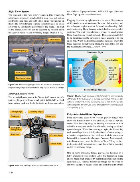
Flapping is caused by a phenomenon known as dissymmetry<br />
of lift. As the plane of rotation of the rotor blades is tilted and<br />
the helicopter begins to move forward, an advancing blade<br />
and a retreating blade become established (on two-bladed<br />
systems). The relative windspeed is greater on an advancing<br />
blade than it is on a retreating blade. This causes greater lift<br />
to be developed on the advancing blade, causing it to rise<br />
up or flap. When blade rotation reaches the point where the<br />
blade becomes the retreating blade, the extra lift is lost and<br />
the blade flaps downward. [Figure 1-97]<br />
Direction of Flight<br />
Pitch horn<br />
Feathering hinge<br />
Feathering hinge<br />
Figure 1-95. The teetering hinge allows the main rotor hub to tilt, and<br />
the feathering hinge enables the pitch angle of the blades to change.<br />
Semirigid Rotor System<br />
The semirigid rotor system in Figure 1-96 makes use of a<br />
teetering hinge at the blade attach point. While held in check<br />
from sliding back and forth, the teetering hinge does allow<br />
Relative wind<br />
Retreating Side<br />
Blade tip<br />
speed<br />
minus<br />
helicopter<br />
speed<br />
(200 knots)<br />
Blade rotation<br />
Blade rotation<br />
Forward Flight 100 knots<br />
Advancing Side<br />
Blade tip<br />
speed<br />
plus<br />
helicopter<br />
speed<br />
(400 knots)<br />
Figure 1-97. The blade tip speed of this helicopter is approximately<br />
300 knots. If the helicopter is moving forward at 100 knots, the<br />
relative windspeed on the advancing side is 400 knots. On the<br />
retreating side, it is only 200 knots. This difference in speed causes<br />
a dissymetry of lift.<br />
Relative wind<br />
Coning hinge<br />
Blade grip<br />
Blade pitch<br />
change horn<br />
Pitch link<br />
Teetering hinge<br />
Blade grip<br />
Coning hinge<br />
Swash plate<br />
Fully Articulated Rotor System<br />
Fully articulated rotor blade systems provide hinges that<br />
allow the rotors to move fore and aft, as well as up and<br />
down. This lead-lag, drag, or hunting movement as it is<br />
called is in response to the Coriolis effect during rotational<br />
speed changes. When first starting to spin, the blades lag<br />
until centrifugal force is fully developed. Once rotating, a<br />
reduction in speed causes the blades to lead the main rotor<br />
hub until forces come into balance. Constant fluctuations in<br />
rotor blade speeds cause the blades to “hunt.” They are free<br />
to do so in a fully articulating system due to being mounted<br />
on the vertical drag hinge.<br />
Figure 1-96. The semirigid rotor system of the Robinson R22.<br />
One or more horizontal hinges provide for flapping on a<br />
fully articulated rotor system. Also, the feathering hinge<br />
allows blade pitch changes by permitting rotation about the<br />
spanwise axis. Various dampers and stops can be found on<br />
different designs to reduce shock and limit travel in certain<br />
1-44