Tribologytransactions
Create successful ePaper yourself
Turn your PDF publications into a flip-book with our unique Google optimized e-Paper software.
Design of Spur Gears Using Profile Modification 743<br />
Downloaded by [Manipal University], [sachidananda H K] at 21:24 26 May 2015<br />
lower in a 25 pressure angle compared to a 20 pressure angle.<br />
This analysis holds for changing of s max from point C to point D<br />
similar to point B and point C. The behavior of altered toothsum<br />
gearing performs in the same way as discussed above for<br />
changing of points from point C to point D.<br />
Morphological Investigation<br />
Generally, to ensure long-term transmission reliability in<br />
automotive vehicles the gear designer must consider requirements<br />
such as high static strength, bending fatigue, and rolling<br />
contact fatigue (William and Richard (30)). In particular, rolling<br />
contact fatigue cracks are one of the most important problems<br />
for gears (Aslantas and Tasgetiren (16); Vera and Ivana (29)).<br />
Under rolling contact, various surface damage (pitting, spalling,<br />
and cracking) occurs and cracks develop in the gear tooth surface,<br />
thus leading to loss of serviceability of the gear (Anders<br />
and Soren (13); Singh, et al. (28)). Both macro- and microcracks<br />
lead to surface damage, and subsurface cracks generate heavy<br />
surface damage like pitting. In most material failures, tensile<br />
stresses appear to be the common mode and the material surface<br />
is stretched or pulled apart, thus leading to microscopic surface<br />
cracking and macroscopic-scale pitting or spalling (Dimitrov,<br />
et al. (17); Michele and Giuseppe (23)).<br />
In a meshing gear pair LPSTC to the HPSTC only one pair of<br />
gear tooth in contact and the normal force is higher for this<br />
region. Below the LPSTC and above the HPSTC there is more<br />
than one pair in contact (Marco, et al. (22)). Hence, in the present<br />
investigation point B (LPSTC) and point D (HPSTC) on the<br />
pinion are the critical points of contact that are considered in<br />
gears for rolling type of failure. In this context, 96, 100, and 104<br />
tooth-sum gears were selected for experimentation and are subjected<br />
to fatigue loading. The surfaces at point B (LPSTC) and<br />
point D (HPSTC) on the tested pinion tooth surface were<br />
selected and specimens were prepared for morphological investigations.<br />
SEM micrographs of these surfaces are shown in Fig. 3.<br />
In the experimental results, it is observed that pitting failures<br />
occur roughly between the initial point of a single-tooth contact<br />
(point B) and pitch point C and from pitch point C to the final<br />
point of the single-tooth contact (point D) because these are the<br />
points of highest load when the contact ratio is greater than 1.2<br />
and less than 2.<br />
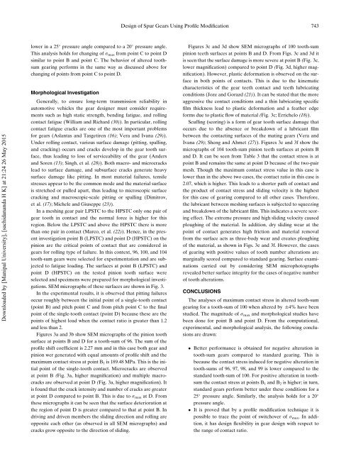
Figures 3a and 3b show SEM micrographs of the pinion tooth<br />
surface at points B and D for a tooth-sum of 96. The sum of the<br />
profile shift coefficient is 2.27 mm and in this case both gear and<br />
pinion wer generated with equal amounts of profile shift and the<br />
maximum contact stress at point B 1 is 189.48 MPa. This is the initial<br />
point of the single-tooth contact. Microcracks are observed<br />
at point B (Fig. 3a, higher magnification) and multiple macrocracks<br />
are observed at point D (Fig. 3a, higher magnification). It<br />
is found that the crack intensity and number of cracks are greater<br />
at point D compared to point B. This is due to s max at D. From<br />
these micrographs it can be seen that the surface deterioration at<br />
the region of point D is greater compared to that at point B. In<br />
driving and driven members the sliding direction and rolling are<br />
opposite each other (as observed in all SEM micrographs) and<br />
cracks grow opposite to the direction of sliding.<br />
Figures 3c and 3d show SEM micrographs of 100 tooth-sum<br />
pinion teeth surfaces at points B and D. From Figs. 3c and 3d it<br />
is seen that the surface damage is more severe at point B (Fig. 3c,<br />
lower magnification) compared to point D (Fig. 3d, higher magnification).<br />
However, plastic deformation is observed on the surface<br />
in both points of contacts. This is due to the kinematic<br />
characteristics of the gear teeth contact and teeth lubricating<br />
conditions (Joze and Gorazd (21)). It can be stated that the more<br />
aggressive the contact conditions and a thin lubricating specific<br />
film thickness lead to plastic deformation and a feather edge<br />
forms due to plastic flow of material (Fig. 3c; Errichelo (18)).<br />
Scuffing (scoring) is a form of gear tooth surface damage that<br />
occurs due to the absence or breakdown of a lubricant film<br />
between the contacting surfaces of the mating gears (Vera and<br />
Ivana (29); Sheng and Ahmet (27)). Figures 3e and 3f show the<br />
micrographs of 104 tooth-sum pinion teeth surfaces at points B<br />
and D. It can be seen from Table 3 that the contact stress is at<br />
point B and remains the same at point D because of the two-pair<br />
mesh. Though the maximum contact stress value in this case is<br />
lower than in the above two cases, the contact ratio in this case is<br />
2.07, which is higher. This leads to a shorter path of contact and<br />
the product of contact stress and sliding velocity is the highest<br />
for this case of gearing compared to all other cases. Therefore,<br />
the lubricant between meshing surfaces is subjected to squeezing<br />
and breakdown of the lubricant film. This indicates a severe scoring<br />
effect. The extreme pressure and high sliding velocity caused<br />
ploughing of the material. In addition, dry sliding wear at the<br />
point of contact generates high friction and material removal<br />
from the surface acts as three-body wear and creates ploughing<br />
of the material, as shown in Figs. 3e and 3f. However, the cases<br />
of gearing with positive values of tooth number alterations are<br />
marginally scored compared to standard gearing. Surface examinations<br />
carried out by considering SEM microphotographs<br />
revealed better surface integrity for the cases of negative number<br />
of tooth alterations.<br />
CONCLUSIONS<br />
The analyses of maximum contact stress in altered tooth-sum<br />
gearing for a tooth-sum of 100 when altered by §4% have been<br />
studied. The magnitude of s max and morphological studies have<br />
been done for point B and point D. From the computational,<br />
experimental, and morphological analysis, the following conclusions<br />
are drawn:<br />
Better performance is obtained for negative alteration in<br />
tooth-sum gears compared to standard gearing. This is<br />
because the contact stress induced for negative alteration in<br />
tooth-sums of 96, 97, 98, and 99 is lower compared to the<br />
standard tooth-sum of 100. For positive alteration in toothsum<br />
the contact stress at points B 1 and B 2 is higher; in turn,<br />
standard gears perform better under these conditions for a<br />
25 pressure angle. Similarly, the analysis holds for a 20 <br />
pressure angle.<br />
It is proved that by a profile modification technique it is<br />
possible to trace the point of switchover of s max . In addition,<br />
it has design flexibility in gear design with respect to<br />
the range of contact ratio.


