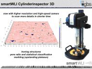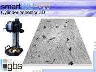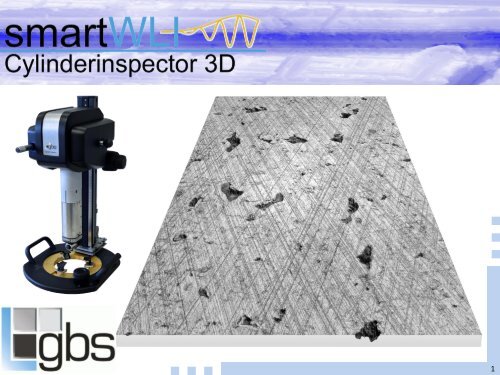
GBS_smartWLI Cylinderinspector 3D

Create successful ePaper yourself
Turn your PDF publications into a flip-book with our unique Google optimized e-Paper software.
1
Product Description<br />
Optical 3d measuring device based on white-light interferometry<br />
• designed for the control of inner cylinder surfaces for the automotive industry<br />
• Speedytec<br />
o massive parallel data processing on GPU’s<br />
o extreme fast scanning<br />
o real time 3d evaluation<br />
o optimized for steep structures<br />
o integrated data quality parameter for sample optimized filtering processes<br />
• single objectives<br />
o manual exchangeable<br />
o magnifications from 2.5x ... 100x<br />
• push button scan and evaluation macros using smartVIS <strong>3D</strong> as system- and MountainsMap as<br />
evaluation software<br />
• simplifies handling<br />
• 360° rotation<br />
• manual insertion axis<br />
• optional motorized insertion axis with automated stitching
Intention of the cylinder inspection<br />
Lapping / structuring of inner cylinder running surfaces:<br />
• structures have an essential influence on the friction:<br />
o the oil retaining volume is essential for the necessary lubrication of the friction partners piston and<br />
cylinder surface<br />
o smooth contact areas reduce the wear and friction special on lower revolution speed<br />
o pores can reduce the oil consumption still providing the necessary oil retaining volume for the<br />
lubrication of the friction partners<br />
o honing structures – angle, furrows... have an big influence of the oil transport and the<br />
hydrodynamic lubrication<br />
• the optimization of the structures can reduce the consumption of engines as well as extend the live time<br />
• there are various positive effects as reduction of the environmental pollution and reduction of the<br />
operation costs – this increase the value of cars and has a significant impact on purchase decisions<br />
Typical operation areas of the <strong>Cylinderinspector</strong><strong>3D</strong><br />
• research and development<br />
o optimization of production processes<br />
o assessment of functional behavior on basis of the 3d structures without extended tests<br />
o wear evaluation after running tests<br />
• quality control<br />
o survey of production processes<br />
o optimization of tool exchanges ... in the production
Technical Product Specification<br />
<strong>smartWLI</strong> <strong>Cylinderinspector</strong> <strong>3D</strong><br />
Cylinder Diameter 70 ... 125 mm (standard configuration)<br />
Measurement Technique White-light interferometry<br />
Height resolution / nm 1 nm (all objectives / field of views)<br />
Scanner Precision piezo drive with gauge control<br />
Scan Range 200 µm<br />
Speed up to 20 µm/s<br />
System Software smartVIS <strong>3D</strong> / Speedytec on GPU<br />
Evaluation Software MountainsMap with <strong>GBS</strong> programmed extensions<br />
Array 1624 x 1234 measuring points<br />
Weight app. 12 ... 14 kg<br />
Power Supply 100 to 240 VAC, 50/60 Hz<br />
4
Optional configuration<br />
standard<br />
extended<br />
motorized<br />
Insertion System<br />
manual down to app. 188 mm<br />
manual down to app. 270 mm<br />
automated z axis down to app. 200 mm<br />
Optical Configuration<br />
Magnification 5x 10x 20x 50x<br />
Field of View / mm 2.8 x 2.08 1.4 x 1.04 0.7 x 0.52 0.28 x 0.21<br />
Point Distance / µm 1.6 0.8 0.4 0.16<br />
5
Modern technologies require a detailed quality control<br />
Aluminum engine blocks*<br />
monolithic quasi - monolithic heterogenous - liner<br />
coated bores<br />
local material<br />
engineering<br />
dry<br />
cast-in pressed in slip-fit<br />
wet<br />
hypereutectic<br />
Al-Si alloy<br />
galvanic Ni-SiC<br />
dispersion<br />
Al matrix<br />
compound<br />
grey iron<br />
machined<br />
grey iron<br />
plasma coating<br />
AlSi/PM<br />
hypereutectic<br />
AlSi<br />
PVD thin layer<br />
TiN, TiAlN<br />
grey iron as<br />
cast with rough<br />
outer surface<br />
galvanic Ni-SiC<br />
dispersion<br />
grey iron<br />
coated<br />
laser alloying<br />
with Si<br />
plasma spayed<br />
AlSi/PM<br />
There are many competitive technologies used (green) new on<br />
the marked (yellow) or under development (red). All technologies<br />
have several production steps and need a sophisticated and<br />
adapted quality control.<br />
*Source Kolbenschmidt 2011 / Al Automotiv manual<br />
6
Evaluation parameters for inner cylinder running surfaces<br />
Honing structures:<br />
• Honing angle<br />
• Honing grooves<br />
o directional classification (rising,<br />
falling, across)<br />
o numbers, depth, area, volume<br />
o Distance between groove<br />
o Cross grooves<br />
Plateaus:<br />
• contact roughness<br />
Functional 2D Parameters<br />
• Rk, Rpk, Rvk<br />
Structure evaluation<br />
Surface Roughness<br />
Cavities / pores:<br />
• numbers / distances<br />
• volume<br />
• area<br />
• depth<br />
• distribution of cavities (according<br />
volume, area and depth)<br />
Marbling:<br />
• % over surrounding surface<br />
Functional <strong>3D</strong> Parameters<br />
• Sk, Spk, Svk<br />
7
Different surfaces and a wide range of priorities for measurements<br />
Technologies get optimized in the same directions:<br />
• lower friction<br />
• wear resistance<br />
• lower oil consumption<br />
• weight reduction<br />
...but measuring devices are use for different purposes...<br />
R&D:<br />
• detailed analysis for technology optimization<br />
Quality control:<br />
• fast survey of predetermined parameters<br />
• different priorities for the used technology<br />
8
Scans with various magnifications<br />
2,5 x Objective<br />
10 x Objective<br />
50 x Objective<br />
more structures per scan – more details from each structure<br />
5 x Objective 20 x Objective 100 x Objective<br />
9
Sample: many cavities but not enough details of honing structures<br />
Partial area of a single scan using the 2.5x Objective<br />
FOV: 7.2 x 4.5 mm²<br />
time:
Sample: many detail but only a single (large) groove inside<br />
Single scan using the 50x Objective<br />
FOV: 0.28 x 0.21 mm²<br />
time:
Sample: local variation of cavities, multiple scans necessary<br />
mm<br />
2.0<br />
1.5<br />
1.0<br />
FOV: 7,2 x 4,5 mm²<br />
time:
Recommendation for the correct field of view<br />
Check list to select the correct system configuration:<br />
• min. 10x higher resolution in xyz than the feature which should be measured<br />
• min. 10 evaluation features inside the scanning area<br />
• min. 10 measuring positions for statistical analysis<br />
feature parameter reality* required system parameter<br />
seize depth density xy res. z res. area<br />
cavities area 500 µm² > 1 µm 10 / mm² 1 / mm
Robust form filtering<br />
cylinder surface<br />
filtered surface (z-range reduced)<br />
surface with out marked cavities<br />
robust filtered surface (z-range reduced)<br />
Robust filters (polynomial, gaussian and combinations) are the basis for all following evaluation processes.<br />
“Robust” are filters, which eliminate the influence of cavities and avoid local waves on the filtered surface.<br />
14
Structure separation<br />
robust filtered cylinder surface<br />
honing<br />
cavities<br />
marbling<br />
Structure characteristics (directional orientation, depth, height, seize) can be used to separate the<br />
structures from each other and evaluate them separately.<br />
15
Honing Structure FFT Analysis<br />
mm<br />
1.0<br />
0.8<br />
0.6<br />
µm<br />
1<br />
0<br />
mm<br />
1.0<br />
0.8<br />
0.6<br />
µm<br />
1<br />
0<br />
-1<br />
-2<br />
0.4<br />
0.2<br />
0.0<br />
0.0 0.5 1.0 mm<br />
-1<br />
-2<br />
-3<br />
0.4<br />
0.2<br />
0.0<br />
0.0 0.5 1.0 mm<br />
-3<br />
-4<br />
-5<br />
-6<br />
Parameters Value Unit<br />
Honing Angle - Honing Structure FFT Analysis 18.20 °<br />
Rising Grooves - Honing Structure FFT Analysis 16.20 °<br />
Falling Grooves - Honing Structure FFT Analysis 20.20 °<br />
Rising Structures - Honing Structure FFT Analysis 26.11 %<br />
Falling Structures - Honing Structure FFT Analysis 34.52 %<br />
Cross Structures - Honing Structure FFT Analysis 2.00 %<br />
Closed Structures - Honing Structure FFT Analysis 37.37 %<br />
Parameters Value Unit<br />
Honing Angle - Honing Structure FFT Analysis 18.05 °<br />
Rising Grooves - Honing Structure FFT Analysis 17.20 °<br />
Falling Grooves - Honing Structure FFT Analysis 18.90 °<br />
Rising Structures - Honing Structure FFT Analysis 8.86 %<br />
Falling Structures - Honing Structure FFT Analysis 14.05 %<br />
Cross Structures - Honing Structure FFT Analysis 4.52 %<br />
Closed Structures - Honing Structure FFT Analysis 72.57 %<br />
Comment:<br />
The <strong>GBS</strong> programmed Honing Structure FFT Analysis allowed a separate analysis of rising and falling structures. The<br />
sample on the right site shows a higher percentage of closed structures because of the cavities (positive) but also more<br />
cross structures. The scan on the left side shows a more falling structures and on the right side more rising structures.<br />
16
Key cavities<br />
1.00 µm<br />
Number of islands 44<br />
Threshold 1.00 µm<br />
Parameters Unit Grain #1 Grain #2 Grain #3 Grain #4 Grain #5 Grain #6 Grain #7 Grain #8 Grain #9 Grain #10 Grain #11 Grain #12 Grain #13<br />
Area mm² 0.0056 0.00515 0.00307 0.00291 0.00235 0.0017 0.00169 0.00159 0.00158 0.0013 0.00113 0.000941 0.000933<br />
Aspect ratio 1.53 1.58 3.41 2.92 2.73 3.83 2.02 2.19 4.03 2.42 2.98 2.67 1.91<br />
Volume µm³ 13995 20813 6088 8015 2807 2576 4531 3282 2414 2432 1116 2045 3372<br />
Max height µm 4.74 9.98 4.00 6.73 2.70 4.67 4.54 3.31 2.89 4.36 2.67 4.29 9.11<br />
Height/Surface ratio µm/mm² 847 1937 1304 2310 1148 2740 2688 2086 1831 3358 2365 4557 9767<br />
Status 0 0 0 0 0 0 0 0 0 0 0 0 0<br />
Separated cavities could be counted and statistically<br />
evaluated.<br />
Many classificatory operator – as depth, volume, form<br />
factors ... can be used to analyze many partial aspects<br />
from the cavities.<br />
17
Key aspect “marbling”<br />
photorealistic 3d plot<br />
grey coded 3d plot<br />
Marbling – the camera image shows an texture as could be seen on marble surfaces. The black lines are<br />
cracks in the surface. Inner tensions could cause that surface plateaus standing out of the surrounding<br />
areas.<br />
18
Key aspect “marbling”<br />
0.20000 µm<br />
NM<br />
Number of islands 23<br />
Threshold 0.20000 µm<br />
Parameters Stat. Value Unit<br />
Area Mean 0.0014092 mm²<br />
Volume Mean 328.36 µm³<br />
Marbling – areas which are standing up can be detected and evaluated.<br />
19
Key 2d parameters<br />
µm<br />
5<br />
0<br />
-5<br />
-10<br />
Context Mean Std dev Min Max<br />
ISO 4287<br />
Amplitude parameters - Roughness profile<br />
Rp µm Robust Gaussian filter, 0.8 m … 0.786 0.328 0.332 1.80<br />
Rv µm Robust Gaussian filter, 0.8 m … 3.07 2.73 0.192 14.5<br />
Rz µm Robust Gaussian filter, 0.8 m … 3.86 2.86 0.773 15.5<br />
Rt µm Robust Gaussian filter, 0.8 m … 5.09 2.96 0.873 16.0<br />
Ra µm Robust Gaussian filter, 0.8 m … 0.318 0.269 0.118 1.65<br />
Rq µm Robust Gaussian filter, 0.8 m … 0.587 0.594 0.146 3.50<br />
ISO 13565<br />
ISO 13565-2<br />
Rk µm Robust Gaussian filter, 0.8 m … 0.489 0.0688 0.344 0.809<br />
Rpk µm Robust Gaussian filter, 0.8 m … 0.280 0.155 0.0951 1.03<br />
Rvk µm Robust Gaussian filter, 0.8 m … 1.81 1.73 0.106 11.3<br />
-15<br />
-20<br />
0.0 0.2 0.4 0.6 0.8 1.0 1.2 1.4 mm<br />
Information<br />
Profile<br />
T-axis<br />
honing with cavities > Mirrored (in Z) > Filtered (Median Denoising 5x5) > Resampled (812 points x 617 line…<br />
Y-axis = -0.549 mm<br />
Parameters Value Unit<br />
Length 1.44 mm<br />
All available lines can be analyzed parallel and statistically classified to increase the significance of results.<br />
20
Key 3d parameters<br />
Sk<br />
Spk<br />
Svk<br />
0<br />
1<br />
2<br />
3<br />
0 10 20 30 40 50 60 70 80 90 100 %<br />
10.0<br />
Vmp<br />
%<br />
80.0 % Vvc<br />
Vmc<br />
4<br />
5<br />
6<br />
7<br />
8<br />
9<br />
10<br />
Vvv<br />
0 20 40 60 80 100 %<br />
Sr1<br />
Sr2<br />
Information<br />
Filter settings Unfiltered.<br />
Parameters Value Unit<br />
Sk 0.532 µm<br />
Spk 0.313 µm<br />
Svk 2.10 µm<br />
Sr1 10.2 %<br />
Sr2 88.2 %<br />
Sa1 16049 µm³/mm²<br />
Sa2 123864 µm³/mm²<br />
11<br />
12<br />
13<br />
14<br />
15<br />
16<br />
µm<br />
Parameters Value Unit<br />
Vmp 0.0147 ml/m2<br />
Vmc 0.187 ml/m2<br />
Vvc 0.264 ml/m2<br />
Vvv 0.138 ml/m2<br />
Parameters as Spk can be used to evaluate the contact roughness.<br />
21
Gehring is using the <strong>smartWLI</strong>’s to optimize production processes<br />
Gehring today:<br />
• Expert for functional surface optimization<br />
• since 1926 worldwide leader for lapping<br />
technologies<br />
• partner for many automotive companies<br />
• worldwide 9 locations with app. 800 employers<br />
• head quarter in Ostfildern near Stuttgart<br />
Technologies:<br />
Technological motivation<br />
EU 2020<br />
95 g CO 2 /km<br />
fuel consumption<br />
optimized<br />
friction<br />
optimized<br />
functional surfaces<br />
honing machines<br />
honing tools<br />
abrasives<br />
Laser systems<br />
Lapping Thermal spraying Laser structuring<br />
22
friction coefficient µ<br />
Structures with high retaining volume and reduced oil consumption<br />
Stribeck-curve<br />
the friction will be reduced and the<br />
minimum achieved on lower speed<br />
(revolution) speed / v<br />
23
Surfaces with functional optimized laser structures<br />
Spk: 0.19 µm<br />
bearing shells will be fixed on elevated<br />
laser structures (much higher friction<br />
and nearly 20x larger Spk values)<br />
Spk: 3.52 µm<br />
24
Rz / nm<br />
Ra / nm<br />
Proven system accuracy<br />
certificate<br />
Rz: 128.4 (113.0 ... 143.8) nm<br />
Ra: 24.1 (21.4 ... 26.8) nm<br />
measurement results:<br />
Rz: 144.6 nm (std. Rz: 3 nm)<br />
Ra: 24.7 nm (std. Ra: 0.7 nm)<br />
field of view: 1.4 x 1.04 mm²<br />
scan time: < 2 s<br />
point density: 0.8 µm<br />
mode:<br />
high resolution<br />
VSI<br />
28<br />
27<br />
26<br />
25<br />
24<br />
23<br />
160<br />
155<br />
repetition<br />
0 5 10 15 20 25 30 35<br />
repetition<br />
150<br />
145<br />
140<br />
0 5 10 15 20 25 30 35<br />
25
Advantages of the <strong>smartWLI</strong> technology<br />
General advantages of the <strong>smartWLI</strong> <strong>Cylinderinspector</strong> <strong>3D</strong><br />
• easy handling<br />
• short scanning time<br />
• complete software based on MountainsMap with customized evaluation macros and <strong>GBS</strong> programmed<br />
functional extensions for the evaluation of honing structures<br />
• insertion depth up to 270 mm<br />
Compared to systems based on confocal measuring technologies<br />
• extreme height resolution of 1 nm for all magnification / objectives<br />
• no reduction of the height resolution for larger scanning areas in single scans<br />
• independent height calculation of direct neighborhood points for improved xy resolution<br />
• without limitations as pinhole density of confocal microscopes<br />
• using of high resolution matrix cameras<br />
Compared to competitive systems with based on similar White-light interferometric technology<br />
• Speedytec use the power of high speed graphic cards or FPGA’s and provides always real time<br />
calculation of the point cloud even for high speed high resolution matrix cameras<br />
• improved algorithms using the high speed image processing of graphic cards or FPGA’s provide a lower<br />
noise and better data quality on geometries with steep slopes and samples with extreme black white<br />
differences<br />
„leading company’s recommend the white light interferometry as preferred method<br />
for cylinder inspections...“<br />
26