
Create successful ePaper yourself
Turn your PDF publications into a flip-book with our unique Google optimized e-Paper software.
Avigilon Control Center<br />
<strong>Enterprise</strong> Client User<br />
Guide<br />
Version 5.10
© 2006 - 2016, Avigilon Corporation. All rights reserved. AVIGILON, the AVIGILON logo, AVIGILON CONTROL<br />
CENTER, <strong>ACC</strong>, HIGH DEFINITION STREAM MANAGEMENT (HDSM), HDSM and RIALTO are trademarks of<br />
Avigilon Corporation. Other product names mentioned herein may be the trademarks of their respective<br />
owners. The absence of the symbols and ® in proximity to each trademark in this document is not a disclaimer<br />
of ownership of the related trademark. Avigilon Corporation protects its innovations with patents issued in the<br />
United States of America and other jurisdictions worldwide: http://www.avigilon.com/patents. Unless stated<br />
explicitly and in writing, no license is granted with respect to any copyright, industrial design, trademark, patent<br />
or other intellectual property rights of Avigilon Corporation or its licensors.<br />
This document has been compiled and published covering the latest product descriptions and specifications.<br />
The contents of this document and the specifications of the products discussed herein are subject to change<br />
without notice. Avigilon Corporation reserves the right to make any such changes without notice. Neither<br />
Avigilon Corporation nor any of its affiliated companies: (1) guarantees the completeness or accuracy of the<br />
information contained in this document; or (2) is responsible for your use of, or reliance on, the information.<br />
Avigilon Corporation shall not be responsible for any losses or damages (including consequential damages)<br />
caused by reliance on the information presented herein.<br />
Avigilon Corporation<br />
http://www.avigilon.com<br />
PDF-CLIENT5-E-I<br />
Revision: 1 - EN<br />
20160824<br />
ii
Table of Contents<br />
What is the Avigilon Control Center Client? 1<br />
System Requirements 1<br />
Updating the Help Files 1<br />
For More Information 2<br />
The Avigilon Training Center 2<br />
Support 2<br />
Upgrades 2<br />
Feedback 2<br />
Getting Started 3<br />
Starting Up and Shutting Down 3<br />
Starting Up the Client Software 3<br />
Shutting Down the Client Software 3<br />
Logging In to and Out of a Site 3<br />
Logging In 4<br />
Logging Out 4<br />
Changing the Administrator Password 5<br />
Navigating the Client 5<br />
Application Window Features 6<br />
System Explorer Icons 7<br />
Adding and Removing Cameras in a View 7<br />
Adding a Camera to a View 7<br />
Removing a Camera from a View 8<br />
Viewing Live and Recorded Video 8<br />
Accessing the Setup Tab 8<br />
System Administration 10<br />
Sites and Servers 10<br />
Discovering Sites 10<br />
Sharing Discovered Sites Between Users 11<br />
Managing Site Logs 11<br />
Managing User Connections 12<br />
Monitoring Site Health 12<br />
Site Settings 13<br />
Naming a Site 14<br />
Editing the Site View 14<br />
Corporate Hierarchy 15<br />
iii
Managing Users and Groups Across Multiple Sites 15<br />
Best Practices 15<br />
Setting Up a Corporate Hierarchy 16<br />
Ranks 17<br />
Unranked Groups 18<br />
Deleted Ranks 18<br />
Ranked Site Families 18<br />
Managing Servers in a site 19<br />
Adding Servers to Sites 19<br />
Disconnecting a Server from a site 20<br />
Connecting Site Families 20<br />
Disconnecting Site Families 21<br />
Upgrading Servers in a Site 21<br />
Removing an Upgrade Installer 23<br />
Connecting/Disconnecting Cameras and Devices 23<br />
Discovering a Device 23<br />
Connecting a Device to a Server 24<br />
Connecting Cameras to a Video Analytics Appliance 25<br />
Editing the Device Connection to a Server 26<br />
Failover Connections 26<br />
Setting Up a Failover Connection 27<br />
Example 27<br />
Disconnecting a Device from a Server 29<br />
Upgrading Camera Firmware 29<br />
Users and Groups 29<br />
Adding a User 29<br />
Editing and Deleting a User 30<br />
Adding Groups 30<br />
Editing and Deleting a Group 31<br />
Importing Active Directory Groups 31<br />
Alarms 32<br />
Adding a New Alarm 32<br />
Editing and Deleting Alarms 34<br />
External Notifications 35<br />
Setting Up the Email Server 35<br />
Configuring Email Notifications 35<br />
Editing and Deleting an Email Notification 36<br />
Enabling Central Station Monitoring 37<br />
iv
Rules 38<br />
Adding a Rule 38<br />
Editing and Deleting a Rule 39<br />
Backing Up System Settings 39<br />
Restoring System Settings 40<br />
Scheduling Site Events 41<br />
Server Settings 42<br />
Naming a Server 42<br />
Recording Schedule 43<br />
Adding and Editing a Recording Schedule Template 43<br />
Editing and Deleting a Template 44<br />
Setting Up a Weekly Recording Schedule 44<br />
Recording and Bandwidth 44<br />
Scheduled Archive 45<br />
POS Transactions 46<br />
Adding a POS Transaction Source 47<br />
Adding a Transaction Source Data Format 47<br />
Adding a Transaction Exception 49<br />
Editing and Deleting a POS Transaction Source 49<br />
License Plate Recognition 50<br />
Setting Up License Plate Recognition 50<br />
Configuring the Watch List 50<br />
Adding Licenses to the Watch List 51<br />
Deleting a License Plate from the Watch List 51<br />
Exporting a Watch List 51<br />
Importing a Watch List 51<br />
Device Settings 52<br />
General 52<br />
Setting a Device's Identity 52<br />
Configuring PTZ 52<br />
Changing the Camera Operating Priority 53<br />
Enabling or Disabling Video Analytics Display 54<br />
Rebooting a Device 55<br />
Network 55<br />
Image and Display 56<br />
Changing Image and Display Settings 56<br />
Zooming and Focusing the Camera Lens 58<br />
Dewarping a Fisheye Lens 59<br />
v
Compression and Image Rate 59<br />
Enabling Idle Scene Mode 60<br />
Manually Adjusting Recorded Video Streams 61<br />
Image Dimensions 62<br />
Motion Detection 63<br />
Setting Up Pixel Motion Detection 63<br />
Setting Up Classified Object Motion Detection 64<br />
Self-Learning Video Analytics 66<br />
Configuring Video Analytics Cameras 66<br />
Configuring Video Analytics Appliances 67<br />
Self-Learning 68<br />
What is Self-Learning? 68<br />
Enabling Self-Learning 69<br />
Teach By Example 69<br />
Assigning Teach Markers 70<br />
Managing Teach Markers 71<br />
Applying Teach Markers to the Device 71<br />
Removing Teach Markers from the Device 71<br />
Video Analytics Events 72<br />
Adding Video Analytics Events 72<br />
Editing and Deleting Video Analytics Events 73<br />
Privacy Zones 73<br />
Adding a Privacy Zone 74<br />
Editing and Deleting a Privacy Zone 74<br />
Manual Recording 74<br />
Digital Inputs and Outputs 75<br />
Setting Up Digital Inputs 75<br />
Setting Up Digital Outputs 75<br />
Microphone 76<br />
Speaker 76<br />
Client Settings 78<br />
General Settings 78<br />
Video Display Settings 79<br />
Displaying Analog Video in Deinterlaced Mode 79<br />
Displaying Logical IDs 79<br />
Displaying Image Overlays 79<br />
Changing Display Quality 80<br />
Joystick Settings 81<br />
vi
Configuring an Avigilon USB Professional Joystick Keyboard For Left-Hand Use 81<br />
Configuring a Standard USB Joystick 81<br />
Discovering Sites 82<br />
Organizing Views 83<br />
Adding and Removing a View 83<br />
View Layouts 83<br />
Selecting a Layout for a View 83<br />
Editing a View Layout 84<br />
Making a View Full Screen 85<br />
Ending Full Screen Mode 85<br />
Cycling Through Views 85<br />
Saved Views 85<br />
Saving a New View 85<br />
Opening a Saved View 86<br />
Editing a Saved View 86<br />
Renaming a Saved View 86<br />
Deleting a Saved View 86<br />
Collaborating 86<br />
Sharing a View 86<br />
Leaving a Shared View 87<br />
Virtual Matrix 87<br />
Controlling Virtual Matrix Monitors 87<br />
Editing Virtual Matrix Monitors 87<br />
Monitoring Video 89<br />
Zooming and Panning in a Video 89<br />
Using the Zoom Tools 89<br />
Using the Pan Tools 89<br />
Maximizing and Restoring an Image Panel 89<br />
Maximizing an Image Panel 89<br />
Restoring an Image Panel 90<br />
Making Image Panel Display Adjustments 90<br />
Listening to Audio in a View 90<br />
Triggering Custom Keyboard Commands 91<br />
Controlling Live Video 91<br />
Broadcasting Audio in a View 91<br />
Using Instant Replay 91<br />
PTZ Cameras 92<br />
vii
Controlling PTZ Cameras 92<br />
Programming PTZ Tours 94<br />
Triggering Manual Recording 95<br />
Camera Recording States 95<br />
Starting and Stopping Manual Recording 95<br />
Triggering Digital Outputs 96<br />
Monitoring Live POS Transactions 96<br />
Controlling Recorded Video 96<br />
Playing Back Recorded Video 96<br />
Synchronizing Recorded Video Playback 98<br />
Enabling Synchronized Recorded Video Playback 98<br />
Disabling Synchronized Recorded Video Playback 98<br />
Bookmarking Recorded Video 98<br />
Adding a Bookmark 99<br />
Exporting, Editing, or Deleting a Bookmark 99<br />
Reviewing Recorded POS Transactions 99<br />
Working with Maps 100<br />
Adding a Map 100<br />
Using a Map 102<br />
Editing and Deleting a Map 103<br />
Working with Web Pages 104<br />
Adding a Web Page 104<br />
Using a Web Page 104<br />
Editing and Deleting a Web Page 104<br />
Monitoring Alarms 105<br />
Accessing the Alarms Tab 105<br />
Reviewing Alarms 106<br />
Reviewing Alarm Video 106<br />
Acknowledging an Alarm 106<br />
Assigning an Alarm 107<br />
Bookmarking an Alarm 107<br />
Purging an Alarm 107<br />
Searching Alarms 107<br />
Exporting Alarms 107<br />
Arming Image Panels 107<br />
Monitoring License Plates 108<br />
License Plate Overlay 109<br />
Reviewing License Plate Matches 109<br />
viii
Search 110<br />
Performing an Event Search 110<br />
Viewing Search Results 110<br />
Performing a Motion Search 111<br />
Viewing Search Results 112<br />
Performing a License Plate Search 112<br />
Viewing Search Results 113<br />
Performing a Thumbnail Search 113<br />
Viewing Search Results 113<br />
Performing Text Source Transactions Search 114<br />
Viewing Search Results 115<br />
Performing an Alarm Search 115<br />
Viewing Search Results 116<br />
Performing a Bookmark Search 116<br />
Viewing Search Results 117<br />
Export 118<br />
Exporting a Snapshot of an Image 118<br />
Exporting Native Video 120<br />
Exporting AVI Video 121<br />
Exporting Still Images 123<br />
Exporting a Print Image 124<br />
Exporting WAV Audio 125<br />
Archive 127<br />
Archiving Recorded Video On Demand 127<br />
Appendix 128<br />
Detailed Feature Descriptions 128<br />
Email Notification Trigger Descriptions 128<br />
Group Permission Descriptions 129<br />
Video Analytics Event Descriptions 131<br />
Rule Event and Action Descriptions 133<br />
Rule Events 133<br />
Rule Actions 137<br />
Rule Conditions 138<br />
Alarm Trigger Source Descriptions 138<br />
Updating the Client Software 139<br />
Accessing the Web Client 139<br />
Supported License Plates 140<br />
ix
Reporting Bugs 143<br />
Keyboard Commands 143<br />
Image Panel & Camera Commands 144<br />
View Tab Commands 145<br />
View Layout Commands 146<br />
Playback Commands 146<br />
PTZ Commands (Digital and Mechanical) 147<br />
x
What is the Avigilon Control Center Client?<br />
The Avigilon Control Center (<strong>ACC</strong>) Client software works with the Avigilon Control Center Server software to<br />
give you access and control of your surveillance system.<br />
The Client software allows you to view live and recorded video, monitor events, and control user access to the<br />
Avigilon Control Center system. The Client software also gives you the ability to configure your surveillance<br />
system.<br />
The Client software can run on the same computer as the Server software, or run on a remote computer that<br />
connects to the site through a local area network (LAN) or a wide area network (WAN).<br />
What you can do in the Client software depends on the Server software edition. There are three editions of the<br />
Server software available: Core, Standard and <strong>Enterprise</strong>. Visit the Avigilon website for an overview of the<br />
features available in each edition: http://avigilon.com/products/video-surveillance/avigilon-controlcenter/editions/.<br />
System Requirements<br />
Minimum requirements<br />
Recommended requirements<br />
Monitor resolution 1280 x 1024 1280 x 1024<br />
OS*<br />
Windows Vista, Windows 7 (32-bit or 64-bit),<br />
Windows 8, Windows 8.1 or Windows 10<br />
Windows 7 (64-bit)<br />
CPU Intel Dual Core 2.0 GHz processor Quad Core 2.0 GHz<br />
System RAM 2 GB 2 GB<br />
Video card<br />
PCI Express, DirectX 10.0 compliant with<br />
256 MB RAM<br />
Network card 1 Gbps 1 Gbps<br />
Hard disk space 500 MB 500 MB<br />
PCI Express, DirectX 10.0 compliant with<br />
256 MB RAM<br />
* For all Windows versions, it is recommended that the latest Microsoft service pack be deployed.<br />
Updating the Help Files<br />
The help files for the Avigilon Control Center Client software and Virtual Matrix software are stored with the<br />
Avigilon Control Center Server application.<br />
If one of these components is ever updated before the others, the help files may become out of date or<br />
describe features that are not currently supported by your system.<br />
What is the Avigilon Control Center Client? 1
• If the help files become out of date, download and install the latest help files from the Avigilon website:<br />
http://www.avigilon.com.<br />
The help file installers are divided into regional language packs.<br />
• If the help files describe a feature that is not currently supported by your copy of the software, upgrade to<br />
the latest version.<br />
For More Information<br />
Visit Avigilon at http://www.avigilon.com for additional product documentation.<br />
The Avigilon Training Center<br />
The Avigilon Training Center provides free online training videos that demonstrate how to set up and use the<br />
Avigilon software. Register online at the Avigilon Partner Portal site to begin: http://avigilon.force.com/login.<br />
Support<br />
For additional support information, visit http://avigilon.com/support-and-downloads/. The Avigilon Partner Portal<br />
also provides self-directed support resources — register and login at http://avigilon.force.com/login.<br />
To call Avigilon Technical Support, go to http://avigilon.com/contact-us/ to find the phone number for your<br />
country.<br />
To email Technical Support, send your messages to support@avigilon.com.<br />
Upgrades<br />
Software and firmware upgrades will be made available for download as they become available. Check<br />
http://avigilon.com/support-and-downloads/ for available upgrades.<br />
Feedback<br />
We value your feedback. Please send any comments on our products and services to feedback@avigilon.com.<br />
For More Information 2
Getting Started<br />
Once the Avigilon Control Center Client software has been installed, you can start using the Avigilon High<br />
Definition Stream Management (HDSM) technology surveillance system immediately. Refer to any of the<br />
procedures in this section to help you get started.<br />
Starting Up and Shutting Down<br />
The Avigilon Control Center Client software can be started or shut down at anytime — video recording is not<br />
affected because it is controlled separately by the Server software.<br />
Starting Up the Client Software<br />
Perform one of the following:<br />
• In the Start menu, select All Programs or All Apps > Avigilon > Avigilon Control Center Client.<br />
• Double-click or desktop shortcut icon.<br />
• From the Avigilon Control Center Admin Tool, click Launch Control Center Client. For more information,<br />
see the Avigilon Control Center Server User Guide.<br />
When you are prompted, log in to your site. You can only access cameras and video after you log in.<br />
For more information, see Logging In to and Out of a Site below.<br />
Shutting Down the Client Software<br />
1. In the top-right corner of the Client software, select > Exit.<br />
2. When the confirmation dialog box appears, click Yes.<br />
Logging In to and Out of a Site<br />
To access any of the features in your <strong>ACC</strong> surveillance system, you must log in to a site.<br />
The default administrator access uses administrator as the username and no password. To maintain the security<br />
of the administrator account, it is recommended that your system administrator immediately create a password<br />
for this account after the first login. Your system administrator can then create user accounts for other users.<br />
Getting Started 3
Logging In<br />
1. Open the Site Login tab. The Site Login tab is automatically displayed if you are launching the Client<br />
software for the first time.<br />
To manually access the Site Login tab, do one of the following:<br />
• From the top-right corner of the window, select > Log In....<br />
• From the top of the application window, click to open the New Task menu, then click .<br />
2. On the left side of the Site Login tab, select one or more sites.<br />
If the site you want to log into is not shown, click Find Site... to discover the site.<br />
3. Enter your username and password for the selected sites.<br />
Or, select the Use current Windows credentials check box to automatically use the same username and<br />
password as your computer.<br />
NOTE: If you are unable to login using your current Windows credentials, your system may be using<br />
Kerberos as a network authentication protocol. Contact your network administrator for help.<br />
4. Click Log In.<br />
You are logged into the selected sites.<br />
If you want to be notified when new or disconnected sites come online, select the Notify me when additional<br />
sites become available check box.<br />
If you want to see the login page each time you launch the Client software, select the Show this tab on startup<br />
check box. If you prefer not to login each time, you can disable this option and configure automatic login from<br />
the Client Settings... dialog box.<br />
Logging Out<br />
You can log out of one or all sites at any time.<br />
To...<br />
Log out of one or select sites<br />
Log out of all sites<br />
Do this...<br />
• In the System Explorer, select one or more sites then right-click and<br />
select Log Out.<br />
1. In the top-right corner of the Client, select > Log Out.<br />
2. In the confirmation dialog box, click Yes.<br />
Related Tasks<br />
Discovering Sites 82<br />
Changing the Administrator Password 5<br />
General Settings 78<br />
Logging In 4
Changing the Administrator Password<br />
After you login with the default administrator credentials for the first time, it is recommended that you change<br />
the default administrator password.<br />
1. At the top of the application window, click to open the New Task menu. When the menu appears,<br />
click .<br />
2. In the Setup tab, click .<br />
3. In the following dialog box, select the administrator user name and click .<br />
4. Click Change Password....<br />
5. In the following dialog box, enter a new password and then confirm the new password.<br />
6. Click OK.<br />
Tip: If you forget the administrator password, resetting the password is difficult and impacts every server in the<br />
site. To avoid this issue, it is highly recommended that you create at least one other administrator level user as a<br />
backup.<br />
Navigating the Client<br />
Once you log in, the Avigilon Control Center Client application window is populated with all the features that are<br />
available to you.<br />
NOTE: Some features are not displayed if the server does not have the required license, or if you do not have<br />
the required user permissions.<br />
Changing the Administrator Password 5
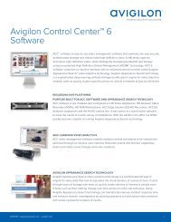
Figure 1: The Avigilon Control Center Client application window.<br />
Application Window Features<br />
Area<br />
Description<br />
Displays all the elements in your surveillance system.<br />
1 System Explorer<br />
Use the Search... bar to quickly locate anything that is available in the<br />
System Explorer. You can search for items by name, and devices can<br />
also be searched for by location, logical ID, serial number and IP<br />
address.<br />
2 View tab<br />
3 Image panel<br />
Tip: The content of the System Explorer changes depending on the tab<br />
you have open. For example, servers are not listed in the View tab.<br />
Allows you to monitor video and organize image panels. You can have<br />
multiple Views open at once.<br />
Displays live or recorded video from a camera. The video control<br />
buttons are displayed when you move your mouse into the image<br />
panel.<br />
4 Toolbar Provides quick access to commonly used tools.<br />
5 Task tabs Displays all the tabs that are currently open.<br />
Application Window Features 6
Area Description<br />
The New Task button<br />
The Application Menu<br />
menu<br />
System message list<br />
Opens the New Task menu so you can select and open new task tabs.<br />
You can access advanced tools like Search and Export, or system<br />
administrative features like Site Setup.<br />
This menu gives you access to local application settings like Client<br />
Settings.... You can also open a new window from this menu.<br />
The highlighted number shows the number of system messages that<br />
need your attention. Click the number to display the list of messages.<br />
The highlight color indicates the severity of the most recent message.<br />
• Red = Error<br />
• Yellow = Warning<br />
• Green = Information<br />
System Explorer Icons<br />
Icon<br />
Description<br />
A site. Listed under a site are all the connected devices and linked features in the system.<br />
A server.<br />
A camera.<br />
A PTZ camera.<br />
An encoder.<br />
A Virtual Matrix monitor.<br />
A saved View.<br />
A map.<br />
A web page.<br />
Adding and Removing Cameras in a View<br />
To monitor video, add a camera to a View. Camera video can be removed from a View at any time.<br />
Adding a Camera to a View<br />
Do one of the following:<br />
• Drag the camera from the System Explorer to an empty image panel in the View tab.<br />
• Double-click a camera in the System Explorer.<br />
• In the System Explorer, right-click the camera and select Add To View.<br />
The camera is added to the next empty image panel in the View layout.<br />
Tip: You can drag the same camera to multiple image panels to watch the video at different zoom levels.<br />
System Explorer Icons 7
Removing a Camera from a View<br />
Do one of the following:<br />
• Right-click the image panel and select Close.<br />
• Inside the image panel, click .<br />
Viewing Live and Recorded Video<br />
NOTE: Some features are not displayed if the server does not have the required license, or if you do not have<br />
the required user permissions.<br />
When you monitor video, you can choose to watch live and recorded video in the same View tab, or only one<br />
type of video per View.<br />
Once you've added cameras to the View tab, you can do the following:<br />
• To switch all of the image panels in the View between live and recorded video, click either Live or<br />
Recorded on the toolbar.<br />
• To switch individual image panels between live and recorded video, right-click the image panel and<br />
select either Live or Recorded.<br />
Image panels displaying recorded video have a green border.<br />
Accessing the Setup Tab<br />
The Setup tab is where you would configure the majority of your system – including sites, servers and cameras.<br />
Follow one of the following steps to open the Setup tab:<br />
• At the top of the application window, click to open the New Task menu then click .<br />
• In the System Explorer, right-click the device you want to configure then select Setup.<br />
Removing a Camera from a View 8
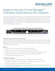
Figure 2: The Setup tab<br />
In the Setup tab, the System Explorer is displayed on the left and the Setup options are displayed on the right.<br />
The Setup options change depending on the device that is selected in the System Explorer.<br />
Accessing the Setup Tab 9
System Administration<br />
NOTE: Some features are not displayed if the server does not have the required license, or if you do not have<br />
the required user permissions.<br />
In Avigilon Control Center 5 software, servers are maintained in clusters called sites. Each site can contain<br />
multiple servers that share configuration settings across the entire site.<br />
At the site level, you can manage your server and device connections, as well as set up site-wide system<br />
events.<br />
At the server level, you can manage the recording and bandwidth for each of the server's connected cameras.<br />
At the device level, you can edit the camera image quality and other device-specific features.<br />
All the site, server and device settings can be configured from the Setup tab.<br />
Sites and Servers<br />
In the Avigilon Control Center software, servers are organized in clusters called sites. By organizing the system<br />
into clusters, you are able to control user access and system wide events through the site settings. Site settings<br />
are stored on the server, or across all servers in a multi-server system.<br />
Depending on your system and license edition, you may have multiple servers in a site. When there are multiple<br />
servers in a site, the site is able to distribute tasks and system data between the servers so that the system can<br />
continue running even if a server fails.<br />
Within a site, each individual server is responsible for managing the devices that are connected to it.<br />
Specifically, the server controls video recording. Through the server settings, you control when video is<br />
recorded, how long it is stored, and how much bandwidth is used to stream video.<br />
For more information about managing servers in a site, see Managing Servers in a site on page 19.<br />
Discovering Sites<br />
If your computer is on the same network segment (subnet) as a site, that site is automatically discovered and<br />
displayed in the System Explorer.<br />
If the site you want to access is not listed, it is because the site is on a different subnet and must be manually<br />
discovered. There is no limit to the number of sites that can be discovered by the Client software.<br />
Tip: After you discover and login to a parent site, all the child sites are automatically discovered.<br />
By default, when a server is first connected to the system, it is added to a site with the same name. To locate a<br />
new server, you need to search for its site.<br />
System Administration 10
1. Open the Find Site dialog box.<br />
• In the top-right corner of the Client, select > Log In... . In the Site Login tab, click Find Site....<br />
• Or, select > Client Settings... > Site Networking. In the Site Networking tab, click Find Site....<br />
2. In the dialog box, enter the IP Address/Hostname: and the Base Port: of the server in the site you want to<br />
discover.<br />
The base port is 38880 by default. You can change the base port number in the Avigilon Control Center<br />
Admin Tool. For more information, see The Avigilon Control Center Server User Guide.<br />
3. Click OK.<br />
If the site is found, it is automatically added to the site list.<br />
If the site is not found, check the following then try again:<br />
• The network settings are configured correctly.<br />
• The firewall is not blocking the application.<br />
• The Avigilon Control Center Server software is running on the server you searched for.<br />
Sharing Discovered Sites Between Users<br />
NOTE: Some features are not displayed if the server does not have the required license, or if you do not have<br />
the required user permissions.<br />
If you manually discovered a site, all users with access to the same copy of the application will be able to access<br />
the discovered site. However, the site will be hidden if the user does not have permission to access the<br />
discovered site.<br />
The connection speed used to connect to the discovered site will be the same for all users.<br />
Managing Site Logs<br />
The Site Logs record events that occur in the <strong>ACC</strong> software. This can be useful for tracking system usage and<br />
diagnosing issues.<br />
You can filter the items displayed in the log and save the log to a separate file for sending to Avigilon support.<br />
NOTE: The Site Logs maintain a record of system events for as long as video data is available or 90 days,<br />
whichever is longer.<br />
1. In the New Task menu, click .<br />
The Site Logs tab is displayed.<br />
2. In the top-left Event Types to Show: area, select the types of logs that you want to see.<br />
3. In the Event Sources: area, you can filter the logs by selecting the specific site, server or device logs that<br />
you want to see.<br />
4. In the Time Range to Search: area, set the date and time range of the search.<br />
5. Click Search.<br />
Sharing Discovered Sites Between Users 11
6. Select a search result to display the event details at the bottom of the tab.<br />
7. To save the log search results, click Save events to file.... You can choose to save the search results as a<br />
text file or a CSV file.<br />
Managing User Connections<br />
If you find that too many users are logged in through the same username, or inactive users are preventing active<br />
users from accessing a site, you can force specific users to log out.<br />
1. In the New Task menu, click . The User Connections tab is displayed.<br />
2. Select a site from the System Explorer to display a list of all the current users on the right.<br />
• The users are listed by User Name and Machine Name so that users that share a login are<br />
displayed separately.<br />
• The Login Duration column lets you know how long that user has been logged in to the site.<br />
3. To force a user to log out of a site, select a user then click Log Users Out.<br />
Monitoring Site Health<br />
To help you monitor the health of your site, you can access a quick overview in the Site Health tab.<br />
• In the New Task menu, click . The Site Health tab is displayed.<br />
o<br />
To export a PDF copy of all the site details, click Export Site Report to PDF at the bottom-right<br />
corner.<br />
The status icons beside each site name identifies the overall health of the site. In the System Explorer, select a<br />
site to display the status of the connected servers.<br />
If your sites are configured into a family, you will be able to see the status of all Child sites if you are logged into<br />
the Parent site. If you are only logged into a Child site, the Parent site status is displayed as unknown.<br />
The following health symbols identify the status of each component in the <strong>ACC</strong> software:<br />
• — the component is functioning normally.<br />
• — the component requires your attention.<br />
• — the component is unavailable or offline.<br />
• — the component status is unknown.<br />
At the top of the tab, click any of the available filters to choose what type of information is displayed. By default,<br />
all available information is displayed.<br />
Listed information include:<br />
Managing User Connections 12
Feature<br />
Description<br />
Server Name — at the top of each pane is the name of the individual server in the site. Beside the name is the<br />
server status.<br />
General Information: Information about the server in the site.<br />
Server IP:<br />
Total Camera Licenses:<br />
Camera Licenses in Use:<br />
CPU Load of <strong>ACC</strong> Server:<br />
Memory usage of <strong>ACC</strong> Server:<br />
System Available Memory:<br />
Up Time:<br />
The server's IP address.<br />
The total number of camera channel licenses that have<br />
been applied to the server.<br />
The number of cameras that are currently connected to the<br />
server.<br />
The percentage of server processing power that is used by<br />
the Avigilon Control Center Server software.<br />
The amount of memory used by the Avigilon Control<br />
Center Server software.<br />
The amount of storage available for video recording.<br />
The amount of time the server has been running since it<br />
was last rebooted.<br />
Network Adapters: The networks that the server is connected to, including the IP address of the network<br />
connection, the network speed and the amount of data passing through the connection.<br />
Adapter Name<br />
Link Speed<br />
IP<br />
Incoming<br />
Outgoing<br />
The name of the network adapter that is connected to the<br />
server.<br />
The maximum speed supported by the network adapter.<br />
The IP address of the network adapter.<br />
Cameras: Information about the devices that are connected to this server.<br />
The speed of incoming data. This includes recording<br />
video.<br />
The speed of outgoing data. This includes video streaming<br />
to the Client software.<br />
NOTE: If the device is disconnected, the device's details may still be displayed but the Compression column is<br />
empty because there is no video streaming.<br />
General<br />
Network<br />
Hardware<br />
Compression<br />
The name, model number and location of the device.<br />
The IP and MAC addresses of the device.<br />
The serial number of the device.<br />
The video compression rate, resolution, quality and images<br />
per second (ips) of video streamed from the device.<br />
Site Settings<br />
The settings stored at the site level impact all users and devices within the site.<br />
Site Settings 13
These settings include user account information and email notifications. This is also where you can set up how<br />
the System Explorer is laid out, and where you can add or remove devices in a site.<br />
NOTE: Some features are not displayed if the server does not have the required license, or if you do not have<br />
the required user permissions.<br />
Naming a Site<br />
Give the site a meaningful name so that it can be easily identified in the System Explorer. Otherwise, the site<br />
uses the name assigned to the server it was originally discovered with.<br />
1. In the site Setup tab, click .<br />
2. In the following dialog box, enter a name for the site.<br />
3. Click OK.<br />
Editing the Site View<br />
You can edit the way your site is organized in the View tab so that it reflects how your system is set up.<br />
By default, all cameras are listed in alphabetical order by site in the System Explorer. Through the Site View<br />
Editor, you can organize the System Explorer to display cameras by location and group items for convenience,<br />
or hide cameras that are not relevant to an ongoing investigation.<br />
NOTE: These settings only affect the System Explorer in the View tab.<br />
1. In the site Setup tab, click .<br />
The Site View Editor dialog box is displayed.<br />
2. Change the site View layout as required.<br />
• Click to add a New Folder. The New Folder is displayed as a virtual sub-site for organizational<br />
purposes only and will not have any Setup options.<br />
Double-click the New Folder to change the name.<br />
• To move one element, select the listed element then use the green arrows to move it up and<br />
down the list, or move it under a sub-site folder.<br />
• To move multiple elements, select more than one element then drag them up and down the list<br />
together, or under the same sub-site folder.<br />
• To show or hide the elements in a sub-site folder, click the arrow on the left to expand or collapse<br />
the sub-site folder.<br />
This setting determines what users see each time they log in to the site. The user can still collapse<br />
or expand sub-site folders in the System Explorer.<br />
• To sort a sub-site folder, select an element then click to sort that folder level into alphabetical<br />
Naming a Site 14
order.<br />
• To delete a sub-site folder, select the folder then click .<br />
3. Click OK to save your changes.<br />
When you open a new View tab, your changes will be displayed in the System Explorer.<br />
Corporate Hierarchy<br />
You can set up a Corporate Hierarchy in the system to reflect your organization's structure.<br />
Groups are given ranks to help define what they have access to. Users cannot see groups of equal or higher<br />
rank than the group they belong to. If users belong to multiple groups of different ranks, they will be able to view<br />
all ranks below the highest rank they belong to.<br />
Sites can also be connected together, into families, and given ranks in the Corporate Hierarchy. This further<br />
defines what devices and events users can control.<br />
Managing Users and Groups Across Multiple Sites<br />
When you have a large organization, you need detailed user access permissions to manage how the system is<br />
used each day.<br />
The Avigilon Control Center system offers several features to help you manage large organizations:<br />
• Active Directory Support: The system can synchronize with Windows Active Directory to quickly import<br />
large number of users. For more information, see Importing Active Directory Groups on page 31.<br />
• Group Privileges: Users must be added to at least one group that defines what they can access within the<br />
system. This includes system features and specific devices. Only users with Setup user and group<br />
settings permission are able to edit other users and groups at all. For more information, see Adding<br />
Groups on page 30.<br />
To help you manage groups across the system, here are some features to help you maintain secure<br />
group access:<br />
Best Practices<br />
• Corporate Hierarchy: Create a Corporate Hierarchy to determine which groups have control over<br />
other groups. For more information, see Corporate Hierarchy above.<br />
• Site Families: You can connect multiple child sites to an <strong>Enterprise</strong> parent site. You can then<br />
control group settings for all of the sites from the parent site. For more information, see Connecting<br />
Site Families on page 20.<br />
Listed here are some recommendations for maintaining an efficient and secure system:<br />
• Change the default administrator password. The default administrator user has control over all aspects of<br />
the system, so adding a password to the account is highly recommended. By default, there is no<br />
password for the administrator account.<br />
• Create a secondary user for the Administrator group. It is recommended that you do not use the default<br />
administrator user account, instead create a secondary user account with the same privileges so that the<br />
default administrator user can still be used in the rare event that the system becomes compromised.<br />
Corporate Hierarchy 15
Tip: If you forget your administrator user password, the alternate administrator user can be used to reset the<br />
password. This will avoid the need for a system-wide reset to restore the default administrator user password.<br />
• Assign a rank to all groups. Unranked groups have access over all other groups, so it is recommended<br />
that any groups with users be assigned a rank to further define their access privileges. The default<br />
Administrators group is Unranked by default, but you can create a new group with same permissions and<br />
assign a rank to the new group. For more information, see Corporate Hierarchy on the previous page.<br />
• Limit the number of users in the default Administrator group. The Administrator group is the oversight<br />
group that should only be used for system maintenance. For example, users in the default Administrator<br />
group are the only ones who can see or remove private bookmarks made by all users.<br />
• Always check that the device access permissions are correct after a child site has been connected to a<br />
parent site. Ranked groups from the parent site whose rank is above or equal to the child site retain their<br />
permissions on the child site. These groups automatically gain access to all devices, maps, saved Views,<br />
and web pages on the child site.<br />
• Always check group access permissions after a new server has been merged into the site.<br />
• If groups have the same name, the site settings are used and the users from both the site and the<br />
server are added to the group.<br />
• Groups that are new to the site automatically get access to all the devices in the site.<br />
• Groups that are new to the server automatically get access to all the devices that are connected<br />
to the server.<br />
• Always check group access permissions after new users and groups settings are imported into the site.<br />
• If groups have the same name, the import settings are used and the users from both the import file<br />
and the current site are added to the group.<br />
• Groups added from the import file automatically gain access to all the new devices that were<br />
added since the settings were exported.<br />
Setting Up a Corporate Hierarchy<br />
Corporate hierarchy is set up by assigning ranks to different access permission groups. This includes user<br />
permission groups and sites that are organized into families. For more information about ranks, see Ranks on the<br />
next page.<br />
You can assign ranks to permission groups through the Users and Groups dialog box. For more information about<br />
adding groups, see Adding Groups on page 30.<br />
You can assign ranks to sites when they are organized into families. For more information about site families, see<br />
Connecting Site Families on page 20.<br />
When you see the Rank option, you can select an existing rank or create a new one.<br />
• To use an existing rank, select an option from the drop down list. The default option is Unranked.<br />
• To add a rank, click . When you see the Edit Corporate Hierarchy dialog box, complete the following<br />
steps:<br />
If you have not yet created a Corporate Hierarchy, a message will appear prompting you to create a new<br />
one. Click Yes.<br />
The default rank is Global. It is the highest rank in the Corporate Hierarchy.<br />
Setting Up a Corporate Hierarchy 16
NOTE: The Global rank cannot be deleted. It can only be renamed.<br />
1. Select Global then click . A new rank is added.<br />
2. To rename the rank, double-click the name and enter a new one in the text field. Click anywhere<br />
outside the text field to save the new name.<br />
3. Select a rank then click to add a new rank immediately below the rank you selected.<br />
NOTE: Ranks can only be added or deleted. They cannot be moved within the Corporate<br />
Hierarchy.<br />
4. To delete a rank, select the rank then click . All subordinate ranks will also be deleted.<br />
NOTE: Make sure there are no members in the rank before you delete it. Members of a deleted<br />
rank are automatically assigned the lowest position in the corporate hierarchy and may lose<br />
required permissions.<br />
5. Click OK to save your changes.<br />
Now that you've set up the Corporate Hierarchy, you can assign ranks to permission groups to define what users<br />
can access within the system. For more information, see Users and Groups on page 29.<br />
You can also organize your sites and servers to mirror their physical location or reference their relationship in the<br />
corporate hierarchy. For more information, see Connecting Site Families on page 20.<br />
Ranks<br />
Ranks in the Corporate Hierarchy feature represent the different levels that may exist in your organization. Each<br />
rank can have different permissions and be responsible for subordinate ranks.<br />
The default rank is Global. It is the highest rank in the Corporate Hierarchy and can configure all ranks that are<br />
added below it.<br />
When you add ranks, be aware that users assigned to a rank can only edit other ranks that are subordinate in the<br />
corporate hierarchy. Any ranks that are above or parallel will not be accessible.<br />
The following image is an example of a Corporate Hierarchy with multiple ranks. Canada is the highest, Global<br />
rank. West Coast and East Coast are of equal rank to each other, and one rank below Canada. Users belonging<br />
to East Coast cannot edit ranks below West Coast and vice versa.<br />
Ranks 17
Unranked Groups<br />
The Unranked groups are above the Corporate Hierarchy and cannot be deleted or edited.<br />
Users belonging to Unranked groups are able to create and edit any ranked or Unranked groups and users if<br />
they have the Setup user and group settings privilege.<br />
The default groups Administrators, Power Users, Restricted Users, and Standard Users are Unranked.<br />
Deleted Ranks<br />
If a rank is deleted, groups in this rank are removed from the hierarchy and assigned an orphaned rank. An<br />
orphaned rank is the lowest rank possible and is only visible to Unranked and Global users.<br />
Unranked and Global users can reassign group ranks at any time. Members of the orphaned rank have no Setup<br />
user and group settings privileges but still retain other privileges, e.g. viewing live video.<br />
Deleting a rank will also delete all the ranks below it in the Corporate Hierarchy. Remotely synchronized users<br />
and groups may become inaccessible.<br />
Ranked Site Families<br />
Ranks can also be applied to sites that have been organized into families. Once a site has been assigned a rank,<br />
all groups, users and device access are subject to the site's rank in the hierarchy.<br />
Unranked Groups 18
The Corporate Hierarchy is configured through the parent site and the Global rank is associated with the parent<br />
site. For more information, see Connecting Site Families on the next page.<br />
Managing Servers in a site<br />
A site can contain multiple servers to share settings and tasks across all the servers. For example, users and<br />
groups that are added to the site will automatically have access to all linked servers.<br />
If you need users and groups to have more detailed access permissions, you can also organize each site into<br />
families to better reflect your corporate hierarchy.<br />
By default, when a server is first discovered on the network, it is added to the System Explorer as a server in a<br />
site of the same name. You can move the server to a different site to share resources.<br />
Tip: It is recommended that you plan how your system should be configured before you implement the features<br />
described in this section. This will help you avoid unnecessary cleanup and prepare for potential issues.<br />
Adding Servers to Sites<br />
By default, each site only has one server but you can add multiple servers to a site so that they can be managed<br />
together. All servers within the site share settings and are represented as one unit in the System Explorer.<br />
Tip: It is recommended that you only add new servers to an existing site to avoid managing a large number of<br />
duplicate settings, and more easily configure device connections across the combined site.<br />
This procedure is primarily for grouping a number of servers in the same local area network to work together<br />
and share settings.<br />
If the servers are installed a wide distance apart but only need to share users and group information — you can<br />
join the sites together into a site family instead. For more information, see Connecting Site Families on the next<br />
page.<br />
1. In the site Setup tab, click .<br />
The Site Management tab lists all the sites that you can access and all the servers that are connected to<br />
each site.<br />
If you do not see the site or server you want to configure, you may need to add the site. For more<br />
information, see Discovering Sites on page 82.<br />
2. When you select a server, you will see the available options at the bottom of the screen.<br />
3. To move a server:<br />
• Select the server and drag it to a different site.<br />
• Or, select the server then click Connect at the bottom-right corner of the tab. In the following<br />
dialog box, select the site you want the server to connect to.<br />
NOTE: sites without any servers are automatically removed from the list.<br />
Once the server is connected to the site, the settings are merged.<br />
Managing Servers in a site 19
• Unique settings from the server are added to the site.<br />
• If the settings are identical, only the site version is kept.<br />
• If a server setting and a site setting have the same name but are configured differently, the server setting<br />
is added to the site and renamed in this format: (server name), e.g. Email1 (Server2F).<br />
• In the rules engine, the Notify users (default) rule is always added and renamed, even if the settings<br />
are the same. The site version remains enabled but the added rule is disabled by default.<br />
• The two site Views are combined.<br />
• The site settings take precedence.<br />
For example, a map from the site was copied to the server in the past. In the server, the map was<br />
placed at the top of the site View. But in the site, the same map is placed at the bottom. After the<br />
server is connected to the site, the map takes the position used by the site (the bottom).<br />
• New, unorganized elements from the server are listed at the bottom of the site View.<br />
• User permission groups are merged.<br />
• If groups have the same name, the site settings are used and the users from both the site and the<br />
server are added to the group.<br />
• Groups that are new to the site automatically get access to all the devices in the site.<br />
• Groups that are new to the server automatically get access to all the devices that are connected<br />
to the server.<br />
• Users with the same name will use the settings configured in the site (including passwords), and gain<br />
group permissions from the server.<br />
• If the site is connected to a Windows Active Directory, the server must be connected to the same Active<br />
Directory domain or the connection will fail. For more information, see Importing Active Directory Groups<br />
on page 31.<br />
Disconnecting a Server from a site<br />
If the site has multiple servers, you can choose to disconnect a server from the current site and re-assign the<br />
server to its own site.<br />
• Select a server from the site then click Disconnect from Site....<br />
When a server is disconnected, it retains all the settings it received from its previous site.<br />
Connecting Site Families<br />
site families are sites that are connected together into a hierarchy. sites are still managed independently, but<br />
user and group information is centrally managed by the parent site.<br />
Child sites are connected to a parent site to create a site family. Once set up, all ranked user and group<br />
privileges on the parent site are applied to the child sites and controlled from the parent site. The child site can<br />
still define local users and groups.<br />
For more information about the corporate hierarchy feature, see Corporate Hierarchy on page 15.<br />
NOTE: A parent site can have multiple child sites, but a child site can only have one parent site. You must be<br />
logged in to both potential parent and child sites before you can connect them.<br />
Disconnecting a Server from a site 20
Only <strong>Enterprise</strong> sites can be parent sites. Each parent site can have up to 1 Core site, 24 Standard sites and<br />
unlimited <strong>Enterprise</strong> sites as child sites.<br />
1. In the site Setup tab, click .<br />
The Site Management tab is displayed.<br />
2. Select the site you want to connect as a child site.<br />
3. In the bottom right corner of the tab, click Connect to Parent Site.<br />
Tip: If you selected a<br />
Connect to Site....<br />
server instead of a site in the previous step, you will only have the option to<br />
4. In the following dialog box, select the parent site from the Connect to: drop down list.<br />
5. In the Rank: drop down list, select a rank for the child site. To edit or view the entire Corporate Hierarchy,<br />
click . For more information, see Setting Up a Corporate Hierarchy on page 16.<br />
6. Click OK.<br />
7. In the confirmation dialog box, click Yes.<br />
Disconnecting Site Families<br />
If a child site needs to be moved or removed from the Corporate Hierarchy, you can disconnect it from the<br />
parent site. The child site can then function independently, be reconnected to the parent site or be connected<br />
to a new parent site.<br />
Depending on your access permissions, you may only be able to perform one of the following:<br />
• To disconnect the parent site from the child site:<br />
1. In the Site Management tab, select the child site you want to disconnect.<br />
2. In the bottom right corner of the tab, click Disconnect from Parent Site....<br />
3. When the confirmation dialog box appears, click OK.<br />
NOTE: If a network issue occurs while you are disconnecting the child site, you need to also revoke<br />
access from the parent site.<br />
• To disconnect a child from the parent site:<br />
1. In the Site Management tab, select the parent site whose child site you want to disconnect.<br />
2. In the bottom right corner of the tab, click Disconnect Child Site... .<br />
3. From the drop down list, select the child site you want to disconnect.<br />
4. When the confirmation dialog box appears, click OK.<br />
Upgrading Servers in a Site<br />
NOTE: To use this feature:<br />
• All NVR servers in the site must be running <strong>ACC</strong> Server version 5.6 or later.<br />
• All <strong>ACC</strong> ES HD Recorders in the site must be running <strong>ACC</strong> Server version 5.8 or later.<br />
Disconnecting Site Families 21
If you have multiple servers in your site, you can choose to upgrade all servers through the Client software rather<br />
than update each server manually at their physical location. This feature is especially helpful when you have an<br />
enterprise system with up to 100 servers in a site.<br />
Tip: To avoid losing video connection, set up failover connections before you perform an upgrade. This allows<br />
cameras to connect to a secondary or tertiary server when the primary server is required to restart as part of the<br />
upgrade process. For more information, see Failover Connections on page 26.<br />
Tip: After you perform each step in the Site Upgrade dialog box, you can close the dialog box and continue<br />
regular operations. Be aware that cameras will briefly disconnect from the system when the server restarts as<br />
part of the upgrade process.<br />
1. Download the latest version of the Avigilon Control Center Server software or Edge Solution (ES) device<br />
firmware from the Avigilon website: http://www.avigilon.com.<br />
2. In the Client software, log in to the site.<br />
3. In the site Setup tab, click .<br />
The Site Upgrade dialog box is displayed. The dialog box lists all the servers that are in the site.<br />
If the site contains an ES camera or recorder, the Platform column is displayed. The column displays the<br />
device model number to help you identify which upgrade package you should use.<br />
4. In the top-right corner of the dialog box, click Upload.<br />
5. In the Open dialog box, locate the installer that you downloaded from the Avigilon website.<br />
6. In the Confirm Selected Installer dialog box, confirm that you've selected the correct installer then click OK.<br />
The dialog box displays the installer details in the Installer Info area and lists the servers that can be<br />
upgraded by the selected installer.<br />
The new installer is uploaded to one server then distributed to the other affected servers in the site. It<br />
may take several moments before the installer is fully uploaded.<br />
When the installer has been distributed to each server in the system, the Upgrade button is displayed<br />
beside the servers that can be upgraded by the new installer. The button is disabled until the installer has<br />
been distributed to all servers.<br />
7. Click Upgrade beside a server.<br />
a. When the confirmation dialog box is displayed, click OK to allow the server to reboot as part of the<br />
upgrade process.<br />
When the server restarts, it will disappear from the list then reappear after it reconnects with the<br />
system.<br />
To facilitate the failover connections, it is recommended that you wait for each server to complete<br />
the upgrade process before upgrading the next server.<br />
b. Repeat this step for each server in the site.<br />
Upgrading Servers in a Site 22
Removing an Upgrade Installer<br />
If you discover that you've uploaded the wrong installer to the site, you can choose to remove the installer<br />
before it is installed on a server.<br />
1. In the site Setup tab, click .<br />
2. In the following dialog box, click Remove.<br />
3. When the confirmation dialog box appears, click OK.<br />
The upgrade installer is deleted from the system.<br />
To upload a new upgrade installer to the site, see Upgrading Servers in a Site on page 21.<br />
Connecting/Disconnecting Cameras and Devices<br />
Cameras and other devices are connected to a site through the linked servers. The server manages and stores<br />
the camera's recorded video, while the site manages the events that can be linked to the camera's video.<br />
You can connect and disconnect cameras and devices through the Connect/Disconnect Cameras... tab.<br />
A camera's connection status is indicated by the icon beside the camera name in the System Explorer. The<br />
status icons may appear over any device icon in the System Explorer.<br />
Icon<br />
Definition<br />
Camera Connected<br />
The camera is connected to the server.<br />
Camera Upgrading<br />
The camera is connected to the server and is currently upgrading its firmware.<br />
The camera cannot connect to a server.<br />
Camera Connection<br />
Error<br />
Camera Disconnected<br />
No Icon<br />
This may be because the camera is no longer on the network or there is a network<br />
conflict.<br />
The camera is disconnected but recorded video from the camera remains on the<br />
server.<br />
The camera is disconnected and no recorded video from the camera remains on the<br />
server.<br />
Discovering a Device<br />
Avigilon and ONVIF devices that are connected to the same network as the Avigilon Control Center Server are<br />
automatically detected and added to the Discovered Cameras list.<br />
If a device is not automatically discovered, it may be on a different subnet or is a third party camera that needs<br />
to be manually discovered.<br />
Removing an Upgrade Installer 23
1. In the site Setup tab, click .<br />
The Connect/Disconnect Cameras... tab is displayed.<br />
2. In the top-left corner, click Find Camera....<br />
3. In the Find Camera dialog box, complete the following fields to find the device:<br />
4. Click OK.<br />
• Search From Server: select the server that you want the device to connect to.<br />
• Search Type: select a search type:<br />
• IP Address — select this option to discover a device by its IP address or hostname. The<br />
device and server’s gateway IP address must be set correctly for the device to be found.<br />
• IP Address Range — select this option to discover a device by IP address range. Only<br />
devices with IP addresses in that range will be discovered.<br />
• Camera Type: select the device's brand name.<br />
Tip: Select ONVIF to discover devices that are ONVIF compliant.<br />
• Control Port: enter the device control port. The default port number is 55080.<br />
• If required, enter the device's User Name: and Password:.<br />
If the device is discovered, it is automatically added to the Discovered Cameras list. You can now connect the<br />
device to a server.<br />
Connecting a Device to a Server<br />
NOTE: Some features are not displayed if the server does not have the required license, or if you do not have<br />
the required user permissions.<br />
To access a device from a site, it must be connected to a server within the site. The server manages and stores<br />
a camera's recorded video, while the site manages the events that can be linked to a camera's video.<br />
Once a device has been discovered on the network, it can be connected to the server. If you do not see a<br />
device you want to connect, see Discovering a Device on the previous page.<br />
1. In the site Setup tab, click .<br />
The Connect/Disconnect Cameras... tab is displayed.<br />
2. In the Discovered Cameras area, select one or more devices then click Connect....<br />
Tip: You can also drag the device to a server on the Connected Cameras list.<br />
3. In the Connect Camera dialog box, select the server you want the device to connect to.<br />
NOTE: If you are connecting multiple devices, all the cameras must use the same connection settings.<br />
4. If you are connecting a third-party device, you may choose to connect the device by its native driver. In<br />
the Camera Type: drop down list, select the device's brand name. If there is only one option in the drop<br />
down list, the system only supports one type of driver from the device.<br />
Connecting a Device to a Server 24
5. In the Connection Type: drop down list, select Primary. The device will automatically connect to this<br />
server if they are in the same network.<br />
If you are creating a failover connection, select Secondary or Tertiary.<br />
6. In the License Priority: drop down list, select the appropriate license priority. The highest priority is 1 and<br />
the lowest priority is 5.<br />
NOTE: This option is only available if you are connecting to a secondary or tertiary server.<br />
The License Priority: setting decides the order that devices are connected to the server. The server will<br />
try to connect cameras with a higher priority before cameras with lower priority. If the server does not<br />
have enough camera channel licenses, low priority devices may not be connected. A camera channel<br />
license is only used when the device actually connects to the server.<br />
7. If the camera supports a secure connection, the Camera Control: drop down list is displayed. Select one<br />
of the following options:<br />
NOTE: The setting may not be displayed if the camera only supports one of the options.<br />
• Secure — The system will protect and secure the camera's configuration and login details. This<br />
option is selected by default.<br />
• Unsecure — The camera's configuration and login details will not be secured and may be<br />
accessible to users with unauthorized access.<br />
Cameras with a secure connection are identified with the icon in the Status column.<br />
8. If it is not displayed, click to display the Site View Editor and choose where the device appears in the<br />
System Explorer.<br />
• If your site includes virtual sub-sites, select a location for the device. The list on the right updates<br />
to show what is stored in that directory.<br />
• In the site directory, drag the device up and down to set where it is displayed.<br />
• If you are connecting multiple devices at the same time, the selected devices must be assigned to<br />
the same sub-site.<br />
Tip: If the site you want is not listed, you may need to connect the device to a different server. Make sure<br />
the selected server is connected to the site you want.<br />
9. Click OK.<br />
10. If the device is password protected, the Camera Authentication dialog box appears. Enter the device's<br />
username and password, then click OK.<br />
Related Tasks<br />
Failover Connections 26<br />
Connecting Cameras to a Video Analytics Appliance<br />
NOTE: For IP video analytics appliances only. This procedure is not required for analog video analytics<br />
appliances.<br />
Connecting Cameras to a Video Analytics Appliance 25
If you have an IP model of the video analytics appliance, you do not need to physically connect the camera to<br />
the appliance. Cameras can be connected to the appliance and configured through the Video Analytics<br />
Configuration dialog box.<br />
NOTE: The connecting camera and video analytics appliance must be on the same server.<br />
1. Add the video analytics appliance to the server. For more information, see Connecting a Device to a<br />
Server on page 24.<br />
2. Connect the required cameras to the same server as the video analytics appliance.<br />
3. In the Setup tab, select a video analytics appliance camera channel.<br />
4. Click . The Video Analytics Configuration dialog box opens.<br />
5. From the Linked Camera: drop down list, select a camera for this camera channel.<br />
6. Click OK.<br />
7. When you are prompted, allow the video analytics appliance to reboot.<br />
NOTE: If the camera you link to has a resolution higher than 2.0 MP, the video analytics appliance will use the<br />
camera's secondary video stream. This does not affect the resolution of recorded video.<br />
Next, configure the appliance's video analytics settings. For more information, see Configuring Video Analytics<br />
Appliances on page 67.<br />
Editing the Device Connection to a Server<br />
1. In the site Setup tab, click .<br />
The Connect/Disconnect Cameras... tab is displayed.<br />
2. Select the device connections you want to edit from the Connected Cameras list.<br />
3. To edit the device connection details, click Edit.... For details about the editable options, see Connecting<br />
a Device to a Server on page 24.<br />
If you selected multiple cameras, only the settings that are identical are displayed.<br />
4. To change the camera password, click Change Password... then enter a new password in the following<br />
dialog box.<br />
5. If the camera has an authentication error, click Login to Camera... then enter the correct password.<br />
6. Click OK.<br />
Failover Connections<br />
You can set up failover connections so that if a server fails, the devices connected to it will automatically<br />
connect to a backup server and continue recording.<br />
NOTE: Failover connections can only be made between servers within the same site.<br />
Failover connections are set up in the Connect/Disconnect Cameras... tab and are defined by the Connection<br />
Type: setting and the License Priority: setting.<br />
The Connection Type: determines when the device will connect to a server:<br />
Editing the Device Connection to a Server 26
• Primary: the device will automatically connect to this server if they are in the same network.<br />
• Secondary: if the Primary server is not available, the device will try to connect to this server.<br />
• Tertiary: if the Primary and Secondary servers are not available, the device will try to connect to this<br />
server.<br />
The License Priority: setting decides the order that devices are connected to the server — 1 is the highest and 5<br />
is the lowest. The server will try to connect devices with a higher priority before devices with lower priority. If the<br />
server does not have enough camera channel licenses, low priority devices may not be connected. A camera<br />
channel license is only used when the device actually connects to the server.<br />
Setting Up a Failover Connection<br />
1. In the Connect/Disconnect Cameras... tab, select a device that is currently connected to its Primary<br />
server.<br />
2. At the bottom of the application window, click Connect....<br />
3. When you see the Connect Camera dialog box, select a different server within the same site and set the<br />
Connection Type: as either Secondary or Tertiary.<br />
4. Select a License Priority: for the failover connection.<br />
5. Click OK.<br />
6. Repeat this procedure until all the required failover connections have been made.<br />
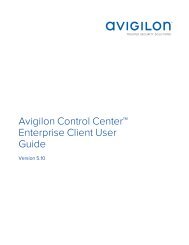
The following is an examples of how failover will work in the event of server failure.<br />
Example<br />
Cameras A, B, C, D, E and F have failover connections set up to two different servers. Assume each server has 6<br />
camera channel licenses, and the license priority is set to 1 for each connection.<br />
Figure 3: Primary connections<br />
Setting Up a Failover Connection 27
When the server NVR1 fails, cameras A and B from NVR 1 automatically connect to their Secondary server, NVR 2.<br />
Figure 4: NVR 1 fails<br />
When the server NVR3 fails, cameras E and F automatically connect to their Tertiary server, NVR 2.<br />
Figure 5: NVR 3 fails<br />
Example 28
Disconnecting a Device from a Server<br />
1. In the site Setup tab, click . The Connect/Disconnect Cameras... tab is displayed.<br />
2. Select the device you want to disconnect from the Connected Cameras list, then do one of the following:<br />
• Click Disconnect. The device will be disconnected from the server and moved to the Discovered<br />
Cameras list.<br />
• Drag the device into the Discovered Cameras list.<br />
Upgrading Camera Firmware<br />
Camera firmware updates are typically included with the <strong>ACC</strong> Server update packages. Camera firmware<br />
updates are automatically downloaded and installed to the camera.<br />
When the camera firmware is being upgraded, video from that camera cannot be displayed and the System<br />
Explorer will display<br />
beside the camera name.<br />
When the firmware upgrade is complete, the System Explorer will display<br />
will display.<br />
again and video from the camera<br />
Users and Groups<br />
When users are added to the <strong>ACC</strong> system, they are assigned to a group that defines their access permissions in<br />
a site. Use the Users and Groups dialog box to create and manage users and groups.<br />
Adding a User<br />
NOTE: (<strong>Enterprise</strong> Edition only) This procedure describes adding individual users to the system. If you are<br />
managing users through Windows Active Directory, add new users directly through Active Directory. For more<br />
information, see Importing Active Directory Groups on page 31.<br />
1. In the site Setup tab, click .<br />
2. In the Users tab, click .<br />
3. When the Add User dialog box appears, complete the User Information area.<br />
4. If you don’t want this user to be active yet, select the Disable user check box. Disabled users are in the<br />
system but cannot access the site.<br />
5. In the Login Timeout area, select the Enable login timeout check box to set the maximum amount of time<br />
the Avigilon Control Center Client software can be idle before the user is automatically logged out of the<br />
application.<br />
6. In the Password area, complete the following fields:<br />
• Password: — enter a password for the user.<br />
• Confirm Password: — re-enter the password.<br />
• Require password change on next login — select this check box if the user must replace the<br />
password after the first login.<br />
• Password Expiry (Days): — specify the number of days before the password must be changed.<br />
• Password never expires — select this check box if the password never needs to be changed.<br />
Disconnecting a Device from a Server 29
7. In the Member Of tab select the check box beside each access group the user belongs to.<br />
The other columns display the permissions that are included in the selected groups.<br />
8. Click OK. The user is added to the site.<br />
Editing and Deleting a User<br />
You can edit and delete users as needed.<br />
NOTE: Be aware that you cannot edit or delete users that belong to the same ranked group as you or higher.<br />
This also means that you cannot edit your own user account unless you are part of an Unranked group.<br />
Tip: If a user has access to more than one site, the changes to the user need to be made on each site.<br />
1. In the site Setup tab, click .<br />
2. In the Users tab, select a user then perform one of the following:<br />
Adding Groups<br />
• To edit the user's information, click . For details about the editable options, see Adding a User<br />
on the previous page.<br />
NOTE: If you want to edit a user that was imported through the Active Directory tab, you will only<br />
be disable the user or change their Login Timeout setting. All other settings are maintained by the<br />
Active Directory.<br />
• To delete the user, click .<br />
NOTE: Users imported through the Active Directory tab cannot be deleted, only disabled.<br />
Groups define what features users have access to. Create new groups to change what users can access.<br />
Groups can be given a rank in the corporate hierarchy to further define what the members of the group can<br />
access. For more information about the corporate hierarchy feature, see Corporate Hierarchy on page 15.<br />
1. In the site Setup tab, click .<br />
2. In the following dialog box, select the Groups tab and click .<br />
3. In the pop-up dialog box, select an existing group to use as a template for your new group, then click OK.<br />
4. In the Edit Group dialog box, complete the following:<br />
a. Give the new group a name.<br />
b. Select a rank for the group from the Rank: drop down list. To edit or view the entire Corporate<br />
Hierarchy, click .<br />
c. Select the required Group Privileges: and Access Rights: for the group. Clear the check box of any<br />
feature or device that you do not want the group to have access to.<br />
5. Select the Members tab to add users to the group.<br />
If a user is added to the group through the Add User dialog box, the user is automatically added to the<br />
group's Members list.<br />
Editing and Deleting a User 30
a. Click .<br />
b. Select the users that should be part of this new group. Only users that have been added to the site<br />
are displayed.<br />
Tip: Enter the name of a user in the Search... field to locate specific users.<br />
c. Click Add. The users are added to the Members list.<br />
6. Click OK to save the new group.<br />
Related Tasks<br />
Setting Up a Corporate Hierarchy 16<br />
Adding a User 29<br />
Reference Materials<br />
Group Permission Descriptions 129<br />
Editing and Deleting a Group<br />
You can change the access permissions for a set of users by editing their access group.<br />
1. In the site Setup tab, click .<br />
2. Select the Groups tab.<br />
3. Select a group and do one of the following:<br />
• To edit the group, click . For details about the configurable options, see Adding Groups on the<br />
previous page.<br />
• To delete the group, click .<br />
NOTE: Default groups cannot be deleted.<br />
Importing Active Directory Groups<br />
You can import Windows Active Directory groups to the site so users can log in using their Windows credentials.<br />
Members of an imported Active Directory group are automatically added as users to the site.<br />
Changes to member accounts in the Active Directory are automatically synchronized with user accounts in the<br />
<strong>ACC</strong> software.<br />
1. In the site Setup tab, click .<br />
2. Select the Active Directory tab.<br />
3. If it says Active Directory Synchronization is Disabled at the top, you need to enable the feature.<br />
a. Click Change....<br />
b. In the dialog box, select the Enable Active Directory synchronization check box.<br />
c. Enter your username and password for the network domain.<br />
d. Click OK.<br />
Editing and Deleting a Group 31
4. Click .<br />
5. Select an existing group to use as a template for the new Active Directory group, then click OK. You can<br />
edit the permissions for the group later.<br />
6. In the Select Groups dialog box, locate the Windows group you want to import by doing one of the<br />
following:<br />
• Enter the name of the Windows group in the Enter the object names to select field and click OK.<br />
• Click the Advanced button and search for the group you want.<br />
Figure 6: The Windows Select Groups dialog box<br />
Once located, the group is automatically added to the Active Directory Groups: list and the Groups list. All the<br />
users in the group are imported into the Users list.<br />
Members of an imported Active Directory group can now be added to any existing ranked user group in the<br />
Client software and will be treated like other users.<br />
Imported user information, including login credentials, is maintained by the Active Directory. In the Client<br />
software, you can only disable an imported user or configure the user's Login Timeout settings.<br />
Alarms<br />
Use the Alarms dialog box to create and manage alarms. Once an alarm has been created, you can monitor<br />
alarm events in the Alarms tab. For more information, see Accessing the Alarms Tab on page 105.<br />
Adding a New Alarm<br />
Alarms need to be added to the site before they can be monitored in the Alarms tab.<br />
1. In the site Setup tab, click .<br />
The Alarms dialog box is displayed.<br />
2. Click .<br />
The Add Alarm wizard is displayed.<br />
Alarms 32
3. On the Select Alarm Trigger Source page, select an Alarm Trigger Source: then choose the trigger<br />
requirements for this alarm. Click<br />
The alarm trigger options are:<br />
to continue.<br />
• Motion Detection — the alarm is triggered when movement is detected in the selected camera's<br />
field of view.<br />
• Video Analytics Event — the alarm is triggered when a video analytics event is detected in the<br />
selected camera's field of view.<br />
NOTE: You must select a video analytics camera or appliance camera channel to use this alarm<br />
trigger.<br />
• Digital Input Activation — the alarm is triggered when the selected digital input is activated.<br />
• License Plate Watchlist Match — the alarm is triggered when a license plate on the Watch List has<br />
been detected.<br />
For more information about setting up a license plate Watch List, see Configuring the Watch List on<br />
page 50.<br />
• POS Transaction Exception — the alarm is triggered when a transaction exception is detected<br />
from the selected POS transaction source.<br />
For more information about configuring a transaction exception, see Adding a Transaction<br />
Exception on page 49.<br />
• Camera Error — the alarm is triggered when an error occurs in the selected camera.<br />
• System Error -— the alarm is triggered when a system error occurs.<br />
• External Software Event — the alarm is triggered by an event generated by a third-party<br />
integration software.<br />
4. On the following Select Linked Cameras page, select the cameras that will record the alarm event then<br />
complete the following:<br />
a. Set the Pre-Alarm Record Time: and the Recording Duration:.<br />
b. Select the View linked cameras when alarm is triggered check box to automatically display the<br />
alarm video in a View when the alarm is triggered.<br />
c. Click to continue.<br />
5. On the Select Alarm Recipients page, select the groups and users that need to be notified of this alarm.<br />
You can create an escalation workflow to determine who is notified next if the alarm is not<br />
acknowledged.<br />
a. Click to add the users or groups that will be notified of this alarm. By default, the list is empty<br />
and you must add at least one user to continue.<br />
b. In the following dialog box, select all the required users ( ) and groups ( ). Use the search bar at<br />
the top of the window to quickly find specific users and groups.<br />
c. Click Add.<br />
Adding a New Alarm 33
d. Assign each user a Wait Time. The Wait Time determines when the user or group will be notified of<br />
the alarm.<br />
If a user is assigned a Wait Time of 0h 0m, the user will be notified immediately after the alarm<br />
occurs. If the next user is assigned a Wait Time of 1h 0m, that user is not notified until one hour after<br />
the alarm occurs but only if the alarm remains active. If the first user acknowledges the alarm within<br />
one hour, the second user is never notified of the alarm.<br />
In the Alarms tab, only users who are notified will see the live alarm trigger. All potential alarm<br />
recipients will see the alarm once it has been acknowledged.<br />
6. Select the Play sound when alarm is triggered: check box to play a sound when the alarm is triggered.<br />
You can choose an alarm sound from the drop down list.<br />
The sound is played in the Client software only, and will be used to notify the selected users.<br />
7. Click to continue.<br />
8. (Optional) On the Select Alarm Acknowledgement Action page, set the actions that must occur when an<br />
alarm is acknowledged then click<br />
to continue.<br />
• If the user must add comments about the alarm, select the Require a comment when<br />
acknowledging alarm check box.<br />
• If a digital output must be activated when the alarm is acknowledged, select the Activate selected<br />
digital output(s) on alarm acknowledgement check box. Then, select the digital outputs that must<br />
be activated.<br />
• If the digital output should only be activated when confirmed by a user, select the Require user<br />
confirmation before activating digital output(s) check box.<br />
9. On the Select Alarm Properties page, complete the following:<br />
a. Enter a name for the alarm.<br />
b. Select a Priority: for the alarm. 1 is the highest alarm priority.<br />
c. Select a Schedule: for the alarm. For more information, see Scheduling Site Events on page 41.<br />
d. Make sure the Enable alarm check box is selected to set the alarm.<br />
10. Click to save the new alarm.<br />
Editing and Deleting Alarms<br />
1. In the site Setup tab, click .<br />
The Alarms dialog box is displayed.<br />
2. Select an alarm then do one of the following:<br />
• To edit the alarm, click .<br />
Go through the Add Alarm wizard and make the required changes on each page. On the last page,<br />
click to save your changes.<br />
For details about the editable options, see Adding a New Alarm on page 32.<br />
• To delete the alarm, click .<br />
Editing and Deleting Alarms 34
External Notifications<br />
Use the External Notifications dialog box to configure the site to send email in response to specific events. You<br />
can set up an email server for the site and choose what events require email notifications.<br />
If you use a central station monitoring service, you would also use this dialog box to set up communication<br />
between your site and the monitoring station.<br />
Setting Up the Email Server<br />
To send email notifications, the site must be given access to an email server.<br />
1. In the site Setup tab, click .<br />
The External Notifications dialog box is displayed.<br />
2. Select the Email Server tab.<br />
3. In the Email Server Settings: area, complete the following:<br />
a. Sender Name: enter a name to represent the site in all email notifications.<br />
b. Sender Email Address: enter an email address for the site.<br />
c. Subject Line: enter a subject line for all emails sent from the site. The default subject is Avigilon<br />
Control Center System Event.<br />
d. SMTP Server: enter the SMTP server address used by the site.<br />
e. Port: enter the SMTP port.<br />
f. Timeout (seconds): enter the maximum amount of time the server will try to send an email before it<br />
quits.<br />
4. (Optional) If the email server uses encryption, you can select the Use secure connection (TLS/SSL) check box.<br />
5. (Optional) If the email account has a username and password, select the Server requires authentication<br />
check box.<br />
6. Click OK.<br />
• Enter the User Name: and Password: for the email account.<br />
Configuring Email Notifications<br />
In the Email Notifications dialog box, you can create email notification groups to specify who will receive email<br />
notifications when certain events occur.<br />
Be aware that you cannot send any email notifications until you've set up an email server for the site. For more<br />
information, see Setting Up the Email Server above.<br />
NOTE: Some features are not displayed if the server does not have the required license, or if you do not have<br />
the required user permissions.<br />
External Notifications 35
1. In the site Setup tab, click .<br />
The External Notifications dialog box is displayed.<br />
2. Make sure the Email Notifications tab is selected.<br />
3. Click .<br />
4. Enter an Email Group Name:.<br />
5. In the Email Recipients: area, add all the user, group and individual emails that are part of this email group.<br />
Do any of the following:<br />
• Click to add a site user or access group. In the dialog box, select all the required users and<br />
groups then click OK.<br />
• Click to add individual emails. In the dialog box, enter the email address then click OK.<br />
Tip: Make sure the site users in the Email Recipients: list have a valid email in their user account.<br />
6. Click to send a test email to everyone on the Email Recipients: list.<br />
7. In the Email Trigger: area, select all the events that will trigger an email for this email group. Click the blue<br />
underlined text to define the event requirements.<br />
Tip: If you require other events or more specific requirements, you can also configure email notification in<br />
the rules engine. For more information, see Rules on page 38.<br />
8. To attach a snapshot of the email notification event, select the Attach images from camera(s) linked to<br />
the event check box.<br />
NOTE: This option is disabled if Motion Detect is not selected because there are no images associated<br />
with system events, digital inputs, or POS transaction exceptions.<br />
9. In the Email Schedule: area, select a schedule for the email notification. For more information, see<br />
Scheduling Site Events on page 41.<br />
10. To limit the number of emails sent, enter the minimum amount of time between each email in the Send<br />
email at most every: field.<br />
11. Click OK.<br />
The new email notification is saved and added to the Email Groups: list.<br />
Editing and Deleting an Email Notification<br />
You can edit or delete email notifications as needed.<br />
Editing and Deleting an Email Notification 36
1. In the site Setup tab, click .<br />
The External Notifications dialog box is displayed.<br />
2. In the Email Notifications tab, do one of the following:<br />
• To edit an email notification, select the notification from the Email Groups: list then make the<br />
required changes. For more information about the editable options, see Configuring Email<br />
Notifications on page 35.<br />
• To delete an email notification, select the notification from the Email Groups: list then click .<br />
Enabling Central Station Monitoring<br />
If you use a central station monitoring service, you can set up the Avigilon Control Center System to<br />
communicate with your central monitoring service.<br />
Consult with your central monitoring service for the correct settings for each field.<br />
1. In the site Setup tab, click .<br />
The External Notifications dialog box is displayed.<br />
2. Select the Central Station Monitoring tab.<br />
3. Select the Enable Central Station Monitoring check box to enable this service.<br />
4. Complete the SMTP fields with the information provided by your central monitoring service.<br />
The central monitoring service will typically provide you with a specific name, email and SMTP details to<br />
identify you in their system.<br />
5. To periodically check the state of the connection to the central monitoring service, select a time interval<br />
from the Minimum Heartbeat Interval: drop down list.<br />
The selected amount of time must pass before a confirmation message is sent. The confirmation<br />
message is only sent if no other notifications are sent during the set time period.<br />
This feature allows the system to automatically send a message to the central monitoring service to<br />
confirm that the systems are still connected and no issues have occurred.<br />
If the central monitoring service requires the system to send a heartbeat test message at specific<br />
intervals, select the option that is equal to half the requested interval. For example, if the central<br />
monitoring service requires a confirmation message be sent once a day, assign the system to send a<br />
message every 12 hours.<br />
6. From the Attachment: options, select one of the following:<br />
Attaching an image or video of an event allows the central monitoring service to verify alarms and take<br />
the appropriate actions.<br />
Enabling Central Station Monitoring 37
• None — The system sends a message to the central monitoring service without any attachments.<br />
• Video Clip for Device Events — The system automatically exports a video of the event in H.264 format,<br />
and attaches it in the message.<br />
NOTE: If a camera does not stream in H.264, a video clip will not be generated.<br />
• Image for Device Events — The system takes a snapshot of the event and attaches it in the<br />
message.<br />
NOTE: To send a message to the central monitoring service, the rule action for an event must be setup to<br />
Send notification to Central Monitoring Station.<br />
7. Click OK to save your changes.<br />
8. Create rules that will notify the central monitoring service of specific events.<br />
• On the Select Rule Action(s) page, make sure the Send notification to Central Monitoring Station<br />
option is selected. This ensures the central monitoring service is notified of the rule event.<br />
For more information about creating rules, see Adding a Rule below.<br />
Tip: The system Email Notifications feature works separately from the Central Station Monitoring feature, but you<br />
can configure the rules to send you the same notifications as the central monitoring service. When you create<br />
rules for the central monitoring service, include the Send email option on the Select Rule Action(s) page. You<br />
can configure the rule to send you details that are not included in the central monitoring notification.<br />
Rules<br />
The Rules engine allows you to trigger specific actions when a certain event, or set of events, occurs.<br />
For example, you can create a rule that starts a live stream when the back door is opened.<br />
If the default email notification options are insufficient for your needs, you can use the Rules engine to set up<br />
more specific trigger events.<br />
Adding a Rule<br />
1. In the site Setup tab, click .<br />
The Rules dialog box is displayed.<br />
2. Click .<br />
3. On the Select Rule Event(s) page, select all the events that will trigger the rule. If there is blue underlined<br />
text in the rule description, click on the text to further define the event.<br />
When the trigger event is defined, click .<br />
4. On the Select Rule Action(s) page, select all the actions that will occur in response to the triggers. If there<br />
is blue underlined text in the rule description, click on the text to further define the event.<br />
When the action is defined, click .<br />
Rules 38
5. On the Select Rule Condition(s) page, select the specific condition that will cause this rule to run. You can<br />
select more than one condition.<br />
If there is blue underlined text in the rule description, click on the text to further define the condition.<br />
When the condition is defined, click .<br />
6. On the Select Rule Properties page, complete the following:<br />
a. Enter a Rule Name: and a Rule Description:.<br />
b. Select a Schedule: for the rule. For more information, see Scheduling Site Events on page 41.<br />
c. Make sure the Rule is enabled check box is selected to enable the rule.<br />
7. Click to save the new rule.<br />
Editing and Deleting a Rule<br />
1. In the site Setup tab, click . The Rules dialog box is displayed.<br />
2. Select a rule, then do one of the following:<br />
• To edit the rule, click . Go through the Rule Setup wizard and make the required changes on<br />
each page. On the last page, click<br />
to save your changes.<br />
For details about the editable options, see Adding a Rule on the previous page.<br />
• To delete a rule, click . When the confirmation dialog box appears, click OK.<br />
Backing Up System Settings<br />
You can back up site and server configuration settings so that they can be restored after an unexpected system<br />
failure or used on a different site.<br />
If you want to back up or archive recorded video, see Archive on page 127.<br />
1. In the site Setup tab, click .<br />
2. In the following dialog box, select the server that you want to back up. The site settings are automatically<br />
included in the backup file.<br />
3. If you want to encrypt the backup file, select the Encrypt the backup file. check box then enter a<br />
password.<br />
The password is required when the backup file is used to restore the system settings. Be aware that if you<br />
lose the encryption password, the file can no longer be used.<br />
NOTE: It is highly recommended that you enable the encryption option because the settings file may<br />
contain sensitive system information.<br />
4. Click OK.<br />
5. In the Save As dialog box, name and save the file.<br />
The backup file is saved in Avigilon Settings File (.avs) format.<br />
Editing and Deleting a Rule 39
NOTE: Backup files can only be restored to servers that are running the same or more recent version of the<br />
Avigilon Control Center Server software.<br />
Restoring System Settings<br />
NOTE: You cannot restore settings from a 5.2.2 or earlier server through this version of the Avigilon Control<br />
Center Client software.<br />
If you have a backup Avigilon Settings File (.avs), you can restore the settings as needed. You would typically<br />
restore settings after a server has been replaced in the site, or when setting up several independent sites that<br />
require similar settings.<br />
NOTE: Make sure the new server has at least the same number of licenses as the server that generated the<br />
backup file. If not, you will lose access to features that were included in the backup file but are not supported by<br />
the new server.<br />
Be aware that when you restore server settings, all existing settings are overwritten by the restored settings.<br />
When you restore site settings, the restored settings are merged with any existing settings.<br />
1. In the site Setup tab, click .<br />
2. In the following dialog box, find and select the .avs file that you want to restore.<br />
3. If the backup file is encrypted, enter the required password in the following dialog box. You will not be<br />
asked to provide a password if the file is not encrypted.<br />
4. Select the settings you want to restore.<br />
By default, the system will select the recommended option for you.<br />
• Restore site and server settings — select this option to restore all settings in the site and the<br />
selected server.<br />
NOTE: If the server is part of a multi-server site, do not select this option because the site settings<br />
are maintained by the other connected servers.<br />
• Restore server settings — select this option to restore all settings to the selected server.<br />
• Use custom settings — click Choose Settings to specify the settings that you want to restore.<br />
Be careful when selecting the custom settings because some settings have dependencies that<br />
may cause unexpected issues if they are not supported by the server.<br />
5. Select the server that you want to restore the settings to.<br />
It is recommended that you only select servers in the Recommended Servers list. Servers in this list do<br />
not have any existing device connections. Restoring settings to a server that is not in this list may<br />
overwrite existing device connection details or cause the system to exceed its license and processing<br />
limits.<br />
6. Click OK.<br />
If you restored the site settings, the settings are merged:<br />
Restoring System Settings 40
• Unique settings are added to the site.<br />
• If the settings are identical, only the current site version is kept.<br />
• If an import setting and a site setting have the same name but are configured differently, the import<br />
setting is added to the site and renamed in this format: (Import), like Email1 (Import).<br />
• In the rules engine, the Notify users (default) rule is always added and renamed, even if the settings<br />
are the same. The import version is enabled and the site version is disabled by default.<br />
• The two site Views are combined.<br />
• The import settings take precedence.<br />
For example, a map from the import file is already used in the site. Currently, the map is stored at<br />
the top of the site View. But in the import file, the map is kept at the bottom. After the import<br />
settings are merged with the current site settings, the map is moved to the bottom.<br />
• Unorganized elements from the import file are listed at the bottom of the site View.<br />
• User permission groups are merged.<br />
• If groups have the same name, the import settings are used and the users from both the import file<br />
and the current site are added to the group.<br />
• Groups added from the import file automatically gain access to all the new devices that were<br />
added since the settings were exported.<br />
• Users with the same name will use the import settings, including passwords.<br />
Scheduling Site Events<br />
site events are actions that can affect the entire site, like email notifications. When you configure a site event,<br />
you are given the option to assign a schedule to the event. Schedules control when events can occur — at<br />
specific times during a day, or only on specific days.<br />
When you see the Schedule option while configuring an event, you can select an existing schedule or create a<br />
new schedule.<br />
• To use a preconfigured schedule, select an option from the drop down list. The default option is Always,<br />
which allows the event to run constantly.<br />
• To change a schedule, select the schedule then click > .<br />
• To delete a schedule, select the schedule then click > . In the following confirmation dialog box,<br />
click OK.<br />
• To create a schedule, click then select . When the Edit… dialog box is displayed, complete the<br />
following steps:<br />
1. Give the new schedule a name.<br />
2. Give the first recurrence a name.<br />
You can add multiple recurrences to create a detailed schedule. For example, you could create<br />
one recurrence to cover every weekend, plus extra recurrences to cover public holidays.<br />
• To add extra recurrences, click .<br />
• To delete a recurrence, select the recurrence then click .<br />
Scheduling Site Events 41
3. For each recurrence, define the duration by entering a Start: and End: time.<br />
Be aware that if you enter an End: time that is earlier than the Start: time, the event will span two<br />
days. For example, if the schedule is set to start at 12:00pm and end at 11:59am, the event is<br />
automatically enabled from 12:00pm on day 1 and will end at 11:59am on day 2.<br />
4. In the Start Date: field, enter when the recurrence should begin.<br />
5. In the Recurrence pattern area, select the frequency of the recurrence.<br />
Option<br />
Description<br />
Daily<br />
The event is enabled during the same time every day.<br />
• Select the number of days between each schedule recurrence.<br />
The event is enabled during the same day and time every week.<br />
Weekly<br />
Monthly<br />
Yearly<br />
• Select the day(s) of the week, then select the number of weeks between<br />
each schedule recurrence.<br />
The event is enabled during the same day and time every month.<br />
• Select the specific day or weekday, then select the number of months<br />
between each schedule recurrence.<br />
The event is enabled during the same day and time every year.<br />
• Select the specific day or weekday and month, then select the number<br />
of years between each schedule recurrence.<br />
6. Add and complete any other recurrences that need to be part of the schedule.<br />
7. Click OK to save the new schedule.<br />
Server Settings<br />
Server settings are related to video recording on each server in the system. This includes configuring the<br />
recording schedule, data aging, and bandwidth usage.<br />
NOTE: Some features are not displayed if the server does not have the required license, or if you do not have<br />
the required user permissions.<br />
Naming a Server<br />
Give the server a meaningful name so that it can be easily identified in the System Explorer. Otherwise, the<br />
server uses the name that is assigned by Windows.<br />
1. In the server Setup tab, click .<br />
2. In the following dialog box, enter a name for the server.<br />
3. Click OK.<br />
Server Settings 42
Recording Schedule<br />
Use the Recording Schedule dialog box to set the recording schedule for cameras connected to the server. By<br />
default, the server is set to record motion and configured events when they occur.<br />
Once the recording schedule is set, video is recorded automatically.<br />
Adding and Editing a Recording Schedule Template<br />
The recording schedule is set by using templates that tell cameras when and what to record. For example, you<br />
can create one recording schedule template for weekdays and another for weekends.<br />
NOTE: Recording templates are shared across a site.<br />
NOTE: Some features are not displayed if the server does not have the required license, or if you do not have<br />
the required user permissions.<br />
1. In the server Setup tab, click . The Recording Schedule dialog box is displayed.<br />
2. Click Add Template below the Templates: list.<br />
3. Enter a name for the New Template.<br />
4. Click the Set Area button, then click or drag the cursor across the Recording Mode: timeline to set the<br />
types of events that the cameras will record throughout the day. Individual rectangles on the Recording<br />
Mode: timeline are colored when they have been selected.<br />
The Recording Mode: options include:<br />
• Continuous — record video constantly.<br />
• Motion — Only record video when motion is detected.<br />
• Digital Inputs — Only record video when a digital input is activated.<br />
• Alarms — Only record video when an alarm is activated.<br />
• POS Transactions — Only record video when a point of sale (POS) transaction is made.<br />
• License Plates — Only record video when a license plate is detected.<br />
5. To disable recording in parts of the template, click the Clear Area button, then click or drag the cursor<br />
across the timeline to remove the set recording areas.<br />
6. If cameras are not recording in Continuous mode all day, you can set cameras to record reference<br />
images between events in the recording schedule.<br />
• Select the Record a reference image every: check box, then set the time between each<br />
reference image.<br />
Recording Schedule 43
Editing and Deleting a Template<br />
1. In the Setup tab, select the server you want to edit then click .<br />
2. In the Recording Schedule dialog box, select a template from the Templates: pane and do one of the<br />
following:<br />
• To edit a template, modify the schedule.<br />
• To rename a template, click Rename Template and enter a new name.<br />
• To delete a template, click Delete Template.<br />
3. Click OK to save your changes.<br />
Setting Up a Weekly Recording Schedule<br />
You can set up a weekly recording schedule by applying templates to cameras for each day of the week.<br />
1. In the server Setup tab, click . The Recording Schedule dialog box is displayed.<br />
2. Select a template from the Templates: list.<br />
3. In the Default Week area, click the days of the week this template applies to for each camera.<br />
Figure 7: The Recording Schedule dialog box: Default Week<br />
4. Click OK.<br />
Recording and Bandwidth<br />
While the Recording Schedule dialog box sets when and what cameras record, the Recording and Bandwidth<br />
dialog box sets how long recorded video is stored.<br />
In the Recording and Bandwidth dialog box, you can change the Data Aging settings and set the maximum<br />
record time for each connected camera. The amount of data aging that is available depends on the camera that<br />
is connected to the system.<br />
• For JPEG2000 or JPEG compression cameras, data aging is available at three rates:<br />
• High Bandwidth keeps recordings at their original quality.<br />
• Half Image Rate discards half of the recorded data to make room for new recordings.<br />
• Quarter Image Rate keeps 1/4 of the original recorded data so that you can still see older video.<br />
• For H.264 cameras that support data aging, data aging is available at two rates:<br />
• High Bandwidth keeps the original high quality video and the secondary stream of low resolution<br />
video.<br />
• Low Bandwidth only keeps the secondary stream of low resolution video.<br />
Editing and Deleting a Template 44
NOTE: The Data aging can only occur when the secondary stream is enabled.<br />
• For H.264 cameras that do not support data aging, only the High Bandwidth video is kept.<br />
By default, the system is set to keep recorded video for the maximum amount of time based on the available<br />
storage.<br />
1. In the server Setup tab, click .<br />
The Recording and Bandwidth dialog box is displayed.<br />
The Data Aging column shows an estimate of the recording time that is available at each image rate,<br />
given the amount of space on the recording device.<br />
2. In the Data Aging column, move the sliders to adjust the amount of time video is stored at each image<br />
rate.<br />
• To change the data aging settings for all linked cameras, move the slider for one linked camera<br />
and all linked cameras will be updated.<br />
• To change the data aging setting for one camera, break the camera's link to other cameras by<br />
clicking the icon to the left of its name, then make your changes.<br />
3. In the Max. Record Time column, manually enter a maximum record time or select one of the options<br />
from the drop down list for each camera.<br />
NOTE: If the time estimated in the Total Record Time column is shorter than what is set in the Max. Record<br />
Time column, the camera's actual recording time will be shorter than the Max. Record Time.<br />
4. Click OK.<br />
Scheduled Archive<br />
Video archiving must be enabled in the Avigilon Control Center Server before the Scheduled Archive settings<br />
can be defined in the Client software.<br />
If you are running the <strong>ACC</strong> Server software on a standard NVR, you would enable the Archive feature in the<br />
Admin Tool. The Admin Tool is also where you manually set the archive folder location. For more information,<br />
see The Avigilon Control Center Server User Guide.<br />
If you are running an Avigilon Edge Solution device, like the H4 ES camera, you would enable archiving through<br />
the product web interface.<br />
Files are always archived in Avigilon Backup (AVK) format. You can review archived video in the Avigilon Control<br />
Center Player.<br />
Once archives are enabled, you can schedule the application to automatically archive recorded video from<br />
each server.<br />
NOTE: The configured schedule will occur in the server's local time and not the client's local time.<br />
Scheduled Archive 45
1. In the server Setup tab, click .<br />
The Scheduled Archive dialog box is displayed.<br />
2. Select the Enable Scheduled Archive check box.<br />
3. In the Camera(s) to Archive: list, select all the devices to back up.<br />
4. In the Archive Options: area, define the following:<br />
• Perform Every: specify the number of days between backups.<br />
• Start Time: the time when backup occurs.<br />
The time specified is in the server's local time. If you are physically located in a different time zone<br />
from the server, remember to consider the time difference if the backups must occur at a specific<br />
time.<br />
• Coverage: the amount of recorded image data that is backed up.<br />
• Starting From: the starting point of the backup.<br />
• Delete oldest backups when disk full: select this check box to automatically delete the oldest<br />
backups when the backup storage location is full.<br />
For example, you want the Scheduled Archive to occur every day at 12 am. You want to back up video<br />
from 30 days ago and the backup will span 1 day worth of video — so only the 30th day is backed up to<br />
the remote server each night. Your settings would be:<br />
5. Click OK.<br />
• Perform Every: 1<br />
• Start Time: 12:00 am<br />
• Coverage: 1<br />
• Starting From: 30<br />
The Status area displays when the next backup will be.<br />
Each video archive is saved in a subfolder that is named after the archive time range.<br />
POS Transactions<br />
The Point of Sale (POS) Transaction Engine is a licensed feature that records raw data from POS transaction<br />
sources. You can link cameras to specific POS transaction sources, and set up the system to make note of<br />
transaction exceptions.<br />
Once POS transactions have been set up, you can see live and recorded POS transaction data in the View tab<br />
while watching any linked video.<br />
To monitor live POS transactions, see Monitoring Live POS Transactions on page 96.<br />
To review recorded POS transactions, see Reviewing Recorded POS Transactions on page 99.<br />
POS Transactions 46
Adding a POS Transaction Source<br />
1. In the server Setup tab, click . The POS Transactions dialog box is displayed.<br />
2. Click . The POS Transactions Setup wizard is displayed.<br />
3. On the Set Transaction Source Device page, enter the Hostname/IP Address: and the Port: of the POS<br />
transaction source device, then click Next.<br />
4. On the Set Transaction Source Data Format page, select a data format, then click Next.<br />
To add or edit a data format, click Add or Edit. Alternatively, click Copy From to duplicate then edit the<br />
selected data format.<br />
For more information about adding a new data format, see Adding a Transaction Source Data Format<br />
below.<br />
5. On the Set Transaction Exceptions page, select any exceptions that need be monitored, then click Next.<br />
If you do not need to monitor for exceptions, you can skip this page.<br />
To add or edit a transaction exception, click Add or Edit. For more information, see Adding a Transaction<br />
Exception on page 49.<br />
6. On the Set Transaction Source Device page, select the cameras you want to link to the transaction<br />
source.<br />
You can also set the amount of time video needs to be recorded before and after each transaction. The<br />
default value is 5 seconds.<br />
When you are ready to continue, click Next.<br />
7. On the Set Transaction Source Name and Description page, enter a name and description for the<br />
transaction source. Select Enable transaction source to start receiving data from the transaction source.<br />
8. Click to save the new transaction source.<br />
Adding a Transaction Source Data Format<br />
NOTE: POS transaction source data formats are shared across a site.<br />
When you add a new POS transaction source, be aware that the transaction source must have a source data<br />
format.<br />
1. In the POS Transactions Setup wizard, click when you arrive on the Set Transaction Source Data<br />
Format page. The Configure Data Format dialog box is displayed.<br />
For information about accessing this dialog box, see Adding a POS Transaction Source above.<br />
2. In the Properties area, define the following:<br />
• Name: enter a name for the data format.<br />
• Description: enter a description of the data format.<br />
• Transaction Start Text: (required) enter the text that identifies the start of each transaction from the<br />
Adding a POS Transaction Source 47
POS transaction source.<br />
• Transaction End Text: (optional) enter the text that identifies the end of each transaction.<br />
• Encoding: Select the encoding used by the POS transaction source.<br />
3. Capture data from the transaction source. Perform any of the following to capture raw data of the source<br />
data format:<br />
The following figure shows raw transaction data on the left and filtered transaction data on the right.<br />
Figure 8: The Configure Data Format dialog box<br />
• Click Capture Data to start capturing a raw transaction data sample.<br />
• Click Stop Capture to stop capturing transaction data.<br />
• Click Load Data... to load raw transaction data from a file.<br />
• Click Save Data... to save a copy of the transaction data that has been captured.<br />
4. To create a new filter for the raw transaction data file, click Add Filter.... The Configure Filter dialog box is<br />
displayed.<br />
There are two default filters in the Current Filters: area — one to create line breaks and the other to delete<br />
extra white space at the beginning of each line. If you do not need extra filters, skip this step.<br />
a. In the Text: field, enter text for the filter to search for.<br />
b. Select the Match case and/or Match whole word check box to focus the text filter to only find text<br />
with the same capitalization or an exact match.<br />
c. In the Method: drop down list, select a search method. You can choose to filter text found through<br />
a Normal search, Wildcards search, or Regular expressions search.<br />
Adding a Transaction Source Data Format 48
d. In the Action to Take: area, select the action the system will take when the filter finds a match to<br />
your text criteria.<br />
e. Click OK.<br />
5. On the Configure Data Format screen, click OK to add the new data format to the data format list.<br />
Adding a Transaction Exception<br />
NOTE: POS transaction exceptions are shared across a site.<br />
To help monitor unusual transactions, you can set up transaction exceptions. Transaction exceptions can help<br />
you identify unauthorized discounts, fake returns, and manual price overrides.<br />
1. In the POS Transactions Setup wizard, click when you arrive on the Set Transaction Exceptions page.<br />
For information about accessing this page, see Adding a POS Transaction Source on page 47.<br />
2. In the Configure Exception dialog box, enter a name for the exception.<br />
3. Select one of the Text to Match options:<br />
4. Click OK.<br />
• Match Text — Enter text that will be monitored as a transaction exception.<br />
The system will monitor all transactions for the text entered in the Text to Match field.<br />
• Match Value — Enter the value that triggers the transaction exception. You can use the relational<br />
operators from the drop down list, and further define the value by entering any text that may<br />
appear before or after the value.<br />
The exception will monitor all transactions for values that match what you enter in the Text Before<br />
Value:, Match when value:, and Text After Value: fields.<br />
The new transaction exception is added to the Set Transaction Exceptions page.<br />
Repeat this procedure until all the required transaction exceptions have been added to the transaction source.<br />
Editing and Deleting a POS Transaction Source<br />
1. In the server Setup tab, click .<br />
The POS Transactions dialog box is displayed.<br />
2. In the POS Transactions dialog box, select a POS transaction source, then do one of the following:<br />
• To edit the POS transaction source, click . Go through the POS Transactions Setup wizard and<br />
make the required changes on each page. On the last page, click to save your changes.<br />
For details about the editable options, see Adding a POS Transaction Source on page 47.<br />
• To delete the POS transaction source, click .<br />
When the confirmation dialog box is displayed, click Yes.<br />
Adding a Transaction Exception 49
License Plate Recognition<br />
License Plate Recognition (LPR) is a licensed feature that allows users to read and store vehicle license plate<br />
numbers from any video streamed through the <strong>ACC</strong> software.<br />
The LPR options are only available if you have the feature licensed and installed on the server.<br />
Setting Up License Plate Recognition<br />
1. In the server Setup tab, click .<br />
The License Plate Recognition dialog box is displayed.<br />
2. Select a lane from the License Plate Lane list.<br />
The number of lanes listed is determined by the number of License Plate Recognition (LPR) channels that<br />
are available on the server.<br />
3. Complete the following fields:<br />
• Name: enter a name for the lane.<br />
• Camera: select the camera that will perform LPR. One camera can be used for multiple lanes.<br />
• License Plate Configuration: select the regional license plate format that needs to be recognized<br />
by the camera. For more information, see Supported License Plates on page 140.<br />
• Pre-Event Record Time: enter the amount of time that video is recorded before the license plate<br />
is recognized.<br />
• Post-Event Record Time: enter the amount of time that video is recorded after the license plate is<br />
recognized.<br />
• Minimum Confidence: move the slider to set the minimum confidence required for a detected<br />
license plate to be recognized. The default value is 80%.<br />
• Enable this lane: select this check box to enable LPR on this lane.<br />
4. Move and adjust the green overlay until it spans the width of the traffic lane in the camera's field of view.<br />
LPR is only performed in the green area.<br />
NOTE: If the overlay is red, the license plate detection area is too large and cannot be used.<br />
5. Click OK.<br />
Configuring the Watch List<br />
The License Plate Recognition (LPR) Watch List identifies license plates that are of special interest. When a<br />
license plate on the Watch List is detected, an event is generated to notify you of the license plate and can be<br />
used to trigger an action in the Rules engine.<br />
You can manually add each license plate that needs to be recognized, or import a list of license plates into the<br />
Client.<br />
License Plate Recognition 50
Adding Licenses to the Watch List<br />
1. In the server Setup tab, click .<br />
The License Plate Recognition dialog box is displayed.<br />
2. Select the Watch List tab.<br />
3. Click . The Add License Plate dialog box is displayed.<br />
4. Enter the license plate number that you want to watch for.<br />
5. Move the Minimum Confidence slider to determine how similar the detected license plate must be<br />
before it is considered a match.<br />
For example, if a license plate on your Watch List is ABC 123 and the <strong>ACC</strong> software detects an ABC 789<br />
license plate, the system will be 50% confident that it has found a match. If the system detects ABC 129, it<br />
will be 83% confident that it has found a match.<br />
6. Click OK.<br />
Deleting a License Plate from the Watch List<br />
1. In the License Plate Recognition dialog box, select the Watch List tab.<br />
2. Select the license plate from the Watch List then click .<br />
Exporting a Watch List<br />
1. In the License Plate Recognition dialog box, select the Watch List tab.<br />
2. Click Export....<br />
3. In the Save As dialog box, name the file and click Save.<br />
The Watch List can be exported as a text file or a comma-separated values (CSV) file.<br />
Importing a Watch List<br />
1. In the License Plate Recognition dialog box, select the Watch List tab.<br />
2. Click Import....<br />
3. In the Import dialog box, locate the Watch List file and click Open.<br />
Adding Licenses to the Watch List 51
Device Settings<br />
Device settings are used to adjust video quality and set up devices that can be connected to cameras and<br />
video analytics appliances. These settings include adjusting camera display quality, video compression and<br />
image rate.<br />
NOTE: Some features are not displayed if the server does not have the required license, or if you do not have<br />
the required user permissions.<br />
NOTE: The dialog box may appear differently depending on the device. Options that are not supported by the<br />
device will be disabled or hidden.<br />
General<br />
Use the device General dialog box to set a device's identity and configure device PTZ settings. You can also<br />
reboot the device through the General dialog box.<br />
Setting a Device's Identity<br />
NOTE: The dialog box may appear differently depending on the device. Options that are not supported by the<br />
device will be disabled or hidden.<br />
In a device's General dialog box, you can give the device a name, describe the device's location and give the<br />
device a logical ID. The logical ID is needed to control the device through keyboard and joystick commands.<br />
1. In the device Setup tab, click .<br />
The General dialog box is displayed.<br />
2. In the Camera Name: field, give the device a meaningful name to help you identify it. By default, the<br />
device model number is used as the device's name.<br />
3. In the Camera Location: field, describe the device's location.<br />
4. In the Logical ID: field, enter a unique number to allow the Client software and integrations to identify this<br />
device. By default, the device's Logical ID: not set and must be manually added.<br />
Tip: If Display LogicalIDs is enabled in Client Settings..., the device's Logical ID will appear beside the<br />
device's name in the System Explorer.<br />
5. (Cameras only) To disable the LEDs on a device, select the Disable camera status LEDs. This may be<br />
required if the device is installed in a covert location.<br />
6. Click OK.<br />
Configuring PTZ<br />
NOTE: The dialog box may appear differently depending on the device. Options that are not supported by the<br />
device will be disabled or hidden.<br />
Device Settings 52
Use the camera General dialog box to enable and configure the motorized pan, tilt, zoom (PTZ) devices that<br />
may be connected to Avigilon cameras. PTZ devices are connected to Avigilon cameras through the RS-485<br />
inputs.<br />
Third-party PTZ camera controls cannot be configured through the Avigilon Control Center software.<br />
1. In the camera Setup tab, click .<br />
The General dialog box is displayed.<br />
2. In the PTZ area, select the Enable PTZ controls check box.<br />
NOTE: If the features described in the following steps are not displayed, the camera only has a motorized<br />
zoom and focus lens. You will be able to control the zoom and focus settings through the PTZ Controls<br />
pane but other PTZ controls will not be available.<br />
3. In the Protocol: drop down list, select the appropriate PTZ protocol. The available protocols include:<br />
• AD Sensormatic<br />
• AXSYS<br />
• AXSYS DCU<br />
• Ernitec ERNA<br />
• Honeywell Diamond<br />
• Kalatel ASCII<br />
• Pelco D<br />
• Pelco P<br />
• TEB Ligne<br />
• Videotec MACRO<br />
• Videotec Legacy<br />
• Vicon extended<br />
• Vicon normal<br />
• JVC JCBP<br />
4. Enter the Dip Switch Address:, Baud Rate:, and Parity: for the PTZ device.<br />
5. Click OK.<br />
Once PTZ has been configured, you can use the camera's PTZ Controls while you watch the camera's live video<br />
stream. For more information, see Controlling PTZ Cameras on page 92.<br />
Changing the Camera Operating Priority<br />
NOTE: The dialog box may appear differently depending on the device. Options that are not supported by the<br />
device will be disabled or hidden.<br />
Changing the Camera Operating Priority 53
Depending on the scene, you may want the camera to maintain a specific frame rate rather than use all the<br />
available features. Or the reverse.<br />
Choose what the camera should prioritize during normal operations.<br />
1. In the device Setup tab, click .<br />
The General dialog box is displayed.<br />
2. From the Mode: drop down list, select one of the following:<br />
3. Click OK.<br />
• High Framerate — the camera will hold the preferred image rate as the priority.<br />
The camera will stream at the configured image rate even if it is unable to use other features<br />
supported by the camera. Depending on the camera model, disabled features may include selflearning<br />
video analytics, WDR and edge storage.<br />
• Full Feature — the camera will maintain the function of all supported features as the priority.<br />
The camera will dedicate more processing power towards maintaining the function of its key<br />
features, and use an optimized image rate. Depending on the camera feature, the image rate may<br />
be capped down to less than half the configured image rate.<br />
Enabling or Disabling Video Analytics Display<br />
NOTE: The dialog box may appear differently depending on the device. Options that are not supported by the<br />
device will be disabled or hidden.<br />
If you are configuring an Avigilon self-learning video analytics device, you can enable or disable the device from<br />
displaying the bounding boxes that highlight video analytics activity.<br />
By default, this setting is enabled.<br />
1. In the device Setup tab, click .<br />
The General dialog box is displayed.<br />
2. To enable video analytics display, make sure the Display video analytics activity check box is selected.<br />
3. To disable video analytics activity, clear the Display video analytics activity check box.<br />
Once disabled, the View tab no longer displays bounding boxes in the camera's video stream, or in the<br />
camera's AVI video export.<br />
The camera continues to detect video analytics data, so you will still be able to see bounding boxes<br />
while configuring video analytic events, Classified Object Motion Detection and Teach By Example.<br />
Bounding boxes will also be displayed when you perform a Motion or Classified Object Events search on<br />
the camera's video.<br />
4. Click OK.<br />
Enabling or Disabling Video Analytics Display 54
If you want to change this setting for all cameras rather than for specific devices, change the Video Analytics<br />
Activity overlay option in the Client Settings... dialog box. For more information, see Video Display Settings on<br />
page 79.<br />
Rebooting a Device<br />
You can restart all Avigilon devices through the device's General dialog box. This feature is not available for<br />
third party devices.<br />
1. In the device Setup tab, click .<br />
The General dialog box is displayed.<br />
2. Click Reboot Camera....<br />
The device will disconnect from the Avigilon Control Center system and shut down. When the device starts up<br />
again, the device should automatically reconnect with the server it was previously connected to.<br />
Network<br />
Use the device Network dialog box to change how a device connects to the server network.<br />
NOTE: Some features are not displayed if the server does not have the required license, or if you do not have<br />
the required user permissions.<br />
1. In the device Setup tab, click .<br />
The Network dialog box is displayed.<br />
2. Select how the device obtains an IP address:<br />
• Obtain an IP address automatically: select this option for the device to connect to the network<br />
through an automatically assigned IP address.<br />
The device will attempt to obtain an address from a DHCP server. If this fails, the device will obtain<br />
an address through Zero Configuration Networking (Zeroconf) and select an address in the<br />
169.254.0.0/16 subnet.<br />
• Use the following IP address: select this option to manually assign a static IP address to the<br />
device.<br />
Enter the IP Address:, Subnet Mask:, and Gateway: you want the device to use.<br />
3. Select the Control Port: for connecting to the device. This port is also used for manually discovering the<br />
device on the network.<br />
4. (Cameras only) Select the Enable Multicast check box to enable multicast streaming from the device. You<br />
must Enable Multicast to set up redundant recording to multiple servers.<br />
Use the default generated IP Address:, TTL:, and Base Port:, or enter your own values.<br />
Rebooting a Device 55
5. Click OK.<br />
6. (Video analytics appliance only) When prompted, allow the system to restart the device.<br />
Image and Display<br />
Use the Image and Display dialog box to control a camera’s display settings for live and recorded video.<br />
An image histogram is provided at the bottom of the window to help you configure your settings.<br />
NOTE: The dialog box may appear differently depending on the device. Options that are not supported by the<br />
device will be disabled or hidden.<br />
Changing Image and Display Settings<br />
NOTE: The dialog box may appear differently depending on the device. Options that are not supported by the<br />
device will be disabled or hidden.<br />
1. In the camera Setup tab, click .<br />
The Image and Display dialog box is displayed.<br />
2. To focus the camera, see Zooming and Focusing the Camera Lens on page 58.<br />
3. Click to toggle the Auto Contrast Adjustment.<br />
This setting changes the contrast of the video displayed in this dialog box. It does not affect recorded<br />
video or video displayed in other views. By default, Auto Contrast Adjustment is off.<br />
4. If the camera supports day/night control, select one of the following options from the Day/Night Mode:<br />
drop down list:<br />
• Automatic — allow the camera to control the infrared cut filter based on the amount of light in the<br />
scene.<br />
If available, move the Day/Night Threshold: slider to set the exposure value (EV) when the camera<br />
changes from day to night mode.<br />
• Day Mode — the camera will only stream in color and the IR cut filter is disabled.<br />
• Night Mode — the camera will only stream in monochrome and the IR cut filter is enabled.<br />
5. Adjust the camera's image settings to best capture the scene. A preview of your changes are displayed<br />
in the image panel and the histogram.<br />
Tip: Use the Maximum Exposure:, Maximum Gain:, and Priority: options to control low light behavior.<br />
Option<br />
Synchronize Image<br />
Settings with All Heads<br />
(Avigilon HD Multisensor<br />
Dome Cameras Only)<br />
Description<br />
You can apply the same image settings to all camera heads by selecting this<br />
check box.<br />
NOTE: Zoom and focus settings must be set individually.<br />
Image and Display 56
Option<br />
Exposure:<br />
Iris:<br />
Maximum Exposure:<br />
Maximum Gain:<br />
Priority:<br />
Description<br />
You can allow the camera to control the exposure by selecting Automatic, or<br />
you can set a specific exposure rate.<br />
NOTE: Increasing the manual exposure time may affect the image rate.<br />
You can allow the camera to control the iris by selecting Automatic, or you<br />
can manually set it to Open or Closed.<br />
You can limit the automatic exposure setting by selecting a Maximum<br />
Exposure: level.<br />
By setting a Maximum Exposure: level for low light situations, you can control<br />
the camera's exposure time to let in the maximum amount of light without<br />
creating blurry images.<br />
You can limit the automatic gain setting by selecting a Maximum Gain: level.<br />
By setting a Maximum Gain: level for low light situations, you can maximize the<br />
detail of an image without creating excessive noise in the images.<br />
You can select Image Rate or Exposure as the priority.<br />
When set to Image Rate, the camera will maintain the set image rate as the<br />
priority, and will not adjust the exposure beyond what can be recorded for the<br />
set image rate.<br />
Flicker Control:<br />
Backlight Compensation:<br />
Enable Wide Dynamic<br />
Range<br />
Enable Adaptive IR<br />
Compensation<br />
Saturation:<br />
Sharpening:<br />
When set to Exposure, the camera will maintain the exposure setting as the<br />
priority, and will override the set image rate to achieve the best image<br />
possible.<br />
If your video image flickers because of the fluorescent lights around the<br />
camera, you can reduce the effects of the flicker by setting the Flicker<br />
Control: to the same frequency as your lights. Generally, Europe is 50 Hz and<br />
North America is 60 Hz.<br />
If your scene has areas of intense light that cause the overall image to be too<br />
dark, move the Backlight Compensation: slider until you achieve a well<br />
exposed image.<br />
Select this box to enable automatic color adjustments through Wide Dynamic<br />
Range (WDR). This allows the camera to adjust the video image to<br />
accommodate scenes where bright light and dark shadow are clearly visible.<br />
Select this box to enable automatic infrared adjustments through Adaptive IR<br />
Compensation. This allows the camera to automatically adjust the video<br />
image for saturation caused by IR illumination.<br />
You can adjust the video's color intensity by moving the Saturation: slider until<br />
the video image meets your requirements.<br />
You can adjust the video sharpness to make the edges of objects more<br />
visible. Move the Sharpening: slider until the video image meets your<br />
requirements.<br />
Image Rotation: You can change the rotation of captured video. You can rotate the video 90,<br />
Changing Image and Display Settings 57
Option<br />
Description<br />
180, or 270 degrees clockwise.<br />
You can control white balance settings to adjust for differences in light.<br />
White Balance<br />
You can allow the camera to control the white balance by selecting Automatic<br />
White Balance, or select Custom White Balance and manually set the Red:<br />
and Blue: settings.<br />
6. Click Apply to Cameras... to apply the same settings to other cameras of the same model.<br />
7. Click OK.<br />
Zooming and Focusing the Camera Lens<br />
If the camera has remote zoom and focus capabilities, you can control the camera's zoom and focus through the<br />
Image and Display dialog box.<br />
1. In the camera Setup tab, click .<br />
The Image and Display dialog box is displayed.<br />
2. If the camera has a built-in auto-focus feature, you can choose one of the following:<br />
• Continuous Focus — the camera will automatically focus itself whenever the scene changes. Skip<br />
the following steps.<br />
• Manual Focus — you can manually focus the camera through the Focus: buttons. Once the focus is<br />
manually set, it will not change.<br />
3. While you watch the preview in the image panel, complete the following steps to zoom and focus the<br />
camera:<br />
Tip: For Avigilon HD Pro Cameras, the lens must be set to auto-focus (AF) mode on the camera. If the<br />
camera does not detect the lens, the Focus: buttons are not displayed.<br />
a. Use the Zoom: buttons to zoom in to the distance you want to focus.<br />
4. In the Iris: drop down list, select Open. When the iris is fully open, the camera's depth of field is the<br />
shortest.<br />
Zooming and Focusing the Camera Lens 58
5. Use the Focus: buttons until the image becomes clear.<br />
Button<br />
Description<br />
Auto Focus<br />
The camera will automatically focus one time.<br />
The camera will focus as close to zero as possible.<br />
Large step toward zero.<br />
Small step toward zero.<br />
Small step toward infinity.<br />
Large step toward infinity.<br />
Infinity.<br />
6. Click Apply to Cameras... to apply the same settings to other cameras of the same model.<br />
7. Click OK.<br />
Dewarping a Fisheye Lens<br />
If your camera uses a supported fisheye or panomorph lens, you may choose to dewarp the image through the<br />
Avigilon Control Center software.<br />
NOTE: The dialog box may appear differently depending on the device. Options that are not supported by the<br />
device will be disabled or hidden.<br />
1. In the camera Setup tab, click .<br />
2. In the View Perspective: drop down list, select one of the following options:<br />
• Floor: select this option if the camera is installed to look up.<br />
• Ceiling: select this option if the camera is installed to look down.<br />
• Wall: select this option if the camera is installed to look at the horizon.<br />
3. If available, edit the Image and Display settings.<br />
4. Click OK.<br />
The system dewarps the lens image based on the way it is installed. You will be able to control how video is<br />
displayed in an image panel through the PTZ controls.<br />
Compression and Image Rate<br />
Use the camera Compression and Image Rate dialog box to modify the camera's frame rate and image quality<br />
settings for sending image data over the network.<br />
Dewarping a Fisheye Lens 59
NOTE: The dialog box may appear differently depending on the device. Options that are not supported by the<br />
device will be disabled or hidden.<br />
1. In the camera Setup tab, click .<br />
The Compression and Image Rate dialog box is displayed.<br />
The Bandwidth: area gives an estimate of the bandwidth used by the camera with the current settings.<br />
Adjust the settings as required.<br />
NOTE: For cameras capable of maintaining multiple streams, the settings in this dialog box only affect the<br />
primary stream.<br />
2. In the Format: drop down list, select the preferred streaming format.<br />
3. In the Image Rate: bar, move the slider to select the number of images per second (ips) you want the<br />
camera to stream over the network.<br />
For H.264 cameras and encoders, the image rate setting must be divisible by the maximum image rate. If<br />
you set the slider between two image rate settings, the application will round to the closest whole<br />
number.<br />
4. In the Image Quality: drop down list, select an image quality setting. An image quality setting of 1 will<br />
produce the highest quality video and require the most bandwidth. The default setting is 6.<br />
5. In the Max Bit Rate: field, select the maximum bandwidth the camera can use in kilobits per second<br />
(kbps).<br />
6. In the Resolution: drop down list, select the preferred image resolution.<br />
7. In the Keyframe Interval: drop down list, enter the preferred number of frames between each keyframe.<br />
To help you determine how frequently keyframes are recorded, the Keyframe Period: area tells you the<br />
amount of time that passes between each recorded keyframe.<br />
It is recommended that you have at least one keyframe per second.<br />
8. If your camera supports multiple video streams, you can select the Enable Low Bandwidth Stream check<br />
box. Depending on your version of the software, the check box may also be called "Enable secondary<br />
stream".<br />
When enabled, the lower resolution video stream is used by the Avigilon HDSM feature to maximize<br />
bandwidth and storage efficiencies.<br />
9. Click Apply to Cameras... to apply the same settings to other cameras of the same model.<br />
10. Click OK.<br />
Enabling Idle Scene Mode<br />
If you are configuring an Avigilon self-learning video analytics camera, the Compression and Image Rate dialog<br />
box offers the option to record video at a different frame rate and quality if there are no motion events detected<br />
in the scene.<br />
A motion event is when the camera uses its Pixel Motion Detection or Classified Object Motion Detection ability<br />
to identify significant events in the scene. For more information, see Motion Detection on page 63.<br />
Enabling Idle Scene Mode 60
Idle scene mode is typically used to set the camera to stream at a lower image rate and reduced quality to<br />
lower the bandwidth and storage used when the scene is idle.<br />
NOTE: This option is only available if the camera is set to stream in H.264 format.<br />
1. In the Compression and Image Rate dialog box, select the Enable Idle Scene Mode check box.<br />
The Idle Scene Mode settings are displayed. If the settings do not automatically display, click<br />
reveal the settings.<br />
to<br />
2. In the Post-Motion Delay: field, enter the amount of time in seconds the scene must be idle before it<br />
switches to idle scene mode.<br />
3. In the following Image Rate: bar, move the slider to select the number of images per second (ips) you<br />
want the camera to stream while the scene is idle.<br />
4. In the Image Quality: drop down list, select the video image quality when the camera is in idle scene<br />
mode.<br />
5. In the Max Bit Rate: field, select the maximum bandwidth the camera can use in this mode.<br />
6. In the Keyframe Interval: drop down list, enter the preferred number of frames between each keyframe.<br />
To help you determine how frequently keyframes are recorded, the Keyframe Period: area tells you the<br />
amount of time that passes between each recorded keyframe.<br />
7. Click OK to save your settings.<br />
Next time the camera's field of view becomes quiet or idle, the camera will automatically switch to idle scene<br />
mode. The camera will automatically switch back to standard streaming mode when motion events are<br />
detected in the scene.<br />
Manually Adjusting Recorded Video Streams<br />
If you have a 1-3 megapixel Avigilon H4 HD camera, you have the option of manually adjusting the primary and<br />
secondary video stream, or allowing the system to automatically use HDSM technology. HDSM technology<br />
allows <strong>ACC</strong> to automatically record both the primary and secondary stream so that the system can intelligently<br />
adjust video bandwidth and storage efficiencies to meet your requirements.<br />
If your local regulations require that a specific video stream be recorded or be a certain resolution, you have the<br />
option of manually adjusting the settings to meet the requirements.<br />
NOTE: If the camera is connected to multiple servers (including for failover), the following settings must be the<br />
same at each server connection. Otherwise, the settings may constantly overwrite each other and the camera is<br />
unable to record the correct video stream settings.<br />
1. In the Compression and Image Rate dialog box, select Manual from the Recording Profile: drop down list.<br />
The High Bandwidth Stream is automatically disabled for recorded video but the settings are still<br />
available for you to configure the live video stream. The Low Bandwidth Stream settings are enabled.<br />
The default HDSM Auto option allows the system to use the HDSM feature for viewing live and recorded<br />
video. Be aware that if you are using the Manual setting, HDSM technology is disabled for recorded video<br />
but is still used for live video streams.<br />
Manually Adjusting Recorded Video Streams 61
2. If you need to adjust the live video stream, change the High Bandwidth Stream settings first.<br />
The High Bandwidth Stream settings are used to optimize the Low Bandwidth Stream settings, so some<br />
of the settings may change depending on your settings for the High Bandwidth Stream.<br />
3. If it is not displayed, click to display the Low Bandwidth Stream settings.<br />
If you prefer to record a higher resolution video, clear the Enable Low Bandwidth Stream check box and<br />
adjust the High Bandwidth Stream settings.<br />
4. In the Resolution: drop down list, select the preferred image resolution.<br />
5. In the Image Rate: bar, move the slider to select the number of images per second (ips) you want the<br />
camera to stream over the network.<br />
6. In the Image Quality: drop down list, select an image quality setting. An image quality setting of 1 will<br />
produce the highest quality video and require the most bandwidth. The default setting is 6.<br />
7. In the Max Bit Rate: field, select the maximum bandwidth the camera can use in kilobits per second<br />
(kbps).<br />
8. In the Keyframe Interval: drop down list, enter the preferred number of frames between each keyframe.<br />
To help you determine how frequently keyframes are recorded, the Keyframe Period: area tells you the<br />
amount of time that passes between each recorded keyframe.<br />
It is recommended that you have at least one keyframe per second.<br />
9. Click Apply to Cameras... to apply the same settings to other cameras of the same model.<br />
10. Click OK.<br />
The changes immediately take effect. The <strong>ACC</strong> Client software will continue to use HDSM technology to<br />
manage the display of live video, but recorded video will only display the configured video stream.<br />
The data aging settings in the Recording and Bandwidth dialog box update to reflect the new recording profile<br />
settings.<br />
Image Dimensions<br />
Use the Image Dimensions dialog box to set the image dimensions for the camera. You can crop the video<br />
image to help reduce bandwidth and increase the maximum image rate.<br />
NOTE: This feature is only available for JPEG2000 cameras.<br />
1. In the camera Setup tab, click .<br />
The Image Dimensions dialog box is displayed.<br />
2. Adjust the image dimensions by doing one of the following:<br />
• Drag the edges of the image until the video is cropped to fit your requirements.<br />
• Change the values for the Top:, Left:, Width:, and Height: fields.<br />
3. Click OK.<br />
Image Dimensions 62
Motion Detection<br />
In the Motion Detection dialog box you can define motion detection areas and configure the camera's sensitivity<br />
and threshold for motion.<br />
Depending on the type of camera you are configuring, there may be two types of motion detection available:<br />
Pixel Motion Detection and Classified Object Motion Detection.<br />
Pixel Motion Detection observes the video stream as a whole and considers any change in pixel as motion in the<br />
scene. This option is available to most cameras that are connected to the system.<br />
Classified Object Motion Detection analyzes the video and only reports the motion of vehicles or persons. This<br />
option is only available to Avigilon self-learning video analytics devices.<br />
Setting Up Pixel Motion Detection<br />
In the Motion Detection dialog box, use the Pixel Motion Detection tab to set up pixel motion detection. This<br />
allows you to define when the system will acknowledge motion in the scene.<br />
1. In the camera Setup tab, click .<br />
2. In the Pixel Motion Detection tab, define the green motion detection area in the camera's field of view:<br />
NOTE: Pixel motion detection is ignored in the areas that are not highlighted in green.<br />
• — Click this button then draw green rectangles to define the pixel motion detection areas.<br />
You can draw multiple rectangles to create your pixel motion detection area.<br />
• — Click this button and draw rectangles to erase sections from the pixel motion detection<br />
area.<br />
• — Click this button and manually draw pixel motion detection areas with your mouse. This<br />
tool allows you to be very specific and highlight unusual shapes.<br />
• — Click this button to highlight the entire image panel for pixel motion detection.<br />
• — Click this button to clear the image panel of all pixel motion detection areas.<br />
Tip: Avoid areas with continuous pixel motion, like a TV or computer monitor, so that the camera is not<br />
constantly detecting unimportant pixel motion events.<br />
Motion Detection 63
Figure 9: The Motion Detection dialog box: the Pixel Motion Detection tab<br />
3. Define how sensitive the system should be to pixel motion.<br />
a. Move the Sensitivity: slider to adjust how much each pixel must change before it is considered in<br />
motion.<br />
When the sensitivity is High, even small movements are detected - like dust floating immediately<br />
before the camera lens.<br />
b. Move the Threshold: slider to adjust how many pixels must change before the image is<br />
considered to have pixel motion.<br />
When the threshold is High, only large motions are detected - like a truck driving across the scene.<br />
Tip: The Motion indicator above the Threshold: slider will move to indicate how much motion is<br />
occurring in the current scene. Only when the Motion indicator moves to the right of the Threshold:<br />
marker will the camera detect the pixel motion.<br />
c. In the Pre-Motion Record Time: and Post-Motion Record Time: fields, specify how long video is<br />
recorded before and after the pixel motion event.<br />
4. Click OK to save your settings.<br />
Setting Up Classified Object Motion Detection<br />
In the Motion Detection dialog box, use the Classified Object Motion Detection tab to set up object motion<br />
detection. This allows you to define when the system will acknowledge a person or vehicle in the scene.<br />
Setting Up Classified Object Motion Detection 64
1. In the device Setup tab, click .<br />
The Motion Detection dialog box is displayed.<br />
2. In the Classified Object Motion Detection tab, define the green motion detection area in the camera's<br />
field of view:<br />
Figure 10: The Motion Detection dialog box: the Classified Object Motion Detection tab<br />
• To change the shape or size of the green overlay, click and drag any of the yellow markers on the<br />
border. Extra markers are automatically added to help you fine tune the shape of the overlay.<br />
• To move the green overlay, place the cursor over the green overlay until the cursor changes into a<br />
hand or the pan tool. Then, click and drag the green overlay to the desired location.<br />
• Click to add an exclusion area. The exclusion area is added inside the green overlay.<br />
Classified object motion is not detected in exclusion areas.<br />
• To set an exclusion area, move and resize the exclusion area as required then click<br />
anywhere on the green overlay.<br />
• To edit an exclusion area, double-click the exclusion area then modify as required.<br />
Setting Up Classified Object Motion Detection 65
• Select an exclusion area then click to delete the exclusion area.<br />
• Click to restore the default green overlay.<br />
3. Define the objects that are detected by the system.<br />
a. Check the Person box to detect people in the area.<br />
b. Check the Vehicle boxes to detect vehicles in the area.<br />
c. Move the Sensitivity: slider to adjust how sensitive the system is to the detection of classified<br />
objects.<br />
d. In the Threshold Time: field, adjust how long an object must be moving before it is considered a<br />
moving object.<br />
e. In the Pre-Motion Record Time: and Post-Motion Record Time: fields, specify how long video is<br />
recorded before and after a classified object motion detection event.<br />
4. Click Apply to save your settings.<br />
Self-Learning Video Analytics<br />
Rialto video analytics appliances and Avigilon cameras with self-learning video analytics can be configured to<br />
learn their surroundings and detect specific events.<br />
To configure Classified Object Motion Detection for a video analytics camera, see Setting Up Classified Object<br />
Motion Detection on page 64.<br />
Configuring Video Analytics Cameras<br />
Cameras with video analytics can be configured to better understand the scene where it is installed and<br />
improve the accuracy of the camera's classified object detection.<br />
1. In the device Setup tab, click .<br />
The Video Analytics Configuration dialog box opens.<br />
2. From the Location: drop down list, select the location that best describes where the camera is installed:<br />
The Location: setting helps the camera identify what it should be looking for.<br />
• Outdoor — Use for outdoor scenes. This setting detects humans and vehicles.<br />
• Large Indoor Area — Use for indoor scenes with a width of 1.5 m (5 ft) or more. Vehicle detection is<br />
disabled.<br />
• Indoor Overhead — Use when the camera is mounted overhead, typically in the center of a room.<br />
This setting is useful for counting people. Vehicle detection is disabled.<br />
Self-Learning Video Analytics 66
• Outdoor High Sensitivity — This setting allows the analytics to run with higher sensitivity for<br />
detecting humans and can be used in more challenging scenes. More frequent false positives may<br />
occur. This setting detects humans and vehicles.<br />
NOTE: If you change the Location: setting after it has been set, the system will delete any data the device<br />
may have learned.<br />
3. Move the Tampering Sensitivity: slider to define how sensitive the camera is to sudden changes in the<br />
scene.<br />
Tampering is defined as a sudden change in the camera field of view, usually caused by someone<br />
unexpectedly moving the camera. Lower the setting if small changes in the scene, like moving shadows,<br />
cause tampering events. If the camera is installed indoors and the scene is unlikely to change, you can<br />
increase the setting to capture more unusual events.<br />
4. Check the Enable Noise Filter box if the camera is too sensitive and falsely detects motion as classified<br />
objects. Disable this option if the camera is not sensitive enough.<br />
5. Click Apply to save your settings.<br />
Next, you can enable self-learning and configure analytics events. For more information, see Self-Learning on<br />
the next page or Video Analytics Events on page 72<br />
Configuring Video Analytics Appliances<br />
To use a video analytics appliance, configure each connected camera channel for video analytics detection.<br />
If you are configuring an analog video analytics appliance, the cameras are physically connected to each<br />
camera channel before the appliance is connected to the system.<br />
If you are configuring an IP video analytics appliance, any camera on the network can be digitally connected to<br />
the appliance camera channels. Before you complete this procedure, connect the required cameras first. For<br />
more information, see Connecting Cameras to a Video Analytics Appliance on page 25.<br />
1. Open the Setup tab, then select one of the appliance camera channels.<br />
2. In the device Setup tab, click .<br />
The Video Analytics Configuration dialog box opens.<br />
3. From the Location: drop down list, select the location that best describes where the camera is installed:<br />
The Location: setting helps the camera identify what it should be looking for.<br />
• Outdoor — Use for outdoor scenes. This setting detects humans and vehicles.<br />
• Large Indoor Area — Use for indoor scenes with a width of 1.5 m (5 ft) or more. Vehicle detection is<br />
disabled.<br />
• Indoor Overhead — Use when the camera is mounted overhead, typically in the center of a room.<br />
This setting is useful for counting people. Vehicle detection is disabled.<br />
Configuring Video Analytics Appliances 67
• Outdoor High Sensitivity — This setting allows the analytics to run with higher sensitivity for<br />
detecting humans and can be used in more difficult scenes. More frequent false positives may<br />
occur. This setting detects humans and vehicles.<br />
NOTE: If you change the Location: setting after it has been set, the system will delete any data the device<br />
may have learned.<br />
4. In the Camera Type: drop down list, select the type of camera that has been connected to this camera<br />
channel.<br />
This helps the video analytics appliance determine what type of image it should expect from the camera.<br />
• Day and Night — select this option if the camera can stream video in color or black and white. This<br />
type of camera typically displays color video during the day and black and white video at night to<br />
capture as much detail as it can of the scene.<br />
• Color — select this option if the camera can only stream video in color.<br />
• Black and White — select this option if the camera can only stream video in black and white.<br />
• FLIR — select this option if the camera can stream forward looking infrared (FLIR) video.<br />
5. Check the Enable Noise Filter box if the camera is too sensitive and falsely detects motion as classified<br />
objects. Disable this option if the camera is not sensitive enough.<br />
6. Click Apply to save your settings.<br />
7. If you are prompted, allow the device to reboot.<br />
Next, you can choose to enable self-learning and configure analytics events. For more information, see Self-<br />
Learning below or Video Analytics Events on page 72.<br />
Self-Learning<br />
When self-learning is enabled, the video analytics device will perform initial self-calibration for the scene in its<br />
field of view. This can significantly improve the accuracy of human and vehicle classification.<br />
NOTE: Enabling and disabling self-learning does not affect the Teach By Example feature.<br />
What is Self-Learning?<br />
Self-learning is the video analytics device's ability to perform an initial self-calibration of the scene. Once<br />
enabled, self-learning can significantly improve object classification accuracy.<br />
Self-learning is configured from the Video Analytics Configuration dialog box. The Self-Learning Progress: status<br />
in the dialog box tells you the following information:<br />
• 0% - 33% — The device is in the initial learning stage where it begins to gather information on the scene.<br />
• 34% - 66% — The device is calibrating itself using the data it has gathered on the average person and<br />
average vehicle in the scene.<br />
• 67% - 100% — The device has established a high level of classified object detection accuracy.<br />
Tip: To help increase the device's detection accuracy, use the Teach By Example feature. For more information,<br />
see Teach By Example on the next page.<br />
NOTE: If the device continues to display low object detection accuracy after completing self-learning, an error<br />
may have occurred during installation. Contact Avigilon Technical Support for help.<br />
Self-Learning 68
It is highly recommended that the self-learning feature be enabled for all video analytics devices, except in the<br />
following circumstances:<br />
• If you do not expect any humans or vehicles in the device's field of view.<br />
• If humans and vehicles in the field of view move at multiple height levels, such as people on a staircase.<br />
If the scene changes significantly, you may want to reset the self-learning settings. When self-learning is reset, all<br />
previous self-learning data is deleted and the device learns anew. You may want to use this feature if a building<br />
in the scene is demolished then rebuilt.<br />
Enabling Self-Learning<br />
The Video Analytics Configuration dialog box allows you to enable or disable self-learning in video analytics<br />
devices.<br />
1. In the device Setup tab, click .<br />
The Video Analytics Configuration dialog box opens.<br />
2. To enable self-learning, check the Enable Self-Learning box.<br />
3. To disable self-learning, clear the Enable Self-Learning check box.<br />
NOTE: Disabling self-learning may result in more classified objects being falsely detected.<br />
Once disabled, the camera stops self-learning and no longer utilizes any learned information.<br />
4. To reset self-learning, click Self-Learning Reset.<br />
• In the confirmation dialog box that appears, click Yes.<br />
NOTE: When self-learning is reset, all previous self-learning data for the device is deleted.<br />
5. Click OK to save your changes.<br />
Teach By Example<br />
You can improve the accuracy of classified object detection by using the Teach By Example feature. You can<br />
assign true or false Teach Markers to detected objects to help train the video analytics device.<br />
Teach Markers can be assigned then applied to devices by different users. Users who assign markers to<br />
detected objects are typically users who monitor video on a regular basis. It is recommended that 30 true and<br />
30 false markers be assigned before they are applied to a device. Users who apply the markers to the device<br />
may be an administrator who is less involved with day to day video monitoring.<br />
NOTE: The Teach Markers are local to a single server and are created for individual cameras. They are not<br />
shared between servers or cameras.<br />
NOTE: Some features are not displayed if the server does not have the required license, or if you do not have<br />
the required user permissions.<br />
Enabling Self-Learning 69
Assigning Teach Markers<br />
Assign true or false markers to the detected objects to help the device increase its detection accuracy. You can<br />
assign Teach Markers to recorded video from the Teach By Example tab and from search results.<br />
NOTE: The Teach Markers are local to a single server and are created for individual cameras. They are not<br />
shared between servers or cameras.<br />
1. Display recorded video from the analytics device in one of the following locations:<br />
• In the device Setup tab, click .<br />
The Teach By Example tab opens.<br />
Playback the recorded video until you encounter bounding boxes in the scene. For more<br />
information about controlling video playback, see Playing Back Recorded Video on page 96.<br />
• In the New Task menu, click one of the following Search options: , , or<br />
.<br />
Perform a search then select a search result that includes bounding boxes. For more information<br />
about performing each of these searches, see Search on page 110.<br />
• In the New Task menu, click the View option.<br />
In the Alarms tab, locate an alarm that is linked to an analytics device then review the Alarm<br />
Triggers until you identify one that includes bounding boxes. For more information about the<br />
Alarms tab, see Monitoring Alarms on page 105.<br />
2. Click inside a bounding box to display the Teach Markers menu.<br />
People detected by the video analytics device are outlined in red bounding boxes and vehicles are<br />
outlined in blue bounding boxes.<br />
3. Select one of the following options:<br />
The options may be different depending on the detected object type.<br />
• True Person/True Vehicle — Select this option if the video analytics device has correctly<br />
identified this object.<br />
• False Person/False Vehicle — Select this option if the video analytics device has incorrectly<br />
identified this object.<br />
• Not Used — Select this option if you do not want to use this object as a teaching sample.<br />
You need at least 30 true Teach Markers and 30 false Teach Markers per camera to teach a video analytics<br />
device. Each camera will accept a maximum of 50 true Teach Markers and 50 false Teach Markers. A tally of the<br />
total number of assigned markers is displayed at the bottom of the Teach By Example tab.<br />
Assigning Teach Markers 70
After you've assigned the minimum number of Teach Markers, you can send the examples to the device. For<br />
more information, see Applying Teach Markers to the Device below.<br />
Managing Teach Markers<br />
After you've assigned Teach Markers to objects detected in the device's recorded video, you can modify or<br />
delete the Teach Markers before they are applied to the device.<br />
1. In the device Setup tab, click .<br />
The Teach By Example tab opens.<br />
2. To edit Teach Markers:<br />
a. Select an item from the Teach Markers list.<br />
b. Click the related bounding box in the image panel then change the assigned object type.<br />
c. Select Not Used to remove individual Teach Markers from the list.<br />
3. To remove all the Teach Markers from the list, click Clear All Markers.<br />
This will delete all the markers that are currently listed, but not the markers that have already been<br />
applied to the camera.<br />
Applying Teach Markers to the Device<br />
After the minimum number of Teach Markers have been assigned, you can apply the markers to the device. This<br />
sends the true and false detection details to the device.<br />
1. In the device Setup tab, click .<br />
The Teach By Example tab opens.<br />
2. To review the Teach Markers, select a marker from the list.<br />
The associated video is displayed in the image panel and the details are displayed below.<br />
You can sort the by markers by clicking the column headings.<br />
3. To apply all the Teach Markers to the video analytics device, click Apply.<br />
NOTE: You must have a minimum of 30 true and 30 false Teach Markers, or an error message is<br />
displayed.<br />
The Teach Markers information is sent to the device, and the device will now use the details to help<br />
increase its detection accuracy.<br />
The listed Teach Markers are moved from the list because they have been applied to the device.<br />
Removing Teach Markers from the Device<br />
If there are significant changes in the scene or if the camera is moved to a different location, you may want to<br />
remove the Teach Markers that have been applied to the device because the information is no longer accurate.<br />
Managing Teach Markers 71
1. In the device Setup tab, click .<br />
The Teach By Example tab opens.<br />
2. Click Restore to Factory Default.<br />
3. When you are prompted, click Yes.<br />
The device's teach data is restored to the factory default settings.<br />
If you have new Teach Markers prepared for the device, those markers are not deleted from the list. Only the<br />
markers that have already been applied to the device are removed.<br />
Video Analytics Events<br />
You can set up specific video analytics events on each Avigilon self-learning video analytics device. Devices<br />
can be configured to detect a variety of human and vehicle activity within a scene.<br />
The configured events can be used to set up detailed rules. For more information, see Rules on page 38.<br />
Adding Video Analytics Events<br />
Before you can add video analytics events to rules and alarms, they must first be created for each video<br />
analytics device.<br />
1. In the device Setup tab, click .<br />
The Video Analytics Configuration dialog box opens.<br />
2. Click . The Analytics Event Configurations: dialog box opens.<br />
3. Enter a name for the video analytics event.<br />
4. Select the Enabled check box. If the check box is clear, the video analytics event will not detect or<br />
trigger any events.<br />
5. In the Activity: area, select one of the following options:<br />
NOTE: The option you select here will define the other settings that are displayed.<br />
• Objects in area – the video analytics event will be triggered when the selected object type<br />
moves into the region of interest.<br />
In the image panel, define the green region of interest. The green overlay can be configured like<br />
the Classified Object Motion Detection feature. For more information, see Setting Up Classified<br />
Object Motion Detection on page 64.<br />
• Object loitering– the video analytics event will be triggered when the selected object type stays<br />
within the region of interest for an extended amount of time.<br />
In the image panel, define the green region of interest.<br />
Video Analytics Events 72
• Objects crossing beam – the video analytics event will be triggered when the selected object<br />
type crosses the beam in the pointed direction.<br />
In the image panel, move or resize the green directional beam as needed:<br />
o<br />
o<br />
To move the beam, click and drag the green beam in any direction.<br />
To change the length or rotate the beam, click one end of the beam and stretch or rotate<br />
the beam.<br />
o To change the direction of the beam, click .<br />
o To detect objects traveling in either direction of the beam, click .<br />
6. In the Object Types: area, select and/or .<br />
7. Move the Sensitivity: slider to adjust how sensitive the video analytics device is to the detection of<br />
classified objects.<br />
8. If available, enter a time in the Threshold Time: field to define how long an object must be in the region of<br />
interest before it triggers a video analytics event.<br />
9. Click OK to save your settings.<br />
For more video analytic event options, click Show Advanced Options. For a description of the advanced<br />
options, see Video Analytics Event Descriptions on page 131.<br />
Editing and Deleting Video Analytics Events<br />
1. In the device Setup tab, click .<br />
The Video Analytics Configuration dialog box opens.<br />
2. Select an event from the Analytics Event Configurations: list and do one of the following:<br />
• To edit the video analytics event, click . In the following dialog box, make the required<br />
changes. For more information, see Adding Video Analytics Events on the previous page.<br />
NOTE: If you change the name of the event, any rules or alarms linked to the event may no longer<br />
function.<br />
• To delete the video analytics event, click .<br />
Privacy Zones<br />
You can set privacy zones in the camera's field of view to block out areas that you do not want to see or record,<br />
like bathroom entrances and other private areas.<br />
Editing and Deleting Video Analytics Events 73
Adding a Privacy Zone<br />
1. In the camera Setup tab, click .<br />
The Privacy Zones dialog box is displayed.<br />
2. Click and a green box will appear in the image panel.<br />
3. Move and resize the green box until it covers the area you want to keep private.<br />
4. Click OK.<br />
Editing and Deleting a Privacy Zone<br />
1. In the camera Setup tab, click .<br />
The Privacy Zones dialog box is displayed.<br />
2. Select a privacy zone from the Privacy Zones: list and do one of the following:<br />
• To edit the privacy zone, adjust the green box in the image.<br />
• To delete the privacy zone, click .<br />
3. Click OK to save your changes.<br />
Manual Recording<br />
When you trigger manual recording in an image panel, you are telling the camera to record video outside of its<br />
recording schedule. Manual recording continues until it is stopped, or until the maximum manual recording time<br />
is reached.<br />
To set the maximum manual recording time, follow these steps:<br />
1. In the camera Setup tab, click .<br />
The Manual Recording dialog box is displayed.<br />
2. Define the following:<br />
• Manual Recording Duration: enter how long the camera should record if recording is not manually<br />
stopped.<br />
• Pre-Trigger Record Time: enter the amount of time video is recorded before manual recording is<br />
activated.<br />
3. Click Apply to Cameras... to apply the same settings to other cameras of the same model.<br />
4. Click OK.<br />
For more information on manually recording video, see Triggering Manual Recording on page 95.<br />
Adding a Privacy Zone 74
Digital Inputs and Outputs<br />
Use the Digital Inputs and Outputs dialog box to set up external digital input and output devices that are<br />
connected to the device (a camera or video analytics appliance).<br />
The external devices can be used to create alarms or trigger recording events and specific actions through the<br />
Rules engine. For more information, see Rules on page 38.<br />
Setting Up Digital Inputs<br />
NOTE: The dialog box may appear differently depending on the device. Options that are not supported by the<br />
device will be disabled or hidden.<br />
1. In the device Setup tab, click .<br />
The Digital Inputs and Outputs dialog box is displayed.<br />
2. In the Digital Inputs: area, select an input.<br />
3. Enter a Name: for the digital input.<br />
4. In the Recording Duration: area, select one of the following:<br />
• Select Follow event to record the entire digital input event.<br />
• Select Maximum time: to limit the recording time.<br />
5. Enter the Pre-Event Record Time: and Post-Event Record Time:.<br />
6. Select the digital input's default Circuit State:.<br />
7. Select cameras to link to this digital input.<br />
If the Recording Schedule is configured to record digital inputs, the cameras selected in the Link to<br />
Camera(s): area are used to record the events triggered by this digital input.<br />
8. Click OK.<br />
Setting Up Digital Outputs<br />
Once a digital output is configured, you can manually trigger the digital output in an image panel. For more<br />
information, see Triggering Digital Outputs on page 96.<br />
NOTE: The dialog box may appear differently depending on the device. Options that are not supported by the<br />
device will be disabled or hidden.<br />
1. In the device Setup tab, click .<br />
The Digital Inputs and Outputs box is displayed.<br />
2. In the Digital Outputs: area, select an output.<br />
3. Enter a Name: for the digital output.<br />
4. Select the digital output's default Circuit State:.<br />
Digital Inputs and Outputs 75
5. The Trigger Behavior: options define what occurs when the digital output is activated.<br />
• Select Activate to enable the digital output in continuous mode. The Duration: fields allow you to<br />
specify how long the digital output should be active for.<br />
• Select Pulse to enable the digital output in pulse mode. Specify the Period:, Duty Cycle:, and<br />
Repeat Count: for the pulse.<br />
6. If there is only a Trigger Duration: field, specify the trigger duration in minutes and seconds.<br />
7. In the Link to Camera(s): area, select the cameras that are permitted to trigger this digital output.<br />
By default, the system automatically selects the camera that this digital output is connected to.<br />
8. Click OK.<br />
Microphone<br />
Use the Microphone dialog box to change the settings for any audio input device that is connected to a camera<br />
or video analytics appliance. You can also link the audio to other cameras.<br />
To use this feature, a microphone must be connected to the device.<br />
NOTE: The dialog box may appear differently depending on the device. Options that are not supported by the<br />
device will be disabled or hidden.<br />
1. In the device Setup tab, click .<br />
The Microphone dialog box is displayed.<br />
2. If multiple Microphone Inputs: are listed, select the one you want to edit.<br />
3. Select the Enable check box to enable audio recording from microphones connected to the device.<br />
4. Enter a name for the microphone.<br />
5. In the Source: drop down list, select the audio input source.<br />
6. In the Gain: drop down list, select the amount of analog gain that is applied to the audio input. The higher<br />
the dB setting, the louder the volume.<br />
7. In the Link to Camera(s): area, select cameras to link to this audio.<br />
8. Click OK.<br />
Speaker<br />
Use the Speaker dialog box to change the settings for any audio output that is connected to a device (a camera<br />
or video analytics appliance). You can also link the audio to other devices.<br />
To use this feature, speakers must be connected to the device and a microphone must be connected to your<br />
local Client.<br />
NOTE: The dialog box may appear differently depending on the device. Options that are not supported by the<br />
device will be disabled or hidden.<br />
Microphone 76
1. In the device Setup tab, click .<br />
The Speaker dialog box is displayed.<br />
2. If multiple Speaker Outputs: are listed, select the one you want to edit.<br />
3. Select the Enable check box to enable audio broadcasting. Speakers connected to the device will<br />
broadcast audio from the microphone that is connected to the local Client.<br />
4. Select the Record speaker output check box to record what is broadcast.<br />
5. Enter a name for the speaker.<br />
6. The Volume: slider controls the volume of the speakers.<br />
7. In the Link to Camera(s): area, select cameras to link to the speakers.<br />
8. To test the Microphone Level:, speak into the microphone. The red bar will move to show the audio input<br />
level.<br />
9. Click OK.<br />
If you want to enable two-way audio for your local application, see General Settings on the next page.<br />
Speaker 77
Client Settings<br />
The Client Settings... are used to set your preferences for your local copy of the Client software. This includes<br />
saving your password, setting the language, saving your last window layout, configuring your joystick, and<br />
manually adding and removing sites.<br />
General Settings<br />
Use the General settings to set your local Client preferences. Any changes you make will only affect this copy of<br />
the Client software.<br />
NOTE: Some features are not displayed if the server does not have the required license, or if you do not have<br />
the required user permissions.<br />
1. In the top-right corner of the Client, select > Client Settings....<br />
2. In the General tab, make any required changes:<br />
• Save/restore window layout: Select this check box if you want the Client to remember your layout<br />
preferences.<br />
• Automatically launch full screen: Select this check box if you want the Client to automatically<br />
launch in full screen mode each time it starts.<br />
• Display Notifications: Select this check box if you want the Client to display system messages.<br />
System messages are listed in the red box at the top-right corner of the Client - click the red box to<br />
see the messages. System messages notify you of site events, system events and possible<br />
device connection issues.<br />
If this check box is cleared, all system messages are hidden.<br />
• Synchronize recorded video playback: Select this check box to allow the system to automatically<br />
synchronize the Timelines in all new View tabs.<br />
For more information, see Synchronizing Recorded Video Playback on page 98.<br />
Cycle dwell time: Enter the number of seconds the Client waits before it cycles to a different View<br />
tab. For more information, see Cycling Through Views on page 85.<br />
• Language: Select a language from the drop down list to change the Client language. Select<br />
Windows Default for the Client to use the same language as the operating system.<br />
• Automatically log in to sites: Select this check box to automatically log in to all sites you can<br />
access. Select the type of login you use:<br />
• Select Using Windows Authentication if you use your Windows login to access sites.<br />
• Select Using saved user name and password: if you use your Avigilon Control Center<br />
username and password.<br />
Client Settings 78
• In the Maximum Incoming Client Bandwidth: area, you can set how much bandwidth is received by<br />
the client. This includes video streaming.<br />
You can select Unlimited or Other:, and specify the maximum bandwidth allowance in kilobits per<br />
second (kbit/s).<br />
• In the Client Duplex Audio Setting: area, decide if you want to enable two-way audio. This allows<br />
people in the video to talk with the operator monitoring the video.<br />
You have the option of Full-duplex audio, which allows simultaneous communication, or Halfduplex,<br />
which only allows communication from one side at a time. To use this feature, you need to<br />
set up microphones and speakers to cameras. For more information, see Microphone on page 76<br />
and Speaker on page 76.<br />
3. Click OK to save your changes.<br />
Video Display Settings<br />
You can adjust the Client Display settings to improve how video is displayed on your monitor.<br />
NOTE: Some features are not displayed if the server does not have the required license, or if you do not have<br />
the required user permissions.<br />
1. In the top-right corner of the Client, select > Client Settings... > Display.<br />
2. Complete any of the following procedures to adjust how video is displayed in image panels.<br />
Displaying Analog Video in Deinterlaced Mode<br />
Select the Display Deinterlaced Images check box if the analog video you are watching is showing interfacing<br />
artifacts. This setting will help improve video image and smooth out some of the artifacts.<br />
Displaying Logical IDs<br />
Select the Display LogicalIDs check box if you need to see the Logical ID of all devices. Logical IDs must be<br />
unique numbers. This setting will display the device's Logical ID in brackets beside the device's name in the<br />
System Explorer.<br />
When this setting is enabled, the device's name in the System Explorer is displayed in the following format.<br />
(Serial Number)(Logical ID). For example, 2.0-H3A-DP1(574065)(101).<br />
The Device Name and Serial Number can be changed in the General settings dialog box by editing the Camera<br />
Name: field. The Logical ID can be changed in the General settings dialog box by editing the Logical ID: field.<br />
Displaying Image Overlays<br />
Select any of the Image Overlays: options to set the type of information that is displayed over video.<br />
Overlay<br />
Camera Name<br />
Camera Location<br />
Playback Timestamp<br />
Description<br />
Displays the name assigned to the camera.<br />
Displays the location assigned to the camera.<br />
(Recorded video only) Displays the exposure timestamp for the video.<br />
Video Display Settings 79
Overlay<br />
Description<br />
From the Timestamp Zone: area, select the time that should be displayed:<br />
• Show device time — If you have cameras installed at different locations in your<br />
system, select this option to display the time recorded at the camera location.<br />
• Show local time — Select this option to display the recorded video time in your<br />
local timezone.<br />
(Live video only) Displays the current date and time to the millisecond.<br />
Live Timestamp<br />
From the Timestamp Zone: area, select the time that should be displayed:<br />
• Show device time — If you have cameras installed at different locations in your<br />
system, select this option to display the time at the camera location.<br />
• Show local time — Select this option to display the time in your local timezone.<br />
(Live video only) Displays the recording status of a camera.<br />
The recording status is indicated by the round icon on the top left corner of the image<br />
panel. The color of the icon shows the camera's recording status.<br />
Record Indicator<br />
• : recording triggered by a motion event<br />
• : recording<br />
• : not recording. Click this icon at any time to begin manual recording.<br />
Motion Activity<br />
Highlights motion in red.<br />
Bounding boxes outline objects detected in the video. The color of the bounding box<br />
identifies the object type:<br />
Video Analytics Activity<br />
• Red - a person<br />
• Blue - a vehicle<br />
The Video Analytics Activity overlay is only activated for video from a video analytics<br />
device.<br />
License Plate<br />
NOTE: The bounding boxes may not be displayed if the feature is disabled on the<br />
specific device. For more information, see Enabling or Disabling Video Analytics<br />
Display on page 54.<br />
(Live video only) Displays license plate numbers as they are detected.<br />
NOTE: This feature is only available if the License Plate Recognition feature is<br />
installed.<br />
Changing Display Quality<br />
If your computer does not have enough network bandwidth or processing power, you may not be able to watch<br />
video at its full image rate and quality. You can configure the image panels to display video in high quality and<br />
low frame rate, or low quality and high frame rate.<br />
Select a higher display quality setting if you need to see specific details or faces in the scene. Select a lower<br />
display quality setting if it's more important to see moving events as they occur.<br />
Changing Display Quality 80
The Change Display Quality: settings only affect the image panel display and do not affect the actual video<br />
quality or image rate between the camera and the server. Therefore, you can review recorded footage later to<br />
confirm what you saw in the image panel.<br />
In the Change Display Quality: area, select one of the following options:<br />
• Maximum: displays video at full resolution with the lowest image rate.<br />
• High (Default): displays video at 1/4 resolution.<br />
• Medium: displays video at 1/16 resolution.<br />
• Low: displays video at 1/64 resolution with the highest image rate.<br />
Joystick Settings<br />
There are two types of joysticks supported by the Client: standard Microsoft DirectX USB joysticks and the<br />
Avigilon USB Professional Joystick Keyboard.<br />
Access the Joystick settings to install the required drivers and configure your joystick options.<br />
Configuring an Avigilon USB Professional Joystick Keyboard For Left-Hand Use<br />
The Avigilon USB Professional Joystick Keyboard is a USB add-on that contains a joystick for controlling<br />
zooming and panning within image panels, a jog shuttle for controlling the Timeline, and a keypad programmed<br />
with the Client software keyboard commands. For more information about the keypad commands that control<br />
the Client software, see Keyboard Commands on page 143.<br />
By default, the keyboard is installed in right-hand mode. Change the Joystick settings to configure it for left-hand<br />
mode.<br />
1. Connect the keyboard.<br />
2. In the top-right corner of the Client, select > Client Settings... > Joystick.<br />
If the keyboard is not automatically detected, an error message is displayed. Click Scan for Joysticks....<br />
3. In the Joystick tab, select the Enable left-hand mode check box.<br />
4. Click OK. The keyboard is now configured for left-hand mode.<br />
5. Rotate the keyboard until the joystick is on the left and the jog shuttle is on the right. Reinstall the keypad<br />
cover with the View button labels at the top.<br />
For more information about the Avigilon USB Professional Joystick Keyboard, see the installation guide that is<br />
included with the device.<br />
Configuring a Standard USB Joystick<br />
Use the Joystick settings to configure the buttons used in your standard Microsoft DirectX USB joystick.<br />
Joystick Settings 81
1. Connect the joystick. In the top-right corner of the Client, select<br />
> Client Settings... > Joystick.<br />
2. If the joystick is not automatically detected, an error message will appear. Click Scan for Joysticks....<br />
3. In the Joystick tab, choose an action for each button on the joystick:<br />
4. Click OK.<br />
a. Press a button on the joystick to highlight its label in the dialog box.<br />
b. Select an action for the button from the drop down list.<br />
Options include ways to control recorded video, Views, image panels, instant replay, audio,<br />
snapshots and PTZ.<br />
c. Repeat this procedure for each button on the joystick.<br />
Discovering Sites<br />
If your computer is on the same network segment (subnet) as a site, that site is automatically discovered and<br />
displayed in the System Explorer.<br />
If the site you want to access is not listed, it is because the site is on a different subnet and must be manually<br />
discovered. There is no limit to the number of sites that can be discovered by the Client software.<br />
Tip: After you discover and login to a parent site, all the child sites are automatically discovered.<br />
By default, when a server is first connected to the system, it is added to a site with the same name. To locate a<br />
new server, you need to search for its site.<br />
1. Open the Find Site dialog box.<br />
• In the top-right corner of the Client, select > Log In... . In the Site Login tab, click Find Site....<br />
• Or, select > Client Settings... > Site Networking. In the Site Networking tab, click Find Site....<br />
2. In the dialog box, enter the IP Address/Hostname: and the Base Port: of the server in the site you want to<br />
discover.<br />
The base port is 38880 by default. You can change the base port number in the Avigilon Control Center<br />
Admin Tool. For more information, see The Avigilon Control Center Server User Guide.<br />
3. Click OK.<br />
If the site is found, it is automatically added to the site list.<br />
If the site is not found, check the following then try again:<br />
• The network settings are configured correctly.<br />
• The firewall is not blocking the application.<br />
• The Avigilon Control Center Server software is running on the server you searched for.<br />
Discovering Sites 82
Organizing Views<br />
A View tab is where you watch camera video. Inside the View tab is a set of image panels that allows you to<br />
organize how video is displayed.<br />
You can arrange image panels into different layouts to take advantage of different camera angles and save<br />
View layouts that you like.<br />
You can share Views with other users during investigations, and organize how video is displayed across multiple<br />
monitors.<br />
Adding and Removing a View<br />
View tabs allow you to customize how you monitor video. You can open a new View in the current window or<br />
open a View in a new window to make use of multiple monitors. Views can also be removed as required.<br />
If you want to make use of a large number of monitors, like a video wall, see Virtual Matrix on page 87.<br />
To...<br />
Do this...<br />
Open a new View tab<br />
Click > .<br />
Close a View tab On the View tab, click .<br />
Open a new window<br />
Select<br />
> New Window<br />
A new window appears. You can now position this window to make use<br />
of multiple monitors.<br />
In the top-right corner of the window, click .<br />
Close a window<br />
NOTE: If you see a confirmation dialog box, it is because there is only<br />
one window open and closing this window will also close the<br />
application.<br />
View Layouts<br />
You can organize how video is displayed through View layouts. You can choose to display video in 1 - 64 image<br />
panels. You can also customize the shape of image panels to accommodate cameras that are installed vertically<br />
to capture long hallways.<br />
There are 10 pre-configured layouts that you can edit to fit your needs.<br />
Selecting a Layout for a View<br />
You can organize how video is displayed by selecting a View layout.<br />
• On the toolbar, click then select one of the layout options.<br />
Organizing Views 83
Editing a View Layout<br />
If the default View layouts do not fit your surveillance requirements, you can customize a View layout.<br />
1. On the toolbar, select > Edit Layouts....<br />
2. In the Edit Layouts dialog box, select the layout you want to change.<br />
3. Enter the number of Columns: and Rows: you want in your layout.<br />
4. In the layout diagram, do any of the following to further customize the layout.<br />
Figure 11: The Edit Layouts dialog box<br />
• To create a larger image panel, select a gray line to delete the border between two image panels.<br />
When a line is highlighted in red, the line can be deleted.<br />
• To restore an image panel, select a dotted line to divide a larger image panel into two. When a<br />
dotted line is highlighted in green, the line can be restored.<br />
• To restore all default View layouts, click Restore Defaults. All custom layouts in the Layouts: list will<br />
be replaced.<br />
NOTE: You can only add or subtract lines to create a rectangular shape.<br />
5. Click OK to save your changes. The previous View layout has been replaced with your customized<br />
layout.<br />
Editing a View Layout 84
Tip: The keyboard commands used to access View layouts are linked to the layout's position in the Layouts: list.<br />
For example, if your custom layout is placed at the top of the Layouts: list (layout 1), you can press Alt + 1 to<br />
use that layout.<br />
Making a View Full Screen<br />
You can maximize a View to fill an entire monitor screen.<br />
• On the toolbar, click .<br />
Ending Full Screen Mode<br />
• While the View is in full screen mode, click .<br />
Cycling Through Views<br />
If you have multiple Views open, you can cycle through the View tabs by displaying each one for a few seconds.<br />
This is useful when monitoring a large number of cameras.<br />
• To activate the Cycle Views feature, click .<br />
To change the amount of time each View is displayed for, change the Cycle dwell time: setting. For more<br />
information, see General Settings on page 78.<br />
Saved Views<br />
Once you have set up a View you like, you can save the View to share with other users in the site. A saved View<br />
remembers the current View layout, the cameras displayed in each image panel, and the image panel display<br />
settings.<br />
Saving a New View<br />
1. From the toolbar, select > Save As New View.<br />
2. In the following dialog box, complete the following:<br />
a. Select the site that the View should be added to.<br />
b. Give the saved View a name.<br />
c. Assign a number to the saved View in the Logical ID: field. The logical ID is a unique number that is<br />
used to open the saved View through keyboard commands.<br />
d. If it is not displayed, click to display the Site View Editor and choose where the saved View<br />
appears in the System Explorer.<br />
e. Click OK.<br />
• If your site includes virtual sub-sites, select a location for the saved View. The list on the<br />
right updates to show what is stored in that directory.<br />
• In the site directory, drag the saved View up and down to set where it is displayed.<br />
Making a View Full Screen 85
Your saved View is added to the System Explorer under the selected site. You can now manage the saved View<br />
as a part of your site.<br />
Opening a Saved View<br />
Do one of the following<br />
• In the System Explorer, double-click the saved View ( ).<br />
• In the System Explorer, right-click and select Open.<br />
• Drag from the System Explorer to the current View in the application or new window.<br />
Editing a Saved View<br />
1. Open a saved View.<br />
2. Make any required changes to the View tab.<br />
3. From the tool bar, select > Update Saved View.<br />
Renaming a Saved View<br />
1. In the System Explorer, right-click and select Edit....<br />
2. In the Edit View dialog box, enter a new name or logical ID and click OK.<br />
Deleting a Saved View<br />
1. In the System Explorer, right-click and select Delete.<br />
2. In the confirmation dialog box, click Yes.<br />
Collaborating<br />
If you want to show another user an incident or need help investigating an event, you can share your current<br />
View with another user. You will both be able to control the View and show each other your findings.<br />
Sharing a View<br />
1. In the toolbar, click .<br />
2. In the following dialog box, select the user you want to collaborate with, then click OK.<br />
The users are listed by username and computer name. The computer name is used to help you identify a<br />
specific user if the username is shared by several people. Only users who are currently logged in to the<br />
site are displayed.<br />
Opening a Saved View 86
a. The user you select will see a pop-up message with your invitation to collaborate and may choose<br />
to accept or decline.<br />
b. You will receive a pop-up message with the user's response to your invitation.<br />
If they say Yes, the View you are looking at is automatically opened as a new tab in your<br />
collaborator's window.<br />
3. Repeat this procedure to collaborate with multiple users.<br />
While you are collaborating, any changes made to the current View by a collaborator are shared with the other<br />
collaborators. Anything that you can do in a standard View can be done in a shared View.<br />
Leaving a Shared View<br />
• To leave a shared View, just close the View tab. The remaining users stay in collaboration mode.<br />
Virtual Matrix<br />
The optional Virtual Matrix feature allows you to control the View displayed on multiple monitors, or a video wall,<br />
from any instance of the application. To use this feature, the Virtual Matrix software must be installed on the<br />
system that all the displays are connected to.<br />
A copy of the Virtual Matrix software can be downloaded from the Avigilon website.<br />
For more information about the Virtual Matrix software, see The Avigilon Control Center Virtual Matrix User<br />
Guide.<br />
Once the Virtual Matrix has been installed and loaded, the monitors connected to the system are automatically<br />
added to a site. All monitors linked by the Virtual Matrix software are displayed in the System Explorer as<br />
followed by the monitor name.<br />
Controlling Virtual Matrix Monitors<br />
In the System Explorer, each<br />
represents a View that is displayed on a connected Virtual Matrix monitor.<br />
To control what is displayed on each Virtual Matrix monitor, you need to open the monitor:<br />
• In the System Explorer, right-click and select Open.<br />
• Double-click or drag from the System Explorer to the current View.<br />
The Virtual Matrix monitor is opened in a new tab and can be controlled like any View — you can change the<br />
View layout, control video display, and use any active PTZ controls. The changes you make should<br />
automatically appear on the Virtual Matrix monitor.<br />
When you are done, you can close the Virtual Matrix monitor tab. The monitor will continue to display the View<br />
you have configured until you make new changes or the Virtual Matrix is shut down.<br />
Editing Virtual Matrix Monitors<br />
In the Avigilon Control Center Client software, you can edit the name and logical ID of Virtual Matrix monitors.<br />
Adding or removing active Virtual Matrix monitors must be done through the Avigilon Control Center Virtual<br />
Matrix software.<br />
Leaving a Shared View 87
1. In the System Explorer, right-click<br />
and select Edit....<br />
2. In the following dialog box, enter a new name and logical ID for the Virtual Matrix monitor.<br />
3. If it is not displayed, click to display the Site View Editor and choose where the monitor appears in the<br />
System Explorer. By default, the monitor is added to the site that you initially selected.<br />
4. Click OK.<br />
• If your site includes virtual sub-sites, select a location for the monitor. The list on the right updates<br />
to show what is stored in that directory.<br />
• In the site directory, drag the monitor up and down to set where it is displayed.<br />
Your changes are saved and sent to the Virtual Matrix software.<br />
5. To delete a disconnected Virtual Matrix monitor:<br />
NOTE: You can only delete a monitor that has been disconnected or removed from the Virtual Matrix<br />
software.<br />
a. Right-click and select Delete.<br />
b. When the confirmation dialog box is displayed, click Yes.<br />
For more information, see the Avigilon Control Center Virtual Matrix User Guide.<br />
Editing Virtual Matrix Monitors 88
Monitoring Video<br />
Inside a View tab, you can monitor and control video from multiple cameras. Once you open a camera in a View<br />
tab, you can control the camera's live and recorded video stream. You also have access to the camera's PTZ<br />
controls and other playback settings.<br />
To organize how video is displayed in the View tab, see Organizing Views on page 83.<br />
NOTE: Some features are not displayed if the server does not have the required license, or if you do not have<br />
the required user permissions.<br />
To help monitor video in relation to your organization, you can use the Map feature to identify a camera's<br />
location and field of view. You can also use the Web Page feature to manage shortcuts to useful web pages.<br />
To review video in relation to detected events, you can use the Alarms tab to review video with the alarm<br />
triggers, and use the Watch List notifications to review video of detected license plates.<br />
Zooming and Panning in a Video<br />
Use the zoom and pan tools to focus on specific areas in the video stream.<br />
Using the Zoom Tools<br />
There are two ways to digitally zoom in and zoom out of a video image:<br />
• Move your mouse over the video image, then rotate your mouse wheel forward and backward.<br />
• On the toolbar, select or , then click the image panel until you reach the desired zoom depth.<br />
Using the Pan Tools<br />
There are two ways to pan through the video image:<br />
• Right-click and drag inside an image panel.<br />
• On the toolbar, select , then click and drag the video image in any direction inside the image panel.<br />
Maximizing and Restoring an Image Panel<br />
You can maximize an image panel to enlarge the video display.<br />
Maximizing an Image Panel<br />
Do one of the following:<br />
Monitoring Video 89
• Right-click an image panel and select Maximize.<br />
• Inside the image panel, click .<br />
• Double-click the image panel.<br />
Restoring an Image Panel<br />
In a maximized image panel, do one of the following:<br />
• Right-click the maximized image panel and select Restore Down.<br />
• Inside the image panel, click .<br />
• Double-click the image panel.<br />
Making Image Panel Display Adjustments<br />
You can change the image panel display settings to bring out video details that are hard to see with the image<br />
panel's default settings.<br />
1. Right-click an image panel and select Display Adjustments....<br />
The Display Adjustments... settings are displayed in a floating pane immediately beside the image panel.<br />
2. Move the sliders to adjust the Gamma:, Black Level: and White Level:.<br />
The image panel displays the effects of your changes.<br />
3. Click Restore Defaults to clear your changes.<br />
Listening to Audio in a View<br />
If there is an audio input device linked to a camera, the button is displayed in the image panel when you<br />
watch the camera's video. To listen to the streaming audio, make sure there are speakers connected to your<br />
computer. By default the audio is muted.<br />
The camera's microphone must be enabled before you can listen to any audio. The<br />
the microphone is disabled.<br />
button is not displayed if<br />
To control audio playback, do any of the following:<br />
• In the lower-right corner of the image panel, click to mute or activate the audio.<br />
• Move the slider to change the volume.<br />
To enable the camera's microphone, see Microphone on page 76 for more information.<br />
Restoring an Image Panel 90
Triggering Custom Keyboard Commands<br />
If your system has custom keyboard commands set up to run specific rule events, you can activate the keyboard<br />
commands by doing the following:<br />
1. Press Ctrl + K on your keyboard.<br />
2. Enter the custom keyboard command number to begin running the rule event.<br />
Consult your system administrator for details about the custom keyboard commands that are available in your<br />
system. Custom keyboard commands are set up as rule events through the Rules engine. For more information<br />
about setting up rule events, see Rules on page 38.<br />
Controlling Live Video<br />
In this section are features that are only available while monitoring live video.<br />
Tip: If video appears slow, it may be a network issue between the Client software and the server that the camera<br />
is connected to. Actual recorded video quality is not affected.<br />
Broadcasting Audio in a View<br />
If there are speakers linked to a camera, the<br />
button is displayed in the image panel when you watch the<br />
camera's video. The button allows you to broadcast your verbal response to what is occurring in the video,<br />
like a Public Address (P.A.) system.<br />
The camera's speakers must be enabled before you can broadcast any audio. The<br />
the speakers are disabled.<br />
button is not displayed if<br />
• To broadcast audio, hold and speak into your microphone. The red bar moves to show the<br />
microphone's audio input levels. If the level is low, speak louder or adjust the microphone volume in the<br />
Windows Control Panel.<br />
• Release the button to stop the broadcast.<br />
To set up two-way audio, see General Settings on page 78.<br />
For more information about enabling camera speakers, see Speaker on page 76.<br />
Using Instant Replay<br />
To review an event that just occurred, you can immediately access recently recorded video through the instant<br />
replay feature.<br />
• Right-click the image panel and select one of the instant replay options:<br />
• Replay - 30 Seconds<br />
• Replay - 60 Seconds<br />
• Replay - 90 Seconds<br />
The image panel immediately plays back the camera's most recently recorded video.<br />
Triggering Custom Keyboard Commands 91
PTZ Cameras<br />
PTZ cameras can be controlled through the image panel on-screen controls or by using the tools in the PTZ<br />
Controls pane.<br />
Some tools and features may not be displayed if they are not supported by your camera.<br />
Controlling PTZ Cameras<br />
Pan, Tilt, Zoom (PTZ) controls allow you to control cameras with PTZ features. You can control a PTZ camera by<br />
using the on-screen controls or by using the tools in the PTZ Controls pane.<br />
For other ways to use the PTZ Controls, see Keyboard Commands on page 143.<br />
NOTE: For video analytics devices, classified object detection only works when the camera is in its Home<br />
position.<br />
1. In the toolbar, click . PTZ controls are now enabled in image panels that are displaying PTZ video.<br />
2. In the image panel, click .<br />
The PTZ Controls are displayed in a floating pane immediately beside the image panel.<br />
NOTE: The controls may appear differently depending on the camera. Some options are disabled or<br />
hidden if they are not supported by the camera.<br />
3. To pan or tilt, do one of the following:<br />
• In the image panel, drag your mouse from the center to move the camera in that direction. The<br />
farther the cursor is from the center of the image panel, the faster the camera will move.<br />
• If the camera supports Click to Center, click anywhere on the image panel to center the camera to<br />
that point.<br />
Figure 12: PTZ On-screen controls<br />
PTZ Cameras 92
4. Use the other PTZ controls to perform any of the following:<br />
To...<br />
Do this...<br />
• Click to zoom in.<br />
• Click to zoom out.<br />
Zoom<br />
• Click the image panel and use the mouse scroll wheel<br />
to zoom in and out.<br />
• If the camera supports Drag to Zoom, click and drag to<br />
create a green box to define the area you want to<br />
zoom in and see.<br />
• Right-click the image panel and select Zoom Out Full.<br />
Control the iris<br />
Control the focus<br />
Program a PTZ preset<br />
• Click to close the iris.<br />
• Click to open the iris.<br />
• Click to focus near the camera.<br />
• Click to focus far from the camera.<br />
1. Move the camera's field of view into position.<br />
2. In the Presets drop down list, select a number then<br />
click .<br />
3. In the dialog box, enter a name for the preset.<br />
4. Select the Set as home preset check box if you want<br />
this to be the camera's Home preset.<br />
5. Click OK.<br />
Activate a PTZ preset Select a preset then click .<br />
Return to the Home preset position<br />
Program a PTZ pattern<br />
If the PTZ camera supports a Home preset position, click<br />
to return the camera to its Home position.<br />
1. In the PTZ Controls pane, select a pattern number and<br />
click .<br />
2. Use the PTZ controls to move the camera and create<br />
the pattern.<br />
3. Click to stop recording the pattern.<br />
Activate a PTZ pattern<br />
Program a PTZ tour<br />
In the PTZ Controls pane, select a pattern number and click<br />
.<br />
The pattern will repeat until the pattern is stopped or another<br />
pattern is run.<br />
For more information, see Programming PTZ Tours on the<br />
next page.<br />
Activate a PTZ tour In the PTZ Controls pane, select a tour number and click .<br />
Controlling PTZ Cameras 93
To...<br />
Do this...<br />
The tour will repeat until stopped or until other PTZ controls<br />
are used.<br />
Activate an auxiliary command<br />
1. Select an aux command number and click .<br />
2. Click to turn off the auxiliary output.<br />
1. Click .<br />
2. To move through the menu options, click any of the<br />
following:<br />
Display the PTZ camera on-screen menu<br />
• Click to move down the options.<br />
• Click to move up the options.<br />
• Click to confirm your selection.<br />
• Click to cancel your selection.<br />
Click .<br />
Other users will be unable to use the PTZ controls for this<br />
camera until you unlock the controls or log out.<br />
Lock the PTZ controls<br />
Users ranked higher in the corporate hierarchy will be able to<br />
override and re-assign the lock to themselves.<br />
NOTE: Override feature is only available if all servers in the<br />
site are running the same version of the <strong>ACC</strong> Server<br />
software.<br />
Programming PTZ Tours<br />
If the PTZ camera supports guard tours, the tours can be programmed through the PTZ controls pane. Tours<br />
allow the PTZ camera to automatically move between a series of preset positions, and can be set to pause at<br />
each preset for a specific amount of time for video monitoring.<br />
NOTE: For video analytics devices, classified object detection only works when the camera is in its Home<br />
position.<br />
1. Create all the PTZ presets you need for this tour.<br />
2. In the PTZ Controls pane, select a tour number then click . The Edit PTZ Tour dialog box is displayed.<br />
3. Give the tour a name.<br />
4. In the Tour Pause Duration: field, enter the amount of time before the tour repeats. Tours repeat until<br />
manually stopped, or until other PTZ controls are used.<br />
5. In the Tour Mode: drop down list, select one of the following:<br />
• Sequential: the PTZ camera will go to each preset in the set order.<br />
• Random: the PTZ camera will go to each preset in random order.<br />
Programming PTZ Tours 94
6. Select the Set as default tour check box if you want this tour to run automatically.<br />
• The Default Tour Idle Start Time: field is now enabled. Enter the amount of time the PTZ camera<br />
must be idle before this tour automatically starts.<br />
7. To add a preset to the list, click .<br />
a. In the Preset column, select a preset from the drop down list.<br />
b. In the Move Speed column, enter how fast you want the PTZ camera to move to this preset. The<br />
higher the %, the faster the camera moves.<br />
c. In the View Time column, enter the amount of time you want the PTZ camera to stay at this preset<br />
position. The view time is 10 seconds by default.<br />
d. Repeat this step until all the presets for the tour have been added.<br />
8. To remove a preset, select the preset then click .<br />
9. To re-order a preset, select the preset then click or . The preset order only affects tours that use<br />
Sequential mode.<br />
10. Click OK to save the tour.<br />
Triggering Manual Recording<br />
Cameras are set to follow a recording schedule. If an event occurs outside the camera's recording schedule,<br />
you can click the record indicator icon to force the camera to record the event. For more information about<br />
recording schedules, see Recording Schedule on page 43.<br />
The Record Indicator overlay must be enabled to use manual recording. For more information, see Video<br />
Display Settings on page 79.<br />
Camera Recording States<br />
Recording Recording triggered by an event Not recording<br />
Starting and Stopping Manual Recording<br />
In an image panel that is displaying video, do either of the following:<br />
• In the top-left corner of the image panel, click to start manual recording.<br />
The recording indicator is highlighted in blue to show that the camera is recording. Manual recording<br />
continues until it is stopped or until the maximum manual recording time is reached.<br />
• Click to manually stop video recording.<br />
The maximum manual recording time is configured in the Manual Recording dialog box. For more information,<br />
see Manual Recording on page 74.<br />
Triggering Manual Recording 95
Triggering Digital Outputs<br />
While you monitor live video in an image panel, you can manually trigger any digital output that is connected to<br />
the camera.<br />
Digital outputs are configured in the Digital Inputs and Outputs dialog box. For more information, see Setting Up<br />
Digital Outputs on page 75.<br />
To trigger a digital output:<br />
1. Open the camera's live video in an image panel.<br />
2. In the image panel, click .<br />
3. If there is more than one digital output linked to the camera, you will be prompted to select the digital<br />
output you want to trigger.<br />
Monitoring Live POS Transactions<br />
If a camera is linked to a point of sale (POS) transaction source, you can monitor live POS transactions while you<br />
monitor video from the linked camera.<br />
1. Open the camera's video in an image panel.<br />
2. In the image panel, click .<br />
NOTE: If the camera is not linked to a POS transaction source, the icon is not displayed.<br />
If there is more than one POS transaction source linked to the camera, you will be prompted to select<br />
one. The POS transactions are displayed in the next image panel.<br />
Each transaction is separated by date and time, and the most recent transaction is highlighted in blue.<br />
3. To display cameras that are linked to the POS transaction source, click in the POS transaction image<br />
panel.<br />
If multiple cameras are connected to the POS transaction source, you will be prompted to select one.<br />
Controlling Recorded Video<br />
In this section are features that are only available while monitoring recorded video.<br />
Tip: If video appears slow, it may be a network issue between the Client software and the server that the camera<br />
is connected to. Actual recorded video quality is not affected.<br />
Playing Back Recorded Video<br />
The Timeline displays when video was recorded and lets you control video playback.<br />
The colored bars on the Timeline show the camera's recording history:<br />
Triggering Digital Outputs 96
• A red bar shows the camera has recorded a motion event.<br />
• A blue bar shows the camera has recorded video.<br />
• White areas show when the camera has not recorded any video.<br />
• A yellow bar is a bookmark in the camera's recording history.<br />
For more information about bookmarks, see Bookmarking Recorded Video on the next page.<br />
Figure 13: Playback controls on the Timeline<br />
To...<br />
Select a playback<br />
time<br />
Do this...<br />
• Click the dark gray date display and select a specific date and time.<br />
• Click a point on the Timeline.<br />
Click .<br />
Start playback<br />
• Click to fast forward. Tap the arrow again to increase the playback speed.<br />
• Click to rewind. Tap the arrow again to increase the playback speed.<br />
You can play the video up to eight times the original speed.<br />
Click .<br />
Stop playback<br />
• Click to step forward one frame.<br />
• Click to step backward one frame.<br />
Jump forward or<br />
backward on the<br />
Timeline<br />
On the Timeline, click or to move to set points on the<br />
Timeline.<br />
• Move the slider on the bottom left to zoom in or out<br />
on the Timeline.<br />
Zoom in or out of the<br />
Timeline<br />
• Place your mouse over the Timeline and use the<br />
scroll wheel to zoom in or out on the Timeline.<br />
You can zoom in to a quarter of a second, and zoom out to<br />
see years if recorded video exists.<br />
Playing Back Recorded Video 97
To...<br />
Center the Timeline<br />
on the time marker<br />
Pan the Timeline<br />
Do this...<br />
Right-click the Timeline, and select Center on Marker.<br />
• Click and drag the time marker through the<br />
Timeline.<br />
• Move the horizontal scroll bar under the Timeline.<br />
• Right-click and drag the Timeline.<br />
Synchronizing Recorded Video Playback<br />
Synchronizing recorded video playback allows you to synchronize Timelines across multiple tabs while they are<br />
in recorded mode.<br />
Synchronized recorded video playback is disabled by default. Once it is enabled, it will remain enabled until it is<br />
manually disabled.<br />
NOTE: Tabs can only be synchronized to one time. You cannot synchronize groups of tabs to separate times.<br />
Enabling Synchronized Recorded Video Playback<br />
• To enable synchronized video playback in all new View tabs, select > Client Settings... > General ><br />
Synchronize recorded video playback.<br />
The Timelines in new View tabs are automatically centered on the current time.<br />
Enabling synchronized recorded video playback in the Client Settings... dialog box will not synchronize<br />
the Timelines of previously opened tabs, it will only synchronize new tabs that are opened after enabling<br />
synchronized recorded video playback. Previously opened tabs need to be synchronized individually.<br />
• To synchronize playback between specific tabs, click at the bottom of each Timeline. The icon<br />
changes to to show that it is now synchronized.<br />
The Timeline will synchronize with the first tab you selected.<br />
Disabling Synchronized Recorded Video Playback<br />
• To disable synchronized recorded video playback in all new View tabs, clear the Synchronize recorded<br />
video playback check box in the Client Settings... dialog box.<br />
Previously synchronized tabs will remain synchronized.<br />
• To disable synchronized video playback in individual tabs, click at the bottom of the Timeline. The<br />
icon changes to to show that synchronized playback is disabled.<br />
The Timeline will continue to display the same time but will no longer be synchronized with other<br />
Timelines.<br />
Bookmarking Recorded Video<br />
You can add bookmarks to recorded video to help you find and review an event later. Bookmarked video can<br />
be protected against scheduled data cleanup so that the video is never deleted.<br />
Synchronizing Recorded Video Playback 98
Adding a Bookmark<br />
Tip: You can add a bookmark any time the Timeline is displayed.<br />
1. Drag the time marker to where you want to start the bookmark, then right-click the Timeline and select<br />
Add Bookmark.<br />
The Edit Bookmark dialog box appears, and the bookmark time range is highlighted on the Timeline.<br />
2. Enter a name for the New Bookmark.<br />
3. In the Cameras: pane, select all the cameras that need to be attached to this bookmark.<br />
NOTE: You can only bookmark multiple cameras from the same site.<br />
4. In the Time Range to Bookmark: area, enter the full duration of the bookmark.<br />
You can also move the black time range markers on the Timeline to adjust the time range.<br />
5. In the Description: field, enter any extra information that you want to include with the bookmark.<br />
6. To protect the bookmark video from being deleted, select the Protect bookmark data check box.<br />
NOTE: Protected bookmarks are never deleted. Be aware that bookmarked videos take up space and<br />
can become the oldest video on the server.<br />
7. To make the bookmark private, select the Bookmark is private check box. Private bookmarks are only<br />
visible to the user who marked the bookmark as private, and the system administrator. No one else will<br />
have access to the bookmark.<br />
8. Click OK.<br />
Exporting, Editing, or Deleting a Bookmark<br />
• Click the bookmark on the Timeline, then do one of the following:<br />
To<br />
Do this...<br />
Export a bookmark<br />
Edit a bookmark<br />
Delete a bookmark<br />
Click Export, then complete the Export tab. For more information, see Export<br />
on page 118.<br />
Click Edit, then make your changes. For more information about the editable<br />
options, see Adding a Bookmark above.<br />
Click Delete. When the confirmation dialog box appears, click Yes.<br />
Reviewing Recorded POS Transactions<br />
While you watch recorded video, you can review POS transactions that occur at the same time.<br />
1. Select a camera that is linked to the POS transaction source and display the camera's recorded video<br />
2. In the image panel, click .<br />
If there is more than one POS transaction source linked to the camera, you will be prompted to select<br />
one. The POS transactions are displayed in the next image panel.<br />
Adding a Bookmark 99
• Each transaction is separated by date and time.<br />
• When you select a transaction, the video jumps to that event on the Timeline.<br />
• Scroll up or down to see other recorded POS transactions.<br />
3. To display cameras that are linked to the POS transaction source, click in the POS transaction image<br />
panel.<br />
If multiple cameras are connected to the POS transaction source, you will be prompted to select one.<br />
4. Use the Timeline to review the video in more detail.<br />
For more information about Timelines, see Playing Back Recorded Video on page 96.<br />
If you want to find a specific POS transaction, see Performing Text Source Transactions Search on page 114.<br />
Working with Maps<br />
A map is a graphical reference of your surveillance site. You can create a map out of any image of your location,<br />
then add cameras, encoders, saved Views, and other maps to the image to help you quickly navigate through<br />
your surveillance site.<br />
Adding a Map<br />
You can create a map from any image in JPEG, BMP, PNG, or GIF format. The image is used as the map<br />
background and cameras are added on top to show where they are located in your surveillance site.<br />
NOTE: The recommended map image size should be no more than 3000 x 3000 px or 9 MP. Larger images may<br />
cause rendering issues.<br />
1. In the System Explorer, right-click a site or site folder and select New Map....<br />
2. In the Map Properties dialog box, click Change Image... and locate your map image.<br />
3. In the Name: field, enter a name for the map.<br />
4. If it is not displayed, click to display the Site View Editor and choose where the map appears in the<br />
System Explorer. By default, the map is added to the site that you initially selected.<br />
5. Click OK.<br />
• If your site includes virtual sub-sites, select a location listed on the left. The list on the right updates<br />
to show what is stored in that directory.<br />
• In the site directory, drag the map up and down to set where it is displayed.<br />
In the following Editing: Map tab, you can click Edit Properties... to open the Map Properties dialog box<br />
again.<br />
Working with Maps 100
6. Drag and place cameras from the System Explorer onto the map.<br />
Figure 14: The Editing: Map tab<br />
By default a camera is displayed as an icon with a yellow triangle to represent its field of view.<br />
• Drag the black points at the end of the yellow field of view to re-size and position the camera<br />
angle.<br />
7. Drag encoders, saved Views and other maps that you need from the System Explorer onto the map.<br />
8. In the Map Icon Properties options, you can change the way icons are displayed on the map. Select any<br />
icon on the map then do the following:<br />
Figure 15: Map Icon Properties options<br />
Adding a Map 101
a. To replace an icon with a clickable shape region, select one of the shape buttons. You can replace<br />
the icon with a rectangle, ellipse or polygon region.<br />
b. Select the Show name check box to display the object's name on the map.<br />
c. Click Delete from Map to remove the object from the map.<br />
d. (Cameras only) Select the Show field of view check box to display the camera's yellow field of<br />
view. This option is only available when the camera icon is used.<br />
Drag the corners of the yellow triangle to expand the field of view. Drag the black circle at the end<br />
of the triangle to rotate the field of view.<br />
e. (Cameras only) Click Change Image Region to define the specific area that is displayed when you<br />
access the camera from the map.<br />
In the following dialog box, move and resize the green overlay to select the region you want to<br />
focus on, then click OK.<br />
9. Click to save your new map.<br />
Using a Map<br />
You can open a map in any image panel, then open video or alarms from the map.<br />
1. To open a map in an image panel, do one of the following:<br />
• Double-click in the System Explorer.<br />
• Drag from the System Explorer to an image panel.<br />
• In the System Explorer, right-click and select Add To View.<br />
2. When the map appears in an image panel, do any of the following:<br />
Using a Map 102
Figure 16: Map in an image panel.<br />
To...<br />
Do this...<br />
Review an alarm<br />
Display video from a camera on the<br />
map<br />
Open a linked map<br />
When a camera flashes in red, an alarm linked to the camera has been<br />
triggered.<br />
• Click the camera to monitor the live alarm video.<br />
• Drag a camera from the map to a different image panel, or<br />
• Click the camera on the map.<br />
• Click the map icon on the map.<br />
You can use the Forward and Back buttons to move between maps.<br />
Open a linked View • Click the saved View on the map.<br />
Editing and Deleting a Map<br />
You can update a map or delete an old map anytime.<br />
1. In the System Explorer, right-click then select one of the following:<br />
• To edit the map, select Edit.... For more information about the available map options, see Adding a<br />
Map on page 100.<br />
• To delete the map, select Delete. When the confirmation dialog box appears, click Yes.<br />
Editing and Deleting a Map 103
Working with Web Pages<br />
You can quickly review online content while monitoring videos by adding web pages to the System Explorer.<br />
NOTE: Web pages will not load if you do not have internet access.<br />
Adding a Web Page<br />
You can add web pages to a site for quick access to internet content that is related to your surveillance system.<br />
1. In the System Explorer, right-click a site or site folder and select New Web Page....<br />
The Web Page Properties dialog box is displayed.<br />
2. In the Name: field, enter a name for the web page.<br />
3. Enter the web page URL in the URL: field.<br />
4. Select a Zoom level: for viewing the web page inside an image panel.<br />
5. If it is not displayed, click to display the Site View Editor and choose where the web page appears in<br />
the System Explorer. By default, the web page is added to the site you initially selected.<br />
6. Click OK.<br />
• If your site includes virtual sub-sites, select a location listed on the left. The list on the right updates<br />
to show what is stored in that directory.<br />
• In the site directory, drag the web page up and down to set where it is displayed.<br />
Using a Web Page<br />
To open a web page, do one of the following:<br />
• Double-click in the System Explorer.<br />
• Drag from the System Explorer to an image panel.<br />
• In the System Explorer, right-click and select Add To View.<br />
The web page is displayed in one of the image panels. Use the web browser buttons to navigate through the<br />
internet.<br />
Figure 17: Web Page controls.<br />
NOTE: If the web page does not render, you may need to install the latest version of Internet Explorer.<br />
Editing and Deleting a Web Page<br />
Whenever a web page address becomes out of date, you can choose to update the web page or delete the<br />
web page from the site.<br />
Working with Web Pages 104
• In the System Explorer, right-click then select one of the following:<br />
• To edit the web page, select Edit.... For more information about the editable options, see Adding a<br />
Web Page on the previous page.<br />
• To delete the web page, select Delete. When the confirmation dialog box is displayed, click Yes.<br />
Monitoring Alarms<br />
The Alarms tab allows you to monitor and acknowledge alarms. You can quickly review video of the event,<br />
bookmark the recorded incident, and export alarm video for further investigation.<br />
Accessing the Alarms Tab<br />
• At the top of the application window, click > .<br />
Figure 18: The Alarms tab<br />
The Alarms tab is divided into a series of vertical alarm panels. The panels display alarms that are currently<br />
active, acknowledged or assigned to a user.<br />
To view more alarm panels, use the horizontal scroll bar at the bottom of the Alarms tab.<br />
Tip: The most relevant alarm is in the leftmost panel. Alarm names that are displayed in red indicate alarms that<br />
have not been acknowledged.<br />
Monitoring Alarms 105
Panels are sorted from left to right by:<br />
• Alarm status: Alarms Assigned to Me, Active Alarms, Alarms Assigned to Others, Acknowledged Alarms<br />
• Priority<br />
• Most recent alarm trigger time<br />
The alarm panel is divided into the following areas:<br />
• The top of the panel displays the alarm name and status.<br />
• The middle of the panel displays video from all of the cameras linked to the alarm.<br />
• The bottom of the panel displays the Alarm Triggers list and the available alarm response actions.<br />
Reviewing Alarms<br />
In the Alarms tab, you can review and manage alarms. Active alarms can be assigned to yourself, and<br />
acknowledged alarms can be exported or purged as required.<br />
Reviewing Alarm Video<br />
You can review active and acknowledged alarms in detail through the alarm panel, or by opening the alarm<br />
video in a new View.<br />
Each panel in the Alarms tab displays a different alarm.<br />
1. At the top of the tab, click any of the filters to choose the types of alarms that are displayed.<br />
Alarms can be filtered by Active Alarms, Alarms Assigned to Me, Alarms Assigned to Others, and<br />
Acknowledged Alarms.<br />
2. In the Alarm Triggers list, select an alarm trigger to display video for that instance of the alarm.<br />
• Select Live from the top of the list to display the live video stream from the same cameras.<br />
3. You can zoom and pan in the image panels like you would in a regular image panel. For information, see<br />
Zooming and Panning in a Video on page 89.<br />
4. Click Open In View to open the alarm video in a new View.<br />
Acknowledging an Alarm<br />
Acknowledging an alarm shows that an alarm has been reviewed and is no longer active. You can acknowledge<br />
any alarm that is active or assigned to you.<br />
Tip: To hide Acknowledged alarms without purging them, disable the Acknowledged Alarms filter at the top of<br />
the tab.<br />
1. Click Acknowledge.<br />
2. If required, enter notes describing the nature of the alarm in the Acknowledge Alarm text box.<br />
3. If there is a digital output linked to the alarm, a dialog box may appear to ask for permission to activate<br />
the digital output. Activate the digital output as required.<br />
The Alarm is given an Acknowledged status in the system.<br />
Reviewing Alarms 106
Assigning an Alarm<br />
You can assign an alarm to yourself to let others know that the alarm is being reviewed. This includes reassigning<br />
alarms that are currently assigned to someone else.<br />
Although you can only assign alarms to yourself, you can unassign the alarm at any time.<br />
1. In the alarm panel, click Assign Alarm.<br />
2. To unassign an alarm, in the alarm panel click Unassign Alarm.<br />
Bookmarking an Alarm<br />
You can bookmark active and acknowledged alarm video.<br />
1. Select an alarm then click Bookmark Alarm.<br />
2. When the Edit Bookmark dialog box appears, define the details of your bookmark.<br />
The Edit Bookmark dialog box automatically selects all the cameras that are linked to the alarm, and sets<br />
the time range to span the first and last alarm trigger.<br />
3. Click OK to save the new bookmark.<br />
For more information about the bookmark options, see Bookmarking Recorded Video on page 98.<br />
Purging an Alarm<br />
Purging an alarm removes the acknowledged alarm from the Alarms tab until the alarm is activated again.<br />
Although purged alarms are no longer visible, you can still search through the alarm's history.<br />
• In the acknowledged alarm panel, click Purge Alarm.<br />
Searching Alarms<br />
You can search through an alarm's history to review other instances of the alarm.<br />
• In the acknowledged alarm panel, click Search Alarm.<br />
For more information about searching alarms, see Performing an Alarm Search on page 115.<br />
Exporting Alarms<br />
You can export alarm video for review on other computers.<br />
• In the acknowledged alarm panel, click Export Alarm.<br />
For information about the export options, see Export on page 118.<br />
Arming Image Panels<br />
Arming an image panel reserves the image panel specifically for displaying video linked to alarms or rules.<br />
Armed image panels allow you to review and acknowledge alarms while monitoring video in a View. Any image<br />
panel can be armed or disarmed as required.<br />
If there are no armed image panels, alarm video will appear in the next empty image panel in the current View,<br />
or in a new View if all current image panels are in use.<br />
Assigning an Alarm 107
Figure 19: Armed image panel<br />
Tip: You can still use the features that are common to all image panels in an armed panel, like taking snapshots<br />
or maximizing the image panel.<br />
To...<br />
Arm an image panel<br />
In an image panel, click .<br />
Do this...<br />
The image panel is given a red border and an alarm label to show that it is<br />
armed.<br />
Acknowledge an alarm Click .<br />
Move between linked alarm<br />
video<br />
If the alarm is linked to multiple cameras, use the green arrows to move<br />
between the linked cameras.<br />
Disarm an image panel In an armed image panel, click .<br />
If multiple alarms are triggered at the same time, the linked videos are queued inside the armed image panel.<br />
The alarm videos are displayed by order of alarm priority, then time. Once an alarm is acknowledged or<br />
assigned to a user, the alarm video is removed from the armed image panel.<br />
NOTE: If you choose to close a video in the armed image panel, the video is removed but the alarm continues<br />
to be active.<br />
Videos triggered by a rule are queued in the armed image panel after alarms, with the most recent video<br />
displayed first. Rule videos are not labeled and do not need to be acknowledged.<br />
Monitoring License Plates<br />
License Plate Recognition (LPR) is a licensed feature that allows you to monitor vehicle license plates that are<br />
detected by the <strong>ACC</strong> software.<br />
Monitoring License Plates 108
You can use the license plate overlay to monitor license plates as they are detected. You can also use the<br />
License Plate Watch List feature to alert you when specific license plates are detected.<br />
To set up License Plate Recognition, see License Plate Recognition on page 50.<br />
License Plate Overlay<br />
While you monitor video in an image panel, you can also monitor license plates as they are detected by the<br />
system.<br />
When the license plate overlay is enabled, detected license plate numbers are displayed in the bottom right<br />
corner of the image panel.<br />
To enable the License Plate overlay:<br />
1. In the top-right corner of the Client window, select > Client Settings... > Display.<br />
2. In the Image Overlays: area, select the License Plate check box.<br />
3. Click OK.<br />
When you display live video for a camera that is configured for license plate recognition, the detected license<br />
plates are displayed by the overlay.<br />
Reviewing License Plate Matches<br />
If your system is configured to track specific license plates through the Watch List, you will be notified by a popup<br />
dialog box when matches are detected.<br />
Select one of the license plate matches and do any of the following:<br />
• Click View this Event or double-click the selected license plate to open a snapshot of the detected<br />
license plate in a new View.<br />
• Click Delete to delete the license plate from the list.<br />
• Click Clear All to empty the current match list. The list will be repopulated as new license plates are<br />
detected.<br />
License Plate Overlay 109
Search<br />
You can quickly search for recorded video that is linked to an event or search through a camera's recording<br />
history.<br />
NOTE: Some features are not displayed if the server does not have the required license, or if you do not have<br />
the required user permissions.<br />
Performing an Event Search<br />
The Event Search allows you to search for specific events that the system is configured to identify.<br />
1. In the New Task menu, click .<br />
The Search: Event tab is displayed.<br />
2. In the Camera(s) to Search: area, select all the cameras you want to include in the search.<br />
3. In the Time Range to Search: area, set the date and time range of your search. The time range is<br />
highlighted on the Timeline by the black time range markers. You can also drag the time range markers to<br />
modify the time range.<br />
4. In the Events to Search For: area, select the types of events to include in the search.<br />
• Select Motion Events to find events detected in the camera's Motion Detection area.<br />
• Select Digital Input Events to find events detected by digital inputs that are connected to the<br />
selected cameras.<br />
• Select Classified Object Events to find events detected in the camera's Video Analytics<br />
Configuration area.<br />
5. Click Search.<br />
Viewing Search Results<br />
1. In the Search Results area, select a search result. The event is highlighted on the Timeline and the video<br />
is displayed in the image panel. Details about the search result are displayed to the right.<br />
2. Use the Timeline controls to review the event.<br />
For more information, see Playing Back Recorded Video on page 96.<br />
3. Click Export this event to export the selected event video.<br />
For more information, see Export on page 118.<br />
4. If you want to further refine your search, click Perform a motion search on this event. You can now search<br />
for detailed changes in the selected search result.<br />
For more information, see Performing a Motion Search on the next page.<br />
5. Click Bookmark this event to bookmark the selected search result.<br />
Search 110
For more information, see Bookmarking Recorded Video on page 98.<br />
6. Click Add to new View to display the search result video in a new View tab.<br />
7. To export all listed search results, click Export results to a file and save the file. The search results can be<br />
saved as either a CSV or Text file.<br />
Performing a Motion Search<br />
The Motion Search tab allows you to search for classified object motion and pixel motion.<br />
NOTE: Classified Object Motion search is always displayed but only video from a self-learning video analytics<br />
device will generate meaningful search results.<br />
1. In the New Task menu, click .<br />
The Search: Motion tab is displayed. By default, the entire search image panel is highlighted in green.<br />
2. In the Camera to Search: area, select a camera.<br />
3. In the Time Range to Search: area, set the date and time range of your search. The time range is<br />
highlighted on the Timeline by the black time range markers. You can also drag the time range markers to<br />
modify the time range.<br />
4. Select the type of motion search that you would like to perform:<br />
• Click Classified Object Motion to search for objects detected by a video analytics camera.<br />
a. In the Classified Object Motion area, check the box to search for persons.<br />
b. Check the box to search for vehicles.<br />
c. Move the Confidence: slider to set how certain the system must be that it identified the<br />
correct object type.<br />
d. Enter a time in seconds in the Object Duration: field to define how long each result must be<br />
in the scene.<br />
e. Select one of the following options:<br />
• Individual objects — select this option to display each classified object as an<br />
individual search result.<br />
• Joined by time — select this option to display objects that appear simultaneously as<br />
one search result. Define the minimum number of seconds apart before the next<br />
search result is generated.<br />
• Click Pixel Motion to search for tiny pixel changes in a specific area in the camera's field of view.<br />
a. In the Pixel Search Options: area, drag the Threshold: slider to select the amount of motion<br />
required to return a search result.<br />
A high threshold requires more pixels to change before results are found.<br />
b. Enter a number in the Join results less than field to set the minimum number of seconds<br />
between separate search results. You can enter any number between 1-100 seconds.<br />
Performing a Motion Search 111
5. Define the green search area by using the tools above the image panel.<br />
For more information about using the classified object motion tools, see Setting Up Classified Object<br />
Motion Detection on page 64.<br />
For more information about using the pixel motion tools, see Setting Up Pixel Motion Detection on<br />
page 63.<br />
6. Click Search.<br />
Viewing Search Results<br />
Depending on the type of Motion Search you performed, some of the following options may not be available.<br />
1. In the Search Results area, select a search result. The event is highlighted on the Timeline and the video<br />
is displayed in the image panel. Details about the search result are displayed to the right.<br />
If you performed a Classified Object Motion search, the objects in the search result are highlighted in the<br />
image panel.<br />
2. Use the Timeline controls to review the event.<br />
For more information, see Playing Back Recorded Video on page 96.<br />
3. Click Export this event to export the selected event video.<br />
For more information, see Export on page 118.<br />
4. Click Bookmark this event to bookmark the selected search result.<br />
For more information, see Bookmarking Recorded Video on page 98.<br />
5. Click Add to new View to display the search result video in a new View tab.<br />
6. To export all listed search results, click Export results to a file and save the file. The search results can be<br />
saved as either a CSV or Text file.<br />
7. If you performed a Classified Object Motion search and chose to join the search results, you will have the<br />
option to Find individual objects in this event. Click this button to perform a new search to identify each<br />
individual object in the search result.<br />
Performing a License Plate Search<br />
The License Plate Search allows you to search for detected license plates.<br />
NOTE: The License Plate Search is only available if the License Plate Recognition feature is installed.<br />
1. In the New Task menu, click .<br />
The Search: License Plates tab is displayed.<br />
2. In the Camera(s) to Search: area, select all the cameras you want to include in the search.<br />
3. In the Time Range to Search: area, set the date and time range of your search. The time range is<br />
highlighted on the Timeline by the black time range markers. You can also drag the time range markers to<br />
Viewing Search Results 112
modify the time range.<br />
4. In the License Plate Search Options: area, enter the license plate you want to find and a minimum<br />
confidence of a match.<br />
5. Click Search.<br />
Viewing Search Results<br />
1. In the Search Results area, select a search result. The event is highlighted on the Timeline and the video<br />
is displayed in the image panel. Details about the search result are displayed to the right.<br />
2. Use the Timeline controls to review the event.<br />
For more information, see Playing Back Recorded Video on page 96.<br />
3. If the search result is linked to multiple cameras, select a camera from the drop down list above the<br />
image panel to change the video that is displayed.<br />
4. Click Export this event to export the selected event video.<br />
For more information, see Export on page 118.<br />
5. Click Bookmark this event to bookmark the selected search result.<br />
For more information, see Bookmarking Recorded Video on page 98.<br />
6. Click Add to new View to display the search result video in a new View tab.<br />
7. To export all listed search results, click Export results to a file and save the file. The search results can be<br />
saved as either a CSV or Text file.<br />
Performing a Thumbnail Search<br />
The Thumbnail Search is a visual search that displays search results as a series of thumbnail images.<br />
1. In the New Task menu, click .<br />
The Search: Thumbnails tab is displayed.<br />
2. In the Camera to Search: area, select a camera.<br />
3. In the Time Range to Search: area, set the date and time range of your search. The time range is<br />
highlighted on the Timeline by the black time range markers. You can also drag the time range markers to<br />
modify the time range.<br />
4. In the image panel, move or drag the edges of the green overlay to focus the search on one area in the<br />
video image. Only the area highlighted in green will be searched.<br />
5. Click Search.<br />
Viewing Search Results<br />
The search results display thumbnails at equal intervals on the Timeline.<br />
Viewing Search Results 113
1. To change the size of the search result thumbnails, select Large Thumbnails, Medium Thumbnails or<br />
Small Thumbnails from the menu above the search results.<br />
Figure 20: The Search: Thumbnails results tab<br />
2. Select a thumbnail to highlight the video on the Timeline.<br />
3. Click Step In, or double-click the thumbnail to perform another search around the thumbnail.<br />
Click Step Out to return to the previous results page.<br />
4. Click Open In View (after selecting a thumbnail) to open the recorded video in a new View.<br />
5. Click Change Search to change the search criteria.<br />
Performing Text Source Transactions Search<br />
The Text Source Transactions Search allows you to search for specific transactions recorded by the POS<br />
transactions feature.<br />
Performing Text Source Transactions Search 114
1. In the New Task menu, click .<br />
The Search: POS Transactions tab is displayed.<br />
2. In the POS Transaction Sources to Search: area, select all the POS transaction sources you would like to<br />
include in the search.<br />
3. In the Time Range to Search: area, set the date and time range of your search. The time range is<br />
highlighted on the Timeline by the black time range markers. You can also drag the time range markers to<br />
modify the time range.<br />
4. In the Search Text: area, enter any text that will help you filter the search results. For example, you can<br />
enter product names or transaction values.<br />
Use Wildcards and Regular expressions search methods to find a range of results. Leave the Text: field<br />
blank to find all transactions.<br />
5. Click Search.<br />
Viewing Search Results<br />
1. In the Search Results area, select a search result. The event is highlighted on the Timeline and the video<br />
is displayed in the image panel. Details about the search result are displayed to the right.<br />
You can resize the image panel, search results and result details to see the information more clearly.<br />
2. Use the Timeline controls to review the event.<br />
For more information, see Playing Back Recorded Video on page 96.<br />
3. If the search result is linked to multiple cameras, select a camera from the drop down list above the<br />
image panel to change the video that is displayed.<br />
4. Click Export this event to export the selected event video.<br />
For more information, see Export on page 118.<br />
5. Click Bookmark this event to bookmark the selected search result.<br />
For more information, see Bookmarking Recorded Video on page 98.<br />
6. To export all listed search results, click Export results to a file and save the file. The search results can be<br />
saved as either a CSV or Text file.<br />
Performing an Alarm Search<br />
The Alarm Search allows you to search through an alarm's history.<br />
Viewing Search Results 115
1. In the New Task menu, click<br />
in the Search area.<br />
The Search: Alarms tab is displayed.<br />
2. In the Alarms to Search: list, select all the alarms you would like to include in the alarm search.<br />
3. In the Time Range to Search: area, set the date and time range of your search. The time range is<br />
highlighted on the Timeline by the black time range markers. You can also drag the time range markers to<br />
modify the time range.<br />
4. Click Search.<br />
Viewing Search Results<br />
1. In the Search Results area, select a search result. The event is highlighted on the Timeline and the video<br />
is displayed in the image panel. Details about the search result are displayed to the right.<br />
2. Use the Timeline controls to review the event.<br />
For more information, see Playing Back Recorded Video on page 96.<br />
3. If the search result is linked to multiple cameras, select a camera from the drop down list above the<br />
image panel to change the video that is displayed.<br />
4. Click Export this event to export the selected event video.<br />
For more information, see Export on page 118.<br />
5. Click Bookmark this event to bookmark the selected search result.<br />
For more information, see Bookmarking Recorded Video on page 98.<br />
6. To export all listed search results, click Export results to a file and save the file. The search results can be<br />
saved as either a CSV or Text file.<br />
Performing a Bookmark Search<br />
The Bookmark Search allows you to search for a specific bookmark.<br />
1. In the New Task menu, click .<br />
The Search: Bookmark tab is displayed. All available bookmarks are listed on the left.<br />
2. In the Search: field at the top of the tab, enter any text that may appear in the bookmark's title,<br />
description, linked camera name or the name of the user who created the bookmark.<br />
The search is automatically performed on all the listed bookmarks until only the matches are displayed.<br />
Viewing Search Results 116
Viewing Search Results<br />
1. In the Bookmark list, select a bookmark. The bookmark is highlighted on the Timeline and the video is<br />
displayed in the image panel. Details about the bookmark are displayed under the image panel.<br />
2. Use the Timeline controls to review the event.<br />
For more information, see Playing Back Recorded Video on page 96.<br />
3. If the search result is linked to multiple cameras, select a camera from the drop down list above the<br />
image panel to change the video that is displayed.<br />
4. Click Export this event to export the selected bookmark.<br />
5. If you want to further refine your search, click Perform a motion search on this event. You can now search<br />
for more detailed changes in the selected bookmarked video.<br />
For more information, see Performing a Motion Search on page 111.<br />
6. Click Edit this bookmark to edit the bookmark.<br />
For more information, see Bookmarking Recorded Video on page 98.<br />
7. To export a list of all bookmarks in the system, click Export results to a file and save the file. The list can<br />
be saved as either a CSV or Text file.<br />
Viewing Search Results 117
Export<br />
You can export video in multiple video and image formats. The Export tab can be accessed from bookmark<br />
options, the New Task menu and any Search tab.<br />
You can also export snapshots of an image panel as you monitor video.<br />
It is recommended that you export video of individual events and back up video for your archives. For more<br />
information, see Archive on page 127.<br />
Exporting a Snapshot of an Image<br />
You can export a snapshot of any image panel with video. When you export a snapshot, you are exporting what<br />
the image panel is currently displaying.<br />
1. To export a snapshot, do one of the following:<br />
• In the image panel, click .<br />
• Right-click the image panel and select Save Snapshot.<br />
The Export tab opens and your snapshot is displayed in the image panel.<br />
2. In the Format: drop down list, select the export file format then define your preferences:<br />
Native<br />
Format<br />
NOTE: The Native format requires the<br />
Avigilon Control Center Player to view.<br />
PNG image<br />
Export Options<br />
This is the recommended export format because the exported<br />
image maintains its original compression and can be<br />
authenticated against tampering in the Avigilon Control Center<br />
Player software.<br />
• Select the Export Control Center Player check box if you<br />
want to include a copy of the Avigilon Control Center<br />
Player software with the export.<br />
• Click Burn to Disc to burn the export file directly to disk<br />
rather than export the file first.<br />
1. In the Resolution: field, select a resolution for the video<br />
image. You can manually enter the resolution or click the<br />
drop down arrow to select a standard resolution.<br />
NOTE: The Resolution: field automatically maintains the<br />
image aspect ratio.<br />
2. Select the image overlays you want: Timestamp, Camera<br />
name and Camera location.<br />
3. Click Change Image Region... to only export part of the<br />
video image. In the Change Image Region dialog box,<br />
move and resize the green overlay then click OK. Only<br />
areas highlighted in green are exported.<br />
Export 118
Format<br />
Export Options<br />
JPEG image<br />
TIFF image<br />
Print image<br />
PDF file<br />
4. Click Display Adjustments... to adjust the Gamma:, Black<br />
Level: and White Level:.<br />
1. In the Quality: drop down list, select the exported image<br />
quality level.<br />
2. Set the image Resolution:.<br />
3. Select the image overlays you want.<br />
4. Click Change Image Region... to only export a part of the<br />
video image.<br />
5. Click Display Adjustments... to modify the image quality.<br />
1. Set the image Resolution:.<br />
2. Select the image overlays you want.<br />
3. Click Change Image Region... to only export a part of the<br />
video image.<br />
4. Click Display Adjustments... to modify the image quality.<br />
1. Select the image overlays you want.<br />
2. Click Change Image Region... to only export a part of the<br />
video image.<br />
3. Click Display Adjustments... to modify the image quality.<br />
4. Click Printer Settings... to change the selected printer<br />
and paper size.<br />
5. Click Add Export Notes... to add notes about the<br />
snapshot. The notes are printed below the image.<br />
1. Select the image overlays you want.<br />
2. Click Change Image Region... to only export a part of the<br />
video image.<br />
3. Click Display Adjustments... to modify the image quality.<br />
4. Click Add Export Notes... to add notes about the<br />
snapshot.<br />
4. Click Start Export.<br />
5. In the Save As dialog box, name the export file and click Save. If you are printing the snapshot, the image<br />
is sent to your printer instead.<br />
The Preview area displays the snapshot you are exporting.<br />
6. When the export is complete, click OK.<br />
Exporting a Snapshot of an Image 119
Exporting Native Video<br />
The Native (AVE) format is the recommended format for exporting video. You can export video from multiple<br />
cameras in a single file, and the video maintains its original compression. AVE video export also includes the<br />
original video metadata so you can search the exported video, including video analytics data. AVE video is<br />
played in the Avigilon Control Center Player, where the video can be authenticated against tampering and reexported<br />
to other formats.<br />
If there is audio linked to the video, the audio is automatically included in the export.<br />
If you are exporting a large amount of video for your records, back up the video instead. For more information,<br />
see Archiving Recorded Video On Demand on page 127.<br />
1. In the New Task menu, click . The Export tab opens.<br />
2. In the Format: drop down list, select Native.<br />
3. From the Cameras: drop down explorer, select the camera video that you want to export.<br />
A preview of the video is displayed in the image panel. Use the Timeline controls to playback the video.<br />
For more information, see Playing Back Recorded Video on page 96.<br />
Tip: You can select more than one camera for this type of export.<br />
4. Enter the Time Range you want to export. The Time Range is highlighted on the Timeline by black time<br />
range markers. You can also drag the time range markers to modify the time range.<br />
5. If you want to add another video clip to the export, click Add clip then select the required cameras and<br />
time range.<br />
The Add clip feature allows you to export video from different combinations of cameras and different<br />
time ranges as one export file.<br />
For example, there is a person that is suspected of stealing from a store. During the investigation, you<br />
discover that the same person visits the store multiple times over one week. The Add clip feature allows<br />
you to export one file that includes all video of the suspect from the week.<br />
Repeat this step until you've added all the clips that you need. You can remove a clip from the export by<br />
clicking the X button in the top-right corner of the clip area.<br />
6. From the Image Rate: drop down list, select how many images per second are exported.<br />
For example, the video is streaming at 30 images per second. If you select 1/2, only 15 images for that<br />
second will be exported.<br />
To define a specific image rate, select Custom (ips) then enter the image rate in minutes and seconds. If<br />
you enter 1 minute and 0 seconds, one frame of video is exported for each minute of the export.<br />
7. To automatically divide the export into separate files, select a Maximum file size:.<br />
This option allows you to export smaller files for storing in a flash drive or on optical media.<br />
This setting is automatically disabled if you choose to burn the export to disc because the system autodetects<br />
the disc size.<br />
Exporting Native Video 120
8. If you want to include a copy of the Player application with the export, select the Export Control Center<br />
Player check box.<br />
9. Click one of the following:<br />
Tip: While the file is being exported, you can continue to use the Client software for regular operations in<br />
the other tabs.<br />
• Start Export: to save the file locally.<br />
• In the Save As dialog box, name the export file and click Save.<br />
• Burn to Disc: to burn the file directly to disc media.<br />
a. When the dialog box appears, insert a disc and select the media burning drive.<br />
b. Name the export file. The file name is automatically given a numbered suffix to help identify<br />
which file you are playing if the export spans multiple discs.<br />
c. Click Burn to Disc to start the export. If this button is disabled, the disc may be corrupt or full.<br />
d. Monitor the export progress to see if extra discs are required. When a disc is full, the export<br />
automatically pauses and you are asked to insert a new disc. After you insert a new disc,<br />
click Resume Export.<br />
The number of discs required to export a video varies widely depending on the type of camera and disc<br />
used. Video is stored on the server with minimal compression to maximize the function of Avigilon<br />
HDSM technology, so the size of an export can be quite large due to the camera's high megapixel<br />
resolution and frame rate.<br />
Generally, if you export a 2 minute video from a 2MP H.264 HD camera into AVE format, you will export a<br />
93 MB file. To reduce the number of discs required, you can lower the frame rate or use a disc type with a<br />
larger capacity. Be aware that reducing the frame rate too much may cause the exported video to be<br />
jerky or missing data.<br />
10. When the export is complete, click OK.<br />
Exporting AVI Video<br />
Video exported in Audio Video Interleave (AVI) format can be played in most media players. Be aware that you<br />
can only export one video at a time in this format.<br />
If there is audio linked to the video, the audio is automatically included in the export.<br />
1. In the New Task menu, click . The Export tab opens.<br />
2. In the Format: drop down list, select AVI video.<br />
3. From the Cameras: drop down explorer, select the camera video that you want to export.<br />
A preview of the video is displayed in the image panel. Use the Timeline controls to playback the video.<br />
For more information, see Playing Back Recorded Video on page 96.<br />
4. Enter the Time Range you want to export. The Time Range is highlighted on the Timeline by black time<br />
range markers. You can also drag the time range markers to modify the time range.<br />
5. In the Encoder: field, select the compression used. The VC-1 (Windows Media Video) compression is<br />
Exporting AVI Video 121
included by default because it is tailored for high-resolution AVI encoding.<br />
If you are planning to burn the export to disc, it is important to select a compression method to help<br />
reduce the export size and maintain video quality.<br />
6. In the Quality: drop down list, select the exported image quality level.<br />
NOTE: You can only change the Quality: setting if you've selected an Encoder: for the export.<br />
7. In the Resolution: field, select a resolution for the video image. You can manually enter the resolution or<br />
click the drop down arrow to select a standard resolution.<br />
NOTE: The Resolution: field automatically maintains the image aspect ratio.<br />
8. From the Image Rate: drop down list, select how many images per second are exported.<br />
For example, the video is streaming at 30 images per second. If you select 1/2, only 15 images for that<br />
second will be exported.<br />
To define a specific image rate, select Custom (ips) then enter the image rate in minutes and seconds. If<br />
you enter 1 minute and 0 seconds, one frame of video is exported for each minute of the export.<br />
9. To automatically divide the export into separate files, select a Maximum file size:.<br />
This option allows you to export smaller files for storing in a flash drive or on optical media.<br />
This setting is automatically disabled if you choose to burn the export to disc because the system autodetects<br />
the disc size.<br />
10. Select the Skip recording gaps check box to avoid pauses in the video caused by gaps in the recording.<br />
11. Select the image overlays that you want to display in the export: Timestamp, Camera name and Camera<br />
location.<br />
NOTE: The Timestamp displays the time that was recorded by the server that the camera is connected to.<br />
Select the Video Analytics Activity overlay to include classified object bounding boxes in the export. The<br />
bounding boxes will be embedded in the video and cannot be removed from the export.<br />
12. Click Change Image Region... to only export part of the video image. In the Change Image Region...<br />
dialog box, move and resize the green overlay to select the region you want to export, then click OK.<br />
Only areas highlighted in green will be exported.<br />
13. Click Display Adjustments... to adjust the Gamma:, Black Level: and/or White Level:.<br />
14. Click one of the following:<br />
Tip: While the file is being exported, you can continue to use the Client software for regular operations in<br />
the other tabs.<br />
Exporting AVI Video 122
• Start Export: to save the file locally.<br />
• In the Save As dialog box, name the export file and click Save.<br />
• Burn to Disc: to burn the file directly to disc media.<br />
a. When the dialog box appears, insert a disc and select the media burning drive.<br />
b. Name the export file. The file name is automatically given a numbered suffix to help identify<br />
which file you are playing if the export spans multiple discs.<br />
c. Click Burn to Disc to start the export. If this button is disabled, the disc may be corrupt or full.<br />
d. Monitor the export progress to see if extra discs are required. When a disc is full, the export<br />
automatically pauses and you are asked to insert a new disc. After you insert a new disc,<br />
click Resume Export.<br />
The number of discs required to export a video varies widely depending on the type of camera and disc<br />
used. Video is stored on the server with minimal compression to maximize the function of Avigilon HDSM<br />
technology, so the size of an export can be quite large due to the camera's high megapixel resolution<br />
and frame rate.<br />
Generally, if you export a 2 minute video from a 2MP H.264 HD camera into uncompressed AVI format,<br />
you will export a 2.7 GB file. If you select an Encoder: format and compress the video, you can export a<br />
224 MB video at high quality. It is recommended that you always select an Encoder: format for AVI export<br />
to help significantly reduce the file size.<br />
To further reduce the file size you can select a lower quality setting, lower the export frame rate, reduce<br />
the video resolution, or focus the export on a specific image region. Be aware that reducing each of the<br />
available settings too much may cause the export to be blurry or missing frames.<br />
If it is important to have a high quality and full frame rate export, it is recommended that you use the AVE<br />
export format instead. AVE export intelligently compresses the video to create a smaller export file while<br />
maintaining video data so that you can search, re-export video, and authenticate the video against<br />
tampering through the Avigilon Control Center Player software.<br />
15. When the export is complete, click OK.<br />
Exporting Still Images<br />
Video can be exported as a series of still PNG images, JPEG images, or TIFF images. When you export a series<br />
of still images, you are exporting each frame of video as an independent file.<br />
If you only want one photo of the video you are watching, take a snapshot. For more information, see Exporting<br />
a Snapshot of an Image on page 118.<br />
1. In the New Task menu, click . The Export tab opens.<br />
2. In the Format: drop down list, select PNG images, JPEG images, or TIFF images.<br />
3. From the Cameras: drop down explorer, select the camera video that you want to export.<br />
A preview of the video is displayed in the image panel. Use the Timeline controls to playback the video.<br />
For more information, see Playing Back Recorded Video on page 96.<br />
Exporting Still Images 123
4. Enter the Time Range you want to export. The Time Range is highlighted on the Timeline by black time<br />
range markers. You can also drag the time range markers to modify the time range.<br />
5. (JPEG only) In the Quality: drop down list, select the exported image quality level.<br />
6. In the Resolution: field, select a resolution for the video image. You can manually enter the resolution or<br />
click the drop down arrow to select a standard resolution.<br />
NOTE: The Resolution: field automatically maintains the image aspect ratio.<br />
7. From the Image Rate: drop down list, select how many images per second are exported.<br />
For example, the video is streaming at 30 images per second. If you select 1/2, only 15 images for that<br />
second will be exported.<br />
To define a specific image rate, select Custom (ips) then enter the image rate in minutes and seconds. If<br />
you enter 1 minute and 0 seconds, one frame of video is exported for each minute of the export.<br />
8. To limit the number of images that are exported, enter a maximum number in the Images to Export: field<br />
or use the default Unlimited setting.<br />
The export stops when the maximum number is reached, or when the end of the export time range is<br />
reached.<br />
9. Select the image overlays that you want to display in the export: Timestamp, Camera name and Camera<br />
location.<br />
NOTE: The Timestamp displays the time that was recorded by the server that the camera is connected to.<br />
10. Click Change Image Region... to only export part of the video image. In the Change Image Region...<br />
dialog box, move and resize the green overlay to select the region you want to export, then click OK.<br />
Only areas highlighted in green will be exported.<br />
11. Click Display Adjustments... to adjust the Gamma:, Black Level: and/or White Level:.<br />
12. Click Start Export.<br />
13. In the Save As dialog box, name the export file and click Save.<br />
The Preview area displays the video you are exporting.<br />
14. When the export is complete, click OK.<br />
Exporting a Print Image<br />
You can export a frame of video directly to your printer or as a PDF. The export can also include any notes you<br />
may have about the image.<br />
Tip: You can perform a similar export by taking a snapshot. For more information, see Exporting a Snapshot of an<br />
Image on page 118.<br />
Exporting a Print Image 124
1. In the New Task menu, click<br />
. The Export tab opens.<br />
2. In the Format: drop down list, select Print image or PDF file.<br />
3. From the Cameras: drop down explorer, select the camera video that you want to export.<br />
A preview of the video is displayed in the image panel. Use the Timeline controls to playback the video.<br />
For more information, see Playing Back Recorded Video on page 96.<br />
4. On the Timeline, move the red time marker to locate the video image that you want to export.<br />
5. Select the image overlays that you want to display in the export: Timestamp, Camera name and Camera<br />
location.<br />
NOTE: The Timestamp displays the time that was recorded by the server that the camera is connected to.<br />
6. Click Change Image Region... to only export part of the video image. In the Change Image Region...<br />
dialog box, move and resize the green overlay to select the region you want to export, then click OK.<br />
Only areas highlighted in green will be exported.<br />
7. Click Display Adjustments... to adjust the Gamma:, Black Level: and/or White Level:.<br />
8. (Print Image Only) Click Printer Settings... to change the printer and paper size.<br />
9. Click Add Export Notes... to add notes about the exported image. The notes are added below the<br />
image.<br />
10. Click Start Export.<br />
• If you are exporting a Print image, the image is sent to the printer.<br />
• If you are exporting a PDF file, save the image.<br />
The Preview area displays the video you are exporting.<br />
11. When the export is complete, click OK.<br />
Exporting WAV Audio<br />
If you want to export audio with video, simply export the video in Native or AVI format. Any audio that is linked to<br />
the video is automatically included in the export file.<br />
This procedure exports the audio alone.<br />
1. In the New Task menu, click . The Export tab opens.<br />
2. In the Format: drop down list, select WAV audio.<br />
3. In the Cameras: drop down list, select the camera that the audio is linked to.<br />
4. Enter the Time Range you want to export. The Time Range is highlighted on the Timeline by black time<br />
range markers. You can also drag the time range markers to modify the time range.<br />
5. Click Start Export.<br />
Exporting WAV Audio 125
6. In the Save As dialog box, name the export file and click Save.<br />
The Preview area displays the video that is linked to the audio you are exporting.<br />
7. When the export is complete, click OK.<br />
Exporting WAV Audio 126
Archive<br />
If you need to export a large amount of camera video, it is faster to archive the content into Avigilon Backup<br />
(AVK) format. AVK files can be opened in the Avigilon Control Center Player and re-exported as needed.<br />
If you only want to archive an individual event, it is recommended that you export the video instead. For more<br />
information, see Export on page 118.<br />
In the <strong>Enterprise</strong> Edition of the software, you can set the system to archive files automatically on a schedule. For<br />
information about configuring automatic backup, see Scheduled Archive on page 45.<br />
Archiving Recorded Video On Demand<br />
If you want a copy of the recorded video in your system, use the Archive feature. Video is always archived in<br />
Avigilon Backup (AVK) format. You can review the archived video in the Avigilon Control Center Player.<br />
The archived files are stored in a folder set by the Avigilon Control Center Admin Tool. For information about<br />
changing the archive location, see The Avigilon Control Center Server User Guide.<br />
1. In the application window, click > .<br />
The Archive tab is displayed.<br />
2. In the System Explorer, select all the cameras you want to archive.<br />
NOTE: You can only archive video from one server at a time.<br />
3. In the Archive Options area, set the time range of the archive.<br />
The time range is highlighted on the Timeline by the black time range markers. You can also drag the<br />
time range markers to change the time range.<br />
4. Select the Delete oldest archives when disk full check box to allow the application to automatically<br />
overwrite old archive files when the archive folder is full.<br />
5. Click Start Archiving.<br />
6. When the archive is complete, click OK.<br />
Each video archive is saved in a subfolder that is named after the archive time range.<br />
Archive 127
Appendix<br />
Detailed Feature Descriptions<br />
NOTE: Some features are not displayed if the server does not have the required license, or if you do not have<br />
the required user permissions.<br />
This section provides a detailed list of the options that are available when you configure the following features:<br />
Email Notification Trigger Descriptions<br />
The following table shows the email notification trigger options that are available when you set up an email<br />
notification. For more information about setting up an email notification, see Configuring Email Notifications on<br />
page 35.<br />
System event<br />
Email Notification Trigger<br />
Description<br />
Email notifications are sent when one of the following rule events<br />
occurs:<br />
• Server application starting up<br />
• Server application shutting down<br />
• Server application terminated unexpectedly<br />
• Server application low on resources<br />
• Server application installation error<br />
• Server connection lost<br />
• Server hardware event<br />
• Connection created to standby server<br />
• Connection removed from standby server<br />
• Connection failure<br />
• Connection restored<br />
• Network connection found<br />
• Network connection lost<br />
• Network packet loss acceptable<br />
• Network packet loss unacceptable<br />
• License expires soon<br />
• License expired<br />
• Database error<br />
• Data initialization error<br />
• Data volume size reduced<br />
• Data write error<br />
• Data upgrade started<br />
• Data upgrade completed<br />
Appendix 128
Email Notification Trigger<br />
Motion detected on _<br />
Digital input activated on _<br />
POS transaction exception on _<br />
• Data upgrade failed<br />
• Data volume failed<br />
• Data volume recovered<br />
• Data recovery started<br />
• Data recovery completed<br />
• Data recovery failed<br />
• Firmware upgrade failed<br />
• Recording interrupted<br />
• Recording resumed<br />
Description<br />
An email notification is sent when camera motion detection has<br />
started. You can select the camera.<br />
An email notification is sent when a digital input has been activated.<br />
You can select the digital input.<br />
An email notification is sent when a POS transaction exception<br />
occurs. You can select the transaction source.<br />
Group Permission Descriptions<br />
The following table shows the options that are available when you set up a permission group. For more<br />
information about setting up a permission group, see Adding Groups on page 30.<br />
Group Permission<br />
View live images<br />
Use PTZ controls<br />
Lock PTZ controls<br />
Trigger manual recording<br />
Trigger digital outputs<br />
Broadcast to speakers<br />
View recorded images<br />
Export images<br />
Archive images<br />
Create teach markers<br />
Manage saved views<br />
Manage maps<br />
Description<br />
Allows users to watch a camera's live video<br />
stream in a View.<br />
Allows users to use a camera's PTZ controls.<br />
Allows users to lock a camera's PTZ controls.<br />
Allows users to trigger manual recording while<br />
watching video in a View.<br />
Allows users to trigger digital outputs while<br />
watching video in a View.<br />
Allows users to broadcast audio through<br />
speakers that are connected to a camera.<br />
Allows users to watch a camera's recorded video<br />
in a View.<br />
Allows users to export recorded images.<br />
Allows users to back up recorded images.<br />
Allows users to assign Teach Markers in<br />
recorded video.<br />
Allows users to add and edit saved Views.<br />
Allows users to add and edit maps.<br />
Group Permission Descriptions 129
Group Permission<br />
Manage web pages<br />
Manage virtual matrix monitors<br />
Initiate collaboration sessions<br />
Manage user sessions<br />
Listen to microphones<br />
Setup cameras<br />
Setup general settings<br />
Setup network settings<br />
Setup image and display settings<br />
Setup compression and image rate settings<br />
Setup image dimension settings<br />
Setup motion detection settings<br />
Setup privacy zone settings<br />
Setup manual recording settings<br />
Setup digital input & output settings<br />
Setup microphone settings<br />
Setup speaker settings<br />
Setup analytics settings<br />
Setup teach by example<br />
Setup sites<br />
Setup name<br />
Manage site<br />
Setup site view<br />
Setup user and group settings<br />
Description<br />
Allows users to add and edit web pages.<br />
Allows users to add and edit Virtual Matrix<br />
monitors.<br />
Allows users to initiate collaboration sessions<br />
with other users on the same network.<br />
Allows users to log other users out of the site.<br />
Allows users to listen to microphones that are<br />
connected to a camera.<br />
Allows users to configure cameras.<br />
Allows users to edit a camera's General dialog<br />
box.<br />
Allows users to edit the Network dialog box.<br />
Allows users to edit the Image and Display dialog<br />
box.<br />
Allows users to edit the Compression and Image<br />
Rate dialog box.<br />
Allows users to edit the Image Dimensions dialog<br />
box.<br />
Allows users to edit the Motion Detection dialog<br />
box.<br />
Allows users to edit the Privacy Zones dialog<br />
box.<br />
Allows users to edit the Manual Recording dialog<br />
box.<br />
Allows users to edit the Digital Inputs and<br />
Outputs dialog box.<br />
Allows users to edit the Microphone dialog box.<br />
Allows users to edit the Speaker dialog box.<br />
Allows user to edit the Video Analytics<br />
Configuration dialog box.<br />
Allows users access to the Teach By Example<br />
tab, and the ability to apply or remove Teach<br />
Markers from an analytics device.<br />
Allows users to configure sites.<br />
Allows users to edit the site name.<br />
Allows users to add and upgrade servers in a<br />
site.<br />
Allows users to organize the order of cameras in<br />
the System Explorer.<br />
Allows users to edit the Users and Groups dialog<br />
Group Permission Descriptions 130
Setup servers<br />
Group Permission<br />
Setup Active Directory Synchronization<br />
Setup corporate hierarchy<br />
Setup alarm management settings<br />
Setup POS transaction settings<br />
Setup LPR settings<br />
Setup external notification settings<br />
Setup rule engine settings<br />
View site logs<br />
Connect and disconnect cameras<br />
View Site Health<br />
Manage server<br />
Setup schedule settings<br />
Setup recording and bandwidth settings<br />
Setup scheduled archive settings<br />
Backup settings<br />
box.<br />
Description<br />
Allows users to set up Active Directory<br />
Synchronization.<br />
Allows users to edit the Edit Corporate Hierarchy<br />
dialog box.<br />
Allows users to edit the Alarms dialog box.<br />
Allows users to edit the POS Transactions dialog<br />
box.<br />
Allows users to edit the License Plate<br />
Recognition dialog box.<br />
Allows users to edit the Email Notifications dialog<br />
box.<br />
Allows users to edit the Rules dialog box.<br />
Allows users to view Site Logs.<br />
Allows users to connect and disconnect cameras<br />
to servers.<br />
Allows users to see Site Health details.<br />
Allows users to configure servers.<br />
Allows users to edit the server name.<br />
Allows users to edit the camera Recording<br />
Schedule.<br />
Allows users to edit the camera Recording and<br />
Bandwidth settings.<br />
Allows users to set up Scheduled Archive.<br />
Allows users to back up server settings.<br />
Video Analytics Event Descriptions<br />
The following table shows the Activity: options that can be used when configuring video analytics events. These<br />
triggers are based on the activity of detected classified objects.<br />
NOTE: All events are reset when their duration reaches the specified Timeout: period.<br />
For more information, see Adding Video Analytics Events on page 72.<br />
Activity: Description Advanced Options<br />
Objects in area<br />
The event is triggered when the<br />
selected object type moves into<br />
the region of interest.<br />
If the number of objects is<br />
exceeded, a new event is not<br />
triggered until the number of<br />
• Number of Objects: enter<br />
the maximum number of<br />
objects that can be in the<br />
region of interest before<br />
the event is triggered. The<br />
default number is 1.<br />
Video Analytics Event Descriptions 131
Activity: Description Advanced Options<br />
Object loitering<br />
Objects crossing beam<br />
Object appears or enters area<br />
Object not present in area<br />
Objects enter area<br />
objects falls below the defined<br />
value.<br />
The event is triggered when the<br />
selected object type stays within<br />
the region of interest for an<br />
extended amount of time. The<br />
event is reset when the object<br />
leaves the region of interest.<br />
The event is triggered when the<br />
specified Number of Objects:<br />
have crossed the directional<br />
beam that has is configured over<br />
the camera's field of view. The<br />
beam can be unidirectional or<br />
bidirectional.<br />
If the number of objects is<br />
exceeded, a new event is not<br />
triggered until the event<br />
timesout.<br />
The event is triggered by each<br />
object that enters the region of<br />
interest. This event can be used<br />
to count objects.<br />
The event is triggered when no<br />
objects are present in the region<br />
of interest.<br />
The event is triggered when the<br />
specified Number of Objects:<br />
have entered the region of<br />
interest.<br />
• Timeout: enter the<br />
maximum duration of the<br />
event. After this time, if<br />
the event is still active, a<br />
new event is triggered in<br />
the system.<br />
• Timeout: enter the<br />
maximum duration of the<br />
event. After this time, if<br />
the event is still active, a<br />
new event is triggered in<br />
the system.<br />
• Number of Objects: enter<br />
the maximum number of<br />
objects that can be in the<br />
region of interest before<br />
the event is triggered. The<br />
default number is 1.<br />
• Timeout: enter the<br />
maximum duration of the<br />
event. After this time, if<br />
the event is still active, a<br />
new event is triggered in<br />
the system.<br />
• Timeout: enter the<br />
maximum duration of the<br />
event. After this time, if<br />
the event is still active, a<br />
new event is triggered in<br />
the system.<br />
• Timeout: enter the<br />
maximum duration of the<br />
event. After this time, if<br />
the event is still active, a<br />
new event is triggered in<br />
the system.<br />
• Number of Objects: enter<br />
the maximum number of<br />
objects that can be in the<br />
region of interest before<br />
the event is triggered. The<br />
default number is 1.<br />
• Timeout: enter the<br />
maximum duration of the<br />
event. After this time, if<br />
Video Analytics Event Descriptions 132
Activity: Description Advanced Options<br />
Objects leave area<br />
Object stops in area<br />
Direction violated<br />
The event is triggered when the<br />
specified Number of Objects:<br />
have left the region of interest.<br />
The event is triggered when an<br />
object in a region of interest<br />
stops moving for the specified<br />
Threshold Time:.<br />
The event is triggered when an<br />
object moves in the prohibited<br />
direction of travel.<br />
the event is still active, a<br />
new event is triggered in<br />
the system.<br />
• Number of Objects: enter<br />
the maximum number of<br />
objects that can be in the<br />
region of interest before<br />
the event is triggered. The<br />
default number is 1.<br />
• Timeout: enter the<br />
maximum duration of the<br />
event. After this time, if<br />
the event is still active, a<br />
new event is triggered in<br />
the system.<br />
• Timeout: enter the<br />
maximum duration of the<br />
event. After this time, if<br />
the event is still active, a<br />
new event is triggered in<br />
the system.<br />
• Timeout: enter the<br />
maximum duration of the<br />
event. After this time, if<br />
the event is still active, a<br />
new event is triggered in<br />
the system.<br />
• Prohibited Direction:<br />
move the arrow in the<br />
circle to define the<br />
direction that objects<br />
should not be traveling.<br />
Rule Event and Action Descriptions<br />
The following tables describe the trigger events and actions that are available when you set up a rule. For more<br />
information about setting up a rule, see Adding a Rule on page 38.<br />
Rule Events<br />
Rule events are the events that trigger a rule.<br />
Server Events<br />
Rule Events<br />
Server application starting up<br />
Description<br />
The server software starts up.<br />
Rule Event and Action Descriptions 133
Rule Events<br />
Server application shutting down<br />
Server application terminated unexpectedly<br />
Server application low on resources<br />
Server application installation error<br />
License expires soon<br />
License expired<br />
Database error<br />
Data initialization error<br />
Data volume failed<br />
Data volume recovered<br />
Data volume size reduced<br />
Data write error<br />
Data upgrade started<br />
Data upgrade completed<br />
Data upgrade failed<br />
Data recovery started<br />
Data recovery completed<br />
Data recovery failed<br />
Bookmark save failed<br />
Network connection found<br />
Network connection lost<br />
Email send error<br />
Server hardware event<br />
Archiving started<br />
Archiving completed<br />
Archiving failed<br />
Server connection lost<br />
Device Events<br />
Connection created<br />
Connection removed<br />
Connection created to standby server<br />
Connection removed from standby server<br />
Description<br />
The server software shuts down.<br />
The server software shuts down unexpectedly.<br />
The server software is low on memory or storage.<br />
The server software was installed incorrectly.<br />
The server software license expires soon.<br />
The server software license has expired.<br />
The server database has generated an error.<br />
The server database has generated an error<br />
during initialization.<br />
The server data volume has failed.<br />
The server data volume was recovered.<br />
The server data volume size was reduced.<br />
The server generated an error while writing data.<br />
A server data upgrade has started.<br />
A server data upgrade has completed.<br />
A server data upgrade has failed.<br />
Server data recovery has started.<br />
Server data recovery has completed.<br />
Server data recovery has failed.<br />
A bookmark failed to save.<br />
The server network connection was found.<br />
The server network connection was lost.<br />
An error was generated while sending an email<br />
notification.<br />
A server hardware error has occurred.<br />
Server backup has started.<br />
Server backup has completed.<br />
Server backup has failed.<br />
The server connection to the site was lost.<br />
A camera or device has connected to a server.<br />
A camera or device has disconnected from a<br />
server.<br />
A camera or device has connected to a standby<br />
server.<br />
A camera or device has disconnected from a<br />
standby server.<br />
Rule Events 134
Rule Events<br />
Connection failure<br />
Connection restored<br />
Network packet loss unacceptable<br />
Network packet loss acceptable<br />
Motion detection started<br />
Motion detection ended<br />
Video analytics event started<br />
Video analytics event ended<br />
Tampering detected<br />
Description<br />
A camera or device connection has failed.<br />
A camera or device connection has been<br />
restored.<br />
A camera or device network packet loss is<br />
unacceptable.<br />
A camera or device network packet loss is<br />
acceptable.<br />
Motion detection has started on a camera.<br />
Motion detection has ended on a camera.<br />
A video analytics event has started.<br />
A video analytics event has ended.<br />
A video analytics camera or device has detected<br />
an unexpected change in the scene.<br />
Recording started<br />
Recording ended<br />
Recording interrupted<br />
Recording resumed<br />
Digital input activated<br />
Digital input deactivated<br />
Firmware upgrade started<br />
Firmware upgrade completed<br />
Firmware upgrade failed<br />
Obsolete firmware detected<br />
User Events<br />
User login<br />
User logout<br />
Server setting changed<br />
Site setting changed<br />
Device setting changed<br />
Device connected<br />
Device disconnected<br />
A camera or device recording has started.<br />
A camera or device recording has ended.<br />
A camera or device recording was interrupted.<br />
A camera or device recording has resumed.<br />
A camera or device digital input was activated.<br />
A camera or device digital input was deactivated.<br />
A camera or device firmware upgrade has<br />
started.<br />
A camera or device firmware upgrade has been<br />
completed.<br />
A camera or device firmware upgrade has failed.<br />
A camera or device is detected to be running<br />
obsolete firmware. The system is unable to<br />
perform an automatic upgrade.<br />
A user has logged in.<br />
A user has logged out.<br />
A user has changed the server settings.<br />
A user has changed the site settings.<br />
A user has changed the camera or device<br />
settings.<br />
A user has connected a camera or device to a<br />
server.<br />
A user has disconnected a camera or device from<br />
a server.<br />
Rule Events 135
Rule Events<br />
Digital output triggered<br />
Bookmark added<br />
Bookmark updated<br />
Bookmark deleted<br />
PTZ moved<br />
PTZ idle<br />
Export performed<br />
Speaker activated<br />
Speaker deactivated<br />
Virtual matrix monitor opened<br />
Map added<br />
Map updated<br />
Map deleted<br />
View added<br />
View updated<br />
View deleted<br />
Web Page added<br />
Web Page updated<br />
Web Page deleted<br />
Site View updated<br />
Custom keyboard command triggered<br />
Alarm Events<br />
Alarm acknowledged<br />
Alarm auto acknowledged<br />
Alarm triggered<br />
Alarm assigned<br />
Alarm unassigned<br />
Alarm purged<br />
POS Transaction Events<br />
POS transaction started<br />
POS transaction ended<br />
POS transaction exception<br />
Description<br />
A user has manually triggered a digital output.<br />
A user has added a bookmark.<br />
A user has updated a bookmark.<br />
A user has deleted a bookmark.<br />
A user has moved a PTZ camera.<br />
A user has left a PTZ camera idle.<br />
A user has performed a video export.<br />
A user is broadcasting audio through camera or<br />
device speakers.<br />
A user has stopped broadcasting audio.<br />
A user has opened a Virtual Matrix monitor in the<br />
View.<br />
A user has added a new map.<br />
A user has updated a map.<br />
A user has deleted a map.<br />
A user has added a saved View.<br />
A user has updated a saved View.<br />
A user has deleted a saved View.<br />
A user has added a new web page.<br />
A user has updated a web page.<br />
A user has deleted a web page.<br />
A user has updated the way cameras are<br />
organized in the System Explorer.<br />
A user has triggered a custom keyboard<br />
command.<br />
An alarm has been acknowledged.<br />
An alarm has been acknowledged automatically.<br />
An alarm has been triggered.<br />
An alarm has been assigned to a user.<br />
An alarm has been unassigned from a user.<br />
An alarm has been purged.<br />
A POS transaction has started.<br />
A POS transaction has ended.<br />
A POS transaction exception has occurred.<br />
Rule Events 136
Rule Events<br />
License Plate Recognition Events<br />
License plate detection started<br />
License plate detection ended<br />
License plate watchlist match<br />
Description<br />
License plate detection has started.<br />
License plate detection has ended.<br />
A license plate on the LPR Watch List has been<br />
detected.<br />
Rule Actions<br />
Rule actions are the response to a rule event.<br />
Rule Actions<br />
User Notification Actions<br />
Display on-screen message<br />
Send email<br />
Send notification to Central Monitoring Station<br />
Play a sound<br />
Monitoring Actions<br />
Start live streaming<br />
Create Bookmark<br />
Open a saved view<br />
Start live streaming on a virtual matrix monitor<br />
Open a map on a virtual matrix monitor<br />
Open a web page on a virtual matrix monitor<br />
Device Actions<br />
Reboot camera<br />
Trigger digital output<br />
Description<br />
An on-screen message is displayed about the<br />
rule event.<br />
An email notification is sent about the rule event<br />
to the selected recipient(s).<br />
An email notification is sent to the central<br />
monitoring station.<br />
A notification sound is played within the Client<br />
when the rule event occurs.<br />
The linked live video stream is displayed when<br />
the rule event occurs.<br />
The recorded video of the rule event is<br />
bookmarked.<br />
The selected saved View is automatically<br />
displayed.<br />
The live stream from the selected camera is<br />
automatically displayed on the selected Virtual<br />
Matrix monitor.<br />
The selected map is automatically displayed on<br />
the selected Virtual Matrix monitor.<br />
The selected web page is automatically<br />
displayed on the selected Virtual Matrix monitor.<br />
The camera or device reboots when the rule<br />
event occurs.<br />
A digital output is triggered when the rule event<br />
occurs.<br />
PTZ Actions<br />
Rule Actions 137
Rule Actions<br />
Go to Preset<br />
Go to home preset<br />
Run a Pattern<br />
Set Auxiliary<br />
Clear Auxiliary<br />
Description<br />
The selected PTZ camera(s) moves to the<br />
selected preset position when the rule event<br />
occurs.<br />
The selected PTZ camera(s) moves to the home<br />
position when the rule event occurs.<br />
The selected PTZ camera(s) runs a selected<br />
pattern when the rule event occurs.<br />
The selected PTZ camera(s) starts the selected<br />
auxiliary command when the rule event occurs.<br />
The selected PTZ camera(s) ends the selected<br />
auxiliary command when the rule event occurs.<br />
Alarm Actions<br />
Trigger an alarm<br />
Acknowledge an alarm<br />
An alarm is triggered when the rule event occurs.<br />
An alarm is acknowledged when the rule event<br />
occurs.<br />
Rule Conditions<br />
Rule conditions are the scenarios that must be met before the rule is triggered.<br />
Rule Condition<br />
Device Events<br />
Digital input is active<br />
Digital input is not active<br />
Description<br />
The rule is triggered if the connected digital input<br />
is active while the selected rule event occurs.<br />
The rule is triggered if the connected digital input<br />
is inactive while the selected rule event occurs.<br />
Alarm Trigger Source Descriptions<br />
The following table shows the Alarm Trigger Source: options that are available when you set up an alarm. For<br />
more information about setting up an alarm, see Adding a New Alarm on page 32.<br />
Alarm Trigger Source:<br />
Motion Detection<br />
Video Analytics Event<br />
Digital Input Activation<br />
License Plate Watchlist Match<br />
POS Transaction Exception<br />
Description<br />
The alarm is triggered when motion is detected by the selected<br />
cameras.<br />
The alarm is triggered when a video analytics event is detected by<br />
the selected cameras.<br />
The alarm is triggered when the selected digital inputs are<br />
activated.<br />
The alarm is triggered when a license plate on the Watch List is<br />
detected.<br />
The alarm is triggered when a POS transaction exception has<br />
Rule Conditions 138
Alarm Trigger Source:<br />
Camera Error<br />
System Error<br />
External Software Event<br />
Description<br />
occurred.<br />
The alarm is triggered when a camera error occurs.<br />
The alarm is triggered when a system error occurs.<br />
The alarm is triggered by third party integration software.<br />
Updating the Client Software<br />
Avigilon Control Center Client software updates are typically included with the Avigilon Control Center Server<br />
update packages. When you first open the Client software, you may be prompted to update with the following<br />
popup message:<br />
A new version of Avigilon Control Center Client is available for download from server %1%.<br />
Choose one of the following options:<br />
• Click Update to allow the Client software to update. The software update is automatically downloaded<br />
and a dialog box displays the download progress.<br />
When the update has finished downloading, click Update Avigilon Control Center Client. When the<br />
installation wizard appears, follow the prompts to complete the update.<br />
• Click Do Not Update to continue working with the Client software without updating. The Client software<br />
will not be updated, and you can continue working with the software as before.<br />
The Client software can also be downloaded from the Software Updates & Downloads page of the Avigilon<br />
website: http://avigilon.com/support-and-downloads/for-software/software-updates-and-downloads/.<br />
Accessing the Web Client<br />
You have the option of accessing cameras in your site through the Avigilon Control Center Web Client. The Web<br />
Client is a simplified version of the Client software. It allows you to monitor your surveillance system, search for<br />
video events and export recorded video outside the Client software.<br />
NOTE: You cannot modify any system settings through the Avigilon Control Center Web Client.<br />
To access the Web Client, you need the IP address and port number of a server in your site. The IP address is<br />
listed in the server's Setup tab in the Client software. The port number can be found in the Admin Tool under<br />
Settings > Network.<br />
1. To access the Web Client, open Internet Explorer (version 6+) and enter the address of your Web Client in<br />
the following format:<br />
http://:/<br />
(For example, http://192.168.2.62:38880/)<br />
If you have not accessed the Web Client before, you may be prompted to install the required plug-in<br />
software before the Web Client will open.<br />
Updating the Client Software 139
2. When the login screen appears, enter your username and password for the site.<br />
The Web Client will open in your browser. You can access the video and cameras that are connected to the site.<br />
Figure 21: The Avigilon Control Center Web Client<br />
Supported License Plates<br />
The following license plates are currently supported by the Avigilon Control Center License Plate Recognition<br />
(LPR) feature. If the license plate format you need is not listed, you can email Avigilon Technical Support at<br />
support@avigilon.com and request an LPR Font Template.<br />
To configure one of the following license plates for LPR, see License Plate Recognition on page 50.<br />
• Africa<br />
• Asia<br />
• Morocco<br />
• South Africa<br />
• China<br />
• Australia<br />
• Europe<br />
• Pakistan<br />
• Singapore<br />
• South Korea<br />
• Thailand<br />
Supported License Plates 140
• Belarus<br />
• Belgium<br />
• Bulgaria<br />
• Croatia<br />
• Cyprus<br />
• Estonia<br />
• France<br />
• Germany<br />
• Greece<br />
• Hungary<br />
• Ireland<br />
• Italy<br />
• Latvia<br />
• Netherlands<br />
• Poland<br />
• Portugal<br />
• Romania<br />
• Spain<br />
• Switzerland<br />
• Ukraine<br />
• United Kingdom<br />
• BE-DE-NL<br />
• BG-DE<br />
• BG-DE-RO<br />
• HRV-DEU-HUN-ITA<br />
• UK-IE<br />
• UK-FR<br />
• Middle East<br />
• Bahrain<br />
• Dubai<br />
• Israel<br />
• Jordan<br />
• Kuwait<br />
• Lebanon<br />
• Qatar<br />
• Saudi Arabia<br />
• New Zealand<br />
• North America<br />
Supported License Plates 141
• Canada<br />
• British Columbia<br />
• New Brunswick<br />
• Ontario<br />
• Quebec<br />
• Mexico<br />
• USA<br />
• Alaska<br />
• Arizona<br />
• California<br />
• Connecticut<br />
• Florida<br />
• Georgia<br />
• Illinois<br />
• Indiana<br />
• Kansas<br />
• Louisiana<br />
• Massachusetts<br />
• Michigan<br />
• Minnesota<br />
• Mississippi<br />
• Missouri<br />
• Montana<br />
• New Hampshire<br />
• New Jersey<br />
• New Mexico<br />
• New York<br />
• North Carolina<br />
• Ohio<br />
• Pennsylvania<br />
• South Carolina<br />
• Texas<br />
• Utah<br />
• Virginia<br />
• Washington<br />
• Wisconsin<br />
• Wyoming<br />
• AZ-CA<br />
Supported License Plates 142
• CT-NY-NJ<br />
• MI-IN-OH<br />
• NY-VA-MD<br />
• MO-KS<br />
• MT-WY<br />
• NC-VA-MD<br />
• NY-NJ<br />
• Russia<br />
• Russia<br />
• RU-UA-EE-BY-LT-LV<br />
• South America<br />
• Argentina<br />
• Brazil<br />
• Chile<br />
• Colombia<br />
Reporting Bugs<br />
If an error occurs in the <strong>ACC</strong> software, you can contact Avigilon Technical Support at support@avigilon.com or<br />
+1.888.281.5182 option 1.<br />
To help diagnose your problem, the Avigilon Technical Support team may ask you to provide a System Bug<br />
Report. The System Bug Report is a zip file generated by the Avigilon Control Center Client software that<br />
contains the system log and error reports for each of the servers that you can access.<br />
To generate a System Bug Report:<br />
1. Select > System Bug Report....<br />
2. When the Download System Bug Report dialog box appears, click Download.<br />
3. In the Save As dialog box, name the file and click Save.<br />
4. Once the System Bug Report has downloaded successfully, click Close.<br />
Keyboard Commands<br />
Use any of the keyboard commands below to help you navigate the Avigilon Control Center Client software.<br />
The Key Combination column shows the commands used on a standard keyboard, while the Keypad<br />
Combination column shows the commands used on an Avigilon USB Professional Joystick Keyboard.<br />
NOTE: Some features are not displayed if the server does not have the required license, or if you do not have<br />
the required user permissions.<br />
Reporting Bugs 143
Image Panel & Camera Commands<br />
Command<br />
Select an image panel<br />
Image panel # is displayed<br />
after pressing the first key.<br />
Add a camera to the View<br />
The camera's logical ID is<br />
required.<br />
Select the next image<br />
panel<br />
Select the previous image<br />
panel<br />
Clear image panel<br />
selection<br />
Remove camera from the<br />
selected image panel<br />
Key Combination<br />
* + + Enter<br />
/ + + Enter<br />
Tab<br />
Shift + Tab<br />
* + 0 + Enter<br />
Backspace<br />
Keypad Combination (Image Panel<br />
buttons)<br />
+ +<br />
+ +<br />
+ 0 +<br />
Maximize/Restore the<br />
selected image panel<br />
Ctrl + E<br />
Replay 30 seconds Ctrl + ,<br />
Replay 60 seconds Ctrl + .<br />
Replay 90 seconds Ctrl + /<br />
Add a bookmark for<br />
selected camera<br />
NOTE: For recorded video<br />
only.<br />
Start/Stop manual<br />
recording for the selected<br />
camera<br />
Ctrl + B<br />
R<br />
Activate/Mute audio for the<br />
selected camera<br />
A<br />
Broadcast audio<br />
Take a snapshot of the<br />
selected image panel<br />
S<br />
Hold to speak. Release to stop<br />
broadcasting.<br />
F4<br />
Hold to speak. Release to stop<br />
broadcasting.<br />
Image Panel & Camera Commands 144
Command<br />
Display linked POS<br />
transaction source/camera<br />
Key Combination<br />
Ctrl + I<br />
Keypad Combination (Image Panel<br />
buttons)<br />
Enable digital output<br />
K<br />
Acknowledge the alarm<br />
currently displayed in an<br />
armed image panel<br />
Trigger custom keyboard<br />
command<br />
L<br />
Ctrl + K<br />
View Tab Commands<br />
Command Key Combination Keypad Combination (View buttons)<br />
Select the next View<br />
Select the previous View<br />
Ctrl + Tab<br />
Ctrl + Shift + Tab<br />
Jump to View #_ Ctrl + 1 to 9<br />
Start/Stop cycle Views<br />
Ctrl + Y<br />
Open a new View Ctrl + T<br />
Close current View<br />
Ctrl + W<br />
Open a new window Ctrl + N<br />
Switch current View to display live<br />
video<br />
Ctrl + L<br />
Switch current View to display<br />
recorded video<br />
Remove all cameras from the<br />
current View<br />
Ctrl + P<br />
Ctrl + Backspace<br />
Full screen a View/End full screen<br />
F11<br />
Open a saved View<br />
The saved View's logical ID is<br />
required.<br />
Open a Virtual Matrix monitor<br />
The Virtual Matrix monitor's logical<br />
ID is required.<br />
Ctrl + G + + +<br />
Ctrl + G + + +<br />
View Tab Commands 145
View Layout Commands<br />
NOTE: Customized View layouts are linked to their position in the Layouts list. For example, if your custom layout<br />
is placed at the top of the Layouts list, you can use the keyboard command for layout 1 to select the custom<br />
layout.<br />
Command Key Combination Keypad Combination (View buttons)<br />
Change to layout 1 Alt + 1 +<br />
Change to layout 2 Alt + 2 +<br />
Change to layout 3 Alt + 3 +<br />
Change to layout 4 Alt + 4 +<br />
Change to layout 5 Alt + 5 +<br />
Change to layout 6 Alt + 6 +<br />
Change to layout 7 Alt + 7 +<br />
Change to layout 8 Alt + 8 +<br />
Change to layout 9 Alt + 9 +<br />
Change to layout 10 Alt + 0 +<br />
Change to next layout Alt + ]<br />
Change to previous layout Alt + [<br />
Playback Commands<br />
Command<br />
Key Combination<br />
Keypad Combination (Timeline<br />
buttons)<br />
Play/Pause video playback<br />
Spacebar<br />
Increase playback speed<br />
Decrease playback speed<br />
Page Up<br />
Page Down<br />
Step to next frame<br />
Shift + →<br />
Step to previous frame<br />
Shift + ←<br />
Go to next event Alt + →<br />
Go to previous event Alt + ←<br />
View Layout Commands 146
Command<br />
Go forward one second<br />
Go forward five seconds<br />
Go backward one second<br />
Go backward five seconds<br />
Key Combination<br />
Ctrl + →<br />
Ctrl + Shift + →<br />
Ctrl + ←<br />
Ctrl + Shift + ←<br />
Keypad Combination (Timeline<br />
buttons)<br />
Zoom in on the Timeline Ctrl + Alt + +<br />
Zoom out on the Timeline Ctrl + Alt + –<br />
Scroll forward on the Timeline Ctrl + Alt + →<br />
Scroll backward on the Timeline Ctrl + Alt + ←<br />
Move the Timeline marker forward<br />
Move the Timeline marker<br />
backward<br />
Go to the start of the Timeline Ctrl + Alt + Home<br />
Go to the end of the Timeline Ctrl + Alt + End<br />
Center the Timeline on the time<br />
marker<br />
PTZ Commands (Digital and Mechanical)<br />
Ctrl + C<br />
Command Key Combination Keypad Combination (PTZ buttons)<br />
Toggle PTZ controls<br />
Ctrl + D<br />
Zoom in +<br />
PTZ Commands (Digital and Mechanical) 147
Command Key Combination Keypad Combination (PTZ buttons)<br />
Zoom out –<br />
Pan left<br />
←<br />
Pan right<br />
→<br />
Tilt up<br />
↑<br />
Tilt down<br />
↓<br />
Open iris<br />
Home<br />
Close iris<br />
End<br />
Focus near<br />
Insert<br />
Focus far<br />
Delete<br />
PTZ menu left ←<br />
PTZ menu right →<br />
PTZ menu up ↑<br />
PTZ Commands (Digital and Mechanical) 148
Command Key Combination Keypad Combination (PTZ buttons)<br />
PTZ menu down ↓<br />
Activate preset Q + + +<br />
Run pattern + +<br />
Start auxiliary W + <br />
+ +<br />
Stop auxiliary E + <br />
+ +<br />
PTZ Commands (Digital and Mechanical) 149