Sistema controle de fluidos
Sistema controle de fluidos
Sistema controle de fluidos

Create successful ePaper yourself
Turn your PDF publications into a flip-book with our unique Google optimized e-Paper software.
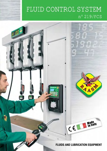
FLUID CONTROL SYSTEM<br />
n° 219/FCS<br />
FLUIDS AND LUBRICATION EQUIPMENT
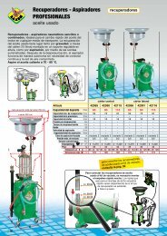
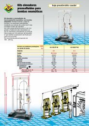
The FCS is an integrated system<br />
for managing and controlling the<br />
dispensing of fluids in maintenance<br />
facilities. Highly versatile and<br />
intuitive, it allows customised<br />
configurations in or<strong>de</strong>r to fully<br />
adapt to the customer’s<br />
needs.<br />
2<br />
► automatic control of fluid inventories<br />
► display with simple and intuitive menu<br />
► optional summary ticket for each action<br />
► ability to connect to personal computer<br />
► dispensing authorised by means of access co<strong>de</strong>
Fluid Control System<br />
can manage:<br />
► OPERATORS<br />
The FCS can be used by a maximum<br />
of 1000 authorized operators, who<br />
can access the system by entering a<br />
numerical password, or by using the<br />
“i-button” key. All the operations carried<br />
out, such as dispensing, filling and<br />
draining fluids, calibration, etc., are<br />
stored in the system’s memory.<br />
► TANKS<br />
The FCS can manage up to a<br />
maximum of 50 tanks, which are<br />
progressively numbered and<br />
associated with the type of fluid<br />
contained. The quantity of fluid insi<strong>de</strong><br />
each tank is constantly calculated by the<br />
system. Also, special reserve and <strong>de</strong>livery<br />
blocking alarms, or optional level gauge<br />
probes, prevent going below a minimum<br />
level fixed by the user.<br />
► FLUIDS<br />
The FCS can manage up to a maximum<br />
of 50 types of fluids. Each fluid is<br />
distinguished by the complete name and<br />
an abbreviation (6-digit), which simplifies<br />
the analysis of dispensing operations<br />
carried out by the system.<br />
The quantities dispensed are counted with<br />
the unit of measure chosen by the user:<br />
Liters, Gallons, Quarts, Pints.<br />
► DISPENSERS (OUTLETS)<br />
The FCS manages up to a maximum of<br />
1188 dispensing points (99 control units<br />
x 12 outlets). Each Operator Control Unit<br />
(OCU) can manage a maximum of 12<br />
outlets, 6 of which are able to work at the<br />
same time. The date and time, operator’s<br />
name, or<strong>de</strong>r number or vehicle<br />
number-plate, type of fluid and quantity<br />
dispensed are recor<strong>de</strong>d for each<br />
dispensing operation. All these <strong>de</strong>tails<br />
can be printed on tickets.<br />
► DATA BASE<br />
The internal memory of the OCU allows<br />
the recording of up to a maximum of<br />
4000 operations. When connected to<br />
a PC, <strong>de</strong>dicated software supplied with<br />
the FCS enables data management<br />
and customization of the system, as well<br />
as sending the stored data.<br />
3
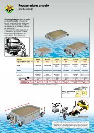
FCS software<br />
► The FCS software is both sophisticated<br />
and easy to use. The system is<br />
simple to configure for accurately<br />
managing tanks, operators,<br />
dispensers, fluids and more.<br />
The FCS software also provi<strong>de</strong>s tools<br />
for analyzing your fluids consumption.<br />
Raasm - FCS<br />
File<br />
Users<br />
System status<br />
System configuration<br />
Supplies list<br />
Summary list<br />
Reference Products Tanks Dispensers Help<br />
Tanks<br />
Tank1 90%<br />
Tank2 15%<br />
Tank3 5%<br />
Archive backup<br />
Archive restore<br />
Exit<br />
Users<br />
Users list<br />
Users insertion<br />
Reference<br />
Reference list<br />
Reference insertion<br />
Products<br />
Products list<br />
Products insertion<br />
Tanks<br />
Tank list<br />
Tank insertion<br />
Load/Unload insert<br />
List of movements<br />
Dispensers<br />
Input dispensers<br />
Dispensers list<br />
4
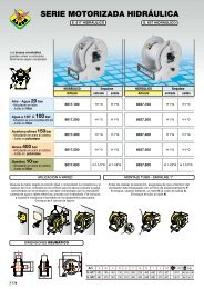
Operator Control Unit: Menu<br />
► The Operator Control Unit allows the administrator<br />
to access to a <strong>de</strong>tailed menu where personalized<br />
configurations can be entered and the entire system<br />
managed. If the Operator Control Unit is connected<br />
with a computer most of the operations shown<br />
above can be managed through the FCS software<br />
(see page asi<strong>de</strong>).<br />
► Every <strong>de</strong>livery can be summarized by a printed<br />
ticket (optional) which shows the most important<br />
information recor<strong>de</strong>d by the system.<br />
5
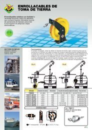
Wiring Diagram FCS<br />
7<br />
2<br />
1<br />
Depleted oil tanks where a level indicator<br />
shows when the fixed maximum level has<br />
been reached.<br />
Fluids tanks, which can be installed in the<br />
storage room, can either be standard<br />
200 l drums or tanks of various sizes.<br />
1<br />
Art. 39599 OPERATOR CONTROL UNIT (OCU)<br />
The OCU is installed near the dispensing points and allows operators to communicate with the<br />
system by means of the special membrane keypad and large display. There is an optional<br />
printer for tickets.<br />
Important: for operation, each OCU must be connected to a DMU.<br />
Art. 39598 OPERATOR CONTROL UNIT (OCU)<br />
Like Art. 39599 but without printer for tickets.<br />
System functionality:<br />
► Access to the system by means of PIN co<strong>de</strong> or I-button <strong>de</strong>vice ► Possibility of installing external bar<br />
co<strong>de</strong> or badge rea<strong>de</strong>r ► Customizable ticket printout at the end of each dispensing operation (version with<br />
printer) ► Up to 1000 authorized operators ► Memory holds up to 4000 operations ► Possibility of free<br />
dispensing or preset amount ► Individual calibration of each single dispenser ► Large graphic display with<br />
intuitive and easy to scroll through menu ► Possibility of connecting the system to a PC ► Up to 6 simultaneous<br />
<strong>de</strong>liveries (when connected with 3 DMUs) ► It is possible to manage up to 12 dispensers when<br />
using 3 DMUs.<br />
6
4<br />
2<br />
3<br />
3<br />
4<br />
5<br />
6<br />
CABLE DESCRIPTION LENGHT<br />
Power cable 110 V - 230 V<br />
max 100 m<br />
Cable for connecting main air supply solenoid valve to DMU<br />
max 100 m<br />
Cable for connecting air supply solenoid valve to DMU<br />
max 100 m<br />
Cable for connecting level indicator to DMU<br />
max 1000 m<br />
Cable for connecting remote display to DMU<br />
max 30 m<br />
Cable for connecting OCU to DMU and successive DMU’s<br />
Cable for connecting OCU to PC and other OCU’s<br />
max 1000 m<br />
Cable for connecting <strong>de</strong>pleted oil level indicator to DMU<br />
max 1000 m<br />
Cable for connecting DMU to PDV or PSV<br />
max 30 m<br />
Power cable 24 V - D.C.<br />
max 100 m<br />
2<br />
Art. 39605 DISPENSER MANAGEMENT UNIT (DMU)<br />
As well as sending commands to all the components of the system, the Dispenser<br />
Management Unit (DMU) ensures the low voltage (24 V - D.C.) power supply. It contains all<br />
the electrical connections for the system. Each DMU directly controls up to 4 dispensers.<br />
If 5-8 dispensers are to be controlled, a second DMU can be connected to the first, thereby<br />
enabling a single OCU to control 8 dispensers. For controlling 9-12 dispensers, a third DMU<br />
can be connected to the first, (see installation examples on the following pages).<br />
DMU characteristics:<br />
► Powered by 110 V - 230 V - A.C., it supplies the 24 V - D.C. feed to all the components of the<br />
system ► Can control up to 4 dispensers which are each connected to a pulser-valve unit (PDV or PSV)<br />
►Enables the simultaneous use of 2 dispensers per unit ► Max. distance between DMU and pulser-valve:<br />
30 m. ► Suitable to be connected with 4 oil level gauges and 1 waste oil level gauge ► 4 Air solenoid<br />
valves (one for each pump), or 1 general air solenoid valve, may be connected with the DMU to pressurize<br />
the pumps only during use ► 2 Remote display may be connected with the DMU.<br />
7
3<br />
Art. 39630 PULSER DOUBLE VALVE (PDV)<br />
The PDV is installed along the pipe that takes the fluid from the pump to the dispensing<br />
points. It closes the supply line, acting as a valve that opens when receiving consent from<br />
the DMU to which it is connected. It also measures the product flowing through the pipe,<br />
immediately sending the data to the DMU which feeds it with 24 V - D.C. The double valve<br />
offers greater precision in measuring the dispensed fluid, by reducing the flow before<br />
reaching the preset quantity. Inlet and outlet connections 1/2” F.<br />
4<br />
Art. 39620 PULSER SINGLE VALVE (PSV) FOR OIL 1/2”<br />
The Pulser in single valve version for oil, with 1/2” connections, as an alternative to the<br />
double valve version PDV.<br />
Art. 39623 PULSER SINGLE VALVE (PSV) FOR OIL 3/4”<br />
The Pulser single valve version for oil with 3/4” connections.<br />
Art. 39621 PULSER SINGLE VALVE (PSV) FOR ANTIFREEZE 1/2”<br />
The Pulser single valve version for antifreeze and window washing liquid with 1/2”<br />
connections.<br />
Art. 39624 PULSER SINGLE VALVE (PSV) FOR DIESEL 3/4”<br />
The Pulser single valve version for gas oil with 3/4” connections.<br />
► All the PSV’s are fed by the DMU 24 V - D.C.<br />
5<br />
Art. 39640 REMOTE DISPLAY (LCD)<br />
The remote display allows the dispensed quantities to be viewed from a distance.<br />
It is possible to connect 2 remote displays for each DMU.<br />
► Fed by DMU 24 V - D.C.<br />
6<br />
Art. 39680 KIT PERSONAL COMPUTER (KIT PC)<br />
The PC Kit enables a personal computer to centralize and manage the system. It comprises<br />
a USB signal converter to connect the FCS Module to the PC and installation software on<br />
a CD ROM. The software has been <strong>de</strong>signed to manage all necessary operations to control<br />
dispensing, including but not limited to: system configuration, operator setup, and checking<br />
inventory.<br />
it manages:<br />
► Max. 1000 operators ► Max. 50 tanks ► Max. 50 products ► Max. 5000 reference numbers (or<br />
or<strong>de</strong>r numbers) ► Can set unit of measure to liters, gallons, quarts or pints (liters set as <strong>de</strong>fault) ► Tank<br />
block level ► Tank alarm level ► Max. 1188 controlled outlets ► Windows compatible software ► Data<br />
can be exported as an .xls or .txt file for compatibility with other management software ► Can dispense<br />
directly from your PC ► Can preset multiple dispensing quantities, which are i<strong>de</strong>ntified by a “Refnumber”<br />
► Displays remaining stock in real-time for every tank and can graph the trend of remaining stocks over<br />
time.<br />
Art. 39685<br />
Converter USB-RS232/RS485, to connect OCU with personal computer.<br />
Art. 39690<br />
“I BUTTON” <strong>de</strong>vice allows operators communicate with the system.<br />
It is an alternative to PIN co<strong>de</strong>.<br />
8
Art. 39650<br />
Low level gauge h 860 mm, suitable for 180 - 220 Kg drums, to be connected with FCS.<br />
Art. 39651<br />
Low level gauge h 1300 mm, suitable for tanks, to be connected with FCS.<br />
Art. 39652<br />
Low level gauge h 1500 mm, suitable for tanks, to be connected with FCS.<br />
Art. 39655<br />
High level gauge for waste oil, suitable to be connected with FCS.<br />
Art. 39610<br />
Pulser meter for oil with inlet/outlet 1/2” is used to measure fluids and to transmit data.<br />
It is usually installed on centralized lubrication system to control and manage <strong>de</strong>livery of<br />
fluids.<br />
Art. 39611<br />
Pulser meter for antifreeze and windscreen washing liquid with inlet/outlet 1/2” is used to<br />
measure fluids and to transmit data. It is usually installed on centralized lubrication system<br />
to control and manage <strong>de</strong>livery of fluids.<br />
Art. 39613<br />
Pulser meter for oil with inlet/outlet 3/4” is used to measure fluids and to transmit data.<br />
It is usually installed on centralized lubrication system to control and manage <strong>de</strong>livery of<br />
fluids.<br />
Art. 39614<br />
Pulser meter for diesel with inlet/outlet 3/4” is used to measure fluids and to transmit data.<br />
It is usually installed on centralized lubrication system to control and manage <strong>de</strong>livery of<br />
fluids.<br />
9
Accessories for oil room<br />
Art. 39280<br />
Timer 24 V D.C. with daily and weekly programminng for programmed<br />
activation of air solenoid valves 24 V - D.C. connected with all the pneumatic pumps.<br />
Art. 39281<br />
Fee<strong>de</strong>r 220 - 24 V D.C. - 6A. It provi<strong>de</strong>s power supply to all the acessories for the oil room.<br />
Art. 39282<br />
Automatic manual-selector 24 V D.C. for feeding solenoid valves, to activate every pump.<br />
Art. 39284 PNEUMATIC SOLENOID VALVE 1/4”<br />
The pneumatic solenoid valve 24 V - D.C. with FxF 1/4” connections, equipped with pressure<br />
regulator 0-8 bar, controls the opening and/or closing of the compressed air supply for each<br />
single pump mounted on fluid tanks. The connected DMU controls when it opens.<br />
Art. 39285 PNEUMATIC SOLENOID VALVE 1/2”<br />
The pneumatic solenoid valve 24 V - D.C. with FxF 1/2” connections, equipped with pressure<br />
regulator 0-8 bar, controls the opening and/or closing of the compressed air system that<br />
feeds the pumps mounted on fluids tanks.<br />
7<br />
Art. 39286 PNEUMATIC SOLENOID VALVE 1/4”<br />
The pneumatic solenoid valve 24 V - D.C. with FxF 1/4” connections controls the opening<br />
and/or closing of the compressed air supply for each single pump mounted on fluid tanks.<br />
The connected DMU controls when it opens.<br />
Art. 39287 PNEUMATIC SOLENOID VALVE 1/2”<br />
The pneumatic solenoid valve 24 V - D.C. with FxF 1/2” connections controls the opening<br />
and/or closing of the compressed air system that feeds the pumps mounted on fluids tanks.<br />
Art. 39289<br />
Luminous acoustic flashing light, connected with a level gauge, signals exhaustion of fluids.<br />
Art. 39290<br />
Electric line main stop push button for all the acessories in the oil room.<br />
10
Installation examples<br />
n° 1<br />
SYSTEM<br />
CHARACTERISTICS<br />
OCU<br />
with ticket<br />
printer<br />
Art. 39599<br />
FCS comprising a operator control unit without ticket printer<br />
connected to DMU with 4 dispensers. Connection to a PC not present.<br />
n° 1 DMU Art. 39605<br />
n° 4 PDV Art. 39630<br />
n° 4<br />
Dispensing<br />
points<br />
-<br />
n° 2<br />
SYSTEM<br />
CHARACTERISTICS<br />
OCU<br />
with ticket<br />
printer<br />
Art. 39599<br />
FCS comprising 2 control units, the first connected to 2 DMU’s with 7 dispensers and remote<br />
display; the second connected to DMU with 4 dispensers. The system is connected to a PC.<br />
n° 3 DMU Art. 39605<br />
n° 11 PDV Art. 39630<br />
n° 1 LCD Art. 39640<br />
n° 1 Kit PC Art. 39680<br />
n° 11<br />
Dispensing<br />
points<br />
-<br />
SYSTEM<br />
CHARACTERISTICS<br />
FCS comprising 3 control units, each connected to a different number of dispensers<br />
by means of DMU. Remote displays present. The system is connected to a PC.<br />
n° 3<br />
OCU<br />
with ticket<br />
printer<br />
Art. 39599<br />
n° 7 DMU Art. 39605<br />
n° 24 PDV Art. 39630<br />
n° 5 LCD Art. 39640<br />
n° 1 Kit PC Art. 39680<br />
n° 24<br />
Dispensing<br />
points<br />
-<br />
11
IDEAL FOR<br />
► REPAIR GARAGES<br />
► QUICK MAINTENANCE CENTRES<br />
► LUBRICANT DISTRIBUTION CENTRES<br />
► EQUIPPED TRUCKS<br />
► AUTOMOBILE INDUSTRY<br />
► METALWORKING INDUSTRY<br />
► MUNICIPAL WORKSHOPS<br />
► MINES<br />
Authorized distributor<br />
GB<br />
RAASM S.p.A.<br />
36022 S. ZENO DI CASSOLA (VI)<br />
Via Marangoni, 33 - ITALY<br />
Export <strong>de</strong>partment<br />
Tel. +39 0424 571130 - Fax 0424 571135<br />
Technical <strong>de</strong>partment<br />
Tel. +39 0424 571150 - Fax 0424 571155<br />
WRDA/MO.2011-GB<br />
info@raasm.com<br />
www.raasm.com<br />
All rights reserved to Raasm S.p.A.