Sistema controle de fluidos
Sistema controle de fluidos
Sistema controle de fluidos

You also want an ePaper? Increase the reach of your titles
YUMPU automatically turns print PDFs into web optimized ePapers that Google loves.
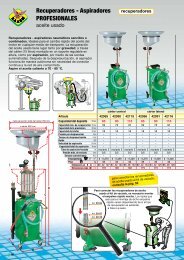
FLUID CONTROL SYSTEM<br />
n° 219/FCS<br />
FLUIDS AND LUBRICATION EQUIPMENT
The FCS is an integrated system<br />
for managing and controlling the<br />
dispensing of fluids in maintenance<br />
facilities. Highly versatile and<br />
intuitive, it allows customised<br />
configurations in or<strong>de</strong>r to fully<br />
adapt to the customer’s<br />
needs.<br />
2<br />
► automatic control of fluid inventories<br />
► display with simple and intuitive menu<br />
► optional summary ticket for each action<br />
► ability to connect to personal computer<br />
► dispensing authorised by means of access co<strong>de</strong>
Fluid Control System<br />
can manage:<br />
► OPERATORS<br />
The FCS can be used by a maximum<br />
of 1000 authorized operators, who<br />
can access the system by entering a<br />
numerical password, or by using the<br />
“i-button” key. All the operations carried<br />
out, such as dispensing, filling and<br />
draining fluids, calibration, etc., are<br />
stored in the system’s memory.<br />
► TANKS<br />
The FCS can manage up to a<br />
maximum of 50 tanks, which are<br />
progressively numbered and<br />
associated with the type of fluid<br />
contained. The quantity of fluid insi<strong>de</strong><br />
each tank is constantly calculated by the<br />
system. Also, special reserve and <strong>de</strong>livery<br />
blocking alarms, or optional level gauge<br />
probes, prevent going below a minimum<br />
level fixed by the user.<br />
► FLUIDS<br />
The FCS can manage up to a maximum<br />
of 50 types of fluids. Each fluid is<br />
distinguished by the complete name and<br />
an abbreviation (6-digit), which simplifies<br />
the analysis of dispensing operations<br />
carried out by the system.<br />
The quantities dispensed are counted with<br />
the unit of measure chosen by the user:<br />
Liters, Gallons, Quarts, Pints.<br />
► DISPENSERS (OUTLETS)<br />
The FCS manages up to a maximum of<br />
1188 dispensing points (99 control units<br />
x 12 outlets). Each Operator Control Unit<br />
(OCU) can manage a maximum of 12<br />
outlets, 6 of which are able to work at the<br />
same time. The date and time, operator’s<br />
name, or<strong>de</strong>r number or vehicle<br />
number-plate, type of fluid and quantity<br />
dispensed are recor<strong>de</strong>d for each<br />
dispensing operation. All these <strong>de</strong>tails<br />
can be printed on tickets.<br />
► DATA BASE<br />
The internal memory of the OCU allows<br />
the recording of up to a maximum of<br />
4000 operations. When connected to<br />
a PC, <strong>de</strong>dicated software supplied with<br />
the FCS enables data management<br />
and customization of the system, as well<br />
as sending the stored data.<br />
3
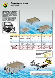
FCS software<br />
► The FCS software is both sophisticated<br />
and easy to use. The system is<br />
simple to configure for accurately<br />
managing tanks, operators,<br />
dispensers, fluids and more.<br />
The FCS software also provi<strong>de</strong>s tools<br />
for analyzing your fluids consumption.<br />
Raasm - FCS<br />
File<br />
Users<br />
System status<br />
System configuration<br />
Supplies list<br />
Summary list<br />
Reference Products Tanks Dispensers Help<br />
Tanks<br />
Tank1 90%<br />
Tank2 15%<br />
Tank3 5%<br />
Archive backup<br />
Archive restore<br />
Exit<br />
Users<br />
Users list<br />
Users insertion<br />
Reference<br />
Reference list<br />
Reference insertion<br />
Products<br />
Products list<br />
Products insertion<br />
Tanks<br />
Tank list<br />
Tank insertion<br />
Load/Unload insert<br />
List of movements<br />
Dispensers<br />
Input dispensers<br />
Dispensers list<br />
4
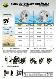
Operator Control Unit: Menu<br />
► The Operator Control Unit allows the administrator<br />
to access to a <strong>de</strong>tailed menu where personalized<br />
configurations can be entered and the entire system<br />
managed. If the Operator Control Unit is connected<br />
with a computer most of the operations shown<br />
above can be managed through the FCS software<br />
(see page asi<strong>de</strong>).<br />
► Every <strong>de</strong>livery can be summarized by a printed<br />
ticket (optional) which shows the most important<br />
information recor<strong>de</strong>d by the system.<br />
5
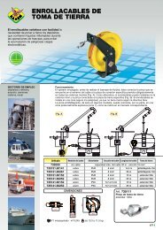
Wiring Diagram FCS<br />
7<br />
2<br />
1<br />
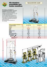
Depleted oil tanks where a level indicator<br />
shows when the fixed maximum level has<br />
been reached.<br />
Fluids tanks, which can be installed in the<br />
storage room, can either be standard<br />
200 l drums or tanks of various sizes.<br />
1<br />
Art. 39599 OPERATOR CONTROL UNIT (OCU)<br />
The OCU is installed near the dispensing points and allows operators to communicate with the<br />
system by means of the special membrane keypad and large display. There is an optional<br />
printer for tickets.<br />
Important: for operation, each OCU must be connected to a DMU.<br />
Art. 39598 OPERATOR CONTROL UNIT (OCU)<br />
Like Art. 39599 but without printer for tickets.<br />
System functionality:<br />
► Access to the system by means of PIN co<strong>de</strong> or I-button <strong>de</strong>vice ► Possibility of installing external bar<br />
co<strong>de</strong> or badge rea<strong>de</strong>r ► Customizable ticket printout at the end of each dispensing operation (version with<br />
printer) ► Up to 1000 authorized operators ► Memory holds up to 4000 operations ► Possibility of free<br />
dispensing or preset amount ► Individual calibration of each single dispenser ► Large graphic display with<br />
intuitive and easy to scroll through menu ► Possibility of connecting the system to a PC ► Up to 6 simultaneous<br />
<strong>de</strong>liveries (when connected with 3 DMUs) ► It is possible to manage up to 12 dispensers when<br />
using 3 DMUs.<br />
6
4<br />
2<br />
3<br />
3<br />
4<br />
5<br />
6<br />
CABLE DESCRIPTION LENGHT<br />
Power cable 110 V - 230 V<br />
max 100 m<br />
Cable for connecting main air supply solenoid valve to DMU<br />
max 100 m<br />
Cable for connecting air supply solenoid valve to DMU<br />
max 100 m<br />
Cable for connecting level indicator to DMU<br />
max 1000 m<br />
Cable for connecting remote display to DMU<br />
max 30 m<br />
Cable for connecting OCU to DMU and successive DMU’s<br />
Cable for connecting OCU to PC and other OCU’s<br />
max 1000 m<br />
Cable for connecting <strong>de</strong>pleted oil level indicator to DMU<br />
max 1000 m<br />
Cable for connecting DMU to PDV or PSV<br />
max 30 m<br />
Power cable 24 V - D.C.<br />
max 100 m<br />
2<br />
Art. 39605 DISPENSER MANAGEMENT UNIT (DMU)<br />
As well as sending commands to all the components of the system, the Dispenser<br />
Management Unit (DMU) ensures the low voltage (24 V - D.C.) power supply. It contains all<br />
the electrical connections for the system. Each DMU directly controls up to 4 dispensers.<br />
If 5-8 dispensers are to be controlled, a second DMU can be connected to the first, thereby<br />
enabling a single OCU to control 8 dispensers. For controlling 9-12 dispensers, a third DMU<br />
can be connected to the first, (see installation examples on the following pages).<br />
DMU characteristics:<br />
► Powered by 110 V - 230 V - A.C., it supplies the 24 V - D.C. feed to all the components of the<br />
system ► Can control up to 4 dispensers which are each connected to a pulser-valve unit (PDV or PSV)<br />
►Enables the simultaneous use of 2 dispensers per unit ► Max. distance between DMU and pulser-valve:<br />
30 m. ► Suitable to be connected with 4 oil level gauges and 1 waste oil level gauge ► 4 Air solenoid<br />
valves (one for each pump), or 1 general air solenoid valve, may be connected with the DMU to pressurize<br />
the pumps only during use ► 2 Remote display may be connected with the DMU.<br />
7
3<br />
Art. 39630 PULSER DOUBLE VALVE (PDV)<br />
The PDV is installed along the pipe that takes the fluid from the pump to the dispensing<br />
points. It closes the supply line, acting as a valve that opens when receiving consent from<br />
the DMU to which it is connected. It also measures the product flowing through the pipe,<br />
immediately sending the data to the DMU which feeds it with 24 V - D.C. The double valve<br />
offers greater precision in measuring the dispensed fluid, by reducing the flow before<br />
reaching the preset quantity. Inlet and outlet connections 1/2” F.<br />
4<br />
Art. 39620 PULSER SINGLE VALVE (PSV) FOR OIL 1/2”<br />
The Pulser in single valve version for oil, with 1/2” connections, as an alternative to the<br />
double valve version PDV.<br />
Art. 39623 PULSER SINGLE VALVE (PSV) FOR OIL 3/4”<br />
The Pulser single valve version for oil with 3/4” connections.<br />
Art. 39621 PULSER SINGLE VALVE (PSV) FOR ANTIFREEZE 1/2”<br />
The Pulser single valve version for antifreeze and window washing liquid with 1/2”<br />
connections.<br />
Art. 39624 PULSER SINGLE VALVE (PSV) FOR DIESEL 3/4”<br />
The Pulser single valve version for gas oil with 3/4” connections.<br />
► All the PSV’s are fed by the DMU 24 V - D.C.<br />
5<br />
Art. 39640 REMOTE DISPLAY (LCD)<br />
The remote display allows the dispensed quantities to be viewed from a distance.<br />
It is possible to connect 2 remote displays for each DMU.<br />
► Fed by DMU 24 V - D.C.<br />
6<br />
Art. 39680 KIT PERSONAL COMPUTER (KIT PC)<br />
The PC Kit enables a personal computer to centralize and manage the system. It comprises<br />
a USB signal converter to connect the FCS Module to the PC and installation software on<br />
a CD ROM. The software has been <strong>de</strong>signed to manage all necessary operations to control<br />
dispensing, including but not limited to: system configuration, operator setup, and checking<br />
inventory.<br />
it manages:<br />
► Max. 1000 operators ► Max. 50 tanks ► Max. 50 products ► Max. 5000 reference numbers (or<br />
or<strong>de</strong>r numbers) ► Can set unit of measure to liters, gallons, quarts or pints (liters set as <strong>de</strong>fault) ► Tank<br />
block level ► Tank alarm level ► Max. 1188 controlled outlets ► Windows compatible software ► Data<br />
can be exported as an .xls or .txt file for compatibility with other management software ► Can dispense<br />
directly from your PC ► Can preset multiple dispensing quantities, which are i<strong>de</strong>ntified by a “Refnumber”<br />
► Displays remaining stock in real-time for every tank and can graph the trend of remaining stocks over<br />
time.<br />
Art. 39685<br />
Converter USB-RS232/RS485, to connect OCU with personal computer.<br />
Art. 39690<br />
“I BUTTON” <strong>de</strong>vice allows operators communicate with the system.<br />
It is an alternative to PIN co<strong>de</strong>.<br />
8
Art. 39650<br />
Low level gauge h 860 mm, suitable for 180 - 220 Kg drums, to be connected with FCS.<br />
Art. 39651<br />
Low level gauge h 1300 mm, suitable for tanks, to be connected with FCS.<br />
Art. 39652<br />
Low level gauge h 1500 mm, suitable for tanks, to be connected with FCS.<br />
Art. 39655<br />
High level gauge for waste oil, suitable to be connected with FCS.<br />
Art. 39610<br />
Pulser meter for oil with inlet/outlet 1/2” is used to measure fluids and to transmit data.<br />
It is usually installed on centralized lubrication system to control and manage <strong>de</strong>livery of<br />
fluids.<br />
Art. 39611<br />
Pulser meter for antifreeze and windscreen washing liquid with inlet/outlet 1/2” is used to<br />
measure fluids and to transmit data. It is usually installed on centralized lubrication system<br />
to control and manage <strong>de</strong>livery of fluids.<br />
Art. 39613<br />
Pulser meter for oil with inlet/outlet 3/4” is used to measure fluids and to transmit data.<br />
It is usually installed on centralized lubrication system to control and manage <strong>de</strong>livery of<br />
fluids.<br />
Art. 39614<br />
Pulser meter for diesel with inlet/outlet 3/4” is used to measure fluids and to transmit data.<br />
It is usually installed on centralized lubrication system to control and manage <strong>de</strong>livery of<br />
fluids.<br />
9
Accessories for oil room<br />
Art. 39280<br />
Timer 24 V D.C. with daily and weekly programminng for programmed<br />
activation of air solenoid valves 24 V - D.C. connected with all the pneumatic pumps.<br />
Art. 39281<br />
Fee<strong>de</strong>r 220 - 24 V D.C. - 6A. It provi<strong>de</strong>s power supply to all the acessories for the oil room.<br />
Art. 39282<br />
Automatic manual-selector 24 V D.C. for feeding solenoid valves, to activate every pump.<br />
Art. 39284 PNEUMATIC SOLENOID VALVE 1/4”<br />
The pneumatic solenoid valve 24 V - D.C. with FxF 1/4” connections, equipped with pressure<br />
regulator 0-8 bar, controls the opening and/or closing of the compressed air supply for each<br />
single pump mounted on fluid tanks. The connected DMU controls when it opens.<br />
Art. 39285 PNEUMATIC SOLENOID VALVE 1/2”<br />
The pneumatic solenoid valve 24 V - D.C. with FxF 1/2” connections, equipped with pressure<br />
regulator 0-8 bar, controls the opening and/or closing of the compressed air system that<br />
feeds the pumps mounted on fluids tanks.<br />
7<br />
Art. 39286 PNEUMATIC SOLENOID VALVE 1/4”<br />
The pneumatic solenoid valve 24 V - D.C. with FxF 1/4” connections controls the opening<br />
and/or closing of the compressed air supply for each single pump mounted on fluid tanks.<br />
The connected DMU controls when it opens.<br />
Art. 39287 PNEUMATIC SOLENOID VALVE 1/2”<br />
The pneumatic solenoid valve 24 V - D.C. with FxF 1/2” connections controls the opening<br />
and/or closing of the compressed air system that feeds the pumps mounted on fluids tanks.<br />
Art. 39289<br />
Luminous acoustic flashing light, connected with a level gauge, signals exhaustion of fluids.<br />
Art. 39290<br />
Electric line main stop push button for all the acessories in the oil room.<br />
10
Installation examples<br />
n° 1<br />
SYSTEM<br />
CHARACTERISTICS<br />
OCU<br />
with ticket<br />
printer<br />
Art. 39599<br />
FCS comprising a operator control unit without ticket printer<br />
connected to DMU with 4 dispensers. Connection to a PC not present.<br />
n° 1 DMU Art. 39605<br />
n° 4 PDV Art. 39630<br />
n° 4<br />
Dispensing<br />
points<br />
-<br />
n° 2<br />
SYSTEM<br />
CHARACTERISTICS<br />
OCU<br />
with ticket<br />
printer<br />
Art. 39599<br />
FCS comprising 2 control units, the first connected to 2 DMU’s with 7 dispensers and remote<br />
display; the second connected to DMU with 4 dispensers. The system is connected to a PC.<br />
n° 3 DMU Art. 39605<br />
n° 11 PDV Art. 39630<br />
n° 1 LCD Art. 39640<br />
n° 1 Kit PC Art. 39680<br />
n° 11<br />
Dispensing<br />
points<br />
-<br />
SYSTEM<br />
CHARACTERISTICS<br />
FCS comprising 3 control units, each connected to a different number of dispensers<br />
by means of DMU. Remote displays present. The system is connected to a PC.<br />
n° 3<br />
OCU<br />
with ticket<br />
printer<br />
Art. 39599<br />
n° 7 DMU Art. 39605<br />
n° 24 PDV Art. 39630<br />
n° 5 LCD Art. 39640<br />
n° 1 Kit PC Art. 39680<br />
n° 24<br />
Dispensing<br />
points<br />
-<br />
11
IDEAL FOR<br />
► REPAIR GARAGES<br />
► QUICK MAINTENANCE CENTRES<br />
► LUBRICANT DISTRIBUTION CENTRES<br />
► EQUIPPED TRUCKS<br />
► AUTOMOBILE INDUSTRY<br />
► METALWORKING INDUSTRY<br />
► MUNICIPAL WORKSHOPS<br />
► MINES<br />
Authorized distributor<br />
GB<br />
RAASM S.p.A.<br />
36022 S. ZENO DI CASSOLA (VI)<br />
Via Marangoni, 33 - ITALY<br />
Export <strong>de</strong>partment<br />
Tel. +39 0424 571130 - Fax 0424 571135<br />
Technical <strong>de</strong>partment<br />
Tel. +39 0424 571150 - Fax 0424 571155<br />
WRDA/MO.2011-GB<br />
info@raasm.com<br />
www.raasm.com<br />
All rights reserved to Raasm S.p.A.