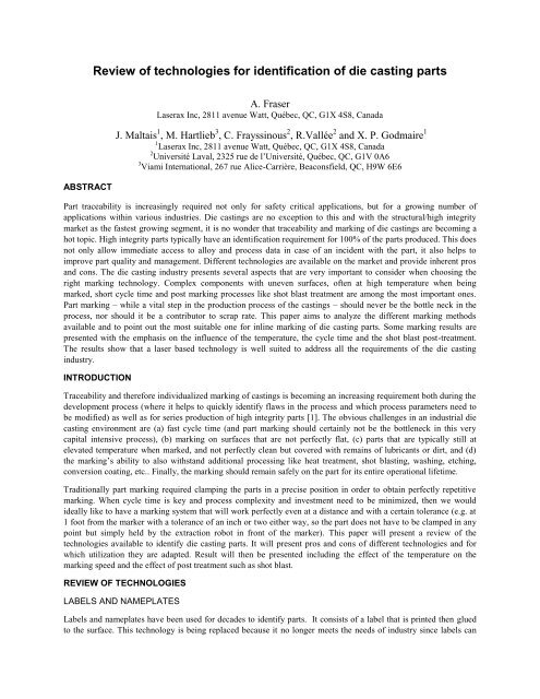
Review of technologies for identification of die casting parts
This paper aims to analyze the different marking methods available and to point out the most suitable one for inline marking of die casting parts. Some marking results are presented with the emphasis on the influence of the temperature, the cycle time and the shot blast post-treatment. The results show that a laser based technology is well suited to address all the equirements of the die casting industry.
This paper aims to analyze the different marking methods available and to point out the most suitable one for inline marking of die casting parts. Some marking results are presented with the emphasis on the influence of the temperature, the cycle time and the shot blast post-treatment. The results show that a laser based technology is well suited to address all the equirements of the die casting industry.

Create successful ePaper yourself
Turn your PDF publications into a flip-book with our unique Google optimized e-Paper software.
<strong>Review</strong> <strong>of</strong> <strong>technologies</strong> <strong>for</strong> <strong>identification</strong> <strong>of</strong> <strong>die</strong> <strong>casting</strong> <strong>parts</strong><br />
A. Fraser<br />
Laserax Inc, 2811 avenue Watt, Québec, QC, G1X 4S8, Canada<br />
J. Maltais 1 , M. Hartlieb 3 , C. Frayssinous 2 , R.Vallée 2 and X. P. Godmaire 1<br />
1 Laserax Inc, 2811 avenue Watt, Québec, QC, G1X 4S8, Canada<br />
2 Université Laval, 2325 rue de l’Université, Québec, QC, G1V 0A6<br />
3 Viami International, 267 rue Alice-Carrière, Beaconsfield, QC, H9W 6E6<br />
ABSTRACT<br />
Part traceability is increasingly required not only <strong>for</strong> safety critical applications, but <strong>for</strong> a growing number <strong>of</strong><br />
applications within various industries. Die <strong>casting</strong>s are no exception to this and with the structural/high integrity<br />
market as the fastest growing segment, it is no wonder that traceability and marking <strong>of</strong> <strong>die</strong> <strong>casting</strong>s are becoming a<br />
hot topic. High integrity <strong>parts</strong> typically have an <strong>identification</strong> requirement <strong>for</strong> 100% <strong>of</strong> the <strong>parts</strong> produced. This does<br />
not only allow immediate access to alloy and process data in case <strong>of</strong> an incident with the part, it also helps to<br />
improve part quality and management. Different <strong>technologies</strong> are available on the market and provide inherent pros<br />
and cons. The <strong>die</strong> <strong>casting</strong> industry presents several aspects that are very important to consider when choosing the<br />
right marking technology. Complex components with uneven surfaces, <strong>of</strong>ten at high temperature when being<br />
marked, short cycle time and post marking processes like shot blast treatment are among the most important ones.<br />
Part marking – while a vital step in the production process <strong>of</strong> the <strong>casting</strong>s – should never be the bottle neck in the<br />
process, nor should it be a contributor to scrap rate. This paper aims to analyze the different marking methods<br />
available and to point out the most suitable one <strong>for</strong> inline marking <strong>of</strong> <strong>die</strong> <strong>casting</strong> <strong>parts</strong>. Some marking results are<br />
presented with the emphasis on the influence <strong>of</strong> the temperature, the cycle time and the shot blast post-treatment.<br />
The results show that a laser based technology is well suited to address all the requirements <strong>of</strong> the <strong>die</strong> <strong>casting</strong><br />
industry.<br />
INTRODUCTION<br />
Traceability and there<strong>for</strong>e individualized marking <strong>of</strong> <strong>casting</strong>s is becoming an increasing requirement both during the<br />
development process (where it helps to quickly identify flaws in the process and which process parameters need to<br />
be modified) as well as <strong>for</strong> series production <strong>of</strong> high integrity <strong>parts</strong> [1]. The obvious challenges in an industrial <strong>die</strong><br />
<strong>casting</strong> environment are (a) fast cycle time (and part marking should certainly not be the bottleneck in this very<br />
capital intensive process), (b) marking on surfaces that are not perfectly flat, (c) <strong>parts</strong> that are typically still at<br />
elevated temperature when marked, and not perfectly clean but covered with remains <strong>of</strong> lubricants or dirt, and (d)<br />
the marking’s ability to also withstand additional processing like heat treatment, shot blasting, washing, etching,<br />
conversion coating, etc.. Finally, the marking should remain safely on the part <strong>for</strong> its entire operational lifetime.<br />
Traditionally part marking required clamping the <strong>parts</strong> in a precise position in order to obtain perfectly repetitive<br />
marking. When cycle time is key and process complexity and investment need to be minimized, then we would<br />
ideally like to have a marking system that will work perfectly even at a distance and with a certain tolerance (e.g. at<br />
1 foot from the marker with a tolerance <strong>of</strong> an inch or two either way, so the part does not have to be clamped in any<br />
point but simply held by the extraction robot in front <strong>of</strong> the marker). This paper will present a review <strong>of</strong> the<br />
<strong>technologies</strong> available to identify <strong>die</strong> <strong>casting</strong> <strong>parts</strong>. It will present pros and cons <strong>of</strong> different <strong>technologies</strong> and <strong>for</strong><br />
which utilization they are adapted. Result will then be presented including the effect <strong>of</strong> the temperature on the<br />
marking speed and the effect <strong>of</strong> post treatment such as shot blast.<br />
REVIEW OF TECHNOLOGIES<br />
LABELS AND NAMEPLATES<br />
Labels and nameplates have been used <strong>for</strong> decades to identify <strong>parts</strong>. It consists <strong>of</strong> a label that is printed then glued<br />
to the surface. This technology is being replaced because it no longer meets the needs <strong>of</strong> industry since labels can
fall <strong>of</strong>f either during subsequent process steps or while <strong>parts</strong> are in use, there<strong>for</strong>e jeopardizing readability.<br />
Furthermore, there is a cost associated with labour to apply the label as well as consumable material required.<br />
However, it is possible to make colored labels. An example is presented in Figure 1.<br />
Figure 1: Printed label (sticker)<br />
Labels are not well suited <strong>for</strong> <strong>die</strong> cast <strong>parts</strong> <strong>for</strong> many reasons. The uneven surface would make them difficult to<br />
apply and the high temperature <strong>of</strong> the <strong>parts</strong> would imply costly heat resistant labels.<br />
PIN STAMPING AND DOT PEEN<br />
Pin stamping / dot peen is another technology used to trace <strong>parts</strong> – and one that is already being applied in <strong>die</strong><br />
<strong>casting</strong>. An example is presented in Figure 2 on an aluminum <strong>die</strong> <strong>casting</strong> surface.<br />
The method is based on a pin that produces a de<strong>for</strong>mation on the marking surface. There are single and multi-pin<br />
marking systems typically using a pneumatically driven metal pin to permanently indent the marking surface with a<br />
(simple) dot matrix/2D code and/or human readable codes, logos, graphics etc. Identifiers <strong>for</strong>med by this method are<br />
strong because the mark is engraved deep in the material. On the other hand, it is relatively slow and can even<br />
contribute to the scrap rate at the <strong>die</strong> caster as it is not always perfectly repetitive. This technology is suitable <strong>for</strong><br />
applications that are not cycle time constrained, do not need any contrast in the marking and simply need permanent<br />
<strong>identification</strong>. This process can typically accommodate surface irregularities <strong>of</strong> up to ¼”.<br />
Figure 2: Pinstamp ® /Dot peen marked <strong>die</strong> <strong>casting</strong>.<br />
Again, this technology is used but not really well adapted to the <strong>die</strong> <strong>casting</strong> industry <strong>for</strong> several reasons: First, the<br />
cycle time is too long. Second the uneven shape <strong>of</strong> the part may interfere with the pin marker unit which has some<br />
footprint and needs to come in close contact with the part. Third, the part needs to be held in a precise position every
time which is more difficult to integrate into the process. Fourth, most high integrity <strong>die</strong> cast <strong>parts</strong> have precise<br />
surface quality requirements so that the surface alteration generated by the pin stamper can in certain cases even<br />
exceed the surface quality specification.<br />
INKJET PRINTING<br />
Ink is directly applied to the surface with the use <strong>of</strong> a gun-body and a microscope nozzle. An example <strong>of</strong> inkjet<br />
marking is shown in Figure 3 on an aluminum slab. Like the label and nameplates, it can create colored labels. The<br />
durability is dependant on the quality <strong>of</strong> the ink used and the environment. In addition, it can be affected by<br />
chemical aggression. It is useful if you need colored and heat-resistant labels.<br />
Figure 3: Inkjet printing.<br />
In <strong>die</strong> <strong>casting</strong>, this is not typically used because subsequent process steps, especially machining in the CNC machine<br />
or surface treatments like shot blasting or even washing/etching/conversion coating would too easily erase the<br />
marking or at least make it very difficult to read.<br />
DIRECT MOLD MARKING<br />
Figure 4: Direct mold marking and punch<br />
This is commonly used in <strong>die</strong> <strong>casting</strong> but not <strong>for</strong> marking each single part with an individual code. It is used to mark<br />
longer term in<strong>for</strong>mation like the alloy, production facility, customer logo, or the day and shift the <strong>casting</strong> was<br />
produced at. It can also give in<strong>for</strong>mation about which tool / cavity was used. It is not used to mark <strong>parts</strong> with<br />
individual in<strong>for</strong>mation about the precise process parameters etc. or to integrate a 2D barcode in the part surface.
LASER MARKING<br />
Laser marking <strong>of</strong> metals is based on a surface modification that creates a contrast [2]. This phenomenon is used to<br />
mark code on metal <strong>parts</strong>. This technology is a fast and robust way <strong>for</strong> generating high contrast identifiers on metal<br />
<strong>parts</strong> [3]. It <strong>of</strong>fers great reproducibility and does not use consumables. In Figure 5 we can see a laser marking on an<br />
aluminum <strong>die</strong> <strong>casting</strong> part.<br />
Figure 5: Laser marked identifier on aluminum <strong>die</strong> <strong>casting</strong> alloy.<br />
As a laser is capable <strong>of</strong> marking with great precision on uneven surfaces at high temperature, it seems to be a very<br />
good choice <strong>for</strong> direct part marking <strong>of</strong> <strong>die</strong> <strong>casting</strong> <strong>parts</strong> [4]. However, the fact that the black marking presents an<br />
elevation with respect to the bare aluminum surface makes it more sensitive to degradation to shot blasting post<br />
treatment [2].<br />
STRATEGY<br />
Laser technology seems to meet the criteria <strong>for</strong> <strong>identification</strong> <strong>of</strong> <strong>die</strong> <strong>casting</strong> <strong>parts</strong>. We want to study the effect <strong>of</strong> post<br />
marking treatment like shot blast on laser marking. Since the marking is above the level <strong>of</strong> the aluminum, a simple<br />
marking will be erased. In order to achieve a laser marking process that is capable <strong>of</strong> resisting shot blast treatment,<br />
we developed the concept illustrated in Figure 6. We know that the black is created by a rough surface where there<br />
are many peaks so the light is trapped. We also know that the black is raised compared to the rest <strong>of</strong> the surface. To<br />
protect the code, we want to mark it on a lower surface. To do this, we scan with the laser multiple times to remove<br />
some material prior to the black marking process itself. We think this will allow conserving the contrast after the<br />
shot blast treatment.<br />
Our assumption was that the crater etched on each individual black cases <strong>of</strong> the 2D barcode will protect these<br />
surfaces against the shot blast process. Then, the necessary depth <strong>of</strong> the pre-etched crater depends on the dimension<br />
<strong>of</strong> the steel balls used <strong>for</strong> the post treatment process and on the size <strong>of</strong> each individual case <strong>of</strong> the 2D code. The<br />
larger the individual cases within the 2D code, the larger the balls must be.<br />
Figure 6: Sketch <strong>of</strong> the idea behind the protected marking.
An important consideration with this approach is the possibility <strong>of</strong> having multiple black cells next to each other and<br />
oriented so that the craters merge together. This would have the effect <strong>of</strong> increasing the necessary dimension <strong>of</strong> the<br />
balls. To avoid that, it may be possible to use a code with more cells than needed <strong>for</strong> the message to be encoded.<br />
This would allow more possibilities in the placement <strong>of</strong> the cells.<br />
EXPERIMENT<br />
The results presented in this paper were obtained with a fiber laser operating at a 1.06 μm wavelength and delivering<br />
an average power <strong>of</strong> 100 W. The laser pulse duration is 100 ns at a frequency <strong>of</strong> 100 kHz. A data matrix was marked<br />
on the sample with various laser parameters. Be<strong>for</strong>e marking the code in black, a different number <strong>of</strong> passes was<br />
made in order to obtain different depths at the black case locations. The number <strong>of</strong> passes varied from 3 to 15. For<br />
the pre-etch passes, the test was done with a speed <strong>of</strong> 3 000 mm/s to 7 000 mm/s and with a line spacing <strong>of</strong> 0.025<br />
mm, 0.05 mm, 0.1 mm and 0.125 mm. The black cases were all done with the same parameters, which are a speed <strong>of</strong><br />
400 mm/s and a line spacing <strong>of</strong> 0.125 mm. Moreover, codes <strong>of</strong> 6 mm x 6 mm and 4 mm x 4 mm were produced.<br />
The shot blast experiments were done with two different ball sizes, S170 and S460, that have a diameter <strong>of</strong> 0.355<br />
mm and 1 mm respectively. The test duration and the flow rate <strong>of</strong> shot can be controlled. However, the speed <strong>of</strong> the<br />
shot cannot be changed. We used a surface pr<strong>of</strong>iler Dektak 150 in order to measure the surface be<strong>for</strong>e and after<br />
treatment.<br />
RESULTS<br />
In Figure 7, we can see the pr<strong>of</strong>ile <strong>of</strong> a surface be<strong>for</strong>e treatment. We can see that to pass 3 times with the laser does<br />
not seem to be enough, since the marking is higher than the aluminum level. Figure 8 presents a 2D pr<strong>of</strong>ile <strong>of</strong> an<br />
individual black case, be<strong>for</strong>e and after the shot blast treatment with S170 ball size, where between 0 and 400 μm is<br />
the untreated aluminum surface. After 400 μm, we can see the pr<strong>of</strong>ile <strong>of</strong> the laser mark. This shows how the surface<br />
is modified by the shot blast treatment, which is quite destructive <strong>for</strong> the black marking.<br />
Figure 7: Surface pr<strong>of</strong>ile <strong>of</strong> samples be<strong>for</strong>e treatment where the laser was passed multiple times be<strong>for</strong>e<br />
marking the black.
Figure 8: Surface pr<strong>of</strong>ile measured with Dektak 150 <strong>of</strong> a marking be<strong>for</strong>e and after treatment with S170 balls.<br />
Photographs <strong>of</strong> the marking are presented in Figure 8 and Figure 9. Left image <strong>of</strong> Figure 9 shows the marking be<strong>for</strong>e<br />
treatment and after shot blast with S170 balls (center) <strong>for</strong> 60 seconds.<br />
Figure 9: Photo <strong>of</strong> a marking be<strong>for</strong>e treatment (left) and after shot blast with S170 balls (center).<br />
In Figure 10, we can see two samples after 20 seconds shot blast treatment with the 1 mm diameter balls.
Figure 10: Photo <strong>of</strong> 2 samples after 20 seconds shot blast with S460 balls.<br />
After the process, we observe that some samples had been less affected by the shots than others. This led to some<br />
samples being very damaged and others almost intact. To be more precise, 15 were damaged and 10 were almost<br />
intact. The 10 almost intact were subjected to another treatment, this time with the S170 balls <strong>for</strong> only 20 seconds. A<br />
sample is presented in Figure 11. We have analysed the surface with a mapping in 3D done with the Dektak 150. It<br />
is presented in Figure 12.<br />
Figure 11: Photo <strong>of</strong> sample after a treatment <strong>of</strong> 20 seconds with S460 balls and another 20 seconds with S170<br />
balls.<br />
Figure 12: 3D pr<strong>of</strong>ile <strong>of</strong> surface after being hit by S470 and S170 balls.
We see in this surface a hole that was created by the impact <strong>of</strong> the S460. This hole has a diameter <strong>of</strong> 0.42 mm and a<br />
depth <strong>of</strong> 48 μm. We can see around this other holes created by a smaller impact that are done by the S170 shot.<br />
These have a diameter <strong>of</strong> 0.24 mm and a depth <strong>of</strong> 20 μm.<br />
DISCUSSION<br />
Shot blast is a treatment that is used in the <strong>die</strong> <strong>casting</strong> industry to smooth the surface and eliminate sharp edges and<br />
burrs. Its operation is simple. Kinetic energy is given to the ball, which can have different parameters to achieve<br />
different surface finishes, by a rotating turbine wheel. The balls hit the metal part and change the surface property.<br />
We can see the difference in the pr<strong>of</strong>ile <strong>of</strong> the surface in Figure 7. The peaks that are contributed to the black<br />
marking are visible in the blue curve but are completely erased by the shot blast process. Also, the edge left by the<br />
laser etching process at the periphery <strong>of</strong> the case is completely removed by the treatment.<br />
The dimension <strong>of</strong> the balls used has a significant direct influence on the result. In fact, the speed <strong>of</strong> the ball cannot<br />
be changed, so a larger ball has more energy. This is what happens on the test with the S460 balls, like we can see in<br />
Figure 10. A hit by these balls was evaluated to create a hole 48 μm deep. The surface <strong>of</strong> the sample is filled with<br />
holes created by these impacts. Since the treatment is lowering the aluminum level, it is enough <strong>for</strong> the shot to touch<br />
the marking and erase it. After the treatment we see no marking as it has been completely destroyed in the treatment.<br />
For the smaller balls, the S170, different observations can be made. In Figure 9, we see the surface be<strong>for</strong>e and after<br />
the treatment. The shot has less kinetic energy than with the S460 balls. The surface <strong>of</strong> the aluminum is smoother<br />
since the shot created holes half the depth <strong>of</strong> the previous larger shot. On the other hand, the data matrix is not<br />
readable. This is due to the lack <strong>of</strong> contrast. We can see the code, but the black is completely erased. The algorithm<br />
is not capable <strong>of</strong> reading the code. Since <strong>for</strong> this test, only the biggest code was done, the balls were too small and<br />
entered the cell <strong>of</strong> the code thus destroying the black marking inside.<br />
Another factor to take into account is that the results depend on how much time the part was left in the process, but<br />
this is quite random. We can have <strong>parts</strong> in really good condition and others in bad condition even if they have<br />
undergone the same treatment as in Figure 10. The longer the treatment, the most likely the <strong>parts</strong> will be affected.<br />
The location <strong>of</strong> the code on the part is also important. We have seen on some samples codes that have been<br />
completely erased on one side <strong>of</strong> the part, but are still there on the other side. If it is on the flat side, the code is more<br />
likely to be hit, since there is nothing to protect it. If it is beside a protrusion, it is less likely to be erased.<br />
Smaller balls are also available. Since they have less energy, maybe this will not affect the marking. However, this<br />
process may be too s<strong>of</strong>t and may not do the deburring job correctly.<br />
CONCLUSION<br />
Laser marking is the most suitable process to permanently mark <strong>die</strong> <strong>casting</strong>s. It can achieve the desired cycle times,<br />
quality and repeatability. It can easily withstand almost all surface treatments typically applied on <strong>die</strong> <strong>casting</strong>s. The<br />
main challenge remains shot blasting which was researched in depth. All the shot blasting parameters previously<br />
presented play a role in the resistance <strong>of</strong> the code. With adequate shot blasting conditions, it should be possible, in<br />
our opinion, to preserve a readable code after shot blast treatment on a <strong>die</strong> <strong>casting</strong> part. This also includes having a<br />
relatively small time <strong>of</strong> the process. It is also important to have balls that are not too big because we have seen that<br />
they are destroying the aluminum surface. The balls must be big enough to not reach the bottom <strong>of</strong> the cases in order<br />
to keep the black surface intact. The dimension <strong>of</strong> the code is also a determining parameter. We think that the<br />
smaller cases increase the chance <strong>of</strong> obtaining a readable code after the treatment. The laser process should be<br />
optimized in order to achieve a cell size <strong>of</strong> around 0.25 mm wide and approximately 100 µm deep. We think this<br />
would allow using the standard S170 balls and keeping the blackening at the bottom intact. Further tests will be<br />
done to demonstrate this and will be presented at the NADCA conference.<br />
Thanks to its versatility, laser technology can adapt to multiple requirements, including fostering resistance to<br />
treatments that are very common in <strong>die</strong> <strong>casting</strong> industries. Laser marking meets many industrial needs, namely<br />
robustness, speed, ability to mark on uneven surfaces as well as at high temperature.
ACKNOWLEDGMENTS<br />
We sincerely want to thank Canimex Inc. in Drummondville who gave us access to their shot blast equipment.<br />
REFERENCES<br />
1. S. Desrosiers et Al., Alloy and heat treatment development <strong>for</strong> weldable structure <strong>parts</strong>, 2014 Die Casting ongress<br />
conference proceedings<br />
2. J. Maltais and al., Surface analysis study <strong>of</strong> laser marking <strong>of</strong> aluminum, submitted to ICSOBA 2016 conference<br />
proceedings<br />
3. Alex Fraser and al., Important considerations <strong>for</strong> laser marking an identifier on aluminum, Light metals 2016<br />
(Proceedings <strong>of</strong> TMS 2016), p. 261-264<br />
4. J. Benes, The lowdown on laser marking, americanmachinist.com, March 25th 2008