VS_2017

Create successful ePaper yourself
Turn your PDF publications into a flip-book with our unique Google optimized e-Paper software.
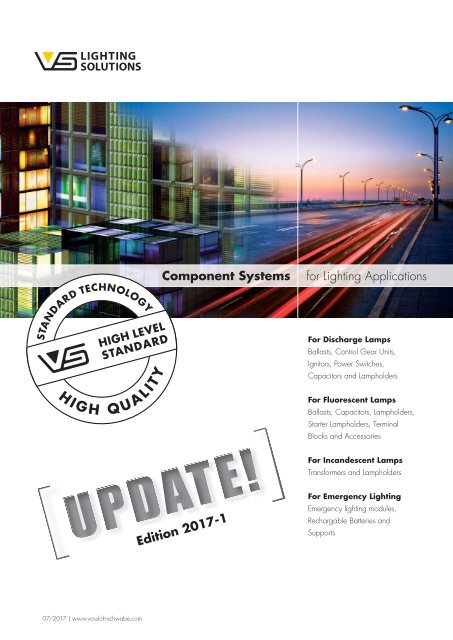
Component Systems<br />
for Lighting Applications<br />
For Discharge Lamps<br />
Ballasts, Control Gear Units,<br />
Ignitors, Power Switches,<br />
Capacitors and Lampholders<br />
For Fluorescent Lamps<br />
Ballasts, Capacitors, Lampholders,<br />
Starter Lampholders, Terminal<br />
Blocks and Accessories<br />
For Incandescent Lamps<br />
Transformers and Lampholders<br />
Edition <strong>2017</strong>-1<br />
For Emergency Lighting<br />
Emergency lighting modules,<br />
Rechargable Batteries and<br />
Supports<br />
07/<strong>2017</strong> | www.vossloh-schwabe.com
Contents<br />
1 Vossloh-Schwabe Projects 4–5 3<br />
Electromagnetic ballasts<br />
for TC and T Lamps 146–155<br />
2<br />
2<br />
2<br />
Ballasts for Discharge Lamps 6–39<br />
Electronic ballasts, accessories 8–12<br />
Luminaire protection device SP 230/10K 12<br />
Control gear units for HS and HI lamps 13–15<br />
Electromagnetic ballasts 16–39<br />
For HS and HI lamps 16–30<br />
For HM and HI lamps 31–33<br />
For power reduction 34–39<br />
Ignitors and Accessories<br />
for Discharge Lamps 40–60<br />
Electronic superimposed ignitors 42–50<br />
Pulse ignitors 51–52<br />
Instant restrike ignitors 53–54<br />
Electronic power switches 55<br />
Electronic superimposed ignitors with power switch 56<br />
Switch units for electronic operating devices<br />
with 1–10 V interface 57<br />
Start-up switches 58–59<br />
Electronic discharge units 60<br />
Lampholders for Discharge Lamps 62–79<br />
E27 lampholders 64–66<br />
E40 lampholders 67–68<br />
G8.5 lampholders 69<br />
GU6.5 lampholders 69<br />
GX10 lampholders 70<br />
GY9.5 lampholders 71<br />
G12 lampholders 71<br />
RX7s lampholders 72–75<br />
Fc2 lampholders 75–76<br />
K12x30s lampholders 77<br />
K12s-7 support 77<br />
3<br />
3<br />
For compact fluorescent lamps 148–151<br />
Standard ballasts 148–151<br />
For tubular fluorescent lamps 152–155<br />
Super low-loss ballasts 152<br />
Standard ballasts 153–155<br />
Lampholders and Accessories<br />
for TC Lamps 156–171<br />
G24, GX24 lampholders 158–162<br />
2G7 lampholders 163<br />
G23 lampholders 164–166<br />
GR10q lampholders 166–167<br />
2G10 lampholders 167<br />
2G11 lampholders 168<br />
Accessories 169–171<br />
GX53-1 lampholders, accessories 171<br />
Lampholders and Accessories<br />
for T Lamps 174–197<br />
G5 lampholders 174–180<br />
G5 lampholders, accessories 174–178<br />
G5 twin lampholder 178<br />
G5 lampholders, degree of protection<br />
IP54/IP65/IP67 179–180<br />
Lamp supports for lamps T-R5 180<br />
G13 lampholders 181–197<br />
G13 push-through lampholders 181–185<br />
G13 push-fit lampholders 183–185<br />
G13 push-fit twin lampholders, accessories 186–187<br />
G13 built-in lampholders 187–190<br />
G13 surface-mounted lampholders 191<br />
Accessories for T8 and T12 lamps 192–193<br />
G13 lampholders, degree of protection<br />
IP54/IP65/IP67, accessories 194–197<br />
2<br />
Technical Details<br />
for Discharge Lamps 78–119<br />
3<br />
Starter Holders and Terminal Blocks,<br />
Accessories 198–207<br />
3<br />
Electronic Ballasts for TC and T Lamps 122–144<br />
Starter holders, accessories 200–203<br />
Terminal blocks, accessories 204–206<br />
Built-in rocker switches 207<br />
For compact fluorescent lamps 122–135<br />
ELXc – Warm start – Linear casing shape 122<br />
ELXd – Dimmable – Linear casing shape 123–124<br />
ELXc – Warm start – Compact casing shape 125–130<br />
ECO EffectLine 131<br />
ELXd – Dimmable – Compact casing shape 132–135<br />
For tubular fluorescent lamps 136–143<br />
ELXc – Warm start – Linear casing shape 136–140<br />
EffectLine and EffectLine II 138<br />
New T5 EffectLine 139<br />
ECO EffectLine 140<br />
ELXd – Dimmable – Linear casing shape 141–143<br />
Accessories for dimmable electronic built-in ballasts 144<br />
3<br />
4<br />
Technical Details<br />
for Fluorescent Lamps 208–235<br />
Parallel Capacitors 236–251<br />
Parallel capacitors 238–241<br />
Technical details for parallel capacitors 242–251<br />
2
Contents<br />
5<br />
Transformers for Low-voltage<br />
Halogen Incandescent Lamps 252–257<br />
5<br />
Technical Details<br />
for Incandescent Lamps 314–327<br />
5<br />
Independent electronic converters 254<br />
Electromagnetic safety transformers 255–257<br />
Lampholders for Low-voltage<br />
Halogen Incandescent Lamps 258–267<br />
G4, GZ4, G5.3, GX5.3, G6.35,<br />
GY6.35 lampholders, accessories 260–261<br />
G4 lampholders, GZ4 lamp connectors 261–263<br />
Lampholders with separate mounting spring<br />
for GU4 lamps 264<br />
GX5.3 lamp connectors 265<br />
GU5.3 lampholders 265<br />
Lampholders with separate mounting spring<br />
for GU5.3 lamps 266<br />
G6.35, GY6.35 lampholders,<br />
GZ6.35 lamp connectors 267<br />
G53 lamp connectors 267<br />
6<br />
7<br />
8<br />
Emergency Lighting Modules<br />
for TC and T Lamps 328–339<br />
Emergency lighting modules<br />
with self-diagnosis function 330–331<br />
Technical details for emergency lighting modules 332–339<br />
Components for UL Market 340–347<br />
For discharge lamps 342–343<br />
For fluorescent lamps 343–346<br />
General Technical Details 349–356<br />
5<br />
Lampholders for Mains Voltage<br />
Halogen Incandescent Lamps 268–277<br />
9<br />
Glossary 357–359<br />
B15d, BA15d lampholders 268<br />
G9 lampholders, accessories 268–270<br />
GU10, GZ10 lampholders, accessories 271–272<br />
R7s ceramic lampholders 273–275<br />
R7s metal lampholders 275<br />
Connection boxes 276<br />
Connectors 277<br />
10<br />
Table of Reference Numbers<br />
and Approval Marks 360–372<br />
5<br />
Lampholders for General-service<br />
Incandescent and Retrofit Lamps 278–313<br />
E14 lampholders 280–288<br />
E14 thermoplastic lampholders, one-piece<br />
and cover caps 280–284<br />
E14 thermoplastic lampholders, three-piece 285–287<br />
E14 metal lampholders, three-piece 287–288<br />
E14 thermoplastic rocker switch lampholders 288<br />
E27 lampholders 289–305<br />
E27 thermoplastic lampholders, one-piece<br />
and cover caps 289–293<br />
E27 renovation kit lampholders 294<br />
E27 thermoplastic lampholders, three-piece 295–297<br />
E27 porcelain lampholders 298–299<br />
E27 metal lampholders, three-piece 300<br />
E27 thermoplastic pull-switch lampholders 301–302<br />
E27 metal pull-switch lampholders 302–303<br />
E27 thermoplastic rocker switch lampholders 303–304<br />
E27 festoon lampholders 304–305<br />
B22d lampholders, accessories 305–306<br />
Accessories for E14, E27 and B22d lampholders 307–312<br />
E40 porcelain lampholders 313<br />
3
Vossloh-Schwabe<br />
LIGHT<br />
TECHNOLOGY<br />
PRODUCTS<br />
Vossloh-Schwabe is not merely a manufacturer of top-quality components<br />
for the lighting industry, but above all a competent and innovative<br />
partner when it comes to providing the growing lighting market<br />
with cost-effective all-round solutions.<br />
Featuring a future-proof component structure that already now satisfies<br />
both the requirements of energy-efficient lighting and European<br />
standards, <strong>VS</strong>' unique product range includes magnetic and electronic<br />
ballasts, state-of-the-art control systems (LiCS), LED lighting systems and<br />
matching operating devices.<br />
Employing in excess of 1,000 people in more than 20 countries,<br />
Vossloh-Schwabe is represented all over the world. As a subsidiary of<br />
the Japanese Panasonic Group, <strong>VS</strong> can draw on extensive resources<br />
for R&D as well as for international expansion activities. A highly motivated<br />
workforce, comprehensive market knowledge, profound industry<br />
expertise as well as eco-awareness and environmental responsibility<br />
show Vossloh-Schwabe to be a reliable partner for the provision of<br />
optimum and cost-effective lighting solutions.<br />
Vossloh-Schwabe's dedication to delivering superior quality is reflected<br />
in its ISO 9001 certification.<br />
Vossloh-Schwabe is ready to embark on a collaborative journey into<br />
an economically illuminated future.<br />
LED components are just as much a part of our product range as<br />
light control systems. Our extensive range of powerful LED modules,<br />
LED drivers, LiCS controllers and sensors is presented in<br />
our separate Innovative Systems<br />
catalogue.<br />
We'll be happy to help you dimension<br />
your lighting project. Contact us.<br />
4
1<br />
PUMA Headquarters<br />
Porsche Museum<br />
2<br />
PUMA Headquarters, Herzogenaurach<br />
As the secret "capital of sport", the little German town of Herzogenaurach<br />
is home to the headquarters of the sport lifestyle company<br />
PUMA. Covering a total surface area of 50,000 square metres, the<br />
complex is made up of three buildings that are positioned so as to<br />
create a large central square, the PUMA Plaza.<br />
The main aim of the lighting concept developed for the new PUMA<br />
corporate headquarters was to deliver optimum quality of light, enable<br />
maximum flexibility in using the available space and yield the greatest<br />
possible energy savings. No less than 985 electronic DALI ballasts<br />
and 4,650 standard electronic ballasts made by Vossloh-Schwabe<br />
went into implementing the lighting system.<br />
The inner courtyard features additional red and white effect lighting<br />
in the form of ground-level linear markings created using LEDs made<br />
by Vossloh-Schwabe. These LEDs enable digital lighting sequences<br />
to flow over the square. To complement the clear-cut, rectilinear forms<br />
that characterise the entire building complex, a number of slender light<br />
columns, made of square aluminium sections, were installed to round<br />
off the courtyard's stylish appearance.<br />
Photos: Markus Bollen<br />
Porsche Museum, Stuttgart<br />
The name "Porsche" both stands for a long tradition of outstanding<br />
quality and the excitement of high-octane driving. The Porsche<br />
Museum in Stuttgart constitutes a fitting presentation venue that does<br />
the brand image every justice. The architectural flagship thus serves to<br />
make the "Porsche experience" available to everyone.<br />
The lighting installed in the Porsche Museum forms a crucial element of<br />
the exhibition space created for around 80 vehicles. It was important<br />
to ensure every detail of these high-end cars was clearly visible. In this<br />
regard, direct and reflecting lighting had to be reduced to an absolute<br />
minimum so as to neither irritate visitors, nor detract from the brilliant<br />
gloss of the bodywork.<br />
This forms another instance in which Vossloh-Schwabe products have<br />
helped to add to the enjoyment of each and every visitor. Built-in electronic<br />
ballasts and electronic DALI safety converters ensure flicker-free,<br />
efficient light.<br />
3<br />
4<br />
5<br />
6<br />
7<br />
8<br />
9<br />
10<br />
5
Ballasts for Discharge Lamps<br />
ELECTRONIC<br />
AND ELECTRO-<br />
MAGNETIC<br />
ELECTRONIC AND<br />
ELECTROMAGNETIC<br />
OPERATING DEVICES<br />
For high-pressure sodium lamps (HS), metal halide<br />
lamps (HI) and mercury vapour lamps (HM)<br />
Electronic ballasts<br />
Modern discharge lamps operate very efficiently in combination<br />
with electronic ballasts. The numerous advantages of using electronic<br />
ballasts to operate high-pressure discharge lamps are listed in more<br />
detail on the product pages.<br />
With the help of temperature and service-life tests, <strong>VS</strong> electronic<br />
ballasts guarantee a high degree of reliability. The quality of the<br />
electronic ballasts is ensured by continuous in-circuit tests and function<br />
tests like burn-in tests.<br />
Magnetic ballasts<br />
The electrical specifications of <strong>VS</strong>' range of ballasts comply with<br />
lampspecific requirements. Vossloh-Schwabe attaches great<br />
importance to ensuring the impedance value of electromagnetic<br />
ballasts is kept within particularly narrow tolerances. This advantage,<br />
which is achieved by individual adjustment of the air gap during the<br />
automated production and testing process of every ballast, decisively<br />
contributes to optimising light output, light colour and service life of<br />
discharge lamps.<br />
The range includes ballasts with variable voltage tapping points and<br />
varying degrees of inherent heating as well as encapsulated devices.<br />
6
2<br />
Ballasts for Discharge Lamps<br />
For high-pressure sodium lamps (HS), metal halide lamps (HI) and mercury vapour lamps (HM)<br />
Electronic ballasts, accessories 8–12<br />
Luminaire protection device SP 230/10K 12<br />
Control gear units for HS and HI lamps 13–15<br />
Electromagnetic ballasts 16–39<br />
For HS and HI lamps 16–30<br />
For HM and HI lamps 31–33<br />
For power reduction 34–39<br />
Technical details for discharge lamps 79–119<br />
General technical details 348–356<br />
Glossary 357–359<br />
1<br />
2<br />
3<br />
4<br />
5<br />
6<br />
7<br />
8<br />
9<br />
10<br />
7
Ballasts for Discharge Lamps<br />
Compact<br />
Electronic Ballasts<br />
for HI Lamps<br />
35 W<br />
Shape: K35<br />
Casing: heat-resistant polyamide,<br />
encapsulated with polyurethane<br />
For ceramic discharge tube lamps (C-HI)<br />
Power factor: > 0.9<br />
Operation frequency: 135 Hz<br />
Push-in terminals: 0.5–1.5 mm²<br />
Constant power consumption<br />
Protection against "no load" operation<br />
For luminaires of protection class I and II<br />
Degree of protection: IP20<br />
Permissible load capacity: 120 pF<br />
RFI-suppressed<br />
Fixing brackets for screws M4<br />
for base mounting<br />
No flickering of defective lamps<br />
K35<br />
K35 with cord grip<br />
Lamp Electronic ballast System<br />
Output Type Base Power con- Type Ref. No. Voltage AC Mains Energy Ambient Casing Ignition Weight Output<br />
sumption 50, 60 Hz current efficiency temperature temperature voltage<br />
W W V –10%+6% A ta (°C) tc (°C) kV g W<br />
K35 – Electronic built-in ballasts<br />
35 HI GU6.5, G8.5, 1 x 39 EHXc 35G.327 B 188993 220–240 0.2 A2 –15 to 45 max. 80 2–4 180 43.5<br />
GX8.5, GX10, G12<br />
K35 – Independent electronic ballasts with cord grip<br />
35 HI GU6.5, G8.5, 1 x 39 EHXc 35G.327 I 188994 220–240 0.2 A2 –15 to 45 max. 80 2–4 195 43.5<br />
GX8.5, GX10, G12<br />
Circuit diagrams see page 87<br />
8
Ballasts for Discharge Lamps<br />
Electronic Ballasts<br />
for HI Lamps<br />
35 and 70 W<br />
1<br />
Shape: M3/K34<br />
Casing: aluminium (M3),<br />
heat-resistant polycarbonate (K34)<br />
For ceramic discharge tube lamps (C-HI)<br />
Power factor: ≥ 0.95<br />
Ignition voltage: max. 5 kV<br />
Operation frequency: 173 Hz<br />
Push-in terminals with lever opener: 0.75–2.5 mm²<br />
Total harmonic distortion: < 10%<br />
Temperature protection<br />
Constant power consumption<br />
Protection against "no load" operation<br />
For luminaires of protection class I (metal casing)<br />
For luminaires of protection class I and II<br />
(plastic casing)<br />
Degree of protection: IP20<br />
Permissible load capacity: 20–120 pF<br />
RFI-suppressed<br />
Fixing brackets for screws M4<br />
for base mounting<br />
No flickering of defective lamps<br />
M3<br />
M3<br />
M3 built-in PCB<br />
K34<br />
K34 with cord grip<br />
t c point definition<br />
2<br />
3<br />
4<br />
5<br />
6<br />
Lamp Electronic ballast System<br />
Output Type Base Power con- Type Ref. No. Voltage AC Mains Energy Ambient Casing Weight Output<br />
sumption 50, 60 Hz current efficiency temperature temperature<br />
W W V ±10% A ta (°C) tc (°C) g W<br />
M3 – Electronic built-in ballast (with cap)<br />
35 HI GU6.5, G8.5, GU8.5, 1 x 39 EHXc 35.325 183033 220–240 0.20–0.18 A2 –20 to 65 max. 80 220 43<br />
GX8.5, G12, E27<br />
70 HI G8.5, GU8.5, GX8.5, G12, 1 x 73 EHXc 70.326 183036 220–240 0.36–0.34 A2 –20 to 55 max. 80 220 80<br />
PG12-2, E27, RX7s<br />
M3 Built-in PCB – Electronic built-in ballasts (without cap)<br />
35 HI GU6.5, G8.5, GU8.5, 1 x 39 EHXc 35.325 183034 220–240 0.20–0.18 A2 –20 to 65 max. 80 180 43<br />
GX8.5, G12, E27<br />
K34 – Independent electronic ballasts with cord grip<br />
35 HI GU6.5, G8.5, GU8.5, 1 x 39 EHXc 35.325 183035 220–240 0.20–0.18 A2 –20 to 65 max. 75 260 43<br />
GX8.5, G12, E27<br />
70 HI G8.5, GU8.5, GX8.5, G12, 1 x 73 EHXc 70.326 183038 220–240 0.36–0.34 A2 –20 to 55 max. 75 260 80<br />
PG12-2, E27, RX7s<br />
Circuit diagrams see page 87<br />
7<br />
8<br />
9<br />
10<br />
9
Ballasts for Discharge Lamps<br />
Electronic Ballasts<br />
for HI Lamps<br />
150 W<br />
Shape: K31<br />
Casing: heat-resistant polycarbonate<br />
For ceramic discharge tube lamps (C-HI)<br />
Power factor: 0.98<br />
Ignition voltage: max. 5 kV<br />
Operation frequency: 170 Hz<br />
Push-in terminals with lever opener: 0.75–2.5 mm²<br />
Total harmonic distortion: < 10%<br />
Temperature protection<br />
Constant power consumption<br />
Protection against "no load" operation<br />
For luminaires of protection class I and II<br />
Degree of protection: IP20<br />
Permissible load capacity: 20–240 pF<br />
RFI-suppressed<br />
Fixing brackets for screws M4<br />
for base mounting<br />
K31<br />
K31<br />
K31 with cord grip<br />
Lamp Electronic ballast System<br />
Output Type Base Power con- Type Ref. No. Voltage AC Mains Energy Ambient Casing Casing Weight Output<br />
sumption 50, 60 Hz current efficiency temperature temperature<br />
W W V ±10% A ta (°C) t c (°C) g W<br />
K31 – Electronic built-in ballasts<br />
150 HI G12, PGX12-2, 1 x 147 EHXc 150G.334 183046 220–240 0.73–0.67 A2 –20 to 45 max. 85 K31 540 160<br />
E27, E40, RX7s<br />
K31 – Independent electronic ballasts with cord grip<br />
150 HI G12, PGX12-2, 1 x 147 EHXc 150G.334 183047 220–240 0.73–0.67 A2 –20 to 45 max. 85 K31 582 160<br />
E27, E40, RX7s<br />
Circuit diagrams see page 87<br />
10
Ballasts for Discharge Lamps<br />
Cord Grip for<br />
Electronic Built-in<br />
Ballasts<br />
For shape K31<br />
By using the cord grip electronic built-in ballasts<br />
for metal halide lamps become independent<br />
ballasts.<br />
Material: heat-resistant polycarbonate<br />
For use with electronic built-in ballasts<br />
with casing K31<br />
For mains leads:<br />
H03VV-F 3X0.75 or NYM 3X1.5 mm²<br />
For lamp leads: SIHY-Cu 3X1 mm²<br />
or SIHSI-Cu 3X1 mm²<br />
Weight: 50 g<br />
Unit: 20 pcs.<br />
By turning the cable clamp by 180°<br />
the lead diameter can be reduced to 5 mm.<br />
Ref. No.: 188080<br />
1<br />
2<br />
3<br />
4<br />
5<br />
6<br />
7<br />
8<br />
9<br />
10<br />
11
Ballasts for Discharge Lamps<br />
Luminaire Protection Device SP 230/10K<br />
For electronic devices<br />
When electronic components form part of lighting<br />
systems, it is often necessary to protect such components<br />
against power-supply interruptions and<br />
electric overloads (power surges).<br />
These can be caused by switching inductive loads<br />
or by atmospheric discharges such as lightning<br />
striking the mains or the ground. A further cause can<br />
be induced voltages from neighbouring cables when<br />
working with leading-edge phase-cutting controls.<br />
Suitable for luminaires of protection class I and II<br />
Solid connecting wire: 0.75 mm²<br />
Lead length: 50 mm<br />
The SP230/10K protection unit reduces<br />
overvoltages at the connection terminals<br />
of electronic components. The remaining<br />
residual voltage is then reduced to a<br />
respective protective level, based on the<br />
discharge current (see diagram below).<br />
In our Innovative Systems catalogue you will<br />
find further products of this series.<br />
Wiring diagram<br />
Type Best.-Nr. Voltage AC Impulse Impulse Protection level at Min. ambient Casing Weight<br />
50, 60 Hz voltage discharge current discharge current temperature temperature<br />
V ±10% UOC (V) I N (8/20 µs) (A) of 1,000 A (V) t a (°C) t c (°C) g<br />
SP 230/10 K 147230 220–240 max. 10,000 max. 10,000 850 –30 max. 80 20<br />
Bandwidth of the standard impulse: tr = 20 µs<br />
The protection unit can withstand at least 10 spikes<br />
of 5 kA.<br />
Residual voltage, based on the discharge current (B)<br />
A = Leak current | B = Protection levels<br />
Source: Epcos Databook 2011<br />
12
Ballasts for Discharge Lamps<br />
Control Gear Units<br />
for HS and HI<br />
Lamps 35 to 150 W<br />
Compact plastic casing<br />
Shape: 64x72 mm<br />
For high pressure sodium lamps (HS),<br />
metal halide lamps (HI)<br />
and ceramic discharge lamps (C-HI)<br />
Compact control gear unit with ballast with<br />
patented, intelligent thermal cut-out with<br />
automatic reset (which evaluates the temperature<br />
and current of the ballast), digital timer ignitor with<br />
IPP ++ technology and compensation capacitor<br />
with thermal fuse<br />
As individual components no longer need<br />
to be wired, there is a significant reduction<br />
in assembly time and costs.<br />
Protection class II<br />
Degree of protection: IP40<br />
Permissible load capacity: 20–1000 pF<br />
Lead length to the lamp: max. 10 m<br />
tw 130<br />
Push-in terminals: 0.5–2.5 mm²<br />
Cord grips for mains and lamp leads<br />
Further outputs and voltages on request<br />
1<br />
2<br />
3<br />
4<br />
5<br />
6<br />
Lamp<br />
Control gear unit<br />
Output Type Current Type Ref. No. Voltage AC Mains current a b Weight t a Power factor Energy efficiency<br />
W A V, Hz A mm mm kg °C λ<br />
230 V, 50 Hz<br />
35 HS, HI 0.53 VNaHJ 35PZTG.568* 536199 230, 50 0.210 175 166 1.32 55 0.92 EEI=A3<br />
70 HS, HI 0.98 VNaHJ 70PZTG.203 563416 230, 50 0.380 214 205 2.25 45 0.91 A2<br />
VNaHJ 70PZTG.566* 535657 230, 50 0.380 175 166 1.32 45 0.91 EEI=A3<br />
100 HS, HI 1.20 VNaHJ 100PZTG.202 563417 230, 50 0.560 214 205 2.25 45 0.85 A2<br />
VNaHJ 100PZTG.571* 536200 230, 50 0.560 214 205 1.85 45 0.85 EEI=A3<br />
150 HS, HI 1.80 VNaHJ 150PZTG.567* 535695 230, 50 0.720 214 205 2.25 45 0.91 EEI=A3<br />
240 V, 50 Hz<br />
35 HS, HI 0.53 VNaHJ 35PZTG.568 536201 240, 50 0.210 175 166 1.32 55 0.94 EEI=A3<br />
70 HS, HI 0.98 VNaHJ 70PZTG.566 536202 240, 50 0.370 175 166 1.32 40 0.94 EEI=A3<br />
100 HS, HI 1.20 VNaHJ 100PZTG.571 536203 240, 50 0.560 214 205 1.85 40 0.86 EEI=A3<br />
150 HS, HI 1.80 VNaHJ 150PZTG.567 536204 240, 50 0.730 214 205 2.25 40 0.91 EEI=A3<br />
220 V, 60 Hz<br />
35 HS, HI 0.53 VNaHJ 35PZTG.574 536205 220, 60 0.220 175 166 1.32 60 0.98 EEI=A3<br />
70 HS, HI 0.98 VNaHJ 70PZTG.575 536207 220, 60 0.370 175 166 1.32 50 0.97 EEI=A3<br />
150 HS, HI 1.80 VNaHJ 150PZTG.576 536209 220, 60 0.800 214 205 2.25 45 0.98 EEI=A3<br />
* Ballasts without CE marking for replacements or markets outside of the EU<br />
7<br />
8<br />
9<br />
10<br />
13
Ballasts for Discharge Lamps<br />
Control Gear<br />
Units IP65 for<br />
HS and HI Lamps<br />
35 to 150 W<br />
Encapsulated unit in<br />
compact plastic casing<br />
Shape: 61x72 mm<br />
For high pressure sodium lamps (HS),<br />
metal halide lamps (HI)<br />
and ceramic discharge lamps (C-HI)<br />
Compact control gear unit with ballast with<br />
patented, intelligent thermal cut-out with<br />
automatic reset (which evaluates the temperature<br />
and current of the ballast), digital timer ignitor with<br />
IPP ++ technology and compensation capacitor<br />
with thermal fuse<br />
As individual components no longer need<br />
to be wired, there is a significant reduction<br />
in assembly time and costs.<br />
Protection class II<br />
Degree of protection: IP65<br />
Permissible load capacity: 20–1000 pF<br />
Lead length to the lamp: max. 10 m<br />
tw 130<br />
Lead length<br />
Lamp<br />
Control gear unit<br />
Output Type Current Type Ref. No. Voltage Mains current a b Weight t a Power factor Energy efficiency<br />
W A V, Hz A mm mm kg °C λ<br />
230 V, 50 Hz<br />
35 HS, HI 0.53 VNaHJ 35PZTG.050* 533391 230, 50 0.240 222 214 1.95 60 0.96 EEI=A3<br />
50 HS, HI 0.76 VNaH 50PZTG.058* 543733 230, 50 0.290 222 214 1.95 60 0.94 EEI=A3<br />
70 HS, HI 0.98 VNaHJ 70PZTG.051* 533392 230, 50 0.370 222 214 1.95 50 0.97 EEI=A3<br />
100 HS, HI 1.20 VNaHJ 100PZTG.078* 533393 230, 50 0.560 249 240 2.25 55 0.90 EEI=A3<br />
150 HS, HI 1.80 VNaHJ 150PZTG.052* 533394 230, 50 0.740 249 240 2.75 50 0.94 EEI=A3<br />
240 V, 50 Hz<br />
35 HS, HI 0.53 VNaHJ 35PZTG.053 534107 240, 50 0.240 222 214 1.95 60 0.96 EEI=A3<br />
70 HS, HI 0.98 VNaHJ 70PZTG.054 534109 240, 50 0.370 222 214 1.95 50 0.97 EEI=A3<br />
150 HS, HI 1.80 VNaHJ 150PZTG.055 534115 240, 50 0.730 249 240 2.75 50 0.95 EEI=A3<br />
220 V, 60 Hz<br />
35 HS, HI 0.53 VNaHJ 35PZTG.041 534122 220, 60 0.220 222 214 1.95 70 0.98 EEI=A3<br />
70 HS, HI 0.98 VNaHJ 70PZTG.067 534111 220, 60 0.370 222 214 1.95 50 0.97 EEI=A3<br />
150 HS, HI 1.80 VNaHJ 150PZTG.068 534117 220, 60 0.800 249 240 2.25 45 0.98 EEI=A3<br />
* Ballasts without CE marking for replacements or markets outside of the EU<br />
14
Ballasts for Discharge Lamps<br />
Control Gear Units<br />
for HS and<br />
HI Lamps<br />
250 and 400 W<br />
Shape: 76x91 mm<br />
For high pressure sodium lamps (HS),<br />
metal halide lamps (HI) and<br />
ceramic discharge lamps (C-HI)<br />
Fully wired slim, weather-proof control gear unit<br />
with ballast with thermal cut-out with automatic reset,<br />
capacitor, timer ignitor and connection terminal<br />
Suitable for installation in or on pylons<br />
Frontal cable feed using a PG thread fitting<br />
Front access to terminals<br />
Screw-fixed end cap<br />
Screw terminals: 0.75–2.5 mm²<br />
For luminaires of protection class I<br />
Degree of protection: IP54<br />
Permissible load capacity: 20–1000 pF<br />
Distance to the lamp: max. 10 m<br />
tw 130<br />
With connection for protective earth conductor<br />
1<br />
2<br />
3<br />
4<br />
5<br />
6<br />
7<br />
8<br />
Lamp<br />
Control gear unit<br />
Output Type Current Mains current Type Ref. No. Voltage AC L L1 Weight Power factor Energy efficiency<br />
W A A V, Hz mm mm kg λ<br />
250 HS, HI 3.0 1.3 VNaHJ 250PZT.745* 531476 230, 50 322 302 4.30 > 0.94 EEI=A3<br />
400 HS, HI 4.45 2.0 VNaHJ 400PZT.743 531475 230, 50 357 337 5.62 > 0.91 A2<br />
* Ballasts without CE marking for replacements or markets outside of the EU<br />
9<br />
10<br />
15
Ballasts for Discharge Lamps<br />
Ballast Units<br />
for HS and HI Lamps<br />
1000 and 2000 W<br />
Shape: 114x116 mm<br />
For high-pressure sodium vapour lamps (HS)<br />
and metal halide lamps (HI)<br />
Slim, weather-proof ballast unit fully wired with<br />
ballast, capacitor and connection terminal<br />
Suitable for installation in or on pylons<br />
With connection for protective earth conductor<br />
Frontal cable feed using a PG thread fitting<br />
Front access to terminals or fuses<br />
Optional additional third PG connection for mains<br />
feed-through wiring<br />
Screw-fixed end cap<br />
Diverse mounting options using an assembly plate<br />
or rail<br />
Screw terminals: 0.75–10 mm²<br />
For luminaires of protection class I<br />
tw 130<br />
Degree of protection: IP54<br />
Lamp<br />
Ballast unit<br />
Output Type Current Mains current Type Ref. No. Voltage AC L L1 L2 Weight Power factor Energy efficiency<br />
W A A V, Hz mm mm mm kg λ<br />
1000 HS 10.3 5.0 VNaHJ 1000.61 531472 230–240, 50 487 410 370 11.6 > 0.90 A2<br />
HI 9.5 4.9 A2<br />
2000 HI 10.3 6.0 VJD 2000.63 531474 380–400, 50 627 550 510 20.2 > 0.90 A2<br />
Degree of protection: IP65<br />
Fully encapsulated ballast unit with leads<br />
Lamp<br />
Ballast unit<br />
Output Type Current Mains current Type Ref. No. Voltage AC L L1 L2 Weight Power factor Energy efficiency<br />
W A A V, Hz mm mm mm kg λ<br />
1000 HS 10.3 5.0 VNaHJ 1000.61 531480 220, 50 487 410 370 11.6 > 0.90 A2<br />
HI 9.5 4.9 A2<br />
2000 HI 10.3 6.0 VJD 2000.63 531481 380, 50 627 550 510 20.2 > 0.90 A2<br />
16
Ballasts for Discharge Lamps<br />
Ballast Units<br />
for HS and HI Lamps<br />
1000 to 2000 W<br />
Encapsulated in a plastic casing<br />
For high-pressure sodium vapour lamps (HS)<br />
and metal halide lamps (HI)<br />
Fully encapsulated ballast unit in a self-extinguishing,<br />
fibre-glass-reinforced polyamide casing consisting<br />
of a ballast, capacitor, fuse and a ready-to-use,<br />
pre-wired connection terminal.<br />
Cable feed using a PG thread fitting<br />
Screw terminals: 0.75–10 mm²<br />
Protection class II<br />
tw 130<br />
1<br />
2<br />
3<br />
4<br />
5<br />
6<br />
Degree of protection: IP65<br />
With double insulation<br />
Lamp<br />
Ballast unit<br />
Output Type Current Mains Type Ref. No. Voltage AC a b c d Weight Power factor Energy<br />
W A current (A) V, Hz mm mm mm mm kg λ efficiency<br />
230/240 V, 50 Hz and 380/400/415 V, 50 Hz<br />
1000 HS 10.3/11.3 5.75 VNaHJ 1000.75 554313 230/240, 50 288 217 — 220 15 > 0.90 A2<br />
HI 9.5 4.9 A2<br />
2000 HI 8.8/9.2 5.7 VJ 2000.76 554314 380/400/415, 50 320 217 225 225 21 > 0.90 A2<br />
10.3/11.3 6.0 VJD 2000.77 554315 380/400/415, 50 320 220 225 225 23 > 0.90 A2<br />
12.2 6.0 VJD 2000I.78 554316 380/400/415, 50 320 220 225 225 25 > 0.90 A2<br />
220 V, 60 Hz and 380 V, 60 Hz<br />
1000 HS 10.3/11.3 5.75 VNaHJ 1000.75 554904 220, 60 288 217 — 220 15 > 0.90 A2<br />
HI 9.5 4.9 A2<br />
2000 HI 8.8/9.2 5.7 VJ 2000.76 554905 380, 60 320 220 225 225 21 > 0.90 A2<br />
10.3/11.3 6.0 VJD 2000.77 554906 380, 60 320 220 225 225 23 > 0.90 A2<br />
12.2 6.0 VJD 2000I.78 554909 380, 60 320 220 225 225 25 > 0.90 A2<br />
7<br />
8<br />
9<br />
10<br />
17
Ballasts for Discharge Lamps<br />
Compact<br />
Assembly Kits for<br />
HS and HI Lamps<br />
35 to 150 W<br />
Ballast shape: 53x66 mm<br />
For high pressure sodium lamps (HS),<br />
metal halide lamps (HI)<br />
and ceramic discharge lamps (C-HI)<br />
Compact assembly kit with ballast with or<br />
without patented, intelligent thermal cut-out<br />
with automatic reset (which evaluates the<br />
temperature and current of the ballast), superimposed<br />
ignitor and compensation capacitor<br />
With luminaire terminal block:<br />
screw terminal 0.75–2.5 mm²<br />
With earth terminal<br />
Permissible load capacity: 20–100 pF<br />
Lead length to the lamp: max. 1.5 m<br />
tw 130<br />
On request:<br />
Further outputs and voltages<br />
With digital timer ignitor<br />
For pulse ignition system<br />
As individual components no longer<br />
need to be wired, there is a significant<br />
reduction in assembly time and costs.<br />
Especially suitable for change of lamp<br />
technology from HM to HS.<br />
Lamp<br />
Assembly kit<br />
Output Type Current Type Ref. No. Voltage AC Mains Temperature a b c d Weight Power Energy<br />
current protection factor efficiency<br />
W A V, Hz A mm mm mm mm kg λ<br />
230 V, 50 Hz<br />
35 HS, HI 0.53 PKNaHJ 35.008* 546797 230, 50 0.22 yes 117 86 108 54 1.2 > 0.90 EEI=A3<br />
50 HS, HI 0.76 PKNaH 50PZT.992* 543378 230, 50 0.30 yes 117 86 111 59 1.4 > 0.90 EEI=A3<br />
70 HS, HI 0.98 PKNaHJ 70.128* 538675 230, 50 0.37 yes 117 86 111 59 1.4 > 0.90 EEI=A3<br />
538685 no EEI=A3<br />
100 HS, HI 1.20 PKNaHJ 100.941* 538676 230, 50 0.56 yes 117 86 111 59 1.6 > 0.90 EEI=A3<br />
538686 no EEI=A3<br />
150 HS, HI 1.80 PKNaHJ 150.620* 538677 230, 50 0.74 yes 151 120 115 63 2.2 > 0.90 EEI=A3<br />
538687 no EEI=A3<br />
220 V, 60 Hz<br />
35 HS, HI 0.53 PKNaHJ 35.008 547285 220, 60 0.23 yes 117 86 108 54 1.2 > 0.90 EEI=A3<br />
543401 no EEI=A3<br />
70 HS, HI 0.98 PKNaHJ 70.653 547287 220, 60 0.37 yes 117 86 111 59 1.4 > 0.90 EEI=A3<br />
538680 no EEI=A3<br />
100 HS, HI 1.20 PKNaHJ 100.271 538681 220, 60 0.56 no 117 86 111 59 1.6 > 0.90 EEI=A3<br />
150 HS, HI 1.80 PKNaHJ 150.679 538682 220, 60 0.74 no 151 120 115 63 2.2 > 0.90 EEI=A3<br />
220/240 V, 60 Hz<br />
100 HS, HI 1.20 PKNaHJ 100.345 543295 220/240, 60 0.60 no 117 86 111 60 1.6 > 0.90 EEI=A3<br />
150 HS, HI 1.80 PKNaHJ 150.301 543299 220/240, 60 0.80 no 151 120 115 63 2.2 > 0.90 EEI=A3<br />
* Ballasts without CE marking for replacements or markets outside of the EU<br />
18
Ballasts for Discharge Lamps<br />
Compact<br />
Assembly Kits for<br />
HS and HI Lamps<br />
250 and 400 W<br />
Ballast shape: 71x75 mm<br />
For high pressure sodium lamps (HS),<br />
metal halide lamps (HI)<br />
and ceramic discharge lamps (C-HI)<br />
Compact assembly kit with ballast with or<br />
without thermal cut-out with automatic reset,<br />
superimposed ignitor and compensation<br />
capacitor<br />
With luminaire terminal block:<br />
screw terminal 0.75–2.5 mm²<br />
With earth terminal<br />
Permissible load capacity: 20–100 pF<br />
Lead length to the lamp: max. 1.5 m<br />
tw 130<br />
On request:<br />
Further outputs and voltages<br />
With digital timer ignitor<br />
For pulse ignition system<br />
As individual components no<br />
longer need to be wired, there is<br />
a significant reduction in assembly<br />
time and costs.<br />
Especially suitable for change of<br />
lamp technology from HM to HS.<br />
1<br />
2<br />
3<br />
4<br />
5<br />
6<br />
Lamp<br />
Assembly kit<br />
Output Type Current Type Ref. No. Voltage AC Mains Temperature a b c d Weight Power Energy<br />
current protection factor efficiency<br />
W A V, Hz A mm mm mm mm kg λ<br />
230 V, 50 Hz<br />
250 HS, HI 3.00 PKNaHJ 250.741 538678 230, 50 1.20 yes 141 110 128 73 3.2 > 0.90 A2<br />
538688 no A2<br />
400 HS, HI 4.45 PKNaHJ 400.743 538679 230, 50 1.80 yes 171 140 129 73 5.2 > 0.90 A2<br />
538689 no A2<br />
220 V, 60 Hz<br />
250 HS, HI 3.00 PKNaHJ 250.742 538683 220, 60 1.20 no 141 110 126 71 3.2 > 0.90 A2<br />
400 HS, HI 4.45 PKNaHJ 400.744 538684 220, 60 1.80 no 171 140 129 71 5.2 > 0.90 A2<br />
7<br />
8<br />
9<br />
10<br />
19
Ballasts for Discharge Lamps<br />
Standard Ballasts<br />
for HS and HI<br />
Lamps 35 to 70 W<br />
Shape: 53x66 mm<br />
For high pressure sodium lamps (HS),<br />
metal halide lamps (HI) and<br />
ceramic discharge lamps (C-HI)<br />
Vacuum-impregnated with polyester resin<br />
Screw terminals: 0.5–2.5 mm²<br />
Protection class I<br />
tw 130<br />
Ballasts for pulse ignition system on request<br />
Lamp Ballast Capacitor<br />
Output Type Current Type Ref. No. Voltage AC a b c Weight Δt Power factor Energy C P IN<br />
W A V, Hz mm mm mm kg K λ efficiency µF A<br />
35 HS, HI 0.53 NaHJ 35.485* 526517 220/230, 50 108 86 36 1.07 60 0.40 EEI=A3 6 0.22/0.21<br />
NaHJ 35.485* 161367 230/240, 50 108 86 36 1.07 60 0.40 EEI=A3 6 0.22/0.21<br />
NaHJ 35.638 161371 220, 60 108 86 36 1.07 50 0.41 EEI=A3 5 0.23<br />
50 HS, HI 0.76 NaH 50.486* 161379 230/240, 50 108 86 36 1.07 65 0.37 EEI=A3 8 0.30/0.29<br />
NaH 50.654 161399 220, 60 108 86 36 1.07 60 0.36 EEI=A3 8 0.31<br />
50 HS, HI 0.76 NaHJ 70/50.157* 160613 230, 50 108 86 42 1.23 55 0.37 EEI=A3 8 0.30<br />
70 HS, HI 0.98 70 0.37 EEI=A3 12 0.38<br />
70 HS, HI 0.98 NaHJ 70.300 174961 220, 50 108 86 36 1.07 75 0.40 EEI=A3 12 0.40<br />
NaHJ 70.128* 533568 230, 50 108 86 36 1.07 70 0.36 EEI=A3 12 0.38<br />
NaHJ 70.128* 539434 230/240, 50 108 86 36 1.07 70/75 0.36 EEI=A3 12 0.38/0.37<br />
NaHJ 70.158 161662 240, 50 108 86 42 1.23 70 0.36 EEI=A3 12 0.37<br />
NaHJ 70.128 538407 240, 50 108 86 36 1.07 75 0.37 EEI=A3 12 0.37<br />
NaHJ 70.653 161392 220, 60 108 86 36 1.07 60 0.42 EEI=A3 10 0.40<br />
* Ballasts without CE marking for replacements or markets outside of the EU<br />
20
Ballasts for Discharge Lamps<br />
Standard Ballasts for HS and HI Lamps<br />
70 to 250 W<br />
Shape: 53x66 mm<br />
Lamp Ballast Capacitor<br />
Output Type Current Type Ref. No. Voltage AC a b c Weight Δt Power factor Energy C P I N<br />
W A V, Hz mm mm mm kg K λ efficiency µF A<br />
70 HS, HI 0.98 NaHJ 100/70.703* 161469 230, 50 145 120 48 1.39 60 0.37 EEI=A3 12 0.38<br />
100 HS, HI 1.20 70 0.43 EEI=A3 12 0.55<br />
70 HS, HI 0.98 NaHJ 100/70.519 161158 230/240, 50 145 120 75 2.03 50 0.36 A2 12 0.38/0.37<br />
100 HS, HI 1.20 60 0.42 EEI=A3 12 0.55/0.53<br />
70 HS, HI 0.98 NaHJ 100/70.709 161471 220, 60 145 120 48 1.39 50 0.39 EEI=A3 10 0.40<br />
100 HS, HI 1.20 60 0.44 EEI=A3 10 0.57<br />
100 HS, HI 1.20 NaHJ 100.126 507671 220, 50 108 86 42 1.24 75 0.44 EEI=A3 12 0.55<br />
NaHJ 100.941* 161707 230/240, 50 108 86 42 1.24 75/80 0.42 EEI=A3 12 0.55/0.53<br />
NaHJ 100.271 530195 220, 60 108 86 42 1.24 75 0.45 EEI=A3 10 0.57<br />
150 HS, HI 1.80 NaHJ 150.159 533602 220, 50 145 120 64 1.80 75 0.41 EEI=A3 20 0.80<br />
NaHJ 150.620* 533565 230, 50 145 120 64 1.80 70 0.40 EEI=A3 20 0.77<br />
NaHJ 150.620 534540 240, 50 145 120 64 1.80 75 0.40 EEI=A3 20 0.74<br />
NaHJ 150.679 526196 220, 60 145 120 55 1.55 75 0.44 EEI=A3 16 0.80<br />
NaHJ 150.679 537793 220, 60 117 92 55 1.55 75 0.44 EEI=A3 16 0.80<br />
250 HS, HI 3.00 NaHJ 250.204 529087 220, 50 160 135 95 2.50 80 0.42 EEI=A3 32 1.32<br />
NaHJ 250.160 160597 220, 50 180 155 110 2.84 75 0.41 EEI=A3 32 1.32<br />
NaHJ 250.915* 161686 230, 50 180 155 110 2.84 80 0.40 EEI=A3 32 1.26<br />
NaHJ 250.340* 504109 230/240, 50 180 155 110 2.84 80 0.39 EEI=A3 32 1.26/1.21<br />
NaHJ 250.340 178177 240, 50 180 155 110 2.84 80 0.39 EEI=A3 32 1.21<br />
NaHJ 250.163 529072 220, 60 160 135 95 2.50 70 0.42 A2 25 1.35<br />
NaHJ 250.163 160604 220, 60 180 155 95 2.50 70 0.42 A2 25 1.35<br />
* Ballasts without CE marking for replacements or markets outside of the EU<br />
1<br />
2<br />
3<br />
4<br />
5<br />
6<br />
7<br />
8<br />
9<br />
10<br />
21
Ballasts for Discharge Lamps<br />
Ballasts with<br />
Thermal Cut-out<br />
for HS and<br />
HI Lamps<br />
35 to 150 W<br />
Shape: 53x66 mm<br />
For high pressure sodium lamps (HS),<br />
metal halide lamps (HI) and<br />
ceramic discharge lamps (C-HI)<br />
Vacuum-impregnated with polyester resin<br />
With <strong>VS</strong>-patented, intelligent temperature switch<br />
with automatic reset (evaluates the<br />
temperature and current of the ballast)<br />
Protection class I<br />
tw 130<br />
Ballasts for pulse ignition system on request<br />
A Push-in terminals: 0.5–1.5 mm² B Screw terminals: 0.5–2.5 mm²<br />
C<br />
Screw terminals: 0.75–2.5 mm²<br />
Lamp Ballast Capacitor<br />
Output Type Current Type Ref. No. Voltage AC Drawing a b c Weight Δt Power Energy CP IN<br />
W A V, Hz mm mm mm kg K factor (λ) efficiency µF A<br />
Push-in terminals: 0.5–1.5 mm²<br />
35 HS, HI 0.53 NaHJ 35.209 543737 230/240, 50 A 108 86 36 1.07 35 0.36 A2 6 0.22<br />
NaHJ 35.485* 506122 230/240, 50 A 108 86 36 1.07 60 0.40 EEI=A3 6 0.22/0.21<br />
NaHJ 35.638 509170 220, 60 A 108 86 36 1.07 50 0.41 EEI=A3 5 0.23<br />
50 HS, HI 0.76 NaH 50.206 543738 230, 50 A 108 86 48 1.39 45 0.35 A2 8 0.30<br />
50 HS, HI 0.76 NaHJ 70/50.157* 507341 230, 50 A 108 86 42 1.23 55 0.37 EEI=A3 8 0.30<br />
70 HS, HI 0.98 70 0.37 EEI=A3 12 0.38<br />
50 HS, HI 0.76 NaHJ 70/50.520* 538361 230, 50 A 117 92 48 1.39 45 0.36 EEI=A3 8 0.30<br />
70 HS, HI 0.98 55 0.36 EEI=A3 12 0.38<br />
70 HS, HI 0.98 NaHJ 70.128* 535191 230, 50 A 108 86 36 1.07 70 0.36 EEI=A3 12 0.38<br />
NaHJ 70.226 543741 230, 50 A 108 86 48 1.39 50 0.37 A2 12 0.38<br />
NaHJ 70.128* 533572 230/240, 50 A 108 86 36 1.07 70/75 0.36 EEI=A3 12 0.38/0.37<br />
NaHJ 70.653 509169 220, 60 A 108 86 36 1.07 60 0.42 EEI=A3 10 0.40<br />
70 HS, HI 0.98 NaHJ 100/70.703* 507342 230, 50 A 145 120 48 1.39 60 0.37 EEI=A3 12 0.38<br />
100 HS, HI 1.20 70 0.43 EEI=A3 12 0.55<br />
100 HS, HI 1.20 NaHJ 100.670* 506120 230/240, 50 A 117 92 48 1.39 70 0.42 EEI=A3 12 0.55/0.53<br />
NaHJ 100.941* 539492 230/240, 50 A 108 86 42 1.23 75/80 0.42 EEI=A3 12 0.55/0.53<br />
100 HS, HI 1.20 NaHJ 150/100.973* 507343 230, 50 A 145 120 75 2.02 55 0.41 A2 12 0.55<br />
150 HS, HI 1.80 75 0.41 EEI=A3 20 0.57<br />
150 HS, HI 1.80 NaHJ 150.620* 535216 230, 50 A 145 120 64 1.80 70 0.40 EEI=A3 20 0.77<br />
NaHJ 150.620* 538543 230/240, 50 A 145 120 64 1.80 70/75 0.40 EEI=A3 20 0.77/0.74<br />
NaHJ 150.355* 509100 230/240, 50 A 145 120 75 2.02 65 0.39 EEI=A3 20 0.77/0.74<br />
NaHJ 150.679 509171 220, 60 A 145 120 75 2.02 65 0.42 EEI=A3 16 0.80<br />
* Ballasts without CE marking for replacements or markets outside of the EU<br />
22
Ballasts for Discharge Lamps<br />
Ballasts with Thermal Cut-out for<br />
HS and HI Lamps 35 to 250 W<br />
Shape: 53x66 mm<br />
Lamp Ballast Capacitor<br />
Output Type Current Type Ref. No. Voltage AC Drawing a b c Weight Δt Power factor Energy C P I N<br />
W A V, Hz mm mm mm kg K λ efficiency µF A<br />
Screw terminals: 0.5–2.5 mm² (Drawing B) or 0.75–2.5 mm² (Drawing C)<br />
35 HS, HI 0.53 NaHJ 35.485* 503010 230/240, 50 B 108 86 36 1.07 60 0.40 EEI=A3 6 0.22/0.21<br />
35 HS, HI 0.53 NaH 50/35.412 563871 230, 50 B 117 92 55 1.52 25 0.36 A2 6 0.22<br />
50 HS, HI 0.76 40 0.34 A2 8 0.30<br />
35 HS, HI 0.53 NaH 50/35.797* 539515 230, 50 B 108 86 36 1.07 45 0.40 EEI=A3 6 0.22<br />
50 HS, HI 0.76 70 0.37 EEI=A3 8 0.30<br />
50 HS, HI 0.76 NaH 50.486* 507498 230/240, 50 B 108 86 36 1.07 65 0.37 EEI=A3 8 0.30<br />
50 HS, HI 0.76 NaHJ 70/50.695* 507697 230/240, 50 B 108 86 48 1.39 50 0.37 EEI=A3 8 0.30/0.29<br />
70 HS, HI 0.98 70 0.37 EEI=A3 12 0.38/0.37<br />
70 HS, HI 0.98 NaHJ 70.226 563039 230, 50 B 108 86 48 1.39 50 0.37 A2 12 0.38<br />
NaHJ 70.128* 536582 230, 50 B 108 86 36 1.07 70 0.36 EEI=A3 12 0.38<br />
NaHJ 70.158* 169722 230/240, 50 B 108 86 42 1.23 70 0.36 EEI=A3 12 0.38/0.37<br />
NaHJ 70.128* 538830 230/240, 50 B 108 86 36 1.07 70/75 0.36 EEI=A3 12 0.38/0.37<br />
NaHJ 70.158 546817 240, 50 B 108 86 42 1.23 70 0.36 EEI=A3 12 0.37<br />
70 HS, HI 0.98 NaHJ 100/70.519 507628 230, 50 B 145 120 75 2.03 60 0.36 A2 12 0.38<br />
100 HS, HI 1.20 70 0.41 A2 12 0.55<br />
70 HS, HI 0.98 NaHJ 100/70.703* 504131 230, 50 B 117 92 48 1.39 60 0.37 EEI=A3 12 0.38<br />
100 HS, HI 1.20 70 0.43 EEI=A3 12 0.55<br />
100 HS, HI 1.20 NaHJ 100.213 554005 230/240, 50 B 117 92 55 1.55 60 0.41 A2 12 0.55/0.53<br />
NaHJ 100.941* 543349 230, 50 B 108 86 42 1.23 75 0.42 EEI=A3 12 0.55<br />
NaHJ 100.941* 502799 230/240, 50 B 108 86 42 1.23 75/80 0.42 EEI=A3 12 0.55/0.53<br />
100 HS, HI 1.20 NaHJ 150/100.923 563876 230, 50 C 135 115 68 2.87 30 0.40 A2 12 0.55<br />
150 HS, HI 1.80 45 0.40 A2 20 0.77<br />
100 HS, HI 1.20 NaHJ 150/100.973* 504135 230, 50 B 145 120 75 2.02 55 0.41 A2 12 0.55<br />
150 HS, HI 1.80 75 0.41 EEI=A3 20 0.77<br />
150 HS, HI 1.80 NaHJ 150.166 562450 230/240, 50 B 160 135 95 2.5 50 0.40 A2 20 0.77/0.74<br />
NaHJ 150.355 539270 220, 50 B 145 120 75 2.02 65 0.39 EEI=A3 20 0.80<br />
NaHJ 150.620* 536593 230, 50 B 145 120 64 1.80 70 0.40 EEI=A3 20 0.77<br />
NaHJ 150.995* 169721 230/240, 50 B 145 120 75 2.02 70 0.40 EEI=A3 20 0.77/0.74<br />
NaHJ 150.620* 538831 230/240, 50 B 145 120 64 1.80 70/75 0.40 EEI=A3 20 0.77/0.74<br />
NaHJ 150.620 537763 240, 50 B 130 105 64 1.80 75 0.40 EEI=A3 20 0.74<br />
NaHJ 150.679 526616 220, 60 B 145 120 75 2.02 65 0.42 EEI=A3 16 0.80<br />
250 HS, HI 3.00 NaHJ 250.915* 505054 230, 50 B 180 155 110 2.84 80 0.40 EEI=A3 32 1.26<br />
NaHJ 250.340* 542349 230/240, 50 B 180 155 110 2.84 80 0.39 EEI=A3 32 1.26<br />
NaHJ 250.340 508723 240, 50 B 180 155 110 2.84 80 0.39 EEI=A3 32 1.26<br />
* Ballasts without CE marking for replacements or markets outside of the EU<br />
1<br />
2<br />
3<br />
4<br />
5<br />
6<br />
7<br />
8<br />
9<br />
10<br />
23
Ballasts for Discharge Lamps<br />
Compact Ballasts<br />
for HS and<br />
HI Lamps<br />
35 to 150 W<br />
Shape: 53x66 mm<br />
For high pressure sodium lamps (HS),<br />
metal halide lamps (HI) and<br />
ceramic discharge lamps (C-HI)<br />
Vacuum-impregnated with polyester resin<br />
Push-in terminals: 0.5–1 mm²<br />
IDC terminals for leads H05V-U 0.5<br />
Protection class I<br />
Ballasts with screw terminals on request<br />
Lamp Ballast Capacitor<br />
Output Type Current Type Ref. No. Voltage AC a b c Weight Δt tw Power Energy CP I N<br />
factor efficiency<br />
W A V, Hz mm mm mm kg K °C λ µF A<br />
35 HS, HI 0.53 NaHJ 35.485* 538807 230/240, 50 80 67 36 1.07 60 130 0.40 EEI=A3 6 0.22/0.21<br />
70 HS, HI 0.98 NaHJ 70.128* 538810 230, 50 80 67 36 1.07 70 130 0.36 EEI=A3 12 0.38<br />
NaHJ 70.128* 538823 230/240, 50 80 67 36 1.07 70/75 130 0.36 EEI=A3 12 0.38/0.37<br />
NaHJ 70.653 538828 220, 60 80 67 36 1.07 60 130 0.42 EEI=A3 10 0.40<br />
150 HS, HI 1.80 NaHJ 150.620* 538834 230, 50 107 94 64 1.80 70 130 0.40 EEI=A3 20 0.77<br />
NaHJ 150.625 538843 240, 50 107 94 64 1.80 75 130 0.40 EEI=A3 20 0.74<br />
NaHJ 150.679 542557 220, 60 107 94 64 1.80 75 130 0.44 EEI=A3 16 0.80<br />
* Ballasts without CE marking for replacements or markets outside of the EU<br />
With Thermal Cut-out<br />
Thermal cut-out with automatic reset<br />
Lamp Ballast Capacitor<br />
Output Type Current Type Ref. No. Voltage AC a b c Weight Δt tw Power Energy C P I N<br />
factor efficiency<br />
W A V, Hz mm mm mm kg K °C λ µF A<br />
35 HS, HI 0.53 NaHJ 35.485* 538258 230/240, 50 80 67 36 1.07 60 130 0.40 EEI=A3 6 0.22/0.21<br />
70 HS, HI 0.98 NaHJ 70.128* 539223 230/240, 50 80 67 36 1.07 70/75 140 0.36 EEI=A3 12 0.38/0.37<br />
NaHJ 70.653 538537 220, 60 80 67 36 1.07 60 130 0.42 EEI=A3 10 0.40<br />
100 HS, HI 1.20 NaHJ 100.581* 539081 230/240, 50 107 94 64 1.80 60 130 0.42 EEI=A3 12 0.55/0.53<br />
150 HS, HI 1.80 NaHJ 150.159 548260 220, 50 107 94 64 1.80 75 130 0.41 EEI=A3 20 0.77<br />
NaHJ 150.620* 538262 230, 50 107 94 64 1.80 70 130 0.40 EEI=A3 20 0.77<br />
NaHJ 150.620* 539306 230, 50 107 94 64 1.80 70 140 0.40 EEI=A3 20 0.77<br />
NaHJ 150.620 538264 240, 50 107 94 64 1.80 75 130 0.40 EEI=A3 20 0.74<br />
NaHJ 150.620 539286 240, 50 107 94 64 1.80 75 140 0.40 EEI=A3 20 0.74<br />
NaHJ 150.679 539311 220, 60 107 94 64 1.80 75 130 0.44 EEI=A3 16 0.80<br />
* Ballasts without CE marking for replacements or markets outside of the EU<br />
24
Ballasts for Discharge Lamps<br />
Ballasts with<br />
Thermal Cut-out for<br />
HS and HI Lamps<br />
35 to 150 W,<br />
Protection Class II<br />
Encapsulated ballast in<br />
compact plastic casing<br />
Shape: 61x72 mm<br />
For high pressure sodium lamps (HS),<br />
metal halide lamps (HI) and<br />
ceramic discharge lamps (C-HI)<br />
With cable holder<br />
Thermal cut-out with automatic reset<br />
Screw terminals: 0.5–2.5 mm²<br />
Protection class ll<br />
tw 130<br />
1<br />
2<br />
3<br />
4<br />
5<br />
6<br />
Lamp Ballast Capacitor<br />
Output Type Current Type Ref. No. Voltage AC a b Weight Δt Power factor Energy efficiency C P IN<br />
W A V, Hz mm mm kg K λ µF A<br />
35 HS, HI 0.53 NaHZ 50/35.797* 539609 230, 50 134 125 1.60 45 0.40 EEI=A3 6 0.22<br />
50 HS, HI 0.76 70 0.37 EEI=A3 8 0.30<br />
50 HS, HI 0.76 NaHJZ 70/50.520* 533395 230, 50 134 125 1.60 45 0.36 EEI=A3 8 0.30<br />
70 HS, HI 0.98 65 0.36 EEI=A3 12 0.38<br />
70 HS, HI 0.98 NaHJZ 100/70.519* 533396 230, 50 161 152 2.10 45 0.36 EEI=A3 12 0.38<br />
100 HS, HI 1.20 60 0.42 EEI=A3 12 0.55<br />
100 HS, HI 1.20 NaHJZ 150/100.466* 533398 230, 50 161 152 2.30 45 0.41 A2 12 0.85<br />
150 HS, HI 1.80 70 0.39 EEI=A3 20 0.77<br />
* Ballasts without CE marking for replacements or markets outside of the EU<br />
7<br />
8<br />
9<br />
10<br />
25
Ballasts for Discharge Lamps<br />
Ballasts with<br />
Thermal Cut-out and<br />
Thermal Fuse for<br />
HS and HI Lamps<br />
35 to 150 W,<br />
Protection Class II<br />
With double insulation<br />
Shape: 53x66 mm<br />
For high pressure sodium lamps (HS),<br />
metal halide lamps (HI) and<br />
ceramic discharge lamps (C-HI)<br />
Thermal cut-out with automatic reset<br />
Screw terminals: 0.5–2.5 mm²<br />
Protection class ll<br />
tw 130<br />
Lamp Ballast Capacitor<br />
Output Type Current Type Ref. No. Voltage AC a b c Weight ∆t Power factor Energy efficiency CP I N<br />
W A V, Hz mm mm mm kg K λ µF A<br />
35 HS, HI 0.53 NaHZ 50/35.797* 553806 230, 50 108 92 36 1.07 45 0.40 EEI=A3 6 0.22<br />
50 HS, HI 0.76 70 0.37 EEI=A3 8 0.30<br />
50 HS, HI 0.76 NaHJZ 70/50.785* 509490 230, 50 108 92 42 1.24 50 0.35 EEI=A3 8 0.30<br />
70 HS, HI 0.98 70 0.38 EEI=A3 12 0.38<br />
70 HS, HI 0.98 NaHJZ 100/70.786* 509491 230, 50 145 120 69 1.83 55 0.38 A2 12 0.38<br />
100 HS, HI 1.20 65 0.41 A2 12 0.55<br />
100 HS, HI 1.20 NaHJZ 150/100.787* 509492 230, 50 145 120 69 1.83 50 0.39 EEI=A3 12 0.85<br />
150 HS, HI 1.80 75 0.41 EEI=A3 20 0.77<br />
* Ballasts without CE marking for replacements or markets outside of the EU<br />
26
Ballasts for Discharge Lamps<br />
Ballasts for<br />
HS and HI Lamps<br />
150 to 400 W<br />
Shape: 71x75 mm<br />
For high pressure sodium lamps (HS),<br />
metal halide lamps (HI) and<br />
ceramic discharge lamps (C-HI)<br />
Vacuum-impregnated with polyester resin<br />
Screw terminals: 0.75–2.5 mm²<br />
Protection class I<br />
tw 130<br />
Ballasts for pulse ignition system on request<br />
1<br />
2<br />
3<br />
4<br />
Lamp Ballast Capacitor<br />
Output Type Current Type Ref. No. Voltage AC a b c Weight Δt Power factor Energy efficiency CP I N<br />
W A V, Hz mm mm mm kg K λ µF A<br />
250 HS, HI 3.00 NaHJ 250.741 536147 220, 50 135 115 68 2.85 70 0.42 A2 32 1.35<br />
NaHJ 250.741 536148 230, 50 135 115 68 2.85 75 0.40 A2 32 1.30<br />
NaHJ 250.741 536149 240, 50 135 115 68 2.85 75 0.39 A2 32 1.25<br />
NaHJ 250.742 536150 220, 60 135 115 68 2.85 70 0.42 A2 25 1.40<br />
400 HS, HI 4.45 NaHJ 400.743 536142 220, 50 165 145 103 4.1 70 0.45 A2 45 2.10<br />
NaHJ 400.743 535142 230, 50 165 145 103 4.1 75 0.44 A2 45 2.00<br />
NaHJ 400.743 536143 240, 50 165 145 103 4.1 75 0.40 A2 45 1.85<br />
NaHJ 400.744 536144 220, 60 165 145 103 4.1 70 0.44 A2 40 2.05<br />
With Thermal Cut-out<br />
Thermal cut-out with automatic reset<br />
Lamp Ballast Capacitor<br />
Output Type Current Type Ref. No. Voltage AC a b c Weight Δt Power factor Energy efficiency CP IN<br />
W A V, Hz mm mm mm kg K λ µF A<br />
150 HS, HI 1.80 NaHJ 150.216 554006 230/240, 50 135 115 68 2.85 45 0.40 A2 20 0.77<br />
250 HS, HI 3.00 NaHJ 250.741 539274 220, 50 135 115 68 2.85 70 0.42 A2 32 1.35<br />
NaHJ 250.741 544210 230, 50 135 115 68 2.85 65 0.40 A2 32 1.30<br />
NaHJ 250.741 536151 230, 50 135 115 68 2.85 75 0.40 A2 32 1.30<br />
NaHJ 250.741 537726 230/240, 50 135 115 68 2.85 75 0.40 A2 32 1.30/1.25<br />
NaHJ 250.741 536152 240, 50 135 115 68 2.85 75 0.39 A2 32 1.25<br />
400 HS, HI 4.45 NaHJ 400.743 548259 220, 50 165 145 103 4.1 70 0.44 A2 45 2.10<br />
NaHJ 400.743 536145 230, 50 165 145 103 4.1 75 0.44 A2 45 2.00<br />
NaHJ 400.743 538204 230, 50 165 145 103 4.1 65 0.41 A2 45 2.00<br />
NaHJ 400.743 539209 230/240, 50 165 145 103 4.1 75 0.41 A2 45 2.00/1.85<br />
NaHJ 400.743 543986 240, 50 165 145 103 4.1 70 0.40 A2 45 1.85<br />
NaHJ 400.743 536146 240, 50 165 145 103 4.1 75 0.40 A2 45 1.85<br />
NaHJ 400.744 538620 220, 60 165 145 103 4.1 70 0.44 A2 40 2.05<br />
5<br />
6<br />
7<br />
8<br />
9<br />
10<br />
27
Ballasts for Discharge Lamps<br />
Ballasts for<br />
HS and HI Lamps<br />
250 to 600 W<br />
Shape: 92x102 mm<br />
For high pressure sodium lamps (HS),<br />
metal halide lamps (HI) and<br />
ceramic discharge lamps (C-HI)<br />
Vacuum-impregnated with polyester resin<br />
Screw terminals: 0.75–2.5 mm²<br />
Protection class I<br />
tw 130<br />
Ballasts for pulse ignition system on request<br />
Lamp Ballast Capacitor<br />
Output Type Current Type Ref. No. Voltage AC a b c Weight Δt Power factor Energy efficiency C P IN<br />
W A V, Hz mm mm mm kg K λ µF A<br />
250 HS, HI 3.00 NaHJ 250.003 179743 220, 50 133 120 44 3.53 70 0.41 EEI=A3 32 1.32<br />
NaHJ 250.727* 178771 230, 50 133 120 44 3.53 70 0.39 EEI=A3 32 1.26<br />
NaHJ 250.727 500976 240, 50 133 120 44 3.53 70 0.39 EEI=A3 32 1.21<br />
NaHJ 250.011 500401 220, 60 133 120 44 3.53 65 0.43 A2 25 1.35<br />
400 HS, HI 4.45 NaHJ 400.006 179740 220, 50 148 135 68 5.20 70 0.44 A2 45 2.00<br />
NaHJ 400.006 178790 230, 50 148 135 68 5.20 70 0.44 A2 45 1.95<br />
NaHJ 400.737 500402 240, 50 148 135 68 5.20 75 0.43 A2 45 1.90<br />
NaHJ 400.012 500403 220, 60 148 135 68 5.20 70 0.44 A2 40 2.00<br />
HI 3.50 J 400.027 505782 230/240, 50 148 135 68 5.20 60 0.45 A2 35 1.64/1.59<br />
600 HS 6.20 NaH 600.010 179742 220, 50 173 160 96 6.80 70 0.44 A2 65 2.90<br />
NaH 600.005 533484 230/240, 50 173 160 96 6.80 70 0.44 A2 65 2.90/2.85<br />
NaH 600.140 529560 220, 60 173 160 96 6.80 65 0.46 A2 55 3.00<br />
* Ballasts without CE marking for replacements or markets outside of the EU<br />
With Thermal Cut-out<br />
Thermal cut-out with automatic reset<br />
Lamp Ballast Capacitor<br />
Output Type Current Type Ref. No. Voltage AC a b c Weight Δt Power factor Energy efficiency CP IN<br />
W A V, Hz mm mm mm kg K λ µF A<br />
250 HS, HI 3.00 NaHJ 250.727* 500969 230/240, 50 133 120 44 3.53 70 0.39 EEI=A3 32 1.26/1.21<br />
NaHJ 250.011 508744 220, 60 133 120 44 3.46 65 0.43 A2 25 1.35<br />
400 HS, HI 4.45 NaHJ 400.737 179424 230/240, 50 148 135 68 5.20 70/75 0.43 A2 45 1.95/1.90<br />
HI 3.50 J 400.027 509613 230/240, 50 148 135 68 5.20 60 0.45 A2 35 1.64/1.59<br />
HS, HI 4.45 NaHJ 400.012 508741 220, 60 148 135 68 5.20 70 0.44 A2 40 2.00<br />
600 HS 6.20 NaH 600.005 179454 230/240, 50 173 160 96 6.80 70 0.44 A2 65 2.90/2.85<br />
* Ballasts without CE marking for replacements or markets outside of the EU<br />
28
Ballasts for Discharge Lamps<br />
Ballasts for<br />
HS and HI Lamps<br />
1000 W<br />
Shape: 92x102 mm<br />
For high pressure sodium lamps (HS)<br />
and metal halide lamps (HI)<br />
Vacuum-impregnated with polyester resin<br />
Screw terminals: 0.75–2.5 mm²<br />
Protection class I<br />
tw 130<br />
Ballasts for pulse ignition system on request<br />
1<br />
2<br />
3<br />
4<br />
5<br />
6<br />
7<br />
Lamp Ballast Capacitor<br />
Output Type Current Type Ref. No. Voltage AC a b c Weight Δt Power factor Energy efficiency C P I N<br />
W A V, Hz mm mm mm kg K λ µF A<br />
1000 HS 10.30 NaHJ 1000.089 534487 220, 50 203 188 124 8.90 80 0.47 A2 100 5.1<br />
HI 9.50 70 0.51 A2 85 5.0<br />
1000 HS 10.30 NaHJ 1000.089 539212 220/230, 50 203 188 124 8.90 80 0.45 A2 100 5.1<br />
HI 9.50 70 0.49 A2 85 5.0<br />
1000 HS 10.30 NaHJ 1000.089 528548 230, 50 203 188 124 8.90 80 0.45 A2 100 5.1<br />
HI 9.50 70 0.49 A2 85 5.0<br />
1000 HS 10.30 NaHJ 1000.089 544787 230/240, 50 203 188 124 8.90 85 0.45 A2 100 5.1<br />
HI 9.50 70 0.46 A2 85 5.0<br />
1000 HS 10.30 NaHJ 1000.089 536140 240, 50 203 188 124 8.90 85 0.42 A2 100 4.8<br />
HI 9.50 75 0.46 A2 85 4.9<br />
1000 HS 10.30 NaHJ 1000.089 528536 220, 60 203 188 124 8.90 75 0.46 A2 100 5.1<br />
HI 9.50 60 0.50 A2 85 5.0<br />
8<br />
9<br />
10<br />
29
Ballasts for Discharge Lamps<br />
Ballasts for<br />
HI Lamps<br />
up to 2500 W<br />
Shape: 150x150 mm<br />
For metal halide lamps (HI)<br />
Vacuum impregnated with polyester resin<br />
Screw terminals: 0.75–4 mm²<br />
For luminaires of protection class I<br />
tw 130<br />
For Short Arc Lamps<br />
Lamp Ballast Capacitor<br />
Output Type Current Type Ref. No. Voltage AC a b c Weight Δt Power factor Energy efficiency C P I N<br />
W A V, Hz mm mm mm kg K λ µF A<br />
2000 HI 8.8 J 2000.71 554303 380/400, 50 122 175 200 15 75 0.60 A2 37 6<br />
J 2000.72 554304 380/400/415, 50 122 135 160 14 70 0.58 A2 37 6<br />
J 2000.73 554305 380, 60 122 175 200 15 75 0.53 A2 30 6<br />
2000 HI 10.3/11.3 JD 2000.81 554270 380/400, 50 122 175 200 15 80 0.53 A2 60 6<br />
JD 2000.81 554306 380/400/415, 50 122 135 160 14 75 0.52 A2 60 6<br />
JD 2000.83 554283 380, 60 122 175 200 15 75 0.54 A2 50 6<br />
2000 HI 12.2 JD 2000II.91 554307 380/400, 50 122 175 200 16 80 0.46 A2 70 6<br />
JD 2000II.92 554308 380, 60 122 175 200 16 75 0.45 A2 60 6<br />
2000 HI 16.5 JD 2000I.85 554309 230/240, 50 122 135 160 14 80 0.57 A2 125 10.5<br />
JD 2000I.86 554310 220, 60 122 135 160 14 80 0.57 A2 105 10<br />
For Short Arc Lamps 1200 and 2500 W<br />
1200 HI 13.8 J 1200.95 554311 208, 60 122 105 130 11 — 0.40 A2 150 6<br />
230/245, 50 A2<br />
2500 HI 25.6 J 2500.96 554312 208, 60 122 175 200 16 — 0.44 A2 260 12.3<br />
230/245, 50 A2<br />
30
Ballasts for Discharge Lamps<br />
Ballasts for<br />
HM and HI Lamps<br />
50 to 400 W<br />
Shape: 53x66 mm<br />
For mercury vapour lamps (HM) and<br />
metal halide lamps (HI) with ignition voltage 1 kV<br />
Vacuum-impregnated with polyester resin<br />
Screw terminals: 0.5–2.5 mm²<br />
Protection class I<br />
tw 130<br />
1<br />
2<br />
3<br />
4<br />
Lamp Ballast Capacitor<br />
Output Type Current Type Ref. No. Voltage AC a b c Weight Δt Power factor Energy efficiency CP IN<br />
W A V, Hz mm mm mm kg K λ µF A<br />
50 HM 0.61 Q 50.501 167100 220, 50 108 86 36 1.07 55 0.44 EEI=A3 7 0.28<br />
Q 50.550* 167213 230, 50 108 86 36 1.07 55 0.44 EEI=A3 7 0.27<br />
Q 50.508 167125 240, 50 108 86 36 1.07 65 0.42 EEI=A3 7 0.26<br />
Q 50.535 167185 220, 60 108 86 36 1.07 50 0.44 EEI=A3 6 0.28<br />
50 HM 0.61 Q 80/50.596* 167311 230, 50 108 86 36 1.07 55 0.43 EEI=A3 7 0.27<br />
80 HM 0.80 70 0.51 EEI=A3 8 0.41<br />
50 HM 0.61 Q 80/50.592 167306 220, 60 108 86 36 1.07 50 0.44 EEI=A3 6 0.28<br />
80 HM 0.80 60 0.53 EEI=A3 7 0.43<br />
80 HM 0.80 Q 80.587 167302 220, 50 108 86 36 1.07 65 0.52 EEI=A3 8 0.43<br />
Q 80.588* 167304 230, 50 108 86 36 1.07 70 0.51 EEI=A3 8 0.41<br />
Q 80.510 167132 240, 50 108 86 36 1.07 60 0.48 EEI=A3 8 0.40<br />
Q 80.584 167299 220, 60 108 86 36 1.07 55 0.51 EEI=A3 7 0.43<br />
80 HM 0.80 Q 125/80.611* 167326 230, 50 108 86 42 1.23 50 0.49 EEI=A3 8 0.41<br />
125 HM 1.15 70 0.54 EEI=A3 10 0.60<br />
80 HM 0.80 Q 125/80.511 167136 240, 50 108 86 48 1.39 50 0.48 EEI=A3 8 0.40<br />
125 HM 1.15 70 0.52 EEI=A3 10 0.58<br />
125 HM 1.15 Q 125.549 169947 220, 50 108 86 36 1.07 70 0.56 EEI=A3 10 0.63<br />
Q 125.568* 167263 230, 50 108 86 36 1.07 75 0.54 EEI=A3 10 0.60<br />
Q 125.512 167140 240, 50 108 86 48 1.39 65 0.51 EEI=A3 10 0.58<br />
Q 125.598 502818 220, 60 108 86 36 1.07 60 0.57 EEI=A3 10 0.65<br />
250 HM 2.13 Q 250.513 167144** 220, 50 145 120 75 2.10 75 0.58 A2 18 1.26<br />
Q 250.528 167367** 230, 50 145 120 75 2.10 75 0.56 A2 18 1.20<br />
Q 250.703 507256** 240, 50 145 120 75 2.10 75 0.53 A2 18 1.15<br />
Q 250.606 533705** 220, 60 145 120 64 1.80 70 0.58 A2 15 1.30<br />
400 HM 3.25 Q 400.616 528236** 220, 50 160 135 95 2.50 80 0.60 EEI=A3 25 2.00<br />
Q 400.561 167250** 220, 50 180 155 110 2.88 75 0.60 A2 25 2.00<br />
Q 400.612 167330** 230, 50 180 155 110 2.88 75 0.56 A2 25 1.90<br />
Q 400.669 167374** 240, 50 180 155 110 2.88 75 0.54 A2 25 1.85<br />
Q 400.613 167335** 220, 60 180 155 110 2.88 65 0.60 A2 25 2.00<br />
Q 400.613 508245** 220, 60 180 155 95 2.50 75 0.60 A2 25 2.00<br />
* Ballasts without CE marking for replacements or markets outside of the EU<br />
** Suitable for metal halide lamps (HI) with ignition voltage 1 kV in combination with pulse ignitor PZI 1000/1 K (see page 52)<br />
5<br />
6<br />
7<br />
8<br />
9<br />
10<br />
31
Ballasts for Discharge Lamps<br />
Ballasts for<br />
HM and HI Lamps<br />
250 and 400 W<br />
Shape: 71x75 mm<br />
For mercury vapour lamps (HM) and<br />
metal halide lamps (HI) with ignition voltage 1 kV<br />
Vacuum-impregnated with polyester resin<br />
Screw terminals: 0.75–2.5 mm²<br />
Protection class I<br />
tw 130<br />
Lamp Ballast Capacitor<br />
Output Type Current Type Ref. No. Voltage AC a b c Weight Δt Power factor Energy efficiency CP IN<br />
W A V, Hz mm mm mm kg K λ µF A<br />
250 HM 2.13 Q 250.800 536260* 230/240, 50 135 115 68 2.85 55 0.53 A2 18 1.3<br />
400 HM 3.25 Q 400.715 537869* 220, 50 135 115 68 2.85 70 0.59 A2 25 2.0<br />
Q 400.801 536258* 230, 50 135 115 68 2.85 75 0.58 A2 25 2.0<br />
Q 400.801 538034* 230, 50 135 115 68 2.85 65 0.58 A2 25 2.0<br />
Q 400.801 537703* 230/240, 50 135 115 68 2.85 75 0.58 A2 25 2.0/1.85<br />
Q 400.732 537873* 220, 60 135 115 68 2.85 70 0.59 A2 25 2.0<br />
* Suitable for metal halide lamps (HI) with ignition voltage 1 kV in combination with pulse ignitor PZI 1000/1 K (see page 52)<br />
With Thermal Cut-out<br />
Thermal cut-out with automatic reset<br />
Lamp Ballast Capacitor<br />
Output Type Current Type Ref. No. Voltage AC a b c Weight Δt Power factor Energy efficiency C P IN<br />
W A V, Hz mm mm mm kg K λ µF A<br />
250 HM 2.13 Q 250.800 536261* 230/240, 50 135 115 68 2.85 55 0.53 A2 18 1.3<br />
400 HM 3.25 Q 400.801 536259* 230, 50 135 115 68 2.85 75 0.58 A2 25 2.0<br />
* Suitable for metal halide lamps (HI) with ignition voltage 1 kV in combination with pulse ignitor PZI 1000/1 K (see page 52)<br />
32
Ballasts for Discharge Lamps<br />
Ballasts for<br />
HM and HI Lamps<br />
250 to 1000 W<br />
Shape: 92x102 mm<br />
For mercury vapour lamps (HM) and<br />
metal halide lamps (HI) with ignition voltage 1 kV<br />
Vacuum-impregnated with polyester resin<br />
Screw terminals: 0.75–2.5 mm²<br />
Protection class I<br />
tw 130<br />
1<br />
2<br />
3<br />
4<br />
Lamp Ballast Capacitor<br />
Output Type Current Type Ref. No. Voltage AC a b c Weight Δt Power factor Energy efficiency CP IN<br />
W A V, Hz mm mm mm kg K λ µF A<br />
250 HM 2.13 Q 250.417 504467* 230/240, 50 133 120 44 3.53 50 0.52 A2 18 1.20<br />
400 HM 3.25 Q 400.001 504474* 230/240, 50 133 120 44 3.53 65 0.56 A2 25 1.80<br />
700 HM 5.40 Q 700.035 528521 230/240, 50 173 160 96 6.90 60 0.56 A2 40 3.40<br />
1000 HM 7.50 Q 1000.097 537103* 220, 50 173 160 96 6.90 75 0.61 A2 60 4.80<br />
Q 1000.096 538540* 230, 50 173 160 96 6.90 65 0.60 A2 60 4.80<br />
Q 1000.096 528761* 230, 50 173 160 96 6.90 65 0.60 A2 60 4.80<br />
Q 1000.145 528886* 240, 50 173 160 96 6.90 75 0.58 A2 60 4.60<br />
Q 1000.311 526715* 220, 60 173 160 96 6.90 70 0.61 A2 50 5.00<br />
* Suitable for metal halide lamps (HI) with ignition voltage 1 kV in combination with pulse ignitor PZI 1000/1 K (see page 52)<br />
With Thermal Cut-out<br />
Thermal cut-out with automatic reset<br />
Lamp Ballast Capacitor<br />
Output Type Current Type Ref. No. Voltage AC a b c Weight Δt Power factor Energy efficiency C P IN<br />
W A V, Hz mm mm mm kg K λ µF A<br />
250 HM 2.13 Q 250.417 508746* 230/240, 50 133 120 44 3.53 50 0.52 A2 18 1.20<br />
400 HM 3.25 Q 400.001 505002* 230/240, 50 133 120 44 3.53 65 0.56 A2 25 1.80<br />
* Suitable for metal halide lamps (HI) with ignition voltage 1 kV in combination with pulse ignitor PZI 1000/1 K (see page 52)<br />
5<br />
6<br />
7<br />
8<br />
9<br />
10<br />
33
Ballasts for Discharge Lamps<br />
Compact<br />
Power Reduction<br />
Kits for HS Lamps<br />
50 to 150 W<br />
Ballast shape: 53x66 mm<br />
For high pressure sodium lamps (HS)<br />
Compact power reduction kit with ballast with or<br />
without patented, intelligent thermal cut-out with automatic<br />
reset (which evaluates the temperature and<br />
current of the ballast), ignitor, power switch and<br />
compensation capacitor<br />
With luminaire terminal block:<br />
screw terminal 0.75–2.5 mm²<br />
With earth terminal<br />
Permissible load capacity: 20–100 pF<br />
Lead length to the lamp: max. 1.5 m<br />
tw 130<br />
Further outputs and voltages on request<br />
With digital timer ignitor on request<br />
As individual components no longer<br />
need to be wired, there is a significant<br />
reduction in assembly time and costs.<br />
Lamp<br />
Power reduction kit<br />
Output Type Current Type Ref. No. Voltage Mains Temperature a b c c 1 d Weight Power Energy<br />
AC current protection factor efficiency<br />
V, Hz A mm mm mm mm mm kg λ<br />
Power reduction without control phase – Intelligent power switch PR 12 K LC (Light Control)<br />
70/40% HS 0.98 PRKUNaH 70/40%.525 543384 220, 50 0.38 no 117 86 151 76 60 1.5 > 0.90 EEI=A3<br />
100/40% HS 1.20 PRKUNaH 100/40%.522 543388 220, 50 0.56 no 123 92 151 76 60 1.7 > 0.90 EEI=A3<br />
150/40% HS 1.80 PRKUNaH 150/40%.142 543385 220, 50 0.77 no 151 120 154 79 60 2.3 > 0.90 EEI=A3<br />
50/40% HS 0.76 PRKUNaH 50/40%.021* 544760 230, 50 0.30 yes 117 86 151 76 56 1.5 > 0.90 EEI=A3<br />
70/40% HS 0.98 PRKUNaH 70/40%.525* 543742 230, 50 0.38 yes 117 86 151 76 60 1.5 > 0.90 EEI=A3<br />
100/40% HS 1.20 PRKUNaH 100/40%.522* 543743 230, 50 0.55 yes 123 92 151 76 60 1.7 > 0.90 EEI=A3<br />
150/40% HS 1.80 PRKUNaH 150/40%.142* 543744 230, 50 0.77 yes 151 120 154 79 60 2.3 > 0.90 EEI=A3<br />
Power reduction without control phase – Power switch PR 12 KD with selectable switching time<br />
70/40% HS 0.98 PRKUNaH 70/40%.525 539328 220, 50 0.38 no 117 86 151 76 60 1.5 > 0.90 EEI=A3<br />
100/40% HS 1.20 PRKUNaH 100/40%.522 539330 220, 50 0.56 no 123 92 151 76 60 1.7 > 0.90 EEI=A3<br />
150/40% HS 1.80 PRKUNaH 150/40%.142 539332 220, 50 0.77 no 151 120 154 79 60 2.3 > 0.90 EEI=A3<br />
70/40% HS 0.98 PRKUNaH 70/40%.525* 538690 230, 50 0.38 yes 117 86 151 76 60 1.5 > 0.90 EEI=A3<br />
100/40% HS 1.20 PRKUNaH 100/40%.522* 538691 230, 50 0.56 yes 123 92 151 76 60 1.7 > 0.90 EEI=A3<br />
150/40% HS 1.80 PRKUNaH 150/40%.142 538692 230, 50 0.77 yes 151 120 154 79 60 2.3 > 0.90 EEI=A3<br />
70/40% HS 0.98 PRKUNaH 70/40%.525 538700 220, 60 0.38 no 117 86 151 76 60 1.5 > 0.90 EEI=A3<br />
100/40% HS 1.20 PRKUNaH 100/40%.522 538701 220, 60 0.56 no 123 92 151 76 60 1.7 > 0.90 EEI=A3<br />
150/40% HS 1.80 PRKUNaH 150/40%.142 538702 220, 60 0.77 no 151 120 154 79 60 2.3 > 0.90 EEI=A3<br />
Power reduction with control phase – Power switch PU 12 K<br />
70/40% HS 0.98 PRKUNaH 70/40%.525 539329 220, 50 0.38 no 117 86 151 76 56 1.5 > 0.90 EEI=A3<br />
100/40% HS 1.20 PRKUNaH 100/40%.522 539331 220, 50 0.56 no 123 92 151 76 56 1.7 > 0.90 EEI=A3<br />
150/40% HS 1.80 PRKUNaH 150/40%.142 539333 220, 50 0.77 no 151 120 154 79 56 2.3 > 0.90 EEI=A3<br />
70/40% HS 0.98 PRKUNaH 70/40%.525* 538695 230, 50 0.38 yes 117 86 151 76 56 1.5 > 0.90 EEI=A3<br />
100/40% HS 1.20 PRKUNaH 100/40%.522* 538696 230, 50 0.56 yes 123 92 151 76 56 1.7 > 0.90 EEI=A3<br />
150/40% HS 1.80 PRKUNaH 150/40%.142* 538697 230, 50 0.77 yes 151 120 154 79 56 2.3 > 0.90 EEI=A3<br />
70/40% HS 0.98 PRKUNaH 70/40%.525 538705 220, 60 0.38 no 117 86 151 76 56 1.5 > 0.90 EEI=A3<br />
100/40% HS 1.20 PRKUNaH 100/40%.522 538706 220, 60 0.56 no 123 92 151 76 56 1.7 > 0.90 EEI=A3<br />
150/40% HS 1.80 PRKUNaH 150/40%.142 538707 220, 60 0.77 no 151 120 154 79 56 2.3 > 0.90 EEI=A3<br />
* Ballasts without CE marking for replacements or markets outside of the EU<br />
34
Ballasts for Discharge Lamps<br />
Compact<br />
Power Reduction<br />
Kits for HS Lamps<br />
250 and 400 W<br />
Ballast shape: 71x75 mm<br />
For high pressure sodium lamps (HS)<br />
Compact power reduction kit with ballast<br />
with or without thermal cut-out with automatic<br />
reset, superimposed ignitor, power switch and<br />
compensation capacitor<br />
With luminaire terminal block:<br />
screw terminal 0.75–2.5 mm²<br />
With earth terminal<br />
Permissible load capacity: 20–100 pF<br />
Lead length to the lamp: max. 1.5 m<br />
tw 130<br />
Further outputs and voltages on request<br />
With digital timer ignitor on request<br />
As individual components<br />
no longer need to be wired,<br />
there is a significant reduction<br />
in assembly time and costs.<br />
1<br />
2<br />
3<br />
4<br />
5<br />
6<br />
Lamp<br />
Power reduction kit<br />
Output Type Current Type Ref. No. Voltage Mains Temperature a b c c 1 d Weight Power Energy<br />
AC current protection factor efficiency<br />
W A V, Hz A mm mm mm mm mm kg λ<br />
Power reduction without control phase – Intelligent power switch PR 12 K LC (Light Control)<br />
250/40% HS 3.00 PRKUNaH 250/40%.936* 543386 220, 50 1.26 no 141 110 171 91 71 3.3 > 0.90 EEI=A3<br />
400/40% HS 4.45 PRKUNaH 400/40%.906 543389 220, 50 1.95 no 171 140 171 91 71 5.3 > 0.90 A2<br />
250/40% HS 3.00 PRKUNaH 250/40%.936* 543745 230, 50 1.26 yes 141 110 171 91 71 3.3 > 0.90 EEI=A3<br />
400/40% HS 4.45 PRKUNaH 400/40%.906 543746 230, 50 1.95 yes 171 140 171 91 71 5.3 > 0.90 A2<br />
Power reduction without control phase – Power switch PR 12 KD with selectable switching time<br />
250/40% HS 3.00 PRKUNaH 250/40%.758 546585 220, 50 1.26 no 171 140 171 91 71 5.3 > 0.90 EEI=A3<br />
250/40% HS 3.00 PRKUNaH 250/40%.936 539334 220, 50 1.26 no 141 110 171 91 71 3.3 > 0.90 EEI=A3<br />
400/40% HS 4.45 PRKUNaH 400/40%.906 539335 220, 50 1.95 no 171 140 171 91 71 5.3 > 0.90 A2<br />
250/40% HS 3.00 PRKUNaH 250/40%.936* 538693 230, 50 1.26 yes 141 110 171 91 71 3.3 > 0.90 EEI=A3<br />
400/40% HS 4.45 PRKUNaH 400/40%.906 538694 230, 50 1.95 yes 171 140 171 91 71 5.3 > 0.90 A2<br />
250/40% HS 3.00 PRKUNaH 250/40%.983 538703 220, 60 1.26 no 141 110 165 86 71 3.3 > 0.90 EEI=A3<br />
400/40% HS 4.45 PRKUNaH 400/40%.937 538704 220, 60 1.95 no 171 140 171 91 71 5.3 > 0.90 A2<br />
Power reduction with control phase – Power switch PU 12 K<br />
250/40% HS 3.00 PRKUNaH 250/40%.936 539336 220, 50 1.26 no 141 110 171 91 71 3.3 > 0.90 EEI=A3<br />
400/40% HS 4.45 PRKUNaH 400/40%.906 539337 220, 50 1.95 no 171 140 171 91 71 5.3 > 0.90 A2<br />
250/40% HS 3.00 PRKUNaH 250/40%.936* 538698 230, 50 1.26 yes 141 110 171 91 71 3.3 > 0.90 EEI=A3<br />
400/40% HS 4.45 PRKUNaH 400/40%.906 538699 230, 50 1.95 yes 171 140 171 91 71 5.3 > 0.90 A2<br />
250/40% HS 3.00 PRKUNaH 250/40%.983 538708 220, 60 1.26 no 141 110 165 86 71 3.3 > 0.90 EEI=A3<br />
400/40% HS 4.45 PRKUNaH 400/40%.937 538709 220, 60 1.95 no 171 140 171 91 71 5.3 > 0.90 A2<br />
* Ballasts without CE marking for replacements or markets outside of the EU<br />
7<br />
8<br />
9<br />
10<br />
35
Ballasts for Discharge Lamps<br />
Ballasts for<br />
Power Reduction<br />
of HS Lamps<br />
70 to 250 W<br />
Shape: 53x66 mm<br />
For high pressure sodium lamps (HS)<br />
Vacuum-impregnated with polyester resin<br />
Screw terminals: 0.5–2.5 mm²<br />
Protection class I<br />
tw 130<br />
Lamp Ballast Capacitor<br />
Output Type Current Type Ref. No. Voltage AC a b c Weight Δt Power factor Energy CP I N<br />
W A V, Hz mm mm mm kg K λ efficiency µF A<br />
70 (42) HS 0.98 UNaH 70/40%.501 534128 220, 50 108 86 42 1.23 65 0.39 EEI=A3 12 0.40<br />
UNaH 70/40%.525* 535348 230, 50 108 86 42 1.23 70 0.38 EEI=A3 12 0.38<br />
UNaH 70/40%.691 161460 220, 60 108 86 48 1.39 60 0.42 EEI=A3 10 0.40<br />
100 (60) HS 1.20 UNaH 100/40%.452 533947 220, 50 117 92 55 1.52 65 0.43 EEI=A3 12 0.55<br />
UNaH 100/40%.522* 535347 230, 50 117 92 55 1.52 70 0.42 EEI=A3 12 0.55<br />
NaHJ 100/70.709 161471 220, 60 145 120 48 1.39 60/50 0.44 EEI=A3 10 0.57<br />
150 (90) HS 1.80 UNaH 150/40%.453 533948 220, 50 145 120 75 2.03 75 0.42 EEI=A3 20 0.80<br />
UNaH 150/40%.142* 535333 230, 50 145 120 75 2.03 75 0.40 EEI=A3 20 0.77<br />
UNaH 150/40%.717 161475 220, 60 145 120 75 2.03 70 0.44 EEI=A3 20 0.77<br />
250 (150) HS 3.00 UNaH 250/40%.454 533949 220, 50 180 155 110 2.88 80 0.42 EEI=A3 32 1.32<br />
UNaH 250/40%.983 169892 220, 60 145 120 75 2.03 75 0.40 EEI=A3 32 1.32<br />
* Ballasts without CE marking for replacements or markets outside of the EU<br />
36
Ballasts for Discharge Lamps<br />
Ballasts with<br />
Thermal Cut-out for<br />
Power Reduction<br />
of HS Lamps<br />
50 to 150 W<br />
1<br />
2<br />
Shape: 53x66 mm<br />
For high pressure sodium lamps (HS)<br />
Vacuum-impregnated with polyester resin<br />
Thermal cut-out with automatic reset<br />
Protection class I<br />
tw 130<br />
A Push-in terminals: 0.5–1.5 mm²<br />
B Screw terminals: 0.5–2.5 mm²<br />
3<br />
4<br />
C Screw terminals: 0.75–2.5 mm²<br />
5<br />
Lamp Ballast Capacitor<br />
Output Type Current Type Ref. No. Voltage AC Drawing a b c Weight Δt Power factor Energy CP I N<br />
W A V, Hz mm mm mm mm kg K λ efficiency µF A<br />
With push-in terminals: 0.5–1.5 mm²<br />
70 (42) HS 0.98 UNaH 70/40%.525* 544728 230, 50 A 108 86 42 1.23 70 0.38 EEI=A3 12 0.38<br />
100 (60) HS 1.20 UNaH 100/40%.522* 544730 230, 50 A 117 92 55 1.55 70 0.42 EEI=A3 12 0.55<br />
150 (90) HS 1.80 UNaH 150/40%.142* 544729 230, 50 A 145 120 75 2.10 75 0.40 EEI=A3 20 0.77<br />
150 (101) HS 1.80 UNaH 150/100.722* 539050 230/240, 50 A 160 135 95 2.50 65/50 0.41 EEI=A3 20 0.77<br />
150 (101) HS 1.80 UNaH 150/100.722* 507627 230/240, 50 A 180 155 95 2.50 65/50 0.41 EEI=A3 20 0.77<br />
With screw terminals: 0.5–2.5 mm² (Drawing B) or 0.75–2.5 mm² (Drawing C)<br />
50 (33) HS 0.76 NaH 50/35.412 563871 230, 50 B 117 92 55 1.07 40/25 0.34 A2 6 0.22<br />
NaH 50/35.797* 539515 230, 50 B 108 86 36 1.07 70/45 0.37 EEI=A3 6 0.22<br />
70 (44) HS 0.98 NaHJ 70/50.411 563870 230, 50 B 108 86 48 1.34 50/35 0.37 A2 12 0.38<br />
NaHJ 70/50.695* 503136 230, 50 B 108 86 48 1.34 70/50 0.37 EEI=A3 12 0.38<br />
UNAH 70/40%.413 563872 230, 50 B 117 92 55 1.52 50/35 0.37 A2 12 0.38<br />
100 (64) HS 1.20 NaHJ 100/70.519 507628 230, 50 B 145 120 75 2.03 60/50 0.42 A2 12 0.55<br />
NaHJ 100/70.703* 504131 230, 50 B 117 92 48 1.39 70/60 0.43 EEI=A3 12 0.55<br />
UNAH 100/40%.41 563873 230, 50 B 145 120 75 2.03 50 0.41 A2 12 0.55<br />
150 (101) HS 1.80 NaHJ 150/100.923 563876 230, 50 C 135 115 68 2.87 45/35 0.40 A2 20 0.77<br />
NaHJ 150/100.973* 504135 230, 50 B 145 120 75 2.10 75/55 0.41 EEI=A3/A2 20 0.77<br />
UNAH150/40%.922 563874 230, 50 C 135 115 68 2.87 45/35 0.40 A2 20 0.77<br />
* Ballasts without CE marking for replacements or markets outside of the EU<br />
6<br />
7<br />
8<br />
9<br />
10<br />
37
Ballasts for Discharge Lamps<br />
Ballasts with<br />
Thermal Cut-out for<br />
Power Reduction<br />
of HS Lamps<br />
70 to 150 W,<br />
Protection Class II<br />
Encapsulated ballast in<br />
compact plastic casing<br />
Shape: 61x72 mm<br />
For high pressure sodium lamps (HS)<br />
With cable holder<br />
Thermal cut-out with automatic reset<br />
Screw terminals: 0.5–2.5 mm²<br />
Protection class ll<br />
tw 130<br />
Lamp Ballast Capacitor<br />
Output Type Current Type Ref. No. Voltage AC a b Weight Δt Power factor Energy CP IN<br />
W A V, Hz mm mm kg K λ efficiency µF A<br />
70 (44) HS 0.98 NaHJZ 70/50.520* 533395 230, 50 134 125 1.52 65/45 0.36 EEI=A3 12 0.38<br />
100 (64) HS 1.20 NaHJZ 100/70.519* 533396 230, 50 161 152 2.10 60/45 0.42 EEI=A3 12 0.55<br />
150 (101) HS 1.80 NaHJZ 150/100.466* 533398 230, 50 161 152 2.30 70/45 0.39 EEI=A3 20 0.77<br />
* Ballasts without CE marking for replacements or markets outside of the EU<br />
38
Ballasts for Discharge Lamps<br />
Ballasts for<br />
Power Reduction<br />
of HS Lamps<br />
250 to 600 W<br />
Shape: 71x75 mm<br />
Shape: 92x102 mm<br />
For high pressure sodium lamps (HS)<br />
Vacuum-impregnated with polyester resin<br />
Screw terminals: 0.75–2.5 mm²<br />
Protection class I<br />
tw 130<br />
A<br />
1<br />
2<br />
3<br />
4<br />
B<br />
5<br />
6<br />
Lamp Ballast Capacitor<br />
Output Type Current Type Ref. No. Voltage AC Drawing a b c Weight Δt Power Energy CP IN<br />
factor efficiency<br />
W A V, Hz mm mm mm kg K λ µF A<br />
250 (150) HS 3.00 UNaH 250/40%.746 539283 220, 50 A 135 115 68 2.85 75 0.42 EEI=A3 32 1.35<br />
UNaH 250/150.176 530509 230, 50 B 133 120 44 3.97 65 0.40 A2 32 1.30<br />
UNaH 250/40%.936* 543747 230, 50 A 135 115 68 2.85 75 0.40 EEI=A3 32 1.30<br />
UNaH 250/40%.747 539517 220, 60 A 135 115 68 2.85 75 0.42 EEI=A3 25 1.40<br />
400 (240) HS 4.45 UNaH 400/40%.892 538592 220, 50 A 165 145 103 4.13 75 0.44 A2 45 2.10<br />
UNaH 400/40%.906 543748 230, 50 A 165 145 103 4.13 75 0.42 A2 45 2.00<br />
UNaH 400/40%.937 538715 220, 60 A 165 145 103 4.13 75 0.44 A2 40 2.05<br />
600 (360) HS 6.20 UNaH 600/40%.060 539384 230/240, 50 B 173 160 108 6.80 75 0.44 A2 65 2.80<br />
* Ballasts without CE marking for replacements or markets outside of the EU<br />
With Thermal Cut-out<br />
Thermal cut-out with automatic reset<br />
7<br />
8<br />
9<br />
Lamp Ballast Capacitor<br />
Output Type Current Type Ref. No. Voltage AC Drawing a b c Weight Δt Power Energy CP I N<br />
factor efficiency<br />
W A V, Hz mm mm mm kg K λ µF A<br />
250 (150) HS 3.00 UNaH 250/40%.936* 538711 230, 50 A 135 115 68 2.85 75 0.40 EEI=A3 32 1.30<br />
400 (240) HS 4.45 UNaH 400/40%.906 538710 230, 50 A 165 145 103 4.13 75 0.42 A2 45 2.00<br />
* Ballasts without CE marking for replacements or markets outside of the EU<br />
10<br />
39
Ignitors and Accessories for Discharge Lamps<br />
SUPERIMPOSED,<br />
PULSE AND<br />
INSTANT RESTRIKE<br />
ELECTRONIC IGNITORS<br />
Superimposed ignitors<br />
Superimposed ignitors work independently of ballasts and generate<br />
defined ignition pulses during every half-wave within the stipulated<br />
voltage ranges. As the mains frequency only plays a subordinate role,<br />
these systems work equally well at 50 Hz and 60 Hz.<br />
Superimposed ignitors should be mounted near the lampholder. The<br />
clearance needed between the ignitor and the lamp is determined<br />
by the respective maximum load capacitance, which is specified for<br />
each ignitor in the technical details. The capacitive load of the cable<br />
is dependent on its physical properties and wiring layout; this value<br />
usually ranges between 70–100 pF per metre.<br />
Pulse ignitors<br />
As pulse ignitors use the winding of an inductive ballast to generate<br />
the requisite pulse voltage, such ballasts must be designed to withstand<br />
these high ignition voltages.<br />
Instant restrike ignitors<br />
Instant restrike ignitors are a special type of ignitor for high-pressure<br />
discharge lamps. In comparison to superimposed and pulse ignitors,<br />
instant restrike ignitors have a very specified field of application.<br />
However, safety-relevant lighting systems, e.g. in power plants,<br />
stadiums, but also in television studios, make instant re-ignition of hot<br />
high-pressure discharge lamps necessary.<br />
On the following pages, Vossloh-Schwabe presents an extensive<br />
range of ignitors for all areas of application.<br />
40
2<br />
Ignitors and Accessories for Discharge Lamps<br />
Electronic superimposed ignitors 42–50<br />
Pulse ignitors 51–52<br />
Instant restrike ignitors 53–54<br />
Electronic power switches 55<br />
Electronic superimposed ignitors with power switch 56<br />
Switch units for electronic operating devices with 1–10 V interface 57<br />
Start-up switches 58–59<br />
Electronic discharge units 60<br />
Technical details for discharge lamps 78–119<br />
General technical details 348–356<br />
Glossary 357–359<br />
1<br />
2<br />
3<br />
4<br />
5<br />
6<br />
7<br />
8<br />
9<br />
10<br />
41
Ignitors and Accessories for Discharge Lamps<br />
Electronic<br />
Superimposed<br />
Ignitors<br />
for HS Lamps<br />
up to 70 W<br />
Standard version or with automatic switch-off<br />
For high pressure sodium lamps (HS) and<br />
ceramic discharge lamps C-HI-TT/ET with base E27<br />
Phasing of the ignition voltage:<br />
60–90 °el and 240–270 °el<br />
Max. permitted casing temperature: 105 °C<br />
Fastening: male nipple with pre-assembled<br />
washer and nut<br />
For luminaires of protection class I and II<br />
Al casing<br />
PC casing – K<br />
PC casing – K D20<br />
PC casing – with push-in terminals<br />
Type Ref. No. Voltage AC Max. Internal Inherent Ignition Load Switch-off time Casing Weight<br />
50–60 Hz lamp loss heating voltage capacity d (Ø) a b c<br />
V A W K kV pF sec./Hz mm mm mm mm g<br />
Aluminium casing (Al) with screw terminals: 0.75–4 mm²<br />
Z 70 S 140413 220–240 2 < 0.6 < 5 1.8–2.3 20–200 — 35 76 — — 135<br />
Plastic casing (PC) with screw terminals: 0.75–4 mm²<br />
Z 70 K 140481 220–240 2 < 0.6 < 5 1.8–2.3 20–200 — — 78 34 27 125<br />
Z 70 K D20 141580* 220–240 2 < 0.6 < 5 1.8–2.3 20–100 1216/50–60 — 80 34 30 145<br />
Plastic casing (PC) with push-in terminals: 0.5–2.5 mm²<br />
Z 70 K D20 142330* 220–240 2 < 0.6 < 5 1.8–2.3 20–100 1216/50–60 — 83 34 30 145<br />
* With IPP technology<br />
42
Ignitors and Accessories for Discharge Lamps<br />
Electronic<br />
Superimposed<br />
Ignitors<br />
for HS Lamps<br />
70 (DE) to 250 W<br />
and HI Lamps<br />
35 to 250 W<br />
Standard version or with automatic switch-off<br />
For high pressure sodium lamps (HS),<br />
metal halide lamps (HI) and<br />
ceramic discharge lamps (C-HI)<br />
Phasing of the ignition voltage:<br />
60–90 °el and 240–270 °el<br />
Max. permitted casing temperature: 105 °C<br />
Fastening: male nipple with pre-assembled<br />
washer and nut<br />
For luminaires of protection class I and II<br />
Al casing<br />
PC casing – K<br />
PC casing – K D20<br />
1<br />
2<br />
3<br />
4<br />
5<br />
PC casing – with push-in terminals<br />
6<br />
Type Ref. No. Voltage AC Max. Internal Inherent Ignition Load Switch-off time Casing Weight<br />
50–60 Hz lamp current loss heating voltage capacity d (Ø) a b c<br />
V A W K kV pF sec./Hz mm mm mm mm g<br />
Aluminium casing (Al) with screw terminals: 0.75–4 mm²<br />
Z 250 S 140425 220–240 3.5 < 1.8 < 20 4–5 20–100 — 35 76 — — 140<br />
Plastic casing (PC) with screw terminals: 0.75–4 mm²<br />
Z 250 K 140489 220–240 3.5 < 1.8 < 20 4–5 20–100 — — 78 34 27 130<br />
Z 250 K D20 141581* 220–240 3.5 < 1.8 < 20 4–5 20–100 1216/50–60 — 80 34 30 145<br />
Plastic casing (PC) with push-in terminals: 0.5–2.5 mm²<br />
Z 250 K D20* 142350* 220–240 3.5 < 1.8 < 20 4–5 20–100 1216/50–60 — 83 34 30 145<br />
* With IPP technology<br />
7<br />
8<br />
9<br />
10<br />
43
Ignitors and Accessories for Discharge Lamps<br />
Electronic<br />
Superimposed<br />
Ignitors<br />
for HS Lamps<br />
70 (DE) to 400 W<br />
and HI Lamps<br />
35 to 400 W<br />
Standard version or with automatic switch-off<br />
For high pressure sodium lamps (HS),<br />
metal halide lamps (HI) and<br />
ceramic discharge lamps (C-HI)<br />
Phasing of the ignition voltage:<br />
60–90 °el and 240–270 °el<br />
Max. permitted casing temperature: 105 °C<br />
Screw terminals: 0.75–4 mm²<br />
Fastening: male nipple with pre-assembled<br />
washer and nut<br />
For luminaires of protection class I and II<br />
Al casing<br />
Type Ref. No. Voltage AC Max. Internal Inherent Ignition Load Switch-off time Casing Weight<br />
50–60 Hz lamp current loss heating voltage capacity d (Ø) a b c<br />
V A W K kV pF sec./Hz mm mm mm mm g<br />
Aluminium casing (Al)<br />
Z 400 S 140427 220–240 5 < 3 < 25 4–5 20–100 — 45 76 — — 250<br />
Z 400 S D20 141583* 220–240 5 < 3 < 25 4–5 20–100 1216/50–60 45 90 — — 280<br />
* With IPP technology<br />
44
Ignitors and Accessories for Discharge Lamps<br />
Electronic<br />
Superimposed<br />
Ignitors<br />
for HS Lamps<br />
70 (DE) to 400 W<br />
and HI Lamps<br />
35 to 400 W<br />
Standard version or with automatic switch-off<br />
Compact shape<br />
For high pressure sodium lamps (HS),<br />
metal halide lamps (HI) and<br />
ceramic discharge lamps (C-HI)<br />
Ignition voltage: 4–5 kV<br />
Phasing of the ignition voltage:<br />
60–90 °el and 240–270 °el<br />
Max. permitted casing temperature: 105 °C<br />
Fastening: male nipple with pre-assembled<br />
washer and nut<br />
For luminaires of protection class I and II<br />
For luminaires of protection class I<br />
(140594, 147707)<br />
Al casing<br />
PC casing – K<br />
PC casing – K D20<br />
PC casing – with push-in terminals<br />
1<br />
2<br />
3<br />
4<br />
5<br />
6<br />
Type Ref. No. Voltage AC Max. Internal Inherent Ignition Load Switch-off time Casing Weight<br />
50–60 Hz lamp current loss heating voltage capacity d (Ø) a b c<br />
V A W K kV pF sec./Hz mm mm mm mm g<br />
Aluminium casing (Al) with screw terminals: 0.75–4 mm²<br />
Z 400 M 140594 220–240 5 < 3 < 35 4–5 20–50 — 35 76 — — 140<br />
Z 400 M <strong>VS</strong>-Power 147707** 220–240 5 < 3 < 35 4–5 20–50 — 35 76 — — 140<br />
Z 400 M S 140693 220–240 5 < 3 < 35 4–5 20–50 — 35 76 — — 140<br />
Plastic casing (PC) with screw terminals: 0.75–4 mm²<br />
Z 400 M K 140597 220–240 5 < 3 < 35 4–5 20–50 — — 78 34 27 130<br />
Z 400 M K <strong>VS</strong>-Power 142897** 220–240 5 < 3 < 35 4–5 20–50 — — 78 34 27 130<br />
Z 400 M K D20 141582* 220–240 5 < 3 < 35 4–5 20–50 1216/50–60 — 80 34 30 145<br />
Plastic casing (PC) with push-in terminals: 0.5–2.5 mm²<br />
Z 400 M K D20 142370* 220–240 5 < 3 < 35 4–5 20–50 1216/50–60 — 83 34 30 145<br />
Recommended for outdoor lighting<br />
* With IPP technology<br />
** Not suitable for C-HI lamps<br />
7<br />
8<br />
9<br />
10<br />
45
Ignitors and Accessories for Discharge Lamps<br />
Electronic<br />
Superimposed<br />
Ignitors<br />
for HS Lamps<br />
600 and 750 W<br />
Standard version<br />
For high pressure sodium lamps (HS)<br />
Phasing of the ignition voltage:<br />
60–90 °el and 240–270 °el<br />
Max. permitted casing temperature: 105 °C<br />
Screw terminals: 0.75–4 mm²<br />
Fastening: male nipple with pre-assembled<br />
washer and nut<br />
For luminaires of protection class I and II<br />
Al casing<br />
Type Ref. No. Voltage AC Max. Internal Inherent Ignition Load Switch-off time Casing Weight<br />
50–60 Hz lamp current loss heating voltage capacity d (Ø) a b c<br />
V A W K kV pF sec./Hz mm mm mm mm g<br />
Aluminium casing (Al)<br />
Z 750 S 146990 220–240 8 < 3 < 20 4–5 20–100 — 50 90 — — 360<br />
46
Ignitors and Accessories for Discharge Lamps<br />
Electronic<br />
Superimposed<br />
Ignitors<br />
for HS and<br />
HI Lamps<br />
250 to 1000 W<br />
Standard version or with automatic switch-off<br />
For high pressure sodium lamps (HS)<br />
and metal halide lamps (HI)<br />
Phasing of the ignition voltage:<br />
60–90 °el and 240–270 °el<br />
Max. permitted casing temperature: 105 °C<br />
Screw terminals: 0.75–2.5 mm²<br />
(Z 1000 S: 0.75–4 mm²)<br />
Fastening: male nipple with pre-assembled<br />
washer and nut<br />
For luminaires of protection class I and II<br />
Al casing<br />
Z 1000 TOP<br />
1<br />
2<br />
3<br />
4<br />
5<br />
6<br />
Type Ref. No. Voltage AC Max. Internal Inherent Ignition Load Switch-off time Casing Weight<br />
50–60 Hz lamp current loss heating voltage capacity d (Ø) a b c<br />
V A W K kV pF sec./Hz mm mm mm mm g<br />
Aluminium casing (Al)<br />
Z 1000 S 140430 220–240 12 < 6 < 35 4–5 20–100 — 50 80 — — 340<br />
Z 1000 TOP 140607** 220–240 12 < 6 < 35 4–5 20–100 — — 83 83 68 620<br />
Z 1000 S D20 141584* 220–240 12 < 6 < 35 4–5 20–100 1216/50–60 50 80 — — 340<br />
* With IPP technology<br />
** For flange-mounting with gasket for degree of protection IP55<br />
7<br />
8<br />
9<br />
10<br />
47
Ignitors and Accessories for Discharge Lamps<br />
Electronic<br />
Superimposed<br />
Ignitors for HS and<br />
HI Lamps<br />
up to 1000 W<br />
Standard version<br />
For high pressure sodium lamps (HS)<br />
and metal halide lamps (HI)<br />
For long lead lengths<br />
Max. permitted casing temperature: 105 °C<br />
Screw terminals: 0.75–2.5 mm²<br />
Fastening: male nipple with pre-assembled<br />
washer and nut<br />
Al casing<br />
For HS and HI lamps 150 to 1000 W<br />
Phasing of the ignition voltage: 60–90 °el<br />
For luminaires of protection class I<br />
Type Ref. No. Voltage AC Max. Internal Inherent Ignition Load Switch-off time Casing Weight<br />
50–60 Hz lamp current loss heating voltage capacity d (Ø) a b c<br />
V A W K kV pF sec./Hz mm mm mm mm g<br />
Aluminium casing (Al)<br />
Z 1000 L 140471* 220–240 12 < 6 < 35 4–5 20–2000 — 50 97 — — 340<br />
* Not suitable for HI lamps types NDL, WDL or for HS lamps types S, de-Luxe, Comfort or similar<br />
For HS lamps 600 to 1000 W/400 V<br />
and HI lamps 1000 W/400 V<br />
Phasing of the ignition voltage:<br />
60–90 °el and 240–270 °el<br />
For luminaires of protection class I and II<br />
Type Ref. No. Voltage AC Max. Internal Inherent Ignition Load Switch-off time Casing Weight<br />
50–60 Hz lamp current loss heating voltage capacity d (Ø) a b c<br />
V A W K kV pF sec./Hz mm mm mm mm g<br />
Aluminium casing (Al)<br />
Z 1000 S/400 V 140496 380–415 6 < 3.3 < 28 4–5 20–2000 — 45 84 — — 295<br />
48
Ignitors and Accessories for Discharge Lamps<br />
Electronic<br />
Superimposed<br />
Ignitors for<br />
Projection Lamps<br />
up to 1200 W<br />
Standard version<br />
For high-pressure discharge lamps<br />
Phasing of the ignition voltage:<br />
60–90 °el and 240–270 °el<br />
Max. permitted casing temperature: 105 °C<br />
Screw terminals: 0.75–2.5 mm²<br />
Fastening: male nipple with pre-assembled<br />
washer and nut<br />
For luminaires of protection class I<br />
1<br />
2<br />
3<br />
4<br />
Al casing<br />
5<br />
6<br />
Type Ref. No. Voltage AC Max. Internal Inherent Ignition Load Switch-off time Casing Weight<br />
50–60 Hz lamp current loss heating voltage capacity d (Ø) a b c<br />
V A W K kV pF sec./Hz mm mm mm mm g<br />
Aluminium casing (Al)<br />
Z 1200/2.5 140608* 220–240 15 < 7.5 < 40 2–2.5 20–200 — 50 80 — — 330<br />
Z 1200/9 140609** 220–240 15 < 10 < 40 7–8 20–50 — 50 135 — — 650<br />
* For lamps, e.g. HSR, MSR, SN<br />
** For lamps, e.g. HMI, HTI, CDI, RSI, CSR<br />
7<br />
8<br />
9<br />
10<br />
49
Ignitors and Accessories for Discharge Lamps<br />
Electronic<br />
Superimposed<br />
Ignitors<br />
for HI Lamps<br />
up to 3500 W<br />
Standard version<br />
For metal halide lamps (HI)<br />
Phasing of the ignition voltage:<br />
60–90 °el and 240–270 °el<br />
Max. permitted casing temperature: 105 °C<br />
Screw terminals: 0.75–2.5 mm²<br />
Fastening: male nipple with pre-assembled<br />
washer and nut<br />
For luminaires of protection class I and II<br />
A<br />
B<br />
Type Ref. No. Voltage AC Max. Internal Inherent Ignition Load Switch-off Drawing Casing Weight<br />
50–60 Hz lamp current loss heating voltage capacity time d (Ø) a b c<br />
V A W K kV pF sec./Hz mm mm mm mm g<br />
Aluminium casing (Al)<br />
Z 2000 S 140432 220–240 20 < 6 < 30 4–5 20–100 — A 65 96 — — 640<br />
Z 2000 S/400 V 140497 380–415 12.7 < 5 < 32 4–5 20–2000 — B 50 88 — — 340<br />
Z 3500 S/400 V 140499 380–415 20 < 7 < 35 4–5 20–100 — A 65 96 — — 650<br />
50
Ignitors and Accessories for Discharge Lamps<br />
Pulse Ignitors<br />
for HS and<br />
HI Lamps<br />
up to 1000 W<br />
With automatic switch-off<br />
For high pressure sodium lamps (HS),<br />
metal halide lamps (HI) and<br />
ceramic discharge lamps (C-HI)<br />
Max. permitted casing temperature: 95 °C<br />
Screw terminals: 0.75–2.5 mm²<br />
Fastening: male nipple with pre-assembled<br />
washer and nut<br />
For luminaires of protection class I<br />
This pulse ignitor is only for use with ballasts that<br />
have a dedicated tapping, as this determines the<br />
size of the ignition voltage.<br />
Al casing<br />
1<br />
2<br />
3<br />
4<br />
PC casing<br />
5<br />
6<br />
For HS lamps 50 to 1000 W,<br />
HI lamps 35 to 1000 W and C-HI lamps 35 to 400 W<br />
Type Ref. No. Voltage AC Number of Ignition Load Programmed Casing Weight<br />
50–60 Hz ignition pulses voltage capacity switch-off time a b c<br />
V per mains period kV pF sec./Hz mm mm mm g<br />
Plastic casing (PC)<br />
PZ 1000 K D20 142784* 220–240 ±10% ≥ 2 1.8–2.3/4–5 20–1000 1216/50–60 74 34 27 100<br />
With IPP technology<br />
* Suitable ballasts (type: NaHJ...PZT) are available on request<br />
For HS lamps 600 to 1000 W/400 V<br />
and HI lamps 1000 W/400 V<br />
Type Ref. No. Voltage AC Number of Ignition Load Programmed Casing Weight<br />
50–60 Hz ignition pulses voltage capacity switch-off time d (Ø) a b c<br />
V per mains period kV pF sec./Hz mm mm mm mm g<br />
Aluminium casing (Al)<br />
PZ 1000/400 V A5 142783* 380–420 ≥ 1 4–5 20–800 300/50 40 80 — — 155<br />
* Suitable ballasts (type: NaHJ...PZT) are available on request<br />
7<br />
8<br />
9<br />
10<br />
51
Ignitors and Accessories for Discharge Lamps<br />
Pulse Ignitors for HS Lamps<br />
50 to 1000 W<br />
Standard version<br />
For standard high pressure sodium lamps (HS)<br />
Max. permitted casing temperature: 95 °C<br />
Screw terminals: 0.5–1.5 mm²<br />
Fastening: male nipple with pre-assembled<br />
washer and nut<br />
For luminaires of protection class I<br />
Type Ref. No. Voltage AC Number of Ignition Load Programmed Casing Weight<br />
50–60 Hz ignition pulses voltage capacity switch-off time d (Ø) a b c<br />
V per mains period kV pF sec. mm mm mm mm g<br />
Plastic casing (PC)<br />
PZS 1000 K 140613 220–240 approx. 1/sec. approx. 4 20–4000 — — 50 28 27 50<br />
Not suitable for HS lamps types Plus, Super, XL, HO<br />
Suitable ballasts (type: NaH...P) are available on request<br />
Pulse Ignitors for HI Lamps<br />
250 to 2000 W,<br />
Ignition Voltage up to 1 kV<br />
Standard version<br />
For metal halide lamps (HI)<br />
with ignition voltage of 0.9 kV<br />
Max. permitted casing temperature: 95 °C<br />
Screw terminals: 0.5–2.5 mm²<br />
Fastening: male nipple with pre-assembled<br />
washer and nut<br />
For luminaires of protection class I<br />
Type Ref. No. Voltage AC Number of Ignition Load Programmed Casing Weight<br />
50–60 Hz ignition pulses voltage capacity switch-off time a b c<br />
V per mains period kV pF sec. mm mm mm g<br />
Plastic casing (PC)<br />
PZI 1000/1 K 140617 220–240 ≥ 1 0.7–0.9 max. 10000 — 57 28 27 50<br />
Suitable ballasts see page 31, 32 and 33<br />
52
Ignitors and Accessories for Discharge Lamps<br />
Instant Restrike<br />
Ignitors for<br />
High-pressure<br />
Discharge Lamps<br />
up to 600 W<br />
For high pressure sodium lamps (HS),<br />
metal halide lamps (HI), ceramic discharge<br />
lamps (C-HI) and projection lamps in<br />
accordance with the lamp table shown below<br />
For installation as a symmetric ignition device<br />
(whereby the ignition voltage is split equally<br />
over both lamp electrodes)<br />
For installation in luminaires of protection class I<br />
Max. permitted ambient temperature t a: 60 °C<br />
Mains connection: screw terminal 3-poles,<br />
0.75–2.5 mm²<br />
Lamp connection: screw terminal 0.75–2.5 mm²<br />
for circuit 1 and 2<br />
Fastening: 2 mounting slots for screws M4<br />
Material: plastic casing made of ABS<br />
CAUTION<br />
Defective lamps must be replaced immediately<br />
Circuit 1 Circuit 2<br />
1<br />
2<br />
3<br />
4<br />
5<br />
Type Ref. No. Voltage AC Max. Internal Inherent Ignition Ignition Load Casing Weight<br />
50–60 Hz lamp current loss heating voltage* time capacity a b c<br />
V A W K kV sec. pF mm mm mm g<br />
HZ 600 K 147790 230 ±10% 8 < 4 < 10 20–30 approx. 6 5–30 247 66 47 1000<br />
* Depending on the respective circuit; the ignition voltage is split equally over both lamp electrodes<br />
Lamp table<br />
Circuit 1 Circuit 2<br />
Lamp type Base <strong>VS</strong> lampholder type Catalogue page Lamp type Base <strong>VS</strong> lampholder type<br />
CDM-TD 70 W RX7s 306 77 HBO 50 W SFa8-2 —<br />
HCI-TS 70 W RX7s 306 77 MSR 125 HR GZX9.5 —<br />
HI 70 W (DE) RX7s 306 77 HBO 200 W SFc10-4 —<br />
HS 70 W (DE) RX7s 306 77 HBO 200 W SFc10-4 —<br />
RCI-TS 70 W RX7s 306 77 MSR 200 HR GZX9.5 —<br />
HS 150 W (DE) RX7s 306 77 HTI 250 W FaX1.5 —<br />
HMI 200 W X515 — HMI 400 W/SE GZZ9.5 —<br />
HMI 200 W/X GZY9.5 — HMP 400 W FaX1.5 —<br />
MSI 200 W GZY9.5 — HTI 400 W FaX1.5 —<br />
RSI 200 W X515 — RSI 400 W GZX9.5 —<br />
HS 250 W (DE) Fc2 025 77–78 HBO 500 W SFcY13-5 —<br />
HS 400 W (DE) Fc2 025 77–78 HMP 575 W SFc10-4 / G22 —<br />
MSR 400 HR GZZ9.5 — HMI 575 W SFc10-4 —<br />
MSI 575 W SFc10 — RSI 575 W G22 —<br />
MSR 575 HR G22 — HTI 600 W FaX1.5 —<br />
6<br />
7<br />
8<br />
9<br />
10<br />
53
Ignitors and Accessories for Discharge Lamps<br />
Instant Restrike<br />
Ignitors for<br />
High-pressure<br />
Discharge Lamps<br />
1000 W/230 V<br />
and 2000 W/400 V<br />
For high pressure sodium lamps (HS), metal halide<br />
lamps (HI), ceramic discharge lamps (C-HI) in<br />
accordance with the lamp table shown below<br />
For installation as a symmetric ignition device<br />
(whereby the ignition voltage is split equally<br />
over both lamp electrodes)<br />
Degree of protection: IP65<br />
For installation in luminaires of protection class I<br />
Max. permitted ambient temperature t a: 60 °C<br />
Mains connection: screw terminal 3-poles,<br />
max. 4 mm²<br />
Earth connection: screw terminal max. 4 mm²<br />
Lamp connection: screw terminal max. 4 mm²<br />
Fastening: 4 holes Ø 6.3 mm in the base of casing<br />
Material: casing made of fibreglass-reinforced<br />
polyester<br />
CAUTION<br />
Defective lamps must be replaced immediately<br />
Circuit diagram HZ 1000 K/230V<br />
Circuit diagram HZ 2000 K/400 V<br />
Type Ref. No. Voltage AC Max. Internal Inherent Ignition Ignition Load Casing Weight<br />
50–60 Hz lamp current loss heating voltage* time capacity a b c<br />
V A W K kV sec. pF mm mm mm g<br />
HZ 1000 K 147791 230 ±10% 12 < 5 < 10 36 approx. 6 5–50 218 120 92 3745<br />
HZ 2000 K/400 V 147793 400 ±10% 12.7 < 5 < 10 36 approx. 6 5–30 218 120 92 3745<br />
* The ignition voltage is split equally over both lamp electrodes<br />
Lamp table HZ 1000 K<br />
Lamp type Lamp manufacturer Base <strong>VS</strong> lampholder type Catalogue page Lamp type Base <strong>VS</strong> lampholder type Catalogue page<br />
CDM-TD 150 W Philips RX7s 306 77 HI 400 W (DE) Fc2 025 77–78<br />
HCI-TS 150 W Osram RX7s 306 77 HS 400 W (DE) Fc2 025 77–78<br />
HI 150 W (DE) RX7s 306 77 HI 1000 W (DE) Fc2 025 77–78<br />
HS 150 W (DE) RX7s 306 77 HS 1000 W (DE) Cable, K12s-7 211 79<br />
HI 250 W (DE) Fc2 025 77–78 — — — —<br />
HS 250 W (DE) Fc2 025 77–78 — — — —<br />
Lamp table HZ 2000 K/400 V<br />
Lamp type Base <strong>VS</strong> lampholder type Catalogue page Note<br />
HI 2000 W (DE) Cable, K12s-7 211 79 not suitable for HRI-TS 2000 W/N/L, HQI-TS 2000 W/N/L<br />
54
Ignitors and Accessories for Discharge Lamps<br />
Electronic<br />
Power Switches<br />
for HS Lamps<br />
up to 600 W<br />
and HM Lamps<br />
up to 700 W<br />
For high pressure sodium lamps (HS)<br />
and mercury vapour lamps (HM)<br />
For power reduction by using ballasts<br />
with multiple voltage tapping and<br />
superimposed ignitors<br />
PR 12 K LC and PR 12 K D are also suitable for<br />
power switching of LED drivers and electronic ballasts.<br />
Casing: PC<br />
Max. permitted casing temperature t c: 80 °C<br />
Screw terminals: 0.75–2.5 mm²<br />
Fastening: male nipple with pre-assembled<br />
washer and nut<br />
For luminaires of protection class I and II<br />
Circuit diagrams for power reduction<br />
see pages 96–97.<br />
Advantages of PR 12 K LC<br />
• intelligent, auto-adaptive concept<br />
• eliminates the time-consuming task of continually adjusting the times<br />
of power-reduced operation to suit constantly changing day-night cycles<br />
• removes the need for making adjustments due to daylight-saving times<br />
• easy programming via dial<br />
• no additional control line necessary<br />
• optimal suitable for the supplementary integration into existing luminaires<br />
• suitable for luminaires of protection class I and II<br />
PU 12 K/PR 12 KD/PR 12 K LC<br />
PU 120 K<br />
PU 121 K<br />
1<br />
2<br />
3<br />
4<br />
5<br />
6<br />
7<br />
Type Ref. No. Voltage AC Max. contact Inherent Integrated Control phase Casing Weight<br />
current heating delay for power reduction a b c<br />
V, Hz A/λ A/λ K switching (circuitry logic) mm mm mm g<br />
Power reduction with control phase<br />
PU 12 K 140621 230, 50 / 220, 60 8/0.5 12/1 < 25 — disconnect or connect 74 34 27 100<br />
PU 120 K 140622* 230, 50 / 220, 60 8/0.5 12/1 < 10 327 sec. disconnect 74 34 27 100<br />
PU 121 K 140623* 230, 50 / 220, 60 8/0.5 12/1 < 25 327 sec. connect 74 34 27 100<br />
Power reduction without control phase<br />
PR 12 K LC**** 142170** 220–230 ±10% , 50 8/0.5 12/1 < 12 selectable without control phase 76 34 31 100<br />
220 ±10% , 60<br />
PR 12 K D**** 142150*** 220–230 ±10% , 50 8/0.5 12/1 < 12 selectable without control phase 76 34 31 100<br />
220 ±10% , 60<br />
* For full-load lamp start<br />
** Time of power-reduced operation selectable, starting point of switching-time changes automatically to suit constantly changing day-night cycles<br />
*** Power reduction after a constant switching-time (delay switching); swichting-time selectable: 3 | 3.5 | 4 | 4.5 | 5 | 5.5 | 6 hrs at 50 Hz<br />
**** 120–240 V ±10% on request<br />
8<br />
9<br />
10<br />
55
Ignitors and Accessories for Discharge Lamps<br />
Electronic<br />
Superimposed<br />
Ignitors with<br />
Power Switch<br />
for HS Lamps<br />
50 to 250 W<br />
For ignition and power reduction of<br />
high pressure sodium lamps (HS)<br />
Casing: PC<br />
Control voltage: 230 V ±10%<br />
Response/cut-out voltage: 170–198 V<br />
Phasing of the ignition voltage:<br />
60–90 °el and 240–270 °el<br />
Max. permitted casing temperature t c: 80 °C<br />
Push-in terminals: 0.75–1.5 mm²<br />
Fastening: male nipple with pre-assembled<br />
washer and nut<br />
For luminaires of protection class I and II<br />
Applicable for positive switch logic allowing for terminal<br />
pin assignment of power switch<br />
• Full load lamp start is guaranteed<br />
• Switching to power reduced operation<br />
after delay time of approx. 5 min.<br />
Type Ref. No. Voltage AC Max. Number of Internal Inherent Ignition Load Programmed Casing Weight<br />
lamp ignition pulses loss heating voltage capacity switch-off time a b c<br />
current per mains<br />
V, Hz A period W K kV pF sec./Hz mm mm mm g<br />
HS lamps 50 and 70 W<br />
ZPU 70 K D20 142098 230, 50/220, 60 2 4 < 2 < 15 1.8–2.3 20–200 1216/50–60 96 50 32 240<br />
HS lamps 70 (DE) to 250 W<br />
ZPU 250 K D20 142099 230, 50/220, 60 3 6 < 2 < 15 4–5 20–50 1216/50–60 96 50 32 240<br />
Circuit diagrams see page 95<br />
56
Ignitors and Accessories for Discharge Lamps<br />
Switch Units for Electronic Operating<br />
Devices with 1–10 V Interface<br />
1<br />
Vossloh-Schwabe's switch units are designed to<br />
enable one-step power reduction of lamps (FL, CFL,<br />
LED, HS, HI and C-HI) with the help of the respective<br />
electronic ballast or converter.<br />
To this end, the switch units utilises the 1–10 V interface<br />
of the control gear unit. The switch unit is mainly<br />
intended for outdoor luminaires in systems with or<br />
without a control phase.<br />
Shape: 56x28x27 mm<br />
Casing: PC<br />
Screw terminals: 0.75–2.5 mm²<br />
Max. permissible casing temperature tc: 80 °C<br />
Min. permissible ambient temperature t a: –30 °C<br />
Fastening: plastic male nipple with pre-assembled<br />
washer and nut<br />
Circuit diagram SU 1–10 V K<br />
L<br />
L ST<br />
R ext.<br />
EVG / EB / BE<br />
+<br />
–<br />
1–10V<br />
Power reduction SU 1–10 V K for<br />
lighting systems featuring an LST control<br />
phase<br />
The switch unit employs a positive switching to<br />
reduce power, i.e. power is reduced when the<br />
control phase is switched off (LST = 0 V).<br />
The 1–10 V interface of the electronic ballast is<br />
addressed at the moment that power reduction is<br />
effected.<br />
Power reduction PR 1–10 V K LC for<br />
lighting systems without a control phase<br />
This switch unit can be used to effect power<br />
reduction in lighting systems that do not feature a<br />
control phase.<br />
The 1–10 V interface is addressed on the basis<br />
of the fundamental operating principle used by<br />
Vossloh-Schwabe's PR 12 K LC power switch<br />
(details of which can be made available on<br />
request). This power switch is capable of<br />
determining the starting time of reduced-power<br />
operation over the measured operating time<br />
of a lighting system. As a result, it is no longer<br />
necessary to spend valuable time modifying the<br />
power-reduction unit to suit the continually<br />
changing day-night cycle; changing the clocks in<br />
line with daylight saving measures in the summer<br />
and winter is equally unnecessary. The 1–10 V<br />
interface of the electronic ballast is addressed as<br />
soon as the system is switched to reduced power.<br />
Circuit diagram PR 1–10 V K LC<br />
L<br />
R ext.<br />
EVG / EB / BE<br />
+<br />
–<br />
1–10V<br />
2<br />
3<br />
4<br />
5<br />
6<br />
7<br />
SU<br />
LAMP<br />
PR<br />
LAMP<br />
N<br />
N<br />
8<br />
Type Ref. No. Control voltage LST Externally (on site) connected resistor (Rext.) Self-heating Weight<br />
V, 50/60 Hz kΩ (min. 0.1 W) K g<br />
For lighting systems with control phase<br />
SU 1–10 V K 149992 220–240 V ±10% 1–70 < 10 50<br />
For lighting systems without control phase<br />
PR 1–10 V K LC 149993 — 1–70 < 10 50<br />
9<br />
10<br />
57
Ignitors and Accessories for Discharge Lamps<br />
Start-up Switches for<br />
HS and HI Lamps 35 to 1000 W<br />
and HM Lamps 50 to 700 W<br />
To bridge a phase of darkness during the starting-up period of high-pressure<br />
discharge lamps and also after a brief interruption of the power supply until<br />
the high-pressure discharge lamps are restarted<br />
For mercury vapour lamps (HM),<br />
high-pressure sodium lamps (HS),<br />
metal halide lamps (HI) and<br />
ceramic discharge lamps (C-HI)<br />
For HS, HI and C-HI lamps only if used<br />
together with a superimposed ignitor<br />
Nominal voltage/frequency:<br />
220–230 V ± 10%/50–60 Hz<br />
240 V ± 10%/50 Hz<br />
Max. permitted casing temperature t c: 85 °C<br />
Screw terminals: 0.75–2.5 mm²<br />
Fastening: male nipple with pre-assembled<br />
washer and nut<br />
Max. wattage of incandescent lamp: 1000 W<br />
Automatic switch-off at 60% of the discharge<br />
lamp's luminous flux<br />
Circuit for HM lamps<br />
During the ignition and start-up period, the<br />
start-up switch activates an incandescent lamp<br />
to provide a basic level of lighting. After a brief<br />
interruption in the supply voltage during the<br />
re-ignition of the discharge lamp, the integrated<br />
control electronics also bridges the phase of<br />
darkness by switching on the auxilliary lighting.<br />
The incandescent lamp is automatically<br />
switched off when the discharge lamp has<br />
achieved a sufficient luminous flux (approx.<br />
60%).<br />
Circuit for HS and HI lamps<br />
AS 1000 K<br />
Casing: PC<br />
Weight: 100 g<br />
Internal loss: < 0.8 W<br />
Inherent heating: < 10 K<br />
Type: AS 1000 K<br />
Ref. No.: 140627<br />
The time diagram shows some typical switching<br />
examples of a luminaire equipped with a highpressure<br />
discharge lamp, incandescent lamp and<br />
start-up switch AS 1000 K.<br />
58
Ignitors and Accessories for Discharge Lamps<br />
AS 1000 K A10<br />
Specially for using with electronic<br />
ballasts or pulse ignitors for highpressure<br />
discharge lamps<br />
Casing: PC<br />
Delayed switching: 655 sec. (50 Hz)<br />
For luminaires of protection class I and II<br />
Max. contact current: 6 A at λ 0.5, 10 A at λ 1<br />
Internal loss: < 1 W<br />
Inherent heating: < 12 K<br />
Weight: 100 g<br />
Type: AS 1000 K A10<br />
Ref. No.: 141193<br />
Circuit with electronic ballast<br />
1<br />
2<br />
3<br />
4<br />
The time diagram shows some typical switching<br />
examples of a luminaire equipped with a highpressure<br />
discharge lamp, incandescent lamp and<br />
start-up switch AS 1000 K A10.<br />
5<br />
6<br />
7<br />
8<br />
9<br />
10<br />
59
Ignitors and Accessories for Discharge Lamps<br />
Electronic Discharge Units<br />
for Parallel Connected Capacitors 0.1 to 100 µF<br />
On luminaires with parallel compensation and<br />
designed for plug connection to the mains supply,<br />
the plugs retain their charge for a relatively long<br />
time after disconnection from the power supply.<br />
The discharge resistors built into the compensation<br />
capacitor are designed for stationary lamps<br />
and when disconnected from the mains permit a<br />
voltage reduction to 50 V after 1 minute at the<br />
earliest.<br />
With the aid of the electronic discharge<br />
unit CE 50, it is possible to discharge a<br />
capacitor with a capacitance of up to<br />
100 µF to 34 V within 1 second, i.e.<br />
within the time specified in EN 60598-1.<br />
According to European standard EN 60598-1,<br />
the compensation capacitor on mobile lamps<br />
must be discharged to 34 V within 1 second.<br />
Until now so-called discharge chokes built like<br />
conventional ballasts have been used for this<br />
purpose. These conventional discharge chokes<br />
are connected in parallel to the compensation<br />
capacitor and after disconnection from the power<br />
supply rapidly discharge the capacitor owing to<br />
their low ohmic resistance.<br />
In their rated operating conditions, conventional<br />
discharge chokes exhibit a considerable inductive<br />
reactance which diminishes the effect of the compensation<br />
capacitor particularly if it has a low<br />
capacitance.<br />
Thanks to its high reliability, low inherent losses,<br />
small dimensions and low weight, the CE 50<br />
represents an inexpensive solution to the problem<br />
of capacitor discharge.<br />
Furthermore, conventional discharge chokes cause<br />
considerable losses and feature high weight.<br />
CE 50<br />
All electronic, wear resistant switching element<br />
Casing: aluminium<br />
Nominal voltage: 34–264 V<br />
Nominal frequency: 50–60 Hz<br />
Internal loss: < 0.5 W<br />
Inherent heating: < 6 K<br />
Max. permitted casing temperature: 95 °C<br />
Push-in terminals: 1 mm²<br />
Fastening: male nipple with pre-assembled washer<br />
and nut<br />
Weight: 40 g<br />
Type: CE 50<br />
Ref. No.: 140537<br />
60
Ignitors and Accessories for Discharge Lamps<br />
1<br />
2<br />
3<br />
4<br />
5<br />
6<br />
7<br />
8<br />
9<br />
10<br />
61
Lampholders for Discharge Lamps<br />
THERMOPLASTICS<br />
AND PORCELAIN<br />
THE RIGHT MATERIAL MIX<br />
SPELLS A DECISIVE ADVANTAGE<br />
The lampholders presented in this chapter are designed for highpressure<br />
discharge lamps, for which high ignition voltages and high<br />
starting currents are characteristic. High temperatures can also occur<br />
with higher lamp outputs.<br />
Vossloh-Schwabe therefore attaches great importance to ensuring<br />
casings, contacts and cables are made of high-grade materials.<br />
Owing to the high ignition voltages, these lampholders are also<br />
governed by stricter requirements regarding creepage and air<br />
clearance distances.<br />
When operating high-pressure discharge lamps with E27 and E40<br />
Edison bases, care must be taken to ensure that the respective<br />
lampholders are approved for use with discharge lamps. Lampholders<br />
that are suitable in this respect are marked with "5 kV".<br />
Lampholders with E26 and E39 bases and UL-approved wiring can<br />
be found under www.unvlt.com.<br />
62
2<br />
Lampholders for Discharge Lamps<br />
E27 lampholders 64–66<br />
E40 lampholders 67–68<br />
G8.5 lampholders 69<br />
GU6.5 lampholders 69<br />
GX10 lampholders 70<br />
GY9.5 lampholders 71<br />
G12 lampholders 71<br />
RX7s lampholders 72–75<br />
Fc2 lampholders 75–76<br />
K12x30s lampholders 77<br />
1<br />
2<br />
3<br />
4<br />
K12s-7 support 77<br />
Technical details for discharge lamps 78–119<br />
General technical details 348–356<br />
Glossary 357–359<br />
5<br />
6<br />
7<br />
8<br />
9<br />
10<br />
63
Lampholders for Discharge Lamps<br />
E27 Lampholders<br />
For discharge lamps with base E27<br />
E27 lampholders, for cover caps (see p. 291-293)<br />
Profiled shape, external thread 40x2.5 IEC 60399<br />
Nominal rating: 4/250/5 kV<br />
Push-in twin terminals: 0.5–2.5 mm²<br />
Fixing holes for screws M3<br />
Rear fixing holes for self-tapping screws<br />
acc. to ISO 1481/7049-ST3.9-C/F<br />
Weight: 15/16.5 g, unit: 500 pcs.<br />
Type: 64719<br />
Ref. No.: 505721 PET GF, black, T210<br />
Ref. No.: 505720 LCP, black, T270<br />
E27 lampholders, for cover caps (see p. 291-293)<br />
Profiled shape, plain<br />
Nominal rating: 4/250/5 kV<br />
Push-in twin terminals: 0.5–2.5 mm²<br />
Fixing holes for screws M3<br />
Rear fixing holes for self-tapping screws<br />
acc. to ISO 1481/7049-ST3.9-C/F<br />
Weight: 15 g, unit: 500 pcs.<br />
Type: 64770<br />
Ref. No.: 505389 PET GF, black, T210<br />
Ref. No.: 505014 LCP, black, T270<br />
E27 lampholders<br />
Casing: PPS, black, T230<br />
Nominal rating: 4/500/5 kV<br />
Screw terminals: 0.5–2.5 mm²<br />
Spring loaded central contact<br />
Fixing holes for screws M4 and M5<br />
Weight: 35/35.4 g, unit: 250 pcs.<br />
Type: 62150<br />
Ref. No.: 108718<br />
Type: 62151 with lamp safety catch<br />
Ref. No.: 108719<br />
E27 lampholders<br />
Casing: porcelain, white, T210<br />
Nominal rating: 4/250/5 kV<br />
Screw terminals: 0.5–2.5 mm²<br />
Spring loaded central contact<br />
Oblong holes for screws M4<br />
Weight: 65/67.7 g, unit: 200 pcs.<br />
Type: 62600<br />
Ref. No.: 102635<br />
Type: 62601 with lamp safety catch<br />
Ref. No.: 102637<br />
64
Lampholders for Discharge Lamps<br />
E27 lampholder<br />
Casing: porcelain, white, T210<br />
Nominal rating: 4/250/5 kV<br />
Screw terminals: 0.5–2.5 mm²<br />
Spring loaded central contact<br />
Threaded bushes for screws M3<br />
Weight: 69.3 g, unit: 200 pcs.<br />
Type: 62622<br />
Ref. No.: 108416<br />
1<br />
2<br />
E27 lampholders<br />
Casing: porcelain, white, T210<br />
Nominal rating: 4/250/5 kV<br />
Screw terminals: 0.5–2.5 mm²<br />
Spring loaded central contact<br />
Oblong holes for screws M4, length max. 15 mm<br />
Weight: 106.8/103.9 g, unit: 100 pcs.<br />
Type: 62104<br />
Ref. No.: 102615<br />
Type: 62105 with lamp safety catch<br />
Ref. No.: 102617<br />
E27 lampholders<br />
Casing: porcelain, white, T210<br />
Nominal rating: 4/250/5 kV<br />
Screw terminals: 0.5–2.5 mm²<br />
Spring loaded central contact<br />
Fixing bracket with slot for screws M5<br />
Weight: 113 g, unit: 100 pcs.<br />
Type: 62110<br />
Ref. No.: 106585<br />
Type: 62111 with lamp safety catch<br />
Ref. No.: 109568<br />
E27 lampholders<br />
Casing: porcelain, white, T270<br />
Nominal rating: 4/250/5 kV<br />
Screw terminals: 0.5–2.5 mm²<br />
Spring loaded central contact<br />
Fixing oblong holes for screws M4<br />
Weight: 60.6 g, unit: 200 pcs.<br />
Type: 62050<br />
Ref. No.: 102599<br />
Type: 62010 with lamp safety catch (with spring)<br />
Ref. No.: 102577<br />
Type: 62009 with lamp safety catch (with crushing)<br />
Ref. No.: 544605<br />
E27 lampholder<br />
Casing: porcelain, white, T270<br />
Nominal rating: 4/250/5 kV<br />
Screw terminals: 0.5–2.5 mm²<br />
Spring loaded central contact<br />
Fastening bushes for screws M3<br />
Weight: 66.3 g, unit: 200 pcs.<br />
Type: 62015<br />
Ref. No.: 102582<br />
3<br />
4<br />
5<br />
6<br />
7<br />
8<br />
9<br />
10<br />
65
Lampholders for Discharge Lamps<br />
E27 lampholder, one-piece<br />
Material: porcelain, white, T270<br />
Nominal rating: 4/250/5 kV<br />
Screw terminals: 0.5–2.5 mm²<br />
Spring loaded central contact<br />
Fixing oblong holes for screws M4<br />
Weight: 60.5 g, unit: 200 pcs.<br />
Type: 62070<br />
Ref. No.: 543304<br />
E27 lampholder<br />
Material: porcelain, white, T270<br />
Nominal rating: 4/250/5 kV<br />
Screw terminals: 0.5–2.5 mm²<br />
With lateral fixing flange,<br />
tilt angle: 15°<br />
Spring loaded central contact<br />
Fixing hole for screw M4<br />
Weight: 67.6 g, unit: 200 pcs.<br />
Type: 62415<br />
Ref. No.: 543414<br />
E27 lampholder, for cover caps (see page 291-293)<br />
Casing: porcelain, white, T270<br />
Nominal rating: 4/250/5 kV<br />
Screw terminals: 0.5–2.5 mm²<br />
Spring loaded central contact<br />
Fixing oblong holes for screws M4<br />
Weight: 66.5 g, unit: 150 pcs.<br />
Type: 62310<br />
Ref. No.: 102624<br />
E27 lampholder<br />
For cover caps type 80010, 97735<br />
and 97742 (see page 299)<br />
Casing: porcelain, white, T270<br />
Nominal rating: 4/250/5 kV<br />
Screw terminals: 0.5–2.5 mm²<br />
Spring loaded central contact<br />
Fixing oblong holes for screw M4<br />
Weight: 66.5 g, unit: 200 pcs.<br />
Type: 62370<br />
Ref. No.: 543303<br />
66
Lampholders for Discharge Lamps<br />
E40 Lampholders<br />
For discharge lamps with base E40<br />
Nominal rating: 18/500/5 kV<br />
Screw terminals: 1.5–4 mm²<br />
Spring loaded central contact<br />
1<br />
2<br />
E40 lampholders<br />
Casing: PPS, black, T240<br />
Oblong holes for screws M5<br />
Weight: 111.7/112.1 g, unit: 40 pcs.<br />
Type: 12600/12601<br />
Ref. No.: 400913<br />
Ref. No.: 400914 with lamp safety catch<br />
With steel thread<br />
Ref. No.: 533428<br />
Ref. No.: 533429 with lamp safety catch<br />
E40 lampholders<br />
Casing: PPS, black, T240<br />
Fixing bracket with slots for screws M5<br />
Weight: 122.3/122.7 g, unit: 40 pcs.<br />
Type: 12610/12611<br />
Ref. No.: 400915<br />
Ref. No.: 400916 with lamp safety catch<br />
With steel thread<br />
Ref. No.: 533430<br />
Ref. No.: 533431 with lamp safety catch<br />
E40 lampholders<br />
Casing: PPS, black, T240<br />
Fixing bracket with tapped fixing holes M5<br />
Weight: 122.9/123.3 g, unit: 40 pcs.<br />
Type: 12614/12612<br />
Ref. No.: 400917<br />
Ref. No.: 400918 with lamp safety catch<br />
With steel thread<br />
Ref. No.: 536220<br />
Ref. No.: 533432 with lamp safety catch<br />
E40 lampholders<br />
Casing: porcelain, white, T270<br />
Oblong holes for screws M5<br />
Weight: 224/229.3 g, unit: 48 pcs.<br />
Type: 12800/12801<br />
Ref. No.: 108208<br />
Ref. No.: 107780 with lamp safety catch<br />
With steel thread<br />
Ref. No.: 532602<br />
Ref. No.: 532603 with lamp safety catch<br />
3<br />
4<br />
5<br />
6<br />
7<br />
8<br />
9<br />
10<br />
67
Lampholders for Discharge Lamps<br />
E40 lampholders<br />
Casing: porcelain, white, T270<br />
Fixing bracket with slots for screws M5<br />
Weight: 252.3/243 g, unit: 48 pcs.<br />
Type: 12810/12811<br />
Ref. No.: 108374<br />
Ref. No.: 108375 with lamp safety catch<br />
With steel thread<br />
Ref. No.: 532604<br />
Ref. No.: 532605 with lamp safety catch<br />
E40 lampholders<br />
Casing: porcelain, white, T270<br />
Fixing bracket with tapped fixing holes M5<br />
With lamp safety catch<br />
Weight: 252.8 g, unit: 48 pcs.<br />
Type: 12812<br />
Ref. No.: 108373<br />
With steel thread<br />
Ref. No.: 532606<br />
E40 lampholders<br />
Only for lamps with base E40/E45<br />
Casing: porcelain, white, T270<br />
Oblong holes for screws M5<br />
Weight: 206 g, unit: 50 pcs.<br />
Type: 12900/12901<br />
Ref. No.: 528252<br />
Ref. No.: 528958 with lamp safety catch<br />
E40 lampholders<br />
Only for lamps with base E40/E45<br />
Casing: porcelain, white, T270<br />
Fixing bracket with slots for screws M5<br />
Weight: 217 g, unit: 50 pcs.<br />
Type: 12910/12911<br />
Ref. No.: 528253<br />
Ref. No.: 528254 with lamp safety catch<br />
68
Lampholders Fassungen für for Entladungslampen<br />
Discharge Lamps<br />
G8.5 Lampholders<br />
For discharge lamps with base G8.5<br />
Nominal rating: 2/500/5 kV<br />
Multipoint contacts: CuNiZn<br />
Fixing holes for screws M3<br />
G8.5 lampholders<br />
Push-in terminals for stranded conductors<br />
with ferrule bare end of cores Ø 1.4–1.8 mm<br />
Type: 33600 casing: LCP, black, T260<br />
Weight: 5 g, unit: 1000 pcs.<br />
Ref. No.: 502394<br />
Type: 33650 casing: ceramic, T300<br />
Weight: 12.6 g, unit: 150 pcs.<br />
Ref. No.: 554542<br />
G8.5 lampholder<br />
Casing: ceramic, T300<br />
Welded leads: Cu tinned, stranded conductors 1 mm²,<br />
Si-insulation max. Ø 3.6 mm, length: 300 mm<br />
Weight: 26.4 g, unit: 100 pcs.<br />
Type: 33671<br />
Ref. No.: 554543<br />
GU6.5 Lampholders<br />
For discharge lamps with base GU6.5<br />
Suitable for luminaries of protection class II<br />
Casing: ceramic, cover: PPS, T250<br />
Nominal rating: 2/250/5 kV<br />
Leads: Cu nickel-plated, stranded conductors 0.75 mm²,<br />
double PTFE-insulation, length: 250 mm<br />
GU6.5 lampholders<br />
Weight: 13.8 g, unit: 100 pcs.<br />
Type: 34510 fixing holes for screws M3<br />
Ref. No.: 547761<br />
Type: 34511 threaded bushes for screws M3<br />
Ref. No.: 534220<br />
1<br />
2<br />
3<br />
4<br />
5<br />
6<br />
7<br />
8<br />
GU6.5 lampholder<br />
Fixing holes for screws M3<br />
Identical mounting hole layout and lamp focus<br />
of the PGJ5 lampholder 34120 offer an effortless<br />
interchangeability of both lamp technologies.<br />
Weight: 15 g, unit: 100 pcs.<br />
Type: 34520<br />
Ref. No.: 539497<br />
9<br />
10<br />
69
Lampholders for Discharge Lamps<br />
GX10 Lampholders<br />
For discharge lamps with base GX10<br />
GX10 lampholder, for luminaires of protection class II<br />
Casing: PPS, black, T240, nominal rating: 2/250/5 kV<br />
Push-in twin terminals for stranded conductors<br />
with ferrule bare end of cores max. Ø 1.8 mm<br />
Fixing holes for screws M3<br />
Weight: 9 g, unit: 100 pcs.. Type: 31400<br />
Ref. No.: 509356<br />
GX10 lampholder, for luminaires of protection class II<br />
Casing: steatite, cover plate: PPS<br />
T240, nominal rating: 2/500/5 kV<br />
Push-in terminals for stranded conductors<br />
with ferrule bare end of cores Ø 1.5–1.8 mm<br />
For leads with outer diameter: max. 3 mm<br />
Fixing holes for screws M3<br />
Weight: 14 g, unit: 100 pcs.<br />
Type: 31500<br />
Ref. No.: 536469<br />
GX10 lampholder<br />
Casing: steatite, cover plate: PPS<br />
T240, nominal rating: 2/500/5 kV<br />
Welded leads: 2x0.75 mm², stranded conductors,<br />
length: 400 mm<br />
5 kV: Cu nickel-pIated, PTFE-insulation,<br />
Cu tinned, Si-insulation<br />
Fixing holes for screws M3<br />
Weight: 36.3 g, unit: 100 pcs.<br />
Type: 31500<br />
Ref. No.: 549999<br />
GX10 lampholder, for luminaires of protection class II<br />
Casing: steatite, cover plate: PPS<br />
T240, nominal rating: 2/500/5 kV<br />
Welded leads: Cu nickel-pIated, stranded conductors<br />
0.75 mm², double PTFE-insulation, length: 250 mm<br />
Fixing holes for screws M3<br />
Weight: 23.3 g, unit: 100 pcs.<br />
Type: 31530<br />
Ref. No.: 543267<br />
70
Lampholders for Discharge Lamps<br />
GY9.5 Lampholders<br />
For discharge lamps with base GY9.5<br />
GY9.5 lampholder<br />
Casing: ceramic, cover plate: PPS, black<br />
T240, nominal rating: 10/500/5 kV, contacts: Ni<br />
Leads: Cu tinned, stranded conductors<br />
5 kV: 1 mm², Si-insulation max. Ø 3.6 mm,<br />
length: 300 mm and Cu tinned,<br />
stranded conductors 0.75 mm², Si-insulation,<br />
length: 300 mm<br />
Fixing holes for screws M3<br />
Weight: 48 g, unit: 150 pcs.<br />
Type: 37001<br />
Ref. No.: 533663´<br />
G12 Lampholders<br />
For discharge lamps with base G12<br />
G12 lampholders<br />
Casing: ceramic, cover plate: LCP<br />
T250, nominal rating: 5/500/5 kV<br />
Contacts: CrNi<br />
Push-in terminals for leads with<br />
ferrule bare end of cores max. Ø 1.8 mm<br />
Weight: 30.7 g, unit: 25 pcs.<br />
Type: 42200/ 42210<br />
Ref. No.: 535750 fixing holes Ø 4.2 mm<br />
Ref. No.: 535751 threaded bushes M3<br />
G12 lampholders<br />
Casing: ceramic<br />
T250, nominal rating: 5/500/5 kV<br />
Contacts: CrNi<br />
Welded leads: Cu tinned, stranded conductors 1 mm²<br />
Si-insulation, white, length: 300 mm<br />
Weight: 43/52 g, unit: 25 pcs.<br />
Type: 42222/42242<br />
Ref. No.: 535755 cover plate: LCP<br />
Ref. No.: 543643 cover plate: ceramic<br />
G12 lampholder<br />
Casing: LCP, black<br />
T250, nominal rating: 2/500/5 kV<br />
Contacts: CrNi<br />
Push-in terminals for leads with<br />
ferrule bare end of cores max. Ø 1.8 mm<br />
For tinned lead ends: 0.5–1 mm²<br />
Fixing holes for screws M4<br />
Weight: 13.6 g, unit: 250 pcs.<br />
Type: 42000<br />
Ref. No.: 509213<br />
1<br />
2<br />
3<br />
4<br />
5<br />
6<br />
7<br />
8<br />
9<br />
10<br />
71
Lampholders for Discharge Lamps<br />
RX7s Lampholders<br />
If the central hole on the bracket is used for fixing it<br />
has to be ensured by an additional support within the<br />
luminaire that the bracket cannot be deformed. If the<br />
lampholders are used for lamps with ignition voltage<br />
max. 20 kV the luminaire manufacturer is responsible<br />
for sufficient creepage distances and clearances.<br />
Remark on lampholders type<br />
323 and 343:<br />
The luminaire design must ensure protection from<br />
electric shock as well as sufficient creepage<br />
distances and clearances from live parts on the<br />
back of lampholder.<br />
Type 343:<br />
With doubled insulated leads<br />
suitable for luminaires of protection<br />
class II<br />
RX7s lampholders<br />
Contact pin: Ni, nominal rating: 2/500/5 kV<br />
Lead: Cu tinned, stranded conductors 1 mm²,<br />
Si-insulation max. Ø 3.6 mm, length: 300 mm<br />
Fixing holes for screws M4<br />
Weight: 23.3/20.1 g, unit: 25 pcs.<br />
Type: 31662/31672 PPS, black, T220<br />
Ref. No.: 107065 lead exit right<br />
Ref. No.: 107066 lead exit left<br />
Type: 31695/31696 LCP, black, T260<br />
Ref. No.: 504416 lead exit right<br />
Ref. No.: 504669 lead exit left<br />
RX7s lampholder<br />
Casing: PPS, black, T220<br />
Contact pin: Cu, silver bulb<br />
Nominal rating: 2/250/5 kV<br />
Lead: Cu tinned, stranded conductors 1 mm²,<br />
Si-insulation max. Ø 3.6 mm, length: 200 mm<br />
With screw M4<br />
Weight: 14 g, unit: 300 pcs.<br />
Type: 34301<br />
Ref. No.: 509117<br />
RX7s lampholder<br />
Casing: PPS, black, T220<br />
Contact pin: Cu, silver bulb<br />
Nominal rating: 2/250/5 kV<br />
Leads: Cu tinned, stranded conductors 1 mm²,<br />
Si-insulation max. Ø 3.6 mm, length: 200 mm<br />
Oblong holes for screws M4<br />
Central hole for screw M4<br />
Other bracket versions on request<br />
Weight: 43.8 g, unit: 200 pcs.<br />
Type: 34311 contact distance 114.2 mm<br />
Ref. No.: 529841<br />
RX7s lampholder<br />
Casing: PPS, black, T220<br />
Contact pin: Cu, silver bulb<br />
Nominal rating: 2/250/5 kV<br />
Leads: Cu tinned, stranded conductors 1 mm²,<br />
Si-insulation max. Ø 3.6 mm, length: 200 mm<br />
Oblong holes for screws M4<br />
Central tapped hole M4<br />
Weight: 47.5 g, unit: 200 pcs.<br />
Type: 34326 contact distance: 132 mm<br />
Ref. No.: 529845<br />
72
Lampholders for Discharge Lamps<br />
Partly enclosed RX7s lampholder<br />
Casing: ceramic, T350<br />
Contact pin: Cu, silver bulb<br />
Nominal rating: 4/500/5 kV<br />
Lead: Cu tinned, stranded conductors 1 mm²,<br />
Si-insulation max. Ø 3.6 mm, length: 200 mm<br />
Fixing screw M4<br />
Weight: 26.2 g, unit: 300 pcs.<br />
Type: 32301<br />
Ref. No.: 100913<br />
Partly enclosed RX7s lampholder<br />
Casing: ceramic, T350<br />
Contact pin: Cu, silver bulb<br />
Nominal rating: 4/500/5 kV<br />
Leads: Cu tinned, stranded conductors 1 mm²,<br />
Si-insulation max. Ø 3.6 mm, length: 200 mm<br />
Oblong holes for screws M4<br />
Central hole for screw M4<br />
Weight: 74.8 g, unit: 200 pcs.<br />
Type: 32311 contact distance: 114.2 mm<br />
Ref. No.: 100921<br />
Partly enclosed RX7s lampholder<br />
Casing: ceramic, T350<br />
Contact pin: Cu, silver bulb<br />
Nominal rating: 4/500/5 kV<br />
Leads: Cu tinned, stranded conductors 1 mm²,<br />
Si-insulation max. Ø 3.6 mm, length: 200 mm<br />
Oblong holes for screws M4<br />
Central tapped holes M4<br />
Weight: 76 g, unit: 200 pcs.<br />
Type: 32321 contact distance: 114.2 mm<br />
Ref. No.: 100922<br />
Partly enclosed RX7s lampholder<br />
Casing: ceramic, T350<br />
Contact pin: Cu, silver bulb<br />
Nominal rating: 4/500/5 kV<br />
Leads: Cu tinned, stranded conductors 1 mm²,<br />
Si-insulation max. Ø 3.6 mm, length: 200 mm<br />
Oblong holes for screws M4<br />
Central hole for screw M4<br />
Weight: 74 g, unit: 200 pcs.<br />
Type: 32341 contact distance: 114.2 mm<br />
Ref. No.: 100932<br />
Partly enclosed RX7s lampholder<br />
Casing: ceramic, T350<br />
Contact pin: Cu, silver bulb<br />
Nominal rating: 4/500/5 kV<br />
Leads: Cu tinned, stranded conductors 1 mm²,<br />
Si-insulation max. Ø 3.6 mm, length: 200 mm<br />
Oblong holes for screws M4<br />
Central hole for screw M5<br />
Weight: 75.5 g, unit: 200 pcs.<br />
Type: 32361 contact distance: 114.2 mm<br />
Ref. No.: 100934<br />
1<br />
2<br />
3<br />
4<br />
5<br />
6<br />
7<br />
8<br />
9<br />
10<br />
73
Lampholders for Discharge Lamps<br />
Partly enclosed RX7s lampholder<br />
Casing: ceramic, T350<br />
Contact pin: Cu, silver bulb<br />
Nominal rating: 4/500/5 kV<br />
Leads: Cu tinned, stranded conductors 1 mm²,<br />
Si-insulation max. Ø 3.6 mm, length: 200 mm<br />
Oblong holes for screws M4<br />
Central hole for screw M5<br />
Weight: 76.4 g, unit: 200 pcs.<br />
Type: 32381 contact distance: 114.2 mm<br />
Ref. No.: 100937<br />
Partly enclosed RX7s lampholder<br />
Casing: ceramic, T350<br />
Contact pin: Cu, silver bulb<br />
Nominal rating: 4/500/5 kV<br />
Leads: Cu tinned, stranded conductors 1 mm²,<br />
Si-insulation max. Ø 3.6 mm, length: 200 mm<br />
Oblong holes for screws M4<br />
Central tapped hole M4<br />
Weight: 78.3 g, unit: 200 pcs.<br />
Type: 32326 contact distance: 132 mm<br />
Ref. No.: 100925<br />
Partly enclosed RX7s lampholder<br />
Casing: ceramic, T350<br />
Contact pin: Cu, silver bulb<br />
Nominal rating: 4/500/5 kV<br />
Leads: Cu tinned, stranded conductors 1 mm²,<br />
Si-insulation max. Ø 3.6 mm, length: 200 mm<br />
Oblong holes for screws M4<br />
Central hole for screw M5<br />
Weight: 77.6 g, unit: 200 pcs.<br />
Type: 32330 contact distance: 132 mm<br />
Ref. No.: 100928<br />
Partly enclosed RX7s lampholder<br />
Casing: ceramic, T350<br />
Contact pin: Cu, silver bulb<br />
Nominal rating: 4/500/5 kV<br />
Leads: Cu tinned, stranded conductors 1 mm²,<br />
Si-insulation max. Ø 3.6 mm, length: 200 mm<br />
Oblong holes for screws M4<br />
Central hole for screw M5<br />
Weight: 75.7 g, unit: 200 pcs.<br />
Type: 32336 contact distance: 132 mm<br />
Ref. No.: 100931<br />
Protection caps for RX7s lampholders<br />
For push-fit onto lampholders type 323<br />
Protection against electrical shock<br />
on the rear side of the lampholder<br />
Lampholders with assembled protection cap<br />
on request<br />
Weight: 0.7/0.6 g, unit: 1000 pcs.<br />
Type: 97528<br />
Ref. No.: 507592 LCP, natural<br />
Ref. No.: 507593 PET, white<br />
74
Lampholders for Discharge Lamps<br />
RX7s lampholder<br />
Casing: ceramic, T250<br />
Contact pin: Ni<br />
Nominal rating: 10/500/5 kV<br />
Lead: Cu tinned, stranded conductors 1 mm²,<br />
Si-insulation max. Ø 3.6 mm, length: 300 mm<br />
Fixing holes for screws M4<br />
Weight: 72 g, unit: 25 pcs.<br />
Type: 30602<br />
Ref. No.: 100723<br />
RX7s lampholder<br />
Casing: ceramic, T250, contact pin: Ni<br />
Nominal rating: 10/500/20 kV<br />
Lead: Cu tinned, stranded conductors 1 mm²,<br />
Si-insulation with spun glass filler Ø 7 mm,<br />
for ignition voltage: max. 20 kV,<br />
length: 1000 mm<br />
Fixing holes for screws M4<br />
Weight: 120 g, unit: 25 pcs.<br />
Type: 30620<br />
Ref. No.: 100741<br />
Fc2 Lampholders<br />
For discharge lamps with base Fc2<br />
If the lampholders are used for lamps with<br />
ignition voltage max. 20 kV the luminaire manufacturer<br />
is responsible for sufficient creepage<br />
distances and clearances.<br />
Fc2 lampholder<br />
Casing: ceramic, T250<br />
Nominal rating: 10/500/5 kV<br />
Contacts: Ni<br />
Lead: Cu tinned, stranded conductors 1 mm²,<br />
Si-insulation max. Ø 3.6 mm, length: 300 mm<br />
Fixing holes for screws M4<br />
Weight: 100 g, unit: 200 pcs.<br />
Type: 02500<br />
Ref. No.: 108937<br />
Fc2 lampholder<br />
Casing: ceramic, T250<br />
Nominal rating: 10/500/5 kV, contacts: Ni<br />
Lead: Cu tinned, stranded conductors 1 mm²,<br />
Si-insulation max. Ø 3.6 mm, length: 300 mm<br />
Fixing screws M4, captive<br />
Weight: 102 g, unit: 25 pcs.<br />
Type: 02574 rigid fixing<br />
Ref. No.: 100096<br />
1<br />
2<br />
3<br />
4<br />
5<br />
6<br />
7<br />
8<br />
9<br />
10<br />
75
Lampholders for Discharge Lamps<br />
Fc2 lampholder<br />
Casing: ceramic, T250<br />
Nominal rating: 10/500/5 kV, contacts: Ni<br />
Lead: Cu tinned, stranded conductors 1 mm²,<br />
Si-insulation max. Ø 3.6 mm, length: 300 mm<br />
Fixing screws M4, captive<br />
Weight: 102 g, unit: 25 pcs.<br />
Type: 02575 adjustable fixing<br />
Ref. No.: 100098<br />
Fc2 lampholder<br />
Casing: ceramic, T250<br />
Nominal rating: 10/500/20 kV, contacts: Ni<br />
Lead: Cu tinned, stranded conductors 1 mm²,<br />
Si-insulation with spun glass filler Ø 7 mm,<br />
for ignition voltage: max. 20 kV,<br />
length: 500 mm<br />
Fixing screws M4, captive<br />
Weight: 120 g, unit: 25 pcs.<br />
Type: 02525 rigid fixing<br />
Ref. No.: 100082<br />
Fc2 lampholder<br />
Casing: ceramic, T250<br />
Nominal rating: 10/500/20 kV, contacts: Ni<br />
Lead: Cu tinned, stranded conductors 1 mm²,<br />
Si-insulation with spun glass filler Ø 7 mm,<br />
for ignition voltage: max. 20 kV,<br />
length: 500 mm<br />
Fixing screws M4, captive<br />
Weight: 120 g, unit: 25 pcs.<br />
Type: 02543 adjustable fixing<br />
Ref. No.: 100086<br />
Lamp safety catch<br />
For push-fit onto the lampholders 100082,<br />
100086, 100096 and 100098<br />
Casing: ceramic<br />
Spring: stainless steel<br />
Weight: 21 g, unit: 50 pcs.<br />
Type: 86037<br />
Ref. No.: 103818<br />
76
Lampholders for Discharge Lamps<br />
K12x30s Lampholders<br />
For discharge lamps with base K12x30s<br />
K12x30s lampholders<br />
Suitable for luminaires of protection class II<br />
Casing: LCP, black, T150<br />
Nominal rating: 4/500/3 kV<br />
Contacts: CuSn6, silver plated<br />
Leads: Cu tinned, stranded conductors 1 mm²<br />
Si-insulation, doubled insulated<br />
Rear recess M4, wrench size 7<br />
Rear and bottom fixing holes for screws M5<br />
Weight: 75.9/61.5 g, unit: 100 pcs.<br />
Type: 13010<br />
Ref. No.: 532430 lead length: 705 mm<br />
Ref. No.: 532431 lead length: 155 mm<br />
1<br />
2<br />
3<br />
4<br />
K12s-7 Support<br />
For metal halide lamps 1000 and 2000 W<br />
Type Osram HQI TS and Radium HRI TS<br />
The luminaire design must ensure protection<br />
from electric shock as well as sufficient creepage<br />
and clearance distances.<br />
K12s-7 support<br />
Cable connection on cable lug for lead<br />
0.75–2.5 mm²<br />
Casing: ceramic, T300<br />
Support: stainless steel, heat-resistant<br />
Oblong holes for screws M5<br />
Weight: 70 g, unit: 25 pcs.<br />
Type: 21100<br />
Ref. No.: 107677<br />
5<br />
6<br />
7<br />
8<br />
9<br />
10<br />
77
Technical Details<br />
2<br />
Components for Discharge Lamps<br />
Electronic ballasts 79–84<br />
Assembly instructions for mounting and installing 80–84<br />
Circuit diagrams 84<br />
Electromagnetic ballasts 84–89<br />
Power reduction 84–85<br />
Assembly instructions for mounting and installing 89–92<br />
Electromagnetic control gear units 86–89<br />
Assembly instructions for mounting and installing 86–89<br />
Circuit diagrams – Electromagnetic ballasts 93–95<br />
Lampholders for high-pressure discharge lamps 96–97<br />
Ignitors 97–102<br />
Assembly instructions for mounting and installing 100–102<br />
Power switches 103–105<br />
Switch units 105–106<br />
Lamp table 107–119<br />
Energy efficiency classification 118<br />
General technical details 348–356<br />
Glossary 357–359<br />
78
Technical Details – Components for Discharge Lamps<br />
If the electrical current through a discharge lamp is increased, a discharge channel with very high<br />
luminous efficiency is created in the discharge chamber. Luminous flux and light output increase<br />
substantially. The internal pressure of the discharge chamber rises and attains between 1 and 10 bar –<br />
these are so-called high-pressure discharge lamps or simply discharge lamps. The light output and<br />
colour rendition of high-pressure lamps vary considerably depending on the lamp family.<br />
Discharge lamps can only be operated with ballasts. Ignitors are additionally required for sodium lamps<br />
and metal halide lamps. Furthermore, to compensate blind current when using magnetic ballasts,<br />
compensation capacitors must be fitted. The lampholders enable the lamp to be fixed in the luminaire<br />
and ensure simple exchange of lamps at the end of their service life.<br />
As well as stabilising the lamp's operating point, ballasts also influence the lamp's output and luminous flux,<br />
the system's light output, the service life of the lamps as well as the colour temperature of the light.<br />
The following chapters provide technical information regarding <strong>VS</strong> components for<br />
• High-pressure sodium lamps<br />
(HS lamps)<br />
• Metal halide lamps<br />
(HI lamps)<br />
• Metal halide lamps with a ceramic discharge tube (C-HI lamps)<br />
• Mercury vapour lamps<br />
(HM lamps)<br />
• Low-pressure sodium lamps<br />
(LS lamps)<br />
Electromagnetic or electronic ballasts can be used for high-pressure discharge lamps. Unlike with fluorescent<br />
lamps, lamp efficiency is not decisively altered by the use of electronic ballasts. In contrast, electronic<br />
ballasts lead to a reduction of the inherent losses and thus to an increase in system efficiency. In addition,<br />
electronic ballasts ensure gentle lamp operation, which increases the lamp's service life.<br />
Independent electronic and electromagnetic ballasts have also been developed, which in the form of<br />
control gear units then provide special advantages during application.<br />
Electronic Ballasts for HI and C-HI Lamps<br />
Electronic ballasts are fitted with all the components required to operate discharge lamps.<br />
Furthermore, they safely shut down lamps at the end of their service life to prevent high temperatures<br />
from being generated within the luminaires that could influence the service life of the luminaires and<br />
components.<br />
By adding a strain-relief module, <strong>VS</strong> electronic built-in ballasts turn into independent operating devices that<br />
can, for instance, be used as a power unit and can also be installed in intermediate ceilings in this form.<br />
1<br />
2<br />
3<br />
4<br />
5<br />
6<br />
7<br />
8<br />
9<br />
10<br />
79
Technical Details – Components for Discharge Lamps<br />
Assembly Instructions for Electronic Ballasts<br />
Assembly instructions for mounting and installing electronic ballasts<br />
for high-pressure discharge lamps<br />
Mandatory regulations<br />
DIN VDE 0100 Erection of low voltage installations<br />
EN 60598-1<br />
EN 61347-1<br />
EN 61347-2-12<br />
EN 55015<br />
Luminaires – part 1: general requirements and tests<br />
Operating devices for lamps – part 1: general and safety requirements<br />
Control gear for lamps; part 2-12: Particular requirements for d.c. or a.c. supplied electronic<br />
ballasts for discharge lamps (excluding fluorescent lamps)<br />
Limits and methods of measurement of radio disturbance characteristics of electrical lighting<br />
and similar equipment<br />
EN 61000-3-2 Electromagnetic Compatibility (EMC) – part 3: maximum values – main section part 2:<br />
maximum values for mains harmonics (device input current up to and including 16 A per conductor)<br />
EN 61547<br />
Installations for general lighting purposes – EMC immunity requirements<br />
Descriptions of <strong>VS</strong> EBs for discharge lamps<br />
The type designations for <strong>VS</strong> HID ballasts all follow the same pattern, as follows:<br />
EHXc 70 .326<br />
Electronic ballast for HID lamps Wattage Serial number<br />
Mechanical mounting<br />
Surface<br />
Firm, flat surface required to ensure good heat transfer. Avoid mounting on protruding surfaces.<br />
Mounting location<br />
Electronic ballasts must be protected against moisture and heat. Installation in outdoor luminaires:<br />
water protection rate of > 4 (e.g. IP54 required).<br />
Fastening<br />
Heat transfer<br />
Using M4 screws in the designated holes<br />
If the ballast is destined for installation in a luminaire, sufficient heat transfer must be ensured between<br />
the electronic ballast and the luminaire casing. Electronic ballasts should be mounted with the greatest<br />
possible clearance to heat sources or lamps. During operation, the temperature measure at the<br />
ballast's tc point must not exceed the specified maximum value.<br />
Supplement for independent electronic ballasts<br />
Mounting position<br />
Any position using the mounting tabs<br />
Clearance<br />
Surface<br />
Min. of 0.10 m from walls, ceilings and insulation<br />
Min. of 0.10 m from further electronic ballasts<br />
Min. of 0.25 m from sources of heat (lamp)<br />
Solid; EB must not be allowed to sink into insulation materials<br />
80
Technical Details – Components for Discharge Lamps<br />
Technical specifications<br />
Type Operating voltage Protective Mean service Power Temperature Possible no. of <strong>VS</strong> devices/automatic cut-out type<br />
range conductor life*** factor protection* B (10A) B (16A) C (10A) C (16A)<br />
AC: 220 V...240 V mA hrs. λ<br />
Standard EB<br />
EHXc 35.325 ±10% 0.5 32,000 (tc 85 °C) 0.95 yes** 7 12 12 20<br />
(183033;183034) 40,000 (tc 80 °C)<br />
50,000 (t c 75 °C)<br />
EHXc 35.325 ±10% 0.5 32,000 (tc 80 °C) 0.95 yes 7 12 12 20<br />
(183035) 40,000 (tc 75 °C)<br />
50,000 (t c 70 °C)<br />
EHXc 35G.327 +6 –10% 0.5 30,000 (tc 80 °C) > 0.95 yes 7 12 12 20<br />
EHXc 70.326 ±10% 0.5 32,000 (t c 80 °C) 0.95 yes** 7 12 12 20<br />
(183036) 40,000 (t c 75 °C)<br />
50,000 (t c 70 °C)<br />
EHXc 70.326 ±10% 0.5 26,000 (tc 75 °C) 0.95 yes 7 12 12 20<br />
(183038) 40,000 (t c 65 °C)<br />
50,000 (t c 60 °C)<br />
EHXc 150G.334 +6 –10% 0.5 50,000 (tc 75 °C) > 0.98 yes 4 7 7 12<br />
* The devices are fitted with a temperature switch to protect against impermissible overheating.<br />
Once the device has cooled down, it is switched on again. It may prove necessary to briefly dis- and then reconnect the device to the mains voltage.<br />
** The temperature protection inside the luminaire must be checked when using devices without a cap.<br />
*** To achieve the mean service life, the max. temperature (tc max.) at the tc point must not be exceeded; failure rate = 0.2% per 1000 hrs<br />
Product features<br />
Shutdown of defective lamps<br />
In the event of a lamp failing to ignite or of a lamp with an increased operating voltage (end<br />
of the lamp's service life), the electronic ballast will switch off after a defined period of time<br />
(< 20 minutes). The ballast will also shut down if the lamp fails to attain its specified rated output.<br />
The ballast can be reset by disconnecting and then reconnecting the mains voltage. The ballast<br />
must always be disconnected from the mains prior to changing a lamp.<br />
EOL Effect<br />
In high-pressure discharge lamps, the EOL effect manifests itself in a change of the lamp's voltage.<br />
These changes can, for instance, occur due to unsealed parts of the burner or the rectifier effect. An<br />
automatic EOL cut-out prevents safety risks at the end of the service life of high-pressure discharge<br />
lamps. EOL tests are conducted to check the behaviour of electronic ballasts at the end of a lamp's<br />
service life. The EOL cut-out stops the lamp base overheating at the end of a lamp's service life.<br />
Short-circuit resistance<br />
The ballast outputs (to the lamp) are short-circuit-proof. Short-circuits between the lamp connection<br />
and the casing (earth conductor) will destroy the ballast.<br />
Temperature protection<br />
To prevent excess temperatures, some ballasts are fitted with temperature protection. A ballast will<br />
restart after it has cooled down. It might be necessary to briefly interrupt the supply voltage. The<br />
above table contains a list of temperature-protected devices.<br />
Transient mains peak protection<br />
Values are in compliance with EN 61547 (interference immunity).<br />
1<br />
2<br />
3<br />
4<br />
5<br />
6<br />
7<br />
8<br />
9<br />
10<br />
81
Technical Details – Components for Discharge Lamps<br />
Electrical installation<br />
Wiring<br />
• The wiring between the mains, electronic ballast and lamp must comply with the<br />
respective circuit diagram. Note: the luminaire casing (metal) must be connected to<br />
the earth conductor.<br />
• The electronic ballast must be earthed using a toothed washer or similar (protection<br />
class I, compliance with RFI/BCI standards).<br />
• To ensure compliance with RFI suppression limits, mains conductors should not be<br />
wired parallel to lamp conductors and maximum clearance should be ensured.<br />
• After the installation of electronic ballasts, luminaires must be tested to ensure<br />
compliance with maximum values laid down in EN 55015.<br />
It is permissible to connect the protective conductor of the ballast by attaching the<br />
ballast to metal conductors that are connected to the protective conductor. In doing so,<br />
care must be taken to ensure the protective conductor is contacted in accordance with<br />
EN 60598. If, however, a ballast is fitted with a connection terminal for a protective<br />
conductor without through-wiring and if this is to be used to connect the protective<br />
conductor, this connection terminal may only be used for the ballast itself.<br />
Push-in terminals The used terminals can be connected using rigid or flexible conductors with a section<br />
of 0.75–2.5 mm² (K35 ballasts: 0.5–1.5 mm²). The stripped conductor length is<br />
10–11 mm (K35 ballasts: 8.5–9.5 mm) for terminal grid 3.5 mm. Conductors must not<br />
be tin-plated.<br />
Error current<br />
Impulse-resistant leak-current protection must be installed. Distribute the luminaires to<br />
phases L1, L2 and L3; install tri-phase FI switches. If permissible, install FI switches with<br />
30 mA leak current; connect no more than 15 luminaires as FI switches can be triggered<br />
at half the leak current value.<br />
Tri-phase connection of luminaires with EB<br />
• Prior to operating newly installed lighting systems: check the mains voltage is<br />
appropriate to the electronic ballast's mains voltage range (AC, DC).<br />
• The N-type conductor must be properly connected to all luminaires or ballasts.<br />
• Conductors can only be connected or disconnected if the ballast is disconnected<br />
from the mains. Attention: N-type conductors must never be disconnected individually<br />
or as the first element.<br />
• Insulation resistance test: from L to PE (L and N must not be connected)<br />
• The neutral conductor must be reconnected after completion of the test.<br />
Electromagnetic Compatibility (EMC)<br />
Vossloh-Schwabe's electronic ballast range was developed in accordance with valid<br />
EMC standards (interference, interference immunity and mains harmonics) and specially<br />
designed to ensure safe compliance with the limiting values. It is assumed that any<br />
remarks regarding conductor wiring and conductor length in the instructions for installing<br />
electronic ballasts in luminaires or for independent ballasts will be observed.<br />
Compensation Luminaires with electronic ballasts do not need compensation (power factor 0.95).<br />
Selection of automatic cut-outs<br />
Dimensioning automatic cut-outs<br />
High transient currents occur when an EB is switched on because the capacitors have<br />
to load. Lamp ignition occurs almost simultaneously.This also causes a simultaneous high<br />
demand for power. These high currents when the system is switched on put a strain on<br />
the automatic conductor cut-outs, which must be selected and dimensioned to suit.<br />
Release reaction The release reaction of the automatic conductor cut-outs comply with VDE 0641,<br />
part 11, for B, C characteristics.<br />
82
Technical Details – Components for Discharge Lamps<br />
No. of electronic ballasts (see table on page 81)<br />
The maximum number of <strong>VS</strong> ballasts applies to cases where the devices are switched<br />
on simultaneously. Specifications apply to single-pole fuses. The number of permissible<br />
ballasts must be reduced by 20% for multi-pole fuses. The considered circuit impedance<br />
equals 400 mΩ (approx. 20 m [2.5 mm²] of conductor from the power supply to the<br />
distributor and a further 15 m to the luminaire). Doubling circuit impedance to 800 mΩ<br />
increases the possible number of ballasts by 10%.<br />
Additional information<br />
Information on the installation of electronic ballasts for optimising EMC. To ensure good radio interference<br />
suppression and the greatest possible operating safety, the following points should be observed when<br />
installing electronic ballasts:<br />
• Conductors between the EB and the lamp (HF conductors) must be kept short<br />
(reduction of electromagnetic interference).<br />
• Mains and lamp conductors must be kept separate and if possible should not be laid<br />
in parallel to one another. The distance between HF and mains conductors should be<br />
as large as possible, ideally > 5 cm. (This prevents the induction of interference<br />
between the mains and lamp conductors.)<br />
• The mains conductor within the luminaire must be kept short (to reduce the induction<br />
of interference).<br />
• Devices must be properly earthed. EBs require secure contacts to the luminaire casing<br />
or must be earthed using a PE connection. This PE connection should be effected<br />
using an independent conductor to achieve better dissipation of the leak current. EMC<br />
improves at frequencies greater than 30 MHz.<br />
• The mains conductor must not be laid too close to the EB or the lamp (this is especially<br />
important in the event of through-wiring).<br />
• Mains and lamp conductors must not be crossed. Should this be impossible to avoid,<br />
conductors should be crossed at right angles to one another if at all possible.<br />
• Should conductors be wired through metal parts, such conductors must always be<br />
additionally shielded (e.g. with an insulating sleeve or grommet).<br />
Temperature<br />
Reference point temperature tc<br />
The safe operation of electronic ballasts is dependent on the maximum permissible<br />
temperature not being exceeded at the measuring point. Vossloh-Schwabe has<br />
determined a casing temperature measuring point – tc max. – on all EB casings. To<br />
avoid shortening the service life or diminishing operating safety, the stipulated maximum<br />
temperature must not be exceeded at this tc point. This point is determined by testing the<br />
converter during normal, IEC-standardised operation at the specified ambient temperature<br />
(ta), which is also indicated on the type plate. As both the design-related ambient<br />
temperature and the ballast's inherent heat, as determined by the installed load, are<br />
subject to great variation, the casing temperature should be tested at the tc point<br />
under real installation conditions.<br />
Ambient temperature ta<br />
The ambient temperature – as specified on every EB – denotes the permissible temperature<br />
range within the luminaire.<br />
Reliability and service life<br />
If the max. temperature at the tc reference point (as specified on the type plate and the<br />
technical documentation of the ballast) is not exceeded, the defined service life can be<br />
expected to be achieved, assuming a switching cycle of 165 minutes on and 15 minutes<br />
off. See table on page 81 for service life details.<br />
1<br />
2<br />
3<br />
4<br />
5<br />
6<br />
7<br />
8<br />
9<br />
10<br />
83
Technical Details – Components for Discharge Lamps<br />
Circuit diagrams for metal halide lamps (HI) and<br />
high-pressure sodium lamps (HS) with electronic ballasts (EB)<br />
Electromagnetic Ballasts<br />
for Discharge Lamps<br />
Test circuit for thermally<br />
protected ballasts<br />
Electromagnetic ballasts for HI and HS Lamps<br />
As the lamp manufacturer's reference values regarding lamp current and voltage are generally identical<br />
for metal halide (HI) and high-pressure sodium lamps (HS) of the same lamp wattage and the impedance<br />
values required for the ballast are also identical, the same ballasts can frequently be used for both lamp<br />
types. It should be remembered that HI lamps react sensitively to impedance deviations from the rated<br />
value with appreciable colour changes. Vossloh-Schwabe ballasts therefore comply with the lamp's<br />
narrower tolerances. Moreover, ballasts remain below the maximum peak DC value for HI lamps. This<br />
value is not specified for HS lamps; instead, the maximum stated start-up current must not be exceeded.<br />
In order to keep the temperature of the luminaires and the electrical values of the lamps within tolerable<br />
limits, the impedance of the ballasts must remain constant over the entire service life. A so-called service<br />
life test (test of thermal durability) provides proof of this requirement having been met.<br />
HI and HS lamps constitute a special case in terms of thermal testing. In rare cases, a safety risk can<br />
occur at the end of the service life of lamps fitted with external bulbs. The safety risk is caused by<br />
the so-called lamp rectifier effect, which can lead to overheating of ballasts, ignitors, lampholders and<br />
conductors and can therefore destroy the luminaire. Against this background, the luminaire standard<br />
EN 60598-1 "luminaires; part 1: general requirements and tests" has been supplemented by tests<br />
concerning this safety risk. As a result, since 1 September 2002, it has been illegal to market luminaires<br />
that do not comply with the new regulations. This means luminaires need to be fitted with thermal<br />
protection that prevents a luminaire from overheating in the event of this malfunction.<br />
In this respect, it is recommended to use <strong>VS</strong> ballasts with temperature<br />
switches that have already been tested using this circuit.<br />
Electromagnetic ballasts for HM lamps<br />
Even in the event of major mains fluctuations (92–106% of the rated voltage), the ballast must not fall short<br />
of the no-load voltage specified by the lamp manufacturer nor exceed a fixed short-circuit current. The startup<br />
current must be high enough to ensure that at least 90% of the lamp's operating voltage is achieved<br />
within 15 minutes.<br />
84
Technical Details – Components for Discharge Lamps<br />
Power reduction with HS and HM lamps<br />
The lamp wattage can be reduced by operating the ballast at a higher impedance value, higher than the<br />
rated value. The lamp manufacturer's specifications must be observed in doing so to avoid shortening the<br />
lamp's service life. The lamps should be started at the ballast's rated impedance and only switched down<br />
to reduced operation after a period of at least five minutes.<br />
The impedance value can be altered by using an additional ballast (high-effort option) or by using a<br />
switch-able ballast (low-cost option). These ballast models can be switched using either a modern,<br />
time-controlled electronic power reduction switch, which is equipped with an additional control conductor<br />
(230 V), or a power reduction switch with a constant incentive rate setting (no control conductor).<br />
The construction of power reduction switches with control conductors differs according to the selected<br />
increase in impedance.<br />
Power reduction with switchable ballasts<br />
Ballast type Tested with Mains voltage System output 100% Reduced system output Reduced luminous flux<br />
W W % % (approx. values)<br />
U-NaHJ 70/40% HS 70 230, 50 83 50 60 55<br />
U-NaH 100/40% HS 100 230, 50 114 67 58 55<br />
U-NaH 150/40% HS 150 230, 50 160 98 61 55<br />
U-NaH 250/40% HS 250 230, 50 271 150 55 50<br />
U-NaH 400/250.805 HS 400 230, 50 421 253 60 50<br />
Q 80/50.596 HM 80 230, 50 90 55 61 55<br />
Q 125/80.611 HM 125 230, 50 134 89 65 55<br />
U-Q 250/150.438 HM 250 230, 50 274 164 60 55<br />
U-Q 400/250.437 HM 400 230, 50 422 267 65 55<br />
Example: Osram lamp, type NAV, HQL<br />
Start-up switches<br />
As high-pressure lamps operate with a start-up phase, the lamp's full luminous flux will only be reached<br />
after completion of this start-up period. In the event of disconnection from the mains, this start-up phase is<br />
dependent on the lamp's temperature. If an additional source of light is desired or required for this start-up<br />
period for safety-relevant applications, it is possible to switch on an auxiliary lamp with the help of a<br />
start-up switch.<br />
There are two types of start-up switches:<br />
• AS 1000 K for superimposed ignition systems. This switch monitors the lamp's operating voltage. If this<br />
is below a defined value (approx. 60% of the lamp's luminous flux), an auxiliary lamp is switched on.<br />
• AS 1000 K A10 for pulse ignition systems and electronic ballasts.<br />
This model switches the auxiliary lamp off after a defined period of time (10 minutes), after which<br />
the high-pressure lamp will have reached the desired illumination level.<br />
Lamp family Typical start-up time Typical restart time<br />
(mains interruption at lamp operating temperature)<br />
HS 3 min. 5 min.<br />
HI / C-HI 3 min. 10 min.<br />
HM 4–5 min. 4–5 min.<br />
LS 10 min. 5 min.<br />
Switching to reduced power<br />
using additional impedance<br />
(second ballast)<br />
Switching to reduced power<br />
using a switchable ballast<br />
(ballast with tapping points)<br />
1<br />
2<br />
3<br />
4<br />
5<br />
6<br />
7<br />
8<br />
9<br />
10<br />
85
Technical Details – Components for Discharge Lamps<br />
Control Gear Units for<br />
High-pressure Discharge Lamps<br />
With electromagnetic ballasts<br />
Control gear units with electromagnetic ballasts for high-pressure sodium lamps (HS), metal halide lamps<br />
(HI) and metal halide lamps with a ceramic discharge tube (C-HI) are fitted with all the components<br />
needed to ensure safe normal operation. Apart from a ballast, control gear units also contain a digital<br />
timer ignitor with IPP ++ technology (Intelligent-Pulse-Pause-Mode), a compensation capacitor and a<br />
temperature switch with automatic reset. As all these components form a matched system, they create<br />
optimum operating conditions for lamps and small models. These compact control gear units remove the<br />
need for separate installation and wiring of individual components, thus considerably reducing assembly<br />
time.<br />
Mandatory regulations<br />
DIN VDE 0100 Erection of low voltage installations<br />
EN 60598-1<br />
EN 61347-1<br />
EN 61347-2-1<br />
EN 61347-2-9<br />
EN 60923<br />
EN 60927<br />
EN 61048<br />
EN 61049<br />
EN 55015<br />
Luminaires – part 1: general requirements and tests<br />
Operating devices for lamps – part 1: general and safety requirements<br />
Control gear for lamps; part 2-1: special requirements for ignitors<br />
(other than glow starters)<br />
Control gear for lamps; part 2-9: special requirements for ballasts<br />
for discharge lamps (except fluorescent lamps)<br />
Ballasts for discharge lamps – performance requirements<br />
Operating devices for lamps; ignitors (glow starters); performance requirements<br />
Operating devices for lamps – capacitors for fluorescent lamp circuits and<br />
other discharge lamp circuits; general and safety requirements<br />
Operating devices for lamps – capacitors for fluorescent lamp circuits and<br />
other discharge lamp circuits; performance requirements<br />
Limits and methods of measurement of radio disturbance characteristics<br />
of electrical lighting and similar equipment<br />
EN 61000-3-2 Electromagnetic Compatibility (EMC) – part 3:<br />
maximum values – main section part 2: maximum values for mains harmonics<br />
(device input current up to and including 16 A per conductor)<br />
EN 61547<br />
Installations for general lighting purposes – EMC immunity requirements<br />
86
Technical Details – Components for Discharge Lamps<br />
Technical specifications<br />
Operating voltage range<br />
Control gear units can be operated at the specified mains voltage within a tolerance<br />
range of ± 10% for HS/HI lamps and ± 3% for C-HI lamps.<br />
Leak current<br />
0.1 mA<br />
Compensation/power factor<br />
Parallel-compensated control gear units with a power factor of λ < 0.9<br />
(λ < 0.85 for 100 W)<br />
Degree of protection<br />
IP40, IP65<br />
IP54 for aluminium casing<br />
Protection class<br />
Independent, protection class II control gear units (plastic casing)<br />
Independent, protection class I control gear units (aluminium casing)<br />
Max. ambient temperature<br />
See ta value on the type plate of the control gear unit<br />
Lead length to lamp<br />
Max. 10 m<br />
"F" designation<br />
Mechanical mounting<br />
Suitable for mounting on surfaces of normal flammability<br />
Mounting position<br />
Any position using the mounting tabs<br />
Clearance<br />
Surface<br />
Min. of 0.20 m from walls, ceilings and insulation<br />
Min. of 0.20 m from further control gear units<br />
Min. of 0.25 m from sources of heat (lamp)<br />
Solid; control gear unit must not be allowed to sink into insulation materials<br />
Electromagnetic compatibility (EMC)<br />
1<br />
2<br />
3<br />
4<br />
5<br />
6<br />
7<br />
Interference<br />
Interference voltage measurements only have to be taken at the connection terminals for<br />
luminaires with electromagnetic control gear units as these systems operate with lamp<br />
voltages of under 100 Hz. These low-frequency interference voltages are generally not<br />
critical with high-pressure discharge lamps with electromagnetic control gear units.<br />
8<br />
Interference immunity<br />
Thanks to the robust design and choice of materials, electromagnetic control gear units<br />
provide a high degree of interference immunity and are not impaired by normal mains<br />
power interference.<br />
Mains Harmonics<br />
After every zero crossing of the lamp current, discharge lamps experience a re-ignition<br />
peak as the lamps go out for a brief (imperceptible) moment. These re-ignition peaks<br />
of discharge lamps generate mains harmonics that are smoothed by the ballast's<br />
impedance. <strong>VS</strong> electromagnetic control gear units all comply with the stipulated<br />
maximum values.<br />
9<br />
10<br />
87
Technical Details – Components for Discharge Lamps<br />
Selection of automatic cut-outs for <strong>VS</strong> control gear units<br />
Dimensioning automatic cut-outs<br />
When a control gear unit is switched on, high transient current peaks occur due to the<br />
smoothing capacitor having to load. The lamps are ignited almost simultaneously, which<br />
also causes energy consumption peaks. These high system switch-on currents put a strain<br />
on the automatic conductor cut-outs, which must be selected and dimensioned to suit.<br />
Release reaction The release reaction of the automatic conductor cut-outs comply with VDE 0641,<br />
part 11, for B and C characteristics.<br />
No. of control gear units<br />
The following values are meant as guidelines only and may vary depending on the<br />
respective lighting system. The specified maximum number applies to the number of<br />
devices that can be switched on simultaneously. Specifications apply to single-pole<br />
fuses; using multi-pole fuses reduces the maximum number by 20%. The considered<br />
circuit impedance equals 400 mΩ (approx. 20 m [2.5 mm²] of conductor from the<br />
power supply to the distributor and a further 15 m to the luminaire). Doubling circuit<br />
impedance to 800 mΩ increases the possible number of control gear units by 10%.<br />
Type of control gear unit<br />
Type of automatic cut-out<br />
B (10 A) B (16 A) C (10 A) C (16 A)<br />
VNaHJ 35PZT 7 12 12 20<br />
VNaHJ 70PZT 7 12 12 20<br />
VNaHJ 100PZT 6 10 10 16<br />
VNaHJ 150PZT 5 8 8 14<br />
VNaHJ 250PZT 3 5 5 7<br />
VNaHJ 400PZT 2 4 3 5<br />
Safety functions<br />
Shutdown of defective lamps<br />
In the event of a lamp failing to ignite the control gear unit will automatically shut down<br />
after a preset safety period. The programmed switch off time prevents flickering at the<br />
end of the lamp's service life. The control gear unit can be reset after shut down and<br />
lamp changing by disconnecting and then reconnecting the mains voltage.<br />
Temperature protection<br />
To protect against impermissible excess temperatures, the devices are fitted with a<br />
temperature fuse.<br />
Protection against installation and wiring errors<br />
The integrated IPP ++ function will prevent the power unit from making any attempt to start<br />
the lamp in the event of an installation or wiring error and also if the neutral conductor is<br />
dislodged within the existing mains voltage network (three-phase supply network).<br />
Should the nominal supply voltage be connected, the power unit will begin starting the<br />
lamp immediately.<br />
Reliability and service life<br />
The control gear units can be expected to provide a service life of 50,000 operating hours provided that<br />
the assembly instructions are observed and the maximum tw value of the ballast is not exceeded. Failure<br />
rate: < 0.1%/1,000 hrs<br />
88
Technical Details – Components for Discharge Lamps<br />
Electrical installation<br />
Connection terminals<br />
Terminals can be contacted with rigid or flexible conductors<br />
• Rigid conductors: max. 2.5 mm²<br />
• Flexible conductors: max. 2.5 mm²<br />
• Stripped lead length: 10–11 mm<br />
• Conductors must not be tin-plated<br />
Connection leads<br />
Admissible diameter 7–9 mm<br />
The suitability of luminaire conductors and cables for use within luminaires with ignition<br />
devices must be checked in accordance with luminaire standard EN 60598-1 10.2.2.<br />
In general, all silicone and standard PVC cables meet these requirements.<br />
Wiring<br />
The wiring between the supply mains, control gear unit and lamp must be in accordance<br />
with the circuit diagram shown on the type plate.<br />
Note: luminaire casing (metal) must be connected to the protective earth conductor.<br />
Assembly Instructions for<br />
Electromagnetic Ballasts<br />
For mounting and installing electromagnetic ballasts for high-pressure discharge<br />
lamps<br />
Mandatory regulations<br />
DIN VDE 0100 Erection of low voltage installations<br />
EN 60598-1<br />
EN 61347-1<br />
Luminaires – part 1: general requirements and tests<br />
Operating devices for lamps – part 1: general and safety requirements<br />
1<br />
2<br />
3<br />
4<br />
5<br />
6<br />
EN 61347-2-9<br />
EN 60923<br />
Operating devices for lamps; part 2-9: special requirements for ballasts<br />
for discharge lamps (except fluorescent lamps)<br />
Ballasts for discharge lamps – performance requirements<br />
7<br />
EN 55015<br />
Maximum values and methods of measurement for RFI suppression in<br />
electrical lighting installations and similar electrical appliances<br />
EN 61000-3-2 Electromagnetic Compatibility (EMC) – part 3:<br />
maximum values – main section part 2: maximum values for mains harmonics<br />
(device input current up to and including 16 A per conductor)<br />
8<br />
EN 61547<br />
Installations for general lighting purposes – EMC immunity requirements<br />
9<br />
10<br />
89
Technical Details – Components for Discharge Lamps<br />
Technical specifications<br />
Operating voltage range<br />
The ballasts can be operated at the specified mains voltage within<br />
a tolerance range of ±10% for HS/HI and HM lamps and ±3% for C-HI lamps.<br />
Leak current<br />
0.1 mA<br />
Compensation/power factor<br />
Inductive ballasts: λ 0.5<br />
Parallel-compensated ballasts: λ 0.85<br />
Mechanical mounting<br />
Mounting position<br />
Any<br />
Mounting location<br />
Ballasts are designed for installation in luminaires or comparable devices.<br />
Independent ballasts do not need to be installed in a casing.<br />
Fastening<br />
Temperature<br />
Preferably using M4 to M6 screws, depending on the size of the ballast.<br />
Encapsulated ballasts may only be used with flat-headed screws (M5), underlaid with<br />
a washer (DIN 9021). (Tightening torque ≈ 2 Nm)<br />
The winding temperature tw must be checked during operation and must not exceed<br />
the specified maximum value. It must be tested by using the standardised method of<br />
measuring resistance. The Δt marking on the type plate is a measure of the ballast's<br />
inherent heating and thus of its power loss. The lower this value is the lower the power<br />
loss of the ballast. This value is determined using standardised measuring regulations<br />
and constitutes a benchmark for comparing ballasts of the same design for selection<br />
purposes.<br />
Electromagnetic compatibility (EMC)<br />
Interference<br />
Interference voltage measurements have to be taken at the connection terminals for<br />
luminaires with electromagnetic ballasts as these are systems that operate with lamp<br />
voltages of under 100 Hz. These low-frequency interference voltages are generally not<br />
critical with high-pressure discharge lamps with electromagnetic ballasts.<br />
Interference immunity<br />
Thanks to the robust design and choice of materials, electromagnetic ballasts provide<br />
a high degree of interference immunity and are not impaired by normal mains power<br />
interference.<br />
Mains Harmonics<br />
After every zero crossing of the lamp current, discharge lamps experience a re-ignition<br />
peak as the lamps go out for a brief (imperceptible) moment. These re-ignition peaks<br />
of discharge lamps generate mains harmonics that are smoothed by the ballast's<br />
impedance. <strong>VS</strong> electromagnetic ballasts all comply with the stipulated maximum values.<br />
Selection of automatic cut-outs for <strong>VS</strong> electromagnetic ballasts<br />
Dimensioning automatic cut-outs<br />
When a ballast is switched on, high transient current peaks occur due to parasite<br />
capacitances that can accumulate with the number of luminaires. These high system<br />
switch-on currents put a strain on the automatic conductor cut-outs. For this reason,<br />
only surge-current-proof automatic cut-outs should be used for lighting systems.<br />
90
Technical Details – Components for Discharge Lamps<br />
Release reaction The release reaction of the automatic conductor cut-outs comply with VDE 0641, part 11,<br />
for B and C characteristics.<br />
No. of ballasts<br />
The following values are meant as guidelines only and may vary depending on the respective<br />
lighting system. The maximum number of <strong>VS</strong> ballasts applies to cases where the devices are<br />
switched on simultaneously. Specifications apply to singlepole fuses. The number of permissible<br />
ballasts must be reduced by 20% for multi-pole fuses. The considered circuit impedance equals<br />
400 mΩ (approx. 20 m of [2.5 m²] conductor from the power supply to the distributor and<br />
a further 15 m to the luminaire). Doubling circuit impedance to 800 mΩ increases the possible<br />
number of ballasts by 10%. The values quoted in the following tables are guidelines and can<br />
be affected by system-specific factors.<br />
Possible number of ballasts connected to automatic cut-outs with or without compensation<br />
Lamp data C P Max. number of ballasts connected to automatic cut-outs – without compensation / with compensation<br />
C10 C13 C16 C20 C25 B10 B13 B16 B20 B25<br />
W V µF without with without with without with without with without with without with without with without with without with without with<br />
Mercury vapour lamps (HM)<br />
50 230 7 10 19 13 25 15 31 18 39 23 49 8 10 11 12 13 15 16 18 20 23<br />
80 230 8 6 12 7 15 9 19 11 24 14 30 6 6 8 7 10 9 12 11 15 14<br />
125 230 10 4 7 5 9 7 12 7 15 9 19 4 4 5 5 7 6 9 7 10 9<br />
250 230 18 2 4 3 5 3 6 3 7 4 9 2 2 3 2 3 3 4 3 5 4<br />
400 230 25 1 2 1 3 2 4 2 5 2 6 1 1 1 1 2 22 3 2 3 2<br />
700 230 40 — 1 — 1 1 2 1 2 1 3 1 — 1 — 1 1 1 1 2 1<br />
1000 230 60 — 1 — 1 — 1 1 2 1 2 — — — — 1 — 1 1 1 1<br />
Metal halide lamps (HI)<br />
35 230 6 11 22 14 29 18 36 23 45 29 50 9 11 12 14 15 18 18 23 23 27<br />
70 230 12 7 12 9 15 11 18 14 23 17 29 5 8 6 10 8 13 9 16 12 20<br />
100 230 12 6 10 7 13 9 16 11 20 14 25 4 7 5 9 6 11 8 14 10 17<br />
150 230 20 4 7 5 9 6 11 7 14 9 17 2 5 3 6 4 8 5 10 6 12<br />
250 230 32 2 5 2 6 3 7 4 9 5 11 1 3 1 4 2 5 3 6 4 8<br />
400 230 35 2 3 2 4 3 5 4 7 5 8 1 2 1 3 2 4 2 5 3 6<br />
1000 230 85 — 1 — 1 1 1 1 3 1 3 — — — — — 1 1 1 1 2<br />
2000 380 60 — 1 — 1 — 2 — 2 — 3 — — — — — 1 — 1 — 2<br />
2000 380 37 — — — — — 1 — 1 — 2 — — — — — — — 1 — 1<br />
3500 380 100 — — — — — — — — — — — — — — — — — — — —<br />
High pressure sodium vapour lamps (HS)<br />
35 230 6 11 22 14 29 18 36 23 45 29 50 9 11 12 14 15 18 18 23 23 27<br />
50 230 10 9 16 11 20 14 24 18 31 22 38 6 11 8 14 10 17 13 22 16 27<br />
70 230 12 7 12 9 15 11 18 14 23 17 29 5 8 6 10 8 13 10 16 12 20<br />
100 230 12 6 10 7 13 9 16 11 20 14 25 4 7 5 9 6 11 8 14 10 17<br />
150 230 20 4 7 5 9 6 11 7 14 9 17 2 5 3 6 4 8 5 10 7 12<br />
250 230 36 2 5 2 6 3 7 4 9 5 11 1 3 1 4 2 5 3 6 4 8<br />
400 230 45 1 3 1 3 2 4 3 5 4 7 1 2 1 2 1 3 2 4 2 5<br />
600 230 60 1 2 1 2 1 2 2 3 2 4 — 1 — 1 1 2 2 2 2 3<br />
1000 230 100 1 1 1 1 1 1 1 2 2 3 — — — — — 1 1 1 1 2<br />
1<br />
2<br />
3<br />
4<br />
5<br />
6<br />
7<br />
8<br />
Safety functions<br />
The <strong>VS</strong> range includes ballasts with an integrated temperature switch that safely disconnects the lamp from the<br />
power supply if the lamp should develop the rectifier effect towards the end of its service life. The cut-out behaviour<br />
of the temperature switch is influenced by the luminaire construction. The luminaire manufacturer is responsible for<br />
checking the factory settings of the temperature switch in accordance with EN 60598-1 Section 12.5. <strong>VS</strong> can<br />
adjust the temperature switch to the appropriate cut-out temperature to suit requirements.<br />
9<br />
10<br />
91
Technical Details – Components for Discharge Lamps<br />
Reliability and service life<br />
Provided the maximum winding temperature is not exceeded, the ballasts can be expected to yield a<br />
service life of 100,000 operating hours.<br />
Failure rate < 0.025 %/1,000 hrs<br />
Electrical installation<br />
Push-in terminals Terminals can be contacted with rigid conductors up to a maximum of 1.5 mm².<br />
Screw terminals • Terminals can be contacted with rigid or flexible conductors with ferrules on bare end<br />
of core<br />
• Conductor cross-sections are determined by the terminals and can vary according to<br />
type 0.5–1.5 mm² / 0.75–2.5 mm² / 1.5–2.5 mm²<br />
• Stripped lead length: 8–9 mm<br />
• Conductors must not be tin-plated<br />
• Max. tightening torque 0.5 Nm<br />
Wiring<br />
Components<br />
The wiring between the power supply, ballast and lamp must be in accordance with<br />
the respective circuit diagram (see pages 93–95).<br />
High-pressure discharge lamps must only be fitted with components that are rated to<br />
withstand the respective ignition voltage.<br />
92
Technical Details – Components for Discharge Lamps<br />
Circuit diagrams for high-pressure sodium lamps (HS) and metal halide lamps (HI)<br />
50<br />
51<br />
52<br />
1<br />
Superimposed ignition of HS and HI lamps<br />
Superimposed ignition of HS and HI lamps<br />
(ballasts with two alternative voltage tapping points)<br />
Superimposed ignition of HS and HI lamps<br />
(ballasts with three alternative voltage tapping points)<br />
2<br />
53<br />
54<br />
55<br />
3<br />
Superimposed ignition of HS and HI lamps<br />
(ballasts with two alternative power tapping points)<br />
Superimposed ignition of HS and HI lamps<br />
(ballasts with two alternative voltage and<br />
power tapping points)<br />
Pulse ignition of standard HS lamps<br />
4<br />
56<br />
58<br />
5<br />
Pulse ignition of HI lamps, ignition voltage 0.9 kV<br />
Pulse ignition for HS and HI lamps<br />
59<br />
60<br />
61<br />
6<br />
Start-up switch for HI lamps, ignition voltage 0.9 kV<br />
Start-up switch for standard HS lamps<br />
Start-up switch for HS and HI lamp<br />
7<br />
62<br />
63<br />
64<br />
8<br />
Start-up switch for HS and HI lamps<br />
SDW-T lamps<br />
HS lamps with internal ignitor (ballasts with<br />
two alternative voltage tapping points)<br />
65<br />
66<br />
9<br />
Superimposed ignition of HS and HI lamps<br />
with three alternative power tapping points<br />
Superimposed ignition of HS and HI lamps<br />
with polyphase power systems<br />
10<br />
93
Technical Details – Components for Discharge Lamps<br />
Circuit diagrams for mercury vapour lamps (HM)<br />
67<br />
68<br />
69<br />
HM lamps<br />
HM lamps (ballasts with<br />
two alternative voltage tapping points)<br />
HM lamps (ballasts with<br />
two alternative power tapping points)<br />
70<br />
71<br />
HM lamps (ballasts with two alternative voltage<br />
and power tapping points apiece)<br />
Start-up switch for HM lamps with auxiliary lamp<br />
Power reduction of mercury vapour lamps (HM lamps)<br />
LST connectable to L1, L2 and L3<br />
92<br />
93<br />
94<br />
Disconnected control phase (L ST = 0 V)<br />
with ballasts with two tapping points<br />
Connected control phase (L ST = 230 V)<br />
with ballasts with two tapping points<br />
Disconnected control phase (L ST = 0 V)<br />
with ballasts with two tapping points<br />
95<br />
96<br />
97<br />
Connected control phase (LST = 230 V)<br />
with ballasts with two tapping points<br />
Disconnected control phase (LST = 0 V)<br />
with two ballasts connected in parallel<br />
Electronic power reduction without control phase<br />
98<br />
Ballasts with two tapping points and<br />
two voltage tapping points (L ST = 0 V or L ST > 0 V)<br />
94
Technical Details – Components for Discharge Lamps<br />
Power reduction of high-pressure sodium lamps (HS lamps) – superimposed ignition system<br />
LST connectable to L1, L2 or L3<br />
80<br />
81<br />
82<br />
1<br />
2<br />
Disconnected control phase (L ST = 0 V)<br />
with ballasts with two tapping point<br />
83<br />
Connected control phase (L ST = 230 V)<br />
with ballasts with two tapping points<br />
84<br />
Disconnected control phase (L ST = 0 V)<br />
with ballasts with two tapping points<br />
85<br />
3<br />
4<br />
Connected control phase (LST = 230 V)<br />
with ballasts with two tapping points<br />
Disconnected control phase (LST = 0 V)<br />
with main ballast and additional inductance<br />
Electronic power reduction without control phase<br />
5<br />
86<br />
89<br />
6<br />
Ballast with two tapping points and two<br />
voltage tapping points (L ST = 0 V or L ST > 0 V)<br />
Power switching of LED drivers and electronic ballasts<br />
100<br />
Disconnected control phase (L ST = 0 V)<br />
with ballasts with two tapping points<br />
7<br />
8<br />
9<br />
10<br />
95
Technical Details – Components for Discharge Lamps<br />
Lampholders for High-pressure<br />
Discharge Lamps<br />
Metal halide and high-pressure sodium lamps feature extremely different bases, which include RX7s,<br />
Fc2, G8.5, GX8.5, GU8.5, GX10, G12, GX12, PG12, PGJ5, GU6.5, E27 and E40, depending on<br />
whether the lamp is single- or double-ended. All lampholders are subject to the same typical conditions<br />
found with discharge lamps: high ignition voltages and temperatures. The high start-up currents deserve<br />
particular attention in lampholder design. This is also reflected by the insulation materials, which are<br />
usually solid ceramics or heat-resistant plastic (e.g. PPS – polyphenylene sulphide). Depending on the<br />
lamp's requirements (voltage, current, temperature, etc.), silver, nickel and copper alloys with thick nickel<br />
coatings are used as conductors. The luminaire regulation EN 60598-1 (VDE 0711 part 1), defines the<br />
safety requirements with regard to ignition voltages in connection with creepage and air clearance<br />
distances. Special care must be taken to ensure that lampholders are approved for discharge lamps<br />
when using high-pressure lamps with E27 and E40 Edison bases. Lampholders that are suitable for this<br />
purpose are marked with a maximum value of "5 kV" and comply with the increased creepage and air<br />
clearance distances specified by the lampholder requirements in EN 60238 (VDE 0616 part 1). The<br />
lampholder regulations governing special lampholders, EN 60838-1 (VDE 0616 part 5), apply<br />
analogously to all other base systems. The high ignition voltage pulses also place special demands on<br />
the conductors. In practice, silicone-insulated conductors with an outer diameter of 3.6 mm have proved<br />
to be suitable for discharge lamps. Silicone-insulated conductors with a glass-silk lining with a diameter<br />
of 7 mm should be used for lamps with an instant hot restart (20 kV) function.<br />
<strong>VS</strong> lampholders for the UL<br />
market and UL approved<br />
leads are available for all<br />
common lamp types.<br />
Further information can be<br />
found at www.unvlt.com.<br />
When connecting lampholders to push-in terminals of ballasts, the diameter of the conductor and the<br />
length of the stripped cables must be taken into account to ensure correct operation of the installed<br />
components. To this end, Vossloh-Schwabe can make additional versions available with compacted<br />
cable ends as further options.<br />
When using compacted cable ends, the reduction of the cable diameter at the end of the cable must<br />
be taken into account, which means that the respective ballast push-in terminal has to be capable of<br />
taking the next-smaller cable diameter (see table with examples).<br />
When using screw terminals to connect a ballast, it is recommended to use a ferrules on the bare end<br />
of core.<br />
Cable cross-section Push-in terminal range on the ballast when using compacted cable ends<br />
mm²<br />
mm²<br />
0.75 0.5<br />
1 0.75<br />
Bases for the most commonly used HI and HS lamps<br />
96
Technical Details – Components for Discharge Lamps<br />
Bases for the most commonly used HM lamps<br />
Edison bases are predominantly used for mercury vapour lamps (HM)<br />
1<br />
2<br />
Ignitors<br />
Ignition voltages for high-pressure sodium lamps (HS) and metal halide lamps (HI)<br />
The ignition voltage of HS and HI lamps is determined by the respective lamp technology as well as the<br />
creepage and air clearance distances of the base-lampholder system. High-pressure sodium lamps of 35,<br />
50 and 70 W with an E27 base are ignited with a voltage of between 1.8 and 2.3 kV. All other<br />
high-pressure lamps of the sodium and metal halide families require an ignition voltage of between 4<br />
and 5 kV (except for special lamps and lamps with base PGJ5).<br />
Superimposed ignitors<br />
Superimposed ignitors work independently of ballasts and generate defined ignition pulses within<br />
the voltage ranges of 220–240 V ±10% and 380–415 V ±10%. As the mains frequency only plays<br />
a minor role, these systems work equally well at 50 Hz and 60 Hz. In accordance with the lamp<br />
manufacturer's specifications, pulses or clusters of pulses of defined width and height are generated<br />
in every half wave. Although lamp current flows through superimposed ignitors, they only cause low<br />
losses in relation to the system's power consumption. The maximum ambient temperature can be<br />
calculated by subtracting the ignitor's self-heating, which is caused by the inherent losses, from the<br />
specified maximum casing temperature (tc).<br />
Superimposed ignitors should be mounted near the lampholder. The clearance needed between the<br />
ignitor and the lamp is determined by the respective maximum load capacitance, which is specified<br />
for each ignitor in the technical specifications. The capacitive load of the cable is dependent on its<br />
physical properties and wiring layout; this value usually ranges between 70 pF and 100 pF per metre.<br />
The casing temperature must not fall below –30 °C and must not exceed the maximum value specified<br />
on the device.<br />
Pulse ignitors<br />
Pulse ignitors use the winding of an inductive ballast to generate the pulse voltage needed to ignite<br />
high-pressure discharge lamps. For that reason, ballasts must be designed to withstand these high ignition<br />
voltages. In this respect, special attention is paid to the insulation as well as the creepage and air<br />
clearance distances. As pulse ignition systems generate high-energy pulses, they are also suitable in the<br />
event of longer conductor distances between ignitor and lamp. State-of-the-art ignitors feature electronic<br />
circuitry. Depending on their design and the technical requirements, the simplest solution is to connect pulse<br />
ignitors in parallel with the lamp. Further models make partial use of the winding of a ballast, which will<br />
either feature multiple tapping points for voltage selection or special tapping points for pulse operation.<br />
Circuit principle of a<br />
superimposed ignitor<br />
Circuit principle of<br />
a pulse ignitor<br />
3<br />
4<br />
5<br />
6<br />
7<br />
8<br />
9<br />
10<br />
97
Technical Details – Components for Discharge Lamps<br />
<strong>VS</strong> ignitors provide the following advantages:<br />
• fully electronic construction<br />
• compact design<br />
• large nominal voltage range<br />
• large output range<br />
• low self-heating<br />
• minimal power loss<br />
• low noise<br />
• long service life<br />
• high electrical safety due to high-quality<br />
components (e.g. approved capacitors)<br />
• highly heat-resistant (max. permissible casing<br />
temperature tc: 105 °C for superimposed ignitors<br />
and 95 °C for pulse ignitors)<br />
• highly fire-resistant potting compound<br />
(certified according to EN 60926 and UL 94-V0)<br />
• environmentally compatible potting compound<br />
(waste key No. 57110)<br />
Product range<br />
Vossloh-Schwabe's product range covers superimposed and pulse ignitors in standard models and with<br />
automatic cut-outs. Superimposed ignitors with automatic cut-outs are available with various cut-out times<br />
and ignition voltage pulse mechanisms (A and D). In this respect, D-series ignitors featuring the intelligent<br />
pulse-pause mode (IPP) are the best solution in terms of ignition reliability and switching off defective<br />
lamps.<br />
Electronic ignitors with integrated cut-outs capture data on ignition behaviour during the ignition process.<br />
These data, e.g. regarding ignition frequency or failure, serve to identify ageing lamps and to ensure the<br />
ignition process is reliably switched off after a defined period of time at the end of the lamp's service life<br />
or in the event of defective lamps. This reduces the negative consequences associated with defective<br />
lamps.<br />
Superimposed and Pulse Ignitors<br />
with Automatic Cut-out<br />
Ignitors with IPP technology and extended cut-out – D series<br />
After connection to mains voltage, D series ignitors generate ignition voltage pulses that are controlled and<br />
if necessary switched off by the ignitor in accordance with the lamp's operating state, lamp recognition<br />
and the safe burning time. If the safe burning time is not attained after three consecutive ignition attempts,<br />
pulse generation will cease.<br />
Appropriately programmed microprocessors enable these performance features<br />
of ignitors with IPP technology (Intelligent Pulse-Pause Mode) and extended cut-outs.<br />
Z ... D20/<br />
PZ ... D20<br />
for HS, HI and C-HI lamps<br />
programmed cut-out time: 1,216 seconds<br />
Ignitors with IPP technology and extended cut-outs are available up to an output of 1,000 W.<br />
98
Technical Details – Components for Discharge Lamps<br />
Programmed cut-out function of <strong>VS</strong> ignitors<br />
1<br />
2<br />
Ignitors with automatic cut-out – A series<br />
After connection to mains voltage, A series ignitors supply a continuous stream of ignition voltage pulses<br />
until the lamp has ignited or the predefined cut-out time (sum of all ignition periods) has been reached if<br />
the lamp fails to ignite.<br />
PZ ... A5<br />
for HSI lamps<br />
programmed cut-out time: ca. 300 seconds<br />
Pulse ignition systems – overview of technical specifications<br />
For HS, HI and C-HI lamps – PZ 1000 K D20<br />
for high-pressure sodium lamps (HS) 50–1000 W,<br />
metal halide lamps (HI) 35–1000 W and<br />
for ceramic discharge tube lamps (C-HI) 35–400 W<br />
Ignition voltage: 1.8–2.3 kV or 4–5 kV<br />
No. of pulses: 2 per mains period<br />
Load capacitance: 20–1000 pF<br />
Ignitors with automatic cut-out and IPP technology<br />
Suitable ballast types: NaHJ ... PZT with special winding tapping point,<br />
whose position is determined by the magnitude of the ignition voltage<br />
For HS lamps – PZS 1000 K<br />
for standard high-pressure sodium lamps (HS) 50–1000 W<br />
Not suitable for discharge lamp models SUPER, PLUS, XL, etc.<br />
Ignition voltage: approx. 4 kV<br />
No. of pulses: 1 per second<br />
Load capacitance: 20–4000 pF<br />
Suitable ballast types:<br />
NaH ... P with winding tapping point<br />
(20 V voltage difference)<br />
For HI lamps – PZI 1000/1 K<br />
for metal halide lamps (HI)<br />
with an ignition voltage up to 0.9 kV<br />
No. of pulses: 1 per mains period<br />
Load capacitance: max. 10,000 pF<br />
Suitable ballast models: Q...<br />
3<br />
4<br />
5<br />
6<br />
7<br />
8<br />
9<br />
10<br />
99
Technical Details – Components for Discharge Lamps<br />
Assembly Instructions for Ignitors<br />
For mounting and installing ignitors<br />
Mandatory regulations<br />
DIN VDE 0100 Erection of low voltage installations<br />
EN 60598-1<br />
EN 61347-1<br />
EN 61347-2-1<br />
EN 60927<br />
EN 55015<br />
Luminaires – part 1: general requirements and tests<br />
Operating devices for lamps – part 1: general and safety requirements<br />
Control gear for lamps; part 2-1: special requirements for ignitors<br />
(other than glow starters)<br />
Control gear for lamps; ignitors (other than glow starters); performance requirements<br />
Maximum values and methods of measurement for RFI suppression in electrical lighting<br />
installations and similar electrical appliances<br />
EN 61000-3-2 Electromagnetic Compatibility (EMC) – part 3:<br />
maximum values – main section part 2: maximum values for mains harmonics<br />
(device input current up to and including 16 A per conductor)<br />
EN 61547<br />
Installations for general lighting purposes – EMC immunity requirements<br />
Technical specifications<br />
Operating voltage range<br />
Ignitors can be operated at the specified mains voltage within a tolerance range<br />
of ±10%.<br />
Max. casing temperature t c<br />
A maximum casing temperature t c of 105 °C or 95 °C is specified for superimposed<br />
ignitors and pulse ignitors, respectively. Tests carried out during operation must ensure<br />
this maximum value is not exceeded. Selecting an ignitor for higher lamp currents can<br />
reduce self-heating and thus also the temperature at the tc measuring point. Details<br />
regarding self-heating can be found in the following table. The temperature structure in<br />
the luminaires is negatively influenced by ageing lamps.<br />
Minimum ambient temperature ta<br />
The minimum ambient temperature ta for all superimposed and pulse ignitors is –30 °C.<br />
Ignitors for use in applications with special requirements to the ambient temperature (for<br />
example –40 °C) are available on request.<br />
100
Technical Details – Components for Discharge Lamps<br />
Superimposed ignitors – Technical specifications<br />
Voltage Ignitor type Max. Power Inherent Ignition Max. Max. Connection terminals Casing Dimensions<br />
lamp loss heating voltage load conductor (mm²) material (dia. x L or<br />
current capacity length between L x W x H)<br />
ignitor and<br />
length without<br />
lamp*<br />
threaded stud<br />
V/Hz A W K kV pF m Screw Push-in mm<br />
220–240/ Z 70 S 2 < 0.6 < 5 1.8–2.3 200 2 0.75–4 — Al Ø35 x 76<br />
50–60 Z 70 K 2 < 0.6 < 5 1.8–2.3 200 2 0.75–4 — PC 78 x 34 x 27<br />
— 0.5–2.5 81 x 34 x 27<br />
Z 70 K D20 2 < 0.6 < 5 1.8–2.3 100 2 0.75–4 — PC 80 x 34 x 30<br />
— 0.5–2.5 83 x 34 x 30<br />
Z 250 S 3.5 < 1.8 < 20 4.0–5.0 100 1 0.75–4 — Al Ø35 x 76<br />
Z 250 K 3.5 < 1.8 < 20 4.0–5.0 100 1 0.75–4 — PC 78 x 34 x 27<br />
— 0.5–2.5 81 x 34 x 27<br />
Z 250 K D20 3.5 < 1.8 < 20 4.0–5.0 100 1 0.75–4 — PC 80 x 34 x 30<br />
— 0.5–2.5 83 x 34 x 30<br />
Z 400 S 5 < 3.0 < 25 4.0–5.0 100 1 0.75–4 — Al Ø45 x 76<br />
Z 400 M<br />
5 < 3.0 < 35 4.0–5.0 50 0.5 0.75–4 — Al Ø35 x 76<br />
Z 400 M <strong>VS</strong>-Power<br />
Z 400 M S<br />
Z 400 M K 5 < 3.0 < 35 4.0–5.0 50 0.5 0.75–4 — PC 78 x 34 x 27<br />
— 0.5–2.5 81 x 34 x 27<br />
Z 400 M K <strong>VS</strong>-Power 5 < 3.0 < 35 4.0–5.0 50 0.5 0.75–4 — PC 78 x 34 x 27<br />
— 0.5–2.5 81 x 34 x 27<br />
Z 400 S D20 5 < 3.0 < 25 4.0–5.0 100 1 0.75–4 — Al Ø45 x 90<br />
Z 400 M K D20 5 < 3.0 < 35 4.0–5.0 50 0.5 0.75–4 — PC 80 x 34 x 30<br />
— 0.5–2.5 83 x 34 x 30<br />
Z 750 S 8 < 3.0 < 20 4.0–5.0 100 1 0.75–2.5 — Al Ø50 x 90<br />
Z 1000 S 12 < 6.0 < 35 4.0–5.0 100 1 0.75–2.5 — Al Ø50 x 80<br />
Z 1000 TOP 83 x 83 x 68<br />
Z 1000 S D20 12 < 6.0 < 35 4.0–5.0 100 1 0.75–2.5 — Al Ø50 x 89<br />
Z 1000 L 12 < 6.0 < 35 4.0–5.0 2000 20 0.75–2.5 — Al Ø50 x 97<br />
Z 1200/2,5 15 < 7.5 < 40 2.0–2.5 200 2 0.75–2.5 — Al Ø50 x 80<br />
Z 1200/9 15 < 10.0 < 40 7.0–8.0 50 0.5 0.75–2.5 — Al Ø50 x 135<br />
Z 2000 S 20 < 6.0 < 30 4.0–5.0 100 1 0.75–2.5 — Al Ø65 x 96<br />
380–420/ Z 1000 S/400V 6 < 3.3 < 28 4.0–5.0 2000 20 0.75–2.5 — Al Ø45 x 84<br />
50–60 Z 2000 S/400V 12 < 5.0 < 32 4.0–5.0 2000 20 0.75–2.5 — Al Ø50 x 88<br />
Z 3500 S/400V 20 < 7.0 < 35 4.0–5.0 100 1 0.75–2.5 — Al Ø65 x 96<br />
* With a conductor of, for instance, 100 pF per m (3x2.5 mm²)<br />
Pulse ignitors – Technical specifications<br />
Nominal voltage/ Pulse ignitor Casing Ignition Max. Max. conductor Connection Casing Dimensions<br />
frequency type temperature voltage load length between screw material (dia. x L or<br />
tc capacity ignitor and lamp* terminals L x W x H)<br />
length without<br />
threaded stud<br />
V/Hz °C kV pF m mm² mm<br />
220–240/50–60 PZS 1000 K 95 approx. 4 4000 40 0.5–1.5 PC 50 x 28 x 27<br />
220–240/50–60 PZ 1000 K D20 95 1.8–2.3/ 1000 10 0.75–2.5 PC 74 x 34 x 27<br />
4.0–5.0<br />
220–240/50–60 PZI 1000/1 K 95 0.7–0.9 10000 100 0.5–2.5 PC 57 x 28 x 27<br />
380–420/50–60 PZ 1000/400 V A5 95 4.0–5.0 800 8 0.75–2.5 Al Ø40 x 80<br />
* With a conductor of, for instance, 100 pF per m (3x2.5 mm²) – wiring must be taken into consideration<br />
1<br />
2<br />
3<br />
4<br />
5<br />
6<br />
7<br />
8<br />
9<br />
10<br />
101
Technical Details – Components for Discharge Lamps<br />
Mechanical mounting<br />
Mounting position<br />
Any<br />
Mounting location<br />
Ignitors are designed for installation in luminaires or comparable constructions. Ignitors must be protected<br />
against radiation of direct lamp heat by appropriate installation.<br />
Clearance from lamp<br />
The clearance needed between ignitor and lamp is determined by the load capacitance of the conductors and<br />
by the type of ignitor pulses. The table on page 101 gives details of the clearance needed for a typical 3-phase lead<br />
with a cross-section of 2.5 mm² per conductor.<br />
Casing materials Unmarked in the type description: aluminium; marked "K": polycarbonate<br />
Fastening<br />
Dimensions<br />
Via threaded stud M8x10 (Z 2000 S, Z 3500 S/400 V: M12x12)<br />
The table on page 101 provides details of ignitor dimensions.<br />
Electromagnetic compatibility (EMC)<br />
Interference<br />
Ignitors only generate interference due to the high ignition voltages during lamp ignition. This is classified as click<br />
interference and is not evaluated in lighting technology. However, as this interference occurs continuously in the event<br />
of old lamps that fail to ignite, operators of lighting systems are legally obliged to exchange such lamps.<br />
Interference immunity<br />
Owing to their design and the materials used, <strong>VS</strong> ignitors are characterised by high interference immunity and comply<br />
with the specified maximum values.<br />
Mains harmonics<br />
Are not observed during lamp ignition. <strong>VS</strong> ignitors meet the requirements.<br />
Reliability and service life<br />
The service life of an ignitor is dependent on strict compliance with the casing temperature tc during operation. As the ignitors are only subjected<br />
to loads during high-voltage lamp ignition, a service life of 10 years can be expected provided the tc values are not exceeded. Failure rate:<br />
< 0.04%/1,000 hrs.<br />
Electrical installation<br />
Connection terminals<br />
Ignitors feature screw or push-in terminals. For screw terminals a maximum torque value of 0.8 Nm must not be exceeded when<br />
connecting the conductor. Push-in terminals are for rigid conductors with a cross section of 0.5–2.5 mm² or respective flexible<br />
conductors with ferrule bare end of cores. Stripped lead ends of 8–9 mm are required. Tinned lead ends are not permitted.<br />
The permissible conductor cross-sections can be seen in the table on page 101.<br />
Wiring The ignitors must be wired between ballast and lamp in accordance with the circuit diagrams on pages 93–95.<br />
The load capacitances of the wiring must also be taken into account. Distances to lamps should be kept as short as possible.<br />
102
Technical Details – Components for Discharge Lamps<br />
Power switches for street lighting<br />
In view of the drive to cut public spending on energy and also in the light of environmental policies to protect resources, reducing the power<br />
consumption of high-pressure discharge lamps is becoming increasingly important.<br />
Power reduction is possible on high-pressure sodium vapour and mercury vapour lamps and is realised with the aid of electronic actuators<br />
or by switching the inductance in the luminaire itself with the aid of power switches.<br />
Provided that the lamp still emits an acceptable minimum of light output and uniformity, these lamps can be used to reduce the lighting level<br />
of outdoor lighting systems during off-peak traffic periods (e.g. in accordance with DIN 5044 for street lighting).In conjunction with the appropriate<br />
ballasts, the <strong>VS</strong> power switches constitute a perfect all-round solution for power switching purposes. This <strong>VS</strong> system has been approved by leading<br />
lamp manufacturers.<br />
Power switch PR 12 K LC – Power reduction without control line<br />
The new <strong>VS</strong> PR 12 K LC power switch is capable of setting the period of power-reduced operation based on the measured burning time of a lighting<br />
system. This eliminates the time-consuming task of continually adjusting the times of power-reduced operation to suit constantly changing day-night<br />
cycles; it also removes the need for making adjustments due to daylight-saving times and is thus suitable for use worldwide (regionally independent).<br />
Function<br />
The intelligent PR 12 K LC power switch does not require a control line to reduce lamp output; it uses the tapping of the ballast. Thanks to an<br />
integrated microprocessor, the PR 12 K LC power switch can measure the burning time of the luminaire. This value is then compared to data stored<br />
on the chip and used to set the time at which the luminaire will switch over to power-reduced operation. The luminaire will be operated at reduced<br />
power for a minimum of six hours (reduced by approx. 40% of the lamp's nominal rating at 50% of luminous flux). This period of power reduction<br />
can be extended to a maximum of 10 hours.<br />
Setting periods of power-reduced operation<br />
The power switch is delivered in its default setting – i.e. the dial is set to 'Test (Code 0)'. After the luminaire has been installed, the desired power<br />
reduction time must be set using the dial on the power switch. The power-reduction period can be set to a minimum of six hours and can be extended<br />
by up to two hours in both directions (i.e. earlier or later). This results in a maximum power-reduction period of 10 hours.<br />
The dial enables the following settings:<br />
Dial settings t 1 Basic power t 2 Total power<br />
Position Timings Hours reduction period (hrs) Hours reduction time (hrs)<br />
0 Test Factory setting: 5 seconds on full load, followed by power reduction<br />
1 0/0 0 6 0 6<br />
2 0/1 0 6 1 7<br />
3 0/2 0 6 2 8<br />
4 0.5/0 0.5 6 0 6.5<br />
5 0.5/1 0.5 6 1 7.5<br />
6 0.5/2 0.5 6 2 8.5<br />
7 1/0 1 6 0 7<br />
8 1/1 1 6 1 8<br />
9 1/2 1 6 2 9<br />
A 1.5/0 1.5 6 0 7.5<br />
B 1.5/1 1.5 6 1 8.5<br />
C 1.5/2 1.5 6 2 9.5<br />
D 2/0 2 6 0 8<br />
E 2/1 2 6 1 9<br />
F 2/2 2 6 2 10<br />
1<br />
2<br />
3<br />
4<br />
5<br />
6<br />
7<br />
8<br />
9<br />
10<br />
103
Technical Details – Components for Discharge Lamps<br />
Determining operating/power reduction periods<br />
• The dial is set to the desired period of power reduction, e.g. to position 1 (0/0), which corresponds<br />
to a power-reduction period of six hours.<br />
• In the first night, the luminaire is activated by the twilight switch (e.g. at 20:30 hours) and will operate at<br />
its nominal rating. After four hours (default setting), the luminaire will be switched down by 40% of the lamp<br />
output by the power switch and will then remain in power-reduced operation until the twilight switch turns<br />
the system off (e.g. at 06:30 hours).<br />
• During this time, the power switch will measure the entire burning time of the lamp (10 hours in our example).<br />
• The power switch then compares the measured burning period with values stored on the microprocessor.<br />
The integrated comparative values of the power switch form the basis for the starting point of power-reduced<br />
operation for the following night. The "new" starting time will then be stored by the power switch until the<br />
following night.<br />
• In the second night, the lighting system – controlled by the twilight switch and thus dependent on the<br />
day/night cycle of the respective region and the time of year – will be activated (and deactivated) at<br />
a slightly different time as compared to the first night (either earlier or later, depending on the season)<br />
• With the dial set to position 1, the power switch will thus activate the six-hour period of powerreduced<br />
operation after two hours, as per our example, and will then revert to nominal operation<br />
before the twilight switch finally sends the signal to switch the lighting system off.<br />
• During the night, the power switch will again measure the entire burning time, compare this value with the<br />
stored values and then reset the starting time for power-reduced operation.<br />
• The period of power-reduced operation can be adjusted by changing the dial setting. This period can<br />
be extended in both directions (i.e. earlier or later) as detailed in the table on page 103.<br />
• If the dial is, for instance, set to 9 (1/2) this will produce a total period of power-reduced operation of<br />
9 hours (1+6+2). As a result, power-reduced operation will begin one hour earlier than the value determined<br />
the night before would ordinarily prescribe and will then extend the minimum period of powerreduced<br />
operation by two hours.<br />
• If, in very rare cases, the total burning period of the lighting system should remain under six hours per night,<br />
the power switch will activate power-reduced operation after 15 minutes of nominal operation and stay in<br />
power-reduced mode until the lighting system is switched off. Switching diagram for power reduced operation.<br />
Switching diagram for power reduced operation<br />
Deactivating reduced-power operation for the night<br />
The functional scope of the PR 12 K LC power switch has been extended with an extra function that permits<br />
the operator to deactivate reduced-power operation of the lighting system for a single night. The function can<br />
be useful for local festivities or events (e.g. town fêtes) during which it would not be appropriate to operate<br />
the local street lighting system at reduced power for safety reasons.<br />
The power switch can be easily programmed to operate the lighting system at normal (i.e. 100%) power for the<br />
immediately following night cycle. The power switch is programmed by briefly switching the lighting system on<br />
for a period of min. 60 and max. 90 seconds during the day of the event and then switching it off again. The<br />
intelligent power switch recognises this command and sets the usual reduced-power operation to zero. The<br />
power switch can be successively programmed in this manner as many days in a row as necessary. For every<br />
night the lighting system is to be operated at normal (100%) power, the lighting system will have to be switched<br />
on for a period of min. 60 and max. 90 seconds during the day. The lighting system will be operated at normal<br />
(100%) power in the respective night following day-time activation of the extra function.<br />
104
Technical Details – Components for Discharge Lamps<br />
The power switch does not need to be reprogrammed to return to power-reduced operation of the lighting<br />
system. The power switch will automatically return to its original (power-reducing) program if the lighting<br />
system is not switched on during the day for a period of min. 60 and max. 90 seconds.<br />
Before testing the extra function, it is important to ensure that the power switch has been in operation for at<br />
least one night cycle. Only then will the "learning cycle" start that is required to perform the basic function.<br />
After that, the extra function can be activated as described above.<br />
Luminaire testing<br />
The 'Test (Code 0)' dial setting on the power switch is used for luminaire testing during production as well<br />
as for direct function tests for "subsequent" installation in the lighting system. After the luminaire is switched<br />
on, the lamp is first operated at its nominal rating. After only five seconds, the system will be switched over<br />
to power-reduced operation, which will produce a visible change even though the lamp will not yet have<br />
attained its full output.<br />
Maintenance work on the lighting system<br />
Maintenance work that requires the lighting system to be switched on for a period of less than two<br />
hours will not influence the settings of power switch PR 12 K LC.<br />
Should the lighting system need to be switched on for more than two hours during maintenance work,<br />
the PR 12 K LC power switch will activate power-reduced operation after 15 minutes of nominal<br />
operation in the following night and will then start to re-measure the total burning time of the lighting<br />
system. To determine the starting time of power-reduced operation for subsequent nights, the power<br />
switch will again use the stored comparative values.<br />
Switch Units<br />
For power reduction using electronic ballasts with a 1–10 V interface<br />
Suitable for a broad range of lamps<br />
Vossloh-Schwabe's switch units are designed to enable one-step power reduction of lamps (FL, CFL, LED,<br />
HS, HI and C-HI) with the help of the respective electronic ballast or converter. To this end, the switch<br />
units utilises the 1–10 V interface of the control gear unit. The switch unit is mainly intended for outdoor<br />
luminaires in systems with or without a control phase.<br />
Discharge lamps may only be operated at reduced power if they have been expressly approved for this<br />
purpose by the manufacturer. In addition, the unit can also be used to dim tubular and compact fluorescent<br />
lamps as well as LEDs.<br />
The 1–10 V interface is addressed via an external circuit at the output of the switch unit using a suitably<br />
dimensioned resistor. The type of resistor and circuitry are selected by the luminaire manufacturer to suit<br />
the desired degree of power reduction.<br />
The switch unit satisfies the provisions of DIN EN 61347 and is suitable for use in outdoor luminaires of<br />
protection classes I and II.<br />
1<br />
2<br />
3<br />
4<br />
5<br />
6<br />
7<br />
8<br />
9<br />
10<br />
105
Technical Details – Components for Discharge Lamps<br />
Function PR 1–10 V K LC<br />
The intelligent PR 1–10 V K LC switch unit does not require a control line to reduce lamp output.<br />
Thanks to an integrated microprocessor, the PR 1–10 V K LC switch unit can measure the burning time of the<br />
luminaire. This value is then compared to data stored on the chip and used to set the time at which the luminaire<br />
will switch over to power-reduced operation.<br />
The luminaire will be operated at reduced power for a minimum of six hours (reduced by approx. 40% of the<br />
lamp's nominal rating at 50% of luminous flux). This period of power reduction can be extended to a maximum<br />
of 10 hours.<br />
Setting periods of power-reduced operation for PR 1–10 V K LC<br />
The PR 1–10 V K LC switch unit is delivered in its default setting – i.e. the dial is set to 'Test (Code 0)'.<br />
After the luminaire has been installed, the desired power reduction time must be set using the dial on the switch<br />
unit. The power-reduction period can be set to a minimum of six hours and can be extended by up to two hours<br />
in both directions (i.e. earlier or later). This results in a maximum power-reduction period of 10 hours.<br />
The dial enables the following settings:<br />
Dial Settings t1 Basic power t2 Total power<br />
Position Timings Hours reduction period (hrs) Hours reduction time (hrs)<br />
0 Test Factory setting: 5 seconds on full load, followed by power reduction<br />
1 0/0 0 6 0 6<br />
2 0/1 0 6 1 7<br />
3 0/2 0 6 2 8<br />
4 0.5/0 0.5 6 0 6.5<br />
5 0.5/1 0.5 6 1 7.5<br />
6 0.5/2 0.5 6 2 8.5<br />
7 1/0 1 6 0 7<br />
8 1/1 1 6 1 8<br />
9 1/2 1 6 2 9<br />
A 1.5/0 1.5 6 0 7.5<br />
B 1.5/1 1.5 6 1 8.5<br />
C 1.5/2 1.5 6 2 9.5<br />
D 2/0 2 6 0 8<br />
E 2/1 2 6 1 9<br />
F 2/2 2 6 2 10<br />
Circuit diagrams for switch units<br />
L<br />
L ST<br />
R ext.<br />
EVG / EB / BE<br />
+<br />
–<br />
1–10V<br />
L<br />
R ext.<br />
EVG / EB / BE<br />
+<br />
–<br />
1–10V<br />
SU<br />
LAMP<br />
PR<br />
LAMP<br />
N<br />
N<br />
SU 1–10 V K<br />
PR 1–10 V K LC<br />
106
Technical Details – Components for Discharge Lamps<br />
Lamp Table for Discharge Lamps<br />
High-pressure sodium lamps (HS lamps)<br />
Manu- Designation Base Lamp Superimposed ignition system Pulse ignition system Instant restrike ignition system Control EB<br />
facturer current Ignitor Ballast Ignitor Ballast Ignitor Ballast gear unit<br />
Lamp output 35 W<br />
Philips SDW-T PG12-1 0.48 ignitor/ NaH 35II — — — — — —<br />
stabiliser<br />
Sylvania SHP-S...CO/E E27 0.53 Z 70… NaHJ 35 PZ 1000KD20 NaHJ 35PZT — — — —<br />
Lamp output 50 W<br />
Aura ST 50 W E27 0.80 Z 70… NaH 50 PZ 1000KD20 NaH 50PZT — — VNaH 50 —<br />
Aura SE 50 W E27 0.80 Z 70… NaH 50 PZ 1000KD20 NaH 50PZT — — VNaH 50 —<br />
GE LU… E27 0.76 Z 70… NaH 50 PZ 1000KD20 — — — — —<br />
GE LU...XO E27 0.76 Z 70… NaH 50 PZ 1000KD20 — — — — —<br />
GE LU...SBY E27 0.76 Z 70… NaH 50 PZ 1000KD20 — — — — —<br />
Iwasaki NH.../HV/… E27 0.76 Z 70… NaH 50 PZ 1000KD20 — — — — —<br />
Narva NA E27 0.76 Z 70… NaH 50 PZ 1000KD20 — — — — —<br />
Narva NA…-D E27 0.76 Z 70… NaH 50 PZ 1000KD20 — — — — —<br />
Osram NAV-E .../E E27 0.76 Z 70… NaH 50 PZ 1000KD20 — — — — —<br />
Osram NAV-E...4Y E27 0.76 Z 70… NaH 50 PZ 1000KD20 — — — — —<br />
Osram NAV-T...Super 4Y E27 0.76 Z 70… NaH 50 PZ 1000KD20 — — — — —<br />
Philips SDW-T PG12-1 0.78 ignitor/ NaH 50II — — — — — —<br />
stabiliser<br />
Philips SON...Hg free E27 0.76 Z 70… NaH 50 PZ 1000KD20 — — — — —<br />
Philips SON...Pro E27 0.76 Z 70… NaH 50 PZ 1000KD20 — — — — —<br />
Philips SON-T...Plus E27 0.76 Z 70… NaH 50 PZ 1000KD20 — — — — —<br />
Radium RNP E27 0.76 Z 70… NaH 50 PZ 1000KD20 — — — — —<br />
Sylvania SHP-S E27 0.76 Z 70… NaH 50 PZ 1000KD20 — — — — —<br />
Sylvania SHP-TS E27 0.76 Z 70… NaH 50 PZ 1000KD20 — — — — —<br />
Lamp output 70 W<br />
Aura ST 70 W E27 0.98 Z 70… NaHJ 70 PZ 1000KD20 NaHJ 70PZT — — VNaHJ 70 —<br />
Aura SE 70 W E27 0.98 Z 70… NaHJ 70 PZ 1000KD20 NaHJ 70PZT — — VNaHJ 70 —<br />
BLV HST-SE E27 0.98 Z 70… NaHJ 70 PZ 1000KD20 NaHJ 70PZT — — VNaHJ 70 —<br />
GE LU E27 0.98 Z 70… NaHJ 70 PZ 1000KD20 NaHJ 70PZT — — VNaHJ 70 —<br />
GE LU...RFL E27 0.98 Z 70… NaHJ 70 PZ 1000KD20 NaHJ 70PZT — — VNaHJ 70 —<br />
GE LU...SBY E27 0.98 Z 70… NaHJ 70 PZ 1000KD20 NaHJ 70PZT — — VNaHJ 70 —<br />
GE LU...XO E27 0.98 Z 70… NaHJ 70 PZ 1000KD20 NaHJ 70PZT — — VNaHJ 70 —<br />
Iwasaki NH.../HV/… E27 0.98 Z 70… NaHJ 70 PZ 1000KD20 NaHJ 70PZT — — VNaHJ 70 —<br />
Narva NA. E27 0.98 Z 70… NaHJ 70 PZ 1000KD20 NaHJ 70PZT — — VNaHJ 70 —<br />
Narva NA...-D E27 0.98 Z 70… NaHJ 70 PZ 1000KD20 NaHJ 70PZT — — VNaHJ 70 —<br />
Osram NAV-E.../E E27 0.98 Z 70… NaHJ 70 PZ 1000KD20 NaHJ 70PZT — — VNaHJ 70 —<br />
Osram NAV-E...4Y E27 0.98 Z 70… NaHJ 70 PZ 1000KD20 NaHJ 70PZT — — VNaHJ 70 —<br />
Osram NAV-T E27 0.98 Z 70… NaHJ 70 PZ 1000KD20 NaHJ 70PZT — — VNaHJ 70 —<br />
Osram NAV-T...4Y E27 0.98 Z 70… NaHJ 70 PZ 1000KD20 NaHJ 70PZT — — VNaHJ 70 —<br />
Osram NAV-T...Super 4Y E27 0.98 Z 70… NaHJ 70 PZ 1000KD20 NaHJ 70PZT — — VNaHJ 70 —<br />
Osram NAV-TS...Super 4Y RX7s 0.98 Z 400… NaHJ 70 PZ 1000KD20 NaHJ 70PZT HZ 600K NaHJ 70 VNaHJ 70 —<br />
Philips SON...Hg free E27 0.98 Z 70… NaHJ 70 PZ 1000KD20 NaHJ 70PZT — — VNaHJ 70 —<br />
Philips SON...Pro E27 0.98 Z 70… NaHJ 70 PZ 1000KD20 NaHJ 70PZT — — VNaHJ 70 —<br />
Philips SON-T...Plus E27 0.98 Z 70… NaHJ 70 PZ 1000KD20 NaHJ 70PZT — — VNaHJ 70 —<br />
Philips SON-T...Pro E27 0.98 Z 70… NaHJ 70 PZ 1000KD20 NaHJ 70PZT — — VNaHJ 70 —<br />
Radium RNP-E E27 0.98 Z 70… NaHJ 70 PZ 1000KD20 NaHJ 70PZT — — VNaHJ 70 —<br />
Radium RNP-T E27 0.98 Z 70… NaHJ 70 PZ 1000KD20 NaHJ 70PZT — — VNaHJ 70 —<br />
Radium RNP-TS RX7s 0.98 Z 400… NaHJ 70 PZ 1000KD20 NaHJ 70PZT HZ 600K NaHJ 70 VNaHJ 70 —<br />
Sylvania SHP E27 0.98 Z 70… NaHJ 70 PZ 1000KD20 NaHJ 70PZT — — VNaHJ 70 —<br />
Sylvania SHP-T E27 0.98 Z 70… NaHJ 70 PZ 1000KD20 NaHJ 70PZT — — VNaHJ 70 —<br />
Sylvania SHP-TS E27 0.98 Z 70… NaHJ 70 PZ 1000KD20 NaHJ 70PZT — — VNaHJ 70 —<br />
Sylvania SHP.../CO-E E27 0.98 Z 70… NaHJ 70 PZ 1000KD20 NaHJ 70PZT — — VNaHJ 70 —<br />
Sylvania SHP-S E27 0.98 Z 70… NaHJ 70 PZ 1000KD20 NaHJ 70PZT — — VNaHJ 70 —<br />
Lamp output 100 W<br />
Aura ST 100 W E40 1.20 Z 250…, Z 400… NaHJ100 PZ 1000KD20 NaHJ 100PZT — — VNaHJ 100 —<br />
Aura SE 100 W E40 1.20 Z 250…, Z 400… NaHJ100 PZ 1000KD20 NaHJ 100PZT — — VNaHJ 100 —<br />
BLV HST-SE E40 1.20 Z 250…, Z 400… NaHJ 100 PZ 1000KD20 NaHJ 100PZT — — VNaHJ 100 —<br />
GE LU E40 1.20 Z 250…, Z 400… NaHJ100 PZ 1000KD20 NaHJ 100PZT — — VNaHJ 100 —<br />
GE LU...SBY E40 1.20 Z 250…, Z 400… NaHJ100 PZ 1000KD20 NaHJ 100PZT — — VNaHJ 100 —<br />
GE LU...XO E40 1.20 Z 250…, Z 400… NaHJ100 PZ 1000KD20 NaHJ 100PZT — — VNaHJ 100 —<br />
Iwasaki NH...F E40 1.20 Z 250…, Z 400… NaHJ100 PZ 1000KD20 NaHJ 100PZT — — VNaHJ 100 —<br />
Iwasaki NHT...F E40 1.20 Z 250…, Z 400… NaHJ100 PZ 1000KD20 NaHJ 100PZT — — VNaHJ 100 —<br />
Narva NA. E40 1.20 Z 250…, Z 400… NaHJ100 PZ 1000KD20 NaHJ 100PZT — — VNaHJ 100 —<br />
1<br />
2<br />
3<br />
4<br />
5<br />
6<br />
7<br />
8<br />
9<br />
10<br />
107
Technical Details – Components for Discharge Lamps<br />
Lamp Table for Discharge Lamps<br />
High-pressure sodium lamps (HS lamps)<br />
Manu- Designation Base Lamp Superimposed ignition system Pulse ignition system Instant restrike ignition system Control EB<br />
facturer current Ignitor Ballast Ignitor Ballast Ignitor Ballast gear unit<br />
Lamp output 100 W<br />
Narva NA…-D E40 1.20 Z 250…, Z 400… NaHJ 100 PZ 1000KD20 NaHJ 100PZT — — VNaHJ 100 —<br />
Osram NAV-E E40 1.20 Z 250…, Z 400… NaHJ 100 PZ 1000KD20 NaHJ 100PZT — — VNaHJ 100 —<br />
Osram NAV-E...Super 4Y E40 1.20 Z 250…, Z 400… NaHJ 100 PZ 1000KD20 NaHJ 100PZT — — VNaHJ 100 —<br />
Osram NAV-T E40 1.20 Z 250…, Z 400… NaHJ 100 PZ 1000KD20 NaHJ 100PZT — — VNaHJ 100 —<br />
Osram NAV-T...Super 4Y E40 1.20 Z 250…, Z 400… NaHJ 100 PZ 1000KD20 NaHJ 100PZT — — VNaHJ 100 —<br />
Philips SDW-T PG12-1 1.30 ignitor/ NaH 100II — — — — — —<br />
stabiliser<br />
Philips SON...Plus E40 1.20 Z 250…, Z 400… NaHJ 100 PZ 1000KD20 NaHJ 100PZT — — VNaHJ 100 —<br />
Philips SON...Pro E40 1.20 Z 250…, Z 400… NaHJ 100 PZ 1000KD20 NaHJ 100PZT — — VNaHJ 100 —<br />
Philips SON-T...Hg free E40 1.20 Z 250…, Z 400… NaHJ 100 PZ 1000KD20 NaHJ 100PZT — — VNaHJ 100 —<br />
Philips SON-T...Plus E40 1.20 Z 250…, Z 400… NaHJ 100 PZ 1000KD20 NaHJ 100PZT — — VNaHJ 100 —<br />
Philips SON-T...Pro E40 1.20 Z 250…, Z 400… NaHJ 100 PZ 1000KD20 NaHJ 100PZT — — VNaHJ 100 —<br />
Radium RNP-E E40 1.20 Z 250…, Z 400… NaHJ 100 PZ 1000KD20 NaHJ 100PZT — — VNaHJ 100 —<br />
Radium RNP-T E40 1.20 Z 250…, Z 400… NaHJ 100 PZ 1000KD20 NaHJ 100PZT — — VNaHJ 100 —<br />
Sylvania SHP-S E40 1.20 Z 250…, Z 400… NaHJ 100 PZ 1000KD20 NaHJ 100PZT — — VNaHJ 100 —<br />
Sylvania SHP-T E40 1.20 Z 250…, Z 400… NaHJ 100 PZ 1000KD20 NaHJ 100PZT — — VNaHJ 100 —<br />
Sylvania SHP-TS E40 1.20 Z 250…, Z 400… NaHJ 100 PZ 1000KD20 NaHJ 100PZT — — VNaHJ 100 —<br />
Lamp output 150 W<br />
Aura ST 150 W E40 1.80 Z 250…, Z 400… NaHJ 150 PZ 1000KD20 NaHJ 150PZT — — VNaHJ 150 —<br />
Aura SE 150 W E40 1.80 Z 250…, Z 400… NaHJ 150 PZ 1000KD20 NaHJ 150PZT — — VNaHJ 150 —<br />
BLV HST-DE Fc2 1.80 Z 250…, Z 400… NaHJ 150 PZ 1000KD20 NaHJ 150PZT HZ 600K NaHJ 150 VNaHJ 150 —<br />
BLV HST-DE RX7s 1.80 Z 250…, Z 400… NaHJ 150 PZ 1000KD20 NaHJ 150PZT HZ 600K NaHJ 150 VNaHJ 150 —<br />
BLV HST-SE E40 1.80 Z 250…, Z 400… NaHJ 150 PZ 1000KD20 NaHJ 150PZT — — VNaHJ 150 —<br />
GE LU E40 1.80 Z 250…, Z 400… NaHJ 150 PZ 1000KD20 NaHJ 150PZT — — VNaHJ 150 —<br />
GE LU...SBY E40 1.80 Z 250…, Z 400… NaHJ 150 PZ 1000KD20 NaHJ 150PZT — — VNaHJ 150 —<br />
GE LU...XO E40 1.80 Z 250…, Z 400… NaHJ 150 PZ 1000KD20 NaHJ 150PZT — — VNaHJ 150 —<br />
Iwasaki NH E40 1.80 Z 250…, Z 400… NaHJ 150 PZ 1000KD20 NaHJ 150PZT — — VNaHJ 150 —<br />
Iwasaki NHT E40 1.80 Z 250…, Z 400… NaHJ 150 PZ 1000KD20 NaHJ 150PZT — — VNaHJ 150 —<br />
Narva NA E40 1.80 Z 250…, Z 400… NaHJ 150 PZ 1000KD20 NaHJ 150PZT — — VNaHJ 150 —<br />
Narva NA…-D E40 1.80 Z 250…, Z 400… NaHJ 150 PZ 1000KD20 NaHJ 150PZT — — VNaHJ 150 —<br />
Osram NAV-E E40 1.80 Z 250…, Z 400… NaHJ 150 PZ 1000KD20 NaHJ 150PZT — — VNaHJ 150 —<br />
Osram NAV-E...4Y E40 1.80 Z 250…, Z 400… NaHJ 150 PZ 1000KD20 NaHJ 150PZT — — VNaHJ 150 —<br />
Osram NAV-E...Super 4Y E40 1.80 Z 250…, Z 400… NaHJ 150 PZ 1000KD20 NaHJ 150PZT — — VNaHJ 150 —<br />
Osram NAV-T E40 1.80 Z 250…, Z 400… NaHJ 150 PZ 1000KD20 NaHJ 150PZT — — VNaHJ 150 —<br />
Osram NAV-T...4Y E40 1.80 Z 250…, Z 400… NaHJ 150 PZ 1000KD20 NaHJ 150PZT — — VNaHJ 150 —<br />
Osram NAV-T...Super 4Y E40 1.80 Z 250…, Z 400… NaHJ 150 PZ 1000KD20 NaHJ 150PZT — — VNaHJ 150 —<br />
Osram NAV-TS...Super 4Y RX7s 1.80 Z 250…, Z 400… NaHJ 150 PZ 1000KD20 NaHJ 150PZT HZ 600K NaHJ 150 VNaHJ 150 —<br />
Philips SON...Hg free E40 1.80 Z 250…, Z 400… NaHJ 150 PZ 1000KD20 NaHJ 150PZT — — VNaHJ 150 —<br />
Philips SON...Plus E40 1.80 Z 250…, Z 400… NaHJ 150 PZ 1000KD20 NaHJ 150PZT — — VNaHJ 150 —<br />
Philips SON...Pro E40 1.80 Z 250…, Z 400… NaHJ 150 PZ 1000KD20 NaHJ 150PZT — — VNaHJ 150 —<br />
Philips SON...Comfort Pro E40 1.82 Z 250…, Z 400… NaHJ 150 PZ 1000KD20 NaHJ 150PZT — — VNaHJ 150 —<br />
Philips SON-T...Hg free E40 1.80 Z 250…, Z 400… NaHJ 150 PZ 1000KD20 NaHJ 150PZT — — VNaHJ 150 —<br />
Philips SON-T...Plus E40 1.80 Z 250…, Z 400… NaHJ 150 PZ 1000KD20 NaHJ 150PZT — — VNaHJ 150 —<br />
Philips SON-T...Pro E40 1.80 Z 250…, Z 400… NaHJ 150 PZ 1000KD20 NaHJ 150PZT — — VNaHJ 150 —<br />
Philips SON-T...Comfort Pro E40 1.80 Z 250…, Z 400… NaHJ 150 PZ 1000KD20 NaHJ 150PZT — — VNaHJ 150 —<br />
Radium RNP-E E40 1.80 Z 250…, Z 400… NaHJ 150 PZ 1000KD20 NaHJ 150PZT — — VNaHJ 150 —<br />
Radium RNP-T E40 1.80 Z 250…, Z 400… NaHJ 150 PZ 1000KD20 NaHJ 150PZT — — VNaHJ 150 —<br />
Radium RNP-TS RX7s 1.80 Z 250…, Z 400… NaHJ 150 PZ 1000KD20 NaHJ 150PZT HZ 600K NaHJ 150 VNaHJ 150 —<br />
Sylvania SHP-S E40 1.80 Z 250…, Z 400… NaHJ 150 PZ 1000KD20 NaHJ 150PZT — — VNaHJ 150 —<br />
Sylvania SHP-T E40 1.80 Z 250…, Z 400… NaHJ 150 PZ 1000KD20 NaHJ 150PZT — — VNaHJ 150 —<br />
Sylvania SHP-TS E40 1.80 Z 250…, Z 400… NaHJ 150 PZ 1000KD20 NaHJ 150PZT — — VNaHJ 150 —<br />
Lamp output 250 W<br />
Aura ST 250 W E40 3.00 Z 250…, Z 400… NaHJ 250 PZ 1000KD20 NaHJ 250PZT — — VNaHJ 250 —<br />
Aura SE 250 W E40 3.00 Z 250…, Z 400… NaHJ 250 PZ 1000KD20 NaHJ 250PZT — — VNaHJ 250 —<br />
BLV HST-DE RX7s 3.00 Z 250…, Z 400… NaHJ 250 PZ 1000KD20 NaHJ 250PZT HZ 600K NaHJ 250 VNaHJ 250 —<br />
BLV HST-SE E40 3.00 Z 250…, Z 400… NaHJ 250 PZ 1000KD20 NaHJ 250PZT — — VNaHJ 250 —<br />
GE LU E40 3.00 Z 250…, Z 400… NaHJ 250 PZ 1000KD20 NaHJ 250PZT — — VNaHJ 250 —<br />
GE LU...SBY E40 3.00 Z 250…, Z 400… NaHJ 250 PZ 1000KD20 NaHJ 250PZT — — VNaHJ 250 —<br />
GE LU...TD RX7s 2.95 Z 250…, Z 400… NaHJ 250 PZ 1000KD20 NaHJ 250PZT HZ 600K NaHJ 250 VNaHJ 250 —<br />
GE LU...XO E40 2.95 Z 250…, Z 400… NaHJ 250 PZ 1000KD20 NaHJ 250PZT — — VNaHJ 250 —<br />
Iwasaki NH E40 3.00 Z 250…, Z 400… NaHJ 250 PZ 1000KD20 NaHJ 250PZT — — VNaHJ 250 —<br />
Iwasaki NHT E40 3.00 Z 250…, Z 400… NaHJ 250 PZ 1000KD20 NaHJ 250PZT — — VNaHJ 250 —<br />
108
Technical Details – Components for Discharge Lamps<br />
Lamp Table for Discharge Lamps<br />
High-pressure sodium lamps (HS lamps)<br />
Manu- Designation Base Lamp Superimposed ignition system Pulse ignition system Instant restrike ignition system Control EB<br />
facturer current Ignitor Ballast Ignitor Ballast Ignitor Ballast gear unit<br />
Lamp output 250 W<br />
Narva NA E40 3.00 Z 250…, Z 400… NaHJ 250 PZ 1000KD20 NaHJ 250PZT — — VNaHJ 250 —<br />
Narva NA…-D E40 3.00 Z 250…, Z 400… NaHJ 250 PZ 1000KD20 NaHJ 250PZT — — VNaHJ 250 —<br />
Osram NAV-E E40 3.00 Z 250…, Z 400… NaHJ 250 PZ 1000KD20 NaHJ 250PZT — — VNaHJ 250 —<br />
Osram NAV-E...4Y E40 3.00 Z 250…, Z 400… NaHJ 250 PZ 1000KD20 NaHJ 250PZT — — VNaHJ 250 —<br />
Osram NAV-E...Super 4Y E40 3.00 Z 250…, Z 400… NaHJ 250 PZ 1000KD20 NaHJ 250PZT — — VNaHJ 250 —<br />
Osram NAV-T E40 3.00 Z 250…, Z 400… NaHJ 250 PZ 1000KD20 NaHJ 250PZT — — VNaHJ 250 —<br />
Osram NAV-T...4Y E40 3.00 Z 250…, Z 400… NaHJ 250 PZ 1000KD20 NaHJ 250PZT — — VNaHJ 250 —<br />
Osram NAV-T...Super 4Y E40 3.00 Z 250…, Z 400… NaHJ 250 PZ 1000KD20 NaHJ 250PZT — — VNaHJ 250 —<br />
Osram NAV-TS RX7s 3.00 Z 250…, Z 400… NaHJ 250 PZ 1000KD20 NaHJ 250PZT HZ 600K NaHJ 250 VNaHJ 250 —<br />
Philips SON...Hg free E40 3.00 Z 250…, Z 400… NaHJ 250 PZ 1000KD20 NaHJ 250PZT — — VNaHJ 250 —<br />
Philips SON...Plus E40 3.00 Z 250…, Z 400… NaHJ 250 PZ 1000KD20 NaHJ 250PZT — — VNaHJ 250 —<br />
Philips SON...Pro E40 3.00 Z 250…, Z 400… NaHJ 250 PZ 1000KD20 NaHJ 250PZT — — VNaHJ 250 —<br />
Philips SON...Comfort Pro E40 3.00 Z 250…, Z 400… NaHJ 250 PZ 1000KD20 NaHJ 250PZT — — VNaHJ 250 —<br />
Philips SON-T...Hg free E40 3.00 Z 250…, Z 400… NaHJ 250 PZ 1000KD20 NaHJ 250PZT — — VNaHJ 250 —<br />
Philips SON-T...Plus E40 3.00 Z 250…, Z 400… NaHJ 250 PZ 1000KD20 NaHJ 250PZT — — VNaHJ 250 —<br />
Philips SON-T...Pro E40 3.00 Z 250…, Z 400… NaHJ 250 PZ 1000KD20 NaHJ 250PZT — — VNaHJ 250 —<br />
Philips SON-T...Comfort Pro E40 3.00 Z 250…, Z 400… NaHJ 250 PZ 1000KD20 NaHJ 250PZT — — VNaHJ 250 —<br />
Radium RNP-E E40 3.00 Z 250…, Z 400… NaHJ 250 PZ 1000KD20 NaHJ 250PZT — — VNaHJ 250 —<br />
Radium RNP-T E40 3.00 Z 250…, Z 400… NaHJ 250 PZ 1000KD20 NaHJ 250PZT — — VNaHJ 250 —<br />
Sylvania SHP E40 3.00 Z 250…, Z 400… NaHJ 250 PZ 1000KD20 NaHJ 250PZT — — VNaHJ 250 —<br />
Sylvania SHP-T E40 3.00 Z 250…, Z 400… NaHJ 250 PZ 1000KD20 NaHJ 250PZT — — VNaHJ 250 —<br />
Sylvania SHP-S E40 2.95 Z 250…, Z 400… NaHJ 250 PZ 1000KD20 NaHJ 250PZT — — VNaHJ 250 —<br />
Sylvania SHP-TS E40 2.95 Z 250…, Z 400… NaHJ 250 PZ 1000KD20 NaHJ 250PZT — — VNaHJ 250 —<br />
Lamp output 400 W<br />
Aura ST 400 W E40 4.40 Z 400…, Z 1000… NaHJ 400 PZ 1000KD20 NaHJ 400PZT — — VNaHJ 400 —<br />
Aura SE 400 W E40 4.40 Z 400…, Z 1000… NaHJ 400 PZ 1000KD20 NaHJ 400PZT — — VNaHJ 400 —<br />
BLV HST-DE RX7s 4.40 Z 400…, Z 1000… NaHJ 400 PZ 1000KD20 NaHJ 400PZT HZ 600K NaHJ 400 VNaHJ 400 —<br />
BLV HST-SE E40 4.40 Z 400…, Z 1000… NaHJ 400 PZ 1000KD20 NaHJ 400PZT — — VNaHJ 400 —<br />
GE LU E40 4.60 Z 400…, Z 1000… NaHJ 400 PZ 1000KD20 NaHJ 400PZT — — VNaHJ 400 —<br />
GE LU...PSL E40 4.30 Z 400…, Z 1000… NaHJ 400 PZ 1000KD20 NaHJ 400PZT — — VNaHJ 400 —<br />
GE LU...SBY E40 4.45 Z 400…, Z 1000… NaHJ 400 PZ 1000KD20 NaHJ 400PZT — — VNaHJ 400 —<br />
GE LU...TD RX7s 4.40 Z 400…, Z 1000… NaHJ 400 PZ 1000KD20 NaHJ 400PZT HZ 600K NaHJ 400 VNaHJ 400 —<br />
GE LU...XO E40 4.50 Z 400…, Z 1000… NaHJ 400 PZ 1000KD20 NaHJ 400PZT — — VNaHJ 400 —<br />
Iwasaki NH E40 4.60 Z 400…, Z 1000… NaHJ 400 PZ 1000KD20 NaHJ 400PZT — — VNaHJ 400 —<br />
Iwasaki NHT E40 4.60 Z 400…, Z 1000… NaHJ 400 PZ 1000KD20 NaHJ 400PZT — — VNaHJ 400 —<br />
Narva NA E40 4.45 Z 400…, Z 1000… NaHJ 400 PZ 1000KD20 NaHJ 400PZT — — VNaHJ 400 —<br />
Narva NA…-D E40 4.45 Z 400…, Z 1000… NaHJ 400 PZ 1000KD20 NaHJ 400PZT — — VNaHJ 400 —<br />
Narva NA…-S E40 4.45 Z 400…, Z 1000… NaHJ 400 PZ 1000KD20 NaHJ 400PZT — — VNaHJ 400 —<br />
Osram NAV-E E40 4.45 Z 400…, Z 1000… NaHJ 400 PZ 1000KD20 NaHJ 400PZT — — VNaHJ 400 —<br />
Osram NAV-E...4Y E40 4.45 Z 400…, Z 1000… NaHJ 400 PZ 1000KD20 NaHJ 400PZT — — VNaHJ 400 —<br />
Osram NAV-E...Super 4Y E40 4.40 Z 400…, Z 1000… NaHJ 400 PZ 1000KD20 NaHJ 400PZT — — VNaHJ 400 —<br />
Osram NAV-T E40 4.40 Z 400…, Z 1000… NaHJ 400 PZ 1000KD20 NaHJ 400PZT — — VNaHJ 400 —<br />
Osram NAV-T...4Y E40 4.40 Z 400…, Z 1000… NaHJ 400 PZ 1000KD20 NaHJ 400PZT — — VNaHJ 400 —<br />
Osram NAV-T...Super 4Y E40 4.40 Z 400…, Z 1000… NaHJ 400 PZ 1000KD20 NaHJ 400PZT — — VNaHJ 400 —<br />
Osram NAV-TS RX7s 4.40 Z 400…, Z 1000… NaHJ 400 PZ 1000KD20 NaHJ 400PZT HZ 600K NaHJ 400 VNaHJ 400 —<br />
Osram Plantastar E40 4.40 Z 400…, Z 1000… NaHJ 400 PZ 1000KD20 NaHJ 400PZT — — VNaHJ 400 —<br />
Philips SON...Hg free E40 4.50 Z 400…, Z 1000… NaHJ 400 PZ 1000KD20 NaHJ 400PZT — — VNaHJ 400 —<br />
Philips SON...Plus E40 4.50 Z 400…, Z 1000… NaHJ 400 PZ 1000KD20 NaHJ 400PZT — — VNaHJ 400 —<br />
Philips SON...Pro E40 4.45 Z 400…, Z 1000… NaHJ 400 PZ 1000KD20 NaHJ 400PZT — — VNaHJ 400 —<br />
Philips SON...Comfort Pro E40 4.60 Z 400…, Z 1000… NaHJ 400 PZ 1000KD20 NaHJ 400PZT — — VNaHJ 400 —<br />
Philips SON-T...Agro E40 4.13 Z 400…, Z 1000… NaHJ 400 PZ 1000KD20 NaHJ 400PZT — — VNaHJ 400 —<br />
Philips SON-T... Green Power E40 4.23 Z 400…, Z 1000… NaHJ 400 PZ 1000KD20 NaHJ 400PZT — — VNaHJ 400 —<br />
Philips SON-T...Hg free E40 4.60 Z 400…, Z 1000… NaHJ 400 PZ 1000KD20 NaHJ 400PZT — — VNaHJ 400 —<br />
Philips SON-T...Plus E40 4.50 Z 400…, Z 1000… NaHJ 400 PZ 1000KD20 NaHJ 400PZT — — VNaHJ 400 —<br />
Philips SON-T...Pro E40 4.60 Z 400…, Z 1000… NaHJ 400 PZ 1000KD20 NaHJ 400PZT — — VNaHJ 400 —<br />
Philips SON-T...Comfort Pro E40 4.45 Z 400…, Z 1000… NaHJ 400 PZ 1000KD20 NaHJ 400PZT — — VNaHJ 400 —<br />
Radium RNP-E E40 4.60 Z 400…, Z 1000… NaHJ 400 PZ 1000KD20 NaHJ 400PZT — — VNaHJ 400 —<br />
Radium RNP-T E40 4.60 Z 400…, Z 1000… NaHJ 400 PZ 1000KD20 NaHJ 400PZT — — VNaHJ 400 —<br />
Sylvania SHP E40 4.60 Z 400…, Z 1000… NaHJ 400 PZ 1000KD20 NaHJ 400PZT — — VNaHJ 400 —<br />
Sylvania SHP-S E40 4.50 Z 400…, Z 1000… NaHJ 400 PZ 1000KD20 NaHJ 400PZT — — VNaHJ 400 —<br />
Sylvania SHP-TS E40 4.50 Z 400…, Z 1000… NaHJ 400 PZ 1000KD20 NaHJ 400PZT — — VNaHJ 400 —<br />
Sylvania SHP-TS...Gro-Lux E40 4.00 Z 400…, Z 1000… NaHJ 400 PZ 1000KD20 NaHJ 400PZT — — VNaHJ 400 —<br />
1<br />
2<br />
3<br />
4<br />
5<br />
6<br />
7<br />
8<br />
9<br />
10<br />
109
Technical Details – Components for Discharge Lamps<br />
Lamp Table for Discharge Lamps<br />
High-pressure sodium lamps (HS lamps)<br />
Manu- Designation Base Lamp Superimposed ignition system Pulse ignition system Instant restrike ignition system Control EB<br />
facturer current Ignitor Ballast Ignitor Ballast Ignitor Ballast gear unit<br />
Lamp output 600 W<br />
Aura ST 600 W E40 6.20 Z 1000… NaHJ 600 PZ 1000KD20 NaHJ 600PZT — — VNaHJ 600 —<br />
Aura SE 600 W E40 6.20 Z 1000… NaHJ 600 PZ 1000KD20 NaHJ 600PZT — — VNaHJ 600 —<br />
GE LU...PSL E40 6.00 Z 750… NaH 600 PZ 1000KD20 NaH 600PZT — — VNaH 600 —<br />
GE LU...XO E40 6.00 Z 750… NaH 600 PZ 1000KD20 NaH 600PZT — — VNaH 600 —<br />
GE LU 400V/600W PSL E40 3.60 Z 1000/400V NaH 600/400V PZ 1000/400V A5 NaH 600PZT/400V — — — —<br />
Narva NA E40 6.20 Z 750… NaH 600 PZ 1000KD20 NaH 600PZT — — VNaH 600 —<br />
Narva NA…-S E40 6.20 Z 750… NaH 600 PZ 1000KD20 NaH 600PZT — — VNaH 600 —<br />
Osram NAV-T….Super 4Y E40 6.20 Z 750… NaH 600 PZ 1000KD20 NaH 600PZT — — VNaH 600 —<br />
Osram Plantastar 600 E40 6.20 Z 750… NaH 600 PZ 1000KD20 NaH 600PZT — — VNaH 600 —<br />
Philips SON-T...Plus E40 5.80 Z 750… NaH 600 PZ 1000KD20 NaH 600PZT — — VNaH 600 —<br />
Philips SON-T... Green Power E40 6.30 Z 750… NaH 600 PZ 1000KD20 NaH 600PZT — — VNaH 600 —<br />
Philips SON-T 600W/400V E40 3.62 Z 1000/400V NaH 600/400V PZ 1000/400V A5 NaH 600PZT/400V — — — —<br />
Green Power<br />
Philips SON-T 600W EL E40 2.93 — — — — — — — —<br />
400V Green Power* –2.24<br />
Radium RNP-T E40 6.20 Z 750… NaH 600 PZ 1000KD20 NaH 600PZT — — VNaH 600 —<br />
Sylvania SHP-TS E40 5.90 Z 750… NaH 600 PZ 1000KD20 NaH 600PZT — — VNaH 600 —<br />
Sylvania SHP-TS...Gro-Lux E40 5.50 Z 750… NaH 600 PZ 1000KD20 NaH 600PZT — — VNaH 600 —<br />
Lamp output 750 W<br />
GE LU...PSL E40 7.00 Z 750… NaH 750 PZ 1000KD20 NaH 750/600PZT — — — —<br />
GE LU 400V/750W PSL E40 4.40 Z 1000/400V NaH 750/400V PZ 1000/400V A5 NaHJ 750PZT — — — —<br />
Lamp output 1000 W<br />
Aura ST 1000 W E40 10.60 Z 1000… NaHJ 1000 PZ 1000KD20 — — — — —<br />
Aura SE 1000 W E40 10.30 Z 1000… NaHJ 1000 PZ 1000KD20 — — — — —<br />
GE LU...T E40 10.60 Z 1000… NaH 1000, PZ 1000KD20 — — — — —<br />
NaHJD 1000<br />
GE LU...D E40 10.30 Z 1000… NaH 1000, PZ 1000KD20 — — — — —<br />
NaHJD 1000<br />
GE LU...TD RX7s 10.30 Z 1000… NaH 1000, PZ 1000KD20 — — — — —<br />
NaHJD 1000<br />
Iwasaki NH E40 10.30 Z 1000… NaH 1000, PZ 1000KD20 — — — — —<br />
NaHJD 1000<br />
Iwasaki NHT E40 10.30 Z 1000… NaH 1000, PZ 1000KD20 — — — — —<br />
NaHJD 1000<br />
Narva NA E40 10.60 Z 1000… NaH 1000, PZ 1000KD20 — — — — —<br />
NaHJD 1000<br />
Narva NA…-D E40 10.60 Z 1000… NaH 1000, PZ 1000KD20 — — — — —<br />
NaHJD 1000<br />
Narva NAT-VEG 1000/400V E40 5.70 Z 1000/400V, — PZ 1000/400V A5 — — — — —<br />
Z 2000/400V<br />
Osram NAV-E E40 10.30 Z 1000… NaH 1000, PZ 1000KD20 — — — — —<br />
NaHJD 1000<br />
Osram NAV-T E40 10.30 Z 1000… NaH 1000, PZ 1000KD20 — — — — —<br />
NaHJD 1000<br />
Philips SON...Pro E40 10.30 Z 1000… NaH 1000, PZ 1000KD20 — — — — —<br />
NaHJD 1000<br />
Philips SON-T...Pro E40 10.60 Z 1000… NaH 1000, PZ 1000KD20 — — — — —<br />
NaHJD 1000<br />
Philips SON-T 1000W EL Wire 4–3.17 — — — — — — — —<br />
400V Green Power**<br />
Radium RNP-E E40 10.30 Z 1000… NaH 1000, PZ 1000KD20 — — — — —<br />
NaHJD 1000<br />
Radium RNP-T E40 10.30 Z 1000… NaH 1000, PZ 1000KD20 — — — — —<br />
NaHJD 1000<br />
Sylvania SHP-T E40 10.60 Z 1000… NaH 1000, PZ 1000KD20 — — — — —<br />
NaHJD 1000<br />
Sylvania SHP-T...SBY E40 10.60 Z 1000… NaH 1000, PZ 1000KD20 — — — — —<br />
NaHJD 1000<br />
* Voltage range 210–275 V ** Voltage range 250–315 V<br />
110
Technical Details – Components for Discharge Lamps<br />
Lamp Table for Discharge Lamps<br />
Metal halide lamps (HI lamps)<br />
Manu- Designation Base Lamp Superimposed ignition system Pulse ignition system Instant restrike ignition system Control EB<br />
facturer current Ignitor Ballast Ignitor Ballast Ignitor Ballast gear unit<br />
Lamp output 70 W<br />
BLV HIE E27 0.90 Z 250…, Z 400… NaHJ 70 PZ 1000KD20 NaHJ 70PZT — — VNaHJ 70 EHXc 70<br />
BLV HIE-P E27 0.90 Z 250…, Z 400… NaHJ 70 PZ 1000KD20 NaHJ 70PZT — — VNaHJ 70 EHXc 70<br />
BLV HIT G12 0.90 Z 250…, Z 400… NaHJ 70 PZ 1000KD20 NaHJ 70PZT — — VNaHJ 70 EHXc 70<br />
BLV HIT-DE RX7s 0.90 Z 250…, Z 400… NaHJ 70 PZ 1000KD20 NaHJ 70PZT — — VNaHJ 70 EHXc 70<br />
GE ARC G12 0.95 Z 250…, Z 400… NaHJ 70 PZ 1000KD20 NaHJ 70PZT — — VNaHJ 70 EHXc 70<br />
GE ARC Rx7s 0.95 Z 250…, Z 400… NaHJ 70 PZ 1000KD20 NaHJ 70PZT HZ 600K NaHJ 70 VNaHJ 70 EHXc 70<br />
Iwasaki M E27 1.00 Z 250…, Z 400… NaHJ 70 PZ 1000KD20 NaHJ 70PZT — — VNaHJ 70 EHXc 70<br />
Iwasaki MT E27 1.00 Z 70… NaHJ 70 PZ 1000KD20 NaHJ 70PZT — — VNaHJ 70 EHXc 70<br />
Iwasaki MT G8.5 1.00 Z 250…, Z 400… NaHJ 70 PZ 1000KD20 NaHJ 70PZT — — VNaHJ 70 EHXc 70<br />
Iwasaki MT G12 1.00 Z 250…, Z 400… NaHJ 70 PZ 1000KD20 NaHJ 70PZT — — VNaHJ 70 EHXc 70<br />
Narva NC… E27; G12 0.90 Z 250…, Z 400… NaHJ 70 PZ 1000KD20 NaHJ 70PZT — — VNaHJ 70 EHXc 70<br />
Narva NC… RX7s 0.90 Z 250…, Z 400… NaHJ 70 PZ 1000KD20 NaHJ 70PZT HZ 600K NaHJ 70 VNaHJ 70 EHXc 70<br />
Osram HQI-E E27 0.95–1.00 Z 250…, Z 400… NaHJ 70 PZ 1000KD20 NaHJ 70PZT — — VNaHJ 70 EHXc 70<br />
Osram HQI-T G12 1.00 Z 250…, Z 400… NaHJ 70 PZ 1000KD20 NaHJ 70PZT — — VNaHJ 70 EHXc 70<br />
Osram HQI-TS RX7s 1.00 Z 250…, Z 400… NaHJ 70 PZ 1000KD20 NaHJ 70PZT HZ 600K NaHJ 70 VNaHJ 70 EHXc 70<br />
Philips MHN-TD RX7s 1.00 Z 250…, Z 400… NaHJ 70 PZ 1000KD20 NaHJ 70PZT HZ 600K NaHJ 70 VNaHJ 70 EHXc 70<br />
Philips MHW-TD RX7s 1.00 Z 250…, Z 400… NaHJ 70 PZ 1000KD20 NaHJ 70PZT HZ 600K NaHJ 70 VNaHJ 70 EHXc 70<br />
Radium HRI-E E27 0.95 Z 250…, Z 400… NaHJ 70 PZ 1000KD20 NaHJ 70PZT — — VNaHJ 70 EHXc 70<br />
Radium HRI-T G12 1.00 Z 250…, Z 400… NaHJ 70 PZ 1000KD20 NaHJ 70PZT — — VNaHJ 70 EHXc 70<br />
Radium HRI-TS RX7s 1.00 Z 250…, Z 400… NaHJ 70 PZ 1000KD20 NaHJ 70PZT HZ 600K NaHJ 70 VNaHJ 70 EHXc 70<br />
Sylvania HSI-MP E27 1.00 Z 250…, Z 400… NaHJ 70 PZ 1000KD20 NaHJ 70PZT — — VNaHJ 70 EHXc 70<br />
Sylvania HSI-T G12 0.95 Z 250…, Z 400… NaHJ 70 PZ 1000KD20 NaHJ 70PZT — — VNaHJ 70 EHXc 70<br />
Sylvania HSI-TD RX7s 0.98 Z 250…, Z 400… NaHJ 70 PZ 1000KD20 NaHJ 70PZT HZ 600K NaHJ 70 VNaHJ 70 EHXc 70<br />
Venture HIE E27 0.90 Z 250…, Z 400… NaHJ 70 PZ 1000KD20 NaHJ 70PZT — — VNaHJ 70 EHXc 70<br />
Venture HIPE E27 0.90 Z 250…, Z 400… NaHJ 70 PZ 1000KD20 NaHJ 70PZT — — VNaHJ 70 EHXc 70<br />
Venture HIT E27 0.90 Z 250…, Z 400… NaHJ 70 PZ 1000KD20 NaHJ 70PZT — — VNaHJ 70 EHXc 70<br />
Venture HIT G12 0.90 Z 250…, Z 400… NaHJ 70 PZ 1000KD20 NaHJ 70PZT — — VNaHJ 70 EHXc 70<br />
Venture MH-DE RX7s 1.00 Z 250…, Z 400… NaHJ 70 PZ 1000KD20 NaHJ 70PZT — — VNaHJ 70 EHXc 70<br />
Lamp output 100 W<br />
BLV HIE E27 1.20 Z 250…, Z 400… NaHJ 100 PZ 1000KD20 NaHJ 100PZT — — VNaHJ 100 —<br />
BLV HIE-P E27 1.20 Z 250…, Z 400… NaHJ 100 PZ 1000KD20 NaHJ 100PZT — — VNaHJ 100 —<br />
Narva NC… E27; E40 1.10 Z 250…, Z 400… NaHJ 100 PZ 1000KD20 NaHJ 100PZT — — VNaHJ 100 —<br />
Osram HQI-E E27 1.10 Z 250…, Z 400… NaHJ 100 PZ 1000KD20 NaHJ 100PZT — — VNaHJ 100 —<br />
Radium HRI-E E27 1.10 Z 250…, Z 400… NaHJ 100 PZ 1000KD20 NaHJ 100PZT — — VNaHJ 100 —<br />
Sylvania HSI-MP E27 1.15 Z 250…, Z 400… NaHJ 100 PZ 1000KD20 NaHJ 100PZT — — VNaHJ 100 —<br />
Venture HIE E27 1.10 Z 250…, Z 400… NaHJ 100 PZ 1000KD20 NaHJ 100PZT — — VNaHJ 100 —<br />
Venture HIPE E27; E40 1.10 Z 250…, Z 400… NaHJ 100 PZ 1000KD20 NaHJ 100PZT — — VNaHJ 100 —<br />
Venture HIT E27; E40 1.10 Z 250…, Z 400… NaHJ 100 PZ 1000KD20 NaHJ 100PZT — — VNaHJ 100 —<br />
Lamp output 150 W<br />
BLV HIE E27 1.80 Z 250…, Z 400… NaHJ 150 PZ 1000KD20 NaHJ 150PZT — — VNaHJ 150 EHXc 150<br />
BLV HIE-P E27 1.80 Z 250…, Z 400… NaHJ 150 PZ 1000KD20 NaHJ 150PZT — — VNaHJ 150 EHXc 150<br />
BLV HIT G12; E27; E40 1.80 Z 250…, Z 400… NaHJ 150 PZ 1000KD20 NaHJ 150PZT — — VNaHJ 150 EHXc 150<br />
BLV HIT-DE RX7s-24 1.80 Z 250…, Z 400… NaHJ 150 PZ 1000KD20 NaHJ 150PZT HZ 1000K NaHJ 150 VNaHJ 150 EHXc 150<br />
GE ARC G12 1.80 Z 250…, Z 400… NaHJ 150 PZ 1000KD20 NaHJ 150PZT — — VNaHJ 150 EHXc 150<br />
GE ARC RX7s-24 1.80 Z 250…, Z 400… NaHJ 150 PZ 1000KD20 NaHJ 150PZT HZ 1000K NaHJ 150 VNaHJ 150 EHXc 150<br />
Iwasaki M E27 1.90 Z 250…, Z 400… NaHJ 150 PZ 1000KD20 NaHJ 150PZT — — VNaHJ 150 EHXc 150<br />
Iwasaki MT E27 1.90 Z 250…, Z 400… NaHJ 150 PZ 1000KD20 NaHJ 150PZT — — VNaHJ 150 EHXc 150<br />
Iwasaki MT G12 1.90 Z 250…, Z 400… NaHJ 150 PZ 1000KD20 NaHJ 150PZT — — VNaHJ 150 EHXc 150<br />
Iwasaki MTD RX7s 1.90 Z 250…, Z 400… NaHJ 150 PZ 1000KD20 NaHJ 150PZT HZ 1000K NaHJ 150 VNaHJ 150 EHXc 150<br />
Narva NC… E27; E40; G12 1.80 Z 250…, Z 400… NaHJ 150 PZ 1000KD20 NaHJ 150PZT — — VNaHJ 150 EHXc 150<br />
Narva NC… RX7s 1.80 Z 250…, Z 400… NaHJ 150 PZ 1000KD20 NaHJ 150PZT HZ 1000K NaHJ 150 VNaHJ 150 EHXc 150<br />
Osram HQI-E E27 1.80 Z 250…, Z 400… NaHJ 150 PZ 1000KD20 NaHJ 150PZT — — VNaHJ 150 EHXc 150<br />
Osram HQI-R connector 1.80 Z 250…, Z 400… NaHJ 150 PZ 1000KD20 NaHJ 150PZT — — VNaHJ 150 —<br />
Osram HQI-T G12 1.80 Z 250…, Z 400… NaHJ 150 PZ 1000KD20 NaHJ 150PZT — — VNaHJ 150 EHXc 150<br />
Osram HQI-TS RX7s-24 1.80 Z 250…, Z 400… NaHJ 150 PZ 1000KD20 NaHJ 150PZT HZ 1000K NaHJ 150 VNaHJ 150 EHXc 150<br />
Philips MHN-TD RX7s 1.80 Z 250…, Z 400… NaHJ 150 PZ 1000KD20 NaHJ 150PZT HZ 1000K NaHJ 150 VNaHJ 150 EHXc 150<br />
Philips MHW-TD RX7s 1.80 Z 250…, Z 400… NaHJ 150 PZ 1000KD20 NaHJ 150PZT HZ 1000K NaHJ 150 VNaHJ 150 EHXc 150<br />
Radium HRI-E E27 1.80 Z 250…, Z 400… NaHJ 150 PZ 1000KD20 NaHJ 150PZT — — VNaHJ 150 EHXc 150<br />
Radium HRI-T G12 1.80 Z 250…, Z 400… NaHJ 150 PZ 1000KD20 NaHJ 150PZT — — VNaHJ 150 EHXc 150<br />
Radium HRI-TS RX7s 1.80 Z 250…, Z 400… NaHJ 150 PZ 1000KD20 NaHJ 150PZT HZ 1000K NaHJ 150 VNaHJ 150 EHXc 150<br />
1<br />
2<br />
3<br />
4<br />
5<br />
6<br />
7<br />
8<br />
9<br />
10<br />
111
Technical Details – Components for Discharge Lamps<br />
Lamp Table for Discharge Lamps<br />
Metal halide lamps (HI lamps)<br />
Manu- Designation Base Lamp Superimposed ignition system Pulse ignition system Instant restrike ignition system Control EB<br />
facturer current Ignitor Ballast Ignitor Ballast Ignitor Ballast gear unit<br />
Lamp output 150 W<br />
Sylvania HSI-MP E27 1.80 Z 250…, Z 400… NaHJ 150 PZ 1000KD20 NaHJ 150PZT — — VNaHJ 150 EHXc 150<br />
Sylvania HSI-T G12 1.80 Z 250…, Z 400… NaHJ 150 PZ 1000KD20 NaHJ 150PZT — — VNaHJ 150 EHXc 150<br />
Sylvania HSI-TD RX7s 1.80 Z 250…, Z 400… NaHJ 150 PZ 1000KD20 NaHJ 150PZT HZ 1000K NaHJ 150 VNaHJ 150 EHXc 150<br />
Venture HIE E27 1.80 Z 250…, Z 400… NaHJ 150 PZ 1000KD20 NaHJ 150PZT — — VNaHJ 150 EHXc 150<br />
Venture HIPE E27; E40 1.80 Z 250…, Z 400… NaHJ 150 PZ 1000KD20 NaHJ 150PZT — — VNaHJ 150 EHXc 150<br />
Venture HIT E27; E40 1.80 Z 250…, Z 400… NaHJ 150 PZ 1000KD20 NaHJ 150PZT — — VNaHJ 150 EHXc 150<br />
Venture HIT G12 1.80 Z 250…, Z 400… NaHJ 150 PZ 1000KD20 NaHJ 150PZT — — VNaHJ 150 EHXc 150<br />
Venture MH-DE RX7s 1.80 Z 250…, Z 400… NaHJ 150 PZ 1000KD20 NaHJ 150PZT HZ 1000K NaHJ 150 VNaHJ 150 EHXc 150<br />
Lamp output 250 W<br />
BLV HIE E40 3.00 Z 250…, Z 400… NaHJ 250 PZ 1000KD20 NaHJ 250PZT — — VNaHJ 250 —<br />
BLV HIT E40 3.00 Z 250…, Z 400… NaHJ 250 PZ 1000KD20 NaHJ 250PZT — — VNaHJ 250 —<br />
BLV HIT-DE Fc2 3.00 Z 250…, Z 400… NaHJ 250 PZ 1000KD20 NaHJ 250PZT HZ 1000K NaHJ 250 VNaHJ 250 —<br />
GE ARC250/T E40 2.75 Z 250…, Z 400… NaHJ 250 PZ 1000KD20 NaHJ 250PZT — — VNaHJ 250 —<br />
GE ARC250/TD Fc2 3.00 Z 250…, Z 400… NaHJ 250 PZ 1000KD20 NaHJ 250PZT HZ 1000K NaHJ 250 VNaHJ 250 —<br />
Narva NC… E40 2.15 Z 250…, Z 400… NaHJ 250 PZ 1000KD20 NaHJ 250PZT — — VNaHJ 250 —<br />
Narva NC…-P E40 2.15 — — PZI 1000/1 Q 250 — — — —<br />
Osram HQI-E E40 3.00 Z 250…, Z 400… NaHJ 250 PZ 1000KD20 NaHJ 250PZT — — VNaHJ 250 —<br />
Osram HQI-E/P E40 3.00 Z 250…, Z 400… NaHJ 250 PZ 1000KD20 NaHJ 250PZT — — VNaHJ 250 —<br />
Osram HQI-T E40 3.00 Z 250…, Z 400… NaHJ 250 PZ 1000KD20 NaHJ 250PZT — — VNaHJ 250 —<br />
Osram HQI-TS Fc2 3.00 Z 250…, Z 400… NaHJ 250 PZ 1000KD20 NaHJ 250PZT HZ 1000K NaHJ 250 VNaHJ 250 —<br />
Philips HPI Plus E40 2.20 Z 250…, Z 400… — PZI 1000/1 Q 250 — — — —<br />
Philips HPI-T E40 2.15 Z 250…, Z 400… — PZI 1000/1 Q 250 — — — —<br />
Philips MHN-TD Fc2 3.00 Z 250…, Z 400… NaHJ 250 PZ 1000KD20 NaHJ 250PZT — — VNaHJ 250 —<br />
Radium HRI-E E40 3.00 Z 250…, Z 400… NaHJ 250 PZ 1000KD20 NaHJ 250PZT — — VNaHJ 250 —<br />
Radium HRI-T E40 3.00 Z 250…, Z 400… NaHJ 250 PZ 1000KD20 NaHJ 250PZT — — VNaHJ 250 —<br />
Radium HRI-TS Fc2 3.00 Z 250…, Z 400… NaHJ 250 PZ 1000KD20 NaHJ 250PZT HZ 1000K NaHJ 250 VNaHJ 250 —<br />
Sylvania HSI-HX E40 2.10 — — PZI 1000/1 Q 250 — — — —<br />
Sylvania HSI-T E40 3.00 Z 250…, Z 400… NaHJ 250 PZ 1000KD20 NaHJ 250PZT — — VNaHJ 250 —<br />
Sylvania HSI-TD Fc2 3.00 Z 250…, Z 400… NaHJ 250 PZ 1000KD20 NaHJ 250PZT HZ 1000K NaHJ 250 VNaHJ 250 —<br />
Sylvania HSI-THX E40 2.10 — — PZI 1000/1 Q 250 — — — —<br />
Sylvania HSI-TSX E40 2.90 Z 250…, Z 400… NaHJ 250 PZ 1000KD20 NaHJ 250PZT — — VNaHJ 250 —<br />
Sylvania HSI-SX E40 2.90 Z 250…, Z 400… NaHJ 250 PZ 1000KD20 NaHJ 250PZT — — VNaHJ 250 —<br />
Venture HIE E40 3.10 Z 250…, Z 400… NaHJ 250 PZ 1000KD20 NaHJ 250PZT — — VNaHJ 250 —<br />
Venture HIPE E40 3.10 Z 250…, Z 400… NaHJ 250 PZ 1000KD20 NaHJ 250PZT — — VNaHJ 250 —<br />
Venture HIT E40 3.10 Z 250…, Z 400… NaHJ 250 PZ 1000KD20 NaHJ 250PZT — — VNaHJ 250 —<br />
Venture HIT…EURO E40 2.10 — — PZI 1000/1 Q 250 — — — —<br />
Venture MH-DE Fc2 3.10 Z 250…, Z 400… NaHJ 250 PZ 1000KD20 NaHJ 250PZT HZ 1000K NaHJ 250 VNaHJ 250 —<br />
Lamp output 400 W<br />
BLV HIE E40 4.00 Z 400…, Z 1000… NaHJ 400 PZ 1000KD20 NaHJ 400PZT — — VNaHJ 400 —<br />
BLV HIT E40 4.00 Z 400…, Z 1000… NaHJ 400 PZ 1000KD20 NaHJ 400PZT — — VNaHJ 400 —<br />
GE ARC400/T E40 4.35 Z 400…, Z 1000… NaHJ 400 PZ 1000KD20 NaHJ 400PZT — — VNaHJ 400 —<br />
Narva NC… E40 3.25 Z 400…, Z 1000… NaHJ 400 PZ 1000KD20 NaHJ 400PZT — — VNaHJ 400 —<br />
Narva NC…-P E40 3.25 — — PZI 1000/1 Q 400 — — — —<br />
Osram HQI-E E40 3.50 Z 400…, Z 1000… NaHJ 400 PZ 1000KD20 NaHJ 400PZT — — VNaHJ 400 —<br />
Osram HQI-E/P E40 3.50 Z 400…, Z 1000… NaHJ 400 PZ 1000KD20 NaHJ 400PZT — — VNaHJ 400 —<br />
Osram HQI-T E40 3.60 Z 400…, Z 1000… NaHJ 400 PZ 1000KD20 NaHJ 400PZT — — VNaHJ 400 —<br />
Osram HQI-TS Fc2 3.60 Z 400…, Z 1000… NaHJ 400 PZ 1000KD20 NaHJ 400PZT HZ 1000K NaHJ 400 VNaHJ 400 —<br />
Philips HPI-T E40 3.40 — — PZI 1000/1 Q 400 — — — —<br />
Philips MH-T E40 3.40 Z 400…, Z 1000… NaHJ 400 PZ 1000KD20 NaHJ 400PZT — — VNaHJ 400 —<br />
Radium HRI-BT E40 4.00 Z 400…, Z 1000… NaHJ 400 PZ 1000KD20 NaHJ 400PZT — — VNaHJ 400 —<br />
Radium HRI-E E40 4.60 Z 400…, Z 1000… NaHJ 400 PZ 1000KD20 NaHJ 400PZT — — VNaHJ 400 —<br />
Radium HRI-T E40 4.60 Z 400…, Z 1000… NaHJ 400 PZ 1000KD20 NaHJ 400PZT — — VNaHJ 400 —<br />
Radium HRI-TS Fc2 4.10 Z 400…, Z 1000… NaHJ 400 PZ 1000KD20 NaHJ 400PZT HZ 1000K NaHJ 400 VNaHJ 400 —<br />
Sylvania HSI-HX E40 3.40 — — PZI 1000/1 Q 400 — — — —<br />
Sylvania HSI-T E40 4.00 Z 400…, Z 1000… NaHJ 400 PZ 1000KD20 NaHJ 400PZT — — VNaHJ 400 —<br />
Sylvania HSI-THX E40 3.40 — — PZI 1000/1 Q 400 — — — —<br />
Sylvania HSI-TSX E40 4.40 Z 400…, Z 1000… NaHJ 400 PZ 1000KD20 NaHJ 400PZT — — VNaHJ 400 —<br />
Sylvania HSI-SX E40 4.40 Z 400…, Z 1000… NaHJ 400 PZ 1000KD20 NaHJ 400PZT — — VNaHJ 400 —<br />
Venture HIE E40 3.20 Z 400…, Z 1000… NaHJ 400 PZ 1000KD20 NaHJ 400PZT — — VNaHJ 400 —<br />
Venture HIPE E40 3.20 Z 400…, Z 1000… NaHJ 400 PZ 1000KD20 NaHJ 400PZT — — VNaHJ 400 —<br />
112
Technical Details – Components for Discharge Lamps<br />
Lamp Table for Discharge Lamps<br />
Metal halide lamps (HI lamps)<br />
Manu- Designation Base Lamp Superimposed ignition system Pulse ignition system Instant restrike ignition system Control EB<br />
facturer current Ignitor Ballast Ignitor Ballast Ignitor Ballast gear unit<br />
Lamp output 400 W<br />
Venture HIT E40 3.20 Z 400…, Z 1000… NaHJ 400 PZ 1000KD20 NaHJ 400PZT — — VNaHJ 400 —<br />
Venture HIT …EURO E40 3.20 — — PZI 1000/1 Q 400 — — — —<br />
Lamp output 600 W<br />
Osram HQI-TM G22 6.10 Z1000 NaH 600 PZ 1000KD20 NaH 600PZT — — VNaH 600 —<br />
Radium HRI-TM G22 6.10 Z1000 NaH 600 PZ 1000KD20 NaH 600PZT — — VNaH 600 —<br />
Lamp output 1000 W<br />
BLV HIT E40 9.50 Z 1000…, Z 2000 NaHJ 1000 PZ 1000KD20 — — — — —<br />
GE SPL 1000 E40 9.50 Z 1000…, Z 2000 NaHJ 1000 PZ 1000KD20 — — — — —<br />
Narva NC… E40 8.25 Z 1000…, Z 2000 NaHJ 1000 PZ 1000KD20 — — — — —<br />
Narva NC…-P E40 8.25 — — PZI 1000/1 Q 1000 — — — —<br />
Narva NCT…/400V E40 4.80 Z 1000/400V; NaHJ 1000 — — — — — —<br />
Z 2000/400V<br />
Osram HQI-TM G22 9,50 Z 1000 NaHJ 1000 PZ 1000KD20<br />
Osram HQI-E E40 9.50 Z 1000…, Z 2000 NaHJ 1000 PZ 1000KD20 — — — — —<br />
Osram HQI-T E40 9.50 Z 1000…, Z 2000 NaHJ 1000 PZ 1000KD20 — — — — —<br />
Osram HQI-TS cables 9.60 Z 1000…, Z 2000 NaHJ 1000 PZ 1000KD20 — HZ 1000K NaHJ 1000 — —<br />
Philips HPI-T E40 8.25 — — PZI 1000/1 Q 1000 — — — —<br />
Philips MHN-LA cables 9.30 Z 1000…, Z 2000 NaHJ 1000 PZ 1000KD20 — HZ 1000K NaHJ 1000 — —<br />
Radium HRI-T E40 9.50 Z 1000…, Z 2000 NaHJ 1000 PZ 1000KD20 — — — — —<br />
Radium HRI-TM G22 9.50 Z 1000 NaHJ 1000 PZ 1000KD20<br />
Radium HRI-TS cables 9.60 Z 1000…, Z 2000 NaHJ 1000 PZ 1000KD20 — HZ 1000K NaHJ 1000 — —<br />
Sylvania HSI-THX E40 8.25 — — PZI 1000/1 Q 1000 — — — —<br />
Venture HIT E40 9.15 Z 1000…, Z 2000 NaHJ1000 PZ 1000KD20 — — — — —<br />
Venture MBIL RX7s 4.40 Z 2000/400V — — — HZ 2000K/ — — —<br />
400V<br />
Lamp output 2000 W<br />
GE SPL 2000/T E40 10.30 Z 2000/400V JD 2000 — — — — — —<br />
Osram HQI-T/D E40 10.30 Z 2000/400V JD 2000 — — — — — —<br />
Osram HQI-T… /380V E40 8.80 — — – QJ 2000 — — — —<br />
Osram HQI-TS cables 11.30 Z 2000/400V JD 2000 — — HZ 2000K/ JD 2000 — —<br />
400 V<br />
Osram HQI-TS cables 12.2 Z 2000/400V JD 2000II/ — — — — — —<br />
12.2<br />
Philips HPI-T 220V E40 16.50 — — PZI 1000/1 JD 2000 I — — — —<br />
Philips HPI-T 380V E40 9.10 — – QJ 2000 — — — —<br />
Philips MHN-LA cables 9.6–10.3 Z 2000/400V JD 2000 — — HZ 2000K/ JD 2000 — —<br />
400 V<br />
Philips MHN-SA X830R 11.30 Z 2000/400V JD 2000 — — HZ 2000K/ JD 2000 — —<br />
400 V<br />
Philips MHN-SB 400V cables 11.30 Z 2000/400V JD 2000 — — HZ 2000K/ — — —<br />
400 V<br />
Radium HRI-T 230V E40 16.50 — — PZI 1000/1 JD 2000 I — — — —<br />
(2x8.25)<br />
Radium HRI-T/D E40 10.30 Z 2000/400V JD 2000<br />
Radium HRI-TS E40 10.30 Z 2000/400V JD 2000 — — — — — —<br />
Radium HRI-TS cables 11.30 Z 2000/400V JD 2000 — — HZ 2000K/ JD 2000 — —<br />
400 V*<br />
Sylvania HSI-T E40 9.00 Z 2000/400V JD 2000 — — — — — —<br />
Sylvania HSI-TD cables 11.30 Z 2000/400V JD 2000 — — HZ 2000K/ JD 2000 — —<br />
400<br />
Venture MH cables 10.30 Z 2000 JD 2000 — — — — — —<br />
Venture MBIL RX7s 10.30 Z 2000 JD 2000 — — — — — —<br />
Lamp output 3500 W<br />
Radium HRI-T E40 18.00 Z 3500/400V JD 3500 — — — — — —<br />
Radium HRI-TS cables 18.00 Z 3500/400V JD 3500 — — — — — —<br />
* Not suitable HRI-TS 2000W/N/L; HQI-TS 2000W/N/L<br />
1<br />
2<br />
3<br />
4<br />
5<br />
6<br />
7<br />
8<br />
9<br />
10<br />
113
Technical Details – Components for Discharge Lamps<br />
Lamp Table for Discharge Lamps<br />
Ceramic discharge tube lamps (C-HI)<br />
Manu- Designation Base Lamp Superimposed ignition system Pulse ignition system Instant restrike ignition sysrem Control EB<br />
facturer current Ignitor* Ballast Ignitor Ballast Ignitor Ballast gear unit<br />
Lamp output 20 W<br />
GE CMH20MR16 GX10 0.21 — — — — — — — —<br />
GE CMH20PAR E27 0.23 — — — — — — — —<br />
GE CMH20T G12 0.23 — — — — — — — —<br />
GE CMH20T GU6.5 0.21 — — — — — — — —<br />
GE CMH20TC G8.5 0.23 — — — — — — — —<br />
GE CMH20TC G12 0.23 — — — — — — — —<br />
Osram HCI-PAR E27 0.22 — — — — — — — —<br />
Osram HCI-R111 GX8.5 0.22 — — — — — — — —<br />
Osram HCI-TF GU6.5 0.22 — — — — — — — —<br />
Osram HCI-TC G8.5 0.22 — — — — — — — —<br />
Philips CDM-TM PGJ5 0.22 — — — — — — — —<br />
Philips CDM-R GX10 0.22 — — — — — — — —<br />
Radium RCC-TC G8.5 0.22 — — — — — — — —<br />
Lamp output 35 W<br />
Aura TT 35 W E27 0.45 Z 250…, Z 400… NaHJ 35 PZ 1000KD20 NaHJ 35PZT — — VNaHJ 35 —<br />
BLV C-HIT G12 0.50 Z 250…, Z 400… NaHJ 35 PZ 1000KD20 NaHJ 35PZT — — VNaHJ 35 EHXc 35<br />
GE CMH35PAR E27 0.50 Z 250…, Z 400… NaHJ 35 PZ 1000KD20 NaHJ 35PZT — — VNaHJ 35 EHXc 35<br />
GE CMH35T G12 0.50 Z 250…, Z 400… NaHJ 35 PZ 1000KD20 NaHJ 35PZT — — VNaHJ 35 EHXc 35<br />
GE CMH35TC G8.5 0.50 Z 250…, Z 400… NaHJ 35 PZ 1000KD20 NaHJ 35PZT — — VNaHJ 35 EHXc 35<br />
Osram HCI-E/P E27 0.50 Z 250…, Z 400… NaHJ 35 PZ 1000KD20 NaHJ 35PZT — — VNaHJ 35 EHXc 35<br />
Osram HCI-PAR E27 0.50 Z 250…, Z 400… NaHJ 35 PZ 1000KD20 NaHJ 35PZT — — VNaHJ 35 EHXc 35<br />
Osram HCI-R111 GX8.5 0.50 Z 250…, Z 400… NaHJ 35 PZ 1000KD20 NaHJ 35PZT — — VNaHJ 35 EHXc 35<br />
Osram HCI-T G12 0.50 Z 250…, Z 400… NaHJ 35 PZ 1000KD20 NaHJ 35PZT — — VNaHJ 35 EHXc 35<br />
Osram HCI-TC G8.5 0.50 Z 250…, Z 400… NaHJ 35 PZ 1000KD20 NaHJ 35PZT — — VNaHJ 35 EHXc 35<br />
Osram HCI-TF GU6.5 0.50 Z 250…, Z 400… NaHJ 35 PZ 1000KD20 NaHJ 35PZT — — VNaHJ 35 EHXc 35<br />
Panasonic CPS 35 W GU8.5 0.44 — — — — — — — EHXc 35<br />
Philips CDM-R E27 0.53 Z 250…, Z 400… NaHJ 35 PZ 1000KD20 NaHJ 35PZT — — VNaHJ 35 EHXc 35<br />
Philips CDM-R111 GX8.5 0.53 Z 250…, Z 400… NaHJ 35 PZ 1000KD20 NaHJ 35PZT — — VNaHJ 35 EHXc 35<br />
Philips CDM-T G12 0.53 Z 250…, Z 400… NaHJ 35 PZ 1000KD20 NaHJ 35PZT — — VNaHJ 35 EHXc 35<br />
Philips CDM-TC G8.5 0.53 Z 250…, Z 400… NaHJ 35 PZ 1000KD20 NaHJ 35PZT — — VNaHJ 35 EHXc 35<br />
Philips CDM-R GX10 0,53 Z 250…, Z 400… NaHJ 35 PZ 1000KD20 NaHJ 35PZT — — — EHXc 35G<br />
Radium RCC-PAR E27 0.50 Z 250…, Z 400… NaHJ 35 PZ 1000KD20 NaHJ 35PZT — — VNaHJ 35 EHXc 35<br />
Radium RCC-T G12 0.50 Z 250…, Z 400… NaHJ 35 PZ 1000KD20 NaHJ 35PZT — — VNaHJ 35 EHXc 35<br />
Radium RCC-TC G8.5 0.50 Z 250…, Z 400… NaHJ 35 PZ 1000KD20 NaHJ 35PZT — — VNaHJ 35 EHXc 35<br />
Sylvania CMI-T G12 0.53 Z 250…, Z 400… NaHJ 35 PZ 1000KD20 NaHJ 35PZT — — VNaHJ 35 EHXc 35<br />
Sylvania CMI-TC G8.5 0.53 Z 250…, Z 400… NaHJ 35 PZ 1000KD20 NaHJ 35PZT — — VNaHJ 35 EHXc 35<br />
Venture CMH35/T G12 0.50 Z 250…, Z 400… NaHJ 35 PZ 1000KD20 NaHJ 35PZT — — VNaHJ 35 EHXc 35<br />
Venture CMH35/TC G8.5 0.50 Z 250…, Z 400… NaHJ 35 PZ 1000KD20 NaHJ 35PZT — — VNaHJ 35 EHXc 35<br />
Lamp output 50 W<br />
Aura TT 50 W E27 0.60 Z250…, Z400… NaH 50 PZ1000KD20 NAH50PZT — — VNaH 50 —<br />
Philips CDM-TC Elite G8.5 0,59 Z 70… NaH 50 — — — — VNaH 50 —<br />
Philips CDM-T Elite G12 0,57 Z 70… NaH 50 — — — — VNaH 50 —<br />
Lamp output 70 W<br />
Aura TT 70 W E27 0.80 Z 250…, Z 400… NaHJ 70 PZ 1000KD20 NaHJ 70PZT — — VNaHJ 70 —<br />
BLV C-HIT G12 0.98 Z 250…, Z 400… NaHJ 70 PZ 1000KD20 NaHJ 70PZT — — VNaHJ 70 EHXc 70<br />
BLV C-HIT-DE RX7s 0.90 Z 250…, Z 400… NaHJ 70 PZ 1000KD20 NaHJ 70PZT — — VNaHJ 70 EHXc 70<br />
GE CMH70E E27 0.98 Z 250…, Z 400… NaHJ 70 PZ 1000KD20 NaHJ 70PZT — — VNaHJ 70 EHXc 70<br />
GE CMH70PAR E27 0.98 Z 250…, Z 400… NaHJ 70 PZ 1000KD20 NaHJ 70PZT — — VNaHJ 70 EHXc 70<br />
GE CMH70T G12 0.98 Z 250…, Z 400… NaHJ 70 PZ 1000KD20 NaHJ 70PZT — — VNaHJ 70 EHXc 70<br />
GE CMH70TC G8.5 0.98 Z 250…, Z 400… NaHJ 70 PZ 1000KD20 NaHJ 70PZT — — VNaHJ 70 EHXc 70<br />
GE CMH70TD Rx7s 0.98 Z 250…, Z 400… NaHJ 70 PZ 1000KD20 NaHJ 70PZT — — VNaHJ 70 EHXc 70<br />
GE CMH70TT E27 0.98 Z 70… NaHJ 70 PZ 1000KD20 NaHJ 70PZT — — VNaHJ 70 EHXc 70<br />
Osram HCI-E/P E27 0.98 Z 250…, Z 400… NaHJ 70 PZ 1000KD20 NaHJ 70PZT — — VNaHJ 70 EHXc 70<br />
Osram HCI-PAR E27 0.97 Z 250…, Z 400… NaHJ 70 PZ 1000KD20 NaHJ 70PZT — — VNaHJ 70 EHXc 70<br />
Osram HCI-R111 GX8.5 0.98 Z 250…, Z 400… NaHJ 70 PZ 1000KD20 NaHJ 70PZT — — VNaHJ 70 EHXc 70<br />
Osram HCI-T G12 0.96 Z 250…, Z 400… NaHJ 70 PZ 1000KD20 NaHJ 70PZT — — VNaHJ 70 EHXc 70<br />
Osram HCI-T/P E27 0.98 Z 250…, Z 400… NaHJ 70 PZ 1000KD20 NaHJ 70PZT — — VNaHJ 70 EHXc 70<br />
Osram HCI-TC G8.5 0.96 Z 250…, Z 400… NaHJ 70 PZ 1000KD20 NaHJ 70PZT — — VNaHJ 70 EHXc 70<br />
Osram HCI-TS RX7s 0.95 Z 250…, Z 400… NaHJ 70 PZ 1000KD20 NaHJ 70PZT HZ 600K NaHJ 70 VNaHJ 70 EHXc 70<br />
Osram HCI-TT E27 0.92 Z 70… NaHJ 70 PZ 1000KD20 NaHJ 70PZT — — VNaHJ 70 EHXc 70<br />
114
Technical Details – Components for Discharge Lamps<br />
Lamp Table for Discharge Lamps<br />
Ceramic discharge tube lamps (C-HI)<br />
Manu- Designation Base Lamp Superimposed ignition system Pulse ignition system Instant restrike ignition sysrem Control EB<br />
facturer current Ignitor* Ballast Ignitor Ballast Ignitor Ballast gear unit<br />
Lamp output 70 W<br />
Panasonic CPS 70 W GU8.5 0.86 — — — — — — — EHXc 70<br />
Philips CDO-ET E27 0.98 Z 70… NaHJ 70 PZ 1000KD20 NaHJ 70PZT — — VNaHJ 70 EHXc 70<br />
Philips CDO-TT E27 1.00 Z 70… NaHJ 70 PZ 1000KD20 NaHJ 70PZT — — VNaHJ 70 —<br />
Philips CDM-R E27 0.97 Z 250…, Z 400… NaHJ 70 PZ 1000KD20 NaHJ 70PZT — — VNaHJ 70 EHXc 70<br />
Philips CDM-R111 GX8.5 0.97 Z 250…, Z 400… NaHJ 70 PZ 1000KD20 NaHJ 70PZT — — VNaHJ 70 EHXc 70<br />
Philips CDM-T G12 0.98 Z 250…, Z 400… NaHJ 70 PZ 1000KD20 NaHJ 70PZT — — VNaHJ 70 EHXc 70<br />
Philips CDM-TC G8.5 0.98 Z 250…, Z 400… NaHJ 70 PZ 1000KD20 NaHJ 70PZT — — VNaHJ 70 EHXc 70<br />
Philips CDM-TD RX7s 0.97 Z 250…, Z 400… NaHJ 70 PZ 1000KD20 NaHJ 70PZT HZ 600K NaHJ 70 VNaHJ 70 EHXc 70<br />
Philips CDM-TP PG12-2 0.98 Z 250…, Z 400… NaHJ 70 PZ 1000KD20 NaHJ 70PZT — — VNaHJ 70 EHXc 70<br />
Radium RCC-PAR E27 0.98 Z 250…, Z 400… NaHJ 70 PZ 1000KD20 NaHJ 70PZT — — VNaHJ 70 EHXc 70<br />
Radium RCC-T G12 0.96 Z 250…, Z 400… NaHJ 70 PZ 1000KD20 NaHJ 70PZT — — VNaHJ 70 EHXc 70<br />
Radium RCC-TC G8.5 0.96 Z 250…, Z 400… NaHJ 70 PZ 1000KD20 NaHJ 70PZT — — VNaHJ 70 EHXc 70<br />
Radium RCC-TS RX7s 0.98 Z 250…, Z 400… NaHJ 70 PZ 1000KD20 NaHJ 70PZT HZ 600K NaHJ 70 VNaHJ 70 EHXc 70<br />
Sylvania CMI-T G12 0.98 Z 250…, Z 400… NaHJ 70 PZ 1000KD20 NaHJ 70PZT — — VNaHJ 70 EHXc 70<br />
Sylvania CMI-TC G8.5 0.98 Z 250…, Z 400… NaHJ 70 PZ 1000KD20 NaHJ 70PZT — — VNaHJ 70 EHXc 70<br />
Sylvania CMI-TD RX7s 0.98 Z 250…, Z 400… NaHJ 70 PZ 1000KD20 NaHJ 70PZT — — VNaHJ 70 EHXc 70<br />
Venture CMH70/T G12 0.98 Z 250…, Z 400… NaHJ 70 PZ 1000KD20 NaHJ 70PZT — — VNaHJ 70 EHXc 70<br />
Venture CMH70/TC G8.5 0.98 Z 250…, Z 400… NaHJ 70 PZ 1000KD20 NaHJ 70PZT — — VNaHJ 70 EHXc 70<br />
Venture CMH70/TD RX7s 0.98 Z 250…, Z 400… NaHJ 70 PZ 1000KD20 NaHJ 70PZT — — VNaHJ 70 EHXc 70<br />
Venture CMH70/TT E27 0.98 Z 70… NaHJ 70 PZ 1000KD20 NaHJ 70PZT — — VNaHJ 70 EHXc 70<br />
Lamp output 100 W<br />
Aura TT 100 W E40 1.30 Z 250…, Z 400… NaHJ 100 PZ 1000KD20 NaHJ 100PZT — — VNaHJ 100 —<br />
GE CMH100PAR E26 1.10 Z 250…, Z 400… NaHJ 100 PZ 1000KD20 NaHJ 100PZT — — VNaHJ 100 —<br />
GE LUCALOX XO E40 1.11 Z 250…, Z 400… NaHJ 100 PZ 1000KD20 NaHJ 100PZT — — VNaHJ 100 —<br />
Osram HCI-E/P E27 1.20 Z 250…, Z 400… NaHJ 100 PZ 1000KD20 NaHJ 100PZT — — VNaHJ 100 —<br />
Osram HCI-T/P E27 1.20 Z 250…, Z 400… NaHJ 100 PZ 1000KD20 NaHJ 100PZT — — VNaHJ 100 —<br />
Osram HCI-T G12 1.10 Z 250…, Z 400… NaHJ 100 PZ 1000KD20 NaHJ 100PZT — — VNaHJ 100 —<br />
Philips CDO-ET E40 1.20 Z 250…, Z 400… NaHJ 100 PZ 1000KD20 NaHJ 100PZT — — VNaHJ 100 —<br />
Philips CDO-TT E40 1.20 Z 250…, Z 400… NaHJ 100 PZ 1000KD20 NaHJ 100PZT — — VNaHJ 100 —<br />
Philips CDM-T Elite G12 1.14 Z 250…, Z 400… NaHJ 100 PZ 1000KD20 NaHJ 100PZT — — VNaHJ 100 —<br />
Lamp output 150 W<br />
Aura TT 150 W E40 1.70 Z 250…, Z 400… NaHJ 150 PZ 1000KD20 NaHJ 150PZT — — VNaHJ 150 —<br />
BLV C-HIT G12 1.85 Z 250…, Z 400… NaHJ 150 PZ 1000KD20 NaHJ 150PZT — — VNaHJ 150 EHXc 150<br />
BLV C-HIT-DE RX7s-24 1.80 Z 250…, Z 400… NaHJ 150 PZ 1000KD20 NaHJ 150PZT — — VNaHJ 150 —<br />
GE CMH150T G12 1.85 Z 250…, Z 400… NaHJ 150 PZ 1000KD20 NaHJ 150PZT — — VNaHJ 150 EHXc 150<br />
GE CMH150TD RX7s 1.80 Z 250…, Z 400… NaHJ 150 PZ 1000KD20 NaHJ 150PZT — — VNaHJ 150 EHXc 150<br />
Osram HCI-E/P E27 1.80 Z 250…, Z 400… NaHJ 150 PZ 1000KD20 NaHJ 150PZT — — VNaHJ 150 EHXc 150<br />
Osram HCI-T G12 1.80 Z 250…, Z 400… NaHJ 150 PZ 1000KD20 NaHJ 150PZT — — VNaHJ 150 EHXc 150<br />
Osram HCI-T/P E27 1.80 Z 250…, Z 400… NaHJ 150 PZ 1000KD20 NaHJ 150PZT — — VNaHJ 150 EHXc 150<br />
Osram HCI-TS RX7s-24 1.80 Z 250…, Z 400… NaHJ 150 PZ 1000KD20 NaHJ 150PZT HZ 1000K NaHJ 150 VNaHJ 150 —<br />
Osram HCI-TT E40 1.80 Z 250…, Z 400… NaHJ 150 PZ 1000KD20 NaHJ 150PZT — — VNaHJ 150 EHXc 150<br />
Philips CDO-ET E40 1.80 Z 250…, Z 400… NaHJ 150 PZ 1000KD20 NaHJ 150PZT — — VNaHJ 150 EHXc 150<br />
Philips CDO-TT E40 1.80 Z 250…, Z 400… NaHJ 150 PZ 1000KD20 NaHJ 150PZT — — VNaHJ 150 EHXc 150<br />
Philips CDM-T G12 1.80–1.90 Z 250…, Z 400… NaHJ 150 PZ 1000KD20 NaHJ 150PZT — — VNaHJ 150 EHXc 150<br />
Philips CDM-TD RX7s 1.80 Z 250…, Z 400… NaHJ 150 PZ 1000KD20 NaHJ 150PZT HZ 1000K NaHJ 150 VNaHJ 150 EHXc 150<br />
Philips CDM-TP PGX12-2 1.80 Z 250…, Z 400… NaHJ 150 PZ 1000KD20 NaHJ 150PZT — — VNaHJ 150 EHXc 150<br />
Radium RCC-T G12 1.80 Z 250…, Z 400… NaHJ 150 PZ 1000KD20 NaHJ 150PZT HZ 1000K NaHJ 150 VNaHJ 150 EHXc 150<br />
Radium RCC-TS RX7s 1.80 Z 250…, Z 400… NaHJ 150 PZ 1000KD20 NaHJ 150PZT — — VNaHJ 150 EHXc 150<br />
Sylvania CMI-T G12 1.82 Z 250…, Z 400… NaHJ 150 PZ 1000KD20 NaHJ 150PZT — — VNaHJ 150 EHXc 150<br />
Sylvania CMI-TD RX7s-24 1.82 Z 250…, Z 400… NaHJ 150 PZ 1000KD20 NaHJ 150PZT — — VNaHJ 150 —<br />
Venture CMH150/T G12 1.85 Z 250…, Z 400… NaHJ 150 PZ 1000KD20 NaHJ 150PZT — — VNaHJ 150 EHXc 150<br />
Venture CMH150/TD RX7s 1.80 Z 250…, Z 400… NaHJ 150 PZ 1000KD20 NaHJ 150PZT — — VNaHJ 150 EHXc 150<br />
Lamp output 250 W<br />
Aura TT 250 W E40 3.00 Z 250…, Z 400… NaHJ 250 PZ 1000KD20 NaHJ 250PZT — — VNaHJ 250 —<br />
GE CMH250E E40 2.70 Z 250…, Z 400… NaHJ 250 PZ 1000KD20 NaHJ 250PZT — — VNaHJ 250 —<br />
GE CMH250P E40 2.70 Z 250…, Z 400… NaHJ 250 PZ 1000KD20 NaHJ 250PZT — — VNaHJ 250 —<br />
GE CMH-TT E40 2.90 Z 250…, Z 400… NaHJ 250 PZ 1000KD20 NaHJ 250PZT — — VNaHJ 250 —<br />
Osram HCI-E E40 2.90 Z 250…, Z 400… NaHJ 250 PZ 1000KD20 NaHJ 250PZT — — VNaHJ 250 —<br />
Osram HCI-TC E40 2.90 Z 250…, Z 400… NaHJ 250 PZ 1000KD20 NaHJ 250PZT — — VNaHJ 250 —<br />
Osram HCI-TM G22 2.90 Z 250…, Z 400… NaHJ 250 PZ 1000KD20 NaHJ 250PZT HZ 1000K NaHJ 250 VNaHJ 250 —<br />
Osram HCI-TS E40; Fc2 3.00 Z 250…, Z 400… NaHJ 250 PZ 1000KD20 NaHJ 250PZT HZ 1000K NaHJ 250 VNaHJ 250 —<br />
1<br />
2<br />
3<br />
4<br />
5<br />
6<br />
7<br />
8<br />
9<br />
10<br />
115
Technical Details – Components for Discharge Lamps<br />
Lamp Table for Discharge Lamps<br />
Ceramic discharge tube lamps (C-HI)<br />
Manu- Designation Base Lamp Superimposed ignition system Pulse ignition system Instant restrike ignition sysrem Control EB<br />
facturer current Ignitor* Ballast Ignitor Ballast Ignitor Ballast gear unit<br />
Lamp output 250 W<br />
Philips CDO-TT E40 3.00 Z 250…, Z 400… NaHJ 250 PZ 1000KD20 NaHJ 250PZT — — VNaHJ 250 —<br />
Philips CDM-T G12 3.00 Z 250…, Z 400… NaHJ 250 PZ 1000KD20 NaHJ 250PZT — — VNaHJ 250 —<br />
Radium RCC-E E40 2.90 Z 250…, Z 400… NaHJ 250 PZ 1000KD20 NaHJ 250PZT — — VNaHJ 250 —<br />
Radium RCC-T E40 2.80 Z 250…, Z 400… NaHJ 250 PZ 1000KD20 NaHJ 250PZT — — VNaHJ 250 —<br />
Radium RCC-TM G22 2.90 Z 250…, Z 400… NaHJ 250 PZ 1000KD20 NaHJ 250PZT HZ 1000K NaHJ 250 VNaHJ 250 —<br />
Radium RCC-TS Fc2 3.00 Z 250…, Z 400… NaHJ 250 PZ 1000KD20 NaHJ 250PZT HZ 1000K NaHJ 250 VNaHJ 250 —<br />
Lamp output 400 W<br />
Aura TT 400 W E40 4.40 Z 400… NaHJ 400 PZ 1000KD20 NaHJ 400PZT — — VNaHJ 400 —<br />
GE CMHTT E40 4.60 Z 400M…, Z 400… NaHJ 400 PZ 1000KD20 NaHJ 400PZT — — VNaHJ 400 —<br />
Osram HCI-TM G22 4.45 Z 400M…, Z 400… NaHJ 400 PZ 1000KD20 NaHJ 400PZT — — VNaHJ 400 —<br />
* Z 400 M <strong>VS</strong> power ignitor is not suitable for C-HI lamps<br />
116
Technical Details – Components for Discharge Lamps<br />
Lamp Table for Discharge Lamps<br />
Mercury vapour lamps (HM lamps)<br />
Manufacturer Designation Base Current Operating devices Capacitor<br />
Ballasts (ignitor not required)<br />
at 50 Hz<br />
Lamp output 50 W<br />
GE H 50 E27, B22d 0.62 Q 50, Q 80/50 7 µF<br />
Iwasaki HF 50 PD E27 0.62 Q 50, Q 80/50 7 µF<br />
Narva NF 50 E27 0.62 Q 50, Q 80/50 7 µF<br />
Osram HQL 50 E27 0.62 Q 50, Q 80/50 7 µF<br />
Philips HPL 50 E27 0.62 Q 50, Q 80/50 7 µF<br />
Radium HRL 50 E27 0.62 Q 50, Q 80/50 7 µF<br />
Sylvania HSL 50 E27 0.62 Q 50, Q 80/50 7 µF<br />
Lamp output 80 W<br />
GE H 80 E27, B22d-3* 0.80 Q 80, Q 80/50, Q 125/80 8 µF<br />
Iwasaki HF 80 PD E27 0.80 Q 80, Q 80/50, Q 125/80 8 µF<br />
Narva NF 80 E27 0.80 Q 80, Q 80/50, Q 125/80 8 µF<br />
Osram HQL 80 E27 0.80 Q 80, Q 80/50, Q 125/80 8 µF<br />
Philips HPL 80 E27 0.80 Q 80, Q 80/50, Q 125/80 8 µF<br />
Radium HRL 80 E27 0.80 Q 80, Q 80/50, Q 125/80 8 µF<br />
Sylvania HSL 80 E27 0.80 Q 80, Q 80/50, Q 125/80 8 µF<br />
Lamp output 125 W<br />
GE H 125 E27, B22d-3* 1.15 Q 125, Q 125/80 10 µF<br />
Iwasaki HF 125 PD E27 1.15 Q 125, Q 125/80 10 µF<br />
Narva NF 125 E27 1.15 Q 125, Q 125/80 10 µF<br />
Osram HQL 125 E27, E40 1.15 Q 125, Q 125/80 10 µF<br />
Philips HPL 125 E27 1.15 Q 125, Q 125/80 10 µF<br />
Radium HRL 125 E27 1.15 Q 125, Q 125/80 10 µF<br />
Sylvania HSL 125 E27, B22d-3* 1.15 Q 125, Q 125/80 10 µF<br />
Lamp output 250 W<br />
GE H 250 E40 2.15 Q 250, U-Q 250/150 18 µF<br />
Iwasaki HF 250 PD E40 2.15 Q 250, U-Q 250/150 18 µF<br />
Narva NF 250 E40 2.15 Q 250, U-Q 250/150 18 µF<br />
Osram HQL 250 E40 2.15 Q 250, U-Q 250/150 18 µF<br />
Philips HPL 250 E40 2.15 Q 250, U-Q 250/150 18 µF<br />
Radium HRL 250 E40 2.15 Q 250, U-Q 250/150 18 µF<br />
Sylvania HSL 250 E40 2.15 Q 250, U-Q 250/150 18 µF<br />
Lamp output 400 W<br />
GE H 400 E40 3.25 Q 400, U-Q 400/250 25 µF<br />
Iwasaki HF 400 PD E40 3.25 Q 400, U-Q 400/250 25 µF<br />
Narva NF 400 E40 3.25 Q 400, U-Q 400/250 25 µF<br />
Osram HQL 400 E40 3.25 Q 400, U-Q 400/250 25 µF<br />
Philips HPL 400 E40 3.25 Q 400, U-Q 400/250 25 µF<br />
Radium HRL 400 E40 3.25 Q 400, U-Q 400/250 25 µF<br />
Sylvania HSL 400 E40 3.25 Q 400, U-Q 400/250 25 µF<br />
Lamp output 700 W<br />
GE H 700 E40 5.45 Q 700 40 µF<br />
Iwasaki HF 700 PD E40 5.40 Q 700 40 µF<br />
Narva NF 700 E40 5.40 Q 700 40 µF<br />
Osram HQL 700 E40 5.40 Q 700 40 µF<br />
Philips HPL 700 E40 5.40 Q 700 40 µF<br />
Radium HRL 700 E40 5.40 Q 700 40 µF<br />
Sylvania HSL 700 E40 5.40 Q 700 40 µF<br />
Lamp output 1000 W<br />
GE H 1000 E40 7.50 Q 1000 60 µF<br />
Iwasaki HF 1000 PD E40 7.50 Q 1000 60 µF<br />
Narva NF 1000 E40 7.50 Q 1000 60 µF<br />
Osram HQL 1000 E40 7.50 Q 1000 60 µF<br />
Philips HPL 1000 E40 7.50 Q 1000 60 µF<br />
Radium HRL 1000 E40 7.50 Q 1000 60 µF<br />
Sylvania HSL 1000 E40 7.50 Q 1000 60 µF<br />
* The <strong>VS</strong> range does not include a lampholder for base B22d-3<br />
1<br />
2<br />
3<br />
4<br />
5<br />
6<br />
7<br />
8<br />
9<br />
10<br />
117
Technical Details – Components for Discharge Lamps<br />
Energy efficiency classification<br />
The commission's regulation (EC) No. 245/2009 dated 18 March 2009 implementing Directive<br />
2005/32/EC of the European Parliament and of the Council with regard to defining ecodesign requirements<br />
for fluorescent lamps without integrated ballast, high-pressure discharge lamps and for ballasts and<br />
luminaires needed for their operation, and repealing Directive 2000/55/EC of the European Parliament<br />
and of the Council (official title), has created a legal framework in the EU that defines fundamental requirements<br />
for operating efficient lighting technology products.<br />
Although the Regulation predominantly applies to general lighting, it is also product-orientated and thus<br />
independent of any specific application. The efficiency and performance requirements (specifications<br />
governing performance features) apply to fluorescent lamps without integrated ballast, high-pressure<br />
discharge lamps as well as ballasts and luminaires needed to operate these lamps. A brief overview<br />
of the requirements governing high-pressure discharge lamps is provided in the following table (excerpt<br />
from the CELMA guide).<br />
Stage Requirements governing<br />
1<br />
Ballasts • No special requirements.<br />
13.04.2010<br />
Interim Stage Luminaires • After 18 months: technical information must be made available, both online and<br />
13.09.2010<br />
in luminaire documentation (for luminaires > 2,000 Lumens)<br />
2<br />
13.04.2012<br />
Ballasts • Introduction of minimum energy-effi ciency index values for HID ballasts and their labelling:<br />
P < 30 W – η 65 %<br />
30 < P < 75 W – η 75 %<br />
75 < P < 105 W – η 80 %<br />
105 < P < 405 W – η 85 %<br />
P > 405 W – η 90 %<br />
• HID ballasts to be labelled: EEI=A3<br />
at the latest by<br />
13.04.2014<br />
3<br />
13.04.<strong>2017</strong><br />
Luminaires<br />
• Luminaire designs must permit the integration of 3rd-stage ballasts.<br />
Exception: luminaires > IP4X<br />
Revision of the regulation<br />
Technological progress as well as the sum of the experience gained during the implementation<br />
of the Regulatio be taken into oconsideration during the revision process..<br />
Ballasts • Minimum energy-effi ciency index values will be raised:<br />
P < 30 W – η 78%<br />
30 < P < 75 W – η 85%<br />
75 < P < 105 W – η 87%<br />
105 < P < 405 W – η 90%<br />
P > 405 W – η 92%<br />
• HID ballasts to be labelled: A2<br />
Luminaires • All luminaire designs must permit the integration of 3rd-stage ballasts.<br />
Directive EU 245/2009 stipulates limit values governing the energy consumption of lamps, luminaires and<br />
control gear, regardless of the technology, and applies to both electromagnetic and electronic control<br />
gear. Since the directive will apply in all EU member states with effect from 13th April <strong>2017</strong>, it will only be<br />
possible to put products into circulation on this market onwards of this date if they comply with the energy<br />
efficiency values of stage three of directive EU 245/2009.<br />
However, outside of the EU it will continue to be possible to market products of all energy classes, as<br />
before, in compliance with local laws and directives.<br />
Warehouse stock held by traders may continue to be marketed without restrictions – even within the<br />
EU – after 13th April <strong>2017</strong>.<br />
Requirements for replacements constitute a special case with regard to the new directive. If the<br />
device in question is to be used for replacement purposes only, the device – even with poorer energy<br />
efficiency values than stipulated in the directive and without a CE mark – may be used to replace a<br />
defective unit in an existing luminaire.<br />
The approbation of a luminaire will not be invalidated by replacing a defective control gear unit<br />
with an equivalent replacement control gear unit.<br />
118
Technical Details – Components for Discharge Lamps<br />
1<br />
2<br />
3<br />
4<br />
5<br />
6<br />
7<br />
8<br />
9<br />
10<br />
119
Electronic Ballasts for TC and T Lamps<br />
WARMSTART,<br />
DIMMABLE AND<br />
INSTANT START<br />
ELECTRONIC BALLASTS<br />
Operating fluorescent lamps with electronic ballasts yields numerous<br />
advantages with regard to efficiency and convenience. Further details<br />
are provided on the respective product pages and the technical<br />
appendix.<br />
The brightness of fluorescent lamps can also be regulated with the<br />
help of dimmable electronic ballasts. Adjusting lamp wattage leads to<br />
a further reduction of energy consumption and of the associated costs.<br />
The corresponding ELXd units from Vossloh-Schwabe enable conventional<br />
1–10 V control units to be connected via a bipolar 1–10 V<br />
dimmer interface.<br />
Moreover, Vossloh-Schwabe's product range also contains<br />
electronic ballasts that can be dimmed using conventional light<br />
sensors or polarity-independent dimmer interfaces via DALI-compatible<br />
control units. Both interfaces (1–10 V and DALI) were developed in<br />
accordance with EN 60929. Under consideration of the maximum<br />
current of the respective control unit, it is also possible to operate<br />
several electronic ballasts in parallel.<br />
120
3<br />
Electronic Ballasts for TC and T Lamps<br />
Electronic ballasts for compact fluorescent lamps 122–135<br />
ELXc – Warm start – Linear casing shape 122<br />
ELXd – Dimmable – Linear casing shape 123–124<br />
ELXc – Warm start – Compact casing shape 125–130<br />
ECO EffectLine 131<br />
ELXd – Dimmable – Compact casing shape 132–135<br />
Electronic ballasts for tubular fluorescent lamps 136–143<br />
ELXc – Warm start – Linear casing shape 136–140<br />
EffectLine and EffectLine II 138<br />
New T5 EffectLine 139<br />
ECO EffectLine 140<br />
ELXd – Dimmable – Linear casing shape 141–143<br />
Accessories for dimmable electronic built-in ballasts 144<br />
Technical details for fluorescent lamps 208–235<br />
General technical details 348–356<br />
Glossary 357–359<br />
1<br />
2<br />
3<br />
4<br />
5<br />
6<br />
7<br />
8<br />
9<br />
10<br />
121
Electronic Ballasts for TC and T Lamps<br />
ELXc – Warm Start for TC-F, TC-L Lamps<br />
Electronic built-in ballasts<br />
Casing: metal<br />
Power factor: > 0.96<br />
DC voltage<br />
for operation: 176–264 V<br />
for ignition: 198–264 V<br />
(ELXc 180.866, 280.538: DC voltage<br />
cannot be reduced to 176 V)<br />
Push-in terminals: 0.5–1 mm²<br />
For the automatic luminaire wiring:<br />
IDC terminals for leads H05V-U 0.5<br />
RFI-suppressed<br />
For luminaires of protection class I<br />
Degree of protection: IP20<br />
For lighting systems with<br />
high switching frequency (> 5/day)<br />
EOL shut down approved acc. to EN 61347 Test 2<br />
M10/M11<br />
T5 TC BUILT-IN 1–10 V<br />
T8 INDEPENDENT DALI/PUSH<br />
Lamp Electronic ballast System<br />
Output Type Base Power con- Type Ref. No. Voltage AC Energy Ambient Casing Casing Output Luminous<br />
sumption 50, 60 Hz efficiency temperature temperature factor<br />
W W V±10% ta (°C) tc (°C) W %<br />
18 TC-F/-L 2G10/2G11 1 x 16.0 ELXc 140.862 188140 220–240 A2 –15 to 55 max. 70 M10 19.0 109.0<br />
2x18 TC-F/-L 2G10/2G11 2 x 16.0 ELXc 240.863 188616 220–240 A2 BAT –15 to 55 max. 70 M10 35.0 105.3<br />
24 TC-F/-L 2G10/2G11 1 x 22.0 ELXc 140.862 188140 220–240 A2 –15 to 55 max. 70 M10 27.0 109.0<br />
2x24 TC-F/-L 2G10/2G11 2 x 22.0 ELXc 240.863 188616 220–240 A2 BAT –15 to 55 max. 70 M10 51.0 106.8<br />
36 TC-F/-L 2G10/2G11 1 x 32.0 ELXc 140.862 188140 220–240 A2 –15 to 55 max. 70 M10 35.0 101.0<br />
2x36 TC-F/-L 2G10/2G11 2 x 32.0 ELXc 240.863 188616 220–240 A2 BAT –15 to 55 max. 70 M10 71.0 98.7<br />
40 TC-L 2G11 1 x 40.0 ELXc 140.862 188140 220–240 A2 –15 to 55 max. 70 M10 46.0 104.0<br />
2x40 TC-L 2G11 2 x 40.0 ELXc 240.863 188616 220–240 A2 BAT –15 to 55 max. 70 M10 89.0 103.6<br />
55 TC-L 2G11 1 x 55.0 ELXc 180.866 188144 220–240 A2 BAT –15 to 55 max. 70 M10 62.0 107.3<br />
2x55 TC-L 2G11 2 x 50.0 ELXc 254.865 188618 220–240 A2 BAT –15 to 50 max. 70 M10 112.0 92.9<br />
2 x 55.0 ELXc 280.538 188619 220–240 A2 BAT –15 to 50 max. 70 M11 120.0 100.0<br />
80 TC-L 2G11 1 x 80.0 ELXc 180.866 188144 220–240 A2 BAT –15 to 55 max. 70 M10 87.0 97.6<br />
2x80 TC-L 2G11 2 x 80.0 ELXc 280.538 188619 220–240 A2 BAT –15 to 50 max. 70 M11 175.0 100.0<br />
Circuit diagrams see pages 220–223<br />
122
Electronic Ballasts for TC and T Lamps<br />
ELXd – Dimmable for TC-F, TC-L Lamps<br />
Electronic built-in ballasts<br />
Casing: metal<br />
Dimming range:<br />
approx. 1–100% of lamp power<br />
Power factor: ≥ 0.95 at 100% operation<br />
DC voltage<br />
for operation: 154–276 V (M22, M23, M24)<br />
for operation: 176–264 V (M9)<br />
for ignition: 198–264 V<br />
Push-in terminals: 0.5–1 mm²<br />
For the automatic luminaire wiring:<br />
IDC terminals for leads H05V-U 0.5<br />
RFI-suppressed<br />
For luminaires of protection class I<br />
Degree of protection: IP20<br />
Fixing holes for screws M4<br />
for lateral or base mounting<br />
For lighting systems with<br />
high switching frequency (> 5/day)<br />
EOL shut down approved acc. to EN 61347 Test 2<br />
M9<br />
M23<br />
M22/M24<br />
1<br />
2<br />
3<br />
4<br />
5<br />
6<br />
7<br />
8<br />
9<br />
10<br />
123
Electronic Ballasts for TC and T Lamps<br />
ELXd – Dimmable 1–10 V for TC-F, TC-L lamps<br />
Control voltage: DC 1–10 V<br />
acc. to EN 60929 with earth leakage current 0.5 mA<br />
(protected if connected to mains voltage)<br />
For use with open- or closed-loop control units<br />
T5 TC BUILT-IN 1–10 V<br />
T8 INDEPENDENT DALI/PUSH<br />
Lamp Electronic ballast System<br />
Output Type Base Power con- Type Ref. No. Voltage AC Energie Ambient Casing Casing Output Luminous<br />
sumption 50, 60 Hz efficiency temperature temperature factor<br />
W W V±10% ta (°C) t c (°C) W %<br />
18 TC-F/-L 2G10/2G11 1 x 16.0 ELXd 118.718 188873 220–240 EEI=A1 10 to 50 max. 70 M9 18.0 94.0<br />
2x18 TC-F/-L 2G10/2G11 2 x 16.0 ELXd 218.719 188874 220–240 EEI=A1 10 to 50 max. 70 M9 36.0 90.6<br />
24 TC-F/-L 2G10/2G11 1 x 22.0 ELXd 118.718 188873 220–240 EEI=A1 10 to 50 max. 70 M9 27.0 96.6<br />
1 x 23.0 ELXd 124.607 188336 220–240 A1 BAT 10 to 50 max. 75 M22 26.0 100.0<br />
2x24 TC-F/-L 2G10/2G11 2 x 22.0 ELXd 218.719 188874 220–240 EEI=A1 10 to 50 max. 70 M9 52.0 100.8<br />
2 x 23.0 ELXd 224.608 188337 220–240 A1 BAT 10 to 50 max. 75 M24 49.0 100.0<br />
3x24 TC-F/-L 2G10/2G11 3 x 24.0 ELXd 324.623 188597 220–240 A1 BAT 10 to 50 max. 75 M23 73.4 100.0<br />
4x24 TC-F/-L 2G10/2G11 4 x 24.0 ELXd 424.624 188598 220–240 A1 BAT 10 to 50 max. 75 M23 97.6 100.0<br />
36 TC-F/-L 2G10/2G11 1 x 32.0 ELXd 136.720 188875 220–240 A1 BAT 10 to 50 max. 70 M9 37.3 93.5<br />
2x36 TC-F/-L 2G10/2G11 2 x 32.0 ELXd 236.721 188876 220–240 EEI=A1 10 to 50 max. 70 M9 72.0 92.6<br />
40 TC-L 2G11 1 x 38.0 ELXd 139.609 188338 220–240 A1 BAT 10 to 50 max. 75 M22 42.0 100.0<br />
2x40 TC-L 2G11 2 x 38.0 ELXd 239.610 188339 220–240 A1 BAT 10 to 50 max. 75 M24 82.0 100.0<br />
55 TC-L 2G11 1 x 51.0 ELXd 158.722 188877 220–240 EEI=A1 10 to 50 max. 70 M9 56.0 92.5<br />
1 x 54.0 ELXd 154.611 188340 220–240 A1 BAT 10 to 50 max. 75 M22 59.0 100.0<br />
2x55 TC-L 2G11 2 x 54.0 ELXd 254.612 188341 220–240 A1 BAT 10 to 50 max. 75 M24 115.0 100.0<br />
80 TC-L 2G11 1 x 80.0 ELXd 180.613 188342 220–240 A1 BAT 10 to 50 max. 75 M22 88.0 100.0<br />
Circuit diagrams see pages 220–223<br />
ELXd – Dimmable with push key or DALI for TC-F, TC-L lamps<br />
Complete implementation of the DALI-standard:<br />
addressable, memory store for scenes and groups,<br />
revertive information communication, physical and<br />
RND-selection, standardized lamp characteristic<br />
Low-power design ensures very low standby<br />
power consumption<br />
standby power consumption: ≤ 0.2 W<br />
T5 TC BUILT-IN 1–10 V<br />
T8 INDEPENDENT DALI/PUSH<br />
Lamp Electronic ballast System<br />
Output Type Base Power con- Type Ref. No. Voltage AC Energie Ambient Casing Casing Output Luminous<br />
sumption 50, 60 Hz efficiency temperature temperature factor<br />
W W V±10% ta (°C) t c (°C) W %<br />
24 TC-F/-L 2G10/2G11 1 x 23.0 ELXd 124.600 188329 220–240 A1 BAT 10 to 50 max. 75 M22 26.0 100.0<br />
2x24 TC-F/-L 2G10/2G11 2 x 23.0 ELXd 224.601 188330 220–240 A1 BAT 10 to 50 max. 75 M24 49.0 100.0<br />
3x24 TC-F/-L 2G10/2G11 3 x 23.0 ELXd 324.626 188600 220–240 A1 BAT 10 to 50 max. 75 M23 73.4 100.0<br />
4x24 TC-F/-L 2G10/2G11 4 x 23.0 ELXd 424.628 188602 220–240 A1 BAT 10 to 50 max. 75 M23 97.6 100.0<br />
40 TC-L 2G11 1 x 38.0 ELXd 139.602 188331 220–240 A1 BAT 10 to 50 max. 75 M22 42.0 100.0<br />
2x40 TC-L 2G11 2 x 38.0 ELXd 239.621 188350 220–240 A1 BAT 10 to 50 max. 75 M24 82.0 100.0<br />
55 TC-L 2G11 1 x 54.0 ELXd 154.603 188332 220–240 A1 BAT 10 to 50 max. 75 M22 59.0 100.0<br />
2x55 TC-L 2G11 2 x 54.0 ELXd 254.604 188333 220–240 A1 BAT 10 to 50 max. 75 M24 115.0 100.0<br />
80 TC-L 2G11 1 x 80.0 ELXd 180.605 188334 220–240 A1 BAT 10 to 50 max. 75 M22 88.0 100.0<br />
Circuit diagrams see pages 220–223<br />
124
Electronic Ballasts for TC and T Lamps<br />
ELXc – Warm Start for Compact Fluorescent Lamps<br />
Electronic ballasts<br />
Casing: heat-resistant polyamide (K2, K3)<br />
or heat-resistant polycarbonate (K2.1)<br />
DC voltage<br />
for operation: 176–264 V<br />
for ignition: 198–264 V<br />
(ELXc 242.837: DC voltage cannot<br />
be reduced to 176 V)<br />
Power factor: > 0.96 (K2.1: 0.98)<br />
Push-in terminals with lever opener: 0.5–1.5 mm²<br />
RFI-suppressed<br />
Constant power consumption<br />
For luminaires of protection class I<br />
Degree of protection: IP20<br />
Fixing brackets for screws M4<br />
for lateral or base mounting<br />
For lighting systems with<br />
high switching frequency (> 5/day)<br />
EOL shut down approved acc. to<br />
EN 61347 Test 2<br />
1<br />
2<br />
3<br />
4<br />
Electronic built-in ballasts<br />
K2<br />
K3<br />
5<br />
6<br />
7<br />
8<br />
9<br />
10<br />
125
Electronic Ballasts for TC and T Lamps<br />
ELXc – Warm Start for Compact Fluorescent Lamps<br />
Independent electronic ballasts<br />
K2 with cord grip<br />
K2.1 with cord grip<br />
K3 with cord grip<br />
126
Electronic Ballasts for TC and T Lamps<br />
1<br />
2<br />
ELXc – Warm start for compact fluorescent lamps<br />
Built-in ballasts<br />
ELXc 213.870, 218.871, 142.872,<br />
242.837, 155.378 have a second earth terminal<br />
to ground the luminaires for example<br />
T5 TC BUILT-IN 1–10 V<br />
T8 INDEPENDENT DALI/PUSH<br />
Lamp Electronic ballast System<br />
Output Type Base Power con- Type Ref. No. Voltage AC Energie Ambient Casing Casing Output Luminous<br />
sumption 50, 60 Hz efficiency temperature temperature factor<br />
W W V±10% ta (°C) tc (°C) W %<br />
9 TC-SEL 2G7 1 x 8.0 ELXc 213.870 188698 220–240 A2 BAT –20 to 50 max. 65 K2 10.7 102.9<br />
2x9 TC-SEL 2G7 2 x 8.0 ELXc 213.870 188698 220–240 A2 BAT –20 to 50 max. 65 K2 19.4 102.9<br />
10 TC-DEL G24q-1 1 x 9.5 ELXc 213.870 188698 220–240 A2 BAT –20 to 50 max. 65 K2 10.9 99.2<br />
2x10 TC-DEL G24q-1 2 x 9.5 ELXc 213.870 188698 220–240 A2 BAT –20 to 50 max. 65 K2 20.5 98.8<br />
11 TC-SEL 2G7 1 x 11.0 ELXc 213.870 188698 220–240 A2 BAT –20 to 50 max. 65 K2 14.7 110.1<br />
2x11 TC-SEL 2G7 2 x 11.0 ELXc 213.870 188698 220–240 A2 BAT –20 to 50 max. 65 K2 27.9 116.1<br />
13 TC-DEL/-TEL G24q-1/GX24q-1 1 x 12.5 ELXc 213.870 188698 220–240 A2 BAT –20 to 50 max. 65 K2 15.0 102.9<br />
2x13 TC-DEL/-TEL G24q-1/GX24q-1 2 x 12.5 ELXc 213.870 188698 220–240 A2 BAT –20 to 50 max. 65 K2 28.1 110.9<br />
18 TC-DEL/-TEL G24q-2/GX24q-2 1 x 16.5 ELXc 218.871 188699 220–240 A2 BAT –20 to 50 max. 65 K2 21.0 104.8<br />
TC-F/-L 2G10/2G11 1 x 16.0 ELXc 142.872 188700 220–240 A2 BAT –20 to 50 max. 65 K2 18.0 102.0<br />
2x18 TC-DEL/-TEL G24q-2/GX24q-2 2 x 16.5 ELXc 218.871 188699 220–240 A2 BAT –20 to 50 max. 65 K2 38.0 100.7<br />
TC-F/-L 2G10/2G11 2 x 16.0 ELXc 242.837 188643 220–240 A2 BAT –20 to 50 max. 65 K3 35.0 104.3<br />
ELXc 142.872 188700 220–240 A2 BAT –20 to 50 max. 65 K2 34.0 98.0<br />
22 T-R5 2GX13 1 x 22.0 ELXc 142.872 188700 220–240 A2 BAT –20 to 50 max. 65 K2 26.0 103.0<br />
ELXc 128.869 188589 220–240 A2 BAT –20 to 50 max. 70 K2 25.0 96.7<br />
22+40 T-R5 2GX13 1 x 22+40 ELXc 242.837 188643 220–240 A2 BAT –20 to 50 max. 65 K3 68.0 100.0<br />
2x22 T-R5 2GX13 2 x 22.0 ELXc 242.837 188643 220–240 A2 BAT –20 to 50 max. 65 K3 48.5 105.8<br />
24 TC-F/-L 2G10/2G11 1 x 22.0 ELXc 142.872 188700 220–240 A2 BAT –20 to 50 max. 65 K2 27.0 105.0<br />
1 x 22.5 ELXc 128.869 188589 220–240 A2 –20 to 50 max. 70 K2 25.0 95.8<br />
2x24 TC-F/-L 2G10/2G11 2 x 22.0 ELXc 242.837 188643 220–240 A2 BAT –20 to 50 max. 65 K3 48.5 106.2<br />
ELXc 142.872 188700 220–240 A2 BAT –20 to 50 max. 65 K2 47.0 102.0<br />
26 TC-DEL/-TEL G24q-3/GX24q-3 1 x 24.0 ELXc 142.872 188700 220–240 A2 BAT –20 to 50 max. 65 K2 26.0 104.0<br />
2x26 TC-DEL/-TEL G24q-3/GX24q-3 2 x 24.0 ELXc 242.837 188643 220–240 A2 BAT –20 to 50 max. 65 K3 53.0 106.1<br />
ELXc 142.872 188700 220–240 A2 BAT –20 to 50 max. 65 K2 53.0 105.0<br />
Circuit diagrams see pages 220–223<br />
3<br />
4<br />
5<br />
6<br />
7<br />
8<br />
9<br />
10<br />
127
Electronic Ballasts for TC and T Lamps<br />
ELXc – Warm start for compact fluorescent lamps<br />
Built-in ballasts<br />
ELXc 213.870, 218.871, 142.872,<br />
242.837, 155.378 have a second earth terminal<br />
to ground the luminaires for example<br />
T5 TC BUILT-IN 1–10 V<br />
T8 INDEPENDENT DALI/PUSH<br />
Lamp Electronic ballast System<br />
Output Type Base Power con- Type Ref. No. Voltage AC Energie Ambient Casing Casing Output Luminous<br />
sumption 50, 60 Hz efficiency temperature temperature factor<br />
W W V±10% ta (°C) tc (°C) W %<br />
28 TC-DD GR10q 1 x 26.0 ELXc 128.869 188589 220–240 A2 BAT –20 to 50 max. 70 K2 32.0 98.1<br />
32 TC-TEL GX24q-3 1 x 32.0 ELXc 142.872 188700 220–240 A2 BAT –20 to 50 max. 65 K2 33.0 102.0<br />
2x32 TC-TEL GX24q-3 2 x 32.0 ELXc 242.837 188643 220–240 A2 BAT –20 to 50 max. 65 K3 70.5 104.8<br />
36 TC-F/-L 2G10/2G11 1 x 32.0 ELXc 142.872 188700 220–240 A2 BAT –20 to 50 max. 65 K2 34.0 105.0<br />
2x36 TC-F/-L 2G10/2G11 2 x 32.0 ELXc 242.837 188643 220–240 A2 BAT –20 to 50 max. 65 K3 70.5 101.8<br />
38 TC-DD GR10q 1 x 36.0 ELXc 142.872 188700 220–240 A2 BAT –20 to 50 max. 65 K2 38.0 95.0<br />
2x38 TC-DD GR10q 2 x 36.0 ELXc 242.837 188643 220–240 A2 BAT –20 to 50 max. 65 K3 79.2 101.3<br />
40 TC-L 2G11 1 x 40.0 ELXc 142.872 188700 220–240 A2 BAT –20 to 50 max. 65 K2 43.0 99.0<br />
T-R5 2GX13 1 x 40.0 ELXc 142.872 188700 220–240 A2 BAT –20 to 50 max. 65 K2 41.0 96.0<br />
2x40 TC-L 2G11 2 x 40.0 ELXc 242.837 188643 220–240 A2 BAT –20 to 50 max. 65 K3 88.0 101.3<br />
T-R5 2GX13 2 x 40.0 ELXc 242.837 188643 220–240 A2 BAT –20 to 50 max. 65 K3 88.0 101.1<br />
42 TC-TEL GX24q-4 1 x 42.0 ELXc 142.872 188700 220–240 A2 BAT –20 to 50 max. 65 K2 45.0 99.0<br />
2x42 TC-TEL GX24q-4 2 x 43.0 ELXc 242.837 188643 220–240 A2 BAT –20 to 50 max. 65 K3 94.5 100.6<br />
55 TC-L 2G11 1 x 55.6 ELXc 155.378 188680 220–240 A2 BAT –20 to 50 max. 70 K3 60.0 102.4<br />
T-R5 2GX13 1 x 55.6 ELXc 155.378 188680 220–240 A2 BAT –20 to 50 max. 70 K3 60.0 101.2<br />
60 T-R5 2GX13 1 x 60.6 ELXc 155.378 188680 220–240 A2 –20 to 50 max. 70 K3 66.0 109.5<br />
80 TC-L 2G11 1 x 80.5 ELXc 155.378 188680 220–240 A2 BAT –20 to 50 max. 70 K3 88.0 101.3<br />
Circuit diagrams see pages 220–223<br />
128
Electronic Ballasts for TC and T Lamps<br />
1<br />
2<br />
ELXc – Warm start for compact fluorescent lamps<br />
Independent ballasts<br />
ELXc 213.870, 218.871, 142.872,<br />
155.378 have a second earth terminal<br />
to ground the luminaires<br />
T5 TC BUILT-IN 1–10 V<br />
T8 INDEPENDENT DALI/PUSH<br />
Lamp Electronic ballast System<br />
Output Type Base Power con- Type Ref. No. Voltage AC Energy Ambient Casing Casing Output Luminous<br />
sumption 50, 60 Hz efficiency temperature temperature factor<br />
W W V±10% ta (°C) tc (°C) W %<br />
9 TC-SEL 2G7 1 x 8.0 ELXc 213.870 188712 220–240 A2 BAT –20 to 50 max. 65 K2 10.7 102.9<br />
2x9 TC-SEL 2G7 2 x 8.0 ELXc 213.870 188712 220–240 A2 BAT –20 to 50 max. 65 K2 19.4 102.9<br />
10 TC-DEL G24q-1 1 x 9.5 ELXc 213.870 188712 220–240 A2 BAT –20 to 50 max. 65 K2 10.9 99.2<br />
2x10 TC-DEL G24q-1 2 x 9.5 ELXc 213.870 188712 220–240 A2 BAT –20 to 50 max. 65 K2 20.5 98.8<br />
11 TC-SEL 2G7 1 x 11.0 ELXc 213.870 188712 220–240 A2 BAT –20 to 50 max. 65 K2 14.7 110.1<br />
2x11 TC-SEL 2G7 2 x 11.0 ELXc 213.870 188712 220–240 A2 BAT –20 to 50 max. 65 K2 27.9 116.1<br />
13 TC-DEL/-TEL G24q-1/GX24q-1 1 x 12.5 ELXc 213.870 188712 220–240 A2 BAT –20 to 50 max. 65 K2 15.0 102.9<br />
2x13 TC-DEL/-TEL G24q-1/GX24q-1 2 x 12.5 ELXc 213.870 188712 220–240 A2 BAT –20 to 50 max. 65 K2 28.1 110.9<br />
18 TC-DEL/-TEL G24q-2/GX24q-2 1 x 16.5 ELXc 218.871 188713 220–240 A2 BAT –20 to 50 max. 65 K2 21.0 104.8<br />
TC-F/-L 2G10/2G11 1 x 16.0 ELXc 142.872 188714 220–240 A2 BAT –20 to 50 max. 65 K2 18.0 102.0<br />
2x18 TC-DEL/-TEL G24q-2/GX24q-2 2 x 16.5 ELXc 218.871 188713 220–240 A2 BAT –20 to 50 max. 65 K2 38.0 100.7<br />
TC-F/-L 2G10/2G11 2 x 16.0 ELXc 142.872 188714 220–240 A2 BAT –20 to 50 max. 65 K2 34.0 98.0<br />
22 T-R5 2GX13 1 x 22.0 ELXc 142.872 188714 220–240 A2 BAT –20 to 50 max. 65 K2 26.0 103.0<br />
ELXc 128.869 188590 220–240 A2 BAT –20 to 50 max. 70 K2 25.0 96.7<br />
24 TC-F/-L 2G10/2G11 1 x 22.0 ELXc 142.872 188714 220–240 A2 BAT –20 to 50 max. 65 K2 27.0 105.0<br />
TC-F/-L 2G10/2G11 1 x 22.5 ELXc 128.869 188590 220–240 A2 –20 to 50 max. 70 K2 25.0 95.8<br />
2x24 TC-F/-L 2G10/2G11 2 x 22.0 ELXc 142.872 188714 220–240 A2 BAT –20 to 50 max. 65 K2 47.0 102.0<br />
26 TC-DEL/-TEL G24q-3/GX24q-3 1 x 24.0 ELXc 142.872 188714 220–240 A2 BAT –20 to 50 max. 65 K2 26.0 104.0<br />
ELXc 226.878 183040 220–240 A2 BAT –20 to 55 max. 65 K2.1 28.0 104.0<br />
ELXc 226.878 183108* 220–240 A2 BAT –20 to 55 max. 65 K2.1 28.0 104.0<br />
2x26 TC-DEL/-TEL G24q-3/GX24q-3 2 x 24.0 ELXc 226.878 183040 220–240 A2 BAT –20 to 55 max. 65 K2.1 50.0 101.0<br />
ELXc 226.878 183108* 220–240 A2 BAT –20 to 55 max. 65 K2.1 50.0 101.0<br />
ELXc 142.872 188714 220–240 A2 BAT –20 to 50 max. 65 K2 53.0 105.0<br />
Circuit diagrams see pages 220–223<br />
* Without cover cap on cord grip = built-in version<br />
3<br />
4<br />
5<br />
6<br />
7<br />
8<br />
9<br />
10<br />
129
Electronic Ballasts for TC and T Lamps<br />
ELXc – Compact warm start for compact fluorescent lamps – Independent ballasts<br />
ELXc 213.870, 218.871, 142.872,<br />
155.378 have a second earth terminal<br />
to ground the luminaires for example<br />
T5 TC BUILT-IN 1–10 V<br />
T8 INDEPENDENT DALI/PUSH<br />
Lamp Electronic ballast System<br />
Output Type Base Power con- Type Ref. No. Voltage AC Energy Ambient Casing Casing Output Luminous<br />
sumption 50, 60 Hz efficiency temperature temperature factor<br />
W W V±10% ta (°C) tc (°C) W %<br />
28 TC-DD GR10q 1 x 26.0 ELXc 128.869 188590 220–240 A2 BAT –20 to 50 max. 70 K2 32.0 98.1<br />
32 TC-TEL GX24q-3 1 x 32.0 ELXc 142.872 188714 220–240 A2 BAT –20 to 50 max. 65 K2 33.0 102.0<br />
36 TC-F/-L 2G10/2G11 1 x 32.0 ELXc 142.872 188714 220–240 A2 BAT –20 to 50 max. 65 K2 34.0 105.0<br />
38 TC-DD GR10q 1 x 36.0 ELXc 142.872 188714 220–240 A2 BAT –20 to 50 max. 65 K2 38.0 95.0<br />
40 TC-L 2G11 1 x 40.0 ELXc 142.872 188714 220–240 A2 BAT –20 to 50 max. 65 K2 43.0 99.0<br />
T-R5 2GX13 1 x 40.0 ELXc 142.872 188714 220–240 A2 BAT –20 to 50 max. 65 K2 41.0 96.0<br />
42 TC-TEL GX24q-4 1 x 42.0 ELXc 142.872 188714 220–240 A2 BAT –20 to 50 max. 65 K2 45.0 99.0<br />
55 TC-L 2G11 1 x 55.6 ELXc 155.378 188681 220–240 A2 BAT –20 to 50 max. 70 K3 60.0 102.4<br />
T-R5 2GX13 1 x 55.6 ELXc 155.378 188681 220–240 A2 BAT –20 to 50 max. 70 K3 60.0 101.2<br />
60 T-R5 2GX13 1 x 60.6 ELXc 155.378 188681 220–240 A2 –20 to 50 max. 70 K3 66.0 109.5<br />
80 TC-L 2G11 1 x 80.5 ELXc 155.378 188681 220–240 A2 BAT –20 to 50 max. 70 K3 88.0 101.3<br />
Circuit diagrams see pages 220–223<br />
130
Electronic Ballasts for TC and T Lamps<br />
ELXc – ECO EffectLine<br />
Warm Start for<br />
Compact<br />
Fluorescent Lamps<br />
Electronic ballasts<br />
Casing: PC, white<br />
Mains voltage: 198–264 V<br />
Push-in terminals: 0.5–1.5 mm²<br />
RFI-suppressed<br />
For luminaires of protection class I<br />
Degree of protection: IP20<br />
For lighting systems with<br />
high switching frequency (> 5/day)<br />
EOL shut down approved acc. to EN 61347 Test 1<br />
K1.1<br />
1<br />
2<br />
3<br />
4<br />
5<br />
ELXc – Warm start for compact fluorescent lamps<br />
– Built-in ballasts<br />
T5 TC BUILT-IN 1–10 V<br />
T8 INDEPENDENT DALI/PUSH<br />
Lamp Electronic ballast System<br />
Output Type Base Power con- Type Ref. No. Voltage AC Energy Power Ambient Casing Output Luminous<br />
sumption 50, 60 Hz efficiency factor temperature temperature factor<br />
W W V±10 % ta (°C) tc (°C) W %<br />
18 TC-DEL/-TEL G24q-2/GX24q-2 1 x 16.5 ELXc 118.879 183134 220–240 A2 > 0.95 –10 to 50 max. 70 19.5 100<br />
2x18 TC-DEL/-TEL G24q-2/GX24q-2 2 x 16.5 ELXc 218.881 183136 220–240 A2 > 0.95 –15 to 50 max. 75 38.0 100<br />
26 TC-DEL/-TEL G24q-3/GX24q-3 1 x 24.0 ELXc 126.880 183135 220–240 A2 > 0.95 –10 to 50 max. 75 28.0 100<br />
2x26 TC-DEL/-TEL G24q-3/GX24q-3 2 x 24.0 ELXc 226.882 183137 220–240 A2 > 0.95 –15 to 50 max. 80 53.5 100<br />
Circuit diagrams see pages 220–223<br />
6<br />
7<br />
8<br />
9<br />
10<br />
131
Electronic Ballasts for TC and T Lamps<br />
ELXd – Dimmable for TC-DEL, TC-TEL Lamps<br />
Electronic ballasts<br />
Casing: heat-resistant polycarbonate<br />
Dimming range:<br />
approx. 3–100% of lamp power<br />
Push-in terminals with lever opener: 0.5–1.5 mm²<br />
RFI-suppressed<br />
Degree of protection: IP20<br />
For luminaires of protection class I<br />
Fixing brackets for screws M4<br />
for lateral or base mounting<br />
For lighting systems with<br />
high switching frequency (> 5/day<br />
EOL shut down approved<br />
acc. to EN 61347 Test 2<br />
Electronic built-in ballasts<br />
K2<br />
K3<br />
K4<br />
132
Electronic Ballasts for TC and T Lamps<br />
ELXd – Dimmable for TC-DEL, TC-TEL Lamps<br />
1<br />
2<br />
3<br />
4<br />
Independent electronic ballasts<br />
K2 with cord grip<br />
K3 with cord grip<br />
5<br />
6<br />
7<br />
K4 with cord grip<br />
8<br />
9<br />
10<br />
133
Electronic Ballasts for TC and T Lamps<br />
ELXd – Dimmable 1–10 V for TC-DEL, TC-TEL lamps<br />
Electronic built-in ballasts<br />
Casing: K3, K4<br />
Control voltage: DC 1–10 V acc. to<br />
EN 60929 with earth leakage current 0.5 mA<br />
(protected if connected to mains voltage)<br />
For use with open- or closed-loop control units<br />
Power factor: 0.98 at 100% operation<br />
DC voltage<br />
for operation: 176–264 V<br />
for ignition: 198–264 V<br />
T5 TC BUILT-IN 1–10 V<br />
T8 INDEPENDENT DALI/PUSH<br />
Lamp Electronic ballast System<br />
Output Type Base Power con- Type Ref. No. Voltage AC Energy Ambient Casing Casing Output Luminous<br />
sumption 50, 60 Hz efficiency temperature temperature factor<br />
W W V±10% ta (°C) t c (°C) W %<br />
18 TC-DEL/-TEL G24q-2/GX24q-2 1 x 16.5 ELXd 118.802 188564 220–240 A1 BAT 5 to 55 max. 70 K3 21.0 100.0<br />
2x18 TC-DEL/-TEL G24q-2/GX24q-2 2 x 16.5 ELXd 218.803 188549 220–240 A1 BAT 5 to 55 max. 70 K4 38.0 100.0<br />
26 TC-DEL/-TEL G24q-3/GX24q-3 1 x 24.0 ELXd 142.806 188565 220–240 A1 BAT 10 to 50 max. 70 K3 27.0 100.0<br />
2x26 TC-DEL/-TEL G24q-3/GX24q-3 2 x 24.0 ELXd 242.807 188550 220–240 A1 BAT 10 to 50 max. 70 K4 53.0 100.0<br />
ELXd 226.801 188431 220–240 A1 BAT 10 to 50 max. 70 K3 54.0 100.0<br />
32 TC-TEL GX24q-3 1 x 32.0 ELXd 142.806 188565 220–240 A1 BAT 10 to 50 max. 70 K3 36.0 100.0<br />
2x32 TC-TEL GX24q-3 2 x 32.0 ELXd 242.807 188550 220–240 A1 BAT 10 to 50 max. 70 K4 71.0 100.0<br />
42 TC-TEL GX24q-4 1 x 43.0 ELXd 142.806 188565 220–240 A1 BAT 10 to 50 max. 70 K3 46.0 100.0<br />
2x42 TC-TEL GX24q-4 2 x 43.0 ELXd 242.807 188550 220–240 A1 BAT 10 to 50 max. 70 K4 92.0 100.0<br />
Circuit diagrams see pages 220–223<br />
ELXd – Dimmable 1–10 V for TC-DEL, TC-TEL lamps<br />
Independent electronic ballasts<br />
Casing with cord grip: K3, K4<br />
Control voltage: DC 1–10 V acc. to<br />
EN 60929 with earth leakage current 0.5 mA<br />
(protected if connected to mains voltage)<br />
For use with open- or closed-loop control units<br />
Power factor: 0.98 at 100% operation<br />
DC voltage<br />
for operation: 176–264 V<br />
for ignition: 198–264 V<br />
T5 TC BUILT-IN 1–10 V<br />
T8 INDEPENDENT DALI/PUSH<br />
Lamp Electronic ballast System<br />
Output Type Base Power con- Type Ref. No. Voltage AC Energy Ambient Casing Casing Output Luminous<br />
sumption 50, 60 Hz efficiency temperature temperature factor<br />
W W V±10% ta (°C) tc (°C) W %<br />
18 TC-DEL/-TEL G24q-2/GX24q-2 1 x 16.5 ELXd 118.802 188694 220–240 A1 BAT 5 to 55 max. 70 K3 21.0 100.0<br />
2x18 TC-DEL/-TEL G24q-2/GX24q-2 2 x 16.5 ELXd 218.803 188696 220–240 A1 BAT 5 to 55 max. 70 K4 38.0 100.0<br />
26 TC-DEL/-TEL G24q-3/GX24q-3 1 x 24.0 ELXd 142.806 188695 220–240 A1 BAT 10 to 50 max. 70 K3 27.0 100.0<br />
2x26 TC-DEL/-TEL G24q-3/GX24q-3 2 x 24.0 ELXd 242.807 188697 220–240 A1 BAT 10 to 50 max. 70 K4 53.0 100.0<br />
ELXd 226.801 188490 220–240 A1 BAT 10 to 50 max. 70 K3 54.0 100.0<br />
32 TC-TEL GX24q-3 1 x 32.0 ELXd 142.806 188695 220–240 A1 BAT 10 to 50 max. 70 K3 36.0 100.0<br />
2x32 TC-TEL GX24q-3 2 x 32.0 ELXd 242.807 188697 220–240 A1 BAT 10 to 50 max. 70 K4 71.0 100.0<br />
42 TC-TEL GX24q-4 1 x 43.0 ELXd 142.806 188695 220–240 A1 BAT 10 to 50 max. 70 K3 46.0 100.0<br />
2x42 TC-TEL GX24q-4 2 x 43.0 ELXd 242.807 188697 220–240 A1 BAT 10 to 50 max. 70 K4 92.0 100.0<br />
Circuit diagrams see pages 220–223<br />
134
Electronic Ballasts for TC and T Lamps<br />
ELXd – Dimmable with push key or DALI for TC-DEL, TC-TEL lamps<br />
Electronic ballasts<br />
PUSH: dimmable with usual push key<br />
and sensor<br />
DALI: poles are not polarity sensitive<br />
(protected if connected to mains voltage)<br />
for use with DALI compatible control units<br />
Automatic restart after lamp has been changed<br />
Power factor: > 0.95 at 100% operation<br />
DC voltage<br />
for operation: 176–264 V<br />
for ignition: 198–264 V<br />
Standby power consumption: ≤ 0.5 W<br />
Electronic built-in ballasts<br />
Complete implementation of the DALI-standard:<br />
addressable, memory store for scenes and groups,<br />
revertive information communication, physical and<br />
RND-selection, standardized lamp characteristic<br />
Low-power design ensures very low standby<br />
power consumption<br />
Compatible with IEC 62386<br />
T5 TC BUILT-IN 1–10 V<br />
T8 INDEPENDENT DALI/PUSH<br />
Lamp Electronic ballast System<br />
Output Type Base Power con- Type Ref. No. Voltage AC Energy Ambient Casing Casing Output Luminous<br />
sumption 50, 60 Hz efficiency temperature temperature factor<br />
W W V±10% ta (°C) tc (°C) W %<br />
2x18 TC-DEL/-TEL G24q-2/GX24q-2 2 x 18.0 ELXd 218.707 188954 220–240 A1 BAT 10 to 50 max. 70 K3 40.0 100.1<br />
26 TC-DEL/-TEL G24q-3/GX24q-3 1 x 25.0 ELXd 142.709 188923 220–240 A1 BAT 10 to 50 max. 65 K2 27.5 106.8<br />
2x26 TC-DEL/-TEL G24q-3/GX24q-3 2 x 24.0 ELXd 242.711 188974 220–240 A1 BAT 10 to 50 max. 70 K3 56.0 97.9<br />
32 TC-TEL GX24q-3 1 x 32.0 ELXd 142.709 188923 220–240 A1 BAT 10 to 50 max. 65 K2 34.5 106.3<br />
2x32 TC-TEL GX24q-3 2 x 32.0 ELXd 242.711 188974 220–240 A1 BAT 10 to 50 max. 70 K3 69.0 97.6<br />
42 TC-TEL GX24q-4 1 x 42.0 ELXd 142.709 188923 220–240 A1 BAT 10 to 50 max. 65 K2 45.0 103.8<br />
2x42 TC-TEL GX24q-4 2 x 42.0 ELXd 242.711 188974 220–240 A1 BAT 10 to 50 max. 70 K3 90.0 99.1<br />
Circuit diagrams see pages 220–223<br />
1<br />
2<br />
3<br />
4<br />
5<br />
6<br />
Independent electronic ballasts<br />
T5 TC BUILT-IN 1–10 V<br />
T8 INDEPENDENT DALI/PUSH<br />
7<br />
Lamp Electronic ballast System<br />
Output Type Base Power con- Type Ref. No. Voltage AC Energy Ambient Casing Casing Output Luminous<br />
sumption 50, 60 Hz efficiency temperature temperature factor<br />
W W V±10% ta (°C) tc (°C) W %<br />
18 TC-DEL/-TEL G24q-2/GX24q-2 1 x 16.5 ELXd 118.705 188953 220–240 A1BAT 10 to 50 max. 65 K2 20.2 105.5<br />
2x18 TC-DEL/-TEL G24q-2/GX24q-2 2 x 18.0 ELXd 218.707 188955 220–240 A1BAT 10 to 60 max. 70 K3 40.0 100.1<br />
26 TC-DEL/-TEL G24q-3/GX24q-3 1 x 25.0 ELXd 142.709 188924 220–240 A1BAT 10 to 50 max. 65 K2 27.5 106.3<br />
2x26 TC-DEL/-TEL G24q-3/GX24q-3 2 x 24.0 ELXd 242.711 188975 220–240 A1BAT 10 to 50 max. 70 K3 56.0 97.9<br />
32 TC-TEL GX24q-3 1 x 32.0 ELXd 142.709 188924 220–240 A1BAT 10 to 50 max. 65 K2 34.8 106.3<br />
2x32 TC-TEL GX24q-3 2 x 32.0 ELXd 242.711 188975 220–240 A1BAT 10 to 50 max. 70 K3 69.0 97.6<br />
42 TC-TEL GX24q-4 1 x 42.0 ELXd 142.709 188924 220–240 A1BAT 10 to 50 max. 65 K2 45.0 103.8<br />
2x42 TC-TEL GX24q-4 2 x 42.0 ELXd 242.711 188975 220–240 A1BAT 10 to 50 max. 70 K3 90.0 99.1<br />
Circuit diagrams see pages 220–223<br />
8<br />
9<br />
10<br />
135
Electronic Ballasts for TC and T Lamps<br />
ELXc – Warm Start for T5 and T8 Lamps<br />
Electronic built-in ballasts<br />
Casing: metal<br />
Power factor: ≥ 0.95<br />
RFI-suppressed<br />
For luminaires of protection class I<br />
Degree of protection: IP20<br />
For lighting systems with<br />
high switching frequency (> 5/day)<br />
M6<br />
M8<br />
M10/M11<br />
136
Electronic Ballasts for TC and T Lamps<br />
ELXc – Warm Start for T5 and T8 Lamps<br />
DC voltage<br />
for operation: 176–264 V<br />
for ignition: 198–264 V<br />
(ELXc 135.856, 235.857, 149.858,<br />
154.864, 180.866, 280.538:<br />
DC voltage cannot be reduced to 176 V)<br />
Push-in terminals: 0.5–1 mm²<br />
For the automatic luminaire wiring:<br />
IDC terminals for leads H05V-U 0.5<br />
EOL shut down approved<br />
acc. to EN 61347 Test 2 (for T5)<br />
EOL shut down (for T8)<br />
T5 TC BUILT-IN 1–10 V<br />
T8 INDEPENDENT DALI/PUSH<br />
Lamp Electronic ballast System<br />
Output Type Base Power con- Type Ref. No. Voltage AC Energy Ambient Casing Casing Output Luminous<br />
sumption 50, 60 Hz efficiency temperature temperature factor<br />
W W V±10% ta (°C) tc (°C) W %<br />
For T5 lamps – Casing: M8, M10 and M11<br />
14 T5 G5 1 x 14.0 ELXc 135.856 188093 220–240 A2 BAT –15 to 55 max. 70 M10 17.0 110.7<br />
2x14 T5 G5 2 x 14.0 ELXc 235.857 188094 220–240 A2 BAT –15 to 55 max. 70 M10 33.4 107.0<br />
3x14 T5 G5 3 x 14.0 ELXc 414.868 188438 220–240 A2 BAT –15 to 55 max. 70 M8 48.0 105.4<br />
4x14 T5 G5 4 x 14.0 ELXc 414.868 188438 220–240 A2 BAT –15 to 55 max. 70 M8 63.0 102.3<br />
21 T5 G5 1 x 21.0 ELXc 135.856 188093 220–240 A2 BAT –15 to 55 max. 70 M10 24.0 107.4<br />
2x21 T5 G5 2 x 21.0 ELXc 235.857 188094 220–240 A2 BAT –15 to 55 max. 70 M10 50.2 110.6<br />
24 T5 G5 1 x 22.5 ELXc 140.862 188140 220–240 A2 BAT –15 to 55 max. 70 M10 27.0 114.0<br />
2x24 T5 G5 2 x 22.5 ELXc 240.863 188616 220–240 A2 BAT –15 to 55 max. 70 M10 51.0 107.4<br />
3x24 T5 G5 3 x 22.5 ELXc 424.223 183039 220–240 A2 BAT –15 to 55 max. 75 M8 78.0 103.7<br />
4x24 T5 G5 4 x 22.5 ELXc 424.223 183039 220–240 A2 BAT –15 to 55 max. 75 M8 101.7 103.5<br />
28 T5 G5 1 x 28.0 ELXc 135.856 188093 220–240 A2 BAT –15 to 55 max. 70 M10 32.0 104.9<br />
2x28 T5 G5 2 x 28.0 ELXc 235.857 188094 220–240 A2 BAT –15 to 55 max. 70 M10 60.6 106.2<br />
35 T5 G5 1 x 35.0 ELXc 135.856 188093 220–240 A2 BAT –15 to 55 max. 70 M10 39.5 102.7<br />
2x35 T5 G5 2 x 35.0 ELXc 235.857 188094 220–240 A2 BAT –15 to 55 max. 70 M10 74.5 102.5<br />
39 T5 G5 1 x 38.0 ELXc 140.862 188140 220–240 A2 BAT –15 to 55 max. 70 M10 43.0 107.0<br />
2x39 T5 G5 2 x 38.0 ELXc 240.863 188616 220–240 A2 BAT –15 to 55 max. 70 M10 82.0 97.9<br />
49 T5 G5 1 x 49.0 ELXc 149.858 188095 220–240 A2 BAT –15 to 55 max. 70 M10 54.0 102.5<br />
2x49 T5 G5 2 x 49.0 ELXc 249.859 188617 220–240 A2 BAT –15 to 50 max. 70 M10 113.0 106.6<br />
54 T5 G5 1 x 54.0 ELXc 154.864 188142 220–240 A2 BAT –15 to 55 max. 65 M10 59.0 101.1<br />
2x54 T5 G5 2 x 54.0 ELXc 254.865 188618 220–240 A2 BAT –15 to 50 max. 70 M10 119.0 106.0<br />
80 T5 G5 1 x 80.0 ELXc 180.866 188144 220–240 A2 BAT –15 to 55 max. 70 M10 87.0 97.6<br />
2x80 T5 G5 2 x 80.0 ELXc 280.538 188619 220–240 A2 BAT –15 to 50 max. 70 M11 175.0 97.2<br />
For T8 lamps – Casing: M8<br />
3x18 T8 G13 3 x 16.0 ELXc 418.204 188744 220–240 A2 BAT –15 to 55 max. 70 M8 56.0 100.8<br />
4x18 T8 G13 4 x 16.0 ELXc 418.204 188744 220–240 A2 BAT –15 to 55 max. 70 M8 71.5 98.9<br />
3x36 T8 G13 3 x 32.0 ELXc 336.214 188595 220–240 A2 BAT –15 to 50 max. 65 M8 105.0 99.4<br />
Circuit diagrams see pages 220–223<br />
1<br />
2<br />
3<br />
4<br />
5<br />
6<br />
7<br />
8<br />
9<br />
10<br />
137
Electronic Ballasts for TC and T Lamps<br />
ELXc EffectLine – Warm start<br />
Warm start for T5 and T8 lamps – Casing: M6, M8 and M10<br />
DC voltage<br />
for operation: 176–264 V<br />
for ignition: 198–264 V<br />
(not possible for T8)<br />
Push-in terminals with lever opener: 0.5–1.5 mm²<br />
EOL shut down approved<br />
acc. to EN 61347 Test 2 (for T5)<br />
EOL shut down (for T8)<br />
T5 TC BUILT-IN 1–10 V<br />
T8 INDEPENDENT DALI/PUSH<br />
Lamp Electronic ballast System<br />
Output Type Base Power con- Type Ref. No. Voltage AC Energy Ambient Casing Casing Output Luminous<br />
sumption 50, 60 Hz efficiency temperature temperature factor<br />
W W V±10% ta (°C) tc (°C) W %<br />
For T5 lamps – Casing: M6 and M10<br />
14 T5 G5 1 x 14.3 ELXc 135.220 188921 220–240 A2 BAT –15 to 55 max. 70 M6 17.0 104.8<br />
2x14 T5 G5 2 x 14.3 ELXc 235.221 188922 220–240 A2 BAT –15 to 55 max. 70 M10 34.5 101.9<br />
21 T5 G5 1 x 20.4 ELXc 135.220 188921 220–240 A2 BAT –15 to 55 max. 70 M6 23.3 106.9<br />
2x21 T5 G5 2 x 21.4 ELXc 235.221 188922 220–240 A2 BAT –15 to 55 max. 70 M10 48.3 104.9<br />
28 T5 G5 1 x 26.7 ELXc 135.220 188921 220–240 A2 BAT –15 to 55 max. 70 M6 29.9 107.5<br />
2x28 T5 G5 2 x 28.7 ELXc 235.221 188922 220–240 A2 BAT –15 to 55 max. 70 M10 62.1 109.0<br />
35 T5 G5 1 x 32.6 ELXc 135.220 188921 220–240 A2 BAT –15 to 55 max. 70 M6 36.5 103.0<br />
2x35 T5 G5 2 x 35.6 ELXc 235.221 188922 220–240 A2 BAT –15 to 55 max. 70 M10 78.2 100.8<br />
For T8 lamps – Casing: M8<br />
18 T8 G13 1 x 16.0 ELXc 136.207 188704 220–240 A2 BAT –20 to 55 max. 60 M8 18.4 105.0<br />
2x18 T8 G13 2 x 16.0 ELXc 236.208 188705 220–240 A2 BAT –20 to 50 max. 60 M8 35.2 106.0<br />
36 T8 G13 1 x 32.0 ELXc 136.207 188704 220–240 A2 BAT –20 to 55 max. 60 M8 35.4 97.0<br />
2x36 T8 G13 2 x 32.0 ELXc 236.208 188705 220–240 A2 BAT –20 to 50 max. 60 M8 69.7 98.0<br />
58 T8 G13 1 x 50.0 ELXc 158.209 188706 220–240 A2 BAT –20 to 50 max. 60 M8 52.6 106.0<br />
2x58 T8 G13 2 x 50.0 ELXc 258.210 188707 220–240 A2 –20 to 50 max. 65 M8 109.9 105.0<br />
Circuit diagrams see pages 220–223<br />
ELXc EffectLine II – Warm start<br />
Warm start for T8 lamps – Casing: M8<br />
DC voltage<br />
for operation: 176–264 V<br />
(DC voltage can be reduced to 176 V for 2 hours)<br />
for ignition: 198–264 V<br />
Push-in terminals with lever opener: 0.5–1.5 mm²<br />
EOL 2 shut down<br />
T5 TC BUILT-IN 1–10 V<br />
T8 INDEPENDENT DALI/PUSH<br />
Lamp Electronic ballast System<br />
Output Type Base Power con- Type Ref. No. Voltage AC Energy Ambient Casing Casing Output Luminous<br />
sumption 50, 60 Hz efficiency temperature temperature factor<br />
W W V±10% ta (°C) tc (°C) W %<br />
18 T8 G13 1 x 16.0 ELXc 136.216 188912 220–240 A2 BAT –20 to 55 max. 65 M8 19.8 105.7<br />
2x18 T8 G13 2 x 16.0 ELXc 236.217 188913 220–240 A2 BAT –20 to 60 max. 70 M8 38.0 101.6<br />
36 T8 G13 1 x 32.0 ELXc 136.216 188912 220–240 A2 BAT –20 to 55 max. 65 M8 34.4 97.5<br />
2x36 T8 G13 2 x 32.0 ELXc 236.217 188913 220–240 A2 BAT –20 to 60 max. 70 M8 71.9 110.6<br />
58 T8 G13 1 x 50.0 ELXc 158.218 188914 220–240 A2 BAT –20 to 60 max. 65 M8 56.0 100.8<br />
2x58 T8 G13 2 x 50.0 ELXc 258.219 188915 220–240 A2 –20 to 55 max. 70 M8 110.0 101.0<br />
Circuit diagrams see pages 220–223<br />
138
Electronic Ballasts for TC and T Lamps<br />
ELXc – Warm Start<br />
New T5 EffectLine<br />
Electronic built-in ballasts<br />
Casing: metal<br />
Push-in terminals with lever opener: 0.5–1 mm²<br />
RFI-suppressed<br />
For luminaires of protection class I<br />
Degree of protection: IP20<br />
For lighting systems with<br />
high switching frequency (> 5/day)<br />
Automatic restart after lamp has been changed<br />
Suitable for use in luminaires for emergency<br />
lighting systems acc. to VDE 0108<br />
EOL shut down approved acc. to EN 61347 Test 1<br />
M7.1 / M10.2<br />
M7.2<br />
1<br />
2<br />
3<br />
4<br />
T5 TC BUILT-IN 1–10 V<br />
T8 INDEPENDENT DALI/PUSH<br />
Lamp Electronic ballast System<br />
Output Type Base Power con- Type Ref. No. Voltage AC Energy Power Ambient Casing Casing Output Luminous<br />
sumption 50, 60 Hz efficiency factor temperature temperature L W factor<br />
W W V±10 % ta (°C) tc (°C) mm mm W %<br />
14 T5 HE G5 1 x 14.0 ELXc 228.229 183111 220–240 EEI=A2 > 0.90 0 to 50 max. 75 M7.1 280 30 16,5 100<br />
ELXc 135.231 183113 220–240 EEI=A2 > 0.90 0 to 50 max. 75 M7.1 280 30 16,5 100<br />
2x14 T5 HE G5 2 x 14.0 ELXc 228.229 183111 220–240 EEI=A2 > 0.92 0 to 50 max. 75 M7.1 280 30 31,0 100<br />
3x14 T5 HE G5 3 x 14.0 ELXc 414.227 183109 220–240 EEI=A2 > 0.95 0 to 50 max. 75 M7.2 280 39 48,0 100<br />
4x14 T5 HE G5 4 x 14.0 ELXc 414.227 183109 220–240 EEI=A2 > 0.95 0 to 50 max. 75 M7.2 280 39 63,0 100<br />
21 T5 HE G5 1 x 21.0 ELXc 228.229 183111 220–240 EEI=A2 > 0.90 0 to 50 max. 75 M7.1 280 30 24,0 100<br />
ELXc 135.231 183113 220–240 EEI=A2 > 0.92 0 to 50 max. 75 M7.1 280 30 24,0 100<br />
2x21 T5 HE G5 2 x 21.0 ELXc 228.229 183111 220–240 EEI=A2 > 0.95 0 to 50 max. 75 M7.1 280 30 47,5 100<br />
24 T5 HO G5 1 x 24.0 ELXc 239.233 183115 220–240 EEI=A2 > 0.90 0 to 50 max. 75 M7.1 280 30 28,0 100<br />
2x24 T5 HO G5 2 x 24.0 ELXc 239.233 183115 220–240 EEI=A2 > 0.95 0 to 50 max. 75 M7.1 280 30 53,5 100<br />
3x24 T5 HO G5 3 x 24.0 ELXc 424.228 183110 220–240 EEI=A2 > 0.95 0 to 50 max. 75 M7.2 280 39 76,0 100<br />
4x24 T5 HO G5 4 x 24.0 ELXc 424.228 183110 220–240 EEI=A2 > 0.95 0 to 50 max. 75 M7.2 280 39 100,0 100<br />
28 T5 HE G5 1 x 28.0 ELXc 228.229 183111 220–240 EEI=A2 > 0.92 0 to 50 max. 75 M7.1 280 30 31,0 100<br />
ELXc 135.231 183113 220–240 EEI=A2 > 0.95 0 to 50 max. 75 M7.1 280 30 32,0 100<br />
2x28 T5 HE G5 2 x 28.0 ELXc 228.229 183111 220–240 EEI=A2 > 0.95 0 to 50 max. 75 M7.1 280 30 61,0 100<br />
ELXc 328.230 183112 220–240 EEI=A2 > 0.95 0 to 50 max. 75 M7.2 280 39 61,0 100<br />
3x28 T5 HE G5 3 x 28.0 ELXc 328.230 183112 220–240 EEI=A2 > 0.95 0 to 50 max. 75 M7.2 280 39 94,0 100<br />
35 T5 HE G5 1 x 35.0 ELXc 135.231 183113 220–240 EEI=A2 > 0.95 0 to 50 max. 75 M7.1 280 30 38,0 100<br />
2x35 T5 HE G5 2 x 35.0 ELXc 235.232 183114 220–240 EEI=A2 > 0.95 0 to 50 max. 75 M10.2 360 30 74,0 100<br />
39 T5 HO G5 1 x 39.0 ELXc 239.233 183115 220–240 EEI=A2 > 0.92 0 to 50 max. 75 M7.1 280 30 43,5 100<br />
2x39 T5 HO G5 2 x 39.0 ELXc 239.233 183115 220–240 EEI=A2 > 0.95 0 to 50 max. 75 M7.1 280 30 83,0 100<br />
49 T5 HO G5 1 x 49.0 ELXc 149.234 183116 220–240 EEI=A2 > 0.95 0 to 50 max. 75 M7.1 280 30 51,0 100<br />
2x49 T5 HO G5 2 x 49.0 ELXc 249.235 183117 220–240 EEI=A2 > 0.95 0 to 50 max. 75 M10.2 360 30 108,0 100<br />
54 T5 HO G5 1 x 54.0 ELXc 254.236 183118 220–240 EEI=A2 > 0.92 0 to 50 max. 75 M7.1 280 30 58,0 100<br />
2x54 T5 HO G5 2 x 54.0 ELXc 254.236 183118 220–240 EEI=A2 > 0.95 0 to 50 max. 75 M7.1 280 30 113,0 100<br />
80 T5 HO G5 1 x 80.0 ELXc 180.237 183119 220–240 EEI=A2 > 0.95 0 to 50 max. 75 M7.1 280 30 86,0 100<br />
Preliminary data | Circuit diagrams see pages 220–223<br />
5<br />
6<br />
7<br />
8<br />
9<br />
10<br />
139
Electronic Ballasts for TC and T Lamps<br />
ELXc – ECO EffectLine<br />
Warm Start for<br />
T5 and T8 Lamps<br />
Electronic built-in ballasts<br />
Casing: PC, white<br />
Push-in terminals with lever opener: 0.5–1.5 mm²<br />
RFI-suppressed<br />
For luminaires of protection class I<br />
Degree of protection: IP20<br />
For lighting systems with<br />
high switching frequency (> 5/day)<br />
EOL shut down approved acc. to EN 61347 Test 1<br />
(for T5 lamps); EOL shut down (for T8 lamps)<br />
K7.1 / K7.2<br />
K5.1 / K5.2<br />
T5 TC BUILT-IN 1–10 V<br />
T8 INDEPENDENT DALI/PUSH<br />
Lamp Electronic ballast System<br />
Output Type Base Power con- Type Ref. No. Voltage AC Energy Power Ambient Casing Casing Output Luminous<br />
sumption 50, 60 Hz efficiency factor temperature temperature W H factor<br />
W W V±10 % ta (°C) t c (°C) mm mm W %<br />
For T5 lamps<br />
14 T5 HE G5 1 x 14.8 ELXc 114.238 183122 220–240 A2 > 0.95 0 to 50 max. 75 K7.1 20 21.5 17.0 100<br />
2x14 T5 HE G5 2 x 14.5 ELXc 214.240 183124 220–240 A2 > 0.95 0 to 50 max. 75 K7.2 33 21.5 33.0 100<br />
4x14 T5 HE G5 4 x 14.0 ELXc 414.242 183126 220–240 A2 > 0.95 0 to 50 max. 75 K5.2 40 30 64.0 100<br />
28 T5 HE G5 1 x 28.5 ELXc 128.239 183123 220–240 A2 > 0.95 0 to 50 max. 75 K7.1 20 21.5 31.5 100<br />
2x28 T5 HE G5 2 x 26.5 ELXc 228.241 183125 220–240 A2 > 0.95 0 to 50 max. 75 K7.2 33 21.5 59.0 95<br />
For T8 lamps<br />
18 T8 G13 1 x 15.5 ELXc 118.243 183127 220–240 A2 > 0.95 –15 to 50 max. 70 K5.1 30 28 18.5 98<br />
2x18 T8 G13 2 x 15.5 ELXc 218.246 183130 220–240 A2 > 0.96 –15 to 50 max. 70 K5.1 30 28 35.0 98<br />
4x18 T8 G13 4 x 15.5 ELXc 418.249 183133 220–240 A2 > 0.98 –15 to 50 max. 70 K5.2 40 30 69.0 97<br />
36 T8 G13 1 x 30.5 ELXc 136.244 183128 220–240 A2 > 0.96 –15 to 50 max. 70 K5.1 30 28 34.0 95<br />
2x36 T8 G13 2 x 31.0 ELXc 236.247 183131 220–240 A2 > 0.98 –15 to 50 max. 70 K5.2 40 30 68.0 97<br />
58 T8 G13 1 x 48.0 ELXc 158.245 183129 220–240 A2 > 0.96 –15 to 50 max. 70 K5.1 30 28 53.5 96<br />
2x58 T8 G13 2 x 49.5 ELXc 258.248 183132 220–240 A2 > 0.98 –15 to 50 max. 80 K5.2 40 30 107.0 100<br />
Preliminary data | Circuit diagrams see pages 220–223<br />
140
Electronic Ballasts for TC and T Lamps<br />
ELXd – Dimmable for<br />
T5 and T8 Lamps<br />
Electronic built-in ballasts<br />
Casing: metal<br />
Power factor: ≥ 0.95 at 100% operation<br />
DC voltage<br />
for operation: 154–276 V (M22, M23, M24)<br />
for operation: 176–264 V (M9)<br />
for ignition: 198–264 V<br />
For the automatic luminaire wiring:<br />
IDC terminals for leads H05V-U 0.5<br />
RFI-suppressed<br />
For luminaires of protection class I<br />
Degree of protection: IP20<br />
For lighting systems with<br />
high switching frequency (> 5/day)<br />
Suitable for use in luminaires for emergency<br />
lighting systems acc. to VDE 0108<br />
M9<br />
M10/M11<br />
M23<br />
1<br />
2<br />
3<br />
4<br />
M22/M24<br />
5<br />
6<br />
7<br />
8<br />
9<br />
10<br />
141
Electronic Ballasts for TC and T Lamps<br />
ELXd – Dimmable 1–10 V with lamp detection<br />
Dimming range:<br />
approx. 1–100% of lamp power<br />
(*3–100 %: ELXd 135.823, 235.735, 118.718,<br />
218.719, 136.720, 236.721, 158.722, 258.723)<br />
Control voltage: DC 1–10 V acc. to EN 60929<br />
with earth leakage current 0.5 mA<br />
(protected if connected to mains voltage)<br />
For use with open- or closed-loop control units<br />
Push-in terminals: 0.5–1 mm²<br />
EOL shut down approved<br />
acc. to EN 61347 Test 2 (for T5)<br />
EOL 2 shut down (for T8)<br />
T5 TC BUILT-IN 1–10 V<br />
T8 INDEPENDENT DALI/PUSH<br />
Lamp Electronic ballast System<br />
Output Type Base Power con- Type Ref. No. Voltage AC Energy Ambient Casing Casing Output Luminous<br />
sumption 50, 60 Hz efficiency temperature temperature factor<br />
W W V±10% ta (°C) tc (°C) W %<br />
T5 lamps – Casing: M10, M22, M23 and M24<br />
14 T5 G5 1 x 14.0 ELXd 135.823 188717* 220–240 A1 BAT 10 to 55 max. 65 M10 17.0 99.5<br />
ELXd 124.607 188336 220–240 A1 BAT 10 to 50 max. 75 M22 16.0 100.0<br />
2x14 T5 G5 2 x 13.6 ELXd 235.735 183059* 220–240 A1 BAT 10 to 50 max. 70 M11 33.4 98.7<br />
2 x 14.0 ELXd 224.608 188337 220–240 A1 BAT 10 to 50 max. 75 M24 31.0 100.0<br />
3x14 T5 G5 3 x 14.0 ELXd 324.623 188597 220–240 A1 BAT 10 to 50 max. 75 M23 45.3 100.0<br />
4x14 T5 G5 4 x 14.0 ELXd 424.624 188598 220–240 A1 BAT 10 to 50 max. 75 M23 60.4 100.0<br />
21 T5 G5 1 x 21.0 ELXd 135.823 188717* 220–240 A1 BAT 10 to 55 max. 65 M10 24.0 99.0<br />
ELXd 139.609 188338 220–240 A1 BAT 10 to 50 max. 75 M22 23.0 100.0<br />
2x21 T5 G5 2 x 20.5 ELXd 235.735 183059* 220–240 A1 BAT 10 to 50 max. 70 M11 47.0 95.1<br />
2 x 21.0 ELXd 239.610 188339 220–240 A1 BAT 10 to 50 max. 75 M24 45.0 100.0<br />
24 T5 G5 1 x 23.0 ELXd 124.607 188336 220–240 A1 BAT 10 to 50 max. 75 M22 26.0 100.0<br />
2x24 T5 G5 2 x 23.0 ELXd 224.608 188337 220–240 A1 BAT 10 to 50 max. 75 M24 50.0 100.0<br />
3x24 T5 G5 3 x 23.0 ELXd 324.623 188597 220–240 A1 BAT 10 to 50 max. 75 M23 73.4 100.0<br />
4x24 T5 G5 4 x 23.0 ELXd 424.624 188598 220–240 A1 BAT 10 to 50 max. 75 M23 97.6 100.0<br />
28 T5 G5 1 x 28.0 ELXd 135.823 188717* 220–240 A1 BAT 10 to 55 max. 65 M10 32.0 98.6<br />
ELXd 154.611 188340 220–240 A1 BAT 10 to 50 max. 75 M22 31.0 100.0<br />
2x28 T5 G5 2 x 27.3 ELXd 235.735 183059* 220–240 A1 BAT 10 to 50 max. 70 M11 62.1 97.6<br />
2 x 28.0 ELXd 254.612 188341 220–240 A1 BAT 10 to 50 max. 75 M24 61.0 100.0<br />
35 T5 G5 1 x 35.0 ELXd 135.823 188717* 220–240 A1 BAT 10 to 55 max. 65 M10 38.0 95.0<br />
ELXd 180.613 188342 220–240 A1 BAT 10 to 50 max. 75 M22 38.0 100.0<br />
2x35 T5 G5 2 x 33.9 ELXd 235.735 183059* 220–240 A1 BAT 10 to 50 max. 70 M11 76.9 96.7<br />
2 x 35.0 ELXd 249.614 188343 220–240 A1 BAT 10 to 50 max. 75 M24 75.0 100.0<br />
ELXd 280.630 188604 220–240 A1 BAT 10 to 50 max. 75 M24 75.0 100.0<br />
39 T5 G5 1 x 38.0 ELXd 139.609 188338 220–240 A1 BAT 10 to 50 max. 75 M22 42.0 100.0<br />
2x39 T5 G5 2 x 38.0 ELXd 239.610 188339 220–240 A1 BAT 10 to 50 max. 75 M24 82.0 100.0<br />
49 T5 G5 1 x 49.0 ELXd 180.613 188342 220–240 A1 BAT 10 to 50 max. 75 M22 54.0 100.0<br />
2x49 T5 G5 2 x 49.0 ELXd 249.614 188343 220–240 A1 BAT 10 to 50 max. 75 M24 104.0 100.0<br />
ELXd 280.630 188604 220–240 A1 BAT 10 to 50 max. 75 M24 104.0 100.0<br />
54 T5 G5 1 x 54.0 ELXd 154.611 188340 220–240 A1 BAT 10 to 50 max. 75 M22 59.0 100.0<br />
2x54 T5 G5 2 x 54.0 ELXd 254.612 188341 220–240 A1 BAT 10 to 50 max. 75 M24 115.0 100.0<br />
80 T5 G5 1 x 80.0 ELXd 180.613 188342 220–240 A1 BAT 10 to 50 max. 75 M22 88.0 100.0<br />
2x80 T5 G5 2 x 80.0 ELXd 280.630 188604 220–240 A1 BAT 10 to 50 max. 75 M24 165.0 100.0<br />
T8 lamps – Casing: M9<br />
18 T8 G13 1 x 16.0 ELXd 118.718 188873* 220–240 EEI=A1 10 to 50 max. 70 M9 21.0 102.1<br />
2x18 T8 G13 2 x 16.0 ELXd 218.719 188874* 220–240 EEI=A1 10 to 50 max. 70 M9 41.5 104.6<br />
36 T8 G13 1 x 32.0 ELXd 136.720 188875* 220–240 A1 BAT 10 to 50 max. 70 M9 37.3 101.6<br />
2x36 T8 G13 2 x 32.0 ELXd 236.721 188876* 220–240 EEI=A1 10 to 50 max. 70 M9 72.0 98.9<br />
58 T8 G13 1 x 50.0 ELXd 158.722 188877* 220–240 A1 BAT 10 to 50 max. 70 M9 55.0 101.3<br />
2x58 T8 G13 2 x 50.0 ELXd 258.723 188878* 220–240 EEI=A1 10 to 50 max. 75 M9 109.0 96.5<br />
Circuit diagrams see pages 220–223<br />
142
Electronic Ballasts for TC and T Lamps<br />
ELXd – Dimmable with push key or DALI<br />
with lamp detection<br />
1<br />
Dimming range:<br />
approx. 1–100% of lamp power<br />
PUSH: dimmable with usual push key<br />
DALI: poles are not polarity sensitive<br />
(protected if connected to mains voltage)<br />
for use with DALI compatible control units<br />
Push-in terminals: 0.5–1 mm²<br />
EOL shut down approved<br />
acc. to EN 61347 Test 2 (for T5)<br />
EOL 2 shut down (for T8)<br />
standby power consumption: ≤ 0.2 W<br />
Complete implementation of the DALI-standard:<br />
addressable, memory store for scenes and groups,<br />
revertive information communication, physical and<br />
RND-selection, standardized lamp characteristic<br />
Low-power design ensures very low standby<br />
power consumption<br />
Compatible with IEC 62386<br />
2<br />
3<br />
T5 TC BUILT-IN 1–10 V<br />
T8 INDEPENDENT DALI/PUSH<br />
Lamp Electronic ballast System<br />
Output Type Base Power con- Type Ref. No. Voltage AC Energy Ambient Casing Casing Output Luminous<br />
sumption 50, 60 Hz efficiency temperature temperature factor<br />
W W V±10% ta (°C) tc (°C) W %<br />
For T5 lamps – Casing: M10, M11, M22, M23 and M24<br />
14 T5 G5 1 x 13.7 ELXd 135.724 188932 220–240 A1 BAT 10 to 50 max. 65 M10 16.4 102.6<br />
1 x 14.0 ELXd 124.600 188329 220–240 A1 BAT 10 to 50 max. 75 M22 16.0 100.0<br />
2x14 T5 G5 2 x 13.6 ELXd 235.725 188933 220–240 A1 BAT 10 to 50 max. 70 M11 33.4 96.7<br />
2 x 14.0 ELXd 224.601 188330 220–240 A1 BAT 10 to 50 max. 75 M24 31.0 100.0<br />
3x14 T5 G5 3 x 14.0 ELXd 324.626 188600 220–240 A1 BAT 10 to 50 max. 75 M23 45.3 100.0<br />
4x14 T5 G5 4 x 14.0 ELXd 424.628 188602 220–240 A1 BAT 10 to 50 max. 75 M23 60.4 100.0<br />
21 T5 G5 1 x 20.7 ELXd 135.724 188932 220–240 A1 BAT 10 to 50 max. 65 M10 24.3 102.7<br />
1 x 21.0 ELXd 139.602 188331 220–240 A1 BAT 10 to 50 max. 75 M22 23.0 100.0<br />
2x21 T5 G5 2 x 20.5 ELXd 235.725 188933 220–240 A1 BAT 10 to 50 max. 70 M11 47.0 97.6<br />
2 x 21.0 ELXd 239.621 188350 220–240 A1 BAT 10 to 50 max. 75 M24 45.0 100.0<br />
24 T5 G5 1 x 23.0 ELXd 124.600 188329 220–240 A1 BAT 10 to 50 max. 75 M22 26.0 100.0<br />
2x24 T5 G5 2 x 23.0 ELXd 224.601 188330 220–240 A1 BAT 10 to 50 max. 75 M24 50.0 100.0<br />
3x24 T5 G5 3 x 23.0 ELXd 324.626 188600 220–240 A1 BAT 10 to 50 max. 75 M23 73.4 100.0<br />
4x24 T5 G5 4 x 23.0 ELXd 424.628 188602 220–240 A1 BAT 10 to 50 max. 75 M23 97.6 100.0<br />
28 T5 G5 1 x 27.8 ELXd 135.724 188932 220–240 A1 BAT 10 to 50 max. 65 M10 32.0 104.1<br />
1 x 28.0 ELXd 154.603 188332 220–240 A1 BAT 10 to 50 max. 75 M22 31.0 100.0<br />
2x28 T5 G5 2 x 27.3 ELXd 235.725 188933 220–240 A1 BAT 10 to 50 max. 70 M11 62.1 95.1<br />
2 x 28.0 ELXd 254.604 188333 220–240 A1 BAT 10 to 50 max. 75 M24 61.0 100.0<br />
35 T5 G5 1 x 34.7 ELXd 135.724 188932 220–240 A1 BAT 10 to 50 max. 65 M10 40.0 107.5<br />
1 x 35.0 ELXd 180.605 188334 220–240 A1 BAT 10 to 50 max. 75 M22 38.0 100.0<br />
2x35 T5 G5 2 x 33.9 ELXd 235.725 188933 220–240 A1 BAT 10 to 50 max. 70 M11 76.9 98.7<br />
2 x 35.0 ELXd 280.631 188605 220–240 A1 BAT 10 to 50 max. 75 M24 74,0 100,0<br />
ELXd 249.606 188335 220–240 A1 BAT 10 to 50 max. 75 M24 75.0 100.0<br />
39 T5 G5 1 x 38.0 ELXd 139.602 188331 220–240 A1 BAT 10 to 50 max. 75 M22 42.0 100.0<br />
2x39 T5 G5 2 x 38.0 ELXd 239.621 188350 220–240 A1 BAT 10 to 50 max. 75 M24 82.0 100.0<br />
49 T5 G5 1 x 49.0 ELXd 180.605 188334 220–240 A1 BAT 10 to 50 max. 75 M22 54.0 100.0<br />
2x49 T5 G5 2 x 49.0 ELXd 280.631 188605 220–240 A1 BAT 10 to 50 max. 75 M24 101,0 100,0<br />
ELXd 249.606 188335 220–240 A1 BAT 10 to 50 max. 75 M24 104.0 100.0<br />
54 T5 G5 1 x 54.0 ELXd 154.603 188332 220–240 A1 BAT 10 to 50 max. 75 M22 59.0 100.0<br />
2x54 T5 G5 2 x 54.0 ELXd 254.604 188333 220–240 A1 BAT 10 to 50 max. 75 M24 115.0 100.0<br />
80 T5 G5 1 x 80.0 ELXd 180.605 188334 220–240 A1 BAT 10 to 50 max. 75 M22 88.0 100.0<br />
2x80 T5 G5 2 x 80.0 ELXd 280.631 188605 220–240 A1 BAT 10 to 50 max. 75 M24 165.0 100.0<br />
Circuit diagrams see pages 220–223<br />
4<br />
5<br />
6<br />
7<br />
8<br />
9<br />
10<br />
143
Electronic Ballasts for TC and T Lamps<br />
Accessories for Dimmable Electronic Ballasts<br />
Manual controller<br />
Dimmer for EB with low-voltage interface 1–10 V<br />
Dimensions: 67x67x51 mm<br />
Push-button change-over switch with stud 4 mm<br />
for installation in flushtype boxes with Ø 55 mm<br />
Max. 50 EBs per dimmer<br />
Weight: 60/30 g, unit: 25 pcs.<br />
Without cover plate<br />
Ref. No.: 172778<br />
Cover plate with rotary knob<br />
Dimensions: 80x80x9 mm<br />
Ref. No.: 172775 white<br />
Light sensor<br />
Constant light control with clamp<br />
fastening for fluorescent lamps T8 (T26)<br />
and compact fluorescent lamps<br />
Dimensions: 33.5x40x96 mm<br />
With connection lead: 2x0.24 mm²<br />
Length: 800 mm<br />
Max. 50 EBs per light sensor<br />
Weight: 55 g, unit: 60 pcs.<br />
Ref. No.: 172776<br />
Multi sensor<br />
Dimensions: 58.5x70.5x42 mm<br />
With the sensor the lighting can be kept<br />
on a pre-defined level<br />
With integrated motion detector<br />
Max. 50 EBs per multi sensor<br />
Weight: 125 g, unit: 25 pcs.<br />
Ref. No.: 172777<br />
144
Electronic Ballasts for TC and T Lamps<br />
1<br />
2<br />
3<br />
4<br />
5<br />
6<br />
7<br />
8<br />
9<br />
10<br />
145
Electromagnetic Ballasts for TC and T Lamps<br />
RELIABLE AND<br />
DURABLE<br />
ELECTROMAGNETIC<br />
BALLASTS<br />
The following chapter presents Vossloh-Schwabe's broad range of<br />
electromagnetic ballasts for compact fluorescent lamps and tubular<br />
fluorescent lamps. The variety of available performance properties<br />
and shapes satisfies the most diverse design requirements.<br />
Vossloh-Schwabe's electromagnetic ballasts are characterized by<br />
extremely tight impedance-value tolerances, which are achieved by<br />
individual adjustment of the air gap during the automated production<br />
and testing process of the ballasts. This optimises both light output<br />
as well as the service life of fluorescent lamps.<br />
146
3<br />
Electromagnetic Ballasts for TC and T Lamps<br />
Electromagnetic ballasts for compact fluorescent lamps 148–151<br />
Standard ballasts 148–151<br />
Electromagnetic ballasts for tubular fluorescent lamps 152–155<br />
Super low-loss ballasts 152<br />
Standard ballasts 153–155<br />
Technical details for fluorescent lamps 208–235<br />
General technical details 348–356<br />
Glossary 357–359<br />
1<br />
2<br />
3<br />
4<br />
5<br />
6<br />
7<br />
8<br />
9<br />
10<br />
147
Electromagnetic Ballasts for TC and T Lamps<br />
Standard Ballasts<br />
5–16 W, 230/240/220 V<br />
For compact fluorescent lamps<br />
Shape: 28x41 mm<br />
Vacuum-impregnated with polyester resin<br />
Push-in terminal for leads: 0.5–1 mm²<br />
For the automatic luminaire wiring:<br />
IDC terminals for leads H05V-U 0.5<br />
tw 130<br />
Protection class I<br />
Lamp Ballast Capacitor<br />
Output Type Base Current Type Ref. No. Voltage a b c Weight Δt/Δtan. Energy C P Current<br />
efficiency<br />
W mA V, Hz mm mm mm kg K µF mA<br />
230 V, 50 Hz<br />
5 TC-S G23 180 L 7/9/11.307* 163694 230, 50 85 75 34 0.32 60/85 B2 2.0 50<br />
2x5 TC-S G23 180 LN 13.805* 169647 230, 50 85 75 34 0.32 50/85 B1 2.0 70<br />
LN 13.313* 163711 230, 50 85 75 34 0.32 55/80 B2 2.0 70<br />
7 TC-S G23 175 L 7/9/11.307* 163694 230, 50 85 75 34 0.32 60/85 B2 2.0 50<br />
2x7 TC-S G23 160 LNN 13.044 564190 230, 50 155 140 92 0.80 25/40 A2 2.0 80<br />
LN 13.805* 169647 230, 50 85 75 34 0.32 50/85 B1 2.0 70<br />
LN 13.313* 163711 230, 50 85 75 34 0.32 55/80 B2 2.0 70<br />
9 TC-S G23 170 LNN 9/11.015 562658 230, 50 155 140 92 0.80 15/40 A2 2.0 60<br />
L 7/9/11.307* 163694 230, 50 85 75 34 0.32 60/85 B1 2.0 60<br />
2x9 TC-S G23 140 LNN 13.044 564190 230, 50 155 140 92 0.80 25/40 A2 2.0 80<br />
LN 13.805* 169647 230, 50 85 75 34 0.32 50/85 B1 2.0 70<br />
LN 13.313* 163711 230, 50 85 75 34 0.32 55/80 B2 2.0 80<br />
10 TC-D G24d-1 190 LN 13.805* 169647 230, 50 85 75 34 0.32 50/85 B1 2.0 70<br />
LN 13.313* 163711 230, 50 85 75 34 0.32 55/80 B2 2.0 70<br />
TC-DD GR10q 180 LN 13.805* 169647 230, 50 85 75 34 0.32 50/85 B1 2.0 70<br />
LN 13.313* 163711 230, 50 85 75 34 0.32 55/80 B2 2.0 70<br />
11 TC-S G23 155 LNN 9/11.015 562658 230, 50 155 140 92 0.80 15/40 A2 2.0 60<br />
L 7/9/11.307* 163694 230, 50 85 75 34 0.32 60/85 B1 2.0 80<br />
13 TC-D/TC-T G24d-1/GX24d-1 175 LNN 13.044 564190 230, 50 155 140 92 0.80 25/40 A2 2.0 80<br />
LN 13.805* 169647 230, 50 85 75 34 0.32 50/85 B1 2.0 80<br />
LN 13.313* 163711 230, 50 85 75 34 0.32 55/80 B2 2.0 80<br />
16 TC-DD GR8/GR10q 195 LN 16.316* 163730 230, 50 85 75 34 0.32 60/125 B1 2.0 100<br />
240 V, 50 Hz<br />
5 TC-S G23 180 L 7/9/11.411 164335 240, 50 85 75 34 0.32 60/85 B2 2.0 50<br />
2x5 TC-S G23 180 LN 13.413 164342 240, 50 85 75 34 0.32 60/90 B2 2.0 70<br />
7 TC-S G23 175 L 7/9/11.411 164335 240, 50 85 75 34 0.32 60/85 B2 2.0 50<br />
2x7 TC-S G23 160 LN 13.413 164342 240, 50 85 75 34 0.32 60/90 B2 2.0 70<br />
9 TC-S G23 170 L 7/9/11.411 164335 240, 50 85 75 34 0.32 60/85 B1 2.0 60<br />
2x9 TC-S G23 140 LN 13.413 164342 240, 50 85 75 34 0.32 60/90 B2 2.0 80<br />
10 TC-D G24d-1 190 LN 13.413 164342 240, 50 85 75 34 0.32 60/90 B2 2.0 70<br />
TC-DD GR10q 180 LN 13.413 164342 240, 50 85 75 34 0.32 60/90 B2 2.0 70<br />
11 TC-S G23 155 L 7/9/11.411 164335 240, 50 85 75 34 0.32 60/85 B1 2.0 80<br />
13 TC-D/TC-T G24d-1/GX24d-1 175 LN 13.413 164342 240, 50 85 75 34 0.32 60/90 B1 2.0 80<br />
16 TC-DD GR8/GR10q 195 LN 16.417 164358 240, 50 85 75 34 0.32 60/130 B1 2.0 100<br />
* Ballasts without CE marking for replacements or markets outside of the EU<br />
148
Electromagnetic Ballasts for TC and T Lamps<br />
Standard Ballasts 5–16 W, 230/240/220 V<br />
Lamp Ballast Capacitor<br />
Output Type Base Current Type Ref. No. Voltage a b c Weight Δt/Δtan. Energy C P Current<br />
efficiency<br />
W mA V, Hz mm mm mm kg K µF mA<br />
220 V, 60 Hz<br />
5 TC-S G23 180 L 7/9/11.207 163305 220, 60 85 75 34 0.32 35/65 — 2.0 70<br />
2x5 TC-S G23 180 L 13.210 520992 220, 60 85 75 34 0.32 45/80 — 2.0 90<br />
7 TC-S G23 175 L 7/9/11.207 163305 220, 60 85 75 34 0.32 35/65 — 2.0 70<br />
2x7 TC-S G23 160 L 13.210 520992 220, 60 85 75 34 0.32 45/80 — 2.0 90<br />
9 TC-S G23 170 L 7/9/11.207 163305 220, 60 85 75 34 0.32 35/65 — 2.0 70<br />
2x9 TC-S G23 140 L 13.210 520992 220, 60 85 75 34 0.32 45/80 — 2.0 90<br />
10 TC-D G24d-1 190 L 13.210 520992 220, 60 85 75 34 0.32 45/80 — 2.0 80<br />
TC-DD GR10q 180 L 13.210 520992 220, 60 85 75 34 0.32 45/80 — 2.0 80<br />
11 TC-S G23 155 L 7/9/11.207 163305 220, 60 85 75 34 0.32 35/65 — 2.0 80<br />
13 TC-D/TC-T G24d-1/GX24d-1 165 L 13.210 520992 220, 60 85 75 34 0.32 45/80 — 2.0 110<br />
1<br />
2<br />
3<br />
4<br />
Standard Ballasts<br />
18–58 W<br />
230/240/220 V<br />
For compact fluorescent lamps<br />
Shape: 28x41 mm<br />
Vacuum-impregnated with polyester resin<br />
Push-in terminal for leads: 0.5–1 mm²<br />
For the automatic luminaire wiring:<br />
IDC terminals for leads H05V-U 0.5<br />
tw 130<br />
Protection class I<br />
5<br />
6<br />
7<br />
Lamp Ballast Capacitor<br />
Output Type Base Current Type Ref. No. Voltage a b c Weight Δt/Δtan. Energy CP Current<br />
efficiency<br />
W mA V, Hz mm mm mm kg K µF mA<br />
230 V, 50 Hz<br />
18 TC-D/TC-T G24d-2/GX24d-2 220 LNN 18I.046 564192 230, 50 232.5 220 160 1.35 15/30 A2 2.0 110<br />
LN 18I.940* 508922 230, 50 85 75 34 0.32 50/120 B1 2.0 110<br />
LN 18I.319* 163763 230, 50 85 75 34 0.32 60/140 B1 2.0 110<br />
TC-F/TC-L 2G10/2G11 370 LN 18.510* 164572 230, 50 155 140 92 0.80 40/65 B1 4.5 120<br />
LN 18.131* 530941 230, 50 150 140 60 0.55 55/95 B2 4.5 120<br />
L 18.934* 534621 230, 50 150 140 45 0.43 70/150 — 4.5 120<br />
T-U 2G13 370 LN 18.131* 530941 230, 50 150 140 60 0.55 55/95 B2 4.5 120<br />
L 18.934* 534621 230, 50 150 140 45 0.43 70/150 — 4.5 120<br />
2x18 TC-F/TC-L 2G10/2G11 400 LNN 2X18.043 564189 230, 50 150 135 60 0.55 40/160 A2 4.0 210<br />
LN 2x18.135* 532155 230, 50 150 140 45 0.43 65 B1 4.0 210<br />
22 T-R G10q 400 LN 30.530* 164680 230, 50 155 140 92 0.80 45/65 B2 4.5 200<br />
24 TC-F/TC-L 2G10/2G11 345 LN 24/26.804* 534490 230, 50 150 140 60 0.55 55/110 B2 4.5 150<br />
L 18.934* 534621 230, 50 150 140 45 0.43 70/150 — 4.5 150<br />
* Ballasts without CE marking for replacements or markets outside of the EU<br />
8<br />
9<br />
10<br />
149
Electromagnetic Ballasts for TC and T Lamps<br />
Standard Ballasts 18–58 W, 230/240/220 V<br />
Lamp Ballast Capacitor<br />
Output Type Base Current Type Ref. No. Voltage a b c Weight Δt/Δtan. Energy C P Current<br />
efficiency<br />
W mA V, Hz mm mm mm kg K µF mA<br />
230 V, 50 Hz<br />
26 TC-D/TC-T G24d-3/GX24d-3 325 LN 18.131* 530941 230, 50 150 140 60 0.55 55/95 B1 3.5 140<br />
LN 26.813* 509502 230, 50 110 100 45 0.41 55/145 B2 3.5 140<br />
L 18.934* 534621 230, 50 150 140 45 0,43 70/150 — 3,5 140<br />
28 TC-DD GR8/GR10q 320 LN 18.510* 164572 230, 50 155 140 92 0.80 40/65 B1 3.5 150<br />
LN 18.131* 530941 230, 50 150 140 60 0.55 55/95 B1 3.5 150<br />
L 18.934* 534621 230, 50 150 140 45 0.43 70/150 — 3.5 150<br />
32 T-R G10q 450 LN 36.570* 169779 230, 50 155 140 92 0.80 35/90 B2 4.0 220<br />
36 TC-F/TC-L 2G10/2G11 430 LN 36.570* 169779 230, 50 155 140 92 0.80 35/90 B1 4.5 210<br />
LN 36.511* 164590 230, 50 155 140 92 0.80 35/95 B1 4.5 210<br />
LN 36.130* 527191 230, 50 150 140 60 0.55 50/140 B2 4.5 210<br />
LN 36.149* 529029 230, 50 150 140 60 0.55 55/150 B2 4.5 210<br />
L 36.132* 535977 230, 50 150 140 45 0.43 65 — 4.5 210<br />
36/40 T-U/T-R 2G13/G10q 430 LN 36.570* 169779 230, 50 150 140 92 0.80 35/90 B1 4.5 210<br />
LN 36.149* 529029 230, 50 150 140 60 0.55 55/150 B2 4.5 210<br />
L 36.132* 535977 230, 50 150 140 45 0.43 65 — 4.5 210<br />
38 TC-DD GR10q 430 LN 36.570* 169779 230, 50 155 140 92 0.80 35/90 B1 4.5 210<br />
LN 36.149* 529029 230, 50 150 140 60 0.55 55/150 B2 4.5 210<br />
L 36.132* 535977 230, 50 150 140 45 0.43 65 — 4.5 210<br />
58 T-U 2G13 670 LN 58.568* 169389 230, 50 233 220 160 1.31 35/95 B1 7.0 320<br />
LN 58.990* 509349 230, 50 190 180 110 0.95 50/130 B2 7.0 320<br />
LN 58.116* 508186 230, 50 190 180 92 0.80 55/160 B2 7.0 320<br />
240 V, 50 Hz<br />
18 TC-D/TC-T G24d-2/GX24d-2 220 LN 18I.418 164353 240, 50 85 75 34 0.28 60/130 B1 2.0 110<br />
TC-F/TC-L 2G10/2G11 370 LN 18.507 164566 240, 50 155 140 92 0.80 35/60 B1 4.5 120<br />
LN 18.162 533043 240, 50 150 140 60 0.55 60/110 B2 4.5 120<br />
L 18.936* 534627 240, 50 150 140 45 0.43 70/140 — 4.5 120<br />
T-U 2G13 370 LN 18.507 164566 240, 50 155 140 92 0.80 35/60 B1 4.5 120<br />
LN 18.162 533043 240, 50 150 140 60 0.55 60/110 B2 4.5 120<br />
L 18.936* 534627 240, 50 150 140 45 0.43 70/140 — 4.5 120<br />
2x18 TC-F/TC-L 2G10/2G11 400 LN 2x18.135 535778 240, 50 150 140 45 0.43 65 B1 4.0 210<br />
LN 36.201 527196 240, 50 150 140 60 0.55 55/140 B1 4.0 210<br />
LN 36.505 164555 240, 50 155 140 92 0.80 40/95 B1 4.0 210<br />
21 TC-DD GR10q 260 LN 21.293 547145 240, 50 105 95 45 0,41 55 B1 3,0 120<br />
24 TC-F/TC-L 2G10/2G11 345 LN 18.507 164566 240, 50 155 140 92 0.80 35/60 B1 4.5 150<br />
LN 18.162 533043 240, 50 150 140 60 0.55 60/110 B2 4.5 150<br />
L 18.936* 534627 240, 50 150 140 45 0.43 70/140 — 4.5 150<br />
26 TC-D/TC-T G24d-3/GX24d-3 325 LN 18.162 533043 240, 50 150 140 60 0.55 60/110 B1 4.5 150<br />
LN 26.238 545405 240, 50 105 95 45 0.41 55/145 B2 3.5 140<br />
28 TC-DD GR8/GR10q 320 LN 18.162 533043 240, 50 150 140 60 0.55 60/110 B1 3.5 150<br />
L 18.936* 534627 240, 50 150 140 45 0.43 70/140 — 3.5 150<br />
32 T-R G10q 450 LN 36.505 164555 240, 50 155 140 92 0.80 40/95 B1 4.0 220<br />
36 TC-F/TC-L 2G10/2G11 430 LN 36.505 164555 240, 50 155 140 92 0.80 40/95 B1 4.5 210<br />
LN 36.201 527196 240, 50 155 140 60 0.55 55/140 B2 4.5 210<br />
L 36/40.443* 164438 240, 50 150 140 60 0.55 65/155 — 4.5 210<br />
36/40 T-U/T-R 2G13/G10q 430 LN 36.505 164555 240, 50 155 140 92 0.80 40/95 B1 4.5 210<br />
LN 36.201 527196 240, 50 150 140 60 0.55 55/140 B2 4.5 210<br />
L 36/40.443* 164438 240, 50 150 140 60 0.55 65/155 — 4.5 210<br />
38 TC-DD GR10q 430 LN 36.201 527196 240, 50 150 140 60 0.55 55/140 B2 4.5 210<br />
L 36/40.443* 164438 240, 50 150 140 60 0.55 65/155 — 4.5 210<br />
58 T-U 2G13 670 LN 58.506 164560 240, 50 233 220 160 1.31 35/85 B1 7.0 320<br />
LN 58.192 507936 240, 50 190 180 110 0.95 50/150 B2 7.0 320<br />
LN 58.722 534252 240, 50 190 180 92 0.80 60/180 B2 7.0 320<br />
* Ballasts without CE marking for replacements or markets outside of the EU<br />
150
Electromagnetic Ballasts for TC and T Lamps<br />
Standard Ballasts 18–58 W, 230/240/220 V<br />
Lamp Ballast Capacitor<br />
Output Type Base Current Type Ref. No. Voltage a b c Weight Δt/Δtan. Energy C P Current<br />
efficiency<br />
W mA V, Hz mm mm mm kg K µF mA<br />
220 V, 50 Hz<br />
18 TC-F/TC-L 2G10/2G11 370 L18.933 534624 220,50 150 140 45 0.43 70/160 — 4.5 120<br />
T-U 2G13 370 L18.933 534624 220,50 150 140 45 0.43 70/160 — 4.5 120<br />
2x18 TC-F/TC-L 2G10/2G11 400 L 36.158 530252 220,50 150 140 45 0.43 65 — 4.0 210<br />
24 TC-F/TC-L 2G10/2G11 345 L18.933 534624 220,50 150 140 45 0.43 70/160 — 4.5 150<br />
26 TC-D/TC-T G24d-3/GX24d-3 325 L18.933 534624 220,50 150 140 45 0.43 70/160 — 3.5 140<br />
28 TC-DD GR8/GR10q 320 L18.933 534624 220,50 150 140 45 0.43 70/160 — 3.5 150<br />
36 TC-F/TC-L 2G10/2G11 430 L 36.158 530252 220,50 150 140 45 0.43 65 — 4.5 210<br />
36/40 T-U/T-R 2G13/G10q 430 L 36.158 530252 220,50 150 140 45 0.43 65 — 4.5 210<br />
38 TC-DD GR10q 430 L 36.158 530252 220,50 150 140 45 0.43 65 — 4.5 210<br />
58 T-U 2G13 670 L 58.625 164828 220,50 190 180 92 0.80 55/155 — 7.0 320<br />
220 V, 60 Hz<br />
18 TC-D/TC-T G24d-2/GX24d-2 220 L 18I.602 164779 220, 60 85 75 34 0.32 45/110 — 2.0 110<br />
TC-F/TC-L 2G10/2G11 370 L 18.121 532149 220, 60 110 100 45 0.42 65/145 — 4.0 150<br />
L 18.121 528582 220, 60 150 140 45 0.43 65/145 — 4.0 150<br />
L 18.249 538801 220, 60 150 140 34 0.32 75/140 — 4.0 150<br />
T-U 2G13 370 L 18.121 532149 220, 60 110 100 45 0.42 65/145 — 4.0 150<br />
L 18.121 528582 220, 60 150 140 45 0.43 65/145 — 4.0 150<br />
L 18.249 538801 220, 60 150 140 34 0.32 75/140 — 4.0 150<br />
2x18 TC-F/TC-L 2G10/2G11 400 L 36.120 509373 220, 60 150 140 45 0.43 60/170 — 4.0 210<br />
24 TC-F/TC-L 2G10/2G11 345 L 18.121 532149 220, 60 110 100 45 0.42 65/145 — 4.0 190<br />
L 18.121 528582 220, 60 150 140 45 0.43 65/145 — 4.0 190<br />
L 18.249 538801 220, 60 150 140 34 0.32 75/140 — 4.0 190<br />
26 TC-D/TC-T G24d-3/GX24d-3 325 L 18.121 532149 220, 60 110 100 45 0.42 65/145 — 3.0 160<br />
L 18.121 528582 220, 60 150 140 45 0.43 65/145 — 3.0 160<br />
L 18.249 538801 220, 60 150 140 34 0.32 75/140 — 3.0 160<br />
28 TC-DD GR8/GR10q 320 L 18.121 532149 220, 60 110 100 45 0.42 65/145 — 3.0 155<br />
L 18.249 538801 220, 60 150 140 34 0.32 75/140 — 3.0 155<br />
36 TC-F/TC-L 2G10/2G11 430 L 36.120 509373 220, 60 150 140 45 0.43 60/170 — 4.0 210<br />
36/40 T-U/T-R 2G13/G10q 430 L 36.120 509373 220, 60 150 140 45 0.43 60/170 — 4.0 220<br />
38 TC-DD GR10q 430 L 36.120 509373 220, 60 150 140 45 0.43 60/170 — 4.0 220<br />
58 T-U 2G13 670 L 58.657 164870 220, 60 195 180 92 0.80 55/140 — 6.0 320<br />
1<br />
2<br />
3<br />
4<br />
5<br />
6<br />
7<br />
8<br />
9<br />
10<br />
151
Electromagnetic Ballasts for TC and T Lamps<br />
Super Low-loss<br />
Ballasts<br />
18–65 W, 230 V<br />
For fluorescent lamps<br />
Shape: 28x41 mm / 53x66 mm<br />
Vacuum-impregnated with polyester resin<br />
Push-in terminal for leads: 0.5–1 mm²<br />
tw 130<br />
Protection class I<br />
Energy efficiency: A2,<br />
minimum EU energy efficiency<br />
requirements as of <strong>2017</strong><br />
A 53x66 mm<br />
B<br />
28x41 mm<br />
Lamp Ballast Capacitor<br />
Output Type Base Current Type Ref. No. Voltage Draw- a b c Weight Δt/Δt an. Energy C P Current<br />
ing<br />
efficiency<br />
W mA V, Hz mm mm mm kg K µF mA<br />
230 V, 50 Hz<br />
2x8 T5 (T16) G5 155 LNN 13.044 564190 230, 50 B 155 140 92 0.80 25/40 A2 2.0 80<br />
13 T5 (T16) G5 165 LNN 13.044 564190 230, 50 B 155 140 92 0.80 25/40 A2 2.0 80<br />
2x15 T8 (T26) G13 340 LNN 30.045 564191 230, 50 B 232.5 220 160 1.35 25/40 A2 4.0 185<br />
18 T8 (T26)/T12 (T38) G13 370 LNN 18I.046 564192 230, 50 B 232.5 220 160 1.35 15/30 A2 2.0 110<br />
18/20 T8 (T26)/T12 (T38) G13 370 LNN 18.645 560657 230, 50 A 130 105 64 1.80 10/20 A2 4.5 120<br />
2x18/20 T8 (T26)/T12 (T38) G13 400 LNN 36.646 560659 230, 50 A 108 90 36 1.10 25/70 A2 4.0 210<br />
LNN 2X18.043 564189 230, 50 B 150 135 60 0.55 40/160 A2 4.0 210<br />
LNN 36.648 560664 230, 50 B 232.5 220 160 1.35 25/40 A2 4.5 210<br />
30 T8 (T26) G13 365 LNN 30.045 564191 230, 50 B 232.5 220 160 1.35 25/40 A2 4.5 180<br />
36/40 T8 (T26)/T12 (T38) G13 430 LNN 36.646 560659 230, 50 A 108 90 36 1.10 25/70 A2 4.0 120<br />
LNN 36.648 560664 230, 50 B 232.5 220 160 1.35 25/40 A2 4.5 210<br />
58/65 T8 (T26)/T12 (T38) G13 670 LNN 58.647 560661 230, 50 A 108 90 36 1.10 30/110 A2 7.0 320<br />
LNN 58TD.649* 560665 230, 50 B 232.5 220 160 1.35 20/40 A2 7.0 320<br />
* TD = halfchoke (two ballasts per lamp are necessary)<br />
152
Electromagnetic Ballasts for TC and T Lamps<br />
Standard Ballasts<br />
4–13 W<br />
230/240/220 V<br />
For fluorescent lamps<br />
Shape: 28x41 mm<br />
Vacuum-impregnated with polyester resin<br />
Push-in terminal for leads: 0.5–1 mm²<br />
For the automatic luminaire wiring:<br />
IDC terminals for leads H05V-U 0.5<br />
tw 130<br />
Protection class I<br />
1<br />
2<br />
3<br />
4<br />
Lamp Ballast Capacitor<br />
Output Type Base Current Type Ref. No. Voltage a b c Weight Δt/Δtan. Energy C P Current<br />
efficiency<br />
W mA V, Hz mm mm mm kg K µF mA<br />
230 V, 50 Hz<br />
4 T5 (T16) G5 170 L 4/6/8.304* 163683 230, 50 85 75 34 0.32 55/85 B2 2.0 40<br />
2x4 T5 (T16) G5 155 L 4/6/8.304* 163683 230, 50 85 75 34 0.32 55/85 B1 2.0 50<br />
6 T5 (T16) G5 160 L 4/6/8.304* 163683 230, 50 85 75 34 0.32 55/85 B1 2.0 50<br />
2x6 T5 (T16) G5 175 LN 13.313* 163711 230, 50 85 75 34 0.32 55/80 B1 2.0 65<br />
8 T5 (T16) G5 145 L 4/6/8.304* 163683 230, 50 85 75 34 0.32 55/85 B1 2.0 60<br />
2x8 T5 (T16) G5 155 LNN 13.044 564190 230, 50 155 140 92 0.80 25/40 A2 2.0 80<br />
LN 13.313* 163711 230, 50 85 75 34 0.32 55/80 B1 2.0 85<br />
13 T5 (T16) G5 165 LNN 13.044 564190 230, 50 155 140 92 0.80 25/40 A2 2.0 80<br />
LN 13.313* 163711 230, 50 85 75 34 0.32 55/80 B1 2.0 80<br />
240 V, 50 Hz<br />
4 T5 (T16) G5 170 L 4/6/8.404 164326 240, 50 85 75 34 0.32 55/80 B2 2.0 40<br />
2x4 T5 (T16) G5 155 L 4/6/8.404 164326 240, 50 85 75 34 0.32 55/80 B1 2.0 50<br />
6 T5 (T16) G5 160 L 4/6/8.404 164326 240, 50 85 75 34 0.32 55/80 B1 2.0 50<br />
2x6 T5 (T16) G5 175 LN 13.413 164342 240, 50 85 75 34 0.32 60/90 B1 2.0 65<br />
8 T5 (T16) G5 145 L 4/6/8.404 164326 240, 50 85 75 34 0.32 55/80 B1 2.0 60<br />
2x8 T5 (T16) G5 155 LN 13.413 164342 240, 50 85 75 34 0.32 60/90 B1 2.0 85<br />
13 T5 (T16) G5 165 LN 13.413 164342 240, 50 85 75 34 0.32 60/90 B1 2.0 80<br />
220 V, 60 Hz<br />
4 T5 (T16) G5 170 L 4/6/8.218 532644 220, 60 85 75 34 0.32 60/80 — 2.0 40<br />
2x4 T5 (T16) G5 155 L 4/6/8.218 532644 220, 60 85 75 34 0.32 60/80 — 2.0 50<br />
6 T5 (T16) G5 160 L 4/6/8.218 532644 220, 60 85 75 34 0.32 60/80 — 2.0 50<br />
2x6 T5 (T16) G5 175 L 13.210 520992 220, 60 85 75 34 0.32 45/80 — 2.0 65<br />
8 T5 (T16) G5 145 L 4/6/8.218 532644 220, 60 85 75 34 0.32 60/80 — 2.0 60<br />
2x8 T5 (T16) G5 155 L 13.210 520992 220, 60 85 75 34 0.32 45/80 — 2.0 85<br />
13 T5 (T16) G5 165 L 13.210 520992 220, 60 85 75 34 0.32 45/80 — 2.0 80<br />
* Ballasts without CE marking for replacements or markets outside of the EU<br />
5<br />
6<br />
7<br />
8<br />
9<br />
10<br />
153
Electromagnetic Ballasts for TC and T Lamps<br />
Standard Ballasts<br />
14–65 W, 230 V<br />
For fluorescent lamps<br />
Shape: 28x41 mm<br />
Vacuum-impregnated with polyester resin<br />
Push-in terminal for leads: 0.5–1 mm²<br />
For the automatic luminaire wiring:<br />
IDC terminals for leads H05V-U 0.5<br />
tw 130<br />
Protection class I<br />
Lamp Ballast Capacitor<br />
Output Type Base Current Type Ref. No. Voltage a b c Weight Δt/Δtan. Energy CP Current<br />
efficiency<br />
W mA V, Hz mm mm mm kg K µF mA<br />
230 V, 50 Hz<br />
14 T8 (T26) G13 395 LN 18.510* 164572 230, 50 155 140 92 0.80 40/65 B2 4.5 150<br />
15 T8 (T26) G13 310 LN 15.329* 163861 230, 50 150 140 60 0.55 50/80 B2 3.5 120<br />
2x15 T8 (T26) G13 340 LNN 30.045 564191 230, 50 232.5 220 160 1.35 25/40 A2 4.0 185<br />
LN 30.801* 169645 230, 50 150 140 60 0.55 55/110 B2 4.0 185<br />
L 30.347* 164033 230, 50 150 140 60 0.55 60/150 — 4.0 185<br />
16 T8 (T26) G13 200 LN 16.316* 163730 230, 50 85 75 34 0.32 60/125 B1 2.0 90<br />
18/20 T8 (T26)/T12 (T38) G13 370 LN 18.510* 164572 230, 50 155 140 92 0.80 40/65 B1 4.5 120<br />
LN 18.131* 530941 230, 50 150 140 60 0.55 55/95 B2 4.5 120<br />
L 18.934* 534621 230, 50 150 140 45 0.43 70/150 — 4.5 120<br />
2x18/20 T8 (T26)/T12 (T38) G13 400 LNN 2X18.043 564189 230, 50 150 135 60 0.55 40/160 A2 4.0 210<br />
LN 2x18.135* 532155 230, 50 150 140 45 0.43 65 B1 4.0 210<br />
25 T12 (T38) G13 290 L 25.346* 164013 230, 50 150 140 60 0.55 45/80 B1 3.5 130<br />
30 T8 (T26) G13 365 LNN 30.045 564191 230, 50 232.5 220 160 1.35 25/40 A2 4.5 180<br />
LN 30.801* 169645 230, 50 150 140 60 0.55 55/110 B2 4.5 180<br />
36-1 T8 (T26) G13 556 L 36I.342* 538072 230, 50 195 180 110 0.87 50/120 B2 6.5 250<br />
36/40 T8 (T26)/T12 (T38) G13 430 LN 36.570* 169779 230, 50 155 140 92 0.80 35/90 B1 4.5 210<br />
LN 36.511* 164590 230, 50 155 140 92 0.80 35/95 B1 4.5 210<br />
LN 36.130* 527191 230, 50 150 140 60 0,55 50/140 B2 4.5 210<br />
LN 36.149* 529029 230, 50 150 140 60 0.55 55/150 B2 4.5 210<br />
L 36.132* 535977 230, 50 150 140 45 0.43 65 — 4.5 210<br />
38 T8 (T26) G13 430 LN 36.570* 169779 230, 50 155 140 92 0.80 35/90 B1 4.5 210<br />
LN 36.511* 164590 230, 50 155 140 92 0.80 35/95 B1 4.5 210<br />
LN 36.149* 529029 230, 50 150 140 60 0.55 55/150 B2 4.5 210<br />
L 36.132* 535977 230, 50 150 140 45 0.43 65 — 4.5 210<br />
58/65 T8 (T26)/T12 (T38) G13 670 LN 58.568* 169389 230, 50 233 220 160 1.31 35/95 B1 7.0 320<br />
LN 58.990* 509349 230, 50 190 180 110 0.95 50/130 B2 7.0 320<br />
LN 58.116* 508186 230, 50 190 180 92 0.80 55/160 B2 7.0 320<br />
L 58.718* 169658 230, 50 190 180 92 0.80 60/170 — 7.0 320<br />
* Ballasts without CE marking for replacements or markets outside of the EU<br />
154
Electromagnetic Ballasts for TC and T Lamps<br />
Standard Ballasts<br />
15–75 W, 240/220 V<br />
For fluorescent lamps<br />
Shape: 28x41 mm<br />
1<br />
2<br />
3<br />
Lamp Ballast Capacitor<br />
Output Type Base Current Type Ref. No. Voltage a b c Weight Δt/Δtan. Energy C P Current<br />
efficiency<br />
W mA V, Hz mm mm mm kg K µF mA<br />
240 V, 50 Hz<br />
2x15 T8 (T26) G13 340 LN 30.806 533067 240, 50 150 140 60 0.55 55/130 B2 4.0 185<br />
16 T8 (T26) G13 200 LN 16.417 164358 240, 50 85 75 34 0.32 60/130 B1 2.0 90<br />
18/20 T8 (T26)/T12 (T38) G13 370 LN 18.507 164566 240, 50 155 140 92 0.80 35/60 B1 4.5 120<br />
LN 18.162 533043 240, 50 150 140 60 0.55 60/110 B2 4.5 120<br />
L 18.936* 534627 240, 50 150 140 45 0.43 70/140 — 4.5 120<br />
2x18/20 T8 (T26)/T12 (T38) G13 400 LN 2x18.135 535778 240, 50 150 140 45 0.43 65 B1 4.0 210<br />
LN 36.201 527196 240, 50 150 140 60 0.55 55/140 B1 4.0 210<br />
LN 36.505 164555 240, 50 155 140 92 0.80 40/95 B1 4.0 210<br />
30 T8 (T26) G13 365 LN 30.806 533067 240, 50 150 140 60 0.55 55/130 B2 4.5 180<br />
36/40 T8 (T26)/T12 (T38) G13 430 LN 36.505 164555 240, 50 155 140 92 0.80 40/95 B1 4.5 210<br />
LN 36.201 527196 240, 50 150 140 60 0.55 55/140 B2 4.5 210<br />
L 36/40.443* 164438 240, 50 150 140 60 0.55 65/155 — 4.5 210<br />
38 T8 (T26) G13 430 LN 36.505 164555 240, 50 155 140 92 0.80 40/95 B1 4.5 210<br />
LN 36.201 527196 240, 50 150 140 60 0.55 55/140 B2 4.5 210<br />
L 36/40.443* 164438 240, 50 150 140 60 0.55 65/155 — 4.5 210<br />
58/65 T8 (T26)/T12 (T38) G13 670 LN 58.506 164560 240, 50 233 220 160 1.31 35/85 B1 7.0 320<br />
LN 58.192 507936 240, 50 190 180 110 0.95 50/150 B2 7.0 320<br />
LN 58.722 534252 240, 50 190 180 92 0.80 60/180 B2 7.0 320<br />
70/75 T8 (T26)/T12 (T38) G13 670 LN 75.170 533650 240, 50 190 180 110 0.95 50/150 B2 6.0 320<br />
220 V, 50 Hz<br />
18/20 T8 (T26)/T12 (T38) G13 370 L 18.933 534624 220, 50 150 140 45 0.43 70/160 — 4.5 120<br />
2x18/20 T8 (T26)/T12 (T38) G13 430 L 36.158 530252 220, 50 150 140 45 0.43 65 — 4.0 210<br />
36/40 T8 (T26)/T12 (T38) G13 430 L 36.158 530252 220, 50 150 140 45 0.43 65 — 4.5 210<br />
38 T8 (T26) G13 430 L 36.158 530252 220, 50 150 140 45 0.43 65 — 4.5 210<br />
58/65 T8 (T26)/T12 (T38) G13 670 L 58.625 164828 220, 50 190 180 92 0.80 55/155 — 7.0 320<br />
220 V, 60 Hz<br />
15 T8 (T26) G13 310 L 15.007 537744 220, 60 150 140 45 0.43 55/80 — 3.0 120<br />
2x15 T8 (T26) G13 350 L 30.006 537750 220, 60 150 140 45 0.43 60/120 — 4.0 185<br />
18/20 T8 (T26)/T12 (T38) G13 370 L 18.121 532149 220, 60 110 100 45 0.42 65/145 — 4.0 190<br />
L 18.121 528582 220, 60 150 140 45 0.43 65/145 – 4.0 190<br />
L 18.149 538801 220, 60 150 140 34 0.32 75/140 — 4.0 190<br />
2x18/20 T8 (T26)/T12 (T38) G13 430 L 36.120 509373 220, 60 150 140 45 0.43 60/170 — 4.0 220<br />
30 T8 (T26) G13 365 L 30.006 537750 220, 60 150 140 45 0.43 60/120 — 4.0 180<br />
36/40 T8 (T26)/T12 (T38) G13 430 L 36.120 509373 220, 60 150 140 45 0.43 60/170 — 4.0 220<br />
38 T8 (T26) G13 430 L 36.120 509373 220, 60 150 140 45 0.43 60/170 — 4.0 230<br />
58/65 T8 (T26)/T12 (T38) G13 670 L 58.657 164870 220, 60 195 180 92 0.80 55/140 — 6.0 320<br />
* Ballasts without CE marking for replacements or markets outside of the EU<br />
4<br />
5<br />
6<br />
7<br />
8<br />
9<br />
10<br />
155
Lampholders and Accessories for TC Lamps<br />
COMPACT AND<br />
VERSATILE<br />
<strong>VS</strong> LAMPHOLDERS FOR<br />
COMPACT FLUORESCENT<br />
LAMPS<br />
Vossloh-Schwabe provides a broad range of lampholders for<br />
singleended compact fluorescent lamps, with regard to which the<br />
numerous fixing methods make just about any luminaire design<br />
possible.<br />
As compact fluorescent lamps generate considerably less heat in<br />
comparison to incandescent lamps, the advantages provided by<br />
thermoplastics can be fully utilized for lampholder design.<br />
Almost all <strong>VS</strong> lampholders for compact fluorescent lamps are made<br />
of thermoplastic PBT and therefore bear the T marking T140, which<br />
refers to the maximum base temperature in accordance with EN<br />
61199 (VDE 0715 T9). The use of this highly heat-resistant material<br />
was born of close cooperation between Vossloh-Schwabe and the<br />
world's leading lamp manufacturers that also use PBT for producing<br />
lamp bases. In connection with fatigue-resistant, stainless steel lamp<br />
mounting springs, harmonizing the casing material ensures a permanent<br />
and secure lamp fit.<br />
156
3<br />
Lampholders and Accessories for TC Lamps<br />
G24, GX24 lampholders 158–162<br />
2G7 lampholders 163<br />
G23 lampholders 164–166<br />
GR10q lampholders 166–167<br />
2G10 lampholders 167<br />
2G11 lampholders 168<br />
Accessories 169–171<br />
GX53-1 lampholders, accessories 171<br />
Technical details for fluorescent lamps 208–235<br />
General technical details 348–348<br />
Glossary 357–359<br />
1<br />
2<br />
3<br />
4<br />
5<br />
6<br />
7<br />
8<br />
9<br />
10<br />
157
Lampholders and Accessories for TC Lamps<br />
G24, GX24 Lampholders<br />
For single-ended compact fluorescent lamps TC-D, TC-T, TC-DEL, TC-TEL<br />
The drawings and photos contained in this chapter<br />
only show lampholders for lamps with base G24q-1.<br />
Further drawings of lamp bases can be found on<br />
page 230.<br />
When mounting the lampholder it has to be<br />
considered that the TC-T and TC-TEL lamp is<br />
wider than the lampholder. When using the<br />
central hole for mounting additional depressions<br />
for anti-rotation pips have to be provided.<br />
G24, GX24 lampholders<br />
Plain casing<br />
Casing: PBT GF, white, T140<br />
Nominal rating: 2/500<br />
Push-in twin terminals: 0.5–1 mm² (lamp circuit)<br />
In addition for G24q, GX24q lampholders:<br />
push-in terminals: 0.5–1 mm² (starter circuit)<br />
Rear fixing holes for self-tapping screws<br />
acc. to ISO 1481/7049-ST4.2-C/F<br />
Front fixing holes for screws M3<br />
Central fixing hole for screw M3<br />
Rotation stop<br />
For cover caps (see p. 291–293)<br />
Type Ref. No. Base Lamp Output (W) Weight (g) Unit (pcs.)<br />
71501 527735 G24d-1/GX24d-1 TC-D/TC-T 10, 13 / 13 13 500<br />
71502 527736 G24d-2/GX24d-2 TC-D/TC-T 18 / 18 13 500<br />
71503 527737 G24d-3/GX24d-3 TC-D/TC-T 26 / 26 13 500<br />
71511 527739 G24q-1/GX24q-1 TC-DEL/TC-TEL 10, 13 / 13 14.5 500<br />
71512 527740 G24q-2/GX24q-2 TC-DEL/TC-TEL 18 / 18 14.5 500<br />
71513 527741 G24q-3/GX24q-3 TC-DEL/TC-TEL 26 / 26, 32 14.5 500<br />
71519 527745 GX24q-3/-4* TC-TEL 26, 32 / 42 14.5 500<br />
71514 527742 GX24q-4 TC-TEL 42 14.5 500<br />
71515 527743 GX24q-5 TC-TEL 57 15.1 500<br />
71516 527744 GX24q-6 TC-TEL 70 15.1 500<br />
* Lampholder 527745 may only be used in luminaires that are operated with electronic ballasts that have been certified according to<br />
the applicable standards and that cover the luminaire performance range of 26, 32 and 42 W.<br />
158
Lampholders and Accessories for TC Lamps<br />
G24, GX24 lampholders<br />
External thread 40x2.5 IEC 60399<br />
Casing: PBT GF, white, T140<br />
Nominal rating: 2/500<br />
Push-in twin terminals: 0.5–1 mm² (lamp circuit)<br />
In addition for G24q, GX24q lampholders:<br />
push-in terminals: 0.5–1 mm² (starter circuit)<br />
Rear fixing holes for self-tapping screws<br />
acc. to ISO 1481/7049-ST4.2-C/F<br />
Front fixing holes for screws M3<br />
Central fixing hole for screw M3<br />
Rotation stop<br />
For cover caps (see p. 291–293)<br />
For screw rings (see p. 307)<br />
Type Ref. No. Base Lamp Output (W) Weight (g) Unit (pcs.)<br />
71001 527502 G24d-1/GX24d-1 TC-D/TC-T 10, 13 / 13 12.7 500<br />
71002 527503 G24d-2/GX24d-2 TC-D/TC-T 18 / 18 12.7 500<br />
71003 527504 G24d-3/GX24d-3 TC-D/TC-T 26 / 26 12.7 500<br />
71011 527506 G24q-1/GX24q-1 TC-DEL/TC-TEL 10, 13 / 13 15.2 500<br />
71012 527507 G24q-2/GX24q-2 TC-DEL/TC-TEL 18 / 18 15.2 500<br />
71013 527508 G24q-3/GX24q-3 TC-DEL/TC-TEL 26 / 26, 32 15.2 500<br />
71019 527512 GX24q-3/-4* TC-TEL 26, 32 / 42 15.2 500<br />
71014 527509 GX24q-4 TC-TEL 42 15.2 500<br />
71015 527510 GX24q-5 TC-TEL 57 15.8 500<br />
71016 527511 GX24q-6 TC-TEL 70 15.8 500<br />
* Lampholder 527512 may only be used in luminaires that are operated with electronic ballasts that have been certified according to<br />
the applicable standards and that cover the luminaire performance range of 26, 32 and 42 W.<br />
1<br />
2<br />
3<br />
4<br />
5<br />
6<br />
G24, GX24 lampholders<br />
Profiled shape<br />
Casing: PBT GF, white, T140<br />
Nominal rating: 2/500<br />
Push-in twin terminals: 0.5–1 mm² (lamp circuit)<br />
In addition for G24q, GX24q lampholders:<br />
push-in terminals: 0.5–1 mm² (starter circuit)<br />
Central fixing hole for screw M3<br />
Rotation stop<br />
Type Ref. No. Base Lamp Output (W) Weight (g) Unit (pcs.)<br />
71101 527529 G24d-1/GX24d-1 TC-D/TC-T 10, 13 / 13 8.5 500<br />
71102 527530 G24d-2/GX24d-2 TC-D/TC-T 18 / 18 8.5 500<br />
71103 527531 G24d-3/GX24d-3 TC-D/TC-T 26 / 26 8.5 500<br />
71111 527533 G24q-1/GX24q-1 TC-DEL/TC-TEL 10, 13 / 13 10.9 500<br />
71112 527534 G24q-2/GX24q-2 TC-DEL/TC-TEL 18 / 18 10.9 500<br />
71113 527535 G24q-3/GX24q-3 TC-DEL/TC-TEL 26 / 26, 32 10.9 500<br />
71119 527539 GX24q-3/-4* TC-TEL 26, 32 / 42 10.9 500<br />
71114 527536 GX24q-4 TC-TEL 42 10.9 500<br />
71115 527537 GX24q-5 TC-TEL 57 11.1 500<br />
71116 527538 GX24q-6 TC-TEL 70 11.1 500<br />
* Lampholder 527539 may only be used in luminaires that are operated with electronic ballasts that have been certified according to<br />
the applicable standards and that cover the luminaire performance range of 26, 32 and 42 W.<br />
7<br />
8<br />
9<br />
10<br />
159
Lampholders and Accessories for TC Lamps<br />
G24, GX24 push-fit lampholders<br />
Lamp position: 45°<br />
Casing: PBT GF, white, T140<br />
Nominal rating: 2/500<br />
Push-in twin terminals: 0.5–1 mm² (lamp circuit)<br />
In addition for G24q, GX24q lampholders:<br />
push-in terminals: 0.5–1 mm² (starter circuit)<br />
Push-fit foot for cut-out 10x20 mm<br />
for wall thickness 0.6–1 mm<br />
Foot with facility for cable routing<br />
Type Ref. No. Base Lamp Output (W) Weight (g) Unit (pcs.)<br />
71301 527585 G24d-1/GX24d-1 TC-D/TC-T 10, 13 / 13 10.2 500<br />
71302 527586 G24d-2/GX24d-2 TC-D/TC-T 18 / 18 10.2 500<br />
71303 527587 G24d-3/GX24d-3 TC-D/TC-T 26 / 26 10.2 500<br />
71311 527589 G24q-1/GX24q-1 TC-DEL/TC-TEL 10, 13 / 13 12.1 500<br />
71312 527590 G24q-2/GX24q-2 TC-DEL/TC-TEL 18 / 18 12.1 500<br />
71313 527591 G24q-3/GX24q-3 TC-DEL/TC-TEL 26 / 26, 32 12.1 500<br />
71319 527596 GX24q-3/-4* TC-TEL 26, 32 / 42 12.1 500<br />
71314 527592 GX24q-4 TC-TEL 42 12.1 500<br />
71315 527594 GX24q-5 TC-TEL 57 12.6 500<br />
71316 527595 GX24q-6 TC-TEL 70 12.6 500<br />
* Lampholder 527596 may only be used in luminaires that are operated with electronic ballasts that have been certified according to<br />
the applicable standards and that cover the luminaire performance range of 26, 32 and 42 W.<br />
G24, GX24 push-fit lampholders<br />
Casing: PBT GF, white, T140<br />
Nominal rating: 2/500<br />
Push-in twin terminals: 0.5–1 mm² (lamp circuit)<br />
In addition for G24q, GX24q lampholders:<br />
push-in terminals: 0.5–1 mm² (starter circuit)<br />
Push-fit foot for cut-out 10x20 mm<br />
for wall thickness 0.6–1 mm<br />
Foot with facility for cable routing<br />
Type Ref. No. Base Lamp Output (W) Weight (g) Unit (pcs.)<br />
71801 528029 G24d-1/GX24d-1 TC-D/TC-T 10, 13 / 13 10.2 500<br />
71802 528030 G24d-2/GX24d-2 TC-D/TC-T 18 / 18 10.2 500<br />
71803 528031 G24d-3/GX24d-3 TC-D/TC-T 26 / 26 10.2 500<br />
71811 528033 G24q-1/GX24q-1 TC-DEL/TC-TEL 10, 13 / 13 12.1 500<br />
71812 528034 G24q-2/GX24q-2 TC-DEL/TC-TEL 18 / 18 12.1 500<br />
71813 528035 G24q-3/GX24q-3 TC-DEL/TC-TEL 26 / 26, 32 12.1 500<br />
71819 528039 GX24q-3/-4* TC-TEL 26, 32 / 42 12.1 500<br />
71814 528036 GX24q-4 TC-TEL 42 12.1 500<br />
71815 528037 GX24q-5 TC-TEL 57 12.7 500<br />
71816 528038 GX24q-6 TC-TEL 70 12.7 500<br />
* Lampholder 528039 may only be used in luminaires that are operated with electronic ballasts that have been certified according to<br />
the applicable standards and that cover the luminaire performance range of 26, 32 and 42 W.<br />
160
Lampholders and Accessories for TC Lamps<br />
G24, GX24 surface-mounted lampholders<br />
Casing: PBT GF, white, T140, Nominal rating: 2/500<br />
Push-in twin terminals: 0.5–1 mm² (lamp circuit)<br />
In addition for G24q, GX24q lampholders:<br />
push-in terminals: 0.5–1 mm² (starter circuit)<br />
Base fixing holes for self-tapping screws<br />
acc. to ISO 1481/7049-ST4.2-C/F<br />
Base oblong holes for screws M4<br />
Rear fixing holes for self-tapping screws<br />
acc. to ISO 1481/7049-ST2.9-C/F<br />
and ST4.2-C/F<br />
Front fixing holes for screws M3<br />
Type Ref. No. Base Lamp Output (W) Weight (g) Unit (pcs.)<br />
71701 527790 G24d-1/GX24d-1 TC-D/TC-T 10, 13 / 13 13.2 500<br />
71702 527791 G24d-2/GX24d-2 TC-D/TC-T 18 / 18 13.2 500<br />
71703 527792 G24d-3/GX24d-3 TC-D/TC-T 26 / 26 13.2 500<br />
71711 527794 G24q-1/GX24q-1 TC-DEL/TC-TEL 10, 13 / 13 15.2 500<br />
71712 527795 G24q-2/GX24q-2 TC-DEL/TC-TEL 18 / 18 15.2 500<br />
71713 527796 G24q-3/GX24q-3 TC-DEL/TC-TEL 26 / 26, 32 15.2 500<br />
71719 527800 GX24q-3/-4* TC-TEL 26, 32 / 42 15.2 500<br />
71714 527797 GX24q-4 TC-TEL 42 15.2 500<br />
71715 527798 GX24q-5 TC-TEL 57 15.8 500<br />
71716 527799 GX24q-6 TC-TEL 70 15.8 500<br />
* Lampholder 527800 may only be used in luminaires that are operated with electronic ballasts that have been certified according to<br />
the applicable standards and that cover the luminaire performance range of 26, 32 and 42 W.G24, GX24 surface-mounted lampholders<br />
1<br />
2<br />
3<br />
4<br />
5<br />
6<br />
Casing: PBT GF, white, T140<br />
Nominal rating: 2/500<br />
Push-in twin terminals: 0.5–1 mm² (lamp circuit)<br />
In addition for G24q, GX24q lampholders:<br />
push-in terminals: 0.5–1 mm² (starter circuit)<br />
Front fixing holes for screws M3<br />
7<br />
8<br />
Type Ref. No. Base Lamp Output (W) Weight (g) Unit (pcs.)<br />
71201 527556 G24d-1/GX24d-1 TC-D/TC-T 10, 13 / 13 12 500<br />
71202 527557 G24d-2/GX24d-2 TC-D/TC-T 18 / 18 12 500<br />
71203 527558 G24d-3/GX24d-3 TC-D/TC-T 26 / 26 12 500<br />
71211 527560 G24q-1/GX24q-1 TC-DEL/TC-TEL 10, 13 / 13 12.9 500<br />
71212 527561 G24q-2/GX24q-2 TC-DEL/TC-TEL 18 / 18 12.9 500<br />
71213 527562 G24q-3/GX24q-3 TC-DEL/TC-TEL 26 / 26, 32 12.9 500<br />
71219 527566 GX24q-3/-4* TC-TEL 26, 32 / 42 12.9 500<br />
71214 527563 GX24q-4 TC-TEL 42 12.9 500<br />
71215 527564 GX24q-5 TC-TEL 57 13.5 500<br />
71216 527565 GX24q-6 TC-TEL 70 13.5 500<br />
* Lampholder 527566 may only be used in luminaires that are operated with electronic ballasts that have been certified according to<br />
the applicable standards and that cover the luminaire performance range of 26, 32 and 42 W.<br />
9<br />
10<br />
161
Lampholders and Accessories for TC Lamps<br />
G24, GX24 push-fit lampholders<br />
Casing: PBT GF, white, T140<br />
Nominal rating: 2/500<br />
Push-in twin terminals: 0.5–1 mm² (lamp circuit)<br />
In addition for G24q, GX24q lampholders:<br />
push-in terminals: 0.5–1 mm² (starter circuit)<br />
Base split pins for wall thickness 0.8–1.7 mm<br />
Type Ref. No. Base Lamp Output (W) Weight (g) Unit (pcs.)<br />
71601 527762 G24d-1/GX24d-1 TC-D/TC-T 10, 13 / 13 10.5 500<br />
71602 527763 G24d-2/GX24d-2 TC-D/TC-T 18 / 18 10.5 500<br />
71603 527764 G24d-3/GX24d-3 TC-D/TC-T 26 / 26 10.5 500<br />
71611 527766 G24q-1/GX24q-1 TC-DEL/TC-TEL 10, 13 / 13 12 500<br />
71612 527768 G24q-2/GX24q-2 TC-DEL/TC-TEL 18 / 18 12 500<br />
71613 527769 G24q-3/GX24q-3 TC-DEL/TC-TEL 26 / 26, 32 12 500<br />
71619 527773 GX24q-3/-4* TC-TEL 26, 32 / 42 12 500<br />
71614 527770 GX24q-4 TC-TEL 42 12 500<br />
71615 527771 GX24q-5 TC-TEL 57 12.6 500<br />
71616 527772 GX24q-6 TC-TEL 70 12.6 500<br />
* Lampholder 527773 may only be used in luminaires that are operated with electronic ballasts that have been certified according to<br />
the applicable standards and that cover the luminaire performance range of 26, 32 and 42 W.<br />
G24, GX24 push-fit lampholders<br />
Casing: PBT GF, white, T140<br />
Nominal rating: 2/500<br />
Push-in twin terminals: 0.5–1 mm² (lamp circuit)<br />
In addition for G24q, GX24q lampholders:<br />
push-in terminals: 0.5–1 mm² (starter circuit)<br />
Rear split pins for wall thickness 0.8–1.7 mm<br />
Width of split pin: 4.5 mm<br />
Type Ref. No. Base Lamp Output (W) Weight (g) Unit (pcs.)<br />
72101 528116 G24d-1/GX24d-1 TC-D/TC-T 10, 13 / 13 10.4 500<br />
72102 528117 G24d-2/GX24d-2 TC-D/TC-T 18 / 18 10.4 500<br />
72103 528118 G24d-3/GX24d-3 TC-D/TC-T 26 / 26 10.4 500<br />
72111 528120 G24q-1/GX24q-1 TC-DEL/TC-TEL 10, 13 / 13 12.3 500<br />
72112 528121 G24q-2/GX24q-2 TC-DEL/TC-TEL 18 / 18 12.3 500<br />
72113 528122 G24q-3/GX24q-3 TC-DEL/TC-TEL 26 / 26, 32 12.3 500<br />
72119 528126 GX24q-3/-4* TC-TEL 26, 32 / 42 12.3 500<br />
72114 528123 GX24q-4 TC-TEL 42 12.3 500<br />
72115 528124 GX24q-5 TC-TEL 57 12.9 500<br />
72116 528125 GX24q-6 TC-TEL 70 12.9 500<br />
* Lampholder 528126 may only be used in luminaires that are operated with electronic ballasts that have been certified according to<br />
the applicable standards and that cover the luminaire performance range of 26, 32 and 42 W.<br />
162
Lampholders and Accessories for TC Lamps<br />
2G7 Lampholders<br />
For single-ended compact fluorescent lamps TC-SEL<br />
1<br />
2<br />
2G7 push-fit lampholder<br />
Casing: PBT GF, white, T140, nominal rating: 2/250<br />
Push-in twin terminals: 0.5–1 mm² (lamp circuit)<br />
Push-in terminals: 0.5–1 mm² (starter circuit)<br />
Rear fixing hole for self-tapping screw<br />
acc. to ISO 1481/7049-ST4.2-C/F<br />
Front fixing holes for screws M3<br />
Locking of the lampholder by a 15° turn<br />
Weight: 13.7 g, unit: 500 pcs.<br />
Type: 35610<br />
Ref. No.: 109235<br />
2G7 push-fit lampholder<br />
Casing: PBT GF, white, T140<br />
Nominal rating: 2/250<br />
Push-in twin terminals: 0.5–1 mm² (lamp circuit)<br />
Push-in terminals: 0.5–1 mm² (starter circuit)<br />
Push-fit foot for cut-out 10x20 mm<br />
for wall thickness 0.6–1 mm<br />
Weight: 18 g, unit: 500 pcs.<br />
Type: 35613<br />
Ref. No.: 500574<br />
2G7 surface-mounted lampholder<br />
Casing: PBT GF, white, T140, nominal rating: 2/250<br />
Push-in twin terminals: 0.5–1 mm² (lamp circuit)<br />
Push-in terminals: 0.5–1 mm² (starter circuit)<br />
Fixing holes for screws M4<br />
Lateral and rear fixing holes for self-tapping<br />
screws acc. to ISO 1481/7049-ST4.2-C/F<br />
Front fixing holes for screws M3<br />
Weight: 18.1 g, unit: 500 pcs.<br />
Type: 35611<br />
Ref. No.: 109238<br />
2G7 surface-mounted lampholder<br />
Casing: PBT GF, white, T140<br />
Nominal rating: 2/250<br />
Push-in twin terminals: 0.5–1 mm² (lamp circuit)<br />
Push-in terminals: 0.5–1 mm² (starter circuit)<br />
Rear fixing holes for self-tapping screws<br />
acc. to ISO 1481/7049-ST4.2-C/F<br />
Front fixing holes for screws M3<br />
Weight: 14 g, unit: 500 pcs.<br />
Type: 35612<br />
Ref. No.: 109240<br />
3<br />
4<br />
5<br />
6<br />
7<br />
8<br />
9<br />
10<br />
163
Lampholders and Accessories for TC Lamps<br />
G23 Lampholders<br />
For single-ended compact fluorescent lamps TC-S<br />
If the central hole is used for mounting,<br />
make sure there is no risk of rotation.<br />
G23 push-fit lampholder<br />
Casing: PBT GF, white, T140<br />
Nominal rating: 2/250<br />
Push-in twin terminals: 0.5–1 mm²<br />
Split pins for wall thickness up to 1.2 mm<br />
Central fixing hole for screw M3<br />
Weight: 12 g, unit: 500 pcs.<br />
Type: 35004<br />
Ref. No.: 101298<br />
G23 surface-mounted lampholder<br />
Casing: PBT GF, white, T140<br />
Nominal rating: 2/250<br />
Push-in twin terminals: 0.5–1 mm²<br />
Fixing holes for screws M4<br />
Central fixing hole for screw M3<br />
Weight: 12.4 g, unit: 500 pcs.<br />
Type: 35006<br />
Ref. No.: 101306<br />
G23 lampholder<br />
For push-fit on track<br />
Casing: PBT GF, white, T140, nominal rating: 2/250<br />
Push-in twin terminals: 0.5–1 mm²<br />
Lateral fixing holes for self-tapping screws<br />
acc. to ISO 1481/7049-ST2.9-C/F<br />
Fixing holes for screws M4<br />
Central fixing hole for screw M3<br />
Weight: 14 g, unit: 500 pcs.<br />
Type: 35007<br />
Ref. No.: 101310<br />
G23 surface-mounted lampholder<br />
Casing: PBT GF, white, T140<br />
Nominal rating: 2/250<br />
Push-in twin terminals: 0.5–1 mm²<br />
Fixing holes for screws M4<br />
Central fixing hole for screw M3<br />
Weight: 11.1 g, unit: 500 pcs.<br />
Type: 35008<br />
Ref. No.: 101314<br />
164
Lampholders and Accessories for TC Lamps<br />
G23 lampholder, for cover caps (see p. 291–293)<br />
External thread 40x2.5 IEC 60399<br />
Casing: PBT GF, white, T140, nominal rating: 2/250<br />
Push-in twin terminals: 0.5–1 mm²<br />
Central fixing hole for screw M3<br />
When using the central hole for mounting<br />
additional depressions for anti-rotation pips<br />
have to be provided.<br />
For screw rings (see p. 307)<br />
Weight: 16.3 g, unit: 500 pcs.<br />
Type: 35010<br />
Ref. No.: 101320<br />
G23 lampholder<br />
Casing: PBT GF, white, T140<br />
Nominal rating: 2/250<br />
Push-in twin terminals: 0.5–1 mm²<br />
Lateral pivots for bracket 105820<br />
Central fixing hole for screw M3<br />
Weight: 11 g, unit: 500 pcs.<br />
Type: 35011<br />
Ref. No.: 101324<br />
G23 surface-mounted lampholder<br />
Casing: PBT GF, white, T140<br />
Nominal rating: 2/250<br />
Push-in twin terminals: 0.5–1 mm²<br />
Front fixing holes for screws M3<br />
Rear fixing holes for self-tapping screws<br />
acc. to ISO 1481/7049-ST4.2-C/F<br />
Weight: 11.9 g, unit: 500 pcs.<br />
Type: 35012<br />
Ref. No.: 108898<br />
G23 push-fit lampholder<br />
Casing: PBT GF, white, T140<br />
Nominal rating: 2/250<br />
Push-in twin terminals: 0.5–1 mm²<br />
Push-fit foot for wall thickness 0.8–1.3 mm<br />
Central fixing hole for screw M3<br />
Weight: 11 g, unit: 500 pcs.<br />
Type: 35051<br />
Ref. No.: 101344<br />
G23 push-fit lampholder<br />
Casing: PBT GF, white, T140<br />
Nominal rating: 2/250<br />
Push-in twin terminals: 0.5–1 mm²<br />
Front split pins for wall thickness 0.8–1.3 mm<br />
Central fixing hole for screw M3<br />
Weight: 12 g, unit: 500 pcs.<br />
Type: 35052<br />
Ref. No.: 101346<br />
1<br />
2<br />
3<br />
4<br />
5<br />
6<br />
7<br />
8<br />
9<br />
10<br />
165
Lampholders and Accessories for TC Lamps<br />
G23 lampholder<br />
Casing: PBT GF, white, T140<br />
Nominal rating: 2/250<br />
Push-in terminals: 0.5–1 mm²<br />
Central fixing hole for screw M3<br />
Particularly suitable for narrow mounting<br />
(e.g. for insertion into tube systems)<br />
Weight: 8 g, unit: 500 pcs.<br />
Type: 35201<br />
Ref. No.: 101364<br />
GR10q Lampholders<br />
For single-ended compact fluorescent lamps TC-DD<br />
GR10q push-fit lampholder<br />
Casing: PC, white, T110<br />
Nominal rating: 2/250<br />
Base push-in terminals: 0.5–1 mm²<br />
Base fixing clip for wall thickness 0.6–1 mm<br />
Weight: 6.2 g, unit: 1000 pcs.<br />
Type: 35500<br />
Ref. No.: 108927<br />
GR10q push-fit lampholder<br />
Casing: PC, white, T110<br />
Nominal rating: 2/250<br />
Base push-in terminals: 0.5–1 mm²<br />
Base split pins for wall thickness 0.6–1 mm<br />
Weight: 6.2 g, unit: 1000 pcs.<br />
Type: 35510<br />
Ref. No.: 108928<br />
GR10q push-fit lampholder<br />
Material: PBT, white, T110<br />
Nominal rating: 2/250<br />
Lateral push-in terminals: 0.5–1 mm²<br />
Base fixing clip for wall thickness 0.6–1 mm<br />
Weight: 7.2 g, unit: 1000 pcs.<br />
Type: 35530<br />
Ref. No.: 108932<br />
166
Lampholders and Accessories for TC Lamps<br />
GR10q push-fit lampholder<br />
Material: PBT, white, T110<br />
Nominal rating: 2/250<br />
Lateral push-in terminals: 0.5–1 mm²<br />
Base split pins for wall thickness 0.6–1 mm<br />
Weight: 7.2 g, unit: 1000 pcs.<br />
Type: 35540<br />
Ref. No.: 108933<br />
1<br />
2<br />
GR10q surface-mounted lampholder<br />
Material: PBT, white, T110<br />
Nominal rating: 2/250<br />
Lateral push-in terminals: 0.5–1 mm²<br />
Fastening slots for screws M3<br />
Weight: 7.4 g, unit: 1000 pcs.<br />
Type: 35550<br />
Ref. No.: 108934<br />
3<br />
4<br />
5<br />
2G10 Lampholders<br />
For single-ended compact fluorescent lamps TC-F<br />
2G10 surface-mounted lampholder, with lamp lock<br />
Casing: PBT GF, white, T140, nominal rating: 2/250<br />
Push-in twin terminals: 0.5–1 mm²<br />
Lateral lamp insertion<br />
Front fixing holes for cheese-head screws M3<br />
Rear fixing holes for self-tapping screws<br />
acc. to ISO 1481/7049-ST4.2-C/F<br />
Base fixing holes for screws M4<br />
Weight: 25.5 g, unit: 250 pcs.<br />
Type: 36300<br />
Ref. No.: 101521<br />
6<br />
7<br />
8<br />
9<br />
10<br />
167
Lampholders and Accessories for TC Lamps<br />
2G11 Lampholders<br />
For single-ended compact fluorescent lamps TC-L<br />
2G11 surface-mounted lampholder<br />
Casing: PBT GF, white, T140, nominal rating: 2/500<br />
Push-in twin terminals: 0.5–1 mm² (lamp circuit)<br />
Push-in terminals: 0.5–1 mm² (starter circuit)<br />
Base fixing holes for screws M4<br />
Rear fixing holes for self-tapping screws<br />
acc. to ISO 1481/7049-ST4.2-C/F<br />
Front fixing holes for screws M3<br />
Weight: 13.7 g, unit: 500 pcs.<br />
Type: 36050<br />
Ref. No.: 101485<br />
2G11 surface-mounted lampholder<br />
Casing: PBT GF, white, T140, nominal rating: 2/500<br />
Push-in twin terminals: 0.5–1 mm² (lamp circuit)<br />
Push-in terminals: 0.5–1 mm² (starter circuit)<br />
Rear fixing holes for self-tapping screws<br />
acc. to ISO 1481/7049-ST4.2-C/F<br />
Front fixing holes for screws M3<br />
Weight: 12.7 g, unit: 500 pcs.<br />
Type: 36051<br />
Ref. No.: 101489<br />
2G11 push-fit lampholder<br />
Casing: PBT GF, white, T140, nominal rating: 2/500<br />
Push-in twin terminals: 0.5–1 mm² (lamp circuit)<br />
Push-in terminals: 0.5–1 mm² (starter circuit)<br />
Lamp position: vertical<br />
Rear fixing holes for self-tapping screws<br />
acc. to ISO 1481/7049-ST4.2-C/F<br />
Front fixing holes for screws M3<br />
Weight: 14.3 g, unit: 500 pcs.<br />
Type: 36052<br />
Ref. No.: 101491<br />
2G11 push-fit lampholder<br />
Casing: PBT GF, white, T140, nominal rating: 2/500<br />
Push-in twin terminals: 0.5–1 mm² (lamp circuit)<br />
Push-in terminals: 0.5–1 mm² (starter circuit)<br />
Rear fixing holes for self-tapping screws<br />
acc. to ISO 1481/7049-ST4.2-C/F<br />
Front fixing holes for screws M3<br />
Option for base wiring<br />
Weight: 14.1 g, unit: 500 pcs.<br />
Type: 36053<br />
Ref. No.: 101493<br />
168
Lampholders and Accessories for TC Lamps<br />
Accessories<br />
1<br />
For single-ended compact fluorescent lamps<br />
The luminaire manufacturer is responsible<br />
for the right choice of accessories.<br />
Cover caps for G24/GX24 lampholders<br />
(see p. 290–293)<br />
Lamp support for TC-D, TC-DEL lamps<br />
Material: PC, white, UV-stabilised<br />
Lamp position: 45°<br />
Fixing foot with slot for screw M3.5<br />
Weight: 1.5 g, unit: 500 pcs.<br />
Type: 97031<br />
Ref. No.: 105448<br />
Lamp supports for TC-S, TC-SEL lamps<br />
Height adjustable H: 17.5/20.5/23.5 mm<br />
Push-fit foot for cut-out Ø 5.5 mm<br />
for wall thickness up to 1 mm<br />
Weight: 0.4/0.8/0.8 g, unit: 500 pcs.<br />
Type: 35060<br />
Ref. No.: 105775 foot, PC, white<br />
Ref. No.: 105776 bracket, PC, crystal-clear,<br />
UV-stabilised<br />
Ref. No.: 106416 bracket, PC, white,<br />
UV-stabilised<br />
Lamp supports for TC-S, TC-SEL lamps<br />
Height adjustable H: 27.5/30.5/33.5 mm<br />
Push-fit foot for cut-out Ø 5.5 mm<br />
for wall thickness up to 1 mm<br />
Weight: 0.7/0.8/0.8 g, unit: 500 pcs.<br />
Type: 35061<br />
Ref. No.: 105931 foot, PC, white<br />
Ref. No.: 105776 bracket, PC, crystal-clear,<br />
UV-stabilised<br />
Ref. No.: 106416 bracket, PC, white,<br />
UV-stabilised<br />
Lamp supports for TC-L lamps<br />
Height adjustable H: 21/24/27 mm<br />
Push-fit foot for cut-out Ø 5.5 mm<br />
for wall thickness up to 1 mm<br />
Weight: 0.4/1.3/1.1 g, unit: 500 pcs.<br />
Type: 35760<br />
Ref. No.: 105775 foot, PC, white<br />
Ref. No.: 105777 bracket, PC, crystal-clear,<br />
UV-stabilised<br />
Ref. No.: 106417 bracket, PC, white,<br />
UV-stabilised<br />
2<br />
3<br />
4<br />
5<br />
6<br />
7<br />
8<br />
9<br />
10<br />
169
Lampholders and Accessories for TC Lamps<br />
Lamp supports for TC-L lamps<br />
Height adjustable H: 31/34/37 mm<br />
Push-fit foot for cut-out Ø 5.5 mm<br />
for wall thickness up to 1 mm<br />
Weight: 0.7/1.3/1.1 g, unit: 500 pcs.<br />
Type: 35761<br />
Ref. No.: 105931 foot, PC, white<br />
Ref. No.: 105777 bracket, PC, crystal-clear,<br />
UV-stabilised<br />
Ref. No.: 106417 bracket, PC, white,<br />
UV-stabilised<br />
Lamp supports for TC-S, TC-SEL lamps<br />
Material: stainless steel<br />
Weight: 1.3 g, unit: 500 pcs.<br />
Type: 93056 push-fit foot for Ø 5.5 mm<br />
Ref. No.: 509522<br />
Type: 93057 push-fit foot for 8.5x10.5 mm<br />
Ref. No.: 509521<br />
Lamp supports for TC-F, TC-L lamps<br />
Material: stainless steel<br />
Weight: 1.5 g, unit: 500 pcs.<br />
Type: 93058 push-fit foot for Ø 5.5 mm<br />
Ref. No.: 509520<br />
Type: 93059 push-fit foot for 8.5x10.5 mm<br />
Ref. No.: 509519<br />
Lamp supports for TC-F, TC-L lamps<br />
For wall thickness 0.6–1 mm<br />
Material: PC, white, UV-stabilised<br />
Weight: 1.3 g, unit: 500 pcs.<br />
Type: 97638 push-fit foot for Ø 5.5 mm<br />
Ref. No.: 105981<br />
Lamp support for TC-L lamps<br />
Material: PC, white, UV-stabilised<br />
Push-fit foot for cut-out Ø 5.5 mm<br />
for wall thickness up to 1 mm<br />
Weight: 0.7 g, unit: 500 pcs.<br />
Type: 36060<br />
Ref. No.: 108878<br />
170
Lampholders and Accessories for TC Lamps<br />
Lamp support for TC-L lamps<br />
Material: PC, crystal-clear, UV-stabilised<br />
Lockable<br />
Base split pins for wall thickness 0.6–1 mm<br />
Weight: 4 g, unit: 500 pcs.<br />
Type: 36061<br />
Ref. No.: 101497<br />
1<br />
2<br />
GX53-1 Lampholders, Accessories<br />
For single-ended compact fluorescent<br />
lamps with integrated ballasts<br />
GX53-1 lampholder<br />
Casing: PC, white, T100, nominal rating: 2/250<br />
Push-in terminals for through-wiring<br />
for single-core leads: 0.5–1 mm²<br />
for stranded leads:<br />
0.75 mm², tinned lead ends<br />
Fixing holes for screws M3<br />
Weight: 12.8 g, unit: 200 pcs.<br />
Type: 11000<br />
Ref. No.: 530878<br />
GX53-1 lampholder<br />
Fixing springs for installation into furniture panels<br />
Casing: PC, white, T100, nominal rating: 2/250<br />
Push-in terminals for through-wiring<br />
for single-core leads: 0.5–1 mm²<br />
for stranded leads:<br />
0.75 mm², tinned lead ends<br />
Cut-out: Ø 78 +0.2 mm<br />
Weight: 13.2 g, unit: 200 pcs.<br />
Type: 11010<br />
Ref. No.: 530879<br />
Cord grip/cover plate for GX53-1 lampholders<br />
For leads H03VVH2-F 2X0.75, tinned lead ends<br />
For luminaires of protection class II<br />
Material: PC, white<br />
Weight: 1.6 g, unit: 200 pcs.<br />
Type: 97278<br />
Ref. No.: 504939<br />
Surface-mounted installation ring<br />
For wood or furniture panels<br />
Material: PC, white<br />
Weight: 10.4 g, unit: 100 pcs.<br />
Type: 97277<br />
Ref. No.: 504938<br />
3<br />
4<br />
5<br />
6<br />
7<br />
8<br />
9<br />
10<br />
171
Lampholders and Accessories for T Lamps<br />
LAMPHOLDERS FOR<br />
T5, T8, T12 AND T2<br />
LAMPS<br />
<strong>VS</strong> LAMPHOLDERS FOR DOUBLE-<br />
ENDED FLUORESCENT LAMPS<br />
Vossloh-Schwabe's comprehensive range of lampholders for doubleended<br />
fluorescent lamps covers all major fixing methods. Push-through,<br />
push-fit and built-in lampholders with split pins or catches are available<br />
just as models with screw and push fittings.<br />
High-grade materials for the contacts and thermoplastics for the<br />
casings guarantee reliable contacts and a long service life of the<br />
components.<br />
Special G13 lampholders for the USA and Canada can be found<br />
under www.unvlt.com.<br />
172
3<br />
Lampholders and Accessories for T Lamps<br />
G5 lampholders 174–180<br />
G5 lampholders, accessories 174–178<br />
G5 twin lampholder 178<br />
G5 lampholders, degree of protection IP54/IP65/IP67 179–180<br />
Lamp supports for lamps T-R5 180<br />
G13 lampholders 181–197<br />
G13 push-through lampholders 181–183<br />
G13 push-fit lampholders 183–185<br />
G13 push-fit twin lampholders, accessories 186–187<br />
G13 built-in lampholders 187–190<br />
G13 surface-mounted lampholders 191<br />
Accessories for T8 and T12 lamps 192–193<br />
G13 lampholders, degree of protection IP54/IP65/IP67, accessories 194–197<br />
Technical details for fluorescent lamps 208–235<br />
General technical details 348–356<br />
Glossary 357–359<br />
1<br />
2<br />
3<br />
4<br />
5<br />
6<br />
7<br />
8<br />
9<br />
10<br />
173
Lampholders and Accessories for T Lamps<br />
G5 Lampholders, Accessories<br />
For fluorescent lamps T5 (T16)<br />
Max. permitted temperature T m<br />
on the rear side of the lampholder: 110 °C<br />
G5 push-through/surface-mounted lampholder<br />
Lamp axis push-through lampholder: 13.2 mm<br />
Lamp axis surface-mounted lampholder: 15.2 mm<br />
Casing: PC, white, T110<br />
Nominal rating: 2/500<br />
Push-in terminals: 0.5–1 mm²<br />
Lateral fixing clips for wall thickness 0.5–1.5 mm<br />
Fixing slot for screw M3<br />
Weight: 3.2 g, unit: 1000 pcs.<br />
Type: 09105<br />
Ref. No.: 100305<br />
G5 built-in lampholder<br />
Casing: PC, white, T110<br />
Nominal rating: 2/500<br />
Push-in terminals: 0.5–1 mm²<br />
Rear split pins for wall thickness up to 1.2 mm<br />
Weight: 2.6 g, unit: 1000 pcs.<br />
Type: 09205<br />
Ref. No.: 100310<br />
G5 built-in/push-fit lampholder<br />
Lamp axis: 12 mm<br />
Casing: PC, white, T110<br />
Nominal rating: 2/500<br />
Push-in terminals: 0.5–1 mm²<br />
Rear split pins for wall thickness up to 1.2 mm<br />
Base split pins for wall thickness up to 1 mm<br />
Weight: 2.9 g, unit: 1000 pcs.<br />
Type: 09210<br />
Ref. No.: 106455<br />
G5 push-through lampholders<br />
For the automatic luminaire wiring<br />
Casing: PBT GF, white, frontplate: PC, white<br />
Rotor: PBT GF, white, T140, lamp axis: 15 mm<br />
Nominal rating: 2/500<br />
IDC terminals for leads H05V-U 0.5<br />
Lateral fixing clips for wall thickness 0.5–1.5 mm<br />
Weight: 5 g, unit: 1000 pcs.<br />
Type: 09420/ 09421<br />
Ref. No.: 532377 with stop<br />
Ref. No.: 532378 without stop<br />
174
Lampholders and Accessories for T Lamps<br />
G5 push-fit lampholder<br />
For the automatic luminaire wiring<br />
Lamp axis: 18 mm<br />
Casing: PC, white, rotor: PBT GF, white, T130<br />
Nominal rating: 2/500<br />
IDC terminals for leads H05V-U 0.5<br />
Lateral push-in twin terminals: 0.5–1 mm²<br />
Weight: 5.5 g, unit: 1000 pcs.<br />
Type: 09900<br />
Ref. No.: 534644<br />
G5 built-in lampholder<br />
Casing: PBT GF, white, rotor: PBT GF, white<br />
T140, nominal rating: 2/500<br />
Push-in twin terminals: 0.5–1 mm²<br />
Lateral fixing clips<br />
Weight: 2.8 g, unit: 1000 pcs.<br />
Type: 09404<br />
Ref. No.: 505732<br />
G5 built-in lampholders<br />
Casing: PBT GF, white, rotor: PBT GF, white<br />
T140, nominal rating: 2/500<br />
Push-in twin terminals: 0.5–1 mm²<br />
Rear split pins for wall thickness up to 1.2 mm<br />
Weight: 2.9/3.3 g, unit: 1000 pcs.<br />
Type: 09405<br />
Ref. No.: 505733<br />
Type: 09406 with spring adjustment<br />
Ref. No.: 505734<br />
G5 built-in lampholder<br />
Lampholder thickness: 12.5 mm<br />
Casing: PBT GF, white, rotor: PBT GF, white<br />
T140, nominal rating: 2/500<br />
Push-in twin terminals: 0.5–1 mm²<br />
Rear split pins for wall thickness up to 1 mm<br />
Weight: 3 g, unit: 1000 pcs.<br />
Type: 09407<br />
Ref. No.: 508590<br />
G5 built-in lampholders<br />
Casing: PBT GF, white, rotor: PBT GF, white<br />
T140, nominal rating: 2/500<br />
Push-in twin terminals: 0.5–1 mm²<br />
Rear split pins for wall thickness up to 1.2 mm<br />
Weight: 2.9/3.2 g, unit: 1000 pcs.<br />
Type: 09415<br />
Ref. No.: 505735<br />
Type: 09416 with spring adjustment<br />
Ref. No.: 505736<br />
1<br />
2<br />
3<br />
4<br />
5<br />
6<br />
7<br />
8<br />
9<br />
10<br />
175
Lampholders and Accessories for T Lamps<br />
G5 push-through lampholders<br />
Lamp axis: 15 mm<br />
Casing: PBT GF, white, rotor: PBT GF, white<br />
T140, nominal rating: 2/500<br />
Push-in twin terminals: 0.5–1 mm²<br />
Lateral fixing clips for wall thickness 0.5–1.5 mm<br />
Weight: 3.5/3.4 g, unit: 1000 pcs.<br />
Type: 09420/09421<br />
Ref. No.: 505737 with stop<br />
Ref. No.: 505739 without stop<br />
G5 push-through lampholders<br />
Lamp axis: 20 mm<br />
Casing: PBT GF, white, rotor: PBT GF, white<br />
T140, nominal rating: 2/500<br />
Push-in twin terminals: 0.5–1 mm²<br />
Lateral fixing clips for wall thickness 0.5–1.5 mm<br />
Weight: 4.1 g, unit: 1000 pcs.<br />
Type: 09432/09433<br />
Ref. No.: 545933 with stop<br />
Ref. No.: 545935 without stop<br />
G5 push-through lampholders<br />
Lamp axis: 25 mm<br />
Casing: PBT GF, white, rotor: PBT GF, white<br />
T140, nominal rating: 2/500<br />
Push-in twin terminals: 0.5–1 mm²<br />
Lateral fixing clips for wall thickness 0.5–1.5 mm<br />
Weight: 4.5 g, unit: 1000 pcs.<br />
Type: 09434/09435<br />
Ref. No.: 545937 with stop<br />
Ref. No.: 545939 without stop<br />
G5 push-through lampholders<br />
Lamp axis: 35 mm<br />
Casing: PBT GF, white, rotor: PBT GF, white<br />
T140, nominal rating: 2/500<br />
Push-in twin terminals: 0.5–1 mm²<br />
Lateral fixing clips for wall thickness 0.5–1.5 mm<br />
Weight: 4.6 g, unit: 1000 pcs.<br />
Type: 09426/09427<br />
Ref. No.: 505745 with stop<br />
Ref. No.: 505746 without stop<br />
G5 push-fit lampholder<br />
Lamp axis: 14 mm<br />
Casing: PBT GF, white, rotor: PBT GF, white<br />
T140, nominal rating: 2/500<br />
Push-in twin terminals: 0.5–1 mm²<br />
Rear fixing clips for wall thickness 0.6–1 mm<br />
Base or lateral wiring<br />
Weight: 3.3 g, unit: 1000 pcs.<br />
Type: 09440<br />
Ref. No.: 505747<br />
176
Lampholders and Accessories for T Lamps<br />
G5 push-fit lampholder<br />
Lamp axis: 18 mm<br />
Casing: PBT GF, white, rotor: PBT GF, white<br />
T140, nominal rating: 2/500<br />
Push-in twin terminals: 0.5–1 mm²<br />
Rear fixing clips for wall thickness 0.6–1 mm<br />
Base or lateral wiring<br />
Weight: 3.9 g, unit: 1000 pcs.<br />
Type: 09446<br />
Ref. No.: 545894<br />
G5 push-fit lampholder<br />
Lamp axis: 23 mm<br />
Casing: PBT GF, white, rotor: PBT GF, white<br />
T140, nominal rating: 2/500<br />
Push-in twin terminals: 0.5–1 mm²<br />
Rear fixing clips for wall thickness 0.6–1 mm<br />
Base or lateral wiring<br />
Weight: 4.2 g, unit: 1000 pcs.<br />
Type: 09447<br />
Ref. No.: 545896<br />
G5 push-fit lampholder<br />
Lamp axis: 15 mm<br />
Casing: PBT GF, white, rotor: PBT GF, white<br />
T140, nominal rating: 2/500<br />
Push-in twin terminals: 0.5–1 mm²<br />
Base split pins for wall thickness 0.6–1 mm<br />
Weight: 3.4 g, unit: 1000 pcs.<br />
Type: 09450<br />
Ref. No.: 505750<br />
G5 push-fit lampholder<br />
Lamp axis: 11.8 mm<br />
Casing: PBT GF, white, rotor: PBT GF, white<br />
T140, nominal rating: 2/500<br />
Push-in twin terminals: 0.5–1 mm²<br />
Base split pins for wall thickness up to 1 mm<br />
Lateral wiring<br />
Weight: 3.1 g, unit: 1000 pcs.<br />
Type: 09460<br />
Ref. No.: 505751<br />
G5 lampholder<br />
For push-fit onto the lamp<br />
Casing: PBT GF, white, T130<br />
Nominal rating: 2/500<br />
Push-in twin terminals: 0.5–1 mm²<br />
Pin support for reliable contact<br />
Lamp support 109685 (see page 178)<br />
Weight: 3.7 g, unit: 1000 pcs.<br />
Type: 09170<br />
Ref. No.: 109686<br />
1<br />
2<br />
3<br />
4<br />
5<br />
6<br />
7<br />
8<br />
9<br />
10<br />
177
Lampholders and Accessories for T Lamps<br />
Lamp support for lamps Ø 16 mm<br />
Material: zinc-coated polished steel<br />
Fixing hole for screw M3.5<br />
Weight: 1.3 g, unit: 1000 pcs.<br />
Type: 94088<br />
Ref. No.: 109685<br />
Lamp support for lamps Ø 16 mm<br />
Material: PC, white, UV-stabilised<br />
Push-fit foot for cut-out Ø 5.5 mm<br />
Weight: 1 g, unit: 500 pcs.<br />
Type: 84001<br />
Ref. No.: 500757<br />
G5 Twin Lampholder<br />
For fluorescent lamps T5 (T16)<br />
Max. permitted temperature Tm<br />
on the rear side of the lampholder: 110 °C<br />
G5 built-in lampholder<br />
Casing: PBT GF, white, rotor: PBT GF, white<br />
T140, nominal rating: 2/500<br />
Push-in twin terminals: 0.5–1 mm²<br />
Lateral fixing clips<br />
Weight: 2.8 g, unit: 1000 pcs.<br />
Type: 09404<br />
Ref. No.: 505732<br />
Push-fit bracket<br />
For two G5 built-in lampholders 505732<br />
Material: PC, white<br />
Lamp axis: 20 mm<br />
Distance between two lamp axes: 24 mm<br />
Push-fit foot for wall thickness 0.5–1 mm<br />
Weight: 3.5 g, unit: 1000 pcs.<br />
Type: 97677<br />
Ref. No.: 507562<br />
178
Lampholders and Accessories for T Lamps<br />
G5 Lampholders, Degree of Protection IP54/IP65/IP67<br />
For fluorescent lamps T5 (T16)<br />
For luminaires of protection class I and II<br />
1<br />
Lampholders protected against dust and<br />
splashing water (IP54)<br />
Lampholders protected against dust and<br />
jet of water (IP65)<br />
Dust and watertight lampholders (IP67)<br />
G5 push-fit lampholder for metal casing<br />
Casing: PC, white, interior part: PBT GF<br />
T140, nominal rating: 2/500<br />
Push-in twin terminals: 0.5–1 mm²<br />
Push-fit foot for wall thickness: 1.4–2 mm<br />
Weight: 11.3 g, unit: 500 pcs.<br />
Type: 84101 system 153<br />
Ref. No.: 529832<br />
Foot gaskets for systems 153<br />
Weight: 0.5/0.7/0.7 g<br />
Unit: 1000 pcs.<br />
Type: 98002 degree of protection IP67<br />
Ref. No.: 108947 material: PE foam<br />
Type: 98087 degree of protection IP67<br />
Ref. No.: 503773 material: EPDM, black<br />
Type: 98003 degree of protection IP54<br />
Ref. No.: 108266 material: EPDM, black<br />
G5 push-fit lampholder<br />
Casing: PC, white, interior part: PBT GF<br />
T140, nominal rating: 2/500<br />
Push-in twin terminals: 0.5–1 mm²<br />
Push-fit foot for wall thickness: 1.4–2 mm<br />
Weight: 12.7 g, unit: 250 pcs.<br />
Type: 84108 system 151<br />
Ref. No.: 534073<br />
Pin support for reliable contact<br />
With spring adjustment<br />
Max. permitted temperature Tm<br />
on the rear side of the lampholder: 110 °C<br />
2<br />
3<br />
4<br />
5<br />
6<br />
7<br />
Foot gaskets for system 151<br />
Weight: 1/1.1/1.1 g<br />
Unit: 1000 pcs.<br />
Type: 98004 degree of protection IP65<br />
Ref. No.: 108267 material: cellular rubber,<br />
black<br />
Type: 98011 degree of protection IP67<br />
Ref. No.: 504078 material: silicone, transparent<br />
Type: 98008 degree of protection IP67<br />
Ref. No.: 546254 profiled foot gasket,<br />
material: EPDM, black<br />
8<br />
9<br />
10<br />
179
Lampholders and Accessories for T Lamps<br />
Screw ring for systems 151 and 153<br />
Ring: PBT GF, white, gasket: silicone<br />
Weight: 11.8 g, unit: 250 pcs.<br />
Type: 84103<br />
Ref. No.: 529836<br />
Lamp supports for lamps T-R5<br />
For fluorescent lamps T-R5 (T-R16)<br />
Lamp support for lamps Ø 16 mm<br />
Material: PC, white, UV-stabilised<br />
Fixing hole for screw M3<br />
Fixing hole for self-tapping screw<br />
acc. to ISO 1481/7049-ST4.2-C/F<br />
Weight: 1 g, unit: 500 pcs.<br />
Type: 84000<br />
Ref. No.: 109532<br />
Lamp support for lamps Ø 16 mm<br />
Material: PC, white, UV-stabilised<br />
Push-fit foot for cut-out Ø 5.5 mm<br />
Weight: 1 g, unit: 500 pcs.<br />
Type: 84001<br />
Ref. No.: 500757<br />
180
Lampholders and Accessories for T Lamps<br />
G13 Push-through Lampholders<br />
For fluorescent lamps T8 (T26), T12 (T38)<br />
Lampholders with integrated starter holder have<br />
push-in twin terminals for the lamp circuit and<br />
push-in terminals for the the starter circuit.<br />
Pin support for reliable contact<br />
Max. permitted temperature Tm<br />
on the rear side of the lampholder: 110 °C<br />
G13 push-through lampholders for lamps T8 and T12<br />
Lamp axis: 23 mm<br />
Casing: PC, white, frontplate: PBT GF, white<br />
T140, nominal rating: 2/500<br />
Push-in terminals: 0.5–1 mm²<br />
Lateral fixing clips for wall thickness 0.4–2 mm<br />
Weight: 6 g, unit: 1000 pcs.<br />
Type: 27700/27701<br />
Ref. No.: 109330 with stop<br />
Ref. No.: 109331 without stop<br />
G13 Rotoclic push-through lampholders<br />
for lamps T8 and T12<br />
Lamp axis: 23 mm<br />
Casing: PC, white, frontplate: PBT GF, white<br />
T140, nominal rating: 2/500<br />
Push-in terminals: 0.5–1 mm²<br />
Lateral fixing clips for wall thickness 0.4–2 mm<br />
Weight: 6.8 g, unit: 1000 pcs.<br />
Type: 27700/27701<br />
Ref. No.: 546641 with stop<br />
Ref. No.: 546642 without stop<br />
G13 push-through lampholders for lamps T8<br />
With starter attachment<br />
Lamp axis: 23 mm<br />
Casing: PC, white, frontplate: PBT GF, white<br />
T140, nominal rating: 2/500<br />
Push-in terminals: 0.5–1 mm²<br />
Lateral fixing clips for wall thickness 0.4–2 mm<br />
Weight: 10.4 g, unit: 500 pcs.<br />
Type: 27800/27801<br />
Ref. No.: 109332 with stop<br />
Ref. No.: 109335 without stop<br />
G13 Rotoclic push-through lampholders<br />
for lamps T8, with starter attachment<br />
Lamp axis: 23 mm<br />
Casing: PC, white, frontplate: PBT GF, white<br />
T140, nominal rating: 2/500<br />
Push-in terminals: 0.5–1 mm²<br />
Lateral fixing clips for wall thickness 0.4–2 mm<br />
Weight: 10.4 g, unit: 500 pcs.<br />
Type: 27800/27801<br />
Ref. No.: 546647 with stop<br />
Ref. No.: 546648 without stop<br />
1<br />
2<br />
3<br />
4<br />
5<br />
6<br />
7<br />
8<br />
9<br />
10<br />
181
Starter Holders and Terminal Blocks, Accessories<br />
G13 push-through lampholders for lamps T8, T12<br />
Lamp axis: 17 mm<br />
Casing: PC, white, frontplate: PBT GF, white<br />
T140, nominal rating: 2/500<br />
Push-in terminals: 0.5–1 mm²<br />
Lateral fixing clips for wall thickness 0.4–2 mm<br />
Weight: 5,4 g, unit: 1000 pcs.<br />
Type: 26300/26310<br />
Ref. No.: 551271 with stop<br />
Ref. No.: 551272 without stop<br />
G13 push-through lampholders for lamps T8 and T12<br />
With starter attachment<br />
Lamp axis: 22.5 mm<br />
Casing: PC, white, rotor: PBT, white<br />
T130, nominal rating: 2/500<br />
Push-in terminals: 0.5–1 mm²<br />
Lateral fixing clips for wall thickness 0.6–2 mm<br />
Weight: 9.5 g, unit: 500 pcs.<br />
Type: 27820/27821<br />
Ref. No.: 100579 with stop<br />
Ref. No.: 100581 without stop<br />
G13 push-through lampholders for lamps T8 and T12<br />
Lamp axis: 31 mm<br />
Casing: PC, white, frontplate: PBT GF, white<br />
T140, nominal rating: 2/500<br />
Push-in terminals: 0.5–1 mm²<br />
Lateral fixing clips for wall thickness 0.4–2 mm<br />
Weight: 7.8 g, unit: 1000 pcs.<br />
Type: 28500/28501<br />
Ref. No.: 109338 with stop<br />
Ref. No.: 109339 without stop<br />
G13 push-through lampholders for lamps T8 and T12<br />
With starter attachment<br />
Lamp axis: 31 mm<br />
Casing: PC, white, frontplate: PBT GF, white<br />
T140, nominal rating: 2/500<br />
Push-in terminals: 0.5–1 mm²<br />
Lateral fixing clips for wall thickness 0.4–2 mm<br />
Weight: 10.3/10.1 g, unit: 500 pcs.<br />
Type: 28600/28601<br />
Ref. No.: 109340 with stop<br />
Ref. No.: 109341 without stop<br />
G13 push-through lampholders for lamps T8 and T12<br />
Lamp axis: 31 mm<br />
Casing: PC, white, rotor: PBT GF, white<br />
T130, nominal rating: 2/500<br />
Push-in terminals: 0.5–1 mm²<br />
Lateral fixing clips for wall thickness 0.6–2 mm<br />
Weight: 9.6 g, unit: 500 pcs.<br />
Type: 28740/28741<br />
Ref. No.: 542983 with stop<br />
Ref. No.: 542984 without stop<br />
182
Lampholders and Accessories for T Lamps<br />
G13 push-through lampholders for lamps T8 and T12<br />
Lamp axis: 31 mm<br />
Casing: PC, white, rotor: PBT, white<br />
T130, nominal rating: 2/500<br />
Push-in terminals: 0.5–1 mm²<br />
Lateral fixing clips for wall thickness 0.6–2 mm<br />
Weight: 9.9 g, unit: 1000 pcs.<br />
Type: 28500/28501<br />
Ref. No.: 100591 with stop<br />
Ref. No.: 100593 without stop<br />
G13 Push-fit Lampholders<br />
For fluorescent lamps T8 (T26), T12 (T38)<br />
1<br />
2<br />
3<br />
Lampholders with integrated starter holder<br />
are equipped with big rotor and have<br />
push-in twin terminals for the lamp circuit and<br />
push-in terminals for the the starter circuit.<br />
Pin support for reliable contact<br />
Casing: PC, white, frontplate/rotor: PBT GF, white<br />
Max. permitted temperature Tm<br />
on the rear side of the lampholder: 110 °C<br />
T-Marking acc. to IEC<br />
IP50 version: push-fit foot with gasket<br />
4<br />
G13 Rotoclic push-fit lampholders for lamps T8 and T12<br />
T140, nominal rating: 2/500, suitable for Top Test<br />
Lateral push-in terminals: 0.5–1 mm²<br />
Push-fit foot for luminaire cut-out 13.3x25.5 mm<br />
with wall thickness 0.6–1 mm<br />
Lampholder foot/luminaire: IP40 (537135: IP50)<br />
Weight: 5.9/5.9/6/6 g, unit: 1000 pcs.<br />
Type: 24100/24110/24170/24150<br />
Ref. No.: 537132 lamp axis H: 25 mm<br />
Ref. No.: 537135 lamp axis H: 25 mm, IP50<br />
Ref. No.: 537150 lamp axis H: 21 mm<br />
Ref. No.: 537144 lamp axis H: 18 mm<br />
G13 Rotoclic push-fit lampholders for lamps T8 and T12<br />
T140, nominal rating: 2/500, suitable for Top Test<br />
Lateral push-in terminals: 0.5–1 mm²<br />
Push-fit foot for luminaire cut-out 10x20 mm<br />
with wall thickness 0.6–1 mm<br />
Lampholder foot/luminaire: IP40<br />
Weight: 5.7/6 g, unit: 1000 pcs.<br />
Type: 24120/24160<br />
Ref. No.: 537138 lamp axis H: 25 mm<br />
Ref. No.: 537147 lamp axis H: 21 mm<br />
G13 Rotoclic push-fit lampholders for lamps T8<br />
T140, nominal rating: 2/500<br />
Base push-in terminals: 0.5–1 mm²<br />
Base split pins for wall thickness up to 1.2 mm<br />
Lampholder foot/luminaire: IP40<br />
Weight: 5.9/5.7 g, unit: 1000 pcs.<br />
Type: 24360/24350<br />
Ref. No.: 537155 lamp axis H: 30 mm<br />
Ref. No.: 537153 lamp axis H: 23.5 mm<br />
5<br />
6<br />
7<br />
8<br />
9<br />
10<br />
183
Lampholders and Accessories for T Lamps<br />
G13 Rotoclic push-fit lampholders for lamps T8<br />
T140, nominal rating: 2/500<br />
Suitable for Top Test<br />
Lateral push-in terminals: 0.5–1 mm²<br />
Base split pins for wall thickness up to 1.2 mm<br />
Lampholder foot/luminaire: IP40<br />
Weight: 6/5.8/5.3 g, unit: 1000 pcs.<br />
Type: 23360/23350/23370<br />
Ref. No.: 537160 lamp axis H: 30 mm<br />
Ref. No.: 537157 lamp axis H: 23.5 mm<br />
Ref. No.: 539128 lamp axis H: 18 mm<br />
G13 push-fit lampholders with starter attachment<br />
for lamps T8<br />
T130, nominal rating: 2/250<br />
Base push-in terminals: 0.5–1 mm²<br />
Base split pins for wall thickness up to 1.2 mm<br />
Lampholder foot/luminaire: IP40<br />
Weight: 9.7/9.5 g, unit: 1000 pcs.<br />
Type: 27460/27450<br />
Ref. No.: 100559 lamp axis H: 30 mm<br />
Ref. No.: 100557 lamp axis H: 23.5 mm<br />
G13 push-fit lampholders for lamps T8 and T12<br />
Lamp axis H: 25 mm<br />
T130, nominal rating: 2/500<br />
Base push-in terminals: 0.5–1 mm²<br />
Push-fit foot for luminaire cut-out 13.3x25.5 mm<br />
with wall thickness 0.5–1 mm<br />
Lampholder foot/luminaire: IP40<br />
Weight: 5/11 g, unit: 500 pcs.<br />
Type: 28100/28200<br />
Ref. No.: 100585<br />
Ref. No.: 100588 with starter attachment<br />
G13 push-fit lampholder for lamps T8<br />
For the automatic luminaire wiring<br />
Lamp axis: 31 mm<br />
T130, nominal rating: 2/500<br />
IDC terminals for leads H05V-U 0.5<br />
Base split pins for wall thickness up to 1 mm<br />
Weight: 7.2 g, unit: 1000 pcs.<br />
Type: 28310<br />
Ref. No.: 506007<br />
G13 push-fit lampholder for lamps T8<br />
For the automatic luminaire wiring<br />
Lamp axis: 26.5 mm<br />
T130, nominal rating: 2/500<br />
IDC terminals for leads H05V-U 0.5<br />
Base split pins for wall thickness up to 1 mm<br />
Weight: 7.1 g, unit: 1000 pcs.<br />
Type: 28315<br />
Ref. No.: 504202<br />
184
Lampholders and Accessories for T Lamps<br />
G13 push-fit lampholder for lamps T8<br />
For the automatic luminaire wiring<br />
Lamp axis: 31 mm<br />
T130, nominal rating: 2/500<br />
IDC terminals for leads H05V-U 0.5<br />
Lateral push-in twin terminals: 0.5–1 mm²<br />
Base split pins for wall thickness up to 1 mm<br />
Front cable holder for up to 3 individual conductors<br />
Weight: 8 g, unit: 1000 pcs.<br />
Type: 28330<br />
Ref. No.: 508423<br />
G13 push-fit lampholders<br />
Lamp axis: 25 mm<br />
T130, nominal rating: 5/500<br />
Lateral and base push-in terminals: 0.5–1 mm²<br />
Push-fit foot for luminaire cut-out 10x20 mm<br />
for wall thickness 0.4–1 mm<br />
Weight: 6/8.5 g, unit: 500 pcs.<br />
Type: 28921/28920<br />
Ref. No.: 108438 for lamps T8 and T12<br />
Ref. No.: 108437 for lamps T8<br />
with starter attachment<br />
1<br />
2<br />
3<br />
4<br />
5<br />
6<br />
7<br />
8<br />
9<br />
10<br />
185
Lampholders and Accessories for T Lamps<br />
G13 Push-fit Twin Lampholders, Accessories<br />
For fluorescent lamps T8 (T26), T12 (T38)<br />
Casing: PC, white, rotor: PBT GF, white<br />
Pin support for reliable contact<br />
Max. permitted temperature Tm<br />
on the rear side of the lampholder: 110 °C<br />
G13 twin lampholder for lamps T8<br />
Lamp axis: 22 mm<br />
Distance between two lamp axes: 50 mm<br />
T130, nominal rating: 2/500<br />
Base wiring<br />
Push-in terminals: 0.5–1 mm²<br />
Push-fit foot for wall thickness 1 mm<br />
Weight: 14 g, unit: 400 pcs.<br />
Type: 22900<br />
Ref. No.: 108984<br />
G13 twin lampholders for lamps T8 and T12<br />
Lamp axis: 25 mm<br />
Distance between two lamp axes: 76 mm<br />
T130, nominal rating: 2/500<br />
Base push-in twin terminals: 0.5–1 mm² (lamp circuit)<br />
Base push-in terminals: 0.5–1 mm² (starter circuit)<br />
Push-fit foot for wall thickness 0.6–1 mm<br />
Weight: 21 g, unit: 200/500 pcs.<br />
Type: 22604/22602 without starter attachment<br />
Ref. No.: 108816 with stop<br />
Ref. No.: 100487 without stop<br />
Type: 22600/22601 with starter attachment<br />
Ref. No.: 100484 with stop<br />
Ref. No.: 100486 without stop<br />
G13 twin lampholders for lamps T8 and T12<br />
Lamp axis: 31.5 mm<br />
Distance between two lamp axes: 76 mm<br />
T130, nominal rating: 2/500<br />
For wiring inserts 108777/108778<br />
and 545261/545262<br />
Weight: 17 g, unit: 250 pcs.<br />
Type: 22800/22801<br />
Ref. No.: 108773 with starter attachment<br />
Ref. No.: 108775 without starter attachment<br />
Wiring inserts with push-fit foot<br />
For G13 twin lampholders 108773/108775<br />
Material: PC, white<br />
Push-in terminals: 0.5 mm²<br />
For the automatic luminaire wiring:<br />
IDC terminals for leads H05V-U 0.5<br />
Weight: 5.3 g, unit: 500 pcs.<br />
Type: 22850/22851<br />
Ref. No.: 108777 with stop<br />
Ref. No.: 108778 without stop<br />
186
Lampholders and Accessories for T Lamps<br />
Wiring inserts with push-fit foot<br />
For G13 twin lampholders 108773/108775<br />
Material: PC, white<br />
Push-in terminals: 0.5–1 mm²<br />
Weight: 4.4 g, unit: 500 pcs.<br />
Type: 22860/22861<br />
Ref. No.: 545261 with stop<br />
Ref. No.: 545262 without stop<br />
1<br />
2<br />
G13 Built-in Lampholders<br />
For fluorescent lamps T8 (T26), T12 (T38)<br />
Lampholders with integrated starter holder<br />
are equipped with big rotor and have<br />
push-in twin terminals for the lamp circuit and<br />
push-in terminals for the the starter circuit.<br />
Pin support for reliable contact<br />
(except for type 485)<br />
Casing: PC, white, frontplate/rotor: PBT GF, white<br />
Max. permitted temperature Tm<br />
on the rear side of the lampholder: 110 °C<br />
T-Marking acc. to IEC<br />
G13 built-in lampholders for lamps T8 and T12<br />
Lampholder thickness: 13 mm<br />
T140, nominal rating: 2/500<br />
Push-in terminals: 0.5–1 mm²<br />
Rear split pins for wall thickness up to 1.2 mm<br />
Weight: 4.6/5.4 g, unit: 1000 pcs.<br />
Type: 47105/47106<br />
Ref. No.: 509152<br />
Ref. No.: 509154 with spring adjustment<br />
G13 built-in lampholders for lamps T8 and T12<br />
Lampholder thickness: 9.5 mm<br />
T140, nominal rating: 2/500<br />
Push-in terminals: 0.5–1 mm²<br />
Rear split pins for wall thickness up to 1.2 mm<br />
Weight: 4.4/5.1 g, unit: 1000 pcs.<br />
Type: 47505/47506<br />
Ref. No.: 509162<br />
Ref. No.: 509164 with spring adjustment<br />
G13 built-in lampholder for lamps T8 and T12<br />
Lampholder thickness: 10.5 mm<br />
T140, nominal rating: 2/500<br />
Push-in terminals: 0.5–1 mm²<br />
Weight: 4.6 g, unit: 1000 pcs.<br />
Type: 47304<br />
Ref. No.: 509156<br />
3<br />
4<br />
5<br />
6<br />
7<br />
8<br />
9<br />
10<br />
187
Lampholders and Accessories for T Lamps<br />
G13 Rotoclic built-in lampholders for lamps T8 and T12<br />
T140, nominal rating: 2/500<br />
Base push-in terminals: 0.5–1 mm²<br />
Fixing holes Ø 3.2 mm<br />
Weight: 5 g, unit: 1000 pcs.<br />
Type: 49100/49500<br />
Ref. No.: 537165 lampholder thickness: 13 mm<br />
Ref. No.: 537173 lampholder thickness: 9.5 mm<br />
G13 built-in lampholders with spring adjustment<br />
for lamps T8 and T12<br />
T130, nominal rating: 2/500<br />
Base push-in terminals: 0.5–1 mm²<br />
Fixing holes for screws M3<br />
Weight: 6/5.5 g, unit: 1000 pcs.<br />
Type: 47102/47502<br />
Ref. No.: 101681 lampholder thickness: 13 mm<br />
Ref. No.: 101740 lampholder thickness: 9.5 mm<br />
G13 Rotoclic built-in lampholders for lamps T8 and T12<br />
T140, nominal rating: 2/500<br />
Lateral push-in terminals: 0.5–1 mm²<br />
Suitable for Top Test<br />
Fixing holes Ø 3.2 mm<br />
Weight: 5/4.7 g, unit: 1000 pcs.<br />
Type: 59100/59500<br />
Ref. No.: 537181 lampholder thickness: 13 mm<br />
Ref. No.: 537205 lampholder thickness: 9.5 mm<br />
G13 built-in lampholders with starter attachment<br />
for lamps T8 and T12<br />
T130, nominal rating: 2/500<br />
Base push-in terminals: 0.5–1 mm²<br />
Fixing holes for screws M3<br />
Weight: 8.7/8 g, unit: 1000 pcs.<br />
Type: 47200 lampholder thickness: 13 mm<br />
Ref. No.: 101706<br />
Type: 47600 lampholder thickness: 9,5 mm<br />
Ref. No.: 101765<br />
G13 Rotoclic built-in lampholders for lamps T8 and T12<br />
T140, nominal rating: 2/500<br />
Base push-in terminals: 0.5–1 mm²<br />
Rear split pins for wall thickness up to 1.2 mm<br />
Weight: 5.1/5.9/5/5.5 g, unit: 1000 pcs.<br />
Type: 49105/49106 lampholder thickness: 13 mm<br />
Ref. No.: 537166<br />
Ref. No.: 537167 with spring adjustment<br />
Type: 49505/49506 lampholder thickness: 9.5 mm<br />
Ref. No.: 537174<br />
Ref. No.: 537175 with spring adjustment<br />
188
Lampholders and Accessories for T Lamps<br />
G13 Rotoclic built-in lampholders for lamps T8 and T12<br />
T140, nominal rating: 2/500<br />
Lateral push-in terminals: 0.5–1 mm², suitable for Top Test<br />
Rear split pins for wall thickness up to 1.2 mm<br />
Weight: 5.1/5.9/5/5.5 g, unit: 1000 pcs.<br />
Type: 59105/59106 lampholder thickness: 13 mm<br />
Ref. No.: 537182<br />
Ref. No.: 537183 with spring adjustment<br />
Type: 59505/59506 lampholder thickness: 9.5 mm<br />
Ref. No.: 537206<br />
Ref. No.: 537207 with spring adjustment<br />
G13 built-in lampholders with starter attachment<br />
for lamps T8 and T12, T130, nominal rating: 2/500<br />
Base push-in terminals: 0.5–1 mm²<br />
Rear split pins for wall thickness up to 1.2 mm<br />
Weight: 9/9.5/8/8.5 g, unit: 1000 pcs.<br />
Type: 47205/47206 lampholder thickness: 13 mm<br />
Ref. No.: 101712<br />
Ref. No.: 101716 with spring adjustment<br />
Type: 47605/47606 lampholder thickness: 9.5 mm<br />
Ref. No.: 101769<br />
Ref. No.: 101773 with spring adjustment<br />
G13 built-in lampholder for lamps T8 and T12<br />
Lampholder thickness: 10.7 mm<br />
T130<br />
Nominal rating: 2/500<br />
Push-in terminals: 0.5–1 mm²<br />
Lateral fixing clips<br />
Weight: 4.7 g, unit: 1000 pcs.<br />
Type: 47504<br />
Ref. No.: 101745<br />
G13 lampholder<br />
For push-fitting onto lamps T12<br />
Lampholder thickness: 9.5 mm<br />
Casing: PC, white, T110<br />
Front cover plate: PBT GF, white<br />
Nominal rating: 2/250<br />
Push-in terminals: 0.5–1 mm²<br />
Fixing holes for screws M3<br />
Weight: 10.5 g, unit: 1000 pcs.<br />
Type: 47700<br />
Ref. No.: 101781<br />
G13 lampholder<br />
For push-fitting onto lamps T8<br />
Lampholder thickness: 9.5 mm<br />
Casing: PC, white, T110<br />
Front cover plate: PBT GF, white<br />
Nominal rating: 2/500<br />
Push-in terminals: 0.5–1 mm²<br />
Fixing hole for screw M3<br />
Weight: 5.3 g, unit: 1000 pcs.<br />
Type: 47900<br />
Ref. No.: 101784<br />
1<br />
2<br />
3<br />
4<br />
5<br />
6<br />
7<br />
8<br />
9<br />
10<br />
189
Lampholders and Accessories for T Lamps<br />
G13 lampholder with starter attachment<br />
For push-fitting onto lamps T8<br />
Lampholder thickness: 9.5 mm<br />
Casing: PC, white, T110<br />
Front cover plate: PBT GF, white<br />
Nominal rating: 2/250<br />
Push-in terminals: 0.5–1 mm²<br />
Fixing hole for screw M3<br />
Weight: 8.1 g, unit: 1000 pcs.<br />
Type: 47920<br />
Ref. No.: 101785<br />
G13 built-in lampholder with lamp lock<br />
for lamps T8 and T12<br />
Contacts on both sides<br />
Casing: PBT GF, white, T130, nominal rating: 2/500<br />
Screw terminals: 0.5–2.5 mm²<br />
Fixing holes for screws M3<br />
Weight: 12.9/18 g, unit: 500 pcs.<br />
Type: 46100/46101<br />
Ref. No.: 101643<br />
Ref. No.: 101647 with spring adjustment<br />
G13 built-in lampholders for lamps T8 and T12<br />
Casing: PC, white, T110<br />
Nominal rating: 2/500<br />
Screw terminals: 0.5–2.5 mm²<br />
Fixing holes for screws M3<br />
5 rotation stops<br />
Weight: 9/10.6 g, unit: 1000 pcs.<br />
Type: 48500/48501<br />
Ref. No.: 101787<br />
Ref. No.: 101789 with spring adjustment<br />
190
Lampholders and Accessories for T Lamps<br />
G13 Surface-mounted Lampholders<br />
For fluorescent lamps T8 (T26), T12 (T38)<br />
Pin support for reliable contact<br />
(except for type 485)<br />
Max. permitted temperature Tm<br />
on the rear side of the lampholder: 110 °C<br />
1<br />
2<br />
G13 surface-mounted lampholder for lamps T8 and T12<br />
Lamp axis: 25.5 mm<br />
Casing: PC, white, rotor: PBT GF, white, T130<br />
Nominal rating: 2/500<br />
Push-in twin terminals: 0.5–1 mm²<br />
Fixing hole: Ø 3.8 mm<br />
Weight: 7.2 g, unit: 500 pcs.<br />
Type: 27722<br />
Ref. No.: 100572<br />
G13 surface-mounted lampholder with starter attachment<br />
for lamps T8 and T12<br />
Lamp axis: 25.5 mm<br />
Casing: PC, white, rotor: PBT GF, white, T130<br />
Nominal rating: 2/500<br />
Push-in twin terminals: 0.5–1 mm²<br />
Fixing hole: Ø 3.8 mm<br />
Weight: 9.5 g, unit: 500 pcs.<br />
Type: 27822<br />
Ref. No.: 100583<br />
G13 surface-mounted lampholder for lamps T8<br />
Lamp axis: 17 mm<br />
Casing: PC, white, rotor: PBT GF, white, T130<br />
Nominal rating: 2/250<br />
Push-in twin terminals: 0.5–1 mm²<br />
Fixing hole for self-tapping screw<br />
acc. to ISO 1481/7049-ST3.5-C/F<br />
Weight: 5.4 g, unit: 1000 pcs.<br />
Type: 27356<br />
Ref. No.: 100551<br />
G13 surface-mounted lampholders<br />
for lamps T8 and T12<br />
Lamp axis: 25 mm, casing: PC, white, T110<br />
Screw terminals: 0.5–2.5 mm², nominal rating: 2/500<br />
Bracket: zinc-coated polished steel<br />
Fixing slots for screws M4<br />
5 rotation stops<br />
Weight: 26/28.1 g, unit: 500 pcs.<br />
Type: 48502/48503<br />
Ref. No.: 101791<br />
Ref. No.: 101793 with spring adjustment<br />
3<br />
4<br />
5<br />
6<br />
7<br />
8<br />
9<br />
10<br />
191
Lampholders and Accessories for T Lamps<br />
Accessories<br />
For lampholders for fluorescent lamps T8 (T26), T12 (T38)<br />
The luminaire manufacturer is responsible for<br />
the right choice of accessories.<br />
Lamp supports<br />
Fixing hole for screw M4<br />
Weight: 4.3/6.8 g, unit: 500 pcs.<br />
Type: 20400 for lamps T8<br />
Ref. No.: 100442<br />
material: zinc-coated polished steel<br />
Lamp supports for lamps T8<br />
Material: PC, crystal-clear<br />
Fixing hole for screw M4<br />
Weight: 2 g, unit: 1000 pcs.<br />
Type: 20501<br />
Ref. No.: 100448<br />
Push-fit bracket<br />
For G13 built-in lampholder 537174, 537206<br />
(see p. 188, 189) and starter holder 101627<br />
and 109792 (see p. 201, 202), material: PC, white<br />
Lamp axis optional: 46/51/56 mm<br />
or 43 mm (lateral lamp insertion)<br />
Push-fit foot for wall thickness 0.5–1 mm<br />
Option for lateral or base wiring<br />
Weight: 5.3 g, unit: 1000 pcs.<br />
Type: 97532<br />
Ref. No.: 105843<br />
Push-fit bracket<br />
For G13 built-in lampholder 537181, 537166,<br />
537174 (see p. 188), 537206 (see p. 189)<br />
Material: PC, grey<br />
Lamp axis optional: 33/40/46/51/56<br />
or 43 mm (lateral lamp insertion)<br />
Push-fit foot for wall thickness 0.5–1 mm<br />
Weight: 6 g, unit: 1000 pcs.<br />
Type: 97044<br />
Ref. No.: 108780<br />
192
Lampholders and Accessories for T Lamps<br />
Foot gasket for degree of protection IP50<br />
For push-fit bracket 108780<br />
Material: EPDM, black<br />
Weight: 0.7 g<br />
Type: 98003<br />
Ref. No.: 108266<br />
1<br />
2<br />
Cable holder<br />
Material: PA, white<br />
Push-fit foot for cut-out Ø 4 mm<br />
for wall thickness 0.6–1.2 mm<br />
Weight: 0.2 g, unit: 5000 pcs.<br />
Type: 97147<br />
Ref. No.: 109086<br />
Cable holder<br />
For the automatic luminaire wiring<br />
and manual wiring<br />
Material: PC, white<br />
Degree of protection IP50<br />
Weight: 0.5 g, unit: 5000 pcs.<br />
Type: 97117<br />
Ref. No.: 108845<br />
Cable holder<br />
For the automatic luminaire wiring<br />
and manual wiring<br />
Material: PA, white<br />
Weight: 2.1 g, unit: 7500 pcs.<br />
Type: 0607<br />
Ref. No.: 159968<br />
3<br />
4<br />
5<br />
6<br />
7<br />
8<br />
9<br />
10<br />
193
Lampholders and Accessories for T Lamps<br />
G13 Lampholders, Degree of Protection IP54<br />
For fluorescent lamps T8 (T26), T12 (T38)<br />
For luminaires of protection class I and II<br />
Lampholders protected against dust and<br />
splashing water (IP54)<br />
To convert luminaires from IP20 to IP54<br />
Pin support for reliable contact<br />
With spring adjustment<br />
Max. permitted temperature Tm<br />
on the rear side of the lampholder: 110 °C<br />
G13 push-fit lampholder for lamps T8/T12<br />
Casing: PC, white, interior part: PBT GF, white<br />
Rotor: PBT GF, white, T140<br />
Nominal rating: 2/500<br />
Push-in terminals: 0.5–1 mm²<br />
Fixing clips for wall thickness 0.7 mm<br />
Screw rings see page 197<br />
Weight: 17.1 g, unit: 500 pcs.<br />
Type: 84171 system 161<br />
Ref. No.: 107957<br />
G13 push-fit twin lampholder for lamps T8/T12<br />
Casing: PC, white, interior part: PBT GF, white<br />
Rotor: PBT GF, white, T140<br />
Nominal rating: 2/500<br />
Push-in terminals: 0.5–1 mm²<br />
Fixing clips for wall thickness 0.7 mm<br />
Screw rings see page 197<br />
Weight: 33.6 g, unit: 250 pcs.<br />
Type: 84173 system 162<br />
Ref. No.: 107959<br />
Food gasket for degree of protection IP54<br />
For lampholder systems 161, 162<br />
Material: EPDM, black<br />
Weight: 0.7 g<br />
Type: 98003<br />
Ref. No.: 108266<br />
194
Lampholders and Accessories for T Lamps<br />
G13 Lampholders, Degree of Protection IP65/IP67<br />
For fluorescent lamps T8 (T26), T12 (T38)<br />
For luminaires of protection class I and II<br />
1<br />
Lampholders protected against dust and<br />
jet of water (IP65)<br />
Dust and watertight lampholders (IP67)<br />
Pin support for reliable contact<br />
with spring adjustment<br />
G13 push-fit lampholders for lamps T8/T12<br />
Casing: PC, interior part: PBT GF<br />
Rotor: PBT GF, white, T140<br />
Nominal rating: 2/500<br />
Push-in terminals: 0.5–1 mm²<br />
Fixing clips for wall thickness 1.4–2 mm<br />
Screw rings see page 197<br />
Weight: 17.3 g, unit: 500 pcs.<br />
Type: 84172 system 163<br />
Ref. No.: 107958 casing white<br />
Ref. No.: 108666 casing grey<br />
G13 push-fit twin lampholders for lamps T8/T12<br />
Casing: PC, interior part: PBT GF<br />
Rotor: PBT GF, white, T140<br />
Nominal rating: 2/500<br />
Push-in terminals: 0.5–1 mm²<br />
Fixing clips for wall thickness 1.4–2 mm<br />
Screw rings see page 197<br />
Weight: 34.2 g, unit: 250 pcs.<br />
Type: 84174 system 164<br />
Ref. No.: 107960 casing white<br />
Ref. No.: 108669 casing grey<br />
G13 push-fit lampholders for lamps T8/T12<br />
Casing: PC, interior part: PBT GF, T140<br />
Nominal rating: 2/500<br />
Push-in terminals: 0.5–1 mm²<br />
Fixing clips for wall thickness 1.4–2 mm<br />
With slot insertion<br />
Screw rings see page 197<br />
Weight: 14.5 g, unit: 250 pcs.<br />
Type: 84175 system 165<br />
Ref. No.: 108608 casing white<br />
Ref. No.: 108614 casing grey<br />
Foot gaskets<br />
For lampholder systems 163, 164, 165<br />
Weight: 1/1.1 g<br />
For degree of protection IP65<br />
Material: cellular rubber<br />
Type: 98004<br />
Ref. No.: 108267<br />
For degree of protection IP67<br />
Material: silicone, transparent<br />
Type: 98011<br />
Ref. No.: 504078<br />
Max. permitted temperature Tm<br />
on the rear side of the lampholder: 110 °C<br />
2<br />
3<br />
4<br />
5<br />
6<br />
7<br />
8<br />
9<br />
10<br />
195
Lampholders and Accessories for T Lamps<br />
Profiled foot gasket<br />
For degree of protection IP67<br />
For lampholder systems 163, 164, 165<br />
Material: EPDM, black<br />
Weight: 1.1 g, unit: 1000 pcs.<br />
Type: 98008<br />
Ref. No.: 546254<br />
Foot gasket, profiled shape<br />
For degree of protection IP67<br />
For lampholder systems 167, 168<br />
Material: EPDM, black<br />
Weight: 0.7 g, unit: 1000 pcs.<br />
Type: 98087<br />
Ref. No.: 503773<br />
G13 lampholder for lamps T8/T12<br />
Casing: PC, white, interior part: PBT GF, T140<br />
Nominal rating: 2/500<br />
Screw fixing foot with tapped holes M4<br />
Screw rings see page 197<br />
With slot insertion<br />
Weight: 14 g, unit: 250 pcs.<br />
Type: 84105 system 152<br />
Ref. No.: 521123<br />
Foot gasket for degree of protection IP65/IP67<br />
For lampholder system 152<br />
Material: EPDM, black<br />
Weight: 1.4 g, unit: 1000 pcs.<br />
Type: 98085<br />
Ref. No.: 106094<br />
196
Lampholders and Accessories for T Lamps<br />
Screw Rings for G13 Lampholders,<br />
Degree of Protection IP54, IP65, IP67<br />
For lampholder systems 152, 161, 162, 163, 164, 165<br />
1<br />
2<br />
Screw rings<br />
Ring: PBT GF, gasket: silicone<br />
Weight: 17/20 g, unit: 500/250 pcs.<br />
Type: 84122 for lamps T8<br />
Ref. No.: 103710 white<br />
Ref. No.: 103709 grey<br />
Type: 84123 for lamps T12 or<br />
for lamps T8 with protection tube Ø 38 mm<br />
Ref. No.: 103712 white<br />
Ref. No.: 103711 grey<br />
Screw rings with heat dissipator<br />
For lamps T8 with<br />
plastic protection tube Ø 38 mm<br />
Ring: PBT GF<br />
Gasket: silicone, shell: aluminium<br />
Weight: 40 g, unit: 250 pcs.<br />
Type: 84154<br />
Ref. No.: 103744 white<br />
Ref. No.: 103743 grey<br />
3<br />
4<br />
5<br />
6<br />
7<br />
8<br />
9<br />
10<br />
197
Starter Holders and Terminal Blocks, Accessories<br />
OPTIMUM<br />
START WITH<br />
COMPONENTS<br />
MADE BY <strong>VS</strong><br />
STARTER HOLDERS AND<br />
TERMINAL BLOCKS,<br />
ACCESSORIES<br />
Vossloh-Schwabe provides a comprehensive range of miscellaneous<br />
accessories for operating fluorescent lamps.<br />
Starter holders<br />
Starters are needed for lamp circuits operated with electromagnetic<br />
ballasts. <strong>VS</strong> provides a number of starter holders with various designs<br />
for this purpose. Almost all starter holders are made of polycarbonate<br />
and qualify for a T110 temperature rating.<br />
Terminal blocks<br />
Furthermore, Vossloh-Schwabe's product range also includes<br />
connection terminals, some of which feature the VDE-approved IDC<br />
method in addition to the well-known and installation-friendly push-in<br />
connectors. The connection terminals therefore make it possible to<br />
automate luminaire wiring and thus wire up several terminals using<br />
a single cable.<br />
The range is rounded off by built-in rocker switches.<br />
198
3<br />
Starter Holders and Terminal Blocks, Accessories<br />
Starter holders, accessories 200–203<br />
Terminal blocks, accessories 204–206<br />
Built-in rocker switches 207<br />
Technical details for fluorescent lamps 208–235<br />
General technical details 348–356<br />
Glossary 357–359<br />
1<br />
2<br />
3<br />
4<br />
5<br />
6<br />
7<br />
8<br />
9<br />
10<br />
199
Starter Holders and Terminal Blocks, Accessories<br />
Starter Holders, Accessories<br />
For starters acc. to DIN VDE 0712 part 101,<br />
IEC 60155<br />
Starter holders with central studs, suitable for luminaires<br />
of protection class II, are available on request.<br />
Starter holder<br />
Material: PC, white<br />
T110, nominal rating: 2/250<br />
Push-in terminals: 0.5–1 mm²<br />
Rear split pins for wall thickness up to 1.2 mm<br />
Weight: 2.1 g, unit: 1000 pcs.<br />
Type: 02113<br />
Ref. No.: 535131<br />
Starter holder<br />
Material: PC, white<br />
T110, nominal rating: 2/250<br />
Push-in terminals: 0.5–1 mm², single-core<br />
Front and rear split pins for wall thickness<br />
up to 1.2 mm<br />
Rear of starter holder/luminaire: IP40<br />
Weight: 2.8 g, unit: 1000 pcs.<br />
Type: 02110<br />
Ref. No.: 109784<br />
Starter holder<br />
Material: PC, white<br />
T110, nominal rating: 2/250<br />
Push-in terminals: 0.5–1 mm²<br />
Rear split pins for wall thickness up to 1.2 mm<br />
Lateral split pins for wall thickness up to 1.25 mm<br />
Rear of starter holder/luminaire: IP40<br />
Weight: 3.7 g, unit: 1000 pcs.<br />
Type: 02120<br />
Ref. No.: 100064<br />
Starter holder<br />
Material: PC, white<br />
T110, nominal rating: 2/250<br />
Push-in terminals: 0.5–1 mm²<br />
Fixing holes for screws M3<br />
Weight: 3.8 g, unit: 1000 pcs.<br />
Type: 02150<br />
Ref. No.: 100069<br />
200
Starter Holders and Terminal Blocks, Accessories<br />
Starter holder<br />
Material: PC, white<br />
T110, nominal rating: 2/250<br />
Push-in terminals: 0.5–1 mm²<br />
Front split pins, flat<br />
for wall thickness 0.6–1 mm<br />
Weight: 3.1 g, unit: 1000 pcs.<br />
Type: 02170<br />
Ref. No.: 106818<br />
1<br />
2<br />
Starter holder<br />
Material: PC, white<br />
T110, nominal rating: 2/250<br />
Push-in terminals: 0.5–1 mm²<br />
Rear split pins for wall thickness up to 1.2 mm<br />
Rear of starter holder/luminaire: IP40<br />
Weight: 3.3 g, unit: 1000 pcs.<br />
Type: 43000<br />
Ref. No.: 101627<br />
Starter holder<br />
Material: PC, white<br />
T110, nominal rating: 2/250<br />
Push-in terminals: 0.5–1 mm²<br />
Lateral split pins for wall thickness up to 1 mm<br />
Rear of starter holder/luminaire: IP40<br />
Weight: 3.4 g, unit: 1000 pcs.<br />
Type: 43010<br />
Ref. No.: 101629<br />
Starter holder<br />
Material: PC, white<br />
T110, nominal rating: 2/250<br />
Push-in terminals: 0.5–1 mm²<br />
Rear and lateral split pins<br />
for wall thickness up to 1 mm<br />
Rear of starter holder/luminaire: IP40<br />
Weight: 3.5 g, unit: 1000 pcs.<br />
Type: 43020<br />
Ref. No.: 108671<br />
Starter holder<br />
Material: PC, white<br />
T110, nominal rating: 2/250<br />
Push-in terminals: 0.5–1 mm²<br />
Fixing holes for screws M3<br />
Weight: 3.7 g, unit: 1000 pcs.<br />
Type: 43100<br />
Ref. No.: 101631<br />
3<br />
4<br />
5<br />
6<br />
7<br />
8<br />
9<br />
10<br />
201
Starter Holders and Terminal Blocks, Accessories<br />
Starter holder<br />
Material: PC, white<br />
T110, nominal rating: 2/250<br />
Push-in terminals: 0.5–1 mm², single-core<br />
Lateral split pins for wall thickness up to 1 mm<br />
Rear of starter holder/luminaire: IP40<br />
Weight: 3.7 g, unit: 1000 pcs.<br />
Type: 43200<br />
Ref. No.: 109790<br />
Starter holder<br />
Material: PC, white<br />
T110, nominal rating: 2/250<br />
Push-in terminals: 0.5–1 mm², single-core<br />
Rear split pins for wall thickness up to 1.2 mm<br />
Lateral split pins for wall thickness up to 1 mm<br />
Rear of starter holder/luminaire: IP40<br />
Weight: 3.7 g, unit: 1000 pcs.<br />
Type: 43210<br />
Ref. No.: 109792<br />
Starter holder with integrated extension piece<br />
Material: PC, white<br />
T110, nominal rating: 2/250<br />
Push-in terminals: 0.5–1 mm²<br />
Front split pins for wall thickness up to 0.8 mm<br />
Weight: 5.4 g, unit: 1000 pcs.<br />
Type: 43300<br />
Ref. No.: 101636<br />
Starter holder with integrated extension piece<br />
Material: PC, white<br />
For the automatic luminaire wiring<br />
T110, nominal rating: 2/250<br />
IDC terminals for leads H05V-U 0.5<br />
Front split pins for wall thickness up to 1 mm<br />
Weight: 5.4 g, unit: 1000 pcs.<br />
Type: 43500<br />
Ref. No.: 108454<br />
Starter holder<br />
Material: PC, white<br />
T110, nominal rating: 2/250<br />
Push-in terminals: 0.5–1 mm²<br />
For the automatic luminaire wiring:<br />
IDC terminals for leads H05V-U 0.5<br />
Rear split pins for wall thickness up to 1 mm<br />
Weight: 3 g, unit: 1000 pcs.<br />
Type: 43520<br />
Ref. No.: 530079<br />
202
Starter Holders and Terminal Blocks, Accessories<br />
Starter holder<br />
Material: PA, white<br />
T110, nominal rating: 2/250<br />
For the automatic luminaire wiring:<br />
IDC terminals for leads H05V-U 0.5<br />
Lateral split pins for wall thickness up to 1 mm<br />
Weight: 3 g, unit: 1000 pcs.<br />
Type: 43410<br />
Ref. No.: 107445<br />
1<br />
2<br />
Extension piece<br />
For front clip-in fixing into luminaire metal sheets<br />
For use with starter holder 109784 (see p. 200)<br />
For screw caps type 97065<br />
Material: PC, white<br />
Weight: 3.5 g, unit: 500 pcs.<br />
Type: 97064<br />
Ref. No.: 105482<br />
Cut-out for wall thickness<br />
0.7–1.2 mm<br />
Cut-out for wall thickness<br />
1.5–2 mm<br />
3<br />
4<br />
Screw caps for degree of protection IP54/IP65/IP67<br />
For extension piece 105482<br />
Material: PP<br />
Gasket: EPDM cellular rubber<br />
Weight: 3.2/4/0.3 g, unit: 500 pcs.<br />
Type: 97065 screw cap<br />
Ref. No.: 105483 white<br />
Ref. No.: 109575 grey<br />
Type: 98086 gasket<br />
Ref. No.: 106095<br />
5<br />
6<br />
7<br />
8<br />
9<br />
10<br />
203
Starter Holders and Terminal Blocks, Accessories<br />
Terminal Blocks, Accessories<br />
Suitable only for solid conductors on the secondary connection<br />
Terminal blocks<br />
Casing: PC, white, T85<br />
Nominal rating: 450 V<br />
Primary connection with release button:<br />
push-in twin terminals 0.5–2.5 mm²/16 A<br />
Secondary connection:<br />
push-in twin terminals 0.5–1.5 mm²/16 A<br />
and 0.5–2.5 mm²/16 A<br />
Connection for X2 RFI-suppression capacitor:<br />
0.5–0.75 mm², capacitor's pins must be<br />
insulated (stripped lead ends: 8 +1 mm)<br />
For the automatic luminaire wiring:<br />
IDC terminals for leads H05V-U 0.5/6 A<br />
Base split pins for wall thickness 0.6–1 mm<br />
Type Ref. No. Number of poles Earth-contact connection Mark Weight (g) Unit (pcs.)<br />
41500 533312 3-poles not earthed N, L2, L1 9.2 500<br />
41510 533313 3-poles earth spike N, PE, L1 9.4 500<br />
41520 533314 3-poles earth strap M4 N, PE, L1 10 500<br />
41530 534948 3-poles earth finger N, PE, L1 10 500<br />
41540 533315 5-poles not earthed L3, L2, L4, N, L1 15.1 500<br />
41550 533316 5-poles earth spike L3, L2, PE, N, L1 15.3 500<br />
41560 533317 5-poles earth strap M4 L3, L2, PE, N, L1 16 500<br />
41570 534954 5-poles earth finger L3, L2, PE, N, L1 16 500<br />
Push-in cord grip<br />
For terminal blocks type 415<br />
For leads with insulation max. Ø 10.5 mm<br />
Conductor fixed with self-tapping screws<br />
acc. to ISO 1481/7049-ST2.9-C/F<br />
Material: PA, white<br />
Weight: 2.2 g, unit: 500 pcs.<br />
Type: 97734<br />
Ref. No.: 535474<br />
204
Starter Holders and Terminal Blocks, Accessories<br />
Terminal blocks<br />
Casing: PC, white, T85<br />
Nominal rating: 450 V<br />
Primary connection:<br />
screw terminals 2.5 mm²<br />
Secondary connection:<br />
push-in twin terminals 1.5 mm²<br />
(with IDC contacts: 1 mm²)<br />
push-in terminal 0.5 mm²<br />
For the automatic luminaire wiring:<br />
IDC terminals for leads H05V-U 0.5<br />
Base split pins for wall thickness 0.6–1.2 mm<br />
Type Ref. No. IDC Number of poles Earth-contact connection Weight (g) Unit (pcs.)<br />
40660 543793 no 3-poles not earthed 5.7 1000<br />
40662 543795 no 3-poles earth strap M4 8.4 1000<br />
40666 543800 no 3-poles earth finger 8.3 1000<br />
40661 543794 yes 3-poles not earthed 6 1000<br />
40663 543796 yes 3-poles earth strap M4 8.7 1000<br />
40667 547801 yes 3-poles earth finger 8.6 1000<br />
1<br />
2<br />
3<br />
4<br />
Terminal blocks with fuse holder<br />
Material: PC, white, T70<br />
nominal rating: 250 V<br />
Primary connection: screw terminals 2.5 mm²<br />
Secondary connection:<br />
push-in twin terminals 1.5 mm²<br />
(with IDC contacts: 1 mm²)<br />
push-in terminal 0.5 mm²<br />
For the automatic luminaire wiring:<br />
IDC terminals for leads H05V-U 0.5<br />
With retaining clip for fuses 5x20 mm<br />
With integrated fuse on request<br />
Base split pins for wall thickness 0.6–1.2 mm<br />
Type Ref. No. IDC Number of poles Earth-contact connection Weight (g) Unit (pcs.)<br />
40670 543802 no 3-poles not earthed 8.7 1000<br />
40672 543805 no 3-poles earth strap M4 11.5 1000<br />
40676 543809 no 3-poles earth finger 14.1 1000<br />
40671 543803 yes 3-poles not earthed 9.0 1000<br />
40673 543806 yes 3-poles earth strap M4 11.8 1000<br />
40677 543810 yes 3-poles earth finger 14.4 1000<br />
5<br />
6<br />
7<br />
8<br />
9<br />
10<br />
205
Starter Holders and Terminal Blocks, Accessories<br />
Terminal blocks<br />
Casing: PC, grey, T85<br />
Nominal rating: 450 V<br />
Primary connection:<br />
screw terminals 2.5 mm²<br />
Secondary connection:<br />
push-in twin terminal 1.5 mm²<br />
(with IDC contacts: 1 mm²)<br />
push-in terminal 0.5 mm²<br />
For the automatic luminaire wiring:<br />
IDC terminals for leads H05V-U 0.5<br />
Base split pins for wall thickness 0.6–1.2 mm<br />
Type Ref. No. IDC Number of poles Earth-contact connection Weight (g) Unit (pcs.)<br />
40560 543770 no 3-poles not earthed 8 1000<br />
40562 543772 no 3-poles earth strap M4 8.7 1000<br />
40566 543777 no 3-poles earth finger 8.8 1000<br />
40561 543771 yes 3-poles not earthed 8.3 1000<br />
40563 543773 yes 3-poles earth strap M4 9 1000<br />
40567 543778 yes 3-poles earth finger 9.1 1000<br />
Terminal blocks with fuse holder<br />
Material: PBT, grey, T70<br />
Nominal rating: 250 V<br />
Primary connection: screw terminals 2.5 mm²<br />
Secondary connection:<br />
push-in twin terminals 1.5 mm²<br />
(with IDC contacts: 1 mm²)<br />
push-in terminal 0.5 mm²<br />
For the automatic luminaire wiring:<br />
IDC terminals for leads H05V-U 0.5<br />
With retaining clip for fuses 6x25 mm<br />
With integrated fuse on request<br />
Base split pins for wall thickness 0.6–1.2 mm<br />
Type Ref. No. IDC Number of poles Earth-contact connection Weight (g) Unit (pcs.)<br />
40570 543781 no 3-poles not earthed 11 500<br />
40572 543783 no 3-poles earth strap M4 11.7 500<br />
40576 543787 no 3-poles earth finger 11.8 500<br />
40571 543782 yes 3-poles not earthed 11.3 500<br />
40573 543784 yes 3-poles earth strap M4 12 500<br />
40577 543788 yes 3-poles earth finger 12.1 500<br />
206
Starter Holders and Terminal Blocks, Accessories<br />
Built-in Rocker Switches<br />
1<br />
2<br />
Built-in rocker switch 1-pole<br />
For cut-out 16x26 mm<br />
Casing: PC, white, T100<br />
Contact pillar and rocker: PBT, white<br />
Terminal: nichrome steel<br />
Nominal rating: 6(2)/250~<br />
Push-in terminals: 0.5–1 mm²<br />
Lateral fixing clips for wall thickness 0.6–1 mm<br />
Weight: 7.2 g, unit: 500 pcs.<br />
Type: 20200<br />
Ref. No.: 100437<br />
3<br />
4<br />
5<br />
6<br />
7<br />
8<br />
9<br />
10<br />
207
Technical Details<br />
3<br />
Components for Fluorescent Lamps<br />
Electronic ballasts 209–223<br />
Assembly instructions for mounting and installing – Electronic ballasts 210–216<br />
DALI system information 217–219<br />
Circuit diagrams – Electronic ballasts 220–223<br />
Electromagnetic ballasts 223–227<br />
Assembly instructions for mounting and installing – Electromagnetic ballasts 224–227<br />
Circuit diagrams – Electromagnetic ballasts 227<br />
Connection terminals 228<br />
Lampholders for fluorescent lamps 229<br />
Lamp table 230–232<br />
Key to lamp designations 232<br />
Energy efficiency classification 233–235<br />
General technical details 348–356<br />
Glossary 357–359<br />
208
Technical Details – Components for Fluorescent Lamps<br />
Ballasts for fluorescent lamps<br />
The operation of a fluorescent lamp depends on a ballast that stabilises the lamp's preheat current after<br />
connection to the mains and, in conjunction with the starter, also supplies the required lamp ignition<br />
voltage after preheating. After ignition, the ballast then serves to limit the lamp current. As fluorescent lamps<br />
are characterised by a negative characteristic current-voltage curve, lamp current stabilisation is essential<br />
with regard to both the lamp's stable operation and a long service life, which is also dependent on<br />
compliance with the starting conditions (preheat current and ignition voltage). Unfavourable starting conditions<br />
cause damage to the electrodes every time the lamp is started and thus reduce the lamp's service<br />
life. Furthermore, care should be taken to prevent crossdischarge in the electrode area during preheating,<br />
which also shortens lamp service life.<br />
Electromagnetic (inductive) ballasts have to be operated in conjunction with starters for lamp ignition and<br />
capacitors for blind current compensation. In addition, capacitors for RFI suppression will also be required<br />
for certain circuits. Electronic ballasts do not require any additional components.<br />
Electronic ballasts (EB)<br />
<strong>VS</strong> electronic ballasts are designed for mains voltages of 220 V to 240 V (exceptions are devices for the<br />
North American market where the nominal mains voltage is 120 V or 277 V) and are used to operate<br />
fluorescent lamps at high frequencies. The lamps are ignited with an internally generated ignition voltage,<br />
thereby removing the need for an external starter. The power factor (λ) > 0.95 also removes the need for<br />
compensation, unlike with electromagnetic ballasts. The only exceptions are low-output ELXs models,<br />
which attain a power factor of 0.6. Luminaires fitted with electronic ballasts are characterised by low<br />
energy consumption as they draw substantially less system power than conventional, inductive applications.<br />
This is firstly because the lamp consumes less power to achieve the same luminous flux and secondly<br />
because the internal loss of an electronic ballast only amounts to approx. 8% to 10% of the lamp's output.<br />
Furthermore, thanks to their modern circuitry, the power input of <strong>VS</strong> electronic ballasts remains constant<br />
even in the event of mains voltage fluctuations, thus ensuring permanently low energy consumption.<br />
<strong>VS</strong> electronic ballasts permit a broad range of applications. For instance, the <strong>VS</strong> product range includes<br />
many ballast types for multiple lamp operation. These ballasts reduce installation and component costs<br />
and thus enable particularly efficient luminaires. Twin-lamp electronic ballasts permit so-called master-slave<br />
operation. The lamps of two single-lamp luminaires are operated by a twin-lamp electronic ballast that<br />
is built into the so-called master luminaire. The lamp of the slave luminaire is electrically connected to the<br />
electronic ballast.<br />
Multi-lamp electronic ballasts also provide an interesting advantage in that several lamps of different ratings<br />
can be connected. Electronic ballasts of this kind simplify storage and logistics.<br />
1<br />
2<br />
3<br />
4<br />
5<br />
6<br />
7<br />
8<br />
9<br />
10<br />
209
Technical Details – Components for Fluorescent Lamps<br />
The use of electronic ballasts makes a lighting system both more convenient and efficient to operate:<br />
• reduced power consumption (up to 30%) at undiminished light output<br />
• 50% longer service life<br />
• stabilised lamp output<br />
• overvoltage protection<br />
• no stroboscopic effect<br />
• flicker-free lamp start<br />
• no need for a starter or capacitor<br />
• low wiring effort<br />
• no radiated electromagnetic interference<br />
• low self-heating due to minimal power loss<br />
• automatic shutdown of defective lamps<br />
• automatic restart once the lamp has been changed (except ELXe series)<br />
Vossloh-Schwabe electronic ballasts are developed on the basis of the latest technological and component<br />
standards and are produced using state-of-the-art technology, whereby consideration is taken of our<br />
customers' quality standards in our quality assurance system.<br />
Assembly Instructions for<br />
Electronic Ballasts<br />
For mounting and installing of electronic ballasts for fluorescent lamps<br />
Mandatory regulations<br />
EN 61347-1<br />
EN 61347-2-3<br />
EN 60929<br />
Lamp controlgear – part 1: general and safety requirements<br />
Lamp controlgear – part 2-3: particular requirements for a.c. supplied<br />
electronic ballasts for fluorescent lamps<br />
AC-supplied electronic ballasts for tubular fluorescent lamps<br />
DIN VDE 0100 Erection of low voltage installations<br />
EN 60598-1<br />
Luminaires – part 1: general requirements and tests<br />
EN 61000-3-2 Electromagnetic compatibility (EMC) – part 3:<br />
maximum values – main section part 2: maximum values for mains harmonics<br />
(device input current up to and including 16 A per conductor)<br />
EN 55015<br />
EN 61547<br />
Maximum values and methods of measurement for RFI suppression<br />
in electrical lighting installations and similar electrical appliances<br />
Installations for general lighting purposes – EMC immunity requirements<br />
210
Technical Details – Components for Fluorescent Lamps<br />
Descriptions of <strong>VS</strong> electronic ballasts (EBs)<br />
ELXc ballasts (warm start)<br />
In contrast to the ELXs series, ELXc ballasts have a power factor of better than 0.95 and cover the<br />
complete capacity range.<br />
ELXc ballasts ensure the lamp is started following a defined lamp electrode preheating period of approx.<br />
1–2.5 seconds using a fixed ignition voltage. This particularly gentle lamp start makes over 20,000 lamp<br />
starts possible. ELXc ballasts should be used for applications with high switching frequencies (e.g. hotels or<br />
offices) where energy savings as well as low maintenance costs are desired. The average service life of<br />
these ballasts totals 50,000 hours with a failure rate of ≤ 0.2% per 1,000 operating hours. The average<br />
life of the series ECO-EffectLine: 30.000 hours and New T5 EffectLine: 50.000 hours with a failure rate<br />
of ≤ 0.2% per 1,000 operating hours.<br />
ELXd ballasts (dimmable)<br />
These are warm start ballasts with an additional dimming function that is controlled via an interface fitted<br />
to the ballast. The interface of these ballasts can be either analogue (1–10 Volt) or digital (DALI; PUSH);<br />
the interface enables lighting to be ideally adjusted to suit the given need. Control components can also<br />
be used as long as they comply with the respective standard (Annex to IEC/EN 60929). The power<br />
factor for these ballasts is > 0.95 at 100% lamp operation. When using ELXd ballasts in a lighting system,<br />
an energy saving of 75% can be achieved if, for instance, the control inputs of the ballasts are coupled<br />
with movement detectors and light sensors. The average service life of these ballasts totals 50,000 hours<br />
with a failure rate of ≤ 0.2% per 1,000 operating hours.<br />
To guarantee trouble-free operation and a long service life of the various types of electronic ballast,<br />
attention should be paid to the regulations and mounting instructions (page 228–235). In addition,<br />
the installation instructions for lighting systems must be observed when installing luminaires with<br />
electronic ballasts.<br />
Mounting and installation instructions can be obtained from Vossloh-Schwabe on request or can be<br />
found online at www.vossloh-schwabe.com.<br />
1<br />
2<br />
3<br />
4<br />
5<br />
6<br />
7<br />
8<br />
9<br />
10<br />
211
Technical Details – Components for Fluorescent Lamps<br />
Mechanical mounting<br />
Surface<br />
Solid, flat surface for good heat dissipation required.<br />
Avoid mounting on protruding surfaces.<br />
Mounting location<br />
Electronic ballasts must be protected against moisture and heat.<br />
Installation in external luminaires: water protection rate of ≥ 4<br />
(e.g. IP54 required)<br />
Fastening<br />
Heat transfer<br />
With M4 screws in the designated holes<br />
If the ballast is destined for installation in a luminaire, sufficient heat transfer must be<br />
ensured between the ballast and the luminaire casing.<br />
Electronic ballasts should be mounted with the greatest possible clearance to heat sources<br />
or lamps. During operation, the temperature measured at the t c point of the ballast<br />
must not exceed the specified maximum value.<br />
Supplement for independent electronic ballasts<br />
Mounting position Any<br />
Clearance<br />
Surface<br />
Min. of 0.10 m from walls, ceilings, insulation<br />
Min. of 0.10 m from other electronic ballasts<br />
Min. of 0.25 m from sources of heat (lamp)<br />
Solid; device must not be allowed to sink into insulation materials<br />
Technical specifications<br />
Operating voltage range<br />
AC: 220 to 240 V (±10%)<br />
DC: please observe the specifications on the individual product pages<br />
Ignition time<br />
Preheat time<br />
Leak current<br />
ELXe ballasts t < 0.5 seconds (instant start)<br />
ELXc and ELXd ballasts t = 0.5 or 1.5 to 2.5 seconds (warm start)<br />
≤ 0.5 mA per electronic ballast<br />
Product features<br />
Overheating<br />
<strong>VS</strong> EBs for fluorescent lamps are not protected against overheating<br />
Overvoltage protection<br />
AC: up to 48 hours at UNAC = 320 V<br />
DC: no disorders occur with input voltages of up to UNDC 285 V.<br />
UNDC voltages in excess of 288 V destroy the ballast.<br />
Shutdown of defective lamps<br />
During starting operation, the electronic ballast will detect whether a lamp is connected.<br />
If no lamp is present, the ballast will cancel the starting operation. Deactivated lamps or<br />
interrupted electrodes are detected and lead to the high-frequency supply being<br />
switched off after an unsuccessful ignition attempt. Changing a lamp during operation<br />
will lead to the high-frequency supply being switched off.<br />
212
Technical Details – Components for Fluorescent Lamps<br />
EOL effect<br />
Up to now, it has not been possible to conclusively reproduce the end-of-life effect<br />
under laboratory conditions. However, it can be qualitatively described for fluorescent<br />
lamps as follows: when the emitter material of the cathode (i.e. the filament in<br />
conventional bi-pin lamps) has been fully consumed or has otherwise lost its emitting<br />
power, the emission of electrons is hampered, which leads to a voltage drop at the<br />
cathode. Frequent cold starts accelerate active emitter loss.<br />
Operating a lamp with a constant current (an electronic ballasts (EB) provides a nearconstant<br />
current) results in high dissipation losses that also cause the lamp base and<br />
lampholder to heat up and can even cause damage to both. This is often referred to<br />
as the EOL effect; from an electrical point of view, this is manifested in the so-called<br />
"partial rectifier effect".<br />
The EOL cut-out ensures that a ballast is safely switched off and the lamp base does not<br />
overheat at the end of a lamp's service life.<br />
EN 61347-2-3:2011 + AC:2011 describes three possible tests.<br />
The first are now in widespread use and are described in more detail here.<br />
The third test is not conducted at <strong>VS</strong>.<br />
1. EOL Test 1 (61347-2-3:2011 + AC:2011 17.2)<br />
Asymmetric pulse test<br />
2. EOL Test 2 (61347-2-3:2011 + AC:2011 17.3)<br />
Asymmetric power test<br />
3. EOL Test 3 (61347-2-3:2011 + AC:2011 17.4)<br />
Exposed filament test<br />
The first two tests attempt to simulate the rectifier effect:<br />
• Test 1 pulse switching of rectifying effect<br />
• Test 2 by applying a DC voltage that is constantly higher than required by the lamp.<br />
1<br />
2<br />
3<br />
4<br />
5<br />
<strong>VS</strong> EBs are capable of suitably assessing the altered voltage signal in comparison to<br />
normal operation so as to meet EOL requirements.<br />
Protection against transient mains peaks<br />
Values are in compliance with EN 61547 (interference immunity)<br />
(1 kV for AC and 0.5 kV for DC and control conductors).<br />
Electrical installation<br />
Wiring<br />
The wiring between the mains, electronic ballast and lamp must comply with the respective<br />
circuit diagram. Note: with ELXe models, one side of the lamp electrode is never<br />
connected to the electronic ballast.<br />
The electronic ballast must be earthed using a toothed washer or similar (protection<br />
class I, ignition help, compliance with RFI/BCI standards).<br />
To ensure compliance with RFI-suppression limits, mains conductors should not be wired<br />
in parallel to high-frequency carrying lamp conductors; maximum clearance should be<br />
ensured and all conductors marked with an * must be kept short. As a general rule, a<br />
maximum conductor length should not be exceeded when using conventional conductors<br />
(see table on page 221–223 for precise details). Luminaire must be tested for<br />
compliance with the RFI suppression limits stipulated by EN 55015.<br />
Conductors must not exceed 3 m in length in the event of master-slave operation.<br />
Dimmable electronic ballasts are unsuitable for master/slave<br />
operation.<br />
6<br />
7<br />
8<br />
9<br />
10<br />
213
Technical Details – Components for Fluorescent Lamps<br />
Cord grip<br />
EBs with cord grip can be used with the following conductors, for instance:<br />
Designation<br />
Mains lead<br />
Control lead<br />
Mains and control lead in one lead<br />
Lamp lead<br />
Lead type<br />
H03VV-F 3X0.75 mm² or NYM 3X1.5 mm²<br />
H03VV-F 2X0.5 mm²<br />
H03VV-F 5X0.75 mm²<br />
H05VV-F 4X1 mm² or 5X1 mm²<br />
Connection terminals for automatic luminaire wiring (ALF connections)<br />
• Use copper (not stranded) wire<br />
• Rquired diameter for push-in connection 0.5–1 mm²<br />
• Stripped lead length 8–9 mm<br />
• Required diameter for IDC 0.5 mm², max. Ø 2 mm including insulation,<br />
no wire stripping required; mounting requires a special tool<br />
Push-in terminals The integrated terminals can be used with flexible or rigid leads with a crosssection<br />
of 0.5–1.5 mm². The stripped lead length ranges between 8.5–9.5 mm for a 3.5 mm<br />
terminal grid.<br />
Error current<br />
Impulse-resistant leak-current protection must be installed. Distribute the luminaires to<br />
phases L1, L2 and L3; install tri-phase FI switches. If permissible, install FI switches with<br />
30 mA leak current; connect no more than 15 luminaires as FI switches can be triggered<br />
at half the leak current value.<br />
Tri-phase connection of luminaires with EB<br />
• Prior to operating newly installed lighting systems: check the mains voltage is<br />
appropriate to the electronic ballast's mains voltage range (AC, DC).<br />
• The N-type conductor must be properly connected to all luminaires or ballasts.<br />
• Conductors can only be connected or disconnected if the ballast is<br />
disconnected from the mains. Attention: N-type conductors must never be<br />
disconnected individually or as the first element.<br />
• Insulation resistance test: from L to PE (L and N must not be connected)<br />
• The neutral conductor must be reconnected after completion of the test.<br />
Power factor/compensation<br />
Luminaires with electronic ballasts do not require compensation:<br />
power factor ≥ 0.95.<br />
214
Technical Details – Components for Fluorescent Lamps<br />
Selection of automatic cut-outs<br />
Dimensioning automatic cut-outs<br />
High transient currents occur when an EB is switched on because the capacitors have to<br />
load. Lamp ignition occurs almost simultaneously. This also causes a simultaneous high<br />
demand for power. These high currents when the system is switched on put a strain on<br />
the automatic conductor cut-outs, which must be selected and dimensioned to suit.<br />
Release reaction The release reaction of the automatic conductor cut-outs comply with VDE 0641,<br />
part 11, for B and C characteristics.<br />
No. of electronic ballasts (see the table on pages 229–231)<br />
The maximum number of <strong>VS</strong> ballasts applies to cases where the devices are switched<br />
on simultaneously. Specifications apply to single-pole fuses. The number of permissible<br />
ballasts must be reduced by 20% for multi-pole fuses. The considered circuit impedance<br />
equals 400 mΩ (approx. 20 m of conductor [2.5 mm²] from the power supply to the<br />
distributor and a further 15 m to the luminaire). Doubling circuit impedance to 800 mΩ<br />
increases the possible number of ballasts by 10%.<br />
EB output voltage Electronic ballasts bear the information "UOUT" on their type plates. All subsequently<br />
connected components must be designed for this EB output voltage. When using T5<br />
lamps, any components connected to the output side of the EB must be approved for a<br />
voltage of ≥ 430 V (especially lampholders). This also applies to dimmable T5 EBs.<br />
Lamps and dimmed operation<br />
For lighting systems with dimmable electronic ballasts, Vossloh-Schwabe recommends<br />
that fluorescent lamps always be replaced as a full complement to maintain uniform<br />
lighting levels and colour impressions. New lamps must be burnt in at maximum<br />
brightness for approx. 100 hours.<br />
Without restrictions, <strong>VS</strong> electronic ballasts can be used to operate ECO T5 fluorsecent<br />
lamps (except for with types ELXc 135.856 and ELXc 235.857) and T8 fluorescent<br />
lamps. A two-lamp dimmable electronic ballast can only be used with lamps of a single<br />
lamp manufacturer. The following EBs are restricted in their suitability for dimmer<br />
operation of amalgam lamps: ELXd 118.802, 218.803, 142.806, 242.807.<br />
Dimming interface<br />
DC 1–10 V according to EN 60929 with power source 0.5 mA (protected in the event<br />
of mains voltage connection); designed to enable connection of control and regulation<br />
units. Dimming range: 3–100% of lamp power<br />
DALI (Digital Addressable Lighting Interface) dimming interface<br />
Polarity reversible dimmer interface – protected in accordance with EN 60929 given<br />
mains voltage supply – for connecting control devices that work according to the standard<br />
digital protocol. Dimming range: 1–100% of the lamp's rating<br />
Potential interference with IR systems<br />
Operating lamps at frequencies of 20 to 50 kHz can cause interference with infrared<br />
systems (remote controls, sound transmission, personal pager systems).<br />
Countermeasures: optical filters, switching to infrared systems with higher carrier<br />
frequencies (over 400 kHz).<br />
1<br />
2<br />
3<br />
4<br />
5<br />
6<br />
7<br />
8<br />
9<br />
10<br />
215
Technical Details – Components for Fluorescent Lamps<br />
Electromagnetic Compatibility (EMC)<br />
Vossloh-Schwabe's electronic ballast range was developed in accordance with valid<br />
EMC standards (interference, interference immunity and mains harmonics) and specially<br />
designed to ensure safe compliance with the limiting values.<br />
It is assumed that that any remarks regarding conductor wiring and conductor length in<br />
the instructions for installing electronic ballasts in luminaires or for independent ballasts<br />
will be observed.<br />
Vossloh-Schwabe electronic ballasts are also tested in commercially available luminaires<br />
in addition to the CISPR 30 sample luminaires.<br />
Mains harmonics: the maximum values laid down in EN 61547 (Interference Immunity)<br />
are satisfied.<br />
Additional information<br />
Information on the installation of electronic ballasts for optimising EMC<br />
To ensure good radio interference suppression and the greatest possible operating<br />
safety, the following points should be observed when installing electronic ballasts:<br />
• Conductors between the EB and the lamp (HF conductors) must be kept short<br />
(reduction of electromagnetic interference). High-potential lamp conductors must<br />
be kept as short as possible, in particular with tubular lamps. Lamp conductors of<br />
this kind are labelled with an * in the wiring diagram on the type plate (see<br />
page 221–223).<br />
• Mains and lamp conductors must be kept separate and if possible should not be<br />
laid in parallel to one another. The distance between HF and mains conductors<br />
should be as large as possible, ideally > 5 cm. (This prevents the induction of<br />
interference between the mains and lamp conductors.)<br />
• The mains conductor within the luminaire must be kept short (to reduce the induction<br />
of interference).<br />
• Devices must be properly earthed. EBs require secure contacts to the luminaire casing<br />
or must be earthed using a PE connection. This PE connection should be effected<br />
using an independent conductor to achieve better dissipation of the leak current.<br />
EMC improves at frequencies greater than 30 MHz.<br />
• The mains conductor must not be laid too close to the EB or the lamp (this is especially<br />
important in the event of through-wiring).<br />
• Mains and lamp conductors must not be crossed. Should this be impossible to avoid,<br />
conductors should be crossed at right angles to one another to avoid inducing<br />
interference between mains and HF conductors.<br />
• Should conductors be wired through metal parts, such conductors must always be<br />
additionally shielded (e.g. with an insulating sleeve or grommet).<br />
Temperature<br />
Reference point temperature tc<br />
The safe operation of electronic ballasts is dependent on the maximum permissible<br />
temperature not being exceeded at the measuring point. Vossloh-Schwabe has<br />
determined a casing temperature measuring point – tc max. – on all EB casings. To<br />
avoid shortening the service life or diminishing operating safety, the stipulated maximum<br />
temperature must not be exceeded at this tc point. This point is determined by testing<br />
the convertor during normal, IEC-standardised operation at the specified ambient<br />
temperature (ta), which is also indicated on the type plate. As both the design-related<br />
ambient temperature and the ballast's inherent heat, as determined by the installed load,<br />
are subject to great variation, the casing temperature should be tested at the tc point<br />
under real installation conditions.<br />
Ambient temperature ta<br />
The ambient temperature – as specified on every EB – denotes the permissible<br />
temperature range within the luminaire.<br />
216
Technical Details – Components for Fluorescent Lamps<br />
Reliability and service life<br />
If the max. temperature at the tc reference point (as specified on the type plate and the<br />
technical documentation of the ballast) is not exceeded, the defined service life can be<br />
expected to be achieved, assuming a switching cycle of 165 minutes on and 15 minutes<br />
off. See page 211 for service life details regarding the various electronic ballast families.<br />
Emergency lighting<br />
All Vossloh-Schwabe EBs that are suitable for DC voltage operation can be used in<br />
emergency lighting systems. Consideration must, however, be taken of system requirements.<br />
1<br />
2<br />
<strong>VS</strong> Dimmable Electronic Ballasts<br />
Vossloh-Schwabe's range of electronic ballasts is rounded off by dimmable ballasts for fluorescent lamps<br />
The standardised interfaces "1–10 V" and "DALI" are used for this purpose. Coupled with sensors, electronic<br />
ballasts fitted with a "1–10 V" interface make it easy to create intelligent luminaires and room lighting<br />
systems, whereby the luminaires are "programmed" via the wiring to the control units, i.e. via the hardware.<br />
The digital interface "DALI" (Digital Addressable Lighting Interface) constitutes a further development of<br />
the "1–10 V" analogue interface. This digital interface was jointly developed by leading manufacturers of<br />
electronic ballasts in order to create a uniform standard for the lighting industry. The uniform interface<br />
and telegram definition dictates the function of a DALI operating device or DALI consumer and ensures<br />
exchangeability of operating devices made by various manufacturers.<br />
Each <strong>VS</strong> DALI ballast is additionally fitted with the so-called PUSH function. The data input DA (DALI &<br />
PUSH) is used as a control input for both signal structures, with the exception of devices featuring separate<br />
inputs. When used as a DALI ballast, control is effected via the DALI protocol; when used as a PUSH<br />
ballast, control is effected via a push key and is achieved via current flow times of differing duration.<br />
Due to the working principle involved, dimming compact fluorescent lamps causes a negligible drop<br />
in colour temperature. However, sudden larger changes in the dimmer setting can temporarily cause<br />
greater variation in colour temperature. The dimmer function is optimised to minimise this subjective visual<br />
change in colour temperature when the dimmer setting is suddenly subjected to larger change.<br />
<strong>VS</strong> DALI electronic ballasts are characterised by the following performance feature<br />
• Two-strand, potential-free, polarity-independent control input<br />
• Dimmer curve analogue to the light sensitivity of the human eye<br />
• Addressing options: total system, group-wise or individually<br />
• Scene memory<br />
• Feedback in the event of defective lamps<br />
These features ensure a number of advantages for lighting systems<br />
• No group wiring needed<br />
• Each DALI ballast can be individually addressed<br />
• No need for scene memory modules<br />
• Synchronised scene transitions<br />
• Operating devices provide reports on lamp status<br />
• Simple integration into facility management systems<br />
<strong>VS</strong> DALI electronic ballasts<br />
provide the convenience<br />
of a bus system that is<br />
both easy to install and<br />
operate.<br />
DALI and PUSH must not<br />
be used at the same time!<br />
Switching mains voltage<br />
to the DALI conductors<br />
within a DALI system will<br />
lead to the destruction<br />
of both the DALI power<br />
supply and the DALI<br />
master!<br />
3<br />
4<br />
5<br />
6<br />
7<br />
8<br />
9<br />
10<br />
217
Technical Details – Components for Fluorescent Lamps<br />
PUSH function characteristic<br />
• Just one key for dimming and ON/OFF<br />
• Polarity- and phase-independent control<br />
• Control input with large working voltage range<br />
• Suitable for multi-layer control<br />
• Fully DC-compatible – no functional restrictions during DC operation<br />
• After disconnection from the primary voltage the ballast will reproduce the last stored lighting level<br />
• Soft start<br />
• Automatic recognition of DALI and PUSH signals<br />
PUSH operating voltage ranges during control signal input<br />
EB type ELXd 118.705, ELXd 218.707, ELXd 142.709, ELXd 242.711 All other DALI/PUSH ballasts<br />
AC 220–240 V ±10% 10–230 V<br />
DC 198–264 V —<br />
Failing to observe these working voltage ranges can lead to non-recognition of the signals; exceeding the maximum<br />
voltages can lead to the destruction of the data inputs.<br />
PUSH control signals (key activation)<br />
Short push (80 ms < t < 460 ms) (0 ms < t < 500 ms)<br />
Is used to switch between ON/OFF lighting states. After the device is switched on, the last selected lighting level is<br />
restored and the next dimming direction will be upwards.<br />
Long push (460 ms < t < 10 s) (500 ms < t < )<br />
Is used to dim upwards or downwards; a long push will change the dimming direction. Thus, a long push will<br />
reverse the dimming direction until the upper or lower limit is reached. If the light was off, a long push will switch<br />
it on and the dimmer will start at the lowest light intensity.<br />
Push to synchronise (t > 10 s) long – short – long<br />
Light is dimmed to the preset factory level and the next<br />
dimming direction will be upwards.<br />
Starting situation: luminaires are switched off.<br />
The "long – short – long" combination first switches<br />
the lamp on, then off and finally on again,<br />
after which it gets gradually brighter. The EBs<br />
will be synchronised again after this procedure.<br />
Synchronisation<br />
Any 1-key dimmer that does not feature a central control module (as each ballast will have its own controls)<br />
can develop asynchronous behaviour (e.g. children might play with the key). The system will then be out of sync,<br />
i.e. some lamps will be on, others off or the dimming direction will differ from lamp to lamp.<br />
Two methods of synchronisation can be used:<br />
• Push the key for more than 10 seconds, after which<br />
the light will be dimmed to a preset level and the next<br />
dimming direction will be upwards.<br />
• Start with a long push of the key so that all lamps are<br />
switched on. Follow with a short push to turn the<br />
system off. The system will now be resynchronised.<br />
218
Technical Details – Components for Fluorescent Lamps<br />
Wiring examples for PUSH function<br />
Note<br />
Not permissible: N-type conductors must not be used as PUSH potentials for<br />
multi-phase systems. Example: if the PUSH key is not activated, the series connection<br />
of the internal resistors of the DA inputs will approach the delta voltage of 400 V<br />
(voltage between L2 and L3) (Fig. 1).<br />
1<br />
2<br />
Fig. 1<br />
N conductor must not be used as a PUSH<br />
potential<br />
Fig. 2<br />
Standard application for T5 and T8 lamps<br />
3<br />
4<br />
5<br />
Fig. 3<br />
Standard application for TC lamps<br />
General information on PUSH and DALI<br />
Mains voltage and interface conductors must not be wired in parallel to the lamp conductors so as<br />
to avoid capacitive bridging of the mains filter.<br />
If more than one device is operated with a single key during PUSH operation, asynchronous behaviour<br />
can occur, which will require manual resynchronisation using the method described. Should this be<br />
unacceptable, a DALI control module will have to be used instead. It is recommended not to control<br />
more than four devices using a single key.<br />
When using dimmable devices, new lamps should generally be burnt in for at least 100 hours at full<br />
brightness before they are dimmed. This process can become necessary again should the lamps be<br />
physically relocated (e.g. transport).<br />
After initial operation of a DALI system (address assignment, luminaire allocation, group formation, scene<br />
settings) it is recommended to disconnect the primary voltage of the DALI control units at the circuit breaker<br />
for at least 3 seconds and then to reconnect it. The devices will detect this disconnection from the mains<br />
and store the settings.<br />
DALI devices with a PUSH function must be operated with a control module (DALI control module or<br />
key pad with PUSH function). DALI devices with a PUSH function must not be operated with an open<br />
or bridged DALI/PUSH input.<br />
To ensure the ballast does not distort and misinterpret signals when operated in PUSH mode, connected<br />
PUSH buttons must not feature a control lamp.<br />
6<br />
7<br />
8<br />
9<br />
10<br />
219
Technical Details – Components for Fluorescent Lamps<br />
Circuit diagrams for Vossloh-Schwabe electronic ballasts<br />
The circuit diagrams shown here are wiring examples for Vossloh-Schwabe electronic ballasts, whereby the number and configuration<br />
of the contacts differ. See the table on page 221–223 for details.<br />
EB 1 lamp 2 lamps 3 lamps 4 lamps<br />
ELXd<br />
Linear ballast shape*<br />
ELXc<br />
Compact ballast shape<br />
* ELXc devices can also be wired under observation of the circuit diagram on the ballast.<br />
220
Technical Details – Components for Fluorescent Lamps<br />
Explanation of circuit diagrams for Vossloh-Schwabe electronic ballasts (see page 220)<br />
Electronic ballasts Lamp Electronic ballasts Max. lead length Operation Output THD Possible quantity of<br />
Ref. No. Type Quantity Terminals hot* cold frequency voltage EB/automatic cut-outs<br />
1 2 3 4 5 6 7 8 9 10 11 12 13 14 15 U OUT B B C C<br />
(m/pf) (m/pf) kHz V % (10A) (16A) (10A) (16A)<br />
ELXc<br />
183039 ELXc 424.223 3 x* x* — x x x x — — x x — — — — 1/100 2/200 44 400 < 10 9 14 14 22<br />
4 x* x* — x x x x x x x x — — — — 1/100 2/200 44 400 < 10 9 14 14 22<br />
183040 ELXc 226.878 1 x x — — x* x* — — — — — — — — — 1/100 1.5/150 45 300 < 10 11 18 18 30<br />
2 x x x x x* x* — — — — — — — — — 1/100 1.5/150 45 300 < 10 11 18 18 30<br />
183108 ELXc 226.878 1 x x — — x* x* — — — — — — — — — 1/100 1.5/150 45 300 < 10 11 18 18 30<br />
2 x x x x x* x* — — — — — — — — — 1/100 1.5/150 45 300 < 10 11 18 18 30<br />
183109 ELXc 414.227 3 x* x* x x x x x x x* x* — — — — — 1/100 2/200 45 350 < 15 7 12 12 20<br />
4 x* x* x x x x x x x* x* — — — — — 1/100 2/200 45 350 < 15 7 12 12 20<br />
183110 ELXc 424.228 3 x* x* x x x x x x x* x* — — — — — 1/100 2/200 47 350 < 15 7 12 12 20<br />
4 x* x* x x x x x x x* x* — — — — — 1/100 2/200 47 350 < 15 7 12 12 20<br />
183111 ELXc 228.229 1 x* x* x x x x — — — — — — — — — 1/100 2/200 47 350 < 15 9 15 15 25<br />
2 x* x* x x x x — — — — — — — — — 1/100 2/200 47 350 < 20 9 15 15 25<br />
183112 ELXc 328.230 2 x* x* x x x x x x x* x* — — — — — 1/100 2/200 45 350 < 15 7 12 12 20<br />
3 x* x* x x x x x x x* x* — — — — — 1/100 2/200 45 350 < 15 7 12 12 20<br />
183113 ELXc 135.231 1 x* x* x x — — — — — — — — — — — 1/100 2/200 47 400 < 15 11 18 18 30<br />
183114 ELXc 235.232 2 x x x* x* x* x* — — — — — — — — — 1/100 2/200 46 400 < 15 9 15 15 25<br />
183115 ELXc 239.233 1 x* x* x x x x — — — — — — — — — 1/100 2/200 47 350 < 15 7 12 12 20<br />
2 x* x* x x x x — — — — — — — — — 1/100 2/200 47 350 < 15 7 12 12 20<br />
183116 ELXc 149.234 1 x* x* x x — — — — — — — — — — — 1/100 2/200 47 250 < 15 9 15 15 25<br />
183117 ELXc 249.235 2 x x x* x* x* x* — — — — — — — — — 1/100 2/200 47 350 < 15 7 12 12 20<br />
183118 ELXc 254.236 1 x* x* x x x x — — — — — — — — — 1/100 2/200 48 350 < 15 7 12 12 20<br />
2 x* x* x x x x — — — — — — — — — 1/100 2/200 48 350 < 15 7 12 12 20<br />
183119 ELXc 180.237 1 x* x* x x — — — — — — — — — — — 1/100 2/200 46 350 < 15 9 15 15 25<br />
183122 ELXc 114.238 1 x* x* x x — — — — — — — — — — — 1/100 2/200 45 380 < 20 8 17 17 28<br />
183123 ELXc 128.239 1 x* x* x x — — — — — — — — — — — 1/100 2/200 45 380 < 20 8 17 17 28<br />
183124 ELXc 214.240 2 x x x x x* x* x* — — — — — — — — 1/100 2/200 45 380 < 20 8 17 17 28<br />
183125 ELXc 228.241 2 x x x x x* x* x* — — — — — — — — 1/100 2/200 45 380 < 20 4 7 7 12<br />
183126 ELXc 414.242 4 x* x* x x x x x x x* x* — — — — — 1/100 2/200 45 430 < 20 4 7 7 12<br />
183127 ELXc 118.243 1 x* x* x x — — — — — — — — — — — 1/100 2/200 45 390 < 20 8 17 17 28<br />
183128 ELXc 136.244 1 x* x* x x — — — — — — — — — — — 1/100 2/200 45 390 < 20 8 17 17 28<br />
183129 ELXc 158.245 1 x* x* x x — — — — — — — — — — — 1/100 2/200 45 390 < 20 4 7 7 12<br />
183130 ELXc 218.246 2 x* x* x x x x — — — — — — — — — 1/100 2/200 45 390 < 20 8 17 17 28<br />
183131 ELXc 236.247 2 x* x* x x x x — — — — — — — — — 1/100 2/200 45 390 < 20 4 7 7 12<br />
183132 ELXc 258.248 2 x* x* x x x* x* x — — — — — — — — 1/100 2/200 45 390 < 20 2 5 5 8<br />
183133 ELXc 418.249 4 x* x* x x x x x x x* x* — — — — — 1/100 2/200 45 390 < 20 4 7 7 12<br />
183134 ELXc 118.879 1 x* x* x x — — — — — — — — — — — 1/100 2/200 45 380 < 20 8 17 17 28<br />
183135 ELXc 126.880 1 x* x* x x — — — — — — — — — — — 1/100 2/200 45 380 < 20 8 17 17 28<br />
183136 ELXc 218.881 2 x* x* x x x* x* — — — — — — — — — 1/100 2/200 45 380 < 20 4 7 7 12<br />
183137 ELXc 226.882 2 x* x* x x x* x* — — — — — — — — — 1/100 2/200 45 380 < 20 4 7 7 12<br />
188093 ELXc 135.856 1 x* x* x x — — — — — — — — — — — 1/100 2/200 44 330 < 10 11 18 18 30<br />
188094 ELXc 235.857 2 x* x* x x x x* x* — — — — — — — — 1/100 2/200 45 330 < 10 9 15 15 25<br />
188095 ELXc 149.858 1 x* x* x x — — — — — — — — — — — 1/100 2/200 28 330 < 10 11 18 18 30<br />
188140 ELXc 140.862 1 x* x* x x — — — — — — — — — — — 1/100 2/200 45 250 < 10 11 18 18 30<br />
188142 ELXc 154.864 1 x* x* x x — — — — — — — — — — — 1/100 2/200 34 300 < 10 9 15 15 25<br />
188144 ELXc 180.866 1 x* x* x x — — — — — — — — — — — 1/100 2/200 45 300 < 10 9 15 15 25<br />
188438 ELXc 414.868 3 x* x* — x x x x — — x x — — — — 1/100 2/200 45 400 < 10 7 12 12 20<br />
4 x* x* — x x x x x x x x — — — — 1/100 2/200 45 400 < 10 7 12 12 20<br />
188589 ELXc 128.869 1 x* x* x x — — — — — — — — — — — 1/100 1.5/150 54 450 < 10 11 18 18 30<br />
188590 ELXc 128.869 1 x* x* x x — — — — — — — — — — — 1/100 1.5/150 54 450 < 10 11 18 18 30<br />
188595 ELXc 336.214 3 x x x x x x x* x* — — — — — — — 1/100 2/200 70 370 < 10 6 11 11 18<br />
188616 ELXc 240.863 2 x* x* x — x x x — — — — — — — — 1/100 2/200 46 360 < 15 7 12 12 20<br />
188617 ELXc 249.859 2 x* x* x x x x* x* — — — — — — — — 1/100 2/200 43 480 < 10 7 12 12 20<br />
188618 ELXc 254.865 2 x* x* x — x x x — — — — — — — — 1/100 2/200 43 390 < 10 7 12 12 20<br />
188619 ELXc 280.538 2 x* x* x x x x* x* — — — — — — — — 1/100 2/200 50 420 < 10 — 10 — 10<br />
188643 ELXc 242.837 2 x x x x x* x* — — — — — — — — — 1/100 1.5/150 43 440 < 15 7 12 12 20<br />
188680 ELXc 155.378 1 x x x* x* — — — — — — — — — — — 1/100 1.5/150 47 250 < 15 7 12 12 20<br />
188681 ELXc 155.378 1 x x x* x* — — — — — — — — — — — 1/100 1.5/150 47 250 < 15 7 12 12 20<br />
1<br />
2<br />
3<br />
4<br />
5<br />
6<br />
7<br />
8<br />
9<br />
10<br />
221
Technical Details – Components for Fluorescent Lamps<br />
Electronic ballasts Lamp Electronic ballasts Max. lead length Operation Output THD Possible quantity of<br />
Ref. No. Type Quantity Terminals hot* cold frequency voltage EB/automatic cut-outs<br />
1 2 3 4 5 6 7 8 9 10 11 12 13 14 15 UOUT B B C C<br />
(m/pf) (m/pf) kHz V % (10A) (16A) (10A) (16A)<br />
ELXc<br />
188698 ELXc 213.870 1 x x — — x* x* — — — — — — — — — 1/100 1.5/150 42 250 < 20 11 18 18 30<br />
2 x x x x x* x* — — — — — — — — — 1/100 1.5/150 42 250 < 20 11 18 18 30<br />
188699 ELXc 218.871 1 x x — — x* x* — — — — — — — — — 1/100 1.5/150 35 350 < 12 11 18 18 30<br />
2 x x x x x* x* — — — — — — — — — 1/100 1.5/150 35 350 < 12 11 18 18 30<br />
188700 ELXc 142.872 1 x x — — x* x* — — — — — — — — — 1/100 1.5/150 44 480 < 15 11 18 18 30<br />
2 x x x x x* x* — — — — — — — — — 1/100 1.5/150 44 480 < 15 11 18 18 30<br />
188704 ELXc 136.207 1 x x — — x* x* — — — — — — — — — — — 48 350 < 20 11 18 18 30<br />
188705 ELXc 236.208 2 x x x x x* x* — — — — — — — — — — — 45 250 < 20 11 18 18 30<br />
188706 ELXc 158.209 1 x x — — x* x* — — — — — — — — — — — 33 250 < 20 9 15 15 25<br />
188707 ELXc 258.210 2 x x x x x* x* — — — — — — — — — — — 48 350 < 20 7 12 12 19<br />
188712 ELXc 213.870 1 x x — — x* x* — — — — — — — — — 1/100 1.5/150 42 250 < 20 11 18 18 30<br />
2 x x x x x* x* — — — — — — — — — 1/100 1.5/150 42 250 < 20 11 18 18 30<br />
188713 ELXc 218.871 1 x x — — x* x* — — — — — — — — — 1/100 1.5/150 35 350 < 12 11 18 18 30<br />
2 x x x x x* x* — — — — — — — — — 1/100 1.5/150 35 350 < 12 11 18 18 30<br />
188714 ELXc 142.872 1 x x — — x* x* — — — — — — — — — 1/100 1.5/150 44 480 < 15 11 18 18 30<br />
2 x x x x x* x* — — — — — — — — — 1/100 1.5/150 44 480 < 15 11 18 18 30<br />
188744 ELXc 418.204 3 x* x* — x x x x — — x x — — — — 1/100 2/200 44 480 < 10 7 12 12 20<br />
4 x* x* — x x x x x x x x — — — — 1/100 2/200 44 480 < 10 7 12 12 20<br />
188912 ELXc 136.216 1 x x — — x* x* — — — — — — — — — 1/75 1.5/100 47,5 430 < 20 17 28 28 46<br />
188913 ELXc 236.217 2 x* x* x x x* x* — — — — — — — — — 1/75 1.5/100 45 430 < 10 17 28 28 46<br />
188914 ELXc 158.218 1 x x — — x* x* — — — — — — — — — 1/75 1.5/100 34 430 < 10 17 28 28 46<br />
188915 ELXc 258.219 2 x* x* x x x* x* — — — — — — — — — 1/75 1.5/100 52 430 < 10 17 28 28 46<br />
188921 ELXc 135.220 1 x* x* x x — — — — — — — — — — — 1/100 2/150 41 300 < 10 11 18 18 30<br />
188922 ELXc 235.221 2 x x x x x x* x* — — — — — — — — 1/100 2/150 41 300 < 10 11 18 18 30<br />
ELXd<br />
183059 ELXd 235.735 2 x* x+ x x x x* x* — — — — — — — — 1/100 2/200 42 300 < 5 10 17 18 28<br />
188329 ELXd 124.600 1 x x — — — x* x* — — — — — — — — 1/100 1.5/150 76–120 430 < 10 17 28 28 46<br />
188330 ELXd 224.601 2 x x x x* x* x* x* — — — — — — — — 1/100 1.5/150 53–120 430 < 10 17 28 28 46<br />
188331 ELXd 139.602 1 x x — — — x* x* — — — — — — — — 1/100 1.5/150 85–120 430 < 10 17 28 28 46<br />
188332 ELXd 154.603 1 x x — — — x* x* — — — — — — — — 1/100 1.5/150 83–120 430 < 10 17 28 28 46<br />
188333 ELXd 254.604 2 x x x x* x* x* x* — — — — — — — — 1/100 1.5/150 44–120 430 < 10 8 13 13 21<br />
188334 ELXd 180.605 1 x x — — — x* x* — — — — — — — — 1/100 1.5/150 91–120 430 < 10 12 19 19 31<br />
188335 ELXd 249.606 2 x x x x* x* x* x* — — — — — — — — 1/100 1.5/150 44–120 430 < 10 8 13 13 21<br />
188336 ELXd 124.607 1 x x — — — x* x* — — — — — — — — 1/100 1.5/150 76–120 430 < 10 17 28 28 46<br />
188337 ELXd 224.608 2 x x x x* x* x* x* — — — — — — — — 1/100 1.5/150 53–120 430 < 10 17 28 28 46<br />
188338 ELXd 139.609 1 x x — — — x* x* — — — — — — — — 1/100 1.5/150 85–120 430 < 10 17 28 28 46<br />
188339 ELXd 239.610 2 x x x x* x* x* x* — — — — — — — — 1/100 1.5/150 53–120 430 < 10 17 28 28 46<br />
188340 ELXd 154.611 1 x x — — — x* x* — — — — — — — — 1/100 1.5/150 83–120 430 < 10 17 28 28 46<br />
188341 ELXd 254.612 2 x x x x* x* x* x* — — — — — — — — 1/100 1.5/150 44–120 430 < 10 8 13 13 21<br />
188342 ELXd 180.613 1 x x — — — x* x* — — — — — — — — 1/100 1.5/150 91–120 430 < 10 12 19 19 31<br />
188343 ELXd 249.614 2 x x x x* x* x* x* — — — — — — — — 1/100 1.5/150 44–120 430 < 10 8 13 13 21<br />
188350 ELXd 239.621 2 x x x x* x* x* x* — — — — — — — — 1/100 1.5/150 53–120 430 < 10 17 28 28 46<br />
188431 ELXd 226.801 2 x x x x x* x* — — — — — — — — — 0.5/50 0.75/75 50–90 470 < 10 7 12 12 20<br />
188490 ELXd 226.801 2 x x x x x* x* — — — — — — — — — 0.5/50 0.75/75 50–90 470 < 10 7 12 12 20<br />
188549 ELXd 218.803 2 x* x* x x x x* x* — — — — — — — — 0.5/50 0.75/75 60–99 300 < 10 11 18 18 30<br />
188550 ELXd 242.807 2 x* x* x x x x* x* — — — — — — — — 0.5/50 0.75/75 45–95 400 < 10 7 12 12 20<br />
188564 ELXd 118.802 1 x x — — x* x* — — — — — — — — — 0.5/50 0.75/75 60–105 400 < 10 11 18 18 30<br />
188565 ELXd 142.806 1 x x — — x* x* — — — — — — — — — 0.5/50 0.75/75 40–95 400 < 10 11 18 18 30<br />
188597 ELXd 324.623 3 — x* x* x* x* x* x* — — — — x* x* x* x* 0.5/50 — 67–120 430 < 10 8 13 13 21<br />
188598 ELXd 424.624 4 — x* x* x* x* x* x* x* x* — — x* x* x* x* 0.5/50 — 45–120 430 < 10 8 13 13 21<br />
188600 ELXd 324.626 3 — x* x* x* x* x* x* — — — — x* x* x* x* 0.5/50 — 67–120 430 < 10 8 13 13 21<br />
188602 ELXd 424.628 4 — x* x* x* x* x* x* x* x* — — x* x* x* x* 0.5/50 — 45–120 430 < 10 8 13 13 21<br />
188604 ELXd 280.630 2 x x x x* x* x* x* — — — — — — — — 1/100 1.5/150 44–120 430 < 10 5 9 9 15<br />
188605 ELXd 280.631 2 x x x x* x* x* x* — — — — — — — — 1/100 1.5/150 44–120 430 < 10 5 9 9 15<br />
188694 ELXd 118.802 1 x x — — x* x* — — — — — — — — — 0.5/50 0.75/75 60–105 400 < 10 11 18 18 30<br />
188695 ELXd 142.806 1 x x — — x* x* — — — — — — — — — 0.5/50 0.75/75 40–95 400 < 10 11 18 18 30<br />
188696 ELXd 218.803 2 x* x* x x x x* x* — — — — — — — — 0.5/50 0.75/75 60–99 300 < 10 11 18 18 30<br />
188697 ELXd 242.807 2 x* x* x x x x* x* — — — — — — — — 0.5/50 0.75/75 45–95 400 < 10 7 12 12 20<br />
188717 ELXd 135.823 1 x* x* x x — — — — — — — — — — — 1/75 1.5/100 45 420 < 10 30 50 30 50<br />
222
Technical Details – Components for Fluorescent Lamps<br />
Electronic ballasts Lamp Electronic ballasts Max. lead length Operation Output THD Possible quantity of<br />
Ref. No. Type Quantity Terminals hot* cold frequency voltage EB/automatic cut-outs<br />
1 2 3 4 5 6 7 8 9 10 11 12 13 14 15 U OUT B B C C<br />
(m/pf) (m/pf) kHz V % (10A) (16A) (10A) (16A)<br />
ELXd<br />
188873 ELXd 118.718 1 x* x* x x — — — — — — — — — — — 1.5/150 2,0/200 55–113 300 < 5 15 24 25 40<br />
188874 ELXd 218.719 2 x* x* x x x x* x* — — — — — — — — 1.5/150 2,0/200 42–114 400 < 5 17 27 28 46<br />
188875 ELXd 136.720 1 x* x* x x — — — — — — — — — — — 1.5/100 2,0/200 47–105 300 < 5 15 24 25 40<br />
188876 ELXd 236.721 2 x* x* x x x x* x* — — — — — — — — 1.5/100 2,0/200 42–107 400 < 5 17 27 27 44<br />
188877 ELXd 158.722 1 x* x* x x — — — — — — — — — — — 1.5/100 2,0/200 47–105 300 < 8 15 24 25 40<br />
188878 ELXd 258.723 2 x* x* x x x x* x* — — — — — — — — 1.5/150 2,0/200 45–110 400 < 10 11 18 19 31<br />
188923 ELXd 142.709 1 — — x* x* x* x* — — — — — — — — — 0.5/50 0.5/50 41–104 400 < 10 8 12 12 20<br />
188924 ELXd 142.709 1 — — x* x* x* x* — — — — — — — — — 0.5/50 0.5/50 41–104 400 < 10 8 12 12 20<br />
188932 ELXd 135.724 1 x* x* x x — — — — — — — — — — — 1/100 2/200 43 330 < 10 11 17 18 29<br />
188933 ELXd 235.725 2 x* x* x x x x* x* — — — — — — — — 1/100 2/200 43 330 < 5 10 17 18 28<br />
188953 ELXd 118.705 1 — — x* x* x* x* — — — — — — — — — 0.5/50 0.5/50 47 250 < 10 13 20 21 34<br />
188954 ELXd 218.707 2 x* x* x* x* x* x* x* — — — — — — — — 0.5/50 0.5/50 41 250 < 10 12 20 21 33<br />
188955 ELXd 218.707 2 x* x* x* x* x* x* x* — — — — — — — — 0.5/50 0.5/50 41 250 < 10 12 20 21 33<br />
188974 ELXd 242.711 2 x* x* x* x* x* x* x* — — — — — — — — 0.5/50 0.5/50 40 250 < 10 12 20 21 33<br />
188975 ELXd 242.711 2 x* x* x x* x* x* — — — — — — — — — 0.5/50 0.5/50 40 250 < 10 12 20 21 33<br />
Electromagnetic ballasts<br />
Electromagnetic (inductive) ballasts are active components that in conjunction with starters preheat the lamp<br />
electrodes, supply the ignition voltage and stabilise lamp currents during operation. Series or parallel<br />
capacitors are required to compensate blind current.<br />
For installation in luminaires, consideration must be taken of the mains voltage and mains frequency, the<br />
dimensions and maximum thermal values as well as any potential noise generation. To fulfil these special<br />
requirements, Vossloh-Schwabe provides a large variety of different ballasts.<br />
<strong>VS</strong> magnetic ballasts have been optimised with regard to their magnetic fields and loads so that usually so that<br />
noise cannot usually be perceived. However, the luminaire design can cause magnetic vibrations to affect large<br />
areas. When designing luminaires, it might therefore be necessary to fit a concertina section or grooves to<br />
prevent vibrations from spreading and thus from noise being generated.<br />
The service life of an inductive ballast is mainly determined by the material chosen for the winding insulation.<br />
The maximum winding temperature denotes the temperature (tw) that the insulation will withstand for a period<br />
of 10 years given continuous operation under rated conditions. This maximum winding temperature must not be<br />
exceeded in real conditions to ensure the ballast can achieve its full service life. The winding temperature of the<br />
ballast that is measured in the luminaire is made up of the ambient temperature of the luminaire, the thermal<br />
conditions within the luminaire and the power loss of the ballast. The Δt marking on the ballast type plate<br />
provides a measure of the power loss of the ballast. In addition to this, the power loss of ballast-lamp circuits is<br />
measured in accordance with EN 50294. This test method forms the basis for the CELMA energy classification<br />
of ballasts and is also applied in European Regulation 245/2009/EG "Definition of eco-design requirements<br />
regarding fluorescent lamps without an integrated ballast, high-pressure discharge lamps as well as ballasts<br />
and luminaires in their operation and the invalidation of Directive 2000/55/EC" (see pages 233–235 for<br />
further details).<br />
As a result of their design features, inductive ballasts cause leak current that is discharged via the earth<br />
conductor of the luminaire. The maximum permissible leak current for protection class I luminaires is 1 mA,<br />
a value of which all Vossloh-Schwabe electronic ballasts fall clearly short. Values of max. 0.1 mA are<br />
measured per electromagnetic ballast. However, as these values accumulate with the number of installed<br />
ballasts, this should be taken into account when dimensioning the F1 protective switch.<br />
1<br />
2<br />
3<br />
4<br />
5<br />
6<br />
7<br />
8<br />
9<br />
10<br />
223
Technical Details – Components for Fluorescent Lamps<br />
Starters for fluorescent lamps<br />
As mentioned above, the operation of fluorescent lamps also requires starters in addition to ballasts. A<br />
distinction is made between glow starters, which are also available with automatic cut-outs, and electronic<br />
starters. The correct choice of voltage and power range is crucial. Starters are available for 220–240 V<br />
and for 110–127 V mains voltage. The latter are also required for twin-lamp operation (e.g. 2x18 W at<br />
230 V).<br />
Operating SL-series <strong>VS</strong> ballasts (100–127 V) depends on the use of a 220–240 V starter as these operating<br />
devices are high-reactance transformers that supply higher voltages to the lamp. Starters should only<br />
be used with starter contacts with a hardness value of at least HB 100.<br />
Assembly Instructions for<br />
Electromagnetic Ballasts<br />
For mounting and installing of electromagnetic ballasts for fluorescent lamps<br />
Mandatory regulations<br />
DIN VDE 0100 Erection of low voltage installations<br />
EN 60598-1<br />
Luminaires – part 1: general requirements and tests<br />
EN 61347-1<br />
Operating devices for lamps – part 1: general and safety requirements<br />
EN 61347-2-8<br />
Operating devices for lamps – part 2-8: special requirements for ballasts<br />
for fluorescent lamps<br />
EN 60921<br />
Ballasts for fluorescent tube lamps – performance requirements<br />
EN 50294<br />
Methods for measuring the total input power of ballast-lamp circuits<br />
EN 55015<br />
Maximum values and methods of measurement for RFI suppression<br />
in electrical lighting installations and similar electrical appliances<br />
EN 61000-3-2 Electromagnetic Compatibility (EMC) – part 3:<br />
maximum values – main section part 2: maximum values for mains harmonics<br />
(device input current up to and including 16 A per conductor)<br />
EN 61547 Installations for general lighting purposes – EMC immunity requirements<br />
Technical specifications<br />
Operating voltage range<br />
<strong>VS</strong> ballasts can be operated at the specified mains voltage within a tolerance range<br />
of ±10%<br />
Leak current<br />
≤ 0.1 mA per ballast<br />
Error current Impulse-resistant leak-current protection must be installed. Distribute the luminaires to<br />
phases L1, L2 and L3; install tri-phase FI switches. If permissible, install FI switches with<br />
30 mA leak current; connect no more than 15 luminaires as FI switches can be triggered<br />
at half the leak current value.<br />
Power factor Inductive ballasts: λ 0.5<br />
Parallel-compensated ballasts: λ 0.85<br />
224
Technical Details – Components for Fluorescent Lamps<br />
Compensation<br />
<strong>VS</strong> recommends the use of parallel capacitors owing to their technical advantages and<br />
power balance.<br />
Possible interference with IR systems<br />
Are not known to occur<br />
Mechanical mounting<br />
Mounting position<br />
Any<br />
Mounting location<br />
Ballasts are designed for installation in luminaires or comparable devices.<br />
Independent ballasts do not need to be installed in a casing.<br />
Fastening<br />
Preferably using screws Ø 4 mm<br />
Maximum temperatures<br />
The stipulated winding temperature (tw 130, tw 140 and tw 150, respectively) must<br />
not be exceeded during normal operation. The corresponding maximum values<br />
(232 °C, 248 °C and 264 °C, respectively) must be observed during anomalous<br />
operation. These values must be checked by measuring resistance during operation.<br />
Temperature increase<br />
The lamp current flowing through the ballast generates a power loss that leads to an<br />
increase in winding temperature. The Δt values for normal and abnormal operation<br />
provide<br />
a measure of this temperature increase. The Δt values are ascertained using standardised<br />
connections for measurement and are provided on the ballast type plate in Kelvin.<br />
Example: Δt = 55 K/140 K:<br />
The first Δt value indicates the temperature increase for normal operation at the lamp's<br />
operating current. The second value, 140 K in this case, denotes the temperature<br />
increase of the winding that results from the current that flows when the lamp's discharge<br />
path is short-circuited. The current that flows in this state is the preheat current through<br />
the lamp's electrodes.<br />
Electromagnetic compatibility (EMC)<br />
Interference<br />
Interference voltage measurements have to be taken at the connection terminals for<br />
luminaires with magnetic ballasts as these are systems that operate with lamp voltages<br />
of under 100 Hz. These low-frequency interference voltages are generally not critical<br />
with magnetic ballasts.<br />
Interference immunity<br />
Thanks to the robust design and choice of materials, magnetic ballasts provide a high<br />
degree of interference immunity and are not impaired by admissible mains power<br />
interference.<br />
Mains Harmonics<br />
After every zero crossing of the lamp current, fluorescent lamps experience a re-ignition<br />
peak as the lamps go out for a brief (imperceptible) moment. These re-ignition peaks<br />
generate mains harmonics that are smoothed by the ballast's impedance. The right<br />
design, i.e. determining the operating point of the magnetic ballast, ensures mains<br />
harmonics are limited to the maximum values permitted by EN 61000-3-2. <strong>VS</strong><br />
electromagnetic ballasts all comply with the stipulated maximum values.<br />
1<br />
2<br />
3<br />
4<br />
5<br />
6<br />
7<br />
8<br />
9<br />
10<br />
225
Technical Details – Components for Fluorescent Lamps<br />
Selection of automatic cut-outs for <strong>VS</strong> electromagnetic ballasts<br />
Dimensioning automatic cut-outs<br />
When a ballast is switched on, high transient current peaks occur due to parasite<br />
capacitances that can accumulate with the number of luminaires. These high system<br />
switch-on currents put a strain on the automatic conductor cut-outs. For this reason,<br />
only surge-current-proof automatic cut-outs should be used for lighting systems.<br />
Release reaction The release reaction of the automatic conductor cut-outs comply with VDE 0641,<br />
part 11, for B and C characteristics.<br />
No. of ballasts<br />
The following values are meant as guidelines only and may vary depending on the<br />
respective lighting system. The maximum number of <strong>VS</strong> ballasts applies to cases where<br />
the devices are switched on simultaneously. Specifications apply to single-pole fuses.<br />
The number of permissible ballasts must be reduced by 20% for multi-pole fuses. The<br />
considered circuit impedance equals 400 mΩ (approx. 20 m of [2.5 m²] conductor<br />
from the power supply to the distributor and a further 15 m to the luminaire). Doubling<br />
circuit impedance to 800 mΩ increases the possible number of ballasts by 10%.<br />
The values quoted in the following tables are guidelines and can be affected by<br />
systemspecific factors.<br />
Possible number of ballasts connected to automatic cut-outs for compact fluorescent lamps<br />
(single lamp operation)<br />
Lamp output 10 A (B) 16 A (B)<br />
W Inductive Parallel compensation Inductive Parallel compensation<br />
5/7/8/9/10/11/13 50 90 80 130<br />
18 (TC-L) 27 32 43 51<br />
18 (TC-D) 40 65 65 110<br />
24 25 32 40 51<br />
26 27 32 43 51<br />
36 23 32 37 51<br />
Possible number of ballasts connected to automatic cut-outs for tubular<br />
and U-shaped fluorescent lamps (single lamp operation)<br />
Lamp output 10 A (B) 16 A (B)<br />
W Inductive Parallel compensation Inductive Parallel compensation<br />
4/6/8/10 50 90 80 130<br />
13 45 80 70 115<br />
15/18/20 27 32 43 51<br />
30/36/38/40 23 32 37 51<br />
58/65 15 20 22 32<br />
70 13 18 20 30<br />
226
Technical Details – Components for Fluorescent Lamps<br />
Reliability and service life<br />
Provided the specified maximum values for the winding temperature are complied with, a service life of<br />
10 years can be expected. Failure rate: ≤ 0.025%/1,000 hours.<br />
Electrical installation<br />
Connection terminals (combination terminals)<br />
• Use copper (not stranded) wire<br />
• Required diameter for push-in connection 0.5–1 mm²<br />
• Stripped lead length 8 mm<br />
• Required cross-section for IDC zone 0.5 mm²; max. Ø 2 mm including<br />
Insulation, no wire stripping required; mounting requires a special tool<br />
Push-in terminals The integrated terminals can only be used with rigid leads.<br />
Rigid leads: 0.5–1.5 mm². The stripped lead length totals 8 mm.<br />
Wiring<br />
The wiring between the mains, ballasts and lamps must comply with the<br />
respective circuit diagram.<br />
Circuit diagrams for the operation of fluorescent lamps<br />
with Vossloh-Schwabe electromagnetic ballasts<br />
1<br />
2<br />
3<br />
4<br />
5<br />
Inductive single circuit<br />
Parallel-compensated single circuit<br />
6<br />
Inductive tandem circuit<br />
Parallel-compensated tandem circuit<br />
7<br />
Parallel-compensated single circuit with<br />
high-reactance transformer<br />
Parallel-compensated tandem circuit with<br />
high-reactance transformer<br />
8<br />
9<br />
10<br />
227
Technical Details – Components for Fluorescent Lamps<br />
Connection terminals<br />
In the interest of ensuring firm contacts and long component service life, Vossloh-Schwabe uses only<br />
top-quality materials for plastic or metal parts during the production of connection terminals. These quality<br />
features apply to both Vossloh-Schwabe's luminaire connection terminals as well as to the terminals fitted<br />
to ballasts and lampholders.<br />
Notes on connection terminals on electronic ballasts<br />
Vossloh-Schwabe electronic ballasts are fitted with installation-friendly push-in connectors. In addition,<br />
many models for linear fluorescent lamps are also available with IDC terminals (for solid conductors<br />
0.5 mm²) and supplementary push-in terminals (for solid conductors 0.5–1 mm²), stripped length 8–9 mm.<br />
IDC terminals permit automated luminaire wiring and testing using the ALF system and are thus particularly<br />
efficient.<br />
Notes on connection terminals on electromagnetic ballasts<br />
Standard issue Vossloh-Schwabe electromagnetic ballasts are fitted with installation-friendly IDC/push-in<br />
terminals (combination terminals) or push-in terminals. The terminals are designed for use with solid conductors<br />
with cross-sections of 0.5–1 mm² (combination terminals) or up to 1.5 mm² (push-in terminals) and<br />
are approved for current loads of up to 6 A (combination terminal) and 16 A (push-in terminal). The lead<br />
stripping length totals 7–9 mm for push-in terminals; leads do not need to be stripped for IDC terminals.<br />
On request, many ballasts can also be provided with screw terminals (current load up to 16 A) for<br />
conductor cross-sections of 0.5 to 2.5 mm².<br />
Notes on connection terminals on lampholders<br />
Vossloh-Schwabe usually equips lampholders for T and TC lamps as well as starter lampholders with<br />
installation-friendly push-in terminals for solid conductors of 0.5–1 mm². Most lampholders are fitted with<br />
twin push-in terminals and thus permit through-wiring. The required lead stripping length amounts to<br />
8–9 mm for all types.<br />
IDC terminals<br />
In order to fully exploit the vast potential for rationalisation offered by automated wiring and testing with<br />
the ALF system, a totally new component family was developed that is equipped with the VDE-tested IDC<br />
terminal technology. This technology has already been used very successfully on a large scale in other<br />
branches of industry. This connection technology dispenses with the stripping of conductors that is required<br />
for the push-in, screw or crimping methods. The tried-and-tested IDC terminal technology has created the<br />
foundation for efficient automation as it ensures both high connection quality and rapid contacting. Components<br />
equipped in this fashion make it possible to through-wire several terminals with a single conductor.<br />
This constitutes a further economic advantage as it significantly reduces the required conductor lengths.<br />
Furthermore, this design principle makes it possible to use adapters to simply and reliably make electrical<br />
contact from above for a VDE-compatible final luminaire inspection.<br />
228
Technical Details – Components for Fluorescent Lamps<br />
Lampholders for Fluorescent Lamps<br />
Lampholders for compact fluorescent lamps<br />
Vossloh-Schwabe produces the majority of lampholders for TC lamps using PBT, a thermoplastic material.<br />
This highly heat-resistant material is responsible for the T140 temperature rating. Leading lamp manufacturers<br />
also use PBT for the lamp bases they produce. This material harmonisation in conjunction with<br />
fatigue-free, stainless steel lamp mounting springs ensures a permanently secure lamp fit.<br />
Lampholders for double-ended fluorescent lamps<br />
<strong>VS</strong> lampholders for T lamps are characterised by a number of technical features that guarantee a high<br />
degree of reliability and safety. The heat-resistant PBT rotor with which most <strong>VS</strong> lampholders are fitted is a<br />
recognised trademark. In addition to the lampholders with the field-tested large rotor, <strong>VS</strong> also provides a<br />
new generation of lampholders featuring innovative "Rotoclic" rotor technology. This new <strong>VS</strong> technology<br />
constitutes a further milestone in the development of highly heat-resistant rotor systems.<br />
Among the special features of this new technology is a T140 temperature rating thanks to a front plate<br />
made entirely of PBT as well as a clearly audible click when the lamp is inserted or replaced. As a result,<br />
the motion of turning the lamp from "replacement" to "operating" position is aided acoustically.<br />
In addition to this, <strong>VS</strong> produces a further series of lampholders with a rotor-like function, whose front plates<br />
are also made of highly heat-resistant PBT and have similarly been given a T140 temperature rating.<br />
The maximum permissible temperature at the back of all lampholders is Tm 110 °C. Another key feature<br />
common to all <strong>VS</strong> lampholders is a highly effective support for the lamp pin that reliably prevents any base<br />
pin deflection, even with older lamps, and guarantees a durable and firm contact.<br />
Push-through lampholders<br />
Push-through lampholders are inserted from below through a cut-out in the luminaire casing and are secured<br />
by lateral catches. This type of lampholder is frequently used in luminaires on which the lampholder remains<br />
visible from the outside, e.g. in so-called strip lighting. The electrical leads are laid beneath the sheet<br />
metal level. Luminaire directive EN 60598-1 Para. 8.2 must be observed with regard to the luminaire.<br />
Push-fit lampholders<br />
This lampholder type, which is frequently found in surface-mounted ceiling and built-in luminaires, is pushed<br />
into the luminaire casing from above. The lampholder foot should protrude by no more than 4 mm to<br />
match the usual height of the spacing cams in the luminaire casing. These lampholders are mostly wired<br />
above the luminaire casing to the side of the lampholder. However, there are also lampholders on which<br />
the wiring runs through the lampholder foot, with the leads laid beneath the luminaire casing.<br />
Built-in lampholders<br />
This design is also predominantly used for recessed ceiling and surface-mounted luminaires. However,<br />
unlike push-fit lampholders, built-in lampholders are usually fitted at the ends of the luminaire boxes. In<br />
addition to the usual fixing with split pins attached to the rear, there are also countless versions with fixing<br />
clips, push-fit studs or screw-in holes, which are also available with spring-loaded length compensation.<br />
Built-in lampholders offer luminaire designers a wealth of scope regarding the choice of lamp position in<br />
relation to the reflector. This enables great variation in light distribution as the lampholder does not dictate<br />
the distance of the centre of the lamp from the metal casing.<br />
Surface-mounted lampholders<br />
The fastening system of surface-mounted lampholders usually consists of screws or rivets above a fixing<br />
level, along which the wiring is also laid. As this type of installation is usually too costly nowadays for<br />
large unit numbers, these lampholders are used almost exclusively for special applications, e.g. displays or<br />
illuminated advertisements.<br />
<strong>VS</strong> lampholders for the UL market and UL approved leads are available for all<br />
common lamp types. Further information can be found at www.unvlt.com.<br />
1<br />
2<br />
3<br />
4<br />
5<br />
6<br />
7<br />
8<br />
9<br />
10<br />
229
Technical Details – Components for Fluorescent Lamps<br />
Lamp Table – Fluorescent Lamps<br />
Lamp type/lamp base Base Output (W) Max. length (C) acc. to IEC<br />
G24q-1 10<br />
13<br />
95<br />
130<br />
G24q-2 18 140<br />
G24q-3 26 160<br />
GX24q-1 13 90<br />
GX24q-2 18 110<br />
GX24q-3 26<br />
32<br />
130<br />
145<br />
GX24q-4 42 155<br />
GX24q-5 57 191<br />
GX24q-6 70 219<br />
G24d-1 8<br />
10<br />
13<br />
73*<br />
95<br />
130<br />
G24d-2 18 140<br />
G24d-3 26 160<br />
GX24d-1 13 90<br />
GX24d-2 18 110<br />
GX24d-3 26 130<br />
G23 5<br />
7<br />
9<br />
11<br />
2G7 5<br />
7<br />
9<br />
11<br />
2G8-1 60<br />
85<br />
120<br />
85<br />
115<br />
145<br />
215<br />
85<br />
115<br />
145<br />
215<br />
167<br />
208<br />
285<br />
GR14q-1 14<br />
17<br />
A B C D<br />
99.7<br />
121.7<br />
120<br />
142<br />
126.6<br />
148.6<br />
41*<br />
41*<br />
GR8 16<br />
28<br />
GR10q 10<br />
16<br />
21<br />
28<br />
38<br />
A<br />
138<br />
205<br />
92<br />
138<br />
138<br />
205<br />
205<br />
B<br />
141<br />
207<br />
95<br />
141<br />
141<br />
207<br />
207<br />
GRY10q-3 55 205 205*<br />
GRZ10d 18 137 141*<br />
GRZ10t 30 202 206*<br />
2G10 18<br />
24<br />
36<br />
122<br />
165<br />
217<br />
*not included in IEC standard (non-committal specifications)<br />
2G11 18<br />
24<br />
34<br />
36<br />
40<br />
55<br />
80<br />
225<br />
320<br />
533*<br />
415<br />
535<br />
535<br />
565<br />
230
Technical Details – Components for Fluorescent Lamps<br />
Lamp Table – Fluorescent Lamps<br />
Lamp type/lamp base Base Output (W) Ø D (mm) Length A/C (mm) acc. to IEC 60081/<br />
60901 (for circular lamps B)<br />
GX53-1 7<br />
9<br />
W4.3x8.5d 6<br />
8<br />
11<br />
13<br />
G5 4<br />
6<br />
8<br />
13<br />
14<br />
20<br />
21<br />
24<br />
25<br />
28<br />
32<br />
34<br />
35<br />
39<br />
45<br />
49<br />
50<br />
54<br />
73<br />
80<br />
G13 10<br />
14<br />
15<br />
16<br />
16<br />
18<br />
20* 1<br />
23<br />
30<br />
32<br />
33<br />
34<br />
36<br />
36<br />
38<br />
50<br />
51<br />
58<br />
70<br />
G13 20<br />
25<br />
30<br />
40<br />
65<br />
75<br />
80* 1<br />
85<br />
85* 1<br />
100<br />
100* 1<br />
115<br />
125<br />
140<br />
140* 1<br />
7<br />
7<br />
7<br />
7<br />
16<br />
16<br />
16<br />
16<br />
16<br />
16<br />
16<br />
16<br />
16<br />
16<br />
16<br />
16<br />
16<br />
16<br />
16<br />
16<br />
16<br />
16<br />
16<br />
16<br />
26<br />
26<br />
26<br />
26<br />
26<br />
26<br />
26<br />
26<br />
26<br />
26<br />
26<br />
26<br />
26<br />
26<br />
26<br />
26<br />
26<br />
26<br />
26<br />
38<br />
38<br />
38<br />
38<br />
38<br />
38<br />
38<br />
38<br />
38<br />
38<br />
38<br />
38<br />
38<br />
38<br />
160* 1<br />
38<br />
38<br />
219.3<br />
320.9<br />
422.5<br />
524.1<br />
135.9<br />
212.1<br />
288.3<br />
516.9<br />
549.0<br />
549.0<br />
849.0<br />
549.0<br />
1149.0<br />
1149.0<br />
1449.0<br />
849.0<br />
1449.0<br />
849.0<br />
1449.0<br />
1449.0<br />
1449.0<br />
1149.0<br />
1449.0<br />
1449.0<br />
470.0*²<br />
360.0*²<br />
437.4<br />
589.8<br />
720.0*²<br />
589.8<br />
438.0*²<br />
970.0*²<br />
894.6<br />
1199.4<br />
1149.0<br />
1047.0*²<br />
1199.4<br />
970.0*²<br />
1047.0<br />
1500.0<br />
1500.0<br />
1500.0<br />
1763.8<br />
589.8<br />
970.0<br />
894.6<br />
1199.4<br />
1500.0<br />
1763.8<br />
1500.0<br />
2374.3<br />
1763.8<br />
2374.3<br />
1800.0*²<br />
1200.0*²<br />
2374.3<br />
1500.0*²<br />
1800.0*²<br />
1800.0*²<br />
*1 UV solarium lamps<br />
*² Not included in IEC standard<br />
(non-committal specifications)<br />
1<br />
2<br />
3<br />
4<br />
5<br />
6<br />
7<br />
8<br />
9<br />
10<br />
231
Technical Details – Components for Fluorescent Lamps<br />
Lamp Table – Fluorescent Lamps<br />
Lamp type/lamp base Base Output (W) Ø D (mm) A (mm)<br />
2GX13 22<br />
40<br />
55<br />
60<br />
16<br />
16<br />
16<br />
16<br />
230.0<br />
305.0<br />
305.0<br />
379.0<br />
G10q 22<br />
32<br />
40<br />
60<br />
29<br />
29<br />
29<br />
30<br />
215.9<br />
304.8<br />
406.4<br />
408.8*<br />
2G13-92 18<br />
36<br />
58<br />
26<br />
26<br />
26<br />
304*<br />
566, 601*<br />
566, 759*<br />
* Not yet included in IEC standard<br />
(non-committal specifications)<br />
Tube lengths of plastic and glass protective tube<br />
Ø D (mm) Length L (mm)<br />
38 ±0.5 L = A–20 ±1<br />
50 ±0.8 L = A–30 ±1<br />
Key to lamp designations<br />
TC-S<br />
TC-SEL<br />
TC-D<br />
TC-DEL<br />
TC-T<br />
TC-TEL<br />
TC-Q<br />
TC-QEL<br />
TC-DD<br />
TC-L<br />
TC-F<br />
T2 (T7)<br />
T5 (T16)<br />
T8 (T26)<br />
T12 (T38)<br />
T-U<br />
T-R<br />
T-R5 (T-R16)<br />
Tube Compact-Single<br />
Tube Compact-Single Electronic<br />
Tube Compact-Double<br />
Tube Compact-Double Electronic<br />
Tube Compact-Triple<br />
Tube Compact-Triple Electronic<br />
Tube Compact-Quad<br />
Tube Compact-Quad Electronic<br />
Tube Compact-Double D-Shape<br />
Tube Compact-Long<br />
Tube Compact-Flat<br />
Tube Ø 2/8" (7 mm)<br />
Tube Ø 5/8" (16 mm)<br />
Tube Ø 8/8" (26 mm)<br />
Tube Ø 12/8" (38 mm)<br />
Tube, U-Shape<br />
Tube, Ring-Shape<br />
Tube, Ring-Shape Ø 5/8" (16 mm)<br />
232
Technical Details – Components for Fluorescent Lamps<br />
Energy efficiency classification<br />
Together with the amendments in Commission Regulation (EU) 2015/1428 dated 25. August 2015,<br />
Commission Regulation (EU) 245/2009 dated 18. March 2009 implementing Directive 2005/32/EC of<br />
the European Parliament and of the Council with regard to defining ecodesign requirements for fluorescent<br />
lamps without integrated ballast, high-pressure discharge lamps and for ballasts and luminaires needed<br />
for their operation, and repealing Directive 2000/55/EC of the European Parliament and of the Council<br />
(official title), has created a legal framework in the EU that defines fundamental requirements for operating<br />
efficient lighting technology products.<br />
Although the Regulation predominantly applies to general lighting, it is also product-orientated and thus<br />
independent of any specific application. The efficiency and performance requirements (specifications<br />
governing performance features) apply to fluorescent lamps without integrated ballast, high-pressure<br />
discharge lamps as well as ballasts and luminaires needed to operate these lamps.<br />
1<br />
2<br />
3<br />
4<br />
5<br />
6<br />
7<br />
8<br />
9<br />
10<br />
233
Technical Details – Components for Fluorescent Lamps<br />
Energy efficiency classification<br />
Lamp types<br />
The following table taken from Regulation 245/2009/EC provides an overview of (1st- and 2nd-stage)<br />
ballast requirements, ordered according to efficiency values:<br />
Lamp data<br />
Ballast efficiency (P Lamp/P Input)<br />
Type Nominal ILCOS-Code Typical rating (non-dimmable ballasts)<br />
output 50 Hz HF A2 BAT A2 A3 B1 B2<br />
W W W % % % % %<br />
T8 15 FD-15-E-G13-26/450 15 13.5 87.8 84.4 75.0 67.9 62.0<br />
18 FD-18-E-G13-26/600 18 16 87.7 84.2 76.2 71.3 65.8<br />
30 FD-30-E-G13-26/900 30 24 82.1 77.4 72.7 79.2 75.0<br />
36 FD-36-E-G13-26/1200 36 32 91.4 88.9 84.2 83.4 79.5<br />
38 FD-38-E-G13-26/1050 38.5 32 87.7 84.2 80.0 84.1 80.4<br />
58 FD-58-E-G13-26/1500 58 50 93.0 90.9 84.7 86.1 82.2<br />
70 FD-70-E-G13-26/1800 69.5 60 90.9 88.2 83.3 86.3 83.1<br />
TC-L 18 FSD-18-E-2G11 18 16 87.7 84.2 76.2 71.3 65.8<br />
24 FSD-24-E-2G11 24 22 90.7 88.0 81.5 76.0 71.3<br />
36 FSD-36-E-2G11 36 32 91.4 88.9 84.2 83.4 79.5<br />
TC-F 18 FSS-18-E-2G10 18 16 87.7 84.2 76.2 71.3 65.8<br />
24 FSS-24-E-2G10 24 22 90.7 88.0 81.5 76.0 71.3<br />
36 FSS-36-E-2G10 36 32 91.4 88.9 84.2 83.4 79.5<br />
TC-D/ 10 FSQ-10-E-G24q=1<br />
10 9.5 89.4 86.4 73.1 67.9 59.4<br />
FSQ-10-I-G24d=1<br />
TC-DE 13 FSQ-13-E-G24q=1<br />
13 12.5 91.7 89.3 78.1 72.6 65.0<br />
FSQ-13-I-G24d=1<br />
18 FSQ-18-E-G24q=2<br />
18 16.5 89.8 86.8 78.6 71.3 65.8<br />
FSQ-18-I-G24d=2<br />
26 FSQ-26-E-G24q=3<br />
26 24 91.4 88.9 82.8 77.2 72.6<br />
FSQ-26-I-G24d=3<br />
TC-T/ 13 FSM-13-E-GX24q=1<br />
13 12.5 91.7 89.3 78.1 72.6 65.0<br />
FSM-13-I-GX24d=1<br />
TC-TE 18 FSM-18-E-GX24q=2<br />
18 16.5 89.8 86.8 78.6 71.3 65.8<br />
FSM-18-I-GX24d=2<br />
26 FSM-26-E-GX24q=3<br />
26.5 24 91.4 88.9 82.8 77.5 73.0<br />
FSM-26-I-GX24d=3<br />
TC-DD/ 10 FSS-10-E-GR10q<br />
10.5 9.5 86.4 82.6 70.4 68.8 60.5<br />
FSS-10-L/P/H-GR10q<br />
TC-DDE 16 FSS-16-E-GR10q<br />
FSS-16-I-GR10q<br />
FSS-10-L/P/H-GR10q<br />
16 15 87.0 83.3 75.0 72.4 66.1<br />
21 FSS-21-E-GR10q<br />
FSS-21-I-GR10q<br />
FSS-21-L/P/H-GR10q<br />
28 FSS-28-E-GR10q<br />
FSS-28-I-GR10q<br />
FSS-28-L/P/L-GR10q<br />
21 19 89.4 86.4 79.2 73.9 68.8<br />
28 26 89.7 86.7 81.3 78.2 73.9<br />
38 FSS-38-E-GR10q<br />
38.5 36 92.3 90.0 85.7 84.1 80.4<br />
FSS-38-L/P/L-GR10q<br />
TC 5 FSD-5-I-G23 FSD-5-E-2G7 5.4 5 72.7 66.7 58.8 49.3 41.4<br />
7 FSD-7-I-G23 FSD-7-E-2G7 7.1 6.5 77.6 72.2 65.0 55.7 47.8<br />
9 FSD-9-I-G23 FSD-9-E-2G7 8.7 8 78.0 72.7 66.7 60.3 52.6<br />
11 FSD-11-I-G23 FSD-11-E-2G7 11.8 11 83.0 78.6 73.3 66.7 59.6<br />
T5 4 FD-4-E-G5-16/150 4.5 3.6 64.9 58.1 50.0 45.0 37.2<br />
6 FD-6-E-G5-16/225 6 5.4 71.3 65.1 58.1 51.8 43.8<br />
8 FD-8-E-G5-16/300 7.1 7.5 69.9 63.6 58.6 48.9 42.7<br />
13 FD-13-E-G5-16/525 13 12.8 84.2 80.0 75.3 72.6 65.0<br />
T9-C 22 FSC-22-E-G10q-29/200 22 19 89.4 86.4 79.2 74.6 69.7<br />
32 FSC-32-E-G10q-29/300 32 30 88.9 85.7 81.1 80.0 76.0<br />
40 FSC-40-E-G10q-29/400 40 32 89.5 86.5 82.1 82.6 79.2<br />
T8<br />
TC-L<br />
TC-F<br />
TC-D/TC-DE<br />
TC-T/TC-TE<br />
TC-DD/TC-DDE<br />
TC<br />
T5<br />
234
Technical Details – Components for Fluorescent Lamps<br />
Lamp data<br />
Ballast efficiency (PLamp/PInput)<br />
Type Nominal ILCOS-Code Typical rating (non-dimmable ballasts)<br />
output 50 Hz HF A2 BAT A2 A3 B1 B2<br />
W W W % % % % %<br />
T2 6 FDH-6-L/P-W4.3x8.5d-7/220 5 72.7 66.7 58.8 — —<br />
8 FDH-8-L/P-W4.3x8.5d-7/320 7.8 76.5 70.9 65.0 — —<br />
11 FDH-11-L/P-W4.3x8.5d-7/420 10.8 81.8 77.1 72.0 — —<br />
13 FDH-13-L/P-W4.3x8.5d-7/520 13.3 84.7 80.6 76.0 — —<br />
21 FDH-21-L/P-W4.3x8.5d-7 21 88.9 85.7 79.2 — —<br />
23 FDH-23-L/P-W4.3x8.5d-7 23 89.8 86.8 80.7 — —<br />
T5-E 14 FDH-14-L/P-G5-16/550 13.7 84.7 80.6 72.1 — —<br />
21 FDH-21-L/P-G5-16/850 20.7 89.3 86.3 79.6 — —<br />
24 FDH-24-L/P-G5-16/550 22.5 89.6 86.5 80.4 — —<br />
28 FDH-28-L/P-G5-16/1150 27.8 89.8 86.9 81.8 — —<br />
35 FDH-35-L/P-G5-16/1450 34.7 91.5 89.0 82.6 — —<br />
39 FDH-39-L/P-G5-16/850 38 91.0 88.4 82.6 — —<br />
49 FDH-49-L/P-G5-16/1450 49.3 91.6 89.2 84.6 — —<br />
54 FDH-54-L/P-G5-16/1150 53.8 92.0 89.7 85.4 — —<br />
80 FDH-80-L/P-G5-16/1150 80 93.0 90.9 87.0 — —<br />
95 FDH-95-L/P-G5-16/1150 95 92.7 90.5 84.1 — —<br />
120 FDH-120-L/P-G5-16/1450 120 92.5 90.2 84.5 — —<br />
T5-C 22 FSCH-22-L/P-2GX13-16/225 22.3 88.1 84.8 78.8 — —<br />
40 FSCH-40-L/P-2GX13-16/300 39.9 91.4 88.9 83.3 — —<br />
55 FSCH-55-L/P-2GX13-16/300 55 92.4 90.2 84.6 — —<br />
60 FSCH-60-L/P-2GX13-16/375 60 93.0 90.9 85.7 — —<br />
TC-LE 40 FSDH-40-L/P-2G11 40 91.4 88.9 83.3 — —<br />
55 FSDH-55-L/P-2G11 55 92.4 90.2 84.6 — —<br />
80 FSDH-80-L/P-2G11 80 93.0 90.9 87.0 — —<br />
TC-TE 32 FSMH-32-L/P-GX24q=3 32 91.4 88.9 82.1 — —<br />
42 FSMH-42-L/P-GX24q=4 43 93.5 91.5 86.0 — —<br />
57 FSM6H-57-L/P-GX24q=5<br />
56 91.4 88.9 83.6 — —<br />
FSM8H-57-L/P-GX24q=5<br />
70 FSM6H-70-L/P-GX24q=6<br />
70 93.0 90.9 85.4 — —<br />
FSM8H-70-L/P-GX24q=6<br />
60 FSM6H-60-L/P-2G8=1 63 92.3 90.0 84.0 — —<br />
62 FSM8H-62-L/P-2G8=2 62 92.2 89.9 83.8 — —<br />
82 FSM8H-82-L/P-2G8=2 82 92.4 90.1 83.7 — —<br />
85 FSM6H-85-L/P-2G8=1 87 92.8 90.6 84.5 — —<br />
120 FSM6H-120-L/P-2G8=1<br />
122 92.6 90.4 84.7 — —<br />
FSM8H-120-L/P-2G8=1<br />
TC-DD 55 FSSH-55-L/P-GR10q 55 92.4 90.2 84.6 — —<br />
At the very latest, the following energy efficiency formula for ballasts will be introduced to coincide<br />
with the 3rd stage:<br />
If PLamp ≤ 5 W EBbFL = 0.71<br />
If 5 W < PLamp < 100 W Bb FL = P Lamp/(2*sqrt (P Lamp/36)+38/36*P Lamp +1)<br />
If PLamp ≥ 100 W EBb FL = 0.91<br />
The following limiting values must be observed:<br />
η Ballast<br />
≥ EBbFL<br />
≥ 1–0.75*(1–EBb FL)<br />
Energy efficiency classes<br />
A2 and A1BAT<br />
A2 BAT<br />
The graph illustrates the difference between Classes A2, A1 BAT and A2 BAT<br />
(BAT = best available technology).<br />
Lamp types<br />
T9-C<br />
T2<br />
T5-E<br />
T5-C<br />
TC-LE<br />
TC-TE<br />
TC-DD<br />
1<br />
2<br />
3<br />
4<br />
5<br />
6<br />
7<br />
8<br />
9<br />
10<br />
235
Parallel Capacitors<br />
SYSTEM-<br />
OPTIMISING<br />
COMPENSATION<br />
PARALLEL CAPACITORS<br />
Capacitors are designed to compensate inductive reactive current of<br />
discharge lamps in 50/60 Hz networks when operated with electromagnetic<br />
ballasts. As required by utility companies, capacitors serve<br />
to compensate the reactive current generated by the respective<br />
ballast. A power factor of λ ≥ 0.9 is achieved.<br />
In addition, capacitors can also be used to compensate or generate<br />
phase displacements. Careful selection of the raw materials as well<br />
as special thermal treatment of the capacitor coil guarantee a long<br />
servicelife and stable capacitance.<br />
236
4<br />
Parallel Capacitors<br />
Parallel capacitors 238–241<br />
Technical details for parallel capacitors 242–251<br />
General technical details 348–356<br />
Glossary 357–359<br />
1<br />
2<br />
3<br />
4<br />
5<br />
6<br />
7<br />
8<br />
9<br />
10<br />
237
Parallel Capacitors<br />
Parallel Connected<br />
Capacitors with<br />
Break-action<br />
Mechanism<br />
Capacitors type B<br />
Casing: aluminium<br />
Filling material: based on vegetable oil<br />
Fastening: male nipple<br />
with nut and washer included<br />
Discharge resistance<br />
Overpressure protection<br />
On request further capacities or connectors<br />
A Push-in twin terminals 0.5–1 mm² B Double spade connector 6.3x0.8 acc. to IEC 61210<br />
238
Parallel Capacitors<br />
Parallel Connected Capacitors<br />
with Break-action Mechanism<br />
Capacitors type B<br />
Ref. No. Capacity Temperature range Drawing Ø (D) Length (L) Male nipple/ Weight Unit<br />
µF °C mm mm length (mm) g pcs.<br />
250 V, 50/60 Hz<br />
536378 2.0 –40 to 100 A 25 63 M8x10 85 100<br />
536379 4.0 –40 to 100 A 25 63 M8x10 80 100<br />
536380 6.0 –40 to 100 A 25 63 M8x10 80 100<br />
536381 8.0 –40 to 100 A 25 63 M8x10 85 100<br />
551645 9.0 –40 to 100 A 30 78 M8x10 95 100<br />
536382 10.0 –40 to 100 A 30 78 M8x10 90 100<br />
536383 12.0 –40 to 100 A 30 78 M8x10 90 100<br />
536384 13.0 –40 to 100 A 30 78 M8x10 90 100<br />
536385 16.0 –40 to 100 A 35 78 M8x10 90 81<br />
536386 18.0 –40 to 100 A 35 78 M8x10 90 81<br />
536387 20.0 –40 to 100 A 35 78 M8x10 90 81<br />
536388 25.0 –40 to 100 A 40 78 M8x10 100 64<br />
536389 30.0 –40 to 100 A 35 103 M8x10 100 81<br />
536390 32.0 –40 to 100 A 35 103 M8x10 120 81<br />
536391 35.0 –40 to 100 A 40 103 M8x10 120 64<br />
536392 40.0 –40 to 100 A 40 103 M8x10 120 64<br />
536393 45.0 –40 to 100 A 40 103 M8x10 150 64<br />
536394 50.0 –40 to 100 A 45 103 M8x10 150 49<br />
536395 55.0 –40 to 100 A 45 103 M8x10 150 49<br />
536396 60.0 –40 to 100 A 45 103 M8x10 200 49<br />
380–450 V, 50/60 Hz<br />
536397 13.0 –40 to 85 A 35 103 M8x10 100 81<br />
536398 18.0 –40 to 85 A 40 103 M8x10 120 64<br />
536399 28.0 –40 to 85 A 45 103 M8x10 150 49<br />
536400 32.0 –40 to 85 A 45 103 M8x10 200 49<br />
536401 37.0 –40 to 85 A 50 103 M12x12 200 36<br />
536402 50.0 –40 to 85 A 55 103 M12x12 250 36<br />
536403 55.0 –40 to 85 B 50 128 M12x12 250 36<br />
536404 60.0 –40 to 85 B 55 128 M12x12 250 36<br />
536405 85.0 –40 to 85 B 60 138 M12x12 300 36<br />
1<br />
2<br />
3<br />
4<br />
5<br />
6<br />
7<br />
8<br />
9<br />
10<br />
239
Parallel Capacitors<br />
Parallel Connected<br />
Capacitors<br />
250 V, 50/60 Hz<br />
Capacitors type A<br />
Casing: plastics, white or aluminium<br />
Fastening: male nipple<br />
with nut and washer included<br />
Discharge resistance<br />
Optional: thermal cut-out,<br />
European wide patent<br />
On request with alternative capacities,<br />
connection terminals, mounting options,<br />
casing materials or with a thermal fuse<br />
as well as versions with IDC terminal for<br />
the automatic luminaire wiring<br />
Ref. No. Capacity Temperature range Ø (D) Length (L) Male nipple/ Push-in Weight Unit<br />
µF °C mm mm length (mm) twin terminals g pcs.<br />
Plastic casing<br />
500296 2.0 –40 to 85 30 53 M8x10 0.5–1 mm² 22 530<br />
500299 2.5 –40 to 85 30 53 M8x10 0.5–1 mm² 22 530<br />
500300 3.0 –40 to 85 25 57 M8x10 0.5–1 mm² 22 530<br />
500301 3.5 –40 to 85 30 53 M8x10 0.5–1 mm² 22 530<br />
500302 4.0 –40 to 85 30 53 M8x10 0.5–1 mm² 22 450<br />
500303 4.5 –40 to 85 30 53 M8x10 0.5–1 mm² 22 450<br />
500304 5.0 –40 to 85 30 53 M8x10 0.5–1 mm² 22 450<br />
500305 6.0 –40 to 85 30 53 M8x10 0.5–1 mm² 22 450<br />
506495 7.0 –40 to 85 30 53 M8x10 0.5–1 mm² 22 320<br />
502783 8.0 –40 to 85 30 69 M8x10 0.5–1 mm² 24 320<br />
504351 9.0 –40 to 85 30 69 M8x10 0.5–1 mm² 32 320<br />
508667 10.0 –40 to 85 30 69 M8x10 0.5–1 mm² 32 320<br />
506366 12.0 –40 to 85 30 78 M8x10 0.5–1 mm² 32 260<br />
508468 15.0 –40 to 85 30 93 M8x10 0.5–1 mm² 36 260<br />
508668 16.0 –40 to 85 30 93 M8x10 0.5–1 mm² 32 260<br />
500315 18.0 –40 to 85 35 93 M8x10 0.5–1.5 mm² 36 190<br />
500316 20.0 –40 to 85 35 93 M8x10 0.5–1.5 mm² 55 190<br />
500317 25.0 –40 to 85 35 93 M8x10 0.5–1.5 mm² 66 80<br />
500318 30.0 –40 to 85 40 93 M8x10 0.5–1.5 mm² 72 100<br />
Aluminium casing<br />
500319 32.0 –40 to 85 35 135 M8x10 0.5–1.5 mm² 110 50<br />
500320 35.0 –40 to 85 40 139 M8x10 0.5–1.5 mm² 127 36<br />
500321 40.0 –40 to 85 40 139 M8x10 0.5–1.5 mm² 127 36<br />
536406 45.0 –40 to 85 40 103 M8x10 0.5–1.5 mm² 120 36<br />
500322 50.0 –40 to 85 45 103 M8x10 0.5–1.5 mm² 150 32<br />
500323 55.0 –40 to 85 45 135 M8x10 0.5–1.5 mm² 159 32<br />
240
Parallel Capacitors<br />
Parallel Connected<br />
Capacitors<br />
with Leads<br />
250 V, 50/60 Hz<br />
Capacitors type A<br />
Casing: plastics, white<br />
Fastening: male nipple<br />
with nut and washer included<br />
Discharge resistance<br />
Fixing centres: 20 mm<br />
Optional: thermal cut-out,<br />
European wide patent<br />
On request with alternative capacities,<br />
connection terminals, mounting options,<br />
casing materials or with a thermal fuse<br />
as well as versions with IDC terminal<br />
for the automatic luminaire wiring<br />
1<br />
2<br />
3<br />
4<br />
5<br />
6<br />
Ref. No. Capacity Temperature range Ø (D) Length (L) Male nipple/ Lead length Weight Unit<br />
µF °C mm mm length (mm) mm g pcs.<br />
Plastic casing<br />
552774 2.0 –25 to 85 25 57 M8x10 150 22 400<br />
526169 4.0 –25 to 85 25 63 M8x10 250 31 350<br />
526170 6.0 –40 to 85 28 54 M8x10 250 22 320<br />
526171 8.0 –40 to 85 32 67 M8x10 250 24 220<br />
529665 10.0 –40 to 85 32 67 M8x10 200 32 280<br />
536742 12.0 –25 to 85 30 78 M8x10 150 42 120<br />
529666 16.0 –25 to 85 35 73 M8x10 200 52 120<br />
536741 20.0 –40 to 85 36 92 M8x10 150 85 160<br />
508484 25.0 –25 to 85 40 93 M8x10 250 89 80<br />
536743 30.0 –25 to 85 40 93 M8x10 150 108 80<br />
528554 35.0 –25 to 85 45 94 M8x10 250 173 60<br />
536813 40.0 –25 to 85 45 94 M8x10 400 166 60<br />
528555 45.0 –25 to 85 50 94 M8x10 250 167 50<br />
7<br />
8<br />
9<br />
10<br />
241
Technical Details<br />
4<br />
Capacitors for Fluorescent and Discharge Lamps<br />
Idle current compensation 243<br />
Parallel compensation 244<br />
MPP capacitor technology 244–246<br />
Assembly instructions – Capacitors 247–248<br />
Capacitor tables 249–250<br />
General technical details 348–356<br />
Glossary 357–359<br />
242
Technical Details – Capacitors for Fluorescent and Discharge Lamps<br />
Compensation of idle current<br />
When using magnetic ballasts a phase shift occurs between the mains voltage and the current drawn.<br />
This phase shift is expressed by the power factor λ, which generally ranges between a value of 0.3 and<br />
0.7 with inductive circuits.<br />
As a result of this phase shift, idle current, which does not boost the efficiency of the lighting unit, is also<br />
taken up from the power supply network in addition to real power. Power utility companies therefore<br />
require an increase of the power factor to values of over 0.85 for systems exceeding a certain rating<br />
(usually upwards of 250 W per external conductor).<br />
Compensation capacitors are used to counteract idle current (by increasing the power factor) and can be<br />
connected either in parallel or in series.<br />
Thanks to a power factor of approx. 0.95, electronic ballasts do not need to be operated with compensation<br />
capacitors.<br />
Compensation using series capacitors<br />
Series compensation employs a so-called dual circuit (two fluorescent lamp circuits connected in parallel),<br />
whereby the capacitor, which is connected in a branch of the circuit, over compensates the inductive idle<br />
current to such an extent that it covers the idle current of both ballasts. This type of circuit is only used with<br />
fluorescent lamps. As series capacitors are dimensioned for nominal-voltage and ballast tolerances, the<br />
lamp in the capacitor branch of the dual circuit operates with a higher current and thus also with a higher<br />
rating. Apart from differences in lamp brightness, the power loss in the circuit branch with the capacitor<br />
will also be greater.<br />
An advantage of the dual circuit is that it prevents the radiated light from flickering.<br />
The higher current in the so-called capacitive lamp circuit causes an up to 14% increase in lamp rating and<br />
a reduction of the lamp service life by as much as 20%. This goes hand in hand with substantial technical,<br />
ecological and economic disadvantages.<br />
Series capacitors have to meet very high technical requirements to suit various aspects like temperature,<br />
nominal voltage, tolerances of the capacitance values, etc.<br />
As defined by EC directive 2000/55/EC (European Standard EN 50294 governing the measurement<br />
of total power consumption), a series capacitor is considered to be a part of the ballast. If the system<br />
rating of the capacitive circuit containing the lamps and ballasts is then determined in line with the above<br />
definition, rating increases of up to 14% will become apparent in comparison to operation without a series<br />
capacitor. Experience has shown that this increased power consumption often means devices fall in the<br />
directive's "banned" category. It is therefore strongly advised that due consideration be given to the<br />
elevated power consumption values common to using series capacitors for compensation purposes.<br />
Series compensation in a branch of the<br />
dual circuit with a series capacitor, magnetic<br />
ballasts and starters<br />
1<br />
2<br />
3<br />
4<br />
5<br />
6<br />
7<br />
8<br />
9<br />
10<br />
243
Technical Details – Capacitors for Fluorescent and Discharge Lamps<br />
Parallel compensation<br />
During parallel compensation, each lamp circuit is assigned to a capacitor connected in parallel to the<br />
mains. Only one capacitor providing sufficient capacitance is needed for luminaires with several lamps.<br />
Parallel compensation does not affect current flow through a discharge lamp. The requirements placed on<br />
parallel capacitors are clearly lower than those for series capacitors.<br />
However, parallel compensation can be subject to limitations when using audio-frequency ripple control<br />
pulses if the system operates with a connected rating of over 5 kVA and ripple control frequencies of over<br />
300 Hz are used. The respective power utility company should be consulted for advice in such cases.<br />
Parallel compensation<br />
of a fluorescent lamp circuit<br />
Parallel compensation is used in fluorescent lamp and high-pressure discharge lamp circuits.<br />
As parallel compensation offers substantial advantages, this has become the accepted method<br />
in the last few years.<br />
Metallised polypropylene film capacitors<br />
Parallel compensation of a high-pressure<br />
discharge lamp circuit with a superimposed<br />
ignitor<br />
Metallised polypropylene film capacitors are designed to compensate the inductive idle current drawn<br />
by discharge lamps (fluorescent lamps, high-pressure mercury vapour lamps, high-pressure sodium<br />
vapour lamps and metal halide lamps with a ceramic discharge tube) in 50 Hz/60 Hz grids. All<br />
Vossloh-Schwabe compensation capacitors for luminaires feature a metallised polypropylene film dielectric.<br />
Compensation capacitors help to increase the power factor to values of over λ 0.85 as required by<br />
power utility companies.<br />
Construction of metallised polypropylene film capacitors<br />
<strong>VS</strong> MPP capacitors contain a low-loss metallised polypropylene film dielectric, which is produced by<br />
depositing a thin layer of zinc and aluminium or pure aluminium vapour onto one side of the polypropylene<br />
film. The contacts at either end of the capacitor coil are created by spraying on a layer of metal and thus<br />
guarantee a high current-carrying capacity as well as a low-inductive connection between the terminals<br />
and the coils.<br />
Parallel compensation of a high-pressure<br />
discharge lamp circuit with a pulse ignitor<br />
All capacitors with a nominal voltage upwards of 280 V are filled with oil or resin after the coils have<br />
been inserted and then hermetically sealed. This protects the coils from environmental influences and<br />
reduces partial discharge, which contributes to a long service life and stable capacitance. The effects of<br />
partial discharge only play a minor role for capacitors with a nominal voltage of under 280 V so<br />
that these devices do not need to be filled.<br />
244
Technical Details – Capacitors for Fluorescent and Discharge Lamps<br />
Hermetically sealed, filled capacitors with an overpressure contact breaker should always be used in<br />
critical ambient conditions (high humidity, aggressive atmospheres, high temperatures), if the workload and<br />
power supply conditions are unknown as well as in situations that demand increased attention to safety.<br />
<strong>VS</strong> MPP capacitors feature a self-healing dielectric. In the event of a dielectric breakdown in the coil (short<br />
circuit), the metal coating vaporises around the breakdown site owing to the high temperature of the transient<br />
arc that is produced. Owing to the excess pressure generated during such a breakdown, the metal<br />
vapour is pushed outwards away from the centre of the site within the space of just a few microseconds.<br />
This creates a coating-free corona around the breakdown site that completely isolates it and means the<br />
capacitor remains fully functional during a dielectric breakdown.<br />
The self-healing properties of a capacitor can decrease with time and with constant overloading. This<br />
bears the risk of a non-healing breakdown with a permanent short circuit. Therefore self-healing must not<br />
be confused with failsafe.<br />
Compensation capacitors are divided into two type families (A and B) in accordance with IEC 61048 A2.<br />
• Type A capacitors defined:<br />
"Self-healing parallel capacitors; without an (overpressure) contact breaker in the event of failure".<br />
They are referred to as unsecured capacitors.<br />
• Type B capacitors defined:<br />
"Self-healing capacitors for series connection in lighting circuits or self-healing parallel<br />
capacitors; with an (overpressure) contact breaker in the event of failure".<br />
These are referred to as hermetically sealed, secured capacitors.<br />
In accordance with the standard, the discharge resistor of both capacitor families must be<br />
capable of reducing capacitor voltage to a value of under 50 V in the space of 60 seconds after<br />
disconnection from the mains.<br />
Capacitors without a contact breaker, unsecured,<br />
Type A capacitors in accordance with IEC 61048 A2<br />
IEC 61048 A2-compliant Type A capacitors are self-healing and require no short-circuit protection for<br />
normal operation.<br />
Type A capacitors are not fitted with a specific failsafe mechanism as prescribed by the standards for<br />
Type B capacitors. Nevertheless, the requirements laid down in the standard for Type A capacitors,<br />
especially with regard to temperature and service life tests, are designed to ensure a sufficient degree of<br />
device safety and availability provided the device was correctly installed and operated<br />
under calculable and known ambient operating conditions.<br />
Even so, in very rare cases these capacitors can still develop erratic behaviour due to overloading<br />
or at the end of the device's service life.<br />
For that reason, Type A capacitors should only be integrated into luminaires for operation in ambient conditions<br />
that are uncritical with regard to flammable materials. Luminaires should feature protection against<br />
secondary damage inside and outside the luminaire in the event of a defect.<br />
1<br />
2<br />
3<br />
4<br />
5<br />
6<br />
7<br />
8<br />
9<br />
10<br />
245
Technical Details – Capacitors for Fluorescent and Discharge Lamps<br />
Temperature-protected capacitors are a further development of Type A capacitors and are fitted with a<br />
thermal fuse that is triggered by overheating as a result of electrical or thermal overloading. They are<br />
tested in accordance with IEC 61048 A2 and comply with Type A requirements. Excess temperatures<br />
cause the two wire ends of the element inside the fuse to melt into bead shapes that are fully isolated<br />
from each other by special insulation.<br />
In 99% of all the rare cases of critical capacitor failure, this failure is preceded by a gradual increase<br />
in the loss factor, which leads to an increase in the winding temperature and thus triggers the thermal fuse.<br />
Vossloh-Schwabe recommends that preference be given to Type A capacitors with a thermal fuse as a<br />
matter of course for reasons of safety.<br />
Type A capacitors predominantly feature a plastic casing.<br />
Capacitors with a contact breaker,<br />
secured Type B capacitors in accordance with IEC 61048 A2<br />
Self-healing capacitors do not require short-circuit protection for normal operation as they automatically<br />
regenerate after a dielectric breakdown. However, as a result of frequent self-healing caused by<br />
overloading (voltage, current, temperature) or towards the end of the capacitor's service life, overpressure<br />
can build up inside the capacitor (due to the decomposition products of the vaporised polypropylene).<br />
In order to prevent the capacitor casing from exploding in such cases, hermetically sealed capacitors in<br />
accordance with IEC 61048 A2 (Type B capacitors) are fitted with an overpressure contact breaker. If<br />
excess pressure builds up within these capacitors, e.g. due to undue thermal loading or excessive voltages<br />
or at the end of the capacitor's service life, a concertina section opens out that causes the casing to<br />
expand lengthways. As a result, the wire contacts rupture at a predetermined breaking point, which<br />
irreversibly interrupts the current (contact breaker).<br />
This type of overpressure-protected capacitor with a contact breaker is also referred to as a flame- and<br />
explosion-proof capacitor with a break-action mechanism.<br />
Type B capacitors with a contact breaker are available in an aluminium casing.<br />
246
Technical Details – Capacitors for Fluorescent and Discharge Lamps<br />
Assembly Instructions for Capacitors<br />
For mounting and installing compensation capacitors<br />
Mandatory regulations<br />
DIN VDE 0100 Erection of low voltage installations<br />
EN 60598<br />
EN 55015<br />
Luminaires – part 1: General requirements and tests<br />
Maximum values and testing methods for radio disturbance of electrical lighting<br />
facilities and similar electrical equipment<br />
EN 61000-3-2 Electromagnetic Compatibility (EMC) – part 3:<br />
maximum values – main section part 2: maximum values for mains harmonics<br />
(ballast input current up to and including 16 A per conductor)<br />
1<br />
2<br />
3<br />
EN 61048<br />
EN 61049<br />
Operating devices for lamps – capacitors for fluorescent lamp circuits and<br />
other discharge lamp circuits; general and safety requirements<br />
Operating devices for lamps – capacitors for fluorescent lamp circuits and<br />
other discharge lamp circuits; performance requirements<br />
4<br />
Mechanical mounting<br />
Fastening<br />
Base screw (permissible torque):<br />
• M8x10 – 5 Nm (aluminium casing)<br />
• M8x10 – 2.2 Nm (plastic casing)<br />
Mounting location<br />
Any<br />
Capacitors fitted with overpressure protection require clearance of at least 10 mm<br />
above the contacts so ensure the casing can expand unhindered if the contact breaker<br />
is triggered.<br />
5<br />
6<br />
Heat transfer<br />
t c point<br />
UV Radiation<br />
Thermal load<br />
Capacitors should be mounted with the greatest possible clearance to heat sources or<br />
lamps. During operation, the temperature measured at the tc point must not exceed<br />
the specified maximum value.<br />
The tc point is defined as an arbitrary point on the surface of the capacitor, which is not<br />
specifically marked.<br />
Capacitors should not be installed in an unprotected manner directly next to any sources<br />
of light, heat radiation or convection (ballasts, lamps, heating elements, etc.) as both<br />
high temperatures and constant exposure to UV radiation can lead to premature ageing.<br />
In combination with high temperatures, UV radiation or other substances and influencing<br />
factors, chemicals such as ozone and chlorine can lead to accelerated ageing and<br />
material embrittlement.<br />
All capacitor casings are made of flame-retardant materials. However, the potting<br />
material, oils and the winding material are flammable and consideration must be taken<br />
of this fact during installation. The thermal load of an MKP capacitor is approx.<br />
40 MJ/kg.<br />
7<br />
8<br />
9<br />
10<br />
247
Technical Details – Capacitors for Fluorescent and Discharge Lamps<br />
Safety functions<br />
Type A capacitors<br />
are not fitted with any special protective functions in case of defect.<br />
Temperature-protected capacitors are a further development of Type A capacitors and<br />
feature a thermal fuse that is triggered by excess temperatures and disconnects the<br />
capacitor from the mains.<br />
Type B capacitors<br />
are fitted with an overpressure contact breaker in case of defects at the end of<br />
the capacitor's service life.<br />
Connection<br />
Parallel capacitors for fluorescent lamps:<br />
• Casing diameter 25–30 mm: push-in terminals for 0.5–1 mm² conductors<br />
and IDC terminals for H05V-U 0.5 conductors<br />
• Casing diameter > 30 mm: push-in terminals for 0.5–1 mm² conductors<br />
Parallel capacitors for high-pressure lamps:<br />
• Casing diameter 25–30 mm: push-in terminals for 0.5–1 mm² conductors<br />
and IDC terminals for H05V-U 0.5 conductors<br />
• Casing diameter > 30 mm: push-in terminals for 0.5–1.5 mm² conductors<br />
Reliability and service life<br />
Provided the max. specified voltage and current loads, temperature, humidity and mains harmonics values<br />
are observed,<br />
• approx. 50,000 hours for overpressure-protected parallel capacitors<br />
• approx. 30,000 hours for parallel capacitors without overpressure<br />
protection in a plastic or aluminium casing<br />
A 3–10% decrease in capacitance must be expected in the course of the capacitor's service life.<br />
Failure rate: 1‰ per 1,000 operating hours when maximum voltage, current and temperature values are<br />
not exceeded.<br />
Electrical installation<br />
Nominal voltage 250 V, 50/60 Hz; 280 V, 50/60 Hz; 450 V, 50/60 Hz<br />
(dependent on type)<br />
Capacitance tolerance<br />
±10% (±5% dependent on type)<br />
Temperature range<br />
–25/–40 °C to +85/+100 °C (dependent on type, details see product page)<br />
Optional thermal fuse<br />
Relative humidity Class F for Type B capacitors: 75% annual mean, 95% peak value on 30 days<br />
Class G for Type A capacitors: 65% annual mean, 85% peak value on 30 days<br />
Condensation<br />
Impermissible<br />
248
Technical Details – Capacitors for Fluorescent and Discharge Lamps<br />
Capacitors for fluorescent lamp circuits<br />
Lamp Parallel compensation capacitor (µF ±10% at 250 V) Series compensation capacitor (µF ±4%)<br />
Output Type 220–240 V/50 Hz 220–230 V/60 Hz 220 V/50 Hz 230 V/50 Hz 220 V/60 Hz<br />
W µF µF µF µF µF<br />
4 T 2** 2** — — —<br />
6 T 2** 2** — — —<br />
8 T 2** 2** — — —<br />
10 T 2 2 — — —<br />
13 T 2 2 — — —<br />
14 T 4.5 4.5 — — —<br />
15 T 3.5 or 4* 3 or 4* — — —<br />
16 T 2 2 — — —<br />
18 T 4.5 or 4* 4** 2.9/440 V 2.8/480 V 2.4/440 V<br />
20 T 4.5 or 4* 4** 2.9/440 V 2.8/480 V 2.4/440 V<br />
23 T 3.5 3 — — —<br />
25 T 3.5 3 — 2.3/450 V —<br />
30 T 4.5 4 3/420 V 2.9/450 V —<br />
36 T 4.5 4 3.6/420 V 3.4/450 V 3/420 V<br />
36-1m T 6.5 — — — —<br />
38 T 4.5 4 — — —<br />
40 T 4.5 4 3.6/420 V 3.4/450 V 3/420 V<br />
42 T 6.5 — — — —<br />
58 T 7 6 5.7/450 V 5.3/450 V 4.8/420 V<br />
65 T 7 6 5.7/450 V 5.3/450 V 4.8/420 V<br />
70 T 6 — — — —<br />
75 T 6 — — — —<br />
80 T 9 8 — 7.2/420 V —<br />
85 T 8 6.5 — 8.4/420 V —<br />
100 T 10 9 — — —<br />
115 T 18 16 — — —<br />
140 T 14 14 — — —<br />
160 T 14 14 — — —<br />
16 T-U 2 2 — — —<br />
18/20 T-U 4.5 or 4* 4** 2.9/440 V 2.8/480 V 2.4/440 V<br />
36/40 T-U 4.5 4 3.6/420 V 3.4/450 V 3/420 V<br />
58/65 T-U 7 6 — — —<br />
22 T-R 5 4.5 — 3.2/440 V —<br />
32 T-R 5 4.5 — 3.4/450 V —<br />
40 T-R 4.5 4 3.6/420 V 3.4/450 V 3/420 V<br />
5/7/9/11 TC-S 2** 2** — — —<br />
10 TC-D/TC-T 2 2 — — —<br />
13 TC-D/TC-T 2 2 — — —<br />
18 TC-D/TC-T 2 2 — — —<br />
26 TC-D/TC-T 3.5 3 — — —<br />
10 TC-DD 2 2 — — —<br />
16 TC-DD 2 2 — — —<br />
21 TC-DD 3 3 — — —<br />
28 TC-DD 3.5 3 — — —<br />
38 TC-DD 4.5 4 — — —<br />
18 TC-L/TC-F 4.5 or 4* 4** — — —<br />
24 TC-L/TC-F 4.5 4 — — —<br />
34 TC-L/TC-F 4.5 4 — — —<br />
36 TC-L/TC-F 4.5 4 — — —<br />
*) Two lamps connected to a ballast in series **) Applies to one lamp connected to a ballast or two lamps connected in series<br />
1<br />
2<br />
3<br />
4<br />
5<br />
6<br />
7<br />
8<br />
9<br />
10<br />
249
Technical Details – Capacitors for Fluorescent and Discharge Lamps<br />
Capacitors for<br />
Lamp Compensation capacitor (µF ±10%)<br />
Output Type 220/230/240/252 V 220 V 380/400/420 V, 380 V/60 Hz<br />
W 50 Hz (µF) 60 Hz (µF) 50 Hz (µF) 60 Hz (µF)<br />
high-pressure mercury vapour lamp circuits<br />
50 HM 7 6<br />
80 HM 8 7<br />
125 HM 10 10<br />
250 HM 18 15<br />
400 HM 25 25<br />
700 HM 40 35<br />
1000 HM 60 50<br />
high-pressure sodium vapour lamp circuits<br />
35 HS 6 5<br />
50 HS 8 8<br />
70 HS 12 10<br />
100 HS 12 10<br />
150 HS 20 16<br />
250 HS 32 25<br />
400 HS 45 40<br />
600 HS 65 55 25 20<br />
750 HS 70 60 25 25<br />
1000 HS 100 85<br />
metal halide lamp circuits<br />
35 HI 6 5<br />
70 HI 12 10<br />
100 HI 12 10<br />
150 HI 20 16<br />
250 HI 32 25<br />
400 HI 35/45 35/45<br />
1000 HI 85 75<br />
2000 HI 125 125<br />
2000 HI 37 37<br />
2000 HI 60 60<br />
2000 HI 60 60<br />
2000 HI 100 100<br />
Capacitors for low-pressure discharge lamp circuits<br />
Lamp Compensation capacitor (µF ±10%)<br />
Output Type 230 V/50 Hz<br />
W µF<br />
35 LS 20<br />
55 LS 20<br />
90 LS 26<br />
135 LS 40<br />
180 LS 40<br />
250
Technical Details – Capacitors for Fluorescent and Discharge Lamps<br />
1<br />
2<br />
3<br />
4<br />
5<br />
6<br />
7<br />
8<br />
9<br />
10<br />
251
Transformers for Low-voltage Halogen Incandescent Lamps<br />
ELECTRONIC<br />
AND ELECTRO-<br />
MAGNETIC<br />
TRANSFORMERS<br />
FOR LOW-VOLTAGE<br />
HALOGEN INCANDESCENT<br />
LAMPS<br />
The operating voltage of low-voltage halogen lamps is normally<br />
12 V (6 and 24 V are also used for special applications). As a<br />
result, transformers are required in order to connect such lamps to<br />
the normal mains supply within buildings, whereby international<br />
requirements governing building installations specify that safety<br />
transformers or converters (electronic transformers) be exclusively<br />
used for such purposes nowadays. These devices are designed in<br />
such a way as to prevent both personal injury and the outbreak<br />
of fire should the lighting system malfunction.<br />
Electronic converters<br />
The following chapter provides an overview of the <strong>VS</strong> range of electronic<br />
converters that feature a whole range of advantages: light and<br />
compact, superior efficiency (approx. 95%), short-circuit protection,<br />
integrated overheating and overload protection, soft start for longer<br />
lamp life, broad part-load range and dimmability.<br />
Electromagnetic safety transformers<br />
The following chapter also provides an overview of Vossloh-<br />
Schwabe's range of electromagnetic transformers. The range is<br />
split into protection class II transformers and protection class I<br />
built-in transformers whose ultra-flat design make them particularly<br />
user-friendly. Lamp brightness can be regulated using conventional<br />
phase dimmers for low-voltage halogen lamps.<br />
252
5<br />
Transformers for Low-voltage Halogen Incandescent Lamps<br />
Independent electronic converters 254<br />
Electromagnetic safety transformers 255–257<br />
Technical details for incandescent lamps 314–327<br />
General technical details 348–356<br />
Glossary 357–359<br />
1<br />
2<br />
3<br />
4<br />
5<br />
6<br />
7<br />
8<br />
9<br />
10<br />
253
Transformers for Low-voltage Halogen Incandescent Lamps<br />
Independent<br />
Electronic<br />
Converters – LiteLine<br />
Electronic safety converters<br />
for low-voltage halogen incandescent lamps 12 V<br />
Casing: heat-resistant polyamide<br />
Mains frequency: 50–60 Hz<br />
Protection against "no load" operation<br />
Protection against short-circuit:<br />
electronic switch-off with automatic restart<br />
Electronically controlled overload<br />
and temperature protection<br />
Suitable for installation in furniture<br />
and on combustible surfaces<br />
Power factor: > 0.95<br />
Efficiency: 94%<br />
Dimming: optional with phase-cutting leadingedge<br />
or phase-cutting trailing-edge dimmer<br />
Screw terminals: 2.5 mm²<br />
(EST 60/12.635 primary: 4 mm²)<br />
Quantity of screw terminals:<br />
1x2-poles primary<br />
1x2-poles secondary<br />
With integrated cord grip<br />
Protection class II<br />
SELV<br />
Degree of protection: IP20<br />
RFI-suppressed<br />
A<br />
C<br />
B<br />
Type Ref. No. Capacity Voltage (V) Nominal current Ambient Casing Drawing Weight<br />
range (W) prim. (±10%) sec. A temperature t a (°C) temperature tc (°C) g<br />
Dimensions: 22x36x103.5 mm<br />
EST 60/12.635 186173 10–60 220–240 10.2–12 0.258–0.260 –20 to 45 max. 85 A 70<br />
Dimensions: 28x37x128 mm<br />
EST 70/12.380 186072 20–70 230–240 11.3–11.7 0.30–0.31 –20 to 45 max. 70 B 85<br />
EST 105/12.381 186077 20–105 230–240 11.2–11.7 0.435–0.445 –20 to 40 max. 85 B 95<br />
Dimensions: 33x37x185 mm<br />
EST 150/12.622 186098 50–150 230–240 11.2–11.6 0.595–0.605 –20 to 45 max. 85 C 175<br />
254
Transformers for Low-voltage Halogen Incandescent Lamps<br />
Super-thin<br />
Electromagnetic<br />
Built-in Transformers<br />
20–105 VA<br />
Shape: 28x41 mm<br />
Electromagnetic safety transformers<br />
for low-voltage halogen incandescent lamps 12 V<br />
Vacuum-impregnated with polyester resin<br />
Screw terminals: 0.5–2.5 mm²<br />
Protection class I<br />
For these transformers without thermal cut-out,<br />
a slow-acting fuse should be installed in the<br />
wiring on site<br />
A<br />
1<br />
2<br />
3<br />
4<br />
B<br />
5<br />
6<br />
Safety transformers<br />
Primary fuse<br />
Type Ref. No. Capacity range 50, 60 Hz Ambient Drawing a b c Weight<br />
W V prim. V sec. temperature ta (°C) mm mm mm kg AT<br />
220 V/50, 60 Hz<br />
STr 50/12.207 500843 35–50 220 11.5 40/B A 175 165 83 0.73 0.250<br />
230 V/50, 60 Hz<br />
STr 20/12.306 161781 15–20 230 11.5 60/B A 155 140 63 0.55 0.125<br />
STr 50/12.301 161757 35–50 230 11.5 50/B A 195 180 92 0.80 0.250<br />
STr 50/12.342 507181 35–50 230 11.5 40/B A 175 165 83 0.73 0.250<br />
STr 60/12.338 179604 40–60 230 11.5 50/F A 195 180 92 0.80 0.315<br />
STr 105/12.311 170002 60–105 230 11.5 30/F B 240 230 160 1.33 0.500<br />
240 V/50, 60 Hz<br />
STr 50/12.401 169830 35–50 240 11.5 45/B A 195 180 92 0.80 0.250<br />
STr 50/12.422 502592 35–50 240 11.5 40/B A 175 165 83 0.73 0.250<br />
STr 105/12.406 169125 60–105 240 11.5 50/H B 240 230 160 1.33 0.500<br />
127 V/60 Hz<br />
STr 50/12.109 525791 35–50 127 11.5 40/F A 155 140 63 0.55 0.500<br />
7<br />
8<br />
9<br />
10<br />
255
Transformers for Low-voltage Halogen Incandescent Lamps<br />
Super-thin<br />
Electromagnetic<br />
Built-in Transformers<br />
with Thermal Cut-out<br />
20–105 VA<br />
Shape: 28x41 mm<br />
Electromagnetic safety transformers<br />
for low-voltage halogen incandescent lamps 12 V<br />
Vacuum-impregnated with polyester resin<br />
Screw terminals: 0.5–2.5 mm²<br />
Protection class I<br />
Temperature switch with self-holding protection<br />
against overheating,<br />
no primary fuse necessary<br />
A<br />
B<br />
Type Ref. No. Capacity range 50, 60 Hz Ambient Drawing a b c Weight<br />
W V prim. V sec. temperature ta (°C) mm mm mm kg<br />
230 V/50, 60 Hz<br />
STr 20/12.306 161860 15–20 230 11.5 60/B A 155 140 63 0.55<br />
STr 50/12.337 179444 35–50 230 11.5 50/F A 175 165 83 0.73<br />
STr 50/12.301 170091 35–50 230 11.5 50/B A 195 180 92 0.80<br />
STr 60/12.338 179608 40–60 230 11.5 50/F A 195 180 92 0.80<br />
STr 105/12.311 169747 60–105 230 11.5 45/F B 240 230 160 1.33<br />
240 V/50, 60 Hz<br />
STr 50/12.401 169748 35–50 240 11.5 45/B A 195 180 92 0.80<br />
STr 105/12.406 161935 60–105 240 11.5 50/H B 240 230 160 1.33<br />
127 V/60 Hz<br />
STr 50/12.109 537403 35–50 127 11.5 40/F A 155 140 63 0.55<br />
256
Transformers for Low-voltage Halogen Incandescent Lamps<br />
Compact<br />
Electromagnetic<br />
Transformers<br />
70–300 VA<br />
1<br />
2<br />
Shape: 85x85 mm (200 VA)<br />
Shape: 99x85 mm (300 VA)<br />
Built-in electromagnetic safety transformers<br />
for low-voltage halogen incandescent lamps 12 V<br />
Fully encapsulated transformer in a plastic casing<br />
Mains frequency: 50–60 Hz<br />
Built-in primary fuse and temperature switch<br />
Connections<br />
primary: lead<br />
secondary: screw terminals up to 6 mm²<br />
Degree of protection: IP24<br />
Protection class II<br />
Suitable for installation in furniture<br />
and on combustible surfaces<br />
3<br />
4<br />
5<br />
6<br />
7<br />
Type Ref. No. Capacity range Voltage AC Ambient temperature t a A B Weight<br />
V –10%+6%<br />
W prim. sec. °C mm mm kg<br />
230 V/50, 60 Hz<br />
STr 200/12.40 554325 70–200 230 12 40 85 70 2.9<br />
STr 300/12.41 554326 150–300 230 12 40 99 84 3.9<br />
8<br />
9<br />
10<br />
257
Lampholders for Halogen Incandescent Lamps<br />
LOW- AND MAINS<br />
VOLTAGE<br />
LAMPHOLDERS<br />
LAMPHOLDERS FOR<br />
HALOGEN INCANDESCENT<br />
LAMPS<br />
As the tungsten-halogen cycle and the high lamp current can cause<br />
very high temperatures when operating low-voltage halogen lamps,<br />
close attention must be paid to the luminaire's thermal conditions and<br />
components must be made of high-grade materials.<br />
<strong>VS</strong> lampholders for low-voltage halogen lamps<br />
The following chapter contains Vossloh-Schwabe's comprehensive<br />
range of connection elements, lampholders and accessories for safe<br />
and reliable installation in accordance with the latest regulations and<br />
developments.<br />
<strong>VS</strong> lampholders for mains voltage halogen lamps<br />
The following chapter contains Vossloh-Schwabe's comprehensive<br />
range of lampholders for single-ended halogen lamps (GU/GZ10<br />
and G9 bases), lampholders for bayonet lamps (B15d and B22d<br />
bases) as well as lampholders for double-ended tubular lamps (R7s<br />
base).<br />
258
5<br />
Lampholders for Halogen Incandescent Lamps<br />
Lampholders for low-voltage halogen incandescent lamps 260–267<br />
G4, GZ4, G5.3, GX5.3, G6.35, GY6.35 lampholders, accessories 260–261<br />
G4 lampholders, GZ4 lamp connectors 261–263<br />
Lampholders with separate mounting spring for GU4 lamps 264<br />
GX5.3 lamp connectors 265<br />
GU5.3 lampholders 265<br />
Lampholders with separate mounting spring for GU5.3 lamps 266<br />
G6.35, GY6.35 lampholders, GZ6.35 lamp connectors 267<br />
G53 lamp connectors 267<br />
Lampholders for mains voltage halogen incandescent lamps 268–277<br />
B15d, BA15d lampholders 268<br />
G9 lampholders, accessories 268–270<br />
GU10, GZ10 lampholders, accessories 271–272<br />
R7s ceramic lampholders 273–275<br />
R7s metal lampholders 275<br />
Connection boxes 276<br />
Connectors 277<br />
Technical details for incandescent lamps 314–327<br />
General technical details 348–356<br />
Glossary 357–359<br />
1<br />
2<br />
3<br />
4<br />
5<br />
6<br />
7<br />
8<br />
9<br />
10<br />
259
Lampholders for Halogen Incandescent Lamps<br />
G4, GZ4, G5.3, GX5.3, G6.35, GY6.35 Lampholders,<br />
Accessories<br />
For low-voltage halogen incandescent lamps<br />
The lampholders listed in this chapter permit the<br />
use of lamps with different bases. It is important<br />
to ensure that under no circumstances a lamp<br />
with a smaller pin diameter is used<br />
if a lamp with a larger pin diameter<br />
has already been used.<br />
G/GZ4, G/GX5.3, G/GY6.35 lampholder<br />
Casing: LCP, natural, T270<br />
Nominal rating: 8/24 (for G4/GZ4 lamps: 4/24)<br />
Multipoint contacts: CuNiZn<br />
Push-in terminals for stranded conductors<br />
with ferrule on bare end of core Ø 1.4–1.8 mm<br />
Fixing holes for screws M3<br />
Weight: 2.4 g, unit: 1000 pcs.<br />
Type: 33300<br />
Ref. No.: 109547<br />
Cover caps<br />
For push-fit onto lampholders type 333<br />
External thread 20.8x2<br />
Material: LCP, natural<br />
Moulded thread: M10x1<br />
Weight: 3.8 g, unit: 1000 pcs.<br />
Type: 97255<br />
Ref. No.: 109548<br />
Screw rings<br />
For components with external thread 20.8x2<br />
Weight: 1.7/1.4 g, unit: 1000 pcs.<br />
Type: 97257<br />
Ref. No.: 109550 PPS, black<br />
Ref. No.: 507490 LCP, natural<br />
G/GZ4, G/GX5.3, G/GY6.35 lampholder<br />
Casing: LCP, natural, T270<br />
Nominal rating: 8/24 (for G4/GZ4 lamps: 4/24)<br />
Multipoint contacts: CuNiZn<br />
Push-in terminals for stranded conductors<br />
with ferrule on bare end of core Ø 1.4–1.8 mm<br />
Fixing holes for screws M3<br />
Weight: 2.6 g, unit: 1000 pcs.<br />
Type: 33400<br />
Ref. No.: 109674<br />
260
Lampholders for Halogen Incandescent Lamps<br />
G/GZ4, G/GX5.3, G/GY6.35 lampholder<br />
Casing: ceramic, cover plate: mica<br />
T350<br />
Nominal rating: 10/24<br />
Contacts: Ni<br />
Leads: Cu nickel-plated, stranded conductors<br />
0.75 mm², PTFE-insulation, length: 140 mm<br />
Fixing holes for screws M3<br />
Weight: 6.8 g, unit: 500 pcs.<br />
Type: 32400<br />
Ref. No.: 100939<br />
G/GZ4, G/GX5.3, G/GY6.35 lampholder<br />
Casing: ceramic, cover plate: mica<br />
T300<br />
Nominal rating: 10/24<br />
Multipoint contacts: CuNiZn<br />
Leads: Cu nickel-plated, stranded conductors<br />
0.75 mm², PTFE-insulation, length: 140 mm<br />
Fixing holes for screws M3<br />
Weight: 7.1 g, unit: 1000 pcs.<br />
Type: 32700<br />
Ref. No.: 101258<br />
G/GZ4, G/GX5.3, G/GY6.35 lampholder<br />
Casing: ceramic, cover plate: mica<br />
T300, nominal rating: 10/24<br />
Multipoint contacts: CuNiZn<br />
Leads: Cu nickel-plated, stranded conductors<br />
0.75 mm², PTFE-insulation, length: 140 mm<br />
Fixing plate: zinc-coated polished steel<br />
Fixing holes for screws M3<br />
Weight: 8.8 g, unit: 1000 pcs.<br />
Type: 32720<br />
Ref. No.: 101274<br />
1<br />
2<br />
3<br />
4<br />
5<br />
6<br />
7<br />
G4 Lampholders, GZ4 Lamp Connectors<br />
For low-voltage halogen incandescent lamps<br />
G4 lampholder, GZ4 lamp connector<br />
Casing: PPS, black, T240<br />
Nominal rating: 4/24, multipoint contacts: steel<br />
Leads: Cu tinned, stranded conductors 0.75 mm²,<br />
Si-insulation, length: 140 mm<br />
Option for lateral wiring<br />
Lampholder height: 16 mm<br />
Fixing holes for screws M3<br />
Weight: 5.7 g, unit: 1000 pcs.<br />
Type: 30400<br />
Ref. No.: 530024<br />
8<br />
9<br />
10<br />
261
Lampholders for Halogen Incandescent Lamps<br />
G4 lampholder, GZ4 lamp connector<br />
Casing: PPS, black, T240<br />
Nominal rating: 4/24, multipoint contacts: steel<br />
Leads: Cu tinned, stranded conductors 0.75 mm²,<br />
Si-insulation, length: 140 mm<br />
Lampholder height: 12.8 mm<br />
Fixing holes for screws M3<br />
Weight: 5.5 g, unit: 1000 pcs.<br />
Type: 30450<br />
Ref. No.: 530025<br />
G4 lampholder, GZ4 lamp connector<br />
Casing: PPS, black, T240<br />
Nominal rating: 4/24, multipoint contacts: steel<br />
Leads: Cu tinned, stranded conductors 0.75 mm²,<br />
Si-insulation, length: 140 mm<br />
Option for lateral wiring<br />
Lampholder height: 16 mm<br />
For push-fit onto the lamp<br />
Weight: 5.3 g, unit: 1000 pcs.<br />
Type: 30460<br />
Ref. No.: 530026<br />
G4 lampholder, GZ4 lamp connector<br />
Casing: PPS, black, T240<br />
Nominal rating: 4/24, multipoint contacts: steel<br />
Leads: Cu tinned, stranded conductors 0.75 mm²,<br />
Si-insulation, length: 140 mm<br />
Option for lateral and base wiring<br />
Lampholder height: 12.8 mm<br />
For push-fit onto the lamp<br />
Weight: 5.1 g, unit: 1000 pcs.<br />
Type: 30465<br />
Ref. No.: 530027<br />
G4 lampholders<br />
For push-fit into lampholder support 535267<br />
T240<br />
Nominal rating: 2/50<br />
Multipoint contacts: CuNiZn<br />
Push-in terminals for stranded conductors<br />
with ferrule on bare end of core Ø 1.4–1.8 mm<br />
Weight: 1.5/1.6 g, unit: 1000 pcs.<br />
Type: 30800<br />
Ref. No.: 535146 material: LCP<br />
Ref. No.: 535263 material: PPS<br />
Lampholder support for G4 lampholders type 30800<br />
Material: polyamide<br />
Base split pins for wall thickness 0.6 mm<br />
Weight: 0.8 g, unit: 500 pcs.<br />
Type: 95300<br />
Ref. No.: 535267<br />
262
Lampholders for Halogen Incandescent Lamps<br />
G4 lampholder<br />
Casing: PPS, black, T200<br />
Nominal rating: 2/24<br />
Multipoint contacts: CuNiZn<br />
Leads: Cu tinned, stranded conductors 0.75 mm²,<br />
Si-insulation brown/blue, length: 140 mm<br />
Push-in fixing<br />
Weight: 4.4 g, unit: 1000 pcs.<br />
Type: 30485<br />
Ref. No.: 535988<br />
G4 clip-in tube lampholder<br />
With earth contact<br />
Casing: PPS, black, T200<br />
Nominal rating: 2/24<br />
Multipoint contacts: CuNiZn<br />
Lead: Cu tinned, stranded conductors 0.75 mm²,<br />
Si-insulation blue, length: 140 mm<br />
Push-in fixing<br />
Weight: 2.7 g, unit: 1000 pcs.<br />
Type: 30471<br />
Ref. No.: 108449<br />
G4 clip-in tube lampholder<br />
With integrated cable holder for Teflon conductor<br />
Casing: PPS, black, T200<br />
Nominal rating: 2/24<br />
Multipoint contacts: CuNiZn<br />
Leads: Cu tinned, stranded conductors 0.61 mm²,<br />
FEP-insulation brown/blue, length: 140 mm<br />
Push-in fixing<br />
Weight: 8.1 g, unit: 1000 pcs.<br />
Type: 30470<br />
Ref. No.: 520865<br />
G4 lampholder<br />
Casing: PPS, black, T240<br />
Nominal rating: 4/24<br />
Multipoint contacts: steel<br />
Leads: Cu tinned, stranded conductors 0.75 mm²,<br />
Si-insulation, length: 140 mm<br />
For push-fit onto the lamp<br />
Weight: 4.7 g, unit: 1000 pcs.<br />
Type: 34000<br />
Ref. No.: 507105<br />
1<br />
2<br />
3<br />
4<br />
5<br />
6<br />
7<br />
8<br />
9<br />
10<br />
263
Lampholders for Halogen Incandescent Lamps<br />
Lampholders with Separate Mounting Spring<br />
for GU4 Lamps<br />
For low-voltage halogen incandescent lamps<br />
G/GZ4, G/GX5.3, G/GY6.35 lampholder<br />
Casing: LCP, natural, T270<br />
Nominal rating: 8/24 (for G4/GZ4 lamps: 4/24)<br />
Multipoint contacts: CuNiZn<br />
Push-in terminals for stranded conductors<br />
with ferrule on bare end of core Ø 1.4–1.8 mm<br />
Fixing holes for screws M3<br />
For cover cap (see p. 268)<br />
Weight: 2.4 g, unit: 1000 pcs.<br />
Type: 33300<br />
Ref. No.: 109547<br />
GU4 mounting spring for lamp<br />
Material: stainless steel<br />
For push-fit onto lampholders type 333 and 32210<br />
Weight: 0.8 g, unit: 1000 pcs.<br />
Type: 94095<br />
Ref. No.: 109553<br />
G/GZ4-, G/GX5.3, G/GY6.35 lampholder<br />
Casing: ceramic, cover plate: mica<br />
T350<br />
Nominal rating: 10/24<br />
Contacts: Ni<br />
Leads: Cu nickel-plated, stranded conductors<br />
0.75 mm², PTFE-insulation, length: 140 mm<br />
Fixing holes for screws M3<br />
Weight: 6.8 g, unit: 500 pcs.<br />
Type: 32400<br />
Ref. No.: 100939<br />
GU4 mounting spring for lamp<br />
Material: stainless steel<br />
The mounting spring has to be fastened<br />
to the lampholder 100939.<br />
The luminaire manufacturer is responsible<br />
for the attachment.<br />
Weight: 1.6 g, unit: 1000 pcs.<br />
Type: 94071<br />
Ref. No.: 108678<br />
264
Lampholders for Halogen Incandescent Lamps<br />
GX5.3 Lamp Connectors<br />
For low-voltage halogen incandescent lamps<br />
1<br />
2<br />
GX5.3 lamp connectors<br />
Casing: ceramic, cover plate: mica<br />
T300, nominal rating: 10/24<br />
Multipoint contacts: Ni<br />
Leads: Cu nickel-plated, stranded conductors<br />
0.75 mm², PTFE-insulation, length: 140 mm<br />
Weight: 7.8/8.5 g, unit: 500 pcs.<br />
Type: 32600 holes for screws M3<br />
Ref. No.: 101162<br />
Type: 32620 threaded bushes M3<br />
Ref. No.: 101207<br />
3<br />
4<br />
5<br />
GU5.3 Lampholders<br />
For low-voltage halogen incandescent lamps<br />
GU5.3 lampholder<br />
Casing: ceramic, cover plate: mica<br />
T350, nominal rating: 10/24<br />
Contacts: Ni<br />
Leads: Cu nickel-plated, stranded conductors<br />
0.75 mm², PTFE-insulation, length: 140 mm<br />
Fixing holes for screws ST2.9<br />
Mounting spring for lamp: stainless steel<br />
Weight: 9.1 g, unit: 1000 pcs.<br />
Type: 32480<br />
Ref. No.: 106457<br />
GU5.3 lampholders<br />
Casing: ceramic, cover plate: mica<br />
T300, nominal rating: 10/24, multipoint contacts: Ni<br />
Leads: Cu nickel-plated, stranded conductors<br />
0.75 mm², PTFE-insulation, length: 140 mm<br />
Mounting spring for lamp: stainless steel<br />
Weight: 11/12 g, unit: 500 pcs.<br />
Type: 32680 holes for screws M3<br />
Ref. No.: 101248<br />
Type: 32690 threaded bushes M3<br />
Ref. No.: 101253<br />
6<br />
7<br />
8<br />
9<br />
10<br />
265
Lampholders for Halogen Incandescent Lamps<br />
Lampholders with Separate Mounting Spring<br />
for GU5.3 Lamps<br />
For low-voltage halogen incandescent lamps<br />
G/GZ4, G/GX5.3, G/GY6.35 lampholder<br />
Casing: LCP, natural, T270<br />
Nominal rating: 8/24 (for G4/GZ4 lamps: 4/24)<br />
Multipoint contacts: CuNiZn<br />
Push-in terminals for stranded conductors<br />
with ferrule on bare end of core Ø 1.4–1.8 mm<br />
Fixing holes for screws M3<br />
For cover cap (see p. 260)<br />
Weight: 2.4 g, unit: 1000 pcs.<br />
Type: 33300<br />
Ref. No.: 109547<br />
GU5.3 mounting spring for lamp<br />
Material: stainless steel<br />
For push-fit onto lampholders type 333<br />
Weight: 1.1 g, unit: 1000 pcs.<br />
Type: 94096<br />
Ref. No.: 109554<br />
G/GZ4, G/GX5.3, G/GY6.35 lampholder<br />
Casing: ceramic, cover plate: mica<br />
T350<br />
Nominal rating: 10/24<br />
Contacts: Ni<br />
Leads: Cu nickel-plated, stranded conductors<br />
0.75 mm², PTFE-insulation, length: 140 mm<br />
Fixing holes for screws M3<br />
Weight: 6.8 g, unit: 500 pcs.<br />
Type: 32400<br />
Ref. No.: 100939<br />
GU5.3 mounting spring for lamp<br />
Material: stainless steel<br />
The mounting spring has to be fastened<br />
to the lampholder 100939.<br />
The luminaire manufacturer is responsible<br />
for the attachment.<br />
Weight: 2 g, unit: 1000 pcs.<br />
Type: 94060<br />
Ref. No.: 106256<br />
266
Lampholders for Halogen Incandescent Lamps<br />
G6.35, GY6.35 Lampholders, GZ6.35 Lamp Connectors<br />
For low-voltage halogen incandescent lamps<br />
1<br />
2<br />
G/GY6.35 lampholder, GZ6.35 lamp connector<br />
Casing: ceramic, cover plate: mica<br />
T300, nominal rating: 10/24<br />
Multipoint contacts: Ni<br />
Leads: Cu nickel-plated, stranded conductors<br />
0.75 mm², PTFE-insulation, length: 140 mm<br />
Fixing holes for screws M3<br />
Lamp fixing holes: diagonal<br />
Weight: 11 g, unit: 500 pcs.<br />
Type: 30300<br />
Ref. No.: 100662<br />
3<br />
4<br />
5<br />
G53 Lamp Connectors<br />
For low-voltage halogen incandescent lamps<br />
G53 lamp connector<br />
Casing: PPS, black<br />
Nominal rating: 10/24<br />
Contacts: CuNiZn<br />
Lead: Cu tinned, stranded conductors 0.75 mm²,<br />
Si-insulation, length: 140 mm<br />
Fixing hole for screw M4<br />
Lead exit: lateral<br />
Weight: 4.4 g, unit: 1000 pcs.<br />
Type: 33100<br />
Ref. No.: 107694<br />
6<br />
7<br />
8<br />
9<br />
10<br />
267
Lampholders for Halogen Incandescent Lamps<br />
B15d, BA15d Lampholders<br />
For low-voltage and mains voltage halogen incandescent lamps<br />
One-piece contact pins with screw terminals<br />
to reduce voltage drop.<br />
When using lampholders without cap it has to<br />
be ensured protection from electric shock as well<br />
as sufficient creepage distances and clearances<br />
from live parts on the back of lampholders.<br />
B15d, BA15d lampholders<br />
Casing with fixing flange: zinc-coated polished steel<br />
Insert: ceramic, T230<br />
Nominal rating: 8/250<br />
Fixing holes for screws M3<br />
Weight: 15/16 g, unit: 500 pcs.<br />
Type: 78100<br />
Ref. No.: 102923<br />
G9 Lampholders, Accessories<br />
For mains voltage halogen incandescent lamps<br />
For luminaires of protection class II<br />
G9 lampholder<br />
Casing: ceramic, cover plate: LCP, natural<br />
T300, nominal rating: 2/250<br />
Push-in twin terminals for stranded conductors<br />
with ferrule on bare end of core Ø 1.4–1.8 mm<br />
Weight: 7.5 g, unit: 1000 pcs.<br />
Type: 33800<br />
Ref. No.: 509357<br />
268
Lampholders for Halogen Incandescent Lamps<br />
G9 lampholder<br />
Casing: ceramic, T300, nominal rating: 2/250<br />
Leads: Cu nickel-plated, stranded conductors<br />
0.75 mm², double PTFE-insulation,<br />
length: 180 mm<br />
Weight: 12.8 g, unit: 1000 pcs.<br />
Type: 33906<br />
Ref. No.: 532610<br />
1<br />
2<br />
Metal bracket with nipple<br />
For G9 lampholders type 338/339<br />
Material: zinc-coated steel<br />
Female nipple: M10x1<br />
Weight: 7.8 g, unit: 1000 pcs.<br />
Type: 94455<br />
Ref. No.: 520880<br />
Metal brackets<br />
For G9 lampholders type 338/339<br />
Material: zinc-coated steel<br />
Fixing holes for screws M3<br />
Weight: 1.5/3.5 g, unit: 1000 pcs.<br />
Type: 94457<br />
Ref. No.: 520882<br />
Type: 80280 with bracket 90°<br />
Ref. No.: 521010<br />
Cover cap for G9 lampholders type 338/339<br />
Material: LCP<br />
External thread 20.8x2<br />
Moulded thread: M10x1<br />
Weight: 3.2 g, unit: 1000 pcs.<br />
Type: 97760<br />
Ref. No.: 525583<br />
Screw rings<br />
For components with external thread 20.8x2<br />
Weight: 1.7/1.4 g, unit: 1000 pcs.<br />
Type: 97257<br />
Ref. No.: 109550 PPS, black<br />
Ref. No.: 507490 LCP, natural<br />
3<br />
4<br />
5<br />
6<br />
7<br />
8<br />
9<br />
10<br />
269
Lampholders for Halogen Incandescent Lamps<br />
Metal screw rings<br />
For components with external thread 20.8x2<br />
Material: zinc-coated polished steel<br />
Weight: 1.6/2 g, unit: 1000 pcs.<br />
Type: 93034 Ø 27 mm, height: 7 mm<br />
Ref. No.: 509110<br />
Type: 93035 Ø 27 mm, height: 11 mm<br />
Ref. No.: 509118<br />
G9 lampholder<br />
Casing: ceramic, cover plate: LCP, natural<br />
T270, nominal rating: 2/250<br />
Push-in twin terminals for stranded conductors<br />
with ferrule on bare end of core Ø 1.4–1.8 mm<br />
Fixing holes for screws M3<br />
Weight: 14.4 g, unit: 1000 pcs.<br />
Type: 33500<br />
Ref. No.: 502004<br />
Cover caps for G9 lampholder 502004<br />
Material: LCP, natural<br />
External thread 28x2 IEC 60399<br />
Fixing holes for screws M3<br />
Weight: 8.7/4.6 g, unit: 1000 pcs.<br />
Type: 83310 female nipple: M10x1<br />
Ref. No.: 505951<br />
Type: 97268 moulded thread: M10x1<br />
Ref. No.: 501942<br />
Screw ring<br />
For components with external thread 28x2<br />
Material: PPS, black<br />
Ø 34 mm, height: 7.5 mm<br />
Weight: 1.9 g, unit: 1000 pcs.<br />
Type: 05202<br />
Ref. No.: 502503<br />
270
Lampholders for Halogen Incandescent Lamps<br />
GU10, GZ10 Lampholders, Accessories<br />
For mains voltage halogen incandescent lamps<br />
1<br />
2<br />
GU10, GZ10 lampholders<br />
Casing: LCP, natural, T270, nominal rating: 2/250<br />
Push-in twin terminals for stranded conductors<br />
with ferrule on bare end of core Ø 1.4–1.8 mm<br />
Fixing holes for screws M3<br />
Weight: 7 g, unit: 1000 pcs.<br />
Type: 31000/31010<br />
Ref. No.: 108979 GU10, GZ10 lampholder<br />
Ref. No.: 109007 GU10 lampholder<br />
GU10, GZ10 lampholders<br />
For luminaires of protection class II<br />
Casing: LCP, natural, T270, nominal rating: 2/250<br />
Push-in twin terminals for stranded conductors<br />
with ferrule on bare end of core Ø 1.4–1.8 mm<br />
Fixing holes for screws M3<br />
Weight: 8 g, unit: 1000 pcs.<br />
Type: 31020/31030<br />
Ref. No.: 502111 GU10, GZ10 lampholder<br />
Ref. No.: 502112 GU10 lampholder<br />
Cover cap for GU10, GZ10 lampholders type 310<br />
Material: PA GF, black<br />
Moulded thread: M10x1<br />
Fixing holes for screws M3<br />
Weight: 3.4 g, unit: 1000 pcs.<br />
Type: 97244<br />
Ref. No.: 109411<br />
Cover cap for lampholders 502111/502112<br />
External thread 32x2<br />
Material: LCP, natural<br />
Moulded thread: M10x1<br />
Weight: 6 g, unit: 1000 pcs.<br />
Type: 97320<br />
Ref. No.: 502064<br />
3<br />
4<br />
5<br />
6<br />
7<br />
8<br />
9<br />
10<br />
271
Lampholders for Halogen Incandescent Lamps<br />
Screw ring<br />
For components with external thread 32x2<br />
Ø 38.9 mm, height: 7.5 mm<br />
Material: PPS, black<br />
Weight: 2.3 g, unit: 1000 pcs.<br />
Type: 97282<br />
Ref. No.: 502416<br />
GU10, GZ10 lampholders<br />
Casing: steatite, cover plate: PPS<br />
T240, nominal rating: 2/250<br />
Push-in terminals for stranded conductors<br />
with ferrule on bare end of core Ø 1.5–1.8 mm<br />
Fixing holes for screws M3<br />
Weight: 13.6/14 g, unit: 500 pcs.<br />
Type: 31755/31705<br />
Ref. No.: 535034 GU10, GZ10 lampholder<br />
Ref. No.: 535032 GU10 lampholder<br />
Cover caps for lampholders type 315/317<br />
Material: PBT GF<br />
Front fixing holes for self-tapping<br />
screws acc. to ISO 1481/7049-ST2.9-C/F<br />
Cord grip: twist and block (for single-core leads)<br />
Rear lead exit: max. Ø 2.5 mm<br />
Weight: 6.9 g, unit: 500 pcs.<br />
Type: 97765<br />
Ref. No.: 536164 black<br />
Ref. No.: 543615 grey<br />
GU/GZ10 Lampholder set<br />
For luminaires of protection class II<br />
Casing lampholder: steatite, cover plate: PPS<br />
T240, nominal value: 2/250<br />
Cover cap with cord grip: PBT GF<br />
Leads: Cu, stranded conductors<br />
0.5 mm², double FEP-insulation, length: 150 mm<br />
Weight: 25 g, unit: 500 pcs.<br />
Type: 31760<br />
Ref. No. 554662<br />
272
Lampholders for Halogen Incandescent Lamps<br />
R7s Ceramic Lampholders<br />
For mains voltage halogen incandescent lamps<br />
1<br />
The luminaire design must ensure protection from<br />
electric shock as well as sufficient creepage<br />
distances and clearances from live parts on the<br />
back of lampholder.<br />
If the central hole on the bracket is used for<br />
fixing there must be a support within the luminaire<br />
to ensure that the bracket cannot be deformed.<br />
2<br />
Partly enclosed R7s lampholder<br />
Casing: ceramic, T350<br />
Contact pin: Cu, silver bulb<br />
Nominal rating: 8/250<br />
Leads: Cu nickel-plated, stranded conductors<br />
0.75 mm², PTFE-insulation, length: 200 mm<br />
With fixing screw M4<br />
Weight: 25.4 g, unit: 400 pcs.<br />
Type: 32300<br />
Ref. No.: 100912<br />
3<br />
4<br />
Partly enclosed R7s lampholder<br />
Casing: ceramic, T350<br />
Contact pin: Cu, silver bulb<br />
Nominal rating: 8/250<br />
Leads: Cu nickel-plated, stranded conductors<br />
0.75 mm², PTFE-insulation, length: 200 mm<br />
Oblong holes for screws M3/M4<br />
Central hole for screw M4<br />
Weight: 59.3 g, unit: 200 pcs.<br />
Type: 32390 contact distance: 74.9 mm<br />
Ref. No.: 107213<br />
Partly enclosed R7s lampholder<br />
Casing: ceramic, T350<br />
Contact pin: Cu, silver bulb<br />
Nominal rating: 8/250<br />
Leads: Cu nickel-plated, stranded conductors<br />
0.75 mm², PTFE-insulation, length: 200 mm<br />
Oblong holes for screws M3/M4<br />
Central hole for screw M4<br />
Weight: 61 g, unit: 200 pcs.<br />
Type: 32391 contact distance: 74.9 mm<br />
Ref. No.: 107214<br />
Partly enclosed R7s lampholder<br />
Casing: ceramic, T350<br />
Contact pin: Cu, silver bulb<br />
Nominal rating: 8/250<br />
Leads: Cu nickel-plated, stranded conductors<br />
0.75 mm², PTFE-insulation, length: 200 mm<br />
Oblong holes for screws M3/M4<br />
Central hole for screw M4<br />
Weight: 61.3 g, unit: 200 pcs.<br />
Type: 32395 contact distance: 74.9 mm<br />
Ref. No.: 107215<br />
5<br />
6<br />
7<br />
8<br />
9<br />
10<br />
273
Lampholders for Halogen Incandescent Lamps<br />
Partly enclosed R7s lampholder<br />
Casing: ceramic, T350<br />
Contact pin: Cu, silver bulb<br />
Nominal rating: 8/250<br />
Leads: Cu nickel-plated, stranded conductors<br />
0.75 mm², PTFE-insulation, length: 200 mm<br />
Oblong holes for screws M4<br />
Central hole for screw M4<br />
Weight: 64.9 g, unit: 200 pcs.<br />
Type: 32310 contact distance: 114.2 mm<br />
Ref. No.: 107195<br />
Partly enclosed R7s lampholder<br />
Casing: ceramic, T350<br />
Contact pin: Cu, silver bulb<br />
Nominal rating: 8/250<br />
Leads: Cu nickel-plated, stranded conductors<br />
0.75 mm², PTFE-insulation, length: 200 mm<br />
Oblong holes for screws M4<br />
Central threaded bush M4<br />
Weight: 66.5 g, unit: 200 pcs.<br />
Type: 32320 contact distance: 114.2 mm<br />
Ref. No.: 107194<br />
Partly enclosed R7s lampholder<br />
Casing: ceramic, T350<br />
Contact pin: Cu, silver bulb<br />
Nominal rating: 8/250<br />
Leads: Cu nickel-plated, stranded conductors<br />
0.75 mm², PTFE-insulation, length: 200 mm<br />
Oblong holes for screws M4<br />
Central hole for screw M4<br />
Weight: 65.4 g, unit: 200 pcs.<br />
Type: 32340 contact distance: 114.2 mm<br />
Ref. No.: 107193<br />
Partly enclosed R7s lampholder<br />
Casing: ceramic, T350<br />
Contact pin: Cu, silver bulb<br />
Nominal rating: 8/250<br />
Leads: Cu nickel-plated, stranded conductors<br />
0.75 mm², PTFE-insulation, length: 200 mm<br />
Oblong holes for screws M4<br />
Central hole for screw M5<br />
Weight: 66.7 g, unit: 200 pcs.<br />
Type: 32360 contact distance: 114.2 mm<br />
Ref. No.: 107192<br />
Partly enclosed R7s lampholder<br />
Casing: ceramic, T350<br />
Contact pin: Cu, silver bulb<br />
Nominal rating: 8/250<br />
Leads: Cu nickel-plated, stranded conductors<br />
0.75 mm², PTFE-insulation, length: 200 mm<br />
Oblong holes for screws M4<br />
Central hole for screw M5<br />
Weight: 71.3 g, unit: 200 pcs.<br />
Type: 32380 contact distance: 114.2 mm<br />
Ref. No.: 109497<br />
274
Lampholders for Halogen Incandescent Lamps<br />
Protection cap for R7s lampholders<br />
For push-fit onto lampholders type 323<br />
Protection against electrical shock<br />
on the rear side of the lampholder<br />
Lampholder with assembled protection cap on request<br />
Material: LCP, natural<br />
Weight: 0.7 g, unit: 1000 pcs.<br />
Type: 97528<br />
Ref. No.: 507592<br />
1<br />
2<br />
3<br />
R7s Metal Lampholders<br />
For mains voltage halogen incandescent lamps<br />
R7s lampholder<br />
Casing: Al, T300, contact pin: Ni<br />
Nominal rating: 10/250<br />
Lead: Cu nickel-plated, stranded conductors<br />
0.75 mm², PTFE-insulation, length: 300 mm<br />
Fixing flange<br />
Fixing holes for screws M4<br />
Weight: 21 g, unit: 50 pcs.<br />
Type: 30023<br />
Ref. No.: 100616<br />
R7s lampholder<br />
Casing: Al, T300, contact pin: Cu, silver bulb<br />
Nominal rating: 10/250<br />
Lead: Cu nickel-plated, stranded conductors<br />
1 mm², PTFE-insulation, length: 300 mm<br />
Fixing flange<br />
Fixing holes for screws M3<br />
Weight: 15.7 g, unit: 1000 pcs.<br />
Type: 30523<br />
Ref. No.: 100710<br />
R7s lampholder<br />
Casing: Al, T300, contact pin: Cu, silver bulb<br />
Nominal rating: 10/250<br />
Lead: Cu nickel-plated, stranded conductors<br />
1 mm², PTFE-insulation, length: 350 mm<br />
Fixing bracket<br />
Fixing holes for screws M4<br />
Weight: 24.8 g, unit: 500 pcs.<br />
Type: 30550<br />
Ref. No.: 100720<br />
4<br />
5<br />
6<br />
7<br />
8<br />
9<br />
10<br />
275
Lampholders for Halogen Incandescent Lamps<br />
Connection Boxes<br />
For connecting downlights in false ceilings<br />
according to standards<br />
The luminaire manufaturer is responsible for<br />
the right choice of accessories.<br />
Application examples<br />
for connection box<br />
Connection box<br />
Material: PC, black<br />
Split pins for wall thickness 0.5–1.5 mm<br />
With integrated 2-pole terminal block and<br />
contact bushings: 2.5 mm²<br />
With cord grip<br />
Weight: 18 g, unit: 500 pcs.<br />
Type: 85007<br />
Ref. No.: 108940<br />
Connection boxes<br />
Material: PA, black<br />
With integrated 2-pole terminal block for leads<br />
with cross-section: 0.5–2.5 mm²<br />
Cord grip on primary side for leads<br />
H03VV-F/H05VV-F (Ø 5–7 mm) and<br />
single-core Ø 3–7 mm<br />
Cord grip on secondary side for<br />
single-core Teflon leads up to Ø 3 mm<br />
and single-core PVC leads up to Ø 2.2 mm<br />
Weight: 21.8/20.1 g, unit: 500 pcs.<br />
Type: 85011/85012 plastic bracket<br />
with locking screw<br />
Ref. No.: 543048 12 V<br />
Ref. No.: 543049 230 V<br />
Type: 85013/85014 for fixing screw<br />
Ref. No.: 543053 12 V<br />
Ref. No.: 543054 230 V<br />
Connection boxes<br />
With plastic bracket with locking screw<br />
Material: PA, black<br />
With integrated 3-pole terminal block for leads<br />
with cross-section: 0.75–4 mm²<br />
Cord grip on primary side for leads Ø 2.5–11 mm<br />
Cord grip on secondary side for<br />
single-core Teflon leads up to Ø 1.8 mm<br />
and single-core PVC leads up to Ø 2.2 mm<br />
Weight: 28.7 g, unit: 500 pcs.<br />
Type: 85015/85016<br />
Ref. No.: 543058 12 V<br />
Ref. No.: 543059 230 V<br />
276
Lampholders for Halogen Incandescent Lamps<br />
Connectors<br />
Modular system for various assembly options<br />
Connectors can be delivered pre-assembled<br />
with lampholder and lead assemblies<br />
1<br />
2<br />
Male and female plug<br />
Nominal rating: 7/600<br />
For cable: 0.3–0.9 mm²<br />
For crimping on the end of lead<br />
Material: brass, tinned<br />
Weight: 0.1 g, unit: 5000 pcs.<br />
Type: 93088 male plug<br />
Ref. No.: 505251<br />
Type: 93089 female plug<br />
Ref. No.: 506807<br />
Male and female casing<br />
For male and female plug<br />
For push-fit assembly<br />
Material: PA, natural<br />
Weight: 0.8/1 g, unit: 2500 pcs.<br />
Type: 97355 male casing<br />
Ref. No.: 509295 UL94V-0<br />
Ref. No.: 508562 UL94V-2<br />
Type: 97356 female casing<br />
Ref. No.: 509296 UL94V-0<br />
Ref. No.: 508563 UL94V-2<br />
3<br />
4<br />
5<br />
6<br />
7<br />
8<br />
9<br />
10<br />
277
Lampholders for General-service Incandescent<br />
LAMPHOLDERS<br />
MADE OF THERMO-<br />
PLASTICS, METAL<br />
AND PORCELAIN<br />
LAMPHOLDERS FOR<br />
GENERAL-SERVICE<br />
INCANDESCENT<br />
The general-service light bulb owes its name to its bulbous shape,<br />
which has remained almost unchanged to this day. The tungsten filament<br />
contained within the bulb's glass shell, in which there used to be<br />
a vacuum but which is nowadays more usually filled with an inert gas,<br />
begins to glow as electricity is passed through it. Despite the considerable<br />
technical progress that has been made, the typical disadvantages<br />
associated with light bulbs still remain. For instance, incandescent<br />
lamps mainly radiate heat with no more than 5–10% light output and<br />
have a service life of approx. 1000 operating hours.<br />
As a result of energy-efficiency regulations in the various regions of the<br />
world, the use of all-purpose incandescent lamps has been limited or<br />
even banned. Nonetheless, thanks to the many different shapes and<br />
surfaces of lamp bulbs, all-purpose incandescent lamps still have a<br />
firm place in decorative residential lighting applications and are often<br />
an important feature of luminaire designs. Retrofit lamps that comply<br />
with energy-efficiency regulations are increasingly being used as a<br />
replacement for all-purpose incandescent lamps and use the same<br />
lampholder systems found with E12/E14, E26/E27, E39/E40, B15d<br />
and B22d bases.<br />
<strong>VS</strong> lampholders for general-service incandescent and<br />
retrofit lamps<br />
Depending on the operating conditions, lampholders can be made<br />
of thermoplastics, metal or porcelain. Metal lampholders are most<br />
often used for high-grade decorative luminaires. In accordance with<br />
protection class I, metal lampholders must be included in the measures<br />
taken to earth the luminaire.<br />
Due to their heat resistance, Edison lampholders made of porcelain<br />
are frequently used for higher-output lamps. Classic lampholder<br />
materials like metal and porcelain are increasingly being displaced by<br />
modern thermoplastics.<br />
278
5<br />
Lampholders for General-service Incandescent<br />
E14 lampholders 280–288<br />
E14 thermoplastic lampholders, one-piece and cover caps 280–284<br />
E14 thermoplastic lampholders, three-piece 285–287<br />
E14 metal lampholders, three-piece 287–288<br />
E14 thermoplastic rocker switch lampholders 288<br />
E27 lampholders 289–305<br />
E27 thermoplastic lampholders, one-piece and cover caps 289–293<br />
E27 renovation kit lampholders 294<br />
E27 thermoplastic lampholders, three-piece 295–297<br />
E27 porcelain lampholders 298–299<br />
E27 metal lampholders, three-piece 300<br />
E27 thermoplastic pull-switch lampholders 301–302<br />
E27 metal pull-switch lampholders 302–303<br />
E27 thermoplastic rocker switch lampholders 303–304<br />
E27 festoon lampholders 304–305<br />
B22d lampholders, accessories 305–306<br />
Accessories for E14, E27 and B22d lampholders 307–312<br />
E40 porcelain lampholders 313<br />
Technical details for incandescent lamps 314–327<br />
General technical details 348–356<br />
Glossary 357–359<br />
1<br />
2<br />
3<br />
4<br />
5<br />
6<br />
7<br />
8<br />
9<br />
10<br />
279
Lampholders for General-service Incandescent<br />
E14 Thermoplastic Lampholders, One-piece<br />
For incandescent lamps with base E14<br />
E14 lampholders with temperature marking<br />
T180 on request.<br />
Brass-finished versions are available on request.<br />
E14 lampholders, for cover caps<br />
Plain casing<br />
Casing: PET GF, T210, nominal rating: 2/250<br />
Push-in twin terminals: 0.5–1.5 mm²<br />
Rear fixing holes for self-tapping screws<br />
acc. to ISO 1481/7049-ST2.9-C/F<br />
Weight: 11.3/11.4 g, unit: 1000 pcs.<br />
Type: 64001<br />
Ref. No.: 109384 white<br />
Ref. No.: 109383 black<br />
E14 lampholders, for cover caps<br />
External thread 28x2 IEC 60399<br />
Casing: PET GF, T210, nominal rating: 2/250<br />
Push-in twin terminals: 0.5–1.5 mm²<br />
Rear fixing holes for self-tapping screws<br />
acc. to ISO 1481/7049-ST2.9-C/F<br />
Weight: 12.5/12.2 g, unit: 1000 pcs.<br />
Type: 64101<br />
Ref. No.: 109387 white<br />
Ref. No.: 109386 black<br />
E14 lampholders, for cover caps<br />
External thread 28x2 IEC 60399, with flange<br />
Casing: PET GF, T210, nominal rating: 2/250<br />
Push-in twin terminals: 0.5–1.5 mm²<br />
Rear fixing holes for self-tapping screws<br />
acc. to ISO 1481/7049-ST2.9-C/F<br />
Weight: 12.7 g, unit: 1000 pcs.<br />
Type: 64201<br />
Ref. No.: 503924 white<br />
Ref. No.: 503923 black<br />
E14 lampholders, for cover caps<br />
Profiled shape, short external thread 28x2 IEC 60399<br />
Casing: PET GF, T210, Nominal rating: 2/250<br />
Push-in twin terminals: 0.5–1.5 mm²<br />
Rear fixing holes for self-tapping screws<br />
acc. to ISO 1481/7049-ST2.9-C/F<br />
Weight: 8.5/8.4 g, unit: 1000 pcs.<br />
Type: 64370<br />
Ref. No.: 546456 white<br />
Ref. No.: 546454 black<br />
280
Lampholders for General-service Incandescent<br />
E14 lampholders<br />
Profiled shape, short external thread 28x2 IEC 60399<br />
Casing: PET GF, T210, nominal rating: 2/250<br />
Push-in twin terminals: 0.5–1.5 mm²<br />
For clipping-in<br />
Weight: 6.6/6.8 g, unit: 1000 pcs.<br />
Type: 64360<br />
Ref. No.: 506247 white<br />
Ref. No.: 506249 black<br />
1<br />
2<br />
E14 lampholders<br />
Profiled shape, nominal rating: 2/250<br />
Push-in twin terminals: 0.5–1.5 mm²<br />
Lateral push-fit foot for cut-out 10x20 mm<br />
for wall thickness 0.6–1.3 mm<br />
Tilt of lamp axis: 6°<br />
For cover cap 503579<br />
Weight: 9.1/9.2 g, unit: 1000 pcs.<br />
Type: 64307<br />
Ref. No.: 108983 PBT GF, white, T180<br />
Ref. No.: 509263 PET GF, natural, T210<br />
E14 lampholder<br />
Profiled shape<br />
Casing: PET GF, white, T210<br />
Nominal rating: 2/250<br />
Push-in twin terminals: 0.5–1.5 mm²<br />
For insertion, clipping-in or bayonet fixing<br />
for plastic cut-out: Ø 27.5 mm<br />
with wall thickness: 2.5 mm<br />
Weight: 7.1 g, unit: 1000 pcs.<br />
Type: 64308<br />
Ref. No.: 533820<br />
E14 lampholder<br />
Profiled shape<br />
Casing: PET GF, white, T250<br />
Nominal rating: 2/250<br />
Push-in twin terminals: 0.5–1.5mm²<br />
For insertion: clipping-in for<br />
a profiled hole with wall thickness 0.6–0.7 mm<br />
Weight: 9 g, packaging unit: 1000 pcs.<br />
Type: 64314<br />
Ref. No.: 564135<br />
3<br />
4<br />
5<br />
6<br />
7<br />
8<br />
9<br />
10<br />
281
Lampholders for General-service Incandescent<br />
Cover Caps<br />
For E14 thermoplastic lampholders, one-piece<br />
Brass-finished versions are available on request.<br />
Cover cap for lampholders type 64307<br />
For luminaires of protection class II<br />
Material: PP, white<br />
Weight: 2.4 g, unit: 1000 pcs.<br />
Type: 97322<br />
Ref. No.: 503579<br />
Cover caps<br />
Material: PA GF<br />
Female nipple: M10x1<br />
Weight: 7.6/8.8 g, unit: 1000 pcs.<br />
Type: 85075<br />
Ref. No.: 109110 white<br />
Ref. No.: 109112 black<br />
Cover caps<br />
Material: PA GF<br />
Moulded thread: M10x1<br />
Rotation stop: external<br />
Weight: 2.7 g, unit: 1000 pcs.<br />
Type: 97636<br />
Ref. No.: 109676 white<br />
Ref. No.: 109677 black<br />
Cover caps<br />
Material: PA GF<br />
Moulded thread: M10x1<br />
Rotation stop: external<br />
With locking screw<br />
Weight: 3 g, unit: 1000 pcs.<br />
Type: 85076<br />
Ref. No.: 400818 white<br />
Ref. No.: 400817 black<br />
Cover caps<br />
Height: 19 mm<br />
Material: PA GF<br />
Moulded thread: M10x1<br />
Rotation stop: external<br />
Weight: 3.2/3.1 g, unit: 1000 pcs.<br />
Type: 97705<br />
Ref. No.: 520733 white<br />
Ref. No.: 520734 black<br />
282
Lampholders for General-service Incandescent<br />
Cover caps<br />
Height: 19 mm<br />
Material: PA GF<br />
Moulded thread: M10x1<br />
Rotation stop: external<br />
With locking screw<br />
Weight: 3.6/3.5 g, unit: 1000 pcs.<br />
Type: 85074<br />
Ref. No.: 520735 white<br />
Ref. No.: 520736 black<br />
Cover caps<br />
Material: PA GF<br />
Round hole: Ø 10.5 mm<br />
Rotation stop: internal and external<br />
Weight: 4.3 g, unit: 1000 pcs.<br />
Type: 97666<br />
Ref. No.: 109119 white<br />
Ref. No.: 109120 black<br />
Cover caps<br />
Material: PA GF<br />
Profiled hole: Ø 10.5x8.6 mm<br />
Fixing holes for screws M3<br />
Weight: 4.4/4.3 g, unit: 1000 pcs.<br />
Type: 97635<br />
Ref. No.: 109122 white<br />
Ref. No.: 109123 black<br />
Cover cap<br />
Material: PA GF<br />
Profiled hole: Ø 10.4 mm<br />
Rotation stop: internal and external<br />
Weight: 4 g, unit: 1000 pcs.<br />
Type: 97697<br />
Ref. No.: 109126 black<br />
Cover caps<br />
Height: 19 mm<br />
Material: PA GF<br />
Profiled hole: Ø 10.4 mm<br />
Rotation stop: internal and external<br />
Weight: 2.7 g, unit: 1000 pcs.<br />
Type: 97708<br />
Ref. No.: 520759 white<br />
Ref. No.: 520760 black<br />
1<br />
2<br />
3<br />
4<br />
5<br />
6<br />
7<br />
8<br />
9<br />
10<br />
283
Lampholders for General-service Incandescent<br />
Cover caps<br />
With peg<br />
With integrated cord grip<br />
For leads H03VVH2-F 2X0.75<br />
Material: PA GF<br />
Weight: 4.2/4.3 g, unit: 1000 pcs.<br />
Type: 97000<br />
Ref. No.: 503457 white<br />
Ref. No.: 503458 black<br />
Cover cap<br />
With male nipple: M10x1<br />
With rotation stop<br />
With integrated cord grip<br />
For leads H03VVH2-F 2X0.75<br />
Material: PA GF, white<br />
Weight: 4.1 g, unit: 1000 pcs.<br />
Type: 97037<br />
Ref. No.: 508067<br />
Cover cap<br />
External thread 28x2 IEC 60399<br />
With integrated cord grip<br />
For leads H03VVH2-F 2X0.75<br />
Material: PA GF, natural<br />
Weight: 5.5 g, unit: 1000 pcs.<br />
Type: 97427<br />
Ref. No.: 509340<br />
Cover cap<br />
Lateral push-fit foot for cut-out 10x20 mm<br />
For luminaires of protection class II<br />
Material: PA GF, white<br />
Weight: 4.3 g, unit: 1000 pcs.<br />
Type: 97745<br />
Ref. No.: 546006<br />
Cover cap<br />
With central positioning stud<br />
Material: PA GF<br />
Fixing holes for countersunk screws Ø 3 mm<br />
Weight: 3 g, unit: 1000 pcs.<br />
Type: 91522<br />
Ref. No.: 535357<br />
284
Lampholders for General-service Incandescent<br />
E14 Thermoplastic Lampholders,<br />
Three-piece<br />
For incandescent lamps with base E14<br />
Nominal rating: 2/250<br />
Temperature marking: T190<br />
Brass-finished versions are available on request.<br />
Inserts<br />
Material: PET GF, black<br />
Casing lock<br />
Weight: 3.9/3.2 g, unit: 1000 pcs.<br />
Type: 81095 screw terminals: 0.5–2.5 mm²<br />
Ref. No.: 103424<br />
Type: 81096 push-in twin terminals: 0.5–1.5 mm²<br />
Ref. No.: 107716<br />
Plain casings<br />
Material: PET GF<br />
Weight: 9/8.5 g, unit: 1000 pcs.<br />
Type: 81093<br />
Ref. No.: 103415 white<br />
Ref. No.: 103414 black<br />
1<br />
2<br />
3<br />
4<br />
5<br />
6<br />
Threaded casings 28x2 IEC 60399<br />
Material: PET GF<br />
Weight: 9.8/9.6 g, unit: 1000 pcs.<br />
Type: 81109<br />
Ref. No.: 103431 white<br />
Ref. No.: 103430 black<br />
7<br />
8<br />
Threaded casings 28x2 IEC 60399<br />
With flange<br />
Material: PET GF<br />
Weight: 10.6/10.4 g, unit: 1000 pcs.<br />
Type: 81120<br />
Ref. No.: 103443 white<br />
Ref. No.: 103442 black<br />
9<br />
10<br />
285
Lampholders for General-service Incandescent<br />
Caps<br />
Material: PA GF<br />
Female nipple: M10x1<br />
Height: 13.7 mm<br />
Weight: 6.9/7.2 g, unit: 1000 pcs.<br />
Type: 81002<br />
Ref. No.: 109102 white<br />
Ref. No.: 109103 black<br />
Caps<br />
Material: PA GF<br />
Female nipple: M10x1<br />
Height: 18.7 mm<br />
Weight: 7/7.3 g, unit: 1000 pcs.<br />
Type: 81024<br />
Ref. No.: 109805 white<br />
Ref. No.: 109145 black<br />
Caps<br />
Material: PA GF<br />
Moulded thread: M10x1<br />
Rotation stop: external<br />
Height: 13.7 mm<br />
Weight: 3.3/3.7 g, unit: 1000 pcs.<br />
Type: 96159<br />
Ref. No.: 109095 white<br />
Ref. No.: 109084 black<br />
Caps<br />
Material: PA GF<br />
Moulded thread: M10x1<br />
Rotation stop: external<br />
Height: 18.7 mm<br />
Weight: 3.6/3.9 g, unit: 1000 pcs.<br />
Type: 96211<br />
Ref. No.: 109149 white<br />
Ref. No.: 109150 black<br />
Caps<br />
Material: PA GF<br />
Moulded thread: M10x1<br />
Rotation stop: external<br />
With locking screw<br />
Height: 13.7 mm<br />
Weight: 3.7/4 g, unit: 1000 pcs.<br />
Type: 81130<br />
Ref. No.: 109041 white<br />
Ref. No.: 109054 black<br />
286
Lampholders for General-service Incandescent<br />
Caps<br />
Material: PA GF<br />
Moulded thread: M10x1<br />
Rotation stop: external<br />
With locking screw<br />
Height: 18.7 mm<br />
Weight: 3.9/4.3 g, unit: 1000 pcs.<br />
Type: 81132<br />
Ref. No.: 109152 white<br />
Ref. No.: 109153 black<br />
Caps<br />
Material: PA GF<br />
Round hole: Ø 10.5 mm<br />
Rotation stop: internal<br />
Height: 13.7 mm<br />
Weight: 3.3 g, unit: 1000 pcs.<br />
Type: 96004<br />
Ref. No.: 508352 white<br />
Ref. No.: 508353 black<br />
E14 Metal Lampholders, Three-piece<br />
For incandescent lamps with base E14<br />
Nominal rating: 2/250<br />
Temperature marking: T190/T240<br />
Type: 513 plain casing<br />
Type: 514 threaded casing 28x2<br />
Insert<br />
Material: porcelain, white<br />
Casing lock<br />
Screw terminals: 0.5–2.5 mm²<br />
Weight: 10.3 g, unit: 500 pcs.<br />
Type: 83142<br />
Ref. No.: 550375<br />
Plain casings<br />
Material: zinc-coated polished steel<br />
Weight: 14.3/14.2/18.3/18.2 g<br />
Unit: 500 pcs.<br />
Type: 81019 insulating threaded ring: duroplastic, T190<br />
Ref. No.: 103359 chrome-finish<br />
Ref. No.: 103360 brass-finish<br />
Type: 81018 insulating threaded ring: steatite, T240<br />
Ref. No.: 507049 chrome-finish<br />
Ref. No.: 507050 brass-finish<br />
1<br />
2<br />
3<br />
4<br />
5<br />
6<br />
7<br />
8<br />
9<br />
10<br />
287
Lampholders for General-service Incandescent<br />
Threaded casings 28x2 IEC 60399<br />
Material: zinc-coated polished steel<br />
Weight: 14.4/14.4/18.9/18.9 g<br />
Unit: 500 pcs.<br />
Type: 81022 insulating threaded ring: duroplastic, T190<br />
Ref. No.: 103365 chrome-finish<br />
Ref. No.: 103366 brass-finish<br />
Type: 81017 insulating threaded ring: steatite, T240<br />
Ref. No.: 507052 chrome-finish<br />
Ref. No.: 507053 brass-finish<br />
Caps<br />
Material: zinc-coated polished steel<br />
Female nipple: M10x1<br />
Weight: 7.2/7.1/7.9/7.8 g<br />
Unit: 500 pcs.<br />
Type: 80006<br />
Ref. No.: 102946 chrome-finish<br />
Ref. No.: 102947 brass-finish<br />
Type: 80003 with earth terminal<br />
Ref. No.: 102938 chrome-finish<br />
Ref. No.: 102939 brass-finish<br />
E14 Thermoplastic Rocker Switch<br />
Lampholders<br />
For incandescent lamps with base E14<br />
Nominal rating: 2/250<br />
Temperature marking: T160<br />
Suitable casings see page 293:<br />
Type: 81093 plain casing<br />
Type: 81109 threaded casing 28x2<br />
Type: 81120 threaded casing 28x2, with flange<br />
Inserts with switch<br />
Material: PET GF<br />
Screw terminals: 0.5–2.5 mm²<br />
Weight: 7.9 g, unit: 1000 pcs.<br />
Type: 83141<br />
Ref. No.: 537087 switch, white<br />
Ref. No.: 537088 switch, black<br />
Caps<br />
Material: PET GF<br />
Moulded thread: M10x1<br />
with locking screw<br />
Weight: 9.9 g, unit: 1000 pcs.<br />
Type: 81100<br />
Ref. No.: 537079 white<br />
Ref. No.: 537080 black<br />
288
Lampholders for General-service Incandescent<br />
E27 Thermoplastic Lampholders, One-piece<br />
For incandescent lamps with base E27<br />
E27 lampholders with temperature marking<br />
T180 on request.<br />
Brass-finished versions are available on request.<br />
1<br />
2<br />
E27 lampholders, for cover caps<br />
Plain casing<br />
Casing: PET GF, T210<br />
Nominal rating: 4/250<br />
Push-in twin terminals: 0.5–2.5 mm²<br />
Fixing holes for screws M4<br />
Weight: 17.4 g, unit: 500 pcs.<br />
Type: 64401<br />
Ref. No.: 108936 white<br />
Ref. No.: 500810 black<br />
E27 lampholders, for cover caps<br />
External thread 40x2.5 IEC 60399<br />
Casing: PET GF, T210<br />
Nominal rating: 4/250<br />
Push-in twin terminals: 0.5–2.5 mm²<br />
Fixing holes for screws M4<br />
Weight: 19.1/18.8 g, unit: 500 pcs.<br />
Type: 64501<br />
Ref. No.: 108965 white<br />
Ref. No.: 109429 black<br />
E27 lampholders, for cover caps<br />
External thread 40x2.5 IEC 60399, with flange<br />
Casing: PET GF, T210<br />
Nominal rating: 4/250<br />
Push-in twin terminals: 0.5–2.5 mm²<br />
Fixing holes for screws M4<br />
Weight: 21.4 g, unit: 500 pcs.<br />
Type: 64601<br />
Ref. No.: 501358 white<br />
Ref. No.: 501356 black<br />
E27 lampholders, for cover caps<br />
Profiled shape, external thread 40x2.5 IEC 60399<br />
Casing: PET GF, T210, nominal rating: 4/250<br />
Push-in twin terminals: 0.5–2.5 mm²<br />
Fixing holes for screws M3<br />
Rear fixing holes for self-tapping screws<br />
acc. to ISO 1481/7049-ST3.9-C/F<br />
Weight: 14.8/14.9 g, unit: 500 pcs.<br />
Type: 64719<br />
Ref. No.: 504303 white<br />
Ref. No.: 504302 black<br />
3<br />
4<br />
5<br />
6<br />
7<br />
8<br />
9<br />
10<br />
289
Lampholders for General-service Incandescent<br />
E27 lampholders, for cover caps<br />
Profiled shape, external thread 40x2.5 IEC 60399<br />
Casing: PET GF, T210, nominal rating: 4/250<br />
Push-in twin terminals: 0.5–2.5 mm²<br />
Fixing holes for screws M3<br />
Rear fixing holes for self-tapping screws<br />
acc. to ISO 1481/7049-ST3.9-C/F<br />
Weight: 11.4/11.3 g, unit: 500 pcs.<br />
Type: 64775<br />
Ref. No.: 506255 white<br />
Ref. No.: 506257 black<br />
E27 lampholders<br />
Profiled shape, plain, nominal rating: 4/250<br />
Screw terminals: 0.5–2.5 mm²<br />
Fixing holes for screws M3<br />
Rear fixing holes for self-tapping screws<br />
acc. to ISO 1481/7049-ST3.9-C/F<br />
Weight: 11.7/11.5/13 g, unit: 500 pcs.<br />
Type: 64785<br />
Ref. No.: 506263 PET GF, white, T210<br />
Ref. No.: 506265 PET GF, black, T210<br />
Ref. No.: 506267 LCP, natural, T270<br />
E27 lampholders<br />
For cover caps type 97545/80023 (see p. 292)<br />
Profiled shape, plain, nominal rating: 4/250<br />
Push-in twin terminals: 0.5–2.5 mm²<br />
Fixing holes for screws M3<br />
Rear fixing holes for self-tapping screws<br />
acc. to ISO 1481/7049-ST3.9-C/F<br />
Weight: 11.5/14.9 g, unit: 500 pcs.<br />
Type: 64770<br />
Ref. No.: 108953 PET GF, natural, T210<br />
Ref. No.: 109838 LCP, natural, T270<br />
E27 lampholder<br />
For luminaires of protection class II<br />
Profiled shape, plain<br />
Casing: PET GF, white, T210<br />
Nominal rating: 4/250<br />
Screw terminals: 0.5–2.5 mm²<br />
Lateral fixing hole for screw M4<br />
Tilt of lamp axis: 3°<br />
Weight: 15.2 g, unit: 500 pcs.<br />
Type: 64781<br />
Ref. No.: 503041<br />
E27 lampholders<br />
Profiled shape, plain<br />
Casing: PET GF, T210<br />
Nominal rating: 4/250<br />
Push-in twin terminals: 0.5–2.5 mm²<br />
Lateral fixing hole for screw M4<br />
Tilt of lamp axis: 3°<br />
Weight: 13.3 g, unit: 500 pcs.<br />
Type: 64740<br />
Ref. No.: 108747 white<br />
Ref. No.: 529599 natural<br />
290
Lampholders for General-service Incandescent<br />
E27 lampholder<br />
Profiled shape, external thread 40x2.5 IEC 60399<br />
Casing: PET GF, natural, T210, nominal rating: 4/250<br />
Push-in twin terminals: 0.5–2.5 mm²<br />
Lateral push-fit foot for cut-out 10x20 mm<br />
Fixing clips for wall thickness 0.4–1 mm<br />
Tilt of lamp axis: 12°<br />
For cover cap 504615 (see below)<br />
Weight: 14.7 g, unit: 500 pcs.<br />
Type: 64741<br />
Ref. No.: 108758<br />
1<br />
2<br />
3<br />
Cover Caps<br />
For E27 thermoplastic lampholders, one-piece<br />
and for B22d thermoplastic lampholders<br />
Cover cap for lampholder 108758 (see above)<br />
For luminaires of protection class II<br />
Material: PA GF, white<br />
Weight: 2.7 g, unit: 500 pcs.<br />
Type: 97321<br />
Ref. No.: 504615<br />
4<br />
5<br />
6<br />
Protection caps for E27 lampholders with<br />
bracket with earth connection 400772 (s. p. 309<br />
For lampholder type 64770/64785 (s. p. 290)<br />
For luminaires of protection class II<br />
Material: PA GF, natural<br />
Weight: 4.8 g, unit: 500 pcs.<br />
Type: 97497<br />
Ref. No.: 526886<br />
Type: 97498 fixing hole: Ø 10 mm<br />
Ref. No.: 529464<br />
Cover caps<br />
Material: PA GF<br />
Female nipple: M10x1<br />
Weight: 9.6/9.9 g, unit: 500 pcs.<br />
Type: 85070<br />
Ref. No.: 109077 white<br />
Ref. No.: 109092 black<br />
7<br />
8<br />
9<br />
10<br />
291
Lampholders for General-service Incandescent<br />
Cover caps<br />
Material: PA GF<br />
Moulded thread: M10x1<br />
Cross groove for rotation stop: external<br />
Weight: 4.4/4.6 g, unit: 500 pcs.<br />
Type: 97665<br />
Ref. No.: 109679 white<br />
Ref. No.: 109680 black<br />
Cover caps<br />
Material: PA GF<br />
Moulded thread: M10x1<br />
Cross groove for rotation stop: external<br />
With lateral hole<br />
Weight: 4/4.6 g, unit: 500 pcs.<br />
Type: 97664<br />
Ref. No.: 109795 white<br />
Ref. No.: 109794 black<br />
Cover caps<br />
Material: PA GF<br />
Moulded thread: M10x1<br />
Cross groove for rotation stop: external<br />
With locking screw<br />
Weight: 4.7/4.9 g, unit: 500 pcs.<br />
Type: 85077<br />
Ref. No.: 400819 white<br />
Ref. No.: 400820 black<br />
Cover caps<br />
For E27 lampholders type 64770<br />
Material: PA GF, black<br />
Moulded thread: M10x1<br />
Cross groove for rotation stop: external<br />
Weight: 3.1/3.4 g, unit: 500 pcs.<br />
Type: 97545<br />
Ref. No.: 532390<br />
Type: 80023 with locking screw<br />
Ref. No.: 532391<br />
Cover caps<br />
Material: PA GF<br />
Profiled hole: Ø 10.4 mm<br />
Rotation stop: internal and external<br />
Weight: 5.7/5.9 g, unit: 500 pcs.<br />
Type: 97698<br />
Ref. No.: 109560 white<br />
Ref. No.: 109184 black<br />
292
Lampholders for General-service Incandescent<br />
Cover caps<br />
Material: PA GF<br />
Round hole: Ø 10.5 mm<br />
Rotation stop: external<br />
Fixing holes for screws M4<br />
Weight: 5.4/5.5 g, unit: 500 pcs.<br />
Type: 97511<br />
Ref. No.: 109045 white<br />
Ref. No.: 109062 black<br />
1<br />
2<br />
Cover caps<br />
Conical shape<br />
Material: PA GF<br />
Moulded thread: M10x1<br />
Cross groove for rotation stop: external<br />
Weight: 8.9/8.8 g, unit: 500 pcs.<br />
Type: 97260<br />
Ref. No.: 109555 white<br />
Ref. No.: 109556 black<br />
Cover caps<br />
Conical shape<br />
Material: PA GF<br />
With integrated cord grip<br />
For leads H03VV-F 2X0.5 or<br />
H03VV-F 2X0.75<br />
Weight: 10.6/10.5 g, unit: 500 pcs.<br />
Type: 83282<br />
Ref. No.: 109159 white<br />
Ref. No.: 109462 black<br />
Cover cap for lampholder 102624 (see p. 299)<br />
With cord grip for self-tapping screws<br />
acc. to ISO 1481/7049-ST2.9-C/F<br />
Cord grip for luminaires of protection class II<br />
Material: PA GF, black<br />
Weight: 12.5/2.2 g, unit: 500 pcs.<br />
Type: 96206 cover cap<br />
Ref. No.: 107178<br />
Type: 96242 cord grip<br />
Ref. No.: 107177<br />
Cover caps<br />
Material: PA GF<br />
With integrated cord grip<br />
For leads H03VV-F 2X0.5 or<br />
H03VV-F 2X0.75<br />
Weight: 6.6/5.8 g, unit: 500 pcs.<br />
Type: 83283<br />
Ref. No.: 504769 white<br />
Ref. No.: 507075 black<br />
3<br />
4<br />
5<br />
6<br />
7<br />
8<br />
9<br />
10<br />
293
Lampholders for General-service Incandescent<br />
E27 Renovation Kit Lampholders<br />
For incandescent lamps with base E27<br />
E27 renovation kit lampholders with suspension<br />
Profiled shaped lampholder 64770 – T180<br />
Cover cap with cord grip 532394<br />
Nominal rating: 4/250<br />
Lead: Cu, stranded conductors 0.75 mm²,<br />
double PVC-insulation, length: 150 mm<br />
Weight: 25.8/26.2 g, unit: 150 pcs.<br />
Type: 64770<br />
Ref. No.: 564680 black, with screw terminal<br />
Ref. No.: 564681 black, with push-in terminal<br />
294
Lampholders for General-service Incandescent<br />
E27 Thermoplastic Lampholders,<br />
Three-piece<br />
For incandescent lamps with base E27<br />
Nominal rating: 4/250<br />
Temperature marking: T190<br />
Brass-finished versions are available on request.<br />
Inserts<br />
Material: PET GF, black<br />
Casing lock<br />
Weight: 5.7/6.1 g, unit: 500 pcs.<br />
Type: 83285 push-in terminals: 0.5–1.5 mm²<br />
Ref. No.: 103643<br />
Type: 83011 screw terminals: 0.5–2.5 mm²<br />
Ref. No.: 103520<br />
Plain casings<br />
Material: PET GF<br />
Weight: 14.5/14.3 g, unit: 500 pcs.<br />
Type: 83000<br />
Ref. No.: 103468 white<br />
Ref. No.: 103467 black<br />
1<br />
2<br />
3<br />
4<br />
5<br />
6<br />
Threaded casings 40x2.5 IEC 60399<br />
Material: PET GF<br />
Weight: 17/16.1 g, unit: 500 pcs.<br />
Type: 83002<br />
Ref. No.: 103484 white<br />
Ref. No.: 103483 black<br />
7<br />
8<br />
Threaded casings 40x2.5 IEC 60399<br />
With flange<br />
Material: PET GF<br />
Weight: 16.7/17 g, unit: 500 pcs.<br />
Type: 83173<br />
Ref. No.: 103570 white<br />
Ref. No.: 103569 black<br />
9<br />
10<br />
295
Lampholders for General-service Incandescent<br />
Caps<br />
Material: PA GF<br />
Profiled hole: Ø 10.5x8.6 mm<br />
Fixing holes for screws M4<br />
Height: 13.8 mm<br />
Weight: 5.6/6 g, unit: 500 pcs.<br />
Type: 96148<br />
Ref. No.: 109188 white<br />
Ref. No.: 109187 black<br />
Caps<br />
Material: PA GF<br />
Female nipple: M10x1<br />
Height: 17 mm<br />
Weight: 9.8/10.1 g, unit: 500 pcs.<br />
Type: 83007<br />
Ref. No.: 109052 white<br />
Ref. No.: 109039 black<br />
Caps with earth terminal<br />
Material: PA GF<br />
Female nipple: M10x1<br />
Height: 17 mm<br />
Weight: 10.7/11 g, unit: 500 pcs.<br />
Type: 83035<br />
Ref. No.: 109098 white<br />
Ref. No.: 109099 black<br />
Caps<br />
Material: PA GF<br />
Moulded thread: M10x1<br />
Rotation stop: external<br />
Height: 17 mm<br />
Weight: 6.7/7 g, unit: 500 pcs.<br />
Type: 96147<br />
Ref. No.: 109195 white<br />
Ref. No.: 109196 black<br />
Caps<br />
Material: PA GF<br />
Moulded thread: M10x1<br />
Rotation stop: external<br />
With locking screw<br />
Height: 17 mm<br />
Weight: 7.1/7.3 g, unit: 500 pcs.<br />
Type: 83293<br />
Ref. No.: 109087 white<br />
Ref. No.: 109074 black<br />
296
Lampholders for General-service Incandescent<br />
Caps<br />
Material: PA GF<br />
Round hole: Ø 10.5 mm<br />
Rotation stop: internal and external<br />
Height: 17 mm<br />
Weight: 5.9/6.6 g, unit: 500 pcs.<br />
Type: 96154<br />
Ref. No.: 109190 white<br />
Ref. No.: 109191 black<br />
1<br />
2<br />
Caps<br />
Material: PA GF<br />
Profiled hole: Ø 10.3 mm<br />
Rotation stop: internal and external<br />
Height: 17 mm<br />
Weight: 5.9/6.6 g, unit: 500 pcs.<br />
Type: 96124<br />
Ref. No.: 109559 white<br />
Ref. No.: 109512 black<br />
Caps<br />
Conical shape<br />
Material: PA GF<br />
Female nipple: M10x1<br />
Height: 19.2 mm<br />
Weight: 14.2/15.2 g, unit: 500 pcs.<br />
Type: 83274<br />
Ref. No.: 109081 white<br />
Ref. No.: 109093 black<br />
Caps<br />
Conical shape<br />
Material: PA GF<br />
Round hole: Ø 10.5 mm<br />
Rotation stop: internal<br />
Height: 19.2 mm<br />
Weight: 10.4/10.6 g, unit: 500 pcs.<br />
Type: 96172<br />
Ref. No.: 109060 white<br />
Ref. No.: 109044 black<br />
3<br />
4<br />
5<br />
6<br />
7<br />
8<br />
9<br />
10<br />
297
Lampholders for General-service Incandescent<br />
E27 Porcelain Lampholders<br />
For incandescent lamps with base E27<br />
E27 lampholders, one-piece<br />
Material: porcelain, white, T270<br />
Nominal rating: 4/250/5 kV<br />
Screw terminals: 0.5–2.5 mm²<br />
Spring loaded central contact<br />
Fixing oblong holes for screws M4<br />
Weight: 60.6 g, unit: 250 pcs.<br />
Type: 62050<br />
Ref. No.: 102599<br />
Type: 62010 with lamp safety catch (with spring)<br />
Ref. No.: 102577<br />
Type: 62009 with lamp safety catch (with crushing)<br />
Ref. No.: 544605<br />
E27 lampholder, one-piece<br />
Material: porcelain, white, T270<br />
Nominal rating: 4/250/5 kV<br />
Screw terminals: 0.5–2.5 mm²<br />
Spring loaded central contact<br />
Fixing pillars for screws M3<br />
Weight: 66.3 g, unit: 250 pcs.<br />
Type: 62015<br />
Ref. No.: 102582<br />
E27 lampholder, one-piece<br />
Material: porcelain, white, T270<br />
Nominal rating: 4/250/5 kV<br />
Screw terminals: 0.5–2.5 mm²<br />
Spring loaded central contact<br />
Fixing oblong holes for screws M4<br />
Weight: 60.5 g, unit: 200 pcs.<br />
Type: 62070<br />
Ref. No.: 543304<br />
E27 lampholder, one-piece<br />
Material: porcelain, white, T270<br />
Nominal rating: 4/250/5 kV<br />
Screw terminals: 0.5–2.5 mm²<br />
With lateral fixing flange,<br />
tilt angle: 15°<br />
Spring loaded central contact<br />
Fixing hole for screw M4<br />
Weight: 67.6 g, unit: 200 pcs.<br />
Type: 62415<br />
Ref. No.: 543414<br />
298
Lampholders for General-service Incandescent<br />
E27 lampholder, one-piece, for cover caps (see p. 291–293)<br />
Material: porcelain, white, T270<br />
Nominal rating: 4/250/5 kV<br />
Screw terminals: 0.5–2.5 mm²<br />
Spring loaded central contact<br />
Fixing oblong holes for screws M4<br />
Weight: 66.5 g, unit: 250 pcs.<br />
Type: 62310<br />
Ref. No.: 102624<br />
1<br />
2<br />
E27 lampholder<br />
For cover caps type 80010, 97735 and 97742<br />
(see below)<br />
Material: porcelain, white, T270<br />
Nominal rating: 4/250/5 kV<br />
Screw terminals: 0.5–2.5 mm²<br />
Spring loaded central contact<br />
Fixing holes for screw M4<br />
Weight: 66.5 g, unit: 250 pcs.<br />
Type: 62370<br />
Ref. No.: 543303<br />
Cover caps for lampholder 543303<br />
Material: PA GF<br />
Weight: 12.5/12.5/10/10 g, unit: 500 pcs.<br />
Type: 97735 moulded thread: M10x1,<br />
without locking screw<br />
Ref. No.: 536445 black<br />
Ref. No.: 536446 white<br />
Type: 97742 moulded thread: M10x1,<br />
with lateral hole, without locking screw<br />
Ref. No.: 535247 black<br />
Type: 80010 female nipple: G3/8A<br />
Ref. No.: 535694 white<br />
3<br />
4<br />
5<br />
6<br />
7<br />
E27 lampholder, three-piece<br />
Material: porcelain, white, T240, nominal<br />
rating: 4/250, screw terminals: 0.5–2.5 mm²<br />
Weight: 116/125/116/125/121.7/130.7 g<br />
Unit: 25 pcs.<br />
Type: 62061 female nipple: M10x1<br />
Ref. No.: 535684<br />
Ref. No.: 535685 with earth screw<br />
Type: 62062 female nipple: M13x1<br />
Ref. No.: 536451<br />
Ref. No.: 536452 with earth screw<br />
Type: 62063 female nipple: G3/8A<br />
Ref. No.: 534832<br />
Ref. No.: 534833 with earth screw<br />
8<br />
9<br />
10<br />
299
Lampholders for General-service Incandescent<br />
E27 Metal Lampholders, Three-piece<br />
For incandescent lamps with base E27<br />
Nominal rating: 4/250<br />
Type: 670 plain casing<br />
Type: 671 threaded casing 40x2.5<br />
Temperature marking: T240<br />
Inserts<br />
Material: porcelain, white<br />
Screw terminals: 0.5–2.5 mm²<br />
Spring loaded central contact, casing lock<br />
Weight: 22.8/23.3 g, unit: 500 pcs.<br />
Type: 83221<br />
Ref. No.: 103595<br />
Type: 83223 with earth terminal<br />
Ref. No.: 103597<br />
Plain casings<br />
Material: zinc-coated polished steel<br />
Weight: 23.5/22.9/27.1/27.1g<br />
Unit: 500 pcs.<br />
Type: 83218 insulating threaded ring: PPS<br />
Ref. No.: 103582 chrome-finish<br />
Ref. No.: 103583 brass-finish<br />
Type: 83226 insulating threaded ring: steatite<br />
Ref. No.: 504640 chrome-finish<br />
Ref. No.: 504641 brass-finish<br />
Threaded casings 40x2.5 IEC 60399<br />
Material: zinc-coated polished steel<br />
Weight: 24/23.1/27.3/27.6 g<br />
Unit: 500 pcs.<br />
Type: 83219 insulating threaded ring: PPS<br />
Ref. No.: 103590 chrome-finish<br />
Ref. No.: 103591 brass-finish<br />
Type: 83227 insulating threaded ring: steatite<br />
Ref. No.: 504643 chrome-finish<br />
Ref. No.: 504644 brass-finish<br />
Caps<br />
Material: zinc-coated polished steel<br />
Female nipple: M10x1<br />
Weight: 10.6/10.8/11.4/11.3 g<br />
Unit: 500 pcs.<br />
Type: 80342<br />
Ref. No.: 103020 chrome-finish<br />
Ref. No.: 103021 brass-finish<br />
Type: 80343 with earth terminal<br />
Ref. No.: 103026 chrome-finish<br />
Ref. No.: 103027 brass-finish<br />
300
Lampholders for General-service Incandescent<br />
E27 Thermoplastic Pull-switch<br />
Lampholders<br />
For incandescent lamps with base E27<br />
Nominal rating: 2/250<br />
Type: 65300 plain casing, with pull cord<br />
Type: 65308 plain casing, with draw chain<br />
Type: 65400 threaded casing 40x2.5,<br />
with pull cord<br />
Type: 65408 threaded casing 40x2.5,<br />
with draw chain<br />
Insert with pull cord<br />
Material: PET GF, black<br />
Screw terminals: 0.5–2.5 mm²<br />
Length of cord: 250 mm<br />
Weight: 12.3 g, unit: 500 pcs.<br />
Type: 83146<br />
Ref. No.: 507802<br />
End button for pull cord, material: PS, white<br />
Weight: 0.8 g, unit: 500 pcs.<br />
Type: 96010<br />
Ref. No.: 105144<br />
Insert for brass chain<br />
Material: PET GF, black<br />
Screw terminals: 0.5–2.5 mm²<br />
Weight: 11.7 g, unit: 500 pcs.<br />
Type: 83147<br />
Ref. No.: 507803<br />
Draw chain with end button<br />
Material: brass, length of chain: 85 mm<br />
Weight: 3.9 g, unit: 500 pcs.<br />
Type: 94304<br />
Ref. No.: 104928<br />
Plain casings<br />
Material: PET GF<br />
Weight: 11.7 g, unit: 500 pcs.<br />
Type: 96033<br />
Ref. No.: 105179 white<br />
Ref. No.: 109280 black<br />
Threaded casings 40x2.5 IEC 60399<br />
Material: PET GF<br />
Weight: 9.3 g, unit: 500 pcs.<br />
Type: 96034<br />
Ref. No.: 105185 white<br />
Ref. No.: 109281 black<br />
1<br />
2<br />
3<br />
4<br />
5<br />
6<br />
7<br />
8<br />
9<br />
10<br />
301
Lampholders for General-service Incandescent<br />
Caps<br />
Material: PET GF<br />
Female nipple: M10x1<br />
Weight: 19.8/19.4 g, unit: 500 pcs.<br />
Type: 83258<br />
Ref. No.: 109282 white<br />
Ref. No.: 109283 black<br />
Flange rings<br />
For pull-switch lampholders type 654<br />
Material: PA GF<br />
Ø 60 mm, height: 6.5 mm<br />
Weight: 3/3.1 g, unit: 500 pcs.<br />
Type: 08400<br />
Ref. No.: 501351 white<br />
Ref. No.: 501352 black<br />
E27 Metal Pull-switch Lampholders<br />
For incandescent lamps with base E27<br />
Nominal rating: 2/250<br />
Type: 55204 plain casing, with pull cord<br />
Type: 55203 plain casing, with draw chain<br />
Type: 55304 threaded casing 40x2.5, with pull cord<br />
Type: 55303 threaded casing 40x2.5, with draw chain<br />
Insert with pull cord<br />
Material: porcelain, white<br />
Screw terminals: 0.5–2.5 mm²<br />
Length of cord: 250 mm, casing lock<br />
Weight: 28 g, unit: 500 pcs.<br />
Type: 83006<br />
Ref. No.: 103504<br />
End button for pull cord, material: PS, white<br />
Weight: 0.8 g, unit: 500 pcs.<br />
Type: 96010<br />
Ref. No.: 105144<br />
Insert for brass chain<br />
Material: porcelain, white<br />
Screw terminals: 0.5–2.5 mm²<br />
Weight: 29.4 g, unit: 500 pcs.<br />
Type: 83008<br />
Ref. No.: 103515<br />
Draw chain with end button<br />
Material: brass, length of chain: 85 mm<br />
Weight: 3.9 g, unit: 500 pcs.<br />
Type: 94304<br />
Ref. No.: 104928<br />
302
Lampholders for General-service Incandescent<br />
Casings<br />
Material: brass, passivated<br />
Insulating threaded ring: PPS<br />
Weight: 21.5/22.7 g, unit: 500 pcs.<br />
Type: 83218 plain casing<br />
Ref. No.: 103587<br />
Type: 83219 threaded casing 40x2.5<br />
Ref. No.: 103594<br />
1<br />
2<br />
Cap with earth terminal<br />
Material: brass, passivated<br />
Female nipple: M10x1<br />
With insulating insert<br />
Weight: 20 g, unit: 500 pcs.<br />
Type: 80014<br />
Ref. No.: 102956<br />
E27 Thermoplastic Rocker Switch<br />
Lampholders<br />
3<br />
4<br />
5<br />
For incandescent lamps with base E27<br />
Nominal rating: 2/250<br />
Temperature marking: T180<br />
Suitable casings see page 295:<br />
Type: 83000 plain casing<br />
Type: 83002 threaded casing 40x2.5<br />
Type: 83173 threaded casing 40x2.5, with flange<br />
Inserts with switch<br />
Material: PET GF, white<br />
Screw terminals: 0.5–2.5 mm²<br />
Weight: 11/11.1 g, unit: 500 pcs.<br />
Type: 83015<br />
Ref. No.: 107331 switch, white<br />
Ref. No.: 107096 switch, black<br />
Caps<br />
Material: PA GF<br />
Female nipple: M10x1<br />
Weight: 14.2/14.7 g, unit: 500 pcs.<br />
Type: 83260<br />
Ref. No.: 109198 white<br />
Ref. No.: 109199 black<br />
6<br />
7<br />
8<br />
9<br />
10<br />
303
Lampholders for General-service Incandescent<br />
Caps<br />
Material: PA GF<br />
Profiled hole: Ø 10.4 mm<br />
Rotation stop: internal and external<br />
Weight: 8.2/10.4 g, unit: 500 pcs.<br />
Type: 96229<br />
Ref. No.: 109200 white<br />
Ref. No.: 109201 black<br />
E27 Festoon Lampholders<br />
For lighting chains of protection class II<br />
Degree of protection: IP44<br />
Type: 64710/11<br />
The lampholders may only be operated with the<br />
lamp pointing downwards and with a gasket.<br />
E27 festoon lampholder<br />
For lamps max. 40 W<br />
Material: PBT GF, black<br />
Nominal rating: 4/250<br />
Blade contacts<br />
for festoon lead H05RN H2-F 2X1.5<br />
To be used only with protection cap<br />
Weight: 13.8 g, unit: 500 pcs.<br />
Type: 83297<br />
Ref. No.: 109158<br />
Protection cap<br />
For E27 festoon lampholders<br />
Material: PA GF, black<br />
With ready-fitted stainless screws<br />
Weight: 6.3 g, unit: 500 pcs.<br />
Type: 83300 with non-removable screws<br />
Ref. No.: 109243<br />
304
Lampholders for General-service Incandescent<br />
Protection cap<br />
For E27 festoon lampholders<br />
Material: PA GF, black<br />
With ready-fitted stainless screws<br />
Fixing holes for screws M4<br />
Weight: 7.2 g, unit: 500 pcs.<br />
Type: 83301 with non-removable screws<br />
Ref. No.: 502515<br />
1<br />
2<br />
Gasket<br />
For E27 festoon lampholders<br />
Material: silicone<br />
Weight: 4 g, unit: 500 pcs.<br />
Type: 98006<br />
Ref. No.: 106817<br />
3<br />
4<br />
5<br />
B22d Lampholders, Accessories<br />
For mains voltage halogen incandescent lamps<br />
B22d lampholders<br />
For cover caps (see p. 291–293)<br />
Nominal rating: 2/250<br />
Push-in twin terminals: 0.5–1.5 mm²<br />
Fixing holes for self-tapping screws<br />
acc. to ISO 1481/7049-ST3.9-C/F<br />
Weight: 12.7/12.3 g, unit: 500 pcs.<br />
Type: 64800<br />
Ref. No.: 108748 PET GF, T180, white<br />
Ref. No.: 544621 PET GF, T210, white<br />
Plain casing<br />
For B22d lampholders type 64800<br />
For cover caps (see p. 291–293)<br />
Threaded casing on request<br />
Material: PA GF, white<br />
Weight: 14.5 g, unit: 500 pcs.<br />
Type: 96021<br />
Ref. No.: 504749<br />
6<br />
7<br />
8<br />
9<br />
10<br />
305
Lampholders for General-service Incandescent<br />
B22d lampholder<br />
With protection flange<br />
For cover caps type 80010, 97735<br />
and 97742 (see below)<br />
Casing: porcelain, white, T240<br />
Nominal rating: 2/250<br />
Screw terminals: 0.5–2.5 mm²<br />
Fixing holes for screws M3<br />
Weight: 84.7 g, unit: 150 pcs.<br />
Type: 64900<br />
Ref. No.: 535673<br />
B22d lampholder<br />
Casing: porcelain, white, T240<br />
Nominal rating: 2/250<br />
Screw terminals: 0.5–2.5 mm²<br />
Lateral fixing bracket<br />
Tilt angle: 15°<br />
Fixing hole for screws M4<br />
Weight: 70 g, unit: 150 pcs.<br />
Type: 64940<br />
Ref. No.: 535674<br />
Cover caps for lampholder 535673<br />
Material: PA GF<br />
Weight: 12.5/12.5/10/10 g, unit: 500 pcs.<br />
Type: 97735 moulded thread: M10x1,<br />
without locking screw<br />
Ref. No.: 536445 black<br />
Ref. No.: 536446 white<br />
Type: 97742 moulded thread: M10x1,<br />
with lateral hole, without locking screw<br />
Ref. No.: 535247 black<br />
Type: 80010 female nipple: G3/8A<br />
Ref. No.: 535694 white<br />
306
Lampholders for General-service Incandescent<br />
Accessories<br />
For E14, E27 lampholders, one-piece and three-piece<br />
and B22d lampholders<br />
The luminaire manufacturer is responsible for<br />
the right choice of accessories.<br />
Brass-finished versions are available on request.<br />
1<br />
2<br />
Plastic screw rings<br />
For E14 lampholders<br />
with external thread 28x2 IEC 60399<br />
Weight: 3.6/3.2/1.8/1.6 g, unit: 1000 pcs.<br />
Type: 03210 Ø 43 mm, height: 15 mm<br />
Ref. No.: 100125 PET GF, white<br />
Ref. No.: 109162 PA GF, black<br />
Type: 05202 Ø 34 mm, height: 7.5 mm<br />
Ref. No.: 107154 PET GF, white<br />
Ref. No.: 109166 PA GF, black<br />
Metal screw ring<br />
For E14 lampholders<br />
with external thread 28x2 IEC 60399<br />
Material: zinc-coated polished steel, chrome-finish<br />
Ø 40 mm, height: 12 mm<br />
Weight: 4.3 g, unit: 500 pcs.<br />
Type: 06700<br />
Ref. No.: 100194<br />
Front gasket<br />
For E14 lampholders type 64305, 64306, 64308,<br />
64313, 64316, 64360, 64380 and 64381<br />
As lamp safety catch and for protection<br />
against moisture acc. to IEC 60079-15<br />
Material: elastomer<br />
Weight: 1.1 g, unit: 2000 pcs.<br />
Type: 98013<br />
Ref. No.: 534689<br />
Plastic screw rings<br />
For E27 and B22d lampholders<br />
Weight: 4.9/4.4/3.3/3 g, unit: 500 pcs.<br />
Type: 08610 Ø 55 mm, height: 15 mm<br />
Ref. No.: 100270 PET GF, white<br />
Ref. No.: 109285 PA GF, black<br />
Type: 08701 Ø 47.8 mm, height: 9 mm<br />
Ref. No.: 100273 PET GF, white<br />
Ref. No.: 109291 PA GF, black<br />
3<br />
4<br />
5<br />
6<br />
7<br />
8<br />
9<br />
10<br />
307
Lampholders for General-service Incandescent<br />
Metal screw ring<br />
For E27 and B22d lampholders<br />
Material: zinc-coated polished steel, chrome-finish<br />
Ø 56.5 mm, height: 13 mm<br />
Weight: 7 g, unit: 500 pcs.<br />
Type: 07400<br />
Ref. No.: 100217<br />
Brackets for E14 lampholders<br />
For fastening with nipples 109249, 109247<br />
Material: zinc-coated polished steel<br />
Fixing holes for screws M3<br />
Weight: 5.5/5.3/5.3 g, unit: 1000 pcs.<br />
Type: 94068 internal bracket 90°<br />
Ref. No.: 106767<br />
Type: 94066 external bracket 90°<br />
Ref. No.: 400671<br />
Type: 94069 internal bracket 110°<br />
Ref. No.: 106768<br />
Bracket 90° for E14 lampholders<br />
For fastening with nipples 109249, 109247<br />
Material: zinc-coated polished steel<br />
Fixing holes for screws M3<br />
Weight: 6.2/8.5/8.5 g, unit: 1000 pcs.<br />
Type: 94074 external bracket 18.5x33 mm<br />
Ref. No.: 106802 holes diagonal<br />
Type: 94067 external bracket 24x41.5 mm<br />
Ref. No.: 106766 holes vertical<br />
Type: 94079 internal bracket 24x41.5 mm<br />
Ref. No.: 506211 holes vertical<br />
U-shaped clips<br />
For E27 lampholders, one-piece<br />
Material: zinc-coated polished steel, chrome-finish<br />
For wall thickness: 0.5–2 mm<br />
Weight: 3.7/4.3 g, unit: 2500 pcs.<br />
Type: 94435<br />
Ref. No.: 109621<br />
Type: 80433 with earth terminal<br />
Ref. No.: 103087<br />
Base clips<br />
For E14 and E27 lampholders, one-piece<br />
Material: zinc-coated polished steel, chrome-finish<br />
For wall thickness: 0.8–1.5 mm<br />
Weight: 3.3/4 g, unit: 2500 pcs.<br />
Type: 94436<br />
Ref. No.: 109622<br />
Type: 80474 with earth terminal<br />
(without drawing)<br />
Ref. No.: 400699<br />
308
Lampholders for General-service Incandescent<br />
Brackets: 90°, 12.5x47.1 mm<br />
For E14 and E27 lampholders, one-piece<br />
Material: zinc-coated polished steel, chrome-finish<br />
Fixing hole for screw M5<br />
Weight: 5.6/4.8 g, unit: 500 pcs.<br />
Type: 80475 with earth terminal<br />
Ref. No.: 400779<br />
Type: 94444<br />
Ref. No.: 401536<br />
1<br />
2<br />
Brackets: 100°, 22.9x36.6 mm<br />
For E14 and E27 lampholders, one-piece<br />
Material: zinc-coated polished steel, chrome-finish<br />
Fixing holes for self-tapping screws<br />
acc. to ISO 1481/7049-ST2.9-C/F<br />
Tapped hole M4<br />
Weight: 5.5/4.6 g, unit: 1000 pcs.<br />
Type: 80476 with earth terminal<br />
Ref. No.: 400772<br />
Type: 94438<br />
Ref. No.: 401549<br />
Fixing bracket<br />
For E14 and E27 lampholders, one-piece<br />
Material: zinc-coated polished steel, chrome-finish<br />
With slots for screws M4<br />
Weight: 4.6 g, unit: 1000 pcs.<br />
Type: 94450<br />
Ref. No.: 106829<br />
Fixing bracket: 8°<br />
For E27 thermoplastic lampholders<br />
type 64719 (see p. 289) and for B22d<br />
thermoplastic lampholders type 648 (see p. 313)<br />
For clicking-on onto the lampholder<br />
Material: PA, white<br />
Oblong hole for screw M4<br />
Weight: 1.9 g, unit: 500 pcs.<br />
Type: 97194<br />
Ref. No.: 108956<br />
Fixing brackets: 8°, 14.5x39 mm<br />
For E27 thermoplastic lampholders, one-piece<br />
Material: PET GF, white<br />
With cable holder<br />
Oblong hole for screw M4<br />
Weight: 3/3.6 g, unit: 1000 pcs.<br />
Type: 97750 fixing holes: Ø 4 mm<br />
Ref. No.: 109725<br />
Type: 97752 fixing holes for self-tapping<br />
screws acc. to ISO 1481/7049-ST3.9-C/F<br />
Ref. No.: 109728<br />
3<br />
4<br />
5<br />
6<br />
7<br />
8<br />
9<br />
10<br />
309
Lampholders for General-service Incandescent<br />
Fixing brackets: 8°, 14.4x39 mm<br />
For E27 thermoplastic lampholders, one-piece<br />
Material: PET GF, white<br />
Oblong hole for screw M4<br />
Weight: 1.9/4.3 g, unit: 1000 pcs.<br />
Type: 97159 fixing holes: Ø 4 mm<br />
Ref. No.: 108304<br />
Type: 97755 fixing holes for self-tapping<br />
screws acc. to ISO 1481/7049-ST3.9-C/F<br />
Ref. No.: 400732<br />
Fixing bracket: 8°, 20x44.4 mm<br />
For E27 thermoplastic lampholders, one-piece<br />
Material: PET GF, white<br />
Fixing holes: Ø 4 mm<br />
With cable holder<br />
Oblong hole for screw M4<br />
Weight: 3.7 g, unit: 1000 pcs.<br />
Type: 97754<br />
Ref. No.: 401970<br />
Nipples<br />
For E14 cover caps with moulded thread: M10x1<br />
Cross groove for rotation stop: external<br />
For E27 caps (see p. 296–297), for fastening<br />
of brackets 106766 and 106802 (see p. 308)<br />
Material: PA, white<br />
Male nipple: M10x1, with hexagon flange<br />
Weight: 0.5 g, unit: 1000 pcs.<br />
Type: 09700/09703/09708<br />
Ref. No.: 538089 length: 15 mm<br />
Ref. No.: 109249 length: 10 mm<br />
Ref. No.: 109247 length: 7 mm<br />
Locking nut for thread M10x1<br />
Material: PA GF<br />
Weight: 0.9 g, unit: 1000 pcs.<br />
Type: 97267<br />
Ref. No.: 507797 white<br />
Ref. No.: 507798 black<br />
Cord grip with insulating socket<br />
For E14 and E27 lampholders<br />
Material: PA, natural<br />
For luminaires of protection class II<br />
For leads H03VVH2-F 2X0.75<br />
Weight: 0.6 g, unit: 1000 pcs.<br />
Type: 97632<br />
Ref. No.: 534097<br />
310
Lampholders for General-service Incandescent<br />
Cable grips<br />
For leads H03VV-F and H03VVH2-F 2X0.5<br />
or 2X0.75<br />
Material: PA<br />
Male nipple: M10x1, length: 11 mm<br />
With locking screw<br />
Weight: 1.6/1.5 g, unit: 1000 pcs.<br />
Type: 09701<br />
Ref. No.: 109248 white<br />
Ref. No.: 109253 black<br />
Cord grip<br />
For E14 lampholders, three-piece,<br />
with cap height: 19 mm<br />
For leads H03VVH2-F<br />
Material: PA, black<br />
Weight: 0.6 g, unit: 1000 pcs.<br />
Type: 09501<br />
Ref. No.: 106948<br />
Cord grip<br />
For E27 lampholders, three-piece (without switch)<br />
For leads H03VVH2-F<br />
Weight: 0.9 g, unit: 1000 pcs.<br />
Type: 09502<br />
Ref. No.: 106949 PA, black<br />
Insulating socket<br />
Material: PA, transparent<br />
Weight: 0.5 g, unit: 1000 pcs.<br />
Type: 09705<br />
Ref. No.: 109592<br />
Cord grips<br />
For leads H03VV-F 2X0.5 or<br />
H03VV-F 2X0.75<br />
Material: PA<br />
Weight: 0.9/0.8/1.7/1.6 g, unit: 1000 pcs.<br />
Type: 09606 cord grips<br />
Ref. No.: 506026 white<br />
Ref. No.: 506027 black<br />
Type: 96160 screw caps<br />
Ref. No.: 109318 white<br />
Ref. No.: 109317 black<br />
Cord grips<br />
For leads H03VV-F 2X0.5 or<br />
H03VV-F 2X0.75<br />
Material: PA, male nipple: M10x1<br />
Weight: 1/0.9/1.7/1.6 g, unit: 1000 pcs.<br />
Type: 09607 cord grips<br />
Ref. No.: 506024 white<br />
Ref. No.: 506020 black<br />
Type: 96160 screw caps<br />
Ref. No.: 109318 white<br />
Ref. No.: 109317 black<br />
1<br />
2<br />
3<br />
4<br />
5<br />
6<br />
7<br />
8<br />
9<br />
10<br />
311
Lampholders for General-service Incandescent<br />
Insulating socket for E14 lampholders<br />
Material: PA, transparent<br />
Weight: 1 g, unit: 1000 pcs.<br />
Type: 09704<br />
Ref. No.: 109600<br />
312
Lampholders for General-service Incandescent<br />
E40 Porcelain Lampholders<br />
For incandescent lamps with base E40<br />
Nominal rating: 18/500/5 kV<br />
Screw terminals: 1.5–4 mm²<br />
Spring loaded central contact<br />
1<br />
2<br />
E40 lampholders<br />
Material: porcelain, white, T270<br />
Oblong holes for screws M5<br />
Weight: 224/229.3/224/229.3 g<br />
Unit: 48 pcs.<br />
Type: 12800/12801<br />
Ref. No.: 108208<br />
Ref. No.: 107780 with lamp safety catch<br />
With steel thread<br />
Ref. No.: 532602<br />
Ref. No.: 532603 with lamp safety catch<br />
E40 lampholders<br />
Material: porcelain, white, T270<br />
Fixing bracket with slots for screws M5<br />
Weight: 252.3/243/252.3/243 g<br />
Unit: 48 pcs.<br />
Type: 12810/12811<br />
Ref. No.: 108374<br />
Ref. No.: 108375 with lamp safety catch<br />
With steel thread<br />
Ref. No.: 532604<br />
Ref. No.: 532605 with lamp safety catch<br />
E40 lampholders<br />
Material: porcelain, white, T270<br />
Fixing bracket with tapped holes<br />
for screws M5<br />
With lamp safety catch<br />
Weight: 252.8 g, unit: 48 pcs.<br />
Type: 12812<br />
Ref. No.: 108373<br />
With steel thread<br />
Ref. No.: 532606<br />
3<br />
4<br />
5<br />
6<br />
7<br />
8<br />
9<br />
10<br />
313
Technical Details<br />
5<br />
Components for Incandescent Lamps<br />
Transformers and converters for low-voltage halogen lamps 315<br />
Dimmability of <strong>VS</strong> transformers and <strong>VS</strong> converters 316<br />
Electronic converters 316–320<br />
Assembly instructions – Electronic converters 317–320<br />
Electromagnetic transformers 321–325<br />
Assembly instructions – Electromagnetic transformers 322–325<br />
Conductors for low-voltage halogen installations 324–325<br />
Lampholders for incandescent lamps 325–326<br />
Retrofit Lamps 327<br />
General technical details 348–356<br />
Glossary 357–359<br />
314
Technical Details – Components for Incandescent Lamps<br />
Transformers and converters for low-voltage halogen lamps<br />
Operating low-voltage halogen lamps depends on operating devices that transform the usual mains<br />
voltage of 230 V to under 24 V. Safety transformers, of either electromagnetic or electronic (converter)<br />
design, have been in almost exclusive use for several years now. The type plate of electromagnetic<br />
transformers bears the symbol for safety transformers in accordance with VDE 0570, corresponding to<br />
EN 61558. Electronic converters are marked with the sign for Safety Extra-Low Voltage (SELV), which<br />
indicates that the product is an isolating converter whose secondary output is safe to touch even during<br />
no-load operation.<br />
All Vossloh-Schwabe transformers are safety transformers, i.e. isolation transformers for supplying SELV<br />
(safety extra-low voltage) and PELV (protection extra-low voltage) circuits. With such systems, the voltage<br />
must not exceed a value of 50 V AC or 120 V DC (smoothed) between the conductors or a conductor<br />
and the earth conductor of a circuit that is separated from the mains by a safety transformer. The specified<br />
values apply for protected (non-touchable) voltages; 25 V AC and 60 V DC (smoothed) apply for<br />
exposed (touchable) voltages.<br />
Depending on their design features to protect against touchable live parts, transformers and converters fall<br />
into one of two protection classes. Operating devices of protection class I are base-insulated and have a<br />
protective earth conductor connection terminal that must be connected to the protective earth conductor<br />
for safety reasons. Isolating transformers and converters of protection class II are equipped with double or<br />
reinforced insulation that protects against dangerous casing currents; these operating devices are solely<br />
available as independent operating devices (also see page 353; Protection Classes of Luminaires and<br />
Operating Devices).<br />
Electronic converters can also be fitted with a functional earth terminal that must be connected to a<br />
functional earth to ensure compliance with EMC requirements. In addition, some electronic converters<br />
are designed in such a way that neither a protective earth conductor nor a functional earth needs to<br />
be connected.<br />
Operating devices can also be differentiated according to the way they are used. Built-in transformers<br />
have to be installed in a permanent casing, e.g. a luminaire. In contrast, so-called independent<br />
transformers and converters can be operated independently of a luminaire. These are often found in<br />
ceiling installations; in order to prevent possible noise development, isolation transformers must be<br />
mounted in such a way as to avoid vibration transmission.<br />
Transformers or converters bearing the MM mark can be mounted on surfaces of unknown flammability,<br />
which can be the case when mounting these devices on wooden furniture elements. Such devices comply<br />
with the temperature requirements of VDE 0710, part 14, of < 95 °C during normal and < 115 °C during<br />
abnormal operation.<br />
Converters are labelled with a tc point. The stipulated temperature (e.g. 75 °C) must not be exceeded<br />
when installed so that the service life of the converter is not shortened. The temperature quoted in the<br />
triangle (e.g. 110) denotes that the surface of the converter must never (even in the event of a defect)<br />
exceed this temperature.<br />
Protection symbols<br />
1<br />
2<br />
3<br />
4<br />
5<br />
6<br />
7<br />
8<br />
9<br />
10<br />
315
Technical Details – Components for Incandescent Lamps<br />
Dimmability of <strong>VS</strong> transformers and <strong>VS</strong> converters<br />
Electromagnetic <strong>VS</strong> transformers can be controlled using phase-cutting leading-edge dimmers. These<br />
dimmers "cut" the sinusoidal mains voltage in the negative and positive half wave at an angle in the<br />
ascending portion of this sinusoidal half wave. The higher the angle is set at the dimmer controls,<br />
the lower the effective value of the voltage and hence the lamp's output.<br />
Electronic <strong>VS</strong> converters can be controlled using phase-cutting trailing-edge dimmers. In this case, a<br />
semiconductor ensures the predefined descending portion of the sinusoidal half wave is clipped, i.e. the<br />
voltage is reduced in reverse mode. Again, higher the angle is set at the dimmer controls, the lower the<br />
effective value of the voltage and hence the lamp's output.<br />
Dimmable using phase-cutting<br />
leading-edge or trailing-edge<br />
dimmers<br />
Dimmable using phase-cutting<br />
leading-edge dimmers<br />
Converters of the LiteLine (EST 70/12.380, EST 105/12.381, EST 150/12.622 and EST 60/12.635)<br />
families can be operated using conventional phase-cutting trailing-edge and phase-cutting leading-edge<br />
dimmers.<br />
Electronic Converters<br />
The safe operation of electronic converters is dependent on the maximum permissible temperature<br />
not being exceeded at the measuring point. Vossloh-Schwabe has determined a casing temperature<br />
measuring point – tc max. – on all converter casings. To avoid shortening the service life or diminishing<br />
operating safety, the stipulated maximum temperature must not be exceeded at this tc point. This point<br />
is determined by testing the converter during normal, IEC-standardised operation at the specified max.<br />
ambient temperature (ta), which is also indicated on the type plate. As both the design-related ambient<br />
temperature and the converter's inherent heat generation, as determined by the installed load, are subject<br />
to great variation, the casing temperature should be tested at the converter's tc point under real installation<br />
conditions.<br />
Temperature-protected converters feature a further protection symbol, namely a triangle containing the<br />
maximum temperature. This symbol certifies that the stipulated surface temperature of the device casing<br />
will not be exceed during any operating state or in the event of a defect.<br />
Vossloh-Schwabe electronic converters are tested in accordance with EN 61347. Function tests are carried<br />
out in accordance with EN 61047. <strong>VS</strong> converters can be operated without causing any inadmissible<br />
system reactions as all devices comply with EN 61000-3-2 on the limitation of mains harmonics. They also<br />
meet the EMC requirements of EN 61547. These devices are thus also protected against mains surges (as<br />
defined in the standard) that can be caused by, for instance, inductive ballasts during combined operation<br />
of fluorescent and low-voltage halogen lamps.<br />
Dimmable using phase-cutting<br />
trailing-edge dimmers<br />
Working principle of a phasecutting<br />
leading-edge dimmer<br />
= Ignition angle<br />
λ = Operating angle<br />
U = Voltage<br />
I = Current<br />
Working principle of a phasecutting<br />
trailing-edge dimmer<br />
In addition, all devices comply with the RFI requirements of EN 55015. As the highly effective integrated<br />
filter can only limit the unit's own interference, the secondary conductor should be kept to under 2 metres in<br />
length so as to avoid RFI interference in the lighting system.<br />
316
Technical Details – Components for Incandescent Lamps<br />
Assembly Instruction for<br />
Electronic Converters<br />
For mounting and installing electronic converters for low-voltage halogen lamps<br />
Mandatory regulations<br />
DIN VDE 0100 Erection of low voltage installations<br />
EN 60598-1<br />
Luminaires – part 1: general requirements and tests<br />
EN 61000-3-2 Electromagnetic compatibility (EMC) – part 3:<br />
maximum values – main section part 2: maximum values for mains harmonics<br />
(device input current up to and including 16 A per conductor)<br />
1<br />
2<br />
3<br />
EN 55015<br />
EN 61547<br />
EN 61347-1<br />
Maximum values and methods of measurement for RFI suppression<br />
in electrical lighting installations and similar electrical appliances<br />
Installations for general lighting purposes – EMC immunity requirements<br />
Operating devices for lamps – part 1: general and safety requirements<br />
4<br />
EN 61347-2-2<br />
Operating devices for lamps – part 2-2: special requirements for DC- or<br />
AC-powered electronic converters for incandescent lamps<br />
EN 61047 DC- or AC-powered electronic converters for incandescent lamps –<br />
performance requirements<br />
Designations for <strong>VS</strong> converters<br />
Designations for electronic converters are first listed by the name of the product family, which in each case<br />
reflects the visible product properties. The type designation should be read as follows:<br />
EST 60 /12 .388<br />
Electronic safety transformer Max. wattage Lamp voltage Serial number<br />
5<br />
6<br />
7<br />
Mechanical mounting<br />
Mounting position Any<br />
Clearance<br />
Surface<br />
Min. of 0.1 m from walls, ceilings, insulation; min. of 0.1 m from other electronic converters;<br />
min. of 0.25 m from sources of heat (lamp)<br />
Solid; device must not be allowed to sink into insulation materials<br />
Mounting location<br />
In dry rooms or in luminaires, cases, casings or similar in the instance<br />
of built-in converters<br />
8<br />
9<br />
Fastening<br />
Heat transfer<br />
Independent converters: using screws, Ø 4 mm<br />
If the electronic converter is destined for installation in a luminaire, sufficient heat transfer<br />
must be ensured between the converter and the luminaire casing. During operation, the<br />
tc point must not exceed the specified value.<br />
10<br />
317
Technical Details – Components for Incandescent Lamps<br />
Technical specifications<br />
Type Operating Dimmability Temperature Through- Type of automatic cut-out and<br />
voltage protection wiring³ number of possible <strong>VS</strong> devices<br />
range AC<br />
Unsuitable for Phasecutting Phasecutting Electronic Converter B (10A) B (16A) C (10A) C (16A)<br />
DC operation trailing edge 1 leading edge 1 control² quantity<br />
LiteLine EST 70/12.380 230–240 x x x — 28 45 28 45<br />
EST 105/12.381 230–240 x x x — 20 32 20 32<br />
EST 150/12.622 230–240 x x x — 14 23 14 23<br />
...Mini EST 60/12.635 220–240 x x x — 35 56 35 56<br />
1<br />
The dimmer is connected to the primary side between mains and converter.<br />
It is possible to connect several converters to one dimmer (whereby the dimmer's minimum and maximum load must be observed).<br />
The dimmer-converter system should be subjected to function and noise development tests prior to installation.<br />
2<br />
The rating is decreased electronically in the event of overheating.<br />
3<br />
Distributed secondary leads are only permitted on non-metallic surfaces (RFI suppression)<br />
Properties of electronic converters<br />
Overheating<br />
Short-circuit<br />
Overload<br />
Protection against overheating is provided by an electronic controller (see table above).<br />
The converter will be electronically disconnected in the event of a short-circuit at the output;<br />
once the short-circuit has been eliminated, the converter will switch on again automatically.<br />
Minor overloads (< 50%) will trigger the temperature switch against overheating; major<br />
overloads (> 50%) will trigger the same reaction as for short-circuit.<br />
Should any of the above-mentioned safety functions be triggered,<br />
disconnect the converter from the power supply, then find and eliminate<br />
the cause of the problem.<br />
Protection against transient mains peaks<br />
Values compliant with EN 61547 (immunity)<br />
318
Technical Details – Components for Incandescent Lamps<br />
Electrical installation<br />
Conductors<br />
Primary conductor cross-section: min. 0.75 mm²<br />
Secondary conductor cross-section: min. 0,75 mm² for 50 W output and<br />
min. 1 mm² for 100 W output<br />
Stripping<br />
Converter 60/12.635 70/12.380,<br />
105/12.381,<br />
150/12.622<br />
Type of lead All usual types H03-VVH2-F 2X0.75<br />
of lead up to H05-VVH2-F 2X0.75<br />
4 mm² H03-VV-F 2X0.75<br />
H05-VV-F 2X0.75<br />
Lead<br />
preparation<br />
1<br />
2<br />
3<br />
Connections<br />
Screw terminals: max. initial torque of 0.4 Nm must not be exceeded<br />
4<br />
Secondary length<br />
Min. 0.25 m (clearance to lamp), max. 2 m (RFI protection)<br />
Secondary wiring<br />
Min. 0.1 m clearance from the mains (RFI protection)<br />
Star wiring<br />
Twist single-wire or lead wires narrowly; silicone-insulated leads are recommended<br />
Parallel connection<br />
Secondary-side parallel connection is inadmissible<br />
Feed-through of the mains voltage<br />
See table on page 318<br />
Distributed secondary leads are only permitted on non-metallic surfaces (RFI suppression)<br />
Selection of automatic cut-outs for <strong>VS</strong> converters<br />
Dimensioning automatic cut-outs<br />
High transient mains current pulses occur when a converter is switched on because the<br />
capacitor has to load. As the lamps ignite almost simultaneously, this also creates a high<br />
power drain. The high currents that occur when the system is switched on put a strain on<br />
the automatic conductor cut-outs, which must be selected and dimensioned to suit.<br />
Release reaction Release reaction of automatic cut-outs in accordance with VDE 0641, Part 11; for B and<br />
C characteristics. The values provided in the table on page 318 are meant as guidelines<br />
only and may vary depending on the respective lighting system.<br />
No. of converters The maximum number of <strong>VS</strong> converters (see table on page 318) applies to cases where<br />
the devices are switched on simultaneously. Specifications apply to single-pole fuses.<br />
The number of permissible ballasts must be reduced by 20% for multi-pole fuses. The<br />
considered circuit impedance equals 400 mΩ (approx. 20 m [2.5 mm²] of conductor<br />
from the power supply to the distributor and a further 15 m to the luminaire).<br />
5<br />
6<br />
7<br />
8<br />
9<br />
10<br />
319
Technical Details – Components for Incandescent Lamps<br />
Dimmability of electronic converters<br />
Dimmed operation<br />
<strong>VS</strong> converters can be operated with phase-cutting trailing-edge dimmers. Some converters<br />
can additionally be operated with phase-cutting leading-edge dimmers (see table on<br />
page 326). The dimmer is connected to the primary side between mains and converter.<br />
It is possible to connect several converters to one dimmer (whereby the dimmer's<br />
minimum and maximum load must be observed). The dimmer-converter system should<br />
be subjected tofunction and noise development tests prior to installation.<br />
Electromagnetic compatibility (EMC)<br />
Mains Harmonics<br />
Maximum values are observed in accordance with EN 61000-3-2.<br />
Interference<br />
The requirements of EN 55015 must be met for luminaires with converters for operating<br />
low-voltage halogen lamps.<br />
Vossloh-Schwabe converters are designed and manufactured to ensure these requirements<br />
are satisfied provided the installation instructions regarding the interference voltage<br />
at the connection terminals and electromagnetic interference fields up to 300 MHz are<br />
observed.<br />
Additional information<br />
Wiring<br />
Temperature<br />
To ensure good radio interference suppression and the greatest possible operating<br />
safety, the following points should be observed when installing electronic converters:<br />
• Conductors between the EST and the lamp (HF conductors) must be kept short<br />
(reduction of electromagnetic interference).<br />
• Mains and lamp conductors must be kept separate and if possible should not be laid<br />
in parallel to one another. The distance between HF conductors and mains conductors<br />
should be as large as possible, ideally > 5 cm. (This prevents the induction of<br />
interference between the mains and lamp conductors).<br />
• The mains conductor within the luminaire must be kept short (to reduce the induction<br />
of interference).<br />
• The mains conductor must not be laid too close to the EST (this is especially important<br />
in the event of through-wiring).<br />
• Mains and lamp conductors must not be crossed. Should this be impossible to avoid,<br />
conductors should be crossed at right angles to one another (to avoid inducing interference<br />
between mains and HF conductors).<br />
• Should conductors be wired through metal parts, such conductors must always<br />
be additionally shielded (e.g. with an insulating sleeve or grommet).<br />
Reference point temperature tc<br />
The safe operation of electronic converters is dependent on the maximum permissible<br />
temperature not being exceeded at the measuring point. Vossloh-Schwabe has<br />
determined a casing temperature measuring point – tc max. – on all converter casings.<br />
To avoid shortening the service life or diminishing operating safety, the stipulated<br />
maximum temperature must not be exceeded at this tc point. This point is determined by<br />
testing the converter during normal, IEC-standardised operation at the specified ambient<br />
temperature (ta), which is also indicated on the type plate. As both the design-related<br />
ambient temperature and the converter's inherent heat, as determined by the installed<br />
load, are subject to great variation, the casing temperature should be tested at the tc<br />
point under real installation conditions.<br />
Ambient temperature t a<br />
The ambient temperature – as specified on every converter – denotes the<br />
permissible temperature range within the luminaire or at the place of installation.<br />
320
Technical Details – Components for Incandescent Lamps<br />
Reliability<br />
Service life of 50,000 hrs at reference point temperature tc, whereby a switching cycle<br />
of 165 minutes on and 15 minutes off is assumed. Failure rate: ≤ 0.2%/1,000 hrs<br />
In order to achieve the average service life, the maximum temperature<br />
(t c max.) must not be exceeded at the tc point.<br />
1<br />
Emergency lighting<br />
<strong>VS</strong> electronic converters cannot be used for emergency lighting purposes as they are<br />
unsuitable for DC voltage operation.<br />
Electromagnetic Transformers<br />
Owing to the low internal impedance of electromagnetic transformers, high currents can occur in the event<br />
of a short-circuit on the secondary side, which can lead to the transformer being destroyed. For this reason,<br />
IEC 61558-1 differentiates between three types of transformer:<br />
Transformers without short-circuit resistance<br />
These transformers require external protection to prevent excessive temperatures being generated.<br />
At Vossloh-Schwabe, these transformers are marked with the symbol "not short-circuit proof safety transformer".<br />
To protect against current overload during overload or short-circuit operation, Vossloh-Schwabe<br />
recommends installing a fuse on the primary side. As an aid to the user, the rating of this fuse is stated on<br />
the type plate in accordance with IEC 60127. The installed primary-side fuse should be easily accessible<br />
so that it can be readily replaced at any time.<br />
Transformers with (limited) short-circuit resistance<br />
These transformers feature a safety device that prevents excessive temperatures being generated.<br />
Electromagnetic transformers with thermal cut-outs afford a limited degree of short-circuit resistance<br />
and do not need to be additionally fused. <strong>VS</strong> safety transformers of limited short-circuit resistance are<br />
designed to safely cut out in the event of overload or short-circuit, but not to restart automatically after<br />
cooling off. The transformer must first be disconnected from the mains (i.e. switched off and on) before it<br />
can be restarted. The thermal cut-outs are dimensioned to ensure that the maximum permissible winding<br />
temperature of 225 °C (transformers of thermal class B) or 240 °C (F) or 260 °C (H) is not exceeded<br />
in the event of overload or short-circuit.<br />
Transformers with (unlimited) short-circuit resistance<br />
These transformers are designed to ensure that fixed maximum temperatures are not exceeded in<br />
the event of overload or short-circuit.<br />
This type of safety transformer is not in common use within the lighting industry due to the relatively large<br />
dimensions it needs to meet the overload and short-circuit requirements.<br />
All transformers will function perfectly and meet the requirements of the standard after the overload or<br />
shortcircuit has been eliminated.<br />
In addition to the above, there are also so-called failsafe transformers that are rendered<br />
permanently inoperative in the event of improper use, but do not pose a threat to the user or the<br />
surroundings. Vossloh-Schwabe does not provide this type of isolation transformer.<br />
All Vossloh-Schwabe transformers are tested for compliance with the safety requirements of European<br />
standard EN 61558 regarding creepage and air clearance distances, the winding temperature and the<br />
maximum permissible ambient temperature (t a).<br />
Protection symbols<br />
2<br />
3<br />
4<br />
5<br />
6<br />
7<br />
8<br />
9<br />
10<br />
321
Technical Details – Components for Incandescent Lamps<br />
EN 61558 specifies five insulation classes for electromagnetic transformers; respective testing temperatures<br />
and times are assigned to these classes. Due to the quality of the insulation materials used by Vossloh-<br />
Schwabe, <strong>VS</strong> transformers are only available in the three highest insulation classes B (120°C), F (140°C)<br />
and H (165°C). In this case, the quoted temperature refers to the maximum permissible winding<br />
temperature during permanent operation.<br />
As luminaire casings made of plastic or sheet metal will discharge heat to varying degrees and because<br />
transformer installation conditions can differ, a transformer's winding temperature must be tested within<br />
the luminaire. The measured values will show whether the maximum temperature corresponds to the<br />
transformer's insulation class.<br />
On request, Vossloh-Schwabe can carry out such luminaire tests to assess built-in components.<br />
Assembly Instruction for<br />
Electromagnetic Transformers<br />
For mounting and installing electromagnetic transformers<br />
for low-voltage halogen lamps<br />
Mandatory regulations<br />
DIN VDE 0100 Erection of low voltage installations<br />
EN 60598-1<br />
Luminaires – part 1: general requirements and tests<br />
EN 61558-1 Safety of transformers, power supply units and similar – part 1:<br />
general requirements and tests<br />
EN 61558-2-6 Safety of transformers, power supply units and similar – part 2-6:<br />
special requirements for safety transformers for general use<br />
EN 61000-3-2 Electromagnetic compatibility (EMC) – part 3:<br />
maximum values – main section part 2: maximum values for mains harmonics<br />
(device input current up to and including 16 A per conductor)<br />
EN 55015<br />
EN 61547<br />
Maximum values and testing methods for radio disturbance of electrical lighting facilities<br />
and similar electrical equipment<br />
Installations for general lighting purposes – EMC immunity requirements<br />
Technical specifications<br />
Mains voltage range<br />
<strong>VS</strong> safety transformers can be operated at the specified mains voltage within<br />
a tolerance range of ±10%<br />
Leak current<br />
≤ 0.1 mA per safety transformer<br />
Power factor λ ≥ 0.85<br />
Compensation<br />
Not required<br />
322
Technical Details – Components for Incandescent Lamps<br />
Mechanical mounting<br />
Mounting position<br />
Any<br />
Mounting location<br />
Safety transformers are designed for installation in luminaires or comparable<br />
devices. Independent safety transformers do not need to be built into a casing.<br />
Fastening<br />
Preferably using screws, Ø 4 mm<br />
Insulation classes and maximum temperatures<br />
In accordance with EN 61558, safety transformers are assigned to insulation classes on<br />
the basis of the insulation materials used (also called insulation material classes for this<br />
reason) in the transformers. These insulation classes also prescribe respective maximum<br />
winding temperatures that must not be exceeded during normal operation or in the<br />
event of overload or short-circuit.<br />
Compliance with the maximum winding temperatures is tested by measuring the<br />
resistance of the transformer's copper winding.<br />
Insulation classes for safety transformers in accordance with EN 61558-1<br />
A E B F H<br />
Max. winding temperature (1.06 UN) 100 °C 115 °C 120 °C 140 °C 165 °C<br />
during normal operation<br />
Max. winding temperature in the event 200 °C 215 °C 225 °C 240 °C 260 °C<br />
of overload or short-circuit<br />
1<br />
2<br />
3<br />
4<br />
5<br />
Electromagnetic compatibility (EMC)<br />
Interference<br />
Interference voltage measurements do not have to be taken for luminaires with magnetic<br />
safety transformers for operating low-voltage halogen lamps as these are systems with<br />
lamp voltages of under 100 Hz and it is assumed that such systems do not cause<br />
interference.<br />
Interference immunity<br />
Thanks to the robust design and choice of materials, magnetic safety transformers<br />
provide a high degree of interference immunity and are not impaired by admissible<br />
mains power interference.<br />
Mains harmonics<br />
Owing to the Ohmic resistance characteristics of low-voltage halogen lamps and the<br />
low degree of distortion caused by magnetic transformers, mains harmonics remain low.<br />
Safety functions of <strong>VS</strong> transformers<br />
Load<br />
Transformer features<br />
Unprotected (OS)<br />
With self-locking temperature protection (TS)<br />
Overheating Is not recorded Protection is provided by the<br />
Short-circuit Protection must be provided built-in thermal switch<br />
Overload<br />
by devices fitted in the luminaire<br />
(fuse or thermal switch)<br />
Should one of the safety<br />
functions be triggered,<br />
the transformer must be<br />
disconnected from the<br />
mains, the cause of the<br />
fault found and then<br />
eliminated.<br />
6<br />
7<br />
8<br />
9<br />
10<br />
323
Technical Details – Components for Incandescent Lamps<br />
Dimmer operation<br />
<strong>VS</strong> safety transformers can be controlled using progressively adjustable phase-cutting leading-edge<br />
dimmers for low-voltage halogen lamps.<br />
Reliability and service life<br />
<strong>VS</strong> safety transformers are designed for a long service life. Provided the specified maximum values for<br />
the winding temperature are complied with during operation, a service life of 10 years can be expected.<br />
Failure rate: < 0.025%/1,000 hrs<br />
Conductor Contacts<br />
Electrical installation<br />
Conductors<br />
Connections<br />
Primary conductor cross-section: min. 0.75 m²,<br />
secondary conductor cross-section: min. 0.75 m² for 50 W output<br />
and a min. of 1 mm² for 100 W output<br />
Terminal screws: max. torque of 0.5 Nm must not be exceeded<br />
Parallel connection<br />
Parallel connection is admissible on the primary side, but is inadmissible on<br />
the secondary side<br />
Conductors for low-voltage halogen installations<br />
As the high temperatures associated with the operation of low-voltage halogen lamps place severe demands<br />
on lampholder conductors, a skilful combination of conductor and insulation is essential. Tin-plated<br />
copper conductors with silicone insulation are recommended for temperatures of up to 180 °C at the<br />
cable's conductor; nickel-plated copper cables with polytetrafluoroethylene (PTFE) sheathing are recommended<br />
for temperatures of up to 250 °C. Welded connections ensure the most effective heat discharge.<br />
Control measurements should be carried out if other connection types are used, e.g. crimping or plug<br />
connectors. To prevent the risk of additional heat generation, the maximum permissible current load must<br />
be observed when dimensioning the conductor cross-section. When using electromagnetic transformers,<br />
the conductor resistance causes a relatively large voltage drop. This drop in voltage is always associated<br />
with a reduction of luminous flux. For instance, an 11% drop in voltage will lead to a 30% drop in luminous<br />
flux. For this reason, care should be taken to ensure secondary conductors are kept as short as possible<br />
and conductor cross-sections are adequately dimensioned when wiring luminaires. Nevertheless, transformers<br />
should not be mounted too near the light source (> 25 cm clearance if possible) to prevent the heat<br />
generated by the lamp from raising the ambient temperature above the critical level for a transformer.<br />
As electronic converters operate at high frequencies, consideration must be taken of the skin effect,<br />
i.e. the displacement of the electrons from the middle of the conductor to its surface. As a result, the full<br />
cross-section of the conductor is no longer used, resistance increases and thus leads to a greater drop<br />
in voltage. In addition, AC resistance, which is caused by feed line inductance, can result in an even<br />
greater voltage drop. It is therefore recommended that lamp conductors be laid closely parallel or<br />
twisted together.<br />
Voltage losses (V) with a two-metre secondary conductor<br />
Working frequency Load Cross-section/Voltage drop<br />
W 0.75 mm² 1 mm² 1.5 mm²<br />
50 Hz (electromagnetic transformers) 50 0,38 V 0.29 V 0.2 V<br />
any wiring layout 100 0.74 V 0.56 V 0.39 V<br />
40 kHz (electronic converters) 50 1.4 V 1.25 V 1.2 V<br />
any wiring layout (loops) 100 3.3 V 3.1 V 3 V<br />
40 kHz (electronic converters) 50 0.5 V 0.45 V 0.35 V<br />
wires twisted together or closely parallel 100 1.2 V 1 V 0.85 V<br />
324
Technical Details – Components for Incandescent Lamps<br />
Conductors for installations with halogen lamps<br />
All conductors must be selected to suit the luminaire conditions (see table) in terms of material, crosssection<br />
and insulation. Testing these conductors under worst case conditions is essential as the commonly<br />
occurring high temperatures considerably reduce the conductivity of the conductor and hence its current-carrying<br />
capacity.<br />
Insulation Conductor Cross-section Mains voltage Max. temperature<br />
Material mm² V °C<br />
SI Cu tin-plated (Cu vz) 0.75 300 180<br />
FEP Cu tin-plated (Cu vz) 0.75 300 180<br />
PTFE Cu nickel-plated (Cu vn) 0.75 500 250<br />
PTFE Cu nickel-plated (Cu vn) 1 500 250<br />
PTFE Ni 1 500 250<br />
PTFE Ni 1.5 500 250<br />
1<br />
2<br />
3<br />
Lampholders<br />
For low-voltage halogen lamps<br />
With the exception of B15d bases, the low-voltage sector is dominated by pin bases, which are fitted<br />
with a variety of different pin distances and diameters. Apart from classic lampholders that ensure both the<br />
electrical contact and the correct positioning of the lamp, connection elements are also available. These<br />
components are solely responsible for establishing electrical contact and are used in cases where, for<br />
instance, the regulations demand that the lamp be attached to its reflector (e.g. cold-light reflector lamps<br />
with GZ4 and GX5.3 bases). Extremely high temperatures are also generated when operating low-voltage<br />
halogen lamps as a result of the tungsten-halogen cycle and high lamp currents. In addition, the respective<br />
luminaires are often of very compact design, which leads to heat accumulation and thus to high internal<br />
temperatures. The materials the lampholder is made of thus play a vital role for the luminaire's operating<br />
safety and the lamp's service life. In addition to tried-and-tested materials – ceramics for casings and mica<br />
for covers – ever more frequent use is being made of highly heat-resistant plastics like LCP (liquid crystal<br />
polymer for e.g. G4, GU4, GX5.3, GU5.3 and GY6.35 lampholders) and PPS (polyphenylene sulphide<br />
for G4 lampholders). Plastic lampholders provide clear advantages: narrow dimensional tolerances, no<br />
material fractures, low weight and clip-attachment options.<br />
The type of contact also plays an important role. Conventional contacts are only attached to one side<br />
of the lamp pin. In contrast, additional contact points – known as multipoint contacts – lead to a reduction<br />
of current density at the point of transition from the lamp pins to the lampholder contact and with that<br />
to a decrease in temperature. These contacts provide the further advantage of ensuring superior heat<br />
dissipation from the lamp pins to the conductor. The temperature advantage of multipoint contacts in<br />
defined conditions (including welded-on conductors) can amount to as much as 100 °C. In extremely<br />
rare cases, due to the high internal pressure in the bulb, it is possible for the lamp to shatter. For reasons<br />
of fire prevention (high temperature of the glass bulb), the lamp's components must be prevented from<br />
falling out. Enclosed luminaires meet these requirements. Open luminaires, however, may only be<br />
operated using lamps with enclosed bulbs or low-pressure lamps. Lamps of this kind are suitably<br />
marked with pictograms on the lamp's packaging and in the lamp manufacturer's documentation.<br />
Lamps marked with pictogram No. 1 are suitable for use with open luminaires, whereas those marked<br />
with pictogram No. 2 may only be used in enclosed luminaires.<br />
Lampholders for low-voltage halogen lamps are equipped with mounted cables or with plug-type<br />
connectors. In addition to the various lampholders contained in the catalogue, further lampholder models<br />
with various cable lengths and of various qualities as well as lampholders with plug-connected cables<br />
can be made available on request.<br />
<strong>VS</strong> lampholders for<br />
the UL market and UL<br />
approved leads are<br />
available for all common<br />
lamp types.<br />
Further information can be<br />
found at www.unvlt.com.<br />
4<br />
5<br />
6<br />
7<br />
8<br />
9<br />
10<br />
325
Technical Details – Components for Incandescent Lamps<br />
Bases of the most widely used low-voltage halogen lamps<br />
Lampholders for mains voltage halogen lamps<br />
A major factor in lampholder design is the lamp temperature, which is determined by the tungstenhalogen<br />
cycle, high lamp current and high wattages. Lampholder casings can be made of ceramics, metal or the<br />
ever more popular highly heat-resistant thermoplastics like PET (polyethyleneterephthalate), PPS (polyphenylene<br />
sulphide) and LCP (liquid crystal polymer). The most suitable contact materials for these temperatures<br />
are nickel, copper-nickel alloys or copper materials with sufficiently thick nickel coatings. For tubular lamps<br />
(R7s base), the standard IEC 60061-2 7005-53 prescribes the respective contact pressure of lampholder<br />
contact materials.<br />
Although halogen lamps offer twice the service life of general-purpose light bulbs, this can only be fully<br />
realised if luminaire manufacturers observe the recommended maximum temperatures at the lamp's pinch<br />
point. There is usually a welded-on molybdenum plate at the pinch point where the lamp base pins join<br />
the lamp filament. Lamp manufacturers ascertain the pinch temperature at this point, which is generally<br />
located within the lamp's quartz glass, using specially prepared measuring lamps. The pinch temperature<br />
is a critical thermal reference point which must not be exceeded within the luminaire.<br />
<strong>VS</strong> lampholders for the UL<br />
market and UL approved<br />
leads are available for all<br />
common lamp types.<br />
Further information can be<br />
found at www.unvlt.com.<br />
The bases of the most widely used mains voltage incandescent lamps<br />
326
Technical Details – Components for Incandescent Lamps<br />
Retrofit Lamps<br />
So-called retrofit lamps have been introduced to the market thanks to LED technology. Some of these can<br />
significantly exceed the weight of the original lamp.<br />
When using such lamps in luminaires already introduced to the market (with conventional lampholders),<br />
but also for new luminaire designs (with conventional lampholders), this can cause a greater risk<br />
with regard to disconnecting the power supply and, in addition, can lead to greater mechanical damage.<br />
1<br />
2<br />
3<br />
4<br />
5<br />
6<br />
7<br />
8<br />
9<br />
10<br />
327
Emergency Lighting Modules for TC and T Lamps<br />
6–80 W<br />
EMERGENCY<br />
LIGHTING<br />
MODULES<br />
EMERGENCY LIGHTING<br />
Emergency lighting systems spring to life any time normal artificial<br />
lighting systems fail. Emergency lighting is designed to ensure that<br />
work can continue without risk, that staff can safely leave any<br />
workplaces involving special hazards and that there is sufficient<br />
lighting to illuminate rescue paths/routes as well as to avoid panic<br />
situations.<br />
As power cuts result in a risk to safety, legislation has been enacted in<br />
the form of the Health and Safety at Work Directive (Europe) and the<br />
Health and Safety at Work Acts of the individual European countries<br />
(e.g. Germany), all of which stipulate that emergency lighting must be<br />
provided. The requirements placed on emergency lighting installed in<br />
places of public assembly and public buildings are governed by<br />
supplementary directives and laws.<br />
Vossloh-Schwabe's emergency lighting units are designed for use<br />
with T5, T8 and compact fluorescent lamps and can be operated with<br />
electromagnetic or electronic ballasts.<br />
<strong>VS</strong> emergency lighting units are suitable for both continuous and<br />
standby circuits with a nominal operating period of 1 or 3 hours.<br />
328
6<br />
Emergency Lighting Modules for TC and T Lamps<br />
Emergency lighting modules with self-diagnosis function 330–331<br />
Technical details for emergency lighting modules 332–339<br />
General technical details 348–356<br />
Glossary 357–359<br />
1<br />
2<br />
3<br />
4<br />
5<br />
6<br />
7<br />
8<br />
9<br />
10<br />
329
Emergency Lighting Modules for TC and T Lamps<br />
Emergency Lighting<br />
Modules 6 to 80 W<br />
with Self-Diagnosis<br />
Function<br />
EMXs – Emergency lighting modules<br />
For one-, two-, three- or four-lamp operation<br />
with standard and dimmable electronic or<br />
magnetic ballasts<br />
EB phase is switched off during emergency<br />
operation<br />
Short circuit protection<br />
RoHS-compliant (excluding rechargeable batteries)<br />
5-pin technology and therefore EMC-compliant<br />
even during emergency operation<br />
Suitable for protection class I<br />
EN 61347-1, EN 61347-2-7<br />
Suitable for systems in accordance with<br />
VDE 0108 or EN 50172<br />
Not suitable for lamps with an integrated<br />
starter<br />
Dimensions (LxWxH): 210x31.4x21.5 mm<br />
Fixing hole distance: 205.5 mm<br />
Nominal voltage: 230 V ±10%, 50–60 Hz<br />
Ambient temperature ta: 0 to 50 °C<br />
Unit: 25 pcs.<br />
Emergency lighting module<br />
LED<br />
Rechargeable battery<br />
These <strong>VS</strong> emergency lighting modules include an<br />
automatic self-diagnosis feature that performs<br />
a two-minute function test of the device, the lamp<br />
and the battery every seven days.<br />
In addition, the operating period is tested every<br />
12 months with subsequent battery reactivation.<br />
Optical status display<br />
• Red LED, flashing intermittently:<br />
defective lamp. The status display will be<br />
reset approx. one minute after the fault has<br />
been rectified.<br />
• White LED, not illuminated:<br />
if connected to the power supply, the LED<br />
must turn green after a maximum of five minutes.<br />
If not, the device either has no voltage supply<br />
or the emergency lighting module is defective.<br />
• Red LED, permanently flashing:<br />
battery capacity is too low or the battery<br />
supply line has been interrupted.<br />
• Green LED: fully functional.<br />
330
Emergency Lighting Modules for TC and T Lamps<br />
Emergency Lighting Modules 6 to 80 W<br />
with Self-Diagnosis Function<br />
EMXs – Emergency lighting modules<br />
Type Ref. No. Ref. No. Nominal operating Rechargeable Dimensions LxD (Ø) Test function Weight Weight<br />
Module Battery period battery type of battery module battery<br />
hrs. mm g g<br />
EMXs 180.000 188792 188823 1 4.8V 1.8Ah NiCd 1 / 190 x 23 automatic 160 200<br />
EMXs 180.001 188793 188824 3 4.8V 4.5Ah NiCd 1 / 240 x 33 automatic 160 490<br />
EMXs 180.002 188794 188825 1 4.8V 1.8Ah NiMH 1 / 200 x 17 automatic 160 140<br />
EMXs 180.003 188795 188826 3 4.8V 4.5Ah NiMH 2 / 450 x 19 automatic 160 320<br />
Circuit diagrams see page 336–338<br />
1<br />
2<br />
3<br />
Holders for Rechargeable Batteries for<br />
Emergency Lighting Modules<br />
Material: PC (188828: PBT)<br />
Type: Rechargeable Battery Holder<br />
Ref. No. For rechargeable Dimensions (mm)<br />
battery type a b c d e f<br />
188827 4.8V 1.8Ah NiCd 35.0 18.0 26.3 26.7 13.0 5.5<br />
188828 4.8V 4.5Ah NiCd 39.0 23.2 36.2 37.3 12.4 6.0<br />
188829 4.8V 1.8Ah NiMH 22.5 15.0 22.8 22.5 8.0 4.0<br />
188829 4.8V 4.5Ah NiMH 22.5 15.0 22.8 22.5 8.0 4.0<br />
It is recommended to use two holders per rechargeable battery<br />
to ensure optimum hold.<br />
4<br />
5<br />
6<br />
7<br />
Table of suitable lamp types<br />
Lamp type<br />
Lamp nominal output<br />
W<br />
T8 15, 18, 32, 36, 58, 70<br />
T5 HE 14, 21, 28, 35<br />
T5 HO 24, 39, 49, 54, 80<br />
T5 6, 8, 13<br />
T-R5 (T-R16) 22, 40, 55, 60<br />
T-R (T29-R) 22, 32, 40<br />
TC-L/TC-F 18, 24, 36, 40, 55, 80<br />
TC-DEL 10, 13, 18, 26<br />
TC-TEL 13, 18, 26, 32, 42, 57, 70<br />
TC-SEL 7, 9, 11<br />
TC-DD (2D) 10, 16, 21, 28, 38, 55<br />
Luminous flux factor of lamps during emergency operation<br />
Lamp nominal output<br />
Luminous flux factor*<br />
W %<br />
6 43.0<br />
8 32.0<br />
18 13.0<br />
28 9.0<br />
32 7.0<br />
35 7.0<br />
36 7.0<br />
49 4.7<br />
54 4.3<br />
55 4.7<br />
58 5.2<br />
70 4.3<br />
80 3.7<br />
* Theoretically defined reference values at 25 °C ambient temperature<br />
8<br />
9<br />
10<br />
331
Technical Details<br />
6<br />
Emergency Lighting Modules for TC and T Lamps<br />
Assembly instructions for emergency lighting modules 333–338<br />
Electrical installation 333–334<br />
Emergency lighting module display 335<br />
Circuit diagrams 336–338<br />
General technical details 348–356<br />
Glossary 357–359<br />
332
Technical Details – Emergency Lighting Modules for TC and T Lamps<br />
Emergency lighting modules are designed for operation with 6 to 80 W, 4-pin fluorescent lamps.<br />
Luminaires with integrated emergency lighting modules can be operated using a continuous or standby circuit.<br />
Technical specifications<br />
EMXs emergency lighting modules<br />
Permissible mains voltage 230 V ±10%<br />
Permissible mains frequency<br />
50–60 Hz<br />
Power consumption with standby circuit<br />
3 W<br />
Nominal period of operation<br />
1 to 3 hours, depending on the type of rechargeable battery<br />
Batteries<br />
NiCd or NiMH<br />
Ambient temperature 0* to 50°C<br />
Charging time<br />
24 hrs<br />
Protection class 1<br />
Degree of protection<br />
IP20<br />
Certification<br />
CENELEC<br />
Tested in accordance with EN 61347-2-7<br />
Suitable for systems compliant with VDE 0108 / EN 50172<br />
Casing<br />
Metal (zinc-plated)<br />
Installation outside the luminaire<br />
Permissible lead length between the emergency lighting module and the lamp must not exceed two metres.<br />
Luminous flux factors during emergency operation See the table on page 331, values apply to 25 °C ambient temperature.<br />
* Ignition in progress; the values of the colour rendering index and the luminous flux factor may deviate.<br />
Assembly Instructions for Emergency Lighting Modules<br />
For mounting and installing of emergency lighting modules<br />
If the emergency lighting module is integrated in the luminaire, the LED and battery have to be wired separately, i.e. not in parallel with the mains<br />
or lamp. Emergency lighting modules must be fixed in a suitable spot within the luminaire (4-mm bore holes for mounting).<br />
In the interest of maximising battery capacity and service life, care must be taken to ensure the battery is positioned at the coolest part of the<br />
luminaire. The ambient temperature of the battery must not exceed 50 °C. Emergency lighting modules must not be mounted on surfaces that<br />
ignite, melt or undergo some other thermal change at a temperature of 60 °C. Moreover, emergency lighting modules must not be operated in<br />
explosionendangered enclosed spaces.<br />
Electrical installation<br />
The respective ordinances and standards valid at the place of operation must be observed for installation purposes. Emergency lighting modules and<br />
luminaires must only be installed by trained staff. Operating voltages exceed 50 V. Caution: potentially fatal hazard!<br />
Prior to first operation of emergency luminaires, all covers must be attached. Furthermore, care must be taken to ensure that the supply voltage complies<br />
with the specifications on the type plate and the protective conductor is connected.<br />
1. Fuse<br />
2. Light switch<br />
3. Room lighting<br />
4. Emergency luminaires<br />
Emergency luminaires must be connected to a direct phase to enable mains monitoring and ensure constant charge retention. This phase must<br />
be connected to the group fuse of the regular room luminaire. Emergency luminaires are generally delivered with uncharged batteries and must be<br />
connected to the mains for at least 48 hours to be fully functional or for approx. 10 minutes for mains operation in the case of a continuous circuit.<br />
1<br />
2<br />
3<br />
4<br />
5<br />
6<br />
7<br />
8<br />
9<br />
10<br />
333
Technical Details – Emergency Lighting Modules for TC and T Lamps<br />
Additional information for optimising EMC<br />
Information on the installation of electronic ballasts for optimising EMC<br />
To ensure good radio interference suppression and the greatest possible operating<br />
safety, the following points should be observed when installing electronic ballasts:<br />
• Conductors between the EB and the lamp (HF conductors) must be kept short<br />
(reduction of electromagnetic interference). High-potential lamp conductors must<br />
be kept as short as possible, in particular with tubular lamps.<br />
Lamp conductors of this kind are labelled with an * in the wiring diagram on<br />
the type plate.<br />
• Mains and lamp conductors must be kept separate and if possible should not<br />
be laid in parallel to one another. The distance between HF and mains<br />
conductors should be as large as possible, ideally > 5 cm.<br />
(This prevents the induction of interference between the mains and lamp conductors.)<br />
• The mains conductor within the luminaire must be kept short (to reduce the<br />
induction of interference).<br />
• Devices must be properly earthed. EBs require secure contacts to the luminaire<br />
casing or must be earthed using a PE connection. This PE connection should be<br />
effected using an independent conductor to achieve better dissipation of the<br />
leak current. EMC improves at frequencies greater than 30 MHz.<br />
• The mains conductor must not be laid too close to the EB or the lamp (this is<br />
especially important in the event of through-wiring).<br />
• Mains and lamp conductors must not be crossed. Should this be impossible to avoid,<br />
conductors should be crossed at right angles to one another to avoid inducing<br />
interference between mains and HF conductors.<br />
• Should conductors be wired through metal parts, such conductors must always<br />
be additionally shielded (e.g. with an insulating sleeve or grommet).<br />
Maintenance With regard to system maintenance and control, care must be taken to ensure<br />
compliance with any ordinances and standards governing emergency lighting at the<br />
place of installation. Prior to opening lamp covers, the following procedure must be<br />
observed:<br />
1. Disconnect luminaires from the mains voltage.<br />
2. Remove cover.<br />
3. Disconnect battery from the emergency lighting module (disconnect the plug).<br />
<strong>VS</strong> recommends connecting control LEDs to be visible on the outside of emergency<br />
luminaires to enable simple and regular control of emergency luminaires and<br />
emergency lighting modules.<br />
Changing batteries<br />
Batteries need to be replaced if the operating period of luminaires falls short of 60 minutes<br />
in the case of 1-hour operation and 180 minutes for 3-hour operation, respectively.<br />
Emergency lighting modules have a status display for this purpose.<br />
Spent batteries must be replaced with the manufacturer's original batteries only. Furthermore,<br />
the polarity of the batteries must be strictly observed. The battery supply lines of<br />
the emergency lighting module are marked as follows:<br />
red = +; black = –<br />
334
Technical Details – Emergency Lighting Modules for TC and T Lamps<br />
Emergency lighting module display<br />
Normal operation is indicated by a green LED. During emergency operation or for as<br />
long as the battery remains fully discharged, the LED is off (i.e. does not glow). The LED<br />
will flash red if the battery is missing or not properly connected.<br />
Automatic test of emergency lighting modules<br />
In the case of emergency luminaires with emergency lighting modules, the operational<br />
readiness of the device, the lamp and the battery is tested automatically every seven<br />
days. In addition, battery capacity is measured during a simulated loss of mains power<br />
every 12 months.<br />
The first capacity test will be carried out seven days following initial installation or any<br />
repair work. The LED must be checked after the first self-test. A green LED indicates all is<br />
in working order, any other display indicates a problem.<br />
The device features a two-colour LED display to indicate that the emergency luminaire is<br />
ready for use.<br />
1<br />
2<br />
3<br />
Optical status display<br />
Emergency luminaires merely require regular visual inspection of the status display (LED)<br />
and the luminaire itself.<br />
Red LED, flashing intermittently During initial operation, a lamp recognition test is first carried<br />
out. Prior to and during this test, the LED will be red and flash<br />
intermittently.<br />
White LED, not illuminated If connected to mains power, the LED must turn green after<br />
a maximum of five minutes. If not, the device has no mains<br />
voltage or the emergency lighting module is defective.<br />
4<br />
Red LED, continuous flashing<br />
Green LED<br />
Battery capacity is too low or the battery supply line has been<br />
interrupted. The warning light will go off again as soon as the<br />
problem has been rectified.<br />
Fully functional.<br />
5<br />
Notes<br />
Vossloh-Schwabe accepts no liability for any direct, indirect or incidental damage caused<br />
by putting a device to any improper use, i.e. any use not expressly permitted by <strong>VS</strong>.<br />
Similarly, Vossloh-Schwabe accepts no liability for third-party claims arising from putting<br />
a device to any improper use, i.e. any use not expressly permitted by <strong>VS</strong>. Emergency<br />
lighting modules must not be opened or modified in any way. The components of emergency<br />
lighting modules must be replaced with original parts only.<br />
Should emergency lighting modules be damaged in a way that suggests it cannot be<br />
operated safely, the luminaires or emergency lighting modules, respectively, must not be<br />
operated. <strong>VS</strong> reserves the right to make changes to diagrams, weights, tables of dimensions<br />
or other such details included in the catalogue or instructions for use without prior<br />
notice if such changes prove to be necessary or are made as a result of technological<br />
progress. <strong>VS</strong> emergency lighting modules are patent protected.<br />
Any act of producing counterfeit <strong>VS</strong> products will be prosecuted according to criminal<br />
and civil law.<br />
6<br />
7<br />
8<br />
Caution!<br />
Emergency lighting modules from <strong>VS</strong> must not be operated with amalgam lamps.<br />
9<br />
10<br />
335
Technical Details – Emergency Lighting Modules for TC and T Lamps<br />
Circuit Diagrams<br />
For <strong>VS</strong> emergency lighting modules<br />
Notes for wiring:<br />
• The distance between mains lead and lead 8 should be as large as possible<br />
• Leads 2/4/6/8 must be kept short<br />
Circuit diagrams – 1-lamp operation<br />
1-lamp operation<br />
without electronic or electromagnetic<br />
ballast (continuous circuits)<br />
1-lamp operation<br />
with electromagnetic ballast<br />
1-lamp operation – Warm start<br />
with electronic ballast ELXs<br />
1-lamp operation – Dimming / Warm start<br />
with electronic ballast ELXd / ELXc<br />
1-lamp operation – Instant start<br />
with electronic ballast ELXe<br />
336
Technical Details – Emergency Lighting Modules for TC and T Lamps<br />
Circuit diagrams – 2-lamp operation<br />
1<br />
2<br />
2-lamp operation<br />
with electromagnetic ballast<br />
2-lamp operation – Warm start<br />
with electronic ballast ELXc<br />
3<br />
4<br />
2-lamp operation – Dimming / Warm start<br />
with electronic ballast ELXd / ELXc<br />
2-lamp operation – Dimming<br />
with electronic ballast ELXd<br />
5<br />
6<br />
2-lamp operation – Dimming<br />
with electronic ballast ELXd<br />
Circuit diagrams – 3-lamp operation<br />
2-lamp operation – Instant start<br />
with electronic ballast ELXe<br />
7<br />
8<br />
9<br />
3-lamp operation – Warm start<br />
with electronic ballast ELXc<br />
3-lamp operation – Warm start<br />
with electronic ballast ELXc<br />
10<br />
337
Technical Details – Emergency Lighting Modules for TC and T Lamps<br />
Circuit diagrams – 3-lamp operation<br />
3-lamp operation – Dimming<br />
with electronic ballast ELXd<br />
3-lamp operation – Instant start<br />
with electronic ballast ELXe<br />
Circuit diagrams – 4-lamp operation<br />
4-lamp operation – Warm start<br />
with electronic ballast ELXc<br />
4-lamp operation – Dimming<br />
with electronic ballast ELXd<br />
4-lamp operation – Instant start<br />
with electronic ballast ELXe<br />
338
Technical Details – Emergency Lighting Modules for TC and T Lamps<br />
1<br />
2<br />
3<br />
4<br />
5<br />
6<br />
7<br />
8<br />
9<br />
10<br />
339
Components for the UL Market<br />
LIGHTING<br />
TECHNOLOGY<br />
COMPONENTS FOR<br />
THE UL MARKET<br />
At the beginning of 2010, the US American sales office, Vossloh-<br />
Schwabe Inc., was merged with Universal Lighting Technologies, Inc.,<br />
a further Panasonic subsidiary.<br />
Universal Lighting Technologies, Inc., produces some of the world's<br />
most advanced linear fluorescent, compact fluorescent, HID, eHID,<br />
and LED solutions for commercial lighting applications.<br />
The following pages serve to give you some idea of the highly extensive<br />
product range of <strong>VS</strong> lampholders for the UL market.<br />
A global leader in research and development since 1947, Universal<br />
proudly features recognized and trusted brands like Universal ® and<br />
Triad ® , with a reputation for innovations that can significantly reduce<br />
energy costs with high efficiency solutions, installer-friendly options,<br />
and greater flexibility for fixture designs.<br />
Advanced lighting technologies such as step-dimming, 0–10 V analog<br />
dimming, DALI dimming and energy management systems help meet<br />
specific application and user requirements.<br />
The EVERLINE ® brand of LED products leads the industry on performance,<br />
flexibility and quality. Whether developed individually or to<br />
be part of a system, EVERLINE makes it easy to configure a full<br />
featured, high efficiency LED system.<br />
Further information can be found at www.unvlt.com.<br />
Nashville, TN 37214<br />
Phone: 615-316-5100<br />
www.unvlt.com<br />
340
1<br />
2<br />
3<br />
4<br />
5<br />
Energy Management & Controllable<br />
Lighting<br />
Linear Fluorescent Ballasts<br />
Electronic & Magnetic HID Ballasts<br />
6<br />
7<br />
8<br />
Sign Ballasts Comapct Fluorescent Ballasts LED Systems<br />
9<br />
10<br />
341
Components for the UL Market<br />
E39 Porcelain Lampholders<br />
For discharge lamps with base E39 / Mogul base<br />
Screw terminals: max. 16–12 AWG, solid conductor<br />
E39 lampholders<br />
Casing: porcelain, white<br />
Nominal rating: 2000 W/600 V/6 kV pulse rating<br />
Cylindric shape<br />
Screw shell: brass, nickel-plated<br />
Central contact: brass, nickel-plated<br />
Spring loaded central contact<br />
Screw terminals: 18–14 AWG<br />
Fixing distance: 35 mm (1.378")<br />
Thread measured in inches No. 8-32 UNC (ISO)<br />
Weight: 190 g, unit: 50 pcs.<br />
Type: 12870/12876<br />
Ref. No.: 109014<br />
Ref. No.: 109518 with lamp safety catch<br />
E199586<br />
GU6.5 Lampholders<br />
For single-ended discharge lamps<br />
Additional lead lengths and types on request<br />
GU6.5 lampholders<br />
Casing: ceramic, cover plate: PPS<br />
Nominal rating: 2 A/250 V/5 kV pulse rating<br />
Leads: Cu nickel-plated, stranded conductors 18 AWG,<br />
PTFE-insulation, length: 305 mm (12")<br />
Weight: 20 g, unit: 100 pcs.<br />
Type: 34515 fixing holes for screws M3 (#4)<br />
Ref. No.: 534218<br />
Type: 34516 threaded bushes for screws M3 (#4)<br />
Ref. No.: 534219<br />
E105519<br />
GU6.5 lampholders<br />
Casing: ceramic, cover plate: PPS<br />
Nominal rating: 2 A/250 V/5 kV pulse rating<br />
Leads: Cu nickel-plated, stranded conductors 18 AWG,<br />
PTFE-insulation, length: 305 mm (12")<br />
Weight: 20 g, unit: 100 pcs.<br />
Type: 34525 dia. 22 mm<br />
Ref. No.: 535783<br />
E105519<br />
342
Components for the UL Market<br />
GX10 Lampholders<br />
For single-ended discharge lamps<br />
GX10 lampholder<br />
Casing: steatite, cover plate: PPS<br />
Nominal rating: 2/500/5 kV<br />
Leads: Cu nickel-pIated, stranded conductors<br />
18AWG, PTFE insulation, length: 305 mm (12")<br />
Weight: 25 g, unit: 100 pcs.<br />
Type: 31550<br />
Ref. No.: 543153<br />
E105519<br />
1<br />
2<br />
3<br />
4<br />
2G11 Lampholders for Twin-tube 4-pin Lamps<br />
For Single-ended Compact Fluorescent Twin-tube 4-pin Lamps<br />
5<br />
Nominal rating: 660W/600V<br />
Degree of protection: IP20<br />
Quick-connect twin terminals: 18AWG<br />
solid or stranded solder-dipped (lamp circuit)<br />
Quick-connect terminals: 18AWG solid<br />
or stranded solder-dipped (starter circuit)<br />
All products in this chapter carry a<br />
T rating of T120 acc. to UL standards<br />
(shunted versions correspond to<br />
Circle-I requirements).<br />
6<br />
2G11 back panel or bracket mount lampholders<br />
Casing: PBT GF, white<br />
Lateral pivots for bracket<br />
Rear mounting holes for self-tapping #8 screws<br />
Front mounting holes for #4 screws (M3)<br />
Weight: 12.7 g, unit: 500 pcs.<br />
Type: 36051<br />
Ref. No.: 101489<br />
7<br />
E110363<br />
8<br />
9<br />
10<br />
343
Components for the UL Market<br />
G24 Lampholders for Quad-tube Lamps,<br />
GX24 Lampholders for Triple-tube Lamps<br />
For Single-ended Compact Fluorescent Bi-pin and 4-pin Lamps<br />
The drawings and photos contained in this<br />
chapter only show lampholders for lamps<br />
with base G24d-1.<br />
All T ratings in this chapter refer to IEC standards<br />
When mounting lampholder remember triple-tube<br />
GX24d/GX24q lamps are wider than lampholder.<br />
When using central-mounting hole provisions must<br />
be made to prevent lampholder rotation.<br />
All lampholders with quick-connect<br />
terminals (UL File No. E110363):<br />
18AWG solid or stranded solderdipped<br />
G24, GX24 snap-in lampholders<br />
Casing: PBT GF, white, T140 (acc. to IEC)<br />
Nominal rating: 660 W/600 V<br />
Quick-connect twin terminals: 18AWG (lamp circuit)<br />
For G24q, GX24q lampholders:<br />
quick-connect terminals: 18AWG (starter circuit)<br />
Rear split pins for wall thickness<br />
0.8–1.7 mm (0.031–0.067")<br />
Width of split pin: 4.5 mm (0.177")<br />
E110363<br />
Type Ref. No. Base Output (W) Weight (g) Unit (pcs.)<br />
72101 528116 G24d-1/GX24d-1 8, 10, 13 / 13 10.4 500<br />
72102 528117 G24d-2/GX24d-2 18 / 18 10.4 500<br />
72103 528118 G24d-3/GX24d-3 26 / 26 10.4 500<br />
72111 528120 G24q-1/GX24q-1 10, 13 / 13 12.3 500<br />
72112 528121 G24q-2/GX24q-2 18 / 18 12.3 500<br />
72113 528122 G24q-3/GX24q-3 26 / 26, 32 12.3 500<br />
72119 528126 GX24q-3/-4* 26, 32 / 42 12.3 500<br />
72114 528123 GX24q-4 42 12.3 500<br />
72115 528124 GX24q-5 57 12.9 500<br />
72116 528125 GX24q-6 70 12.9 500<br />
Shunted Version<br />
72111 528128 G24q-1/GX24q-1 10, 13 / 13 12.3 500<br />
72112 528129 G24q-2/GX24q-2 18 / 18 12.3 500<br />
72113 528130 G24q-3/GX24q-3 26 / 26, 32 12.3 500<br />
72119 528134 GX24q-3/-4* 26, 32 / 42 12.3 500<br />
72114 528131 GX24q-4 42 12.3 500<br />
72115 528132 GX24q-5 57 12.9 500<br />
72116 528133 GX24q-6 70 12.9 500<br />
* Lampholders 528126 and 528134 may only be used in luminaires that are operated with electronic ballasts that have been certified according to<br />
the applicable standards and that cover the luminaire performance range of 26, 32 and 42W.<br />
344
Components for the UL Market<br />
G13 Push-through Lampholders for T8, T12 Lamps<br />
Lampholders for fluorescent lamps T8 and T12 / Medium Bi-Pin<br />
1<br />
Nominal rating: 660 W/600 V<br />
Push-in twin terminals: 18 AWG, solid or<br />
stranded conductors, tinned<br />
Lateral fixing clips for wall thickness 0.4–2 mm<br />
(0.016"–0.079")<br />
Casing: PC, white<br />
(shunted versions: PBT, white)<br />
Front plate: PBT GF, white<br />
All products in this chapter carry a<br />
T rating of T120 acc. to UL standards<br />
(shunted versions correspond to<br />
Circle-I requirements).<br />
2<br />
G13 push-through lampholders for lamps T8, T12<br />
Pin support for reliable contact<br />
Lamp axis: 17 mm (0.67")<br />
Weight: 5,4 g, unit: 1000 pcs.<br />
Type: 26300/26302 with stop<br />
Ref. No.: 551271<br />
Ref. No.: 551275 internally shunted<br />
Type: 26310/26312 without stop<br />
Ref. No.: 551272<br />
Ref. No.: 551277 internally shunted<br />
E110363<br />
3<br />
4<br />
G13 push-through lampholders for lamps T8, T12<br />
Pin support for reliable contact<br />
Lamp axis: 23 mm (0.906")<br />
Weight: 6.6 g, unit: 1000 pcs.<br />
Type: 29100/29125 with stop<br />
Ref. No.: 545845<br />
Ref. No.: 545840 internally shunted<br />
Type: 29101/29126 without stop<br />
Ref. No.: 545849<br />
Ref. No.: 545842 internally shunted<br />
E110363<br />
5<br />
6<br />
G13 push-through lampholders for lamps T8, T12<br />
Pin support for reliable contact<br />
Lamp axis: 31 mm (1.220")<br />
Weight: 7.8 g, unit: 1000 pcs.<br />
Type: 28700/28725 with stop<br />
Ref. No.: 109342<br />
Ref. No.: 109376 internally shunted<br />
Type: 28701/28726 without stop<br />
Ref. No.: 109343<br />
Ref. No.: 109377 internally shunted<br />
E110363<br />
7<br />
8<br />
9<br />
10<br />
345
Components for the UL Market<br />
G5 Lampholders<br />
Lampholders for fluorescent lamps with base G5<br />
Nominal rating: 120 W/600 V<br />
Push-in twin terminals: 18 AWG, solid or<br />
stranded conductors, tinned<br />
Lateral fixing clips for wall thickness 0.5–1.5 mm<br />
(0.020"–0.059")<br />
All products in this chapter carry a<br />
T rating of T120 acc. to UL standards<br />
(shunted versions correspond to<br />
Circle-I requirements).<br />
G5 push-through lampholders<br />
Lamp axis: 20 mm (0.787")<br />
Casing: PBT GF/PC, white, rotor: PBT GF, white<br />
Weight: 4.1 g, unit: 1000 pcs.<br />
Type: 09432/09433<br />
Ref. No.: 545933 with stop<br />
Ref. No.: 545935 without stop<br />
E110363<br />
G5 push-through lampholders<br />
Lamp axis: 25 mm (0.984")<br />
Casing: PBT GF/PC, white, rotor: PBT GF, white<br />
T140, nominal rating: 2/500<br />
Weight: 4.5 g, unit: 1000 pcs.<br />
Type: 09434/09435<br />
Ref. No.: 545937 with stop<br />
Ref. No.: 545939 without stop<br />
E110363<br />
G5 push-through lampholders<br />
Lamp axis: 15 mm (0.591")<br />
Casing: PBT GF/PC, white, rotor: PBT GF, white<br />
Weight: 3.5 g, unit: 1000 pcs.<br />
Type: 09420/09421<br />
Ref. No.: 505737 with stop<br />
Ref. No.: 505739 without stop<br />
E110363<br />
346
Components for the UL Market<br />
1<br />
2<br />
3<br />
4<br />
5<br />
6<br />
7<br />
8<br />
9<br />
10<br />
347
Technical Details<br />
8<br />
General Technical Details<br />
General technical details 349–356<br />
Product development and product certification 349–350<br />
CE mark 350<br />
Climate and environmental protection 352<br />
Protection classes of luminaires and operating devices 353<br />
Operating devices with double or reinforced insulation for installation in protection class II luminaires 353–354<br />
Protection classes of luminaires and operating devices 355<br />
Selection of components, materials and dimensions 356<br />
Impulse voltage categories for lampholders 356<br />
Torque to be applied to screws 356<br />
Glossary 357–359<br />
348
General Technical Details<br />
Product development and product certification<br />
The increasingly converging world and the global markets that are being created are both placing new<br />
design demands on the sector and its technologies. Against this background, standardisation – both on a<br />
regional and international scale – is becoming more and more important in positioning new technologies<br />
and innovations on the market. Standardisation ensures the necessary degree of safety, reliability, exchangeability<br />
and cost-effectiveness.<br />
Vossloh-Schwabe products have been developed and produced on the basis of technical innovations,<br />
internationally and regionally applicable standards and valid environmental regulations for more than<br />
90 years. In this respect, we already take account of integrated components and materials, production<br />
methods and technologies, comprehensive environmental aspects as well as a product's energy efficiency<br />
during the development phase. An important entrepreneurial goal in all these years has been and continues<br />
to be to create lighting components that satisfy the requirements of our customers with regard to safety,<br />
function, longevity and cost-effectiveness.<br />
1<br />
2<br />
3<br />
In addition to observing valid, state-of-the-art standards, we also take consideration of the recommendations<br />
of industrial associations when developing new products.<br />
Our cooperation in national and international committees ensures we receive early information about new<br />
or changed regulations and thus helps to guarantee future-orientated products.<br />
In addition to undergoing internal production approval tests, mass-produced devices are also submitted<br />
to national and international testing institutes for certification. The applicable testing and assessment<br />
regulations of the testing institutes are subject to international variation. The marks of conformity shown<br />
here are therefore not valid for all the products featured in the catalogue. You will find an overview of<br />
the approval marks for the products presented in the catalogue from page 360 on. On request, we will<br />
gladly provide information about all of the existing approvals. You can also find test certificates in our<br />
online catalogue at www.vossloh-schwabe.com.<br />
As the international IEC (International Electrotechnical Commission) standards for lighting technology are<br />
also adopted by the European Institute for Standardisation CENELEC (Comité Européen de Normalisation<br />
Electrotechnique), the European standards (EN) therefore contain the same requirements. In rare cases,<br />
national deviations are permitted. The certification (third-party testing) of <strong>VS</strong> catalogue products in<br />
accordance with EN standards is documented by the ENEC mark.<br />
The ENEC mark (European Norms of Electrical Certification) was created in Europe as a uniform<br />
certification mark for electrotechnical products. The ENEC Agreement currently governs the following<br />
product groups:<br />
• luminaires<br />
• luminaire components<br />
• energy-saving lamps<br />
• IT equipment<br />
• connection terminals, clips<br />
• capacitors<br />
• couplers<br />
• switches for household appliances<br />
• noise filters<br />
• safety transformers<br />
• tools<br />
• consumer electronic<br />
• batteries<br />
• domestic appliance<br />
mobile tools<br />
• IT products<br />
There are plans to include further electrical equipment in the ENEC Agreement.<br />
4<br />
5<br />
6<br />
7<br />
8<br />
9<br />
10<br />
349
General Technical Details<br />
The certification of products is also expanded to include non-European manufacturers. However,<br />
certification testing for lighting equipment must be carried out by an ENEC testing institute in Europe.<br />
At present, a total of 24 testing houses in 20 countries are signatories of the ENEC agreement (see table).<br />
Obtaining an ENEC mark for luminaire components like ballasts and ignitors also includes having the<br />
product assessed in accordance with the standards governing safety and function. Certification must be<br />
based on the EN standards listed in the Agreement.The mark documents that the product not only complies<br />
with the applicable standards, but also that ongoing production is monitored by inspectors from a testing<br />
institute and that the manufacturer operates an effective quality assurance system in accordance with the<br />
ISO 9000 standard suite (International Standards Organisation). ISO deals with the standardisation of<br />
non-electrotechnical products.<br />
The ENEC mark is displayed with the identification number and often the logo of the testing institute, as<br />
follows:<br />
Identification No. Testing Institute Identification No. Testing Institute<br />
01 AENOR – Spain 16 SGS Fimko – Finland<br />
02 SGS – Belgium 17 NEMKO – Norway<br />
03 IMQ – Italy 18 TRI MEEI – Hungary<br />
04 CERTIF – Portugal 19 ITCL – United Kingdom<br />
05 DEKRA – Netherlands 21 EZÚ – Czech Republic<br />
08 LCIE – France 22 SIQ – Slovenia<br />
09 MIR-TEC – Greece 23 TSE – Turkey<br />
10 VDE – Germany 24 TRLPTÜV – Germany<br />
11 ÖVE – Austria 25 TÜV SÜD PS – Germany<br />
12 BSI – United Kingdom 28 SEP – BBJ – Poland<br />
13 Electrosuisse – Switzerland 30 PREDOM – OBR – Poland<br />
14 Intertek SEMKO – Sweden EVPU – Slovakia<br />
15 UL Int'I DEMKO – Denmark<br />
Apart from a product's safety and performance certification, a further useful selection aid is to have a<br />
product's electromagnetic compatibility (EMC) tested by an independent test institute, particularly in the<br />
case of electronic ballasts. If the product passes the EMC test, an additional test mark is awarded, for<br />
instance the VDE EMC mark of the VDE test and certification institute in Offenbach. The EMC certifications<br />
for control gears are helpful for the EMC luminaire certification and could reduce time and cost for the<br />
luminaire certification.<br />
CE mark<br />
EC Directives form the basis for a common European domestic market without any trade restrictions.<br />
Any products that are destined for the European market have to meet the requirements of all directives that<br />
apply to the product in question. Compliance with the directives is documented by the CE mark on the<br />
product or in the technical documents.<br />
This CE mark is therefore not a mark of compliance with standards (test certificate) of a testing institute, like<br />
the ENEC mark is, and can therefore not be issued by a testing institute. The CE mark must be printed on<br />
the product, the packaging or both and is not directed at the consumer, but at supervisory authorities.<br />
350
General Technical Details<br />
The following table contains a list of key EC Directives governing lighting:<br />
2015/1428/EC Directive dated 25 August 2015 that amends Directive (EC) No. 244/2009 of the Commission with regard to laying down requirements for the<br />
eco-friendly design of households lamps with unbundled light and Directive (EC) No. 245/2009 of the Commission with regard to laying down<br />
requirements for the eco-friendly design of fluorescent lamps without a built-in ballast, high-pressure discharge lamps as well as ballasts and luminaires<br />
for their operation and for annulling Directive 2000/55/EC of the European Parliament and the Committee and Directive (EU) No. 1194/2012<br />
of the Commission with regard to the eco-friendly design of lamps with bundled light, LED lamps and associated devices.<br />
2014/53/EC Requirements for radio equipment (luminaires with built-in transmitters) dated 16 April 2014 governing the harmonisation of<br />
legal regulations on retailing radio equipment on the market and to render Directive 1999/5/EC invalid.<br />
2014/35/EC Electrical equipment designed for use within certain voltage limits (Low Voltage Directive); valid from 20.04.2016<br />
2014/30/EC<br />
2012/19/EU<br />
2012/27/EU<br />
Directive on the harmonisation of the laws of the Member States relating to electromagnetic compatibility; national laws had to take effect<br />
by 20.01.2007. Applicable to new products since 20.07.2007. (EMC Directive); valid from 20.04.2016<br />
Directive governing the recycling of used electric and electronic devices (WEEE Directive)<br />
Energy efficiency directive that amends Directives 2009/125/EC as well as 2010/30/EU and renders Directives 2004/8/EC<br />
and 2006/32/EC invalid<br />
1194/2012/EC Ecodesign requirements for directional lamps, light emitting diode lamps and related equipment<br />
874/2012/EC Energy labelling of electrical lamps and luminaires<br />
2011/65/EC Restrictions governing the use of certain hazardous substances in electrical and electronic devices. On 3 January 2015, the 2011/65/EU (RoHS 2)<br />
Directive superseded the previous 2002/95/EC (RoHS 1) Directive. Both directives are unofficially shortened to RoHS (Restriction of Hazardous<br />
Substances).<br />
347/2010/EC Ecodesign requirements for fluorescent lamps without an integrated ballast, for high intensity discharge lamps, and for ballasts and<br />
luminaires able to operate such lamps<br />
2010/31/EC Directive governing the total energy efficiency of buildings<br />
2010/30/EC Indication by labelling and standard product information of the consumption of energy and other resources by energy-related products<br />
(this directive supersedes directive 98/11/EC)<br />
859/2009/EC Ecodesign requirements on ultraviolet radiation of non-directional household lamps<br />
245/2009/EC Definition of eco-design requirements regarding fluorescent lamps without an integrated ballast, high-pressure discharge lamps as well as ballasts<br />
and luminaires in their operation and the invalidation of Directive 2000/55/EC of the European Parliament and Council.<br />
244/2009/EC Definition of eco-design requirements regarding household lamps with non-directional light.<br />
2009/125/EC Setting of ecodesign requirements for energy-related products (ErP). This directive supersedes directive 2005/32/EC.<br />
The new directive was extended and now includes all energy-consuming products. Regulations 244 and 245 remain unaffected by this change.<br />
1907/2006/EC Specifications governing the registration, evaluation, authorisation and description of chemicals:<br />
REACH (Registration, Evaluation, Authorisation and Restriction of Chemical Substances)<br />
plus amending regulations; e.g. 348/2013/EC, latest amendment of the REACH regulation<br />
2006/95/EC Electrical equipment designed for use within certain voltage limits (Low Voltage Directive); valid till 19.04.2016<br />
2006/32/EC Energy end-use efficiency and energy services â “ ES Directive (Energy Service); national laws must take effect by 17.05.2008.<br />
2006/25/EC Directive on the minimum health and safety requirements regarding the exposure of workers arising from physical agents (artificial optical radiation)<br />
2005/32/EC Eco-design requirements for energy-using products â “ EuP directive (Energy using Products).<br />
2005/20/EC Directive regarding packaging<br />
2004/108/EC Directive on the approximation of the laws of the Member States relating to electromagnetic compatibility; national laws had to take effect<br />
by 20.01.2007. Applicable to new products since 20.07.2007. (EMC Directive); valid till 19.04.2016<br />
2004/40/EC Directive on the minimum health and safety requirements regarding the exposure to the risks arising from physical agents (electromagnetic fields)<br />
2004/12/EC Directive on packaging<br />
2003/66/EC Directive on energy labelling of household electrical refrigerators, freezers and lamps<br />
2002/96/EC Old electrical and electronic devices; effective since 13.08.2005; does not fall under the CE mark directive<br />
2002/91/EC Total energy efficiency of buildings; effective since 04.01.2006; does not fall under the CE mark directive<br />
2001/95/EC Directive on general product safety<br />
1999/05/EC Requirements for radio-controlled systems and telecommunications equipment as well as reciprocal acknowledgement of their conformity<br />
(R&TTE = Radio Equipment and Telecommunications Terminal Equipment) dated 9 March 1999. Also applies to luminaires with built-in transmitters.<br />
1998/11/EC Energy rating of household lamps; effective since 14.06.1999<br />
1994/62/EC Directive on packaging<br />
93/68/EWC CE marking directive<br />
1<br />
2<br />
3<br />
4<br />
5<br />
6<br />
7<br />
8<br />
9<br />
10<br />
351
General Technical Details<br />
Manufacturers are obliged to keep conformity declarations as well as test and production documentation<br />
ready for presentation.<br />
The documents must be retained for a period of 10 years after the product was last marketed.<br />
Vossloh-Schwabe operating devices all bear the CE mark; the respective conformity declaration and production<br />
documentation are available for inspection. As a consequence, all luminaires that are equipped<br />
with properly installed <strong>VS</strong> components and for which the assembly instructions were observed meet the<br />
legal requirements.<br />
Climate and environmental protection<br />
The European Union adopted a number of EU Directives that are designed to reduce the CO 2 output.<br />
Essentially, these objectives can be grouped into three categories:<br />
• requirements placed on new products,<br />
• requirements placed on buildings and<br />
• revision of existing installations.<br />
The requirements placed on new products are governed by the ErP framework directive (Energyrelated<br />
Products) together with the so-called implementation directives, which envisage the setting of<br />
special energy requirements for lamps (minimum lm/W requirements), operating devices (minimum efficiency<br />
ratings) and luminaires (minimum energy efficiency requirements) for all lighting technologies.<br />
The directive on energy efficiency requirements regarding ballasts for fluorescent lamps is integrated into<br />
the implementation directives.<br />
The requirements for buildings (EPBD: Energy Performance of Buildings) are specify targets for<br />
the maximum permissible primary output of lighting. In so doing, a calculation method is employed that<br />
will stipulate the permissible maximum electrical output values of the lighting system using a reference<br />
procedure.<br />
With regard to the revision of existing installations the EU member states are called upon to set up national<br />
action plans (Energy Service Directive) that show which measures can be used to achieve the<br />
targeted CO2 reductions.<br />
In addition to the climate protection requirements, a number of directives were also produced to cover<br />
waste reduction and recycling, specifically the WEEE (Waste of Electrical and Electronic Equipment) and<br />
RoHS (Restriction of the use of certain Hazardous Substances) directives. These directives regulate the<br />
disposal and reduction of waste and the use of hazardous substances.<br />
As a result of the REACH system (Registration, Evaluation, Authorisation and Restriction of Chemical<br />
Substances) only registered chemical substances can now be brought onto the market. The principle is:<br />
no data, no market.<br />
As operating devices and lampholders are constituent parts of luminaires, these components are to be<br />
disposed of along with the luminaire; separate disposal is not provided for.<br />
352
General Technical Details<br />
Protection classes of luminaires and operating devices<br />
The electric shock protection that luminaires and control gears are fitted with provides dual protection,<br />
which prevents any danger in the event of a technical defect. With regard to safety, the simultaneous<br />
occurrence of two errors can be taken into account in certain circumstances, e.g. given a street luminaire<br />
with two lamp casings, one of which is used to house the ballast that operates the lamp. This also<br />
applies to low-voltage LED lighting systems.<br />
Luminaires and operating devices of protection class I provide protection against electrical shock<br />
solely using the base insulation and the safe connection of all exposed conductive parts to an earth<br />
conductor. Thus, should the base insulation fail, no exposed conductive parts can become live.<br />
Luminaires and operating devices of protection class II provide protection against electrical shock<br />
using both the base insulation and an additional or reinforced insulation. Protection class II products do<br />
not feature a connection to a protective earth conductor. The mounting conditions do not ensure any<br />
additional degree of protection, either.<br />
In special cases with Protection Class II luminaires, it can be permissible to connect a protective<br />
conductor or a function protection conductor, as follows:<br />
• for EMC reasons – in such cases, it can be necessary to connect a function protection<br />
conductor to remain within EMC limiting values. The component manufacturer's specifications<br />
regarding the individual operating devices must be observed during the construction of the<br />
luminaire. If an operating device is marked as containing a function protection conductor, the<br />
creepage and air clearance distances of the operating device connection must comply with<br />
the requirements of protection class II (reinforced or additional insulation);<br />
• as an ignition aid for lamps – connecting a function protection conductor can be<br />
necessary as a capacitive ignition aid for lamps. In such cases the creepage and air clearance<br />
distances around the ignition aid within the luminaire and the function protection conductor<br />
connection terminal have to comply with the requirements of protection class II (reinforced or<br />
additional insulation). The ignition behaviour of a lamp should be agreed with the manufacturer<br />
in these cases;<br />
• when wiring the protective conductor from the luminaire to another device. This is an<br />
installation point of the protective conductor and creepage and air clearances must comply with<br />
the respective requirements laid down in the luminaire standard as well as any requirements<br />
regarding reinforced or additional insulation.<br />
Functional earth connections of control gear or Protection Class II luminaires must always feature<br />
double or reinforced insulation since no technical safety requirements exist for functional earth.<br />
Operating devices with double or reinforced insulation for installation in protection<br />
class II luminaires<br />
Protection class II specifications have to be met by the luminaire along with its installed operating device.<br />
Both protection class I and class II ballasts can be installed. The design of the luminaire must be adapted<br />
to suit. This means that if a protection class I ballast is installed in a protection class II luminaire, the<br />
design of the luminaire has to be correspondingly sophisticated to ensure the creepage and air<br />
clearance distances can be met. On the other hand, using a protection class II ballast, only available as<br />
an independent ballast nowadays, will in most cases result in a need for too much technical effort and thus<br />
in high costs. Against this background, the standards contain special requirements for ballasts destined for<br />
installation in protection class II luminaires.<br />
These "double or reinforced insulation ballasts" and respective protection class II lampholders<br />
permit technically and cost-effective construction of protection class II luminaires.<br />
1<br />
2<br />
3<br />
4<br />
5<br />
6<br />
7<br />
8<br />
9<br />
10<br />
353
General Technical Details<br />
Protection class III luminaires provide protection against electrical shock by using Safety Extra Low<br />
Voltage (SELV). Luminaires of protection class III are not permitted to generate higher voltages than the<br />
Safety Extra Low Voltage (SELV).<br />
The following table (X1), which has been taken from the luminaire standard EN 60598-1, provides an<br />
overview of the insulation coordination between the various types of built-in electronic ballasts and the<br />
types of insulation found in luminaires.<br />
Operating gear<br />
Necessary insulation between active parts and exposed conductive parts<br />
Insulation Output voltage Protection class I Protection class II Protection class II<br />
between<br />
Insulation of Insulation of an exposed, Insulation of more than one<br />
LV supply and<br />
exposed, earthed conductive part or more exposed, conductive part<br />
the secondary<br />
and conductive as one with potential without potential equalisation<br />
circuit<br />
parts<br />
equalisation<br />
None<br />
Basic<br />
Double or<br />
reinforced<br />
UOUT > LV Supply<br />
Basic insulation Double or reinforced insulation Double or reinforced insulation<br />
suitable for U OUT suitable for UOUT suitable for UOUT<br />
UOUT ≤ L<strong>VS</strong>upply<br />
Voltage > ELV<br />
ELV (FELV)<br />
Voltage > ELV<br />
ELV (SELV)<br />
Basic insulation Double or reinforced insulation Double or reinforced insulation<br />
suitable for U OUT suitable for U OUT suitable for LV Supply<br />
Basic insulation<br />
suitable for UOUT<br />
Additional insulation<br />
suitable for<br />
UOUT plus L<strong>VS</strong>upply<br />
Insulation must satisfy the higher<br />
requirement of a) or b)<br />
a) Additional insulation suitable<br />
for UOUT plus L<strong>VS</strong>upply<br />
b) Double or reinforced<br />
insulation suitable for UOUT<br />
Basic insulation Additional insulation Additional insulation<br />
suitable for UOUT suitable for U OUT plus LV Supply suitable for U OUT plus LV Supply<br />
Basic insulation Basic insulation Double or reinforced insulation<br />
suitable for UOUT suitable for UOUT suitable for UOUT<br />
Basic insulation Basic insulation Basic insulation<br />
suitable for U OUT suitable for UOUT suitable for UOUT<br />
also see requirement of IEC 60598-1, sections 8, 10 and 11<br />
354
General Technical Details<br />
Protection classes of luminaires and operating devices<br />
IEC 60529 (EN 60529) defines protection classes for enclosures of casings. The IP Code (International<br />
Protection Code) describes the level of protection provided against accidental contact and penetration by<br />
foreign bodies as well as protection against water. The first number stands for protection against foreign<br />
bodies, the second stands for protection against water. These specifications are important with particular<br />
regard to built-in or mounted luminaires as the provisions governing protection against accidental contact<br />
provide the basis for the insulation system for components and conductors (also see luminaire standard<br />
EN 60598-1).<br />
1<br />
2<br />
To comply with the IP requirements, the installation instructions supplied by the luminaire and/or operating<br />
device manufacturer(s) must be observed.<br />
Number 1st Number 2nd Number<br />
Protection against<br />
contact<br />
Protection against<br />
foreign bodies<br />
0 No protection No protection No protection<br />
1 Protected against contact<br />
with the back of the hand<br />
2 Protected against finger<br />
contact<br />
3 Protected against contact<br />
with tools<br />
4 Protected against contact<br />
with wire<br />
5 Protected against contact<br />
with wire<br />
6 Protected against contact<br />
with wire<br />
Protected against solid foreign<br />
bodies Ø ≥ 50 mm<br />
Protected against solid foreign<br />
bodies Ø ≥ 12 mm<br />
Protected against solid foreign<br />
bodies Ø ≥ 2.5 mm<br />
Protected against solid foreign<br />
bodies Ø ≥ 1 mm<br />
Protected against dust<br />
Dust-tight<br />
Protection against water<br />
Protected against vertically dripping water<br />
Protected against diagonally dripping<br />
water (angle of 15° from above)<br />
Protected against diagonal water spray<br />
up to an angle of 60° from above<br />
Protected against water splashes from<br />
any direction<br />
Protected against jets of water<br />
Protected against strong jets of water<br />
7 – – Protected against temporary immersion<br />
in water<br />
8 – – Protected against permanent submersion<br />
in water. Specific testing conditions must<br />
be agreed, especially with regard to highpressure<br />
cleaning equipment.<br />
9 – – For high-pressure cleaning IPx9<br />
in accordance with DIN 4005<br />
If any components like ballasts or conductors of built-in or mounted luminaires (e.g. wall-mounted<br />
luminaires) are accessible to accidental contact, they must comply with the requirements of the two safety<br />
levels stipulated for these components. Luminaire construction must be in line with these conditions, which<br />
can mean that, for instance, conductors have to feature additional or reinforced insulation.<br />
3<br />
4<br />
5<br />
6<br />
7<br />
For lampholders the compliance with the two safety levels is proved by conducting a special voltage test.<br />
European standard EN 50102 “Degrees of protection provided by enclosures for electrical equipment<br />
against external mechanical impacts (IK code)” introduces an IK code, analogous to the IP degree of<br />
protection of electrical control gear, that was also adopted as a national standard in France, e.g. with the<br />
French standard NF EN 50102. Testing is carried out using a pendulum hammer that, in accordance with<br />
the IK code, must be dropped from a certain height with respective weights attached to exert the specified<br />
impact energy. The table details impact energy values for luminaires (IK00 to IK10).<br />
IK Code Energy IK Code Energy<br />
Nm or Joule<br />
Nm or Joule<br />
IK00 0.0 IK06 1<br />
IK01 0.14 IK07 2<br />
IK02 0.2 IK08 5<br />
IK03 0.35 IK09 10<br />
IK04 0.5 IK10 20<br />
IK05 0.7<br />
8<br />
9<br />
10<br />
355
General Technical Details<br />
Selection of components, materials and dimensions<br />
The documentation provided by Vossloh-Schwabe is carefully researched. Technical advice is given to the<br />
best of our knowledge. The details on the product or the type plate are binding in every case.<br />
Any manipulation of <strong>VS</strong> products or product packaging is illegal and violates registered trademark<br />
rights. Manipulations can negatively influence or destroy technical properties and can possibly result in<br />
secondary damage. Vossloh-Schwabe does not accept any liability for manipulated products and cannot<br />
be held responsible for any secondary damage.<br />
Manufacturers of luminaires and lighting systems remain responsible for the selection of suitable luminaire<br />
components, e.g. operating devices and lampholders, and component materials just as for their safe and<br />
correct installation in line with luminaire and system set-up regulations.<br />
Particular attention should be paid to the following:<br />
• temperature measurements and temperature limits<br />
• compliance with creepage and air clearance distances and insulation thicknesses<br />
• selection of components to suit their operating conditions and degree of strain<br />
(e.g. voltage, current, mechanical loading, UV radiation)<br />
• protection against contact and safe protective earth conductor connections<br />
• resistance to corrosion<br />
The product drawings without tolerances are contained in this catalogue only feature nominal dimensions.<br />
For space and simplicity reasons, the full dimensions and particularly the associated tolerances cannot be<br />
shown. For detailed information resp. details of luminaire design, please request our in-depth dimensional<br />
assembly drawings.<br />
All <strong>VS</strong> products comply with the relevant standards and are developed and produced using the latest<br />
technological expertise.<br />
To ensure safe luminaire production we do not recommend reusing dismantled lampholders.<br />
Impulse voltage categories for lampholders<br />
Lampholder Standard Impulse voltage category<br />
E14: 250 V / 2 A 2<br />
E27: 250/500 V / 4 A IEC 60238 / VDE 0616-1 2<br />
E40 2<br />
Starters: 250 V / 2 A IEC 60400 / VDE 0616-3 2<br />
Fluorescent lamps 250 V / 500 V / 2 A IEC 60400 / VDE 0616-3 2<br />
Halogen lamps and other lamps IEC 60838-1 / VDE 0616-5 2<br />
Bayonet fitting IEC 61184 / VDE 0616-2 2<br />
Torques for screws<br />
With regard to lampholders secured with screws, we recommend using a torque of around 80% of the<br />
value stipulated in DIN EN 60598-1<br />
Nominal diameter of the screw's outside thread<br />
Torque (Nm) for screws with a head in acc.<br />
mm with DIN EN 60598-1<br />
to 2.8 0.40<br />
< 2.8 to 3.0 0.50<br />
< 3.0 to 3.2 0.60<br />
< 3.2 to 3.5 0.80<br />
< 3.6 to 4.1 1.20<br />
< 4.1 to 4.7 1.80<br />
< 4.7 to 5.3 2.00<br />
< 5.3 to 6.0 2.50<br />
356
Glossary<br />
A A type, B type capacitors The requirements of the safety standard for capacitors differentiates between capacitor types; A type capacitors stand for plastic<br />
can capacitors; B type capacitors stand for aluminium can capacitors.<br />
AG DALI<br />
International working group under the umbrella of ZVEI (the German Electrical and Electronic Manufacturers' Association) in<br />
support of DALI (Digital Addressable Lighting Interface).<br />
Analogue interface 1–10 V Bipolar interface of dimmable operating devices with a built-in constant current source.<br />
Average service life<br />
Specified service life of electronic operating devices with a failure rate per unit of time.<br />
B Ballast Device that is connected in between the voltage supply and one or more discharge lamps and serves the purpose of igniting<br />
the lamps and limiting lamp current during operation.<br />
C<br />
Ballast-Lumen Factor<br />
(luminous flux factor of<br />
a ballast)<br />
Capacitive circuit<br />
(series compensation)<br />
CE Mark<br />
CELMA<br />
CENELEC<br />
CISPR<br />
Colour rendering index<br />
(CRI) Ra<br />
Compensated circuit<br />
(parallel compensation)<br />
Compensation<br />
capacitors<br />
Conformity declaration<br />
The ratio of luminous flux emitted by a reference lamp when operated with a particular production ballast to the luminous flux<br />
emitted by the same lamp when operated with its reference ballast.<br />
Circuit of an inductive ballast with a capacitor connected in series.<br />
European regulation governing all products that are introduced to the market. Products must comply with the respective<br />
EC directives.<br />
Association of European component and luminaire manufacturers (Committee of E.E.C. Luminaires Components Manufacturers<br />
Associations).<br />
European committee for electronic standardisation (Comité Européen de Normalisation Electrotechnique).<br />
International special commission for radio interference (Comité International Spécial des Perturbations Radioélectriques).<br />
Index to determine the degree of deviation from a viewed body colour (with 8 standardised test colours) under a given type of<br />
lighting. Ra = 100 denotes a light source that causes no distortion of any colour. Lower R a values denote light sources with less<br />
positive colour rendition properties.<br />
Circuit of an inductive ballast with a capacitor between phase and neutral conductor.<br />
The power factor can be increased to a value of 0.9–0.98 by using compensation capacitors.<br />
Documentation for an operating device or a luminaire regarding compliance with European directives; this documentation is<br />
for submission to national supervisory authorities (e.g. regulation authority for telecommunications and post (Reg. TP) or trade<br />
supervisory authorities).<br />
Convertors<br />
Electronic convertor (electronic conversion of mains voltage in extra-low voltage) to generate operating voltage for low-voltage<br />
halogen lamps.<br />
Creepage and air<br />
clearance distances<br />
Regulation minimum distances between voltage-carrying components of different polarity or between voltage-carrying components<br />
and the accessible casing surfaces (air clearance: shortest distance through air; creepage distance: shortest distance<br />
across a surface).<br />
Cross discharge<br />
Discharge in the lamp electrode region during preheating.<br />
D DALI Digital interface for controlling dimmable electronic operating devices (Digital Addressable Lighting Interface).<br />
Δt<br />
Increase in the winding temperature during the operation of a ballast (the ballast is mounted on 75 mm high wooden blocks<br />
and its temperature is measured at an ambient temperature of 25 °C).<br />
Δtan<br />
Temperature increase during short-circuit operation (e.g. defective starter, defective lamp).<br />
DIAL<br />
German institute for applied lighting technology (Deutsches Institut für Angewandte Lichttechnik), Lüdenscheid, Germany.<br />
DKE<br />
German electrotechnical commission of the DIN and VDE.<br />
Driver<br />
Name commonly given to ballasts used for operating LED modules.<br />
E EC directives Regulations (laws) of the European Community that have to be transposed into national laws within a prescribed period of time.<br />
Efficiency<br />
Ratio of power output in relation to power input.<br />
ELC<br />
European Lamp Companies Federation<br />
EMC<br />
Electromagnetic compatibility<br />
EMF<br />
Electromagnetic fields<br />
ENEC agreement<br />
Agreement between the European testing institutes for issuing the European test mark.<br />
ENEC mark<br />
Marking for a device that complies with the European standards and that was tested by a testing institute that is a part of the<br />
ENEC agreement (European Norms of Electrical Certification).<br />
Energy classification EEI CELMA system to determine energy classes for ballasts for fluorescent lamps (Energy Efficency Index).<br />
Error current<br />
Current that is caused by a fault in the insulation of a device or via creepage or air clearance distances.<br />
Error current protection switch Evaluates the magnitude of the error current and switches the circuit off if a predefined maximum value is reached.<br />
F Feed-through of mains The possibility of connecting two lamps to a single terminal so that an electrical connection can be made to another device.<br />
voltage<br />
FELV<br />
Functional extra-low voltage without adequate protection from accidental contact with higher voltages in other parts of the<br />
same circuit.<br />
FEP capacitors<br />
Flame- and explosion-proof capacitors with a contact breaker.<br />
FGL<br />
Promotion Society for Good Lighting (Fördergemeinschaft Gutes Licht – ZVEI).<br />
Function protection<br />
conductor<br />
It may be necessary to connect a "function protection conductor" to ensure compliance with the EMC requirements or as a<br />
starting aid for lamps; <strong>VS</strong> operating devices are suitably marked.<br />
1<br />
2<br />
3<br />
4<br />
5<br />
6<br />
7<br />
8<br />
9<br />
10<br />
357
Glossary<br />
I IDC terminal (ALF terminal) IDC-type connection terminal (Insulation Displacement Connection) for automatic luminaire fabrication (ALF terminal).<br />
IEC<br />
International Electrotechnical Commission<br />
ILCOS lamp designation International IEC marking system for lamps.<br />
system<br />
Illuminance E V<br />
Illuminance (Ev) is the total luminous flux (Φ) incident on a horizontal, vertical or angled illuminated surface (per unit area). The<br />
unit is lux [lx=lm/m²], with luminous flux in [lm] and area in [m²]. Illuminance Ev forms the basis for all lighting calculations and<br />
designs.<br />
Impedance<br />
Impedance is a conductor's apparent resistance to an alternating current.<br />
IMQ<br />
Italian institute for quality marking; at the same time, the mark of conformity with standards (Istituto Italiano del Marchio di<br />
Qualitá).<br />
Independent lamp operation Possibility of operating a single lamp with a multi-lamp operating device after the other lamps have failed.<br />
Independent operating device Operating device that does not have to be installed in a casing; the safety regulations are fulfilled by the operating device itself.<br />
Inductance<br />
Inductance establishes the connection between the current and the magnetic flux caused by it in a conductor arrangement after<br />
taking account of all design and material fluctuations.<br />
Inductive circuit<br />
Operation of a fluorescent lamp with a ballast without a capacitor.<br />
Interference<br />
Interference signals emitted by operating devices via the mains voltage or the air.<br />
Interference immunity Property of an operating device to remain fully functional despite interference emitted by other operating devices.<br />
IP numbers<br />
Code system for marking the protection level of an operating device or a luminaire against moisture or foreign bodies entering<br />
(the first figure stands for foreign bodies and the second for moisture).<br />
IPP technology<br />
Generating the ignition voltage required for high-pressure lamps using the special intelligent pulse pause technology.<br />
L LBS lamp designation System Marking system for lamps, established for Europe.<br />
Leak current<br />
Current of an operating device or a luminaire that is discharged via the potential compensation conductor (earth conductor).<br />
LED (light emitting diode) Solid state device embodying a p-n junction, emtting optical radiation when excited by an electric current.<br />
LED light engine<br />
Functional unit consisting of an LED module and control gear. The LED light module and the control gear can be used separately<br />
in two different casings or combined as a single unit.<br />
LED module<br />
Unit supplied as a light source. In addition to one or more LED's it may contain other components,<br />
e.g. optical, electrical, mechanical and/or electronic.<br />
Light colour<br />
Perceived colour of the light radiated by a lamp.<br />
LightingEurope<br />
An industry association consisting of European lamp, component and luminaire manufacturers as well as national lighting<br />
associations in Europe. LightingEurope is the successor organisation of CELMA and ELC (European Lamp Companies).<br />
LightingEurope represents the interests of the European lighting industry.<br />
Light intensity<br />
Represents the spatial distribution of the light intensity of light sources.<br />
distribution curve<br />
LiTG<br />
German Association for Lighting Technology (Deutsche Lichttechnische Gesellschaft)<br />
Luminance L<br />
Luminance L is the luminous intensity density of an area that emits or reflects light with a certain emission angle. The unit of luminance<br />
L is [cd/m²] and is the photo-technical measure that corresponds to the subjective perception of the level of brightness<br />
of a light source or an object, while luminous flux Φ, luminous intensity I and illuminance E are not visible, i.e. not sensed by<br />
the human eye. Light only becomes visible when it hits an object that it is either reflected by or penetrates in a diffused manner.<br />
Objects of different levels of brightness therefore only seem to be darker or brighter at same illuminance because they reflect the<br />
light differently.<br />
Luminous efficiency /<br />
efficiency<br />
Ratio of luminous flux to power input (lm/W).<br />
Luminous flux Φ<br />
(photon radiation)<br />
Luminous intensity I<br />
Luminous flux Φ is the radiated/emitted light power in lumen [lm] of a light source, a unit of measurement for the number of light<br />
photons emitted in all directions. Luminous flux is the photometrical light output perceived by the human eye.<br />
Luminous intensity I in [cd] is decisive for characterising of a source of light and is defined as a quotient of the emitted luminous<br />
flux Φ and the radiated area of the solid angle Ω. Luminous intensity I is thus the focused luminous flux Φ within the radiated<br />
solid angle Ω. Today's LEDs can reach a luminous intensity of more than I=10 cd. The luminous intensity value depends on the<br />
viewing angle, i.e. the luminous intensity of an LED chip in a 30° reflector will be higher than that of an identical LED chip in a<br />
60° reflector. This is because a 60° reflector results in the same luminous flux Φ having to illuminate a larger area.<br />
M Mains harmonics<br />
Mains current distortions by higher-frequency currents.<br />
Master/slave circuit<br />
Operating several lamps in different luminaires with one ballast.<br />
µF Unit of capacitance (microfarad)<br />
MPP capacitors<br />
Metallised polypropylene film dielectric capacitors.<br />
P Parallel-compensated Circuit of an inductive ballast with a capacitor between phase and neutral conductor (connected in parallel to the lamp circuit).<br />
circuits<br />
Part load range<br />
Variable load range up to the maximum rated load.<br />
PELV<br />
Protective extra-low voltage with adequate protection from accidental contact with higher voltages in other parts of the same<br />
circuit.<br />
Phase-cutting leadingedge<br />
control<br />
In accordance with the defined angle, voltage regions are suppressed of the positive and negative sinusoidal oscillations of the<br />
mains voltage in an upwards direction starting with the voltage zero crossing.<br />
Pinch temperature<br />
This is measured at a defined point of the lamp base; the permissible maximum values are internationally determined.<br />
Polyester resin<br />
impregnation<br />
High-grade vacuum impregnation with polyester resin.<br />
Power factor<br />
Pulse Ignition<br />
PUSH<br />
Ratio of true power to apparent power (total power). Lambda (λ) expresses the power factor for non-sinusoidal currents and<br />
voltages. In contrast, cos (phi) expresses the power factor for sinusoidal currents or voltages.<br />
Generation of the ignition voltage for high-pressure lamps with the help of ballasts (ballast insulation must match the ignition<br />
voltage).<br />
Key-operated bipolar interface of <strong>VS</strong> electronic ballasts for controlling the brightness of connected lamps.<br />
358
Glossary<br />
R Reference ballast Special ballast that is either inductive for lamps operated with mains voltage or ohmic for lamps operated at high frequencies.<br />
Reference ballasts are designed to deliver comparable values for testing ballasts, selecting reference lamps and testing<br />
mass-produced lamps under standardised conditions.<br />
Reference lamp<br />
When used in combination with a suitable reference ballast, reference lamps provide key electrical data that are close to the<br />
target values laid down in the lamp standards.<br />
S Safety transformer Isolation transformer for supplying circuits with safety extra-low voltages.<br />
SELV<br />
Safety extra-low voltage.<br />
Short-circuit-proof<br />
Short-circuit-proof operating devices do not pose a safety risk if a short-circuit occurs at the output of the operating device;<br />
a difference is made between operating devices offering limited and unlimited protection against short-circuit; in the case of<br />
operating devices with limited short-circuit protection, an additional mechanism has to be installed.<br />
Solid angle Ω<br />
Solid angle Ω is the area within a sphere that is pervaded by the light emitted by a light source. The steradian (sr) is the unit of<br />
measure for solid angle, whereby 1sr = 65.5°. This describes a cone with its peak in the light source and a beam spread<br />
angle of 65.5°. A whole solid angle is expressed as 4Лsr = 12.56 sr.<br />
Standards<br />
<strong>VS</strong> products comply with the regulations of the following European standards:<br />
• Electronic ballasts for fluorescent lamps: EN 61347-1, EN 61347-2-3, EN 60929, EN 55015, EN 61547,<br />
EN 61000-3-2, IEC 62493<br />
• Electronic ballasts for high-pressure discharge lamps: EN 61347-1, EN 61347-2-12, EN 55015,<br />
EN 61547, EN 61000-3-2, IEC 62493<br />
• Electronic convertors: EN 61347-1, EN 61347-2-2, EN 61047, EN 55015, EN 61547, EN 61000-3-2,<br />
IEC 62493<br />
• Electromagnetic ballasts: EN 61347-1, EN 61347-2-8, EN 61347-2-9, EN 60921, EN 60923, EN 50294,<br />
EN 55015, EN 61547, EN 61000-3-2, IEC 62493<br />
• Electromagnetic transformers: EN 61558-1, EN 61558-2-6, EN 55015, EN 61547, EN 61000-3-2,<br />
IEC 62493<br />
• Ignitors: EN 61347-1, EN 61347-2, EN 60927, EN 55015, EN 61547, EN 61000-3-2<br />
• Capacitors: EN 61048, EN 61049<br />
• Lampholders: EN 60238, EN 60400, EN 60838-1, EN 61184, EN 60399<br />
• Digital control inputs of operating devices: IEC 62386<br />
• LED: IEC 62031, IEC 61347-1, IEC 61347-2-13, IEC 62384, IEC 61231, IEC TR 61341, IEC 60838-2-2,<br />
IEC 62471(-1), EC 62471-2<br />
• EMC/EMF: EN 55015, EN 61547, EN 61000-3-2, IEC 62493<br />
Stroboscopic effect<br />
Optical illusion whereby objects appear either to be moving or stationary in contrast to their actual state when illuminated by<br />
periodically alternating light.<br />
Superimposed ignition Generation of the ignition voltage required for high-pressure lamps by the ignitor independent of the ballast (superimposed over<br />
the mains voltage).<br />
System power consumption Total power input of lamp and operating device (in watt).<br />
T ta Ambient temperature<br />
TALQ<br />
Industrial consortium for the globally recognised standardisation of a management software interface for outdoor lighting networks.<br />
The aim is to enable the interoperability of central management systems and outdoor lighting networks made by different<br />
manufacturers.<br />
Tandem circuit<br />
Series connection of two fluorescent lamps using a single ballast.<br />
tc<br />
Maximum operating temperature of the casing at the marked measuring point.<br />
Temperature details<br />
The temperature details on our <strong>VS</strong> ballasts are always maximum values; these are based on the maximum voltage values given<br />
on the type plate.<br />
The Connected Lighting Alliance<br />
Thermal classes<br />
Thermal cut-out<br />
Industrial consortium that was founded by GE Lighting, Lutron, OSRAM, Panasonic, Philips, Toshiba in August 2012 for the<br />
purpose of supporting global use and distribution of wireless connectivity in lighting applications.<br />
Classification of transformers according to the degree of heat resistance offered by the insulation materials.<br />
Protection from overheating due to abnormal lamp conditions (rectifier effect, short-circuit and overload), with automatic restart<br />
after cooling.<br />
Transient mains overvoltages Voltage peaks that briefly occur and are superimposed over the mains voltage.<br />
T rating<br />
Rated value of the lampholder's maximum operating temperature (e.g. T130).<br />
Tungsten-halogen cycle In the outer, cooler part of the lamp, the halogen combines with the tungsten vapour released by the filament to form a tungstenhalogen<br />
molecule which then decomposes and deposits the tungsten on the filament.<br />
tw<br />
Maximum permissible winding temperature.<br />
U UL, UL approval Underwriters' Laboratories Inc., USA; US conformity mark for safety.<br />
V VDE mark Safety mark on the basis of the German safety standard for electrical equipment; tested by the VDE-PZI (Verband Deutscher<br />
Elektrotechniker – Prüf- und Zertifizierungsinstitut).<br />
W Winding temperature Temperature of the copper winding in a magnetic ballast; the change in winding temperature is measured using the change of<br />
the resistance of the copper winding.<br />
Z Zhaga Global industrial consortium that has taken on the task of standardising the interfaces needed for LED light engines.<br />
ZVEI<br />
Central association of the electrotechnical and electronics industry in Germany (Zentralverband Elektrotechnik- und<br />
Elektronikindustrie e.V.).<br />
1<br />
2<br />
3<br />
4<br />
5<br />
6<br />
7<br />
8<br />
9<br />
10<br />
359
Reference Numbers<br />
Ref. No. Type Page Approval<br />
100064 02120 200 1,3<br />
100069 02150 200 1,3,33<br />
100082 02525 76 1<br />
100086 02543 76 1<br />
100096 02574 75 1<br />
100098 02575 76 1<br />
100125 03210 307 —<br />
100194 06700 307 —<br />
100217 07400 308 —<br />
100270 08610 307 —<br />
100273 08701 307 —<br />
100305 09105 174 1,3<br />
100310 09205 174 1,3<br />
100437 20200 207 1<br />
100442 20400 192 —<br />
100448 20501 192 —<br />
100484 22600 186 1,3,33<br />
100486 22601 186 1,3,33<br />
100487 22602 186 1,3,33<br />
100551 27356 191 1,3<br />
100557 27450 184 1,3,33<br />
100559 27460 184 1,3<br />
100572 27722 191 1,3<br />
100579 27820 182 1,3,33<br />
100581 27821 182 1,3<br />
100583 27822 191 1,3<br />
100585 28100 184 1,3,33<br />
100588 28200 184 1,3,33<br />
100591 28500 183 1,3,33<br />
100593 28501 183 1,3,33<br />
100616 30023 275 1<br />
100662 30300 267 1<br />
100710 30523 275 1<br />
100720 30550 275 1<br />
100723 30602 75 1<br />
100741 30620 75 1<br />
100912 32300 273 1<br />
100913 32301 73 1<br />
100921 32311 73 1<br />
100922 32321 73 1<br />
100925 32326 74 1<br />
100928 32330 74 1<br />
100931 32336 74 1<br />
100932 32341 73 1<br />
100934 32361 73 1<br />
100937 32381 74 1<br />
100939 32400 261,264,266 1<br />
101162 32600 265 1<br />
101207 32620 265 1<br />
101248 32680 265<br />
101253 32690 265<br />
101258 32700 261 1<br />
101274 32720 261 1<br />
101298 35004 164 1,3,33<br />
101306 35006 164 1,3,33<br />
101310 35007 164 1,3,33<br />
101314 35008 164 1,3<br />
101320 35010 165 1,3,33<br />
Ref. No. Type Page Approval<br />
101324 35011 165 1,3,33<br />
101344 35051 165 1,3,33<br />
101346 35052 165 1,3<br />
101364 35201 166 1,3,33<br />
101485 36050 168 1,3,33<br />
101489 36051 168,343 1,3,33<br />
101491 36052 168 1,3,33<br />
101493 36053 168 1,3,33<br />
101497 36061 171 —<br />
101521 36300 167 1,3<br />
101627 43000 201 1,3,33<br />
101629 43010 201 1,3<br />
101631 43100 201 1,3<br />
101636 43300 202 1,3,33<br />
101643 46100 190 1,3<br />
101647 46101 190 1,3<br />
101681 47102 188 1,3<br />
101706 47200 188 1,3<br />
101712 47205 189 1,3<br />
101716 47206 189 1,3<br />
101740 47502 188 1,3<br />
101745 47504 189 1,3,33<br />
101765 47600 188 1,3<br />
101769 47605 189 1,3,33<br />
101773 47606 189 1,3<br />
101781 47700 189 1,3<br />
101784 47900 189 1,3,33<br />
101785 47920 190 1,33<br />
101787 48500 190 1,3<br />
101789 48501 190 1,3<br />
101791 48502 192 1,3<br />
101793 48503 192 1,3<br />
102577 62010 65,298 1<br />
102582 62015 65,298 1<br />
102599 62050 65,298 1<br />
102615 62104 65 1<br />
102617 62105 65 1<br />
102624 62310 66,299 1<br />
102635 62600 64 1<br />
102637 62601 64 1<br />
102923 78100 268 1,3<br />
102938 80003 288 —<br />
102939 80003 288 —<br />
102946 80006 288 —<br />
102947 80006 288 —<br />
102956 80014 303 —<br />
103020 80342 300 —<br />
103021 80342 300 —<br />
103026 80343 300 —<br />
103027 80343 300 —<br />
103087 80433 308 —<br />
103359 81019 287 —<br />
103360 81019 287 —<br />
103365 81022 288 —<br />
103366 81022 288 —<br />
103414 81093 285 —<br />
103415 81093 285 —<br />
103424 81095 285 1,33<br />
360
Reference Numbers<br />
Ref. No. Type Page Approval<br />
103430 81109 285 —<br />
103431 81109 285 —<br />
103442 81120 285 —<br />
103443 81120 285 —<br />
103467 83000 295 —<br />
103468 83000 295 —<br />
103483 83002 295 —<br />
103484 83002 295 —<br />
103504 83006 302 1<br />
103515 83008 302 1<br />
103520 83011 295 1,33<br />
103569 83173 295 —<br />
103570 83173 295 —<br />
103582 83218 300 —<br />
103583 83218 300 —<br />
103587 83218 303 —<br />
103590 83219 300 —<br />
103591 83219 300 —<br />
103594 83219 303 —<br />
103595 83221 300 1<br />
103597 83223 300 1<br />
103643 83285 295 1,33<br />
103709 84122 197 —<br />
103710 84122 197 —<br />
103711 84123 197 —<br />
103712 84123 197 —<br />
103743 84154 197 —<br />
103744 84154 197 —<br />
103818 86037 76 —<br />
104928 94304 301,302 —<br />
105144 96010 301,302 —<br />
105179 96033 301 —<br />
105185 96034 301 —<br />
105448 97031 169 —<br />
105482 97064 203 —<br />
105483 97065 203 —<br />
105775 35060 170 —<br />
105776 35060 169 —<br />
105777 35760 169 —<br />
105843 97532 192 —<br />
105931 35061 169 —<br />
105981 97638 170 —<br />
106094 98085 196 —<br />
106095 98086 203 —<br />
106256 94060 267<br />
106416 35060 169 —<br />
106417 35760 169 —<br />
106455 9210 174 1,3<br />
106457 32480 265 1<br />
106585 62110 65 1<br />
106766 94067 308 —<br />
106767 94068 308 —<br />
106768 94069 308 —<br />
106802 94074 308 —<br />
106817 98006 305 —<br />
106818 02170 201 1,3<br />
106829 94450 309 —<br />
106948 09501 311 —<br />
Ref. No. Type Page Approval<br />
106949 09502 311 —<br />
107065 31662 72 1<br />
107066 31672 72 1<br />
107096 83015 303 1<br />
107154 05202 307 —<br />
107177 96242 293 —<br />
107178 96206 293 —<br />
107192 32360 274 1<br />
107193 32340 274 1<br />
107194 32320 274 1<br />
107195 32310 274 1<br />
107213 32390 273 1<br />
107214 32391 273 1<br />
107215 32395 273 1<br />
107331 83015 303 1<br />
107445 43410 203 1<br />
107677 21100 77 34<br />
107694 33100 267 —<br />
107716 81096 285 1,33<br />
107780 12801 67,313 1<br />
107957 84171 194 1<br />
107958 84172 195 1,3<br />
107959 84173 194 1<br />
107960 84174 195 1,3<br />
108208 12800 67,313 1<br />
108266 98003 180,193,194 —<br />
108267 98004 179,195 —<br />
108304 97159 310 —<br />
108373 12812 68,313 1<br />
108374 12810 68,313 1<br />
108375 12811 68,313 1<br />
108416 62622 65 1<br />
108437 28920 185 1,3<br />
108438 28921 185 1,3<br />
108449 30471 263 1<br />
108454 43500 202 1<br />
108608 84175 195 1,3<br />
108614 84175 195 1,3<br />
108666 84172 195 1,3<br />
108669 84174 195 1,3<br />
108671 43020 201 1,3<br />
108678 94071 264 —<br />
108718 62150 64 1<br />
108719 62151 64 1<br />
108747 64740 290 1,33<br />
108748 64800 305 1<br />
108758 64741 291 1,33<br />
108773 22800 186 1<br />
108775 22801 186 1<br />
108777 22850 186 1<br />
108778 22851 186 1<br />
108780 97044 192 —<br />
108816 22604 186 1,3,33<br />
108845 97117 193 —<br />
108878 36060 170 —<br />
108898 35012 165 1,3,33<br />
108927 35500 166 1,3<br />
108928 35510 166 1,3<br />
1<br />
2<br />
3<br />
4<br />
5<br />
6<br />
7<br />
8<br />
9<br />
10<br />
361
Reference Numbers<br />
Ref. No. Type Page Approval<br />
108932 35530 166 1,3<br />
108933 35540 167 1,3<br />
108934 35550 167 1,3<br />
108936 64401 289 1,33<br />
108937 02500 75 1<br />
108940 85007 276 —<br />
108947 98002 179 —<br />
108953 64770 290 1,33<br />
108956 97194 309 —<br />
108965 64501 289 1,33<br />
108979 31000 271 1,34<br />
108983 64307 281 1,33<br />
108984 22900 186 1<br />
109007 31010 271 1,34<br />
109014 12870 342 34<br />
109039 83007 296 —<br />
109041 81130 286 —<br />
109044 96172 297 —<br />
109045 97511 293 —<br />
109052 83007 296 —<br />
109054 81130 286 —<br />
109060 96172 297 —<br />
109062 97511 293 —<br />
109074 83293 296 —<br />
109077 85070 291 —<br />
109081 83274 297 —<br />
109084 96159 286 —<br />
109086 97147 193 —<br />
109087 83293 296 —<br />
109092 85070 291 —<br />
109093 83274 297 —<br />
109095 96159 286 —<br />
109098 83035 296 —<br />
109099 83035 296 —<br />
109102 81002 286 —<br />
109103 81002 286 —<br />
109110 85075 282 —<br />
109112 85075 282 —<br />
109119 97666 283 —<br />
109120 97666 283 —<br />
109122 97635 283 —<br />
109123 97635 283 —<br />
109126 97697 283 —<br />
109145 81024 286 —<br />
109149 96211 286 —<br />
109150 96211 286 —<br />
109152 81132 287 —<br />
109153 81132 287 —<br />
109158 83297 304 1<br />
109159 83282 293 —<br />
109162 03210 307 —<br />
109166 05202 307 —<br />
109184 97698 292 —<br />
109187 96148 296 —<br />
109188 96148 296 —<br />
109190 96154 297 —<br />
109191 96154 297 —<br />
109195 96147 296 —<br />
Ref. No. Type Page Approval<br />
109196 96147 296 —<br />
109198 83260 303 —<br />
109199 83260 303 —<br />
109200 96229 304 —<br />
109201 96229 304 —<br />
109235 35610 163 1,3<br />
109238 35611 163 1,3<br />
109240 35612 163 1,3<br />
109243 83300 304 —<br />
109247 09708 310 —<br />
109248 09701 311 —<br />
109249 09703 310 —<br />
109253 09701 311 —<br />
109280 96033 301 —<br />
109281 96034 301 —<br />
109282 83258 302 —<br />
109283 83258 302 —<br />
109285 08610 307 —<br />
109291 08701 307 —<br />
109317 96160 311,312 17<br />
109318 96160 311,312 17<br />
109330 27700 181 1,3,33<br />
109331 27701 181 1,3,33<br />
109332 27800 181 1,3<br />
109335 27801 181 1,3<br />
109338 28500 182 1,3,33<br />
109339 28501 182 1,3,33<br />
109340 28600 182 1,3,33<br />
109341 28601 182 1,3,33<br />
109342 28700 345 —<br />
109343 28701 345 —<br />
109376 28725 345 —<br />
109377 28726 345 —<br />
109383 64001 280 1,33<br />
109384 64001 280 1,33<br />
109386 64101 280 1,33<br />
109387 64101 280 1,33<br />
109411 97244 271 —<br />
109429 64501 289 1,33<br />
109462 83282 293 —<br />
109497 32380 274 1<br />
109512 96124 297 —<br />
109518 12876 342 34<br />
109532 84000 180 —<br />
109547 33300 260,264,266 1,34<br />
109548 97255 260 —<br />
109550 97257 260,269 —<br />
109553 94095 264 —<br />
109554 94096 266 —<br />
109555 97260 293 —<br />
109556 97260 293 —<br />
109559 96124 297 —<br />
109560 97698 292 —<br />
109568 62111 65 1<br />
109575 97065 203 —<br />
109592 09705 311 —<br />
109600 09704 312 —<br />
109621 94435 308 —<br />
362
Reference Numbers<br />
Ref. No. Type Page Approval<br />
109622 94436 308 —<br />
109674 33400 260 1,34<br />
109676 97636 282 —<br />
109677 97636 282 —<br />
109679 97665 292 —<br />
109680 97665 292 —<br />
109685 94088 178 —<br />
109686 09170 177 1,3<br />
109725 97750 309 —<br />
109728 97752 309 —<br />
109784 02110 200 1,3,33<br />
109790 43200 202 1,3<br />
109792 43210 202 1,3,33<br />
109794 97664 292 —<br />
109795 97664 292 —<br />
109805 81024 286 —<br />
109838 64770 290 1,33<br />
140413 Z 70 S 42 1,14<br />
140425 Z 250 S 43 1,14<br />
140427 Z 400 S 44 1,14<br />
140430 Z 1000 S 47 1,14<br />
140432 Z 2000 S 50 —<br />
140471 Z 1000 L 48 —<br />
140481 Z 70 K 42 1,14<br />
140489 Z 250 K 43 1,14<br />
140496 Z 1000 S/400 V 48 14<br />
140497 Z 2000 S/400 V 50 14<br />
140499 Z 3500 S/400 V 50 —<br />
140537 CE 50 60 —<br />
140594 Z 400 M 45 1,14<br />
140597 Z 400 M K 45 1,14<br />
140607 Z 1000 TOP 47 14<br />
140608 Z 1200/2,5 49 —<br />
140609 Z 1200/9 49 —<br />
140613 PZS 1000 K 52 14<br />
140617 PZI 1000/1 K 52 14<br />
140621 PU 12 K 55 14<br />
140622 PU 120 K 55 14<br />
140623 PU 121 K 55 —<br />
140627 AS 1000 K 58 1,14<br />
140693 Z 400 M S 45 1,14<br />
141193 AS 1000 K A10 59 —<br />
141580 Z 70 K D20 42 1,14<br />
141581 Z 250 K D20 43 1,14<br />
141582 Z 400 M K D20 45 1,14<br />
141583 Z 400 S D20 44 1,14<br />
141584 Z 1000 S D20 47 1,14<br />
142098 ZPU 70 K D20 56 14<br />
142099 ZPU 250 K D20 56 14<br />
142150 PR 12 K D 55 14<br />
142170 PR 12 K LC 55 14<br />
142330 Z 70 K D20 42 1,14<br />
142350 Z 250 K D20 43 1,14<br />
142370 Z 400 M K D20 45 1,14<br />
142783 PZ 1000/400 V A5 51 14<br />
142784 PZ 1000 K D20 51 14<br />
142897 Z 400 M K <strong>VS</strong>-Power 45 14<br />
146990 Z 750 S 46 14<br />
Ref. No. Type Page Approval<br />
147230 SP 230/10 K 12 14<br />
147707 Z 400 M <strong>VS</strong>-Power 45 14<br />
147790 HZ 600 K 53 —<br />
147791 HZ 1000 K 54 —<br />
147793 HZ 2000 K/400 V 54 —<br />
149992 SU 1–10 V K 57 14<br />
149993 PR 1–10 V K LC 57 14<br />
159968 0607 193 —<br />
160597 NaHJ 250.160 21 1,19,31<br />
160604 NaHJ 250.163 21 —<br />
160613 NaHJ 70/50.157 20 1<br />
161158 NaHJ 100/70.519 21 1<br />
161367 NaHJ 35.485 20 1<br />
161371 NaHJ 35.638 20 —<br />
161379 NaH 50.486 20 1<br />
161392 NaHJ 70.653 20 —<br />
161399 NaH 50.654 20 —<br />
161460 UNaH 70/40%.691 36 —<br />
161469 NaHJ 100/70.703 21 1<br />
161471 NaHJ 100/70.709 21, 36 —<br />
161475 UNaH 150/40%.717 36 —<br />
161662 NaHJ 70.158 20 1<br />
161686 NaHJ 250.915 21 1,31,32<br />
161707 NaHJ 100.941 21 1<br />
161757 STr 50/12.301 255 15,19<br />
161781 STr 20/12.306 255 19<br />
161860 STr 20/12.306 256 19<br />
161935 STr 105/12.406 256 —<br />
163305 L 7/9/11.207 149 —<br />
163683 L 4/6/8.304 153 1,19,25<br />
163694 L 7/9/11.307 148 1,19,25,31<br />
163711 LN 13.313 148,153 1,19,25,31<br />
163730 LN 16.316 148,154 1,25<br />
163763 LN 18I.319 149 1,19,25,31<br />
163861 LN 15.329 154 1,25<br />
164013 L 25.346 154 1<br />
164033 L 30.347 154 19,25,31<br />
164326 L 4/6/8.404 153 1<br />
164335 L 7/9/11.411 148 1<br />
164342 LN 13.413 148,153 1<br />
164353 LN 18I.418 150 1<br />
164358 LN 16.417 148,155 1<br />
164438 L 36/40.443 150,155 1<br />
164555 LN 36.505 150,155 1<br />
164560 LN 58.506 150,155 1<br />
164566 LN 18.507 150,155 1<br />
164572 LN 18.510 149,150,154 1<br />
164590 LN 36.511 150,154 1<br />
164680 LN 30.530 149 —<br />
164779 L 18I.602 151 —<br />
164828 L 58.625 151,155 —<br />
164870 L 58.657 151,155 —<br />
167100 Q 50.501 31 1<br />
167125 Q 50.508 31 1<br />
167132 Q 80.510 31 1<br />
167136 Q 125/80.511 31 1<br />
167140 Q 125.512 31 1<br />
167144 Q 250.513 31 1,19,31<br />
1<br />
2<br />
3<br />
4<br />
5<br />
6<br />
7<br />
8<br />
9<br />
10<br />
363
Reference Numbers<br />
Ref. No. Type Page Approval<br />
167185 Q 50.535 31 —<br />
167213 Q 50.550 31 1,32<br />
167250 Q 400.561 31 1,19,31<br />
167263 Q 125.568 31 1,19,31,32<br />
167299 Q 80.584 31 —<br />
167302 Q 80.587 31 19<br />
167304 Q 80.588 31 1,19,31,32<br />
167306 Q 80/50.592 31 —<br />
167311 Q 80/50.596 31 1<br />
167326 Q 125/80.611 31 1<br />
167330 Q 400.612 31 1,19,31,32<br />
167335 Q 400.613 31 —<br />
167367 Q 250.528 31 1,19,31,32<br />
167374 Q 400.669 31 1<br />
169125 STr 105/12.406 255 —<br />
169389 LN 58.568 150,154 1<br />
169645 LN 30.801 154 1<br />
169647 LN 13.805 148 1<br />
169721 NaHJ 150.995 23 1,32<br />
169722 NaHJ 70.158 23 1,32<br />
169747 STr 105/12.311 256 19,31<br />
169748 STr 50/12.401 256 —<br />
169779 LN 36.570 150,154 1<br />
169830 STr 50/12.401 255 —<br />
169892 UNaH 250/40%.983 36 —<br />
169947 Q 125.549 31 1,19<br />
170002 STr 105/12.311 255 15,19,31<br />
170091 STr 50/12.301 256 14,19<br />
172775 Cover plate 144 —<br />
172776 Light sensor 144 —<br />
172777 Multi sensor 144 —<br />
172778 Manual controller 144 —<br />
174961 NaHJ 70.300 20 1,31<br />
178177 NaHJ 250.340 21 1<br />
178771 NaHJ 250.727 28 1,19,32<br />
178790 NaHJ 400.006 28 1,31,32<br />
179424 NaHJ 400.737 28 1,19,31,32<br />
179444 STr 50/12.337 256 —<br />
179454 NaH 600.005 28 1,19<br />
179604 STr 60/12.338 255 —<br />
179608 STr 60/12.338 256 —<br />
179740 NaHJ 400.006 28 1,31,19<br />
179742 NaH 600.010 28 1<br />
179743 NaHJ 250.003 28 1<br />
183033 EHXc 35.325 9 1,14,28<br />
183034 EHXc 35.325 9 1,14,28<br />
183035 EHXc 35.325 9 1,14,28<br />
183036 EHXc 70.326 9 1,14,28<br />
183038 EHXc 70.326 9 1,14,28<br />
183039 ELXc 424.223 137 1,14,28<br />
183040 ELXc 226.878 129 1,14,28<br />
183046 EHXc 150G.334 10 1,14,28<br />
183047 EHXc 150G.334 10 1,14,28<br />
183059 ELXd 235.735 142 1,14,28<br />
183108 ELXc 226.878 129 1,14,28<br />
183109 ELXc 414.227 139 16<br />
183110 ELXc 424.228 139 16<br />
183111 ELXc 228.229 139 16<br />
Ref. No. Type Page Approval<br />
183112 ELXc 328.230 139 16<br />
183113 ELXc 135.231 139 16<br />
183114 ELXc 235.232 139 16<br />
183115 ELXc 239.233 139 16<br />
183116 ELXc 149.234 139 16<br />
183117 ELXc 249.235 139 16<br />
183118 ELXc 254.236 139 16<br />
183119 ELXc 180.237 139 16<br />
183122 ELXc 114.238 140 16<br />
183123 ELXc 128.239 140 16<br />
183124 ELXc 214.240 140 16<br />
183125 ELXc 228.241 140 16<br />
183126 ELXc 414.242 140 16<br />
183127 ELXc 118.243 140 16<br />
183128 ELXc 136.244 140 16<br />
183129 ELXc 158.245 140 16<br />
183130 ELXc 218.246 140 16<br />
183131 ELXc 236.247 140 16<br />
183132 ELXc 258.248 140 16<br />
183133 ELXc 418.249 140 16<br />
183134 ELXc 118.879 131 16<br />
183135 ELXc 126.880 131 16<br />
183136 ELXc 218.881 131 16<br />
183137 ELXc 226.882 131 16<br />
186072 EST 70/12.380 254 1,14,28<br />
186077 EST 105/12.381 254 1,14,28<br />
186098 EST 150/12.622 254 1,14,28<br />
186173 EST 60/12.635 254 13<br />
188080 Cord Grip 11 —<br />
188093 ELXc 135.856 137 1,14,28<br />
188094 ELXc 235.857 137 1,14,28<br />
188095 ELXc 149.858 137 1,14,28<br />
188140 ELXc 140.862 122,137 1,14,28<br />
188142 ELXc 154.864 137 1,14,28<br />
188144 ELXc 180.866 122,137 1,14,28<br />
188329 ELXd 124.600 124,143 1,14,28<br />
188330 ELXd 224.601 124,143 1,14,28<br />
188331 ELXd 139.602 124,143 1,14,28<br />
188332 ELXd 154.603 124,143 1,14,28<br />
188333 ELXd 254.604 124,143 1,14,28<br />
188334 ELXd 180.605 124,143 1,14,28<br />
188335 ELXd 249.606 143 1,14,28<br />
188336 ELXd 124.607 124,142 1,14,28<br />
188337 ELXd 224.608 124,142 1,14,28<br />
188338 ELXd 139.609 124,142 1,14,28<br />
188339 ELXd 239.610 124,142 1,14,28<br />
188340 ELXd 154.611 124,142 1,14,28<br />
188341 ELXd 254.612 124,142 1,14,28<br />
188342 ELXd 180.613 124,142 1,14,28<br />
188343 ELXd 249.614 142 1,14,28<br />
188350 ELXd 239.621 124,143 1,14,28<br />
188431 ELXd 226.801 134 14,28<br />
188438 ELXc 414.868 137 1,14,28<br />
188490 ELXd 226.801 134 14,28<br />
188549 ELXd 218.803 134 1,14,28<br />
188550 ELXd 242.807 134 1,14,28<br />
188564 ELXd 118.802 134 1,14,28<br />
188565 ELXd 142.806 134 1,14,28<br />
364
Reference Numbers<br />
Ref. No. Type Page Approval<br />
188589 ELXc 128.869 127 1,14,28<br />
188590 ELXc 128.869 129,13 1,14,28<br />
188595 ELXc 336.214 137 1,14,28<br />
188597 ELXd 324.623 124,142 1,14,28<br />
188598 ELXd 424.624 124,142 1,14,28<br />
188600 ELXd 324.626 124,143 1,14,28<br />
188602 ELXd 424.628 124,143 1,14,28<br />
188604 ELXd 280.630 142 1,14,28<br />
188605 ELXd 280.631 143 1,14,28<br />
188616 ELXc 240.863 122,137 1,14,28<br />
188617 ELXc 249.859 137 1,14,28<br />
188618 ELXc 254.865 122,137 1,14,28<br />
188619 ELXc 280.538 122,137 1,14,28<br />
188643 ELXc 242.837 127,128 1,14,28<br />
188680 ELXc 155.378 128 1,14,28<br />
188681 ELXc 155.378 130 1,14,28<br />
188694 ELXd 118.802 134 1,14,28<br />
188695 ELXd 142.806 134 1,14,28<br />
188696 ELXd 218.803 134 1,14,28<br />
188697 ELXd 242.807 134 1,14,28<br />
188698 ELXc 213.870 127 1,14,28<br />
188699 ELXc 218.871 127 1,14,28<br />
188700 ELXc 142.872 127,128 1,14,28<br />
188704 ELXc 136.207 138 14<br />
188705 ELXc 236.208 138 14<br />
188706 ELXc 158.209 138 14<br />
188707 ELXc 258.210 138 14<br />
188712 ELXc 213.870 129<br />
188713 ELXc 218.871 129 1,14,28<br />
188714 ELXc 142.872 129,13 1,14,28<br />
188717 ELXd 135.823 142 1,14,28<br />
188744 ELXc 418.204 137 1,14,28<br />
188792 EMXs 180.000 331 36<br />
188793 EMXs 180.001 331 36<br />
188794 EMXs 180.002 331 36<br />
188795 EMXs 180.003 331 36<br />
188823 EMXs 180.000 331 —<br />
188824 EMXs 180.001 331 —<br />
188825 EMXs 180.002 331 —<br />
188826 EMXs 180.003 331 —<br />
188827 Battery Holder 331 —<br />
188828 Battery Holder 331 —<br />
188829 Battery Holder 331 —<br />
188873 ELXd 118.718 124,142 1,14,28<br />
188874 ELXd 218.719 124,142 1,14,28<br />
188875 ELXd 136.720 124,142 1,14,28<br />
188876 ELXd 236.721 124,142 1,14,28<br />
188877 ELXd 158.722 124,142 1,14,28<br />
188878 ELXd 258.723 142 1,14,28<br />
188912 ELXc 136.216 138 1,14,28<br />
188913 ELXc 236.217 138 1,14,28<br />
188914 ELXc 158.218 138 1,14,28<br />
188915 ELXc 258.219 138 1,14,28<br />
188921 ELXc 135.220 138 14,28<br />
188922 ELXc 235.221 138 14,28<br />
188923 ELXd 142.709 135 1,14,28<br />
188924 ELXd 142.709 135 1,14<br />
188932 ELXd 135.724 143 1,14,28<br />
Ref. No. Type Page Approval<br />
188933 ELXd 235.725 143 1,14,28<br />
188953 ELXd 118.705 135 1,14<br />
188954 ELXd 218.707 135 1,14,28<br />
188955 ELXd 218.707 135 1,14<br />
188974 ELXd 242.711 135 1,14,28<br />
188975 ELXd 242.711 135 1,14<br />
188993 EHXc 35G.327 B 8 1,14,28<br />
188994 EHXc 35G.327 I 8 1,14,28<br />
400671 94066 308 —<br />
400699 80474 308 —<br />
400732 97755 310 —<br />
400772 80476 309 —<br />
400779 80475 309 —<br />
400817 85076 282 —<br />
400818 85076 282 —<br />
400819 85077 292 —<br />
400820 85077 292 —<br />
400913 12600 67 1<br />
400914 12600 67 1<br />
400915 12610 67 1<br />
400916 12610 67 1<br />
400917 12614 67 1<br />
400918 12614 67 1<br />
401536 94444 309 —<br />
401549 94438 309 —<br />
401970 97754 310 —<br />
500296 Capacitor 240 1<br />
500299 Capacitor 240 1<br />
500300 Capacitor 240 1<br />
500301 Capacitor 240 1<br />
500302 Capacitor 240 1<br />
500303 Capacitor 240 1<br />
500304 Capacitor 240 1<br />
500305 Capacitor 240 1<br />
500315 Capacitor 240 1<br />
500316 Capacitor 240 1<br />
500317 Capacitor 240 1<br />
500318 Capacitor 240 1<br />
500319 Capacitor 240 1<br />
500320 Capacitor 240 1<br />
500321 Capacitor 240 1<br />
500322 Capacitor 240 1<br />
500323 Capacitor 240 —<br />
500401 NaHJ 250.011 28 —<br />
500402 NaHJ 400.737 28 1<br />
500403 NaHJ 400.012 28 1<br />
500574 35613 163 1,3<br />
500757 84001 178,18 —<br />
500810 64401 289 1,33<br />
500843 STr 50/12.207 255 —<br />
500969 NaHJ 250.727 28 1,19<br />
500976 NaHJ 250.727 28 1,19<br />
501351 08400 302 —<br />
501352 08400 302 —<br />
501356 64601 289 1,33<br />
501358 64601 289 1,33<br />
501942 97268 270 —<br />
502004 33500 270 1,34<br />
1<br />
2<br />
3<br />
4<br />
5<br />
6<br />
7<br />
8<br />
9<br />
10<br />
365
Reference Numbers<br />
Ref. No. Type Page Approval<br />
502064 97320 271 —<br />
502111 31020 271 1,34<br />
502112 31030 271 1,34<br />
502394 33600 69 1<br />
502416 97282 272 —<br />
502503 05202 270 —<br />
502515 83301 305 —<br />
502592 STr 50/12.422 255 —<br />
502783 Capacitor 240 1<br />
502799 NaHJ 100.941 23 1<br />
502818 Q 125.598 31 —<br />
503010 NaHJ 35.485 23 1,32<br />
503041 64781 290 1,33<br />
503136 NaHJ 70/50.695 37 1<br />
503457 97000 284 5<br />
503458 97000 284 5<br />
503579 97322 282 —<br />
503773 98087 179,196 —<br />
503923 64201 280 1,33<br />
503924 64201 280 1,33<br />
504078 98011 179,195 —<br />
504109 NaHJ 250.340 21 1<br />
504131 NaHJ 100/70.703 23, 37 1<br />
504135 NaHJ 150/100.973 23, 37 1<br />
504202 28315 184 1<br />
504302 64719 289 1,33<br />
504303 64719 289 1,33<br />
504351 Capacitor 240 1<br />
504416 31695 72 1<br />
504467 Q 250.417 33 1,32<br />
504474 Q 400.001 33 1,32<br />
504615 97321 291 —<br />
504640 83226 300 —<br />
504641 83226 300 —<br />
504643 83227 300 —<br />
504644 83227 300 —<br />
504669 31696 72 1<br />
504749 96021 305 —<br />
504769 83283 293 —<br />
504938 97277 171 —<br />
504939 97278 171 —<br />
505002 Q 400.001 33 1<br />
505014 64770 64 1<br />
505054 NaHJ 250.915 23 1,31,32<br />
505251 93088 277 15<br />
505389 64770 64 1,33<br />
505720 64719 64 1<br />
505721 64719 64 1,33<br />
505732 09404 175,178 1,3<br />
505733 09405 175 1,3,33<br />
505734 09406 175 1,3,33<br />
505735 09415 175 1,3,33<br />
505736 09416 175 1,3,33<br />
505737 09420 176,346 1,3,33<br />
505739 09421 176,346 1,3<br />
505745 09426 176 1,3,33<br />
505746 09427 176 1,3,33<br />
505747 09440 176 1,3<br />
Ref. No. Type Page Approval<br />
505750 09450 177 1,3,33<br />
505751 09460 177 1,3,33<br />
505782 J 400.027 28 1<br />
505951 83310 270 —<br />
506007 28310 184 1,33<br />
506020 09607 312 17<br />
506024 09607 312 17<br />
506026 09606 311 17<br />
506027 09606 311 17<br />
506120 NaHJ 100.670 22 1,19<br />
506122 NaHJ 35.485 22 1,32<br />
506211 94079 308 —<br />
506247 64360 281 1,33<br />
506249 64360 281 1,33<br />
506255 64775 290 1,33<br />
506257 64775 290 1,33<br />
506263 64785 290 1,33<br />
506265 64785 290 1,33<br />
506267 64785 290 1,33<br />
506366 Capacitor 240 1<br />
506495 Capacitor 240 1<br />
506807 93089 277 15<br />
507049 81018 287 —<br />
507050 81018 287 —<br />
507052 81017 288 —<br />
507053 81017 288 —<br />
507075 83283 293 —<br />
507105 34000 263 1<br />
507181 STr 50/12.342 255 —<br />
507256 Q 250.703 31 1<br />
507341 NaHJ 70/50.157 22 1<br />
507342 NaHJ 100/70.703 22 1<br />
507343 NaHJ 150/100.973 22 1<br />
507490 97257 260,269 —<br />
507498 NaH 50.486 23 1<br />
507562 97677 178 —<br />
507592 97528 74,275 —<br />
507593 97528 74 —<br />
507627 UNaH 150/100.722 37 1<br />
507628 NaHJ 100/70.519 23, 37 0<br />
507671 NaHJ 100.126 21 1,19<br />
507697 NaHJ 70/50.695 23 1<br />
507797 97267 310 —<br />
507798 97267 310 —<br />
507802 83146 301 1<br />
507803 83147 301 1<br />
507936 LN 58.192 150,155 1<br />
508067 97037 284 5<br />
508186 LN 58.116 150,154 1<br />
508245 Q 400.613 31 —<br />
508352 96004 287 —<br />
508353 96004 287 —<br />
508423 28330 185 1<br />
508468 Capacitor 240 1<br />
508484 Capacitor 241 1<br />
508562 97355 277 15<br />
508563 97356 277 15<br />
508590 09407 175 1,3<br />
366
Reference Numbers<br />
Ref. No. Type Page Approval<br />
508667 Capacitor 240 1<br />
508668 Capacitor 240 1<br />
508723 NaHJ 250.340 23 1<br />
508741 NaHJ 400.012 28 1<br />
508744 NaHJ 250.011 28 —<br />
508746 Q 250.417 33 1<br />
508922 LN 18I.940 149 1<br />
509100 NaHJ 150.355 22 1,19,31<br />
509110 93034 270 —<br />
509117 34301 72 1<br />
509118 93035 270 —<br />
509152 47105 187 1,3,33<br />
509154 47106 187 1,3,33<br />
509156 47304 187 1,3,33<br />
509162 47505 187 1,3,33<br />
509164 47506 187 1,3,33<br />
509169 NaHJ 70.653 22 —<br />
509170 NaHJ 35.638 22 —<br />
509171 NaHJ 150.679 22 —<br />
509213 42000 71 1,3<br />
509263 64307 281 1,33<br />
509295 97355 277 15<br />
509296 97356 277 15<br />
509340 97427 284 17<br />
509349 LN 58.990 150,154 1<br />
509356 31400 70 1,34<br />
509357 33800 268 1,34<br />
509373 L 36.120 151,155 —<br />
509490 NaHJZ 70/50.785 26 15<br />
509491 NaHJZ 100/70.786 26 15<br />
509492 NaHJZ 150/100.787 26 15<br />
509502 LN 26.813 150 1,31<br />
509519 93059 170 —<br />
509520 93058 170 —<br />
509521 93057 170 —<br />
509522 93056 170 —<br />
509613 J 400.027 28 1<br />
520733 97705 282 —<br />
520734 97705 282 —<br />
520735 85074 283 —<br />
520736 85074 283 —<br />
520759 97708 283 —<br />
520760 97708 283 —<br />
520865 30470 263 1,34<br />
520880 94455 269 —<br />
520882 94457 269 —<br />
520992 L 13.210 149,153 —<br />
521010 80280 269 —<br />
521123 84105 196 1,3<br />
525583 97760 269 —<br />
525791 STr 50/12.109 255 —<br />
526169 Capacitor 241 1<br />
526170 Capacitor 241 1<br />
526171 Capacitor 241 1<br />
526196 NaHJ 150.679 21 —<br />
526517 NaHJ 35.485 20 1<br />
526616 NaHJ 150.679 23 —<br />
526715 Q 1000.311 33 —<br />
Ref. No. Type Page Approval<br />
526886 97497 291 —<br />
527191 LN 36.130 150,154 1<br />
527196 LN 36.201 150,155 1<br />
527502 71001 159 1,3,33<br />
527503 71002 159 1,3,33<br />
527504 71003 159 1,3,33<br />
527506 71011 159 1,3,33<br />
527507 71012 159 1,3,33<br />
527508 71013 159 1,3,33<br />
527509 71014 159 1,3,33<br />
527510 71015 159 1,3<br />
527511 71016 159 1,3<br />
527512 71019 159 1,3,33<br />
527529 71101 159 1,3,33<br />
527530 71102 159 1,3,33<br />
527531 71103 159 1,3,33<br />
527533 71111 159 1,3,33<br />
527534 71112 159 1,3,33<br />
527535 71113 159 1,3,33<br />
527536 71114 159 1,3,33<br />
527537 71115 159 1,3<br />
527538 71116 159 1,3<br />
527539 71119 159 1,3,33<br />
527556 71201 161 1,3,33<br />
527557 71202 161 1,3,33<br />
527558 71203 161 1,3,33<br />
527560 71211 161 1,3,33<br />
527561 71212 161 1,3,33<br />
527562 71213 161 1,3,33<br />
527563 71214 161 1,3,33<br />
527564 71215 161 1,3<br />
527565 71216 161 1,3<br />
527566 71219 161 1,3,33<br />
527585 71301 160 1,3,33<br />
527586 71302 160 1,3,33<br />
527587 71303 160 1,3,33<br />
527589 71311 160 1,3,33<br />
527590 71312 160 1,3,33<br />
527591 71313 160 1,3,33<br />
527592 71314 160 1,3,33<br />
527594 71315 160 1,3<br />
527595 71316 160 1,3<br />
527596 71319 160 1,3,33<br />
527735 71501 158 1,3,33<br />
527736 71502 158 1,3,33<br />
527737 71503 158 1,3,33<br />
527739 71511 158 1,3,33<br />
527740 71512 158 1,3,33<br />
527741 71513 158 1,3,33<br />
527742 71514 158 1,3,33<br />
527743 71515 158 1,3<br />
527744 71516 158 1,3<br />
527745 71519 158 1,3,33<br />
527762 71601 162 1,3,33<br />
527763 71602 162 1,3,33<br />
527764 71603 162 1,3,33<br />
527766 71611 162 1,3,33<br />
527768 71612 162 1,3,33<br />
1<br />
2<br />
3<br />
4<br />
5<br />
6<br />
7<br />
8<br />
9<br />
10<br />
367
Reference Numbers<br />
Ref. No. Type Page Approval<br />
527769 71613 162 1,3,33<br />
527770 71614 162 1,3,33<br />
527771 71615 162 1,3<br />
527772 71616 162 1,3<br />
527773 71619 162 1,3,33<br />
527790 71701 161 1,3,33<br />
527791 71702 161 1,3,33<br />
527792 71703 161 1,3,33<br />
527794 71711 161 1,3,33<br />
527795 71712 161 1,3,33<br />
527796 71713 161 1,3,33<br />
527797 71714 161 1,3,33<br />
527798 71715 161 1,3<br />
527799 71716 161 1,3<br />
527800 71719 161 1,3,33<br />
528029 71801 160 1,3,33<br />
528030 71802 160 1,3,33<br />
528031 71803 160 1,3,33<br />
528033 71811 160 1,3,33<br />
528034 71812 160 1,3,33<br />
528035 71813 160 1,3,33<br />
528036 71814 160 1,3,33<br />
528037 71815 160 1,3<br />
528038 71816 160 1,3<br />
528039 71819 160 1,3,33<br />
528116 72101 162,344 1,3,33<br />
528117 72102 162,344 1,3,33<br />
528118 72103 162,344 1,3,33<br />
528120 72111 162,344 1,3,33<br />
528121 72112 162,344 1,3,33<br />
528122 72113 162,344 1,3,33<br />
528123 72114 162,344 1,3,33<br />
528124 72115 162,344 1,3<br />
528125 72116 162,344 1,3<br />
528126 72119 162,344 1,3,33<br />
528128 72131 344 —<br />
528129 72132 344 —<br />
528130 72133 344 —<br />
528131 72134 344 —<br />
528132 72135 344 —<br />
528133 72136 344 —<br />
528134 72139 344 —<br />
528236 Q 400.616 31 1,19<br />
528252 12900 68 15<br />
528253 12910 68 15<br />
528254 12911 68 15<br />
528521 Q 700.035 33 —<br />
528536 NaHJ 1000.089 29 1<br />
528548 NaHJ 1000.089 29 1<br />
528554 Capacitor 241 1<br />
528555 Capacitor 241 1<br />
528582 L 18.121 151,155 1<br />
528761 Q 1000.096 33 1<br />
528886 Q 1000.145 33 1<br />
528958 12901 68 15<br />
529029 LN 36.149 150,154 1<br />
529072 NaHJ 250.163 21 —<br />
529087 NaHJ 250.204 21 1,19<br />
Ref. No. Type Page Approval<br />
529464 97498 291 —<br />
529560 NaH 600.140 28 —<br />
529599 64740 290 1,33<br />
529665 Capacitor 241 1<br />
529666 Capacitor 241 1<br />
529832 84101 179 1,3<br />
529836 84103 180 —<br />
529841 34311 72 1<br />
529845 34326 72 1<br />
530024 30400 261 1<br />
530025 30450 262 1<br />
530026 30460 262 1<br />
530027 30465 262 1<br />
530079 43520 202 1<br />
530195 NaHJ 100.271 21 —<br />
530252 L 36.158 151,155 14<br />
530509 UNaH 250/150.176 39 0<br />
530878 11000 171 1,3,33<br />
530879 11010 171 1,3,33<br />
530941 LN 18.131 149,150,155 1<br />
531472 VNaHJ 1000.61 16 —<br />
531474 VJD 2000.63 16 —<br />
531475 VNaHJ 400PZT.743 15 —<br />
531476 VNaHJ 250PZT.745 15 —<br />
531480 VNaHJ 1000.61 16 —<br />
531481 VJD 2000.63 16 —<br />
532149 L 18.121 151,155 1<br />
532155 LN 2x18.135 149,154 1<br />
532377 09420 174 1,3<br />
532378 09421 174 1,3<br />
532379 09422 175 1,3<br />
532390 97545 292 —<br />
532391 80023 292 —<br />
532430 13010 77 0<br />
532431 13010 77 0<br />
532602 12800 67,313 1<br />
532603 12801 67,313 1<br />
532604 12810 68,313 1<br />
532605 12811 68,313 1<br />
532606 12812 68,313 1<br />
532610 33906 269 1<br />
532644 L 4/6/8.218 153 —<br />
533043 LN 18.162 150,155 1<br />
533067 LN 30.806 155 —<br />
533312 41500 204 1<br />
533313 41510 204 1<br />
533314 41520 204 1<br />
533315 41540 204 1<br />
533316 41550 204 1<br />
533317 41560 204 1<br />
533391 VNaHJ 35PZTG.050 14 1<br />
533392 VNaHJ 70PZTG.051 14 1<br />
533393 VNaHJ 100PZTG.078 14 —<br />
533394 VNaHJ 150PZTG.052 14 1<br />
533395 NaHJZ 70/50.520 25, 38 1<br />
533396 NaHJZ 100/70.519 25, 38 1<br />
533398 NaHJZ 150/100.466 25, 38 1<br />
533428 12601 67 1<br />
368
Reference Numbers<br />
Ref. No. Type Page Approval<br />
533429 12601 67 1<br />
533430 12611 67 1<br />
533431 12611 67 1<br />
533432 12612 67 1<br />
533484 NaH 600.005 28 1,19<br />
533565 NaHJ 150.620 21 1<br />
533568 NaHJ 70.128 20 1<br />
533572 NaHJ 70.128 22 1<br />
533602 NaHJ 150.159 21 1,19<br />
533650 LN 75.170 155 1<br />
533663 37001 71 1<br />
533705 Q 250.606 31 —<br />
533820 64308 281 1,33<br />
533947 UNaH 100/40%.452 36 —<br />
533948 UNaH 150/40%.453 36 —<br />
533949 UNaH 250/40%.454 36 —<br />
534073 84108 179 1,3<br />
534097 97632 310 17<br />
534107 VNaHJ 35PZTG.053 14 1<br />
534109 VNaHJ 70PZTG.054 14 1<br />
534111 VNaHJ 70PZTG.067 14 —<br />
534115 VNaHJ 150PZTG.055 14 1<br />
534117 VNaHJ 150PZTG.068 14 —<br />
534122 VNaHJ 35PZTG.041 14 —<br />
534128 UNaH 70/40%.501 36 —<br />
534218 34515 342 17, 34<br />
534219 34516 342 17, 34<br />
534220 34511 69 1<br />
534252 LN 58.722 150,155 1<br />
534487 NaHJ 1000.089 29 1<br />
534490 LN 24/26.804 149 1<br />
534540 NaHJ 150.620 21 1<br />
534621 L 18.934 149,150,156 —<br />
534624 L18.933 151,155 —<br />
534627 L 18.936 150,155 —<br />
534644 09900 175 1<br />
534689 98013 307 —<br />
534832 62063 299 1<br />
534833 62063 299 1<br />
534948 41530 204 1<br />
534954 41570 204 1<br />
535032 31705 272 1<br />
535034 31755 272 1<br />
535131 02113 200 1<br />
535142 NaHJ 400.743 27 1<br />
535146 30800 262 1<br />
535191 NaHJ 70.128 22 1<br />
535216 NaHJ 150.620 22 1<br />
535247 97742 299,306 —<br />
535263 30800 262 1<br />
535267 95300 262 —<br />
535333 UNaH 150/40%.142 36 —<br />
535347 UNaH 100/40%.522 36 —<br />
535348 UNaH 70/40%.525 36 —<br />
535357 91522 284 —<br />
535474 97734 204 17<br />
535657 VNaHJ 70PZTG.566 13 1<br />
535673 64900 306 —<br />
Ref. No. Type Page Approval<br />
535674 64940 306 —<br />
535684 62061 299 1<br />
535685 62061 299 1<br />
535694 80010 299,306 —<br />
535695 VNaHJ 150PZTG.567 13 1<br />
535750 42200 71 1<br />
535751 42210 71 1<br />
535755 42222 71 1<br />
535778 LN 2x18.135 150,155 1<br />
535783 34525 342 17, 34<br />
535977 L 36.132 150,154 14<br />
535988 30485 263 1<br />
536140 NaHJ 1000.089 29 1<br />
536142 NaHJ 400.743 27 1<br />
536143 NaHJ 400.743 27 1<br />
536144 NaHJ 400.744 27 —<br />
536145 NaHJ 400.743 27 1<br />
536146 NaHJ 400.743 27 1<br />
536147 NaHJ 250.741 27 1<br />
536148 NaHJ 250.741 27 1<br />
536149 NaHJ 250.741 27 1<br />
536150 NaHJ 250.742 27 —<br />
536151 NaHJ 250.741 27 1<br />
536152 NaHJ 250.741 27 1<br />
536164 97765 272 —<br />
536199 VNaHJ 35PZTG.568 13 1<br />
536200 VNaHJ 100PZTG.571 13 —<br />
536201 VNaHJ 35PZTG.568 13 1<br />
536202 VNaHJ 70PZTG.566 13 1<br />
536203 VNaHJ 100PZTG.571 13 —<br />
536204 VNaHJ 150PZTG.567 13 1<br />
536205 VNaHJ 35PZTG.574 13 —<br />
536207 VNaHJ 70PZTG.575 13 —<br />
536209 VNaHJ 150PZTG.576 13 —<br />
536220 12612 67 1<br />
536258 Q 400.801 32 1<br />
536259 Q 400.801 32 1<br />
536260 Q 250.800 32 1<br />
536261 Q 250.800 32 1<br />
536378 Capacitor 239 1<br />
536379 Capacitor 239 1<br />
536380 Capacitor 239 1<br />
536381 Capacitor 239 1<br />
536382 Capacitor 239 1<br />
536383 Capacitor 239 1<br />
536384 Capacitor 239 1<br />
536385 Capacitor 239 1<br />
536386 Capacitor 239 1<br />
536387 Capacitor 239 1<br />
536388 Capacitor 239 1<br />
536389 Capacitor 239 1<br />
536390 Capacitor 239 1<br />
536391 Capacitor 239 1<br />
536392 Capacitor 239 1<br />
536393 Capacitor 239 1<br />
536394 Capacitor 239 1<br />
536395 Capacitor 239 1<br />
536396 Capacitor 239 1<br />
1<br />
2<br />
3<br />
4<br />
5<br />
6<br />
7<br />
8<br />
9<br />
10<br />
369
Reference Numbers<br />
Ref. No. Type Page Approval<br />
536397 Capacitor 239 1<br />
536398 Capacitor 239 1<br />
536399 Capacitor 239 1<br />
536400 Capacitor 239 1<br />
536401 Capacitor 239 1<br />
536402 Capacitor 239 1<br />
536403 Capacitor 239 1<br />
536404 Capacitor 239 1<br />
536405 Capacitor 239 1<br />
536406 Capacitor 240 —<br />
536445 97735 299,306 —<br />
536446 97735 299,306 —<br />
536451 62062 299 1<br />
536452 62062 299 1<br />
536469 31500 70 1<br />
536582 NaHJ 70.128 23 1<br />
536593 NaHJ 150.620 23 1<br />
536741 Capacitor 241 1<br />
536742 Capacitor 241 1<br />
536743 Capacitor 241 1<br />
536813 Capacitor 241 1<br />
537079 81100 288 —<br />
537080 81100 288 —<br />
537087 83141 288 1<br />
537088 83141 288 1<br />
537103 Q 1000.097 33 19<br />
537132 24100 183 1,3<br />
537135 24110 183 1,3<br />
537138 24120 183 1,3<br />
537144 24150 183 1,3<br />
537147 24160 183 1,3<br />
537150 24170 183 1,3<br />
537153 24350 183 1,3<br />
537155 24360 183 1,3<br />
537157 23350 184 1,3<br />
537160 23360 184 1,3<br />
537165 49100 188 1,3<br />
537166 49105 188 1,3<br />
537167 49106 188<br />
537173 49500 188 1,3<br />
537174 49505 188 1,3<br />
537175 49506 188 1,3<br />
537181 59100 188 1,3<br />
537182 59105 189 1,3<br />
537183 59106 189 1,3<br />
537205 59500 188 1,3<br />
537206 59505 189 1,3<br />
537207 59506 189 1,3<br />
537403 STr 50/12.109 256 —<br />
537703 Q 400.801 32 1<br />
537726 NaHJ 250.741 27 1<br />
537744 L 15.007 155 —<br />
537750 L 30.006 155 —<br />
537763 NaHJ 150.620 23 1<br />
537793 NaHJ 150.679 21 —<br />
537869 Q 400.715 32 —<br />
537873 Q 400.732 32 —<br />
538034 Q 400.801 32 1<br />
Ref. No. Type Page Approval<br />
538072 L 36I.342 154 1<br />
538089 09700 310 —<br />
538204 NaHJ 400.743 27 1<br />
538258 NaHJ 35.485 24 1<br />
538262 NaHJ 150.620 24 1<br />
538264 NaHJ 150.620 24 1<br />
538361 NaHJ 70/50.520 22 1<br />
538407 NaHJ 70.128 20 1<br />
538537 NaHJ 70.653 24 —<br />
538540 Q 1000.096 33 1<br />
538543 NaHJ 150.620 22 1<br />
538592 UNaH 400/40%.892 39 —<br />
538620 NaHJ 400.744 27 —<br />
538675 PKNaHJ 70.128 18 —<br />
538676 PKNaHJ 100.941 18 —<br />
538677 PKNaHJ 150.620 18 —<br />
538678 PKNaHJ 250.741 19 —<br />
538679 PKNaHJ 400.743 19 —<br />
538680 PKNaHJ 70.653 18 —<br />
538681 PKNaHJ 100.271 18 —<br />
538682 PKNaHJ 150.679 18 —<br />
538683 PKNaHJ 250.742 19 —<br />
538684 PKNaHJ 400.744 19 —<br />
538685 PKNaHJ 70.128 18 —<br />
538686 PKNaHJ 100.941 18 —<br />
538687 PKNaHJ 150.620 18 —<br />
538688 PKNaHJ 250.741 19 —<br />
538689 PKNaHJ 400.743 19 —<br />
538690 PRKUNaH 70/40%.525 34 —<br />
538691 PRKUNaH 100/40%.522 34 —<br />
538692 PRKUNaH 150/40%.142 34 —<br />
538693 PRKUNaH 250/40%.936 35 —<br />
538694 PRKUNaH 400/40%.906 35 —<br />
538695 PRKUNaH 70/40%.525 34 —<br />
538696 PRKUNaH 100/40%.522 34 —<br />
538697 PRKUNaH 150/40%.142 34 —<br />
538698 PRKUNaH 250/40%.936 35 —<br />
538699 PRKUNaH 400/40%.906 35 —<br />
538700 PRKUNaH 70/40%.525 34 —<br />
538701 PRKUNaH 100/40%.522 34 —<br />
538702 PRKUNaH 150/40%.142 34 —<br />
538703 PRKUNaH 250/40%.983 35 —<br />
538704 PRKUNaH 400/40%.937 35 —<br />
538705 PRKUNaH 70/40%.525 34 —<br />
538706 PRKUNaH 100/40%.522 34 —<br />
538707 PRKUNaH 150/40%.142 34 —<br />
538708 PRKUNaH 250/40%.983 35 —<br />
538709 PRKUNaH 400/40%.937 35 —<br />
538710 UNaH 400/40%.906 39 1<br />
538711 UNaH 250/40%.936 39 1<br />
538715 UNaH 400/40%.937 39 —<br />
538801 L 18.249 151,155 14<br />
538807 NaHJ 35.485 24 1<br />
538810 NaHJ 70.128 24 1<br />
538823 NaHJ 70.128 24 1<br />
538828 NaHJ 70.653 24 —<br />
538830 NaHJ 70.128 23 1<br />
538831 NaHJ 150.620 23 1<br />
370
Reference Numbers<br />
Ref. No. Type Page Approval<br />
538834 NaHJ 150.620 24 1<br />
538843 NaHJ 150.625 24 1<br />
539050 UNaH 150/100.722 37 1<br />
539081 NaHJ 100.581 24 1<br />
539128 23370 184 1,3<br />
539209 NaHJ 400.743 27 1<br />
539212 NaHJ 1000.089 29 1<br />
539223 NaHJ 70.128 24 1<br />
539270 NaHJ 150.355 23 1,19,31<br />
539274 NaHJ 250.741 27 1<br />
539283 UNaH 250/40%.746 39 —<br />
539286 NaHJ 150.620 24 1<br />
539306 NaHJ 150.620 24 1<br />
539311 NaHJ 150.679 24 —<br />
539328 PRKUNaH 70/40%.525 34 —<br />
539329 PRKUNaH 70/40%.525 34 —<br />
539330 PRKUNaH 100/40%.522 34 —<br />
539331 PRKUNaH 100/40%.522 34 —<br />
539332 PRKUNaH 150/40%.142 34 —<br />
539333 PRKUNaH 150/40%.142 34 —<br />
539334 PRKUNaH 250/40%.936 35 —<br />
539335 PRKUNaH 400/40%.906 35 —<br />
539336 PRKUNaH 250/40%.936 35 —<br />
539337 PRKUNaH 400/40%.906 35 —<br />
539384 UNaH 600/40%.060 39 —<br />
539434 NaHJ 70.128 20 1<br />
539492 NaHJ 100.941 22 1<br />
539497 34520 69 1<br />
539515 NaH 50/35.797 23, 37 1<br />
539517 UNaH 250/40%.747 39 —<br />
539609 NaHZ 50/35.797 25 1<br />
542349 NaHJ 250.340 23 1<br />
542557 NaHJ 150.679 24 —<br />
542983 28740 182 1<br />
542984 28741 182 1<br />
543048 85011 276 —<br />
543049 85012 276 —<br />
543053 85013 276 —<br />
543054 85012 276 —<br />
543058 85015 276 —<br />
543059 85016 276 —<br />
543153 31550 343 —<br />
543267 31530 70 1<br />
543295 PKNaHJ 100.345 18 —<br />
543299 PKNaHJ 150.301 18 —<br />
543303 62370 66,299 1<br />
543304 62070 66,298 1<br />
543349 NaHJ 100.941 23 1<br />
543378 PKNaH 50PZT.992 18 —<br />
543384 PRKUNaH 70/40%.525 34 —<br />
543385 PRKUNaH 150/40%.142 34 —<br />
543386 PRKUNaH 250/40%.936 35 —<br />
543388 PRKUNaH 100/40%.522 34 —<br />
543389 PRKUNaH 400/40%.906 35 —<br />
543401 PKNaHJ 35.008 18 —<br />
543414 62415 66,298 1<br />
543615 97765 272 —<br />
543643 42242 71 1<br />
Ref. No. Type Page Approval<br />
543733 VNaH 50PZTG.058 14 —<br />
543737 NaHJ 35.209 22 1<br />
543738 NaH 50.206 22 1<br />
543741 NaHJ 70.226 22 1<br />
543742 PRKUNaH 70/40%.525 34 —<br />
543743 PRKUNaH 100/40%.522 34 —<br />
543744 PRKUNaH 150/40%.142 34 —<br />
543745 PRKUNaH 250/40%.936 35 —<br />
543746 PRKUNaH 400/40%.906 35 —<br />
543747 UNaH 250/40%.936 39 1<br />
543748 UNaH 400/40%.906 39 1<br />
543770 40560 206 1<br />
543771 40561 206 1<br />
543772 40562 206 1<br />
543773 40563 206 1<br />
543777 40566 206 1<br />
543778 40567 206 1<br />
543781 40570 206 1<br />
543782 40571 206 1<br />
543783 40572 206 1<br />
543784 40573 206 1<br />
543787 40576 206 1<br />
543788 40577 206 1<br />
543793 40660 205 1<br />
543794 40661 205 1<br />
543795 40662 205 1<br />
543796 40663 205 1<br />
543800 40666 205 1<br />
543801 40667 205 1<br />
543802 40670 205 7<br />
543803 40671 205 7<br />
543805 40672 205 7<br />
543806 40673 205 7<br />
543809 40676 205 7<br />
543810 40677 205 7<br />
543986 NaHJ 400.743 27 1<br />
544210 NaHJ 250.741 27 1<br />
544605 62009 65,298 1<br />
544621 64800 305 —<br />
544728 UNaH 70/40%.525 37 —<br />
544729 UNaH 150/40%.142 37 —<br />
544730 UNaH 100/40%.522 37 —<br />
544760 PRKUNaH 50/40%.021 34 —<br />
544787 NaHJ 1000.089 29 1<br />
545261 22860 187 1<br />
545262 22861 187 1<br />
545405 LN 26.238 150 1<br />
545840 29125 345 —<br />
545842 29126 345 —<br />
545845 29100 345 —<br />
545849 29101 345 —<br />
545894 09446 177 1,3<br />
545896 09447 177 1,3<br />
545933 09432 176,346 1,3<br />
545935 09433 176,346 1,3<br />
545937 09434 176,346 1,3<br />
545939 09435 176,346 1,3<br />
546006 97745 284 —<br />
1<br />
2<br />
3<br />
4<br />
5<br />
6<br />
7<br />
8<br />
9<br />
10<br />
371
Reference Numbers<br />
Ref. No. Type Page Approval<br />
546254 98008 179,196 —<br />
546454 64370 280 1,33<br />
546456 64370 280 1,33<br />
546585 PRKUNaH 250/40%.758 35 —<br />
546641 27700 R 181 1,3<br />
546642 27701 R 181 1,3<br />
546647 27800 R 181 1,3<br />
546648 27801 R 181 1,3<br />
546797 PKNaHJ 35.008 18 —<br />
546817 NaHJ 70.158 23 —<br />
547145 LN 21.293 150 —<br />
547285 PKNaHJ 35.008 18 —<br />
547287 PKNaHJ 70.653 18 —<br />
547761 34510 69 1<br />
548259 NaHJ 400.743 27 1<br />
548260 NaHJ 150.159 24 1,19<br />
549999 31500 70 1<br />
550375 83142 287 1<br />
551271 26300 182,345 1a,3<br />
551272 26310 182,345 1a,3<br />
551275 26302 345 —<br />
551277 26312 345 —<br />
551645 Capacitor 239 —<br />
552774 Capacitor 241 1<br />
553806 NaHZ 50/35.797 26 —<br />
554005 NaHJ 100.213 23 1<br />
554006 NaHJ 150.216 27 1<br />
554270 JD 2000.81 30 —<br />
554283 JD 2000.83 30 —<br />
554303 J 2000.71 30 —<br />
554304 J 2000.72 30 —<br />
554305 J 2000.73 30 —<br />
554306 JD 2000.82 30 —<br />
554307 JD 2000II.91 30 —<br />
554308 JD 2000II.92 30 —<br />
554309 JD 2000I.85 30 —<br />
554310 JD 2000I.86 30 —<br />
554311 J 1200.95 30 —<br />
554312 J 2500.96 30 —<br />
554313 VNaHJ 1000.75 17 —<br />
554314 VJ 2000.76 17 —<br />
554315 VJD 2000.77 17 —<br />
554316 VJD 2000I.78 17 —<br />
554325 STr 200/12.40 257 —<br />
554326 STr 300/12.41 257 —<br />
554542 33650 69 1<br />
554543 33671 69 1<br />
554662 31760 272 1<br />
554904 VNaHJ 1000.75 17 —<br />
554905 VJ 2000.76 17 —<br />
554906 VJD 2000.77 17 —<br />
554909 VJD 2000I.78 17 —<br />
560657 LNN 18.645 152 —<br />
560659 LNN 18.646 152 —<br />
560661 LNN 18.647 152 —<br />
560664 LNN 18.648 152 —<br />
560665 LNN 58TD.649 152 —<br />
562450 NaHJ 150.166 23 1<br />
Ref. No. Type Page Approval<br />
562658 LNN 9/11.015 148 1a<br />
563039 NaHJ 70.226 23 1<br />
563416 VNaHJ 70PZTG.203 13 —<br />
563417 VNaHJ 100PZTG.202 13 —<br />
563870 NaHJ 70/50.411 37 —<br />
563871 NaH 50/35.412 23, 37 —<br />
563872 UNAH 70/40%.413 37 —<br />
563873 UNAH 100/40%.41 37 —<br />
563874 UNAH150/40%.922 37 —<br />
563876 NaHJ 150/100.923 23, 37 —<br />
564135 64314 281 1<br />
564189 LNN 2X18.043 149,152,154 1a<br />
564190 LNN 13.044 148,152,153 1a<br />
564191 LNN 30.045 152,154 1a<br />
564192 LNN 18I.046 149,152 1a<br />
564680 64770 294 —<br />
564681 64770 294 —<br />
554314 VJ 2000.76 17 —<br />
554315 VJD 2000.77 17 —<br />
554316 VJD 2000I.78 17 —<br />
554325 STr 200/12.40 265 —<br />
554326 STr 300/12.41 265 —<br />
554542 33650 69 1<br />
554543 33671 69 1<br />
554662 31760 280 1<br />
554904 VNaHJ 1000.75 17 —<br />
554905 VJ 2000.76 17 —<br />
554906 VJD 2000.77 17 —<br />
554909 VJD 2000I.78 17 —<br />
560657 LNN 18.645 154 —<br />
560659 LNN 18.646 154 —<br />
560661 LNN 18.647 154 —<br />
560664 LNN 18.648 154 —<br />
560665 LNN 58TD.649 154 —<br />
562450 NaHJ 150.166 23 1<br />
562658 LNN 9/11.015 150 1a<br />
563039 NaHJ 70.226 23 1<br />
563416 VNaHJ 70PZTG.203 13 —<br />
563417 VNaHJ 100PZTG.202 13 —<br />
563870 NaHJ 70/50.411 37 —<br />
563871 NaH 50/35.412 23, 37 —<br />
563872 UNAH 70/40%.413 37 —<br />
563873 UNAH 100/40%.41 37 —<br />
563874 UNAH150/40%.922 37 —<br />
563876 NaHJ 150/100.923 23, 37 —<br />
564135 64314 289 1<br />
564189 LNN 2X18.043 151, 154, 156 1a<br />
564190 LNN 13.044 150, 154, 155 1a<br />
564191 LNN 30.045 154, 156 1a<br />
564192 LNN 18I.046 151, 154 1a<br />
564680 64770 302 —<br />
564681 64770 302 —<br />
372
Subsidiaries<br />
Subsidiaries Adress Phone / Fax / Email<br />
Vossloh-Schwabe Deutschland GmbH P.O. Box 28 69 Phone: +49/(0)2351/10 10<br />
Germany, Benelux, CIS, Georgia, Great Britain, Ireland, D-58478 Lüdenscheid, Germany Fax: +49/(0)2351/10 12 17<br />
Austria, Switzerland, Scandinavia, Turkey, Ukraine<br />
info.vsv@vsv.vossloh-schwabe.com<br />
Australia Branch Office Sydney Phone: +61/(0)2/88 43 07 00<br />
Vossloh-Schwabe Deutschland GmbH Unit 4C, 6 Boundary Road Fax: +61/(0)2/88 43 07 77<br />
Northmead, NSW, 2152, Australia<br />
sales-aus@vsaus.vossloh-schwabe.com<br />
China Room 2935, Capitaland, HuMin Road, Phone: +852/2877 9688<br />
Vossloh-Schwabe Hong Kong Ltd. Xinzhuang, Minhang Fax: +852/2877 9933<br />
(Shanghai Office) Shanghai, 201199, China ryan.gao@vshk.vossloh-schwabe.com<br />
France Branch Office France Phone: +33/(0)389/20 12 12<br />
Vossloh-Schwabe Deutschland GmbH 10 Rue Denis Papin CS50101 Fax: +33/(0)389/24 18 65<br />
68025 Colmar, France vsf.ventes@vsf.vossloh-schwabe.com<br />
Hong Kong Room B5, 17/F., TML Tower Phone: +852/2877 9688<br />
Vossloh-Schwabe Hong Kong Ltd. 3 Hoi Shing Road, Fax: +852/2877 9933<br />
Tsuen Wan, N.T., Hong Kong<br />
sales.vshk@vshk.vossloh-schwabe.com<br />
Italy Via Strada S. Martino 15 Phone: +39/0547/9 81 11<br />
Vossloh-Schwabe Italia S.p.A. 47027 Sarsina/Forlí-Cesena, Italy Fax: +39/0547/9 82 60<br />
vs-i@vsi.vossloh-schwabe.com<br />
Korea #605 Cosmo Tower Building Phone: +82 2 3484 6611~6<br />
Vossloh-Schwabe Korea 416 Youngdongdae-ro, Gangnam-gu Fax: +82 2 3484 6617<br />
Seoul 135-549, Korea<br />
sales.vskr@vs.vossloh-schwabe.com<br />
New Zealand Branch Office Auckland Phone: +64/(0)9/265 11 10<br />
Vossloh-Schwabe Deutschland GmbH P.O. Box 58809 Fax: +64/(0)9/265 11 20<br />
2163 Botany, Manukau / New Zealand sales-nz@vsnz.vossloh-schwabe.com<br />
Poland, Baltic States, Czech Republic Sales office Poland Phone: +48 12 357 23 23<br />
Vossloh-Schwabe Deutschland GmbH ul. Dr. Jana Piltza 48/15 Fax: +48 12 262 03 26<br />
PL 30392 Krakow<br />
lukasz.niemczycki@vsv.vossloh-schwabe.com<br />
Poland<br />
marcin.niemczycki@vsv.vossloh-schwabe.com<br />
Serbia, Albania, Bosnia-Herzegovina, Bulgaria, Sales Office Belgrad/Serbia Phone: +381/63/286 330<br />
Croatia, Greece, Kosovo, Macedonia, Danila Lekica 1 Fax: +381/63/286 330<br />
Montenegro, Cyprus 11000 Belgrade, Serbia goran.stankovic@vsv.vossloh-schwabe.com<br />
Vossloh-Schwabe Deutschland GmbH<br />
Singapore No. 33 Ubi Avenue 3 Phone: +65/6275 7533<br />
Vossloh-Schwabe Pte. Ltd. #06-72 Vertex Tower A Fax: +65/6275 7633<br />
Singapore 408868<br />
sales.vsfe@vsfe.vossloh-schwabe.com<br />
Slovakia, Hungary, Slovenia Sales office Slovakia Phone: +386 51 261 605<br />
Vossloh-Schwabe Deutschland GmbH Priemyselná 5 dejan.hergan@vsv.vossloh-schwabe.com<br />
917 01 Trnava, Slovakia<br />
South Africa Branch Office Johannesburg Phone: +27/11/31 44 340<br />
Vossloh-Schwabe Deutschland GmbH 154, Lechwe Avenue, Corporate Park Fax: +27/11/31 45 287<br />
Midrand 1685, South Africa<br />
barry.hall@vsaf.vossloh-schwabe.com<br />
Spain, South America, Portugal Venezuela 105, 5º - A Phone: +34/93/481 70 70<br />
Vossloh-Schwabe Ibérica, S.L. 08019 Barcelona, Spain Fax: +34/93/481 70 71<br />
vs-e@vse.vossloh-schwabe.com<br />
Taiwan Taiwan Branch Phone: +886-2/2568 3622<br />
Vossloh-Schwabe Pte. Ltd. 9FL-2, No. 80, Sung Chiang Road Fax: +886-2/2568 3620<br />
Taipei, Taiwan 10456<br />
sales.vstw@vstw.vossloh-schwabe.com<br />
Thailand 3rd Floor, Unit 1, Bangkok Union Insurance Bldg. Phone: +66 02634-7311<br />
Vossloh-Schwabe Trading Ltd. 175–177 Surawong Road, Kwaeng Suriyawong Fax: +66 02634-7313<br />
Khet Bangrak, Bangkok 10500, Thailand sales.vstt@vstt.vossloh-schwabe.com<br />
Tunisia Rue de l'énergie, BP. 299 Phone: +216/71/384 900<br />
Vossloh-Schwabe Tunisie S.A. Zone Industrielle de Ben Arous 2013 Fax: +216/71/384 990<br />
Tunis, Tunisia<br />
hatem.benyahmed@vstu.com.tn<br />
USA, Canada, Mexico 26 Century Blvd. Phone: +1/615/316-5100<br />
Universal Lighting Technologies Nashville, TN 37214-3683, USA Fax: +1/615/316-5205<br />
oem_sales@unvlt.com<br />
373<br />
373
Whenever an electric light goes on around<br />
the world, Vossloh-Schwabe is likely to have<br />
made a key contribution to ensuring that<br />
everything works at the flick of a switch.<br />
Headquartered in Germany, Vossloh-<br />
Schwabe has been a member of the global<br />
Panasonic group since 2002 and counts as<br />
a technology leader within the lighting sector.<br />
Top-quality, high-performance products form<br />
the basis of the company's success.<br />
Whether cost-effective standard components<br />
or tailor-made product developments are<br />
needed, Vossloh-Schwabe can satisfy even<br />
the most diverse market and customer requirements.<br />
Vossloh-Schwabe's extensive product<br />
portfolio covers all lighting components: LED<br />
systems with matching control gear units and<br />
state-of-the-art control systems (LiCS) as well<br />
as electronic and magnetic ballasts and<br />
lampholders.<br />
Vossloh-Schwabe Deutschland GmbH<br />
Hohe Steinert 8 · 58509 Lüdenscheid · Germany<br />
Phone +49/23 51/10 10 · Fax +49/23 51/10 12 17<br />
www.vossloh-schwabe.com<br />
All rights reserved © Vossloh-Schwabe<br />
Photos: istockphoto.com; shutterstock.com<br />
Specifications are subject to change without notice<br />
<strong>VS</strong> Component Systems Standard EN <strong>2017</strong>-1