CRT 36-24A/25 Maintenance - Wacker Neuson
CRT 36-24A/25 Maintenance - Wacker Neuson
CRT 36-24A/25 Maintenance - Wacker Neuson

You also want an ePaper? Increase the reach of your titles
YUMPU automatically turns print PDFs into web optimized ePapers that Google loves.
0163203en 004 0311<br />
0 1 6 3 2 0 3 E N<br />
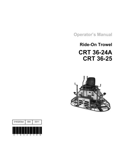
Operator’s Manual<br />
Ride-On Trowel<br />
<strong>CRT</strong> <strong>36</strong>-<strong>24A</strong><br />
<strong>CRT</strong> <strong>36</strong>-<strong>25</strong>
Copyright<br />
notice<br />
© Copyright 2010 by <strong>Wacker</strong> <strong>Neuson</strong> Corporation.<br />
All rights, including copying and distribution rights, are reserved.<br />
This publication may be photocopied by the original purchaser of the machine. Any<br />
other type of reproduction is prohibited without express written permission from<br />
<strong>Wacker</strong> <strong>Neuson</strong> Corporation.<br />
Any type of reproduction or distribution not authorized by <strong>Wacker</strong> <strong>Neuson</strong> Corporation<br />
represents an infringement of valid copyrights. Violators will be prosecuted.<br />
Trademarks All trademarks referenced in this manual are the property of their respective owners.<br />
Manufacturer <strong>Wacker</strong> <strong>Neuson</strong> Corporation<br />
N92W15000 Anthony Avenue<br />
Menomonee Falls, WI 53051 U.S.A.<br />
Tel: (262) <strong>25</strong>5-0500 · Fax: (262) <strong>25</strong>5-0550 · Tel: (800) 770-0957<br />
www.wackerneuson.com<br />
Translated<br />
instructions<br />
This Operator’s Manual presents the original instructions. The original language of this<br />
Operator’s Manual is American English.
<strong>CRT</strong> <strong>36</strong> Foreword<br />
Foreword<br />
Machines<br />
covered by<br />
this manual<br />
Machine<br />
documentation<br />
Expectations<br />
for<br />
information in<br />
this manual<br />
CALIFORNIA<br />
Proposition<br />
65 Warning<br />
Laws<br />
pertaining to<br />
spark<br />
arresters<br />
Manufacturer’s<br />
approval<br />
Machine Item Number Machine Item Number<br />
<strong>CRT</strong> <strong>36</strong>-<strong>24A</strong> 0620080 <strong>CRT</strong> <strong>36</strong>-<strong>25</strong> 0620115<br />
<strong>CRT</strong> <strong>36</strong>-<strong>24A</strong> 0620299 <strong>CRT</strong> <strong>36</strong>-<strong>25</strong> 0620295<br />
<strong>CRT</strong> <strong>36</strong>-<strong>24A</strong> 0620801 <strong>CRT</strong> <strong>36</strong>-<strong>25</strong> 0620803<br />
<strong>CRT</strong> <strong>36</strong>-<strong>24A</strong> 0620802 <strong>CRT</strong> <strong>36</strong>-<strong>25</strong> 0620804<br />
� Keep a copy of the Operator’s Manual with the machine at all times.<br />
� Use the separate Parts Book supplied with the machine to order replacement<br />
parts.<br />
� Refer to the separate Repair Manual for detailed instructions on servicing and<br />
repairing the machine.<br />
� If you are missing any of these documents, please contact <strong>Wacker</strong> <strong>Neuson</strong><br />
Corporation to order a replacement or visit www.wackerneuson.com.<br />
� When ordering parts or requesting service information, be prepared to provide<br />
the machine model number, item number, revision number, and serial number.<br />
� This manual provides information and procedures to safely operate and maintain<br />
the above <strong>Wacker</strong> <strong>Neuson</strong> model(s). For your own safety and to reduce<br />
the risk of injury, carefully read, understand, and observe all instructions<br />
described in this manual.<br />
� <strong>Wacker</strong> <strong>Neuson</strong> Corporation expressly reserves the right to make technical<br />
modifications, even without notice, which improve the performance or safety<br />
standards of its machines.<br />
� The information contained in this manual is based on machines manufactured<br />
up until the time of publication. <strong>Wacker</strong> <strong>Neuson</strong> Corporation reserves the right<br />
to change any portion of this information without notice.<br />
Engine exhaust, some of its constituents, and certain vehicle components, contain<br />
or emit chemicals known to the State of California to cause cancer and birth<br />
defects or other reproductive harm.<br />
NOTICE: State Health Safety Codes and Public Resources Codes specify that in<br />
certain locations spark arresters be used on internal combustion engines that use<br />
hydrocarbon fuels. A spark arrester is a device designed to prevent accidental discharge<br />
of sparks or flames from the engine exhaust. Spark arresters are qualified<br />
and rated by the United States Forest Service for this purpose. In order to comply<br />
with local laws regarding spark arresters, consult the engine distributor or the local<br />
Health and Safety Administrator.<br />
This manual contains references to approved parts, attachments, and modifications.<br />
The following definitions apply:<br />
� Approved parts or attachments are those either manufactured or provided by<br />
<strong>Wacker</strong> <strong>Neuson</strong>.<br />
wc_tx001268gb.fm 3
Foreword <strong>CRT</strong> <strong>36</strong><br />
� Approved modifications are those performed by an authorized <strong>Wacker</strong> <strong>Neuson</strong><br />
service center according to written instructions published by <strong>Wacker</strong> <strong>Neuson</strong>.<br />
� Unapproved parts, attachments, and modifications are those that do not<br />
meet the approved criteria.<br />
Unapproved parts, attachments, or modifications may have the following consequences:<br />
� Serious injury hazards to the operator and persons in the work area<br />
� Permanent damage to the machine which will not be covered under warranty<br />
Contact your <strong>Wacker</strong> <strong>Neuson</strong> dealer immediately if you have questions about<br />
approved or unapproved parts, attachments, or modifications.<br />
4 wc_tx001268gb.fm
<strong>CRT</strong> <strong>36</strong>-<strong>24A</strong>/<strong>25</strong> Table of Contents<br />
Foreword 3<br />
1 Safety Information 7<br />
1.1 Signal Words found in this Manual ....................................................... 7<br />
1.2 Machine Description and Intended Use ............................................... 8<br />
1.3 Operating Safety .................................................................................. 9<br />
1.4 Operator Safety while using Internal Combustion Engines ................ 10<br />
1.5 Service Safety .................................................................................... 11<br />
2 Labels 15<br />
2.1 Label Locations .................................................................................. 15<br />
2.2 Safety Labels ...................................................................................... 17<br />
2.3 Informational Labels ........................................................................... 19<br />
3 Operation 21<br />
3.1 Features and Controls ........................................................................ 21<br />
3.2 Position of the Operator ..................................................................... 23<br />
3.3 Preparing the Machine for First Use ................................................... 23<br />
3.4 Break-in Period ................................................................................... 24<br />
3.5 Before Starting ................................................................................... 24<br />
3.6 Starting ............................................................................................... <strong>25</strong><br />
3.7 Stopping ............................................................................................. <strong>25</strong><br />
3.8 Operation ............................................................................................ 26<br />
3.9 Steering .............................................................................................. 27<br />
3.10 Pitch Adjustment ................................................................................ 28<br />
3.11 Emergency Shutdown Procedure ....................................................... 28<br />
4 <strong>Maintenance</strong> 29<br />
4.1 Periodic <strong>Maintenance</strong> Schedule ......................................................... 29<br />
4.2 Trowel Gearboxes .............................................................................. 30<br />
4.3 Lubrication .......................................................................................... 31<br />
4.4 Control Arm Adjustment (Forward or Backward) ................................ 32<br />
wc_bo0163203en_004TOC.fm 5
Table of Contents <strong>CRT</strong> <strong>36</strong>-<strong>24A</strong>/<strong>25</strong><br />
4.5 Right-hand Control Arm Adjustment (Right or Left) .............................33<br />
4.6 Mounting Float Pans ...........................................................................33<br />
4.7 Transporting Trowels ...........................................................................34<br />
4.8 Drive Belt .............................................................................................35<br />
4.9 Battery Jump Start Procedure .............................................................<strong>36</strong><br />
4.10 Spark Plug ...........................................................................................37<br />
4.11 Air Cleaner ..........................................................................................38<br />
4.12 Engine Oil and Filter ............................................................................39<br />
4.13 Storing the Machine ............................................................................40<br />
4.14 Troubleshooting ...................................................................................41<br />
5 Schematic 43<br />
5.1 Schematic Components ......................................................................44<br />
6 Technical Data 45<br />
6.1 Engine .................................................................................................45<br />
6.2 Trowel ..................................................................................................46<br />
6.3 Sound and Vibration Specifications .....................................................47<br />
6 wc_bo0163203en_004TOC.fm
<strong>CRT</strong> <strong>36</strong>-<strong>24A</strong>/<strong>25</strong> Safety Information<br />
1 Safety Information<br />
1.1 Signal Words Found in this Manual<br />
This is the safety alert symbol. It is used to alert you to potential personal hazards.<br />
� Obey all safety messages that follow this symbol.<br />
DANGER<br />
DANGER indicates a hazardous situation which, if not avoided, will result in death<br />
or serious injury.<br />
� To avoid death or serious injury from this type of hazard, obey all safety messages<br />
that follow this signal word.<br />
WARNING<br />
WARNING indicates a hazardous situation which, if not avoided, could result in<br />
death or serious injury.<br />
� To avoid possible death or serious injury from this type of hazard, obey all<br />
safety messages that follow this signal word.<br />
CAUTION<br />
CAUTION indicates a hazardous situation which, if not avoided, could result in<br />
minor or moderate injury.<br />
� To avoid possible minor or moderate injury from this type of hazard, obey all<br />
safety messages that follow this signal word.<br />
NOTICE: Used without the safety alert symbol, NOTICE indicates a<br />
situation which, if not avoided, could result in property damage.<br />
Note: A Note contains additional information important to a procedure.<br />
wc_si000377gb.fm 7
Safety Information <strong>CRT</strong> <strong>36</strong>-<strong>24A</strong>/<strong>25</strong><br />
1.2 Machine Description and Intended Use<br />
This machine is a ride-on concrete finishing trowel. The <strong>Wacker</strong><br />
<strong>Neuson</strong> Ride-On Trowel consists of a frame onto which are mounted<br />
a gasoline or diesel engine, a fuel tank, a water tank, two gearboxes<br />
joined by a drive shaft, and an operator’s platform with controls and a<br />
seat. A set of metal blades is connected to each gearbox. A ring<br />
guard surrounds the blades. The engine rotates the blades via the<br />
gearboxes and a clutch mechanism. The rotating blades ride on the<br />
surface of curing concrete, creating a smooth finish. The operator,<br />
who sits on the operator’s platform, uses the controls and the throttle<br />
pedal to control speed and direction of the machine.<br />
This machine is intended to be used for floating and burnishing curing<br />
concrete.<br />
This machine has been designed and built strictly for the intended use<br />
described above. Using the machine for any other purpose could<br />
permanently damage the machine or seriously injure the operator or<br />
other persons in the area. Machine damage caused by misuse is not<br />
covered under warranty.<br />
The following are some examples of misuse:<br />
• Using the machine as a ladder, support, or work surface<br />
• Using the machine to carry or transport passengers or equipment<br />
• Using the machine to finish inappropriate materials such as slurries,<br />
sealers, or epoxy finishes<br />
• Operating the machine outside of factory specifications<br />
• Operating the machine in a manner inconsistent with all warnings<br />
found on the machine and in the Operator’s Manual<br />
This machine has been designed and built in accordance with the<br />
latest global safety standards. It has been carefully engineered to<br />
eliminate hazards as far as practicable and to increase operator<br />
safety through protective guards and labeling. However, some risks<br />
may remain even after protective measures have been taken. They<br />
are called residual risks. On this machine, they may include exposure<br />
to:<br />
• Heat, noise, exhaust, and carbon monoxide from the engine<br />
• Chemical burns from the curing concrete<br />
• Fire hazards from improper refueling techniques<br />
• Fuel and its fumes, fuel spillage from improper lifting technique<br />
• Personal injury from improper lifting techniques<br />
• Cutting hazards from sharp or worn blades<br />
8 wc_si000377gb.fm
<strong>CRT</strong> <strong>36</strong>-<strong>24A</strong>/<strong>25</strong> Safety Information<br />
To protect yourself and others, make sure you thoroughly read and<br />
understand the safety information presented in this manual before<br />
operating the machine.<br />
wc_si000377gb.fm 9
Safety Information <strong>CRT</strong> <strong>36</strong>-<strong>24A</strong>/<strong>25</strong><br />
1.3 Operating Safety<br />
Familiarity and proper training are required for the safe operation of the<br />
machine. Machines operated improperly or by untrained personnel<br />
can be hazardous. Read the operating instructions contained in this<br />
WARNING<br />
manual and the engine manual, and familiarize yourself with the<br />
location and proper use of all controls. Inexperienced operators should<br />
receive instruction from someone familiar with the machine before<br />
being allowed to operate it.<br />
1.3.1 Operator qualifications<br />
Only trained personnel are permitted to start, operate, and shut down<br />
the machine. They also must meet the following qualifications:<br />
• have received instruction on how to properly use the machine<br />
• are familiar with required safety devices<br />
The machine must not be accessed or operated by:<br />
• children<br />
• people impaired by alcohol or drugs<br />
1.3.2 Never operate this machine in applications for which it is not intended.<br />
1.3.3 Do not allow anyone to operate this equipment without proper training.<br />
People operating this equipment must be familiar with the risks and<br />
hazards associated with it.<br />
1.3.4 Do not touch the engine or muffler while the engine is on or<br />
immediately after it has been turned off. These areas get hot and may<br />
cause burns.<br />
1.3.5 Do not operate the machine with unapproved accessories or<br />
attachments.<br />
1.3.6 NEVER operate the machine with the beltguard missing. Exposed<br />
drive belt and pulleys create potentially dangerous hazards that can<br />
cause serious injuries.<br />
1.3.7 Never leave the machine running unattended.<br />
1.3.8 Do not run the machine indoors or in an enclosed area such as a deep<br />
trench unless adequate ventilation, through such items as exhaust<br />
fans or hoses, is provided. Engine exhaust contains carbon monoxide.<br />
This is a poison you cannot see or smell. Exposure to carbon<br />
monoxide can cause loss of consciousness and CAN KILL YOU IN<br />
MINUTES.<br />
1.3.9 ALWAYS remain aware of moving parts and keep hands, feet, and<br />
loose clothing away from the moving parts of the machine.<br />
1.3.10 Always wear protective clothing appropriate to the job site when<br />
operating the machine.<br />
1.3.11 Read, understand, and follow procedures in the Operator’s Manual<br />
before attempting to operate the machine.<br />
10 wc_si000377gb.fm
<strong>CRT</strong> <strong>36</strong>-<strong>24A</strong>/<strong>25</strong> Safety Information<br />
1.3.12 Be sure operator is familiar with proper safety precautions and<br />
operation techniques before using machine.<br />
1.3.13 Close fuel valve on engines equipped with one when machine is not<br />
being operated.<br />
1.3.14 Store the machine properly when it is not being used. The machine<br />
should be stored in a clean, dry location out of the reach of children.<br />
1.3.15 Always operate the machine with all safety devices and guards in<br />
place and in working order.<br />
1.3.16 Personal Protective Equipment (PPE)<br />
Wear the following Personal Protective Equipment (PPE) while<br />
operating this machine:<br />
• Close-fitting work clothes that do not hinder movement<br />
• Safety glasses with side shields<br />
• Hearing protection<br />
• Safety-toed footwear<br />
wc_si000377gb.fm 11
Safety Information <strong>CRT</strong> <strong>36</strong>-<strong>24A</strong>/<strong>25</strong><br />
1.4 Operator Safety while using Internal Combustion Engines<br />
WARNING<br />
Internal combustion engines present special hazards during operation and fueling.<br />
Failure to follow the warnings and safety standards could result in severe injury or death.<br />
� Read and follow the warning instructions in the engine owner’s manual and the<br />
safety guidelines below.<br />
DANGER<br />
Exhaust gas from the engine contains carbon monoxide, a deadly poison.<br />
Exposure to carbon monoxide can kill you in minutes.<br />
� NEVER operate the machine inside an enclosed area, such as a tunnel, unless<br />
adequate ventilation is provided through such items as exhaust fans or hoses.<br />
Operating safety<br />
When running the engine:<br />
• Keep the area around exhaust pipe free of flammable materials.<br />
• Check the fuel lines and the fuel tank for leaks and cracks before<br />
starting the engine. Do not run the machine if fuel leaks are<br />
present or the fuel lines are loose.<br />
When running the engine:<br />
• Do not smoke while operating the machine.<br />
• Do not run the engine near sparks or open flames.<br />
• Do not touch the engine or muffler while the engine is running or<br />
immediately after it has been turned off.<br />
• Do not operate a machine when its fuel cap is loose or missing.<br />
• Do not start the engine if fuel has spilled or a fuel odor is present.<br />
Move the machine away from the spill and wipe the machine dry<br />
before starting.<br />
Refueling safety<br />
When refueling the engine:<br />
• Clean up any spilled fuel immediately.<br />
• Refill the fuel tank in a well-ventilated area.<br />
• Replace the fuel tank cap after refueling.<br />
• Do not smoke.<br />
• Do not refuel a hot or running engine.<br />
• Do not refuel the engine near sparks or open flames.<br />
12 wc_si000377gb.fm
<strong>CRT</strong> <strong>36</strong>-<strong>24A</strong>/<strong>25</strong> Safety Information<br />
1.5 Service Safety<br />
WARNING<br />
• Do not refuel if the machine is positioned in a truck fitted with a<br />
plastic bed liner. Static electricity can ignite the fuel or fuel<br />
vapors.<br />
A poorly maintained machine can become a safety hazard! In order<br />
for the machine to operate safely and properly over a long period of<br />
time, periodic maintenance and occasional repairs are necessary.<br />
1.5.1 Service training<br />
Before servicing or maintaining the machine:<br />
• Read and understand the instructions contained in all manuals<br />
delivered with the machine.<br />
• Familiarize yourself with the location and proper use of all controls<br />
and safety devices.<br />
• Only trained personnel shall troubleshoot or repair problems<br />
occurring with the machine.<br />
• Contact <strong>Wacker</strong> <strong>Neuson</strong> Corporation for additional training if necessary.<br />
When servicing or maintaining this machine:<br />
• Do not allow improperly trained people to service or maintain the<br />
machine. Personnel servicing or maintaining the machine must<br />
be familiar with the associated potential risks and hazards.<br />
1.5.2 Personal Protective Equipment (PPE)<br />
Wear the following Personal Protective Equipment (PPE) while<br />
servicing or maintaining this machine:<br />
• Close-fitting work clothes that do not hinder movement<br />
• Safety glasses with side shields<br />
• Hearing protection<br />
• Safety-toed footwear<br />
In addition, before servicing or maintaining the machine:<br />
• Tie back long hair.<br />
• Remove all jewelry (including rings).<br />
1.5.3 Do not attempt to clean or service the machine while it is running.<br />
Rotating parts can cause severe injury.<br />
1.5.4 Do not crank a flooded engine with the spark plug removed on<br />
gasoline-powered engines. Fuel trapped in the cylinder will squirt out<br />
the spark plug opening.<br />
wc_si000377gb.fm 13
Safety Information <strong>CRT</strong> <strong>36</strong>-<strong>24A</strong>/<strong>25</strong><br />
1.5.5 Do not test for spark on gasoline-powered engines if the engine is<br />
flooded or the smell of gasoline is present. A stray spark could ignite<br />
the fumes.<br />
1.5.6 Do not use gasoline or other types of fuels or flammable solvents to<br />
clean parts, especially in enclosed areas. Fumes from fuels and<br />
solvents can become explosive.<br />
1.5.7 ALWAYS turn engine off and remove key from machine before<br />
performing maintenance or making repairs.<br />
1.5.8 ALWAYS handle blades carefully. The blades can develop sharp<br />
edges which can cause serious cuts.<br />
1.5.9 Keep the area around the muffler free of debris such as leaves, paper,<br />
cartons, etc. A hot muffler could ignite the debris and start a fire.<br />
1.5.10 When replacement parts are required for this machine, use only<br />
<strong>Wacker</strong> <strong>Neuson</strong> replacement parts or those parts equivalent to the<br />
original in all types of specifications, such as physical dimensions,<br />
type, strength, and material.<br />
1.5.11 Disconnect the spark plug on machines equipped with gasoline<br />
engines, before servicing, to avoid accidental start-up.<br />
1.5.12 ALWAYS switch off the power supply at the battery disconnect before<br />
adjusting or maintaining the electrical equipment.<br />
1.5.13 Keep the machine clean and labels legible. Replace all missing and<br />
hard-to-read labels. Labels provide important operating instructions<br />
and warn of dangers and hazards.<br />
14 wc_si000377gb.fm
<strong>CRT</strong> <strong>36</strong>-<strong>24A</strong>/<strong>25</strong> Safety Information<br />
Notes<br />
wc_si000377gb.fm 15
Labels <strong>CRT</strong> <strong>36</strong>-<strong>24A</strong>/<strong>25</strong><br />
2 Labels<br />
2.1 Label Locations<br />
D<br />
C<br />
B<br />
J<br />
16 wc_si000378gb.fm
<strong>CRT</strong> <strong>36</strong>-<strong>24A</strong>/<strong>25</strong> Labels<br />
wc_si000378gb.fm 17<br />
A<br />
wc_gr007015
Labels <strong>CRT</strong> <strong>36</strong>-<strong>24A</strong>/<strong>25</strong><br />
2.2 Safety Labels<br />
Ref. Label Meaning<br />
A DANGER!<br />
Asphyxiation hazard.<br />
� Engines emit carbon monoxide.<br />
B WARNING!<br />
J<br />
L<br />
� Do not run the machine indoors or in an<br />
enclosed area unless adequate ventilation,<br />
through such items as exhaust fans or hoses, is<br />
provided.<br />
� Read the Operator’s Manual.<br />
� No sparks, flames, or burning objects near the<br />
machine.<br />
� Stop the engine before refueling.<br />
To reduce the risk of hearing loss and eye injury, always<br />
wear hearing protection and eye protection when<br />
operating this machine.<br />
WARNING!<br />
Read and understand the supplied Operator’s Manual<br />
before operating the machine. Failure to do so<br />
increases the risk of injury to yourself and others.<br />
CAUTION<br />
Lifting point.<br />
O WARNING!<br />
Cutting hazard. Keep hands and feet away from<br />
moving blade.<br />
18 wc_si000378gb.fm
<strong>CRT</strong> <strong>36</strong>-<strong>24A</strong>/<strong>25</strong> Labels<br />
Ref. Label Meaning<br />
S<br />
T<br />
--<br />
4 A � � L A F = � B H � � J H � M A � > A B � H A � E B J E � C � = ? D E � A<br />
� L A H D A = @ �<br />
2 = � I ? = � B = � � = � @ ? = K I A @ A = J D � H I A H E � K I E � � K H O E B<br />
= F A H I � � E I D E J �<br />
/ � A E J I ? D A E > A L � � * A J � � C � � J J A H A � J B A H � A � > A L � H<br />
@ = I / A H � J K > A H � � F B D � D A C A D � > A � M E H @ �<br />
/ � A E J I ? D A E > A � = � � B = � � A � K � @ I ? D M A H A 8 A H � A J � K � C<br />
� @ A H 6 � @ L A H K H I = ? D A � M A � � 2 A H I � � = � C A J H � B B A � M E H @ �<br />
3 K E J A A � @ E I ? � @ A B � � J = ? E � � = � J A I @ A � A L = � J = H � =<br />
� � G K E � = = � E I = @ � H = @ A D � H � E C � � �<br />
� � I @ E I ? � I F � @ H � = � ? = A H O � = J = H � � = I J E � = H<br />
I A H E = � A � J A = K � = F A H I � � = G K A I A A � ? K A � J H A ? A H ? = �<br />
) L = � J @ A � A L A H � \ = F F = H A E � = K � @ A I I K I @ A L � J H A J � J A �<br />
� J A H � A @ E I G K A @ A J = � � ? D = C A @ A � = J H K A � � A �<br />
� A @ E I G K A @ A J = � � ? D = C A F A K J J � � > A H A J A � J H = � � A H<br />
@ A C H = L A I > � A I I K H A I � K � � � A � = � � H J �<br />
wc_si000378gb.fm 19<br />
& $ & &<br />
WARNING!<br />
Hot surface!<br />
WARNING!<br />
Entanglement hazard. Keep hands away from spinning<br />
belt and pulley.<br />
WARNING!<br />
Remove pan from trowel before lifting machine overhead.<br />
Pans can fall and cause death or serious injury if<br />
a person is hit. (Label located on top side of float pan.)
Labels <strong>CRT</strong> <strong>36</strong>-<strong>24A</strong>/<strong>25</strong><br />
2.3 Informational Labels<br />
Ref. Label Meaning<br />
C Positions of the key switch:<br />
� ON<br />
� OFF<br />
� Engine crank<br />
D Steering control:<br />
E<br />
� Push both levers forward to move forward<br />
� Pull both levers backward to move rearward<br />
� Push the left lever forward and pull the right<br />
lever backward to rotate clockwise<br />
� Pull the left lever backward and push the right<br />
lever forward to rotate counterclockwise<br />
� Move both levers to the left to move left<br />
� Move both levers to the right to move right<br />
Check engine oil level.<br />
K Pitch control:<br />
To increase pitch: Rotate the left pitch control<br />
clockwise, rotate the right pitch control<br />
counterclockwise.<br />
To decrease pitch: Rotate the left pitch control<br />
counterclockwise, rotate the right pitch control<br />
clockwise<br />
N<br />
Tie-down point.<br />
20 wc_si000378gb.fm
<strong>CRT</strong> <strong>36</strong>-<strong>24A</strong>/<strong>25</strong> Labels<br />
Ref. Label Meaning<br />
P<br />
W<br />
--<br />
--<br />
--<br />
WACKER NEUSON<br />
wc_si000378gb.fm 21<br />
Operator’s Manual must be stored on machine.<br />
Replacement Operator’s Manual can be ordered<br />
through your local <strong>Wacker</strong> <strong>Neuson</strong> distributor.<br />
Water tank fill. Use only clean water or water-based<br />
retardants.<br />
Use only Glygoyle 460 gear oil in gearbox.<br />
A nameplate listing the model number, item number,<br />
revision number, and serial number is attached to each<br />
unit. Please record the information found on this plate<br />
so it will be available should the nameplate become lost<br />
or damaged. When ordering parts or requesting service<br />
information, you will always be asked to specify the<br />
model number, item number, revision number, and<br />
serial number of the unit.<br />
This machine may be covered by one or more patents.
Operation <strong>CRT</strong> <strong>36</strong><br />
3 Operation<br />
3.1 Features and Controls<br />
22 wc_tx000639gb.fm
<strong>CRT</strong> <strong>36</strong> Operation<br />
Control locations and functions:<br />
Ref. Description Ref. Description<br />
a Right pitch control k Foot pedal (throttle control)<br />
b Fuel tank l Engine choke control<br />
c Control arms m Work light switch<br />
d Operator’s seat with “operator presence”<br />
switch<br />
n Oil pressure indicator light<br />
e Left pitch control o Engine keyswitch<br />
f Rear work light (one each side) p Hour meter<br />
g Water tank q Water spray control<br />
h Work light (one each side) — —<br />
The Ride-On Trowel features a seat with an integrated “operator<br />
presence” system, which works in conjunction with a throttle mounted<br />
switch. This system allows the engine to remain running (idling) with<br />
no operator seated in the seat, as long as the throttle is not depressed.<br />
This system meets all safety requirements and eliminates the need for<br />
a foot-operated “kill switch”.<br />
To familiarize a new operator with the Ride-On Trowel the following<br />
steps should be taken:<br />
3.1.1 With the operator in the seat, show him or her the functions of the<br />
control arms (c) and how to start the machine.<br />
3.1.2 Have the operator practice steering the trowel. A hard concrete slab<br />
slightly wetted with water is an ideal place for an operator to practice<br />
with the machine. For this practice, pitch the blades up approximately<br />
¼" on the leading edge. Start by making the machine hover in one<br />
spot, and then practice driving the machine in a straight line and<br />
making 180° turns. The best control is achieved at full rpm.<br />
wc_tx000639gb.fm 23
Operation <strong>CRT</strong> <strong>36</strong><br />
3.2 Position of the Operator<br />
Safe and efficient use of this machine is the operator’s responsibility.<br />
Full control of the machine is not possible unless the operator<br />
maintains the proper working position at all times.<br />
While operating this machine the operator must:<br />
• be seated in the operator’s seat facing forward<br />
• have both feet on the control deck<br />
• have both hands on the controls<br />
3.3 Preparing the Machine for First Use<br />
Preparing for first use<br />
To prepare your machine for first use:<br />
3.3.1 Make sure all loose packaging materials have been removed from the<br />
machine.<br />
3.3.2 Check the machine and its components for damage. If there is visible<br />
damage, do not operate the machine! Contact your <strong>Wacker</strong> <strong>Neuson</strong><br />
dealer immediately for assistance.<br />
3.3.3 Take inventory of all items included with the machine and verify that<br />
all loose components and fasteners are accounted for.<br />
3.3.4 Attach component parts not already attached.<br />
3.3.5 Add fluids as needed and applicable, including fuel, engine oil, and<br />
battery acid.<br />
3.3.6 Move the machine to its operating location.<br />
24 wc_tx000639gb.fm
<strong>CRT</strong> <strong>36</strong> Operation<br />
3.4 Break-in Period<br />
See Graphic: wc_gr001<strong>25</strong>2<br />
3.4.1 To break in the gearboxes, run the engine at 50% of full throttle for the<br />
first 2–4 hours. This will prevent premature wear and extend gear life.<br />
NOTICE: Running the engine at full throttle during the break-in period<br />
could result in premature gear failure.<br />
3.4.2 Verify that the horizontal blade pitch links are properly assembled.<br />
When seated on the machine, the right rotor should have an “R”<br />
designation located towards the upper portion of the pitch link and the<br />
left rotor should have an “L”.<br />
3.5 Before Starting<br />
Before starting the trowel, check the following:<br />
• fuel level<br />
• oil level in the engine<br />
• condition of the air filter<br />
• condition of trowel arms and blades<br />
Grease the trowel arms daily.<br />
wc_tx000639gb.fm <strong>25</strong>
Operation <strong>CRT</strong> <strong>36</strong><br />
3.6 Starting<br />
Before starting the operator must know the location and function of all<br />
controls.<br />
3.6.1 Push down on the throttle foot pedal, turn the engine keyswitch (o),<br />
and hold it until the engine starts.<br />
Note: If the engine is cold, pull out the choke control knob fully. The<br />
choke may need to be opened even when starting a warm engine.<br />
NOTICE: Cranking the engine for more than 5 seconds can cause<br />
starter damage. If the engine fails to start, release the keyswitch and<br />
wait 10 seconds before operating the starter again.<br />
Note: The engine has an oil alert light to notify operator if the oil<br />
pressure is low. If engine will not start, or stops during operation, check<br />
engine oil level.<br />
3.6.2 Allow the engine to warm up before operating the trowel.<br />
3.7 Stopping<br />
To stop trowel movement, return control levers to their neutral position<br />
and release pressure on the throttle foot pedal.<br />
To stop the engine, turn the keyswitch to “O” (off).<br />
26 wc_tx000639gb.fm
<strong>CRT</strong> <strong>36</strong> Operation<br />
3.8 Operation<br />
To utilize your <strong>Wacker</strong> <strong>Neuson</strong> Ride-On Trowel to its fullest capacity,<br />
the machine should be driven in the direction that the operator is<br />
facing. This will finish the widest possible area, while giving the<br />
operator an excellent view of the slab surface about to be troweled.<br />
When the machine reaches the end of the slab, make a 180° U-turn,<br />
and repeat the straight line of direction to the other end of the slab.<br />
Note: During the break-in period, run the engine at 50% of full throttle.<br />
Refer to Section New Machines.<br />
NOTICE: DO NOT use excessive pressure on the control levers.<br />
Excessive pressure does not increase the reaction time of the machine<br />
and can damage the steering controls.<br />
NOTICE: Attempting to use the trowel too early in the curing stage of<br />
the concrete may result in an undesirable finish. Only experienced<br />
concrete finishers should operate the trowel.<br />
wc_tx000639gb.fm 27
Operation <strong>CRT</strong> <strong>36</strong><br />
3.9 Steering<br />
See Graphic: wc_gr000146<br />
Refer to the illustration for the necessary hand motions to move the<br />
trowel in the desired direction, described below.<br />
1 - forward<br />
2 - reverse<br />
3 - rotate clockwise<br />
4 - rotate counter-clockwise<br />
5 - left sideways<br />
6 - right sideways<br />
1 2<br />
3<br />
4<br />
5 6<br />
wc_gr000146<br />
28 wc_tx000639gb.fm
<strong>CRT</strong> <strong>36</strong> Operation<br />
3.10 Pitch Adjustment<br />
When changing or setting the pitch (angle) of the trowel blades, slow<br />
the machine, set the desired pitch on the left side of the machine, then<br />
adjust the right side to match.<br />
To increase pitch: Rotate the left pitch control (L) clockwise, rotate the<br />
right pitch control (R) counterclockwise.<br />
To decrease pitch: Rotate the left pitch control (L) counterclockwise,<br />
rotate the right pitch control (R) clockwise.<br />
3.11 Emergency Shutdown Procedure<br />
Procedure<br />
3.11.1<br />
If a breakdown or accident occurs while the machine is operating,<br />
follow the procedure below:<br />
Stop the engine.<br />
3.11.2 Close the fuel valve.<br />
3.11.3 Remove the machine from the job site using the wheel kit.<br />
3.11.4 Clean concrete from the blades and the machine.<br />
3.11.5 Contact the rental yard or machine owner for further instructions.<br />
wc_tx000639gb.fm 29<br />
Working Conditions of<br />
Concrete<br />
1. Wet surface working<br />
stage<br />
2. Wet to plastic working<br />
stage<br />
3. Semi-hard working<br />
stage<br />
4. Hard finishing stage<br />
(burnishing)<br />
Suggested Working<br />
Pitch<br />
Flat (No Pitch)<br />
Slight Pitch<br />
Additional Pitch<br />
Maximum Pitch
<strong>Maintenance</strong> <strong>CRT</strong> <strong>36</strong>-<strong>24A</strong>/<strong>25</strong><br />
4 <strong>Maintenance</strong><br />
4.1 Periodic <strong>Maintenance</strong> Schedule<br />
The table below lists basic machine maintenance. Tasks designated<br />
with check marks may be performed by the operator. Tasks<br />
designated with square bullet points require special training and<br />
equipment.<br />
Refer to the engine operator’s manual for information on engine<br />
maintenance.<br />
Grease trowel arms. �<br />
Check fuel level. �<br />
Check engine oil level. 1 �<br />
Inspect air filter. Replace as needed. �<br />
Check external hardware. �<br />
Pressure wash all surfaces until free of concrete.<br />
2<br />
Daily Every<br />
20<br />
hrs.<br />
Check oil level in gearboxes. �<br />
Grease gearbox, drive system and pitch posts<br />
fittings.<br />
Grease control linkage. �<br />
�<br />
Every<br />
50<br />
hrs.<br />
Check drive belt for wear. �<br />
�<br />
Every<br />
100<br />
hrs.<br />
3<br />
Change engine oil. �<br />
Check fuel filter. �<br />
Clean and check spark plug. �<br />
Replace oil filter. �<br />
Every<br />
200<br />
hrs.<br />
Replace spark plug. �<br />
Replace fuel filter. �<br />
Replace oil in gearboxes. �<br />
1<br />
Check engine oil twice daily (every 4<br />
hours).<br />
2<br />
Pressure wash immediately after use.<br />
Every<br />
300<br />
hrs.<br />
3<br />
Change engine oil after first 20 hours of operation.<br />
30 wc_tx000640gb.fm
<strong>CRT</strong> <strong>36</strong>-<strong>24A</strong>/<strong>25</strong> <strong>Maintenance</strong><br />
4.2 Trowel Gearboxes<br />
See Graphic: wc_gr003730<br />
Check the gearboxes for the correct oil level after every 20 hours of<br />
operation. Change the gearbox oil every 300 hours.<br />
To check the oil level:<br />
Each <strong>CRT</strong> gearbox is equipped with two oil fill plugs. Remove one<br />
gearbox oil fill plug (b). If the level is below the threads of the oil fill plug<br />
hole, add synthetic gear oil through the opening. DO NOT overfill.<br />
Wipe the threads dry on both the gearbox and the oil fill plug, apply<br />
Loctite 545 or equivalent to the oil fill plug threads, replace the oil fill<br />
plug and torque to 16–20 Nm (12–15 ft.lbs.).<br />
NOTICE: DO NOT mix types of gear oil. DO NOT overfill the gearbox<br />
with oil. Damage to the gearbox may occur if oils are mixed, or if the<br />
gearbox is overfilled. See Technical Data for oil quantity and type.<br />
To change gearbox oil:<br />
4.2.1 Place a container of sufficient capacity (approximately 3.8 l [1 gallon])<br />
under each gearbox.<br />
4.2.2 Remove the gearbox oil drain plug (c) and allow the oil to drain out. It<br />
may be necessary to remove the gearbox oil fill plug(s) to facilitate<br />
draining. After most of the oil has drained out, tip the back of the trowel<br />
upwards to allow the remaining oil to drain out.<br />
4.2.3 After all the oil has drained out, wipe the threads dry on both the<br />
gearbox and the oil drain plug, apply Loctite 545 or equivalent to the oil<br />
drain plug threads, and replace the gearbox oil drain plug.<br />
Note: Dispose of used gear oil in accordance with environmental<br />
protection legislation.<br />
4.2.4 With the trowel level, fill the gearbox with approximately 1.83 l (62 oz.)<br />
synthetic gear oil through the oil fill plug as described above.<br />
4.2.5 Wipe the threads dry on both the gearbox and the oil fill plug, apply<br />
Loctite 545 or equivalent to the oil fill plug threads, replace the oil fill<br />
plug(s), and torque all plugs to 16-20 Nm (12–15 ft.lbs.).<br />
Each gearbox has a pressure relief valve (a) which can become<br />
clogged over time. Check or replace as needed. Failure to replace the<br />
valve can result in oil leakage from the gearbox shaft seals.<br />
wc_tx000640gb.fm 31
<strong>Maintenance</strong> <strong>CRT</strong> <strong>36</strong>-<strong>24A</strong>/<strong>25</strong><br />
4.3 Lubrication<br />
See Graphic: wc_gr003731, wc_gr003732<br />
The drive system, gearbox and pitch posts are equipped with several<br />
grease fittings. Grease these fittings once a week, or every 20 hours,<br />
to prevent wear.<br />
Use a general purpose grease and add one to two shots of grease at<br />
each fitting.<br />
32 wc_tx000640gb.fm
<strong>CRT</strong> <strong>36</strong>-<strong>24A</strong>/<strong>25</strong> <strong>Maintenance</strong><br />
4.4 Control Arm Adjustment (Forward or Backward)<br />
See Graphic: wc_gr003732<br />
The control arms should line up evenly. If arms appear out of<br />
adjustment, they can be re-adjusted forward or backward as follows:<br />
4.4.1 Loosen jam nuts (b).<br />
4.4.2 Turn the vertical linkage (a) as follows:<br />
• Extend the linkage to adjust control levers forward. See section<br />
4.5 before extending linkage.<br />
• Shorten the linkage to adjust control levers backward.<br />
4.4.3 After the arms have been adjusted to the desired position, tighten jam<br />
nuts (b).<br />
NOTICE: Control arms are adjusted as part of the steering assist system.<br />
Changing orientation of the control arms may affect steering effort.<br />
wc_tx000640gb.fm 33
<strong>Maintenance</strong> <strong>CRT</strong> <strong>36</strong>-<strong>24A</strong>/<strong>25</strong><br />
4.5 Right-hand Control Arm Adjustment (Right or Left)<br />
See Graphic: wc_gr003732<br />
The arms should be set to be perfectly vertical. Should the arms come<br />
out of adjustment, adjust as follows:<br />
4.5.1 Loosen the jam nuts (d).<br />
4.5.2 Drop the horizontal linkage (e) down to clear the bracket.<br />
4.5.3 Shorten the linkage to move the control arms to the left.<br />
4.5.4 Extend the linkage to move the control arms to the right.<br />
4.5.5 After the control lever has been adjusted to the desired position,<br />
reassemble the nut and the bolt (c) and tighten the jam nuts (d).<br />
4.6 Mounting Float Pans<br />
See Graphic: wc_gr000151<br />
Certain applications may require the use of float pans. Optional float<br />
pans (a) are available, and are used with the machines in the nonoverlapping<br />
configuration only.<br />
To mount float pans:<br />
Lift trowel off the ground with the engine off and position the pan<br />
against the blades. Turn pan either to the right or left to engage clip<br />
angles (b) as shown. Remember, the right-hand trowel blades turn<br />
counterclockwise; the left-hand blades turn clockwise.<br />
34 wc_tx000640gb.fm
<strong>CRT</strong> <strong>36</strong>-<strong>24A</strong>/<strong>25</strong> <strong>Maintenance</strong><br />
4.7 Transporting Trowels<br />
See Graphic: wc_gr003733<br />
WARNING<br />
WARNING<br />
ALWAYS turn the engine off and remove the key from the machine<br />
before moving or transporting machine.<br />
To hoist the trowel:<br />
Attach a sling or chains through the lifting bars (a) on each side of the<br />
seat pedestal.<br />
NOTICE: Make sure the lifting device has enough weight-bearing<br />
capacity to lift machine safely. Refer to section Technical Data.<br />
DO NOT lift the trowel by the guard rings or any part of the trowel other<br />
than the lifting fixture, as the component may fail, causing the trowel to<br />
fall, possibly injuring bystanders.<br />
If equipped with the optional integrated wheel kit (b):<br />
From the rear of machine, use the jack handle to raise the blades off<br />
the ground 76-102 mm (3-4 in.). Push the machine using the upper<br />
frame.<br />
wc_tx000640gb.fm 35
<strong>Maintenance</strong> <strong>CRT</strong> <strong>36</strong>-<strong>24A</strong>/<strong>25</strong><br />
4.8 Drive Belt<br />
See Graphic: wc_gr003734<br />
To replace the drive belt:<br />
4.8.1 Place the trowel on a flat, level surface with the blades pitched flat.<br />
4.8.2 Turn engine off and disconnect battery.<br />
4.8.3 Remove the beltguard.<br />
4.8.4 Remove 2 bolts (a), washers (b) and nuts (c) from each bearing flange.<br />
4.8.5 Remove the 4 bolts (d) holding each inside universal joint to the shaft<br />
fitting. Remove universal joints and shims (if included) from ends of<br />
drive shaft.<br />
4.8.6 Lift the drive pulley up far enough to slide belt past.<br />
4.8.7 Remove the old belt and install a new one.<br />
4.8.8 Reverse the procedure for assembly. Align the bearings and shaft as<br />
straight as possible. Adjust pulley offset and center distance to values<br />
as shown.<br />
4.8.9 Torque the bearing bolts (a) to 99±10 ft.lbs. Torque the universal joint<br />
bolts (d) to 10±1 ft.lbs.<br />
<strong>36</strong> wc_tx000640gb.fm
<strong>CRT</strong> <strong>36</strong>-<strong>24A</strong>/<strong>25</strong> <strong>Maintenance</strong><br />
4.9 Battery Jump Start Procedure<br />
DANGER<br />
WARNING<br />
Occasionally, it may be necessary to jump start a weak battery. If jump<br />
starting is necessary, the following procedure is recommended to<br />
prevent starter damage, battery damage, and personal injuries.<br />
Jump starting a battery incorrectly can cause battery to explode,<br />
resulting in severe personal injury or death. Do not smoke or allow<br />
ignition sources near the battery, and do not jump start a frozen<br />
battery.<br />
Electrical arcing can cause severe personal injury. Do not allow<br />
positive and negative cable ends to touch.<br />
4.9.1 Disconnect engine load.<br />
4.9.2 Use a battery of the same voltage (12V) as is used with your engine.<br />
4.9.3 Attach one end of the positive booster cable (red) to the positive (+)<br />
terminal of the booster battery. Attach the other end to the positive<br />
terminal of your engine battery.<br />
4.9.4 Attach one end of the negative booster cable (black) to the negative<br />
(–) terminal of the booster battery. Attach other end of negative cable<br />
to a solid chassis ground on your engine.<br />
NOTICE: Jump starting in any other manner may result in damage to<br />
the battery or the electrical system.<br />
4.9.5 Push down on the throttle foot pedal, turn the engine keyswitch and<br />
hold it until the engine starts.<br />
NOTICE: Cranking the engine for more than 5 seconds can cause<br />
starter damage. If the engine fails to start, release the keyswitch and<br />
wait 10 seconds before operating the starter again.<br />
NOTICE: When using lights or high amperage draw accessories, idle<br />
the engine for a period of 20 minutes to bring the battery to charge<br />
state.<br />
wc_tx000640gb.fm 37
<strong>Maintenance</strong> <strong>CRT</strong> <strong>36</strong>-<strong>24A</strong>/<strong>25</strong><br />
4.10 Spark Plug<br />
WARNING<br />
Clean or replace spark plug as needed to ensure proper operation.<br />
Refer to the engine Owner’s Manual.<br />
Note: Refer to the Technical Data for the recommended spark plug<br />
type and the electrode gap setting.<br />
The muffler and engine cylinder become very hot during operation and<br />
remain hot for a while after stopping the engine. Allow engine to cool<br />
before removing spark plug.<br />
4.10.1 Remove spark plug and inspect it.<br />
4.10.2 Replace plug if the insulator is cracked or chipped. Clean spark plug<br />
electrodes with a wire brush.<br />
4.10.3 Set the electrode gap.<br />
4.10.4 Tighten spark plug securely.<br />
NOTICE: A loose spark plug can become very hot and may cause<br />
engine damage.<br />
38 wc_tx000640gb.fm
<strong>CRT</strong> <strong>36</strong>-<strong>24A</strong>/<strong>25</strong> <strong>Maintenance</strong><br />
4.11 Air Cleaner<br />
See Graphic: wc_gr000154, wc_gr003765<br />
The engine is equipped with a dual element air cleaner. Service air<br />
cleaner frequently to prevent carburetor malfunction.<br />
NOTICE: NEVER run engine without air cleaner. Severe engine<br />
damage will occur.<br />
WARNING<br />
NEVER use gasoline or other types of low flash point solvents for<br />
cleaning the air cleaner. A fire or explosion could result.<br />
To service:<br />
4.11.1 Remove air cleaner cover (a). Remove both elements (b, c) and<br />
inspect them for holes or tears. Replace damaged elements.<br />
4.11.2 Wash foam element (b) in solution of mild detergent and warm water.<br />
Rinse thoroughly in clean water. Allow element to dry thoroughly.<br />
Do not put oil on the foam element.<br />
4.11.3 Tap paper element (c) lightly to remove excess dirt. Replace paper<br />
element if it appears heavily soiled.<br />
wc_tx000640gb.fm 39<br />
b<br />
c<br />
a<br />
wc_gr003765
<strong>Maintenance</strong> <strong>CRT</strong> <strong>36</strong>-<strong>24A</strong>/<strong>25</strong><br />
4.12 Engine Oil and Filter<br />
See Graphic: wc_gr000155<br />
Drain oil while engine is still warm.<br />
4.12.1 Remove oil fill cap (a) and drain plug (b) to drain oil.<br />
Note: In the interests of environmental protection, place a plastic sheet<br />
and a container under the machine to collect any liquid which drains<br />
off. Dispose of this liquid in accordance with environmental protection<br />
legislation.<br />
4.12.2 Install drain plug and tighten.<br />
4.12.3 Fill engine crankcase with recommended oil to the upper limit mark on<br />
the dipstick (c).<br />
4.12.4 Install oil fill cap and dipstick securely.<br />
4.12.5 Remove front pedestal panel to access oil filter. To replace the oil filter,<br />
remove the installed oil filter after oil has been drained. Apply a thin<br />
coat of oil to the rubber gasket of the replacement oil filter. Screw the<br />
filter on until it just contacts the filter adapter, then turn it an additional<br />
22.24 mm (7/8 in.) turn. Refill with oil as described above.<br />
a<br />
b<br />
c<br />
40 wc_tx000640gb.fm
<strong>CRT</strong> <strong>36</strong>-<strong>24A</strong>/<strong>25</strong> <strong>Maintenance</strong><br />
4.13 Storing the Machine<br />
When<br />
Follow the procedures below if the machine is to be stored for more<br />
than 30 days.<br />
Maintaining the machine<br />
4.13.1<br />
To prepare the machine for long-term storage:<br />
Drain the fuel tank and the water tank.<br />
4.13.2 Change the engine oil.<br />
4.13.3 Maintain the engine (see below).<br />
4.13.4 Clean the entire trowel and engine compartment.<br />
4.13.5 Remove dirt from the cooling fins on the engine cylinders and on the<br />
blower housing.<br />
4.13.6 Remove the battery from the machine and charge it periodically.<br />
4.13.7 Cover the entire machine and place it in a dry protected area.<br />
Maintaining the engine<br />
• If your machine has a diesel engine, consult your engine owner’s<br />
manual for maintenance instructions.<br />
• If your machine has a gasoline engine:<br />
4.13.8 Disconnect the ignition wires from the spark plugs. Remove the spark<br />
plugs.<br />
4.13.9 Pour approximately 30 ml (1 ounce) of SAE 30W oil into each engine<br />
cylinder through the spark plug opening.<br />
4.13.10 Reinstall the spark plugs, but leave the ignition wires disconnected to<br />
prevent the engine from starting.<br />
4.13.11 Crank the engine for one or two seconds to distribute the oil inside the<br />
engine cylinders.<br />
4.13.12 Reconnect the ignition wires.<br />
wc_tx000640gb.fm 41
<strong>Maintenance</strong> <strong>CRT</strong> <strong>36</strong>-<strong>24A</strong>/<strong>25</strong><br />
4.14 Troubleshooting<br />
Problem Reason Remedy<br />
Engine does not start. Engine problem. Consult engine manufacturer’s<br />
service manual.<br />
Machine out of balance;<br />
wobbling excessively.<br />
Poor handling; excessive<br />
range in control lever<br />
movement.<br />
Operator is over-steering. The movement of each<br />
gearbox is controlled by<br />
“stops” to provide the correct<br />
relationship of the control<br />
arm movement to<br />
machine movement.<br />
Excessive pressure on control<br />
arms in any direction<br />
will not increase reaction<br />
time and can damage<br />
steering controls causing<br />
machine to wobble.<br />
Trowel arm(s) bent. Replace trowel arm(s).<br />
Trowel blade(s) bent. Replace trowel blade(s).<br />
Main shaft(s) bent due to<br />
machine being dropped.<br />
Worn bushings due to lack<br />
of lubrication.<br />
Control arm lever adjustment<br />
has moved or control<br />
arm has been bent.<br />
Lower control arm(s) bent.<br />
This can be caused by<br />
dropping machine.<br />
Replace main shafts(s).<br />
Replace bushings and<br />
lubricate at least every 20<br />
hours.<br />
Reset control arm lever.<br />
Replace lower control<br />
arm(s). Use lifting brackets<br />
and/or forklift pockets provided<br />
on machine for lifting.<br />
42 wc_tx000640gb.fm
<strong>CRT</strong> <strong>36</strong>-<strong>24A</strong>/<strong>25</strong> <strong>Maintenance</strong><br />
Problem Reason Remedy<br />
Machine does not move. Drive belt broken. Replace drive belt.<br />
Vacuum between bottom of<br />
blades and surface of concrete.<br />
Key sheared in the main<br />
shaft.<br />
Trowel noisy. Trowel blades have<br />
become misaligned and are<br />
contacting each other during<br />
rotation.<br />
wc_tx000640gb.fm 43<br />
Change pitch on blades to<br />
break suction.<br />
Replace damaged key.<br />
Replace damaged blades.<br />
Align blades so that one set<br />
represents a (+) and the<br />
other an (x) when viewed<br />
from above.<br />
Sheared key. Check all keys in drive system.<br />
Loose clutch. Tighten clutch.
Schematic <strong>CRT</strong> <strong>36</strong>-<strong>24A</strong>/<strong>25</strong><br />
5 Schematic<br />
44 wc_tx001324gb.fm
<strong>CRT</strong> <strong>36</strong>-<strong>24A</strong>/<strong>25</strong> Schematic<br />
5.1 Schematic Components<br />
Ref. Description Ref. Description<br />
A Battery U Spray pump motor<br />
B Oil pressure switch (dual circuit) V Engine connector<br />
C Fuel pump W Fuel cut-off solenoid<br />
D Fuel pump relay X Starter motor<br />
E Key switch Y Engine crank solenoid<br />
F Hour meter Z Glow plug fuse<br />
G Oil pressure indicator light AA Relay—safety system<br />
H Operator presence switch<br />
(normally open)<br />
J Throttle sense switch<br />
(normally closed)<br />
wc_tx001324gb.fm 45<br />
BB Voltage regulator<br />
CC Alternator<br />
K Neutral relay DD Glow plug temperature sensors<br />
L Right front light EE Glow plugs<br />
M Right rear light FF Keyed power fuse<br />
N Left rear light GG Temperature sensor<br />
O Left front light HH Coils—ignition<br />
P Fuse—spray system JJ Ignition module<br />
Q Fuse—main KK Engine speed sensor<br />
R Fuse—light circuit LL External voltage regulator<br />
(Honda engines only)<br />
S Light switch MM Glow plug relay<br />
T Spray pump switch — —
Technical Data <strong>CRT</strong> <strong>36</strong>-<strong>24A</strong>/<strong>25</strong><br />
6 Technical Data<br />
6.1 Engine<br />
Engine Power Rating<br />
Net power rating per SAE J1349. Actual power output may vary due to<br />
conditions of specific use.<br />
Part No. <strong>CRT</strong> <strong>36</strong>-<strong>24A</strong><br />
0620080<br />
0620299<br />
Engine<br />
<strong>CRT</strong> <strong>36</strong>-<strong>25</strong><br />
0620115<br />
0620295<br />
Engine make Honda <strong>Wacker</strong> <strong>Neuson</strong><br />
Engine model GX670 WM720<br />
Max. rated power @ rated speed kW (Hp) 15.3 (20.5)<br />
@ 3850 rpm<br />
18.6 (<strong>25</strong>)<br />
@ 3850 rpm<br />
Displacement cm³ (in³) 670 (41) 720 (44)<br />
Spark plug NGK ZGR5A<br />
DENSO J16CR-U<br />
NGK BPR4EY<br />
Electrode gap mm (in.) 0.70 (0.028)<br />
Engine speed - operating rpm 3850<br />
Engine speed - idle rpm 1400<br />
Battery V / size 12 / 340CCA<br />
Fuel type Regular unleaded gasoline<br />
Fuel tank capacity l (gal.) 24.6 (6.5)<br />
Fuel consumption l (qt.)/hr. 9 (9.5)<br />
Running time hrs. 2.7<br />
Clutch type Variable speed<br />
Engine oil capacity l (qt.) 1.1 (1.2) 1.7 (1.8)<br />
Engine lubrication oil grade SAE 10W30 API CF-4, CF, SJ<br />
46 wc_td000187gb.fm
<strong>CRT</strong> <strong>36</strong>-<strong>24A</strong>/<strong>25</strong> Technical Data<br />
6.2 Trowel<br />
Part No. <strong>CRT</strong> <strong>36</strong>-<strong>24A</strong><br />
0620080<br />
0620299<br />
Trowel<br />
Operating Weight kg (lbs.) 0620080<br />
376 (830)<br />
0620299<br />
389 (865)<br />
Dimensions (L x W x H)<br />
wc_td000187gb.fm 47<br />
mm<br />
(in.)<br />
2043 x 1043 x 1<strong>36</strong>6<br />
(80 x 41 x 54)<br />
Rotor Speed (range) rpm 35-160<br />
Blade Pitch (range) degrees 0-<strong>25</strong><br />
Gearbox type heavy duty<br />
Gearbox Lubrication type Mobil Glygoyle 460<br />
l (oz.) 1.83 (62) each<br />
<strong>CRT</strong> <strong>36</strong>-<strong>25</strong><br />
0620115<br />
0620295<br />
0620115<br />
378 (835)<br />
0620295<br />
392 (870)<br />
Driveshaft type splined universal joint<br />
Troweling Width<br />
with pans (non-overlapping)<br />
without pans (non-overlapping)<br />
Troweling Area<br />
with pans (non-overlapping)<br />
without pans (non-overlapping)<br />
Operation<br />
mm (in.) 1975 (78)<br />
1905 (75)<br />
m 2 (ft 2 ) 1.8 (19)<br />
1.6 (18)
Technical Data <strong>CRT</strong> <strong>36</strong>-<strong>24A</strong>/<strong>25</strong><br />
6.3 Sound and Vibration Specifications<br />
The required sound specifications, per Annex VIII, Directive 2000/14/<br />
EC of the EC-Machine Regulations, are:<br />
-the sound pressure level at operator’s location (LpA ): 91.2 dB(A) (<strong>CRT</strong><br />
<strong>36</strong>-<strong>24A</strong>), and 91.7 dB(A) (<strong>CRT</strong> <strong>36</strong>-<strong>25</strong>).<br />
-the guaranteed sound power level (LWA ): 104.7 dB(A) (<strong>CRT</strong> <strong>36</strong>-<strong>24A</strong>)<br />
and 108.6 dB(A) (<strong>CRT</strong> <strong>36</strong>-<strong>25</strong>)<br />
These sound values were determined according to ISO 3744 for the<br />
sound power level (LWA ) and ISO 11204 for the sound pressure level<br />
(LpA ) at the operator’s location.<br />
The weighted effective acceleration value, determined according to<br />
ISO 5349-1and ISO 2631, is:<br />
-for whole body: 0.215 m/s2 (<strong>CRT</strong> <strong>36</strong>-<strong>24A</strong>) and 0.316 m/s2 (<strong>CRT</strong> <strong>36</strong>-<br />
<strong>25</strong>).<br />
-for hand/arm: 1.81 m/s2 (<strong>CRT</strong> <strong>36</strong>-<strong>24A</strong>) and 1.72 m/s2 (<strong>CRT</strong> <strong>36</strong>-<strong>25</strong>).<br />
The sound and vibration specifications were obtained with the unit<br />
operating on fully cured, water wetted concrete at nominal engine<br />
speed.<br />
Vibration Uncertainties<br />
Hand-transmitted vibration was measured per ISO 5349-1. This<br />
measurement includes an uncertainty of 1.5 m/sec 2 .<br />
Whole body vibration was measured per ISO 2631-1. This<br />
measurement includes an uncertainty of 0.3 m/sec 2 .<br />
48 wc_td000187gb.fm
Emission Control Systems Information and Warranty<br />
7 Emission Control Systems Information and Warranty<br />
The Emission Control Warranty and associated information is valid only for the<br />
U.S.A., its territories, and Canada.<br />
7.1 Emission Control System Background Information<br />
Introduction<br />
<strong>Wacker</strong> <strong>Neuson</strong> spark-ignited engines/equipment must conform with applicable<br />
Environmental Protection Agency (EPA) and the State of California emissions<br />
regulations. There are two types of emissions that fall under these regulations: 1)<br />
exhaust, and 2) evaporative. These regulations require that manufacturers warrant<br />
the emission control systems for defects in materials and workmanship.<br />
Furthermore, EPA and California regulations require all manufacturers to furnish<br />
written instructions describing how to operate and maintain the engines/equipment<br />
including the emission control systems. This information is provided with all<br />
<strong>Wacker</strong> <strong>Neuson</strong> engines/equipment at the time of purchase.<br />
Exhaust Emissions<br />
The combustion process produces carbon monoxide, oxides of nitrogen, and<br />
hydrocarbons. Control of hydrocarbons and oxides of nitrogen is very important<br />
because, under certain conditions, they react to form photochemical smog when<br />
subjected to sunlight. Carbon monoxide does not react in the same way, but it is<br />
toxic.<br />
<strong>Wacker</strong> <strong>Neuson</strong> utilizes lean carburetor settings and other systems to reduce the<br />
emissions of carbon monoxide, oxides of nitrogen, and hydrocarbons.<br />
Evaporative Emissions<br />
Evaporative emissions are fuel emissions and generally include emissions that<br />
result from permeation of fuel through the fuel-system materials or from ventilation<br />
of the fuel system.<br />
<strong>Wacker</strong> <strong>Neuson</strong> utilizes low-permeation fuel lines and fuel tanks where applicable<br />
to reduce evaporative emissions.<br />
Problems that may affect Emissions<br />
If any of the following symptoms arise, have the engine/equipment inspected and<br />
repaired by a <strong>Wacker</strong> <strong>Neuson</strong> dealer/service center.<br />
� Hard starting or stalling after starting<br />
� Rough idling<br />
� Misfiring or backfiring under load<br />
� Afterburning (backfiring)<br />
� Presence of black exhaust smoke during operation<br />
� High fuel consumption<br />
wc_tx001754gb.fm 49
Emission Control Systems Information and Warranty<br />
Tampering and Altering<br />
Tampering with or altering the emission control system may increase emissions<br />
beyond the legal limit. If evidence of tampering is found, <strong>Wacker</strong> <strong>Neuson</strong> may deny<br />
a warranty claim. Among those acts that constitute tampering are:<br />
� Removing or altering of any part of the air intake, fuel, or exhaust systems.<br />
� Altering or defeating the speed-adjusting mechanism causing the engine to<br />
operate outside its design parameters.<br />
7.2 Limited Defect Warranty for Exhaust Emission Control System<br />
See the supplied engine owner’s manual for the applicable emission warranty<br />
statement.<br />
50 wc_tx001754gb.fm
Emission Control Systems Information and Warranty<br />
7.3 Limited Defect Warranty for <strong>Wacker</strong> <strong>Neuson</strong> Evaporative<br />
Emission Control Systems<br />
The Emission Control Warranty is valid only for the U.S.A., its territories, and<br />
Canada.<br />
<strong>Wacker</strong> <strong>Neuson</strong> Sales Americas, LLC, N92 W15000 Anthony Avenue,<br />
Menomonee Falls, WI 53051, (hereinafter “<strong>Wacker</strong> <strong>Neuson</strong>”) warrants to the initial<br />
retail purchaser and each subsequent owner, that this engine/equipment, including<br />
all parts of its evaporative emission control system, have been designed, built, and<br />
equipped to conform at the time of initial sale to all applicable evaporative emission<br />
regulations of the U.S. Environmental Protection Agency (EPA), and that the<br />
engine/equipment is free of defects in materials and workmanship which would<br />
cause this engine/equipment to fail to conform to EPA regulations during its<br />
warranty period.<br />
<strong>Wacker</strong> <strong>Neuson</strong> is also liable for damages to other engine/equipment components<br />
caused by a failure of any warranted parts during the warranty period.<br />
Limited Defect Warranty Period for <strong>Wacker</strong> <strong>Neuson</strong> Evaporative<br />
Emission Control Systems<br />
The warranty period for this engine/equipment begins on the date of sale to the<br />
initial purchaser and continues for a minimum of two (2) years. For the warranty<br />
terms for your specific engine/equipment, visit wackerneuson.com.<br />
Any implied warranties are limited to the duration of this written warranty.<br />
What is covered<br />
<strong>Wacker</strong> <strong>Neuson</strong> recommends the use of genuine <strong>Wacker</strong> <strong>Neuson</strong> parts, or the<br />
equivalent, whenever maintenance is performed. The use of replacement parts not<br />
equivalent to the original parts may impair the effectiveness of the engine/<br />
equipment emission controls systems. If such a replacement part is used in the<br />
repair or maintenance of the engine/equipment, assure yourself that such part is<br />
warranted by its manufacturer to be equivalent to the parts offered by <strong>Wacker</strong><br />
<strong>Neuson</strong> in performance and durability. Furthermore, if such a replacement part is<br />
used in the repair or maintenance of the engine/equipment, and an authorized<br />
<strong>Wacker</strong> <strong>Neuson</strong> dealer/service center determines it is defective or causes a failure<br />
of a warranted part, the claim for repair of the engine/equipment may be denied. If<br />
the part in question is not related to the reason the engine/equipment requires<br />
repair, the claim will not be denied.<br />
For the components listed in the following table, an authorized <strong>Wacker</strong> <strong>Neuson</strong><br />
dealer/service center will, at no cost to you, make the necessary diagnosis, repair,<br />
or replacement necessary to ensure that the engine/equipment complies with the<br />
applicable EPA regulations. All defective parts replaced under this warranty<br />
become property of <strong>Wacker</strong> <strong>Neuson</strong>.<br />
wc_tx001754gb.fm 51
Emission Control Systems Information and Warranty<br />
System Covered Components<br />
Evaporative emissions Fuel tank (if applicable)<br />
Fuel tank cap (if applicable)<br />
Fuel line (if applicable)<br />
Fuel line fittings (if applicable)<br />
Clamps (if applicable)<br />
Carbon canister (if applicable)<br />
Purge port connector (if applicable)<br />
Miscellaneous parts associated with the Clamps<br />
evaporative emission control system Gaskets<br />
Mounting brackets<br />
What is not covered<br />
� Failures other than those resulting from defects in material or workmanship.<br />
� Any systems or parts which are affected or damaged by owner abuse,<br />
tampering, neglect, improper maintenance, misuse, improper fueling,<br />
improper storage, accident and/or collision; the incorporation of, or any use<br />
of, add-on or modified parts, or unsuitable attachments, or the alteration of<br />
any part.<br />
� Replacement of expendable maintenance items made in connection with<br />
required maintenance services after the item’s first scheduled replacement<br />
as listed in the maintenance section of the engine/equipment operator’s<br />
manual, such as spark plugs and filters.<br />
� Incidental or consequential damages such as loss of time or the use of the<br />
engine/equipment, or any commercial loss due to the failure of the engine/<br />
equipment.<br />
� Diagnosis and inspection charges that do not result in warranty-eligible<br />
service being performed.<br />
� Any non-authorized replacement part, or malfunction of authorized parts due<br />
to use of-non authorized parts.<br />
Owner’s Warranty Responsibility<br />
The engine/equipment owner, is responsible for the performance of the required<br />
maintenance listed in the <strong>Wacker</strong> <strong>Neuson</strong> engine/equipment operator’s manual.<br />
<strong>Wacker</strong> <strong>Neuson</strong> recommends that all receipts covering maintenance on the<br />
engine/equipment be retained, but <strong>Wacker</strong> <strong>Neuson</strong> cannot deny warranty<br />
coverage solely for the lack of receipts or for the failure to ensure the performance<br />
of all scheduled maintenance.<br />
Normal maintenance, replacement, or repair of emission control devices and<br />
systems may be performed by any repair establishment or individual; however,<br />
warranty repairs must be performed by an authorized <strong>Wacker</strong> <strong>Neuson</strong> dealer/<br />
service center.<br />
The engine/equipment must be presented to an authorized <strong>Wacker</strong> <strong>Neuson</strong> dealer/<br />
service center as soon as a problem exists. Contact <strong>Wacker</strong> <strong>Neuson</strong> Product<br />
52 wc_tx001754gb.fm
Emission Control Systems Information and Warranty<br />
Support Department (1-800-770-0957) or visit wackerneuson.com to find a dealer/<br />
service center in your area, or to answer questions regarding warranty rights and<br />
responsibilities.<br />
How to Make a Claim<br />
In the event that any emission-related part is found to be defective during the<br />
warranty period, you shall notify <strong>Wacker</strong> <strong>Neuson</strong> Product Support Department (1-<br />
800-770-0957), and you will be advised of the appropriate dealer/service center<br />
where warranty repair can be performed. All repairs qualifying under this limited<br />
warranty must be performed by an authorized <strong>Wacker</strong> <strong>Neuson</strong> dealer/service<br />
center.<br />
You must take your <strong>Wacker</strong> <strong>Neuson</strong> engine/equipment along with proof of original<br />
purchase date, at your expense, to the authorized <strong>Wacker</strong> <strong>Neuson</strong> dealer/service<br />
center during their normal business hours.<br />
For owners located more than 100 miles from an authorized dealer/service center<br />
(excluding the states with high-altitude areas as identified in 40 CFR Part 1068,<br />
Appendix III), <strong>Wacker</strong> <strong>Neuson</strong> will pay for pre-approved shipping costs to and from<br />
an authorized <strong>Wacker</strong> <strong>Neuson</strong> dealer/service center.<br />
Claims for repair or adjustment found to be caused solely by defects in material or<br />
workmanship will not be denied because the engine/equipment was not properly<br />
maintained and used.<br />
The warranty repairs should be completed in a reasonable amount of time, not to<br />
exceed 30 days.<br />
wc_tx001754gb.fm 53
2010-CE-<strong>CRT</strong><strong>36</strong>-<strong>CRT</strong>48-en.fm<br />
EC DECLARATION OF CONFORMITY<br />
WACKER NEUSON CORPORATION, N92W15000 ANTHONY AVENUE, MENOMONEE FALLS, WISCONSIN USA<br />
AUTHORIZED REPRESENTATIVE IN THE EUROPEAN UNION Axel Häret<br />
WACKER NEUSON SE<br />
Preußenstraße 41<br />
80809 München<br />
hereby certifies that the construction equipment specified hereunder:<br />
1. Category:<br />
Ride-On Trowels<br />
2. Machine function:<br />
This machine is intended to be used for floating and burnishing curing concrete.<br />
3. Type / Model<br />
Trowel <strong>CRT</strong> <strong>36</strong>-<strong>24A</strong>, <strong>CRT</strong> <strong>36</strong>-<strong>25</strong>, <strong>CRT</strong> 48-35V, <strong>CRT</strong> 48-34V, <strong>CRT</strong> 48-35L<br />
4. Item number of equipment:<br />
0620801, 0620802, 0620803, 0620804, 0620805, 0620806, 0620807<br />
5. This machinery fulfills the relevant provisions of Machinery Directive 2006/42/EC and is also produced in accordance with<br />
these standards:<br />
2004/108/EC<br />
EN 12649<br />
18.12.09<br />
Date<br />
William Lahner Robert Motl<br />
Vice President of Engineering Manager, Product Engineering<br />
WACKER NEUSON CORPORATION<br />
The original language of this EC Declaration of Conformity is American English.
<strong>Wacker</strong> <strong>Neuson</strong> SE · Preußenstraße 41 · D-80809 München · Tel.: +49-(0)89-3 54 02-0 · Fax: +49 - (0)89-3 54 02-390<br />
<strong>Wacker</strong> <strong>Neuson</strong> Corporation · N92W15000 Anthony Ave. · Menomonee Falls, WI 53051 · Tel. : (262) <strong>25</strong>5-0500 · Fax: (262) <strong>25</strong>5-0550 ·Tel. : (800) 770-0957<br />
<strong>Wacker</strong> <strong>Neuson</strong> Limited - Room 1701–03 & 1717–20, 17/F. Tower 1, Grand Century Place, 193 Prince Edward Road West, Mongkok, Kowloon, Hongkong.<br />
Tel: (852) <strong>36</strong>05 5<strong>36</strong>0, Fax: (852) 2758 0032