CRT Repair Steering and Pitch Control - Wacker Neuson
CRT Repair Steering and Pitch Control - Wacker Neuson
CRT Repair Steering and Pitch Control - Wacker Neuson

Create successful ePaper yourself
Turn your PDF publications into a flip-book with our unique Google optimized e-Paper software.
www.wackergroup.com<br />
REPAIR MANUAL<br />
0 1 5 8 5 7 6 E N<br />
0158576en 001<br />
0704<br />
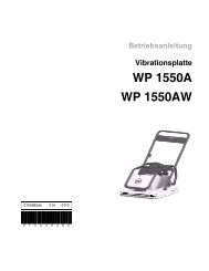
Ride-On Trowels<br />
<strong>CRT</strong> 36-23K-H<br />
<strong>CRT</strong> 48-25K-L<br />
<strong>CRT</strong> 48-25K-H<br />
<strong>CRT</strong> 36-24A<br />
<strong>CRT</strong> 48-31V<br />
<strong>CRT</strong> 48-31V-ES
<strong>CRT</strong> <strong>Repair</strong> Table of Contents<br />
1. Foreword 3<br />
2. Safety Information 6<br />
2.1 Operating Safety .................................................................................. 7<br />
2.2 Operator Safety while using Internal Combustion Engines .................. 8<br />
2.3 Service Safety ...................................................................................... 9<br />
3. Technical Data 10<br />
3.1 Kohler Engine ..................................................................................... 10<br />
3.2 Honda Engine ..................................................................................... 12<br />
3.3 Vanguard Engine (manual steer) ....................................................... 14<br />
3.4 Vanguard Engine (electric steer) ........................................................ 16<br />
4. General 18<br />
4.1 Features <strong>and</strong> <strong>Control</strong>s-Kohler or Honda Engine ................................ 18<br />
4.2 Features <strong>and</strong> <strong>Control</strong>s-Vanguard Engine (manual steer) ................... 20<br />
4.3 Features <strong>and</strong> <strong>Control</strong>s-Vanguard Engine (electric steer) ................... 22<br />
4.4 Transporting Trowels .......................................................................... 24<br />
4.5 Wheel Kit - 0150397 ........................................................................... 25<br />
4.6 Wheel Kit - 0154750 ........................................................................... 27<br />
4.7 Wheel Kit - 0160259 ........................................................................... 28<br />
5. Drive Line 30<br />
5.1 Belt Replacement ............................................................................... 30<br />
5.2 Belt Adjustment .................................................................................. 31<br />
5.3 Drive Line Exploded View .................................................................. 32<br />
5.4 Drive Line Teardown <strong>and</strong> Rebuild ...................................................... 33<br />
6. Gearbox <strong>and</strong> Spider 34<br />
6.1 Gearbox Basics .................................................................................. 34<br />
6.2 Gearbox Removal <strong>and</strong> Installation ..................................................... 35<br />
6.3 Spider Removal <strong>and</strong> Installation ......................................................... 37<br />
6.4 Lift Ring Disassembly <strong>and</strong> Assembly ................................................. 40<br />
6.5 Gearbox Disassembly ........................................................................ 42<br />
6.6 Gearbox Assembly ............................................................................. 44<br />
wc_br0158576en_001TOC.fm 1
Table of Contents <strong>CRT</strong> <strong>Repair</strong><br />
7. <strong>Steering</strong> <strong>and</strong> <strong>Pitch</strong> <strong>Control</strong> 45<br />
7.1 Removal <strong>and</strong> Installation of Manual <strong>Steering</strong> Yokes ...........................45<br />
7.2 Adjustment of Manual <strong>Steering</strong> ...........................................................49<br />
7.3 <strong>Pitch</strong> <strong>Control</strong> Removal <strong>and</strong> Installation ...............................................50<br />
7.4 Removal <strong>and</strong> Installation of Electric <strong>Steering</strong> Load Pins .....................52<br />
7.5 Removal <strong>and</strong> Installation of Electric <strong>Steering</strong> Actuators ......................54<br />
7.6 Removal <strong>and</strong> Installation of Electric <strong>Steering</strong> Joysticks ......................55<br />
7.7 Removal <strong>and</strong> Installation of Electric Steer <strong>Control</strong> Board ...................56<br />
7.8 Electric Steer Error Code Diagnostics <strong>and</strong> Troubleshooting ...............58<br />
7.9 Error Code 111 - Right Actuator Fault .................................................60<br />
7.10 Error Code 121 - Side Actuator Fault ..................................................62<br />
7.11 Error Code 131 - Left Actuator Fault ...................................................64<br />
7.12 Error Code 211 - Right Load Pin Open Circuit ....................................66<br />
7.13 Error Code 212 - Right Load Pin Short Circuit ....................................66<br />
7.14 Error Code 221 - Side Load Pin Open Circuit .....................................67<br />
7.15 Error Code 222 - Side Load Pin Short Circuit .....................................68<br />
7.16 Error Code 231 - Left Load Pin Open Circuit ......................................69<br />
7.17 Error Code 232 - Left Load Pin Short Circuit .......................................70<br />
7.18 Error Code 311 - Right Joystick Open Circuit .....................................71<br />
7.19 Error Code 312 - Right Joystick Short Circuit ......................................72<br />
7.20 Error Code 321 - Left Joystick Open Circuit ........................................73<br />
7.21 Error Code 322 - Left Joystick Short Circuit ........................................74<br />
7.22 Error Code 414 - <strong>Control</strong> Board Over Temperature ............................75<br />
7.23 Error Code 415 - Low Battery Voltage ................................................75<br />
8. Engine 76<br />
8.1 Engine Removal <strong>and</strong> Installation-Kohler or Honda Engine .................76<br />
8.2 Engine Removal <strong>and</strong> Installation-Vanguard Engine ............................79<br />
8.3 Wiring Schematic-Kohler .....................................................................82<br />
8.4 Wiring Schematic-Honda .....................................................................86<br />
8.5 Wiring Schematic-Vanguard Engine (manual steer) ...........................90<br />
8.6 Wiring Schematic-Vanguard Engine (electric steer) ............................92<br />
wc_br0158576en_001TOC.fm 2
WARNING<br />
1. Foreword<br />
CALIFORNIA<br />
Proposition 65 Warning:<br />
Engine exhaust, some of its constituents, <strong>and</strong> certain vehicle<br />
components contain or emit chemicals known to the State of California<br />
to cause cancer <strong>and</strong> birth defects or other reproductive harm.<br />
This manual provides information <strong>and</strong> procedures to safely operate<br />
<strong>and</strong> maintain this <strong>Wacker</strong> model. For your own safety <strong>and</strong> protection<br />
from injury, carefully read, underst<strong>and</strong> <strong>and</strong> observe the safety<br />
instructions described in this manual.<br />
Keep this manual or a copy of it with the machine. If you lose this<br />
manual or need an additional copy, please contact <strong>Wacker</strong><br />
Corporation. This machine is built with user safety in mind; however,<br />
it can present hazards if improperly operated <strong>and</strong> serviced. Follow<br />
operating instructions carefully! If you have questions about operating<br />
or servicing this equipment, please contact <strong>Wacker</strong> Corporation.<br />
The information contained in this manual was based on machines in<br />
production at the time of publication. <strong>Wacker</strong> Corporation reserves the<br />
right to change any portion of this information without notice.<br />
All rights, especially copying <strong>and</strong> distribution rights, are reserved.<br />
Copyright 2004 by <strong>Wacker</strong> Corporation.<br />
No part of this publication may be reproduced in any form or by any<br />
means, electronic or mechanical, including photocopying, without<br />
express written permission from <strong>Wacker</strong> Corporation.<br />
Any type of reproduction or distribution not authorized by <strong>Wacker</strong><br />
Corporation represents an infringement of valid copyrights <strong>and</strong> will be<br />
prosecuted. We expressly reserve the right to make technical<br />
modifications, even without due notice, which aim at improving our<br />
machines or their safety st<strong>and</strong>ards.<br />
wc_tx000093gb.fm 3
Notes:<br />
wc_tx000093gb.fm 4
This manual covers machines with Item Number:<br />
0009083, 0009084, 0009085, 0009086, 0009216<br />
0009232, 0009481, 0009482, 0009483<br />
Operating / Parts Information<br />
You must be familiar with the operation of this machine before you<br />
attempt to troubleshoot or make any repairs to it. Basic operating <strong>and</strong><br />
maintenance procedures are described in the operator’s manual<br />
supplied with the machine. Keep a copy of it with the machine at all<br />
times. Use the separate parts manual supplied with the machine to<br />
order replacement parts. If either of the manuals becomes lost, please<br />
contact <strong>Wacker</strong> Corporation to order a replacement.<br />
Damage caused by misuse or neglect of the unit should be brought to<br />
the attention of the operator, to prevent similar occurrences from<br />
happening in the future.<br />
This manual provides information <strong>and</strong> procedures to safely repair <strong>and</strong><br />
maintain the above <strong>Wacker</strong> model(s). For your own safety <strong>and</strong><br />
protection from injury, carefully read, underst<strong>and</strong>, <strong>and</strong> observe all<br />
instructions described in this manual. THE INFORMATION<br />
CONTAINED IN THIS MANUAL IS BASED ON MACHINES<br />
MANUFACTURED UP TO THE TIME OF PUBLICATION. WACKER<br />
CORPORATION RESERVES THE RIGHT TO CHANGE ANY<br />
PORTION OF THIS INFORMATION WITHOUT NOTICE.<br />
wc_tx000093gb.fm 5
Safety Information <strong>CRT</strong> <strong>Repair</strong><br />
2. Safety Information<br />
DANGER<br />
WARNING<br />
CAUTION<br />
This manual contains DANGER, WARNING, CAUTION, <strong>and</strong> NOTE<br />
callouts which must be followed to reduce the possibility of personal<br />
injury, damage to the equipment, or improper service.<br />
This is the safety alert symbol. It is used to alert you to potential<br />
personal injury hazards. Obey all safety messages that follow this<br />
symbol to avoid possible injury or death.<br />
DANGER indicates an imminently hazardous situation which, if not<br />
avoided, will result in death or serious injury.<br />
WARNING indicates a potentially hazardous situation which, if not<br />
avoided, could result in death or serious injury.<br />
CAUTION indicates a potentially hazardous situation which, if not<br />
avoided, may result in minor or moderate injury.<br />
CAUTION: Used without the safety alert symbol, CAUTION indicates<br />
a potentially hazardous situation which, if not avoided, may result in<br />
property damage.<br />
Note: Contains additional information important to a procedure.<br />
wc_tx000093gb.fm 6
<strong>CRT</strong> <strong>Repair</strong> Safety Information<br />
2.1 Operating Safety<br />
Familiarity <strong>and</strong> proper training are required for the safe operation of<br />
equipment! Equipment operated improperly or by untrained personnel<br />
can be dangerous! Read the operating instructions contained in both<br />
this manual <strong>and</strong> the engine manual <strong>and</strong> familiarize yourself with the<br />
location <strong>and</strong> proper use of all controls. Inexperienced operators should<br />
receive instruction from someone familiar with the equipment before<br />
being allowed to operate the machine.<br />
2.1.1 NEVER operate this machine in applications for which it is not<br />
intended.<br />
2.1.2 NEVER allow anyone to operate this equipment without proper<br />
training. People operating this equipment must be familiar with the<br />
risks <strong>and</strong> hazards associated with it.<br />
2.1.3 NEVER touch the engine or muffler while the engine is on or<br />
immediately after it has been turned off. These areas get hot <strong>and</strong> may<br />
cause burns.<br />
2.1.4 NEVER use accessories or attachments that are not recommended by<br />
<strong>Wacker</strong>. Damage to equipment <strong>and</strong> injury to the user may result.<br />
2.1.5 NEVER operate the machine with the beltguard missing. Exposed<br />
drive belt <strong>and</strong> pulleys create potentially dangerous hazards that can<br />
cause serious injuries.<br />
2.1.6 NEVER leave machine running unattended.<br />
2.1.7 DO NOT run machine indoors or in an enclosed area such as a deep<br />
trench unless adequate ventilation, through such items as exhaust<br />
fans or hoses, is provided. Exhaust gas from the engine contains<br />
poisonous carbon monoxide gas; exposure to carbon monoxide can<br />
cause loss of consciousness <strong>and</strong> may lead to death.<br />
2.1.8 ALWAYS remain aware of moving parts <strong>and</strong> keep h<strong>and</strong>s, feet, <strong>and</strong><br />
loose clothing away from moving parts of equipment.<br />
2.1.9 ALWAYS keep h<strong>and</strong>s, feet, <strong>and</strong> loose clothing away from moving parts<br />
of the machine.<br />
2.1.10 ALWAYS wear protective clothing appropriate to the job site when<br />
operating equipment.<br />
2.1.11 ALWAYS read, underst<strong>and</strong>, <strong>and</strong> follow procedures in Operator's<br />
Manual before attempting to operate equipment.<br />
2.1.12 ALWAYS be sure operator is familiar with proper safety precautions<br />
<strong>and</strong> operation techniques before using machine.<br />
2.1.13 ALWAYS close fuel valve on engines equipped with one when<br />
machine is not being operated.<br />
2.1.14 ALWAYS store equipment properly when it is not being used.<br />
Equipment should be stored in a clean, dry location out of the reach of<br />
children.<br />
2.1.15 ALWAYS operate machine with all safety devices <strong>and</strong> guards in place<br />
<strong>and</strong> in working order.<br />
WARNING<br />
wc_tx000093gb.fm 7
Safety Information <strong>CRT</strong> <strong>Repair</strong><br />
2.2 Operator Safety while using Internal Combustion Engines<br />
Internal combustion engines present special hazards during operation<br />
<strong>and</strong> fueling! Read <strong>and</strong> follow warning instructions in engine owner's<br />
manual <strong>and</strong> safety guidelines below. Failure to follow warnings <strong>and</strong><br />
DANGER<br />
safety guidelines could result in severe injury or death.<br />
2.2.1 DO NOT run machine indoors or in an enclosed area such as a deep<br />
trench unless adequate ventilation, through such items as exhaust<br />
fans or hoses, is provided. Exhaust gas from the engine contains<br />
poisonous carbon monoxide gas; exposure to carbon monoxide can<br />
cause loss of consciousness <strong>and</strong> may lead to death.<br />
2.2.2 DO NOT smoke while operating machine.<br />
2.2.3 DO NOT smoke when refueling engine.<br />
2.2.4 DO NOT refuel hot or running engine.<br />
2.2.5 DO NOT refuel engine near open flame.<br />
2.2.6 DO NOT spill fuel when refueling engine.<br />
2.2.7 DO NOT run engine near open flames.<br />
2.2.8 ALWAYS refill fuel tank in well-ventilated area.<br />
2.2.9 ALWAYS replace fuel tank cap after refueling.<br />
2.2.10 ALWAYS keep area around muffler free of debris such as leaves,<br />
paper, cartons, etc. A hot muffler could ignite them, starting a fire.<br />
wc_tx000093gb.fm 8
<strong>CRT</strong> <strong>Repair</strong> Safety Information<br />
2.3 Service Safety<br />
WARNING<br />
Poorly maintained equipment can become a safety hazard! In order<br />
for the equipment to operate safely <strong>and</strong> properly over a long period of<br />
time, periodic maintenance <strong>and</strong> occasional repairs are necessary.<br />
2.3.1 DO NOT attempt to clean or service machine while it is running.<br />
Rotating parts can cause severe injury.<br />
2.3.2 DO NOT crank a flooded engine with the spark plug removed on<br />
gasoline-powered engines. Fuel trapped in the cylinder will squirt out<br />
the spark plug opening.<br />
2.3.3 DO NOT test for spark on gasoline-powered engines, if engine is<br />
flooded or the smell of gasoline is present. A stray spark could ignite<br />
fumes.<br />
2.3.4 DO NOT use gasoline or other types of fuels or flammable solvents to<br />
clean parts, especially in enclosed areas. Fumes from fuels <strong>and</strong><br />
solvents can become explosive.<br />
2.3.5 ALWAYS h<strong>and</strong>le blades carefully. The blades can develop sharp<br />
edges which can cause serious cuts.<br />
2.3.6 ALWAYS keep area around muffler free of debris such as leaves,<br />
paper, cartons, etc. A hot muffler could ignite them, starting a fire.<br />
2.3.7 ALWAYS replace worn or damaged components with spare parts<br />
designed <strong>and</strong> recommended by <strong>Wacker</strong>.<br />
2.3.8 ALWAYS disconnect spark plug on machines equipped with gasoline<br />
engines, before servicing, to avoid accidental start-up.<br />
2.3.9 ALWAYS switch off the power supply at the battery disconnect before<br />
adjusting or maintaining the electrical equipment.<br />
2.3.10 ALWAYS keep machine clean <strong>and</strong> labels legible. Replace all missing<br />
<strong>and</strong> hard-to-read labels. Labels provide important operating<br />
instructions <strong>and</strong> warn of dangers <strong>and</strong> hazards.<br />
wc_tx000093gb.fm 9
Technical Data <strong>CRT</strong> <strong>Repair</strong><br />
3. Technical Data<br />
3.1 Kohler Engine<br />
Part No. <strong>CRT</strong> 48<br />
0009084, 0009085<br />
Engine<br />
wc_tx000093gb.fm 10<br />
<strong>CRT</strong> 36<br />
0009083<br />
Engine Make Kohler Kohler<br />
Engine Model CH25 CH23<br />
Rated Power kW (Hp) 18.6 (25) 17.2 (23)<br />
Displacement cm³ (in³) 725 (44) 674 (41)<br />
Spark Plug Champion RC12YC<br />
Electrode Gap mm (in.) 0.76 (0.030)<br />
Engine Speed - full load rpm 4000<br />
Engine Speed - idle rpm 1200<br />
Battery V / size 12 / 340CCA<br />
Fuel type Regular unleaded gasoline<br />
Fuel Tank Capacity l (gal.) 24.6 (6.5)<br />
Fuel Consumption l (qt.)/hr. 7.6 (8.0)<br />
Running Time hrs. 3.3<br />
Clutch type variable speed<br />
Low Oil Shutdown yes<br />
Engine Oil Capacity l (qt.) 2 (2.1)<br />
Engine Lubrication oil grade SAE 10W30 API CF-4, CF, SJ
<strong>CRT</strong> <strong>Repair</strong> Technical Data<br />
Part No. <strong>CRT</strong> 48<br />
0009084, 0009085<br />
Trowel<br />
wc_tx000093gb.fm 11<br />
<strong>CRT</strong> 36<br />
0009083<br />
Operating Weight kg (lbs.) 430 (945) 383 (845)<br />
Dimensions (L x W x H) mm<br />
(in.)<br />
2665 x 1395 x 1330<br />
(105 x 55 x 52)<br />
Rotor Speed (range) rpm <strong>CRT</strong>48-25K-L: 35-120<br />
<strong>CRT</strong>48-25K-H: 25-150<br />
Blade <strong>Pitch</strong> (range) degrees 0-25<br />
2170 x 1170 x 1330<br />
(86 x 46 x 52)<br />
35-150<br />
Gearbox heavy duty, fan cooled heavy duty<br />
Gearbox Lubrication* l (oz.) 1.83 (62) each<br />
Driveshaft type splined universal joint<br />
*Use only Mobil Oil SHC634 synthetic oil.<br />
Troweling Width<br />
with pans<br />
(non-overlapping)<br />
without pans<br />
(overlapping)<br />
Troweling Area<br />
with pans<br />
(non-overlapping)<br />
without pans<br />
(overlapping)<br />
Operation<br />
mm (in.) 2464 (97)<br />
2515 (99)<br />
m 2 (ft 2 ) 3 (32)<br />
3.2 (34)<br />
1945 (77)<br />
2020 (80)<br />
1.8 (19)<br />
2 (22)
Technical Data <strong>CRT</strong> <strong>Repair</strong><br />
3.2 Honda Engine<br />
Part No. <strong>CRT</strong> 36A<br />
0009232<br />
Engine<br />
Engine Make Honda<br />
Engine Model GX670<br />
Rated Power kW (Hp) 17.9 (24)<br />
Displacement cm³ (in³) 670 (41)<br />
Spark Plug NGK ZGR5A<br />
DENSO J16CR-U<br />
Electrode Gap mm (in.) 0.70 (0.028)<br />
Engine Speed - full load rpm 3850<br />
Engine Speed - idle rpm 1400<br />
Battery V / size 12 / 340CCA<br />
wc_tx000093gb.fm 12<br />
<strong>CRT</strong> 36A-E<br />
0009483<br />
Fuel type Regular unleaded gasoline<br />
Fuel Tank Capacity l (gal.) 24.6 (6.5)<br />
Fuel Consumption l (qt.)/hr. 9 (9.5)<br />
Running Time hrs. 2.7<br />
Clutch type variable speed<br />
Low Oil Shutdown yes<br />
Engine Oil Capacity l (qt.) 1.9 (2.0)<br />
Engine Lubrication oil grade SAE 10W30 API CF-4, CF, SJ
<strong>CRT</strong> <strong>Repair</strong> Technical Data<br />
Part No. <strong>CRT</strong> 36A<br />
0009232<br />
Trowel<br />
Operating Weight kg (lbs.) 410 (905)<br />
Dimensions (L x W x H)<br />
mm<br />
(in.)<br />
wc_tx000093gb.fm 13<br />
2170 x 1170 x 1330<br />
(86 x 46 x 52)<br />
Rotor Speed (range) rpm 35-150<br />
Blade <strong>Pitch</strong> (range) degrees 0-25<br />
Gearbox heavy duty<br />
Gearbox Lubrication* l (oz.) 1.83 (62) each<br />
<strong>CRT</strong> 36A-E<br />
0009483<br />
2032 x 1170 x 1320<br />
(80 x 46 x 52)<br />
Driveshaft type splined universal joint<br />
*Use only Mobil Oil SHC634 synthetic oil.<br />
Troweling Width<br />
with pans<br />
(non-overlapping)<br />
without pans<br />
(overlapping)<br />
without pans<br />
(non-overlapping)<br />
Troweling Area<br />
with pans<br />
(non-overlapping)<br />
without pans<br />
(overlapping)<br />
without pans<br />
(non-overlapping)<br />
Operation<br />
mm (in.) 1975 (78)<br />
2020 (80)<br />
--<br />
m 2 (ft 2 ) 1.8 (19)<br />
2.0 (22)<br />
--<br />
1975 (78)<br />
--<br />
1905 (75)<br />
1.8 (19)<br />
--<br />
1.6 (18)
Technical Data <strong>CRT</strong> <strong>Repair</strong><br />
3.3 Vanguard Engine (manual steer)<br />
Part No. <strong>CRT</strong> 48-31V<br />
0009086<br />
Engine<br />
Engine Make Vanguard<br />
Engine Model DM950G<br />
Rated Power kW (Hp) 23.1 (31)<br />
Displacement cm³ (in³) 950 (58)<br />
wc_tx000093gb.fm 14<br />
<strong>CRT</strong> 48-31V-E<br />
0009481<br />
Spark Plug type Champion RC12YC<br />
Electrode Gap mm (in.) 0.76 (0.030)<br />
Engine Speed - full load rpm 4000<br />
Engine Speed - idle rpm 1500<br />
Battery V / size 12 / BCI G24<br />
Fuel type Regular unleaded gasoline<br />
Fuel Tank Capacity l (gal.) 24.6 (6.5)<br />
Fuel Consumption l (gal.)/hr. 10 (2.6)<br />
Running Time hrs. 2.5<br />
Clutch type variable speed<br />
Low Oil Shutdown yes<br />
Engine Oil Capacity l (qt.) 3.3 (3.5)<br />
Engine Lubrication oil grade SAE 10W30 SH, SJ
<strong>CRT</strong> <strong>Repair</strong> Technical Data<br />
Part No. <strong>CRT</strong> 48-31V<br />
0009086<br />
Trowel<br />
Operating Weight kg (lbs.) 562 (1240)<br />
Dimensions (L x W x H)<br />
mm<br />
(in.)<br />
wc_tx000093gb.fm 15<br />
2665 x 1395 x 1330<br />
(105 x 55 x 52)<br />
Rotor Speed (range) rpm 25-150<br />
Blade <strong>Pitch</strong> (range) degrees 0-25<br />
<strong>CRT</strong> 48-31V-E<br />
0009481<br />
2530 x 1397 x 1328<br />
(100 x 55 x 52)<br />
Gearbox heavy duty, fan cooled<br />
Gearbox Lubrication* l (oz.) 1.83 (62) each<br />
Driveshaft type splined universal joint<br />
*Use only Mobil Oil SHC634 synthetic oil.<br />
Troweling Width<br />
with pans<br />
(non-overlapping)<br />
without pans<br />
(overlapping)<br />
without pans<br />
(non-overlapping)<br />
Troweling Area<br />
with pans<br />
(non-overlapping)<br />
without pans<br />
(overlapping)<br />
without pans<br />
(non-overlapping)<br />
Operation<br />
mm (in.) 2465 (97)<br />
2515 (99)<br />
--<br />
m 2 (ft 2 ) 3 (32)<br />
3.2 (34)<br />
--<br />
2465 (97)<br />
--<br />
2413 (95)<br />
3 (32)<br />
--<br />
2.8 (30)
Technical Data <strong>CRT</strong> <strong>Repair</strong><br />
3.4 Vanguard Engine (electric steer)<br />
Part No. <strong>CRT</strong> 48-31V-ES<br />
0009216<br />
Engine<br />
Engine Make Vanguard<br />
Engine Model DM950G<br />
Rated Power kW (Hp) 23.1 (31)<br />
Displacement cm³ (in³) 950 (58)<br />
wc_tx000093gb.fm 16<br />
<strong>CRT</strong> 48-31V-ES-E<br />
0009482<br />
Spark Plug type Champion RC12YC<br />
Electrode Gap mm (in.) 0.76 (0.030)<br />
Engine Speed - full load rpm 4000<br />
Engine Speed - idle rpm 1500<br />
Battery V / size 12 / Group 24<br />
Fuel type Regular unleaded gasoline<br />
Fuel Tank Capacity l (gal.) 24.6 (6.5)<br />
Fuel Consumption l (gal.)/hr. 10 (2.6)<br />
Running Time hrs. 2.5<br />
Clutch type variable speed<br />
Low Oil Shutdown yes<br />
Engine Oil Capacity l (qt.) 3.3 (3.5)<br />
Engine Lubrication oil grade SAE 10W30 SH, SJ<br />
Driveshaft type splined universal joint
<strong>CRT</strong> <strong>Repair</strong> Technical Data<br />
Part No. <strong>CRT</strong> 48-31V-ES<br />
0009216<br />
Trowel<br />
Operating Weight kg (lbs.) 528 (1165)<br />
Dimensions (L x W x H)<br />
mm<br />
(in.)<br />
wc_tx000093gb.fm 17<br />
2665 x 1395 x 1330<br />
(105 x 55 x 52)<br />
Rotor Speed (range) rpm 25-150<br />
Blade <strong>Pitch</strong> (range) degrees 0-25<br />
<strong>CRT</strong> 48-31V-ES-E<br />
0009482<br />
2530 x 1397 x 1328<br />
(100 x 55 x 52)<br />
Gearbox heavy duty, fan cooled<br />
Gearbox Lubrication* l (oz.) 1.83 (62) each<br />
*Use only Mobil Oil SHC634 synthetic oil.<br />
Troweling Width<br />
with pans<br />
(non-overlapping)<br />
without pans<br />
(overlapping)<br />
without pans<br />
(non-overlapping)<br />
Troweling Area<br />
with pans<br />
(non-overlapping)<br />
without pans<br />
(overlapping)<br />
without pans<br />
(non-overlapping)<br />
Operation<br />
mm (in.) 2465 (97)<br />
2515 (99)<br />
--<br />
m 2 (ft 2 ) 3 (32)<br />
3.2 (34)<br />
--<br />
2465 (97)<br />
--<br />
2413 (95)<br />
3 (32)<br />
--<br />
2.8 (30)
General <strong>CRT</strong> <strong>Repair</strong><br />
4. General<br />
4.1 Features <strong>and</strong> <strong>Control</strong>s-Kohler or Honda Engine<br />
See Graphic: wc_gr000142<br />
<strong>Control</strong> locations <strong>and</strong> functions:<br />
a right pitch control m work light (one each side)<br />
b water tank n foot pedal (throttle control)<br />
c control arms o engine choke control<br />
d operator’s seat with “operator presence”<br />
switch<br />
q work light switch<br />
e left pitch control r DC accessory outlet<br />
f rear work light (one each side) s engine keyswitch<br />
g control panel (one each side) t hour meter<br />
h fuel tank u water spray control<br />
The Riding Trowel features a seat with an integrated “operator<br />
presence” system, which works in conjunction with a throttle mounted<br />
switch. This system allows the engine to remain running (idling) with<br />
no operator seated in the seat, as long as the throttle is not depressed.<br />
This system meets all safety requirements <strong>and</strong> eliminates the need for<br />
a foot-operated “kill switch”.<br />
To familiarize a new operator with the Riding Trowel the following<br />
steps should be taken:<br />
4.1.1 With the operator in the seat, show him or her the functions of the<br />
control arms (c) <strong>and</strong> how to start the machine.<br />
4.1.2 Have the operator practice steering the trowel. A hard concrete slab<br />
slightly wetted with water is an ideal place for an operator to practice<br />
with the machine. For this practice, pitch the blades up approximately<br />
¼" on the leading edge. Start by making the machine hover in one<br />
spot, <strong>and</strong> then practice driving the machine in a straight line <strong>and</strong><br />
making 180° turns. The best control is achieved at full rpm.<br />
wc_tx000093gb.fm 18
<strong>CRT</strong> <strong>Repair</strong> General<br />
Kohler or Honda Engine<br />
wc_tx000093gb.fm 19
General <strong>CRT</strong> <strong>Repair</strong><br />
4.2 Features <strong>and</strong> <strong>Control</strong>s-Vanguard Engine (manual steer)<br />
See Graphic: wc_gr000250<br />
<strong>Control</strong> locations <strong>and</strong> functions:<br />
a right pitch control o engine choke control<br />
b water tank q work light switch<br />
c control arms r DC accessory outlet<br />
d operator’s seat with “operator presence”<br />
switch<br />
s engine keyswitch<br />
e left pitch control t hour meter<br />
f rear work light (one each side) u water spray control<br />
g control panel v oil pressure indicator light<br />
h fuel tank w alternator charging indicator light<br />
m work light (one each side) x coolant temperature indicator light<br />
n foot pedal (throttle control)<br />
The Riding Trowel features a seat with an integrated “operator<br />
presence” system, which works in conjunction with a throttle mounted<br />
switch. This system allows the engine to remain running (idling) with<br />
no operator seated in the seat, as long as the throttle is not depressed.<br />
This system meets all safety requirements <strong>and</strong> eliminates the need for<br />
a foot-operated “kill switch”.<br />
To familiarize a new operator with the Riding Trowel the following<br />
steps should be taken:<br />
4.2.1 With the operator in the seat, show him or her the functions of the<br />
control arms (c) <strong>and</strong> how to start the machine.<br />
4.2.2 Have the operator practice steering the trowel. A hard concrete slab<br />
slightly wetted with water is an ideal place for an operator to practice<br />
with the machine. For this practice, pitch the blades up approximately<br />
¼" on the leading edge. Start by making the machine hover in one<br />
spot, <strong>and</strong> then practice driving the machine in a straight line <strong>and</strong><br />
making 180° turns. The best control is achieved at full rpm.<br />
wc_tx000093gb.fm 20
<strong>CRT</strong> <strong>Repair</strong> General<br />
Vanguard Engine (manual steer)<br />
wc_tx000093gb.fm 21
General <strong>CRT</strong> <strong>Repair</strong><br />
4.3 Features <strong>and</strong> <strong>Control</strong>s-Vanguard Engine (electric steer)<br />
See Graphic: wc_gr000696<br />
Ref. Description Ref. Description<br />
a right pitch control q work light switch<br />
b water tank r DC accessory outlet<br />
c joystick s engine keyswitch<br />
d operator’s seat with “operator<br />
presence” switch<br />
t hour meter<br />
e left pitch control u water spray control<br />
f rear work light (one each side) v oil pressure indicator light<br />
g control panel w alternator charging indicator light<br />
h fuel tank x coolant temperature indicator light<br />
m work light (one each side) y status OK indicator light (green)<br />
n foot pedal (throttle control) z status error indicator light (red)<br />
o engine choke control<br />
The Riding Trowel features a seat with an integrated “operator<br />
presence” system, which works in conjunction with a throttle mounted<br />
switch. This system allows the engine to remain running (idling) with<br />
no operator seated in the seat, as long as the throttle is not depressed.<br />
This system meets all safety requirements <strong>and</strong> eliminates the need for<br />
a foot-operated “kill switch”.<br />
To familiarize a new operator with the Riding Trowel the following<br />
steps should be taken:<br />
4.3.1 With the operator in the seat, show him or her the functions of the<br />
joysticks (c) <strong>and</strong> how to start the machine.<br />
4.3.2 Have the operator practice steering the trowel. A hard concrete slab<br />
slightly wetted with water is an ideal place for an operator to practice<br />
with the machine. For this practice, pitch the blades up approximately<br />
¼" on the leading edge. Start by making the machine hover in one<br />
spot, <strong>and</strong> then practice driving the machine in a straight line <strong>and</strong><br />
making 180° turns. The best control is achieved at full rpm.<br />
wc_tx000093gb.fm 22
<strong>CRT</strong> <strong>Repair</strong> General<br />
Vanguard Engine (electric steer)<br />
wc_tx000093gb.fm 23
General <strong>CRT</strong> <strong>Repair</strong><br />
4.4 Transporting Trowels<br />
See Graphic: wc_gr000144<br />
To lift the trowel with a fork lift:<br />
Fork lift pockets (a) are provided on both the front <strong>and</strong> back of the<br />
machine. Carefully run the fork lift’s forks into either set of fork lift<br />
pockets.<br />
To hoist the trowel:<br />
Attach a sling or chains through the lifting bars (b) on each side of the<br />
seat pedestal.<br />
CAUTION: Make sure the lifting device has enough weight-bearing<br />
capacity to lift machine safely. Refer to Section Technical Data.<br />
DO NOT lift the trowel by the guard rings or any part of the trowel other<br />
than the lifting fixture, as the component may fail, causing the trowel to<br />
fall, possibly injuring byst<strong>and</strong>ers.<br />
WARNING<br />
wc_tx000093gb.fm 24
<strong>CRT</strong> <strong>Repair</strong> General<br />
4.5 Wheel Kit - 0150397<br />
See Graphic: wc_gr002302<br />
Assembling Wheel Kit Components:<br />
4.5.1 Bolt the wheels (b) to the tube assemblies (a) using screws (c),<br />
washers (d), <strong>and</strong> nuts (e) provided. The rigid wheels should be<br />
attached perpendicular to the tube assemblies. The lock pin on the<br />
swivel casters should be perpendicular to the tube assemblies when<br />
attached.<br />
4.5.2 Insert one h<strong>and</strong>le (g) into the other h<strong>and</strong>le (g).<br />
4.5.3 Align the holes.<br />
4.5.4 Insert the screw (h) <strong>and</strong> tighten the nut (j).<br />
Raising the <strong>CRT</strong>:<br />
4.5.5 Insert the wheel assemblies into the <strong>CRT</strong> fork lift pockets. Make sure<br />
the two swivel casters are toward the same end of the machine.<br />
4.5.6 Insert the retaining pins (f) into the wheel assemblies.<br />
CAUTION: Be sure the retaining pins (f) are in place before continuing.<br />
4.5.7 Lock the swivel casters so that the wheels are in the same direction as<br />
the rigid casters.<br />
4.5.8 Pivot each wheel bracket towards the closer end of the machine. If<br />
necessary, unlock the brackets by pulling on the spring pin <strong>and</strong><br />
pivoting the wheel. The wheels should lock approximately parallel to<br />
the ground.<br />
4.5.9 Insert the h<strong>and</strong>le into the tube on one of the wheels.<br />
4.5.10 Unlock the bracket by pulling on the spring pin <strong>and</strong> use the h<strong>and</strong>le to<br />
pivot the bracket <strong>and</strong> raise the machine until the spring pin locks with<br />
the wheel in an upright position.<br />
4.5.11 Repeat last two steps on the other three wheels. It is easiest to do both<br />
wheels on the same end of the machine first.<br />
CAUTION: If there is weight on a wheel, it will pivot the wheel <strong>and</strong><br />
h<strong>and</strong>le, therefore firmly grip the h<strong>and</strong>le.<br />
4.5.12 Unlock the swivel casters.<br />
4.5.13 Do not push on pitch posts during transport. Lift up on <strong>CRT</strong> to assist in<br />
turning.<br />
Lowering the <strong>CRT</strong>:<br />
4.5.14 Lock the swivel casters so that the wheels are in the same direction as<br />
the rigid casters.<br />
4.5.15 Insert the h<strong>and</strong>le into the tube on one of the wheel brackets.<br />
4.5.16 Unlock the wheel by pulling on the spring pin <strong>and</strong> pivoting the wheel.<br />
wc_tx000093gb.fm 25
General <strong>CRT</strong> <strong>Repair</strong><br />
4.5.17<br />
CAUTION: The weight of the trowel will pivot the wheel <strong>and</strong> h<strong>and</strong>le,<br />
therefore firmly grip the h<strong>and</strong>le.<br />
Pivot the wheel until it locks at 90 degrees.<br />
4.5.18 Remove the h<strong>and</strong>le.<br />
4.5.19 Repeat last four steps for the other wheels.<br />
4.5.20 Remove the retaining pins from the wheel assemblies.<br />
4.5.21 Remove the wheel assemblies from the machine.<br />
wc_tx000093gb.fm 26
<strong>CRT</strong> <strong>Repair</strong> General<br />
4.6 Wheel Kit - 0154750<br />
See Graphic: wc_gr002301<br />
Assembling Wheel Kit Components:<br />
4.6.1 Bolt the wheels (a) to the brackets (b) using screws (c), washers (d),<br />
<strong>and</strong> nuts (e) provided. The rigid wheels should be attached<br />
perpendicular to the brackets.<br />
4.6.2 Attach pins (f) to lanyards (g) <strong>and</strong> jacks (l).<br />
4.6.3 Bolt lanyards to the brackets using screws (h), washers (j), <strong>and</strong> nuts<br />
(k) provided.<br />
Raising the <strong>CRT</strong>:<br />
4.6.4 Insert a screw jack into the square socket in the front of the <strong>CRT</strong>. Insert<br />
the pin into the bottom of the mount.<br />
CAUTION: Be sure pin is in place before continuing.<br />
4.6.5 Insert a jack into the square socket on the back of the <strong>CRT</strong>. Insert the<br />
pin into the top of the mount.<br />
CAUTION: Be sure pin is in place before continuing.<br />
4.6.6 Crank the jack h<strong>and</strong>les to raise the <strong>CRT</strong>.<br />
4.6.7 Insert the wheel assemblies into the front <strong>CRT</strong> fork pockets. Use one<br />
swivel <strong>and</strong> one rigid wheel. Insert the pins into the outer holes on the<br />
brackets.<br />
CAUTION: Be sure pins are in place before continuing.<br />
4.6.8 Insert the wheel assemblies into the rear <strong>CRT</strong> fork pockets. Place the<br />
swivel caster toward the same end of the machine as in the front. Insert<br />
the pins into the inner holes on the brackets.<br />
CAUTION: Be sure pins are in place before continuing.<br />
4.6.9 Lower the jacks so the weight rests on the wheels.<br />
4.6.10 Unpin <strong>and</strong> remove the jacks.<br />
Lowering the <strong>CRT</strong>:<br />
4.6.11 Insert a screw jack into the square socket in the front of the <strong>CRT</strong>. Insert<br />
the pin into the bottom of the mount.<br />
CAUTION: Be sure pin is in place before continuing.<br />
4.6.12 Insert a jack into the square socket on the back of the <strong>CRT</strong>. Insert the<br />
pin into the top of the mount.<br />
CAUTION: Be sure pin is in place before continuing.<br />
4.6.13 Crank the jack h<strong>and</strong>les to raise the <strong>CRT</strong>.<br />
4.6.14 Unpin <strong>and</strong> remove the wheel assemblies from the <strong>CRT</strong>.<br />
4.6.15 Lower the jacks so the weight rests on ground.<br />
4.6.16 Unpin <strong>and</strong> remove the jacks.<br />
CAUTION: Do not operate trowel with jacks installed.<br />
wc_tx000093gb.fm 27
General <strong>CRT</strong> <strong>Repair</strong><br />
4.7 Wheel Kit - 0160259<br />
See Graphic: wc_gr002300<br />
Assembling Wheel Kit Components:<br />
4.7.1 Attach large wheels (a) to the axles (b) using washers (c), <strong>and</strong> small<br />
cotter pins (d) provided. Store wheels on h<strong>and</strong>le using large cotter pins<br />
(h).<br />
4.7.2 Attach small wheels (e) to h<strong>and</strong>le using washers (f), <strong>and</strong> small cotter<br />
pins (g) provided.<br />
Raising the <strong>CRT</strong>:<br />
4.7.3 Remove safety snap pin (j) <strong>and</strong> lengthen h<strong>and</strong>le. Insert safety snap pin<br />
(j).<br />
4.7.4 Remove large wheels from h<strong>and</strong>le.<br />
4.7.5 Using the h<strong>and</strong>le, lift one end of the trowel (1) <strong>and</strong> insert the large<br />
wheels (2) as shown.<br />
4.7.6 Move h<strong>and</strong>le to other end of trowel (3), lift <strong>and</strong> transport.<br />
Lowering the <strong>CRT</strong>:<br />
4.7.7 Lift the end of the trowel with wheels.<br />
4.7.8 Remove wheels <strong>and</strong> lower trowel. Store wheels on h<strong>and</strong>le using large<br />
cotter pins (h).<br />
wc_tx000093gb.fm 28
<strong>CRT</strong> <strong>Repair</strong> General<br />
wc_tx000093gb.fm 29
Drive Line <strong>CRT</strong> <strong>Repair</strong><br />
5. Drive Line<br />
5.1 Belt Replacement<br />
See Graphic: wc_gr 000152<br />
To replace the drive belt:<br />
5.1.1 Place the trowel on a flat, level surface with the blades pitched flat.<br />
5.1.2 Disconnect battery.<br />
5.1.3 Remove the beltguard.<br />
Honda / Kohler:<br />
Remove bolts holding guard in place.<br />
Vanguard:<br />
Remove two bolts holding base of air cleaner to beltguard. Remove<br />
two bolts holding beltguard to engine.<br />
5.1.4 Remove 2 bolts (d), washers (e) <strong>and</strong> nuts (f) from each bearing flange.<br />
5.1.5 Remove the 4 bolts (b) holding each inside universal joint to the shaft<br />
fitting. Remove universal joints <strong>and</strong> shims (if included) from ends of<br />
drive shaft.<br />
5.1.6 Lift the drive pulley up far enough to slide belt past.<br />
5.1.7 Remove the old belt <strong>and</strong> install a new one.<br />
5.1.8 Reverse the procedure for assembly. Align the bearings <strong>and</strong> shaft as<br />
straight as possible. Adjust pulley offset <strong>and</strong> center distance to values<br />
as shown.<br />
5.1.9 Torque the bearing bolts (d) to 99±10 ft.lbs. Torque the universal joint<br />
bolts (b) to 10±1 ft.lbs.<br />
wc_tx000094gb.fm 30
<strong>CRT</strong> <strong>Repair</strong> Drive Line<br />
5.2 Belt Adjustment<br />
5.2.1 Remove beltguard.<br />
5.2.2 To adjust the tension, loosen the 4 mounting bolts <strong>and</strong> slide engine<br />
forward to loosen; back to tighten.<br />
5.2.3 Maximum belt play should be from 32 mm to 38 mm (1 1/4" to 1 1/2")<br />
at the center of the span.<br />
Note: Tension on new belts should be checked after the first 10-12<br />
hours of operation.<br />
wc_tx000094gb.fm 31
Drive Line <strong>CRT</strong> <strong>Repair</strong><br />
5.3 Drive Line Exploded View<br />
d<br />
e<br />
k<br />
i<br />
wc_tx000094gb.fm 32<br />
g<br />
b<br />
l<br />
c<br />
a<br />
h<br />
a<br />
l<br />
i k<br />
c<br />
b<br />
d<br />
e<br />
h<br />
f<br />
g<br />
m<br />
p<br />
n<br />
j<br />
wc_gr001580<br />
o
<strong>CRT</strong> <strong>Repair</strong> Drive Line<br />
5.4 Drive Line Teardown <strong>and</strong> Rebuild<br />
See Graphic: wc_gr001580<br />
Teardown:<br />
5.4.1 Remove drive belt. See Section Belt Replacement.<br />
5.4.2 Remove 4 screws (a) from outside end of each universal joint (c).<br />
5.4.3 Remove 2 bolts (d), washers (e) <strong>and</strong> nuts (f) from each bearing flange<br />
(g).<br />
5.4.4 Remove the drive shaft <strong>and</strong> clutch as an assembly.<br />
5.4.5 Remove 4 screws (b) from inside end of each universal joint (c).<br />
Remove universal joints <strong>and</strong> shims (h) (if included) from ends of drive<br />
shaft.<br />
5.4.6 Remove center bolt (i) <strong>and</strong> washer (k) from outer joint fitting (l).<br />
Remove bearing flange (g) with a puller. Remove key (j). Repeat for<br />
other side.<br />
5.4.7 Slide clutch (n) <strong>and</strong> spacer (o) off. Remove key (m).<br />
Rebuild:<br />
5.4.8 Apply anti-seize compound to mounting areas of shaft (p).<br />
5.4.9 Replace key (m). Slide clutch (n) <strong>and</strong> spacer (o) onto shaft.<br />
5.4.10 Replace keys (j). Replace bearing flange (g) <strong>and</strong> fitting (l). Apply<br />
Loctite 243 to center bolt (i) <strong>and</strong> reinstall with washer (k). Torque to 10<br />
Nm (7 ft.lbs.).<br />
5.4.11 Attach inside end of each universal joint <strong>and</strong> shims with 4 screws (b).<br />
Torque to 10 Nm (7 ft.lbs.).<br />
5.4.12 Repeat last 2 steps to assemble other side.<br />
5.4.13 Replace assembled drive shaft <strong>and</strong> clutch into machine.<br />
5.4.14 Apply Loctite 243 to the 2 bolts (d) <strong>and</strong> reinstall each bearing flange<br />
(g) with washers (e) <strong>and</strong> nuts (f). Torque to 135 Nm (99 ft.lbs.).<br />
5.4.15 Apply Loctite 243 to the 4 screws (a) <strong>and</strong> attach outside end of each<br />
universal joint (c). Torque to 10 Nm (7 ft.lbs.).<br />
5.4.16 Replace drive belt. See Section Belt Replacement.<br />
wc_tx000094gb.fm 33
Gearbox <strong>and</strong> Spider <strong>CRT</strong> <strong>Repair</strong><br />
6. Gearbox <strong>and</strong> Spider<br />
6.1 Gearbox Basics<br />
See Graphic: wc_gr001579<br />
Rotation of the gearboxes will differ depending on which side of the<br />
trowel the gearbox is located. Gearboxes located on the Right-h<strong>and</strong><br />
side of the trowel rotate counterclockwise or left-h<strong>and</strong> rotation when<br />
viewed from the top. Gearboxes on the Left-h<strong>and</strong> side of the trowel<br />
rotate clockwise or right-h<strong>and</strong> rotation. The blade rotors rotate IN<br />
under the operator.<br />
Blade rotors require timing so they will not interfere with each other<br />
during operation.<br />
Anytime the drive line or gearboxes are removed, timing may be<br />
required. When properly timed, the blades should be positioned 45<br />
degrees off of each other.<br />
To time the rotors:<br />
6.1.1 Elevate the trowel off the ground. Use either the dolly jack wheels or<br />
place the trowel on blocks.<br />
6.1.2 Rotate the input shaft of the uncoupled gearbox until the blades align<br />
as shown.<br />
wc_tx000095gb.fm 34
<strong>CRT</strong> <strong>Repair</strong> Gearbox <strong>and</strong> Spider<br />
6.2 Gearbox Removal <strong>and</strong> Installation<br />
See Graphic: wc_gr001582<br />
6.2.1 Place trowel on a flat, level surface large enough for the trowel <strong>and</strong><br />
capable of supporting the weight of the trowel.<br />
To remove right side gearbox:<br />
6.2.2 Drain water tank. Remove 2 bolts located under tank.<br />
6.2.3 Remove water line from tank by loosening clamp <strong>and</strong> pulling off tube.<br />
Remove tank.<br />
To remove left side gearbox:<br />
6.2.4 Close fuel valve. Remove bolts located under tank.<br />
6.2.5 Loosen clamp <strong>and</strong> slide hose from fitting.<br />
Removal:<br />
6.2.6 Remove nut (q) from each pitch cable <strong>and</strong> pull cable out of pitch yoke.<br />
6.2.7 Remove 4 screws (a) from outside end of each universal joint (c).<br />
6.2.8 Remove 2 bolts (r) <strong>and</strong> washers (s) holding each gearbox mount<br />
bearing flange (t) on each gearbox.<br />
6.2.9 Using an appropriate lifting device, carefully <strong>and</strong> slowly lift the trowel<br />
off the gearbox.<br />
WARNING<br />
Trowel will be unbalanced <strong>and</strong> could swing. Be sure to have an<br />
additional person to guide the trowel.<br />
6.2.10 Proceed to Section Spider Removal <strong>and</strong> Installation for spider<br />
removal.<br />
Installation:<br />
6.2.11 Proceed to Section Spider Removal <strong>and</strong> Installation for spider<br />
installation.<br />
6.2.12 To reinstall the gearboxes, place the gearbox under the trowel.<br />
6.2.13 Align the bolt holes <strong>and</strong> apply Loctite 243 or equivalent to the bolts (r)<br />
<strong>and</strong> reinstall along with washers (s). Torque bolts to 86 Nm (60 ft.lbs.).<br />
6.2.14 Replace 4 screws (a) from outside end of each universal joint (c).<br />
6.2.15 Pull each cable down to the pitch yoke <strong>and</strong> thread it through the hole<br />
of the pitch cable mount (u). Attach nut (q).<br />
wc_tx000095gb.fm 35
Gearbox <strong>and</strong> Spider <strong>CRT</strong> <strong>Repair</strong><br />
6.2.16<br />
To install right side gearbox:<br />
Replace water tank. Attach tube <strong>and</strong> tighten clamp.<br />
6.2.17 Install 2 bolts located under tank. Fill water tank.<br />
To install left side gearbox:<br />
6.2.18 Slide hose into fitting <strong>and</strong> tighten clamp.<br />
6.2.19 Install bolts located under tank. Open fuel valve.<br />
r, s<br />
wc_tx000095gb.fm 36<br />
q<br />
t<br />
u<br />
a c<br />
c<br />
r, s<br />
t<br />
a<br />
q<br />
u<br />
wc_gr001582
<strong>CRT</strong> <strong>Repair</strong> Gearbox <strong>and</strong> Spider<br />
6.3 Spider Removal <strong>and</strong> Installation<br />
See Graphic: wc_gr001583, wc_gr001580<br />
Removal:<br />
6.3.1 Remove gearbox. See Section Gearbox Removal <strong>and</strong> Installation.<br />
6.3.2 Loosen blade arms.<br />
For 36" models:<br />
Remove grease fittings (aa) from spider.<br />
For 48" models:<br />
Remove stabilizer ring shoulder bolts (v) from arm ends <strong>and</strong> lift<br />
ring (y) off.<br />
6.3.3 Remove blades by removing mounting bolts (x) from arms.<br />
CAUTION: Blades may have sharp edges.<br />
6.3.4 Remove shoulder bolts (w) from lift ring assembly. Take care not to<br />
move lifting links (qq) unless readjustment is being done.<br />
6.3.5 Remove cotter pin (ff) <strong>and</strong> pivot pin (gg) from blade yoke (hh), <strong>and</strong><br />
remove blade yoke.<br />
6.3.6 Remove plug (dd) from spider. Using a 17mm socket, remove bolt (bb)<br />
<strong>and</strong> washer (cc). Remove spider from shaft.<br />
6.3.7 Remove key (m) <strong>and</strong> spacer (o) from gearbox output shaft.<br />
6.3.8 Remove lift ring assembly (ii) from spider (ee).<br />
6.3.9 Repeat for opposite gearbox.<br />
Installation:<br />
6.3.10 Install lift ring assembly (ii) onto spider (ee).<br />
6.3.11 Install spacer (o) <strong>and</strong> key (m) to output shaft. Apply anti-seize<br />
compound to gearbox output shaft.<br />
6.3.12 Place spider onto output shaft. Take care to align the keyways.<br />
Replace washer (cc) <strong>and</strong> apply Loctite 243 or equivalent to bolt (bb),<br />
<strong>and</strong> torque to 102 Nm (75 ft.lbs.). Install plug (dd).<br />
6.3.13 Place blade yoke (hh) under tubes (ll) on lift ring assembly. Install pivot<br />
pin (gg) <strong>and</strong> install cotter pins (ff).<br />
6.3.14 Replace blade arms.<br />
For 36" models:<br />
Place arms into spider <strong>and</strong> install grease fittings (aa).<br />
For 48" models:<br />
Place stabilizer ring (y) on spider before installing blade arms.<br />
Replace arms into spider. Apply Loctite 243 or equivalent to<br />
shoulder bolt (v) <strong>and</strong> install into arm. Tighten bolts only enough to<br />
remove play in ring.<br />
wc_tx000095gb.fm 37
Gearbox <strong>and</strong> Spider <strong>CRT</strong> <strong>Repair</strong><br />
6.3.15 Replace shoulder bolts (w) into lifting ring. Do not tighten if links are in<br />
need of adjustment. See Section Lift Ring Disassembly <strong>and</strong> Assembly.<br />
6.3.16 Install blades using bolts (x) through arms.<br />
6.3.17 Install spider onto gearbox.<br />
6.3.18 Attach gearbox. See Section Gearbox Removal <strong>and</strong> Installation.<br />
wc_tx000095gb.fm 38
<strong>CRT</strong> <strong>Repair</strong> Gearbox <strong>and</strong> Spider<br />
wc_tx000095gb.fm 39
Gearbox <strong>and</strong> Spider <strong>CRT</strong> <strong>Repair</strong><br />
6.4 Lift Ring Disassembly <strong>and</strong> Assembly<br />
See Graphic: wc_gr001583, wc_gr002447<br />
Disassembly:<br />
6.4.1 Remove gearbox. See Section Gearbox Removal <strong>and</strong> Installation.<br />
6.4.2 Remove spider. See Section Spider Removal <strong>and</strong> Installation.<br />
6.4.3 Lift ring assembly (ii) from spider.<br />
6.4.4 Clamp assembly securely in vise <strong>and</strong> remove the lift cap (mm) by<br />
unthreading.<br />
6.4.5 Remove seal ring (nn) <strong>and</strong> bearing holder (oo). Press bearing (pp)<br />
from bearing holder.<br />
Assembly:<br />
6.4.6 Press bearing (pp) into bearing holder (oo).<br />
6.4.7 Apply anti-seize to threads <strong>and</strong> bearing area of lift ring (ii).<br />
6.4.8 Slide bearing holder <strong>and</strong> bearing onto lift ring.<br />
6.4.9 Thread lift cap (mm) onto ring (ii) <strong>and</strong> tighten.<br />
6.4.10 Slide tubes (kk) onto bolts (ll). Apply Loctite 243 or equivalent to<br />
threads <strong>and</strong> thread into bearing holder (oo). Do not overtighten as<br />
tubes should rotate freely.<br />
6.4.11 Install lift assembly onto spider.<br />
6.4.12 Replace spider. See Section Spider Removal <strong>and</strong> Installation.<br />
6.4.13 Replace gearbox. See Section Gearbox Removal <strong>and</strong> Installation.<br />
Lift Link Adjustment (blade arm):<br />
6.4.14 Set trowel on a flat surface. Install new blades for adjustment.<br />
6.4.15 Turn blade pitch controls until blades are one-half pitch.<br />
6.4.16 <strong>Wacker</strong> recommends using an angle gauge to check <strong>and</strong> adjust blade<br />
angle (1).<br />
6.4.17 Check the angle of each blade by placing the gauge along the front<br />
edge of the blade.<br />
6.4.18 If adjustment is needed, remove shoulder bolt (w) <strong>and</strong> turn link (qq) in<br />
to increase or out to decrease blade angle.<br />
Note: All blades must be set at the same angle for correct operation.<br />
6.4.19 Once all blade angles have been set, apply Loctite 243 or equivalent<br />
to shoulder bolt threads <strong>and</strong> tighten bolts.<br />
Alternate Lift Link Adjustment method:<br />
6.4.20 Set trowel on a flat surface. Install new blades for adjustment.<br />
6.4.21 Turn blade pitch controls until blades are at one-half pitch.<br />
wc_tx000095gb.fm 40
<strong>CRT</strong> <strong>Repair</strong> Gearbox <strong>and</strong> Spider<br />
(1)<br />
6.4.22 Using a combination square, place the end of the blade on the flat<br />
surface (2).<br />
6.4.23 With the combination square’s blade against the front (raised) edge of<br />
the trowel blade, move the sliding portion down to the top of the trowel<br />
blade <strong>and</strong> lock it in place.<br />
6.4.24 Check each blade against this measurement.<br />
6.4.25 If adjustment is needed, remove shoulder bolt (w) <strong>and</strong> turn link (qq) in<br />
to increase or out to decrease blade angle.<br />
Note: All blades must be set at the same angle for correct operation.<br />
6.4.26 Once all blade angles have been set, apply Loctite 243 or equivalent<br />
to shoulder bolt threads <strong>and</strong> tighten bolts.<br />
wc_tx000095gb.fm 41<br />
(2)<br />
wc_gr002447
Gearbox <strong>and</strong> Spider <strong>CRT</strong> <strong>Repair</strong><br />
6.5 Gearbox Disassembly<br />
See Graphic: wc_gr001584<br />
6.5.1 Remove gearbox. See Section Gearbox Removal <strong>and</strong> Installation.<br />
6.5.2 Remove spider assembly. See Section Spider Removal <strong>and</strong><br />
Installation.<br />
6.5.3 Remove the drain plug (a) <strong>and</strong> allow the oil to drain out. It may be<br />
necessary to remove the oil fill plug (cc) to facilitate draining. Open or<br />
remove pressure relief valve (b) if needed.<br />
Note: In the interests of environmental protection, place a plastic sheet<br />
<strong>and</strong> a container under the machine to collect any liquid which drains<br />
off. Dispose of this liquid in accordance with environmental protection<br />
legislation.<br />
6.5.4 For 48" models:<br />
Remove protective guard (c) by removing 2 screws (d), washers<br />
(e), <strong>and</strong> 2 studs (f) from gearbox.<br />
Remove center screw (g) <strong>and</strong> washer (h) from fan (i). Remove<br />
fan.<br />
6.5.5 Remove 4 screws (j) from each seal cover (k). Remove covers,<br />
shim(s) (l), <strong>and</strong> o-rings (m).<br />
6.5.6 Remove 2 bolts (n) from top cover (o). Remove top cover, shim(s) (p),<br />
<strong>and</strong> o-rings (q).<br />
6.5.7 Using rubber hammer, tap input shaft (r) towards opposite end.<br />
Remove output shaft (s) with output gear (t). Remove shaft.<br />
6.5.8 Support the output gear (t) in a press. Press the output shaft out<br />
through the gear <strong>and</strong> upper bearing (u).<br />
6.5.9 Remove the key (v) from the output shaft <strong>and</strong> press off lower bearing<br />
(w).<br />
Note: If there is difficulty removing roller cup bearings from shafts, heat<br />
housing until cup removes easily.<br />
6.5.10 Press bearings (u, w, x) off each shaft (r, s). Remove bearing cups (y,<br />
z) <strong>and</strong> seals (aa, bb).<br />
6.5.11 Clean parts with appropriate cleaning solvent.<br />
wc_tx000095gb.fm 42
<strong>CRT</strong> <strong>Repair</strong> Gearbox <strong>and</strong> Spider<br />
wc_tx000095gb.fm 43
Gearbox <strong>and</strong> Spider <strong>CRT</strong> <strong>Repair</strong><br />
6.6 Gearbox Assembly<br />
See Graphic: wc_gr001584<br />
6.6.1 Pack area between the 2 seals (bb) with grease <strong>and</strong> press into bottom<br />
of gearbox, lip side facing inward.<br />
6.6.2 Reassemble the input <strong>and</strong> output shafts.<br />
6.6.3 Oil input shaft bearings (x) <strong>and</strong> loosely insert input shaft (r) into<br />
gearbox housing.<br />
6.6.4 Pack upper bearing (u) with grease on output shaft (s) <strong>and</strong> lightly oil<br />
lower bearing (w). Carefully install output shaft into housing.<br />
6.6.5 Install input bearing cup (z) so it is flush with housing. Tap in with<br />
rubber mallet.<br />
6.6.6 Starting with the input shaft coupling side, replace cover (k), shim(s)<br />
(l), <strong>and</strong> o-ring (m).<br />
6.6.7 Replace other seal (k) <strong>and</strong> check for input shaft end play. Shaft should<br />
have up to 0.05 mm (0.002") play. Add or remove shims under input<br />
endcap to achieve proper end-play. Apply Loctite 243 or equivalent to<br />
screws (j) <strong>and</strong> torque to 25 Nm (18 ft.lbs.).<br />
6.6.8 Replace top cover (o). Replace pressure relief valve (b) if removed.<br />
6.6.9 Tap the end of the output shaft with a deadblow hammer to seat<br />
bearings. Check the output shaft side-play. Side-play should be 0.00<br />
to 0.05 mm (0.00" to 0.002"). Add or remove shims as needed.<br />
6.6.10 Apply Loctite 243 or equivalent to cover screws (n) <strong>and</strong> torque to 86<br />
Nm (60 ft.lbs.).<br />
6.6.11 Apply Loctite 545 or equivalent to the oil drain plug (a) <strong>and</strong> replace.<br />
6.6.12 With the gearbox level, fill with approximately 1.83 l (62 oz.) Mobil<br />
SHC634 synthetic gear oil through the oil fill plug (cc) located on the<br />
side of the gearbox. Oil level should be even with the bottom of the<br />
opening. DO NOT overfill. Wipe the threads dry on both the gearbox<br />
<strong>and</strong> the oil fill plug, apply Loctite 545 or equivalent to the oil fill plug<br />
threads, replace the oil fill plug <strong>and</strong> torque to 16-20 Nm (12-15 ft.lbs.).<br />
6.6.13 For 48" models:<br />
Replace fan (i). Apply Loctite 243 or equivalent to center screw<br />
(g) <strong>and</strong> install with washer (h). Torque to 10 Nm (7 ft.lbs.).<br />
Replace protective guard (c). Apply Loctite 243 or equivalent to 2<br />
screws (d) <strong>and</strong> install with washers (e). Apply Loctite 243 or<br />
equivalent to 2 studs (f) <strong>and</strong> install. Torque to screws <strong>and</strong> studs<br />
to 3.4 Nm (2.5 ft.lbs.). DO NOT overtighten screws or cover could<br />
be damaged.<br />
wc_tx000095gb.fm 44
<strong>CRT</strong> <strong>Repair</strong> <strong>Steering</strong> <strong>and</strong> <strong>Pitch</strong> <strong>Control</strong><br />
7. <strong>Steering</strong> <strong>and</strong> <strong>Pitch</strong> <strong>Control</strong><br />
7.1 Removal <strong>and</strong> Installation of Manual <strong>Steering</strong> Yokes<br />
See Graphic: wc_gr001581, wc_gr001653<br />
Removal:<br />
7.1.1 Unplug wiring harness (a). Remove 4 bolts (b) holding steering levers<br />
(d) on the h<strong>and</strong>le mounts (c).<br />
7.1.2 Remove 4 screws from front grill panel. Unplug water pump <strong>and</strong><br />
remove panel.<br />
7.1.3 Remove bolts (d, e) <strong>and</strong> spacers (f) from bottom of each steering lever.<br />
7.1.4 Remove bolt (g) <strong>and</strong> nut (h) from each pivot bracket (i).<br />
7.1.5 Remove screws (j) <strong>and</strong> nuts (k) from outside bearings (l).<br />
7.1.6 Remove directional control shaft.<br />
7.1.7 Remove screws (m) <strong>and</strong> nuts (n) from center bearings (o).<br />
Installation:<br />
7.1.8 Grease center bearings (o) <strong>and</strong> attach with screws (m) <strong>and</strong> nuts (n).<br />
Torque screws to 24 Nm (18 ft.lbs.).<br />
7.1.9 Install directional control shaft.<br />
7.1.10 Attach outside bearings (l) with screw (j) <strong>and</strong> nuts (k). Torque screws<br />
to 24 Nm (18 ft.lbs.).<br />
7.1.11 Attach each pivot bracket (i) with bolt (g) <strong>and</strong> nut (h).<br />
7.1.12 Attach each steering lever with bolts (d, e) <strong>and</strong> spacers (f).<br />
7.1.13 Adjust the steering h<strong>and</strong>le pitch by loosening the nuts on the left/right<br />
pivot links (q) <strong>and</strong> turning the adjustable links to increase or decrease<br />
the h<strong>and</strong>le pitch. The optimum pitch has been determined to be 5°<br />
forward for most operators. A rafter angle gauge works well for<br />
determining pitch. After setting desired pitch, torque nuts to 75 Nm (55<br />
ft.lbs.).<br />
7.1.14 Adjust the steering h<strong>and</strong>le force <strong>and</strong> travel. Locate the forward/reverse<br />
steering pivots (r) <strong>and</strong> the left/right pivot links (q). The attaching bolts<br />
(s) <strong>and</strong> nuts (t) for these links can be moved to the front or rear<br />
mounting holes. The hole towards the front of the machine will give the<br />
operator a lighter steering h<strong>and</strong>le feel but does require a bit more<br />
h<strong>and</strong>le travel for steering responsiveness. Placing the link in the rear<br />
hole will increase the steering response somewhat but also increases<br />
the amount of effort needed to move the steering h<strong>and</strong>les. The links<br />
also need to be moved in the upper pivot bracket (i) so the adjustable<br />
link remains in a vertical position. Torque the nuts (t) to 75 Nm (55<br />
ft.lbs.).<br />
wc_tx000096gb.fm 45
<strong>Steering</strong> <strong>and</strong> <strong>Pitch</strong> <strong>Control</strong> <strong>CRT</strong> <strong>Repair</strong><br />
7.1.15 Center the steering h<strong>and</strong>les. The left pivot bracket (v) must be in a<br />
horizontal position when the machine is at rest. This link attaches to<br />
the gearbox pivot <strong>and</strong> the left pivot bracket (v). To adjust, loosen the<br />
jam nuts on the left/right pivot link (u) <strong>and</strong> turn until the left pivot bracket<br />
(v) is horizontal. Torque the nuts to 75 Nm (55 ft.lbs.). If steering<br />
h<strong>and</strong>les are not centered, loosen the nuts on the offset pivot link (w)<br />
<strong>and</strong> remove the bolt (d) from the bottom of the steering h<strong>and</strong>le. Turn<br />
the h<strong>and</strong>le mounts (c) until the steering h<strong>and</strong>les are centered. Reinstall<br />
the bolt (d) into the bottom of the steering h<strong>and</strong>le. Torque the jam nuts<br />
on the offset pivot link (w) to 75 Nm (55 ft.lbs.).<br />
7.1.16 Adjust steering h<strong>and</strong>le spacing. Loosen the jam nuts on the h<strong>and</strong>le<br />
pivot link (x). Loosen the bolts (d, e) from the bottom of the steering<br />
h<strong>and</strong>les. Turn the h<strong>and</strong>les in or out to increase or decrease to the width<br />
preferred by the operator. Torque the jam nuts <strong>and</strong> bolts to 75 Nm (55<br />
ft.lbs.).<br />
7.1.17 Adjust forward <strong>and</strong> reverse movement. The forward/reverse steering<br />
pivots (r) must be in a horizontal position when the machine is at rest.<br />
Loosen the jam nuts on the pivot links (q <strong>and</strong> y). Turn the links in or<br />
out to level the steering pivots. Torque the jam nuts to 77 Nm (57<br />
ft.lbs.).<br />
7.1.18 Attach front grill panel with 4 screws <strong>and</strong> plug in water pump.<br />
wc_tx000096gb.fm 46
<strong>CRT</strong> <strong>Repair</strong> <strong>Steering</strong> <strong>and</strong> <strong>Pitch</strong> <strong>Control</strong><br />
Honda (manual)<br />
Kohler (manual)<br />
wc_tx000096gb.fm 47
<strong>Steering</strong> <strong>and</strong> <strong>Pitch</strong> <strong>Control</strong> <strong>CRT</strong> <strong>Repair</strong><br />
Vanguard (manual steering)<br />
wc_tx000096gb.fm 48
<strong>CRT</strong> <strong>Repair</strong> <strong>Steering</strong> <strong>and</strong> <strong>Pitch</strong> <strong>Control</strong><br />
7.2 Adjustment of Manual <strong>Steering</strong><br />
See Graphic: wc_gr002337<br />
Ref. Description Ref. Description<br />
a Tilts down 5° when steering<br />
h<strong>and</strong>les are tilted towards seat<br />
b 16.83 cm (6 5/8")<br />
between center lines of tie-rods<br />
c 15.88 cm (6 1/4")<br />
between center lines of tie-rods<br />
d <strong>CRT</strong> 48: 48.26 cm (19")<br />
<strong>CRT</strong> 36: 35.88 cm (14 1/8")<br />
between center lines of tie-rods<br />
wc_tx000096gb.fm 49<br />
e <strong>CRT</strong> 48: 13.97 cm (5 1/2")<br />
<strong>CRT</strong> 36: 12.70 cm (5")<br />
between center lines of tie-rods<br />
f Tilt steering h<strong>and</strong>les towards seat: 5°<br />
Spread steering h<strong>and</strong>les towards rotors:<br />
<strong>CRT</strong> 48: 2°–3°<br />
<strong>CRT</strong> 36: 4°–5°<br />
g 19.37 cm (7 5/8")<br />
between center lines of tie-rods
<strong>Steering</strong> <strong>and</strong> <strong>Pitch</strong> <strong>Control</strong> <strong>CRT</strong> <strong>Repair</strong><br />
7.3 <strong>Pitch</strong> <strong>Control</strong> Removal <strong>and</strong> Installation<br />
See Graphic: wc_gr001585<br />
Removal:<br />
7.3.1 Remove water or fuel tank if necessary. See Section Gearbox<br />
Removal <strong>and</strong> Installation (steps 2-4).<br />
7.3.2 Turn h<strong>and</strong>le down (r) to remove tension on pitch cable (g).<br />
7.3.3 Disconnect pitch cable (g) by removing locknut (t) located under the lift<br />
yoke (m).<br />
7.3.4 Remove four screws (a) <strong>and</strong> nuts (b) from bottom of pitch control. Lift<br />
from machine.<br />
7.3.5 Remove four screws (n) <strong>and</strong> carefully turn h<strong>and</strong>le (r) up to remove<br />
h<strong>and</strong>le assembly.<br />
7.3.6 Remove two spring-loaded balls <strong>and</strong> springs (c) from housing.<br />
7.3.7 If replacing cable, remove the index bolt (h) from the long nut (f) <strong>and</strong><br />
slide out of tube.<br />
7.3.8 Press pin (k) out enough to slide cable out of holder.<br />
Installation:<br />
7.3.9 If pitch cable (g) was removed, insert cable into long nut (f) <strong>and</strong> press<br />
pin (k) through end of cable to secure.<br />
7.3.10 Install long nut (f) into bottom of tube (j). Apply Loctite 243 or<br />
equivalent to threads of index bolt (h) <strong>and</strong> install into nut.<br />
7.3.11 Lightly grease spring-loaded balls <strong>and</strong> springs (c) <strong>and</strong> install.<br />
7.3.12 Lightly grease threaded shaft (e) <strong>and</strong> screw into tube (l).<br />
7.3.13 Gently seat crank h<strong>and</strong>le assembly onto spring-loaded balls (c). Apply<br />
Loctite 243 or equivalent to screws (n) <strong>and</strong> tighten. Torque to 2.94 Nm<br />
(26 in.lbs.).<br />
7.3.14 Install pitch post labeled “L” on the left gearbox pivot <strong>and</strong> pitch post<br />
labeled “R” on the right gearbox pivot.<br />
Note: Left <strong>and</strong> Right are defined from operator’s position.<br />
7.3.15 Apply Loctite 243 or equivalent to screws (a). Install screws <strong>and</strong> torque<br />
to 25 Nm (18 ft.lbs.).<br />
7.3.16 Insert threaded end of pitch cable into the pitch cable mount (l). With<br />
the h<strong>and</strong>le cranked to the lowest position <strong>and</strong> the blades flat (0° pitch),<br />
lift the yoke (m) until it contacts the rollers. Thread on locknut (t) until<br />
it contacts the mount (l).<br />
7.3.17 Be sure that blades are flat <strong>and</strong> all slack is removed from the cable.<br />
7.3.18 Replace water tank or fuel tank if removed.<br />
wc_tx000096gb.fm 50
<strong>CRT</strong> <strong>Repair</strong> <strong>Steering</strong> <strong>and</strong> <strong>Pitch</strong> <strong>Control</strong><br />
m<br />
wc_tx000096gb.fm 51<br />
c<br />
t<br />
r<br />
l<br />
e<br />
f<br />
g<br />
i<br />
n<br />
k<br />
d<br />
h<br />
a<br />
b<br />
wc_gr001585
<strong>Steering</strong> <strong>and</strong> <strong>Pitch</strong> <strong>Control</strong> <strong>CRT</strong> <strong>Repair</strong><br />
7.4 Removal <strong>and</strong> Installation of Electric <strong>Steering</strong> Load Pins<br />
See Graphic: wc_gr002280<br />
Removal:<br />
7.4.1 Turn ignition switch to the OFF position.<br />
7.4.2 Trowel should be on a flat surface with the blades pitched flat.<br />
7.4.3 Flip seat assembly forward. Make sure seat lock engages.<br />
7.4.4 For the rear actuator (left/right steering), remove the protective cover<br />
(a).<br />
7.4.5 Disconnect the load pin wiring connector (b).<br />
7.4.6 Using snap ring pliers, remove the load pin retaining snap ring (c) from<br />
the shaft.<br />
7.4.7 Support the actuator motor <strong>and</strong> carefully remove the load pin (d).<br />
Secure the actuator motor to prevent damage.<br />
Installation:<br />
7.4.8 Align actuator motor mounting hole <strong>and</strong> carefully insert the load pin (d).<br />
7.4.9 Rotate load pin (d) so the smaller alignment flat engages the locking<br />
plate (k).<br />
7.4.10 Install load pin retaining snap ring (c). Make sure the snap ring is fully<br />
engaged into the shaft groove. Check load pin for movement. It should<br />
NOT move in or out.<br />
7.4.11 Connect load pin wiring connector (b).<br />
7.4.12 Install protective cover (a) on rear actuator, if removed.<br />
7.4.13 Lower seat assembly.<br />
wc_tx000096gb.fm 52
<strong>CRT</strong> <strong>Repair</strong> <strong>Steering</strong> <strong>and</strong> <strong>Pitch</strong> <strong>Control</strong><br />
wc_tx000096gb.fm 53
<strong>Steering</strong> <strong>and</strong> <strong>Pitch</strong> <strong>Control</strong> <strong>CRT</strong> <strong>Repair</strong><br />
7.5 Removal <strong>and</strong> Installation of Electric <strong>Steering</strong> Actuators<br />
See Graphic: wc_gr002280<br />
Removal:<br />
7.5.1 Turn ignition key to the “OFF” position.<br />
7.5.2 Flip seat assembly forward. Make sure seat lock engages.<br />
7.5.3 Disconnect actuator motor wiring harness (e) <strong>and</strong> load pin wiring<br />
connector (b).<br />
7.5.4 Remove lower actuator mounting bolt or pin (f).<br />
7.5.5 Remove the load pin retaining snap ring (c).<br />
7.5.6 Support the actuator motor <strong>and</strong> carefully remove the load pin (d).<br />
Remove the actuator from the mount.<br />
Installation:<br />
Note: Actuator length should be checked every time the actuator is<br />
removed from the machine.<br />
7.5.7 If actuator was removed, adjust actuator length before installation.<br />
Loosen locknut (g) <strong>and</strong> rotate barrel (h) clockwise until it stops<br />
retracting.<br />
7.5.8 Rotate barrel (h) counter-clockwise to achieve dimension shown in<br />
graphic.<br />
7.5.9 Align actuator motor mounting hole <strong>and</strong> carefully insert the load pin (d).<br />
7.5.10 Rotate load pin (d) so the smaller alignment flat engages the locking<br />
plate (k).<br />
7.5.11 Install load pin retaining snap ring (c). Make sure the snap ring is fully<br />
engaged into the shaft groove. Check load pin for movement. It should<br />
NOT move in or out.<br />
7.5.12 With the blades pitched flat <strong>and</strong> the trowel flat on ground, screw rod<br />
end (i) in or out to align hole with mounting hole in gearbox pivot rod.<br />
Hold barrel (h) so it does not rotate while adjusting rod end.<br />
7.5.13 Apply medium strength thread-lock to mounting screw (f) <strong>and</strong> reinstall<br />
through rod end (i). Torque to 77 ± 8 Nm (57 ± 6 ft.lbs.).<br />
7.5.14 Apply medium strength thread-lock to the threads above the locknut<br />
(g) on the rod end (i). Using b<strong>and</strong> clamp or slip joint pliers around the<br />
barrel (h), tighten locknut to 41 ± 7 Nm (30 ± 5 ft.lbs.).<br />
7.5.15 Connect load pin connector (b) <strong>and</strong> actuator motor connector (e).<br />
Reinstall any wiring fasteners removed.<br />
7.5.16 Turn key to the “ON” position <strong>and</strong> test actuator function(s).<br />
7.5.17 Lower seat assembly.<br />
wc_tx000096gb.fm 54
<strong>CRT</strong> <strong>Repair</strong> <strong>Steering</strong> <strong>and</strong> <strong>Pitch</strong> <strong>Control</strong><br />
7.6 Removal <strong>and</strong> Installation of Electric <strong>Steering</strong> Joysticks<br />
See Graphic: wc_gr002341<br />
Removal:<br />
7.6.1 Disconnect negative battery cable.<br />
7.6.2 Remove the 4 screws from the side of the housing <strong>and</strong> lift off.<br />
7.6.3 Unplug the joystick from the wiring harness.<br />
7.6.4 Remove the 4 nuts, screws <strong>and</strong> washers retaining the joystick in the<br />
housing.<br />
7.6.5 Lower the joystick <strong>and</strong> backing plate from the housing.<br />
Installation:<br />
7.6.6 Position backing plate onto joystick.<br />
7.6.7 Align joystick in housing <strong>and</strong> insert from bottom. Insert 4 screws with<br />
washers into top of housing <strong>and</strong> through backing plate. Install locknuts<br />
<strong>and</strong> tighten.<br />
7.6.8 Carefully connect wiring harness into joystick.<br />
7.6.9 Lower housing assembly onto mount. Apply medium strength threadlock<br />
to the 4 screws <strong>and</strong> install.<br />
7.6.10 Connect negative battery cable. Turn key to the “ON” position <strong>and</strong><br />
check joystick function.<br />
wc_tx000096gb.fm 55
<strong>Steering</strong> <strong>and</strong> <strong>Pitch</strong> <strong>Control</strong> <strong>CRT</strong> <strong>Repair</strong><br />
7.7 Removal <strong>and</strong> Installation of Electric Steer <strong>Control</strong> Board<br />
Removal:<br />
7.7.1 Make sure key switch is turned OFF.<br />
7.7.2 Disconnect negative battery cable from battery.<br />
7.7.3 Disconnect the gray <strong>and</strong> black control board connectors from the<br />
control board.<br />
7.7.4 Remove the 4 nuts holding the wire cover on <strong>and</strong> remove the cover.<br />
7.7.5 Check that the wires are labeled before removing them from the<br />
control board.<br />
7.7.6 Remove the wires from the control board.<br />
7.7.7 Remove the screws holding the control board onto the front panel <strong>and</strong><br />
remove the board.<br />
Installation:<br />
7.7.8 Inspect control board. Make sure insulating strips are attached to the<br />
back of the board. DO NOT INSTALL BOARD WITHOUT THE<br />
INSULATORS INSTALLED! The back of the board has batterypositive<br />
terminals on it that may short without them.<br />
7.7.9 Place a drop of medium strength thread-lock compound onto the<br />
mounting screws for the board <strong>and</strong> install. Torque to 10 Nm (7 ft.lbs.).<br />
7.7.10 Install the motor control wires onto the terminals of the board. DO NOT<br />
OVERTIGHTEN.<br />
7.7.11 Install the wire cover <strong>and</strong> tighten nuts.<br />
7.7.12 Connect the gray connector to the gray receptacle <strong>and</strong> the black<br />
connector to the black receptacle on the control board.<br />
7.7.13 Reconnect negative battery cable.<br />
7.7.14 Turn key switch ON <strong>and</strong> test all control board functions.<br />
wc_tx000096gb.fm 56
<strong>CRT</strong> <strong>Repair</strong> <strong>Steering</strong> <strong>and</strong> <strong>Pitch</strong> <strong>Control</strong><br />
Notes:<br />
wc_tx000096gb.fm 57
<strong>Steering</strong> <strong>and</strong> <strong>Pitch</strong> <strong>Control</strong> <strong>CRT</strong> <strong>Repair</strong><br />
7.8 Electric Steer Error Code Diagnostics <strong>and</strong> Troubleshooting<br />
See Graphic: wc_gr002279<br />
When an error code is displayed via the flashing red warning lamp the<br />
following steps should always be followed.<br />
7.8.1 Turn ignition switch OFF. Turn ignition switch back ON <strong>and</strong> check the<br />
steering system functionality on all 3 circuits; right, side, <strong>and</strong> left. If<br />
error warning lamp is no longer flashing <strong>and</strong> the system is functional,<br />
no further action is required. If the lamp is still flashing, turn ignition<br />
switch OFF <strong>and</strong> proceed to next step.<br />
7.8.2 Use a digital volt/ohm meter <strong>and</strong> check the static battery voltage.<br />
Voltage must be over 11 VDC. If the system voltage is 11 VDC or<br />
more, check the 70 amp Maxi-Fuse for the steering control system<br />
actuators. It is located under the seat pedestal above the relays <strong>and</strong><br />
ignition module cover. If the voltage is under 11 volts, test <strong>and</strong> repair<br />
the charging system.<br />
7.8.3 Turn ignition switch ON <strong>and</strong> allow system to initialize. Record the error<br />
code being displayed by the flashing red warning lamp. The lamp will<br />
show a long pause followed by 1 to 4 quick flashes, a short pause, 1<br />
to 3 quick flashes, a short pause <strong>and</strong> 1 to 5 quick flashes. The<br />
sequence will repeat as long as there is a fault present. If the green<br />
lamp is flashing, the machine is in an “open loop” <strong>and</strong> this indicates a<br />
load pin fault. When the system goes into “open loop”, the load pins no<br />
longer provide feedback to the control board. The actuators are driven<br />
in or out by the joystick only. When the joystick is moved the actuator<br />
will move. The actuator does not return to the center position when the<br />
joystick is released, as it does in “closed loop”. The joystick must be<br />
used to move the actuator in the opposite direction.<br />
7.8.4 Use the following troubleshooting guide to diagnose <strong>and</strong> repair the<br />
failure.<br />
wc_tx000096gb.fm 58
<strong>CRT</strong> <strong>Repair</strong> <strong>Steering</strong> <strong>and</strong> <strong>Pitch</strong> <strong>Control</strong><br />
Ref. Description Ref. Description<br />
M1 Right actuator motor L1 Right load pin<br />
M2 Side actuator motor L2 Side load pin<br />
M3 Left actuator motor L3 Left load pin<br />
P1 Gray control board connector C1 <strong>Control</strong> board<br />
P2 Black control board connector<br />
wc_tx000096gb.fm 59
<strong>Steering</strong> <strong>and</strong> <strong>Pitch</strong> <strong>Control</strong> <strong>CRT</strong> <strong>Repair</strong><br />
WARNING<br />
Failure to follow the steps in this guide can cause irreparable damage<br />
to the electronic components in the steering system!<br />
7.9 Error Code 111 - Right Actuator Fault<br />
7.9.1 Perform a visual inspection of the right actuator wire connections <strong>and</strong><br />
associated wiring. Inspect the mechanical parts to make sure no<br />
hardware is loose <strong>and</strong> the jam nut is tight. If no faults are found<br />
proceed to next step.<br />
7.9.2 Turn ignition switch ON. Watch for movement of the right actuator<br />
when the right joystick is moved to full forward <strong>and</strong> full reverse<br />
positions. If there is little or erratic movement, turn ignition switch OFF.<br />
Inspect that the jam nut at the bottom of the actuator cylinder is tight.<br />
If the nut is loose it will have erratic or no movement as the drive barrel<br />
will spin on the threaded rod end. See section Removal <strong>and</strong> Installation<br />
of Electric <strong>Steering</strong> Actuators to replace actuator. If the jam nut is tight,<br />
proceed to next step.<br />
7.9.3 Disconnect the wire connector labeled M1 at the actuator. Use a digital<br />
volt/ohm meter, check actuator motor resistance at the motor wire<br />
connector. The motor resistance should be 0.2-1.0 ohms. If the<br />
reading is higher than 1.0 ohms, replace the right actuator motor. If<br />
there was no actuator movement, the jam nut was tight, <strong>and</strong> the motor<br />
resistance is correct, proceed to next step.<br />
7.9.4 Be certain the ignition switch is turned OFF. Connect the black lead of<br />
the digital volt/ohm meter to the battery ground on the right rear frame<br />
of the machine. Set the meter to the DC voltage scale <strong>and</strong> check<br />
terminals of the wiring harness side of the M1 connector. The orange<br />
<strong>and</strong> the black wires should read battery voltage with the ignition switch<br />
OFF. Turn ignition switch ON <strong>and</strong> check the wires again. With the right<br />
joystick in the centered position, the meter should read 0 volts.<br />
Connect to the orange wire <strong>and</strong> move the right joystick to the full<br />
forward, back to center <strong>and</strong> to full reverse positions. The meter should<br />
read battery voltage in one direction but read 0 VDC in the center <strong>and</strong><br />
opposite positions. Perform the same test on the black wire, readings<br />
should be reversed. Proceed to next step.<br />
7.9.5 Be certain the ignition switch is turned OFF. Disconnect the motor<br />
connector from the M3 actuator motor. Cut the wire ties so the wiring<br />
harness side of the M3 connector can be connected to the M1 actuator<br />
motor.<br />
WARNING<br />
Do not connect the M1 wiring harness to the M3 motor at this time!<br />
Doing so can cause irreparable damage to the electronic components<br />
in the steering system!<br />
wc_tx000096gb.fm 60
<strong>CRT</strong> <strong>Repair</strong> <strong>Steering</strong> <strong>and</strong> <strong>Pitch</strong> <strong>Control</strong><br />
Turn ignition switch ON. Move the left joystick forward/back while<br />
watching the right actuator for movement. The control system will go<br />
into “open loop” as at this time there is no load pin feedback <strong>and</strong> the<br />
green lamp should flash. The right actuator must move in <strong>and</strong> out with<br />
corresponding left joystick movements. Turn ignition switch OFF.<br />
Disconnect the M3 wiring harness from the M1 actuator motor <strong>and</strong><br />
move the harness back to its original position. If the right actuator did<br />
not move, replace the right actuator. If the right actuator moved,<br />
proceed to next step.<br />
7.9.6 Be certain the ignition switch is turned OFF. Disconnect the motor<br />
connector from the M1 actuator motor. Cut the wire ties so the wiring<br />
harness side of the M1 connector can be connected to the M3 actuator<br />
motor.<br />
Do not connect the M3 wiring harness to the M1 motor at this time!<br />
Doing so can cause irreparable damage to the electronic components<br />
in the steering system!<br />
Turn ignition switch ON. Move the right joystick forward/back watching<br />
the left actuator for movement. The control system will go into “open<br />
loop” at this time as there is no load pin feedback, <strong>and</strong> the green lamp<br />
should flash. The left actuator must move in <strong>and</strong> out with<br />
corresponding right joystick movements. Turn ignition switch OFF.<br />
Disconnect the M3 wiring harness from the M1 actuator motor <strong>and</strong><br />
move the harness back to its original position. If the left actuator does<br />
not move, or only moves in one direction, replace the control board.<br />
Proceed to next step when all components have been restored to their<br />
original configuration.<br />
7.9.7 After replacing the failed component make sure to reposition the wiring<br />
harnesses in the correct configuration <strong>and</strong> secure with wire ties. Turn<br />
ignition switch ON <strong>and</strong> test the functionality of all 3 circuits; right, left,<br />
<strong>and</strong> side.<br />
WARNING<br />
wc_tx000096gb.fm 61
<strong>Steering</strong> <strong>and</strong> <strong>Pitch</strong> <strong>Control</strong> <strong>CRT</strong> <strong>Repair</strong><br />
7.10 Error Code 121 - Side Actuator Fault<br />
7.10.1 Perform a visual inspection of the side actuator wire connections <strong>and</strong><br />
associated wiring. Inspect the mechanical parts to make sure no<br />
hardware is loose <strong>and</strong> the jam nut is tight. If no faults are found<br />
proceed to next step.<br />
7.10.2 Turn ignition switch ON. Watch for movement of the side actuator<br />
when the right joystick is moved to full left <strong>and</strong> right positions. If there<br />
is little or erratic movement turn ignition switch OFF. Ensure that the<br />
jam nut at the bottom of the actuator cylinder is tight. If the nut is loose<br />
it will have erratic or no movement as the drive barrel will spin on the<br />
threaded rod end. See section Removal <strong>and</strong> Installation of Electric<br />
<strong>Steering</strong> Actuators to replace actuator. If the jam nut was tight,<br />
proceed to next step.<br />
7.10.3 Disconnect the wire connector labeled M2 at the actuator. Using a<br />
digital volt/ohm meter, check actuator motor resistance at the motor<br />
wire connector. The motor resistance should be 0.2-1.0 ohms. If the<br />
reading is higher than 1.0 ohms, replace the actuator motor. If there is<br />
no actuator movement, the jam nut is tight, <strong>and</strong> the motor resistance is<br />
correct, proceed to next step.<br />
7.10.4 Be certain the ignition switch is turned OFF. Connect the black lead of<br />
the digital volt/ohm meter to the battery ground on the right rear frame<br />
of the machine. Set the meter to the DC voltage scale <strong>and</strong> check<br />
terminals of the wiring harness side of the M2 connector. The orange<br />
<strong>and</strong> the black wires should read battery voltage with the ignition switch<br />
OFF. Turn ignition switch ON <strong>and</strong> check both wires again. With the<br />
right joystick in the centered position, the meter should read 0 VDC.<br />
Connect to the orange wire <strong>and</strong> move the right joystick full left, back to<br />
the center <strong>and</strong> to full right positions. The meter should read battery<br />
voltage when the right joystick is moved in one direction but read 0<br />
VDC in the center <strong>and</strong> opposite direction. Perform the same test on the<br />
black wire; readings should be reversed. Proceed to next step.<br />
7.10.5 Be certain the ignition switch is turned OFF. Disconnect the motor<br />
connector from the M1 actuator motor. Cut the wire ties so the wiring<br />
harness side of the M1 connector can be connected to the M2 actuator<br />
motor.<br />
Do not connect the M2 wiring harness to the M1 motor at this time!<br />
Doing so can cause irreparable damage to the electronic components<br />
in the steering system!<br />
WARNING<br />
wc_tx000096gb.fm 62
<strong>CRT</strong> <strong>Repair</strong> <strong>Steering</strong> <strong>and</strong> <strong>Pitch</strong> <strong>Control</strong><br />
Turn ignition switch ON. Move the right joystick forward/back watching<br />
the side actuator for movement. The control system will go into “open<br />
loop” as at this time there is no load pin feedback <strong>and</strong> the green lamp<br />
should flash. The side actuator must move in <strong>and</strong> out with<br />
corresponding right joystick movements. Turn ignition switch OFF.<br />
Disconnect the M1 wiring harness from the M2 actuator motor <strong>and</strong><br />
move the harness back to its original position. If the side actuator did<br />
not move, replace the side actuator. If the side actuator moved,<br />
proceed to next step.<br />
7.10.6 Be certain the ignition switch is turned OFF. Disconnect the motor<br />
connector from the M2 actuator motor. Cut the wire ties so the wiring<br />
harness side of the M2 connector can be connected to the M1 actuator<br />
motor.<br />
Do not connect the M1 wiring harness to the M2 motor at this time!<br />
Doing so can cause irreparable damage to the electronic components<br />
in the steering system!<br />
Turn ignition switch ON. Move the right joystick left/right watching the<br />
right actuator for movement. The control system will go into “open<br />
loop” as at this time there is no load pin feedback <strong>and</strong> the green lamp<br />
should flash. The right actuator must move in <strong>and</strong> out with<br />
corresponding right joystick movements. Turn ignition switch OFF.<br />
Disconnect the M2 wiring harness from the M1 actuator motor <strong>and</strong><br />
move the harness back to its original position. If the right actuator did<br />
not move, or only moved in one direction, replace the control board.<br />
Proceed to next step when all components have been restored to their<br />
original configuration.<br />
7.10.7 After replacing the failed component make sure to reposition the wiring<br />
harnesses in the correct configuration <strong>and</strong> secure with wire ties. Turn<br />
ignition switch ON <strong>and</strong> test the functionality of all 3 circuits; right, left,<br />
<strong>and</strong> side.<br />
WARNING<br />
wc_tx000096gb.fm 63
<strong>Steering</strong> <strong>and</strong> <strong>Pitch</strong> <strong>Control</strong> <strong>CRT</strong> <strong>Repair</strong><br />
7.11 Error Code 131 - Left Actuator Fault<br />
7.11.1 Perform a visual inspection of the left actuator wire connections <strong>and</strong><br />
associated wiring. Inspect the mechanical parts to make sure no<br />
hardware is loose <strong>and</strong> the jam nut is tight. If no faults are found<br />
proceed to next step.<br />
7.11.2 Turn ignition switch ON. Watch for movement of the left actuator when<br />
the left joystick is moved to full left <strong>and</strong> right positions. If there is little<br />
or erratic movement turn ignition switch OFF. Ensure that the jam nut<br />
at the bottom of the actuator cylinder is tight. If the nut is loose it will<br />
have erratic or no movement as the drive barrel will spin on the<br />
threaded rod end. See section Removal <strong>and</strong> Installation of Electric<br />
<strong>Steering</strong> Actuators to replace actuator. If the jam nut is tight, proceed<br />
to next step.<br />
7.11.3 Disconnect the wire connector labeled M3 at the actuator. Use a digital<br />
volt/ohm meter to check the actuator motor resistance at the motor<br />
wire connector. The motor resistance should be 0.2-1.0 ohms. If the<br />
reading is higher than 1.0 ohms, replace the actuator motor. If there<br />
was no actuator movement, the jam nut was tight, <strong>and</strong> the motor<br />
resistance tested correctly, proceed to next step.<br />
7.11.4 Be certain the ignition switch is turned OFF. Connect the black lead of<br />
the digital volt/ohm meter to the battery ground on the right rear frame<br />
of the machine. Set the meter to the DC voltage scale <strong>and</strong> check the<br />
terminals of the wiring harness side of the M3 connector. The orange<br />
<strong>and</strong> the black wires should read battery voltage with the ignition switch<br />
OFF. Turn ignition switch ON <strong>and</strong> check both wires again. With the left<br />
joystick in the centered position, the meter should read 0 VDC.<br />
Connect to the orange wire <strong>and</strong> move the left joystick to the full<br />
forward, back to center <strong>and</strong> to full reverse positions. The meter should<br />
read battery voltage when the left joystick is either moved in one<br />
direction but read 0 VDC in the center <strong>and</strong> opposite direction. Perform<br />
the same test on the black wire; readings should be reversed. Proceed<br />
to next step.<br />
7.11.5 Be certain the ignition switch is turned OFF. Disconnect the motor<br />
connector from the M1 actuator motor. Cut the wire ties so the wiring<br />
harness side of the M1 connector can be connected to the M3 actuator<br />
motor.<br />
Do not connect the M3 wiring harness to the M1 motor at this time!<br />
Doing so can cause irreparable damage to the electronic components<br />
in the steering system!<br />
WARNING<br />
wc_tx000096gb.fm 64
<strong>CRT</strong> <strong>Repair</strong> <strong>Steering</strong> <strong>and</strong> <strong>Pitch</strong> <strong>Control</strong><br />
Turn ignition switch ON. Move the right joystick forward/back while<br />
watching the left actuator for movement. The control system will go into<br />
“open loop” as at this time there is no load pin feedback <strong>and</strong> the green<br />
lamp should flash. The left actuator must move in <strong>and</strong> out with<br />
corresponding right joystick movements. Turn ignition switch OFF.<br />
Disconnect the M1 wiring harness from the M3 actuator motor <strong>and</strong><br />
move the harness back to its original position. If the left actuator did not<br />
move, replace the left actuator. If the left actuator moved, proceed to<br />
next step.<br />
7.11.6 Be certain the ignition switch is turned OFF. Disconnect the motor<br />
connector from the M3 actuator motor. Cut the wire ties so the wiring<br />
harness side of the M3 connector can be connected to the M1 actuator<br />
motor.<br />
Do not connect the M1 wiring harness to the M3 motor at this time!<br />
Doing so can cause irreparable damage to the electronic components<br />
in the steering system!<br />
Turn ignition switch ON. Move the left joystick forward/back watching<br />
the right actuator for movement. The control system will go into “open<br />
loop” as at this time there is no load pin feedback <strong>and</strong> the green lamp<br />
should flash. The right actuator must move in <strong>and</strong> out with<br />
corresponding left joystick movements. Turn ignition switch OFF.<br />
Disconnect the M3 wiring harness from the M1 actuator motor <strong>and</strong><br />
move the harness back to its original position. If the right actuator did<br />
not move, or only moved in one direction, replace the control board.<br />
Proceed to next step when all components have been restored to their<br />
original configuration.<br />
7.11.7 After replacing the failed component make sure to reposition the wiring<br />
harnesses in the correct configuration <strong>and</strong> secure with wire ties. Turn<br />
ignition switch ON <strong>and</strong> test the functionality of all 3 circuits; right, left,<br />
<strong>and</strong> side.<br />
WARNING<br />
wc_tx000096gb.fm 65
<strong>Steering</strong> <strong>and</strong> <strong>Pitch</strong> <strong>Control</strong> <strong>CRT</strong> <strong>Repair</strong><br />
7.12 Error Code 211 - Right Load Pin Open Circuit<br />
7.12.1 Check the right load pin L1 wire connections. Perform a visual<br />
inspection of the right load pin L1 <strong>and</strong> associated wiring. If no faults are<br />
found proceed to next step.<br />
7.12.2 Use a digital volt/ohm meter to test for voltage at the black P2 control<br />
board connector. Turn ignition switch ON. Connect the black meter<br />
lead to a common ground. With the red meter lead, back probe the #1<br />
terminal at the black P2 connector. The meter should read that there<br />
is battery voltage. If no voltage is present, replace the control board. If<br />
voltage is present, back probe the #2 terminal at the black P2<br />
connector. The meter should read 2.5 +/- .2 VDC with the right joystick<br />
in the centered position. If no voltage is present, replace the right load<br />
pin L1. If voltage is present, move the meter ground lead to terminal #3<br />
of the black P2 connector. Move the red meter lead to terminal #1 of<br />
the black P2 connector. The meter should read battery voltage. If no<br />
voltage is present, keep the black meter lead inserted in terminal #3<br />
<strong>and</strong> move the red meter lead to the alternator battery terminal. The<br />
meter should read battery voltage. If voltage is present, replace the<br />
right load pin L1. If no voltage is present, replace the control board.<br />
7.12.3 After replacing the failed component be sure to reposition the wiring<br />
harnesses in the correct configuration <strong>and</strong> retain the harnesses. Turn<br />
the ignition switch to ON <strong>and</strong> test the functionality of all 3 circuits: right,<br />
left, <strong>and</strong> side.<br />
7.13 Error Code 212 - Right Load Pin Short Circuit<br />
7.13.1 Check the right load pin L1 wire connections. Perform a visual<br />
inspection of the right load pin L1 <strong>and</strong> associated wiring. If no faults are<br />
found proceed to next step.<br />
7.13.2 Use a digital volt/ohm meter to test for voltage at the black P2 control<br />
board connector. Turn ignition switch ON. Connect the black meter<br />
lead to a common ground. With the red meter lead, back probe the #1<br />
terminal at the black P2 connector. The meter should read battery<br />
voltage. If no voltage is present, replace the control board. If voltage is<br />
present, back probe the #2 terminal at the black P2 connector. The<br />
meter should read 2.5 +/- .2 VDC with the right joystick in the centered<br />
position. If the meter reads over 2.5 +/- .2 VDC, replace the right load<br />
pin L1. If the correct voltage is present, insert the red meter lead in<br />
terminal #3 of the black P2 connector. The meter should read 0 VDC.<br />
If voltage is present, proceed to next step.<br />
wc_tx000096gb.fm 66
<strong>CRT</strong> <strong>Repair</strong> <strong>Steering</strong> <strong>and</strong> <strong>Pitch</strong> <strong>Control</strong><br />
7.13.3 Turn ignition switch OFF. Remove the black P2 connector from the<br />
control board. Remove the orange locking plug from the front of the<br />
connector. Use a small screwdriver to release the locking tab <strong>and</strong><br />
remove terminal #3 from the connector. Be sure to isolate the terminal<br />
from any metal surface. Install the orange locking plug <strong>and</strong> reinstall the<br />
connector. Turn ignition switch ON. Connect the red lead of the meter<br />
to the black wire from terminal #3. If voltage is present, replace the<br />
right load pin L1. If no voltage is present, insert the red meter lead in<br />
terminal #3 of the black P2 connector. The meter should read 0 VDC.<br />
If voltage is present, replace the control board. Be sure to reinstall<br />
terminal #3 into the black P2 connector, Reverse procedure to install.<br />
7.13.4 After replacing the failed component make sure to reposition the wiring<br />
harnesses in the correct configuration <strong>and</strong> secure with wire ties. Turn<br />
ignition switch ON <strong>and</strong> test the functionality of all 3 circuits: right, left,<br />
<strong>and</strong> side.<br />
7.14 Error Code 221 - Side Load Pin Open Circuit<br />
7.14.1 Check the side load pin L2 wire connections. Perform a visual<br />
inspection of the side load pin L2 <strong>and</strong> associated wiring. If no faults are<br />
found proceed to next step.<br />
7.14.2 Use a digital volt/ohm meter to test for voltage at the black P2 control<br />
board connector. Turn ignition switch ON. Connect the black meter<br />
lead to a common ground. With the red meter lead, back probe the #4<br />
terminal at the black P2 connector. The meter should read battery<br />
voltage. If no voltage is present, replace the control board. If voltage is<br />
present, back probe the #5 terminal at the black P2 connector. The<br />
meter should read 2.5 +/- .2 VDC with the right joystick in the centered<br />
position. If no voltage is present, replace the side load pin L2. If voltage<br />
is present, move the meter ground lead to terminal #6 of the black P2<br />
connector. Move the red meter lead to terminal #4 of the black P2<br />
connector. The meter should read battery voltage. If no voltage is<br />
present, keep the black meter lead inserted in terminal #6 <strong>and</strong> move<br />
the red meter lead to the alternator battery terminal. The meter should<br />
read battery voltage. If voltage is present, replace the side load pin L2.<br />
If no voltage is present, replace the control board.<br />
7.14.3 After replacing the failed component make sure to reposition the wiring<br />
harnesses in the correct configuration <strong>and</strong> secure with wire ties. Turn<br />
ignition switch ON <strong>and</strong> test the functionality of all 3 circuits; right, left,<br />
<strong>and</strong> side.<br />
wc_tx000096gb.fm 67
<strong>Steering</strong> <strong>and</strong> <strong>Pitch</strong> <strong>Control</strong> <strong>CRT</strong> <strong>Repair</strong><br />
7.15 Error Code 222 - Side Load Pin Short Circuit<br />
7.15.1 Check the side load pin L2 wire connections. Perform a visual<br />
inspection of the side load pin L2 <strong>and</strong> associated wiring. If no faults are<br />
found proceed to next step.<br />
7.15.2 Use a digital volt/ohm meter to test for voltage at the black P2 control<br />
board connector. Turn the ignition switch to the ON position. Connect<br />
the black meter lead to a common ground. With the red meter lead,<br />
back probe the #4 terminal at the black P2 connector. The meter<br />
should read battery voltage. If no voltage is present, replace the control<br />
board. If voltage is present, back probe the #5 terminal at the black P2<br />
connector. The meter should read 2.5 +/- .2 VDC with the right joystick<br />
in the centered position. If the meter reads over 2.5 +/- .2 VDC, replace<br />
the side load pin L2. If the correct voltage is present, insert the red<br />
meter lead in terminal #6 of the black P2 connector. The meter should<br />
read 0 VDC. If voltage is present, proceed to next step.<br />
7.15.3 Turn ignition switch OFF. Remove the black P2 connector from the<br />
control board. Remove the orange locking plug from the front of the<br />
connector. Use a small screwdriver to release the locking tab <strong>and</strong><br />
remove terminal #6 from the connector. Be sure to isolate the terminal<br />
from any metal surface. Install the orange locking plug <strong>and</strong> reinstall the<br />
connector. Turn ignition switch ON. Connect the red lead of the meter<br />
to the black wire from terminal #6. If voltage is present replace the side<br />
load pin L2. If no voltage is present, insert the red meter lead in<br />
terminal #6 of the black P2 connector. The meter should read 0 VDC.<br />
If voltage is present, replace the control board. Be sure to reinstall<br />
terminal #6 into the black P2 connector, reverse the removal<br />
procedure to install.<br />
7.15.4 After replacing the failed component make sure to reposition the wiring<br />
harnesses in the correct configuration <strong>and</strong> secure with wire ties. Turn<br />
ignition switch ON <strong>and</strong> test the functionality of all 3 circuits; right, left,<br />
<strong>and</strong> side.<br />
wc_tx000096gb.fm 68
<strong>CRT</strong> <strong>Repair</strong> <strong>Steering</strong> <strong>and</strong> <strong>Pitch</strong> <strong>Control</strong><br />
7.16 Error Code 231 - Left Load Pin Open Circuit<br />
7.16.1 Check the left load pin L3 wire connections. Perform a visual<br />
inspection of the left load pin L3 <strong>and</strong> associated wiring. If no faults are<br />
found proceed to next step.<br />
7.16.2 Use a digital volt/ohm meter to test for voltage at the black P2 control<br />
board connector. Turn ignition switch ON. Connect the black meter<br />
lead to a common ground. With the red meter lead, back probe the #7<br />
terminal at the black P2 connector. The meter should read battery<br />
voltage. If no voltage is present, replace the control board. If voltage is<br />
present, back probe the #8 terminal at the black P2 connector. The<br />
meter should read 2.5 +/- .2 VDC with the left joystick in the centered<br />
position. If no voltage is present, replace the left load pin L3. If voltage<br />
is present, move the meter ground lead to terminal #9 of the black P2<br />
connector. Move the red meter lead to terminal #7 of the black P2<br />
connector. The meter should read battery voltage. If no voltage is<br />
present, keep the black meter lead inserted in terminal #9 <strong>and</strong> move<br />
the red meter lead to the alternator battery terminal. The meter should<br />
read battery voltage. If voltage is present, replace the left load pin L3.<br />
If no voltage is present replace the control board.<br />
7.16.3 After replacing the failed component make sure to reposition the wiring<br />
harnesses in the correct configuration <strong>and</strong> secure with wire ties. Turn<br />
ignition switch ON <strong>and</strong> test the functionality of all 3 circuits; right, left,<br />
<strong>and</strong> side.<br />
wc_tx000096gb.fm 69
<strong>Steering</strong> <strong>and</strong> <strong>Pitch</strong> <strong>Control</strong> <strong>CRT</strong> <strong>Repair</strong><br />
7.17 Error Code 232 - Left Load Pin Short Circuit<br />
7.17.1 Check the left load pin L3 wire connections. Perform a visual<br />
inspection of the left load pin L3 <strong>and</strong> associated wiring. If no faults are<br />
found proceed to next step.<br />
7.17.2 Use a digital volt/ohm meter to test for voltage at the black P2 control<br />
board connector. Turn ignition switch ON. Connect the black meter<br />
lead to a common ground. With the red meter lead, back probe the #7<br />
terminal at the black P2 connector. The meter should read battery<br />
voltage. If no voltage is present, replace the control board. If voltage is<br />
present, back probe the #8 terminal at the black P2 connector. The<br />
meter should read 2.5 +/- .2 VDC with the left joystick in the centered<br />
position. If the meter reads over 2.5 +/- .2 VDC, replace the left load<br />
pin L3. If the correct voltage is present, insert the red meter lead in<br />
terminal #9 of the black P2 connector. The meter should read 0 VDC.<br />
If voltage is present, proceed to next step.<br />
7.17.3 Turn ignition switch OFF. Remove the black P2 connector from the<br />
control board. Remove the orange locking plug from the front of the<br />
connector. Use a small screwdriver to release the locking tab <strong>and</strong><br />
remove terminal #9 from the connector. Be sure to isolate the terminal<br />
from any metal surface. Install the orange locking plug <strong>and</strong> reinstall the<br />
connector. Turn ignition switch ON. Connect the red lead of the meter<br />
to the black wire from terminal #9. If voltage is present replace the left<br />
load pin L3. If no voltage is present, insert the red meter lead in<br />
terminal #9 of the black P2 connector. The meter should read 0 VDC.<br />
If voltage is present, replace the control board. Be sure to reinstall<br />
terminal #9 into the black P2 connector, reverse the removal<br />
procedure to install.<br />
7.17.4 After replacing the failed component make sure to reposition the wiring<br />
harnesses in the correct configuration <strong>and</strong> secure with wire ties. Turn<br />
ignition switch ON <strong>and</strong> test the functionality of all 3 circuits; right, left,<br />
<strong>and</strong> side.<br />
wc_tx000096gb.fm 70
<strong>CRT</strong> <strong>Repair</strong> <strong>Steering</strong> <strong>and</strong> <strong>Pitch</strong> <strong>Control</strong><br />
7.18 Error Code 311 - Right Joystick Open Circuit<br />
7.18.1 Check the right joystick wire connections. Perform a visual inspection<br />
of the right joystick <strong>and</strong> associated wiring. If no faults are found<br />
proceed to next step.<br />
7.18.2 Use a digital volt/ohm meter to test for voltage at the gray P1 control<br />
board connector. Turn ignition switch ON. Connect the black meter<br />
lead to a common ground. With the red meter lead, back probe the #2<br />
terminal at the gray P1 connector. The meter should read 5 VDC. If no<br />
voltage is present, replace the control board. If voltage is present, back<br />
probe the #3 terminal at the gray P1 connector. The meter should read<br />
2.5 +/- .2 VDC with the right joystick in the centered position. If no<br />
voltage is present, replace the right joystick. If voltage is present, back<br />
probe the #4 terminal at the gray P1 connector. The meter should read<br />
2.5 +/- .2 VDC with the right joystick in the centered position. If no<br />
voltage is present, replace the right joystick. If voltage is present, move<br />
the meter ground lead to terminal #6 of the gray P1 connector. Move<br />
the red meter lead to terminal #2 of the gray P1 connector. The meter<br />
should read 5 VDC. If no voltage is present, keep the black meter lead<br />
inserted in terminal #6 <strong>and</strong> move the red meter lead to the alternator<br />
battery terminal. The meter should read battery voltage. If voltage is<br />
present, replace the right joystick. If no voltage is present, replace the<br />
control board.<br />
7.18.3 After replacing the failed component make sure to reposition the wiring<br />
harnesses in the correct configuration <strong>and</strong> secure with wire ties. Turn<br />
ignition switch ON <strong>and</strong> test the functionality of all 3 circuits; right, left,<br />
<strong>and</strong> side.<br />
wc_tx000096gb.fm 71
<strong>Steering</strong> <strong>and</strong> <strong>Pitch</strong> <strong>Control</strong> <strong>CRT</strong> <strong>Repair</strong><br />
7.19 Error Code 312 - Right Joystick Short Circuit<br />
7.19.1 Check the right joystick wire connections. Perform a visual inspection<br />
of the right joystick <strong>and</strong> associated wiring. If no faults are found<br />
proceed to next step.<br />
7.19.2 Use a digital volt/ohm meter to test for voltage at the gray P1 control<br />
board connector. Turn ignition switch ON. Connect the black meter<br />
lead to a common ground. With the red meter lead, back probe the #2<br />
terminal at the gray P1 connector. The meter should read 5 VDC. If no<br />
voltage is present, replace the control board. If voltage is present, back<br />
probe the #3 terminal at the gray P1 connector. The meter should read<br />
2.5 +/- .2 VDC with the right joystick in the centered position. If the<br />
meter reads over 2.5 +/- .2 VDC, replace the right joystick. If the correct<br />
voltage is present, back probe the #4 terminal at the gray P1<br />
connector. The meter should read 2.5 +/- .2 VDC with the right joystick<br />
in the centered position. If the meter reads over 2.5 +/- .2 VDC, replace<br />
the right joystick. If the correct voltage is present, insert the red meter<br />
lead in terminal #5 of the gray P1 connector. The meter should read 0<br />
VDC. If voltage is present, proceed to next step.<br />
7.19.3 Turn ignition switch OFF. Remove the gray P1 connector from the<br />
control board. Remove the orange locking plug from the front of the<br />
connector. Use a small screwdriver to release the locking tab <strong>and</strong><br />
remove terminal #5 from the connector. Be sure to isolate the terminal<br />
from any metal surface. Install the orange locking plug <strong>and</strong> reinstall the<br />
connector. Turn ignition switch ON. Connect the red lead of the meter<br />
to the black wire from terminal #5. There should be no voltage present.<br />
If voltage is present, replace the right joystick. If no voltage is present,<br />
insert the red meter lead in terminal #5 of the gray P1 connector. The<br />
meter should read 0 VDC. If voltage is present, replace the control<br />
board. Be sure to reinstall terminal #5 into the gray P1 connector,<br />
reverse the removal procedure to install.<br />
7.19.4 After replacing the failed component make sure to reposition the wiring<br />
harnesses in the correct configuration <strong>and</strong> secure with wire ties. Turn<br />
ignition switch ON <strong>and</strong> test the functionality of all 3 circuits; right, left,<br />
<strong>and</strong> side.<br />
wc_tx000096gb.fm 72
<strong>CRT</strong> <strong>Repair</strong> <strong>Steering</strong> <strong>and</strong> <strong>Pitch</strong> <strong>Control</strong><br />
7.20 Error Code 321 - Left Joystick Open Circuit<br />
7.20.1 Check the left joystick wire connections. Perform a visual inspection of<br />
the left joystick <strong>and</strong> associated wiring. If no faults are found proceed to<br />
next step.<br />
7.20.2 Use a digital volt/ohm meter to test for voltage at the gray P1 control<br />
board connector. Turn ignition switch ON. Connect the black meter<br />
lead to a common ground. With the red meter lead, back probe the #7<br />
terminal at the gray P1 connector. The meter should read 5 VDC. If no<br />
voltage is present, replace the control board. If voltage is present, back<br />
probe the #8 terminal at the gray P1 connector. The meter should read<br />
2.5 +/- .2 VDC with the left joystick in the centered position. If no<br />
voltage is present, replace the left joystick. If voltage is present, move<br />
the meter ground lead to terminal #10 of the gray P1 connector. Move<br />
the red meter lead to terminal #8 of the gray P1 connector. The meter<br />
should read 5 VDC. If no voltage is present, keep the black meter lead<br />
inserted in terminal #10 <strong>and</strong> move the red meter lead to the alternator<br />
battery terminal. The meter should read battery voltage. If voltage is<br />
present, replace the left joystick. If no voltage is present, replace the<br />
control board.<br />
7.20.3 After replacing the failed component make sure to reposition the wiring<br />
harnesses in the correct configuration <strong>and</strong> secure with wire ties. Turn<br />
ignition switch ON <strong>and</strong> test the functionality of all 3 circuits; right, left,<br />
<strong>and</strong> side.<br />
wc_tx000096gb.fm 73
<strong>Steering</strong> <strong>and</strong> <strong>Pitch</strong> <strong>Control</strong> <strong>CRT</strong> <strong>Repair</strong><br />
7.21 Error Code 322 - Left Joystick Short Circuit<br />
7.21.1 Check the left joystick wire connections. Perform a visual inspection of<br />
the left joystick <strong>and</strong> associated wiring. If no faults are found proceed to<br />
next step.<br />
7.21.2 Use a digital volt/ohm meter to test for voltage at the gray P1 control<br />
board connector. Turn ignition switch ON. Connect the black meter<br />
lead to a common ground. With the red meter lead, back probe the #7<br />
terminal at the gray P1 connector. The meter should read 5 VDC. If no<br />
voltage is present, replace the control board. If voltage is present, back<br />
probe the #8 terminal at the gray P1 connector. The meter should read<br />
2.5 +/- .2 VDC with the left joystick in the centered position. If the meter<br />
reads over 2.5 +/- .2 VDC, replace the left joystick. If the correct<br />
voltage is present, insert the red meter lead in terminal #10 of the gray<br />
P1 connector. The meter should read 0 VDC. If voltage is present,<br />
proceed to next step.<br />
7.21.3 Turn ignition switch OFF. Remove the gray P1 connector from the<br />
control board. Remove the orange locking plug from the front of the<br />
connector. Use a small screwdriver to release the locking tab <strong>and</strong><br />
remove terminal #10 from the connector. Be sure to isolate the<br />
terminal from any metal surface. Install the orange locking plug <strong>and</strong><br />
reinstall the connector. Turn ignition switch ON. Connect the red lead<br />
of the meter to the black wire from terminal #10. If voltage is present,<br />
replace the left joystick. If no voltage is present, insert the red meter<br />
lead in terminal #10 of the gray P1 connector. The meter should read<br />
0 VDC. If voltage is present, replace the control board. Be sure to<br />
reinstall terminal #5 into the gray P1 connector, reverse the removal<br />
procedure to install.<br />
7.21.4 After replacing the failed component make sure to reposition the wiring<br />
harnesses in the correct configuration <strong>and</strong> secure with wire ties. Turn<br />
the ignition switch to ON <strong>and</strong> test the functionality of all 3 circuits; right,<br />
left, <strong>and</strong> side.<br />
wc_tx000096gb.fm 74
<strong>CRT</strong> <strong>Repair</strong> <strong>Steering</strong> <strong>and</strong> <strong>Pitch</strong> <strong>Control</strong><br />
7.22 Error Code 414 - <strong>Control</strong> Board Over Temperature<br />
7.22.1 Shut down machine <strong>and</strong> allow control board to cool to ambient<br />
temperature. Inspect area surrounding control board <strong>and</strong> remove any<br />
accumulated debris. After machine has cooled attempt to run machine.<br />
If error code reappears replace the control board.<br />
7.23 Error Code 415 - Low Battery Voltage<br />
7.23.1 Inspect battery <strong>and</strong> all associated wiring. Remove all corrosion from<br />
battery terminals. Inspect actuator wiring at control board <strong>and</strong> remove<br />
all corrosion. Test the two 70 amp Maxi Fuses, one under the seat<br />
pedestal <strong>and</strong> one inside the battery box. Battery voltage must be<br />
above 11 VDC. Load test battery <strong>and</strong> replace if needed. Test alternator<br />
output <strong>and</strong> replace if needed. The alternator is rated at 65 amps.<br />
wc_tx000096gb.fm 75
Engine <strong>CRT</strong> <strong>Repair</strong><br />
8. Engine<br />
8.1 Engine Removal <strong>and</strong> Installation-Kohler or Honda Engine<br />
See Graphic: wc_gr002098<br />
Removal:<br />
8.1.1 Remove 4 nuts to remove cross brace.<br />
8.1.2 Disconnect battery.<br />
8.1.3 Close fuel valve on fuel tank.<br />
8.1.4 Disconnect fuel line at fuel pump.<br />
8.1.5 Unplug main engine harness (a).<br />
8.1.6 Unplug single black wire from engine harness.<br />
8.1.7 Unplug single white wire from engine harness.<br />
8.1.8 Unplug single yellow to pink/purple/orange wires.<br />
8.1.9 Cut tie wraps, <strong>and</strong> disconnect relay (b).<br />
8.1.10 Remove battery terminal nut from starter (c).<br />
8.1.11 Remove battery cable (d).<br />
8.1.12 Remove auxiliary power cable (e).<br />
8.1.13 Remove cotter pin (f) from throttle cable connection.<br />
8.1.14 Loosen up throttle mounting nuts.<br />
8.1.15 Lift throttle cable free.<br />
8.1.16 Remove air filter cover <strong>and</strong> filter.<br />
8.1.17 Close choke (g) <strong>and</strong> remove 3 bolts from air cleaner base <strong>and</strong> lift off.<br />
8.1.18 Remove 2 wires from oil switch (grey <strong>and</strong> red).<br />
8.1.19 Loosen screw for choke cable <strong>and</strong> remove cable.<br />
8.1.20 Loosen 4 engine mounting bolts from under engine.<br />
8.1.21 Push engine forward to remove belt from primary clutch.<br />
8.1.22 Remove engine using the lifting eye.<br />
Installation:<br />
8.1.23 Install engine using the lifting eye.<br />
8.1.24 Attach belt to primary clutch <strong>and</strong> push engine back.<br />
8.1.25 Replace 4 engine mounting bolts from under engine. Torque to 49 Nm<br />
(36 ft.lbs.).<br />
8.1.26 Attach choke cable <strong>and</strong> tighten screw for choke cable.<br />
8.1.27 Attach 2 wires to oil switch (grey <strong>and</strong> red).<br />
wc_tx000097gb.fm 76
<strong>CRT</strong> <strong>Repair</strong> Engine<br />
8.1.28 Replace air cleaner base <strong>and</strong> attach with 3 bolts. Torque to 9.9 Nm (88<br />
in. lbs.). Open choke (g).<br />
8.1.29 Install air filter <strong>and</strong> cover.<br />
8.1.30 Replace throttle cable.<br />
8.1.31 Tighten up throttle mounting nuts.<br />
8.1.32 Install cotter pin (f) from throttle cable connection.<br />
8.1.33 Attach auxiliary power cable (e).<br />
8.1.34 Attach battery cable (d).<br />
8.1.35 Attach <strong>and</strong> tighten battery terminal nut (c) to starter.<br />
8.1.36 Connect relay (b) <strong>and</strong> replace tie wrap.<br />
8.1.37 Plug in single yellow to pink/purple/orange wires.<br />
8.1.38 Plug in single white wire to engine harness.<br />
8.1.39 Plug in single black wire to engine harness.<br />
8.1.40 Plug in main engine harness (a).<br />
8.1.41 Connect fuel line at fuel pump.<br />
8.1.42 Open fuel valve on fuel tank.<br />
8.1.43 Connect battery.<br />
8.1.44 Apply Loctite 243 to bolts <strong>and</strong> install cross brace. Torque to 25 Nm (18<br />
ft.lbs.).<br />
wc_tx000097gb.fm 77
Engine <strong>CRT</strong> <strong>Repair</strong><br />
f<br />
a e d<br />
wc_tx000097gb.fm 78<br />
b<br />
g<br />
c<br />
wc_gr002098
<strong>CRT</strong> <strong>Repair</strong> Engine<br />
8.2 Engine Removal <strong>and</strong> Installation-Vanguard Engine<br />
See Graphic: wc_gr002079<br />
Removal:<br />
8.2.1 Disconnect battery.<br />
8.2.2 Lift trowel. Attach a slings or chains through the lifting bars on each<br />
side of the seat pedestal.<br />
CAUTION: Make sure the lifting device has enough weight bearing<br />
capacity to lift machine safely. Refer to Section Technical Data.<br />
8.2.3<br />
DO NOT lift the trowel by the guard rings or any part of the trowel other<br />
than the lifting fixture, as the component may fail, causing the trowel to<br />
fall, possibly injuring byst<strong>and</strong>ers.<br />
While trowel is lifted remove the 6 bolts holding on the splash pan.<br />
Remove only the two shockmount nuts located under the engine.<br />
8.2.4 Set trowel down on a flat surface.<br />
8.2.5 Remove 2 bolts <strong>and</strong> remove cross brace.<br />
8.2.6 Close fuel valve on fuel tank.<br />
8.2.7 Unplug the 6 ignition secondary wires (a).<br />
8.2.8 Unplug the oil pressure switch (b).<br />
8.2.9 Unplug the anti-backfire solenoid (c).<br />
8.2.10 Unplug the alternator output cable (d).<br />
8.2.11 Unplug the alternator control wire (e).<br />
8.2.12 Unplug the alternator sensor (f).<br />
8.2.13 Disconnect the fuel line (g) at the carburetor. Remove clamp from<br />
radiator shroud that holds the fuel line.<br />
8.2.14 Disconnect the throttle <strong>and</strong> choke cables (h).<br />
8.2.15 Unplug the temperature sender wire (i).<br />
8.2.16 Cut tie wraps as needed.<br />
8.2.17 Disconnect ground cable from right side of engine.<br />
8.2.18 Remove battery positive cable (k) <strong>and</strong> stater wire (l).<br />
8.2.19 Remove the 4 bolts holding each inside universal joint to the shaft<br />
fitting. Remove universal joints <strong>and</strong> shims (if included) from ends of<br />
drive shaft.<br />
8.2.20 Remove the remaining 3 shockmount nuts from the front <strong>and</strong> side of<br />
the engine base.<br />
8.2.21 Lift <strong>and</strong> slide the engine back, using the lift brackets (m).<br />
WARNING<br />
wc_tx000097gb.fm 79
Engine <strong>CRT</strong> <strong>Repair</strong><br />
8.2.22<br />
Installation:<br />
Lift <strong>and</strong> slide the engine into the frame of the machine, using the lift<br />
brackets (m).<br />
8.2.23 Apply Loctite 243 to the screws <strong>and</strong> install the 3 shockmount nuts into<br />
the front <strong>and</strong> side of the engine base. Torque to 25 Nm (18 ft.lbs.)<br />
8.2.24 Install the universal joints <strong>and</strong> shims (if removed) to ends of drive shaft.<br />
Install the 4 bolts holding each inside universal joint to the shaft fitting.<br />
Torque to 17 Nm (12 ft.lbs.).<br />
8.2.25 Attach battery positive cable (k) <strong>and</strong> stater wire (l).<br />
8.2.26 Connect ground cable to right side of engine.<br />
8.2.27 Replace tie wraps as needed.<br />
8.2.28 Connect the temperature sender wire (i).<br />
8.2.29 Connect the throttle <strong>and</strong> choke cable (h).<br />
8.2.30 Connect the fuel line (g) at the carburetor. Attach clamp to radiator<br />
shroud that holds the fuel line.<br />
8.2.31 Plug in the alternator sensor (f).<br />
8.2.32 Plug in the alternator control wire (e).<br />
8.2.33 Attach the alternator output cable (d).<br />
8.2.34 Plug in the anti-backfire solenoid (c).<br />
8.2.35 Plug in the oil pressure switch (b).<br />
8.2.36 Plug in the 6 ignition secondary wires (a).<br />
8.2.37 Apply Loctite 243 to bolts <strong>and</strong> install cross brace. Torque to 25 Nm (18<br />
ft.lbs.).<br />
8.2.38 Lift trowel.<br />
8.2.39 Apply Loctite 243 to the screws <strong>and</strong> install the remaining 2<br />
shockmounts located under the engine. Torque to 25 Nm (18 ft.lbs.).<br />
While trowel is lifted install the 6 bolts holding on the splash pan.<br />
Torque to 25 Nm (18 ft.lbs.).<br />
8.2.40 Set trowel down on a flat surface.<br />
8.2.41 Open fuel valve on fuel tank.<br />
8.2.42 Connect battery.<br />
wc_tx000097gb.fm 80
<strong>CRT</strong> <strong>Repair</strong> Engine<br />
a b c<br />
m d e f g h<br />
i l k<br />
wc_tx000097gb.fm 81<br />
wc_gr002079
Engine <strong>CRT</strong> <strong>Repair</strong><br />
8.3 Wiring Schematic-Kohler<br />
wc_tx000097gb.fm 82
<strong>CRT</strong> <strong>Repair</strong> Engine<br />
Kohler Motor<br />
Ref. Description Ref. Description<br />
1 Wiring harness 16 Throttle sense switch<br />
(normally closed)<br />
2 Starter 17 Low oil pressure switch<br />
(normally open)<br />
3 Solenoid 18 Hour meter<br />
4 Battery 19 Fuse 15A - Light circuit<br />
5 Fuel cut-off solenoid 20 Light switch<br />
6 Key switch 21 Left front light<br />
7 Spark plug (left) 22 Left rear light<br />
8 Regulator 23 Right front light<br />
9 Coil-ignition (left) 24 Right rear light<br />
10 Module, ignition 25 Fuse 20A - Accessory outlet<br />
11 Alternator 26 Accessory outlet<br />
12 Coil-ignition (right) 27 Fuse 5A - Spray system<br />
13 Spark plug (right) 28 Spray pump switch<br />
14 Relay - Safety system 29 Spray pump motor<br />
15 Operator Presence switch<br />
(normally open)<br />
Wire Colors<br />
B Black R Red Y Yellow Or Orange<br />
G Green T Tan Br Brown Pr Purple<br />
L Blue V Violet Cl Clear Sh Shield<br />
P Pink W White Gr Gray LL Light Blue<br />
wc_tx000097gb.fm 83
Engine <strong>CRT</strong> <strong>Repair</strong><br />
Kohler<br />
wc_tx000097gb.fm 84
<strong>CRT</strong> <strong>Repair</strong> Engine<br />
Kohler Motor<br />
Ref. Description Ref. Description<br />
1 Wiring harness 16 Throttle sense switch<br />
(normally closed)<br />
2 Starter 17 Low oil pressure switch<br />
(normally open)<br />
3 Solenoid 18 Hour meter<br />
4 Battery 19 Fuse 15A - Light circuit<br />
5 Fuel cut-off solenoid 20 Light switch<br />
6 Key switch 21 Left front light<br />
7 Spark plug (left) 22 Left rear light<br />
8 Regulator 23 Right front light<br />
9 Coil-ignition (left) 24 Right rear light<br />
10 Module, ignition 25 Fuse 20A - Accessory outlet<br />
11 Alternator 26 Accessory outlet<br />
12 Coil-ignition (right) 27 Fuse 5A - Spray system<br />
13 Spark plug (right) 28 Spray pump switch<br />
14 Relay - Safety system 29 Spray pump motor<br />
15 Operator Presence switch<br />
(normally open)<br />
Wire Colors<br />
B Black R Red Y Yellow Or Orange<br />
G Green T Tan Br Brown Pr Purple<br />
L Blue V Violet Cl Clear Sh Shield<br />
P Pink W White Gr Gray LL Light Blue<br />
wc_tx000097gb.fm 85
Engine <strong>CRT</strong> <strong>Repair</strong><br />
8.4 Wiring Schematic-Honda<br />
wc_tx000097gb.fm 86
<strong>CRT</strong> <strong>Repair</strong> Engine<br />
Honda Motor<br />
Ref. Description Ref. Description<br />
1 Spark plug (right) 16 Relay - Safety system<br />
2 Coil-ignition (right) 17 Fuse 15A - Light circuit<br />
3 Engine Stop Diode 18 Light switch<br />
4 Regulator/Rectifier 19 Left front light<br />
5 Wiring harness 20 Left rear light<br />
6 Spark plug (left) 21 Right front light<br />
7 Coil-ignition (left) 22 Right rear light<br />
8 Charging Coil - 20 Amp 23 Fuse 20A - Accessory outlet<br />
9 Battery 24 Accessory outlet<br />
10 Starter Motor 25 Fuse 5A - Spray system<br />
11 Fuel cut-off solenoid 26 Spray pump switch<br />
12 Key switch 27 Spray pump motor<br />
13 Starter relay 28 Oil pressure indicator light<br />
14 Operator Presence switch<br />
(normally open)<br />
15 Throttle sense switch<br />
(normally closed)<br />
Wire Colors<br />
wc_tx000097gb.fm 87<br />
29 Hour meter<br />
30 Oil pressure switch (dual circuit)<br />
B Black R Red Y Yellow Or Orange<br />
G Green T Tan Br Brown Pr Purple<br />
L Blue V Violet Cl Clear Sh Shield<br />
P Pink W White Gr Gray LL Light Blue
Engine <strong>CRT</strong> <strong>Repair</strong><br />
Honda<br />
wc_tx000097gb.fm 88
<strong>CRT</strong> <strong>Repair</strong> Engine<br />
Honda Motor<br />
Ref. Description Ref. Description<br />
1 Spark plug (right) 16 Relay - Safety system<br />
2 Coil-ignition (right) 17 Fuse 15A - Light circuit<br />
3 Engine Stop Diode 18 Light switch<br />
4 Regulator/Rectifier 19 Left front light<br />
5 Wiring harness 20 Left rear light<br />
6 Spark plug (left) 21 Right front light<br />
7 Coil-ignition (left) 22 Right rear light<br />
8 Charging Coil - 20 Amp 23 Fuse 20A - Accessory outlet<br />
9 Battery 24 Accessory outlet<br />
10 Starter Motor 25 Fuse 5A - Spray system<br />
11 Fuel cut-off solenoid 26 Spray pump switch<br />
12 Key switch 27 Spray pump motor<br />
13 Starter relay 28 Oil pressure indicator light<br />
14 Operator Presence switch<br />
(normally open)<br />
15 Throttle sense switch<br />
(normally closed)<br />
Wire Colors<br />
wc_tx000097gb.fm 89<br />
29 Hour meter<br />
30 Oil pressure switch (dual circuit)<br />
B Black R Red Y Yellow Or Orange<br />
G Green T Tan Br Brown Pr Purple<br />
L Blue V Violet Cl Clear Sh Shield<br />
P Pink W White Gr Gray LL Light Blue
Engine <strong>CRT</strong> <strong>Repair</strong><br />
8.5 Wiring Schematic-Vanguard Engine (manual steer)<br />
wc_tx000097gb.fm 90
<strong>CRT</strong> <strong>Repair</strong> Engine<br />
Vanguard Motor (manual steer)<br />
Ref. Description Ref. Description<br />
1 Work lights 18 Fuse 20A<br />
2 Light switch 19 Fuse 5A<br />
3 DC accessory outlet 20 Starter<br />
4 Water pump 21 Key switch<br />
5 Sprayer pump switch 22 Fuse 50A<br />
6 Seat switch (normally open) 23 Battery<br />
7 Operator presence relay 24 Hour meter<br />
8 Throttle pedal 25 Alternator<br />
9 Throttle switch (normally closed) 26 Charging light<br />
10 Fuel pump relay 27 Overheating warning light<br />
11 Fuel pump 28 Oil pressure indicator light<br />
12 Crankshaft pulley 29 Oil level switch<br />
13 Trigger coil 30 Water temperature switch<br />
14 Ignition module 31 Ignition coils<br />
15 Carburetor 32 (not used)<br />
16 Solenoid 33 (not used)<br />
17 Fuse 15A<br />
Wire Colors<br />
B Black R Red Y Yellow Or Orange<br />
G Green T Tan Br Brown Pr Purple<br />
L Blue V Violet Cl Clear Sh Shield<br />
P Pink W White Gr Gray LL Light Blue<br />
wc_tx000097gb.fm 91
Engine <strong>CRT</strong> <strong>Repair</strong><br />
8.6 Wiring Schematic-Vanguard Engine (electric steer)<br />
wc_tx000097gb.fm 92
<strong>CRT</strong> <strong>Repair</strong> Engine<br />
Vanguard Motor (electric steer)<br />
Ref. Description Ref. Description<br />
1 Work lights 22 Fuse 50A<br />
2 Light switch 23 Battery<br />
3 DC accessory outlet 24 Hour meter<br />
4 Water pump 25 Alternator<br />
5 Fuse 70A 26 Charging light<br />
6 Seat switch (normally open) 27 Overheating warning light<br />
7 Operator presence relay 28 Oil pressure indicator light<br />
8 Throttle pedal 29 Oil level switch<br />
9 Throttle switch (normally closed) 30 Water temperature switch<br />
10 Fuel pump relay 31 Ignition coils<br />
11 Fuel pump 32 Left joystick<br />
12 Crankshaft pulley 33 Right joystick<br />
13 Trigger coil 34 Right load pin<br />
14 Ignition module 35 Side load pin<br />
15 Carburetor 36 Left load pin<br />
16 Solenoid 37 Status OK indicator light (green)<br />
17 Fuse 15A 38 Status error indicator light (red)<br />
18 Fuse 20A 39 Electronic control module<br />
19 Fuse 5A 40 Right actuator<br />
20 Starter 41 Side actuator<br />
21 Key switch 42 Left actuator<br />
Wire Colors<br />
B Black R Red Y Yellow Or Orange<br />
G Green T Tan Br Brown Pr Purple<br />
L Blue V Violet Cl Clear Sh Shield<br />
P Pink W White Gr Gray LL Light Blue<br />
wc_tx000097gb.fm 93
Engine <strong>CRT</strong> <strong>Repair</strong><br />
Vanguard (electric steer)<br />
wc_tx000097gb.fm 94
<strong>CRT</strong> <strong>Repair</strong> Engine<br />
Vanguard Motor (electric steer)<br />
Ref. Description Ref. Description<br />
1 Work lights 22 Fuse 50A<br />
2 Light switch 23 Battery<br />
3 DC accessory outlet 24 Hour meter<br />
4 Water pump 25 Alternator<br />
5 Fuse 70A 26 Charging light<br />
6 Seat switch (normally open) 27 Overheating warning light<br />
7 Operator presence relay 28 Oil pressure indicator light<br />
8 Throttle pedal 29 Oil level switch<br />
9 Throttle switch (normally closed) 30 Water temperature switch<br />
10 Fuel pump relay 31 Ignition coils<br />
11 Fuel pump 32 Left joystick<br />
12 Crankshaft pulley 33 Right joystick<br />
13 Trigger coil 34 Right load pin<br />
14 Ignition module 35 Side load pin<br />
15 Carburetor 36 Left load pin<br />
16 Solenoid 37 Status OK indicator light (green)<br />
17 Fuse 15A 38 Status error indicator light (red)<br />
18 Fuse 20A 39 Electronic control module<br />
19 Fuse 5A 40 Right actuator<br />
20 Starter 41 Side actuator<br />
21 Key switch 42 Left actuator<br />
Wire Colors<br />
B Black R Red Y Yellow Or Orange<br />
G Green T Tan Br Brown Pr Purple<br />
L Blue V Violet Cl Clear Sh Shield<br />
P Pink W White Gr Gray LL Light Blue<br />
wc_tx000097gb.fm 95
Engine <strong>CRT</strong> <strong>Repair</strong><br />
Notes:<br />
wc_tx000097gb.fm 96
Threadlockers <strong>and</strong> Sealants<br />
TYPE<br />
( ) = Europe COLOR USAGE<br />
Loctite 222<br />
Hernon 420<br />
Omnifit 1150 (50M)<br />
Hernon 423<br />
Omnifit 1350 (100M)<br />
Loctite 271/277<br />
Hernon 427<br />
Omnifit 1550 (220M)<br />
Loctite 290<br />
Hernon 431<br />
Omnifit 1710 (230LL)<br />
Loctite 609<br />
Hernon 822<br />
Omnifit 1730 (230L)<br />
Loctite 545<br />
Hernon 947<br />
Omnifit 1150 (50M)<br />
Loctite 592<br />
Hernon 920<br />
Omnifit 790<br />
Loctite 515<br />
Hernon 910<br />
Omnifit 10<br />
Loctite 496<br />
Hernon 110<br />
Omnifit Sicomet 7000<br />
Threadlockers <strong>and</strong> Sealants<br />
Threadlocking adhesives <strong>and</strong> sealants are specified throughout this<br />
manual by a notation of “S” plus a number (S#) <strong>and</strong> should be used<br />
where indicated. Threadlocking compounds normally break down at<br />
temperatures above 175°C (350°F). If a screw or bolt is hard to<br />
remove, heat it using a small propane torch to break down the sealant.<br />
When applying sealants, follow instructions on container. The sealants<br />
listed below are recommended for use on <strong>Wacker</strong> equipment.<br />
Purple Low strength, for locking threads smaller than 6 mm<br />
(1/4").<br />
H<strong>and</strong> tool removable.<br />
Temp. range, -54 to 149°C (-65 to 300°F)<br />
Blue Medium strength, for locking threads larger than<br />
6 mm (1/4").<br />
H<strong>and</strong> tool removable.<br />
Temp. range, -54 to 149°C (-65 to 300°F)<br />
Red High strength, for all threads up to 25 mm (1”).<br />
Heat parts before disassembly.<br />
Temp. range, -54 to 149°C (-65 to 300°F)<br />
Green Medium to high strength, for locking preassembled<br />
threads <strong>and</strong> for sealing weld porosity (wicking).<br />
Gaps up to 0.13 mm (0.005")<br />
Temp. range, -54 to 149°C (-65 to 300° F)<br />
Green Medium strength retaining compound for slip or press<br />
fit of shafts, bearings, gears, pulleys, etc.<br />
Gaps up to 0.13 mm (0.005")<br />
Temp. range, -54 to 149°C (-65 to 300°F)<br />
Brown Hydraulic sealant<br />
Temp. range, -54 to 149°C (-65 to 300°F)<br />
White Pipe sealant with Teflon for moderate pressures.<br />
Temp. range, -54 to 149°C (-65 to 300°F)<br />
Purple Form-in-place gasket for flexible joints.<br />
Fills gaps up to 1.3 mm (0.05")<br />
Temp. range, -54 to 149°C (-65 to 300°F)<br />
Clear Instant adhesive for bonding rubber, metal <strong>and</strong> plastics;<br />
general purpose.<br />
For gaps up to 0.15 mm (0.006")<br />
Read caution instructions before using.<br />
Temp. range, -54 to 82°C (-65 to 180°F)<br />
PART NO. -<br />
SIZE<br />
73287 - 10 ml<br />
29311 - .5 ml<br />
17380 - 50 ml<br />
29312 - .5 ml<br />
26685 - 10 ml<br />
73285 - 50 ml<br />
28824 - .5 ml<br />
25316 - 10 ml<br />
29314 - .5 ml<br />
79356 - 50 ml<br />
26695 - 6 ml<br />
73289 - 50 ml<br />
70735 - 50 ml<br />
52676 - 1 oz.
Threadlockers <strong>and</strong> Sealants<br />
TYPE<br />
( ) = Europe COLOR USAGE<br />
Loctite Primer T<br />
Hernon Primer 10<br />
Omnifit VC Activator<br />
Aerosol<br />
Spray<br />
Fast curing primer for threadlocking, retaining <strong>and</strong><br />
sealing compounds. Must be used with stainless steel<br />
hardware. Recommended for use with gasket sealants.<br />
PART NO. -<br />
SIZE<br />
2006124 -<br />
6 oz.
Torque Values<br />
Metric Fasteners (DIN)<br />
TORQUE VALUES (Based on Bolt Size <strong>and</strong> Hardness) WRENCH SIZE<br />
8.8 10.9 12.9<br />
Torque Values<br />
Size ft.lb. Nm ft.lb. Nm ft.lb. Nm Inch Metric Inch Metric<br />
M3 *11 1.2 *14 1.6 *19 2.1 7/32 5.5 - 2.5<br />
M4 *26 2.9 *36 4.1 *43 4.9 9/32 7 - 3<br />
M5 *53 6.0 6 8.5 7 10 5/16 8 - 4<br />
M6 7 10 10 14 13 17 - 10 - 5<br />
M8 18 25 26 35 30 41 1/2 13 - 6<br />
M10 36 49 51 69 61 83 11/16 17 - 8<br />
M12 63 86 88 120 107 145 3/4 19 - 10<br />
M14 99 135 140 190 169 230 7/8 22 - 12<br />
M16 155 210 217 295 262 355 15/16 24 - 14<br />
M18 214 290 298 405 357 485 1-1/16 27 - 14<br />
M20 302 410 427 580 508 690 1-1/4 30 - 17<br />
1 ft.lb. = 1.357 Nm. * = in.lb. 1 Inch = 25.4 mm
Torque Values<br />
Inch Fasteners (SAE)<br />
Size ft.lb. Nm ft.lb. Nm ft.lb. Nm Inch Metric Inch Metric<br />
No.4 *6 0.7 *14 1.0 *12 1.4 1/4 5.5 3/32 -<br />
No.6 *12 1.4 *17 1.9 *21 2.4 5/16 8 7/64 -<br />
No.8 *22 2.5 *31 3.5 *42 4.7 11/32 9 9/64 -<br />
No.10 *32 3.6 *45 5.1 *60 6.8 3/8 - 5/32 -<br />
1/4 6 8.1 9 12 12 16 7/16 - 3/32 -<br />
5/16 13 18 19 26 24 33 1/2 13 1/4 -<br />
3/8 23 31 33 45 43 58 9/16 - 5/16 -<br />
7/16 37 50 52 71 69 94 5/8 16 3/8 -<br />
1/2 57 77 80 109 105 142 3/4 19 3/8 -<br />
9/16 82 111 115 156 158 214 13/16 - - -<br />
5/8 112 152 159 216 195 265 15/16 24 1/2 -<br />
3/4 200 271 282 383 353 479 1-1/8 - 5/8 -<br />
1 ft.lb. = 1.357 Nm. * = in.lb. 1 Inch = 25.4 mm
<strong>Wacker</strong> Construction Equipment AG · Preußenstraße 41 · D-80809 München · Tel.: +49-(0)89-354 02 - 0 · Fax: +49 - (0)89-354 02-390<br />
<strong>Wacker</strong> Corporation · P.O. Box 9007 · Menomonee Falls, WI 53052-9007 · Tel. : +1-(1)(262) 255-0500 · Fax: +1-(1)(262) 255-0550 · Tel. : (800) 770-0957<br />
<strong>Wacker</strong> Asia Pacific Operations · Sunley Center, Unit 912, 9/F · 9 Wing Qin Street, Kwai Chung, N.T. · Hong Kong · Tel. + 852 2406 60 32 · Fax: + 852 2406 60 21