JOB REPORT - Bomag
JOB REPORT - Bomag
JOB REPORT - Bomag

Create successful ePaper yourself
Turn your PDF publications into a flip-book with our unique Google optimized e-Paper software.
Roller Integrated Surface Covering Dynamic<br />
ERDE <strong>JOB</strong> <strong>REPORT</strong><br />
Compaction Control.<br />
<strong>JOB</strong><br />
<strong>REPORT</strong>
Roller Integrated Surface Covering Dynamic<br />
Compaction Control.<br />
Measuring Principle, Measuring Equipment and<br />
Application of the Method.<br />
Dipl.-Ing. Hans-Josef Kloubert and Dipl.-Ing. Wolfgang Wallrath<br />
BOMAG GmbH , Hellerwald, D-56154 Boppard , Germany<br />
Abstract<br />
Dynamic roller mounted measuring systems for<br />
continuous compaction control (CCC) have been<br />
available for earthworks and road construction<br />
applications for thirty years. The development of<br />
these systems is the result of progressively increasing<br />
construction outputs, the pressures on financial<br />
returns and higher demands for quality assurance.<br />
Conventional testing methods on their own cannot<br />
meet these requirements. On large scale construction<br />
projects the effect of interruptions to plant<br />
utilization schedules caused by conventional test<br />
programmes must now be considered. Conventional<br />
tests will also only be made at selected locations<br />
thus providing only a partial and random verification<br />
of the achieved compaction status. Inconsistencies<br />
or weak spots may not be identified at all or possibly<br />
merely by chance. The verification of the uniformity<br />
of bearing capacity which may be of critical<br />
importance for certain types of construction is virtually<br />
impossible.<br />
Dynamic measuring systems offer the possibility of<br />
surface quality assurance adapted to modern construction<br />
operations. An indicator provides the roller<br />
operator with information about the compaction<br />
quality of the soil during rolling.<br />
In Germany, Austria, Swiss and Sweden CCC regulations<br />
and recommendations were established and<br />
standardized and are used on highway, railway, airfield<br />
and dam construction projects.<br />
The paper describes in detail the BOMAG roller integrated<br />
measuring method, the components of the<br />
system, the way of compaction data collection, data<br />
monitoring and data evaluation. The measuring<br />
principle enables the determination of the vibration<br />
modulus EVIB based on the interrelationship between<br />
drum/soil contact force and soil deformation during<br />
the compaction process of the vibrating drum. Since<br />
EVIB value is a physical measuring magnitude it is<br />
directly related to the soil deformation modulus.<br />
Furthermore the paper presents various examples<br />
of CCC applications from Germany and Scandinavia.<br />
1. 1. Introduction<br />
Control of the achieved compaction quality is an<br />
essential component of compaction technology in<br />
earth construction and the construction of traffic<br />
routes, alongside the actual compaction itself. This<br />
quality of compaction can be assessed via density<br />
2
3<br />
Roller Integrated Surface Covering Dynamic Compaction Control<br />
or load bearing capacity using conventional testing<br />
methods. These methods are based on the<br />
visual selection of local, potentially weak spots and<br />
the application of individual tests, which only allow<br />
selective, random quality assessments. Moreover,<br />
executing this method is very time consuming<br />
and causes construction downtimes, if detected<br />
weak spots need to be reprocessed. This impairs<br />
construction progress, which is becoming increasingly<br />
significant, and the efficiency of construction<br />
operation.<br />
Both beneficial aspects of surface covering and<br />
work integrated quality assurance have lead to the<br />
development of “Continuous Compaction Control”<br />
(CCC). For this purpose some compaction equipment<br />
manufacturers developed dynamically working,<br />
roller drum mounted measuring systems for<br />
direct continuous compaction control, already three<br />
decades ago. After years of experience and testing<br />
of these systems on large-scale projects in<br />
road, railway and airport construction in connection<br />
with scientific investigations, the surface covering<br />
dynamic compaction control was finally integrated<br />
into the national earth works standards of Sweden,<br />
Austria, Switzerland and Germany in the nineties.<br />
2. Functional principle of the BOMAG Terrameter<br />
The measuring systems currently offered by the<br />
roller manufacturers are based on the interaction<br />
between the accelerated roller drum and the stiffness<br />
of the soil, as it changes with compaction.<br />
Measuring the acceleration of the drum during the<br />
compaction process serves as basis for all measuring<br />
systems. They differ with respect to the method<br />
for analysing the vibration characteristic.<br />
The BOMAG measuring system Terrameter (BTM)<br />
uses two acceleration transducers arranged verti-<br />
cally to each other. A force-travel diagram (Fig. 2)<br />
stemming from the vertical equilibrium of forces<br />
and the vertical oscillating path of the drum<br />
(Fig. 1) is created for each eccentric revolution from<br />
the acceleration signals measured by the vibrating<br />
roller body. The acceleration transducers used<br />
pick up the absolute accelerations of the oscillating<br />
mass as per the Newtonian axiom in dependence<br />
on the time. Since the two acceleration transducer<br />
arranged vertically to each other have been<br />
turned by 45° from vertical orientation, all courses<br />
of motion sequences taking place in the oscillation<br />
plane can be analysed.<br />
Besides the mass force of the roller drum, which<br />
is proportional to the acceleration, the centrifugal<br />
forces of the exciter system, the static axle load<br />
comprising the weight force of the vibrating mass<br />
plus the statically effective mass of the superstructure<br />
and the desired ground contact force, act in<br />
vertical direction of oscillation (Fig. 1).<br />
Fig. 1: Equilibrium of forces on the vibrating roller body and temporal<br />
course of forces.<br />
The differential proportion, i.e. the desired ground<br />
contact force, result from the temporal course of<br />
acceleration of the proportional mass force and the<br />
purely sinusoidal centrifugal force. Applying the<br />
ground contact force acting between soil and drum<br />
above the oscillation path of the roller drum or the<br />
deformation of the ground, results in the indicator<br />
diagram Fig. 2). The indexed area of the indicator<br />
diagram matches the compaction power transferred
Fig. 2: Soil compression of the drum and indicator diagram.<br />
into the ground. The inclination of the Force-Path-<br />
Characteristic during the compression phase represents<br />
a characteristic value k for assessing the<br />
stiffness of the soil. It is plausible, that with a low<br />
stiffness of the soil the compression curve is flat<br />
(flat indicator diagram) and that with increasing<br />
stiffness of the soil during the compression phase<br />
the resistance against the drum entering into the<br />
ground becomes higher (steep indicator diagram)<br />
(Fig. 1).<br />
The stiffness k increases with drum width and<br />
drum diameter and, in addition to this, depends on<br />
the vibrating mass, the statically applied load and<br />
the installed unbalance of the machine. In order<br />
to obtain a value which is independent from the<br />
Fig. 3: Analogy of the BOMAG measuring method compared with the<br />
static load plate test.<br />
machine, the so-called “Vibration modulus EVIB ”,<br />
which corresponds with the dynamic deformation<br />
modulus of the soil, was introduced under due consideration<br />
of the contact area and the penetrating<br />
depth.<br />
In case of a certain geometry the force-path relation<br />
allows conclusions about the properties of<br />
the soil. The equations from Hertz (1895) and<br />
Lundberg (1939) provide the dependency from<br />
geometry, ground force and E-modulus for the<br />
linear-elastic-isotropic semi-space. If the soil would<br />
fulfil the conditions linearly, elastically and isotropically,<br />
the deformation modulus would converge<br />
against the E-modulus. Similar to the static load<br />
plate test we do not use the term E-modulus for<br />
practical evaluation, but, for the purpose of differentiation<br />
and with respect to the vibrational excitation,<br />
the modulus is named “Vibration modulus EVIB ”<br />
instead. Compared with previously used indirect<br />
non-dimensional measured values this is a physical<br />
characteristic of the soil expressed in MN/m²,<br />
which is directly related to the deformation modulus<br />
of the soil.<br />
The EVIB value is determined in very short timing<br />
cycles and in a very tight sequence. The system<br />
generates approx. 10-15 values per second, which<br />
in fact corresponds with a distance of 6.6 - 10 cm<br />
at a typical roller working speed of 3.6 km/h. With<br />
continuous compaction this results in an unbroken,<br />
surface covering image of the load bearing and<br />
compaction status of the soil as well as of the compaction<br />
progress.<br />
3. Examination results concerning the vibration<br />
modulus EVIB The following correlations for comparing the vibration<br />
modulus EVIB with the static load plate test, the<br />
dry density and questions concerning the repro-<br />
24
ducibility of the measuring value were examined<br />
over the past 10 years in the BOMAG Research and<br />
Application Center, as well as on international construction<br />
sites.<br />
Comparing the Vibration modulus EVIB with the deformation<br />
moduli EV1 and EV2 revealed that at the start<br />
of compaction the EVIB value is near the EV1 value,<br />
because of the high plastic deformation, but will<br />
approach the EV2 value with increasing compaction.<br />
The increase of the EVIB value between two successive<br />
passes decreases continuously. The soil reacts<br />
increasingly elastically, the compaction potential of<br />
the roller decreases. Maximum compaction of the<br />
soil is reached when deformation modulus EV2 and<br />
vibration modulus EVIB are converging.<br />
5<br />
Roller Integrated Surface Covering Dynamic Compaction Control<br />
Fig. 4: Comparison and correlation of E VIB with E V1 , E V2 when compacting<br />
silty gravel.<br />
Fig. 5: Comparison of E VIB with the dry density on silty gravel and correlation.<br />
Fig. 6: E VIB control pass with different amplitudes on 40 cm sand gravel<br />
layer.<br />
The EVIB value can be directly used for the qualitative<br />
and quantitative assessment of the soil’s load<br />
bearing capacity.<br />
Comparing the EVIB value with the dry density provides<br />
evidence of the excellent correlation potential<br />
on silty gravel. The test field was in this case<br />
prepared in form of a wedge with a lift height of<br />
approx. 0.50 m in the front area (0 - 4 m) ending<br />
in 1.50 m in the rear area (16-20 m). A 15 t<br />
BW 213 DH-4 BVC with controlled automatically<br />
adapting amplitude was used for compaction.<br />
While the EVIB values still vary in dependence<br />
on the lift height at the beginning of compaction,<br />
they increase with progressing compaction and are<br />
very uniform at the end of compaction, which also<br />
applies for the dry densities. Comparison the mean<br />
Fig. 7: The same E VIB modulus with different types of equipment and<br />
depth effect.
values of each pass revealed an excellent correlation<br />
straight with a correlation coefficient r = 0.99.<br />
As dimensional physical value expressed in MN/m²<br />
the vibration modulus, which describes the current<br />
soil condition, must be determined in a reproducible<br />
way during compaction and during sole control<br />
passes. Here the effective and measuring depth<br />
of the roller, which to a great extent depends on<br />
the dead weight, amplitude and vibration frequency<br />
of the excited drum, plays a major role. A soil that<br />
is homogeneous over the entire measuring depth<br />
must show the same EVIB moduli during compaction<br />
measurement, even when changing the equipment<br />
specific influencing variables (Fig. 6 and 7). Extensive<br />
tests were performed concerning this matter.<br />
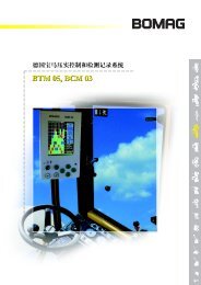
BOMAG compaction measuring and documentation system.<br />
4. Roller integrated measuring and documentation<br />
system<br />
The Terrameter BTM essentially consists of the<br />
recorder unit with two acceleration sensors (which<br />
are not arranged on the rotating part of the drum),<br />
the electronic unit, a travel sensor, the operating<br />
and display unit and a printer. The Terrameter display<br />
continuously shows the EVIB value, the working<br />
speed, frequency and amplitude. The printer enables<br />
printouts to be made directly on-site for paths up to<br />
150 m long. The paper strip documents the recorded<br />
EVIB values as a continuous line record and also the<br />
operating parameters of the compaction equipment.<br />
The measurement printout is particularly helpful<br />
on smaller construction measures and for caseby-case<br />
control of compaction on larger measures.<br />
Weak points and areas with a low bearing capacity<br />
can be precisely localized on the measuring route.<br />
By comparing the measurement printouts from sev-<br />
26
7<br />
Roller Integrated Surface Covering Dynamic Compaction Control<br />
eral passes, you can also identify and document the<br />
compaction progress and the maximum compaction<br />
level possible with the equipment.<br />
The BCM 05 documentation system is indispensable<br />
for surface covering observation of the construction<br />
site and for exchanging data between roller and<br />
site office on medium-sized and large construction<br />
measures, like those that occur when building traffic<br />
routes or when preparing areas to be ready for<br />
the development of commercial and industrial buildings<br />
and container terminals. During the compaction<br />
process, any measured data coming from the<br />
Terrameter is displayed graphically and numerically<br />
to the roller driver on the colour display of the<br />
BCM 05 system and is analysed, managed and<br />
documented on a PC using the evaluation program<br />
BCM 05 office. Data transfer between display and<br />
PC is by USB memory stick (Figure 8). The BCM 05<br />
Track-bound documentation with the BOMAG BW 213 DH-4 and BCM 05.<br />
software creates meaningful and detailed data<br />
summaries with calculations of areas and static<br />
examination of the EVIB values for assessing compaction<br />
quality both on the BCM display for the<br />
roller driver and in the site office for the data evaluator.<br />
The graphical representation can optionally be<br />
visualized in form of a plan view with colour assignment,<br />
or as 2D view.<br />
Without a GPS, documentation is implemented on<br />
a track-bound basis using path lengths usually of<br />
100 m. For this purpose, the area to be processed<br />
is subdivided into a roller path grid; grid size, positioning<br />
within the field by XY coordinates and other<br />
data important for describing compaction work are<br />
prepared in the site office using BCM 05 office and<br />
saved onto a USB stick.<br />
Fig.10: BOMAG BW 213 DH-4 BVC with GPS and BCM 05 equipment as<br />
well as surface covering representation of the compaction quality.<br />
The documentation system not only offers track-oriented<br />
documentation with manual positioning in the<br />
section but also a satellite supported documentation<br />
solution with the software module BCM 05 positioning<br />
developed by BOMAG (Figure 10).<br />
This not only provides continuous, unbroken recording<br />
and documentation of the EVIB value, but also
of the locational and height-related position of the<br />
roller, the operating parameters of the roller and the<br />
time of measurement. In principle, all conventional,<br />
differential GPS systems with correction signals<br />
from reference stations or with satellite supported<br />
reference services can be used. Depending on the<br />
system and receiver quality, positioning accuracies<br />
of 2-5 cm (RTK-GPS) or 10-30 cm can be achieved<br />
with solutions using a reference satellite. The<br />
BCM 05 positioning software converts the incoming<br />
satellite data into UTM or Gauß Krüger coordinates.<br />
When entering corresponding transformation<br />
parameters, the satellite data can be transformed<br />
into other national or local coordinate systems. Axes<br />
and outlines can be easily incorporated for orienta-<br />
Application<br />
Fig. 11: Application possibilities for CCC.<br />
Recommended<br />
roller equipment<br />
Weak point analysis Small construction:<br />
Terrameter BTM<br />
Larger Construction:<br />
additional BCM 05<br />
Proof of the maximum level<br />
of compaction possible<br />
Small constructions:<br />
Terrameter BTM<br />
Larger Constructions:<br />
additional BCM 05<br />
Determination of work instructions BTM and<br />
BCM 05 and<br />
GPS<br />
Proof of compaction by calibration Small construction:<br />
Terrameter BTM<br />
Larger Construction:<br />
additional BCM 05<br />
Control of compaction work Small construction:<br />
Terrameter BTM<br />
Larger Construction:<br />
additional BCM 05<br />
tion within documented areas by recording special<br />
points in the construction measure.<br />
5. Application possibilities for the surface covering<br />
compaction control<br />
Since the introduction of the ZTVE – StB 94/97<br />
(German earthworks regulations) roller integrated<br />
measuring and documentation systems can be used<br />
in Germany within the scope of self-monitoring and<br />
external monitoring of earthwork in road construction.<br />
In this case, special emphasis is on the application<br />
of CCC as a one hundred percent test based on<br />
Examples Advantages Suitabilit<br />
Foundation areas,<br />
earth-grade and dam fills<br />
Dyke fills<br />
Frost protection layers<br />
Unbound bearing courses<br />
Plane<br />
Frost protection layers<br />
Unbound bearing courses<br />
Dyke fills<br />
Dyke fills<br />
Frost protection layers<br />
Unbound bearing courses<br />
Detection of areas with<br />
high and low measuring<br />
values (weak spot analysis<br />
/ proof rolling)<br />
targeted use of conventional<br />
testing methods<br />
Comparison of measuring<br />
values between individual<br />
passes<br />
Optimized use of<br />
equipment<br />
Documentation of<br />
passes and weak<br />
spots<br />
Surface covering compaction<br />
control<br />
Economy<br />
Optimized use of<br />
equipment<br />
All soils<br />
All soils<br />
All soils<br />
Rock fills<br />
Coarse particle soils<br />
Mixed soils<br />
Mineral mixes<br />
All soils<br />
28
9<br />
Roller Integrated Surface Covering Dynamic Compaction Control<br />
calibration of the dynamic measured values of the<br />
roller to the test features defined in the building contract,<br />
compaction degree and deformation module.<br />
The procedural method is laid down as the M2 test<br />
method in the ZTVE – StB 94/97 and in the German<br />
technical test specifications for soil and field in road<br />
construction (TP BF – StB) CCC method – Part E 2.<br />
Furthermore, CCC offers a range of other application<br />
options which do not require any calibration. A<br />
surface covering search for weak points carried out<br />
with the BCM 05 by proof rolling can be applied to<br />
all types of soil. Weak points with low EVIB values can<br />
thus be identified and documented. Compaction can<br />
be assessed at these weak points in a targeted way<br />
using individual tests. The area can be assessed as a<br />
whole by combining the dynamic measured value of<br />
the roller and an individual test.<br />
Another important application is the documentation<br />
of compaction based on trial compaction and<br />
the related determination of a work instruction. To<br />
this end, the EVIB values and position of the roller are<br />
continuously documented using the BCM 05 system<br />
and a GPS connection, which consequently means<br />
that the compaction passes are also controlled. The<br />
advantages connected with the different application<br />
options with CCC, in respect of increasing compaction<br />
performance and improving compaction quality,<br />
can be summarized (Fig. 11).<br />
6. Construction site applications<br />
6.1 New construction motorway section A33,<br />
Germany<br />
The surface covering compaction control acc. to<br />
German ZTVE-StB09 was used on the new construction<br />
of the 8 km A33 motorway section between<br />
Steinhagen and Bielefeld for the purpose of processing<br />
dam fills and compaction tests. Slightly gravelly<br />
sands with a fine particle component of approx.<br />
8 % by mass were used as dam fill material. A compaction<br />
degree of 97% as per table 2 of the ZTVE<br />
was demanded for the range 1 m below earth-grade<br />
down to the dam sole and 98% for the range from<br />
formation level down to a depth of 1 m. In addition<br />
requirements concerning the load bearing capacity<br />
were placed on the formation, which called for a<br />
deformation modulus EV2 > 45 MN/m².<br />
The employment of method M2 always requires calibration<br />
of the compaction equipment, for which the<br />
measuring value of the compaction machine is correlated<br />
with the density or the degree of compaction<br />
DPr and the EV2 value on a calibration field with a<br />
size arrangement of approx. 10 m x 30 m. The correlation<br />
coefficient r thereby must be > 0.7. The subbase<br />
of the calibration field must be re-compacted<br />
and documented by a measuring pass.<br />
The compaction equipment used was a BOMAG<br />
BW 213 DH-4 BVC equipped with BOMAG Terrameter<br />
and BOMAG Compaction Management System<br />
BCM 05. On the calibration field three layers of 50 cm<br />
each of the dam fill material were arranged in three<br />
strips next to each other, also for examining the<br />
influence of the sub-soil, and compacted with different<br />
numbers of passes (low compaction, medium<br />
compaction, high compaction). Finally, measuring<br />
passes were run to measure each individual track.<br />
In order to determine the degree of compaction and<br />
density and to provide evidence of the load bearing<br />
capacity of the formation, three field density tests<br />
Fig. 12: Calibration of the E VIB value with the compaction degree and<br />
with the EV 2 value for slightly gravelly sands, dam fill material A33.
and five static load plate tests were then executed<br />
on each track and assigned to the EVIB value of the<br />
BW 213 DH-4 BVC. Fig. 12 shows the results.<br />
For the provision of evidence of compaction this<br />
results in an EVIB target value of 80 MN/m² for range<br />
1.0 m below earth-grade down to dam sole and an<br />
EVIB target value of 90 MN/m² for the range from<br />
earth-grade down to a depth of 1.0 m. The determined<br />
correlation coefficient r = 0.9, which is considerably<br />
higher than the minimum requirement<br />
(r > 0.7) of the German ZTVE-StB09. According to<br />
the calibration (Fig. 12) an EVIB value of at least<br />
56 MN/m² is required for providing evidence of the<br />
load bearing capacity on the formation. However, the<br />
requirement concerning compaction would thereby<br />
not be fulfilled. This means that the minimum value<br />
of EVIB = 90 MN/m² determined for compaction is<br />
decisive as evidence for the load bearing capacity of<br />
formation.<br />
Fig. 13: Documentation of passes (layer no. 10) and the uniformity of<br />
compaction, Kristiansund, Norway.<br />
6.2 Extension of the air traffic areas on the<br />
Kristansund airport, Norway<br />
The runway extension required filling and dam<br />
fill work with an overall volume of 2.3 million m³.<br />
Blasted granite rock material with good<br />
particle distribution and a maximum edge<br />
length of 1000 mm was used, which was then<br />
compacted in 1,5 meter thick layers by two<br />
26 tonne BOMAG single drum rollers type<br />
BW 226 DH-4 BVC. The rollers were equipped<br />
with Terrameter and the BCM 05 documentation<br />
system as well as a GPS system for the purpose<br />
of surface covering documentation of compaction<br />
work. Before work was started, test compaction<br />
took place, during which the settlement<br />
was used as a criterion of compaction. During<br />
the test compaction the settlement was measured<br />
after each pass. The difference in settlement<br />
between the last passes being less than<br />
10% of the total settlement served as definition<br />
for the end of effective compaction. This was<br />
reached after 6 passes. Purpose of the measuring<br />
and documentation system was the provision<br />
of evidence for the compaction work by<br />
surface covering documentation of the 6 passes,<br />
while drawing the attention to inhomogeneities<br />
and weak spots at the same time.<br />
6.3 Rotterdam harbour extension – Euromax<br />
Container Terminal, Netherlands<br />
For the construction of the Rotterdam Euromax<br />
Container Terminal Phase 2 the already existing<br />
area, that had been constructed with North Sea<br />
sand using the dredging method 30 years ago,<br />
had to be excavated down to a depth of 2.70 m<br />
and then refilled again in 50 cm layers.<br />
102
11<br />
Roller Integrated Surface Covering Dynamic Compaction Control<br />
The sand was fine sand with a 10% silt component.<br />
The Proctor densities were in the range of<br />
1600-1650 kg/m³ with an optimal water content<br />
of 16-17%. For this measure a compaction<br />
degree of 100% was demanded and,<br />
additionally as proof for the load bearing<br />
capacity on formation, a deformation modulus<br />
of 120 MN/m². The company Ooms Nederland<br />
Holding bv, who was entrusted with earth construction<br />
work, used a 15 t BW 213 DH-4 BVC<br />
with attachment plates and equipped with<br />
measuring and documentation system for compacting<br />
the sand. The compaction measuring<br />
and documentation system served the purpose<br />
of recognizing the maximum possible compaction<br />
by monitoring the E VIB increase with each<br />
additional pass and to avoid loosening of the<br />
highly sensitive sand by further passes. Furthermore,<br />
uniform compaction and load bearing<br />
Data exchange:<br />
The same information<br />
for all participants<br />
Fig. 15:Exchange of information between compaction equipment and<br />
between construction site and site office.<br />
capacity should be assured and possible local<br />
weak spots should immediately be detected<br />
Fig. 14: Evidence and documentation of the maximum possible<br />
compaction on the Euromax Terminal area, Rotterdam-Netherlands.<br />
and re-processed. Detailed examinations at the<br />
beginning of compaction work showed that E VIB<br />
values of 140 MN/m² are required to fulfil the<br />
compaction and load bearing requirements (see<br />
Fig. 14).<br />
Construction<br />
management<br />
and quality<br />
control
7. Further development<br />
The further development at BOMAG currently<br />
concentrates on two points of emphasis. On the<br />
one hand on the data transfer between several<br />
rollers and from the rollers to the construction<br />
site office and on the other hand on the elimination<br />
of the frequently disadvantageous sub-base<br />
influences on the measuring value by determining<br />
the layer modulus for the layer to be compacted.<br />
Both of these fields of development are<br />
of significance for soil compaction, but particularly<br />
for asphalt compaction.<br />
All machines involved in the compaction process<br />
should have the same level of information<br />
by communicating position and compaction<br />
data. This should speed up the construction process,<br />
make it more efficient and lead to a further<br />
improvement of the quality. Fig. 15 shows<br />
the data management concept BCM net for<br />
asphalt applications targeted by BOMAG. First<br />
practical experiences on a large-scale construction<br />
have been gathered in 2011.<br />
With almost homogeneous soil the vibration<br />
modulus E VIB converges towards the deformation<br />
modulus EV 2. Here a value specified by<br />
Bild 16: Determination of the layer moduli for a multi-layer road construction<br />
with a BOMAG CCC roller equipped with several sensors for<br />
detecting the deformation line.<br />
the body of rules serves as standard for sufficient<br />
compaction. If this value has not yet been<br />
reached, compaction must be continued, irrespective<br />
of the fact whether falling short of this<br />
value results from the top or the bottom soil<br />
layer. When looking at a dam fill or a road structure<br />
as a system of layers, the vibration modulus<br />
E VIB can be interpreted as an equivalent<br />
modulus, which is effective throughout the layer<br />
to be compacted, depending on the measuring<br />
depth (Fig. 16). This means that the E VIB value<br />
detected by the roller is partly determined by<br />
the stiffness of the sub-base, depending on the<br />
lift height. For surface covering compaction control<br />
a preceding calibration on a test field for<br />
investigating the influence of the sub-base is<br />
therefore required. This work can be minimized<br />
by determining the stiffness of the individual<br />
layers in addition to the vibration modulus E VIB<br />
In this case the compaction process is finished<br />
when the layer modulus of the upper layer has<br />
reached maximum.<br />
The BOMAG solution is targeted to determine<br />
the layer stiffness values using the theory of<br />
a multi-layer model as basis by detecting the<br />
depression hollow. The stiffness modulus of<br />
the sub-base, which is also available, informs<br />
about a uniformly bearing sub-base or a subbase<br />
with weak spots and thus completes the<br />
surface covering compaction control CCC.<br />
8. Summary<br />
The use of the compaction equipment as measuring<br />
and test system is based on the interaction<br />
between the acceleration characteristic of<br />
the vibrating roller drum and the stiffness of the<br />
soil changing with progressing compaction. The<br />
advantages of the application lie in the optimi-<br />
12
13<br />
Roller Integrated Surface Covering Dynamic Compaction Control<br />
zation of construction equipment and compaction<br />
work as well as in the improvement of the<br />
uniformity in the quality of earthwork, in the<br />
minimization of the risk of misinterpretation<br />
and, last but not least, in the higher reliability<br />
of quality assurance. Comprehensive practical<br />
experience and scientific findings from numerous<br />
construction projects with respect to the<br />
assuring subsoil and earthwork quality have<br />
led to the development of continuous compaction<br />
control method (CCC). In Germany, Austria,<br />
Sweden and Switzerland a number of technical<br />
regulations and recommendations were published<br />
which cleared the path for the general<br />
use of CCC in this countries. In the meantime<br />
the use of micro-processor controls and the<br />
introduction of automatic documentation systems<br />
and GPS supported positioning systems<br />
paved the path for a compaction management<br />
which links the position data from the roller<br />
with the compaction data and thus controls and<br />
documents the compaction quality and its uniformity<br />
as well as the roller passes. The related<br />
advantages have led to a further circulation and<br />
application of the continuous surface covering<br />
compaction control.<br />
With the possibilities of a radio-based online<br />
transfer of measuring data to the site office and<br />
the linking of rollers, the vision of a process<br />
controlled compaction technology has come a<br />
whole lot closer.
9. Literature<br />
Lehrstuhl und Prüfamt für Grundbau, Boden-<br />
und Felsmechanik, Technische Universität<br />
München:<br />
Dynamische Verdichtungsprüfung bei Erd- und<br />
Straßenbauten. Forschungsberichte aus dem<br />
Forschungsprogramm des Bundesministers für<br />
Verkehr und der Forschungsgesellschaft für<br />
Straßen- und Verkehrswesen e.V., Heft 612,<br />
1991<br />
FLOSS, R. (2001):<br />
Verdichtungstechnik im Erdbau und Verkehrswegebau;<br />
Band 1, BOMAG Deutschland<br />
FLOSS, R.; KRÖBER, W.; WALLRATH, W. (2001):<br />
Dynamische Bodensteifigkeit als Qualitätskriterium<br />
für die Bodenverdichtung; Berichte<br />
des Internationalen Symposiums Technik,<br />
Technologie des Verkehrswegebaus, München<br />
KLOUBERT, H.J. (2004):<br />
Intelligent VARIOCONTROL rollers with integrated<br />
quality control system for soil compaction –<br />
principle, measurement, applications -; Workshop<br />
414 “Intelligent Compaction Systems”,<br />
83 rd TRB Annual Meeting, Washington D.C.,<br />
Jan 2004<br />
KLOUBERT, H.J.; THIELE, R.; DIETL, F. (2007):<br />
Flughafen Leipzig/Halle – Prüfung des ungebundenen<br />
Oberbaus der Verkehrsflächen durch<br />
FDVK; Strasse und Autobahn, Heft 5/2007<br />
De BONDT, A. (2009):<br />
Sand subbase / subgrade compaction trial,<br />
Euromax Terminal, seaport Rotterdam; Ooms<br />
Nederland Holding bv Department o0f Research<br />
& Development<br />
NEUHAUS, M. (2010):<br />
Prüfbericht zur Kalibrierung der Messwalze und<br />
Festlegung der Anforderungswerte nach Prüfmethode<br />
M2 – FDVK für die A33 Bau-km<br />
3 + 100, Landesbetrieb Straßenbau Nordrhein-<br />
Westfalen, Prüfcenter Münster<br />
ZTVE-StB09<br />
Zusätzliche Technische Vertragsbedingungen<br />
und Richtlinien für Erdarbeiten im Straßenbau,<br />
ZTVE-StB09<br />
FGSV (1994)<br />
Technische Vorschrift für Boden und Fels im<br />
Straßenbau TP BF – StB Teil E 2, Flächendeckende<br />
dynamische Prüfung der Verdichtung<br />
FGSV (2005)<br />
Merkblatt über flächendeckende dynamische<br />
Prüfung der Verdichtung im Erdbau.<br />
(zur Zeit in Überarbeitung )<br />
14
www.bomag.com<br />
Head Office / Hauptsitz:<br />
BOMAG<br />
Hellerwald<br />
56154 Boppard<br />
GERMANY<br />
Tel. +49 6742 100-0<br />
Fax +49 6742 3090<br />
info@bomag.com<br />
BOMAG Maschinenhandelsgesellschaft<br />
m.b.H.<br />
Porschestraße 9<br />
1230 Wien<br />
AUSTRIA<br />
Tel. +43 1 69040-0<br />
Fax +43 1 69040-20<br />
austria@bomag.com<br />
BOMAG (CANADA), INC.<br />
3455 Semenyk Court<br />
Mississauga, Ontario L5C 4P9<br />
CANADA<br />
Tel. +1 905 361 9961<br />
Fax +1 905 361 9962<br />
canada@bomag.com<br />
BOMAG (CHINA)<br />
Compaction Machinery Co. Ltd.<br />
No. 2808 West Huancheng Road<br />
Shanghai Comprehensive<br />
Industrial Zone (Fengxian)<br />
Shanghai 201401<br />
CHINA<br />
Tel. +86 21 33655566<br />
Fax +86 21 33655508<br />
china@bomag.com<br />
BOMA Equipment<br />
Hong Kong LTD<br />
Room 1003, 10/F Cham Centre<br />
700, Castle Peak Road<br />
Kowloon<br />
HONG KONG<br />
Tel. +852 2721 6363<br />
Fax +852 2721 3212<br />
bomahk@bomag.com<br />
BOMAG France S.A.S.<br />
2, avenue du Général de Gaulle<br />
91170 Viry-Châtillon<br />
FRANCE<br />
Tel. +33 1 69578600<br />
Fax +33 1 69962660<br />
france@bomag.com<br />
BOMAG (GREAT BRITAIN), LTD.<br />
Sheldon Way<br />
Larkfield, Aylesford<br />
Kent ME20 6SE<br />
GREAT BRITAIN<br />
Tel. +44 1622 716611<br />
Fax +44 1622 718385<br />
gb@bomag.com<br />
BOMAG Italia Srl.<br />
Via Roma 50<br />
48011 Alfonsine<br />
ITALY<br />
Tel. +39 0544 864235<br />
Fax +39 0544-864367<br />
italy@bomag.com<br />
FAYAT BOMAG Polska Sp. z o.o.<br />
Ul. Szyszkowa 52<br />
02-285 Warszawa<br />
POLAND<br />
Tel. +48 22 482 0400<br />
Fax +48 22 482 04 01<br />
poland@bomag.com<br />
FAYAT BOMAG RUS OOO<br />
141400, RF, Moscow region<br />
Khimki, Klayazma block, h. 1-g<br />
RUSSIA<br />
Tel. +7 (495) 287 92 90<br />
Fax +7 (495) 287 92 91<br />
russia@bomag.com<br />
BOMAG GmbH<br />
300 Beach Road<br />
The Concourse, #18-06<br />
Singapore 199555<br />
SINGAPORE<br />
Tel. +65 6 294 1277<br />
Fax +65 6 294 1377<br />
singapore@bomag.com<br />
BOMAG Americas, Inc.<br />
2000 Kentville Road<br />
Kewanee, Illinois 61443<br />
U.S.A.<br />
Tel. +1 309 8533571<br />
Fax +1 309 8520350<br />
usa@bomag.com<br />
05/12 PRE 108 070