Decarburization Efficiency in EAF With Hot Metal ... - Steel Library
Decarburization Efficiency in EAF With Hot Metal ... - Steel Library
Decarburization Efficiency in EAF With Hot Metal ... - Steel Library

You also want an ePaper? Increase the reach of your titles
YUMPU automatically turns print PDFs into web optimized ePapers that Google loves.
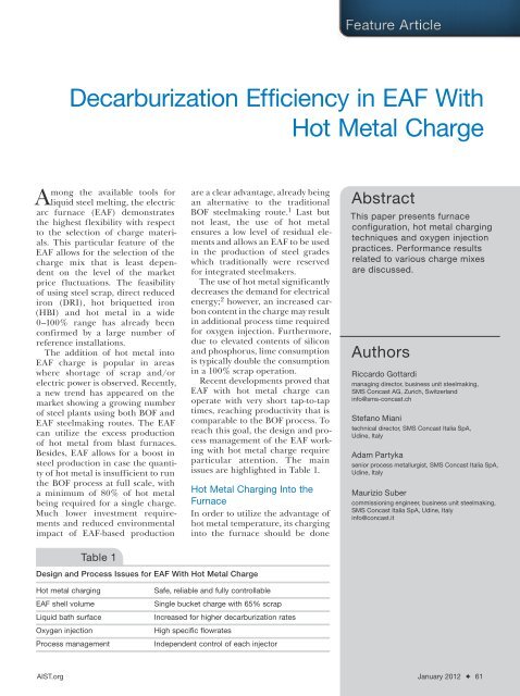
<strong>Decarburization</strong> <strong>Efficiency</strong> <strong>in</strong> <strong>EAF</strong> <strong>With</strong><br />
<strong>Hot</strong> <strong>Metal</strong> Charge<br />
Among the available tools for<br />
liquid steel melt<strong>in</strong>g, the electric<br />
arc furnace (<strong>EAF</strong>) demonstrates<br />
the highest flexibility with respect<br />
to the selection of charge materials.<br />
This particular feature of the<br />
<strong>EAF</strong> allows for the selection of the<br />
charge mix that is least dependent<br />
on the level of the market<br />
price fluctuations. The feasibility<br />
of us<strong>in</strong>g steel scrap, direct reduced<br />
iron (DRI), hot briquetted iron<br />
(HBI) and hot metal <strong>in</strong> a wide<br />
0–100% range has already been<br />
confirmed by a large number of<br />
reference <strong>in</strong>stallations.<br />
The addition of hot metal <strong>in</strong>to<br />
<strong>EAF</strong> charge is popular <strong>in</strong> areas<br />
where shortage of scrap and/or<br />
electric power is observed. Recently,<br />
a new trend has appeared on the<br />
market show<strong>in</strong>g a grow<strong>in</strong>g number<br />
of steel plants us<strong>in</strong>g both BOF and<br />
<strong>EAF</strong> steelmak<strong>in</strong>g routes. The <strong>EAF</strong><br />
can utilize the excess production<br />
of hot metal from blast furnaces.<br />
Besides, <strong>EAF</strong> allows for a boost <strong>in</strong><br />
steel production <strong>in</strong> case the quantity<br />
of hot metal is <strong>in</strong>sufficient to run<br />
the BOF process at full scale, with<br />
a m<strong>in</strong>imum of 80% of hot metal<br />
be<strong>in</strong>g required for a s<strong>in</strong>gle charge.<br />
Much lower <strong>in</strong>vestment requirements<br />
and reduced environmental<br />
impact of <strong>EAF</strong>-based production<br />
Table 1<br />
Design and Process Issues for <strong>EAF</strong> <strong>With</strong> <strong>Hot</strong> <strong>Metal</strong> Charge<br />
are a clear advantage, already be<strong>in</strong>g<br />
an alternative to the traditional<br />
BOF steelmak<strong>in</strong>g route. 1 Last but<br />
not least, the use of hot metal<br />
ensures a low level of residual elements<br />
and allows an <strong>EAF</strong> to be used<br />
<strong>in</strong> the production of steel grades<br />
which traditionally were reserved<br />
for <strong>in</strong>tegrated steelmakers.<br />
The use of hot metal significantly<br />
decreases the demand for electrical<br />
energy; 2 however, an <strong>in</strong>creased carbon<br />
content <strong>in</strong> the charge may result<br />
<strong>in</strong> additional process time required<br />
for oxygen <strong>in</strong>jection. Furthermore,<br />
due to elevated contents of silicon<br />
and phosphorus, lime consumption<br />
is typically double the consumption<br />
<strong>in</strong> a 100% scrap operation.<br />
Recent developments proved that<br />
<strong>EAF</strong> with hot metal charge can<br />
operate with very short tap-to-tap<br />
times, reach<strong>in</strong>g productivity that is<br />
comparable to the BOF process. To<br />
reach this goal, the design and process<br />
management of the <strong>EAF</strong> work<strong>in</strong>g<br />
with hot metal charge require<br />
particular attention. The ma<strong>in</strong><br />
issues are highlighted <strong>in</strong> Table 1.<br />
<strong>Hot</strong> <strong>Metal</strong> Charg<strong>in</strong>g Into the<br />
Furnace<br />
In order to utilize the advantage of<br />
hot metal temperature, its charg<strong>in</strong>g<br />
<strong>in</strong>to the furnace should be done<br />
<strong>Hot</strong> metal charg<strong>in</strong>g Safe, reliable and fully controllable<br />
<strong>EAF</strong> shell volume S<strong>in</strong>gle bucket charge with 65% scrap<br />
Liquid bath surface Increased for higher decarburization rates<br />
Oxygen <strong>in</strong>jection High specific flowrates<br />
Process management Independent control of each <strong>in</strong>jector<br />
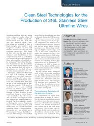
Abstract<br />
This paper presents furnace<br />
configuration, hot metal charg<strong>in</strong>g<br />
techniques and oxygen <strong>in</strong>jection<br />
practices. Performance results<br />
related to various charge mixes<br />
are discussed.<br />
Authors<br />
Riccardo Gottardi<br />
manag<strong>in</strong>g director, bus<strong>in</strong>ess unit steelmak<strong>in</strong>g,<br />
SMS Concast AG, Zurich, Switzerland<br />
<strong>in</strong>fo@sms-concast.ch<br />
Stefano Miani<br />
technical director, SMS Concast Italia SpA,<br />
Ud<strong>in</strong>e, Italy<br />
Adam Partyka<br />
senior process metallurgist, SMS Concast Italia SpA,<br />
Ud<strong>in</strong>e, Italy<br />
Maurizio Suber<br />
commission<strong>in</strong>g eng<strong>in</strong>eer, bus<strong>in</strong>ess unit steelmak<strong>in</strong>g,<br />
SMS Concast Italia SpA, Ud<strong>in</strong>e, Italy<br />
<strong>in</strong>fo@concast.it<br />
AIST.org January 2012 ✦ 61
Figure 1<br />
Schematic of ways of feed<strong>in</strong>g hot metal <strong>in</strong>to the furnace.<br />
with a closed roof. Usually steel plant logistics and<br />
layout limitations do not allow the freedom to select<br />
the place where hot metal ladles are delivered to the<br />
meltshop, i.e., on the charg<strong>in</strong>g or tapp<strong>in</strong>g side of the<br />
furnace. The furnace design itself imposes additional<br />
limitations. Position of the transformer, offgas exhaust,<br />
material handl<strong>in</strong>g system, etc., seriously limit the available<br />
space where a hot metal runner can be <strong>in</strong>serted<br />
<strong>in</strong>to the furnace shell. The actual charg<strong>in</strong>g method and<br />
hot metal runner position<strong>in</strong>g are a compromise among<br />
various considerations. 3<br />
The runner <strong>in</strong>serted through the slag door must be<br />
movable (by means of a dedicated hot metal charg<strong>in</strong>g<br />
car). In other positions, the runner can be fixed<br />
on either the furnace shell or on a charg<strong>in</strong>g car or<br />
manipulator.<br />
The most serious disadvantage of charg<strong>in</strong>g through<br />
the slag door is that pour<strong>in</strong>g of hot metal is done<br />
aga<strong>in</strong>st the flow of slag. In some cases, this can result<br />
<strong>in</strong> poor phosphorus removal from the liquid bath. The<br />
runner has to be moved <strong>in</strong>to charg<strong>in</strong>g position before<br />
scrap load<strong>in</strong>g to avoid scrap build<strong>in</strong>g up on the sill level.<br />
Sidewall position of the runner can be very problematic<br />
<strong>in</strong> case of possible hot metal overflow. At that<br />
particular location, it is difficult to collect spilled metal.<br />
Furthermore, hot metal overflow from the runner creates<br />
a risk for all pip<strong>in</strong>g <strong>in</strong>stalled <strong>in</strong> neighbor<strong>in</strong>g areas.<br />
The runner located on the EBT balcony seems to be<br />
the most advantageous. Thanks to limited scrap presence<br />
<strong>in</strong> that area, charg<strong>in</strong>g of hot metal can be started<br />
very early. In case of overflow, spilled hot metal can be<br />
collected <strong>in</strong> the tapp<strong>in</strong>g pit below the furnace.<br />
<strong>Hot</strong> metal charg<strong>in</strong>g operation requires great<br />
care, s<strong>in</strong>ce contact with highly oxidized furnace<br />
slag or cold scrap can result <strong>in</strong> violent<br />
reactions. The same usually happens if large<br />
carbon-concentration gradients develop <strong>in</strong> the<br />
liquid bath dur<strong>in</strong>g the superheat<strong>in</strong>g phase.<br />
Loss of control dur<strong>in</strong>g hot metal charg<strong>in</strong>g will<br />
result <strong>in</strong> overflow of slag and steel from the<br />
furnace; however, <strong>in</strong> extreme cases, damage to<br />
the electrode arms can also be observed dur<strong>in</strong>g<br />
violent eruptions <strong>in</strong> the furnace.<br />
Summariz<strong>in</strong>g the issue of trouble-free charg<strong>in</strong>g<br />
of hot metal <strong>in</strong>to the furnace, the follow<strong>in</strong>g<br />
preferences have been def<strong>in</strong>ed:<br />
• <strong>Hot</strong> metal pour<strong>in</strong>g should be carried<br />
out with power on to avoid productivity<br />
losses.<br />
• Tilt<strong>in</strong>g of the hot metal ladle should not<br />
<strong>in</strong>volve a crane.<br />
• <strong>Hot</strong> metal ladle tilt<strong>in</strong>g control should be<br />
precise enough to ensure stable pour<strong>in</strong>g<br />
rates.<br />
• <strong>Hot</strong> metal runner length should be as<br />
short as possible to avoid freez<strong>in</strong>g of hot<br />
metal.<br />
• The runner should be preheated<br />
between pour<strong>in</strong>g operations.<br />
Customized <strong>EAF</strong> for Operation <strong>With</strong> <strong>Hot</strong> <strong>Metal</strong><br />
In November 2007, Concast commissioned a new furnace<br />
at Zhangjiagang Hongchang Wire Rod Co. (ZHW),<br />
belong<strong>in</strong>g to Shagang Group <strong>in</strong> Jiangsu Prov<strong>in</strong>ce, P.R.<br />
Ch<strong>in</strong>a. This furnace, designed for tap-to-tap times of<br />
less than 35 m<strong>in</strong>utes, is the heart of a new production<br />
l<strong>in</strong>e <strong>in</strong>clud<strong>in</strong>g LF, VD and 6-strand billet caster with an<br />
annual output of 1.1 million tons of SBQ steels for the<br />
expand<strong>in</strong>g automotive <strong>in</strong>dustry <strong>in</strong> Ch<strong>in</strong>a. 4<br />
In 2009–2010, two other furnaces with hot metal<br />
charge were supplied to Tianj<strong>in</strong> Iron & <strong>Steel</strong> Group,<br />
P.R. Ch<strong>in</strong>a, where they are a part of 2.2 million tpy<br />
m<strong>in</strong>i-mill equipped with two ladle furnaces, one tw<strong>in</strong>-<br />
VD station, bloom and billet caster. Another two <strong>EAF</strong>s<br />
for customers <strong>in</strong> Ch<strong>in</strong>a are <strong>in</strong> the eng<strong>in</strong>eer<strong>in</strong>g phase.<br />
The furnaces of Shagang and Tianj<strong>in</strong> are almost<br />
identical; the ma<strong>in</strong> difference between them is related<br />
to the hot metal charg<strong>in</strong>g method. The Shagang <strong>EAF</strong><br />
is fed with hot metal from the EBT balcony, while both<br />
Tianj<strong>in</strong> furnaces have been equipped with charg<strong>in</strong>g<br />
cars with refractory-l<strong>in</strong>ed spouts which are <strong>in</strong>serted<br />
through the slag door.<br />
The ma<strong>in</strong> data of the Shagang and Tianj<strong>in</strong> furnaces<br />
are shown <strong>in</strong> Table 2.<br />
Shagang Group runs several meltshops equipped<br />
both with BOF and <strong>EAF</strong> units and has ga<strong>in</strong>ed solid<br />
experience of us<strong>in</strong>g hot metal <strong>in</strong> the <strong>EAF</strong> process. The<br />
design solutions adopted for that furnace have been<br />
<strong>in</strong>tensively tested <strong>in</strong> practice. This particularly relates to<br />
the hot metal charg<strong>in</strong>g system. Although the <strong>EAF</strong> was<br />
orig<strong>in</strong>ally designed for 30–40% hot metal utilization,<br />
Shagang already tested operation with up to 70% hot<br />
62 ✦ Iron & <strong>Steel</strong> Technology A Publication of the Association for Iron & <strong>Steel</strong> Technology
Table 2<br />
Data for the Shagang and Tianj<strong>in</strong> <strong>EAF</strong>s<br />
<strong>EAF</strong> type AC, full platform<br />
Average tap weight 110 tons<br />
<strong>Hot</strong> heel 15–30 tons<br />
Shell diameter 6,500 mm<br />
Shell volume 130 m 3<br />
Flat bath area 27 m 2<br />
Transformer rate power 80 MVA + 20%<br />
Electrodes 610 mm<br />
Burners 6 x 6 MW (6 x 610 Nm 3 /hour natural gas)<br />
Supersonic oxygen 6 x 2,500 Nm 3 /hour<br />
Carbon <strong>in</strong>jection 3 x 50 kg/m<strong>in</strong>ute<br />
metal without a significant decrease of the designed<br />
productivity.<br />
For Tianj<strong>in</strong>, <strong>EAF</strong> technology is a new challenge.<br />
However, through an extensive exchange with other<br />
Ch<strong>in</strong>ese steelmakers also work<strong>in</strong>g with hot metal, a<br />
background for thorough test<strong>in</strong>g of the delivered <strong>EAF</strong><br />
flexibility and capability has been created there.<br />
Shagang <strong>EAF</strong> Operations<br />
The <strong>EAF</strong> has been equipped with a dedicated system for<br />
hot metal charg<strong>in</strong>g from the tapp<strong>in</strong>g side.<br />
The hot metal ladle is placed on a tilt<strong>in</strong>g stand.<br />
The tilter has its own runner with a buffer conta<strong>in</strong>er,<br />
improv<strong>in</strong>g flow control. Dur<strong>in</strong>g hot metal pour<strong>in</strong>g, the<br />
tilter is rotated by 90° above the EBT balcony, where it<br />
meets another short runner permanently attached to<br />
the furnace shell.<br />
Hydraulic tilt<strong>in</strong>g of the hot metal ladle is fairly precise.<br />
For reference, the whole pour<strong>in</strong>g operation for<br />
an <strong>EAF</strong> charge configuration with 35% (40 tons) hot<br />
metal can be completed with<strong>in</strong> 3–4 m<strong>in</strong>utes, as hot<br />
metal can be charged safely with average rates of 7–10<br />
t/m<strong>in</strong>ute.<br />
A very efficient dephosphorization, thanks to a lime<br />
discharge po<strong>in</strong>t above the hot metal pool and extended<br />
reaction time between hot metal and highly basic slag,<br />
has proved to be an additional benefit of hot metal<br />
pour<strong>in</strong>g from the EBT side.<br />
The furnace shell volume permits the use of a<br />
s<strong>in</strong>gle-bucket scrap charg<strong>in</strong>g practice if the m<strong>in</strong>imum<br />
hot metal share is above 30%. Except for at least 15%<br />
reduction of the power-off time, s<strong>in</strong>gle-bucket charg<strong>in</strong>g<br />
practice allows also for the utilization of heat generated<br />
through hot metal decarburization and post-combustion<br />
of carbon monoxide for a very efficient preheat<strong>in</strong>g<br />
of a scrap column <strong>in</strong>side the shell. 5<br />
The key issue of the furnace is its decarburization<br />
capacity. High carbon content <strong>in</strong> the charge may<br />
require additional time for decarburization. <strong>EAF</strong>s cannot<br />
utilize the oxygen <strong>in</strong>jection rates typical for BOF<br />
practice. Accord<strong>in</strong>g to literature data, a hot metal share<br />
of 40% has been considered as a maximum limit, above<br />
which the <strong>EAF</strong> productivity is reduced due to <strong>in</strong>sufficient<br />
oxygen <strong>in</strong>jection capacity. 6 The exist<strong>in</strong>g oxygen<br />
<strong>in</strong>jection limits are usually related to problems with<br />
extensive splash<strong>in</strong>g phenomena, backfire, electrode<br />
consumption <strong>in</strong>crease and erosion of refractory l<strong>in</strong><strong>in</strong>g,<br />
as well as reduced life of roof panels and refractory<br />
delta centerpiece.<br />
The Shagang <strong>EAF</strong> has been equipped with CONSOtype<br />
comb<strong>in</strong>ed <strong>in</strong>jectors, allow<strong>in</strong>g operation with up<br />
to 15,000 Nm 3 /hour of oxygen flow <strong>in</strong> supersonic<br />
<strong>in</strong>jection mode. The CONSO <strong>in</strong>jectors are proprietary<br />
SMS Concast design, and their effective performances<br />
have been demonstrated on more than 50 <strong>EAF</strong>s. The<br />
CONSO system is also a platform of an <strong>in</strong>tensively<br />
developed chemical energy package called ultrahigh<br />
chemical power (UHCP) <strong>EAF</strong>, for which the power of<br />
<strong>in</strong>stalled burners equals 40% of effectively used electrical<br />
power. 7 Before Shagang, the high decarburization<br />
capacity of the CONSO system was verified <strong>in</strong> practice<br />
on a furnace operat<strong>in</strong>g with up to 35% pig iron <strong>in</strong> the<br />
charge.<br />
In total, six CONSO units have been <strong>in</strong>stalled on the<br />
furnace. Their distribution on the shell perimeter has<br />
been decided, with the aim to reach perfect thermal<br />
equilibration of the furnace volume, elim<strong>in</strong>ation of the<br />
cold spots and enhancement of the metallurgical reactions<br />
by <strong>in</strong>tensive bath stirr<strong>in</strong>g and homogenization.<br />
Each <strong>in</strong>jector can use up to 600 Nm 3 /hour of natural<br />
gas and 1,250 Nm 3 /hour of oxygen <strong>in</strong> burner mode.<br />
The lance, which is supplied from a separate oxygen<br />
l<strong>in</strong>e, can operate with 800–1,300 Nm 3 /hour <strong>in</strong> subsonic<br />
<strong>in</strong>jection mode and 1,700–2,500 Nm 3 /hour of oxygen<br />
<strong>in</strong> supersonic <strong>in</strong>jection mode.<br />
Injectors 3, 5 and 6 are coupled with carbon <strong>in</strong>jection<br />
tuyeres, allow<strong>in</strong>g the precise <strong>in</strong>jection of carbon <strong>in</strong>to<br />
the oxygen jet. Except for slag foam<strong>in</strong>g purposes, early<br />
carbon <strong>in</strong>jection is needed for process safety aspects.<br />
Equilibration of FeO content <strong>in</strong> slag prevents the occurrence<br />
of carbon and oxygen gradients <strong>in</strong>side the liquid<br />
bath volume.<br />
After scrap charg<strong>in</strong>g, all <strong>in</strong>jectors are switched to<br />
a low-power preheat<strong>in</strong>g burner flame with a gradual<br />
<strong>in</strong>crease of the power <strong>in</strong> the burner-cutt<strong>in</strong>g mode.<br />
Pour<strong>in</strong>g of hot metal is usually <strong>in</strong>itiated with<strong>in</strong> the first<br />
m<strong>in</strong>ute of power-on. For a short time, <strong>in</strong>jectors 3, 4 and<br />
5 are used very <strong>in</strong>tensively to melt scrap rema<strong>in</strong><strong>in</strong>g <strong>in</strong><br />
the hot metal discharge area. At the same time, the<br />
AIST.org January 2012 ✦ 63
Figure 2<br />
Pour<strong>in</strong>g of hot metal through the EBT balcony runner.<br />
<strong>in</strong>jectors on both sides of the slag door are still kept <strong>in</strong><br />
lower-power burner mode to preheat bigger scrap quantities<br />
deposited there.<br />
<strong>With</strong> about half of the hot metal be<strong>in</strong>g already<br />
charged, the supersonic oxygen lanc<strong>in</strong>g starts — <strong>in</strong>itially<br />
us<strong>in</strong>g <strong>in</strong>jectors 2, 3, 4 and 5. At that time, <strong>in</strong>jectors<br />
1 and 6 are operated with full burner power, followed<br />
by subsonic oxygen flow for the delivery of oxygen for<br />
post-combustion of large volumes of carbon monoxide<br />
generated dur<strong>in</strong>g the reaction of hot metal.<br />
After completion, silicon oxidation and liquid bath<br />
temperature <strong>in</strong>crease, and all <strong>in</strong>jectors are switched to<br />
supersonic lance operation. About 3 m<strong>in</strong>utes before<br />
tapp<strong>in</strong>g, temperature and oxygen activity <strong>in</strong> the liquid<br />
bath are measured. Depend<strong>in</strong>g on the actual carbon<br />
content, the oxygen flow can then be reduced or<br />
<strong>in</strong>creased to obta<strong>in</strong> the target value at tapp<strong>in</strong>g.<br />
The electrical power <strong>in</strong>put program is fully <strong>in</strong>tegrated<br />
with the operation of the CONSO <strong>in</strong>jectors <strong>in</strong><br />
the profile executed by the <strong>EAF</strong> automation. The same<br />
applies to the carbon <strong>in</strong>jection system. Usually two carbon<br />
<strong>in</strong>jections are <strong>in</strong> operation, while the third one is<br />
kept <strong>in</strong> standby mode. Slag control system (SCAD) is<br />
further used to modify <strong>in</strong>jection carbon flow set po<strong>in</strong>ts<br />
<strong>in</strong> function of the actual coverage of the electric arcs.<br />
Tianj<strong>in</strong> <strong>EAF</strong> Operations<br />
The practice of pour<strong>in</strong>g hot metal through the slag<br />
door is the pr<strong>in</strong>cipal difference between the Shagang<br />
and the Tianj<strong>in</strong> furnaces. Due to layout limitations,<br />
the <strong>EAF</strong> charg<strong>in</strong>g bay was the only available hot metal<br />
delivery po<strong>in</strong>t, so slag door charg<strong>in</strong>g had to be selected<br />
as a compromise.<br />
The hot metal ladle is loaded onto a car equipped<br />
with onboard hydraulic station power<strong>in</strong>g hot metal<br />
ladle tilt<strong>in</strong>g frame movements. <strong>Hot</strong> metal is poured <strong>in</strong>to<br />
a flow-control buffer conta<strong>in</strong>er with a fixed outlet diameter,<br />
which ensures uniform flow of hot metal <strong>in</strong>to the<br />
runner. The runner is l<strong>in</strong>ed with a typical iron throughrammed<br />
refractory material and can be exchanged<br />
completely <strong>in</strong> case of excessive wear.<br />
The hot metal ladle is placed on a charg<strong>in</strong>g car dur<strong>in</strong>g<br />
furnace turnover, so the spout enters the slag door<br />
tunnel before scrap bucket charg<strong>in</strong>g, thus avoid<strong>in</strong>g<br />
problems with a possible scrap presence <strong>in</strong>side. Beh<strong>in</strong>d<br />
the slag door sill, an impact pad is made to avoid <strong>EAF</strong><br />
refractory erosion caused by hot metal flow.<br />
As soon as the <strong>EAF</strong> roof is closed after scrap charg<strong>in</strong>g,<br />
the hot metal can be tilted. The average pour<strong>in</strong>g<br />
rates are 5–8 t/m<strong>in</strong>ute and may be slightly reduced <strong>in</strong><br />
cased of <strong>in</strong>tensive reactions between the hot metal and<br />
highly oxidized slag and low-carbon-conta<strong>in</strong><strong>in</strong>g metal<br />
of the hot heel.<br />
For safety reasons, oxygen lanc<strong>in</strong>g is not used dur<strong>in</strong>g<br />
hot metal charg<strong>in</strong>g. Consequently, the decarburization<br />
of the liquid bath has to be delayed. This is the<br />
most significant disadvantage when compared with the<br />
Shagang furnace and hot metal charg<strong>in</strong>g practice from<br />
the EBT side.<br />
Both Tianj<strong>in</strong> furnaces have also been equipped with<br />
six CONSO <strong>in</strong>jectors of similar size, i.e., 6 MW <strong>in</strong> burner<br />
mode and 2,500 Nm 3 /hour of oxygen <strong>in</strong> supersonic<br />
<strong>in</strong>jection mode.<br />
The location of <strong>in</strong>dividual <strong>in</strong>jectors has been optimized<br />
for the simulated advancement of melt<strong>in</strong>g process.<br />
The <strong>in</strong>jectors located <strong>in</strong> the scrap melt<strong>in</strong>g area are<br />
64 ✦ Iron & <strong>Steel</strong> Technology A Publication of the Association for Iron & <strong>Steel</strong> Technology
more <strong>in</strong>tensively used as full-power burners, while those<br />
close to the hot metal pool are switched to lanc<strong>in</strong>g<br />
mode immediately after charg<strong>in</strong>g car withdrawal <strong>in</strong>to<br />
the park<strong>in</strong>g position. Injector No. 6 helps to melt scrap<br />
accumulated above the hot metal spout, after which it<br />
delivers oxygen for CO post-combustion.<br />
Execution of the melt<strong>in</strong>g program is fully automatic.<br />
Several programs are available for different percentages<br />
of hot metal <strong>in</strong> the charge.<br />
Figure 4<br />
Figure 3<br />
CONSO <strong>in</strong>jectors layout and melt<strong>in</strong>g zone distribution.<br />
<strong>Hot</strong> metal charg<strong>in</strong>g with slag door spout.<br />
More or less <strong>in</strong> the middle of the superheat<strong>in</strong>g phase,<br />
the first steel sampl<strong>in</strong>g and temperature measurement<br />
are done. Depend<strong>in</strong>g on the result, the rema<strong>in</strong><strong>in</strong>g programmed<br />
oxygen volume is updated to ensure targets<br />
at tapp<strong>in</strong>g. Such practice is very similar to <strong>in</strong>-blow sampl<strong>in</strong>g<br />
<strong>in</strong> the BOF process. In case of excess steel bath<br />
temperature, additional lime is charged through the<br />
fifth hole to cool down the bath, prevent<strong>in</strong>g phosphorus<br />
reversion from slag.<br />
AIST.org January 2012 ✦ 65
Comparison of the performance results of the<br />
Shagang and Tianj<strong>in</strong> furnaces clearly <strong>in</strong>dicates that the<br />
hot metal charg<strong>in</strong>g method has rather significant <strong>in</strong>fluence.<br />
Slag door charg<strong>in</strong>g is a less favorable solution,<br />
mostly due to the uneven mix<strong>in</strong>g pattern of the liquid<br />
bath <strong>in</strong> the furnace, reduced reaction area and lower<br />
efficiency of the available chemical energy utilization.<br />
For the same share of hot metal <strong>in</strong> the charge, the<br />
specific energy consumption is about 20 kWh/ton<br />
higher, with a 2-m<strong>in</strong>ute power-on time <strong>in</strong>crease and<br />
consequent loss of productivity.<br />
Figure 6<br />
Figure 5<br />
CONSO <strong>in</strong>jectors layout and melt<strong>in</strong>g zone distribution (Tianj<strong>in</strong> <strong>EAF</strong> No. 2).<br />
CONSO <strong>in</strong>jector profiles dur<strong>in</strong>g melt<strong>in</strong>g (a) and superheat<strong>in</strong>g (b) phases (40% hot metal).<br />
Evaluation of <strong>Decarburization</strong> <strong>Efficiency</strong><br />
The furnaces presented <strong>in</strong> this paper were orig<strong>in</strong>ally<br />
designed for a reference charge configuration with a<br />
maximum 40% hot metal.<br />
The average decarburization rates of 0.12% C/m<strong>in</strong>ute<br />
were calculated to be achieved with average specific<br />
oxygen <strong>in</strong>jection rates of 300 Nm 3 /hour/m 2 of liquid<br />
bath surface, correspond<strong>in</strong>g to four CONSO lances<br />
operated at 2,000 Nm 3 /hour each.<br />
Consider<strong>in</strong>g that with 40% hot metal, the carbon<br />
content <strong>in</strong> the liquid bath is about 2% (1.7% C from hot<br />
metal and 0.3% C from scrap), the required cont<strong>in</strong>uous<br />
(a) (b)<br />
66 ✦ Iron & <strong>Steel</strong> Technology A Publication of the Association for Iron & <strong>Steel</strong> Technology
Figure 7<br />
In-blow sample carbon content (250 heats from commission<strong>in</strong>g<br />
phase)<br />
oxygen lanc<strong>in</strong>g time with the earlier def<strong>in</strong>ed decarburization<br />
rate should be about 16 m<strong>in</strong>utes. S<strong>in</strong>ce<br />
the calculated average power-on time was 25 m<strong>in</strong>utes,<br />
about 7 m<strong>in</strong>utes were reserved for burner operation<br />
and oxygen <strong>in</strong>jection at subsonic flowrates. Accord<strong>in</strong>g<br />
to melt<strong>in</strong>g process simulations, all heats could be<br />
completed without extra power-off time for additional<br />
decarburization.<br />
<strong>Decarburization</strong> rates achieved <strong>in</strong> practice proved<br />
to be better than the earlier assumed values. Figure 6<br />
shows the results of the <strong>in</strong>-blow carbon sampl<strong>in</strong>g from<br />
the early days of the Shagang <strong>EAF</strong> operation. In some<br />
cases, the results <strong>in</strong>dicate slightly higher carbon values,<br />
which can be expla<strong>in</strong>ed by <strong>in</strong>consistency <strong>in</strong> the carbon<br />
and silicon contents <strong>in</strong> hot metal, which deviated the <strong>in</strong>/<br />
out oxygen balance. Nevertheless, thanks to a correctly<br />
def<strong>in</strong>ed moment of sampl<strong>in</strong>g, sufficient time was always<br />
reserved for eventual oxygen blow pattern update with<br />
oxygen flowrate <strong>in</strong>crease, if required. However, <strong>in</strong> most<br />
of the cases, the f<strong>in</strong>al phase of superheat<strong>in</strong>g was done<br />
with a reduced oxygen <strong>in</strong>jection rate to avoid too-low<br />
carbon at tapp<strong>in</strong>g.<br />
The CONSO <strong>in</strong>jection system operation fully confirmed<br />
expectations regard<strong>in</strong>g high decarburization<br />
efficiency. It was also concluded that the capacity of the<br />
system can be further <strong>in</strong>creased us<strong>in</strong>g higher supersonic<br />
oxygen flowrates.<br />
Fac<strong>in</strong>g shortage and <strong>in</strong>consistency of scrap supplies,<br />
the <strong>EAF</strong> users were forced to <strong>in</strong>crease the share of hot<br />
metal <strong>in</strong> the charge — <strong>in</strong>itially to 50% and later even<br />
to 70%. New melt<strong>in</strong>g programs with higher specific<br />
oxygen flowrates were established for such occasions.<br />
Precise evaluation of the actual decarburization rates<br />
is an extremely difficult task for several reasons. Among<br />
them, the experienced variations <strong>in</strong> hot metal parameters,<br />
i.e., carbon, silicon and manganese contents, as<br />
well as its temperature at the moment of pour<strong>in</strong>g <strong>in</strong>to<br />
the <strong>EAF</strong>, play a key role. Diversified hot metal deliveries<br />
from different blast furnaces additionally <strong>in</strong>creased the<br />
deviation range of the start<strong>in</strong>g conditions.<br />
In view of that, the follow<strong>in</strong>g evaluation procedure<br />
was adopted:<br />
• Start<strong>in</strong>g carbon content was calculated based on<br />
the composition of furnace charge components.<br />
Figure 8<br />
<strong>Decarburization</strong> results.<br />
• Start of decarburization time was identified as the<br />
moment when <strong>in</strong>tense flames were seen (spontaneous<br />
carbon “ignition”).<br />
• <strong>Decarburization</strong> time was counted until the time<br />
of the first sampl<strong>in</strong>g, when end carbon value was<br />
analyzed.<br />
• Actual decarburization rates were calculated from<br />
carbon content difference and recorded time.<br />
Figure 8 shows the results from about 1,300 heats<br />
produced with variable hot metal share <strong>in</strong> the charge.<br />
Available results demonstrate the fact that — except<br />
for earlier identified factors — the actual decarburization<br />
rates also depend on the <strong>in</strong>itial carbon content <strong>in</strong><br />
the liquid bath. Some analogies to the decarburization<br />
reaction <strong>in</strong> VOD or AOD processes can be noted at this<br />
po<strong>in</strong>t.<br />
Interdependence between carbon content and decarburization<br />
<strong>in</strong>tensity is a precious observation which<br />
can be used for sett<strong>in</strong>g up the process conditions for a<br />
high share of hot metal <strong>in</strong> the furnace charge. It can<br />
be assumed that the decarburization rate can be very<br />
high, provid<strong>in</strong>g that sufficient oxygen <strong>in</strong>jection density<br />
is ensured.<br />
For higher carbon contents <strong>in</strong> the charge, the deviation<br />
of the actual decarburization rates is limited. This<br />
can be expla<strong>in</strong>ed easily by the fact that available oxygen<br />
Figure 9<br />
<strong>Decarburization</strong> rates by sample-to-sample method.<br />
AIST.org January 2012 ✦ 67
<strong>in</strong>jectors had to be always operated at maximum available<br />
capacity. In case of lower charge carbon contents<br />
(20–40% hot metal), the deviations are more significant.<br />
It is believed that the deviations were caused by<br />
<strong>in</strong>consistent process conditions, among them manual<br />
control of power and chemical energy <strong>in</strong>put, as well<br />
as <strong>in</strong>correct identification of decarburization reaction<br />
launch.<br />
The decarburization reaction efficiency was also evaluated<br />
us<strong>in</strong>g an alternative method, based on sampleto-sample<br />
carbon content difference and elapsed time<br />
between the samples. This method could not be used<br />
for higher carbon contents.<br />
The first sample used to be taken when more or less<br />
flat bath conditions were identified, i.e., when the progress<br />
of decarburization reaction reached 60% or more<br />
for charges with 35–40% hot metal. The second sample<br />
was usually taken close to the superheat<strong>in</strong>g end.<br />
Although the accuracy of carbon content evaluation<br />
<strong>in</strong> the first sample can be questionable, the obta<strong>in</strong>ed<br />
results (Figure 9) are very <strong>in</strong>terest<strong>in</strong>g. Similarly, as <strong>in</strong><br />
the previous case, the relation between carbon content<br />
<strong>in</strong> the liquid bath and the actual decarburization rate<br />
is rather clear. Moreover, the trendl<strong>in</strong>e for all available<br />
results is almost identical to the one <strong>in</strong>dicated <strong>in</strong><br />
Figure 8.<br />
The decarburization rates estimated by the second<br />
method are higher than <strong>in</strong> the first case. This can<br />
probably be expla<strong>in</strong>ed by too-high carbon content<br />
analyzed <strong>in</strong> the <strong>in</strong>itial samples, which were not fully<br />
representative of the whole volume of the liquid bath<br />
<strong>in</strong> the furnace.<br />
Performance Data<br />
All three furnaces presented <strong>in</strong> this paper are almost<br />
identical from the design po<strong>in</strong>t of view. The difference<br />
between adopted hot metal charg<strong>in</strong>g practice has<br />
been considered less significant for such performance<br />
<strong>in</strong>dexes as specific energy consumption, lance oxygen<br />
consumption and productivity. Therefore, the available<br />
performance data have been evaluated jo<strong>in</strong>tly.<br />
Figure 11<br />
Specific lance oxygen consumption.<br />
Figure 10<br />
Specific energy consumption results (to liquid steel).<br />
The specific electrical energy consumption results<br />
are shown <strong>in</strong> Figure 10.<br />
For the most frequent charge configuration of<br />
30–40% hot metal, the energy consumption is 220–180<br />
kWh/ton, respectively. <strong>With</strong> 70% hot metal, it is practically<br />
“zero consumption.” For this charge configuration,<br />
practically observed, very limited energy was consumed<br />
<strong>in</strong> the <strong>in</strong>itial part of the heat or before tapp<strong>in</strong>g for the<br />
f<strong>in</strong>e adjustment of required tap temperature.<br />
The lance oxygen consumption results are shown <strong>in</strong><br />
Figure 11. The deviations observed on the graph are<br />
related to the fact that oxygen consumed for silicon<br />
oxidation could not be filtered out <strong>in</strong> a predictable way.<br />
Also, the earlier mentioned <strong>in</strong>consistency <strong>in</strong> <strong>in</strong>jection<br />
system operation with manual control is significant.<br />
Increase of the hot metal share <strong>in</strong> the furnace charge<br />
to 70% dramatically <strong>in</strong>creases the oxygen consumption.<br />
The required oxygen volume <strong>in</strong> lance mode is about<br />
6,000 Nm 3 per heat. <strong>With</strong> six CONSO units operat<strong>in</strong>g<br />
at 2,500 Nm 3 /hour, lance oxygen <strong>in</strong>jection can be<br />
completed <strong>in</strong> less than 25 m<strong>in</strong>utes, with the average<br />
decarburization rates of 0.12–0.14% C/m<strong>in</strong>ute, which<br />
corresponds to the values practically observed dur<strong>in</strong>g<br />
normal operation.<br />
Figure 12<br />
<strong>EAF</strong> productivity results.<br />
68 ✦ Iron & <strong>Steel</strong> Technology A Publication of the Association for Iron & <strong>Steel</strong> Technology
Evaluation of the <strong>EAF</strong> productivity leads to <strong>in</strong>terest<strong>in</strong>g<br />
conclusions as well. The graph <strong>in</strong> Figure 12 was plotted<br />
comb<strong>in</strong><strong>in</strong>g tap-to-tap time results (with unexpected<br />
delays filtered out for higher regularity) and tapped<br />
steel weights.<br />
The designed productivity of discussed furnaces was<br />
close to 200 t/hour for reference charges with 35% hot<br />
metal. Increase of hot metal share to 45% gives an additional<br />
productivity boost to the level of 210–215 t/hour.<br />
The most important observation is related to the fact<br />
that, even with a 55% share of hot metal <strong>in</strong> the charge,<br />
the orig<strong>in</strong>al <strong>EAF</strong> design productivity can still be ma<strong>in</strong>ta<strong>in</strong>ed.<br />
This conclusion is a breakthrough <strong>in</strong> view of the<br />
traditional op<strong>in</strong>ions say<strong>in</strong>g that the <strong>in</strong>crease of the hot<br />
metal percentage <strong>in</strong> the <strong>EAF</strong> charge above 40% results<br />
<strong>in</strong> losses of the furnace productivity.<br />
Conclusions<br />
The operational results achieved by the Shagang and<br />
Tianj<strong>in</strong> furnaces clearly demonstrate that the <strong>EAF</strong> is an<br />
<strong>in</strong>terest<strong>in</strong>g alternative or supplement to BOF steelmak<strong>in</strong>g<br />
shops. Short melt<strong>in</strong>g cycle and extremely high productivity<br />
can be guaranteed even with a high hot metal<br />
share <strong>in</strong> the charge above the traditional limits.<br />
Customized furnace design, an appropriate method<br />
for hot metal charg<strong>in</strong>g, and reliable and efficient oxygen<br />
<strong>in</strong>jection technology, allow<strong>in</strong>g for achievable high<br />
decarburization rates, form the base of success.<br />
Liquid steel production with hot metal allows for a<br />
wide range of steels with low levels of residual elements.<br />
In common with effective secondary ref<strong>in</strong><strong>in</strong>g and cast<strong>in</strong>g<br />
technologies, the new m<strong>in</strong>i-mills have confirmed<br />
Shagang and Tianj<strong>in</strong>’s expectations concern<strong>in</strong>g high<br />
process efficiency and high productivity comb<strong>in</strong>ed with<br />
outstand<strong>in</strong>g quality of end products.<br />
Nom<strong>in</strong>ate this paper<br />
Summary<br />
For many years, hot metal share <strong>in</strong> the <strong>EAF</strong> charge was<br />
limited to ensure maximum furnace output. Increase<br />
of hot metal quantity above 40% usually required additional<br />
process time to conclude decarburization of steel.<br />
Recently, <strong>in</strong> P.R. Ch<strong>in</strong>a, SMS Concast has commissioned<br />
furnaces work<strong>in</strong>g with mixed scrap and hot<br />
metal charges. The customers’ demands to <strong>in</strong>crease<br />
hot metal share to 70% and above <strong>in</strong>tensified studies<br />
on possible improvements of decarburization efficiency.<br />
References<br />
1. L. Iperti, “Do Russian <strong>Steel</strong> Producers Really Have a Competitive<br />
Advantage?” La <strong>Metal</strong>lurgia Italiana, Vol. 97, October 2005, p. 58.<br />
2. S. Köhle, “Recent Improvements <strong>in</strong> Model<strong>in</strong>g Energy<br />
Consumption of Electric Arc Furnace,” 7th European Electric<br />
<strong>Steel</strong>mak<strong>in</strong>g Conference Proceed<strong>in</strong>gs, Venice, 2002, p. 1.305.<br />
3. R. Gottardi, S. Miani and A. Partyka, “The <strong>Hot</strong> <strong>Metal</strong> Meets<br />
the Electric Arc Furnace <strong>Steel</strong>mak<strong>in</strong>g Route,” 9th European Electric<br />
<strong>Steel</strong>mak<strong>in</strong>g Conference Proceed<strong>in</strong>gs, Cracow, 2008.<br />
4. J. Liu, G. Bünemann, P. Rivetti and A. Partyka, “S<strong>in</strong>gle Bucket<br />
<strong>EAF</strong> <strong>With</strong> <strong>Hot</strong> <strong>Metal</strong> Charge,” 3rd International <strong>Steel</strong> Conference<br />
on New Developments <strong>in</strong> <strong>Metal</strong>lurgical Process Technologies<br />
Proceed<strong>in</strong>gs, METEC 2007, Düsseldorf, p. 402.<br />
5. S. Laurenti, R. Gottardi, S. Miani and A. Partyka, “High<br />
Performance S<strong>in</strong>gle-Bucket Charg<strong>in</strong>g <strong>EAF</strong> Practice,” Ironmak<strong>in</strong>g &<br />
<strong>Steel</strong>mak<strong>in</strong>g, Vol. 32, No. 3, 2005, p. 195.<br />
6. X. Xiaohong, R. Xiaojiang, Z. Guowei, D. X<strong>in</strong>g, M. Grant and C.<br />
Tao, “High-<strong>Efficiency</strong> Production Practice of a 100 t DC EBT <strong>EAF</strong> at<br />
X<strong>in</strong>g Cheng <strong>Steel</strong> Works,” AISTech 2006 Conference Proceed<strong>in</strong>gs,<br />
Vol. 2, pp. 413–422.<br />
7. R. Gottardi, S. Miani, H. Novak and A. Partyka, “Ultrahigh<br />
Chemical Power <strong>EAF</strong>,” AISTech 2006 Conference Proceed<strong>in</strong>gs,<br />
Vol. 2, p. 246. ✦<br />
Did you f<strong>in</strong>d this article to be of significant relevance to the advancement of steel technology? If so, please consider nom<strong>in</strong>at<strong>in</strong>g it for the<br />
AIST Hunt-Kelly Outstand<strong>in</strong>g Paper Award at AIST.org/huntkelly.<br />
This paper was presented at AISTech 2011 — The Iron & <strong>Steel</strong> Technology Conference and Exposition, Indianapolis, Ind., and published <strong>in</strong> the Conference Proceed<strong>in</strong>gs.<br />
AIST.org January 2012 ✦ 69