
You also want an ePaper? Increase the reach of your titles
YUMPU automatically turns print PDFs into web optimized ePapers that Google loves.
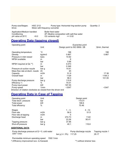
Pump size/Stages: <strong>HGC</strong> 2/<strong>12</strong> Pump type: Horizontal ring-section pump Quantity: 2<br />
Drive:<br />
Motor with frequency converter<br />
Application/Medium handled: Boiler feed water<br />
Conditioning<br />
AF Alkaline composition with salt-free water<br />
pH value at 25°C >9.0 O2 contents mg/l
Type / size Speed [1/min] Temperature [°C] Density [kg/dm3]<br />
HG 2/<strong>12</strong> 4.1 4.1 3347 198 0.867<br />
Qmin, continuous<br />
1000<br />
Qmin, thermal<br />
Qmax<br />
Discharge head<br />
[m]<br />
500<br />
0 20 [m3/h] 40 60 80 100<br />
16<br />
[m]<br />
NPSH req.<br />
10<br />
2<br />
0 20 [m3/h] 40 60 80 100<br />
Efficiency<br />
50<br />
[% ]<br />
0<br />
0 20 [m3/h] 40 60 80 100<br />
300<br />
[kW ]<br />
Power<br />
200<br />
50<br />
0 20 [m3/h] 40 60 80 100
Nozzle Design DN PN Drilled acc to Position [°] *)<br />
Inlet Flange 80 40 EN 1092-1 vertically upwards<br />
Outlet Block flange 65 160 EN 1092-1 vertically upwards<br />
Tapping Flange 40 63 EN 1092-1 45.0<br />
*) clockwise viewed from the driven end ( 0° = top)<br />
Shaft Seal Manufacturer Type Material Cooling<br />
Mech. seal Burgmann H75N AQ1EGG Circulation and jacket cooling<br />
Cooler KSB DWK 10<br />
Axial thrust balancing<br />
Hydraulically by means of Disc<br />
Bearing Design Lubrication Cooling Indicator<br />
Radial Plain bearing Oil ring No Oil level indicator with<br />
marking<br />
Thrust - - -<br />
Pump Feet Arrangement<br />
Centreline<br />
Accessories<br />
Balancing water pipe return to the deaerator tank including angle-way safety relief valve<br />
Internal piping for circulation and jacket cooling<br />
Instrumentation acc. to list of measuring points<br />
Special tools and appliances 1 set<br />
Baseplate for pump and motor (with foundation bolts)<br />
Material<br />
Part No. Description Material<br />
106 Suction casing 1.4317-I<br />
107 Discharge casing S355J2G3+PLATT<br />
108 Stage casing 1.4006+QT<br />
171 Diffuser 1.4008<br />
210 Shaft C45+C+GAL CR<br />
230.01 Suction stage impeller 1.4008.09<br />
230.02 Impeller 1.4008.09<br />
441 Shaft seal housing 1.4021+QT700<br />
502.02 Casing wear ring RWA 350<br />
523.01 Shaft sleeve 1.4138<br />
601.01 Balance disc 1.4024.09<br />
602.01 Balance disc seat RWA 350
Lubricant Quality (recommendation)<br />
ISO high-quality oil VG 32 or VG 46 to DIN ISO 3448, TD 32 or TD 46 to DIN 51515, or equivalent.<br />
If a gear or geared variable speed coupling is included in the scope of supply, observe the manufacturer's<br />
instructions.<br />
Lubricant Quantities<br />
Bearing Lubrication Quantity Unit<br />
Radial bearing Oil ring 1.5 Liter<br />
Coupling Type Lubricant Quantity Unit<br />
Pump - motor ZIZS 2 Grease 0.16 dm3<br />
Cooling water quality (recommendation)<br />
Only cleaned water not liable to precipitation of salts causing hardness may be used as coolant. The cooling water<br />
temperature at the outlet must not exceed 55 °C. (131 F)<br />
Cooling water requirement<br />
Quantity<br />
Unit<br />
Jacket cooling 3.52 l/min<br />
Circulation 6.49 l/min<br />
Normal<br />
Maximum<br />
Inlet temperature [°C] 20 45<br />
Minimum<br />
Maximum<br />
Cooling water pressure [bar] 2 6
1. Explanatory Notes<br />
The noise data below conform to DIN standard 45635 - Measurement of noise emitted by machines - Part 1 – Airborne noise emission,<br />
Enveloping surface method, Basic method divided into 3 grades of accuracy and Part 24 – Measurement of airborne noise emitted by<br />
machines, Enveloping surface method, Liquid pumps.<br />
The noise data meet the requirements of accuracy grade 2.<br />
DIN 45635 standards for measurement largely correspond to international stipulations such as EN ISO 3744-09.1994 and<br />
ISO 1<strong>12</strong>01-<strong>12</strong>.1995.<br />
The equipment used for measurements meet the requirements placed on precision sound level meters DIN EN 60651.<br />
It was submitted to the standardising authority for examination within the required period of 2 years.<br />
The non-weighted and A-weighted sound pressure levels were used as acoustic measurands expressed in dB.<br />
The frequency weighting curve A is defined in DIN EN 60651.<br />
2. Prerequisites<br />
The noise data refer to the pump without sound insulation.<br />
The data apply without electric motor.<br />
The noise particulars apply to the normal operating range of the pump, i.e. Q/Qopt = 0.8 – 1.2<br />
No allowance is made for operation under extreme part-load, overload or cavitation conditions.<br />
3. Definitions<br />
LpA: The surface sound pressure level is the A-weighted sound pressure level averaged over the measurement surface S, expressed in dB.<br />
LS: The measurement surface ratio is calculated from the measurement surface S, whose size depends on the position of the measuring<br />
points.<br />
The measurement distance is typically chosen to be 1 m from the machine outline. LS is expressed in dB.<br />
LWA: The A-weighted sound power level is the rate of the total noise radiated by the machine into the ambient air, expressed in dB.<br />
The air-borne sound octave spectrum supplements the surface sound pressure level LpA data and provides information on the noise<br />
composition in the acoustic frequency range from 63 Hz to 8 kHz.<br />
This frequency range is subdivided in octave bands characterised by their centre frequency.<br />
4. Noise Characteristic Values<br />
The following values are expected noise values and cannot be warranted. The values indicated do not include the measurement tolerance.<br />
If the values are to be warranted, an allowance for design and measurement tolerances of +3 dB has to be made.<br />
Noise Characteristics for Operating Point (expected values)<br />
Operating point - pump: Q [m3/h] H [m] P [kW]<br />
51.9 1<strong>12</strong>8.4<br />
It. Component Description N LpA LS LWA<br />
[1/min] [dB] [dB] [dB]<br />
1 Pump <strong>HGC</strong> 2/<strong>12</strong> 3347 83 14 97<br />
Total of items 1 83 14 97<br />
Air-borne sound octave spectr. in 63 Hz <strong>12</strong>5 Hz 250 Hz 500Hz 1000 2000 4000 8000<br />
dB for item 1 75 71 73 76 Hz 79 Hz 78 Hz 74 Hz 71
Pump - motor<br />
Manufacturer<br />
FLENDER<br />
Type / size ZIZS 2<br />
Coupling type<br />
Tooth coupling<br />
Mass 23.1 kg<br />
Quantity 2<br />
Spacer for shaft distance 180 mm<br />
Retaining ring<br />
No<br />
Lubrication<br />
Grease<br />
Max. bore 80 mm<br />
Spacer plates<br />
1 set<br />
Coupling guard<br />
Sheet steel<br />
Balancing quality Q 2,5
The minimum flow valve protects the pump against overheating during operation in the low load range. Increased<br />
wear on the pump and the minimum flow system is not avoidable.<br />
If the installation's mode of operation requires low load, at flow rates below 1.35 x Qmin (e.g. operation at extremely<br />
low flow, filling of the boiler, stand-by heating and minimum flow rate, etc.), notification thereof shall be given. In this<br />
case, a minimum flow valve with branch for manual operation must be used.<br />
The characteristics of the boiler control valve can influence the behaviour of the minimum flow valve, and the valve<br />
must be suitable for low flow operation.<br />
2 Minimum flow control valve<br />
Manufacturer:<br />
SCHROEDER<br />
Type series: SSV 18 A Scheme No. UA429759<br />
Inlet branch DN 65 PN 160 EN 1092-1<br />
Outlet branch DN 65 PN 160 EN 1092-1<br />
Bypass DN 40 PN 160 EN 1092-1<br />
including screws/bolts and seal elements for the connection pump – minimum flow control valve
INDEX<br />
MINDESTFÖRDERSTROMVENTIL UND ENTLASTUNGSFLÜSSIGKEITSRÜCKFÜHRUNG<br />
MINIMUM FLOW DEVICE AND BALANCING LIQUID RETURN<br />
Entlastungsflüssigkeit-Rückführung zum Zulaufbe<br />
hälter.<br />
Bei Leitungslängen >10 m ist eine Erweiterung von<br />
DN25 auf DN40 bzw. von DN40 auf DN50 erforder<br />
lich. Max. Länge 30 m.<br />
Balancing liquid return to feed water tank.<br />
Return line length >10 m require an enlargement from<br />
DN25 to DN40 resp. from DN40 to DN50.<br />
Max. length 30 m.<br />
Blende zur Vermeidung<br />
der Verd<strong>amp</strong>fung in der<br />
Leitung. So nahe wie<br />
möglich am Zulaufbe<br />
hälter.<br />
Orifice to prevent evapo<br />
ration in the line. Located<br />
as close as possible to<br />
the feed water tank.<br />
Dp = 2.5 bar<br />
Dp = 36.25 psi<br />
Zulaufbehälter<br />
Feed water tank<br />
Mindestförderstrom zum Zulaufbehälter<br />
Minimum flow outlet to feed water tank<br />
B<br />
A<br />
A B<br />
B<br />
A<br />
B<br />
A<br />
nur bei Mindestförder<br />
stromventil SMA63<br />
only for minimum flow<br />
valve SMA63<br />
B<br />
A<br />
Absperrventil, geschweißt<br />
Stop valve, welded<br />
A<br />
B<br />
Rückschlagventil, geschweißt<br />
Non-return valve, welded<br />
Kundenseitige Abführung an<br />
einen sicheren Ort.<br />
Discharge to a safe place to<br />
be provided by the customer.<br />
B<br />
A<br />
Sicherheitsventil<br />
Safety valve<br />
Blende<br />
Orifice<br />
Flanschverbindung<br />
Flange connection<br />
Liefergrenze, A = KSB, B = Kunde<br />
Limits of scope of supply, A = KSB, B = Customer<br />
05<br />
neues Original<br />
ÄNDERUNG<br />
ALTERATION<br />
NORM<br />
STANDARD<br />
GEPRÜFT<br />
APPROVED<br />
BEARB.<br />
PREPARED<br />
T-MP132-G<br />
02.04.03<br />
02.04.03<br />
DATUM<br />
DATE<br />
02.04.03<br />
DATUM<br />
DATE<br />
Meyer<br />
Stahl<br />
NAME<br />
Stahl<br />
NAME<br />
BENENNUNG/DENOMINATION<br />
Fließschema<br />
Flow Diagram<br />
NR./NO.<br />
UA4 29759 01 EN<br />
SCHUTZVERMERK ISO 16016<br />
COPYRIGHT ACCORDING TO ISO 16016<br />
ERS. FÜR/REPL. FOR<br />
ENTST. AUS/ORIGINAT. FROM<br />
BLATT-NR.<br />
SHEET-NO.<br />
1<br />
ANZ. D.<br />
BLÄTTER<br />
NO. OF<br />
SHEETS<br />
1
The strainer in the inlet pipe serves as an additional pump protection and is destined to hold back welding beads,<br />
scale and other impurities (>500µm) from the pump. It is not intended to as a filtration system, since the gaps within<br />
the pumps are smaller than 500µm. A strainer with smaller mesh width can be quoted as an additional option. In any<br />
case, a filtration system must be installed by customer, independent from the mesh size of the strainer.<br />
Main pump<br />
Type<br />
Conical strainer<br />
Standard ZN 1364<br />
Manufacturer<br />
FIEDLER<br />
Type<br />
AF<br />
Quantity 2<br />
Installation<br />
Vertical<br />
Weight kg 1.3<br />
DN DN: <strong>12</strong>5<br />
Type<br />
Perforated plate with fine wire mesh<br />
(0.5x0.25 mm)<br />
Material<br />
CrNiSt<br />
Length mm 500<br />
Head loss m 0.34 (with clean strainer)<br />
Strainer casing<br />
Length<br />
555 mm<br />
DN / PN <strong>12</strong>5 / 40
Meas.<br />
point<br />
No.<br />
Location of measuring point<br />
Medium/Material<br />
PI 101 Pump suction pressure<br />
Suction nozzle<br />
Feed pump<br />
Feed water<br />
PI 102 Pump discharge pressue<br />
Discharge nozzle<br />
Feed pump<br />
Feed water<br />
PI 103 Tapping pressure<br />
Tapping nozzle<br />
Feed pump<br />
Feed water<br />
PI 104 Balancing water pressure<br />
Balancing water line<br />
Feed pump<br />
Feed water<br />
PDIA<br />
101<br />
TI 103<br />
TI 104<br />
TAZ<br />
105<br />
TAZ<br />
106<br />
Differential pressure<br />
Strainer<br />
Feed pump<br />
Feed water<br />
Oil temperature<br />
Radial bearing, DE<br />
Feed pump<br />
Oil<br />
Oil temperature<br />
Radial bearing, NDE<br />
Feed pump<br />
Oil<br />
Bearing temperature<br />
Radial bearing, DE<br />
Feed pump<br />
Metal<br />
Bearing temperature<br />
Radial bearing, NDE<br />
Feed pump<br />
Metal<br />
YE 103 Shock pulse measurement<br />
Driven end<br />
YE 104 Shock pulse measurement<br />
Non-driven end<br />
Type<br />
Scope of supply<br />
Pressure gauge<br />
KSB<br />
Pressure gauge<br />
KSB<br />
Pressure gauge<br />
KSB<br />
Pressure gauge<br />
KSB<br />
Measuring<br />
range<br />
Housing<br />
diameter<br />
Threaded<br />
connect.<br />
0 - 25 bar<br />
100 mm<br />
G 1/2 A<br />
0 - 160 bar<br />
100 mm<br />
G 1/2 A<br />
0 - 100 bar<br />
100 mm<br />
G 1/2 A<br />
0 - 25 bar<br />
100 mm<br />
G 1/2 A<br />
Differential pressure 0-1,0 bar<br />
gauge with magnetic 100 mm<br />
snap-action contact G 1/2<br />
KSB<br />
Thermometer<br />
KSB<br />
Thermometer<br />
KSB<br />
RTD, 1 x PT 100<br />
KSB<br />
RTD, 1 x PT 100<br />
KSB<br />
SPM nipple<br />
KSB<br />
SPM nipple<br />
KSB<br />
0 - 100 ° C<br />
150 mm<br />
G 1/2A<br />
0 - 100 ° C<br />
150 mm<br />
G 1/2A<br />
-<br />
-<br />
M18 x 1,5<br />
x 11<br />
-<br />
-<br />
M18 x 1,5<br />
x 11<br />
M8<br />
M8<br />
Measuring Instrument<br />
Sensor Indication /<br />
length Interlocking<br />
Diameter<br />
d<br />
Local<br />
Local<br />
Local<br />
Local<br />
Make<br />
Drawing No.<br />
DIN No.<br />
Ident. No.<br />
WIKA<br />
ZN 16064<br />
00402207<br />
WIKA<br />
ZN 16064<br />
00402211<br />
WIKA<br />
ZN 16064<br />
00402210<br />
WIKA<br />
Remarks<br />
With<br />
pressure<br />
gauge valve<br />
With<br />
pressure<br />
gauge valve<br />
With<br />
pressure<br />
gauge valve<br />
With<br />
pressure<br />
gauge valve<br />
ZN 16064<br />
00402207<br />
Local with contact WIKA With<br />
pressure<br />
gauge valce<br />
160 mm SIKA oder WIKA<br />
DIN 16185<br />
00402376<br />
160 mm SIKA oder WIKA<br />
<strong>12</strong>0 mm<br />
4 / 6 mm<br />
<strong>12</strong>0 mm<br />
4 / 6 mm<br />
PB alarm T => 90 °C<br />
PB switch-off T =><br />
100 °C<br />
PB alarm T => 90 °C<br />
PB switch-off T =><br />
100 °C<br />
DIN 16185<br />
00402376<br />
WIKA oder<br />
RECKMANN<br />
ZN 1477<br />
01058630<br />
WIKA oder<br />
RECKMANN<br />
ZN 1477<br />
01058630<br />
-<br />
ZN 407<br />
00<strong>12</strong>9477<br />
-<br />
ZN 407<br />
00<strong>12</strong>9477
Quality Class according to ZN 35 – 4<br />
EN<br />
Coating<br />
type<br />
Permissible<br />
temperature<br />
range<br />
Surface<br />
preparation<br />
Primer<br />
Finish coat<br />
A<br />
B<br />
C<br />
-30 to +80 [°C]<br />
-22 to +176 [F]<br />
-30 to +80 [°C]<br />
-22 to +176 [F]<br />
+80 to +400 [°C]<br />
+176 to +752 [F]<br />
Degreased by<br />
solvent<br />
Sand-blasting<br />
SA 1<br />
Degreased by<br />
solvent<br />
Product name<br />
Luberhyd 1K<br />
Luberhyd 1K<br />
Colour type and film<br />
thickness [µm]<br />
Hydro dip primer,<br />
water-thinned<br />
1 x approx. 40-50<br />
Hydro dip primer,<br />
water-thinned<br />
1 x approx. 40-50<br />
Product name<br />
Luberhyd<br />
Luberhyd<br />
- - Lubersil 1-<br />
component<br />
varnish paint<br />
Colour type and film<br />
thickness [µm]<br />
Acrylate-alkyd<br />
compound, waterthinned<br />
1 x approx. 40-50<br />
Acrylate-alkyd<br />
compound, waterthinned<br />
1 x approx. 40-50<br />
Silicon resin compound,<br />
water-thinned<br />
1 x approx. 30-40<br />
Colour<br />
RAL<br />
5002<br />
ultramarine<br />
blue<br />
RAL<br />
5002<br />
ultramarine<br />
blue<br />
Metallic<br />
silver<br />
Coating Type and Colour<br />
Item *) Coating type RAL No.<br />
Pump C RAL 9006<br />
Coupling guard A RAL 5002<br />
Oil lines A RAL 5002<br />
Cooling water lines A RAL 5002<br />
Baseplate B RAL 5002<br />
Balancing water pipe, pressure gauge line, C RAL 9006<br />
pre-warming line<br />
Min. flow control valve with auxiliary valves Manufacturer's standard Manufacturer's standard<br />
Gear / variable speed coupling Manufacturer's standard Manufacturer's standard<br />
Strainer body C RAL 9006<br />
*) if included in scope of supply<br />
Preservation for pump removed from system (indoor storage). Period and measures.<br />
Storage of pump < <strong>12</strong> months<br />
Pump is preserved after performance test<br />
(Anticorit 87, Fuchs Mineralölwerke GmbH)
Documentation, drawings Scheduled date *)<br />
Installation plan + forces and moments<br />
Sectional drawing<br />
List of components<br />
Standard P+ I diagram<br />
List of measuring points<br />
PO+4<br />
PO+<strong>12</strong><br />
PO+<strong>12</strong><br />
PO+8<br />
PO+8<br />
Language:<br />
English<br />
Quality documentation Scheduled date *)<br />
Declaration of quality<br />
D<br />
Test curve, record D-1<br />
Balancing record<br />
Pressure test record<br />
Language:<br />
German / English<br />
Kind of documentation<br />
Quantity<br />
Documentation on CD-ROM 1<br />
Instruction manual Scheduled date Quantity<br />
Instruction manual on CD-ROM D 1<br />
Language:<br />
English<br />
*) PO+n: n weeks after purchase order<br />
D: on delivery, D-n: n weeks before delivery
Material inspections<br />
Standard QCP / acceptance class ZN 57 117 / 1<br />
Certification<br />
Declaration of quality<br />
Language of certificate<br />
German / English (depending on supplier)<br />
Pressure test (dynamic)<br />
Standard pressure test plan UA4 11390 02<br />
Test pressure<br />
1.3 x nominal pressure<br />
Suction casing 19 barg<br />
Chamber to disch. casing<br />
Different for each stage<br />
Tapping casing 57.73 barg<br />
Discharge casing 165 barg<br />
Seal housing / balancing water chamber 19 barg<br />
Hydraulic performance test<br />
Performance test procedure<br />
Test curve no.<br />
Test class<br />
ISO 9906 / 2B<br />
No. of Q/H curve meas. points 5 No. of NPSH flow points 0<br />
Pumps per order inspected/tested Quantity - non-witnessed Quantity - witnessed<br />
Pressure test 2 0<br />
Performance test *) 2 0<br />
NPSH test 0 0<br />
Invitation time for witnessed inspections/tests 5 Working days<br />
For witn. and special insp./tests: take into account delivery time<br />
*) Pumps will be tested with closed tapping, tapping pressure will be recorded
1. Explanations<br />
DE vert.<br />
NDE vert.<br />
DE horiz.<br />
axial<br />
NDE horiz.<br />
KSB’s HG pumps are designed for compliance with the vibration velocity limits according to nach DIN ISO 10816-7, category I. These are<br />
determined as overall root-mean-square values v eff [mm/s] in the frequency range of 10 – 1000 Hz.<br />
The permissible root-mean-square value of the vibration velocity is determined by the type of assembly and the evaluation zone B.<br />
The following applies to HG pumps, all values in mm/s<br />
Preferred operating range<br />
Permitted operating range<br />
200 kW / 268 hp 200 kW / 268 hp<br />
Site of installation 2,5 3,5 4,0 5,0<br />
Acceptance test in KSB test bed 3,3 4,3 4,0 5,0<br />
The measurement points are schematically represented in the figure above.<br />
NDE: Non Drive End DE: Drive End<br />
2. Prerequisites<br />
The above-mentioned vibration velocity values shall apply under the following conditions:<br />
1. Measurement of vibrations in steady-state operation at nominal speed or within the specified speed range (not under transient<br />
operating conditions, not with changing speeds or loads).<br />
Measurement at nominal flow rate or in the preferred operating range of between 0.7 .... 1.2 x Q opt (extreme part load or overload as<br />
well as operation at cavitation are excluded), permitted operating range is defined as 0,5 .... 1.25 x Q opt .<br />
2. The measurements are performed at the positions indicated using vibration velocity sensors. Only measuring instruments that were<br />
calibrated within the framework of the applicable quality assurance system are used.<br />
3. Measurement of vibration velocity in the installation/plant:<br />
For operation in the installation/plant, the machine has to be installed in compliance with the instruction manual.