External Control Manual - Panasonic Electric Works Corporation of ...
External Control Manual - Panasonic Electric Works Corporation of ...
External Control Manual - Panasonic Electric Works Corporation of ...

You also want an ePaper? Increase the reach of your titles
YUMPU automatically turns print PDFs into web optimized ePapers that Google loves.
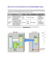
ME-LPS-EX-3 No.9000-0027-35V<br />
2012.4<br />
panasonic-electric-works.net/sunx<br />
FAYb Laser Marker<br />
SERIES<br />
<strong>External</strong> <strong>Control</strong> <strong>Manual</strong>
Preface<br />
Thank you for purchasing Laser Marker .<br />
For full use <strong>of</strong> this laser marker safely and properly, please read this manual carefully.<br />
This product has been strictly checked and tested prior to its delivery. However, please make sure that this product operates<br />
properly before using it.<br />
In case that the product becomes damaged or does not operate as specifi ed in this manual, contact the dealer you<br />
purchased it or our sales agency.<br />
� Symbol Indications<br />
This manual uses a variety <strong>of</strong> symbols to explain safety precautions, instructions, and references for operating personnel.<br />
Before reading this manual, fully understand the contents <strong>of</strong> these indications.<br />
� Note<br />
2<br />
This symbol denotes a general prohibition notice.<br />
This symbol denotes a general action which operators must take.<br />
“CHECK” denotes any instructions or precautions for using this product.<br />
“REFERENCE” denotes any hints for operation, detail explanations, or references.<br />
1. Before using this product, or before every starting operation, please confi rm the correct functioning and performance <strong>of</strong><br />
this product.<br />
2. This manual is subject to LP-S series. Note that the illustration may vary with model.<br />
3. Contents <strong>of</strong> this manual could be changed without notice. This manual must not be partially or totally copied or revised.<br />
4. If there are any questions, mistakes, or comments in this manual, please notify us.<br />
5. Please remind that we have not responsibility <strong>of</strong> any results <strong>of</strong> operations in regardless <strong>of</strong> the above 4 clause.<br />
� Setting ranges<br />
This manual describes the setting ranges for LP-S500.Items where different setting ranges are specifi ed for different models<br />
are marked with an asterisk (*).<br />
For setting ranges for each model, refer to “Input Setting Value by Series” (P.212 and onwards).<br />
� Trademarks<br />
� Windows is a registered trademark or trademark <strong>of</strong> Micros<strong>of</strong>t <strong>Corporation</strong> in the United States and other countries.<br />
� QR Code is a registered trademarks <strong>of</strong> DENSO WAVE INCORPORATED.<br />
� “Adobe ® ,” “Adobe ® Logo,” “Adobe Reader ® ,” and “Adobe ® Illustrator ® ” are registered trademarks <strong>of</strong> U.S.A. Adobe Systems<br />
Incorporated and other countries.<br />
� All other product names and companies provided in this manual are trademarks or registered trademarks <strong>of</strong> their<br />
respective companies.
Quality Use <strong>of</strong> Each <strong>Manual</strong><br />
This laser marker is prepared for the following manuals. Read the corresponding manual for the target, and operate this<br />
laser marker fully. Also, store these manuals after reading them.<br />
�Starting Guide<br />
This manual describes the safety precautions for using the laser marker and the items required for the introduction and<br />
installation <strong>of</strong> the laser marker.<br />
�Operation <strong>Manual</strong><br />
This manual describes the items required for the operation <strong>of</strong> the laser marker.<br />
The following contents, cautions, basic active operation, screen operation for setting marking contents, and measurement<br />
for error are described in this manual.<br />
Mainly the users that operate this laser marker for actual marking procedure shall be required for reading this manual.<br />
�<strong>External</strong> <strong>Control</strong> <strong>Manual</strong><br />
This manual describes the external control <strong>of</strong> the laser marker.<br />
• <strong>Control</strong> from I/O connector<br />
Describes the signal layout <strong>of</strong> I/O connector, I/O rating, timing chart, example <strong>of</strong> control, etc.<br />
• <strong>Control</strong> from communication port (RS-232/Ethernet)<br />
Describes the signal layout <strong>of</strong> the connector, communication data format, communication command, example <strong>of</strong><br />
control, etc.<br />
Mainly the machine builder and system integrator shall be required for reading this manual.<br />
Operation <strong>Manual</strong> and <strong>External</strong> <strong>Control</strong> <strong>Manual</strong> are included on an attached CD-R “Laser Marker PDF<br />
<strong>Manual</strong>”. The hardcopy versions <strong>of</strong> the manuals are available for pay. For details, please contact our sales<br />
agency.<br />
To read the PDF manual, Adobe Reader (Version 7 or later) <strong>of</strong> Adobe Systems Incorporated is required.<br />
3
Contents<br />
4<br />
Preface …………………………………………………… 2<br />
Quality Use <strong>of</strong> Each <strong>Manual</strong> …………………………… 3<br />
1-1 Operation Method for Laser Marker ……………… 8<br />
1-1-1 Operation Method Using <strong>External</strong> <strong>Control</strong> ………………… 8<br />
1-1-2 Operation Procedure Using Laser Marker ………………… 9<br />
1-1-3 Shift to Remote Mode …………………………………………10<br />
1-1-4 Shift to RUN Mode ……………………………………………11<br />
1-1-5 DIP Switch ……………………………………………………12<br />
2-1 Basics ………………………………………………… 14<br />
2-1-1 Before <strong>External</strong> <strong>Control</strong> <strong>of</strong> Laser Marker by I/O ……………14<br />
2-1-2 Terminal Connector ……………………………………………15<br />
2-1-3 Input/Output Terminal …………………………………………20<br />
2-1-4 Signals and Details <strong>of</strong> I/O Connector ………………………22<br />
2-1-5 Signals and Details <strong>of</strong> Interlock Connector …………………23<br />
2-1-6 Connecting Sample with <strong>External</strong> Devices …………………24<br />
2-1-7 Input Rating and Input Circuit ………………………………26<br />
2-1-8 Output Rating and Output Circuit ……………………………27<br />
2-2 Input/Output Operation …………………………… 28<br />
2-2-1 Input Signal ……………………………………………………28<br />
2-2-2 Output Signal …………………………………………………32<br />
2-2-3 Power …………………………………………………………33<br />
2-3 Timing Chart ………………………………………… 34<br />
2-3-1 Basic Input/Output ……………………………………………34<br />
2-3-2 Trigger Marking ………………………………………………35<br />
2-3-3 Equidistant Marking (Flying Object Marking) ………………35<br />
2-3-4 Guide Laser ……………………………………………………36<br />
2-3-5 Select File ………………………………………………………37<br />
2-3-6 Time Hold ………………………………………………………38<br />
2-3-7 Counter End ……………………………………………………38<br />
2-3-8 Count-up/Count-down ………………………………………39<br />
2-3-9 Counter Reset …………………………………………………40<br />
2-3-10 Rank/Offset Marking …………………………………………41
2-3-11 Laser Stop1 …………………………………………………42<br />
2-3-12 Laser Stop2 …………………………………………………43<br />
2-3-13 Serial Data Marking …………………………………………46<br />
2-3-14 Serial Offset Marking ………………………………………46<br />
3-1 Basics ………………………………………………… 48<br />
3-1-1 Before <strong>External</strong> <strong>Control</strong> <strong>of</strong> Laser Marker<br />
by Communication Port ……………………………………48<br />
3-1-2 Communication Port Connector ……………………………49<br />
3-1-3 Communication Port Specifi cation …………………………50<br />
3-1-4 Setting <strong>of</strong> Communication Conditions ………………………51<br />
3-1-5 Connecting Sample with <strong>External</strong> <strong>Control</strong>ler ………………52<br />
3-1-6 Connection Check ……………………………………………54<br />
3-1-7 <strong>Control</strong> Sample ………………………………………………55<br />
3-1-8 Communication Data Format ………………………………58<br />
3-1-9 Communication Sequence ……………………………………62<br />
3-2 Communication Command and Function ………… 64<br />
3-2-1 Command List …………………………………………………64<br />
3-3 Command Description ……………………………… 66<br />
3-4 LP-F10/F10W Mode …………………………… 139<br />
3-4-1 Selecting DIP Switch ……………………………………… 139<br />
3-4-2 LP-F10/F10W Mode Command List ……………………… 140<br />
3-5 Each Command Description in<br />
LP-F10/F10W Mode …………………………… 142<br />
3-6 Notes ……………………………………………… 191<br />
3-6-1 Marking Operation and Command Transmission ……… 191<br />
3-6-2 Combined Use <strong>of</strong> RS-232C and I/O Connector ………… 192<br />
Troubleshooting ……………………………………… 194<br />
Error Indication ……………………………………… 204<br />
Alarm ……………………………………………………………… 204<br />
Warning …………………………………………………………… 207<br />
Input Setting Value by Series<br />
(LP-S Standard Mode) ……………………………… 212<br />
5
6<br />
Input Setting Value by Series<br />
(LP-F10/F10W Mode) ………………………………… 216<br />
Character Code Table ……………………………… 220<br />
ASCII Code ………………………………………………………… 220<br />
Original Font ……………………………………………………… 221<br />
JIS Level-1 Font …………………………………………………… 222<br />
JIS Level-2 Font …………………………………………………… 228<br />
Index …………………………………………………… 238
1<br />
Before <strong>External</strong> <strong>Control</strong>
1-1 Operation Method for Laser Marker<br />
1-1-1 Operation Method Using <strong>External</strong> <strong>Control</strong><br />
8<br />
CAUTION<br />
It is obligated by IEC/FDA/JIS that laser products shall incorporate a key-actuated master control. Actuation<br />
<strong>of</strong> our laser marker is basically controlled by the key switch located on the front <strong>of</strong> the controller box.<br />
However, in considering situations when the laser marker is operating as a part <strong>of</strong> a larger system, the laser<br />
marker turns on if the key switch is already in ON position, and power is supplied. In this case, be sure that<br />
the external system controls the operation <strong>of</strong> the laser marker with a key-actuated master control.<br />
In case <strong>of</strong> controlling the laser marker with the external control device, the following three connecting methods are<br />
applicable.<br />
<strong>External</strong> <strong>Control</strong> using I/O *1 <strong>External</strong> <strong>Control</strong> using<br />
communication port *1<br />
ABCI<br />
ABCI<br />
RUN Mode *2<br />
(Console or monitor is used)<br />
*1 It is available to combine I/O and the communication port for external control.<br />
*2 It perceives the marking starting signal from the external device, but other than it are controlled by the console or monitor.<br />
<strong>Manual</strong> Marking<br />
Other than external control, the manual marking can be performed using the console (option) or the personal computer<br />
installed Laser Marker NAVI plus.<br />
ABCI<br />
ABCD<br />
ABCD
1-1-2 Operation Procedure Using Laser Marker<br />
This section describes the basic operation procedures using external control.<br />
� Flow Chart<br />
<strong>External</strong> <strong>Control</strong> using I/O<br />
<strong>Control</strong>ler remote switch ON<br />
Turn ON key switch <strong>of</strong> laser marker controller<br />
<strong>External</strong> <strong>Control</strong> using<br />
communication port<br />
� �<br />
Shift to remote mode.<br />
Refer to “3-1-3 Shift to Remote Mode” <strong>of</strong> <strong>External</strong> <strong>Control</strong> <strong>Manual</strong>.<br />
RUN Mode<br />
(Console or monitor is used)<br />
� �<br />
Select File Select File<br />
Select fi le No. using external control.<br />
Select fi le on console and<br />
Monitor screen.<br />
� �<br />
Start Laser pumping Start Laser pumping<br />
Turn ON the laser using the external control.<br />
* After the start <strong>of</strong> pumping, marking is not started for about 20 seconds<br />
with LP-S*** type and about 15 seconds with LP-S***W type.<br />
Press the laser pumping switch<br />
on the controller.<br />
* After the start <strong>of</strong> pumping,<br />
marking is not started for about<br />
20 seconds with LP-S*** type<br />
and about 15 seconds with LP-<br />
S***W type.<br />
� �<br />
Open shutter Start RUN mode<br />
Turn ON the shutter using the internal control.<br />
READY Output ON<br />
The trigger is ready for reception.<br />
Trigger Input ON<br />
The product starts marking.<br />
Marking<br />
Select “RUN” on the monitor<br />
screen, and Press “START”.<br />
� �<br />
�<br />
�<br />
• For turning into remote mode, there are two methods other than turning on the remote switch <strong>of</strong> the controller,<br />
(1) inputting remote <strong>of</strong> terminal block and (2) turning on the key switch for remote.<br />
For details, refer to “3-1-3 Shift to Remote Mode” <strong>of</strong> <strong>External</strong> <strong>Control</strong> <strong>Manual</strong>.<br />
• It is available to combine I/O and the communication port for external control.<br />
9
1-1-3 Shift to Remote Mode<br />
In case <strong>of</strong> controlling the laser marker by external control such as I/O and communication port, it needs to shift the laser<br />
marker to “Remote Mode”. Before performing the external control by either method shown below, shift the laser marker to<br />
“Remote Mode”.<br />
Press remote switch in front <strong>of</strong> controller.<br />
Turn ON “Remote Input” from the terminal block.<br />
10<br />
* Check that DIP switch No. 5 is OFF.<br />
“1-1-5 DIP Switch” (P.12)<br />
* Check that DIP switch No. 5 is ON.<br />
“1-1-5 DIP Switch” (P.12)<br />
Turn ON the key switch <strong>of</strong> the controller, and shift the mode <strong>of</strong> the laser marker into the<br />
remote one automatically.<br />
* Check that DIP switch No. 5 is OFF, and No. 6 is ON.<br />
“1-1-5 DIP Switch” (P.12)
1-1-4 Shift to RUN Mode<br />
When the laser marker is activated in “RUN Mode”, the internal shutter is opened, and the device is ready for receiving<br />
trigger from input terminal.Since the setting contents <strong>of</strong> the trigger is refl ected in “RUN Mode”, start “RUN Mode” after<br />
performing “Trigger Setting” (Refer to Operation <strong>Manual</strong>).<br />
Shift the mode <strong>of</strong> the laser marker into “RUN Mode” following the following screens.<br />
Operator Adjusting Screen Maintenance Inspection<br />
Screen<br />
File Screen Character Setting Screen<br />
Function Setting Screen Marking Condition Screen Laser Setting Screen Trigger Setting Screen<br />
Common Setting Screen Image Display<br />
The � shows that the condition is already set.<br />
Pressing “START” on operation screen changes the marking mode into “RUN Mode”. The internal shutter<br />
<strong>of</strong> the laser marker is opened by pressing “START”, and the laser marker is ready for receiving trigger from<br />
input terminal.<br />
Shift Procedure to RUN Mode<br />
1 Change<br />
2 Press<br />
the marking mode into “RUN”.<br />
“START”.<br />
The internal shutter <strong>of</strong> the laser marker is opened by<br />
pressing “START”, and the laser marker is ready for<br />
receiving trigger from input terminal.<br />
11
1-1-5 DIP Switch<br />
Connecting Sample with <strong>External</strong> <strong>Control</strong>ler<br />
No.1 Switch for system reservation. Keep OFF <strong>of</strong> this switch.<br />
No.2 Selects external control method <strong>of</strong> “Laser Pumping” and “Shutter <strong>Control</strong>”.<br />
ON indicates “Laser Pumping” and “Shutter <strong>Control</strong>” are externally controlled using<br />
communication port.<br />
OFF indicates “Laser Pumping” and “Shutter <strong>Control</strong>” are controlled using input terminal.<br />
* Turn on this switch when using the laser radiation command (SPT).<br />
No.3 Sets buzzer for error occurrence.<br />
ON This setting does not sound buzzer when occurring error.<br />
OFF This setting sounds buzzer when occurring error.<br />
No.4 Selects valid/invalid for password lock when shifting screen from operation to each setting one.<br />
ON Sets invalid for password lock.<br />
OFF Sets valid for password lock.<br />
Refer to “When password is forgotten” for the detail.<br />
No.5 Selects shifting method for the remote mode.<br />
ON <strong>Control</strong>s switching to the remote mode from the input terminal block.<br />
OFF In case <strong>of</strong> shifting mode into remote mode using the remote switch on the front <strong>of</strong> the<br />
controller. (To set No.6 to ON, set No.5 to OFF.)<br />
No.6 Selects status when the key switch is turned ON.<br />
ON Shifts to the remote mode by setting the key switch to ON.<br />
OFF Does not shift to the remote mode by turning the key switch ON.<br />
(To set No.5 to ON, set No.6 to OFF.)<br />
CAUTION<br />
No.7<br />
No.8<br />
12<br />
If the DIP switch No.5 and No.6 are used while turned on, construct a system for re-pumping the laser manually<br />
as safety protection measures after stop <strong>of</strong> the laser radiation.<br />
The command mode <strong>of</strong> the serial communication switches over according to the combination <strong>of</strong> ON and OFF <strong>of</strong><br />
the No.7 and No.8.<br />
LP-S Mode LP-F10 Mode LP-F10W Mode<br />
No.7…OFF<br />
No.8…OFF<br />
No.7…ON<br />
No.8…OFF<br />
• The DIP switch is located in rear <strong>of</strong> the controller. (P.32)<br />
• The all DIP switch is set to OFF side at factory shipment.<br />
• Switch the DIP switch with the power be shut down.<br />
No.7…OFF<br />
No.8…ON
2<br />
<strong>Control</strong> by I/O
2-1 Basics<br />
2-1-1 Before <strong>External</strong> <strong>Control</strong> <strong>of</strong> Laser Marker by I/O<br />
This paragraph explains the procedures necessary prior to external control <strong>of</strong> laser marker by I/O.<br />
� Flow Chart<br />
14<br />
1 Check DIP Switch.<br />
When you control “Laser Pumping” and “Shutter <strong>Control</strong>” by input terminal, check that the No.2 DIP<br />
swith is in OFF position.<br />
* Set DIP switch (No. 2) to ON when “Laser pumping” and “Shutter <strong>Control</strong>” is controlled by communication<br />
port.<br />
2 Turn ON the key switch <strong>of</strong> laser marker controller.<br />
3 Turn ON the remote switch.<br />
Change the mode to remote mode.<br />
4 <strong>External</strong>ly control the laser marker.<br />
<strong>Control</strong> the laser marker in accordance with the description in this section.<br />
• The following two methods are available to change the mode to the remote mode without turning on<br />
the remote switch on the controller; 1) Input the remote input (REMOTE IN) on the input terminal block,<br />
and 2) Turn on the key switch. Refer to “1-1-3 Shift to Remote Mode” (P.10).<br />
• The laser marker can be controlled by I/O and communication port combined. The external control<br />
method should be decided for “Laser <strong>Control</strong>” and “Shutter <strong>Control</strong>” by No.2 DIP switch beforehand.
2-1-2 Terminal Connector<br />
� Input Terminal/Output Terminal<br />
User Side Input Terminal BLZF5.08/20/180LR SN OR<br />
User Side Output Terminal BLZF5.08/14/180LR SN OR<br />
<strong>Control</strong>ler Side Input Terminal SL-SMT5.08/20/180LF BOX3.2 SN SW<br />
<strong>Control</strong>ler Side Output Terminal SL-SMT5.08/14/180LF BOX3.2 SN SW<br />
� I/O Connector<br />
<strong>Control</strong>ler Side<br />
(Female Connector)<br />
Attached connector HDCB-37 PF (05)<br />
Attached connector cover HDC-CTH 1<br />
Applicable connector on main body FDCD-37 S<br />
� Interlock Connector<br />
2<br />
3<br />
1<br />
<strong>Control</strong>ler Side<br />
(Female<br />
Connector)<br />
1 2<br />
3<br />
On the controller<br />
(Female<br />
Connector)<br />
On the controller<br />
(Female Connector)<br />
1. Turn a hook<br />
2. Demountable Input/Output<br />
Weidmueller Japan Co.,Ltd.<br />
* This view is facing the connecting surface.<br />
* This view is facing the connecting surface.<br />
Hirose Electoric Co., Ltd.<br />
Attached connector SRCN6A13-3P Japan Aviation Electronics<br />
Industry, Ltd.<br />
Applicable connector on main body SRCN2A13-3S<br />
For the interlock connector connecting samples, refer to “Interlock Connector Connecting Samples” on P.18.<br />
15
Connecting Samples (Independent Operation <strong>of</strong> Laser Marker)<br />
� at NPN<br />
• Connect X1[24V], X2[IN COM.] and Y1[0V], Y2[OUT COM.] as I/O power supply for marking.<br />
• Connect X16[LASER STOP2A], X17[LASER STOP2B] and X18[OUT COM.] to release the emergency stop function.<br />
(Opening status between X16 - X17 - X18 activates emergency stop and changes the status <strong>of</strong> the device into invalid for<br />
marking.)<br />
• Connect X14[LASER STOP1] and X15[OUT COM.] to release the erroneous irradiation prevention function for the laser.<br />
(Opening the status between X14 - X15 closes the internal shutter, and changes the status <strong>of</strong> the device into invalid for<br />
marking.)<br />
• The following 3 connections are short-circuited by a short bar at factory shipment.<br />
16<br />
Y1:0V<br />
Y2:OUT COM<br />
X1:24V<br />
X2:IN COM<br />
X6:TRIG.IN<br />
X12:OUT COM<br />
X14:LASER STOP1<br />
X15:OUT COM.<br />
X16:LASER STOP2A<br />
X17:LASER STOP2B<br />
X18:OUT COM.<br />
X16[LASER STOP2A] ― X17[LASER STOP2B] ― X18[OUT COM.]<br />
X14[LASER STOP1] ― X15[OUT COM.]<br />
X11[SHUTTER(B)] ― X12[OUT COM.]<br />
To Sensor<br />
• Short-circuiting IN COM. and OUT COM. in supplying power might cause the short out and also cause<br />
the trouble with the laser marker.<br />
• IN COM. and OUT COM. on the I/O connector are connected with IN COM. and OUT COM. on the<br />
Input/Output terminal respectively and internally. Therefore, inverting the power supply wiring for the<br />
Input/Output terminal and the I/O connector might cause a short circuit, resulting in the failure <strong>of</strong> the<br />
laser marker.<br />
• Please make sure to check the power wiring before running the laser marker.<br />
• “Output simulation” and monitorable “I/O check monitor” can simulate ON/OFF state on each connector.<br />
Please use these functions in checking the wiring. (Refer to the Operation <strong>Manual</strong>.)<br />
When the laser marker is to be controlled by external power such as PLC, connect + side <strong>of</strong> the external<br />
power to X2 [IN COM.] and - side to Y2 [OUT COM.]. In this case, make sure to connect nothing to<br />
X1:24V or Y1:0V.<br />
For details, refer to “2-1-6 Connecting Sample with <strong>External</strong> Devices” on P.24.<br />
VDD<br />
OUT<br />
0V<br />
To <strong>Manual</strong> Door<br />
To Emergency Stop Switch<br />
To Emergency Stop Switch
� at PNP<br />
Y2:OUT COM X2:IN COM<br />
Y3:24V<br />
X1:24V<br />
X3:0V<br />
X6:TRIG.IN<br />
X14:LASER STOP1<br />
X15:OUT COM.<br />
X16:LASER STOP2A<br />
X17:LASER STOP2B<br />
X18:OUT COM.<br />
• Connect X2[ IN COM.] andX3[0V], Y2[OUT COM.] and Y3[24V] as I/O power supply for marking.<br />
(NPN power is wired by a short bar at factory shipment. Wire after removing a short bar.)<br />
• Connect X16[LASER STOP2A], X17[LASER STOP2B] and X18[OUT COM.] to release the emergency stop function.<br />
(Opening status between X16 - X17 - X18 activates emergency stop and changes the status <strong>of</strong> the device into invalid for<br />
marking.)<br />
• Connect X14[LASER STOP1] and X15[OUT COM.] to release the erroneous irradiation prevention function for the laser.<br />
(Opening the status between X14 - X15 closes the auto-shutter, and changes the status <strong>of</strong> the device into invalid for<br />
marking.)<br />
• The following 5 connections are short-circuited by a short bar at factory shipment.<br />
To Sensor<br />
X16[LASER STOP2A] ― X17[LASER STOP2B] ― X18[OUT COM.]<br />
X14[LASER STOP1] ― X15[OUT COM.]<br />
X11[SHUTTER(B)] ― X12[OUT COM.]<br />
• Short-circuiting IN COM. and OUT COM. in supplying power might cause the short out and also cause<br />
the trouble with the laser marker.<br />
• IN COM. and OUT COM. on the I/O connector are connected with IN COM. and OUT COM. on the<br />
Input/Output terminal respectively and internally. Therefore, inverting the power supply wiring for the<br />
Input/Output terminal and the I/O connector might cause a short circuit, resulting in the failure <strong>of</strong> the<br />
laser marker.<br />
• Please make sure to check the power wiring before running the laser marker.<br />
• “Output simulation” and monitorable “I/O check monitor” can simulate ON/OFF state on each connector.<br />
Please use these functions in checking the wiring. (Refer to the Operation <strong>Manual</strong>.)<br />
When the laser marker is to be controlled by external power such as PLC, connect + side <strong>of</strong> the external<br />
power to Y2 [OUT COM.] and - side to X2 [IN COM.]. In this case, make sure to connect nothing to<br />
X1:24V or Y1:0V.<br />
For details, refer to “2-1-6 Connecting Sample with <strong>External</strong> Devices” on P.24.<br />
VDD<br />
OUT<br />
0V<br />
To <strong>Manual</strong> Door<br />
To Emergency Stop Switch<br />
To Emergency Stop Switch<br />
17
Interlock Connector Connecting Samples<br />
Interlock<br />
Input Terminal<br />
(<strong>Control</strong>ler)<br />
• The laser pumping is shut-<strong>of</strong>f by opening “1” and “3” in the interlock connector.<br />
• Connect 1.[INTERLOCK COM.] and 3.[INTERLOCK] on the contact for starting marking.<br />
(Between “1” and “3” are short-circuited by short bar at factory shipment.)<br />
18<br />
1 2<br />
3<br />
1. INTERLOCK COM<br />
3. INTERLOCK<br />
• Interlock connector input is connected to the operating coil <strong>of</strong> the internal relay. Connect 1.[INTERLOCK<br />
COM.] and 3.[INTERLOCK] in the interlock connector on the dry connecting point. Do not connect by the<br />
non-contact input such as a transistor.<br />
• Interlock Connectors have no interconnection with input/output terminal and common in the I/O<br />
connector.<br />
When primary AC power supply <strong>of</strong> the system is performed as a safety measure, process AC power cable to<br />
set the switch as follows.<br />
AC Power Cable<br />
Emergency Stop Switch<br />
Relay<br />
To Emergency<br />
Stop Switch
MEMO<br />
19
2-1-3 Input/Output Terminal<br />
� INPUT<br />
Term. No. Signal Name Description<br />
20<br />
X2 IN COM. Input common Input common.<br />
X4 RESERVE System reservation Do not connect externally.<br />
X5 REMOTE IN Remote input<br />
X6 TRIG. IN trigger input<br />
X7 ENC. A Encoder input (A)<br />
X8 ENC. B Encoder input (B)<br />
X9 LASER IN Laser pumping input<br />
X10 SHUTTER A Shutter control input (A)<br />
The mode is being the remote mode while it remains in ON position.<br />
(Turn <strong>of</strong>f the input when the remote mode is not selected.)<br />
Starts marking by edge <strong>of</strong> input ON. Performs marking during input<br />
ON at proportional marking.<br />
A phase <strong>of</strong> encoder input.<br />
(This is not usable for LP-S***W type. Do not connect externally.)<br />
B phase <strong>of</strong> encoder input.<br />
(This is not usable for LP-S***W type. Do not connect externally.)<br />
Pump laser during input ON.* After the start <strong>of</strong> pumping, marking<br />
is not started for about 20 seconds with LP-S*** type and about 15<br />
seconds with LP-S***W type.<br />
Open the internal shutter inside the head during input ON. (The<br />
terminal control is available during shutter control Input (B) ON.)<br />
X11 SHUTTER B Shutter control input (B) <strong>Control</strong> by the shutter control input (A) is available during input ON.<br />
The input becomes ON by short-circuiting between shutter control<br />
X12 OUT COM. Output common input (B) and OUT COM. Normally, use these terminals in input ON.<br />
X13 ALARM RES. Alarm reset input<br />
Remove the cause <strong>of</strong> alarm, and reset it and automatically recover<br />
the system at ON.<br />
X14 LASER STOP 1 Laser Stop 1 Opening the status between X14 - X15 closes the internal shutter,<br />
and changes the status <strong>of</strong> the device into invalid for marking. The<br />
X15 OUT COM. Output common short-circuiting between X14 - X15 to operate marking.<br />
X16 LASER STOP 2A Laser Stop 2 Input (A)<br />
X17 LASER STOP 2B Laser Stop 2 Input (B)<br />
X18 OUT COM. Output common<br />
X19 RESERVE System reservation Do not connect externally.<br />
X20 RESERVE System reservation Do not connect externally.<br />
� OUTPUT<br />
Opening the status between X16 - X18 (Laser Stop 2 input (A) or<br />
Laser Stop 2 Input (B)) activates the emergency stop, and changes<br />
the status <strong>of</strong> the device into invalid for marking X16 - X18.<br />
(Setting a redundant circuit on the equipment side is available.)<br />
Term. No. Signal Name Description<br />
Y2 OUT COM. Output common Common terminal for each output.<br />
Y4 STAND BY Standby output<br />
Y5 REMOTE OUT Remote output Output ON at remote mode.<br />
Y6 READY Marking ready output<br />
Output ON during laser pumping. Output ON in approximately 70<br />
seconds after key Switch ON is activated.<br />
Output ON when marking function available (TRIG. IN input<br />
acceptable status).
Term. No. Signal Name Description<br />
Y7 MARKING Marking output This signal is turned to ON during marking (laser radiation).<br />
Y8 MARK END Marking end output<br />
Y9 LASER OUT Laser pumping output Output ON during laser pumping.<br />
Output ON at the end <strong>of</strong> marking One-shot output with the length <strong>of</strong><br />
2 to 510 msec preset.<br />
Y10 SHUTTER OUT Shutter opening output Output ON during shutter opening<br />
Y11 RESERVE System reservation Do not connect externally.<br />
Y12 WARNING Warning output<br />
Y13 ALARM Alarm output<br />
Y14 RESERVE System reservation Do not connect externally.<br />
� Power Supply<br />
Output OFF at warning occurrence. “Trigger Warning detection<br />
during marking” is output with one-shot.<br />
Output OFF at alarm occurrence. The detailed description for the<br />
alarm is displayed with a code at 7-segment <strong>of</strong> controller.<br />
Term. No. Signal Name Description<br />
X1<br />
Y3<br />
X3<br />
Y1<br />
24V OUT +24V<br />
0V OUT 0V<br />
I/O power supply for marking +24VDC (Max. 300mA)<br />
(X1 and Y3 are connected internally. Use as the power supply when<br />
operating laser marker alone. Do not connect extenal power.)<br />
Power supply for external device 0V<br />
(X1 and Y3 are connected internally. Use as the power supply when<br />
operating laser marker alone. Do not connect extenal power.)<br />
• Respective inputs are bidirectional photo-coupler inputs. The regulation for input ON is based on the ON<br />
status <strong>of</strong> photo-coupler.<br />
• Respective outputs are photo-coupler outputs. The regulation for output ON is based on the ON status <strong>of</strong><br />
photo-coupler.<br />
• Connect X2[IN COM.] and Y2 [OUT COM.] to the power supply.<br />
at NPN X2[IN COM.] ― +V, Y2[OUT COM.] ― GND<br />
at PNP X2[IN COM.] ― GND, Y2[OUT COM.] ― +V<br />
* For further details, please refer to “Connection Sample (In case <strong>of</strong> operating only laser marker)” (P.24).<br />
Do not mix the connecting pattern for NPN and PNP<br />
• Make sure <strong>of</strong> using X3 or Y1 in GND <strong>of</strong> X1 and Y3. Do not mix the connecting pattern for NPN and PNP.<br />
• X12, X15, X18, and Y2 are connected internally.<br />
• Short-circuiting IN COM. and OUT COM. in supplying power might cause the short out and also cause<br />
the trouble with the laser marker.<br />
21
2-1-4 Signals and Details <strong>of</strong> I/O Connector<br />
� INPUT<br />
22<br />
No. Signal Name Description<br />
1 IN COM. Input common<br />
2 SET Set input<br />
3 D0<br />
Internally connected to the IN COM. on the input terminal block. It is<br />
not necessary to be connected if connected at the input terminal block.<br />
Switched to ON when setting the fi le No., parallel data No., count-up<br />
value, count-down value and count reset.<br />
4 D1<br />
5<br />
6<br />
D2<br />
D3<br />
� File No.<br />
Specifi es the fi le saved in the controller. Specify the fi le No. by D0 to<br />
D15 while inputting SELECT 0 to 2 and set it by SET.<br />
7<br />
8<br />
9<br />
10<br />
11<br />
12<br />
13<br />
14<br />
D4<br />
D5<br />
D6<br />
D7<br />
D8<br />
D9<br />
D10<br />
D11<br />
Number input<br />
File No.<br />
Parallel data No.<br />
Counter Reset No.<br />
Count-up<br />
Count-down<br />
(Denote the number to be<br />
selected by binary number, and<br />
select by ON/OFF. For details,<br />
refer to “Input Signal on I/O<br />
Connector” (P.29))<br />
� Parallel data No.<br />
Specifi es the parallel data value for rank <strong>of</strong>fset at D0 to D15. Specify<br />
the parallel data No. by D0 to D15 while inputting SELECT and set it<br />
by SET.<br />
� Counter Reset No.<br />
Specifi es the counter No. to be reset. Specify the counter No. to be<br />
reset by D0 to D7 while inputting SELECT 0 to 2 and set it by SET to<br />
reset it.<br />
� Count-up<br />
Specifi es the step-up value <strong>of</strong> counter. Specify the counter number at<br />
D0 to D7, and step value to be counted up at D8 to D15 and set it by<br />
SET to count up by step value specifi ed while inputting SELECT 0 to 2.<br />
� Count-down<br />
Specifi es the step-down value <strong>of</strong> counter. Specify the counter number<br />
15 D12<br />
at D0 to D7, and step value to be counted down at D8 to D15 and<br />
set it by SET to count down by step value specifi ed while inputting<br />
16 D13<br />
SELECT 0 to 2.<br />
17 D14<br />
18 D15<br />
19 RESERVE System reservation Do not connect externally.<br />
20 SELECT0 Select 0 input<br />
21 SELECT1 Select 1 input<br />
22 SELECT2 Select 2 input<br />
Specify the object <strong>of</strong> number input.Input the number and set it while<br />
inputting to select 0 to 2 (SELECT 0 to SELECT 2), depending on the<br />
object <strong>of</strong> number input as follows:<br />
SELECT 0 SELECT 1 SELECT 2<br />
File No. OFF OFF OFF<br />
Parallel data No. ON OFF OFF<br />
Count-up OFF ON OFF<br />
Count-down ON ON OFF<br />
Counter Reset No. OFF OFF ON<br />
23 TIME HOLD Time hold input Performs marking <strong>of</strong> date, expiry, and lot, refl ecting the input ON time.<br />
24<br />
25<br />
RESERVE System reservation Do not connect externally.<br />
26 GUIDE Guide Laser Input<br />
27<br />
28<br />
29<br />
RESERVE System reservation Do not connect externally.<br />
Radiates guide laser selected by select input the number and set it<br />
while inputting to select 0 to 1 (SELECT 0 to SELECT 1), depending on<br />
the object <strong>of</strong> number input as follows:<br />
SELECT 0 SELECT 1<br />
Dual Pointer OFF OFF<br />
Guide laser (Marking character string) ON OFF<br />
Guide Laser (Marking Area) OFF ON<br />
Work image ON ON
� OUTPUT<br />
No. Signal Name Description<br />
30 RESERVE System reservation Do not connect externally.<br />
31 GAP Date gap output<br />
32 CEND 0/4 Counter 0/4 end output<br />
33 CEND 1/5 Counter 1/5 end output<br />
34 CEND 2/6 Counter 2/6 end output<br />
35 CEND 3/7 Counter 3/7 end output<br />
Turned to ON as a warning if the date being marked is different from<br />
that set by the internal clock when the laser marker is operated for the<br />
second successive day.<br />
Turned to ON when reaching to the end value <strong>of</strong> counter 0/4.<br />
* CEND 0 is selected as a default setting for this terminal. CEND 0/<br />
CEND 4 can be switched in the environment setting.<br />
Turned to ON when reaching to the end value <strong>of</strong> counter 1/5.<br />
* CEND 1 is selected as a default setting for this terminal. CEND 1/<br />
CEND 5 can be switched in the environment setting.<br />
Turned to ON when reaching to the end value <strong>of</strong> counter 2/6.<br />
* CEND 2 is selected as a default setting for this terminal. CEND 2/<br />
CEND 6 can be switched in the environment setting.<br />
Turned to ON when reaching to the end value <strong>of</strong> counter 3/7.<br />
* CEND 3 is selected as a default setting for this terminal. CEND 3/<br />
CEND 7 can be switched in the environment setting.<br />
36 SET OK Setting completion output Output ON at the end <strong>of</strong> marking. This is One-shot output.<br />
37 OUT COM. Output common<br />
Internally connected to the OUT COM. on the input terminal block. It is<br />
not necessary to be connected if connected at the input terminal block.<br />
IN COM. and OUT COM. on the I/O connector are connected with IN COM. and OUT COM. on the Input/<br />
Output terminal internally. If the power supply for I/O connector and for Input/Output terminal are set<br />
inversely, the short out might be occurred, and laser marker might be broken. Be sure to check the wiring<br />
before starting the laser marker without fail.<br />
2-1-5 Signals and Details <strong>of</strong> Interlock Connector<br />
No. Signal Name Description<br />
1<br />
INTERLOCK-<br />
COM.<br />
Interlock common Common signal for interlock.<br />
2 N.C. ― Do not connect externally.<br />
3 INTERLOCK Interlock Input<br />
Connecting to INTERLOCK-COM. can emit laser. The laser pumping is<br />
shut-<strong>of</strong>f in the construction <strong>of</strong> hardware by opening.<br />
• Interlock connector input is connected to the operating coil <strong>of</strong> the internal relay. Connect 1[INTERLOCK<br />
COM.] and 3[INTERLOCK] in the interlock connector on the dry connecting point. Do not connect by the<br />
non-contact input such as a transistor.<br />
• Interlock Connectors have no interconnection with input/output terminal and common in the I/O<br />
connector.<br />
23
2-1-6 Connecting Sample with <strong>External</strong> Devices<br />
This paragraph exemplifi es a basic interface sample with external device such as a sequencer.<br />
� NPN Connection Sample (In case <strong>of</strong> operating only laser marker)<br />
0V<br />
24<br />
PLC<br />
Input (X1)<br />
Input (X0)<br />
Input (X2)<br />
Y2:OUT COM<br />
Y5:REMOTE OUT<br />
Y6:READY<br />
Y13:ALARM<br />
ABCI<br />
X2:IN COM<br />
X6:TRIG.IN<br />
• Connect X2[IN COM.] and Y2[OUT COM.] as I/O power supply for marking. When the external power<br />
such as PLC controls the laser marker, connect an external power (+) to X2 [IN COM.], and connect an<br />
external power (-) to Y2 [OUT COM.].<br />
• Do not connect externally to X1 and Y3[24V], and X3 and Y1[0V] <strong>of</strong> Input/Output terminal.<br />
• Connect X16[LASER STOP2A], X17[LASER STOP2B] and X18[OUT COM.] to release the emergency<br />
stop function. (Opening status between X16 - X17 - X18 activates emergency stop and changes the<br />
status <strong>of</strong> the device into invalid for marking.)<br />
• Connect X14[LASER STOP1] and X15[OUT COM.] to release the erroneous irradiation prevention<br />
function for the laser. (Opening the status between X14 - X15 closes the auto-shutter, and changes the<br />
status <strong>of</strong> the device into invalid for marking.)<br />
• At the factory shipments, the following three positions are already short-circuited by short bars. When<br />
connecting to any external devices, remove the short bar(s) from the terminals to be used, to connect the<br />
devices.<br />
X16[LASER STOP2A] ― X17[LASER STOP2B] ― X18[OUT COM.]<br />
X14[LASER STOP1] ― X15[OUT COM.]<br />
X11[SHUTTER(B)] ― X12[OUT COM.]<br />
PLC<br />
X9:LASER IN<br />
X10:SHUTTER (A)<br />
X11:SHUTTER (B)<br />
24V<br />
PLC<br />
Output (Y3)<br />
Output (Y0)<br />
Output (Y1)<br />
Output (Y2)
� PNP Connection Sample (In case <strong>of</strong> operating only laser marker)<br />
24V<br />
PLC<br />
Input (X1)<br />
Input (X0)<br />
Input (X2)<br />
Y2:OUT COM<br />
Y5:REMOTE OUT<br />
Y6:READY<br />
Y13:ALARM<br />
X2:IN COM<br />
X6:TRIG.IN<br />
X9:LASER IN<br />
X10:SHUTTER (A)<br />
X11:SHUTTER (B)<br />
• Connect X2[IN COM.] and Y2[OUT COM.] as I/O power supply for marking. When the external power<br />
such as PLC controls the laser marker, connect an external power (+) to X2 [IN COM.], and connect an<br />
external power (-) to Y2 [OUT COM.].<br />
• Do not connect externally to X1 and Y3[24V], and X3 and Y1[0V] <strong>of</strong> Input/Output terminal.<br />
• Connect X16[LASER STOP2A], X17[LASER STOP2B] and X18[OUT COM.] to release the emergency<br />
stop function. (Opening status between X16 - X17 - X18 activates emergency stop and changes the<br />
status <strong>of</strong> the device into invalid for marking.)<br />
• Connect X14[LASER STOP1] and X15[OUT COM.] to release the erroneous irradiation prevention<br />
function for the laser. (Opening the status between X14 - X15 closes the auto-shutter, and changes the<br />
status <strong>of</strong> the device into invalid for marking.)<br />
• At the factory shipments, the following three positions are already short-circuited by short bars. When<br />
connecting to any external devices, remove the short bar(s) from the terminals to be used, to connect the<br />
devices.<br />
X16[LASER STOP2A] ― X17[LASER STOP2B] ― X18[OUT COM.]<br />
X14[LASER STOP1] ― X15[OUT COM.]<br />
X11[SHUTTER(B)] ― X12[OUT COM.]<br />
• Short-circuiting IN COM. and OUT COM. in supplying power might cause the short out and also cause<br />
the trouble with the laser marker.<br />
• IN COM. and OUT COM. on the I/O connector are connected with IN COM. and OUT COM. on the<br />
Input/Output terminal respectively and internally. Therefore, inverting the power supply wiring might<br />
cause a short circuit, resulting in the failure <strong>of</strong> the laser marker.<br />
• Please make sure to check the power wiring before running the laser marker.<br />
• Make sure that the power is turned OFF at wiring.<br />
• Do not apply the voltage exceeding the maximum applied voltage, or devices may be broken.<br />
• Do not apply the electric current for input (output) terminal exceeding the maximum output current, or<br />
devices may be broken.<br />
• “Output simulation” and monitorable “I/O check monitor” can simulate ON/OFF state on each connector.<br />
Please use these functions in checking the wiring. (Refer to the Operation <strong>Manual</strong>.)<br />
0V<br />
PLC<br />
Output (Y3)<br />
Output (Y0)<br />
Output (Y1)<br />
Output (Y2)<br />
25
2-1-7 Input Rating and Input Circuit<br />
The input rating and input circuit for the Input terminal and I/O connector are shown as follows:<br />
� Input Rating<br />
26<br />
Item Terminal Block, I/O Connector Input<br />
Input Form Bidirectional photo-coupler<br />
Operation<br />
ON voltage<br />
OFF Voltage<br />
Difference <strong>of</strong> voltages between input and input common: +8V or more<br />
Difference <strong>of</strong> voltages between input and input common: +4V or less<br />
Rated Input Voltage +24VDC ± 10%<br />
� Input Circuit<br />
Internal Circuit<br />
� NPN Sample<br />
Input<br />
� PNP Sample<br />
Input<br />
Input Common<br />
(IN COM.)<br />
Each Input<br />
Each Input<br />
Input Common<br />
(IN COM.)<br />
680Ω<br />
4.7KΩ*<br />
Input<br />
Input Common<br />
* : The resistance for X7, X8 encoder input terminals 2.7KΩ<br />
<strong>External</strong> Power<br />
(+24VDC)<br />
NPN Open<br />
Collector Output<br />
<strong>External</strong> Power<br />
(+24VDC)<br />
PNP Open<br />
Collector Output<br />
• Each input common (IN COM.) on the input terminal block and I/O connector are connected internally.<br />
• Wiring LASER STOP 1/LASER STOP 2 terminal by dry contact is recommended.<br />
• The product can compatible with both NPN transistor and PNP transistor. However, mixing use <strong>of</strong> NPN/<br />
PNP is impossible. Operate the product after selecting either NPN or PNP.<br />
• Do not short-circuit. It might cause the trouble with the laser marker.<br />
• Supply power to input commons (IN COM.) and output commons (OUT COM.).
2-1-8 Output Rating and Output Circuit<br />
The output rating and output circuit for the output terminal block and I/O connector are shown as follows:<br />
� Output Rating<br />
Item Output Terminal I/O Connector Output<br />
Output Form NPN/PNP Photo-coupler (insulated output)<br />
Protection function for<br />
short-circuit<br />
None<br />
Max. Output Current 50mA 20mA<br />
Max. Applied Voltage +30VDC<br />
Residual Voltage +2.0VDC or less<br />
� Output Circuit<br />
Internal Circuit<br />
� NPN Sample<br />
Output<br />
� PNP Sample<br />
Output<br />
Each Output<br />
Output Common<br />
(OUT COM.)<br />
Output Common<br />
(OUT COM.)<br />
Each Output<br />
Output<br />
Output Common<br />
<strong>External</strong> Power +30VDC MAX<br />
Load<br />
Load<br />
:Terminal Block Output MAX 50mA<br />
I/O Connector Output MAX 20mA<br />
<strong>External</strong> Power +30VDC MAX<br />
:Terminal Block Output MAX 50mA<br />
I/O Connector Output MAX 20mA<br />
• Each output common (OUT COM.) on the input/output terminal block and I/O connector are connected<br />
internally.<br />
• The product can compatible with both NPN transistor and PNP transistor. However, mixing use <strong>of</strong> NPN/<br />
PNP is impossible. Operate the product after selecting either NPN or PNP.<br />
• Do not short-circuit. It might cause the trouble with the laser marker.<br />
• Supply power to input commons (IN COM.) and output commons (OUT COM.).<br />
27
2-2 Input/Output Operation<br />
2-2-1 Input Signal<br />
� Input Terminal: INPUT<br />
Terminal block<br />
No.<br />
28<br />
X2<br />
X5<br />
X6<br />
X7/X8<br />
X9<br />
X10<br />
X11/<br />
X12<br />
X13<br />
X14/<br />
X15<br />
X16/<br />
X17/<br />
X18<br />
Input common (IN COM.)<br />
Name / Description<br />
Input common. In case <strong>of</strong> NPN connection, this terminal is connected to the “+ (plus)” side <strong>of</strong> power which is used for control. In<br />
case <strong>of</strong> PNP connection, this terminal is connected to the “- (minus)” side <strong>of</strong> power which is used for control.<br />
Remote input (REMOTE IN)<br />
This terminal is switched to ON when selecting the remote mode. (Turn it to OFF when selecting the mode other than remote<br />
mode.)<br />
The mode is being the remote mode while it remains in ON position.<br />
Set the DIP switch to select the remote mode with the remote input (REMOTE IN) from the terminal block.<br />
(Refer to “1-1-3 Shift to Remote Mode” (P.10).)<br />
Trigger input (TRIG. IN)<br />
Marking start signal. Marking is started by the edge <strong>of</strong> trigger input ON while marking ready output (READY) is ON.<br />
This signal also performs marking while the input is ON at even interval marking.<br />
Encoder input A phase/B phase (ENC.A/ENC.B)<br />
Encoder input at marking to movable bodies. Input up to 100kHz is possible for A and B phases respectively.<br />
• Use the [ENC.A] for input and connect the [ENC.B] to Input common if either <strong>of</strong> these encoders are used.<br />
• No. 7[ENC. A] and No.8 [ENC. B] are not used with the LP-S***W type. Do not connect externally.<br />
Laser pumping input (LASER IN)<br />
Laser pumping input. Laser is being pumped while the terminal remains in ON position. (Marking function is not available for 20<br />
seconds after starting pumping.)<br />
Shutter control input A (SHUTTER A)<br />
The internal shutter inside head is opened while the terminal remains in ON position. (The terminal control is available during<br />
shutter control Input B ON).<br />
Shutter control input B (SHUTTER B)/Output common (OUT COM.)<br />
<strong>Control</strong> by the shutter control input (A) is available during input ON. The input becomes ON by short-circuiting between X11:<br />
shutter control input (B) and X12: OUT COM. Normally, use these terminals in input ON.<br />
Do not use Shutter Input as the interlock.<br />
Alarm reset input (ALARM RES.)<br />
Alarm reset input. Removing the cause <strong>of</strong> alarm and switching the terminal to ON resets the device and automatically recovers<br />
the system <strong>of</strong> laser marker.<br />
Laser stop 1 (0V) (LASER STOP1) / Output common (OUT COM.)<br />
Laser stop input. This terminal is connected to the switch for the hand operated door on the device.<br />
Disconnecting (OPEN) between “LASER STOP -” and “LASER STOP +” closes the internal shutter inside the head to cut <strong>of</strong>f the<br />
laser radiation. (The function relating to safety must be shut <strong>of</strong>f mechanically. Therefore, wire these terminal by dry contact.)<br />
Laser stop 2 (A) (LASER STOP 2A) / Laser stop 2 (B) (LASER STOP 2B) / Output common (OUT COM.)<br />
Emergency stop input. This terminal is connected to the external emergency stop switch. Setting the Laser Stop 2 Input (A) and<br />
Output common to OPEN stops the laser pumping. When the Laser Stop 2 Input (B) is ON (short-circuiting between the Laser<br />
Stop 2 Input (B) and Output Common), control by the Laser Stop 2 Input (A) is available. (The function relating to safety must be<br />
shut <strong>of</strong>f mechanically. Therefore, wire these terminal by dry contact.)<br />
At the factory shipments, the following three positions are already short-circuited by short bars. When connecting to any<br />
external devices, remove the short bar(s) from the terminals to be used, to connect the devices.<br />
X16[LASER STOP2A] ― X17[LASER STOP2B] ― X18[OUT COM.]<br />
X14[LASER STOP1] ― X15[OUT COM.]<br />
X11[SHUTTER(B)] ― X12[OUT COM.]
� Input Signal on I/O Connector<br />
Terminal block<br />
No.<br />
1<br />
2<br />
3 to 18<br />
Input common (IN COM.)<br />
Name / Description<br />
Input common. This terminal is internally connected to the input common on the input terminal block. It is not necessary to be<br />
connected if connected at the input terminal block.<br />
The inverting a power wiring <strong>of</strong> input/output terminal and I/O connector has trouble with the laser marker.<br />
Please make sure to check the power wiring before running the laser marker.<br />
Set input (SET)<br />
This terminal is switched to ON when inputting the selected number, which is set with the edge <strong>of</strong> “SET”.<br />
Turn it to ON while specifying the input for select 0 to 2 and the number (D0 to D15).<br />
Number input (D0 to D15)<br />
This terminal specifi es 1) fi le number<br />
2) counter number/count-up step<br />
3) counter number/count-down step<br />
4) counter reset number<br />
5) parallel data number is selected.<br />
The operation varies depending on the number selected at the Select 0 to 2 input (SELECT0 to SELECT2).Turn the number<br />
input (D0 to D15) and set input (SET) to ON while inputting SELECT0 to SELECT2.Refer to P.41 for select input.<br />
1) File number<br />
The fi le number registered inside the laser marker (0 to 2047) can be specifi ed by D0 to D15 and set by SET. Use binary<br />
number to indicate the fi le number to be selected. Switch each terminal (ON/OFF) to select “1” or “0”.<br />
ex) When specifying the fi le No. 618<br />
“618” is indicated as “0000 0010 0110 1010” by binary number <strong>of</strong> 16-bit. Set the lowest terminals to D0 and select the input<br />
from ON or OFF as shown in the charts below.<br />
Terminal Binary No. INPUT Terminal Binary No. INPUT<br />
D0 0 OFF D8 0 OFF<br />
D1 1 ON D9 1 ON<br />
D2 0 OFF D10 0 OFF<br />
D3 1 ON D11 0 OFF<br />
D4 0 OFF D12 0 OFF<br />
D5 1 ON D13 0 OFF<br />
D6 1 ON D14 0 OFF<br />
D7 0 OFF D15 0 OFF<br />
2) Counter number/count-up step<br />
The counter number and step value to be counted up can be specifi ed.<br />
Specify the counter number at D0 to D7, and step value to be counted up at D8 to D15 by binary number.<br />
ex) Counter number: 3 Step value: 2<br />
Counter number ‘3’ and count up step value ‘2’ is indicated as ‘0000 0010’ by binary number <strong>of</strong> 8-bit. Set the terminals D0 to<br />
D15 as shown in the charts below:<br />
D0 to D7: Counter number D8 to D15: Count-up step value<br />
Terminal Counter No. INPUT Terminal Count-up Step INPUT<br />
D0 0 OFF D8 0 OFF<br />
D1 1 OFF D9 1 ON<br />
D2 2 OFF D10 0 OFF<br />
D3 3 ON D11 0 OFF<br />
D4 4 OFF D12 0 OFF<br />
D5 5 OFF D13 0 OFF<br />
D6 6 OFF D14 0 OFF<br />
D7 7 OFF D15 0 OFF<br />
The inverting a power wiring <strong>of</strong> input/output terminal and I/O connector has trouble with the laser marker.<br />
Please make sure to check the power wiring before running the laser marker.<br />
29
30<br />
3) Counter number/count-down step<br />
The counter number and step value to be counted down are specifi ed.<br />
Specify the counter number at D0 to D7, and step value to be counted down at D8 to D15 by binary number and set by SET.<br />
ex) Counter number: 2 Step value: 1<br />
Specify the counter number at D0 to D7, and step value to be counted down at D8 to D15 by binary number.<br />
Counter number ‘2’ is indicated as ‘00000100’ in 8-bit binary numbers and count down step value ‘1’ is indicated as ‘0000 0001’<br />
in 8-bit binary numbers. Set the terminals D0 to D15 by turning them ON or OFF as shown in the charts below.<br />
D0 to D7: Counter number D8 to D15: Count-down step value<br />
Terminal Counter No. INPUT Terminal Count-up Step INPUT<br />
D0 0 OFF D8 1 ON<br />
D1 1 OFF D9 0 OFF<br />
D2 2 ON D10 0 OFF<br />
D3 3 OFF D11 0 OFF<br />
D4 4 OFF D12 0 OFF<br />
D5 5 OFF D13 0 OFF<br />
D6 6 OFF D14 0 OFF<br />
D7 7 OFF D15 0 OFF<br />
In case two or more counter numbers are specifi ed, all counters specifi ed are counted down by the step<br />
value specifi ed.<br />
4) Counter reset number<br />
Specify the counter reset number at D0 to D7 and set by SET.<br />
ex) When the counter Nos. 0 to 3 are reset.<br />
Use ON or OFF to select the item as shown below.<br />
D0 to D7: Counter number<br />
Terminal Counter No. INPUT<br />
D0 0 ON<br />
D1 1 ON<br />
D2 2 ON<br />
D3 3 ON<br />
D4 4 OFF<br />
D5 5 OFF<br />
D6 6 OFF<br />
D7 7 OFF<br />
In case two or more counter numbers are specifi ed, all counters specifi ed are reset.<br />
5) Parallel data number<br />
Specify the parallel data value for rank <strong>of</strong>fset at D0 to D15 by binary number and set by SET.<br />
ex) When specifying the parallel data 15 (the lower 8 bits are used)<br />
“15” is indicated as “0000 1111” by binary number <strong>of</strong> 8-bit. Set the terminals D0 to D7 as shown in the charts below:<br />
D0 to D7: Counter number<br />
Terminal Counter No. INPUT<br />
D0 1 ON<br />
D1 1 ON<br />
D2 1 ON<br />
D3 1 ON<br />
D4 0 OFF<br />
D5 0 OFF<br />
D6 0 OFF<br />
D7 0 OFF
Terminal block<br />
No.<br />
20<br />
to<br />
22<br />
23<br />
26<br />
Name / Description<br />
Select 0 input, select 1 input, select 2 input (SELECT0 to SELECT2)<br />
The object <strong>of</strong> number input such as fi le number, counter number/count-up step, counter number/count-down step, counter<br />
reset number and parallel data number is selected.<br />
Input the number and set it while inputting to select 0 to 2 (SELECT0 to SELECT2), depending on the object <strong>of</strong> number input<br />
as follows:<br />
SELECT0 SELECT1 SELECT2<br />
File No. OFF OFF OFF<br />
Counter number/count-up step OFF ON OFF<br />
Counter number/count-down step ON ON OFF<br />
Counter reset number OFF OFF ON<br />
Parallel data number ON OFF OFF<br />
* The select input (SELECT0 to SELECT2) is not necessary to be switched to ON when specifying the fi le number.<br />
The object <strong>of</strong> guide laser such as dual pointer, guide laser (marking character string), guide laser (marking area), and work<br />
image is selected. Switch the number input and set input (SET) to ON while inputting to select 0 to 1 (SELECT0 to SELECT2),<br />
depending on the object <strong>of</strong> number input.<br />
SELECT0 SELECT1<br />
Dual Pointer OFF OFF<br />
Guide laser (Marking character string) ON OFF<br />
Guide Laser (Marking Area) OFF ON<br />
Work image ON ON<br />
Time hold input (TIME HOLD)<br />
This terminal holds the time at ON and makes the marking <strong>of</strong> functional characters available when it is used refl ecting to the<br />
internal clock.<br />
By keeping the input ON, some functional characters based on the time at input ON is possible to be marked. The objected<br />
characters are current date, expiry date, and lot.<br />
The time at power ON is held when input is ON at power ON.<br />
Guide Laser Input (GUIDE)<br />
Radiates guide laser selected by select input the number and set it while inputting to select 0 to 2 (SELECT 0 to SELECT 2),<br />
depending on the object <strong>of</strong> number input.<br />
31
2-2-2 Output Signal<br />
� Output Terminal Output Signal<br />
Terminal block<br />
No.<br />
32<br />
Y2<br />
Y4<br />
Y5<br />
Y6<br />
Y7<br />
Y8<br />
Y9<br />
Y10<br />
Y12<br />
Y13<br />
Output common (OUT COM.)<br />
Name/Description<br />
Output common. In case <strong>of</strong> NPN connection, this terminal is connected to the "- (minus)" side <strong>of</strong> power which is used for control.<br />
In case <strong>of</strong> PNP connection, this terminal is connected to the "+ (plus)" side <strong>of</strong> power which is used for control.<br />
Standby output (STAND BY)<br />
Output ON during laser pumping. Output ON in approximately 70 seconds after key Switch ON is activated.<br />
Remote output (REMOTE OUT)<br />
Remote output. Output ON at remote mode. For external control with various connectors and communication port, it must be<br />
ON.<br />
The remote output is turned ON when the remote input <strong>of</strong> input terminal is turned ON or the remote switch on the front <strong>of</strong> the<br />
controller is pressed.<br />
Set the DIP switch to select the remote mode with the remote input <strong>of</strong> the input terminal.<br />
"1-1-3 Shift to Remote Mode" (P.10)<br />
Marking ready output (READY)<br />
Marking ready output. Output ON when marking function available (trigger input acceptable status).<br />
For rank <strong>of</strong>fset marking, the READY is not output unless the SET is input.<br />
Marking output (MARKING)<br />
Marking output. This signal is turned to ON during marking (laser radiation). In case the marking time is shorter than the set<br />
one-shot time, the signal remains ON until the one-shot time ends.<br />
Marking end output (MARK END)<br />
Marking end output. Output ON when marking ends. Time to turn the output ON may be set to any value between 2 to 510ms<br />
by one-shot output in the "environment setting screen". (The initial value is 40ms.)<br />
Marking ready is output even during one-shot output <strong>of</strong> marking end output.<br />
When trigger input (TRIG.IN) is input during marking ready output, marking is started.<br />
Marking end output is output even when marking is interrupted by the Emergency stop button or laser stop<br />
input during marking.<br />
Laser pumping output (LASER OUT)<br />
Output ON when laser pumping is completed. (Nothing is output for about 20 seconds after starting laser pumping.)<br />
Shutter opening output (SHUTTER)<br />
Output ON during internal shutter <strong>of</strong> the laser marker head opening.<br />
Warning output (WARNING)<br />
Output OFF at warning occurrence.<br />
Contents <strong>of</strong> warning are indicated by codes in controller fi le No./error code indicator.<br />
For contents <strong>of</strong> warning, refer to "4-2 Error Indication" (P.204).<br />
In addition, warning error generated in the event <strong>of</strong> TRIG. IN during marking is one-shot output in 2 to 510ms depending on the<br />
setting. (Indicated for about 2 seconds in fi le No./error code indicator.)<br />
Alarm output (ALARM)<br />
Output OFF at alarm occurrence. Laser pumping output OFF at the same time as this output.<br />
Contents <strong>of</strong> alarm are indicated by codes in controller fi le No./error code indicator.<br />
For contents <strong>of</strong> alarm, refer to "4-2 Error Indication" (P.204).
� I/O Connector Output Signal<br />
Terminal block<br />
No.<br />
31<br />
32<br />
33<br />
34<br />
35<br />
36<br />
37<br />
Date gap output (GAP OUT)<br />
Name/Description<br />
Output ON as a warning when date different from preset date in the internal clock is marked after the date changes with the time<br />
hold input ON.<br />
Counter 0/4 end output (CEND 0/4)<br />
Turned to ON when reaching to the end value <strong>of</strong> counter 0/4. Counter 0 end output or counter 4 end output is selected in the<br />
laser marker environment setting (refer to Operation <strong>Manual</strong>).<br />
Counter 1/5 end output (CEND 1/5)<br />
Turned to ON when reaching to the end value <strong>of</strong> counter 1/5. Counter 1 end output or counter 5 end output is selected in the<br />
laser marker environment setting (refer to Operation <strong>Manual</strong>).<br />
Counter 2/6 end output (CEND 2/6)<br />
Turned to ON when reaching to the end value <strong>of</strong> counter 2/6. Counter 2 end output or counter 6 end output is selected in the<br />
laser marker environment setting (refer to Operation <strong>Manual</strong>).<br />
Counter 3/7 end output (CEND 3/7)<br />
Turned to ON when reaching to the end value <strong>of</strong> counter 3/7. Counter 3 end output or counter 7 end output is selected in the<br />
laser marker environment setting (refer to Operation <strong>Manual</strong>).<br />
• The counter does not operate at test marking.<br />
• Counting is activated from the initial value again when the counter reaches to the end value.<br />
• Only the counter input with the character string is available.<br />
Set output (SETOK)<br />
Output ON when number inputs such as fi le No. and counter reset are set. (Acceptance <strong>of</strong> set input is indicated.) Time to turn<br />
the output ON may be set to any value between 2 to 510ms by one-shot output in the "environment setting screen". (The initial<br />
value is 40ms.)<br />
Set output is a response to set input. Confi rm marking enabled state (trigger input acceptance status)<br />
by the marking ready output.<br />
Output common (OUT COM.)<br />
Output common. Connected to the OUT COM. on the input/output terminal. Connection is not necessary if it is connected via the<br />
terminal block.<br />
2-2- 3 Power<br />
The inverting a power wiring <strong>of</strong> input/output terminal and I/O connector has trouble with the laser marker.<br />
Please make sure to check the power wiring before running the laser marker.<br />
� Input Terminal/Output Terminal Power<br />
Terminal block<br />
No.<br />
X1/Y3<br />
X3/Y1<br />
24V (+24V OUT)<br />
Name/Description<br />
Power (+24V) to operate the laser marker independently. Maximum output current is 300mA. Do not connect external power to<br />
this part.<br />
0V (0V OUT)<br />
Power (0V) to operate the laser marker independently. Do not connect external power to this part.<br />
33
2-3 Timing Chart<br />
34<br />
ON/OFF on the timing chart does not intend to High/Low <strong>of</strong> voltage level. It intends to ON/OFF <strong>of</strong> operation.<br />
2-3-1 Basic Input/Output<br />
[Input]<br />
KEY SWITCH<br />
REMOTE INPUT<br />
(Remote SW)<br />
LASER IN<br />
ON<br />
OFF<br />
ON<br />
OFF<br />
ON<br />
OFF<br />
(Open) ON<br />
SHUTTER CONTROL<br />
INPUT B<br />
(Close) OFF<br />
(Open) ON<br />
SHUTTER CONTROL<br />
INPUT A<br />
(Close) OFF<br />
ON<br />
TRIG. IN<br />
[Output]<br />
STANDBY<br />
REMOTE OUT<br />
LASER OUT<br />
SHUTTER<br />
ALARM<br />
(Active Low)<br />
WARNING<br />
(Active Low)<br />
READY<br />
MARKING<br />
MARK END<br />
(Open)<br />
(Close)<br />
OFF<br />
ON<br />
OFF<br />
ON<br />
OFF<br />
ON<br />
OFF<br />
ON<br />
OFF<br />
ON<br />
OFF<br />
ON<br />
OFF<br />
ON<br />
OFF<br />
ON<br />
OFF<br />
ON<br />
OFF<br />
T1<br />
T2<br />
Item Hour Remarks<br />
T1 approx. 70 sec. System Starting Time. Change to the remote mode after system start-up.<br />
T3<br />
T3<br />
T2 about 20 seconds/about 15 seconds After pumping input ON, marking is not started for about 20 seconds with LP-S*** type and about 15 seconds with LP-S***W type.<br />
T3 ―<br />
T3<br />
1. When laser pumping is completed<br />
Period for creating marking data. It varies depending on the quantity <strong>of</strong> data to be marked.<br />
2. When laser pumping is not completed<br />
Period for creating marking data or period until the laser pumping is completed. The longer one <strong>of</strong><br />
the two above is employed.<br />
T4 10ms or more Keep the ON status for 10ms or more.<br />
T5 2 to 510ms<br />
This is a one-shot output. Set the one-shot time on the environment setting screen. There is a small<br />
margin <strong>of</strong> error for the setting value.<br />
T4<br />
T5
2-3-2 Trigger Marking<br />
READY<br />
TRIG.IN<br />
MARKING<br />
WARNING<br />
(Active low)<br />
ON<br />
OFF<br />
ON<br />
OFF<br />
ON<br />
OFF<br />
ON<br />
OFF<br />
T1 T1<br />
Item Hour Remarks<br />
T1 10ms or more Keep the ON status for 10ms or more.<br />
T2 2 to 510ms<br />
One-shot output. Set the one-shot time on the environment setting screen. There is a margin for the<br />
setting value.<br />
• The marking is started when TRIG. IN is turned to ON while either the delay time or delay distance is 0.<br />
• A warning occurs when TRIG. IN is detected during marking while “Trigger warning detection at marking”<br />
in the environment setting is ON.<br />
2-3-3 Equidistant Marking (Flying Object Marking)<br />
Marking ready output<br />
Trigger input<br />
Marking output<br />
Marking end output<br />
ON<br />
OFF<br />
ON<br />
OFF<br />
ON<br />
OFF<br />
ON<br />
OFF<br />
T2 T2 T2<br />
Item Hour Remarks<br />
T1 10ms or more Keep the ON status for 10ms or more.<br />
T1<br />
T2 - The time when the work travels the distance set by marking interval.<br />
T3 2 to 510ms<br />
T3<br />
T3<br />
T3<br />
One-shot output.Set the one-shot time on the environment setting screen. There is a small margin <strong>of</strong><br />
error for the setting value.<br />
• No marking functions for mobile devices are implemented to LP-S***W type.<br />
• Equidistant marking is performed while TRIG. IN is ON.<br />
• The laser marker stops after marking is completed if TRIG. IN is turned to OFF during marking.<br />
• Equidistant marking is performed after travels the distance that is set in the “trigger ready”.<br />
T2<br />
T3<br />
35
2-3-4 Guide Laser<br />
36<br />
SHUTTER IN (A)<br />
SHUTTER IN (B)<br />
SELECT 0 to 1<br />
GUIDE LASER<br />
READY<br />
SHUTTER<br />
ON<br />
OFF<br />
ON<br />
OFF<br />
ON<br />
OFF<br />
ON<br />
OFF<br />
ON<br />
OFF<br />
(Open) ON<br />
(Close) OFF<br />
Item Hour Remarks<br />
T1 0.5ms or more Setup time for select input to the guide laser input.<br />
Select the target <strong>of</strong> guide laser input (dual pointer/guide laser (marking character) / guide laser (marking area) / work image)<br />
by select input. Switch the number input and set guide laser input to ON while inputting to select 0 to 1 (refer to the table<br />
below) depending on the object <strong>of</strong> guide laser.<br />
T1<br />
SELECT0 SELECT1<br />
Dual Pointer OFF OFF<br />
Guide laser (Marking character string) ON OFF<br />
Guide Laser (Marking Area) OFF ON<br />
Work image ON ON<br />
• Guide laser is enabled when laser stop 1/ interlock is input.<br />
• Guide indication by I/O guide laser input is unavailable when the No.2 DIP switch on the back surface <strong>of</strong><br />
controller is turned to ON.
2-3-5 Select File<br />
SELECT<br />
Number Input<br />
SET<br />
TRIG.IN<br />
READY<br />
MARKING<br />
SET OK<br />
ON<br />
OFF<br />
ON<br />
OFF<br />
ON<br />
OFF<br />
ON<br />
OFF<br />
ON<br />
OFF<br />
ON<br />
OFF<br />
ON<br />
OFF<br />
T1<br />
Item Hour Remarks<br />
T1 0.5ms or more Setup time for fi le No. input to the SET.<br />
T2 0ms or more Keep T2 until the SET OK is turned to ON.<br />
T3 2 to 510ms<br />
T4 ―<br />
T5 0ms or more<br />
T2<br />
T3<br />
T4<br />
T1<br />
One-shot output. Set the one-shot time on the environment setting screen. There is a margin for the<br />
setting value.<br />
1. When laser pumping is completed<br />
Period for creating marking data. It varies depending on the quantity <strong>of</strong> data to be marked.<br />
2. When laser pumping is not completed<br />
Period for creating marking data or period until the laser pumping is completed. The longer one <strong>of</strong><br />
the two above is employed.<br />
Detect the MARKING before inputting SET when changing <strong>of</strong> fi le No. and TRIG. IN input are performed<br />
at the same time.<br />
T6 10ms or more Keep the ON status for 10ms or more.<br />
SELECT0 (Terminal No.20) SELECT1 (Terminal No.21) SELECT2 (Terminal No.22)<br />
File No. OFF OFF OFF<br />
• If marking is still being performed at the time SET input is turned to ON, the fi le will be changed after<br />
marking is completed.<br />
• TRIG.IN is acceptable while the READY is turned to ON.<br />
• When changing the fi le No. per each marking, input the number in parallel with the mark trigger input and<br />
then input SET after 0.5ms has passed to achieve the minimum period for changing.<br />
T5<br />
T6<br />
T2<br />
T4<br />
37
2-3-6 Time Hold<br />
38<br />
TIME HOLD<br />
TRIG.IN<br />
MARKING<br />
READY<br />
GAP OUT<br />
Actual date<br />
ON<br />
OFF<br />
ON<br />
OFF<br />
ON<br />
OFF<br />
ON<br />
OFF<br />
ON<br />
The time stamp <strong>of</strong> ON is preserved.<br />
(Example: 15 o'clock on 1st.)<br />
OFF<br />
Day 1<br />
Marking with<br />
the time at<br />
ON<br />
(3 p.m. at Day 1)<br />
Re-dating<br />
Marking with<br />
the time at<br />
ON<br />
(3 p.m. at Day 1)<br />
Day 2<br />
8 a.m. at Day 2<br />
(Marking with the time<br />
at 8 a.m. at Day 2)<br />
• The time at system startup is held when the laser marker is turned to on with the TIME HOLD ON.<br />
• If the TIME HOLD is set ON, the time is held in spite <strong>of</strong> switching the fi le No..<br />
2-3-7 Counter End<br />
READY<br />
TRIG.IN<br />
MARKING<br />
Counter 0~7<br />
End<br />
ON<br />
OFF<br />
ON<br />
OFF<br />
ON<br />
OFF<br />
ON<br />
OFF<br />
T1 T1 T1 T1<br />
The end value is marked.<br />
Item Hour Remarks<br />
T1 10ms or more Keep the ON status for 10ms or more.<br />
Counter End outputs are kept till the next start <strong>of</strong> marking. Counter End output becomes OFF when shutter<br />
is closed.
2-3-8 Count-up/Count-down<br />
SELECT0 to 2<br />
INPUT<br />
Number Input<br />
(D0 to D7)<br />
(Counter No.)<br />
Number Input<br />
(D8 to D15)<br />
(Count UP/Count<br />
Down Step<br />
SET<br />
TRIG. IN<br />
SETOK<br />
READY<br />
MARKING<br />
ON<br />
OFF<br />
ON<br />
OFF<br />
ON<br />
OFF<br />
ON<br />
OFF<br />
ON<br />
OFF<br />
ON<br />
OFF<br />
ON<br />
OFF<br />
ON<br />
OFF<br />
Select Value<br />
*1<br />
Count No.<br />
*2<br />
Up/Down<br />
Step Value<br />
T5<br />
Item Hour Remarks<br />
T1 0ms or more Keep T2 until the SET OK is turned to ON.<br />
T2 2 to 510ms<br />
T3 ―<br />
T1<br />
T2<br />
T3<br />
T4<br />
One-shot output. Set the one-shot time on the environment setting screen.<br />
There is a margin for the setting value.<br />
1. When laser pumping is completed<br />
Period for creating marking data. It varies depending on the quantity <strong>of</strong> data to be marked.<br />
2. When laser pumping is not completed<br />
Period for creating marking data or period until the laser pumping is completed. The longer one <strong>of</strong><br />
the two above is employed.<br />
T4 10ms or more Keep the ON status for 10ms or more.<br />
T5 0.5ms or more Setup time for number input to the SET.<br />
SELECT0 (Terminal No.20) SELECT1 (Terminal No.21) SELECT2 (Terminal No.22)<br />
Count-up OFF ON OFF<br />
Count-down ON ON OFF<br />
* 1: Please set up as follows: [Count-up]<br />
I/O Connector No. 20: Select 0 input = OFF, No 21: Select 1 input = ON, No. 22: Select 2 input = OFF.<br />
[Count-down]<br />
I/O Connector No. 20: Select 0 input = ON, No. 21: Select 1 input = ON, No. 22: Select 2 input = OFF.<br />
* 2: Specify the counter No. and step value for count-up/count-down at D0 to D7 and D8 to D15 respectively.Refer to “2-1-4<br />
Signals on I/O Connector” (P. 22) for the detail.<br />
* 3: When you wish to input the next fi xed input immediately after the trigger input, detect the marking output before the<br />
input <strong>of</strong> the fi xed input.<br />
39
2-3-9 Counter Reset<br />
TRIG. IN<br />
SELECT 0 to 2<br />
INPUT<br />
Number Input<br />
(D0 to D7)<br />
(Counter No.)<br />
SET<br />
READY<br />
MARKING<br />
SETOK<br />
40<br />
ON<br />
OFF<br />
ON<br />
OFF<br />
ON<br />
OFF<br />
ON<br />
OFF<br />
ON<br />
OFF<br />
ON<br />
OFF<br />
ON<br />
OFF<br />
T1<br />
Select Value<br />
*1<br />
Specify Counter No.<br />
*2<br />
Item Hour Remarks<br />
T1 10ms or more Keep the ON status for 10ms or more.<br />
T2 0ms or more Keep T2 until the SET OK is turned to ON.<br />
T3 2 to 510ms<br />
T4 ―<br />
T5<br />
T2<br />
T3<br />
One-shot output. Set the one-shot time on the environment setting screen. There is a margin for the<br />
setting value.<br />
1. When laser pumping is completed<br />
Period for creating marking data. It varies depending on the quantity <strong>of</strong> data to be marked.<br />
2. When laser pumping is not completed<br />
Period for creating marking data or period until the laser pumping is completed. The longer one <strong>of</strong><br />
the two above is employed.<br />
T5 0.5ms or more Setup time for number input to the SET.<br />
T4<br />
SELECT0 (Terminal No.20) SELECT1 (Terminal No.21) SELECT2 (Terminal No.22)<br />
Counter Reset No. OFF OFF ON<br />
* 1: Please set up as follows: I/O Connector No. 20: Select 0 input = OFF, No 21: Select 1 input = OFF, No 22: Select 2<br />
input = ON.<br />
* 2: Specify the counter No. to be reset at D0 to D7.Refer to “2-1-4 Signals on I/O Connector” (P. 22) for the detail.
2-3-10 Rank/Offset Marking<br />
TRIG.IN<br />
SELECT 0 to 2<br />
Number Input<br />
(D0~D15)<br />
SET<br />
READY<br />
MARKING<br />
SET OK<br />
ON<br />
OFF<br />
ON<br />
OFF<br />
ON<br />
OFF<br />
ON<br />
OFF<br />
ON<br />
OFF<br />
ON<br />
OFF<br />
ON<br />
OFF<br />
T7<br />
Select<br />
Value<br />
Parallel<br />
Data A<br />
Select<br />
Select<br />
∗ 1 Value ∗ 1 Value ∗ 1<br />
T2<br />
T2 T2 T2<br />
T1 T1<br />
Parallel<br />
Data A<br />
Parallel<br />
Data B<br />
T2<br />
Parallel<br />
Data C<br />
T6 T2<br />
Parallel<br />
Data B<br />
T3 T3 T3<br />
Item Hour Remarks<br />
T1 ― Period for creating marking data. It varies depending on the quantity <strong>of</strong> data to be marked.<br />
T2 0ms or more Keep T2 until the SET OK is turned to ON.<br />
T3 2 to 510ms<br />
T4 ―<br />
T4<br />
T5<br />
Parallel<br />
Data C<br />
One-shot output. Set the one-shot time on the environment setting screen. There is a margin for the<br />
setting value.<br />
When T5T1: T4 is 1ms or less.<br />
T6 0ms or more Turn ON the SET after MARKING is turned to ON.<br />
T7 0.5ms or more Setup time for parallel data No. input to the SET.<br />
SELECT0 (Terminal No.20) SELECT1 (Terminal No.21) SELECT2 (Terminal No.22)<br />
Serial Data Input ON OFF OFF<br />
* 1: Specify the parallel data number in D0 to D15.Refer to “2-1-4 Signals and Details <strong>of</strong> I/O Connector” (P.22)<br />
• The data that can be switched at D0 to D15 are 8-bit (256 kinds) + 8-bit (256 kinds) and 4-bit (16 kinds) +<br />
4-bit (16 kinds) + 4-bit (16 kinds) + 4-bit (16 kinds).<br />
• The next SET can be input at MARKING ON when the data to be marked is set.<br />
• In case <strong>of</strong> the rank <strong>of</strong>fset marking, one marking should be done for one SET input.<br />
• SET input is necessary to be set per every marking though the data to be marked is the same.<br />
• The READY is not output unless the SET is input.<br />
• Do not input the SET for the next parallel data until the MARKING is turned to ON after SET and marking<br />
trigger are input.<br />
• Input Rank Offset when the shutter opens.<br />
• Even though the number <strong>of</strong> the data without setting for the rank <strong>of</strong>fset is input, the MARKING READY is<br />
output.<br />
• When resetting the input for the rank <strong>of</strong>fset, close the shutter.<br />
• Input the SET for the parallel data when the laser pumping is completed, and the internal shutter opens.<br />
41
2-3-11 Laser Stop1<br />
[Input]<br />
[Output]<br />
42<br />
LASER IN<br />
ON<br />
OFF<br />
ON<br />
SHUTTER CONTROL<br />
INPUT A<br />
OFF<br />
ON<br />
SHUTTER CONTROL<br />
INPUT B<br />
OFF<br />
ON<br />
TRIG. IN<br />
OFF<br />
ON<br />
ALARM RES.<br />
LASER STOP<br />
INPUT 1<br />
READY<br />
MARK END<br />
ALARM<br />
(Active Low)<br />
OFF<br />
ON<br />
OFF<br />
ON<br />
OFF<br />
ON<br />
LASER OUT<br />
OFF<br />
(Open) ON<br />
SHUTTER<br />
MARKING<br />
WARNING<br />
(Active Low)<br />
(Close) OFF<br />
ON<br />
OFF<br />
ON<br />
OFF<br />
ON<br />
OFF<br />
ON<br />
OFF<br />
Item Hour Remarks<br />
T1 ―<br />
T3<br />
Marking Interrupted<br />
1. When laser pumping is completed<br />
Period for creating marking data. It varies depending on the quantity <strong>of</strong> data to be marked.<br />
2. When laser pumping is not completed<br />
Period for creating marking data or period until the laser pumping is completed. The longer one <strong>of</strong><br />
the two above is employed.<br />
T2 100ms or more Keep the ON status for 100ms or more.<br />
T3 2 to 510ms<br />
One-shot output. Set the one-shot time on the environment setting screen. There is a margin for the<br />
setting value.<br />
For release method <strong>of</strong> alarm and warning, refer to “Release Method <strong>of</strong> Alarm” (P.45) and “Release Method <strong>of</strong><br />
Warning” (P.45), respectively.<br />
T2<br />
T1
2-3-12 Laser Stop2<br />
[Input]<br />
[Output]<br />
LASER IN<br />
ON<br />
OFF<br />
ON<br />
SHUTTER CONTROL<br />
INPUT (A)<br />
OFF<br />
ON<br />
SHUTTER CONTROL<br />
INPUT (B)<br />
OFF<br />
ON<br />
TRIG. IN<br />
ALARM RES.<br />
LASER STOP<br />
INPUT 2A<br />
LASER STOP<br />
INPUT 2B<br />
READY<br />
OFF<br />
ON<br />
OFF<br />
ON<br />
OFF<br />
ON<br />
OFF<br />
ON<br />
OFF<br />
ON<br />
LASER OUT<br />
OFF<br />
(Open) ON<br />
SHUTTER<br />
MARKING<br />
MARK END<br />
ALARM<br />
(Active Low)<br />
(Close) OFF<br />
ON<br />
OFF<br />
ON<br />
OFF<br />
ON<br />
OFF<br />
T1<br />
T2 T2 T2<br />
Item Hour Remarks<br />
T1 ―<br />
T1 T1<br />
T3<br />
Marking<br />
Interrupted<br />
1. When laser pumping is completed<br />
Period for creating marking data. It varies depending on the quantity <strong>of</strong> data to be marked.<br />
2. When laser pumping is not completed<br />
Period for creating marking data or period until the laser pumping is completed. The longer one <strong>of</strong><br />
the two above is employed.<br />
T2 100ms or more Keep the ON status for 100ms or more.<br />
T3 2 to 510ms<br />
One-shot output. Set the one-shot time on the environment setting screen. There is a margin for the<br />
setting value.<br />
For release method <strong>of</strong> alarm and warning, refer to “Release Method <strong>of</strong> Alarm” (P.45) and “Release Method <strong>of</strong><br />
Warning” (P.45), respectively.<br />
43
� The following table shows the operation <strong>of</strong> laser marker when Emergency stop button, Interlock<br />
input, and Laser Stop are operated.<br />
Laser pumping can not be started if Emergency stop button is pushed or Interlock Connecter/ Laser Stop 2 are opened.<br />
• The state <strong>of</strong> laser marker: Stand-by (Test Markig Mode - Laser pumping state, internal shutter CLOSE)<br />
Laser Marker Operations Laser Pumping Internal Shutter Error Indications Release Method<br />
44<br />
Push Emergency stop<br />
switch<br />
Interlock Connector<br />
CLOSE to OPEN<br />
Laser Stop1<br />
CLOSE to OPEN<br />
Laser Stop 2<br />
CLOSE to OPEN<br />
ON to OFF CLOSE None Push Emergency stop switch<br />
ON to OFF CLOSE None Close Interlock Connector<br />
Hold ON CLOSE None Close Laser Stop1<br />
ON to OFF CLOSE None Close Laser Stop2<br />
• The state <strong>of</strong> laser marker: Marking Ready ON (Remote/Run mode: Laser Pumping, internal shutter OPEN)<br />
Laser Marker Operations Laser Pumping Internal Shutter Error Indications Release Method<br />
Push Emergency stop<br />
switch<br />
Interlock Connector<br />
CLOSE to OPEN<br />
Laser Stop 1<br />
CLOSE to OPEN<br />
Laser Stop 2<br />
CLOSE to OPEN<br />
• The state <strong>of</strong> laser marker: Marking<br />
ON to OFF OPEN to CLOSE<br />
ON to OFF OPEN to CLOSE<br />
Hold ON OPEN to CLOSE<br />
ON to OFF OPEN to CLOSE<br />
Alarm:E002<br />
Emergency stop button <strong>of</strong> the controller is pushed.<br />
Alarm:E260<br />
Interlock has occurred on external terminal.<br />
Warning:E811<br />
Laser Stop1 <strong>of</strong> the input terminal is opened.<br />
Alarm:E004<br />
Laser Stop2 <strong>of</strong> the input terminal is opened.<br />
1. Push Emergency stop switch<br />
2.Turn on the alarm reset on the input terminal block<br />
1.Close Interlock Connector<br />
2.Turn on the alarm reset on the input terminal block<br />
Close Laser Stop1<br />
1. Close Laser Stop2<br />
2.Turn on the alarm reset on the input terminal block<br />
Laser Marker Operations Laser Pumping Internal Shutter Error Indications Release Method<br />
Push Emergency stop<br />
switch<br />
Interlock Connector<br />
CLOSE to OPEN<br />
Laser Stop 1<br />
CLOSE to OPEN<br />
Laser Stop 2<br />
CLOSE to OPEN<br />
ON to OFF OPEN to CLOSE<br />
ON to OFF OPEN to CLOSE<br />
ON to OFF OPEN to CLOSE<br />
ON to OFF OPEN to CLOSE<br />
Alarm:E002<br />
Emergency stop button <strong>of</strong> controller was pushed.<br />
Alarm:E260<br />
Interlock has occurred on external terminal.<br />
Alarm:E011<br />
Laser Stop1 <strong>of</strong> the input terminal is opened.<br />
Alarm:E004<br />
Laser Stop2 <strong>of</strong> the input terminal is opened.<br />
1. Push Emergency stop switch<br />
2.Turn on the alarm reset on the input terminal block<br />
1.Close Interlock Connector<br />
2.Turn on the alarm reset on the input terminal block<br />
1. Close Laser Stop1<br />
2.Turn on the alarm reset on the input terminal block<br />
1. Close Laser Stop2<br />
2.Turn on the alarm reset on the input terminal block<br />
• Shut the power supply forcibly for laser oscillation when Interlock Connector is opened.<br />
• Laser pumping can not be started if Emergency stop button is pushed or Interlock Connecter/Laser Stop<br />
2 are opened.
� Release Method <strong>of</strong> Alarm<br />
1) Remove a cause <strong>of</strong> alarm.<br />
2) Push the alarm reset switch on the front surface <strong>of</strong> the controller, or turn on the alarm reset on the input terminal block.<br />
Any alarms due to hardware’s problem cannot be released.<br />
� Release Method <strong>of</strong> Warning<br />
1) Remove a cause <strong>of</strong> warning.<br />
2) Turn <strong>of</strong>f the shutter control input, and close the internal shutter.<br />
3) In case that marking is executed again, make sure that the warning output is turned on, and then open the internal shutter.<br />
* For a warning against the trigger input is produced during marking, only the warning output <strong>of</strong> the set one-shot output is<br />
turned to <strong>of</strong>f, and then, it is released automatically.<br />
* For a warning against the laser stop1 is produced, only while the laser stop1 and OUTCOM. is opened turned to <strong>of</strong>f, and<br />
then it is released automatically when the laser stop1 and OUTCOM. is closed.<br />
45
2-3-13 Serial Data Marking<br />
The timing chart for the command for serial data input (SIN) <strong>of</strong> RS-232C is shown below. (“3-3 Serial Data Input (Code: SIN)”<br />
(P.125)<br />
%01:S0, %01:S1 (example when serial data number 0 and 1 are set)<br />
ON<br />
46<br />
SHUTTER<br />
TRIG. IN<br />
READY<br />
MARKING<br />
Command Data<br />
Response Data<br />
OFF<br />
ON<br />
OFF<br />
ON<br />
OFF<br />
ON<br />
OFF<br />
0ms or more<br />
SINS00 SINS01 SINS00 SINS01<br />
ACK ACK ACK ACK<br />
• The timing chart above shows the data under the laser pumping is turned on.<br />
• The subsequent data can be transmitted when the marking output is turned on.<br />
• The command for serial data input (SIN) can be transmitted to the laser marker only under remote control,<br />
and when the internal shutter is opened (except when marking is being interrupted).<br />
• Whenever marking is performed, data <strong>of</strong> all set serial data function numbers must be transmitted.<br />
2-3-14 Serial Offset Marking<br />
The timing chart for the command for serial <strong>of</strong>fset (SEO) <strong>of</strong> RS-232C is shown below.<br />
Refer to “Serial Offset (Code: SEO)” (P.109) for detail.<br />
ON<br />
SHUTTER<br />
TRIG. IN<br />
READY<br />
MARKING<br />
Command Data<br />
Response Data<br />
OFF<br />
ON<br />
OFF<br />
ON<br />
OFF<br />
ON<br />
OFF<br />
0ms or more<br />
SEOS SEOS<br />
ACK ACK<br />
• Transmission is available for the command for serial <strong>of</strong>fset (SEO) only during remote control, and when<br />
the internal shutter is opened (excepting during marking interruption).<br />
• When serial <strong>of</strong>fset is set with external <strong>of</strong>fset condition, data <strong>of</strong> set serial <strong>of</strong>fset must be transmitted by<br />
every marking.
3<br />
<strong>Control</strong> from Communication Port
3-1 Basics<br />
The communication port (RS-232C or Ethernet) can control the laser marker externally. This section describes the external<br />
control method using the communication port.<br />
3-1-1 Before <strong>External</strong> <strong>Control</strong> <strong>of</strong> Laser Marker by Communication Port<br />
� Flow<br />
48<br />
1. Check DIP Switch.<br />
When laser pumping/shutter control is controlled by RS-232C, check that the No.2 DIP switch is in the ON<br />
position.<br />
When laser pumping/shutter control is controlled by input terminal, turn OFF the No.2 DIP switch.<br />
2. Turn on the power switch for external device.<br />
3. Turn ON the key switch <strong>of</strong> laser marker.<br />
4. Coordinate the communication conditions between<br />
laser marker and external device.<br />
“3-1-4 Setting <strong>of</strong> Communication Conditions” (P.51)<br />
5. Set Remote Mode<br />
The following two methods are available to change the mode to the remote mode without turning on the remote<br />
switch on the controller; 1) Input the remote input (REMOTE) on the input terminal block, and 2) Turn on the key<br />
switch.<br />
(For details, refer to “1-1-3 Shift to Remote Mode” (P.10).)<br />
6. <strong>External</strong>ly control the laser marker.<br />
<strong>Control</strong> the laser marker in accordance with the description in this section.<br />
For communication with external devices, select either RS-232C or Ethernet port. (They cannot be used at<br />
the same time, or switched.) The tab selected in [Environment 3] on the environment setting screen indicates<br />
the valid communication port.<br />
The laser marker can be controlled by I/O and communication port combined. Besides the external control<br />
method should be decided for "Laser Pumping" and "Shutter <strong>Control</strong>" by No.2 DIP switch beforehand.
3-1-2 Communication Port Connector<br />
� RS-232C<br />
Use the “RS-232C” to perform serial communication control <strong>of</strong> laser marker by RS-232C.<br />
1<br />
6<br />
5<br />
9<br />
The connector shape is common to RETURN OUT and RS-232C.<br />
Connector on body : D-sub9 pin/male (No.4-40UNC-inch screw)<br />
Connector adaptable<br />
Cover adaptable<br />
:<br />
:<br />
17JE-13090-02(D1)<br />
17JE-09H1-1C<br />
DDK Ltd.<br />
Terminal No. Signal Function<br />
1 * DCD (CD) Carrier detection<br />
2 RXD (RD) Receiving data (TXD[SD] <strong>of</strong> external control device is connected.)<br />
3 TXD (SD) Transmission data (RXD[RD] <strong>of</strong> external control device is connected.)<br />
4 * DTR (ER) Data terminal ready<br />
5 GND (SG) Signal ground (GND[SG] <strong>of</strong> external control device is connected.)<br />
6 * DSR (DR) Data set ready<br />
7 * RTS (RS) Transmission request<br />
8 * CTS (CS) Clear to send<br />
9 * RI (CI) Ring indicator<br />
� Ethernet<br />
* Not used on laser marker<br />
The signal “GND” <strong>of</strong> RS-232C connector is common to the body <strong>of</strong> the laser marker.<br />
When Ethernet perform communication control <strong>of</strong> the laser marker, use an Ethernet port.<br />
Green LED<br />
Orange LED<br />
Connector: RJ-45 8-pole connector<br />
Light color Baud rate<br />
Green The indicator lights up while connected normally. It blinks during communication.<br />
Orange The indicator lights up only when baud rate is 1,000 megabits (1 gigabit).<br />
49
3-1-3 Communication Port Specifi cation<br />
� RS-232C<br />
50<br />
Connector D-sub9 pin/male<br />
Synchro system Start-stop method<br />
Communication Full-duplex transmission<br />
Stop Bits 1-bit / 2-bit<br />
Data Length 8-bit fi xed<br />
Baud Rate 1200 / 2400 / 4800 / 9600 / 19200 / 38400 bps<br />
Parity None / Even / Odd<br />
Check Sum OFF / ON<br />
Delimiter CR+LF / CR<br />
Transmission timer Timeout monitoring (sending: 10 sec, receiving: 10 sec)<br />
� Ethernet<br />
Communication protocol TCP/IP<br />
Standard IEEE802.3ab (1000BASE-T)/IEEE802.3u (100BASE-TX)/IEEE802.3 (10BASE-T)<br />
Applicable cable Category 5e or higher<br />
• To use an external device and the laser marker one to one ... Cross cable<br />
• To use an external device and the laser marker one to many ... Straight cable<br />
HUB (or router) adaptable 1000BASE-T/100BASE-TX/10BASE-T<br />
IP address 1.0.0.0 to 223.255.255.255 (except 127 in the 1st octet) [Initial Value: 192.168.1.5]<br />
Subnet mask 128.0.0.0 to 255.255.255.254 [Initial Value: 255.255.255.0]<br />
Default gateway 1.0.0.0 to 223.255.255.255 (except 127 in the 1st octet) [Initial Value: none (blank)]<br />
Port 1025 to 65534 (except 9090) [Initial Value: 9094]<br />
Transmission timer Timeout monitoring (sending: 10 sec, receiving: 10 sec)<br />
• Although the cable length between the devices is specifi ed as 100 m at maximum in the Ethernet standard,<br />
use <strong>of</strong> cable length below 10 m is recommended to avoid communication failure caused by noise and device<br />
malfunction.<br />
• The communication control <strong>of</strong> the laser marker through the Ethernet should be performed in a secure<br />
network environment.<br />
• Depending on the combination, there are cases where IP Address and Subnet Mask values cannot be set<br />
even if they are within the setting range.<br />
• Make sure that the IP address for the laser marker on the network is not overlapping the IP address for the<br />
PC.<br />
Otherwise, a system error occurs.<br />
Refer to “3-2 Communication Command and Function” (P.64) for the command on the communication<br />
command.
3-1-4 Setting <strong>of</strong> Communication Conditions<br />
To set each communication port in [Environment 3] on the environment setting screen, select the [RS-232C] or [Ethernet]<br />
tab.<br />
The selected tab indicates the valid communication port.<br />
� RS-232C<br />
Baud Rate :<br />
Specifi es the baud rate. The setting value varies as shown below every time the setting<br />
area is pressed.<br />
The setting varies as shown below every time the setting area is pressed.<br />
Data Length : Indicates the data length. 8-bit fi xed.<br />
Parity<br />
Stop Bits<br />
Delimit<br />
Check Sum<br />
� Ethernet<br />
1200bps ��2400bps ��4800bps ��9600bps ��19200bps ��38400bps<br />
[Default]<br />
Specifi es the parity. The setting value varies as shown below every time the setting area is<br />
pressed.<br />
The setting varies as shown below every time the setting area is pressed.<br />
None � Odd � Even<br />
Specifi es the stop bit.<br />
The setting varies as shown below every time the setting area is pressed.<br />
1bit � 2bit<br />
Sets the delimiter (code to identify the end <strong>of</strong> telegraphic message)<br />
The setting varies as shown below every time the setting area is pressed.<br />
CR � CR+LF<br />
Check Sum: Specify ON/OFF <strong>of</strong> check sum (error detection information).<br />
Check � to display � to turn on it.<br />
Check Sum indicates the lower 1-byte <strong>of</strong> adding result <strong>of</strong> value (binary) from the start code<br />
to the last data by converting it to two characters for ASCII.<br />
IP address Specifi es an IP address.<br />
Setting range: 1.0.0.0 to 223.255.255.255 (except 127 in the 1st octet) [Initial Value:<br />
192.168.1.5]<br />
Subnet mask Specifi es a subnet mask.<br />
Setting range: 128.0.0.0 to 255.255.255.254 [Initial Value: 255.255.255.0]<br />
Default gateway Specifi es a default gateway.<br />
Setting range: 1.0.0.0 to 223.255.255.255 (except 127 in the 1st octet) [Initial Value:<br />
none (blank)]<br />
Port Specifi es a port.<br />
Setting range: 1025 to 65534 (except 9090) [Initial Value: 9094]<br />
51
3-1-5 Connecting Sample with <strong>External</strong> <strong>Control</strong>ler<br />
� RS-232C<br />
� Ethernet<br />
52<br />
RS-232C<br />
(<strong>Control</strong>ler)<br />
Terminal No. Signal Name<br />
2<br />
3<br />
5<br />
RXD<br />
TXD<br />
GND<br />
<strong>External</strong> <strong>Control</strong> Device<br />
Signal Name<br />
RXD<br />
TXD<br />
GND<br />
DCD<br />
DTR<br />
DSR<br />
RTS<br />
CTS<br />
Terminal No.<br />
* The wiring <strong>of</strong> the loop back shown in the fi gure above is just sample<br />
• The external device may need the loop back line. Connect it referring to the instruction manual for external<br />
control device.<br />
• Use the commercial cross cable for the connection between a control personal computer and laser marker.<br />
• In case <strong>of</strong> connecting to PLC, a type <strong>of</strong> the cable (straight or cross) differs depending on a manufacturer or a<br />
model. Please follow the PLC manual.<br />
<br />
Use a Category 5e or higher cross cable for connection.<br />
Cross cable<br />
<br />
Use a HUB (or a rooter) that supports 1000BASE-T/100BASE-TX/10BASE-T and Category 5e or higher straight cables for<br />
connection.<br />
HUB (or rooter)<br />
Straight cable<br />
2<br />
3<br />
5<br />
1<br />
4<br />
6<br />
7<br />
8
PC<br />
IP Address<br />
192.168.1.10<br />
Subnet Mask<br />
255.255.255.0<br />
Default Gateway<br />
None<br />
Port<br />
9094<br />
PC<br />
HUB<br />
Straight cable<br />
Laser Marker A Laser Marker B Laser Marker C Laser Marker D Laser Marker E<br />
IP Address IP Address IP Address IP Address IP Address<br />
192.168.1.5 192.168.1.6 192.168.1.7 192.168.1.8 192.168.1.9<br />
Subnet Mask Subnet Mask Subnet Mask Subnet Mask Subnet Mask<br />
255.255.255.0 255.255.255.0 255.255.255.0 255.255.255.0 255.255.255.0<br />
Default Gateway Default Gateway Default Gateway Default Gateway Default Gateway<br />
None None None None None<br />
Port Port Port Port Port<br />
9094 9094 9094 9094 9094<br />
53
3-1-6 Connection Check<br />
Check the connection between laser marker and external control device if they are correctly connected.<br />
� Flow<br />
54<br />
1. Turn on the power switch for external device.<br />
2. Turn ON the key switch <strong>of</strong> laser marker.<br />
3. Coordinate the communication conditions between<br />
laser marker and external device.<br />
“3-1-4 Setting <strong>of</strong> Communication Conditions” (P.51)<br />
4. Turn ON the remote switch.<br />
The following two methods are available to change the mode to the remote mode without turning on the remote<br />
switch on the controller; 1) Input the remote input (REMOTE) on the input terminal block, and 2) Turn on the key<br />
switch. Refer to “1-1-3 Shift to Remote Mode” (P.10)<br />
5. Transmit the “File No. Change (code: FNO)” command.<br />
Start Code<br />
(Fixed)<br />
STX<br />
Command Code<br />
File No. Change<br />
FNO<br />
Sub Command<br />
Data Setting or<br />
Operation<br />
S<br />
Data<br />
File No.<br />
2047<br />
Check Sum<br />
*1<br />
Delimiter *2<br />
Data End Identifi cation<br />
Code<br />
CR+LF<br />
02 46 4E 4F 53 32 30 34 37 30 35 0D 0A (HEX)<br />
6. Check the response from laser marker.<br />
The laser marker sends the response data ACK or NAK when the connection to external device is correctly<br />
performed.<br />
(Response data: Normal)<br />
ACK 00 Check Sum Delimiter<br />
06<br />
(Response data: Abnormal)<br />
30 30 36 36 0D 0A (HEX)<br />
NAK Response Code Check Sum Delimiter<br />
15 0D 0A (HEX)<br />
*1 Check sum (Can be specifi ed only in case <strong>of</strong> RS-232C.)<br />
In check sum, the characters from start code to data end are converted to the code by hexadecimal numeral (binary) by<br />
ASCII code chart to add them.<br />
02(HEX) + 46(HEX) + 4E(HEX) + 4F(HEX) + 53(HEX) + 32(HEX) + 30(HEX) + 34(HEX) + 37(HEX) = 205(HEX)<br />
Lower two characters (lower 1-byte) = 05(HEX)<br />
This is indicated 30 35(HEX) by two characters for ASCII.<br />
*2 Delimiter ... Select [CR] or [CR+LF] in case <strong>of</strong> RS-232C. [CR] is fi xed in case <strong>of</strong> Ethernet.<br />
The laser marker does not send a response data if the connection is wrong. Check the connecting procedures<br />
1 to 5 again.
3-1-7 <strong>Control</strong> Sample<br />
This paragraph gives the sample <strong>of</strong> fl ow chart for control <strong>of</strong> laser marker by the RS-232C.<br />
1<br />
2<br />
3<br />
4<br />
5<br />
6<br />
7<br />
Remote control ON<br />
Laser pumping (ON)<br />
Marking character string setting<br />
General condition setting<br />
Character condition setting<br />
Laser power setting<br />
Scan speed setting<br />
Shutter (open) setting<br />
LSR command<br />
STR command<br />
ALC command<br />
STC command<br />
LPW command<br />
SSP command<br />
SHT command<br />
8 Status request STS command<br />
Send STS command<br />
No<br />
again after a while.<br />
“READY”: ON<br />
9 Marking trigger MRK command<br />
Completes<br />
the setting.<br />
13<br />
14<br />
Yes<br />
Change setting contents<br />
10<br />
11<br />
12<br />
Shutter setting (close)<br />
Laser pumping (OFF)<br />
Remote control OFF<br />
Marking mode setting (interrupt)<br />
Various conditions setting<br />
Marking mode setting (restart)<br />
SHT command<br />
LSR command<br />
Changes<br />
the setting.<br />
MKM command<br />
Various command<br />
MKM command<br />
The interval between "1 Laser<br />
pumping ON" and "9 Marking<br />
trigger" should be about 20<br />
seconds or more with the<br />
LP-S*** type, and about 15<br />
seconds or more with the<br />
LP-S***W type.<br />
The commands unacceptable<br />
during marking are marked<br />
with “12. Marking mode<br />
setting (restart)” by setting<br />
various conditions after<br />
sending “10. Marking mode<br />
setting (interrupt)”.<br />
55
� <strong>Control</strong> Sample 1: Marking is performed while changing the characters.<br />
56<br />
1<br />
2<br />
3<br />
Remote control ON<br />
Laser pumping (ON)<br />
Marking character string setting<br />
Shutter setting (open)<br />
LSR command<br />
SHT command<br />
4 Status request STS command<br />
“READY”: ON<br />
Yes<br />
5 Marking trigger MRK command<br />
Marks same<br />
character.<br />
9<br />
10<br />
Changes the character<br />
to be marked.<br />
Completes<br />
marking<br />
Shutter setting (close)<br />
Laser pumping (OFF)<br />
6<br />
7<br />
8<br />
Remote control OFF<br />
MCS command<br />
or STR command<br />
No<br />
Changes the<br />
character.<br />
Marking mode setting (interrupt)<br />
Marking character string setting<br />
Marking mode setting (restart)<br />
SHT command<br />
LSR command<br />
Send the character<br />
to be marked.<br />
*<br />
Send STS command<br />
again after a while.<br />
MKM command<br />
MCS command<br />
or STR command<br />
MKM command<br />
To memorize the last marked<br />
character into the laser marker,<br />
save it with “File Overwriting<br />
Registration (FOR)”.<br />
Other than STR and MCS command, SIN command can be used for changing character <strong>of</strong> marking<br />
command. SIN command is recommended to use in case faster processing is required.
� <strong>Control</strong> Sample 2: Marking is performed while switching the fi le.<br />
1<br />
2<br />
3<br />
Laser pumping (ON)<br />
Change File No.<br />
Remote control ON<br />
Shutter setting (open)<br />
6<br />
LSR command<br />
FNO command<br />
SHT command<br />
4 Status request STS command<br />
Yes<br />
5 Marking trigger MRK command<br />
Marks same<br />
file.<br />
7<br />
8<br />
“READY”: ON<br />
Changes the file<br />
to be marked.<br />
Completes<br />
marking<br />
Shutter setting (close)<br />
Laser pumping (OFF)<br />
Remote control OFF<br />
No<br />
Changes the<br />
file.<br />
Send STS command<br />
again after a while.<br />
Change File No. FNO command<br />
SHT command<br />
LSR command<br />
57
3-1-8 Communication Data Format<br />
Use the ASCII code basically and the shift JIS code partially as characters for communication when controlling the laser<br />
marker by external device.<br />
The characters (or character strings) enclosed with double quotation marks (“ ”) in the description below indicates that they<br />
uses the ASCII code.<br />
When using the shift JIS code, it is described in each case.<br />
� Command Data<br />
The word “command” means the instruction which is sent to the laser marker from external device. Command data is created<br />
with the specifi ed format. Remote control <strong>of</strong> laser marker or execution <strong>of</strong> specifi ed procedures are possible by sending the<br />
command data to laser marker.<br />
• Command data format<br />
58<br />
Start Code<br />
Single Character<br />
Command<br />
Three Characters<br />
Sub Command<br />
Single Character<br />
Data<br />
Variable length<br />
Check Sum<br />
Two Characters<br />
Delimiter<br />
Two Characters/<br />
Single Character<br />
Head End<br />
Code Description<br />
Start Code A start code is a code to identify the data head. STX (code: 02(HEX)) fi xed.<br />
Command A command is specifi ed with three characters. “3-2 Communication Command and<br />
Function” (P.64)<br />
Sub Command A sub command is an instruction <strong>of</strong> setting/readout complementary added to a command.<br />
Specifi es one <strong>of</strong> the characters below.<br />
“S”…Data setting or operation (Set)<br />
“R”…Readout <strong>of</strong> setting data (Read)<br />
(Note) “S” or “R” cannot be selected for some commands.<br />
Data Data specifi ed per command<br />
The content to be specifi ed varies per command. “3-2 Communication Command and<br />
Function” (P.64)<br />
Check Sum *1<br />
Delimiter *2<br />
Check sum indicates the lower 1-byte <strong>of</strong> adding result <strong>of</strong> value (binary) from the start code<br />
to the last data by converting it to two characters by ASCII.<br />
where the command is “ABC”, sub command is “S” and data is “000”<br />
02(HEX)+41(HEX)+42(HEX)+43(HEX)+53(HEX)+30(HEX)+30(HEX)+30(HEX)=1AB(HEX)<br />
AB(HEX), the lower 1-byte <strong>of</strong> 1AB(HEX) is converted to 41(HEX)+42(HEX) to two<br />
characters by ASCII.<br />
ON/OFF <strong>of</strong> check sum can be selected on the environment setting <strong>of</strong> laser marker.<br />
Refer to “2-15 Environment setting” in Operation <strong>Manual</strong> for the details.<br />
Delimiter is a code to identify the end <strong>of</strong> data.<br />
CR+LF (0D(HEX) 0A(HEX)) or CR(0D(HEX)).<br />
Selects CR+LF or CR on the console. Refer to “2-15 Environment setting” in Operation<br />
<strong>Manual</strong> for the details.<br />
*1 A check sum can be added in case <strong>of</strong> RS-232C.<br />
*2 You can select [CR] or [CR+LF] for a delimiter in case <strong>of</strong> RS-232C. [CR] is fi xed in case <strong>of</strong> Ethernet.<br />
• The laser marker recognizes the data from the start code (STX) to the delimiter (CR or CR+LF) as one<br />
command data. If there exists an unnecessary character string before the start code or after the delimiter, it<br />
is ignored (neither an abnormal response data is returned).<br />
• When using the external device set by 2byte, NUL00 (HEX) can be used.<br />
• Add to NUL00 (HEX) before STX or after delimiter.
� Response Data<br />
Response data is data which is returned from the laser marker for the command sent by an external device and consists <strong>of</strong><br />
the following three types.<br />
1. Response data for normal receiving<br />
The data starts with the start code “ACK”. It returns when the command transmitted is normal or the command<br />
processing has been completed normally.<br />
2. Response data for abnormal receiving<br />
The data starts with the start code “NAK”. It returns when the command transmitted is abnormal or the command<br />
processing has been completed abnormally.<br />
3. Readout data<br />
The data starts with the start code “STX”. It returns when the command transmitted is normal and the sub command<br />
is specifi ed to ‘R’.<br />
• Response data format for normal receiving<br />
Start Code<br />
Single Character<br />
Response Code<br />
Two Characters<br />
Check Sum<br />
Two Characters<br />
Delimiter<br />
Two Characters/<br />
Single Character<br />
Head End<br />
Code Description<br />
Start Code ACK (code: 06(HEX)) fi xed. A start code is a code to identify the data head and to indicate<br />
that the data is a response data for normal receiving.<br />
Response Code Two characters ‘00’ is returned if the start code is ACK.<br />
Check Sum *1<br />
Delimiter *2<br />
Check sum indicates the lower 1-byte <strong>of</strong> adding result <strong>of</strong> value (binary) from the start code<br />
to the response code by converting it to two characters by ASCII.<br />
(ex): 06(HEX)+30(HEX)+30(HEX)=66(HEX)<br />
66(HEX) is converted to 36(HEX)+36(HEX), to two characters by ASCII.<br />
ON/OFF <strong>of</strong> check sum can be selected on the environment setting <strong>of</strong> laser marker.<br />
Refer to “2-15 Environment setting” in Operation <strong>Manual</strong> for the details.<br />
Delimiter is a code to identify the end <strong>of</strong> data.<br />
CR+LF (0D(HEX) 0A(HEX)) or CR(0D(HEX)).<br />
Selects CR+LF or CR on the console. Refer to “2-15 Environment setting” in Operation<br />
<strong>Manual</strong> for the details.<br />
*1 A check sum can be added in case <strong>of</strong> RS-232C.<br />
*2 You can select [CR] or [CR+LF] for a delimiter in case <strong>of</strong> RS-232C. [CR] is fi xed in case <strong>of</strong> Ethernet.<br />
59
• Response data format for abnormal receiving<br />
60<br />
Start Code<br />
Single Character<br />
Response Code<br />
Two Characters<br />
Check Sum<br />
Two Characters<br />
Delimiter<br />
Two Characters/<br />
Single Character<br />
Head End<br />
Code Description<br />
Start Code NAK (code: 15(HEX)) fi xed. A start code is a code to identify the data head and to indicate<br />
that the data is a response data for abnormal receiving.<br />
Response Code Two characters is returned if the start code is NAK.<br />
01…Inappropriate STX has been received.<br />
02…Inappropriate delimiter has been received.<br />
03…Unacceptable command during marking operation, shutter status: open or MKM<br />
command: interruption<br />
04…No applicable command<br />
05…Incorrect check sum<br />
06…Incorrect length <strong>of</strong> receiving data<br />
07…Unacceptable command due to priority <strong>of</strong> input terminal<br />
08…Incorrect sub command<br />
09…Incorrect receiving data<br />
10…Alarm or warning occurs<br />
11…Serial data input is not acceptable.<br />
• Internal shutter status is close<br />
• Transmitting Serial data input twice or more to the same number <strong>of</strong> serial data<br />
• No setting <strong>of</strong> Serial data input (command: SIN) on character string<br />
12…The fi le cannot be saved due to lack <strong>of</strong> capacity in the fl ash disk<br />
14…This command is not supported with the LP-F10/LP-F10W.<br />
15…This function is not supported with the LP-F10/LP-F10W.<br />
99…Others<br />
Check Sum *1<br />
Delimiter *2<br />
Check sum indicates the lower 1-byte <strong>of</strong> adding result <strong>of</strong> value (binary) from the start code<br />
to the response code by converting it to two characters by ASCII.<br />
(ex): where the response code is ‘20’,<br />
15(HEX)+32(HEX)+30(HEX)=77(HEX)<br />
77(HEX) is converted to 37(HEX)+37(HEX), to two characters by ASCII.<br />
ON/OFF <strong>of</strong> check sum can be selected on the environment setting <strong>of</strong> laser marker.<br />
Refer to “2-15 Environment setting” in Operation <strong>Manual</strong> for the details.<br />
Delimiter is a code to identify the end <strong>of</strong> data.<br />
CR+LF (0D(HEX) 0A(HEX)) or CR(0D(HEX)).<br />
Selects CR+LF or CR on the console. Refer to “2-15 Environment setting” in Operation<br />
<strong>Manual</strong> for the details.<br />
*1 A check sum can be added in case <strong>of</strong> RS-232C.<br />
*2 You can select [CR] or [CR+LF] for a delimiter in case <strong>of</strong> RS-232C. [CR] is fi xed in case <strong>of</strong> Ethernet.
• Readout data format<br />
Start Code<br />
Single Character<br />
Command<br />
Three Characters<br />
Sub Command<br />
Single Character<br />
Data<br />
Variable length<br />
Check Sum<br />
Two Characters<br />
Delimiter<br />
Two Characters/<br />
Single Character<br />
Head End<br />
Code Description<br />
Start Code A start code is a code to identify the data head. STX(code:02(HEX)) fi xed.<br />
Command A command is specifi ed with three characters. “3-2 Communication Command and<br />
Function” (P.64)<br />
Sub Command A sub command is an instruction <strong>of</strong> setting/readout complementary added to a command.<br />
Specifi es one <strong>of</strong> the characters below.<br />
“S”…Data setting or operation (Set)<br />
“R”…Readout <strong>of</strong> setting data (Read)<br />
(Note) “S” or “R” cannot be selected for some commands.<br />
Data Data specifi ed per command<br />
The content to be specifi ed varies per command. “3-2 Communication Command and<br />
Function” (P.64)<br />
Check Sum *1<br />
Delimiter *2<br />
Check sum indicates the lower 1-byte <strong>of</strong> adding result <strong>of</strong> value (binary) from the start code<br />
to the last data by converting it to two characters by ASCII.<br />
ex): where the command is “ABC”, sub command is “A” and data is “000”<br />
02(HEX)+41(HEX)+42(HEX)+43(HEX)+41(HEX)+30(HEX)+30(HEX)+30(HEX)=199(HEX)<br />
99(HEX), the lower 1-byte <strong>of</strong> 199(HEX) is converted to 39(HEX)+39(HEX), to two<br />
characters by ASCII.<br />
ON/OFF <strong>of</strong> check sum can be selected on the environment setting <strong>of</strong> laser marker.<br />
Refer to “2-15 Environment setting” in Operation <strong>Manual</strong> for the details.<br />
Delimiter is a code to identify the end <strong>of</strong> data.<br />
CR+LF (0D(HEX) 0A(HEX)) or CR(0D(HEX)).<br />
Selects CR+LF or CR on the console. Refer to “2-15 Environment setting” in Operation<br />
<strong>Manual</strong> for the details.<br />
*1 A check sum can be added in case <strong>of</strong> RS-232C.<br />
*2 You can select [CR] or [CR+LF] for a delimiter in case <strong>of</strong> RS-232C. [CR] is fi xed in case <strong>of</strong> Ethernet.<br />
61
3-1-9 Communication Sequence<br />
This chapter explains the communication (transmitting/receiving) sequence <strong>of</strong> command or response data between external<br />
device and laser marker.<br />
The sequence varies in the interrupt permission status.<br />
� Communication sequence at normal data setting/operation instruction<br />
The communication sequence where normal command/setting is transmitted from external device to laser marker is shown<br />
below.<br />
<strong>External</strong> Device<br />
Laser Marker<br />
62<br />
Transmission<br />
Reception<br />
Command (Instruction/Setting Data)<br />
Normal Receiving Response (ACK)<br />
� Communication sequence at normal readout <strong>of</strong> setting data<br />
Reception<br />
Transmission<br />
The communication sequence where normal readout <strong>of</strong> setting (sub command “R”) is transmitted from external device to<br />
laser marker is shown below.<br />
<strong>External</strong> Device<br />
Laser Marker<br />
Transmission<br />
Reception<br />
Command (Readout <strong>of</strong> Setting Data)<br />
Readout Response<br />
Reception<br />
Transmission<br />
� Communication sequence at abnormal data setting/operation instruction<br />
The communication sequence where abnormal command/setting is transmitted from external device to laser marker is<br />
shown below.<br />
<strong>External</strong> Device<br />
Laser Marker<br />
Transmission<br />
Reception<br />
� Reception timeout<br />
Command (Instruction/Setting Data)<br />
Abnormal Receiving Response (NAK)<br />
Reception<br />
Transmission<br />
The laser marker has “reception timeout check” function, which monitors the lapsed time <strong>of</strong> receiving the command from the<br />
head till the end when it receives the command from external device. The period for reception timeout is 10 seconds. If the<br />
telegraphic message reception has not been fully completed within the specifi ed period, the laser marker considers that any<br />
trouble may occur in external device or in the communication line and stops all communication process.<br />
The data under being received are broken.<br />
� Transmission timeout<br />
The laser marker activates “transmission timeout check” when it transmits the response data to external devices. The<br />
transmission timeout check monitors the whole transmission time, i.e., the time from when the laser maker starts to sent the<br />
response data to when the external device completely receives it. The period for transmission timeout is 10 seconds. If the<br />
telegraphic message transmission has not been fully completed within the specifi ed period, the laser marker considers that<br />
any trouble may occur in external device or in the communication line and stops all communication process.<br />
When the transmission timeout occurs, the whole response signal under transmission is cleared.
� Communication sequence at transmission prohibition/permission for marking status<br />
Generally in the communication sequence, “the laser marker returns the response to the command from external device”.<br />
However, the marking operation (mark end or warning under some marking conditions) timing <strong>of</strong> the laser marker can be<br />
checked from the laser marker when the Marking Status Sending Enable is set to on (“3-2 Communication Command and<br />
Function” (P.64)).<br />
• Communication sequence where “transmission prohibited” is set for marking status sending enable command<br />
The next command<br />
transmission may be<br />
restricted during marking<br />
operation.<br />
<strong>External</strong> Device<br />
Marking Status Sending Enable Command<br />
(Specify Transmission Prohibited)<br />
Normal Receiving Response (ACK)<br />
Shutter (Shutter Open) Command<br />
Normal Receiving Response (ACK)<br />
Marking Trigger Command<br />
Normal Receiving Response (ACK)<br />
Shutter (Shutter Close) Command<br />
Normal Receiving Response (ACK)<br />
Laser Marker<br />
Warning occured<br />
according to the setting<br />
<strong>of</strong> marking condition<br />
during marking<br />
operation.<br />
• Communication sequence where “transmission permitted” is set for marking status sending enable command<br />
<strong>External</strong> Device<br />
Laser Marker<br />
The next command<br />
is transmitted,<br />
waiting the marking<br />
status from laser<br />
marker.<br />
Marking Status Sending Enable Command<br />
(Specify Transmission Permitted)<br />
Normal Receiving Response (ACK)<br />
Shutter (Shutter Open) Command<br />
Normal Receiving Response (ACK)<br />
Marking Trigger Command<br />
Normal Receiving Response (ACK)<br />
Marking Status Response<br />
(Marking Completer Normally)<br />
Marking Trigger Command<br />
Normal Receiving Response (ACK)<br />
Marking Status Response (Error Code)<br />
Shutter (Shutter Close) Command<br />
Normal Receiving Response (ACK)<br />
Marking is being<br />
performed.<br />
In case <strong>of</strong> occurring<br />
error or warning<br />
63
3-2 Communication Command and Function<br />
3-2-1 Command List<br />
64<br />
Name Code Function Description<br />
File Name FNM Sets registration name <strong>of</strong> fi le under editing. P.66<br />
File Overwriting Registration FOR Overwrite and register the fi le under editing. P.66<br />
File Registration FRG Register the fi le under editing to the specifi ed No. P.67<br />
Change File No. (File No. Specifi ed) FNO Specifi es the fi le No. to change the fi le. P.67<br />
Change File No. (Comment Specifi ed) FNN Specifi es the fi le name (comment) to change the fi le. P.68<br />
Marking Character String STR Sets the marking character string. P.69<br />
Marking Character String (onebyte<br />
Character)<br />
MCS Sets the marking character string by one-byte character. P.71<br />
Expiry Date/Time LMT Sets the function <strong>of</strong> expiry date. P.72<br />
Counter CNT Sets the counter function. P.73<br />
Lot Condition LTC Sets the lot marking condition. P.74<br />
Lot Character String LTS Sets the character string to be applied to lot marking. P.75<br />
Logo File CDF Sets the logo fi le. P.77<br />
VEC Logo Conditions CDC Sets the marking condition <strong>of</strong> VEC logo fi le. P.79<br />
DXF Logo Condition Setting CDD Sets the marking condition <strong>of</strong> DXF logo fi le. P.79<br />
General Condition ALC Sets the conditions related to whole fi le. P.80<br />
Step and Repeat Condition SRC Sets the Step & Repeat conditions. P.81<br />
Step & Repeat Setting SRA Sets the fi ne adjustment <strong>of</strong> Step & Repeat. P.82<br />
Character Condition STC<br />
Character Condition (Shorted<br />
Form)<br />
SPC<br />
Character Condition SCC<br />
Sets the condition for marking character string (shorted<br />
form) per line.<br />
Sets the condition for marking character string (shorted<br />
form) per line.<br />
Sets the marking pitch interval for bold character and<br />
kerning for marking proportional character.<br />
Laser Power LPW Sets the laser power. P.89<br />
Scan Speed SSP Sets the scan speed <strong>of</strong> the laser. P.89<br />
Laser Pulse Cycle*1 MPL Sets the marking pulse cycle <strong>of</strong> laser. P.90<br />
Line Width Correction WDC<br />
Sets the width necessary to avoid crossing at marking<br />
intersection.<br />
P.91<br />
Setting <strong>of</strong> Work Distance*2 WRD Sets the Work Distance. P.91<br />
Trigger Condition*1 TRG Sets the condition applied for fl ying object. P.92<br />
Delay DLY Sets the delay time or distance after inputting sensor. P.93<br />
Marking Interval*1 INT Sets the distance between equidistant marking. P.93<br />
Flying Object Wait*1 MWT Sets the waiting time <strong>of</strong> the fl ying object to be marked. P.94<br />
Line Speed*1 LSP Sets the moving speed. P.94<br />
Encoder Signal*1 ENC Sets the encoder pulse number. P.95<br />
Year/Month/Date/Time YMD Sets year, month, date, hour for system. P.96<br />
Era Year ERA Sets era year. P.97<br />
P.85<br />
P.87<br />
P.88
Name Code Function Description<br />
Shutter SHT <strong>Control</strong>s the internal shutter. P.97<br />
Marking Mode MKM Sets the marking status. P.98<br />
Counter Reset CTR Resets the counter. P.98<br />
Status Request STS Requires the operation status <strong>of</strong> laser marker. P.99<br />
Laser Pumping LSR <strong>Control</strong>s the laser pumping. P.100<br />
Marking Trigger*1 MRK <strong>Control</strong>s the marking. P.100<br />
Guide LD Display GID Displays guide with red LD pointer. P.101<br />
Marking Status Transmission<br />
Permission<br />
MST Sets the enable/disable <strong>of</strong> response sending at the end <strong>of</strong> marking. P.102<br />
I/O Environment ENV Sets the operation environment <strong>of</strong> I/O terminal. P.103<br />
Marking Quality Adjustment WTC Sets the adjustment <strong>of</strong> starting point,ending point, edge, curve, etc. P.104<br />
Laser Check Radiation SPT Executes the laser check radiation. P.105<br />
Rank Condition RKC Sets the input condition <strong>of</strong> the rank marking. P.105<br />
Rank Character String RKS Sets the character string to be applied for rank marking. P.106<br />
Offset Condition OFC Sets the <strong>of</strong>fset input condition. P.107<br />
Offset OFS Sets the <strong>of</strong>fset to be applied for parallel input. P.108<br />
Serial Offset SEO Sets the serial <strong>of</strong>fset data No. P.109<br />
Bar Code Marking Condition BRF Sets the marking condition for bar code, 2D code. P.110<br />
Bar Code Marking Data BRS Sets the marking data for barcode, 2D code. P.119<br />
2D Code Pattern BRP Sets the pattern for 2D code. P.120<br />
Bar Code Marking Data (onebyte<br />
Character)<br />
BCS<br />
Sets the marking character string using one-byte<br />
characters.<br />
Human Readable Text Setting BRV Sets the human readable information. P.122<br />
Common Bar Code Condition BCC<br />
Sets the marking interval, marking direction, and skip<br />
marking <strong>of</strong> the bar code.<br />
P.124<br />
Serial Data Input SIN Inputs marking data <strong>of</strong> the serial data function. P.125<br />
Processing Condition Setting LAY<br />
Sets the processing condition <strong>of</strong> the specifi ed processing<br />
condition No.<br />
P.126<br />
Processing Element Setting FIG Sets the processing element (straight line, circle, arc). P.127<br />
Week Setting WKM Sets the timing for week setting and the fi rst week. P.129<br />
Arbitrary Point Radiation<br />
Condition Setting<br />
Arbitrary Point Radiation<br />
Coordinate Setting<br />
P.121<br />
PRF Sets the arbitrary point radiation condition. P.130<br />
PRD Sets the arbitrary point radiation coordinate. P.131<br />
Marking Energy Range Setting*1 MEN Sets the threshold <strong>of</strong> the marking energy. P.132<br />
Marking Energy Measurement*1 MEM Sets the lower limit <strong>of</strong> the marking energy. P.133<br />
Low alarm limit PWL Sets the low alarm limit. P.133<br />
Power Check*2 PWR Checks the power. P.134<br />
Power Check*1 PWM Checks the power. P.136<br />
Test Marking*1 TST Starts test marking. P.138<br />
*1: (LP-S*** type only)<br />
*2: (LP-S*** W type only)<br />
65
3-3 Command Description<br />
66<br />
The laser marker sends a response data after setting/readout command is transmitted.<br />
“3-1-8 Communication Data Format” (P.58)<br />
� File Name (Code: FNM)<br />
• Setting <strong>of</strong> fi le name<br />
Set the fi le name currently being edited with the following format:<br />
STX FNM S<br />
• Readout <strong>of</strong> fi le name<br />
Data<br />
[File Name]<br />
Max. 20-byte<br />
Read out the fi le name currently being edited with the following format:<br />
STX FNM R (Check Sum) Delimiter<br />
• Readout data<br />
Set the fi le name currently being edited with the following format:<br />
STX FNM A<br />
Data<br />
[File Name]<br />
Max. 20-byte<br />
(Check Sum) Delimiter<br />
(Check Sum) Delimiter<br />
Name Data Length [byte] Outline Description<br />
File Name Max 20<br />
Specify the fi le name <strong>of</strong> currently specifi ed<br />
number with 10 or less characters <strong>of</strong> shift<br />
JIS code or 20 or less characters <strong>of</strong> ASCII<br />
code. Specify 0 byte to the fi le name to be<br />
deleted.<br />
� File Overwriting Registration (Code: FOR)<br />
• Overwriting <strong>of</strong> fi le<br />
Overwrite the fi le currently being edited over the fi le selected.<br />
Overwriting is possible when the fi le has been already determined.<br />
STX FOR S (Check Sum) Delimiter<br />
Overwriting is possible when the fi le number has been already determined.<br />
(ex) when specifying the fi le name<br />
"ABCD"(hexadecimal numeral)<br />
When specifying the fi le name in<br />
shift JIS code<br />
82,62,82,63,82,64,82,65(HEX)<br />
When specifying the fi le name in<br />
ASCII code<br />
41,42,43,44(HEX)
� File Registration (Code: FRG)<br />
• Registration <strong>of</strong> fi le<br />
Register the fi le <strong>of</strong> specifi ed number.<br />
STX FRG S<br />
Data<br />
[File No.]<br />
4-byte<br />
(Check Sum) Delimiter<br />
Name Data Length [byte] Outline Description<br />
File No. 4<br />
� File No. Change (Code: FNO)<br />
• Change File No.<br />
Read out the fi le <strong>of</strong> specifi ed number.<br />
STX FNO S<br />
• Readout <strong>of</strong> fi le No.<br />
Register the fi le currently used to the<br />
fi le <strong>of</strong> specifi ed number and change the<br />
fi le number currently being edited to the<br />
specifi ed number.<br />
Data<br />
[File No.]<br />
4-byte<br />
Read out the fi le number currently being edited with the following format:<br />
STX FNO R (Check Sum) Delimiter<br />
• Readout data<br />
STX FNO A<br />
Data<br />
[File No.]<br />
4-byte<br />
“0000” to “2047”<br />
(Check Sum) Delimiter<br />
(Check Sum) Delimiter<br />
Name Data Length [byte] Outline Description<br />
File No. 4<br />
The fi le number to be used and the fi le<br />
number currently being used is indicated<br />
at fi le No. change and readout <strong>of</strong> fi le No.<br />
respectively.<br />
“0000” to “2047”<br />
“9999”…new fi le<br />
67
� File No. Change (comment) (Code: FNN)<br />
• Change File No.<br />
68<br />
Changes fi le No. according to the fi le name (comment).<br />
STX FNN S<br />
Data<br />
[File Name]<br />
Max. 20-byte<br />
(Check Sum) Delimiter<br />
Name Data Length [byte] Outline Description<br />
File Name Max 20<br />
Specify the fi le name with 10 or less<br />
characters <strong>of</strong> shift JIS code or 20 or less<br />
characters <strong>of</strong> ASCII code. When the same<br />
fi le name exists, change the fi le No. to the<br />
smaller one.<br />
Ex) When changing to a fi le name<br />
(comment) with “ABCD”<br />
(hexadecimal numeral)<br />
When specifying the fi le name in<br />
shift JIS code<br />
82,62,82,63,82,64,82,65(HEX)<br />
When specifying the fi le name in<br />
ASCII code<br />
41,42,43,44(HEX)
� Marking Character String (Code: STR)<br />
• Setting <strong>of</strong> marking character string<br />
Set the marking character string in the specifi ed line number with the following format:<br />
STX STR S<br />
• Readout <strong>of</strong> marking character string<br />
Data<br />
[Line No.] [Marking Character String]<br />
Max. 62-byte<br />
Read out the marking character string in the specifi ed line number with the following format:<br />
STX STR R<br />
• Readout data<br />
Data<br />
[Line No.]<br />
2-byte<br />
(Check Sum) Delimiter<br />
Character string for marking in the specifi ed line number is read out with the following format:<br />
STX STR A<br />
Data<br />
[Line No.] [Marking Character String]<br />
Max. 62-byte<br />
(Check Sum) Delimiter<br />
(Check Sum) Delimiter<br />
Name Data Length [byte] Outline Description<br />
Line No. 2<br />
Marking<br />
Character<br />
String<br />
Max 60<br />
The line number to be set in the fi le is<br />
specifi ed.<br />
The character string to be set in the<br />
specifi ed line is specifi ed with shift JIS code.<br />
(However, the function character should be<br />
specifi ed by ASCII code.) Specify 0 byte to<br />
the character string to be deleted.<br />
Setting method <strong>of</strong> character string for marking (specifi ed with shift JIS code)<br />
“01” to “99” [row]<br />
See below.<br />
Use shift JIS code “Character Code Table” (P.220) to set standard characters and registered characters. In case <strong>of</strong> setting with<br />
ASCII code, perform the next procedure.<br />
69
Functional character (specifi ed with ASCII code)<br />
Use shift JIS code (“Character Code Table” (P.220)) to set standard characters and registered characters. In case <strong>of</strong> setting with<br />
ASCII code, perform the next procedure.<br />
N : digit number (1 to 6)<br />
MM : number <strong>of</strong> digits (00 to 30)<br />
X :<br />
n :<br />
70<br />
Type (Y: dominical year, y: era year, M: month, D: date, H: 24-hour time, h: 12-hour time, m: minute, s:<br />
second, w: week, J: 365 days, C: counter)<br />
counter number, lot function number (0 to 7), date/time number (0: current date/time, 1 to 8: expiry date/time (1<br />
to 8), rank function number (0 to 3), serial data function number (0 to 9, A to F), bar code number (0 to 9, A to F)<br />
Y : counter <strong>of</strong>fset (+1 to +9) This letter is not used in case <strong>of</strong> no <strong>of</strong>fset.<br />
Z : counter numbering system -1 (1 to 9, A to Z) This letter is not used when decimal number is used.<br />
%0N:XnYZ = with zero %N-:XnYZ = without zero stop %INP:n = Rank<br />
%N:XnYZ = without zero right %APM:n =<br />
“AM” (before noon),<br />
“PM” (afternoon)<br />
%MM:Sn = Serial Data<br />
%N:XnYZ = without zero left %SFT:n = Lot character %BAR:n = Check Digit<br />
[Examples]<br />
Marking <strong>of</strong> “ABCD” (with hexadecimal number)<br />
82,62,82,63,82,64,82,65,8A,94,8E,AE,89,EF,8E,D0<br />
Marking <strong>of</strong> “counter 0” by 6 digits, right aligned without zero<br />
25,20,36,3A,43,30…“% 6:C0”<br />
Marking <strong>of</strong> current year/month/date with four digits for dominical year, two digits for month<br />
and date respectively, right aligned with zero, and <strong>of</strong> the unit by Kanji.<br />
25,30,34,3A,59,30,94,4E,25,30,32,3A,4D,30,8C,8E,25,30,32,3A,44,30,93,FA…“%04:Y0 Year %02:M0 Month %02:D0 Day”
� Marking Character String (one-byte Character) (Code: MCS)<br />
• Setting <strong>of</strong> marking character string<br />
Set the marking character string in the specifi ed line number with the following format:<br />
STX MCS S<br />
• Readout <strong>of</strong> marking character string<br />
Data<br />
[Line No.] [Marking Character String]<br />
Max. 32-byte<br />
Read out the marking character string in the specifi ed line number with the following format:<br />
STX MCS R<br />
• Readout data<br />
Data (Line No.)<br />
2-byte<br />
(Check Sum) Delimiter<br />
Character string for marking in the specifi ed line number is read out with the following format:<br />
STX MCS A<br />
Data<br />
[Line No.] [Marking Character String]<br />
Max. 32-byte<br />
(Check Sum) Delimiter<br />
(Check Sum) Delimiter<br />
Name Data Length [byte] Outline Description<br />
Line No. 2<br />
Marking<br />
Character<br />
String<br />
Max 30<br />
The line number to be set in the fi le is<br />
specifi ed.<br />
Specifi es the character setting in the<br />
specifi ed line. Specify 0 byte to the character<br />
string to be deleted.<br />
“01” to “99” [row]<br />
20 one-byte characters within the<br />
range from (HEX) to 7E(HEX).<br />
(functional characters should not<br />
be included)<br />
• If readout data includes function characters (such as “%SFT”), they are read out as “%SFT”. (A value that<br />
can be got from a function character is not read out.)<br />
• If readout data includes characters that cannot be expressed in ASCII code such as Katakana and Kanji (2byte<br />
character), only these 2-byte characters are read out in shift JIS code.<br />
71
� Expiry Date/Time (Code: LMT)<br />
• Setting <strong>of</strong> Expiry Date/Time<br />
Set the condition <strong>of</strong> expiry date/time for the specifi ed number with the following format:<br />
Expiry date/time can be set within the range from EANuary 1, 1980 to December 31, 2099.<br />
72<br />
STX LMT S<br />
• Readout <strong>of</strong> expiry date/time<br />
Data<br />
[Expiry No.] [Expiry] [Reference Unit] [Start Date]<br />
7-byte<br />
Read out the expiry date/time in the specifi ed line number with the following format:<br />
STX LMT R<br />
• Readout data<br />
STX LMT A<br />
Data<br />
[Expiry No.]<br />
1-byte<br />
(Check Sum) Delimiter<br />
Data<br />
[Expiry No.] [Expiry] [Reference Unit] [Start Date]<br />
7-byte<br />
(Check Sum) Delimiter<br />
(Check Sum) Delimiter<br />
Name Data Length [byte] Outline Description<br />
Expiry No. 1<br />
The expiry No. to be set or to be read out is<br />
indicated.<br />
Expiry 4 The expiry is indicated. “-999” to “+999”<br />
Reference Unit 1 The reference unit is indicated.<br />
Start Date 1<br />
Possible to be set only when the reference<br />
unit is set to “year” or “month”. Indicating if<br />
the date <strong>of</strong> “today” is included or not.<br />
“1” to “8”<br />
(“5” to “8”: common expiry date/<br />
time)<br />
“0”…year<br />
“1”…month<br />
“2”…day<br />
“3”…hour<br />
“4”…minute<br />
“0”…Today not included<br />
“1”…Today included
� Counter (Code: CNT)<br />
• Setting <strong>of</strong> counter condition<br />
Set the counter condition for the specifi ed number with the following format:<br />
STX CNT S<br />
• Readout <strong>of</strong> counter condition<br />
Data<br />
[Counter No.] [Current Value] [Initial value] [End Value]<br />
[Step] [Count Source] [Flag]<br />
27-byte<br />
Read out the counter condition for the specifi ed number with the following format:<br />
STX CNT R<br />
• Readout data<br />
STX CNT A<br />
Data<br />
[Counter No.]<br />
1-byte<br />
(Check Sum) Delimiter<br />
Data<br />
[Counter No.] [Current Value] [Initial value] [End Value]<br />
[Step] [Count Source] [Flag]<br />
27-byte<br />
(Check Sum) Delimiter<br />
(Check Sum) Delimiter<br />
Name Data Length [byte] Outline Description<br />
Counter No. 1<br />
The counter No. to be set or to be read out<br />
is indicated.<br />
“0” to “7”<br />
(“4” to “7”: common counter)<br />
Current Value 6 Current value <strong>of</strong> counter. No minus number. “000000” to “999999”<br />
Initial Value 6 Initial value <strong>of</strong> counter. No minus number. “000000” to “999999”<br />
End Value 6 End value <strong>of</strong> counter. No minus number. “000000” to “999999”<br />
Step 6 Step value <strong>of</strong> counter. No minus number. “000000” to “999999”<br />
Count Source 1 Trigger source to be counted.<br />
Flag Reset 1 ON/OFF <strong>of</strong> reset at update date.<br />
“0”…Counter 0<br />
“1”…Counter 1<br />
“2”…Counter 2<br />
“3”…Counter 3<br />
“4”…Counter 4<br />
“5”…Counter 5<br />
“6”…Counter 6<br />
“7”…Counter 7<br />
“8”…Trigger input<br />
“0”…reset OFF at re-dating<br />
“1”…reset ON at re-dating<br />
73
� Lot Condition (Code: LTC)<br />
• Setting <strong>of</strong> lot condition<br />
Set the lot condition for the specifi ed number with the following format:<br />
74<br />
STX LTC S<br />
• Readout <strong>of</strong> lot condition<br />
Data<br />
[Lot No.] [Period] [Unit]<br />
4-byte<br />
Read out the lot condition for the specifi ed number with the following format:<br />
STX LTC R<br />
• Readout data<br />
STX LTC A<br />
Data<br />
(Lot No.)<br />
1-byte<br />
Data<br />
[Lot No.] [Period] [Unit]<br />
4-byte<br />
(Check Sum) Delimiter<br />
(Check Sum) Delimiter<br />
(Check Sum) Delimiter<br />
Name Data Length [byte] Outline Description<br />
Lot No. 1<br />
Lot Condition 2<br />
Period<br />
Condition<br />
1<br />
The lot No. to be set or to be read out is<br />
indicated.<br />
The time <strong>of</strong> period for lot marking is<br />
indicated.<br />
The unit <strong>of</strong> period to switch the character<br />
string for marking is indicated.<br />
“0” to “7”<br />
(“4” to “7”: common lot)<br />
“00”…current<br />
“01” to “08”…expiry 1 to 8<br />
“10” to “17”…counter 0 to 7<br />
“0”…year or counter<br />
“1”…month<br />
“2”…day<br />
“3”…Y/M<br />
“4”…M/D<br />
“5”…day <strong>of</strong> week<br />
“6”…hour<br />
“7”…week<br />
“8”…minute<br />
“9”…hour/min.
� Lot Character String (Code: LTS)<br />
• Setting <strong>of</strong> lot character string<br />
Set the lot character string for the specifi ed number with the following format:<br />
STX LTS S<br />
• Readout <strong>of</strong> lot character string<br />
Data<br />
[Lot No.] [Unit] [Start Period]<br />
[End Period] [Marking Character String]<br />
Max. 33-byte<br />
Read out the lot character string for the specifi ed number with the following format:<br />
STX LTS R<br />
• Readout data<br />
STX LTS A<br />
Data<br />
(Lot No., Period Unit No.)<br />
3-byte<br />
Data<br />
[Lot No.] [Unit] [Start Period]<br />
[End Period] [Marking Character String]<br />
Max. 33-byte<br />
(Check Sum) Delimiter<br />
(Check Sum) Delimiter<br />
(Check Sum) Delimiter<br />
Name Data Length [byte] Outline Description<br />
Lot No. 1<br />
Period Unit No. 2<br />
The lot No. to be set or to be read out is<br />
indicated.<br />
The expiry No. to be set or to be read out is<br />
indicated.<br />
The expiry is indicated.<br />
The setting range varies depending on the<br />
condition <strong>of</strong> period unit.<br />
“0” to “7”<br />
(“4” to “7”: common lot)<br />
Period<br />
Condition<br />
Setting range<br />
Year “01” to “60”<br />
Month “01” to “12”<br />
Day “01” to “31”<br />
Y/M “01” to “60”<br />
M/D “01” to “60”<br />
Hour “01” to “24”<br />
Min. “01” to “60”<br />
Hour/Min. “01” to “60”<br />
Week “01” to “54”<br />
Day <strong>of</strong> Week “01” to “07”<br />
Counter “01” to “60”<br />
75
76<br />
Name Data Length [byte] Outline Period Condition Setting range<br />
Start Period 6<br />
End Period 6<br />
Marking<br />
Character<br />
String<br />
Max 18<br />
The start period <strong>of</strong> marking the character<br />
string for setting is set.<br />
The setting range varies depending on the<br />
condition <strong>of</strong> period unit.<br />
Set “??????” with the end period to delete it.<br />
“??????” is indicated if the period which has<br />
not been set is read out.<br />
The end period <strong>of</strong> marking the character<br />
string for setting is set.<br />
The setting range varies depending on the<br />
condition <strong>of</strong> period unit.<br />
Set “??????” with the start period to delete it.<br />
“??????” is indicated if the period which has<br />
not been set is read out.<br />
The character string to be marked with the<br />
specifi ed period is set. Specify 0-byte <strong>of</strong><br />
data length to delete the character string <strong>of</strong><br />
period.<br />
Year “198000” to “209900”<br />
Month “000001” to “000012”<br />
Day “000001” to “000031”<br />
Y/M “198001” to “209912”<br />
M/D<br />
Day <strong>of</strong> Week<br />
“000101” to “001231”<br />
(The higher 4<br />
characters: month,<br />
the lower 2<br />
characters: date)<br />
“000000” to “000006”<br />
(“000000”: Sunday,<br />
“000006”: Saturday)<br />
Hour “000000” to “000023”<br />
Week “000000” to “000054”<br />
Minute “000000” to “000059”<br />
H/M “000000” to “002359”<br />
Counter “000000” to “999999”<br />
Use the shift JIS code.
� Logo File (Code: CDF)<br />
• Setting <strong>of</strong> logo marking function<br />
Set the logo fi le to the specifi ed number with the following format:<br />
STX CDF S<br />
• Readout <strong>of</strong> logo marking function<br />
Data<br />
[Log No.] [Log File Name]<br />
Variable length<br />
Read out the logo fi le in the specifi ed number with the following format:<br />
STX CDF R<br />
• Readout data<br />
STX CDF A<br />
Data<br />
(Logo No.)<br />
2-byte<br />
Data<br />
[Log No.] [Log File Name]<br />
Variable length<br />
(Check Sum) Delimiter<br />
(Check Sum) Delimiter<br />
(Check Sum) Delimiter<br />
Name Data Length [byte] Outline Description<br />
Logo Cond. No. 2<br />
Logo File Name Variable length<br />
The logo fi le No. to be set or to be read out<br />
is indicated.<br />
The logo fi le name corresponding to the<br />
specifi ed number is indicated without<br />
extension. In case <strong>of</strong> a DXF fi le, an<br />
extension is required. For VEC fi le, the<br />
extension can be omitted (in this case, the<br />
response has an extension.) (in this case,<br />
the response has an extension.)<br />
The logo fi le specifi cation will be deleted<br />
unless the fi le name is specifi ed.<br />
“00” to “99”<br />
When the fi le name is “ABCD.<br />
VEC”…“ABCD” or “ABCD.VEC”<br />
When the fi le name is “ABCD.<br />
DXF”…“ABCD.DXF”.<br />
(The long fi le name can be<br />
specifi ed. Except the extended<br />
characters, entry <strong>of</strong> up to 10<br />
double-byte characters or 20 onebyte<br />
characters is recommended.)<br />
In the case <strong>of</strong> specifying logo fi le in VEC format, apply CDC command for setting logo condition, and in the<br />
case <strong>of</strong> specifying logo fi le in DXF format, apply CDD command for setting logo condition.<br />
77
� VEC Logo Conditions (Code:CDC)<br />
• Setting <strong>of</strong> DXF logo condition<br />
Set the marking condition <strong>of</strong> logo fi le with the following format:<br />
STX CDC S<br />
• Readout <strong>of</strong> DXF logo condition<br />
Data<br />
[Logo No.] [Layer No.] [X Scale] [Y Scale] [X Position] [Y Position]<br />
[Rotation Angle] [Laser power correction] [Scan speed<br />
correction]<br />
Laser Pulse Cyc Cor. (Laser Pulse Cycle Correction)*<br />
52-byte (LP-S*** type), 49-byte (LP-S***W type)<br />
Read out the marking condition <strong>of</strong> logo fi le with the following format:<br />
STX CDC R<br />
• Readout data<br />
STX CDC A<br />
Name<br />
Data<br />
[Logo No.]<br />
2-byte<br />
(Check Sum) Delimiter<br />
Data<br />
[Logo No.] [Layer No.] [X Scale] [Y Scale] [X Position] [Y Position]<br />
[Rotation Angle] [Laser power correction] [Scan speed correction]<br />
Laser Pulse Cyc Cor. (Laser Pulse Cycle Correction)*<br />
52-byte (LP-S*** type), 49-byte (LP-S***W type)<br />
Data Length<br />
[byte]<br />
(Check Sum) Delimiter<br />
(Check Sum) Delimiter<br />
Outline Content<br />
Logo Cond. No. 2 The number <strong>of</strong> array for logo condition is indicated. "00" to "99"<br />
Layer No. 2 Set the layer number. "00" to "15"<br />
X Scale 8<br />
Y Scale 8<br />
X Position 8 Specifi es X position <strong>of</strong> origin.<br />
Y Position 8 Specifi es Y position <strong>of</strong> origin.<br />
Rotation Angle 7<br />
Laser Power Correction<br />
3<br />
The X magnifi cation with which the logo fi le is marked is indicated.<br />
The Y magnifi cation with which the logo fi le is marked is indicated.<br />
The angle <strong>of</strong> rotation in counter-clockwise direction, centering<br />
on the origin position <strong>of</strong> logo fi le, is indicated.<br />
Indicates the correction value for laser power specifi ed at the<br />
laser setting.<br />
"0010.000" to "1000.000" [%]<br />
"-330.000" to "+330.000" [mm]<br />
"-180.00" to "+180.00" ["]<br />
"000" to "999" [%]<br />
Scan Speed Correction 3 Performs correction <strong>of</strong> the set scan speed at specifi ed value. "001" to "999" [%]<br />
(Laser Pulse Cycle<br />
Correction)*<br />
(3)<br />
Indicates the correction value corresponding with the marking<br />
pulse cycle specifi ed value here.<br />
*(Nothing should be input with the LP-S***W type.)<br />
"001" to "999" [%]<br />
Use the CDD Command for the condition setting <strong>of</strong> DXF fi le.The common parameters with DXF are changed<br />
by either CDC/CDD command.<br />
79
� General Condition (Code: ALC)<br />
• Setting <strong>of</strong> general condition<br />
Set the logo fi le to the specifi ed number with the following format:<br />
80<br />
STX ALC S<br />
• Readout <strong>of</strong> general condition<br />
Data<br />
[X Offset] [Y Offset] [System Reservation]<br />
[Rotation Offset] [Overwriting Frequency] [Overwriting Interval]<br />
[Mirror (Y Axis Summetry)] [Flip (X Axis Summetry)] [System Reservation]<br />
41-byte<br />
Read out the logo fi le in the specifi ed number with the following format:<br />
STX ALC R (Check Sum) Delimiter<br />
• Readout data<br />
STX ALC A<br />
Name<br />
Data Length<br />
[byte]<br />
Data<br />
[X Offset] [Y Offset] [System Reservation]<br />
[Rotation Offset] [Overwriting Frequency] [Overwriting Interval]<br />
[Mirror (Y Axis Summetry)] [Flip (X Axis Summetry)] [System Reservation]<br />
41-byte<br />
X Offset 8 The marking position is <strong>of</strong>fset to the X direction.<br />
Y Offset 8 The marking position is <strong>of</strong>fset to the Y direction.<br />
System<br />
reservation<br />
Rotation Offset 7<br />
Overwriting<br />
Frequency<br />
Overwriting<br />
Interval<br />
Mirror (Y Axis<br />
Summetry)<br />
Flip (X Axis<br />
Summetry)<br />
System<br />
reservation<br />
8<br />
(Check Sum) Delimiter<br />
(Check Sum) Delimiter<br />
Outline Description<br />
To give compatibility to this command used in the<br />
LP-Z series, specify “+000.000” here.<br />
If you specify other value, data transmission can<br />
properly performed, but “+000.000” will always be<br />
returned as read-out data.<br />
The marking position is <strong>of</strong>fset to the rotating<br />
direction.<br />
LP-S500*:<br />
“-045.000” to “+045.000” [mm]<br />
“+000.000”<br />
“-180.00” to “+180.00” [°]<br />
4 Marking is repeated by the repeat number set. “0001” to “9999” [times]<br />
3 The interval period at overwriting marking is set.<br />
1 The character marked is inverted to the Y axis.<br />
1 The character marked is inverted to the X axis.<br />
(1)<br />
This fi eld is used for give compatibility to this<br />
command used in the LP-Z series, but it can be<br />
omitted.<br />
If you specify other value, data transmission can<br />
properly performed, but “0” will always be returned<br />
as read-out data.<br />
“0.0” to “9.9” [sec] or “000” to<br />
“060" [sec]<br />
“0”…inversion OFF “1”…<br />
inversion ON<br />
“0”…inversion OFF “1”…<br />
inversion ON<br />
* For the setting range <strong>of</strong> the other model, refer to “Input Setting Value by Series (LP-S Standard Mode)” (P.212).<br />
“0”
� Step & Repeat Condition (Code: SRC)<br />
• Setting <strong>of</strong> general condition<br />
Set the Step & Repeat condition for specifi ed number with the following format:<br />
STX SRC S<br />
• Readout <strong>of</strong> general condition<br />
Data<br />
[Step & Repeat] [Number <strong>of</strong> Row] [Number <strong>of</strong> column]<br />
[Row Step] [Column Step] [XOffset] [Y Offset]<br />
[Base Position] [Counter Update at each step]<br />
1/25/41-byte<br />
Read out the Step & Repeat condition for specifi ed number with the following format:<br />
STX SRC R (Check Sum) Delimiter<br />
• Readout data<br />
STX SRC A<br />
Data<br />
[Step & Repeat] [Number <strong>of</strong> Row] [Number <strong>of</strong> column]<br />
[Row Step] [Column Step] [X Offset] [Y Offset]<br />
[Base Position] [Counter Update at each step]<br />
1/25/41-byte<br />
(Check Sum) Delimiter<br />
(Check Sum) Delimiter<br />
Name Data Length [byte] Outline Description<br />
Step & Repeat 1<br />
Number <strong>of</strong> Row 3<br />
Number <strong>of</strong><br />
column<br />
3<br />
Row Step 7<br />
Column Step 7<br />
Marking the same data is repeated to the X<br />
or Y axis direction.<br />
The number <strong>of</strong> row to be marked to the Y<br />
direction is indicated.<br />
The number <strong>of</strong> column to be marked to the<br />
X direction is indicated.<br />
“0”…OFF<br />
“1”… ON<br />
“001” to “400”…[row]<br />
(number <strong>of</strong> row x column < 4000)<br />
“001” to “400”…[column]<br />
(number <strong>of</strong> row x column < 4000)<br />
The marking pitch to the Y direction is<br />
specifi ed. LP-S500*:<br />
The marking pitch to the X direction is “000.000” to “090.000” [mm]<br />
specifi ed.<br />
X Offset (8) Specifi es X Offset <strong>of</strong> the reference step.<br />
Y Offset (8)<br />
Reference<br />
Position<br />
Selection<br />
Counter Update<br />
at each step<br />
Specifi es Y Offset <strong>of</strong> the reference step.<br />
(If both values <strong>of</strong> X&Y <strong>of</strong>fsets are “0“, X/Y <strong>of</strong>f<br />
setting can be omitted.)<br />
2 Select the base position.<br />
2 Handling <strong>of</strong> counter is indicated.<br />
LP-S500*:<br />
“-045.000” to “+045.000” [mm]<br />
“00”…upper left<br />
“01”…upper right<br />
“10”…lower left<br />
“11”…lower right<br />
“00”…same in all steps<br />
“11”…missing number and marking<br />
laterally direction<br />
“12”…missing number and marking<br />
lengthways direction<br />
“21”…sequential number and<br />
marking laterally direction<br />
“22”…sequential number and<br />
marking lengthways direction<br />
* For the setting range <strong>of</strong> the other model, refer to “Input Setting Value by Series (LP-S Standard Mode)” (P.212).<br />
• When the Step and Repeat setting is set to “None,” the Step and Repeat setting can be omitted. If data is<br />
input and that data is out <strong>of</strong> the setting range, response data for abnormal receiving is returned.<br />
• When the data is readout under the step & repeat is set to "none", the subsequent fi elds following to "number<br />
<strong>of</strong> Row" is not readoutIf both values <strong>of</strong> X&Y <strong>of</strong>fsets are "0", X/Y <strong>of</strong>f setting can be omitted.<br />
81
� Step & Repeat Setting (Code: SRA)<br />
• Setting <strong>of</strong> instruction for fi ne adjustment<br />
Set the instruction for fi ne adjustment with the following format:<br />
STX SRA S<br />
• Readout <strong>of</strong> instruction for fi ne adjustment<br />
Data<br />
[List line] [Fine Adj. Type ] [Varies depending on the type <strong>of</strong> line adj.]<br />
Max. 605-byte<br />
Read out the instruction for fi ne adjustment with the following format:<br />
STX SRA R<br />
• Readout data<br />
Data<br />
[List line]<br />
4-byte<br />
(Check Sum) Delimiter<br />
Read out the instruction data for fi ne adjustment with the following format:<br />
STX SRA A<br />
1. Setting deletion<br />
Name<br />
Data Length<br />
[byte]<br />
List line 4<br />
Fine Adj. Type 1<br />
Number <strong>of</strong><br />
delete line<br />
2. Single<br />
Name<br />
(4)<br />
Data Length<br />
[byte]<br />
List line 4<br />
Data<br />
[List line] [Fine Adj. Type] [Varies depending on the type <strong>of</strong> line adj.]<br />
Max. 605-byte<br />
(Check Sum) Delimiter<br />
(Check Sum) Delimiter<br />
Outline Description<br />
The line in the list where this instruction is stores is<br />
indicated.<br />
The type <strong>of</strong> instruction for fi ne adjustment is<br />
indicated.<br />
The number <strong>of</strong> delete line is specifi ed. If only the fi rst<br />
line in the list line will be deleted, the setting can be<br />
omitted.<br />
“0000” to “0399”<br />
“0”…Setting deletion<br />
“0001” to “0400”<br />
Outline Description<br />
The line in the list where this instruction is stored is<br />
indicated.<br />
“0000” to “0399”<br />
Fine Adj. Type 1 The type <strong>of</strong> instruction for fi ne adjustment is indicated. “1”…single fi ne adjustment<br />
Target Row 3<br />
Target Column 3<br />
The target row to which the fi ne adjustment is<br />
provided is indicated.<br />
The target column to which the fi ne adjustment is<br />
provided is indicated.<br />
FineTune X 8 The amount <strong>of</strong> adjustment for X axis is indicated.<br />
FineTune Y 8 The amount <strong>of</strong> adjustment for Y axis is indicated.<br />
System<br />
reservation<br />
8<br />
To give compatibility to this command used in the<br />
LP-Z series, specify “+000.000” here.<br />
If you specify other value, data transmission can<br />
properly performed, but “+000.000” will always be<br />
returned as read-out data.<br />
“001” to “400”<br />
“001” to “400”<br />
LP-S500*1:<br />
“-045.000” to “+045.000” [mm]<br />
“+000.000”<br />
Rotation Angle (7) Specifi es the rotation angle. *2 “-180.00” to “+180.00” [°]<br />
Laser Power<br />
Adjustment<br />
(3)<br />
The amount <strong>of</strong> adjustment for laser power is<br />
indicated. *2<br />
“-50” to “+50” [%]<br />
*1: For the setting range <strong>of</strong> the other model, refer to “Input Setting Value by Series (LP-S Standard Mode)” (P.212).<br />
*2: When both setting values <strong>of</strong> the rotation angle and laser power adjustment are “0”, those settings can be omitted.<br />
82
3. In case <strong>of</strong> “Markig OFF”<br />
Name<br />
Data Length<br />
[byte]<br />
Outline Description<br />
List line 4 The line in the list where this instruction is stores is indicated. “0000” to “0399”<br />
Fine Adj. Type 1 The type <strong>of</strong> instruction for fi ne adjustment is indicated. “2”…Marking OFF<br />
Target Row 3<br />
Target Column 3<br />
The target row to which the fi ne adjustment is<br />
provided is indicated.<br />
The target column to which the fi ne adjustment is<br />
provided is indicated.<br />
* Setting <strong>of</strong> the target row and target column can be successively-implemented up to 100 sets.<br />
4. Setting deletion<br />
Name<br />
Data Length<br />
[byte]<br />
“001” to “400”<br />
“001” to “400”<br />
Outline Description<br />
List line 4 The line in the list where this instruction is stored is indicated. “0000” to “0399”<br />
Fine Adj. Type 1 The type <strong>of</strong> instruction for fi ne adjustment is indicated. “3”…fi ne adjustment for all columns<br />
Target Column 3<br />
The target column to which the fi ne adjustment is<br />
provided is indicated.<br />
“001” to “400”<br />
FineTune X 8 The amount <strong>of</strong> adjustment for X axis is indicated. LP-S500:<br />
“-045.000” to “+045.000” [mm]*1<br />
FineTune Y 8 The amount <strong>of</strong> adjustment for Y axis is indicated.<br />
System<br />
reservation<br />
8<br />
To give compatibility to this command used in the<br />
LP-Z series, specify “+000.000” here.<br />
If you specify other value, data transmission can<br />
properly performed, but “+000.000” will always be<br />
returned as read-out data.<br />
“+000.000”<br />
Rotation Angle (7) Specifi es the rotation angle. *2 “-180.00” to “+180.00” [°]<br />
Laser Power<br />
Adjustment<br />
(3)<br />
The amount <strong>of</strong> adjustment for laser power is<br />
indicated. *2<br />
“-50” to “+50” [%]<br />
*1: For the setting range <strong>of</strong> the other model, refer to “Input Setting Value by Series (LP-S Standard Mode)” (P.212).<br />
*2: When both setting values <strong>of</strong> the rotation angle and laser power adjustment are “0”, those settings can be omitted.<br />
5. Fine adjustment for all rows<br />
Name<br />
Data Length<br />
[byte]<br />
Outline Description<br />
List line 4 The line in the list where this instruction is stored is indicated. “0000” to “0399”<br />
Fine Adj. Type 1 The type <strong>of</strong> instruction for fi ne adjustment is indicated. “3”…fi ne adjustment for all rows<br />
Target Row 3<br />
The target row to which the fi ne adjustment is<br />
provided is indicated<br />
“001” to “400”<br />
FineTune X 8 The amount <strong>of</strong> adjustment for X axis is indicated. LP-S500*1:<br />
“-045.000” to “+045.000” [mm]<br />
FineTune Y 8 The amount <strong>of</strong> adjustment for Y axis is indicated.<br />
System<br />
reservation<br />
8<br />
To give compatibility to this command used in the<br />
LP-Z series, specify “+000.000” here.<br />
If you specify other value, data transmission can<br />
properly performed, but “+000.000” will always be<br />
returned as read-out data.<br />
“+000.000”<br />
Rotation Angle (7) Specifi es the rotation angle. *2 “-180.00” to “+180.00” [°]<br />
Laser Power<br />
Adjustment<br />
(3)<br />
The amount <strong>of</strong> adjustment for laser power is<br />
indicated. *2<br />
“-50” to “+50” [%]<br />
*1: For the setting range <strong>of</strong> the other model, refer to “Input Setting Value by Series (LP-S Standard Mode)” (P.212).<br />
*2: When both setting values <strong>of</strong> the rotation angle and laser power adjustment are “0”, those settings can be omitted.<br />
83
6. Fine adjustment for column<br />
84<br />
Name<br />
Data Length<br />
[byte]<br />
List line 4<br />
Fine Adj. Type 1<br />
Target Column 3<br />
Outline Description<br />
The line in the list where this instruction is stored is<br />
indicated.<br />
The type <strong>of</strong> instruction for fi ne adjustment is<br />
indicated.<br />
The target column to which the fi ne adjustment is<br />
provided is indicated.<br />
FineTune X 8 The amount <strong>of</strong> adjustment for X axis is indicated.<br />
FineTune Y 8 The amount <strong>of</strong> adjustment for Y axis is indicated.<br />
System<br />
reservation<br />
8<br />
To give compatibility to this command used in the<br />
LP-Z series, specify “+000.000” here.<br />
If you specify other value, data transmission can<br />
properly performed, but “+000.000” will always be<br />
returned as read-out data.<br />
“0000” to “0399”<br />
“3”…fi ne adjustment for columns<br />
“001” to “400”<br />
LP-S500*1:<br />
“-045.000” to “+045.000” [mm]<br />
“+000.000”<br />
Rotation Angle (7) Specifi es the rotation angle. *2 “-180.00” to “+180.00” [°]<br />
Laser Power<br />
Adjustment<br />
(3)<br />
The amount <strong>of</strong> adjustment for laser power is<br />
indicated. *2<br />
“-50” to “+50” [%]<br />
*1: For the setting range <strong>of</strong> the other model, refer to “Input Setting Value by Series (LP-S Standard Mode)” (P.212).<br />
*2: When both setting values <strong>of</strong> the rotation angle and laser power adjustment are “0”, those settings can be omitted.<br />
7. Fine adjustment for row<br />
Name<br />
Data Length<br />
[byte]<br />
List line 4<br />
Fine Adj. Type 1<br />
Target Row 3<br />
Outline Description<br />
The line in the list where this instruction is stored is<br />
indicated.<br />
The type <strong>of</strong> instruction for fi ne adjustment is<br />
indicated.<br />
The target row to which the fi ne adjustment is<br />
provided is indicated.<br />
FineTune X 8 The amount <strong>of</strong> adjustment for X axis is indicated.<br />
FineTune Y 8 The amount <strong>of</strong> adjustment for Y axis is indicated.<br />
System<br />
reservation<br />
8<br />
To give compatibility to this command used in the<br />
LP-Z series, specify “+000.000” here.<br />
If you specify other value, data transmission can<br />
properly performed, but “+000.000” will always be<br />
returned as read-out data.<br />
“0000” to “0399”<br />
“3”…fi ne adjustment for columns<br />
“001” to “400”<br />
LP-S500*1:<br />
“-045.000” to “+045.000” [mm]<br />
“+000.000”<br />
Rotation Angle (7) Specifi es the rotation angle. *2 “-180.00” to “+180.00” [°]<br />
Laser Power<br />
Adjustment<br />
(3)<br />
The amount <strong>of</strong> adjustment for laser power is<br />
indicated. *2<br />
“-50” to “+50” [%]<br />
*1: For the setting range <strong>of</strong> the other model, refer to “Input Setting Value by Series (LP-S Standard Mode)” (P.212).<br />
*2: When both setting values <strong>of</strong> the rotation angle and laser power adjustment are “0”, those settings can be omitted.
� Character Condition (Code: STC)<br />
• Setting <strong>of</strong> character condition<br />
Set the instruction for fi ne adjustment with the following format:<br />
STX STC S<br />
• Readout <strong>of</strong> character condition<br />
Data<br />
[Condition No.] [Layer No.] [Start Line] [End Line]<br />
[Marking Shape] [Vary with the Marking Shape]<br />
[Font No.] [Bold Line Width] [Laser Power Correction]<br />
[Scan Speed Correction] [Laser Pulse Cycle Correction]*<br />
Max. 85-byte (LP-S*** type), Max. 82-byte ((LP-S***W type)<br />
Read out the instruction for fi ne adjustment with the following format:<br />
STX STC R<br />
• Readout data<br />
STX STC A<br />
Data<br />
[Condition No.]<br />
2-byte<br />
(Check Sum) Delimiter<br />
Data<br />
[Condition No.] [Layer No.] [Start Line] [End Line]<br />
[Marking Shape] [Vary with the Marking Shape]<br />
[Font No.] [Bold Line Width] [Laser Power Correction]<br />
[Scan Speed Correction] [Laser Pulse Cycle Correction]*<br />
Max. 85-byte (LP-S*** type), Max. 82-byte ((LP-S***W type)<br />
1. When markings from is straight line/proportional/justify<br />
(Data length …77-byte (LP-S*** type), 74-byte (LP-S***W type))<br />
Name<br />
Data Length<br />
[byte]<br />
(Check Sum) Delimiter<br />
(Check Sum) Delimiter<br />
Outline Description<br />
Condition No. 2 The number <strong>of</strong> array for marking condition is indicated. “01” to “99”<br />
Layer No. 2 Set the layer number. “00” to “15”<br />
Start Line 2<br />
End Line 2<br />
The start line <strong>of</strong> character string for marking with this<br />
condition is indicated.<br />
The end line <strong>of</strong> character string for marking with this condition<br />
is indicated.<br />
Marking Shape 1 The marking form is indicated.<br />
Alignment 1 The Alignment is indicated.<br />
Character Height 7 The height <strong>of</strong> character for marking is indicated.<br />
Character Width 7 The width <strong>of</strong> character for marking is indicated.<br />
“01” to “99” [row]<br />
“01” to “99” [row]<br />
“0”…straight line<br />
“1”…Proportional<br />
“2”…Justify<br />
“0”…left<br />
“1”…center<br />
“2”…right<br />
LP-S500*:<br />
“000.100” to “090.00” [mm]<br />
X Position 8 The X coordinate where the fi rst character is marked is indicated. LP-S500*:<br />
“-045.000” to “+045.000”<br />
Y Position 8 The Y coordinate where the fi rst character is marked is indicated.<br />
[mm]<br />
85
86<br />
Character<br />
Interval/<br />
Character<br />
String Width<br />
7<br />
Line Interval 7<br />
Straight line: gap between adjacent characters by their<br />
respective reference points.<br />
Proportional: gap between the right end <strong>of</strong> a character and<br />
the left end <strong>of</strong> the next character.<br />
Justify: the total width <strong>of</strong> character string<br />
The marking interval to mark the next line is indicated when<br />
the character string is marked over two or more lines.<br />
LP-S500*:<br />
“000.000” to “090.000”<br />
[mm]<br />
Tilt Angle 7 The tilt angle for character for marking to X axis is indicated. “-180.00” to “+180.00” [°]<br />
Font No. 2<br />
The number corresponding to the 10 fonts previously<br />
registered is indicated.<br />
Char. Font “01” to “10”<br />
Bold Line Width 5 The thickness <strong>of</strong> line for character for marking is indicated. “-0.000” to “2.000” [mm]<br />
Laser Power<br />
Corrrection<br />
Scan<br />
Speed Correction<br />
(Laser Pulse<br />
Cycle Cor.)*<br />
3<br />
3<br />
(3)<br />
Indicates the correction value for laser power specifi ed at the<br />
laser setting.<br />
Indicates the correction value for the scan speed specifi ed at<br />
the laser setting<br />
Indicates the correction value corresponding with the marking<br />
pulse cycle specifi ed value here.<br />
*(Nothing should be input with the LP-S***W type.)<br />
“000” to “999” [%]<br />
“001” to “999” [%]<br />
“001” to “999” [%]<br />
* For the setting range <strong>of</strong> the other model, refer to “Input Setting Value by Series (LP-S Standard Mode)” (P.212).<br />
2. Single fi ne adjustment<br />
(Data length …85-byte (LP-S*** type), 82-byte (LP-S***W type))<br />
Name<br />
Data Length<br />
[byte]<br />
Outline Description<br />
Condition No. 2 The number <strong>of</strong> array for marking condition is indicated. “01” to “99”<br />
Layer No. 2 Set the layer number. “00” to “15”<br />
Start Line 2<br />
The start line <strong>of</strong> character string for marking with this<br />
condition is indicated.<br />
“01” to “99” [row]<br />
End Line 2 The end line <strong>of</strong> character string for marking with this condition is indicated. “01” to “99” [row]<br />
Marking Shape 1 The marking form is indicated.<br />
Alignment 1 The Alignment is indicated.<br />
“3”… marking outside arc<br />
with clockwise rotation<br />
“4”…marking inside arc with<br />
counterclockwise rotation<br />
“0”…left<br />
“1”…center<br />
“2”…right<br />
Character Height 7 The height <strong>of</strong> character for marking is indicated. LP-S500*:<br />
“000.100” to “090.00”<br />
Character Width 7 The width <strong>of</strong> character for marking is indicated.<br />
[mm]<br />
Center Position X 8 The center <strong>of</strong> X coordinate for arc is indicated. “-999.999” to “+999.999”<br />
[mm]<br />
Center Position Y 8 The center <strong>of</strong> Y coordinate for arc is indicated.<br />
Radius 8 The radius <strong>of</strong> arc is indicated.<br />
Radius <strong>of</strong> Line<br />
Interval<br />
7<br />
Start Angle 7<br />
Angle <strong>of</strong><br />
Character Interval<br />
7<br />
The difference <strong>of</strong> radius from the center position <strong>of</strong> marking<br />
position to the next line is indicated when the character string<br />
is marked over two or more lines.<br />
The angle from the positive (+) side <strong>of</strong> X coordinate with counterclockwise<br />
at the fi rst character in character string for marking is indicated.<br />
The angle between the center <strong>of</strong> character and the center <strong>of</strong><br />
next character is indicated.<br />
“+000.000” to “+999.999”<br />
[mm]<br />
LP-S500*:<br />
“000.000” to “090.000”<br />
[mm]<br />
“-180.00” to “+180.00” [°]<br />
“-180.00” to “+180.00” [°]<br />
Font No. 2 The number corresponding to the 10 fonts previously registered is indicated. Char. Font “01” to “10”
Bold Line Width 5 The thickness <strong>of</strong> line for character for marking is indicated. “0.000” to “2.000” [mm]<br />
Laser Power<br />
Corrrection<br />
Scan<br />
Speed Correction<br />
(Laser Pulse<br />
Cycle Cor.)*<br />
3<br />
3<br />
(3)<br />
Indicates the correction value for laser power specifi ed at the<br />
laser setting.<br />
Indicates the correction value for the scan speed specifi ed at<br />
the laser setting<br />
Indicates the correction value corresponding with the marking<br />
pulse cycle specifi ed value here.<br />
*(Nothing should be input with the LP-S***W type.)<br />
“000” to “999” [%]<br />
“001” to “999” [%]<br />
“001” to “999” [%]<br />
* For the setting range <strong>of</strong> the other model, refer to “Input Setting Value by Series (LP-S Standard Mode)” (P.212).<br />
• At marking <strong>of</strong> bold characters, set the values so ratio <strong>of</strong> character height to character width be within 1/10 to 10.<br />
• Set the Bold Line Width to 1/2 or less <strong>of</strong> the character height or the character width, whichever is smaller.<br />
� Character Condition (Shortened Form) (Code: SPC)<br />
• Setting <strong>of</strong> character condition (shortened form)<br />
Set the marking condition <strong>of</strong> character string with the following format:<br />
STX SPC S<br />
• Readout <strong>of</strong> character condition (shortened form)<br />
Data<br />
[Condition No.] [X Position] [Y Position] [Laser Power Correction]<br />
21-byte<br />
Read out the marking condition <strong>of</strong> character string with the following format:<br />
STX SPC R<br />
• Readout data<br />
STX SPC A<br />
Name<br />
Data Length<br />
[byte]<br />
Data<br />
[Condition No.]<br />
2-byte<br />
(Check Sum) Delimiter<br />
Data<br />
[Condition No.] [X Position] [Y Position] [Laser Power Correction]<br />
21-byte<br />
(Check Sum) Delimiter<br />
(Check Sum) Delimiter<br />
Outline Description<br />
Condition No. 2 The number <strong>of</strong> array for marking condition is indicated. “01” to “99”<br />
X Position 8<br />
Y Position 8<br />
Laser Power<br />
Corrrection<br />
3<br />
The X coordinate where the fi rst character is marked<br />
is indicated.<br />
The Y coordinate where the fi rst character is marked<br />
is indicated.<br />
Indicates the correction value corresponding with the<br />
marking pulse cycle specifi ed value here.<br />
When the marking form is<br />
other than sector marking<br />
LP-S500*:<br />
“-045.000” to “+045.000” [mm]<br />
When the marking form is<br />
other than sector marking<br />
“-999.999” to “+999.999” [mm]<br />
“000” to “999” [%]<br />
* For the setting range <strong>of</strong> the other model, refer to “Input Setting Value by Series (LP-S Standard Mode)” (P.212).<br />
87
� Character Condition (Code: SCC)<br />
• Setting <strong>of</strong> general condition<br />
Sets the marking pitch interval for bold character and kerning for marking proportional character.<br />
88<br />
STX SCC S<br />
• Readout <strong>of</strong> general condition<br />
Data<br />
[Marking Pitch] [Kerning]<br />
6-byte<br />
STX SCC R (Check Sum) Delimiter<br />
• Readout data<br />
STX SCC A<br />
Data<br />
[Marking Pitch] [Kerning]<br />
6-byte<br />
(Check Sum) Delimiter<br />
(Check Sum) Delimiter<br />
Name Data Length [byte] Outline Description<br />
Marking Pitch 5<br />
Kerning 1<br />
The marking pitch for the bold character is<br />
indicated.<br />
The minimum value <strong>of</strong> character interval<br />
with proportional form is specifi ed.<br />
“0.010” to “2.000” [mm]<br />
“1” … level 1<br />
(Minimize the base point <strong>of</strong><br />
the character interval with this<br />
condition. The letter-spacing <strong>of</strong> the<br />
letter “i” and “l” (small letter “L”)<br />
are recognized as “0”.)<br />
“2” … level 2<br />
(Set the origin point <strong>of</strong> the<br />
character with intermediate degree<br />
between the character interval<br />
set with Level 1 and Level 3.The<br />
character widths <strong>of</strong> “i” and “l” (small<br />
letter “L”) become 1/5 (half) <strong>of</strong> each<br />
character width.)<br />
“3” … level 3<br />
(Maximize the origin point <strong>of</strong><br />
the character interval with this<br />
condition. The character widths <strong>of</strong><br />
“i” and “l” (small letter “L”) become<br />
1/2 (half) <strong>of</strong> each character width.)
� Laser Power (Code: LPW)<br />
• Setting <strong>of</strong> laser power<br />
Set the peak value <strong>of</strong> laser power with the following format:<br />
STX LPW S<br />
• Readout <strong>of</strong> laser power<br />
Data<br />
[Laser Power]<br />
5-byte<br />
Read out the peak value <strong>of</strong> laser power with the following format:<br />
STX LPW R (Check Sum) Delimiter<br />
• Readout data<br />
STX LPW A<br />
Name<br />
Data Length<br />
[byte]<br />
Data<br />
[Laser Power]<br />
5-byte<br />
Laser Power 5 The peak value <strong>of</strong> laser power is indicated.<br />
(Check Sum) Delimiter<br />
(Check Sum) Delimiter<br />
Outline Description<br />
LP-S500*:<br />
“012.0” to “100.0” by increment<br />
<strong>of</strong> 0.5<br />
* For the setting range <strong>of</strong> the other model, refer to “Input Setting Value by Series (LP-S Standard Mode)” (P.212).<br />
� Scan Speed (Code: SSP)<br />
• Setting <strong>of</strong> scan speed<br />
Set the scan speed with the following format:<br />
STX SSP S<br />
• Readout <strong>of</strong> scan speed<br />
Data<br />
[Scan Speed]<br />
5-byte<br />
Read out the scan speed with the following format:<br />
STX SSP R (Check Sum) Delimiter<br />
• Readout data<br />
STX SSP A<br />
Name<br />
Data Length<br />
[byte]<br />
Data<br />
[Scan Speed]<br />
5-byte<br />
Scan Speed 5 The moving speed <strong>of</strong> laser is indicated.<br />
(Check Sum) Delimiter<br />
(Check Sum) Delimiter<br />
Outline Description<br />
LP-S500*:<br />
“00001” to “12000” [mm/s]<br />
* For the setting range <strong>of</strong> the other model, refer to “Input Setting Value by Series (LP-S Standard Mode)” (P.212).<br />
89
� Laser Pulse Cycle (Code: MPL)<br />
[LP-S*** type only]<br />
• Setting <strong>of</strong> marking pulse cycle<br />
Set the marking pulse cycle <strong>of</strong> laser with the following format:<br />
STX MPL S<br />
Data<br />
[Laser Pulse Cycle] [System Reservation]<br />
5-byte<br />
• Readout <strong>of</strong> marking pulse cycle<br />
Read out the marking pulse cycle <strong>of</strong> laser with the following format:<br />
90<br />
STX MPL R (Check Sum) Delimiter<br />
• Readout data<br />
STX MPL A<br />
Name<br />
Data Length<br />
[byte]<br />
Data<br />
[Laser Pulse Cycle] [System Reservation]<br />
5-byte<br />
Laser Pulse Cycle 4 The marking pulse cycle is indicated.<br />
System<br />
reservation<br />
(1)<br />
(Check Sum) Delimiter<br />
(Check Sum) Delimiter<br />
Outline Description<br />
This fi eld is used for give compatibility to this command<br />
used in the LP-Z series, but it can be omitted.<br />
If you specify other value, data transmission can<br />
properly performed, but “0” will always be returned as<br />
read-out data.<br />
LP-S500*:<br />
“02.0” to “20.0” [µS]<br />
* For the setting range <strong>of</strong> the other model, refer to “Input Setting Value by Series (LP-S Standard Mode)” (P.212).<br />
“0”
� Line Width Correction (Code: WDC)<br />
• Setting <strong>of</strong> line width correction<br />
Set the line width for crossing avoidance at the crossing point <strong>of</strong> marking line with the following format:<br />
STX WDC S<br />
• Readout <strong>of</strong> line width correction<br />
Data<br />
[Line Width Correction] [System reservation]<br />
6-byte<br />
(Check Sum) Delimiter<br />
Read out the line width for crossing avoidance at the crossing point <strong>of</strong> marking line with the following format:<br />
STX WDC R (Check Sum) Delimiter<br />
• Readout data<br />
STX WDC A<br />
Name<br />
Correction <strong>of</strong><br />
Marking Line Width<br />
Data Length<br />
[byte]<br />
System reservation (1)<br />
5<br />
Data<br />
[Line Width Correction] [System reservation]<br />
6-byte<br />
(Check Sum) Delimiter<br />
Outline Description<br />
The line width for crossing avoidance at the crossing<br />
point <strong>of</strong> marking line is indicated.<br />
This fi eld is used for give compatibility to this command<br />
used in the LP-Z series, but it can be omitted.<br />
If you specify other value, data transmission can<br />
properly performed, but “0” will always be returned as<br />
read-out data.<br />
� Setting <strong>of</strong> Work Distance (Code: WRD)<br />
[LP-S***W type only]<br />
• Setting <strong>of</strong> work distance<br />
Set the work distance with the following format:<br />
STX WRD S<br />
• Readout <strong>of</strong> work distance<br />
Data<br />
[Work distance]<br />
5-byte<br />
Readout the work distance value with the following format:<br />
STX WRD R (Check Sum) Delimiter<br />
• Readout data<br />
STX WRD A<br />
Data<br />
[Work distance]<br />
5-byte<br />
“0.010” to “2.000” [mm]<br />
“0”<br />
(Check Sum) Delimiter<br />
(Check Sum) Delimiter<br />
Name Data Length [byte] Outline Description<br />
Work distance 5 Work distance is indicated.<br />
LP-S500W*:<br />
“173.0” to “213.0” [mm]<br />
*For the setting range <strong>of</strong> the other model, refer to “Input Setting Value by Series (LP-S Standard Mode)” (P.212)<br />
91
� Trigger Condition (Code: TRG)<br />
[LP-S*** type only]<br />
• Setting <strong>of</strong> trigger condition<br />
Set the trigger condition with the following format:<br />
92<br />
STX TRG S<br />
• Readout <strong>of</strong> trigger condition<br />
Read out the trigger condition with the following format:<br />
Data<br />
[Moving Direction] [Encoder] [Trigger Type]<br />
3-byte<br />
STX TRG R (Check Sum) Delimiter<br />
• Readout data<br />
STX TRG S<br />
Name<br />
Data Length<br />
[byte]<br />
Moving Direction 1<br />
Data<br />
[Moving Direction] [Encoder] [Trigger Type]<br />
3-byte<br />
(Check Sum) Delimiter<br />
(Check Sum) Delimiter<br />
Outline Description<br />
The moving direction <strong>of</strong> line at marking to fl ying object<br />
is set.<br />
“0”…still “1”…left<br />
“2”…right<br />
“4”…back<br />
“3”…front<br />
Encoder 1 The ON/OFF <strong>of</strong> encoder signal is indicated. “0”…OFF “1”…ON<br />
Trigger Type 1<br />
Available only when the “moving speed” is “still”.<br />
The applicable mode <strong>of</strong> signal which is input into the<br />
trigger input for marking is indicated.<br />
“0”…trigger marking<br />
“1”…Equidistant marking
� Delay (Code: DLY)<br />
• Setting <strong>of</strong> delay<br />
Set the delay with the following format:<br />
STX DLY S<br />
• Readout <strong>of</strong> delay<br />
Data<br />
[Delay Distance/Time]<br />
6-byte<br />
Read out the delay setting with the following format:<br />
STX DLY R (Check Sum) Delimiter<br />
• Readout data<br />
STX DLY A<br />
Name<br />
[Delay Distance/<br />
Time]<br />
Data Length<br />
[byte]<br />
Data<br />
[Delay Distance/Time]<br />
6-byte<br />
� Marking Interval (Code: INT)<br />
[LP-S*** type only]<br />
• Setting <strong>of</strong> marking interval<br />
Set the marking interval with the following format:<br />
STX INT S<br />
• Readout <strong>of</strong> marking interval<br />
6<br />
(Check Sum) Delimiter<br />
(Check Sum) Delimiter<br />
Outline Description<br />
When the moving speed is “still”, delay time is shown<br />
and the marking start time after the trigger input is<br />
displayed.When the moving speed is other than “still”,<br />
delay distance is shown and the distance where the<br />
marking starts after the trigger input is displayed.<br />
(The delay time is displayed with the LP-S***W type.)<br />
Data<br />
[Marking interval]<br />
6-byte<br />
Read out the marking interval with the following format:<br />
STX INT R (Check Sum) Delimiter<br />
• Readout data<br />
STX INT A<br />
Name<br />
Data Length<br />
[byte]<br />
Marking Interval 6<br />
Data<br />
[Marking interval]<br />
6-byte<br />
(Check Sum) Delimiter<br />
(Check Sum) Delimiter<br />
Delay Distance…“000.00” to<br />
“500.00” [mm]<br />
Delay Time…“000000” to<br />
“005000” [ms]<br />
Outline Description<br />
The marking interval is indicated, available only when<br />
the moving direction is other than “still” and trigger<br />
type is “equidistant”.<br />
“0000.0” to “3000.0” [mm]<br />
93
� Flying Object Wait (Code: MWT)<br />
[LP-S*** type only]<br />
• Setting <strong>of</strong> fl ying object wait<br />
Set the fl ying object wait with the following format.<br />
94<br />
STX MWT S<br />
• Readout <strong>of</strong> fl ying object wait<br />
Data<br />
[Flying Object Wait]<br />
6-byte<br />
Readout the setting value <strong>of</strong> fl ying object wait with the following format.<br />
STX MWT R (Check Sum) Delimiter<br />
• Readout data<br />
STX MWT A<br />
Name<br />
Data Length<br />
[byte]<br />
Flying Object Wait 6<br />
� Line Speed (Code: LSP)<br />
Data<br />
[Flying Object Wait]<br />
6-byte<br />
(Check Sum) Delimiter<br />
(Check Sum) Delimiter<br />
Outline Description<br />
The value <strong>of</strong> the fl ying object wait is indicated,<br />
available only when the moving direction <strong>of</strong> marking<br />
object is other than “still”.<br />
• Setting <strong>of</strong> line speed<br />
[LP-S*** type only]<br />
Set the moving speed <strong>of</strong> object to be marked with the following format:<br />
STX LSP S<br />
• Readout <strong>of</strong> line speed<br />
Data<br />
[Line Speed]<br />
7-byte<br />
(Check Sum) Delimiter<br />
Read out the setting value <strong>of</strong> moving speed <strong>of</strong> object to be marked with the following format:<br />
STX LSP R (Check Sum) Delimiter<br />
• Readout data<br />
STX LSP A<br />
Name<br />
Data<br />
Length<br />
[byte]<br />
Line Speed 7<br />
Data<br />
[Line Speed]<br />
7-byte<br />
(Check Sum) Delimiter<br />
“000.00” to “500.00” [ms]<br />
Outline Description<br />
The speed with which the object to be marked passes<br />
is indicated, available only when the traveling direction<br />
is other than “still” and encoder signal is “OFF”.<br />
LP-S500*:<br />
“000.060” to “240.000” [m/min]<br />
* For the setting range <strong>of</strong> the other model, refer to “Input Setting Value by Series (LP-S Standard Mode)” (P.212).
� Encoder Signal (Code: ENC)<br />
[LP-S*** type only]<br />
• Setting <strong>of</strong> encoder signal<br />
Set the pulse number <strong>of</strong> encoder with the following format:<br />
STX ENC S<br />
• Readout <strong>of</strong> encoder signal<br />
Data<br />
[Encoder signal]<br />
6-byte<br />
Read out the pulse number <strong>of</strong> encoder with the following format:<br />
STX ENC R (Check Sum) Delimiter<br />
• Readout data<br />
STX ENC A<br />
Name<br />
Data Length<br />
[byte]<br />
Encoder Pulse 6<br />
Data<br />
[Encoder signal]<br />
6-byte<br />
(Check Sum) Delimiter<br />
(Check Sum) Delimiter<br />
Outline Description<br />
Available only when the moving direction is other than<br />
“still”. The pulse number <strong>of</strong> encoder is indicated.<br />
“005.00” to “600.00” [Pulse/mm]<br />
95
� Year/Month/Date/Time (Code: YMD)<br />
• Setting <strong>of</strong> year/month/date/time<br />
Set the clock in the system with the following format:<br />
96<br />
STX YMD S<br />
• Readout <strong>of</strong> year/month/date/time<br />
Data<br />
[Dominical Year] [Month] [Day] [Hour] [Min.] [Second]<br />
14-byte<br />
Read out the setting <strong>of</strong> clock in the system with the following format:<br />
STX YMD R (Check Sum) Delimiter<br />
• Readout data<br />
STX YMD A<br />
Name<br />
Data Length<br />
[byte]<br />
Data<br />
[Dominical Year] [Month] [Day] [Hour] [Min.] [Second]<br />
14-byte<br />
(Check Sum) Delimiter<br />
(Check Sum) Delimiter<br />
Outline Description<br />
Dominical Year 4 Dominical year is indicated. “1980” to “2037” [year]<br />
Month 2 Month is indicated. “01” to “12” [month]<br />
Day 2 Date is indicated. “01” to “31” [day]<br />
Hour 2 Hour is indicated. “00” to “23” [hour]<br />
Min. 2 Minute is indicated. “00” to “59” [minute]<br />
Second 2 Second is indicated. “00” to “59” [second]<br />
The setting changed by this command is saved without overwriting.
� Era Year (Code: ERA)<br />
• Setting <strong>of</strong> era year<br />
Set the era year with the following format:<br />
STX ERA S<br />
• Readout <strong>of</strong> era year<br />
Data<br />
[Era year]<br />
4-byte<br />
Read out the setting <strong>of</strong> era year with the following format:<br />
STX ERA R (Check Sum) Delimiter<br />
• Readout data<br />
STX ERA A<br />
Name<br />
Data Length<br />
[byte]<br />
Data<br />
[Era year]<br />
4-byte<br />
(Check Sum) Delimiter<br />
(Check Sum) Delimiter<br />
Outline Description<br />
Era Year 4 The era year is indicated. “0001” to “9999” [year]<br />
The setting changed by this command is saved without overwriting.<br />
� Shutter (Code: SHT)<br />
• Setting <strong>of</strong> shutter<br />
Set the control <strong>of</strong> shutter with the following format:<br />
STX SHT S<br />
Name<br />
Data Length<br />
[byte]<br />
Data<br />
[Shutter]<br />
1-byte<br />
Shutter Status 1 The control <strong>of</strong> shutter is indicated.<br />
(Check Sum) Delimiter<br />
Outline Description<br />
“0”…close<br />
“1”…open<br />
• <strong>Control</strong> <strong>of</strong> shutter by this command is unavailable when the No.2 DIP switch on the back surface <strong>of</strong> controller<br />
is turned to OFF.<br />
• Use the marking mode command (MKM) instead <strong>of</strong> the shutter command (SHT) when the number <strong>of</strong> open<br />
and shut <strong>of</strong> the shutter is a lot.<br />
• Response data for abnormal receiving (NAK03) is returned when shutter open command is transmitted in<br />
shutter open status.<br />
97
� Marking Mode (Code: MKM)<br />
• Setting <strong>of</strong> marking mode<br />
Set the interruption/restart <strong>of</strong> marking during operation with the following format:<br />
98<br />
STX MKM S<br />
• Readout <strong>of</strong> marking mode<br />
Data<br />
[Marking Mode]<br />
1-byte<br />
Read out the mode during marking with the following format:<br />
STX MKM R (Check Sum) Delimiter<br />
• Readout data<br />
STX MKM A<br />
Name<br />
Data Length<br />
[byte]<br />
Data<br />
[Marking Mode]<br />
1-byte<br />
Marking Mode 1 The marking mode is indicated.<br />
(Check Sum) Delimiter<br />
(Check Sum) Delimiter<br />
Marking ready is set to OFF while the marking mode is interruption.<br />
� Counter Reset (Code: CTR)<br />
• Counter reset<br />
Set the counter <strong>of</strong> fi le currently selected to the initial value.<br />
STX CTR S<br />
Name<br />
Data Length<br />
[byte]<br />
Counter 0 1<br />
Counter 1 1<br />
Counter 2 1<br />
Counter 3 1<br />
Counter 4 * 1<br />
Counter 5 * 1<br />
Counter 6 * 1<br />
Counter 7 * 1<br />
* Counters 4 to 7 are common counters.<br />
Data<br />
[counter 0 to 7]<br />
8-byte<br />
ON/OFF <strong>of</strong> counter reset is specifi ed.<br />
Outline Description<br />
(Check Sum) Delimiter<br />
“0”…interrupt<br />
“1”…restart<br />
Outline Description<br />
“0”…reset OFF<br />
“1”…reset ON
� Status Request (Code: STS)<br />
• Status Request<br />
Read out the operating status <strong>of</strong> laser marker with the following format:<br />
STX STS R (Check Sum) Delimiter<br />
• Response to status request<br />
Read out with the following format:<br />
STX STS A<br />
Name<br />
Error occurrence<br />
status<br />
Laser Pumping<br />
Status<br />
Data Length<br />
[byte]<br />
Data<br />
[Error occurrence status] [Laser Pumping Status]<br />
[Standby Status] [Marking Ready Status] [Trigger Status]<br />
5-byte<br />
(Check Sum) Delimiter<br />
Outline Description<br />
1 The status <strong>of</strong> error occurrence is indicated. “0”…no error “1”…error occurrence<br />
1 The status <strong>of</strong> laser pumping is indicated.<br />
Standby Status 1 The status <strong>of</strong> marking operation is indicated.<br />
Marking Ready<br />
Status<br />
1<br />
Trigger Status 1<br />
The status <strong>of</strong> marking trigger acceptability is<br />
indicated.<br />
The status <strong>of</strong> trigger input (TRIG.IN) is<br />
indicated when “equidistant marking” is<br />
selected at trigger condition.<br />
* Marking is enable when the response data is either “02110” or “02111”.<br />
“0”…laser pumping OFF<br />
“1”…laser pumping<br />
“2”…laser pumping completed<br />
“0”…standby<br />
“1”…marking being operated<br />
“0”…marking disable (ready OFF)<br />
“1”…marking enable (ready ON)<br />
“0”…trigger OFF<br />
“1”…Trigger ON<br />
99
� Laser Pumping (Code: LSR)<br />
• Setting <strong>of</strong> laser Pumping<br />
Set the status <strong>of</strong> laser with the following format:<br />
100<br />
STX LSR S Data (1-byte) (Check Sum) Delimiter<br />
• Readout <strong>of</strong> laser pumping state<br />
Read out the status <strong>of</strong> laser with the following format:<br />
STX LSR R (Check Sum) Delimiter<br />
• Readout data<br />
STX LSR A Data (1-byte) (Check Sum) Delimiter<br />
Name<br />
Data Length<br />
[byte]<br />
Laser Pumping 1 The status <strong>of</strong> laser is indicated.<br />
Outline Description<br />
“0”…OFF<br />
“1”…ON<br />
• <strong>Control</strong> <strong>of</strong> laser pumping by this command is unavailable when the No.2 DIP switch on the back surface <strong>of</strong><br />
controller is turned to OFF.<br />
• After the start <strong>of</strong> pumping, marking is not started for about 20 seconds with LP-S*** type and about 15<br />
seconds with LP-S***W type.<br />
� Marking Trigger (Code: MRK)<br />
[LP-S*** type only]<br />
• Setting <strong>of</strong> marking trigger<br />
Set the trigger in marking trigger waiting status with the following format:<br />
STX MRK S Data (1-byte) (Check Sum) Delimiter<br />
Name<br />
Marking<br />
Specifi cation<br />
Data Length<br />
[byte]<br />
1<br />
Outline Description<br />
The instruction <strong>of</strong> marking start/stop is executed<br />
when “equidistant marking” is set at the trigger type<br />
in the trigger condition (TRG command). Marking<br />
is performed at command reception, regardless <strong>of</strong><br />
the setting in “trigger marking” when “even interval<br />
marking” is set at the trigger type.<br />
“0”…stop<br />
“1”…start<br />
Marking is performed at command reception, regardless <strong>of</strong> the setting in “marking trigger” when “equidistant<br />
marking” is set at the trigger type.
� Guide LD Display (Code: GID)<br />
• Setting <strong>of</strong> Guide LD Display:<br />
STX GID S<br />
Name<br />
Data Length<br />
[byte]<br />
Data<br />
[Display method] [Scan Speed ] [System reservation]<br />
Max. 14-byte<br />
Display method 1 Specifi es the display method <strong>of</strong> the guide LD.<br />
Scan Speed 5<br />
System<br />
reservation<br />
(8)<br />
(Check Sum) Delimiter<br />
Outline Description<br />
The moving speed <strong>of</strong> the guide indication is indicated.<br />
(omissible)<br />
This fi eld is used for give compatibility to this<br />
command used in the LP-Z series, but it can be<br />
omitted.<br />
If you specify other value, data transmission can<br />
properly performed, but “+000.000” will always be<br />
returned as read-out data. (omissible)<br />
“0”: Display stop<br />
“1”: Marking area<br />
“2”: Marking Character<br />
“3”: Work Image Display<br />
“4”: Dual pointer<br />
LP-S500*:<br />
“00001” to “06000”<br />
“+000.000”<br />
• Omit the system reservation too if omitting the scan speed setting.<br />
(You cannot omit only the scan speed setting.)<br />
• This command that controls the red guide LD become unavailable when DIP switch (No.2) on the back <strong>of</strong> the<br />
controller is turned OFF.<br />
101
� Marking Status Transmission Permission (Code: MST)<br />
• Setting <strong>of</strong> marking status transmission permission<br />
Set the transmission permission/prohibition <strong>of</strong> response synchronized with marking completion or occurrence <strong>of</strong> area over<br />
for marking with the following format:<br />
102<br />
STX MST S Data (1-byte) (Check Sum) Delimiter<br />
• Readout <strong>of</strong> transmission permission/prohibition <strong>of</strong> response<br />
Read out the transmission permission/prohibition <strong>of</strong> response with the following format:<br />
STX MST R (Check Sum) Delimiter<br />
• Readout data<br />
STX MST A Data (1-byte) (Check Sum) Delimiter<br />
Name<br />
Trans-mission<br />
Permission/<br />
Prohibition<br />
Data Length<br />
[byte]<br />
1<br />
Outline Description<br />
The status <strong>of</strong> transmission permission for response is<br />
indicated.<br />
• Data transmission after setting marking status transmission permission<br />
“0”…Transmission prohibited<br />
“1”…Transmission permitted<br />
The status is transmitted if the marking failure occurs when marking is normally completed or when character string is set<br />
outside the marking area transmission permission when receiving a marking trigger from the RS-232C after marking status<br />
transmission permission is set.<br />
STX MST A<br />
Name<br />
Data Length<br />
[byte]<br />
Data<br />
[Status] [Energy Measurement] [Marking Energy Value]<br />
(Data length …14-byte (LP-S*** type), 4-byte (LP-<br />
S***W type))<br />
Status 4 The status after marking operation is indicated.<br />
(Marking Energy<br />
Measurement)*<br />
(Marking Energy<br />
Value)*<br />
1<br />
9<br />
(Check Sum) Delimiter<br />
Outline Description<br />
Indicates the result <strong>of</strong> marking energy measurement.<br />
(LP-S*** type only)<br />
Indicates the marking energy.<br />
(LP-S*** type only)<br />
“0000”…Marking is normally<br />
completed.<br />
Others: Error code at marking<br />
operation<br />
“0”: Marking Energy Correct<br />
“1”: Marking Energy Incorrect<br />
“2”: Determination Impossible<br />
(when an error other than<br />
E710 occurs or after the<br />
power check completes.)<br />
“000000100” to “999999999”<br />
[mJ]<br />
It is valid in the correct<br />
operation and E710. In<br />
other cases, “000000000” is<br />
indicated.<br />
When marking status function is used, set the transmission permission before every shifting to the remote<br />
mode.<br />
When the remote mode is released, the marking status transmission is returned to the default transmission<br />
prohibition.
� I/O Environment (Code: ENV)<br />
• Setting <strong>of</strong> I/O environment<br />
Set the I/O environment.<br />
STX ENV S<br />
• Readout <strong>of</strong> I/O environment<br />
Data<br />
[One-shot time] [Detect TRIG. warning during marking]<br />
4-byte<br />
Read out the setting <strong>of</strong> I/O environment with the following format:<br />
STX ENV R (Check Sum) Delimiter<br />
• Readout data<br />
STX ENV A<br />
Data<br />
[One-shot time] [Detect TRIG. warning during marking]<br />
4-byte<br />
(Check Sum) Delimiter<br />
(Check Sum) Delimiter<br />
Name Data Length [byte] Outline Description<br />
One-shot time 3<br />
Detect TRIG.<br />
warning during<br />
marking<br />
1<br />
The delay time <strong>of</strong> terminal output OFF at the<br />
end <strong>of</strong> marking is indicated.<br />
The output status <strong>of</strong> warning at detection <strong>of</strong><br />
trigger during marking operation is indicated.<br />
The setting changed by this command is saved without overwriting.<br />
“002” to “510” [ms]<br />
“0”…no output<br />
“1”…output<br />
103
� Marking Quality Adjustment (Code: WTC)<br />
• Setting <strong>of</strong> marking quality adjustment<br />
Set the adjustment <strong>of</strong> start point, end point, edge and curve with the following format:<br />
104<br />
STX WTC S<br />
• Readout <strong>of</strong> marking quality adjustment<br />
Data<br />
[Laser Adjustment <strong>of</strong> Starting Point] [Laser Adjustment <strong>of</strong> Ending Point]<br />
[Edge Adjustment] [Curve Adjustment] [Waiting Time] [Pre-scan Time]<br />
[Jump Adjustment] [Point Radiation ON] [Point Radiation OFF]<br />
Max. 33-byte<br />
Read out the adjustment <strong>of</strong> start point, end point, edge and curve with the following format:<br />
STX WTC R (Check Sum) Delimiter<br />
• Readout data<br />
STX WTC A<br />
Data<br />
[Laser Adjustment <strong>of</strong> Starting Point] [Laser Adjustment <strong>of</strong> Ending Point]<br />
[Edge Adjustment] [Curve Adjustment] [Waiting Time] [Pre-scan Time]<br />
[Jump Adjustment] [Point Radiation ON] [Point Radiation OFF]<br />
33-byte<br />
(Check Sum) Delimiter<br />
(Check Sum) Delimiter<br />
Name Data Length [byte] Outline Description<br />
Adjustment <strong>of</strong><br />
Laser Start Point<br />
Adjustment <strong>of</strong><br />
Laser End Point<br />
4 The timing <strong>of</strong> starting laser is adjusted. “-100” to “+100”<br />
4 The timing <strong>of</strong> stopping laser is adjusted. “-100” to “+100”<br />
Edge Adjustment 3 The wait at edge is adjusted. “000” to “100”<br />
Curve Adjustment 3 The wait at curved line is adjusted. “000” to “100”<br />
Waiting Time 3 The waiting time is adjusted. “000” to “100”<br />
Pre-scan Time 5 The pre-scan time is adjusted. “00.00” to “10.00” [mS]<br />
Jump Adjustment 3<br />
Point Radiation<br />
ON<br />
Point Radiation<br />
OFF<br />
4<br />
4<br />
The correction value <strong>of</strong> galvano jump is<br />
adjusted. (omissible)<br />
The timing <strong>of</strong> the fi xed point radiation ON is<br />
adjusted. (omissible *)<br />
The timing <strong>of</strong> the fi xed point radiation OFF is<br />
adjusted. (omissible *)<br />
“000” to “100”<br />
“0.00” to “9.99”<br />
“0.00” to “9.99”<br />
* Only one <strong>of</strong> [Point Radiation ON] and [Point Radiation OFF] cannot be omitted. (Response is not omitted.)
� Laser Check Radiation (Code: SPT)<br />
• Setting <strong>of</strong> laser check<br />
The laser check is controlled.<br />
The laser is radiated at the center position. The laser power can be changed by setting the laser condition.<br />
STX SPT S Data (1-byte) (Check Sum) Delimiter<br />
Name<br />
Laser Check<br />
Radiation<br />
Data Length<br />
[byte]<br />
1<br />
Outline Description<br />
The start/stop <strong>of</strong> laser check is<br />
controlled.<br />
“0”…stop:<br />
Spot radiation is stopped and the<br />
internal shutter is closed.<br />
“1”…start: Laser check is started. When the<br />
internal shutter has been closed, it<br />
is opened to perform spot radiation.<br />
(The setting can be transmitted to<br />
the laser marker when the internal<br />
shutter is closed or when the laser<br />
marking is interrupted.)<br />
“2”…interrupt Laser check is interrupted. The<br />
internal shutter, however, is not<br />
closed.<br />
• <strong>Control</strong> <strong>of</strong> laser check by this command is unavailable when the No.2 DIP switch on the back surface <strong>of</strong><br />
controller is turned to OFF.<br />
• The setting can be transmitted to the laser marker only when the laser check is interrupted.<br />
� Rank Condition (Code: RKC)<br />
• Setting <strong>of</strong> rank condition<br />
Set the rank condition with the following format:<br />
STX RKC S Data (1-byte) (Check Sum) Delimiter<br />
• Readout <strong>of</strong> rank condition<br />
Read out the rank condition with the following format:<br />
STX RKC R (Check Sum) Delimiter<br />
• Readout data<br />
STX RKC A Data (1-byte) (Check Sum) Delimiter<br />
Name Data Length [byte] Outline Description<br />
Parallel Input 1 The condition for parallel input is indicated.<br />
“1”…4-bit × 4<br />
“2”…8-bit × 2<br />
105
� Rank Character String (Code: RKS)<br />
• Setting <strong>of</strong> rank character string<br />
Set the rank character string <strong>of</strong> specifi ed number with the following format:<br />
106<br />
STX RKS S<br />
• Readout <strong>of</strong> rank character string<br />
Data<br />
[Rank No.] [Marking Character String]<br />
Max. 21-byte<br />
Read out the rank character string <strong>of</strong> specifi ed number with the following format:<br />
STX RKS R<br />
• Readout data<br />
STX RKS A<br />
Data<br />
[Rank No.]<br />
3-byte<br />
Data<br />
[Rank No.] [Marking Character String]<br />
Max. 21-byte<br />
(Check Sum) Delimiter<br />
(Check Sum) Delimiter<br />
(Check Sum) Delimiter<br />
Name Data Length [byte] Outline Description<br />
Rank No. 3<br />
Marking<br />
Character<br />
String<br />
Max 18<br />
The number in which the character<br />
string is set is indicated.<br />
The setting range varies depending<br />
on the condition <strong>of</strong> parallel input.<br />
The character string to be marked<br />
with the specifi ed period is set.<br />
Specify 0-byte <strong>of</strong> data length<br />
to delete the character string <strong>of</strong><br />
period.<br />
Parallel Input Setting range<br />
8-bit (D15-8) “256” to “511”<br />
8-bit (D7-0) “000” to “255”<br />
4-bit (D15-12) “048” to “063”<br />
4-bit (D11-8) “032” to “047”<br />
4-bit (D7-4) “016” to “031”<br />
4-bit (D3-0) “000” to “015”<br />
Use the shift JIS code.
� Offset Condition (Code: OFC)<br />
• Setting <strong>of</strong> <strong>of</strong>fset condition<br />
Set the <strong>of</strong>fset condition with the following format:<br />
STX OFC S Data (1-byte) (Check Sum) Delimiter<br />
• Readout <strong>of</strong> <strong>of</strong>fset condition<br />
Read out the <strong>of</strong>fset condition with the following format:<br />
STX OFC R (Check Sum) Delimiter<br />
• Readout data<br />
STX OFC A Data (1-byte) (Check Sum) Delimiter<br />
Name Data Length [byte] Outline Description<br />
<strong>External</strong> Offset 1 The condition for parallel input is indicated.<br />
“0”…no use<br />
“1”…low 4-bit<br />
“2”…low 8-bit<br />
“3”…low 10-bit<br />
“4”…Serial Data mode<br />
107
� Offset (Code: OFS)<br />
• Setting <strong>of</strong> <strong>of</strong>fset<br />
Set the <strong>of</strong>fset <strong>of</strong> specifi ed <strong>of</strong>fset number with the following format:<br />
108<br />
STX OFS S<br />
• Readout <strong>of</strong> <strong>of</strong>fset<br />
Data<br />
[Offset No.] [X Offset] [Y Offset]<br />
[System Reservation] [Offset θ] [Power correction]<br />
38-byte<br />
Read out the <strong>of</strong>fset <strong>of</strong> specifi ed <strong>of</strong>fset number with the following format:<br />
STX OFS R<br />
• Readout data<br />
STX OFS A<br />
Name<br />
Data Length<br />
[byte]<br />
Data<br />
[Offset No.]<br />
4-byte<br />
Data<br />
[Offset No.] [X Offset] [Y Offset]<br />
[Offset θ] [Power correction]<br />
38-byte<br />
(Check Sum) Delimiter<br />
(Check Sum) Delimiter<br />
(Check Sum) Delimiter<br />
Outline Description<br />
Offset No. 4 The number in which <strong>of</strong>fset is set is indicated. “0000” to “1023”<br />
X Offset 8 The <strong>of</strong>fset <strong>of</strong> X coordinate is indicated.<br />
Y Offset 8 The <strong>of</strong>fset <strong>of</strong> Y coordinate is indicated.<br />
System<br />
reservation<br />
8<br />
To give compatibility to this command used in the<br />
LP-Z series, specify “+000.000” here.<br />
If you specify other value, data transmission can<br />
properly performed, but “+000.000” will always be<br />
returned as read-out data.<br />
LP-S500*:<br />
“-045.000” to “+045.000” [mm]<br />
“+000.0000”<br />
Offset θ 7 The rotation <strong>of</strong>fset is indicated. “-180.00” to “+180.00” [°]<br />
Power correction 3 The power correction is indicated. “000” to “999”<br />
* For the setting range <strong>of</strong> the other model, refer to “Input Setting Value by Series (LP-S Standard Mode)” (P.212).
� Serial Offset (Code: SEO)<br />
• Serial <strong>of</strong>fset setting<br />
STX SEO S<br />
Data<br />
[X Offset] [Y Offset] [System reservation]<br />
[θ Offset] [Power correction]<br />
34-byte<br />
(Check Sum) Delimiter<br />
The command for serial <strong>of</strong>fset input is enable when serial <strong>of</strong>fset is set with external <strong>of</strong>fset condition.<br />
Name Data Length [byte] Outline Description<br />
X Offset 8<br />
Y Offset 8<br />
System<br />
reservation<br />
8<br />
Offset θ 7<br />
Laser Power<br />
Correction<br />
3<br />
The <strong>of</strong>fset <strong>of</strong> X coordinate is<br />
indicated.<br />
The <strong>of</strong>fset <strong>of</strong> Y coordinate is<br />
indicated.<br />
To give compatibility to this<br />
command used in the LP-Z series,<br />
specify “+000.000” here.<br />
If you specify other value, data<br />
transmission can properly<br />
performed, but “+000.000” will<br />
always be returned as read-out<br />
data.<br />
The <strong>of</strong>fset <strong>of</strong> θ coordinate is<br />
indicated.<br />
Indicates the correction value for<br />
laser power specifi ed at the laser<br />
setting.<br />
LP-S500*:<br />
“-045.000” to “+045.000” [mm]<br />
“+000.0000”<br />
“-180.00” to “+180.00”<br />
“000” to “999” [%]<br />
* For the setting range <strong>of</strong> the other model, refer to “Input Setting Value by Series (LP-S Standard Mode)” (P.212).<br />
Transmission is available only during remote control and when the internal shutter is opened (excepting during<br />
marking suspension).<br />
109
� Bar Code Marking Condition (Code: BRF)<br />
• Setting <strong>of</strong> bar code marking condition<br />
110<br />
STX BRF S<br />
• Readout <strong>of</strong> bar code marking condition<br />
Format (other than composite)<br />
STX BRF R<br />
Format (in case <strong>of</strong> composite)<br />
STX BRF R<br />
Data<br />
[Bar Code No.] [Layer No.] [Type] [Setting Data]<br />
(varies depending on bar code type)<br />
Data<br />
[Bar Code No.]<br />
2-byte<br />
Data<br />
[Bar Code No.] [Setting Section]<br />
3-byte<br />
Specify “1”(1D side) or “2”(2D side) for Setting section.<br />
• Readout data<br />
STX BRF A<br />
1. QR Code (Data length...44-byte)<br />
Name<br />
Data Length<br />
[byte]<br />
(Check Sum) Delimiter<br />
Data<br />
[Bar Code No.] [Layer No.] [Type] [Setting Data]<br />
(varies depending on bar code type)<br />
(Check Sum) Delimiter<br />
(Check Sum) Delimiter<br />
(Check Sum) Delimiter<br />
Outline Description<br />
Bar Code No. 2 Bar code which sets the condition “00” to “15”<br />
Layer No. 2 Set the layer number. “00” to “15”<br />
Type 2 Specifi es bar code type<br />
System reservation 1 Switch for system reservation.<br />
Version 2<br />
Specifi es version <strong>of</strong> QR code.<br />
When specifying “00”, it is automatically<br />
specifi ed.<br />
Data Input Mode 1 Data input mode <strong>of</strong> QR code<br />
Error Correction<br />
Level<br />
1 Error correction level <strong>of</strong> QR code<br />
“10”: model 1<br />
“11”: model 2<br />
“12”: micro QR code<br />
“0” fi xed<br />
(System reservation)<br />
Model 1: “00” to “14”<br />
Model 2: “00” to “22”<br />
Micro QR: “00” to “04”<br />
“0”: Number<br />
“1”: Alpha (text)<br />
“2”: Binary<br />
“3”: Kanji<br />
“0”: L (High density level)<br />
“1”: M(Standard level)<br />
“2”: Q (High responsibility level)<br />
“3”: H (Super high responsibility level)<br />
For micro QR, this H: super high<br />
reliability cannot be specifi ed.
X Position 8 X coordinate <strong>of</strong> center <strong>of</strong> QR code<br />
Y Position 8 Y coordinate <strong>of</strong> center <strong>of</strong> QR code<br />
LP-S500*:<br />
“-045.000” to “+045.000” [mm]<br />
Rotation Angle 7 Rotation angle <strong>of</strong> QR code “-180.00” to “+180.00” [°]<br />
Module H. 5 Interval <strong>of</strong> module in longitudinal direction.<br />
Module W. 5 Interval <strong>of</strong> module in lateral direction<br />
“0.001” to “9.999” [mm]<br />
* For the setting range <strong>of</strong> the other model, refer to “Input Setting Value by Series (LP-S Standard Mode)” (P.212).<br />
2. In case <strong>of</strong> data matrix code / GS1 data matrix code (Data length: 44-byte)<br />
Name<br />
Data Length<br />
[byte]<br />
Outline Description<br />
Bar Code No. 2 Bar code which sets the condition “00” to “15”<br />
Layer No. 2 Set the layer number. “00” to “15”<br />
Type 2 Specifi es bar code type<br />
Human Readable<br />
Text<br />
Data Input Mode 1 Data Input Mode.<br />
Number <strong>of</strong> Row 2<br />
Number <strong>of</strong> column 2<br />
1 Sets valid or invalid <strong>of</strong> human readable text.<br />
Number <strong>of</strong> module in Y direction<br />
Specifying “00” for number <strong>of</strong> both row and<br />
column encodes with the minimum size<br />
(square).<br />
Number <strong>of</strong> module in X direction<br />
Specifying “00” for number <strong>of</strong> both row and<br />
column encodes with the minimum size<br />
(square).<br />
“20”: Data matrix (ECC200)<br />
“21”: GS1 Data Matrix<br />
“0”… OFF<br />
“1”… ON<br />
(“0” is specifi ed for the data matrix.)<br />
“0”: Binary<br />
“1”: Kanji<br />
“0” is specifi ed for the GS1 data<br />
matrix<br />
“00”, “08” to “88”<br />
(Combination <strong>of</strong> number <strong>of</strong> row and<br />
column is limited. *1)<br />
“00”, “10” to “80”<br />
(Combination <strong>of</strong> number <strong>of</strong> row and<br />
column is limited.*1)<br />
X Position 8 X coordinate <strong>of</strong> center LP-S500*2:<br />
“-045.000” to “+045.000” [mm]<br />
Y Position 8 Y coordinate <strong>of</strong> center<br />
Rotation Angle 7 Rotation angle “-180.00” to “+180.00” [°]<br />
Module H. 5 Interval <strong>of</strong> module in longitudinal direction.<br />
Module W. 5 Interval <strong>of</strong> module in lateral direction<br />
*1: Available combination <strong>of</strong> number <strong>of</strong> row and column Auto:<br />
Auto : 00 × 00<br />
Square :<br />
“0.001” to “9.999” [mm]<br />
10 × 10, 12 × 12, 14 × 14, 16 × 16, 18 × 18, 20 × 20, 22 × 22, 24 × 24, 26 × 26,<br />
32 × 32, 36 × 36, 40 × 40, 48 × 48, 52 × 52, 64 × 64, 72 × 72, 80 × 80, 88 × 88<br />
Rectangle : 08 × 18, 08 × 32, 12 × 26, 12 × 36, 16 × 36, 16 × 48<br />
*2: For the setting range <strong>of</strong> the other model, refer to “Input Setting Value by Series (LP-S Standard Mode)” (P.212).<br />
111
3. In case <strong>of</strong> ITF/CODE39/NW-7<br />
(Data length …60-byte (LP-S*** type), 57-byte (LP-S***W type))<br />
112<br />
Name<br />
Data Length<br />
[byte]<br />
Outline Description<br />
Bar Code No. 2 Bar code which sets the condition “00” to “15”<br />
Layer No. 2 Set the layer number. “00” to “15”<br />
Type 2 Specifi es bar code type<br />
Human Readable Text 1 Sets valid or invalid <strong>of</strong> human readable text.<br />
Inversion 1 Indicates valid or invalid <strong>of</strong> inversion<br />
Check Character/Start/<br />
Stop Character<br />
1<br />
Height 7 Height <strong>of</strong> bar code<br />
Narrow Element 5<br />
Indicates existence <strong>of</strong> check character and<br />
start/stop character <strong>of</strong> NW-7.<br />
Indicates the width <strong>of</strong> narrow element <strong>of</strong> bar<br />
and space<br />
“00”: CODE39 “03”: NW-7<br />
“01”: ITF<br />
“0” fi xed<br />
(System reservation)<br />
“0”: invalid<br />
“1”: valid<br />
In case <strong>of</strong> CODE39, ITF<br />
“0”: Absence<br />
“1”: Presence<br />
In case <strong>of</strong> NW-7<br />
“A” to “D”: Check character absence<br />
“a” to “d”: Check character presence<br />
LP-S500*:<br />
“001.000” to “090.00” [mm]<br />
“0.050” to “1.000” [mm]<br />
X Position 8 X coordinate <strong>of</strong> center <strong>of</strong> bar code LP-S500*:<br />
“-045.000” to “+045.000” [mm]<br />
Y Position 8 Y coordinate <strong>of</strong> center <strong>of</strong> bar code<br />
Tilt Angle 7 Tilt angle <strong>of</strong> bar code. “-180.00” to “+180.00” [°]<br />
Quiet/<br />
Narrow Element W<br />
Wide/<br />
Narrow Element W<br />
Laser Power<br />
Corrrection<br />
Scan Speed Correction 3<br />
(Laser Pulse Cycle<br />
Correction)<br />
4 Ratio <strong>of</strong> quiet width to narrow element width. “00.0” to “20.0”<br />
3<br />
3<br />
(3)<br />
Ratio <strong>of</strong> wide element width to narrow<br />
element width<br />
Indicates the correction value for laser power<br />
specifi ed at the laser setting.<br />
Indicates the correction value for the scan<br />
speed specifi ed at the laser setting<br />
Indicates the correction value corresponding<br />
with the marking pulse cycle specifi ed value<br />
here.<br />
*(Nothing should be input with the LP-S***W<br />
type.)<br />
“1.8” to “3.4”<br />
“000” to “999” [%]<br />
“001” to “999” [%]<br />
“001” to “999” [%]<br />
* For the setting range <strong>of</strong> the other model, refer to “Input Setting Value by Series (LP-S Standard Mode)” (P.212).
4. In case <strong>of</strong> CODE128, EAN/UPC (Data length…57byte)<br />
(Data length …57-byte (LP-S*** type), 54-byte (LP-S***W type))<br />
Name<br />
Data Length<br />
[byte]<br />
Bar Code No. 2<br />
Outline Description<br />
Function No. <strong>of</strong> bar code which specifi es the<br />
condition<br />
“00” to “15”<br />
Layer No. 2 Set the layer number. “00” to “15”<br />
Type 2 Specifi es the bar code type.<br />
Human Readable Text 1 Sets valid or invalid <strong>of</strong> human readable<br />
Inversion 1 Indicates valid or invalid <strong>of</strong> inversion<br />
“02”: CODE128<br />
“04”: EAN/UPC<br />
“0”: Invalid<br />
“1”: Valid<br />
“0”: Invalid<br />
“1”: valid<br />
System reservation 1 Switch for system reservation. “0” fi xed<br />
Height 7 Height <strong>of</strong> bar code<br />
Narrow Element 5<br />
Indicates the width <strong>of</strong> narrow element <strong>of</strong> bar<br />
and space<br />
LP-S500*:<br />
“001.000” to “090.00” [mm]<br />
“0.050” to “1.000” [mm]<br />
X Position 8 X coordinate <strong>of</strong> center <strong>of</strong> bar code LP-S500*:<br />
“-045.000” to “+045.000” [mm]<br />
Y Position 8 Y coordinate <strong>of</strong> center <strong>of</strong> bar code<br />
Tilt Angle 7 Tilt angle <strong>of</strong> bar code. “-180.00” to “+180.00” [°]<br />
Quiet/ 3 Ratio <strong>of</strong> quiet width to narrow element width. “00.0” to “20.0”<br />
Narrow Element W 4 Ratio <strong>of</strong> quiet width to narrow element width. “000” to “999” [%]<br />
Laser Power Correction 3<br />
Scan Speed Correction 3<br />
(Laser Pulse Cycle<br />
Correction)<br />
(3)<br />
Indicates the correction value for laser power<br />
specifi ed at the laser setting.<br />
Indicates the correction value for the scan<br />
speed specifi ed at the laser setting<br />
Indicates the correction value corresponding<br />
with the marking pulse cycle specifi ed value<br />
here.<br />
*(Nothing should be input with the LP-S***W<br />
type.)<br />
“001” to “999” [%]<br />
“001” to “999” [%]<br />
“001” to “999” [%]<br />
* For the setting range <strong>of</strong> the other model, refer to “Input Setting Value by Series (LP-S Standard Mode)” (P.212).<br />
113
5. In case <strong>of</strong> RSS-14 (GS1 DataBar) Standard & Truncated/RSS (GS1 DataBar) Limited/RSS (GS1 DataBar)<br />
(Data length …52-byte (LP-S*** type), 49-byte (LP-S***W type))<br />
114<br />
Name<br />
Data Length<br />
[byte]<br />
Outline Description<br />
Bar Code No. 2 Bar code which sets the condition. “00” to “15”<br />
Layer No. 2 Set the layer number. “00” to “15”<br />
Type 2 Type <strong>of</strong> RSS code<br />
Human Readable Text 1<br />
Sets valid or invalid <strong>of</strong> human readable<br />
text<br />
Inversion 1 Indicates valid or invalid <strong>of</strong> inversion<br />
Bar Code Height 7 Height <strong>of</strong> bar code<br />
“30”: RSS-14 STD & Truncated<br />
“33”: RSS Limited<br />
“34”: RSS Expanded<br />
“40”: RSS-14 STD & Truncated CC-A<br />
“43”: RSS Limited CC-A<br />
“44”: RSS Expanded CC-A<br />
“50”: RSS-14 STD & Truncated CC-B<br />
“53”: RSS Limited CC-B<br />
“54”: RSS Expanded CC-B<br />
“0”: Invalid<br />
“1”: Valid<br />
“0”: Invalid<br />
“1”: Valid<br />
“2”: Valid (with guard)<br />
LP-S500*:<br />
“001.000” to “090.00” [mm]<br />
Module width 5 Indicates the width <strong>of</strong> the basic module “0.050” to “1.000” [mm]<br />
X Position 8 X coordinate <strong>of</strong> center <strong>of</strong> bar code LP-S500*:<br />
“-045.000” to “+045.000” [mm]<br />
Y Position 8 Y coordinate <strong>of</strong> center <strong>of</strong> bar code<br />
Tilt Angle 7 Tilt angle <strong>of</strong> bar code. “-180.00” to “+180.00” [°]<br />
Laser Power Correction 3<br />
Scan Speed Correction 3<br />
(Laser Pulse Cycle<br />
Correction)*<br />
(3)<br />
Indicates the correction value for laser<br />
power specifi ed at the laser setting.<br />
Indicates the correction value for the<br />
scan speed specifi ed at the laser setting.<br />
Indicates the correction value<br />
corresponding with the marking pulse<br />
cycle specifi ed value here.<br />
*(Nothing should be input with the LP-<br />
S***W type.)<br />
“000” to “999” [%]<br />
“001” to “999” [%]<br />
“001” to “999” [%]<br />
* For the setting range <strong>of</strong> the other model, refer to “Input Setting Value by Series (LP-S Standard Mode)” (P.212).
6. In case <strong>of</strong> RSS-14 (GS1 DataBar) Stacked/RSS-14 (GS1 DataBar) Stacked Omnidirectional 1D part <strong>of</strong> the<br />
composite<br />
(Data length …56-byte (LP-S*** type), 53-byte (LP-S***W type))<br />
Name<br />
Data Length<br />
[byte]<br />
Outline Description<br />
Bar Code No. 2 Bar code which sets the condition. “00” to “15”<br />
Layer No. 2 Set the layer number. “00” to “15”<br />
Type 2 Type <strong>of</strong> RSS code.<br />
Human Readable Text 1<br />
Sets valid or invalid <strong>of</strong> human readable<br />
text.<br />
Inversion 1 Indicates valid or invalid <strong>of</strong> inversion.<br />
Lower Bar Height<br />
(RSS-14 Stacked)<br />
One Bar Code H.<br />
(RSS-14 Stacked<br />
Omnidirectional)<br />
Separator Height/(W) 4<br />
7 Height <strong>of</strong> bar code.<br />
Ratio <strong>of</strong> separation pattern height to<br />
width.<br />
“31”: RSS-14 Stacked<br />
“32”: RSS-14 Stacked Omnidirectional<br />
“41”: RSS-14 Stacked CC-A<br />
“42”: RSS-14 Stacked Omnidirectional<br />
CC-A<br />
“51”: RSS-14 Stacked CC-B<br />
“52”: RSS-14 Stacked Omnidirectional<br />
CC-B<br />
“0”: Invalid<br />
“1”: Valid<br />
“0”: Invalid<br />
“1”: Valid<br />
“2”: Valid (with guard)<br />
LP-S500*:<br />
“001.000” to “090.00” [mm]<br />
“00.0” to “10.0”<br />
Module width 5 Indicates the width <strong>of</strong> the basic module. “0.050” to “1.000” [mm]<br />
X Position 8 X coordinate <strong>of</strong> center <strong>of</strong> bar code. LP-S500*:<br />
“-045.000” to “+045.000” [mm]<br />
Y Position 8 Y coordinate <strong>of</strong> center <strong>of</strong> bar code.<br />
Tilt Angle 7 Tilt angle <strong>of</strong> bar code. “-180.00” to “+180.00” [°]<br />
Laser Power Correction 3<br />
Scan Speed Correction 3<br />
(Laser Pulse Cycle<br />
Correction)*<br />
(3)<br />
Indicates the correction value for laser<br />
power specifi ed at the laser setting.<br />
Indicates the correction value for the<br />
scan speed specifi ed at the laser setting.<br />
Indicates the correction value<br />
corresponding with the marking pulse<br />
cycle specifi ed value here.<br />
*(Nothing should be input with the LP-<br />
S***W type.)<br />
“000” to “999” [%]<br />
“001” to “999” [%]<br />
“001” to “999” [%]<br />
* For the setting range <strong>of</strong> the other model, refer to “Input Setting Value by Series (LP-S Standard Mode)” (P.212).<br />
115
7. In case <strong>of</strong> RSS-14 (GS1 DataBar) Expanded Stacked or 1D part <strong>of</strong> the composite<br />
(Data length …58-byte (LP-S*** type), 55-byte (LP-S***W type))<br />
116<br />
Name<br />
Data Length<br />
[byte]<br />
Outline Description<br />
Bar Code No. 2 Bar code which sets the condition. “00” to “15”<br />
Layer No. 2 Set the layer number. “00” to “15”<br />
Type 2 Type <strong>of</strong> RSS code.<br />
Human Readable Text 1<br />
Sets valid or invalid <strong>of</strong> human readable<br />
text.<br />
Inversion 1 Indicates valid or invalid <strong>of</strong> inversion.<br />
One Bar Code H. 7 Height <strong>of</strong> bar code.<br />
Separator Height/(W) 4<br />
Symbol Char.<br />
In row<br />
2<br />
Ratio <strong>of</strong> separation pattern height to<br />
width.<br />
Number <strong>of</strong> Symbol Character in lateral<br />
direction.<br />
“35”: RSS Expanded Stacked<br />
“45”: RSS Expanded Stacked CC-A<br />
“55”: RSS Expanded Stacked CC-B<br />
“0”: Invalid<br />
“1”: Valid<br />
“0”: Invalid<br />
“1”: Valid<br />
“2”: Valid (with guard)<br />
LP-S500*:<br />
“001.000” to “090.000” [mm]<br />
“00.0” to “10.0”<br />
“02” to “20” Only even value applied<br />
Module width 5 Indicates the width <strong>of</strong> the basic module “0.050” to “1.000” [mm]<br />
X Position 8 X coordinate <strong>of</strong> center <strong>of</strong> bar code. LP-S500*:<br />
“-045.000” to “+045.000” [mm]<br />
Y Position 8 Y coordinate <strong>of</strong> center <strong>of</strong> bar code.<br />
Tilt Angle 7 Tilt angle <strong>of</strong> bar code. “-180.00” to “+180.00” [°]<br />
Laser Power Correction 3<br />
Scan Speed Correction 3<br />
(Laser Pulse Cycle<br />
Correction)*<br />
(3)<br />
Indicates the correction value for laser<br />
power specifi ed at the laser setting.<br />
Indicates the correction value for the<br />
scan speed specifi ed at the laser setting.<br />
Indicates the correction value<br />
corresponding with the marking pulse<br />
cycle specifi ed value here.<br />
*(Nothing should be input with the LP-<br />
S***W type.)<br />
“000” to “999” [%]<br />
“001” to “999” [%]<br />
“001” to “999” [%]<br />
* For the setting range <strong>of</strong> the other model, refer to “Input Setting Value by Series (LP-S Standard Mode)” (P.212).
8. In case <strong>of</strong> Composite (1D part) In case <strong>of</strong> EAN/UPC/EAN 128(GS1-128)<br />
(Data length …57-byte (LP-S*** type), 54-byte (LP-S***W type))<br />
Name<br />
Data Length<br />
[byte]<br />
Bar Code No. 2<br />
Outline Description<br />
Function No. <strong>of</strong> bar code which specifi es the<br />
condition<br />
“00” to “15”<br />
Layer No. 2 Set the layer number. “00” to “15”<br />
Type 2 Specifi es the bar code type.<br />
Human Readable Text 1 Sets valid or invalid <strong>of</strong> human readable.<br />
Inversion 1 Indicates valid or invalid <strong>of</strong> inversion.<br />
CC-A Composite<br />
“46”: EAN/UPC<br />
“47”: UCC/EAN128<br />
CC-B Composite<br />
“56”: EAN/UPC<br />
“57”: UCC/EAN128<br />
CC-C Composite<br />
“67”: UCC/EAN128<br />
“0”: Invalid<br />
“1”: Valid<br />
“0”: Invalid<br />
“1”: Valid<br />
System reservation 1 Switch for system reservation. “0” fi xed<br />
Bar Code Height 7 Height <strong>of</strong> bar code.<br />
Narrow Element 5<br />
Indicates the width <strong>of</strong> narrow element <strong>of</strong> bar<br />
and space.<br />
LP-S500*:<br />
“001.000” to “090.000” [mm]<br />
“0.050” to “1.000” [mm]<br />
X Position 8 X coordinate <strong>of</strong> center <strong>of</strong> bar code. LP-S500*:<br />
“-045.000” to “+045.000” [mm]<br />
Y Position 8 Y coordinate <strong>of</strong> center <strong>of</strong> bar code.<br />
Tilt Angle 7 Tilt angle <strong>of</strong> bar code. “-180.00” to “+180.00” [°]<br />
Quiet/<br />
Narrow Element W<br />
3 Ratio <strong>of</strong> quiet width to narrow element width. “00.0” to “20.0”<br />
Laser Power Correction 4 Ratio <strong>of</strong> quiet width to narrow element width. “000” to “999” [%]<br />
Scan Speed Correction 3<br />
(Laser Pulse Cycle<br />
Correction)*<br />
(3)<br />
Indicates the correction value for laser power<br />
specifi ed at the laser setting.<br />
Indicates the correction value for the scan<br />
speed specifi ed at the laser setting.<br />
*(Nothing should be input with the LP-S***W<br />
type.)<br />
“001” to “999” [%]<br />
“001” to “999” [%]<br />
* For the setting range <strong>of</strong> the other model, refer to “Input Setting Value by Series (LP-S Standard Mode)” (P.212).<br />
117
9. In case <strong>of</strong> the composite (2D)<br />
(Data length …34-byte (LP-S*** type), 31-byte (LP-S***W type))<br />
118<br />
Name<br />
Data Length<br />
[byte]<br />
Outline Description<br />
Bar Code No. 2 Bar code which sets the condition. “00” to “15”<br />
Layer No. 2 Set the layer number. “00” to “15”<br />
Type 2 Specifi es the bar code type.<br />
2D with human<br />
readable text<br />
1 2D Specifi es bar code type.<br />
Composit (CC-A)<br />
“40”: RSS-14 STD & Truncated CC-A<br />
“41”: RSS-14 Stacked CC-A<br />
“42”: RSS-14 Stacked Omnidirectional<br />
CC-A<br />
“43”: RSS Limited CC-A<br />
“44”: RSS Expanded CC-A<br />
“45”: RSS Expanded Stacked CC-A<br />
“46”: EAN/UPC CC-A<br />
“47”: UCC/EAN128 CC-A<br />
Composite (CC-B)<br />
“50”: RSS-14 STD & Truncated CC-B<br />
“51”: RSS-14 Stacked CC-B<br />
“52”: RSS-14 Stacked Omnidirectional<br />
CC-B<br />
“53”: RSS Limited CC-B<br />
“54”: RSS Expanded CC-B<br />
“55”: RSS Expanded Stacked CC-B<br />
“56”: EAN/UPC CC-B<br />
“57”: UCC/EAN128 CC-B<br />
Composite (CC-C)<br />
“67”: EAN128<br />
“2”: Invalid<br />
“3”: Valid<br />
Composite Row H 5 Height <strong>of</strong> 2D part. “0.050” to “9.999” [mm]<br />
Number <strong>of</strong> Column 2 The number <strong>of</strong> column <strong>of</strong> 2D part.<br />
Number <strong>of</strong> column 2 The number <strong>of</strong> row <strong>of</strong> 2D part.<br />
Separator Height/(W) 4 ― “00.0” to “10.0”<br />
Quiet/ (W) Ratio 4 ― “00.0” to “20.0”<br />
Error Correction Level 1 ―<br />
Laser Power<br />
Correction<br />
Scan Speed Correction 3<br />
(Laser Pulse Cycle<br />
Correction)*<br />
3<br />
(3)<br />
Indicates the correction value for<br />
laser power specifi ed at the laser<br />
setting.<br />
Indicates the correction value for the<br />
scan speed specifi ed at the laser<br />
setting.<br />
Indicates the correction value<br />
corresponding with the marking<br />
pulse cycle specifi ed value here.<br />
*(Nothing should be input with the<br />
LP-S***W type.)<br />
“00”: Auto<br />
“03” to “90” (Limited: refer to the below)<br />
“00” for CC-A or CC-B<br />
“00” to “30” for CC-C (“00” is Auto)<br />
“0” for CC-A or CC-B<br />
“0” to “9” for CC-C<br />
“000” to “999” [%]<br />
“001” to “999” [%]<br />
“001” to “999” [%]
� Bar Code Marking Data (Code: BRS)<br />
• Setting <strong>of</strong> bar code marking data<br />
STX BRS S<br />
• Readout <strong>of</strong> bar code marking data<br />
STX BRS R<br />
• Readout data<br />
STX BRS A<br />
Data<br />
[Bar Code No.] [Line Number] [Marking Data]<br />
Max. 63-byte<br />
Data<br />
[Bar Code No.] [Line No.]<br />
3/4-byte<br />
Data<br />
[Bar Code No.] [Line Number] [Marking Data]<br />
Max. 63-byte<br />
(Check Sum) Delimiter<br />
(Check Sum) Delimiter<br />
(Check Sum) Delimiter<br />
Name Data Length [byte] Outline Description<br />
Bar Code No. 2 Bar code which sets the condition. “00” to “15”<br />
Line No. 1 or 2 Specifi es the line for data setting.<br />
Marking Data Max 60<br />
1D code: “1” to “2”<br />
2D code: “1” to “9”<br />
2D part <strong>of</strong> Composite: “01” to “09”<br />
Specifi es the character string within 30 characters with shift JIS code for setting in<br />
the specifi ed line.<br />
However, for the functional characters, specifi es in one-byte characters with<br />
beginning with “%” (25(HEX)).<br />
In case <strong>of</strong> barcode marking, each line is connected in the order <strong>of</strong> number, and<br />
barcode is generated. Be sure that the connected data length must be less than<br />
510-byte.<br />
• Only the ASCII Code that is compliant to JIS Standard shown above is supported by the laser marker. (The<br />
ASCII Code defi ned by the IEC/ANSI Standard differs from the ASCII Code shown above.)<br />
• When using the external device set by 2byte, NUL00 (HEX) can be used. Please add NUL00 (HEX) before<br />
STX or after delimiter.<br />
• In case <strong>of</strong> CODE128, Data Matrix Code, and Composite (2D bar code), the control code can be specifi ed<br />
to the marking data, however, it cannot be transmitted/received by RS-232C. Therefore, use the following<br />
alternate codes.<br />
<strong>Control</strong> Code : 00 (HEX) to 1F (HEX), 7F (HEX), FUNC1<br />
Alternate code : F050 (HEX) to F06F (HEX), F071 (HEX), F072 (HEX)<br />
119
� 2D Code Pattern (Code: BRP)<br />
• Setting <strong>of</strong> 2D code pattern<br />
120<br />
STX BRP S<br />
• Readout <strong>of</strong> 2D code pattern<br />
STX BRP R<br />
• Readout data<br />
STX BRP A<br />
Name<br />
Data Length<br />
[byte]<br />
Data<br />
[Bar Code No.] [Pattern No.] [Character Code]<br />
[Laser Power Correction] [Scan Speed Correction]<br />
[Laser Pulse Cycle Correction]*<br />
(Data length …16-byte (LP-S*** type), 13-byte (LP-<br />
S***W type))<br />
Data<br />
[Bar Code No.] [Pattern No.]<br />
3-byte<br />
Data<br />
[Bar Code No.] [Pattern No.] [Character Code]<br />
[Laser Power Correction] [Scan Speed Correction]<br />
[Laser Pulse Cycle Correction]*<br />
(Data length …16-byte (LP-S*** type), 13-byte (LP-<br />
S***W type))<br />
(Check Sum) Delimiter<br />
(Check Sum) Delimiter<br />
(Check Sum) Delimiter<br />
Outline Description<br />
Bar Code No. 2 Bar code which sets the condition “00” to “15”<br />
Pattern No. 1 Specifi es the type <strong>of</strong> pattern<br />
Character code 4<br />
Laser Power<br />
Correction<br />
Scan Speed Correction 3<br />
(Laser Pulse Cycle<br />
Correction)*<br />
3<br />
(3)<br />
Specifi es the character code to be used<br />
as a pattern in JIS code. Set “0000” to<br />
no marking pattern. However, when the<br />
alignment/fi nder pattern <strong>of</strong> 2D code is set<br />
to “0000”, marking is performed using dark/<br />
light module.<br />
Indicates the correction value for laser<br />
power specifi ed at the laser setting.<br />
Performs correction <strong>of</strong> the set scan speed<br />
at specifi ed value.<br />
Indicates the correction value<br />
corresponding with the marking pulse cycle<br />
specifi ed value here.<br />
*(Nothing should be input with the LP-<br />
S***W type.)<br />
• QR code:<br />
“0”: Margin<br />
“1”: Dark Module<br />
“2”: Light Module<br />
“3”: Alignment<br />
“4”: Finder<br />
• Data Matrix code:<br />
“0”: Quiet Zone:<br />
“1”: Mark Module<br />
“2”: Space Module<br />
“3”: Border<br />
“4”: Finder<br />
“0000”, “2230” to “2239” or “8121” to<br />
“8152”<br />
“000” to “999” [%]<br />
“001” to “999” [%]<br />
“001” to “999” [%]
� Bar Code Marking Data (one-byte Character) (Code: BCS)<br />
• Setting <strong>of</strong> marking character string<br />
STX BCS S<br />
Data<br />
[Bar Code No.] [Line No.] [Bar Code Data]<br />
Max. 34-byte<br />
• Readout <strong>of</strong> bar code setting (one-byte character)<br />
Reads the bar code data on the specifi ed line No.<br />
STX BCS R<br />
• Readout data<br />
STX BCS A<br />
Data<br />
[Bar Code No.] [Line No.]<br />
Max. 4-byte<br />
Data<br />
[Bar Code No.] [Line No.] [Bar Code Data]<br />
Max. 34-byte<br />
(Check Sum) Delimiter<br />
(Check Sum) Delimiter<br />
(Check Sum) Delimiter<br />
• If readout data includes function characters (such as “%SFT”), they are read out as “%SFT”. (A value that<br />
can be got from a function character is not read out.)<br />
• If readout data includes characters that cannot be expressed in ASCII code such as Katakana and Kanji (2byte<br />
character), only these 2-byte characters are read out in shift JIS code.<br />
• Use the BRS command (2-byte character) when bar code data includes a control code.<br />
Name<br />
Data Length<br />
[byte]<br />
Outline Description<br />
Bar Code No. 2 Specifi es bar code No. “00” to “15”<br />
Line No. 1 or 2 Specifi es the line for data setting.<br />
Bar Code Data<br />
(at setting)<br />
Max 30<br />
Specifi es the character setting in the<br />
specifi ed line.<br />
Specify the data length with 0 byte in order<br />
to delete the character string.<br />
1D code: “1” to “2”<br />
2D code: “1” to “9”<br />
2D part <strong>of</strong> Composite: “01” to “09”<br />
20 one-byte characters within the<br />
range from (HEX) to 7E(HEX).<br />
(Functional characters should not be<br />
included.)<br />
FNC1 can be entered at 1D(HEX).<br />
121
� Human Readable Text Setting (Code: BRV)<br />
• Setting <strong>of</strong> Human Readable Text<br />
Sets X position, Y position, character height, character width, ON/OFF <strong>of</strong> line feed, and line interval.<br />
122<br />
STX BRV S<br />
• Readout <strong>of</strong> Human Readable Text<br />
Data<br />
[Bar Code No.] [Setting Section]<br />
[Human Readable Text Setting]<br />
Read out the X position, Y position, character height, character width, ON/OFF <strong>of</strong> line feed, and line interval.<br />
STX BRV R<br />
• Readout data<br />
STX BRV A<br />
Data<br />
[Bar Code No.] [Setting Section]<br />
3-byte<br />
Data<br />
[Bar Code No.] [Setting Section]<br />
[Human Readable Text Setting]<br />
(Check Sum) Delimiter<br />
(Check Sum) Delimiter<br />
(Check Sum) Delimiter<br />
A one-byte character which can not be converted to one-byte, including Katakana, is read out using the<br />
corresponding double-byte character (shift JIS).<br />
1. In case <strong>of</strong> EAN/UPC and 1D side <strong>of</strong> Composite<br />
Name<br />
Data Length<br />
[byte]<br />
Outline Description<br />
Bar Code No. 2 Specifi es bar code No. “00” to “15”<br />
Setting Section 1<br />
X Position 8<br />
Y Position 8<br />
Character Height 7<br />
Character Width 7<br />
Character Interval 7<br />
Font 2<br />
Bold Line Width 5<br />
If the bar code is not Composite or if the<br />
setting section <strong>of</strong> the human readable text is<br />
for 1D side <strong>of</strong> Composite, “1” is specifi ed and<br />
if the setting section is 2D side <strong>of</strong> Composite,<br />
“2” is specifi ed.<br />
(1D should be specifi ed for GS1 data matrix.)<br />
“1”: 1D side<br />
“2”: 2D side<br />
Specifi es relative coordinate <strong>of</strong> X position<br />
<strong>of</strong> human readable text to the center <strong>of</strong> bar<br />
code. LP-S500*:<br />
Specifi es relative coordinate <strong>of</strong> Y position<br />
<strong>of</strong> human readable text to the center <strong>of</strong> bar<br />
code.<br />
Specifi es the character height <strong>of</strong> human<br />
readable text. LP-S500*:<br />
Specifi es the character width <strong>of</strong> human<br />
readable text.<br />
Specifi es the character interval <strong>of</strong> human<br />
readable text.<br />
Selects font type <strong>of</strong> human readable text from<br />
the registered font.<br />
Specifi es the Bold Line Width <strong>of</strong> human<br />
readable text.<br />
“-045.000” to “+045.000” [mm]<br />
“000.100” to “090.000” [mm]<br />
LP-S500*:<br />
“000.000” to “090.000” [mm]<br />
“01” to “10”<br />
“0.000” to “2.000” [mm]
Laser Power<br />
Correction<br />
Scan Speed Correction 3<br />
(Laser Pulse Cycle<br />
Correction)<br />
3<br />
(3)<br />
New Line (1)<br />
Line Interval (7)<br />
Corrects the laser power for human readable<br />
text marking.<br />
Corrects the scan speed for human readable<br />
text marking.<br />
The marking pulse cycle set is corrected by<br />
the specifi ed value here.<br />
*(Nothing should be input with the LP-S***W<br />
type.)<br />
Specifi es the linefeed at marking human<br />
readable text.<br />
Specifi es the line interval at marking human<br />
readable text on a new line (only for marking<br />
<strong>of</strong> Composite on 2D side).<br />
“000” to “999” [%]<br />
“001” to “999” [%]<br />
“001” to “999” [%]<br />
“0”: Same line<br />
“1”: New line (Only for 2D side)<br />
(Only for 2D side or GS1 data<br />
matrix)<br />
LP-S500*:<br />
“000.000” to “090.000” [mm]<br />
(only for marking <strong>of</strong> Composite on<br />
a new line on 2D side).<br />
* For the setting range <strong>of</strong> the other model, refer to “Input Setting Value by Series (LP-S Standard Mode)” (P.212).<br />
2. In case <strong>of</strong> EAN/UPC and 1D side <strong>of</strong> Composite<br />
Name<br />
Data Length<br />
[byte]<br />
Outline Description<br />
Bar Code No. 2 Specifi es bar code No. “00” to “15”<br />
Setting Section 1<br />
Font 2<br />
Bold Line Width 5<br />
Laser Power<br />
Correction<br />
Scan Speed Correction 3<br />
(Laser Pulse Cycle<br />
Correction)*<br />
3<br />
(3)<br />
If the bar code is not Composite or if the<br />
setting section <strong>of</strong> the human readable text is<br />
for 1D side <strong>of</strong> Composite, “1” is specifi ed and<br />
if the setting section is 2D side <strong>of</strong> Composite,<br />
“2” is specifi ed.<br />
Selects font type <strong>of</strong> human readable text from<br />
the registered font.<br />
Specifi es the Bold Line Width <strong>of</strong> human<br />
readable text.<br />
Corrects the laser power for human readable<br />
text marking.<br />
Corrects the scan speed for human readable<br />
text marking.<br />
The marking pulse cycle set is corrected by<br />
the specifi ed value here.<br />
*(Nothing should be input with the LP-S***W<br />
type.)<br />
“1”: 1D side<br />
“2”: 2D side<br />
“01” to “10”<br />
“0.000” to “2.000” [mm]<br />
“000” to “999” [%]<br />
“001” to “999” [%]<br />
“001” to “999” [%]<br />
123
� Common Bar Code Condition (Code: BCC)<br />
• Setting <strong>of</strong> common bar code condition<br />
124<br />
STX BCC S<br />
• Readout data<br />
Data<br />
[Marking Pitch] [Direction] [Skip Marking]<br />
7-byte<br />
STX BCC R Data (Check Sum) Delimiter<br />
• Readout data<br />
STX BCC A<br />
Name<br />
Data Length<br />
[byte]<br />
Marking Pitch 5<br />
Data<br />
[Marking Pitch] [Direction] [Skip Marking]<br />
7-byte<br />
(Check Sum) Delimiter<br />
(Check Sum) Delimiter<br />
Outline Description<br />
The marking pitch for the bar code is<br />
indicated.<br />
Direction 1 The marking direction is indicated.<br />
Skip Marking 1 Sets valid or invalid <strong>of</strong> skip marking.<br />
“0.010” to “2.000”<br />
“0”: One direction<br />
“1”: Bidirection<br />
“0”: Invalid<br />
“1”: Valid
� Serial Data Input (Code: SIN)<br />
Function characters (serial data) are preset to the marking character string or bar code data. Marking <strong>of</strong> the transmitted<br />
character string corresponding with the serial data starts.<br />
• Setting <strong>of</strong> serial data input<br />
STX SIN S Serial Data No. Data (Check Sum) Delimiter<br />
Name<br />
Data Length<br />
[byte]<br />
Outline Description<br />
Serial Data No. 2 Sets the serial data No. “00” to “15”<br />
Data Max 510<br />
Be sure that total <strong>of</strong> the number <strong>of</strong><br />
characters in the specifi ed line must be<br />
less than 255.<br />
one-byte or double-byte (shift JIS<br />
code) characters less than 255<br />
(mixed not available)<br />
• Only when the internal shutter is opened during the remote control (excluding during marking interruption),<br />
the serial data can be transmitted to the laser marker.<br />
• For using this command, set “serial data” <strong>of</strong> function characters at setting screen beforehand.<br />
• When setting function characters (serial data), transmit this command by every marking. Otherwise it does<br />
not become marking ready condition, and marking is not available.<br />
• When transmit this command without any data, marking ready become ON, then nothing to be marked with<br />
serial data input.<br />
• For resetting the data, either close the shutter or transmit the marking mode command (marking interruption).<br />
• This input cannot be used with the external <strong>of</strong>fset and marking on moving object.<br />
• In case <strong>of</strong> transmitting character using the RS-232C which is differed to the specifi ed number <strong>of</strong> digit, the<br />
character is marked with the differed number <strong>of</strong> digit.<br />
• Refer to the timing chart for this command transmission. (P.34).<br />
• In case <strong>of</strong> CODE128, Data Matrix Code, and Composite (2D bar code), the control code can be specifi ed<br />
to the marking data, however, it cannot be transmitted/received by RS-232C. Therefore, use the following<br />
alternate codes.<br />
<strong>Control</strong> Code : 00 (HEX) to 1F (HEX), 7F (HEX), FNC1<br />
Alternate code : F050 (HEX) to F06F (HEX), F071 (HEX) F072(HEX)<br />
125
� Processing Condition Setting (Code: LAY)<br />
• Setting <strong>of</strong> processing condition<br />
126<br />
STX LAY S<br />
• Readout <strong>of</strong> processing condition<br />
STX LAY R<br />
• Readout data<br />
STX LAY A<br />
Data<br />
[Processing Condition No.] [Layer No.] [X Offset]<br />
[Y Offset] [Rotation Angle] [Laser Power Correction]<br />
[Scan Speed Correction] [Laser Pulse Cycle<br />
Correction]*<br />
(Data length …36-byte (LP-S*** type), 33-byte (LP-<br />
S***W type))<br />
Data<br />
[Processing Condition No.]<br />
2-byte<br />
(Check Sum) Delimiter<br />
Data<br />
[Processing Condition No.] [Layer No.] [X Offset]<br />
[Y Offset] [Rotation Angle] [Laser Power Correction]<br />
[Scan Speed Correction] [Laser Pulse Cycle<br />
Correction]*<br />
(Data length …36-byte (LP-S*** type), 33-byte (LP-<br />
S***W type))<br />
(Check Sum) Delimiter<br />
(Check Sum) Delimiter<br />
Name Data Length [byte] Outline Description<br />
Processing<br />
Condition No.<br />
2 Specifi es the processing condition No. “00” to “15”<br />
Layer No. 2 Set the layer number. “00” to “15”<br />
X Offset 8 Specifi es X <strong>of</strong>fset. LP-S500*:<br />
“-045.000” to “+045.000” [mm]<br />
Y Offset 8 Specifi es Y <strong>of</strong>fset.<br />
Rotation Angle 7 Specifi es the rotation angle. “-180.00” to “+180.00” [°]<br />
Laser Power<br />
Correction<br />
Scan Speed<br />
Correction<br />
(Laser Pulse Cycle<br />
Correction)<br />
3<br />
3<br />
(3)<br />
Indicates the correction value<br />
corresponding with the marking pulse<br />
cycle specifi ed value here.<br />
Performs correction <strong>of</strong> the set scan<br />
speed at specifi ed value.<br />
The marking pulse cycle set is corrected<br />
by the specifi ed value here<br />
*(Nothing should be input with the LP-<br />
S***W type.)<br />
“000” to “999” [%]<br />
“001” to “999” [%]<br />
“001” to “999” [%]<br />
* For the setting range <strong>of</strong> the other model, refer to “Input Setting Value by Series (LP-S Standard Mode)” (P.212).
� Processing Element Setting (Code: FIG)<br />
• Setting <strong>of</strong> processing element<br />
STX FIG S<br />
• Readout <strong>of</strong> processing condition<br />
STX FIG R<br />
• Readout data<br />
STX FIG A<br />
1. In case <strong>of</strong> straight line:<br />
Data<br />
[Processing Condition No.] [Processing Element No.]<br />
[Element type] [depending on the element type]<br />
Data<br />
[Processing Condition No.] [Processing Element No.]<br />
5-byte<br />
Data<br />
[Processing Condition No.] [Processing Element No.]<br />
[Element type] [depending on the element type]<br />
(Check Sum) Delimiter<br />
(Check Sum) Delimiter<br />
(Check Sum) Delimiter<br />
Name Data Length [byte] Outline Description<br />
Processing<br />
Condition No.<br />
Processing<br />
Element No.<br />
Element type 1<br />
X Coordinate <strong>of</strong><br />
Start Point<br />
Y Coordinate <strong>of</strong><br />
Start Point<br />
X Coordinate <strong>of</strong><br />
End Point<br />
Y Coordinate <strong>of</strong><br />
End Point<br />
Dashed Line:<br />
Length <strong>of</strong> Solid<br />
Part<br />
Dashed Line:<br />
Length <strong>of</strong> Blank<br />
Part<br />
2 Specifi es the processing condition No. “00” to “15”<br />
3 Specifi es the processing element No. “000” to “031”<br />
Specifi es the type <strong>of</strong> the processing<br />
element.<br />
8 Specifi es the X coordinate <strong>of</strong> start point.<br />
8 Specifi es the Y coordinate <strong>of</strong> start point.<br />
8 Specifi es the X coordinate <strong>of</strong> end point.<br />
8 Specifi es the Y coordinate <strong>of</strong> end point.<br />
7<br />
7<br />
Specifi es the length <strong>of</strong> the solid part <strong>of</strong> the<br />
dashed line.<br />
This fi eld is not existed for solid line.<br />
Specifi es the length <strong>of</strong> the blank part <strong>of</strong> the<br />
dashed line.<br />
This fi eld is not existed for solid line.<br />
“0”: straight line<br />
LP-S500*:<br />
“-045.000” to “+045.000” [mm]<br />
LP-S500*:<br />
“000.010” to “090.000” [mm]<br />
LP-S500*:<br />
“000.000” to “090.000” [mm]<br />
For deletion <strong>of</strong> the processing element, set the element type to straight line, and set X and Y coordinates <strong>of</strong> both start and<br />
end points to “0”.<br />
* For the setting range <strong>of</strong> the other model, refer to “Input Setting Value by Series (LP-S Standard Mode)” (P.212).<br />
127
2. In case <strong>of</strong> circle<br />
128<br />
Name Data Length [byte] Outline Description<br />
Processing<br />
Condition No.<br />
Processing<br />
Element No.<br />
Mode 1<br />
2 Specifi es the processing condition No. “00” to “15”<br />
3 Specifi es the processing element No. “000” to “031”<br />
Specifi es the type <strong>of</strong> the processing<br />
element.<br />
Center X 8 Specifi es X coordinate <strong>of</strong> the center.<br />
Y Coordinate <strong>of</strong><br />
Center<br />
8 Specifi es Y coordinate <strong>of</strong> the center.<br />
Radius 7 Specifi es the radius <strong>of</strong> the circle.<br />
Dashed Line:<br />
Length <strong>of</strong> Solid<br />
Part<br />
Dashed Line:<br />
Length <strong>of</strong> Blank<br />
Part<br />
7<br />
7<br />
Specifi es the length <strong>of</strong> the solid part <strong>of</strong> the<br />
dashed line.<br />
This fi eld is not existed for solid line.<br />
Specifi es the length <strong>of</strong> the blank part <strong>of</strong> the<br />
dashed line.<br />
This fi eld is not existed for solid line.<br />
“1”: circle<br />
LP-S500*:<br />
“-045.000” to “+045.000” [mm]<br />
LP-S500*:<br />
“045.000” to “090.000” [mm]<br />
LP-S500*:<br />
“000.010” to “090.000” [mm]<br />
LP-S500*:<br />
“000.000” to “090.000” [mm]<br />
* For the setting range <strong>of</strong> the other model, refer to “Input Setting Value by Series (LP-S Standard Mode)” (P.212).<br />
3. In case <strong>of</strong> arc<br />
Name Data Length [byte] Outline Description<br />
Processing<br />
Condition No.<br />
Processing<br />
Element No.<br />
Mode 1<br />
X Coordinate <strong>of</strong><br />
Start Point<br />
Y Coordinate <strong>of</strong><br />
Start Point<br />
X Coordinate <strong>of</strong><br />
End Point<br />
Y Coordinate <strong>of</strong><br />
End Point<br />
2 Specifi es the processing condition No. “00” to “15”<br />
3 Specifi es the processing element No. “000” to “031”<br />
Specifi es the type <strong>of</strong> the processing<br />
element.<br />
8 Specifi es the X coordinate <strong>of</strong> start point.<br />
8 Specifi es the Y coordinate <strong>of</strong> start point.<br />
8 Specifi es the X coordinate <strong>of</strong> end point.<br />
8 Specifi es the Y coordinate <strong>of</strong> end point.<br />
“2”: arc<br />
LP-S500*:<br />
“-045.00” to “+045.00” [mm]<br />
Radius 7 Specifi es the radius <strong>of</strong> the arc. “000.010” to “330.000” [mm]<br />
Direction 1 Specifi es the writing order <strong>of</strong> the arc. “0”: CCW, “1”: CW<br />
Open Angle 1 Specifi es the center angle <strong>of</strong> arc. “0”:180° under. “1”: 180° more<br />
Dashed Line:<br />
Length <strong>of</strong> Solid<br />
Part<br />
Dashed Line:<br />
Length <strong>of</strong> Blank<br />
Part<br />
7<br />
7<br />
Specifi es the length <strong>of</strong> the solid part <strong>of</strong> the<br />
dashed line.<br />
This fi eld is not existed for solid line.<br />
Specifi es the length <strong>of</strong> the blank part <strong>of</strong> the<br />
dashed line.<br />
This fi eld is not existed for solid line.<br />
LP-S500*:<br />
“000.010” to “090.000” [mm]<br />
LP-S500*:<br />
“000.000” to “090.000” [mm]<br />
For deletion <strong>of</strong> the processing element, set the element type to straight line, and set X and Y coordinates <strong>of</strong> both start and<br />
end points to “0”.<br />
* For the setting range <strong>of</strong> the other model, refer to “Input Setting Value by Series (LP-S Standard Mode)” (P.212).
� Week Setting (Code: WKM)<br />
• Week Setting<br />
Sets week renewal timing (the-fi rst-<strong>of</strong>-the-week) & the-fi rst-week-<strong>of</strong>-the-year<br />
STX WKM S<br />
• Readout <strong>of</strong> week setting<br />
Data<br />
[Week update day] [First-Week-<strong>of</strong>- the-year]<br />
2-byte<br />
Readout the data <strong>of</strong> week renewal timing & fi rst-week-<strong>of</strong>-the-year.<br />
STX WKM R (Check Sum) Delimiter<br />
• Readout data<br />
STX WKM A<br />
Data<br />
[Week update day] [First-Week-<strong>of</strong>- the-year]<br />
2-byte<br />
(Check Sum) Delimiter<br />
(Check Sum) Delimiter<br />
Name Data Length [byte] Outline Description<br />
Week update<br />
day<br />
First-Week-<strong>of</strong>the-year<br />
1 Sets the-fi rst-day-<strong>of</strong>-the-week.<br />
1 Sets the-fi rst-week-<strong>of</strong>-the-year.<br />
The setting changed by this command is saved without overwriting.<br />
“0”…Sunday (Renews at 0:00)<br />
“1”…Monday (Renews at 0:00)<br />
“0”…after JAN.1, week which<br />
contains JAN.<br />
“1”…Week which contains the fi rst<br />
Thursday<br />
129
� Arbitrary Point Radiation Condition Setting (Code: PRF)<br />
• Setting <strong>of</strong> general condition<br />
130<br />
STX PRF S<br />
• Readout <strong>of</strong> processing condition<br />
STX PRF R<br />
• Readout data<br />
STX PRF A<br />
Name<br />
Data Length<br />
[byte]<br />
Condition No. 2<br />
Data<br />
[Condition No.] [Layer No.] [X Offset]<br />
[Y Offset] [Laser Power Correction]<br />
[Laser Pulse Cycle Correction]*<br />
(Data length …26-byte (LP-S*** type), 23byte<br />
(LP-S***W type))<br />
Data<br />
[Condition No.]<br />
2-byte<br />
(Check Sum) Delimiter<br />
Data<br />
[Condition No.] [Layer No.] [X Offset]<br />
[Y Offset] [Laser Power Correction]<br />
[Laser Pulse Cycle Correction]*<br />
(Data length …26-byte (LP-S*** type), 23byte<br />
(LP-S***W type))<br />
(Check Sum) Delimiter<br />
(Check Sum) Delimiter<br />
Outline Description<br />
The condition No. to be set or to be read<br />
out is indicated.<br />
“00” to “15”<br />
Layer No. 2 Set the layer number. “00” fi xed<br />
X Offset 8 Specifi es X <strong>of</strong>fset. LP-S500*:<br />
“-045.000” to “+045.000” [mm]<br />
Y Offset 8 Specifi es Y <strong>of</strong>fset.<br />
Laser Power<br />
Correction<br />
(Laser Pulse Cycle<br />
Correction)*<br />
3<br />
(3)<br />
Indicates the correction value for laser<br />
power specifi ed at the laser setting.<br />
Indicates the correction value<br />
corresponding with the marking pulse cycle<br />
specifi ed value here.<br />
*(Nothing should be input with the LP-<br />
S***W type.)<br />
“000” to “999” [%]<br />
“001” to “999” [%]<br />
* For the setting range <strong>of</strong> the other model, refer to “Input Setting Value by Series (LP-S Standard Mode)” (P.212).
� Arbitrary Point Radiation Coordinate Setting (Code: PRD)<br />
• Setting <strong>of</strong> fi xed point radiation condition<br />
STX PRD S<br />
Data<br />
Condition No.] [Start Line] [Radiation Time][Laser<br />
Power Correction] [X coordinate] [Y Coordinate] [• • •] [X<br />
coordinate] [Y Coordinate]<br />
15+16n-byte<br />
• Setting <strong>of</strong> radiation time, and laser power correction only<br />
STX PRD S<br />
• Delete <strong>of</strong> fi xed point radiation condition<br />
STX PRD S<br />
Data<br />
[Condition No.] [Line No.] [Radiation Time] [Laser Power Correction]<br />
15-byte<br />
Data<br />
[Condition No.] [Start Line] [End Line]<br />
8-byte<br />
• Readout <strong>of</strong> fi xed point radiation condition<br />
STX PRD R<br />
• Readout data<br />
STX PRD A<br />
Data<br />
[Condition No.] [Line No.]<br />
5-byte<br />
(Check Sum) Delimiter<br />
Data<br />
[Condition No.] [Line No.] [Radiation Time] [Laser Power<br />
Correction] [X Coordinate] [Y Coordinate]<br />
Max. 31-byte<br />
(Check Sum) Delimiter<br />
(Check Sum) Delimiter<br />
(Check Sum) Delimiter<br />
(Check Sum) Delimiter<br />
When the setting line is cancelled, [Radiation Time], [Laser Power Correction], [X Coordinate] and [Y Coordinate] fi elds are<br />
not existed.<br />
Name<br />
Data Length<br />
[byte]<br />
Condition No. 2<br />
Outline Description<br />
The condition No. to be set or to be read<br />
out is indicated.<br />
“00” to “15”<br />
Line No. 3 Specifi es Line No. “000” to “049”<br />
Start Line 3 Specifi es Start Line No.<br />
End Line 3 Specifi es End Line No.<br />
“000” to “049”<br />
Radiation Time 7 Specifi es the radiation time. “00000.1” to “99999.9” [ms]<br />
Laser Power<br />
Correction<br />
3<br />
Indicates the correction value for laser<br />
power specifi ed at the laser setting.<br />
“000” to “999” [%]<br />
X Position 8 Specifi es X coordinate for radiation. LP-S500*:<br />
“-045.00” to “+045.00” [mm]<br />
Y Position 8 Specifi es Y coordinate for radiation<br />
* For the setting range <strong>of</strong> the other model, refer to “Input Setting Value by Series (LP-S Standard Mode)” (P.212).<br />
131
� Marking Energy Range Setting (Code: MEN)<br />
[LP-S*** type only]<br />
• Setting marking energy upper/lower limits<br />
Sets the lower/upper limit <strong>of</strong> the marking energy.<br />
132<br />
STX MEN S<br />
Data<br />
[Upper limit] [lower limit]<br />
18-byte<br />
• Reading out marking energy upper/lower limits<br />
STX MEN R (Check Sum) Delimiter<br />
• Readout data<br />
STX MEN A<br />
Data<br />
[Upper limit] [lower limit]<br />
18-byte<br />
(Check Sum) Delimiter<br />
(Check Sum) Delimiter<br />
Name Data Length [byte] Outline Description<br />
Upper limit 9<br />
Lower limit 9<br />
Sets the threshold <strong>of</strong> the marking energy.<br />
“000000000”: OFF<br />
“000000100” to “999999999” [mJ]<br />
However, if the upper limit is not<br />
“000000000”, the value should be<br />
less than the upper limit.
� Marking Energy Measurement (Code: MEM)<br />
[LP-S*** type only]<br />
• Setting the marking energy measurement<br />
Specifi es whether the Marking Energy Measurement is enabled.<br />
STX MEM S<br />
• Reading out marking energy measurement<br />
Data<br />
[Marking Energy Measurement]<br />
1-byte<br />
STX MEM R (Check Sum) Delimiter<br />
• Readout data<br />
STX MEM A<br />
Name Data Length<br />
[byte]<br />
Marking Energy Measurement 1<br />
� Low alarm limit (Code: PWL)<br />
• Setting the low alarm limit<br />
Sets the low alarm limit.<br />
STX PWL S<br />
Data<br />
[Marking Energy Measurement]<br />
1-byte<br />
Specifi es whether the marking energy<br />
measurement is enabled.<br />
Data<br />
[Low alarm limit]<br />
2-byte<br />
• Reading out marking energy upper/lower limits<br />
STX PWL R (Check Sum) Delimiter<br />
• Readout data<br />
STX PWL A<br />
Name<br />
Data Length<br />
[byte]<br />
Data<br />
[Low alarm limit]<br />
2-byte<br />
Low alarm limit 2 Sets the threshold <strong>of</strong> the marking energy.<br />
(Check Sum) Delimiter<br />
(Check Sum) Delimiter<br />
Outline Description<br />
“0”: OFF<br />
“1”: ON<br />
(Check Sum) Delimiter<br />
(Check Sum) Delimiter<br />
Outline Description<br />
“00” to “99” [%]<br />
When “00” is set, the<br />
detection is disabled.<br />
133
� Power Check (Code: PWR)<br />
[LP-S***W type only]<br />
Power check designation<br />
Designates the power check operation.<br />
134<br />
STX PWR S<br />
Name<br />
Designation<br />
Mode<br />
Power Correction<br />
Ratio<br />
Data Length<br />
[byte]<br />
1<br />
(3)<br />
Data<br />
[Designation Mode] [Power Correction Ratio]<br />
Variable length<br />
(Check Sum) Delimiter<br />
Outline Content<br />
The mode <strong>of</strong> power check is indicated.<br />
It is necessary to conduct a power check<br />
immediately before starting the automatic/<br />
manual power correction.<br />
Indicates the power correction ration in the<br />
manual power correction mode.Adds this<br />
data only when the destination mode is set<br />
to the manual power correction.<br />
"0"…Starts the power check<br />
(Start <strong>of</strong> current power measurement)<br />
“1” … Start <strong>of</strong> automatic power correction<br />
“2” … Start <strong>of</strong> manual power correction<br />
“050” to “200”[%]<br />
*For the setting range <strong>of</strong> the other model, refer to “Input Setting Value by Series (LP-S Standard Mode)” (P.212)<br />
• The power check command is rejected when the DIP switch (No. 2) in the rear side <strong>of</strong> the laser marker is set<br />
to OFF (when externally controlled).<br />
• If a command is sent when laser pumping is OFF and the shutter is open (when marking is being<br />
interrupted), response data for abnormal receiving (NAK03) is returned.<br />
• When the Marking Status Sending Enable is set to on, marking status is returned after the power check and<br />
power correction are performed.<br />
Power check readout designation<br />
STX PWR R<br />
Data<br />
[Readout Data Format]<br />
1-byte<br />
(Check Sum) Delimiter
Response to readout designation <strong>of</strong> power check result<br />
STX PWR A<br />
Name<br />
Data Length<br />
[byte]<br />
Current Power 3<br />
Power after<br />
Correction<br />
Power Correction<br />
Ratio<br />
Correction<br />
Date<br />
Total Laser<br />
Radiation Time<br />
3<br />
5<br />
14<br />
Determination 1<br />
Data<br />
[Current Power] [Power after Correction]<br />
[Power Correction Ratio] [Correction Date] [Total Laser<br />
Radiation time]<br />
33-byte<br />
(Check Sum) Delimiter<br />
Outline Content<br />
Indicates the current power output.<br />
Indicates the power output at the time <strong>of</strong> the power<br />
check conducted immediately before automatic or<br />
manual power correction.<br />
Indicates the power output after power correction.Indicates<br />
the output calculated in the power check and the<br />
output measured in automatic or manual power correction.<br />
Indicates the time and date when power correction was<br />
conducted.<br />
This result is valid only in the measurement result<br />
readout just after the measurement power is 100.0 at<br />
the start point <strong>of</strong> the power check.<br />
“000” to “xxx”<br />
“000” to “xxx”<br />
(When the power correction has<br />
not been performed, it is considered<br />
as "000".)<br />
"050.0" to "200.0" [%]<br />
(When the power correction has<br />
not been performed, it is considered<br />
as "000".)<br />
For 15:00:00 on April 1, 2012<br />
"20120401150000"<br />
(When the power correction has<br />
not been performed, it is considered<br />
as "00000000000000".)<br />
9 Displays the accumulated laser radiation time. "0000000.0" to "1000000.0"[h]<br />
This result is valid only in the measurement result<br />
readout just after the start point <strong>of</strong> the power check.<br />
"0": Correct<br />
"1": Lower than the low alarm<br />
limit.<br />
135
� Laser Pumping Measurement (Code: PWM)<br />
[LP-S*** type only]<br />
• Laser pumping measurement designation<br />
Designates the laser pumping measurement operation.<br />
136<br />
STX PWM S<br />
Name<br />
Designation<br />
Mode<br />
Measurement<br />
Value <strong>of</strong> Laser<br />
Power<br />
Power<br />
Correction Ratio<br />
Data Length<br />
[byte]<br />
1<br />
5<br />
3<br />
Data<br />
[Designation Mode] [Measurement Value <strong>of</strong><br />
Laser Power/Power Correction Ratio]<br />
Variable length<br />
(Check Sum) Delimiter<br />
Outline Description<br />
The mode <strong>of</strong> laser pumping measurement<br />
is indicated.<br />
Before starting the automatic/manual<br />
power correction or power measurement,<br />
conduct the laser pumping measurement<br />
at the measurement power <strong>of</strong> 100%.<br />
Specifi es measurement power in the<br />
laser pumping measurement mode.<br />
Adds this data only in the laser pumping<br />
measurement mode.<br />
Indicates the power correction ration in the<br />
manual power correction mode. Adds this<br />
data only when the destination mode is set<br />
to the manual power correction.<br />
“0”…Starts the laser pumping measurement<br />
(Start <strong>of</strong> current power measurement)<br />
“1”…Automatic power correction/Start <strong>of</strong><br />
power measurement<br />
“2”…<strong>Manual</strong> power correction/Start <strong>of</strong> power<br />
measurement<br />
LP-S500*:<br />
“012.0” to “100.0” by increment <strong>of</strong> 0.5<br />
“050” to “200” [%]<br />
* For the setting range <strong>of</strong> the other model, refer to “Input Setting Value by Series (LP-S Standard Mode)” (P.212).<br />
• The laser pumping measurement command is rejected when the DIP switch (No. 2) in the rear side <strong>of</strong> the<br />
laser marker is set to OFF (when externally controlled).<br />
• When the laser pumping is set to OFF <strong>of</strong> shutter is opened (during marking interruption), NAK is returned.<br />
• When the Marking Status Sending Enable is set to on, marking status is returned after the laser pumping<br />
measurement and power correction are performed.<br />
• When the measurement results are read out<br />
STX PWM A<br />
Data<br />
[Readout Data Format]<br />
1-byte<br />
(Check Sum) Delimiter
• Readout <strong>of</strong> the measurement result <strong>of</strong> laser pumping<br />
STX PWM A<br />
Name<br />
Readout Data<br />
Format<br />
Measurement<br />
Value <strong>of</strong> Laser<br />
Power<br />
Initial Ratio <strong>of</strong><br />
Laser Power<br />
Data Length<br />
[byte]<br />
1<br />
5<br />
3<br />
Determination 1<br />
• Readout the correction data<br />
STX PWM A<br />
Name<br />
Readout Data<br />
Format<br />
Power<br />
Correction Ratio<br />
Data Length<br />
[byte]<br />
1<br />
Data<br />
[Readout Data Format] [Measurement Value<br />
<strong>of</strong> Laser Power] [Initial Ratio <strong>of</strong> Laser Power]<br />
[Determination]<br />
10-byte<br />
(Check Sum) Delimiter<br />
Outline Description<br />
Specifi es the readout data format.<br />
For the measurement value <strong>of</strong> laser power, the initial<br />
ratio <strong>of</strong> laser power [%] fi led is valid only when the<br />
measurement power is 100.0 at the start point <strong>of</strong> the<br />
laser pumping measurement.<br />
For the correction data, power correction ratio, correction<br />
date and total laser radiation time are read out.<br />
Specifi es measurement power in the laser pumping<br />
measurement.Adds this data only in the laser<br />
pumping measurement.<br />
This result is valid only in the measurement result<br />
readout just after the start point <strong>of</strong> the laser pumping<br />
measurement and the measurement power is 100.0.<br />
Indicates initial ratio.<br />
This result is valid only in the measurement result<br />
readout just after the start point <strong>of</strong> the laser pumping<br />
measurement and the measurement power is 100.0.<br />
Data<br />
[Readout Data Format] [Power Correction<br />
Ratio] [Correction Date] [Total Laser<br />
Radiation Time]<br />
27-byte<br />
“0”… Measurement value <strong>of</strong> laser<br />
power<br />
“1”…Correction data<br />
“000.0” to “xxx.x” [W]<br />
“000” to “xxx” [%]<br />
(When the measurement power<br />
is not 100.0, it is considered as<br />
“100”.)<br />
“0”: Correct or the measurement<br />
power is not 100<br />
“1”: Lower than the low power<br />
detect.<br />
(Check Sum) Delimiter<br />
Outline Description<br />
Specifi es the readout data format.<br />
For the measurement result, the measurement result [%]<br />
fi led is valid only when the measurement power is 100.0<br />
at the start point <strong>of</strong> the laser pumping measurement.<br />
For the correction data, power correction ratio, correction<br />
date and total laser radiation time are read out.<br />
3 The power correction ratio is indicated.<br />
Correction Date 14 The power correction date is indicated.<br />
Total Laser<br />
Radiation Time<br />
“0”… Measurement result<br />
“1”…Correction data<br />
“050” to “200” [%]<br />
When the power correction has<br />
not been performed, it becomes<br />
“000”.<br />
When the time is 15:00:00<br />
<strong>of</strong> January 15, 2011,<br />
“20110115150000” appears.<br />
When the power correction<br />
has not been performed,<br />
“00000000000000”<br />
9 Indicates total laser radiation time. “0000000.0” to “1000000.0” [h]<br />
137
� Test Marking (Code: TST)<br />
[LP-S*** type only]<br />
• Execute Test Marking<br />
Designates the start <strong>of</strong> the test marking<br />
138<br />
STX TST S<br />
• Readout <strong>of</strong> test marking result<br />
Data<br />
[Test Marking Mode]<br />
0/1-byte<br />
Readout the data <strong>of</strong> week renewal timing & fi rst-week-<strong>of</strong>-the-year.<br />
STX TST R (Check Sum) Delimiter<br />
• Readout data<br />
STX TST A<br />
Data<br />
[Marking Energy] [Marking Time]<br />
15-byte<br />
(Check Sum) Delimiter<br />
(Check Sum) Delimiter<br />
Name Data Length [byte] Outline Description<br />
Test Marking<br />
Mode<br />
(1)<br />
The test marking mode is indicated.<br />
Detects the marking energy error when<br />
omitted.<br />
“0”: Marking energy error detection<br />
“1”: Marking energy error mask<br />
Marking Energy 9 Indicates the marking energy. “000000000” to “999999999” [mJ]<br />
Marking Time 6<br />
Indicates the period <strong>of</strong> marking.<br />
When the marking time is 100 seconds or<br />
more, the number <strong>of</strong> decimal places should<br />
be 1 and when it is less than 100, it should<br />
be 2.<br />
“000.01” to “9999.9” [s]<br />
• The “shutter control” command is not acceptable when the No.2 DIP switch on the back surface <strong>of</strong> controller<br />
is turned to OFF.<br />
• When the Marking Status Sending Enable (MST/MKR) is set to on, the marking status is transmitted after the<br />
marking is completed.
3-4 LP-F10/F10W Mode<br />
For the users <strong>of</strong> the LP-F10/F10W, this function gives LP-F10/F10W compatibility to the RS-232C commands which can be<br />
used as in the past.<br />
3-4-1 Selecting DIP Switch<br />
The DIP switch is located in rear <strong>of</strong> the controller.<br />
The DIP switch is already set to OFF side at factory shipment.<br />
1. LP-S Standard Mode<br />
DIP Switch No.7-OFF<br />
DIP Switch No.8-OFF<br />
2. LP-F10 Mode<br />
DIP Switch No.7-ON<br />
DIP Switch No.8-OFF<br />
3. LP-F10W Mode<br />
DIP Switch No.7-OFF<br />
DIP Switch No.8-ON<br />
139
3-4-2 LP-F10/F10W Mode Command List<br />
Command for switching between LP-S and LP-F10/F10W<br />
140<br />
Name Code Function Description<br />
Command Mode Setting RSM Switches between LP-S Standard mode and LP-F10/F10W. P.142<br />
LP-F10/F10W Mode Command<br />
Name Code Function Description<br />
File Name FNM Sets registration name <strong>of</strong> fi le under editing. P.143<br />
File Overwriting Registration FOR Overwrite and register the fi le under editing. P.143<br />
File Registration FRG Register the fi le under editing to the specifi ed No. P.144<br />
File No. Change FNO Change the fi le No. into the specifi ed fi le one. P.144<br />
Marking Character String STR Sets the marking character string. P.145<br />
Marking Character String (onebyte<br />
character)<br />
MCS Sets the marking character string by one-byte character. P.147<br />
Expiry Date/Time LMT Sets the function <strong>of</strong> expiry date. P.148<br />
Counter CNT Sets the counter function. P.149<br />
Lot Condition LTC Sets the lot marking condition. P.150<br />
Lot Character String LTS Sets the character string to be applied to lot marking. P.151<br />
CAD File CDF Sets the logo fi le. P.153<br />
General Condition ALC Sets the conditions related to whole fi le. P.154<br />
Step & Repeat Setting SRA Sets the fi ne adjustment <strong>of</strong> Step & Repeat. P.155<br />
Character Condition STC<br />
Sets the condition for marking character string (shorted<br />
form) per line.<br />
CAD Condition CDC Sets the marking condition for logo fi le. P.160<br />
Laser Power LPW Sets the laser power. P.161<br />
Scan Speed SSP Sets the scan speed <strong>of</strong> the laser. P.161<br />
Laser Pulse Cycle MPL Sets the marking pulse cycle <strong>of</strong> laser. P.162<br />
CW Pulse Cycle/Duty CWL<br />
Line Width Correction WDC<br />
Marking Quality Adjustment WTC<br />
Adjust the laser pulse cycle and duty.<br />
(LP-F10W mode only)<br />
Sets the width necessary to avoid crossing at marking<br />
intersection.<br />
Sets the adjustment <strong>of</strong> starting point,ending point, edge,<br />
curve, etc.<br />
Trigger Condition* TRG Sets the condition applied for fl ying object. P.165<br />
Delay* DLY Sets the delay time or distance after inputting sensor. P.166<br />
Marking Interval* INT Sets the distance between equidistant marking. P.166<br />
Line Speed* LSP Sets the moving speed. P.167<br />
Encoder Signal* ENC Sets the encoder pulse number. P.168<br />
Year/Month/Date/Time YMD Sets year, month, date, hour for system. P.169<br />
Era Year ERA Sets era year. P.170<br />
Shutter SHT <strong>Control</strong>s the internal shutter. P.170<br />
P.157<br />
P.162<br />
P.163<br />
P.164
Name Code Function Description<br />
Marking Mode MKM Sets the marking status. P.171<br />
Counter Reset CTR Resets the counter. P.171<br />
Status Request STS Requires the operation status <strong>of</strong> laser marker. P.172<br />
Laser <strong>Control</strong> LSR <strong>Control</strong>s the laser pumping. P.173<br />
Marking Trigger* MRK <strong>Control</strong>s the marking. P.173<br />
Marking Status Transmission<br />
Permission<br />
MST<br />
Sets the enable/disable <strong>of</strong> response sending at the end <strong>of</strong><br />
marking.<br />
I/O Environment ENV Sets the operation environment <strong>of</strong> I/O terminal. P.175<br />
Laser Check Radiation SPT Executes the laser check radiation. P.176<br />
Option S<strong>of</strong>tware Command<br />
Name Code Function Description<br />
Rank Condition RKC Sets the input condition <strong>of</strong> the rank marking. P.177<br />
Rank Character String RKS Sets the character string to be applied for rank marking. P.178<br />
Offset Condition OFC Sets the <strong>of</strong>fset input condition. P.179<br />
Offset OFS Sets the <strong>of</strong>fset to be applied for parallel input. P.180<br />
Bar Code Marking Condition BCF Sets the marking condition for bar code. P.181<br />
Bar Code Data Setting BCS Sets the marking data for bar code. P.183<br />
Serial Data Input SIN Inputs marking data <strong>of</strong> the serial data function. P.184<br />
QR Code Marking Condition QRF Sets the marking condition for QR code. P.185<br />
QR Code Pattern QRP Sets the marking condition for QR code pattern. P.186<br />
QR Code Data QRS Sets the data <strong>of</strong> QR code. P.187<br />
Data Matrix Code Marking<br />
Condition<br />
P.174<br />
DMF Sets the marking condition for data matrix code. P.188<br />
Data Matrix Code Pattern DMP Sets the data matrix code pattern. P.189<br />
Data Matrix Code Data DMS Sets the data <strong>of</strong> data matrix code. P.190<br />
*: LP-S*** type W only<br />
141
3-5 Each Command Description in LP-F10/F10W Mode<br />
142<br />
The laser marker sends a response data after setting/readout command is transmitted.<br />
“3-1-8 Communication Data Format” (P.58)<br />
■ Command Mode Setting (Code: RSM)<br />
• Setting <strong>of</strong> marking mode<br />
Set the command mode for the serial communication.<br />
STX RSM S<br />
• Readout <strong>of</strong> fi le name<br />
Data<br />
[Command Mode]<br />
1-byte<br />
Read out the command mode for the serial communication.<br />
STX RSM R (Check Sum) Delimiter<br />
• Readout data<br />
Set the fi le name currently being edited with the following format:<br />
STX RSM A<br />
Data<br />
[Command Mode]<br />
1-byte<br />
(Check Sum) Delimiter<br />
(Check Sum) Delimiter<br />
Name Data Length [byte] Outline Description<br />
Command<br />
Mode<br />
1<br />
Indicates the command mode for the serial<br />
communication.<br />
“0”: LP-F10/LP-F10W Mode<br />
“1”: LP-S Standard Mode<br />
This command is valid only when the DIP switches are set to LP-F10 mode or LP-F10W mode.<br />
When the Remote mode is set to OFF or power is OFF, the mode returns to the initial value (LP-F10/LP-F10W<br />
mode).
■ File Registration (Code: FRG)<br />
• Registration <strong>of</strong> fi le<br />
144<br />
Register the fi le <strong>of</strong> specifi ed number.<br />
STX FRG S<br />
Data<br />
[File No.]<br />
3-byte<br />
(Check Sum) Delimiter<br />
Name Data Length [byte] Outline Description<br />
File No. 3<br />
� File No. Change (Code: FNO)<br />
• Change File No.<br />
Read out the fi le <strong>of</strong> specifi ed number.<br />
STX FNO S<br />
• Readout <strong>of</strong> fi le No.<br />
Register the fi le currently used to the<br />
fi le <strong>of</strong> specifi ed number and change the<br />
fi le number currently being edited to the<br />
specifi ed number.<br />
Data<br />
[File No.]<br />
3-byte<br />
Read out the fi le number currently being edited with the following format:<br />
STX FNO R (Check Sum) Delimiter<br />
• Readout data<br />
STX FNO A<br />
Data<br />
[File No.]<br />
3-byte<br />
“000” to “255”<br />
(Check Sum) Delimiter<br />
(Check Sum) Delimiter<br />
Name Data Length [byte] Outline Description<br />
File No. 3<br />
The fi le number to be used and the fi le<br />
number currently being used is indicated<br />
at fi le No. change and readout <strong>of</strong> fi le No.<br />
respectively.<br />
“000” to “255”<br />
“999”…new fi le<br />
• The fi le Nos. 256 and after cannot be specifi ed.(NAK09 is returned.)<br />
NAK15 is returned when the readout was performed with the fi le No. 256 to 2047.<br />
• When new fi le is created using the communication command, initialize the kerning level to Level 2.<br />
Furthermore, if the mode is set to LP-F10W mode, additionally initialize the laser pulse cycle to 2.0μs.<br />
(If the fi le is newly created using the console, initialize the kerning level to Level 3.)
� Marking Character String (Code: STR)<br />
• Setting <strong>of</strong> marking character string<br />
Set the marking character string in the specifi ed line number with the following format:<br />
STX STR S<br />
• Readout <strong>of</strong> marking character string<br />
Data<br />
[Line No.] [Marking Character String]<br />
Max. 62-byte<br />
Read out the marking character string in the specifi ed line number with the following format:<br />
STX STR R<br />
• Readout data<br />
Data<br />
[Line No.]<br />
2-byte<br />
(Check Sum) Delimiter<br />
Character string for marking in the specifi ed line number is read out with the following format:<br />
STX STR A<br />
Data<br />
[Line No.] [Marking Character String]<br />
Max. 62-byte<br />
(Check Sum) Delimiter<br />
(Check Sum) Delimiter<br />
Name Data Length [byte] Outline Description<br />
Line No. 2<br />
Marking<br />
Character<br />
String<br />
Max 60<br />
The line number to be set in the fi le is<br />
specifi ed.<br />
The character string to be set in the<br />
specifi ed line is specifi ed with shift JIS code.<br />
(However, the function character should be<br />
specifi ed by ASCII code.) Specify 0 byte to<br />
the character string to be deleted.<br />
The line 31 and after cannot be set and read out. (NAK09 is returned.)<br />
“01” to “30” [row]<br />
See below.<br />
145
Setting method <strong>of</strong> character string for marking (specifi ed with shift JIS code)<br />
Use shift JIS code “Character Code Table” (P.220) to set standard characters and registered characters. In case <strong>of</strong> setting with<br />
ASCII code, perform the next procedure.<br />
Functional character (specifi ed with ASCII code)<br />
Use shift JIS code “Character Code Table” (P.220) to set standard characters and registered characters. In case <strong>of</strong> setting with<br />
ASCII code, perform the next procedure.<br />
Set the functional characters (counter, current date/time, expiry date/time, and lot) by 6 to 8 letters <strong>of</strong> one-byte (ASCII Code),<br />
starting with “%”.<br />
When %BAR: n is shown, counter numbering system is specifi ed, function type is set to s (sec) and function character<br />
number is out <strong>of</strong> range for the LP-F10/LP-F10W mode, NAK09 is returned. But at read-out time, NAK15 is returned.<br />
The %MM: Sn in the serial data (MM: fi gure, n: function No.) is set and read out in the LP-F10/LP-F10W mode.<br />
N : digit number (1 to 6)<br />
MM : number <strong>of</strong> digits (00 to 30)<br />
X :<br />
n :<br />
146<br />
Type (Y: dominical year, y: era year, M: month, D: date, H: 24-hour time, h: 12-hour time, m: minute, w: week,<br />
J: 365 days, C: counter)<br />
Counter number, lot function number (0 to 7), date/time number (0: current date/time, 1 to 8: expiry date/time<br />
1 to 8),<br />
rank function number (0 to 3), serial data function number (0 to 9, A to F), bar code number (0 to 9, A to F)<br />
Y : counter <strong>of</strong>fset (+1 to +9) This letter is not used in case <strong>of</strong> no <strong>of</strong>fset.<br />
%0N:XnY = with zero %N-:XnY = without zero stop %INP:n = Rank<br />
%N :XnY = without zero right %APM:n =<br />
“AM” (before noon),<br />
“PM” (afternoon)<br />
%N :XnY = without zero left %SFT:n = Lot character<br />
[Examples]<br />
Marking <strong>of</strong> “ABCD” (with hexadecimal number)<br />
82,62,82,63,82,64,82,65,8A,94,8E,AE,89,EF,8E,D0<br />
Marking <strong>of</strong> “counter 0” by 6 digits, right aligned without zero<br />
25,20,36,3A,43,30…“% 6:C0”<br />
%SIN:n = Serial Data<br />
Marking <strong>of</strong> current year/month/date with four digits for dominical year, two digits for month<br />
and date respectively, right aligned with zero, and <strong>of</strong> the unit by Kanji.<br />
25,30,34,3A,59,30,94,4E,25,30,32,3A,4D,30,8C,8E,25,30,32,3A,44,30,93,FA…“%04:Y0 Year %02:M0 Month %02:D0 Day”
� Marking Character String (one-byte Character) (Code: MCS)<br />
• Setting <strong>of</strong> marking character string<br />
Set the marking character string in the specifi ed line number with the following format:<br />
STX MCS S<br />
• Readout <strong>of</strong> marking character string<br />
Data<br />
[Line No.] [Marking Character String]<br />
Max. 32-byte<br />
Read out the marking character string in the specifi ed line number with the following format:<br />
STX MCS R<br />
• Readout data<br />
Data<br />
[Line No.]<br />
2-byte<br />
(Check Sum) Delimiter<br />
Character string for marking in the specifi ed line number is read out with the following format:<br />
STX MCS A<br />
Data<br />
[Line No.] [Marking Character String]<br />
Max. 32-byte<br />
(Check Sum) Delimiter<br />
(Check Sum) Delimiter<br />
Name Data Length [byte] Outline Description<br />
Line No. 2<br />
Marking<br />
Character<br />
String<br />
Max 30<br />
The line number to be set in the fi le is<br />
specifi ed.<br />
Specifi es the character setting in the<br />
specifi ed line. Specify 0 byte to the<br />
character string to be deleted.<br />
“01” to “30” [row]<br />
20 one-byte characters within the<br />
range from (HEX) to 7E(HEX).<br />
(functional characters should not<br />
be included)<br />
• If there is any unwritable characters in ASCII code within the marking character string when performing<br />
reading out, these characters are converted into shift JIS code automatically.<br />
• The line 31 and after cannot be set and read out. (NAK09 is returned.)<br />
147
� Expiry Date/Time (Code: LMT)<br />
• Setting <strong>of</strong> Expiry Date/Time<br />
Set the condition <strong>of</strong> expiry date/time for the specifi ed number with the following format:<br />
Expiry date/time can be set within the range from EANuary 1, 1980 to December 31, 2099.<br />
148<br />
STX LMT S<br />
• Readout <strong>of</strong> expiry date/time<br />
Data<br />
[Expiry No.] [Expiry] [Reference Unit] [Start Date]<br />
6-byte<br />
Read out the expiry date/time in the specifi ed line number with the following format:<br />
STX LMT R<br />
• Readout data<br />
STX LMT A<br />
Data<br />
(Expiry No.)<br />
1-byte<br />
(Check Sum) Delimiter<br />
Data<br />
[Expiry No.] [Expiry] [Reference Unit] [Start Date]<br />
6-byte<br />
(Check Sum) Delimiter<br />
(Check Sum) Delimiter<br />
Name Data Length [byte] Outline Description<br />
Expiry No. 1<br />
The expiry No. to be set or to be read out is<br />
indicated.<br />
“1” to “4”<br />
Expiry 3 The expiry is indicated. “001” to “999”<br />
Reference Unit 1 The reference unit is indicated.<br />
Start Date 1<br />
Possible to be set only when the reference<br />
unit is set to “year” or “month”. Indicating if<br />
the date <strong>of</strong> “today” is included or not.<br />
Expiry<br />
“0”…year<br />
“1”…month<br />
“2”…day<br />
“3”…hour<br />
“4”…minute<br />
Past<br />
“5”…year<br />
“6”…month<br />
“7”…day<br />
“8”…hour<br />
“9”…minute<br />
“0”…Today not included<br />
“1”…Today included<br />
The common expiry (expiry Nos. 5 to 8) cannot be set and read out. (NAK09 is returned.)
� Counter (Code: CNT)<br />
• Setting <strong>of</strong> counter condition<br />
Set the counter condition for the specifi ed number with the following format:<br />
STX CNT S<br />
• Readout <strong>of</strong> counter condition<br />
Data<br />
[Counter number] [Current Value] [Initial value]<br />
[End Value] [Step] [Count Source]<br />
26-byte<br />
Read out the counter condition for the specifi ed number with the following format:<br />
STX CNT R<br />
• Readout data<br />
STX CNT A<br />
Data<br />
[Counter number]<br />
1-byte<br />
(Check Sum) Delimiter<br />
Data<br />
[Counter number] [Current Value] [Initial value]<br />
[End Value] [Step] [Count Source]<br />
26-byte<br />
(Check Sum) Delimiter<br />
(Check Sum) Delimiter<br />
Name Data Length [byte] Outline Description<br />
Counter No. 1<br />
The counter No. to be set or to be read out<br />
is indicated.<br />
“0” to “3”<br />
Current Value 6 Current value <strong>of</strong> counter.No minus number. “000000” to “999999”<br />
Initial Value 6 Initial value <strong>of</strong> counter.No minus number. “000000” to “999999”<br />
End Value 6 End value <strong>of</strong> counter.No minus number. “000000” to “999999”<br />
Step 6<br />
Step value <strong>of</strong> counter.<br />
No minus number.<br />
Count Source 1 Trigger source to be counted.<br />
“000000” to “999999”<br />
“0”…Counter 0<br />
“1”…Counter 1<br />
“2”…Counter 2<br />
“3”…Counter 3<br />
“4”…Trigger<br />
• The common counter (counter Nos. 4 to 7) cannot be set and read out. (NAK09 is returned.)<br />
When the trigger source is common counter, it cannot be read out. (NAK15 is returned.)<br />
• When the setting is performed using this command, “Reset at Date Update” is cancelled.<br />
149
� Lot Condition (Code: LTC)<br />
• Setting <strong>of</strong> lot condition<br />
Set the lot condition for the specifi ed number with the following format:<br />
150<br />
STX LTC S<br />
• Readout <strong>of</strong> lot condition<br />
Data<br />
[Lot No.] [Period] [Unit]<br />
3-byte<br />
Read out the lot condition for the specifi ed number with the following format:<br />
STX LTC R<br />
• Readout data<br />
STX LTC A<br />
Data<br />
(Lot Function Number)<br />
1-byte<br />
Data<br />
[Lot No.] [Period] [Unit]<br />
3-byte<br />
(Check Sum) Delimiter<br />
(Check Sum) Delimiter<br />
(Check Sum) Delimiter<br />
Name Data Length [byte] Outline Description<br />
Lot No. 1<br />
Lot Condition 1<br />
Period<br />
Condition<br />
1<br />
The lot No. to be set or to be read out is<br />
indicated.<br />
The time <strong>of</strong> period for lot marking is<br />
indicated.<br />
The unit <strong>of</strong> period to switch the character<br />
string for marking is indicated.<br />
“0” to “3”<br />
“0”…current<br />
“1”…Expiry 1<br />
“2”…Expiry 2<br />
“3”…Expiry 3<br />
“4”…Expiry 4<br />
“0”…year or counter<br />
“1”…month<br />
“2”…day<br />
“3”…Y/M<br />
“4”…M/D<br />
“5”…day <strong>of</strong> week<br />
“6”…hour<br />
“7”…Week<br />
• The common lot (Lot function Nos. 4 to 7) cannot be set and read out. (NAK09 is returned.)<br />
When the lot condition is counter common expiry and the unit <strong>of</strong> the expiry period is “Min” or “Hour/Min” at<br />
read-out time, NAK15 is returned.<br />
• The settings for all period number <strong>of</strong> the lot functional number are cleared if the period condition is changed.
� Lot Character String (Code: LTS)<br />
• Setting <strong>of</strong> lot character string<br />
Set the lot character string for the specifi ed number with the following format:<br />
STX LTS S<br />
• Readout <strong>of</strong> lot character string<br />
Data<br />
[Lot No.] [Unit] [Start Period]<br />
[End Period] [ Marking Character String]<br />
Max. 33-byte<br />
Read out the lot character string for the specifi ed number with the following format:<br />
STX LTS R<br />
• Readout data<br />
STX LTS A<br />
Data<br />
(Lot No., Period Unit No.)<br />
3-byte<br />
Data<br />
[Lot No.] [Unit] [Start Period]<br />
[End Period] [Marking Character String]<br />
Max. 33-byte<br />
(Check Sum) Delimiter<br />
(Check Sum) Delimiter<br />
(Check Sum) Delimiter<br />
Name Data Length [byte] Outline Description<br />
Lot No. 1<br />
Period Unit No. 2<br />
The lot No. to be set or to be read out is<br />
indicated.<br />
The unit to be set or to be read out is<br />
indicated.<br />
The expiry is indicated.<br />
The setting range varies depending on the<br />
condition <strong>of</strong> period unit.<br />
“0” to “3”<br />
Period Condition Setting range<br />
Year “01” to “54”<br />
Month “01” to “12”<br />
Day “01” to “31”<br />
Y/M “01” to “54”<br />
M/D “01” to “54”<br />
Day <strong>of</strong> Week “01” to “07”<br />
Hour “01” to “24”<br />
Week “01” to “54”<br />
151
152<br />
Name Data Length [byte] Outline Period Condition Setting range<br />
Start Period 6<br />
End Period 6<br />
Marking<br />
Character<br />
String<br />
Max 18<br />
The start period <strong>of</strong> marking the character<br />
string for setting is set.<br />
The setting range varies depending on the<br />
condition <strong>of</strong> period unit.<br />
Set “999999” with the end period to delete it.<br />
“999999” is indicated if the period which has<br />
not been set is read out.<br />
The end period <strong>of</strong> marking the character<br />
string for setting is set.<br />
The setting range varies depending on the<br />
condition <strong>of</strong> period unit.<br />
Set “999999” with the start period to delete it.<br />
“999999” is indicated if the period which has<br />
not been set is read out.<br />
The character string to be marked with the<br />
specifi ed period is set. Specify 0-byte <strong>of</strong><br />
data length to delete the character string <strong>of</strong><br />
period.<br />
Year “198000” to “209900”<br />
Month “000001” to “000012”<br />
Day “000001” to “000031”<br />
Y/M “198001” to “209912”<br />
M/D<br />
Day <strong>of</strong> Week<br />
“000101” to “001231”<br />
(The higher 4<br />
characters: month,<br />
the lower 2<br />
characters: date)<br />
“000000” to “000006”<br />
(“000000” : Sunday,<br />
“000006”: Saturday)<br />
Hour “000000” to “000023”<br />
Week “000000” to “000054”<br />
Year “198000” to “209900”<br />
Month “000001” to “000012”<br />
Day “000001” to “000031”<br />
Y/M “198001” to “209912”<br />
M/D<br />
Day <strong>of</strong> Week<br />
“000101” to “001231”<br />
(The higher 4<br />
characters: month,<br />
the lower 2<br />
characters: date)<br />
“000000” to “000006”<br />
(“000000”: Sunday,<br />
“000006”: Saturday)<br />
Hour “000000” to “000023”<br />
Week “000000” to “000059”<br />
Use the shift JIS code.<br />
• The common lot (Lot function Nos. 4 to 7) cannot be set and read out. (NAK09 is returned.)<br />
When the period unit exceeds the setting range above, NAK09 is returned.
� CAD File (Code: CDF)<br />
• Setting <strong>of</strong> CAD marking function<br />
Set the logo fi le to the specifi ed number with the following format:<br />
STX CDF S<br />
• Readout <strong>of</strong> CAD marking function<br />
Data<br />
[CAD No.] [CAD File Name]<br />
Max. 10-byte<br />
Read out the logo fi le in the specifi ed number with the following format:<br />
STX CDF R<br />
• Readout data<br />
STX CDF A<br />
Data<br />
(CAD No.)<br />
2-byte<br />
Data<br />
[CAD No.] [CAD File Name]<br />
Max. 10-byte<br />
(Check Sum) Delimiter<br />
(Check Sum) Delimiter<br />
(Check Sum) Delimiter<br />
Name Data Length [byte] Outline Description<br />
CAD No. 2<br />
CAD File Name Max 8<br />
The CAD File No. to be set or to be read out<br />
is indicated.<br />
The CAD fi le name corresponding to the<br />
specifi ed number is indicated without<br />
extension.<br />
The CAD fi le specifi cation will be deleted<br />
unless the fi le name is specifi ed.<br />
“00” to “15”<br />
When the fi le name is “ABCD.<br />
VEC”: “ABCD”.<br />
• Logo fi le for the LP-F series is treated as one for LP-F10/F10W (marking area �90mm).Logo fi le used for<br />
special-order model (marking area other than �90mm) is not supported.<br />
• The CAD No. 16 and after cannot be set and read out. (NAK09 is returned.)<br />
• The long fi le name and DXF fi le name cannot be specifi ed. (NAK09 is returned.)<br />
If readout is performed when long fi le name and DXF fi le name are specifi ed, NAK15 is returned.<br />
153
� General Condition (Code: ALC)<br />
• Setting <strong>of</strong> general condition<br />
Set the Step & Repeat condition for specifi ed number with the following format:<br />
STX ALC S<br />
• Readout <strong>of</strong> general condition<br />
154<br />
Data<br />
[X Offset] [Y Offset] [Rotation Offset] [Overwriting Frequency]<br />
[Flip (X Axis Symmetry)] [Mirror (Y axis symmetrical)] [Step & Repeat]<br />
[Number <strong>of</strong> Row] [Number <strong>of</strong> Col.] [Row Step] [Col. Step] [Flat<br />
Marking] 41-byte<br />
Read out the Step & Repeat condition for specifi ed number with the following format:<br />
STX ALC R (Check Sum) Delimiter<br />
• Readout data<br />
STX ALC A<br />
Name<br />
Data<br />
[X Offset] [Y Offset] [Rotation Offset] [Overwriting Frequency]<br />
[Flip (X Axis Symmetry)] [Mirror (Y axis symmetrical)] [Step & Repeat]<br />
[Number <strong>of</strong> Row] [Number <strong>of</strong> Col.] [Row Step] [Col. Step] [Flat Marking]<br />
41-byte<br />
Data<br />
Length<br />
[byte]<br />
Outline Content<br />
(Check Sum) Delimiter<br />
(Check Sum) Delimiter<br />
X Offset 7 The marking position is <strong>of</strong>fset to the X direction. LP-S500*:<br />
“-045.00” to “+045.00” [mm]<br />
Y Offset 7 The marking position is <strong>of</strong>fset to the Y direction.<br />
Rotation Offset 6<br />
Overwriting<br />
Frequency<br />
1<br />
The marking position is <strong>of</strong>fset to the rotating<br />
direction.<br />
Marking is repeated by the repeat number<br />
set.<br />
“-180.0” to “+180.0” [°]<br />
“1” to “9” [times]<br />
Flip (X Axis Symmetry) 1 The character marked is inverted to the X axis. “0”… inversion OFF “1”… inversion ON<br />
Mirror (Y Axis Symmetry) 1 The character marked is inverted to the Y axis. “0”… inversion OFF “1”… inversion ON<br />
Step & Repeat 1<br />
Number <strong>of</strong> Row 3<br />
Number <strong>of</strong> Column 3<br />
Marking the same data is repeated to the X<br />
or Y axis direction.<br />
The number <strong>of</strong> row to be marked to the Y<br />
direction is indicated.<br />
The number <strong>of</strong> column to be marked to the<br />
X direction is indicated.<br />
“0”…OFF<br />
“1”…ON<br />
“001” to “100”…[row]<br />
(number <strong>of</strong> row x column < 900)<br />
“001” to “100”…[column]<br />
(number <strong>of</strong> row x column < 900)<br />
Row Step 5 The marking pitch to the Y direction is specifi ed. LP-S500*:<br />
“00.00” to “90.00”[mm]<br />
Column Step 5 The marking pitch to the X direction is specifi ed.<br />
Flat Marking 1 Sets the fl at marking function. “0”…OFF, “1”…ON<br />
* For the setting range <strong>of</strong> the other model, refer to “Input Setting Value by Series (LP-F10/F10W Mode)” (P.216).<br />
• Flat Marking can not be saved (when save as a new fi le or overwrite).<br />
• When the number <strong>of</strong> overlapped marking is 10 to 9999, setting cannot be performed.(NAK09 is returned.)<br />
If readout is performed when the number <strong>of</strong> overlapped marking is 10 to 9999, NAK15 is returned.<br />
• In readout response, the digit <strong>of</strong> 1μm or 0.01° is rounded down.<br />
• When the setting is performed using this command, the following items will be specifi ed.<br />
Overwriting Interval=0<br />
Step & Repeat: Reference Position X/Y Offset=0, Reference Position: Upper left, lateral direction, Common<br />
Counter, Missing number
� Step & Repeat Setting (Code: SRA)<br />
• Setting <strong>of</strong> instruction for fi ne adjustment<br />
Set the instruction for fi ne adjustment with the following format:<br />
STX SRA S<br />
• Readout <strong>of</strong> instruction for fi ne adjustment<br />
Data<br />
[List line] [Fine Adj. Type ] [Varies depending on the type <strong>of</strong> line adj.]<br />
Read out the instruction for fi ne adjustment with the following format:<br />
STX SRA R<br />
• Readout data<br />
Data<br />
[List line] (2byte)<br />
Read out the instruction data for fi ne adjustment with the following format:<br />
STX SRA A<br />
1. Setting deletion<br />
(Check Sum) Delimiter<br />
Data<br />
[List line] [Fine Adj. Type ] [Varies depending on the type <strong>of</strong> line adj.]<br />
(Check Sum) Delimiter<br />
(Check Sum) Delimiter<br />
Name Data Length [byte] Outline Description<br />
List line 2<br />
Fine Adj. Type 1<br />
2. Setting deletion<br />
The line in the list where this instruction is<br />
stores is indicated.<br />
The type <strong>of</strong> instruction for fi ne adjustment is<br />
indicated.<br />
“00” to “99”<br />
“0”…Setting deletion<br />
Name Data Length [byte] Outline Description<br />
List line 2<br />
Fine Adj. Type 1<br />
Target Row 3<br />
Target Column 3<br />
The line in the list where this instruction is<br />
stored is indicated.<br />
The type <strong>of</strong> instruction for fi ne adjustment is<br />
indicated.<br />
The target row to which the fi ne adjustment<br />
is provided is indicated.<br />
The target column to which the fi ne<br />
adjustment is provided is indicated.<br />
“00” to “99”<br />
“1”…single fi ne adjustment<br />
“001” to “100”<br />
“001” to “100”<br />
FineTune X 6<br />
The amount <strong>of</strong> adjustment for X axis is<br />
indicated. LP-S500*:<br />
FineTune Y 6<br />
The amount <strong>of</strong> adjustment for Y axis is<br />
indicated.<br />
“-45.00” to “+45.00” [mm]<br />
* For the setting range <strong>of</strong> the other model, refer to “Input Setting Value by Series (LP-F10/F10W Mode)” (P.216).<br />
3. In case <strong>of</strong> “Marking OFF”<br />
Name Data Length [byte] Outline Description<br />
List line 2<br />
Fine Adj. Type 1<br />
Target Row 3<br />
Target Column 3<br />
The line in the list where this instruction is<br />
stores is indicated.<br />
The type <strong>of</strong> instruction for fi ne adjustment is<br />
indicated.<br />
The target row to which the fi ne adjustment<br />
is provided is indicated.<br />
The target column to which the fi ne<br />
adjustment is provided is indicated.<br />
“00” to “99”<br />
“2”…Marking OFF<br />
“001” to “100”<br />
“001” to “100”<br />
155
4. Setting deletion<br />
156<br />
Name Data Length [byte] Outline Description<br />
List line 2<br />
The line in the list where this instruction is<br />
stored is indicated.<br />
“00” to “99”<br />
Fine Adj. Type 1 The type <strong>of</strong> instruction for fi ne adjustment is indicated. “3”…fi ne adjustment for all columns<br />
Target Column 3<br />
The target column to which the fi ne<br />
adjustment is provided is indicated.<br />
“001” to “100”<br />
FineTune X 6 The amount <strong>of</strong> adjustment for X axis is indicated. LP-S500*:<br />
“-45.00” to “+45.00” [mm]<br />
FineTune Y 6 The amount <strong>of</strong> adjustment for Y axis is indicated.<br />
* For the setting range <strong>of</strong> the other model, refer to “Input Setting Value by Series (LP-F10/F10W Mode)” (P.216).<br />
5. Fine adjustment for all rows<br />
Name Data Length [byte] Outline Description<br />
List line 2<br />
The line in the list where this instruction is<br />
stored is indicated.<br />
“00” to “99”<br />
Fine Adj. Type 1 The type <strong>of</strong> instruction for fi ne adjustment is indicated. “4”…fi ne adjustment for all rows<br />
Target Row 3<br />
The target row to which the fi ne adjustment<br />
is provided is indicated<br />
“001” to “100”<br />
FineTune X 6 The amount <strong>of</strong> adjustment for X axis is indicated. LP-S500*:<br />
“-45.00” to “+45.00” [mm]<br />
FineTune Y 6 The amount <strong>of</strong> adjustment for Y axis is indicated.<br />
* For the setting range <strong>of</strong> the other model, refer to “Input Setting Value by Series (LP-F10/F10W Mode)” (P.216).<br />
6. Fine adjustment for column<br />
Name Data Length [byte] Outline Description<br />
List line 2<br />
The line in the list where this instruction is<br />
stored is indicated.<br />
“00” to “99”<br />
Fine Adj. Type 1 The type <strong>of</strong> instruction for fi ne adjustment is indicated. “5”…fi ne adjustment for all columns<br />
Target Column 3<br />
The target column to which the fi ne<br />
adjustment is provided is indicated.<br />
“001” to “100”<br />
FineTune X 6 The amount <strong>of</strong> adjustment for X axis is indicated. LP-S500*:<br />
“-45.00” to “+45.00” [mm]<br />
FineTune Y 6 The amount <strong>of</strong> adjustment for Y axis is indicated.<br />
* For the setting range <strong>of</strong> the other model, refer to “Input Setting Value by Series (LP-F10/F10W Mode)” (P.216).<br />
7. Fine adjustment for row<br />
Name Data Length [byte] Outline Description<br />
List line 2<br />
The line in the list where this instruction is<br />
stored is indicated.<br />
“00” to “99”<br />
Fine Adj. Type 1 The type <strong>of</strong> instruction for fi ne adjustment is indicated. “6”…fi ne adjustment for row<br />
Target Row 3<br />
The target row to which the fi ne adjustment<br />
is provided is indicated.<br />
“001” to “100”<br />
FineTune X 6 The amount <strong>of</strong> adjustment for X axis is indicated. LP-S500*:<br />
“-45.00” to “+45.00” [mm]<br />
FineTune Y 6 The amount <strong>of</strong> adjustment for Y axis is indicated.<br />
* For the setting range <strong>of</strong> the other model, refer to “Input Setting Value by Series (LP-F10/F10W Mode)” (P.216).<br />
• The readout <strong>of</strong> the list line 100 and after cannot be set. (NAK09 is returned.)<br />
• When the setting is performed using this command, the rotation angle and laser power adjustment become “0”.<br />
• In readout response, the digit <strong>of</strong> 1μm is rounded down.
� Character Condition (Code: STC)<br />
• Setting <strong>of</strong> character condition<br />
Set the character conditions with the following format:<br />
STX STC S<br />
• Readout <strong>of</strong> character condition<br />
Data<br />
[Condition No.] [Start Line] [End Line] [Marking Shape]<br />
[Vary with the Marking Shape] [Font Specifi cation] [Bold<br />
Line Width] [Laser Power Correction] [Scan Speed<br />
Correction] [Laser Pulse Cycle Correction]<br />
Read out the character conditions with the following format:<br />
STX STC R<br />
• Readout data<br />
STX STC A<br />
Data<br />
[Condition No.]<br />
2-byte<br />
(Check Sum) Delimiter<br />
Data<br />
[Condition No.] [Start Line] [End Line] [Marking Shape]<br />
[Vary with the Marking Shape] [Font Specifi cation] [Bold<br />
Line Width] [Laser Power Correction] [Scan Speed<br />
Correction] [Laser Pulse Cycle Correction]<br />
1. When markings from is straight line/proportional (Data length: 57/60-byte)<br />
Name<br />
Data Length<br />
[byte]<br />
(Check Sum) Delimiter<br />
(Check Sum) Delimiter<br />
Outline Description<br />
Condition No. 2 The number <strong>of</strong> array for marking condition is indicated. “01” to “30”<br />
Start Line 2<br />
End Line 2<br />
Marking Shape 1 The marking form is indicated.<br />
The start line <strong>of</strong> character string for marking with this condition is<br />
indicated.<br />
The end line <strong>of</strong> character string for marking with this condition is<br />
indicated.<br />
Character Height 6 The height <strong>of</strong> character for marking is indicated.<br />
Character Width 6 The width <strong>of</strong> character for marking is indicated.<br />
“01” to “30” [row]<br />
“01” to “30” [row]<br />
“0”…straight line<br />
“4”…straight line Proportional<br />
LP-S500*:<br />
“000.20” to “090.00” [mm]<br />
X Position 7 The X coordinate where the fi rst character is marked is indicated. LP-S500*:<br />
Y Position 7 The Y coordinate where the fi rst character is marked is indicated.<br />
“-045.00” to “+045.00” [mm]<br />
Character Interval 6 Indicates the gap between adjacent characters.<br />
Line Interval 6<br />
Font Specifi cation 1<br />
The marking interval to mark the next line is indicated when the<br />
character string is marked over two or more lines.<br />
The number corresponding to the 10 fonts previously registered is<br />
indicated.<br />
Bold Line Width 5 The thickness <strong>of</strong> line for character for marking is indicated.<br />
Laser Power<br />
Correction<br />
Scan<br />
Speed Correction<br />
3<br />
3<br />
Indicates the correction value for laser power specifi ed at the laser<br />
setting.<br />
Indicates the correction value for the scan speed specifi ed at the<br />
laser setting<br />
LP-S500*:<br />
“000.000” to “045.00” [mm]<br />
“1”…font 1<br />
“2”…font 2<br />
LP-F10 Mode<br />
“-00.00” to “01.92” [mm]<br />
LP-F10W Mode<br />
“-00.00” to “02.00” [mm]<br />
“000” to “200” [%]<br />
“050” to “200” [%]<br />
157
Laser Pulse<br />
Cycle Correction<br />
158<br />
(3)<br />
Indicates the correction value corresponding with the marking pulse<br />
cycle specifi ed value here.<br />
“050” to “200” [%]<br />
(LP-F10 mode only)<br />
* For the setting range <strong>of</strong> the other model, refer to “Input Setting Value by Series (LP-F10/F10W Mode)” (P.216).<br />
• The condition Nos. 31 and after cannot be set and read out. (NAK09 is returned.)<br />
• When the start line/end line is 31 to 99; font is 3 to 10, marking shape is proportional, arc radius and line<br />
width <strong>of</strong> bold character; laser power correction, speed scan correction and laser pulse cycle correction are<br />
out <strong>of</strong> the setting range <strong>of</strong> the LP-F10/LP-F10W, readout cannot be performed. (NAK15 is returned.)<br />
• At the time <strong>of</strong> setting, the character height, character width and X coordinate are converted according to the<br />
defi nition <strong>of</strong> the LP-S series so that they have the same layout, and at the time <strong>of</strong> readout, they are converted<br />
according to the defi nition <strong>of</strong> the LP-F10/LP-F10W. If any <strong>of</strong> the character height, character width and X<br />
coordinate exceeds the setting range in this conversion, NAK09 is returned at the time <strong>of</strong> setting and NAK15<br />
is returned at the time <strong>of</strong> readout.<br />
• In readout response, the digit <strong>of</strong> 1μm or 0.01° is rounded down. (Excluding the items with conversion<br />
process.)<br />
• When the marking shape is proportional, the kerning level should be set to level 2 that is supported by LP-<br />
F10/LP-F10W.<br />
• When the setting is performed using this command, the start point <strong>of</strong> the character string is set to the leftmost<br />
and the layer No. is “0”.<br />
• In the LP-F10W mode, the laser pulse cycle correction becomes 100%. (The same correction rate is applied<br />
to other marking forms.)<br />
2. When markings from is slope/slope proportional (Data length: 63/66-byte)<br />
Name<br />
Data Length<br />
[byte]<br />
Outline Description<br />
Condition No. 2 The number <strong>of</strong> array for marking condition is indicated. “01” to “30”<br />
Start Line 2<br />
End Line 2<br />
The start line <strong>of</strong> character string for marking with this<br />
condition is indicated.<br />
The end line <strong>of</strong> character string for marking with this condition<br />
is indicated.<br />
Marking Shape 1 The marking form is indicated.<br />
“01” to “30” [row]<br />
“01” to “30” [row]<br />
“1”…slope<br />
“5”…slope proportional<br />
Character Height 6 The height <strong>of</strong> character for marking is indicated. LP-S500*:<br />
“000.20” to “090.00” [mm]<br />
Character Width 6 The width <strong>of</strong> character for marking is indicated.<br />
X Position 7 The center <strong>of</strong> X coordinate for arc is indicated.<br />
Y Position 7 The center <strong>of</strong> Y coordinate for arc is indicated.<br />
Character Interval 6 Indicates the gap between adjacent characters.<br />
Line Interval 6<br />
The marking interval to mark the next line is indicated when<br />
the character string is marked over two or more lines.<br />
Tilt Angle 6 The tilt angle for character for marking to X axis is indicated.<br />
Font<br />
Specifi cation<br />
1<br />
The number corresponding to the 2 fonts previously<br />
registered is indicated.<br />
Bold Line Width 5 The thickness <strong>of</strong> line for character for marking is indicated.<br />
Laser Power<br />
Correction<br />
Scan<br />
Speed Correction<br />
3<br />
3<br />
Indicates the correction value for laser power specifi ed at the<br />
laser setting.<br />
Indicates the correction value for the scan speed specifi ed at<br />
the laser setting<br />
LP-S500*:<br />
“-045.00” to “+045.00” [mm]<br />
LP-S500*:<br />
“000.00” to “045.000” [mm]<br />
LP-S500*:<br />
“000.00” to “045.000” [mm]<br />
LP-S500*:<br />
“000.00” to “045.000” [mm]<br />
“1”…font 1<br />
“2”…font 2<br />
LP-F10 Mode<br />
“00.00” to “01.92” [mm]<br />
LP-F10W Mode<br />
“00.00” to “02.00” [mm]<br />
“000” to “200” [%]<br />
“050” to “200” [%]
Laser Pulse<br />
Cycle Cor.<br />
(3)<br />
Indicates the correction value corresponding with the marking<br />
pulse cycle specifi ed value here.<br />
“050” to “200” [%]<br />
(LP-F10 mode only)<br />
* For the setting range <strong>of</strong> the other model, refer to “Input Setting Value by Series (LP-F10/F10W Mode)” (P.216).<br />
3. When the marking form is a sector marking (Data length … 70/73-byte)<br />
Name<br />
Data Length<br />
[byte]<br />
Outline Description<br />
Condition No. 2 The number <strong>of</strong> array for marking condition is indicated. “01” to “30”<br />
Start Line 2<br />
End Line 2<br />
The start line <strong>of</strong> character string for marking with this<br />
condition is indicated.<br />
The end line <strong>of</strong> character string for marking with this condition<br />
is indicated.<br />
Marking Shape 1 The marking form is indicated.<br />
“01” to “30” [row]<br />
“01” to “30” [row]<br />
“2”… Sector CW direction<br />
outside<br />
“3”… Sector CCW direction<br />
inside<br />
Character Height 6 The height <strong>of</strong> character for marking is indicated. LP-S500*:<br />
“000.20” to “090.00” [mm]<br />
Character Width 6 The width <strong>of</strong> character for marking is indicated.<br />
Center Position X 7 The center <strong>of</strong> X coordinate for arc is indicated.<br />
Center Position Y 7 The center <strong>of</strong> Y coordinate for arc is indicated.<br />
“-300.00” to “+300.00” [mm]<br />
Radius 7 The radius <strong>of</strong> arc is indicated. “+000.00” to “+300.00” [mm]<br />
Radius <strong>of</strong> Line<br />
Interval<br />
6<br />
Start Angle 6<br />
Angle <strong>of</strong> Character<br />
Interval<br />
Font<br />
Specifi cation<br />
6<br />
1<br />
The difference <strong>of</strong> radius from the center position <strong>of</strong> marking<br />
position to the next line is indicated when the character string<br />
is marked over two or more lines.<br />
The angle from the positive (+) side <strong>of</strong> X coordinate with<br />
counter-clockwise at the fi rst character in character string for<br />
marking is indicated.<br />
The angle between the center <strong>of</strong> character and the center <strong>of</strong><br />
next character is indicated.<br />
The number corresponding to the 2 fonts previously<br />
registered is indicated.<br />
Bold Line Width 5 The thickness <strong>of</strong> line for character for marking is indicated.<br />
Laser Power<br />
Correction<br />
Scan<br />
Speed Correction<br />
Laser Pulse<br />
Cycle Cor.<br />
3<br />
3<br />
(3)<br />
Indicates the correction value for laser power specifi ed at the<br />
laser setting.<br />
Indicates the correction value for the scan speed specifi ed at<br />
the laser setting<br />
Indicates the correction value corresponding with the marking<br />
pulse cycle specifi ed value here.<br />
LP-S500*:<br />
“000.00” to “045.00” [mm]<br />
“-180.0” to “+180.0” [°]<br />
“-180.0” to “+180.0” [°]<br />
“1”…font 1<br />
“2”…font 2<br />
LP-F10 Mode<br />
“00.00” to “01.92” [mm]<br />
LP-F10W Mode<br />
“00.00” to “02.00” [mm]<br />
“000” to “200” [%]<br />
“050” to “200” [%]<br />
“050” to “200” [%]<br />
(LP-F10 mode only)<br />
* For the setting range <strong>of</strong> the other model, refer to “Input Setting Value by Series (LP-F10/F10W Mode)” (P.216).<br />
159
� CAD Condition (Code: CDC)<br />
• Setting CAD Condition<br />
Set the marking condition <strong>of</strong> CAD fi le with the following format:<br />
STX CDC S<br />
• Read out <strong>of</strong> CAD condition<br />
160<br />
Data<br />
[CAD No.] [XPosition] [Y Position] [Scale] [Rotation Angle]<br />
[Laser Pulse Cycle Correction] [Scan Speed Correction] [Laser<br />
Pulse Cycle Correction]<br />
33/36-byte<br />
Read out the marking condition <strong>of</strong> CAD fi le with the following format:<br />
STX CDC R<br />
• Readout data<br />
STX CDC R<br />
Name<br />
Data<br />
[CAD No.]<br />
2-byte<br />
(Check Sum) Delimiter<br />
Data<br />
[CAD No.] [XPosition] [Y Position] [Scale] [Rotation Angle]<br />
[Laser Pulse Cycle Correction] [Scan Speed Correction] [Laser<br />
Pulse Cycle Correction]<br />
33/36-byte<br />
Data Length<br />
[byte]<br />
(Check Sum) Delimiter<br />
(Check Sum) Delimiter<br />
Outline Description<br />
CAD No. 2 The number <strong>of</strong> array for CAD condition is indicated. “00” to “15”<br />
X Position 7 The X coordinate <strong>of</strong> origin position on the CAD fi le is indicated.<br />
Y Position 7 The Y coordinate <strong>of</strong> origin position on the CAD fi le is indicated.<br />
Magnifi cation 5<br />
Rotation Angle 6<br />
Laser Power<br />
Correction<br />
Scan Speed<br />
Correction<br />
(Laser Pulse Cycle<br />
Correction)<br />
3<br />
The X magnifi cation with which the CAD fi le is marked is<br />
indicated.<br />
The angle <strong>of</strong> rotation in counter-clockwise direction, centering<br />
on the origin position <strong>of</strong> CAD fi le, is indicated.<br />
Indicates the correction value for laser power specifi ed at the<br />
laser setting.<br />
“-300.00” to “+300.00” [mm]<br />
LP-S500*:<br />
“00.10” to “01.98” [times]<br />
“-180.0” to “+180.0” [°]<br />
“000” to “200” [%]<br />
3 Performs correction <strong>of</strong> the set scan speed at specifi ed value. “050” to “200” [%]<br />
(3)<br />
Indicates the correction value corresponding with the marking<br />
pulse cycle specifi ed value here. (LP-F10 mode only)<br />
“050” to “200” [%]<br />
* For the setting range <strong>of</strong> the other model, refer to “Input Setting Value by Series (LP-F10/F10W Mode)” (P.216).<br />
• Logo fi le for the LP-F series is treated as one for LP-F10/F10W (marking area�90mm).Logo fi le used for<br />
special-order model (marking area other than�90mm) is not supported.<br />
• When a logo fi le for the LP-F series is used, X/Y scales are automatically adjusted to the same size in the<br />
LP-S series.X/Y scales for readout <strong>of</strong> CAD condition are different from values specifi ed in CAD condition<br />
setting.<br />
• In readout response, the digit <strong>of</strong> 1μm or 0.01° is rounded down.<br />
• The laser power correction, speed scan correction and laser pulse cycle correction are out <strong>of</strong> the setting<br />
range <strong>of</strong> the LP-F10/F10W, readout cannot be performed.(NAK15 is returned.)<br />
• When the setting is performed using this command, the layer No. is “0”.<br />
• In the LP-F10W mode, the laser pulse cycle correction is 100%.
� Laser Power (Code: LPW)<br />
• Setting <strong>of</strong> laser power<br />
Set the peak value <strong>of</strong> laser power with the following format:<br />
STX LPW S<br />
• Readout <strong>of</strong> laser power<br />
Data<br />
[Laser Power] 5-byte<br />
Read out the peak value <strong>of</strong> laser power with the following format:<br />
STX LPW R (Check Sum) Delimiter<br />
• Readout data<br />
STX LPW A<br />
Data<br />
[Laser Power] 5-byte<br />
(Check Sum) Delimiter<br />
(Check Sum) Delimiter<br />
Name Data Length [byte] Outline Description<br />
Laser Power 5 The peak value <strong>of</strong> laser power is indicated.<br />
LP-S500*:<br />
“012.0” to “100.0” by increment<br />
<strong>of</strong> 0.5<br />
* For the setting range <strong>of</strong> the other model, refer to “Input Setting Value by Series (LP-F10/F10W Mode)” (P.216).<br />
• The LP-S series has a different laser power from that <strong>of</strong> the LP-F series so that it is necessary to make some<br />
adjustments before the LP-S series is used at fi rst.<br />
� Scan Speed (Code: SSP)<br />
• Setting <strong>of</strong> scan speed<br />
Set the scan speed with the following format:<br />
STX SSP S<br />
• Readout <strong>of</strong> scan speed<br />
Data<br />
[Scan Speed] 4Byte<br />
Read out the scan speed with the following format:<br />
STX SSP R (Check Sum) Delimiter<br />
• Readout data<br />
STX SSP A<br />
Data<br />
[Scan Speed] 4Byte<br />
(Check Sum) Delimiter<br />
(Check Sum) Delimiter<br />
Name Data Length [byte] Outline Description<br />
Scan Speed 4 The moving speed <strong>of</strong> laser is indicated. “0001” to “3000” [mm/s]<br />
• More than 3000 cannot be specifi ed. (NAK09 is returned.)<br />
• When the setting exceeds 3000 and readout is tried, NAK15 is returned.<br />
• The LP-S series has a different laser power and galvanometer performance from those <strong>of</strong> the LP-F series so<br />
that it is necessary to make some adjustments separately before the LP-S series is used at fi rst.<br />
161
� Laser Pulse Cycle (Code: MPL)<br />
• Setting <strong>of</strong> marking pulse cycle<br />
Set the marking pulse cycle <strong>of</strong> laser with the following format:<br />
162<br />
STX MPL S<br />
• Readout <strong>of</strong> marking pulse cycle<br />
Data<br />
[Laser Pulse Frequency] 4-byte<br />
Read out the marking pulse cycle <strong>of</strong> laser with the following format:<br />
STX MPL R (Check Sum) Delimiter<br />
• Readout data<br />
STX MPL S<br />
Data<br />
[Laser Pulse Frequency] 4-byte<br />
(Check Sum) Delimiter<br />
(Check Sum) Delimiter<br />
Name Data Length [byte] Outline Description<br />
Laser Pulse Cycle 4 The marking pulse cycle is indicated.<br />
LP-S500*:<br />
“02.0” to “20.0” [μS]<br />
* For the setting range <strong>of</strong> the other model, refer to “Input Setting Value by Series (LP-F10/F10W Mode)” (P.216).<br />
Note that the setting range is different from the LP-F series due to the difference <strong>of</strong> specifi cation for the laser<br />
oscillator.<br />
� CW Pulse Cycle/Duty (Code: CWL)<br />
[LP-F10W mode only]<br />
• CW Pulse Cycle/Duty Setting<br />
Adjust the FAYb-CW type laser pulse cycle duty.<br />
STX CWL S<br />
• Readout <strong>of</strong> W Pulse Cycle/Duty<br />
Read out the FAYb-CW type laser pulse cycle duty.<br />
Data<br />
CW Pulse Cycle [Duty]<br />
7-byte<br />
STX CWL R (Check Sum) Delimiter<br />
• Readout data<br />
STX CWL A<br />
Data<br />
CW Pulse Cycle [Duty]<br />
7-byte<br />
(Check Sum) Delimiter<br />
(Check Sum) Delimiter<br />
Name Data Length [byte] Outline Description<br />
CW Pulse Cycle 4 Indicates the CW pulse cycle. “0050” to “1000”<br />
Duty 3 Sets CW duty. “050” to “100”<br />
Setting does not affect the marking. Also this setting is not saved in the fi le.
� Line Width Correction (Code: WDC)<br />
• Setting <strong>of</strong> line width correction<br />
Set the line width for crossing avoidance at the crossing point <strong>of</strong> marking line and marking pitch for bold character with the<br />
following format:<br />
STX WDC S<br />
• Readout <strong>of</strong> line width correction<br />
Data<br />
[Line Width Correction] [Marking Pitch]<br />
8-byte<br />
(Check Sum) Delimiter<br />
Read out the line width for crossing avoidance at the crossing point <strong>of</strong> marking line and marking pitch for bold character with<br />
the following format:<br />
STX WDC R (Check Sum) Delimiter<br />
• Readout data<br />
STX WDC A<br />
Name<br />
Correction <strong>of</strong><br />
Marking Line Width<br />
Data Length<br />
[byte]<br />
4<br />
Marking Pitch 4<br />
Data<br />
[Line Width Correction] [Marking Pitch]<br />
8-byte<br />
(Check Sum) Delimiter<br />
Outline Description<br />
The line width for crossing avoidance at the crossing<br />
point <strong>of</strong> marking line is indicated.<br />
Sets the density at marking <strong>of</strong> bold characters.<br />
When “0.00” is specifi ed, create the bold character<br />
and set the marking pitch to 1/2 <strong>of</strong> the marking line<br />
width (when the character height = character width).<br />
“0.01” to “2.00” [mm]<br />
“0.00” to “2.00” [mm]<br />
• The bar code marking pitch and the bold character marking pitch are set to the specifi ed values at the time <strong>of</strong><br />
setting, and the bold character marking pitch is read out at the time <strong>of</strong> readout.<br />
• When “0.00” is specifi ed for the marking pitch, the marking line width correction is set to 1/2.<br />
(“0.00” cannot be read out.)<br />
• In readout response, the digit <strong>of</strong> 1μm is rounded down.<br />
163
� Marking Quality Adjustment (Code: WTC)<br />
• Setting <strong>of</strong> marking quality adjustment<br />
Set the adjustment <strong>of</strong> start point, end point, edge and curve with the following format:<br />
164<br />
STX WTC S<br />
• Readout <strong>of</strong> marking quality adjustment<br />
Data<br />
[Adjustment <strong>of</strong> Starting Point] [Adjustment <strong>of</strong> Ending Point]<br />
[Edge Adjustment] [Curve Adjustment]<br />
12-byte<br />
Read out the adjustment <strong>of</strong> start point, end point, edge and curve with the following format:<br />
STX WTC R (Check Sum) Delimiter<br />
• Readout data<br />
STX WTC A<br />
Data<br />
[Adjustment <strong>of</strong> Starting Point] [Adjustment <strong>of</strong> Ending Point]<br />
[Edge Adjustment] [Curve Adjustment]<br />
12-byte<br />
(Check Sum) Delimiter<br />
(Check Sum) Delimiter<br />
Name Data Length [byte] Outline Description<br />
Adjustment <strong>of</strong><br />
Laser Start Point<br />
Adjustment <strong>of</strong><br />
Laser End Point<br />
3 The timing <strong>of</strong> starting laser is adjusted. “000” to “200”<br />
3 The timing <strong>of</strong> stopping laser is adjusted. “000” to “200”<br />
Edge Adjustment 3 The wait at edge is adjusted. “000” to “200”<br />
Curve Adjustment 3 The wait at curved line is adjusted. “000” to “200”<br />
• In adjustment <strong>of</strong> starting/ending points <strong>of</strong> edge and curve, the value specifi ed by this command minus 100<br />
will be set and the value specifi ed by this command plus 100 will be read out. However, if the value specifi ed<br />
by this command minus 100 is negative value, 0 is set in the adjustment <strong>of</strong> edge and curve.<br />
• The Wait/Jump Adjustment, jump adjustment and pre-scan time cannot be set and read out.<br />
• In the LP-S series, it is necessary to adjust the marking quality separately because the start-up and fall<br />
characteristics <strong>of</strong> the galvanometer and laser are different from those in the LP-F10/LP-F10W.
� Trigger Condition (Code: TRG)<br />
[LP-S*** type only]<br />
• Setting <strong>of</strong> trigger condition<br />
Set the trigger condition with the following format:<br />
STX TRG S<br />
• Readout <strong>of</strong> trigger condition<br />
Read out the trigger condition with the following format:<br />
Data<br />
[Moving Direction] [Encoder] [Trigger Type]<br />
3-byte<br />
STX TRG R (Check Sum) Delimiter<br />
• Readout data<br />
STX TRG A<br />
Name<br />
Data Length<br />
[byte]<br />
Moving direction: 1<br />
Data<br />
[Moving Direction] [Encoder] [Trigger Type]<br />
3-byte<br />
(Check Sum) Delimiter<br />
(Check Sum) Delimiter<br />
Outline Description<br />
The moving direction <strong>of</strong> line at marking to fl ying object<br />
is set.<br />
“0”…still “1”…left<br />
“2”…right<br />
“4”…back<br />
“3”…front<br />
Encoder 1 The ON/OFF <strong>of</strong> encoder signal is indicated. “0”…OFF “1”…ON<br />
Trigger Type 1<br />
Available only when the “moving speed” is “still”.<br />
The applicable mode <strong>of</strong> signal which is input into the<br />
trigger input for marking is indicated.<br />
“0”…trigger marking<br />
“1”…equidistant marking<br />
165
� Delay (Code: DLY)<br />
• Setting <strong>of</strong> delay<br />
Set the delay with the following format:<br />
166<br />
STX DLY S<br />
• Readout <strong>of</strong> delay<br />
Data<br />
[Delay Distance/Time]<br />
6-byte<br />
Read out the delay setting with the following format:<br />
STX DLY R (Check Sum) Delimiter<br />
• Readout data<br />
STX DLY A<br />
Data<br />
[Delay Distance/Time]<br />
6-byte<br />
(Check Sum) Delimiter<br />
(Check Sum) Delimiter<br />
Name Data Length [byte] Outline Description<br />
[Delay Distance/<br />
Time]<br />
� Marking Interval (Code: INT)<br />
[LP-S*** type only]<br />
• Setting <strong>of</strong> marking interval<br />
Set the marking interval with the following format:<br />
STX INT S<br />
• Readout <strong>of</strong> marking interval<br />
6<br />
When the moving speed is “still”, delay time is shown and<br />
the marking start time after the trigger input is displayed.<br />
When the moving speed is other than “still”, delay distance<br />
is shown and the distance where the marking starts after the<br />
trigger input is displayed.<br />
(The delay time is displayed with the LP-S***W type.)<br />
Data<br />
[marking interval]<br />
5-byte<br />
Read out the marking interval with the following format:<br />
STX INT R (Check Sum) Delimiter<br />
• Readout data<br />
STX INT A<br />
Name<br />
Data Length<br />
[byte]<br />
Marking Interval 5<br />
Data<br />
[marking interval]<br />
5-byte<br />
(Check Sum) Delimiter<br />
(Check Sum) Delimiter<br />
Delay Distance…“000.00” to<br />
“500.00” [mm]<br />
Delay Time…“000000” to<br />
“005000” [ms]<br />
Outline Description<br />
The marking interval is indicated, available only when<br />
the moving direction is other than “still” and trigger<br />
type is “equidistant”.<br />
• 1000.0 or more cannot be specifi ed. (NAK09 is returned.)<br />
• When the setting exceeds 1000.0 and readout is tried, NAK15 is returned.<br />
“000.0” to “999.9” [mm]
� Line Speed (Code: LSP)<br />
[LP-S*** type only]<br />
• Setting <strong>of</strong> line speed<br />
Set the moving speed <strong>of</strong> object to be marked with the following format:<br />
STX LSP S<br />
• Readout <strong>of</strong> line speed<br />
Data<br />
[Line Speed]<br />
6-byte<br />
(Check Sum) Delimiter<br />
Read out the setting value <strong>of</strong> moving speed <strong>of</strong> object to be marked with the following format:<br />
STX LSP R (Check Sum) Delimiter<br />
• Readout data<br />
STX LSP A<br />
Name<br />
Data Length<br />
[byte]<br />
Line Speed 6<br />
Data<br />
[Line Speed]<br />
6-byte<br />
(Check Sum) Delimiter<br />
Outline Description<br />
The speed with which the object to be marked passes is<br />
indicated, available only when the traveling direction is other<br />
than “still” and encoder signal is “OFF”.<br />
• The value more than 60.000 cannot be specifi ed. (NAK09 is returned.)<br />
• When the setting exceeds 60.000 and readout is tried, NAK15 is returned.<br />
“00.060” to “60.000” [m/min]<br />
167
� Encoder Signal (Code: ENC)<br />
[LP-S*** type only]<br />
• Setting <strong>of</strong> encoder signal<br />
Set the pulse number <strong>of</strong> encoder with the following format:<br />
168<br />
STX ENC S<br />
• Readout <strong>of</strong> encoder signal<br />
Data<br />
[Encoder Pulse]<br />
6-byte<br />
Read out the pulse number <strong>of</strong> encoder with the following format:<br />
STX ENC R (Check Sum) Delimiter<br />
• Readout data<br />
STX ENC A<br />
Name<br />
Data Length<br />
[byte]<br />
Encoder Pulse 6<br />
Data<br />
[Encoder Pulse]<br />
6-byte<br />
(Check Sum) Delimiter<br />
(Check Sum) Delimiter<br />
Outline Description<br />
Available only when the moving direction is other than<br />
“still”. The pulse number <strong>of</strong> encoder is indicated.<br />
“005.00” to “600.00” [Pulse/mm]
� Year/Month/Date/Time (Code: YMD)<br />
• Setting <strong>of</strong> year/month/date/time<br />
Set the clock in the system with the following format:<br />
STX YMD S<br />
• Readout <strong>of</strong> year/month/date/time<br />
Data<br />
[Dominical Year] [Month] [Day] [Hour]<br />
[Min.] [Second]<br />
14-byte<br />
Read out the setting <strong>of</strong> clock in the system with the following format:<br />
STX YMD R (Check Sum) Delimiter<br />
• Readout data<br />
STX YMD A<br />
Name<br />
Data Length<br />
[byte]<br />
Data<br />
[Dominical Year] [Month] [Day] [Hour]<br />
[Min.] [Second]<br />
14-byte<br />
(Check Sum) Delimiter<br />
(Check Sum) Delimiter<br />
Outline Description<br />
Dominical Year 4 Dominical year is indicated. “1980” to “2037” [year]<br />
Month 2 Month is indicated. “01” to “12” [month]<br />
Day 2 Date is indicated. “01” to “31” [day]<br />
Hour 2 Hour is indicated. “00” to “23” [hour]<br />
Min. 2 Minute is indicated. “00” to “59” [minute]<br />
Second 2 Second is indicated. “00” to “59” [second]<br />
The setting changed by this command is saved without overwriting.<br />
169
� Era Year (Code: ERA)<br />
• Setting <strong>of</strong> era year<br />
Set the era year with the following format:<br />
170<br />
STX ERA S<br />
• Readout <strong>of</strong> era year<br />
Data<br />
[Era year]<br />
2-byte<br />
Read out the setting <strong>of</strong> era year with the following format:<br />
STX ERA R (Check Sum) Delimiter<br />
• Readout data<br />
STX ERA A<br />
Name<br />
Data Length<br />
[byte]<br />
Data<br />
[Era year]<br />
2-byte<br />
(Check Sum) Delimiter<br />
(Check Sum) Delimiter<br />
Outline Description<br />
Era Year 2 The era year is indicated. “01” to “99” [year]<br />
• The setting changed by this command is saved without overwriting.<br />
• When Year is set to 100 to 9999 and read out, NAK15 is returned.<br />
� Shutter (Code: SHT)<br />
• Setting <strong>of</strong> shutter<br />
Set the control <strong>of</strong> shutter with the following format:<br />
STX SHT S<br />
Name<br />
Data Length<br />
[byte]<br />
Data<br />
[Shutter Status]<br />
1-byte<br />
Shutter Status 1 The control <strong>of</strong> shutter is indicated.<br />
(Check Sum) Delimiter<br />
Outline Description<br />
“0”…close<br />
“1”…open<br />
• <strong>Control</strong> <strong>of</strong> shutter by this command is unavailable when the No.2 DIP switch on the back surface <strong>of</strong> controller<br />
is turned to OFF.<br />
• Use the marking mode command (MKM) instead <strong>of</strong> the shutter command (SHT) when the number <strong>of</strong> open<br />
and shut <strong>of</strong> the shutter is a lot.<br />
• Response data for abnormal receiving (NAK03) is returned when shutter open command is transmitted in<br />
shutter open status.
� Marking Mode (Code: MKM)<br />
• Setting <strong>of</strong> marking mode<br />
Set the interruption/restart <strong>of</strong> marking during operation with the following format:<br />
STX MKM S<br />
• Readout <strong>of</strong> marking mode<br />
Data<br />
[Marking Mode]<br />
1-byte<br />
Read out the mode during marking with the following format:<br />
STX MKM R (Check Sum) Delimiter<br />
• Readout data<br />
STX MKM A<br />
Name<br />
Data Length<br />
[byte]<br />
Data<br />
[Marking Mode]<br />
1-byte<br />
Marking Mode 1 The marking mode is indicated.<br />
(Check Sum) Delimiter<br />
(Check Sum) Delimiter<br />
Marking ready is set to OFF while the marking mode is interruption.<br />
� Counter Reset (Code: CTR)<br />
• Counter reset<br />
Set the counter <strong>of</strong> fi le currently selected to the initial value.<br />
STX CTR S (Check Sum) Delimiter<br />
Outline Description<br />
“0”…interrupt<br />
“1”…restart<br />
Reset the counter 0 to 3 (the value currently selected is set to the initial value). The common counters cannot be reset.<br />
171
� Status Request (Code: STS)<br />
• Status request<br />
Read out the operating status <strong>of</strong> laser marker with the following format:<br />
172<br />
STX STS R (Check Sum) Delimiter<br />
• Response to status request<br />
Read out with the following format:<br />
STX STS A<br />
Name<br />
Error occurrence<br />
status<br />
Laser Pumping<br />
Status<br />
Data Length<br />
[byte]<br />
Data<br />
[Error occurrence status] [Laser Pumping Status]<br />
[Standby Status] [Marking Ready Status] [Trigger Status]<br />
5-byte<br />
(Check Sum) Delimiter<br />
Outline Description<br />
1 The status <strong>of</strong> error occurrence is indicated. “0”…no error “1”…error occurrence<br />
1 The status <strong>of</strong> laser pumping is indicated.<br />
Standby Status 1 The status <strong>of</strong> marking operation is indicated.<br />
Marking Ready<br />
Status<br />
1<br />
The status <strong>of</strong> marking trigger acceptability is<br />
indicated.<br />
Trigger Status 1<br />
The status <strong>of</strong> trigger input (TRIG.IN) is<br />
indicated when “equidistant marking” is<br />
selected at trigger condition.<br />
* Marking is enable when the response data is either “02110” or “02111”.<br />
“0”…laser pumping OFF<br />
“1”…laser pumping<br />
“2”…laser pumping completed<br />
“0”…standby<br />
“1”…marking being operated<br />
“0”…marking disable (ready OFF)<br />
“1”…marking enable (ready ON)<br />
“0”…trigger OFF<br />
“1”…trigger ON
� Laser Pumping (Code: LSR)<br />
• Setting <strong>of</strong> laser control<br />
Set the status <strong>of</strong> laser with the following format:<br />
STX LSR S<br />
• Readout <strong>of</strong> marking mode<br />
Data<br />
[Laser Status]<br />
1-byte<br />
Read out the status <strong>of</strong> laser with the following format:<br />
STX LSR R (Check Sum) Delimiter<br />
• Readout data<br />
STX LSR A<br />
Name<br />
Data Length<br />
[byte]<br />
Data<br />
[Laser Status]<br />
1-byte<br />
Laser <strong>Control</strong> 1 The status <strong>of</strong> laser is indicated.<br />
(Check Sum) Delimiter<br />
(Check Sum) Delimiter<br />
Outline Description<br />
“0”…OFF<br />
“1”…ON<br />
• <strong>Control</strong> <strong>of</strong> laser pumping by this command is unavailable when the No.2 DIP switch on the back surface <strong>of</strong><br />
controller is turned to OFF.<br />
• After the start <strong>of</strong> pumping, marking is not started for about 20 seconds with LP-S*** type and about 15<br />
seconds with LP-S***W type.<br />
� Marking Trigger (Code: MRK)<br />
[LP-S*** type only]<br />
• Setting <strong>of</strong> marking trigger<br />
Set the trigger in marking trigger waiting status with the following format:<br />
STX MRK S<br />
Name<br />
Marking<br />
Specifi cation<br />
Data Length<br />
[byte]<br />
1<br />
Data<br />
[Marking Specifi cation]<br />
1-byte<br />
(Check Sum) Delimiter<br />
Outline Description<br />
The instruction <strong>of</strong> marking start/stop is executed<br />
when “equidistant marking” is set at the trigger type<br />
in the trigger condition (TRG command). Marking<br />
is performed at command reception, regardless <strong>of</strong><br />
the setting in “trigger marking” when “even interval<br />
marking” is set at the trigger type.<br />
“0”…stop<br />
“1”…start<br />
Marking is performed at command reception, regardless <strong>of</strong> the setting in “marking trigger” when “equidistant<br />
marking” is set at the trigger type.<br />
173
� Marking Status Transmission Permission (Code: MST)<br />
• Setting <strong>of</strong> marking status transmission permission<br />
Set the transmission permission/prohibition <strong>of</strong> response synchronized with marking completion or occurrence <strong>of</strong> area over<br />
for marking with the following format:<br />
174<br />
STX MST S<br />
Data<br />
[Transmission permitted]<br />
1-byte<br />
• Readout <strong>of</strong> transmission permission/prohibition <strong>of</strong> response<br />
(Check Sum) Delimiter<br />
Read out the transmission permission/prohibition <strong>of</strong> response with the following format:<br />
STX MST R (Check Sum) Delimiter<br />
• Readout data<br />
STX MST A<br />
Data<br />
[Transmission permitted]<br />
1-byte<br />
(Check Sum) Delimiter<br />
Name Data Length [byte] Outline Description<br />
Trans-mission<br />
Permission/<br />
Prohibition<br />
1<br />
The status <strong>of</strong> transmission permission for<br />
response is indicated.<br />
• Data transmission after setting marking status transmission permission<br />
“0”…Transmission prohibited<br />
“1”…Transmission permitted<br />
The status is transmitted if the marking failure occurs when marking is normally completed or when character string is set<br />
outside the marking area transmission permission when receiving a marking trigger from the RS-232C after marking status<br />
transmission permission is set.<br />
STX MST S<br />
• Readout data<br />
Data<br />
[Status]<br />
4-byte<br />
STX MST R (Check Sum) Delimiter<br />
(Check Sum) Delimiter<br />
Name Data Length [byte] Outline Description<br />
Status 4 The status after marking operation is indicated.<br />
“0000”…Marking is normally<br />
completed.<br />
Others: Error code at marking<br />
operation<br />
• When marking status function is used, set the transmission permission before every shifting to the remote<br />
mode.<br />
• When the remote mode is released, the marking status transmission is returned to the default transmission<br />
prohibition.<br />
• Refer to “Chapter 4 Troubleshooting” for the detail <strong>of</strong> the error code at marking operation.<br />
The error code is as the same as those in the LP-S Standard mode. (It is different from LP-F10/LP-F10W<br />
Mode.)
� I/O Environment (Code: ENV)<br />
• Setting <strong>of</strong> I/O environment<br />
Set the I/O environment with the following format:<br />
STX ENV S<br />
• Readout <strong>of</strong> I/O environment<br />
Data<br />
[One-shot time] [Detect TRIG. warning during marking]<br />
4-byte<br />
Read out the setting <strong>of</strong> I/O environment with the following format:<br />
STX ENV R (Check Sum) Delimiter<br />
• Readout data<br />
STX ENV A<br />
Data<br />
[One-shot time] [Detect TRIG. warning during marking]<br />
4-byte<br />
(Check Sum) Delimiter<br />
(Check Sum) Delimiter<br />
Name Data Length [byte] Outline Description<br />
One-shot time 3<br />
Detect TRIG.<br />
Warning during<br />
Marking<br />
1<br />
The delay time <strong>of</strong> terminal output OFF at the<br />
end <strong>of</strong> marking is indicated.<br />
The output status <strong>of</strong> warning at detection <strong>of</strong><br />
trigger during marking operation is indicated.<br />
The setting changed by this command is saved without overwriting.<br />
“002” to “510” [ms]<br />
“0”…no output<br />
“1”…output<br />
175
� Laser Check Radiation (Code: SPT)<br />
• Setting <strong>of</strong> laser check<br />
The laser check is controlled.<br />
The laser is radiated at the center position. The laser power can be changed by setting the laser condition.<br />
176<br />
STX SPT S Data (1-byte) (Check Sum) Delimiter<br />
Name<br />
Laser Check<br />
Radiation<br />
Data Length<br />
[byte]<br />
1<br />
Outline Description<br />
The start/stop <strong>of</strong> laser check is<br />
controlled.<br />
“0”…stop:<br />
Spot radiation is stopped and the<br />
internal shutter is closed.<br />
“1”…start: Laser check is started. When the<br />
internal shutter has been closed, it<br />
is opened to perform spot radiation.<br />
(The setting can be transmitted to<br />
the laser marker when the internal<br />
shutter is closed or when the laser<br />
marking is interrupted.)<br />
“2”…interrupt Laser check is interrupted. The<br />
internal shutter, however, is not<br />
closed.<br />
• <strong>Control</strong> <strong>of</strong> laser check by this command is unavailable when the No.2 DIP switch on the back surface <strong>of</strong><br />
controller is turned to OFF.<br />
• The setting can be transmitted to the laser marker only when the laser check is interrupted.
� Rank Condition (Code: RKC)<br />
• Setting <strong>of</strong> rank condition<br />
Set the rank condition <strong>of</strong> specifi ed number with the following format:<br />
STX RKC S<br />
• Readout <strong>of</strong> rank condition<br />
Data<br />
1-byte<br />
Read out the rank condition <strong>of</strong> specifi ed number with the following format:<br />
STX RKC R (Check Sum) Delimiter<br />
• Readout data<br />
STX RKC A<br />
Data<br />
1-byte<br />
(Check Sum) Delimiter<br />
(Check Sum) Delimiter<br />
Name Data Length [byte] Outline Description<br />
Parallel Input 1<br />
The condition for parallel input is<br />
indicated.<br />
“0”…no use<br />
“1”…4-bit × 2<br />
“4”…8-bit × 1<br />
177
� Rank Character String (Code: RKS)<br />
• Setting <strong>of</strong> rank character string<br />
Set the rank character string <strong>of</strong> specifi ed number with the following format:<br />
178<br />
STX RKS S<br />
• Readout <strong>of</strong> rank character string<br />
Data<br />
[Rank No.] [Marking Character String]<br />
Max. 21-byte<br />
Read out the rank character string <strong>of</strong> specifi ed number with the following format:<br />
STX RKS R<br />
• Readout data<br />
STX RKS A<br />
Data<br />
[Rank No.]<br />
3-byte<br />
Data<br />
[Rank No.] [Marking Character String]<br />
Max. 21-byte<br />
(Check Sum) Delimiter<br />
(Check Sum) Delimiter<br />
(Check Sum) Delimiter<br />
Name Data Length [byte] Outline Description<br />
Rank No. 3<br />
Marking<br />
Character<br />
String<br />
Max 18<br />
The number in which the character<br />
string is set is indicated.<br />
The setting range varies depending<br />
on the condition <strong>of</strong> parallel input.<br />
The character string to be marked<br />
with the specifi ed period is set.<br />
Specify 0-byte <strong>of</strong> data length<br />
to delete the character string <strong>of</strong><br />
period.<br />
Parallel Input Setting range<br />
8-bit “000” to “255”<br />
Low 4 bit “016” to “031”<br />
higher 4-bit “000” to “015”<br />
Use the shift JIS code.
� Offset Condition (Code: OFC)<br />
• Setting <strong>of</strong> <strong>of</strong>fset condition<br />
Set the <strong>of</strong>fset condition with the following format:<br />
STX OFC S Data (1-byte) (Check Sum) Delimiter<br />
• Readout <strong>of</strong> <strong>of</strong>fset condition<br />
Read out the fi le name currently being edited with the following format:<br />
STX OFC R (Check Sum) Delimiter<br />
• Readout data<br />
STX OFC A Data (1-byte) (Check Sum) Delimiter<br />
Name Data Length [byte] Outline Description<br />
Parallel Input 1 The condition for parallel input is indicated.<br />
“0”…no use<br />
“1”…low 4-bit<br />
“4”…low 8-bit<br />
When “Low 10 bit” and “Serial Data” are set, readout cannot be performed. (NAK15 is returned.)<br />
179
� Offset (Code: OFS)<br />
• Setting <strong>of</strong> <strong>of</strong>fset<br />
Set the <strong>of</strong>fset <strong>of</strong> specifi ed <strong>of</strong>fset number with the following format:<br />
180<br />
STX OFS S<br />
• Readout <strong>of</strong> <strong>of</strong>fset<br />
Data<br />
[Offset No.] [X Offset] [Y Offset]<br />
[Offset θ]<br />
21-byte<br />
Read out the <strong>of</strong>fset <strong>of</strong> specifi ed <strong>of</strong>fset number with the following format:<br />
STX OFS R<br />
• Readout data<br />
STX OFS A<br />
Data<br />
[Offset No.]<br />
3-byte<br />
Data<br />
[Offset No.] [X Offset] [Y Offset]<br />
[Offset θ]<br />
21-byte<br />
(Check Sum) Delimiter<br />
(Check Sum) Delimiter<br />
(Check Sum) Delimiter<br />
Name Data Length [byte] Outline Description<br />
Offset No. 3<br />
The number in which <strong>of</strong>fset is set is<br />
indicated.<br />
“000” to “255”<br />
X Offset 6 The <strong>of</strong>fset <strong>of</strong> X coordinate is indicated. LP-S500*:<br />
Y Offset 6 The <strong>of</strong>fset <strong>of</strong> Y coordinate is indicated. “-045.00” to “+045.00” [mm]<br />
Offset θ 6 The rotation <strong>of</strong>fset is indicated. “-180.0” to “+180.0” [°]<br />
* For the setting range <strong>of</strong> the other model, refer to “Input Setting Value by Series (LP-F10/F10W Mode)” (P.216).
� Bar Code Marking Condition (Code: BCF)<br />
• Setting <strong>of</strong> bar code marking condition<br />
STX BCF S<br />
Data<br />
[Bar code No.] [Bar Code Type] [Inversion] [Check Character] [Height]<br />
[Narrow Element] [X Position] [Y Position] [Tilt Angle]<br />
[Quiet Ratio] [Wide Element] [Laser Power Cor.]<br />
[Scan Speed Correction] [Laser Pulse Cycle Correction]<br />
47/50-byte<br />
• Readout <strong>of</strong> bar code marking condition<br />
Read out the specifi ed bar code marking condition with the following format:<br />
STX BCF R<br />
• Readout data<br />
STX BCF A<br />
Name<br />
Data<br />
[Bar Code No.]<br />
1-byte<br />
(Check Sum) Delimiter<br />
Data<br />
[Bar code No.] [Bar Code Type] [Inversion] [Check Character]<br />
[Height] [Narrow Element] [X Position] [Y Position] [Tilt Angle]<br />
[Quiet Ratio] [Wide Element] [Laser Power Cor.]<br />
[Scan Speed Correction] [Laser Pulse Cycle Correction]<br />
47/50-byte<br />
Data Length<br />
[byte]<br />
(Check Sum) Delimiter<br />
(Check Sum) Delimiter<br />
Outline Description<br />
Bar Code No. 1 Bar code which sets the condition “0” to “3”<br />
Bar Code Type 1 Specifi es bar code type<br />
Inversion 1 Indicates valid or invalid <strong>of</strong> inversion<br />
Check Character 1 Indicates existence <strong>of</strong> check character.<br />
Height 6 Height <strong>of</strong> bar code<br />
Narrow Element 4<br />
Indicates the width <strong>of</strong> narrow element <strong>of</strong> bar<br />
and space<br />
X Position 7 X coordinate <strong>of</strong> center <strong>of</strong> bar code<br />
Y Position 7 Y coordinate <strong>of</strong> center <strong>of</strong> bar code<br />
“0”: CODE39<br />
“1”: ITF<br />
“0”: invalid<br />
“1”: valid<br />
“0”: Absence<br />
“1”: Presence<br />
LP-S500*:<br />
“001.00” to “090.00” [mm]<br />
“0.05” to “1.00” [mm]<br />
LP-S500*:<br />
“-045.00” to “+045.00” [mm]<br />
Tilt Angle 6 Tilt angle <strong>of</strong> bar code “-180.0” to “+180.0” [°]<br />
Quiet/<br />
Narrow Ratio<br />
Wide/<br />
Narrow Ratio<br />
Laser Power<br />
Corrrection<br />
4 Ratio <strong>of</strong> quiet width to narrow element width “00.0” to “20.0”<br />
3<br />
3<br />
Ratio <strong>of</strong> wide element width to narrow<br />
element width<br />
Indicates the correction value for laser power<br />
specifi ed at the laser setting.<br />
“1.8” to “3.4”<br />
“000” to “200” [%]<br />
181
182<br />
Name<br />
Data Length<br />
[byte]<br />
Scan Speed Correction 3<br />
(Laser Pulse Cycle<br />
Correction)<br />
3<br />
Outline Description<br />
Indicates the correction value for the scan<br />
speed specifi ed at the laser setting<br />
Indicates the correction value corresponding<br />
with the marking pulse cycle specifi ed value<br />
here. (LP-F10 mode only)<br />
“001” to “200” [%]<br />
“050” to “200” [%]<br />
* For the setting range <strong>of</strong> the other model, refer to “Input Setting Value by Series (LP-F10/F10W Mode)” (P.216).<br />
• The bar code No. 4 to 7 cannot be set and read out. (NAK09 is returned.)<br />
• Readout is available only when CODE39/ITF is set in the bar code type.<br />
(When other bar code is set, NAK15 is returned.)<br />
• In readout response, the digit <strong>of</strong> 1μm or 0.01° is rounded down.<br />
• When the setting is performed using this command, the layer No. is “0”.<br />
• In the LP-F10W mode, the laser pulse cycle correction becomes 100%.
� Bar Code Data Setting (Code: BCS)<br />
• Setting <strong>of</strong> bar code marking data<br />
STX BCS S<br />
• Readout <strong>of</strong> bar code marking data<br />
STX BCS R<br />
• Readout data<br />
STX BCS A<br />
Data<br />
[Bar Code No.] [Bar Code Data]<br />
Max. 61-byte<br />
Data<br />
[Bar Code No.]<br />
1-byte<br />
Data<br />
[Bar Code No.] [Bar Code Data]<br />
Max. 61-byte<br />
(Check Sum) Delimiter<br />
(Check Sum) Delimiter<br />
(Check Sum) Delimiter<br />
• A one-byte character which can not be converted to one-byte, including Katakana, is read out using the<br />
corresponding double-byte character (shift JIS).<br />
• Use the BRS command (two-byte Character) because this command cannot use the control code.<br />
Name<br />
Data Length<br />
[byte]<br />
Bar Code No. 1<br />
Bar Code Data Max 60 Data <strong>of</strong> bar code<br />
Outline Description<br />
Function No. <strong>of</strong> bar code which sets the<br />
data.<br />
“0” to “3”<br />
20 one-byte characters within the<br />
range from (HEX) to 7E(HEX).<br />
(Functional characters should not be<br />
included.)<br />
Refer to “Setting method <strong>of</strong> character string for marking (specifi ed with shift JIS code)” (P.146) for the detail <strong>of</strong><br />
the setting method <strong>of</strong> character string.<br />
183
� Serial Data Input (Code: SIN)<br />
Function characters (serial data) are preset to the marking character string or bar code data. Marking <strong>of</strong> the transmitted<br />
character string corresponding with the serial data starts.<br />
• Setting <strong>of</strong> serial data input<br />
184<br />
STX SIN S Serial Data No. Data (Check Sum) Delimiter<br />
Name<br />
Data Length<br />
[byte]<br />
Outline Description<br />
Serial Data No. 2 Sets the serial data No. “00” to “15”<br />
Data Max 60<br />
Be sure that total <strong>of</strong> the number <strong>of</strong><br />
characters in the specifi ed line must be<br />
less than 30.<br />
one-byte or double-byte (shift JIS<br />
code) characters less than 30 (mixed<br />
not available)<br />
• Only when the internal shutter is opened during the remote control (excluding during marking interruption),<br />
the serial data can be transmitted to the laser marker.<br />
• For using this command, set “serial data” <strong>of</strong> function characters at setting screen beforehand.<br />
• When setting function characters (serial data), transmit this command by every marking. Otherwise it does<br />
not become marking ready condition, and marking is not available.<br />
• When transmit this command without any data, marking ready become ON, then nothing to be marked with<br />
serial data input.<br />
• For resetting the data, either close the shutter or transmit the marking mode command (marking interruption).<br />
• This input cannot be used with the external <strong>of</strong>fset and marking on moving object.<br />
• In case <strong>of</strong> transmitting character using the RS-232C which is differed to the specifi ed number <strong>of</strong> digit, the<br />
character is marked with the differed number <strong>of</strong> digit.<br />
• Refer to the timing chart for this command transmission.(P.34).
� QR Code Marking Condition (Code: QRF)<br />
• QR Code Marking Condition Setting<br />
STX QRF S<br />
• Readout <strong>of</strong> QR code marking condition<br />
STX QRF R<br />
• Readout data<br />
STX QRF A<br />
Name<br />
Data Length<br />
[byte]<br />
Data<br />
[QR Code No.] [Model] [Input Mode] [Error correction]<br />
[Position/Angle] [Module H/W]<br />
32-byte<br />
Data<br />
[QR Code No.]<br />
1-byte<br />
(Check Sum) Delimiter<br />
Data<br />
[QR Code No.] [Model] [Input Mode] [Error correction]<br />
[Position/Angle] [Module H/W]<br />
32-byte<br />
(Check Sum) Delimiter<br />
(Check Sum) Delimiter<br />
Outline Description<br />
QR Code No. 1 QR code No. which sets the condition. “0” to “3”<br />
Mode 1 Specifi es bar code type.<br />
Data Input Mode 1 Data input mode <strong>of</strong> QR code.<br />
Error Correction<br />
Level<br />
1 Error correction level <strong>of</strong> QR code.<br />
X Position 7 X coordinate <strong>of</strong> center <strong>of</strong> QR code.<br />
Y Position 7 Y coordinate <strong>of</strong> center <strong>of</strong> QR code.<br />
“1”: model 1<br />
“2”: model 2<br />
“3”: micro QR code<br />
“0”: Number<br />
“1”: Alpha<br />
“2”: Binary (prohibited)<br />
“3”: Kanji<br />
“0”: High density<br />
“1”: Standard<br />
“2”: High responsibility<br />
“3”: Super high responsibility<br />
For micro QR, the high reliability<br />
cannot be specifi ed.<br />
LP-S500*:<br />
“-045.00” to “+045.00” [mm]<br />
Rotation Angle 6 Rotation angle <strong>of</strong> QR code. “-180.0” to “+180.0” [°]<br />
Module H. 4 Interval <strong>of</strong> module in longitudinal direction.<br />
Module W. 4 Interval <strong>of</strong> module in lateral direction.<br />
“0.05” to “1.00” [mm]<br />
* For the setting range <strong>of</strong> the other model, refer to “Input Setting Value by Series (LP-F10/F10W Mode)” (P.216).<br />
• The QR code version becomes automatic and the minimum size is specifi ed.<br />
• The data matrix No. 4 to 7 cannot be set and read out. (NAK09 is returned.)<br />
• Readout is available only when the QR code is set to the bar code type.<br />
(When other bar code is set, NAK15 is returned.)<br />
• In readout response, the digit <strong>of</strong> 1μm or 0.01° is rounded down.<br />
• When the setting is performed using this command, the layer No. is “0”.<br />
185
� QR Code Pattern (Code: QRP)<br />
• QR Code Pattern Setting<br />
186<br />
STX QRP S<br />
• Readout <strong>of</strong> QR code pattern<br />
Data<br />
[QR Code No.] [Margin.] [Finder]<br />
[Alignment] [Dark module] [Light module]<br />
66-byte<br />
STX QRP R QR Code No. (Check Sum) Delimiter<br />
• Readout data<br />
STX QRP A<br />
Name<br />
Data Length<br />
[byte]<br />
QR Code No. 1<br />
Margin Pattern 13<br />
Finder Pattern 13<br />
Alignment Pattern 13<br />
Dark module 13<br />
Light Module<br />
Pattern<br />
13<br />
Data<br />
[QR Code No.] [Margin.] [Finder]<br />
[Alignment] [Dark module] [Light module]<br />
66-byte<br />
(Check Sum) Delimiter<br />
(Check Sum) Delimiter<br />
Outline Description<br />
Function No. <strong>of</strong> QR code which sets the<br />
pattern.<br />
Specifi es a character code (a pattern code)<br />
to use for the margin pattern.<br />
Specifi es a correction value <strong>of</strong> laser and scan<br />
speed when marking the margin pattern.<br />
• Laser Power Correction (3-byte)<br />
• Scan Speed Correction (3-byte)<br />
• Laser Pulse Cycle Correction (3-byte)<br />
Specifi es the fi nder pattern. When “0000”<br />
is specifi ed for the character code, marking<br />
is performed at the pattern setting <strong>of</strong> dark<br />
module/light module. The other settings are<br />
the same as those for the margin pattern.<br />
When “0000” is specifi ed for the character<br />
code in the alignment setting, marking is<br />
performed at the pattern setting <strong>of</strong> dark<br />
module/light module. The other settings are<br />
the same as those for the margin pattern.<br />
Specifi es the dark module pattern and the<br />
details are the same as those for the margin<br />
pattern.<br />
Specifi es the light module pattern and the<br />
details are the same as those for the margin<br />
pattern.<br />
“0” to “3”<br />
Refer to “Character Code Table”<br />
(P.220) for the character code. When<br />
the marking cannot be done, set the<br />
character code to “0000”.<br />
“000” to “200”<br />
“050” to “200”<br />
“050” to “200” (Specify “100” in<br />
LP-F10W mode.)<br />
Same as above<br />
Same as above<br />
Same as above<br />
Same as above
� QR Code Data (Code: QRS)<br />
• QR Code Data Setting<br />
STX QRS S<br />
• Readout <strong>of</strong> QR code data<br />
STX QRS R<br />
• Readout data<br />
STX QRS A<br />
Name<br />
Data Length<br />
[byte]<br />
QR Code No. 1<br />
Data<br />
[QR Code No.] [Line No.] [QR Code Data]<br />
62-byte<br />
Data<br />
[QR Code No.]<br />
1-byte<br />
Data<br />
[QR Code No.] [Line No.] [QR Code Data]<br />
62-byte<br />
(Check Sum) Delimiter<br />
(Check Sum) Delimiter<br />
(Check Sum) Delimiter<br />
Outline Description<br />
Function No. <strong>of</strong> QR code which sets the<br />
data.<br />
“0” to “3”<br />
Line No. 1 Specifi es the line for data setting “1” to “9”<br />
QR Code Data Max 60<br />
Specifi es the character setting in the<br />
specifi ed line.In case <strong>of</strong> QR code marking,<br />
each line is connected in the order <strong>of</strong><br />
number, and barcode is generated. Be sure<br />
that the connected QR code data length<br />
must be less than 510-byte.<br />
Refer to the below.<br />
Refer to “Setting method <strong>of</strong> character string for marking (specifi ed with shift JIS code)” (P.146) for the detail <strong>of</strong><br />
the setting method <strong>of</strong> character string.<br />
187
� Data Matrix Code Marking Condition (Code: DMF)<br />
• Set the data matrix code marking condition.<br />
188<br />
STX DMF S<br />
• Readout <strong>of</strong> data matrix code marking condition<br />
STX DMF R<br />
• Readout data<br />
STX DMF A<br />
Name<br />
Data Length<br />
[byte]<br />
Data<br />
[Data Matrix No.] [Data Input Mode]<br />
[Number <strong>of</strong> Row] [Number <strong>of</strong> Column] [X Position]<br />
[Y Position] [Rotation Angle] [Module H.] [Module W.]<br />
36-byte<br />
Data<br />
[Data Matrix No.]<br />
1-byte<br />
(Check Sum) Delimiter<br />
Data<br />
[Data Matrix No.] [Data Input Mode]<br />
[Number <strong>of</strong> Row] [Number <strong>of</strong> Column] [X Position]<br />
[Y Position] [Rotation Angle] [Module H.] [Module W.]<br />
36-byte<br />
(Check Sum) Delimiter<br />
(Check Sum) Delimiter<br />
Outline Description<br />
[Data Matrix No.] 1 Bar code which sets the condition. “0” to “3”<br />
Data Input Mode 1<br />
Number <strong>of</strong> Row 2<br />
Number <strong>of</strong> column 2<br />
Type <strong>of</strong> character to be encoded in the data<br />
matrix code.<br />
Longitudinal symbol size (the number <strong>of</strong> modules)<br />
<strong>of</strong> the data matrix code.<br />
When “0” is specifi ed for the number <strong>of</strong> both row<br />
and column, the symbol size is encoded in the<br />
minimum size.<br />
Lateral symbol size (the number <strong>of</strong> modules) <strong>of</strong><br />
the data matrix code.<br />
X Position 7 X coordinate <strong>of</strong> center <strong>of</strong> data matrix code.<br />
Y Position 7 Y coordinate <strong>of</strong> center <strong>of</strong> data matrix code.<br />
“0”: Binary<br />
“1”: Kanji<br />
“00” or “08” to “88”<br />
Only “0” or the combination<br />
allowed in ECC200 can be<br />
specifi ed for both the number <strong>of</strong><br />
row and the number <strong>of</strong> column.<br />
“00” or “10” to “88”<br />
LP-S500*:<br />
“-045.00” to “+045.00” [mm]<br />
Rotation Angle 6 Rotation angle <strong>of</strong> data matrix code. “-180.0” to “+180.0” [°]<br />
Module H. 5 Interval <strong>of</strong> module in longitudinal direction.<br />
Module W. 5 Interval <strong>of</strong> module in lateral direction.<br />
“0.001” to “1.000” [mm]<br />
* For the setting range <strong>of</strong> the other model, refer to “Input Setting Value by Series (LP-F10/F10W Mode)” (P.216).<br />
• The data matrix No. 4 to 7 cannot be set and read out. (NAK09 is returned.)<br />
• Readout is available only when the data matrix is set to the bar code type.<br />
(When other bar code is set, NAK15 is returned.)<br />
• In readout response, the digit <strong>of</strong> 1μm or 0.01° is rounded down.<br />
• When the setting is performed using this command, the layer No. is “0”.
� Data Matrix Code Pattern (Code: DMP)<br />
• Data Matrix Code Pattern Setting<br />
STX DMP S<br />
• Readout <strong>of</strong> data matrix code pattern<br />
STX DMP R<br />
• Readout data<br />
STX DMP A<br />
Name<br />
Data Matrix No.<br />
Quiet Zone<br />
Pattern<br />
Data Length<br />
[byte]<br />
1<br />
13<br />
Mark Module<br />
Pattern 13<br />
Space Module<br />
Pattern 13<br />
Data<br />
[Data Matrix No.] [Quiet Zone]<br />
[Mark Module] [Space Module]<br />
40-byte<br />
Data<br />
[Data Matrix No.]<br />
1-byte<br />
Data<br />
[Data Matrix No.] [Quiet Zone]<br />
[Mark Module] [Space Module]<br />
40-byte<br />
(Check Sum) Delimiter<br />
(Check Sum) Delimiter<br />
(Check Sum) Delimiter<br />
Outline Description<br />
Function No. <strong>of</strong> data matrix code which sets<br />
the pattern.<br />
Specifi es a character code (a pattern code)<br />
to use for the quiet zone pattern.<br />
Specifi es a correction value <strong>of</strong> laser and<br />
scan speed when marking the quiet zone<br />
pattern.<br />
• Laser Power Correction (3-byte)<br />
• Scan Speed Correction (3-byte)<br />
• Laser Pulse Cycle Correction (3-byte)<br />
Specifi es the character code to be used for<br />
the mark module pattern and the correction<br />
value to mark the mark module pattern.<br />
Specifi es the character code to be used for<br />
the space module pattern and the correction<br />
value to mark the mark module pattern.<br />
“0” to “3”<br />
Refer to “Character Code Table” (P.220)<br />
for the character code.<br />
When the marking cannot be done,<br />
set the character code to “0000”.<br />
“000” to “200”<br />
“050” to “200”<br />
“050” to “200”<br />
(Specify “100” in LP-F10W mode.)<br />
Same as above<br />
Same as above<br />
Refer to “Setting method <strong>of</strong> character string for marking (specifi ed with shift JIS code)” (P.146) for the detail <strong>of</strong><br />
the setting method <strong>of</strong> character string.<br />
189
� Data Matrix Code Data (Code: DMS)<br />
• Data Matrix Code Data Setting<br />
190<br />
STX DMS S<br />
• Readout <strong>of</strong> data matrix code data<br />
STX DMS R<br />
• Readout data<br />
STX DMS A<br />
Name<br />
Data Length<br />
[byte]<br />
[Data Matrix No.] 1<br />
Data<br />
[Data Matrix Code No.] [Line Number]<br />
[Data Matrix Code Data]<br />
Max. 62-byte<br />
Data<br />
[Data Matrix No.]<br />
1-byte<br />
Data<br />
[Data Matrix Code No.] [Line Number]<br />
[Data Matrix Code Data]<br />
Max. 62-byte<br />
(Check Sum) Delimiter<br />
(Check Sum) Delimiter<br />
(Check Sum) Delimiter<br />
Outline Description<br />
Function No. <strong>of</strong> data matrix code which sets<br />
the data.<br />
“0” to “3”<br />
Line No. 1 Specifi es the line for data setting. “1” to “9”<br />
Data Matrix Data Max 60<br />
Specifi es the character setting in the<br />
specifi ed line. In case <strong>of</strong> data matrix code<br />
marking, each line is connected in the order<br />
<strong>of</strong> number, and barcode is generated. Be<br />
sure that the connected data matrix code<br />
data length must be less than 510-byte.<br />
Refer to the below.<br />
Refer to “Setting method <strong>of</strong> character string for marking (specifi ed with shift JIS code)” (P.146) for the detail <strong>of</strong><br />
the setting method <strong>of</strong> character string.
3-6 Notes<br />
3-6-1 Marking Operation and Command Transmission<br />
� Commands acceptable with shutter opened<br />
There is a restriction <strong>of</strong> command type acceptable while the shutter is opened.<br />
The nine commands acceptable for the laser marker while the shutter is opened are as follows:<br />
• Change <strong>of</strong> File No.<br />
• Shutter (close only)<br />
• Marking Mode<br />
• Laser Pumping<br />
• Counter Reset<br />
• Status request<br />
• Marking Trigger<br />
• Serial Offset<br />
• Serial Data Input<br />
Transmit the marking mode command (marking interruption) before either setting or reading out the command<br />
other than the listed above.<br />
� Commands acceptable during warning/alarm occurrence<br />
The laser marker accepts only the following commands while an alarm or warning occurs.<br />
• Alarm<br />
Status request<br />
• Warning<br />
Status request<br />
Shutter (close only)<br />
Marking mode (interruption <strong>of</strong> marking and read out <strong>of</strong> marking mode only)<br />
• The laser marker should be in the remote status when controlling it by the RS-232C.<br />
• The “shutter control” command is not acceptable when the No.2 DIP switch on the back surface <strong>of</strong> controller<br />
is turned to OFF.<br />
• Close the internal shutter by shutter control command or remove the cause <strong>of</strong> warning after interrupting the<br />
marking by marking mode setting command to release the warning (except error codes E800 to E811) by<br />
controlling the RS-232C.<br />
• An alarm can not be released by the control from the RS-232C.<br />
191
3-6-2 Combined Use <strong>of</strong> RS-232C and I/O Connector<br />
• The priority should be decided between the RS-232C and input terminal block for the commands “laser pumping” and<br />
“shutter control”. (They cannot be used combined.)<br />
• Turn the No.2 DIP switch on the back surface <strong>of</strong> controller before turning on the power to select the control (RS-232C or<br />
terminal block).<br />
• The laser radiation command (SPT), test marking (TST), guide LD indication (GID) and power check (PWM) can be<br />
used only when the DIP switch No. 2 is set to ON.<br />
192
Troubleshooting
Troubleshooting<br />
If any operation errors occur, check items below fi rst.<br />
When the problems cannot be resolved by the following the below measures, please contact us.<br />
� Start-up<br />
194<br />
Troubles Causes Measures<br />
• Power supply is not<br />
turned on.<br />
• The unit does not<br />
start up.<br />
� Pumping<br />
Power cable is not connected. Connect the power supply cable.<br />
Key switch is not turned on. Turn on the key switch.<br />
Outlet is not powered. Check power to outlet.<br />
Troubles Causes Measures<br />
Laser is not pumped.<br />
Emergency stop switch is pressed.<br />
[IN COM.] [OUT COM.] <strong>of</strong> terminal<br />
block is not connected to the power<br />
supply.<br />
Reset emergency stop switches located on the<br />
head and controller. If an emergency stop switch<br />
remains on, laser cannot be pumped.<br />
Connect [IN COM.] and [OUT COM.] in Input/<br />
Output Terminal to internal power supply or supply<br />
power from outside.<br />
The laser marker does not work unless [IN COM.]<br />
and [OUT COM.] are powered.
� Display<br />
Troubles Causes Measures<br />
Touch panel shows<br />
nothing.<br />
Touch panel does not<br />
respond to screen tap.<br />
Monitor shows nothing.<br />
Laser marker has not be started.<br />
Power cable <strong>of</strong> console is not<br />
connected.<br />
Return harness is not connected.<br />
Return harness is not connected.<br />
See remedial action against “Laser marker fails to<br />
start up”.<br />
Check that console cable is securely connected to<br />
connector [CONSOLE] on front <strong>of</strong> controller.<br />
Connect return harness ([COM1 OUT] [VGA<br />
OUT]) on the rear <strong>of</strong> the controller.<br />
Connect return harness ([COM1 OUT] [VGA<br />
OUT]) on the rear <strong>of</strong> the controller.<br />
Monitor is not turned on. Check power to monitor.<br />
Monitor cable is not connected.<br />
Mouse does not work. Mouse relay cable is not connected.<br />
Check that monitor cable is securely connected to<br />
connector [VGA OUT] on back <strong>of</strong> controller.<br />
Use mouse adaptor cable. If mouse is plugged<br />
directly into mouse connector on back <strong>of</strong><br />
controller, it does not work.<br />
195
� Marking<br />
196<br />
Troubles Causes Measures<br />
Marking cannot be done.<br />
(Laser maker fails to<br />
start marking even when<br />
TEST button is pressed.)<br />
Laser has not been pumped. Refer to “The laser is not pumped”.<br />
The marking mode is “RUN”. Select [TEST] <strong>of</strong> the marking mode.<br />
Lens cap has not been removed. Remove lens cap.<br />
Distance to object is not appropriate.<br />
Object is not in place.<br />
Obstacle hinders laser beam.<br />
Adjust distance between bottom surface <strong>of</strong> laser<br />
maker and target surface <strong>of</strong> object as specifi ed.<br />
Correct position <strong>of</strong> object. Guide indication feature<br />
may be helpful for this purpose.<br />
Remove obstacle between head <strong>of</strong> laser marker<br />
and object.<br />
Laser power is insuffi cient. Increase laser power (including correction factor).<br />
Scan speed is too high. Decrease scan speed (including correction factor).<br />
Trigger setting is for marking on fl ying<br />
objects.<br />
Laser wavelength is not appropriate for<br />
material <strong>of</strong> objects.<br />
Set “Moving direction” to “STILL.” on the Trigger<br />
Setting screen.<br />
Materials on which barcode can be marked differ<br />
depending on type <strong>of</strong> laser marker.<br />
<br />
Metal, resin (excluding transparent and translucent<br />
types)
Troubles Causes Measures<br />
Marking cannot be<br />
done.<br />
(Marking trigger<br />
signal is refused.)<br />
Marking trigger signal is not inputted.<br />
[IN COM.] [OUT COM.] <strong>of</strong> Input/<br />
Output Terminal is not connected to<br />
the power supply.<br />
• The marking mode is “TEST”.<br />
• Laser marker is not in remote<br />
mode.<br />
Internal shutter is closed.<br />
Next marking trigger signal is entered<br />
before completion <strong>of</strong> current marking<br />
cycle.<br />
Mark trigger signal is inputted.<br />
Mark trigger signal is inputted.<br />
(When using Rank Function/Offset<br />
Function/Serial Data Input Function.)<br />
Mark trigger signal is ON while the<br />
marking mode is set to “Marking<br />
Interruption”.<br />
(When communication control is<br />
used)<br />
• Check connections with external equipment for misconnection,<br />
disconnection or contact failure due to<br />
any loose connector.<br />
• Check if marking trigger signal meets write<br />
conditions.<br />
<br />
Check if one-shot signal <strong>of</strong> 10 ms or longer is provided<br />
per marking cycle.<br />
<br />
Check if status <strong>of</strong> the signal remains on during marking.<br />
Connect [IN COM.] and [OUT COM.] in Input/Output<br />
Terminal to internal power supply or supply power from<br />
outside.<br />
The laser marker does not work unless [IN COM.] and<br />
[OUT COM.] in Input/Output Terminal are powered.<br />
• Set the marking mode into [RUN].<br />
• Press Remote to cause marker to enter remote<br />
mode.<br />
Open the internal shutter.<br />
<br />
Select RUN and press [Start].<br />
<br />
Turn <strong>of</strong>f DIP switch No. 2 and turn on terminal SHUTTER<br />
in terminal block.<br />
<br />
Turn on DIP switch No. 2 and send shutter command<br />
(code: SHT).<br />
A restart <strong>of</strong> laser marker is required for setting changes to<br />
become effective.<br />
Enter next marking tripper signal after making sure that<br />
READY output is on. (E800 occurs.)<br />
Enter marking tripper signal after making sure that<br />
[READY] output is on if you want to change registration<br />
fi le to another one.<br />
If rank, <strong>of</strong>fset and serial data functions are enabled while<br />
marking conditions are not yet specifi ed, enter respective<br />
data per marking cycle.<br />
Enter marking tripper signal after making sure that<br />
[READY] output is on or checking status <strong>of</strong> READY using<br />
status request command.<br />
Use mode command [MKM] to set laser marker to resume<br />
mode. Before entering marking trigger signal, use status<br />
request command [STS] to make sure that READY is on.<br />
197
� Marking Quality<br />
198<br />
Troubles Causes Measures<br />
Character is partially<br />
chipped.<br />
Marking is dotted.<br />
Marking fades entirely/<br />
partially.<br />
• Obstacle hinders laser beam.<br />
• Lens is contaminated.<br />
Setting <strong>of</strong> laser pulse cycle and scan<br />
speed are inadequate.<br />
Lens and/or lens protection cover are<br />
contaminated.<br />
Glass is not clean.<br />
Target surface <strong>of</strong> object is inclined.<br />
Fumes occurring during marking hinder<br />
laser beam.<br />
Distance to object is not appropriate.<br />
There are variations in properties <strong>of</strong><br />
objects.<br />
• Remove obstacle between head <strong>of</strong> laser<br />
marker and object.<br />
• Clean contaminants <strong>of</strong>f lens and/or lens<br />
protection cover (glass). Refer to “4-1-2<br />
Cleaning <strong>of</strong> Lens” <strong>of</strong> the Starting Guide.<br />
If contaminants persist, replace lens and/or lens<br />
protection cover (glass).<br />
Contact your local dealer.<br />
Decrease scan speed or marking pulse interval.<br />
Clean contaminants <strong>of</strong>f lens and/or lens protection<br />
cover (glass). Refer to “4-1-2 Cleaning <strong>of</strong> Lens” <strong>of</strong><br />
the Starting Guide.<br />
If contaminants persist, replace lens and/or lens<br />
protection cover (glass).<br />
Contact your local dealer.<br />
Make adjustment so that bottom surface <strong>of</strong> laser<br />
marker head and target surface <strong>of</strong> object are<br />
parallel with each other.<br />
Lack <strong>of</strong> parallelism may result in marking density<br />
variation between center and perimeter areas <strong>of</strong><br />
target surface.<br />
Fumes may cause marking to fade.<br />
• Install dust collector.<br />
• Check that dust collector works well.<br />
Adjust distance between bottom surface <strong>of</strong> laser<br />
maker and target surface <strong>of</strong> object.<br />
Readjust marking conditions according to<br />
variations found.<br />
<br />
Distance to object may vary resulting in a change<br />
<strong>of</strong> marking quality.<br />
<br />
Marking quality may change. Variations in surface<br />
roughness include those in gloss.<br />
<br />
Slight variations may result in a change <strong>of</strong> marking<br />
quality. Variations in material include those in<br />
chemical composition.
Troubles Causes Measures<br />
Marking fades entirely/<br />
partially.<br />
Marking disorder<br />
(Characters crushed,<br />
unreadable)<br />
Object feeder is not stable.<br />
Performance <strong>of</strong> laser oscillator<br />
deteriorates.<br />
There are vibrations coming from<br />
surrounding equipment.<br />
(Marking is disturbed from beginning to<br />
end <strong>of</strong> marking.)<br />
There are irregular vibrations coming<br />
from surrounding equipment.<br />
(Marking is disturbed at irregular<br />
intervals.)<br />
Start and/or stop timing <strong>of</strong> feeder does<br />
not match with marking operation.<br />
(Marking is disturbed at beginning/end<br />
<strong>of</strong> marking.)<br />
There are noises coming from<br />
surrounding equipment.<br />
Variations in position <strong>of</strong> objects may vary distance<br />
to object, resulting in instability <strong>of</strong> marking quality.<br />
Adjust object feeder so that position <strong>of</strong> objects<br />
become stable.<br />
Performance <strong>of</strong> laser oscillator may deteriorate<br />
due to aging.<br />
• Increase laser power setting.<br />
• Decrease scan speed.<br />
If initial marking quality cannot be reached even<br />
if laser power is set to 100 (upper limit), laser<br />
oscillator must be replaced. Contact your local<br />
dealer.<br />
Surrounding equipment such as motor and press<br />
may generate continuous vibrations.<br />
Perform vibration prevention measures.<br />
Surrounding equipment such as air cylinder and<br />
forklift may generate irregular vibrations. Perform<br />
vibration prevention measures.<br />
<br />
Marking trigger signal is likely to be entered before<br />
object is fully stopped. Marking may disturbed due<br />
to remaining vibration even if object is in full stop.<br />
Use delay timer etc. so that marking trigger signal<br />
turns on after vibrations are completely damped.<br />
<br />
Object is likely to start moving before completion<br />
<strong>of</strong> marking.<br />
Delay start timing <strong>of</strong> feeder or decrease scan<br />
speed so that marking is fi nished before object<br />
starts moving.<br />
Noises applied to head or controller <strong>of</strong> laser<br />
marker or lines connecting to external equipment<br />
may cause malfunction or marking disturbance.<br />
Protect laser marker against noises as follows:<br />
• Securely ground frame ground (FG) <strong>of</strong> laser<br />
marker or surrounding equipment.<br />
• Isolate power and signal lines from each other<br />
if they have been routed in parallel.<br />
• Shield signal line.<br />
• Isolate power supply for laser marker from<br />
other equipment.<br />
• Use noise cut transformer to absorb noises<br />
from power supply.<br />
199
� Moving objects (encoder not used)<br />
200<br />
Troubles Causes Measures<br />
Marking disorder<br />
(Characters crushed,<br />
unreadable)<br />
There are vibrations coming from<br />
surrounding equipment.<br />
(Marking is disturbed from beginning to<br />
end <strong>of</strong> marking.)<br />
There are irregular vibrations coming<br />
from surrounding equipment.<br />
(Marking is disturbed at irregular<br />
intervals.)<br />
Start and/or stop timing <strong>of</strong> feeder does<br />
not match with marking operation.<br />
(Marking is disturbed at beginning/end<br />
<strong>of</strong> marking.)<br />
There are noises coming from<br />
surrounding equipment.<br />
Actual speed and preset speed for<br />
feeding objects are different due to<br />
slippage <strong>of</strong> objects.<br />
Surrounding equipment such as motor and press<br />
may generate continuous vibrations. Perform<br />
vibration prevention measures.<br />
Surrounding equipment such as air cylinder and<br />
forklift may generate irregular vibrations. Perform<br />
vibration prevention measures.<br />
<br />
Marking trigger signal is likely to be entered before<br />
object is fully stopped. Marking may disturbed due<br />
to remaining vibration even if object is in full stop.<br />
Use delay timer etc. so that marking trigger signal<br />
turns on after vibrations are completely damped.<br />
<br />
Object is likely to start moving before completion<br />
<strong>of</strong> marking.<br />
Delay start timing <strong>of</strong> feeder or decrease scan<br />
speed so that marking is fi nished before object<br />
starts moving.<br />
Noises applied to head or controller <strong>of</strong> laser<br />
marker or lines connecting to external equipment<br />
may cause malfunction or marking disturbance.<br />
Protect laser marker against noises as follows:<br />
• Securely ground frame ground (FG) <strong>of</strong> laser<br />
marker or surrounding equipment.<br />
• Isolate power and signal lines from each other<br />
if they have been routed in parallel.<br />
• Shield signal line.<br />
• Isolate power supply for laser marker from<br />
other equipment.<br />
• Use noise cut transformer to absorb noises<br />
from power supply.<br />
Remove cause <strong>of</strong> object slippage.
� Moving objects (encoder used)<br />
Troubles Causes Measures<br />
Marking cannot be done. Encoder signal is <strong>of</strong>f. Check for proper connection to encoder.<br />
Characters unreadable<br />
One object is skipped<br />
to be marked every two<br />
objects.<br />
(E800 occurs.)<br />
Actual spacing between<br />
characters is larger or<br />
small than setting.<br />
Marking disorder<br />
Marking position is<br />
unstable.<br />
Feed direction is not correct. Match feed direction with laser marker operation.<br />
Pulse setting <strong>of</strong> encoder is not correct.<br />
Marking trigger signal is entered before<br />
current marking is fi nished.<br />
Pulse setting <strong>of</strong> encoder is not correct.<br />
Either A or B phase signal is refused. (A<br />
and B phase used)<br />
Measured number <strong>of</strong> encoder pulses<br />
differs from calculated one.<br />
Measure the number <strong>of</strong> encoder pulses and adjust<br />
“Number <strong>of</strong> encoder pulses”.<br />
Marking trigger signal is entered before current<br />
marking is fi nished. Do as follows:<br />
• Increase scan speed setting <strong>of</strong> laser marker.<br />
• Decrease delay distance setting <strong>of</strong> laser<br />
marker.<br />
• Reduce feeder speed.<br />
• Increase marking interval (interval between<br />
objects on feeder).<br />
Check setting to be sure that:<br />
<br />
Number encoder pulses = Number <strong>of</strong> pulses/mm - Twice<br />
<br />
Number encoder pulses = Number <strong>of</strong> pulses/mm - Four times<br />
Check that signal is applied to A and B phase<br />
terminals <strong>of</strong> encoder.<br />
Increase or decrease values in “Encoder fi ne<br />
adjustment” fi eld as appropriate.<br />
<br />
Increase the setting.<br />
<br />
Decrease the setting.<br />
Encoder is out <strong>of</strong> order. Check encoder for proper function.<br />
Speed changes at conveyor junction.<br />
Positional misalignment is likely to<br />
occur due to meandering motion <strong>of</strong><br />
conveyor.<br />
If conveyors are coupled, avoid marking near<br />
conveyor junction.<br />
Secure objects to prevent misalignment.<br />
201
� Communication control<br />
202<br />
Troubles Causes Measures<br />
Communication control<br />
fails<br />
Laser marker is not in remote mode.<br />
Type <strong>of</strong> connection cable used is in<br />
appropriate.<br />
Communication command is not allowed unless<br />
laser marker is in remote mode.<br />
Press Remote button on front <strong>of</strong> controller or enter remote<br />
mode in a manner described in <strong>External</strong> <strong>Control</strong> <strong>Manual</strong>.<br />
<br />
Use commercially available cross cable.<br />
(A straight cable cannot be used.)<br />
Laser marker has three-wire connection. (Only pins<br />
Nos. 2, 3 and 5 <strong>of</strong> RS-232C connector are used.)<br />
<br />
• To use an external device and the laser marker one to one,<br />
connect them with a commercially available cross cable (STP<br />
cross cable <strong>of</strong> the Category 5e or higher is recommended).<br />
• To use an external device and the laser markers one to<br />
many, prepare a hub or rooter compliant to 1000BASE-T,<br />
100BASE-TX, or 10BASE-T and connect them with a<br />
commercially available straight cable (STP cross cable <strong>of</strong><br />
the Category 5e or higher is recommended).<br />
Connection cable is disconnected. Check for continuity using tester or the like.<br />
Selected communication port is<br />
inappropriate.<br />
Communication parameter settings are<br />
incorrect.<br />
Command data is not received from<br />
external equipment.<br />
Communication data format is incorrect.<br />
For communication with external devices, select<br />
either RS-232C or Ethernet port.<br />
(They cannot be used at the same time, or<br />
switched.)<br />
The port selected in “Environment 3” in the<br />
environment setting screen indicates the valid<br />
communication port.<br />
RS-232C is selected at factory shipment.<br />
Match communication parameter settings to external equipment.<br />
Communication parameter settings <strong>of</strong> laser marker<br />
can be viewed by selecting [Confi guration 3] from<br />
[Confi guration] menu. Default settings are as follows:<br />
<br />
[Baud Rate=9600bps] [IP Address=192.168.1.5]<br />
[Data Length=8bit] [Subnet Mask=255.255.255.0]<br />
[Parity=None] [Default Gateway=None (blank)]<br />
[StopBits=1bit] [Port=9094]<br />
[Delimit=CR]<br />
[Check Sum:None]<br />
Using commercially available line monitor or network<br />
analyzer, check if external equipment transmits data.<br />
Check if format <strong>of</strong> communication data command<br />
transmitted from external equipment is correct.<br />
• Is start code STX (02: HEX) placed at<br />
beginning <strong>of</strong> transmitted data?<br />
• Is the delimiter added to the end <strong>of</strong> the<br />
transmission data? ([CR] (0D:HEX) or<br />
[CR+LF] (0D:HEX 0A:HEX) for RS-232C, [CR]<br />
(0D:HEX) for Ethernet)
Troubles Causes Measures<br />
Communication control<br />
fails<br />
Almost all commands<br />
including [STR] are<br />
rejected (NAK responce).<br />
� Others<br />
There are noises coming from<br />
surrounding equipment.<br />
DIP switch No. 2 on back <strong>of</strong> laser<br />
marker is <strong>of</strong>f.<br />
The marking mode is not set to “Marking<br />
Interruption”.<br />
Alarm or error occurs.<br />
Noises applied to head or controller <strong>of</strong> laser<br />
marker or lines connecting to external equipment<br />
may cause malfunction or marking disturbance.<br />
Protect laser marker against noises as follows:<br />
• Securely ground frame ground (FG) <strong>of</strong> laser<br />
marker or surrounding equipment.<br />
• Isolate power and signal lines from each other<br />
if they have been routed in parallel.<br />
• Shield signal line.<br />
• Isolate power supply for laser marker from<br />
other equipment.<br />
• Use noise cut transformer to absorb noises<br />
from power supply.<br />
Turn on DIP switch No. 2.<br />
Laser marker refuses all commands except the<br />
following unless it is in interruption mode.<br />
Use marking mode command [MKM] to set the<br />
marking mode to [Marking Interruption] before<br />
command transmission.<br />
• File No. Change [FNO]<br />
• File No. Change (comment) [FNN]<br />
• Shutter <strong>Control</strong> [SHT]<br />
• Marking Mode [MKM]<br />
• Laser <strong>Control</strong> [LSR]<br />
• Counter Reset [CTR]<br />
• Status Request [STS]<br />
• Marking Trigger [MRK]<br />
• Serial Data Input [SIN]<br />
• Serial Offset [SEO]<br />
All commands except the following are refused<br />
while alarm or error is active.<br />
<br />
• Status Request [STS]<br />
<br />
• Status Request [STS]<br />
• Shutter control [SHT] (for closing motion only)<br />
• Marking Mode [MKM]<br />
(for marking interruption and mode read-out only)<br />
Troubles Causes Measures<br />
Mark Flying Object<br />
Laser marker sometimes<br />
starts marking arbitrarily.<br />
Photoelectric sensor for marking trigger<br />
signal malfunctions.<br />
Date is reset. Internal battery has run out.<br />
Fumes may cause malfunction <strong>of</strong> photoelectric<br />
sensor for marking trigger signal.<br />
• Install dust collector.<br />
• Check that dust collector works well.<br />
Contact failure may also be a cause <strong>of</strong> this<br />
symptom. When laser marker have been in use for<br />
fi ve years or more, internal battery is easy to run<br />
out.<br />
Contact your local dealer for replacement <strong>of</strong><br />
internal battery.<br />
203
Error Indication<br />
There is cases that alarm/warning occurs by operation status <strong>of</strong> the laser marker or main unit status <strong>of</strong> the laser marker.<br />
When alarm/warning occurs, an error code corresponding with alarm/warning appear on the “fi le No./error code occurrence<br />
area” or the “console” <strong>of</strong> the front <strong>of</strong> the controller.<br />
This chapter provide the contents <strong>of</strong> errors, their causes and measures to be taken against them.<br />
Alarm<br />
When an alarm is produced, the marking operation stops and the laser pumping is turned <strong>of</strong>f.<br />
ERROR<br />
CODE<br />
204<br />
E002<br />
E004<br />
E011<br />
E021<br />
Error Indications Causes Measures<br />
Emergency stop button<br />
<strong>of</strong> controller is pushed.<br />
Laser Stop 2 <strong>of</strong> the<br />
input terminal is<br />
opened.<br />
Laser Stop 1 <strong>of</strong> the<br />
input terminal is<br />
opened.<br />
Cover <strong>of</strong> scanning<br />
section or fi ber unit is<br />
detached.<br />
E210 Galvanometer error.<br />
Emergency stop button <strong>of</strong> the<br />
controller Switch is pushed.<br />
Laser Stop 2 <strong>of</strong> the input<br />
terminal is opened.<br />
Laser Stop 1 <strong>of</strong> the input<br />
terminal is opened.<br />
Cover <strong>of</strong> scanning section is<br />
opened.<br />
The fi ber unit comes <strong>of</strong>f.<br />
Head control signal cable or<br />
head power cable is not<br />
connected correctly.<br />
Abnormality occurred in<br />
galvanometer on head.<br />
Release emergency stop button <strong>of</strong> controller by<br />
turning it in arrow direction.<br />
Check the wiring <strong>of</strong> the laser stop 2 input terminal<br />
and contact <strong>of</strong> the switch.<br />
Check the wiring <strong>of</strong> the laser stop 1 input terminal<br />
and contact <strong>of</strong> the switch.<br />
Contact to our sales agency.<br />
See “2-3-1 Fiber Unit Installation Method” <strong>of</strong> the<br />
Starting Guide for correct installation.<br />
Check and correct the power status.<br />
Or change the outlet <strong>of</strong> AC power supply.<br />
Connect head control signal cable or head power<br />
cable properly, and restart with key switch.<br />
Check and correct the power status. Or change<br />
the outlet <strong>of</strong> AC power supply.<br />
Connect head control signal cable or head power<br />
cable properly, and restart with key switch.<br />
When not recovered, contact our sales agency.<br />
E220<br />
Internal shutter error.<br />
Head control signal cable is not<br />
connected correctly.<br />
Connect head control signal cable properly, and<br />
restart with key switch.<br />
E221 Internal shutter is faulty. Contact to our sales agency.
ERROR<br />
CODE<br />
E233 Laser error.<br />
E234<br />
E235<br />
E240<br />
E250<br />
Error Indications Causes Measures<br />
Detected unintended-<br />
irradiation.<br />
There is a short line<br />
segment that cannot<br />
be marked.<br />
The temperature <strong>of</strong> the<br />
laser has reached its<br />
upper limit.<br />
A fall in power supply<br />
voltage was detected.<br />
Detected a decrease in<br />
power supply voltage.<br />
The internal temperature <strong>of</strong><br />
the laser oscillator exceeds the<br />
upper limit.<br />
Instantaneous interruption <strong>of</strong><br />
laser power supply is detected.<br />
Head control signal cable is not<br />
connected properly.<br />
Fiber is broken.<br />
The abnormality <strong>of</strong> the laser<br />
oscillator is confi rmed.<br />
There might be occurred the<br />
malfunction <strong>of</strong> the internal<br />
shutter.<br />
The protective function is activated because<br />
the laser oscillator in the controller received<br />
excessive heat load and the internal temperature<br />
exceeds the upper limit. Turn the key switch to<br />
the OFF position and check the followings: Cool<br />
the laser oscillator thoroughly before restarting<br />
the controller.<br />
• Check that the ambient temperature<br />
surrounding the controller is 40°C or less.<br />
• Check the air fi lter <strong>of</strong> the controller for clogging.<br />
• Check the air intake and exhaust system and<br />
the rear fan <strong>of</strong> the controller for clogging.<br />
• Check and correct the power status. Or change<br />
the outlet <strong>of</strong> AC power supply.<br />
• Connect head power cable properly, and restart<br />
with key switch.<br />
Insert the head control cable properly and restart<br />
the controller by turning the key switch to the on<br />
position.<br />
Contact to our sales agency.<br />
Detected unintended-irradiation. Contact to our sales agency.<br />
There is a short line segment<br />
in marking data that cannot be<br />
marked.<br />
Temperature measured by laser<br />
oscillator arises and temperature<br />
error occurs.<br />
Instantaneous interruption <strong>of</strong><br />
laser power supply is detected.<br />
There are many short line segments in marking<br />
data that cannot be marked. Delete any<br />
unrequited line segments in logo fi le.<br />
Set scan speed smaller, or “0” to “Pre-Scan time”<br />
on Laser Setting.<br />
Lower ambient temperature.<br />
Make sure cooling fan operates.<br />
When not recovered, contact our sales agency.<br />
Check and correct the power status.<br />
Or change the outlet <strong>of</strong> AC power supply.<br />
Connect head power cable properly, and restart<br />
with key switch.<br />
When not recovered, contact our sales agency.<br />
205
ERROR<br />
CODE<br />
206<br />
E260<br />
E300<br />
E310<br />
Error Indications Causes Measures<br />
Interlock has occurred<br />
on external terminal.<br />
A head is not<br />
connected. Shut <strong>of</strong>f a<br />
power and connect a<br />
head.<br />
Unsupported head.<br />
Change either head or<br />
controller.<br />
E311 System error.<br />
E312 System error.<br />
E320<br />
E400<br />
to<br />
E443<br />
E450<br />
to<br />
E456<br />
Unit combination is<br />
incorrect.<br />
System error.<br />
Memory error.<br />
Test marking starts while<br />
interlock connector on controller<br />
is in OPEN status.<br />
Interlock on controller is in<br />
OPEN status. (Marking in<br />
remote status)<br />
Cable between head and<br />
controller has not been<br />
connected correctly.<br />
Head control signal cable is not<br />
connected properly.<br />
Wrong head has been<br />
connected to controller.<br />
Head control signal cable is not<br />
connected properly.<br />
Wrong head has been<br />
connected to controller.<br />
Abnormality has occurred on the<br />
laser marker system.<br />
Cable between head and<br />
controller has not been<br />
connected correctly.<br />
Wrong head has been<br />
connected to controller.<br />
Abnormality has occurred on the<br />
laser marker system.<br />
Abnormality has occurred on<br />
counter memory.<br />
Check wiring <strong>of</strong> the interlock input on the<br />
controller and contact <strong>of</strong> the switch.<br />
Confi rm operation logic <strong>of</strong> connection device.<br />
(contact input)<br />
Check wiring <strong>of</strong> the interlock input on the<br />
controller and contact <strong>of</strong> the switch.<br />
Confi rm operation logic <strong>of</strong> connection device.<br />
(contact input)<br />
Connect head control signal cable properly, and<br />
restart with key switch.<br />
Connect head control signal cable properly, and<br />
restart with key switch.<br />
Check if head with correct model has been<br />
connected.<br />
If it is wrong, replace head or controller with<br />
correct one.<br />
Connect head control signal cable properly, and<br />
restart with key switch.<br />
Check if head with correct model has been<br />
connected.<br />
If it is wrong, replace head or controller with<br />
correct one.<br />
Contact to our sales agency.<br />
Connect head control signal cable properly, and<br />
restart with key switch.<br />
Check if head with correct model has been<br />
connected.<br />
If it is wrong, replace head or controller with<br />
correct one.<br />
Contact to our sales agency.<br />
Contact to our sales agency.<br />
When other error not listed in this section was occurred, restart the laser marker.<br />
If the symptom persists after restart, contact your local dealer.
Warning<br />
Warning is occurred when there is a trouble in the setting <strong>of</strong> marking priority. During Warning making operation cannot be<br />
started. (However, laser pumping is kept.)<br />
ERROR<br />
CODE<br />
E251<br />
E500<br />
E501<br />
E502<br />
E503<br />
Error Indications Causes Measures<br />
Detected a decrease in<br />
clock battery voltage.<br />
Reset date and time.<br />
There is not enough<br />
free space.<br />
The fi le cannot be<br />
registered.<br />
Cannot register setting<br />
because <strong>of</strong> memory<br />
error.<br />
Invalid fi le format.<br />
E600 No setting fi le.<br />
E601 No font fi le.<br />
The internal clock battery voltage<br />
(for backup) has decreased.<br />
Internal memory has become<br />
full and registration has become<br />
impossible.<br />
Abnormality occurred in internal<br />
memory.<br />
Data error occurred in font fi le<br />
and logo fi le.<br />
No characters have been set in<br />
fi les.<br />
Font fi le has not been specifi ed/<br />
registered.<br />
E602 Rack <strong>of</strong> font memory. Font fi le has been too large.<br />
E603 No logo fi le.<br />
E604<br />
E605<br />
E606<br />
Included character not<br />
registered into font fi le.<br />
Exceed valid number<br />
<strong>of</strong> characters.<br />
(Max. 30 characters/<br />
line.)<br />
Existed mar king data<br />
outside <strong>of</strong> marking<br />
area.<br />
Logo fi le has not been<br />
registered.<br />
No font corresponding to set<br />
characters were found.<br />
Set numbers <strong>of</strong> characters<br />
exceeds limited number <strong>of</strong><br />
characters that can be set on<br />
one line.<br />
Setting <strong>of</strong> marking data exceeds<br />
limited range for marking area.<br />
Contact to our sales agency.<br />
While laser Marker power is on, reset “Date and<br />
Time” in Environment Setting. When the power is<br />
<strong>of</strong>f, reset “Date and Time”.<br />
Delete registered fi le and logo fi le.<br />
Restart with key switch.<br />
When not recovered, contact our sales agency.<br />
Contact to our sales agency.<br />
Set characters.<br />
Register font fi le.<br />
Set a registered font to the font in character<br />
condition.<br />
Make font fi le smaller, or delete unnecessary font<br />
fi le.<br />
Register logo fi le.<br />
Change characters.<br />
Make numbers <strong>of</strong> characters smaller.<br />
Contain marking data within marking area.<br />
• Change marking position.<br />
• Make characters smaller.<br />
• Narrow character interval.<br />
etc.<br />
207
ERROR<br />
CODE<br />
208<br />
E607<br />
E610<br />
to<br />
E612<br />
E620<br />
to<br />
E622<br />
E623<br />
E630<br />
Error Indications Causes Measures<br />
Existed marking data<br />
outside <strong>of</strong> marking<br />
area.<br />
Lack <strong>of</strong> marking<br />
memory.<br />
Cannot follow line<br />
speed.<br />
Too narrow<br />
marking interval for<br />
proportioned fl ying<br />
object.<br />
Too much quantity<br />
<strong>of</strong> Step and Repeat<br />
marking.<br />
Bold character could not<br />
be created because invalid<br />
character for bolding exists with<br />
setting.<br />
Marking data is too large.<br />
The line length is too long.<br />
(spiral, etc.)<br />
Can not follow line speed <strong>of</strong><br />
fl ying object marking.<br />
Setting <strong>of</strong> marking interval is too<br />
narrow.<br />
Numbers <strong>of</strong> Step & Repeat<br />
marking exceeded limited<br />
numbers.<br />
Set any standard font without original 4 font.<br />
Use Font Maker provided to create the proper<br />
pattern font.<br />
• Reduce numbers <strong>of</strong> characters and logo<br />
data.<br />
• Reduce numbers <strong>of</strong> step & repeat.<br />
• Reduce numbers <strong>of</strong> a start point and a end<br />
point <strong>of</strong> characters or logo data.<br />
Separate the long segment into short data.<br />
Shorten marking time with the following methods.<br />
• Speed up scan speed.<br />
• Narrow character interval.<br />
• Make characters smaller.<br />
• Reduce numbers <strong>of</strong> characters.<br />
• Change setting <strong>of</strong> curve/edge.<br />
• Reduce numbers <strong>of</strong> character lines.<br />
• Displace a start point <strong>of</strong> marking, etc.<br />
Adjust the line speed <strong>of</strong> the fl ying object.<br />
Adjust the waiting time <strong>of</strong> the fl ying object.<br />
Increase setting value <strong>of</strong> marking spacing.<br />
Shorten marking time with the following methods.<br />
• Speed up scan speed.<br />
• Narrow character interval.<br />
• Make characters smaller.<br />
• Reduce numbers <strong>of</strong> characters.<br />
• Change setting <strong>of</strong> curve/edge.<br />
• Reduce numbers <strong>of</strong> character lines.<br />
• Narrow character spacing, etc.<br />
Reduce numbers <strong>of</strong> characters to be marked.<br />
(Max.: 4000)
ERROR<br />
CODE<br />
E640<br />
E650<br />
E651<br />
Error Indications Causes Measures<br />
Invalid function for<br />
combining with fl ying<br />
object.<br />
Invalid setting <strong>of</strong><br />
processing element.<br />
Too short line segment<br />
<strong>of</strong> processing element.<br />
E660 Cannot convert dxf fi le.<br />
E690<br />
E700<br />
E701<br />
Cannot fi nish<br />
measurement during<br />
specifi ed time.<br />
Started marking in<br />
laser pumping OFF<br />
state.<br />
Started laser power<br />
check in laser pumping<br />
OFF state.<br />
Step & Repeat, Rank Offset,<br />
Serial data marking, Reset at<br />
date update function, arbitrary<br />
point radiation, or overwrite<br />
function is set and fl ying object<br />
marking starts.<br />
The distance between startingending<br />
points <strong>of</strong> the arc is larger<br />
than double <strong>of</strong> radius.<br />
The line length is smaller than<br />
width <strong>of</strong> the line segment.<br />
Element which can not be<br />
converted for DXF fi le is<br />
included.<br />
Since the marking data is too<br />
large, the measurement cannot<br />
be fi nished within the limited<br />
time at simulation.<br />
Marking starts without setting<br />
laser pumping on.<br />
Power check is started with<br />
laser pumping OFF.<br />
E710 Marking energy error. Marking energy error.<br />
E800 -----------------------------<br />
Trigger input occurred while<br />
marking ready output is set to<br />
<strong>of</strong>f.<br />
Release Step & Repeat, Rank Offset, Serial data<br />
marking, Reset at date update function, arbitrary<br />
point radiation, or overwrite function.<br />
Release fl ying object marking function with<br />
trigger setting.<br />
Set the distance between start and end points <strong>of</strong><br />
the arc smaller than double <strong>of</strong> radius.<br />
Set the larger value to the length <strong>of</strong> the line than<br />
width <strong>of</strong> the line.<br />
Re-create the DXF fi le.<br />
Reduce marking contents and measure marking<br />
time.<br />
Speed up scan speed.<br />
Turn on laser pumping switch, and start marking<br />
in lighting status.<br />
Turn on laser pumping switch, and start power<br />
check.<br />
Check the thresholds (upper and lower limit) <strong>of</strong><br />
the marking energy.<br />
Change marking timing so that trigger input is<br />
performed after marking ready output is turned<br />
on.<br />
Check wiring and control procedure for input<br />
terminal, wiring to communication port, and the<br />
procedure <strong>of</strong> the communication command.<br />
209
ERROR<br />
CODE<br />
210<br />
E811<br />
E900<br />
E901<br />
E902<br />
E903<br />
E910<br />
Error Indications Causes Measures<br />
Laser Stop 1 <strong>of</strong> the<br />
input terminal is<br />
opened.<br />
Existed invalid<br />
function character for<br />
simultaneous use.<br />
Existed invalid<br />
character for converted<br />
into 2D code.<br />
Cannot create a 2D<br />
code.<br />
No specifi ed 2D code<br />
pattern.<br />
Existed invalid<br />
character for converting<br />
into bar code.<br />
E911 Cannot create ar code.<br />
E912<br />
E913<br />
E914<br />
Too small dimension <strong>of</strong><br />
narrow element/basic<br />
module with for bar<br />
code.<br />
No quiet zone in bar<br />
code.<br />
Too small separate<br />
pattern or composite<br />
row height.<br />
Laser stop1 on terminal block is<br />
in OPEN.<br />
Laser stop 1 on terminal block is<br />
in OPEN status.<br />
(In remote/operating marking)<br />
The data includes function<br />
characters that cannot be used<br />
simultaneously.<br />
The data includes a character<br />
that cannot be converted into 2D<br />
code.<br />
The system fails to create a 2D<br />
code.<br />
The pattern which has not<br />
registered as 2D code font is<br />
specifi ed.<br />
The data includes a character<br />
that cannot be bar coded.<br />
The system fails to create a bar<br />
code.<br />
The setting value for width <strong>of</strong> the<br />
narrow element/basic module is<br />
too small.<br />
Although inversion mode has<br />
been set, the quiet zone has not<br />
been defi ned.<br />
The setting value <strong>of</strong> comparison<br />
ratio between “one bar code<br />
height” and “separator pattern<br />
height ratio” is not proper.<br />
Check the wiring <strong>of</strong> the laser stop 1 input terminal<br />
and contact <strong>of</strong> the switch.<br />
Confi rm operation logic <strong>of</strong> connection device.<br />
Check the wiring <strong>of</strong> the laser stop 1 input terminal<br />
and contact <strong>of</strong> the switch.<br />
Confi rm operation logic <strong>of</strong> connection device.<br />
Set either rank function character or serial data<br />
function character.<br />
Set the character that can be converted into 2D<br />
code.<br />
Use the condition where 2D code can be created.<br />
Specify 2D pattern code which has been already<br />
registered.<br />
Set the character that can be bar coded.<br />
Use the condition where a barcode can be<br />
created.<br />
Specify the setting value for the width <strong>of</strong> the<br />
narrow element/basic module larger than that <strong>of</strong><br />
the line width <strong>of</strong> the laser.<br />
Set the proper value for “Quiet/Narrow Ratio”.<br />
Adjust the height <strong>of</strong> one step bar code.<br />
When other error not listed in this section was occurred, restart the laser marker.<br />
If the symptom persists after restart, contact your local dealer.<br />
Specify the proper value for “Separation Ptrn<br />
H/W” so that the “Separation Pattern Height”<br />
becomes “0” or “Marking Width” is larger than<br />
“Separation Pattern Width”.
Appendix
Input Setting Value by Series (LP-S Standard Mode)<br />
(LP-S*** type only)<br />
Setting Screen Item Unit<br />
212<br />
Input Range<br />
LP-S200 LP-S500 LP-S202 LP-S502 LP-S205 LP-S505<br />
Standard area type Small spot type Wide area type<br />
� Work Distance mm 190 130 350<br />
� Marking Field mm 90×90 55×55 160×160<br />
Layer No. � 0 to 15<br />
Operation X/Y Offset mm -045.000 to +045.000 -027.500 to +027.500 -080.000 to +080.000<br />
Screen -<br />
Operator<br />
Adjustment<br />
Laser Power<br />
Laser Pulse Cycle<br />
�<br />
μs 02.0 to 50.0<br />
012.0 to 100.0 by increment <strong>of</strong> 0.5<br />
02.0 to 20.0 02.0 to 50.0 02.0 to 20.0 02.0 to 50.0 02.0 to 20.0<br />
Screen Scan Speed mm/s 00001 to 12000 00001 to 06000 00001 to 12000<br />
Line Speed m/min. 000.060 to 240.000 000.060 to 120.000 000.060 to 240.000<br />
Guide Scan Speed mm/s 0001 to 6000 0001 to 3000 0001 to 6000<br />
File File No. - 0000 to 2047<br />
Character<br />
Setting<br />
Set Number <strong>of</strong><br />
Row<br />
row 01 to 99<br />
Function<br />
Setting -<br />
<strong>External</strong> Offset<br />
Marking<br />
Condition -<br />
Overall<br />
Condition -<br />
General<br />
Condition<br />
Marking<br />
Condition -<br />
Overall<br />
Condition -<br />
Step & Repeat<br />
Marking Condition -<br />
Overall Condition -<br />
Step & Repeat<br />
Fine-Adjustment<br />
Marking<br />
Condition -<br />
Character<br />
Condition<br />
Marking<br />
Condition -<br />
Logo Condition<br />
X/Y Offset mm -045.000 to +045.000 -027.500 to +027.500 -080.000 to +080.000<br />
Offset θ ° -180.00 to +180.00<br />
X/Y Offset mm -045.000 to +045.000 -027.500 to +027.500 -080.000 to +080.000<br />
Offset θ ° -180.00 to +180.00<br />
Overwriting Frequency times 0001 to 9999<br />
Overwriting Interval s 0.0 to 9.9 or 010 to 060<br />
Marking Pitch mm 0.010~2.000<br />
Number <strong>of</strong> Row row 001 to 400 (maximum value <strong>of</strong> number <strong>of</strong> row x column that can be set is 4000)<br />
Number <strong>of</strong> Column column 001 to 400 (maximum value <strong>of</strong> number <strong>of</strong> row x column that can be set is 4000)<br />
Row/Column Step mm 000.000 to 090.000 000.000 to 055.000 000.000 to 160.000<br />
X/Y Offset mm -045.000 to +045.000 -027.500 to +027.500 -080.000 to +080.000<br />
Adjust X/Y mm -045.000 to +045.000 -027.500 to +027.500 -080.000 to +080.000<br />
Rotation Angle ° -180.00 to +180.00<br />
Laser Power<br />
Adjustment<br />
% -50 to +50<br />
Character Height/Width mm 000.100 to 090.000 000.100 to 055.000 000.100 to 160.000<br />
X/Y Position mm -045.000 to +045.000 -027.500 to +027.500 -080.000 to +080.000<br />
Character Interval mm 000.000 to 090.000 000.000 to 055.000 000.000 to 160.000<br />
Line Interval/Radius<br />
<strong>of</strong> Line Interval<br />
mm 000.000 to 090.000 000.000 to 055.000 000.000 to 160.000<br />
Tilt Angle ° -180.00 to +180.00<br />
Character String Width mm 000.000 to 090.000 000.000 to 055.000 000.000 to 160.000<br />
Center X/Y mm -999.999 to +999.999<br />
Radius mm 000.000 to 999.999<br />
Bold Line Width mm 0.000 to 2.000 0.000 to 2.000 0.000 to 4.000<br />
X/Y Position mm -330.000 to +330.000<br />
Rotation Angle ° -180.00 to +180.00<br />
Height/Width mm 000.100 to 090.000 000.100 to 055.000 000.100 to 160.000<br />
X/Y Scale time 0.100 to 10.000
Setting Screen Item Unit<br />
Marking<br />
Condition -<br />
Bar Code<br />
Condition<br />
Marking<br />
Condition -<br />
Bar Code<br />
Condition<br />
(Human<br />
Readable Text)<br />
Marking<br />
Condition -<br />
Processing<br />
Condition<br />
Marking<br />
Condition -<br />
Arbitrary Point<br />
Radiation<br />
Conditions<br />
Laser Setting<br />
Trigger Setting<br />
Environment<br />
Setting-<br />
System <strong>of</strong>fset<br />
Input Range<br />
LP-S200 LP-S500 LP-S202 LP-S502 LP-S205 LP-S505<br />
Standard area type Small spot type Wide area type<br />
Narrow Element (W) mm 0.050 to 1.000<br />
Bar Code Height<br />
Lower Bar Code Height<br />
One Bar Code Height<br />
mm 001.000 to 090.000 001.000 to 055.000 001.000 to 160.000<br />
Module Height/Width mm 0.001 to 9.999<br />
Center X/Y mm -045.000 to +045.000 -027.500 to +027.500 -080.000 to +080.000<br />
Tilt Angle ° -180.00 to +180.00<br />
Relative X/Y Position mm -045.000 to +045.000 -027.500 to +027.500 -080.000 to +080.000<br />
Character Height mm 000.100 to 090.000 000.100 to 055.000 000.100 to 160.000<br />
Character Width mm 000.100 to 090.000 000.100 to 055.000 000.100 to 160.000<br />
Character Interval mm 000.000 to 090.000 000.000 to 055.000 000.000 to 160.000<br />
Line Interval mm 000.000 to 090.000 000.000 to 055.000 000.000 to 160.000<br />
X/Y Offset mm -045.000 to +045.000 -027.500 to +027.500 -080.000 to +080.000<br />
Rotation Angle ° -180.00 to +180.00<br />
Start Pt. <strong>of</strong> X/Y<br />
End Pt. <strong>of</strong> X/Y<br />
mm -045.000 to +045.000 -027.500 to +027.500 -080.000 to +080.000<br />
Center Pt. <strong>of</strong> X/Y mm -045.000 to +045.000 -027.500 to +027.500 -080.000 to +080.000<br />
Radius (Circle) mm 0.010 to 45.000 0.010 to 27.500 0.010 to 80.000<br />
Radius (Arc) mm 0.010 to 330.000<br />
Solid part <strong>of</strong><br />
dashed line<br />
mm 000.010 to 090.000 000.010 to 055.000 000.010 to 160.000<br />
Blank <strong>of</strong><br />
dashedline<br />
mm 000.000 to 090.000 000.000 to 055.000 000.000 to 160.000<br />
X/Y Offset mm -045.000 to +045.000 -027.500 to +027.500 -080.000 to +080.000<br />
X/Y Point mm -045.000 to +045.000 -027.500 to +027.500 -080.000 to +080.000<br />
Laser Power - 012.0 to 100.0 by increment <strong>of</strong> 0.5<br />
Scan Speed mm/s 00001 to 12000 00001 to 06000 00001 to 12000<br />
Laser Pulse Cycle μs 02.0 to 50.0 02.0 to 20.0 02.0 to 50.0 02.0 to 20.0 02.0 to 50.0 02.0 to 20.0<br />
Line Width mm 0.010 to 2.000<br />
Line Speed m/min. 000.060 to 240.000 000.060 to 120.000 000.060 to 240.000<br />
Flying Object Wait ms 000.00 to 500.00<br />
Line Speed m/min. 000.060 to 240.000 000.060 to 120.000 000.060 to 240.000<br />
Delay Time (Still) ms 000000 to 005000<br />
Delay Distance<br />
(Flying Object)<br />
mm 000.00 to 500.00<br />
Flying Object Wait ms 000.00 to 500.00<br />
X/Y Offset mm -30.000 to +30.000 -27.500 to +27.500 -30.000 to +30.000<br />
Rotation Offset ° -180.00 to +180.00<br />
X/Y Magnifying<br />
Factor<br />
% 070.000 to 130.000<br />
213
(LP-S***W type)<br />
Setting Screen Item Unit<br />
214<br />
Input Range<br />
LP-S500W LP-S505W<br />
Standard area type Wide area type<br />
�<br />
the central point between<br />
the works*<br />
mm 193 357<br />
� Marking Field mm 90×90 160×160<br />
Operation Layer No. - 0 to 15<br />
Screen -<br />
Operator<br />
Adjustment<br />
X/Y Offset<br />
Laser Power<br />
mm<br />
-<br />
-045.000 to +045.000 -080.000 to +080.000<br />
020.0 to 100.0 by increment <strong>of</strong> 0.5<br />
Screen Scan Speed mm/s 00001 to 03000<br />
Guide Scan Speed mm/s 00001 to 03000<br />
File File No. - 0000 to 2047<br />
Character Setting<br />
Set Number <strong>of</strong> Row row 01 to 99<br />
Function Set- X/Y Offset mm -045.000 to +045.000 -080.000 to +080.000<br />
ting -<br />
<strong>External</strong> Offset<br />
Offset θ ° -180.00 to +180.00<br />
Marking Condi- X/Y Offset mm -045.000 to +045.000 -080.000 to +080.000<br />
tion -<br />
Offset θ ° -180.00 to +180.00<br />
Overall Condi- Overwriting Frequency times 0001 to 9999<br />
tion -<br />
General Condi-<br />
Overwriting Interval s 0.0 to 9.9 or 010 to 060<br />
tion<br />
Marking Pitch mm 0.010~2.000<br />
Marking Condition<br />
-<br />
Overall Condition<br />
-<br />
Step &<br />
Repeat<br />
Marking Condition<br />
-<br />
Overall Condition<br />
-<br />
Step &<br />
Repeat Fine-<br />
Adjustment<br />
Marking Condition<br />
-<br />
Character Condition<br />
Marking Condition<br />
-<br />
Logo condition<br />
Number <strong>of</strong> Row row<br />
Number <strong>of</strong> Column<br />
column<br />
001 to 400 (maximum value <strong>of</strong> number <strong>of</strong> row x column that can be set<br />
is 4000)<br />
001 to 400 (maximum value <strong>of</strong> number <strong>of</strong> row x column that can be set<br />
is 4000)<br />
Row/Column Step mm 000.000 to 090.000 000.000 to 160.000<br />
X/Y Offset mm -045.000 to +045.000 -080.000 to +080.000<br />
Adjust X/Y mm -045.000 to +045.000 -080.000 to +080.000<br />
Rotation Angle ° -180.00 to +180.00<br />
Laser Power Adjustment<br />
% -50 to +50<br />
Character Height/<br />
Width<br />
mm 000.100 to 090.000 000.100 to 160.000<br />
X/Y Position mm -045.000 to +045.000 -080.000 to +080.000<br />
Character Interval mm 000.000 to 090.000 000.000 to 160.000<br />
Line Interval/Radius <strong>of</strong><br />
Line Interval<br />
mm 000.000 to 090.000 000.000 to 160.000<br />
Tilt Angle ° -180.00 to +180.00<br />
Character String Width mm 000.000 to 090.000 000.000 to 160.000<br />
Center X/Y mm -999.999 to +999.999<br />
Radius mm 000.000 to 999.999<br />
Bold Line Width mm 0.000 to 2.000 0.000 to 4.000<br />
X/Y Position mm -330.000 to +330.000<br />
Rotation Angle ° -180.00 to +180.00<br />
Height/Width mm 000.100 to 090.000 000.100 to 160.000<br />
X/Y Scale times 0.100 to 10.000
Setting Screen Item Unit<br />
Marking Condition<br />
-<br />
Bar Code Condition<br />
Marking Condition<br />
-Bar Code<br />
Condition(Human<br />
Readable Text)<br />
Marking Condition<br />
-<br />
Processing<br />
Condition<br />
Marking Condition<br />
-<br />
Arbitrary Point<br />
Radiation Conditions<br />
Laser Setting<br />
Trigger Setting<br />
Input Range<br />
LP-S500W LP-S505W<br />
Standard area type Wide area type<br />
Narrow Element (W) mm 0.050 to 1.000<br />
Bar Code Height<br />
Lower Bar Code Height<br />
One Bar Code Height<br />
mm 001.000 to 090.000 001.000 to 160.000<br />
Module Height/Width mm 0.001 to 9.999<br />
Center X/Y mm -045.000 to +045.000 -080.000 to +080.000<br />
Tilt Angle ° -180.00 to +180.00<br />
Relative X/Y Position mm -045.000 to +045.000 -080.000 to +080.000<br />
Character Height mm 000.100 to 090.000 000.100 to 160.000<br />
Character Width mm 000.100 to 090.000 000.100 to 160.000<br />
Character Interval mm 000.000 to 090.000 000.000 to 160.000<br />
Line Interval mm 000.000 to 090.000 000.000 to 160.000<br />
X/Y Offset mm -045.000 to +045.000 -080.000 to +080.000<br />
Rotation Angle ° -180.00 to +180.00<br />
Start Pt. <strong>of</strong> X/Y<br />
End Pt. <strong>of</strong> X/Y<br />
mm -045.000 to +045.000 -080.000 to +080.000<br />
Center Pt. <strong>of</strong> X/Y mm -045.000 to +045.000 -080.000 to +080.000<br />
Radius (Circle) mm 0.010 to 45.000 0.010 to 80.000<br />
Radius (Arc) mm 0.010 to 330.000<br />
Solid part <strong>of</strong> dashed<br />
line<br />
mm 000.010 to 090.000 000.010 to 160.000<br />
Blank <strong>of</strong> dashed line mm 000.000 to 090.000 000.000 to 160.000<br />
X/Y Offset mm -045.000 to +045.000 -080.000 to +080.000<br />
X/Y Point mm -045.000 to +045.000 -080.000 to +080.000<br />
Laser Power - 020.0 to 100.0 by increment <strong>of</strong> 0.5<br />
Work Distance mm 173 to 213 327 to 387<br />
Scan Speed mm/s 00001 to 03000<br />
Line Width mm 0.010 to 2.000<br />
Delay Time<br />
(Still)<br />
ms 000000 to 005000<br />
Environment X/Y Offset mm -30.000 to +30.000 -30.000 to +30.000<br />
Setting -<br />
System<br />
Rotation Offset ° -180.00 to +180.00<br />
Offset<br />
X/Y Scale % 070.000 to 130.000<br />
* The work distance can arbitrarily be set by laser setting, provided that the center position is within the range <strong>of</strong> 193mm +/-<br />
20mm (173 to 213mm) for LP-S500W, and 357mm +/- 30mm (327 to 387mm) for LP-S505W.<br />
(To set the distance between adjacent works, refer to “2-10 Laser Setting” in Operation <strong>Manual</strong>.)<br />
215
Communication<br />
Command<br />
LSP<br />
DLY<br />
Item Unit<br />
Input Range<br />
LP-S200 LP-S500 LP-S202 LP-S502 LP-S205 LP-S505<br />
Standard area type Small spot type Wide area type<br />
Line Speed m/min. 00.060 to 60.000<br />
Delay Time<br />
(Still)<br />
Delay Distance<br />
(Flying Object)<br />
ms 000000 to 005000<br />
mm 000.00 to 500.00<br />
217
(LP-S***W type)<br />
Communication<br />
Command<br />
218<br />
FRG<br />
FNO<br />
STR<br />
MCS<br />
STC<br />
Item Unit<br />
Input Range<br />
LP-S500W LP-S505W<br />
Standard area type Wide area type<br />
File No. - 000 to 255<br />
Set Number <strong>of</strong><br />
Row<br />
row 01 to 30<br />
OFS<br />
X/Y Offset<br />
Offset θ<br />
mm<br />
°<br />
-045.00 to +045.00<br />
-180.00 to +180.00<br />
-080.00 to +080.00<br />
X/Y Offset mm -045.00 to +045.00 -080.00 to +080.00<br />
Offset θ ° -180.0 to +180.0<br />
Overwriting Frequency<br />
times 1 to 9<br />
ALC<br />
Marking Pitch mm 0.00~2.00<br />
Number <strong>of</strong> Row row 001 to 100 (maximum value <strong>of</strong> number <strong>of</strong> row x column that can be set is 900)<br />
Number <strong>of</strong> Column column 001 to 100 (maximum value <strong>of</strong> number <strong>of</strong> row x column that can be set is 900)<br />
Row/Column Step mm 00.00 to 90.000 00.00 to 99.99<br />
SRA Adjust X/Y mm -45.00 to +45.00 -80.00 to +80.00<br />
Character Height/<br />
Width<br />
mm 000.20 to 090.00 000.20 to 160.00<br />
STC<br />
CDC<br />
BCF<br />
QRF<br />
DMF<br />
LPW<br />
SSP<br />
WDC<br />
X/Y Position mm -045.00 to +045.00 -080.00 to +080.00<br />
Character Interval mm 000.00 to 090.00 000.00 to 160.00<br />
Line Interval/Radius<br />
<strong>of</strong> Line Interval<br />
mm 000.00 to 090.00 000.00 to 160.00<br />
Tilt Angle ° -180.0 to +180.0<br />
Character String<br />
Width<br />
mm 000.00 to 090.00 000.00 to 160.00<br />
Center X/Y mm -300.00 to +300.00<br />
Radius mm 000.00 to 300.00<br />
Bold Line Width<br />
(LP-F10 mode)<br />
mm 00.00 to 01.92<br />
Bold Line Width<br />
(LP-F10W mode)<br />
mm 00.00 to 02.00 00.00 to 03.20<br />
X/Y Position mm -300.00 to +300.00<br />
Rotation Angle ° -180.0 to +180.0<br />
Magnifi cation times "00.10" to "02.27" "00.10" to "04.04"<br />
Narrow Element<br />
(W)<br />
mm 0.05 to 1.00<br />
Module Height/<br />
Width<br />
mm<br />
QR code: 0.05 to 1.00<br />
Data Matrix: 0.001 to 1.000<br />
Center X/Y mm -045.00 to +045.00 -080.00 to +080.00<br />
Rotation Angle ° -180.0 to +180.0<br />
Laser Power - 020.0 to 100.0 by increment <strong>of</strong> 0.5<br />
Scan Speed mm/s 0001 to 3000<br />
Line Width mm 0.010 to 2.000
Communication<br />
Command<br />
LSP<br />
DLY<br />
Item Unit<br />
Input Range<br />
LP-S500W LP-S505W<br />
Standard area type Wide area type<br />
Line Speed m/min. 00.060 to 60.000<br />
Delay Time ms 000000 to 005000<br />
219
Character Code Table<br />
ASCII Code<br />
220<br />
Bottom<br />
Top<br />
00 10 20 30 40 50 60 70<br />
0 (NUL) (SP) 0 @ P ' p<br />
1 ! 1 A Q a q<br />
2 (STX) " 2 B R b r<br />
3 # 3 C S c s<br />
4 $ 4 D T d t<br />
5 (NAK) % 5 E U e u<br />
6 (ACK) & 6 F V f v<br />
7 ' 7 G W g w<br />
8 ( 8 H X h x<br />
9 ) 9 I Y i y<br />
A (LF) * : J Z j z<br />
B + ; K [ k {<br />
C , < L I l |<br />
D (CR) (GS) - = M ] m }<br />
E . > N ^ n ~<br />
F / ? O _ o<br />
• Only the ASCII Code that is compliant to JIS Standard shown above is supported by the laser marker. (The<br />
ASCII Code defi ned by the IEC/ANSI Standard differs from the ASCII Code shown above.)<br />
• When using the external device set by 2byte, NUL00 (HEX) can be used.Please add NUL00 (HEX) before<br />
STX or after delimiter<br />
• In case <strong>of</strong> CODE128, Data Matrix Code, and Composit (2D bar code), the control code can be specifi ed<br />
to the marking data, however, it cannot be transmitted/received by RS-232C. Therefore, use the following<br />
alternate codes.<br />
<strong>Control</strong> Code : 00 (HEX) to 1F (HEX), 7F (HEX), FUNC1<br />
Alternate code : F050 (HEX) to F06F (HEX), F071 (HEX) F072 (HEX)
Index
Index<br />
Numbers<br />
238<br />
2D Code Pattern (Code: BRP) [LP-S STD Mode] ………… 120<br />
Roman<br />
A<br />
B<br />
C<br />
Alarm ………………………………………………………… 204<br />
Arbitrary Point Radiation Condition Setting (Code: PRF)<br />
[LP-S STD Mode] ………………………………………… 130<br />
Arbitrary Point Radiation Coordinate Setting (Code: PRD)<br />
[LP-S STD Mode] ………………………………………… 131<br />
ASCII Code …………………………………………………… 220<br />
Bar Code Marking Condition (Code: BRF)<br />
[LP-S STD Mode] ………………………………………… 110<br />
Bar Code Marking Condition (Code: BCF)<br />
[LP-F10 Mode] …………………………………………… 181<br />
Bar Code Marking Data (Code: BRS)<br />
[LP-S STD Mode] ………………………………………… 119<br />
Bar Code Marking Data (one-byte Character) (Code: BCS)<br />
[LP-S STD Mode] ………………………………………… 121<br />
Bar Code Marking Data (one-byte Character) (Code: BCS)<br />
[LP-F10 Mode] …………………………………………… 183<br />
CAD Condition (Code: CDC) ……………………………… 160<br />
CAD File (Code: CDF) ……………………………………… 153<br />
Character Code Table ……………………………… 219, 220<br />
Character Condition (Code: STC) [LP-S STD Mode] …… 85<br />
Character Condition (Code: STC) [LP-F10 Mode] ……… 157<br />
Character Condition (Shortened Form) (Code: SPC)<br />
[LP-S STD Mode] ………………………………………… 87<br />
Command List (Code: OFS) [LP-S STD Mode] …………… 64<br />
Command List (Code: OFS) [LP-F10 Mode] ……………… 140<br />
Common Bar Code Condition (Code: BCC)<br />
[LP-S STD Mode] ………………………………………… 124<br />
Communication Data Format ……………………………… 58<br />
Communication Sequence ………………………………… 62<br />
Connecting Sample with <strong>External</strong> Devices………………… 24<br />
Connection Check (RS-232C) ……………………………… 54<br />
<strong>Control</strong> Sample (RS-232C) ………………………………… 55<br />
Counter (Code: CNT) [LP-S STD Mode] ………………… 73<br />
D<br />
E<br />
F<br />
G<br />
H<br />
I<br />
Counter (Code: CNT) [LP-F10 Mode] ……………………… 149<br />
Counter Reset (Code: CTR) [LP-F10 Mode] ……………… 171<br />
CW Pulse Cycle/Duty (Code: CWL) ……………………… 162<br />
Data Matrix Code Data (Code: DMS) [LP-F10 Mode] …… 190<br />
Data Matrix Code Marking Condition (Code: DMF)<br />
[LP-F10 Mode] …………………………………………… 188<br />
Data Matrix Code Pattern (Code: DMP) [LP-F10 Mode] … 189<br />
Delay (Code: DLY) [LP-S STD Mode] ……………………… 93<br />
Delay (Code: DLY) [LP-F10 Mode] ………………………… 166<br />
DIP Switch …………………………………………………… 12<br />
DXF Logo Condition Setting(code: CDD)<br />
[LP-S STD Mode] ………………………………………… 78<br />
Emergency Stop Switch …………………………………… 59<br />
Encoder Signal (Code: ENC) ……………………………… 95<br />
Encoder Signal (Code: ENC) [LP-F10 Mode] …………… 168<br />
Era Year (Code: ERA) [LP-F10 Mode] …………………… 170<br />
Era Year (Code: ERA) [LP-S STD Mode] ………………… 97<br />
Error Indication ……………………………………………… 204<br />
Ethernet<br />
Connecting Sample with <strong>External</strong> <strong>Control</strong>ler …………… 52<br />
RS-232C Connector ……………………………………… 49<br />
RS-232C Specifi cation …………………………………… 50<br />
Setting <strong>of</strong> Communication Conditions …………………… 51<br />
File Name (Code: FNM) [LP-S STD Mode] ……………… 66<br />
File Name (Code: FNM) [LP-F10 Mode] …………………… 143<br />
File No. Change (comment) (Code: FNN)<br />
[LP-S STD Mode] ………………………………………… 68<br />
File Registration (Code: FRG) [LP-S STD Mode] ………… 67<br />
File Registration (Code: FRG) [LP-F10 Mode] …………… 144<br />
Flying Object Wait (Code: MWT) [LP-S STD Mode] ……… 94<br />
Functional character (specifi ed with ASCII code) ………… 70<br />
Functions for Safety Measures ……………………………… 54<br />
Guide LD Display (Code: GID) [LP-S STD Mode] ………… 101<br />
Human Readable Text Setting (Code: BRV)<br />
[LP-S STD Mode] ………………………………………… 122
J<br />
K<br />
L<br />
M<br />
Input Circuit …………………………………………………… 26<br />
Input/Output Terminal ………………………………………… 20<br />
Input Rating …………………………………………………… 26<br />
Input Signal …………………………………………………… 28<br />
Input Terminal/Output Terminal …………………………… 15<br />
Input Terminal/Output Terminal Power …………………… 33<br />
Interlock Connector ………………………………………… 15<br />
Interlock Connector Connecting Samples ………………… 18<br />
I/O Connector ………………………………………………… 15<br />
I/O Environment (Code: ENV) [LP-F10 Mode] …………… 175<br />
I/O Environment (Code: ENV) [LP-S STD Mode] ………… 103<br />
I/O Connector Output Signal ………………………………… 33<br />
JIS Level-1 Font ……………………………………………… 222<br />
JIS Level-2 Font ……………………………………………… 228<br />
Key Switch …………………………………………………… 59<br />
Laser Check (Code: SPT) [LP-S STD Mode] ……………… 105<br />
Laser Check (Code: SPT) [LP-F10 Mode] ………………… 176<br />
Laser <strong>Control</strong> (Code: LSR) [LP-S STD Mode] …………… 100<br />
Laser <strong>Control</strong> (Code: LSR) [LP-F10 Mode] ……………… 173<br />
Laser Power (Code: LPW) [LP-S STD Mode] …………… 89<br />
Laser Power (Code: LPW) [LP-F10 Mode] ………………… 161<br />
Laser Pulse Cycle (Code: MPL) [LP-S Mode] …………… 90<br />
Laser Pulse Cycle (Code: MPL) [LP-F10 Mode] ………… 162<br />
Line Speed (Code: LSP) [LP-F10 Mode] ………………… 167<br />
Line Width Correction (Code: WDC) [LP-S STD Mode] … 91<br />
Line Width Correction (Code: WDC) [LP-F10 Mode] …… 163<br />
Logo Condition (Code: CDC) [LP-S STD Mode] ………… 79<br />
Logo File (Code: CDF) [LP-S STD Mode] ………………… 77<br />
Lot Character String (Code: LTS) [LP-S STD Mode] …… 75<br />
Lot Character String (Code: LTS) [LP-F10 Mode] ………… 151<br />
Lot Condition (Code: LTC) [LP-S STD Mode] …………… 74<br />
Lot Condition (Code: LTC) [LP-F10 Mode] ………………… 150<br />
Low alarm limit (Code: PWL) [LP-S STD Mode] ………… 133<br />
LP-F10 Mode ………………………………………………… 139<br />
Main Power Indicator ………………………………………… 59<br />
Marking Character String (1-byte Character) (Code: MCS)<br />
[LP-S Mode] ……………………………………………… 71<br />
Marking Character String (Code:STR) [LP-S Mode]……… 69<br />
Marking Character String (1-byte Character) (Code: MCS)<br />
N<br />
O<br />
P<br />
Q<br />
[LP-F10 Mode] …………………………………………… 147<br />
Marking Character String (Code:STR) [LP-F10 Mode] … 145<br />
Marking Mode (Code: MKW) [LP-F10 Mode] ……………… 171<br />
Marking Mode (Code: MKW) [LP-S Mode] ………………… 98<br />
Marking Interval (Code:INT) [LP-S STD Mode] …………… 93<br />
Marking Interval (Code:INT) [LP-F10 Mode] ……………… 166<br />
Marking Operation and Command Transmission ………… 191<br />
Marking Quality Adjustment (Code: WTC) [LP-S Mode] … 104<br />
Marking Quality Adjustment (Code: WTC)<br />
[LP-F10 Mode] …………………………………………… 164<br />
Marking Status Transmission Permission (Code: MST)<br />
[LP-F10 Mode] …………………………………………… 174<br />
Marking Status Transmission Permission (Code: MST)<br />
[LP-S STD Mode] …………………………… 102, 132, 133<br />
Marking Trigger (Code:MRK) [LP-S STD Mode] ………… 100<br />
NPN Connection Sample …………………………………… 24<br />
Offset (Code: OFS) ………………………………………… 108<br />
Offset Condition (Code: OFC) [LP-S STD Mode] ………… 107<br />
Offset Condition (Code: OFC) [LP-F10 Mode] …………… 179<br />
Offset (Code: OFS) [LP-F10 Mode] ………………………… 180<br />
Original Font ………………………………………………… 221<br />
Output Circuit ………………………………………………… 27<br />
Output Rating ………………………………………………… 27<br />
Output Terminal Output Signal ……………………………… 32<br />
Character Condition (Code: SCC) [LP-S STD Mode] …… 88<br />
Overall Condition (Code: ALC) [LP-F10 Mode] …………… 154<br />
Overall Condition (Code: ALC) [LP-S STD Mode]………… 80<br />
PNP Connection Sample …………………………………… 25<br />
Power Check (Code: PWM) ………………………………… 136<br />
Power Check (Code: PWR) ………………………………… 134<br />
Processing Condition Setting (Code: LAY)<br />
[LP-S STD Mode] ………………………………………… 126<br />
Processing Element Setting (Code: FIG)<br />
[LP-S STD Mode] ………………………………………… 127<br />
QR Code Data (Coded:QRS) [LP-F10 Mode] …………… 187<br />
QR Code Marking Condition (Coded:QRF)<br />
[LP-F10 Mode] …………………………………………… 185<br />
239
R<br />
S<br />
T<br />
W<br />
Y<br />
240<br />
QR Code Pattern (Coded:QRP) [LP-F10 Mode] ………… 186<br />
Rank Character String (Code: RKS) [LP-S STD Mode] … 106<br />
Rank Character String (Code: RKS) [LP-F10 Mode] …… 178<br />
Rank Condition (Code: RKC) [LP-S STD Mode] ………… 105<br />
Rank Condition (Code: RKC) [LP-F10 Mode] …………… 177<br />
Response data format for abnormal receiving (NAK) …… 60<br />
Response data format for normal receiving (ACK) ……… 59<br />
Scan Speed (Code: SSP) [LP-S STD Mode] ……………… 89<br />
Scan Speed (Code: SSP) [LP-F10 Mode] ………………… 161<br />
Serial Data Input (Code:SIN) [LP-S STD Mode] ………… 125<br />
Serial Data Input [Code:SIN] [LP-F10 Mode] ……………… 184<br />
Serial Offset (Code: SEO) …………………………………… 109<br />
Setting input value for each model ………………………… 214<br />
Setting method <strong>of</strong> character string for marking<br />
(specifi ed with shift JIS code) …………………………… 69<br />
Shift to Remote Mode ……………………………………… 10<br />
Shift to RUN Mode …………………………………………… 11<br />
Shutter (Code: SHT) [LP-S STD Mode] …………………… 97<br />
Signals on I/O Connector …………………………………… 22<br />
Status Request (Code: STS) [LP-S STD Mode] ………… 99<br />
Status Request (Code: STS) [LP-F10 Mode]……………… 172<br />
Step and Repeat Setting (Code: SRA) [LP-F10 Mode] … 155<br />
Step & Repeat Condition (Code: SRC)<br />
[LP-S STD Mode] ………………………………………… 81<br />
Step & Repeat Setting (Code: SRA) [LP-S STD Mode] … 82<br />
Terminal Connector ………………………………………… 15<br />
Test Marking (Code: TST) [LP-S STD Mode] ……………… 138<br />
Timing Chart ………………………………………………… 34<br />
Transmission timeout ………………………………………… 62<br />
Trigger Condition (Code: TRG) [LP-S STD Mode] ……… 92<br />
Trigger Condition (Code: TRG) [LP-F10 Mode] …………… 165<br />
Troubleshooting ……………………………………………… 194<br />
Warning ……………………………………………………… 207<br />
Week Setting (Code: WKM) [LP-S STD Mode] ………… 129<br />
Year/Month/Date/Time (Code: YMD) [LP-S STD Mode] … 96<br />
Year/Month/Date/Time (Code: YMD) [LP-F10 Mode] …… 169<br />
No.9000-0027-35V
No.9000-0027-35V
���������������������������������������<br />
����������������������������������������<br />
�������������������������������������<br />
��������������������������������������������������������<br />
�������������������������������������������<br />
������������������������������������������������������<br />
��������������������������������������������������<br />
���������������������<br />
���������������������������������������������������������������<br />
�������������������������������������������������������<br />
����������������������<br />
����������������<br />
© ��������������������������������������������<br />
�������������