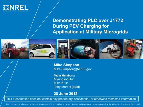
Demonstrating PLC over J1772 During PEV Charging for ...
Demonstrating PLC over J1772 During PEV Charging for ...
Demonstrating PLC over J1772 During PEV Charging for ...

Create successful ePaper yourself
Turn your PDF publications into a flip-book with our unique Google optimized e-Paper software.
<strong>Demonstrating</strong> <strong>PLC</strong> <strong>over</strong> <strong>J1772</strong><br />
<strong>During</strong> <strong>PEV</strong> <strong>Charging</strong> <strong>for</strong><br />
Application at Military Microgrids<br />
Mike Simpson<br />
Mike.Simpson@NREL.gov<br />
Team Members:<br />
Myungsoo Jun<br />
Mike Kuss<br />
Tony Markel (lead)<br />
28 June 2012<br />
This presentation does not contain any proprietary, confidential, or otherwise restricted in<strong>for</strong>mation.<br />
NREL is a national laboratory of the U.S. Department of Energy, Office of Energy Efficiency and Renewable Energy, operated by the Alliance <strong>for</strong> Sustainable Energy, LLC.
Agenda<br />
• NREL Electric Vehicle Grid Integration<br />
(EVGI) Background<br />
• SPIDERS and Military Microgrids<br />
• Proposed Messaging <strong>for</strong> bi-directional<br />
vehicle charging (V2x)<br />
• Power Line Communications (<strong>PLC</strong>)<br />
Hardware Implementation<br />
• Lessons Learned<br />
• Next Steps<br />
2
What is Electric Vehicle Grid Integration (EVGI)?<br />
3
SPIDERS: JCTD<br />
• Smart Power Infrastructure Demonstration <strong>for</strong><br />
Energy Reliability and Security (SPIDERS)<br />
– Joint Command Technology Demonstration (JCTD)<br />
• NORTHCOM + PACOM<br />
– Demonstrate:<br />
• Cyber-security of electric grid<br />
• Smart Grid technologies & applications<br />
• Islanded micro-grid<br />
• Demand-side management<br />
• Redundant back-up power systems<br />
• Integration of distributed/intermittent renewables<br />
• Fort Carson: “Triple Net Zero” Installation<br />
– Currently have 2-MW Solar array on-base<br />
• Demo-ing several other RE tech on-site<br />
– Project goal is to demonstrate:<br />
• Large-scale renewables<br />
• Smart micro-grid<br />
• Vehicle-to-Grid (V2G) with Plug-in Electric Vehicles (<strong>PEV</strong>s)<br />
Smith Newton Electric Truck; NREL PIX 17631<br />
4
Diagram courtesy Dean McGrew, TARDEC<br />
SPIDERS <strong>PEV</strong> Charge Interface<br />
Representative Block Diagram, TARDEC<br />
5
SAE J2847/3 Message Initialization Procedure<br />
Disconnected<br />
Pilot=<br />
State A<br />
(disconnected)<br />
Not Ready<br />
· EVSE prompts user to<br />
disconnect<br />
· EVSE disables current<br />
flow<br />
· <strong>PEV</strong> ensures that<br />
connector is unlocked<br />
Contactor =<br />
Opened<br />
Shutdown/2<br />
· <strong>PEV</strong> per<strong>for</strong>ms welded checks<br />
· <strong>PEV</strong> opens contactor<br />
· <strong>PEV</strong> unlocks connector<br />
Connector =<br />
Unlocked<br />
Fault<br />
· UI prompts driver be<strong>for</strong>e exiting, e.g. “Leaving<br />
around 4:30pm today?”<br />
àIf no explicit confirmation, Grid Control = 1<br />
Pilot=<br />
State B<br />
Shutdown/1<br />
Fault<br />
· <strong>PEV</strong> requests zero current<br />
· <strong>PEV</strong> waits <strong>for</strong> safe voltage level<br />
Initialization<br />
· EVSE/<strong>PEV</strong> exchange<br />
operating limits<br />
· <strong>PEV</strong> locks connector<br />
· EVSE per<strong>for</strong>ms Internal<br />
Isolation Monitoring<br />
Vehicle Ready = TRUE<br />
AND<br />
Connector = Locked<br />
(to restart charging)<br />
Fault<br />
Fault<br />
Fault<br />
Pilot = State B<br />
Charge Complete = 1<br />
Black text is in original 2847/1 and 2847/2<br />
Red text is proposed <strong>for</strong> 2847/3<br />
Connector = Locked AND<br />
Charger Status = Isolation Monitoring Active<br />
Isolation Monitoring<br />
· EVSE may continue to check<br />
isolation on its side of the <strong>PEV</strong><br />
contactor<br />
· <strong>PEV</strong> monitors isolation on its<br />
side of the contactor<br />
Fault<br />
Precharge<br />
Pilot= State C or D<br />
AND<br />
Vehicle Ready = TRUE<br />
· EVSE enables HV DC output<br />
· <strong>PEV</strong> requests voltage and small<br />
current<br />
· EVSE controls to <strong>PEV</strong> request<br />
· <strong>PEV</strong> waits <strong>for</strong> voltage to match ESS<br />
· EVSE sends Grid Control request if<br />
V2G capable<br />
· <strong>PEV</strong> acknowledges Grid Control<br />
request (or denies/ignores)<br />
Voltages matched AND<br />
Grid Control = 0<br />
(<strong>PEV</strong> closes contactor)<br />
Energy Transfer<br />
· <strong>PEV</strong> continuously monitors HV<br />
isolation<br />
· <strong>PEV</strong> controls current level request<br />
· EVSE transfers energy per <strong>PEV</strong><br />
Request<br />
Fault OR<br />
Pilot=State B<br />
Charge Complete = 1<br />
Fault<br />
Voltages Matched AND<br />
Grid Control = 1<br />
Digital comm timeout<br />
> 10T OR<br />
V/I outside <strong>PEV</strong>-defined limits<br />
PreV2G<br />
· <strong>PEV</strong> sends kWh Avail, Min/Max I, kWh<br />
requested & departure time, VehID<br />
· EVSE sends EVSE ID, returns EV data<br />
(handshake)<br />
· IF handshake success = 1, <strong>PEV</strong> Status =<br />
“V2G” ELSE <strong>PEV</strong> Status = “Energy xfer”<br />
Voltages matched AND<br />
<strong>PEV</strong> Status = “Energy xfer”<br />
V2G<br />
Voltages matched AND<br />
<strong>PEV</strong> Status = “V2G”<br />
· EVSE continuously monitors HV isolation<br />
· <strong>PEV</strong> isolation monitor not active<br />
· EVSE controls current level request –<br />
EVSE transfers current within <strong>PEV</strong>defined<br />
limits (EVSE will disconnect from<br />
aggregator in the event of low SOC and<br />
imminent departure by setting Grid<br />
Control = 0)<br />
EVSE-Aggregator<br />
· Aggregator pings EVSEs <strong>for</strong> the<br />
following data: Min/Max Power, Energy<br />
available, Energy request<br />
· Aggregator sends kW command to<br />
each EVSE (based on utility command<br />
and proprietary scheduling algorithms)<br />
6
Suggested Messages (adapted from J2847/2)<br />
Variable Description [suggested XML variable name if applicable] Units From—To Standard<br />
Ecap <strong>PEV</strong> Energy Storage System (ESS) capacity [EVEnergyCapacity] kWh <strong>PEV</strong>-EVSE J2847/2<br />
SOC ESS State-of-Charge (SOC) [EVRESSSOC] <strong>PEV</strong>-EVSE J2847/2<br />
Emin Minimum allowable depth-of-discharge [kWhAvailable] kWh Calculated by EVSE J2847/2<br />
x <strong>PEV</strong> kWh request [EVEnergyRequest] kWh <strong>PEV</strong>-EVSE-Agg J2847/2<br />
X Aggregated <strong>PEV</strong> Energy available <strong>for</strong> charging (regulation down) MWh Agg-Utility Rules vary; e.g., CAISO; CEC Rule 21<br />
α <strong>PEV</strong> energy available (<strong>for</strong> V2G) [kWhAvailable] kWh <strong>PEV</strong>-EVSE-Agg J2847/1<br />
А Aggregated <strong>PEV</strong> energy available <strong>for</strong> discharging (regulation up) MWh by Agg-Utility Rules vary; e.g., CAISO; CEC Rule 21<br />
Pmin_nom <strong>PEV</strong>-EVSE-defined max discharge rate kW <strong>PEV</strong>-EVSE 2847/2<br />
Pmin EVSE-calculated min power rate based on energy trajectory kW EVSE-Agg 2847/1<br />
Pmax; ū <strong>PEV</strong>-EVSE-defined max charge rate kW <strong>PEV</strong>-EVSE-Agg 2847/2<br />
Pmin_agg Aggregated minimum power output capability MW Agg-Utility Rules vary; e.g., CAISO; CEC Rule 21<br />
Pmax_agg Aggregated minimum power output capability MW Agg-Utility Rules vary; e.g., CAISO; CEC Rule 21<br />
Pagg Power command from Grid Operator (GO) to Aggregator (Agg) MW Utility-Agg Rules vary; e.g., CAISO; CEC Rule 21<br />
PFagg Power factor command from the GO to the aggregator Utility-Agg Rules vary; e.g., CAISO; CEC Rule 21<br />
<strong>PEV</strong>SE Power command from the aggregator to each EVSE kW Agg-EVSE J2847/1<br />
PFEVSE Power factor command from the aggregator to an EVSE Agg-EVSE J2847/1<br />
t Time now J2847/2<br />
TETD Estimated time of departure <strong>PEV</strong>-EVSE J2847/2<br />
THTD Hours til departure hours calculated by EVSE J2847/2<br />
EF Energy <strong>for</strong>ecast (time-dependent array) kWh calculated by EVSE J2847/2<br />
e Error between energy <strong>for</strong>ecast and actual energy in ESS kWh calculated by EVSE J2847/1<br />
n Vehicle index (aggregator) calculated by Agg J2847/1<br />
N Number of <strong>PEV</strong>s connected to aggregator J2847/1<br />
Black text is in original 2847/1 and 2847/2. Red text denotes new or proposed options. Blue text denotes calculated values that do not require<br />
communication among entities. Messages slated to be integrated with Aeych LLC & others proposed changes (6/2012)<br />
7
V2G Relevant Variables<br />
• Minimize message count to<br />
avoid discrepancies between<br />
<strong>PEV</strong> and charge controller or<br />
aggregator<br />
• Minimize required bandwidth<br />
• Utilize existing J2847/2<br />
messages<br />
• Provide operational flexibility<br />
Note: ACE = Area Control Error<br />
8
Simultaneous <strong>PEV</strong> <strong>Charging</strong> and <strong>PLC</strong><br />
Communications of <strong>PEV</strong> State via EVSE<br />
Photo Credit: Mike Simpson, NREL<br />
9
<strong>PEV</strong>–<strong>PLC</strong> Test Setup<br />
<strong>PLC</strong><br />
Module<br />
EVSE<br />
On-board Power<br />
Electronics<br />
<strong>PLC</strong><br />
Module<br />
Pilot Line In<br />
Development<br />
Board + CPU<br />
Cables<br />
<strong>PEV</strong> CAN-bus<br />
Serial<br />
USB<br />
Custom<br />
<strong>J1772</strong> control pilot<br />
Development<br />
Board + CPU<br />
Display<br />
Display<br />
Connectors<br />
DB9 M<br />
DB9 F<br />
<strong>J1772</strong> Connector<br />
Deutch Connector<br />
Bare Wire<br />
Connection<br />
10
J2847 Message Test Plat<strong>for</strong>m Vehicle<br />
<strong>PLC</strong><br />
communications<br />
module wired to<br />
<strong>J1772</strong> pilot line<br />
Photo Credit: Mike Simpson, NREL<br />
Connections<br />
to Vehicle<br />
CAN bus<br />
Development board<br />
deployed to translate CAN<br />
into J2847 messages<br />
PC display<br />
11
J2847 Message Test Plat<strong>for</strong>m Infrastructure<br />
<strong>PLC</strong> communications<br />
module<br />
receiving/translating<br />
signals<br />
PC display<br />
Clipper Creek CS40<br />
Level 2 EVSE (with<br />
<strong>PLC</strong> flowing through<br />
pilot line)<br />
Development board<br />
deployed to translate CAN<br />
into and control EVSE Photo Credit: Mike Simpson, NREL<br />
Communications<br />
flowing through<br />
vehicle, through<br />
<strong>J1772</strong> connection<br />
12
Planned Next Steps<br />
• Test all messages<br />
• Integrate DC bi-directional charging with<br />
stationary battery and <strong>J1772</strong> Combo<br />
Connector<br />
• Integrate DC bi-directional charging with<br />
Smith Newton electric vehicle<br />
• Demonstrate grid services<br />
– Frequency regulation<br />
– Peak shaving<br />
• Integrate development board functionality into<br />
HomePlug Green PHY hardware<br />
13
Special thanks to:<br />
Our sponsor —<br />
• Merrill Smith, Office of Electricity, U.S.<br />
Department of Energy<br />
Project collaborators —<br />
• Dean McGrew, TARDEC<br />
• Azure Dynamics<br />
Questions?