


Create successful ePaper yourself
Turn your PDF publications into a flip-book with our unique Google optimized e-Paper software.
CONTROL-FLEX ® COUPLINGS<br />
Bolted-Style<br />
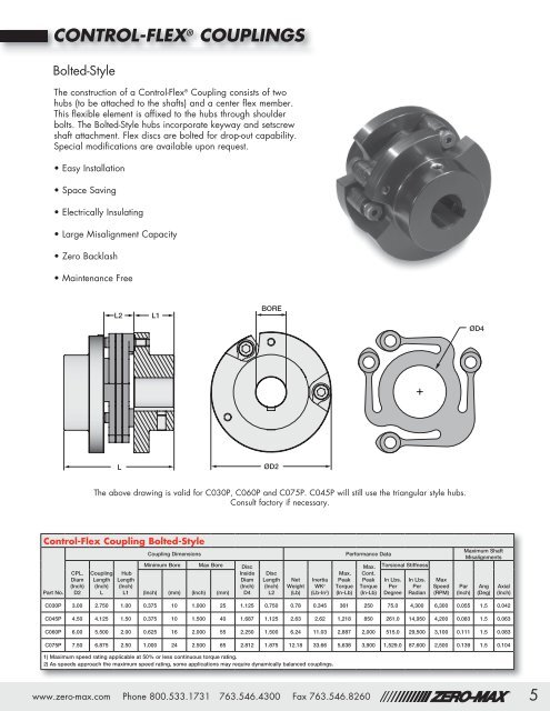
The construction of a <strong>Control</strong>-<strong>Flex</strong> ® Coupling consists of two<br />
hubs (to be attached to the shafts) and a center flex member.<br />
This flexible element is affixed to the hubs through shoulder<br />
bolts. The Bolted-Style hubs incorporate keyway and setscrew<br />
shaft attachment. <strong>Flex</strong> discs are bolted for drop-out capability.<br />
Special modifications are available upon request.<br />
• Easy Installation<br />
• Space Saving<br />
• Electrically Insulating<br />
• Large Misalignment Capacity<br />
• <strong>Zero</strong> Backlash<br />
• Maintenance Free<br />
L2<br />
L2 L1L2<br />
L1<br />
L1<br />
BORE<br />
BORE BORE<br />
ØD4<br />
ØD4 ØD4<br />
L<br />
L<br />
L<br />
ØD2<br />
ØD2 ØD2<br />
The above drawing is valid for C030P, C060P and C075P. C045P will still use the triangular style hubs.<br />
Consult factory if necessary.<br />
<strong>Control</strong>-<strong>Flex</strong> Coupling Bolted-Style<br />
Part No.<br />
CPL.<br />
Diam<br />
(Inch)<br />
D2<br />
Coupling<br />
Length<br />
(Inch)<br />
L<br />
Hub<br />
Length<br />
(Inch)<br />
L1<br />
Coupling Dimensions<br />
Minimum Bore <strong>Max</strong> Bore Disc<br />
Inside<br />
Diam<br />
(Inch)<br />
(Inch) (mm) (Inch) (mm) D4<br />
Disc<br />
Length<br />
(Inch)<br />
L2<br />
Net<br />
Weight<br />
(Lb)<br />
Performance Data<br />
MOTION CONTROL <strong>Max</strong>.<br />
SOLUTIONS<strong>Max</strong>.<br />
Cont.<br />
Inertia Peak Peak<br />
WK 2 Torque Torque<br />
(Lb-In 2 ) (In-Lb) (In-Lb)<br />
MOTION Torsional Stiffness CONTROL<br />
SOLUTIONS<br />
In Lbs. In Lbs.<br />
Per Per<br />
Degree Radian<br />
<strong>Max</strong><br />
Speed<br />
(RPM)<br />
Par<br />
(Inch)<br />
<strong>Max</strong>imum Shaft<br />
Misalignments<br />
Ang<br />
(Deg)<br />
Axial<br />
(Inch)<br />
C030P 3.00 2.750 1.00 0.375 10 1.000 25 1.125 0.750 0.78 0.345 361 250 75.0 4,300 6,300 0.055 1.5 0.042<br />
C045P 4.50 4.125 1.50 0.375 10 1.500 40 1.687 1.125 2.63 2.62 1,218 850 261.0 14,950 4,200 0.083 1.5 0.063<br />
C060P 6.00 5.500 2.00 0.625 16 2.000 55 2.250 1.500 6.24 11.03 2,887 2,000 515.0 29,500 3,100 0.111 1.5 0.083<br />
C075P 7.50 6.875 2.50 1.000 24 2.500 65 2.812 1.875 12.18 33.66 5,638 3,900 1,529.0 87,600 2,500 0.139 1.5 0.104<br />
1) <strong>Max</strong>imum speed rating applicable at 50% or less continuous torque rating.<br />
2) As speeds approach the maximum speed rating, some applications may require dynamically balanced couplings.<br />
485 Pantone Red<br />
®<br />
www.zero-max.com Phone 800.533.1731 763.546.4300 Fax 763.546.8260<br />
®<br />
5


