- Page 2 and 3:
SAFETY NOTICE CAUTION ALL SERVICE A
- Page 4 and 5:
._._ -_- 1 -. MODEL INDICATIONS The
- Page 6 and 7:
o-2 GENERAL - Technical Features TE
- Page 8 and 9:
o-4 GENERAL - Technical Features BA
- Page 10 and 11:
O-6 GENERAL - Technical Features Ig
- Page 12 and 13:
O-8 GENERAL - Technical Features TH
- Page 14 and 15:
-.-- O-10 GENERAL - Vehicle Identif
- Page 16 and 17:
o-12 GENERAL - Vehicle Identificati
- Page 18 and 19:
o-14 GENERAL - General Data and Spe
- Page 20 and 21:
2-2 FRONT SUSPENSION - General Info
- Page 22 and 23:
FRONT SUSPENSION - General Informat
- Page 24 and 25:
---- 2-6 FRONT SUSPENSION - Offset
- Page 26 and 27:
2-8 FRONT SUSPENSION - Front Axle F
- Page 28 and 29:
3-1 REAR AXLE CONTENTS RoJA- . _ AX
- Page 30 and 31:
MEHM nnlL - ueneral mrormation J-J
- Page 32 and 33:
REAR AXLE - Viscous Coupling Type L
- Page 34 and 35:
CONSTRUCTION REAR AXLE - Viscous Co
- Page 36 and 37:
REAR AXLE - Differential Support Me
- Page 38 and 39:
5-2 BRAKES - General Information GE
- Page 40 and 41:
5-4 BRAKES - Service Brakes FRONT D
- Page 42 and 43:
5-6 BRAKES - Service Brakes In addi
- Page 44 and 45:
til _.. _ _ - b 6-1 CLUTCH ir-- CON
- Page 46 and 47:
-. . .- ,..__ _. I-., . . . . - . .
- Page 48 and 49:
7-2 COOLING - General Information G
- Page 50 and 51:
----------------l-~).. 7-4 CLUTCH -
- Page 52 and 53:
_---.__ - _.__-. 7-6 COOLING - Two-
- Page 54 and 55:
8-2 ELECTRICAL - Fuses FUSES MAIN F
- Page 56 and 57:
_-- 8-4 ELECTRICAL - Fuses / Diagno
- Page 58 and 59:
__._._ -.. .- 8-6 ELECTRICAL - Junc
- Page 60 and 61:
8-8 ELECTRICAL - Relays, Control Un
- Page 62 and 63:
- __ .- I 8-10 ELECTRICAL - Relays,
- Page 64 and 65:
- . . - -- -- __ .__-... 8-12 ELECT
- Page 66 and 67:
ELECTRICAL - Relays, Control Units
- Page 68 and 69:
8-16 ELECTRICAL - Lighting LIGHTING
- Page 70 and 71:
8-18 ELECTRICAL - Lighting HEADLIGH
- Page 72 and 73:
_ -. _ -. __- ELECTRICAL - Lighting
- Page 74 and 75:
8-22 ELECTRICAL - Lighting Ignition
- Page 76 and 77:
.- 8-24 ELECTRICAL - Engine Electri
- Page 78 and 79:
8-26 ELECTRICAL - Engine Electrical
- Page 80 and 81:
8-28 ELECTRICAL - Engine Electrical
- Page 82 and 83:
8-30 ELECTRICAL - Engine Electrical
- Page 84 and 85:
8-32 ELECTRICAL - Theft-alarm Syste
- Page 86 and 87:
.._. - -II.- -..... ENGINE CONTENTS
- Page 88 and 89:
q7 -- _-.- ENGINE - General Informa
- Page 90 and 91:
10 - - - - - - - - - -. ENGINE - Ge
- Page 92 and 93:
s’ y _._-- ,_ - k - ..-_ _ _ BASE
- Page 94 and 95:
ENGINE - Base Engine 9-9 CYLINDER B
- Page 96 and 97:
Oil jet Front mark ENGINE - Base En
- Page 98 and 99:
ENGINE - Base Engine 9-13 VALVE MEC
- Page 100 and 101:
5-j ENGINE - Base Engine 9-15 Opera
- Page 102 and 103:
ENGINE - Base Engine 9-17 CAMSHAR E
- Page 104 and 105:
,_-.._-~ _._. I _ ‘... - - - - EN
- Page 106 and 107:
L1 MOUNTS . * the mounts, the princ
- Page 108 and 109:
?/ .- 3 EXHAUST MANIFOLD ..........
- Page 110 and 111:
g TURBOCHARGER _ INTAKE AND EXHAUST
- Page 112 and 113:
INTAKE AND EXHAUST - Exhaust Pipe I
- Page 114 and 115:
14-2 “GENERAL The fuel system is
- Page 116 and 117:
FUEL SYSTEM - duel Supply and Fuel
- Page 118 and 119:
14-6 FUEL SYSTEM - Fuel Supply and
- Page 120 and 121:
- _.. I -~ 14-8 FUEL PUMP This fuel
- Page 122 and 123:
14-10 FUEL SYSTEM - Fuel Supply and
- Page 124 and 125:
I 140’I2 FUEL SYSTEM - Intake Air
- Page 126 and 127:
14-14 SENSORS .._~- ---. FUEL SYSTE
- Page 128 and 129:
14-16 FUEL SYSTEM - Sensors Transmi
- Page 130 and 131:
14-18 FUEL SYSTEM - Sensors t BAROM
- Page 132 and 133:
FUEL SYSTEM - Sensors CRANK ANGLE S
- Page 134 and 135:
14-22 FUEL SYSTEM - Sensors VEHICLE
- Page 136 and 137:
-- 14-24 FUEL SYSTEM - Sensors POWE
- Page 138 and 139:
14-26 FUEL SYSTEM - Sensors Battery
- Page 140 and 141:
14-28 FUEL SYSTEM - Ennine Control
- Page 142 and 143:
14-30 FUEL SYSTEM - Engine Control
- Page 144 and 145:
__.-~-..- - FUEL SYSTEM - Ermine Co
- Page 146 and 147:
- 14-34 FUEL SYSTEM - Fuel Injectio
- Page 148 and 149:
14-36 FUEL SYSTEM - Fuel lniection
- Page 150 and 151:
When cranking the cold engine, fuel
- Page 152 and 153:
14-40 FUEL SYSTEM - Fuel Injection
- Page 154 and 155:
14-42 FUEL SYSTEM - Fuel Injection
- Page 156 and 157:
- __..-- 14-44 FUEL SYSTEM - Idle S
- Page 158 and 159:
. 14-46 FUEL SYSTEM - Idle Speed Co
- Page 160 and 161:
14-48 FUEL SYSTEM - Idle Speed Cont
- Page 162 and 163:
14-50 FUEL SYSTEM - Idle Speed Cont
- Page 164 and 165:
-- 14-52 FUEL SYSTEM - Idle Speed C
- Page 166 and 167:
FUEL SYSTEM - Power Supply Control
- Page 168 and 169:
14-56 FUEL SYSTEM - Supercharge Pre
- Page 170 and 171: ._ ..- 14-58 ACCELERATOR COMPONENTS
- Page 172 and 173: -. --- 14-60 FUEL SYSTEM - Auto-cru
- Page 174 and 175: 14-62 FUEL SYSTEM - Auto-cruise Con
- Page 176 and 177: 14-64 FUEL SYSTEM - Auto-cruise Con
- Page 178 and 179: -- 14-66 FUEL SYSTEM - Auto-cruise
- Page 180 and 181: -.. . _. .-. ._ _ 14-68 FUEL SYSTEM
- Page 182 and 183: -_ 14-70 FUEL SYSTEM - Auto-cruise
- Page 184 and 185: ._ ___ - 14-72 FUEL SYSTEM - Auto-c
- Page 186 and 187: _ ,. -.. 14-74 FUEL SYSTEM - Auto-c
- Page 188 and 189: - ----- .--.. 14-76 FUEL SYSTEM - A
- Page 190 and 191: ---. ._.. ^. I -, ,.>.-,- - ._, ..
- Page 192 and 193: SPEClFlCATlONS PROPELLER SHAFT - Ge
- Page 194 and 195: 17-I REAR SUSPENSION CONTENTS m7*-
- Page 196 and 197: SPECIFICATIONS REAR SUSPENSION tZWD
- Page 198 and 199: ---_ REAR SUSPENSION - Three-link
- Page 200 and 201: c Y REAR HUB REAR SUSPENSION - Rea
- Page 202 and 203: THREE SIDE VIEWS _ - . ..__ .- REAR
- Page 204 and 205: . -.- REAR SUSPENSION - Double Wish
- Page 206 and 207: - REAR SUSPENSION - Double Wishbone
- Page 208 and 209: REAR SUSPENSION - Double Wishbone S
- Page 210 and 211: 19-I POWER STEERING CONTENTS RIB& -
- Page 212 and 213: POWER STEERING - General Informatio
- Page 214 and 215: .-. -- POWER STEERING - Power Steer
- Page 216 and 217: : POWER STEERING - Pinion and Valve
- Page 218 and 219: POWER STEERING - Pinion and Valve A
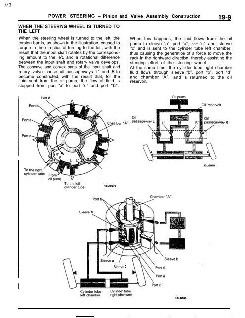
- Page 222 and 223: POWER STEERING - Oil Pump 19-11 i P
- Page 224 and 225: i t-7 POWER STEERING - Oil Pump 19-
- Page 226 and 227: 21-2 MANUAL TRANSAXLE - General In
- Page 228 and 229: MANUAL TRANSAXLE - General Informa
- Page 230 and 231: MANUAL TRANSAXLE - General Informa
- Page 232 and 233: c. _. 21-8 MANUAL TRANSAXLE - Gene
- Page 234 and 235: 21-10 MANUAL TRANSAXLE - General I
- Page 236 and 237: 21-12 MANUAL TRANSAXLE - Viscous C
- Page 238 and 239: 21-14 MANUAL TRANSAXLE t4WD> - Visc
- Page 240 and 241: _- 21-16 AUTOMATIC TRANSAXLE - Gene
- Page 242 and 243: 21-18 AUTOMATIC TRANSAXLE - Transax
- Page 244 and 245: 7 -_ - .--. ! 21-20 AUTOMATIC TRANS
- Page 246 and 247: TORQUE CONVERTER AUTOMATIC TRANSAXL
- Page 248 and 249: 21-24 AUTOMATIC TRANSAXLE - Transax
- Page 250 and 251: 21-26 AUTOMATIC TRANSAXLE - Transax
- Page 252 and 253: I .- 21-28 AUTOMATIC TRANSAXLE - Tr
- Page 254 and 255: 21-30 AUTOMATIC TRANSAXLE - Transax
- Page 256 and 257: -.., ‘~ ~,.~.“., 21-32 AUTOMATI
- Page 258 and 259: _____--._- . 21-34 AUTOMATIC TRANSA
- Page 260 and 261: 21-36 AUTOMATIC TRANSAXLE - Transax
- Page 262 and 263: 21-38 AUTOMATIC TRANSAXLE - Transax
- Page 264 and 265: 21-40 AUTOMATIC TRANSAXLE - Transax
- Page 266 and 267: 21-42 AUTOMATIC TRANSAXLE - Transax
- Page 268 and 269: _-.. 21-44 AUTOMATIC TRANSAXLE - Tr
- Page 270 and 271:
--- 21-46 AUTOMATIC TRANSAXLE - Tra
- Page 272 and 273:
21-48 AUTOMATIC TRANSAXLE - Transax
- Page 274 and 275:
21-50 AUTOMATIC TRANSAXLE - Transax
- Page 276 and 277:
AUTOMATIC TRANSAXLE - Transaxle Con
- Page 278 and 279:
- 21-54 AUTOMATIC TRANSAXLE - Trans
- Page 280 and 281:
- 21-56 AUTOMATIC TRANSAXLE - Trans
- Page 282 and 283:
21-58 AUTOMATIC TRANSAXLE - Transax
- Page 284 and 285:
21-60 AUTOMATIC TRANSAXLE - Transax
- Page 286 and 287:
- 21-64 AUTOMATIC TRANSAXLE - Trans
- Page 288 and 289:
21-66 AUTOMATIC TRANSAXLE - Transax
- Page 290 and 291:
__- _ - _ _ ----____. _ ., _.- -...
- Page 292 and 293:
21-70 AUTOMATIC TRANSAXLE - Transax
- Page 294 and 295:
_. --. 21-72 AUTOMATIC TRANSAXLE -
- Page 296 and 297:
21-74 AUTOMATIC TRANSAXLE - Transax
- Page 298 and 299:
21-76 AUTOMATIC TRANSAXLE - Transax
- Page 300 and 301:
.-. ‘r 21-78 AUTOMATIC TRANSAXLE
- Page 302 and 303:
21-80 AUTOMATIC TRANSAXLE - Transax
- Page 304 and 305:
21-82 AUTOMATIC TRANSAXLE - Transax
- Page 306 and 307:
-- I1 21-84 AUTOMATIC TRANSAXLE - T
- Page 308 and 309:
21-86 AUTOMATIC TRANSAXLE - Transax
- Page 310 and 311:
21-88 AUTOMATIC TRANSAXLE - Transax
- Page 312 and 313:
F 1, / 21-90 AUTOMATIC TRANSAXLE -
- Page 314 and 315:
21-92 AUTOMATIC TRANSAXLE - Ttansax
- Page 316 and 317:
21-94 AUTOMATIC TRANSAXLE - Transax
- Page 318 and 319:
-- - 21-96 AUTOMATIC TRANSAXLE - Tr
- Page 320 and 321:
23-2 MAIN BODY BODY COMPONENTS BODY
- Page 322 and 323:
-x&f-33 \ L 4 -_ - 23-4 BODY - Main
- Page 324 and 325:
23-6 BODY - Main Body SPECIAL STEEL
- Page 326 and 327:
1 j .,j i / : : : 23-8 BODY - Main
- Page 328 and 329:
BODY MAJOR CROSS SECTIONS BODY - Ma
- Page 330 and 331:
23-12 BODY - Main Bodv MAIN BODY Ma
- Page 332 and 333:
MAINTENANCE SERVICEABILITY ;ide Str
- Page 334 and 335:
BODY - Main Bodv ‘rant Deck ,he p
- Page 336 and 337:
i73 BODY - Doors 23-19 The doors ar
- Page 338 and 339:
BODY - Central Door Locks 23-21 I W
- Page 340 and 341:
BODY - Power Windows 23-23 I Batter
- Page 342 and 343:
BODY - Sunroof 23-25 CUNROOF R22lAA
- Page 344 and 345:
BODY - Door Mirrors . 23-27 DOOR MI
- Page 346 and 347:
“WTRUMENT PANEL BODY - Instrument
- Page 348 and 349:
._-- - BODY - Seat Belts 23-31 SEAT
- Page 350 and 351:
Gear e Gear B Energy-absorbing belt
- Page 352 and 353:
BODY - Seat Belts 23-35 OPERATlON O
- Page 354 and 355:
COMPONENT PARTS AND FUNCTION BODY -
- Page 356 and 357:
BODY - Seat Belts 23-39 OPERATlON B
- Page 358 and 359:
BODY - Seat Belts * 23-41 switch Dr
- Page 360 and 361:
BODY - Seat Belts 23-43 9utput Sign
- Page 362 and 363:
BODY - Seat Belts 23-45 QRIVER’S
- Page 364 and 365:
24-1 HEATERS AND AIR CONDITIONING C
- Page 366 and 367:
‘5sY - _- COMPONENTS HEATERS AND
- Page 368 and 369:
HEATERS AND AIR CONDITIONING - Gene
- Page 370 and 371:
HEATERS AND AIR CONDITIONING - Heat
- Page 372 and 373:
19/ ---..-_ Ii” E SPEED CONTROL H
- Page 374 and 375:
25-2 EMISSION CONTROL SYSTEMS - Gen
- Page 376 and 377:
--. 25-2 EMISSION CONTROL SYSTEMS -
- Page 378 and 379:
Turbo for California EMISSION CONTR
- Page 380 and 381:
-. - 25-6 EMISSION CONTROL SYSTEMS
- Page 382 and 383:
-- 25-8 EMISSION CONTROL SYSTEMS -
- Page 384 and 385:
25-10 EMISSION CONTROL SYSTEMS - Cr
- Page 386 and 387:
25-12 EMISSION CONTROL SYSTEMS - Ev
- Page 388 and 389:
--. 2 5 - 1 4 EMISSION CONTROL SYST
- Page 390 and 391:
NOTES -_ --


