

uf2

Create successful ePaper yourself
Turn your PDF publications into a flip-book with our unique Google optimized e-Paper software.
(19) United States<br />
US 20030209637A1<br />
(12) Patent Application Publication (10) Pub. No.: US 2003/0209637 A1<br />
St. Clair (43) Pub. Date: Nov. 13, 2003<br />
(54) ROTATING ELECTROSTATIC PROPULSION<br />
SYSTEM<br />
(76) Inventor: John Quincy St. Clair, San Juan, PR<br />
(US)<br />
Correspondence Address:<br />
John St. Clair<br />
Hyperspace Research Institute<br />
52 Kings Court, 4A<br />
San Juan, PR 00911 (US)<br />
(21) Appl. No.: 10/142,582<br />
(22) Filed: May 9, 2002<br />
Publication Classification<br />
(51) Int. Cl. ............................... B64G 1/40; B64G 1/42<br />
(52) U.S. Cl. .............................................................. 244,172<br />
(57) ABSTRACT<br />
This invention relates to a Spacecraft propulsion System<br />
utilizing thrusters comprised of a motor-driven electroStati<br />
cally charged cylinder rotating within an electroStatically<br />
charged annular ring for the purpose of creating a Spacetime<br />
curvature StreSS-energy tension in the horizontal direction.<br />
The thrusters are augmented by magnetic Vortex generators,<br />
either embedded in the cylinders or located above each<br />
thruster, for the purpose of increasing the permittivity of<br />
Space by permeating each thruster with low density hyper<br />
Space energy generated by a wormhole created between our<br />
Space and hyperSpace. A combination of three thrusters<br />
mounted on the underside of the hull of the spacecraft<br />
provide thrust and yaw motion control.
Patent Application Publication Nov. 13, 2003 Sheet 1 of 4<br />
US 2003/0209637 A1<br />
Figure 1<br />
Figure 2
Patent Application Publication Nov. 13, 2003 Sheet 2 of 4<br />
US 2003/0209637 A1<br />
Figure 3<br />
TZr -- 0 E.E. coul n n m s” kgm s? -1<br />
Qc’ 4t m’n coul coulkgm' s’ kgm m'<br />
Figure 4<br />
Figure 5<br />
t| 0 E 0 E.<br />
O. r|E 0 0 0<br />
F“B = 0 0 0 0 (0<br />
ZE 0 0 0
Patent Application Publication Nov. 13, 2003 Sheet 3 of 4<br />
US 2003/0209637 A1<br />
Figure 6<br />
Figure 7<br />
EE<br />
dt<br />
S. = &o 8, ,x'T'n Area = &otzin,<br />
47t<br />
Area<br />
Figure 8<br />
coul n in 2 1. 1.<br />
-Sec m = kg sec = kg<br />
min coul coul SCC SCC<br />
Figure 9<br />
e'EE, area +0e'EE to area<br />
d 8.<br />
S. = 0<br />
dt'' 47t - i&n ;<br />
47t
Patent Application Publication Nov. 13, 2003 Sheet 4 of 4<br />
US 2003/0209637 A1<br />
Figure 10<br />
Figure 11<br />
Figure 12
US 2003/0209637 A1<br />
Nov. 13, 2003<br />
ROTATING ELECTROSTATIC PROPULSION<br />
SYSTEM<br />
BRIEF SUMMARY OF THE INVENTION<br />
0001. The invention, which is the object of my present<br />
application, is a Spacecraft propulsion System which devel<br />
ops a Spacetime curvature tension utilizing a combination of<br />
a rotating radial electroStatic field and a fixed vertical<br />
electrostatic field. The two fields create a stress-energy T."<br />
gradient in the radially direction which is equal to force. The<br />
radial field is created on the Side of a charged rotating<br />
cylinder on the underside of the hull. The vertical field is<br />
created by an annular charged ring concentric with the<br />
cylinder. Three rotating cylinders are located in a triangle on<br />
the bottom of the hull in order to produce a force in any<br />
direction in the horizontal plane.<br />
REFERENCE PAPERS<br />
0002 Gravitation, Wheeler, page 80.<br />
BACKGROUND OF THE INVENTION<br />
0003) When working with Maxwell's equations in tensor<br />
notation, it became apparent that a tensor can change iden<br />
tity depending on what permutation of variables is involved.<br />
For example, one Single equation can involve both charge<br />
density and current density. And all of Maxwell's equations<br />
can be reduced to just two equations.<br />
0004. In the tensor equation for momentum, if the lever<br />
arm is length then the equation is equal to the flow rate of<br />
angular momentum. If the lever arm is time, then you get<br />
linear momentum. And if the field rotates with time, then the<br />
time rate of change of linear momentum is a force which is<br />
the basis for this invention.<br />
0005 Einstein said that mass curves space and space tells<br />
mass how to move. In this Sense, generalized mass can be<br />
mass, electromagnetic fields, charge or angular momentum<br />
which create a Spacetime curvature that produces a force on<br />
the Spacecraft.<br />
SUMMARY OF THE INVENTION<br />
0006 The invention relates to a spacecraft utilizing a<br />
rotating electroStatically charged cylinder and a concentric<br />
annular charged ring to create a StreSS-energy Spacetime<br />
curvature in the horizontal plane on the Spacecraft's under<br />
side hull. A motor drives the rotating cylinder which extends<br />
below the hull. A charged Surface produces an electric field<br />
in the direction normal to the Surface. The vertical and<br />
rotating electric fields combine to create a rate of change of<br />
linear momentum which creates a horizontal propulsive<br />
force on the hull.<br />
STATEMENT REGARDING FEDERALLY<br />
SPONSORED RESEARCH OR DEVELOPMENT<br />
0007) Not Applicable.<br />
A BRIEF DESCRIPTION OF THE DRAWINGS<br />
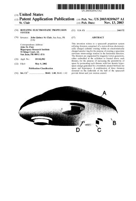
0008 FIG. 1. Perspective view of spacecraft hull (A)<br />
with the three electrostatically charged rotating cylinders (C)<br />
Surrounded by their annular charge rings (D) extending<br />
down on the underside of the hull (B).<br />
0009 FIG. 2. Perspective view of individual thruster<br />
showing rotating cylinder and ring.<br />
0010 FIG. 3. Stress-energy tension created by two elec<br />
tric fields and having units of curvature.<br />
0011) FIG. 4. Cylindrical spacetime coordinates {t, r, 0,<br />
Z}.<br />
0012 FIG. 5. Faraday electromagnetic F tensor contain<br />
ing electric fields in the radial and vertical directions.<br />
0013 FIG. 6. Stress-energy tensor T showing it is equal<br />
to the product of the two electric fields divided by 47t.<br />
0014 FIG. 7. The tensor equation for flow rate of angular<br />
momentum S.<br />
0.015 FIG.8. The units are linear momentum due to the<br />
time lever arm.<br />
0016 FIG. 9. The rate of change of linear momentum is<br />
the horizontal force produced by the two electric fields.<br />
0017 FIG. 10. The angular momentum flows through an<br />
area whose normal vector is in the radial direction.<br />
0018 FIG. 11. Cylinder with only one electrostatically<br />
charged Segment.<br />
0019 FIG. 12. Annular ring with three individual seg<br />
ments which can be charged Separately to create a force in<br />
a particular direction.<br />
DETAILED DESCRIPTION OF THE<br />
INVENTION<br />
0020) 1. Referring to FIG. 1, the spacecraft comprises<br />
an upper hull (A) with three rotating electrostatically<br />
charged cylinders (C) with their concentric annular<br />
electrostatically charged rings (D) located on the Space<br />
craft's bottom hull (B).<br />
0021 2. In a closer view of one of the cylinders seen<br />
in FIG. 2, motor-driven rotating cylinder (A) has an<br />
electroStatically charged Surface which produces an<br />
electric field (C) normal to said surface. The fixed,<br />
electrostatically charged annular ring (B), which is<br />
concentric with the cylinder, produces a vertical elec<br />
tric field (D) normal to its surface. This crossed field (E)<br />
creates a negative Spacetime curvature tension which is<br />
the product of the two fields divided by 4t as seen in<br />
the equation, FIG. 3.<br />
0022. 3. Notice that the equation involves the permit<br />
tivity of Space eo divided by the linear mass of the<br />
universe S2 and the Speed of light. This produces units<br />
of inverse meter Squared which is the Spacetime cur<br />
vature. In Einstein's General Theory of Relativity, the<br />
Spacetime curvature tensor is equal to the StreSS-energy<br />
tensor or G=87tT where G is the curvature, and T is the<br />
product of the electromagnetic fields. The problem with<br />
this equation, which has been resolved with this inven<br />
tion, is that the linear mass S2 times the Speed of light<br />
c is an enormous number. Even with the Square of<br />
enormous electric fields, the curvature would be too<br />
Small even to notice, and little force would be gener<br />
ated.<br />
0023 4. In another patent application of mine entitled<br />
Magnetic Vortex Generator, it was shown that a rotating
US 2003/0209637 A1<br />
Nov. 13, 2003<br />
cylinder containing embedded and Stacked bar magnets<br />
produces a negative mass and negative Spacetime<br />
Spring constant. It can be shown that this combination<br />
produces a Small wormhole or interdimensional con<br />
nection between our space and hyperSpace along the<br />
centerline of the rotating cylinder. Co-dimensions of<br />
hyperSpace have different physics constants. A low<br />
preSSure region of hyperspace has a very low mass<br />
density and a very low speed of light. The wormhole<br />
allows this low density hyperSpace energy to enter into<br />
our Space and permeate the cylinder and annular ring.<br />
The permittivity is proportional to the inverse of the<br />
Speed of light Squared. The hyperSpace Speed of light,<br />
obtained from my tetrahedron physics diagram, is 8971<br />
meters per Second. The Speed of light in our dimension<br />
is 299792458 meters per second. As shown by the<br />
enclosed reference calculation, the hyperSpace permit<br />
tivity is about a trillion times larger. Because the force<br />
is equal to this new permittivity times the electric fields<br />
Squared times the area around cylinder, the force is<br />
greatly amplified by this increase in the permittivity of<br />
Space.<br />
0024 5. It is pertinent to this invention how the stress<br />
energy is created due to the two electric fields in the<br />
Vertical and radial direction. In gravitational physics,<br />
there is a Faraday F tensor which contains all the<br />
components of the electromagnetic fields. It is a 4 by 4<br />
matrix whose rows and columns correspond to the<br />
coordinates of Spacetime which in cylindrical coordi<br />
nates are {t, r, 0, Z} where t is time, r the radius, theta<br />
the horizontal angle and Z the vertical height. These<br />
coordinates are shown in FIG. 4.<br />
0025 6. The radial electric E. field and the vertical<br />
electric E field can be inserted into the Faraday tensor<br />
seen in FIG. 5. The sign of the vertical field is positive<br />
because it points in the positive Z-direction due to the<br />
fact that the annular ring has a negative charge. The<br />
cylinder has a positive charge. This produces the nega<br />
tive stress-energy tensor Ti" as drawn in FIG. 6.<br />
0026 7. In order to calculate the force on the cylinder,<br />
it is necessary to calculate the flow rate of angular<br />
momentum. Momentum is mass times Velocity or mass<br />
meter per Second. If the mass is moving in a circle, then<br />
there is a lever arm times the momentum which makes<br />
it mass meter Squared per Second. If this is differenti<br />
ated with respect to time, then a flow rate of angular<br />
momentum is produced with units of mass meter<br />
Squared per Second Squared. AS mentioned previously,<br />
tensors have this dual nature where depending on the<br />
permutation of the variables, it means one thing or<br />
another. In this case, the lever arm will be time, rather<br />
than length which converts the flow rate of angular<br />
momentum into just linear momentum. If you change<br />
linear momentum with respect to time, then you get a<br />
force.<br />
0027 8. The flow rate of angular momentum S is<br />
shown in FIG. 7. The force has to be against the area<br />
whose normal vector is in the radial direction which is<br />
also the direction of the momentum. So S has an r<br />
Subscript indicating that it flows in the radial direction.<br />
The permutation tensor e has three Subscripts which<br />
keeps track of the tensor notation. The first Subscript is<br />
the same as the momentum Subscript. Permutations of<br />
the coordinate variables which are in order have a plus<br />
one sign. Permutations which are in reverse order have<br />
a minus one sign. Permutations in which the variable<br />
are repeated are Zero. For example, ele=-e, because<br />
the r and t are in reverse order in cylindrical coordi<br />
nates. Because the permutation tensor Starts with r, then<br />
we can have permutations such as {r,t,Z} which is a<br />
reverse order negative permutation. This negative sign<br />
cancels the negative Sign of the StreSS tensor. The<br />
reason this permutation is chosen is because the first<br />
Subscript on the StreSS-energy tensor is now Z. Because<br />
the normal to the area is in the radial direction, then the<br />
StreSS-tensor matches the electric fields that we have<br />
available, which are also in the Zr-direction.<br />
0028 9. In this case, the second subscript of the<br />
permutation tensor is time, rather than length. So the<br />
units become, as shown in FIG. 8, those of linear<br />
momentum. To me, this was very Surprising. Then I<br />
realized that the radial electric field rotates with time<br />
which means the differential of the linear momentum<br />
produces a force on the hull. In exponential notation,<br />
the radial electric field rotates with Expiot). This is<br />
multiplied by the time lever arm, so the term that has<br />
to be differentiated is te". The time lever arm saves<br />
the differentiation by making one term real So that the<br />
force is real. This is shown in FIG. 9. The units of the<br />
first term are real newtons. In the Second term, the time<br />
t multiplied by the frequency cancels out in terms of<br />
units, So the units are Still force, but imaginary<br />
0029) 10. There is an area involved in the force equa<br />
tion which is depicted in FIG. 10. The charged rotating<br />
cylinder (C) located inside the charged annular ring (B)<br />
is driven by motor (A). The radial electric field (E) is<br />
normal to the area (D) whose normal vector is also in<br />
the radial direction. The angular momentum flows<br />
through this area which Surrounds the cylinder. In<br />
doing So, it curves Spacetime which produces the force.<br />
0030) 11. If the radial electric field is continuous<br />
around the cylinder, then the net force is Zero. Referring<br />
to FIG. 11, one section (A) of the rotating cylinder is<br />
charged, which means that there is a force once per<br />
cycle in a Selected direction depending on when the<br />
annular ring is charged. The other option, referring to<br />
FIG. 12, is that the annular ring is divided up into two<br />
or three Sections with the feature that the charge can be<br />
turned on (A) or off (B) on a particular segment. As the<br />
rotating electric field goes around, one of the annular<br />
ring Sections will have an electric field in order create<br />
a force on that Side.<br />
0031) 12. Since there are three force cylinders, this<br />
allows for yaw motion control so that the hull of the<br />
Spacecraft can pivot to change direction. After the<br />
directional change, the two back cylinders can be<br />
Synchronized to produce thrust in the forward direction.<br />
0032) 13. There could also be a polarity change for the<br />
Vertical electric field Such that a positive StreSS-energy<br />
is produced which would reverse the direction of the<br />
thrust.
US 2003/0209637 A1<br />
Nov. 13, 2003<br />
What I claim as my invention is:<br />
1. A Spacecraft propulsion System utilizing three electro<br />
Statically charged motor-driven cylinders each one of which<br />
rotates within a charged annular ring to produce a Spacetime<br />
StreSS curvature tension in the horizontal plane on the<br />
underside of the hull.<br />
2. Said rotating cylinder comprised of bar magnets<br />
embedded in the cylinder and Stacked in groups at intervals<br />
around the periphery of the cylinder with the purpose of<br />
increasing the permittivity of Space by permeating the<br />
cylinder and ring with low linear mass, low speed of light<br />
hyperSpace energy by means of a wormhole between our<br />
Space and hyperspace. The larger permittivity is to increase<br />
the force. Said technique is contained in my patent appli<br />
cations Magnetic Vortex Wormhole Generator and Magnetic<br />
Vortex Generator.<br />
3. Said rotating cylinder and annular ring having a Suit<br />
able metal Surface for forming and maintaining the electro<br />
Static charge.<br />
4. Said rotating cylinder having one or more Segments<br />
which can be electroStatically charged individually or<br />
together to produce a force in a particular direction.<br />
5. Said annular ring having one or more Segments which<br />
can be electroStatically charged individually or together to<br />
produce a force in a particular direction.<br />
6. A combination of three Such thrusters providing a force<br />
in any particular direction or for yaw motion control.<br />
7. Electric polarity switching of the fields in order to<br />
reverse the Spacetime curvature and therefore change the<br />
direction of thrust.<br />
8. The use of a magnetic Vortex generator located above<br />
each thruster in order to permeate the cylinders and rings<br />
with low density hyperSpace energy which would Substitute<br />
for the embedded magnets in each cylinder.


