Installation & Operating Instructions for SmartCal Valve Positioner
Installation & Operating Instructions for SmartCal Valve Positioner
Installation & Operating Instructions for SmartCal Valve Positioner

Create successful ePaper yourself
Turn your PDF publications into a flip-book with our unique Google optimized e-Paper software.
w<br />
ANALOG POSITIONERS<br />
®<br />
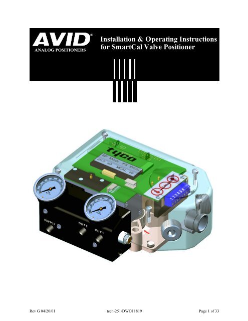
<strong>Installation</strong> & <strong>Operating</strong> <strong>Instructions</strong><br />
<strong>for</strong> <strong>SmartCal</strong> <strong>Valve</strong> <strong>Positioner</strong><br />
Rev G 04/20/01 tech-251/DWO11819 Page 1 of 33
Table of Contents<br />
Section 1 - Introduction Page<br />
1.1 Description of <strong>SmartCal</strong>...................................................................................... 3<br />
1.2 Principal of Operation.......................................................................................... 4<br />
Section 2 - Initial Setup<br />
2.1 Mounting <strong>Positioner</strong> on a Rotary Actuator........................................................... 5<br />
2.2 Mounting Remote <strong>Positioner</strong> on a Rotary Actuator............................................. 6<br />
2.3 Wiring the Remote Sencor to the <strong>Positioner</strong>........................................................ 7<br />
2.4 Pneumatic Connection......................................................................................... 8<br />
2.5 Electrical Connection........................................................................................... 9<br />
Section 3 - Calibration<br />
3.1 Enter Calibration................................................................................................. 10<br />
3.2 Configure The <strong>Positioner</strong>s Parameters............................................................... 10<br />
3.3 Automatic Calibration.......................................................................................... 11<br />
3.4 Advanced Calibration (Optional)......................................................................... 11<br />
3.5 Exit Calibration.................................................................................................... 12<br />
3.6 Description of Menu’s........................................................................................ 12-13<br />
3.7 Description of Functions.................................................................................... 14-16<br />
3.8 Manually Control <strong>Valve</strong> Position......................................................................... 16<br />
Section 4 - Trouble Shooting<br />
4.1 Preliminary Checks............................................................................................. 17<br />
4.2 Common Problems............................................................................................. 18<br />
Section 5 - Specifications.............................................................................. 19<br />
Section 6 - Error Codes................................................................................... 20<br />
Section 7 - Exploded Parts List..................................................................... 21<br />
Section 8 - Product Matrix.............................................................................. 21<br />
Section 9 - Dimensions.................................................................................... 22<br />
Appendices<br />
A. Procedure to Adjust Err 3 Setting......................................................................... 23<br />
B. Procedure to Remove Display Board & Electronic Canister................................. 24<br />
C. Procedure to Check transducer Operation........................................................... 25<br />
D. Grounding Schematic........................................................................................... 26<br />
E. Pneumatic Manifold Diagram............................................................................... 27<br />
F. Control Schematic <strong>for</strong> Wiring of Intrinsically Safe <strong>SmartCal</strong>............................... 28-31<br />
G. Procedure to Reset the EEprom to Factory Settings.............................................32<br />
H. Hart ® Communicator Menu Flow Chart................................................................ 33<br />
Rev G 04/20/01 tech-251/DWO11819 Page 2 of 33
Section 1- Introduction<br />
1.1 Description of <strong>SmartCal</strong> <strong>Positioner</strong><br />
The <strong>SmartCal</strong> <strong>Valve</strong> <strong>Positioner</strong> is an<br />
electro-pneumatic servo system that<br />
continuously controls the position of a<br />
valve based on a 4 to 20 mA input signal.<br />
The <strong>SmartCal</strong> is an instrument that<br />
derives its power directly from a control<br />
systems current loop. The instrument<br />
senses valve position via a non-contact<br />
Hall effect sensor and controls valve<br />
position through a current to pressure<br />
transducer.<br />
Calibration of the <strong>SmartCal</strong> can transpire<br />
by two means. Non-Hart calibration is<br />
through an on-board keypad. Communication<br />
using Hart protocol allows calibration<br />
and access to on-line diagnostics via<br />
a Rosemount 275 hand-held terminal or<br />
through software.<br />
The positioner has a local liquid crystal<br />
display which indicates valve position<br />
and set-point in percentage open. It also<br />
indicates whether the positioner is in calibration<br />
mode.<br />
The <strong>SmartCal</strong> has the capability to monitor operation. If a failure condition occurs,<br />
an error message is displayed on the local liquid crystal display.<br />
Rev G 04/20/01 tech-251/DWO11819 Page 3 of 33
1.2 Principal of Operation<br />
Unlike conventional positioners, the <strong>SmartCal</strong> <strong>Positioner</strong> feeds back valve position without<br />
the need <strong>for</strong> linkages, levers, or rotary and linear seals. Position sensing is per<strong>for</strong>med totally<br />
by non-contacting means, permitting use of advanced control strategies where knowledge of<br />
valve position is used in predictive and other algorithms. By the integration of multiple components<br />
into a singular, cost efficient unit, microprocessor-based intelligence can now be used<br />
to implement advanced functions such as early warning diagnostics and fugitive emissions<br />
monitoring.<br />
The <strong>SmartCal</strong> positioner provides intelligence <strong>for</strong> the control valve through a microprocessorbased<br />
diagnostic system utilizing the HART ® protocol. Accurate measurement of valve stem<br />
position, input signal, actuator pressure and travel time can be recorded during normal operation,<br />
thereby providing in<strong>for</strong>mation <strong>for</strong> control valve signature generation.<br />
Non-Contact Position Feedback<br />
To provide consistently accurate per<strong>for</strong>mance in<strong>for</strong>mation, all linkages, levers and connecting<br />
rods, from the positioner to the control valve have been eliminated from the design. <strong>Valve</strong><br />
position sensing is per<strong>for</strong>med totally by non-contacting means based upon characterization<br />
of flux strength as a function of position.<br />
Remote Position Control<br />
Since valve position feedback to the <strong>SmartCal</strong><br />
positioner is accomplished by non-contacting<br />
means, the <strong>SmartCal</strong> has the unique ability to<br />
be mounted remotely (up to a distance of 50<br />
feet) from the device it is controlling. In the event<br />
the control valve is located in either a high vibration<br />
or extremely corrosive environment, the<br />
non-contact position feedback feature allows <strong>for</strong><br />
isolated placement of the positioner.<br />
Local Keypad<br />
All <strong>SmartCal</strong> positioners are provided with a 3<br />
button membrane keypad.The keypad is provided<br />
<strong>for</strong> zero and span adjustments, as well as<br />
valve characterization and gain adjustments.<br />
Intelligent Calibration (HART ® Protocol)<br />
The <strong>SmartCal</strong> positioner responds to HART ® commands <strong>for</strong> seeking the “valve closed” position<br />
and assigns an instrument signal of 4 mA to this position. The counterpart of the operation <strong>for</strong> a<br />
full open state is implemented next by setting the span value. Action reversal is also configured.<br />
Additionally, provisions are made <strong>for</strong> altering internal servo loop tuning via the HART ® link. In this<br />
manner, positioner per<strong>for</strong>mance may be optimized with a wide combination of valves and actuators.<br />
Rev G 04/20/01 tech-251/DWO11819 Page 4 of 33
Section 2 - Initial Setup<br />
2.1 Mounting <strong>Positioner</strong> on a Rotary Actuator<br />
Condition 1:<br />
Actuator fails in a clockwise direction<br />
(Turns counter clockwise from fail position).<br />
Spring Return<br />
Output Port 2 is plugged.<br />
Output Port 1 is piped to turn the actuator counter<br />
clockwise.<br />
Double Acting<br />
Output Port 2 is piped to turn the actuator clockwise.<br />
Output Port 1 is piped to turn the actuator counter<br />
clockwise.<br />
Condition 2:<br />
Actuator fails in a counter clockwise direction<br />
(Turns clockwise from fail position).<br />
Spring Return<br />
Output Port 2 is plugged.<br />
Output Port 1 is piped to turn the actuator clockwise.<br />
Double Acting<br />
Output Port 2 is piped to turn the actuator counter<br />
clockwise.<br />
Output Port 1 is piped to turn the actuator clockwise.<br />
*<br />
Note:<br />
1. Drive insert must be provided with Keystone/Tyco<br />
actuators <strong>for</strong> ModMount installations.<br />
2. Drive insert may need to be disengaged and rotated<br />
90 to allow <strong>for</strong> proper mounting.<br />
Figure 2-1<br />
Port 1<br />
Port 2<br />
Semi-Circle Faces<br />
The Front of the<br />
<strong>Positioner</strong><br />
Drive Insert *<br />
Port 1<br />
Port 2<br />
Triangle Faces the<br />
Front of the<br />
<strong>Positioner</strong><br />
Drive Insert *<br />
TURNS<br />
COUNTER-CLOCKWISE<br />
(From Fail Position)<br />
TURNS CLOCKWISE<br />
(From Fail Position)<br />
Supply<br />
ModMount<br />
Actuator<br />
(In Fail Position)<br />
Supply<br />
ModMount<br />
Actuator<br />
(In Fail Position)<br />
Rev G 04/20/01 tech-251/DWO11819 Page 5 of 33
2.2 Mounting Remote <strong>Positioner</strong> on a Rotary Actuator<br />
Condition 1:<br />
Actuator fails in a clockwise direction<br />
(Turns counter clockwise from fail position).<br />
Spring Return<br />
Output Port 2 is plugged.<br />
Output Port 1 is piped to turn the actuator counter<br />
clockwise.<br />
Double Acting<br />
Output Port 2 is piped to turn the actuator clockwise.<br />
Output Port 1 is piped to turn the actuator counter<br />
clockwise.<br />
Condition 2:<br />
Actuator fails in a counter clockwise direction<br />
(Turns clockwise from fail position).<br />
Spring Return<br />
Output Port 2 is plugged.<br />
Output Port 1 is piped to turn the actuator clockwise.<br />
Double Acting<br />
Output Port 2 is piped to turn the actuator counter<br />
clockwise<br />
Output Port 1 is piped to turn the actuator clockwise<br />
*<br />
Note:<br />
1. Drive insert must be provided with Keystone/Tyco<br />
actuators <strong>for</strong> ModMount installations.<br />
2. Drive insert may need to be disengaged and rotated<br />
90 to allow <strong>for</strong> proper mounting.<br />
Figure 2-2<br />
Semi-Circle Faces<br />
Side With The<br />
Conduit Entry<br />
Conduit Entry Mounting<br />
Assembly<br />
Drive Insert *<br />
TURNS<br />
COUNTER-CLOCKWISE<br />
(From Fail Position)<br />
TURNS CLOCKWISE<br />
(From Fail Position)<br />
<strong>Positioner</strong><br />
Sensor<br />
Actuator<br />
(In Fail Position)<br />
<strong>Positioner</strong><br />
Sensor<br />
Triangle Faces the<br />
Side With The<br />
Conduit Entry<br />
Conduit Entry Mounting<br />
Assembly<br />
Drive Insert *<br />
Actuator<br />
(In Fail Position)<br />
Rev G 04/20/01 tech-251/DWO11819 Page 6 of 33
2.3 Wiring the Remote Sensor to the <strong>Positioner</strong><br />
Mount positioner at a remote location, wire the positioner sensor back to the positioner using the<br />
cable provided (See Figure 2-3).<br />
Position Sensor<br />
(Mounted on Actuator<br />
as Described in Section 2.2)<br />
Actuator<br />
(Top View)<br />
HALL<br />
EFFECT<br />
SENSOR<br />
<strong>Positioner</strong><br />
Sensor<br />
1/2 NPT<br />
(F)<br />
8<br />
7<br />
6<br />
5<br />
4<br />
3<br />
2<br />
1<br />
<strong>Positioner</strong><br />
(Mounted Remote from<br />
Actuator at Users Discretion)<br />
(4) Conductor Cable<br />
(Cut to Required Length<br />
and Run Through Conduit)<br />
SHIELD (YELLOW)<br />
BLACK<br />
GREEN<br />
RED<br />
WHITE<br />
Figure 2-3<br />
J4A J4B<br />
OUT 2 SUPPLY<br />
3/4 NPT<br />
(F)<br />
Rev G 04/20/01 tech-251/DWO11819 Page 7 of 33<br />
OUT 1<br />
Wiring Schematic<br />
J1<br />
LCD1<br />
J3<br />
TRANSDUCER<br />
J5<br />
J6<br />
TP1<br />
TP2<br />
(4) Conductor Shielded<br />
Cable<br />
Pin Connector<br />
(To Display Board<br />
of <strong>Positioner</strong>)<br />
CAL<br />
4-20mA<br />
- +<br />
1 2 3 4 5 6
2.4 Pneumatic Connection<br />
MOUNTING INSTRUCTIONS<br />
Single Acting Actuator (Spring Return):<br />
For single acting actuators Outlet Port 2 is to<br />
be plugged. Outlet Port 1 is to be piped to the<br />
actuator inlet port that acts against the<br />
spring. (Increasing signal causes pressure to<br />
increase in Outlet Port 1 of the positioner).<br />
Double Acting Actuator (Double Return):<br />
For double acting actuators Outlet Port 2 is<br />
piped to drive the actuator towards the fail<br />
position. Outlet Port 1 is piped to drive the<br />
Outlet Port 1<br />
Gage<br />
Outlet Port 2<br />
Gage<br />
Inlet Port<br />
Gage<br />
Outlet Port 1<br />
actuator away from the fail position. (Increasing<br />
signal causes pressure to increase in Outlet<br />
Port 1 of the positioner and pressure to<br />
decrease in Outlet Port 2 of the positioner).<br />
Note: Air supply to the positioner must be<br />
clean, dry, oil free instrument air per ISA-S7.3.<br />
Maximum supply pressure is 120 psi. All<br />
pneumatic connections are 1/4” NPT.<br />
Outlet Port 2<br />
Inlet Port<br />
1. Single Acting/Spring Return (Plug Outlet Port 2) increasing<br />
signal causes pressure to increase in Outlet Port 1.<br />
2. Double Acting/Double Return (Pipe Outlet Port 2 to drive<br />
actuator towards the desired failure direction) increasing<br />
signal causes pressure to decrease in Outlet Port 2 and<br />
pressure to increase in Outlet Port 1.<br />
Notes:<br />
1. On loss of power pressure fails to Outlet Port 2.<br />
Figure 2-4<br />
Rev G 04/20/01 tech-251/DWO11819 Page 8 of 33
2.5 Electrical Connection<br />
Slide Off Terminal Strip<br />
from Keypad assembly<br />
DISPLAY BOARD<br />
1. Remove positioner cover.<br />
2. Locate terminal strip and carefully disconnect<br />
(slide off).<br />
3. Connect the 4 to 20 mA loop signal to terminal<br />
points marked (+) and (-). See figure 2-5<br />
<strong>for</strong> a wiring schematic.<br />
4. If using the analog transmitter, connect output<br />
wiring to terminal points 5 & 6, (Polarities<br />
Shown Below). The 4 to 20mA analog<br />
output requires an external 24 volt DC power<br />
supply.<br />
5. After all connections have been made reconnect<br />
the terminal strip and replace positioner<br />
cover.<br />
Figure 2-5<br />
ANALOG<br />
INPUT<br />
ANALOG<br />
OUTPUT<br />
Rev G 04/20/01 tech-251/DWO11819 Page 9 of 33<br />
1 2 3 4 5 6 - +<br />
+<br />
- }<br />
+<br />
- }
Section 3 - Calibration<br />
If during the calibration routine you need more in<strong>for</strong>mation describing any of the menus or functions refer to Sections<br />
3.7 and 3.8. The <strong>SmartCal</strong> positioners also has an on-board help menu that can be accessed by pressing the<br />
Cal button and either arrow button simultaneously, anytime during calibration.<br />
3.1 Enter Calibration (Menu Level)<br />
Enter the calibration routine by pressing and holding the CAL button. Continue to hold the CAL button until<br />
ACAL appears on the LCD. ACAL (Auto Cal Menu) is the first of four menus. By pressing the down arrow<br />
button you can cycle through the four menus. The remaining three menus are MCAL (Manual Cal Menu),<br />
Cofg (Configuration Menu), Stro (Manual Position Override Menu). The menu level is shown below.<br />
Normal Operation<br />
(“OK” Displayed on LCD)<br />
Press & Hold CAL<br />
key until “ACAL”<br />
appears on display<br />
Up<br />
Arrow<br />
Up<br />
Arrow<br />
Down<br />
ACAL Arrow MCAL<br />
Down<br />
Arrow<br />
Up<br />
Arrow<br />
3.2 Configure the <strong>Positioner</strong>s Parameters<br />
From the menu level press the down arrow button until the Cofg (Configuration Menu) is shown on the display<br />
(Configuration Routine Shown Below). Enter this menu and change any of the parameters, if other<br />
than the factory settings are needed. The factory settings are highlighted.<br />
Up Arrow<br />
(Exit Calibration)<br />
Down Arrow<br />
(From Previous Menu)<br />
Flow<br />
CAL<br />
Rev G 04/20/01 tech-251/DWO11819 Page 10 of 33<br />
Cofg<br />
(See Section 3.3) (See Section 3.4) (See Section 3.2)<br />
Lin<br />
Linear<br />
Flow<br />
Down<br />
OPn<br />
Quick<br />
Opening<br />
Down<br />
CAL<br />
CAL<br />
EP<br />
Equal<br />
Percentage<br />
Down CAL<br />
CAL<br />
Down<br />
Arrow<br />
Up Arrow<br />
Up Arrow<br />
Type<br />
CAL<br />
Lin<br />
Linear<br />
<strong>Valve</strong><br />
Down<br />
rot<br />
Rotary<br />
<strong>Valve</strong><br />
Down<br />
CAL<br />
CAL<br />
Cofg<br />
Down<br />
Arrow<br />
Up Arrow<br />
FLOP<br />
CAL<br />
OFF<br />
Fail<br />
Closed<br />
Down<br />
On<br />
Fail<br />
Open<br />
Down<br />
CAL<br />
CAL<br />
Down<br />
Arrow<br />
Down Arrow<br />
(To Next Menu)<br />
Up Arrow<br />
OPSP<br />
CAL<br />
Use UP<br />
& Down<br />
Arrows<br />
to Select<br />
Open<br />
Speed<br />
01=Slow<br />
05=Fast<br />
CAL<br />
Down<br />
Arrow<br />
Down<br />
Arrow<br />
Up Arrow<br />
CLSP<br />
CAL<br />
Use UP<br />
& Down<br />
Arrows<br />
to Select<br />
Close<br />
Speed<br />
01=Slow<br />
05=Fast<br />
CAL<br />
Down<br />
Arrow<br />
Up<br />
Arrow<br />
Stro<br />
(See Section 3.6)<br />
Up Arrow<br />
EDb<br />
CAL<br />
OFF<br />
Deadband<br />
at ± .5%<br />
Down<br />
ON<br />
CAL<br />
Use UP<br />
& Down<br />
Arrows<br />
to Adjust<br />
Deadband<br />
CAL<br />
Down<br />
Arrow<br />
Down<br />
Arrow<br />
CAL<br />
Down
3.3 Automatic Calibration<br />
The Automatic Calibration (ACAL) per<strong>for</strong>ms several self-adjustments, as well as a zero calibration, a span<br />
calibration, and tunes the positioners PID gain settings. Enter and start the Automatic Calibration from the<br />
Menu level. From the menu level press the down arrow button until ACAL is shown on the display (ACAL<br />
Routine Shown Below).<br />
Down Arrow<br />
(From Previous Menu)<br />
Up Arrow<br />
(Exit Calibration)<br />
ACAL<br />
Set 12mA<br />
Press CAL Key<br />
Auto Calibrate<br />
1. Sensor Cal<br />
2. Trnd<br />
3. Lo<br />
4. Hi<br />
5. Auto PID<br />
Down Arrow<br />
(To Next Menu)<br />
3.4 Proceed to Exiting Calibration or Per<strong>for</strong>m Advanced Calibration<br />
At this point the calibration of the positioner is complete. The Automatic Calibration that was per<strong>for</strong>med in<br />
Section 3.3 is adequate <strong>for</strong> most applications. If no advanced calibration is required proceed to Section 3.5<br />
to exit calibration. If the user requires to use the advanced settings to fine tune the positioner he may proceed<br />
with the remainder of this step and per<strong>for</strong>m adjustments and calibrations in the Manual Calibration<br />
Menu (MCAL). From the menu level press the down arrow button until MCAL is shown on the display<br />
(MCAL Routine shown below).<br />
Up Arrow<br />
CAL<br />
-Lo-<br />
Press CAL Key<br />
Set mA<br />
<strong>for</strong> Fail Position<br />
Press CAL Key<br />
Zero<br />
Calibration<br />
Optional:<br />
Select Arbitrary<br />
Zero Using Up<br />
& Down Arrow<br />
Keys<br />
Press CAL Key<br />
When Complete<br />
Down<br />
Arrow<br />
Down Arrow<br />
(From Previous Menu)<br />
Down<br />
Arrow<br />
-Hi-<br />
Press CAL Key<br />
Set mA<br />
<strong>for</strong> Fail Position<br />
Press CAL Key<br />
Span<br />
Calibration<br />
Optional:<br />
Select Arbitrary<br />
Span Using Up<br />
& Down Arrow<br />
Keys<br />
Press CAL Key<br />
When Complete<br />
Down<br />
Arrow<br />
Press CAL Key<br />
Down<br />
Arrow<br />
AUT<br />
Press CAL Key<br />
Automatic<br />
PID Routine<br />
ICAL<br />
OFF<br />
Press CAL Key<br />
Up Arrow<br />
(Exit Calibration)<br />
MCAL<br />
Up Arrow<br />
Up Arrow<br />
Down<br />
Arrow<br />
Down<br />
Arrow<br />
PID<br />
MAN<br />
Press CAL Key<br />
PCAL<br />
Adjust using<br />
Up & Down<br />
Arrow Keys<br />
(1-20)<br />
Press CAL Key<br />
ICAL<br />
ON<br />
Press CAL Key<br />
ICAL<br />
Adjust using<br />
Up & Down<br />
Arrow Keys<br />
(1-5)<br />
Press CAL Key<br />
DCAL<br />
Adjust using<br />
Up & Down<br />
Arrow Keys<br />
(1-20)<br />
Press CAL Key<br />
When Complete<br />
Down<br />
Arrow<br />
Down Arrow<br />
(To Next Menu)<br />
Rev G 04/20/01 tech-251/DWO11819 Page 11 of 33<br />
Snsr<br />
Set 12 mA<br />
Press CAL Key<br />
Sensor<br />
Calibration<br />
Down<br />
Arrow<br />
Up Arrow<br />
Trnd<br />
Set 12 mA<br />
Press CAL Key<br />
Transducer<br />
Calibration<br />
Down<br />
Arrow<br />
Up Arrow<br />
-mA-<br />
Press CAL Key<br />
Set 4.0 mA<br />
Press CAL Key<br />
Set 20.0 mA<br />
Press CAL Key<br />
Down<br />
Arrow<br />
Up Arrow<br />
Xmr<br />
Press CAL Key<br />
Read Transmitter<br />
Value & Use<br />
Up & Down<br />
Arrows to Enter The<br />
Present Zero Value<br />
Press CAL Key<br />
Use Up & Down<br />
Arrows to Enter<br />
the Desired Zero<br />
Current, Typically<br />
4.0 mA<br />
Press CAL Key<br />
Read Transmitter<br />
Value & Use<br />
Up & Down<br />
Arrows to Enter The<br />
Present Span Value<br />
Press CAL Key<br />
Use Up & Down<br />
Arrows to Enter<br />
the Desired Span<br />
Current, Typically<br />
20.0 mA<br />
Press CAL Key<br />
When Complete<br />
Down<br />
Arrow
3.5 Exiting Calibration<br />
To exit calibration mode and return to normal operation use the up arrow key as follows:<br />
• If the positioner is at Menu level in the calibration, as determined by LCD displaying a<br />
Menu name only (MCAL, etc.), press the up arrow key once to exit CAL mode.<br />
• If the positioner is at function level in the calibration, as determined by LCD displaying a<br />
function and Menu name only (MCAL Lo, etc.), press the up arrow key once to enter the<br />
Menu level and once more to exit CAL mode.<br />
• When the calibration mode is exited the Menu and function names will no longer be displayed<br />
by the LCD. The LCD will be displayed “OK”.<br />
Exiting can not be done during a calibration procedure. When a calibration function is initiated,<br />
the user must wait until the function’s calibration is complete be<strong>for</strong>e being able to exit calibration.<br />
The up arrow key can be used, as described above, to move to the Menu level and then to exit<br />
CAL mode.<br />
3.6 Manual Override of Input Signal (Via On-Board Keypad)<br />
The positioner has a feature which allows the operator to override the analog signal and change valve<br />
position from the <strong>SmartCal</strong>. This is done from the Stro (Manual Override-Stroke Menu). Enter calibration<br />
as described in section 3.1 and use the down arrow button to cycle to the Stro menu. Enter<br />
this menu and control the position of the valve as shown below.<br />
Down Arrow<br />
(From Previous Menu)<br />
Up<br />
Adjs<br />
CAL<br />
Fast<br />
Move<br />
Press Up<br />
or Down<br />
Arrow<br />
one time<br />
valve<br />
moves<br />
5%<br />
CAL<br />
Slow<br />
Move<br />
Press &<br />
Hold Up<br />
or Down<br />
Arrow<br />
valve will<br />
move<br />
slowly<br />
CAL<br />
CAL<br />
Up Arrow<br />
(Exit Calibration)<br />
Down<br />
Arrow<br />
Stro<br />
Rev G 04/20/01 tech-251/DWO11819 Page 12 of 33<br />
Up<br />
OP<br />
CAL<br />
<strong>Valve</strong><br />
Full Open<br />
Use Up<br />
& Down<br />
can<br />
move<br />
valve<br />
Slowly<br />
CAL<br />
Down<br />
Arrow<br />
Down Arrow<br />
(To Next Menu)<br />
CLs<br />
CAL<br />
<strong>Valve</strong><br />
Closed<br />
Use Up<br />
& Down<br />
can<br />
move<br />
valve<br />
Slowly<br />
CAL<br />
Up<br />
Down<br />
Arrow
3.7 Description of Menu’s<br />
The calibration functions of the <strong>SmartCal</strong> positioner is organized into the following four menus:<br />
Menus<br />
• Menu 1: ACAL (Automatic Calibration)<br />
• Menu 2: MCAL (Manual Calibration)<br />
• Menu 3: Cofg (Configuration)<br />
• Menu 4: Stro (Manual Override of Input Signal)<br />
Menu desciptions are as follows:<br />
Menu 1: ACAL (Automatic Calibration)<br />
Entering this menu allows you to initiate an approximately seven minute self-calibration function.<br />
The <strong>SmartCal</strong> positioner will automatically enter digital control mode and per<strong>for</strong>m a shallow<br />
(input current independent) calibration in the following sequence:<br />
Function<br />
1. -Snsr- Sensor Calibration<br />
2. -Trnd- Transducer Calibration<br />
3. -Lo- Low (Zero) Calibration<br />
4. -Hi- High (Span) Calibration<br />
5. -Auto- Automatic PID Tuning<br />
Menu 2: MCAL (Manual Calibration)<br />
Entering this menu allows you access to the following four calibration functions via the keypad:<br />
1. -Lo- Low (Zero) Calibration<br />
2. -Hi- High (Span) Calibration<br />
3. -PID- Proportional, Integral and Derivative Gain Adjustment<br />
4. -Snsr- Sensor Calibration<br />
5. -Trnd- Transducer Calibration<br />
6. -mA- Milliampere Calibration<br />
7. -Xmr- Transmitter Calibration<br />
Rev G 04/20/01 tech-251/DWO11819 Page 13 of 33
Menu 3: Cofg (Configuration)<br />
Entering this menu allows you access to the following five configuration functions via the keypad:<br />
1. -Flow- <strong>Positioner</strong> Output Flow Characteristics<br />
2. -Type- <strong>Positioner</strong> Recognition of Magnetic Feedback, Rotary or Linear<br />
3. -Flop- <strong>Positioner</strong> Fail Position, Open or Closed<br />
4. -OPSP- <strong>Positioner</strong> Opening Speed Adjustment<br />
5. -CLSP- <strong>Positioner</strong> Opening Speed Adjustment<br />
These functions allow display, speed and valve characteristic changes from standard factory settings.<br />
Menu 4: Stro (Manual Override of Input Signal)<br />
Entering this menu allows you access to the following three stroking functions via the keypad:<br />
1. -Adjs- Adjustment of <strong>Positioner</strong> to Any Position Using Keypad Arrows<br />
2. -OP- Open, Sets the <strong>Valve</strong> to the Full Open Position<br />
3. -CLs- Close, Sets the <strong>Valve</strong> to the Full Closed Position<br />
These functions set the positioner to digital control mode (input current independent) and<br />
there<strong>for</strong>e allow override of the control signal.<br />
3.8 Description of Functions<br />
LO This function serves to set the fail position of the actuator/valve. Initially during this calibration<br />
the valve is driven to the fail position (hard stop). The user will notice full pressure to<br />
Outlet Port 2 and zero pressure to Outlet Port 1. After a short period of time pressure will<br />
increase in Outlet Port 1 and the valve will be driven to the fully energized position and then<br />
back to the fail position. After approximately 30 seconds pressure will again increase in Outlet<br />
Port 1 and the valve will be driven off of the hard stop (approx. 10% of full travel), and<br />
then driven back to the hard stop. The calibration is making note of the torques required to<br />
fully seat and un-seat the valve from the hard stop. At this point the user has the option to<br />
select the hard stop as low (zero) position or to select an arbitrary position as low (zero)<br />
position.<br />
HI This function serves to set the fully energized (full travel) position of the actuator/valve. initially<br />
during this calibration the valve is driven to the fully energized (full travel) position<br />
(hard stop). The user will notice full pressure to Outlet Port 1 and zero pressure to Outlet<br />
Port 2. After a short period of time pressure will increase in Outlet Port 2 and will be driven<br />
off of the hard stop (approx. 10% of full travel), and then driven back to the hard stop. The<br />
calibration is making note of the torques required to fully seat and un-seat the valve from a<br />
hard stop. At this point the user has the option to select the hard stop as the high (span)<br />
position. or to select an arbitrary position as the high (span) position.<br />
Rev G 04/20/01 tech-251/DWO11819 Page 14 of 33
PID The PID function allows the user to enter or change the PID settings of the positioner. This<br />
function is most often used to fine tune the PID values obtained from the automatic calibration<br />
function (ACAL). This function will allow the user to optimize the dynamic response of<br />
the positioner with respect to speed of response, overshoot and percent error by varying the<br />
appropriate gain settings.The Proportional (PCAL) and Derivative (DCAL) gain settings<br />
can be varied incrementally on a scale from 1-20. The Integral (ICAL) gain setting can be<br />
varied incrementally on a scale from 1-5. The larger the number the higher the gain setting.<br />
Snsr The sensor calibration is a self adjustment that sets the positoners Hall-Effect circuitry. This<br />
is automatically done during the ACAL (Automatic Calibration) routine. The sensor calibration<br />
also shows up under the MCAL menu. This calibration only needs to be per<strong>for</strong>med<br />
under the MCAL routine when the positioner is set-up on a new application and only if the<br />
ACAL routine is not per<strong>for</strong>med.<br />
trnd The purpose of this function is to calibrate the positioner’s transducer. The transducer is<br />
calibrated on all new positioners at the factory, there<strong>for</strong> this procedure does not need to be<br />
per<strong>for</strong>med <strong>for</strong> a new positioner. Per<strong>for</strong>m this calibration function only if a replacement transducer<br />
or electronic canister was installed in the positioner.<br />
-mA- This routine calibrates the positioner’s electronics to recognizing input current. This is done<br />
using 4.0 mA and 20.0 mA as reference points. If exactly 4.0 mA or 20.0 mA can not be<br />
given as inputs, the user can adjust the positioners values to the input using the arrow buttons.<br />
Xmr This routine calibrates the positioner’s transmitter. The transmitter calibration does not<br />
require the user to change the input current, although it does require the user to be able to<br />
read the transmitter’s value in mA. For each, the zero and span, the user is first prompted to<br />
enter the value that the transmitter is presently at. This is done by using the up and down<br />
arrow buttons. The user is then prompted to enter the desired transmitter output (typically<br />
4.0 mA <strong>for</strong> zero and 20.0 mA <strong>for</strong> span). The positioner then calculates the difference<br />
between the present and the desired output currents (<strong>for</strong> zero and span) and uses the differential<br />
to adjust the transmitter accordingly.<br />
Flow This function allows <strong>for</strong> the setting of the flow characteristic of the positioner (not to be confused<br />
with the flow characteristic of the valve). The options are Lin (Linear), EP (Equal<br />
Percentage) and Opn (Quick Opening). A Lin (Linear) positioner characteristic duplicates<br />
the inherent characteristic of the valve and is the most often used setting.<br />
Type This function configures the positioner <strong>for</strong> the type of valve. The options are rot<br />
(Rotary) and lin (Linear). This setting needs to be done in order to configure the positioner<br />
to recognize the type of magnetic feedback being given to the positioner.<br />
FLOP This function allows the user to configure the positioner to match the failure method of the<br />
valve/actuator. The options are “off” or “on”. The “off” option is <strong>for</strong> fail closed applications<br />
and the “on” option is <strong>for</strong> fail open application. When “off” is chosen the LCD will read 0%<br />
at the zero (Lo Calibration) and 100% at the span (Hi Calibration). When “on” is chosen<br />
the LCD will read 100% at the zero (Lo Calibration) and 0% at the span (Hi Calibration).<br />
Rev G 04/20/01 tech-251/DWO11819 Page 15 of 33
OPSP This function allows <strong>for</strong> the setting of the opening speed of the actuator/valve. The range is<br />
1 thru 5. Setting 5 is the fastest opening speed and setting 1 is the slowest opening speed.<br />
Setting Approx.% Dynamic Speed<br />
5<br />
4<br />
3<br />
2<br />
1<br />
100%<br />
CLSP This function allows <strong>for</strong> the setting of the closing speed of the actuator/valve. The range is 1<br />
thru 5. Setting 5 is the fastest closing speed and setting 1 is the slowest closing speed.<br />
EDb This feature configures the positioner’s operating deadband. The configuration options are “off”<br />
and “on”. The positioner is factory set as “off”. When the deadband feature is “off” it operates<br />
with nominal value of ± 0.3% of full scale <strong>for</strong> deadband. When the feature is turned<br />
“on”, the deadband can be set using the up and down arrow buttons to a value from 1 to<br />
20. The value 1 (lowest deadband when turned “on”) has a deadband range of 1%,<br />
which is equivalent to a deadband of ± 0.5%. The value 20 (highest deadband value) has<br />
a range of 20%, which is equivalent to a deadband of ± 10%.<br />
Adjs This function allows <strong>for</strong> the adjustment of the positioner to any position via the keypad. This<br />
function places the positioner in digital control mode (input current independent) and<br />
there<strong>for</strong> allows override of the control signal. Within this function there are Fast and Slow<br />
move modes. In Fast move mode the valve is opened or closed in 5% increments via the<br />
keypad. In Slow move mode the valve is opened or closed slowly via the keypad.<br />
OP This function sets the valve to the fully energized position via the keypad (Outlet Port 1 =<br />
Supply psi & Outlet Port 2 = 0 psi). This function places the positioner in digital control<br />
mode (input current independent) and there<strong>for</strong> allows override of the control signal.<br />
CLs This function sets the valve to the fully denergized position via the keypad (Outlet Port 1 =<br />
0 psi & Outlet Port 2 = Supply psi). This function places the positioner in digital control<br />
mode (input current independent) and there<strong>for</strong> allows override of the control signal.<br />
Rev G 04/20/01 tech-251/DWO11819 Page 16 of 33<br />
80%<br />
60%<br />
40%<br />
20%<br />
Setting Approx.% Dynamic Speed<br />
5<br />
4<br />
3<br />
2<br />
1<br />
100%<br />
80%<br />
60%<br />
40%<br />
20%
Section 4 - Trouble Shooting<br />
4.1 Preliminary Checks<br />
Be<strong>for</strong>e operating the positioner check the following:<br />
1. Voltage<br />
The positioner requires a 24 volt DC (nominal), 4-20 mA current loop.<br />
2. Electrical Connection<br />
Check the polarity of the 4-20 mA current loop. The <strong>SmartCal</strong> terminal strip visually designates<br />
the positive and negative terminal points <strong>for</strong> connection with a “+” and “-”, respectively.<br />
3. Pneumatic Connection<br />
Single Acting: Output port 1 should be piped to drive the actuator away from the valves fail position.<br />
Output port 2 should be plugged. (See Section 2.4)<br />
Double Acting: Outport port 1 should be piped to drive the actuator away from the valves fail<br />
position. Output port 2 should be piped to drive the actuator towards the valves fail position. (See<br />
Section 2.4)<br />
4. Magnetic feedback to the <strong>Positioner</strong><br />
The magnetic beacon should be set in the proper orientation, based on the direction of failure.<br />
(See Section 2.1 or 2.2)<br />
Rev G 04/20/01 tech-251/DWO11819 Page 17 of 33
5. Supply Pressure<br />
The supply pressure should be regulated appropriately with regard to the actuator. If there is question<br />
as to the proper supply pressure, the actuator manufacturer should be contacted.<br />
4.2 Common Problems<br />
Listed here are some common problems encountered with the <strong>SmartCal</strong> positioner. Possible<br />
causes are given and steps to help rectify the problem are offered.<br />
1. The LCD remains blank even after power<br />
is applied to the positioner.<br />
The positioner should be given a minimum<br />
of 14 VDC. The voltage across the<br />
positioner can be checked by removing the<br />
cover and connecting a voltmeter across<br />
TP1 and TP2 on the display board.<br />
2. The positioner has power but the position<br />
as shown on the LCD does not seem to<br />
match the actual position of the actuator/<br />
valve.<br />
May need to be calibrated.<br />
Beacon may be mis-oriented.<br />
3. The positioner is properly set-up, and air is<br />
applied to the positioner. When powering<br />
up the positioner, the actuator goes into a<br />
state of constant oscillation.<br />
The gain settings are to high <strong>for</strong> the actuator/valve<br />
assembly. Enter the calibration<br />
mode and reduce the PCAL, ICAL and<br />
DCAL settings.<br />
4. After a successful calibration, position and<br />
set point as shown on the LCD does not<br />
match the input signal.<br />
The flow characteristic during calibration<br />
was set to equal percentage or quick opening,<br />
not linear. If linear is desired enter<br />
calibration and make this change (See Cal-<br />
ibration <strong>Instructions</strong> section 3).<br />
5. After removing power to the positioner<br />
there is full pressure to output port 1 and<br />
zero pressure to output port 2.<br />
On loss of power the positioner fails full<br />
air pressure to output port 2. If this does<br />
not happen the positioner is damaged.<br />
Contact factory.<br />
6. An Err 6 (Calibration Error) is returned<br />
during a Lo or Hi Calibration.<br />
In the case of a rotary application, the beacon<br />
may be mis-oriented.<br />
In the case of a rotary application, the<br />
actuator may not have enough rotation.<br />
The positioner requires the actuator to<br />
stroke a minimum of 45 degrees.<br />
7. An Err 5 (Integrator Overflow) message<br />
is shown on the display.<br />
This messages indicates a deviation<br />
between position and set-point. This error<br />
message does not clear itself after the<br />
problem ceases, there<strong>for</strong>e, try clearing the<br />
message. This can be accomplished by<br />
entering, then exiting calibration. See section<br />
3.<br />
If the Err 5 returns, make sure all the preliminary<br />
checks, as described earlier in<br />
this section, have been made. If still the<br />
cause <strong>for</strong> the Err 5 can not be diagnosed,<br />
call the factory <strong>for</strong> help.<br />
Rev G 04/20/01 tech-251/DWO11819 Page 18 of 33
Section 5 - Specifications<br />
Input<br />
Signal: 4 to 20 mA, two wire<br />
Voltage: 12.3 Volts DC<br />
Pressure: 15 - 45 psi (Low)<br />
40 - 120 psi: (High)<br />
Output<br />
Flow Rate: 8.0 scfm @ 25 psi (Low)<br />
16.2 scfm @ 90 psi (High)<br />
Pressure: 0 to 45 psi (Low)<br />
0 to 120 psi (High)<br />
Actuator: Single Acting or<br />
Double Acting<br />
Technical<br />
Resolution: .2% Full Travel<br />
Linearity: .5% Full Scale (Rotary)<br />
1% Full Scale (Linear)<br />
Hysteresis: .2% Full Scale<br />
Repeatability: .2% Over One Hour<br />
<strong>Operating</strong> Temp: -40° C to 85° C<br />
(-40° F to 185° F)<br />
Thermal Coefficient: 2% / 100° C<br />
Air Consumption: .30 scfm @ 25 psi (Low)<br />
.71 scfm @ 90 psi (High)<br />
Hazardous Rating: Non-Incendive,<br />
Class I, Division 2,<br />
Groups A,B,C,D<br />
Class II, Division 2,<br />
Groups F,G<br />
Class III, Division 2<br />
Intrinsically Safe<br />
Class I, Division 1,<br />
Groups A,B,C,D<br />
Class II, Division 1,<br />
Groups E,F,G<br />
Class III, Division 1<br />
EEx ib IIC<br />
Stroke: 0 to 95 Degrees<br />
Position Feedback: Magnetic (Non-Contact)<br />
Diagnostics: HART Protocol, Software<br />
Utilizing HART Protocol<br />
Enclosure<br />
Material: Engineered Resin<br />
Class of Equipment: NEMA type 4<br />
Weight: 7.2 Pounds<br />
Air Connections: 1/4” NPT<br />
Conduit Connection: 1/2” NPT<br />
Approvals FM, CSA<br />
Rev G 04/20/01 tech-251/DWO11819 Page 19 of 33
Section 6 - Error Codes<br />
Err 3 (Error 3) Low Input Pressure or Clogged Filter<br />
Err 5 (Error 5) Intergrator Overflow - Position of actuator does not<br />
match setpoint of positioner<br />
Err 6 (Error 6) Calibration Error - <strong>Positioner</strong> could not successfully<br />
per<strong>for</strong>m calibration<br />
ALR (Alert 3) <strong>Valve</strong> position is not being maintained within the<br />
deadband range. The deadband range (EDb) is set<br />
from the configuration menu during calibration (Section<br />
3). The EDb must be set to other then zero (0) to<br />
enable the Alert 3 message.<br />
Rev G 04/20/01 tech-251/DWO11819 Page 20 of 33
Section 7 - Exploded Parts List<br />
6<br />
4<br />
Section 8 - Product Matrix<br />
SM 0<br />
Product<br />
Code<br />
Bracket Type<br />
Conduit Size “1” = 1/2” NPT<br />
7<br />
1<br />
2<br />
Manifold<br />
Air Port Size<br />
Application “G” = General Purpose<br />
“I” = Intrinsically Safe<br />
5<br />
3<br />
“D” = ModMount<br />
<strong>SmartCal</strong> Parts Description<br />
Item # Qty<br />
Description<br />
1 1 Cover Assembly<br />
Rev G 04/20/01 tech-251/DWO11819 Page 21 of 33<br />
2<br />
3<br />
4<br />
5<br />
6<br />
7<br />
“N” = 1/4” NPT<br />
“0” = N/A<br />
Remote Option “D” = ModMount Housing<br />
“R” = Remote Mount Housing<br />
1<br />
1<br />
1<br />
1<br />
1<br />
1<br />
Display Board Assembly<br />
Electronics Module Assembly<br />
Transducer Assembly<br />
Housing Assembly<br />
Manifold Assembly<br />
ModMount<br />
Example:<br />
SMI1DD0N = <strong>SmartCal</strong> Intrinsically Safe, 1/2" NPT Conduit, Direct Mount Housing,<br />
Direct Mount Bracket, 1/4” NPT Manifold Air Port Size
Section 9 - Dimensions<br />
4.52<br />
(114.8)<br />
Inches<br />
(mm)<br />
ModMount<br />
(Namur Pattern)<br />
Actuator<br />
7.76<br />
(197)<br />
4.25<br />
(108)<br />
Side View<br />
<strong>SmartCal</strong> <strong>Positioner</strong><br />
W/Tyco Direct Mounting<br />
1/4” NPT<br />
1.11<br />
(28.2)<br />
7.05<br />
(179.1)<br />
4.50<br />
(114.3)<br />
Top View<br />
1/2” NPT<br />
Rev G 04/20/01 tech-251/DWO11819 Page 22 of 33<br />
2.94<br />
(74.7)<br />
3.00<br />
(76.2)
Appendix A<br />
Procedure to Adjust the Error 3 Setting<br />
Note: The error 3 message is pre-set from the factory. For a low pressure positioner it<br />
is set to 15 psi and <strong>for</strong> a high pressure positioner it is set at 55 psi. If these settings<br />
come out of calibration or if it is necessary to change these settings, the following<br />
instructions can be followed.<br />
1. Be<strong>for</strong>e adjusting the Error 3 setting the positioner must be mounted and set-up. See section<br />
3 of this manual.<br />
2. To adjust the setting of the Error 3 message to indicate low input pressure, there is an<br />
adjustment screw located on the top of the transducer. (See Figure Below)<br />
3. To set the Error 3 <strong>for</strong> an explicit pressure value, loosen the lock nut on the adjustment<br />
screw and gently turn the screw clockwise as far as it will go. Do not <strong>for</strong>ce the screw past<br />
its limit or the Error 3 diaphragm assembly may be damaged.<br />
4. Regulate the supply pressure to the pressure you would like to set as a low input pressure<br />
flag.<br />
5. Turn the adjustment screw slowly counter-clockwise to the point where the Err 3 message<br />
appears on from the display.<br />
6. Set this point by tightening the lock nut. Be careful not to effect the adjustment screw setting.<br />
7. Re-regulate the supply air to the normal operating pressure.<br />
Error 3<br />
Adjustment Screw<br />
(With Locknut)<br />
Transducer<br />
Rev G 04/20/01 tech-251/DWO11819 Page 23 of 33
Appendix B<br />
Procedure to Remove Display Board and Electronic Canister<br />
1. Remove the three screws that fasten the display board. (See Figure Below).<br />
2. Gently pull up the display board disconnecting the board from the 30-pin connector on the<br />
upper right corner of the display board.<br />
3. Gently remove the transducer pin connector. Be careful not to pull any of the wires out of<br />
the connector.<br />
4. Gently remove the hall effect sensor pin connector. Be careful not to pull any of the wires<br />
out of the connector.<br />
5. At this point the display board is completely disconnected. If the electronic canister is to be<br />
removed, it can be done so by removing the three screws that fasten it to the housing.<br />
Hall Effect<br />
Sensor Pin<br />
Connector<br />
Screw<br />
Transducer<br />
Pin Connector<br />
Display Board<br />
(Shaded Area)<br />
30 - Pin<br />
Connector<br />
Screws<br />
Rev G 04/20/01 tech-251/DWO11819 Page 24 of 33
Appendix C<br />
Procedure to Check Transducer Operation<br />
(This procedure should only be used <strong>for</strong> trouble shooting)<br />
1. Mount the positioner and connect the pneumatics as described in section 3 of this manual.<br />
2. Remove the Display Board as described in Appendix C of this manual. The electronic canister<br />
does not need to be removed.<br />
3. Locate Pin 2 & Pin 4 on transducer pin connector. (See Figure Below)<br />
Ref.: Pin 1 is furthest from the pressure gages, Pin 10 is nearest to the to the pressure<br />
gages.<br />
4. Connect positive lead of the signal generator to Pin 2 and connect negative lead to Pin 4.<br />
Note: Make sure power on the signal generator is turned off be<strong>for</strong>e connecting it to the<br />
pins.<br />
Note: Make sure the two leads are not shorting by both coming in contact with Pin 3.<br />
5. Turn on the 4-20 mA signal generator.<br />
Note: The transducer operates between 0 and 3.3 mA. There<strong>for</strong>e, make sure when turning<br />
on the current supply’s power the current is turned down within this range. Applying a<br />
current greater then 3.3 mA can damage the transducer.<br />
6. Apply the supply air to the positioner.<br />
7. The transducer consists of a spool that will channel air between the two output ports of the<br />
positioner. As the current is raised air is removed from Output Port 2 and applied to Output<br />
Port 1 of the positioner.<br />
8. To check the operation of the positioner, raise and lower the current between 0 and 4 mA.<br />
This should allow you to open and close the actuator. You should also be able to control<br />
the position of the actuator by adjusting the current supply at an intermediary (idle) current<br />
somewhere between 0 and 3.3 mA.<br />
To Pin 2<br />
(Red +)<br />
To Pin 4<br />
(Black -)<br />
4-20 mA<br />
Signal<br />
Generator<br />
(Do Not Exceed<br />
3.3 mA)<br />
Rev G 04/20/01 tech-251/DWO11819 Page 25 of 33<br />
*
Appendix D<br />
Grounding Schematic<br />
1<br />
2<br />
3<br />
4-20 mA<br />
OUTPUT<br />
4.<br />
PLC OR DCS<br />
+ -<br />
SHLD<br />
TO HPORT MUX<br />
(HART INTERFACE)<br />
{<br />
CONNECTION FROM DCS OR PLC TO POSITIONER IS<br />
20 GAUGE SHIELDED TWISTED PAIR (BELDEN 8762 OR<br />
EQUIVALENT). MAXIMUM DISTANCE IS 5000 FEET.<br />
TWISTED SHIELDED PAIR<br />
SHIELD SHOULD BE<br />
CONNECTED TO THE<br />
SHIELD TERMINATION<br />
POINT OF THE OUTPUT<br />
MODULE OR TO THE<br />
POWER SUPPLY GROUND<br />
CONNECTION FROM HART MULTIPLEXER TO POSITIONER<br />
IS 20 GAUGE SHIELDED TWISTED PAIR (BELDEN 8762<br />
OR EQUIVALENT). MAXIMUM DISTANCE FROM HART<br />
MULTIPLEXER TO POSITIONER IS 6000 FEET.<br />
SHIELD SHALL BE CONNECTED TO GROUND AT ONE<br />
POINT ONLY IN ORDER TO AVOID GROUND LOOPS AND<br />
NOISE INTERFERENCE.<br />
THE FOLLOWING TABLE, PER IEEE STD 518-1982, INDICATES<br />
THE MINIMUM DISTANCE BETWEEN CABLE TRAYS AND<br />
CONDUITS CONTAINING LEVEL 1 (THIS INCLUDES 4-20 mA<br />
SIGNALS) AND 120 VAC OR 480 VAC, IN ORDER TO MINIMIZE<br />
ELECTRICAL NOISE INTERFERENCE.<br />
RACEWAY<br />
TRAY<br />
TRAY-CONDUIT<br />
CONDUIT<br />
2<br />
480 VAC 120 VAC<br />
26”<br />
18”<br />
12”<br />
3<br />
6”<br />
4”<br />
3”<br />
<strong>SmartCal</strong><br />
POSITIONER<br />
Rev G 04/20/01 tech-251/DWO11819 Page 26 of 33<br />
1<br />
2<br />
+ -<br />
TAPE SHIELD &<br />
DRAIN WIRE TO<br />
PREVENT CONTACT<br />
WITH GROUND
Appendix E<br />
Pneumatic Manifold Diagram<br />
Outlet<br />
Port #1<br />
Air to<br />
Transducer<br />
Air to<br />
Actuator<br />
( Air out of<br />
Transducer)<br />
Pilot Air<br />
to Transducer<br />
Outlet<br />
Port #2<br />
20 Micron<br />
Air Filter<br />
Pilot Air<br />
Assembly<br />
Supply<br />
Air<br />
Rev G 04/20/01 tech-251/DWO11819 Page 27 of 33
Appendix F<br />
Control Schematic <strong>for</strong> Wiring of Intrinsically Safe <strong>Positioner</strong><br />
HAZARDOUS LOCATION<br />
CLASS I, DIV 1, GROUPS A,B,C,D<br />
CLASS II, DIV 1, GROUPS E,F,G<br />
CLASS III, DIV 1<br />
ROSEMOUNT ® 275 HART ®<br />
COMMUNICATOR-NOTES 3,6 & 9<br />
<strong>SmartCal</strong> SERIES<br />
POSITIONER<br />
4-20mA<br />
JP5<br />
ANALOG<br />
OUTPUT<br />
NOTE 5<br />
REMOTE HALL EFFECT SENSOR<br />
(OPTIONAL) No. 5 IN 4TH<br />
DIGIT OF PART NUMBER. 50 FT<br />
MAX. LENGTH, 5 CONDUCTOR 22<br />
AWG CABLE PROVIDED WITH<br />
OPTION<br />
(Sheet 1 of 4)<br />
ASSOCIATED APPARATUS<br />
(INTRINSIC SAFETY<br />
BARRIERS) NOTES 1 & 2<br />
Entity parameters <strong>for</strong><br />
each field wiring<br />
terminal pair of <strong>SmartCal</strong>: Vmax = 30V Imax = 100mA<br />
Ci = 120 pF Li = OmH<br />
1. FMRC Entity approved associated apparatus used in an approved configuration, such that:<br />
NONHAZARDOUS LOCATION<br />
CONTROL<br />
EQUIPMENT<br />
NOTE 4<br />
A. <strong>SmartCal</strong> Vmax ≥ Voc and Vt of associated apparatus.<br />
B. <strong>SmartCal</strong> Imax ≥ Isc and It of associated apparatus.<br />
C. Ci of <strong>SmartCal</strong> + Ci of ROSEMOUNT ® 275 HART ® COMMUNICATOR (if used) + cable capacitance ≤ Ca of associated<br />
apparatus.<br />
D. In cases where the ROSEMOUNT ® 275 HART ® COMMUNICATOR is not connected between the associated apparatus<br />
and the <strong>SmartCal</strong>, Li of <strong>SmartCal</strong> + cable inductance ≤ La of associated apparatus.<br />
E. In cases where the ROSEMOUNT ® 275 HART ® COMMUNICATOR is connected between the associated apparatus and<br />
the <strong>SmartCal</strong>, cable inductance should be determined in accordance with ROSEMOUNT ® installation drawing 00275-<br />
0081.<br />
2. Associated apparatus manufacturer’s installation drawing must be followed when installing this equipment.<br />
3. In cases where the ROSEMOUNT ® 275 HART ® COMMUNICATOR is connected between the associated apparatus and the<br />
<strong>SmartCal</strong>. ROSEMOUNT ® installation drawing 00275-0081 must be followed when installing this equipment.<br />
4. Control equipment connected to associated apparatus must not use or generate more than 250V.<br />
5. To maintain intrinsic safety, each field wiring pair (4-20 mA and Analog Output) must be run in separate cables or separate<br />
shields connected to intrinsically safe (Associated Apparatus) ground.<br />
6. ROSEMOUNT ® 275 HART ® COMMUNICATOR is NOT FMRC approved <strong>for</strong> use in Class II and III Hazardous Locations.<br />
7. For Class II and III locations where rigid metal conduit is not used, seal <strong>SmartCal</strong> cable entries against dust and fibers using an<br />
appropriate NRTL listed cable gland fitting.<br />
8. <strong>Installation</strong> should be in accordance with ANSI/ISA RP12.6 and the National Electrical Code (ANSI/NFPA 70).<br />
9. ROSEMOUNT ® 275 HART ® COMMUNICATOR not used with Model 4100.<br />
Rev G 04/20/01 tech-251/DWO11819 Page 28 of 33
Appendix F<br />
Control Schematic <strong>for</strong> Wiring of Intrinsically Safe <strong>Positioner</strong><br />
HAZARDOUS LOCATION<br />
CLASS I, DIV 1, GROUPS A,B,C,D<br />
CLASS II, DIV 1, GROUPS E,F,G<br />
CLASS III, DIV 1<br />
<strong>SmartCal</strong> SERIES<br />
POSITIONER<br />
4-20mA<br />
ANALOG<br />
OUTPUT<br />
MAGNUM<br />
SWITCH<br />
OPTION{<br />
ROSEMOUNT 275 HART<br />
COMMUNICATOR-NOTE 4<br />
NOTE 3<br />
(Sheet of 2 of 4)<br />
ASSOCIATED APPARATUS<br />
(INTRINSIC SAFETY<br />
BARRIERS) MTL MODEL<br />
707 OR 787S<br />
NOTE 1<br />
MTL MODEL 7087 USED FOR<br />
DIGITAL ON/OFF IN RTS<br />
3 1<br />
NONHAZARDOUS LOCATION<br />
CONTROL<br />
EQUIPMENT<br />
NOTE 2<br />
Rev G 04/20/01 tech-251/DWO11819 Page 29 of 33<br />
4<br />
3<br />
4<br />
2<br />
1<br />
2<br />
4 1<br />
1. Associated apparatus manufacturer’s installation drawing must be followed when installing this equipment.<br />
2. Control equipment connected to associated apparatus must not use or generate more than 250V.<br />
3. To maintain intrinsic safety, each field wiring pair (4-20 mA and Analog Output) must be run in separate cables or<br />
separate shields connected to intrinsically safe (Associated Apparatus) ground.<br />
4. ROSEMOUNT ® 275 HART ® COMMUNICATOR is NOT FMRC approved <strong>for</strong> use in Class II and III Hazardous<br />
Locations.<br />
5. For Class II and III locations where rigid metal conduit is not used, seal <strong>SmartCal</strong> cable entries against dust and<br />
fibers using an appropriate NRTL listed cable gland fitting.<br />
6. <strong>Installation</strong> should be in accordance with ANSI/ISA RP12.6 and the National Electrical Code (ANSI/NFPA 70).<br />
MAXIMUM FIELD WIRING CAPACITANCE AND INDUCTANCE<br />
HAZARDOUS LOCATION &<br />
CONFIGURATION<br />
GP A OR B LOCATION W/<br />
COMMUNICATOR<br />
GP C,D,E,F,G LOCATION<br />
W/ COMMUNICATOR<br />
GP A OR B LOCATION<br />
W/OUT COMMUNICATOR*<br />
GP C,D,E,F,G LOCATION<br />
W/OUT COMMUNICATOR*<br />
MAXIMUM ALLOWABLE<br />
FIELD WIRING<br />
CAPACITANCE<br />
30nF<br />
230nF<br />
100nF<br />
300nF<br />
4<br />
5<br />
5<br />
1<br />
2<br />
2<br />
MAXIMUM ALLOWABLE<br />
FIELD WIRING<br />
INDUCTANCE<br />
* ROSEMOUNT ® 275 HART ® COMMUNICATOR not used or used only on the INPUT side of associated apparatus.<br />
4.0mH<br />
16mH<br />
4.0mH<br />
16mH
Appendix F<br />
Control Schematic <strong>for</strong> Wiring of Intrinsically Safe <strong>Positioner</strong><br />
HAZARDOUS LOCATION<br />
CLASS I, DIV 1, GROUPS A,B,C,D<br />
CLASS II, DIV 1, GROUPS E,F,G<br />
CLASS III, DIV 1<br />
<strong>SmartCal</strong> SERIES<br />
POSITIONER<br />
4-20mA<br />
ANALOG<br />
OUTPUT<br />
MAGNUM<br />
SWITCH<br />
OPTION{<br />
ROSEMOUNT 275 HART<br />
COMMUNICATOR-NOTE 4<br />
NOTE 3<br />
(Sheet of 3 of 4)<br />
NONHAZARDOUS LOCATION<br />
ASSOCIATED APPARATUS<br />
(INTRINSIC SAFETY<br />
BARRIERS) MTL MODEL 3045<br />
NOTE 1<br />
MTL MODEL 7087 FOR DIGITAL<br />
ON/OFF INPUTS<br />
3 1<br />
CONTROL<br />
EQUIPMENT<br />
NOTE 2<br />
Rev G 04/20/01 tech-251/DWO11819 Page 30 of 33<br />
4<br />
3<br />
4<br />
2<br />
1<br />
2<br />
4 1<br />
1. Associated apparatus manufacturer’s installation drawing must be followed when installing this equipment.<br />
2. Control equipment connected to associated apparatus must not use or generate more than 250V.<br />
3. To maintain intrinsic safety, each field wiring pair (4-20 mA and Analog Output) must be run in separate cables or<br />
separate shields connected to intrinsically safe (Associated Apparatus) ground.<br />
4. ROSEMOUNT ® 275 HART ® COMMUNICATOR is NOT FMRC approved <strong>for</strong> use in Class II and III Hazardous<br />
Locations.<br />
5. For Class II and III locations where rigid metal conduit is not used, seal <strong>SmartCal</strong> cable entries against dust and<br />
fibers using an appropriate NRTL listed cable gland fitting.<br />
6. <strong>Installation</strong> should be in accordance with ANSI/ISA RP12.6 and the National Electrical Code (ANSI/NFPA 70).<br />
MAXIMUM FIELD WIRING CAPACITANCE AND INDUCTANCE<br />
HAZARDOUS LOCATION &<br />
CONFIGURATION<br />
GP A OR B LOCATION W/<br />
COMMUNICATOR<br />
GP C,D,E,F,G LOCATION<br />
W/ COMMUNICATOR<br />
GP A OR B LOCATION<br />
W/OUT COMMUNICATOR*<br />
GP C,D,E,F,G LOCATION<br />
W/OUT COMMUNICATOR*<br />
MAXIMUM ALLOWABLE<br />
FIELD WIRING<br />
CAPACITANCE<br />
30nF<br />
230nF<br />
100nF<br />
300nF<br />
4<br />
5<br />
5<br />
1<br />
2<br />
2<br />
MAXIMUM ALLOWABLE<br />
FIELD WIRING<br />
INDUCTANCE<br />
* ROSEMOUNT ® 275 HART ® COMMUNICATOR not used or used only on the INPUT side of associated appara-<br />
4.0mH<br />
16mH<br />
4.0mH<br />
16mH
Appendix F<br />
Control Schematic <strong>for</strong> Wiring of Intrinsically Safe <strong>Positioner</strong><br />
HAZARDOUS LOCATION<br />
CLASS I, DIV 1, GROUPS A,B,C,D<br />
CLASS II, DIV 1, GROUPS E,F,G<br />
CLASS III, DIV 1<br />
<strong>SmartCal</strong> SERIES<br />
POSITIONER<br />
4-20mA<br />
ANALOG<br />
OUTPUT<br />
NOTE 5<br />
(Sheet of 4 of 4)<br />
Entity parameters <strong>for</strong><br />
each field wiring<br />
terminal pair of <strong>SmartCal</strong>: Vmax = 30V Imax = 100mA<br />
Ci = 120 pF Li = OmH<br />
CSA Notes:<br />
ASSOCIATED APPARATUS<br />
(INTRINSIC SAFETY<br />
BARRIERS) NOTES 1 & 2<br />
NONHAZARDOUS LOCATION<br />
CONTROL<br />
EQUIPMENT<br />
NOTE 4<br />
1. Barrier must be a CSA certified, single channel grounded shunt-diode zener barrier or single channel isolating barrier<br />
or one dual channel or two single channel barriers may be used where both channels have been certified <strong>for</strong> use<br />
together with combined entity parameters.<br />
The following conditions must be satisfied:<br />
Voc or Vo ≤ Vmax or Ui Ca > Ci + C Cable<br />
Isc or Io ≤ Imax or Ii La > Li + L Cable<br />
2. Associated apparatus manufacturer’s installation drawing must be followed when installing this equipment.<br />
3. Control equipment connected to associated apparatus must not use or generate more than 250V.<br />
4. To maintain intrinsic safety, each field wiring pair (4-20 mA and Analog Output) must be run in separate cables or<br />
separate shields connected to intrinsically safe (Associated Apparatus) ground.<br />
5. ROSEMOUNT ® 275 HART ® COMMUNICATOR is NOT FMRC approved <strong>for</strong> use in Class II and III Hazardous<br />
Locations.<br />
6. For Class II and III locations where rigid metal conduit is not used, seal ICoT cable entries against dust and fibers<br />
using an appropriate NRTL listed cable gland fitting.<br />
7. <strong>Installation</strong> should be in accordance with ANSI/ISA RP12.6 and the National Electrical Code (ANSI/NFPA 70).<br />
8. Install in accordance with Canadian Electrical Code Part 1.<br />
Rev G 04/20/01 tech-251/DWO11819 Page 31 of 33
Appendix G<br />
Procedure to Reset the EEprom to Factory Settings<br />
The <strong>SmartCal</strong> <strong>Positioner</strong> is a digital device. <strong>Positioner</strong> operation relies on data that is stored in the<br />
positioner’s EEprom chip. Calibration and configuration data that has been established during the positioner’s<br />
calibration is stored in the EEprom. Under abnormal conditions this stored in<strong>for</strong>mation can<br />
become corrupted. If this occurs it is necessary to reset the chip and re-calibrate the positioner.<br />
1.) Remove power to the positioner. This can be done by removing the plug-in style terminal strip.<br />
2.) Press and hold the CAL button while replacing the terminal strip (returning power). The LCD<br />
will show “TYCO <strong>SmartCal</strong> <strong>Positioner</strong>-Rev ” <strong>for</strong> several seconds while holding down the CAL<br />
button.<br />
3.) Continue to hold the CAL button until the LCD shows “reset EEprom values to Mfg values.<br />
When this statement appears release the CAL button.<br />
4.) After releasing the CAL button you will be prompted to enter 4.0 mA. Change your input to the<br />
positioner to exactly 4.0 mA and press the CAL button. If your zero position signal is other than<br />
exactly 4.0 mA then use the Up/Down arrow buttons to adjust the value shown on the positioner’s<br />
LCD to match the zero position mA and press the CAL button.<br />
5.) You will then be prompted to enter 20 mA. Change your input to the positioner to exactly 20.0<br />
mA and press the CAL button. If your full-scale position signal is other then exactly 20.0 mA<br />
then use the Up/Down arrow buttons to adjust the value shown on the positioner’s LCD to match<br />
the full-scale position mA and press the CAL button.<br />
6.) The positioner will automatically return to normal operating mode.<br />
7.) If desired, follow the normal calibration procedure as described in the manual.<br />
Rev G 04/20/01 tech-251/DWO11819 Page 32 of 33
Appendix H<br />
Hart ® Communicator Menu Flow Chart<br />
Rev G 04/20/01 tech-251/DWO11819 Page 33 of 33