MODEL 73N BUILT-IN VALVE POSITIONER - Csidesigns.com
MODEL 73N BUILT-IN VALVE POSITIONER - Csidesigns.com
MODEL 73N BUILT-IN VALVE POSITIONER - Csidesigns.com

You also want an ePaper? Increase the reach of your titles
YUMPU automatically turns print PDFs into web optimized ePapers that Google loves.
Siemens<br />
Energy & Automation<br />
<strong>IN</strong>STALLATION AND SERVICE <strong>IN</strong>STRUCTION<br />
<strong>MODEL</strong> <strong>73N</strong> <strong>BUILT</strong>-<strong>IN</strong> <strong>VALVE</strong> <strong>POSITIONER</strong><br />
SD73<br />
Rev 12<br />
December 2005<br />
Supersedes Rev 11<br />
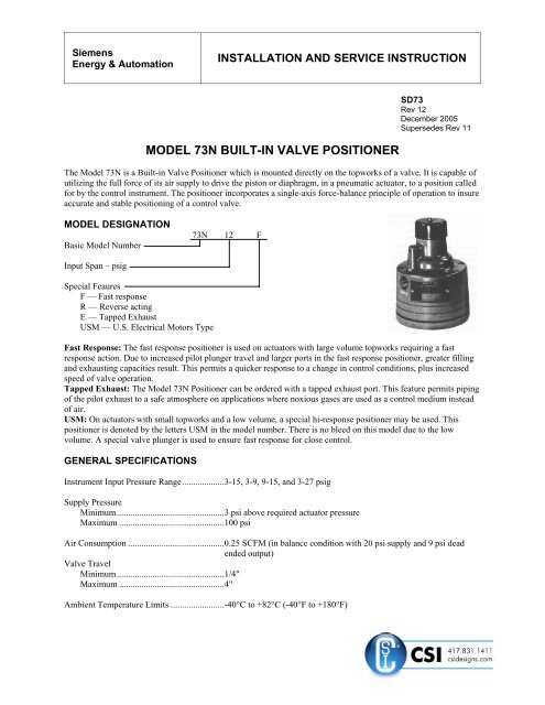
The Model <strong>73N</strong> is a Built-in Valve Positioner which is mounted directly on the topworks of a valve. It is capable of<br />
utilizing the full force of its air supply to drive the piston or diaphragm, in a pneumatic actuator, to a position called<br />
for by the control instrument. The positioner incorporates a single-axis force-balance principle of operation to insure<br />
accurate and stable positioning of a control valve.<br />
<strong>MODEL</strong> DESIGNATION<br />
Basic Model Number<br />
Input Span – psig<br />
Special Feaures<br />
F — Fast response<br />
R — Reverse acting<br />
E — Tapped Exhaust<br />
USM — U.S. Electrical Motors Type<br />
<strong>73N</strong> 12 F<br />
Fast Response: The fast response positioner is used on actuators with large volume topworks requiring a fast<br />
response action. Due to increased pilot plunger travel and larger ports in the fast response positioner, greater filling<br />
and exhausting capacities result. This permits a quicker response to a change in control conditions, plus increased<br />
speed of valve operation.<br />
Tapped Exhaust: The Model <strong>73N</strong> Positioner can be ordered with a tapped exhaust port. This feature permits piping<br />
of the pilot exhaust to a safe atmosphere on applications where noxious gases are used as a control medium instead<br />
of air.<br />
USM: On actuators with small topworks and a low volume, a special hi-response positioner may be used. This<br />
positioner is denoted by the letters USM in the model number. There is no bleed on this model due to the low<br />
volume. A special valve plunger is used to ensure fast response for close control.<br />
GENERAL SPECIFICATIONS<br />
Instrument Input Pressure Range...................3-15, 3-9, 9-15, and 3-27 psig<br />
Supply Pressure<br />
Minimum................................................3 psi above required actuator pressure<br />
Maximum ...............................................100 psi<br />
Air Consumption ...........................................0.25 SCFM (in balance condition with 20 psi supply and 9 psi dead<br />
ended output)<br />
Valve Travel<br />
Minimum................................................1/4"<br />
Maximum ...............................................4"<br />
Ambient Temperature Limits ........................-40°C to +82°C (-40°F to +180°F)
SD73<br />
<strong>IN</strong>STALLATION<br />
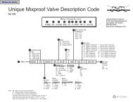
Refer to Figure 1 for mounting dimensions and connections. A centering washer (customer provided) which fits the<br />
I.D. of the range spring should be used. This acts as a spring seat and keeps the spring from shifting.<br />
Mounting hardware is included with the positioner in a plastic bag numbered 10448-88. It contains (6) mounting<br />
screws and washers, (1) range spring seat and (1) gasket.<br />
CAUTION<br />
Exceeding the specified ambient temperature limits can adversely affect performance<br />
and may cause the positioner to fail.<br />
1. Place centering washer on the actuator's diaphragm or piston.<br />
2. Place the positioner range spring on the center of the actuator diaphragm or piston.<br />
3. Place the gasket on the mounting flange of the actuator top works. Substitute the P/N 10636-59 centering<br />
diaphragm for the gasket if the P/N 12388-6412 or 12395-6412 range spring is used.<br />
4. Place the positioner range spring seat on the center nut of the positioner diaphragm assembly.<br />
5. Hold the spring seat and guide the positioner and seat onto the range spring.<br />
6. Orient the positioner for desired location of connections.<br />
7. Insert mounting screws and washers and tighten screws.<br />
PNEUMATIC CONNECTIONS<br />
1. All connections are 1/4" NPT.<br />
2. The piping re<strong>com</strong>mended for the positioner is 1/4" O.D. tubing for the <strong>IN</strong>STRUMENT (input) connection and<br />
3/8" O.D. tubing for the supply connection. However, any scale-free piping may be used.<br />
3. Blow out all piping before connections are made to prevent dirt, chips, etc., from entering the positioner.<br />
4. Use pipe sealant sparingly and then only on the male threads. A non-hardening sealant is strongly<br />
re<strong>com</strong>mended.<br />
5. Connect the positioner to a source of clean, dry, oil-free instrument air supply (see <strong>IN</strong>STRUMENT AIR<br />
REQUIREMENTS).<br />
CAUTION<br />
Pressure in excess of 150 psig to any connection may cause damage.<br />
<strong>IN</strong>STRUMENT AIR REQUIREMENTS<br />
Connect the positioner to a source of clean, dry, oil-free supply air. Failure to do so will increase the possibility of a<br />
malfunction or deviation from specified performance.<br />
CAUTION<br />
Use of process fluids other than instrument air is not re<strong>com</strong>mended. No claim is made as to<br />
the suitability of this product for use with other process fluids, such as hazardous gases,<br />
except as listed on the appropriate certificate. Non-approved instruments are suitable for<br />
use with instrument air only. Optional features and modifications such as tapped exhaust do<br />
not imply suitability for use with hazardous gases except as listed on the approval<br />
certificate.<br />
CAUTION<br />
Synthetic <strong>com</strong>pressor lubricants in the air stream at the instrument may cause the positioner<br />
to fail.<br />
2
There are many types of synthetic lubricants. Some may not be <strong>com</strong>patible with the materials used in the<br />
construction of the positioner. Wetting of these materials by such an oil mist or oil vapor, etc., may cause them to<br />
deteriorate. This may ultimately result in failure of the positioner. The following materials are in contact with supply<br />
air: Aluminum, Brass, Stainless Steel, Neoprene and Buna-N.<br />
The requirements for a quality air supply can be found in the Instrument Society of America's "Quality Standard for<br />
Instrument Air" (ISA-S7.3). Basically this standard calls for the following:<br />
Particle Size — Maximum particle size in the air stream should be no larger than 3 microns.<br />
Figure 1 Installation Dimensions and Connections<br />
3<br />
SD73
SD73<br />
Dew Point — Dew point at line pressure should be at least 10°C (18°F) below the minimum temperature to which<br />
any part of the instrument air system is exposed at any season of the year. Under no circumstances should the dew<br />
point at line pressure exceed 2°C (35.6°F).<br />
Oil Content — Maximum total oil or hydrocarbon content, exclusive of non-condensables, should not exceed 1 ppm<br />
under normal operating conditions.<br />
ADJUSTMENT<br />
CAUTION<br />
Exceeding the specified ambient temperature limits can adversely affect performance and<br />
may cause damage.<br />
The only adjustment that can be made on the positioner is a zero adjustment. The zero adjusting screw is located<br />
under the positioner top cover.<br />
To adjust the zero, set the instrument pressure to the midpoint of its span, and turn the zero adjustment until the<br />
valve is at the mid-point of its stroke.<br />
In some cases, valve shut-off or opening may be required at a specific instrument pressure. To zero the positioner at<br />
this point, set the instrument pressure at the specific pressure and turn the zero adjustment screw until the valve<br />
reaches the required position.<br />
A slight change of the instrument pressure should start to move the valve.<br />
The valve stroke for a given span may also be suppressed or shifted to the desired range by means of the zero<br />
adjusting screw.<br />
RANGE SPR<strong>IN</strong>G SELECTION<br />
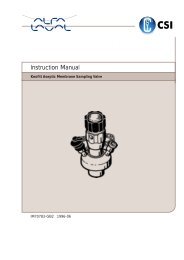
Range springs for the positioner are selected from the table in Figure 2. Color coding of the range springs is given<br />
by the table in Figure 3.<br />
To find the proper spring, select the stroke listed which most nearly agrees with the desired stroke, and the pressure<br />
span which most nearly agrees with the desired span. The proper spring will be found at the intersection of these two<br />
columns.<br />
Series 4090 and 12395 range springs are available for stroke range tolerances of ±10%. Series 12388 range springs<br />
are available, at extra cost, for stroke range tolerances of ±5%.<br />
4
Input Pressure Span (see Special Notes below)<br />
4 5 6 8 10 12 16 20 24<br />
Valve Stroke<br />
(inches)<br />
Item No. of Range Spring Series 12395 Series +/- 5% stroke range tolerance<br />
1/4 1212 1012 812 612 512 412 624 524 424<br />
5/16 1812 1212 1012 712 612 512 824 624 524<br />
3/8 1812 1412 1212 1012 712 612 1024 724 624<br />
7/16 2012 1812 1412 1012 812 712 1024 824 724<br />
1/2 2412 2012 1612 1212 1012 812 1224 1024 824<br />
9/16 2812 2012 1812 1412 1012 1012 1424 1024<br />
5/8 3212 2412 2012 1612 1212 1012 1624 1224 1024<br />
3/4 3612 2812 2412 1812 1412 1212 1464 1224<br />
7/8 4412 3612 2812 2012 1812 1412 2024 1624 1424<br />
1 4812 4012 3212 2412 2012 1612 2424 2024 1624<br />
1-1/8 5612 4412 3612 2812 2012 1812 2024<br />
1-1/4 6412 4812 4012 3212 2412 2012 2824 2424 2024<br />
1-1/2 6412 4812 3612 2812 2412 4024 2824 2424<br />
1-5/8 6412 4812 4012 3212 2612 4024 3224<br />
1-3/4 6412 5612 4412 3612 2812 4024 3224 2824<br />
2 6412 4812 4012 3212 4824 4024 3224<br />
2-1/4 6412 5612 4412 3612 4024<br />
2-1/2 6412 4812 4012 4824 4024<br />
2-3/4 6412 4812 4412 4824 4824<br />
3 6412 4812 4824<br />
3-1/2 5612<br />
4 6412<br />
Special Notes:<br />
1) All range springs are identified as Part No. (P/N) 12395-______(# from table)<br />
2) Input pressure span = pressure @ max. input – (minus) pressure @ min input, e.g. @ 3-15 psig range = @ 12<br />
psig span<br />
Spring Selection:<br />
1) Find valve stroke nearest desired valve stroke.<br />
2) Find instrument input pressure span nearest desired instrument input pressure span.<br />
3) Select proper range spring at intersection of valve stroke and instrument input pressure span columns.<br />
Springs purchased with models are quoted as model discounts all others get spare parts pricing.<br />
Notes:<br />
1) The maximum zero pressure for the Model <strong>73N</strong>12F is 9 psig when the 12395 series range spring is used.<br />
2) The maximum zero pressure for the Model <strong>73N</strong>24F is 15 psig for instrument pressure spans of 16 psi or greater<br />
and 28 psig when used for spans of 12 psi or less.<br />
3) The maximum instrument pressure for the Model <strong>73N</strong>-FR is 15 psig for instrument pressure spans of 12 psi or<br />
less and 27 psi for spans of 16 psi or greater.<br />
Figure 2 Range Spring Index<br />
5<br />
SD73
SD73<br />
MA<strong>IN</strong>TENANCE GENERAL<br />
Clean, dry, oil-free instrument air will reduce most<br />
problems associated with pneumatic instruments.<br />
Refer to <strong>IN</strong>STRUMENT AIR REQUIREMENTS.<br />
If these requirements are observed, no routine<br />
maintenance is re<strong>com</strong>mended. Cleaning the<br />
plunger is to only maintenance which may be<br />
required on an occasional basis.<br />
The system should be shut down or the valve<br />
isolated from the system before service or removal<br />
of the positioner is ac<strong>com</strong>plished.<br />
CLEAN<strong>IN</strong>G (Refer to parts list)<br />
The plunger can be cleaned without dismantling<br />
the positioner. Use the following procedure:<br />
1. Turn off the supply air.<br />
2. Remove the positioner top cover.<br />
3. Remove the retaining nut.<br />
4. Remove the plunger.<br />
5. Use a non-abrasive solvent to clean the<br />
plunger.<br />
6. Replace the plunger.<br />
7. Replace and tighten the retaining nut.<br />
8. Replace the top cover.<br />
DISASSEMBLY (Refer to parts list)<br />
1. Loosen the six socket head mounting screws<br />
holding the positioner to the actuator.<br />
2. Remove the positioner.<br />
3. Remove the two body screws holding the<br />
diaphragm stack assembly to the positioner<br />
body (located on the underside of the stack).<br />
4. The diaphragm stack assembly can be further<br />
disassembled by removing the diaphragm jam<br />
nut.<br />
ASSEMBLY (Refer to parts list)<br />
To assemble, reverse the disassembly procedures.<br />
Take care to insure proper alignment of the<br />
diaphragms and rings. When tightening the jam nut<br />
on the diaphragm assembly, make sure the<br />
diaphragms do not rotate out of position.<br />
An alignment slot is provided on the rings to<br />
facilitate proper assembly.<br />
6<br />
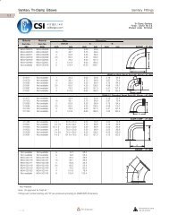
Figure 3 Range and Zero Spring Color Codes
Figure 4 Schematic – Direct Acting<br />
Figure 5 Schematic – Reverse Acting<br />
7<br />
SD73
SD73<br />
PRODUCT SUPPORT<br />
This section provides the Internet site addresses, e-mail addresses, telephone numbers, and related information for<br />
customers to access Siemens product support.<br />
When contacting Siemens for support:<br />
• Please have <strong>com</strong>plete product information at hand:<br />
• For hardware, this information is provided on the product nameplate (part number or model number,<br />
serial number, and/or version).<br />
• For most software, this information is given in the Help > About screen.<br />
• If there is a problem with product operation:<br />
• Is the problem intermittent or repeatable? What symptoms have been observed?<br />
• What steps, configuration changes, loop modifications, etc. were performed before the problem<br />
occurred?<br />
• What status messages, error messages, or LED indications are displayed?<br />
• What troubleshooting steps have been performed?<br />
• Is the installation environment (e.g. temperature, humidity) within the product’s specified operating<br />
parameters? For software, does the PC meet or exceed the minimum requirements (e.g. processor,<br />
memory, operating system)?<br />
• A copy of the product Service Instruction, User’s Manual, or other technical literature should be at hand. The<br />
Siemens public Internet site (see the table) has current revisions of technical literature, in Portable Document<br />
Format, for downloading.<br />
• To send an instrument to Siemens for repair, request a Return Material Authorization (RMA).<br />
IMPORTANT<br />
An instrument must be thoroughly cleaned (decontaminated) to remove any process materials,<br />
hazardous materials, or blood born pathogens prior to return for repair. Read and <strong>com</strong>plete the<br />
Siemens RMA form(s).<br />
United States<br />
of America<br />
Contact Information<br />
Telephone +1 800 569 2132, option 2 for Siemens and Moore brand instruments<br />
Fax +1 215 646 3547<br />
E-mail PITechSupp@sea.siemens.<strong>com</strong><br />
Hours of Operation 8 a.m. to 4:45 p.m. eastern time<br />
Monday – Friday (except holidays)<br />
Public Internet Site www.sea.siemens.<strong>com</strong>/ia/<br />
Repair Service +1 215 646 7400 extension 3187<br />
For contact information outside the U.S.A., visit the Siemens public Internet site (see the above table for the URL),<br />
locate “Customer Support Process Instrumentation,” and click on the Contact Tech Support link to access the Global<br />
Support link.<br />
Current revisions of instructions and manuals, in Portable Document Format (PDF), can be found at the Siemens<br />
public Internet site.<br />
8
WARRANTY<br />
(a) Seller warrants that on the date of shipment the goods are of the kind and quality described herein and<br />
are free of non-conformities in workmanship and material. This warranty does not apply to goods<br />
delivered by Seller but manufactured by others.<br />
(b) Buyer's exclusive remedy for a nonconformity in any item of the goods shall be the repair or the<br />
replacement (at Seller's option) of the item and any affected part of the goods. Seller’s obligation to repair<br />
or replace shall be in effect for a period of one (1) year from initial operation of the goods but not more<br />
than eighteen (18) months from Seller’s shipment of the goods, provided Buyer has sent written notice<br />
within that period of time to Seller that the goods do not conform to the above warranty. Repaired and<br />
replacement parts shall be warranted for the remainder of the original period of notification set forth above,<br />
but in no event less than 12 months from repair or replacement. At its expense, Buyer shall remove and<br />
ship to Seller any such nonconforming items and shall reinstall the repaired or replaced parts. Buyer shall<br />
grant Seller access to the goods at all reasonable times in order for Seller to determine any nonconformity<br />
in the goods. Seller shall have the right of disposal of items replaced by it. If Seller is unable or unwilling<br />
to repair or replace, or if repair or replacement does not remedy the nonconformity, Seller and Buyer shall<br />
negotiate an equitable adjustment in the contract price, which may include a full refund of the contract<br />
price for the nonconforming goods.<br />
(c) SELLER HEREBY DISCLAIMS ALL OTHER WARRANTIES, EXPRESS OR IMPLIED, EXCEPT THAT<br />
OF TITLE. SPECIFICALLY, IT DISCLAIMS THE IMPLIED WARRANTIES OF MERCHANTABILITY,<br />
FITNESS FOR A PARTICULAR PURPOSE, COURSE OF DEAL<strong>IN</strong>G AND USAGE OF TRADE.<br />
(d) Buyer and successors of Buyer are limited to the remedies specified in this article and shall have no<br />
others for a nonconformity in the goods. Buyer agrees that these remedies provide Buyer and its successors<br />
with a minimum adequate remedy and are their exclusive remedies, whether Buyer's or its successors’<br />
remedies are based on contract, warranty, tort (including negligence), strict liability, indemnity, or any<br />
other legal theory, and whether arising out of warranties, representations, instructions, installations, or nonconformities<br />
from any cause.<br />
(e) Note: The above does not apply to any software which may be furnished by Seller. In such cases, the<br />
attached Software License Addendum applies.<br />
9<br />
SD73
SD73<br />
PARTS LIST<br />
SIEMENS <strong>MODEL</strong> SERIES <strong>73N</strong> <strong>BUILT</strong>-<strong>IN</strong> <strong>VALVE</strong> <strong>POSITIONER</strong><br />
IMPORTANT<br />
10<br />
Drawing No. 10636PL<br />
3/91 Supersedes 8/88<br />
Service Parts Kits are available for servicing the instrument. Contact Siemens for available kits; refer to the Product<br />
Support section of this instruction. Some parts in this Parts List may not be available for separate purchase.
PARTS LIST<br />
SIEMENS <strong>MODEL</strong> SERIES <strong>73N</strong>12FUSM <strong>BUILT</strong>-<strong>IN</strong> <strong>VALVE</strong> <strong>POSITIONER</strong><br />
IMPORTANT<br />
Service Parts Kits are available for servicing the instrument. Contact Siemens for available kits; refer to the Product<br />
Support section of this instruction. Some parts in this Parts List may not be available for separate purchase.<br />
11<br />
SD73<br />
Drawing No. 10976PL<br />
3/91 Supersedes 5/86