Manual - PMV Positioners
Manual - PMV Positioners
Manual - PMV Positioners

You also want an ePaper? Increase the reach of your titles
YUMPU automatically turns print PDFs into web optimized ePapers that Google loves.
Function<br />
The positioning is based on the principle of balanced forces. One force is<br />
originated by the signal pressure transmitted through bellows (25) on balance<br />
arm (19). The otherforce is from the feed back spring (14) and is proportional<br />
to the level of the lower arm (8).<br />
The lower arm (8) level is determined by the position ofthe cam (6) which is<br />
secured to the spindle (2). The spindle (2) is activated by the cylinder rod.<br />
When these two forces are equal, the balance arm (19) isinacentralneutral<br />
position, as is the spool (30). There is a slight leakage of air past the close<br />
tolerances between the pilot valve parts (29 and 30). A small flow runs from<br />
supply S past the pilot valve ports into the cylinder through<br />
connections C1 and C2. Another small flow leaks out into the positioner<br />
housing.<br />
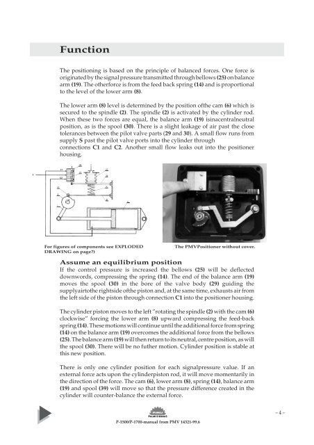
For figures of components see EXPLODED<br />
DRAWING on page?)<br />
P-1500/P-1700-manual from <strong>PMV</strong> 14321-99.6<br />
The <strong>PMV</strong>Positioner without cover.<br />
Assume an equilibrium position<br />
If the control pressure is increased the bellows (25) will be deflected<br />
downwords, compressing the spring (14). The end of the balance arm (19)<br />
moves the spool (30) in the bore of the valve body (29) guiding the<br />
supplyairtothe rightside ofthe piston and, at the same time, exhausts air from<br />
the left side of the piston through connection C1 into the positioner housing.<br />
The cylinder piston moves to the left ”rotating the spindle (2) with the cam (6)<br />
clockwise” forcing the lower arm (8) upward compressing the feed-back<br />
spring (14). These motions will continue until the additional force from spring<br />
(14) on the balance arm (19) overcomes the additional force from the bellows<br />
(25). The balance arm (19) will then return to its neutral, centre position, as will<br />
the spool (30). There will be no futher motion. Cylinder position is stable at<br />
this new position.<br />
There is only one cylinder position for each signalpressure value. If an<br />
external force acts upon the cylinderpiston rod, it will move momentarily in<br />
the direction of the force. The cam (6), lower arm (8), spring (14), balance arm<br />
(19) and spool (39) will move so that the pressure difference created in the<br />
cylinder will counter-balance the external force.<br />
– 4 –