Manual - PMV Positioners
Manual - PMV Positioners
Manual - PMV Positioners

You also want an ePaper? Increase the reach of your titles
YUMPU automatically turns print PDFs into web optimized ePapers that Google loves.
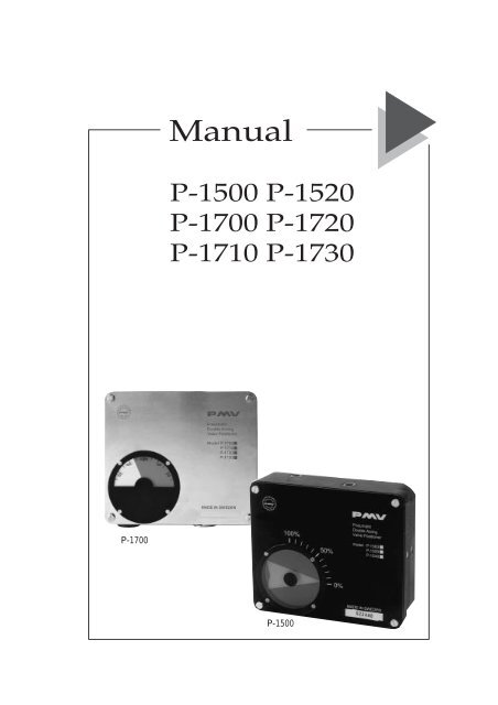
P-1700<br />
<strong>Manual</strong><br />
P-1500 P-1520<br />
P-1700 P-1720<br />
P-1710 P-1730<br />
P-1500<br />
P-1500/P-1700-manual from <strong>PMV</strong> 14321-99.6<br />
– 1 –
Manufacturers declaration • Hersteller-Erklärung • Déclaration de fabricant<br />
GB<br />
Manufacturers declaration<br />
in compliance with EC directive 89/392/EEC.<br />
We hereby confirm that the appliances described in this sheet has been manufactured in compliance<br />
with the applicable standards and is intended for installation in a machine/application, and that<br />
commissioning is strictly prohibited until evidence has been provided that the machine/application in<br />
question is also in compliance with<br />
EC directive 89/392/EEC.<br />
This manufacturers declaration is applicable to the following <strong>PMV</strong> series:<br />
P-1500, P-1520, P-1700, P-1710, P-1720, P-1730.<br />
D<br />
Hersteller-Erklärung<br />
im Sinne der EG-Richtlinie 89/392/EWG.<br />
Hiermit erklären wir, daß die in diesem Blatt beschriebenen Geräte entsprechend den gültigen Normen<br />
gebaut und zum Einbau in eine Maschine oder Applikation bestimmt sind, sowie daß deren<br />
Inbetriebnahme so lange untersagt ist, bis festgestellt wurde, daß diese<br />
Maschine/Applikation ebenfalls der EG-Richtlinie<br />
89/392/EWG.<br />
Diese Herstellererklärung hat für folgende <strong>PMV</strong>-Serien Gültigkeit:<br />
P-1500, P-1520, P-1700, P-1710, P-1720, P-1730.<br />
F<br />
Déclaration de fabricant<br />
au sens dela directive de la 89/392/CEE.<br />
Nous déclarons par la présente que les appareils décrits sur cette page sont construits en conformité<br />
avec les normes en vigueur et qu'ils sont destinés à être montés dans une machine ou une application,<br />
nous déclarons également que leur mise en service est interdite tant qu'il n'a pas été constaté que cette<br />
macine/application satisfait<br />
également à la directive 89/392/CEE.<br />
Cette déclaration de fournisseur est valable pour les types d'appareils <strong>PMV</strong> suivants:<br />
P-1500, P-1520, P-1700, P-1710, P-1720, P-1730.<br />
Mr. Jan-Eric Andersson<br />
President, Palmstiernas Instrument AB<br />
P-1500/P-1700-manual from <strong>PMV</strong> 14321-99.6<br />
– 2 –
<strong>PMV</strong> Positioner storage and handling procedures<br />
<strong>PMV</strong> <strong>Positioners</strong> are precision instruments which should be stored and<br />
handled accordingly to avoid problems or damage.<br />
Appropriate precautions should be taken to protect units while in storage.<br />
Warehouse storage<br />
Stored in original <strong>PMV</strong> shipping containers, units should be stored in an<br />
environmentally controlled area, i.e. clean, cool (15-26°C, 6~80°F) and dry,<br />
out of direct sunlight or weather exposure.<br />
Field storage<br />
Note: Once air supply to the positioner is connected and turned on, internal<br />
air bleed will prevent the ingress of moisture and protect the unit from<br />
corrosion. It is recommended that the air supply be left on at all times.<br />
• If units are installed immediately, tum, and leave on, the air supply.<br />
• If positioner must be stored outdoors, tighten all covers which may<br />
loosened in shipment, make sure all open enclosure entry points are sealed.<br />
<strong>Positioners</strong> should be wrapped and sealed air and watertight with desiccant<br />
inside the plastic, units should be securely covered with an opaque cover and<br />
not exposed to direct sunlight, rain or snow.<br />
Potential damage mechanism<br />
When units are stored in hot, humid climates, the daily heating/cooling cycle<br />
will cause air to expand/ contract and be drawn in and out of the positioner<br />
housing.<br />
Dependent on the local temperature variations, humidity, dew points and the<br />
time in storage condensation could occur and accumulate inside causing<br />
erractic operation or failure due to water or corrosion. The potential for<br />
condensation damage is especially high in southern climates and aggravated<br />
if units are exposed to direct sunlight.<br />
For further assistance, please contact your nearest <strong>PMV</strong> office.<br />
P-1500/P-1700-manual from <strong>PMV</strong> 14321-99.6<br />
– 3 –
Function<br />
The positioning is based on the principle of balanced forces. One force is<br />
originated by the signal pressure transmitted through bellows (25) on balance<br />
arm (19). The otherforce is from the feed back spring (14) and is proportional<br />
to the level of the lower arm (8).<br />
The lower arm (8) level is determined by the position ofthe cam (6) which is<br />
secured to the spindle (2). The spindle (2) is activated by the cylinder rod.<br />
When these two forces are equal, the balance arm (19) isinacentralneutral<br />
position, as is the spool (30). There is a slight leakage of air past the close<br />
tolerances between the pilot valve parts (29 and 30). A small flow runs from<br />
supply S past the pilot valve ports into the cylinder through<br />
connections C1 and C2. Another small flow leaks out into the positioner<br />
housing.<br />
For figures of components see EXPLODED<br />
DRAWING on page?)<br />
P-1500/P-1700-manual from <strong>PMV</strong> 14321-99.6<br />
The <strong>PMV</strong>Positioner without cover.<br />
Assume an equilibrium position<br />
If the control pressure is increased the bellows (25) will be deflected<br />
downwords, compressing the spring (14). The end of the balance arm (19)<br />
moves the spool (30) in the bore of the valve body (29) guiding the<br />
supplyairtothe rightside ofthe piston and, at the same time, exhausts air from<br />
the left side of the piston through connection C1 into the positioner housing.<br />
The cylinder piston moves to the left ”rotating the spindle (2) with the cam (6)<br />
clockwise” forcing the lower arm (8) upward compressing the feed-back<br />
spring (14). These motions will continue until the additional force from spring<br />
(14) on the balance arm (19) overcomes the additional force from the bellows<br />
(25). The balance arm (19) will then return to its neutral, centre position, as will<br />
the spool (30). There will be no futher motion. Cylinder position is stable at<br />
this new position.<br />
There is only one cylinder position for each signalpressure value. If an<br />
external force acts upon the cylinderpiston rod, it will move momentarily in<br />
the direction of the force. The cam (6), lower arm (8), spring (14), balance arm<br />
(19) and spool (39) will move so that the pressure difference created in the<br />
cylinder will counter-balance the external force.<br />
– 4 –
The <strong>PMV</strong> Rotary Positioner<br />
Air preparation<br />
The <strong>PMV</strong> Rotary Positioner can work with supply<br />
pressure up to 10 bar (150 psi). In order to obtain<br />
satisfactory operation and high reliability, the<br />
positioner should be fed with dry, clean oil free<br />
air.<br />
By connecting the air supply to the positioner via<br />
a filter 25 microns which is placed as close to the<br />
positioner as possible, the required air quality is<br />
received.<br />
1. To zero the positioner<br />
The zeroing screw is<br />
accessible from the outside.<br />
Back off the screw and move<br />
the cover to one side. Fig 1<br />
Adjust by means of a<br />
screwdriver. The adjusting<br />
screw is provided with a<br />
friction brake and need not<br />
therefore be locked after<br />
adjustment. Fig 2<br />
Figure 1<br />
Figure 2<br />
P-1500/P-1700-manual from <strong>PMV</strong> 14321-99.6<br />
For large pressure variations of the supply air, a<br />
pressure regulator should be mounted between<br />
filter and positioner in order to eliminate the<br />
fluctuations.<br />
Installation<br />
The supply air shall be connected to the port S.<br />
The control pressure shall be connected to port I<br />
while ports C1 and C2 are connected to the<br />
connections of the cylinder.<br />
2. To adjust the Control<br />
Pressure Range<br />
2.1 General<br />
The top end of the spring is<br />
provided with an adjusting<br />
nut.The effective length<br />
of the spnng can be varied by<br />
turning the spring relative to<br />
the nut . For any fixed control<br />
range the actuator will move<br />
more if the effective length of<br />
the spring is increased. Fig 3<br />
A. Long travel<br />
B. Short travel<br />
After the spring length has<br />
been adjusted, the spring<br />
guide must be turned in<br />
relation to the nut so that its<br />
underside is not in contact<br />
with the end of the spring.<br />
Fig 4<br />
A. Incorrect<br />
B. Correct<br />
A B<br />
Figure 3<br />
A B<br />
Figure 4<br />
– 5 –
2.2 To increase the actuator travel<br />
IMPORTANT: Always start<br />
from zero! Make zero<br />
adjustment (se 1). Adjust<br />
slowly the control pressure to<br />
the top value and check the<br />
movement of the actuator.<br />
Should you need moretravel:<br />
Back off the locking screw<br />
which locks the spring to the<br />
adjusting nut. Fig 5<br />
Turn the spring clockwise to<br />
increase the effective length<br />
of the spring. Tighten the<br />
screw. Fig 6<br />
After making an adjustment<br />
of the effective spring length<br />
you must again start by making<br />
zero adjustments. Should<br />
large adjustments be necessary<br />
you must rearrange the<br />
position of nut relative to the<br />
spnng guide in order to be<br />
able to make zero adjustments<br />
Fig 7<br />
Back off the locking screw<br />
which locks the adjusting nut<br />
to the spring guide.<br />
Turn the spring and the spring<br />
guide anticlock-wise until the<br />
end of spring is almost in<br />
contact with the flat of the top<br />
spring guide.<br />
Fig 8<br />
Figure 5<br />
Figure 6<br />
Figure 7<br />
Figure 8<br />
Tighten screw (16).<br />
Be sure the control pressure is<br />
adjusted to minimum value.<br />
When the zero is correctly<br />
adjusted tum once more the<br />
control pressure slowly to top<br />
value and check the<br />
movement of the actuator.<br />
Make further adjustments if<br />
necessary – N.B. a/ways go<br />
back and startfrom the zero<br />
position.<br />
Fig 9<br />
2.3 To reduce the actuator<br />
travel<br />
IMPORTANT: Always start<br />
from zero! Make zero<br />
adjustment (see I. above).<br />
Adjust the control pressure<br />
signal to the top value slowly<br />
and check the movement of<br />
the actuator. Should you need<br />
less travel:<br />
Please notice: Should large<br />
adjustments be required you<br />
must rearrange the position<br />
of the nut relative to the top<br />
spring guide in order to be<br />
able to reduce the effective<br />
length of the spring<br />
Back off the locking screw.<br />
Fig 10<br />
Turn the spring and the top<br />
spring guide clockwise to<br />
allow space for the free end<br />
of the spring when reducing<br />
the amount of effective<br />
spring length.<br />
Fig 11<br />
P-1500/P-1700-manual from <strong>PMV</strong> 14321-99.6<br />
Figure 9<br />
Figure 10<br />
Figure 11<br />
– 6 –
Tighten the screw and back<br />
off screw.<br />
Fig 12<br />
Turn the spring relative to the<br />
nut for less effective spring.<br />
Fig 13<br />
Tighten the screw and make<br />
zero adjustment (make sure<br />
the control pressure signal is<br />
at zero level). Adjust once<br />
more the control pres-sure signal<br />
to top level and check the<br />
movement of the actuator.<br />
Make further adjustments if<br />
necessary.<br />
Fig 14<br />
N.B. After adjustments are<br />
completed please make sure<br />
that screws and are securely<br />
fastened. If these screws are<br />
not accessible, see Section 2.4<br />
below.<br />
Figure 12<br />
Figure 13<br />
Figure 14<br />
2.4 To turn the top spring guide (18) through 120 degrees<br />
The spring guide can be fitted in three positions in<br />
relation to the balance arm. By compressing the spring,<br />
the spring guide will be released from the balance<br />
arm, and the spring and spring guide can be turned<br />
through 120 degrees in either direction. The spring<br />
guide, nut and spring can thus always be fitted so that<br />
the locking screws and will he accessible.<br />
3. To change the action<br />
3.1 To change from valve opening<br />
on increasing signal to valve<br />
closing on increasing signal, or<br />
vice- versa, proceed as follows:<br />
Shut off supply and instrumental<br />
air.<br />
As standard, the positioner is<br />
fitted with an intermediate<br />
piece.<br />
Fig 15<br />
Reverse the flexible tubing<br />
between the positioner ports<br />
Cl and C2.<br />
Remove the positioner cover .<br />
The screws can be left partially<br />
threaded into the cover.<br />
Remove the nut that fastens<br />
the cam to the spindle.<br />
Fig 16<br />
Invert the cam, position it to<br />
the desired signal range,<br />
(stamped on the cam lobes),<br />
and install the nut but do not<br />
tighten the nut yet.<br />
Fig 17<br />
Turn on the supply and instrumental<br />
air.<br />
Make sure the actuator is in<br />
the position corresponding to<br />
the minimum signal (fully<br />
open for units piped to close<br />
on increasing signal or fully<br />
closed on units piped to open<br />
on increasing signal).<br />
P-1500/P-1700-manual from <strong>PMV</strong> 14321-99.6<br />
Figure 15<br />
Figure 16<br />
Figure 17<br />
– 7 –
Position the cam as shown.<br />
The ballbearing should not<br />
ride up on the inactive portion<br />
of the cam.<br />
Fig 18<br />
NOTE: The cam will turn<br />
slightly with the nut as it is<br />
tightened. Be sure to allow for<br />
that slight clock-wise rotation.<br />
4. To clean the valve body<br />
Remove the four screws and<br />
remove the cover.<br />
Remove the screws.<br />
Fig 21<br />
Carefully remove the valve<br />
body. Fit so that the spool<br />
slides easily and does not bind<br />
against the balance arm.<br />
Fig 22<br />
Figure 18<br />
Figure 19<br />
Figure 20<br />
Figure 21<br />
Remove the screw retaining<br />
the intermediate piece.<br />
Wash the components and<br />
blow them clean and dry with<br />
compressed air. Check that<br />
ports Cl and C2 are clean.<br />
Certain adapters incorporate<br />
filters which cannot be removed.<br />
Such adapters should be<br />
replaced, if necessary.<br />
Check that the O-rings are in<br />
good condition.<br />
Fig 22<br />
P-1500/P-1700-manual from <strong>PMV</strong> 14321-99.6<br />
Figure 22<br />
– 8 –
Fit the intermediate piece and<br />
tighten the screw lightly.<br />
Fig 23<br />
Check that the bottom edge of<br />
the intermediate piece is<br />
slightly (0.5-1 mm) outside the<br />
face in the casing.<br />
Fig 24<br />
Fit the valve body with spool.<br />
Take care not to damage the<br />
groove in the spool for the<br />
balance arm.<br />
Fit the screws with the<br />
washers. Press the valve body<br />
against the inter-mediate<br />
piece. Back off I the screw.<br />
Press hard and tighten the<br />
screws. Tighten the screw.<br />
Fig 25<br />
Adjust the starting point by<br />
means of the screw.<br />
Fig 26<br />
Figure 23<br />
Figure 24<br />
Figure 25<br />
Figure 26<br />
5. To replace the bellows<br />
Remove the cover. Remove<br />
the spring with its adjusting<br />
nut and spring guide by<br />
compressing the spring. Remove<br />
the screws and remove<br />
the balance arm. Turn the<br />
bellows back and forth while<br />
with-drawing it out of its<br />
mounting.<br />
Before fitting, the length of<br />
the bellows must be<br />
measured. The length should<br />
be 35mm and should be<br />
adjusted if necessary by stretching<br />
or compressing the<br />
bellows.<br />
Check that the O-ring is in<br />
good condition and take care<br />
when compressing the<br />
bellows while fitting it into<br />
place.<br />
Fig 27<br />
N.B. Hold the part of the<br />
bellows to which the O-nng is<br />
fitted when pressing in the<br />
bellows, since the dimension<br />
35 mm may otherwise alter.<br />
Refit the balance arm and the<br />
spring.<br />
6. To zero the indicator<br />
P-1500/P-1700-manual from <strong>PMV</strong> 14321-99.6<br />
Figure 27<br />
Remove the four screws and remove the cover.<br />
Back off the locking screw and zero the indicator.<br />
Replace the cover to check the setting of the indicator.<br />
Make fine adjustments if necessary.<br />
Tighten the locking screw. Do not tighten screw too<br />
hard, otherwise the indicator will crack.<br />
Mount the cover and tighten the four screws.<br />
– 9 –
Exploded drawing<br />
P-1500/P-1700-manual from <strong>PMV</strong> 14321-99.6<br />
– 10 –
Dimension drawing P1500/P-1700<br />
P-1500/P-1700-manual from <strong>PMV</strong> 14321-99.6<br />
– 11 –
SUBSIDIARIES:<br />
Distributor<br />
<strong>PMV</strong> Controls Ltd<br />
Headlands Business Park<br />
Ringwood<br />
Hampshire BH24 3PB<br />
ENGLAND<br />
Tel: +44 (0) 1425 48 08 88<br />
Fax: +44 (0) 1425 48 08 89<br />
E-mail: pmv_uk@compuserve.com<br />
<strong>PMV</strong>-USA, Inc<br />
1440 Lake Front Circle<br />
Unit 160<br />
The Woodlands, Texas 77380<br />
USA<br />
Tel: +1 281 292 7500<br />
Fax: +1 281 292 7760<br />
E-mail: pmvusa@pmvusa.com<br />
Internet: www.pmvusa.com<br />
Palmstiernas Instrument AB<br />
Tulegatan 15<br />
SE-113 53 Stockholm<br />
SWEDEN<br />
Tel: +46 (0) 8 15 14 85<br />
Fax: +46 (0) 8 673 39 83<br />
E-mail: info@pmvpositioners.com<br />
Internet: www.pmvpositioners.com<br />
(The information in this manual is subject to change without notice.)<br />
P-1500/P-1700-manual from <strong>PMV</strong> 14321-99.6<br />
<strong>PMV</strong> Regeltechnik GmbH<br />
Losensteinleiten 7<br />
A-4493 Wolfern<br />
AUSTRIA<br />
Tel: +43 (0) 7253 82410<br />
Fax: +43 (0) 7253 82419<br />
E-mail: aw.pmv@ambos.co.at<br />
<strong>PMV</strong> GmbH<br />
Postfach 2310<br />
D-41554 Kaarst<br />
GERMANY<br />
Tel: +49 (0) 2131 667 081/82<br />
Fax: +49 (0) 2131 667 083<br />
Palmstiernas Svenska AB<br />
Box 21<br />
SE-663 21 Skoghall<br />
SWEDEN<br />
Tel: +46 (0) 54 52 14 70<br />
Fax: +46 (0) 54 52 14 42<br />
E-mail: info@palmstiernas.se<br />
Internet: www.palmstiernas.se<br />
(The information in this brochure is subject to change without notice.)<br />
– 12 –<br />
14321/99.6 Ekvator