Valtek XL Series Positioners - Flowserve Corporation
Valtek XL Series Positioners - Flowserve Corporation
Valtek XL Series Positioners - Flowserve Corporation

You also want an ePaper? Increase the reach of your titles
YUMPU automatically turns print PDFs into web optimized ePapers that Google loves.
<strong>Valtek</strong> <strong>XL</strong> <strong>Series</strong> <strong>Positioners</strong><br />
Operation<br />
6<br />
Supply Seat<br />
Upper Pilot<br />
Poppet<br />
Exhaust Seat<br />
Output 1<br />
Restriction<br />
Supply<br />
Pilot Valve<br />
Capsule<br />
Exhaust Seat<br />
Output 2<br />
Lower Pilot<br />
Poppet<br />
Supply Seat<br />
Balance Adjustment<br />
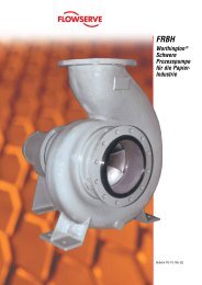
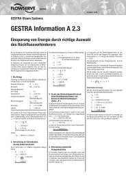
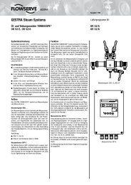
Figure 4: <strong>XL</strong> <strong>Series</strong> <strong>Positioners</strong>’ Schematic for Air-to-Open (linear valve shown)<br />
The <strong>XL</strong> <strong>Series</strong> positioners are two-stage, forcebalanced<br />
instruments. Figure 4 shows an <strong>XL</strong> <strong>Series</strong><br />
positioner used in conjunction with either an electropneumatic<br />
or pneumatic module, installed on a doubleacting<br />
actuator for air-to-open action. Positioning is<br />
based on a balance of two forces: one proportional to<br />
the instrument signal and the other proportional to the<br />
stem position.<br />
The current signal for the NT 3000 I/P module is first<br />
converted to a 3-15 psi (0.2-1.03 bar) air signal, while<br />
the 3-15 psi air signal for the pneumatic model is passed<br />
directly into the positioner. The supply pressure is<br />
filtered and regulated in the transducer by a filter<br />
element and an internal regulator.<br />
The output of the transducer is controlled by a feedback<br />
loop consisting of a pressure sensor, electromagnetic<br />
pressure modulator and circuit board. The<br />
pressure modulator consists of a stiff flapper that is<br />
attracted by the electromagnet to a nozzle. The nozzleflapper<br />
spacing determines the transducer output.<br />
Based on the difference between the input and the<br />
output measured by the pressure sensor, the circuit<br />
board sends a current to the pressure modulator that<br />
adjusts nozzle-flapper spacing to provide correct output<br />
pressure to the positioner. For more information,<br />
refer to NT 3000 <strong>Series</strong> Electro-pneumatic Transducer<br />
Module technical bulletin.<br />
Zero Adjustment<br />
Feedback<br />
Spring<br />
Detecting<br />
Nozzle<br />
Input Capsule<br />
Flapper<br />
Range<br />
Adjust Screw<br />
Cam<br />
Follower<br />
Arm<br />
Upper Diaphragm<br />
Instrument Signal<br />
Lower Diaphragm<br />
Piston<br />
Cylinder<br />
Take-off Arm<br />
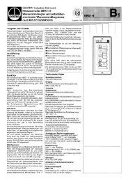
The positioner operates as follows: An increase in the<br />
instrument signal forces the instrument signal capsule<br />
and flapper downward. The nozzle now releases air<br />
and the pressure decreases on top of the pilot valve<br />
capsule. The pressure differential moves the pilot valve<br />
capsule upward, opening the upper supply seat and<br />
allowing supply pressure to output 1. This opens the<br />
exhaust seat on output 2, causing the actuator piston<br />
to move upward.<br />
The upward motion of the piston is transmitted back to<br />
the positioner through the feedback linkage and cam<br />
resulting in the spring being stretched proportionally to<br />
the valve position. The piston continues to stroke<br />
upward until the force in the feedback spring increases<br />
sufficiently to counter the force generated by the<br />
instrument signal capsule. At this point, the balance<br />
beam and spool begin to return to their equilibrium<br />
position. As the valve spool ports start to close, the air<br />
flow rate to the actuator is decreased.<br />
After the piston has reached the required position, the<br />
feedback spring tension force will equal the force<br />
generated in the instrument signal capsule. The flapper<br />
and instrument signal capsule will remain in their<br />
equilibrium positions with no air flowing to the actuator<br />
until a change in the instrument signal is made.<br />
A decrease in signal reverses the action, causing downward<br />
movement of the actuator piston and stem.<br />
<strong>Flowserve</strong> <strong>Corporation</strong>, <strong>Valtek</strong> Control Products, Tel. USA 801 489 8611<br />
O<br />
S