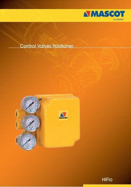
HiFlo Control Valves Positioner
HiFlo Control Valves Positioner
HiFlo Control Valves Positioner
Create successful ePaper yourself
Turn your PDF publications into a flip-book with our unique Google optimized e-Paper software.
<strong>Control</strong> <strong>Valves</strong> <strong>Positioner</strong><br />
<strong>HiFlo</strong>
<strong>HiFlo</strong><br />
Valve Features<br />
Electro-pneumatic (I/P) module<br />
Interchangable<br />
Easy calibration<br />
Pneumatic module<br />
Withstands 150 psi<br />
at all parts<br />
Valve positioners are primarily utilized by Mascot. A<br />
pneumatic module for air control signals, or an electropneumatic<br />
(I/P) module for milliamp electrical control signals<br />
is offered with Mascot valve positioner. Valve positioners are<br />
single or double-acting, force-balanced instruments that<br />
provide fast, sensitive and accurate positioning of cylinder<br />
and diaphragm actuators. These positioners being compact,<br />
field reversible, are designed for high performance and are<br />
reliable because of the rugged built.<br />
Features<br />
• P/P or I/P Signal Convertible – Easy accomplishment of<br />
field conversion from one control signal to another by<br />
replacing one module with another<br />
• Corrosion Resistant – Epoxy powder painted on cover and<br />
base assembly and continuously purged from the inside with<br />
instrument air making corrosion resistant internal section.<br />
Internal working parts are constructed from 300 series<br />
stainless steel, anodized aluminum or Buna-N.<br />
• Shock and Vibration Resistant – the make and design of<br />
valve positioners is such that they have high natural frequency<br />
coupled with pneumatic damping. It is unaffected by<br />
vibration, acceleration up to 2 G’s, and frequencies to 500<br />
Hz.<br />
• For Single or Double-acting Actuators – The valve<br />
positioner is versatile usable with either single or double<br />
acting actuators.<br />
• Standard Mounting – Valve positioners use the standard<br />
mounting. By changing the cams and follower arms, the same<br />
positioner can be used on both linear and rotary actuators.<br />
This results in fewer required spare parts.<br />
2<br />
Split ranges can be<br />
easily adjusted<br />
Corrosion-resistant<br />
cover and base<br />
Optional / NPT for<br />
piped exhaust<br />
Two -sided cam<br />
for easy field<br />
reversibility<br />
• Easily Field Reversed – A reversal of action in the field is<br />
achieved by simply turning the cam over, reversing the<br />
anti-backlash spring and changing the output tubing.<br />
• Insensitive to Mounting Position – <strong>Positioner</strong>s can<br />
be mounted in any orientation.<br />
• Simple Calibration – Easy calibration as there is minimal<br />
interaction between zero and span. For protection and to<br />
discourage tampering, positioner adjustments are totally<br />
enclosed.<br />
• Split-Range Service – Standard signal ranges are 4<br />
- 20 mA for the electro-pneumatic (I/P) module and 3-<br />
15 psi (0-1 Bar) for the pneumatic (P/P) model. Optional<br />
ranges are 10-50 mA and 6-30 psi (0.4-2.1 Bar),<br />
respectively. All models can be calibrated for a 2 or 3way<br />
split range.<br />
• Simplified Maintenance – Ease in maintenance because<br />
of positioners simplicity, modular design and a few parts.<br />
• Regulator not needed – Designed to withstand 150 psi<br />
(10.3 bar) at all parts, the valve positioners are insensitive to<br />
supply pressure fluctuations.<br />
• Low Air Consumption – Steady state air consumption is<br />
.25 SCFM @ 60 psi (4.1 Bar) supply.<br />
• Changeable Flow Characteristics – Easily changed<br />
cam provides characterized flow feedback.<br />
• High Air Flow Gain Model – Standard on 200 square<br />
inch actuators and above, optional on others.<br />
• Output Gauge Helps Monitor Unit: – Permits easy<br />
verification of transducer and positioner calibration as it<br />
indicates transducer output to the positioner.
<strong>HiFlo</strong><br />
Specifications & performance<br />
<strong>HiFlo</strong> <strong>Positioner</strong> Specifications<br />
Specification Pneumatic Module<br />
Input signal range: 3-1 5 psi (0-1 Bar), 2 or 3-way split range;<br />
6-30 (0.4-2.1 Bar) psi, 2 or 3 and 4-way<br />
Supply pressure 30 psi to 150 psi (2.1 to 10.3 Bar)<br />
Ambient Standard model: -20° to +1 85° F<br />
temperature limits (-30° to 85° C) Ext. temp, model:<br />
-50° to +250° F (-46° to 1 21 ° C)<br />
Connections Supply, instrument and output: 1 U -inch<br />
NPT; Gauges: 1 /e-inch NPT<br />
Standard materials Stainless steel, anodized aluminum,<br />
nickel-plated steel, epoxy powder-painted<br />
steel and Buna-N<br />
Net weight 3lbs. (1.4kg)<br />
<strong>HiFlo</strong> <strong>Positioner</strong> Performance*<br />
<strong>HiFlo</strong> <strong>Positioner</strong> Performance Pneumatic Module<br />
Independent Linearity - Maximum deviation from a best fit straight line ±1.0% F.S.<br />
Hysteresis - Maximum position error for the same value of input when 0.5% F.S.<br />
approached from opposite ends of the scale.<br />
Repeatability - Maximum variation in position for the same value of input when 0.2% F.S.<br />
approached from the same direction.<br />
Response Level - Maximum change in input required to cause a change in 0.2% F.S.<br />
valve stem position in one direction.<br />
Dead Band - Maximum change in input required to cause a reversal in valve 0.3% F.S.<br />
stem movement.<br />
Resolution - Smallest possible change in valve stem position. .1%F.S.<br />
Steady State Air Consumption @ 60 psi (4.1 Bar) .25 SCFM<br />
Supply Pressure Effect - Position change for a 10 psi (0.7 Bar) supply pressure change. .05% F.S.<br />
"Open-loop" Gain - Ratio of cylinder pressure unbalance to instrument 300:1<br />
pressure change with locked stem. @60 psi<br />
Maximum Flow Capacity @ 60 psi (4.1 Bar) 1 1 SCFM<br />
Frequency Response - -6 dB Frequency .8 Hz -<br />
(With sinusoidal input of ±5% F.S. centered about 50% F.S.) Phase Angle at -6dB - 71°<br />
Stroking Speed - Closed to open 2.3 in/sec.<br />
-Open to closed 1 .3 in/sec.<br />
* Data is based on tests of the <strong>HiFlo</strong> positioner mounted on a double-acting cylinder actuator having a piston area of 25 square inches with<br />
a valve stroke of 1.5 inches (38mm) and 60 psi (401 Bar) supply pressure instrument. single was 3-15 psi (0-1 Bar) with pneumatic module<br />
3
<strong>HiFlo</strong><br />
Operation<br />
Figure 4 shows a valve positioner . The valve positioner is a<br />
force-balanced instrument, with pneumatic module installed<br />
on a double-acting actuator for air to open action.<br />
Positioning is based on a balance of two forces; one<br />
proportional to the instrument signal and the other<br />
proportional to the stem position.<br />
A downward force is activated as the signal pressure acts<br />
upon the diaphragms in the instrument signal capsule,<br />
through the follower arm and cam, the motion of the<br />
actuator stem is transmitted to the top end of the feedback<br />
spring resulting in the varying of tension in feedback spring<br />
as stem position changes.<br />
The system will be in equilibrium and stem will be in the<br />
position called for by the instrument signal when these<br />
opposing forces balance exactly. The balance will move up<br />
or down and by means of the spool valve, will change the<br />
output pressures and flow rate if these opposing forces are<br />
not in balance. This will lead to the piston to moving until the<br />
tension on the feedback spring opposes exactly the<br />
instrument signal pressure.<br />
The detailed sequence of positioner operations are as<br />
follows: An increase in the instrument signal forces<br />
MODULE<br />
the instrument signal capsule and balance beam<br />
downward. This motion of the balance beam also pulls<br />
the pilot valve spool downward from its equilibrium<br />
position. This opens the pilot valve ports, supplying<br />
air to port 1 and exhausting air from port 2. This causes<br />
the actuator piston upward.<br />
Proportionally to the valve position, to counter the force<br />
generated by the instrument signal capsule, the piston<br />
continues to stroke upwards until force in the feedback spring<br />
increases sufficiently. At this point the balance beam and<br />
spool begin to return to equilibrium position. As the valve<br />
spool ports start to close, the air flow rate to the actuator is<br />
decreased.<br />
The feedback spring tension force will equal the force<br />
generated in the instrument signal capsule after the piston<br />
has reached the required position. The balance beam and<br />
instrument signal capsule will remain in their<br />
equilibrium positions with no air flowing to the actuator<br />
until a change in the instrument signal is made.<br />
A proportional downward movement of the actuator piston<br />
and stem is affected by a decrease in the instrument signal<br />
which reverses the described actions.<br />
Figure 4 : <strong>Positioner</strong> Schematic for Air-to-Open (Retract)<br />
Output 2<br />
Output 1<br />
Signal<br />
3-15 psi<br />
Range Adjustment Lock Screw<br />
Zero Adjustment Knob<br />
Pivot<br />
Zero<br />
Adjustment<br />
Lock<br />
Knob<br />
Feedback Spring<br />
Pilot Valve Body Pilot Valve Spool<br />
Range Adjustment Gear<br />
Cylinder<br />
Piston<br />
L - R<br />
Instrument Signal Capsule<br />
4<br />
Follower Arm<br />
Take-off Arm<br />
Balance<br />
Beam
<strong>HiFlo</strong><br />
Mounting with different models/make<br />
The uniqueness and principal feature of the <strong>HiFlo</strong> positioner<br />
is that it can be mounted on any pneumatic actuator, both<br />
single and double acting. Diagrams presented herewith show<br />
the mounting dimensions and standard follower arms that are<br />
available.<br />
<strong>HiFlo</strong> mounts easily on a diaphragm actuator.<br />
The <strong>HiFlo</strong> positioner is designed to mount on most rotary valves<br />
5<br />
<strong>HiFlo</strong> <strong>Positioner</strong> comes standard on a Mascot GFlo<br />
Optional Models<br />
Extended Temperature : Built with Flurosilicone<br />
diaphragms and O-rings<br />
for temperatures -<br />
50°F to 250°F<br />
Oxygen Service : Built with Flurosilicone diaphragms<br />
and O-rings cleaned and<br />
assembled in a clean room.<br />
Piped Vent : To vent off positioner exhaust used<br />
for natural gas operations.
<strong>HiFlo</strong><br />
Mounting dimensions<br />
Linear Stroke Actuators<br />
1.62<br />
1.62<br />
3.63<br />
Instrument<br />
Output 2<br />
1.31<br />
Instrument<br />
2.36<br />
.67<br />
5.42<br />
Pin Assembly<br />
No. 19564<br />
TOP VIEW<br />
Pin attached to follower arm and<br />
rotates the arm 45° resting on a flat<br />
surface which travels with valve stroke.<br />
.5-1 1.5 2 2.5 3 3.5<br />
65TYP<br />
22.5°<br />
Supply<br />
45°<br />
3.91<br />
FRONT VIEW<br />
0.5*<br />
Thru<br />
8.00<br />
Inch<br />
Stroke.<br />
SIDE VIEW<br />
5.08<br />
Valve Stem<br />
Optional feedback spring<br />
required in positioner<br />
for 1/2 inch stroke.<br />
Optional 1/2 N.P.T. for piped exhaust or<br />
conduit for position indicator<br />
6<br />
.39<br />
2.13<br />
2.01<br />
.39<br />
.75<br />
.12<br />
1.79<br />
10.45<br />
5 6 7 8<br />
(5 to 8 inch stroke) # 72684<br />
5.23<br />
.5-1 1.0 2. 2.5 3 3.5 4<br />
(0.5 to 4 inch stroke) # 62684<br />
1.97<br />
.39<br />
.80 Dia<br />
Vent<br />
Screen<br />
1.00<br />
3.92<br />
.5-1 1.5 2 2.5 3<br />
(0.5 to 3 inch stroke) # 52684<br />
1.96<br />
.5-1 1.5<br />
(0.5 to 1.5 inch stroke) # 42684<br />
5.35<br />
.5-1 1.5 2 2.5 3 3.5 4<br />
(0.5 to 4 inch adjusstable stroke)<br />
Standard Arms Available<br />
For linear Mounting<br />
Supply<br />
.25<br />
3.87<br />
4.50<br />
3.200 Dia'<br />
Mounting Holes<br />
for #10 Screws<br />
BACK VIEW<br />
Output 2<br />
Output<br />
Instrument
<strong>HiFlo</strong><br />
Mounting Dimensions<br />
1.62<br />
1.62<br />
3.63<br />
Instrument<br />
Output 2<br />
Instrument<br />
.188 Dia.<br />
Pin<br />
X<br />
NOTE 1<br />
TOP VIEW<br />
45°<br />
22.5°<br />
.67 Zo<br />
NOTE 1<br />
Z<br />
2.36<br />
SIDE VIEW<br />
Supply<br />
90°<br />
3.91<br />
.20<br />
Y<br />
Pin in lever<br />
Rotates 90°<br />
with Valve<br />
NOTE 1<br />
Valve rotation on<br />
Increasing signal<br />
5.08<br />
Optional 1/2 N.P.T. for piped<br />
exhaust or conduit for position<br />
indicator<br />
NOTE : Dimension X and Y (Radius<br />
of pin from valve stem Centerline)<br />
are a function of Z0- Z0 and solve<br />
for X and Y, using the following<br />
equations:<br />
Z = Z0 + .670X = .765 X Z<br />
Y = .414 X ZEach follower arm<br />
will work with particular range for X<br />
Values.<br />
7<br />
Typical Rotary Mounting<br />
45° <strong>Positioner</strong><br />
Rotation<br />
2.913<br />
71414<br />
X = 2.30 to 2.73<br />
81414<br />
81414<br />
X<br />
4.469<br />
X = 2.30 to 4.29<br />
45°<br />
Z<br />
90°<br />
61824<br />
Y<br />
3.625<br />
X = 2.30 to 3.45<br />
90° Valve<br />
Rotation<br />
Standard Arms Available For Rotary Mounting<br />
.39<br />
2.13<br />
2.01<br />
.39<br />
.75<br />
.12<br />
1.79<br />
1.97<br />
.39<br />
.80 Dia<br />
Vent<br />
Screen<br />
1.00<br />
Supply<br />
.25<br />
3.87<br />
4.50<br />
BACK VIEW<br />
3.200 Dia'<br />
Mounting Holes<br />
for #10 Screws<br />
Output 2<br />
Output<br />
Instrument
<strong>HiFlo</strong><br />
Ordering Information<br />
Ordering Information<br />
We need the following information when you order the <strong>HiFlo</strong><br />
positioner. This helps you get accurate material and timely<br />
delivery thereby leading to great satisfaction of serving you in<br />
the best possible way. You are requested to specify the<br />
desired part numbers.<br />
LINEAR ACTUATOR<br />
When ordering a positioner for a pneumatic linear actuator,<br />
you should choose two part numbers; one from Section 1<br />
which provides positioner part numbers for each model, and<br />
another from Section 2 which contains follower arm part<br />
numbers.<br />
SECTION 1: Pneumatic <strong>Positioner</strong><br />
Model with 3-15 psi Span*<br />
H Series H Series H Series H Series<br />
Ext. Oxy. Piped<br />
Temp. Ser. Vent<br />
Std. Air-to-Open** 89934 70764 31684 51684<br />
Stroke Air-to-Close 99934 80764 41684 64644<br />
Short Air-to-Open 61684 81684 02684 22684<br />
Stroke Air-to-Close 71684 91684 12684 32684<br />
* Can be split ranged 2:1 or 3:1without additional parts.<br />
** The cam can be turned over in the field for opposite air action.<br />
SECTION 2: Follower Arm Kits for<br />
Pneumatic Linear Actuators<br />
Stroke Range*** Part Number<br />
1/2 - 1.5 42684<br />
1/2 - 3 52684<br />
1/2 - 4 62684<br />
5-8 72684<br />
1/2-4 Consult<br />
Adjustable Factory<br />
*** For a ½" stroke on a 25 or 50 square-inch actuator, or for a ¾"<br />
stroke on a 100 or 200 square inch actuator, select the short stroke<br />
positioner model.<br />
MODELS<br />
<strong>HiFlo</strong> Extended Temperature<br />
<strong>HiFlo</strong> Oxygen Service, <strong>HiFlo</strong> Piped Vent<br />
90° TURN ROTARY ACTUATORS<br />
When ordering a positioner for a pneumatic rotary actuator,<br />
you should select two part numbers; one from section 3<br />
which provides part numbers for each positioner model, and<br />
another from section 4 which includes part numbers for the<br />
follower arm.<br />
SECTION 3 - Pneumatic <strong>Positioner</strong><br />
Model with 3-15 psi span *<br />
Installed <strong>HiFlo</strong> <strong>HiFlo</strong> <strong>HiFlo</strong> <strong>HiFlo</strong><br />
Cam **** Ext. Oxy. Piped<br />
25, 50 B 46584 66584 82684 03684<br />
and100 C 56584 76584 92684 86584<br />
sq. in Act.<br />
* Can be split ranged 2:1 or 3:1without additional parts. Also<br />
available are positioner models with 6.30 psi span and the same<br />
split ranges.<br />
**** The cam can be turned over in the field to the opposite side "B"<br />
or "C". To select the correct positioner model choose either "B" or "C"<br />
from the DF Series cam Characteristics chart.<br />
When installed on a DF Series valve, the signal Vs flow<br />
characteristics can be either equal percentage or linear based<br />
on air action as well as cam characteristics. See below<br />
DF Series Cam Characteristics<br />
Equal Percentage Linear<br />
Air-to-Open B C<br />
Air-to-Close C B<br />
SECTION 4: - Follower Arms for<br />
Pneumatics Rotary Actuators<br />
Actuator Size Part Number<br />
(Inches)<br />
25 71414<br />
50 61824<br />
100 81414<br />
166 / 167, G I D C, Naroda, Ahmedabad : 382330. India<br />
Phone : +91 79 22821619/22823369, Fax : +91 79 22822430<br />
Email : info@mascotvalves.com / web : www.mascotvalves.com


