HiFlo Control Valves Positioner
HiFlo Control Valves Positioner
HiFlo Control Valves Positioner

You also want an ePaper? Increase the reach of your titles
YUMPU automatically turns print PDFs into web optimized ePapers that Google loves.
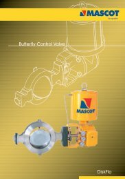
<strong>Control</strong> <strong>Valves</strong> <strong>Positioner</strong><br />
<strong>HiFlo</strong>
<strong>HiFlo</strong><br />
Valve Features<br />
Electro-pneumatic (I/P) module<br />
Interchangable<br />
Easy calibration<br />
Pneumatic module<br />
Withstands 150 psi<br />
at all parts<br />
Valve positioners are primarily utilized by Mascot. A<br />
pneumatic module for air control signals, or an electropneumatic<br />
(I/P) module for milliamp electrical control signals<br />
is offered with Mascot valve positioner. Valve positioners are<br />
single or double-acting, force-balanced instruments that<br />
provide fast, sensitive and accurate positioning of cylinder<br />
and diaphragm actuators. These positioners being compact,<br />
field reversible, are designed for high performance and are<br />
reliable because of the rugged built.<br />
Features<br />
• P/P or I/P Signal Convertible – Easy accomplishment of<br />
field conversion from one control signal to another by<br />
replacing one module with another<br />
• Corrosion Resistant – Epoxy powder painted on cover and<br />
base assembly and continuously purged from the inside with<br />
instrument air making corrosion resistant internal section.<br />
Internal working parts are constructed from 300 series<br />
stainless steel, anodized aluminum or Buna-N.<br />
• Shock and Vibration Resistant – the make and design of<br />
valve positioners is such that they have high natural frequency<br />
coupled with pneumatic damping. It is unaffected by<br />
vibration, acceleration up to 2 G’s, and frequencies to 500<br />
Hz.<br />
• For Single or Double-acting Actuators – The valve<br />
positioner is versatile usable with either single or double<br />
acting actuators.<br />
• Standard Mounting – Valve positioners use the standard<br />
mounting. By changing the cams and follower arms, the same<br />
positioner can be used on both linear and rotary actuators.<br />
This results in fewer required spare parts.<br />
2<br />
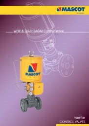
Split ranges can be<br />
easily adjusted<br />
Corrosion-resistant<br />
cover and base<br />
Optional / NPT for<br />
piped exhaust<br />
Two -sided cam<br />
for easy field<br />
reversibility<br />
• Easily Field Reversed – A reversal of action in the field is<br />
achieved by simply turning the cam over, reversing the<br />
anti-backlash spring and changing the output tubing.<br />
• Insensitive to Mounting Position – <strong>Positioner</strong>s can<br />
be mounted in any orientation.<br />
• Simple Calibration – Easy calibration as there is minimal<br />
interaction between zero and span. For protection and to<br />
discourage tampering, positioner adjustments are totally<br />
enclosed.<br />
• Split-Range Service – Standard signal ranges are 4<br />
- 20 mA for the electro-pneumatic (I/P) module and 3-<br />
15 psi (0-1 Bar) for the pneumatic (P/P) model. Optional<br />
ranges are 10-50 mA and 6-30 psi (0.4-2.1 Bar),<br />
respectively. All models can be calibrated for a 2 or 3way<br />
split range.<br />
• Simplified Maintenance – Ease in maintenance because<br />
of positioners simplicity, modular design and a few parts.<br />
• Regulator not needed – Designed to withstand 150 psi<br />
(10.3 bar) at all parts, the valve positioners are insensitive to<br />
supply pressure fluctuations.<br />
• Low Air Consumption – Steady state air consumption is<br />
.25 SCFM @ 60 psi (4.1 Bar) supply.<br />
• Changeable Flow Characteristics – Easily changed<br />
cam provides characterized flow feedback.<br />
• High Air Flow Gain Model – Standard on 200 square<br />
inch actuators and above, optional on others.<br />
• Output Gauge Helps Monitor Unit: – Permits easy<br />
verification of transducer and positioner calibration as it<br />
indicates transducer output to the positioner.
<strong>HiFlo</strong><br />
Specifications & performance<br />
<strong>HiFlo</strong> <strong>Positioner</strong> Specifications<br />
Specification Pneumatic Module<br />
Input signal range: 3-1 5 psi (0-1 Bar), 2 or 3-way split range;<br />
6-30 (0.4-2.1 Bar) psi, 2 or 3 and 4-way<br />
Supply pressure 30 psi to 150 psi (2.1 to 10.3 Bar)<br />
Ambient Standard model: -20° to +1 85° F<br />
temperature limits (-30° to 85° C) Ext. temp, model:<br />
-50° to +250° F (-46° to 1 21 ° C)<br />
Connections Supply, instrument and output: 1 U -inch<br />
NPT; Gauges: 1 /e-inch NPT<br />
Standard materials Stainless steel, anodized aluminum,<br />
nickel-plated steel, epoxy powder-painted<br />
steel and Buna-N<br />
Net weight 3lbs. (1.4kg)<br />
<strong>HiFlo</strong> <strong>Positioner</strong> Performance*<br />
<strong>HiFlo</strong> <strong>Positioner</strong> Performance Pneumatic Module<br />
Independent Linearity - Maximum deviation from a best fit straight line ±1.0% F.S.<br />
Hysteresis - Maximum position error for the same value of input when 0.5% F.S.<br />
approached from opposite ends of the scale.<br />
Repeatability - Maximum variation in position for the same value of input when 0.2% F.S.<br />
approached from the same direction.<br />
Response Level - Maximum change in input required to cause a change in 0.2% F.S.<br />
valve stem position in one direction.<br />
Dead Band - Maximum change in input required to cause a reversal in valve 0.3% F.S.<br />
stem movement.<br />
Resolution - Smallest possible change in valve stem position. .1%F.S.<br />
Steady State Air Consumption @ 60 psi (4.1 Bar) .25 SCFM<br />
Supply Pressure Effect - Position change for a 10 psi (0.7 Bar) supply pressure change. .05% F.S.<br />
"Open-loop" Gain - Ratio of cylinder pressure unbalance to instrument 300:1<br />
pressure change with locked stem. @60 psi<br />
Maximum Flow Capacity @ 60 psi (4.1 Bar) 1 1 SCFM<br />
Frequency Response - -6 dB Frequency .8 Hz -<br />
(With sinusoidal input of ±5% F.S. centered about 50% F.S.) Phase Angle at -6dB - 71°<br />
Stroking Speed - Closed to open 2.3 in/sec.<br />
-Open to closed 1 .3 in/sec.<br />
* Data is based on tests of the <strong>HiFlo</strong> positioner mounted on a double-acting cylinder actuator having a piston area of 25 square inches with<br />
a valve stroke of 1.5 inches (38mm) and 60 psi (401 Bar) supply pressure instrument. single was 3-15 psi (0-1 Bar) with pneumatic module<br />
3
<strong>HiFlo</strong><br />
Operation<br />
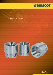
Figure 4 shows a valve positioner . The valve positioner is a<br />
force-balanced instrument, with pneumatic module installed<br />
on a double-acting actuator for air to open action.<br />
Positioning is based on a balance of two forces; one<br />
proportional to the instrument signal and the other<br />
proportional to the stem position.<br />
A downward force is activated as the signal pressure acts<br />
upon the diaphragms in the instrument signal capsule,<br />
through the follower arm and cam, the motion of the<br />
actuator stem is transmitted to the top end of the feedback<br />
spring resulting in the varying of tension in feedback spring<br />
as stem position changes.<br />
The system will be in equilibrium and stem will be in the<br />
position called for by the instrument signal when these<br />
opposing forces balance exactly. The balance will move up<br />
or down and by means of the spool valve, will change the<br />
output pressures and flow rate if these opposing forces are<br />
not in balance. This will lead to the piston to moving until the<br />
tension on the feedback spring opposes exactly the<br />
instrument signal pressure.<br />
The detailed sequence of positioner operations are as<br />
follows: An increase in the instrument signal forces<br />
MODULE<br />
the instrument signal capsule and balance beam<br />
downward. This motion of the balance beam also pulls<br />
the pilot valve spool downward from its equilibrium<br />
position. This opens the pilot valve ports, supplying<br />
air to port 1 and exhausting air from port 2. This causes<br />
the actuator piston upward.<br />
Proportionally to the valve position, to counter the force<br />
generated by the instrument signal capsule, the piston<br />
continues to stroke upwards until force in the feedback spring<br />
increases sufficiently. At this point the balance beam and<br />
spool begin to return to equilibrium position. As the valve<br />
spool ports start to close, the air flow rate to the actuator is<br />
decreased.<br />
The feedback spring tension force will equal the force<br />
generated in the instrument signal capsule after the piston<br />
has reached the required position. The balance beam and<br />
instrument signal capsule will remain in their<br />
equilibrium positions with no air flowing to the actuator<br />
until a change in the instrument signal is made.<br />
A proportional downward movement of the actuator piston<br />
and stem is affected by a decrease in the instrument signal<br />
which reverses the described actions.<br />
Figure 4 : <strong>Positioner</strong> Schematic for Air-to-Open (Retract)<br />
Output 2<br />
Output 1<br />
Signal<br />
3-15 psi<br />
Range Adjustment Lock Screw<br />
Zero Adjustment Knob<br />
Pivot<br />
Zero<br />
Adjustment<br />
Lock<br />
Knob<br />
Feedback Spring<br />
Pilot Valve Body Pilot Valve Spool<br />
Range Adjustment Gear<br />
Cylinder<br />
Piston<br />
L - R<br />
Instrument Signal Capsule<br />
4<br />
Follower Arm<br />
Take-off Arm<br />
Balance<br />
Beam
<strong>HiFlo</strong><br />
Mounting with different models/make<br />
The uniqueness and principal feature of the <strong>HiFlo</strong> positioner<br />
is that it can be mounted on any pneumatic actuator, both<br />
single and double acting. Diagrams presented herewith show<br />
the mounting dimensions and standard follower arms that are<br />
available.<br />
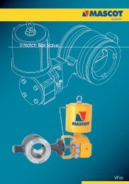
<strong>HiFlo</strong> mounts easily on a diaphragm actuator.<br />
The <strong>HiFlo</strong> positioner is designed to mount on most rotary valves<br />
5<br />
<strong>HiFlo</strong> <strong>Positioner</strong> comes standard on a Mascot GFlo<br />
Optional Models<br />
Extended Temperature : Built with Flurosilicone<br />
diaphragms and O-rings<br />
for temperatures -<br />
50°F to 250°F<br />
Oxygen Service : Built with Flurosilicone diaphragms<br />
and O-rings cleaned and<br />
assembled in a clean room.<br />
Piped Vent : To vent off positioner exhaust used<br />
for natural gas operations.
<strong>HiFlo</strong><br />
Mounting dimensions<br />
Linear Stroke Actuators<br />
1.62<br />
1.62<br />
3.63<br />
Instrument<br />
Output 2<br />
1.31<br />
Instrument<br />
2.36<br />
.67<br />
5.42<br />
Pin Assembly<br />
No. 19564<br />
TOP VIEW<br />
Pin attached to follower arm and<br />
rotates the arm 45° resting on a flat<br />
surface which travels with valve stroke.<br />
.5-1 1.5 2 2.5 3 3.5<br />
65TYP<br />
22.5°<br />
Supply<br />
45°<br />
3.91<br />
FRONT VIEW<br />
0.5*<br />
Thru<br />
8.00<br />
Inch<br />
Stroke.<br />
SIDE VIEW<br />
5.08<br />
Valve Stem<br />
Optional feedback spring<br />
required in positioner<br />
for 1/2 inch stroke.<br />
Optional 1/2 N.P.T. for piped exhaust or<br />
conduit for position indicator<br />
6<br />
.39<br />
2.13<br />
2.01<br />
.39<br />
.75<br />
.12<br />
1.79<br />
10.45<br />
5 6 7 8<br />
(5 to 8 inch stroke) # 72684<br />
5.23<br />
.5-1 1.0 2. 2.5 3 3.5 4<br />
(0.5 to 4 inch stroke) # 62684<br />
1.97<br />
.39<br />
.80 Dia<br />
Vent<br />
Screen<br />
1.00<br />
3.92<br />
.5-1 1.5 2 2.5 3<br />
(0.5 to 3 inch stroke) # 52684<br />
1.96<br />
.5-1 1.5<br />
(0.5 to 1.5 inch stroke) # 42684<br />
5.35<br />
.5-1 1.5 2 2.5 3 3.5 4<br />
(0.5 to 4 inch adjusstable stroke)<br />
Standard Arms Available<br />
For linear Mounting<br />
Supply<br />
.25<br />
3.87<br />
4.50<br />
3.200 Dia'<br />
Mounting Holes<br />
for #10 Screws<br />
BACK VIEW<br />
Output 2<br />
Output<br />
Instrument
<strong>HiFlo</strong><br />
Mounting Dimensions<br />
1.62<br />
1.62<br />
3.63<br />
Instrument<br />
Output 2<br />
Instrument<br />
.188 Dia.<br />
Pin<br />
X<br />
NOTE 1<br />
TOP VIEW<br />
45°<br />
22.5°<br />
.67 Zo<br />
NOTE 1<br />
Z<br />
2.36<br />
SIDE VIEW<br />
Supply<br />
90°<br />
3.91<br />
.20<br />
Y<br />
Pin in lever<br />
Rotates 90°<br />
with Valve<br />
NOTE 1<br />
Valve rotation on<br />
Increasing signal<br />
5.08<br />
Optional 1/2 N.P.T. for piped<br />
exhaust or conduit for position<br />
indicator<br />
NOTE : Dimension X and Y (Radius<br />
of pin from valve stem Centerline)<br />
are a function of Z0- Z0 and solve<br />
for X and Y, using the following<br />
equations:<br />
Z = Z0 + .670X = .765 X Z<br />
Y = .414 X ZEach follower arm<br />
will work with particular range for X<br />
Values.<br />
7<br />
Typical Rotary Mounting<br />
45° <strong>Positioner</strong><br />
Rotation<br />
2.913<br />
71414<br />
X = 2.30 to 2.73<br />
81414<br />
81414<br />
X<br />
4.469<br />
X = 2.30 to 4.29<br />
45°<br />
Z<br />
90°<br />
61824<br />
Y<br />
3.625<br />
X = 2.30 to 3.45<br />
90° Valve<br />
Rotation<br />
Standard Arms Available For Rotary Mounting<br />
.39<br />
2.13<br />
2.01<br />
.39<br />
.75<br />
.12<br />
1.79<br />
1.97<br />
.39<br />
.80 Dia<br />
Vent<br />
Screen<br />
1.00<br />
Supply<br />
.25<br />
3.87<br />
4.50<br />
BACK VIEW<br />
3.200 Dia'<br />
Mounting Holes<br />
for #10 Screws<br />
Output 2<br />
Output<br />
Instrument
<strong>HiFlo</strong><br />
Ordering Information<br />
Ordering Information<br />
We need the following information when you order the <strong>HiFlo</strong><br />
positioner. This helps you get accurate material and timely<br />
delivery thereby leading to great satisfaction of serving you in<br />
the best possible way. You are requested to specify the<br />
desired part numbers.<br />
LINEAR ACTUATOR<br />
When ordering a positioner for a pneumatic linear actuator,<br />
you should choose two part numbers; one from Section 1<br />
which provides positioner part numbers for each model, and<br />
another from Section 2 which contains follower arm part<br />
numbers.<br />
SECTION 1: Pneumatic <strong>Positioner</strong><br />
Model with 3-15 psi Span*<br />
H Series H Series H Series H Series<br />
Ext. Oxy. Piped<br />
Temp. Ser. Vent<br />
Std. Air-to-Open** 89934 70764 31684 51684<br />
Stroke Air-to-Close 99934 80764 41684 64644<br />
Short Air-to-Open 61684 81684 02684 22684<br />
Stroke Air-to-Close 71684 91684 12684 32684<br />
* Can be split ranged 2:1 or 3:1without additional parts.<br />
** The cam can be turned over in the field for opposite air action.<br />
SECTION 2: Follower Arm Kits for<br />
Pneumatic Linear Actuators<br />
Stroke Range*** Part Number<br />
1/2 - 1.5 42684<br />
1/2 - 3 52684<br />
1/2 - 4 62684<br />
5-8 72684<br />
1/2-4 Consult<br />
Adjustable Factory<br />
*** For a ½" stroke on a 25 or 50 square-inch actuator, or for a ¾"<br />
stroke on a 100 or 200 square inch actuator, select the short stroke<br />
positioner model.<br />
MODELS<br />
<strong>HiFlo</strong> Extended Temperature<br />
<strong>HiFlo</strong> Oxygen Service, <strong>HiFlo</strong> Piped Vent<br />
90° TURN ROTARY ACTUATORS<br />
When ordering a positioner for a pneumatic rotary actuator,<br />
you should select two part numbers; one from section 3<br />
which provides part numbers for each positioner model, and<br />
another from section 4 which includes part numbers for the<br />
follower arm.<br />
SECTION 3 - Pneumatic <strong>Positioner</strong><br />
Model with 3-15 psi span *<br />
Installed <strong>HiFlo</strong> <strong>HiFlo</strong> <strong>HiFlo</strong> <strong>HiFlo</strong><br />
Cam **** Ext. Oxy. Piped<br />
25, 50 B 46584 66584 82684 03684<br />
and100 C 56584 76584 92684 86584<br />
sq. in Act.<br />
* Can be split ranged 2:1 or 3:1without additional parts. Also<br />
available are positioner models with 6.30 psi span and the same<br />
split ranges.<br />
**** The cam can be turned over in the field to the opposite side "B"<br />
or "C". To select the correct positioner model choose either "B" or "C"<br />
from the DF Series cam Characteristics chart.<br />
When installed on a DF Series valve, the signal Vs flow<br />
characteristics can be either equal percentage or linear based<br />
on air action as well as cam characteristics. See below<br />
DF Series Cam Characteristics<br />
Equal Percentage Linear<br />
Air-to-Open B C<br />
Air-to-Close C B<br />
SECTION 4: - Follower Arms for<br />
Pneumatics Rotary Actuators<br />
Actuator Size Part Number<br />
(Inches)<br />
25 71414<br />
50 61824<br />
100 81414<br />
166 / 167, G I D C, Naroda, Ahmedabad : 382330. India<br />
Phone : +91 79 22821619/22823369, Fax : +91 79 22822430<br />
Email : info@mascotvalves.com / web : www.mascotvalves.com