Catalogue, Plastics, 100 per cent Quality... (500-510e) - Helmar
Catalogue, Plastics, 100 per cent Quality... (500-510e) - Helmar
Catalogue, Plastics, 100 per cent Quality... (500-510e) - Helmar

Create successful ePaper yourself
Turn your PDF publications into a flip-book with our unique Google optimized e-Paper software.
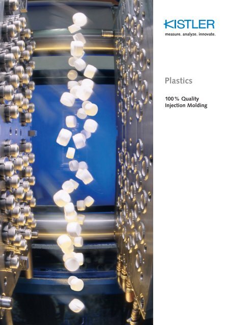
<strong>Plastics</strong><br />
<strong>100</strong>% <strong>Quality</strong><br />
Injection Molding
Kistler –<br />
Your partner for efficiency and quality<br />
Sensors and systems for optimizing, monitoring<br />
and documenting the quality data<br />
during injection molding processes is only<br />
part of the solutions for the industry provided<br />
by Kistler Instruments AG. With headquarters<br />
in Switzerland, we supply plastics<br />
processing solutions as well as specific sensors<br />
and systems for combustion engines,<br />
automotive engineering, mechanical production<br />
and biomechanical engineering.<br />
Our core competence lies in the development,<br />
production and implementation of<br />
sensors for pressure, force and acceleration<br />
measurement. Kistler electronic systems<br />
and ex<strong>per</strong>tise used for processing measurement<br />
signals allow the analyses of physical<br />
processes, process control and optimization<br />
as well as the enhancement of<br />
product quality for the processing industry.<br />
2<br />
Every year, Kistler invests 10 % of its sales<br />
in research and development – for innovative<br />
and efficient technical solutions at<br />
the leading edge of technology.<br />
The Kistler group with more than 600 employees<br />
is the leading supplier of dynamic<br />
measuring technology throughout the<br />
world. Close coo<strong>per</strong>ation with the customer,<br />
individual application support and<br />
short delivery times are guaranteed by the<br />
group's 18 member companies and more<br />
than 30 agencies.<br />
www.kistler.com
www.kistler.com<br />
Table of Contents<br />
The benefits of mold cavity pressure measurement<br />
More productivity – lower costs 4<br />
More efficient processes – better quality 6<br />
The basics of mold cavity pressure measurement<br />
The pressure profile and its interpretation 8<br />
Using mold cavity pressure in practical applications<br />
Measuring: Sensors and positioning 10<br />
Connecting: Safe transmission with suitable cables 14<br />
Amplifying: From charges to signals<br />
Analyzing: Optimizing, monitoring and documenting<br />
16<br />
injection molding processes<br />
Sensors for mold cavity pressure measurement<br />
18<br />
Measuring chains for cavity pressure measurement 20<br />
Sensors and systems for injection molding machines<br />
Measuring the melt pressure 28<br />
Measuring the tie bar extension 29<br />
Measuring the clamping force and mold protection 29<br />
Sensors and measuring chains for injection molding machines 30<br />
Product details / Product range<br />
Measuring: Sensors 32<br />
Connecting: Connecting and extension cables 48<br />
Amplifying: Charge amplifiers 54<br />
Analyzing: Optimizing and documentation systems 58<br />
Accessories / Tools 60<br />
Technical Literature 64<br />
Product overview by type numbers 65<br />
3
The benefits of cavity pressure measurement systems<br />
Modern injection molding technology is<br />
faced with ever more exacting requirements<br />
and a rising number of complex injection<br />
molding processes. Equipped with<br />
high-<strong>per</strong>formance systems based on measuring<br />
the pressure in the mold cavity, injection<br />
molding machines are able to produce<br />
flawless high-quality parts. These<br />
systems can automatically monitor, optimize<br />
and control injection molding processes,<br />
boost productivity and cut costs.<br />
During the first decades of industrial injection<br />
molding the development of control<br />
systems focused on machine parameters<br />
alone. However, these processes had<br />
a rather limited informative value or benefit<br />
for users. From the early 1990s on, it<br />
became clear that for many applications,<br />
high process constancy and optimum part<br />
quality could only be ensured over a long<br />
<strong>per</strong>iod of time by using measuring<br />
systems which focused on the pressure in<br />
the mold cavity.<br />
Mold cavity pressure measurement and<br />
systems using cavity pressure for monitoring<br />
and controlling injection molding processes<br />
offer a range of technical and economical<br />
benefits such as the following:<br />
• Reduction of the reject quota<br />
• Optimization of the cycle time<br />
• Shortening of installation and setup<br />
times<br />
• Minimization of material requirements<br />
• Reduction of <strong>per</strong>sonnel costs<br />
• Less energy costs<br />
• Active mold protection<br />
Systems measuring the pressure in the<br />
mold cavity are almost fully automatic<br />
and easy to o<strong>per</strong>ate. Quartz sensors have<br />
proved to be particularly suitable for both<br />
direct and indirect cavity pressure measurement.<br />
Modern system solutions o<strong>per</strong>ate<br />
with a closed circuit which includes mold<br />
cavity pressure recording with the help of<br />
quartz sensors, smart electronic equipment<br />
and ergonomic software.<br />
The processes within the mold are crucial<br />
to the quality of the injection molded<br />
parts, yet they can never be viewed directly.<br />
Attempts at describing process phases<br />
in terms of machine parameters such as<br />
hydraulic pressure, have not yielded any<br />
success. The main reason for this lies in<br />
the fact that machine parameters cannot<br />
record the effects of sprue solidification or<br />
melt compressibility.<br />
4 www.kistler.com
More productivity – lower costs<br />
Mold cavity pressure is the most<br />
informative process parameter<br />
Only a continuous documentation of the<br />
mold cavity pressure profile yields a detailed<br />
record of the processes occurring<br />
during the injection, compression and holding<br />
pressure phases of injection molding.<br />
Only this parameter correlates with all<br />
other quality-related part pro<strong>per</strong>ties such<br />
as weight, morphology, fidelity of reproduction,<br />
flashes, sink marks, voids, shrinkage<br />
and warpage.<br />
The mold cavity pressure not only optimizes<br />
the change-over from compression to<br />
holding pressure, in each cycle, its profile<br />
can also be used as a criterion for determining<br />
the change-over point. It allows better<br />
maintenance of the tight part weight<br />
tolerances and numerous other quality<br />
features than any other change-over strategy,<br />
be it based on the hydraulic pressure,<br />
screw stroke or time.<br />
www.kistler.com<br />
<strong>Quality</strong> assurance and documentation<br />
with the help of mold cavity pressure<br />
control<br />
The documentation of the mold cavity<br />
pressure not only proves the quality of<br />
the finished part but also allows selective<br />
monitoring and early detection of process<br />
deviations. Useful algorithms such as statistic<br />
process control or neuronal networks<br />
can deliver very precise information on<br />
the effect of the mold cavity pressure and<br />
other process or machine parameters on<br />
the mold quality.<br />
Precise assessment of the molded parts<br />
requires systems which analyze their<br />
weight and dimensions as well as correlating<br />
features such as streaks and other<br />
surface defects while also providing automatic<br />
control of reject/accept gates. In<br />
the near future, most modern injection<br />
molding systems are likely to rely on an<br />
automatic determination of the optimum<br />
process parameters.<br />
Mold cavity pressure control systems are<br />
reliable and durable<br />
Despite the high number of benefits,<br />
many injection molders are still skeptical<br />
when it comes to mold cavity pressure<br />
control. On the one hand, they are averse<br />
to the investment costs and on the other<br />
hand they anticipate downtimes and follow-up<br />
costs. Ex<strong>per</strong>ience shows, however,<br />
that impro<strong>per</strong> handling of the sensors<br />
during installation, maintenance or mold<br />
changes is the main cause of machine<br />
downtimes. The systems themselves have<br />
proven their sturdiness, reliability and<br />
durability.<br />
The large-scale production of high-quality,<br />
cost-efficient parts provides a competitive<br />
edge and as such it is the decisive criterion<br />
for the success of any injection<br />
molding business. In its wake, quality assurance<br />
will attain major importance for<br />
all injection molding processes. With a<br />
view to increasingly complex processes<br />
and more exacting quality requirements,<br />
only machines with high-<strong>per</strong>formance<br />
systems which are based on cavity pressure<br />
control will be able to deliver flawless<br />
high-quality molded parts.<br />
Prof. Dr.-Ing. Dr.-Ing. E.h. Walter Michaeli<br />
Institute of <strong>Plastics</strong> Processing (IKV) at<br />
RWTH Aachen University<br />
5
The benefits of cavity pressure measurement systems<br />
The efficiency of a particular injection<br />
molding process is determined long before<br />
it is used for large-scale production.<br />
The consistent application of cavity pressure<br />
measurement devices generates user<br />
benefits across the entire product development<br />
chain – from mold sampling to<br />
production documentation.<br />
Mold sampling without mold filling<br />
studies<br />
Mold sampling or, to be more exact, the<br />
acceptance of molded parts for large-scale<br />
production, is a time-consuming process<br />
for processors as it often involves numerous<br />
mold corrections and trial runs. In<br />
this development phase, cavity pressure<br />
measurement systems can be used to analyze<br />
the process and to determine initial<br />
machine settings without mold filling studies.<br />
Moreover, the cavity pressure signal<br />
is an important tool for uncovering errors<br />
and problems at an early stage, which also<br />
minimizes the number of required repetitive<br />
mold sampling procedures. As<br />
these systems reduce the time consumed<br />
for mold sampling to a minimum, they<br />
also help to curb costs. Practical ex<strong>per</strong>ience<br />
shows that mold cavity pressure systems<br />
can reduce the time and effort used<br />
for mold sampling by up to 75 %.<br />
6<br />
Optimum quality, minimum cooling and<br />
cycle times<br />
One essential element of process optimization<br />
is the attempt to find an efficient<br />
production method and a safe processing<br />
window. A process with an optimum cavity<br />
pressure profile will yield high-quality<br />
parts. The achievement of minimum cycle<br />
times and sufficient part quality are at the<br />
heart of this phase. Ex<strong>per</strong>ience shows that<br />
in 70 % of injection molds, the cycle time<br />
is 20 % longer than necessary. Adapting<br />
the mold cavity pressure will help imple-<br />
ment shorter cycle times without affecting<br />
the quality of the molded parts and therefore<br />
allow the determination of optimum<br />
times for injection, holding pressure and<br />
cooling without trial and error. Smart selfoptimizing<br />
mold cavity pressure measuring<br />
systems can automatically determine<br />
the change-over point and required residual<br />
cooling time during the active production<br />
process. At the optimum point in<br />
time during each cycle, these systems will<br />
transmit the corresponding demolding or<br />
change-over signals to the machine.<br />
More flexibility during mold set-up<br />
The use of a reference curve helps to significantly<br />
shorten set-up and change-over<br />
times. This reference curve of the cavity<br />
pressure is determined and saved during<br />
process optimization as soon as the optimum<br />
part quality has been achieved. During<br />
set-up, the machine o<strong>per</strong>ator only<br />
needs to change the machine setting parameters<br />
until the closest approximation<br />
between the current cavity pressure profile<br />
and the reference curve for optimum<br />
part quality has been achieved. In this<br />
way, even machines which show signs of<br />
wear and machines from different manufacturers<br />
will deliver molded parts with<br />
identical pro<strong>per</strong>ties. This approach dispenses<br />
with the need for time-consuming<br />
part quality tests, which are normally<br />
required as a consequence of changes to<br />
the machine settings.<br />
www.kistler.com
More efficient processes – better quality<br />
Error-free production on a large scale<br />
During large-scale production, the mold<br />
cavity pressure is used for a continuous<br />
monitoring of the quality of the molded<br />
parts. If this quality fails to meet the required<br />
standards, an accept/reject flip<strong>per</strong><br />
gate or a handling device can be used to<br />
separate the defective parts from the<br />
batch. This integrated quality assurance<br />
system ensures the detection of flawed<br />
parts at the earliest possible stage of the<br />
production and as such is prerequisite to<br />
the implementation of "lean" production<br />
condi-tions. Moreover, this approach<br />
reduces the reject quota and helps achieve<br />
an error-free production. This in turn<br />
boosts the productivity of the machine as<br />
a consequence of an improved utilization<br />
and lower production costs.<br />
www.kistler.com<br />
Documented quality<br />
The cavity pressure profile determined<br />
during the production process is a clear<br />
reflection of the quality of the parts produced<br />
and is therefore useful material for<br />
documentation. This way, random checks<br />
according to the statistic process control<br />
(SPC) based on cavity pressure measurement<br />
evolve into a <strong>100</strong> % quality assurance<br />
procedure. Cavity pressure measurement<br />
delivers the relevant data to certify<br />
of every individual injection molded part.<br />
It reduces the cost of part quality control<br />
and provides an automatic documentation<br />
of process data which is readily available<br />
for both producers and customers<br />
even years after active part production.<br />
For more information on this topic,<br />
please refer to p. 20<br />
Advantages<br />
During mold sampling<br />
+ Initial machine settings without<br />
mold filling studies<br />
+ A faster procedure saves time<br />
+ Significant cost reduction<br />
During optimization<br />
+ Automatic calculation of switch-over<br />
point and cooling time<br />
+ Optimum cavity pressure profile<br />
+ Minimum cooling and holding<br />
pressure times<br />
+ Minimum cycle times<br />
During mold set-up<br />
+ Optimum part quality even after<br />
machine changes<br />
+ No time-consuming part quality<br />
testing required<br />
+ Shorter set-up times<br />
During large-scale production<br />
+ Automatic reject separation<br />
+ Moving into "Lean Production"<br />
+ Error-free production<br />
For quality assurance<br />
+ <strong>100</strong> % certified quality for each<br />
individual part<br />
+ Cost reduction for part quality control<br />
+ Automatic documentation of quality<br />
data<br />
7
The basics of mold cavity pressure measurement<br />
Cavity<br />
pressure<br />
Pressure<br />
Pressure<br />
Pressure<br />
Pressure<br />
12 3<br />
4<br />
Cavity pressure<br />
5<br />
6<br />
Time<br />
Time<br />
Time<br />
Time<br />
Time<br />
Hydraulic pressure<br />
The cavity pressure within an injection<br />
mold delivers very precise information<br />
about the filling phase, the pack phase<br />
and the holding pressure phase. Gaining<br />
an insight into some physical correlations<br />
facilitates the analysis and interpretation<br />
of the cavity pressure profile<br />
during active processes.<br />
The cavity pressure profile<br />
At the onset of the filling phase (1) plasticized<br />
polymer material enters the cavity.<br />
As soon as the flow front reaches the sensor<br />
(2), pressure is registered. The pressure<br />
should rise in a near-linear gradient<br />
parallel to the duration of the filling time.<br />
During volumetric filling of the cavity,<br />
the filling phase has been completed (3)<br />
and the plasticized material is compacted<br />
during the compression phase to ensure<br />
the reproduction of the contours of the<br />
mold cavity. The holding pressure phase<br />
follows after the maximum cavity pressure<br />
has been reached (4). The holding<br />
pressure phase compensates for the high<br />
thermal contraction of the polymer material<br />
– i.e., the reduction of its volume following<br />
the cooling down process – by<br />
introducing more material. Up to 10 % of<br />
the part volume is being pushed into the<br />
cavity during this production phase. The<br />
fact that the molded part starts to cool<br />
down and solidify near the cavity wall<br />
inhibits the pressure transfer. The melt<br />
flow from the area in front of the screw<br />
to the cavity is slowed down as the viscosity<br />
of the material increases and the flow<br />
channel becomes more constricted in the<br />
process. The progressive solidification of<br />
the plasticized material in the gate area<br />
(5) and the progressive thermal contraction<br />
causes the pressure within the cavity<br />
to drop to ambient levels (6).<br />
8 www.kistler.com<br />
1 ... 2<br />
2 ... 3<br />
3<br />
3 ... 6
The pressure profile and its interpretation<br />
During the mold filling phase, the different<br />
characteristics of plasticized amorphous<br />
or semi-crystalline polymers are immaterial<br />
as long as their viscosity is identical.<br />
However, both materials display a<br />
different compression behavior. A higher<br />
amount of semi-crystalline material than<br />
amorphous material needs to be introduced<br />
into the cavity at the beginning of<br />
the holding pressure phase to achieve a<br />
pressure build-up. When the melt cools<br />
down during the holding pressure phase,<br />
more semi-crystalline material must be<br />
introduced into the cavity to compensate<br />
for the volume contraction and to prevent<br />
voids in the finished part.<br />
Specific characteristics of amorphous<br />
thermoplastics<br />
During the holding pressure phase of injection<br />
molding processes involving amorphous<br />
polymers such as polystyrene (PS),<br />
acrylonitrile-butadiene-styrene (ABS), styrene-acrylo-nitrile<br />
(SAN), polymethyl methacrylate<br />
(PMMA), polycarbonate (PC)<br />
and polyvinyl chloride (PVC), the mold<br />
cavity pressure drops to ambient pressure<br />
levels parallel to the declining part tem<strong>per</strong>ature<br />
in the wake of an increasing viscosity<br />
and the corresponding deterioration<br />
of the pressure transfer from the area in<br />
front of the screw.<br />
Cavity<br />
pressure<br />
www.kistler.com<br />
Time<br />
Specific characteristics of semi-crystalline<br />
thermoplastics<br />
Due to an initially sufficient pressure transfer<br />
during injection molding processes<br />
involving semi-crystalline materials such<br />
as polyethylene (PE), polypropylene (PP),<br />
polyamide (PA) and polyoxymethylene<br />
(POM) there is almost no change in the<br />
mold cavity pressure during the <strong>per</strong>iod<br />
after the compression phase and the onset<br />
of the crystalline melting point. After<br />
that, however, the significant volume<br />
contraction during crystallization brings<br />
about a sudden drop in the pressure. The<br />
duration of the holding pressure phase<br />
depends on factors such as the wall thickness<br />
of the molded part, the degree of<br />
crystallization and the processing parameters.<br />
The crystalline melting point of semicrystalline<br />
materials for example, is dependent<br />
on the prevailing cavity pressure.<br />
Cavity<br />
pressure<br />
Time<br />
9
Using the mold cavity pressure in practical applications<br />
10<br />
Practical application<br />
Installation<br />
options<br />
Sensor fitted directly<br />
into the drilled hole<br />
Sensor fitted into<br />
the drilled hole with<br />
sleeve<br />
Installation and<br />
extraction tools<br />
Spacer sleeve<br />
At a glance<br />
There are two installation options to<br />
accommodate different mold concepts:<br />
• Direct screw-mounted sensor<br />
• Sensor with adapting spacer sleeve<br />
for direct attachment below the<br />
mold platen<br />
Accurate pressure data that is suitable for<br />
analysis can only be acquired by means<br />
of reliable and precise measuring technology.<br />
The mold cavity pressure can be<br />
measured directly, indirectly or in combination<br />
with the contact tem<strong>per</strong>ature. The<br />
position of the sensors within the mold<br />
plays a crucial role in this process.<br />
At the same time, high-resolution and<br />
reliable, sturdy, maintenance-free and<br />
durable measuring equipment is prerequisite<br />
to the reliable acquisition of the pressure<br />
and tem<strong>per</strong>ature data during the<br />
injection molding process. Stringent quality<br />
requirements for molded parts generate<br />
a demand for increasingly precise measurement<br />
systems. These systems are<br />
expected to register and balance minute<br />
pressure variations even at a pressure of<br />
2 000 bar.<br />
Kistler sensors with their dimensions meet<br />
the exacting requirements of modern<br />
injection molding technology and all its<br />
special processing methods. They have an<br />
almost unlimited service life, deliver highly<br />
linear measuring results, cover a wide<br />
frequency range up to <strong>100</strong> kHz and o<strong>per</strong>ate<br />
independently of the tem<strong>per</strong>ature.<br />
Piezoelectric cavity pressure sensors made<br />
by Kistler can withstand mold tem<strong>per</strong>atures<br />
of up to 300 °C and any required melt<br />
tem<strong>per</strong>ature.<br />
Kistler supplies a whole range of cavity<br />
pressure sensors with a standard uniform<br />
sensitivity. Equipped with Unisens technology,<br />
each sensor comes with a guaranteed<br />
uniform sensitivity within a certain<br />
tolerance range. Therefore, the electronic<br />
equipment does not require any individual<br />
adjustment.<br />
Core competence<br />
Unisens technology<br />
eliminates adjustments<br />
Piezoelectric sensors discharge electricity<br />
proportionate to the cavity pressure.<br />
The proportionality is referred to<br />
as sensitivity and is measured in picocoloumbs<br />
<strong>per</strong> bar (pC/bar). Under normal<br />
circumstances, this sensitivity varies<br />
within narrow limits and must be<br />
manually adjusted on the measuring<br />
system or the injection molding machine.<br />
Unisens technology made by Kistler<br />
dispenses with this fine-tuning effort<br />
as the sensors o<strong>per</strong>ate with a fixed sensitivity.<br />
Unisens facilitates machine and<br />
system adjustment and also prevents<br />
erroneous input.<br />
www.kistler.com
Measuring: Sensors and positioning<br />
Direct and indirect<br />
pressure measurement<br />
Mold cavity pressure can be measured directly,<br />
indirectly or in combination with<br />
the contact tem<strong>per</strong>ature.<br />
Direct cavity measurement<br />
During direct measuring, the sensor comes<br />
into contact with the plasticized polymer<br />
material within the mold cavity and measures<br />
its pressure directly and without a<br />
transmission aid. These sensors can be installed<br />
in the drilled holes in the mold with<br />
or without an adapter. While sensors with<br />
adapters supplied by Kistler already have<br />
narrow diameter tolerances, sensors without<br />
adapters require fitting by a mold engineer.<br />
Most sensors allow an adaptation of the<br />
sensor front to suit the cavity structure in<br />
order to prevent impressions in the molded<br />
part. Sensors for direct measurement<br />
are available in different dimensions and<br />
with front diameters of 9.5 mm, 6 mm, 4<br />
mm, 2.5 mm or 1 mm.<br />
For more information on this topic,<br />
please refer to p. 33<br />
www.kistler.com<br />
Indirect measurement behind the ejector<br />
or measuring pin<br />
Alternatively, the force behind the ejector<br />
or measuring pin can be determined and<br />
converted to yield the actual pressure by<br />
means of the pin diameter. Indirect measuring<br />
behind the ejector is recommended<br />
for applications which do not leave enough<br />
room for a direct sensor. Adverse conditions<br />
such as friction, bending of the ejector<br />
pin, platen distortion or contaminated<br />
drilling holes have a detrimental effect on<br />
the measuring results and the corresponding<br />
control or monitoring o<strong>per</strong>ations. Direct<br />
measurement is clearly desirable to indirect<br />
measurement of industrial processes.<br />
For more information on this topic,<br />
please refer to p. 43<br />
Special sensors for molds with inserts<br />
Modern injection molding processes demand<br />
molds which allow easy and costefficient<br />
maintenance. As a result, modern<br />
molds are disassembled easily and quickly<br />
and mold inserts can often be removed<br />
from the mold while it is still installed on<br />
the machine.<br />
Kistler supports mold engineers with an<br />
adapter-based sensor Type 6155AE. It is<br />
mounted on the mold baseplate and<br />
equipped with single-wire technology.<br />
Insert changes no longer require a removal<br />
of the sensor. Thus, both the sensor<br />
and the sensor cables, which can be guided<br />
through drilled holes in the baseplate,<br />
are protected from potential damage during<br />
the removal or installation of the inserts.<br />
Drilled holes in the insert ensure an<br />
accurate positioning of the sensor.<br />
This technology can also be used for molds<br />
without cavity inserts. In these cases, the<br />
sensor is not mounted to the baseplate<br />
but to the second mold platen, where it<br />
remains even after the mold is removed.<br />
The advantages of this method are the<br />
same as those stated above: both the cables<br />
and the sensor are protected in the<br />
mold platen. This approach is particularly<br />
safe for cavity pressure sensors in complex<br />
mold platens with a high number of<br />
cooling holes.<br />
11
Using the mold cavity pressure in practical applications<br />
Combined sensors<br />
Efficient process monitoring requires the<br />
measurement of both the mold cavity<br />
pressure and the tem<strong>per</strong>ature as both parameters<br />
are important for the production<br />
process.<br />
The combination pressure-tem<strong>per</strong>ature<br />
sensor measures both the cavity pressure<br />
and the contact tem<strong>per</strong>ature in the same<br />
point on the molded part. While the cavity<br />
pressure sensor measures the pressure,<br />
a newly developed fast-transmission method<br />
is used to measure the tem<strong>per</strong>ature:<br />
both thermocouple cables run separately<br />
to the sensor front, where they are welded<br />
to a thermocouple type K (Ni-CrN).<br />
As the thermocouple is positioned at the<br />
tip of the sensor, it measures the contact<br />
tem<strong>per</strong>ature of the melt. Thus, even<br />
minute variations in contact tem<strong>per</strong>ature,<br />
which can be caused by changes such as<br />
a falling or rising melt tem<strong>per</strong>ature, can<br />
be monitored.<br />
Cavity<br />
pressure (bar)<br />
<strong>500</strong><br />
400<br />
300<br />
200<br />
<strong>100</strong><br />
For more information on this topic,<br />
please refer to p. 40<br />
P near the gate<br />
T near the gate<br />
Time (s)<br />
Contact<br />
tem<strong>per</strong>ature (°C)<br />
0<br />
0 4 8 12 16 20<br />
P away from the gate<br />
T away from the gate<br />
Tem<strong>per</strong>ature sensors<br />
Kistler sensors for tem<strong>per</strong>ature measurement<br />
are based on the same principle.<br />
Their front diameters correspond to those<br />
specified for pressure sensors (Ø 4 mm,<br />
Ø 2.5 mm and Ø 1 mm) and are compatible<br />
with standard cavity pressure sensors.<br />
12 www.kistler.com<br />
250<br />
200<br />
150<br />
<strong>100</strong><br />
50<br />
0<br />
For more information on this topic,<br />
please refer to p. 41
Positioning the sensor in<br />
the mold<br />
Accurate positioning of the cavity pressure<br />
sensor is important for a sufficient duration<br />
of the signal transmission and informative<br />
value of the measured values.<br />
Both the position of the sensor in relation<br />
to the gate and the wallthickness of the<br />
part at the installation point are of particular<br />
importance.<br />
Measurement near the gate<br />
The cavity pressure profile during the filling<br />
phase is measured when the melt<br />
flow front has reached the sensor. A meaningful<br />
and long-term measuring result is<br />
acquired near the gate and in the vicinity<br />
of the highest wall thickness as thick areas<br />
take longer to solidify. Sensor positioning<br />
should take into account both the<br />
fastest and the slowest melt setting points.<br />
In cavities with several gates, measurements<br />
should be taken from critical areas<br />
of the molded part.<br />
Measurement away from the gate<br />
The greater the distance from the gate,<br />
the later the melt flow front reaches the<br />
sensor, the later the pressure is registered<br />
and the higher the filling level must be<br />
to actually allow pressure measurement.<br />
Consequently, data about the filling phase<br />
cannot be displayed until the sensor has<br />
been reached. Measurement on the edge<br />
of a molded part, i.e. away from the gate<br />
or at the end of the flow path yields a<br />
signal only when the pressure rises suddenly<br />
during the compression phase. Measurement<br />
positions away from the gate<br />
are beneficial only for protecting components<br />
such as threaded spindles or core<br />
pullers from damage caused by pressure<br />
peaks or for monitoring specific quality<br />
problems at the end of the flow path.<br />
www.kistler.com<br />
Practical application<br />
Basic rules for accurate sensor<br />
positioning<br />
1. The cavity pressure sensor should be<br />
installed near the gate, where the pressure<br />
in the molded part is highest. The<br />
closer the sensor is positioned to the<br />
gate, the more detailed the delivered<br />
process information.<br />
2. The sensor must be installed within<br />
the cavity and not in the gate. Sensors<br />
installed in the gate will fail to transmit<br />
signals and monitor the process during<br />
the residual cooling phase after the gate<br />
has been sealed or after the onset of<br />
shrinkage.<br />
3. If possible, the sensor should be positioned<br />
at the thickest cross section of the<br />
molded part where the melt solidifies<br />
last and the duration of the pressure is<br />
most extensive.<br />
4. The installation of a second sensor<br />
away from the gate for measuring large<br />
parts with a critical flow path/wall thickness<br />
ratio is recommended for the acquisition<br />
of additional part quality data.<br />
5. Sensors must not be installed directly<br />
opposite the gate as they will measure<br />
an additional dynamic force component<br />
which will override and distort the cavity<br />
pressure signal.<br />
1./3. 2. 4. 5.<br />
13
Using the mold cavity pressure in practical applications<br />
Cables ensure the accurate transmission<br />
of all signals from the sensor to the mold<br />
connector, from the mold to the charge<br />
amplifier and from the charge amplifier<br />
to the injection molding machine or to<br />
the electronic analysis equipment. In order<br />
to accommodate a wide variety of<br />
customer requirements, Kistler provides<br />
an extensive range of different connecting<br />
and extension cables.<br />
Connecting cable: From the sensor to<br />
the plug<br />
Kistler pressure sensors are available with<br />
classic two-wire coax cables or with the<br />
new single-wire technology. Two-wire<br />
coax cables have a connector plug at the<br />
end, which needs to be accommodated in<br />
the mold. The new technology cable has<br />
only one wire and the connector plug is<br />
no longer integrated into the cable (see<br />
info-box "Single-wire technology"). Twowire<br />
technology (Fig. 1) is being increasingly<br />
replaced by single-wire technology<br />
(Fig. 2).<br />
14<br />
For more information on this topic,<br />
please refer to p. 49<br />
Fig. 1<br />
Fig. 2<br />
Fig. 3<br />
Extension cable: From the connector plug<br />
to the charge amplifier<br />
The sensor's connector plug is mounted<br />
on the outside of mold. The cable must<br />
connect the connector plug with the<br />
charge amplifier, which is usually firmly<br />
installed in the injection molding machine,<br />
or with DataFlow, Kistler's analysis system.<br />
For this application, Kistler provides extension<br />
cables in a variety of designs, depending<br />
on the production environment and<br />
the distance to be covered, and a wide<br />
range of different sheathings, colors and<br />
cable length (Fig. 3, 4).<br />
For more information on this topic,<br />
please refer to p. 50<br />
Fig. 4<br />
Fig. 5<br />
Connection cable: From the charge amplifier<br />
to the machine or analysis equipment<br />
The charge amplifier and downstream<br />
equipment are linked using a connecting<br />
cable. This cable is equipped with a connector<br />
for the multi-pin input socket of<br />
the charge amplifier and compatible interfaces<br />
to the injection molding machine or<br />
PC cards for signal processing by a notebook<br />
or a PC (Fig. 5, 6, 7).<br />
Fig. 6<br />
For more information on this topic,<br />
please refer to p. 51<br />
Fig. 7<br />
www.kistler.com
Connecting: Safe transmission with suitable cables<br />
Single-wire technology<br />
Conventional two-wire connecting cables<br />
are being increasingly replaced by singlewire<br />
technology. The new technology cable<br />
has only one wire without shielding<br />
and the connector is no longer integrated<br />
into the cable. The shielding is provided by<br />
the injection molding machine instead.<br />
Maxwell's law, established by James<br />
Clerk Maxwell in 1864, explains why this<br />
new technology yields the same measuring<br />
results as the old approach. Similar to<br />
the conditions in Faraday's cage, there are<br />
no electric fields in the drilled hole or well<br />
of the injection mold. Faraday's cage prevents<br />
interference from external sources<br />
such as electric motors or hot runners.<br />
This has been proven to be valid by scientific<br />
research as well as by the successful<br />
industrial application of single-wire technology.<br />
www.kistler.com<br />
The single-wire cable has a very small<br />
diameter and can be flexibly installed in<br />
drilled cable ducts and cut to length as<br />
required. A special cut-and-grip system,<br />
which is fully integrated into the connector,<br />
helps to attach the connector to the<br />
cable. As single-wire technology is used<br />
with standard connecting cables and standard<br />
charge amplifiers, it does not incur<br />
any additional investment costs. Easier<br />
handling cuts mold costs. Single-wire<br />
technology also requires less engineering<br />
and significantly facilitates sensor installation.<br />
The service-friendly design guarantees<br />
easy handling during potential mold<br />
or sensor changes. Another decisive<br />
advantage: as o<strong>per</strong>ators can repair singlewire<br />
cables themselves, maintenance costs<br />
for mold cavity pressure measurement are<br />
significantly lower.<br />
Sensors used for multi-cavity molds with<br />
more than four cavities can be connected<br />
to a mold-mounted charge amplifier without<br />
a connector by using the cut-and-grip<br />
technique. This method has the advantage<br />
of reduced space requirements on<br />
the mold as well as particularly short sensor<br />
installation and set-up times. There is<br />
no more danger of mixing up cables. The<br />
multi-cavity system (Type 6829A...) is<br />
comprised of charge amplifiers and sensors.<br />
Advantages<br />
The most important benefits of singlewire<br />
technology:<br />
+ Cost-efficient mold preparation<br />
+ The cables run through drilled holes<br />
+ Easy installation with detachable<br />
connector<br />
+ Mold makers can shorten cables as<br />
required<br />
+ The technology is fully compatible with<br />
other cables and existing electronic<br />
equipment<br />
+ Broken cables can be repaired by the<br />
o<strong>per</strong>ator<br />
+ Small cable diameters allow easy installation<br />
in multi-cavity molds<br />
For more information on this topic,<br />
please refer to p. 23<br />
15
Using the mold cavity pressure in practical applications<br />
Charge amplifiers convert charges transmitted<br />
by a piezoelectric pressure sensor<br />
into a proportional voltage, which can be<br />
used as an input variable for monitoring<br />
and control processes. Smart charge amplifiers<br />
can also utilize specific algorithms<br />
to transmit signals, e.g. for a cavity-pressure<br />
related change-over of injection molding<br />
machines.<br />
Type 5039A...<br />
16<br />
The cavity pressure related change over<br />
from the injection phase to the holding<br />
pressure phase is a standard feature of<br />
modern injection molding machines. The<br />
cavity pressure sensor is connected to<br />
the control system via a charge amplifier,<br />
which is encased in a sturdy housing. The<br />
charge amplifier's output signals are analog<br />
and immediately available via an analog/digital<br />
converter card (A/D converter).<br />
The real-time o<strong>per</strong>ation of charge<br />
amplifiers even allows the control of highspeed<br />
processes based on cavity pressure.<br />
In addition to the cavity pressure, the part<br />
surface tem<strong>per</strong>ature is another important<br />
process parameter used for process monitoring.<br />
During machine start-up, it can<br />
detect that the process is stationary and<br />
start the production process.<br />
For more information on this topic,<br />
please refer to p. 55<br />
Type 5155A...<br />
Kistler supplies a wide range of different<br />
charge amplifiers. While Type 5039... is a<br />
pure single-channel charge amplifier, the<br />
new generation starting with Type 5155…<br />
is equipped with several channels for<br />
charge and tem<strong>per</strong>ature. The 1, 2 and 4channel<br />
amplifiers have identical housings<br />
and connector with an identical pin layout.<br />
Even for changing configurations,<br />
the integration effort is therefore reduced<br />
to a minimum.<br />
Charge amplifiers are prerequisite to cavity<br />
pressure measurement. In order to accommodate<br />
the wide variety of control<br />
hardware it is recommended that injection<br />
molding machine manufacturer supply<br />
suitable charge amplifiers with the machine.<br />
Type 5049A...<br />
www.kistler.com
Amplifying: From charges to signals<br />
Sensor<br />
Smart charge amplifiers<br />
Charge amplifiers with smart algorithms,<br />
which enhance the amplifying process,<br />
can generate control signals from the cavity<br />
pressure profile and the contact tem<strong>per</strong>ature.<br />
These are used as input values<br />
for injection molding machines, where<br />
they serve to increase the repeatability of<br />
the injection molding process in order to<br />
ensure the reliable production of high<br />
quality parts.<br />
www.kistler.com<br />
Wire<br />
Charge<br />
amplifier<br />
Based on the cavity pressure upon volumetric<br />
filling of the cavity, smart charge<br />
amplifiers automatically generate a signal<br />
which causes the injection molding machine<br />
to change-over from injection to<br />
holding pressure. Used in conjunction<br />
with tem<strong>per</strong>ature measurement equipment,<br />
these amplifiers can cut the machine's<br />
residual cooling time to the required<br />
minimum and determine the demolding<br />
point in a self-optimizing o<strong>per</strong>ation.<br />
Type 2859A... PiCo<br />
The following chapter provides<br />
detailed information on smart<br />
charge amplifiers of the SmartAmp<br />
brand supplied by Kistler.<br />
17
Using the mold cavity pressure in practical applications<br />
Smart charge amplifiers use algorithms<br />
for the self-optimizing change over from<br />
injection pressure to holding pressure or<br />
for automatically reducing the residual<br />
cooling time to the required minimum.<br />
A convenient software tool can be used<br />
to document the measured pressure and<br />
tem<strong>per</strong>ature values for the purpose of<br />
process optimization and quality control.<br />
SmartAmp: Self-optimizing change over<br />
The change-over point is an important process<br />
parameter with a significant effect on<br />
the quality and production cost of the molded<br />
part. The change over from injection<br />
to holding pressure must be executed in<br />
conjunction with a volumetric cavity filling.<br />
Traditional methods use the injection time,<br />
the screw stroke or the hydraulic pressure<br />
to determine the change-over point. All<br />
these methods o<strong>per</strong>ate according to the<br />
same principle, which involves the definition<br />
of a threshold to trigger the changeover.<br />
A suitable threshold is determined<br />
manually by means of repeated fillings<br />
without holding pressure. This approach is<br />
time-consuming, costly and has two major<br />
disadvantages:<br />
• Modification of the injection profile<br />
requires a changing or reestablishing<br />
the threshold<br />
• As the change-over point does not<br />
account for process or material fluctua<br />
tions, the change-over is delayed or<br />
triggered prematurely<br />
The cavity pressure profile yields accurate<br />
information on the volumetric filling process.<br />
Independent of the mold geometry,<br />
the cavity pressure rises dramatically after<br />
the holding pressure phase due to the<br />
compression of the melt. This kink in the<br />
curve has its starting point exactly at the<br />
onset of the volumetric filling process.<br />
Therefore, it is ideal for triggering the<br />
change-over process in the machine.<br />
18<br />
Kistler has developed an algorithm, which<br />
is integrated into the SmartAmp charge<br />
amplifier to analyze the cavity pressure<br />
profiles of a wide variety of different parts<br />
and determine the change-over point in<br />
real time. By using the cavity pressure,<br />
SmartAmp technology with ”self-optimizing<br />
change-over" identifies the changeover<br />
point in a fully automatic and selfoptimizing<br />
procedure. The signal transmitted<br />
by the SmartAmp triggers an automatic<br />
change-over from injection to holding<br />
pressure.<br />
The self-optimizing change-over process<br />
is preceded by a fully automatic learning<br />
phase, which lasts 4 to 16 production<br />
cycles. This <strong>per</strong>iod is used to determine<br />
optimum parameters for the algorithms<br />
integrated into the charge amplifier.<br />
The system significantly reduces the reject<br />
quota and controls the effects of batch<br />
variations on the process during the cycle.<br />
Due to the automatic recognition of the<br />
change-over point, which dispenses with<br />
the repetitive process of mold filling studies,<br />
the SmartAmp significantly facilitates<br />
mold set-up.<br />
SmartAmp technology is integrated into<br />
the Type 5049A... one-channel charge<br />
amplifier and into the Type 5155A... multichannel<br />
charge amplifier.<br />
Pressure Druck (bar)<br />
600<br />
<strong>500</strong><br />
400 Self-optimizing<br />
Automatische<br />
change-over<br />
Umschaltung<br />
300<br />
200<br />
<strong>100</strong><br />
0<br />
0.28 0.36 0.44 0.52 0.60 0.68<br />
Time Zeit (s)<br />
Druck Pressure (bar)<br />
600<br />
<strong>500</strong><br />
400 Traditionelle<br />
Conventual<br />
Umschaltung<br />
change-over<br />
300<br />
200<br />
<strong>100</strong><br />
0<br />
0.28 0.36 0.44 0.52 0.60 0.68<br />
Time Zeit (s)<br />
www.kistler.com
Analyzing: Automatic optimization of injection<br />
molding processes<br />
Automatic cooling time calculation<br />
Scientific studies have revealed that the<br />
majority of injection molding processes is<br />
carried out with excessive cooling times.<br />
The cooling time used during the injection<br />
molding of thermoplastic materials is determined<br />
empirically or estimated with the<br />
help of the cooling time formula and then<br />
entered into the machine's control system<br />
as a constant parameter. In order to<br />
compensate for process variations such as<br />
changes in the tem<strong>per</strong>ature or controlrelated<br />
variations to ensure a sufficiently<br />
safe production, the set cycle time often<br />
exceeds the required minimum by between<br />
10% and 20%. This approach is detrimental<br />
to an efficient production process.<br />
Another disadvantage of time-constant<br />
demolding is a fluctuation in the quality<br />
of the molded part, as it cannot compensate<br />
for variations in the process, the machine<br />
control and the material. These deviations,<br />
however, can have an adverse<br />
effect on warpage, dimensional stability<br />
and other pro<strong>per</strong>ties.<br />
www.kistler.com<br />
Based on the part surface tem<strong>per</strong>ature<br />
and the mold cavity pressure, the Smart-<br />
Amp technology involving automatic cooling<br />
time measurement (status-related<br />
demolding) determines the optimum cooling<br />
time for each individual cycle and<br />
transmits an analog signal to open the<br />
mold. In this way, the optimum cooling<br />
time is set for each individual cycle in<br />
order to guarantee constant tem<strong>per</strong>aturerelated<br />
part quality while the production<br />
runs with maximum efficiency.<br />
Advantages<br />
Automatic recognition of the changeover<br />
point<br />
+ Shorter set-up times<br />
+ Automatic compensation of viscosity<br />
variations<br />
+ Automatic compensation of process<br />
variations<br />
+ Highly stable process<br />
Automatic cooling time calculation<br />
+ A significantly improved efficiency due<br />
to a reduction of cycle cooling times<br />
+ A constant demolding tem<strong>per</strong>ature<br />
guarantees a reliable tem<strong>per</strong>aturerelated<br />
part quality and a constant<br />
profile of the cavity wall tem<strong>per</strong>ature<br />
Self-optimizing part removal is available<br />
as an option to the Type 5155A... family of<br />
charge amplifiers. It can be integrated into<br />
the machine control system or used as<br />
additional equipment to be configured<br />
with the included Windows ® software and<br />
a notebook computer. The injection molding<br />
machine must be equipped with a<br />
"mold open" input port to accommodate<br />
this application.<br />
Kistler's combined pressure and tem<strong>per</strong>ature<br />
sensors are ideal for measuring the<br />
part surface tem<strong>per</strong>ature and the mold<br />
cavity pressure.<br />
19
Using the mold cavity pressure in practical applications<br />
Kistler DataFlow<br />
The optimum analysis of measured process<br />
data is prerequisite to the utilization<br />
of cavity pressure and part surface tem<strong>per</strong>ature<br />
measurement equipment.<br />
DataFlow provided by Kistler o<strong>per</strong>ates<br />
with tools which support users across the<br />
entire process chain from mold sampling,<br />
setup and process optimization to production<br />
monitoring including statistical analysis<br />
and documentation. These functions<br />
are based on the determination of the<br />
cavity pressure and the part surface tem<strong>per</strong>ature.<br />
Additional information such as<br />
the hydraulic pressure can also be processed.<br />
DataFlow is easy to o<strong>per</strong>ate as it runs on<br />
conventional <strong>per</strong>sonal computers or notebooks<br />
under Windows XP ® and Windows<br />
2000 ® . Used in conjunction with Kistler<br />
electronic equipment (Type 2859A and<br />
2853A signal conditioners or Type 6829A<br />
multi-cavity systems), DataFlow offers a<br />
comprehensive optimization and documentation<br />
system for all injection molding<br />
processes, which also accommodates<br />
multi-component techniques and multicavity<br />
family molds.<br />
20<br />
DataFlow can control equipment such as<br />
reject gates and reversible belt conveyors<br />
or o<strong>per</strong>ate robot placing processes to<br />
ensure that all parts are separated into<br />
rejects and good parts. The networking<br />
capability of the included statistics tool<br />
provides production data where it is needed,<br />
e.g. for production planning, control<br />
or quality assurance.<br />
www.kistler.com
Analyzing: Optimizing, monitoring and documenting<br />
injection molding processes<br />
Dataflow provides a range of tools across<br />
the entire process chain:<br />
During mold sampling and optimization,<br />
DataFlow provides process data in a variety<br />
of different graphics in order to speed<br />
up the mold sampling process and to utilize<br />
the full optimization potential.<br />
During process optimization, DataFlow<br />
can be used to determine process tolerance<br />
limits and to evaluate processing pro<strong>per</strong>ties<br />
based on the measured data. In<br />
this way, the system reduces mold sampling<br />
times and ensures a fast optimization<br />
of the process. The determined tolerance<br />
limits can be used for monitoring<br />
part pro<strong>per</strong>ties and quality assurance<br />
during the production process and dispense<br />
with the need for manual examination.<br />
During mold set-up, cavity pressure reference<br />
curves can be stored. Optimized<br />
molds can be o<strong>per</strong>ated fast and efficiently<br />
on different machines and the optimum<br />
o<strong>per</strong>ating point can be determined<br />
quickly.<br />
During production, DataFlow will calculate<br />
maximum values, integrals, which<br />
can be defined as required, the filling index<br />
and the injection force from the measured<br />
process data. Moreover, the system<br />
allows the definition of tolerance ranges.<br />
Transgression of these tolerance ranges<br />
by the values recorded from the current<br />
process will either trigger an optical notification<br />
or lead to an activation of the reject<br />
gates or robots.<br />
www.kistler.com<br />
DataFlow provides automatic quality control<br />
and integrates it into the process.<br />
Trend graphics can predict errors in the<br />
active production process to eliminate<br />
them. Networking statistics allow statistical<br />
production analysis (cp, cpk values,<br />
production distribution) for the purpose of<br />
documentation. Automatic reports provide<br />
a documentation of quality for customers.<br />
Statistics data generated by DataFlow can<br />
be used to detect and eliminate weak<br />
points in the production process and help<br />
to determine the reject quota while the<br />
production monitoring function can then<br />
be used to directly identify the cause of<br />
excessive rejects.<br />
21
Using the mold cavity pressure in practical applications<br />
Sensors for cavity pressure and part surface<br />
tem<strong>per</strong>ature measurement<br />
Direct Measurement<br />
Variable Pressure Pressure and Tem<strong>per</strong>ature<br />
tem<strong>per</strong>ature<br />
Pressure range Standard Low pressure Standard/<br />
low pressure<br />
Process Injection molding Reaction Injection Injection<br />
IM molding molding<br />
Material Thermo- Thermosets Thermoplastics Thermosets RIM Thermoplastics Thermoplastics<br />
plastics Elastomers Elastomers Thermosets<br />
LSR LSR Elastomers<br />
LSR<br />
Front- (mm)<br />
Sensor<br />
9,5 4079A...<br />
6 6152A... 6152A... 6172A... 6172A...<br />
4 6157B... 6157B... 6177A... 6177A... 6190A... 6192A...<br />
6155AE 6167A...<br />
2,5 6158A... 6178A... 6194A...<br />
6159A...<br />
6182AE<br />
6195A...<br />
1 6183AE 6193A...<br />
The sensors type 6152A..., 6157B..., 6159A..., 6167A..., 6182AE and 6183AE with single-wire-technology can be used in the 6829A<br />
multi-cavity system.<br />
Indirect pressure measurement<br />
Dimensions (mm)<br />
12,6 9204B...<br />
6 9211A...<br />
9213A...<br />
12,6 x 9,5 9221A...<br />
6 x 6 9223A...<br />
Note: The Type numbers listed in the tables describe the sensors.<br />
22 www.kistler.com
Sensors for cavity pressure measurement<br />
Sensor cables<br />
Sensors Type Connecting Cables Type Extension cables Type<br />
4079A... integral 4767A...<br />
6152AA..., 6152AC... 1961A..., 1963A... 1667B..., 1672B..., 1661A..., 1662A...<br />
6152AB..., 6152AD... 1955A... 1667B..., 1672B..., 1661A..., 1662A...<br />
6152A...E 1666A1, 1666A3 1667B..., 1672B..., 1661A..., 1662A...<br />
6155AE integral 1667B..., 1672B..., 1661A..., 1662A...<br />
6157BA..., 6157AC... 1961A..., 1963A... 1667B..., 1672B..., 1661A..., 1662A...<br />
6157BB..., 6157BD... 1955A... 1667B..., 1672B..., 1661A..., 1662A...<br />
6157B...E 1666A1, 1666A3 1667B..., 1672B..., 1661A..., 1662A...<br />
6158A... integral 1667B..., 1672B..., 1661A..., 1662A...<br />
6159A... 1645C..., 1963A... 1667B..., 1672B..., 1661A..., 1662A...<br />
6159A...U6 1645C..., 1963A... 1667B..., 1672B..., 1661A..., 1662A...<br />
6159AE 1666A2, 1666A4 1667B..., 1672B..., 1661A..., 1662A...<br />
6167A... 1645C..., 1963A... 1667B..., 1672B..., 1661A..., 1662A...<br />
6172A... 1645C..., 1963A... 1667B..., 1672B..., 1661A..., 1662A...<br />
6172A...E 1666A2, 1666A4 1667B..., 1672B..., 1661A..., 1662A...<br />
6177A... 1645C..., 1963A... 1667B..., 1672B..., 1661A..., 1662A...<br />
6177A...E 1666A2, 1666A4 1667B..., 1672B..., 1661A..., 1662A...<br />
6178A... 1645C..., 1963A... 1667B..., 1672B..., 1661A..., 1662A...<br />
6178A...E 1666A2, 1666A4 1667B..., 1672B..., 1661A..., 1662A...<br />
6182AE integral 1667B..., 1672B..., 1661A..., 1662A...<br />
6183AE integral 1667B..., 1672B..., 1661A..., 1662A...<br />
6190A... integral 1667B..., 1672B..., 1661A..., 1662A..., 2290A..., 2295A...<br />
6192A... integral 2290A..., 2295A...<br />
6193A... integral 2290A..., 2295A...<br />
6194A... integral 2290A..., 2295A...<br />
6195A... integral 2290A..., 2295A...<br />
9204B... 1645C... 1667B..., 1672B..., 1661A..., 1662A...<br />
9211A... integral 1667B..., 1672B..., 1661A..., 1662A...<br />
9213A... integral 1667B..., 1672B..., 1661A..., 1662A...<br />
9221A... 1645C... 1667B..., 1672B..., 1661A..., 1662A...<br />
9223A... 1645C... 1667B..., 1672B..., 1661A..., 1662A...<br />
www.kistler.com<br />
23
Using the mold cavity pressure in practical applications<br />
Sensors, cables, charge amplifiers and<br />
electronic analysis equipment must be<br />
combined in an efficient way. Only the<br />
<strong>per</strong>fect interaction of all components<br />
across the measurement chain can ensure<br />
a stable o<strong>per</strong>ation of the cavity pressure<br />
measurement system to the full benefit<br />
of the user.<br />
24<br />
Measuring chains are comprised of sensors,<br />
connection cables, extension cables<br />
if required, charge amplifiers and analysis<br />
equipment. The chains are used to set up<br />
control circuits for monitoring, optimizing<br />
and controlling injection molding processes<br />
and for documenting the acquired<br />
process data.<br />
Machine-integrated systems<br />
Machine-integrated systems acquire measuring<br />
data and/or transmit switching signals<br />
to the machine's control unit. These<br />
systems are available with one channel<br />
for pressure measurement or with multichannel<br />
systems for combined pressure<br />
and tem<strong>per</strong>ature measurement. The charge<br />
amplifiers are integrated into the injection<br />
molding machine. The machine's control<br />
system is responsible for process documentation.<br />
www.kistler.com
Measuring chains for cavity pressure measurement<br />
Mobile systems<br />
While mobile systems o<strong>per</strong>ate independently<br />
of the injection molding machine,<br />
they can still process signals transmitted<br />
by the machine for analysis and actively<br />
transmit switching signals to the machine.<br />
An external PC or notebook computer<br />
equipped with Kistler DataFlow software<br />
is responsible for controlling the process.<br />
Mobile systems are available with one<br />
channel for pressure measurement or as<br />
www.kistler.com<br />
multi-channel systems for combined pressure<br />
and tem<strong>per</strong>ature measurement. As<br />
they can be used for different injection<br />
molding machines, they offer the benefit<br />
of accommodating existing molds modified<br />
with cavity pressure measurement<br />
systems.<br />
Multi-cavity pressure measurement<br />
systems<br />
Multi-cavity systems compile pressure measurement<br />
data from up to 32 cavities in<br />
one charge amplifier. While they o<strong>per</strong>ate<br />
independently of the injection molding<br />
machine, they can still process signals transmitted<br />
by the machine for analysis and<br />
actively transmit switching signals to the<br />
machine. An external PC or notebook computer<br />
equipped with Kistler DataFlow software<br />
controls the process. As mobile<br />
systems they can be used on different<br />
injection molding machines.<br />
25
26 www.kistler.com
www.kistler.com<br />
27
Sensors and systems for injection molding machines<br />
In addition to the measurement and utilization<br />
of the cavity pressure, there is a<br />
wide range of other forces such as the<br />
nozzle pressure, the tie bar extension<br />
and the clamping force to be measured<br />
during the o<strong>per</strong>ation of an injection molding<br />
machine. Measurement of these forces<br />
is important in view of the acceptance<br />
of electric injection and beyond.<br />
28<br />
Measuring the melt<br />
pressure<br />
In view of re<strong>cent</strong> developments in the<br />
area of electric injection molding machines,<br />
the measurement of the melt pressure<br />
has become increasingly important, as<br />
classic control parameters such as the<br />
hydraulic pressure are no longer available.<br />
As measurement sensors recording the<br />
current consumption or the torque are<br />
located at a distance from the mold, they<br />
are not as suitable for accurate control<br />
functions as the direct measurement of<br />
the melt pressure in the area in front of<br />
the screw. The Type 4013A… sensors<br />
provide fast high-precision measurement,<br />
which meets all requirements of electric<br />
injection molding machines.<br />
The piezoresistive sensors, which can be<br />
used for pressures of up to 3 000 bar and<br />
tem<strong>per</strong>atures of up to 350 °C, deliver detailed<br />
process information and are also<br />
suitable for process monitoring with hydraulic<br />
machines. Further areas of applica-<br />
tion for these sensors include pressure<br />
measurement in hot-runner systems.<br />
In addition to pressure monitoring in the<br />
hot-runner, the acquired information can<br />
be used for control purposes. The sensor<br />
can be equipped with a tem<strong>per</strong>ature measurement<br />
feature for a precise determination<br />
of the melt tem<strong>per</strong>ature directly on<br />
the sensor's measuring component.<br />
www.kistler.com
Measurement of the forces applied on<br />
the moving mold half of injection molding<br />
machines helps determine the machine's<br />
clamping force, and protects both the<br />
mold and the machine. Kistler force measurement<br />
systems are used to determine<br />
both the very high clamping forces and<br />
the very low mold movement forces.<br />
Two methods of force measurement are<br />
suitable: the first method, measurement<br />
of the tie bar extension, is taken from<br />
structural machine elements, while the<br />
second method, measurement of the surface<br />
extension, is taken from areas such<br />
as the toggle clamp connecting rod. Measurement of the tie bar extension involves<br />
the installation of Type 9827A…<br />
sensors directly into the drilled holes in<br />
the tie bar. They transmit a signal which is<br />
proportional to the force. Only one sensor<br />
is sufficient for a precise determination of<br />
the clamping force and all mold movement<br />
forces. The forces measured during mold<br />
movement that can be used for protecting<br />
the mold.<br />
www.kistler.com<br />
Measuring the tie bar<br />
extension<br />
Equipping all tie bars with a sensor allows<br />
the measurement of forces on the individual<br />
tie bars to ensure parallelism of the<br />
mold platens and the mold itself, detection<br />
of overloads in individual tie bars and<br />
the active prevention of cracks in the tie<br />
bars. The charge amplifier required for<br />
this application is included in the Type<br />
9827A... measuring chain.<br />
Measuring the clamping<br />
force and mold protection<br />
Measurement data on the surface extension<br />
mounting acquired from a sensor on<br />
structural machine components such as<br />
the toggle clamp connecting rod can be<br />
used for direct determination of the clamping<br />
force and for the purpose of mold<br />
protection, as the measured extensions<br />
are proportional to the active forces. Type<br />
9232A sensors are mounted to the machined<br />
surface with a M6 screw. Due to<br />
the high linearity of the signal, this measurement<br />
method can be applied by using<br />
only one single sensor for measuring both<br />
the high clamping forces and the low<br />
mold movement forces. The charge amplifiers<br />
have been adapted to suit specific<br />
machinery.<br />
29
Sensors and measuring chains for injection<br />
molding machines<br />
30 www.kistler.com
www.kistler.com<br />
31
Measuring<br />
The cavity pressure built up during injection<br />
molding processes can be measured<br />
directly, indirectly or in combination with<br />
the contact tem<strong>per</strong>ature. During direct<br />
measurement the sensor touches the plasticized<br />
material within the cavity to<br />
determine the pressure directly, without<br />
the use of transmission pins.<br />
Alternatively, the force can be measured<br />
behind an ejector pin or measuring pin<br />
and translated into the actual pressure<br />
using the pin diameter. In addition to this,<br />
Kistler offers special sensors for molds<br />
with inserts.<br />
Combined pressure-tem<strong>per</strong>ature sensors<br />
measure both the mold cavity pressure<br />
and the contact tem<strong>per</strong>ature at the exact<br />
same location on the molded part. Kistler<br />
sensors for tem<strong>per</strong>ature measurement<br />
alone are compatible with standard mold<br />
cavity pressure sensors.<br />
Direct cavity pressure<br />
measurement<br />
Direct cavity pressure measurement<br />
(low-pressure processes)<br />
Direct cavity pressure and contact<br />
tem<strong>per</strong>ature measurement<br />
Direct contact tem<strong>per</strong>ature<br />
measurement<br />
In addition to the measurement and utilization<br />
of the cavity pressure, there is a<br />
wide range of other forces such as the<br />
nozzle and hot-runner pressure, the tie<br />
bar extension and the clamping force to<br />
be measured during the o<strong>per</strong>ation of an<br />
injection molding machine. For these measuring<br />
tasks, Kistler also provides optimized<br />
sensors to suit specific applications.<br />
Indirect cavity pressure<br />
measurement<br />
Melt pressure and tem<strong>per</strong>ature<br />
sensor systems<br />
Clamping force measurement<br />
and mold protection<br />
Tie bar extension<br />
32 www.kistler.com
Measuring<br />
Direct mold cavity pressure measuring<br />
Front diameter 6 mm Unisens<br />
4<br />
Technical Data Type 6152AA... Type 6152AC...<br />
Measuring range bar 0 ... 2 000 0 ... 2 000<br />
Overload bar 2 <strong>500</strong> 2 <strong>500</strong><br />
Sensitivity pC/bar -9,4 (Unisens) -9,4 (Unisens)<br />
Cable length m 0,2 / 0,4 / 0,6 / 0,8 / sp* / 0,2 / 0,4 / 0,6 / 0,8 / sp*/<br />
single-wire**,*** single-wire**<br />
Exchangeable cable yes yes<br />
Connector Fischer 1 pin neg. Fischer 1 pin neg.<br />
Machineable front yes no<br />
Coated front<br />
Service tem<strong>per</strong>ature<br />
no yes<br />
Melt (at the front of the sensor) °C
Measuring<br />
Direct mold cavity pressure measuring<br />
Front diameter 4 mm Unisens<br />
8<br />
Technical Data Type 6157BA... Type 6157BC...<br />
Measuring range bar 0 ... 2 000 0 ... 2 000<br />
Overload bar 2 <strong>500</strong> 2 <strong>500</strong><br />
Sensitivity pC/bar -9,4 (Unisens) -9,4 (Unisens)<br />
Cable length m 0,2 / 0,4 / 0,6 / 0,8 / sp*/ 0,2 / 0,4 / 0,6 / 0,8 / sp*/<br />
single-wire**,*** single-wire**<br />
Exchangeable cable yes yes<br />
Connector Fischer 1 pin neg. Fischer 1 pin neg.<br />
Machineable front yes no<br />
Coated front<br />
Service tem<strong>per</strong>ature<br />
no yes<br />
Melt (at the front of the sensor) °C
Measuring<br />
Direct mold cavity pressure measuring<br />
Front diameter 2.5 mm<br />
10<br />
Front diameter 2.5 mm<br />
10<br />
ø7<br />
ø2,5<br />
ø4<br />
ø2,5<br />
Technical Data Type 6158A... Type 6182AE<br />
Measuring range bar 0 ... 2 000 0 ... 2 000<br />
Overload bar 2 <strong>500</strong> 2 <strong>500</strong><br />
Sensitivity pC/bar -2,5 -2,5<br />
Cable length m 0,4 / sp* 1,5 single-wire<br />
Exchangeable cable no no<br />
Connector Fischer 1 pin neg. Fischer 1 pin neg.<br />
Machineable front yes yes<br />
Coated front<br />
Service tem<strong>per</strong>ature<br />
no no<br />
Melt (at the front of the sensor) °C
Measuring<br />
Direct mold cavity pressure measuring<br />
Front diameter 1 mm<br />
11,5<br />
ø1<br />
ø4<br />
Technical Data Type 6183AE...<br />
Measuring range bar 0 ... 2 000<br />
Overload bar 2 <strong>500</strong><br />
Sensitivity pC/bar -2,5<br />
Cable length m 1,5 single-wire<br />
Exchangeable cable no<br />
Connector Fischer 1 pin neg.<br />
Machineable front yes<br />
Coated front<br />
Service tem<strong>per</strong>ature<br />
no<br />
Melt (at the front of the sensor) °C
Measuring<br />
Direct mold cavity pressure measuring<br />
Front diameter 9.5 mm with diaphragm design (measuring chain) for low-pressure processes<br />
M 12x1<br />
11,9<br />
ø9,5<br />
Technical Data Type 4079A...<br />
Measuring range bar 0 ... 5 / 10 / 20 / 50<br />
Overload bar 15 / 15 / 30 / 70<br />
Sensitivity V/bar 2 / 1 / 0,5 / 0,2<br />
Cable length m 2 / 5 / 10 / sp*<br />
Exchangeable cable yes<br />
Connector 4 pin neg.<br />
Machineable front no<br />
Coated front<br />
Service tem<strong>per</strong>ature<br />
no<br />
Melt (at the front of the sensor) °C
Measuring<br />
Direct mold cavity pressure measuring<br />
Front diameter 6 mm for low-pressure processes<br />
Technical Data Type 6172AA... Type 6172AC...<br />
Measuring range bar 0 ... 200 0 ... 200<br />
Overload bar 300 300<br />
Sensitivity pC/bar -45 -45<br />
Cable length m 0,4 / sp*/ single-wire** 0,4 / sp*/ single-wire**<br />
Exchangeable cable yes yes<br />
Connector Fischer 1 pin neg. Fischer 1 pin neg.<br />
Machineable front yes no<br />
Coated front<br />
Service tem<strong>per</strong>ature<br />
no yes<br />
Melt (at the front of the sensor) °C
Measuring<br />
Direct mold cavity pressure measuring<br />
Front diameter 2.5 mm for low-pressure processes<br />
10<br />
ø2,5<br />
ø4<br />
Technical Data Type 6178A...<br />
Measuring range bar 0 ... 200<br />
Overload bar 300<br />
Sensitivity pC/bar -10<br />
Cable length m 0,4 / sp*/ single-wire**<br />
Exchangeable cable no<br />
Connector Fischer 1 pin neg.<br />
Machineable front yes<br />
Coated front<br />
Service tem<strong>per</strong>ature<br />
no<br />
Melt (at the front of the sensor) °C
Measuring<br />
Direct mold cavity pressure and contact tem<strong>per</strong>ature measuring<br />
Front diameter 4 mm<br />
8<br />
ø4<br />
ø7<br />
Technical Data Type 6190A...<br />
Pressure measuring range bar 0 ... 2 000<br />
Tem<strong>per</strong>ature measuring range °C 0 ... 200<br />
Pressure overload bar 2 <strong>500</strong><br />
Pressure sensitivity pC/bar -2,5<br />
Thermocouple Type K<br />
Standard cable length m 0,4 / 0,8 / 1,2 / 1,6 / 2 / sp*<br />
Exchangeable cable no<br />
Pressure connector Fischer 1 pin neg.<br />
Tem<strong>per</strong>ature connector Fischer 2 pin neg.<br />
Machineable front no<br />
Coated front<br />
Service tem<strong>per</strong>ature<br />
no<br />
Melt (at the front of the sensor) °C
Measuring<br />
Direct contact tem<strong>per</strong>ature measuring<br />
Front diameter 4 mm<br />
8<br />
10<br />
ø4<br />
ø7<br />
Front diameter 2.5 mm<br />
ø2,5<br />
ø4<br />
Technical Data Type 6192A...<br />
Measuring range °C 0 ... 200<br />
Thermocouple Type K<br />
Cable length m 0,4 / sp*<br />
Exchageable cable no<br />
Machineable front no<br />
Coated front no<br />
Connector<br />
Service tem<strong>per</strong>ature<br />
Fischer 2 pin neg.<br />
Melt (at the front of the sensor) °C
Measuring<br />
Direct contact tem<strong>per</strong>ature measuring<br />
Front diameter 2.5 mm<br />
10<br />
11,5<br />
ø7<br />
ø2,5<br />
Front diameter 1 mm<br />
ø1<br />
ø4<br />
Technical Data Type 6194A...<br />
Measuring range °C 0 ... 200<br />
Thermocouple Type K<br />
Cable length m 0,4 / sp*<br />
Exchangeable cable no<br />
Machineable front no<br />
Coated front no<br />
Connector<br />
Service tem<strong>per</strong>ature<br />
Fischer 2 pin neg.<br />
Melt (at the front of the sensor) °C
Measuring<br />
Indirect mold cavity pressure measuring<br />
Diameter 12,6 mm<br />
9,5<br />
6<br />
ø12,6<br />
Diameter 6 mm<br />
ø6<br />
M 2,5<br />
Figure shows Type 9211A...<br />
Technical Data Type 9204B...<br />
Measuring range kN 0 ... 10<br />
Overload kN 12<br />
Sensitivity pC/N -1,6<br />
Dimensions mm Ø 12,6<br />
Cable length m 0,2 / 0,4 / 0,6 / 0,8 / sp*<br />
Exchangeable cable yes<br />
Connector Fischer 1 pin neg.<br />
Service tem<strong>per</strong>ature °C -50 ... 200<br />
Pro<strong>per</strong>ties<br />
Piezoelectric force sensor with<br />
M2.5 fastening thread.<br />
* to suit customers requirements<br />
Technical Data Type 9211A... Type 9213A...<br />
Measuring range kN 0 ... 2,5 0 ... 2,5<br />
Overload kN 3 3<br />
Sensitivity pC/N -4,4 -4,4<br />
Dimensions mm Ø 6 Ø 6<br />
Cable length m 0,5 / sp* 0,5 / sp*<br />
Exchangeable cable no no<br />
Connector Fischer 1 pin neg. Fischer 1 pin neg.<br />
Service tem<strong>per</strong>ature °C -40 ... 150 -40 ... 150<br />
Pro<strong>per</strong>ties<br />
Piezoelectric force sensor. Sensor<br />
Type 9213A is equipped with an<br />
M2.5 fastening thread.<br />
* customized length (l min. = 0,1 m / l max. = 3 m)<br />
Areas of application<br />
Indirect mold cavity pressure sensor<br />
that is fitted behind a measuring or<br />
ejector pin. Indirect measurement<br />
allows easy mold upgrading and is<br />
suitable for all injection molding<br />
processes.<br />
Areas of application<br />
Indirect mold cavity pressure sensor<br />
that is behind a measuring or ejector<br />
pin. Ideal for multi-cavity molds or<br />
small parts. Indirect measurement<br />
allows easy mold upgrading and is<br />
suitable for all injection molding<br />
processes.<br />
Accessories<br />
Extension cable TNC<br />
Type 1662A..., 1672B...<br />
Extension cable BNC<br />
Type 1661A..., 1667B...<br />
Data sheet 9204B_000-128<br />
Accessories<br />
Extension cable TNC<br />
Type 1662A..., 1672B...<br />
Extension cable BNC<br />
Type 1661A..., 1667B...<br />
Data sheet 9211A_000-131<br />
Data sheet 9213A_000-132<br />
www.kistler.com 43
Measuring<br />
Indirect mold cavity pressure measuring<br />
Measuring tongue<br />
B<br />
L<br />
H<br />
Figure shows Type 9223A... Pro<strong>per</strong>ties<br />
Piezoelectic force sensor. Sensor<br />
Type 9221AA... is equipped with a<br />
standard cable, Type 9221AC... is<br />
equipped with a metal-sheathed<br />
cable.<br />
Technical Data Type 9221A... Type 9223A...<br />
Measuring range kN 0 ... 10 0 ... 2,5<br />
Overload kN 12 3<br />
Sensitivity pC/N -3,3 -4,5<br />
Dimensions l x w x h mm 72,3 x 12,6 x 9,5 30 x 6 x 6<br />
Cable length m 0,2 / 0,4 / 0,6 / 0,8 / sp* 0,2 / 0,4 / 0,6 / 0,8 / sp*<br />
Exchangeable cable yes yes<br />
Connector Fischer 1 pin neg. Fischer 1 pin neg.<br />
Service tem<strong>per</strong>ature °C -50 ... 200 -40 ... 150<br />
* customized length (l min. = 0.1 m / l max. = 2 m)<br />
Areas of application<br />
Indirect mold cavity pressure gauge<br />
for measuring behind a measuring<br />
or ejector pin. Indirect measurement<br />
allows easy mold upgrading. Suitable<br />
for all injection molding techniques.<br />
Accessories<br />
Extension cable TNC<br />
Type 1662A..., 1672B...<br />
Extension cable BNC<br />
Type 1661A..., 1667B...<br />
Data Sheet 9221A_000-133<br />
Data Sheet 9223A_000-134<br />
44 www.kistler.com
Measuring<br />
Melt pressure and tem<strong>per</strong>ature sensors<br />
350°C sensor<br />
28,6<br />
300°C sensor<br />
28,6<br />
ø7,8<br />
ø10,5<br />
ø7,8<br />
ø10,5<br />
Technical Data Type 4013A...<br />
Measuring range bar 0 ... 3 000<br />
Sensitivity mV/bar 3,33<br />
Linearity %FSO
Measuring<br />
Clamp force measurement and mold protection<br />
Piezoelectric strain sensor<br />
15<br />
17<br />
40<br />
Tie bar extension<br />
Piezoelectric strain measuring chain<br />
31<br />
ø16<br />
Figure shows Type 9827A1392 * included<br />
Technical Data Type 9232A<br />
Measuring range µε ± 600<br />
Overload µε ± 900<br />
Sensitivity pC/µε -80<br />
Service tem<strong>per</strong>ature °C 0 ... 70<br />
Exchangeable cable yes<br />
Connection 10 ... 32 UNF neg.<br />
Pro<strong>per</strong>ties<br />
High-resolution piezoelectric surface<br />
strain sensor for force measurement.<br />
The sensor is screwed to the machined<br />
structure with an M6 fastening<br />
screw. Please specify the maximum<br />
strain for clamping force and mold<br />
protection to allow selection of the<br />
charge amplifier.<br />
* defined to suit customer requirements<br />
Areas of application<br />
Measures clamping force and mold<br />
protection in injection molding<br />
machines. The charge amplifier is<br />
specially adapted to suit the application<br />
and has one output for the<br />
clamping force and one output for<br />
mold protection.<br />
Technical Data Type 9827A2491 Type 9827A1392<br />
Diameter mm 12 16<br />
Measuring range µε ± <strong>500</strong> ± <strong>500</strong><br />
Overload µε ± 1 000 ± 1 000<br />
Sensitivity mV/µε -10,4 -7,3<br />
Service tem<strong>per</strong>ature °C -20 ... 85 -20 ... 85<br />
Power supply V DC 10 ... 36 10 ... 36<br />
Output voltage V DC ± 5 ± 5<br />
Exchangeable cable no no<br />
Pro<strong>per</strong>ties<br />
Measuring chain, comprised of<br />
piezoelectric longitudinal measuring<br />
pin, integrated cable and<br />
miniature charge amplifier. The<br />
sensor is clamped or screwed to<br />
the machined surface.<br />
Areas of application<br />
Measures clamping force and<br />
mold protection and monitors tie<br />
bar rupture in injection molding<br />
machines.<br />
Accessories<br />
Connection cable Type 1939A...<br />
Charge amplifier Type 5155A...*<br />
Data sheet 9232A_000-137<br />
Accessories<br />
Plug 8 pin Type 1<strong>500</strong>A27<br />
Preload tester Type 5991<br />
Data sheet 9827A_000-175<br />
46 www.kistler.com
www.kistler.com 47
Connecting and transmitting<br />
Cables ensure the accurate transmission<br />
of all signals from the sensor to the mold<br />
connector, from the mold to the charge<br />
amplifier and from the charge amplifier<br />
to the injection molding machine or the<br />
data aquisition equipment. In order to<br />
accommodate a wide variety of customer<br />
requirements, Kistler provides an extensive<br />
range of different connecting and extension<br />
cables.<br />
Connection cables link the sensor to the<br />
connector plug. Kistler pressure sensors<br />
are available with classic two-wire coax<br />
cables or with the new single-wire technology.<br />
Two-wire coax cables have a connector<br />
plug at the end, which needs to be<br />
accommodated in the mold. The new<br />
technology cable has only one wire and<br />
the connector plug is no longer soldered<br />
to the cable. Two-wire technology is<br />
increasingly replaced by single-wire technology.<br />
Connection cable<br />
Extension cable<br />
Connection cable<br />
Extension cables are used to bridge the<br />
gap between the connector and the charge<br />
amplifier or the DataFlow, Kistler's<br />
analysis system. For this application,<br />
Kistler provides extension cables in a<br />
variety of designs, depending in the production<br />
environment and the length required,<br />
in a wide range of different sheathings,<br />
colors and cable lengths.<br />
The charge amplifier and downstream<br />
equipment are linked with a connection<br />
cable. It is equipped with a connector for<br />
multi-pin input of the charge amplifier<br />
and compatible interfaces to the injection<br />
molding machine or PC cards for signal<br />
processing by a notebook or a PC.<br />
48 www.kistler.com
Connecting and transmitting<br />
Connecting cable for pressure sensors<br />
Single-wire cables<br />
Single-wire plugs<br />
Coax cables<br />
Coax cables, steel braided<br />
Coax cable for strain sensor Type 9232A<br />
Technical Data Type 1666A1 Type 1666A3 Type 1666A2 Type 1666A4<br />
For sensors Type Unisens Unisens Standard Standard<br />
Connector M4 x 0,35 pos. / Fischer 1-pin neg.<br />
Length m 1,5 5 1,5 5<br />
Service tem<strong>per</strong>ature °C 0 ... 200 0 ... 200 0 ... 200 0 ... 200<br />
Color blue blue green green<br />
Technical Data Type 1839<br />
For sensors Type All single-wire sensors<br />
Connector Cut-and-clamp technique for single-wire<br />
Fischer 1-pin neg.<br />
Service tem<strong>per</strong>ature °C 0 ... 200<br />
Technical Data Type 1961A... Type 1645C...<br />
For sensors Type Unisens Unisens<br />
Connector M4 x 0,35 pos / Fischer 1-pin neg. M4 x 0,35 pos / Fischer 1-pin neg.<br />
Length m 0,2 / 0,4 / 0,6 / 0,8 / sp* 0,2 / 0,4 / 0,6 / 0,8 / sp*<br />
Service tem<strong>per</strong>ature °C 0 ... 200 0 ... 200<br />
Color blue green<br />
* customized length (l min. = 0.1 m / l max. = 5 m)<br />
Technical Data Type 1963A... Type 1955A...<br />
For sensors Type all all<br />
Connector M4 x 0,35 pos. / Fischer 1-pin neg. M4 x 0,35 pos. / Fischer 1-pin neg.<br />
Length m 0,4 / sp* 0,4 / sp*<br />
Service tem<strong>per</strong>ature °C 0 ... 200 0 ... 300<br />
Color steel steel<br />
* customized length (l min. = 0.1 m / l max. = 5 m)<br />
Technical Data Type 1939A...<br />
For sensors Type 9232<br />
Connector UNF 10-32 pos. / BNC<br />
Length m sp*<br />
Service tem<strong>per</strong>ature °C 0 ... 200<br />
Color green<br />
* customized length (l min. = 0.1 m / l max. = 20 m) Data sheet 000-351<br />
www.kistler.com 49
Connecting and transmitting<br />
Extension cables for pressure sensors<br />
High-tem<strong>per</strong>ature cables, Viton-sheathed<br />
High-tem<strong>per</strong>ature cables with flexible metal sheathing<br />
High-tem<strong>per</strong>ature extension cables<br />
Technical Data Type 1667B... Type 1672B...<br />
Connector Fischer 1-pol. pos. Fischer 1-pin pos.<br />
BNC pos. TNC pos.<br />
Length m 2 / 5 / 10 / sp* 2 / 5 / sp*<br />
Service tem<strong>per</strong>ature °C 0 ... 200 0 ... 200<br />
* customized length (l min. = 0.1 m / l max. = 8 m)<br />
Technical Data Type 1661A... Type 1662A...<br />
Connector Fischer 1-pin pos. Fischer 1-pin pos.<br />
BNC pos. TNC pos.<br />
Length m 2 / 5 / 10 / sp* 2 / 5 / sp*<br />
Service tem<strong>per</strong>ature °C 0 ... 200 0 ... 200<br />
* customized length (l min. = 0.5 m / l max. = 8 m)<br />
Extension cables for tem<strong>per</strong>ature sensors<br />
Technical Data Type 2290A... Type 2295A...<br />
Connector Fischer 2-pin pos. Fischer 2-pin pos.<br />
open ends Fischer 2-pin pos.<br />
Length m 2 / 5 / 10 / sp* 2 / 5 / sp*<br />
Service tem<strong>per</strong>ature °C 0 ... 200 0 ... 200<br />
* customized length Data sheet 000-351<br />
50 www.kistler.com
Connecting and transmitting<br />
Connection cables<br />
Signal cables for signal conditioner Type 2859A.../2853A... for notebook with A/D card Type 2855B1<br />
Technical Data Type 1200B43 Type 1200B21<br />
Connector D-SUB 37 pos. D-SUB 37 pos. / D-SUB 9 neg.<br />
PC Card PC Card<br />
Length m 0,5 5<br />
Area of application Connection of analog signals from<br />
Type 2853A..., 2859A... to A/D card<br />
Type 2855B1<br />
Signal cables for signal conditioner 2853A.../2859A...for desktop PC with A/D card Type 2855A3/A4/A6<br />
Technical Data Type 1200A13 Type 1200A41<br />
Connector D-SUB 37 pos. / D-SUB 9 neg. D-SUB 37 pos.<br />
D-SUB 37 neg. D-SUB 37 neg.<br />
Length m 5 5<br />
Area of application Connection of analog signals from<br />
Type 2853A..., 2859A... to A/D card<br />
Type 2855A3/A4/A6 (max. 16<br />
channels); W. digital outputs (TTL)<br />
on D-SUB 9 neg. plug<br />
Communication cables for signal conditioner Type 2853A.../2859A...<br />
for connection with serial interface (RS-232-C) for desktop PC and notebook<br />
Technical Data Type 1200A89 Type 1200A27<br />
Connector D-SUB 9 neg. D-SUB 9 neg<br />
D-SUB 9 pos. D-SUB 9 pos.<br />
Length m 0,75 5<br />
Area of application Connection Type 2859A..., 2853A...<br />
to desktop PC/notebook (RS-232-C)<br />
Trigger input and digital outputs for signal conditioner Type 2853A.../2859A...<br />
Connection of analog signals from<br />
Type 2853A..., 2859A... 2855B1;<br />
with 4 additional digital outputs<br />
(TTL) on D-SUB 9 neg. plug<br />
Connection of analog signals from<br />
Type 2853A..., 2859A... to A/D card<br />
Type 2855A3/A4/A6 (max. 32<br />
channels. Digital outputs with Type<br />
1200A79 or 1200A81 only<br />
Connection Type 2859A..., 2853A...<br />
to desktop PC/notebook (RS-232-C)<br />
Technical Data Type 1200A15 Type 2231<br />
Connector open ends Proximity switch<br />
D-SUB 15 pos. D-SUB 15 pos.<br />
Length m 5 5<br />
Area of application Connection of trigger to<br />
Proximity switch for activation of the<br />
Type 2853A..., 2859A... and measuring process; Connection to<br />
Type 2853A..., 2859A...,<br />
digital outputs on machine,<br />
handling devices or reject gate<br />
Type 2853A..., 2859A...<br />
www.kistler.com 51
Connecting and transmitting<br />
Connection cables<br />
Signal cables for charge amplifier Type 6829A... to desktop PC with A/D card Type 2855A3/A4/A6<br />
or notebook w. A/D card Type 2855B1<br />
Technical Data Type 1700B63 Type 1700A99 Type 1200A83<br />
Connector MIL 41 pin pos. / MIL 41 pin pos. / MIL 41pin pos. /<br />
D-SUB 9 neg.<br />
PC card<br />
D-SUB 37 neg. D-SUB 37 neg.<br />
Length m 5 5 5<br />
Area of application Connection of analog Connection of analog Connection of analog<br />
signals from Type signals from Type signals from Type<br />
6829A... to A/D card 6892A... to A/D card 6892A... to A/D card<br />
Type 2885B1 (max. 16 Type 2855A3/A4 (max. Type 2855A3/A4<br />
channels); With 4 addi- 16 channels). With 4 (max. 16 channels), or<br />
tional digital outputs additional digital outputs 2855A6 (max. 32<br />
(TTL) on D-SUB 9 neg. (TTL) on D-SUB 9 neg. channels. Digital out-<br />
plug<br />
plug<br />
puts with Type<br />
1200A79 or 1200A81<br />
only<br />
Reset/O<strong>per</strong>ate and excitation voltage for multi-channel charge amplifier Type 6829A...<br />
Technical Data Type 1700A62<br />
Connector open ends<br />
MIL 4 pin neg.<br />
Length m 5<br />
Area of application Excitation voltage and Reset/<br />
O<strong>per</strong>ate signal for Type 6829A...<br />
PC slot covers for digital outputs for desktop A/D cards Type 2855A3/A4/A6<br />
Technical Data Type 1200A79 Type 1200A81<br />
Connector feature connector feature connector<br />
D-SUB 37 pos. D-SUB 9 neg.<br />
Area of application Slot cover for 24 additional digital<br />
outputs (TTL) for A/D cards<br />
Type 2855A3/A4/A6<br />
Converter TTL to zero-potential switches for Types 1200B43, 1700B63, 1200A81<br />
Technical Data Type 2863<br />
Connector D-SUB 9 pos.<br />
terminal screws<br />
Area of application Converter for digital outputs from<br />
TTL to zero-potential switches<br />
(MOS-FET) for direct control of<br />
reject gates or handling systems with<br />
cables Type 1200B43 and 1700B63<br />
and slot covers Type 1200A81<br />
Slot cover for 4 additional digital<br />
outputs (TTL) for A/D cards<br />
Type 2855A6<br />
52 www.kistler.com
www.kistler.com 53
Amplifying<br />
Charge amplifiers convert charges transmitted<br />
by a piezoelectric pressure sensor<br />
into a proportional voltage, which can be<br />
used as an input variable for monitoring<br />
and control processes. Kistler supplies a<br />
wide range of different charge amplifiers<br />
such as single-channel charge amplifiers<br />
or multi-channel amplifiers for charge and<br />
tem<strong>per</strong>ature.<br />
Charge amplifiers with smart algorithms,<br />
which enhance the amplifying process,<br />
can generate control signals from the<br />
cavity pressure profile and the contact<br />
tem<strong>per</strong>ature. These are used as input<br />
values for injection molding machines,<br />
where they serve to increase the repeatability<br />
of the injection molding process to<br />
ensure high quality of the produced parts.<br />
Charge amplifiers are encased in a sturdy<br />
housing. Their output signals are analog<br />
and immediately available via an analog/<br />
digital converter card (A/D converter).<br />
The real-time capability of the charge amplifiers<br />
allows the control of high-speed<br />
processes based on cavity pressure.<br />
Based on forces such as the cavity pressure,<br />
smart charge amplifiers can automatically<br />
change over from injection to holding<br />
pressure or determine the optimal<br />
demolding point in a self-optimizing o<strong>per</strong>ation.<br />
54 www.kistler.com
Amplifying<br />
Charge amplifiers for integration into injection molding machines<br />
Charge amplifiers for pressure sensors<br />
Figure shows Type 5049A...<br />
Technical Data Type 5039A... Type 5049A221<br />
No. of channels 1 1<br />
No. of measuring ranges 2 2<br />
Measuring range I pC ±5 000 ... ±50 000 ±2 0000<br />
Ratio measuring range I/ measuring range II 10 / 4 / 2 2<br />
Measuring range I (adjusted to injection molding) pC ±20 000 ±20 000<br />
Measuring range II (adjusted to injection molding) pC ±5 000 ±5 000<br />
Power supply V DC 18 ... 30 18 ... 30<br />
Output signal V ±0 ... 10 ±0 ... 10<br />
Sensor connector TNC or BNC neg. TNC neg.<br />
Connection supply, output signal, control signals<br />
Options<br />
Binder 8 pin pos. Binder 14 pin pos.<br />
SmartAmp self-optimized switch-over no yes<br />
Output current mA 4 ... 20 4 ... 20<br />
Pro<strong>per</strong>ties<br />
Charge amplifier in industrial<br />
housing. Special types for injection<br />
molding Type 5039A221 (TNC<br />
connection) or Type 5039A222<br />
(TNC connection).<br />
* included<br />
Amplifier for pressure and tem<strong>per</strong>ature sensors<br />
Areas of application<br />
Integration into injection molding<br />
machines for connecting piezoelectric<br />
cavity pressure sensors for<br />
visualization and control.<br />
Accessories<br />
For Type 5039A...<br />
plug Type 1<strong>500</strong>A57*<br />
For Type 5049A...<br />
plug Type 1<strong>500</strong>A61*<br />
TNC-BNC-Adapter Type 1708<br />
Data sheet 5039A_000-303<br />
Data sheet 5049A_000-307<br />
Technical Data Type 5155A...<br />
No. of channels 1, 2 or 4 load,<br />
or 1 load and 1 tem<strong>per</strong>ature<br />
or 2 load and 2 tem<strong>per</strong>ature<br />
Measuring ranges load 2<br />
Measuring range I ±5 000 ... ±50 000<br />
Ratio measuring range I/ measuring range II 10 / 4 / 2<br />
Measuring range I (adjusted to injection molding) pC ±20 000<br />
Measuring range II (adjusted to injection molding) pC ±5 000<br />
Measuring range tem<strong>per</strong>ature °C 0 ... 200<br />
Output signal V 0 ... ±10<br />
Power supply V DC 18 ... 30<br />
Sensor connector (pressure) TNC or BNC neg.<br />
Sensor connector (tem<strong>per</strong>ature) Fischer 2 pin neg.<br />
Connection supply, signal outputs, control signals<br />
Options<br />
D-SUB 25 pos.<br />
SmartAmp self-optimizing switch-over on channel 1<br />
Automatic cooling time calculation Only option: 1 channel load and 1 channel temp.<br />
Output current mA 4 ... 20<br />
Pro<strong>per</strong>ties<br />
Multi-channel charge amplifier<br />
and thermocouple amplifier in an<br />
industrial housing. Consult data<br />
sheet for selecting the appropriate<br />
charge amplifier.<br />
Areas of application<br />
Integration into injection molding<br />
machines for connecting piezoelectric<br />
cavity pressure sensors and<br />
tem<strong>per</strong>ature sensors for visualization<br />
and control.<br />
Accessories<br />
Connection cable Type 1200A73<br />
SUB-D plug incl. cover Type<br />
1557A10<br />
Data sheet 5155A_000-403<br />
www.kistler.com 55
Amplifying<br />
Signal conditioner<br />
Signal Conditioner<br />
Figure shows Typ 2859A...<br />
Technical Data Type 2859A... Type 2853A...<br />
Case dimensions Notebook-size 19" rack mount<br />
Dimensions WxHxD<br />
No. of channels<br />
W231 x H55 x D300 mm 3 HE/84 TE<br />
Integrated charge amplifier<br />
No. of channels<br />
4 -<br />
Integrated thermocouple amplifier 4 -<br />
Vacant slots (4 channels)<br />
Digital outputs for controlling<br />
1 8<br />
reject gates or handling devices 4 (zero-potential switch) 4 (zero-potential switch)<br />
Service tem<strong>per</strong>ature range<br />
Options<br />
°C 0 ... 40 0 ... 60<br />
4-channel charge amplifier Type 5063A1 5063A1<br />
4-channel voltage amplifier Type 5227A1 5227A1<br />
4-channel thermocouple amplifier Type 2207A 2207A<br />
4-channel amplifier interface Type 5613A1/A2 5613A1/A2<br />
Pro<strong>per</strong>ties<br />
Both signal conditioners are modular<br />
and can be extended Systems<br />
Type 2859A14 (parallel port) and<br />
2859A15 (USB) are supplied with<br />
signal conditioner Type 2859A and<br />
DataFlow, A/D card, proximity<br />
switch as well as all cables required<br />
for o<strong>per</strong>ation with notebook.<br />
Areas of application<br />
In combination with the Dataflow<br />
software, this product allows the<br />
visualization, optimization and<br />
monitoring of the injection molding<br />
process.<br />
Modules for signal conditioner Type 2853A... and 2859A...<br />
4-channel charge amplifier<br />
4-channel voltage amplifier<br />
Technical Data Type 5063A1<br />
No. of channels 4<br />
No. of measuring ranges 2<br />
Measuring range I pC ±5 000 ... ±50 000<br />
Measuring range I/ II ratio 4<br />
Measuring range I (balanced for injection molding) pC ±20 000<br />
Measuring range II (balanced for injection molding) pC ±5 000<br />
Connector Type BNC neg.<br />
Technical Data Type 5227A1<br />
No. of channels 4<br />
Measuring range V ±10<br />
Adjustable amplification 1 / 2 / 5 / 10<br />
Connector Type BNC neg.<br />
Accessories<br />
Charge amplifier Type 5063A1<br />
Voltage amplifier Type 5227A1<br />
Thermocouple amplifier Type 2207A<br />
Amplifier Interface Type 5613A1/A2<br />
Proximity switch Type 2231<br />
Data sheet 2859A_000-375<br />
Data sheet 5063A_000-408<br />
Data sheet 5063A_000-408<br />
Data sheet 5063A_000-408<br />
56 www.kistler.com
Amplifying<br />
Signal conditioner for signal preparation<br />
4-channel thermocouple amplifier<br />
Technical Data Type 2207A<br />
No. of channels 4<br />
Thermocouple Type J and K<br />
No. of measuring ranges 2<br />
Measuring range I °C 0 ... 400<br />
Measuring range II °C 0 ... 200<br />
Connector Type Phoenix terminal connector<br />
Modules for signal conditioner Type 2853A... and 2859A...<br />
4-channel amplifier interface<br />
Technical Data Type 5613A1 Type 5613A2<br />
No. of channels 4 4<br />
Data sheet 5063A_000-408<br />
Measuring range<br />
Power supply<br />
V ±10 ±10<br />
for external amplifiers VDC 24 ±15<br />
Connector Type SUB-D 9 neg. SUB-D 9 neg.<br />
Data sheet 5063A_000-408<br />
www.kistler.com 57
Analyzing<br />
The DataFlow software is a convenient<br />
tool for documenting the measured pressure<br />
and tem<strong>per</strong>ature values as qualityrelated<br />
data for the purpose of process<br />
optimization. DataFlow o<strong>per</strong>ates with<br />
tools which support users across the entire<br />
process chain from mold sampling,<br />
setup and process optimization to production<br />
monitoring including statistic analysis<br />
and documentation. These functions are<br />
based on the the cavity pressure and the<br />
part surface tem<strong>per</strong>ature as inputs for calculation.<br />
DataFlow runs on conventional <strong>per</strong>sonal<br />
computers or notebooks and is easy to<br />
o<strong>per</strong>ate. DataFlow offers a comprehensive<br />
optimization and documentation system<br />
for all injection molding processes which<br />
also accommodates multi-component<br />
techniques and multi-cavity molds. Data-<br />
Flow can control equipment such as defect<br />
gates and reversible belt conveyors or<br />
can o<strong>per</strong>ate robot placing processes to<br />
ensure that all parts are separated into<br />
defects and accepts and good parts.<br />
The networking capability of the included<br />
statistics tool provides production data<br />
where it is needed, e.g. for production<br />
planning, control or quality assurance.<br />
58 www.kistler.com
Analyzing<br />
Software for monitoring and statistics<br />
DataFlow software<br />
A/D card<br />
Technical Data<br />
System requirements<br />
Type 2805A...<br />
O<strong>per</strong>ating system Windows 2000 ® , Windows XP ® Professional<br />
Memory MB RAM min. 128<br />
Interface RS-232-C<br />
Processor clock frequency MHz min. 600<br />
Bus frequency MHz min. <strong>100</strong><br />
Vacant slot (notebook) PC Card<br />
Vacant slot (desktop) PCI<br />
Pro<strong>per</strong>ties<br />
DataFlow is a universal data<br />
acquisition and analysis system<br />
for injection molding processes.<br />
Production statistics can be compiled<br />
via a network.<br />
Areas of application<br />
Mold trials, retrofitting, process optimization<br />
and production monitoring<br />
based on the mold cavity pressure.<br />
The statistics software allows precise<br />
documentation of all produced parts.<br />
Technical Data Type 2855B1 Type 2855A4 Type 2855A6<br />
No. of channels max. 16 16 32<br />
PC Type Notebook Desktop Desktop<br />
Card Type PC Card PCI Card PCI Card<br />
Resolution bit 12 16 16<br />
Accessories<br />
Signal Conditioner Type 2859A...<br />
Signal Conditioner Type 2853A...<br />
Data sheet 2805A_000-369<br />
Data sheet 2805A_000-369<br />
www.kistler.com 59
Accessories/Tools<br />
Kistler offers a range of accessories for<br />
mounting and calibrating sensors. Accessory<br />
sets for applications such as checking<br />
sensor bores include step drills, countersinks,<br />
twist drills, reamers, taps, reaming<br />
tools, socket wrenches and lapping tools.<br />
Measuring and calibration tools complete<br />
Kistler's extensive product range. Batteryo<strong>per</strong>ated<br />
service units can measure very<br />
high insulation resistance values of up to<br />
4·10 13 . They are used for checking piezoelectric<br />
sensors, charge amplifiers, electrometer<br />
amplifiers, cables and also components<br />
such as condensers.<br />
Preload measurement units are used for<br />
in-situ measurement of charges, e.g. measuring<br />
the preload of piezoelectric strain<br />
measuring sensors required for installation.<br />
This measuring equipment is small, lightweight<br />
and they o<strong>per</strong>ate independently of<br />
the network with an integrated charge<br />
amplifier.<br />
Test sets are used for checking cavity pressure<br />
sensors, which have already been installed<br />
in the injection mold. They provide<br />
a direct digital display of their pressure<br />
sensitivity in pC/bar.<br />
60 www.kistler.com
Accessories/Tools<br />
Tools<br />
Extraction tools for sensors<br />
Tubular socket wrench for mounting nuts<br />
Accessory set for sensors<br />
Technical Data Type 1315A Type 1358 Type 1362A...<br />
Outer diameter mm Ø 5,8 Ø 3,8 Ø 6<br />
Length mm 50 150 150, sp*<br />
Thread Type M5 M3 x 0,35 M3<br />
Sensors Type 6152A..., 6157B..., 6158A..., 6178A..., 6190A..., 6192A...,<br />
6159A..., 6167A..., 6182A..., 6183A..., 6194A...<br />
6177A... 6193A..., 6195A...<br />
* customized length Data sheet 1300_000-068<br />
Technical Data Type 1383 Type 1356<br />
Outer diameter mm Ø 10 Ø 5<br />
Length mm 300 150<br />
Sensors Type 6152A..., 6157B..., 6158A,... 6178A...,<br />
6159A..., 6167A..., 6182AE, 6183AE,<br />
6177A..., 6190A...,<br />
6192A..., 6194A...<br />
6193A..., 6195A...<br />
Technical Data Type 1300A81 Type 1300A83<br />
Description Manufacturing and Manufacturing and<br />
checking sensor checking sensor<br />
bores for 4 mm bores for 4 mm and<br />
front diameters 2,5 mm front diameters<br />
Sensors Type 6157B... 6152A...<br />
Data sheet 1300_000-068<br />
Data sheet 1300A_000-072<br />
www.kistler.com 61
Accessories/Tools<br />
Calibration & testing tools<br />
Insulation tester<br />
Preload tester<br />
Test set for cavity pressure sensors<br />
Technical Data Type 5493<br />
Measuring range Ω 10 11 ... 4 x 10 13<br />
Description Battery-o<strong>per</strong>ated service instrument for measuring insulation resistances<br />
Area of application Insulation testing of piezoelectric sensors, input cables and<br />
connection cables<br />
Technical Data Type 5991<br />
Measuring range pC ±<strong>100</strong> 000<br />
Output voltage V 0 ... ±1<br />
Data sheet 5493_000-354<br />
Description Battery-o<strong>per</strong>ated preload tester for on-the-spot measurement of charges on site<br />
Area of application On-the-spot sensor preload measurement and testing.<br />
With one output for monitoring function<br />
Data sheet 5991_000-340<br />
Technical Data Type 5993A1<br />
Test force N min. 70<br />
N max. 125<br />
Description Battery-o<strong>per</strong>ated handheld test instrument with test pin and<br />
connection cables. Displays the sensitivity of sensors.<br />
Area of application Testing the function of integrated sensors<br />
Data sheet 5993A_000-341<br />
62 www.kistler.com
www.kistler.com 63
Technical literature<br />
Special publications and application brochures<br />
<strong>Plastics</strong> Theory<br />
Thermoplastic 900-319<br />
<strong>Plastics</strong> Processing –<br />
Productivity Increases and<br />
Cost Reductions 920-231<br />
Measuring technology<br />
for low-pressure processes –<br />
Validation of flaw mechanisms<br />
affecting in-mold foaming of<br />
automotive cockpit components 920-249<br />
Injection Molding –<br />
<strong>Quality</strong> Assurance and Documentation<br />
with DataFlow <strong>500</strong>-389<br />
Single-Wire Technique –<br />
Extremely simple – simply brilliant <strong>500</strong>-401<br />
Injection Molding –<br />
<strong>Quality</strong> Assurance and Documentation<br />
with DataFlow <strong>500</strong>-389<br />
Measuring with Crystals 900-335<br />
PiezoStar Crystals –<br />
A New Dimension<br />
in Sensor Technology 920-240<br />
64 www.kistler.com
Product overview by type numbers<br />
Type Page Type Page<br />
1200A13 51<br />
1200A15 51<br />
1200A41 51<br />
1200A79 52<br />
1200A81 52<br />
1200A83 52<br />
1200A89 51<br />
1200A27 51<br />
1200B43 51<br />
1200B21 51<br />
1300A81 61<br />
1300A83 61<br />
1315A 61<br />
1356 61<br />
1358 61<br />
1362A 61<br />
1383 61<br />
1645C... 49<br />
1661A... 50<br />
1662B... 50<br />
1666A1 49<br />
1666A2 49<br />
1666A3 49<br />
1666A4 49<br />
1667B... 50<br />
1672B... 50<br />
1700A62 52<br />
1700A99 52<br />
1700B63 52<br />
1839 49<br />
1939A... 49<br />
1955A... 49<br />
1961A... 49<br />
1963A... 49<br />
2207A 57<br />
2231 51<br />
2290A... 50<br />
2295A... 50<br />
2805A... 59<br />
2853A... 56<br />
2855A4 59<br />
2855A6 59<br />
2859A... 56<br />
2863 52<br />
2885B1 59<br />
Type Page Type Page Type Page<br />
4013A... 45<br />
4079A... 37<br />
4083A... 45<br />
5039A... 55<br />
5049A221 55<br />
5063A1 56<br />
5155A... 55<br />
5227A1 56<br />
5493 62<br />
5613A1 57<br />
5613A2 57<br />
5991 62<br />
5993A1 62<br />
6152AA... 33<br />
6152AB... 33<br />
6152AC... 33<br />
6152AD... 33<br />
6155AE 36<br />
6157BA... 34<br />
6157BB... 34<br />
6157BC... 34<br />
6157BD... 34<br />
6158A... 35<br />
6159A... 35<br />
6159A...U6 35<br />
6167A... 37<br />
6172AA... 38<br />
6172AC... 38<br />
6177AA... 38<br />
6177AC... 38<br />
6178A... 39<br />
6182AE 35<br />
6183AE... 36<br />
6190A... 40<br />
6192A... 41<br />
6193A... 42<br />
6194A... 42<br />
6195A... 41<br />
6829A... 39<br />
Unisens ® and PiezoStar ® are registered trademarks of Kistler Instrumente AG, Winterthur, Switzerland<br />
Windows XP ® and Windows 2000 ® are registered trademarks of Microsoft Corporation<br />
Photos by<br />
Schöttli AG, Diessenhofen, Switzerland<br />
Demag <strong>Plastics</strong> Group, Schwaig, Germany<br />
BIRO Edwin Bischof AG, Romanshorn, Switzerland<br />
9204B... 43<br />
9211A... 43<br />
9213A... 43<br />
9221A... 44<br />
9223A... 44<br />
9232A 46<br />
9827A2491 46<br />
9827A1392 46<br />
www.kistler.com 65
<strong>500</strong>-<strong>510e</strong>-06.05 Mat<strong>100</strong>0 ©2005, Kistler Instrumente AG<br />
Kistler worldwide<br />
Europe<br />
Germany<br />
Kistler Instrumente GmbH<br />
Daimlerstrasse 6<br />
DE-73760 Ostfildern<br />
Tel. +49 711 34 07 0<br />
Fax +49 711 34 07 159<br />
info.de@kistler.com<br />
France<br />
Kistler France<br />
ZA de Courtabœuf 1<br />
15, avenue du Hoggar<br />
FR-91953 Les Ulis cedex<br />
Tel. +33 1 69 18 81 81<br />
Fax +33 1 69 18 81 89<br />
info.fr@kistler.com<br />
Switzerland/Liechtenstein<br />
Kistler Instrumente AG<br />
Verkauf Schweiz<br />
Eulachstrasse 22<br />
CH-8408 Winterthur<br />
Tel. +41 52 224 12 32<br />
Fax +41 52 224 14 21<br />
sales.ch@kistler.com<br />
Asia<br />
Japan<br />
Kistler Japan Co., Ltd.<br />
MT Building<br />
2-7-5, Shibadaimon<br />
Minato-ku, Tokyo 105-0012<br />
Tel. +81 3 35 78 02 71<br />
Fax +81 3 35 78 02 78<br />
sales.jp@kistler.com<br />
China, People’s Republic of<br />
Kistler China Ltd.<br />
Unit D, 24 / F Seabright Plaza<br />
9–23 Shell Street<br />
North Point, Hong Kong<br />
Tel. +852 25 91 59 30<br />
Fax +852 25 91 18 85<br />
sales.cn@kistler.com<br />
Representative Office Beijing<br />
Tel. +86 10 8225 2163<br />
Fax +86 10 8225 2124<br />
sales.cn@kistler.com<br />
India<br />
Kistler Instruments (Pte) Ltd.<br />
India Liaison Office<br />
2B Century Plaza<br />
560/562 Anna Salai<br />
Teynampet, Chennai 600 018<br />
Tel. +91 44 5213 2089<br />
Fax +91 44 5213 2331<br />
sales.in@kistler.com<br />
Headquarters<br />
Switzerland<br />
Kistler Instrumente AG<br />
Eulachstrasse 22<br />
CH-8408 Winterthur<br />
Tel. +41 52 224 11 11<br />
Fax +41 52 224 14 14<br />
info@kistler.com<br />
Austria<br />
Kistler GmbH<br />
Lemböckgasse 49f<br />
AT-1230 Wien<br />
Tel. +43 1 867 48 67 0<br />
Fax +43 1 867 48 67 17<br />
sales.at@kistler.com<br />
Italy<br />
Kistler Italia s.r.l.<br />
Via Ruggero di Lauria, 12/B<br />
IT-20149 Milano<br />
Tel. +39 02 481 27 51<br />
Fax +39 02 481 28 21<br />
sales.it@kistler.com<br />
United Kingdom<br />
Kistler Instruments Ltd.<br />
Alresford House, Mill Lane<br />
Alton, Hampshire GU34 2QJ<br />
Tel. +44 1420 54 44 77<br />
Fax +44 1420 54 44 74<br />
sales.uk@kistler.com<br />
Korea, Republic of<br />
Kistler Korea Co., Ltd.<br />
3rd Floor, Bow Building<br />
1580-1, Seocho-3 dong,<br />
Seocho-ku,<br />
Seoul 137-875<br />
Tel. +82 2 597 6013<br />
Fax +82 2 525 6015<br />
sales.kr@kistler.com<br />
Singapore<br />
Kistler Instruments (Pte) Ltd.<br />
50 Bukit Batok Street 23<br />
#04-06 Midview Building<br />
Singapore 659578<br />
Tel. +65 6316 7331<br />
Fax +65 6316 7332<br />
sales.sg@kistler.com<br />
Taiwan<br />
Kistler Representative Office in Taiwan<br />
Room 9, 8F, No. 6, Lane 180<br />
Sec. 6, Mincyuan E. Road<br />
Taipei 114<br />
Tel. +886 2 7721 2121<br />
Fax +886 2 7721 2112<br />
sales.tw@kistler.com<br />
Thailand<br />
Kistler Instrumente (Thailand) Co., Ltd.<br />
662/43-46 Rama III Road<br />
Bangpongpang, Yannawa<br />
Bangkok 10120<br />
Tel. +66 2293 02234<br />
Fax +66 2293 0212<br />
sales.th@kistler.com<br />
Denmark/Finland/Norway/Sweden<br />
Kistler Nordic AB<br />
Aminogatan 34<br />
SE-431 53 Mölndal<br />
Tel. +46 31 871 566<br />
Fax +46 31 871 597<br />
info.se@kistler.com<br />
Netherlands<br />
Kistler B.V. Nederland<br />
Leeghwaterstraat 25<br />
NL-2811 DT Reeuwijk<br />
Tel. +31 182 304 444<br />
Fax +31 182 304 777<br />
sales.nl@kistler.com<br />
America<br />
USA / Canada / Mexico<br />
Kistler Instrument Corp.<br />
75 John Glenn Drive<br />
Amherst, NY 14228-2171<br />
Tel. +1 716 691 5<strong>100</strong><br />
Fax +1 716 691 5226<br />
sales.us@kistler.com<br />
Other countries<br />
Kistler Instrumente AG<br />
Export Sales<br />
Eulachstrasse 22<br />
CH-8408 Winterthur<br />
Tel. +41 52 224 11 11<br />
Fax +41 52 224 15 49<br />
sales.export@kistler.com<br />
www.kistler.com