flowmeter 52.2. Flex-CF - Honsberg
flowmeter 52.2. Flex-CF - Honsberg
flowmeter 52.2. Flex-CF - Honsberg

You also want an ePaper? Increase the reach of your titles
YUMPU automatically turns print PDFs into web optimized ePapers that Google loves.
<strong>flowmeter</strong> <strong>52.2.</strong><br />
vortex <strong>Flex</strong>-<strong>CF</strong> <strong>Flex</strong>-<strong>CF</strong><br />
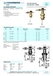
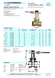
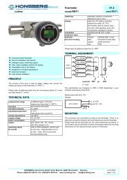
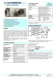
� universal <strong>flowmeter</strong> with vortex principle<br />
� switching output and/or analogue output (4 - 20 mA/0 - 10 V)<br />
� IP67 type of protection<br />
� infinitely rotatable cable outlet for precise alignment<br />
� robust stainless-steel housing<br />
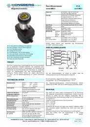
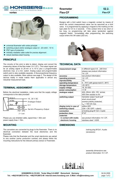
PRINCIPLE<br />
The circuitry of the omni is able to detect, display and convert the<br />
measuring values of the flow meter (14.1.<strong>CF</strong>.). The output signal can<br />
be an analog signal (4..20 mA or 0..10 V) plus a programmable<br />
electronic max. or a min. switch. Analog output and programmable<br />
switch point is also available separate. A flow-proportional frequency<br />
output is also available. More options see page 2. The design of the<br />
devices totally in metal makes them applicable in almost any<br />
industrial measurement task.<br />
TERMINAL ASSIGNMENT<br />
Before the electrical installation, make sure that the supply voltage<br />
corresponds to the data provided!<br />
1<br />
2<br />
3<br />
4<br />
brow n<br />
white<br />
blue<br />
black<br />
z z<br />
PNP NPN<br />
Z = Last<br />
18...30 V DC<br />
Analogue Output<br />
0 V<br />
Sw itch-/Frequency-Output<br />
Please you use shielded cable, signal lines < 30m and<br />
power supply lines < 10m.<br />
PROGRAMMING<br />
Designs with a limit switch have a magnetic contact by means of<br />
which the current measurement value can be assumed as a limit<br />
value. It is programmed by applying a magnet to the marking on the<br />
type plate for 0.5 to 2 seconds. If the contact time is too short or<br />
too long, no programming will take place (protection against<br />
magnetic fields). Immediately after programming, the switching<br />
output enters the OK state (LED on).<br />
TECHNICAL DATA<br />
MOUNTING DIMENSIONS<br />
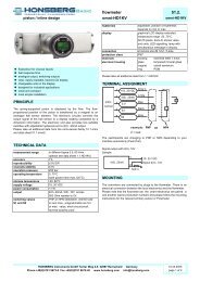
The converters are connected by plugs to the <strong>flowmeter</strong>. There is no<br />
electrical connection between the local electronics and the<br />
<strong>flowmeter</strong>.<br />
Please note that the <strong>flowmeter</strong> and the smart electronics are paired<br />
to one another (same production number) and please follow the<br />
mounting instructions for the relevant primary sensor or Flowmeter.<br />
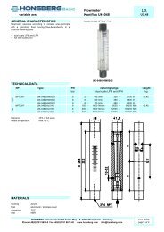
measurement range in different types 0.6…240 l/min<br />
(please see product information<br />
14.1.<strong>CF</strong>.<br />
accuracy<br />
see product information<br />
operating pressure 14.1.<strong>CF</strong>.<br />
reproducibility 1%<br />
operating temperature<br />
temperature 00…70 70°C C with goose-neck goose neck 00...80 80°C C<br />
storage temperature -20..80°C<br />
supply voltage<br />
18..30 VDC<br />
power consumption
<strong>flowmeter</strong> <strong>52.2.</strong><br />
vortex <strong>Flex</strong>-<strong>CF</strong> <strong>Flex</strong>-<strong>CF</strong><br />
NOMENCLATURE<br />
Example:<br />
<strong>Flex</strong>-<br />
A<br />
<strong>CF</strong><br />
B<br />
I<br />
C<br />
U R I<br />
D<br />
A sensor family: Options:<br />
<strong>Flex</strong>- <strong>Flex</strong>-system<br />
�<br />
B for <strong>flowmeter</strong> working range analogue output:<br />
<strong>CF</strong> <strong>flowmeter</strong> <strong>CF</strong> � (< measurement range of piston flow meter)<br />
C analogue output:<br />
I current output 4 - 20 mA � working range frequency output:<br />
U voltage output 0 - 10 V � (< measurement range of piston flow meter)<br />
K no analogue output<br />
�<br />
D switsch output end frequency (max. 2000 Hz)<br />
U push pull PNP and NPN<br />
�<br />
K no switching output � turn-on delay (from alarm to OK)<br />
E switching signal:<br />
L minimum switch � turn-off delay (von OK zu Alarm)<br />
H maximum switch<br />
�<br />
R frequency output � power-on delay<br />
K no switching output � (time after the supply is created; in this time<br />
F inversion of output: the switching output is not activated)<br />
O standard output<br />
�<br />
I inverted output � switching output with permanent setting<br />
RELATED PRODUCTS<br />
ACCESSORIES<br />
Locking plug M12x1<br />
K PU- 02 S<br />
K<br />
KB04<br />
PU-<br />
02<br />
05<br />
10<br />
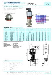
omni-<strong>CF</strong><br />
Electronic with backlit LCD, current output<br />
and two electronic limit switches,<br />
parametrisable via setting ring gauge.<br />
S<br />
G<br />
G<br />
W<br />
S<br />
�<br />
�<br />
�<br />
�<br />
�<br />
�<br />
�<br />
�<br />
�<br />
S �<br />
E<br />
F<br />
basic type<br />
specification<br />
assembled<br />
self makable cable 4-pole<br />
material PUR<br />
length 2 m<br />
length 5 m<br />
length 10 m<br />
moulded-on plug<br />
straight plug<br />
angled plug 90°<br />
shielded<br />
special hysteresis<br />
(standard = 2% F.S.)<br />
gooseneck<br />
All technical changes g reserved<br />
In case of empty fields, the standard<br />
setting will be selected automatically.<br />
l/min<br />
l/min<br />
Hz<br />
s<br />
s<br />
s<br />
l/min<br />
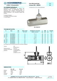
A goose-neck (optional) between the<br />
electronics head and the primary sensor<br />
provides complete freedom in the sensor<br />
alignment. This option also gives thermal<br />
decoupling between both units.<br />
�BASIC Standard �BASIC Programme option �VARIO Special option ⊕ PLUS Accessories not recommendable<br />
HONSBERG & CO.KG Tenter Weg 2-8 42897 Remscheid Germany 04.04.2006<br />
Tel.: +49(2191)9672-0 Fax.: +49(2191)9672-40 Internet:www.honsberg.com E-Mail: info@honsberg.com page 2 of 2<br />
%