AC FEEDTHROUGH CAPACITORS - Technical Sales Solutions
AC FEEDTHROUGH CAPACITORS - Technical Sales Solutions
AC FEEDTHROUGH CAPACITORS - Technical Sales Solutions

Create successful ePaper yourself
Turn your PDF publications into a flip-book with our unique Google optimized e-Paper software.
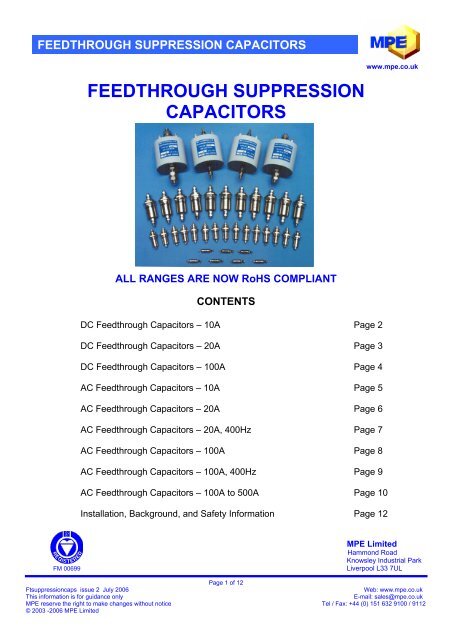
<strong>FEEDTHROUGH</strong> SUPPRESSION CAP<strong>AC</strong>ITORS<br />
<strong>FEEDTHROUGH</strong> SUPPRESSION<br />
CAP<strong>AC</strong>ITORS<br />
ALL RANGES ARE NOW RoHS COMPLIANT<br />
CONTENTS<br />
DC Feedthrough Capacitors – 10A Page 2<br />
DC Feedthrough Capacitors – 20A Page 3<br />
DC Feedthrough Capacitors – 100A Page 4<br />
<strong>AC</strong> Feedthrough Capacitors – 10A Page 5<br />
<strong>AC</strong> Feedthrough Capacitors – 20A Page 6<br />
<strong>AC</strong> Feedthrough Capacitors – 20A, 400Hz Page 7<br />
<strong>AC</strong> Feedthrough Capacitors – 100A Page 8<br />
<strong>AC</strong> Feedthrough Capacitors – 100A, 400Hz Page 9<br />
<strong>AC</strong> Feedthrough Capacitors – 100A to 500A Page 10<br />
Installation, Background, and Safety Information Page 12<br />
www.mpe.co.uk<br />
MPE Limited<br />
Hammond Road<br />
Knowsley Industrial Park<br />
FM 00699 Liverpool L33 7UL<br />
Page 1 of 12<br />
Ftsuppressioncaps issue 2 July 2006 Web: www.mpe.co.uk<br />
This information is for guidance only E-mail: sales@mpe.co.uk<br />
MPE reserve the right to make changes without notice Tel / Fax: +44 (0) 151 632 9100 / 9112<br />
© 2003 -2006 MPE Limited
DC <strong>FEEDTHROUGH</strong> CAP<strong>AC</strong>ITORS – 10A<br />
DESCRIPTION<br />
A range of miniature dc<br />
feedthrough capacitors<br />
rated at 10A.<br />
Capacitance values<br />
from 0.1µF to 1.5µF<br />
Rated voltages from 30V dc to 400V dc<br />
RoHS compliant<br />
RATINGS AND CHAR<strong>AC</strong>TERISTICS<br />
Rated Voltage As tabulated<br />
Test Voltage Twice rated voltage<br />
Rated Current, IR 10A @ 50ºC*<br />
Insulation Resistance > 100MΩ<br />
DC Resistance < 2mΩ<br />
Ambient Temperature Range -55ºC to +85ºC<br />
Climatic Category 55/85/21<br />
* Current derating between 50ºC and 85ºC For temperature, θ Iθ = IR ( 85 − θ ) 35<br />
PRODUCT RANGE<br />
Part<br />
Number<br />
Capacitance<br />
Value<br />
(µF ±20%)<br />
Voltage<br />
Rating<br />
(V dc)<br />
FV<br />
Number<br />
**<br />
www.mpe.co.uk<br />
Performance examples top 1.5µF<br />
middle 0.6µF<br />
bottom 0.1µF<br />
Typical Insertion Loss (dB) in 50 Ω system with/without load<br />
FC25172 0.1 400 FV1084128 - 1 5 14 24 44 70 84<br />
FC25173 0.2 250 FV1084129 - 3 10 20 30 50 74 90<br />
FC25174 0.3 160 FV1084130 - 5 14 24 34 50 74 90<br />
FC25175 0.6 100 FV1084131 3 10 20 30 40 50 80 90<br />
FC25176 0.9 63 FV1084132 5 13 23 33 43 51 83 90<br />
FC25177 1.5 30 FV1084140 8 17 27 37 47 55 87 90<br />
** UK MOD fighting vehicle registration number<br />
DIMENSIONS AND MECHANICAL DETAILS<br />
Dimensions in mm<br />
Mounting hardware 8 A/F fixing nut<br />
and crinkle washer<br />
Case Nickel plated brass<br />
Terminals Nickel plated brass<br />
Weight 5g<br />
Tightening torque Terminals 0.2Nm (use 2 spanners)<br />
Mounting thread 1Nm<br />
Page 2 of 12<br />
Ftsuppressioncaps issue 2 July 2006 Web: www.mpe.co.uk<br />
This information is for guidance only E-mail: sales@mpe.co.uk<br />
MPE reserve the right to make changes without notice Tel / Fax: +44 (0) 151 632 9100 / 9112<br />
© 2003 -2006 MPE Limited<br />
10<br />
kHz<br />
30<br />
kHz<br />
100<br />
kHz<br />
300<br />
kHz<br />
1<br />
MHz<br />
10<br />
MHz<br />
100<br />
MHz<br />
1<br />
GHz
DC <strong>FEEDTHROUGH</strong> CAP<strong>AC</strong>ITORS – 20A<br />
DESCRIPTION<br />
A range of dc feedthrough capacitors<br />
rated at 20A in a compact case size<br />
Capacitance values from 0.8µF to 12µF<br />
Rated voltages from 30V dc to 400V dc<br />
RoHS compliant<br />
RATINGS AND CHAR<strong>AC</strong>TERISTICS<br />
Rated Voltage As tabulated<br />
Test Voltage Twice rated voltage<br />
Rated Current, IR 20A @ 50ºC*<br />
Insulation Resistance > 100MΩ<br />
DC Resistance < 1mΩ<br />
Ambient Temperature Range -55ºC to +85ºC<br />
Climatic Category 55/85/21<br />
*Current derating between 50ºC and 85ºC For temperature, θ Iθ = IR ( 85 − θ ) 35<br />
PRODUCT RANGE<br />
Part<br />
Number<br />
Capacitance<br />
Value<br />
(µF ±20%)<br />
Voltage<br />
Rating<br />
(V dc)<br />
www.mpe.co.uk<br />
Performance examples top 12µF<br />
middle 4µF<br />
bottom 0.8µF<br />
Typical Insertion Loss (dB) in 50 Ω system with/without load<br />
FC23646 0.8 400 4 12 22 32 42 51 82 90<br />
FC23647 1 250 5 14 24 34 44 52 84 90<br />
FC23648 2 160 10 20 30 40 50 58 90 90<br />
FC23649 4 100 16 26 36 46 56 70 90 90<br />
FC23650 5 80 18 28 38 48 58 74 90 90<br />
FC23651 7 63 21 31 41 51 60 79 90 90<br />
FC23652 12 30 26 36 46 56 62 86 90 90<br />
DIMENSIONS AND MECHANICAL DETAILS<br />
Dimensions in mm<br />
Mounting hardware 19 A/F fixing nut and washer<br />
Case Nickel plated brass<br />
Terminals Nickel plated brass<br />
Weight 25g<br />
Max tightening torque:<br />
Terminals 0.5Nm (use 2 spanners)<br />
Mounting thread 7Nm<br />
Page 3 of 12<br />
Ftsuppressioncaps issue 2 July 2006 Web: www.mpe.co.uk<br />
This information is for guidance only E-mail: sales@mpe.co.uk<br />
MPE reserve the right to make changes without notice Tel / Fax: +44 (0) 151 632 9100 / 9112<br />
© 2003 -2006 MPE Limited<br />
10<br />
kHz<br />
30<br />
kHz<br />
100<br />
kHz<br />
300<br />
kHz<br />
1<br />
MHz<br />
10<br />
MHz<br />
100<br />
MHz<br />
1<br />
GHz
DC <strong>FEEDTHROUGH</strong> CAP<strong>AC</strong>ITORS – 100A<br />
DESCRIPTION<br />
A range of dc feedthrough capacitors<br />
rated at 100A<br />
Capacitance values from 0.8µF to 12µF<br />
Rated voltages from 30V dc to 400V dc<br />
RoHS compliant<br />
RATINGS AND CHAR<strong>AC</strong>TERISTICS<br />
Rated Voltage As tabulated<br />
Test Voltage Twice rated voltage<br />
Rated Current, IR 100A @ 50ºC*<br />
Insulation Resistance > 100MΩ<br />
DC Resistance < 0.5mΩ<br />
Ambient Temperature Range -55ºC to +85ºC<br />
Climatic Category 55/85/21<br />
*Current derating between 50ºC and 85ºC For temperature, θ Iθ = IR ( 85 − θ ) 35<br />
PRODUCT RANGE<br />
Part<br />
Number<br />
Capacitance<br />
Value<br />
(µF ±20%)<br />
Voltage<br />
Rating<br />
(V dc)<br />
FV<br />
Number<br />
**<br />
www.mpe.co.uk<br />
Performance examples top 40µF<br />
middle 14µF<br />
bottom 2µF<br />
Typical Insertion Loss (dB) in 50 Ω system with/without load<br />
FC25186 2 400 FV1084133 10 20 30 40 50 58 90 90<br />
FC25187 4 250 FV1084134 16 26 36 46 56 70 90 90<br />
FC25188 6 160 FV1084135 20 30 40 50 60 77 90 90<br />
FC25189 14 100 FV1084136 27 37 47 57 63 87 90 90<br />
FC25190 18 80 FV1084137 29 39 49 59 66 90 90 90<br />
FC25191 25 63 FV1084138 32 42 52 62 66 90 90 90<br />
FC25192 40 30 FV1084141 36 46 56 66 66 90 90 90<br />
** UK MOD fighting vehicle registration number<br />
DIMENSIONS AND MECHANICAL DETAILS<br />
Dimensions in mm<br />
Mounting hardware 30 A/F fixing nut and washer<br />
Case Nickel plated brass<br />
Terminals Nickel plated brass<br />
Weight 120g<br />
Max tightening torque:<br />
Terminals 2.5Nm (use 2 spanners)<br />
Mounting thread 14Nm<br />
Page 4 of 12<br />
Ftsuppressioncaps issue 2 July 2006 Web: www.mpe.co.uk<br />
This information is for guidance only E-mail: sales@mpe.co.uk<br />
MPE reserve the right to make changes without notice Tel / Fax: +44 (0) 151 632 9100 / 9112<br />
© 2003 -2006 MPE Limited<br />
10<br />
kHz<br />
30<br />
kHz<br />
100<br />
kHz<br />
300<br />
kHz<br />
1<br />
MHz<br />
10<br />
MHz<br />
100<br />
MHz<br />
1<br />
GHz
<strong>AC</strong> <strong>FEEDTHROUGH</strong> CAP<strong>AC</strong>ITORS – 10A<br />
DESCRIPTION<br />
A range of miniature ac<br />
feedthrough capacitors rated at 10A<br />
Capacitance values<br />
from 1.3nF to 4.7nF<br />
Test voltage is 2250V dc<br />
RoHS compliant<br />
RATINGS AND CHAR<strong>AC</strong>TERISTICS<br />
Rated Voltage 250V 50/60Hz, or 600V dc<br />
Test Voltage 2250V dc<br />
Rated Current, IR 10A @ 50ºC*<br />
Insulation Resistance > 100MΩ<br />
DC Resistance < 2mΩ<br />
Ambient Temperature Range -55ºC to +85ºC<br />
Climatic Category 55/85/21<br />
*Current derating between 50ºC and 85ºC For temperature, θ Iθ = IR ( 85 − θ ) 35<br />
PRODUCT RANGE<br />
Part<br />
Number<br />
Capacitance<br />
Value<br />
(nF ±20%)<br />
Test<br />
Voltage<br />
(V dc)<br />
Max Leakage<br />
Current (mA)<br />
@ 250V 50Hz<br />
www.mpe.co.uk<br />
Performance examples top 4.7nF<br />
bottom 1.3nF<br />
Typical Insertion Loss (dB) in 50 Ω system with/without load<br />
FC23725 1.3 2250 0.12 7 16 26 36 46<br />
FC23726 3.3 2250 0.31 14 24 34 44 54<br />
FC23727 4.7 2250 0.45 17 27 37 47 57<br />
DIMENSIONS AND MECHANICAL DETAILS<br />
Dimensions in mm<br />
Mounting hardware 8 A/F fixing nut<br />
and crinkle washer<br />
Case Nickel plated brass<br />
Terminals Nickel plated brass<br />
Weight 5g<br />
Tightening torque Terminals 0.2Nm (use 2 spanners)<br />
Mounting thread 1Nm<br />
Page 5 of 12<br />
Ftsuppressioncaps issue 2 July 2006 Web: www.mpe.co.uk<br />
This information is for guidance only E-mail: sales@mpe.co.uk<br />
MPE reserve the right to make changes without notice Tel / Fax: +44 (0) 151 632 9100 / 9112<br />
© 2003 -2006 MPE Limited<br />
10<br />
MHz<br />
30<br />
MHz<br />
100<br />
MHz<br />
300<br />
MHz<br />
1<br />
GHz
<strong>AC</strong> <strong>FEEDTHROUGH</strong> CAP<strong>AC</strong>ITORS – 20A<br />
DESCRIPTION<br />
A range of ac feedthrough capacitors<br />
rated at 20A in a compact case size<br />
Capacitance values from 5nF to 300nF<br />
Test voltages of either 1250V dc or<br />
2250V dc are offered<br />
RoHS compliant<br />
RATINGS AND CHAR<strong>AC</strong>TERISTICS<br />
Rated Voltage 250V ac 50/60Hz, or 600V dc<br />
Test Voltage As tabulated<br />
Rated Current, IR 20A @ 50ºC<br />
Insulation Resistance > 100MΩ<br />
DC Resistance < 1mΩ<br />
Ambient Temperature Range -55ºC to +85ºC<br />
Climatic Category 55/85/21<br />
*Current derating between 50ºC and 85ºC For temperature, θ Iθ = IR ( 85 − θ ) 35<br />
PRODUCT RANGE<br />
Part<br />
Number<br />
Capacitance<br />
Value<br />
(nF ±20%)<br />
Test<br />
Voltage<br />
(V dc)<br />
Max Leakage<br />
Current (mA)<br />
@ 250V 50Hz<br />
www.mpe.co.uk<br />
Performance examples top 300nF<br />
middle 50nF<br />
bottom 5nF<br />
Typical Insertion Loss (dB) in 50 Ω system with/without load<br />
FC23684 5 2250 0.5 - 2 17 37 47 57<br />
FC23685 10 2250 1 1 6 24 44 54 64<br />
FC23686 20 2250 1.9 3 10 30 46 60 70<br />
FC23687 50 2250 4.7 8 18 38 58 68 78<br />
FC23688 80 2250 7.5 12 22 42 62 72 82<br />
FC23689 100 1250 9.4 14 24 44 70 74 84<br />
FC23690 200 1250 19 20 30 50 74 80 90<br />
FC23691 300 1250 28 24 34 50 74 84 90<br />
DIMENSIONS AND MECHANICAL DETAILS<br />
Dimensions in mm<br />
Mounting hardware 19 A/F fixing nut and washer<br />
Case Nickel plated brass<br />
Terminals Nickel plated brass<br />
Weight 25g<br />
Max tightening torque:<br />
Terminals 0.5Nm (use 2 spanners)<br />
Mounting thread 7Nm<br />
Page 6 of 12<br />
Ftsuppressioncaps issue 2 July 2006 Web: www.mpe.co.uk<br />
This information is for guidance only E-mail: sales@mpe.co.uk<br />
MPE reserve the right to make changes without notice Tel / Fax: +44 (0) 151 632 9100 / 9112<br />
© 2003 -2006 MPE Limited<br />
300<br />
kHz<br />
1<br />
MHz<br />
10<br />
MHz<br />
100<br />
MHz<br />
300<br />
MHz<br />
1<br />
GHz
<strong>AC</strong> <strong>FEEDTHROUGH</strong> CAP<strong>AC</strong>ITORS – 20A 400Hz<br />
DESCRIPTION<br />
A range of 115V 400Hz ac feedthrough capacitors<br />
rated at 20A in a compact case size<br />
Capacitance values from 100nF to 250nF<br />
Test voltage is 1250V dc<br />
RoHS compliant<br />
RATINGS AND CHAR<strong>AC</strong>TERISTICS<br />
www.mpe.co.uk<br />
Performance examples top 250nF<br />
bottom 100nF<br />
Rated Voltage 115V 400Hz, or 250V ac 50/60Hz, or 600V dc<br />
Test Voltage 1250V dc<br />
Rated Current, IR 20A @ 50ºC*<br />
Insulation Resistance > 100MΩ<br />
DC Resistance < 1mΩ<br />
Ambient Temperature Range -55ºC to +70ºC<br />
Climatic Category 55/70/21<br />
*Current derating between 50ºC and 70ºC For temperature, θ Iθ = IR ( 70 − θ ) / 20<br />
PRODUCT RANGE<br />
Part<br />
Number<br />
Capacitance<br />
Value<br />
(nF ±20%)<br />
Test<br />
Voltage<br />
(V dc)<br />
Max Leakage<br />
Current (mA)<br />
@ 115V 400Hz<br />
Typical Insertion Loss (dB) in 50 Ω system with/without load<br />
FC25840 100 1250 35 14 24 44 70 74 84<br />
FC25841 200 1250 70 20 30 50 74 80 90<br />
FC25842 250 1250 87 22 32 50 74 82 90<br />
DIMENSIONS AND MECHANICAL DETAILS<br />
Dimensions in mm<br />
Mounting hardware 19 A/F fixing nut and washer<br />
Case Nickel plated brass<br />
Terminals Nickel plated brass<br />
Weight 25g<br />
Max tightening torque:<br />
Terminals 0.5Nm (use 2 spanners)<br />
Mounting thread 7Nm<br />
Page 7 of 12<br />
Ftsuppressioncaps issue 2 July 2006 Web: www.mpe.co.uk<br />
This information is for guidance only E-mail: sales@mpe.co.uk<br />
MPE reserve the right to make changes without notice Tel / Fax: +44 (0) 151 632 9100 / 9112<br />
© 2003 -2006 MPE Limited<br />
300<br />
kHz<br />
1<br />
MHz<br />
10<br />
MHz<br />
100<br />
MHz<br />
300<br />
MHz<br />
1<br />
GHz
<strong>AC</strong> <strong>FEEDTHROUGH</strong> CAP<strong>AC</strong>ITORS – 100A<br />
DESCRIPTION<br />
A range of ac feedthrough capacitors<br />
rated at 100A<br />
Capacitance values from 0.1µF to 1µF<br />
Test voltages of either 1250V dc or<br />
2250V dc are offered<br />
RoHS compliant<br />
RATINGS AND CHAR<strong>AC</strong>TERISTICS<br />
Rated Voltage 250V 50/60Hz, or 600V dc<br />
Test Voltage As tabulated<br />
Rated Current, IR 100A @ 50ºC*<br />
Insulation Resistance > 100MΩ<br />
DC Resistance < 0.5mΩ<br />
Ambient Temperature Range -55ºC to +85ºC<br />
Climatic Category 55/85/21<br />
*Current derating between 50ºC and 85ºC For temperature, θ Iθ = IR ( 85 − θ ) 35<br />
PRODUCT RANGE<br />
Part<br />
Number<br />
Capacitance<br />
Value<br />
(nF ±20%)<br />
Test<br />
Voltage<br />
(V dc)<br />
Max Leakage<br />
Current (mA)<br />
@ 250V 50Hz<br />
www.mpe.co.uk<br />
Performance examples top 1000nF<br />
middle 250nF<br />
bottom 100nF<br />
Typical Insertion Loss (dB) in 50 Ω system with/without load<br />
FC25180 100 2250 9.4 5 14 24 44 70 84<br />
FC25181 200 2250 19 10 20 30 50 74 90<br />
FC25182 250 2250 24 12 22 32 50 74 90<br />
FC25183 500 1250 47 18 28 38 50 78 90<br />
FC25184 1000 1250 94 24 34 44 52 84 90<br />
DIMENSIONS AND MECHANICAL DETAILS<br />
Dimensions in mm<br />
Mounting hardware 30 A/F fixing nut and washer<br />
Case Nickel plated brass<br />
Terminals Nickel plated brass<br />
Weight 120g<br />
Max tightening torque:<br />
Terminals 2.5Nm (use 2 spanners)<br />
Mounting thread 14Nm<br />
Page 8 of 12<br />
Ftsuppressioncaps issue 2 July 2006 Web: www.mpe.co.uk<br />
This information is for guidance only E-mail: sales@mpe.co.uk<br />
MPE reserve the right to make changes without notice Tel / Fax: +44 (0) 151 632 9100 / 9112<br />
© 2003 -2006 MPE Limited<br />
100<br />
kHz<br />
300<br />
kHz<br />
1<br />
MHz<br />
10<br />
MHz<br />
100<br />
MHz<br />
1<br />
GHz
<strong>AC</strong> <strong>FEEDTHROUGH</strong> CAP<strong>AC</strong>ITORS – 100A 400Hz<br />
DESCRIPTION<br />
A range of 115V 400Hz feedthrough<br />
capacitors rated at 100A<br />
Capacitance values from 0.3µF to 1µF<br />
Test voltage is 1250V dc<br />
RoHS compliant<br />
RATINGS AND CHAR<strong>AC</strong>TERISTICS<br />
www.mpe.co.uk<br />
Performance examples top 1000nF<br />
Bottom 300nF<br />
Rated Voltage 115V 400Hz, or 250V ac 50/60Hz, or 600V dc<br />
Test Voltage 1250V dc<br />
Rated Current, IR 100A @ 50ºC*<br />
Insulation Resistance > 100MΩ<br />
DC Resistance < 0.5mΩ<br />
Ambient Temperature Range -55ºC to +70ºC<br />
Climatic Category 55/70/21<br />
*Current derating between 50ºC and 70ºC For temperature, θ Iθ = IR ( 70 − θ ) / 20<br />
PRODUCT RANGE<br />
Part<br />
Number<br />
Capacitance<br />
Value<br />
(nF ±20%)<br />
Test<br />
Voltage<br />
(V dc)<br />
Max Leakage<br />
Current (mA)<br />
@ 115V 400Hz<br />
Typical Insertion Loss (dB) in 50 Ω system with/without load<br />
FC25844 300 1250 104 14 24 34 50 74 90<br />
FC25845 500 1250 174 18 28 38 50 78 90<br />
FC25846 1000 1250 347 24 34 44 52 84 90<br />
DIMENSIONS AND MECHANICAL DETAILS<br />
Dimensions in mm<br />
Mounting hardware 30 A/F fixing nut and washer<br />
Case Nickel plated brass<br />
Terminals Nickel plated brass<br />
Weight 120g<br />
Max tightening torque:<br />
Terminals 2.5Nm (use 2 spanners)<br />
Mounting thread 14Nm<br />
Page 9 of 12<br />
Ftsuppressioncaps issue 2 July 2006 Web: www.mpe.co.uk<br />
This information is for guidance only E-mail: sales@mpe.co.uk<br />
MPE reserve the right to make changes without notice Tel / Fax: +44 (0) 151 632 9100 / 9112<br />
© 2003 -2006 MPE Limited<br />
100<br />
kHz<br />
300<br />
kHz<br />
1<br />
MHz<br />
10<br />
MHz<br />
100<br />
MHz<br />
1<br />
GHz
<strong>AC</strong> <strong>FEEDTHROUGH</strong> CAP<strong>AC</strong>ITORS – 100A – 500A<br />
DESCRIPTION<br />
A range of high current ac feedthrough<br />
capacitors rated at 100A – 500A<br />
Capacitance values from 5µF to 15µF<br />
Test voltage is 1500V dc<br />
This range of capacitors has built-in<br />
discharge resistors for safety<br />
RoHS compliant<br />
RATINGS AND CHAR<strong>AC</strong>TERISTICS<br />
www.mpe.co.uk<br />
Performance examples top 15µF<br />
bottom 5µF<br />
Rated Voltage 250V 50/60Hz, or 115V 400Hz, or 1000V dc<br />
Test Voltage 1500V dc<br />
Rated Current As tabulated<br />
Insulation Resistance >100MΩ (prior to fitting discharge resistors)<br />
Discharge resistance 600kΩ<br />
Discharge time
<strong>AC</strong> <strong>FEEDTHROUGH</strong> CAP<strong>AC</strong>ITORS – 100A – 500A<br />
DIMENSIONS AND MECHANICAL DETAILS<br />
Dimensions in mm<br />
Mounting hardware Supplied with M6 fixing nuts and washers<br />
Case material Tin plated brass or steel, paint finish<br />
Max tightening torque:<br />
Terminal thread As tabulated (use 2 spanners)<br />
Fixing studs 2.5Nm<br />
Part<br />
Number<br />
A B C D E<br />
www.mpe.co.uk<br />
Page 11 of 12<br />
Ftsuppressioncaps issue 2 July 2006 Web: www.mpe.co.uk<br />
This information is for guidance only E-mail: sales@mpe.co.uk<br />
MPE reserve the right to make changes without notice Tel / Fax: +44 (0) 151 632 9100 / 9112<br />
© 2003 -2006 MPE Limited<br />
F<br />
p.c.d.<br />
G<br />
Thread<br />
Max torque<br />
on G<br />
(Nm)<br />
FC25151 76 70 25 120 25 57.2 M6 2.5 900<br />
FC25152 76 70 25 120 25 57.2 M6 2.5 900<br />
FC25123 95 70 25 120 25 76.2 M6 2.5 1400<br />
FC25156 76 70 35 140 25 57.2 M10 8 900<br />
FC25157 76 70 35 140 25 57.2 M10 8 900<br />
FC25158 95 70 35 140 25 76.2 M10 8 1400<br />
FC25160 76 70 40 150 32 57.2 M12 11 900<br />
FC25161 76 70 40 150 32 57.2 M12 11 900<br />
FC25162 95 70 40 150 32 76.2 M12 11 1400<br />
FC25165 76 70 50 170 32 57.2 M16 20 900<br />
FC25166 95 70 50 170 32 76.2 M16 20 1400<br />
FC25167 95 70 50 170 32 76.2 M16 20 1400<br />
INSTALLATION<br />
This range of capacitors should be securely mounted to the bulkhead by means of the four fixing studs in<br />
the base mounting plate. The base of the capacitor is left unpainted to ensure a good electrical interface<br />
with the bulkhead.<br />
Weight<br />
(g)
INSTALLATION, B<strong>AC</strong>KGROUND, AND SAFETY<br />
www.mpe.co.uk<br />
INSTALLATION GUIDELINES<br />
Feedthrough capacitors are designed for through-bulkhead mounting for offering high frequency filtering in line to<br />
ground applications. They should be mounted through a metal bulkhead or chassis.<br />
The bulkhead mounting surface should be clean and unpainted to offer a low impedance path from the capacitor to the<br />
equipment chassis. Poor earth bonding will limit the available performance of the product and could compromise<br />
safety.<br />
Conductive paint finishes should be avoided as they do not usually provide adequate conductivity.<br />
2 spanners should be used when making electrical connections to the terminals, and maximum tightening torque<br />
figures quoted should be observed.<br />
CONSTRUCTION AND RELIABILITY<br />
MPE have been designing and manufacturing feedthrough capacitors and filters for more than 40 years, and plastic<br />
film feedthrough capacitors for more than 25 years. MPE has always been at the forefront of the design of feedthrough<br />
capacitors and the improvements in materials and assembly techniques, which have evolved over the years, have<br />
been incorporated into these ranges of feedthrough capacitors.<br />
The designs covered by this catalogue all utilise self-healing metallised plastic film capacitor material and incorporate a<br />
solderless capacitor assembly technique to avoid heat damage to the plastic dielectric material, which would reduce its<br />
life and reliability. Terminals are nickel plated for good conductivity.<br />
<strong>FEEDTHROUGH</strong> CAP<strong>AC</strong>ITOR PERFORMANCE<br />
• Normal two-terminal capacitors resonate with their lead<br />
inductance in the region 1-10MHz<br />
• This limits their use as suppression components above a<br />
few MHz<br />
• Feedthrough capacitors have no major resonance as they<br />
have no lead inductance<br />
• Their performance continues to increase with frequency<br />
• Hence feedthrough capacitors are essential for good high<br />
frequency performance<br />
• As an example this graph compares the performance of a<br />
1µF feedthrough capacitor with a 1µF two-terminal capacitor<br />
SAFETY<br />
Relevant safety standards have been adhered to in the design and manufacture of these products. However, all<br />
capacitors will store charge after power has been removed and must be treated with respect as this can be lethal when<br />
the voltage and charge are high enough. Except for the range on page 10, the capacitors contained within this<br />
catalogue do not contain internal discharge resistors. It is therefore recommended that they are fitted with external<br />
discharge resistors or other means to discharge the capacitors after the power has been removed. Where necessary,<br />
terminals should be enclosed by the user to prevent any danger of electric shock or accidental shorting.<br />
In all cases, capacitors should always be shorted to earth prior to touching to ensure they are fully discharged.<br />
The user should ensure he is familiar with restrictions on capacitance value, earth leakage current, test voltage, and<br />
safety labelling requirements, which may be applicable to his particular installation.<br />
In particular, safety standards IEC950 and EN60950, which most electrical equipment needs to comply with, contain a<br />
number of specific requirements for equipment incorporating capacitors, which may be applicable.<br />
CUSTOM DESIGNS<br />
MPE offers a rapid design service for custom designs where special packaging, mounting, terminations, or multiple<br />
lines are required. Over 50% of the feedthrough components manufactured by MPE are custom designs and this can<br />
offer a very cost effective installation solution. Please ask to see examples of previously offered solutions.<br />
FURTHER INFORMATION<br />
For more detailed technical background information, and application notes detailing the benefits of feedthrough<br />
capacitors over traditional capacitors, please contact the factory.<br />
Page 12 of 12<br />
Ftsuppressioncaps issue 2 July 2006 Web: www.mpe.co.uk<br />
This information is for guidance only E-mail: sales@mpe.co.uk<br />
MPE reserve the right to make changes without notice Tel / Fax: +44 (0) 151 632 9100 / 9112<br />
© 2003 -2006 MPE Limited