Technical Information Technical Information - KATEC CATALYSTS
Technical Information Technical Information - KATEC CATALYSTS
Technical Information Technical Information - KATEC CATALYSTS

Create successful ePaper yourself
Turn your PDF publications into a flip-book with our unique Google optimized e-Paper software.
<strong>Technical</strong> <strong>Technical</strong> <strong>Information</strong><br />
<strong>Information</strong><br />
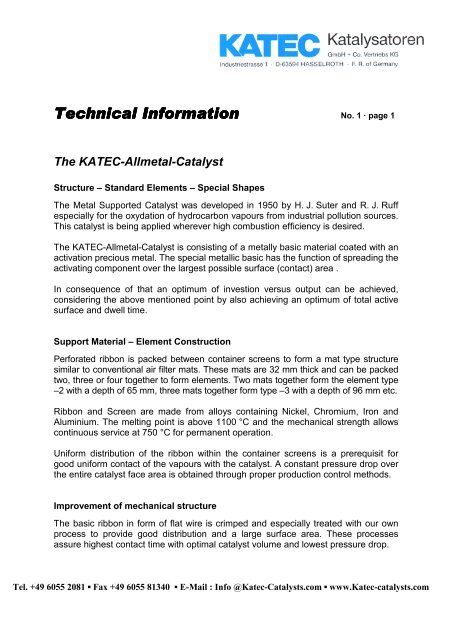
The <strong>KATEC</strong>-Allmetal-Catalyst<br />
Structure – Standard Elements – Special Shapes<br />
No. 1 · page 1<br />
The Metal Supported Catalyst was developed in 1950 by H. J. Suter and R. J. Ruff<br />
especially for the oxydation of hydrocarbon vapours from industrial pollution sources.<br />
This catalyst is being applied wherever high combustion efficiency is desired.<br />
The <strong>KATEC</strong>-Allmetal-Catalyst is consisting of a metally basic material coated with an<br />
activation precious metal. The special metallic basic has the function of spreading the<br />
activating component over the largest possible surface (contact) area .<br />
In consequence of that an optimum of investion versus output can be achieved,<br />
considering the above mentioned point by also achieving an optimum of total active<br />
surface and dwell time.<br />
Support Material – Element Construction<br />
Perforated ribbon is packed between container screens to form a mat type structure<br />
similar to conventional air filter mats. These mats are 32 mm thick and can be packed<br />
two, three or four together to form elements. Two mats together form the element type<br />
–2 with a depth of 65 mm, three mats together form type –3 with a depth of 96 mm etc.<br />
Ribbon and Screen are made from alloys containing Nickel, Chromium, Iron and<br />
Aluminium. The melting point is above 1100 °C and the mechanical strength allows<br />
continuous service at 750 °C for permanent operation.<br />
Uniform distribution of the ribbon within the container screens is a prerequisit for<br />
good uniform contact of the vapours with the catalyst. A constant pressure drop over<br />
the entire catalyst face area is obtained through proper production control methods.<br />
Improvement of mechanical structure<br />
The basic ribbon in form of flat wire is crimped and especially treated with our own<br />
process to provide good distribution and a large surface area. These processes<br />
assure highest contact time with optimal catalyst volume and lowest pressure drop.<br />
Tel. +49 6055 2081 ▪ Fax +49 6055 81340 ▪ E-Mail : Info @Katec-Catalysts.com ▪ www.Katec-catalysts.com
<strong>Technical</strong> <strong>Technical</strong> <strong>Information</strong><br />
<strong>Information</strong><br />
Active Catalyst Surface<br />
No. 1 · page 2<br />
The metallic basic material is coated with metals of the Platinum Group and special<br />
promotors. Production will be completed by activation of each catalyst element so that<br />
reproductable standard for hydrocarbon burning will be obtained prior to shipment.<br />
Catalyst Elements<br />
The catalyst mats described above are packed into stainless steel frames to form<br />
standard catalyst elements. The size of the entry face and the depth of the catalyst<br />
element are selected on the basic of the exhaust gas volume to be treated.<br />
The series of standard size elements listed on page 5 has proven sufficient to treat<br />
common gas volume encountered in most industrial applications. The elements are<br />
assembled in parallel for the treatment of various volumes.<br />
Whenever special applications require a special element design, these can be built in<br />
our works. The polygon or hollow cylindrical design is selected for example, whenever<br />
large gas volumes must be treated.<br />
The advantages of the <strong>KATEC</strong>-metal-supported-catalyst<br />
The advantages of the allmetal catalyst are listed below:<br />
� Compact structure in ready to mount stainless steel frames makes the catalyst<br />
easy to handle and install.<br />
� The building block approach can be applied because the standard elements<br />
have specific volume capacities and can be mounted on suitable frames in<br />
parallel.<br />
� Because of their metallic structure the elements are rugged and unbreakable.<br />
� The fixed bed catalyst stays in position and unlike the ceramic supported<br />
catalyst by-pass channelling is no problem.<br />
� Abrasion of the catalyst surface cannot occur because of the fixed position<br />
structure of the allmetal catalyst.<br />
Tel. +49 6055 2081 ▪ Fax +49 6055 81340 ▪ E-Mail : Info @Katec-Catalysts.com ▪ www.Katec-catalysts.com
<strong>Technical</strong> <strong>Technical</strong> <strong>Information</strong><br />
<strong>Information</strong><br />
No. 1 · page 3<br />
� Even distribution of the metallic basic assures good distribution of the gas<br />
stream across the catalyst entry face.<br />
� The metal structure assures a low pressure drop and allows the application of<br />
conventional heat fans in catalytic incinerators.<br />
� The metal supported catalyst has good activity with the lowest possible<br />
precious metal content, since the precious metal catalyst is distributed on<br />
the basic material surface.<br />
� The metal catalyst can be washed with water and acid, a process which<br />
removes dust and dirt and prolongs full combustion efficiency.<br />
� Metal catalysts can be reactivated by removing the active catalyst surface and<br />
replacing it with a new one. <strong>KATEC</strong>-Allmetal-Catalysts can thus be kept in<br />
service for ten years and more.<br />
Standard Catalyst Elements<br />
The list on page 5 contains a series of rectangular and flat catalyst elements.<br />
The elements differ in their entry surface and depth. The entry surface areas are<br />
selected in order to achieve a suitable volume capacity.<br />
The variation in depth allows an additional variation of volume capacity with the<br />
same element entry face area. The type –2 element is the normal depth used.<br />
Depth of less than 64 mm (type 2) are not recommended, since the low pressure<br />
drop would hinder even distribution of the exhaust gas over the entire face area.<br />
With an increase in depth to 96 mm (type –3) the volume capacity will be 1 ½ times<br />
the capacity of type –2.<br />
Increasing the depth further to 128 mm (type –4) will raise the volume capacity to<br />
2 times that of type –2 while keeping the same face area. These considerations are<br />
important when space limitations in incinerators dictate the face dimensions which a<br />
catalyst can have. The disadvantage is the higher pressure drop, which requires<br />
special gas for elements type –4.<br />
Tel. +49 6055 2081 ▪ Fax +49 6055 81340 ▪ E-Mail : Info @Katec-Catalysts.com ▪ www.Katec-catalysts.com
<strong>Technical</strong> <strong>Technical</strong> <strong>Information</strong><br />
<strong>Information</strong><br />
Expanded Elements<br />
No. 1 · page 4<br />
At times catalysts must be fitted into existing incinerators with allowable pressure<br />
drop already dictated by the hot gas fan installed in the unit. Mostly these systems<br />
are equipped with fans which are already running at maximum permissable speed.<br />
The expanded allmetal catalyst is applied in these cases. The types of elements are<br />
designated with the affixation of the letter “E” behind the type, i. e. Type 1–2 E.<br />
All elements can be manufactured in expanded form.<br />
The expanded form E has twice the depth of the normal form while the amount of<br />
catalyst remains the same as is installed in the normal elements. The expanded<br />
catalyst has the catalyst media spread over twice the depth. E elements have half of<br />
the density of normal elements.<br />
As explained in “<strong>Technical</strong> <strong>Information</strong>” No. 3 expanded elements have less pressure<br />
drop than normal elements which can become a consideration when catalysts are<br />
fitted into existing installations. It is important to remember, however, that the<br />
application of expanded elements necessitates proper mixing of hydrocarbons in the<br />
exhaust gas stream and proper distribution across the catalytic chamber prior to entry<br />
into the catalyst bed.<br />
Many existing installations such as ovens require fixed dimensions on the catalysts<br />
and installation in vertical, horizontal or inclined positions. The allmetal catalyst can<br />
be installed in all positions and manufactured in all sizes and shapes. While slightly<br />
more costly, special elements are part of our product program.<br />
Tel. +49 6055 2081 ▪ Fax +49 6055 81340 ▪ E-Mail : Info @Katec-Catalysts.com ▪ www.Katec-catalysts.com
<strong>Technical</strong> <strong>Technical</strong> <strong>Information</strong><br />
<strong>Information</strong><br />
<strong>Technical</strong> <strong>Information</strong> No. 1 · page 5<br />
Standard Catalyst Elements<br />
– rectangular and flat forms –<br />
Type measurement outside weight off gas volume loading, max.<br />
mm kg Nm³/h<br />
1-2 610 x 457 x 67 11 800<br />
1-3 610 x 457 x 99 17 1200<br />
1-4 610 x 457 x 131 23 1600<br />
2-2 610 x 305 x 67 8 500<br />
2-3 610 x 305 x 99 12 800<br />
2-4 610 x 305 x 131 16 1000<br />
3-2 457 x 305 x 67 6 370<br />
3-3 457 x 305 x 99 9 550<br />
3-4 457 x 305 x 131 12 730<br />
4-2 280 x 186 x 67 3 150<br />
4-3 280 x 186 x 99 4 220<br />
4-4 280 x 186 x 131 5 300<br />
Above listed volume capacities are suitable for catalytic oxidation for those hydrocarbons<br />
like Toluene, Xylene etc. which are easy to burn. The volume capacities<br />
correspond 100 % off gas loading for allmetal catalysts.<br />
For several fields of catalytic oxydation of hydrocarbon emissions above listed<br />
catalysts volume capacities must be reduced.<br />
Tel. +49 6055 2081 ▪ Fax +49 6055 81340 ▪ E-Mail : Info @Katec-Catalysts.com ▪ www.Katec-catalysts.com