Modeling-of-steady-state-performance-of-skid-steering-f_2017_Journal-of-Terr

You also want an ePaper? Increase the reach of your titles
YUMPU automatically turns print PDFs into web optimized ePapers that Google loves.
Available online at www.sciencedirect.com<br />
ScienceDirect<br />
<strong>Journal</strong> <strong>of</strong> <strong>Terr</strong>amechanics 73 (<strong>2017</strong>) 25–35<br />
<strong>Journal</strong><br />
<strong>of</strong><br />
<strong>Terr</strong>amechanics<br />
www.elsevier.com/locate/jterra<br />
<strong>Modeling</strong> <strong>of</strong> <strong>steady</strong>-<strong>state</strong> <strong>performance</strong> <strong>of</strong> <strong>skid</strong>-<strong>steering</strong> for<br />
high-speed tracked vehicles<br />
Shouxing Tang a , Shihua Yuan a,⇑ , Jibin Hu a , Xueyuan Li a , Junjie Zhou a , Jing Guo b<br />
a Science and Technology on Vehicular Transmission Laboratory, Beijing Institute <strong>of</strong> Technology, Beijing 100081, China<br />
b National Key Lab <strong>of</strong> Vehicular Transmission, China North Vehicle Research Institute, Beijing 100081, China<br />
Received 25 March <strong>2017</strong>; received in revised form 9 June <strong>2017</strong>; accepted 12 June <strong>2017</strong><br />
Available online 13 July <strong>2017</strong><br />
Abstract<br />
This paper presents a high-fidelity, general, and modular method for lateral dynamics simulation <strong>of</strong> high-speed tracked vehicle. Based<br />
on classic terramechanics, a novel nonlinear track terrain model is derived. The track terrain model meets the needs <strong>of</strong> longitudinal and<br />
<strong>steering</strong> motions, comprehensive track slips, and modular modeling for tracked vehicles with various configurations. The proposed lateral<br />
dynamics model is in reasonably agreement with the available experimental data. Using the lateral dynamics model, the main factors<br />
(normal pressure distribution, position <strong>of</strong> gravity center, and ratio <strong>of</strong> track-ground contact length and tread L=B) effecting the <strong>steady</strong><br />
<strong>state</strong> characteristics <strong>of</strong> <strong>skid</strong> <strong>steering</strong> are discussed. The normal pressure distribution is idealized as trapezoid and dual trapezoid distribution<br />
to reflect same common driving situation. The under-steer parameter is introduced in this paper to quantitatively evaluate the<br />
<strong>steady</strong>-<strong>state</strong> characteristics <strong>of</strong> <strong>skid</strong> <strong>steering</strong> for tracked vehicle. The results show that the ratio <strong>of</strong> theoretical speed difference and average<br />
speed <strong>of</strong> both side tracks Du=u as the <strong>steering</strong> input is more suitable for the high-speed tracked vehicle. The vehicle with dual trapezoid<br />
normal pressure distribution slightly tending to localize in the middle <strong>of</strong> track or with slightly rearward position <strong>of</strong> gravity center has<br />
better handling stability characteristics.<br />
Ó <strong>2017</strong> ISTVS. Published by Elsevier Ltd. All rights reserved.<br />
Keywords: Tracked vehicle; Unmanned vehicle; Skid <strong>steering</strong>; Lateral dynamics; Steering characteristics<br />
1. Introduction and related research<br />
Tracked vehicles have great mobility, traversability, and<br />
payload carrying capacity on extremely difficult terrain<br />
that wheeled vehicles haven’t (Hohl, 2007). They have been<br />
widely used in many fields such as unmanned/manned military,<br />
agriculture and construction operations (Wong,<br />
2008; Wong et al., 2015; Janarthanan et al., 2011). Whether<br />
wheeled or tracked vehicles, <strong>steering</strong> characteristics is a primary<br />
research field in their design, manufacture, test, and<br />
control. In recent years, <strong>steering</strong> characteristics is widely<br />
⇑ Corresponding author at: School <strong>of</strong> Mechanical and Vehicular<br />
Engineering, Beijing Institute <strong>of</strong> Technology, Beijing 100081, China.<br />
E-mail address: bityuanshihua@163.com (S. Yuan).<br />
concerned in the unmanned ground vehicles research field,<br />
because it has large impact on the motion planning and<br />
path tracking, especially in high-speed operation<br />
(Urmson et al., 2008; Genya et al., 2007). Researchers have<br />
broadly studied the lateral dynamics <strong>of</strong> wheeled vehicle and<br />
made a great number <strong>of</strong> achievements (Gillepie, 1992;<br />
Pacejka, 2006; Vantsevich, 2015). These achievements have<br />
formed a complete theoretical system to support the development<br />
<strong>of</strong> high-speed wheeled vehicle. In contrast, there<br />
are not enough researches on lateral dynamics <strong>of</strong> tracked<br />
vehicles to support the development <strong>of</strong> high-speed tracked<br />
vehicles.<br />
The initial research on <strong>steering</strong> characteristics <strong>of</strong> tracked<br />
vehicle was presented by Merritt (1939), who assumed that<br />
the forces generated between the track and terrain obey the<br />
http://dx.doi.org/10.1016/j.jterra.<strong>2017</strong>.06.003<br />
0022-4898/Ó <strong>2017</strong> ISTVS. Published by Elsevier Ltd. All rights reserved.
26 S. Tang et al. / <strong>Journal</strong> <strong>of</strong> <strong>Terr</strong>amechanics 73 (<strong>2017</strong>) 25–35<br />
Nomenclature<br />
Du velocity difference<br />
/ terrain internal friction angle<br />
u heading angle<br />
x yaw velocity<br />
x s rotating angular speed <strong>of</strong> sprocket<br />
x t yaw angular velocity <strong>of</strong> track coordinate system<br />
h the angle between the comprehensive absolute<br />
velocity and the longitudinal direction <strong>of</strong> the<br />
track coordinate system<br />
d longitudinal slips <strong>of</strong> track<br />
s the shear stress on an element <strong>of</strong> the trackground<br />
interface<br />
j under-steer parameter<br />
b width <strong>of</strong> track<br />
B tread <strong>of</strong> vehicle<br />
c terrain cohesion<br />
dF shear force developed on track element dA<br />
dA area <strong>of</strong> track element<br />
F y lateral force acting on the track<br />
F x longitudinal force acting on the track<br />
h height <strong>of</strong> center <strong>of</strong> gravity<br />
I z rotational inertia about z axis <strong>of</strong> vehicle<br />
j x shear displacement along the x t direction at<br />
point (x t , y t )<br />
j y shear displacement along the y t direction at point<br />
(x t , y t )<br />
j resultant shear displacement at the point (x t , y t )<br />
K terrain shear deformation modulus<br />
k concentration factor <strong>of</strong> normal pressure distribution<br />
k 2 front and rear distribution factor<br />
L track-ground contact length<br />
l x longitudinal <strong>of</strong>fset <strong>of</strong> center <strong>of</strong> gravity to the<br />
geometrical center <strong>of</strong> the vehicle<br />
m mass <strong>of</strong> vehicle<br />
M r turn resistance moment acting on the track<br />
pðx t ; y t Þ normal pressure distribution on the track<br />
r radius <strong>of</strong> sprocket<br />
R turning radius<br />
sðx t Þ the normal distribution density function on the<br />
track<br />
t duration <strong>of</strong> track element from contacting the<br />
ground initially to point (x t , y t )<br />
u Actual forward velocity <strong>of</strong> vehicle<br />
u t longitudinal velocity <strong>of</strong> the track coordinate system<br />
u r theoretical driving velocity <strong>of</strong> vehicle<br />
v Actual lateral velocity <strong>of</strong> C.G.<br />
v t lateral velocity <strong>of</strong> the track coordinate system<br />
V y relative velocity component <strong>of</strong> arbitrary point<br />
(x t , y t ) on the track-ground interface in the y t<br />
direction<br />
V x relative velocity component <strong>of</strong> arbitrary point<br />
(x t , y t ) on the track-ground interface in the x t<br />
direction<br />
W gravity <strong>of</strong> vehicle<br />
W L normal load on left track<br />
W R normal load on right track<br />
xyz body fixed coordinate system with origin at the<br />
C.G.<br />
x t y t z t track coordinate system is fixed on the center <strong>of</strong><br />
track-ground interface and moves with vehicle<br />
XYZ global coordinate system<br />
law <strong>of</strong> Coulomb friction. Subsequently, many researchers<br />
established kinds <strong>of</strong> dynamic models and obtained many<br />
innovative conclusions, taking different factors and<br />
assumptions into consideration. Micklethwait (1944) presented<br />
the friction between the track and terrain is anisotropic<br />
in the longitudinal and lateral directions. Hock<br />
(1961) and others introduced some empirical formulas to<br />
characterize the phenomenon that the lateral friction coefficient<br />
decreases with the increase <strong>of</strong> the turning radius.<br />
Crosheck (1975) introduced the pull-slip equation to<br />
describe the interaction <strong>of</strong> track and terrain. In order to<br />
find out the adequate vehicle model for the control <strong>of</strong><br />
PAISI tracked vehicle test system, Ehlert et al. (1992) used<br />
the tank Jaguar to do some test. Based on test results, he<br />
modified the Hock model, IABG model, and Kitano model<br />
and finally found out an adequate model. Wong and<br />
Chiang (2001) presented a general theoretical <strong>steady</strong>-<strong>state</strong><br />
model <strong>of</strong> tracked vehicles, considering the shear stressshear<br />
displacement relationship on the track-terrain interface.<br />
The purpose <strong>of</strong> above-mentioned researches is to predict<br />
<strong>steering</strong> ability <strong>of</strong> tracked vehicle and estimate the load<br />
on the <strong>steering</strong> mechanism <strong>of</strong> tracked vehicle.<br />
Kitano and Kuma (1977) established a theoretical nonstationary<br />
model based on pull-slip equation to analyze<br />
and predict <strong>steady</strong>-<strong>state</strong> and transient <strong>steering</strong> response<br />
<strong>of</strong> tracked vehicle on different velocity. In the same way<br />
Janarthanan et al. (2011) developed a 5 DOF nonstationary<br />
model to study the handling behavior at high<br />
or low speeds employing different types <strong>of</strong> <strong>steering</strong> input.<br />
Base on the law <strong>of</strong> Coulomb friction Purdy and Wormell<br />
(2003) established the mathematical model <strong>of</strong> CVR (Combat<br />
Vehicle Reconnaissance) tracked vehicle to analyze the<br />
<strong>steering</strong> <strong>performance</strong>. Similar with tires model in lateral<br />
dynamics <strong>of</strong> on-road wheeled vehicle, the track-terrain<br />
interaction model is the mechanical foundation <strong>of</strong> dynamics<br />
model <strong>of</strong> tracked vehicle, which directly influences the<br />
accuracy <strong>of</strong> tracked vehicle simulation, particularly the lateral<br />
mechanics. Above-mentioned track-terrain models<br />
have different lateral shear stress distributions along the<br />
longitudinal direction, which may have significant effects
S. Tang et al. / <strong>Journal</strong> <strong>of</strong> <strong>Terr</strong>amechanics 73 (<strong>2017</strong>) 25–35 27<br />
on the <strong>steering</strong> characteristics <strong>of</strong> tracked vehicles. To date,<br />
the track-terrain interaction has been well studied in the<br />
research field called <strong>Terr</strong>amechanics. In this field shear<br />
stress-shear displacement relationship is believed to be<br />
the more rational formulation <strong>of</strong> track-terrain interaction<br />
than others so far (Wong, 2008).<br />
This paper describes a high-fidelity, general, and modular<br />
method for lateral dynamic simulation <strong>of</strong> high-speed<br />
tracked vehicle. In this method, a novel nonlinear track terrain<br />
model is derived based on classic terramechanics. This<br />
track terrain model meets the needs <strong>of</strong> longitudinal and<br />
<strong>steering</strong> motions <strong>of</strong> vehicle, comprehensive track slips,<br />
and modular modeling for tracked vehicles with various<br />
configurations. This lateral dynamic model is verified by<br />
comparison with the available experimental data. Using<br />
this model, handling and stability characteristics are sufficiently<br />
investigated in high-speed <strong>steering</strong> situation, considering<br />
the main factors (normal pressure distribution,<br />
position <strong>of</strong> gravity center, ratio <strong>of</strong> track-ground contact<br />
length and tread L=B). The results <strong>of</strong> this study are very<br />
useful for the design and control <strong>of</strong> unmanned/manned<br />
high-speed tracked vehicles.<br />
The rest <strong>of</strong> this paper is organized as follows: Section 2<br />
presents the novel track terrain modeling. Section 3<br />
describes the modular lateral dynamic model <strong>of</strong> tracked<br />
vehicle. Section 4 presents model verification by comparison<br />
with the available experimental data. Section 5 presents<br />
the analysis on handling and stability characteristics<br />
by using this model. Finally, concluding remarks are summarized<br />
in Section 6.<br />
2. Track-terrain modeling<br />
The various ways that a tracked vehicle could be steered<br />
are <strong>skid</strong>-<strong>steering</strong>, articulated-<strong>steering</strong>, and curved-<strong>steering</strong><br />
(Kar, 1987; Liu and Liu, 2009). In general, an independent<br />
track-terrain model can be proposed for lateral dynamic<br />
modeling for tracked vehicles with various configurations.<br />
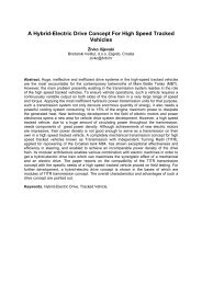
The track-terrain model is able to calculate the track forces<br />
and moment under the normal pressure distribution<br />
pðx t ; y t Þ and the track motions inputs, as illustrated in<br />
Fig. 1. The track motions are described as longitudinal<br />
velocity component u t , lateral velocity component v t , and<br />
yaw angle velocity x t <strong>of</strong> the track coordinate system in<br />
track coordinate system, and the sprocket rotational speed<br />
x s , as shown in Fig. 2. The track coordinate system is<br />
defined moving with the vehicle, and its origin is at the center<br />
<strong>of</strong> track-terrain interface, as shown in Fig. 2. The forces<br />
and moment are longitudinal force component F x , lateral<br />
force component F y and turn resistance moment M r acting<br />
on the track. The track-terrain model is derived from the<br />
track-terrain interaction model and contains the track<br />
parameters and terrain parameters.<br />
Various track-terrain interaction models have been<br />
described in the introduction. The model selected for a<br />
given application may consider corresponding factors. This<br />
study aims at <strong>steering</strong> characteristics <strong>of</strong> high-speed tracked<br />
vehicle. Therefore, the lateral shear stress distribution<br />
along the longitudinal direction on the track terrain interface<br />
is <strong>of</strong> prime importance. In classic terramechanics, the<br />
theoretical relationship was confirmed through experiment.<br />
For typical terrain, the shear stress initially increases<br />
rapidly with increase <strong>of</strong> shear displacement, and then<br />
approaches a constant value with a further increase in<br />
shear displacement (Wong, 2010). This type <strong>of</strong> shear<br />
stress-shear displacement relationship may be described<br />
by an exponential function <strong>of</strong> the following form<br />
<br />
<br />
s ¼ s max 1 e j K ¼ ðc þ r tan / Þ 1 e j K<br />
ð1Þ<br />
where s is the shear stress, J is the shear displacement, K is<br />
the shear deformation modulus, s max is the maximum shear<br />
stress, r is the normal stress, c is the terrain cohesion, and /<br />
is the angle <strong>of</strong> internal shearing resistance <strong>of</strong> the terrain.<br />
Therefore, the shear stress at arbitrary point on the trackground<br />
interface is related to the shear displacement at that<br />
point. In order to avoid complex curvilinear integral and<br />
simplify calculate process, the curve trajectory <strong>of</strong> track pad<br />
moving on the ground can be approximated by the straight<br />
line. And the direction <strong>of</strong> the shear stress at a point on<br />
track–ground interface is assumed to opposite to the direction<br />
<strong>of</strong> the relative sliding velocity <strong>of</strong> the track with respect<br />
to the ground at that point (Wong and Chiang, 2001;<br />
Muro and O’Brien, 2006). Then the shear displacement<br />
can be obtained by integrating the relative shear velocity<br />
between the track and the ground. Relative shear velocity<br />
components <strong>of</strong> arbitrary point (x t , y t ) on the track-ground<br />
interface in the x t and y t direction can be expressed by<br />
Fig. 1. Track-terrain model schematic diagram.
28 S. Tang et al. / <strong>Journal</strong> <strong>of</strong> <strong>Terr</strong>amechanics 73 (<strong>2017</strong>) 25–35<br />
Fig. 2. Single track motions on terrain and forces and moment applied.<br />
V x ¼ u t y t x t rx s ð2Þ<br />
V y ¼ v t þ x t x t<br />
ð3Þ<br />
where r is the radius <strong>of</strong> the sprocket, u t is the longitudinal<br />
velocity <strong>of</strong> track coordinate system, v t is the lateral velocity<br />
<strong>of</strong> track coordinate system, and x t is the yaw velocity <strong>of</strong><br />
track coordinate system.<br />
Then the duration <strong>of</strong> track element from contacting the<br />
ground initially to point (x t ,y t ) can be given by<br />
Z t<br />
Z L<br />
2<br />
dx t<br />
t ¼ dt ¼ ¼ L=2 x t<br />
ð4Þ<br />
0<br />
x t<br />
rx s rx s<br />
where L is the track-terrain contact length.<br />
Consequently, The shear displacement component along<br />
the x t direction at point (x t , y t ) is derived by integrating the<br />
relative shear velocity component along the x t direction.<br />
Z t<br />
Z L<br />
2<br />
J x ¼ V x dt ¼ ðu t y t x t rx s Þ dx t<br />
0<br />
x t<br />
rx s<br />
<br />
L<br />
x<br />
2 t<br />
¼ ðu t y t x t rx s Þ<br />
ð5Þ<br />
rx s<br />
And the shear displacement component along the y t<br />
direction at point (x t ,y t ) is derived by integrating the relative<br />
shear velocity component along the y t direction.<br />
Z t<br />
Z L<br />
2<br />
J y ¼ V y dt ¼ ðv t þ x t x t Þ dx t<br />
0<br />
x t<br />
rx s<br />
h i<br />
L<br />
x<br />
2 t vt þ 1 L 2<br />
2 2<br />
x t2<br />
x t<br />
¼<br />
ð6Þ<br />
rx s<br />
The comprehensive shear displacement at point (x t , y t )<br />
can be expressed by<br />
qffiffiffiffiffiffiffiffiffiffiffiffiffiffiffi<br />
j ¼ J 2 x þ J 2 y<br />
ð7Þ<br />
As mentioned above, the relationship between the shear<br />
stress and the shear displacement satisfies the Eq. (1).<br />
Therefore, the shear force developed on a track element<br />
dA in contact with the ground can be expressed by<br />
<br />
dF ¼ sdA ¼½c þ px ð t ; y t Þtan /Š 1 e j K<br />
<br />
dA<br />
ð8Þ<br />
As shown in Fig. 2, the direction <strong>of</strong> shear force element<br />
is opposite to the direction <strong>of</strong> relative velocity at the point<br />
(x t , y t ) on the track-ground interface. The component <strong>of</strong> the<br />
shear force element along the x t direction constitutes tractive<br />
or braking force F x . The component <strong>of</strong> the shear force<br />
element along the y t direction constitutes the lateral force<br />
F y . The moment <strong>of</strong> the shear force element about the origin<br />
<strong>of</strong> the track coordinate system constitutes the moment <strong>of</strong><br />
turning resistance. The angle between the comprehensive<br />
relative velocity and the longitudinal direction <strong>of</strong> the track<br />
coordinate system can be defined by the following<br />
<br />
h ¼ arctan<br />
V y<br />
V x<br />
<br />
The longitudinal force F x and the lateral force F y acting<br />
on the track can be expressed by<br />
Z Z b<br />
2<br />
Z L<br />
2<br />
<br />
F x ¼ dF x ¼ ½c þ px ð t ; y t Þtan / Š 1 e j K cos hdx t dy t<br />
b L<br />
2 2<br />
Z<br />
F y ¼<br />
ð9Þ<br />
ð10Þ<br />
Z b<br />
2<br />
Z L<br />
2<br />
<br />
dF y ¼ ½c þ px ð t ; y t Þtan / Š 1 e j K sin hdx t dy t<br />
b L<br />
2 2<br />
ð11Þ<br />
where b is the width <strong>of</strong> the track.<br />
The moment <strong>of</strong> the turning resistance M r about the center<br />
<strong>of</strong> track-ground interface acting on the track can be<br />
expressed by<br />
Z<br />
M r ¼ x t dF y<br />
¼<br />
Z b<br />
2<br />
Z L<br />
2<br />
<br />
½c þ px ð t ; y t Þtan /Šx t 1 e j K sin hdx t dy t<br />
b L<br />
2 2<br />
ð12Þ<br />
The proposed track terrain model doesn’t contain any<br />
configuration information <strong>of</strong> tracked vehicle. It makes it<br />
possible to support the modular lateral dynamic simulation<br />
for high-speed tracked vehicles with various configurations.<br />
To improve the accuracy in aggressive maneuvering conditions,<br />
the combination <strong>of</strong> the longitudinal shear and the
S. Tang et al. / <strong>Journal</strong> <strong>of</strong> <strong>Terr</strong>amechanics 73 (<strong>2017</strong>) 25–35 29<br />
lateral shear is used to calculate the shear stress. In the<br />
model proposed by Wong and Chiang (2001), the yaw<br />
velocity x t is retained in the denominator. So this model<br />
(Wong and Chiang, 2001) is not applicable to the longitudinal<br />
driving (x t ¼ 0). But this problem is solved in this<br />
study.<br />
3. Vehicle dynamic model<br />
The object <strong>of</strong> this study is the <strong>skid</strong>-<strong>steering</strong> tracked vehicle,<br />
which employs the double-differential <strong>steering</strong> mechanism<br />
with two input shafts. By using the input shafts,<br />
driving and <strong>steering</strong> can be controlled, independently. So<br />
the forward velocity may be kept constant during <strong>steady</strong><strong>state</strong><br />
turning operation. To improve the modeling efficiency,<br />
we adopt the popular modular method. The topology<br />
<strong>of</strong> the vehicle system model is illustrated in Fig. 3. The<br />
input <strong>of</strong> overall simulation model is from the driver, who<br />
controls the powertrain. In this paper, the dynamics <strong>of</strong><br />
powertrain is neglected. The powertrain module just contains<br />
the simplified kinematics relationship between the<br />
command and the sprocket speeds. The track terrain model<br />
is proposed in Section 2, which calculates the track forces<br />
and moment under the normal pressure distribution and<br />
the track motion inputs. The vehicle body module calculates<br />
the motions <strong>of</strong> vehicle under the track forces and<br />
moment inputs. And the normal pressure distribution module<br />
calculates the dynamic normal pressure distribution<br />
under the accelerations inputs.<br />
In deriving the equations <strong>of</strong> vehicle dynamic model, the<br />
basic assumptions for this model are as follows:<br />
(1) The xyz coordinate system is fixed on the vehicle’s<br />
center <strong>of</strong> gravity and moves along with the vehicle.<br />
The x tL y tL z tL is the track coordinate system <strong>of</strong> left<br />
track, and the x tR y tR z tR is the track coordinate system<br />
<strong>of</strong> right track.<br />
(2) The vehicle is symmetric with respect to xz-plane.<br />
(3) The vehicle drives on the horizontal ground. Track<br />
sinkage and the bulldozing effect in the lateral direction<br />
are neglected.<br />
(4) The rolling resistance and aerodynamic resistance are<br />
neglected. Because that turn resistance is usually much<br />
larger than rolling resistance (Ehlert et al., 1992).<br />
3.1. Kinematics <strong>of</strong> vehicle<br />
Fig. 4 depicts the model <strong>of</strong> the tracked vehicle planar<br />
motions with three degrees <strong>of</strong> freedom on horizontally flat<br />
terrain. The three degrees <strong>of</strong> freedom are longitudinal<br />
velocity u, lateral velocity v and yaw velocity x. Then the<br />
left and right tracks motion can be expressed:<br />
u tL ¼ u x B 2<br />
v tL ¼ v þ xl x<br />
u tR ¼ u þ x B 2<br />
v tR ¼ v þ xl x<br />
x tL ¼ x tR ¼ x<br />
ð13Þ<br />
where l x is the longitudinal <strong>of</strong>fset <strong>of</strong> the vehicle center <strong>of</strong><br />
gravity to the geometrical center <strong>of</strong> the vehicle.<br />
The <strong>steering</strong> input is the theoretical velocity difference<br />
between the relative velocity <strong>of</strong> right track and the relative<br />
velocity <strong>of</strong> left track with respect to vehicle body.<br />
Du ¼ x sR r x sL r ð14Þ<br />
where x sR r is the relative velocity <strong>of</strong> right track with respect<br />
to vehicle body, x sL r is the relative velocity <strong>of</strong> left track<br />
with respect to vehicle body, r is the radius <strong>of</strong> sprocket,<br />
x sL is the rotating angular speed <strong>of</strong> left sprocket, and x sR<br />
is the rotating angular speed <strong>of</strong> right sprocket.<br />
Fig. 3. Simulation model architecture.
30 S. Tang et al. / <strong>Journal</strong> <strong>of</strong> <strong>Terr</strong>amechanics 73 (<strong>2017</strong>) 25–35<br />
W R ¼ W 2 þ h B m v x<br />
ð18Þ<br />
Fig. 4. Kinematics <strong>of</strong> the tracked vehicle planar motions.<br />
Because the rolling resistance and aerodynamic resistance<br />
are neglected, the driving input theoretical velocity<br />
u r can be considered equivalent to the actual longitudinal<br />
velocity u.<br />
u u r ¼ x sRr þ x sL r<br />
ð15Þ<br />
2<br />
For given driving input and <strong>steering</strong> input, the rotating<br />
angular speeds <strong>of</strong> sprockets can be obtained<br />
2u þ Du<br />
x sR ¼ ð16Þ<br />
2r<br />
x sL ¼ 2u Du<br />
ð17Þ<br />
2r<br />
3.2. Normal pressure distribution<br />
The flat terrain is assumed, so the static normal loads on<br />
two tracks are equivalent. Due to the lateral centrifugal<br />
force, the normal load on right track W R and the normal<br />
load on left track W L can be expressed by<br />
W L ¼ W h<br />
2 B m v x<br />
ð19Þ<br />
where W is the gravity <strong>of</strong> the vehicle, m is the mass <strong>of</strong> the<br />
vehicle, h is the height <strong>of</strong> center <strong>of</strong> gravity, and m v x is<br />
the lateral centrifugal force ma y , as shown in Fig.5a.<br />
The distribution <strong>of</strong> normal pressure on the track-ground<br />
interface is a significant factor for maneuverability <strong>of</strong><br />
tracked vehicle. In this paper, the tread <strong>of</strong> vehicle B is far<br />
greater than track width. So the difference <strong>of</strong> normal pressure<br />
along the y t direction can be neglected (Wong and<br />
Chiang, 2001; Muro and O’Brien, 2006). For analyzing different<br />
situations, the normal distribution density functions<br />
are defined as sðx tL Þ and sðx tR Þ, respectively. When the normal<br />
pressure distribution are uniform, sðx tR Þ = sðx tL Þ¼1.<br />
The normal pressure distribution on right track p R ðx tR Þ<br />
and the normal pressure distribution on left track p L ðx tL Þ<br />
can be expressed by [see Fig.5b]<br />
p R ðx tR Þ ¼ W R<br />
bL sx ð tRÞ ð20Þ<br />
p L ðx tL Þ ¼ W L<br />
bL sx ð tLÞ ð21Þ<br />
3.3. 3DOF vehicle dynamic model<br />
Fig.4 shows the forces and the moments acting on the<br />
tracked vehicle during a <strong>steady</strong> <strong>state</strong> turning operation.<br />
The dynamic equations can be obtained from dynamic balance<br />
among all forces, moments, inertial forces and inertial<br />
moments.<br />
B<br />
F yR þ F yL lx F xL<br />
2 þ F B<br />
xR<br />
2 þ M rL þ M rR ¼ I z _x ð22Þ<br />
F yR þ F yL ¼ m ð_v<br />
uxÞ ð23Þ<br />
F xR þ F xL ¼ m ð_u þ vxÞ ð24Þ<br />
where _x is the angular acceleration about the z axis, _v is the<br />
lateral acceleration along the y direction,_u is the longitudi-<br />
Fig. 5. Normal pressure distribution on the track-ground interface.
nal acceleration along the x direction, I z is the rotational<br />
inertia <strong>of</strong> the vehicle about the z axis.<br />
In this paper, the vehicle is in <strong>steady</strong> turn, the longitudinal<br />
velocity u, the yaw rate x, and lateral velocity v are constant.<br />
The acceleration _x, _u, and _v equal to zero.<br />
4. Model verification<br />
S. Tang et al. / <strong>Journal</strong> <strong>of</strong> <strong>Terr</strong>amechanics 73 (<strong>2017</strong>) 25–35 31<br />
In this section, the proposed model has been verified by<br />
comparison with available data reported by Rui et al.<br />
(2015). The experimental platform is a modified tracked<br />
armored vehicle. The vehicle parameters are shown in table<br />
1. The experiment is in progress on sandy terrain, whose<br />
terrain parameters are shown in table 2. The speed and torque<br />
sensors are attached on both output shafts <strong>of</strong> transmission.<br />
The speed and torque <strong>of</strong> sprockets can be translated<br />
from the measurement values <strong>of</strong> the speed and torque sensors.<br />
The differential GPS system with base station is also<br />
equipped. This system can provide real-time accurate data<br />
<strong>of</strong> position, velocity, and orientation. The actual turning<br />
Table 1<br />
Vehicle parameters.<br />
Item Units Value<br />
m kg 20,380<br />
L m 4.51<br />
B m 2.84<br />
b m 0.38<br />
h m 1.11<br />
r m 0.26<br />
l x m 0.358<br />
Table 2<br />
<strong>Terr</strong>ain parameters.<br />
Item Units Value<br />
K m 0.12<br />
c kPa 0<br />
/ ° 39<br />
Fig. 7. Longitudinal slips <strong>of</strong> both tracks with the actual turning radius.<br />
radius, longitudinal velocity, lateral velocity, and yaw rate<br />
<strong>of</strong> the vehicle are obtained based on GPS data.<br />
Fig. 6 shows the variations <strong>of</strong> the longitudinal forces<br />
acting on both tracks with the actual turning radius. The<br />
results show that theoretical longitudinal force curves are<br />
in agreement with the corresponding experimental data<br />
with relatively good accuracy. And it also shows that the<br />
longitudinal forces acting on the both tracks decrease with<br />
increasing actual turning radius.<br />
Fig. 7 shows the variations <strong>of</strong> longitudinal slips d for<br />
both tracks with the actual turning radius. The results show<br />
that theoretical longitudinal slips curves are in agreement<br />
with the corresponding experimental data with relatively<br />
good accuracy. It also shows that the longitudinal slips acting<br />
on both tracks decrease with increasing actual turning<br />
radius.<br />
Based on above comparisons, the proposed vehicle<br />
dynamic model demonstrates adequate accuracy in predicting<br />
<strong>steering</strong> <strong>performance</strong>.<br />
5. Simulation results and discussions<br />
This tracked vehicle is modeled in Section 2 and 3. And<br />
the proposed vehicle dynamic model is verified by comparison<br />
with available data in Section 4. In this section, the<br />
<strong>steady</strong>-<strong>state</strong> characteristics are investigated under different<br />
factors, which include types <strong>of</strong> <strong>steering</strong> input, distribution<br />
<strong>of</strong> normal pressure, the position <strong>of</strong> gravity center, and<br />
the ratio <strong>of</strong> track-ground contact length and tread L=B.<br />
The object <strong>of</strong> this paper is high-speed tracked vehicle,<br />
whose top speed is more than 70 km/h so far. So the speed<br />
in simulation is in the range from 40 km/h to 70 km/h. The<br />
simulation parameters are reported in Tables 1 and 2.<br />
5.1. Types <strong>of</strong> <strong>steering</strong> input<br />
Fig. 6. Longitudinal forces acting on both tracks with the actual turning<br />
radius.<br />
The typical types <strong>of</strong> steer input are the velocity difference<br />
Du and the velocity difference rate Du=u. In the traditional<br />
<strong>steering</strong> theory, the tracked vehicle with doubledifferential<br />
<strong>steering</strong> mechanism satisfied the kinematics<br />
Eq. (25) (neglecting track slips). For a given Du, the turning<br />
radius R increases with increasing forward velocity u. The
32 S. Tang et al. / <strong>Journal</strong> <strong>of</strong> <strong>Terr</strong>amechanics 73 (<strong>2017</strong>) 25–35<br />
Du is selected as the <strong>steering</strong> input, which makes the vehicle<br />
has the inherent under-steer characteristic. Zhang et al.<br />
(2014) derived that the velocity difference rate Du=u is<br />
equivalent to the <strong>steering</strong> angle <strong>of</strong> front wheels for the<br />
Ackermann-steer vehicle by establishing an analytical<br />
dynamic model <strong>of</strong> <strong>skid</strong> <strong>steering</strong> for wheeled vehicle. And<br />
selecting the Du=u as the <strong>steering</strong> input, the vehicle may<br />
has under-steer, neutral-steer or over-steer characteristics.<br />
R ¼ B u<br />
ð25Þ<br />
Du<br />
Fig. 8 shows the comparison <strong>of</strong> turning radius at different<br />
speeds using two types <strong>of</strong> <strong>steering</strong> input. The center <strong>of</strong><br />
gravity is assumed to locate at the geometrical center <strong>of</strong> the<br />
vehicle. The distribution <strong>of</strong> normal pressure is assumed as<br />
uniform. The result shows this vehicle has under-steer characteristic<br />
using both types <strong>of</strong> <strong>steering</strong> input. The vehicle<br />
adopted Du as the <strong>steering</strong> input has more under-steer characteristic<br />
tendency. It means that large compensatory angle<br />
<strong>of</strong> <strong>steering</strong> wheel is needed during acceleration at constant<br />
turning radius. The velocity has significant influent on the<br />
turning radius. Therefore, this type <strong>of</strong> <strong>steering</strong> input<br />
Du=u is more suitable for the high-speed tracked vehicle.<br />
This type <strong>of</strong> <strong>steering</strong> input Du=u is adopted in the following<br />
analysis.<br />
5.2. Distribution <strong>of</strong> normal pressure<br />
The distribution <strong>of</strong> normal pressure on the track-ground<br />
interface is a significant factor for maneuverability <strong>of</strong><br />
tracked vehicle. In the traditional <strong>steering</strong> theory, the distribution<br />
<strong>of</strong> normal pressure is idealized as triangle, trapezoid,<br />
sine etc. The turning resistance moment with these<br />
types <strong>of</strong> normal pressure distribution was analyzed. In general,<br />
distribution <strong>of</strong> normal pressure tending to localize in<br />
the middle <strong>of</strong> track results in lower turning resistance<br />
moment. On the contrary, distribution <strong>of</strong> normal pressure<br />
tending to localize in the ends <strong>of</strong> track results in larger<br />
turning resistance moment. These results indicate that the<br />
tracked vehicle is harder to turn on the concave ground<br />
than the convex ground. In this paper, the influence <strong>of</strong> normal<br />
pressure distribution on the <strong>steady</strong> <strong>state</strong> characteristics<br />
<strong>of</strong> <strong>skid</strong>- <strong>steering</strong> is studied.<br />
Firstly, normal pressure distribution is idealized as dual<br />
trapezoid, as shown in Fig.9. The density function <strong>of</strong> the<br />
normal pressure distribution sðx t Þ can be expressed by<br />
Eq. (26). The slope <strong>of</strong> the diagonal line k is defined as the<br />
concentration factor, which reflects the degree <strong>of</strong> concentration.<br />
When k ¼ 0, the normal pressure distribution is<br />
uniform. When k > 0, the normal pressure distribution<br />
tends to localize in the ends <strong>of</strong> track. When k < 0, the normal<br />
pressure distribution tends to localize in the middle <strong>of</strong><br />
track.<br />
(<br />
kL<br />
kLx t þ 1 2<br />
ðx 4 t 0Þ<br />
sðx t Þ¼<br />
ð26Þ<br />
kL<br />
kLx t þ 1 2<br />
ðx 4 t < 0Þ<br />
The ratio <strong>of</strong> the yaw rate and the <strong>steering</strong> input is<br />
defined as the yaw velocity gain. Fig. 10 shows the yaw<br />
velocity gain versus forward speed for tracked vehicles with<br />
different dual trapezoid normal pressure distribution while<br />
the <strong>steering</strong> input is kept constant Du=u ¼ 0:05. For the<br />
cases <strong>of</strong> the dual trapezoid normal pressure distribution<br />
k ¼ 0:2; 0; 0:2, the yaw velocity gain increases with the<br />
increment <strong>of</strong> the forward speed to the maximum yaw velocity<br />
gain. The result shows that the vehicle has under-steer<br />
characteristic. And the yaw velocity gain increases with<br />
the increment <strong>of</strong> the degree <strong>of</strong> the normal pressure distribution<br />
tending to localize in the middle <strong>of</strong> track. When<br />
k ¼ 0:4, the yaw velocity gain increases with the forward<br />
speed at an increasing rate. The vehicle with this dual<br />
trapezoid normal pressure distribution has over-steer<br />
characteristic.<br />
The <strong>steady</strong> <strong>state</strong> characteristics can be evaluated using<br />
the under-steer parameter for Ackermann-steer vehicle.<br />
The under-steer parameter is defined as the difference<br />
between the reference steer angle gradient and the Ackermann<br />
steer angle gradient for Ackermann <strong>steering</strong> vehicle<br />
(Riede et al., 1984). Riede tested 400 production vehicles.<br />
The under-steer parameter <strong>of</strong> the vehicles ranged from<br />
0.7 deg/g to 8.2 deg/g with lateral acceleration level at<br />
0.15 g. The average under-steer parameter was 3.8 deg/g.<br />
For tracked vehicle, the under-steer parameter j can also<br />
be defined as the ratio <strong>of</strong> the difference between the reference<br />
<strong>steering</strong> input and the <strong>steering</strong> input required by the<br />
kinematics with no track slips and the corresponding lat-<br />
Fig. 8. Comparison <strong>of</strong> turning radius at different speeds using two types <strong>of</strong><br />
<strong>steering</strong> input.<br />
Fig. 9. Idealized dual trapezoid normal pressure distribution.
S. Tang et al. / <strong>Journal</strong> <strong>of</strong> <strong>Terr</strong>amechanics 73 (<strong>2017</strong>) 25–35 33<br />
Fig. 10. Yaw velocity gain versus speed with different dual trapezoid<br />
normal pressure distributions.<br />
eral acceleration, which is shown as Eq. (27). For the cases<br />
<strong>of</strong> the dual trapezoid normal pressure distribution<br />
k ¼ 0:4; 0:2; 0; 0:2, the under-steer parameter j is<br />
4.1, 5.57, 9.23, 11.38, respectively. So the vehicle with<br />
slightly tending to localize in the middle <strong>of</strong> track has better<br />
handling characteristics.<br />
j ¼<br />
Du<br />
u<br />
u 2<br />
R<br />
B<br />
R<br />
ð27Þ<br />
The normal pressure distribution can also be idealized as<br />
trapezoid distribution, as shown in Fig. 11. It represents<br />
the effect <strong>of</strong> longitudinal component <strong>of</strong> inertial force<br />
applied on the vehicle, when the vehicle accelerates/brakes<br />
or drives on slope. The density function <strong>of</strong> the normal pressure<br />
distribution sðx t Þ can be expressed by Eq. (28). The<br />
slope <strong>of</strong> the diagonal line k 2 is defined as the front/rear distribution<br />
factor, which reflects the degree <strong>of</strong> forward or<br />
rearward weight transfer. When k 2 > 0, the normal pressure<br />
distribution tends to localize in the front <strong>of</strong> track.<br />
When k 2 ¼ 0, the normal pressure distribution is uniform.<br />
When k 2 < 0, the normal pressure distribution tends to<br />
localize in the rear <strong>of</strong> track.<br />
sðx t Þ¼ 2k 2 x t<br />
þ 1<br />
ð28Þ<br />
L<br />
Fig. 12 shows the yaw velocity gain versus forward<br />
speed for tracked vehicles with different trapezoid normal<br />
pressure distribution while the <strong>steering</strong> input is kept constant<br />
Du=u ¼ 0:05. For the cases k 2 ¼ 0:6; 0, the normal<br />
pressure distributions are uniform or tends to localize in<br />
the rear <strong>of</strong> track, the yaw velocity gain increases with the<br />
increment <strong>of</strong> the forward speed to the maximum yaw velocity<br />
gain. And the vehicle has under-steer characteristic. For<br />
the case k 2 ¼ 0:6, the yaw velocity gain increases with the<br />
forward speed at an approximately constant rate. The vehicle<br />
with this trapezoid normal pressure distribution has<br />
slightly under-steer characteristic. When k 2 ¼ 0:8; 1, the<br />
normal pressure distribution tends to localize in the front<br />
<strong>of</strong> track, the yaw velocity gain increases with the forward<br />
speed at an increasing rate and reaches infinite value if<br />
the forward speed exceeds the critical speed. The vehicle<br />
with this trapezoid normal pressure distribution has oversteer<br />
characteristic.<br />
5.3. Position <strong>of</strong> gravity center<br />
In traditional <strong>steering</strong> theory, the projection <strong>of</strong> the center<br />
<strong>of</strong> gravity on the ground should coincide with the projection<br />
<strong>of</strong> the geometrical center <strong>of</strong> the vehicle on the<br />
ground. For <strong>skid</strong>-<strong>steering</strong> wheeled vehicle, Zhang et al.<br />
(2014) derives the under-steer parameter from a 2DOF<br />
model, which indicates that the <strong>steady</strong>-<strong>state</strong> characteristics<br />
is influenced by the position <strong>of</strong> gravity center and the<br />
cornering stiffness <strong>of</strong> front tire and the cornering stiffness<br />
<strong>of</strong> rear tire. As mentioned above, when the projection <strong>of</strong><br />
the center <strong>of</strong> gravity on the ground coincides with the projection<br />
<strong>of</strong> the geometrical center <strong>of</strong> the vehicle on the<br />
ground, the vehicle has under-steer characteristic. Fig. 13<br />
shows the yaw velocity gain versus speed with different<br />
positions <strong>of</strong> gravity center. The yaw velocity gain increases<br />
with the increasing rearward displacement <strong>of</strong> position <strong>of</strong><br />
gravity center. For the cases l x ¼ 0; 0:2, the yaw velocity<br />
gain increases with the increment <strong>of</strong> the forward speed to<br />
the maximum yaw velocity gain. The vehicles have understeer<br />
characteristics, whose under-steer parameter j are<br />
9.23 and 7.5, respectively. So the vehicle with slightly rearward<br />
position <strong>of</strong> gravity center has better handling characteristics.<br />
When l x ¼ 0:4, the yaw velocity gain increases<br />
with the forward speed at an approximately constant rate.<br />
This vehicle has neutral-steer characteristics. For the cases<br />
Fig. 11. Idealized trapezoid normal pressure distribution.<br />
Fig. 12. Yaw velocity gain versus speed with different trapezoid normal<br />
pressure distributions.
34 S. Tang et al. / <strong>Journal</strong> <strong>of</strong> <strong>Terr</strong>amechanics 73 (<strong>2017</strong>) 25–35<br />
Fig. 13. Yaw velocity gain versus speed with different positions <strong>of</strong> gravity<br />
center.<br />
Fig. 14. Yaw velocity gain versus speed with different ratios L/B.<br />
l x ¼ 0:6; 0:8, the yaw velocity gain increases with the forward<br />
speed at an increasing rate and reaches infinite value<br />
if the forward speed exceeds the critical speed. The vehicle<br />
has over-steer characteristic.<br />
5.4. The ratio <strong>of</strong> L and B<br />
In traditional <strong>steering</strong> theory, the ratio <strong>of</strong> track-ground<br />
contact length and tread L=B has significant effect on the<br />
steerability, which is recommended to range from 1.2 to<br />
1.8. In this paper, the effect <strong>of</strong> ratio L=B on the <strong>steady</strong> <strong>state</strong><br />
characteristics is analyzed. Fig. 14 shows the result <strong>of</strong> yaw<br />
velocity gain versus speed with different ratios L=B. For the<br />
cases L=B ¼ 1; 1:2; 1:59; 1:8; 2, the yaw velocity gain<br />
increases with the forward speed at an decreasing rate<br />
and reaches its maximum yaw velocity gain. This result<br />
indicates the vehicle has under-steer characteristics, and<br />
the ratios L=B within the recommended range are unlikely<br />
to change the <strong>steady</strong> <strong>state</strong> characteristics essentially. Smaller<br />
ratio L=B can raise the yaw velocity gain response.<br />
6. Conclusions<br />
This study proposed a high-fidelity, general, and modular<br />
method for lateral dynamic simulation <strong>of</strong> high-speed<br />
tracked vehicle on deformable terrain. In this method a<br />
novel nonlinear track terrain model is derived. This track<br />
terrain model meets the need <strong>of</strong> longitudinal and <strong>steering</strong><br />
motions, comprehensive track slips, and modular modeling<br />
for tracked vehicles with various configurations. The lateral<br />
dynamic model is in reasonably agreement with the<br />
available experimental data. Based on the comparisons,<br />
the proposed vehicle dynamic model demonstrates adequate<br />
accuracy in predicting <strong>steering</strong> <strong>performance</strong>. Using<br />
this vehicle dynamic model, the main factors (normal pressure<br />
distribution, position <strong>of</strong> gravity center, ratio L/B)<br />
effecting the <strong>steady</strong> <strong>state</strong> characteristics <strong>of</strong> <strong>skid</strong> <strong>steering</strong><br />
are analyzed. In order to quantitatively evaluate the <strong>steady</strong><br />
<strong>state</strong> characteristics <strong>of</strong> <strong>skid</strong> <strong>steering</strong> for tracked vehicle, the<br />
under-steer parameter is introduced in this paper referring<br />
to the Ackermann-<strong>steering</strong> wheeled vehicle. Several conclusions<br />
can be drawn on the basis <strong>of</strong> this research.<br />
(1) The <strong>steering</strong> input Du=u is more suitable for the highspeed<br />
tracked vehicle. Because that the tracked vehicle<br />
with this type has better handling characteristic<br />
when turning at high speeds.<br />
(2) The vehicle with dual trapezoid normal pressure distribution<br />
tending to localize in the ends <strong>of</strong> track or<br />
slightly tending to localize in the middle <strong>of</strong> track has<br />
under-steer characteristic. The vehicle with dual trapezoid<br />
normal pressure distribution tending to localize in<br />
the middle <strong>of</strong> track has over-steer characteristic. The<br />
vehicle with dual trapezoid normal pressure distribution<br />
slightly tending to localize in the middle <strong>of</strong> track<br />
k ¼ 0:2 has better handling characteristics.<br />
(3) The vehicle with trapezoid normal pressure distribution<br />
tending to localize in the rear <strong>of</strong> track has<br />
under-steer characteristic tendency. The vehicle with<br />
trapezoid normal pressure distribution tending to<br />
localize in the front <strong>of</strong> track has over-steer characteristic<br />
tendency.<br />
(4) When the projection <strong>of</strong> the center <strong>of</strong> gravity on the<br />
ground coincides with the projection <strong>of</strong> the geometrical<br />
center <strong>of</strong> the vehicle on the ground, the vehicle has<br />
under-steer characteristic. The vehicle with rearward<br />
position <strong>of</strong> gravity center has over-steer characteristic<br />
tendency, and the critical speed is obtained.<br />
(5) The vehicle with the ratio L/B in the recommend<br />
range always has under-steer characteristic. And the<br />
vehicle with smaller ratio L/B has bigger yaw velocity<br />
rate response.<br />
In this study, it is assumed that the tracked vehicle conduct<br />
<strong>steady</strong>-<strong>state</strong> turning maneuvers to analyze the <strong>steady</strong><br />
<strong>state</strong> characteristics. However, the transient characteristics<br />
are also significant for the high speed tracked vehicles. This<br />
model is worth to be modified for the transient <strong>performance</strong><br />
in the future work.<br />
Acknowledgement<br />
This work was supported by the Technology Research<br />
and Development Program <strong>of</strong> the Scientific Research Base<br />
<strong>of</strong> China (Grant number VTDP-3301).
S. Tang et al. / <strong>Journal</strong> <strong>of</strong> <strong>Terr</strong>amechanics 73 (<strong>2017</strong>) 25–35 35<br />
References<br />
Crosheck, J.E., 1975. Skid <strong>steering</strong> <strong>of</strong> crawlers. SAE Technical Paper<br />
750552.<br />
Ehlert, W., Hug, B., Schmid, I.C., 1992. Field measurements and<br />
analytical models as a basis <strong>of</strong> test stand simulation <strong>of</strong> the turning<br />
resistance <strong>of</strong> tracked vehicles. J. <strong>Terr</strong>ramech. 29 (1), 57–69.<br />
Genya, I. et al, 2007. <strong>Terr</strong>amechanics-based model for <strong>steering</strong> maneuver<br />
<strong>of</strong> planetary exploration rovers on loose soil. J. Field Robot. 24 (3),<br />
233–250.<br />
Gillepie, T.D., 1992. Fundamentals <strong>of</strong> Vehicle Dynamics. Society <strong>of</strong><br />
Automotive Engineers. Inc., Warrendale, PA.<br />
Hock, J., 1961. Vergleichende Untersuchungen über die Leistungsverluste<br />
und Wirkungsgrade in Lenkgetrieben. für Kettenfahrzeuge. ATZ, Bd.<br />
63, S. 110–115, 145–151,245–252, 410–413.<br />
Janarthanan, B., Padmanabhan, C., Sujatha, C., 2011. Lateral dynamics<br />
<strong>of</strong> single unit <strong>skid</strong>-steered tracked vehicle. Int. J. Automotive Technol.<br />
12 (6), 865–875.<br />
Kar, M.K., 1987. Prediction <strong>of</strong> track forces in <strong>skid</strong>-<strong>steering</strong> <strong>of</strong> military<br />
tracked vehicles. J. <strong>Terr</strong>ramech. 24 (1), 75–84.<br />
Kitano, M., Kuma, M., 1977. An analysis <strong>of</strong> horizontal plane motion <strong>of</strong><br />
tracked vehicles. J. <strong>Terr</strong>ramech. 14 (4), 211–225.<br />
Merritt, H.E., 1939. Some considerations influencing the design <strong>of</strong> highspeed<br />
track-vehicles. Proc. Instit. Automobile Eng. 33 (2), 398–430.<br />
Micklethwait, E.W.E., 1944. Soil mechanics in Relation to Fighting<br />
Vehicles. Military College <strong>of</strong> Science, Chetsey.<br />
Muro, T., O’Brien, J., 2006. <strong>Terr</strong>amechanics: Land Locomotion Mechanics.<br />
CRC Press.<br />
Pacejka, H.B., 2006. Tyre and Vehicle Dynamics, second ed. Butterworth-<br />
Heinemann, UK.<br />
Purdy, D.J., Wormell, P.J.H., 2003. Handling <strong>of</strong> high-speed tracked<br />
vehicles. J. Battlefield Technol. 6 (2), 17–22.<br />
Riede, P.M., Leffert, R.L., Cobb, W.A., 1984. Typical Vehicle Parameters<br />
for Dynamics Studies Revised for the 1980’s. SAE Technical Paper<br />
840561.<br />
Rui, Qiang, Wang, Hongyan, Wang, Qinlong, Guo, Jing, Zou, Tiangang,<br />
Wan, Li, 2015. Analysis and experiment <strong>of</strong> tracked vehicle <strong>steering</strong><br />
torque based on shear stress model. Acta Armamentatii 36 (6), 968–<br />
977 (in Chinese).<br />
Hohl, G.H., 2007. Military terrain vehicles. J. <strong>Terr</strong>ramech. 44 (1), 23–34.<br />
Urmson, C., Anhalt, J., Bagnell, D., Baker, C., Bittner, R., Clark, M.N.,<br />
2008. Autonomous driving in urban environments: Boss and the urban<br />
challenge. J. Field Robot. 25 (8), 425–466.<br />
Vantsevich, V.V., 2015. Road and <strong>of</strong>f-road vehicle system dynamics.<br />
Understanding the future from the past. Vehicle Syst. Dyn. 53 (2),<br />
137–153.<br />
Wong, J.Y., 2008. Theory <strong>of</strong> Ground Vehicles. John Wiley & Sons,<br />
Hoboken, New Jersey.<br />
Wong, J.Y., Chiang, C.F., 2001. A general theory for <strong>skid</strong> <strong>steering</strong> <strong>of</strong><br />
tracked vehicles on firm ground. Proc. Instit. Mech. Eng., Part D: J.<br />
Automobile Eng. 215 (3), 343–355.<br />
Wong, J.Y., 2010. <strong>Terr</strong>amechanics and Off-Road Vehicles. Elsevier,<br />
Oxford.<br />
Wong, J.Y. et al, 2015. Predicting mobility <strong>performance</strong> <strong>of</strong> a small,<br />
lightweight track system using the computer-aided method NTVPM. J.<br />
<strong>Terr</strong>ramech. 61, 23–32.<br />
Liu, Yugang, Liu, Guangjun, 2009. <strong>Modeling</strong> <strong>of</strong> tracked mobile manipulators<br />
with consideration <strong>of</strong> track terrain and vehicle manipulator<br />
interactions. Robot. Autonomous Syst. 57, 1065–1074.<br />
Zhang, Y., Hu, J., Li, X., 2014. Steady-<strong>state</strong> characteristics <strong>of</strong> <strong>skid</strong> <strong>steering</strong><br />
for wheeled vehicles. Proc. Instit. Mech. Eng., Part D: J. Automobile<br />
Eng. 228 (9), 1095–1104.