

Catalog_Compressed_Air_Preparation_EN_v1_4_2_web

Create successful ePaper yourself
Turn your PDF publications into a flip-book with our unique Google optimized e-Paper software.
<strong>Catalog</strong> #1<br />
<strong>Compressed</strong> air preparation, <strong>Compressed</strong> air storage, Moisture management<br />
The refrigerant compressor (1) condenses the gaseous<br />
refrigerant in the condenser (3), where most of the refrigerant<br />
passes into the liquid phase. The liquefied<br />
refrigerant is directed through the filter-dryers (6),<br />
injected via the capillary pipe (4) and evaporated in<br />
the evaporator (2), where it absorbs the heat of the<br />
compressed air.<br />
Due to the heat exchange between the compressed<br />
air and the refrigerant, the refrigerant passes into<br />
the gaseous state. This cycle is continuously repeated.<br />
The cooling circuit is equipped with hot-gas bypass<br />
regulation for providing refrigeration that is adjusted<br />
to the variable compressed air flow.<br />
When demand for compressed air falls, the hot-gas<br />
bypass valve opens and allows the hot air to flow from<br />
the high-pressure side to the low-pressure side. The pressure<br />
in the evaporator is held constant and ensures the pressure<br />
dew point never falls below +3° C in order to prevent<br />
icing of the evaporator.<br />
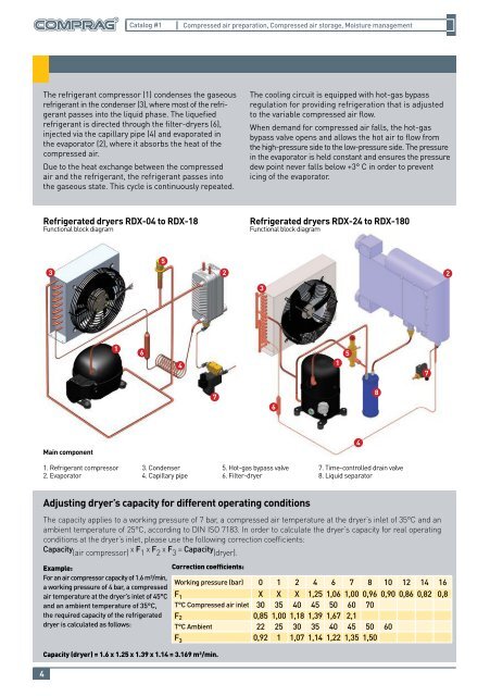
Refrigerated dryers RDX-04 to RDX-18<br />
Functional block diagram<br />
Refrigerated dryers RDX-24 to RDX-180<br />
Functional block diagram<br />
3<br />
5<br />
2 2<br />
3<br />
1<br />
6<br />
4<br />
1<br />
5<br />
7<br />
7<br />
6<br />
8<br />
Main component<br />
1. Refrigerant compressor<br />
2. Evaporator<br />
4<br />
3. Condenser<br />
4. Capillary pipe<br />
5. Hot-gas bypass valve<br />
6. Filter-dryer<br />
7. Time-controlled drain valve<br />
8. Liquid separator<br />
The capacity applies to a working pressure of 7 bar, a compressed air temperature at the dryer’s inlet of 35°C and an<br />
ambient temperature of 25°C, according to DIN ISO 7183. In order to calculate the dryer’s capacity for real operating<br />
conditions at the dryer’s inlet, please use the following correction coefficients:<br />
Capacity (air compressor)<br />
х F 1<br />
х F 2<br />
х F 3<br />
= Capacity (dryer).<br />
4<br />
Adjusting dryer’s capacity for different operating conditions<br />
Example:<br />
For an air compressor capacity of 1.6 m³/min,<br />
a working pressure of 4 bar, a compressed<br />
air temperature at the dryer’s inlet of 45°C<br />
and an ambient temperature of 35°C,<br />
the required capacity of the refrigerated<br />
dryer is calculated as follows:<br />
Correction coefficients:<br />
Capacity (dryer) = 1.6 x 1.25 x 1.39 x 1.14 = 3.169 m³/min.<br />
Working pressure (bar) 0 1 2 4 6 7 8 10 12 14 16<br />
F 1 X X X 1,25 1,06 1,00 0,96 0,90 0,86 0,82 0,8<br />
T°C <strong>Compressed</strong> air inlet 30 35 40 45 50 60 70<br />
F 2 0,85 1,00 1,18 1,39 1,67 2,1<br />
T°C Ambient 22 25 30 35 40 45 50 60<br />
F 3 0,92 1 1,07 1,14 1,22 1,35 1,50


