57350358-PLD-Manual-MERCEDES-INJECTORS-FUEL-SYSTEM

You also want an ePaper? Increase the reach of your titles
YUMPU automatically turns print PDFs into web optimized ePapers that Google loves.
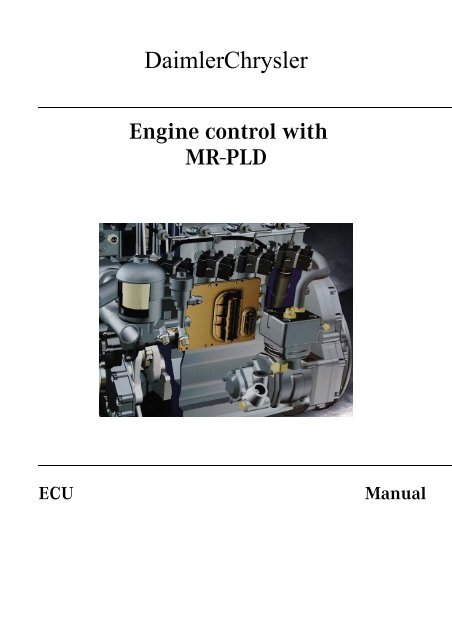
DaimlerChrysler<br />
Engine control with<br />
MR-<strong>PLD</strong><br />
ECU<br />
<strong>Manual</strong>
Environment protection<br />
H<br />
DaimlerChrysler professes itself to an integrated environmental protection, which<br />
sets at the causes and on the environment into the business decisions includes all<br />
effects of the production processes and the product. Goals are the economical<br />
employment of resources and careful handling the natural bases of life, whose<br />
preservation serves humans and nature.<br />
Printed in Germany changes of technical details of the controllers and<br />
engines opposite the data and illustrations of the available manual are<br />
reserved.<br />
Reproduction, duplication or translation, also in part, are not permitted<br />
without written permission.<br />
Editorship conclusion:<br />
Customer service Powertrain Business unit PBE/MSS Responsible for<br />
contents: PBE/DEE<br />
H<br />
Printed<br />
on free from chlorine bleached paper
Powersystems<br />
Document name:<br />
PRODUKT DOCUMENTATION MR-<strong>PLD</strong><br />
Project:<br />
DC - MR-<strong>PLD</strong><br />
Usage:<br />
Generally accessible<br />
Validity:<br />
ECU versions C3 to D21<br />
Pages: 150<br />
File name:<br />
Product documentation MR-<strong>PLD</strong>_1.1.pdf<br />
name dep. fon date sign<br />
processed Scheuer, K. PBE/DEE 52469 02.07.03<br />
checked<br />
waned<br />
responsible Scheuer, K. PBE/DEE 52469<br />
DAIMLERCHRYSLER<br />
Business division<br />
PowerSystems / Engines<br />
ALL RIGHTS RESERVATIONS<br />
- property of the DaimlerChrysler AG -<br />
Version 1.1<br />
Product documentation<br />
engine electronik<br />
MR-<strong>PLD</strong><br />
DaimlerChrysler Order-No.:<br />
02. July 2003<br />
This document is in copyright matters protected. Each utilization outside of the close borders of the copyright law is inadmissible without agreement of<br />
the DaimlerChrysler AG.<br />
3
Powersystems<br />
LIST OF VERSIONS<br />
version date processed remark / description<br />
1.1 05.02.03 Scheuer, K. pre version (draft)<br />
CHANGING US CONDITIONS<br />
version date processed modification<br />
1.1 02.07.03 Scheuer, K. assimilation to German version 1.1<br />
DAIMLERCHRYSLER<br />
Business division<br />
PowerSystems / Engines<br />
ALL RIGHTS RESERVATIONS<br />
- property of the DaimlerChrysler AG -<br />
Version 1.1<br />
Product documentation<br />
engine electronik<br />
MR-<strong>PLD</strong><br />
DaimlerChrysler Order-No.:<br />
02. July 2003<br />
This document is in copyright matters protected. Each utilization outside of the close borders of the copyright law is inadmissible without agreement of<br />
the DaimlerChrysler AG.<br />
4
Index<br />
List of abbreviations ............................................................................................................................. 10<br />
1. Safety .............................................................................................................. 11<br />
1.1. Symbols .............................................................................................................................................11<br />
1.2. General information ........................................................................................................................11<br />
1.3. Use for the indended purpose .......................................................................................................12<br />
1.4. Personnel requirements .................................................................................................................12<br />
1.5. Conversions and modifications to the MR-<strong>PLD</strong>..........................................................................12<br />
1.6. Installation........................................................................................................................................12<br />
1.7. Organizational measures................................................................................................................12<br />
1.8. Safety precautions for engines with electronic control units ..................................................13<br />
1.9. DaimlerChrysler original parts .....................................................................................................14<br />
1.10. Safety and backup running programm......................................................................................14<br />
2. General governor architecture...................................................................... 15<br />
2.1. Standard model of engine control (MR-<strong>PLD</strong>) and vehicle electronics (FRE) .........................15<br />
2.2. Features of the governor and interface module .........................................................................16<br />
2.2.1. VCU (ADM2) as FRE (vehicle electronics)...................................................................................... 16<br />
2.2.2. ADM as FRE (vehicle electronics).................................................................................................... 17<br />
3. MR-<strong>PLD</strong> engine control (pump-line-nozzle) ................................................. 18<br />
3.1. Brief description of the Diesel engine control unit <strong>PLD</strong>-MR ....................................................18<br />
3.2. Control unit - operating principle .................................................................................................18<br />
3.2.1. Overview of the telligent engine system BR 500 .......................................................................... 19<br />
3.2.2. Overview of the telligent engine system BR 900 .......................................................................... 20<br />
3.2.3. Control unit block diagram............................................................................................................... 21<br />
3.2.4. <strong>PLD</strong> control unit as engine control (MR-<strong>PLD</strong>) .............................................................................. 22<br />
3.3. Functional description .....................................................................................................................23<br />
3.3.1. Configuration....................................................................................................................................... 23<br />
3.3.2. Flexibility of the concept................................................................................................................... 23<br />
3.3.3. Control unit description of engine electronics MR-<strong>PLD</strong> .............................................................. 24<br />
3.3.3.1. Safeguard /redundancy...................................................................................................... 24<br />
3.3.3.2. Description of the inputs ................................................................................................... 24<br />
3.3.3.3. Description of the outputs ................................................................................................. 24<br />
3.3.4. Compound network between MR-<strong>PLD</strong> FRE ............................................................................ 25<br />
3.3.4.1. Communication ................................................................................................................... 25<br />
3.3.5. MR-<strong>PLD</strong> FRE interface functions .......................................................................................... 26<br />
3.3.5.1. Idle-speed control / speed control / maximum engine speed limitation .................. 26<br />
3.3.6. Shutoff or throttling of the engine through the FRE (vehicle electronics)............................. 27<br />
3.3.7. Engine start and stop........................................................................................................................ 28<br />
3.3.7.1. Starter control (conditions)................................................................................................ 28<br />
3.3.7.2. Starter protection................................................................................................................. 29<br />
3.3.7.3. Start by the driver............................................................................................................... 29<br />
3.3.7.4. CAN start .............................................................................................................................. 30<br />
3.3.7.5. Starter reset bridge ............................................................................................................. 30<br />
3.3.7.6. Starter driver........................................................................................................................ 31<br />
3.3.7.7. Start through the FRE (vehicle control electronics) via CAN ...................................... 32<br />
3.3.7.8. Starting procedure .............................................................................................................. 32<br />
3.3.7.9. Service start button at the engine block ......................................................................... 32<br />
3.3.7.10. Service stop button at the engine block........................................................................ 32<br />
3.3.7.11. Engine cranking via the service start and stop button .............................................. 33<br />
3.3.7.12. Rev up to maximum speed via service start button.................................................... 33<br />
5
Index<br />
3.3.7.13. Engine stop......................................................................................................................... 33<br />
3.3.8. Plausibility check terminal 50 ........................................................................................................ 34<br />
3.3.9. Calculation of injection delivery angle and start of injection.................................................... 35<br />
3.3.10. Controls (PID governor) ................................................................................................................. 36<br />
3.3.11. Operating modes ............................................................................................................................. 37<br />
3.3.11.1. PTO speed control ............................................................................................................. 37<br />
3.3.11.2. Controlled operation (normal operation)..................................................................... 37<br />
3.3.11.3. Immobilizer........................................................................................................................ 37<br />
3.3.12. Tow starting of the engine............................................................................................................. 37<br />
3.3.13. Emergency syndrome..................................................................................................................... 37<br />
3.4. Mechanical description...................................................................................................................38<br />
3.4.1. Mechanical layout of <strong>PLD</strong> engine electronics ................................................................................ 38<br />
3.4.2. Complete version <strong>PLD</strong> engine electronics ...................................................................................... 38<br />
3.4.2.1 Fuel cooling ........................................................................................................................... 39<br />
3.4.2.2 MR-<strong>PLD</strong> Control Unit ........................................................................................................... 39<br />
3.4.2.2.1.MR-<strong>PLD</strong> - version assignment table................................................................. 41<br />
3.4.3. Technical data .................................................................................................................................... 41<br />
3.4.4. General testing conditions ............................................................................................................... 41<br />
3.5. Electrical description .......................................................................................................................42<br />
3.5.1. System interface diagram ................................................................................................................ 42<br />
3.5.1.1. Interface diagram................................................................................................................ 42<br />
3.5.1.2. Socket pin designation MR-<strong>PLD</strong> control unit (D2.1)/according to pin assignment . 43<br />
3.5.1.3. Pin assignment of MR-<strong>PLD</strong> control unit (D2.1); function oriented/alphabetical ..... 46<br />
3.5.1.4. Voltage supply of control unit MR-<strong>PLD</strong> (D2.1) ............................................................... 50<br />
3.5.2. xx<br />
3.5.2.1. ................................................................................................................................................ xx<br />
3.5.2.2. ................................................................................................................................................ xx<br />
3.5.2.3. ................................................................................................................................................ xx<br />
3.5.3. Sensor system of the <strong>PLD</strong> engine control unit (MR-<strong>PLD</strong>)........................................................... 51<br />
3.5.3.1. Control unit internal sensors ............................................................................................ 51<br />
3.5.3.2. Control unit external sensors............................................................................................ 51<br />
3.5.3.3. Active sensors ...................................................................................................................... 51<br />
3.5.3.4. Passive sensors.................................................................................................................... 52<br />
3.5.3.5. Temperature sensors .......................................................................................................... 52<br />
3.5.3.6. Passive oil pressure ............................................................................................................ 53<br />
3.5.3.7. Oil level ................................................................................................................................. 54<br />
3.5.3.8. Camshaft / crankshaft position (inductive).................................................................... 55<br />
3.5.3.9. Booster speed 1 / 2.............................................................................................................. 55<br />
3.5.3.10. Fan speed............................................................................................................................ 56<br />
3.5.4. Digital inputs...................................................................................................................................... 57<br />
3.5.4.1. Ignition (Terminal 15)......................................................................................................... 57<br />
3.5.4.2. Terminal 50 .......................................................................................................................... 57<br />
3.5.4.3. Service button start/stop ................................................................................................... 58<br />
3.5.4.4. Oil separator......................................................................................................................... 59<br />
3.5.5. Proportional valve control................................................................................................................ 60<br />
3.5.5.1. Functional assignment of proportional valves/hardware status D2.1 ....................... 61<br />
3.5.5.2. Principle block diagram proportional valve control /hardware status D2.1............. 62<br />
3.5.5.3. Functional assignment of the proportional valves/hardware status C3..C6 ........... 63<br />
3.5.5.4. Principle block diagram proportional valve control/hardware status C3..C6.......... 64<br />
3.5.6. Starter control through the MR-<strong>PLD</strong> .............................................................................................. 65<br />
3.5.6.1. Main path (self-locking) ..................................................................................................... 65<br />
3.5.6.2. Auxiliary path (self conducting)....................................................................................... 65<br />
3.5.6.3. Principle block diagram starter control .......................................................................... 66<br />
3.5.6.4. Starter relay.......................................................................................................................... 66<br />
3.5.6.5. Principle block diagram of safety concept of JE-starter ............................................. 67<br />
3.5.7. Serial communication interfaces .................................................................................................... 68<br />
6
Index<br />
3.5.7.1. CAN data bus (2-wire-interface, standard: ISO 11992) ................................................ 68<br />
3.5.7.2. Diagnostic line (standard: ISO 9141)............................................................................... 69<br />
3.5.7.3. Classification of the injector valves ................................................................................. 69<br />
3.6. Configuration possibilities of the MR-<strong>PLD</strong>.................................................................................. 70<br />
3.6.1. Fan type............................................................................................................................................... 70<br />
3.6.1.1. General connection ............................................................................................................. 70<br />
3.6.1.2. Pin assignment of the proportional valve-power stages (PV/Prop) for fan control. 70<br />
3.6.1.2.1. Type 0/Linning-clutch (on highway/two-stage) ........................................... 70<br />
3.6.1.2.2. Type 1/Linning-clutch (off highway/two-stage)........................................... 70<br />
3.6.1.2.2.1.Configuration / fan switch-on threshold (type 1).................... 70<br />
3.6.1.2.3. Type 2 /electrically controlled Viscous-fan................................................... 72<br />
3.6.1.2.4. Type 3 /Hydrostatic Fan ................................................................................... 73<br />
3.6.1.2.5. Type 4/Horton-clutch ........................................................................................ 74<br />
3.6.1.2.6. Type 5/one Hydrostatic-fan.............................................................................. 75<br />
3.6.1.2.7. Type 6/two Hydrostatic-fans............................................................................ 76<br />
3.6.2. Starter control .................................................................................................................................... 77<br />
3.6.2.1. JE-starter ............................................................................................................................... 77<br />
3.6.2.2. KB-starter.............................................................................................................................. 78<br />
3.6.2.2.1. KB-starter with starter solenoid relay (2 A).................................................. 78<br />
3.6.2.2.2. KB-starter without Starter Solenoid Relay (2 A) ......................................... 79<br />
3.6.3. Oil pans ............................................................................................................................................... 80<br />
4. Diagnosis ........................................................................................................ 81<br />
4.1. Measured values ..............................................................................................................................81<br />
4.1.1. Analogue measured values.............................................................................................................. 81<br />
4.1.2. Binary measured values................................................................................................................... 83<br />
4.2. Serial diagnosis interfaces .............................................................................................................86<br />
4.2.1. Diagnostic line ................................................................................................................................... 86<br />
4.2.1.1. Fault memory....................................................................................................................... 86<br />
4.2.1.2. Operating modes ................................................................................................................. 86<br />
4.2.2. CAN data bus systems...................................................................................................................... 87<br />
4.2.2.1. Engine-CAN (ISO 11992) ................................................................................................... 87<br />
4.2.2.2. Vehicle CAN ......................................................................................................................... 87<br />
4.2.3. SAE J1587/SAE J1708 (USA- and partly NAFTA-market).......................................................... 88<br />
4.2.4. Configuration of diagnostic interface............................................................................................. 88<br />
4.2.4.1. MB-truck / Brazil................................................................................................................. 89<br />
4.2.4.2. Europe (ADM / not MB-trucks)......................................................................................... 90<br />
4.2.4.3. Europe (ADM2 / not MB-Trucks)...................................................................................... 91<br />
4.2.4.4. USA- and partly NAFTA-market ....................................................................................... 92<br />
4.2.5. Diagnosis interface/software description ..................................................................................... 93<br />
4.2.5.1. Fault memory structure ..................................................................................................... 93<br />
4.2.5.2. Ground switching................................................................................................................ 93<br />
4.3. Diagnosis unit & application..........................................................................................................94<br />
4.3.1. minidiag2............................................................................................................................................ 94<br />
4.3.1.1. Display/delete fault code memory ................................................................................... 94<br />
4.3.1.2. Testing routines................................................................................................................... 97<br />
4.3.1.2.1.Voltmeter function.............................................................................................. 97<br />
4.3.1.2.2.Cylinder cutoff..................................................................................................... 98<br />
4.3.1.2.3.Compression check............................................................................................. 99<br />
4.3.1.2.4.Idle speed balance (hot engine!)..................................................................... 100<br />
4.3.1.2.5.Impact delay time ............................................................................................. 101<br />
4.3.1.2.6................................................................................................................................. xx<br />
4.3.1.2.7................................................................................................................................. xx<br />
4.3.1.3. Calibration.......................................................................................................................... 102<br />
7
Index<br />
4.3.1.3.1.Single parameters ............................................................................................. 102<br />
4.3.1.3.2.Data set calibration........................................................................................... 104<br />
4.3.1.3.3.Save modified parameter set........................................................................... 105<br />
4.3.1.3.4.Convert modified parameter set..................................................................... 106<br />
4.3.1.4. Program protection ........................................................................................................... 107<br />
4.3.2. Stardiagnose..................................................................................................................................... 107<br />
4.3.3. ServiceLink....................................................................................................................................... 108<br />
4.4. Diagnosis routines.........................................................................................................................109<br />
4.4.1. Detailed testing routines................................................................................................................ 109<br />
4.5. Backup.............................................................................................................................................110<br />
4.5.1. System backup capability .............................................................................................................. 110<br />
4.5.1.1. Microprocessor 1-backup................................................................................................. 110<br />
4.5.1.1.1.Crankshaft backup............................................................................................ 110<br />
4.5.1.1.2.Camshaft backup .............................................................................................. 110<br />
4.5.1.1.3.CAN-backup (definition).................................................................................. 110<br />
4.5.1.1.4.CAN-backup, mode 0 (standard-backup)...................................................... 111<br />
4.5.1.1.5.CAN-backup, mode 1........................................................................................ 112<br />
4.5.1.1.6.CAN-backup, mode 2........................................................................................ 112<br />
4.5.1.1.7.CAN data-area check ........................................................................................ 112<br />
4.5.1.1.8.Nominal engine speed CAN-backup.............................................................. 112<br />
4.5.1.1.8.1.Nominal engine speed CAN-backup mode 0.......................... 112<br />
4.5.1.1.8.2.Nominal engine speed CAN-backup mode 1.......................... 113<br />
4.5.1.2. Microprocessor 2-backup................................................................................................. 113<br />
4.5.2. Backup functions............................................................................................................................. 114<br />
4.5.2.1. Ambient pressure sensor................................................................................................. 114<br />
4.5.2.2. Boost pressure control...................................................................................................... 114<br />
4.5.3. Sensor-replacement values............................................................................................................ 114<br />
4.5.3.1. Plausibility limits and sensor replacement values ..................................................... 114<br />
4.5.4. Diagnosis of sensor and backup functions ................................................................................. 115<br />
4.5.4.1. Temperature and presure sensors.................................................................................. 115<br />
4.5.4.2. Crankshaft sensor ............................................................................................................. 115<br />
4.5.4.3. Camshaft sensor (cylinder 1 recognition)..................................................................... 116<br />
4.5.5. Diagnosis of actuators ................................................................................................................... 117<br />
4.5.5.1. MR-<strong>PLD</strong> injector-/magnetic valves (MV)....................................................................... 117<br />
4.5.5.2. MR-<strong>PLD</strong> proportional valves............................................................................................ 118<br />
4.5.5.3. Starter control.................................................................................................................... 118<br />
4.6. Fault codes & repair instructions............................................................................................... 119<br />
4.6.1. Fault codes ....................................................................................................................................... 119<br />
4.6.1.1. Fault priority 0 ................................................................................................................... 119<br />
4.6.1.2. Fault priority 1 ................................................................................................................... 119<br />
4.6.1.3. Fault priority 2 ................................................................................................................... 119<br />
4.6.2. Fault path ......................................................................................................................................... 120<br />
4.6.3. Fault type ......................................................................................................................................... 122<br />
4.6.4. Fault codes und repair instructions, high priority ................................................................... 124<br />
4.6.5. Fault codes und repair instructions, mean priority.................................................................. 125<br />
4.6.6. Fault codes und repair instructions, minor priority................................................................. 134<br />
4.6.7. ............................................................................................................................................................. xx<br />
4.6.8. ............................................................................................................................................................. xx<br />
4.7. Special measurements..................................................................................................................138<br />
4.7.1. General information ....................................................................................................................... 138<br />
4.7.2. Actuators...........................................................................................................................................138<br />
4.7.2.1. Solenoid valves: Current modulation curve of the injector valve control/type 1.. 138<br />
4.7.2.2. Solenoid valves: Current modulation curve of the injector valve control/ type 2.. 140<br />
4.7.2.3. ................................................................................................................................................. xx<br />
4.7.3. ............................................................................................................................................................. xx<br />
8
Index<br />
5. Parameters (minidiag2)............................................................................... 142<br />
5.1. MR-<strong>PLD</strong> Diagnosis version 3 to 5 (up-/download)...................................................................142<br />
5.2. MR-<strong>PLD</strong> Diagnosis from version 6 (single parameters)..........................................................146<br />
9
a) List of abbreviations<br />
A listing follows in the project "MR-<strong>PLD</strong>" used abbreviations.<br />
Abbreviation Meaning<br />
Abbreviation Meaning<br />
ABS Anti-lock Braking System LRR Engine-Smoothness Control<br />
ADR / PTO PTO speed control / Power Take-off LK Slight Vehicle Class (MB-NFZ)<br />
LS Low Speed (CAN)<br />
ATG / AT Automated Transmission MB Mercedes Benz<br />
AVD Compression check MBR Engine Brake<br />
MR-<strong>PLD</strong> Engine control (Pump-Line-Nozzle<br />
BGR Limitations<br />
System)<br />
BK exhaust flap<br />
BR Engine Type Series (e. g. BR900)<br />
CAN Controller Area Network MS / MTS Engine protection<br />
MV Magnetic Valve<br />
EGR Exhaust Gas Recirculation MZA Mechanical Additional Boost<br />
EMV Electro-Magnetical-Impulse n.d. not difined<br />
EOL End Of Line<br />
EZA Individual cylinder adaption NFZ Commercial Vehicle<br />
FB Start Of Injection NW Camshaft<br />
FDOK Vehicle Documentation System OM Oel Engine<br />
FLA Flame Start Unit OT / TDC Top Dead Centre<br />
PFA Particle Filter System<br />
Vehicle control (e. g. VCU, ADM, ADM2, PID Parameter Identifier<br />
FRE<br />
UCV, FR/FMR)<br />
FRT Free Running Telegramm<br />
FSP PV / Prop Proportional Valve<br />
FW Injection Delivery Angle PWM Pulse Width Modulated<br />
GMA Basic Moment Adaption SEG Segment<br />
SG / Stg. / Electronical Control Unit<br />
HB High Byte<br />
ECU<br />
s.n.v. signal not available<br />
HW HardWare SK Heavy Vehicle Class (MB-NFZ)<br />
ID IDentifier STG / MA <strong>Manual</strong> Transmission<br />
IES Intigrated Electronic System SW SoftWare<br />
INS / ICU3 Dashboard TN (CAN) Attendant<br />
IMO Industrial Engine (Off-Highway) TPC TransPonderCode<br />
KD Decompression Valve UT Bottom Dead Centre<br />
VTG Variable Geometry Turbo<br />
WS Service System<br />
WSP Immobilizer<br />
K-Line Communication Line (serial) ZYL / CYL Cylinder<br />
KW Crankshaft<br />
LB Low Byte<br />
LL / LLR Idle / Idle Control<br />
10
1. Safety<br />
1. Safety<br />
1.1. Symbols<br />
The instructions that follow are shown against various symbols.<br />
G<br />
risk of injury!<br />
This symbol appears against all safety instructions that must be complied with in order to avoid a direct risk of<br />
danger to life and limb.<br />
This symbol is used against all safety instructions that, if disregarded, could give rise to the danger of<br />
material damage or malfunctions.<br />
1.2. General information<br />
accident and live hazard!<br />
G<br />
The engine control unit MR-<strong>PLD</strong> is essential for defining the functions of the engine and vehicle. Functions<br />
such as the exact electric control of injector valves via the magnetic valves, fuel injection, fault recognition,<br />
engine safeguards, backup, diagnosis etc. are relevant to safety.<br />
Incorrectly performed modifications to the parameters or tampering with the wiring can cause far-reaching<br />
changes to the performance of the engine and/or vehicle. This can lead to personal injury and material damage.<br />
The control unit MR-<strong>PLD</strong> has been developed and tested in accordance with the DaimlerChrysler<br />
Specifications for Operating Safety and EMC Compatibility. The manufacturer of the vehicle or equipment is<br />
solely responsible for the examination and implementation of applicable legal stipulations.<br />
11
1. Safety<br />
1.3. Use for the intended purpose<br />
The DaimlerChrysler engine and the MR-<strong>PLD</strong> control unit are only to be used for the purpose stated in the<br />
contract of purchase. Any other use or an extension of the stated use will be regarded as not conforming to the<br />
engines intended purpose.<br />
DaimlerChrysler AG cannot accept any liability for damage resulting from such use. Liability for damage<br />
resulting from the engine not having been used for its intended purpose shall rest solely with the manufacturer<br />
of the complete machine or vehicle in which the engine is installed.<br />
These MR-<strong>PLD</strong> Operating Instructions and the engine Operating Instructions must be observed.<br />
1.4. Personnel requirements<br />
Work on the electrics and programmed parameters should only be carried out by specially skilled persons or<br />
those who have received training from DaimlerChrysler, or by specialists employed by a workshop authorized<br />
by DaimlerChrysler.<br />
1.5. Conversions and modifications to the MR-<strong>PLD</strong><br />
Unauthorized modifications to the MR-<strong>PLD</strong> could affect the operation and safety of the vehicle/machine in<br />
which it is installed. No responsibility will be accepted for any resulting damage.<br />
1.6. Installation<br />
The guidelines and instructions in Chapter 6 (assembly & connecting) and Chapter 3.5.2 (electric installation)<br />
must be observed.<br />
1.7. Organizational measures<br />
These Operating Instructions should be handed to personnel entrusted with the operation of the MR-<strong>PLD</strong> and<br />
should, whenever possible, be stored in an easily accessible place.<br />
With the aid of these Operating Instructions, personnel must be familiarized with the operation of the MR-<br />
<strong>PLD</strong>, paying special attention to the safety-relevant instructions applicable to the engine. This applies in particular<br />
to personnel who only work on the engine and MR-<strong>PLD</strong> occasionally.<br />
In addition to these Operating Instructions, comply with local legal stipulations and any other obligatory<br />
accident prevention and environmental protection regulations which may apply in the country of operation.<br />
12
1. Safety<br />
1.8. Safety precautions for engines with electronic control units<br />
G<br />
acccident hazard!<br />
When the vehicle electrics are first operated, the drive train must be open (transmission in neutral). The engine<br />
could start unexpectedly due to incorrect wiring or unsuitable parameter programming. If the drive train is<br />
closed (transmission not in neutral), the vehicle could unexpectedly start moving or set the working machine<br />
in operation, constituting a risk to life and limb.<br />
The safety precautions stated below must be applied at all times in order to avoid damage to the<br />
engine, its components and wiring, and to avoid possible personal injury.<br />
– Only start the engine with the batteries securely connected<br />
– Do not disconnect the batteries when the engine is running<br />
– Only start the engine with the engine speed sensor connected.<br />
– Do not start the engine with the aid of a rapid battery charger. If emergency starting is necessary, only start<br />
using separate batteries<br />
– The battery terminal clamps must be disconnected before a rapid charger is used. Comply with the operating<br />
instructions for the rapid charger<br />
– If electric welding work is to be performed, the batteries must be disconnected and both cables (+ and -)<br />
secured together<br />
– Work is only to be performed on the wiring and connectors are only to be plugged/unplugged with the<br />
electrical system switched off<br />
– The first time the engine is run, the possibility must be provided to switch off the voltage supply to the MR<br />
engine control and to the vehicle electronics (MR-<strong>PLD</strong> or FRE) in an emergency<br />
– If it is incorrectly wired up, it may no longer be possible to switch the engine off<br />
– Interchanging the poles of the control unit´s voltage supply (e.g. by interchanging the battery poles) can<br />
damage the control unit beyond repair<br />
– Fasten connectors on the fuel injection system with the specified tightening torque<br />
– Only use properly fitting test lead for measurements on plug connectors (DaimlyerChrysler connector set)<br />
If temperatures in excess of 80°C (e.g. in a drying kiln) are to be expected, the control units must be<br />
removed as they could be damaged by such temperatures.<br />
Telephones and two-way radios which are not connected to an external aerial can cause malfunctions in<br />
the vehicle electronics and thus jeapordize the engines operating safety.<br />
13
1. Safety<br />
1.9. DaimlerChrysler original parts<br />
DaimlerChrysler original parts are subject to the most stringent quality checks and guarantee maximum<br />
functional efficiency, safety and retention of value.<br />
Each part is specially designed, produced, selected and approved for DaimlerChrysler. For this reason, we are<br />
obliged to disclaim all liability for damage resulting from the use of parts and accessories which do not meet<br />
the above requirements.<br />
Germany and various other countries, certain parts (for instance parts relevant to safety) are only officially<br />
approved for installation or conversion work if they comply with valid legal stipulations. These regulations<br />
are assured to be satisfied by DaimlerChrysler original parts.<br />
If other parts, which have not been tested and approved by DaimlerChrysler, are installed – even if in individual<br />
circumstances they have been granted an official operating permit – DaimlerChrysler is unable to assess them<br />
or grant an form of warranty, although the company endeavors to monitor market developments as far as<br />
possible. The installation of such parts may therefore restrict the validity of the warranty.<br />
1.10. Safety and backup running programm<br />
The electronic control units MR-<strong>PLD</strong> and FRE monitor the engine and carry out self-diagnosis. As soon as a<br />
fault is detected it is evaluated and one of the following measures is initiated:<br />
– Faults during operation are indicated by the warning lamps being activated<br />
– Switch-over to a suitable substitute function for continued, albeit restricted engine operation (e.g. constant<br />
emergency engine speed)<br />
Have any faults rectified without delay by the responsible DaimlerChrysler Service Station.<br />
Note:<br />
DaimlerChrysler diagnosis testers (hand-held tester (HHT) or Minidiag), which are connected to the 14 pin<br />
diagnosis socket (on the unit), can be used to read off the fault codes.<br />
MR-<strong>PLD</strong> control unit fault codes and their remedial actions are described in Chapter 4.6.<br />
Defective units which are still within the period of warranty cover (6 months from DaimlerChrysler dispatch<br />
date) must be returned to the DaimlerChrysler field service organization.<br />
14
2. General governor architecture<br />
2. General governor architecture<br />
The electronic governor architecture consists of two components:<br />
1) Engine control unit (MR) consisting of <strong>PLD</strong> (short for pump-line-nozzle system)<br />
2) Vehicle electronics (FRE) consisting of the following interface modules:<br />
- FR/FMR (vehicle governor/vehicle engine governor): used in MB Trucks and buses<br />
- ADM/ADM2 (adaptation module): used with MB-engines, IMO (international, but not NAFTA-market)<br />
- VCU (Vehicle Control Unit): used with MB-engines in the NAFTA-market (e.g. Freightliner)<br />
- UCV (Unit Control Vehicle): used with MB-engines in Brasil<br />
Note: The future interface module CPC (Common Powertrain Controller) shall replace all vehicle<br />
controllers and in this documentation the abbreviation FRE (Vehicle Electronics) is used for the<br />
different vehicle controls (ADM/ADM2, VCU, FR-FMR, UCV etc.), due to a clear arrangement.<br />
2.1. Standard model of engine control (MR-<strong>PLD</strong>) and vehicle electronics (FRE)<br />
SAE J1939 or IES-CAN<br />
User functions<br />
Accelerator pedal<br />
Tempomatoperation<br />
Further inputs and<br />
outputs for<br />
vehicle and<br />
off-road<br />
applications<br />
Engine functions<br />
12/24 V<br />
FRE<br />
MR-<br />
<strong>PLD</strong><br />
CAN-Bus<br />
ISO 11992<br />
...<br />
SAE- or IEScompatible<br />
components &<br />
display electronics<br />
with diagnosis<br />
diagnosis via diagnostic line<br />
Block diagram 2.1: Engine control unit (MR-<strong>PLD</strong>) and vehicle electronics (FRE)<br />
Note:<br />
The application of the High-Speed-CAN (SAE J1939/IES-CAN) depends on the vehicle electronics<br />
(FRE)! See also chapter 4.2.2. to 4.2.4.4.<br />
15
2. General governor architecture<br />
2.2. Features of the governor and interface module<br />
2.2.1. VCU (ADM2) as FRE (vehicle electronics)<br />
Display with individual<br />
gauges<br />
Diagnosis via diagnostic line<br />
SAE J1939<br />
User functions<br />
Accelerator pedal,<br />
Cruise controloperation<br />
Further inputs and<br />
outputs for<br />
vehicle and<br />
off-road<br />
applications<br />
Engine functions<br />
12/24 V<br />
VCU<br />
or ADM2<br />
MR-<br />
<strong>PLD</strong><br />
CAN-Bus<br />
ISO 11992<br />
...<br />
SAEcompatible<br />
components<br />
Diagnosis via diagnostic line<br />
Block diagram 2.2.1: Governor architecture with the interface module VCU or ADM2<br />
Note:<br />
The application of the High-Speed-CAN (SAE J1939/IES-CAN) depends on the vehicle electronics<br />
(FRE)! See also chapter 4.2.2. to 4.2.4.4.<br />
• MR-<strong>PLD</strong><br />
The <strong>PLD</strong> governor for the electronic Diesel injection has the following features:<br />
- Cylinder-selective injector valve control<br />
- Control, regulation and monitoring of engine functions<br />
- Starter control<br />
- Fault recognition<br />
- Backup operation functions<br />
- Diagnosis<br />
- Communication interfaces with FRE via engine CAN (ISO 11992) and/or diagnostic line (ISO 9141)<br />
• VCU (ADM2)<br />
- Implementation of user functions, e.g. accelerator pedal, cruise control, limitations, etc.<br />
- Communication interfaces with MR-<strong>PLD</strong> via engine CAN (ISO 11992)<br />
- Communication interfaces with vehicle CAN (SAE J1939/IES)<br />
- Conventional display driver: analogue and digital displays<br />
- Diagnosis<br />
16
2. General governor architecture<br />
2.2.2. ADM as FRE (vehicle electronics)<br />
Display with individual<br />
gauges<br />
Diagnosis via diagnostic line<br />
User functions<br />
Accelerator pedal,<br />
Cruise control<br />
operation<br />
Further inputs and<br />
outputs for<br />
vehicle and<br />
off-road<br />
applications<br />
Engine functions<br />
12/24 V<br />
ADM<br />
MR-<br />
<strong>PLD</strong><br />
CAN-Bus<br />
ISO 11992<br />
Diagnosis via diagnostic line<br />
Block diagram 2.2.2.: Governor architecture with interface module ADM<br />
• ADM<br />
- Implementation of user functions, e.g. accelerator pedal, cruise control, limitations, etc.<br />
- Communication interfaces with MR-<strong>PLD</strong> via engine CAN (ISO 11992)<br />
- Conventional display drivers: analogue and digital displays<br />
- Diagnosis<br />
17
3. MR-<strong>PLD</strong> engine control (pump line nozzle)<br />
3. MR-<strong>PLD</strong> engine control (pump-line-nozzle)<br />
3.1. Brief description of the Diesel engine control unit MR-<strong>PLD</strong><br />
The engine control unit „MR-<strong>PLD</strong>“ (pump-line-nozzle system) controls the electronic Diesel-fuel injection<br />
and is also designed for the engine series 450, 500 and 900. The main function of the control unit is the<br />
exact electric control of the solenoid valves at the injector valves. Regarding this, the optimum start of<br />
injection and the necessary injection quantity for the torque (or the desired speed in the case of a PTO<br />
speed control operation) demanded by the control unit on the engine side, are calculated and set (mapping<br />
specific, through measured engine and ambient conditions).<br />
The control unit also provides further features like fault recognition, possibility of limp-home operating<br />
modes, diagnosis and interfaces with other control systems.<br />
3.2. Control unit - operating principle<br />
vehicle<br />
electronics<br />
sensors<br />
application<br />
system<br />
MR-<strong>PLD</strong><br />
injector valve 1<br />
.<br />
.<br />
.<br />
.<br />
.<br />
.<br />
injector valve 8<br />
proportional valves<br />
(PV)<br />
starter<br />
start-/stop button<br />
18
3. MR-<strong>PLD</strong> engine control (pump line nozzle)<br />
3.2.1. Overview of the telligent engine system BR 500<br />
A3 Controller FRE (FR-FMR) G2 Alternator<br />
A4 Controller Ignition System M1 Starter<br />
A6 Controller MR-<strong>PLD</strong> P1 Speedometer<br />
A42 Electronic to read Transponder Code S1 Driving Switch<br />
B1 Accelerator Pedal S2 Lever for Engine Governor /<br />
B2 Clutch Pedal Permanent Brake<br />
B3 Engine Speed Sensor at Counter Shaft S3 Split Switch<br />
B4 Outside Temperature Sensor S4 Braking Light Switch<br />
B6 Engine Coolant Level Sensor S7 Switch for Reverse Gear<br />
B7 Air Filter Inspection Sensor S8 Switch for Group Position<br />
B9 Turbo Charger Temperature Sensor S9 Switch for Neutral Position<br />
B10 Fuel Temperature Sensor S10 Push-button Engine Start<br />
B11 Oil Temperature Sensor S11 Push-button Engine Stop<br />
B12 Oil Pressure Sensor Y1 Constant Throttle Magnetic Valve<br />
B13 Turbo Charger Pressure Sensor Y2 Engine Brake Magnetic Valve<br />
B14 Oil Level Sensor Y29 MS2 Magnetic Valve<br />
B15 Crankshaft Angle Position Sensor Y30 MS1 Magnetic Valve<br />
B16 TDC Sensor Cylinder 1<br />
B65 Coolant Temperature Sensor<br />
19
3. MR-<strong>PLD</strong> engine control (pump line nozzle)<br />
3.2.2. Overview of the telligent engine system BR 900<br />
A3 Controller FRE (FR-FMR) G2 Alternator<br />
A4 Controller Ignition System M1 Starter<br />
A6 Controller MR-<strong>PLD</strong> P1 Speedometer<br />
A42 Electronic to read Transponder Code S1 Driving Switch<br />
B1 Accelerator Pedal S2 Lever for Engine Governor /<br />
B2 Clutch Pedal Permanent Brake<br />
B3 Engine Speed Sensor at Counter Shaft S4 Braking Light Switch<br />
B4 Outside Temperature Sensor S7 Switch for Reverse Gear<br />
B6 Engine Coolant Level Sensor S9 Switch for Neutral Position<br />
B7 Air Filter Inspection Sensor S10 Push-button Engine Start<br />
B9 Intake Air Temperature Sensor S11 Push-button Engine Stop<br />
B10 Fuel Temperature Sensor S85 Switch 1, Clutch (KUP1) < 15 tons<br />
B14 Oil Level Sensor S89 Switch 2, Clutch (KUP2) > 15 tons<br />
B15 Crankshaft Angle Position Sensor Y1 Engine Brake Magnetic Valve (4 cyl.)<br />
B16 TDC Sensor Cylinder 1 Exhaust Flap brake (6 cyl.)<br />
B65 Coolant Temperature Sensor Y2 Constant Throttle Magnetic Valve (6 cyl.)<br />
B110 Oil Pressure and Temperature Sensor Y6..11 Pump nozzle unit<br />
B111 Turbo Charger Air Pressure and Y63 Split Magnetic Valve<br />
Temperature Sensor Y64 Shift Power Assistant Magnetic Valve G 100<br />
20
3. MR-<strong>PLD</strong> engine control (pump line nozzle)<br />
3.2.3. Control unit block diagram<br />
terminal 30<br />
terminal 31<br />
terminal 15<br />
terminal 50<br />
oil separator<br />
engine service start button<br />
engine service stop button<br />
crankshaft signal<br />
camshaft signal<br />
fan speed<br />
booster speed 1<br />
booster speed 2<br />
active oil pressure<br />
passive oil pressure<br />
scavenging gradient (P2S - P3)<br />
charge-air pressure<br />
fuel pressure/accelerator pedal<br />
oil level<br />
fuel temperature<br />
charge-air temperature<br />
oil temperature<br />
coolant temperature<br />
power supply<br />
unit<br />
switch on<br />
digital<br />
input<br />
speed<br />
interface<br />
input<br />
circuit<br />
analog/<br />
dynamic<br />
5V<br />
reset<br />
watchdogsignal<br />
hold<br />
control unit<br />
microcontroller<br />
2<br />
microcontroller<br />
1<br />
CAN<br />
air pressure<br />
RXD<br />
TXD<br />
diagnosis<br />
switch<br />
output stage<br />
monitoring<br />
valve output<br />
stage<br />
monitoring<br />
proportional<br />
valve<br />
output stage<br />
monitoring<br />
CAN-driver<br />
DC-diagnosis<br />
starter<br />
pump-linenozzle<br />
(cyl. 1 - 8)<br />
engine retarder flap<br />
decompression valve<br />
fan 1<br />
fan 2<br />
-<br />
-<br />
engine - CAN<br />
(ISO 11992)<br />
Note: On the basis of the control unit the function "hold" is activated, which is responsible for the<br />
backup phase of the control unit, if no signal arrives at the power supply unit (switch-on) the control unit<br />
switches off.<br />
21
3. MR-<strong>PLD</strong> engine control (pump line nozzle)<br />
3.2.4. <strong>PLD</strong> control unit as engine control (MR-<strong>PLD</strong>)<br />
ABS = Antilock Brake systems<br />
ADR = PTO speed control<br />
FRE = Vehicle electronics (ADM/ADM2, VCU, FR-FMR etc.)<br />
ASR = Anti-slip control<br />
BGR = Limitations<br />
FFG = Accelerator pedal (operation or speed demand)<br />
FLA = Flame start unit<br />
ISO = International Organisation for Standardization<br />
IWA = Actual value output (for automatic transmission, customer-specific<br />
electronics…)<br />
MBR = Engine brake<br />
MR-<strong>PLD</strong> = <strong>PLD</strong> engine control (pump-line-nozzle system)<br />
SAE J1939 = High-speed CAN (on vehicle side)<br />
Note: In this documentation the abbreviation „FRE“ is used for the different vehicle controls (ADM/<br />
ADM2, VCU, FR-FMR, UCV etc.), due to a clear arrangement.<br />
22
3.3. Functional description<br />
3.3. Functional description<br />
3.3.1. Configuration<br />
The electronic system is divided in two independent subsystems that can be monitored separately.<br />
The cabin mounted control unit “FRE” (vehicle electronics) controls the sensors and actuators attached to<br />
the drivers cab or the vehicle frame and involves all functions which are relevant for the vehicle.<br />
The engine mounted control unit MR-<strong>PLD</strong> controls all sensors and actuators attached to the engine and<br />
involves all functions which are important to the engine operation.<br />
The two control units are connected via a bus connection with “one wire capability”. Via this bus connection<br />
nominal values and the operating mode of the engine are demanded by the respective FRE (e.g.<br />
increase of idle speed, speed-controlled engine operation with programmable desired speed, torque limitation,<br />
freely selectable control characteristic, engine braking torque etc.), and in the opposite direction the<br />
MR-<strong>PLD</strong> control unit transmits information about the actual engine operating mode to the FRE (e.g. flame<br />
start unit).<br />
Advantages:<br />
– the plug connections at the engine are reduced to the connections which are relevant to the engine<br />
– the vehicle connections are located in the uncritical surrounding area of the drivers cab (high<br />
degree of acceleration- and temperature load at the engine)<br />
– less connection lines between engine and vehicle (reduced to the EMV-uncritical CAN connection)<br />
proves to be of particular advantage in the bus (due to the great distance between the control<br />
elements and the engine, like accelerator pedal etc.)<br />
– the computers are only burdened with the functions and tasks of the particular system (the <strong>PLD</strong>-MR<br />
computer is only responsible for the engine management, no load through vehicle functions)<br />
– a modular extension of the system is possible by means of additional units that are connected with<br />
the bus system<br />
3.3.2. Flexibility of the concept<br />
Each subsystem is tuned individually and can be tested as a subsystem. Therefore the engine can be<br />
replaced by an engine of a different design but with the same category of engine performance, without<br />
having to change the configuration in the vehicle-control unit (FRE) (e.g. <strong>PLD</strong>-MR engine is replaced by<br />
Common-Rail engine). 4-, 5-, 6-, and 8-cylinder engines can be operated with the same <strong>PLD</strong>-MR.<br />
Accessory parts at the engine like “Waste Gate”, fan high speed etc. can be regulated, controlled and connected<br />
via 6 PWM outputs at the <strong>PLD</strong>-MR. An additional digital output is reserved for the starter control!<br />
Functional requests of other electronic systems like ABS, ASR, EPB, EAS, automatic transmission, retarder<br />
etc. (data exchange via vehicle-CAN-Bus (e.g. IES-CAN)) are coordinated in the FRE and prepared for the<br />
engine electronics (<strong>PLD</strong>-MR).<br />
23
3.3. Functional description<br />
3.3.3. Control unit description of engine electronics MR-<strong>PLD</strong><br />
The module MR-<strong>PLD</strong> engine electronics consists of the control unit and the fuel cooling. The MR-<strong>PLD</strong> control<br />
unit consists of a component circuit board with base plate (planar technique) and a zinc pressure die<br />
casting housing. The circuit board/base plate combination is screwed to the housing. The seal between<br />
housing and circuit board is achieved by means of a fluid gasket.<br />
The external electrical contact is maintained via a 16 pin and a 55-pin socket. To bring the pressure inside<br />
the housing into equilibrium with the ambient pressure, a pressure sensitive membrane is located on the<br />
bottom of the housing. The housing has 4 eyelets to accommodate the damping elements and screw them<br />
onto the engine. See also chapter 3.4. Mechanical description.<br />
3.3.3.1. Safeguard /redundancy:<br />
The MR-<strong>PLD</strong> is designed as a 2-controller system i.e. in the case of a main controller failure, the limp home<br />
controller takes over the control of the magnetic valves at the injector valves. In this case the engine rpm<br />
is constant (approx. 1300 rpm). This redundancy (i.e. in the case of the failure of one “functional component”,<br />
at least one second operable functional component is available as a safety measure) also applies to<br />
solenoid valves (injector valves), speed sensors, starter control and engine CAN-Bus (one wire capability).<br />
In addition, the electronics are provided with a “Watch-Dog” circuit, extensive self tests are carried out continuously<br />
and in addition a mutual monitoring with the FRE (vehicle electronics) takes place. See also<br />
chapter 4.5. Backup.<br />
3.3.3.2. Description of the inputs:<br />
- 4 temperature inputs (coolant, oil, fuel, charge air)<br />
- 3 pressure inputs (atmospheric pressure (internal sensor), boost pressure, oil pressure)<br />
- 1 input oil level<br />
- 2 analogue inputs reserve<br />
- 2 binary inputs for service-start- and stop-buttons in engine compartment function: engine start,<br />
engine stop, both service-buttons pushed simultaneously => starter is cranking/ no<br />
injection, Service-start-bottom release and with running engine operate/ hold<br />
= > engine again start toward cutoff speed<br />
- 2 inputs for crank-angle and cam-angle sensing<br />
Bores, slits, teeth (esp. tooth wheel) or noses can be used as markings on engine side<br />
(beware polarity!)<br />
3.3.3.3. Description of the outputs:<br />
- 4 / 8 outputs for injector valves (partial assembled) possible for reduction in costs)<br />
- 1 output for starter control<br />
- 6 more PWM-modulated multi-functional outputs for the control of further components like fan high<br />
speed, Waste Gate, Viscous-clutch etc.<br />
The assignment of the outputs can be defined by configuration.<br />
See also chapter 3.5.5. Proportional valve control<br />
Remark:<br />
One of the most important functions is among other things the exact, electric control of the injector valves via<br />
the solenoid valves. See chapter 3.1. “Brief description of the Diesel engine-control unit MR-<strong>PLD</strong>”.<br />
24
3.3. Functional description<br />
3.3.4. Compound network between MR-<strong>PLD</strong> FRE<br />
3.3.4.1. Communication<br />
The FRE makes demands on the MR-<strong>PLD</strong> via the CAN like e.g.:<br />
- Torque demand through accelerator pedal (controlled operation i.e. normal operation)<br />
- ADR-governor type (5 types altogether, see following chapter 3.3.10.<br />
- in the case of ADR mode: desired speed and max. torque<br />
The MR-<strong>PLD</strong> sends the following data to the FRE:<br />
- Actual value (sensor values) like speed, temperature, pressure.....<br />
- Feedback of operating mode<br />
Note: In the case of a total CAN data bus failure e.g. through lead rupture no more communication<br />
between FRE and MR-<strong>PLD</strong> is possible. In this case the MR-<strong>PLD</strong> switches to a limp-home operating<br />
mode. If only one of the two control-/data lines fails, then the communication can still be maintained<br />
via the remaining line and ground line (one wire operation). Refer to chapters 4.2.2.1. and 4.5.1.1. for<br />
further information about the engine CAN data bus (ISO 11992) and the corresponding limp home<br />
functions/performances.<br />
25
3.3. Functional description<br />
3.3.5. MR-<strong>PLD</strong> FRE interface functions<br />
3.3.5.1. Idle-speed control / speed control / maximum engine speed limitation<br />
Speed governor selection:<br />
The FRE determines the MR-<strong>PLD</strong> operating mode via the speed governor selection. Governor structures are<br />
implemented for the idle-speed control (type 15 (“LL”)) and for the operating speed control (type 0 .. type 5;<br />
type 0 is only for DC-engineering!). The MR-<strong>PLD</strong> informs the FRE about the actual operating mode via the<br />
CAN-data bus.<br />
Idle speed control/operation:<br />
If the FRE does not demand any operating speed control, this implies normal operation. The engine is controlled<br />
via the accelerator pedal. Idle-speed and engine limit speed are released via the idle controller or via<br />
the maximum speed limiter.<br />
The FRE has the possibility to increase the idle-nominal value by the demand “increment idle speed”. The<br />
demand is limited through the <strong>PLD</strong>-engine limit speed. the MR-<strong>PLD</strong> transmits the actual idle speed<br />
(16 min -1 /Bit) via the CAN data bus.<br />
Operating speed control:<br />
If the FRE demands a valid operating speed governor and provides a plausible desired engine speed and a<br />
valid desired engine torque for the governor output limitation, it is switched over to operating speed control<br />
in the engine-ON operation.<br />
The torque limitation of the governor is limited by the engine-basic torque. The controlled torque by the<br />
power-output limitation (corrected limit torque). The desired engine speed is limited by the actual idle<br />
speed and the actual maximum speed limitation.<br />
Maximum speed limitation:<br />
The FRE has the possibility to reduce the applied maximum speed limit to the MR-<strong>PLD</strong> internal idle speed,<br />
through the demand of a valid “maximum speed”.<br />
The engine speed which has been determined in this way, is send back to the FRE as “actual cut-off speed”.<br />
Independently of the operating mode the maximum speed limitation restricts the engine speed to the<br />
actual maximum value.<br />
26
3.3. Functional description<br />
3.3.6. Shutoff or throttling of the engine through the FRE (vehicle electronics)<br />
Engine brakes:<br />
Case 1:<br />
As far as available and configured, the decompression valve (MBR-KD) and the engine retarder flap (MBR-<br />
BK) are controlled predominantly by the FRE. The FRE informs the MR-<strong>PLD</strong> about the status. The MR-<strong>PLD</strong><br />
has the possibility to demand the decompression valve and/or the engine retarder flap.<br />
Case 2:<br />
The mechanical booster is controlled by the MR-<strong>PLD</strong>. In this case the FRE demands the engine-braking<br />
equipment from the MR-<strong>PLD</strong>. The MR-<strong>PLD</strong> informs the FRE if the mechanical booster is switched on or<br />
available. Note: Starting from diagnostic version 4 the mechanical loader is no longer realized!<br />
In both cases no fuel injection takes place in the case of an active braking equipment; the governors are<br />
deactivated.<br />
If no braking function is active any more, the injection is still prevented for a certain period of time. Afterwards<br />
the FRE-demand torque is released via a factory preset ramp.<br />
Engine stop, zero torque quantity:<br />
If engine-stop is send to the MR-<strong>PLD</strong> via CAN, the injection is prevented.<br />
Starter interlock starter actuation, zero torque quantity:<br />
If starter interlock is send to the MR-<strong>PLD</strong> via CAN, the injection is also prevented and the starter is locked.<br />
27
3.3. Functional description<br />
3.3.7. Engine start and stop<br />
There are two different types of the engine start control (starter types). A selection is made with the corresponding<br />
configuration.<br />
• Start via MR-<strong>PLD</strong> (standard setting / JE-Starter)<br />
• External start (not via MR-<strong>PLD</strong> / KB-Starter)<br />
3.3.7.1. Starter control (conditions)<br />
With the corresponding configuration the engine control unit (MR-<strong>PLD</strong>) controls the engine starter via a<br />
relay. A redundant power stage is provided for this purpose (multiple protection). Four input signals (starting<br />
sources) can initiate the control of the starter:<br />
- Terminal 50 signal, input engine control unit<br />
- Terminal 50 signal from engine CAN<br />
- Signal “external start” from engine CAN<br />
- Service start button at the engine, input engine control unit<br />
Furthermore when starting engine following voltages must be connected parallel to the MR-<strong>PLD</strong> und FRE:<br />
• Supply voltage terminal 30<br />
• Ignition terminal 15<br />
Once the minimum speed of 50 rpm is reached, the injection is released by the injector valves. The maximum<br />
starter speed is different depending upon engine and temperature. When switching on the ignition<br />
terminal 15, the initialization period of the governors takes approx. 300 ms. The button for terminal 50<br />
should not be actuated in advance. The voltage supply may drop to a minimum of during the starting procedure.<br />
See also chapter 3.3.7.5. Starter reset bridge<br />
28
3.3. Functional description<br />
3.3.7.2. Starter protection<br />
For reasons of safety the starter is locked, switched off or disengaged if:<br />
−<br />
−<br />
−<br />
−<br />
−<br />
−<br />
−<br />
In the case of a switched off ignition terminal 15, the engine can not be started by the actuation of<br />
terminal 50<br />
The starter control disengages the starter automatically, if the maximum engine speed for the starter<br />
operation (set by the factory) is exceeded, and therefore protects the starter from overspeed damage<br />
The maximum starting period is limited, therefore a starting interlock takes place if the authorized<br />
period is exceeded, in order to prevent a burning-out of the starter. After a wait period (for at least<br />
one second after the starter switch off) the starting procedure can be executed once again<br />
A starter lockout exists, as long as the engine speed is above 50 rpm. (cranking state “engine<br />
runs”)<br />
The engine runs and the starter is not engaged (cranking state “engine runs”)<br />
The starting interlock of CAN is active<br />
In the case of an automatic transmission an engine start is only possible, if the FRE input “neutral<br />
position” is activated<br />
The starter is also locked if the engine control unit (MR-<strong>PLD</strong>) Parameter is set on KB-starter. In this case the<br />
text “starter-typ KB” is displayed in the starter status. A control of the starter is still not possible, if three<br />
short circuit events have been detected at the output of the starter driver. In this case the text “starter KS”<br />
is already displayed in the starter status when the first event takes place.<br />
For reasons of security the signal which has caused a start has to be cancelled, before a renewed start due<br />
to the same signal is possible (interlock).<br />
3.3.7.3. Start by the driver<br />
If the starter is not locked, a „start by the driver“ can be initiated via the terminal 50 signal at the input of<br />
the engine control unit (MR-<strong>PLD</strong>). A “start by the driver” has priority over all other starting signals. If the<br />
terminal 50 signal of the MR-<strong>PLD</strong> is present and the signal “terminal 50” of the CAN is not active, the error<br />
“terminal 50 inconsistent” is stored in the fault memory after one second and the start is delayed by this<br />
period (also refer to paragraph “plausibility check terminal 50”). The terminal 50 signal of the MR-<strong>PLD</strong> is<br />
ignored, if it has already been recognized as ON during the ECU run-up. This prevents an uncontrolled<br />
start e.g. due to a bridging between terminal 15- and terminal 50 lead. This does not apply to the event of<br />
the starter reset-bridge (also refer to the chapter of the same name).<br />
29
3.3. Functional description<br />
3.3.7.4. CAN start<br />
If the starter is not locked, a „CAN start“ can be initiated via the signals “terminal 50” or “external engine<br />
start” by the engine-CAN. If the signal terminal 50 from the CAN is present, and the MR-<strong>PLD</strong> does not recognize<br />
the own terminal 50 signal as ON, the error “terminal 50 inconsistent” is stored in the fault memory<br />
after one second and the start is delayed by this period (also refer to paragraph “plausibility check terminal<br />
50”). Via the signal “external engine start” from the CAN a start can be initiated directly e.g. via the “programmable<br />
special module” (PSM).<br />
3.3.7.5. Starter reset bridge<br />
It is possible that during the cold start, in particular in the case of the 12V-system, the engine control unit<br />
(MR-<strong>PLD</strong>) performs a reset due to the extreme voltage drop and starts once again. In order to secure an<br />
engine start in this case, a Starter reset-bridge was implemented.<br />
If the engine start was initiated in a normal way via the terminal 50 signal and no short circuit occurred,<br />
the engine control unit stores a corresponding temporary start information. If the engine control unit now<br />
detects a “hot start” (control unit starts and detects that the backup phase has not been finished before) and<br />
moreover, the temporary start information is recognized, the auxiliary path of the starter is not locked as<br />
usual, but is released until the end of the “hot-start”. Once this is reached the starter control is then (with a<br />
still valid starting signal) switched over to the main path. The starter remains engaged, and this enables an<br />
engine start. Once the control unit-backup phase is terminated, the start information as well as the hot<br />
start characteristic are deleted. A further information, which is also only temporary available, deactivates<br />
the immobilizer in the case of the Starter reset-bridge, provided that it could have been deactivated before<br />
the starting voltage drop.<br />
30
3.3. Functional description<br />
3.3.7.6. Starter driver<br />
The starter driver has a multiple redundancy. The so-called main path consists of two transistors connected<br />
in series, which are powered by the battery voltage. In normal function the starter control takes place via<br />
this main path.<br />
The so-called auxiliary path is powered via terminal 50 and can be released via terminal 50 in the case of a<br />
start, if e.g. the main path is defective. The auxiliary path is also used if the main controller of the engine<br />
control unit is defective. Due to the fact that the auxiliary path has no hardware short circuit protection, it<br />
is fundamentally used only after the activation of the main path, if furthermore there has been no signal<br />
detected via the main path.<br />
The main controller can activate the main path (STA1 and STA2) and disable or release the auxiliary path<br />
(STA-NOT). A level measurement at the starter driver output (STA-level) and a short circuit detection (STAshort<br />
circuit detection) in the main path serve for the fault recognition.<br />
Starter driver<br />
UB<br />
terminal 50<br />
UB<br />
starter input circuit<br />
STA-NOT<br />
STA1<br />
STA-short circuit<br />
detection<br />
STA2<br />
STA-level<br />
starter relais<br />
Note: See also chapter 3.6.2. Starter control<br />
31
3.3. Functional description<br />
3.3.7.7. Start through the FRE (vehicle control electronics) via CAN<br />
The FRE starts the engine directly via CAN, if it transmits a start demand to the MR-<strong>PLD</strong> via CAN, and the<br />
MR-<strong>PLD</strong> does receive no signal from the service start button at the engine block, or does not recognize the<br />
terminal 50 as ON. In this case the engine start is delayed for 1 second, if this is authorized (neutral position).<br />
Note: The FRE has top priority over the MR-<strong>PLD</strong>, because it is located in the protected area of the drivers<br />
cab and is therefore not exposed to external (Temperature, contamination etc.)<br />
influences.<br />
The starter is disengaged if one condition is met or the terminal 50 or the service start button is switched<br />
ON and OFF again.<br />
3.3.7.8. Starting procedure<br />
In order to obtain a safe engine start with an as low as possible pollutant emission, the engine start takes<br />
place independently of the acceleration pedal position. Starting quantity and beginning of injection are<br />
determined temperature- and speed dependent from data maps. If required the starting quantity is<br />
increased. An abortion of the start after exceeding the maximum starting time is also intended (starter protection).<br />
3.3.7.9. Service start button at the engine block<br />
If the starter is not locked (also refer to chapter 3.3.7.2. ”starter protection”), a “button-start” can be initiated<br />
via the service start button at the engine block of the engine control unit (MR-<strong>PLD</strong>), if the ignition is<br />
switched on .<br />
G<br />
risk of injury!<br />
For reasons of safety a start via the service start button at the engine block is prevented by the vehicle<br />
electronics (FRE), if the a gear is engaged. A start via the service start button at the engine block is only<br />
possible in neutral position of the transmission and if the engine CAN is undamaged (in the CANbackup<br />
and in the case of an operation without CAN no start is possible). .<br />
If the service start button at the engine block is pressed, the MR-<strong>PLD</strong> demands an engine start via the CAN.<br />
The FRE checks the permissibility (e.g. neutral position etc.) and confirms the demand. Thereupon the MR-<br />
<strong>PLD</strong> controls the starter.<br />
The starter is disengaged, if the service start button on the engine block is released or the starter safeguard<br />
function becomes active (chapter 3.3.7.2. "starter protection"). If the service start button at the engine block<br />
is released and the start demand from the CAN (MR-<strong>PLD</strong> => FRE) is still active, it is ignored until the takeback<br />
("CAN-starting interlock"). Therefore a self-conservation of the starter can be prevented.<br />
3.3.7.10. Service stop button at the engine block<br />
The engine can be shut off via the service stop button at the engine block. The FRE is informed about the<br />
shutoff of the engine (engine stop, zero torque quantity).<br />
32
3.3. Functional description<br />
3.3.7.11. Engine cranking via the service start and stop button<br />
If the engine is started via the service start button, and the service stop button is pressed simultaneously,<br />
the engine can be cranked with the aid of the starter, and no fuel injection takes place. The injection is<br />
released again, if either both buttons are released and the engine stops or the service start button at the<br />
engine block remains pressed for at least two more seconds, after the stop button has been released.<br />
3.3.7.12. Rev up to maximum speed via service start button<br />
The idle speed can be increased up to the actual maximum speed limitation via the service start button at the<br />
engine block. On the condition, that the engine has been started via the service start button, and that the button<br />
is initially released again. If the service start button at the engine block is then pressed again when the engine<br />
is running, the idle demand value increases from actual speed up to maximum engine speed.<br />
If the button is released, the nominal engine speed immediately drops to the original idle speed. Once activated<br />
through the service start button at the engine block, the function remains active until the engine<br />
stops (engine speed= 0 rpm). If the service start button at the engine block is pressed once again, the nominal<br />
value is increased from the actual engine speed up to the actual maximum speed limitation. Therefore<br />
no dead time occurs after the actuation of the button, the operator immediately experiences a response of<br />
the engine.<br />
3.3.7.13. Engine stop<br />
The engine stop can be initiated by the following two possibilities:<br />
• Actuation of the external stop button of the FRE: The button has to remain pressed until the engine<br />
stops. The engine starts again, as long as the engine speed is above 50 rpm . As a result the engine is<br />
not stopped by a short-time and unintentional actuation of the stop button.<br />
• Ignition terminal 15 off (MR-<strong>PLD</strong> and FRE):<br />
After the deactivation of the control input terminal 15 of MR-<strong>PLD</strong> and FRE, the voltage supply terminal<br />
30 must remain present for approx. 10 s. This enables the store off fault code memory of the fault memory.<br />
If terminal 30 is immediately disconnected, it is possible that the data in the fault memory is incorrect<br />
or not up-to-date in a subsequent diagnosis of the controllers. If the engine is started once again, a<br />
plausibility check of the controllers is carried out and data which may be faulty is corrected.<br />
33
3.3. Functional description<br />
3.3.8. Plausibility check terminal 50<br />
The fault „terminal 50 inconsistent is detected, if the terminal 50 signal of the MR-<strong>PLD</strong> and the terminal 50<br />
signal from the CAN are unequal for more than one second. The control of the starter is delayed for this<br />
period. The check is not performed:<br />
- in the CAN backup<br />
- if parameters are set on operation without CAN<br />
- if parameters are set on KB-starter (no starter control via MR-<strong>PLD</strong>)<br />
- in the case of starting interlock from CAN<br />
- if one of the two terminal 50 signals is recognized as „ON“ within the first 500 ms after control unit<br />
reset<br />
- if the engine has been started via the service start button at the engine block, but has not (yet) been<br />
stopped via the service stop button at the engine block<br />
In these cases the control of the starter is not delayed, as far as authorized.<br />
34
3.3. Functional description<br />
3.3.9. Calculation of injection delivery angle and start of injection<br />
• Calculation of start of injection<br />
Depending on the operating mode the start of injection is calculated for the starting procedure or as<br />
a function of the nominal engine torque for the engine-ON operation.<br />
• Begin of injection limitation<br />
The calculated begin of injection is limited to the current maximum authorized and a minimum<br />
authorized value.<br />
• Calculation of injection delivery angle<br />
The injection delivery angle (which is ,concerning the control duration of the injector valves, a measure<br />
for the injection quantity) is calculated on the basis of the pulse-width-map as a function of the<br />
corrected nominal engine torque.. Within this angel-synchronous part of torque-control cylinder<br />
specific torque corrections are also performed (e.g. by the engine smoothness control etc.)<br />
The actual torque of the engine is controlled via the accelerator pedal (FFG), taking account of the operating<br />
point of the engine.<br />
In order not to overload the engine, the driver’s torque demand is put through a speed-dependent poweroutput<br />
limitation.<br />
Further limitations are following through the maximum speed limitation, a smoke limitation as function of<br />
the engine speed and the calculated air mass and the engine safeguards. Finally a fuel temperature- and an<br />
EOL-adjustment takes place.<br />
The injection delivery angle, which is a measure for the injected fuel quantity, is calculated on the basis of<br />
a further data map, as a function of the engine speed and the limited torque demand from the driver.<br />
The begin of injection is calculated as a function of the engine speed and the torque demand. Dynamic and<br />
static correction functions are implemented for the adaptation to the particular operating conditions.<br />
35
3.3. Functional description<br />
3.3.10. Controls (PID governor)<br />
Several governors are implemented for the speed control. The idle speed control is realized through a map<br />
based PID-governor. Operating speeds are compensated by further governors with PID structure, whose<br />
parameters are adjusted in the data set (can not be changed by configuration).<br />
A characteristic line based PI-controller is also used for the maximum speed limitation.<br />
Notes:<br />
PID-governors are optimized governors. With fixed parameters they can only be adjusted in an optimal way<br />
to one (linearized) working point.<br />
P: Proportionally portion: Rough compensating: Correcting variable = offset * KP<br />
I: Integral portion: Stationary accuracy:<br />
Correcting variable = (offset sum/integrated) * KI<br />
D: Differential portion: Dynamics (all D-controllers are implemented as D-T1-controllers)<br />
Correcting variable = rate of change of the offset * KD<br />
Note: The portions of P, I, D (KP, KI, KD) dependent on the data record!<br />
type feature application<br />
0 PID-governor<br />
1 parameter set (fixed)<br />
engine brake can be demanded<br />
1 PID governor<br />
2 parameter sets (fixed)<br />
for large signal and small signal<br />
2 PID governor<br />
Parameters are characteristic-led<br />
1 set of characteristic parameters<br />
3 PID governor<br />
Speed-adjustment when switching. Is required if:<br />
- exclusive DC-engineering<br />
ADR<br />
Standard ADR-Regler<br />
High-dynamic applications<br />
e.g. concrete pump<br />
operating speed control<br />
25 % more dynamic than type 1<br />
1 parameter set (fixed)<br />
4 corresponds to type 3 operating speed control<br />
25% lower than type 1<br />
5 corresponds to type 1 operating speed control<br />
50% lower than type 1<br />
36
3.3. Functional description<br />
3.3.11. Operating modes<br />
3.3.11.1. PTO speed control<br />
The vehicle control electronics (FRE) demands the operating mode of the PTO speed control. According to<br />
the field of application, different speed governors are required.<br />
For further information refer to chapter 3.3.10. "Controls" or a documentation for the FRE (e.g. ADM2) or ask<br />
your responsible service station or DaimlerChrysler.<br />
3.3.11.2. Controlled operation (normal operation)<br />
The operating mode is called „controlled operation“, if the engine receives signals from the accelerator<br />
pedal. See also chapter 3.3.5.<br />
3.3.11.3. Immobilizer<br />
The immobilizer works with so-called transponder codes, which are programmed in the vehicle key. In the<br />
case of an “active” immobilizer, contact immediately your responsible service station or DaimlerChrysler.<br />
3.3.12. Tow starting of the engine<br />
A tow starting of the engine is possible if the ignition is active. Upon reaching the minimum speed of 50<br />
rpm, the injection is released by the injector valves and the engine can start.<br />
3.3.13. Emergency syndrome<br />
In the case of a defective MR-<strong>PLD</strong> control unit or with an activated immobilizer, the vehicle can still be moved<br />
with the starter. This enables a removal of the vehicle from a danger spot (e.g. railroad embankment) in the case<br />
of an emergency.<br />
37
18 1<br />
36 19 0<br />
9<br />
1<br />
54<br />
16<br />
8<br />
37<br />
3.4. Mechanical description<br />
3.4. Mechanical description<br />
3.4.1. Mechanical layout of <strong>PLD</strong> engine electronics<br />
The complete unit of the <strong>PLD</strong> engine electronics consists of the <strong>PLD</strong> control unit (MB-number dependent<br />
on version) and the fuel cooling, which are screwed together with four fastening screws.<br />
3.4.2. Complete version <strong>PLD</strong> engine electronics<br />
Mechanical layout of the <strong>PLD</strong> control unit<br />
mechanical construct of <strong>PLD</strong> engine electronics<br />
8<br />
In<br />
1<br />
9<br />
<strong>MERCEDES</strong> -BENZ<br />
A 000 070 08 79<br />
7<br />
p 5 bar<br />
max<br />
Out<br />
5<br />
3<br />
2<br />
place for label<br />
4<br />
6<br />
Pos. 1:<br />
Pos. 2:<br />
Pos. 3:<br />
Pos. 4:<br />
Pos. 5:<br />
Pos. 6:<br />
Pos. 7:<br />
Pos. 8:<br />
Pos. 9:<br />
casing<br />
printed circuit board<br />
base plate<br />
16-pin socket<br />
55-pin socket<br />
fastening screw<br />
type label with bar code<br />
fastening screw<br />
fuel cooling<br />
38
3.4. Mechanical description<br />
3.4.2.1. Fuel cooling<br />
If the <strong>PLD</strong>-delivery item includes a fuel cooling, it (pos. 9) is mounted by the supplier.<br />
Specification :<br />
The supplier/or MB is responsible for construction, configuration and testing of the<br />
fuel cooling<br />
Fastening screws:<br />
4 pieces<br />
Screw type (Pos. 10): M6 x 25 - 8.8<br />
Design: according to MBN 10 143<br />
Tightening torque: 8 Nm ± 15 %<br />
3.4.2.2. MR-<strong>PLD</strong> Control Unit<br />
The <strong>PLD</strong> Control Unit consists of a component circuit board (pos. 2) with base plate (pos. 3) and a casing<br />
(pos. 1). The complete circuit board is screwed to the housing with 10 screws M6 x 16. The seal between<br />
housing and circuit board is achieved by means of a fluid silicon gasket.<br />
The external electrical contact is maintained via a 16 pin and a 55 pin socket (pos. 4 and 5), which are soldered<br />
and screwed to the circuit board.<br />
The seal between the pin socket and the base plate is achieved by means of 3-lip silicon gasket rings;<br />
between pin socket and plug connection by means of sealing elements in the pin socket or in the plug connection.<br />
The housing has 4 eyelets to accommodate the damping elements and screw them onto the engine. To bring<br />
the pressure inside the housing into equilibrium with the ambient pressure, a pressure sensitive membrane<br />
is located on the bottom of the housing.<br />
Next to the 16 pin socket a place of 60 mm x 40 mm is provided on the base plate for the MB-internal labeling<br />
(e.g. test number, technical control number (TÜV), etc.). The (supplier) labeling of the <strong>PLD</strong> engine electronics<br />
takes place by means of a type label with bar code (pos. 7) on the bottom of the housing.<br />
39
3.4. Mechanical description<br />
Example: type label with bar code<br />
1<br />
2<br />
3<br />
000 150 28 79<br />
ZGS 003<br />
306351A3<br />
type label with bar code<br />
4<br />
5<br />
6<br />
A C D E F G<br />
12V/24<br />
1: Trademark Mercedes Benz<br />
2: MB star<br />
3: Trademark supplier<br />
4: MB reference number<br />
5: MB design-geometry-status (ZGS)<br />
6: Supplier identification number with parts list index<br />
A: Customer identification A-Z A = Daimler Chrysler<br />
C: Supplier identification number see assignment table<br />
D: Software status T = XX<br />
E: Year of manufacturing 0...9 (last number of manufacturing year)<br />
F: Week of manufacturing (three-digit) 1. digit: letter A...Z<br />
2. digit: number 0...9<br />
3. digit: number 0...9<br />
In the case of capacity transgression: inversion of digit 1 and 3<br />
40
3.4. Mechanical description<br />
3.4.2.2.1. MR-<strong>PLD</strong> - version assignment table<br />
Designation<br />
(Hardware: D21)<br />
Temic identification no. with parts list index<br />
Mannheim<br />
Brazil<br />
History <strong>PLD</strong>-version chart D-Version:<br />
12 V/24 V<br />
6/8-cylinder version<br />
with fuel cooling<br />
12 V/24V<br />
6/8-cylinder version<br />
without fuel cooling<br />
12 V/24V<br />
4-cylinder version<br />
without fuel cooling<br />
00006351xx<br />
00009318xx<br />
00006395xx<br />
00009320xx<br />
00002607xx<br />
00002608xx<br />
MB part number for s/w release 56 000 150 31 79 000 446 80 40 000 446 81 40<br />
MB ZGS for s/w release 56 001 001 001<br />
HW SW 6/8-cylinder version<br />
with fuel cooling<br />
6/8-cylinder version<br />
without fuel cooling<br />
4-cylinder version<br />
without fuel cooling<br />
D0 52A HMG 541 150 00 79 ZGS001 HMG 541 446 70 40 ZGS001 ---<br />
D1 53C A000 150 25 79 ZGS001 A000 446 70 40 ZGS001 ---<br />
D21 53D A000 150 28 79 ZGS001 A000 446 73 40 ZGS001 ---<br />
D21 53G A000 150 29 79 ZGS001 A000 446 74 40 ZGS001 ---<br />
D21 56 A000 150 31 79 ZGS001 A000 446 80 40 ZGS001 ---<br />
3.4.3. Technical data<br />
Fastening:<br />
screwed to engine block onto damping elements<br />
Ambient temperature –40 ×C ... +125 ×C (according to MBN 22 100)<br />
Vibration load:<br />
max. 3g at 10 Hz - 1000 Hz with damping elements<br />
Degree of protection:<br />
IP69k / IP67<br />
Environment requirements resistance to all fluids and toxic gases occurring in the engine compartment<br />
regarding function and seal<br />
Weight:<br />
approx. 1,5 kg<br />
3.4.4. General testing conditions<br />
The general Mercedes Benz test regulation MBN 22 100 of September 1992 is the basis for the test conditions.<br />
It also contains:<br />
- Environmental tests<br />
- Mechanical test conditions<br />
- Electrical test conditions<br />
41
3.5. Electrical description<br />
3.5. Electrical description<br />
3.5.1. System interface diagram<br />
The 55 pin and the 16 pin sockets are the interfaces of the system. In the following block diagram the modules<br />
are combined in main groups. The exact pin assignment lists are on the following pages.<br />
3.5.1.1. Interface diagram<br />
engine plug (55 pin)<br />
sensors<br />
actuators<br />
speed sensing<br />
injector valvessolenoid<br />
valves<br />
starter<br />
X016<br />
X055<br />
block diagram/interface diagram<br />
<strong>PLD</strong>-<br />
vehicle plug (16 pin)<br />
diagnostic line<br />
ignition lock terminal 15 and 50<br />
starter<br />
CAN<br />
voltage supply<br />
vehicle control electronics (FRE)<br />
42
3.5. Electrical description<br />
3.5.1.2. Socket pin designation MR-<strong>PLD</strong> control unit (D2.1)/according to pin assignment<br />
Socket<br />
55 pin (engine plug)<br />
Pin no. Designation or description Type Abbreviation In/Out **<br />
0 oil separator diagnosis signal I<br />
1 camshaft sensor (-) feedback I<br />
2 crankshaft sensor (-) feedback I<br />
3 coolant temperature sensor feedback I<br />
4 fuel temperature sensor feedback I<br />
5 passive oil pressure-/booster-, fan speed feedback<br />
I<br />
sensor<br />
6 active oil pressure sensor supply O<br />
7 boost pressure sensor supply O<br />
8 booster 2-speed sensor signal I<br />
9 injector valves bank 2 ( B-D-F-H ) feedback O<br />
10 active oil pressure sensor alternative oil<br />
combination sensor, each with speed<br />
sensor<br />
feedback<br />
I<br />
11 proportional valve - ground feedback O<br />
12 proportional valve bank (PV 1...4)* supply O<br />
13 optional fuel pressure / P3 supply<br />
14 scavenging gradient sensor/fan speed supply<br />
O<br />
sensor<br />
15 oil temperature-/scavenging gradient feedback<br />
I<br />
sensor<br />
16 injector valve bank 1( A-C-E-G ) feedback O<br />
17 fan speed sensor signal I<br />
18 starter* highside<br />
O<br />
control<br />
19 crankshaft sensor (+) signal I<br />
20 camshaft sensor (+) signal I<br />
21 charge-air temperature sensor feedback I<br />
22 optional fuel pressure feedback<br />
23 boost pressure sensor feedback I<br />
24 booster 1-speed sensor signal I<br />
25 service engine switch- start signal I<br />
26 passive oil pressure sensor signal I<br />
27 proportional valve 5 highside<br />
control<br />
O<br />
43
3.5. Electrical description<br />
Socket<br />
55 pin (engine plug)<br />
Pin no. Designation or description Type Abbreviation In/Out **<br />
28 optional fuel pressure signal<br />
29 boost pressure sensor signal I<br />
30 service engine switch (start/stop) supply O<br />
31 optional scavenging gradient (P2S-P3) signal I<br />
32 active oil pressure sensor signal I<br />
33 oil level sensor signal I<br />
34 coolant-temperature sensor signal I<br />
35 service engine switch- stop signal I<br />
36 fuel temperature sensor signal I<br />
37 injector- /solenoid valve H ( Bank 2 ) highside<br />
O<br />
control<br />
38 injector- /solenoid valve F ( Bank 2 ) highside<br />
control<br />
O<br />
39 oil temperature sensor signal<br />
40 proportional valve 6 lowside<br />
O<br />
control<br />
41 proportional valve 3* lowside<br />
O<br />
control<br />
42 proportional valve 6 supply O<br />
43 proportional valve 4* lowside<br />
control<br />
O<br />
44 injector- /solenoid valve D ( Bank 2 ) highside<br />
O<br />
control<br />
45 injector- /solenoid valve B ( Bank 2 ) highside<br />
O<br />
control<br />
46 injector- /solenoid valve G ( Bank 1 ) highside<br />
O<br />
control<br />
47 injector- /solenoid valve E ( Bank 1 ) highside<br />
O<br />
control<br />
48 charge-air temperature sensor signal I<br />
49 oil level sensor feedback I<br />
50 proportional valve 2 lowside<br />
O<br />
control<br />
51 proportional valve 1 lowside<br />
O<br />
control<br />
52 proportional valve 2 supply<br />
53 injector- /solenoid valve C ( Bank 1 ) highside<br />
control<br />
O<br />
44
3.5. Electrical description<br />
Socket<br />
*: signal also on vehicle plug<br />
** : In = input/Out = output<br />
55 pin (engine plug)<br />
Pin no. Designation or description Type Abbreviation In/Out **<br />
54 injector- /solenoid valve A ( Bank 1 ) highside<br />
O<br />
control<br />
Socket<br />
*: signal also on vehicle plug<br />
** : In = input/Out = output<br />
NC: not connected<br />
16 pin (vehicle plug)<br />
Pin no. Designation or description Type Abbreviation In/Out **<br />
1 CAN interface high line CAN-H I/O<br />
2 CAN interface low line CAN-L I/O<br />
3 CAN-HF ground HF-GND<br />
4 CAN-HF ground HF-GND<br />
5 battery voltage battery plus KL30<br />
6 battery voltage battery plus KL30<br />
7 NC -<br />
8 terminal 50 (start) signal KL50 I<br />
9 ground battery<br />
minus<br />
KL31<br />
10 proportional valve bank (PV1...4)* supply O<br />
11 ground battery KL31<br />
minus<br />
12 starter* highside<br />
O<br />
control<br />
13 diagnosis via diagnostic line (ISO) signal I/O<br />
14 proportional valve 3* lowside<br />
control<br />
PV3<br />
O<br />
15 terminal 15 ignition KL15 I<br />
16 proportional valve 4* lowside PV4<br />
O<br />
control<br />
45
3.5. Electrical description<br />
3.5.1.3. Pin assignment of MR-<strong>PLD</strong> control unit (D2.1); function oriented/alphabetical<br />
Socket<br />
55 pin (engine plug)<br />
Pin no. Designation or description Type Abbreviation In/Out **<br />
Sensors/Activ<br />
6 active oil pressure sensor supply O<br />
32 active oil pressure sensor signal I<br />
10 active oil pressure sensor alternative oil<br />
combination sensor, each with speed<br />
sensor<br />
feedback<br />
I<br />
Sensors/Passive<br />
26 passive oil pressure sensor signal I<br />
5 passive oil pressure-/booster-, fan speed<br />
sensor<br />
feedback<br />
I<br />
Sensors<br />
13 optional fuel pressure / P3 supply<br />
28 optional fuel pressure signal<br />
22 optional fuel pressure feedback<br />
34 coolant-temperature sensor signal I<br />
3 coolant temperature sensor feedback I<br />
19 crankshaft sensor (+) signal I<br />
2 crankshaft sensor (-) feedback I<br />
36 fuel temperature sensor signal I<br />
4 fuel temperature sensor feedback I<br />
7 boost pressure sensor supply O<br />
29 boost pressure sensor signal I<br />
23 boost pressure sensor feedback I<br />
48 charge-air temperature sensor signal I<br />
21 charge-air temperature sensor feedback I<br />
24 booster 1-speed sensor signal I<br />
8 booster 2-speed sensor signal I<br />
17 fan speed sensor signal I<br />
20 camshaft sensor (+) signal I<br />
1 camshaft sensor (-) feedback I<br />
0 oil separator diagnosis signal I<br />
33 oil level sensor signal I<br />
46
3.5. Electrical description<br />
Socket<br />
55 pin (engine plug)<br />
Pin no. Designation or description Type Abbreviation In/Out **<br />
49 oil level sensor feedback I<br />
39 oil temperature sensor signal<br />
15 oil temperature-/scavenging gradient feedback<br />
I<br />
sensor<br />
31 optional scavenging gradient (P2S-P3) signal I<br />
14 scavenging gradient sensor/fan speed<br />
sensor<br />
supply<br />
O<br />
Actuators/Control<br />
18 starter* highside<br />
O<br />
control<br />
30 service engine switch (start/stop) supply O<br />
25 service engine switch- start signal I<br />
35 service engine switch- stop signal I<br />
11 proportional valve - ground feedback O<br />
12 proportional valve bank (PV 1...4)* supply O<br />
52 proportional valve 2 supply<br />
42 proportional valve 6 supply O<br />
51 proportional valve 1 lowside<br />
O<br />
control<br />
50 proportional valve 2 lowside<br />
O<br />
control<br />
41 proportional valve 3* lowside<br />
O<br />
control<br />
43 proportional valve 4* lowside<br />
control<br />
O<br />
27 proportional valve 5 highside<br />
control<br />
40 proportional valve 6 lowside<br />
O<br />
control<br />
16 injector valve bank 1( A-C-E-G ) feedback O<br />
9 injector valves bank 2 ( B-D-F-H ) feedback O<br />
54 injector- /solenoid valve A ( Bank 1 ) highside<br />
O<br />
control<br />
45 injector- /solenoid valve B ( Bank 2 ) highside<br />
O<br />
control<br />
53 injector- /solenoid valve C ( Bank 1 ) highside<br />
control<br />
O<br />
O<br />
47
3.5. Electrical description<br />
Socket<br />
*: signal also on vehicle plug<br />
** : In = input/Out = output<br />
55 pin (engine plug)<br />
Pin no. Designation or description Type Abbreviation In/Out **<br />
44 injector- /solenoid valve D ( Bank 2 ) highside<br />
O<br />
control<br />
47 injector- /solenoid valve E ( Bank 1 ) highside<br />
control<br />
38 injector- /solenoid valve F ( Bank 2 ) highside<br />
control<br />
46 injector- /solenoid valve G ( Bank 1 ) highside<br />
control<br />
37 injector- /solenoid valve H ( Bank 2 ) highside<br />
control<br />
O<br />
O<br />
O<br />
O<br />
48
3.5. Electrical description<br />
Socket<br />
*: signal also on vehicle plug<br />
** : In = input/Out = output<br />
NC: not connected<br />
16 pin (vehicle plug)<br />
Pin no. Designation or description Type Abbreviation In/Out **<br />
12 starter* highside<br />
O<br />
control<br />
5 battery voltage battery plus KL30<br />
6 battery voltage battery plus KL30<br />
1 CAN interface high line CAN-H I/O<br />
2 CAN interface low line CAN-L I/O<br />
3 CAN-HF ground HF-GND<br />
4 CAN-HF ground HF-GND<br />
13 diagnosis via diagnostic line (ISO) signal I/O<br />
15 terminal 15 ignition KL15 I<br />
8 terminal 50 (start) signal KL50 I<br />
9 ground battery KL31<br />
minus<br />
11 ground battery KL31<br />
minus<br />
7 NC -<br />
10 proportional valve bank (PV1...4)* supply O<br />
14 proportional valve 3* lowside<br />
control<br />
PV3<br />
O<br />
16 proportional valve 4* lowside<br />
control<br />
PV4<br />
O<br />
49
3.5. Electrical description<br />
3.5.1.4. Voltage supply of control unit MR-<strong>PLD</strong> (D2.1)<br />
1. Voltage versions 24 V 12 V<br />
2. Supply voltage<br />
Nominal voltage 22 V £ U £ 30 V 11 V £ U £ 16 V<br />
Low voltage<br />
8 £ U < 22 V<br />
limited operating range<br />
(see MBN 22 100)<br />
Overload switch-off U > 33 V U > 33 V<br />
3. Polarity/overload protection<br />
6,5 V £ U < 11 V<br />
limited operating range<br />
(see MBN 22 100)<br />
Polarity protection<br />
Overload resistance<br />
Overload resistance<br />
4. Current consumption<br />
Peak power consumption<br />
(without solenoid drivers)<br />
Stand-by voltage supply:<br />
terminal 15 off and after completion backup<br />
phase<br />
6. Short circuit recognition thresholds<br />
continuous polarity of terminals<br />
30 and 31 without<br />
damage of system constants<br />
58 V<br />
(see MBN 22 100)<br />
100 V<br />
(see SAE J1455)<br />
32 A, cyclic, depending on<br />
engine rpm and series<br />
I < 1 mA<br />
continuous polarity of terminals<br />
30, 31 and 15 without<br />
damage of system<br />
constants<br />
58 V<br />
(see MBN 22 100)<br />
100 V<br />
(see SAE J1455)<br />
32 A, cyclic, depending on<br />
engine rpm and series<br />
I < 1 mA<br />
ground short 20 A 20 A<br />
Starter to ground 2,5 A 2,5 A<br />
solenoid valve to return line 32 A 32 A<br />
Proportional valve supply to ground 14 A 14 A<br />
Proportional valve to ground 2 A 2 A<br />
50
3.5. Electrical description<br />
3.5.3. Sensor system of the <strong>PLD</strong> engine control unit (MR-<strong>PLD</strong>)<br />
3.5.3.1. Control unit internal sensors<br />
For the evaluation of the ambient-air pressure there is a pressure sensor located at the control unit. The<br />
characteristic curves for the calculation of the atmospheric pressure can not be applied.<br />
3.5.3.2. Control unit external sensors<br />
The calculation variables (characteristic curves, data map, fault-thresholds etc.) can be applied via the data<br />
set.<br />
3.5.3.3. Active sensors<br />
Sensor input requirements for active sensors:<br />
Active sensors with an operating voltage of 5 Volt are used. These sensor inputs are capable of pulling a<br />
current against its 5 V supply by means of a Pull-Up resistor. The sensors may use up to a 20 mA current of<br />
the voltage supply. The sensors have a dual power supply laid out to accommodate connection of up to four<br />
sensors each (total current load is a maximum of 80 mA).<br />
Voltage limitation is set for currents greater than 80 mA and the short circuit current is at approx. 10 mA<br />
due to the characteristic line of the voltage limitation feedback. Therefore the sensor inputs are short-circuit<br />
proof.<br />
Principle block diagram of sensor inputs (active sensors)<br />
supply<br />
X55<br />
5V (ecu)<br />
Rv<br />
principle block diagram of a sensor input<br />
Signal<br />
X55<br />
10 kOhm<br />
AD-converter<br />
ground<br />
X55<br />
22 nF 100 nF<br />
The output voltage range (0.5...4.5 V) of the applied sensors assures the diagnosis capability against line<br />
interruption and body contact.<br />
The following specifications refer to the sensor input interface.<br />
Sensor data:<br />
Measured Boost pressure Active oil Fuel pressure scavenging<br />
variable<br />
pressure<br />
gradient<br />
R V in kΩ 10 3 10 10<br />
51
3.5. Electrical description<br />
3.5.3.4. Passive sensors<br />
Requirements:<br />
The passive sensors applied are temperature sensors on the basis of Negative Temperature Coefficient<br />
(NTC) resistance and a pressure sensor (oil) on the basis of a pressure dependent wire resistance. The voltage<br />
drop on the sensor resistor, supplied with current by means of a Pull Up Resistor, is used in the evaluation.<br />
These inputs are short circuit proof and have diagnostic capability as do the active inputs. The<br />
following Pull Up Resistors are integrated in the sensor input circuit.<br />
Principle block diagram of sensor inputs (passive sensors):<br />
5V (ecu)<br />
Rv<br />
principle block diagram input circuit<br />
passive sensor<br />
Signal<br />
X55<br />
ground<br />
X55<br />
10 kOhm<br />
22 anF<br />
AD-converter<br />
3.5.3.5. Temperature sensors<br />
The following indications are in reference to the sensor input circuit.<br />
Temperature sensor R V in kΩ Deviation in %<br />
Oil temperature sensor 1 1<br />
Coolant temperature sensor 1 1<br />
Charge-air temperature sensor 2,2 5<br />
Fuel temperature sensor 2,2 5<br />
52
3.5. Electrical description<br />
3.5.3.6. Passive oil pressure<br />
The Pull Up Resistance of the sensor input circuit for the passive oil pressure is 390 Ω.<br />
Principle block diagram of a sensor input: passive oil pressure<br />
5V (ecu)<br />
principle block diagram of sensor input,<br />
passive oil pressure<br />
Rv<br />
Signal<br />
X55/26<br />
10 kOhm<br />
AD-converter<br />
feedback<br />
X55/05<br />
22 nF 100 nF<br />
53
3.5. Electrical description<br />
3.5.3.7. Oil level<br />
The oil level sensor consists of a hot wire, whose measured resistance is temperature dependent. During<br />
the measurement the sensor is heated up for 0.6 sec with 200 mA direct current. The change in voltage is<br />
measured on the sensor during the switch-on duration. The value of the change in voltage is a correlation<br />
to the oil level. The measurement is repeated every 6 s.<br />
Principle block diagram of an oil level sensor<br />
5V (SG)<br />
principle block diagram oil level sensor<br />
200mA<br />
const.<br />
µP<br />
0,6 s on<br />
AD-converter<br />
probe<br />
The oil level sensor must suffice to meet the following requirements:<br />
heating current:<br />
200 mA (direct current)<br />
resistance: 22,3 Ω *<br />
resistance after 0.6 s under current<br />
- at oil level 100%: 23,0 Ω *<br />
- at oil level 0 %: 28,4 Ω * * at room temperature<br />
The deviation of the constant-current source in the control unit is at < 5%.<br />
54
3.5. Electrical description<br />
3.5.3.8. Camshaft / crankshaft position (inductive)<br />
For the computation and evaluation of the actual crankshaft angle and engine rpm, one inductive sensor<br />
each is used to generate the camshaft and crankshaft signals with the following data:<br />
Specification number: TB speed sensor 011 542 26 17<br />
MB part number: 0001538220<br />
Internal resistance:<br />
R i = 1280 Ω<br />
Inductive sensor data:<br />
L in mH<br />
R in Ω<br />
630 ±15% 1000.....1385<br />
The direct current resistance of the sensors must be within the specified tolerance, to maintain interference<br />
suppression and avoid functional errors concerning the diagnostic function. A deviation of the specified<br />
inductivity causes uncertainty in position recognition, which is passed on to the begin of injection.<br />
In the case of an application of other types, you should come to an agreement with the supplier.<br />
3.5.3.9. Booster speed 1 / 2<br />
For the sensing and the evaluation of the booster speed, an inductive input signal is converted into a digital<br />
signal.<br />
Minimum input voltage:<br />
Minimum input speed:<br />
Maximum input speed:<br />
2,2 V<br />
15000 rpm<br />
150 000 rpm<br />
Circuit: evaluation booster speed<br />
5 V (SG)<br />
circuit : evaluation booster speed<br />
22k<br />
X55/24<br />
booster 1 &<br />
X55/08<br />
booster 2<br />
100n<br />
22k<br />
100k<br />
1n<br />
-<br />
+<br />
(SG)<br />
55
3.5. Electrical description<br />
3.5.3.10. Fan speed<br />
The fan speed evaluation is realized via a digital input with external ground tipping (e.g. open collector).<br />
Minimum speed:<br />
Maximum speed:<br />
Max. Low-voltage:<br />
125 rpm<br />
5000 rpm<br />
0,9 V<br />
Circuit: fan speed evaluation<br />
5V (SG)<br />
fan speed evaluation<br />
1k<br />
X55/17<br />
(Signal)<br />
100k<br />
processing/signal form microprocessor<br />
22n 2,2n<br />
X055/10 (feedback)<br />
56
3.5. Electrical description<br />
3.5.4. Digital inputs<br />
The engine control unit <strong>PLD</strong> possesses the following digital inputs:<br />
terminal 15, terminal 50, oil separator and engine start/stop.<br />
3.5.4.1. Terminal 15<br />
The engine control unit is woken up and starts through the connection of the terminal 15 voltage<br />
(terminal 15 ON).<br />
The switching thresholds for a secure detection of the terminal 15-voltage at plug pin 15 of the 16 pin engine<br />
plug are:<br />
Terminal 15 ON Terminal 15 OFF<br />
> 2/3 U B < 1/3 U B<br />
3.5.4.2. Terminal 50<br />
On account of terminal 50 ON, the starting position of the ignition lock and the transponder code are read<br />
in for the immobilizer. The injection is only released with a valid transponder code. The control unit starts<br />
due to the terminal 50 signal, if this has not already happened via terminal 15.<br />
Example:<br />
- If an open circuit fault exists at terminal 15, the control unit is woken up via terminal 50 ON.<br />
The switching thresholds for a safe detection of the terminal 50 voltage at plug pin 8 of the 16 pin engine<br />
plug are:<br />
Terminal 50 ON Terminal 50 OFF<br />
> 6,6 V < 2,6 V<br />
The switching threshold to wake up the control unit via terminal 50 is 9V.<br />
57
3.5. Electrical description<br />
3.5.4.3. Service button start/stop<br />
The service buttons are supplied by the electronic control unit with a tension of 5 V. As trigger levels are<br />
considered:<br />
There are two digital inputs (circuit proof against ground), which enable the functions service button start<br />
and stop if the driver´s cab is raised. An engine start via the service button at the engine block is only possible<br />
in connection with the vehicle control electronics (FRE) und therefor only in the vehicle. The buttons<br />
are supplied with a voltage of 5 V by the control unit.<br />
Button ON Button OFF<br />
> 1,8 V < 1,5 V<br />
Hardware description<br />
The power supply of the pushed button is approx. 10 mA. The button inputs are also short circuit proof<br />
against ground and insensitive to contaminating resistance parallel to the buttons. The contaminating<br />
resistance can accept values down to 10 kΩ. If the value falls below 10 kΩ, the MR-<strong>PLD</strong> recognizes an open<br />
switch as a closed switch (in the case of extreme high degree of contamination/humidity etc.).<br />
Principle block diagram service button start and stop<br />
principle block diagram service button start/stop<br />
X55/30<br />
contaminating resistor<br />
contaminating<br />
R min<br />
= 10 kOhm<br />
resistor<br />
R min<br />
= 10 kOhm<br />
start button<br />
stop button<br />
X55/35<br />
X55/25<br />
58
3.5. Electrical description<br />
3.5.4.4. Oil separator<br />
The control unit provides an input for the diagnosis of the oil separator. A short circuit of the oil separator<br />
is detected. The input circuit is supplied with a voltage of 5 V by the control unit. The switching thresholds<br />
are:<br />
U ON U OFF<br />
> 3,5 V < 1 V<br />
59
3.5. Electrical description<br />
3.5.5. Proportional valve control<br />
The <strong>PLD</strong> control unit provides 6 power stages for the proportional valve control. It serves for the control of<br />
external setting and switching elements:<br />
Prop. 1: Engine retarder flap (BK)<br />
Prop. 2: Decompression valve<br />
Prop. 3: Fan 1<br />
Prop. 4: Fan 2<br />
Prop. 5: -<br />
Prop. 6: -<br />
Note:<br />
All proportional valve outputs are designed as multi-functional outputs i.e. the output function can be determined<br />
by the configuration. The outputs of the control unit can be pulse width modulated (PWM) or as switch-outputs<br />
(b/w) configured. As a result it is not only possible to connect standard proportional valves, but there is for<br />
example also the option to control an electro pneumatic converter (EPW).<br />
Safety function:<br />
If a switch is defective* no valve may be continuously under current – therefore a series connection of 2<br />
switches does exist.<br />
The nominal voltage of a power stage over the entire temperature range is: I MAX = 2 A. The outputs are<br />
combined in two groups, in proportional valve bank 1 (PVB1) and proportional valve bank 2 (PVB2).<br />
Proportional valve bank 1:<br />
The proportional valves 1,2,3 and 4 are combined in one valve bank (PVB1). The valve bank is supplied<br />
with battery voltage via a common circuit. This circuit contains a short circuit- and a level detection. The<br />
control of the proportional valves is performed „Lowside“ (low side switch) individually for each valve. The<br />
valve bank is switched on if at least one of the proportional valves of this bank is configured.<br />
On account of the compatibility with the C-control unit, the supply voltage is available at X55/12 as well as<br />
at X55/52. The difference between the D- and C-control unit is, that the pin assignment for supply and feedback<br />
is reverse. Over X55/11 (PVB2) ground can be referred by the electronic control unit.<br />
The fan functions (PV3 and PV4) are available at the engine plug (55 pin) as well as at the vehicle plug (16<br />
pin).<br />
Proportional valve bank 2:<br />
The proportional valves 5 and 6 are combined in one valve bank (PVB2).<br />
The valve bank is also supplied with battery voltage via a common circuit, which also contains a short circuit-<br />
and a level detection. The valve bank is switched on if at least one of the proportional valves of this<br />
bank is configured.<br />
PV 5 is designed as a Highside switch, the accompanying technical achievement ground lies close X55/11.<br />
PV 6 is designed as a Lowside switch, the provided supply voltage lies close X55/42.<br />
* through-alloy: ... by fusion developed continuous contact!<br />
60
3.5. Electrical description<br />
3.5.5.1. Functional assignment of proportional valves/hardware status D2.1<br />
Output Function Current Feature<br />
PV1<br />
PV2<br />
PV3<br />
alternative<br />
engine retarder<br />
flap<br />
alternative<br />
decompression<br />
valve<br />
fan 1<br />
alternative<br />
< 2 A<br />
< 2 A<br />
< 2 A<br />
PWM 120 Hz<br />
digital output<br />
PWM 120 Hz<br />
digital output<br />
PWM 5...200 Hz<br />
digital output<br />
Output/pin<br />
assignment<br />
lowside control at<br />
X55/51 (ground)<br />
lowside control at<br />
X55/50 (ground)<br />
lowside control at<br />
X55/41 (ground)<br />
Input/pin<br />
assignment<br />
* U SG -Bank 1:<br />
X55/12<br />
U SG -Bank 1:<br />
X55/52<br />
* U SG -Bank 1:<br />
X55/12<br />
PV4<br />
fan 2<br />
alternative<br />
< 2 A<br />
PWM 5...200 Hz<br />
digital output<br />
lowside control at<br />
X55/43 (ground)<br />
* U SG -Bank 1:<br />
X55/12<br />
PV5<br />
alternative<br />
alternative<br />
< 2 A digital output ** ground: X55/11<br />
highside control<br />
at X55/27<br />
(U SG -Bank 2)<br />
PV6<br />
alternative<br />
engine retarder<br />
flap<br />
< 2 A<br />
PWM 120 Hz<br />
digital output<br />
lowside control at<br />
X55/40 via<br />
ground:<br />
X55/11<br />
U SG -Bank2:<br />
X55/42<br />
*: Lines in the wiring harness splitted in two banks, together over a plug pin to the electronic control unit<br />
**: Ground, not switched<br />
61
3.5. Electrical description<br />
3.5.5.2. Principle block diagram proportional valve control /hardware status D2.1<br />
USG bank 1<br />
USG bank 2<br />
(short circuit detection) (short circuit detection)<br />
safety switch<br />
safety switch<br />
X55/52<br />
X55/12<br />
EXTERNAL<br />
PV 2 PV 3 PV 4 PV 1<br />
X55/42<br />
X55/27<br />
PV 6 PV 5<br />
X55/50 X55/41<br />
X55/43<br />
X55/51<br />
X55/40 X55/11<br />
62
3.5. Electrical description<br />
3.5.5.3. Functional assignment of the proportional valves/hardware status C3..C6<br />
Output Function Current Feature<br />
PV1<br />
PV2<br />
PV3<br />
alternative<br />
engine retarder<br />
flap<br />
alternative<br />
decompression<br />
valve<br />
fan 1<br />
alternative<br />
< 2 A<br />
< 2 A<br />
< 2 A<br />
PWM 120 Hz<br />
digital output<br />
PWM 120 Hz<br />
digital output<br />
PWM 5...200 Hz<br />
digital output<br />
Output / pin<br />
assignment<br />
* ground :<br />
X55/12<br />
** ground:<br />
X55/52;<br />
X55/12<br />
* ground:<br />
X55/12<br />
Input / pin assignment<br />
highside control at<br />
X55/51 (U SG-Bank)<br />
highside control at<br />
X55/50 (U SG-Bank)<br />
highside control at<br />
X55/41 (U SG-Bank)<br />
PV4<br />
fan 2<br />
alternative<br />
< 2 A<br />
PWM 5...200 Hz<br />
digital output<br />
* ground:<br />
X55/12<br />
highside control at<br />
X55/43 (U SG-Bank)<br />
*: Lines in the wiring harness splitted in two banks, together over a plug pin to the electronic control unit<br />
**: Ground X55/52 and X55/12 (ECU-intern bridged)<br />
63
3.5. Electrical description<br />
3.5.5.4. Principle block diagram proportional valve control/hardware status C3..C6<br />
* USG bank * USG bank * USG bank<br />
* USG bank<br />
X55/50<br />
X55/51<br />
X55/41 X55/43<br />
PV 2 PV 1 PV 3 PV 4<br />
X55/52<br />
X55/12<br />
safety switch<br />
(lowside shutoff)<br />
*: highside control<br />
EXTERNAL<br />
64
3.5. Electrical description<br />
3.5.6. Starter control through the MR-<strong>PLD</strong><br />
The starter control is performed via a JE-relay (starter solenoid relay mounted to the starter), which is controlled<br />
by the starter driver of the MR-<strong>PLD</strong> control unit.<br />
The starter driver is split into two driver circuits connected in parallel, the main path and the auxiliary<br />
path, and is constantly monitored if an open circuit fault or a short circuit is present.<br />
3.5.6.1. Main path (self-locking)<br />
The main path is powered by battery voltage and consists of two semiconductor switches connected in<br />
series, each of them has an own power stage circuit. This ensures that the starter can not be controlled<br />
unintentionally in the case of a defective * semiconductor switch.<br />
The main path has also a short circuit detection in series with the two “safety switches”, which cause a signal<br />
if a short circuit exists. In this case the main- and the auxiliary path are locked.<br />
3.5.6.2. Auxiliary path (self conducting)<br />
The auxiliary path is powered by terminal 50 and is switched off by the processor via a semiconductor switch<br />
if the control unit is faultless. In the case of a control unit failure the starter is controlled via the auxiliary path<br />
with “term. 50 ON” (emergency syndrome).<br />
Summary of starter control for main path (A) and auxiliary path (B):<br />
A In normal state, the starter is switched off by the control unit, with terminal 50 conntected. The control is<br />
performed via the main path (U B /term. 15).<br />
B If a control unit failure exists, the starter can be actuated via terminal 50, in order to remove the vechile<br />
e.g. from the railroad embarkment (control via auxiliary path).<br />
See also chapter 3.5.6.4. safety considerations starter in dependance of terminal 15 and terminal 50 for<br />
C- and D-control unit.<br />
Data:<br />
Maximum valve current:<br />
I max = 2 A<br />
Voltage drop power stage<br />
U End = 2 V<br />
* through-alloy: ... by fusion developed continuous contact<br />
65
3.5. Electrical description<br />
3.5.6.3. !Principle block diagram starter control<br />
starter auxiliary path<br />
terminal 50<br />
starter main path<br />
U B<br />
starter driver<br />
connection short circuit detection<br />
µP<br />
transistor<br />
control<br />
transistor<br />
control<br />
µP<br />
transistor<br />
control<br />
µP<br />
µP<br />
level measuring<br />
starter<br />
to<br />
starter relay<br />
3.5.6.4. Starter relay<br />
The demands on the starter relay concerning the internal resistance and inductivity are defined as<br />
follows:<br />
if R the relay internal resistance is at 25°C in ohm<br />
and L the relay inductivity is at 25°C in Henry<br />
then the following applies to the 24V operating-voltage version:<br />
R<br />
≥ 45<br />
L<br />
V<br />
As<br />
⎛<br />
45 ⎟ ⎞<br />
⎜<br />
R<br />
L ≤<br />
V<br />
⎝ As ⎠<br />
or<br />
2<br />
e.g. with it turns out to be<br />
R = 30 Ω<br />
L < 440 mH<br />
R = 12 Ω L < 70 mH<br />
and for the 12V operating-voltage version:<br />
R<br />
≥ 22,6<br />
L<br />
V<br />
As<br />
⎛<br />
22,6<br />
⎟ ⎞<br />
⎜<br />
R<br />
L ≤<br />
V<br />
⎝<br />
As ⎠<br />
or<br />
2<br />
e.g. with it turns out to be<br />
R = 15 Ω<br />
L < 440 mH<br />
R = 6 Ω<br />
L < 70 mH<br />
66
3.5. Electrical description<br />
3.5.6.5. Principle block diagram of safety concept of JE-starter<br />
term. 50<br />
starter ON<br />
term. 15<br />
ignition ON<br />
FRE<br />
CAN<br />
<strong>PLD</strong><br />
Explanation:<br />
The MR-<strong>PLD</strong> receives the signals „term. 15“and „term. 50“ simultaneously via the engine CAN and<br />
directly via the ignition lock. This redundancy makes it possible that e.g. in the case of an CAN-bus<br />
failure the vehicle can nevertheless be started via terminal 50 (directly/ignition lock) and can be<br />
driven to the next service station (workshop) with an engine speed (ca. 1300 rpm) pre-determined<br />
by the main processor (MR-<strong>PLD</strong>). See also chapter backup 4.5. and charts above.<br />
67
3.5. Electrical description<br />
3.5.7. Serial communication interfaces<br />
3.5.7.1. CAN data bus (2-wire-interface, standard: ISO 11992)<br />
The communication takes place via a 2-wire interface (one wire capability) according to ISO 11992. During<br />
initialization the operating mode of the physical interface is set up for two wire operation.<br />
The communication between MR-<strong>PLD</strong> and FRE takes place via this CAN Bus. The interface is laid out for<br />
signal levels of 1/3 U B bzw. 2/3 U B 1/3 U B and is operated with 125 kbit/s.<br />
1<br />
2<br />
3<br />
4<br />
5<br />
6<br />
7<br />
8<br />
16<br />
15<br />
14<br />
13<br />
12<br />
11<br />
10<br />
9<br />
VCC<br />
UB<br />
24k 5k6 22p<br />
24k 5k6 22p<br />
1k8<br />
UB<br />
220<br />
270<br />
1k8<br />
1k8 1k8<br />
16k 22k<br />
47p<br />
47p<br />
16k<br />
1k8<br />
22k<br />
1k8<br />
CAN-A<br />
CAN-B<br />
CAN-RX<br />
CAN-TX<br />
VCC<br />
CAN-H<br />
CAN-L<br />
CAN-interface<br />
Hardware description<br />
Using the signals CAN-A and CAN-B the interface can be addressed in the following operating conditions:<br />
ASEL BSEL Status Remark<br />
0 0 mute no function<br />
0 1 one wire CAN-L limp-home operating mode<br />
1 0 one wire CAN-H limp-home operating mode<br />
1 1 two wire normal operation<br />
68
3.5. Electrical description<br />
3.5.7.2. Diagnostic line (standard: ISO 9141)<br />
The diagnostic-line is provided for the diagnosis and the data set update. Immediately after the terminal 15<br />
has been switched on, the MR-<strong>PLD</strong> sends a “Free Running Protocol” via the diagnostic line, so that the<br />
“diagnosis information” can be received with suitable diagnosis units (see chapter 4.2.1 diagnostic line).<br />
3.5.7.3. Classification of the injector valves<br />
Notes:<br />
69
3.6. Configuration possibilities of the MR-<strong>PLD</strong><br />
3.6. Configuration possibilities of the MR-<strong>PLD</strong><br />
3.6.1. Fan type<br />
3.6.1.1. General connection<br />
Depending on the field of application the connections are mounted on the engine plug of the MR-<strong>PLD</strong> or at<br />
the vehicle plug of the MR-<strong>PLD</strong>. For the corresponding parameters refer to chapter 5 parameter list<br />
(minidiag2).<br />
CAUTION: The polarity of the control unit outputs of the solenoid drivers change from the C-version to<br />
the D2.1-version. There will be a short circuit concerning the additionally connected recovery diodes, if<br />
the corresponding polarity of the particular (external) component has not been adjusted!<br />
3.6.1.2. Pin assignment of the proportional valve-power stages (PV/Prop) for fan control<br />
Note:<br />
The circuits of fan type 0 and 1 are identical. In the case of type 0 all parameters are permanently applied (not<br />
adjustable) in the data set and in the case of type 1 particular parameters (fan switch-on thresholds) can be<br />
calibrated (EEPROM) via diagnosis units (e.g. minidiag2/Stardiagnose).<br />
3.6.1.2.1. Type 0/Linning-clutch (on highway/two-stage)<br />
- ECU/D-version: Connection possible via engine- and vehicle plug<br />
- ECU/C-version: Connection only via engine plug<br />
- Connection to PV3 and PV4 (see block diagrams/chart on the following page)<br />
3.6.1.2.2. Type 1/Linning-clutch (off highway/two-stage)<br />
- ECU/D-version: Connection possible via engine- and vehicle plug<br />
- ECU/C-version: Connection only via engine plug<br />
- Connection to PV3 and PV4 (see block diagram/chart on the following page)<br />
3.6.1.2.2.1. Configuration / fan switch-on threshold (type 1)<br />
Parameter Unit Range Resolution Remark<br />
switch-on threshold<br />
charge-air temperature<br />
[°C] 0...150 1.0 stage 1, EEPROM-value<br />
configurable<br />
switch-on threshold<br />
coolant temperature<br />
[°C] 0...150 1.0 stage 1, EEPROM-value<br />
configurable<br />
switch-on threshold<br />
charge-air temperature<br />
[°C] 0...150 1.0 stage 2, EEPROM-value<br />
configurable<br />
switch-on threshold<br />
coolant temperature<br />
[°C] 0...150 1.0 stage 2, EEPROM-value<br />
configurable<br />
Delta T charge air<br />
according to emission<br />
legislation<br />
[°C]<br />
[K]<br />
0...150<br />
273...423<br />
1.0 stage 1 & 2, EEPROMvalue<br />
configurable<br />
70
3.6. Configuration possibilities of the MR-<strong>PLD</strong><br />
Control unit/C-version:<br />
PV-bank (-) feedback<br />
type 0 and 1 / Linning (truck and IMO/two-stage),<br />
connection only via engine plug<br />
Pin X55/12<br />
PV3 (+) supply<br />
Highside<br />
<strong>PLD</strong>-MR (C-version)<br />
PV4 (+), supply<br />
Highside<br />
Pin X55/41<br />
Pin X55/43<br />
fan<br />
Pin X55/12<br />
ground<br />
Pin X55/12 or X16/10<br />
supply/U B<br />
C-version<br />
Pin X55/41<br />
Highside/PV3<br />
(positive voltage<br />
controlled)<br />
D-version<br />
Pin X55/41 or X16/14<br />
Lowside/PV3<br />
(ground controlled)<br />
Pin X55/43<br />
Highside/PV4<br />
(positive voltage<br />
controlled)<br />
Pin X55/43 or X16/16<br />
Lowside/PV4<br />
(ground controlled)<br />
Control unit/D-version<br />
PV-bank (+) supply<br />
type 0 and 1 / Linning (truck and IMO / two-stage),<br />
connection possible via engine- or vehicle plug<br />
Pin X55/12,<br />
Pin X16/10<br />
PV3/ Lowside<br />
<strong>PLD</strong>-MR (D-version)<br />
PV4/ Lowside<br />
Pin X55/41,<br />
Pin X16/14<br />
Pin X55/43,<br />
Pin X16/16<br />
fan<br />
71
3.6. Configuration possibilities of the MR-<strong>PLD</strong><br />
3.6.1.2.3. Type 2 / electrically controlled Viscous-fan<br />
- Connection possible via engine plug<br />
- Connection to PV3, fan + speed sensor (see block diagram/chart)<br />
Control unit /D-version<br />
PV (+) supply<br />
type 2 / Actros, Atege (Visko),<br />
connection via engine plug<br />
Pin X55/12<br />
PV3/ Lowside<br />
<strong>PLD</strong>-MR (D-version)<br />
PV4/ Lowside<br />
Pin X55/41<br />
Pin X55/43<br />
fan<br />
speed sensor (+) supply<br />
Pin X55/14<br />
Speed<br />
Sensor<br />
speed sensor signal<br />
Pin X55/17<br />
speed sensor (-) feedback<br />
Pin X55/5<br />
Pin X55/12<br />
supply/U B<br />
Pin X55/41 (PV3)<br />
Lowside<br />
(ground<br />
controlled)<br />
D-version<br />
Pin X55/5<br />
speed sensor /<br />
feedback<br />
Pin X55/14<br />
speed sensor/<br />
supply, U B<br />
Pin X55/17<br />
speed sensor /<br />
signal<br />
72
3.6. Configuration possibilities of the MR-<strong>PLD</strong><br />
3.6.1.2.4. Type 3 /Hydrostatic Fan<br />
- Connection possible via engine- and vehicle plug<br />
- Connection to PV3 (see block diagram/chart)<br />
Control unit/C-version<br />
PV (-) feedback<br />
type 3 / NAW, E2000, Unimog (Hydrostatic fan),<br />
connection via engine- or vehicle plug<br />
Pin X55/11,<br />
Pin X16/9<br />
<strong>PLD</strong>-MR (C-version)<br />
fan<br />
PV3 (+), supply<br />
Highside<br />
Pin X55/41,<br />
Pin X16/14<br />
X55/11 or X16/9<br />
ground<br />
X55/12 or X16/10<br />
supply/U B<br />
C-version<br />
X55/41 or X16/14 (PV3)<br />
Highside<br />
(positive voltage controlled)<br />
D-version<br />
X55/41 or X16/14 (PV3)<br />
Lowside<br />
(ground controlled)<br />
Control unit/D-version:<br />
PV (+) supply<br />
type 3 / NAW, E2000, Unimog (Hydrostatic fan),<br />
connection via engine- or vehicle plug<br />
Pin X55/12,<br />
Pin X16/10<br />
<strong>PLD</strong>-MR (D-version)<br />
fan<br />
PV3/ Lowside<br />
Pin X55/41,<br />
Pin X16/14<br />
73
3.6. Configuration possibilities of the MR-<strong>PLD</strong><br />
3.6.1.2.5. Type 4/Horton-clutch<br />
- ECU/D-version: Connection possible via engine- and vehicle plug<br />
- ECU/C-version: Connection only via engine plug<br />
Control unit/C-version:<br />
PV (-) feedback<br />
type 4 / Horton-clutch (Freightliner),<br />
connection only via engine plug<br />
Pin X55/12<br />
PV3 (+) supply<br />
Highside<br />
<strong>PLD</strong>-MR (C-version)<br />
PV4 (+), supply<br />
Highside<br />
Pin X55/41<br />
Pin X55/43<br />
fan<br />
X55/12<br />
ground<br />
X55/12 or X16/16<br />
supply/U B<br />
C-version<br />
X55/41 (PV3)<br />
Highside<br />
(positive voltage<br />
controlled)<br />
D-version<br />
X55/41 or X16/14<br />
Lowside/PV3<br />
(ground<br />
controlled)<br />
X55/43 (PV4)<br />
Highside<br />
(positive voltage<br />
controlled)<br />
X55/43 or X16/16<br />
Lowside/PV4<br />
(ground<br />
controlled)<br />
Control unit /D-version<br />
PV (+) supply<br />
type 4 / Horton-clutch (Freightliner),<br />
connection via engine- or vehicle plug<br />
Pin X55/12,<br />
Pin X16/10<br />
PV3/ Lowside<br />
<strong>PLD</strong>-MR (D-version)<br />
PV4/ Lowside<br />
Pin X55/41,<br />
Pin X16/14<br />
Pin X55/43,<br />
Pin X16/16<br />
fan<br />
74
3.6. Configuration possibilities of the MR-<strong>PLD</strong><br />
3.6.1.2.6. Type 5/one Hydrostatic-fan<br />
- Connection possible via engine- and vehicle plug<br />
- Connection to PV3 (see block diagrams)<br />
Control unit/C-version<br />
PV (-) feedback<br />
type 5 / EVOBUS, Unimog,<br />
connection via engine- or vehicle plug<br />
PV3 (+) supply<br />
Highside<br />
<strong>PLD</strong>-MR (C-version)<br />
Pin X55/11,<br />
Pin X16/9<br />
Pin X55/41,<br />
Pin X16/14<br />
fan<br />
X55/11 or X16/9<br />
ground<br />
X55/12 or X16/10<br />
supply/U B<br />
C-version<br />
X55/41 or X16/14<br />
Highside/PV3<br />
(positive voltage controlled)<br />
D-version<br />
X55/41 or X16/14<br />
Lowside/PV3<br />
(ground controlled)<br />
Control unit/D-version:<br />
PV (+) supply<br />
type 5 / EVOBUS, Unimog,<br />
connection via engine- or vehicle plug<br />
Pin X55/12,<br />
Pin X16/10<br />
PV3/ Lowside<br />
<strong>PLD</strong>-MR (D-version)<br />
Pin X55/41,<br />
Pin X16/14<br />
fan<br />
75
3.6. Configuration possibilities of the MR-<strong>PLD</strong><br />
3.6.1.2.7. Type 6/ two Hydrostatic-fans<br />
- ECU/D-version: Connection possible via engine- and vehicle plug<br />
- ECU/C-version: Connection only via engine plug<br />
- Connection to PV3 and PV4 possible (see block diagrams)<br />
Control unit /C-version:<br />
PV-bank (-) feedback<br />
type 6 / EVOBUS,<br />
connection via engine plug<br />
Pin X55/12<br />
PV3 (+) supply<br />
Highside<br />
<strong>PLD</strong>-MR (C-version)<br />
PV4 (+) supply,<br />
Highside<br />
Pin X55/41<br />
Pin X55/43<br />
fan 1<br />
fan 2<br />
X55/12<br />
ground<br />
X55/12 or X16/10<br />
supply/U B<br />
C-version<br />
X55/41<br />
PV3/ fan 1<br />
Highside<br />
Positive voltage<br />
controlled<br />
D-version<br />
X55/41 or X16/14<br />
PV3/ fan 1<br />
Lowside<br />
(Ground<br />
controlled)<br />
X55/43<br />
PV4/ fan 2<br />
Highside<br />
Positive voltage<br />
controlled<br />
X55/43 or X16/16<br />
PV4/ fan 2<br />
Lowside<br />
(Ground<br />
controlled)<br />
Control unit/D-version:<br />
PV-bank (+) supply<br />
type 6 / EVOBUS,<br />
connection via engine- or vehicle plug<br />
Pin X55/12,<br />
Pin X16/10<br />
PV3/ Lowside<br />
<strong>PLD</strong>-MR (D-version)<br />
PV4/ Lowside<br />
Pin X55/41,<br />
Pin X16/14<br />
Pin X55/43,<br />
Pin X16/16<br />
fan 1<br />
fan 2<br />
76
3.6. Configuration possibilities of the MR-<strong>PLD</strong><br />
3.6.2. Starter control<br />
3.6.2.1. JE-starter<br />
Two control paths are provided for the starter, so that the starter can still be operated via a parallel path in<br />
the case of a failure of one of the power stages (emergency syndrome). See also chapter 3.3.7.1 Starter<br />
control.<br />
As a the engine series are delivered with the parameters set on „JE-starter“ (control via the MR-<strong>PLD</strong>).<br />
Principle block diagram for control unit (JE-mode/parameter = 0)<br />
terminal 50 from ignition lock<br />
Pin 8<br />
terminal 30<br />
redundancy through two<br />
control paths for the starter<br />
auxiliary path main path<br />
MR-<strong>PLD</strong><br />
Pin 12/ vehicleplug<br />
terminal<br />
Pin 18*/ engineplug<br />
terminal 30<br />
terminal 30<br />
starter solenoid relay<br />
starter<br />
solenoid<br />
(8 A)<br />
engine<br />
(800 A)<br />
M<br />
Notes:<br />
- The connection at the starter (input) KL 50 has to be<br />
realized at the vehicle plug (pin12) of the MR-<strong>PLD</strong> control<br />
unit. Also used at the engine connector (pin18) for special<br />
configurations.<br />
- KL 50 from the ignition lock is connected to the<br />
MR-<strong>PLD</strong> (pin8).<br />
- The starter solenoid must be switched with a relay<br />
- Set Starter type calibration parameter "JE" to "0".<br />
- The <strong>PLD</strong> will not activate the starter if the calibration<br />
starter type is „KB“ but the starter is wired for type „JE“<br />
However fuel injection will occur for cranking speeds<br />
above 300 RPM.<br />
*: not connected!<br />
77
3.6. Configuration possibilities of the MR-<strong>PLD</strong><br />
3.6.2.2. KB-starter<br />
For the application of the engine as e.g. stationary machine/aggregate the parameters of the MR-<strong>PLD</strong> control<br />
unit are set on KB-starter. This enables the direct start (without MR-<strong>PLD</strong>) from the outside.<br />
Principle block diagram for starter control (KB-mode/parameter=1<br />
3.6.2.2.1. KB-starter with starter solenoid relay (2 A)<br />
Bemerkung: Motor mit Zündschloss (KL50) oder KL15 ausstellen.<br />
Pin 8*<br />
terminal 30<br />
KB-starter with starter solenoid relay<br />
auxiliary path main path<br />
MR-<strong>PLD</strong><br />
Pin 12*/ vehicleplug<br />
terminal 50<br />
Pin 18*/ engineplug<br />
terminal 30<br />
terminal 50 from ignition lock<br />
terminal 30<br />
starter solenoid relay<br />
starter<br />
relay<br />
(8 A)<br />
engine<br />
(800 A)<br />
M<br />
Notes:<br />
- The terminal 50 from ignition lock is<br />
directly connected to the input of the starter<br />
(terminal 50).<br />
- In the case of KB-starter type the MR-<strong>PLD</strong><br />
must not be connected.<br />
- A starter solenoid relay is required<br />
- Set Starter Type calibration parameter<br />
"KB" to "1".<br />
- If the calibration starter type is set to "JE"<br />
and the starter is wired for "KB", the starter<br />
motor will be activated by the ignition switch,<br />
but the engine will not start.<br />
Remark: Shut off engine with ignition lock (terminal 50) or terminal 15.<br />
*: not connected!<br />
78
3.6. Configuration possibilities of the MR-<strong>PLD</strong><br />
3.6.2.2.2. KB-starter without Starter Solenoid Relay (2 A)<br />
Pin 8*<br />
terminal 30<br />
KB-starter without starter solenoid relay<br />
auxiliary path main path<br />
MR-<strong>PLD</strong><br />
Pin 12*/ vehicleplug<br />
terminal 50<br />
Pin 18*/ engineplug<br />
terminal 30<br />
terminal 50 from ignition lock<br />
terminal 30<br />
Note:<br />
- The terminal 50 of the ignition lock is<br />
directly connected to the input of the<br />
starter (KL50).<br />
starter<br />
relay<br />
(8 A)<br />
engine<br />
(800 A)<br />
M<br />
- In the case of a KB-starter type the MR-<strong>PLD</strong><br />
must not be connected.<br />
- The wiring must not include a starter<br />
solenoid relay<br />
- Set Starter Type calibration parameter<br />
"KB" to "1".<br />
- If the calibration starter type is set to "JE"<br />
and the starter is wired for "KB", the starter<br />
motor will be activated by the ignition switch,<br />
but the engine will not start.<br />
Remark: Shut off engine with ignition lock (terminal 50) or terminal 15.<br />
*: not connected!<br />
79
3.6. Configuration possibilities of the MR-<strong>PLD</strong><br />
3.6.3. Oil pans<br />
Depending on the field of application and the engine type, different oil pans are used. They are calibrationdependant<br />
and the parameters have to be set correspondingly. Turn to DaimlerChrysler for further<br />
assistance.<br />
80
4. Diagnosis<br />
4. Diagnosis<br />
4.1. Measured values<br />
The measured values (actual values) are momentary (current) operating values for the engine or for the<br />
vehicle/equipment. They can be read off with a diagnosis unit (e.g. minidiag2).<br />
4.1.1. Analogue measured values<br />
Measured value/parameter Unit Coding/remark<br />
01 nominal engine torque Nm<br />
02 maximum momentary engine torque Nm<br />
03 actual engine torque (<strong>PLD</strong>) Nm<br />
04 injection delivery angle (mean of all<br />
zylinders)<br />
°crankshaft<br />
05 measured value/parameter (intern)<br />
07 actual governing speed min -1<br />
07 actual engine limit speed min -1<br />
08 governing speed nominal value (of FRE) min -1<br />
09 redundant speed (terminal W) min -1<br />
10 engine speed min -1<br />
11 speed gradient limitation (of FRE) min -1 /s<br />
12 vehicle speed from (of FRE) km/h<br />
13 coolant temperature °C<br />
14 fuel temperature °C<br />
15 oil level l<br />
16 oil temperature °C<br />
17 charge-air temperature °C<br />
18 boost pressure mbar<br />
19 ambient pressure mbar<br />
20 oil pressure mbar<br />
21 battery voltage mV<br />
81
4. Diagnosis<br />
Measured value/parameter Unit Coding/remark<br />
22 governor type -<br />
23 engine operating mode -<br />
0..6, 8..11 = PTO speed control<br />
15 = idle control<br />
0 = engine stop<br />
1= engine start cut-off<br />
2 = status engine start<br />
3 = idle speed control<br />
4 = pto control<br />
5 = torque demand<br />
6 = CAN limp home status<br />
24 fuel pressure mbar not used at the moment<br />
25 scavenging gradient mbar not used at the moment<br />
26 fan speed min -1<br />
27 booster speed 1 min -1<br />
28 booster speed 2 min -1 not used at the moment<br />
82
4. Diagnosis<br />
4.1.2. Binary measured values<br />
No. Information Coding<br />
1 Equipment Option<br />
warning buzzer<br />
00 = without variable brake<br />
01 = with variable brake<br />
10 = n.d.<br />
11 = signal not available<br />
00 = not demanded<br />
01 = demanded<br />
10 = n.d.<br />
11 = signal not available<br />
2<br />
3<br />
stop lamp<br />
CAN status L line<br />
CAN status H line<br />
status terminal 15 (<strong>PLD</strong>)<br />
info terminal 15 (FRE)<br />
status terminal 50 (<strong>PLD</strong>)<br />
status terminal 50 (FRE)<br />
00 = not demanded<br />
01 = demanded<br />
10 = n.d.<br />
11 = signal not available<br />
00 = no communication<br />
01 = communication<br />
10 = n.d.<br />
11 = signal not available<br />
00 = no communication<br />
01 = communication<br />
10 = n.d.<br />
11 = signal not available<br />
00 = not active<br />
01 = active<br />
10 = n.d.<br />
11 = signal not available<br />
00 = not active<br />
01 = active<br />
10 = n.d.<br />
11 = signal not available<br />
00 = not active<br />
01 = active<br />
10 = n.d.<br />
11 = signal not available<br />
00 = not active<br />
01 = active<br />
10 = n.d.<br />
11 = signal not available<br />
83
4. Diagnosis<br />
No. Information Coding<br />
4<br />
5<br />
6<br />
start button at engine<br />
stop button at engine<br />
starter actuation<br />
starter interlock<br />
status PWM 1<br />
status PWM 2<br />
status PWM 3<br />
status PWM 4<br />
Engine Brake Level 2<br />
Engine Brake Level 1<br />
00 = not actuated<br />
01 = actuated<br />
10 = n.d.<br />
11 = signal not available<br />
00 = not actuated<br />
01 = actuated<br />
10 = n.d.<br />
11 = signal not available<br />
00 = not active<br />
01 = active<br />
10 = n.d.<br />
11 = signal not available<br />
00 = not active<br />
01 = active<br />
10 = n.d.<br />
11 = signal not available<br />
00 = not active<br />
01 = active<br />
10 = n.d.<br />
11 = signal not available<br />
00 = not active<br />
01 = active<br />
10 = n.d.<br />
11 = signal not available<br />
00 = not active<br />
01 = active<br />
10 = n.d.<br />
11 = signal not available<br />
00 = not active<br />
01 = active<br />
10 = n.d.<br />
11 =signal not available<br />
00 = not demanded<br />
01 = demanded<br />
10 = n.d.<br />
11 = signal not available<br />
00 = not demanded<br />
01 = demanded<br />
10 = n.d.<br />
11 = signal not available<br />
84
4. Diagnosis<br />
No. Information Coding<br />
torque limitation through:<br />
engine safeguards<br />
00 = not active<br />
01 = active<br />
10 = n.d.<br />
11 = signal not available<br />
7<br />
8<br />
full load<br />
full-load speed regulation<br />
smoke limitation<br />
status PWM 5<br />
status PWM 6<br />
free<br />
00 = not active<br />
01 = active<br />
10 = n.d.<br />
11 = signal not available<br />
00 = not active<br />
01 = active<br />
10 = n.d.<br />
11 = s.n.v.<br />
00 = not active<br />
01 = active<br />
10 = n.d.<br />
11 = signal not available<br />
00 = not active<br />
01 = active<br />
10 = n.d.<br />
11 = signal not available<br />
00 = not active<br />
01 = active<br />
10 = n.d.<br />
11 = signal not available<br />
starting with HW-Version D2.1<br />
& SW-Version 53<br />
free<br />
starting with HW-Version D2.1<br />
& SW-Version 53<br />
85
4.2. Serial diagnosis interfaces<br />
4.2. Serial diagnosis interfaces<br />
Diagnosis interfaces are among other things for the information, fault checking and calibration. Depending<br />
on the type of application (vehicle specific) the following interfaces are realized:<br />
- Diagnostic line (ISO 9141)<br />
- CAN data bus system (vehicle: SAE J1939/IES-CAN or engine: ISO 11992)<br />
- SAE J1587/SAE J1708 (USA- & partially NAFTA market)<br />
4.2.1. Diagnostic line<br />
The diagnostic line is an interface via which measured values, errors and parameters (data) can be diagnosed<br />
or modified. For the MR-<strong>PLD</strong> a data set or SW-download is possible via the diagnostic line.<br />
The ISO diagnosis is accomplished via the diagnostic line. The voltage level of the diagnostic line is dependent<br />
on the operating voltage of the MR-<strong>PLD</strong> control unit, in order to achieve a correct voltage adaptation to<br />
a RS 232 interface (± 12V) an external diagnostic line adapter is required.<br />
Ground switching (i.e. the diagnostic line voltage level is switched to ground) allows switching between<br />
various operating modes of the diagnostic line or erase fault memory of the control unit.<br />
4.2.1.1. Fault memory<br />
To delete the fault memory a ground switching of 1,9 ± 0,02 s is required, which must be provided by an<br />
external test unit.<br />
4.2.1.2. Operating modes<br />
- Free running (monitor operation/default-adjustment, after terminal 15 ON)<br />
After deleting fault memory, it is switched back to Free Running operation.<br />
- ISO diagnosis (according to ISO standards):<br />
In order to switch over to dialog operation it is required, that the diagnostic line is grounded for 1,8<br />
± 0,01s.<br />
- Application system (only available for DC-engineering)<br />
With a ground switching of 1,0 ± 0,1 seconds it is switched over to Calibration mode.<br />
- Top dead center output<br />
In the case of a ground tipping between 4s and 15s the diagnostic line is switched over to the output<br />
of a top dead center signal. The voltage level of the K-Line will be switched “high” for every ignition<br />
TDC point of cylinder number 1 for a duration of 10 degrees crankshaft rotation.<br />
86
4.2. Serial diagnosis interfaces<br />
4.2.2. CAN data bus systems<br />
There are different types, e.g. high-speed or low-speed CAN, which differ among other things in the electrical<br />
specification, transmission speed and the protocol.<br />
1. Low-Speed-CAN (ISO 11992)<br />
- e.g. engine CAN (MR-<strong>PLD</strong> FRE)<br />
- depending on operating voltage<br />
- 125 kBaud, 11 Bit Identifier<br />
2. High-Speed-CAN<br />
a) IES-CAN for Europe (ISO 11898)<br />
- vehicle CAN (application in MB-truck and Brazil)<br />
- 5 V<br />
- 500 kBaud, at the moment 11 Bit. Identifier, 29 Bit Identifier are<br />
possible<br />
b) J1939 (SAE-standard)<br />
- Vehicle CAN (application in USA/NAFTA- and partly on EUROPEAN<br />
market)<br />
- 5 V<br />
- 250 kBaud, 29 Bit Identifier<br />
4.2.2.1. Engine-CAN (ISO 11992)<br />
Is responsible for the communication between MR-<strong>PLD</strong> and the FRE (vehicle control electronics).<br />
Special feature is the „one wire capability“!<br />
If an error is detected during the transfer of the CAN-messages, it is attempted to set up a connection only<br />
via one of the two CAN-wires. If this succeeds, an attempt is made to switch back to the two wire operation<br />
after ten seconds. If the attempt fails, it is switched back to the previous one-wire operation and always<br />
after ten seconds a further attempt to switch back is carried out. The changeover in a possible one wire operation<br />
and the switching back into the two wire operation is carried out so fast, that no CAN backup can<br />
occur.<br />
4.2.2.2. Vehicle CAN<br />
The vehicle CAN is a communication interface via which amongst other things the measured values, faults<br />
and parameters (data) can be read off/or modified.<br />
1. The European vehicle CAN data bus with the DC-designation „IES-CAN“ and the standard ISO<br />
11898 works with 500 kBaud and is operated with 5 V.<br />
2. The American vehicle CAN data bus according to the standard SAE J1939 works with 250 kBaud<br />
and is operated with 5 V.<br />
Note: The High-Speed-CAN has no one wire capability!<br />
87
4.2. Serial diagnosis interfaces<br />
4.2.3. SAE J1587/SAE J1708 (USA- and partly NAFTA-market)<br />
In the USA and partly in the remaining NAFTA-states, the diagnostic interface according to the standard<br />
SAE J1587/SAE J1708 is used (2-wire-line).<br />
4.2.4. Configuration of diagnostic interface<br />
Different diagnostic concepts are realized, depending on the field of application of the engines (MB-truck-<br />
USA-trucks, off highway, etc.).<br />
Overview of the diagnostic concepts as a exemplary configuration with the example of<br />
DC and Brazil:<br />
MB-truck/Brazil<br />
- MR-<strong>PLD</strong>, FRE (FR-FMR for MB-Truck and UCV for Brazil, both 24 V), Low-Speed-CAN (MR-<strong>PLD</strong><br />
FR-FMR or UCV), diagnostic line (single wires), High-Speed-CAN (IES-CAN), IES-compatible<br />
components and display electronics with diagnosis-interface. Block diagram 4.2.4.1<br />
Overview of further diagnostic concepts for:<br />
1.) Europe (not MB-truck)<br />
a) MR-<strong>PLD</strong>, FRE (ADM, 24V), conventional display, Low-Speed-CAN (MR-<strong>PLD</strong> ADM),<br />
diagnostic lines (single wires). Block diagram 4.2.4.2<br />
b) MR-<strong>PLD</strong>, FRE (ADM2, 12/24 V), conventional display, Low-Speed-CAN (MR-<strong>PLD</strong> ADM2),<br />
diagnostic lines (single wires), High-Speed-CAN (SAE J1939), SAE-compatible components.<br />
Block diagram 4.2.4.3<br />
2.) USA- and partly remaining part of NAFTA-market<br />
- MR-<strong>PLD</strong>, FRE (VCU, 12 V), at Freightliner e.g. ICU3 (conventional display), Low-Speed-CAN<br />
(MR-<strong>PLD</strong> VCU), SAE J1587/SAE J1708 (2-wire-line), High-Speed-CAN (SAE J1939), SAEcompatible<br />
components. Block diagram 4.2.4.4<br />
88
4.2. Serial diagnosis interfaces<br />
4.2.4.1. MB-truck / Brazil<br />
FRE = Vehicle control electronics (FR-FMR or UCV)<br />
MR-<strong>PLD</strong> = Engine control (pump-line-nozzle)<br />
IES-CAN = High-Speed-CAN (DC-designation)<br />
INS = Display electronics<br />
GM = Basic module<br />
DS = Diagnostic connector (connected diagnostic line)<br />
KWP = Key Word Protocol 2000 NFZ (ISO 14230)<br />
Diagnosis:<br />
Configuration:<br />
Programming:<br />
Block diagram 4.2.4.1<br />
Diagnosis of MR-<strong>PLD</strong> via CAN and Gateways and directly via diagnostic line of MR-<strong>PLD</strong>.<br />
Example of diagnosis via CAN and Gateways:<br />
Diagnostic line INS/GM High-Speed-CAN FRE Low-Speed-CAN<br />
MR-<strong>PLD</strong><br />
Configuration of the MR-<strong>PLD</strong> via CAN and Gateways and directly via diagnostic line of MR-<br />
<strong>PLD</strong> (see diagnosis).<br />
Programming of the MR-<strong>PLD</strong> software or of the data set via diagnostic line directly at the<br />
diagnosis-interface of the MR-<strong>PLD</strong>.<br />
minidiag 2,<br />
Stardiagnose, ...<br />
D<br />
S<br />
diagnostic<br />
line<br />
INS or GM<br />
IES-CAN<br />
(High-Speed)<br />
No DCdiagnosis<br />
via<br />
this! (as a rule<br />
not assigned!)<br />
ISO<br />
9141<br />
KWP 2000<br />
NFZ<br />
FRE<br />
(FMR-FR & UCV for<br />
Brazil, 24 V)<br />
KWP 2000<br />
...<br />
NFZ<br />
diagnostic<br />
line<br />
ISO<br />
9141<br />
MR-<br />
<strong>PLD</strong><br />
CAN-Bus<br />
ISO 11992<br />
(Low Speed)<br />
IEScompatible<br />
components<br />
89
4.2. Serial diagnosis interfaces<br />
4.2.4.2. Europe (ADM / not MB-trucks)<br />
FRE = Vehicle control electronics (ADM = adaption module)<br />
MR-<strong>PLD</strong> = Engine control (pump-line-nozzle)<br />
DS = Diagnostic connector (connected diagnostic line)<br />
Diagnosis:<br />
Configuration:<br />
Programming:<br />
Diagnosis of the MR-<strong>PLD</strong> via the diagnostic line at the diagnostic-interface of the MR-<strong>PLD</strong>.<br />
Configuration of the MR-<strong>PLD</strong> via the diagnostic line at the diagnostic interface of the MR-<br />
<strong>PLD</strong>.<br />
Programming of the MR-<strong>PLD</strong> software or the data set via the diagnostic line at the diagnostic<br />
interface of the MR-<strong>PLD</strong>.<br />
Block diagram: 4.2.4.2<br />
minidiag2 or<br />
Stardiagnose, ...<br />
D<br />
S<br />
diagnostic<br />
line<br />
conventional display<br />
diagnostic<br />
line<br />
ISO<br />
9141<br />
FRE<br />
(ADM)<br />
24 V<br />
ISO<br />
9141<br />
MR-<br />
<strong>PLD</strong><br />
Single Line<br />
CAN-Bus<br />
ISO 11992<br />
(Low Speed)<br />
90
4.2. Serial diagnosis interfaces<br />
4.2.4.3. Europe (ADM2 / not MB-Trucks)<br />
FRE = Vehicle control electronics (ADM2 = adaption module)<br />
MR-<strong>PLD</strong> = Engine control (pump-line-nozzle)<br />
SAE J1939 = High-Speed-CAN (US-standard)<br />
DS = Diagnostic connector (connected diagnostic line)<br />
Diagnosis:<br />
Configuration:<br />
Programming:<br />
Block diagram: 4.2.4.3<br />
Diagnosis of the MR-<strong>PLD</strong> via diagnostic line at the diagnostic interface of the MR-<strong>PLD</strong>.<br />
Configuration of the MR-<strong>PLD</strong> via diagnostic line at the diagnostic interface of the MR-<strong>PLD</strong>.<br />
Programming of the MR-<strong>PLD</strong> software or the data set via diagnostic line at the diagnostic<br />
interface of the MR-<strong>PLD</strong>.<br />
minidiag2,<br />
Stardiagnose, ...<br />
diagnostic<br />
line<br />
conventional display<br />
D<br />
S<br />
Single Line<br />
SAE J1939<br />
(High-Speed)<br />
ISO<br />
9141<br />
FRE<br />
(ADM2)<br />
12/24 V<br />
SAE<br />
J1939<br />
...<br />
SAE<br />
J1939<br />
diagnostic<br />
line<br />
ISO<br />
9141<br />
MR-<br />
<strong>PLD</strong><br />
CAN-Bus<br />
ISO 11992<br />
(Low Speed)<br />
SAEcompatible<br />
components<br />
91
4.2. Serial diagnosis interfaces<br />
4.2.4.4. USA- and partly NAFTA-market<br />
FRE = Vehicle control electronics (VCU = Vehicle Control Unit)<br />
MR-<strong>PLD</strong> = Engine control (pump-line-nozzle)<br />
SAE J1939 = High-Speed-CAN (US-standard)<br />
SAE J1587/SAE J1708 = Diagnostic interface (2-wire-line/US-standard) is<br />
connected to the diagnostic connector (DS)<br />
ICU3 = Conventional display<br />
DS = Diagnostic connector<br />
Diagnosis<br />
Diagnosis of the MR-<strong>PLD</strong> via a 2-wire-line, Gateway and CAN (connection diagnostic line of<br />
the MR-<strong>PLD</strong> as a rule not assigned).<br />
Example:<br />
SAE J1587/SAE J1708 FRE Low-Speed-CAN MR-<strong>PLD</strong><br />
Configuration:<br />
Configuration of the MR-<strong>PLD</strong> via a 2-wire-line, Gateway and CAN (see diagnosis).<br />
Programming:<br />
Programming of the MR-<strong>PLD</strong> via a 2-wire-line, Gateway and CAN (see diagnosis).<br />
Block diagram: 4.2.4.4<br />
ServiceLink &<br />
minidiag2<br />
SAE J1939<br />
D<br />
SAE J1587/ J1708<br />
S<br />
Single Line<br />
SAE J1587/J1708<br />
ICU3<br />
SAE<br />
J1587/J1708<br />
FRE<br />
(VCU)<br />
12 V<br />
SAE<br />
J1939<br />
SAE<br />
J1587/J1708<br />
...<br />
SAE<br />
J1939<br />
CAN-Bus<br />
ISO 11992<br />
connection/ diagnostic<br />
line (as a rule not<br />
assigned!)<br />
ISO<br />
9141<br />
MR-<br />
<strong>PLD</strong><br />
SAEcompatible<br />
components<br />
92
4.2. Serial diagnosis interfaces<br />
4.2.5. Diagnosis interface/software description<br />
Diagnosis of <strong>PLD</strong> engine electronics:<br />
Functions for the monitoring of the engine electronics (sensors, actuator, etc.) are integrated in the <strong>PLD</strong>-<br />
Program, to enable the detection of errors and the introduction of the corresponding substitute measures.<br />
A short description of the monitoring functions is stated below.<br />
4.2.5.1. Fault memory structure<br />
Fault recognition is achieved in the individual basic functions (sensor signal processing, actuator control,<br />
etc.). The entering of the fault code into the fault memory and the actuation of the fault counter is processed<br />
in the main program.<br />
4.2.5.2. Ground switching<br />
See chapter 4.2.1. diagnostic line<br />
93
4.3. Diagnosis unit & application<br />
4.3. Diagnosis unit & application<br />
Examples for the application of the diagnosis units:<br />
- Configuration<br />
- Fault tracing and instructions for remedial actions<br />
- Actual value output (measured values)<br />
- Software- or data set-download (MR-<strong>PLD</strong>)<br />
The most frequently used diagnosis units are:<br />
- minidiag2<br />
- Stardiagnose (DC-engineering/workshop)<br />
- ServiceLink (USA/NAFTA)<br />
4.3.1. minidiag2<br />
The minidiag2 diagnostic and configuration unit is suitable for engine monitoring and vehicle<br />
configuration.<br />
Note: This is no operating manual of the diagnosis and configuration unit minidiag2. The following is only<br />
a listing of minidiag2 some work instructions and information, which are relevant to the MR-<strong>PLD</strong> control<br />
unit.<br />
4.3.1.1. Display/delete fault code memory<br />
Display fault code memory<br />
- Run ecu search routine (see operating instructions minidiag2 on page 13)<br />
- Cursor on required ecu (e.g. <strong>PLD</strong>)<br />
- The selected ecu funtions are then displayed<br />
- Cursor on „diagnosis“<br />
- Cursor on „show fault code memory“<br />
actual fault codes => actually valid (not yet cleared) fault codes. These can not be deleted.<br />
stored fault codes => not actually (possibly already cleared) fault codes. These can be - if required - deleted.<br />
- Cursor on required fault group (e. g. „actual fault code“<br />
94
4.3. Diagnosis unit & application<br />
- The fault code of the selected fault group are displayed<br />
- Cursor on required fault code<br />
- The selected fault code, attendant description (consisting of fault names and explanations/<br />
remedies) as well as the status of the operating hours counter are displayed.<br />
Display next fault code<br />
Display previous faut code<br />
The operating hours counter indicates the<br />
number of operating hours that have elapsed<br />
since the last fault code occurrence. The counter<br />
can count to a maximum of 255 hours; after<br />
reaching this maximum value it will stop<br />
counting.<br />
Delete fault code memory<br />
- Run ecu search routine (see operating instructions minidiag2 on page 13)<br />
- Cursor on required ecu (e.g. <strong>PLD</strong>)<br />
- The selected ecu funtions are then displayed<br />
- Cursor on „diagnosis“<br />
- Cursor on „show fault code memory“<br />
- Cursor on „delete fault code memory“<br />
- The ecu fault code memory is deleting...<br />
- Wait for next display<br />
95
4.3. Diagnosis unit & application<br />
Depending upon the state of the fault code memory, one of the two following messages is then shown on<br />
the display:<br />
No more actual (not yet cleared) fault codes in memory. The entire fault code memory has been deleted.<br />
or:<br />
The fault code memory contains current (not yet cleared) faults.<br />
Current (not yet cleared) faults can not be<br />
deleted.<br />
- After completing work on the fault code memory, turn off the ignition for 6 seconds. Only then will<br />
the modified faults be permanently deleted from the ecu.<br />
- After switching off the ignition a countdown is displayed. Switch on after the 6 seconds have<br />
elapsed.<br />
96
4.3. Diagnosis unit & application<br />
4.3.1.2. Testing routines<br />
4.3.1.2.1. Voltmeter function<br />
(only available with control unit selection „<strong>PLD</strong>“)<br />
The voltmeter functions is provided for the display of the following voltage levels:<br />
menu level voltage display [mV] of<br />
00 Sensor boost pressure<br />
01 Sensor ambient pressure<br />
02 Sensor engine-oil pressure (passive sensor)<br />
03 Sensor fuel pressure<br />
04 Sensor engine-oil level<br />
05 Sensor charge-air temperature<br />
06 Sensor coolant temperature<br />
07 Sensor fuel temperature<br />
08 Sensor engine-oil temperature<br />
09 Sensor volume air flow<br />
10 Battery voltage<br />
11 Sensor engine-oil pressure (active sensor)<br />
In order to read out voltage levels:<br />
- Run ecu search routine (see operating instructions minidiag2 on page 13)<br />
- Cursor on desired control unit (<strong>PLD</strong>)<br />
- The functions of the selected control unit are displayed<br />
- Cursor on „Routines“<br />
- Select the relevant menu level<br />
97
4.3. Diagnosis unit & application<br />
4.3.1.2.2. Cylinder cutoff<br />
(only available with control unit selection „<strong>PLD</strong>“)<br />
This function allows to switch cylinders on and off individually.<br />
„ON“ (switched on) or „OFF“ (switched off) is displayed as value.<br />
- Run ecu search routine (see operating instructions minidiag2 on page 13)<br />
- Cursor on desired control unit (<strong>PLD</strong>)<br />
- The functions of the selected control unit are displayed (3 routines)<br />
- Cursor on „cylinder cutoff“<br />
In order to switch on and -off<br />
- Select the relevant cylinders with the key (e.g. “ZYL 3” for the 3. cylinder.)<br />
- Actuate the „OK“ key for switching over between „ON“ and „OFF“.<br />
98
4.3. Diagnosis unit & application<br />
4.3.1.2.3. Compression check<br />
(only available with control unit selection „<strong>PLD</strong>“)<br />
The function provides the actual value of the compression pressure (for the desired cylinder) as a percentage<br />
of the nominal value.<br />
- Run ecu search routine (see operating instructions minidiag2 on page 13)<br />
- Cursor on desired control unit (<strong>PLD</strong>)<br />
- The functions of the selected control unit are displayed (3 routines)<br />
In order to read out the actual value:<br />
- Select function „compression check“<br />
In the case of a successful start of the function, the display starts to blink<br />
Note:<br />
In the case of a starting attempt following here upon, no fuel is injected, the injection pumps are switched<br />
off.<br />
- Actuate the starter until the starting process stops automatically (approx. 15 seconds).<br />
- "OK! AVD-Werte (value) determined" should be displayed.<br />
- Select the relevant cylinder with the key and read off the “Avd-Wert” (compression test<br />
value) on the display.<br />
- If the function has to be started once again (detect new compression test value) or the engine has to be<br />
started after that, the voltage supply must be interrupted for at least 15 seconds (ignition lock in<br />
position "0"/ term. 30 and term. 15 off).<br />
99
4.3. Diagnosis unit & application<br />
4.3.1.2.4. Idle speed balance (hot engine!)<br />
(only available with control unit selection „<strong>PLD</strong>“)<br />
The function provides a correction value (in %) for the selected cylinder. Values which differ greatly from<br />
other cylinder values are an indication for a defective cylinder.<br />
Run ecu search routine (see operating instructions minidiag2 on page 13)<br />
- Cursor on desired control unit (<strong>PLD</strong>)<br />
- The functions of the selected control units are displayed (3 routines)<br />
In order to read out values:<br />
- Select function „idle speed balance“<br />
Select value for relevant cylinder with the key <br />
100
4.3. Diagnosis unit & application<br />
4.3.1.2.5. Impact delay time<br />
(only available with control unit selection „<strong>PLD</strong>“)<br />
In order to read out the impact delay time for the cylinders:<br />
- Run ecu search routine (see operating instructions minidiag2 on page 13)<br />
- Cursor on desired control unit (<strong>PLD</strong>)<br />
- The functions of the selected control unit are displayed (3 routines).<br />
- Select function „impact delay time“<br />
-- Select relevant cylinder with the key <br />
The display of the impact delay time is in microseconds (µs).<br />
Note: Strongly varying impact times can refer to air in the fuel, with 24 V point firm of values a defect.<br />
101
4.3. Diagnosis unit & application<br />
4.3.1.3. Calibration<br />
Two types of calibration are possible with the diagnosis unit minidiag2.<br />
• Single Parameters<br />
• Data set calibration<br />
The moreover changed parameter data from the ecu can be stored in the minidiag2 back, in order to load it<br />
later again from the minidiag2 to the PC (chapter 4.3.1.3.3.).<br />
4.3.1.3.1. Single parameters<br />
Individual parameter values are modified.<br />
- Run ecu search routine (see operating instructions minidiag2 on page 13)<br />
- Cursor on desired control unit (<strong>PLD</strong>)<br />
- The functions of the selected control unit are displayed<br />
- Cursor on „set parameters“<br />
- Cursor on „read/write ecu parameters“<br />
- The parameter groups of the control unit are displayed<br />
- Cursor on desired parameter group<br />
- Parameters of the selected parameter group are displayed<br />
Cursor on desired parameter<br />
display next parameter<br />
display previous parameter<br />
Displayed values of the selected parameters:<br />
- Enter new value (In the case of an erroneous entry, the incorrect values can be deleted with the key<br />
“clear”)<br />
102
4.3. Diagnosis unit & application<br />
3x<br />
- Switch off ignition for 6 seconds upon completion of the calibration. Only in this case, the modified<br />
parameters are stored permanently in the control unit.<br />
- A countdown is displayed, after the ignition is switched off. Switch the ignition on once again, after<br />
the sequence of 6 seconds.<br />
The communication with the control unit is restarted:<br />
If several parameters have to be modified: at<br />
first modify all parameters, afterwards switch<br />
off ignition for 6 seconds<br />
No calibration is authorized when the<br />
engine is running!<br />
103
4.3. Diagnosis unit & application<br />
4.3.1.3.2. Data set calibration<br />
A created parameter set is transmitted to a control unit. All parameter values of the control unit are modified<br />
simultaneously according to the parameter set.<br />
- Create parameter set with the aid of the PC-program “minidiag2 Assistant” (see operating instructions<br />
minidiag2 on page 35)<br />
- Transmit parameter set with the aid of the PC-program „minidiag2 Assistant“ to minidiag2 see<br />
operating instructions minidiag2 on page 49)<br />
- Run ecu search routine (see operating instructions minidiag2 on page 13)<br />
- Cursor on the desired control unit (<strong>PLD</strong>)<br />
- The functions of the selected control unit are displayed<br />
- Cursor on „set parameter“<br />
- Cursor on „select parameter set“<br />
- Cursor on desired client<br />
- Cursor on desired application<br />
- The selected control unit (<strong>PLD</strong>) is now calibrated according to the parameter set<br />
(data set).<br />
The transmitted parameter groups are displayed.<br />
- The selected control unit (<strong>PLD</strong>) is now calibrated according to the parameter set<br />
(data set).<br />
2x<br />
- Upon completion of the calibration, switch off ignition for 6 seconds. Only in this case the modified<br />
parameters are stored permanently in the control unit.<br />
- A countdown is displayed, after the ignition is switched off. Switch the ignition on once again, after<br />
the sequence of 6 seconds.<br />
The communication with the control unit is restarted.<br />
No calibration is authorized when the<br />
engine is running!<br />
104
4.3. Diagnosis unit & application<br />
4.3.1.3.3. Save modified parameter set<br />
Parameter data can be stored from the ecu back to the minidiag2.<br />
Part 1 „ecu to minidiag2“:<br />
- Run ecu search routine (see operating instructions minidiag2 on page 13)<br />
- Cursor on required ecu (e. g. <strong>PLD</strong>)<br />
- Cursor on „set parameters“<br />
- Cursor on „store modified parameterset“<br />
- Enter or select customer name (if available) or accept automatically generated name (Noname)<br />
- Enter „parameter set name“ or accept automatically generated name (Acquired 1)<br />
- Parameter groups are read in and displayed<br />
- The parameter data set is read out/stored by the selected ecu (<strong>PLD</strong>)<br />
Part 2 „Save parameters from minidiag2 to PC“<br />
Step 1: Run the minidiag2 assistant using the „Mdiagass.exe“ in the „Minidiag“ on the PC.<br />
Step 2: Click on „logistic assistant “. The „logistic assistant“ window is opened.<br />
Step 3: Click on „parameter from minidiag2“. Two additional windows open containing information on the<br />
parameter data set from the ecu.<br />
Step 4: After confirming by clicking on „OK“ the parameter set is copied to the PC and the procedure is<br />
thus concluded.<br />
No calibration is authorized when the<br />
engine is running!<br />
105
4.3. Diagnosis unit & application<br />
4.3.1.3.4. Convert modified parameter set<br />
With a hardware change (e. g. <strong>PLD</strong> diagnostic version 5 to 6) it is neccessary to convert the parameter set.<br />
- Run ecu search routine (see operating instructions minidiag2 on page 13)<br />
- Cursor on desired control unit (<strong>PLD</strong>)<br />
- The selected ecu functions are then displayed<br />
- Cursor on „set parameters“<br />
- Push the „scroll downwards“ button<br />
- Select „convert modified parameter set“<br />
- Confirm converting to „DiagVer 6“<br />
- Enter or select customer name (if available) or accept automatically generated name (Noname)<br />
- Enter parameter set name or accept automatically generated name (Acquired1)<br />
- Parameter groups are read in, displayed and then stored<br />
The minidiag2 is now ready to be connected to the <strong>PLD</strong> diagnostic version 6. The parameter set can be<br />
transfered to the ecu (<strong>PLD</strong>) as described in chapter 4.3.1.3.2.<br />
No calibration is authorized when the<br />
engine is running!<br />
106
4.3. Diagnosis unit & application<br />
4.3.1.4. Program protection<br />
The program protection is provided for the security and for the avoidance of abuse. The immobilizer is<br />
an example for this safety concept. The entering of the key-transponder codes, or an activation/deactivation<br />
of the immobilizer is only possible with specific tools or programs. Only specialist staff is authorized<br />
to modify the data and to take the required measures.<br />
4.3.2. Stardiagnose<br />
The Stardiagnose is a (internal) DaimlerChrysler service- and diagnostic tool in form of a software program<br />
(for Windows NT) with a special hardware. It is particularly useful, that in the case of a failure guided diagnostics<br />
with the corresponding instructions (with graphic support) can be performed for each fault code.<br />
107
4.3. Diagnosis unit & application<br />
4.3.3. ServiceLink<br />
ServiceLink is also a service- and diagnostic tool in the form of a software program (for Windows 9x/2000/<br />
XP or other 32-Bit operating systems with a parallel interface), which requires an adapter “MagiKey” for<br />
the parallel interface of the PC. ServiceLink is used by Freightliner (USA- and partly in the remaining<br />
NAFTA-market).<br />
In contrast to the Stargdiagnose, it is not provided with guided diagnostics. It is a major advantage of ServiceLink,<br />
that it can contact the Server of Freightliner, in order to download the data status for the respective<br />
control unit (of the relevant engine).<br />
Picture 4.3.3.1 Module "MagiKey" for the parallel interface(http://www.nexiq.com/pdm.asp)<br />
Picture 4.3.3.2 Module "MagiKey" for the serial interface (http://www.nexiq.com/sdm.asp)<br />
108
4.4. Diagnosis routine<br />
4.4. Diagnosis routines<br />
The particular diagnosis routines can be realized with a diagnosis- and configuration unit e.g. minidiag2.<br />
4.4.1. Detailed testing routines<br />
See chapter 4.3.1.2. testing routines.<br />
109
4.5. Backup<br />
4.5. Backup<br />
4.5.1. System backup capability<br />
4.5.1.1. Microprocessor 1-backup<br />
4.5.1.1.1. Crankshaft backup<br />
In the case of the crankshaft backup a distinction has to be made, if the system lost the camshaft signal<br />
only after a synchronous engine operation, or if the camshaft signal has not yet been detected e.g. during<br />
the engine start.<br />
If there is a camshaft signal failure during engine operation, the injection control/control of the injectorand<br />
magnetic valves operates without restrictions.<br />
If there is already no camshaft signal during the starting procedure, the control is operated in a double<br />
injection mode. Two valves are controlled simultaneously, due to the missing cylinder 1 recognition. The<br />
second valve corresponds to the 360° crankshaft displaced cylinder. As a result it is ensured that one cylinder<br />
contributes to the combustion, where as no injection takes place at the other cylinder. It is possible that<br />
the valve control is more inexact in the double injection mode, because there could be an incorrect evaluation<br />
of the cylinder specific rate.<br />
Note: Engine protection are activated in both cases (torque reduction)!<br />
- Upon completion of starting procedure (starting phase – no camshaft signal)<br />
- During the engine operation (synchronization has already taken place)<br />
4.5.1.1.2. Camshaft backup<br />
If there is no crankshaft signal (during starting procedure or engine operation), the system is operated in<br />
the camshaft backup. Due to the greater distances of the reference marks (60°), the magnetic valve control<br />
operates with more inexact adjustments than with the 10°-information of the crankshaft system.<br />
Note: Engine protection are activated in both cases (torque reduction)!<br />
4.5.1.1.3. CAN-backup (definition)<br />
If the data is not plausible or incorrect, or if the connection via the CAN data bus is interrupted, the speed<br />
controlled CAN backup operation is activated.<br />
CAN backup under the condition that:<br />
- No communication is possible via CAN, not even in the one wire operation (hardware<br />
error, CAN line defective/broken => MR-<strong>PLD</strong> does not recognize FRE)<br />
- Data/telegrams on CAN are not valid<br />
- The CAN-module is classified as defective<br />
- The fault is registered in the fault memory of the engine control unit as an active fault<br />
(active fault i.e. 1. CAN-fault is present 2. this fault is permanently stored in the fault<br />
memory after exceeding a certain period of time and 3. it is switched over to CAN<br />
backup)<br />
110
4.5. Backup<br />
A differentiation must be made of three different CAN backup operations, which can be set in the MR-<strong>PLD</strong><br />
control unit via the FRE (with a still intact CAN bus and valid data).<br />
1. CAN backup, mode 0: standard backup with increased engine speed.<br />
2. CAN backup, mode 1: running during idle, accelerator-pedal interlock.<br />
3. CAN backup, mode 2: disable injection and starter.<br />
Note:<br />
The standard CAN backup in mode 0 is activated (is read by the CAN after terminal 15<br />
ON) if from the beginning:<br />
- the connection is interrupted<br />
- the data/telegrams on the CAN are not valid<br />
The calibration of the respective CAN backup operation is achieved exclusively in the vehicle electronics<br />
(FRE). The following overview provides the required data:<br />
- parameter: 00 = CAN backup, mode 1<br />
- parameter: 01 = CAN backup, mode 2<br />
- parameter: 10 = CAN backup, mode 0<br />
- parameter: 11 = CAN backup, mode 0<br />
The system performance of the respective CAN backup operation is described in the following 3 subsidiary<br />
points.<br />
4.5.1.1.4. CAN-backup, mode 0 (standard-backup)<br />
If the CAN backup occurs during engine operation, the engine continues running with the actual engine<br />
speed, if it is below the applied backup-nominal engine speed. If the actual engine speed is higher, the<br />
engine speed is controlled at the backup nominal value. Depending on the EEPROM-calibration the backup<br />
nominal engine speed is read out from the application parameter of the backup nominal value for manual<br />
transmission or automatic transmission. The torque of the backup- (idle-) governor is limited in dependence<br />
on the vehicle speed which was last read by the CAN. The controller is initialized with the actual<br />
load.<br />
If the fault occurs during engine standstill or if the engine is shut off in the CAN backup, and the engine is<br />
started once again, the engine speed nominal value increases to the applied (STG or ATG) backup speed via<br />
a ramp (after starter lockout, starting with actual engine speed). The applied value (constant) is used for<br />
the limitation. In both cases the engine-related limitations (smoke, full load etc.) are effective.<br />
Fault regeneration:<br />
If no CAN fault exists any longer, the CAN backup is terminated and the accelerator pedal is enabled via a<br />
ramp (starting with the backup torque). The fault regeneration is terminated, when the alteration of the<br />
desired torque is not limited any longer.<br />
111
4.5. Backup<br />
4.5.1.1.5. CAN-backup, mode 1<br />
The engine speed is controlled at the idle speed of the engine. If the CAN backup occurs during engine<br />
operation, then the engine speed drops to the actual idle speed and is controlled at the actual idle speed. If<br />
the engine is started in the case of an error, then the engine runs with idle speed after the starter lockout.<br />
The applied constant for the CAN backup is used for the torque limitation (in addition to the other engine<br />
limitations such as smoke, full load, etc.).<br />
Fault regeneration: See backup mode 0<br />
4.5.1.1.6. CAN-backup, mode 2<br />
If the CAN backup is present and the backup mode 2 has been received with an intact communication via<br />
the CAN, the injection and the starter are locked and the engine is therefore shut off or not started at all. If<br />
terminal 15 is switched off, it is waited for the end of the backup phase, and the control unit is switched on<br />
once again, then the control unit runs in the backup mode 0, if the conditions for a CAN backup are still<br />
present.<br />
Fault regeneration:<br />
If no CAN fault exists any longer, the CAN backup is terminated and the accelerator pedal is enabled via a<br />
ramp (starting with the backup torque), injection (via a ramp) and starter are released again. The engine<br />
continues running or can be started in a regular way.<br />
4.5.1.1.7. CAN data-area check<br />
During the initialization phase of the engine control unit, the data area of the CAN send and receive buffer<br />
is checked. In the case of an error the data is neither read from the CAN nor sent.<br />
The engine can be run in the CAN backup, mode 0. The internal fault “CAN data area defective” is stored in<br />
the fault memory of the engine control unit. Corrective action: replace the engine control unit.<br />
4.5.1.1.8. Nominal engine speed CAN-backup<br />
In the CAN backup, the idle governor is used as backup governor. The backup nominal value is calculated<br />
in dependence on the backup mode.<br />
Depending on the calibration, it is switched over to a backup nominal value for the application of the<br />
engine in a truck or in a bus. Both can be applied independently from each other (values in the data set), in<br />
the following, the selected value is designated as backup nominal engine speed. Concerning vehicles with<br />
an automatic transmission, another (lower) nominal value has to be set if necessary.<br />
4.5.1.1.8.1. Nominal engine speed CAN-backup mode 0<br />
If a CAN backup in mode 0 occurs during engine operation, the nominal governor speed is set to the actual<br />
engine speed, if it is smaller than the backup nominal engine speed. If this is not the case, the nominal governor<br />
speed is set to the backup nominal value. If the fault occurs, when the engine is not running or the<br />
engine is shut off and is restarted in the backup operation, then the nominal governor speed (starting with<br />
the engine speed after the starter lockout) is increased to the backup nominal engine speed via a ramp. The<br />
nominal governor speed is limited: the lower limit is the actual idle speed and the upper limit is the actual<br />
engine limit speed.<br />
112
4.5. Backup<br />
4.5.1.1.8.2. Nominal engine speed CAN-backup mode 1<br />
During the active CAN backup in mode 1 the engine has to be run with idle speed. The nominal governor<br />
speed is therefore set to the actual idle speed.<br />
4.5.1.2. Microprocessor 2-backup<br />
If there is a failure of the main processor (microprocessor 1) in the <strong>PLD</strong> control unit, the backup processor<br />
(microprocessor 2) takes over the magnetic valve control. Microprocessor 2 controls the engine speed in a<br />
range between 800...1300 rpm. The backup speed is taught in by the main processor. This operating mode<br />
can only be terminated by turning the control unit off.<br />
113
4.5. Backup<br />
4.5.2. Backup functions<br />
4.5.2.1. Ambient pressure sensor<br />
If an error of the ambient pressure sensor is registered as active in the fault memory, a replacement value<br />
for the ambient pressure is calculated according to the following algorithm.<br />
If the boost pressure sensor is electrically not classified as defective and if it provides plausible signals, the<br />
boost pressure is used as ambient pressure, as long as the engine is run with a load and engine speed<br />
which is below the applied thresholds. If the current engine-operating point is above the applied thresholds,<br />
the boost pressure that has been adopted last is maintained, until the engine runs below the load-/<br />
engine speed threshold again. The applied torque- and engine speed thresholds are also used for the plausibility<br />
check of the boost pressure sensor.<br />
If the boost pressure sensor is electrically defective or does not provide plausible signals, the applied<br />
replacement value is used as ambient pressure. In the case of an error “signal not available” is sent in the<br />
cyclic telegram on the CAN.<br />
4.5.2.2. Boost pressure control<br />
This function is valid for the engine operation as well as for the engine-trailing throttle state. If the boost<br />
pressure sensor is defective, if it delivers a signal which is not plausible, a defective booster path was<br />
detected, or one of the faults (“booster set-value deviation” {valence 1}, “booster pressure deviation” or<br />
"booster braking power MIN") is active, than the boost pressure control is switched off.<br />
The booster can be controlled in a pre-defined manner, via an applicable constant. Because a controlled<br />
booster braking operation is possible no more, the status of the variable engine brake is set on not available<br />
and the braking torque characteristic line is calculated no longer.<br />
4.5.3. Sensor-replacement values<br />
4.5.3.1. Plausibility limits and sensor replacement values<br />
Plausibility limits of the sensor voltages:<br />
Below the minimum sensor voltage, the error shorted to ground is detected. Above the maximum authorized<br />
sensor voltage, the error over voltage is detected. In the case of exceeding or falling below the plausibility<br />
limits, an error is stored in the fault memory.<br />
Sensor – replacement values:<br />
The sensor replacement values are also registered engine-specifically in the data map.<br />
114
4.5. Backup<br />
4.5.4. Diagnosis of sensor and backup functions<br />
4.5.4.1. Temperature and presure sensors<br />
Error recognition: values outside of measuring range:<br />
After the reading of the sensor voltages, the voltage values are tested to assure they are within the valid<br />
range.<br />
If a voltage value is outside of this range, a sporadic error is assumed and the last valid value is used for<br />
further calculations. An error is not stored, until the respective sensor value remains in an unauthorized<br />
value for a certain period of time.<br />
Reaction of <strong>PLD</strong> in case of error:<br />
Using replacement values.<br />
4.5.4.2. Crankshaft sensor<br />
Error recognition: crankshaft time-out<br />
Under normal circumstances, an interrupt is transmitted every 10 degrees crankshaft via the digital<br />
crankshaft signal. If this interrupt does not appear over a certain period of time the error “crankshaft timeout”<br />
(no crankshaft signal) is stored.<br />
Reaction of <strong>PLD</strong> in case of error:<br />
„Crankshaft time-out“ set in the fault memory and a transition to camshaft backup status takes place. I.e.<br />
backup by means of camshaft signal.<br />
Error recognition: crankshaft sensor polarity:<br />
If the connection lines of the crankshaft sensor indicate wrong polarity, the error “crankshaft sensor polarity”<br />
is stored. Corrective measures through customer service, engine must operate in idle.<br />
Note: Polarity can only occur after sensor replacement. The error can only be detected by a routine,<br />
which is started during the diagnosis by the customer service.<br />
Reaction of <strong>PLD</strong> in case of error:<br />
None<br />
Workshop: reverse polarity<br />
Error recognition: short circuit to ground and open circuit fault<br />
Reaction of <strong>PLD</strong> in case of error:<br />
camshaft backup!<br />
115
4.5. Backup<br />
4.5.4.3. Camshaft sensor (cylinder 1 recognition)<br />
Error recognition: camshaft time-out<br />
Under normal circumstances, an interrupt of the digital camshaft signal is transmitted every 60 degrees<br />
crankshaft and 55 degrees crankshaft before cylinder 1 Top Dead Center (12 + 1 markings). If this interrupt<br />
does not appear over a certain period of time, the error “camshaft time-out” (no camshaft signal) is<br />
stored.<br />
Reaction of <strong>PLD</strong> in case of error:<br />
Transition to crankshaft backup status. I.e. backup by means of crankshaft signal.<br />
Error recognition: camshaft sensor polarity<br />
If the connection lines of the camshaft sensor indicate wrong polarity, the error „camshaft sensor polarity“<br />
is stored. Corrective measures through customer service; engine must operate in idle.<br />
Reaction of <strong>PLD</strong> in case of error:<br />
(see camshaft sensor reverse voltage protection)<br />
Error recognition: short circuit to ground and open circuit fault<br />
Reaction of <strong>PLD</strong> in case of error:<br />
Crankshaft backup status!<br />
116
4.5. Backup<br />
4.5.5. Diagnosis of actuators<br />
4.5.5.1. MR-<strong>PLD</strong> injector-/magnetic valves (MV)<br />
Error recognition: short circuit<br />
Is only stored as an error, if it has been recognized as such for several times in succession.<br />
Reaction of <strong>PLD</strong> in case of error:<br />
Switch off the magnetic valve affected by the short circuit error. The valve remains deactivated until the<br />
control unit is restarted via terminal 15 or the error is deleted in the fault memory. As a result the respective<br />
cylinder is switched off.<br />
Error recognition: no magnetic valve contact<br />
The magnetic valves are only completely open, when the valve anchor has made magnetic contact. It is<br />
therefore essential to determine the time between the electrical switch-on point and the point of magnetic<br />
contact on the valve anchor. The MV-starting point must be offset by this period of time to adjust the correct<br />
begin of injection. To this purpose, the point in time of the magnetic contact of the valve anchor is<br />
detected by the system hardware and a contact signal is released. If this signal lies outside of a defined time<br />
reference, an error in point of magnetic contact is recognized.<br />
Reaction of <strong>PLD</strong> in case of error:<br />
If an error in point of magnetic contact is recognized, the last valid point of contact is used.<br />
Error recognition: interference of solenoid valve control<br />
After solenoid valve activation, the valve current must exceed a given current threshold after a specified<br />
period of time (=f(UB)). If this current threshold is not yet surpassed after 1...1,5 ms, a control error is<br />
recognized.<br />
Reaction of <strong>PLD</strong> in case of error:<br />
The solenoid valve affected by the control error, remains electrically switched on, but it is possible that it<br />
does not open (current too low). Renewed solenoid valve control is attempted in the next working cycle.<br />
Measures taken by the customer service:<br />
Control of electrics.<br />
117
4.5. Backup<br />
4.5.5.2. MR-<strong>PLD</strong> proportional valves<br />
Error recognition: short circuit to ground + lead<br />
If there are several consecutive short circuits in the positive lead during control of a proportional valve, the<br />
error „ground short (+lead)“ is stored.<br />
Reaction of <strong>PLD</strong> in case of error:<br />
Switch off the proportional valve affected by the short circuit error. The valve remains closed until the control<br />
unit is restarted via terminal 15 or the error is deleted in the fault memory.<br />
4.5.5.3. Starter control<br />
Error recognition: short circuit to ground<br />
If there are several consecutive short circuits (3 times) during the control of the starter, the error „ground<br />
short starter control“ is stored.<br />
Reaction of <strong>PLD</strong> in case of error:<br />
No further starter control until the next restart via terminal 15 or through the deletion of the error in the<br />
fault memory.<br />
Error recognition: open circuit fault<br />
If there is no starter control, the voltage level of the starter solenoid driver indicates if a open circuit fault<br />
exists.<br />
Reaction of <strong>PLD</strong> in case of error:<br />
None<br />
118
4.6. Fault codes & repair instructions<br />
4.6. Fault codes & repair instructions<br />
4.6.1. Fault codes<br />
The fault codes can be read off with a diagnosis unit (e.g. minidiag2).<br />
• The display differentiates between current and non-current faults.<br />
• Current fault codes cannot be cleared.<br />
The fault codes listed apply to the MR-<strong>PLD</strong>.<br />
The fault codes stored in the control unit describe the priority (valence = „w“), path („pp“) and type („aa“)<br />
of the fault which has developed.<br />
Example of a fault code: 10605<br />
1 = fault priority (w)<br />
06 = fault path (pp)<br />
05 = fault type (aa)<br />
In the 5-digit fault code, the first digit (0,1 or 2) indicates the fault priority. Proceed as follows, depending<br />
on the fault priority:<br />
4.6.1.1. Fault priority 0<br />
If necessary, these faults can be rectified during the next maintenance service.<br />
4.6.1.2. Fault priority 1<br />
The fault must be rectified as soon as possible.<br />
It can be expected that the running characteristics of the engine will be affected.<br />
The driving and the braking characteristics of the vehicle may have changed if driving mode is active. If<br />
working speed governor mode is active, the operating characteristics of the equipment may have changed.<br />
4.6.1.3. Fault priority 2<br />
The fault must be rectified immediately.<br />
The running characteristics of the engine will be affected (emergency running programme).<br />
The driving and braking characteristics of the vehicle will have changed if driving mode is active. If working<br />
speed governor mode is active, the operating characteristics of the equipment will have changed.<br />
Have priority 2 malfunctions rectified immediately in a DaimlerChrysler Service Station<br />
or specialist workshop.<br />
119
4.6. Fault codes & repair instructions<br />
4.6.2. Fault path<br />
Fault path (pp) Description Remark / Application<br />
00 not assigned<br />
01 CAN interface<br />
02 not assigned<br />
03 crankshaft sensor<br />
04 camshaft sensor<br />
05 engine only if no clear assignment is possible<br />
06 not assigned<br />
07 carburation system / lambda control air monitoring, gas monitoring CNG<br />
08 knock sensor CNG ecu<br />
09 lambda sensor (LSU) CNG ecu<br />
10 engine-oil temperature sensor<br />
11 fuel temperature sensor CNG ecu: gas temperature<br />
12 charge-air temperature sensor<br />
13 ambient pressure sensor<br />
14 charge-air pressure sensor<br />
15 coolant temperature sensor<br />
16 engine-oil pressure sensor<br />
17 fuel pressure sensor fuel monitoring (also in the case of CNG)<br />
18 booster path / boost pressure control air routing, Wastegate, VTG etc.<br />
19 fuel circulation fuel pump, fuel filter etc.<br />
20 engine-oil circulation oil pump etc.<br />
21 coolant circulation water pump etc.<br />
22 terminal 15 detection (ignition)<br />
23 terminal 30 detection (supply)<br />
24 scavenging gradient sensor (P2S-P3)<br />
25 engine-oil level sensor<br />
26 speed sensor booster 1 boost pressure control<br />
27 speed sensor booster 2 boost pressure control<br />
28-29 not assigned<br />
30 fuel pressure sensor**<br />
31-39 not assigned<br />
40 control unit internal fault CAUTION: measure: exchange control unit!<br />
41 not assigned<br />
42-47 in-gas valves cylinder 1-6 electric circuit, CNG- ECU<br />
48 control MV bank 1 electric circuit<br />
49 control MV bank 2 electric circuit<br />
50 control MV cylinder 1 electric circuit<br />
51 control MV cylinder 2 electric circuit<br />
52 control MV cylinder 3 electric circuit<br />
53 control MV cylinder 4 electric circuit<br />
54 control MV cylinder 5 electric circuit<br />
55 control MV cylinder 6 electric circuit<br />
56 control MV cylinder 7 electric circuit<br />
57 control MV cylinder 8 electric circuit<br />
58-63 ignition output stage cylinder 1-6 electric circuit, CNG- ECU<br />
64 heater flange**<br />
65 oil separator<br />
66-68 not assigned<br />
69 gas shut-off valve electric circuit, CNG- ECU<br />
70 proportional valve 1 electric circuit<br />
71 proportional valve 3 electric circuit<br />
72 proportional valve 4 electric circuit<br />
73 proportional valve 2 electric circuit<br />
74 proportional valve 5 electric circuit<br />
75 ECU voltage supply terminal 30 / battery<br />
76 proportional valve 6 electric circuit<br />
120
4.6. Fault codes & repair instructions<br />
77 proportional valve bank 1 electric circuit<br />
78 proportional valve bank 2 electric circuit<br />
79 not assigned<br />
80 starter/starter control<br />
81 throttle valve angle sensor B electric circuit, CNG- ECU<br />
82 throttle valve angle sensor A electric circuit, CNG- ECU<br />
83 throttle valve-motor electric circuit, CNG- ECU<br />
84 Lambda sensor (heater circuit) electric circuit, CNG- ECU<br />
85-89 not assigned<br />
90 cylinder 1 mechanical/hydraulic fault, e.g. LRR, EZA<br />
91 cylinder 2 mechanical/hydraulic fault, e.g. LRR, EZA<br />
92 cylinder 3 mechanical/hydraulic fault, e.g. LRR, EZA<br />
93 cylinder 4 mechanical/hydraulic fault, e.g. LRR, EZA<br />
94 cylinder 5 mechanical/hydraulic fault, e.g. LRR, EZA<br />
95 cylinder 6 mechanical/hydraulic fault, e.g. LRR, EZA<br />
96 cylinder 7 mechanical/hydraulic fault, e.g. LRR, EZA<br />
97 cylinder 8 mechanical/hydraulic fault, e.g. LRR, EZA<br />
98 not assigned<br />
99 immobilizer<br />
Chart: fault paths (pp)<br />
**diagnosis version 6 and newer<br />
121
4.6. Fault codes & repair instructions<br />
4.6.3. Fault type<br />
Fault type (aa) Description Remark / Application<br />
00 communication line 1 defective communication interface (e.g. CAN)<br />
01 communication line 2defective communication interface (e.g. CAN)<br />
02 data not plausible communication interface (e.g. CAN)<br />
03 not assigned<br />
04 no communication communication interface (e.g. CAN)<br />
05 shortened to battery voltage (+lead) plus-lead shorted to battery voltage (e.g.<br />
terminal 30)<br />
06 ground short (-lead) minus-lead shorted to ground<br />
07 shortened to battery voltage (-lead) minus-lead shorted to battery voltage (e.g.<br />
terminal 30)<br />
08 ground short (+lead) plus-lead shorted to ground<br />
09 open circuit fault general open circuit<br />
10 signal level too low crankshaft/camshaft<br />
11 signal assignment not plausible crankshaft/camshaft<br />
12 signal timeout generally speed sensor<br />
13 signal polarity wrong crankshaft/camshaft<br />
14 not assigned<br />
15 measuring range exceeded analogue sensor - voltage signal<br />
16 remains under measuring range analogue sensor - voltage signal<br />
17 measuring value not plausible analogue sensor<br />
18 booster path defective<br />
19 signal inconsistent<br />
20 pressure too high<br />
21 pressure too low<br />
22 temperature too high<br />
23 temperature too low<br />
24 auxiliary controller /<br />
internal fault<br />
microcontroller 2 defective<br />
25 fluid level too high<br />
26 fluid level too low<br />
27 control disturbed injector valves<br />
28 injector valve-solenoid valve shorted injector valves<br />
29 fill level to high**<br />
30 engine speed too high<br />
31 engine speed too low<br />
32 not assigned<br />
33 starter relay hangs starter<br />
34 Highside transistor high-resistance internal fault, PV-bank1<br />
35 Highside transistor high-resistance internal fault, PV-bank2<br />
36 Highside transistor high-resistance internal fault, PV5<br />
37 cylinder number not plausible internal fault<br />
38 starter driver high-resistance internal fault<br />
39 starter driver low-resistance internal fault<br />
40 level-detection starter defective internal fault, starter<br />
41 transistor defective internal fault, proportional valves<br />
42 nominal range exceeded e.g. battery voltage<br />
43 remains under nominal range e.g. battery voltage<br />
44 limit value achieved engine-smoothness control<br />
45 limit value achieved individual cylinder adaptation<br />
46 EZA- Timeou individual cylinder adaptation<br />
47 fuel map (characteristic data map) internal fault<br />
defective<br />
48 cylinder number engine type not internal fault<br />
plausible<br />
49 calibration fault<br />
122
4.6. Fault codes & repair instructions<br />
50 hardware detection wrong internal fault<br />
51 EEPROM- read error 1 internal fault<br />
52 EEPROM- read error 2 internal fault<br />
53 EEPROM- read error 3 internal fault<br />
54 CAN data area defective internal fault<br />
55 AD converter monitoring internal fault<br />
56 run off control defective internal fault**<br />
57 power supply defective internal fault (so far only at CNG)**<br />
58 fuel map data set manipulated internal fault**<br />
59 not assigned<br />
60 key number limited to 8 WSP (immobilizer<br />
61 counter overflow WSP (immobilizer<br />
62 not assigned<br />
63 no signal from redundant source e.g. WSP : TPC via CAN TPC (TransPonder<br />
Code)<br />
64 no signal from signal source e.g. WSP : TPC via terminal 50<br />
65 valid but incorrect signal code e.g. WSP: key wrong<br />
66-72 not assigned<br />
73 limit value achieved loader ganging governor<br />
74 set value deviation too high integrator monitoring (e.g. booster)<br />
75 system deviation too high monitoring system deviation (e.g. booster)<br />
76 limit value not achieved e.g. boost pressure in booster trailing-throttle<br />
77 control current not within tolerance e.g. CNG, throttle valve setting-forces too high<br />
78 general actuator fault e.g. CNG, mechanical throttle valve failure<br />
79 not assigned<br />
80 knocking combustion CNG: problem gas quality<br />
81 combustion with misfiring CNG:<br />
82-85 not assigned<br />
86 starter does not engage starter<br />
87-99 not assigned<br />
Chart: fault types (aa)<br />
**diagnosis version 6 and newer<br />
123
4.6. Fault codes & repair instructions<br />
4.6.4. Fault codes und repair instructions, high priority<br />
Fault-No. Fault Repair instructions<br />
2 40 53 internal fault<br />
EEPROM: Checksum- fault 3<br />
(block production or immobilizer)<br />
2 48 05 control solenoid valve:<br />
shortened to battery voltage<br />
Highside<br />
bank 1<br />
2 48 06 control solenoid valve:<br />
ground short Lowside bank 1<br />
2 49 05 control solenoid valve:<br />
shortened to battery voltage<br />
Highside<br />
bank 2<br />
2 49 06 control solenoid valve:<br />
ground short Lowside bank2<br />
2 50 28 short circuit injector-/<br />
solenoid valve cylinder 1<br />
2 51 28 short circuit injector-/<br />
solenoid valve cylinder 2<br />
2 52 28 short circuit injector-/<br />
solenoid valve cylinder 3<br />
2 53 28 short circuit injector-/<br />
solenoid valve cylinder 4<br />
2 54 28 short circuit injector-/<br />
solenoid valve cylinder 5<br />
2 55 28 short circuit injector-/<br />
solenoid valve cylinder 6<br />
2 56 28 short circuit injector-/<br />
solenoid valve cylinder 7<br />
2 57 28 short circuit injector-/<br />
solenoid valve cylinder 8<br />
- check all affected connectors, plug connections and electric components for<br />
damage, loose contact, corrosion etc., and repair if necessary.<br />
- if fault code still present, renew and calibrate control unit.<br />
- perform functional check<br />
important note:<br />
- upon removing mechanical or electrical faults at the injector valves, the enginesmoothness<br />
control has to be set to zero.<br />
- The engine smoothness control can be set to zero in the menu "controls" in the<br />
menu level "check engine smoothness control".<br />
- switch off ignition for at least 10s after each testing stage, start engine and read<br />
out actual fault.<br />
- general visual check (damage, loose contact, corrosion etc.), remove fault if<br />
necessary.<br />
- check electrical screw connections of the affected injector valve for short<br />
circuit.<br />
- disconnect electrical screw connections of the affected injector valve.<br />
example for fault code 25028<br />
- Fault code 25028 not actual: injector valve of the affected cylinder<br />
- fault code 25028 remains actual: check electrical supply lines of the respective<br />
injector valve(s) for short circuit, repair or replace if necessary.<br />
check electrical supply line of the affected injector valve if shorted to battery<br />
voltage and ground short, repair or replace if necessary.<br />
- if fault code 25028 remains present: replace and program ECU engine control<br />
(e.g. MR-<strong>PLD</strong>)<br />
- perform functional check<br />
2 99 65 immobilizer<br />
wrong key<br />
note:<br />
-several attempts were made to start the vehicle with a non-trained key.<br />
- wait for the end of the timeout with the ignition switched on, train transponder<br />
key after that via the select menu "train transponder key" (FDOC authorization<br />
required).<br />
- the duration of the timeout depends on the number of the previous starting trials.<br />
Chart: fault codes and repair instructions, high priority<br />
124
4.6. Fault codes & repair instructions<br />
4.6.5. Fault codes und repair instructions, mean priority<br />
Fault-No. Fault Repair instructions<br />
1 01 00 CAN connection:<br />
CAN-High defective<br />
1 01 01 CAN connection:<br />
CAN-Low defective<br />
1 01 02 CAN connection:<br />
CAN data not plausible<br />
1 01 04 CAN connection:<br />
no connection to CAN<br />
1 01 49 CAN connection:<br />
parameter fault CAN<br />
1 03 08 crankshaft position sensor:<br />
crankshaft sensor ground<br />
short<br />
1 03 09 crankshaft position sensor:<br />
crankshaft sensor open circuit<br />
fault<br />
1 03 10 crankshaft position sensor:<br />
crankshaft level too low<br />
- check wire A6 X1 16/1 - A3 X4 18/1 for open circuit fault, repair or replace if<br />
necessary.<br />
- switch on ignition<br />
- delete fault memory in ECU engine control (e.g. MR-<strong>PLD</strong>)<br />
- delete fault memory in SG FRE<br />
- perform functional check<br />
- check wire A6 X1 16/2 - A3 X4 18/1 for open circuit fault, repair of replace if<br />
necessary<br />
- switch on ignition<br />
- delete fault memory in ECU engine control (e.g. MR-<strong>PLD</strong>)<br />
- delete fault memory in SG FRE<br />
- perform functional check<br />
- work off actual faults of SG FRE apart from CAN data bus fault codes 10201,<br />
00202 and 10203.<br />
- perform functional check<br />
- check CAN connection to SG FRE<br />
- check cables, connectors, plug connectors and electrical components for<br />
damage, correct connection, loose contact and corrosion, repair if necessary.<br />
- remove engine CAN bus fault in the SG FRE<br />
- perform functional check<br />
- communication with the ECU engine control (e.g. MR-<strong>PLD</strong>) restored: check<br />
calibration of ECU engine control (e.g. MR-<strong>PLD</strong>) for one wire capability.<br />
- check parameters 10 and 13 and correct if necessary.<br />
- perform functional check<br />
- check wire N3/2 - N3/19 and position sensor for ground short, replace if<br />
necessary<br />
- nominal value 1.2 kOhm<br />
- check wire N3/2 - N3/19 and position sensor for open circuit fault, replace if<br />
necessary<br />
- nominal value 1.2 kOhm<br />
- pull out position sensor while engine is stopped and perform visual check.<br />
- remove metal pieces/shavings if necessary.<br />
- replace position sensor in the case of mechanical damage (clear stress marks)<br />
- replace clamping sleeve of the position sensor if necessary.<br />
- press-in speed (position) sensor during engine standstill until mechanical limit<br />
stop.<br />
- perform functional check<br />
1 03 11 crankshaft position sensor:<br />
crankshaft/camshaft signal<br />
assignment not plausible<br />
1 03 12 crankshaft position sensor:<br />
crankshaft timeout - no<br />
crankshaft signal<br />
1 03 13 crankshaft position sensor:<br />
crankshaft sensor wrong<br />
polarity<br />
- pull out position sensor during engine standstill and perform visual check.<br />
- replace position sensor in the case of mechanical damage (clear stress marks).<br />
- check crankshaft- and camshaft position sensor for tight fitting, replace<br />
clamping sleeve if necessary.<br />
- press in both speed (position) sensor during engine standstill until mechanical<br />
limit stop.<br />
- check wires at plug connection N3 for damage, correct connection and<br />
corrosion, repair if necessary.<br />
- check crankshaft- and camshaft position sensor at plug N3 for interchanging.<br />
- press in speed (position) sensor during engine standstill until mechanical limit<br />
stop.<br />
- fault code 10309 actual: work off this fault code.<br />
- fault code 10312 actual: check crankshaft position sensor, replace if necessary.<br />
- nominal value 1.2 kOhm<br />
- connect the position sensor correctly with the pin N3 of the control unit MR<br />
- perform functional check<br />
125
4.6. Fault codes & repair instructions<br />
1 04 08 camshaft position sensor:<br />
camshaft sensor ground short<br />
1 04 09 camshaft position sensor:<br />
camshaft sensor open circuit<br />
fault<br />
1 04 12 camshaft position sensor:<br />
camshaft time-out (no camshaft<br />
signal)<br />
- check wire N3/1 - N3/20 and position sensor for ground short, replace if<br />
necessary.<br />
- nominal value: 1.2 kOhm<br />
- check wire N3/1 - N3/20 for open circuit, replace if necessary<br />
- nominal value: 1.2 kOhm<br />
- if fault codes 10408 and 10409 are current, remove them first<br />
- pull out position sensor B16 during engine standstill and perform visual check<br />
- remove metal pieces/shavings if necessary.<br />
- replace position sensor in the case of mechanical damage (clear stress marks).<br />
- press in speed (position) sensor during engine standstill until mechanical limit<br />
stop.<br />
- perform functional check.<br />
1 04 13 camshaft position sensor:<br />
camshaft sensor wrong<br />
polarity<br />
1 05 30 engine:<br />
engine speed too high<br />
1 11 15 fuel temperature sensor<br />
measuring range exceeded<br />
1 11 16 fuel temperature sensor<br />
remains under measuring<br />
range<br />
1 12 15 boost temperature sensor<br />
measuring range exceeded<br />
1 12 16 boost temperature sensor<br />
remains under measuring<br />
range<br />
1 14 15 boost pressure sensor<br />
measuring range exceeded<br />
1 14 16 boost pressure sensor<br />
remains under measuring<br />
range<br />
1 14 17 boost pressure sensor<br />
measured value not plausible<br />
- position sensor B16 correctly with pin N3 of the ECU engine control<br />
(e.g. MR-<strong>PLD</strong>)<br />
- perform functional check<br />
- inform about authorized engine speed<br />
- delete fault memory<br />
- check wire B10, repair or replace if necessary.<br />
- nominal value: 2.4 kOhm (corresponds to 21°C)<br />
- check wire N3/36 - B10/1 if shortened to battery voltage and if open circuit<br />
fault, repair if necessary.<br />
- check wire N3/4 - B10/2 for open circuit fault, repair if necessary.<br />
- perform functional check<br />
- check sensor B10, repair or replace if necessary.<br />
- nominal value: 2.4 kOhm (corresponds to 21°C)<br />
- check wire N3/36 - B10/1 for short circuit to ground, repair if necessary.<br />
- perform functional check<br />
- check temperature sensor B9, replace if necessary.<br />
- nominal value: 2.4 kOhm (corresponds to 21°C)<br />
- check wire N4/48 - B9/1 if connected to battery voltage and if open circuit fault,<br />
repair if necessary.<br />
- check wire N3/21 - B9/2 for open circuit fault, repair if necessary.<br />
- perform functional check.<br />
- check temperature sensor B9, replace if necessary.<br />
- nominal value: 2.4 kOhm (corresponds to 21°C)<br />
- check wire N3/48 - B9/1 for short circuit to ground, repair if necessary.<br />
- perform functional check.<br />
- check boost pressure, replace if necessary.<br />
- check wire N3/29 - B13/2 for open circuit fault and if shorted to battery voltage,<br />
repair if necessary.<br />
- check wire N3/23 - B13/1 for open circuit fault, repair if necessary.<br />
- perform functional check.<br />
- unplug the connector from combination sensor. fault codes 01215 and 11415<br />
actual: replace combination sensor.<br />
- check wire N3/7 - B13/3 for short circuit to ground, repair if necessary.<br />
- check wire N3/29 - B13/2 for short circuit to ground, repair if necessary.<br />
- perform functional check.<br />
- check wire N3/7 - B13/3 for open circuit fault, repair if necessary.<br />
- check boost pressure sensor, replace if necessary.<br />
- perform functional check.<br />
- if fault code 01315 or 01316 also actual: replace and calibrate ECU engine<br />
control (e.g. MR-<strong>PLD</strong>).<br />
126
4.6. Fault codes & repair instructions<br />
1 15 15 coolant temperature sensor<br />
measuring range exceeded<br />
1 15 16 coolant temperature sensor<br />
remains under measuring<br />
range<br />
1 16 15 oil pressure sensor<br />
measuring range exceeded<br />
1 16 16 oil pressure sensor<br />
remains under measuring<br />
range<br />
1 16 17 oil pressure sensor<br />
signal not plausible<br />
1 17 15 combination input<br />
(FPS, P-DK):<br />
measuring range exceeded<br />
1 17 16 combination input<br />
(FPS, P-DK):<br />
remains under measuring<br />
range<br />
1 17 17 combination input<br />
(FPS, P-DK):<br />
signal not plausible<br />
1 18 18 booster path:<br />
booster path defective<br />
1 18 20 booster path:<br />
boost pressure too high<br />
1 18 73 max. output of booster speed<br />
balancing governor<br />
1 18 74 booster path / boost pressure<br />
control:<br />
set value deviation too high<br />
(with power reduction)<br />
1 18 75 booster path / boost pressure<br />
control:<br />
boost pressure deviation too<br />
high<br />
1 18 76 booster path / boost pressure<br />
control:<br />
braking power too low<br />
1 19 17 fuel circulation:<br />
measured value not plausible<br />
1 22 19 terminal 15 detection:<br />
inconsistency MRFR<br />
- check sensor B65, repair or replace if necessary.<br />
- nominal value: 2.4 kOhm (corresponds to 21°C)<br />
- check wire N3/34 - B65/1 for open circuit fault or if shortened to battery<br />
voltage, repair if necessary.<br />
- check wire N3/3 - B65/2 for open circuit fault, repair or replace if necessary.<br />
- perform functional check.<br />
- check sensor B65, repair or replace if necessary.<br />
- nominal value: 2.4 kOhm (corresponds to 21°C)<br />
- check wire N3/34 - B65/1 for open circuit fault, repair or replace if necessary.<br />
- perform functional check.<br />
- check oil pressure sensor, replace if necessary.<br />
- check wire N3/26 - B12/K1 for open circuit fault or if shortened to battery<br />
voltage, repair if necessary.<br />
- check wire N3/5 - B12/K2 for open circuit fault, repair if necessary.<br />
- perform functional check.<br />
- check oil pressure sensor, replace if necessary.<br />
- check wire N3/26 - B12/K1 for short circuit to ground, repair if necessary.<br />
-.perform functional check.<br />
- check oil level, correct if necessary.<br />
- check wire N3 55/6 - B110/3 for open circuit fault, repair or replace if<br />
necessary.<br />
- check oil pressure sensor, replace if necessary.<br />
- perform functional check.<br />
- check tubes and connections between turbocharger, boost air cooler and the<br />
boost air tubes for leakage.<br />
- check boost air cooler.<br />
- perform functional check.<br />
- if fault codes 11415 or11417 are also present, process them first.<br />
- boost pressure system (boost air tubes, boost air cooler) visual check..<br />
- perform functional check.<br />
- check fuse F30, replace if necessary.<br />
- check wires and plug connectors between S1/1 and A3 X2 18/3 or A6 X1 16/15<br />
for open circuit fault, repair or replace if necessary.<br />
- perform functional check.<br />
127
4.6. Fault codes & repair instructions<br />
1 23 19 terminal 50 detection:<br />
inconsistency MRFR<br />
- check wires and plug connectors between S1/2 and A3 X1 18/18 for open<br />
circuit fault, repair if necessary.<br />
- check wires and plug connectors between S1/2 and A6 X1 16/8 for open circuit<br />
fault, repair if necessary.<br />
- perform functional check.<br />
1 24 15 D) scavenging gradient sensor<br />
(P2S-P3):<br />
measuring range exceeded<br />
1 24 16 D) scavenging gradient sensor<br />
(P2S-P3):<br />
remains under measuring<br />
range<br />
1 26 12 no speed booster 1<br />
1 27 12 no speed booster 2<br />
1 40 34 D) internal fault:<br />
HS-transistor PVB1<br />
high-resistance<br />
1 40 35 D) internal fault:<br />
HS-transistor PVB2<br />
high-resistance<br />
1 40 36 D) internal fault:<br />
HS-transistor PV5<br />
high-resistance<br />
1 40 38 internal fault:<br />
starter driver high-resistance<br />
(main path)<br />
1 40 39 internal fault:<br />
starter driver low-resistance<br />
(main path or auxiliary path)<br />
1 40 41 C) internal fault:<br />
PV- Highside- transistor<br />
defective<br />
1 40 49 internal fault:<br />
parametrization fault<br />
1 40 52 internal fault:<br />
EEPROM: CKS- fault 2<br />
(groups vehicle parameters)<br />
1 40 54 internal fault:<br />
CAN-data area defective<br />
1 40 58 internal fault:<br />
fuel map data set manipulated<br />
- check all affected plugs, plug connectors and electrical components for damage,<br />
loose contact, corrosion etc. and repair if necessary.<br />
- if fault code is still present, replace and program control unit.<br />
- perform functional check.<br />
- check all affected plugs, plug connectors and electrical components for damage,<br />
loose contact, corrosion etc. and repair if necessary.<br />
- if fault code is still present, replace and program control unit.<br />
- perform functional check.<br />
- check all affected plugs, plug connectors and electrical components for damage,<br />
loose contact, corrosion etc. and repair if necessary.<br />
- if fault code is still present, replace and program control unit.<br />
- perform functional check.<br />
- check all affected plugs, plug connectors and electrical components for damage,<br />
loose contact, corrosion etc. and repair if necessary.<br />
- if fault code is still present, replace and program control unit.<br />
- perform functional check.<br />
- check all affected plugs, plug connectors and electrical components for damage,<br />
loose contact, corrosion etc. and repair if necessary.<br />
- if fault code is still present, replace and program control unit.<br />
- perform functional check.<br />
An inadmissible change was recognized by the fuel map data set (tuning), which<br />
engine operated in the CAN backup mode (backup engine speed).<br />
128
4.6. Fault codes & repair instructions<br />
1 50 26 contact recognition<br />
injector-/solenoid valve:<br />
no contact cylinder 1<br />
important note:<br />
- upon removing mechanical or electrical faults at the injector valves, the enginesmoothness<br />
control has to be set to zero.<br />
- the engine-smoothness control can be set to zero in the menu "controls" at the<br />
menu level "check of engine-smoothness control".<br />
- if fault code 07543 actual, process this fault code first.<br />
- if fuel filter installed: check fuel filter and clean or replace it if necessary.<br />
- bleed fuel line, after work at fuel system,.<br />
- fault code 15026 remains actual: carry out subsequent checks.<br />
- corresponding fault code actual at another cylinder of the same bank: check<br />
electrical supply lines of the affected injector valve(s) for short circuit, repair or<br />
replace if necessary.<br />
- corresponding fault code actual at another cylinder of the same bank: exchange<br />
injector valve of the affected cylinder with the injector valve of a cylinder which<br />
is not affected. Have the engine run.<br />
- fault code moves on (with the injector valve) to the other cylinder. Replace<br />
exchanged injector valve.<br />
1 50 27 control failure<br />
injector-/solenoid valve:<br />
control cylinder 1 disturbed<br />
important note:<br />
- upon removing mechanical or electrical faults at the injector valves, the<br />
engine-smoothness control has to be set to zero.<br />
- the engine-smoothness control can be set to zero in the menu "controls" at the<br />
menu level "check engine-smoothness control".<br />
- if fault code 07543 actual, process this fault code first.<br />
- check screw terminals at the affected injector valve for tight fitting.<br />
- check the supply line of the affected injector valve for interruption.<br />
- check connectors X1 and N3 of the ECU engine control (e.g. MR-<strong>PLD</strong>) for<br />
correct contacting.<br />
- fault code 15027 remains present: exchange injector valve of the affected<br />
cylinder with the injector valve of a cylinder which is not affected. Have the<br />
engine run.<br />
- fault code moves on (with the injector valve) to the other cylinder. Replace<br />
exchanged injector valve.<br />
1 51 26 contact recognition<br />
injector-/solenoid valve:<br />
no contact cylinder 2<br />
1 51 27 control failure<br />
injector-/solenoid valve:<br />
control cylinder 2 disturbed<br />
1 52 26 contact recognition<br />
injector-/solenoid valve:<br />
no contact cylinder 3<br />
1 52 27 control failure<br />
injector-/solenoid valve:<br />
control cylinder 3 disturbed<br />
1 53 26 contact recognition<br />
injector-/solenoid valve:<br />
no contact cylinder 4<br />
1 53 27 control failure<br />
injector-/solenoid valve:<br />
control cylinder 4 disturbed<br />
1 54 26 contact recognition<br />
injector-/solenoid valve:<br />
no contact cylinder 5<br />
refer to example of fault code 15026...<br />
refer to example of fault code 15027...<br />
refer to example of fault code 15026...<br />
refer to example of fault code 15027....<br />
refer to example of fault code 15026...<br />
refer to example of fault code 15027...<br />
refer to example of fault code 15026...<br />
129
4.6. Fault codes & repair instructions<br />
1 54 27 control failure<br />
injector-/solenoid valve:<br />
control cylinder 5 disturbed<br />
1 55 26 contact recognition<br />
injector-/solenoid valve:<br />
no contact cylinder 6<br />
1 55 27 control failure<br />
injector-/solenoid valve:<br />
control cylinder 6 disturbed<br />
1 56 26 contact recognition<br />
injector-/solenoid valve:<br />
no contact cylinder 7<br />
1 56 27 control failure<br />
injector-/solenoid valve<br />
control cylinder 7 disturbed<br />
1 57 26 contact recognition<br />
injector-/solenoid valve:<br />
no contact cylinder 8<br />
1 57 27 control failure<br />
injector-/solenoid valve:<br />
control cylinder 8 disturbed<br />
1 64 09 heater flange: open circuit<br />
fault<br />
(heater flange defective)<br />
1 70 06 proportional valve 1:<br />
short circuit to ground (-lead)<br />
1 70 07 D) proportional valve 1:<br />
shortened to battery voltage<br />
(-lead)<br />
1 70 09 proportional valve 1:<br />
open circuit fault<br />
1 71 06 proportional valve 3:<br />
short circuit to ground (-lead)<br />
refer to example of fault code 15027...<br />
refer to example of fault code 15026...<br />
refer to example of fault code 15027...<br />
refer to example of fault code 15026...<br />
refer to example of fault code 15027...<br />
refer to example of fault code 15026...<br />
refer to example of fault code 15027...<br />
Condition:<br />
The heating flange becomes after Kl. 15 uniquely briefly switched on. Here if no<br />
break-down of the battery voltage is recognized, the heating flange is classified as<br />
defective. Error threshold and cyclic duration are deposited in the data record.<br />
note: ECU engine control (e.g. MR-<strong>PLD</strong>) wrong calibration.<br />
- check parametrization.<br />
- parameter 06 has to be set to NOT ACTIVE<br />
- if not, then the data set of ECU engine control (e.g. MR-<strong>PLD</strong>) is wrong<br />
- replace and program ECU engine control (e.g. MR-<strong>PLD</strong>).<br />
- perform functional check.<br />
note: ECU engine control (e.g. MR-<strong>PLD</strong>) wrong calibration / short circuit to<br />
ground<br />
- check calibration, correct if necessary. Parameter 008 has to be set to NOT<br />
ACTIVE.<br />
- if the calibration is OK, check wire N3/41 - Y70/1 for short circuit to ground,<br />
repair or replace if necessary.<br />
1 71 07 D) proportional valve 3:<br />
shortened to battery voltage<br />
(-lead)<br />
- if still no fault can be detected, replace and program ECU engine control<br />
(e.g. MR-<strong>PLD</strong>).<br />
- perform functional check.<br />
130
4.6. Fault codes & repair instructions<br />
1 71 09 proportional valve 3:<br />
open circuit fault<br />
note: ECU engine control (e.g. MR-<strong>PLD</strong>) wrong calibration/ open circuit fault<br />
- check calibration, correct if necessary. Parameter 008 has to be set to NOT<br />
ACTIVE.<br />
note:<br />
- if a Linnig-fan is installed, the following calibration applies:<br />
parameters 8 and 9 have to be set to ACTIVE.<br />
parameter 14 has to be set to "Type 0".<br />
- fault code 17109 still actual: check wires N3/41 - Y70/1 and N3/12 - Y70/2 for<br />
open circuit fault, repair or replace if necessary.<br />
1 71 12 fan speed<br />
no signal (timeout)<br />
1 72 06 proportional valve 4:<br />
short circuit to ground (-lead)<br />
- if no fault can be detected, replace and program ECU engine control<br />
(e.g. MR-<strong>PLD</strong>).<br />
- perform functional check.<br />
currently not fan speed detection installed.<br />
- check calibration, correct if necessary. Parameter 14 has to be set to "Type 0".<br />
note: ECU engine control (e.g. MR-<strong>PLD</strong>) wrong calibration / short circuit to<br />
ground<br />
- check calibration, correct if necessary. Parameter 009 has to be set to NOT<br />
ACTIVE.<br />
- if the calibration is OK, check wire N3/43 - Y70/3 for short circuit to ground,<br />
repair or replace if necessary.<br />
1 72 07 D) proportional valve 4:<br />
shortened to battery voltage<br />
(-lead)<br />
1 72 09 proportional valve 4:<br />
open circuit fault<br />
- if still no fault can be detected, replace and program ECU engine control<br />
(e.g. MR-<strong>PLD</strong>).<br />
- perform functional check.<br />
note: ECU engine control (e.g. MR-<strong>PLD</strong>) wrong calibration / open circuit fault<br />
- check calibration, correct if necessary. Parameter 009 has to be set to NOT<br />
ACTIVE.<br />
note:<br />
- if a Linnig-fan is installed, the following calibration applies:<br />
a) parameters 8 and 9 have to be set to ACTIVE.<br />
b) parameter 14 has to be set to "Type 0".<br />
- fault code17209 remains actual: check wires N3/43 - Y71/3 und N3/12 - Y71/4<br />
for open circuit fault, repair or replace if necessary.<br />
1 73 06 proportional valve 2:<br />
short circuit to ground (-lead)<br />
- if no fault can be detected, replace and program ECU engine control<br />
(e.g. MR-<strong>PLD</strong>)<br />
- perform functional check.<br />
note: ECU engine control (e.g. MR-<strong>PLD</strong>) wrong calibration<br />
- check calibration, correct if necessary. Parameter 007 has to be set to NOT<br />
ACTIVE.<br />
- if not, then the data set of the control unit MR is wrong.<br />
- replace and program ECU engine control (e.g. MR-<strong>PLD</strong>).<br />
- perform functional check.<br />
1 73 07 D) proportional valve 2:<br />
shortened to battery voltage<br />
(-lead)<br />
131
4.6. Fault codes & repair instructions<br />
1 73 09 proportional valve 2:<br />
open circuit fault<br />
1 74 05 D) proportional valve 5:<br />
shortened to battery voltage<br />
(+lead)<br />
1 74 08 D) proportional valve 5:<br />
short circuit to ground (+lead)<br />
1 76 09 D) proportional valve 6:<br />
open circuit fault<br />
1 77 05 D) proportional valve bank 1:<br />
shortened to battery voltage<br />
(+lead)<br />
1 77 08 D) proportional valve bank 1:<br />
short circuit to ground (+lead)<br />
1 78 05 D) proportional valve bank 2:<br />
shortened to battery voltage<br />
(+lead)<br />
1 78 08 D) proportional valve bank 2:<br />
short circuit to ground (+lead)<br />
1 80 05 starter control :<br />
starter relay external current<br />
supply<br />
1 80 08 starter control:<br />
short circuit to ground<br />
1 80 09 starter control:<br />
open circuit fault<br />
1 80 33 starter control:<br />
starter relay fixed in closed<br />
position<br />
- check wire N3/18 - terminal 50 input (terminal 86) of starter relay if shortened<br />
to battery voltage, repair or replace if necessary.<br />
- check starter relay, replace if necessary.<br />
- restore electrical connection(s)<br />
- check wire N3/18 - terminal 50 input (terminal 86) of the starter relay for short<br />
circuit to ground, repair or replace if necessary.<br />
- check starter relay, replace if necessary.<br />
- disconnect battery<br />
- check wire N3/18 - terminal 50 input (terminal 86) of the starter relay for open<br />
circuit fault, repair or replace if necessary.<br />
- check starter relay, replace if necessary.<br />
- check starter relay, replace if necessary.<br />
1 80 39 Starter output stage with low<br />
impedance (main branch or<br />
branch of emergency) or load<br />
(relay) also to high resistance<br />
and/or to high inductance.<br />
1 80 86 starter control:<br />
starter does not engage<br />
1 99 60 immobilizer:<br />
key number limited to 8<br />
1 99 61 immobilizer:<br />
counter overflow<br />
Main branch:<br />
During the controller initialization the two transistors of the main branch are<br />
alternating switched on briefly. The level at the starter output changes thereby on<br />
„High“, the main branch is classified as low impedance.<br />
Backup branch:<br />
If that changes for clamp 50 signal on „High“ and follows this level change a<br />
change of the level at the starter output before the starter output stage was<br />
activated, the backup branch is classified as low impedance.<br />
- check starter electrically and mechanically<br />
- perform functional check.<br />
- a maximum of eight key- transponder codes can be stored in the ECU engine<br />
control (e.g. MR-<strong>PLD</strong>).<br />
- if this number of keys has already been lost, train the new keys via the select<br />
menu "train transponder key". This requires a FDOC-authorization.<br />
note:<br />
- ECU engine control (e.g. MR-<strong>PLD</strong>) is unserviceable, because manipulations for<br />
the decoding of the transponder codes (immobilizer) have been made at the<br />
vehicle.<br />
- replace and program ECU engine control (e.g. MR-<strong>PLD</strong>)<br />
- perform functional check.<br />
132
4.6. Fault codes & repair instructions<br />
1 99 62 immobilizer:<br />
X5 has been with drawn<br />
1 99 63 immobilizer:<br />
no TPC via CAN<br />
note:<br />
- a ECU engine control (e.g. MR-<strong>PLD</strong>) for applications without immobilizer has<br />
been installed in a vehicle with immobilizer. The ECU engine control<br />
(e.g. MR-<strong>PLD</strong>) has activated the immobilizer, i.e. it became unserviceable for<br />
the prior application. The SG can only be used for an operation with an<br />
immobilizer.<br />
- train transponder key via the select menu "train transponder key". This requires<br />
FDOC-authorization.<br />
- in the case of power shortage or excessive fuel consumption a new ECU engine<br />
control (e.g. MR-<strong>PLD</strong>) (adjusted to the respective engine) has to be installed.<br />
- fault code 19964 also actual: use spare transponder key in order to start<br />
- engine starts with spare key: try to train the defective transponder key via the<br />
select menu "train transponder key".<br />
if the trial fails, order and train a new transponder code (FDOC authorization<br />
required).<br />
- engine does not start with spare key. Check voltage supply and wiring of the<br />
readout-electronics, repair if necessary. If no fault is detected, replace readoutelectronics<br />
of the immobilizer.<br />
- fault code 19964 not actual: check calibration of the SG FRE for immobilizer.<br />
- in the SG FRE no parameters are set for the immobilizer: calibrate the SG FRE<br />
for immobilizer.<br />
- SG FRE is calibrated for immobilizer: check fault memory for actual fault code<br />
12319.<br />
- fault code 12319 actual: check wire of terminal 50 between driving switch and<br />
SG FRE for open circuit fault, repair or replace if necessary.<br />
- fault code 12319 not actual: work off stored CAN-bus faults.<br />
1 99 64 immobilizer:<br />
no TPC via terminal 50<br />
note.<br />
- the readout-electronics read the transponder code and sends it permanently to<br />
the control units FRE and MR via the wire terminal 50.<br />
- if fault code 19963 actual, process this fault code first.<br />
- check wire of terminal 50 between driving switch and ECU engine control<br />
(e.g. MR-<strong>PLD</strong>) for open circuit fault, repair or replace if necessary.<br />
Chart: fault codes and repair instructions, mean priority.<br />
133
4.6. Fault codes & repair instructions<br />
4.6.6. Fault codes und repair instructions, minor priority<br />
Fault-No. Fault Remark / Repair instructions<br />
0 10 15 oil temperature sensor<br />
measuring range exceeded<br />
0 10 16 oil temperature sensor<br />
remains under measuring<br />
range<br />
0 13 15 ambient pressure sensor<br />
measuring range exceeded<br />
0 13 16 ambient pressure sensor<br />
remains under measuring<br />
range<br />
- check oil temperature sensor B11, replace if necessary.<br />
nominal value: 2.4 kOhm (corresponds to 21 °C)<br />
- check wire N3/39 - B11/1 for open circuit fault and if shortened to battery<br />
voltage, repair if necessary.<br />
- check wire N3/15 - B11/2 for open circuit fault, repair if necessary.<br />
- if fault code is still present: replace and program ECU engine control<br />
(e.g. MR-<strong>PLD</strong>).<br />
- perform functional check.<br />
-check oil temperature sensor B11 and replace if necessary.<br />
nominal value: 2.4 kOhm (corresponds to 21 °C)<br />
- check wire N3/39 - B11/1 for ground short, repair if necessary.<br />
- if fault code still present: replace and program ECU engine control<br />
(e.g. MR-<strong>PLD</strong>).<br />
- perform functional check.<br />
- if fault codes 11415 or 11416 are present, remove them first<br />
- fault code 01315 remains present: read out actual values 014 and 015 and<br />
compare with each other.<br />
- actual value inside tolerance band (+/- 10%) while engine stops: replace and<br />
program ECU engine control (e.g. MR-<strong>PLD</strong>).<br />
- if fault codes 11415 or 11416 are present, remove them first<br />
- fault code 01316 remains present: read out actual values 014 and 015 and<br />
compare with each other.<br />
- actual value inside tolerance band (+/- 10%) while engine stops: replace and<br />
program ECU engine control (e.g. MR-<strong>PLD</strong>).<br />
0 18 22 booster path:<br />
temperature to high<br />
0 18 74 booster path (control) set<br />
value deviation too high<br />
0 20 20 engine oil circulation<br />
pressure too low<br />
0 20 26 engine oil circulation<br />
fluid level too high / too low<br />
0 21 22 coolant circulation<br />
temperature too high<br />
0 25 09 oil level sensor<br />
open circuit fault<br />
0 25 15 oil level sensor<br />
measuring range exceeded<br />
0 25 16 oil level sensor<br />
remains under measuring<br />
range<br />
0 25 17 oil level sensor<br />
measured value not plausible<br />
boost air temperature to high<br />
- check oil level sensor B14, replace if necessary.<br />
- check wire N3/33 - B14/1 for open circuit fault, repair or replace if necessary.<br />
- check wire N3/49 - B14/2 for open circuit fault, repair or replace if necessary<br />
- perform functional check<br />
- check oil level, correct if necessary.<br />
- check wire N3/33 - B14/1 if shortened to battery voltage, repair of replace if<br />
necessary.<br />
- check oil level sensor B14 resistance, replace if necessary<br />
- nominal value: 20-25 Ohm<br />
- perform functional check.<br />
- check oil level, correct if necessary.<br />
- check wire N3/33 - B14/1 for ground short, repair or replace if necessary.<br />
- check oil level sensor B14 resistance, replace if necessary.<br />
nominal value: 20-25 Ohm<br />
- perform functional check.<br />
- check oil level during engine standstill, correct if necessary.<br />
- check calibration of oil pan type, correct if necessary.<br />
- calibration of oil level sensor, correct if necessary.<br />
- check cable, plug, plug connections and electrical components for damage,<br />
correct connection, loose contact and corrosion, repair if necessary.<br />
- check oil level sensor B14 resistance, replace if necessary.<br />
nominal resistance: 22 Ohm when oil pan filled.<br />
- perform functional check.<br />
134
4.6. Fault codes & repair instructions<br />
0 40 24 internal fault:<br />
auxiliary controller defective<br />
0 40 37 internal fault:<br />
cylinder number implausible<br />
0 40 38 internal fault:<br />
high resistance starter driver<br />
(redundant-/auxiliary path)<br />
0 40 40 internal fault:<br />
level detection starter defective<br />
0 40 47 internal fault:<br />
characteristic data map defective<br />
0 40 48 internal fault:<br />
cylinder number implausible<br />
0 40 50 internal fault:<br />
incorrect hardware detection<br />
0 40 51 internal fault:<br />
EEPROM: Checksum failure<br />
1 (memory fault)<br />
0 40 56 internal fault:<br />
backup control defective<br />
0 65 06 D) oil separator:<br />
short circuit to ground<br />
diagnostic line<br />
0 65 64 D) oil separator:<br />
oil separator defective<br />
0 75 42 battery voltage:<br />
nominal range exceeded<br />
- check all affected connectors, plug connections and electrical components for<br />
damage, loose contact, corrosion etc. and repair if necessary.<br />
- if fault code is still present, renew and program control unit<br />
- perform functional check.<br />
- check all affected connectors, plug connections and electrical components for<br />
damage, loose contact, corrosion etc. and repair if necessary.<br />
- if fault code is still present, renew and program control unit.<br />
- perform functional check.<br />
- if fault code 07543 is present, remove this fault code first.<br />
- check all affected connectors, plug connections and electrical components for<br />
damage, loose contact, corrosion etc. and repair if necessary.<br />
- if fault code is still present, renew and program control unit.<br />
- perform functional check.<br />
- check all affected connectors, plug connections and electrical components for<br />
damage, loose contact, corrosion etc. and repair if necessary.<br />
- if fault code is still present, renew and program control unit.<br />
- perform functional check.<br />
- check all affected connectors, plug connections and electrical components for<br />
damage, loose contact, corrosion etc. and repair if necessary.<br />
- if fault code is still present, renew and program control unit.<br />
- perform functional check.<br />
- check all affected connectors, plug connections and electrical components for<br />
damage, loose contact, corrosion etc. and repair if necessary.<br />
- if fault code is still present, renew and program control unit.<br />
- perform functional check.<br />
- check all affected connectors, plug connections and electrical components for<br />
damage, loose contact, corrosion etc. and repair if necessary.<br />
- if fault code is still present, renew and program control unit.<br />
- perform functional check.<br />
- check all affected connectors, plug connections and electrical components for<br />
damage, loose contact, corrosion etc. and repair if necessary.<br />
- if fault code is still present, renew and program control unit.<br />
- perform functional check.<br />
possible sources of fault:<br />
- generator or governor defective.<br />
0 75 43 battery voltage:<br />
remains below nominal range<br />
possible sources of fault:<br />
- battery discharged or defective.<br />
- generator or governor defective.<br />
- fuse F30 at the basic module is defective.<br />
- wires of voltage supply are defective.<br />
135
4.6. Fault codes & repair instructions<br />
0 90 44 engine-smoothness control:<br />
LRR-limitation cylinder 1<br />
important note:<br />
- upon removing mechanical or electrical faults at the injector valves, the enginesmoothness<br />
control has to be set to zero.<br />
- the engine smoothness control can be set to zero in the menu "controls" at the<br />
menu level "check of the engine-smoothness control".<br />
note:<br />
- injection quantity adjustment for the engine-smoothness control for cylinder 1<br />
not within the authorized tolerance (± 6 %).<br />
- check engine-smoothness control via the select menu "controls".<br />
- perform compression check via the select menu "controls".<br />
- check tightening torque of the pressure-pipe tube at the injection nozzle. Check<br />
pressure-pipe tube for cracks.<br />
- exchange the injector valve of the affected cylinder with the injector valve of a<br />
cylinder which is not affected.<br />
- exchange injection nozzle of the affected cylinder with an injection nozzle of a<br />
cylinder which is not affected.<br />
0 90 45 individual cylinder<br />
adaption:<br />
EZA-limitation cylinder 1<br />
important note:<br />
- upon removing mechanical or electrical faults at the injector valves, the engine<br />
smoothness control has to be set to zero<br />
- the engine smoothness control can be set to zero in the menu "controls" at the<br />
menu level "check of the engine-smoothness control".<br />
- perform compression check via the select menu "controls".<br />
- compression of the affected cylinder < 75 % of the nominal value? Remove<br />
mechanical faults (valves, piston ring etc.).<br />
- compression is OK: exchange the injector valve of the affected cylinder with the<br />
injector valve of a cylinder which is not affected. Have the engine run. Perform<br />
individual cylinder adaptation.<br />
- the other cylinder is now affected by the deviation: replace the exchanged<br />
injector valve.<br />
0 91 44 engine-smoothness control:<br />
LRR-limitation cylinder 2<br />
0 91 45 individual cylinder<br />
adaptation:<br />
EZA-limitation cylinder 2<br />
0 92 44 engine-smoothness control:<br />
LRR-limitation cylinder 3<br />
0 92 45 individual cylinder<br />
adaptation:<br />
EZA-limitation cylinder 3<br />
0 93 44 engine-smoothness control:<br />
LRR-limitation cylinder 4<br />
0 93 45 individual cylinder adaption:<br />
EZA-limitation cylinder 4<br />
0 94 44 engine-smoothness control:<br />
LRR-limitation cylinder 5<br />
0 94 45 individual cylinder<br />
adaptation:<br />
EZA-limitation cylinder 5<br />
0 95 44 engine-smoothness control:<br />
LRR-limitation cylinder 6<br />
0 95 45 individual cylinder adaption:<br />
EZA-limitation cylinder 6<br />
- deviation does not change due to the exchange of the injector valves: check<br />
injection nozzle of the affected cylinder and replace if necessary. Check high<br />
pressure side tube to injector valve for leakage. Eliminate leakage problem of<br />
the affected cylinder.<br />
refer to fault code of example 09044...<br />
refer to example of fault code 09045...<br />
refer to fault code of example 09044....<br />
refer to example of fault code 09045...<br />
refer to fault code of example 09044...<br />
refer to example of fault code 09045...<br />
refer to fault code of example 09044...<br />
refer to example of fault code 09045...<br />
refer to fault code of example 09044...<br />
refer to example of fault code 09045...<br />
136
4.6. Fault codes & repair instructions<br />
0 96 44 engine-smoothness control: refer to fault code of example 09044...<br />
LRR-limitation cylinder 7<br />
0 96 45 individual cylinder<br />
refer to example of fault code 09045...<br />
adaptation:<br />
EZA-limitation cylinder 7<br />
0 97 44 engine-smoothness control: refer to fault code of example 09044...<br />
LRR-limitation cylinder 8<br />
0 97 45 individual cylinder<br />
refer to example of fault code 09045...<br />
adaptation:<br />
EZA-limitation cylinder 8<br />
0 98 46 individual cylinder adaption:<br />
timeout<br />
Chart: fault codes and repair instructions, minor priority<br />
137
4.7. Special measurements<br />
4.7. Special measurements<br />
4.7.1. General information<br />
Measurements should normally only be carried out with minidiag2/Stardiagnose. Important safety features<br />
have to be observed, if a measurement is carried out without a DaimlerChrysler measuring- or diagnosis<br />
unit.<br />
The warranty claim expires, if the safety precautions are not appied!<br />
CAUTION:<br />
An external current supply of the actuator outputs is not permissible (only via the MR-<strong>PLD</strong>)!<br />
4.7.2. Actuators<br />
4.7.2.1. Solenoid valves: measuring of the current modulation curve of the injector valve control/<br />
type 1<br />
If there are clamp-on probes at the two-channel oscilloscope, the current of an injector valve can be measured.<br />
CAUTION! Connecting the positive terminal of the battery with the injector valve is not permissible!<br />
Connection/measuring type 1:<br />
clamp-on probe<br />
MR-<strong>PLD</strong><br />
CH1<br />
CH2<br />
GND<br />
injector valve<br />
138
4.7. Special measurements<br />
Diagram/measuring type 1<br />
The diagram (current level) shows the<br />
injection at a cylinder. The injection<br />
depends on the engine operating point.<br />
switch-off<br />
impulse/<br />
meas. type 1!<br />
Note:<br />
For this measurement the respective injector valve has to be connected with the engine harness, in order to<br />
ensure the current supply through the MR-<strong>PLD</strong>.<br />
139
4.7. Special measurements<br />
4.7.2.2. Solenoid valves: measuring of the current modulation curve of the injector valve control/<br />
type 2<br />
With a two-channel oscilloscope the current of an injector valve can be measured, by inverting the voltage<br />
level of a measuring channel (CH2) and adding the two channels (CH1 + CH2). During engine standstill<br />
(ignition OFF) each of the two terminals of the injector valve is connected with one channel (CH1 and CH2).<br />
The ground (GND) of the oscilloscope-wire has to be connected with battery ground.<br />
CAUTION! Connecting the positive terminal of the battery with the injector valve is not permissible!<br />
In the case of a correct wiring, the current modulation curve can be measured when the engine is running.<br />
Connection/measuring type 2:<br />
GND/not connected!<br />
<strong>PLD</strong>-MR<br />
CH1<br />
CH2<br />
GND<br />
GND/not connected!<br />
to vehicle<br />
adjustment of the oscilloscope:<br />
- INVERT CH2<br />
- ADD ( add CH1 + CH2)<br />
- Amplitude/DIV (CH1 & CH2 equal)<br />
+<br />
12/ 24 V<br />
- KL31<br />
injector valve<br />
battery<br />
to vehicle<br />
140
4.7. Special measurements<br />
Diagram/measuring type 2<br />
The diagram (current level) shows<br />
the injection at a cylinder. The injection<br />
depends on the engine operating point.<br />
negative switchoff<br />
impulse/<br />
meas. type 2<br />
Note:<br />
For this measurement the respective injector valve has to be connected with the engine harness, in order to<br />
ensure the current supply through the MR-<strong>PLD</strong>.<br />
141
5. Parameters<br />
5. Parameters (minidiag2)<br />
The parameters of the MR-<strong>PLD</strong> control unit are classified in different groups. Each parameter group corresponds<br />
to one area of influence. Parameters with * are dependent on data set!<br />
5.1. MR-<strong>PLD</strong> Diagnosis version 3 to 5 (up-/download)<br />
Parameter group Parameter Min Max Default Unit<br />
01 data set code 01/01: data set code<br />
02 certification code 02/01: certification code<br />
06/01: proportional valve 1<br />
0 = no function (def.)<br />
1 = boost pressure control<br />
2 = free<br />
3 = engine retarder flap<br />
0 3 0 -<br />
06/02: proportional valvel 2<br />
0 = no function (def.)<br />
1 = free<br />
2 = free<br />
3 = decompression valve<br />
0 3 0 -<br />
06 vehicle parameter set 1<br />
06/03: proportional valve 3<br />
0 = no function(def.)<br />
1 = fan step1<br />
2 = free<br />
3 = free<br />
06/04: proportional valve 4<br />
0 = no function(def.)<br />
1 = fan step 2<br />
2 = free<br />
3 = free<br />
06/05: engine CAN<br />
1 = engine control for CAN<br />
operation<br />
0 = engine control not for CAN<br />
operation<br />
06/06: oel temperature sensor<br />
0 = engine without oel temperature<br />
sensor<br />
1 = engine with oel temperature<br />
sensor<br />
0 3 0 -<br />
0 3 0 -<br />
0 1 1 -<br />
0 1 1 -<br />
142
5. Parameters<br />
Parameter group Parameter Min Max Default Unit<br />
06/07: oel level senssor<br />
0 = type 0<br />
1 = type 2: OM 501, 502<br />
3 = type 3: OM 904 b. Vario<br />
06/08: CAN-one wire operation<br />
0 = no one wire operation<br />
1 = one wire operation<br />
0 3 1 -<br />
0 1 1 -<br />
06 vehicle parameter set 1<br />
06/09: starter type (JE / KE)<br />
0 = engine ecu controls the starter<br />
(JE-mode)<br />
1 = engine ecu controls not the starter<br />
(KE-mode)<br />
06/10: immobilizer (WSP)<br />
0 = no WSP blocked<br />
1 = WSP blocked<br />
remark: only with SW49 or earlier!<br />
06/11: gearbox (MB-truck /<br />
EvoBus)<br />
manual / automatic transmission:<br />
0 = MB-truck (manual / MT)<br />
1 = EvoBus (automatic / AT)<br />
0 1 0 -<br />
0 1 1 -<br />
0 1 0 -<br />
23 scale factor engine start 23/01: scale factor engine start 0 3,5 1<br />
143
5. Parameters<br />
Parameter group Parameter Min Max Default Unit<br />
28/01: oel pan selection<br />
*type 0 = lorry V6 and V8<br />
*type 1 = Frigo V6 and V8<br />
*type 7 = old V8 with low dome<br />
for OM906:<br />
*type 0 = LKN and SKN/R<br />
*type 1 = hLA-EVO-BUS<br />
*type 2 = E2000-NAW<br />
*type 3 = Frigo<br />
*type 4 = FLC-Freightliner<br />
0 7 0<br />
28 vehicle parameter set 2<br />
36 switch on threshold on<br />
coolant temp. speed 1<br />
** from diagnosis version 4<br />
37 switch on threshold on<br />
intake air temp. speed 1<br />
** from diagnosis version 4<br />
*for 904 at Vario = type 0<br />
28/02: fan type selection<br />
0 = Linnig; on highway /2-stage<br />
1 = Linnig; off highway /2-stage<br />
2 = on highway, Unimog /Visko<br />
3 = NAW; Econic, Unimog /1 hydro<br />
4 = Horton; Freightliner /1-stage<br />
5 = Bosch; EvoBus, Unimog,<br />
off highway /1 hydro<br />
6 = Bosch; EvoBus, Unimog /<br />
2 hydro<br />
PV3 and PV4 to 0 = no fan<br />
28/03: fuel temperature<br />
compensation<br />
1 = active<br />
0 = not active<br />
Defines, if the torque temperature<br />
compensation is performed.<br />
28/04: oil pressure sensor type<br />
0 = active absolut pressure<br />
sensor<br />
1 = active relative pressure<br />
sensor<br />
Using a passive pressure sensor<br />
adjustment has no consequence.<br />
36/01: fan speed 1<br />
Temperature at which Electric Fan<br />
engages.<br />
For Horton (ON/OFF) single stage<br />
fan, both 03600 and 03800 should be<br />
set the same.<br />
37/01: fan speed 1<br />
Temperature at which Electric Fan<br />
engages.<br />
For 03700 and 03900 should be set<br />
the same.<br />
0 6 0<br />
0 1 1<br />
0 1 0<br />
0 97 0 °C<br />
0 150 0 °C<br />
144
5. Parameters<br />
Parametergruppe<br />
Parameter<br />
Bereich<br />
Min<br />
Bereich<br />
Max<br />
Grundwert<br />
Einheit<br />
38 switch on threshold on<br />
coolant temp. speed 2<br />
** from diagnosis version 4<br />
39 switch on threshold on<br />
intake air temp. speed 2<br />
** from diagnosis version 4<br />
48 engine running time<br />
counter<br />
** from diagnosis version 5<br />
38/01: fan speed 2<br />
Temperature at which Electric Fan<br />
engages.<br />
For Horton (ON/OFF) single stage<br />
fan, both 03600 and 03800 should be<br />
set the same.<br />
39/01: fan speed 2<br />
Temperature at which Electric Fan<br />
engages.<br />
For 03700 and 03900 should be set<br />
the same.<br />
48/01: hours<br />
48/02: minutes<br />
48/03: seconds<br />
0 100 0 °C<br />
0 150 0 °C<br />
Chart: MR-<strong>PLD</strong> Diagnosis version 3 to 5 (up-/download)<br />
145
5. Parameters<br />
5.2. MR-<strong>PLD</strong> Diagnosis from version 6 (single parameters)<br />
Parameter group Parameter Min Max Default Unit<br />
01/02: gearbox<br />
manual / automatic transmission:<br />
0 = MT (manual / default)<br />
1 = AT (automatic)<br />
0 1 0 -<br />
01/03: starter type (JE / KE)<br />
0 = engine ecu controls the starter<br />
(JE-mode)<br />
1 = engine ecu controls not the starter<br />
(KE-mode)<br />
0 1 0 -<br />
01 engine identification<br />
01/04: port closing-offset add for<br />
engines with CTV<br />
port closing-offset add for engines<br />
with decom-pression valve (CTV)?<br />
0 1 0 -<br />
0 = offset not add (default)<br />
1 = offset add<br />
01/05: boost-pressure sensor<br />
characteristic line<br />
02 CAN configuration<br />
0 = characteristic line 1<br />
(3,5 bar sensor)<br />
1 = characteristic line 2<br />
(4 bar sensor)<br />
02/01: engine control via CAN<br />
0 = switched off<br />
1 = switched on (default)<br />
02/02: CAN one wire capability<br />
0 = not active<br />
1 = active (default)<br />
02/03: CAN extended<br />
0 = 11 Bit ID (default)<br />
1 = 29 Bit ID<br />
0 1 0 -<br />
0 1 1 -<br />
0 1 1 -<br />
0 1 0 -<br />
146
5. Parameters<br />
Parameter group Parameter Min Max Default Unit<br />
03/01: proportional valve 1 (PV1)<br />
0 = no function (def.)<br />
1 = boost control<br />
2 = not used<br />
3 = exhaust flap enabled<br />
0 3 0 -<br />
03/02: proportional valve 2 (PV2)<br />
0 = no function (def.)<br />
1 = not used<br />
2 = not used<br />
3 = decompression valve<br />
(constant throttle)<br />
0 3 0 -<br />
03/03: proportional valve 3 (PV3)<br />
03 proportional valves<br />
0 = no function (def.)<br />
1 = fan step 1<br />
2 = not used<br />
3 = not used<br />
03/04: proportional valve 4 (PV4)<br />
0 = no function (def.)<br />
1 = fan step 2<br />
2 = not used<br />
3 = characteristic diagram<br />
thermostat<br />
03/05: proportional valve 5 (PV5)<br />
0 = no function (def.)<br />
1 = not used<br />
2 = not used<br />
3 = not used<br />
03/06: proportional valve 6 (PV6)<br />
0 = no function (def.)<br />
1 = not used<br />
2 = not used<br />
3 = exhaust flap enabled*<br />
4 = heater flange<br />
*alternative to PV1, if PV1 used for<br />
boost control!<br />
0 3 0 -<br />
0 3 0 -<br />
0 3 0 -<br />
0 4 0 -<br />
147
5. Parameters<br />
Parameter group Parameter Min Max Default Unit<br />
04/01: fan type<br />
0 = Linnig; on highway /2-stage<br />
1 = Linnig; off highway /2-stage<br />
2 = on highway, Unimog /Visko<br />
3 = NAW; Econic, Unimog /1 hydro<br />
4 = Horton; Freightliner /1-stage<br />
5 = Bosch; EvoBus, Unimog,<br />
off highway /1 hydro<br />
6 = Bosch; EvoBus, Unimog /<br />
2 hydro<br />
7 = Horton; Freightliner, off<br />
highway /1-stage (PV3)<br />
8 = BorgWarner; on highway /Visko<br />
9 = Bosch; Unimog, Econic /1 hydro<br />
0 9 0 -<br />
PV3 and PV4 to 0 = no fan<br />
04 fans<br />
04/02: switch on threshold on<br />
coolant temp. speed 1<br />
remark: only for fan type 1, 4 and 7<br />
04/03: switch on threshold on intake<br />
air temp. speed 1<br />
remark: only for fan type 1, 4 and 7<br />
04/04: switch on threshold on<br />
coolant temp. speed 2<br />
remark: only for fan type 1, 4 and 7<br />
04/05: switch on threshold on intake<br />
air temp. speed 2<br />
remark: only for fan type 1, 4 and 7<br />
04/06: diff. threshold fan 1<br />
remark: only for fan type 1, 4 and 7<br />
04/07: switch on threshold on intake<br />
air temp. speed 1 at engine<br />
brake operation<br />
remark: only for fan type 1, 4 and 7<br />
04/08: switch on threshold on intake<br />
air temp. speed 2 at engine<br />
brake operation<br />
remark: only for fan type 1, 4 and 7<br />
04/09: diff. threshold intake air temp<br />
at engine brake operation<br />
remark: only for fan type 1, 4 and 7<br />
0 97 0 °C<br />
0 150 0 °C<br />
0 100 0 °C<br />
0 150 0 °C<br />
0 60 0 °C<br />
0 150 0 °C<br />
0 150 0 °C<br />
0 60 0 °C<br />
148
5. Parameters<br />
Parameter group Parameter Min Max Default Unit<br />
06/01: oil temperature sensor<br />
0 = oil temperature sensor<br />
disabled<br />
1 = oil temperature sensor<br />
enabled<br />
0 1 1 -<br />
06/02: oil level measurement<br />
0 = no function (default)<br />
1 = measurement with running<br />
engine<br />
2 = measurement with current and<br />
standing engine<br />
3 = measurement with engine<br />
switched off<br />
0 3 0 -<br />
06 oil<br />
Starting from the engine end number<br />
164012 must be set "type 3"<br />
(measurement with engine switched<br />
off, ignition ON)!<br />
06/03: select oil pan type<br />
*type 0 = lorry V6 and V8<br />
*type 1 = Frigo V6 and V8<br />
*type 7 = old V8 with low dome<br />
for OM906:<br />
*type 0 = LKN and SKN/R<br />
*type 1 = hLA-EVO-BUS<br />
*type 2 = E2000-NAW<br />
*type 3 = Frigo<br />
*type 4 = FLC-Freightliner<br />
*for 904 at Vario = type 0<br />
06/04: oil pressure sensor type<br />
0 = active absolut pressure<br />
sensor<br />
1 = active relative pressure<br />
sensor<br />
Note: Usually only the active absolut<br />
pressure sensor is blocked! Using a<br />
passive pressure sensor adjustment<br />
has no consequence.<br />
06/05: oil pressure switch or sensor<br />
0 = oil pressure sensor blocked (def.)<br />
1 = oil pressure switch blocked<br />
06/06: configuration data of oil pan<br />
at EEPROM valid?<br />
0 = configuration data invalid (def.)<br />
1 = configuration data valid<br />
0 7 0 -<br />
0 1 0 -<br />
0 1 0 -<br />
0 1 0 -<br />
149
5. Parameters<br />
Parameter group Parameter Min Max Default Unit<br />
08/01: port closing EOL-TDC<br />
balancing<br />
-1,5 1,5 0 °KW<br />
08/02: scale factor engine start 0.00 1,50 1.00 -<br />
08 other factors<br />
08/03: torque temp. compensation<br />
0 = no torque temp. compensation.<br />
1 = torque temp. compensation<br />
(default)<br />
0 1 1 -<br />
08/04: booster class 0 9 0 -<br />
09/01 = engine service-hour counter<br />
09 engine service-hour<br />
counter<br />
09/02 = engine service-minutes<br />
counter<br />
09/03 = engine service-sec. counter<br />
Chart: MR-<strong>PLD</strong> Diagnosis from version 6 (single parameters)<br />
150