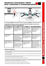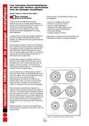
Table of contents - Haug GmbH
Table of contents - Haug GmbH
Table of contents - Haug GmbH

You also want an ePaper? Increase the reach of your titles
YUMPU automatically turns print PDFs into web optimized ePapers that Google loves.
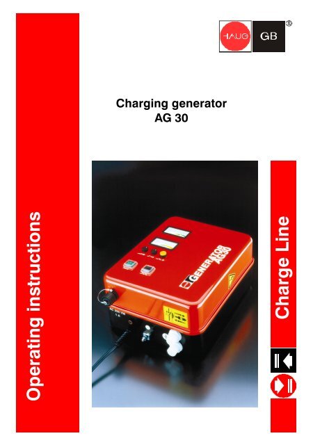
Operating instructions<br />
Charging generator<br />
AG 30<br />
Charge Line
Types<br />
AG 30 positive 115 V 09.7701.200, 09.7801.000<br />
AG 30 positive 230 V 09.7700.200, 09.7800.000<br />
AG 30 negative 115 V 09.7703.200, 09.7803.000<br />
AG 30 negative 230 V 09.7702.200, 09.7802.000
Keep in a safe place for future reference!<br />
<strong>Table</strong> <strong>of</strong> <strong>contents</strong><br />
1 Notes on operating instructions...................................................................................4<br />
1.1 Pictorial markings used..............................................................................................4<br />
2 Safety..............................................................................................................................5<br />
2.1 Intended use..............................................................................................................5<br />
2.2 Danger sources..........................................................................................................6<br />
2.3 Installer qualifications.................................................................................................6<br />
2.4 Operator qualifications...............................................................................................6<br />
3 Description <strong>of</strong> unit.........................................................................................................7<br />
4 Installation......................................................................................................................9<br />
4.1 Important installation instructions...............................................................................9<br />
4.2 Setting up, connecting.............................................................................................10<br />
4.3 Connection socket K1..............................................................................................11<br />
5 Application ...................................................................................................................12<br />
5.1 Putting into operation...............................................................................................12<br />
5.2 Instructions for setting the high voltage...................................................................13<br />
6 Remedy <strong>of</strong> defects.......................................................................................................14<br />
6.1 Troubleshooting .......................................................................................................14<br />
7 Maintenance and repairs.............................................................................................15<br />
7.1 Replacing fuse.........................................................................................................15<br />
7.2 Accessories..............................................................................................................16<br />
8 Technical data..............................................................................................................17<br />
8.1 Connectable charging units.....................................................................................17<br />
8.2 Characteristics and specification..............................................................................17<br />
8.3 Supply voltage.........................................................................................................17<br />
8.4 Ambient conditions ..................................................................................................18<br />
8.5 Housing....................................................................................................................18<br />
9 Disposal........................................................................................................................19
Notes on operating instructions<br />
1 Notes on operating instructions<br />
In these operating instructions, the AG 30 is also referred to as "unit".<br />
1.1 Pictorial markings used<br />
� In these operating instructions<br />
Page 4<br />
WARNING!<br />
High voltage!<br />
Danger <strong>of</strong> fatal accidents!<br />
Do not open unit!<br />
WARNING!<br />
Only plug in/unplug coaxial connector<br />
when the unit is switched <strong>of</strong>f!<br />
ATTENTION!<br />
Important instructions!<br />
� On the unit<br />
WARNING!<br />
High voltage!<br />
Danger <strong>of</strong> fatal accidents!<br />
Do not open unit!<br />
WARNING!<br />
Only plug in/unplug coaxial connector<br />
when the unit is switched <strong>of</strong>f!
Safety<br />
2 Safety<br />
The unit is operationally safe, provided that it is operated in accordance with<br />
its intended use.<br />
In case <strong>of</strong> misuse, dangers may result:<br />
- for life and limb <strong>of</strong> the operator,<br />
- for the unit and other assets.<br />
2.1 Intended use<br />
Also note Chapter 4.1 (refer to page 9 "Important installation notes").<br />
ATTENTION!<br />
Do not install or use the unit in areas subject to explosion hazards!<br />
The charging generator AG 30 is intended exclusively for the high-voltage<br />
supply <strong>of</strong> HAUG charging units.<br />
It generates an adjustable direct high voltage <strong>of</strong> 0...40 kV, with positive or<br />
negative polarity, depending on the unit type.<br />
The direct high voltage is intended for charging material webs in industrial<br />
production processes.<br />
For reasons <strong>of</strong> safety, unauthorized conversions and modifications <strong>of</strong> the unit<br />
are not permitted.<br />
The installation and operating conditions indicated in these Operating<br />
Instructions must be adhered to.<br />
Page 5
Safety<br />
2.2 Danger sources<br />
____________________________________________________________________________<br />
Page 6<br />
WARNING!<br />
The charging units connected to the charging generator conduct high voltage<br />
during operation!<br />
Any contact may lead to injury and consequential accidents.<br />
The operator must provide protective equipment against direct contact when<br />
installing the charging units. Make sure that you read and observe the<br />
operating instructions <strong>of</strong> the connected charging units.<br />
WARNING!<br />
Only plug in/unplug coaxial connector<br />
when the unit is switched <strong>of</strong>f!<br />
____________________________________________________________________________<br />
Defective high-voltage terminals and cables may lead to danger <strong>of</strong> electric<br />
shocks.<br />
Shut down the unit immediately in case <strong>of</strong> visible damage and suspected<br />
electrical defects.<br />
2.3 Installer qualifications<br />
The unit may be installed by trained electricians only. The above mentioned<br />
person must have read the operating instructions and must follow the<br />
instructions, notes and safety advice.<br />
2.4 Operator qualifications<br />
The unit may be maintained and put into operation by trained electricians<br />
only or by authorized persons informed about the potential dangers. The<br />
above mentioned persons must have read the operating instructions and<br />
must follow the instructions, notes and safety advice.
3 Description <strong>of</strong> unit<br />
Figure 1<br />
1. Connection socket K1 (Pulse-/Signalling connection)<br />
2. Mains supply<br />
3. Fuse (for replacement refer to page 15, Section 7.1)<br />
4. Ground connection (terminal)<br />
5. High-voltage terminals<br />
1 2 3 4 5<br />
Description <strong>of</strong> unit<br />
Page 7
Description <strong>of</strong> unit<br />
Page 8<br />
Figure 2<br />
6. Voltage display kVDC<br />
7. Current display mA<br />
8. High voltage potentiometer<br />
9. Current threshold potentiometer<br />
10. Reset pushbutton<br />
11. Mains switch: Switch lights up green when the unit is switched on.<br />
12. Toggle switch pulsed/permanent operation<br />
6<br />
7<br />
8<br />
9<br />
10<br />
11<br />
12<br />
ENERATOR<br />
G AG 30
Installation<br />
4 Installation<br />
The unit may be installed by trained electricians only. The above mentioned<br />
person must have read the operating instructions and must follow the<br />
instructions, notes and safety advice.<br />
4.1 Important installation instructions<br />
____________________________________________________________________________<br />
WARNING!<br />
High voltage!<br />
Danger <strong>of</strong> fatal accidents!<br />
Do not open unit!<br />
WARNING!<br />
Only plug in/unplug coaxial connector<br />
when the unit is switched <strong>of</strong>f!<br />
____________________________________________________________________________<br />
The operation <strong>of</strong> the unit is not affected by the position in which it is installed.<br />
However, we recommend installing the unit so that the high-voltage terminals<br />
points downwards (to protect it from humidity, oil and dirt).<br />
Do not place the unit on a surface generating or radiating heat. Avoid<br />
installation positions exposed to direct sunlight.<br />
Page 9
Installation<br />
4.2 Setting up, connecting<br />
____________________________________________________________________________<br />
Page 10<br />
WARNING!<br />
The charging units connected to the charging generator conduct high voltage<br />
during operation!<br />
Any contact may lead to injury and consequential accidents.<br />
The operator must provide protective equipment against direct contact when<br />
installing the charging units. Make sure that you read and observe the<br />
operating instructions <strong>of</strong> the connected charging units.<br />
WARNING!<br />
Only plug in/unplug coaxial connector<br />
when the unit is switched <strong>of</strong>f!<br />
____________________________________________________________________________<br />
1. Before connecting always check that the unit is suitable for the local mains<br />
voltage (the voltage is indicated on the name plate). Incorrect mains voltage<br />
may result in damage to the unit.<br />
2. Attach unit at the desired location using the enclosed retaining plates.<br />
3. Ensure that the unit is switched <strong>of</strong>f (for mains switch, refer to page 8, Fig. 2,<br />
item 11).<br />
4. Connect charging units to high-voltage terminals.<br />
5. Connect the PE conductor (green-yellow) with the protective earth <strong>of</strong> the<br />
mains. Connecting the PE conductor via parts <strong>of</strong> a machine body is<br />
insufficient.<br />
6. If required, connect the signaling line K1 to the connection socket K1 (refer to<br />
page 7, Fig. 1, item 1).<br />
7. Connect the unit to the mains.<br />
8. Put unit into operation.
4.3 Connection socket K1<br />
Installation<br />
ATTENTION!<br />
No destructive electrical loads may be applied to the signalling contacts<br />
(to protect the electronic system <strong>of</strong> the unit). Before plugging in the<br />
signal line K1, please self-discharge by touching grounded machine<br />
parts.<br />
1. Connect the connector in accordance with the following terminal assignment<br />
diagram.<br />
2. Plug in the connector.<br />
3. The charging generator triggers a signal when the set current threshold is<br />
exceeded.<br />
4. The charging generator can be pulsed via an external contact.<br />
Note:<br />
If a pulse frequency <strong>of</strong> more than 0.5 Hz is chosen, the measuring instrument<br />
(kV) will be unable to follow the on/<strong>of</strong>f cycles. The measuring instrument's<br />
(kV) inertia does not affect its function, however. The unit will perform the<br />
pulses properly up to 1 Hz max.<br />
Figure 3<br />
Pin 1: Joint connection relay<br />
Pin 2: Normally closed contact: Open when current threshold has been<br />
exceeded.<br />
Pin 3: Switching contact: Closed when current threshold has been exceeded.<br />
Pin 4: Not assigned<br />
Pin 5 and 6: Connection <strong>of</strong> a floating normally open contact (Pulse signal)<br />
PE: Shield ground<br />
3 4<br />
PE<br />
2 5<br />
1 6<br />
Page 11
Application<br />
5 Application<br />
____________________________________________________________________________<br />
WARNING!<br />
The charging units connected to the charging generator conduct high voltage<br />
during operation!<br />
Any contact may lead to injury and consequential accidents.<br />
The operator must provide protective equipment against direct contact when<br />
installing the charging units. Make sure that you read and observe the<br />
operating instructions <strong>of</strong> the connected charging units.<br />
____________________________________________________________________________<br />
Page 12<br />
The unit may be put into operation by trained electricians only or by persons<br />
instructed in the potential dangers. The above mentioned persons must have<br />
read the operating instructions and must follow the instructions, notes and<br />
safety advice.<br />
Preconditions:<br />
The charging generator and the charging units must be connected correctly.<br />
5.1 Putting into operation<br />
ATTENTION!<br />
The setting under item 6 should be completed within 10 s, as otherwise a<br />
protective relay will switch <strong>of</strong>f the high voltage. T he signaling lamp<br />
flashes to indicate this status.<br />
Continue adjusting the setting according to item 6 after pressing the<br />
reset pushbutton.<br />
1 Switch on unit at mains switch. The green control lamp lights up to control.<br />
2 Turn high voltage potentiometer to the extreme left (minimum).<br />
3 Turn current threshold potentiometer to the extreme right (maximum).<br />
4 Put changeover switch for pulsed/continuous operation into required<br />
operation mode.<br />
5 Set high voltage potentiometer to desired value. The voltage display (refer to<br />
page 8, Fig. 2, item 6) will indicate the adjusted voltage.<br />
6 Once the process is running, turn the current threshold potentiometer<br />
towards the minimum until the signalling lamp lights up. Then turn it back<br />
slightly towards the maximum until the signalling lamp is extinguished. The<br />
current display (refer to page 8, Fig. 2, item 7) indicates the present current.
5.2 Instructions for setting the high voltage<br />
Application<br />
The output voltage depends on the current load. This is why the voltage<br />
increases if an existing counter electrode is covered with insulating material.<br />
If spark-over occurs, please set a lower voltage or increase the distance<br />
between the charging unit and the counter electrode or the opposing metal<br />
parts.<br />
Page 13
Remedy <strong>of</strong> defects<br />
6 Remedy <strong>of</strong> defects<br />
____________________________________________________________________________<br />
Page 14<br />
WARNING!<br />
High voltage!<br />
Danger <strong>of</strong> fatal accidents!<br />
Do not open unit!<br />
WARNING!<br />
Only plug in/unplug coaxial connector<br />
when the unit is switched <strong>of</strong>f!<br />
____________________________________________________________________________<br />
Any remedy <strong>of</strong> defects must be carried out by trained electricians only. The<br />
above mentioned person must have read the operating instructions and must<br />
follow the instructions, notes and safety advice.<br />
In case <strong>of</strong> defects regarding the generator and the charging unit, please<br />
check for correct installation and fusing first (for replacement, refer to<br />
page 15, chapter 7.1).<br />
6.1 Troubleshooting<br />
Faults Measures<br />
No charging Check mains voltage<br />
Check fuse (for replacement, refer to page 15,<br />
chapter 7.1)<br />
Check connection<br />
Clean charging unit<br />
Check charging unit for damages. If damaged,<br />
immediately shut down and secure against<br />
restarting.<br />
If this does not remedy the defect, please return the charging generator and<br />
the charging unit to HAUG <strong>GmbH</strong> & Co. KG (see address on back page) for<br />
examination.
7 Maintenance and repairs<br />
Maintenance and repairs<br />
____________________________________________________________________________<br />
WARNING!<br />
High voltage!<br />
Danger <strong>of</strong> fatal accidents!<br />
Do not open unit!<br />
WARNING!<br />
Only plug in/unplug coaxial connector<br />
when the unit is switched <strong>of</strong>f!<br />
____________________________________________________________________________<br />
This unit does not include any parts which can be maintained or repaired by<br />
the operator. HAUG <strong>GmbH</strong> & Co. KG only is authorized to repair or calibrate<br />
the unit.<br />
Should the unit prove defective or if a defect is suspected, switch <strong>of</strong>f unit<br />
immediately and secure against subsequent reuse.<br />
7.1 Replacing fuse<br />
1. Switch <strong>of</strong>f unit.<br />
2. Determine and remove the cause for the blown fuse.<br />
3. Detach the fuse holder using a screwdriver and lift out.<br />
4. Replace fuse and reattach fuse holder.<br />
Use the following fuses only:<br />
Unit type Fuse<br />
AG 30 positive/negative 115 V 2,50 A slow, 5 x 20 mm<br />
AG 30 positive/negative 230 V 1,25 A slow, 5 x 20 mm<br />
The unit type and the rated voltage are indicated on the nameplate.<br />
Only use fuses <strong>of</strong> the type indicated.<br />
Page 15
Maintenance and repairs<br />
7.2 Accessories<br />
Article<br />
Page 16<br />
Order<br />
number<br />
Circular plug X – 0616<br />
Right-angle plug X – 5718<br />
Signalling line K1 (incl. plug, assembled) 5 m shielded 06.8941.000<br />
Signalling line K1 (incl. plug, assembled) 10 m shielded 06.8941.001<br />
Signalling line K1 (incl. plug, assembled) 20 m shielded 06.8941.002
8 Technical data<br />
8.1 Connectable charging units<br />
Charging bars ALS, AS SL<br />
Charging electrodes AE, AE SL, SA, PAE<br />
8.2 Characteristics and specification<br />
High-voltage terminals<br />
High voltage<br />
Reference temperature 23 °C<br />
2 HAUG High-voltage<br />
terminals (standard)<br />
Short-circuit current Ik ≤ 4,5 mA<br />
Connection socket K1<br />
Max. cycle frequency 1 Hz<br />
8.3 Supply voltage<br />
Unit type<br />
AG 30<br />
pos./neg.<br />
AG 30<br />
pos./neg.<br />
Technical data<br />
Approx. 40 kVDC (no load),<br />
positive or nagative<br />
Contact load 24 VAC /<br />
35 VDC, max. 50 mA<br />
ATTENTION!<br />
Always connect the PE conductor (green/yellow conductor) to the<br />
protective earth <strong>of</strong> the mains!<br />
Nominal<br />
value<br />
Operating<br />
range<br />
Frequency<br />
range<br />
Power input<br />
115 VAC ±10 % 50 - 60 Hz P max = 60 VA<br />
230 VAC ±10 % 50 - 60 Hz P max = 60 VA<br />
Page 17
Technical data<br />
8.4 Ambient conditions<br />
Ambient temperature:<br />
Rated application range +5 °C to +45 °C<br />
Extreme range for storage and transport -15 °C to +60 °C<br />
Humidity:<br />
Rated application range 20 % to 65 % RF<br />
Extreme range for storage and transport 0 % to 85 % RF<br />
Air pressure:<br />
Rated application range 800 mbar to 1060 mbar<br />
Vibrations:<br />
Extreme range for storage and transport max. 1.5 g (10 to 55 Hz), 1 h<br />
Shock max. 15 g in each direction<br />
Recommended service position:<br />
8.5 Housing<br />
Protection type IP 54<br />
Protection class I<br />
Page 18<br />
vertical, supply cable<br />
downwards<br />
Mains supply approx. 2,6 m fixed on unit<br />
Dimensions:<br />
Height approx. 345 mm<br />
Width approx. 370 mm<br />
Depth approx. 162 mm<br />
Weight: approx. 13 kg
Disposal<br />
9 Disposal<br />
Observe and maintain national and regional waste disposal regulations for<br />
the disposal <strong>of</strong> the unit!<br />
Page 19
made by<br />
HAUG <strong>GmbH</strong> & Co.KG<br />
Friedrich-List-Straße 18<br />
D-70771 Leinfelden-Echterdingen<br />
Telefon 07 11 / 94 98 - 0<br />
Telefax 07 11 / 94 98 - 298<br />
www.haug.de<br />
E-Mail: info@haug.de<br />
HAUG Biel AG<br />
Postfach<br />
CH-2500 Biel/ Bienne 6<br />
Johann-Renfer-Strasse 60<br />
CH-2500 Biel/ Bienne 6<br />
Telefon 0 32 / 3 44 96 96<br />
Telefax 0 32 / 3 44 96 97<br />
www.haug.de<br />
E-Mail: info@haug-biel.ch<br />
D – 0208<br />
V 04<br />
2007-09-10<br />
AG30 v04gb